505S 505s-gb-03.pdf

Watson Marlow 505s Manual Eng
Oct 26, 2014
Welcome message from author
This document is posted to help you gain knowledge. Please leave a comment to let me know what you think about it! Share it to your friends and learn new things together.
Transcript

!"!#
505s-gb-03.pdf
2
Declarations
Declaration ofconformity
When this pump unit is used as a stand alone pump it complies with: Machinery Directive98/37/EC EN60204-1, Low Voltage Directive 73/23/EEC EN61010-1, EMC Directive 89/336/EECEN50081-1/EN50082-1.
Declaration ofIncorporation
When this pump unit is to be installed into a machine or is to be assembled with othermachines for installations, it must not be put into service until the relevant machinery has beendeclared in conformity with the Machinery Directive 98/37/ EC EN60204-1.
Responsible person: Dr R Woods, Managing Director, Watson-Marlow Limited, Falmouth, Cornwall TR11 4RU, England.Telephone 01326 370370 Fax 01326 376009.
Three year warrantyWatson-Marlow Limited warrants, subject to the conditions below, through either Watson-Marlow Limited, its subsidiaries, or itsauthorised distributors, to repair or replace free of charge, including labour, any part of this product which fails within three yearsof delivery of the product to the end user. Such failure must have occurred because of defect in material or workmanship and notas a result of operation of the product other than in accordance with the instructions given in this manual.Conditions of and specific exceptions to the above warranty are:• Consumable items such as tubing, rollers and motor brushes are excluded.• Products must be returned by pre-arrangement carriage paid to Watson-Marlow Limited, its subsidiaries, or its authorised
distributor.• All repairs or modifications must have been made by Watson-Marlow Limited, its subsidiaries, or its authorised distributors or
with the express permission of Watson-Marlow Limited, its subsidiaries, or its authorised distributors.• Products which have been abused, misused, or subjected to malicious or accidental damage or electrical surge are
excluded.Warranties purporting to be on behalf of Watson-Marlow Limited made by any person, including representatives of Watson-Marlow Limited, its subsidiaries, or its distributors, which do not accord with the terms of this warranty shall not be binding uponWatson-Marlow Limited unless expressly approved in writing by a Director or Manager of Watson-Marlow Limited.
Information for returning pumpsEquipment which has been contaminated with, or exposed to, body fluids, toxic chemicals or any other substance hazardous tohealth must be decontaminated before it is returned to Watson-Marlow or its distributor.A certificate included at the rear of these operating instructions, or signed statement, must be attached to the outside of theshipping carton.This certificate is required even if the pump is unused. If the pump has been used, the fluids that have been in contact with thepump and the cleaning procedure must be specified along with a statement that the equipment has been decontaminated.
SafetyIn the interests of safety, this pump and the tubing selected should only be used by competent, suitably trained personnel afterthey have read and understood this manual, and considered any hazard involved.Any person who is involved in the installation or maintenance of this equipment should be fully competent to carry out the work. Inthe UK this person should also be familiar with the Health and Safety at Work Act 1974.
There are dangerous voltages (at mains potential) inside the pump. If access is required, isolatethe pump from the mains before removing the cover.
Recommended operating proceduresDO keep delivery and suction lines as short as possible using a minimum number of swept bends.DO use suction and delivery pipelines with a bore equal to or larger than the bore of the tube fitted in the pumphead. Whenpumping viscous fluids, the losses caused by increased friction can be overcome by using pipe runs with a cross sectionalarea several times greater than the pumping element.DO run at a slow speed when pumping viscous fluids. When using the 501RL pumphead, a 4.8 or 6.4mm bore tube with a1.6mm wall will give best results. Tube smaller than this will generate a high-friction pressure loss, so reducing the flow. Tube
3
with a larger bore will not have sufficient strength to restitute. Flooded suction will enhance pumping performance in all cases,particularly for materials of a viscous nature. Silicone and Marprene tubing is available with a 2.4mm wall thickness for speedsup to 200rpm. (The rotor will require re-setting to a roller/track gap of 3.8mm.)DO fit an extra length of pump tube in the system to enable tube transfer. This will extend tube life and minimise the downtimeof the pumping circuit.DO keep the track and rollers clean.The self-priming nature of peristaltic pumps means valves are not required. Any valves fitted must cause no restriction to flow inthe pumping circuit.When using Marprene tubing, after the first 30 minutes of running, re-tension the tube in the pumphead by releasing the tubeclamp on the delivery side a little and pulling the tube tight. This is to counteract the normal stretching that occurs with Marprenewhich can go unnoticed and result in poor tube life.Tube selection The chemical compatibility list published in the Watson-Marlow catalogue is only a guide. If in doubt about thecompatibility of a tube material and the duty fluid, request a tube sample card for immersion trials.
InstallationThe 505S/RL is suitable for single phase mains electricity supplies only.To ensure correct lubrication of the gearbox the pump should be run only while its feet are standing on a horizontal surface. Thepump should be positioned to allow a free flow of air around it.• Set the voltage selector to either 120V for 100-120V 50/60Hz supplies or 240V for 220-240V 50/60Hz supplies.A mains cable fitted with a moulded plug is supplied with the pump. The wires are colour coded in accordance with thefollowing code:• 220-240V: Live- Brown; Neutral - Blue; Earth - Green/Yellow.• 100-120V: Live - Black; Neutral - White; Earth - Green.
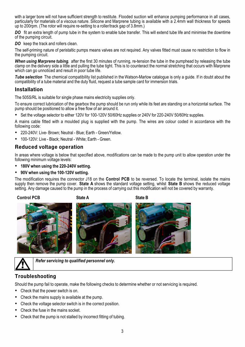
Reduced voltage operationIn areas where voltage is below that specified above, modifications can be made to the pump unit to allow operation under thefollowing minimum voltage levels:• 180V when using the 220-240V setting.• 90V when using the 100-120V setting.The modification requires the connector J18 on the Control PCB to be reversed. To locate the terminal, isolate the mainssupply then remove the pump cover. State A shows the standard voltage setting, whilst State B shows the reduced voltagesetting. Any damage caused to the pump in the process of carrying out this modification will not be covered by warranty.
Control PCB State A State B
Refer servicing to qualified personnel only.
TroubleshootingShould the pump fail to operate, make the following checks to determine whether or not servicing is required.• Check that the power switch is on.• Check the mains supply is available at the pump.• Check the voltage selector switch is in the correct position.• Check the fuse in the mains socket.• Check that the pump is not stalled by incorrect fitting of tubing.
4
Manual operation• Switch power on (drive rear panel).• Change the set speed by pressing the or key. The 505S speed control ratio is 110:1. This will give a minimum speed of
2rpm for the 220rpm drive and 0.5 rpm for the 55rpm drive.• Change direction by pressing the CW/CCW key. Check the flashing CW/CCW symbol for actual direction setting. (CW :
clockwise CCW : counterclockwise).• Select the maximum speed: press the key and the Max key together. Select the minimum speed: press the key and the
Max key together.• The keypad has a locking facility to avoid resetting or tampering. If the pump is stopped, press Stop until the padlock symbol
illuminates. If the pump is running, press Start until the padlock symbol illuminates. All keys will be disabled except for Startand Stop. Press these keys until the padlock symbol extinguishes to unlock the keypad.
• The pump can be set to automatically restart in its operating state set prior to interruption, or set so that after power isreconnected the pump will remain stopped. To invoke the Auto-restart facility switch off power to the pump at the mainssupply. Press the Start key down when the mains supply is switched back on until the ! symbol illuminates. Now press Startto start the pump. This facility can be cancelled by turning the mains supply off and then pressing the Stop key whilst turningthe mains supply back on. The ! symbol will not be illuminated.
• Press Start to start the pump. Press Stop to stop the pump.
Error messagesIf a fault condition is detected in the drive unit it will stop, all keys will be disabled, and the display will flash:
Er1 Tachometer faultEr2 Over temperature errorEr3 EEPROM errorEr4 EEPROM read errorEr5 EEPROM write errorEr6 EEPROM exhausted error. There is a maximum number of times the EEPROM can be written to. If Er6 is displayed,
however, the EEPROM must be replaced.Er9 RAM corruption error
Care and maintenanceThe only scheduled maintenance of the 505S is to inspect the motor brushes and to replace them before their length is lessthan 6mm (1/4"). The life of the brushes will depend on the duty of the pump, which is expected to be at least 10,000 hours atmaximum speed. When the pump needs cleaning, remove the pumphead and use a mild solution of detergent in water. Do notuse strong solvents.If the gearbox is rebuilt you should use 15 ml of the recommended lubricant, which is RD105, this is a SAE 30 mineral oil loadedwith molybdenum disulphide to form a soft fluid grease.
Specification
Maximum rotor speed 55rpm, 220rpmVoltage/frequency 100-120/220-240V 50/60HzControl range 110:1Power consumption 100VAShaft Torque 2.2NmOperating temperature range 5 to 40CStorage temperature range -40C to 70CWeight 7.7kg (17Ib)Noise <70dBA at 1mStandards IEC 335-1, EN60529 (IP31)
Machinery Directive 98/37/EC EN60204- 1Low Voltage Directive 73/23/EEC EN61010- 1
EMC Directive:89/336/EEC EN50081-1 / EN50082-1
501RL PumpheadThe 501RL pumphead has two spring-loaded working rollers, which automatically compensate for minor variations in tubingwall thickness, giving extended tube life. The 501RL is set during manufacture to accept tubing with wall thicknesses of between1.6mm and 2.0mm, and internal diameters of up to 8.0mm. It is equipped with a "tool lockable" guard for increased safety. Thisshould be locked shut whilst the pump is in use.
5
The pumphead can be run clockwise for extended tube life, or anti-clockwise to operate against higher pressures.
Flow ratesFlow rates for the 505S were obtained using silicone tubing with the pumphead rotating clockwise, pumping water at 20C withzero suction and delivery pressures. For critical applications determine flow rates under operating conditions.
InstallationFit the track in any one of three orientations, over the drive shaft and locating boss. Secure the track with the locating screw.Ensure the drive shaft is degreased before locating the rotor onto the shaft via the split collet. Tighten the rotor screw to a torqueof 3Nm to prevent the collet slipping during operation.To reposition the track, swing out the crank handle to expose the rotor retaining screw. Turn the screw anticlockwise one turn torelease the collet, and withdraw the rotor from the shaft. Loosen the track locating screw, and pull the track clear. Rotate thetrack to its new position and tighten the track locating screw. Use this method of removal and fitting in case cleaning is required.
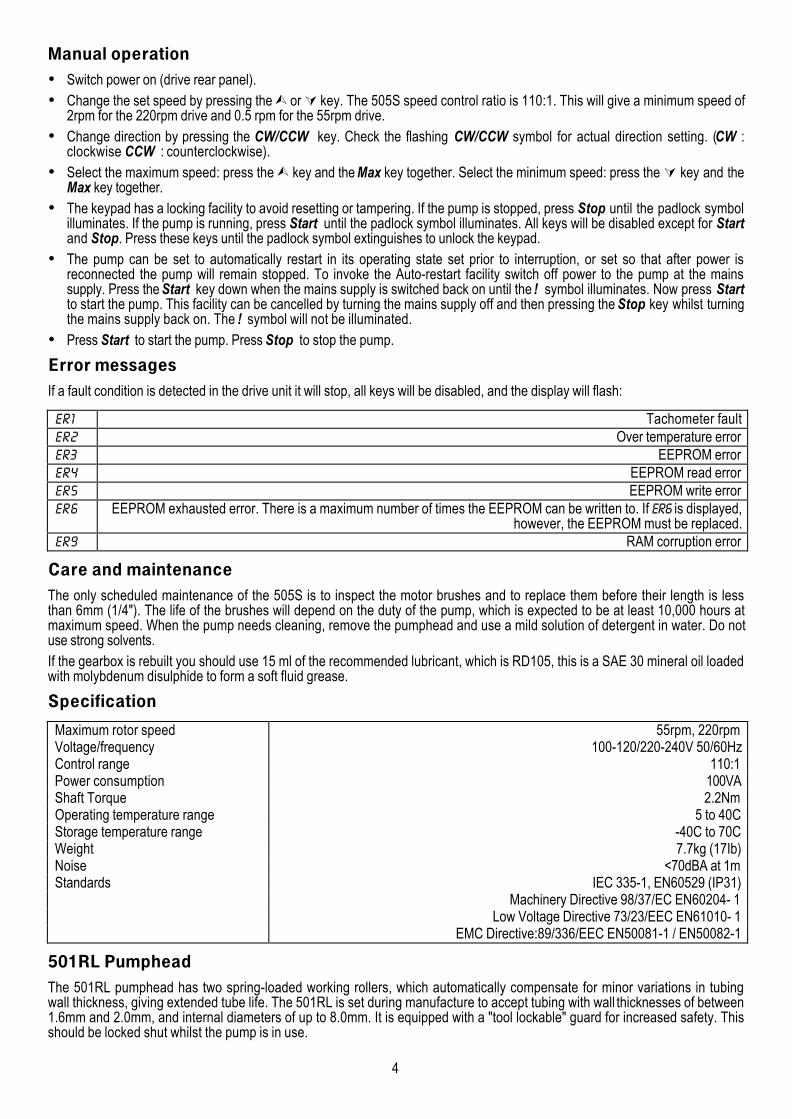
Tube loadingIsolate pump from mains supply. Unlock and open the hinged guard and swing out the rotor crank handle until it locks intoposition. Select the length of tubing required, noting that approximately 240mm is required for the track systems.Fit one end of the tubing into one of the spring loaded clamps, and then, whilst rotating the rotor with the crank handle, feed thetubing between the rollers and the track, aligning it within the rotor tube guides. The tubing must lie naturally against the trackand must not be twisted or stretched.
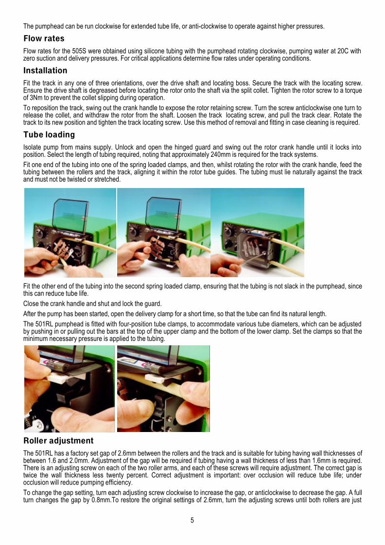
Fit the other end of the tubing into the second spring loaded clamp, ensuring that the tubing is not slack in the pumphead, sincethis can reduce tube life.Close the crank handle and shut and lock the guard.After the pump has been started, open the delivery clamp for a short time, so that the tube can find its natural length.The 501RL pumphead is fitted with four-position tube clamps, to accommodate various tube diameters, which can be adjustedby pushing in or pulling out the bars at the top of the upper clamp and the bottom of the lower clamp. Set the clamps so that theminimum necessary pressure is applied to the tubing.
Roller adjustmentThe 501RL has a factory set gap of 2.6mm between the rollers and the track and is suitable for tubing having wall thicknesses ofbetween 1.6 and 2.0mm. Adjustment of the gap will be required if tubing having a wall thickness of less than 1.6mm is required.There is an adjusting screw on each of the two roller arms, and each of these screws will require adjustment. The correct gap istwice the wall thickness less twenty percent. Correct adjustment is important: over occlusion will reduce tube life; underocclusion will reduce pumping efficiency.To change the gap setting, turn each adjusting screw clockwise to increase the gap, or anticlockwise to decrease the gap. A fullturn changes the gap by 0.8mm.To restore the original settings of 2.6mm, turn the adjusting screws until both rollers are just
6
touching the track, then tighten each screw by three and a quarter turns. The 501RL2 has a factory set gap of 3.8mm betweenthe wall and the track and is suitable for tubing having wall thickness of between 2.1 and 2.5mm.Check moving parts of the rotor from time to time for freedom of movement. Lubricate pivot points and rollers occasionally withTeflon lubricating oil.Specific drive performance details such as loaded drive speed variation against mains supply voltage fluctuation and drivestability from a cold start to normal operating temperature are available on request. For further information please contactWatson-Marlow Technical Support Centre.
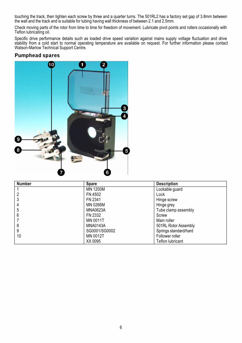
Pumphead spares
Number Spare Description1 MN 1200M Lockable guard2 FN 4502 Lock3 FN 2341 Hinge screw4 MN 0266M Hinge grey5 MNA0623A Tube clamp assembly6 FN 2332 Screw7 MN 0011T Main roller8 MNA0143A 501RL Rotor Assembly9 SG0001/SG0002 Springs standard/hard10 MN 0012T Follower roller
XX 0095 Teflon lubricant

7
Drive spares
Number Spare Description1 SW 0147 On/Off switch2 SW 0086 Voltage selector switch3 TF 0032 Transformer4 MNA0346A Tachometer disc assembly5 BM 0014 Motor brush6 MNA0388A Motor/gearbox 220rpm7 MNA0396A Motor/gearbox 55rpm8 MN 0563B Panel9 MNA0423A CPU and display PCB10 MNA0420A Tachometer PCB11 MNA0422A Speed control PCB12 FS 0003 Mains fuse13 US 0045 Mains connector

8
Outline dimensions
9
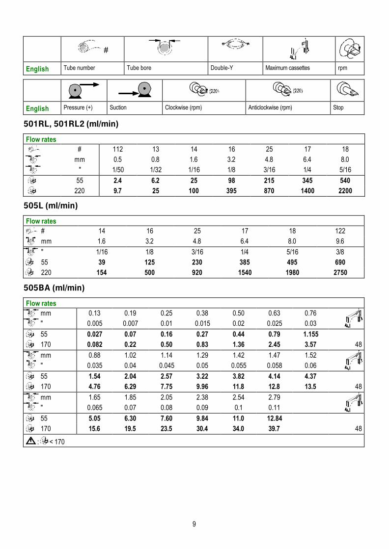
#
English Tube number Tube bore Double-Y Maximum cassettes rpm
English Pressure (+) Suction Clockwise (rpm) Anticlockwise (rpm) Stop
501RL, 501RL2 (ml/min)
Flow rates # 112 13 14 16 25 17 18
mm 0.5 0.8 1.6 3.2 4.8 6.4 8.0" 1/50 1/32 1/16 1/8 3/16 1/4 5/16
55 2.4 6.2 25 98 215 345 540
220 9.7 25 100 395 870 1400 2200
505L (ml/min)
Flow rates # 14 16 25 17 18 122
mm 1.6 3.2 4.8 6.4 8.0 9.6
" 1/16 1/8 3/16 1/4 5/16 3/8
55 39 125 230 385 495 690
220 154 500 920 1540 1980 2750
505BA (ml/min)
Flow ratesmm"
0.130.005
0.190.007
0.250.01
0.380.015
0.500.02
0.630.025
0.760.03
55 0.027 0.07 0.16 0.27 0.44 0.79 1.155170 0.082 0.22 0.50 0.83 1.36 2.45 3.57 48
mm"
0.880.035
1.020.04
1.140.045
1.290.05
1.420.055
1.470.058
1.520.06
55 1.54 2.04 2.57 3.22 3.82 4.14 4.37170 4.76 6.29 7.75 9.96 11.8 12.8 13.5 48
mm"
1.650.065
1.850.07
2.050.08
2.380.09
2.540.1
2.790.11
55 5.05 6.30 7.60 9.84 11.0 12.84170 15.6 19.5 23.5 30.4 34.0 39.7 48
: < 170
10
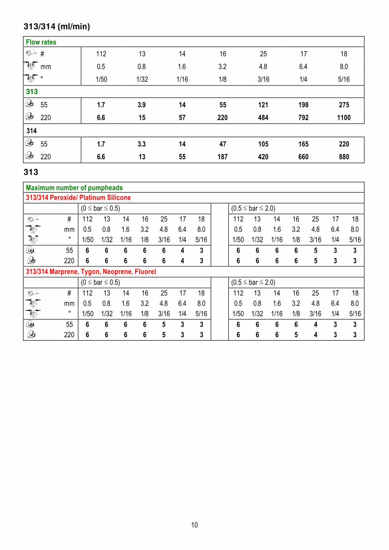
313/314 (ml/min)
Flow rates
# 112 13 14 16 25 17 18
mm 0.5 0.8 1.6 3.2 4.8 6.4 8.0
" 1/50 1/32 1/16 1/8 3/16 1/4 5/16
313 55 1.7 3.9 14 55 121 198 275
220 6.6 15 57 220 484 792 1100
314
55 1.7 3.3 14 47 105 165 220
220 6.6 13 55 187 420 660 880
313
Maximum number of pumpheads313/314 Peroxide/ Platinum Silicone
(0 bar 0.5) (0.5 bar 2.0)
# 112 13 14 16 25 17 18 112 13 14 16 25 17 18mm 0.5 0.8 1.6 3.2 4.8 6.4 8.0 0.5 0.8 1.6 3.2 4.8 6.4 8.0
" 1/50 1/32 1/16 1/8 3/16 1/4 5/16 1/50 1/32 1/16 1/8 3/16 1/4 5/16
55 6 6 6 6 6 4 3 6 6 6 6 5 3 3
220 6 6 6 6 6 4 3 6 6 6 6 5 3 3
313/314 Marprene, Tygon, Neoprene, Fluorel
(0 bar 0.5) (0.5 bar 2.0)
# 112 13 14 16 25 17 18 112 13 14 16 25 17 18mm 0.5 0.8 1.6 3.2 4.8 6.4 8.0 0.5 0.8 1.6 3.2 4.8 6.4 8.0
" 1/50 1/32 1/16 1/8 3/16 1/4 5/16 1/50 1/32 1/16 1/8 3/16 1/4 5/16
55 6 6 6 6 5 3 3 6 6 6 6 4 3 3
220 6 6 6 6 5 3 3 6 6 6 5 4 3 3
11
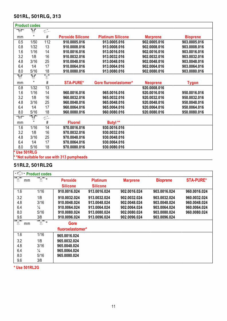
501RL, 501RLG, 313
Product codes
mm " # Peroxide Silicone Platinum Silicone Marprene Bioprene 0.5 1/50 112 910.0005.016 913.0005.016 902.0005.016 903.0005.016 0.8 1/32 13 910.0008.016 913.0008.016 902.0008.016 903.0008.016 1.6 1/16 14 910.0016.016 913.0016.016 902.0016.016 903.0016.016 3.2 1/8 16 910.0032.016 913.0032.016 902.0032.016 903.0032.016 4.8 3/16 25 910.0048.016 913.0048.016 902.0048.016 903.0048.016 6.4 1/4 17 910.0064.016 913.0064.016 902.0064.016 903.0064.016 8.0 5/16 18 910.0080.016 913.0080.016 902.0080.016 903.0080.016
mm " # STA-PURE* Gore flurooelastomer* Neoprene Tygon 0.8 1/32 13 920.0008.016 1.6 1/16 14 960.0016.016 965.0016.016 920.0016.016 950.0016.016 3.2 1/8 16 960.0032.016 965.0032.016 920.0032.016 950.0032.016 4.8 3/16 25 960.0048.016 965.0048.016 920.0048.016 950.0048.016 6.4 1/4 17 960.0064.016 965.0064.016 920.0064.016 950.0064.016 8.0 5/16 18 960.0080.016 960.0080.016 920.0080.016 950.0080.016
mm " # Fluorel Butyl ** 1.6 1/16 14 970.0016.016 930.0016.016 3.2 1/8 16 970.0032.016 930.0032.016 4.8 3/16 25 970.0048.016 930.0048.016 6.4 1/4 17 970.0064.016 930.0064.016 8.0 5/16 18 970.0080.016 930.0080.016
* Use 501RLG* *Not suitable for use with 313 pumpheads
51RL2, 501RL2G
Product codes
mm " PeroxideSilicone
PlatinumSilicone
Marprene Bioprene STA-PURE*
1.6 1/16 910.0016.024 913.0016.024 902.0016.024 903.0016.024 960.0016.024
3.2 1/8 910.0032.024 913.0032.024 902.0032.024 903.0032.024 960.0032.0244.8 3/16 910.0048.024 913.0048.024 902.0048.024 903.0048.024 960.0048.0246.4 ¼ 910.0064.024 913.0064.024 902.0064.024 903.0064.024 960.0064.0248.0 5/16 910.0080.024 913.0080.024 902.0080.024 903.0080.024 960.0080.0249.6 3/8 910.0096.024 913.0096.024 902.0096.024 903.0096.024
mm " Gorefluoroelastomer*
1.6 1/16 965.0016.0243.2 1/8 965.0032.0244.8 3/16 965.0048.0246.4 ¼ 965.0064.0248.0 5/16 965.0080.0249.6 3/8
* Use 501RL2G
12
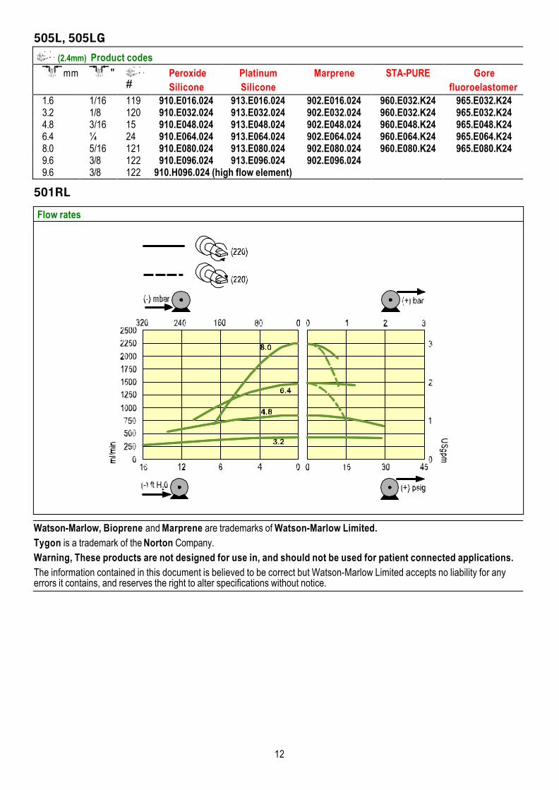
505L, 505LG
(2.4mm) Product codes
mm "#
PeroxideSilicone
PlatinumSilicone
Marprene STA-PURE Gorefluoroelastomer
1.6 1/16 119 910.E016.024 913.E016.024 902.E016.024 960.E032.K24 965.E032.K243.2 1/8 120 910.E032.024 913.E032.024 902.E032.024 960.E032.K24 965.E032.K244.8 3/16 15 910.E048.024 913.E048.024 902.E048.024 960.E048.K24 965.E048.K246.4 ¼ 24 910.E064.024 913.E064.024 902.E064.024 960.E064.K24 965.E064.K248.0 5/16 121 910.E080.024 913.E080.024 902.E080.024 960.E080.K24 965.E080.K249.6 3/8 122 910.E096.024 913.E096.024 902.E096.0249.6 3/8 122 910.H096.024 (high flow element)
501RL
Flow rates
Watson-Marlow, Bioprene and Marprene are trademarks of Watson-Marlow Limited.Tygon is a trademark of the Norton Company.Warning, These products are not designed for use in, and should not be used for patient connected applications.The information contained in this document is believed to be correct but Watson-Marlow Limited accepts no liability for anyerrors it contains, and reserves the right to alter specifications without notice.
13
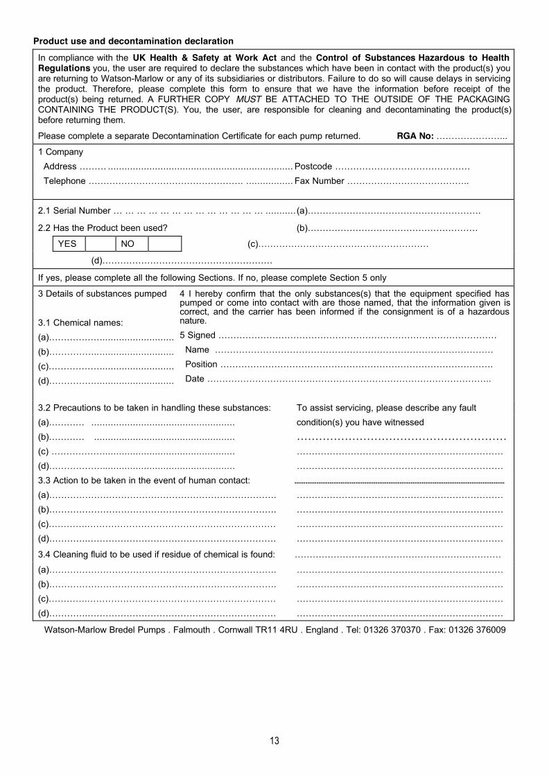
Product use and decontamination declaration
In compliance with the UK Health & Safety at Work Act and the Control of Substances Hazardous to HealthRegulations you, the user are required to declare the substances which have been in contact with the product(s) youare returning to Watson-Marlow or any of its subsidiaries or distributors. Failure to do so will cause delays in servicingthe product. Therefore, please complete this form to ensure that we have the information before receipt of theproduct(s) being returned. A FURTHER COPY MUST BE ATTACHED TO THE OUTSIDE OF THE PACKAGINGCONTAINING THE PRODUCT(S). You, the user, are responsible for cleaning and decontaminating the product(s)before returning them.
Please complete a separate Decontamination Certificate for each pump returned. RGA No: …………………...
1 Company Address ……… ................................................................... Postcode ……………………………………… Telephone ……………………………………………. ................. Fax Number …………………………………..
2.1 Serial Number … … … … … … … … … … … … … ........... (a)………………………………………………….
2.2 Has the Product been used? (b)…………………………………………………
YES NO (c)…………………………………………………
(d)…………………………………………………
If yes, please complete all the following Sections. If no, please complete Section 5 only
3 Details of substances pumped
3.1 Chemical names:(a)………………..........................(b)…………….............................(c)………………..........................(d)…………….............................
4 I hereby confirm that the only substances(s) that the equipment specified haspumped or come into contact with are those named, that the information given iscorrect, and the carrier has been informed if the consignment is of a hazardousnature.5 Signed ………………………………………………………………………………… Name ………………………………………………………………………………… Position ………………………………………………………………………………. Date …………………………………………………………………………………..
3.2 Precautions to be taken in handling these substances: To assist servicing, please describe any fault(a)………… .................................................... condition(s) you have witnessed(b)………… ................................................... …………………………………………………(c) ………………............................................... ……………………………………………………………(d)………………................................................ ……………………………………………………………3.3 Action to be taken in the event of human contact: ……………………………………………………………………………………………………
(a)…………………………………………………………………. ……………………………………………………………(b)…………………………………………………………………. ……………………………………………………………(c)………….……………………………………………………… ……………………………………………………………(d)………….……………………………………………………… ……………………………………………………………
3.4 Cleaning fluid to be used if residue of chemical is found: ……………………………………………………………
(a)…………………………………………………………………. ……………………………………………………………(b)…………………………………………………………………. ……………………………………………………………(c)………….……………………………………………………… ……………………………………………………………(d)………….……………………………………………………… ……………………………………………………………
Watson-Marlow Bredel Pumps . Falmouth . Cornwall TR11 4RU . England . Tel: 01326 370370 . Fax: 01326 376009
Related Documents