Cypress Semiconductor 3901 North First Street San Jose, CA 95134 (408) 943-2600 April 1996 Part Number CY3120DOC Warp VHDL Development System Reference Manual

Welcome message from author
This document is posted to help you gain knowledge. Please leave a comment to let me know what you think about it! Share it to your friends and learn new things together.
Transcript
Cypress Semiconductor3901 North First StreetSan Jose, CA 95134(408) 943-2600April 1996
Part Number CY3120DOC
Warp VHDL Development System
Reference Manual
Cypress Software License Agreement
Cypress Software License Agreement
LICENSE. Cypress Semiconductor Corporation (“Cypress”) hereby grantsyou, as a Customer and Licensee, a single-user, non-exclusive license to usethe enclosed Cypress software program (“Program”) on a single CPU at anygiven point in time. Cypress authorizes you to make archival copies of thesoftware for the sole purpose of backing up your software and protectingyour investment from loss.
TERM AND TERMINATION. This Agreement is effective from the datethe diskettes are received until this Agreement is terminated. Theunauthorized reproduction or use of the Program and/or documentationwill immediately terminate this Agreement without notice. Upontermination you are to destroy both the Program and the documentation.
COPYRIGHT AND PROPRIETARY RIGHTS. The Program anddocumentation are protected by both United States Copyright Law andInternational Treaty provisions. This means that you must treat thedocumentation and Program just like a book, with the exception of makingarchival copies for the sole purpose of protecting your investment from loss.The Program may be used by any number of people, and may be movedfrom one computer to another, so long as there is No Possibility of its beingused by two people at the same time.
DISCLAIMER. THIS PROGRAM AND DOCUMENTATION ARELICENSED “AS-IS,” WITHOUT WARRANTY AS TO PERFORMANCE.CYPRESS EXPRESSLY DISCLAIMS ALL WARRANTIES, EXPRESSEDOR IMPLIED, INCLUDING BUT NOT LIMITED TO THE IMPLIEDWARRANTY OF MERCHANTABILITY OR FITNESS OF THISPROGRAM FOR A PARTICULAR PURPOSE.
RESELLING. The reselling or distribution of this product can be done byCypress authorized distributors only.
LIMITED WARRANTY. The diskette on which this Program is recorded isguaranteed for 90 days from date of purchase. If a defect occurs within 90days, contact the representative at the place of purchase to arrange for areplacement.
BENCHMARKING. This license Agreement does not convey to you theright to publish performance benchmarking results involving any CypressWarp products. Permission to publish performance benchmarking resultsinvolving any Cypress Warp products must be received in writing fromCypress Semiconductor prior to publishing.
iii
Cypress Software License Agreement
LIMITATION OF REMEDIES AND LIABILITY. IN NO EVENT SHALLCYPRESS BE LIABLE FOR INCIDENTAL OR CONSEQUENTIALDAMAGES RESULTING FROM PROGRAM USE, EVEN IF CYPRESSHAS BEEN ADVISED OF THE POSSIBILITY OF SUCH DAMAGES.CYPRESS’S EXCLUSIVE LIABILITY AND YOUR EXCLUSIVE REMEDYWILL BE IN THE REPLACEMENT OF ANY DEFECTIVE DISKETTE ASPROVIDED ABOVE. IN NO EVENT SHALL CYPRESS’S LIABILITYHEREUNDER EXCEED THE PURCHASE PRICE OF THE SOFTWARE.
ENTIRE AGREEMENT. This Agreement constitutes the sole and completeAgreement between Cypress and the Customer for use of the Program anddocumentation. Changes to this Agreement may be made only by writtenmutual consent.
GOVERNING LAW. This Agreement shall be governed by the laws of theState of California. Should you have any question concerning thisAgreement, please contact:
Cypress Semiconductor CorporationAttn: Legal Counsel3901 N. First StreetSan Jose, CA 95134-1599
408-943-2600
iv

The following are trademarks or registered trademarks of Cypress Semiconductor Corporation: Warp, Warp2, Warp3, Nova, Galaxy, ISR, Flash370, PLA2JED, MAX2JED, MAX340, UltraGen, pASIC380.
The following are trademarks or registered trademarks of Viewlogic Systems:Powerview, Workview PLUS, Proseries, ViewDraw, ViewSim, ViewSynth.
The following are trademarks or registered trademarks of Microsoft Corporation: Microsoft, Windows.
The following are trademarks or registered trademarks of QuickLogic Corporation: SpDE, pASIC.
The following is a trademark of Altera Corporation: MAX5000.
The following is a registered trademark of Cadence Design Systems Inc.: Verilog.
Cypress Semiconductor Corporation may revise this publication from time to time without notice. Some states or jurisdictions do not allow disclaimer of express or implied warranties in certain transactions; therefore, this statement may not apply to you.
All other brand or product names are trademarks or registered trademarks of their respective companies or organizations.
Copyright © 1996 Cypress Semiconductor Corporation. All rights reserved.

Conten ts
Warp Reference Manual v
Contents
Contents
Chapter 1 Introduct ion ........................................................................ 1
Overview of Warp Synthesis Compiler ...................................... 2
Warp Synthesis Compiler Capabilities ...................................... 3
About This Manual .................................................................... 5
Chapter 2 Command Line Language ................................................. 7
Warp Command Line Switches ................................................. 8
Warp Command Syntax .................................................. 8Warp Command Options ........................................................... 9
The -d Option .................................................................. 9The -b Option ................................................................ 10The -a Option ................................................................ 11The -e Option ................................................................ 11The -f Option ................................................................. 12The -h Option ................................................................ 14The -l Option ................................................................. 14The -m Option ............................................................... 15The -o Option ................................................................ 15The -p Option ................................................................ 16The -q Option ................................................................ 16The -r Option ................................................................. 16The -s Option ................................................................ 17The -v Option ................................................................ 17The -w Option ............................................................... 18The -xor2 Option ........................................................... 18The -yb Option .............................................................. 18The -yl Option ............................................................... 19The -ym Option ............................................................. 19The -yp Option .............................................................. 19The -yt Option ............................................................... 19The -ygs Option ............................................................ 20The -yga Option ............................................................ 20The -ygc Option ............................................................ 20The -yv Option .............................................................. 20
Recommendations .................................................................. 20
vi Warp Reference Manual
Contents
Warp Output ............................................................................ 21
SpDE Command Line Language ............................................ 21
Chapter 3 Synthesis Direct ives ........................................................ 25
Introduction ............................................................................. 26
Synthesis Directives ................................................................ 27
buffer_gen ..................................................................... 27dont_touch .................................................................... 28enum_encoding ............................................................ 30fixed_ff .......................................................................... 31ff_type ........................................................................... 32goal ............................................................................... 33lab_force ....................................................................... 33max_load ...................................................................... 34no_factor ....................................................................... 35no_latch ........................................................................ 36node_num ..................................................................... 37opt_level ....................................................................... 38order_code .................................................................... 38pad_gen ........................................................................ 39part_name ..................................................................... 40pin_avoid ...................................................................... 41pin_numbers ................................................................. 42polarity .......................................................................... 43state_encoding ............................................................. 44sum_split ....................................................................... 46synthesis_off ................................................................. 46
Control File .............................................................................. 49
Warp Synthesis Directives with ViewDraw .............................. 51
Warp Synthesis Directives ............................................ 51Supported ViewDraw Attributes .................................... 53
Warp Reference Manual vii
Contents
Chapter 4 VHDL ................................................................................. 55
Introduction ............................................................................. 56
Identifiers ................................................................................. 56
Data Objects ........................................................................... 57
Data Types .............................................................................. 59
Pre-Defined Types ........................................................ 60Enumerated Types ....................................................... 62Subtypes ....................................................................... 63Composite Types .......................................................... 64
Operators ................................................................................ 65
Logical Operators ......................................................... 66Relational Operators ..................................................... 67Adding Operators .......................................................... 68Multiplying Operators .................................................... 68Miscellaneous Operators .............................................. 69Assignment Operations ................................................ 69Association Operations ................................................. 70Vector Operations ......................................................... 71
Entities .................................................................................... 73
Architectures ........................................................................... 74
Behavioral Descriptions ................................................ 76Structural Descriptions .................................................. 78Design Methodologies .................................................. 78
Packages .............................................................................. 115
Predefined Packages .................................................. 120Libraries ................................................................................ 132
Additional Design Examples ................................................. 133
DEC24 ........................................................................ 133PINS ........................................................................... 134NAND2_TS ................................................................. 135CNT4_EXP ................................................................. 135CNT4_REC ................................................................. 136Drink ........................................................................... 138Traffic .......................................................................... 140Security ....................................................................... 142
Alphabetical Listing of VHDL Constructs .............................. 143
viii Warp Reference Manual
Contents
Alias ............................................................................ 143Architecture ................................................................. 144Attribute ...................................................................... 145Pre-Defined Attributes ................................................ 147CASE .......................................................................... 153Component ................................................................. 155Constant ..................................................................... 156Entity ........................................................................... 157Exit .............................................................................. 158Generate ..................................................................... 158Generic ....................................................................... 159If-Then-Else ................................................................ 160Library ......................................................................... 162Loops .......................................................................... 162Next ............................................................................ 163Package ...................................................................... 164Port Map ..................................................................... 166Generic Map ............................................................... 167Process ....................................................................... 168Signal .......................................................................... 170Subprograms .............................................................. 171Type ............................................................................ 174USE ............................................................................ 177Variable ....................................................................... 178Wait ............................................................................. 179
Chapter 5 LPM ..................................................................................181
Introduction ........................................................................... 182
LPM Modules ........................................................................ 183
MCNSTNT .................................................................. 183MINV ........................................................................... 184MAND ......................................................................... 185MOR ........................................................................... 186MXOR ......................................................................... 187MBUSTRI .................................................................... 188MMUX ......................................................................... 190
Warp Reference Manual ix
Contents
MDECODE ................................................................. 192MCLSHIFT .................................................................. 194MADD_SUB ................................................................ 196MCOMPARE ............................................................... 198MMULT ....................................................................... 199MCOUNTER ............................................................... 200MLATCH ..................................................................... 202MFF ............................................................................ 204MSHFTREG ................................................................ 206
Other Cypress Modules ........................................................ 208
MBUF .......................................................................... 209MGND ......................................................................... 210MVCC ......................................................................... 211IN .............................................................................. 212OUT ............................................................................ 213TRI .............................................................................. 214
Cypress Exceptions to LPM Standard .................................. 215
Which options of LPM do we support? ....................... 215Hints and Techniques ........................................................... 216
How to Best Use the LPM_HINT ................................ 216MADD_SUB ................................................................ 217MCOUNTER ............................................................... 218MCOMPARE ............................................................... 219MCOUNTER ............................................................... 220
Chapter 6 Report File ......................................................................221
Introduction ........................................................................... 222
Front End Compiler ............................................................... 222
Front End Synthesis and Optimization .................................. 224
pASIC Technology Mapping ................................................. 226
CPLD/PLD Fitting .................................................................. 229
Technology Mapping and Optimization ...................... 229Equations .................................................................... 230Fitting .......................................................................... 233Static Timing Analysis ................................................. 238
x Warp Reference Manual
Contents
Appendix A Error Messages ..............................................................239
Appendix B SpDE Error Messages ....................................................267
Import Design Verifier ........................................................... 268
Notes .......................................................................... 268Warnings ..................................................................... 268Errors .......................................................................... 270
Fatal Errors ........................................................................... 270
User Errors ............................................................................ 273
Appendix C Glossary ..........................................................................285
Appendix D BNF ..................................................................................299
Index ....................................................................................................317
Warp Reference Manual xi

Contents
xii Warp Reference Manual
Chapter 1
1Introduction
Introduction
1
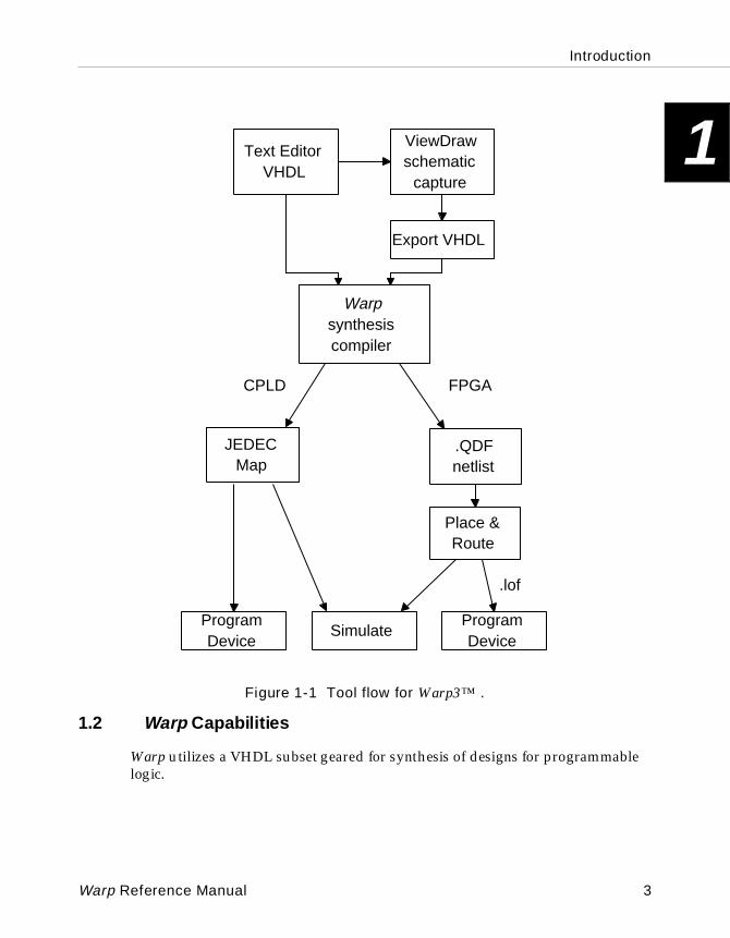
1.1 Overview of WarpThe Warp™ synthesis compiler is a state-of-the-art VHDL compiler for designing CPLDs and FPGAs. Warp utilizes a subset of VHDL as its Hardware Description Language (HDL) for design. Warp accepts VHDL text input, and then synthesizes and optimizes the design for the target hardware. Warp then outputs a JEDEC map for programming PLDs and CPLDs, or a QDIF netlist for the place and route and eventual programming of FPGAs as shown in Figure 1-1.
The JEDEC map that Warp produces when targeting PLDs and CPLDs can be used to program parts with a device programmer. The map can also be used as input to the Nova™ functional simulator. Nova is an interactive, graphical simulator that allows the user to examine the behavior of synthesized designs.
The QDIF file Warp produces when targeting FPGAs can be used as input to the SpDE™ Toolkit. The SpDE Toolkit is a collection of interactive graphical tools that perform logic optimization, placement, and routing of pASIC380™ FPGA designs.
2 Warp Reference Manual
Introduction
1
Figure 1-1 Tool flow for Warp3™ .
1.2 Warp Capabi lities
Warp utilizes a VHDL subset geared for synthesis of designs for programmable logic.
Viewdraw schematic
capture
Text Editor VHDL
Warp synthesis compiler
Export VHDL
JEDEC Map
.QDF netlist
pASIC380 CPLD
Place & Route
Simulate Program Device
Program Device
.lof
ViewDrawschematic
capture
Text EditorVHDL
Warpsynthesiscompiler
Export VHDL
JEDECMap
.QDFnetlist
FPGACPLD
Place &Route
SimulateProgramDevice
ProgramDevice
.lof
ViewDrawschematic
capture
Text EditorVHDL
Warpsynthesiscompiler
Export VHDL
JEDECMap
.QDFnetlist
FPGACPLD
Place &Route
SimulateProgramDevice
ProgramDevice
.lof
ViewDrawschematic
capture
Text EditorVHDL
Warpsynthesiscompiler
Export VHDL
JEDECMap
.QDFnetlist
FPGACPLD
Place &Route
SimulateProgramDevice
ProgramDevice
.lof
Warp Reference Manual 3
Introduction
1
Some highlights of Warp:• VHDL is an open, non-proprietary language, and a de facto standard for describing electronic systems. It is mandated for use by the DOD and supported by every major CAE vendor.
• VHDL allows designers to describe designs at different levels of abstraction. Designs can be entered as descriptions of behavior (high level of abstraction), as state tables and Boolean entry descriptions (intermediate level), or at gate level (low level of abstraction).
• Warp supports the IEEE1164 standard which allows the user to specify three-stated logic and don’t care logic directly in his behavioral VHDL.
• Warp supports numerous data types, including enumerated types, integer types, user-defined type, and others.
• Warp supports the for... generate loop construct for structural descriptions, providing a powerful, efficient facility for describing replication in low-level designs.
• Warp incorporates state-of-the-art optimization and reduction algorithms, including automatic selection of optimal flip-flop type (D- type/T- type).
• Warp includes Cypress’ UltraGen™ module generation technology which automatically identifies complex datapath operators in VHDL code and replaces them with a speed or area optimized module specific for the target device.
• While users can specify the signal-to-pin mapping for their designs, Warp can also map signals from the designs to pins on the target device automatically, making it easy to retarget designs from one device to another.
• Warp can automatically assign state encoding (e.g. gray code, one-hot, binary) for efficient use of device resources.
• Warp supports all Cypress PLD, CPLD and FPGA families, including the FLASH370 ™, pASIC380, and MAX340 ™ (compatible with the MAX5000™) series families.
• Warp supports simulation output for many third party simulators including VHDL and Verilog®.
• Warp3 supports schematic and VHDL libraries based on the Library of Parameterized Modules (LPM), which will provide easy integration with third party EDA tools.
• Warp has a sophisticated GUI with an interactive editor for easy compiling and VHDL library maintenance.
4 Warp Reference Manual
Introduction
1
1.3 About This ManualThis section describes the contents of the remainder of this manual.
Chapter 2 of the manual describes the command line interface, including:
• Warp command line switches
• SpDE command line switches
• recommendations for synthesizing into CPLD as well as FPGA devices
Chapter 3 describes the use of synthesis directives including:
• format of the Control file (.ctl)
• description and syntax of supported .ctl file directives and attributes
• supported ViewDraw® attributes
Chapter 4 describes the fundamental elements of VHDL, as implemented in Warp including:
• identifiers
• data objects and data types
• operators
• taking advantage of the UltraGen module generation technology
• using the bit_arith, std_arith, numeric_bit, numeric_std, and int_arith packages
• design examples
• alphabetical listing of VHDL constructs
Chapter 5 provides a reference to the Library of Parameterized Modules (LPM) as implemented in Warp including:
• the LPM specification as supported by Warp in ViewDraw and VHDL
• non-LPM symbols included in Warp
• LPM specifications not supported by Warp
• Area vs. speed guidelines for LPM implementations
Warp Reference Manual 5
Introduction
1
Chapter 6 gives a description of messages found in the report file (.rpt) to aid in understanding the results of Warp synthesis.Appendix A provides a numerical listing of Warp error messages.
Appendix B provides a numerical listing of SpDE error messages.
Appendix C is a glossary of Warp/VHDL terminology.
Appendix D contains the BNF of supported VHDL.
6 Warp Reference Manual
Chapter
22
Command Line Language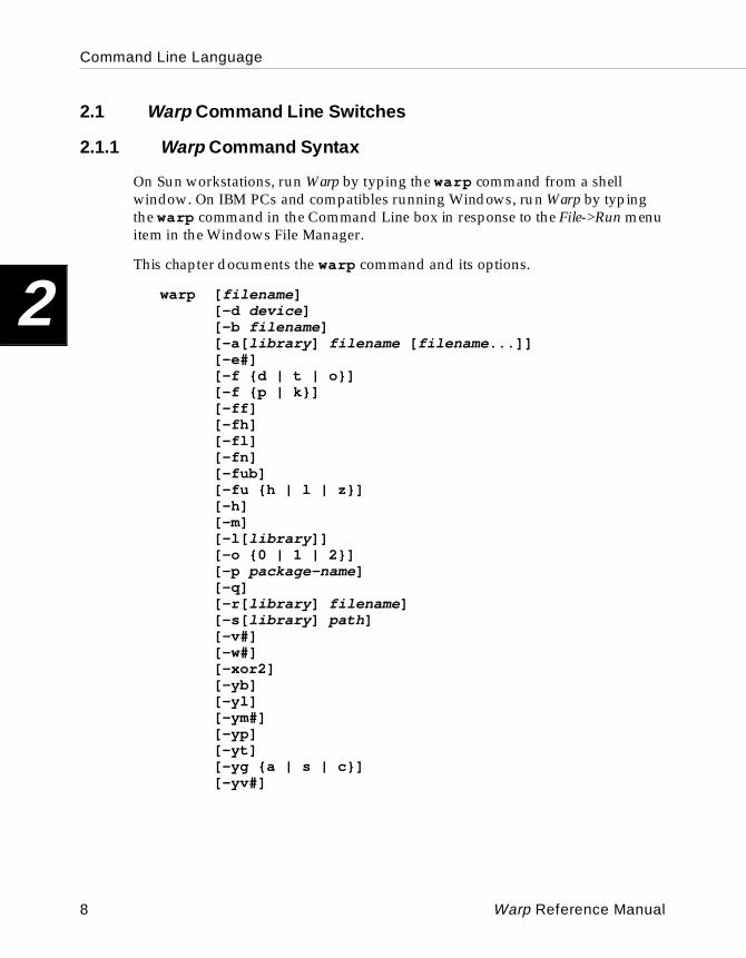
Command Line Language
2
2.1 Warp Command Line Switches
2.1.1 Warp Command Syntax
On Sun workstations, run Warp by typing the warp command from a shell window. On IBM PCs and compatibles running Windows, run Warp by typing the warp command in the Command Line box in response to the File->Run menu item in the Windows File Manager.
This chapter documents the warp command and its options.
warp [ filename ][-d device ][-b filename ][-a[ library ] filename [ filename ...]][-e#][-f {d | t | o}][-f {p | k}][-ff][-fh][-fl][-fn][-fub][-fu {h | l | z}][-h][-m][-l[ library ]][-o {0 | 1 | 2}][-p package-name ][-q][-r[ library ] filename ][-s[ library ] path ][-v#][-w#][-xor2][-yb][-yl][-ym#][-yp][-yt][-yg {a | s | c}][-yv#]
8 Warp Reference Manual
Command Line Language
2
[ ] indicates optional arguments.
{ } indicates a selection (one of the choices must be selected).
| implies a choice.
# implies a numeric (integer) argument of an option.
The warp command runs the Warp synthesis compiler.
Typing warp with no arguments brings up a help screen showing the available options for the warp command. This is the same as typing warp -h .
Typing warp followed by the name of a file compiles the named file and, if compilation is successful, synthesizes the design. This is equivalent to using the -b command line switch.
All options listed above are case-insensitive; however, filenames may be case-sensitive depending on the host platform.
2.2 Warp Command Options
Numerous options control the execution of the warp command from the command line. This section documents Warp’s command line options.
The warp command options used most frequently are -d , -b , and -a . These three options are described first, followed by the remaining options in alphabetical order.
Note that when using the Warp command line interface on a Sun workstation, the command and its options are case-sensitive. On an IBM PC or compatible computer, they are not.
2.2.1 The -d Option
The -d option specifies a target device for synthesis. If this option is not included on the command line, Warp chooses a target device in the following order:
• It searches for a part_name attribute in the file being synthesized and targets the device specified by that attribute.
• If no part_name attribute is found, then it searches for an architecture that identifies a device as a top-level entity and targets that device.
Warp Reference Manual 9
Command Line Language
2
• If no such architecture is found, then it uses the last device targeted by a previous Warp run from the same directory.
• Otherwise, an error is returned.
Example:
warp -d c371 myfile.vhd
The command above compiles and synthesizes a source file named myfile.vhd, targeting a CY7C371.
Allowable arguments for the -d option consist of the letter c followed by a part identifier, usually consisting of the three rightmost digits of the part’s name (e.g., c335 , c371 , etc.). Notable exceptions to this rule are the arguments c22v10 and c22vp10 , which target a PAL22V10 and PAL22VP10, respectively.
Each time the -d option is used in a warp command, it creates a subdirectory within the current directory in which compilation results are stored, if such a subdirectory does not already exist. The name of this subdirectory consists of the letters lc followed by the part identifier used in the argument to the -d option (e.g., an argument of c371 creates an lc371 subdirectory). This subdirectory becomes the work library for that Warp run.
In addition, the -d option causes Warp to look for a library in a subdirectory of the warp directory (default: c:\warp). This subdirectory is named \lib\lcdevice-name. This library has the same root name as the -d option’s argument, followed by the extension .vhd (e.g., the path to the c22v10 library is c:\warp\lib\c22v10\c22v10.vhd).
When Warp interprets the -d option on the command line, Warp creates a subdirectory for the specified device if one does not already exist within the current directory, compiles the appropriate library file(s) for the device within the new sub-directory, assigns the path of the new subdirectory to the “work” logical name, and writes or revises the warp.rc file (if necessary) to reflect the new path to the work library.
2.2.2 The -b Option
The -b option specifies the VHDL source file to compile. All packages referenced within the file, via the USE clause, are also compiled. If compilation is successful, this option also causes Warp to synthesize the design, producing either a .jed file or a .qdf file, depending on the target device.
The -b option assumes that the file to be compiled has an extension of .vhd, unless a different extension is specified on the command line.
10 Warp Reference Manual
Command Line Language
2
The -b option is implied if a filename is included on the command line and no other option is present.
Example:
warp myfile.vhd
The command above compiles a file named myfile.vhd. If compilation is successful, the file will be synthesized, producing the appropriate output file.
2.2.3 The -a Option
The -a option analyzes one or more files and adds them to the work library or to a different, user-specified library. To specify a library other than work, follow the -a option immediately (i.e., without an intervening space) with the name of the library.
The -a option assumes that the file to be compiled has an extension of .vhd, unless a different extension is specified on the command line.
Examples:
warp -a file1 file2 -b myfile.vhd
The command above compiles two files named file1.vhd and file2.vhd and adds them to the work library. If those two files compile successfully, Warp will then compile myfile.vhd. If compilation is successful, myfile.vhd will be synthesized, producing the appropriate output file.
warp -amylib file1 file2 -b myfile.vhd
This command is identical to the previous, except that results from the compilation of file1.vhd and file2.vhd will be written into a subdirectory called mylib.
For more information about libraries and their use, refer to Chapter 4, “VHDL.”
2.2.4 The -e Option
The -e option specifies the maximum number of non-fatal errors that can occur on a single Warp run before Warp exits.
Example:
warp -e5 -b myfile.vhd
Warp Reference Manual 11
Command Line Language
2
2.2.5 The -f Option
The -f option enables certain global fitter options. -f must be followed (without an intervening space) by one of the arguments d, t ,o, f, h, l, n, k, u or p. (Multiple uses of the -f option are allowed on a single line.) Arguments d , t , and o are mutually exclusive. Arguments k and p are also mutually exclusive. The meanings of these arguments are as follows:
• -fd forces registered equations to a D-type registered form (i.e., forces use of D-type flip-flops). For some devices, this may result in a non-minimal solution for an output register. This is the default if the -f option is not specified.
Related VHDL attribute: ff_type
• -ft forces the use of T-type flip-flops for registered equations. For some devices, this may result in a non-minimal solution for an output register. If the target PLD does not support a physical T-type flip-flop, the equation is converted to a D-type registered form using the formula D = T XOR Q. Use of this option may lead to fitter errors if the target device cannot support either a physical T-type flip-flop or product-term programmable XOR function.
Related VHDL attribute: ff_type
• -fo tells the fitter to optimize the Warp-generated design for either D-type or T-type flip-flops, whichever produces the smaller equation set. If the target PLD does not support a physical T-type flip-flop, the equation is converted to a D-type registered form using the formulaD = T XOR Q.
Related VHDL attribute: ff_type
• -ff tells the fitter to ignore any user-specified pin assignments and assign pins itself instead.
Note – In the -ff option, Warp always assigns pins itself, over-riding any pin assignments made in the source file (e.g., by the use of the pin_numbers attribute or the control file).
• -fh writes out the JEDEC output file for PLD or CPLD devices in hexadecimal format. This can effect a considerable (i.e., quadruple) savings in storage space for JEDEC files but may have some programmer ramifications.
12 Warp Reference Manual
Command Line Language
2
• -fk forces the fitter to preserve the user specified polarity for all outputs. This is the opposite of the -fp option which will optimize for the optimal polarity. The -fk option is not recommended for most designs but is useful in certain cases when the user is able to determine the proper polarity for all the signals, such as when board design considerations require a certain polarity.
Related VHDL attribute: polarity
• -fl allows the fitter to perform three-level logic factoring instead of the normal two-level (sum of products) factoring. This is a very important option when targeting pASIC devices. This option will enable multilevel logic factoring which can look at the whole design and produce best factors that can reduce the overall size of the design. This helps to shrink the size of the design and reduces fanout considerably.
Related VHDL attribute: no_factor
• -fn affects all devices and causes any fixed-node-numbers/fixed-flip-flops found in the design to be ignored. This is similar to the -ff option which affects only pins.
• -fp logically reduces output signals via Espresso during the optimization process. This option selects the output polarity that produces the minimum number of product terms. This is the opposite of the -fk option.
Related VHDL attribute: polarity
Note – The -ff a nd -f p arguments can be used in conjunction with the -fd , -fo , or -ft arguments (e.g., -fo -ff -fp ).
Example:
warp -b myfile.vhd -fo -ff -fp
The command above compiles and synthesizes a file named myfile.vhd. During synthesis, Warp is directed to optimize the design to use either D- or T-type flip-flops (-fo ), ignore any pin assignments in the file (-ff ), and optimize output polarity (-fp ).
Warp Reference Manual 13
Command Line Language
2
• The -fuh , -ful and -fuz options will cause unused I/Os of the devices to be programmed to either drive a high (-fuh ) or low (-ful ) value or simply three-state (-fuz ) it. In Release 3.5, the PLD and CPLD I/Os were automatically three-stated, and the pASIC I/Os were driven low. With these options, the user can now control the exact behavior of such unused I/Os. For certain devices where the macrocell portion of the cell is used but the I/O is left unused (a buried node), the -fuh and the -ful options simply connect the output-enable signal to logic level one causing the I/O pin to see the state of the buried macrocell. This means that the I/Os associated with the buried nodes switch as the buried nodes switch. For I/O cells that are connected to unused macrocells, the macrocell is programmed to drive the value specified by this option.
• The -fub option is intended to be used in conjunction with the -fuh and the -ful options. The default behavior of unused I/Os associated with buried nodes is described above. When this option is used along with the -fuh and the -ful options, the I/Os related to the buried nodes are three-stated, and the -fuh and -ful options affect only the I/Os associated with unused macrocells.
2.2.6 The -h Option
The -h (“help”) option lists the available options, their syntax, and meanings. Executing warp with this option is the same as executing warp with no command line options.
Example:
warp -h
The command above prints the warp command’s available options, syntax, and meanings.
2.2.7 The -l Option
The -l option lists the contents of the work library (default) or of any user-specified library. To specify a library other than work, follow the -l option immediately (i.e., without an intervening space) by the name of the library. The listing of library contents includes the type and name of each design unit and the name of the file in which the unit is found.
Examples:
warp -l
The command above lists the contents of the work library.
14 Warp Reference Manual
Command Line Language
2
warp -lmylib
The command above lists the contents of library mylib.
2.2.8 The -m Option
This option, which can be used in conjunction with the -a and -b options, enables a smart compile of the specified VHDL files. Generally, without this option, Warp will compile all the specified files. When this option is specified, Warp will compile only those files that have been modified since the last compile. Library files (the ones specified with the -a option) are recompiled if they have been modified since the last compile, if this is the first time one or more of these files have been modified, or if any of the lower level files have been modified. The top level file is dependent on the target device. In a PLD or CPLD device, the top level file depends on the JEDEC (.jed) file, and for pASIC, it depends on the QDIF (.qdf) file. The top level file also depends on the control (.ctl) file. Warp stores this dependency information in the warp.mk file in the current directory.
2.2.9 The -o Option
The -o option specifies the level of optimization to perform on the design. The -o option should be followed by a number which indicates the effort.
• An argument of 0 provides no minimization. In fact, an effort is made to preserve the equation as-is if the design contained equations in a sum-of-products form. This option is recommended only when the whole design has been hand-optimized.
• An argument of 1 provides a fast but inefficient optimization of the design. This option may produce equations of lower quality; it also will disable several high level syntheses of structures such as latches, multiplexers, XORs and design optimization algorithms such as logic factoring and state machine minimization.
• An argument of 2 provides maximum optimization. This option invokes the industry standard Espresso logic minimizer resulting in the most thorough optimization possible. In addition to performing a better equation optimization, this option enables many other technologies which cause the design to use fewer device resources. This option is highly recommended for all designs.
Related VHDL attribute: opt_level
Warp Reference Manual 15
Command Line Language
2
Example:
warp -d c381a -fl -o2 myfile.vhd
The command compiles and synthesizes a file named myfile.vhd, enabling the highest level of optimization available.
2.2.10 The -p Option
The -p option specifies the device package and speed bin to use when synthesizing a design for a target device. This option will affect the specific pin numbers that are being specified in the VHDL source code or the control file. This option will also determine the device timing characteristics for PLD and CPLD devices to be used when generating timing models and timing reports. Valid package and speed bin combinations can be found in the “Ordering Code” column of the ordering information table for each device in the Cypress Semiconductor Programmable Logic Data Book.
Example:
warp -d c371 -p CY7C371-143JC -b myfile.vhd
This command will compile and synthesize the design called myfile.vhd into a CY7C371-143 in a JC package. This means that any user specified pin numbers must correspond to the pin numbers on a JC package of a CY7C371.
2.2.11 The -q Option
The -q (“quiet”) option suppresses the printing of status messages during compilation. This leads to a less cluttered screen when compilation and synthesis are finished. This is the default when running Warp via the Galaxy graphical user interface.
Example:
warp -q myfile.vhd
This command compiles and synthesizes a file named myfile.vhd, quietly.
2.2.12 The -r Option
The -r option removes design units contained in one or more files from the work library or from a user-specified library. To specify a library other than work, follow the -r option immediately (i.e., without an intervening space) by the name of the library.
16 Warp Reference Manual
Command Line Language
2
Examples:
warp -r file1.vhd
This command removes the design units contained in file file1.vhd from the work library.
warp -rmylib file1.vhd
This command removes the design units contained in file file1.vhd from library mylib.
2.2.13 The -s Option
The -s option pairs a library name with a path. The name of the library and its path are written into the warp.rc file in the current directory. To use a library other than work with a VHDL description, follow the -s option immediately (i.e., without an intervening space) with the name of the library.
Example:
warp -smylib c:\usr\myname\mydir
This command pairs the library name mylib with the path c:\usr\myname\mydir.
2.2.14 The -v Option
The -v option controls a very important aspect of Warp synthesis. After synthesis, Warp performs a task called virtual substitution. For a more detailed explanation of virtual substitution, please refer to Chapter 3, “Synthesis Directives.” The -v option has a numeric argument that controls the aggressiveness of the virtual substitution algorithm. The range of numbers allowed is 0 to 11 , where a value of 0 does not perform any virtual substitution (for compatibility with previous releases) and a value of 11 performs virtual substitution even against the better judgement of the algorithm to isolate large combinatorial nodes and force it to a node in the device. The higher the number, the fewer nodes are created. Typically, for CPLD devices, a high number is a good choice because these devices tend to have macrocells capable of handling large equations. Even for pASIC devices, a large number is recommended so that redundancies in logic can be safely removed, but in rare cases, lowering this option value can help partition the design better. This option can be viewed as a cost threshold which, when crossed, will force a device node.
The default value for this option is 10. The example below sets the node creation threshold at 5.
Warp Reference Manual 17
Command Line Language
2
Example:
warp -v5 -o2 -fl1 -d c384a -b myfile.vhd
2.2.15 The -w Option
The -w option specifies the maximum number of warnings that can appear as a result of a single Warp run before Warp quits.
Example:
warp -w5 -b myfile.vhd
2.2.16 The -xor2 Option
The -xor2 option passes along any XOR operators found in the design to the fitter for PLD or CPLD devices, and to SpDE for pASIC devices. If this option is disabled, any XOR operators contained within the design are flattened, and it would be up to the fitter or to SpDE to detect the XOR contained within the equation. For most devices, an XOR is not available in the target architecture, in which case the XOR must eventually be expanded. For CPLD devices which provide an XOR (MAX340 family), the XOR usage is very specific. The pASIC architecture, however, provides a much better XOR utilization. Even in the case of pASIC devices, this option is not recommended because with the -o2 option, the software can decide the best implementation for the set of equations (XORs versus multiplexors). This option, however, might be useful in certain cases. If a design consists mostly of XORs (for example, many large parity generators), which can only be best implemented with a set of XOR gates, this option will preserve any XOR operators found in the design. This option is global to the design and will affect XOR operators found in all portions of the design (library architectures, lower level user design files, etc.).
Example:
warp -d c382a -xor2 myfile.vhd
2.2.17 The -yb Option
Depending on the value specified by the -ym# option for max_load, Warp normally generates an appropriate number of buffers to reduce fanout. This option will cause buffer generation to be disabled.
Related VHDL attributes: max_load and buffer_gen.
18 Warp Reference Manual
Command Line Language
2
2.2.18 The -yl Option
By default (if -o2 is used), Warp will synthesize latches for the FLASH370 family; however, sometimes this is not desirable if global resources are limited or if synthesizing latches could potentially affect the partitioning of designs into the device. The -yl option disables latch synthesis.
Related VHDL Attribute: no_latch.
2.2.19 The -ym Option
This option specifies the default maximum loading allowed for all nodes in the design. Warp inserts buffers to reduce the fanout. This option is only applicable to the pASIC family of devices. For the current set of PLD and CPLD devices, loading is not a concern, and this option is ignored.
Note – Buffers are not generated for signals already being driven by High-Drive pads or Clock pads.
Related VHDL attributes: max_load and buffer_gen.
Example:
warp -dc381a -o2 -fL -ym8 myfile.vhd
This command will ensure that no signal drives more than 8 inputs.
2.2.20 The -yp Option
The Warp compiler automatically assigns clock pins and other high fan-in inputs to the FPGA devices to special input PADS which provide higher drive strength into the device. In some cases, however, the user may want to control exactly which input signal is assigned to which pin and disable the automatic generation of PADs in the FPGA devices. The -yp option disables the PAD generation feature within Warp. This option is applicable to the pASIC380 family of FPGAs only and has no effect if used when targeting other devices.
2.2.21 The -yt Op tion
Cypress’ FPGA devices do not contain internal three-state buffers. Warp, however, will automatically convert designs which contain internal three-state logic into multiplexor logic. This conversion is possible only when the design configures the three-state buffers in such a way that only one driver is enabled at any given time. This option disables the normal automatic PAD generation
Warp Reference Manual 19
Command Line Language
2
feature within the Warp tool. All pins will be assigned to I/O pins unless otherwise specified, via pin assignments or structural instantiations of specific input PADS. This option is only applicable to the pASIC380 family of FPGA devices.
Related VHDL attribute: pad_gen
2.2.22 The -ygs Op tion
This option causes Warp to synthesize all datapath operators found in the design so that they are optimized for speed.
Related VHDL attribute: goal
2.2.23 The -yga Op tion
This option will cause Warp to synthesize all datapath operators found in the design so that they are optimized for area.
Related VHDL attribute: goal
2.2.24 The -ygc Op tion
This option will cause Warp to synthesize all datapath operators found in the design so that they are optimized for neither area nor speed but rather implemented as simple combinatorial equations. If a simple combinatorial equation is not available, an area efficient one is selected. If an area one is not available, then a speed implementation is selected. Every datapath operator has at least one implementation available.
Related VHDL attribute: goal
2.2.25 The -yv Option
This option controls the amount of information that is reported in the report file. The -yv option should be followed by a digit. The default is 0. Numbers higher than zero produce more verbose report files useful for debugging. By default (with a value of 0), the report file only indicates major events during synthesis.
2.3 Recommendations
Most options described in this section are useful in certain circumstances. For designs targeting the pASIC380 family of devices, Cypress recommends the following command line to obtain best results:
20 Warp Reference Manual
Command Line Language
2
Example:
warp device -o2 -fl1 filename
For designs targeting CPLD and PLDs, Cypress recommends the following command line:
Example:
warp device -o2 -fo -fp filename
2.4 Warp Output
A Warp run produces numerous output files, of which the following are important to the user: .jed files for targeting PLDs or CPLDs, .qdf files for targeting pASIC380 FPGAs, and .rpt files for analyzing compilation results.
A successful Warp run produces two output files in the current directory:
• filename.jed or filename.qdf
• filename.rpt
The .jed file is a fuse map that a PLD programmer can use. The map is also used as input to the Nova simulator.
The .qdf file, which is produced only when targeting pASIC380 FPGAs, can be used as input to the SpDE place and route tool.
The .rpt file is an ASCII text file that contains fitter statistics; informational, warning, and error messages from the Warp run; and pinout information for the synthesized design.
2.5 SpDE Command Line Language
SpDE is the place and route program that places and routes pASIC designs. SpDE consists of many sub-tools (placer, router, sequencer, etc.). Although mostly an interactive tool, SpDE also supports a limited set of command line options intended mostly to allow batch runs.
On UNIX Platformscypspde [filename]
or
cypspde [-runall] [-save] [-critpath | -qtoq] filename
Warp Reference Manual 21
Command Line Language
2
On the PCc:\warp\spde\spde.exe [filename]
or
c:\warp\spde\spde.exe [-runall] [-save] [-critpath | -qtoq] filename
The first form is used to run SpDE graphically. If a filename is specified, SpDE automatically loads that file at startup. The filename should have one of two extensions .qdf (a pre-placed and routed netlist) or a .chp (a partially or fully placed and routed design database) extension.
The second form is used for batch runs.
-runall runs all the necessary tools to produce the results. The results are logged in the file with the same basename as filename but with a .spd extension. Individual options for each sub-tool that -runall invokes are specified through the ~/.spderc file on UNIX platforms and via the c:\warp\spde\data\spde.ini file on PC platforms.
-save option is used in conjunction with the -runall option to save the post place and route results in a .chp file. Without this option, even though a summary of the results is available in the .spd file, the results of the place and route session are not saved.
-critpath and -qtoq are mutually exclusive options that report the worst case timing. -critpath reports the worst case combinatorial critical path, and the -qtoq option reports the worst case timing for operating frequency calculations. The results are saved in the .spd file. These options can be used on a .qdf file in conjunction with the -runall option or directly on a .chp file to extract the timing from an already placed-and-routed result.
filename is the name of the design with either a .qdf or a .chp extension.
Examples:
In the following examples spde represents the command described at the beginning of this section for invoking SpDE.
spde
The above example invokes the graphical SpDE.
spde filename.qdfspde filename.chp
The above examples invoke the interactive mode of SpDE and load said designs into memory.
22 Warp Reference Manual
Command Line Language
2
spde -runall -qtoq -save mydesign.qdf
The above example runs SpDE in batch mode, runs all the tools, saves the results into the file mydesign.chp, and also reports the worst case timing for frequency calculations. A summary is written into the file mydesign.spd.
spde -critpath mydesign.chp
The above example runs the SpDE Path Analyzer on the already placed and routed file mydesign.chp and reports the worst case critical path into the file mydesign.spd.
Warp Reference Manual 23
Command Line Language
2
24 Warp Reference Manual
Chapter
3 Synthesis Directives3
Synthesis Directives
3
3.1 Introduction
In three different ways, synthesis directives supplied to the Warp compiler can control many aspects of Warp synthesis and post synthesis results. Certain directives have global defaults which command line options or Galaxy can override. All synthesis directives can be controlled by inserting these directives directly into the source VHDL design. Most of the directives can also be set in the control file described in Section 3.3, "Control File.”
Synthesis directives in Warp are specified using the VHDL attribute mechanism. VHDL allows attributes to be placed on almost any object, but the target application determines how these attributes are interpreted. Each synthesis directive that Warp supports has a scope and an inheritance mechanism. Certain synthesis directives are intended for signals, and others are intended for components. This defines the scope of the attribute. Warp also supports an inheritance mechanism for many of the synthesis directives. An attribute intended for a signal, for example, can be placed on an architecture or entity so that all signals defined in that architecture or entity and any signals defined in any of the lower level components obtain that attribute. This method of inheritance is called hierarchical. Other attributes, however, are not hierarchical and are meant for the exact object to which they are attached.
Hierarchical attributes also have a certain precedence. Hierarchical attributes can be placed on the following types of VHDL objects:
• entity
• architecture
• component declaration
• component instantiation (component label)
• signal
Of the above objects, the entity has the lowest precedence, and the signal has the highest precedence. Thus, a synthesis directive placed on an architecture can be overridden by a particular signal within that architecture. In other words, directives placed on an architecture serve as a default for all signals derived by that architecture.
26 Warp Reference Manual
Synthesis Directives
3
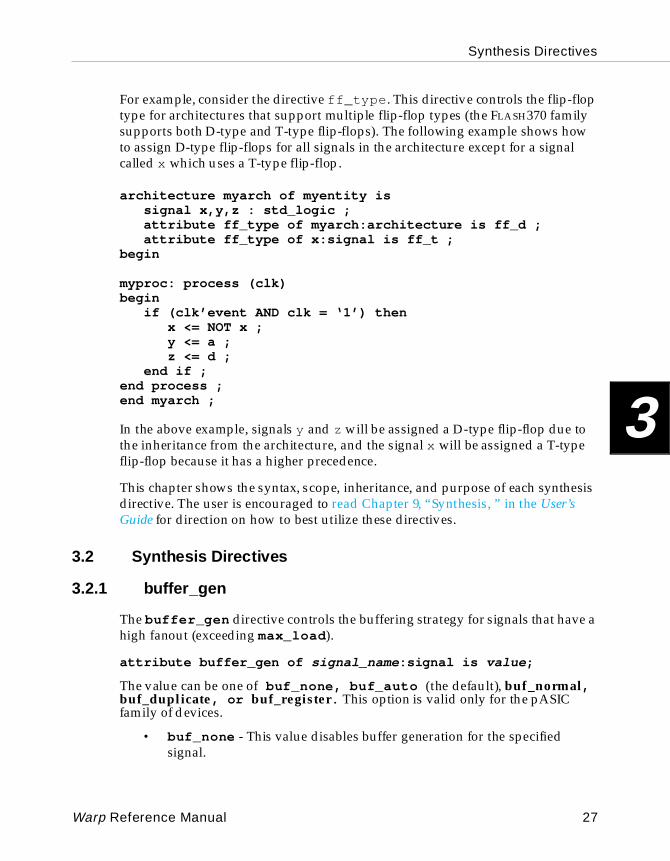
For example, consider the directive ff_type . This directive controls the flip-flop type for architectures that support multiple flip-flop types (the FLASH370 family supports both D-type and T-type flip-flops). The following example shows how to assign D-type flip-flops for all signals in the architecture except for a signal called x which uses a T-type flip-flop.
architecture myarch of myentity issignal x,y,z : std_logic ;attribute ff_type of myarch:architecture is ff_d ;attribute ff_type of x:signal is ff_t ;
begin
myproc: process (clk)begin
if (clk’event AND clk = ‘1’) thenx <= NOT x ;y <= a ;z <= d ;
end if ;end process ;end myarch ;
In the above example, signals y and z will be assigned a D-type flip-flop due to the inheritance from the architecture, and the signal x will be assigned a T-type flip-flop because it has a higher precedence.
This chapter shows the syntax, scope, inheritance, and purpose of each synthesis directive. The user is encouraged to read Chapter 9, “Synthesis, ” in the User’s Guide for direction on how to best utilize these directives.
3.2 Synthesis Directives
3.2.1 buffer_gen
The buffer_gen directive controls the buffering strategy for signals that have a high fanout (exceeding max_load ).
attribute buffer_gen of signal_name :signal is value ;
The value can be one of buf_none, buf_auto (the default), buf_normal, buf_duplicate, or buf_register. This option is valid only for the pASIC family of devices.
• buf_none - This value disables buffer generation for the specified signal.
Warp Reference Manual 27
Synthesis Directives
3
• buf_auto - This value selects the best buffering strategy. Warp selects buf_duplicate if the logic driving the signal is small enough to fit in a pASIC FragA (a 6 input and-gate). Warp then tries buf_normal . buf_auto never selects the buf_register strategy.
• buf_normal - The max_load for the signal has to be greater than one. A buffer is inserted into the network in a tree form until the node satisfies the max_load requirement. For each level in the tree, an attempt is made to distribute the load evenly. In cases where the fanout reaches multiple inputs of the same logic cell, an attempt is made to make the same buffer drive all of those inputs.
• buf_duplicate - This value will cause the logic driving the gate to be duplicated. If the driver is a an RTL component (one of the lower level pASIC primitives like PAfragA, PAfragF, logico, etc.), then buf_duplicate will simply duplicate that driver. When the driver is an equation, however, buf_duplicate may not duplicate the whole equation if that equation does not fit in one logic cell. Instead, buf_duplicate will only duplicate a portion of it.
• buf_register - This value is valid only for registered nodes (nodes driven by the Q output of a flip-flop). This value is similar to buf_duplicate except that buf_register applies to flip-flops only. The D input of the register is made to feed the extra registers that are created to satisfy the max_load directive.
Scope:
Target: SignalInheritance: HierarchicalRelated Command-Line-Option: -ybApplicable to: pASIC Devices Only
Example:
attribute buffer_gen of my_signal:signal is buf_none;
The above example turns off buffer generation for the signal called my_signal .
3.2.2 dont_touch
The dont_touch directive is used when targeting pASIC FPGAs to specify that a component is to pass through synthesis and optimization untouched. This directive “freezes” the structural implementation of an optimized component, such as a hand-tuned carry-select adder.
28 Warp Reference Manual
Synthesis Directives
3
Note – The dont_touch directive has no effect if the target device is not a pASIC FPGA.
attribute dont_touch of label-name :label is value ;
or
attribute dont_touch of entity-name :entity is value ;
The dont_touch directive takes the value true or false . The default is false .
When the dont_touch directive is set to true for an entity or a component instance, the structural implementation of that entity or component is not modified by subsequent synthesis or by Level 1 optimization within SpDE. Setting the dont_touch directive to true is similar to using Level 0 optimization on a component or entity, in that very little optimization or packing is done. This allows hand-optimized portions of the design to stay untouched within SpDE while the rest of the design is optimized and packed with SpDE’s Level 1 or Level 2 optimization.
When using the dont_touch directive, structural or schematic designs must resolve to pASIC primitives (not equations). These primitives are PAfragA, PAfragF, PAfragM, PAfragQ, PAlcell and logico, which constitute portions of the pASIC logic cell.
The dont_touch directive, however, does not apply to packing. For example, suppose a schematic or a structural implementation uses a PAfragA, PAfragM, PAfragF, and PAfragQ, and the dont_touch directive is set to true on the entire schematic or on all the individual instances. Even if components are ideally connected to each other so that they can be packed together, these four frags may not pack into a single logic cell (although it is highly likely that they would). To gain control over the packing of such schematics, higher-level elements like PAlcell and logico should be used. PAlcell represents the whole logic cell. Logico represents the whole logic cell except the flip-flop portion and has only one output.
Another important use of the dont_touch directive is for buffering high fanout nets or for special buffering situations. Sometimes, the logic optimizer inadvertently removes gates that the user intended for buffering. Placing the dont_touch directive forces such gates to be preserved. Buffering is also best done using the pASIC primitives.
Warp Reference Manual 29
Synthesis Directives
3
Higher level library elements (counters, adders, etc.) available from the library are already highly optimized with dont_touch placed in strategic locations. The use of dont_touch within the library elements is rare, however, because in most cases, small equations feeding such library elements or modules can be absorbed into the library element. In most instances, better performance or area is achieved by using this directive sparingly. Using the dont_touch directive severely constrains the logic optimizer within SpDE.
This directive will also prevent Warp from removing duplicate elements from the design, which can be useful when buffering is being done within the design, and the user does not want these buffers to disappear during synthesis or optimization.
Scope:
Target: ComponentInheritance: HierarchicalRelated Command-Line-Option: NoneApplicable to: pASIC Devices Only
Example:
attribute dont_touch of my_adder:entity is true;
The statement in this example applies the dont_touch directive to all signals contained within the entity my_adder . When this design is targeted to a device other than a pASIC device, it is ignored.
3.2.3 enum_encoding
The enum_encoding directive specifies the internal encoding to be used for each value of a user-defined enumerated type. The internal encoding is reflected in the gate-level design when targeting a device.
attribute enum_encoding of type-name :type is “ string ”;
The enum_encoding directive takes a single argument, consisting of a string of 0s and 1s separated by white space (spaces or tabs). Each contiguous string of 0s and 1s represents the encoding for a single value of the enumerated type. The number of contiguous strings in the enum_encoding argument must equal the number of values in the enumerated type.
When included in a Warp description, the enum_encoding directive overrides the value of a state_encoding directive appearing in the same description.
30 Warp Reference Manual
Synthesis Directives
3
Scope:
Target: TypeInheritance: NoneRelated Command-Line-Option: NoneApplicable to: All Devices
Example:
type state is (s0,s1,s2,s3);attribute enum_encoding of state:type is ”00 01 10 11”;
The first statement in this example declares an enumerated type, called state , with four possible values. The possible values of type state can therefore be represented in two bits. The second statement specifies the internal representation of each value of type state . Value s0’s internal representation is “00”. Value s1's internal representation is “01”. Value s2’s internal representation is “10”. Value s3’s internal representation is “11”.
3.2.4 fixed_ff
The fixed_ff directive is used when targeting pASICs to assign a signal to a specific internal register. This fixed placement overrides the default placement that the SpDE Placer assigns.
attribute fixed_ff of signal-name :signal is “ register-loca-tion” ;
The fixed_ff directive is similar to the pin_numbers directive, in that fixed_ff locks a signal to a specific fixed placement. The difference is that fixed_ff applies to fixed internal placement, while the pin_numbers directive applies to fixed external placement.
A given signal could have both a pin-number and a fixed internal flip-flop placement. For instance, the output of a register can be fixed both to internal cell A1 and also to the output pad attached to pin 59 of the chip.
The fixed_ff directive only applies to the Q output signal from a register. If the fixed_ff directive is attached to any other signal besides the Q output of a register, the directive is ignored.
Warp Reference Manual 31
Synthesis Directives
3
Scope:
Target: SignalInheritance: NoneRelated Command-Line-Option: -fnApplicable to: pASIC Devices Only
Example:
attribute fixed_ff of my_signal:signal is “A1”;
The statement in this example assigns the internal registered signal called my_signal to location A1 within the pASIC device.
3.2.5 ff_type
The ff_type directive specifies the flip-flop type used to synthesize individual signals.
attribute ff_type of signal-name :signal is value ;
Legal values for the ff_type directive are ff_d , ff_t , ff_opt , and ff_default .
• A value of ff_d tells Warp to synthesize the signal as a D-type flip-flop.
• A value of ff_t tells Warp to synthesize the signal as a T-type flip-flop.
• A value of ff_opt tells Warp to synthesize the signal to the optimum flip-flop type (i.e., the one that uses the fewest resources on the target device).
• A value of ff_default tells Warp to synthesize the signal based on the default flip-flop type selection strategy, which the command line switches or dialog box settings used in invoking Warp determine.
Scope:
Target: SignalInheritance: HierarchicalRelated Command-Line-Option: -fd or -ft or -foApplicable to: PLD and CPLD Devices Only
Example:
attribute ff_type of abc:signal is ff_opt;
The command above tells Warp to optimize the flip-flop type used to synthesize a signal named abc .
32 Warp Reference Manual
Synthesis Directives
3
3.2.6 goal
The goal directive, which affects the synthesis of datapath operators, can be used to override the global goal objective on an architecture-by-architecture basis.
attribute goal of architecture_name :architecture is value ;
Legal values for the goal directive are speed , area and combinatorial .
• A value of speed indicates that all datapath operators (+,-,*,=,/=,<,>,<=,>=,etc.) should be optimized for speed. The Warp synthesizer will automatically select an implementation of the operator that is optimized for speed.
• A value of area indicates that all datapath operators (+,-,*,=,/=,<,>,<=,>=,etc.) should be optimized for area. The Warp synthesizer will automatically select an implementation of the operator that is optimized for area.
• A value of combinatorial indicates that all datapath operators (+,-,*,=,/=,<,>,<=,>=,etc.) are optimized for neither area nor speed but rather implemented as simple combinatorial equations. If a simple combinatorial equation is not available, an area efficient one is selected. If an area one is not available, then a speed implementation is selected. Every datapath operator has at least one implementation available.
Scope:
Target: Architecture or EntityInheritance: NoneRelated Command-Line-Option: -yga or -ygs or -ygcApplicable to: All Devices
Example:
attribute goal of my_adder:entity is speed;
This directive optimizes the entity called my_adder for speed.
3.2.7 lab_force
The lab_force directive aids in grouping signals together as a suggestion to the fitter. This attribute is valid only for CPLDs.
attribute lab_force of signal_name :signal is “ string” ;
Warp Reference Manual 33
Synthesis Directives
3
The string contains the name of the logic block. For the FLASH370 family, this string can also represent a half logic block (made up of either the top eight macrocells or the bottom eight macrocells). This directive will force the signal my_signal to the logic block without actually assigning it to a specific I/O pin.
Normally, the fitter performs partitioning of the design prior to place and route and produces results that are acceptable for most designs. In some cases, however, the user might want to constrain the fitter due to board layout considerations.
This is an advanced directive and should be used only when the user is very familiar with the features of the CPLD.
Scope:
Target: SignalInheritance: HierarchicalRelated Command-Line-Option: NoneApplicable to: CPLD Devices Only
Examples:
attribute lab_force of my_signal:signal is “A”;
The above example will force the signal my_signal to the logic block A.
attribute lab_force of my_signal:signal is “B2”;
The above example will force the signal my_signal to the lower half of logic block B. The half logic block control is only allowed for the FLASH370 family of devices. The half logic block designation is achieved by simply appending a 1 or a 2 to specify the top half or the bottom half, respectively.
3.2.8 max_load
The max_load directive specifies the maximum fanout that a signal should support.
attribute max_load of s ignal_name :signal is integer ;
The integer represents the maximum loading allowed for the signal my_signal . This directive can be used in conjunction with the buffer_gen directive to specify what method should be used to reduce the fanout for said signal.
Please refer to the documentation on buffer_gen directive for more information.
34 Warp Reference Manual
Synthesis Directives
3
Scope:
Target: SignalInheritance: HierarchicalRelated Command-Line-Option: -ym#Applicable to: pASIC Devices Only
Example:
attribute max_load of my_signal:signal is 8;
The above example instructs Warp to ensure that the signal my_signal should be restricted to drive a maximum of 8 inputs.
3.2.9 no_factor
The no_factor directive prevents logic factoring within the Warp synthesis engine to prevent splitting said node.
attribute no_factor of signal_name :signal is value ;
During the optimization phase, the Warp synthesis engine, among other things, does the following:
• aliases signals which have identical drivers (equations)
• for pASIC devices, creates factors that can be shared among multiple outputs, thereby reducing the size of the overall design. This feature is triggered by the -fl option
Using this directive causes equations to bypass the above two actions. This feature can be useful if the design constraints cause certain identical logic to be duplicated or if the logic factoring algorithm is being overaggressive.
Scope:
Target: SignalInheritance: HierarchicalRelated-Command-line-option: -flApplicable to: All Devices
Warp Reference Manual 35
Synthesis Directives
3
Examples:
attribute no_factor of my_signal:signal is true;
The above example prevents the signal my_signal from being aliased or from being factored.
attribute no_factor of my_architecture:architecture is true;
The above example prevents all signals in my_architecture and its sub-architectures from being aliased or factored.
3.2.10 no_latch
The no_latch directive prevents latches from being synthesized automatically for the signal in question.
attribute no_latch of signal_name :signal is value ;
Normally, when exhaustive optimization is enabled (with the -o2 option), Warp tries to synthesize latches where possible for the FLASH370 family. The following example creates a latch with enable as the enable and a as the latched data for the equation x :
if (enable = ‘1’) then x <= a;
elsex <= x;
end if;
Creating a latch in this case will save a product term for the x equation; however, this has certain other side-effects that might not be desirable:
• If the synthesizer also produced asynchronous resets/presets for the enable, this might have caused more global resources (clocks, resets, presets) to be used.
• Creating a latch might have caused a slower design and introduced setup/hold problems.
Using the no_latch directive would cause Warp to create simply a signal with a combinatorial delay.
36 Warp Reference Manual
Synthesis Directives
3
Scope:
Target: SignalInheritance: HierarchicalRelated Command-Line-Option: -ylApplicable to: FLASH370 Devices Only
Example:
attribute no_latch of x:signal is true;
In this example, the directive causes latch detection to be disabled for signal x .
3.2.11 node_num
The node_num directive tells Warp to map an internal signal to a specific location on the target device.
attribute node_num of signal-name :signal is integer ;
The node_num directive can take a value of any integer or the value of nd_auto . Assigning the nd_auto value to a signal tells Warp to map the signal to the location of best fit on the target device. The node_num directive will implicitly apply the synthesis_off directive to that signal as well. For more information on the synthesis_off directive, see Section 3.2.21, “synthesis_off.”
Scope:
Target: SignalInheritance: NoneRelated Command-Line-Option: -fnApplicable to: PLD and CPLD Devices Only
Examples:
attribute node_num of my_signal:signal is nd_auto;
The command above maps a signal named my_signal to a Warp-determined macrocell in the target device.
attribute node_num of my_signal:signal is 23;
The command above maps a signal named my_signal to a specific node within the device being targeted. This value is both device and package specific and may not be portable to other packages or devices.
Warp Reference Manual 37
Synthesis Directives
3
3.2.12 opt_level
The opt_level directive instructs Warp on the amount of effort that should be spent optimizing certain signals.
attribute opt_level of signal_name :signal is integer ;
The integer represents the amount of effort. Currently, there are three levels of effort (0, 1 and 2). An opt_level of 0 instructs Warp to turn off all optimization on said signal. This directive is also passed along to the PLD/CPLD fitters which do the same thing. An opt_level of 1 causes Warp to perform a simple and quick optimization of equations. An opt_level of 2 causes Warp to perform the highest level of optimization available. An opt_level of 2 is recommended for all designs.
Scope:
Target: SignalInheritance: HierarchicalRelated Command-Line-Option: -o#Applicable to: All Devices
Example:
attribute opt_level of my_signal:signal is 0;
This directive disables all optimization on the signal my_signal .
3.2.13 order_code
The order_code directive tells Warp which device package and speed bin to use when synthesizing a design for a target device.
attribute order_code of entity-name :entity is “ order-code” ;
The order_code directive specifies the package as well as the speed bin for a particular device. The order_code tells Warp the pin names and pin ordering for the device and package that are being targeted.
Legal order codes can be found in the Ordering Code column of the ordering information table for each device in the Cypress Semiconductor Programmable Logic Data Book.
38 Warp Reference Manual
Synthesis Directives
3
Scope:
Target: Top-level EntityInheritance: NoneRelated Command-Line-Option: -pApplicable to: All Devices
Example:
attribute order_code of mydesign:entity is“PALC22V10-25HC”;
This example specifies a package type of PALC22V10-25HC for the entity named my_design .
3.2.14 pad_gen
The pad_gen directive directs Warp to a specific type of PAD for a given input.
attribute pad_gen of signal_name :signal is value ;
The value can be one of pad_none , pad_auto (the default), pad_clock , pad_hd1 , pad_hd2 , pad_hd3 , pad_hd4 , or pad_io . This option is currently only valid for the pASIC380 family of devices and is useful only for dedicated inputs to the design.
• pad_none assigns the input signal to an I/O cell.
• pad_auto (the default) causes Warp to automatically select an appropriate PAD for the signal.
• pad_clock assigns a clock pad.
• pad_hd1 causes Warp to use a high-drive input pad.
• pad_hd2 causes Warp to connect two high-drive input pads in parallel to provide even higher drive strength.
• pad_hd3 causes Warp to connect three high-drive input pads in parallel to provide even higher drive strength.
• pad_hd4 causes Warp to connect four high-drive input pads in parallel to provide even higher drive strength. Since the current family of devices does not provide four input pads on the same side of the chip, this value will use three input pads and a clock pad to achieve the drive strength.
• pad_io is the same as pad_none .
• When using pad_h2 , pad_h3 , or pad_h4 , a like number of pins must be available on a common side of the target device.
Warp Reference Manual 39
Synthesis Directives
3
The following heuristic is used to allocate pads for the pASIC380 family of devices:
• All candidate signals must be dedicated inputs to the design.
• Allocate clock pads that were specified either with this directive or by a pin assignment.
• Allocate input pads (high drive pads) that were specified either with this directive or by a pin assignment.
• Select highest fanout positive polarity clocks and assign to clock pads.
• Select highest fanout positive polarity clocks and assign to input pads.
• If clocks pads also drive other inputs, assign one of the input pins while determining best polarity for the signal.
• Obtain the highest fanout input (either polarity) and assign it to the first available input pad.
• After allocating all possible input pads, if any clock pads are still available, assign the clock pad to the next highest fanout signal.
When assigning inputs to input pads (which have both polarity outputs), Warp will attempt to use both of these outputs if the fanout for both polarities exceed max_load and if enough high drive wires (express-wires) are still available in the device. When automatically determining the pad type, a pad will only be assigned to a signal if that signal’s fanout exceeds max_load .
Scope:
Target: SignalInheritance: HierarchicalRelated Command-Line-Option: -ypApplicable to: pASIC Devices Only
Example:
attribute pad_gen of my_signal:signal is pad_clock;
The above example assigns my_signal to a clock pad.
3.2.15 part_name
The part_name directive specifies the device to target for synthesis.
attribute part_name of entity-name :entity is “ part-name ”;
The part_name directive tells Warp what part is being targeted for synthesis.
40 Warp Reference Manual
Synthesis Directives
3
Scope:
Target:Top-level EntityInheritance: NoneRelated Command-Line-Option: -dApplicable to: All Devices
Example:
attribute part_name of my_design:entity is “c371”;
This examples specifies the CY7C371 as the target device for synthesis.
3.2.16 pin_avoid
The pin_avoid directive is a string type directive that instructs the fitter to avoid mapping any signals to the specified pins. This directive is only valid on the top-level entity of the design.
attribute pin_avoid of entity-name :entity is “ string” ;
The string used in the directive statement consists of one or more pin-numbers. Each pin-number must be separated by white space (spaces or tabs). This string can consist of several smaller, concatenated strings.
This feature can be used if certain pins are being used for some special purposes (such as with In System Reprogrammable devices -- ISR™ ) or need to be reserved for some future functionality.
When this feature is used, the report file will indicate these pins as Reserved in the pin table. Such pins are named as Reserved# where # is an index.
In the case of PLD or CPLD devices where I/O pins have macrocells associated with them, this feature does not prevent the fitter from using the buried macrocell portion associated with that particular pin.
Scope:
Target: Top-level Entity.Inheritance: NoneRelated Command-Line-Option: NoneApplicable to: FLASH370 Devices Only
Warp Reference Manual 41
Synthesis Directives
3
Examples:
attribute pin_avoid of my_design:entity is “2 3 4”;attribute pin_avoid of my_design:entity is “A1 B1 C1”;
The first example instructs the fitter to avoid the pins 2, 3 and 4 when trying to place the design into a device. The second example is a case where the package being used is a Pin-Grid-Array, in which the pin-numbers are actually alpha-numeric.
3.2.17 pin_numbers
The pin_numbers directive maps the external signals of an entity to pins on the target device.
attribute pin_numbers of entity-name :entity is “ string” ;
The string used in the directive statement consists of one or more pairs of the form signal-name:number . Pairs must be separated from each other by white space (spaces or tabs). This string can consist of several smaller, concatenated strings.
Note – If the string contains an embedded line break (carriage return or line feed), a VHDL syntax error may result. Thus, for target devices with lots of pins, it may be more convenient to express the signal-to-pin mapping as a series of concatenated strings, making sure to leave a space between successive concate-nated sub-strings.
Scope:
Target: Top-level EntityInheritance: NoneRelated Command-Line-Option: -ffApplicable to : All Devices
Examples:
attribute pin_numbers of my_design:entity is “sig1:1 ” &“sig2:2 “ &“sig3:3 “ &“sig4:4 “ &“sig5:5 “ &
42 Warp Reference Manual
Synthesis Directives
3
“sig6:6 “ &“sig7:7 “ &“sig8:8”;
This example maps eight signals from entity my_design onto the pins of a target device. The space character before the endquote on the specifications for signals 4 through 7 guarantees that the string for the pin_numbers directive is syntactically correct.
Even though this directive is called pin_numbers , it can also assign PGA package pin-numbers which are in fact alpha-numeric (such as “A1”).
attribute pin_numbers of my_design:entity is “x:1 y:2 clk:3 a(0):4”;
This example maps four signals from an entity called my_design onto the pins of a target device. Signal x is mapped to pin 1, signal y to pin 2, signal clk to pin 3, and signal a(0) to pin 4.
Note – When targeting pASICs: the user can use the pin_numbers directive to assign an input signal to more than one high-drive pad in order to give the signal a higher drive strength. The pin-numbers must be separated by commas within the directive string, e.g., the following line would assign a signal named in1 to pins 2 and 3 of a pASIC device:
attribute pin_numbers of my_design:entity is “in1:2,3”
This feature assigns a signal to any desired combination of input and input/clock pins. The pin-numbers specified in the directive string must match the input and clock pins of the actual device.
3.2.18 polarity
The polarity directive specifies polarity selection for individual signals.
attribute polarity of signal-name :signal is value ;
Legal values for the polarity directive are pl_keep , pl_opt , and pl_default :
• A value of pl_keep tells Warp to keep the polarity of the signal as currently specified.
Warp Reference Manual 43
Synthesis Directives
3
• A value of pl_opt tells Warp to optimize the polarity of the signal to use the fewest resources on the target device.
• A value of pl_default tells Warp to synthesize the signal based on the default polarity selection strategy. This default is determined by the command line switches or Galaxy dialog settings, if any, used in invoking Warp.
Scope:
Target: SignalInheritance: HierarchicalRelated Command-Line-Option: -fp or -fkApplicable to: PLD and CPLD Devices Only
Examples:
attribute polarity of abc:signal is pl_opt;
This example tells Warp to optimize the polarity for signal abc.
attribute polarity of abc:signal is pl_keep;
This example tells Warp to keep the polarity of signal abc as currently specified.
3.2.19 state _encoding
The state_encoding directive specifies the internal encoding scheme for values of an enumerated type.
attribute state_encoding of type-name :type is value ;
The legal values of the state_encoding directive are sequential , one_hot_zero, one_hot_one , and gray .
When the state_encoding directive is set to sequential , the internal encoding of each value of the enumerated type is set to a sequential binary representation. The first value in the type declaration receives an encoding of 00; the second, 01; the third, 10; the fourth, 11; and so on. Sufficient bits are allocated to the representation to encode the number of enumerated type values included in the type declaration.
When the state_encoding directive is set to one_hot_zero , the internal encoding of the first value in the type definition is set to 0. Each succeeding value in the type definition has its own bit position in the encoding. That bit position is set to 1 when the state variable has that value. Thus, a one_hot_zero encoding
44 Warp Reference Manual
Synthesis Directives
3
of an enumerated type with N possible values requires N-1 bits. For example, if an enumerated type had four possible values, three bits would be used in its one_hot_zero encoding. The first value in the type definition would have an encoding of 000. The second would have an encoding of 001. The third would have an encoding of 010. The fourth would have an encoding of 100.
One_hot_one state encoding works similarly to one_hot_zero , except that no zero encoding is used; every value in the enumerated type has a bit position, which is set to one when the state variable has that value. Thus, a one_hot_one encoding of an enumerated type with N possible values requires N bits. For example, if an enumerated type had four possible values, four bits would be used in its one_hot_one encoding. The first value in the type definition would have an encoding of 0001. The second would have an encoding of 0010. The third would have an encoding of 0100. The fourth would have an encoding of 1000.
When the state_encoding directive is set to gray , the internal encoding of successive values of the enumerated type follow a Gray code pattern, where each value differs from the preceding one by only one bit.
Scope:
Target: TypeInheritance: NoneRelated Command-Line-Option: NoneApplicable to: All Devices
Examples:
type state is (s0,s1,s2,s3);attribute state_encoding of state:type is one_hot_zero;
The first statement in this example declares an enumerated type, called state , with four possible values. The second statement specifies that values of type state are to be encoded internally using a one_hot_zero encoding scheme.
type s is (s0,s1,s2,s3);attribute state_encoding of s:type is gray;
The first line of this example declares an enumerated type, called s , with four possible values. The second line specifies that values of type s are to be encoded internally using a Gray code encoding scheme.
Warp Reference Manual 45
Synthesis Directives
3
3.2.20 sum_split
The sum_split directive directs the fitter to chose a sum_splitting strategy.
attribute sum_split of signal_name :signal is value ;
The value of this directive can be one of balanced (the default) or cascaded . This directive is valid only for CPLDs. If a given product term has 18 product terms and the device being targeted has a limit of 16 product terms per macrocell, then the following applies:
• The balanced method, which is the default, uses 3 macrocells. The set of 18 product terms are split into two macrocells, and the outputs of these two macrocells are ORed together to form the final output. At the expense of using more resources, this option provides reliable timing as the design evolves.
• The cascaded method uses only two macrocells to implement the equation. One macrocell is used to absorb 16 product terms while another macrocell is used to absorb the rest of the product terms (2) which are also ORed with the output of the previous macrocell.There is no control over which product term is assigned to which macrocell, however, which makes the timing of the equation unreliable as the design changes. On the other hand, if this is a registered signal, timing may not be a concern.
Scope:
Target: SignalInheritance: HierarchicalRelated Command-Line-Option: NoneApplicable to: CPLD Devices Only
Example:
attribute sum_split of my_signal:signal is cascaded;
The above example will use the cascaded strategy if the number of product terms for the signal my_signal exceeds the limit the CPLD imposes.
3.2.21 synthesis_off
The synthesis_off directive controls the flattening and factoring of expressions feeding signals for which the directive is set to true. This directive causes a signal to be made into a factoring point for logic equations, which keeps the signal from being substituted out during optimization.
46 Warp Reference Manual
Synthesis Directives
3
attribute synthesis_off of signal_name:signal is value ;
The synthesis_off directive can only be applied to signals. The default value of the synthesis_off directive for a given signal is false . This directive gives the user control over which equations or sub-expressions need to be factored into a node (i.e., assigned to a physical routing path).
For PLDs and CPLDs:
• When set to true for a given signal, synthesis_off causes that signal to be made into a node (i.e., a factoring point for logic equations) for the target technology. This keeps the signal from being substituted out during the optimization process. This can be helpful in cases where performing the substitution causes the optimization phase to take an unacceptably long time (due to exponentially increasing CPU and memory requirements) or uses too many resources.
• Making equations into nodes forces signals to take an extra pass through the array, thereby decreasing performance, but may allow designs to fit better.
• The synthesis_off directive should only be used on combinational equations. Registered equations are natural factoring points; the use of synthesis_off on such equations may result in redundant factoring.
For pASICs:
• When set to true for a given signal, synthesis_off causes that signal to be made into a node (i.e., a factoring point for logic equations) for the target technology. This keeps the signal from being substituted out during the optimization process. This can be helpful in cases where performing the substitution causes the optimization phase to take an unacceptably long time (due to exponentially increasing CPU and memory requirements) or uses too many resources.
• Typically, after design flattening (also called virtual-substitution) and optimization, Warp makes an attempt to reproduce intelligent factors of small equations. In some cases, however, Warp might not perform as expected on very large combinatorial signals without synthesis_off on them. In other words, synthesis_off tells the synthesis and optimization software which signals in the design should be considered as factoring points.
• Warp also has the capability of automatically determining large nodes that might cause an exponential blow-up of equations and automatically make such nodes factor points.
Warp Reference Manual 47
Synthesis Directives
3
Scope:
Target: SignalInheritance: HierarchicalRelated Command-Line-Option: -v#Applicable to: All Devices
Example:
attribute synthesis_off of sig1:signal is true;
This example sets the synthesis_off directive to true for a signal named sig1 .
What is Virtual Substitution?For the following equations:
x <= a OR b OR c;y <= NOT x OR d;
The optimizer will expand signal x within the equation for y and produce the following equations:
x <= a OR b OR c;y <= NOT (a OR b OR c) OR d;
Once this is done, if x is no longer required, the equation for x is removed from the design; however, if x is also an output pin or if x is being used to drive something other than an equation (like an RTL component), x is preserved. This process is repeated for all equations in the design.
This process within Warp is called virtual substitution and is desirable in most cases. For CPLDs which have a huge appetite for equations, virtual substitution improves performance and also uses less area. In fine or medium grained architectures such as the pASIC family of devices, this process aids examination of the whole design after virtual substitution to extract the best possible factors automatically. In some cases, however, x could have been a very large equation or an equation whose negation might have resulted in a very large equation, causing Warp to take unacceptably long to complete due to constantly expanding CPU and memory requirements.
A situation might also occur where multiple other outputs (large or small) use signal x , which might cause the design to use too many resources in the CPLD, inefficient factoring in pASIC, failure to optimize, etc. In rare situations such as those mentioned above, setting the synthesis_off directive for signal x to
48 Warp Reference Manual
Synthesis Directives
3
true creates a factoring point during synthesis and fitting. In PLDs and CPLDs, such nodes are assigned to a macrocell.
For pASIC devices, even though Warp will preserve nodes with synthesis_off , the logic optimizer within SpDE does not guarantee the same. The logic optimizer within SpDE, however, does not suffer from the kind of caveats mentioned above, because the SpDE logic optimizer works on small units of the design at a time and thus does not need to preserve any nodes.
Warp uses a sophisticated algorithm to determine automatically good factoring points during the process of virtual substitution. In most cases, the conclusions made by Warp are good, but in certain cases, Warp may be overly aggressive in trying to eliminate as many nodes as possible. By reducing this aggressiveness (using the -v option), it is possible to reduce the complexity of the network. By using the -v option and controlling the aggressiveness of this algorithm, a user can typically find which nodes have the potential for reducing the network. Once such nodes are identified, the user can then select the synthesis_off directive to fix permanently the nodes and then go back to the default behavior of aggressive virtual substitution, thus allowing Warp to substitute any nodes that user deems should be virtually substituted but the software would have made a hard node with a lower cost setting.
3.3 Control File
A control file provides a common location for setting global synthesis directives for a given design. This gives the user detailed control over many aspects of synthesis while maintaining a device and vendor independent VHDL source file. The control file allows the user to attach synthesis directives via the attribute mechanism, and the file supports the VHDL syntax for these attributes to allow the cutting and pasting of these directives between the VHDL source and the control file. The file can also be used for back-annotating pinout and internal placement information from fitting and place and route results automatically.
During the process of synthesis, optimization, and factoring, Warp derives many new signal and node names to realize the design. For example, Warp separates buses into individual signals. Even though objects such as buses make VHDL design entry much simpler, no VHDL legal way exists to assign attributes to portions of a bus. In other cases, Warp produces brand new signal names which may not have any direct correlation to any single VHDL object within a design. This situation occurs during factorization where factors are produced by examining the design globally.
Warp Reference Manual 49
Synthesis Directives
3
Only one control file is allowed per design, and the file should have the same base name as the top-level design file name. For example, for a top-level design whose name is mydesign.vhd, the control file must be called mydesign.ctl.
A control file is not required. The creation and editing of the control file is an iterative process, typically done to refine, improve, or constrain the results of synthesis.
The format of the control file is similar to VHDL. A comment begins with a “--” pattern and terminates at the end of the line. All synthesis directives must be preceded by the keyword attribute . The directives are not case-sensitive.
attribute directive-name [of] object-name [:class] [is]value [;]
The line must start with the keyword attribute .
The keywords of and is are optional and are simply ignored.
Class refers to the type of VHDL object. If the class is not specified, a signal is assumed. Other valid classes include entity , architecture , and label . The label class can be used to specify a directive intended for a component instantiation.
A synthesis directive is terminated either with a new line, a semi-colon, or a comment.
Directive-name is any synthesis directive specified in the previous section except for the following:
• goal
• state_encoding
• enum_encoding
• part_name
• order_code
Object-name is the name of a signal or component-label. This is the object upon which the synthesis directive is being placed. Any signal that is visible after the synthesis and in the report file is a valid object-name. Warp also supports the “*” wild-card character that allows pattern matching.
Value is the value of the directive. The previous section describes valid values depending upon the directive.
50 Warp Reference Manual

Synthesis Directives
3
Synthesis directives override any directives specified directly in the VHDL text for the design.
The above syntax allows users to cut and paste attributes directly from the original VHDL text and vice-versa with minimal editing.
Example:
-- File mydesign.ctl-- This is a comment-- Force ff_type to d-type for signal mysig_1attribute ff_type of mysig_1:signal is ff_d;-- long syntax-- Force ff_type to t-type for signal mysig_2attribute ff_type mysig_2 ff_t -- short syntax-- Wild_card example, select best ff-type -- for all signals-- starting with “abcd”attribute ff_type of abcd* is ff_opt;
This control file example starts with three lines of comments which are denoted by the “--” at the start of each line. Line 4 specifies that mysig_1 be implemented as a D-type flip-flop. Line 7 specifies that mysig_2 be inplemented as a T-type flip-flop using the short syntax. Line 11 instructs the Warp compiler to optimize all signals starting with abcd for either D or T-type flip-flops. This control file is for a design targeting either a PLD or CPLD device, and the same design targeting an FPGA would simply ignore these attributes.
3.4 Warp Synthesis Directives w ith ViewDraw
3.4.1 Warp Synthesis Directives
When using Warp in conjunction with ViewDraw, most of the synthesis directives are available directly within the ViewDraw graphical interface. ViewDraw users have an option to choose either the control file described in the previous section or to embed synthesis directives directly into the schematic.
A synthesis directive within ViewDraw is specified using the attribute mechanism. Attributes can be placed or modified within Viewdraw using the Viewdraw menu items Add->Attr... or Change->Attr....
With the exception of pin_numbers , all the other synthesis directives have the exact same name as the Warp synthesis directive. ViewDraw uses # as the name of the pin_numbers attribute. The attributes must be attached to the wire connecting to the pin and NOT to the pin itself. This is especially true for #.
Warp Reference Manual 51
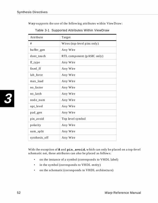
Synthesis Directives
3
Warp supports the use of the following attributes within ViewDraw:
With the exception of # and pin_avoid , which can only be placed on a top-level schematic net, these attributes can also be placed as follows:
• on the instance of a symbol (corresponds to VHDL label)
• in the symbol (corresponds to VHDL entity)
• on the schematic (corresponds to VHDL architecture)
Table 3-1 Supported Attributes Within ViewDraw
Attribute Target
# Wires (top-level pins only)
buffer_gen Any Wire
dont_touch RTL component (pASIC only)
ff_type Any Wire
fixed_ff Any Wire
lab_force Any Wire
max_load Any Wire
no_factor Any Wire
no_latch Any Wire
node_num Any Wire
opt_level Any Wire
pad_gen Any Wire
pin_avoid Top level symbol
polarity Any Wire
sum_split Any Wire
synthesis_off Any Wire
52 Warp Reference Manual
Synthesis Directives
3
The Warp Export VHDL utility netlists these attributes where they are found, and Warp uses its hierarchical inheritance rules to interpret these attributes. These rules are explained at the beginning of this chapter.
3.4.2 Supported ViewDraw Attributes
In addition to the ViewDraw attribute # representing pin assignments, the only other ViewDraw specific attribute that Warp supports is the $ARRAY attribute.
The $ARRAY component attribute specifies a one- or two-dimensional array of the component without actually drawing all of the components.
Arrayed components are defined at the schematic level. The $ARRAY attribute is added to the component to determine the number of occurrences of this component in the logical database. $ARRAY attributes at the symbol level are ignored.
The format for a one-dimensional component array is as follows:
$ARRAY=n
The format for a two-dimensional component array is as follows:
$ARRAY=x,y
Warp Reference Manual 53
Synthesis Directives
3
54 Warp Reference Manual
Chapter
4 VHDL4
VHDL
4
4.1 Introduction
This section discusses some of the fundamental elements of VHDL implemented in Warp.
Topics include:
• identifiers
• data objects (constants, variables, signals)
• data types, including pre-defined types, user-definable types, subtypes, and composite types
• operators, including logical, relational, adding, multiplying, miscellaneous, assignment, and association operators
• entities
• architectures, for behavioral data flow and structural descriptions
• packages and libraries
Designs in VHDL are created in what are called entity and architecture pairs. Entities and architectures are discussed in Sections 4.6 and 4.7. Sections leading up to this discussion cover VHDL language basics such as identifiers, data objects, data types, operators, and syntax.
4.2 Identifiers
An identifier in VHDL is composed of a sequence of one or more alphabetic, numeric, or underscore characters.
Legal characters for identifiers in VHDL include uppercase letters (A...Z), lowercase letters (a...z), digits (0...9), and the underscore character (_).
The first character in an identifier must be a letter.
The last character in an identifier cannot be an underscore character. In addition, two underscore characters cannot appear consecutively.
Lowercase and uppercase letters are considered identical when used in an identifier; thus, SignalA, signala, and SIGNALA all refer to the same identifier.
Comments in a VHDL description begin with two consecutive hyphens (--), and extend to the end of the line. Comments can appear anywhere within a VHDL description.
56 Warp Reference Manual
VHDL
4
VHDL defines a set of reserved words, called keywords, that cannot be used as identifiers.
Examples:
-- this is a comment.
-- this is the first line of -- a three-line comment. Note the repetition-- of the double hyphens for each line.
entity mydesign is -- comment at the end of a line
The following are legal identifiers in VHDL:
SignalAHen3ryOutput_EnableC3POTHX_1138
The following are not legal identifiers in VHDL:
3POC -- identifier can’t start with a digit_Output_Enable -- or an underscore characterMy__Design -- or have two consecutive underscoresMy_Entity_ -- can’t end with an underscore, eitherSig% -- percent sign is an illegal characterSignal -- reserved word
4.3 Data Objects
A data object holds a value of some specified type. In VHDL, all data objects belong to one of three classes: constants, variables, or signals.
Warp Reference Manual 57
VHDL
4
Constant Declar ationconstant identifier [, identifier ...]: type := value ;
Variable Declarationvariable identifier [, identifier ...]: type [:= value ];
Signal D eclar ationsignal identifier [, identifier ...]: type [:= value ];
An object of class constant can hold a single value of a given type. A constant must be assigned a value upon declaration. This value cannot be changed within the design description.
An object of class variable can also hold a single value of a given type at any point in the design description. A variable, however, can take on many different values within the design description. Values are assigned to a variable by means of a variable assignment statement.
An object of class signal is similar to an object of class variable in Warp, with one important difference: signals can hold or pass logic values, while variables cannot. Signals can therefore be synthesized to memory elements or wires.
Variables have no such hardware analogies. Instead, variables are simply used as indexes or value holders to perform computations incidental to modeling components.
Most data objects in VHDL, whether constants, variables, or signals, must be declared before they can be used. Objects can be given a value at declaration time by means of the “:=” operator.
Exceptions to the “always-declare-before-using” rule include:
• The ports of an entity are implicitly declared as signals.
• The generics of an entity are implicitly declared as constants.
• The formal function parameters must be constants or signals, and are implicitly declared by the function declaration. The formal procedure parameters can be constants, variables, or signals, and are implicitly declared by the procedure declaration.
• The indices of a loop or generate statement are implicitly declared when the loop or generate statement begins, and disappear when it ends.
58 Warp Reference Manual
VHDL
4
Examples:
constant bus_width:integer := 8;
This example defines an integer constant called bus_width and gives it a value of 8.
variable ctrl_bits:std_logic_vector(7 downto 0);
This example defines an eight-element bit_vector called ctrl_bits.
signal sig1, sig2, sig3:std_logic;
This example defines three signals of type std_logic, named sig1 , sig2 , and sig3 .
4.4 Data Types
A data type is a name that specifies the set of values that a data object can hold and the operations that are permissible on those values.
Warp supports the following pre-defined VHDL types:
• integer
• boolean
• bit
• character
• string
• bit_vector
• std_logic
• std_logic_vector
Warp also gives the user the capability to define subtypes and composite types by modifying these basic types, and to define particular types by combining elements of different types.
Warp’s pre-defined types, and Warp’s facilities for defining subtypes, composite types, and user-defined types, are all discussed in the following pages.
Warp Reference Manual 59
VHDL
4
Note – VHDL is a strongly typed language. Data objects of one type cannot be assigned to data objects of another, and opera-tions are not allowed on data objects of differing types. Warp pro-vides functions for converting vectors to integers or integers to vectors and functions for allowing certain operations on differing data types.
4.4.1 Pre-Defined Types
Warp supports the following pre-defined VHDL types: integer , boolean , bit , character , string , bit_vector , std_logic , and std_logic_vector .
IntegerVHDL allows each implementation to specify the range of the integer type differently. However, the range must extend from at least -(2**31-1) to +(2**31-1), or -2147483648 to +2147483647. Warp allows data objects of type integer to take on any value in this range.
BooleanData objects of this type can take on the values true or false .
BitDataObjects of this type can take on the values 0 or 1.
CharacterData objects of type character can take on values consisting of any of the 128 standard ASCII characters. The non-printable ASCII characters are represented by two or three-character identifiers, as follows: NUL, SOH, STX, ETX, EOT, ENQ, ACK, BEL, BS, HT, LF, VT, FF, CC, S0, S1, DLE, DC1, DC2, DC3, DC4, NAK, SYN, ETB, CAN, EM, SUB, ESC, FSP, GSP, RSP, and USP.
StringA string is an array of characters.
Example:
variable greeting:string(1 to 13):=”Hello, world!”;
60 Warp Reference Manual
VHDL
4
Bit_VectorA bit_vector is an array of bits in ascending or descending order and provides an easy means to manipulate buses. Bit_vectors can be declared as follows:
signal a, b:bit_vector(0 to 7);signal c, d:bit_vector(7 downto 0);signal e:bit_vector(0 to 5);
Note – bit_vector constants are specified with double quote marks ( " ), whereas single bit constants are specified with single quote marks ( ’ ).
If these signals are subsequently assigned the following values:
a <= “00110101”;c <= “00110101”;b <= x”7A”;d <= x”7A”;e <= O”25”;
then we can compare the individual bits of a and c to discover that a(7) is ‘1’, a(6) is ‘0’, a(5) is ‘1’, a(4) is ‘0’,..., a(0) is ‘0’ whereas c(7) is ‘0’, c(6) is ‘0’, c(5) is ‘1’, c(4) is ‘1’,... c(0) is ‘1’. This is because the bits of signal a are in ascending order, and the bits of signal b are in descending order, and the assignment is made simply from the left most index to the right most index.
The prefix of ’X’ or ’x’ denotes a hexadecimal value; a prefix of ’O’ or ’o’ denotes an octal value; a prefix of ’B’ or ’b’ denotes a binary value. If no prefix is included, a value of ’b’ is assumed. Underscore characters may be freely mixed in with the bit_vector value for clarity. Hexadecimal and octal designators should only be used if the hexadecimal or octal value can be directly mapped to the size of the bit_vector. For example, if ’x’ is a bit_vector(0 to 5), then the assignment a <= x”B”; cannot be made because the hexadecimal number ’B’ uses four bits and does not match the size of the bit_vector to which it is being assigned.
String LiteralsA value that represents a (one-dimensional) string of characters is called a string literal. String literals are written by enclosing the characters of the string within double quotes (“...“). String literals can be assigned either to objects of type string or to objects of type bit_vector (or other types of vectors whose base type is compatible with the string contents), as long as both objects have been declared with enough elements to contain all the characters of the string:
Warp Reference Manual 61
VHDL
4
variable err_msg:string(1 to 18);err_msg := “Fatal error found!”;
signal bus_a:bit_vector(7 downto 0);bus_a<= “10011110”;
signal bus_b:std_logic_vector(7 downto 0);bus_b <= "ZZZZZZZZ" ;
std_logic
std_logic is similar to the basic type bit except that it is not defined within the language. The IEEE std_logic_1164 packages defines std_logic as a type which can have values ‘U’, ‘X’, ‘0’, ‘1’, ‘Z’, ‘W’, ’L’, ‘H’, or ‘-’.
For synthesis purposes, however, only ‘0’, ‘1’, ’Z’ and ’-’ are supported as valid values. The values ’Z’ and ’-’ also have additional restrictions on how and where they can be used.
The values ‘0’ and ‘1’ can be used anywhere in the design.
The ’Z’ which represents the high impedance state can only be used in an assignment to a top level output and has to map to a physical pin on the device.
The ’-’ which represents a don’t care can be used in an assignment but cannot be used to compare values of non-constant signals (in if-then-else or case statements). The std_match functions defined in the numeric packages, however, can be used to compare input don’t cares.
std_logic_vectorThe std_logic_vector is simply a vector or an array of elements of type std_logic . Its use is very similar to the bit_vector type . The main difference between a bit_vector and the std_logic_vector is the type of the elements of the array.
4.4.2 Enumerated Types
An enumerated type is a type with a user-defined set of possible values.
Enumerated Type Declarationtype name is ( value [, value ...]);
The order in which the values are listed in an enumeration type’s declaration defines the lexical ordering for that type. That is, when relational operators are used to compare two objects of an enumerated type, a given value is always less
62 Warp Reference Manual
VHDL
4
than another value that appears to its right in the type declaration. The position number of the leftmost value is 0; the position number of other values is one more than that of the value to its left in the type declaration.
Examples:
type arith_op is (add,sub,mul,div);
This example defines an enumerated type named arith_op whose possible values are add , sub , mul , and div .
type states is (state0, state1, state2, state3)
This example defines an enumerated type named states , with four possible values: state0 , state1 , state2 , and state3 .
4.4.3 Subtypes
A subtype is a subset of a larger type.
Subtype Declarationsubtype type is
base_type range value {to | downto} value ;
Subtypes are useful for range checking or for enforcing constraints upon objects of larger types.
Examples:
subtype byte is std_logic_vector(7 downto 0);subtype single_digit is integer range 0 to 9;
These examples define subtypes called byte and single_digit . Signals or variables that are declared as byte are std_logic_vectors of eight bits in descending order. Signals or variables that are declared as single_digit are integers with possible values consisting of the integers 0 through 9, inclusive.
subtype byte is std_logic_vector(7 downto 0);type arith_op is (add,sub,mul,div);subtype add_op is arith_op range add to sub;subtype mul_op is arith_op range mul to div;
This example first defines an enumerated type called arith_op , with possible values add , sub , mul , and div . It then defines two subtypes: add_op , with possible values add and sub , and mul_op , with possible values mul and div .
Warp Reference Manual 63
VHDL
4
4.4.4 Composite Types
A composite type is a type made up of several elements from another type. There are two kinds of composite types: arrays and records.
Array Type Declarationtype name is array ({ low to high }|
{ high downto low }) of base_type ;
Record Type Declarationrecord type is record
element:element_type[;element:element_type...];
end record;
An array is a data object consisting of a collection of elements of the same type. Arrays can have one or more dimensions. Individual elements of arrays can be referenced by specifying an index value into the array (see examples). Multiple elements of arrays can be referenced using aggregates.
A record is a data object consisting of a collection of elements of different types. Records in VHDL are analogous to records in Pascal and struct declarations in C. Individual fields of a record can be referenced by using selected names (see examples). Multiple elements of records can be referenced using aggregates.
Examples:
The following are examples of array type declarations:
type big_word is array (0 to 63) of std_logic;type matrix_type is array (0 to 15, 0 to 31) of std_logic;type values_type is array (0 to 127) of integer;
Possible object declarations using these types include:
signal word1,word2:big_word;signal device_matrix:matrix_type;variable current_values:values_type;
Some possible ways of assigning values to elements of these objects include:
word1(0)<=’1’; -- assigns value to 0th element in word1word1(5)<=; -- assigns value to 5th element in word1word2 <= word1; -- makes word2 identical to word1word2(63) <= device_matrix(15,31); -- transfers value-- of element from device_matrix to element of word2
64 Warp Reference Manual
VHDL
4
current_values(0) := 0;current_values(127) := 1000;
The following includes an example of a record type declaration:
type opcode is (add,sub,mul,div);type instruction is record
operator:opcode;op1:integer;op2:integer;end record;
Here are two object declarations using this record type declaration:
variable inst1, inst2:instruction;
Some possible ways of assigning values to elements of these objects include:
inst1.opcode := add; -- assigns value to opcode of inst1inst2.opcode := sub; -- assigns value to opcode of inst2inst1.op1 := inst2.op2; -- copies op2 of inst2
-- to op1 of inst2inst2 := inst1; -- makes inst2 identical to inst1
4.5 Operators
VHDL provides a number of operators used to construct expressions to compute values. VHDL also uses assignment and association operators.
VHDL’s expression operators are divided into five groups. They are (in increasing order of precedence): logical, relational, adding, multiplying, and miscellaneous.
In addition, there are assignment operators that transfer values from one data object to another and association operators that associate one data object with another.
Warp Reference Manual 65
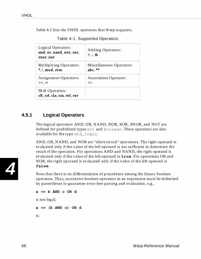
VHDL
4
Table 4-1 lists the VHDL operators that Warp supports.
4.5.1 Logical Operators
The logical operators AND, OR, NAND, NOR, XOR, XNOR, and NOT are defined for predefined types bit and boolean . These operators are also available for the type std_logic .
AND, OR, NAND, and NOR are "short-circuit" operations. The right operand is evaluated only if the value of the left operand is not sufficient to determine the result of the operation. For operations AND and NAND, the right operand is evaluated only if the value of the left operand is true . For operations OR and NOR, the right operand is evaluated only if the value of the left operand is false .
Note that there is no differentiation of precedence among the binary boolean operators. Thus, successive boolean operators in an expression must be delimited by parentheses to guarantee error-free parsing and evaluation, e.g.,
a <= b AND c OR d
is not legal;
a <= (b AND c) OR d
is.
Table 4-1 Supported Operators
Logical Operators: and, or, nand, nor, xor, xnor, not
Adding Operators:+, -, &
Multiplying Operators: *, /, mod, rem
Miscellaneous Operators: abs, **
Assignment Operators: <=, :=
Association Operator:=>
Shift Operators:sll, srl, sla, sra, rol, ror
66 Warp Reference Manual
VHDL
4
4.5.2 Relational Operators
Relational operators include tests for equality, inequality, and ordering of operands.
The operands of each relational operator must be of the same type. The result of each relational operation is of type boolean .
The equality operator “=” returns true if the two operands are equal, false otherwise. The inequality operator “/=” returns false if the two operands are equal, true otherwise.
Two scalar values of the same type are equal if and only if their values are the same. Two composite values of the same type (e.g., vectors) are equal if and only if for each element of the left operand there is a matching element of the right operand, and the values of matching elements are equal.
The ordering operators are defined for any scalar type and for array types (e.g., vectors). For scalar types, ordering is defined in terms of relative values (e.g., ‘0’ is always less than ‘1’). For array types, the relation “<“ (less than) is defined such that the left operand is less than the right operand if and only if:
• the left operand is a null array and the right operand is a non-null array; otherwise
• both operands are non-null arrays, and one of the following conditions is satisfied:
• the leftmost element of the left operand is less than that of the right; or
• the leftmost element of the left operand is equal to that of the right, and the tail of the left operand is less than that of the right. The tail consists of the remaining elements to the right of the leftmost element and can be null.
The relation “<=” (less than or equal to) for array types is defined to be the inclusive disjunction of the results of the “<“ and “=” operators for the same two operands (i.e., it's true if either the “<“ or “=” relations are true). The relations “>” (greater than) and “>=” (greater than or equal to) are defined to be the complements of “<=” and “<“, respectively, for the same two operands.
Warp Reference Manual 67
VHDL
4
4.5.3 Adding Operators
In VHDL, the “+” and “-” operators perform addition and subtraction, respectively. The ‘&’ operator concatenates characters, strings, bits or bit/std_logic vectors. All three of these operators have the same precedence, and so are grouped under the category “Adding Operators.”
The adding operators “+” and “-” are defined for integers and retain their conventional meaning.
These operations are also supported for bit_vectors, through the use of the bit_arith package. (See Section 4.8.1, "Predefined Packages,” later in this chapter for more information.)
In Warp, concatenation is defined for bits and arrays of bits (bit_vectors). The concatenation operator in Warp is “&”.
If both operands are bit_vectors, the result of the concatenation is a one-dimensional array whose length is the sum of the lengths of the operands, and whose elements consist of the elements of the left operand (in left-to-right order) followed by the elements of the right operand (in left-to-right order). The left bound of this result is the left bound of the left operand, unless the left operand is a null array, in which case the result of the operation is the right operand. The direction of the result is the direction of the left operand, unless the left operand is a null array, in which case the direction of the result is that of the right operand.
If one operand is a bit_vector and the other is a bit, or if both are bits, the bit operand is replaced by an implicit one-element bit_vector having the bit operand as its only element. The left bound of the implicit bit_vector is 0, and its direction is ascending. This is in most cases an inconsequential fact if the “&” is being used during an assignment to a constrained vector (vector with known dimensions) but may become important if the concatenated vector is being assigned (or passed to a function) to a unconstrained vector.
4.5.4 Multiplying Ope rators
In VHDL, the ”*” and “/” operators perform multiplication and division, respectively. Two other operands of the same precedence include the mod and rem operators. Both operators return the remainder when one operand is divided by another.
All the multiplication operators are defined for both operands being of the same integer or bit_vector type. The result is also of the same type as the operands.
68 Warp Reference Manual
VHDL
4
The rem operation is defined as the following:
A rem B = A-(A/B)*B
where “/” in the above example indicates an integer division. The result has the sign of A and an absolute value less than the absolute value of B.
The mod operation is similar, except that the result has the sign of B. In addition, , for some integer N, the result satisfies the relation:
A mod B = A-B*N
Note – Warp predefines the ”*” only. There is currently no built-in support for ”/”, “mod” or the “rem” operators but can be used if the user supplies the necessary overloading.
4.5.5 Miscellaneous Operators
The two miscellaneous expression operators in VHDL are “abs” and “**”.
The “abs” operator, defined for integers, returns the absolute value of its operand.
The ”**” operator raises a number to a power of two. It is defined for an integer first operand and a power-of-two second operand. Its result is the same as shifting the bits in the first operand left or right by the amount specified by the second operand.
Note – Warp currently supports these operators for Constant integers only.
4.5.6 Assignment Operations
VHDL has two assignment operators: “<=” and “:=”. The first is used for signal assignments, the second for variable assignments.
Variable Assignment
variable_name := expression ;
Signal Assignment
signal_name <= expression ;
Warp Reference Manual 69
VHDL
4
Variable assignments can only occur inside a process. Signal assignments can occur anywhere inside an architecture.
Assignments to objects of composite types can be assigned values using aggregates, which is simply a way of specifying more than one value to be assigned to elements of an object with a single assignment statement. Examples of the use of aggregates are shown below.
Examples:
type opcode is (add,sub,mul,div);type instruction is record
operator:opcode;op1:integer;op2:integer;
variable inst1,inst2:instruction;signal vec1, vec2 : bit_vector(0 to 3):
vec1 <= (‘1’,’0’,’1’,’0’); -- aggregate assignmentvec2 <= vec1; -- another aggregate assignmentinst1 := (add,5,10); -- aggregate assignment to recordvec1 <= (0=>’0’,others=>’1’); -- assign 0 to 0th bit,
-- set others to 1
4.5.7 Association Operations
To instantiate a component in a Warp description, the user must specify the connection path(s) between the ports of the component being instantiated and the interface signals of the entity/architecture pair being defined. This is done by means of an association list within a port map or a generic map.
Warp supports both named and positional association.
In named association, the user uses the "=>" association operator to associate a formal (the name of the port in the component being instantiated) with an actual (the name of the signal in the entity being defined). The association operator is considered an "arrow" indicating direction. It's easy to remember which way to make the arrow point: it always points to the actual. For example, in the following instantiation of a predefined D flip-flop,
st0: DSRFF port map(d => dat,s => set,r => rst,clk=> clk,q => duh);
70 Warp Reference Manual
VHDL
4
the arrow always points toward the ports of the defined component, the DSRFF in this case. Named association allows the user to associate the signals in any order he desires. In the previous example, the user could have listed the “q => duh” before “d => dat”.
In positional association, the association operator is not used. Instead, the user lists the actuals (signals names) in the port map in the same order as the formals of the component being instantiated, without including the formal names at all.
For example, the jkff component is declared as follows:
component jkff port(j : in bit;k : in bit;clk: in bit;q : out bit);
end component;
An association list for an instantiation of this component could use either named association, like this:
jk1:jkff port map(j_in=>j,k_in=>k,clk=>clk,q_out=>q);
or positional association, like this:
jk1:jkff port map(j_in, k_in, clk, q_out);
Either form maps signals j_in , k_in , clk , and q_out in the entity being defined to ports j , k , clk , and q, respectively, on the instantiated component.
4.5.8 Vector Operations
Addition, subtraction, multiplication, incrementing, decrementing, shifting inverting, and relational operators for vectors are defined in the predefined packages.
With the appropriate package, included within the user’s VHDL file, the user can gain access to the vector-vector or vector-integer operations. The specific package that is needed depends on the type of vectors that the user using in the VHDL file. The following table associates a package with the four predefined vector types supported within Warp.
Warp Reference Manual 71
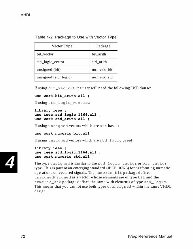
VHDL
4
If using bit_vector s, the user will need the following USE clause:
use work.bit_arith.all ;
If using std_logic_vector s:
library ieee ;use ieee.std_logic_1164.all ;use work.std_arith.all ;
If using unsigned vectors which are bit based:
use work.numeric_bit.all ;
If using unsigned vectors which are std_logic based:
library ieee ;use ieee.std_logic_1164.all ;use work.numeric_std.all ;
The type unsigned is similar to the std_logic_vector or bit_vector type. This is part of an emerging standard (IEEE 1076.3) for performing numeric operations on vectored signals. The numeric_bit package defines unsigned /signed as a vector whose elements are of type bit and the numeric_std package defines the same with elements of type std_logic . This means that you cannot use both types of unsigned within the same VHDL design.
Table 4-2 Package to Use with Vector Type
Vector Type Package
bit_vector bit_arith
std_logic_vector std_arith
unsigned (bit) numeric_bit
unsigned (std_logic) numeric_std
72 Warp Reference Manual
VHDL
4
In all of the above packages, the most significant bit (MSB) for a vector is considered to be the left-most bit. This means that in the following two vectors:
signal veca : std_logic_vector(3 downto 0) ;signal vecb : std_logic_vector(0 to 3) ;
veca(3) is the MSB for veca and vecb(0) is the MSB for vecb .
All of the above four packages mentioned also provide certain other utility functions which are documented in the "Packages” Section, 4.8, of this chapter.
4.6 Entities
VHDL designs consist of entity and architecture pairs, in which the entity describes the design I/O or interface and the architecture describes the content of the design.Together, entity and architecture pairs can be used as complete design descriptions or as components in a hierarchical design or both.
The syntax for an entity declaration is as follows:
ENTITY entity IS PORT([ signal] [ sig-name, ...]:[ direction ] type[; signal [ sig-nam, ...]:[ direction ] type ]..);
END entity-name ;
The entity declaration specifies a name by which the entity can be referenced in a design architecture. In addition, the entity declaration specifies ports. Ports are a class of signals that define the entity interface. Each port has an associated signal name, mode, and type.
Choices for mode are in (default), out , inout and buffer . Mode in is used to describe ports that are inputs only; out is used to describe ports that are outputs only, with no feedback internal to the associated architecture; inout is used to describe bi-directional ports; buffer is used to describe ports that are outputs of the entity but are also fed back internally.
Warp Reference Manual 73
VHDL
4
Two sample entity declarations appear below.
Examples:
entity cnt3bit is port(q:inout std_logic_vector(0 to 2);inc,grst,rst,clk:in std_logic;carry:out std_logic);
end cnt3bit;
entity Bus_Arbiter is port(Clk, -- ClockDRAM_Refresh_Request,-- Refresh RequestVIC_Wants_Bus,-- VIC Bus RequestSparc_Wants_Bus: IN std_logic;-- Sparc Bus RequestRefresh_Control,-- DRAM Refresh ControlVIC_Has_Bus,-- VIC Has BusSparc_Has_Bus: OUT std_logic);-- Sparc Has Bus
end Bus_Arbiter;
The first entity declaration shows the proper declaration for a bidirectional signal (which, in this case, is also a vector), along with several input signals and an output signal.
The second entity declaration shows how comments can be included within an entity declaration to document each signal's use within the entity.
4.7 Architectures
Architectures describe the behavior or structure of associated entities. They can be either, or a combination of the following:
• behavioral descriptions
These descriptions provide a means to define the “behavior” of a circuit in abstract, “high level” algorithms, or in terms of “low level” boolean equations.
• structural descriptions
These descriptions define the “structure” of the circuit in terms of components and resemble a net-list that could describe a schematic equivalent of the design. Structural descriptions contain hierarchy in which components are defined at different levels.
74 Warp Reference Manual
VHDL
4
The architecture syntax follows:
ARCHITECTURE aname OF entity IS[ type-declarations ][ signal-declarations ][ constant-declarations ]
BEGIN[architecture definition]
END aname;
Each architecture has a name and specifies the entity which it defines. Types, signals, and constant must all be declared before the beginning of the architecture definition. The architecture defines the concurrent signal assignments, component instantiations, and processes.
Examples:
library ieee ;use work.std_logic_1164.all ;use work.std_arith.all;architecture archcounter of counter isbeginproc1: process (clk)
begin if (clk'event and clk = '1') then count <= count + 1; end if; end process proc1; x <= '1' when count = "1001" else '0';
end archcounter;
Archcounter is an example of a behavioral architecture description of a counter and a signal x that is asserted when count is a particular value. This design is considered behavioral because of the algorithmic way in which it is described. The details of such descriptions will be covered later.
library ieee ;use work.std_logic_1164.all ;use work.rtlpkg.all;architecture archcapture of capture is
signal c: std_logic;begin
c <= a AND b;d1: dff port map(c, clk, x);
end archcapture;
Warp Reference Manual 75
VHDL
4
Archcapture is the name of an architectural description that is both structural and behavioral in nature. It is considered structural because of the component instantiation, and it is considered behavioral because of the boolean equation. VHDL provides the flexibility to combine behavioral and structural architecture descriptions.
4.7.1 Behavioral Descri ptions
Behavioral design descriptions consist of two types of statements:
• Concurrent statements which define concurrent signal assignments by way of association operators.
• Sequential statements within a process which enable an algorithmic way of describing a circuit’s behavior. Sequential statements enable signal assignments to be based on relational and conditional logic.
These types of statements, as well as structural descriptions, may be combined in any architecture description.
Concurrent StatementsConcurrent statements are found outside of processes and are used to implement boolean equations, when... else constructs, signal assignments, or generate schemes. Here are some examples:
u <= a;v <= u;w <= a XOR b;x <= (a AND s) or (b AND NOT(s));y <= (‘1’ when (a=’0’ and b = ‘1’) else ‘0’;z <= A when (count = “0010”) else b;
Signal u is assigned the value of signal a and is its equivalent. Likewise, v is equivalent to both signals u and a . The order of these signal assignments does not matter because they are outside of a process and are concurrent. The next two statements implement boolean equations, while the last two statements implement when... else constructs. The assignment for signal y may be read as “y gets (is assigned) ‘1’ when a is zero and b is one, otherwise y gets ‘0’.” Likewise, “z gets a when count is “0010,” otherwise z gets b.”
Sequential StatementsSequential statements, which must be within a process, allow the user to describe signal assignments in an algorithmic fashion. All statements in a process are
76 Warp Reference Manual

VHDL
4
evaluated sequentially, and therefore the order of the statements is important. For example, in the process
proc1: process (x)begin
a <= ‘0’;if x = “1011” then
a <= ‘1’;end if;
end process proc1;
signal a is first assigned ‘0’. Later in the process, if x is found to be equivalent to “1011” then signal a is assigned the value ‘1’ .
Final signal assignments occur at the end of the process. In other words, the VHDL compiler evaluates the code sequentially before determining the equations to be synthesized, whereas the compiler synthesizes equations for concurrent statements upon encountering them. A process taken as a whole is a concurrent statement.
The ProcessIn most cases, a process has a sensitivity list: a list of signals in parentheses immediately following the key word “process”. Signals assigned within a process can only change value if one of the signals in the sensitivity list transitions. If the sensitivity list is omitted, then the compiler infers that signal assignments are sensitive to changes in any signal.
The user may find it helpful to think of processes in terms of simulation (VHDL is also used for simulation) in which a process is either active or inactive. A process becomes active only when a signal in the sensitivity list transitions. In the following process
proc1: process (rst, clk)begin
if rst = ‘1’ thenq <= ‘0’;
elsif (clk’event and clk=’1’) thenq <= d;
end if;end process;
only transitions in rst and clk cause the process to become active. If either clk or rst transition, then the process becomes active, and the first condition is checked (if rst = ‘1’). In the case that rst = ’1’ q will be assigned ‘0’, otherwise the second condition is checked (if clk event and clk = ‘1’ ). This condition looks for the rising edge of a clock. All signals within this portion of the
Warp Reference Manual 77
VHDL
4
process are sensitive to this rising edge clock, and the compiler infers a register for these signals. This process creates a D flip-flop with d as its input, q as its output, clk as the clock, and rst as an asynchronous reset.
4.7.2 Structural Descriptions
Structural descriptions are net-lists that allow the user to instantiate components in hierarchical designs. A port map is part of every instantiation and indicates how the ports of the component are connected. Structural descriptions can be combined with behavioral descriptions, as in the following example:
architecture archmixed of mixed isbegin--instantiations cntl1: motor port map(clk, ld, en, c1, chg1, start1, stop1);cntl2: motor port map(clk, ld, en, c2, chg2, start2, stop2);safety: mot_check port map(status, c1, c2);--concurrent statementen <= ‘1’ when (status=’1’ and status = ‘1’) else ‘0’;-- concurrent process with sequential statementsok:process (clk)
beginif (clk’event and clk=’1’) then
status <= update;end if;
end process ok;end archmixed;
This example shows that two motor components and one mot_check component are instantiated. The port maps are associated with inputs and outputs of the motor and mot_check components by way of positional association. Signal en is assigned by a concurrent statement, and signal status is assigned by a process that registers a signal using the common clock clk .
4.7.3 Design Methodologies
Designers can choose from multiple methods of describing designs in VHDL, depending on coding preferences. This section will discuss how to implement combinatorial logic, registered logic, counters, and state machines. The discussion of state machines will cover multiple implementations and the design and synthesis trade-offs for those implementations. Section 4.10, "Additional Design Examples" contains further design examples. Most of the design examples in this section can be found in the directory c:\warp\examples.
78 Warp Reference Manual
VHDL
4
Combinatorial LogicFollowing are examples of a four-bit comparator implemented in four different ways, all yielding the same result. In all examples, the entity is the same:
library ieee ;use ieee.std_logic_1164.all ; -- Defines std_logicentity compare is port( a, b: in std_logic_vector(0 to 3); aeqb: out std_logic);end compare;
The entity declaration specifies that the design has three ports: two input ports (a, b), and one output port (aeqb ). The input ports are of type std_logic_vector and the output port is of type std_logic .
Using a process, the comparator can be implemented as follows:
use work.std_arith.all ;architecture archcompare of compare isbegincomp: process (a, b) begin if a = b then aeqb <= '1'; else aeqb <= '0'; end if; end process comp;end archcompare;
The design behavior is given in the architecture section. The architecture description consists of the process "comp". The process includes the sensitivity list (a,b) so that the process becomes active each time there is a change in one of these signals. The process permits the use of an algorithm to assert aeqb when a equals b . The std_arith package contains a tuned implementation for the "=" operator.
With one concurrent statement, making use of the case...when construct, the same comparator can be described like this:
use work.std_arith.all ;architecture archcompare of compare isbegin aeqb <= '1' when (a = b) else '0';end;
Warp Reference Manual 79
VHDL
4
In this example, the process in the previous example has been replaced by a concurrent signal assignment for aeqb .
Using boolean equations, the comparator looks like this:
architecture archcompare of compare isbegin aeqb <= NOT( (a(0) XOR b(0)) OR (a(1) XOR b(1)) OR (a(2) XOR b(2)) OR (a(3) XOR b(3)));end;
In this example, a boolean equation replaces the when... else construct.
Finally, a structural design which implements a net list of XOR gates, a 4-input OR gate, and an INV gate looks like this:
use work.lpmpkg.all;architecture archcompare of compare isbegin
c0: Mcomparegeneric map(
lpm_width => aeqb’length, -- Evaluates to 4lpm_representation => lpm_unsigned,lpm_hint => speed)
port map(dataa => a, datab => b,alb => open, aeb => aeqb, agb => open,aleb => open, aneb => open, ageb => open);
end;
In this example, the compare architecture is described by instantiating gates much the same as one would by placing gates in a schematic diagram. The Mcompare component used in this architecture is the same as those available in the Warp LPM (Library of Parameterized Elements) library. The port map lists are associated with the inputs and outputs of the gates through named association for readability.
80 Warp Reference Manual
VHDL
4
Many other functions or components can be implemented in multiple ways. Here is one last combinatorial example: a four-bit wide four-to-one multiplexer. In all versions, the entity is the same:
library ieee ;use ieee.std_logic_1164.all ; -- Defines std_logicentity mux is port( a, b, c, d: in std_logic_vector(3 downto 0); s: in std_logic_vector(1 downto 0); x: out std_logic_vector(3 downto 0));end mux;
Using a process, the architecture looks like this:
architecture archmux of mux isbeginmux4_1: process (a, b, c, d) begin if s = "00" then x <= a; elsif s = "01" then x <= b; elsif s = "10" then x <= c; else x <= d; end if; end process mux4_1;end archmux;
Using a concurrent statement with a case... when construct, the architecture can be written as the following:
architecture archmux of mux isbegin x <= a when (s = "00") else b when (s = "01") else c when (s = "10") else d;end archmux;
Warp Reference Manual 81
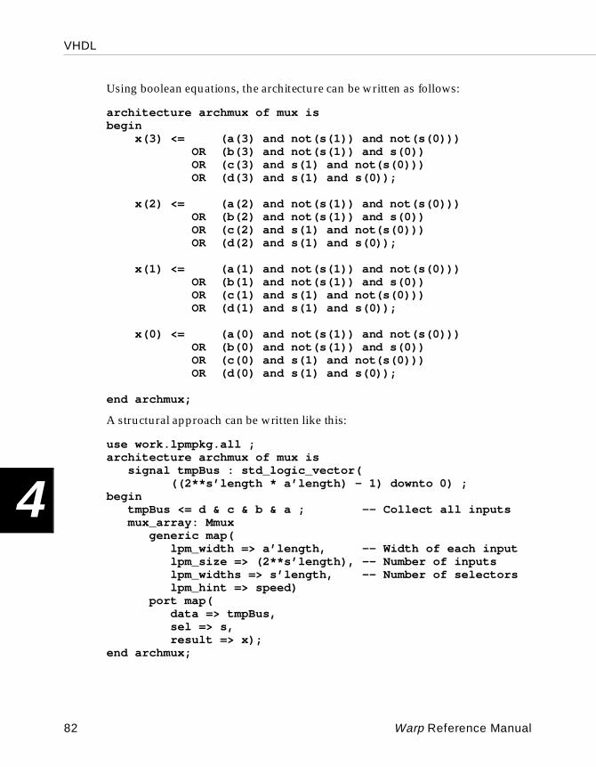
VHDL
4
Using boolean equations, the architecture can be written as follows:
architecture archmux of mux isbegin x(3) <= (a(3) and not(s(1)) and not(s(0))) OR (b(3) and not(s(1)) and s(0)) OR (c(3) and s(1) and not(s(0))) OR (d(3) and s(1) and s(0));
x(2) <= (a(2) and not(s(1)) and not(s(0))) OR (b(2) and not(s(1)) and s(0)) OR (c(2) and s(1) and not(s(0))) OR (d(2) and s(1) and s(0));
x(1) <= (a(1) and not(s(1)) and not(s(0))) OR (b(1) and not(s(1)) and s(0)) OR (c(1) and s(1) and not(s(0))) OR (d(1) and s(1) and s(0));
x(0) <= (a(0) and not(s(1)) and not(s(0))) OR (b(0) and not(s(1)) and s(0)) OR (c(0) and s(1) and not(s(0))) OR (d(0) and s(1) and s(0));
end archmux;
A structural approach can be written like this:
use work.lpmpkg.all ;architecture archmux of mux is
signal tmpBus : std_logic_vector(((2**s’length * a’length) - 1) downto 0) ;
begintmpBus <= d & c & b & a ; -- Collect all inputsmux_array: Mmux
generic map(lpm_width => a’length, -- Width of each inputlpm_size => (2**s’length), -- Number of inputslpm_widths => s’length, -- Number of selectorslpm_hint => speed)
port map(data => tmpBus,sel => s,result => x);
end archmux;
82 Warp Reference Manual
VHDL
4
This design makes use of the multiplexer in the Warp library. Of course, the user could build up his own multiplexers and instantiate them instead.
Registered LogicThere are two methods for implementing registered logic: instantiating a register (or other component with registers) or using a process that is sensitive to a clock edge. For example, if the user wanted to use a D register and a 4-bit counter, he could simply instantiate these components after including the appropriate packages:
use work.rtlpkg.all;use work.lpmpkg.all;...d1: dsrff port map(d, s, r, clk, q);-- Defined in rtlpkgc1: Mcounter -- Defined in lpmpkg
generic map (4)port map(data, clk, one, one, one, count,
zero, rst, zero, zero, zero, zerozero, zero, open) ;
Another method of using registered elements is to include a process that is sensitive to a clock edge or that waits for a clock edge. In processes that are sensitive to clock edges or that wait for clock edges, the compiler infers a register for the signals defined within that process. Four basic templates are supported; each is described below.
process_label: processbegin
wait until clk = ‘1’;. ..
end process;
This process does not have a sensitivity list. Instead it begins with a wait statement. The process will become active when clk transitions to a one (clk —or whatever identifier you give to your clock—can also wait for zero for devices that support such clocking schemes). All signal assignments within such a process will be registered, as these signals only change values on clock edges and retain their values between clock edges.
my_proc: process (clk)begin
if (clk’event and clk =’1’) then...
end if;end process;
Warp Reference Manual 83
VHDL
4
This process is sensitive only to changes in the clock, as the sensitivity list indicates. The first statement within the process looks for a transition from zero to one in signal clk . All signals that are assigned within this process are also registered because the assignments only occur on rising clock edges, and the signals retain their values between rising clock edges.
your_proc: process (rst, clk)begin
if rst = ‘1’ then...
elsif (clk’event and clk=’1’) then...
end if;end process;
This process is sensitive to changes in the clock and signal rst , as the sensitivity list indicates. This process is intended to support signals that must be registered and have an asynchronous set and/or reset. The first statement within the process checks to see if rst has been asserted. Signals that are assigned in this portion of the template are assumed to be registered with rst assigned as either the asynchronous reset or set of the register, as appropriate. If rst has not been asserted, then the remainder of this process works as does the previously described process.
proc1: process (rst, pst, clk)begin
if rst = ‘1’ then...
elsif pst = ‘1’ then...
elsif (clk’event and clk=’1’) then...
end if;end process;
This process is sensitive to changes in the clock and signals rst and pst , as the sensitivity list indicates. This process is intended to support signals that must be registered and have an asynchronous set and reset. The first statement within the process checks to see if rst has been asserted. Signals that are assigned in this portion of the template are assumed to be registered with rst used as either the asynchronous reset or set of the register, as appropriate. The second condition assigns pst as the asynchronous reset or set of the register, as appropriate. If rst and pst have not been asserted, then the remainder of this process works as does the previous process.
84 Warp Reference Manual
VHDL
4
To register 32-bits with an asynchronous reset, the user could simply write the following code:
regs32: process (r, clk2)begin
if (r = ‘1’) thenq <= x”ABC123DE”;
elsif (clk2’event and clk2=’1’) thenq <= d;
end if;end process;
Assuming that q and d are declared as 32-bit signals or ports, then this code example implements 32 registers with d(i) as the input, q(i) as the output, clk2 as the clock, and r as the asynchronous reset for some of the registers and r as the asynchronous preset for the others. This is because resetting the q to the value x”ABC123DE” will cause some registers to go high and other registers to go low when r is asserted.
Counters and state machines designed with processes are described in more detail in the following discussions.
CountersThis is a 4-bit loadable counter:
library ieee;use ieee.std_logic_1164.all ;use work.std_arith.all ;
entity counter is port(clk, load: in std_logic;data: in std_logic_vector(3 downto 0);count: buffer std_logic_vector(3 downto 0));
end counter;
Warp Reference Manual 85
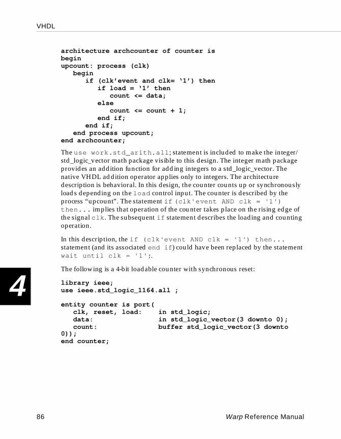
VHDL
4
architecture archcounter of counter isbeginupcount: process (clk)
beginif (clk’event and clk= ‘1’) then
if load = ‘1’ thencount <= data;
elsecount <= count + 1;
end if;end if;
end process upcount;end archcounter;
The use work.std_arith.all ; statement is included to make the integer/std_logic_vector math package visible to this design. The integer math package provides an addition function for adding integers to a std_logic_vector. The native VHDL addition operator applies only to integers. The architecture description is behavioral. In this design, the counter counts up or synchronously loads depending on the load control input. The counter is described by the process “upcount”. The statement if (clk'event AND clk = '1') then... implies that operation of the counter takes place on the rising edge of the signal clk . The subsequent if statement describes the loading and counting operation.
In this description, the if (clk'event AND clk = '1') then... statement (and its associated end if ) could have been replaced by the statement wait until clk = '1'; .
The following is a 4-bit loadable counter with synchronous reset:
library ieee;use ieee.std_logic_1164.all ;
entity counter is port(clk, reset, load: in std_logic;data: in std_logic_vector(3 downto 0);count: buffer std_logic_vector(3 downto
0));end counter;
86 Warp Reference Manual
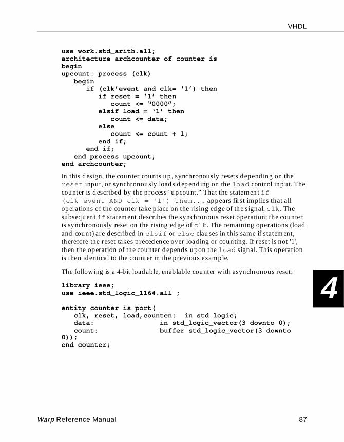
VHDL
4
use work.std_arith.all;architecture archcounter of counter isbeginupcount: process (clk)
beginif (clk’event and clk= ‘1’) then
if reset = ‘1’ then count <= “0000”;
elsif load = ‘1’ thencount <= data;
else count <= count + 1;
end if;end if;
end process upcount;end archcounter;
In this design, the counter counts up, synchronously resets depending on the reset input, or synchronously loads depending on the load control input. The counter is described by the process "upcount.” That the statement if (clk'event AND clk = '1') then... appears first implies that all operations of the counter take place on the rising edge of the signal, clk . The subsequent if statement describes the synchronous reset operation; the counter is synchronously reset on the rising edge of clk . The remaining operations (load and count) are described in elsif or else clauses in this same if statement, therefore the reset takes precedence over loading or counting. If reset is not '1', then the operation of the counter depends upon the load signal. This operation is then identical to the counter in the previous example.
The following is a 4-bit loadable, enablable counter with asynchronous reset:
library ieee;use ieee.std_logic_1164.all ;
entity counter is port(clk, reset, load,counten: in std_logic;data: in std_logic_vector(3 downto 0);count: buffer std_logic_vector(3 downto
0));end counter;
Warp Reference Manual 87
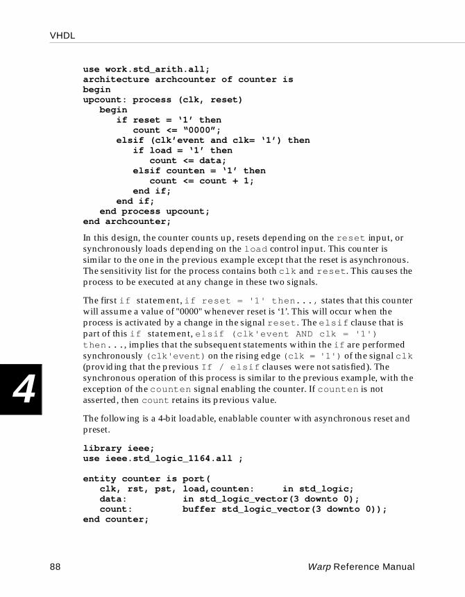
VHDL
4
use work.std_arith.all;architecture archcounter of counter isbeginupcount: process (clk, reset)
beginif reset = ‘1’ then
count <= “0000”;elsif (clk’event and clk= ‘1’) then
if load = ‘1’ thencount <= data;
elsif counten = ‘1’ thencount <= count + 1;
end if;end if;
end process upcount;end archcounter;
In this design, the counter counts up, resets depending on the reset input, or synchronously loads depending on the load control input. This counter is similar to the one in the previous example except that the reset is asynchronous. The sensitivity list for the process contains both clk and reset . This causes the process to be executed at any change in these two signals.
The first if statement, if reset = '1' then..., states that this counter will assume a value of "0000" whenever reset is ‘1’. This will occur when the process is activated by a change in the signal reset . The elsif clause that is part of this if statement, elsif (clk'event AND clk = '1') then... , implies that the subsequent statements within the if are performed synchronously (clk'event) on the rising edge (clk = '1') of the signal clk (providing that the previous If / elsif clauses were not satisfied). The synchronous operation of this process is similar to the previous example, with the exception of the counten signal enabling the counter. If counten is not asserted, then count retains its previous value.
The following is a 4-bit loadable, enablable counter with asynchronous reset and preset.
library ieee;use ieee.std_logic_1164.all ;
entity counter is port(clk, rst, pst, load,counten: in std_logic;data: in std_logic_vector(3 downto 0);count: buffer std_logic_vector(3 downto 0));
end counter;
88 Warp Reference Manual
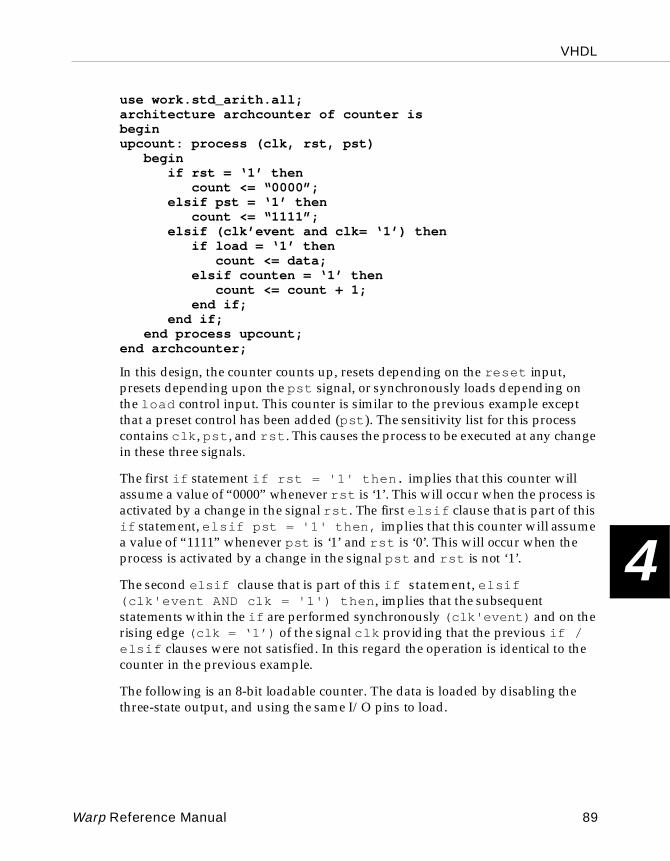
VHDL
4
use work.std_arith.all;architecture archcounter of counter isbeginupcount: process (clk, rst, pst)
beginif rst = ‘1’ then
count <= “0000”;elsif pst = ‘1’ then
count <= “1111”;elsif (clk’event and clk= ‘1’) then
if load = ‘1’ thencount <= data;
elsif counten = ‘1’ thencount <= count + 1;
end if;end if;
end process upcount;end archcounter;
In this design, the counter counts up, resets depending on the reset input, presets depending upon the pst signal, or synchronously loads depending on the load control input. This counter is similar to the previous example except that a preset control has been added (pst ). The sensitivity list for this process contains clk , pst , and rst . This causes the process to be executed at any change in these three signals.
The first if statement if rst = '1' then. implies that this counter will assume a value of “0000” whenever rst is ‘1’. This will occur when the process is activated by a change in the signal rst . The first elsif clause that is part of this if statement, elsif pst = '1' then, implies that this counter will assume a value of “1111” whenever pst is ‘1’ and rst is ‘0’. This will occur when the process is activated by a change in the signal pst and rst is not ‘1’.
The second elsif clause that is part of this if statement, elsif (clk'event AND clk = '1') then , implies that the subsequent statements within the if are performed synchronously (clk'event) and on the rising edge (clk = ‘1’) of the signal clk providing that the previous if / elsif clauses were not satisfied. In this regard the operation is identical to the counter in the previous example.
The following is an 8-bit loadable counter. The data is loaded by disabling the three-state output, and using the same I/O pins to load.
Warp Reference Manual 89
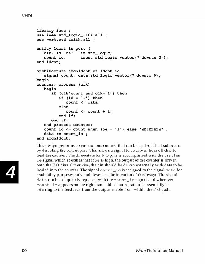
VHDL
4
library ieee ;use ieee.std_logic_1164.all ;use work.std_arith.all ;
entity ldcnt is port (clk, ld, oe: in std_logic;count_io: inout std_logic_vector(7 downto 0));
end ldcnt;
architecture archldcnt of ldcnt issignal count, data:std_logic_vector(7 downto 0);
begincounter: process (clk)
beginif (clk’event and clk=’1’) then
if (ld = ‘1’) thencount <= data;
elsecount <= count + 1;
end if;end if;
end process counter;count_io <= count when (oe = ’1’) else "ZZZZZZZZ" ;data <= count_io ;
end archldcnt;
This design performs a synchronous counter that can be loaded. The load occurs by disabling the output pins. This allows a signal to be driven from off chip to load the counter. The three-state for I/O pins is accomplished with the use of an oe signal which specifies that if oe is high, the output of the counter is driven onto the I/O pins. Otherwise, the pin should be driven externally with data to be loaded into the counter. The signal count_io is assigned to the signal data for readability purposes only and describes the intention of the design. The signal data can be completely replaced with the count_io signal, and wherever count_io appears on the right hand side of an equation, it essentially is referring to the feedback from the output enable from within the I/O pad.
90 Warp Reference Manual
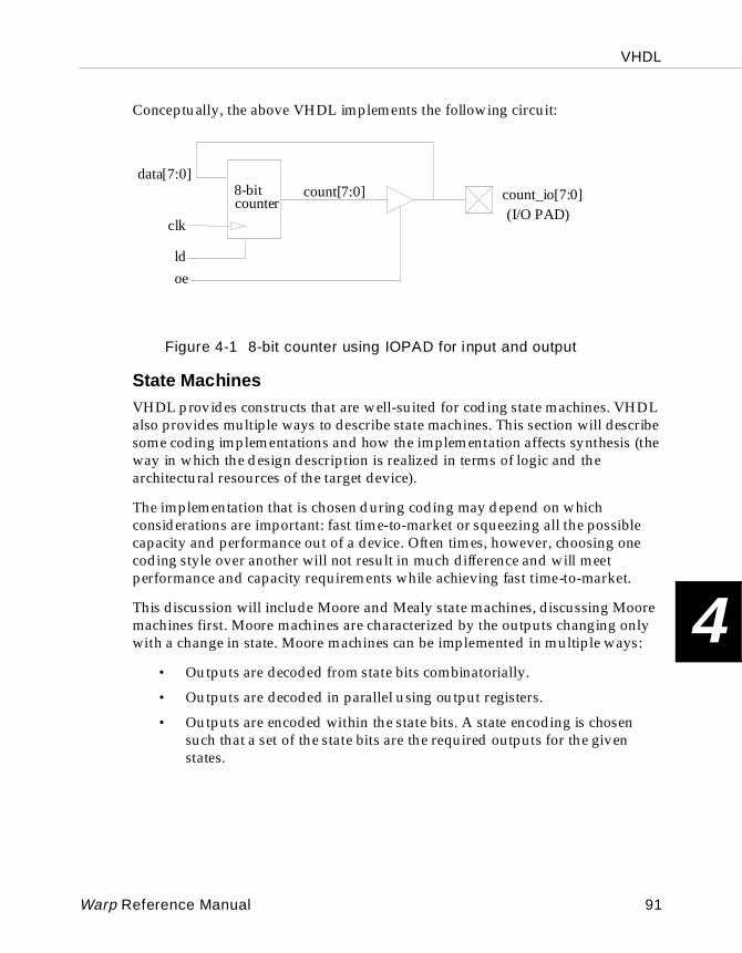
VHDL
4
Conceptually, the above VHDL implements the following circuit:
Figure 4-1 8-bit counter using IOPAD for input and output
State MachinesVHDL provides constructs that are well-suited for coding state machines. VHDL also provides multiple ways to describe state machines. This section will describe some coding implementations and how the implementation affects synthesis (the way in which the design description is realized in terms of logic and the architectural resources of the target device).
The implementation that is chosen during coding may depend on which considerations are important: fast time-to-market or squeezing all the possible capacity and performance out of a device. Often times, however, choosing one coding style over another will not result in much difference and will meet performance and capacity requirements while achieving fast time-to-market.
This discussion will include Moore and Mealy state machines, discussing Moore machines first. Moore machines are characterized by the outputs changing only with a change in state. Moore machines can be implemented in multiple ways:
• Outputs are decoded from state bits combinatorially.
• Outputs are decoded in parallel using output registers.
• Outputs are encoded within the state bits. A state encoding is chosen such that a set of the state bits are the required outputs for the given states.
oe
count_io[7:0]
data[7:0]count[7:0]
clk
ld
8-bitcounter
(I/O PAD)
Warp Reference Manual 91
VHDL
4
• One-hot encoded. One register is asserted “hot” per state. This encoding scheme often reduces the amount of logic required to transition to the next state at the expense of more registers. This implementation is particularly well suited to FPGA, register-intensive devices.
• Truth Tables. A truth table maps the current state and inputs to a next state and outputs.
In the following examples, the same state machine is implemented five different ways as a Moore machine in order to illustrate discussing the design and synthesis issues. Figure 4-2 shows the state diagram.
92 Warp Reference Manual
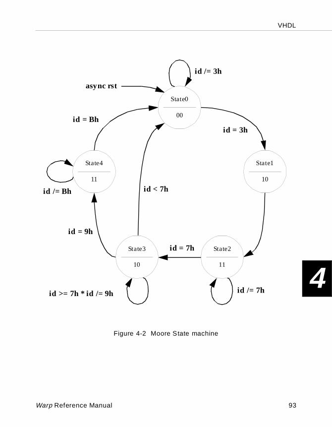
VHDL
4
Figure 4-2 Moore State machine
State1
10
State0
00
State3
10
State2
11
State4
11
async rst
id /= 3h
id = 3h
id /= 7h
id = 7h
id >= 7h * id /= 9h
id < 7h
id = 9h
id /= Bh
id = Bh
Warp Reference Manual 93
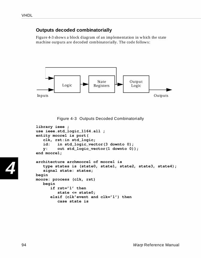
VHDL
4
Outputs decoded combi natoriallyFigure 4-3 shows a block diagram of an implementation in which the state machine outputs are decoded combinatorially. The code follows:
Figure 4-3 Outputs Decoded Combinatorially
library ieee ;use ieee.std_logic_1164.all ;entity moore1 is port(
clk, rst:in std_logic;id: in std_logic_vector(3 downto 0);y: out std_logic_vector(1 downto 0));
end moore1;
architecture archmoore1 of moore1 istype states is (state0, state1, state2, state3, state4);signal state: states;
beginmoore: process (clk, rst)
beginif rst=’1’ then
state <= state0;elsif (clk’event and clk=’1’) then
case state is
Inputs Outputs
LogicState
Output
Registers Logic
94 Warp Reference Manual
VHDL
4
when state0 =>if id = x”3” then
state <= state1;else
state <= state0;end if;
when state1 =>state <= state2;
when state2 =>if id = x”7” then
state <= state3;else
state <= state2;end if;
when state3 =>if id < x”7” then
state <= state0;elsif id = x”9” then
state <= state4;else
state <= state3;end if;
when state4 =>if id = x”b” then
state <= state0;else
state <= state4;end if;
end case;end if;
end process;
--assign state outputs;y <= “00” when (state=state0) else “10” when (state=state1 or state=state3) else “11”; end archmoore1;
The architecture description begins with a type declaration, called an enumerated type, for states which defines five states labeled state0 through state4 . A signal, state , is then declared to be of type states. This means that the signal called state can take on values of state0 , state1 , state2 , state3 , or state4 .
Warp Reference Manual 95
VHDL
4
The state machine itself is described within a process. The first condition of this process defines the asynchronous reset condition which puts the state machine in state0 whenever the signal rst is a ‘1’. If the rst signal is not a ‘1’ and the clock transitions to a ‘1’-- elsif (clk'event and clk='1') --then the state machine algorithm is sequenced. The design can be rising edge triggered, as it is in this example, or falling edge triggered by specifying clk=‘0’ .
On a rising edge of the clock, the case statement (which contains all of the state transitions for the Moore machine) is evaluated. The when statements define the state transitions which are based on the input ID. For example, in the case when the current state is state0 , the state machine will transition to state1 if id=x”3”, otherwise the state machine will remain in state0 . In a concurrent statement outside of the process, the output vector y is assigned a value based on the current state.
This implementation demonstrates the algorithmic and intuitive fashion which VHDL permits in the description of state machines. Simple case... when statements enable the user to define the states and their transitions. There are two design and synthesis issues with this implementation which some designers may wish to consider: clock-to-out times for the combinatorially decoded state machine outputs and an alternative state encoding to use minimal product terms.
The clock-to-out times for the state machine outputs are determined by the time it takes for the state bits to be combinatorially decoded. For designs that require minimal clock-to-out times, an implementation similar to the one above can be used with a design modification: a second process could register the outputs after combinatorial decode. This would introduce a one clock-cycle latency, however. If this latency is not acceptable, then the user will need to choose from the second implementation (outputs decoded in parallel registers) or the third implementation (outputs encoded within state bits).
For designs in which the number product terms must be minimized, the user can implement a design similar to the on described above, with one exception: rather than using the enumerated encoding, the user will want to implement his own encoding scheme. The third implementation shows how to do this.
Outputs D ecoded in Parallel Output RegistersFigure 4-4 shows a block diagram of an implementation in which the state machine outputs are determined at the same time the next state is, by using output registers. The code follows:
96 Warp Reference Manual
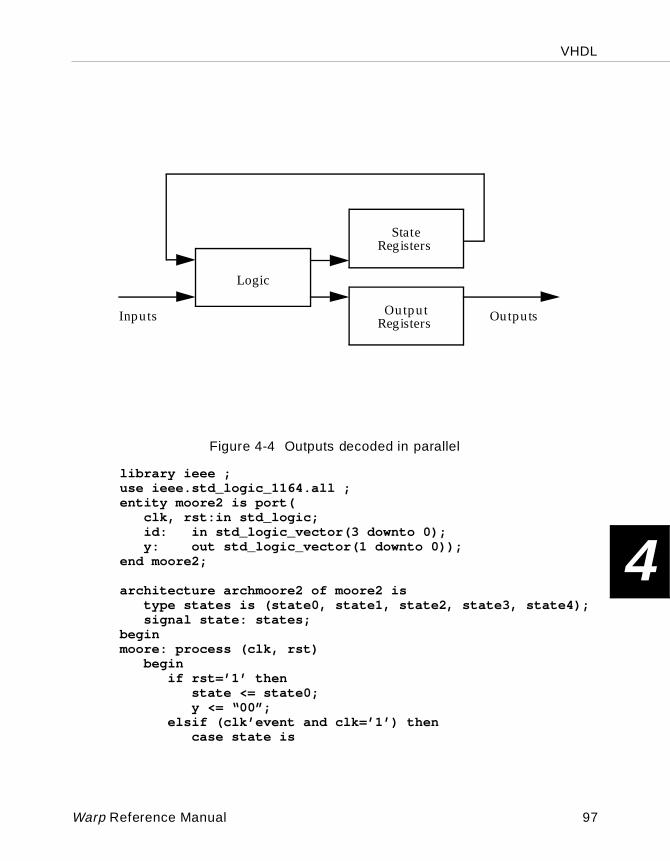
VHDL
4
Figure 4-4 Outputs decoded in parallel
library ieee ;use ieee.std_logic_1164.all ;entity moore2 is port(
clk, rst:in std_logic;id: in std_logic_vector(3 downto 0);y: out std_logic_vector(1 downto 0));
end moore2;
architecture archmoore2 of moore2 istype states is (state0, state1, state2, state3, state4);signal state: states;
beginmoore: process (clk, rst)
beginif rst=’1’ then
state <= state0;y <= “00”;
elsif (clk’event and clk=’1’) thencase state is
Logic
State
Inputs OutputsOutput
Registers
Registers
Warp Reference Manual 97
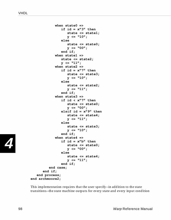
VHDL
4
when state0 =>if id = x”3” then
state <= state1;y <= “10”;
elsestate <= state0;y <= “00”;
end if;when state1 =>
state <= state2;y <= “11”;
when state2 =>if id = x”7” then
state <= state3;y <= “10”;
elsestate <= state2;y <= “11”;
end if;when state3 =>
if id < x”7” then state <= state0;y <= “00”;
elsif id = x”9” thenstate <= state4;y <= “11”;
elsestate <= state3;y <= “10”;
end if;when state4 =>
if id = x”b” thenstate <= state0;y <= “00”;
elsestate <= state4;y <= “11”;
end if;end case;
end if;end process;
end archmoore2;
This implementation requires that the user specify--in addition to the state transitions--the state machine outputs for every state and every input condition
98 Warp Reference Manual
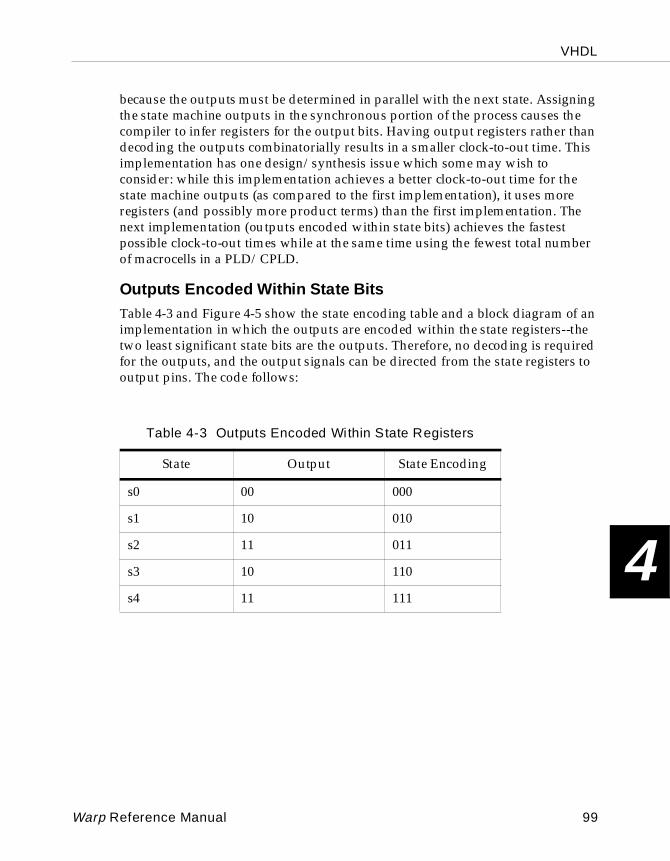
VHDL
4
because the outputs must be determined in parallel with the next state. Assigning the state machine outputs in the synchronous portion of the process causes the compiler to infer registers for the output bits. Having output registers rather than decoding the outputs combinatorially results in a smaller clock-to-out time. This implementation has one design/synthesis issue which some may wish to consider: while this implementation achieves a better clock-to-out time for the state machine outputs (as compared to the first implementation), it uses more registers (and possibly more product terms) than the first implementation. The next implementation (outputs encoded within state bits) achieves the fastest possible clock-to-out times while at the same time using the fewest total number of macrocells in a PLD/CPLD.
Outputs Encoded Within State BitsTable 4-3 and Figure 4-5 show the state encoding table and a block diagram of an implementation in which the outputs are encoded within the state registers--the two least significant state bits are the outputs. Therefore, no decoding is required for the outputs, and the output signals can be directed from the state registers to output pins. The code follows:
Table 4-3 Outputs Encoded Within State Registers
State Output State Encoding
s0 00 000
s1 10 010
s2 11 011
s3 10 110
s4 11 111
Warp Reference Manual 99
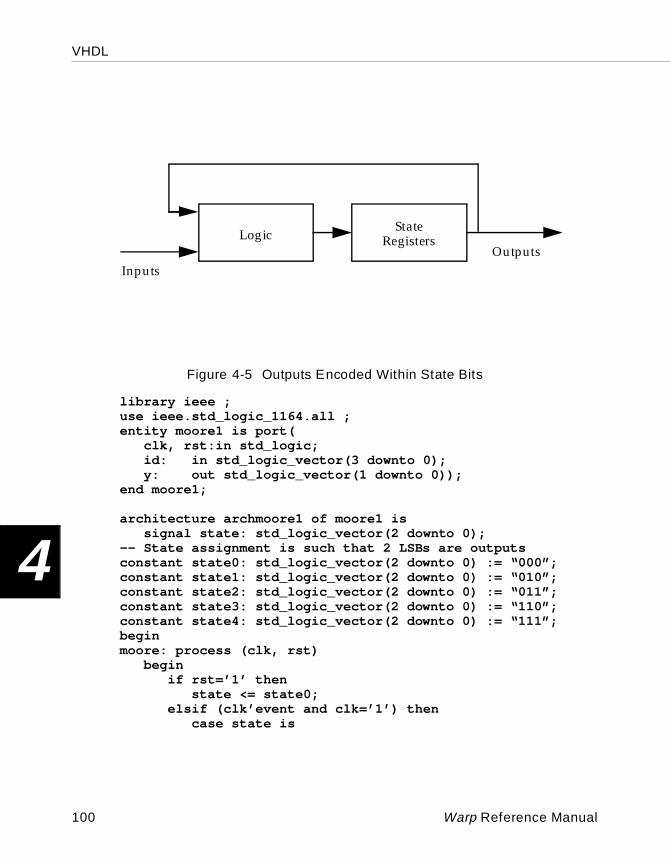
VHDL
4
Figure 4-5 Outputs Encoded Within State Bits
library ieee ;use ieee.std_logic_1164.all ;entity moore1 is port(
clk, rst:in std_logic;id: in std_logic_vector(3 downto 0);y: out std_logic_vector(1 downto 0));
end moore1;
architecture archmoore1 of moore1 issignal state: std_logic_vector(2 downto 0);
-- State assignment is such that 2 LSBs are outputsconstant state0: std_logic_vector(2 downto 0) := “000”;constant state1: std_logic_vector(2 downto 0) := “010”;constant state2: std_logic_vector(2 downto 0) := “011”;constant state3: std_logic_vector(2 downto 0) := “110”;constant state4: std_logic_vector(2 downto 0) := “111”;beginmoore: process (clk, rst)
beginif rst=’1’ then
state <= state0;elsif (clk’event and clk=’1’) then
case state is
Logic
InputsOutputs
StateRegisters
100 Warp Reference Manual
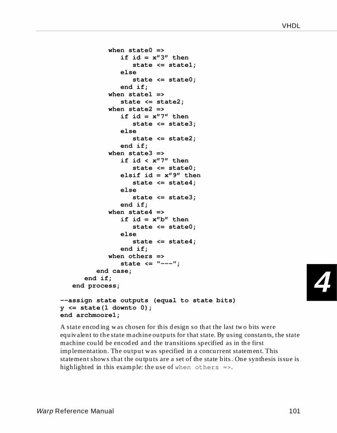
VHDL
4
when state0 =>if id = x”3” then
state <= state1;else
state <= state0;end if;
when state1 =>state <= state2;
when state2 =>if id = x”7” then
state <= state3;else
state <= state2;end if;
when state3 =>if id < x”7” then
state <= state0;elsif id = x”9” then
state <= state4;else
state <= state3;end if;
when state4 =>if id = x”b” then
state <= state0;else
state <= state4;end if;
when others =>state <= "---";
end case;end if;
end process;
--assign state outputs (equal to state bits)y <= state(1 downto 0);end archmoore1;
A state encoding was chosen for this design so that the last two bits were equivalent to the state machine outputs for that state. By using constants, the state machine could be encoded and the transitions specified as in the first implementation. The output was specified in a concurrent statement. This statement shows that the outputs are a set of the state bits . One synthesis issue is highlighted in this example: the use of when others => .
Warp Reference Manual 101
VHDL
4
When others is used when not all possible combinations of a bit sequence have been specified in other when clauses. In this, the states “001,” “100,” and “101” are not defined, and no transitions are specified for these states. If when others is not used, then next state logic must be synthesized, assuming that if the machine gets in one of these states, then it will remain in that state. This has the effect of utilizing more logic (product terms in the case of a PLD/CPLD). Supplying a simple when others is a quick solution to this design issue.
One-Hot-One State MachinesIn a one-hot-one state machine, there is one register for each state. Only one register is asserted, or “hot,” at a time, corresponding to one distinct state.Figure 4-6 shows three states of a state machine and how one of the state bits would be implemented. This implementation demonstrates that the next state logic is quite simple. The trade-off is the number of registers that is required. For example, a state machine with eight states could be coded in three registers. The equivalent one-hot coded state machine would require eight registers. The trade-off is that the next-state logic is simpler, often times enabling faster performance in FPGA architectures which are register intensive, whereas sequential encoding would require multiple levels of logic to decode a complex state transition. The following is the code:
102 Warp Reference Manual
VHDL
4
Figure 4-6 Implementation of one-hot state machine bitslibrary ieee ;use ieee.std_logic_1164.all ;entity one_hot is port(
clk, rst:in std_logic;id: in std_logic_vector(3 downto 0);y: out std_logic_vector(1 downto 0));
end one_hot;
s1
s2
s5
ab = “10” ab = “01”
D
s1
D
s2
D Q
s5
a
b
Q Q
Warp Reference Manual 103
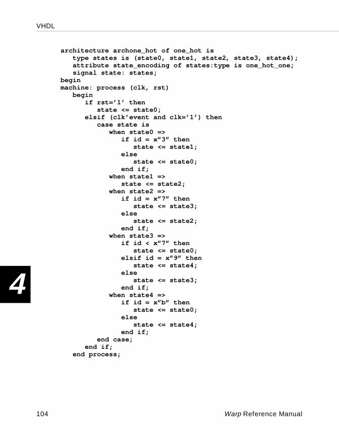
VHDL
4
architecture archone_hot of one_hot istype states is (state0, state1, state2, state3, state4);attribute state_encoding of states:type is one_hot_one;signal state: states;
beginmachine: process (clk, rst)
beginif rst=’1’ then
state <= state0;elsif (clk’event and clk=’1’) then
case state iswhen state0 =>
if id = x”3” thenstate <= state1;
elsestate <= state0;
end if;when state1 =>
state <= state2;when state2 =>
if id = x”7” thenstate <= state3;
elsestate <= state2;
end if;when state3 =>
if id < x”7” then state <= state0;
elsif id = x”9” thenstate <= state4;
elsestate <= state3;
end if;when state4 =>
if id = x”b” thenstate <= state0;
elsestate <= state4;
end if;end case;
end if;end process;
104 Warp Reference Manual
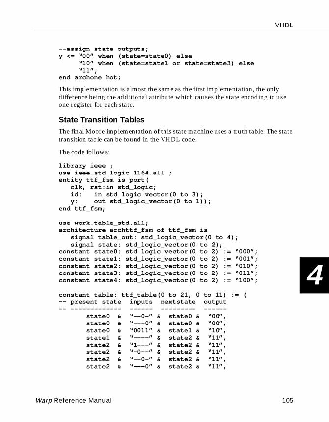
VHDL
4
--assign state outputs;y <= “00” when (state=state0) else “10” when (state=state1 or state=state3) else “11”; end archone_hot;
This implementation is almost the same as the first implementation, the only difference being the additional attribute which causes the state encoding to use one register for each state.
State Transition TablesThe final Moore implementation of this state machine uses a truth table. The state transition table can be found in the VHDL code.
The code follows:
library ieee ;use ieee.std_logic_1164.all ;entity ttf_fsm is port(
clk, rst:in std_logic;id: in std_logic_vector(0 to 3);y: out std_logic_vector(0 to 1));
end ttf_fsm;
use work.table_std.all;architecture archttf_fsm of ttf_fsm is
signal table_out: std_logic_vector(0 to 4);signal state: std_logic_vector(0 to 2);
constant state0: std_logic_vector(0 to 2) := “000”;constant state1: std_logic_vector(0 to 2) := “001”;constant state2: std_logic_vector(0 to 2) := “010”;constant state3: std_logic_vector(0 to 2) := “011”;constant state4: std_logic_vector(0 to 2) := “100”;
constant table: ttf_table(0 to 21, 0 to 11) := (-- present state inputs nextstate output-- ------------- ------ --------- ------
state0 & “--0-” & state0 & “00”, state0 & “---0” & state0 & “00”, state0 & “0011” & state1 & “10”, state1 & “----” & state2 & “11”, state2 & “1---” & state2 & “11”, state2 & “-0--” & state2 & “11”, state2 & “--0-” & state2 & “11”, state2 & “---0” & state2 & “11”,
Warp Reference Manual 105
VHDL
4
state2 & “0111” & state3 & “10”, state3 & “0111” & state3 & “10”, state3 & “1000” & state3 & “10”, state3 & “11--” & state3 & “10”, state3 & “101-” & state3 & “10”, state3 & “0110” & state0 & “00”, state3 & “010-” & state0 & “00”, state3 & “00--” & state0 & “00”, state3 & “1001” & state4 & “11”, state4 & “0---” & state3 & “10”, state4 & “100-” & state3 & “10”, state4 & “11--” & state4 & “11”, state4 & “1010” & state4 & “11”, state4 & “1011” & state0 & “00”);
beginmachine: process (clk, rst)
beginif rst =’1’ then
table_out <= “00000”;elsif (clk’event and clk=’1’) then
table_out <= ttf(table,state & id);end if;
end process;state <= table_out(0 to 2);
--assign state outputs;y <= table_out(3 to 4);end archttf_fsm;
This implementation uses the ttf function (truth table function) which enables you to create a state transition table that lists the inputs, the current state, the next state, and the associated outputs. Within the architecture statement, a few signals and constants are defined. The signal called table_out is the vector which will contain the output from the state table. The signal called state is the state variable itself. Six constants are defined which contain the state encoding - state0 , state1 , state2 , state3 , and state4 , and table - which contains the entire state transition table. The table itself is created as an array with a certain number of rows designating the number of transitions, and a certain number of columns designating the number of input bits, present state bits, next state bits, and output bits.
106 Warp Reference Manual
VHDL
4
Since the ttf function is not a standard part of VHDL, it has been defined in a separate package and provided as part of the Warp software. This package is located in the work library and is called table_std. To allow a design to have access to the ttf function, the user must add the statement use work.table_std.all; to his VHDL description immediately above his architecture definition.
Most of the work lies in creating the truth table, and the process becomes fairly simple. The first portion of the process defines the asynchronous reset. Next, the synchronous portion of the process (elsif clk’event and clk=’1’) is defined in which the signal table_out is assigned the returned value of the ttf function. The function is called with two parameters: the name of the state transition table, and the set of bits which contain the inputs and the present state information. The value that is returned is the remainder of the columns in the table (total number of columns - second parameter). These bits will contain the next state value and the associated outputs. The only task remaining is to split the state information from the output information and assign them to the appropriate signal names. Both of these assignments must occur outside of the process, otherwise another level of registers will be created, as this portion of the process defines synchronous assignments.
This design, as implemented, uses more registers than required but could easily be modified. Registers must be created for both the state registers and the output registers, as in the second implementation (outputs decoded in parallel). The truth table can be modified so that the outputs are encoded in the state bits, as in the third example. Thus, rather than specifying both next state values and outputs, the user can simply specify next state values in which the outputs are encoded.
Mealy state machines are characterized by the outputs which can change depending on the current inputs. This example implements the state machine shown in Figure 4-7, which has Moore outputs and one Mealy output. Figure 4-8 shows a block diagram of a Mealy machine.
The code follows:
library ieee ;use ieee.std_logic_1164.all ;entity mealy1 is port(
clk, rst:in std_logic;id: in std_logic_vector(3 downto 0);w: out std_logic;y: out std_logic_vector(1 downto 0));
end mealy1;
Warp Reference Manual 107
VHDL
4
architecture archmealy1 of mealy1 istype states is (state0, state1, state2, state3, state4);signal state: states;
beginmoore: process (clk, rst)
beginif rst=’1’ then
state <= state0;elsif (clk’event and clk=’1’) then
case state iswhen state0 =>
if id = x”3” thenstate <= state1;
elsestate <= state0;
end if;when state1 =>
state <= state2;when state2 =>
if id = x”7” thenstate <= state3;
elsestate <= state2;
end if;when state3 =>
if id < x”7” then state <= state0;
elsif id = x”9” thenstate <= state4;
elsestate <= state3;
end if;when state4 =>
if id = x”b” thenstate <= state0;
elsestate <= state4;
end if;end case;
end if;end process;
--assign moore state outputs;y <= “00” when (state=state0) else “10” when (state=state1 or state=state3) else
108 Warp Reference Manual
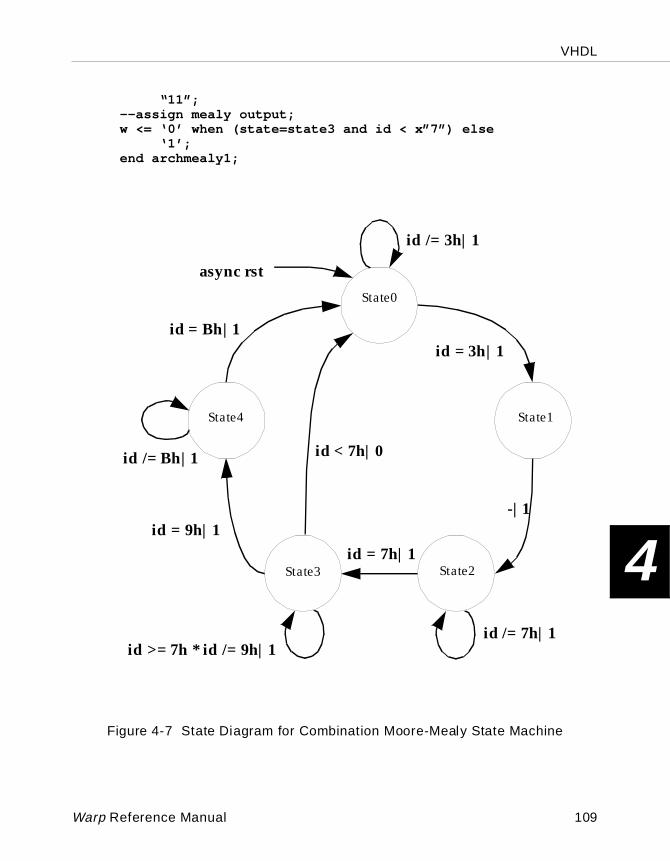
VHDL
4
“11”; --assign mealy output;w <= ‘0’ when (state=state3 and id < x”7”) else ‘1’;end archmealy1;
Figure 4-7 State Diagram for Combination Moore-Mealy State Machine
State0
async rst
id /= 3h|1
id = 3h|1
-|1
id /= 7h|1
id = 7h|1
id >= 7h * id /= 9h|1
id < 7h|0
id = 9h|1
id /= Bh|1
id = Bh|1
State1
State3
State4
State2
Warp Reference Manual 109
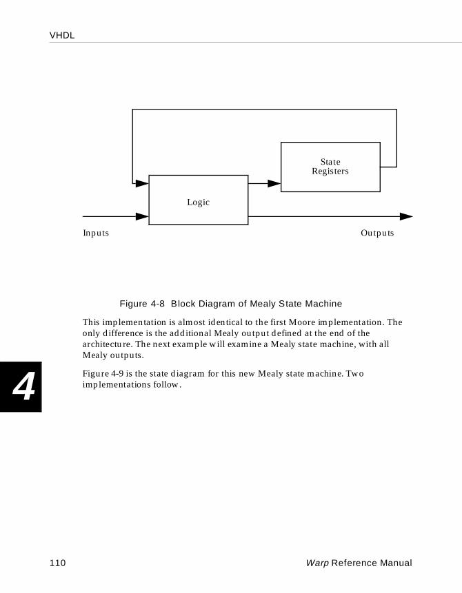
VHDL
4
Figure 4-8 Block Diagram of Mealy State Machine
This implementation is almost identical to the first Moore implementation. The only difference is the additional Mealy output defined at the end of the architecture. The next example will examine a Mealy state machine, with all Mealy outputs.
Figure 4-9 is the state diagram for this new Mealy state machine. Two implementations follow.
Logic
State
Inputs Outputs
Registers
110 Warp Reference Manual
VHDL
4
Figure 4-9 State Diagram for Second Mealy Machine
async rst|00
id /= 3h|00
id = 3h|10
-|11
id /= 7h|11
id = 7h|10
id >= 7h * id /= 9h|10
id < 7h|00
id = 9h|11
id /= Bh|11
id = Bh|00State0
State1
State2State3
State4
Warp Reference Manual 111
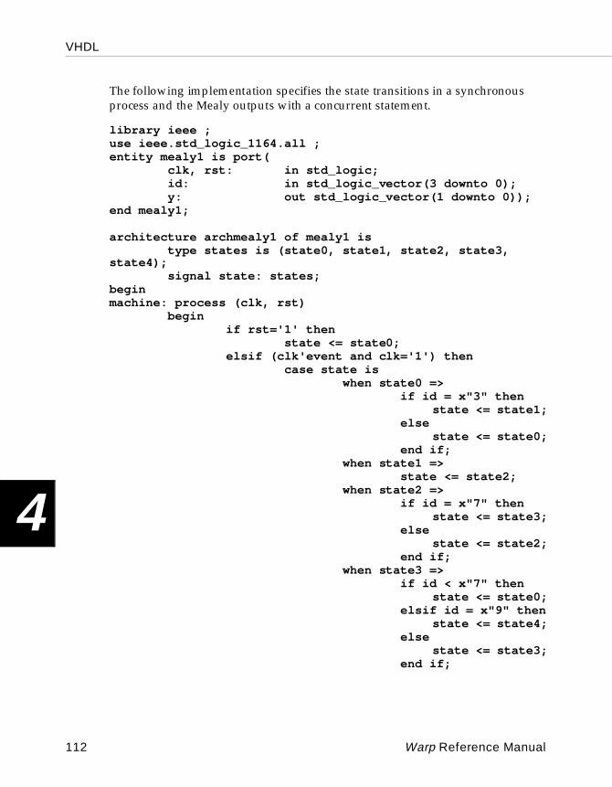
VHDL
4
The following implementation specifies the state transitions in a synchronous process and the Mealy outputs with a concurrent statement.
library ieee ;use ieee.std_logic_1164.all ;entity mealy1 is port( clk, rst: in std_logic; id: in std_logic_vector(3 downto 0); y: out std_logic_vector(1 downto 0));end mealy1;
architecture archmealy1 of mealy1 is type states is (state0, state1, state2, state3, state4); signal state: states;beginmachine: process (clk, rst) begin if rst='1' then state <= state0; elsif (clk'event and clk='1') then case state is when state0 => if id = x"3" then state <= state1; else state <= state0; end if; when state1 => state <= state2; when state2 => if id = x"7" then state <= state3; else state <= state2; end if; when state3 => if id < x"7" then state <= state0; elsif id = x"9" then state <= state4; else state <= state3; end if;
112 Warp Reference Manual
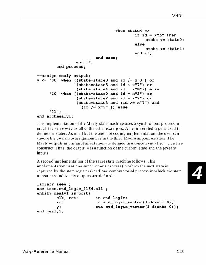
VHDL
4
when state4 => if id = x"b" then state <= state0; else state <= state4; end if; end case; end if; end process;
--assign mealy output;y <= "00" when ((state=state0 and id /= x"3") or (state=state3 and id < x"7") or (state=state4 and id = x"B")) else "10" when ((state=state0 and id = x"3") or (state=state2 and id = x"7") or (state=state3 and (id >= x"7") and
(id /= x"9"))) else "11";end archmealy1;
This implementation of the Mealy state machine uses a synchronous process in much the same way as all of the other examples. An enumerated type is used to define the states. As in all but the one_hot coding implementation, the user can choose his own state assignment, as in the third Moore implementation. The Mealy outputs in this implementation are defined in a concurrent when...else construct. Thus, the output y is a function of the current state and the present inputs.
A second implementation of the same state machine follows. This implementation uses one synchronous process (in which the next state is captured by the state registers) and one combinatorial process in which the state transitions and Mealy outputs are defined.
library ieee ;use ieee.std_logic_1164.all ;entity mealy1 is port( clk, rst: in std_logic; id: in std_logic_vector(3 downto 0); y: out std_logic_vector(1 downto 0));end mealy1;
Warp Reference Manual 113
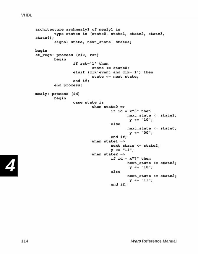
VHDL
4
architecture archmealy1 of mealy1 is type states is (state0, state1, state2, state3, state4); signal state, next_state: states;
beginst_regs: process (clk, rst) begin if rst='1' then state <= state0; elsif (clk'event and clk='1') then state <= next_state; end if; end process;
mealy: process (id) begin case state is when state0 => if id = x"3" then next_state <= state1; y <= "10"; else next_state <= state0; y <= "00"; end if; when state1 => next_state <= state2; y <= "11"; when state2 => if id = x"7" then next_state <= state3; y <= "10"; else next_state <= state2; y <= "11"; end if;
114 Warp Reference Manual
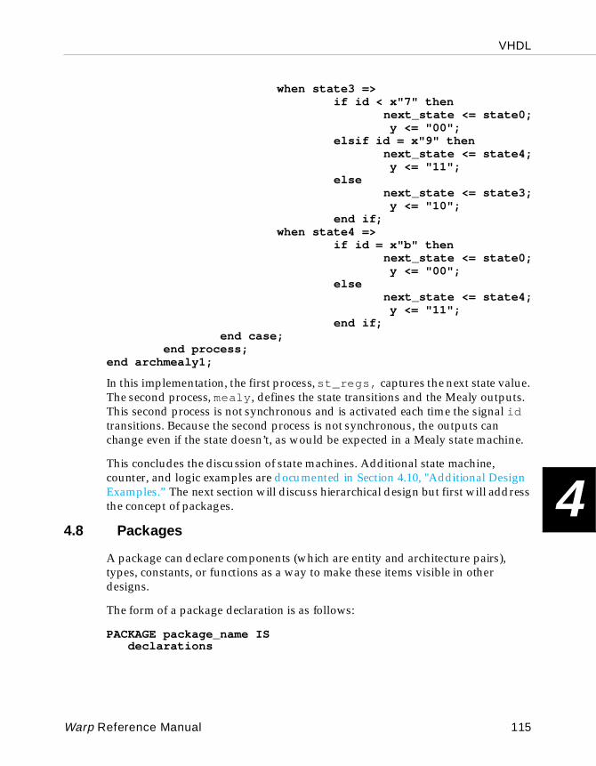
VHDL
4
when state3 => if id < x"7" then next_state <= state0; y <= "00"; elsif id = x"9" then next_state <= state4; y <= "11"; else next_state <= state3; y <= "10"; end if; when state4 => if id = x"b" then next_state <= state0; y <= "00"; else next_state <= state4; y <= "11"; end if; end case; end process;end archmealy1;
In this implementation, the first process, st_regs, captures the next state value. The second process, mealy , defines the state transitions and the Mealy outputs. This second process is not synchronous and is activated each time the signal id transitions. Because the second process is not synchronous, the outputs can change even if the state doesn’t, as would be expected in a Mealy state machine.
This concludes the discussion of state machines. Additional state machine, counter, and logic examples are documented in Section 4.10, "Additional Design Examples.” The next section will discuss hierarchical design but first will address the concept of packages.
4.8 Packages
A package can declare components (which are entity and architecture pairs), types, constants, or functions as a way to make these items visible in other designs.
The form of a package declaration is as follows:
PACKAGE package_name ISdeclarations
Warp Reference Manual 115
VHDL
4
END package_name;
Package declarations are typically used in Warp to declare types, constants, and components to be used by other VHDL descriptions. Most commonly, the user places a package declaration (containing component declarations) at the beginning of a design file (before the entity and architecture pair definitions) in order to use the components in a subsequent or hierarchical design.
Packages which contain only components do not need a package body. If the user wishes to write VHDL functions to be used in multiple designs, however, then these functions must be declared in the package declaration as well as defined in a package body:
PACKAGE BODY package_name ISdeclarations
END package_name;
A package body always has the same name as its corresponding package declaration and is preceded by the reserved words PACKAGE BODY. A package body contains the function bodies whose declarations occur in the package declaration, as well as declarations that are not intended to be used by other VHDL descriptions.
The following example shows a package that declares a component named demo, whose design (entity and architecture pair) follows the package declaration:
package demo_package iscomponent demoport(x:out std_logic; clk, y, z:in std_logic);end component;
end package;
entity demo isport(x:out std_logic; clk, y, z:in std_logic);
end demo;
architecture fsm of demo is...end fsm;
If this description were in the file demofile.vhd, the user could analyze the package and add it to the current work library with the following commands:
warp -a demofile
116 Warp Reference Manual
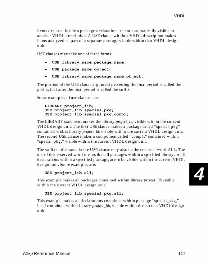
VHDL
4
Items declared inside a package declaration are not automatically visible to another VHDL description. A USE clause within a VHDL description makes items analyzed as part of a separate package visible within that VHDL design unit.
USE clauses may take one of three forms:
• USE library_name.package_name;
• USE package_name.object;
• USE library_name.package_name.object;
The portion of the USE clause argument preceding the final period is called the prefix; that after the final period is called the suffix.
Some examples of use clauses are:
LIBRARY project_lib;USE project_lib.special_pkg;USE project_lib.special_pkg.comp1;
The LIBRARY statement makes the library project_lib visible within the current VHDL design unit. The first USE clause makes a package called “special_pkg” contained within library project_lib visible within the current VHDL design unit. The second USE clause makes a component called “comp1,” contained within “special_pkg,” visible within the current VHDL design unit.
The suffix of the name in the USE clause may also be the reserved word ALL. The use of this reserved word means that all packages within a specified library, or all declarations within a specified package, are to be visible within the current VHDL design unit. Some examples are:
USE project_lib.all;
This example makes all packages contained within library project_lib visible within the current VHDL design unit.
USE project_lib.special_pkg.all;
This example makes all declarations contained within package “special_pkg,” itself contained within library project_lib, visible within the current VHDL design unit.
Warp Reference Manual 117
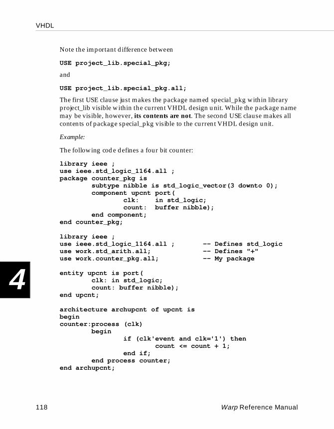
VHDL
4
Note the important difference between
USE project_lib.special_pkg;
and
USE project_lib.special_pkg.all;
The first USE clause just makes the package named special_pkg within library project_lib visible within the current VHDL design unit. While the package name may be visible, however, its contents are not. The second USE clause makes all contents of package special_pkg visible to the current VHDL design unit.
Example:
The following code defines a four bit counter:
library ieee ;use ieee.std_logic_1164.all ;package counter_pkg is subtype nibble is std_logic_vector(3 downto 0); component upcnt port( clk: in std_logic; count: buffer nibble); end component;end counter_pkg;
library ieee ;use ieee.std_logic_1164.all ; -- Defines std_logicuse work.std_arith.all; -- Defines "+"use work.counter_pkg.all; -- My package
entity upcnt is port( clk: in std_logic; count: buffer nibble);end upcnt;
architecture archupcnt of upcnt isbegincounter:process (clk) begin if (clk'event and clk='1') then count <= count + 1; end if; end process counter;end archupcnt;
118 Warp Reference Manual
VHDL
4
The package declaration allows the user to use the upcnt component and the type nibble in other designs. For example, suppose the user needed five of these counters but did not want to write five separate process. He might prefer to simply instantiate the upcnt counter defined above in a new design, creating a level of hierarchy. The code follows:
use work.counter_pkg.all;
entity counters is port( clk1, clk2: in std_logic; acnt, bcnt, ccnt: buffer nibble;
deqe: out std_logic);end counters;
architecture archcounters of counters issignal dcnt, ecnt: nibble;begincounter1: upcnt port map (clk1, acnt);counter2: upcnt port map (clk2, bcnt);counter3: upcnt port map (clk => clk1, count => ccnt);counter4: upcnt port map (clk2, dcnt);counter5: upcnt port map (count => ecnt, clk => clk2);deqe <= ‘1’ when (dcnt = ecnt) else ‘0’;end archcounters;
The initial USE clause makes the counter_pkg available to this design. Counter_pkg is required for the nibble definition used in the entity and the upcnt component used in the architecture. Five counters are then instantiated by using the port map to associate the component I/O with the appropriate entity ports or architecture signals. Three of the instantiations use positional association in which the position of the signals in the port map determines which I/O of the component the signal is associated with. In counter3 and counter5, named association is used to explicitly define the signal to component I/O connections. In named association, the order of the signal assignment is not important.
When using Warp to compile and synthesize the counters design, the design file that contains upcnt must be compiled first, before counters can be compiled and synthesized. This is because the contents of the counter_pkg must first be added to the work library. Therefore, when selecting (in Galaxy) the Warp input files to be compiled and synthesized, select the upcnt design as the first file and the counters design as the second. This will ensure that upcnt is compiled first. Once the upcnt design has been added to the current work library, the design does not need to recompile it when synthesizing the top-level design unless the user makes changes to it or target the design to a different device.
Warp Reference Manual 119
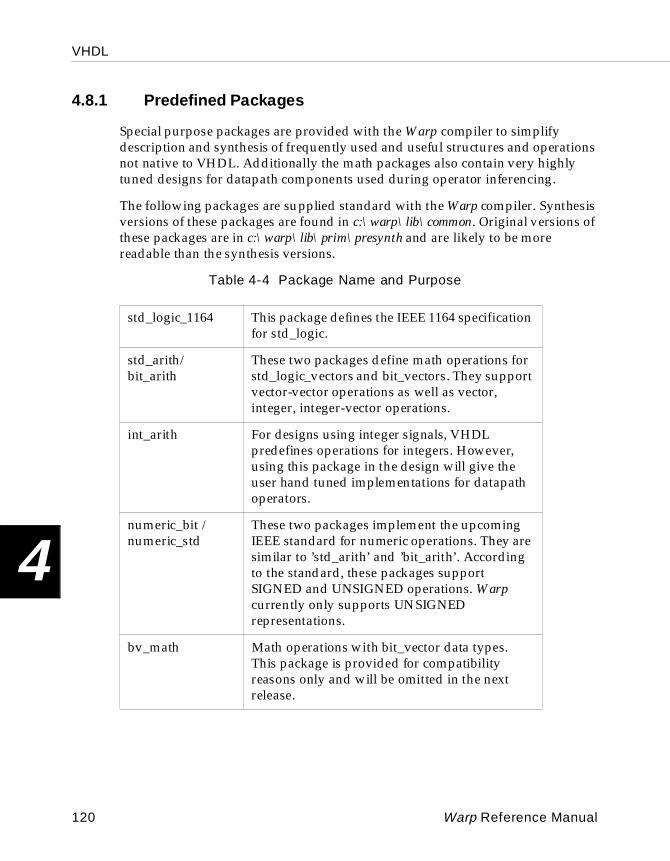
VHDL
4
4.8.1 Predefined Packages
Special purpose packages are provided with the Warp compiler to simplify description and synthesis of frequently used and useful structures and operations not native to VHDL. Additionally the math packages also contain very highly tuned designs for datapath components used during operator inferencing.
The following packages are supplied standard with the Warp compiler. Synthesis versions of these packages are found in c:\warp\lib\common. Original versions of these packages are in c:\warp\lib\prim\presynth and are likely to be more readable than the synthesis versions.
Table 4-4 Package Name and Purpose
std_logic_1164 This package defines the IEEE 1164 specification for std_logic.
std_arith/bit_arith
These two packages define math operations for std_logic_vectors and bit_vectors. They support vector-vector operations as well as vector, integer, integer-vector operations.
int_arith For designs using integer signals, VHDL predefines operations for integers. However, using this package in the design will give the user hand tuned implementations for datapath operators.
numeric_bit / numeric_std
These two packages implement the upcoming IEEE standard for numeric operations. They are similar to ’std_arith’ and ’bit_arith’. According to the standard, these packages support SIGNED and UNSIGNED operations. Warp currently only supports UNSIGNED representations.
bv_math Math operations with bit_vector data types. This package is provided for compatibility reasons only and will be omitted in the next release.
120 Warp Reference Manual
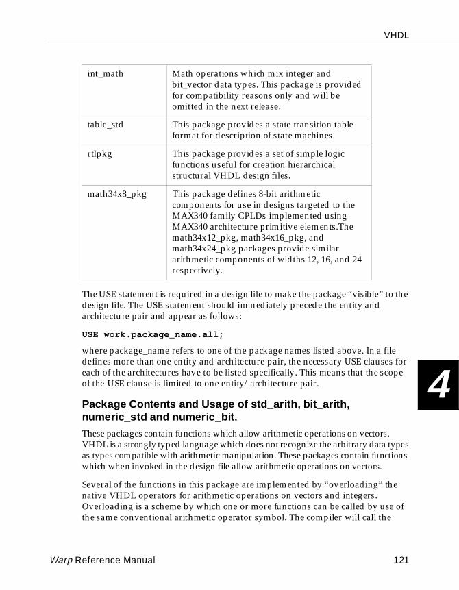
VHDL
4
The USE statement is required in a design file to make the package “visible” to the design file. The USE statement should immediately precede the entity and architecture pair and appear as follows:
USE work.package_name.all;
where package_name refers to one of the package names listed above. In a file defines more than one entity and architecture pair, the necessary USE clauses for each of the architectures have to be listed specifically. This means that the scope of the USE clause is limited to one entity/architecture pair.
Pack age Contents and Usage of std_ari th, bit_ari th, numeric_std and numeric_bit.These packages contain functions which allow arithmetic operations on vectors. VHDL is a strongly typed language which does not recognize the arbitrary data types as types compatible with arithmetic manipulation. These packages contain functions which when invoked in the design file allow arithmetic operations on vectors.
Several of the functions in this package are implemented by “overloading” the native VHDL operators for arithmetic operations on vectors and integers. Overloading is a scheme by which one or more functions can be called by use of the same conventional arithmetic operator symbol. The compiler will call the
int_math Math operations which mix integer and bit_vector data types. This package is provided for compatibility reasons only and will be omitted in the next release.
table_std This package provides a state transition table format for description of state machines.
rtlpkg This package provides a set of simple logic functions useful for creation hierarchical structural VHDL design files.
math34x8_pkg This package defines 8-bit arithmetic components for use in designs targeted to the MAX340 family CPLDs implemented using MAX340 architecture primitive elements.The math34x12_pkg, math34x16_pkg, and math34x24_pkg packages provide similar arithmetic components of widths 12, 16, and 24 respectively.
Warp Reference Manual 121
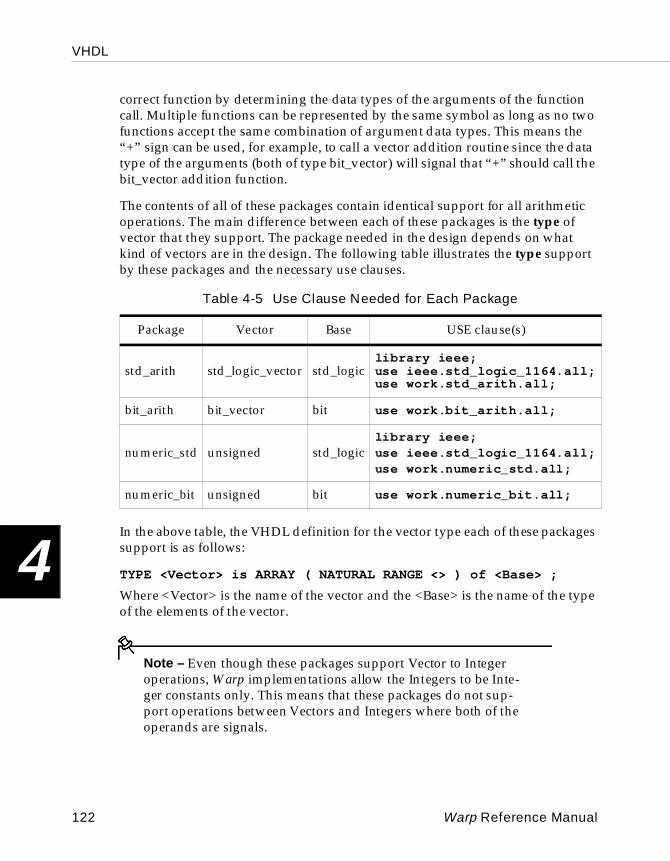
VHDL
4
correct function by determining the data types of the arguments of the function call. Multiple functions can be represented by the same symbol as long as no two functions accept the same combination of argument data types. This means the “+” sign can be used, for example, to call a vector addition routine since the data type of the arguments (both of type bit_vector) will signal that “+” should call the bit_vector addition function.
The contents of all of these packages contain identical support for all arithmetic operations. The main difference between each of these packages is the type of vector that they support. The package needed in the design depends on what kind of vectors are in the design. The following table illustrates the type support by these packages and the necessary use clauses.
In the above table, the VHDL definition for the vector type each of these packages support is as follows:
TYPE <Vector> is ARRAY ( NATURAL RANGE <> ) of <Base> ;
Where <Vector> is the name of the vector and the <Base> is the name of the type of the elements of the vector.
Note – Even though these packages support Vector to Integer operations, Warp implementations allow the Integers to be Inte-ger constants only. This means that these packages do not sup-port operations between Vectors and Integers where both of the operands are signals.
Table 4-5 Use Clause Needed for Each Package
Package Vector Base USE clause(s)
std_arith std_logic_vector std_logiclibrary ieee;use ieee.std_logic_1164.all;use work.std_arith.all;
bit_arith bit_vector bit use work.bit_arith.all;
numeric_std unsigned std_logiclibrary ieee;use ieee.std_logic_1164.all;use work.numeric_std.all;
numeric_bit unsigned bit use work.numeric_bit.all;
122 Warp Reference Manual
VHDL
4
The common convention followed in all of these packages is that the left most bit is the MSB (most significant bit) regardless of the direction of the vector.
The following describes each of the operators supported. The conventions here use:
“a” and “b” for vector signals
“i” for integer constants
.op. for operators.
The operators for which support is provided are:
Addition Oper ators ( +, - )
(a .op. b) Operands are both vectors. The resultant vector is the size of the larger of the two vectors.
(a .op. i) (i .op. a)One operand is a vector and the other an integer constant. The resulant vector is the size of “a”. Integers larger than “a” lose their MSBs.
Multiplication Ope rators ( * )
(a .op. b) Operands are both vectors. The resultant vector is the sum of the sizes of the two vectors.
(a .op. i) (i .op. a)One operand is a vector and the other an integer constant. The resulant vector is twice the size of “a”. Integers larger than “a” lose their MSBs.
Relational Operators ( =, /=, <=, >=, <, > )
(a .op. b) Operands are both vectors. The resultant is of type boolean .
(a .op. i) (i .op. a)One operand is a vector; the other, an integer constant. The result is of type boolean. The current implementations require that the number of bits required to represent “i” be less than or equal to “a”s size.
Warp Reference Manual 123
VHDL
4
Shift Operators (sll, srl, sla, sra, ror, rol)
(a .op. i) For the shift operators, the second operand must be an integer constant.
Boolean Operators (ALL)
(a .op. b) All boolean operators are supported. For binary operators, the length of the two vectors has to be the same.
Miscellaneous Functions
std_match (a, "string")
This function is provided in the numeric_std and std_arith packages only.
This function can be used to compare a vector to a string containing ‘0’, ‘1’ and ’-’. Normally in VHDL, if a is compared to "00-", where the intention is not to compare the LSB, the result will always be false unless a(0) is really set to the value ’-’. In synthesis, this will always evaluate to false. To avoid this problem, the std_match function is provided. The size of the string has to match the size of the vector.
Usage:if (std_match(a, "10-11")) thenx <= ’1’ ;
resize (a, size)
to_unsigned (i,s)
This function is provided in the numeric_std and the numeric_bit packages only.
The argument is an integer that is to be converted, and the size of the resultant vector and the result is an unsigned vector of size “s”.
to_std_logic_vector(i,s)
This function is provided in the std_arith package only.
The argument is an integer that is to be converted, and the size of the resultant vector and the result is an std_logic vector of size “s”.
to_bit_vector (i,s)
124 Warp Reference Manual
VHDL
4
This function is provided in the bit_arith package only.
The argument is an integer that is to be converted, and the size of the resultant vector and the result is an bit_vector of size “s”.
to_integer (a)
This function is provided in all the packages and is given a vector, returns an integer.
Pack age Contents and Usage of int_arithThe int_arith package should be used when both operands of an operator are integer signals. If this package is not used, the design will not produce the best results even though the results will be logically correct. Without this package, the design will use the VHDL language’s implementations. If this package is included, it overloads all the operators and provides tuned implementations for the datapath operators.
Pack age Contents and Usage of bv_mathThis package will be omitted in the next release and is provided in this release only for compatibility purposes. This package should be substituted by one of the above packages. There is one important difference, however, between this package and the arithmetic packages described previously. In this package, the highest index is considered the most significant bit.
The operators for which functions are provided are:
inc_bv(a) increment bit_vector a. If function is assigned to a signal within a clocked process, the synthesized result will be an up counter. Equivalent to a <= a + 1;
Usage: a <= inc_bv(a) ;
dec_bv(a) decrement a bit_vector a. If function is assigned to a signal within a clocked process, the synthesized result will be a down counter. Equivalent to a <= a - 1;.
Usage: a <= dec_bv(a) ;
+(a; b) regular addition function for two bit_vectors a and b . The “+” operator overloads the existing “+” operator for definition of arithmetic operations on integers. The output vector is the same length as the input vector, so that there is no carry output. If a carry
Warp Reference Manual 125
VHDL
4
out is required, the user should increase the length of the input vectors and use the MSB as the carry out.
Usage for two vectors of length 8 with carry out: signal a: bit_vector(0 to 8);signal b: bit_vector(0 to 8);signal q: bit_vector(0 to 8);q <= a + b;
+(a; b) regular addition function for adding to bit_vector a the object b of type bit. This is the equivalent of a conditional incrementing of bit_vector a. The “+” operator overloads the existing “+” operator for definition for arithmetic operations on integers. The output vector is the same length as the input vector so there is no carry output. If a carry out is required the user should increase the length of the input vector and use the MSB as the carry out.
Usage for 16 bit_vector with no carry out:signal a: bit_vector(0 to 15);signal b: bit;signal q: bit_vector(0 to 15);q <= a + b;
-(a; b) regular subtraction function for two bit_vectors. The “-” operator overloads the existing “-” operator definition for arithmetic operations on integers.
Usage: signal a: bit_vector(0 to 7);signal b: bit_vector(0 to 7);signal q: bit_vector(0 to 7);q <= a - b;
-(a; b) regular subtraction function for subtracting from bit_vector a the object b of type bit. This is equivalent to the conditional decrementing of only bit_vector a . The “-” operator overloads the existing “-” operator definition for arithmetic operations on integers.
Usage: signal a: bit_vector(0 to 7) ;signal b: bit;signal q: bit_vector(0 to 7);q <= a - b;
126 Warp Reference Manual
VHDL
4
inv(b) unary invert function for object b of type bit. For use in port maps and sequential assignments.
Usage: signal b: bit ;signal z: bit; z <= inv(b);
inv(a) invert function which inverts each bit of bit_vector a and returns resulting bit_vector.
Usage: signal a: bit_vector(0 to 15) ;signal q: bit_vector(0 to 15);q <= inv(a);
Pack age Contents and Usage of int_mathThis package will be omitted in the next release and is being provided only for compatibility purposes.
This package contains functions which allow mixed arithmetic operations on bit_vectors and integers.
VHDL is a strongly typed language which does not recognize the bit data type as a type compatible with arithmetic manipulation. This package contains functions, which when invoked in the design file, allow arithmetic operations which mix integers and bit_vectors.
Several of the functions in this package are implemented by “overloading” the native VHDL operators for arithmetic operations on integers. Overloading is a scheme by which one or more functions can be called by use of the same conventional arithmetic operator symbol. The compiler will call the correct function by noting the data types of the arguments of the function call. Multiple functions can be represented by the same symbol as long as no two functions accept the same combination of argument data types. This means the “+” sign can be used, for example, to call a routine for adding mixed data types (bit_vector and integer) since the data type of the arguments will signal that “+” should call the package function for mixed addition rather than the native function for integer addition.
Warp Reference Manual 127
VHDL
4
The operators for which functions are provided are:
bv2i(a) converts bit_vector a to an integer.
Usage: variable z: integer range 0 to 15 ;signal a: bit_vector(0 to 3);z := bv2i(a);
i2bv(i; w) converts integer i to binary equivalent and expresses as a bit_vector of length w.
Usage: variable i: integer range 0 to 31 ;signal a: bit_vector(0 to 4);a <= i2bv(i, 5);
i2bvd(i; w) converts integer i to a binary coded decimal bit_vector of length w.
Usage: variable i: integer range 0 to 31 ;signal a: bit_vector(0 to 7);a <= i2bv(i, 8);
=(a; b) converts bit_vector a to integer and checks for equality with integer b . Returns boolean value true if equal, false if not equal. Overloads native operator for integer arithmetic.
Usage: signal a: bit_vector(0 to 15) ;variable b: range 0 to 64;variable z: boolean;z := (a = b);
/=(a; b) converts bit_vector a to integer and checks for equality with integer b . Returns boolean value true if not equal, false if equal.Overloads native operator for integer arithmetic.
Usage: signal a: bit_vector(0 to 15) ;variable b: range 0 to 128;variable z: boolean;z := (a /= b);
128 Warp Reference Manual
VHDL
4
>(a; b) converts bit_vector a to integer and compares with integer b . If a is > b, returns boolean value true , otherwise returns false . Overloads native operator for integer arithmetic.
Usage: signal a: bit_vector(0 to 15) ;variable b: range 0 to 128;variable z: boolean;z := (a > b);
<(a; b) converts bit_vector a to integer and compares with integer b . If a is < b, returns boolean value true , otherwise returns false . Overloads native operator for integer arithmetic.
Usage: signal a: bit_vector(0 to 15) ;variable b: range 0 to 128;variable z: boolean;z:= (a < b);
>=(a; b) converts bit_vector a to integer and compares with integer b. If a is >= b, returns boolean value true , otherwise returns false . Overloads native operator for integer arithmetic.
Usage:signal a: bit_vector(0 to 15) ;variable b: range 0 to 128;variable z: boolean;z:= (a >= b);
<=(a; b) converts bit_vector a to integer and compares with integer b. If a is <= b, returns boolean value true , otherwise returns false . Overloads native operator for integer arithmetic.
Usage: signal a: bit_vector(0 to 3) ;variable b: range 0 to 128;variable z: boolean;z:= (a <= b);
+(a; b) increments bit_vector a the number of times indicated by the value of integer b and returns bit_vector result. Implemented by conversion of integer b to bit_vector and adding to bit_vector a . Overloads native operator for integer arithmetic.
Warp Reference Manual 129
VHDL
4
Usage:signal a: bit_vector(0 to 15) ;variable b: range 0 to 128;signal z: bit_vector(0 to 15);z <= a + b;
-(a; b) decrements bit_vector a the number of times indicated by the value of integer b and returns bit_vector result. Implemented by conversion of integer b to bit_vector and subtracting from bit_vector a . Overloads native operator for integer arithmetic.
Usage: signal a: bit_vector(0 to 15) ;variable b: range 0 to 128;signal z: bit_vector(0 to 15);z <= a - b;
Pack age Contents and Usage of table _stdThe table_std package describes a truth table function, ttf, which can be used to implement state transiting tables or other truth tables. A description and example of the ttf function can be found in Section 4.7.3, "Design Methodologies."
Pack age Contents and Usage of rtlpkgThe package rtlpkg contains VHDL component declarations for basic VHDL components which can be used to construct structural design files of more complex logic circuits. These components are useful for controlling implementation of the design by the Warp compiler to ensure that specific performance or architecture choices are preserved in the final synthesized design. These components are generic components which can be used to describe retargetable designs, which can be synthesized and fit to any desired Cypress device. The compiler makes the appropriate synthesis choices based on the target device's architectural resources to achieve the best possible utilization of the device. By preserving the specified interconnection of the declared components, the compiler maintains the specific circuit implementation intended by the designer.
Components contained in the package rtlpkg are:
Name Function
bufoe bidirectional I/O with three state output driver y with type bit feedback to logic array (yfb)
130 Warp Reference Manual
VHDL
4
dlatch transparent latch with active low latch enable (e) (transparent high)
dff positive edge triggered D-Type flip flop
xdff positive edge triggered D-Type flip flop with XOR of two inputs (x1 & x2 ) feeding D input
jkff positive edge triggered jk flip flop
buf signal buffer to represent a signal not to be removed during synthesis to enable visibility during simulation
srl set/reset latch with reset dominant, set and reset active high
srff positive edge triggered set/reset flip flop, reset dominant, set and reset active high
dsrff positive edge triggered D-Type flip flop without asynchronous set and reset, reset dominant, set and reset active high
tff toggle flip flop
xbuf two input exclusive OR gate
triout three state buffer with active high output enable input
Pack age Contents and Usage of math34x8_pkgThe packages math34x8_pkg, math34x12_pkg, math34x16_pkg, and math34x24_pkg contain VHDL component declarations for optimal arithmetic components to be implemented in the MAX340 family of devices. These components are useful for controlling implementation of arithmetic functions by the Warp compiler to ensure that specific performance or architecture choices are preserved in the final synthesized design. There are four packages containing components that are functionally the same but operate on signals of different widths. The usage for these components is the same. These packages are only available with the 3.5 library. The components included in the math34x8_pkg are as follows:
Name Function
add_8 eight-bit adder
sub_8 eight-bit subtracter
gt_8 eight-bit greater than comparator
Warp Reference Manual 131
VHDL
4
lt_8 eight-bit less than comparator
ge_8 eight-bit greater than or equal to comparator
le_8 eight-bit less than or equal to comparator
4.9 Libraries
If all information about a design description had to appear in one file, many VHDL files would be huge and cumbersome, and information re-use would be impossible. Fortunately, VHDL allows the user to share information between files by means of two constructs: libraries and packages.
In VHDL, a library is a collection of previously analyzed design elements (packages, components, entities, architectures) that can be referenced by other VHDL descriptions. In Warp, a library is implemented as a directory, containing one or more VHDL files and an index to the design elements they contain.
Note – In VHDL, analysis is the examination of a VHDL descrip-tion to guarantee compliance with VHDL syntax, and the extrac-tion of design elements (packages, components, entities, architectures) from that description. Synthesis is the production of a file (to be written onto a physical chip) that embodies the design elements extracted from the VHDL descriptions by analy-sis.
To make the contents of a library accessible to a VHDL description, use a library clause. A library clause takes the form:
LIBRARY library_name [, library name...];
For example, the statement
LIBRARY gates, my_lib;
makes the contents of two libraries called gates and my_lib accessible in the VHDL description in which the library clause is contained.
Library clauses are seldom needed in Warp VHDL descriptions. This is because all VHDL implementations include a special library, named work. Work is the symbolic name given to the current working library during analysis. The results of analyzing a VHDL description are placed by default into the work library for use by other analyses. (In other words, a library clause is not necessary to make the work library accessible).
132 Warp Reference Manual
VHDL
4
4.10 Add itio nal Design Examples
Many examples demonstrating design methodologies can be found in Section 4.7.3 of this chapter. Most of these examples can be found in the c:\warp\examples directory. This section provides a discussion for additional design examples found in the c:\warp\examples directory but not discussed earlier in this chapter. These designs include:
Logic• DEC24: a two-to-four bit decoder.
• PINS: shows how to use the part_name and pin_numbers attributes to map signals to pins.
• NAND2_TS: a two-input NAND gate with three-state output.
Counters• CNT4_EXP: Four bit counter with synchronous reset. The counter uses
expressions for clocks and resets.
• CNT4_REC: Four bit counter with load on the bidirectional pins. Demonstrates use of a record.
State Machines• DRINK: a behavioral description of a mythical drink machine (the drinks
only cost 30 cents!).
• TRAFFIC: a traffic-light controller.
• SECURITY: a simple security system.
4.10.1 DEC24
This example demonstrates a two-to-four decoder.
library ieee ;use ieee.std_logic_1164.all ;
-- two to four demultiplexer/decoder
ENTITY demux2_4 ISPORT(in0, in1: IN std_logic; d0, d1, d2, d3: OUT std_logic);
END demux2_4;
Warp Reference Manual 133
VHDL
4
ARCHITECTURE behavior OF demux2_4 ISBEGIN
d0 <= (NOT(in1) AND NOT(in0));d1 <= (NOT(in1) AND in0);d2 <= (in1 AND NOT(in0));d3 <= (in1 AND in0);
END behavior;
The entity declaration specifies two input ports, in0 and in1 , and four output ports, d0 , d1 , d2 , and d3 , all of type std_logic .
The architecture specifies the various ways that the two inputs are combined to determine the outputs. This is one of several ways that a two-to-four decoder can be implemented.
4.10.2 PINS
This example shows how to use the part_name and pin_numbers attributes to map signals to pins.
library ieee ;use ieee.std_logic_1164.all ;
--Signals that are not assigned to pins can be automatically--assigned pins by Warp. This design uses the C22V10-25DMB.ENTITY and5Gate IS
PORT (a: IN std_logic_vector(0 TO 4); f: OUT std_logic);
ATTRIBUTE part_name of and5Gate:ENTITY IS “C22V10”;ATTRIBUTE pin_numbers of and5Gate:ENTITY IS
“a(0):2 a(1):3 “ --The spaces after 3 and 5 are necessary & “a(2):4 a(3):5 “ --for concatenation (& operator) & “f:23”; --signal a(4) will be assigned a pin by warp
END and5Gate;
ARCHITECTURE see OF and5Gate ISBEGIN
f <= a(0) AND a(1) AND a(2) AND a(3) AND a(4);END see;
Of particular importance in this example is the space just before the closing right-quote of each portion of the attribute value to be concatenated. As shown, this value resolves to
a(0):2 a(1):3 a(2):4 a(3):5 f:23
134 Warp Reference Manual
VHDL
4
Had the spaces not been included, this value would have been
a(0):2 a(1):3a(0):4 a(1):5f:23
which is an unrecognizable string.
4.10.3 NAND2_TS
This example is a two-input NAND gate with three-state output.
library ieee ;use ieee.std_logic_1164.all ;
--Two input NAND gate with three-state output--This design is DEVICE DEPENDENT.
USE work.rtlpkg.all; --needed for triout
ENTITY threeStateNand2 ISPORT (a, b, outen: IN std_logic;
c: INOUT std_logic);END threeStateNand2;
ARCHITECTURE show OF threeStateNand2 ISSIGNAL temp: std_logic;
BEGINtemp <= a NAND b;tri1: triout PORT MAP (temp, outen, c);
END show;
This design is implemented by instantiating one triout component from rtlpkg. Temp is a signal created to be the input to the three-state buffer. Outen is the output enable, and c is the output (the NAND of signals a and b).
4.10.4 CNT4_EXP
This example is a counter that uses expressions for clocks and resets.
-- Fits to a c344
library ieee ;use ieee.std_logic_1164.all ;USE work.std_arith.all;
Warp Reference Manual 135
VHDL
4
ENTITY testExpressions ISPORT (clk1, clk2, res1, res2, in1, in2: IN std_logic;
count: BUFFER std_logic_vector(0 TO 3));END testExpressions;
ARCHITECTURE cool OF testExpressions ISSIGNAL clk, reset: std_logic;
BEGINclk <= clk1 AND clk2; --both clocks must be asserted;reset <= res1 OR res2; --either reset
proc1:PROCESS BEGINWAIT UNTIL clk = ‘1’;
IF reset = ‘1’ THENcount <= x”0”;
ELSE count <= count + 1 ;
END IF;END PROCESS;
END cool;
The entity declaration specifies two clock signals and two reset signals as external interfaces, as well as two input data ports and a four-bit_vector for output.
The architecture declares two new signals, clk and reset , which are later defined to be the AND of clk1 and clk2 and the OR of reset1 and reset2 , respectively. Both clocks must be asserted to detect a clock pulse and trigger the execution of the process. If either reset is asserted when a clock pulse is detected, the counter resets itself, else it increments by one and waits for the next clock pulse.
4.10.5 CNT4_REC
This example is a four bit counter with load on the bidirectional pins, and demonstrates the use of a record.
library ieee ;use ieee.std_logic_1164.all ;USE work.std_arith.all;-- loads on the i/o pins-- temp is a RECORD used to simplify instantiating bufoe
USE work.rtlpkg.all;
136 Warp Reference Manual
VHDL
4
ENTITY counter IS PORT (clk, reset, load, outen: IN std_logic;
count: INOUT std_logic_vector(0 TO 3));END counter;
ARCHITECTURE behavior OF counter ISTYPE bufRec IS -- record for bufoe
RECORD -- inputs and feedbackcnt: std_logic_vector(0 TO 3);dat: std_logic_vector(0 TO 3);
END RECORD;SIGNAL temp: bufRec;
CONSTANT counterSize: INTEGER:= 3;BEGINg1:FOR i IN 0 TO counterSize GENERATE
bx: bufoe PORT MAP(temp.cnt(i), outen, count(i), temp.dat(i));
END GENERATE;
proc1:PROCESS BEGIN
WAIT UNTIL (clk = ‘1’); IF reset = ‘1’ THEN
temp.cnt <= “0000”;ELSIF load = ‘1’ THEN
temp.cnt <= temp.dat;ELSE
temp.cnt <= temp.cnt + 1; -- increment vectorEND IF;
END process;END behavior;
The entity declaration specifies that the design has four input bits (clk , reset , load , and outen ) and a four-bit_vector for output.
The architecture implements a counter with synchronous reset and load, and also demonstrates the use of RECORD types.
Warp Reference Manual 137
VHDL
4
4.10.6 Drink
This example a behavioral description of a mythical drink dispensing machine (the drinks only cost 30 cents!):
library ieee ;use ieee.std_logic_1164.all ;
--In keeping with the fact that this is a mythical drink--machine, the cost of the drink is 30 cents!
entity drink is port (nickel,dime,quarter,clock : in std_logic;returnDime,returnNickel,giveDrink: out std_logic);
end drink;
architecture fsm of drink istype drinkState is (zero,five,ten,fifteen,twenty,twenty-
five,owedime); signal drinkStatus: drinkState;
beginprocess begin
wait until clock = ‘1’;-- set up default valuesgiveDrink <= ‘0’; returnDime <= ‘0’; returnNickel <= ‘0’;case drinkStatus is
when zero =>IF (nickel = ‘1’) then
drinkStatus <= Five; elsif (dime = ‘1’) then
drinkStatus <= Ten; elsif (quarter = ‘1’) then
drinkStatus <= TwentyFive; end if;
when Five =>IF (nickel = ‘1’) then
drinkStatus <= Ten; elsif (dime = ‘1’) then
drinkStatus <= Fifteen; elsif (quarter = ‘1’) then
giveDrink <= ‘1’; drinkStatus <= zero;
end if;
138 Warp Reference Manual

VHDL
4
when Ten =>IF (nickel = ‘1’) then
drinkStatus <= Fifteen; elsif (dime = ‘1’) then
drinkStatus <= Twenty; elsif (quarter = ‘1’) then
giveDrink <= ‘1’; returnNickel <= ‘1’; drinkStatus <= zero;
end if; when Fifteen =>
IF (nickel = ‘1’) thendrinkStatus <= Twenty;
elsif (dime = ‘1’) thendrinkStatus <= TwentyFive;
elsif (quarter = ‘1’) thengiveDrink <= ‘1’; returnDime <= ‘1’; drinkStatus <= zero;
end if; when Twenty =>
IF (nickel = ‘1’) thendrinkStatus <= TwentyFive;
elsif (dime = ‘1’) thengiveDrink <= ‘1’; drinkStatus <= zero;
elsif (quarter = ‘1’) thengiveDrink <= ‘1’; returnNickel <= ‘1’; returnDime <= ‘1’; drinkStatus <= zero;
end if; when TwentyFive =>
IF (nickel = ‘1’) thengiveDrink <= ‘1’; drinkStatus <= zero;
elsif (dime = ‘1’) thenreturnNickel <= ‘1’; giveDrink <= ‘1’; drinkStatus <= zero;
elsif (quarter = ‘1’) thengiveDrink <= ‘1’; returnDime <= ‘1’; drinkStatus <= oweDime;
end if;
Warp Reference Manual 139
VHDL
4
when oweDime =>returnDime <= ‘1’; drinkStatus <= zero;
-- The following WHEN makes sure that the state machine-- resets itself if it somehow gets into an undefined state.
when others => drinkStatus <= zero;
end case;end process;
end fsm;
The entity declaration specifies that the design has four inputs: nickel , dime , quarter , and clock . The outputs are giveDrink , returnNickel , and returnDime . The last two outputs tell the design when to give change after the 30-cent price of the drink has been satisfied.
The architecture then defines an enumerated type with one value for each possible state of the machine, i.e., each possible amount of money deposited. Thus, the initial state of the machine is zero , while other states include five , ten , fifteen , etc.
After some initialization statements, the major part of the architecture consists of a large case statement, containing a when clause for each possible state of the machine. Each when clause contains an if...then...elsif statement to handle each possible input and change of state.
4.10.7 Traffic
This example is a traffic-light controller.
library ieee ;use ieee.std_logic_1164.all ;
-- This state machine implements a simple traffic light.-- The N - S light is usually green, and remains green-- for a minimum of five clocks after being red. If a -- car is travelling E-W, the E-W light turns green for-- only one clock.
ENTITY traffic_light IS PORT(clk, car: IN std_logic;--car is E-W travelling lights: BUFFER std_logic_vector(0 TO 5));
END traffic_light;
140 Warp Reference Manual
VHDL
4
ARCHITECTURE moore1 OF traffic_light IS-- The lights (outputs) are encoded in the following states.-- For example, the-- state green_red indicates the N-S light is green and the-- E-W light is red.-- “001” indicates green light, “010” yellow, “100” red; -- “&” concatenates
CONSTANT green_red : std_logic_vector(0 TO 5) := “001” & “100”;
CONSTANT yellow_red : std_logic_vector(0 TO 5) := “010” & “100”;
CONSTANT red_green : std_logic_vector(0 TO 5) := “100” & “001”;
CONSTANT red_yellow : std_logic_vector(0 TO 5) := “100” & “010”;
-- nscount to verify five consecutive N-S greensSIGNAL nscount: INTEGER RANGE 0 TO 5;
BEGINPROCESSBEGIN
WAIT UNTIL clk = ‘1’;CASE lights IS
WHEN green_red =>IF nscount < 5 THEN
lights <= green_red;nscount <= nscount + 1;
ELSIF car = ‘1’ THEN lights <= yellow_red;nscount <= 0;
ELSElights <= green_red;
END IF;WHEN yellow_red =>
lights <= red_green;WHEN red_green =>
lights <= red_yellow;WHEN red_yellow =>
lights <= green_red;WHEN others =>
lights <= green_red;END CASE;
END PROCESS;END moore1;
Warp Reference Manual 141
VHDL
4
The states in this example are defined such that the outputs are encoded in the state, using red/yellow/green triplets for each of the north-south and east-west light. For example, if the north-south light is red and the east-west light is green, then the state encoding is “100001”.
In this design, the north-south light remains green for a minimum of five clock cycles, while the east-west light only remains green for one clock cycle. Note the use of signal nscount to keep track of the number of clock cycles the north-south light has remained green. This is less confusing than creating five extra states that do basically nothing.
4.10.8 Security
This example is a simple security system.
ENTITY securitySystem ISPORT (set, intruder, clk: IN std_logic;
horn: OUT std_logic);END securitySystem;
ARCHITECTURE behavior OF securitySystem ISTYPE states IS (securityOff, securityOn, securityBreach);SIGNAL state, nextState: states;
BEGINPROC1:PROCESS (set, intruder)
BEGINCASE state ISWHEN securityOff =>
IF set = ‘1’ THENnextState <= securityOn;
END IF;WHEN securityOn =>
IF intruder = ‘1’ THENhorn <= ‘1’; --Mealy outputnextState <= securityBreach;
ELSIF set = ‘0’ THENhorn <= ‘0’;nextState <= securityOff;
END IF;
142 Warp Reference Manual
VHDL
4
WHEN securityBreach =>IF set = ‘0’ THEN
horn <= ‘0’;nextState <= securityOff;
END IF;WHEN others =>
nextState <= securityOff;END CASE;
END PROCESS;proc2:PROCESS
BEGINWAIT UNTIL clk =’1’;state <= nextState;
END PROCESS;END behavior;
The entity declaration specifies that the design has three inputs (set , intruder , and clk ) and one output (horn ), all of type std_logic .
The architecture declares an enumerated type with three possible values: securityOn , securityOff , and securityBreach . It also declares two state variables, named state and nxtState .
The rest of the architecture defines two concurrent processes that interact via the nextState signal. The first process is activated whenever a change occurs in the set or intruder signals, and defines what the new state of the machine will be as of the next clock signal. The second is activated with each rising clock pulse.
4.11 Alphabetical Listing of VHDL Constructs
The following sections provide an encyclopedic reference to each VHDL language element that Warp supports.
Each section shows the syntax of each language element, explains the purpose of the language element, and gives an example of its use.
4.11.1 Alias
ALIAS allows the user to define an alternate name by which to reference a VHDL object. Use ALIAS to create a shorter reference to a long object name, or to provide a mnemonic reference to a name that may be difficult to remember otherwise.
Warp Reference Manual 143
VHDL
4
alias identifier [: subtype_indication ] is name;
Identifier is the alias for name in the alias declaration. An alias of a signal denotes a signal; an alias of a variable denotes a variable; an alias of a constant denotes a constant.
An alias of an object can be updated if and only if the object itself can be updated. Thus, an alias for a constant or for a port of mode in cannot be updated.
An alias may be constrained to a sub-type of the object specified in name, but identifier and name must have the same base type.
Example:
signal Instrctn:std_logic_vector(15 downto 0);alias Opcode:std_logic_vector(3 downto 0) is
Instrctn(15 downto 12);alias Op1:std_logic_vector(5 downto 0) is Instrctn(11 downto
6);alias Op2:std_logic_vector(5 downto 0) is Instrctn(5 downto
0);alias Sign1:std_logic is Op1(5);alias Sign2:std_logic is Op2(5);
The first line of this example declares a signal called Instrctn , containing 16 bits. Succeeding lines define several aliases from sub-elements of this std_logic vector: two six-bit operands (Op1 and Op2) and two sign bits (Sign1 and Sign2 ). The alias declarations for Sign1 and Sign2 make use of previously declared aliases.
4.11.2 Architecture
An architecture (or, more formally, an “architecture body”) describes the internal view of an entity, i.e., it specifies the functionality or the structure of the entity.
architecture name of entity isarchitecture_declarations ;begin
concurrent_statements ;end [ name];
architecture_declaration ::=subtype_declaration| constant_declaration| signal_declaration| component_declaration| attribute_specification
144 Warp Reference Manual
VHDL
4
concurrent_statement ::= process_statement| concurrent_signal_assignment_statement| component_instantiation_statement| generate_statement
Architectures describe the behavior, data flow, or structure of an accompanying entity. (See Section 4.6, "ENTITIES," for more information about entities.)
Architectures start with the keyword architecture , followed by a name for the architecture being declared, the keyword of , the name of the entity to which the architecture is being bound, and the keyword is .
A list of architecture declarations follows. This list declares components, signals, types, constants, and attributes to be used in the architecture. If a USE clause appears before the architecture, any elements referenced by the USE clause need not be re-declared.
The architecture body follows, consisting of component instantiation statements, generate statements, processes, and/or concurrent signal assignment statements.
In practice, architectures in Warp perform one of the following functions:
• They describe the behavior of an entity.
• They describe the data flow of an entity.
• They describe the structure of an entity.
Examples of each of these uses of an architecture are given in Section 4.5, “Operators” and Section 4.10, “Additional Design Examples.”
4.11.3 Attribute
An attribute is a property that can be associated with an entity, architecture, label, or signal in a VHDL description. This property, once associated with the entity, architecture, label, or signal, can be assigned a value, which can then be used in expressions.
Attribute D eclar ationattribute attribute-name : type ;
Attribute Specificationattribute attribute-name
of name-list : name-class is expression ;
Warp Reference Manual 145
VHDL
4
Attribute R eferenceitem-name’attribute-nam e
Attributes are constants associated with names. When working with attributes, it is helpful to remember the following order of operations; declare-specify-reference:
• Declare the attribute with an attribute declaration statement.
• Associate the attribute with a name and give the attribute a value with an attribute specification statement.
• Reference the value of the attribute in an expression.
VHDL contains pre-defined and user-defined attributes.
Pre-defined attributes are part of the definition of the language. Warp supports a subset of these attributes that relate to synthesis operations. This subset is discussed in Section 4.11.4, "Pre-Defined Attributes.”
User-defined attributes are additional attributes that annotate VHDL models with information specific to the user’s application. Several user-defined attributes are supplied with Warp to support synthesis operations.
Declaring New AttributesTo declare a new attribute, use an attribute declaration:
attribute smart is boolean;attribute charm is range 1 to 10;
This example declares two attributes. The first is called smart , of type boolean. The second is called charm and has as possible values the integers 1 through 10, inclusive.
Associating Attributes With NamesTo associate an attribute with a name and assign the attribute a value, use an attribute specification:
attribute smart of sig1:signal is true;attribute charm of ent1:entity is 5;
This example associates the attribute smart with signal sig1 , and assigns smart a value of TRUE, then associates the attribute charm with entity ent1 and assigns charm a value of 5.
146 Warp Reference Manual
VHDL
4
Referencing Attribute ValuesTo use the value of an attribute in an expression, use an attribute reference:
if (sig1’smart = TRUE) then a <= 1 else a <= 0;
This example tests the value of the attribute smart for signal sig1 , then assigns a value to signal a depending on the result of the test.
4.11.4 Pre-Defined Attributes
Warp supports a large set of pre-defined attributes, including value, function, type, and range attributes.
Table 4-6 lists the pre-defined attributes that Warp supports:
• Value attributes operate on items of scalar type or subtype.
• Function attributes operate on types, objects, or signals.
• Type attributes operate on types.
• Range attributes operate on constrained (i.e., bounded) array types.
Value AttributesAll scalar types or subtypes have the following value attributes:
• ‘LEFT: returns the leftmost value in the type declaration.
• ‘RIGHT: returns the rightmost value in the type declaration.
• ‘HIGH: returns the highest value in the type declaration. For enumerated types, this is the rightmost value. For integer sub-range types, this is the value of the highest integer in the range. For other sub-range types, this is the rightmost value if the type declaration uses the keyword “to” or the leftmost value if the type declaration uses the keyword “downto”.
• ‘LOW: returns the lowest value in the type declaration. For enumerated types, this is the leftmost value. For integer sub-range types, this is the value of the lowest integer in the range. For other sub-range types, this is the leftmost value if the type declaration uses the keyword “to” or is the rightmost value if the type declaration uses the keyword “downto”. Constrained array types have the following value attribute:
• ‘LENGTH(N): returns the number of elements in the N’th dimension of the array.
Warp Reference Manual 147
VHDL
4
Constrained array objects also use these same attributes. For objects, the attributes are implemented in VHDL as functions instead of value attributes.
Examples:
For the following type declarations:
type countup is range 0 to 10;type countdown is range 10 downto 0;type months is (JAN,FEB,MAR,APR,MAY,JUN,
JUL,AUG,SEP,OCT,NOV,DEC);type Q1 is months range MAR downto JAN;
Table 4-6 Pre-defined Attributes Supported by Warp
Value Attributes ‘Left, ‘Right, ‘High, ‘Low, ‘Length
Function Attributes (types) ‘Pos, ‘Val, ‘Succ, ‘Pred, ‘Leftof, ‘Rightof
Function Attributes (objects) ‘Left, ‘Right, ‘High, ‘Low, ‘Length
Function Attributes (signals) ‘Event
Type Attributes ‘Base
Range Attributes ‘Range, ‘Reverse_range
148 Warp Reference Manual
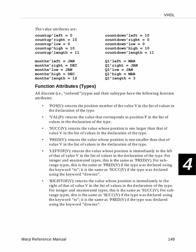
VHDL
4
The value attributes are:
countup’left = 0 countdown’left = 10countup’right = 10 countdown’right = 0countup’low = 0 countdown’low = 0countup’high = 10 countdown’high = 10countup’length = 11 countdown’length = 11
months’left = JAN Q1’left = MARmonths’right = DEC Q1’right = JANmonths’low = JAN Q1’low = JANmonths’high = DEC Q1’high = MARmonths’length = 12 Q1’length = 3
Function Attributes (Types)All discrete (i.e., “ordered”) types and their subtypes have the following function attributes:
• ‘POS(V): returns the position number of the value V in the list of values in the declaration of the type.
• ‘VAL(P): returns the value that corresponds to position P in the list of values in the declaration of the type.
• ‘SUCC(V): returns the value whose position is one larger than that of value V in the list of values in the declaration of the type.
• ‘PRED(V): returns the value whose position is one smaller than that of value V in the list of values in the declaration of the type.
• ‘LEFTOF(V): returns the value whose position is immediately to the left of that of value V in the list of values in the declaration of the type. For integer and enumerated types, this is the same as ‘PRED(V). For sub-range types, this is the same as ‘PRED(V) if the type was declared using the keyword “to”; it is the same as ‘SUCC(V) if the type was declared using the keyword “downto”.
• ‘RIGHTOF(V): returns the value whose position is immediately to the right of that of value V in the list of values in the declaration of the type. For integer and enumerated types, this is the same as ‘SUCC(V). For sub-range types, this is the same as ‘SUCC(V) if the type was declared using the keyword “to”; it is the same as ‘PRED(V) if the type was declared using the keyword “downto”.
Warp Reference Manual 149
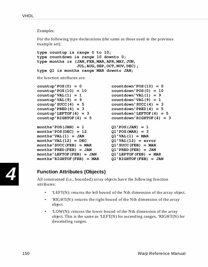
VHDL
4
Examples:
For the following type declarations (the same as those used in the previous example set):
type countup is range 0 to 10;type countdown is range 10 downto 0;type months is (JAN,FEB,MAR,APR,MAY,JUN,
JUL,AUG,SEP,OCT,NOV,DEC);type Q1 is months range MAR downto JAN;
the function attributes are:
countup’POS(0) = 0 countdown’POS(10) = 0countup’POS(10) = 10 countdown’POS(0) = 10countup’VAL(1) = 1 countdown’VAL(1) = 9countup’VAL(9) = 9 countdown’VAL(9) = 1countup’SUCC(4) = 5 countdown’SUCC(4) = 3countup’PRED(4) = 3 countdown’PRED(4) = 5countup’LEFTOF(4) = 3 countdown’LEFTOF(4) = 5countup’RIGHTOF(4) = 5 countdown’RIGHTOF(4) = 3
months’POS(JAN) = 1 Q1’POS(JAN) = 1months’POS(DEC) = 12 Q1’POS(MAR) = 3months’VAL(1) = JAN Q1’VAL(1) = MARmonths’VAL(12) = DEC Q1’VAL(12) = errormonths’SUCC(FEB) = MAR Q1’SUCC(FEB) = MARmonths’PRED(FEB) = JAN Q1’PRED(FEB) = JANmonths’LEFTOF(FEB) = JAN Q1’LEFTOF(FEB) = MARmonths’RIGHTOF(FEB) = MAR Q1’RIGHTOF(FEB) = JAN
Function Attributes (Objects)All constrained (i.e., bounded) array objects have the following function attributes:
• ‘LEFT(N): returns the left bound of the Nth dimension of the array object.
• ‘RIGHT(N): returns the right bound of the Nth dimension of the array object.
• ‘LOW(N): returns the lower bound of the Nth dimension of the array object. This is the same as ‘LEFT(N) for ascending ranges, ‘RIGHT(N) for descending ranges.
150 Warp Reference Manual
VHDL
4
• ‘HIGH(N): returns the upper bound of the Nth dimension of the array object. This is the same as ‘RIGHT(N) for ascending ranges, ‘LEFT(N) for ascending ranges.
In the discussion above, the value of N defaults to 1, which is also the lower bound for the number of dimensions in an array.
Examples:
For the following type and variable declarations:
type two_d_array is array (8 downto 0, 0 to 4);variable my_array:two_d_array;
the function attributes are:
my_array’left(1)= 8 my_array’left(2) = 0my_array’right(1) = 0 my_array’right(2) = 4my_array’low(1) = 0 my_array’low(2) = 0my_array’high(1) = 8 my_array’high(2) = 4
Function Attributes (Signals)Warp supports a single function attribute for signals, namely the ‘EVENT attribute. ‘EVENT is a boolean function that returns TRUE if an event (i.e., change of value) has just occurred on the signal.
Warp supports the ‘EVENT attribute only for clock signals such as in the following example.
Example:
PROCESS BEGINWAIT UNTIL (clk’EVENT AND clk=’1’);...
END PROCESS;
This example shows a process whose statements are executed when an event occurs on signal clk and signal clk goes to ‘1’.
Warp Reference Manual 151
VHDL
4
Type AttributesAll types and subtypes have the following attribute:
• ‘BASE: returns the base type of the original type or subtype.
At first glance, this attribute doesn’t appear very useful in expressions, since it returns a type. But it can be used in conjunction with other attributes, as in the following examples.
Examples:
For the following type declarations:
type day_of_week is (SUN,MON,TUE,WED,THU,FRI,SAT);subtype work_day is day_of_week range MON to FRI;
the following value attributes are true:
work_day’left = MON work_day’BASE’left = SUNwork_day’right = FRI work_day’BASE’right = SATwork_day’low = MON work_day’BASE’low = SUNwork_day’high = FRI work_day’BASE’high = SATwork_day’length = 5 work_day’BASE’length = 7
Range AttributesConstrained array objects have the following attributes:
• ‘RANGE(N): returns the range of the Nth index of the array. If N is not specified, it defaults to 1.
• ‘REVERSE_RANGE(N): returns the reversed range of the Nth index of the array. If N is not specified, it defaults to 1.
The range attributes give the user a way to parameterize the limits of FOR loops and FOR-GENERATE statements, as in the following example.
Example:
Consider a variable declared as:
variable my_bus:std_logic_vector(0 to 7);
152 Warp Reference Manual
VHDL
4
Then, the value of the ‘RANGE and ‘REVERSE_RANGE attributes for my_bus are:
my_bus’RANGE = 0 to 7my_bus’REVERSE_RANGE = 7 downto 0
You could use this attribute in a FOR loop, like this:
for index in my_bus’REVERSE_RANGE loop...end loop;
4.11.5 CASE
The CASE statement selects one or more statements to be executed within a process, based on the value of an expression.
case expression iswhen case1 [| case2 ...] =>
sequence_of_statements ;when case3 [| case4 ...] =>
sequence_of_statements ;...]
[when others =>sequence_of_statements ;]
end case;
In Warp, the expression that determines the branching path of the CASE statement must evaluate to a vector or to a discrete type (i.e., a type with a finite number of possible values, such as an enumerated type or an integer type).
The vertical bar ('|') operator may be used to indicate multiple cases to be checked in a single WHEN clause. This may only be used if the sequence of statements following the WHEN clause is the same for both cases.
The keyword OTHERS may be used to specify a sequence of statements to be executed if no other case statement alternative applies. Because CASE statements execute sequentially, the test for OTHERS should be the last test in the WHEN list.
Warp Reference Manual 153
VHDL
4
When Warp synthesizes a CASE statement, it synthesizes a memory element for the condition being tested (in order to maintain any outputs at their previous values) unless one of the following conditions occurs:
• All outputs within the body of the CASE statement are previously assigned a default value within the process.
• The CASE statement completely specifies the design's behavior following any possible result of the conditional test. The best way to ensure complete specification of design behavior is to include an OTHERS clause within the CASE statement.
When a CASE statement does not specify a branch for all possible results, Warp synthesizes a memory element for the conditional test. This could use up more PLD/FPGA resources than would otherwise be required.
Therefore, to use the fewest possible resources during synthesis, either assign default values to outputs in a process or make sure all CASE statements include an OTHERS clause.
Example:
In the following example, signal s is declared as
s :in std_logic_vector(0 to 2);
In addition, i and o are declared as eight-element vectors:
i : in std_logic_vector(0 to 7);o : out std_logic_vector(0 to 7);
The architecture follows:
architecture demo of Barrel_shifter isbegin process (s, i)
begincase s is
WHEN "000"=> o <= i;
WHEN "001"=> o <=(i(1),i(2),i(3),i(4),i(5),i(6),i(7),i(0));
WHEN "010"=> o <=(i(2),i(3),i(4),i(5),i(6),i(7),i(0),i(1));
WHEN "011"=>o <=(i(3),i(4),i(5),i(6),i(7),i(0),i(1),i(2));
WHEN "100"=> o <=(i(4),i(5),i(6),i(7),i(0),i(1),i(2),i(3));
154 Warp Reference Manual

VHDL
4
WHEN "101"=> o <=(i(5),i(6),i(7),i(0),i(1),i(2),i(3),i(4));
WHEN "110"=> o <=(i(6),i(7),i(0),i(1),i(2),i(3),i(4),i(5));
WHEN "111"=> o <=(i(7),i(0),i(1),i(2),i(3),i(4),i(5),i(6));
end case;end process;
end demo;
In this example, signal s evaluates to a 3- element bit-string literal. The appropriate statement is executed, depending on the value of s , and output vector o gets the value given by the specified ordering of elements in input vector i . Note that the CASE statement completely specifies the results of the conditional test; all possible values of s are covered by a WHEN clause. Hence, no OTHERS clause is needed.
4.11.6 Component
A component declaration specifies a component to be synthesized and lists the local signal names of the component. The component declaration serves the same purpose in VHDL as a function declaration or prototype serves in the C programming language.
Component Declarationcomponent identifier
[generic ( generic_list );][port ( port_list );]end component;
Example:
component barrel_shifter port(clk : IN std_logic;s :in std_logic_vector(0 to 2);insig :in std_logic_vector(0 to 7);outsig :out std_logic_vector(0 to 7));
end component;
This example declares a component called barrel_shifter with a 3-bit input signal, an 8-bit input signal, and an 8-bit output signal.
Warp Reference Manual 155
VHDL
4
Component I nstan tiationinstantiation_label : component_name
[generic generic_mapping ][port port_mapping ];
A component instantiation creates an instance of a component that was previously declared with a component declaration statement. Think of component instantiation as “placing” a previously declared component into an architecture, then “wiring” the newly placed component into the design by means of the generic map or port map.
Example:
a1:barrel_shifterport map(
clk=>clock,s(0)=>s0,s(1)=>s1,s(2)=>s2,insig=>myinput,outsig=>myoutput);
The line a1:barrel_shifter in the example above instantiates a component named a1 of type barrel-shifter . The port map statement that follows maps each signal from this instance of barrel_shifter to signals at a higher level.
Note that, in this case, the barrel_shifter was defined as accepting a single bit signal clk , and three vectors s , insig and outsig . For vectored signals, you can either split the vector up into individual signals, as in the case of s or perform direct vector to vector connections.
Note also the direction of the "arrow" in each mapping: from the "formal" (the signal name on the component) to the "actual" (the name of the pin to which the signal is being mapped).
4.11.7 Constant
A constant is an object whose value may not be changed.
constant identifier_list:type[:=expression];
156 Warp Reference Manual
VHDL
4
Example:
TYPE stvar is std_logic_vector(0 to 1);constant s0:stvar := "00";constant s1:stvar := "01";constant s2:stvar := "10";constant s3:stvar := "11";
This example declares a vector subtype with length 2, called stvar . It then defines four constants of type stvar , and gives them values of “00”, “01”, “10”, and “11”, respectively.
subtype vec8 is std_logic_vector(0 to 7);type v8_table is array(0 to 7) of vec8;constant xtbL1:v8_table := ("00000001","00000010","00000100","00001000","00010000","00100000","01000000","10000000");
This example declares a vector subtype with length 8 called vec8 , a 1-dimensional array type of vec8 called v8_table with eight elements, and a constant of type v8_table called xtbL1 .
Values are assigned to the constant by concatenating a sequence of string literals (e.g., "00000001") into vector form. Only characters ‘0’, ‘1’, ’Z’ and ’-’ are allowed in these string literals, but the values could have been written in hex format (e.g., x"01" is the same as "00000001" for this purpose). The result is a table of constants such that xtbL1(0) is "00000001" and xtbL1(7) is "10000000".
4.11.8 Entity
An entity declaration names a design entity and lists its ports (i.e., external signals). The mode and data type of each port are also declared.
entity identifier is port(port_name : mode type [;port_name : mode type ...])end [ identifier ];
Warp Reference Manual 157
VHDL
4
Choices for mode are IN, OUT, BUFFER, and INOUT.
Example:
entity Barrel_Shifter is port(clk : IN std_logic;s :in std_logic_vector(0 to 2);insig :in std_logic_vector(0 to 7);outsig :out std_logic_vector(0 to 7));
end Barrel_Shifter;
This example declares an entity called barrel_shifter with a 3-bit and an 8-bit input signal as well as an 8-bit output signal.
4.11.9 Exit
The EXIT statement causes a loop to be exited. Execution resumes with the first statement after the loop. The conditional form of the statement causes the loop to be exited when a specified condition is met.
exit [ loop_label ] [when condition ];
Example:
i <= 0;loop
outsig(i)<=barrel_mux8(i,s,insig);i <= i+1;exit when i>7;end loop;
The EXIT statement in the example above causes the loop to exit when variable i becomes greater than 7. The example thus calls the function barrel_mux8 eight times.
4.11.10 Generate
Generate statements specify a repetitive or conditional execution of the set of concurrent statements they contain. Generate statements are especially useful for instantiating an array of components.
158 Warp Reference Manual
VHDL
4
label : generation_scheme generate{ concurrent_statement }
end generate [ label ];
generation_scheme ::= for generate_parameter_specification
| if condition
A "generation scheme" in the syntax above refers to either a FOR-loop specification or an IF-condition specification, as shown in the example below.
Example:
architecture test of serreg issignal zero : std_logic := ‘0’ ;
beginm1: for i in 0 to size-1 generate
m2: if i=0 generatex1:dsrff port map (si, zero, mreset, clk, q(0));end generate;
m3: If i>0 generatex2:dsrff port map(q(I-1), zero, mreset,clk, q(I));end generate;
end generate;end test;
The example above instantiates a single component labeled x1 , and size-1 components labeled x2 . For size=3, for instance, the code shown above is the equivalent of
architecture test of serreg issignal zero : std_logic := ‘0’ ;
beginx1:dsrff port map(si, zero, mreset, clk, q(0));x2:dsrff port map(q(0), zero, mreset, clk, q(1));x3:dsrff port map(q(1), zero, mreset, clk, q(2));
end test;
4.11.11 Generic
Generics are the means by which instantiating (parent) components pass information to instantiated (child) components in VHDL. Typical uses are to specify the size of array objects or the number of subcomponents to be instantiated.
generic( identifier : type [:= value ]);
Warp Reference Manual 159
VHDL
4
Example:
component serreg generic (size:integer:=8);port (si,
clk,mreset : in std_logic;q : inout std_logic_vector(0 to size-1));
end component;
This example declares a component with a bidirectional array of 8 bits, among other signals. The number of bits is given by the value of the size parameter in the generic statement.
4.11.12 If-Then-Else
The IF statement selects one or more statements to be executed within a process, based on the value of a condition.
IF condition THEN sequence_of_statements[ELSIF condition THEN
sequence_of_statements ...][ELSE sequence_of_statements ]
END IF;
A condition is a boolean expression, i.e., an expression that resolves to a boolean value. If the condition evaluates to true, the sequence of statements following the THEN keyword is executed. If the condition evaluates to false, the sequence of statements following the ELSIF or ELSE keyword(s), if present, are executed.
When Warp synthesizes an IF-THEN-ELSE statement, it synthesizes a memory element for the condition being tested (in order to maintain any outputs at their "previous" values) unless one of the following conditions is true:
• All outputs within the body of the IF-THEN-ELSE statement are previously assigned a "default" value within the process.
• The IF-THEN-ELSE statement completely specifies the design's behavior following any possible result of the conditional test. The best way to ensure complete specification of design behavior is to include an ELSE clause within the IF statement. (See example following.)
When an IF-THEN-ELSE statement does not specify a branch for all possible results, Warp synthesizes a memory element for the conditional test. This could use up more PLD resources than would otherwise be required.
160 Warp Reference Manual
VHDL
4
In short, to use the fewest possible PLD resources during synthesis, either assign default values to outputs in a process, or make sure all IF-THEN-ELSE statements include ELSE clauses.
Example:
if (not tmshort=one)then stvar <= ewgo;elsif (tmlong=one)then stvar <= ewwait;elsif (not ew=one AND ns=one)then stvar<=ewgo;elsif (ew=one AND ns=one)then stvar <= ewwait;elsif (not ew=one)then stvar <= ewgo;else stvar <= ewwait;end if;
Note – In the case above, the ELSE statement is to be left out, as opposed to suggestions made on the previous page.
The example above sets a state variable called stvar . The value that stvar receives depends on the value of variables tmshort , tmlong , ew, and ns .
Asynchronous Sets, ResetsUse an IF-THEN-ELSE statement to synthesize the operation of a synchronous circuit containing asynchronous sets or resets.
To do so, use a sensitivity list in the PROCESS statement, naming the sets, resets, and clock signals that will trigger the execution of the process. Then, use a sequence of IF-ELSIF clauses to specify the behavior of the circuit.
The structure of the process should be something like this:
process (set, reset, clk) beginif (reset = ‘0’)then
--assign signals to their “reset” values ;elsif (set = ‘0’)then
-- assign signals to their “set” values ;elsif (clk’EVENT AND clk=’1’)then
--perform synchronous operations;end if;
end process;
The example above shows the VHDL description for active-low set and reset signals. It could just as easily have been coded for active-high sets and resets by using the conditions set=‘1’ and reset=‘1’ .
Warp Reference Manual 161
VHDL
4
The assignments made in the statements that follow the set or reset signal conditions must be “simple” assignments (i.e., of the form name=constant), to a signal of type std_logic , std_logic_vector , or enumerated type (for state variables).
4.11.13 Library
In Warp, a library is a storage facility for previously analyzed design units.
library library-name [, library-name ];
A library clause declares logical names to make libraries visible within a design unit. A design unit is an entity declaration, a package declaration, an architecture body, or a package body.
Example:
library mylib;
The above example makes a library named mylib visible within the design unit containing the library clause.
4.11.14 Loops
Loops execute a sequence of statements repeatedly.
[ loop_label :] [ iteration_scheme ] loopsequence_of_statementsend loop [ loop_label ];
iteration_scheme ::= while condition| for loop_parameter in
{ lower_limit to upper_limit | upper_limit downto lower_limit }
There are three kinds of loops in VHDL:
• Simple loops are bounded by a loop/end loop statement pair. These kinds of loops require an exit statement, otherwise they execute forever;
• FOR loops execute a specified number of times; and
• WHILE loops execute while a specified condition remains true.
162 Warp Reference Manual
VHDL
4
Examples:
Simple loop:
i := 0;loop
outsig(i)<=barrel_mux8(i,s,insig);i := i+1;if (i>7) then
exit; END IF;
end loop;
FOR loop:
for i in 0 to 7 loopoutsig(i)<=barrel_mux8(i,s,insig);end loop;
WHILE loop:
i := 0;while (i<=7) loop
outsig(i)<=barrel_mux8(i,s,insig);i := i+1;end loop;
The examples above show three ways of implementing the same loop. All of these loops call the function barrel_mux8 eight times. (In all three, i must be defined as a variable.)
4.11.15 Next
NEXT advances control to the next iteration of a loop.
next [ loop_label ] [when condition ];
Example:
for i in 0 to 7 loopif ((i =0) or (i=2) or (i=4) or (i=6)) then
outsig(i)<=barrel_mux8(i,s,insig)else
next i;end if;
end loop;
Warp Reference Manual 163
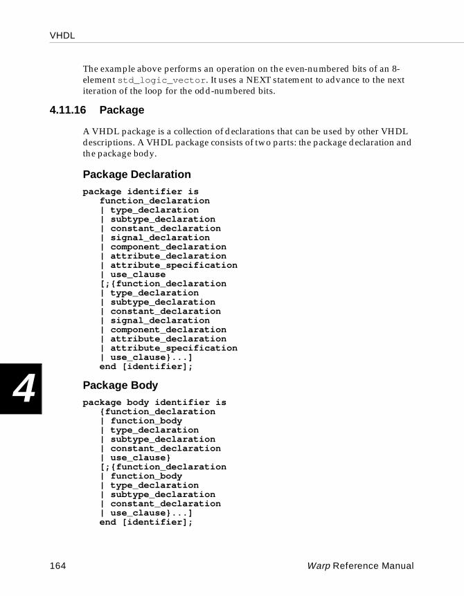
VHDL
4
The example above performs an operation on the even-numbered bits of an 8-element std_logic_vector . It uses a NEXT statement to advance to the next iteration of the loop for the odd-numbered bits.
4.11.16 Package
A VHDL package is a collection of declarations that can be used by other VHDL descriptions. A VHDL package consists of two parts: the package declaration and the package body.
Package Decla rationpackage identifier is
function_declaration| type_declaration| subtype_declaration| constant_declaration| signal_declaration| component_declaration| attribute_declaration| attribute_specification| use_clause[;{function_declaration| type_declaration| subtype_declaration| constant_declaration| signal_declaration| component_declaration| attribute_declaration| attribute_specification| use_clause}...]end [identifier];
Pack age Bodypackage body identifier is
{function_declaration| function_body| type_declaration| subtype_declaration| constant_declaration| use_clause}[;{function_declaration| function_body| type_declaration| subtype_declaration| constant_declaration| use_clause}...]end [identifier];
164 Warp Reference Manual
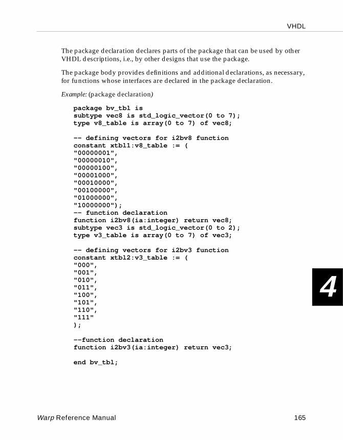
VHDL
4
The package declaration declares parts of the package that can be used by other VHDL descriptions, i.e., by other designs that use the package.
The package body provides definitions and additional declarations, as necessary, for functions whose interfaces are declared in the package declaration.
Example: (package declaration)
package bv_tbl issubtype vec8 is std_logic_vector(0 to 7);type v8_table is array(0 to 7) of vec8;
-- defining vectors for i2bv8 functionconstant xtbl1:v8_table := ("00000001","00000010","00000100","00001000","00010000","00100000","01000000", "10000000");-- function declarationfunction i2bv8(ia:integer) return vec8;subtype vec3 is std_logic_vector(0 to 2);type v3_table is array(0 to 7) of vec3;
-- defining vectors for i2bv3 functionconstant xtbl2:v3_table := ("000","001","010","011","100","101","110","111");
--function declarationfunction i2bv3(ia:integer) return vec3;
end bv_tbl;
Warp Reference Manual 165
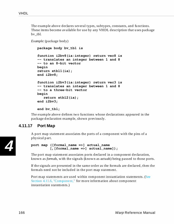
VHDL
4
The example above declares several types, subtypes, constants, and functions. These items become available for use by any VHDL description that uses package bv_tbl.
Example: (package body)
package body bv_tbl is
function i2bv8(ia:integer) return vec8 is-- translates an integer between 1 and 8-- to an 8-bit vectorbeginreturn xtbl1(ia);end i2bv8;
function i2bv3(ia:integer) return vec3 is-- translates an integer between 1 and 8-- to a three-bit vectorbegin
return xtbl2(ia);end i2bv3;
end bv_tbl;
The example above defines two functions whose declarations appeared in the package declaration example, shown previously.
4.11.17 Port Map
A port map statement associates the ports of a component with the pins of a physical part.
port map ([formal_name =>] actual_name[,[formal_name =>] actual_name]);
The port map statement associates ports declared in a component declaration, known as formals, with the signals (known as actuals) being passed to those ports.
If the signals are presented in the same order as the formals are declared, then the formals need not be included in the port map statement.
Port map statements are used within component instantiation statements. (See Section 4.11.6, "Component,” for more information about component instantiation statements.)
166 Warp Reference Manual
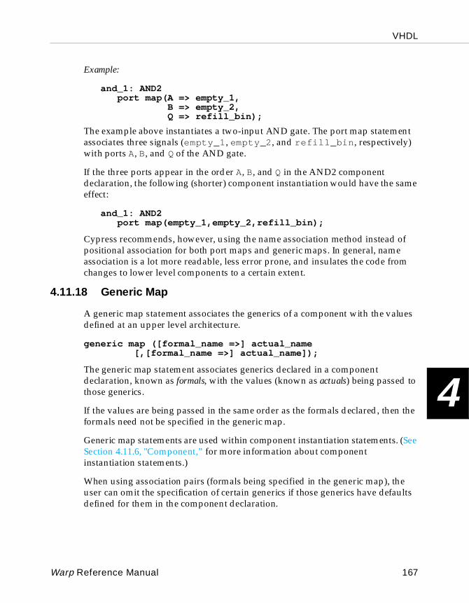
VHDL
4
Example:
and_1: AND2port map(A => empty_1,
B => empty_2,Q => refill_bin);
The example above instantiates a two-input AND gate. The port map statement associates three signals (empty_1 , empty_2 , and refill_bin , respectively) with ports A, B, and Q of the AND gate.
If the three ports appear in the order A, B, and Q in the AND2 component declaration, the following (shorter) component instantiation would have the same effect:
and_1: AND2port map(empty_1,empty_2,refill_bin);
Cypress recommends, however, using the name association method instead of positional association for both port maps and generic maps. In general, name association is a lot more readable, less error prone, and insulates the code from changes to lower level components to a certain extent.
4.11.18 Generic Map
A generic map statement associates the generics of a component with the values defined at an upper level architecture.
generic map ([formal_name =>] actual_name[,[formal_name =>] actual_name]);
The generic map statement associates generics declared in a component declaration, known as formals, with the values (known as actuals) being passed to those generics.
If the values are being passed in the same order as the formals declared, then the formals need not be specified in the generic map.
Generic map statements are used within component instantiation statements. (See Section 4.11.6, "Component,” for more information about component instantiation statements.)
When using association pairs (formals being specified in the generic map), the user can omit the specification of certain generics if those generics have defaults defined for them in the component declaration.
Warp Reference Manual 167
VHDL
4
Example:
u0: MADD_SUBgeneric map(lpm_width => myOutput’length,
lpm_representation => lpm_unsigned,lpm_direction => lpm_add,lpm_hint => speed) ;
port map(dataA => myDataA, dataB => myDataB, cin => zero, add_sub => one,result => myOutput, cout => open,overflow => open) ;
The above example instantiates an add/sub component defined in the LPM library supplied with Warp. In the instantiation, the Madd_sub LPM modules is being configured as an adder only without a carry-in. The carry-out or the overflow outputs are not being used.
Since the Madd_sub moduled defined in the LPM library provided a default for lpm_hint (speed), this association could have been omitted in the generic map. The very first generic lpm_width has no default value, however, and must be specified. The choice of what can be omitted and what has to be defined depends on the component declaration.
Using positional association, the same example could have been written as
u0: MADD_SUBgeneric map(myOutput’length, lpm_unsigned,
lpm_add, speed) ;port map(myDataA,myDataB, zero, one,
myOutput, open, open) ;
Cypress recommends using the name association method instead of positional association for both port maps and generic maps. In general, name association is a lot more readable, less error prone, and insulates the code from changes to lower level components to a certain extent.
4.11.19 Process
A process statement is a concurrent statement that defines a behavior to be executed when that process becomes active. The behavior is specified by a series of sequential statements executed within the process.
168 Warp Reference Manual
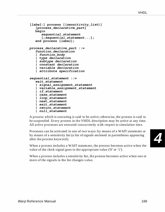
VHDL
4
[ label :] process [( sensitivity_list )][ process_declarative_part ]begin
sequential_statement[; sequential_statement ...];
end process [ label ];
process_declarative_part ::=function_declaration| function_body| type declaration| subtype declaration| constant declaration| variable declaration| attribute specification
sequential_statement ::=wait_statement| signal_assignment_statement| variable_assignment_statement| if_statement| case_statement| loop_statement| next_statement| exit_statement| return_statement| null_statement
A process which is executing is said to be active; otherwise, the process is said to be suspended. Every process in the VHDL description may be active at any time. All active processes are executed concurrently with respect to simulation time.
Processes can be activated in one of two ways: by means of a WAIT statement or by means of a sensitivity list (a list of signals enclosed in parentheses appearing after the process keyword).
When a process includes a WAIT statement, the process becomes active when the value of the clock signal goes to the appropriate value (‘0’ or ‘1’).
When a process includes a sensitivity list, the process becomes active when one or more of the signals in the list changes value.
Warp Reference Manual 169
VHDL
4
Example:
process (s, insig) beginfor i in 0 to 7 loop
outsig(i)<=barrel_mux8(i,s,insig);end loop;
end process;
The example above shows a process that executes whenever activity is sensed on either of two signals, s or insig .
4.11.20 Signal
A signal is a pathway along which information passes from one component in a VHDL description to another. Signals are also used within components to pass values to other signals, or to hold values.
Signal D eclar ationsignal name [, name ...]: type ;
Signal Assignment)signal_name <= expression
[when condition [ else expression ]];
Signals must be declared before they can be used. Declaring a signal gives it a name and a type. Signal declarations often appear as part of port or component declarations.
To assign a value to a signal, replace its current value with the value of some expression of the same type as the signal, using the signal name and the "<=" operator.
The user may also specify a condition under which the replacement is to be made, as well as an alternative value for the signal if the condition is not met. This form of the signal assignment statement uses the "when" and "else" keywords.
Example:
(Signal Declaration examples)
signal c0,c1,cin1,cin2:std_logic;
170 Warp Reference Manual
VHDL
4
This example declares four signals (c0 , c1 , cin1 , and cin2 ), each of type std_logic .
type State is (s1, s2, s3, s4, s5);signal StVar : State;
This example declares an enumerated type named State , with five possible values. It then declares a signal named StVar of type State . Thus, StVar can have values s1 , s2 , s3 , s4 , or s5 .
(Unconditional Signal Assignment examples)
c_in <= '1';
This example sets a variable of type std_logic named c_in to ‘1’.
StVar <= s1;
This example assigns the value s1 to a signal named StVar . Presumably, StVar is a signal of some enumerated type, having s1 as one of its possible values.
(Conditional Signal Assignment example)
c_in2 <= '1' when (stvar=s1) OR (stvar=s2) else '0';
The above example illustrates the use of conditional signal assignment. Signal c_in2 is assigned one value if the specified conditions are met; otherwise, it is assigned a different value.
4.11.21 Subprograms
Subprograms are sequences of declarations and statements that can be invoked repeatedly from different parts of a VHDL description. VHDL includes two kinds of subprograms: procedures and functions.
Procedure Declarationprocedure designator [( formal-parameter-list )];
Procedure Bodyprocedure designator [( formal-parameter-list )] is
[ declarations ]begin
{ sequential-statement ;}end [ designator ];
Warp Reference Manual 171
VHDL
4
Function Declarationfunction designator [( formal-parameter-list )]
return type_mark ;
type_mark ::= type_name | subtype_name
Function Bodyfunction designator [( formal-parameter-list )]
return type_mark is[ declarations ]
begin{ sequential-statement ;}
end [ designator ];
A subprogram is a set of declarations and statements that can be used repeatedly from many points within a VHDL description.
There are two kinds of subprograms in VHDL: procedures and functions. Procedures may return zero or more values. Functions always return a single value. In practice, procedures are most often used to sub-divide a large behavioral description into smaller, more modular sections. Functions are most often used to convert objects from one data type to another or to perform frequently needed computations.
VHDL allows the user to declare a subprogram in one part of a VHDL description while defining it in another. Subprogram declarations contain only interface information: name of the subprogram, interface signals, and return type (for functions). The subprogram body contains local declarations and statements, in addition to the interface information.
Function calls are expressions; the result of a function call is always assigned to a signal or variable, or otherwise used in a larger statement (e.g., as a parameter to be passed to a procedure call). Procedure invocations, by contrast, are entire statements in themselves.
In both procedures and functions, actual and formal parameters may use positional association or named association.
To use positional association, list the parameters to be passed to the subprogram in the same order that the parameters were declared, without naming the parameters.
172 Warp Reference Manual
VHDL
4
To use named association, give the formal parameter (the name shown in the subprogram declaration) and the actual parameter (the name passing to the subprogram) within the procedure invocation or function call, linking the formal and actual parameters with the “=>” operator. In named association, parameters can be listed in any order.
Example:
Consider a procedure, whose declaration is shown below, that takes three signals of type std_logic as input parameters:
procedure crunch(signal sig1,sig2,sig3:in std_logic);
Then, the invocation
crunch(trex,raptor,spitter);
uses positional association to map signal trex to sig1 , signal raptor to sig2 , and signal spitter to sig3 . You could use named association in the following procedure invocation, however, and get the same result:
crunch(sig2=>raptor,sig3=>spitter,sig1=>trex);
More information about procedures and functions is included on the following pages.
4.11.21.1 Procedures
Procedures describe sequential algorithms that may return zero or more values. Procedures are most frequently used to decompose large behavioral descriptions into smaller, more modular sections, which can be used by many processes.
Procedure parameters may be constants, variables, or signals, and their modes may be in, out, or inout. Unless otherwise specified, a parameter is by default a constant if it is of mode in, and a variable if it is of mode out or inout.
In general, procedures can be used both concurrently (outside of any process) and sequentially (inside a process). If any of the procedure parameters are variables, however, the procedure can only be used sequentially (since variables can only be defined inside a process). Any variables declared inside a procedure cease to exist when the procedure terminates.
A procedure body can contain a wait statement, while a function body cannot; however, a process that calls a procedure with a wait statement in it cannot have a sensitivity list. (Processes can’t be sensitive to signals and made to wait simultaneously.)
Warp Reference Manual 173
VHDL
4
4.11.21.2 Functions
Functions describe sequential algorithms that return a single value. Their most frequent uses are: (1) to convert objects from one data type to another; and (2) as shortcuts to perform frequently used computations.
Function parameters must be of mode in and must be signals or constants. If no mode is specified for a function parameter, the parameter is interpreted as having mode in.
A function body cannot contain a wait statement. (Functions are only used to compute values that are available instantaneously.)
Any variables declared inside a function cease to exist when the function terminates (i.e., returns its value).
One common use of functions in VHDL is to convert objects from one data type to another. Warp provides several conversion functions in the various packages for type conversions (integer to vector, vector to integer etc.). Functions can also be used to overload operators or perform simple combinatorial functions.
Example:
function count_ones(vec1:std_logic_vector)return integer is
-- returns the number of ‘1’ bits in a std_logic vectorvariable temp:integer:=0;begin
for i in vec1’low to vec1’high loopif vec1(i) = ‘1’ then
temp := temp+1;end if;
end loop;return temp;
end count_ones;
This function counts the number of ‘1’s in a vector.
4.11.22 Type
In VHDL, objects are anything that can hold a value. Signals, constants, or variables are common objects. All VHDL objects have a type, which specifies the kind of values that the object can hold.
174 Warp Reference Manual
VHDL
4
Enumerated Type Declarationtype name is ( value [, value ...]);
Subtype Declarationsubtype name is base_type
[range { lower_limit to upper_limit | upper_limit downto lower_limit }];
Vector Declarationsubtype name is std_logic_vector
( lower_limit to upper_limit | upper_limit downto lower_limit );
Record Declarationtype name is record name: type ;
[ name : type ;...]end record;
Warp has the following pre-defined types:
• integer: VHDL allows each implementation to specify the range of the integer type differently, but the range must extend from at least -(2**31-1) to +(2**31-1), or -2147483648 to +2147483647. Only variables (not signals) can have type integer.
• boolean: an enumerated type, consisting of the values "true" and "false";
• std_logic: an enumerated type, consisting of the values '0','1', ‘Z’, ‘-’. std_logic in its strictest definition also has values of ‘H’, ‘L’, ‘U’, ‘X’ and ‘W’ which should not be used in VHDL that is intended for synthesis.
• character: an enumerated type, consisting of one literal for each of the 128 ASCII characters. The non-printable characters are represented by two or three-character identifiers, as follows: NUL, SOH, STX, ETX, EOT, ENQ, ACK, BEL, BS, HT, LF, VT, FF, CR, SO, SI, DLE, DC1, DC2, DC3, DC4, NAK, SYN, ETB, CAN,EM, SUB, ESC, FSP, GSP, RSP, and USP.
VHDL objects can take other, user-defined, types as well. Possibilities include:
• enumerated types: This type has values specified by the user. A common example is a state variable type, where the state variable can have values labeled state1, state2, state3, etc.
Warp Reference Manual 175
VHDL
4
• sub-range types: This type limits the range of a larger base type (such as integers) to a smaller set of values. Examples would be positive integers, or non-negative integers from 0 to 100, or printable ASCII characters.
• arrays (especially vectors): This type specifies a collection of elements of a single base type. A commonly used example is the std_logic_vector type, declared in the std_logic_1164 package from IEEE, which denotes an array of std_logic bits.
• records: This type specifies a collection of elements of possibly differing types.
Enumerated Type Declaration Exampletype sigstates is (nsgo, nswait, nswait2, nsdelay, ewgo, ewwait, ewwait2, ewdelay);
This example declares an enumerated type and lists eight possible values for it.
Sub-range Type Declaration Exampletype column is range (1 to 80);type row is
range (1 to 24);
The above examples declare two new sub-range integer types, column and row . Legal values for objects of type column are integers from 1 to 80, inclusive. Legal values for objects of type row are integers from 1 to 24, inclusive.
Vector Type Declaration Examplesubtype vec8 is std_logic_vector(0 to 7);signal insig, outsig : vec8;..insig <= "00000010";..outsig<=insig(2 to 7) & insig(0 to 1);
The above example declares a vector type called vec8 . It then declares two signals of type vec8 , insig and outsig . The signal assignment statement that concludes the example left-shifts insig by two places. (Outsig then contains the value "00001000".)
176 Warp Reference Manual
VHDL
4
Record Type Declaration Examplesubtype vec5 is std_logic_vector(1 to 5);-- define a record type containing a 5-bit vector-- and a single bittype arec is record
abc:vec5;def:std_logic;end record;
-- define a type containing-- an array of five recordstype twodim is array (1 to 5) of arec;-- now define a couple of signalssignal v:twodim;signal vrec:arec;..-- in record 1 of v, set array field to all 0'sv(1).abc <= "00000";
-- in record 2 of v, set first three bits to 0's,-- others to 1'sv(2).abc <= ('0', '0', '0', others => '1');
-- set fifth bit in array within record #5 to 0.v(5).abc(5) <= '0';
-- set bit field within record to 1vrec.def <= '1';
-- set 3rd bit within vrec's array to 1vrec.abc(3) <= '1';
The example above defines a record type and a type consisting of an array of records. The example then demonstrates how to assign values to various elements of these arrays and records.
4.11.23 USE
The USE statement makes items declared in a package visible inside the current design unit. A design unit is an entity declaration, a package declaration, an architecture body, or a package body.
use name {, name};
Warp Reference Manual 177
VHDL
4
Example:
use work.cypress.all;use work.rtlpkg.all;use work.brl4pkg.all;
The example above makes the items declared in the specified packages available for use in the design unit in which the use statements are contained.
Note – The scope of a USE statement extends only to the design unit (entity, architecture, or package) that it immediately precedes.
4.11.24 Variable
A variable is a VHDL object (similar to a signal) that can hold a value.
Variable de clarationvariable name [, name ...]: type [:= expression ];
Variable assignmentsignal_name <= expression ;
Variables differ from signals in that variables have no direct analogue in hardware. Instead, variables are simply used as indices or value-holders to perform the computations incidental to higher-level modeling of components.
Example:
function admod(i,j,max:integer) return integer isvariable c:integer;beginc:=(i+j) mod (max+1);return c;end admod;
The function in the example above declares a variable c as a value-holder for a computation, then uses it and returns its value in the body of the function.
178 Warp Reference Manual
VHDL
4
4.11.25 Wait
The WAIT statement suspends execution of a process until the specified condition becomes true.
wait until [ condition ];
A WAIT statement, if used, must appear as the first sequential statement inside a process.
Example:
wait until clk='1';
The example above suspends execution of the process in which it is contained until the value of signal clk goes to ‘1’.
Warp Reference Manual 179

VHDL
4
180 Warp Reference Manual

Chapter 5
5 LPM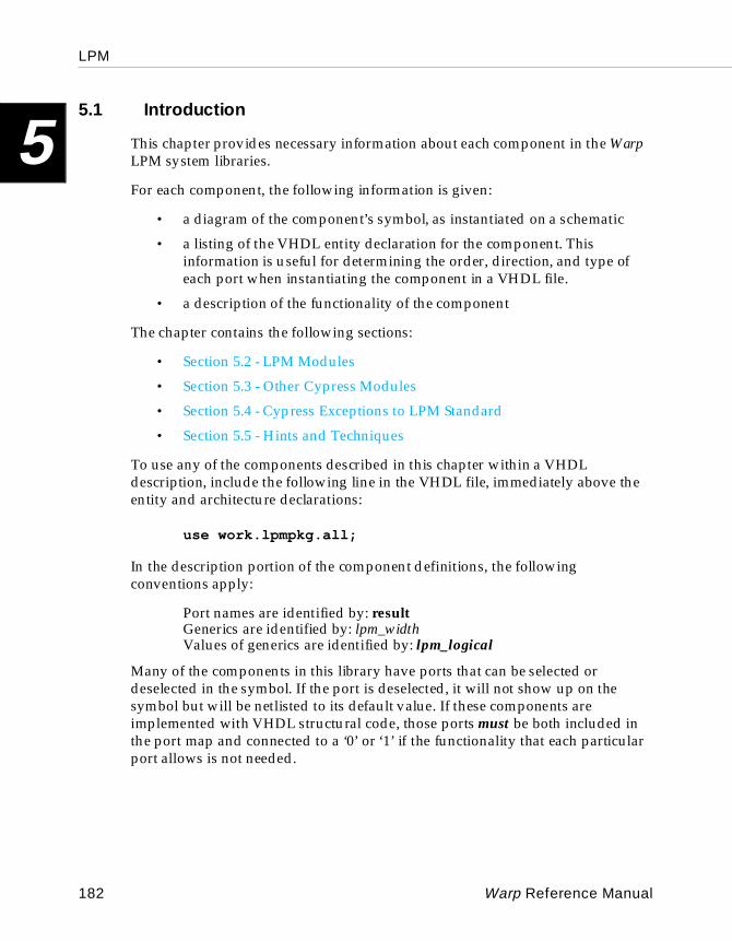
LPM
5
5.1 IntroductionThis chapter provides necessary information about each component in the Warp LPM system libraries.
For each component, the following information is given:
• a diagram of the component’s symbol, as instantiated on a schematic
• a listing of the VHDL entity declaration for the component. This information is useful for determining the order, direction, and type of each port when instantiating the component in a VHDL file.
• a description of the functionality of the component
The chapter contains the following sections:
• Section 5.2 - LPM Modules
• Section 5.3 - Other Cypress Modules
• Section 5.4 - Cypress Exceptions to LPM Standard
• Section 5.5 - Hints and Techniques
To use any of the components described in this chapter within a VHDL description, include the following line in the VHDL file, immediately above the entity and architecture declarations:
use work.lpmpkg.all;
In the description portion of the component definitions, the following conventions apply:
Port names are identified by: resultGenerics are identified by: lpm_widthValues of generics are identified by: lpm_logical
Many of the components in this library have ports that can be selected or deselected in the symbol. If the port is deselected, it will not show up on the symbol but will be netlisted to its default value. If these components are implemented with VHDL structural code, those ports must be both included in the port map and connected to a ‘0’ or ‘1’ if the functionality that each particular port allows is not needed.
182 Warp Reference Manual
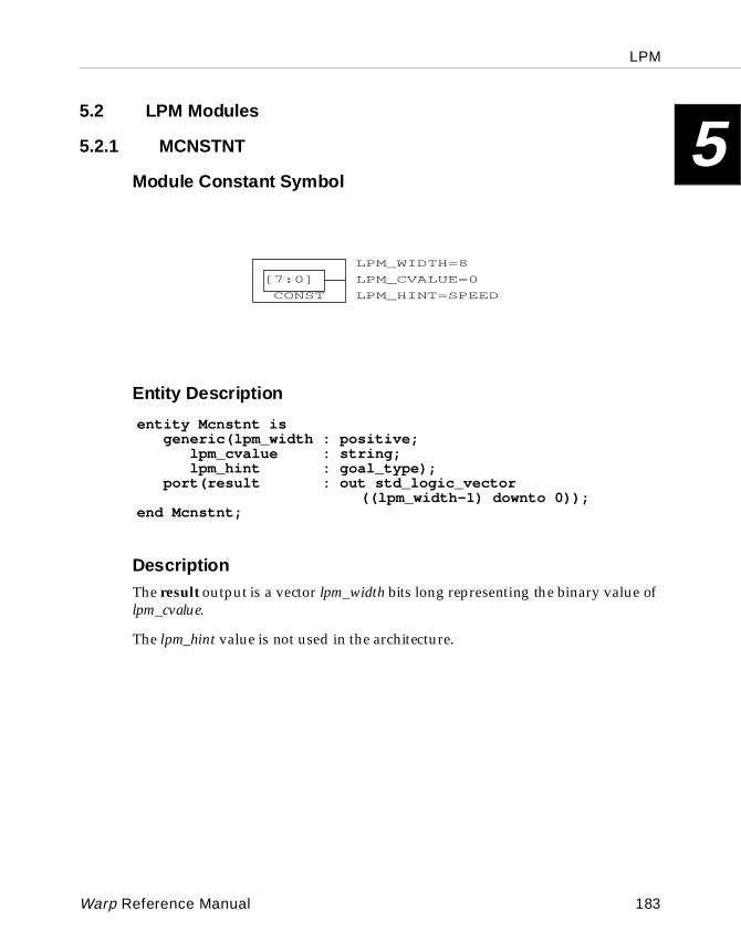
LPM
5
5.2 LPM Modules5.2.1 MCNSTNT
Module Constant Symbol
Entity Descri ption
DescriptionThe result output is a vector lpm_width bits long representing the binary value of lpm_cvalue.
The lpm_hint value is not used in the architecture.
[7:0]
CONST
LPM_WIDTH=8
LPM_HINT=SPEED
LPM_CVALUE=0[7:0]
CONST
LPM_WIDTH=8
LPM_HINT=SPEED
LPM_CVALUE=0
entity Mcnstnt isgeneric(lpm_width : positive;
lpm_cvalue : string;lpm_hint : goal_type);
port(result : out std_logic_vector((lpm_width-1) downto 0));
end Mcnstnt;
Warp Reference Manual 183
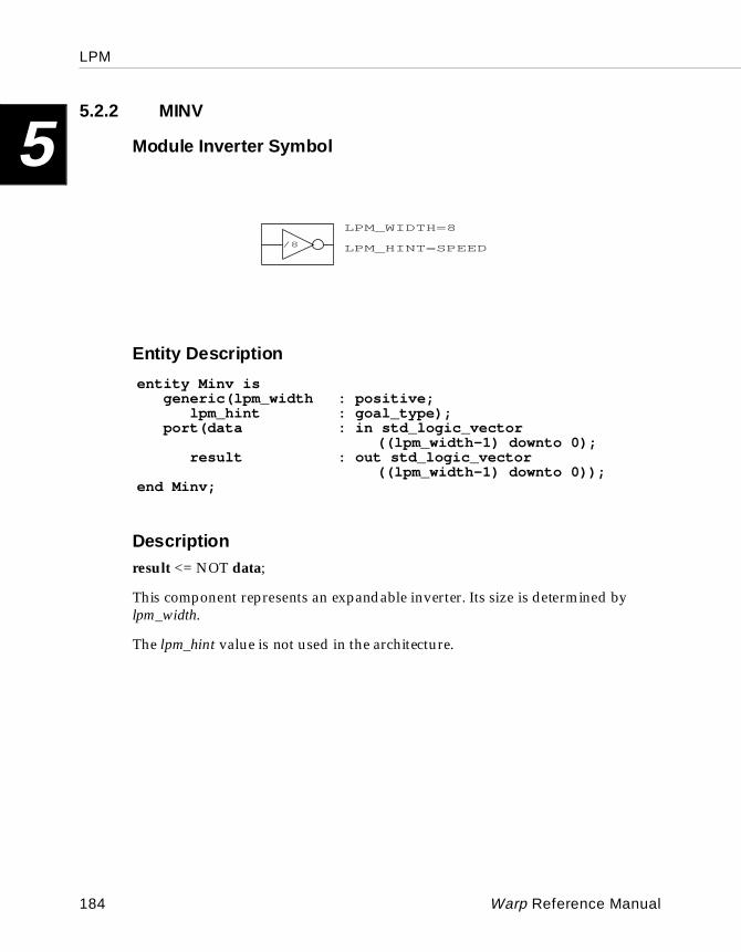
LPM
5
5.2.2 MINVModule Inverter Symbol
Entity Descri ption
Descriptionresult <= NOT data;
This component represents an expandable inverter. Its size is determined by lpm_width.
The lpm_hint value is not used in the architecture.
/8 LPM_HINT=SPEED
LPM_WIDTH=8
/8 LPM_HINT=SPEED
LPM_WIDTH=8
entity Minv isgeneric(lpm_width : positive;
lpm_hint : goal_type);port(data : in std_logic_vector
((lpm_width-1) downto 0);result : out std_logic_vector
((lpm_width-1) downto 0));end Minv;
184 Warp Reference Manual
LPM
5
5.2.3 MANDModule AND Symbol
Entity Descri ption
Descriptionfor i in 0 to (lpm_width-1) :resulti <= data0i AND data1i AND ... data[lpm_size-1]i
This component represents an array of lpm_width AND gates each having lpm_size inputs.
The generics lpm_data_pol and lpm_result_pol are used to select the polarity of each bit of their respective ports. The position of a bit in the string is the same as it is in the port vector with a ‘1’ indicating a non-inverted port while a ‘0’ represents an inverted one. If the generic is not present, the entire port is non-inverted. Access to each bit of each port is available only from VHDL; the schematic GUI allows polarity selection of the entire port only.
The lpm_hint value is not used in the architecture.
LPM_SIZE=4/8
LPM_WIDTH=8
LPM_HINT=SPEED
LPM_SIZE=4/8
LPM_WIDTH=8
LPM_HINT=SPEED
entity Mand isgeneric(lpm_width : positive;
lpm_size : positive;lpm_hint : goal_type);lpm_data_pol : string;lpm_result_pol : string);
port(data : in std_logic_vector(((lpm_width*lpm_size)-1)downto 0);
result : out std_logic_vector((lpm_width-1)downto 0));
end Mand;
Warp Reference Manual 185
LPM
5
5.2.4 MORModule OR Symbol
Entity Descri ption
Descriptionfor i in 0 to (lpm_width-1) :resulti <= data0i OR data1i OR ... data[lpm_size-1]i
This component represents an array of lpm_width OR gates each having lpm_size inputs.
The generics lpm_data_pol and lpm_result_pol are used to select the polarity of each bit of their respective ports. The position of a bit in the string is the same as it is in the port vector with a ‘1’ indicating a non-inverted port while a ‘0’ represents an inverted one. If the generic is not present, the entire port is non-inverted. Access to each bit of each port is available only from VHDL; the schematic GUI allows polarity selection of the entire port only.
The lpm_hint value is not used in the architecture.
LPM_SIZE=4/8
LPM_HINT=SPEED
LPM_WIDTH=8
LPM_SIZE=4/8
LPM_HINT=SPEED
LPM_WIDTH=8
entity Mor isgeneric(lpm_width : positive;
lpm_size : positive;lpm_hint : goal_type;lpm_data_pol : string;lpm_result_pol : string);
port(data : in std_logic_vector(((lpm_width*lpm_size)-1) downto 0);
result : out std_logic_vector((lpm_width-1)downto 0));
end Mor;
186 Warp Reference Manual
LPM
5
5.2.5 MXORModule Exclusive-OR Symbol
Entity Descri ption
Descriptionfor i in 0 to (lpm_width-1) :resulti <= data0i XOR data1i XOR ... data[lpm_size-1]i
This component represents an array of lpm_width Exclusive-OR gates each having lpm_size inputs.
The generics lpm_data_pol and lpm_result_pol are used to select the polarity of each bit of their respective ports. The position of a bit in the string is the same as it is in the port vector with a ‘1’ indicating a non-inverted port while a ‘0’ represents an inverted one. If the generic is not present, the entire port is non-inverted. Access to each bit of each port is available only from VHDL; the schematic GUI allows polarity selection of the entire port only.
The lpm_hint value is not used in the architecture.
LPM_SIZE=4/8
LPM_HINT=SPEED
LPM_WIDTH=8
LPM_SIZE=4/8
LPM_HINT=SPEED
LPM_WIDTH=8
entity Mxor isgeneric(lpm_width : positive;
lpm_size : positive;lpm_hint : goal_type;lpm_data_pol : string;lpm_result_pol : string);
port(data : in std_logic_vector(((lpm_width*lpm_size)-1) downto 0);
result : out std_logic_vector((lpm_width-1)downto 0));
end Mxor;
Warp Reference Manual 187
LPM
5
5.2.6 MBUSTRIModule Bus Tri-State Symbol
Entity Descri ption
Description
EnableDT EnableTR TriData Data Result
L L Hi-Z X Hi-Z
L H L X L (TriData)
L H H X H (TriData)
H L L (Data) L Hi-Z
H L H (Data) H Hi-Z
H H L (Data) L L (Data)
H H H (Data) H H (Data)
/8
/8
LPM_HINT=SPEED
LPM_WIDTH=8
entity Mbustri isgeneric(lpm_width : positive;
lpm_hint : goal_type);port(tridata : inout std_logic_vector((lpm_width-1)
downto 0);data : in std_logic_vector((lpm_width-1)
downto 0);enabletr : in std_logic;enabledt : in std_logic;result : out std_logic_vector((lpm_width-1)
downto 0));end Mbustri;
188 Warp Reference Manual

LPM
5
Tridata plus either result or data must be present. If data is present, then enabledt must be present; if result is present, then enabletr must be present.If either enabletr or enabledt is ‘0’ is not used, the default value is ‘0’.
The lpm_hint value is not used in the architecture.
Warp Reference Manual 189
LPM
5
5.2.7 MMUXModule Multi plexor Symbol
Entity Descri ption
Description
Selectlpm_widths-1 . . . Select1 Select0 Resulti
L L L L Datai0
L L L H Datai1
L L H L Datai2
L L H H Datai3
. . . . . . . . . . . . . . .
H Datai[lpm_size-1]
LPM_HINT=SPEED
LPM_WIDTHS=3
LPM_SIZE=8
LPM_WIDTH=4
/4
MUX
S=3
7654
3210
LPM_HINT=SPEED
LPM_WIDTHS=3
LPM_SIZE=8
LPM_WIDTH=4
/4
MUX
S=3
7654
3210
entity Mmux isgeneric(lpm_width : positive;
lpm_size : positive;lpm_widths : positive;lpm_hint : goal_type);
port(data : in std_logic_vector(((lpm_width*lpm_size)-1) downto 0);
sel : in std_logic_vector((lpm_widths-1) downto 0);
result : out std_logic_vector((lpm_width-1) downto 0));
end Mmux;
190 Warp Reference Manual
LPM
5
Lpm_widths can be any value >= Log2(lpm_size), where lpm_size must be > 1.The lpm_hint value is not used in the architecture.
Warp Reference Manual 191
LPM
5
5.2.8 MDECODEModule Decoder Symbol
Entity Descri ption
Description
Enable Datalpm_width-1 . . . Data1 Data0Eqlpm_widthHigh
L X X X X None
H L L L L Eq0
H L L L H Eq1
H L L H L Eq2
H . . . . . . . . . . . . . . .
H H H H H Eqlpm_decodes-1
LPM_DECODES=7
LPM_WIDTH=3
DECODE
ENABLE
EQ[6:0]
DATA[2:0]
LPM_HINT=SPEED
LPM_DECODES=7
LPM_WIDTH=3
DECODE
ENABLE
EQ[6:0]
DATA[2:0]
LPM_HINT=SPEED
entity Mdecode isgeneric(lpm_width : positive;
lpm_decodes : positive;lpm_hint : goal_type);
port(data : in std_logic_vector((lpm_width-1)downto 0);
enable : in std_logic;eq : out std_logic_vector((lpm_decodes-1)
downto 0));end Mdecode;
192 Warp Reference Manual
LPM
5
Enable is optional, and the default value is ’1’ if not used on the symbol.There must be at lease 1 eq bit and can be no more than 2lpm_width (2lpm_width >= lpm_decodes > 0).
If eqi is not connected or does not appear in the symbol, the selection of ’I’ will result in all outputs being low.
The lpm_hint value is not used in the architecture.
Warp Reference Manual 193
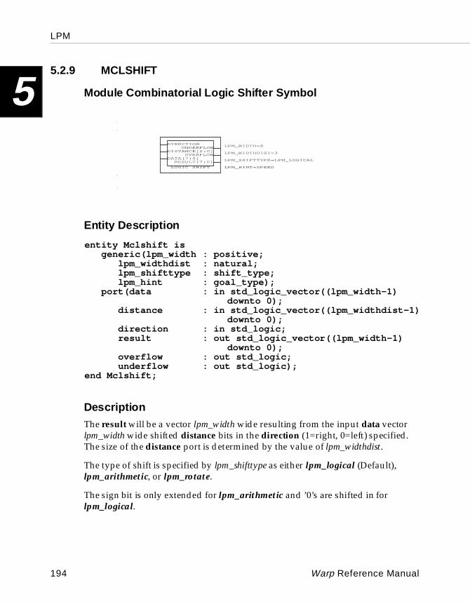
LPM
5
5.2.9 MCLSHIFTModule Combinatorial Logic Shifter Symbol
Entity Descri ption
DescriptionThe result will be a vector lpm_width wide resulting from the input data vector lpm_width wide shifted distance bits in the direction (1=right, 0=left) specified. The size of the distance port is determined by the value of lpm_widthdist.
The type of shift is specified by lpm_shifttype as either lpm_logical (Default), lpm_arithmetic, or lpm_rotate.
The sign bit is only extended for lpm_arithmetic and ’0’s are shifted in for lpm_logical.
LPM_SHIFTTYPE=LPM_LOGI
LOGIC SHIFT
RESULT[7:0]
OVERFLOW
UNDERFLOW
DATA[7:0]
DISTANCE[2:0]
DIRECTION LPM_WIDTH=8
LPM_WIDTHDIST=3
LPM_HINT=SPEED
LOGIC SHIFT
RESULT[7:0]
OVERFLOW
UNDERFLOW
DATA[7:0]
DISTANCE[2:0]
DIRECTION
LPM_SHIFTTYPE=LPM_LOGICAL
LPM_WIDTH=8
LPM_WIDTHDIST=3
LPM_HINT=SPEEDLOGIC SHIFT
RESULT[7:0]
OVERFLOW
UNDERFLOW
DATA[7:0]
DISTANCE[2:0]
DIRECTION
LPM_SHIFTTYPE=LPM_LOGICAL
LPM_WIDTH=8
LPM_WIDTHDIST=3
LPM_HINT=SPEED
entity Mclshift isgeneric(lpm_width : positive;
lpm_widthdist : natural;lpm_shifttype : shift_type;lpm_hint : goal_type);
port(data : in std_logic_vector((lpm_width-1)downto 0);
distance : in std_logic_vector((lpm_widthdist-1)downto 0);
direction : in std_logic;result : out std_logic_vector((lpm_width-1)
downto 0);overflow : out std_logic;underflow : out std_logic);
end Mclshift;
194 Warp Reference Manual
LPM
5
Overflow occurs when the shifted result exceeds the precision of the result port. For lpm_logical values, overflow occurs when a ’1’ is shifted past resultn-1. For lpm_arithmetic values, overflow occurs when the most significant bit (a ’1’ for positive values or ’0’ for negative values) is shifted past resultn-1.Underflow occurs when the shifted result contains no significant digits.
The direction, overflow, and underflow ports are optional, and the default value for direction is ’0’ if it is not used on the symbol.
Lpm_widthdist must be <= log2(lpm_width).
The lpm_hint value is not used in the architecture.
Warp Reference Manual 195
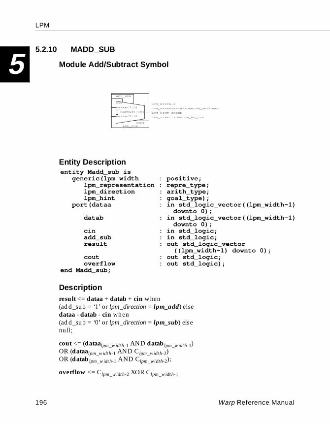
LPM
5
5.2.10 MADD_SUBModule Add/Su btract Symbol
Entity Descri ption
Descriptionresult <= dataa + datab + cin when(add_sub = ‘1’ or lpm_direction = lpm_add) elsedataa - datab - cin when(add_sub = ‘0’ or lpm_direction = lpm_sub) elsenull;
cout <= (dataalpm_width-1 AND datablpm_width-1)OR (dataalpm_width-1 AND Clpm_width-2)OR (datablpm_width-1 AND Clpm_width-2);
overflow <= Clpm_width-2 XOR Clpm_width-1
LPM_REPRESENTATION=LPM_UNSIGNED
LPM_WIDTH=8
ADD_SUB
ADD_SUB
CIN
COUT
DATAB[7:0]
DATAA[7:0]
RESULT[7:0]
LPM_DIRECTION=LPM_NO_TYP
LPM_HINT=SPEED
LPM_REPRESENTATION=LPM_UNSIGNED
LPM_WIDTH=8
ADD_SUB
ADD_SUB
CIN
COUT
DATAB[7:0]
DATAA[7:0]
RESULT[7:0]
LPM_DIRECTION=LPM_NO_TYP
LPM_HINT=SPEED
entity Madd_sub isgeneric(lpm_width : positive;
lpm_representation : repre_type;lpm_direction : arith_type;lpm_hint : goal_type);
port(dataa : in std_logic_vector((lpm_width-1)downto 0);
datab : in std_logic_vector((lpm_width-1)downto 0);
cin : in std_logic;add_sub : in std_logic;result : out std_logic_vector
((lpm_width-1) downto 0);cout : out std_logic;overflow : out std_logic);
end Madd_sub;
196 Warp Reference Manual
LPM
5
It should be noted that overflow is not meaningful for unsigned numbers and only lpm_unsigned is valid for lpm_representation. It is still included in the port map in anticipation of future enhancements.The cin, add_sub, cout, and overflow ports are optional. The default value for add_sub is ’1’ if it is not used on the symbol, and the default value for cin is ’0’ if it is not used on the symbol. This latter default may cause an unobvious and perhaps undesired affect because of the definition of cin, which states:
• if OP = ADD then: low = +0, high = +1
• if OP = SUBTRACT then: low = -1, high = -0
This implies that if the cin port is not used and the component is adding, there is no carry-in. When subtracting, however, there is always a borrow-in or the subtractor will always be subtracting datab - 1 from dataa.
The lpm_direction generic, which is optional, can be either lpm_add (default) or lpm_sub. If it is used, the add_sub port may not be.
The lpm_hint generic is applicable to all parts except C38x. The area version implements a series of 2-bit ripple adders (subtractors) while the speed version implements a series of 2-bit carry-look-ahead adders (subtractors).
Warp Reference Manual 197
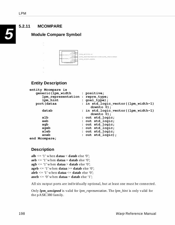
LPM
5
5.2.11 MCOMPAREModule Compare Symbol
Entity Descri ption
Description
alb <= ‘1’ when dataa < datab else ‘0’;aeb <= ‘1’ when dataa = datab else ‘0’;agb <= ‘1’ when dataa > datab else ‘0’;ageb <= ‘1’ when dataa >= datab else ‘0’;aleb <= ‘1’ when dataa <= datab else ‘0’;aneb <= ‘0’ when dataa = datab else ‘1’;
All six output ports are individually optional, but at least one must be connected.
Only lpm_unsigned is valid for lpm_representation. The lpm_hint is only valid for the pASIC380 family.
OMPARE
AGEBAGB
ANEBAEB
ALEBALB
AB[7:0]
AA[7:0]
LPM_REPRESENTATION=LPM_UNS
LPM_HINT=AREA
LPM_WIDTH=8
COMPARE
AGEBAGB
ANEBAEB
ALEBALB
DATAB[7:0]
DATAA[7:0] LPM_WIDTH=8
LPM_REPRESENTATION=LPM_UNSIGNED
LPM_HINT=AREA
entity Mcompare isgeneric(lpm_width : positive;
lpm_representation : repre_type;lpm_hint : goal_type);
port(dataa : in std_logic_vector((lpm_width-1)downto 0);
datab : in std_logic_vector((lpm_width-1)downto 0);
alb : out std_logic;aeb : out std_logic;agb : out std_logic;ageb : out std_logic;aleb : out std_logic;aneb : out std_logic);
end Mcompare;
198 Warp Reference Manual
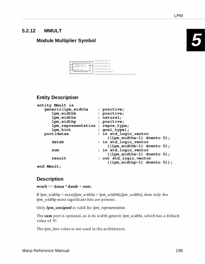
LPM
5
5.2.12 MMULTModule Multiplier Symbol
Entity Descri ption
Descriptionresult <= dataa * datab + sum;
If lpm_widthp < max((lpm_widtha + lpm_widthb),lpm_widths), then only the lpm_widthp most significant bits are present.
Only lpm_unsigned is valid for lpm_representation.
The sum port is optional, as is its width generic lpm_widths, which has a default value of ‘0’.
The lpm_hint value is not used in the architecture.
LPM_WIDTHS=8
TIPLIER
SULT[7:0]
7:0]
AB[3:0]
AA[3:0]
LPM_WIDTHA=4
LPM_WIDTHB=4
LPM_WIDTHP=8
LPM_REPRESENTATION=LPM_UN
LPM_HINT=SPEED
MULTIPLIER
RESULT[7:0]
SUM[7:0]
DATAB[3:0]
DATAA[3:0]
LPM_WIDTHP=8
LPM_HINT=SPEED
LPM_WIDTHS=8
LPM_WIDTHA=4
LPM_WIDTHB=4
LPM_REPRESENTATION=LPM_UNSIGNED
entity Mmult isgeneric(lpm_widtha : positive;
lpm_widthb : positive;lpm_widths : natural;lpm_widthp : positive;lpm_representation : repre_type;lpm_hint : goal_type);
port(dataa : in std_logic_vector((lpm_widtha-1) downto 0);
datab : in std_logic_vector((lpm_widthb-1) downto 0);
sum : in std_logic_vector((lpm_widths-1) downto 0);
result : out std_logic_vector((lpm_widthp-1) downto 0));
end Mmult;
Warp Reference Manual 199
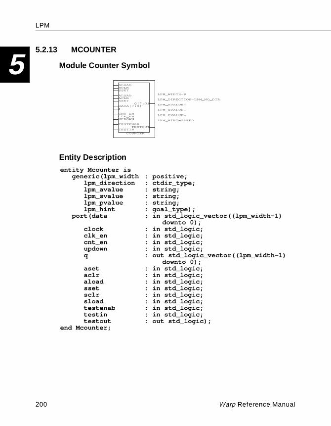
LPM
5
5.2.13 MCOUNTERModule Counter Symbol
Entity Descri ption
LPM_SVALUE=
COUNTER
TESTOUTTESTIN
TESTENAB
SLOADSCLRSSET
ALOADACLRASET
Q[7:0]
UPDOWNCLK_ENCNT_EN
DATA[7:0]
LPM_HINT=SPEED
LPM_PVALUE=
LPM_WIDTH=8
LPM_DIRECTION=LPM_NO_DIR
LPM_AVALUE=
LPM_SVALUE=
COUNTER
TESTOUTTESTIN
TESTENAB
SLOADSCLRSSET
ALOADACLRASET
Q[7:0]
UPDOWNCLK_ENCNT_EN
DATA[7:0]
LPM_HINT=SPEED
LPM_PVALUE=
LPM_WIDTH=8
LPM_DIRECTION=LPM_NO_DIR
LPM_AVALUE=
entity Mcounter isgeneric(lpm_width : positive;
lpm_direction : ctdir_type;lpm_avalue : string;lpm_svalue : string;lpm_pvalue : string;lpm_hint : goal_type);
port(data : in std_logic_vector((lpm_width-1)downto 0);
clock : in std_logic;clk_en : in std_logic;cnt_en : in std_logic;updown : in std_logic;q : out std_logic_vector((lpm_width-1)
downto 0);aset : in std_logic;aclr : in std_logic;aload : in std_logic;sset : in std_logic;sclr : in std_logic;sload : in std_logic;testenab : in std_logic;testin : in std_logic;testout : out std_logic);
end Mcounter;
200 Warp Reference Manual
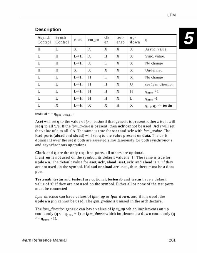
LPM
5
Descriptiontestout <= qlpm_width-1;
Aset will set q to the value of lpm_avalue if that generic is present, otherwise it will set q to all ‘1’s. If the lpm_avalue is present, then aclr cannot be used. Aclr will set the value of q to all ‘0’s. The same is true for sset and sclr with lpm_svalue. The load ports (aload and sload) will set q to the value present on data. The clr is dominant over the set if both are asserted simultaneously for both synchronous and asynchronous operations.
Clock and q are the only required ports, all others are optional.If cnt_en is not used on the symbol, its default value is ‘1’. The same is true for updown. The default value for aset, aclr, aload, sset, sclr, and sload is ‘0’ if they are not used on the symbol. If aload or sload are used, then there must be a data port.
Testenab, testin and testout are optional; testenab and testin have a default value of ‘0’ if they are not used on the symbol. Either all or none of the test ports must be connected.
Lpm_direction can have values of lpm_up or lpm_down, and if it is used, the updown pin cannot be used. The lpm_pvalue is unused in the architecture.
The lpm_direction generic can have values of lpm_up which implements an up count only (q <= qprev + 1) or lpm_down which implements a down count only (q <= qprev - 1).
AsynchControl
SynchControl clock cnt_en clk_
entest-enab
up-down q
H L X X X X X Async. value.
L H L->H X H X X Sync. value.
L H L->H X L X X No change
H H X X X X X Undefined
L L L->H H L X X No change
L L L->H H H X U see 1pm_direction
L L L->H H H X H qprev +1
L L L->H H H X L qprev -1
L X L->H X X H X qi-1, q0 <= testin
Warp Reference Manual 201
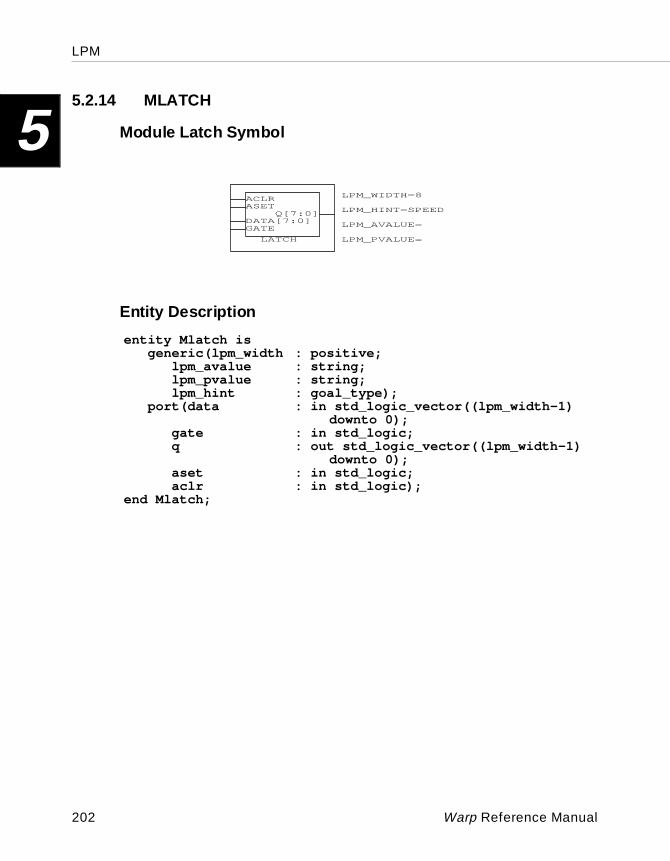
LPM
5
5.2.14 MLATCHModule Latch Symbol
Entity Descri ption
LATCH
TESTOUTTESTIN
TESTENAB
ACLRASET
Q[7:0]DATA[7:0]GATE
LPM_WIDTH=8
LPM_AVALUE=
LPM_PVALUE=
LPM_HINT=SPEED
LPM_HINT=SPEED
LPM_WIDTH=8
LATCH
ACLRASET
Q[7:0]DATA[7:0]GATE LPM_AVALUE=
LPM_PVALUE=
entity Mlatch isgeneric(lpm_width : positive;
lpm_avalue : string;lpm_pvalue : string;lpm_hint : goal_type);
port(data : in std_logic_vector((lpm_width-1)downto 0);
gate : in std_logic;q : out std_logic_vector((lpm_width-1)
downto 0);aset : in std_logic;aclr : in std_logic);
end Mlatch;
202 Warp Reference Manual
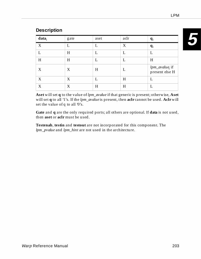
LPM
5
DescriptionAset will set q to the value of lpm_avalue if that generic is present; otherwise, Aset will set q to all ‘1’s. If the lpm_avalue is present, then aclr cannot be used. Aclr will set the value of q to all ‘0’s.
Gate and q are the only required ports; all others are optional. If data is not used, then aset or aclr must be used.
Testenab, testin and testout are not incorporated for this component. The lpm_pvalue and lpm_hint are not used in the architecture.
datai gate aset aclr qi
X L L X qi
L H L L L
H H L L H
X X H L lpm_avaluei if present else H
X X L H L
X X H H L
Warp Reference Manual 203
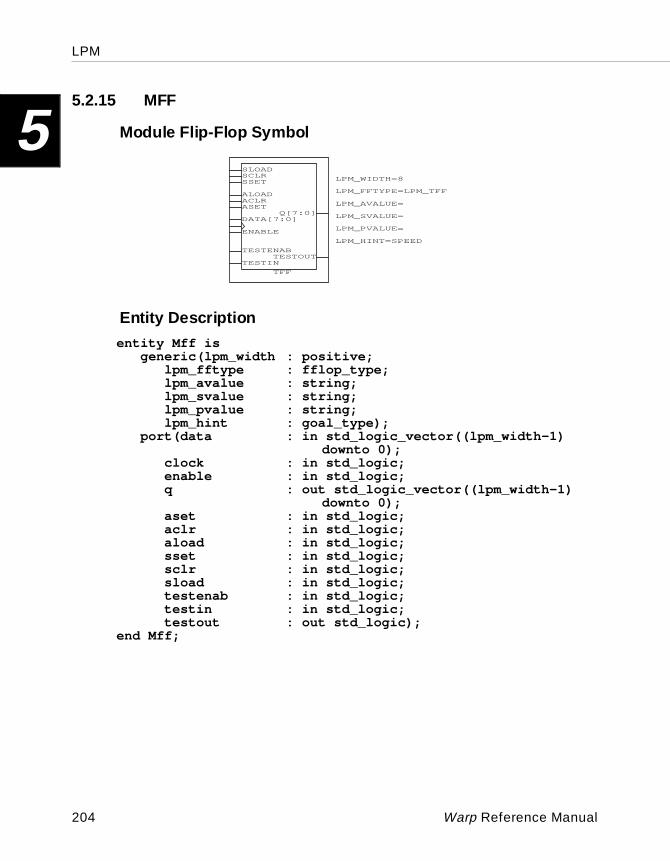
LPM
5
5.2.15 MFFModule Flip-Flop Symbol
Entity Descri ption
LPM_SVALUE=
TFF
TESTOUTTESTIN
TESTENAB
SLOADSCLRSSET
ALOADACLRASET
Q[7:0]
ENABLE
DATA[7:0]
LPM_WIDTH=8
LPM_HINT=SPEED
LPM_FFTYPE=LPM_TFF
LPM_AVALUE=
LPM_PVALUE=
LPM_SVALUE=
TFF
TESTOUTTESTIN
TESTENAB
SLOADSCLRSSET
ALOADACLRASET
Q[7:0]
ENABLE
DATA[7:0]
LPM_WIDTH=8
LPM_HINT=SPEED
LPM_FFTYPE=LPM_TFF
LPM_AVALUE=
LPM_PVALUE=
entity Mff isgeneric(lpm_width : positive;
lpm_fftype : fflop_type;lpm_avalue : string;lpm_svalue : string;lpm_pvalue : string;lpm_hint : goal_type);
port(data : in std_logic_vector((lpm_width-1)downto 0);
clock : in std_logic;enable : in std_logic;q : out std_logic_vector((lpm_width-1)
downto 0);aset : in std_logic;aclr : in std_logic;aload : in std_logic;sset : in std_logic;sclr : in std_logic;sload : in std_logic;testenab : in std_logic;testin : in std_logic;testout : out std_logic);
end Mff;
204 Warp Reference Manual
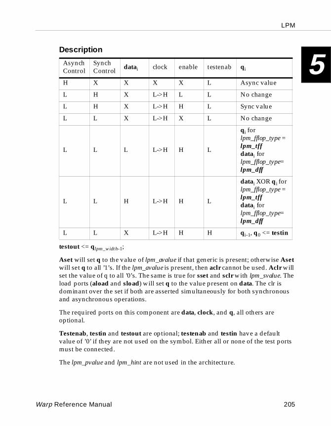
LPM
5
Descriptiontestout <= qlpm_width-1;
Aset will set q to the value of lpm_avalue if that generic is present; otherwise Aset will set q to all ’1’s. If the lpm_avalue is present, then aclr cannot be used. Aclr will set the value of q to all ’0’s. The same is true for sset and sclr with lpm_svalue. The load ports (aload and sload) will set q to the value present on data. The clr is dominant over the set if both are asserted simultaneously for both synchronous and asynchronous operations.
The required ports on this component are data, clock, and q, all others are optional.
Testenab, testin and testout are optional; testenab and testin have a default value of ’0’ if they are not used on the symbol. Either all or none of the test ports must be connected.
The lpm_pvalue and lpm_hint are not used in the architecture.
AsynchControl
SynchControl datai clock enable testenab qi
H X X X X L Async value
L H X L->H L L No change
L H X L->H H L Sync value
L L X L->H X L No change
L L L L->H H L
qi for lpm_fflop_type = lpm_tffdatai for lpm_fflop_type= lpm_dff
L L H L->H H L
datai XOR qi for lpm_fflop_type = lpm_tffdatai for lpm_fflop_type= lpm_dff
L L X L->H H H qi-1, q0 <= testin
Warp Reference Manual 205
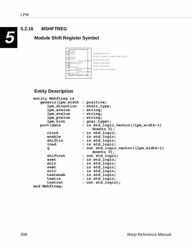
LPM
5
5.2.16 MSHFTREGModule Shift Regis ter Symbol
Entity Descri ption
LPM_SVALUE=
SHIFT LEFT REG
TESTOUTTESTIN
TESTENAB
SCLRSSETLOAD
ACLRASET
DATA[7:0]
SHIFTOUT
SHIFTIN
Q[7:0]
ENABLE
LPM_WIDTH=8
LPM_HINT=SPEED
LPM_DIRECTION=LPM_LEFT
LPM_AVALUE=
LPM_PVALUE=
LPM_SVALUE=
SHIFT LEFT REG
TESTOUTTESTIN
TESTENAB
SCLRSSETLOAD
ACLRASET
DATA[7:0]
SHIFTOUT
SHIFTIN
Q[7:0]
ENABLE
LPM_WIDTH=8
LPM_HINT=SPEED
LPM_DIRECTION=LPM_LEFT
LPM_AVALUE=
LPM_PVALUE=
entity Mshftreg isgeneric(lpm_width : positive;
lpm_direction : shdir_type;lpm_avalue : string;lpm_svalue : string;lpm_pvalue : string;lpm_hint : goal_type);
port(data : in std_logic_vector((lpm_width-1)downto 0);
clock : in std_logic;enable : in std_logic;shiftin : in std_logic;load : in std_logic;q : out std_logic_vector((lpm_width-1)
downto 0);shiftout : out std_logic;aset : in std_logic;aclr : in std_logic;sset : in std_logic;sclr : in std_logic;testenab : in std_logic;testin : in std_logic;testout : out std_logic);
end Mshftreg;
206 Warp Reference Manual
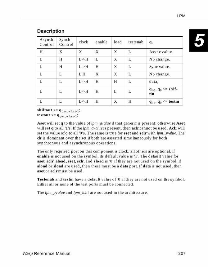
LPM
5
Descriptionshiftout <= qlpm_width-1;testout <= qlpm_width-1;
Aset will set q to the value of lpm_avalue if that generic is present; otherwise Aset will set q to all ’1’s. If the lpm_avalue is present, then aclr cannot be used. Aclr will set the value of q to all ’0’s. The same is true for sset and sclr with lpm_svalue. The clr is dominant over the set if both are asserted simultaneously for both synchronous and asynchronous operations.
The only required port on this component is clock, all others are optional. If enable is not used on the symbol, its default value is ’1’. The default value for aset, aclr, aload, sset, sclr, and sload is ’0’ if they are not used on the symbol. If aload or sload are used, then there must be a data port. If data is not used, then aset or aclr must be used.
Testenab and testin have a default value of ’0’ if they are not used on the symbol. Either all or none of the test ports must be connected.
The lpm_pvalue and lpm_hint are not used in the architecture.
AsynchControl
SynchControl clock enable load testenab qi
H X X X X L Async value
L H L->H L X L No change.
L H L->H H X L Sync value.
L L L,H X X L No change.
L L L->H H H L datai
L L L->H H L L qi-1, q0 <= shif-tin
L L L->H H X H qi-1, q0 <= testin
Warp Reference Manual 207
LPM
5
5.3 Other Cypress ModulesTo use any of the components described in this chapter within a VHDL description, include the following line in the VHDL file, immediately above the entity and architecture declarations:
use work.lpmpkg.all;
In the Description portion of the component definitions, the following conventions apply:
Port names are identified by: resultGenerics are identified by: lpm_widthValues of generics are identified by: lpm_logical
Many of the components in this library have ports that can be selected or deselected in the symbol. If the port is deselected, it will not show up on the symbol but will be netlisted to its default value. If these components are implemented with VHDL structural code, those ports must be both included in the port map and connected to a ’0’ or ’1’ if the functionality that each particular port allows is not needed.
All examples of the entities are presented in std_logic form.
208 Warp Reference Manual
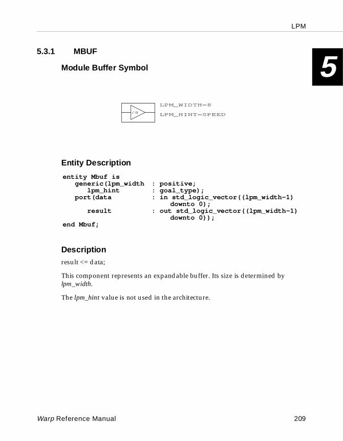
LPM
5
5.3.1 MBUFModule Buffer Symbol
Entity Descri ption
Descriptionresult <= data;
This component represents an expandable buffer. Its size is determined by lpm_width.
The lpm_hint value is not used in the architecture.
LPM_WIDTH=8
/8 LPM_HINT=SPEED
LPM_WIDTH=8
/8 LPM_HINT=SPEED
entity Mbuf isgeneric(lpm_width : positive;
lpm_hint : goal_type);port(data : in std_logic_vector((lpm_width-1)
downto 0);result : out std_logic_vector((lpm_width-1)
downto 0));end Mbuf;
Warp Reference Manual 209

LPM
5
5.3.2 MGNDModule Ground Symbol
Entity Descri ption
Description
x <= (OTHERS => ‘0’);
This component represents an expandable ground. Its size is determined by lpm_width.
8
GND
LPM_WIDTH=88
GND
LPM_WIDTH=8
entity Mbuf isgeneric(lpm_width : positive);port(x : out std_logic_vector((lpm_width-1)
downto 0));end Mbuf;
210 Warp Reference Manual
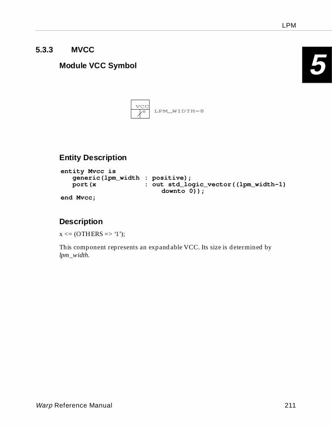
LPM
5
5.3.3 MVCCModule VCC Symbol
Entity Descri ption
Description
x <= (OTHERS => ‘1’);
This component represents an expandable VCC. Its size is determined by lpm_width.
8
VCCLPM_WIDTH=88
VCCLPM_WIDTH=8
entity Mvcc isgeneric(lpm_width : positive);port(x : out std_logic_vector((lpm_width-1)
downto 0));end Mvcc;
Warp Reference Manual 211
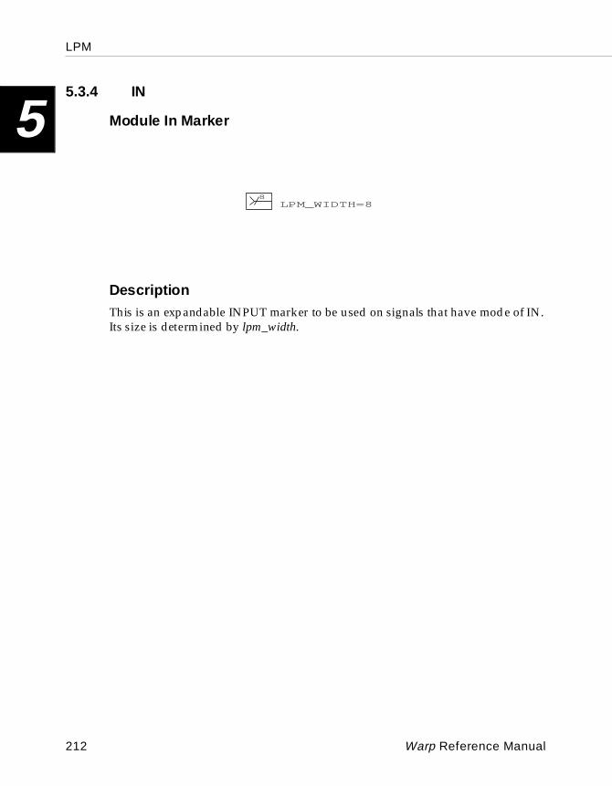
LPM
5
5.3.4 INModule In Marker
DescriptionThis is an expandable INPUT marker to be used on signals that have mode of IN. Its size is determined by lpm_width.
8LPM_WIDTH=8
8LPM_WIDTH=8
212 Warp Reference Manual
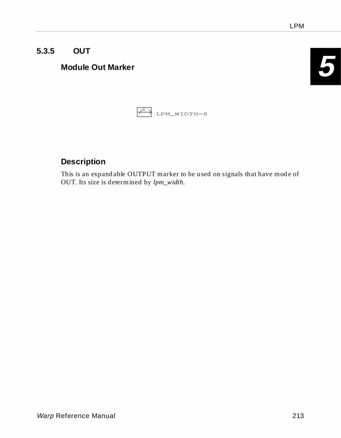
LPM
5
5.3.5 OUTModule Out Marker
DescriptionThis is an expandable OUTPUT marker to be used on signals that have mode of OUT. Its size is determined by lpm_width.
8LPM_WIDTH=8
8LPM_WIDTH=8
Warp Reference Manual 213
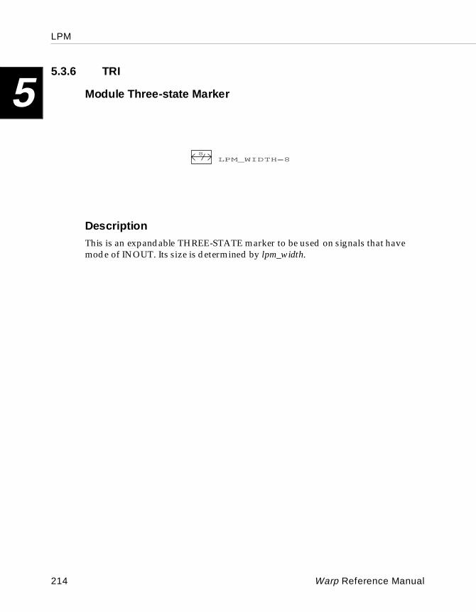
LPM
5
5.3.6 TRIModule Three-state Marker
DescriptionThis is an expandable THREE-STATE marker to be used on signals that have mode of INOUT. Its size is determined by lpm_width.
8LPM_WIDTH=8
8LPM_WIDTH=8
214 Warp Reference Manual
LPM
5
5.4 Cypress Exc eptions to LPM Standard5.4.1 Which Options of LPM Do We Support?
The LPM specification is written so that many features can be implemented without forcing all implementations to be identical. This feature is made possible by using a large number of optional parameters and behaviors in the architectures of the components.
The following is a summary of Cypress’ implementation of those options in the LPM library:
• LPM_POLARITY -in Release 4.0, only the MAND, MOR, and MXOR will have selectable polarity.
• LPM_HINT - this property is vendor unique and is used to specify a synthesis guide. It can take the value of SPEED (default), AREA, or COMBINATORIAL.
• LPM Values - the value properties used in the Cypress LPM library are implemented as strings.
• Signed/Unsigned - the Cypress LPM library offers only LPM_UNSIGNED types.
• Async operations - the exceptions for asynchronous operations are noted by the fitter during compilation.
• Scan Test - all appropriate Cypress LPM library components will have the scan test feature available. The only exception is the MLATCH component.
• The following LPM components have no equivalent in the Cypress LPM library:
• LPM_ABS
• LPM_RAM_DQ
• LPM_RAM_IO
• LPM_ROM
• LPM_TTABLE
• LPM_FSM
Warp Reference Manual 215
LPM
5
• LPM_INPAD• LPM_OUTPAD
• LPM_BIPAD
5.5 Hints and Techniques
5.5.1 How to Best Use the LPM_HINT
The Cypress LPM library includes a few components that may be implemented with the optional LPM_HINT attribute. This attribute can be set to the values of SPEED, AREA and COMBINATORIAL. Although this “hint” is used in many ways for module generation, there are only three components affected by it in the LPM library. Those components are:
• MADD_SUB for CPLDs
• MCOUNTER for CPLDs and pASICs
• MCOMPARE for pASICs
The following sections describe the differences obtained for area and speed for example design components.
The devices used for these examples were the CY7C375 for the CPLD versions and CY7C386A for the FPGA version.
Note – These values are only a guideline and are extremely dependent upon the particular implementation. Any circuitry added before or after these components will affect the synthesis of the component.
216 Warp Reference Manual
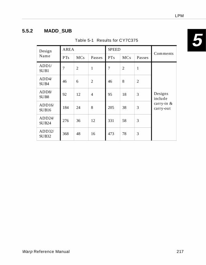
LPM
5
5.5.2 MADD_SUBTable 5-1 Resul ts for CY7C375
Design Name
AREA SPEEDComments
PTs MCs Passes PTs MCs Passes
ADD1/SUB1 7 2 1 7 2 1
Designs include carry-in & carry-out
ADD4/SUB4 46 6 2 46 8 2
ADD8/SUB8 92 12 4 95 18 3
ADD16/SUB16 184 24 8 205 38 3
ADD24/SUB24 276 36 12 331 58 3
ADD32/SUB32 368 48 16 473 78 3
Warp Reference Manual 217
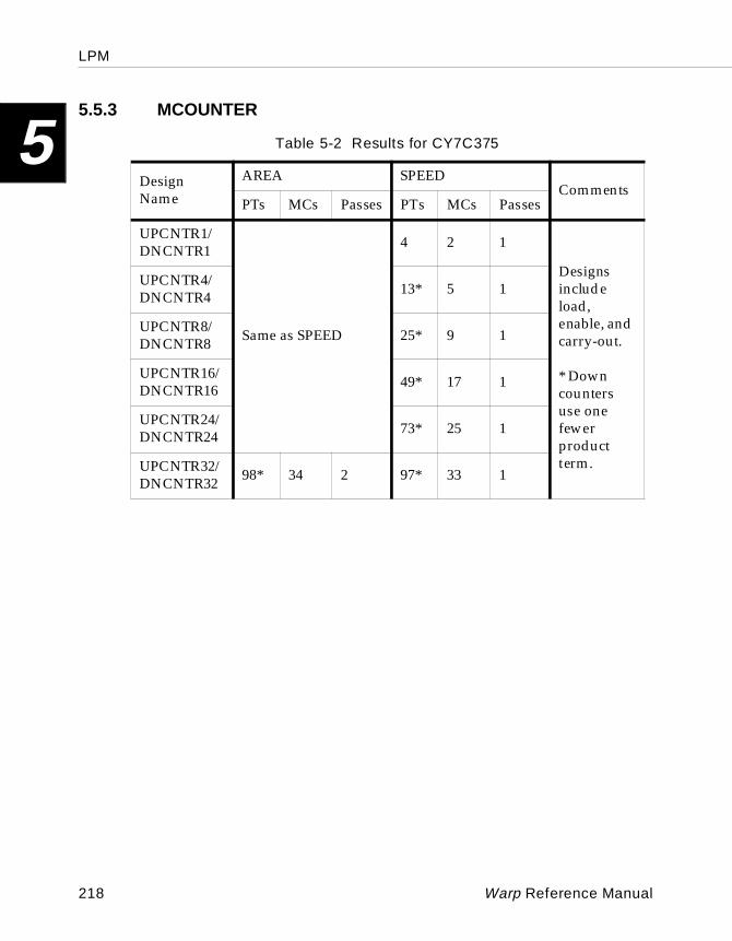
LPM
5
5.5.3 MCOUNTERTable 5-2 Results for CY7C375
Design Name
AREA SPEEDComments
PTs MCs Passes PTs MCs Passes
UPCNTR1/DNCNTR1
Same as SPEED
4 2 1
Designs include load, enable, and carry-out.
* Down counters use one fewerproduct term.
UPCNTR4/DNCNTR4 13* 5 1
UPCNTR8/DNCNTR8 25* 9 1
UPCNTR16/DNCNTR16 49* 17 1
UPCNTR24/DNCNTR24 73* 25 1
UPCNTR32/DNCNTR32 98* 34 2 97* 33 1
218 Warp Reference Manual
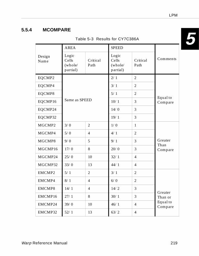
LPM
5
5.5.4 MCOMPARETable 5-3 Results for CY7C386A
Design Name
AREA SPEED
CommentsLogic Cells(whole/partial)
Critical Path
Logic Cells(whole/partial)
Critical Path
EQCMP2
Same as SPEED
2/1 2
Equal to Compare
EQCMP4 3/1 2
EQCMP8 5/1 2
EQCMP16 10/1 3
EQCMP24 14/0 3
EQCMP32 19/1 3
MGCMP2 3/0 2 1/0 1
Greater Than Compare
MGCMP4 5/0 4 4/1 2
MGCMP8 9/0 5 9/1 3
MGCMP16 17/0 8 20/0 3
MGCMP24 25/0 10 32/1 4
MGCMP32 33/0 13 44/1 4
EMCMP2 5/1 2 3/1 2
Greater Than orEqual to Compare
EMCMP4 8/1 4 6/0 2
EMCMP8 14/1 4 14/2 3
EMCMP16 27/1 8 30/1 3
EMCMP24 39/0 10 46/1 4
EMCMP32 52/1 13 63/2 4
Warp Reference Manual 219
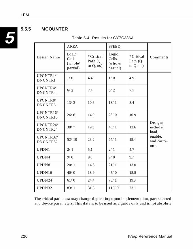
LPM
5
5.5.5 MCOUNTERThe critical path data may change depending upon implementation, part selected and device parameters. This data is to be used as a guide only and is not absolute.
Table 5-4 Results for CY7C386A
Design Name
AREA SPEED
CommentsLogic Cells (whole/ partial)
* Critical Path (Q to Q, ns)
Logic Cells (whole/ partial)
* Critical Path (Q to Q, ns)
UPCNTR1/DNCNTR1 1/0 4.4 1/0 4.9
Designs include load, enable, and carry-out.
UPCNTR4/DNCNTR4 6/2 7.4 6/2 7.7
UPCNTR8/DNCNTR8 13/3 10.6 13/1 8.4
UPCNTR16/DNCNTR16 26/6 14.9 28/0 10.9
UPCNTR24/DNCNTR24 38/7 19.3 45/1 13.6
UPCNTR32/DNCNTR32 52/10 28.2 65/1 19.4
UPDN1 2/1 5.1 2/1 4.7
UPDN4 9/0 9.8 9/0 9.7
UPDN8 20/1 14.3 21/1 13.0
UPDN16 40/0 18.9 45/0 15.5
UPDN24 61/0 24.4 78/1 19.3
UPDN32 83/1 31.8 115/0 23.1
220 Warp Reference Manual

Chapter
66
Report File
Report File
6
6.1 Introduction
This chapter provides an anatomy of the report file generated by Warp. The report file generated by Warp has the same base name as the design VHDL file but with an .rpt extension. Interpreting the report file is very important and can help reduce the amount of time spent debugging designs.
A report file is generated for every file that Warp compiles. If a design is split up among multiple files, the report file that will probably be most useful is the one for the top level design.
The report file can be broken down into three main sections:
• Front End Compiler section
• Front End Synthesis and Optimization section
• CPLD/PLD Fitting section
The Front End sections are common for all devices. The Fitting section, however, is only applicable to the CPLD/PLD families of devices. For pASIC, the Fitting is more complex and is run by a separate tool called SpDE, which is more like a place and route tool with a graphical user interface and various support tools of its own. SpDE also appends information to the report file, which consists mostly of the device PIN information and will not be described in this manual.
In conjunction with this section, see Appendix A, “Error Messages.”
6.2 Front End Compiler
Warp is essentially a combination of multiple tools that perform various functions. They are run in the following order:
• front end (VHDLFE and TOVIF)
• synthesis and optimization (TOPLD)
• fitting (PLA2JED, MAX2JED or C37XFIT)
This section describes the VHDLFE and the TOVIF tools.
After the initial Copyright information is printed, the file being compiled is listed along with the current set of options in effect. The first tool that runs on a design is the VHDL parser (called VHDLFE). VHDLFE first associates the symbolic VHDL library work with a given device. This is a very important step for subsequent phases to produce optimal or correct implementations of the design for the device being targeted. VHDLFE then parses the VHDL file and reports any
222 Warp Reference Manual
Report File
6
direct external references (libraries, packages, etc.) that are being made from the current VHDL file.
VHDLFE’s (parser) main function is to parse or read the VHDL file and check for syntax errors and a few semantic errors. A syntax check, which is strictly a grammatical check of the VHDL, deals with the specification of the design. A semantic check, on the other hand, deals with the meaning of the VHDL being interpreted. Some semantic errors can be caught by the parser right away and are thus reported by the VHDLFE program.
VHDLFE also reports one other important aspect of a design. VHDLFE detects all datapath components of a design (essentially VHDL operators that perform math or comparisons). If these messages do not appear and the design uses these operators, then more than likely the user has his own implementations for these operators or the user is NOT using the proper math libraries for device optimized implementations of datapath operators (see Chapter 4, “VHDL”). Although these messages about datapath operators are informational, the user should be concerned if they do not appear when non-constant operations are in his design.
Once the VHDL has been found to be syntactically error free, the VHDL file goes through high level synthesis, and the components of the VHDL file (packages, functions, entities, architectures, etc.) are then converted to an intermediate format (an expression tree) that can be translated into simple equations and registers (RTL components and equations) in the next phase of Synthesis and Optimization. The program that performs this functions called TOVIF, where VIF is an acronym for “VHDL Intermediate Format”. When designs are composed of multiple files and external references, it is important to note what files/directories are being reported. A common error in compiling libraries is including multiple files that define VHDL components with identical names. When this happens, Warp only uses the last file that was compiled.
Warp Reference Manual 223
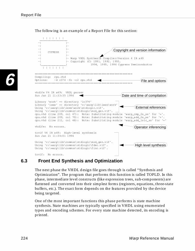
Report File
6
The following is an example of a Report File for this section:
| | | | | | | _________________ -| |- -| |- -| |- -| CYPRESS |- -| |- -| |- Warp VHDL Synthesis Compiler:Version 4 IR x49 -| |- Copyright (C) 1991, 1992, 1993, |_______________| 1994, 1995, 1996 Cypress Semiconductor
| | | | | | |
============================================================Compiling: cpu.vhdOptions: -d c374 -fo -o2 cpu.vhd============================================================
vhdlfe V4 IR x49: VHDL parserSun Jan 21 11:33:35 1996
Library ‘work’ => directory ‘lc374’Library ‘ieee’ => directory ‘c:\warp\lib\ieee\work’Using ‘c:\warp\lib\ieee\work\stdlogic.vif’.Using ‘c:\warp\lib\common\stdlogic\mod_gen.vif’.cpu.vhd (line 209, col 47): Note: Substituting module ‘warp_cmp_2s_ss’ for ‘=’.cpu.vhd (line 209, col 70): Note: Substituting module ‘warp_add_2s_ss’ for ‘+’.cpu.vhd (line 211, col 48): Note: Substituting module ‘warp_add_1s1c_ss’ for ‘+’
vhdlfe: No errors.
tovif V4 IR x49: High-level synthesisSun Jan 21 11:34:01 1996
Using ‘c:\warp\lib\common\stdlogic\mod_gen.vif’.Using ‘c:\warp\lib\common\stdlogic\fdec.vif’.Using ‘c:\warp\lib\common\stdlogic\finc.vif’.
tovif: No errors.
6.3 Front End Synthesis and Optimization
The next phase the VHDL design file goes through is called “Synthesis and Optimization”. The program that performs this function is called TOPLD. In this phase, intermediate level constructs (like expression trees, sub-components) are flattened and converted into their simplest forms (registers, equations, three-state buffers, etc.). The exact form depends on the features provided by the device being targeted.
One of the most important functions this phase performs is state machine synthesis. State machines are typically specified in VHDL using enumerated types and encoding schemes. For every state machine detected, its encoding is printed.
Copyright and version information
File and options
Date and time of compilation
External references
Operator inferencing
High level synthesis
224 Warp Reference Manual
Report File
6
Since this phase also flattens any hierarchical components being referenced from other VIF files, the report file includes this information. The following is an example of a report file targeting a CPLD/PLD.
topld V4 IR x49: Synthesis and optimizationSun Jan 21 11:35:17 1996
State variable ‘cpu_state’ is represented by a Bit_vector (0 to 1).State encoding (sequential) for ‘sd_state’ is:
sreset := b”00” ;idle := b”01” ;add := b”10” ;compare := b”11” ;
Using ‘c:\warp\lib\lc370\stdlogic\c370.vif’.
-------------------------------------------------------Alias Detection-------------------------------------------------------
-------------------------------------------------------Aliased 174 equations, 334 wires.-------------------------------------------------------
-------------------------------------------------------Circuit simplification-------------------------------------------------------
-------------------------------------------------------Circuit simplification results:
Deleted 100 equations/components.Expanded 130 signals.Turned 0 signals into soft nodes.Maximum expansion cost was set at 10.
-------------------------------------------------------
Optimization involves various steps. The “Alias Detection” stage looks for redundant equations and simple wires and eliminates them from the system. “Circuit Simplification” collapses intermediate signals into their fanout (also called Virtual Substitution) and eliminates unused equations. During virtual substitution, certain nodes could potentially become very large. When such a condition is detected, it is made into a soft node (a node that remains in the network), and the process continues. If soft nodes are created, they will appear in the report file. If the Detailed Report file option is chosen in Galaxy, more information will appear during Virtual Substitution and Alias Detection.
The process that follows after this stage depends on the architecture of the device being targeted. See the following two sections for more information.
State variable, number of bits
State encoding
Optimization
Summary of optimization
Warp Reference Manual 225
Report File
6
6.4 pASIC Technology Mapping
TOPLD and SpDE perform different kinds of Optimization and Technology Mapping, both of which are necessary to achieve good results. Technology Mapping is the process of converting equations into a form that is supported by the target architecture (in this case, pASIC).
For pASIC devices, additional optimization phases are performed by TOPLD. They involve factoring and mux detection, but these phases are not reported in the report file. When these kinds of optimizations are performed, however, they may produce additional equations that may have to be deleted. If the Detailed Report file option is chosen in Galaxy, more information may appear in the report file. The goal of this kind of optimization is reducing the overall network size.
The final phase of TOPLD for pASIC devices involves PAD and BUFFER generation in conjunction with producing a QDIF (a .qdf file) netlist for input to SpDE.
Before PAD and BUFFER generation begins, important resources available for the device are listed. First, the maximum available resources are listed. This may change depending upon the exact device. Express Wires are wires capable of higher drive strengths than other kinds of wires and are needed to use an INPUT only pad. Clock pads can also connect to these Express Wires or to the clock distribution tree which provides very low skew. Clock distribution trees connect only to the Clock, Reset, and Preset terminals of a flip-flop. So, if a signal is used both as a clock and in other combinatorial equations, that signal must use one of the express wires to make that connection. If such a situation occurs, the report file will indicate it.
To interpret the PAD and BUFFER generation portion of the report file, the user must first be familiar with the features of the individual pASIC devices and the way synthesis directives can be used to control the use of these features.
226 Warp Reference Manual
Report File
6
The following is an example of a report file using some of these resources:
Max resources.
Express Wires = 4 Clock PADS = 2 Input PADS = 6
Critical resources used by design before PAD generation.
Express Wires = 0 Clock PADS = 0 Input PADS = 0
----------------------------------------------------------Begin PAD Generation.----------------------------------------------------------Created CLKPAD for signal ‘tclock’ Above signal drives 66 Clocks, 0 Set/Resets. Total = 66 And 4 other inputs (active low). Above signal consumed 1 express wireCreated CLKPAD for signal ‘xclock’ Above signal drives 12 Clocks, 6 Set/Resets. Total = 18Created HD1PADi for signal ‘resetn’Above signal drives 0 Clocks, 60 Set/Resets, 0 other inputs. Total = 60Created HD1PAD for signal ‘ad_25’Above signal drives 0 Clocks, 0 Set/Resets, 14 other inputs. Total = 14
Input/Clock PAD resources unused
Express Wires = 1 Clock PADS = 0 Input PADS = 4----------------------------------------------------------Begin Buffer Generation.----------------------------------------------------------[max_load = 13, fanout = 17] Created 1 buffers [Duplicate] for ‘cpu_en’[max_load = 9, fanout = 17] Created 2 buffers [Normal ] for ‘cpu_stateSBV_0’[max_load = 9, fanout = 25] Created 2 buffers [Normal ] for ‘cpu_stateSBV_1’
Primitives synthesized: 612Primitives instantiated: 80------------------------------Total primitives: 692Percentage synthesized: 88%
Muxes detected: 11
topld: No errors.
In the above example, tclock is being used by the design both as a clock which connects directly to a flip-flop and as an input to a combinatorial signal (probably as a product term clock). In a case like this, the report file indicates that the signal tclock not only used a clock PAD but also used one express wire to connect the other 4 inputs. The 4 other inputs, in this case also happen to be active low. Since a clock PAD can produce either an active high or active low input, the software indicates which of these inputs are actually used.
Max available resources
Resources used by user
Clock + comb. signal
Clock only input
Active high input
Active low input
Unused resources
Buffer generation
Final statistics
Pad generation
Warp Reference Manual 227
Report File
6
The signal xclock drives 12 clocks and 6 Set/Reset inputs (a hypothetical case). Since all of these inputs drive a flip-flop directly, this signal only uses the clock distribution tree.
The signal resetn drives 60 flip-flops but is active low. In this case, the report file indicates that the active low input of the HDPAD was used. This is denoted by the ‘i’. The last input ‘ad_25’ connects to 14 inputs and is active high. When reporting HDPADS, the following convention is used.
HDnPAD[i]
where “n” is the number of HDPADSs that are paralleled and the optional “i”, as described above, is used only if the active low output of the HDPAD is in use.
Note – When multiple HDPADs are paralleled to improve drive strength, it still only uses one (1) express wire.
In the BUFFER generation phase, all buffers that Warp generates are listed. For each signal for which buffers are generated, the name of the signal is listed, the maximum loading is specified, and the fanout that it drives before buffer generation is also listed. The number of buffers generated represents the number of additional FRAGS used to create the buffers. For example, for the signal cpu_en, only one additional FRAG was used because the strategy used for buffer generation for this signal is Logic Duplication (Duplicate). The strategy can either be user specified (via synthesis directives) or automatically determined by Warp. The exact strategy used for this signal is also listed. Please refer to Chapter 3, “Synthesis Directives,” for more information on buffering strategies.
Finally, the last section of the report file prints the statistics of the design. “Primitives Synthesized” is a count of the number of 2-input Nand-gate or 1-selector muxes required to implement the design. “Primitives instantiated” is a measure of the number of flip-flops and FRAGS instantiated by the design (some of these can also come from operator inferencing). These numbers can be used as a guide to the size of the design and do NOT represent the actual number of pASIC Logic Cells required to implement the design. In general, however, the higher these numbers are, the more Logic Cells will be required to represent the design. The “Percentage synthesized” also indicates if any obvious improvements can be made by tweaking the design. Typically, if this percentage is low, this means that most of the design was probably entered or synthesized as combinatorial equations, which means that a knowledgeable pASIC designer could probably save some area or gain performance by using logic design techniques. A large number indicates that the design is probably mostly flip-flops
228 Warp Reference Manual
Report File
6
or hand crafted designs consisting of FRAGs which means that although improvement is still possible, it might be more difficult.
The “Muxes Detected” simply indicates how well Warp’s Mux-Detection performed on this particular design.
Finally, the last line should indicate “No errors.” If any errors were detected, the QDF output is NOT generated. The user should also aim to eliminate all “Warnings.”
6.5 CPLD/PLD Fitting
6.5.1 Technology Mapping and Optimization
The last thing TOPLD does is to output a PLA file that is then processed by the fitter. The fitter is really more than just a Place and Route tool. Its responsibilities include optimizing and technology mapping the equations to reduce resource utilization before actual Place and Route can begin.
The optimization phase is conducted in many phases depending upon the options that are currently in effect and the nature of the design. Optimization is conducted by two programs called DSGNOPT and MINOPT. DSGNOPT can be considered as the decision maker and MINOPT as the optimizer.
The first phase of DSGNOPT reduces the design by removing any equations or wires that can be expanded into their fanout. DSGNOPT also determines if there are any equations that need to be converted to nodes. (A node is an equation that will require a macrocell resource). Among other things, DSGNOPT also performs the following functions:
• technology mapping (converts all equations to a form supported by the PLD being targeted)
• register optimization (selects the best of D-type or T-type implementations)
• polarity optimization (selects the best of Active High and Active Low implementations
• sum-splitting (equations too large for a macrocell are split)
• global resource reduction (for global resources like resets/presets, tries to adjust the equations to minimize these resources)
Warp Reference Manual 229
Report File
6
The types of optimizations depends on the device being targeted. For example, certain PLDs do not support a T-type flip-flop. This means that Register Optimization is not performed.
6.5.2 Equations
After all the different phases of DSGNOPT, the actual fitter or Place and Route tool is finally invoked. The exact fitter depends on the type of device being targeted. The FLASH370 family of devices requires the C37XFIT; the MAX340 family requires MAX2JED; and all other PLDs require PLA2JED. All of these fitters use the exact same conventions in their report files, but the exact content depends on the design and the device.
The first thing any of the aforementioned fitters do is print the final equations. This is probably the most important part of a report file for debugging a design. To help understand this portion of the report file, the user will have to understand how equations or macrocells operate in the particular fitter. Typically, a macrocell has many features. Some of these include an asynchronous preset, asynchronous reset, output enable, etc. The fitter also treats the I/O cells (with or without and output enable) simply as a feature of a macrocell. Each feature of the macrocell is given a one to two letter acronym. Each equation printed in the report file is expected to be mapped to a particular macrocell and is actually printed as a group of equations with a common base-name which represents the name of a macrocell. For example, the following represents an equation for one macrocell “bterr ” which is currently using four features of the macrocell:
bterr.D = b_stateSBV_0.Q * /b_stateSBV_3.Q
bterr.AP = GND
bterr.AR = /resetn
bterr.C = tclock
The conventions used in printing the equations are as follows:
• / represents an inversion
• * represents an AND function
• + represents an OR function
• = is an assignment
• VCC and GND represent constant logic values ’1’ and ’0’ respectively.
230 Warp Reference Manual
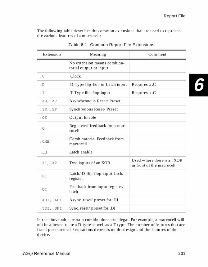
Report File
6
The following table describes the common extensions that are used to represent the various features of a macrocell:
In the above table, certain combinations are illegal. For example, a macrocell will not be allowed to be a D-type as well as a T-type. The number of features that are listed per macrocell/equations depends on the design and the features of the device.
Table 6-1 Common Report File Extensions
Extension Meaning Comment
No extension means combina-torial output or input.
.C Clock
.D D-Type flip-flop or Latch input Requires a .C
.T T-Type flip-flop input Requires a .C
.AR,.AP Asynchronous Reset/Preset
.SR,.SP Synchronous Reset/Preset
.OE Output Enable
.QRegistered feedback from mac-rocell
.CMBCombinatorial Feedback from macrocell
.LH Latch enable
.X1,.X2 Two inputs of an XOR Used where there is an XOR in front of the macrocell.
.DILatch/D-flip-flop input latch/register
.QIFeedback from input register/latch
.ARI,.API Async. reset/preset for .DI
.SRI,.SPI Sync. reset/preset for .DI
Warp Reference Manual 231
Report File
6
Sometimes equations may begin with a ‘/’. This indicates that the equation is considered to be active low. This can happen due to one of two reasons:
• The device may only support active low input to the feature. For example, AR in the MAX340 devices must be active low.
• During the DSGNOPT phase, the fitter determined that active low input requires fewer resources.
Any inversions that exist for signals in the right hand side of the equation literally refer to the active-low sense of the signal. This is important to note when a signal is being fed back into the array and is being generated by a macrocell which is configured to be active low. Consider the following two examples:
Example 1:
a =c + d
b =a.CMB * d
Example 2:
/a =/c * /d
b =a.CMB * d
The above two examples represent identical functionality. The first example is simple with everything being active high. In the second example , a is being represented as an active low signal; however, the signal b ’s equation is not modified to compensate for this. This is done so that when the user is examining b’s equation he does not have to consider the polarity of each of its inputs. Depending upon the device and the macrocell features, the fitter automatically adjusts the polarity during the routing phase. This convention also insulates the equations from the all the various types of macrocells. For example, in some macrocells, even though the D-input of a D-flip-flop can be generated in active low form from the product term array, there might be a programmable inverter just before register, which means that the macrocell might always have an active high output. In some other devices, such an inverter is available after the macrocell feedback.
232 Warp Reference Manual

Report File
6
Note – Regardless of what polarity the fitter uses to implement the individual equations, all outputs at the pins represent the design’s original intentions. This means that if a certain set of inputs should produce a logic level ’0’ at the pin, that logic level will be preserved regardless of whether the fitter produced an active low implementation or active high implementation.
If a signal is being used in an equation and has no extension, it always means that this signal is being fed into the product term directly from the PIN (Input or I/O). When equations are too large to be implemented in a macrocell (for example, greater than 16 product terms for the FLASH370 family), such equations are split. Each of the sub equations is named as prefix “S_n” where “n” is a unique number. When expanders are produced for the MAX340 family, each of these expander terms is labelled “E_n” where “n” is a number.
6.5.3 Fitting
After the equations are printed, the place and route phase begins. The exact message that appears depends on the architecture of the device being targeted. These messages are mostly informational. One of the actions that happen in this phase is the combination of a buried node with an INPUT only signal. A buried node represents a signal that is assigned to a macrocell but never routed to a PIN. When such signals are assigned to a macrocell which in turn is connected to an I/O pin, the I/O pin can still be used as a pure input to the design. The buried nodes are printed within parentheses with the INPUT PIN name concatenated to it. For example, the phrase “(my_internal) my_input” implies that “my_internal” is a buried node and “my_input” is an input pin sharing the same macrocell.
For small PLDs, the fitting stage is very simple and obvious. The FLASH370 family fitting, however, deserves some explanation. Once the fitter determines a solution, it prints the solution for each of the Logic Blocks and for the resources used by each Logic Block individually. Since the FLASH370 family also uses a unique way of sharing product terms, the report file also shows how these product terms are mapped.
Warp Reference Manual 233
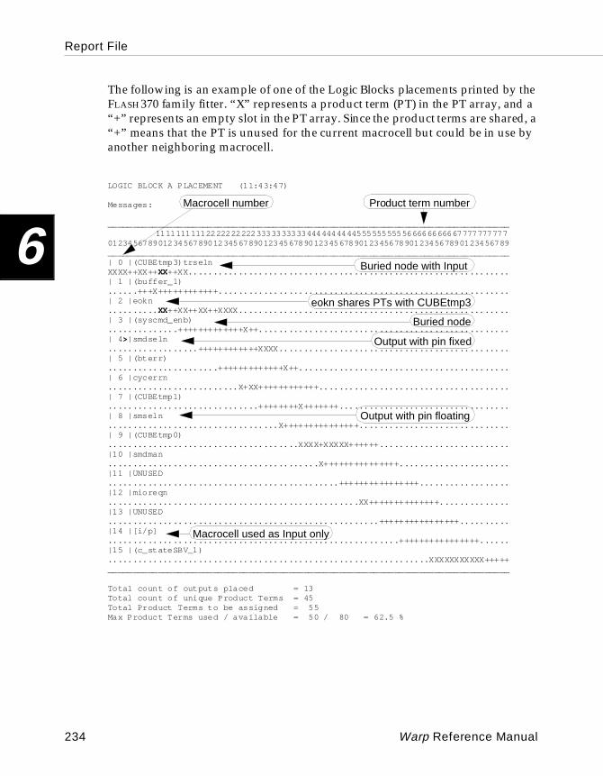
Report File
6
The following is an example of one of the Logic Blocks placements printed by the FLASH370 family fitter. “X” represents a product term (PT) in the PT array, and a “+” represents an empty slot in the PT array. Since the product terms are shared, a “+” means that the PT is unused for the current macrocell but could be in use by another neighboring macrocell.
LOGIC BLOCK A PLACEMENT (11:43:47)
Messages:
________________________________________________________________________________1111111111222222222233333333334444444444555555555566666666667777777777
01234567890123456789012345678901234567890123456789012345678901234567890123456789________________________________________________________________________________| 0 |(CUBEtmp3)trselnXXXX++XX++XX++XX................................................................| 1 |(buffer_1)......+++X++++++++++++..........................................................| 2 |eokn.......... XX++XX++XX++XXXX......................................................| 3 |(syscmd_enb)..............+++++++++++++X++..................................................| 4 >|smdseln..................++++++++++++XXXX..............................................| 5 |(bterr)......................+++++++++++++X++..........................................| 6 |cycerrn..........................X+XX++++++++++++......................................| 7 |(CUBEtmp1)..............................++++++++X+++++++..................................| 8 |smseln..................................X+++++++++++++++..............................| 9 |(CUBEtmp0)......................................XXXX+XXXXX++++++..........................|10 |smdman..........................................X+++++++++++++++......................|11 |UNUSED..............................................++++++++++++++++..................|12 |mioreqn..................................................XX++++++++++++++..............|13 |UNUSED......................................................++++++++++++++++..........|14 |[i/p]..........................................................++++++++++++++++......|15 |(c_stateSBV_1)................................................................XXXXXXXXXXX+++++________________________________________________________________________________
Total count of outputs placed = 13 Total count of unique Product Terms = 45Total Product Terms to be assigned = 55 Max Product Terms used / available = 50 / 80 = 62.5 %
Macrocell number
eokn shares PTs with CUBEtmp3
Buried node
Output with pin fixed
Output with pin floating
Macrocell used as Input only
Product term number
Buried node with Input
234 Warp Reference Manual
Report File
6
In the map for the Logic Block above, the following lines are worth notice. The first column of the Logic Block indicates the macrocell number within the Logic Block. If the macrocell number has a “>” sign next to it (for example macrocell #4), the placement was suggested or fixed by the user. Notice that the first macrocell has a buried node as well as an input. For macrocell #8, the assignment of the signal was done by the fitter. Macrocell #14 is being used as an input.
In the overall statistics for product term utilization, the “Total count of outputs place” represents how many macrocells are in use for logic. This number comes out to be 13 because macrocells 11, 13 and 14 have no product terms assigned to them. The “Total count of unique Product Terms” specify exactly that. The next item specifies the total number of unique and non-unique product terms. The next line describes the number of product terms actually used to implement the solution. In most cases, this matches the total number of unique product terms. In this case, these numbers did not match because the placement caused the sharing to be less than optimal, possibly due to the output enable banking or other placement constraints.
Warp Reference Manual 235
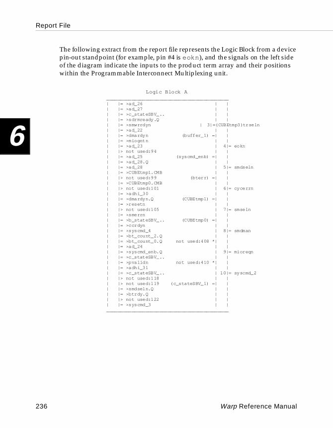
Report File
6
The following extract from the report file represents the Logic Block from a device pin-out standpoint (for example, pin #4 is eokn ), and the signals on the left side of the diagram indicate the inputs to the product term array and their positions within the Programmable Interconnect Multiplexing unit.
Logic Block A ____________________________________________ | |= >ad_26 | | | |= >ad_27 | | | |= >c_stateSBV_.. | | | |= >sdrmready.Q | | | |= >smwrrdyn | 3|=(CUBEtmp3)trseln | |= >ad_22 | | | |= >dmardyn (buffer_1) =| | | |= >miogntn | | | |= >ad_23 | 4|= eokn | |> not used:94 | | | |= >ad_25 (syscmd_enb) =| | | |= >ad_28.Q | | | |= >ad_28 | 5|= smdseln | |= >CUBEtmp1.CMB | | | |> not used:99 (bterr) =| | | |= >CUBEtmp0.CMB | | | |> not used:101 | 6|= cycerrn | |= >adhi_30 | | | |= >dmardyn.Q (CUBEtmp1) =| | | |= >resetn | | | |> not used:105 | 7|= smseln | |= >smerrn | | | |= >b_stateSBV_.. (CUBEtmp0) =| | | |= >ccrdyn | | | |= >syscmd_4 | 8|= smdman | |= >bt_count_2.Q | | | |= >bt_count_0.Q not used:408 *| | | |= >ad_24 | | | |= >syscmd_enb.Q | 9|= mioreqn | |= >c_stateSBV_.. | | | |= >pvalidn not used:410 *| | | |= >adhi_31 | | | |= >c_stateSBV_.. | 10|= syscmd_2 | |> not used:118 | | | |> not used:119 (c_stateSBV_1) =| | | |= >smdseln.Q | | | |= >btrdy.Q | | | |> not used:122 | | | |= >syscmd_3 | | ____________________________________________
236 Warp Reference Manual
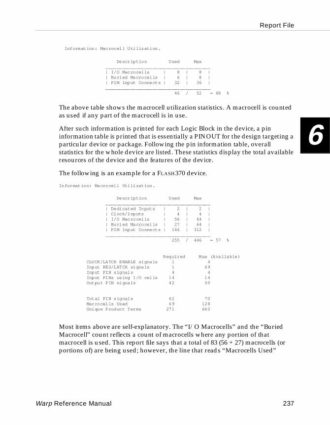
Report File
6
Information: Macrocell Utilization.
Description Used Max ______________________________________ | I/O Macrocells | 8 | 8 | | Buried Macrocells | 6 | 8 | | PIM Input Connects | 32 | 36 | ______________________________________ 46 / 52 = 88 %
The above table shows the macrocell utilization statistics. A macrocell is counted as used if any part of the macrocell is in use.
After such information is printed for each Logic Block in the device, a pin information table is printed that is essentially a PINOUT for the design targeting a particular device or package. Following the pin information table, overall statistics for the whole device are listed. These statistics display the total available resources of the device and the features of the device.
The following is an example for a FLASH370 device.
Information: Macrocell Utilization.
Description Used Max ______________________________________ | Dedicated Inputs | 2 | 2 | | Clock/Inputs | 4 | 4 | | I/O Macrocells | 56 | 64 | | Buried Macrocells | 27 | 64 | | PIM Input Connects | 166 | 312 | ______________________________________ 255 / 446 = 57 %
Required Max (Available) CLOCK/LATCH ENABLE signals 1 4 Input REG/LATCH signals 1 69 Input PIN signals 4 4 Input PINs using I/O cells 14 14 Output PIN signals 42 50
Total PIN signals 62 70 Macrocells Used 69 128 Unique Product Terms 271 640
Most items above are self-explanatory. The “I/O Macrocells” and the “Buried Macrocell” count reflects a count of macrocells where any portion of that macrocell is used. This report file says that a total of 83 (56 + 27) macrocells (or portions of) are being used; however, the line that reads “Macrocells Used”
Warp Reference Manual 237
Report File
6
indicates that only 69 macrocells are used. This is because some of the I/O macrocells are being used purely as input. This is indicated by the line that reads “Input PINs using I/O cells” whose value is 14. This is the reason the “Macrocells Used” line reads 69 (83 - 14).
6.5.4 Static T iming Analysis
The last section of the report file for CPLDs contains a static timing analysis report along with the worst case timing numbers for various parameters. While reading this information, it is important to note the speed grade of the device that was chosen. There are many terms that are used in this section of the report file that may not be familiar to the user. These terms and the waveforms they represent are described in the datasheets for the devices. Refer to the Cypress Semiconductor Programmamble Logic Databook. An important thing to note, however, would be that for paths that require multiple passes through the arrays, the intermediate nodes are also listed.
238 Warp Reference Manual
Appendix
A Error MessagesA
Error Messages
A
This appendix lists the error messages that may be returned by the Warp compiler. A brief explanation is included if the error message is not self-explanatory. Sometimes, a group of error message refers to the same explanation, and such error messages are grouped together above the explanation.
Note – %s refers to any string, %d to a decimal.
E1 :%s: Abort:E2 :Abort:
This is usually the result of running out of memory. Please contact the system administrator to see if increasing virtual or real memory is possible on the system.
E3 :Need a '<=' or ':=' here.
An equal sign instead of an assignment operator was used in an expression.
E4 :Missing 'PORT MAP'.
You might be trying to instantiate a component and list a set of ports to be connected but without the key words PORT MAP.
E5 :Use '=', not ':=' here.
The assignment rather than the comparison operator was used in an expression.
E7 :Can't open file.
An input file couldn't be opened for some reason (usually, because the file doesn't exist or isn't in the current path).
E8 :Syntax error: Can't use '%s' (a %s) here.
An attempt was made to use the wrong character or keyword, or a delimiter is missing.
E9 :Can't take attribute '%s' here.
An attribute was used where not allowed.
240 Warp Reference Manual
Error Messages
A
E10 :Syntax error at/before reserved symbol ‘%s’.
You used a reserved word in an illegal fashion, e.g., as a signal or variable name.
E14 :%s (line %d, col %d):
This message is more of an informative message than an error message. It tells you where to look for an error. The message usually appears as part of another message.
E18 :Missing THEN.
A THEN is missing from an IF-THEN-ELSE statement.
E19 :Not a TYPE or SUBTYPE name: %s
A variable or signal was defined that has an unknown type (e.g., "signal x:nerp").
E20 :'%s' already used
An attempt has been made to define a symbol that already exists.
E21 :%s not an enumeration literal of %s
You have attempted to assign or compare a state variable to a value that is not within its defined enumeration set.
E30 :';' after last item in interface list.
A semicolon was used after the last item in an interface list (the port declaration or parameter list for a function) instead of a right parenthesis.
E31 :Missing en d-quote.
E32 :’%s’ is not an attribute name.
E34 :Undeclared name: %s
You have attempted to use an undeclared (undefined) variable.
E36 :Variable declaration must be in a PROCESS statement.
You have attempted to declare a variable inside an architecture. Signals can be declared in architectures, but variables have to be declared within a process.
Warp Reference Manual 241
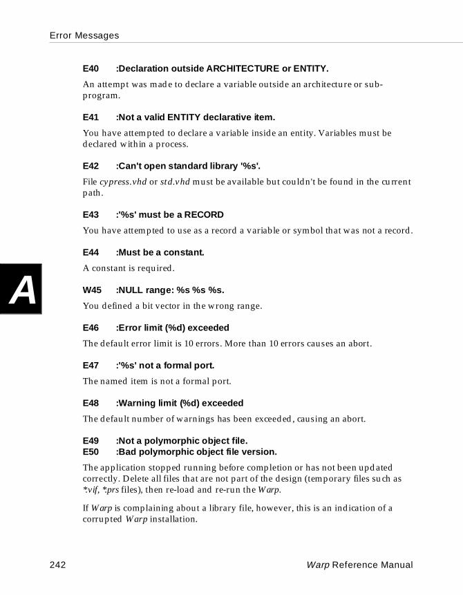
Error Messages
A
E40 :Declaration outside ARCH ITECTURE or ENTITY.
An attempt was made to declare a variable outside an architecture or sub-program.
E41 :Not a valid ENTITY declarative i tem.
You have attempted to declare a variable inside an entity. Variables must be declared within a process.
E42 :Can't open standard library '%s'.
File cypress.vhd or std.vhd must be available but couldn't be found in the current path.
E43 :'%s' must be a R ECORD
You have attempted to use as a record a variable or symbol that was not a record.
E44 :Must be a constant.
A constant is required.
W45 :NULL range: %s %s %s.
You defined a bit vector in the wrong range.
E46 :Error limit (%d) ex ceeded
The default error limit is 10 errors. More than 10 errors causes an abort.
E47 :'%s' not a formal port.
The named item is not a formal port.
E48 :Warning limit (%d) e xceeded
The default number of warnings has been exceeded, causing an abort.
E49 :Not a polymorphic object file.E50 :Bad polymorphic object file version.
The application stopped running before completion or has not been updated correctly. Delete all files that are not part of the design (temporary files such as *.vif, *.prs files), then re-load and re-run the Warp.
If Warp is complaining about a library file, however, this is an indication of a corrupted Warp installation.
242 Warp Reference Manual
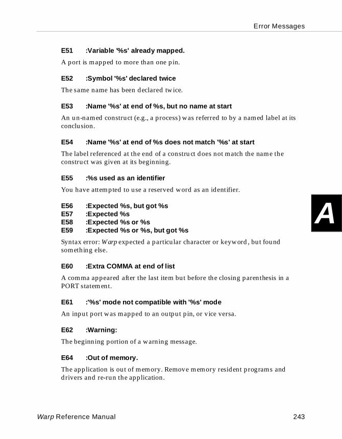
Error Messages
A
E51 :Variable '%s' al ready mapped.
A port is mapped to more than one pin.
E52 :Symbol '%s' declared twice
The same name has been declared twice.
E53 :Name '%s' at end of %s, but no name at start
An un-named construct (e.g., a process) was referred to by a named label at its conclusion.
E54 :Name '%s' at end of %s does not match '%s' at start
The label referenced at the end of a construct does not match the name the construct was given at its beginning.
E55 :%s used as an identifier
You have attempted to use a reserved word as an identifier.
E56 :Expected %s, but got %sE57 :Expected %sE58 :Expected %s or %sE59 :Expected %s or %s, but got %s
Syntax error: Warp expected a particular character or keyword, but found something else.
E60 :Extra COMMA at end of list
A comma appeared after the last item but before the closing parenthesis in a PORT statement.
E61 :'%s' mode not compatible with '%s' mode
An input port was mapped to an output pin, or vice versa.
E62 :Warning:
The beginning portion of a warning message.
E64 :Out of memory.
The application is out of memory. Remove memory resident programs and drivers and re-run the application.
Warp Reference Manual 243
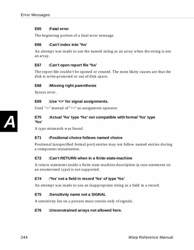
Error Messages
A
E65 :Fatal error
The beginning portion of a fatal error message.
E66 :Can't index into '%s'
An attempt was made to use the named string as an array when the string is not an array.
E67 :Can't open report file '%s'
The report file couldn’t be opened or created. The most likely causes are that the disk is write-protected or out of disk space.
E68 :Missing right parenthesis
Syntax error.
E69 :Use '<=' for signal assignments.
Used ":=" instead of "<=" as assignment operator.
E70 :Actual '%s' type ‘ %s’ not compatible w ith formal '%s' type ‘%s’
A type mismatch was found.
E71 :Positional choice follows named choice
Positional (unspecified formal port) entries may not follow named entries during a component instantiation.
E72 :Can't RETURN when in a f init e-state-machine
A return statement inside a finite state machine description (a case statement on an enumerated type) is not supported.
E74 :'%s' not a field in re cord '%s' of type '%s'
An attempt was made to use an inappropriate string as a field in a record.
E75 :Sensit ivity name not a SIGNAL
A sensitivity list on a process must consist only of signals.
E76 :Unconst rained arrays not allowed here.
244 Warp Reference Manual
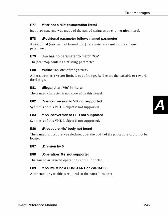
Error Messages
A
E77 :’%s’ not a '%s' en umeration l iteral
Inappropriate use was made of the named string as an enumeration literal.
E78 :Positional parameter follows named parameter
A positional (unspecified formal port) parameter may not follow a named parameter.
E79 :%s has no parameter to match '%s'
The port map contains a missing parameter.
E80 :Value '%s' out of range ‘%s’.
A limit, such as a vector limit, is out of range. Re-declare the variable or rework the design.
E81 :Illegal char. '%c' in literal
The named character is not allowed in this literal.
E82 :'%s' co nversion to VIF not supported
Synthesis of this VHDL object is not supported.
E83 :'%s' co nversion to PLD not supported
Synthesis of this VHDL object is not supported.
E86 :Procedure '%s' body not found
The named procedure was declared, but the body of the procedure could not be located.
E87 :Division by 0
E88 :Operation '%s' not sup ported
The named arithmetic operation is not supported.
E89 :'%s' must be a CONSTANT or VARIABLE
A constant or variable is required in the named instance.
Warp Reference Manual 245
Error Messages
A
E91 :Not in a loopE92 :Not in a loop labelled '%s'
An EXIT or a NEXT statement was found that is not inside a loop.
E95 :FOR variable '%s' not a constant
The named FOR variable is not known at compile time.
E96 :Only integer range suppor ted.
An attempt was made to assign an invalid integer range, such as an enumeration range.
E97 :Missing generations scheme.
E98 :Negative exponent %ld
Negative exponents are not supported.
E99 :Cannot assign this to an array or record.
Only an aggregate with a list of values or another array or record may be assigned to an array or record.
E100 :Too many values (%d) for '%s' of size %d
The list of values in the aggregate was too large for the aggregate to be assigned to an array or record.
E101 :Can't handle function call '%s' here
The named function call cannot be handled.
E102 :Variable expected.
Symbol was incorrectly declared. The symbol must be a variable, not a signal.
E103 :'%s' must be an ARRAY
The named string must be an array.
E104 :Field name or 'OTHERS' expected
Invalid case statement qualifier.
246 Warp Reference Manual
Error Messages
A
E105 :Can't delete '%s' from library '%s'
I/O error. The named string cannot be deleted from the named library.
E106 :You need to declare this as a SUBTYPE.
You declared something as a TYPE that should have been declared a SUBTYPE.
E108 :Function '%s' b ody not found
The named function was declared, but the statements associated with the function could not be located.
E109 :Expected '%s' to return a constant
A function that was expected to return a constant didn't.
E110 :Array sizes don't match for operation %s
You tried a dyadic logical operation (AND, OR, XOR) on two bit vectors of different sizes.
E112 :Positional parameter ' %s' follows named parameter
A positional parameter may not follow a named parameter.
E113 :No funct ion '%s' with these parameter types
The named function with the specified expressions was not found.
E114 :Al ias type mismatch
E115 :'%s' is not a visible LIBRARY or PACKAGE name
Warp cannot identify the named string as a valid name for a library or package.
E116 :'%s' not in PAC KAGE '%s'
The named string is not in the named package.
E117 :Missing/open field '%s' in %s
Missing parameter or port in the named port list.
E118 :Illegal i nteger/identifier '%s'
Identifiers must begin with a letter.
Warp Reference Manual 247
Error Messages
A
E119 :Slice (%d TO %d) is outside array '%s' range (%d TO %d)
The named index range of the slice is outside the named index range of the specified array. The indices of a slice must be within the indices of an array.
E120 :'%s' not an array
The named string is not an array.
E121 :'%s' is not a PACK AGE.
The named string is not a package.
E122 :'%s' must be a SIGNAL or function(SIGNAL).
The named port map parameter may not be an expression, variable, or constant; it must be a signal or signal function.
E123 :Output parm. '%s' must be a SIGNAL or VA RIABLE
The named output parameter must be a single entity, like a signal or variable.
E124 :'%s' is not a COMPONENT
The named string is not a component.
E125 :-s requires a path.
The -s command line option requires a path to the library.
E126 :Wrong number (%d) of indices. %d needed.
The listed number of indices is incorrect for the multi-dimensional array.
E127 :Constraint dimension (%d) doesn't match type dimension (%d)
The named constraint dimension doesn't match the named type dimension (constraint must be in the same number of indices as the array).
E128 :Can’t use mul tiple- dimension index constraint here.
E129 :Illegal '&' opera nds: '%s' and '%s'.
Concatenation is not allowed for the named strings. Concatenation is allowed only for identically typed one-dimensional arrays.
248 Warp Reference Manual
Error Messages
A
E130 :Bad dimension (%d) for attribute '%s'
The named dimension is incorrect for the named array.
E131 :'%s' mapped twice.
The same actual parameter was mapped to two formals.
E132 :Can’t set elements of unconstrained array
E133 :'%s' wasn't mapped
The actual parameter identified in the message was not mapped to a formal in the port map.
E134 :Error occurred w ithin '%s' at line %d, column %d in %s.
A descriptive message to inform the user of the exact error location.
E135 :Unexpected '%s'.
Syntax error.
E136 :'%s' is not a known ENTITY
An attempt was made to use the named string as an entity name.
E137 :Can't use OTHERS for unconstrained array '%s'
Syntax error.
E138 :OTHERS must be the last case statement alternative
No case statement alternatives may follow OTHERS.
E139 :Can't use actual function w ith formal output '%s'
Data is not allowed with the named formal output port.
E140 :Use ':=' for variable assignments.
A string other than ":=" was used for a variable assignment.
E141 :Can't use function(formal) w ith formal input '%s'
You used an fbx() or fxb() (or some other translation function) in the wrong direction.
Warp Reference Manual 249
Error Messages
A
E142 :’%s’ not visible here.'
A symbol/variable was used but not declared in the current scope. This typically happens during a component instantiation or an entity declaration.
E143 :Underbar not allowed at start or end of identifier.
E144 :Only assignments to a single SIGNAL or VARIABLE are suppor ted.
Assignments to aggregates are not yet supported by Warp.
E145 :Illegal character ‘%c’.
E146 :You must ASSIGN function to a signal or variable.
E147 :VAL att ribute not allowed for ‘%s’
E148 :Position %ld out of range
Indicates that the index you have asked for is out of range.
E149 :Duplicate label ‘%s’.
More than one component/generate statement might have the same label. All labels must be unique within their scope.
E150 :’%s’ length %ld doesn’t match ‘ %s’ length %ld.
Please examine the port maps for the component. All mappings must have a length that matches the component declaration.
E151 :’%s’ alre ady has attribute ‘%s’
Please remove one of the duplicate attributes.
E152 :Access variable ‘%s’ is NULL
You probably are trying to access a field of a record which is invalid.
E153 :WAIT not allowed in a process w ith a sensiti vity list.
E154 :Use NOT instead of ‘/’.
VHDL uses ‘NOT’ as the inversion operator.
250 Warp Reference Manual
Error Messages
A
W156 :NULL slice. Direction does not match subtype’s.
When extracting a slice of a vector, the direction (to or downto) of the slice specification should match the direction of the original vector.
E157 :Cannot evaluate %s(non-constant). Too many values ( %ld) in range.
When expanding an array, Warp found too many elements in an array (more than 200). This might be caused due to indexing an array with a non-constant.
E158 :Too few values (%ld) for ‘ %s’ of size %ld
The length of the arrays have to match.
E159 :Can’t find ‘%s’ of class ‘%s’ in current declarative region.
The class specification for the item to which an attribute is being set is not valid.
E160 :Block s pec. ‘%s’ isn’t an architecture of ‘%s’
E161 :Deferred constant ‘%s’ was never given a value.
E162 :Can’t use ‘%s’ here.
W163 :Array sizes %ld and %ld don’t match for ‘%s’.
E164 :’%s’ is not a discrete type.
E165 :L abel ‘%s’ not visible here.
E166 :Guarded assignment to ‘%s’ is not inside a guarded block.
E167 :LENGTH not al lowed for ‘%s’. Array required.
E168 :Double underbar not allowed.
E169 :’%s’ is not a group template.
E170 :Group l ist is not compatible with template ‘%s’.
E171 :WAIT not allowed in function or procedure called from function (%s).
Warp Reference Manual 251
Error Messages
A
E300 :VHDL parser
Message indicating progress of compilation (not really an error).
E360 :Library file ‘%s’ is out of date. Recompile w ith -a.E361 :Bad l ibrary object f ile ‘%s’E362 :Error writ ing to library indexE363 :Error copying '%s' to libraryE364 :Can't create library index '%s'
File I/O.
E365 :Bad l ibrary index '%s'
The named index for the library is corrupted. Delete the library and load another copy.
E366 :Can't create library '%s' with path '%s'
File I/O.
W367 :’%s’ li brary object is missing or is an old version.
Please recompile the library. This is also an indication that some files have been deleted out of the Warp Library directories or that the installation is improper/incomplete.
E368 :Error deleting existing library index entriesE369 :Can't open library '%s' with path '%s'E370 :Error reading library '%s'E371 :Can't find '%s' in library '%s'E372 :Can't open library module '%s'E374 :'%s' not a PACKAGE
File I/O.
E375 :'%s' is not in '%s'
The named package is not in the named library.
W377 :'%s' from '%s' replaces that from '%s' in library '%s'
Warning message. When a module is compiled into a library, module design units with names the same as existing names overwrite the existing design units.
252 Warp Reference Manual
Error Messages
A
E378 :Don't work from within your library directory ('%s')
An attempt was made to run Warp with the named library directory as the current directory.
E411 :GENERATE condi tion ‘%s’ do esn’t si mplify to a constant.
E412 :Port '%' in RTL component '%s' is missing or i mproper
An attempt was made to use the named RTL component without assigning the named port or assigning it inappropriately.
E413 :Cannot use SIGNAL ‘%s’ here. No node # is assigned to it.
A signal is used in an expression, but the signal has not been assigned to any node or pin in a chip.
E414 :Expression too complex: %s
Output assignments must follow a specific format.
E419 :Component’s ‘ %s’ mode does not match mode of ‘ %s’ in entity.
E426 :Component’s ‘ %s’ type ‘ %s’ not compatible w ith type ‘%s’ in entity.
E427 :Target must be a variable.
Target may not be a constant or an aggregate.
E428 :Could not find ent ity '%s (%s)' for comp onent '%s'E429 :Could not find ent ity '%s' for c omponent '%s'
Warp was unable to find the named entity for the named component.
E430 :No entity for architecture '%s'
No entity exists for the named architecture.
E431 :'%s' has already been used as an output.
You attempted to assign two outputs to the same pin.
E432 :Conversion from AONG to '%s' not s upported
Finite state machine enumerated type synthesis is not supported.
Warp Reference Manual 253
Error Messages
A
E433 :Need assignment of a constant for async. reset/preset of ‘%s’.
E434 :Unsup ported PLD '%s'
An attempt was made to compile to an unsupported or nonexistent device.
E435 :Pin ‘%s’ assigned to ‘%s’ is invalid - Please check package pinout.
E436 :Only simple waveform supported. Ignoring assignment.
Warp allows only simple wave forms with no timing information.
E437 :All dr ivers of '%s' are not internal three-states.
You may have a condition where some of the drivers (equations) for a multiple driven signal are three-state drivers and some are not. Warp cannot synthesize such constructs.
W437 :Converting multi-driven PORT '%s' to int ernal t ristate.
This is simply a warning indicating that a multiple driven signal was also found to be a primary I/O signal which currently cannot be mapped to a device. Such signals are converted to equations which means that the I/O signal will never really be in high impedance mode.
E438 :RTL '%s' not supported for %s
An attempt was made to use the named built-in component for an incorrectly named device.
E439 :RTL f ield '%s' too complex: ‘%s’
E440 :Missing RTL field '%s'
An RTL component is missing a port.
E441 :Component formal ' %s' has no match in ‘%s’.
Check for an invalid port map or a typo during a component instantiation.
E442 :Size mi smatch between array types ‘ %s’ and ‘%s’
254 Warp Reference Manual
Error Messages
A
E443 :Unresolved signal '%s' has more than one driver
An attempt was made to use more than one driver with the named signal using an unresolved VHDL type (like bit).
E444 :Device '%s' not sup ported.
Warp does not support the named device.
E445 :No binding archi tecture found.
You probably used the wrong device name, or the installation is incomplete, or wrong CYPRESS_DIR env. variable.
E446 :Can’t handle mul tiple drivers for ‘ %s’ in sel ected device.
Multiple drivers are not supported by default for certain devices (CPLD/PLDs). Even in pASIC only certain kinds of multiple drivers are supported.
E447 :Can’t handle drivers of di fferent types (components and equations) for signal ‘ %s’.
When creating multiple drivers for the purpose of double buffering or HDnPADS (where n > 1), all the drivers must be identical.
E448 :Reset signal ‘ %s’ must be in sensitivity list.
E449 :Only ‘0’ and ‘1’ allowed in user code.
When using user defined state encoding, only ‘0’s and ‘1’s are allowed.
E450 :Too few (%d) bits. %d required.
E451 :Clock signal ‘ %s’ must be in sensitivity list.
E452 :WAIT UN TIL statement must be first in process.
E453 :RESET must be a sim ple assignment.
E454 :This design produ ces 0 nodes.
E455 :Async. reset condition is a constant.
The asynchronous reset condition evaluated to a constant. This is probably not the intention of the design and should be corrected.
Warp Reference Manual 255
Error Messages
A
E457 :Infinite c omponent instant iation recursion at %s:%s.
Even though it is possible for component A to invoke component B which in turn invokes component A (or a case where component A invokes itself), Warp was unable to resolve the recursion because it was too deep. The design must be simplified.
E458 :Call depth is %d. Infinite rec ursion?
You have exceeded an internal limit of 1000 nested function calls. More than likely you might have an infinite recursion.
E459 :Unconst rained arrays not allowed for binding architecture (%s).
The top level of the design cannot have unconstrained arrays.
W460 :’%s’ unassigned in arch. ‘%s’ of ‘%s’.
E461 :Output-enable not supported beneath a WAIT.
E462 :Duplicate CASE choice ‘%s’, alre ady seen on line %d.
E464 :Generic ‘%s’ needs default value for binding architecture (%s).
W465 :Top-level entity ‘%s’ has no output ports.
W466 :WAIT condi tion is a constant.
E467 :’%s’ not allowed in device.
E468 :CASE st atement needs an OTHERS choice.
E469 :CASE st atement is missing %d choices.
You must enumerate all possible choices or use the OTHERS clause to define the missing choices from a CASE statement.
E470 :’IF ... ELSIF (<clock expression>)’ must be 1st in process.
256 Warp Reference Manual
Error Messages
A
E471 :Can’t find state codes array ‘%s’.E472 :State codes obj ect ‘%s’ must be a CONSTANT array.E473 :State codes array ‘%s’ must have indi ces of type ‘%s’.E474 :Enum. code %s has different length than prev. codes.
More than likely you have violated a state machine template supported by Warp.
E476 :Output-enabled/three-stated signal ‘ %s’ must be an OUT or INOUT port.
W477 :Attribute ‘%s’ on ‘%s’ was not u sed during synthesis.
E500 :Can't handle '%s' expression.
An unsupported operation was included in an expression.
E503 :Initiali zer of '%s' must be an enum. literal
You have attempted to initialize a state variable to a value not included in its enumerated list.
W507 :No entry to st ate '%s' of '%s'.
Warp cannot find an entry to the named state, so the state is not used and can be removed.
W508 :No exit f rom state '%s' of '%s'.
Warp cannot find an exit from the named state, so the state is a sink.
E509 :Array sizes don't match for operation %s
You attempted a dyadic logical operation (AND, OR, XOR) on two bit vectors of different sizes.
E510 :Operation '%s' not sup ported for vectors/ integers
Implementation is not supported.
E511 :BIT or array required
Warp does not synthesize integers; a bit or array is required.
E512 :Can’t handle expression '%s' in final equations.
Warp Reference Manual 257
Error Messages
A
E513 :'%s' not a BIT or array
Warp does not synthesize integers; a bit or array is required.
E514 :Only multiplication/divi sion by 2**n is supported.
E515 :Unsup ported use of enumeration literal ‘%s’
W520 :Loop appears to be infinite.
E521 :Exi t/next not supported under a non-constant condi tion.
E522 :Illegal operands for addition/subtraction
E600 :Array lengths %ld, %ld don't match for '%s'.
For the named operation, the named array lengths do not match.
E601 :Bad operand types '%s' and '%s' for operator '%s'.
Type check violation.
E602 :Bad operand type '%s' for operator '%s'.
Type check violation.
E603 :Wrong character '%c' in string
Type check violation.
E604 :Expression type '%s' d oes not match target type '%s'.
Type check violation.
E605 :BOOLEAN required here.
Type check violation.
E606 :Numeric expression required here.
Type check violation.
E607 :Choice type '%s' doesn't match c ase type '%s'.
Type check violation.
258 Warp Reference Manual
Error Messages
A
E608 :'%s' not readable. Mode is OUT.
The mode is defined as OUT, so you can't put it on the right side of an expression.
E609 :'%s' not writable. Mode is IN.
The mode is defined as IN, so you can't put it on the left side of an expression.
E610 :SEVERITY_LEVEL requi red here
An ASSERT statement requires a severity level.
E611 :RETURN not in a function or procedure
A return statement was found that was not inside a function or procedure.
E612 :Can't RETURN a value from a procedure
The application cannot return a value from a procedure; a function is required.
E613 :Function RETURN needs a value.
You attempted to return from a function without specifying a value.
E614 :Return type '%s' does not match function type '%s'.
Syntax error.
E615 :Can't assign to CONSTANT '%s'.
Invalid constant.
E617 :Type m ismatch in range.
E618 :’%s’ is of mode LINKAGE.
E619 :Type ‘ %s’ does not match element type ‘%s’.
E620 :Only a guarded signal or access variable may be assigned NULL.
E621 :Choice must be locally static.
E622 :CASE e xpr. must be discrete, or an array of characters.
E623 :Right operand of ‘ %s’ must be an i nteger.
Warp Reference Manual 259
Error Messages
A
E624 :Left operand of ‘%s’ must be a 1-dim. array of bits or booleans.
E701 :Can’t handle expression ‘%s’ in final equations.
E750 :Can’t open file ‘ %s’.
E751 :Error writ ing to file ‘%s’.
E752 :File n ame must be a STRING.
E753 :Filename must evaluate to a simple STRING.
E754 :Missing parameter ‘%s’.
E755 :File I/O rout ine not yet supported
E1100 :Missing pin number: ‘%s’
Please check the pin_numbers attribute for the missing pin number specification. The pin name should be immediately followed by a “:” and then a pin number (or an alpha numeric for PGA packages).
E1101 :’%s’ not a port name in entity ‘%s’
Invalid name in the pin_numbers attribute.
E1102 :Can’t set pin number of composite ‘%s’
One pin number cannot be assigned to a group of signals that might be derived from a composite or an array.
E1103 :Missing ‘)’ after ‘%s’
Syntax error during a pin_number specification.
E1104 :’%s’ not an array or integer.
You have tried to index into a non-array type signal during a pin_numbers specification.
260 Warp Reference Manual
Error Messages
A
E1105 :Index ‘%d’ out of range for array ‘%s’E1106 :’%s’ not a record.E1107 :Can’t set pin reference name ‘%s’ of composite ‘%s’E1108 :Pin number %d assigned more than once.E1110 :Missing space af ter pin number for ‘%s’.
Invalid pin_numbers specification.
E1320 :Unexpected expression type for multi-driven SI GNAL ‘%s’.
Only simple 6-input (max of 3 active high and 3 active low) AND equations are allowed.
W1320 :fixed_ff attribute on comp. ‘% s’, signal ‘%s’ ignored.
Found the fixed_ff attribute on a non registered output signal. This is ignored.
E1321 :Multi-driven signal expr. for ‘%s’ must be 1 term.
Only simple 6-input AND (max of 3 active high and 3 active low) equations are allowed which evaluate to a single product term.
E1322 :Multi-driven signal expr. for ‘%s’ uses too many signals.
More than 6 signals are not allowed for an equation participating in double- buffering.
E1323 :Bad pin names ‘%s’. Cannot use more than one clock cell.
When assigning multiple input/clock pads to a signal for high drive strength, you can have a maximum of one clock pad involved.
E1324 :Unrecognized pac kage: ‘%s’. Defaulting to ‘%s’.
E1325 :Bad pin name ‘%s’.
The pin name was neither alpha numeric nor numeric.
E1326 :I/O pad for ‘%s’ has nothing co nnected.
An I/O pad was found (pASIC only) where no connections are being made to it, so that it can be driven.
E1327 :Bad pin names ‘%s’. Only clock/input p ads are legal for multi-pin assignments.
For HDnPADS (where n > 1), you can only use a combination of input/clock pins.
Warp Reference Manual 261

Error Messages
A
E1328 :Can’t handle expression ‘%s’ in final equations.
E1329 :Failed to read clock pads from devices.dat. C heck ordercode.E1330 :Failed to read high-drive pads from devices.dat. Check ordercode.
Most likely, an internal error or wrong package specification.
E1332 :Can’t open Warp QDF library ‘%s’.
Please check the CYPRESS_DIR environment variable.
E1333 :Internal Error: Mis connected port
E1334 :’%s’ con nected to PAD is not a top level port.
Warp found an internal net connected to the output of an I/O pad which is supposed to go to the external world.
E1336 :Can’t open QDF output file ‘%s’.
File I/O.
E1337 :Can’t handle multi-dr iven IO pad for signal ‘%s’.E1338 :Invalid multi driver ‘%s’ for pad signal ‘%s’
I/O pads cannot be used in parallel to increase drive strength. Only Clock and Input pads are allowed.
E1339 :More than one clock pad not allowed for multi-driven signal ‘%s’
When assigning multiple input/clock pads to a signal for high drive strength, you can have a maximum of one clock pad involved.
W1340 :Cannot assign bidirectional port ‘ %s’ to C LOCK pad
Clock pads can only be assigned to input-only signals.
262 Warp Reference Manual
Error Messages
A
W1341 :Cannot assign ‘%s’ to CLOCK pad, CLOCK pad resources(%d) exhausted.W1342 :Please try assigning port ‘%s’ to dedicated input
pASIC devices have a limited number of Clock PADS. Please check the pad_gen attribute and any instantiated clock pads (or through pin_numbers) to see if any resources can be freed up. You can also use an INPUT pad as an alternative.
W1343 :Cannot assign bidirectional port ‘ %s’ to HD pad
HD pads (INPUT pads) can only be assigned to input-only signals.
W1344 :Cannot assign ‘%s’ to HD pad, HD pad resources exhausted.
W1345 :Cannot assign ‘%s’ to INPUT pad, High drive wires resources exhausted.
W1346 :Not enough HD p ads for port ‘%s’, %d requested, %d assigned
W1347 :When using multiple high-drive pads, manual pin assignment is suggested
W1350 :Signal ‘%s’ connected to purely to fli p-flops assigned HD%dPAD. Converting to CLKPAD
W1352 :Gate ‘%s’ needs to be paral leled %d times. Setting max_load=%d
W1354 :Out of express wires. Failed pin assignment for ‘%s:%s’
E1355 :Signal ‘%s’ illegally assig ned to input/clock pin ‘%s’
E1356 :Bad HD4PAD assignment for ‘%s’. HD4PAD requires exactly 1 clock pin to be feasible
W1357 :Signal ‘%s’ has no driver?
Warp Reference Manual 263
Error Messages
A
W1358 :Signal ‘%s’ has too many feedbacks for duplicate buffering. Increasing maxload to from %d to %d
The number of feedbacks for the signal is higher than the maximum loading allowed for the signal. Please increase max_load for the signal or use other buffering methods.
W1359 :max_load for signal ‘ %s’ must be more than 1 for Normal/Registered buffering.
E1360 :Max number of pads (4) exceeded for multi-driven signal ‘%s’
E1361 :Too many( %d) drivers (max=2) for double buffered signal ‘%s’
E1362 :Invalid eqn for double buffered signal ‘ %s’. Must fit in FragA and be identical.
E1363 :Components driving ‘%s’ are not identical.
E1364 :Pad ‘%s’ has 4 drivers. One of them must be a clock- input PAD.
E1365 :Invalid driver for double buffered signal ‘ %s’. Use PAfrag_a’s
E1400 :Bad file number
E1500 :Error writ ing ‘%s’.E1501 :Can’t create ‘%s’. You don’t have write permission.E1502 :Can’t write ‘%s’. Out of disk space.E1503 :Can’t create ‘%s’. Too many open files.E1504 :Can’t write ‘%s’. Device is busy.E1505 :Can’t create ‘%s’. Re ad-only file system.
File I/O
264 Warp Reference Manual
Error Messages
A
W1715 :Espresso failed for ‘ %s’.
Warp uses technology from University of California, Berkeley to perform logic optimization. The equations in the design may have encountered certain limitations within Espresso. The message simply indicates, however, that the equation was not minimized using Espresso and instead a simpler kind of optimization was performed which could potentially produce non-optimal but logically correct solutions.
Sometimes it helps to look at the design and use factoring techniques (buffering or synthesis_off) to reduce the fan-in of the equation.
You may also see these kinds of messages from ‘minopt’ during CPLD/PLD fitting. This is usually a result of the fitter trying to perform polarity/register optimization and an exponential blowup of the equation occurs. When this happens, it helps if the node in question has these kinds of optimizations turned off (using the polarity and/or ff_type directives).
E1800 :Missing ‘seek’ data in ‘devices.dat’.E1801 :Section ‘%s’ appears twice in ‘devices.dat’.E1803 :Section ‘%s’ not found in ‘devices.dat’.E1804 :Could not find ‘devices.dat’.E1805 :’devices.dat’ line is too long: %s.E1806 :Already at top of ‘devices. dat’.E1807 :Can’t find end of ‘%s’ section in ‘devices.dat’.E1808 :Bad seek data ‘%s’ in ‘devices.dat’.
Check your CYPRESS_DIR environment variable.
E1820 :Unknown order code ‘ %s’ for ‘%s’.E3001 :illegal device
Check legal device/package names in Galaxy.
W3002 :phase ignored
The fitter is ignoring a statement in the .pla file. It is a warning message.
Warp Reference Manual 265
Error Messages
A
E3003 :internal error couldn’t find signalE3004 :illegal qualifierE3005 :illegal character in arrayE3010 :bad number of output linesE3013 :can’t ask whether a Nodea is_l atchedE3016 :couldn’t f ind domainE3018 :stated number of nodes w rongE3022 :already have node, and it doesn’t allow that dir
These are all internal errors.
E4003 :File Open error
Unable to open file for read/write.
E4006 :Syntax error
Syntax error encountered in .vhd file.
E4010 :Can not create ‘vlg’ directory.
Make sure that you have write permissions to the current directory.
E4031 :File ‘%s’ Open error
If the file extension in the above message is .atr, this error appears while trying to run the back-annotation tool for pASIC devices, with SpDE back-annotation turned off. Make sure that you run SpDE with back-annotation turned on.
For other file extensions, the error appears when the back-annotation tool does not have permissions to create or write a file.
E4032 :Syntax error.
This is just a warning. All lines in the control file having syntax errors are ignored.
E4034 :Warning : ‘Proceeding with default option. Back annotating pins only’
This is just a warning. The back-annotation tool has been called without any option, so compilation continues with the default option of back-annotating pins.
266 Warp Reference Manual
Appendix
B SpDE Error MessagesB
SpDE Error Messages
B
This appendix is a reference of all SpDE messages. You may get error messages after different actions using the SpDE toolkit.
1. Import - QDIF from the SpDE menu: refer to the section of this appendix titled Import Design Verifier.
2. All numbered error messages from SpDE: refer to the section of this appendix titled User Errors.
3. Error messages from other design tools: refer to the documentation for that tool.
B.1 Import Design Verifier
The Design Verifier, which runs when a design is loaded into SpDE, presents Notes, Warnings, and Errors in an interactive list box.
B.1.1 Notes
Notes are intended to bring a situation to the designer’s attention. The situation is probably not a problem, but should be verified nevertheless.
B.1.2 Warnings
Warnings alert the designer to a problematic situation, commonly associated with a real problem.
Gate <gate> is not used, and is being removed.
The Design Verifier has determined that the gate is not being used. This “stripper” function can be deactivated from the SpDE Tools Options dialog box.
Exceeded recommended limit of high-drive nets.
Too many nets are sourced by HDPADs, CKDPADs, and/or double-buffers (parallel AND gates); the router may not be able to complete. Using fewer signals in tandem with these pads guarantees routability.
268 Warp Reference Manual
SpDE Error Messages
B
Gate <gate> cannot have a fixed placement.
The specified gate cannot have a fixed placement. Fixed placements can be applied to logic cells, which utilize the flip-flop in the logic cell.
Gate <gate> has no net on pad.
There is no external net defined for an input or an output of the design. The path analyzer will not be able to use this gate as a defined start or stop point in analysis. Add a net and a net name to the pad.
Net <net> drives no inputs.
The specified net has a fanout of zero. (The net has a driving gate, but no other connections.)
Net <net> has high I/O pad fanout of <fanout>.
The specified net has exceeded the recommended fanout limit for a bi-directional pad driver. If the net is speed-critical, employ buffering or paralleling techniques.
Net <net> has high input pad fanout of <fanout>.
The specified net has exceeded the recommended fanout limit for an input pad driver. If the net is speed-critical, employ buffering or paralleling techniques.
Net <net> has high logic cell fanout of <fanout>.
The specified net has exceeded the recommended fanout limit for a logic cell driver. If the net is speed-critical, employ buffering or paralleling techniques.
Pin <pin#> (<gate>) drives set or reset, disabling ATVG.
One of the restricted testing pins (labeled I/SCLK or I/SM in pinout diagrams) is driving a set or reset, directly or indirectly. These pads are restricted testing pins, and require that ATVG be disabled.
Warp Reference Manual 269
SpDE Error Messages
B
B.1.3 Errors
Errors flag genuine error conditions that would prevent parts from being programmed. However, the tools can still be run for experimental purposes and examination.
B.2 Fatal Er rors
Fatal errors flag serious error conditions that prevent the tools from being run.
Pin <pin#> (<gate>) paralleled, disabling ATVG.
One of the restricted testing pins (labeled I/SCLK or I/SM in pinout diagrams) is wired in parallel with another pin. These pads are restricted testing pins, and require that ATVG be disabled.
Gate <gate> has floating input.
The specified gate has one or more unconnected inputs. Floating inputs are not allowed.
Net <net> driven by multiple I/O pads.
The specified net is driven by more than one I/O pad. A net cannot be driven by multiple I/O pads.
Net <net> has fanout of <24, but >2 drivers.
The specified net has too many high-drive pads. Remove one high-drive pad and re-try.
Net <net> has no driver.
The specified net does not have a driving cell; thus, the inputs of the attached cells are floating.
Clock net <net> has multiple drivers.
The specified net is driven by more than one clock pad. Clock nets must be driven by one and only one clock pad.
270 Warp Reference Manual
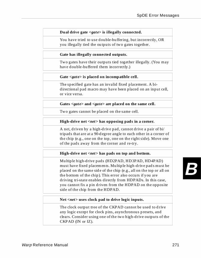
SpDE Error Messages
B
Dual drive gate <gate> is illegally connected.
You have tried to use double-buffering, but incorrectly, OR you illegally tied the outputs of two gates together.
Gate has illegally connected outputs.
Two gates have their outputs tied together illegally. (You may have double-buffered them incorrectly.)
Gate <gate> is placed on incompatible cell.
The specified gate has an invalid fixed placement. A bi-directional pad macro may have been placed on an input cell, or vice versa.
Gates <gate> and <gate> are placed on the same cell.
Two gates cannot be placed on the same cell.
High-drive net <net> has opposing pads in a corner.
A net, driven by a high-drive pad, cannot drive a pair of bi/tripads that are at a 90-degree angle to each other in a corner of the chip (e.g., one on the top, one on the right side). Move one of the pads away from the corner and re-try.
High-drive net <net> has pads on top and bottom.
Multiple high-drive pads (HD2PAD, HD3PAD, HD4PAD) must have fixed placements. Multiple high-drive pads must be placed on the same side of the chip (e.g., all on the top or all on the bottom of the chip). This error also occurs if you are driving tri-state enables directly from HDPADs. In this case, you cannot fix a pin driven from the HDPAD on the opposite side of the chip from the HDPAD.
Net <net> uses clock pad to drive logic inputs.
The clock output tree of the CKPAD cannot be used to drive any logic except for clock pins, asynchronous presets, and clears. Consider using one of the two high-drive outputs of the CKPAD (IN or IZ).
Warp Reference Manual 271
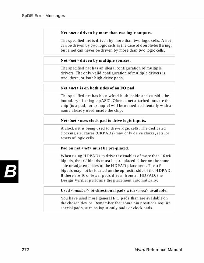
SpDE Error Messages
B
Net <net> driven by more than two logic outputs.
The specified net is driven by more than two logic cells. A net can be driven by two logic cells in the case of double-buffering, but a net can never be driven by more than two logic cells.
Net <net> driven by multiple sources.
The specified net has an illegal configuration of multiple drivers. The only valid configuration of multiple drivers is two, three, or four high-drive pads.
Net <net> is on both sides of an I/O pad.
The specified net has been wired both inside and outside the boundary of a single pASIC. Often, a net attached outside the chip (to a pad, for example) will be named accidentally with a name already used inside the chip.
Net <net> uses clock pad to drive logic inputs.
A clock net is being used to drive logic cells. The dedicated clocking structures (CKPADs) may only drive clocks, sets, or resets of logic cells.
Pad on net <net> must be pre-placed.
When using HDPADs to drive the enables of more than 16 tri/bipads, the tri/bipads must be pre-placed either on the same side or adjacent sides of the HDPAD placement. The tri/bipads may not be located on the opposite side of the HDPAD. If there are 16 or fewer pads driven from an HDPAD, the Design Verifier performs the placement automatically.
Used <number> bi-directional pads with <max> available.
You have used more general I/O pads than are available on the chosen device. Remember that some pin positions require special pads, such as input-only pads or clock pads.
272 Warp Reference Manual
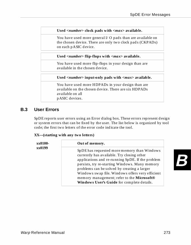
SpDE Error Messages
B
B.3 User Errors
SpDE reports user errors using an Error dialog box. These errors represent design or system errors that can be fixed by the user. The list below is organized by tool code; the first two letters of the error code indicate the tool.
XX—(starting with any two letters)
Used <number> clock pads with <max> available.
You have used more general I/O pads than are available on the chosen device. There are only two clock pads (CKPADs) on each pASIC device.
Used <number> flip-flops with <max> available.
You have used more flip-flops in your design than are available in the chosen device.
Used <number> input-only pads with <max> available.
You have used more HDPADs in your design than are available on the chosen device. There are six HDPADs available on all pASIC devices.
xx0100- xx0199
Out of memory.
SpDE has requested more memory than Windows currently has available. Try closing other applications and re-running SpDE. If the problem persists, try re-starting Windows. Many memory problems can be solved by creating a larger Windows swap file. Windows offers very efficient memory management; refer to the Microsoft® Windows User’s Guide for complete details.
Warp Reference Manual 273
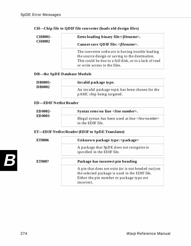
SpDE Error Messages
B
CH—Chip file to QDIF file converter (loads old design files)
DB—the SpDE Database Module
ED—EDIF Netlist Reader
ET—EDIF Netlist Reader (EDIF to SpDE Translator)
CH0001- CH0002
Error loading binary file:<filename>.
Cannot save QDIF file: <filename>.
The converter software is having trouble loading the source design or saving to the destination. This could be due to a full disk, or to a lack of read or write access to the files.
DB0001-DB0002
Invalid package type.
An invalid package topic has been chosen for the pASIC chip being targeted.
ED0002-ED0003
Syntax error on line <line number>.
Illegal syntax has been used at line <line number> in the EDIF file.
ET0006 Unknown package type: <package>
A package that SpDE does not recognize is specified in the EDIF file.
ET0007 Package has incorrect pin bonding
A pin that does not exist (or is not bonded out) on the selected package is used in the EDIF file. Either the pin number or package type are incorrect.
274 Warp Reference Manual
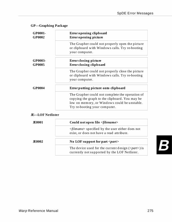
SpDE Error Messages
B
GP—Graphing Package
JE—LOF Netlister
GP0001-GP0002
Error opening clipboardError opening picture
The Grapher could not properly open the picture or clipboard with Windows calls. Try re-booting your computer.
GP0003-GP0005
Error closing pictureError closing clipboard
The Grapher could not properly close the picture or clipboard with Windows calls. Try re-booting your computer.
GP0004 Error putting picture onto clipboard
The Grapher could not complete the operation of copying the graph to the clipboard. You may be low on memory, or Windows could be unstable. Try re-booting your computer.
JE0001 Could not open file <filename>
<filename> specified by the user either does not exist, or does not have a read attribute.
JE0002 No LOF support for part <part>
The device used for the current design (<part>) is currently not supported by the LOF Netlister.
Warp Reference Manual 275
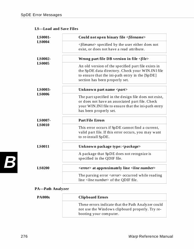
SpDE Error Messages
B
LS—Load and Save Files
PA—Path Analyzer
LS0001-LS0004
Could not open binary file <filename>
<filename> specified by the user either does not exist, or does not have a read attribute.
LS0002-LS0005
Wrong part file DB version in file <file>
An old version of the specified part file exists in the SpDE data directory. Check your WIN.INI file to ensure that the ini-path entry in the [SpDE] section has been properly set.
LS0003-LS0006
Unknown part name <part>
The part specified in the design file does not exist, or does not have an associated part file. Check your WIN.INI file to ensure that the ini-path entry has been properly set.
LS0007-LS0010
Part File Errors
This error occurs if SpDE cannot find a current, valid part file. If this error occurs, you may want to re-install SpDE.
LS0011 Unknown package type: <package>
A package that SpDE does not recognize is specified in the QDIF file.
LS0200 <error> at approximately line <line number>
The parsing error <error> occurred while reading line <line number> of the QDIF file.
PA000x Clipboard Errors
These errors indicate that the Path Analyzer could not use the Windows clipboard properly. Try re-booting your computer.
276 Warp Reference Manual
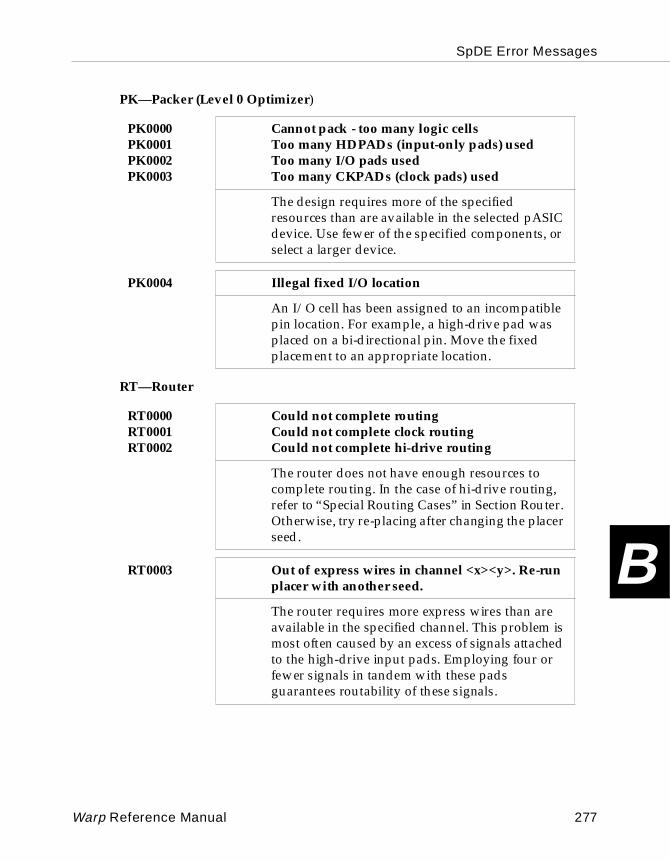
SpDE Error Messages
B
PK—Packer (Level 0 Optimizer)
RT—Router
PK0000PK0001PK0002PK0003
Cannot pack - too many logic cellsToo many HDPADs (input-only pads) usedToo many I/O pads usedToo many CKPADs (clock pads) used
The design requires more of the specified resources than are available in the selected pASIC device. Use fewer of the specified components, or select a larger device.
PK0004 Illegal fixed I/O location
An I/O cell has been assigned to an incompatible pin location. For example, a high-drive pad was placed on a bi-directional pin. Move the fixed placement to an appropriate location.
RT0000RT0001RT0002
Could not complete routingCould not complete clock routingCould not complete hi-drive routing
The router does not have enough resources to complete routing. In the case of hi-drive routing, refer to “Special Routing Cases” in Section Router. Otherwise, try re-placing after changing the placer seed.
RT0003 Out of express wires in channel <x><y>. Re-run placer with another seed.
The router requires more express wires than are available in the specified channel. This problem is most often caused by an excess of signals attached to the high-drive input pads. Employing four or fewer signals in tandem with these pads guarantees routability of these signals.
Warp Reference Manual 277
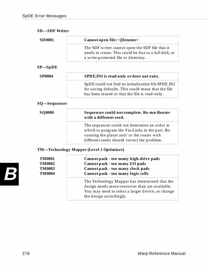
SpDE Error Messages
B
SD—SDF Writer
SP—SpDE
SQ—Sequencer
TM—Technology Mapper (Level 1 Optimizer)
SD0001 Cannot open file: <filename>
The SDF writer cannot open the SDF file that it needs to create. This could be due to a full disk, or a write-protected file or directory.
SP0004 SPDE.INI is read-only or does not exist.
SpDE could not find its initialization file SPDE.INI for saving defaults. This could mean that the file has been erased or that the file is read-only.
SQ0000 Sequencer could not complete. Re-run Router with a different seed.
The sequencer could not determine an order in which to program the Via-Links in the part. Re-running the placer and/or the router with different seeds should correct the problem.
TM0001TM0002TM0003TM0004
Cannot pack - too many high-drive padsCannot pack - too many I/O padsCannot pack - too many clock padsCannot pack - too many logic cells
The Technology Mapper has determined that the design needs more resources than are available. You may need to select a larger device, or change the design accordingly.
278 Warp Reference Manual
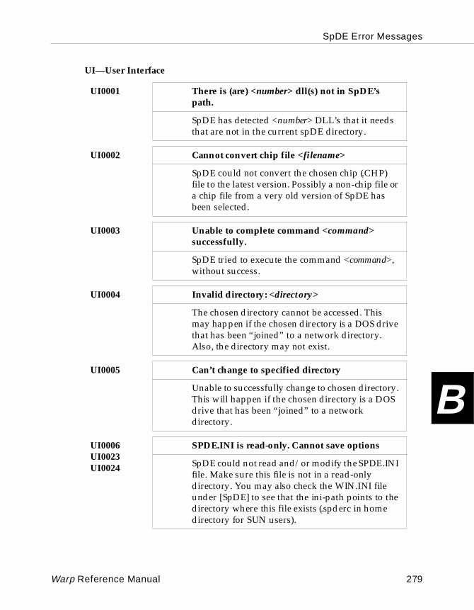
SpDE Error Messages
B
UI—User Interface
UI0001 There is (are) <number> dll(s) not in SpDE’s path.
SpDE has detected <number> DLL’s that it needs that are not in the current spDE directory.
UI0002 Cannot convert chip file <filename>
SpDE could not convert the chosen chip (.CHP) file to the latest version. Possibly a non-chip file or a chip file from a very old version of SpDE has been selected.
UI0003 Unable to complete command <command> successfully.
SpDE tried to execute the command <command>, without success.
UI0004 Invalid directory: <directory>
The chosen directory cannot be accessed. This may happen if the chosen directory is a DOS drive that has been “joined” to a network directory. Also, the directory may not exist.
UI0005 Can’t change to specified directory
Unable to successfully change to chosen directory. This will happen if the chosen directory is a DOS drive that has been “joined” to a network directory.
UI0006UI0023UI0024
SPDE.INI is read-only. Cannot save options
SpDE could not read and/or modify the SPDE.INI file. Make sure this file is not in a read-only directory. You may also check the WIN.INI file under [SpDE] to see that the ini-path points to the directory where this file exists (.spderc in home directory for SUN users).
Warp Reference Manual 279
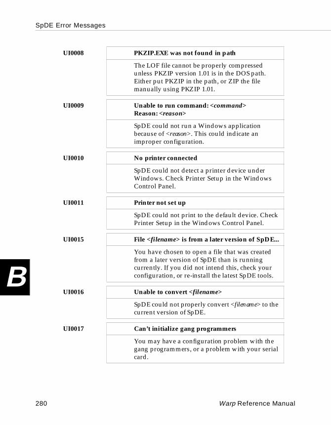
SpDE Error Messages
B
UI0008 PKZIP.EXE was not found in path
The LOF file cannot be properly compressed unless PKZIP version 1.01 is in the DOS path. Either put PKZIP in the path, or ZIP the file manually using PKZIP 1.01.
UI0009 Unable to run command: <command>Reason: <reason>
SpDE could not run a Windows application because of <reason>. This could indicate an improper configuration.
UI0010 No printer connected
SpDE could not detect a printer device under Windows. Check Printer Setup in the Windows Control Panel.
UI0011 Printer not set up
SpDE could not print to the default device. Check Printer Setup in the Windows Control Panel.
UI0015 File <filename> is from a later version of SpDE...
You have chosen to open a file that was created from a later version of SpDE than is running currently. If you did not intend this, check your configuration, or re-install the latest SpDE tools.
UI0016 Unable to convert <filename>
SpDE could not properly convert <filename> to the current version of SpDE.
UI0017 Can’t initialize gang programmers
You may have a configuration problem with the gang programmers, or a problem with your serial card.
280 Warp Reference Manual

SpDE Error Messages
B
UI0018 No gang programmers found
Check to make sure all gang programmers are connected and plugged in, and that the correct COM port has been chosen.
UI0019 No automatic place and route tools were run - Check Place and Route option settings.
You have chosen to Run All Tools after all the tools have already been run. If you wish to iterate, change seeds in the Tools Options, then re-run tools with Run Selected Tools.
UI0020UI0021
Cannot process SPDE.INI file
The SPDE.INI file has been corrupted.
UI0022 Error opening report file <filename>
SpDE could not open the report file it has created. This could happen if you were too low on memory to load the chosen editor, or if the chosen editor could not be loaded properly. Change the chosen editor from View/Preferences.
UI0034 Cannot load QDIF file <filename>
An error was detected while reading a QDIF file. The file may have a syntax error, or the file may have been damaged.
UI0037 Ini-path not found in win.ini. Using c:\pasic\spde\data
SpDE expects to find the variable ini-path under the heading [SpDE] in the win.ini file. The installation program will do this automatically. Check the win.ini file, or re-install SpDE.
Warp Reference Manual 281
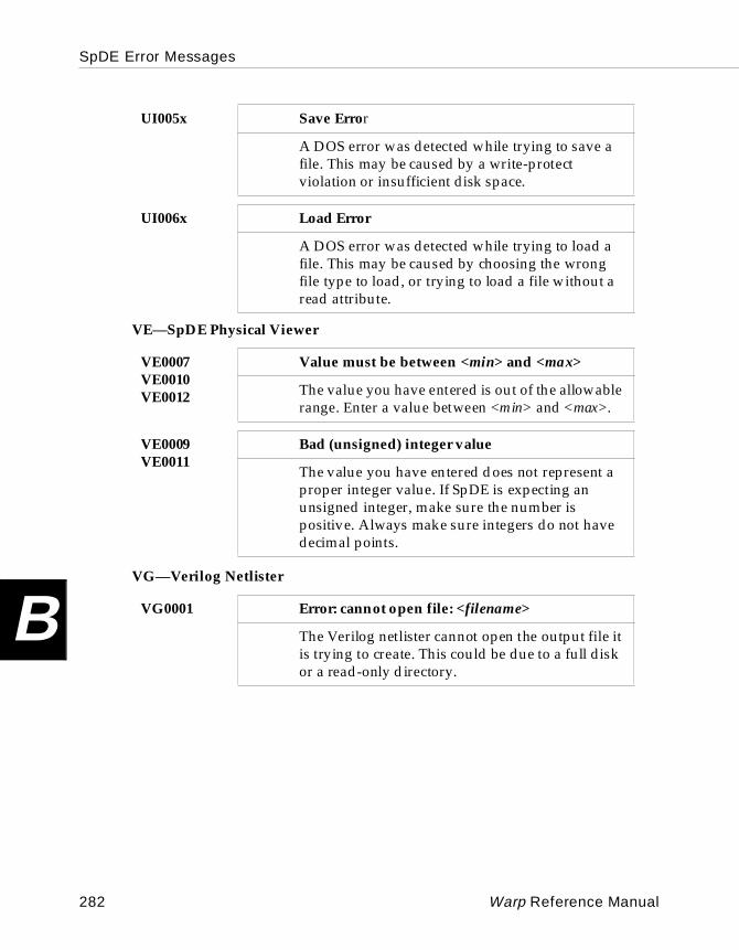
SpDE Error Messages
B
VE—SpDE Physical Viewer
VG—Verilog Netlister
UI005x Save Error
A DOS error was detected while trying to save a file. This may be caused by a write-protect violation or insufficient disk space.
UI006x Load Error
A DOS error was detected while trying to load a file. This may be caused by choosing the wrong file type to load, or trying to load a file without a read attribute.
VE0007VE0010VE0012
Value must be between <min> and <max>
The value you have entered is out of the allowable range. Enter a value between <min> and <max>.
VE0009VE0011
Bad (unsigned) integer value
The value you have entered does not represent a proper integer value. If SpDE is expecting an unsigned integer, make sure the number is positive. Always make sure integers do not have decimal points.
VG0001 Error: cannot open file: <filename>
The Verilog netlister cannot open the output file it is trying to create. This could be due to a full disk or a read-only directory.
282 Warp Reference Manual
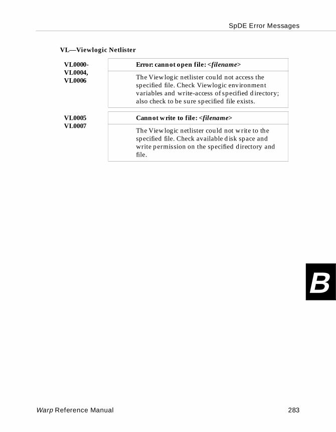
SpDE Error Messages
B
VL—Viewlogic Netlister
VL0000-VL0004,VL0006
Error: cannot open file: <filename>
The Viewlogic netlister could not access the specified file. Check Viewlogic environment variables and write-access of specified directory; also check to be sure specified file exists.
VL0005VL0007
Cannot write to file: <filename>
The Viewlogic netlister could not write to the specified file. Check available disk space and write permission on the specified directory and file.
Warp Reference Manual 283
SpDE Error Messages
B
284 Warp Reference Manual

Appendix C
C Glossary
Glossary
C
Listed here are the definitions of terms encountered frequently in using VHDL, using Warp, and using programmable logic. Note that the context for the VHDL definitions is that of synthesis (as opposed to simulation) modeling.1076 VHDL - the IEEE specification of the VHDL language.
1164 VHDL - the IEEE specification of the std_logic data type.
actual - in port maps used in binding architectures, the name of the pin to which the signal is being mapped.
analysis - the examination of a VHDL description to ensure that it complies with VHDL syntax rules. During analysis, Warp determines the design elements (packages, components, entities, and architectures) that make up the description and places these design elements into a VHDL library and an associated index. The library and index are then available for use in synthesis by other descriptions.
antifuse - whereas a fuse provides an electrical connection of wires that is initially intact, broken only after a programming voltage is applied across the fuse, an antifuse is an interconnection between wires that is initially broken and formed only after a programming voltage is applied across the antifuse.
APR - (Automatic Place and Route) for pASIC the placing of a design, described in the QDIF format, into a part. The output is saved as a .chp file.
architecture - the part of a VHDL description that specifies the behavior or structure of an entity. Entities and architectures are always paired in VHDL descriptions.
attribute - a named characteristic of a VHDL item. An attribute can be a value, function, type, range, signal, or constant. An attribute can also be associated with one or more names in a VHDL description, including entity names, architecture names, labels, and signals. Once an attribute value is associated with a name, the value of the attribute for that name can be used in expressions.
ATVG - (Automatic Test Vector Generation) - is the last tool run from SpDE when placing and routing an FPGA design. These test vectors are run after the part is programmed to test for functionality.
286 Warp Reference Manual

Glossary
Cautomatic clock pad generation - the algorithm in Warp that assigns clock pins or
input pins to ckpads and hdpads on the pASIC devices.
back annotation - the process whereby timing or pin placement information is sent back to the simulator or design entry tools.
back end simulation - see simulation back end.
banked output enable - (oe) for FLASH370 CPLDs, a bank is defined as half of a lab and the output enable control for the upper bank of the lab (macrocells 1 to 8) is separate from the output enable control for the lower bank of the lab (macrocells 9 to 16).
behavioral VHDL - refers to the coding style of VHDL where the code uses higher, more abstract constructs, such as “if then else, ” rather than lower, less abstract constructs, such as boolean equations, to describe a digital design.
binding architecture - an architecture used to map the ports of an entity to the pins of a PLD.
bit_vector - a collection of bits addressed by a common name and index number (an array of bits).
buffer generation - see directive driven fanout buffering.
cell fragments - in pASIC, each logic cell is composed of multiple fragments which can be individually used to place logic. For example, the A fragment is a 6 input AND gate where the output controls a mux and also drives out of the logic cell.
chp files - in pASIC, the place and route output file from SpDE.
ckpads - in pASIC, the clock pads which connect directly to the internal clock buffer tree and can be connected to the clock, set, or reset of the register in the logic cell. (see clock buffer tree)
clock buffer tree - for pASIC, the ckpads connect directly through express wires to an internal clock buffer distribution tree that provides buffering per half column of logic cells to ensure a high speed, low skew clock across the entire chip.
combinatorial - any datapath that is not registered or latched, and therefore does not have a clock or latch enable associated with its timing parameters.
Warp Reference Manual 287
Glossary
C
component - a description of a design that can be used in another design.component declaration - that part of a VHDL description that defines a component. The component declaration is usually encapsulated in a package for export via the library mechanism.
component instantiation statement - a statement in a VHDL description that creates an instance of a previously defined component.
concurrent statement - a statement in an architecture that executes or is modeled concurrently with all other statements in the architecture.
constant declaration - an element of a VHDL description that declares a named data item to be a constant value.
control file - (CTL) a file used for attaching synthesis directives, attributes, and pin node information to signals and components to a VHDL design. Separating this from the VHDL file enables the file to be device independent.
CPLD - (Complex Programmable Logic Device) is a higher density PLD that employs a central programmable interconnect matrix to internally connect multiple LABs together.
crosslink - in pASIC, a vialink used to connect a vertical wire to a horizontal wire.
design architecture - an architecture paired with a previously declared entity that describes the behavior or structure of that entity.
design unit - an entity declaration, a package declaration, an architecture body, or a package body.
directive driven fanout buffering - for pASIC, directives to specify how the software will choose among many options available to reduce the propagation delay on internal signals.
directive driven module generation - directives that will specify either a speed or area optimized implementing of a component from a given operator. For instance, the “+” operator could be recognized as an adder.
directives - instructions to specify software flow. For instance, a synthesis directive such as pad_gen in Warp tells the clock pad generator how to allocate dedicated input pins in a design.
288 Warp Reference Manual
Glossary
Cdon’t care synthesis/optimization - the use of the don’t care conditions to
synthesize the most minimum boolean equations describing a design.
EDIF - (Electronic Data Interchange Format) an industry standard netlist representation of a design that is often used to transport a schematic design from one design platform to another.
entity - that part of a VHDL description that lists or describes the ports (the interfaces to the outside) of the design. An entity describes the names, directions, and data types of each port.
export1076/1164 - the algorithm that takes in a schematic entry and outputs a structural VHDL representation, which can be read directly into a VHDL compiler such as Warp.
express wires - for pASIC, a routing wire that extends the entire vertical or horizontal distance across the device and does not have any passlinks in its path.
factoring point - in synthesis, the preservation of an intermediate node. For instance, in the following equations, “x <= a or b” and “ y <= x or c”, the node “x” could be made a factoring point in the design by the synthesis tool or the node “x” could be eliminated by implementing “y <= a or b or c”. (see synthesis_off attribute)
fanout - the number of gates that a node must drive.
finite state machine - (FSM) a digital design characterized by multiple states (signals held in registers) and at least one output such that external or feedback inputs enable transitions from one state to another.
fitting - a process which converts a description of a design into a programming file, which a programmer can use to program a logic device such as a PLD or a CPLD.
fixed macrocell assignment - forces a given function into a specific macrocell in a PLD or a CPLD.
formal - in port maps used in binding architectures, the signal name on the component.
Warp Reference Manual 289
Glossary
C
FPGA - (Field Programmable Gate Array) a class of programmable logic devicecharacterized by an array of logic cells with horizontal and vertical routing resources between and surrounding the logic cells that functions as an interconnect.
fragments (pASIC) - see cell fragments.
front end simulation - see simulation front end.
function - a subprogram whose invocation is an expression and which therefore returns a value. See subprogram and procedure.
function body - a portion of a VHDL description that defines the implementation of a function.
function declaration - a portion of a VHDL description that defines the parameters passed to and from a function invocation, such as the function name, return type, and list of parameters.
function invocation - a reference to a function from inside a VHDL description.
functional simulation - see simulation front end.
Galaxy - the name for the Graphical User Interface for the Warp synthesis tool.
generic - a VHDL construct that is used with an entity declaration to allow the communication of parameters between levels of hierarchy. A generic is typically used to define parameterized components wherein the size or other configuration are specified during the instantiation of the component. See entity.
generic map - a VHDL construct that enables an instantiating component to pass environment values to an instantiated component. Typically, a generic map is used to size an array or a bit vector or provide true/false environment values.
GUI - (Graphical User Interface) the Galaxy interface for Warp.
half lab - in FLASH370 CPLD devices, the macrocells 1 to 8 or 9 to 16 within a logic block.
HDL - (hardware description language) is a language such as VHDL or Verilog used to describe a digital design as an alternate method to schematic entry.
hdpads - (high drive pads) in pASIC, the dedicated input pins which have higher drive capacity than the I/O pads.
290 Warp Reference Manual
Glossary
CHD(2/3/x) pads - for pASIC, the connection of multiple hdpads together inside the
device to increase its drive capability.
hierarchical VHDL - uses the instantiation(placement) of pre-defined blocks (components) to build a structural design.
highlight net - for pASIC, enables the easy viewing of a node after a design has gone through APR.
instantiation - the process of creating an instance (a copy) of a component and connecting it to other components in the design.
JEDEC file - for PLDs and CPLDs, the programming file created from the Warp compiler.
library - a collection of previously analyzed VHDL design units. In Warp, a library is a directory containing an index and one or more VHDL files.
license file - is needed only for Warp3 users to run the Viewlogic tools.
LOF file - (Link Object Format) for pASIC, this is the programming file that is generated from SpDE.
logic block - (LAB) one of multiple blocks of logic within a CPLD that are interconnected together via a global interconnect. A logic block in a CPLD is similar in nature and capability to a small PLD such as the 22V10. A logic block typically consists of a product term array, a product term distribution scheme, and a set of macrocells.
logic cell - a replicated element of logic within an FPGA device that typically contains a register and additional logic that forms the basic building block for implementing logic in the device.
logic minimization - in the Warp compiler, the part of the synthesis where the boolean equations of a design are reduced to the smallest number of product terms.
Logic optimizer - for pASIC, part of the place and route algorithm of the SpDE tool that runs the packer and technology mapper.
LPM - (Library of Parameterizable Modules) the new schematic library that enables the user to select customized components that are optimized for area or performance.
Warp Reference Manual 291

Glossary
C
macrocell - a replicated element of logic in PLD and CPLD architectures thattypically contains a configurable memory element, polarity control, and one or more feedback paths to the global interconnect.
mixed mode VHDL - in schematic capture, a description of a design that mixes symbols described in textual VHDL with schematic elements.
mode - associated with signals defined in a VHDL entity’s port declaration. A mode defines the direction of communication a signal can have with other levels of hierarchy.
module generation/operator inferencing - See UltraGen.
Nova - the name of the functional simulator.
OTP - (One Time Programmable) pertains to the pASIC family on the vialink technology.
package - a collection of declarations, including component, type, subtype, and constant declarations, that are intended for use by other design units.
package body - the definition of the elements of a package. A package body typically contains the bodies of functions declared within the package.
package declaration - the declaration of the names and values of components, types, subtypes, constants, and functions contained in a package.
packing - for pASIC, the process within SpDE where the design, described in pASIC fragments, is mapped into the logic cells of the device.
pad generation - for pASIC, the program within Warp that automatically assigns input pins to ckpads and hdpads.
partitioning - in an HDL compiler, this is the breakdown of a digital design to a boolean description of the design. This can also mean the placement of a large design into more than one target device.
pASIC - (Programmable Application Specific Integrated Circuit) is the name given to the FPGA 380 family of devices.
292 Warp Reference Manual
Glossary
Cpasslink - in pASIC, a vialink used to connect a vertical wire to a vertical wire or
a horizontal wire to a horizontal wire.
path analyzer - for pASIC within SpDE, the tool that provides timing information after a design has been placed and routed.
performance - the maximum clock frequency or slowest propagation delay of a design as implemented in a particular programmable logic device. Performance is typically measured in nanoseconds for propagation delay or in megahertz for clock frequency.
Physical Viewer - displays the actual layout of a pASIC part after APR.
PIM - (Programmable Interconnect Matrix) in CPLDs, the means with which signals (dedicated inputs, I/O inputs, and macrocell outputs) are fed back to the same logic block or distributed to the other logic blocks of the device. The design of the PIM varies among CPLD vendors and affects the speed, routability, and timing characteristics of the device.
PKZIP.EXE - for pASIC, a compression utility commonly used to reduce the size of LOF files.
PLA format - for CPLDs and PLDs, this is the intermediate sum of products boolean description of a design that is the input file into the fitter for placing the design into a specific device.
place and route - the process of transforming a gate-level representation of a circuit into a programming file that may be used to program an FPGA device. This process requires two steps: one to place the required logic into logic cells, and one to route the logic cells via the horizontal and vertical routing channels to each other and the I/O pins. See synthesis, fitting and logic cell.
placer - for pASIC, the process within SpDE in which the logic cells are placed within the device to minimize routing delays.
PLD - (Programmable Logic Device) is the name of a broad range of products whose architecture is composed of an AND product term array, a fixed “Oring” of the product terms, a programmable macrocell (on some PLDs), and an output macrocell (on some PLDs).
port – a point of connection between a component and anything that uses the component.
Warp Reference Manual 293
Glossary
C
port map - an association between the ports of a component and the signals of anentity instantiating that component. Within the context of a binding architecture, a port map is a VHDL construct that associates signals from an entity with pins on a PLD.
Powerview - the name of Viewlogic’s design entry and simulation tools, included in Warp3, that runs on the SUN workstation.
primitives - a schematic element or VHDL component that is not built from other schematic elements or components.
procedure - a subprogram whose invocation is a statement and which therefore does not return a value. See subprogram and function.
procedure body - a portion of a VHDL description that defines the implementation of a procedure.
procedure declaration - a portion of a VHDL description that defines the parameters passed to and from a procedure invocation, such as the procedure’s name and list of parameters.
procedure invocation - a reference to a procedure from inside a VHDL description.
process - a collection of sequential statements appearing in a design architecture.
product term - for CPLDs and PLDs, this is the boolean “anding” of a variable number of signals to form the “products” part of the “sum of products” implementation that feeds into the macrocell of the device.
Proseries - the name of Viewlogic’s low-end design entry and simulation tools that run on the PC.
QDIF file - for pASIC, this is the output file generated from Warp synthesis that is then used as the input file into SpDE to place and route (fit) into a pASIC device.
quad wires - for pASIC devices 7C385 and greater, the vertical routing wires that span 4 logic cells before passing through a passlink and then horizontal routing wires that span 4 logic cell columns before passing through a passlink.
router - for pASIC, this is the software within SpDE that determines which horizontal and vertical routing wires will be used to connect the logic cell outputs or inputs to logic cells or I/O pins.
294 Warp Reference Manual

Glossary
Csegmented wires - for pASIC, if it is vertical, then the routing wire passes through
a passlink as it passes from one logic cell to another logic cell, and if it is horizontal passes through a passlink as it goes from one column of logic cells to another column of logic cells.
sensitivity list - a list of signals that appears immediately after the process keyword and specifies when the process statements are activated. The process is executed when any signal in the sensitivity list changes value.
sequencer - for pASIC, the SpDE tool that determines the order of how the vialinks are to be programmed.
sequential statement - a statement appearing within a process. All statements within a process are executed sequentially.
signal - a data path from one component to another.
signal declaration - a statement of a signal name, its direction of flow, and the type of data that it carries.
simulation front end - the functional simulation on VHDL code done before the design is synthesized to a particular device.
simulation back end - the functional or timing simulation done after a design is synthesized to a particular device.
skew - a measure of the maximum difference between two or more delay paths.
source level simulation - same as simulation front end.
SpDE - (Seamless pASIC Design Environment) is the name of the place and route tool for all pASIC devices.
std_logic - 1164 VHDL types for individual objects that expands the 1076 VHDL type of “ bit” to include the high impedance state “Z” as well as other types. (see type)
std_logic_vector - same as std_logic except for multiple bits.
structural VHDL - describes a design much like a schematic which instantiates(places) pre-defined blocks (components) and specifies the exact connection of these components.
Warp Reference Manual 295
Glossary
C
subprogram - a sequence of declarations and statements that can be invokedrepeatedly from different locations in a VHDL description. VHDL recognizes two kinds of subprograms: procedures and functions.
subtype - a restricted subset of the legal values of a type.
subtype declaration - a VHDL construct that declares a name for a new type, known as a subtype. A subtype declaration specifies the base type and declares the value range of the subtype.
sum-splitting - for PLDs, the result of implementing a large sum or products equation in more than one pass through the AND array by implementing portions of the product terms in one or more macrocells on the first pass and ORing the partial results in another macrocell as a second pass through the AND array.
synthesis - the production of a file to be mapped to a PLD containing the design elements extracted from VHDL descriptions during the analysis phase. The file is a technology-mapped structural netlist description that is fitted to a user-specified device.
synthesis_off - see factoring point.
technology mapper - in pASIC place and route, the SpDE tool that optimizes the utilization of the logic cell by manipulating inversion bubbles and merging gates.
type - an attribute of a VHDL data object that determines the values that the object can hold. Examples of types are bit and std_logic . Objects of type bit can hold values 0 or 1 . Objects of type std_logic can hold values of U, X, 0 , 1 , Z, W, L , H, or - .
UltraGen - the ability of the Warp compiler to infer operations from behavioral VHDL code, which results in optimal implementations of the basic operations.
Verilog - an alternate HDL to VHDL.
VHDL - (Very High Speed Integrated Circuit (VHSIC) Hardware Description Language) is a powerful language used to describe digital designs and is the language interpreted by the Warp compiler.
vialink - the programmable antifuse element used to connect wires in a pASIC.
ViewDraw - the schematic capture tool from Viewlogic that is the schematic capture tool for Warp3.
296 Warp Reference Manual

Glossary
CViewSim - the timing simulation tool from Viewlogic that is used in Warp3.
Workview PLUS - the name of Viewlogic’s design entry and simulation tools, provided with Warp3 that runs on the PC.
Warp Reference Manual 297

Glossary
C
298 Warp Reference Manual
Appendix
DD
BNF
BNF
D
BNF of Supported VHDL
This appendix presents a simplified Backus-Naur Form (BNF) of the VHDL subset supported by Warp.
Conventions Used In This Appendix
The form of a VHDL description is described by means of context-free syntax, together with context-dependent syntactic and semantic requirements expressed by narrative rules. The context-free syntax of the language is described using a simple variant of Backus-Naur Form, in particular:
1. Lower case words, some containing embedded underlines, are used to denote syntactic categories, for example:formal_port_list
2. Boldface is used to denote reserved words and literal characters, for example:array
3. A vertical bar separates alternative items, unless it appears in boldface immediately after an opening brace, in which case it stands for itself:letter_or_digit ::= letter | digitchoices ::= choice { | choice}
4. Square brackets enclose optional items. Thus, the following two rules are equivalent:return_statement ::= return [expression];return_statement ::= return; | return expression;
5. Braces enclose a repeated item. The item may appear zero or more times; the repetitions occur from left to right as with an equivalent left-recursive rule. Thus, the following two rules are equivalent:term ::= factor {multiplying_operator factor}term ::= factor | term multiplying_operator factor
6. If the name of any syntactic category starts with an italicized part, it is equivalent to the category name without the italicized part. The italicized part is intended to convey some semantic information. For example, type_name and subtype_name are both equivalent to name alone.
7. The term simple_name is used for any occurrence of an identifier that already denotes some declared entity.
300 Warp Reference Manual

BNF
D
BNF
actual_designator ::=expression| signal_name| variable_name| open
actual_parameter_part ::=parameter_asociation_list
actual_part ::=actual_designator| function_name (actual_designator)
adding_operator ::=+ | - | &
aggregate ::=(element_association {, element_association})
alias_declaration ::=alias identifier:subtype_indication is name;
architecture_body ::=architecture identifier of entity_name isarchitecture_declarative_partbegin
architecture_statement_partend [architecture_simple_name];
architecture_declarative_part ::={block_declarative_item}
architecture_statement_part ::={concurrent_statement}
array_type_definition ::=unconstrained_array_definition| constrained_array_definition
assocation_list ::=assocation_element {, association_element}
association_element ::=[formal_part =>] actual_part
Warp Reference Manual 301
BNF
D
attribute_declaration ::=attribute identifier:type_mark;
attribute_designator ::=attribute_simple_name
attribute_name ::=prefix ' attribute_designator [(expression)]
attribute_specification ::=attribute attribute_designator of entity_specificationis expression
block_declarative_item ::=subprogram_declaration| subprogram_body| type_declaration| subtype_declaration| constant_declaration| signal_declaration| alias_declaration| component_declaration| attribute_specification| use_clause
block_declarative_part ::={ block_declarative_item }
block_statement ::=block_label:block block_declarative_partbegin
block_statement_partend block [block_label];
block_statement_part ::={ concurrent_statement }
case_statement ::=case expression is case_statement_alternative{ case_statement_alternative }end case;
case_statement_alternative ::=when choices => sequence_of_statements
302 Warp Reference Manual

BNF
D
choice ::=simple_expression| discrete_range| element_simple_name| others
choices ::=choice [ | choice]
component_declaration ::=component identifier[local_generic_clause][local_port_clause]end component;
component_instantiation_statement ::=instantiation_label:
component_name[generic_map_aspect][port_map_aspect];
composite_type_definition ::=array_type_definition| record_type_definition
concurrent_signal_assignment_statement ::=[label:] conditional_signal_assignment| [label:] selected_signal_assignment
concurrent_statement ::=block_statement| process_statement| concurrent_assertion_statement| concurrent_signal_assignment_statement| component_instantiation_statement| generate_statement
condition ::=boolean_expression
conditional_signal_assignment ::= target <= options conditional_waveforms;
conditional_waveforms ::={ waveform when condition else } waveform
Warp Reference Manual 303
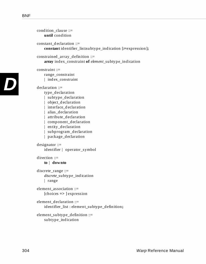
BNF
D
condition_clause ::=until condition
constant_declaration ::=constant identifier_list:subtype_indication [:=expression];
constrained_array_definition ::=array index_constraint of element_subtype_indication
constraint ::=range_constraint| index_constraint
declaration ::=type_declaration| subtype_declaration| object_declaration| interface_declaration| alias_declaration| attribute_declaration| component_declaration| entity_declaration| subprogram_declaration| package_declaration
designator ::=identifier | operator_symbol
direction ::=to | downto
discrete_range ::=discrete_subtype_indication| range
element_association ::=[choices => ] expression
element_declaration ::=identifier_list : element_subtype_definition;
element_subtype_definition ::=subtype_indication
304 Warp Reference Manual

BNF
D
entity_class ::=entity | architecture | configuration| function | package | type| subtype | constant | signal| variable | component | label
entity_declaration ::=entity identifier is
entity_headerentity_declarative_part
[beginentity_statement_part]
end [entity_simple_name];
entity_declarative_item ::=subprogram_declaration| subprogram_body| type_declaration| subtype_declaration| constant_declaration| signal_declaration| alias_declaration| attribute_declaration| attribute_specification| use_clause
entity_declarative_part ::={entity_declarative_item}
entity_designator ::=simple_name | operator_symbol
entity_header ::=[formal_generic_clause][formal_port_clause]
entity_name_list ::=entity_designator {, entity_designator}| others| all
entity_specification ::=entity_name_list : entity_class
Warp Reference Manual 305
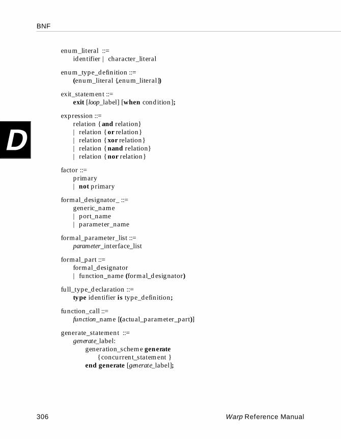
BNF
D
enum_literal ::=identifier | character_literal
enum_type_definition ::=(enum_literal {,enum_literal})
exit_statement ::=exit [loop_label] [when condition];
expression ::=relation { and relation}| relation { or relation}| relation { xor relation}| relation { nand relation}| relation { nor relation}
factor ::=primary| not primary
formal_designator_ ::=generic_name| port_name| parameter_name
formal_parameter_list ::=parameter_interface_list
formal_part ::=formal_designator| function_name (formal_designator)
full_type_declaration ::=type identifier is type_definition;
function_call ::=function_name [(actual_parameter_part)]
generate_statement ::=generate_label:
generation_scheme generate{ concurrent_statement }
end generate [generate_label];
306 Warp Reference Manual
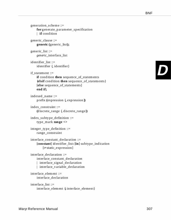
BNF
D
generation_scheme ::=for generate_parameter_specification| if condition
generic_clause ::=generic (generic_list);
generic_list ::=generic_interface_list
identifier_list ::=identifier {, identifier}
if_statement ::=if condition then sequence_of_statements{elsif condition then sequence_of_statements}[else sequence_of_statements]end if;
indexed_name ::=prefix (expression {, expression})
index_constraint ::=(discrete_range {, discrete_range})
index_subtype_definition ::=type_mark range <>
integer_type_definition ::=range_constraint
interface_constant_declaration ::=[constant] identifier_list: [in] subtype_indication
[:=static_expression]
interface_declaration ::=interface_constant_declaration| interface_signal_declaration| interface_variable_declaration
interface_element ::=interface_declaration
interface_list ::=interface_element {; interface_element}
Warp Reference Manual 307
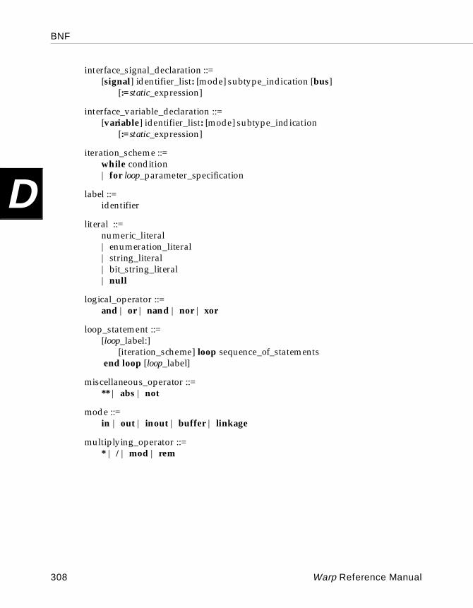
BNF
D
interface_signal_declaration ::=[signal] identifier_list: [mode] subtype_indication [bus]
[:=static_expression]
interface_variable_declaration ::=[variable] identifier_list: [mode] subtype_indication
[:=static_expression]
iteration_scheme ::=while condition| for loop_parameter_specification
label ::=identifier
literal ::=numeric_literal| enumeration_literal| string_literal| bit_string_literal| null
logical_operator ::=and | or | nand | nor | xor
loop_statement ::=[loop_label:]
[iteration_scheme] loop sequence_of_statements end loop [loop_label]
miscellaneous_operator ::=** | abs | not
mode ::=in | out | inout | buffer | linkage
multiplying_operator ::=* | / | mod | rem
308 Warp Reference Manual

BNF
D
name ::=simple_name| operator_symbol| selected_name| indexed_name| slice_name| attribute_name
next_statement ::=next [loop_label] [when condition];
null_statement ::=null;
numeric_literal ::=abstract_literal| physical_literal
object_declaration ::=constant_declaration| signal_declaration| variable_declaration
operator_symbol ::=string_literal
options ::= [ guarded ] [ transport ]
package_body ::=package body package_simple_name is
package_body_declarative_partend [package_simple_name];
package_body_declarative_item ::=function_declaration| function_body| type_declaration| subtype_declaration| constant_declaration| alias_declaration| use_clause
package_body_declarative_part ::={package_body_declarative_item}
Warp Reference Manual 309
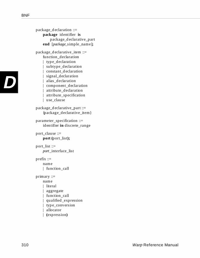
BNF
D
package_declaration ::=package identifier is
package_declarative_partend [package_simple_name];
package_declarative_item ::=function_declaration| type_declaration| subtype_declaration| constant_declaration| signal_declaration| alias_declaration| component_declaration| attribute_declaration| attribute_specification| use_clause
package_declarative_part ::={package_declarative_item}
parameter_specification ::=identifier in discrete_range
port_clause ::=port (port_list);
port_list ::=port_interface_list
prefix ::=name| function_call
primary ::=name| literal| aggregate| function_call| qualified_expression| type_conversion| allocator| (expression)
310 Warp Reference Manual
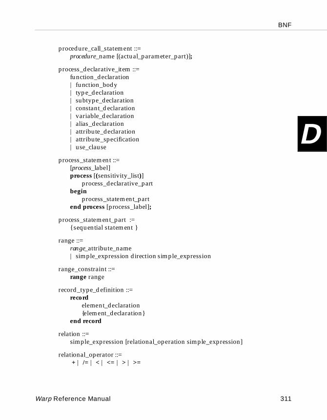
BNF
D
procedure_call_statement ::=procedure_name [(actual_parameter_part)];
process_declarative_item ::=function_declaration| function_body| type_declaration| subtype_declaration| constant_declaration| variable_declaration| alias_declaration| attribute_declaration| attribute_specification| use_clause
process_statement ::=[process_label]process [(sensitivity_list)]
process_declarative_partbegin
process_statement_partend process [process_label];
process_statement_part :={ sequential statement }
range ::=range_attribute_name| simple_expression direction simple_expression
range_constraint ::=range range
record_type_definition ::=record
element_declaration{element_declaration}
end record
relation ::=simple_expression [relational_operation simple_expression]
relational_operator ::= + | /= | < | <= | > | >=
Warp Reference Manual 311
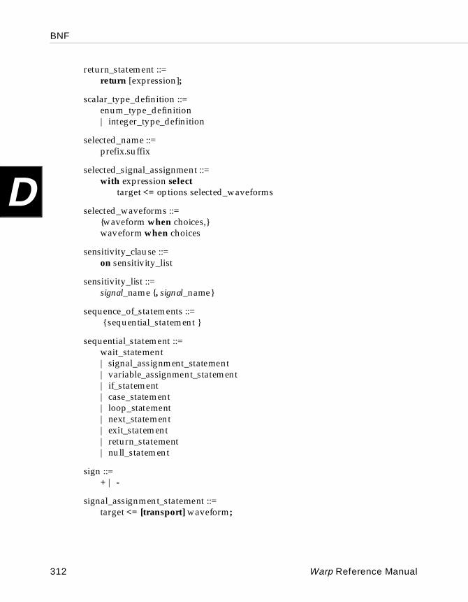
BNF
D
return_statement ::=return [expression];
scalar_type_definition ::=enum_type_definition| integer_type_definition
selected_name ::=prefix.suffix
selected_signal_assignment ::=with expression select
target <= options selected_waveforms
selected_waveforms ::={waveform when choices,}waveform when choices
sensitivity_clause ::=on sensitivity_list
sensitivity_list ::=signal_name {, signal_name}
sequence_of_statements ::= { sequential_statement }
sequential_statement ::=wait_statement| signal_assignment_statement| variable_assignment_statement| if_statement| case_statement| loop_statement| next_statement| exit_statement| return_statement| null_statement
sign ::=+ | -
signal_assignment_statement ::=target <= [transport] waveform;
312 Warp Reference Manual
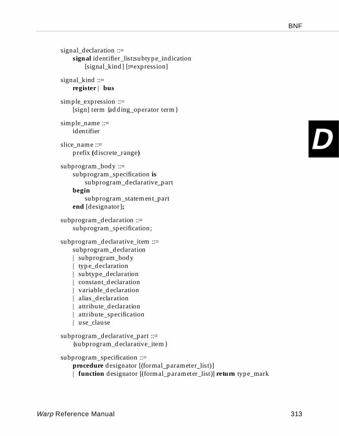
BNF
D
signal_declaration ::=signal identifier_list:subtype_indication
[signal_kind] [:=expression]
signal_kind ::=register | bus
simple_expression ::=[sign] term {adding_operator term}
simple_name ::=identifier
slice_name ::=prefix (discrete_range)
subprogram_body ::=subprogram_specification is
subprogram_declarative_partbegin
subprogram_statement_partend [designator];
subprogram_declaration ::=subprogram_specification;
subprogram_declarative_item ::=subprogram_declaration| subprogram_body| type_declaration| subtype_declaration| constant_declaration| variable_declaration| alias_declaration| attribute_declaration| attribute_specification| use_clause
subprogram_declarative_part ::={subprogram_declarative_item}
subprogram_specification ::=procedure designator [(formal_parameter_list)]| function designator [(formal_parameter_list)] return type_mark
Warp Reference Manual 313
BNF
D
subprogram_statement_part ::={sequential_statement}
subtype_declaration ::=subtype identifier is subtype_indication;
subtype_indication ::=[resolution_function_name} type_mark [constraint]
suffix ::=simple_name| character_literal| operator_symbol| all
target ::=name| aggregate
term ::=factor {multiplying_operator factor}
timeout_clause ::=for time_expression
type_declaration ::=full_type_declaration
type_definition ::=scalar_type_definition| composite_type_definition| access_type_definition
type_mark :=type_name| subtype_name
unconstrained_array_definition ::=array (index_subtype_definition{, index_subtype_definition})
of element_subtype_indication
variable_assignment_statement ::=target := expression;
variable_declaration ::=variable identifier_list:subtype_indication [:=expression];
314 Warp Reference Manual
BNF
D
wait_statement ::=wait [sensitivity_clause] [condition_clause] [timeout_clause];
waveform ::=waveform_element {, waveform_element}
waveform_element ::=value_expression
Warp Reference Manual 315

BNF
D
316 Warp Reference Manual
Index
I
Using Warp
1164 VHDL.........................................................4
A-a option............................................................11Actuals, defined ............................................166Adding operators............................................68Alias, VHDL language element .......... 143-144Analysis in libraries ..............................132, 162APR (automatic place and route) .................22Architectures of VHDL. See also Design
methodologies behavioral descriptions ...................... 76-78 generally ............................................... 74-76 language element ............................ 144-145 structural descriptions..............................78
Array composite type............................... 64-65Association operations ............................. 70-71Attributes, VHDL language element
declaration........................................ 145-146 function............................................. 149-153 names, associating with .........................146 pre-defined...............................................147 range ................................................. 152-153 reference ...........................................146, 147 type............................................................152 value.................................................. 147-149
Automatic place and route (APR) ................22
B-b option ..................................................... 10-11Backus-Naur Form (BNF) of supported
VHDL.......................................... 300-315Banked output enable...................................235
Behavioral VHDL.................................. 160-162Bit_Vector VHDL type...................................61Bit VHDL type.................................................60BNF (Backus-Naur Form) of supported
VHDL.......................................... 300-315Boolean VHDL type........................................60Buffer_gen directive ................................. 27-28BUFFER generation for pASIC ........... 226-228
CCASE statement, VHDL language element ....
..................................................... 153-155Character VHDL type ....................................60Chp file .............................................................22Class of VHDL object .....................................50Clock distribution trees for pASIC..... 226-228CNT4_EXP design example ........ 133, 135-136CNT4_REC design example ........ 133, 136-137Combinatorial logic in design
methodologies ............................... 79-83Command options
-a option .....................................................11 -b option ............................................... 10-11 -d option................................................. 9-10 -e option......................................................11 -f option ................................................ 12-14 generally.......................................................9 -h option .....................................................14 -l option ................................................ 14-15 -m option....................................................15 -o option ............................................... 15-16 -p option.....................................................16 -q option .....................................................16 -r option................................................ 16-17
Index
I
recommendations for specific devices ................................................................ 20-21
-s option......................................................17 -v option ............................................... 17-18 -w option ....................................................18 -xor2 option................................................18 -yb option ...................................................18 -yl option ....................................................19 -ym option..................................................19 -yp option...................................................19 -yt option.............................................. 19-20 -ygs option .................................................20 -yga option .................................................20 -ygc option .................................................20 -yv option ...................................................20
Compiler front end........................................... 222-224 synthesis ................................................... 2-4
Component declaration, VHDL language element ....................................... 155-156
Component instantiation statements ....................................................................156, 166
Composite data type................................. 64-65Concurrent statements ...................................76Constant class of data objects.................. 57-59Constant, VHDL language element ... 156-157Constructs. See VHDL constructsControl file ................................................. 49-51Counter design examples ............ 133, 135-137Counters in design methodologies......... 85-91CPLD/PLD fitting
equations .......................................... 230-233 fitting process .................................. 233-237 static timing analysis ..............................238 technology mapping and optimization .....
..................................................... 229-230Cypress exceptions to LPM standard
specifications.............................. 215-216Cypress modules
component definition conventions.......208 IN (module in marker) ...........................212 MBUF (module buffer symbol) .............209 MGND (module ground symbol).........210 MVCC (module VCC symbol) ..............211 OUT (module out marker).....................213 TRI (module three-state marker) ..........214
D-d option....................................................... 9-10Data objects in VHDL............................... 57-59Data types
composite ............................................. 64-65 definition of ...............................................59 enumerated.......................................... 62-63 pre-defined........................................... 60-62 subtypes .....................................................63
DEC24 design example ........................ 133-134Design methodologies. See also State
machines combinatorial logic ............................. 79-83 counters ........................................ 85-91, 133 examples of ...................................... 133-143 generally.....................................................78 logic...........................................................133 one-hot-one state machines ........... 102-105 outputs decoded combinatorially..... 94-96 outputs decoded in parallel output
registers .......................................... 96-99 outputs encoded within state bits .. 99-102 registered logic .................................... 83-85 state machines ...................................91, 133 state transition tables...................... 105-115
Directive driven fanout buffering ..............228Directive-name synthesis directive ..............50Directives, generally .......................................26Don't care logic ..................................................4Dont_touch directive ................................ 28-30Drink design example .................. 133, 138-140DSGNOPT program .....................................229
E-e option............................................................11Entities in VHDL design .......................... 73-74Entity declaration, VHDL language
element ....................................... 157-158Enum_encoding directive........................ 30-31Enumerated data type.............. 62-63, 175, 176Equations
conventions used in printing ................230 in CPLD/PLD fitting...................... 230-233 report file extension list..........................231
318 Warp User’s Guide
Index
I
Error messages SpDE ................................................. 268-283 Warp compiler................................. 240-266
Exit statement, VHDL language element ..158Express wires ...........................................40, 228
F-f option ...................................................... 12-14Factoring point ................................................47Fanout
defined......................................................225 pASIC, used in.........................................228
Ff_type directive..............................................32Fitting process in CPLD/PLD fitting,
place and route phase.......................233Fixed_ff directive ...................................... 31-32Flash ...............................................................370
device equations in the...........................230 family fitting ............................................233 logic blocks....................................... 234-236 macrocell utilization ...............................237 product term utilization.........................235 split equations .........................................233
Flattening.................................................... 47-49Formals, defined............................................166FRAGS in pASIC................................... 228-229Front end compiler ............................... 222-224Front end synthesis and optimization .............
..................................................... 224-225Function body subprogram.........................172Function declaration subprogram..............172Functions, defined.........................................174
GGalaxy.............................................................226Generate statement, VHDL language
element ....................................... 158-159Generic map statement, VHDL language
element ....................................... 167-168Generic, VHDL language element...... 159-160Global resource reduction in the
DSGNOPT program .........................229Glossary.................................................. 286-297
Goal directive ..................................................33GUI in Warp ......................................................4
H-h option ...........................................................14Half logic block in FLASH370.......................34Hardware description language (HDL) ........2HDPAD in pASIC.........................................228Hierarchical VHDL.........................................26
IIdentifiers in VHDL.................................. 56-57If-then-else statement, VHDL language
element ....................................... 160-162IN (module in marker) Cypress module ...212Instantiation of a component ......................156Integer VHDL type.........................................60
J.jed file ..............................................................21JEDEC map, overview......................................2
L-l option ...................................................... 14-15Lab_force directive ................................... 33-34Libraries. See also LPM (Library of
Parameterized Modules); LPM modules
described ..................................................132 language element in VHDL...................162
Line switches, Warp command .................. 8-9Logic block............................................. 234-236Logic cells in pASIC......................................228Logic design examples ......................... 133-135Logical operators.............................................66Loops, VHDL language element ........ 162-163LPM component definition conventions
lpm_logical.......................................182, 208 lpm_width........................................182, 208 result .................................................182, 208
Warp User’s Guide 319
Index
I
LPM_HINT attribute ....................................216LPM (Library of Parameterized Modules)
library................................................4, 80LPM modules. See also Cypress modules
MADD_SUB component for CY7C375 ....................................................................217
MADD_SUB (module add/subtract symbol) ....................................... 196-197
MAND (module AND symbol) ............185 MBUSTRI (module bus tri-state
symbol) ....................................... 188-189 MCLSHIFT (module combinatorial
logic shifter symbol) ................. 194-195 MCNSTNT (module constant symbol) ......
.............................................................183 MCOMPARE component for
CY7C386A..........................................219 MCOMPARE (module compare
symbol) ...............................................198 MCOUNTER component for CY7C375 .....
.............................................................218 MCOUNTER component for
CY7C386A..........................................220 MCOUNTER (module counter
symbol) ....................................... 200-201 MDECODE (module decoder symbol) ......
..................................................... 192-193 MFF (module flip-flop symbol) .... 204-205 MINV (module inverter symbol)..........184 MLATCH (module latch symbol)...............
..................................................... 202-203 MMULT (module multiplier symbol)..199 MMUX (module multiplexor symbol) .......
..................................................... 190-191 MOR (module OR symbol)....................186 MSHFTREG (module shift register
symbol) ....................................... 206-207 MXOR (module exclusive-OR symbol) .....
.............................................................187LPM standard specifications, Cypress
exceptions to .............................. 215-216
M-m option..........................................................15
MADD_SUB component for CY7C375 ......217MADD_SUB (module add/subtract
symbol) LPM module............... 196-197MAND (module AND symbol) LPM
module................................................185Max_load directive ................................... 34-35MBUF (module buffer symbol) Cypress
module................................................209MBUSTRI (module bus tri-state symbol)
LPM module .............................. 188-189MCLSHIFT (module combinatorial logic
shifter symbol)........................... 194-195MCNSTNT (module constant symbol)
LPM module ......................................183MCOMPARE component for CY7C386A..219MCOMPARE (module compare symbol)
LPM module .....................................198MCOUNTER component for CY7C375 .....218MCOUNTER component for CY7C386A ..220MCOUNTER (module counter symbol)
LPM module .............................. 200-201MDECODE (module decoder symbol)
LPM module .............................. 192-193Mealy state machines ........................... 107-115MFF (module flip-flop symbol) LPM
module........................................ 204-205MGND (module ground symbol) Cypress
module................................................210MINOPT program ........................................229MINV (module inverter symbol) LPM
module................................................184Miscellaneous operators ................................69MLATCH (module latch symbol) LPM
module........................................ 202-203MMULT (module multiplier symbol)
LPM module ......................................199MMUX (module multiplexor symbol)
LPM module .............................. 190-191Modules. See Cypress modules; LPM
modulesMoore state machines............................... 91-93MOR (module OR symbol) LPM module .......
.............................................................186MSHFTREG (module shift register symbol)
LPM module .............................. 206-207Multiplying operators .............................. 68-69
320 Warp User’s Guide
Index
I
MVCC (module VCC symbol) Cypress module................................................211
MXOR (module exclusive-OR symbol)LPM module ......................................187
NNAND2_TS design example ...............133, 135Next, VHDL language element........... 163-164No_factor directive ................................... 35-36No_latch directive..................................... 36-37Node, defined........................................225, 229Node_num directive.......................................37Nova functional simulator...............................2
O-o option ..................................................... 15-16Object-name, defined......................................50One-hot-one state machines ................ 102-105Operators. See also Predefined packages
adding operators .......................................68 assignment operations........................ 69-70 association operations ........................ 70-71 generally .....................................................65 logical..........................................................66 miscellaneous.............................................69 multiplying .......................................... 68-69 relational.....................................................67 vector operations................................. 71-73
Opt_level directive..........................................38Optimization, front end ....................... 224-225Options. See Command optionsOrder_code directive................................ 38-39OUT (module out marker) Cypress
module................................................213Output files ......................................................21
P-p option ...........................................................16Package. See also Package contents;
Predefined packages body .......................................... 116, 164-166 declaration........................................ 164-165
generally........................................... 115-119 use clauses........................................ 117-119 VHDL language element ............... 164-166
Package contents bv_math package ............................ 125-127 int_arith package.....................................125 int_math package............................ 127-130 mth34x8_pkg package.................... 131-132 rtlpkg package................................. 130-131 table_bv package.....................................130 use clauses........................................ 121-123
Pad_gen directive ..................................... 39-40PAD generation for pASIC............ 40, 226-228Part_name directive.................................. 40-41pASIC
pad allocation guide.................................40 technology mapping....................... 226-229
Pin_avoid directive................................... 41-42Pin_numbers directive ....................... 31, 42-43PINS design example ................... 133, 134-135Place and route phase in CPLD/PLD
fitting...................................................233Polarity directive....................................... 43-44Polarity optimization in the DSGNOPT
program..............................................229Port map statement, VHDL language
element ....................................... 166-167Predefined packages. See also Attributes,
VHDL language element; Package contents
addition operators ..................................123 boolean operators ...................................124 miscellaneous functions................. 124-125 multiplication operators ........................123 relational operators.................................123 shift operators..........................................124 standard............................................ 120-121 use clauses................................................122
Primitives .......................................................228Procedure declaration subprogram ...........171Process in VHDL architecture................. 77-78Process statement, VHDL language
element ....................................... 168-170
Warp User’s Guide 321
Index
I
Q-q option ...........................................................16.qdf file ........................................................21, 22QDIF file .....................................................2, 226
R-r option...................................................... 16-17Record composite type ............................. 64-65Record type declaration .......................175, 177Register optimization in the DSGNOPT
program..............................................229Registered logic in design methodologies.......
......................................................... 83-85Relational operators........................................67Report file
CPLD/PLD, targeting of........................225 extension list ............................................231 generally ...................................................222
.rpt file...............................................................21
S-s option............................................................17Security design example .............. 133, 142-143Sensitivity lists in registered logic .......... 83-84Sequential statements ............................... 76-77Signal assignment operation ................... 69-70Signal class of data objects....................... 57-59Signal declaration..........................................170Signal, VHDL language element ........ 170-171Soft node.........................................................225SpDE command line language
pASIC, use in ...........................................226 PC .......................................................... 22-23 Unix platforms...........................................21
SpDE error messages............................ 268-283State_encoding directive.......................... 44-45State machines
design examples...................... 133, 138-143 Mealy state machines ..................... 107-115 Moore state machines......................... 91-93 one-hot-one state machines ........... 102-105 outputs decoded combinatorially..... 94-96
outputs decoded in parallel output registers .......................................... 96-99
outputs encoded within state bits .. 99-102 state transition tables...................... 105-115 synthesis........................................... 224-225
State transition tables ........................... 105-115Static timing analysis in CPLD/PLD
fitting...................................................238Std_logic_vector VHDL type ........................62Std_logic VHDL type .....................................62String literals VHDL type........................ 61-62String VHDL type ...........................................60Structural descriptions ...................................78Subprograms, VHDL language element
functions...................................................174 generally........................................... 171-173 procedures ...............................................173
Sub-range type declaration..........................176Subtype data type...........................................63Subtype declaration................................63, 175Sum_split directive .........................................46Sum-splitting in the DSGNOPT program.......
.............................................................229Syntax, Warp command............................... 8-9Synthesis and optimization, front end.............
..................................................... 224-225Synthesis compiler
capabilities of........................................... 3-4 overview.......................................................2
Synthesis directives attribute mechanism.................................26 buffer_gen ............................................ 27-28 dont_touch ........................................... 28-30 enum_encoding................................... 30-31 ff_type.........................................................32 fixed_ff.................................................. 31-32 goal..............................................................33 hierarchial attributes ................................26 inheritance mechanism ............................26 lab_force ............................................... 33-34 max_load.............................................. 34-35 no_factor............................................... 35-36 no_latch ................................................ 36-37 node_num ..................................................37 opt_level .....................................................38 order_code ........................................... 38-39
322 Warp User’s Guide
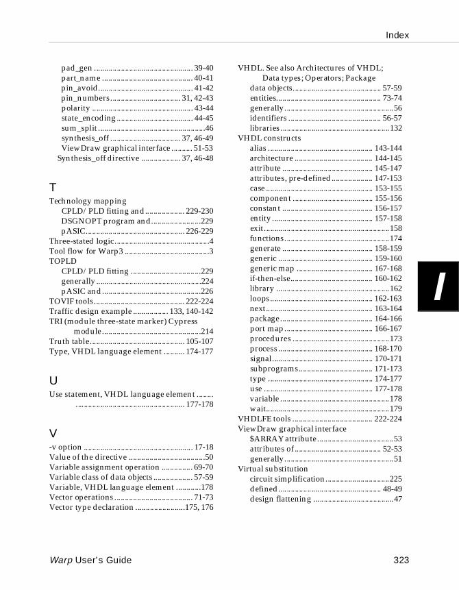
Index
I
pad_gen ................................................ 39-40 part_name ............................................ 40-41 pin_avoid.............................................. 41-42 pin_numbers.................................. 31, 42-43 polarity ................................................. 43-44 state_encoding..................................... 44-45 sum_split ....................................................46 synthesis_off .................................. 37, 46-49 ViewDraw graphical interface .......... 51-53Synthesis_off directive ................... 37, 46-48
TTechnology mapping
CPLD/PLD fitting and................... 229-230 DSGNOPT program and........................229 pASIC................................................ 226-229
Three-stated logic..............................................4Tool flow for Warp3 .........................................3TOPLD
CPLD/PLD fitting ..................................229 generally ...................................................224 pASIC and................................................226
TOVIF tools............................................ 222-224Traffic design example ................. 133, 140-142TRI (module three-state marker) Cypress
module................................................214Truth table.............................................. 105-107Type, VHDL language element .......... 174-177
UUse statement, VHDL language element ........
..................................................... 177-178
V-v option ..................................................... 17-18Value of the directive .....................................50Variable assignment operation ............... 69-70Variable class of data objects ................... 57-59Variable, VHDL language element ............178Vector operations ...................................... 71-73Vector type declaration ........................175, 176
VHDL. See also Architectures of VHDL; Data types; Operators; Package
data objects........................................... 57-59 entities................................................... 73-74 generally.....................................................56 identifiers ............................................. 56-57 libraries.....................................................132
VHDL constructs alias ................................................... 143-144 architecture ...................................... 144-145 attribute ............................................ 145-147 attributes, pre-defined.................... 147-153 case .................................................... 153-155 component ....................................... 155-156 constant ............................................ 156-157 entity ................................................. 157-158 exit.............................................................158 functions...................................................174 generate ............................................ 158-159 generic .............................................. 159-160 generic map ..................................... 167-168 if-then-else........................................ 160-162 library .......................................................162 loops.................................................. 162-163 next.................................................... 163-164 package............................................. 164-166 port map........................................... 166-167 procedures ...............................................173 process .............................................. 168-170 signal................................................. 170-171 subprograms.................................... 171-173 type ................................................... 174-177 use ..................................................... 177-178 variable .....................................................178 wait............................................................179
VHDLFE tools ....................................... 222-224ViewDraw graphical interface
$ARRAY attribute.....................................53 attributes of .......................................... 52-53 generally.....................................................51
Virtual substitution circuit simplification...............................225 defined.................................................. 48-49 design flattening .......................................47
Warp User’s Guide 323
Index
I
W-w option ..........................................................18Wait statement, VHDL language element.......
.............................................................179Warp3 tool flow.................................................3
X-xor2 option......................................................18
Y-yb option .........................................................18-yl option ..........................................................19-ym optin ..........................................................19-yp option.........................................................19-yt option.................................................... 19-20-ygs option .......................................................20-yga option .......................................................20-ygc option .......................................................20-yv option .........................................................20
324 Warp User’s Guide
Related Documents