W100/30 Spindle Moulder Code 201283 Axminster Tool Centre, Unit 10 Weycroft Avenue, Axminster, Devon EX13 5PH axminster.co.uk

Welcome message from author
This document is posted to help you gain knowledge. Please leave a comment to let me know what you think about it! Share it to your friends and learn new things together.
Transcript

W100/30 Spindle Moulder
Code 201283
Axminster Tool Centre,Unit 10 Weycroft Avenue, Axminster, Devon EX13 5PH
axminster.co.uk
2. SAFETY INSTRUCTIONS CONTENT
1. SPECIFICATION
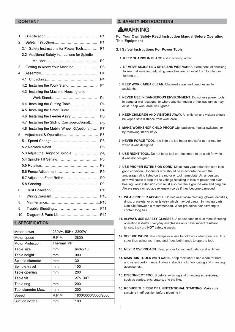
For Your Own Safety Read Instruction Manual Before Operating This Equipment
2.1 Safety Instructions For Power Tools
1. KEEP GUARDS IN PLACE and in working order. 2. REMOVE ADJUSTING KEYS AND WRENCHES. Form habit of checking to see that keys and adjusting wrenches are removed from tool before turning on.
3. KEEP WORK AREA CLEAN. Cluttered areas and benches invite accidents.
4. NEVER USE IN DANGEROUS ENVIRONMENT. Do not use power tools in damp or wet locations, or where any flammable or noxious fumes may exist. Keep work area well lighted.
5. KEEP CHILDREN AND VISITORS AWAY. All children and visitors should be kept a safe distance from work area.
6. MAKE WORKSHOP CHILD PROOF with padlocks, master switches, or by removing starter keys.
7. NEVER FORCE TOOL. It will do the job better and safer at the rate for which it was designed.
8. USE RIGHT TOOL. Do not force tool or attachment to do a job for which it was not designed.
9. USE PROPER EXTENSION CORD. Make sure your extension cord is in good condition. Conductor size should be in accordance with the amperage rating listed on the motor or tool nameplate. An undersized cord will cause a drop in line voltage resulting in loss of power and over- heating. Your extension cord must also contain a ground wire and plug pin. Always repair or replace extension cords if they become damaged.
10. WEAR PROPER APPAREL. Do not wear loose clothing, gloves, neckties, rings, bracelets, or other jewelry which may get caught in moving parts. Non-slip footwear is recommended. Wear protective hair covering to contain long hair.
11. ALWAYS USE SAFETY GLASSES. Also use face or dust mask if cutting operation is dusty. Everyday eyeglasses only have impact resistant lenses, they are NOT safety glasses. 12. SECURE WORK. Use clamps or a vise to hold work when practical. It is safer than using your hand and frees both hands to operate tool.
13. NEVER OVERREACH. Keep proper footing and balance at all times.
14. MAINTAIN TOOLS WITH CARE. Keep tools sharp and clean for best and safest performance. Follow instructions for lubricating and changing accessories. 15. DISCONNECT TOOLS before servicing and changing accessories, such as blades, bits, cutters, and the like.
16. REDUCE THE RISK OF UNINTENTIONAL STARTING. Make sure switch is in off position before plugging in.
1
Motor power 230V~, 50Hz, 2200W
Motor speed R.P.M. 2800Motor Protection Thermal link
Table size mm 640x710Table height mm 900Spindle diameter mm 30Spindle travel mm 100Table opening mm 200Table tilt -5O-+30O
Table ring mm 200Tool diameter Max. mm 200Speed R.P.M. 1800/3000/6000/9000Suction nozzle mm 100
1. Specification……………………………………. P1
2. Safety Instructions……………………………... P1
2.1 Safety Instructions for Power Tools…...…… P1
2.2 Additional Safety Instructions for Spindle
Moulder…………………………………….. P2
3. Getting to Know Your Machine……………….. P3
4. Assembly……………………………………….. P4
4.1 Unpacking……………………………………. P4
4.2 Installing the Work Stand…………………… P4
4.3 Installing the Machine Housing onto
Work Stand………………………………… P4
4.4 Installing the Cutting Tools………………… P4
4.5 Installing the Safer Guard…………………… P4
4.6 Installing the Feeder Ass’y………………… P5
4.7 Installing the Sliding Carriage(optional)…
4.8 Installing the Mobile Wheel Kit(optional)…… P7
5. Adjustment & Operation………………………… P8
5.1 Speed Change……………………………….. P8
5.2 Replace V-belt………………………………… P8
5.3 Adjust the Height of Spindle…………………..
5.4 Spindle Tilt Setting……………………………. P8
5.5 Rotation………………………………………… P9
5.6 Fence Adjustment……………………………. P9
5.7 Adjust the Feed Roller………………………… P9
5.8 Sanding……………………………………….. P9
6. Dust Collection…………………………………. P10
7. Wiring Diagram…………………………………. P10
8. Maintenance……………………………………... P10
9. Trouble Shooting………………………………... P11
10. Diagram & Parts List……………………………. P12
P5
P8
8. KEEP THE UNUSED PORTION of the cutter below the table surface.
9. THE USE OF PUSH STICKS as safety devices in some applications is smart; in others it can be quite dangerous. If the push stick comes in contact with the cutter on the end grain, it can fly out of your hand like a bullet—potentially causing serious injury. We recommend using some type of fixture, jig, or hold-down device as a safer alternative. Always use the guard as described in the manual.
10. NEVER FORCE MATERIALS through the shaper. Let the cutters do the work. Excessive force is likely to result in poor cutting results and will cause dangerous kickback conditions.
11. ALWAYS ensure that the cutters, fence, and spindle elevator knob have been tightened properly before beginning any operation.
12. ALWAYS feed the work toward the cutters in the direction opposite of the cutter rotation. Also, using and maintaining a sharp cutterhead will greatly reduce the chance of kickback.
13. NEVER REACH BEHIND CUTTER to grab the workpiece. Your hand may suddenly be pulled into the cutter in the event of a kickback. 14. IF AT ANY TIME YOU ARE EXPERIENCING DIFFICULTIES PERFORMING THE INTENDED OPERATION, STOP USING THE SPINDLE MOULDER! Then contact our service department or ask a qualified expert how the operation should be performed.
1.3 Site Considerations
Working Clearances
Working clearances can be thought of as the distances between machines and obstacles that allow safe operation of every machine without limitation. Consider existing and anticipated machine needs, size of material to be processed through each machine, and space for auxiliary stands and/or work tables. Also consider the relative position of each machine to one another for efficient material handling. Be sure to allow yourself sufficient room to safely run your machines in any foreseeable operation.
Lighting and outlets
Lighting should be bright enough to eliminate shadow and prevent eye strain. Electrical circuits should be dedicated or large enough to handle combined motor amp loads. Outlets should be located near each machine so power or extension cords are not obstructing high-traffic areas. Be sure to observe local electrical codes for proper installation of new lighting, outlets, or circuits.
Read the manual before assembly and operation. Become familiar with the machine and it’s operation before beginning any work. Serious personal injury may result if safety or operational information is not understood or followed.
17. USE RECOMMENDED ACCESSORIES. Consult the owner’s manual for recommended accessories. The use of improper accessories may cause risk of injury.
18. CHECK DAMAGED PARTS. Before further use of the tool, a guard or other part that is damaged should be carefully checked to determine that it will operate properly and perform its intended function. Check for alignment of moving parts, binding of moving parts, breakage of parts, mounting, and any other conditions that may affect its operation. A guard or other part that is damaged should be properly repaired or replaced.
19. NEVER LEAVE TOOL RUNNING UNATTENDED.TURN POWER OFF. Do not leave tool until it comes to a complete stop.
20. NEVER USE UNDER THE INFLUENCE of alcohol or drugs, or when tired.
21. NEVER ALLOW UNSUPERVISED OR UNTRAINED PERSONNEL TO OPERATE THE MACHINE. Make sure any instructions you give in regards to the operation of the machine are approved, correct, safe, and clearly understood.
2.2 Additional Safety Instructions For Spindle Moulder
Like all power tools, there is danger associated with spindle moulder. Accidents are frequently caused by lack of familiarity or failure to pay attention. Use this tool with respect and caution to lessen the possibility of operator injury. If normal safety precautions are overlooked or ignored, serious personal injury may occur.
No list of safety guidelines can be complete. Every shop environment is different. Always consider safety first, as it applies to your individual working conditions. Use this and other machinery with caution and respect. Failure to do so could result in serious personal injury, damage to equipment or poor work results.
1. NEVER ALLOW YOUR HANDS to come within 12 inches of the cutters. Never pass your hands directly over or in front of the cutter.
2. BLIND CUT WHENEVER POSSIBLE. This keeps the knives on the underside of the workpiece and provides a distance guard for the operator.
3. WHEN SHAPING CONTOURED WORK and using a rub collar, NEVER start out at a corner. See the “Rub Collar” instructions further on in the manual.
4. WITH THE MACHINE UNPLUGGED, always rotate the spindle by hand with any new setup to ensure proper cutter clearance before starting the machine.
5. DO NOT SHAPE STOCK SHORTER than 12 inches without special fixtures or jigs. Where practical, shape longer stock and cut to size.
6. NEVER ATTEMPT to remove too much material in one pass. You are far more likely to enjoy safer and higher quality results if you allow the cutter to remove material in multiple passes.
7. THE DANGER OF kickback is increased when the stock has knots, holes, or foreign objects in it. Warped stock should be run through a jointer before attempting to run it through a shaper.
2
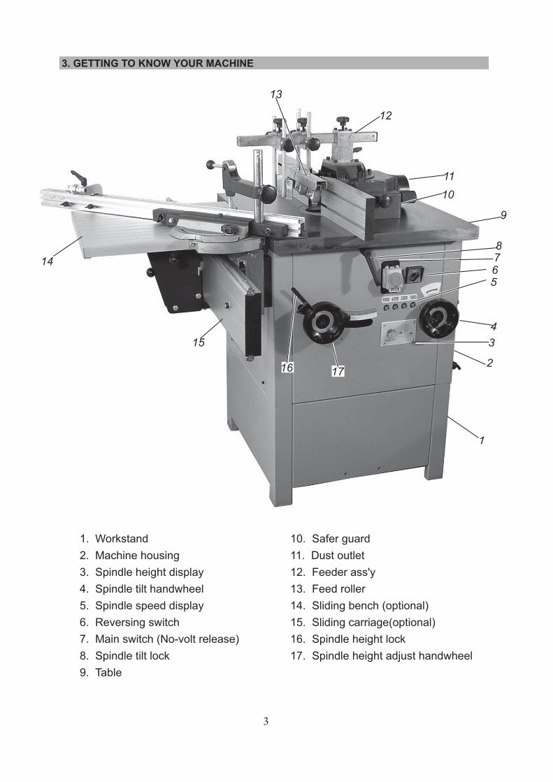
1. Workstand2. Machine housing3. Spindle height display4. Spindle tilt handwheel5. Spindle speed display6. Reversing switch7. Main switch (No-volt release)8. Spindle tilt lock9. Table
10. Safer guard11. Dust outlet12. Feeder ass'y13. Feed roller14. Sliding bench (optional)15. Sliding carriage(optional)16. Spindle height lock17. Spindle height adjust handwheel
3. GETTING TO KNOW YOUR MACHINE
3
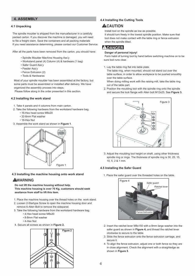
4.1 Unpacking
The spindle moulder is shipped from the manuafacturer in a carefully packed carton. If you discover the machine is damaged, you will need to file a freight claim. Save the containers and all packing materials If you need assistance determining, please contact our Customer Service.
After all the parts have been removed from the carton, you should have:
Most of your spindle moulder has been assembled at the factory, but some parts must be assembled or installed after delivery. We have organized the assembly process into steps. Please follow along in the order presented in this section. 4.2 Installing the work stand
1. Take 4 panels and 4 columns from main carton. 2. Take the following hardware from the workstand hardware bag.
3. Assemble the work stand as shown in Figure 1.
4.3 Installing the machine housing onto work stand
Do not lift the machine housing without help. This machine housing is over 70 Kg, customers should seek assitance from staff to lift this item.
1. Place the machine housing over the thread holes on the work stand. 2. Loosen 2-Startype Screw to open the machine housing door and remove 6-Allen Bolt to remove the sidepanel. 3. Take the following hardware from the workstand hardware bag.
4. Secure all screws as shown in Figure 2.
4. ASSEMBLY
• Spindle Moulder Machine Housing Ass’y• Workstand panel (4) Column (4) & hardware (1 bag)• Safer Guard Ass’y• Feeder Ass’y• Fence Extrusion (2)• Tools & Hardwares
• 16-Hex head screw M8x20• 32-8mm Flat washer• 16-Hex Nut
• 4-Hex head screw M8x20• 8-8mm Flat washer• 4-Hex Nut
Figure 1
4.4 Installing the Cutting Tools
Install tool on the spindle as low as possible. It should turn freely in the lowest spindle position. Make sure that tool does not make contact with the table ring or fence extrusion when the spindle tilted.
Danger of personal injury! Form habit of turning tool by hand before switching machine on to be sure tool runs clear.
1. Lay the table ring flat into table plate. The table ring, when mounted, should not stand out over the table surface, in order to allow workpiece to be pushed smoothly over the table surface. When doing milling work with the raising mill, take the table ring out of the table part. 2. Position the moulding tool with the spindle ring onto the spindle and secure the lock flange with Allen bolt M12x25. See Figure 3.
3. Adjust the moulding tool height on shaft, using other thickness spindle ring or rings. The thickness of spindle ring is 30, 25, 15, 10, 5, 2 & 1 mm.
4.5 Installing the Safer Guard
1. Place the safer guard over the threaded holes on the table.
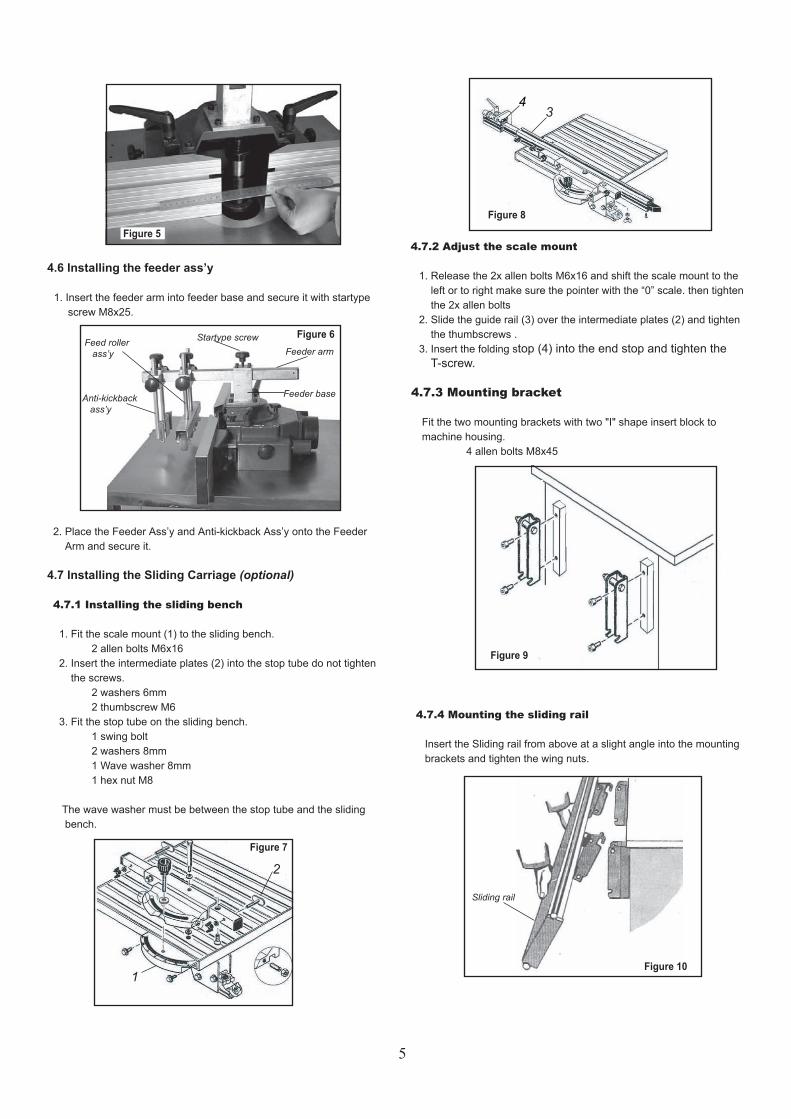
2. Insert the ratchet lever M8x150 with a 8mm large washer into the safer guard as shown in Figure 4, and thread the ratchet lever clockwise to secure to the table. 3. Slide the fence extrusion onto the fence extrusion carriage, and secure it. 4. To align the fence extrusion, adjust one or both fence so they are in close alignment. Check the alignment with a straightedge as shown in Figure 5.
Figure 2
Figure 3
Figure 4Safer guard
Ratchet lever
Fence extrusion
4
4.6 Installing the feeder ass’y
1. Insert the feeder arm into feeder base and secure it with startype screw M8x25.
2. Place the Feeder Ass’y and Anti-kickback Ass’y onto the Feeder Arm and secure it.
4.7 Installing the Sliding Carriage (optional)
4.7.1 Installing the sliding bench
1. Fit the scale mount (1) to the sliding bench. 2 allen bolts M6x16 2. Insert the intermediate plates (2) into the stop tube do not tighten the screws. 2 washers 6mm 2 thumbscrew M6 3. Fit the stop tube on the sliding bench. 1 swing bolt 2 washers 8mm 1 Wave washer 8mm 1 hex nut M8
The wave washer must be between the stop tube and the sliding bench.
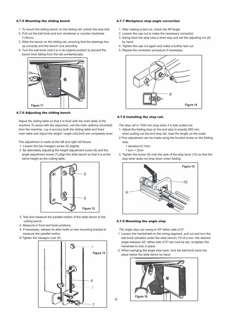
4.7.2 Adjust the scale mount
1. Release the 2x allen bolts M6x16 and shift the scale mount to the left or to right make sure the pointer with the “0” scale. then tighten the 2x allen bolts 2. Slide the guide rail (3) over the intermediate plates (2) and tighten the thumbscrews . 3. Insert the folding stop (4) into the end stop and tighten the T-screw.
4.7.3 Mounting bracket
Fit the two mounting brackets with two "I" shape insert block to machine housing. 4 allen bolts M8x45
4.7.4 Mounting the sliding rail
Insert the Sliding rail from above at a slight angle into the mounting brackets and tighten the wing nuts.
Figure 5
Figure 6
Feeder base
Feeder armStartype screw
Anti-kickback ass’y
Sliding rail
Feed roller ass’y
1
2
Figure 7
43
Figure 8
Figure 9
Figure 10
5
4.7.7 Workpiece stop angle correction
1. After making a test cut, check the 90Oangle. 2. Loosen the cap nut to make the necessary correction. 3. Swing back the stop tube a short way and set the adjusting nut (8) by hand. 4. Tighten the cap nut again and make a further test cut. 5. Repeat the correction procedure if necessary.
4.7.8 Installing the stop rail.
The stop rail is 1500 mm long when it is fully pulled out. 1. Adjust the folding stop on the end stop to exactly 900 mm. when pulling out the end stop rail, read the length on the scale. 2.Fine adjustment can be made using the knurled screw on the folding stop. 1 devision=0.1mm 1 turn = 2mm 3. Tighten the screw (9) onto the axle of the stop lever (10) so that the stop lever does not drop down when folding.
4.7.9 Mounting the angle stop
The angle stop can swing to 45O either side of 0O. 1. Loosen the handwheel on the swing segment, pull out and turn the ball knob (situated under the slide bench) 1/4 of a turn, the desired angle between 45° either side of 0O can now be set, re-tighten the hanwheel to lock in place. 2. When swinging the angle stop back, lock the ball knob back into place below the slide bench by hand.
6
4.7.5 Mounting the sliding bench
1. To mount the sliding bench on the sliding rail, unlock the stop bolt. 2. Pull out the ball knob and turn clockwise or counter-clockwise (1/4turn). 3. Slide the bench on the sliding rail, ensuring that the bearings line up correctly and the bench runs smoothly. 4. Turn the ball knob until it is in its original position to prevent the bench from falling from the rail unintentionally.
4.7.6 Adjusting the sliding bench
Adjust the sliding table so that it is flush with the main table of the machine.To assist with the alignment, use the main ripfence (inverted) from the machine. Lay it accross both the sliding table and fixed main table and adjust the height / angle until both are completely level.
The adjustment is made at the left and right rail fixture. 1. Loosen the two hexagon screw (5) slightly. 2. By alternately adjusting the height adjustment screw (6) and the angle adjustment screw (7),align the slide bench so that it is at the same height as the cutting table.
3. Test and measure the parallel motion of the slide bench to the cutting bench. 4. Measure in front and back positions. 5. If necessary, release 4x allen bolts on two mounting bracket to measure the parallel motion. 6.Tighten the hexagon nuts (5).
Figure 11
5
5
Figure 12
6
5
7
5
Figure 13
8
Figure 14
9
10
Figure 15
Figure 16
4.8 Installing Mobile Wheel Kit (optional)
1. Place “U” Shape Bracket(1) onto Front Wheel Kit Ass’y(2). 2. Insert Hex Head Screw M10x70(3), secure Front Wheel Kit and Sleeve(4) to work stand. 3. Insert Special Thread(5) and secure Front wheel kit. 4. Secure Rear Castor Frame(7) to workstand with two Hex Head Screw M10x20 & washer. 5. When move the machine adjust the Allen Bolt M12x50,and raise the machine about 5mm above floor. Insert the Rear Castor Ass’y, push the lever down and pull the machine round the workshop.
7
4.7.10 Installing the sliding rail
The sliding rail can be moved forwards or backwards. 1. Loosen the 2 wing nuts on the left and right hand mounting brackets. 2. Depending on the size of the workpiece, move the sliding rail into the ideal position relative to the main table, then tighten both sets of wingnuts.
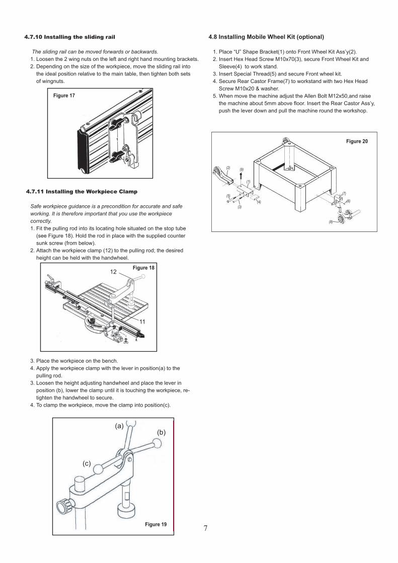
4.7.11 Installing the Workpiece Clamp
Safe workpiece guidance is a precondition for accurate and safe working. It is therefore important that you use the workpiece correctly. 1. Fit the pulling rod into its locating hole situated on the stop tube (see Figure 18). Hold the rod in place with the supplied counter sunk screw (from below). 2. Attach the workpiece clamp (12) to the pulling rod; the desired height can be held with the handwheel.
3. Place the workpiece on the bench. 4. Apply the workpiece clamp with the lever in position(a) to the pulling rod. 3. Loosen the height adjusting handwheel and place the lever in position (b), lower the clamp until it is touching the workpiece, re- tighten the handwheel to secure. 4. To clamp the workpiece, move the clamp into position(c).
Figure 17
Figure 18
Figure 19
11
12
(a)(b)
(c)
Figure 20
5.3 Adjust the height of Spindle
Perform this adjustment must switch off the power first. 1. Loosen the Spindle Height Lock(a). 2. Make sure the fence & table cleaning with milling tool. 3. Move the spindle up or down with the Spindle Height Handwheel(b) until the desired position is obtained. To raise = turn counter-clockwise To lower = turn clockwise Any height adjustment can be read directly from the scale(c). 4. Secure the Spindle Height Lock(a).
5.4 Spindle Tilt Setting
Perform this adjustment must switch off the power first. Using the Tilting table ring! 1. Loosen the Spindle Bevel Lock(a). To loosen = turn counter-clockwise To lock = turn clockside 2. Make sure the fence & table cleaning with milling tool.And sesure that if the spindle tilted, it can touch the fence and table ring. 3. Move the spindle bevel with the Spindle Tilting Handwheel(b) until the desired position is obtained. To right = turn leftside To left = turn rightside 3. Secure the Spindle tilt Lock(a).
8
5. ADJUSTMENT & OPERATION
Read the manual before assembly and operation. Become familiar with the machine and its operation before beginning any work. Serious personal injury may result if safety or operational information is not understood or followed.
5.1 Speed Changes
This machine is equipped with a V-belt drive system that controls the speeds. To change spindle speeds:
1. Unplug the machine. 2. Loosen the two Startype Screw M6x30, open the Machine Housing Door. 3. Loosen the Allen Bolt M12x40(a) with allen wrench, Pull the Motor Tension Lever(b) out.
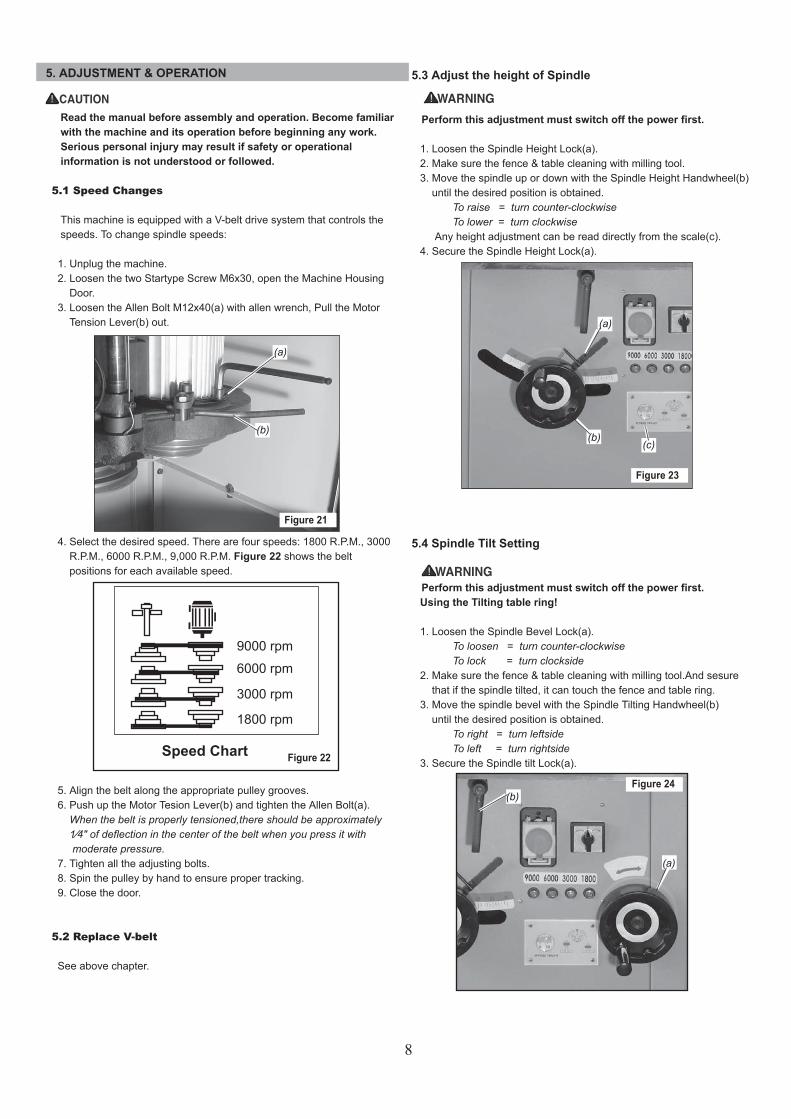
4. Select the desired speed. There are four speeds: 1800 R.P.M., 3000 R.P.M., 6000 R.P.M., 9,000 R.P.M. Figure 22 shows the belt positions for each available speed.
5. Align the belt along the appropriate pulley grooves. 6. Push up the Motor Tesion Lever(b) and tighten the Allen Bolt(a). When the belt is properly tensioned,there should be approximately 1⁄4" of deflection in the center of the belt when you press it with moderate pressure. 7. Tighten all the adjusting bolts. 8. Spin the pulley by hand to ensure proper tracking. 9. Close the door.
5.2 Replace V-belt
See above chapter.
(a)
(b)
Figure 21
Figure 22
9000 rpm
6000 rpm
3000 rpm
1800 rpm
Speed Chart
Figure 23
(a)
(b)(c)
Figure 24(b)
(a)
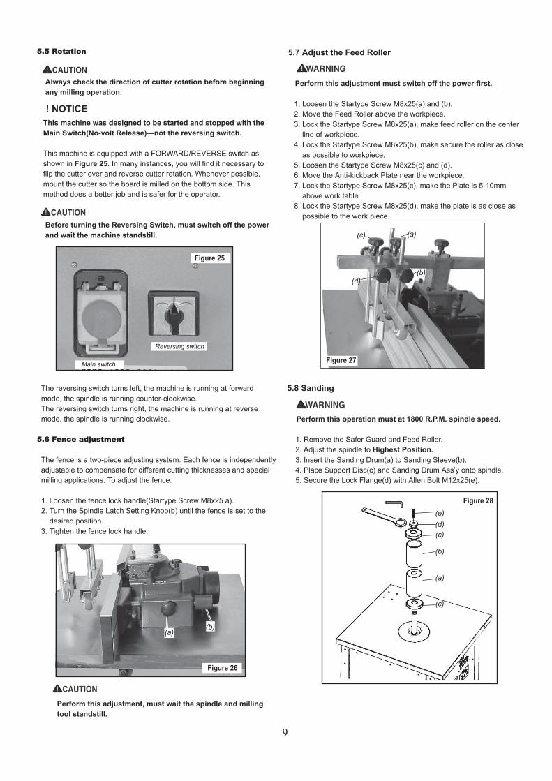
5.7 Adjust the Feed Roller
Perform this adjustment must switch off the power first. 1. Loosen the Startype Screw M8x25(a) and (b). 2. Move the Feed Roller above the workpiece. 3. Lock the Startype Screw M8x25(a), make feed roller on the center line of workpiece. 4. Lock the Startype Screw M8x25(b), make secure the roller as close as possible to workpiece. 5. Loosen the Startype Screw M8x25(c) and (d). 6. Move the Anti-kickback Plate near the workpiece. 7. Lock the Startype Screw M8x25(c), make the Plate is 5-10mm above work table. 8. Lock the Startype Screw M8x25(d), make the plate is as close as possible to the work piece.
9
5.5 Rotation
Always check the direction of cutter rotation before beginning any milling operation.
This machine was designed to be started and stopped with the Main Switch(No-volt Release)—not the reversing switch.
This machine is equipped with a FORWARD/REVERSE switch as shown in Figure 25. In many instances, you will find it necessary to flip the cutter over and reverse cutter rotation. Whenever possible, mount the cutter so the board is milled on the bottom side. This method does a better job and is safer for the operator.
Before turning the Reversing Switch, must switch off the power and wait the machine standstill.
The reversing switch turns left, the machine is running at forward mode, the spindle is running counter-clockwise. The reversing switch turns right, the machine is running at reverse mode, the spindle is running clockwise.
5.6 Fence adjustment
The fence is a two-piece adjusting system. Each fence is independently adjustable to compensate for different cutting thicknesses and special milling applications. To adjust the fence:
1. Loosen the fence lock handle(Startype Screw M8x25 a). 2. Turn the Spindle Latch Setting Knob(b) until the fence is set to the desired position. 3. Tighten the fence lock handle.
Figure 25
Reversing switch
Main switch
Figure 26
(a)(b)
Perform this adjustment, must wait the spindle and milling tool standstill.
Figure 27
(b)
(a)
(d)
(c)
5.8 Sanding
Perform this operation must at 1800 R.P.M. spindle speed. 1. Remove the Safer Guard and Feed Roller. 2. Adjust the spindle to Highest Position. 3. Insert the Sanding Drum(a) to Sanding Sleeve(b). 4. Place Support Disc(c) and Sanding Drum Ass’y onto spindle. 5. Secure the Lock Flange(d) with Allen Bolt M12x25(e).
Figure 28
(a)
(b)
(c)
(c)(d)(e)
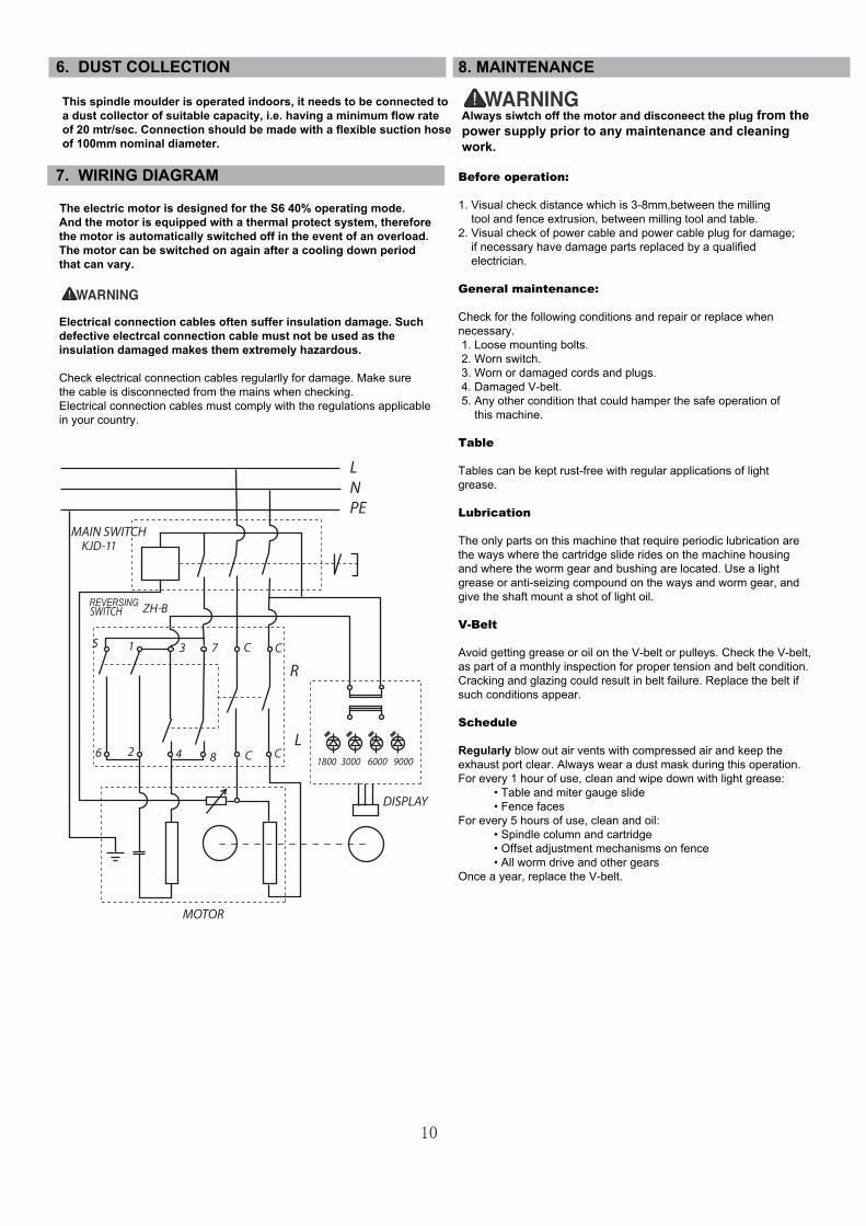
8. MAINTENANCE
Always siwtch off the motor and disconeect the plug from the power supply prior to any maintenance and cleaning work.
Before operation:
1. Visual check distance which is 3-8mm,between the milling tool and fence extrusion, between milling tool and table.2. Visual check of power cable and power cable plug for damage; if necessary have damage parts replaced by a qualified electrician.
General maintenance:
Check for the following conditions and repair or replace when necessary. 1. Loose mounting bolts. 2. Worn switch. 3. Worn or damaged cords and plugs. 4. Damaged V-belt. 5. Any other condition that could hamper the safe operation of this machine.
Table
Tables can be kept rust-free with regular applications of lightgrease.
Lubrication
The only parts on this machine that require periodic lubrication are the ways where the cartridge slide rides on the machine housing and where the worm gear and bushing are located. Use a light grease or anti-seizing compound on the ways and worm gear, and give the shaft mount a shot of light oil.
V-Belt
Avoid getting grease or oil on the V-belt or pulleys. Check the V-belt, as part of a monthly inspection for proper tension and belt condition.Cracking and glazing could result in belt failure. Replace the belt if such conditions appear.
Schedule
Regularly blow out air vents with compressed air and keep the exhaust port clear. Always wear a dust mask during this operation.For every 1 hour of use, clean and wipe down with light grease: • Table and miter gauge slide • Fence facesFor every 5 hours of use, clean and oil: • Spindle column and cartridge • Offset adjustment mechanisms on fence • All worm drive and other gearsOnce a year, replace the V-belt.
6. DUST COLLECTION
This spindle moulder is operated indoors, it needs to be connected to a dust collector of suitable capacity, i.e. having a minimum flow rate of 20 mtr/sec. Connection should be made with a flexible suction hose of 100mm nominal diameter.
7. WIRING DIAGRAM
The electric motor is designed for the S6 40% operating mode. And the motor is equipped with a thermal protect system, therefore the motor is automatically switched off in the event of an overload. The motor can be switched on again after a cooling down period that can vary. Electrical connection cables often suffer insulation damage. Such defective electrcal connection cable must not be used as the insulation damaged makes them extremely hazardous.
Check electrical connection cables regularlly for damage. Make sure the cable is disconnected from the mains when checking. Electrical connection cables must comply with the regulations applicable in your country.
LNPE
10

Before carrying out any fault service or maintenance work always:1. Switch machine OFF 2. Unplug power cable 3. Wait for spindle moulder to come to standstill.
Motor is slow or weak Voltage from source is low.
Windings are burned out or open.
Power Switch is defective.
Circuit is overloaded with appliances,
lights, or other electrically powered
equipment.
Request a voltage check from local
power company.
Have the Motor checked / repaired.
Have the Power Switch replaced.
Do not use other appliances or
electrically powered equipment on the
same circuit when using the Table Saw.
Motor overheats. Motor is overloaded.
Dull milling tool.
Request a voltage check from the local
power company.
Replace the milling tool.
When milling, the cut burns the
work-piece, or stalls the motor.
Milling tool is dull.
Work-piece is warped.
Sharpen or replace the milling tool.
Replace the work-piece.
Bevel & Height Handles are
hard to turn. inside the base.
Clean and lubricate the mechanisms
inside the base.
The spindle does not bevel ordoes not lower or higher. Height Lock Handle is not fully released.
Bevel Lock Handle is not fully released. Fully release the Bevel Lock Handle.
Trouble Shooting Guide Problem Cause Solution
Spindle moulder does not start.
Circuit fuse is blown.
Circuit breaker is tripped.
Motor Cord or Switch is damaged.
Plug in Motor Cord to volt electrical
outlet.
Replace circuit fuse.
Reset circuit breaker.
Have the Motor Cord or Switch
replaced.
Power Switch does not
operate.
Power Switch contacts are burned out.
Capacitor is defective.
Wiring connections are loose or
damaged.
Have the Power Switch replaced.
Request a voltage check from the local
power company.
Have the Capacitor replaced.
Have the wiring connections checked /
repaired.
Fuses or circuit breakers open
frequently.
Motor is overloaded.
Fuses or circuit breakers are wrong size
or defective.
Dull milling tool.
Power Switch is defective.
Feed work-piece more slowly.
Replace fuses or circuit breakers.
Replace the milling tool.
Have the Power Switch replaced.
Motor stalls, blows fuses, or
trips circuit breakers.
Motor is overloaded.
Dull milling tool.
Fuses or circuit breakers are wrong size
or defective.
Feeding work-piece too rapidly.
Request a voltage check from the local
power company.
Replace the milling tool.
Replace fuses or circuit breakers.
Feed work-piece more slowly.
Spindle moulder is noisy when
running.
Motor is loose or defective. Have the Motor checked/repaired
Warning: To prevent personal injury and/or damage to the spindle moulder, maintenance and repairs should
be done only by a qualified technician.
Spindle moulder vibrates excessively. V-belt is damaged.
Milling tool is damaged.
Loose bolt, Screws, Nuts.
Readjust the Leveling Feet.
Replace the V-belt.
Replace the milling tool.
Tighten all Hardware.
Floor surface is uneven.
Fully release the height Lock Handle.
Motor Cord is not plugged in.
Dust has collected on the mechanisms
11
9. TROUBLE SHOOTING
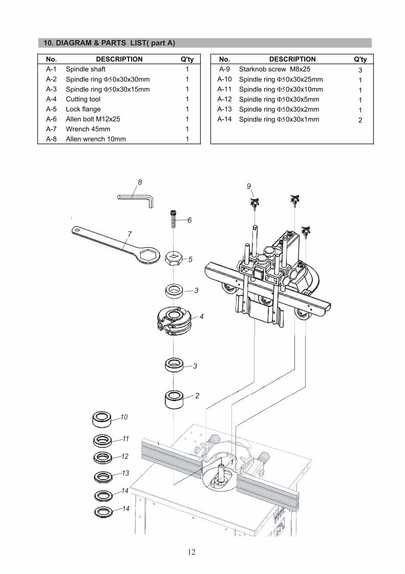
No. DESCRIPTION Q'ty No. DESCRIPTION Q'tyA-1 Spindle shaft 1 A-9 Starknob screw M8x25 3A-2 Spindle ring Φ50x30x30mm 1 A-10 Spindle ring Φ50x30x25mm 1A-3 Spindle ring Φ50x30x15mm 1 A-11 Spindle ring Φ50x30x10mm 1A-4 Cutting tool 1 A-12 Spindle ring Φ50x30x5mm 1A-5 Lock flange 1 A-13 Spindle ring Φ50x30x2mm 1A-6 Allen bolt M12x25 1 A-14 Spindle ring Φ50x30x1mm 2A-7 Wrench 45mm 1A-8 Allen wrench 10mm 1
12
10. DIAGRAM & PARTS LIST( part A)

No. DESCRIPTION Q'ty No. DESCRIPTION Q'tyB-1 Table 1 B-26 Feeder base 1B-2 Table ring 200mm for tilt 1 B-27 Block,feeder base 1B-3 Table ring 200/150mm 1 B-28 Roll pin 3x10 5B-4 Table ring 150/110mm 1 B-29 Allen bolt M8x20 2B-5 Table ring 110/80mm 1 B-30 Flat washer 8mm 4B-6 End cap, fence 2 B-31 Spring washer 8mm 6B-7 Carriage bolt, M8x40 2 B-32 Allen bolt M8x25 4B-8 Guide, bolt 2 B-33 End cap, feeder arm 2B-9 Fence extrusion 2 B-34 Feed arm 1B-10 Countrsunk head screw M8x20 2 B-35 Insert, feed arm 2B-11 Fence extrusion carriage 2 B-36 Feeder joint 2B-12 Flower nut 2 B-37 Rod, roller 2B-13 Safer guard 1 B-38 Rod, roller 2B-14 Flower screw M8x25 8 B-39 Plate, anti-kickback 1B-15 Rachet lever M8x150 2 B-40 Pin, roller 6B-16 Lock spacer 2 B-41 Spring washer 8mm 2B-17 Dust outlet 1 B-42 Hex nut M8 2B-18 Cross recessed pan head screw M5x12 6 B-43 Roller frame 1B-19 Lock piece, handle 2 B-44 Roller house 3B-20 Guide spindle, spindle latch 2 B-45 Hex head screw M6x35 3B-21 Hex nut M5 2 B-46 Plate spring 3B-22 Setting knob, spindle latch 2 B-47 Lock nut M6 3B-23 Large washer 2 B-48 Roller bushing 3B-24 Cover, safer guard 1 B-49 Roller 3B-25 Starknob screw M8x25 3
13
10. DIAGRAM & PARTS LIST( cont. - part B)

14

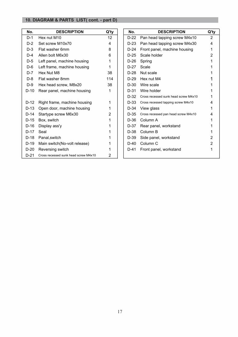
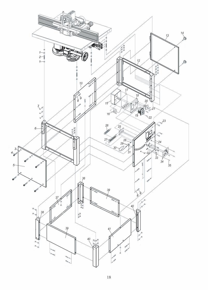
No. DESCRIPTION Q'ty No. DESCRIPTION Q'tyD-1 Hex nut M10 12 D-22 Pan head tapping screw M4x10 2D-2 Set screw M10x70 4 D-23 Pan head tapping screw M4x30 4D-3 Flat washer 6mm 8 D-24 Front panel, machine housing 1D-4 Allen bolt M6x30 6 D-25 Scale holder 2D-5 Left panel, machine housing 1 D-26 Spring 1D-6 Left frame, machine housing 1 D-27 Scale 1D-7 Hex Nut M8 38 D-28 Nut scale 1D-8 Flat washer 8mm 114 D-29 Hex nut M4 1D-9 Hex head screw, M8x20 38 D-30 Wire scale 1D-10 Rear panel, machine housing 1 D-31 Wire holder 1
D-32 Cross recessed sunk head screw M4x10 1D-12 Right frame, machine housing 1 D-33 Cross recessed tapping screw M4x10 4D-13 Open door, machine housing 1 D-34 View glass 1D-14 Startype screw M6x30 2 D-35 Cross recessed pan head screw M4x10 4D-15 Box, switch 1 D-36 Column A 1D-16 Display ass'y 1 D-37 Rear panel, workstand 1D-17 Seal 1 D-38 Column B 1D-18 Panal,switch 1 D-39 Side panel, workstand 2D-19 Main switch(No-volt release) 1 D-40 Column C 2D-20 Reversing switch 1 D-41 Front panel, workstand 1D-21 Cross recessed sunk head screw M4x10 2
10. DIAGRAM & PARTS LIST( cont. - part D)
17
18

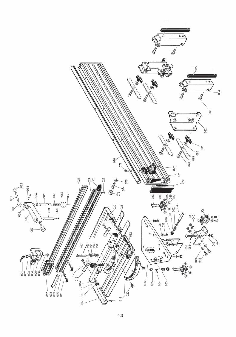
No. DESCRIPTION No. DESCRIPTIOND-001 Ratchet lever M6 D-047 Self-locking nut M8D-002 Bushing D-048 Hexagon head screwD-003 Flat washer 6mm D-049 Flat washer 8mmD-004 Folding stop D-051 U bracketD-005 Bolt guide D-052 Carriage bolt M8x85D-006 Carriage bolt M6x36 D-053 SpringD-007 End stop D-054 Roll pin 3x30D-008 Indermediate plate D-055 Rotate shaftD-009 Roll D-056 Mounting bracketD-010 Washer 6mm D-057 Flower handleD-011 Thumbscrew M6x25 D-058 Workpiece clampD-012 Carriage bolt M6x50 D-059 Circle ringD-013 Bolt guide D-060 CamD-014 Stop tube D-061 LeverD-015 Washer 6 mm D-062 Knob-leverD-016 Wing nut M6 D-063 PinD-017 End plate, sliding bench D-064 Circle ringD-018 Taping screw 3.5x13 D-065 Holder rodD-019 Scale mount D-066 SpringD-020 Allen bolt M6x16 D-067 HolderD-021 Lock handle M8 D-068 Countersunk head screw M6x16D-022 Swing bolt D-069 Pulling rodD-023 Flat Washer 8 mm D-070 End cap, sliding railD-024 Wave washer 8mm D-071 Sliding railD-025 Hex nut M8 D-072 Hex nut M8D-026 Stop rail D-073 Rubber bushingD-027 Guide rail D-074 Allen screw M8x20D-028 End cap D-075 Flat washer 8 mmD-029 Taping screw 4x13 D-076 RailD-030 Sliding bench D-077 Allen screw M6x20D-031 Indermediate plate D-078 Carriage bolt M8X30D-032 Indermediate plate D-079 Bolt guideD-033 Sunk head screw M6x18 D-080 Flat washer 8 mmD-034 Roller seat D-081 Wing nut M8D-035 Hex nut M6 D-082 Guide carriageD-036 Ball bearing D-083 Allen screw M8x20D-037 Circle ring D-084 Mounting bracketD-038 Serrated washer 6mm D-085 Insert blockD-039 Hexagon head screw M6x20D-040 Ball knobD-041 SpringD-042 Flat washer 8mmD-043 ShaftD-044 Hex nut M8D-045 Flat washer 8mmD-046 Flat washer 8mm
10. DIAGRAM & PARTS LIST( cont. - part D)(optional)
19
001
002
003
004
005
006
007
008
009
010
011
0
12
01
301
401
7 0
16
015
018
01
9
0
20
026
027
028
029
030
031
032
033
034
035
036
037
038
039
040
041
042
043
044
045
046
047
049
048
056
055
054
053
021
022
023
024
023
025
052
051
057
058
05906
006
1
062
063
064
065
066
067
068
069
068
085
20
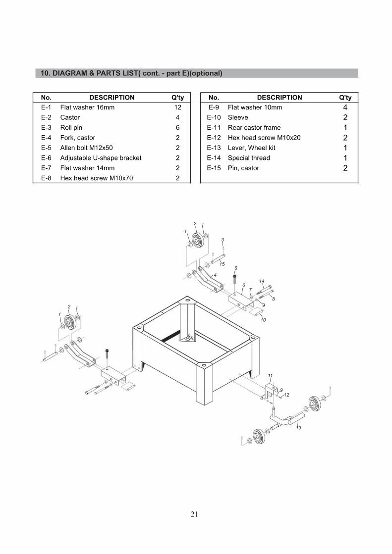
No. DESCRIPTION Q'ty No. DESCRIPTION Q'tyE-1 Flat washer 16mm 12 E-9 Flat washer 10mm 4E-2 Castor 4 E-10 Sleeve 2E-3 Roll pin 6 E-11 Rear castor frame 1E-4 Fork, castor 2 E-12 Hex head screw M10x20 2E-5 Allen bolt M12x50 2 E-13 Lever, Wheel kit 1E-6 Adjustable U-shape bracket 2 E-14 Special thread 1E-7 Flat washer 14mm 2 E-15 Pin, castor 2E-8 Hex head screw M10x70 2
10. DIAGRAM & PARTS LIST( cont. - part E)(optional)
21

Please dispose of packaging for the product in a responsible manner. It is suitable for recycling. Help to protect the environment, take the packaging to the local recycling centre and place into the appropriate recycling bin.
Do not dispose of electric tools together with household waste material. In observance of European Directive 2002/96/EC on waste electrical and electronic equipment and itsimplementation in accordance with national law, electric tools that have reached the end of their life must be collected separately and returned to an environmentally compatible recycling facility.
Only for EU countries
Related Documents