vRealize Automation Load Balancing Configuration Guide Version 7.4 TECHNICAL WHITE PAPER JULY 2018 VERSION 29

Welcome message from author
This document is posted to help you gain knowledge. Please leave a comment to let me know what you think about it! Share it to your friends and learn new things together.
Transcript
vRealize Automation
Load Balancing
Configuration Guide
Version 7.4
T E C H N I C A L W H I T E P A P E R
J U L Y 2 0 1 8
V E R S I O N 2 9
vRealize Automation Load Balancing
T E C H N I C A L W H I T E P A P E R / 2
Table of Contents PRIntroduction .................................................................................................................................. 4
Load Balancing Concepts ............................................................................................................ 5
SSL Pass-Through ................................................................................................................... 5
Session Persistence .................................................................................................................. 5
Source IP Address Hash (NSX) .............................................................................................. 5
Email Notifications on Load Balancer .................................................................................... 5
One-Arm or Multi-Arm Topologies ........................................................................................ 6
Prerequisites for Configuring Load Balancers with vRealize Automation .................................. 7
Complete the vRealize Automation Initial Installation ........................................................... 7
Configure vRealize Automation Identity Connectors for Kerberos (Optional) ........................... 9
Configuring F5 Big IP ..................................................................................................................... 9
Configure Custom Persistence Profile ......................................................................................... 9
Configure Monitors ................................................................................................................... 10
Configure Server Pools .............................................................................................................. 12
Configure Virtual Servers .......................................................................................................... 13
Configuring NSX ........................................................................................................................... 16
Configure Global Settings ......................................................................................................... 16
Add Application Profiles ........................................................................................................... 17
Add Service Monitoring ............................................................................................................ 18
Add Pools .................................................................................................................................. 19
Add Virtual Servers ................................................................................................................... 20
Configuring Citrix NetScaler ......................................................................................................... 21
Configure Monitors ................................................................................................................... 21
Configure Service Groups ......................................................................................................... 23
Configure Virtual Servers .......................................................................................................... 25
Configure Group ........................................................................................................................ 26
Troubleshooting ............................................................................................................................. 27
Provisioning failures when using OneConnect with F5 BIG-IP for a virtual server with SSL
pass-through .............................................................................................................................. 27
F5 BIG-IP license limits network bandwidth ............................................................................ 27
Proxy Agent ping failure............................................................................................................ 27
Connection reset errors in the catalina.out log file .................................................................... 27
Proxy Agents cannot connect to load balanced Manger Service endpoint ................................ 28

vRealize Automation Load Balancing
T E C H N I C A L W H I T E P A P E R / 3

vRealize Automation Load Balancing
T E C H N I C A L W H I T E P A P E R / 4
Revision History
DATE VERSION DESCRIPTION
August 2015 1.0 Initial version
December 2015 1.1 Minor updates
December 2015 2.0 Updates for vRealize Automation 7.0
January 2016 2.1 Minor updates
May 2016 2.2 Updates for vRealize Automation 7.0.x
June 2016 2.3 ▪ Updated timeout to 10 seconds for Configure
Monitors and Add Service Monitoring in F5 and NSX
sections respectively
▪ Added source IP persistence and timeout of 1800
seconds for Add Application Profiles section
▪ Updated all the screenshots to match the content
▪ Updated NSX load balancing method to be round
robin
August 2016 2.4 ▪ Added configuration for Citrix NetScaler
▪ Updated for NSX 6.2
November 2016 2.5 ▪ Updated interval to 5 seconds for Configure Monitors
in Citrix NetScaler section
▪ Updated timeout to 4 seconds for Configure Monitors
in Citrix NetScaler section
May 2017 2.6 Minor updates.
May 2017 2.7 • Added monitor and pool configurations for
vRealize Orchestrator Control Center.
• Added troubleshooting section.
May 2018 2.8 • Updated version to 7.4
• Added information about expected result for load
balancer installation
• Added troubleshooting topic for increasing
connection time
• Revised SSL pass-through information.
• Revised Configure Persistence Group section
Introduction
This document describes the configuration of the load balancing modules of F5 Networks BIG-IP software (F5), Citrix
NetScaler, and NSX load balancers for vRealize Automation 7.x in a distributed and high availability deployment. This
document is not an installation guide, but a load-balancing configuration guide that supplements the vRealize
Automation installation and configuration documentation available in VMware vRealize Automation product
documentation.
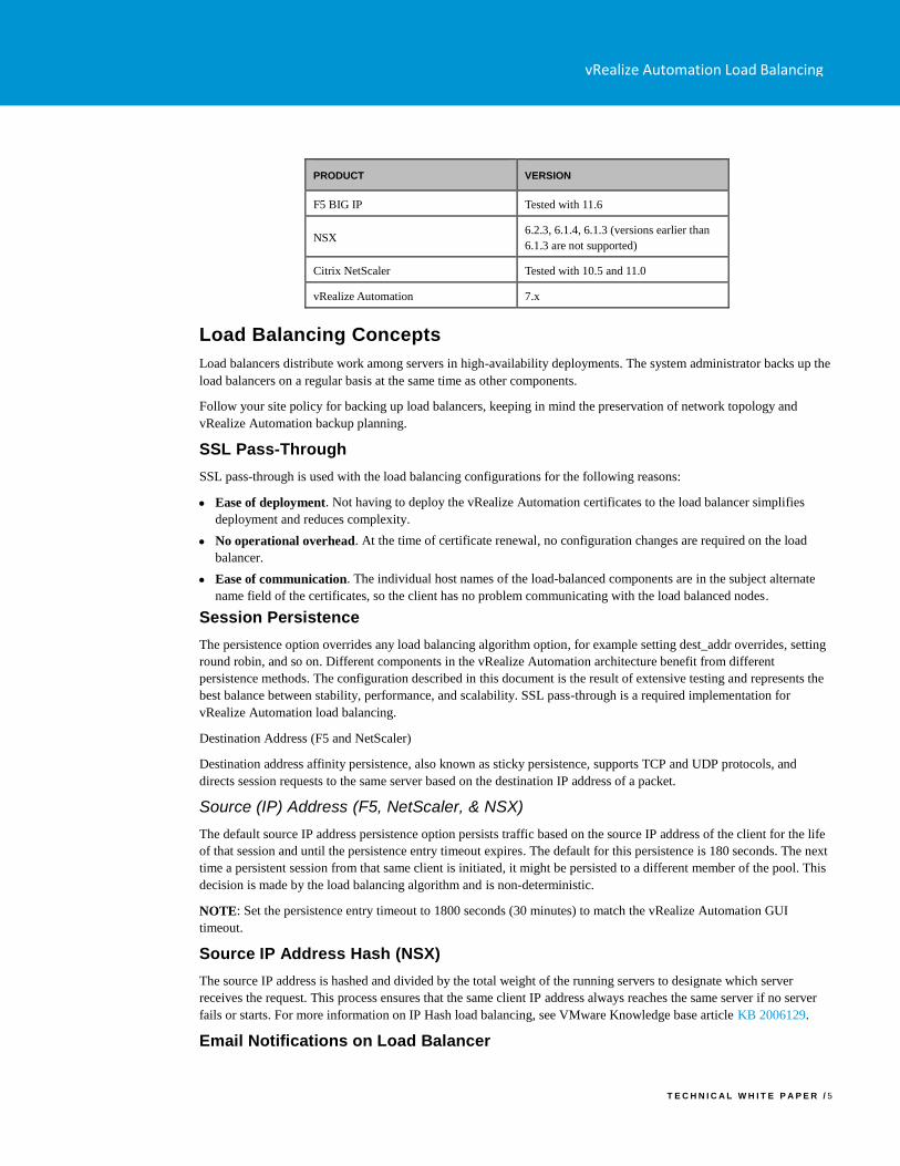
This information is for the following products and versions.
vRealize Automation Load Balancing
T E C H N I C A L W H I T E P A P E R / 5
PRODUCT VERSION
F5 BIG IP Tested with 11.6
NSX 6.2.3, 6.1.4, 6.1.3 (versions earlier than
6.1.3 are not supported)
Citrix NetScaler Tested with 10.5 and 11.0
vRealize Automation 7.x
Load Balancing Concepts
Load balancers distribute work among servers in high-availability deployments. The system administrator backs up the
load balancers on a regular basis at the same time as other components.
Follow your site policy for backing up load balancers, keeping in mind the preservation of network topology and
vRealize Automation backup planning.
SSL Pass-Through
SSL pass-through is used with the load balancing configurations for the following reasons:
• Ease of deployment. Not having to deploy the vRealize Automation certificates to the load balancer simplifies
deployment and reduces complexity.
• No operational overhead. At the time of certificate renewal, no configuration changes are required on the load
balancer.
• Ease of communication. The individual host names of the load-balanced components are in the subject alternate
name field of the certificates, so the client has no problem communicating with the load balanced nodes.
Session Persistence
The persistence option overrides any load balancing algorithm option, for example setting dest_addr overrides, setting
round robin, and so on. Different components in the vRealize Automation architecture benefit from different
persistence methods. The configuration described in this document is the result of extensive testing and represents the
best balance between stability, performance, and scalability. SSL pass-through is a required implementation for
vRealize Automation load balancing.
Destination Address (F5 and NetScaler)
Destination address affinity persistence, also known as sticky persistence, supports TCP and UDP protocols, and
directs session requests to the same server based on the destination IP address of a packet.
Source (IP) Address (F5, NetScaler, & NSX)
The default source IP address persistence option persists traffic based on the source IP address of the client for the life
of that session and until the persistence entry timeout expires. The default for this persistence is 180 seconds. The next
time a persistent session from that same client is initiated, it might be persisted to a different member of the pool. This
decision is made by the load balancing algorithm and is non-deterministic.
NOTE: Set the persistence entry timeout to 1800 seconds (30 minutes) to match the vRealize Automation GUI
timeout.
Source IP Address Hash (NSX)
The source IP address is hashed and divided by the total weight of the running servers to designate which server
receives the request. This process ensures that the same client IP address always reaches the same server if no server
fails or starts. For more information on IP Hash load balancing, see VMware Knowledge base article KB 2006129.
Email Notifications on Load Balancer
vRealize Automation Load Balancing
T E C H N I C A L W H I T E P A P E R / 6
It is a good practice to set up an email notification on the Load Balancer that sends emails to the system administrator
every time a vRealize Automation or vRealize Orchestrator node goes down. Currently, NSX does not support email
notification for such a scenario.
For NetScaler, configure specific SNMP traps and an SNMP manager to send alerts. Consult the NetScaler
documentation for information on SNMP configuration.
You can set up an email notification with F5 by following methods:
• Configuring the BIG-IP system to deliver locally generated email messages
• Configuring custom SNMP traps
• Configuring alerts to send email notifications
One-Arm or Multi-Arm Topologies In one-arm deployment, the load balancer is not physically in line of the traffic, which means that the load balancer’s
ingress and egress traffic goes through the same network interface. Traffic from the client through the load balancer is
network address translated (NAT) with the load balancer as its source address. The nodes send their return traffic to the
load balancer before being passed back to the client. Without this reverse packet flow, return traffic would try to reach
the client directly, causing connections to fail.
In a multi-arm configuration, the traffic is routed through the load balancer. The end devices typically have the load
balancer as their default gateway.
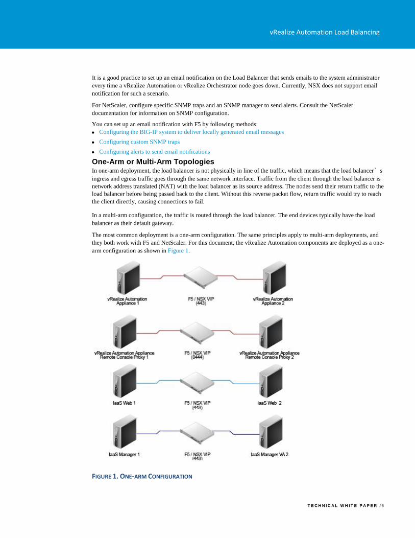
The most common deployment is a one-arm configuration. The same principles apply to multi-arm deployments, and
they both work with F5 and NetScaler. For this document, the vRealize Automation components are deployed as a one-
arm configuration as shown in Figure 1.
FIGURE 1. ONE-ARM CONFIGURATION
vRealize Automation Load Balancing
T E C H N I C A L W H I T E P A P E R / 7
Prerequisites for Configuring Load Balancers with vRealize Automation
• F5 - Before you start the HA implementation of vRealize Automation using an F5 load balancer, ensure that F5 is
installed and licensed and that the DNS server configuration is complete.
• NetScaler - Before you start HA implementation of vRealize Automation by using the NetScaler load balancer,
ensure that NetScaler is installed and has installed at least a Standard Edition license.
• NSX - Before you start the HA implementation of vRealize Automation using NSX as a load balancer, ensure that
your NSX topology is configured and that your version of NSX is supported. This document covers the load
balancing aspect of an NSX configuration, and assumes that NSX is configured and validated to work properly on
the target environment and networks.
To verify that your version is supported, see the vRealize Automation Support Matrix for the current release.
• Certificates - Create signed or self-signed certificates to contain the vRealize Automation virtual IP and the
hostnames of the vRealize Automation nodes in the SubjectAltNames section. This configuration enables the load
balancer to serve traffic without SSL errors. If you need to replace the self-signed certificates with CA signed
certificates, see the VMware knowledge base article KB 2107816. For more information about certificate
troubleshooting and supportability, see the VMware knowledge base article KB 2106583.
• Identity provider - With vRealize Automation 7.0, the preferred Identity Provider is VMware Identity Manager,
which is embedded in the vRealize Automation Appliance.
• Database – Verify that supported database servers are available for vRealize Infrastructure-as-a-Service (IaaS)
nodes. IaaS components require an Microsoft SQL Server instance.
For more information on installation and configuration see vRealize Automation product documentation.
If required, external Orchestrator cluster can be configured to work with the vRealize Automation system. This can be
done after the vRealize Automation system is up and running. However, a vRealize Automation Highly-Available
setup already includes an embedded Orchestrator cluster.
Complete the vRealize Automation Initial Installation
During the initial setup process, the load balancer with all nodes enabled routes half of the traffic to the secondary
nodes, which are not yet installed, and the installation fails. To avoid these failures and to complete the initial
installation of a vRealize Automation, you must perform the following tasks.
1. Configure the F5, NSX, or NetScaler load balancer. See Configuring F5 Big IP, Configuring NSX, and
Configuring Citrix NetScaler.
2. Turn off the health monitors or change them temporarily to default TCP, and ensure traffic is still forwarding to
your primary nodes.
3. Disable all secondary nodes (VA and IaaS) from the load balancer pools.
4. Install and configure all the system components as detailed in vRealize Automation Installation and Configuration
documentation.
5. When all components are installed, enable all nodes on the load balancer.
6. Configure the load balancer with all monitors (health-checks) enabled.
After you complete this procedure, update the monitor that you created in Configure Monitors.
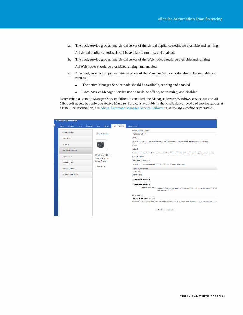
After you have configured a directory for at least one tenant, ensure that the IdP Hostname is set to the load
balancer virtual IP for the vRealize Automation virtual appliances and available connectors are enabled and
configured for authentication for each virtual appliance node.
7. Ensure that all nodes are in the expected state with the health monitor enabled in the load balancer after
installation:
vRealize Automation Load Balancing
T E C H N I C A L W H I T E P A P E R / 8
a. The pool, service groups, and virtual server of the virtual appliance nodes are available and running.
All virtual appliance nodes should be available, running, and enabled.
b. The pool, service groups, and virtual server of the Web nodes should be available and running.
All Web nodes should be available, running, and enabled.
c. The pool, service groups, and virtual server of the Manager Service nodes should be available and
running.
• The active Manager Service node should be available, running and enabled.
• Each passive Manager Service node should be offline, not running, and disabled.
Note: When automatic Manager Service failover is enabled, the Manager Service Windows service runs on all
Microsoft nodes, but only one Active Manager Service is available in the load balancer pool and service groups at
a time. For information, see About Automatic Manager Service Failover in Installing vRealize Automation.
vRealize Automation Load Balancing
T E C H N I C A L W H I T E P A P E R / 9
Configure vRealize Automation Identity Connectors for Kerberos (Optional)
If you require your vRealize Automation users to be authenticated by using Kerberos and they log in to the
administration console by using Windows Single Sign-on, then you must configure the identity connectors.
Connect vRealize Automation to an Active Directory by using the IWA method.
Configure policies and methods for Kerberos authentication.
Open the administration console and navigate to Administration > Directories Management > Connectors. See
Using Directories Management to Create an Active Directory in Configuring vRealize Automation.
In the Worker column, select a worker to view the connector details and navigate to the Auth Adapters page.
Click KerberosIdpAdapter.
You are redirected to the vIDM Console. ??Should this be vRA console?
Select Enable Windows Authentication.
Select Enable Redirect.
In Redirect Host Name, enter the FQDN of the appliance you are configuring.
Configure the KerberosIdPAdapter on all of the connectors in your cluster. Ensure that the configuration of the
adapter is identical on all the connectors, with the exception of the Redirect Host Name value, which should be
specific to each connector.
The Enable Redirect option directs HTTPS access for all client computers to a vRealize Automation node on port 443.
The user’s browser is redirected away from the load Balancing vRealize Automation endpoint to the appliance’s FQDN
to perform authentication. After authentication, the user's browser is redirected to the load balancing vRealize
Automation FQDN.
Configuring the same HOST SPN (the load balancing FQDN) for each computer object in AD is not supported because
Kerberos authentication relies on SPNs configured in Active Directory, which should be unique for every host. The
only way to enable single sign-on for all members of a vRealize Automation cluster is to tell vIDM to redirect from the
load balancing FQDN to the individual node, verify the ticket, and then redirect to the FQDN.
If you do not want to expose individual vRealize Automation appliances directly to the user and you still require
Kerberos authentication, then your best option is to federate the vRealize Automation solution with a thir-party SAML
identity provider such as Active Directory Federation Services.
Configuring F5 Big IP
This document assumes that the F5 device is already deployed in the environment and can access vRealize Automation
components over a network.
• The F5 device can be either physical or virtual and can be deployed in one-arm or multi-arm topologies
• The Local Traffic module (LTM) must be configured and licensed as either Nominal, Minimum, or Dedicated. You
can configure the LTM on the System > Resource Provisioning page
If you are using an F5 version earlier than 11.x, you might need to change your health monitor settings related to the
Send string. For more information about how to set up your health monitor send string for the different versions of F5
see HTTP health checks may fail even though the node is responding correctly.
Configure Custom Persistence Profile
vRealize Automation Load Balancing
T E C H N I C A L W H I T E P A P E R / 1 0
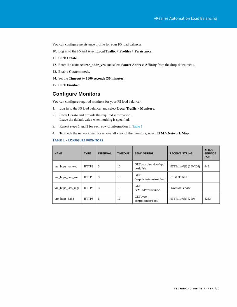
You can configure persistence profile for your F5 load balancer.
Log in to the F5 and select Local Traffic > Profiles > Persistence.
Click Create.
Enter the name source_addr_vra and select Source Address Affinity from the drop-down menu.
Enable Custom mode.
Set the Timeout to 1800 seconds (30 minutes).
Click Finished.
Configure Monitors
You can configure required monitors for your F5 load balancer.
1. Log in to the F5 load balancer and select Local Traffic > Monitors.
2. Click Create and provide the required information.
Leave the default value when nothing is specified.
3. Repeat steps 1 and 2 for each row of information in Table 1.
4. To check the network map for an overall view of the monitors, select LTM > Network Map.
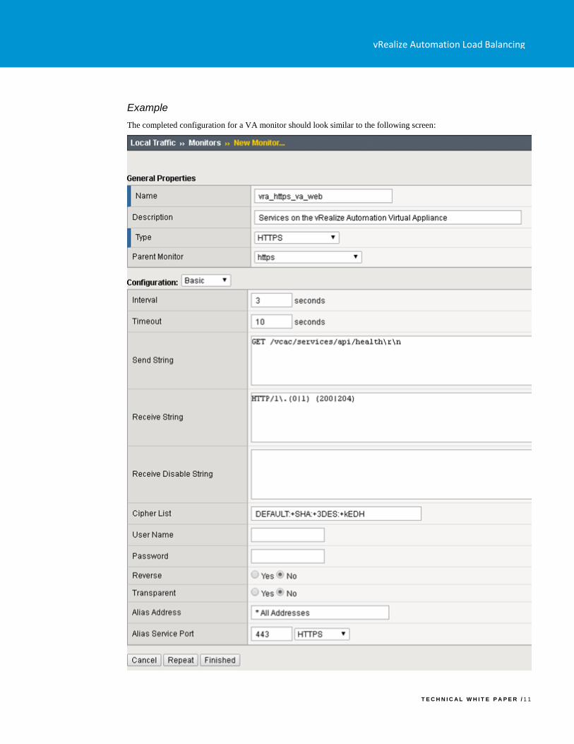
TABLE 1 - CONFIGURE MONITORS
NAME TYPE INTERVAL TIMEOUT SEND STRING RECEIVE STRING
ALIAS
SERVICE
PORT
vra_https_va_web HTTPS 3 10 GET /vcac/services/api/
health\r\n HTTP/1\.(0|1) (200|204) 443
vra_https_iaas_web HTTPS 3 10 GET
/wapi/api/status/web\r\n REGISTERED
vra_https_iaas_mgr HTTPS 3 10 GET
/VMPSProvision\r\n ProvisionService
vro_https_8283 HTTPS 5 16 GET /vco-
controlcenter/docs/ HTTP/1\.(0|1) (200) 8283
vRealize Automation Load Balancing
T E C H N I C A L W H I T E P A P E R / 1 1
Example
The completed configuration for a VA monitor should look similar to the following screen:
vRealize Automation Load Balancing
T E C H N I C A L W H I T E P A P E R / 1 2
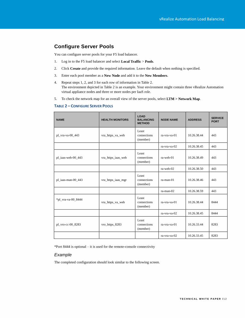
Configure Server Pools
You can configure server pools for your F5 load balancer.
1. Log in to the F5 load balancer and select Local Traffic > Pools.
2. Click Create and provide the required information. Leave the default when nothing is specified.
3. Enter each pool member as a New Node and add it to the New Members.
4. Repeat steps 1, 2, and 3 for each row of information in Table 2.
The environment depicted in Table 2 is an example. Your environment might contain three vRealize Automation
virtual appliance nodes and three or more nodes per IaaS role.
5. To check the network map for an overall view of the server pools, select LTM > Network Map.
TABLE 2 – CONFIGURE SERVER POOLS
NAME HEALTH MONITORS
LOAD
BALANCING
METHOD
NODE NAME ADDRESS SERVICE
PORT
pl_vra-va-00_443 vra_https_va_web
Least
connections
(member)
ra-vra-va-01 10.26.38.44 443
ra-vra-va-02 10.26.38.45 443
pl_iaas-web-00_443 vra_https_iaas_web
Least
connections
(member)
ra-web-01 10.26.38.49 443
ra-web-02 10.26.38.50 443
pl_iaas-man-00_443 vra_https_iaas_mgr
Least
connections
(member)
ra-man-01 10.26.38.46 443
ra-man-02 10.26.38.59 443
*pl_vra-va-00_8444
vra_https_va_web
Least
connections
(member)
ra-vra-va-01 10.26.38.44 8444
ra-vra-va-02 10.26.38.45 8444
pl_vro-cc-00_8283 vro_https_8283
Least
connections
(member)
ra-vra-va-01 10.26.33.44 8283
ra-vra-va-02 10.26.33.45 8283
*Port 8444 is optional – it is used for the remote-console connectivity
Example
The completed configuration should look similar to the following screen.
vRealize Automation Load Balancing
T E C H N I C A L W H I T E P A P E R / 1 3
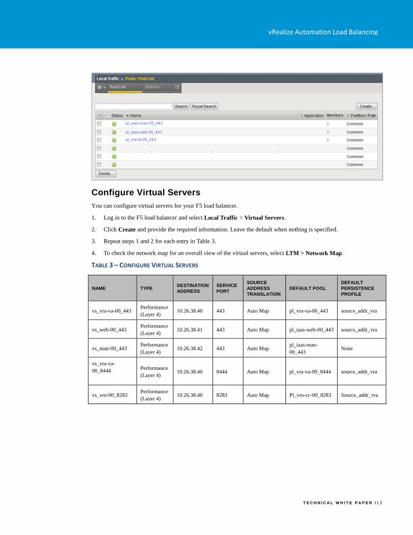
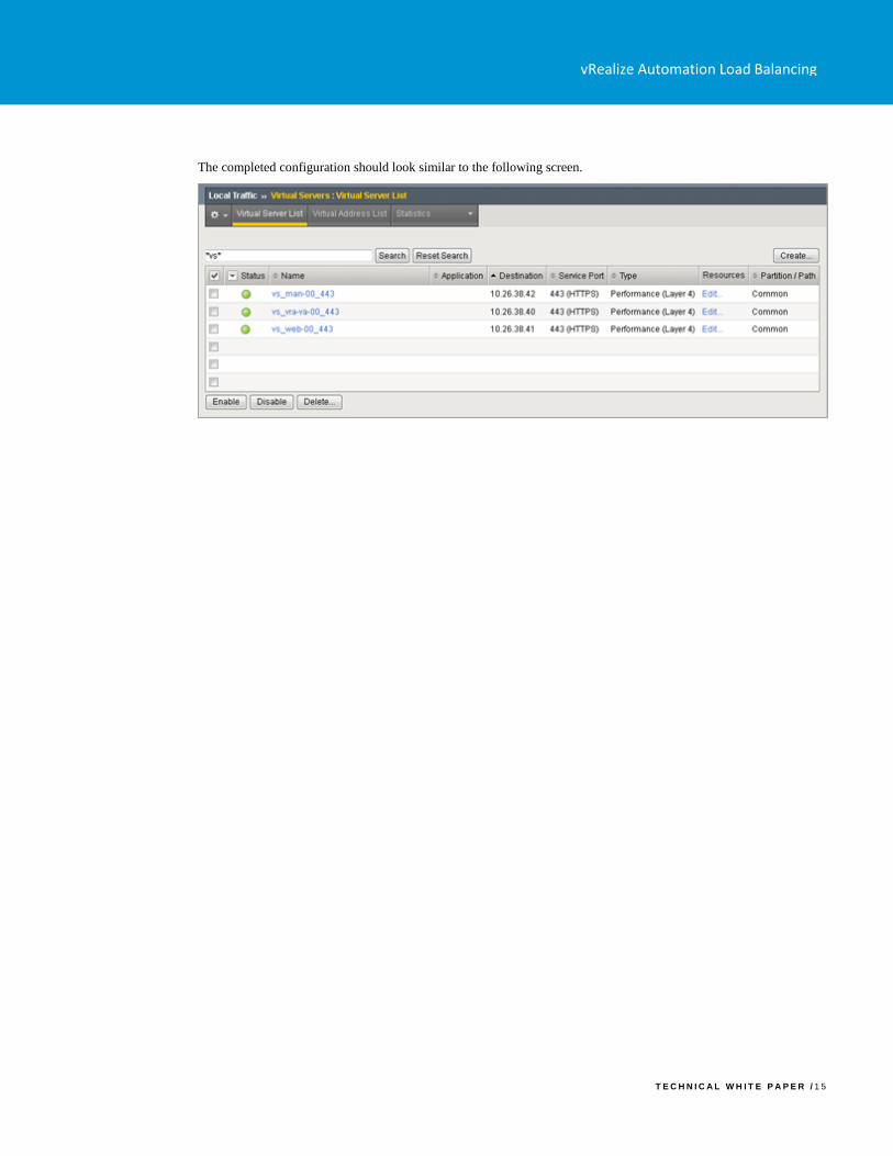
Configure Virtual Servers
You can configure virtual servers for your F5 load balancer.
1. Log in to the F5 load balancer and select Local Traffic > Virtual Servers.
2. Click Create and provide the required information. Leave the default when nothing is specified.
3. Repeat steps 1 and 2 for each entry in Table 3.
4. To check the network map for an overall view of the virtual servers, select LTM > Network Map.
TABLE 3 – CONFIGURE VIRTUAL SERVERS
NAME TYPE DESTINATION
ADDRESS
SERVICE
PORT
SOURCE
ADDRESS
TRANSLATION
DEFAULT POOL
DEFAULT
PERSISTENCE
PROFILE
vs_vra-va-00_443 Performance
(Layer 4) 10.26.38.40 443 Auto Map pl_vra-va-00_443 source_addr_vra
vs_web-00_443 Performance
(Layer 4) 10.26.38.41 443 Auto Map pl_iaas-web-00_443 source_addr_vra
vs_man-00_443 Performance
(Layer 4) 10.26.38.42 443 Auto Map
pl_iaas-man-
00_443 None
vs_vra-va-
00_8444
Performance
(Layer 4) 10.26.38.40 8444 Auto Map pl_vra-va-00_8444 source_addr_vra
vs_vro-00_8283 Performance
(Layer 4) 10.26.38.40 8283 Auto Map Pl_vro-cc-00_8283 Source_addr_vra
vRealize Automation Load Balancing
T E C H N I C A L W H I T E P A P E R / 1 4
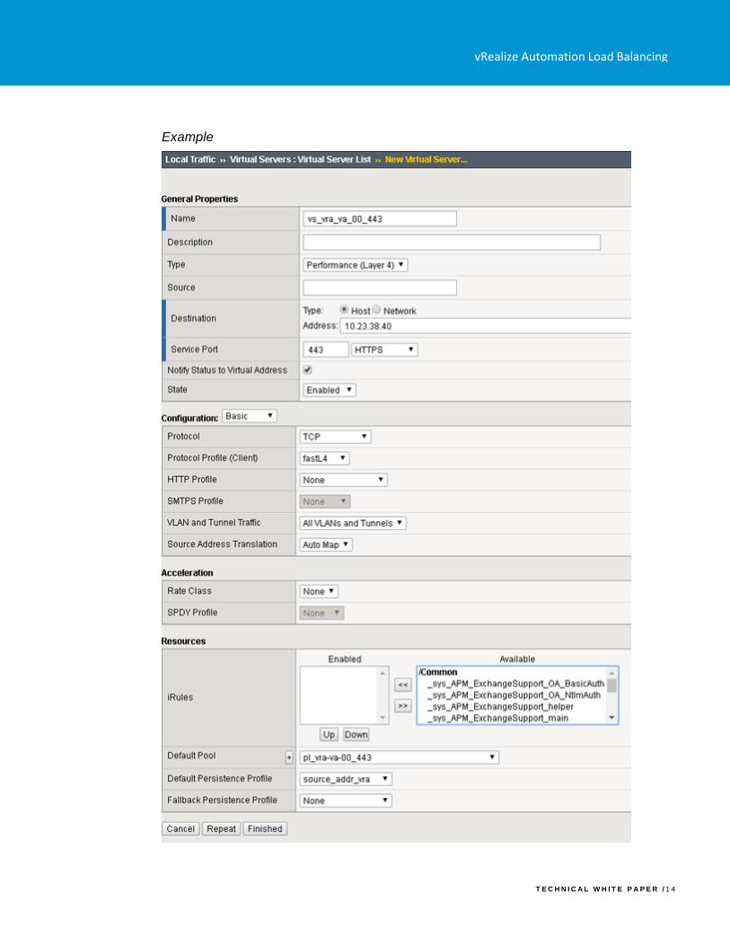
Example
vRealize Automation Load Balancing
T E C H N I C A L W H I T E P A P E R / 1 5
The completed configuration should look similar to the following screen.
vRealize Automation Load Balancing
T E C H N I C A L W H I T E P A P E R / 1 6
Configuring NSX
You can deploy a new NSX Edge Services Gateway or use an existing one. It must have network connectivity to and
from the vRealize Automation components being load balanced.
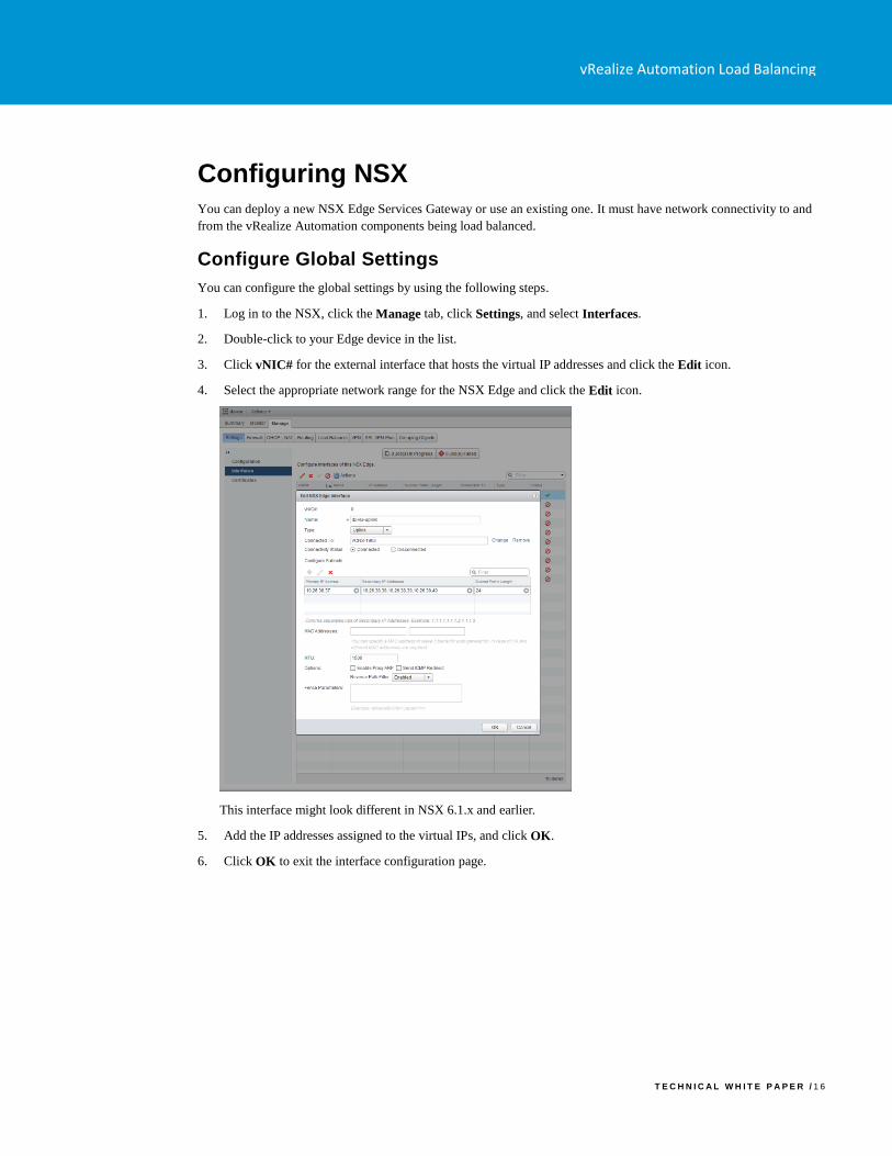
Configure Global Settings
You can configure the global settings by using the following steps.
1. Log in to the NSX, click the Manage tab, click Settings, and select Interfaces.
2. Double-click to your Edge device in the list.
3. Click vNIC# for the external interface that hosts the virtual IP addresses and click the Edit icon.
4. Select the appropriate network range for the NSX Edge and click the Edit icon.
This interface might look different in NSX 6.1.x and earlier.
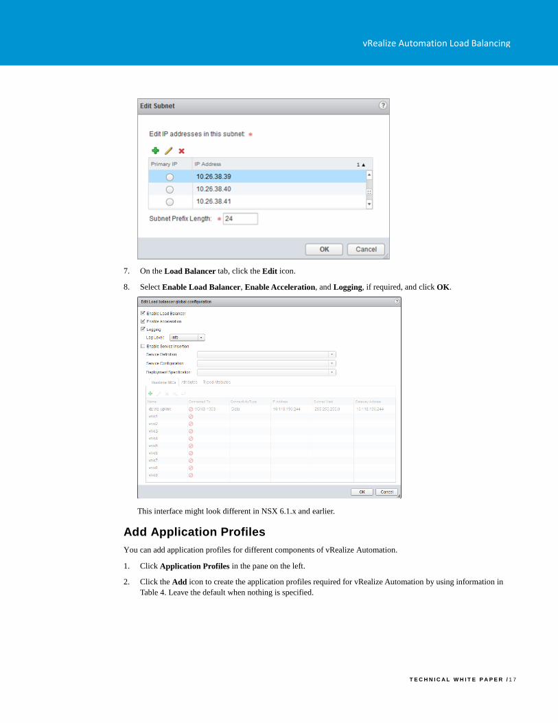
5. Add the IP addresses assigned to the virtual IPs, and click OK.
6. Click OK to exit the interface configuration page.
vRealize Automation Load Balancing
T E C H N I C A L W H I T E P A P E R / 1 7
7. On the Load Balancer tab, click the Edit icon.
8. Select Enable Load Balancer, Enable Acceleration, and Logging, if required, and click OK.
This interface might look different in NSX 6.1.x and earlier.
Add Application Profiles
You can add application profiles for different components of vRealize Automation.
1. Click Application Profiles in the pane on the left.
2. Click the Add icon to create the application profiles required for vRealize Automation by using information in
Table 4. Leave the default when nothing is specified.
vRealize Automation Load Balancing
T E C H N I C A L W H I T E P A P E R / 1 8
TABLE 4 – ADD APPLICATION PROFILES
NAME TYPE
ENABLE
SSL
PASS-
THROUGH
TIMEOUT PERSISTENCE
IaaS
Manager HTTPS Checked
- None
IaaS Web HTTPS Checked 1800
seconds Source IP
vRealize
Automation
VA Web
HTTPS Checked
1800
seconds Source IP
vRealize
Orchestrator
Control
Center
HTTPS Checked
Source IP
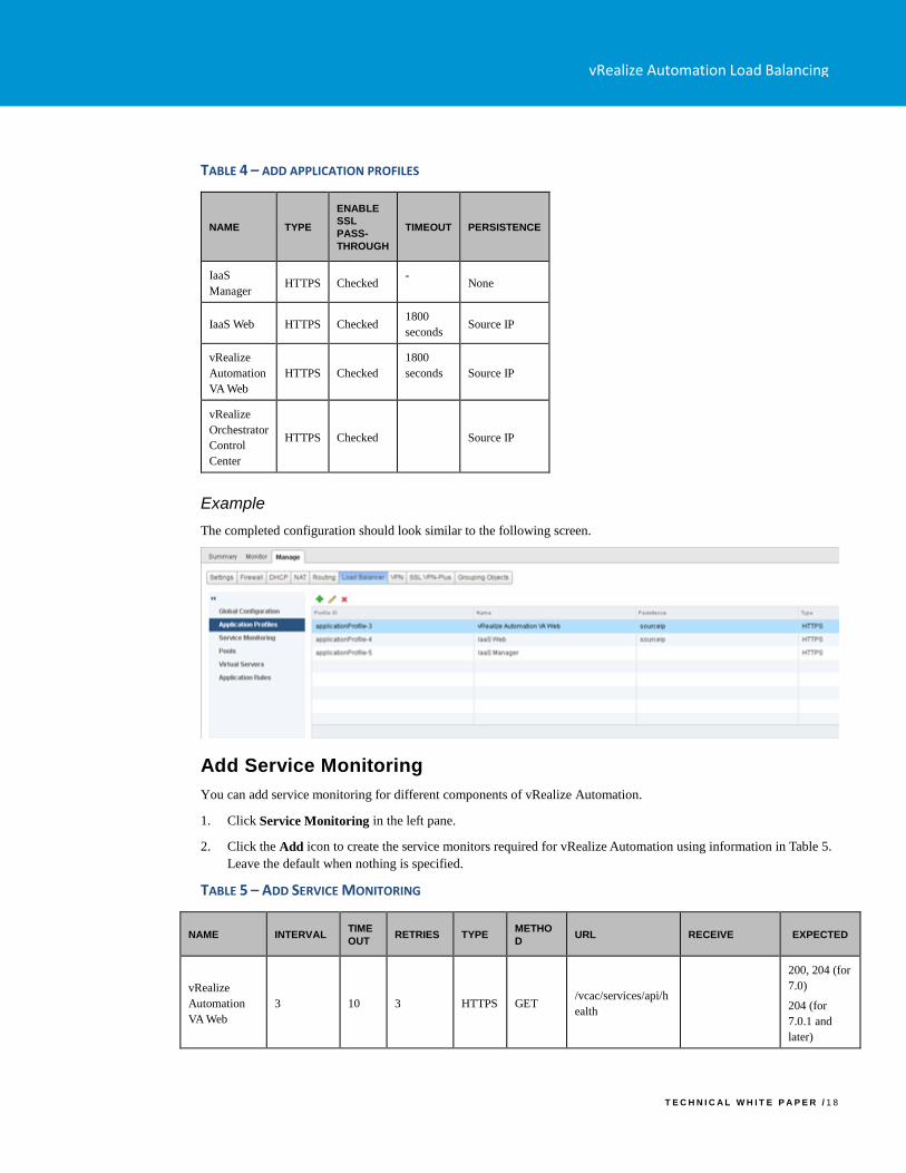
Example
The completed configuration should look similar to the following screen.
Add Service Monitoring
You can add service monitoring for different components of vRealize Automation.
1. Click Service Monitoring in the left pane.
2. Click the Add icon to create the service monitors required for vRealize Automation using information in Table 5.
Leave the default when nothing is specified.
TABLE 5 – ADD SERVICE MONITORING
NAME INTERVAL TIME
OUT RETRIES TYPE
METHO
D URL RECEIVE EXPECTED
vRealize
Automation
VA Web
3 10 3 HTTPS GET /vcac/services/api/h
ealth
200, 204 (for
7.0)
204 (for
7.0.1 and
later)
vRealize Automation Load Balancing
T E C H N I C A L W H I T E P A P E R / 1 9
IaaS Web 3 10 3 HTTPS GET /wapi/api/status/we
b REGISTERED
IaaS Manager 3 10 3 HTTPS GET /VMPSProvision ProvisionService
vRealize
Orchestrator
Control
Center
3 10 3 HTTPS GET /vco-
controlcenter/docs/
HTTP/1.1
200
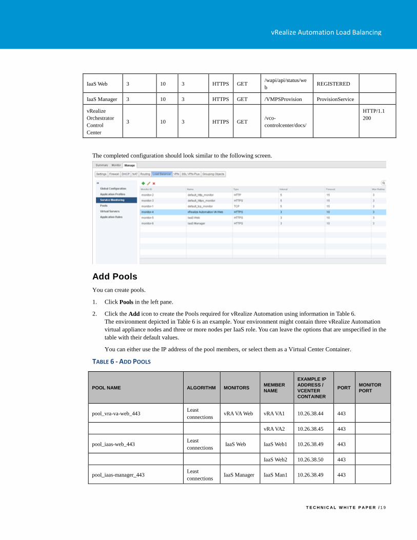
The completed configuration should look similar to the following screen.
Add Pools
You can create pools.
1. Click Pools in the left pane.
2. Click the Add icon to create the Pools required for vRealize Automation using information in Table 6.
The environment depicted in Table 6 is an example. Your environment might contain three vRealize Automation
virtual appliance nodes and three or more nodes per IaaS role. You can leave the options that are unspecified in the
table with their default values.
You can either use the IP address of the pool members, or select them as a Virtual Center Container.
TABLE 6 - ADD POOLS
POOL NAME ALGORITHM MONITORS MEMBER
NAME
EXAMPLE IP
ADDRESS /
VCENTER
CONTAINER
PORT MONITOR
PORT
pool_vra-va-web_443 Least
connections vRA VA Web vRA VA1 10.26.38.44 443
vRA VA2 10.26.38.45 443
pool_iaas-web_443 Least
connections IaaS Web IaaS Web1 10.26.38.49 443
IaaS Web2 10.26.38.50 443
pool_iaas-manager_443 Least
connections IaaS Manager IaaS Man1 10.26.38.49 443
vRealize Automation Load Balancing
T E C H N I C A L W H I T E P A P E R / 2 0
IaaS Man2 10.26.38.50 443
*pool_vra-rconsole_8444 Least
connections vRA VA Web vRA VA1 10.26.38.44 8444 443
vRA VA2 10.26.38.45 8444 443
pool_vro-cc_8283 Least
connections
vRealize
Orchestrator
Control
Center
vRA VA 1 10.26.38.44 8283
vRA VA 2 10.26.38.45 8283
*Only needed if remote-console access is used
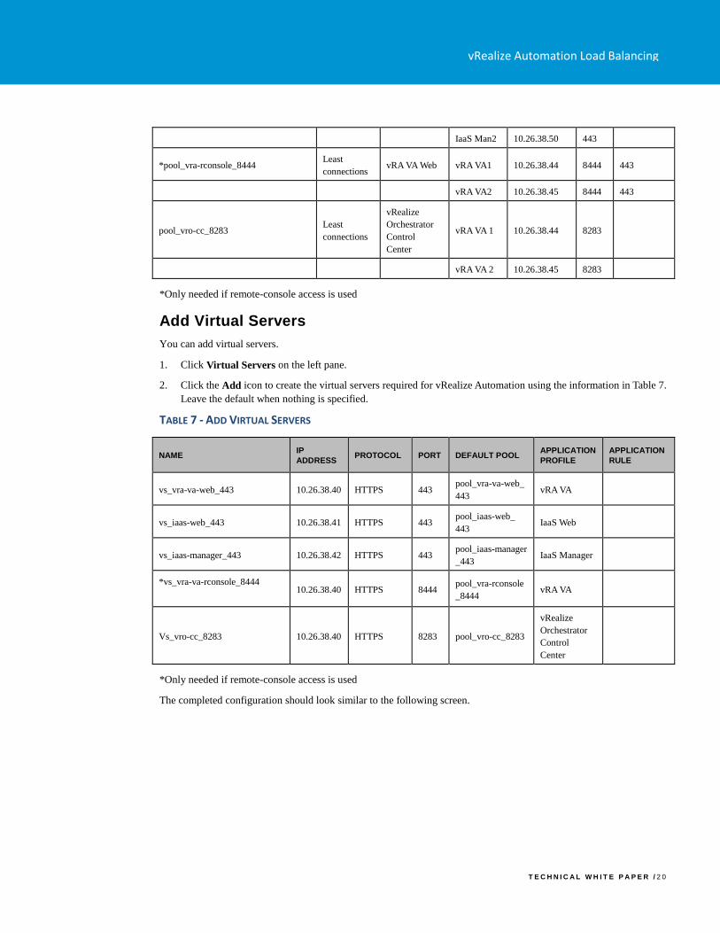
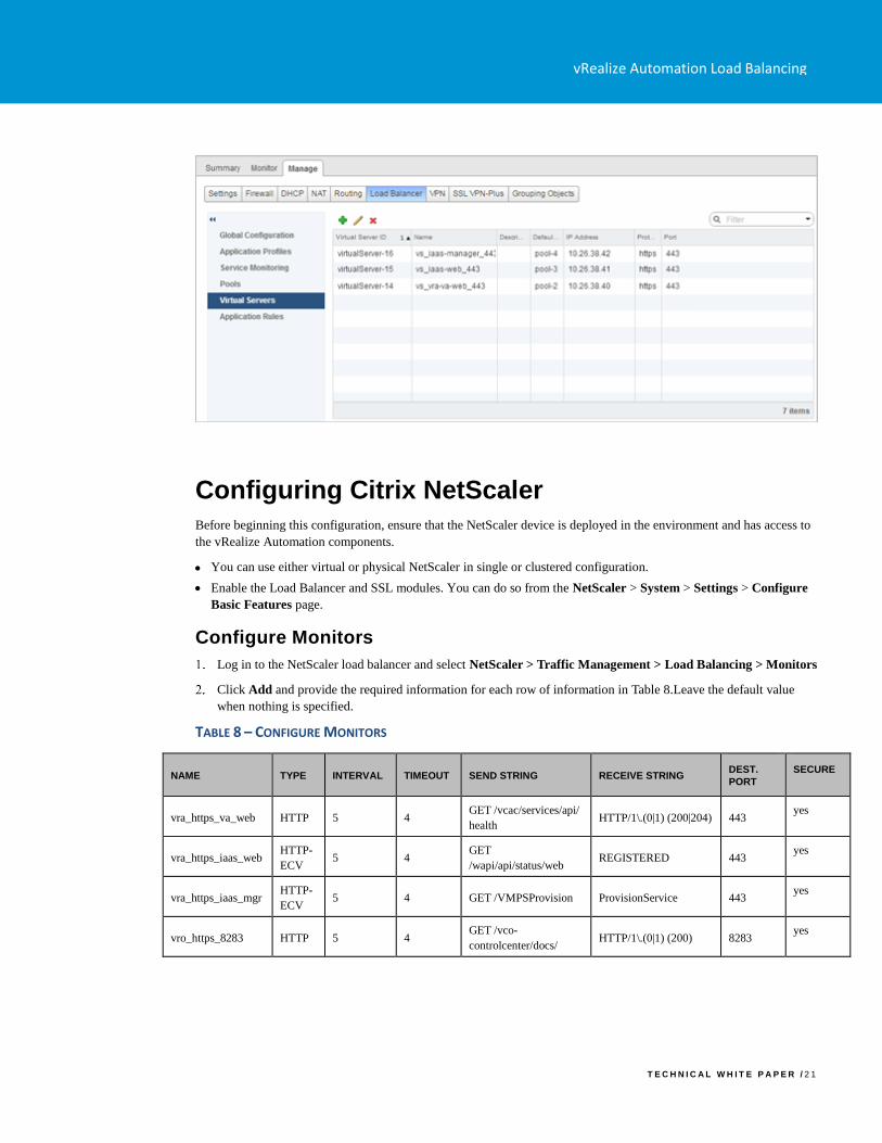
Add Virtual Servers
You can add virtual servers.
1. Click Virtual Servers on the left pane.
2. Click the Add icon to create the virtual servers required for vRealize Automation using the information in Table 7.
Leave the default when nothing is specified.
TABLE 7 - ADD VIRTUAL SERVERS
NAME IP
ADDRESS PROTOCOL PORT DEFAULT POOL
APPLICATION
PROFILE
APPLICATION
RULE
vs_vra-va-web_443 10.26.38.40 HTTPS 443 pool_vra-va-web_
443 vRA VA
vs_iaas-web_443 10.26.38.41 HTTPS 443 pool_iaas-web_
443 IaaS Web
vs_iaas-manager_443 10.26.38.42 HTTPS 443 pool_iaas-manager
_443 IaaS Manager
*vs_vra-va-rconsole_8444
10.26.38.40 HTTPS 8444
pool_vra-rconsole
_8444 vRA VA
Vs_vro-cc_8283 10.26.38.40 HTTPS 8283 pool_vro-cc_8283
vRealize
Orchestrator
Control
Center
*Only needed if remote-console access is used
The completed configuration should look similar to the following screen.
vRealize Automation Load Balancing
T E C H N I C A L W H I T E P A P E R / 2 1
Configuring Citrix NetScaler
Before beginning this configuration, ensure that the NetScaler device is deployed in the environment and has access to
the vRealize Automation components.
• You can use either virtual or physical NetScaler in single or clustered configuration.
• Enable the Load Balancer and SSL modules. You can do so from the NetScaler > System > Settings > Configure
Basic Features page.
Configure Monitors
Log in to the NetScaler load balancer and select NetScaler > Traffic Management > Load Balancing > Monitors
Click Add and provide the required information for each row of information in Table 8.Leave the default value
when nothing is specified.
TABLE 8 – CONFIGURE MONITORS
NAME TYPE INTERVAL TIMEOUT SEND STRING RECEIVE STRING DEST.
PORT
SECURE
vra_https_va_web HTTP 5 4 GET /vcac/services/api/
health HTTP/1\.(0|1) (200|204) 443
yes
vra_https_iaas_web HTTP-
ECV 5 4
GET
/wapi/api/status/web REGISTERED 443
yes
vra_https_iaas_mgr HTTP-
ECV 5 4 GET /VMPSProvision ProvisionService 443
yes
vro_https_8283 HTTP 5 4 GET /vco-
controlcenter/docs/ HTTP/1\.(0|1) (200) 8283
yes
vRealize Automation Load Balancing
T E C H N I C A L W H I T E P A P E R / 2 2
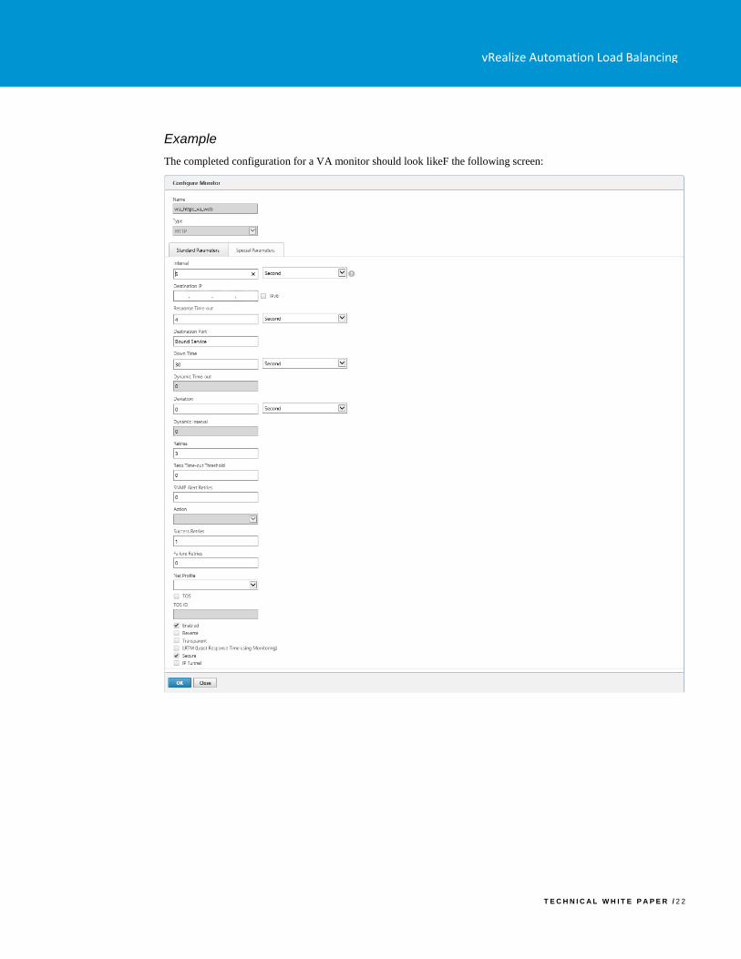
Example
The completed configuration for a VA monitor should look likeF the following screen:
vRealize Automation Load Balancing
T E C H N I C A L W H I T E P A P E R / 2 3
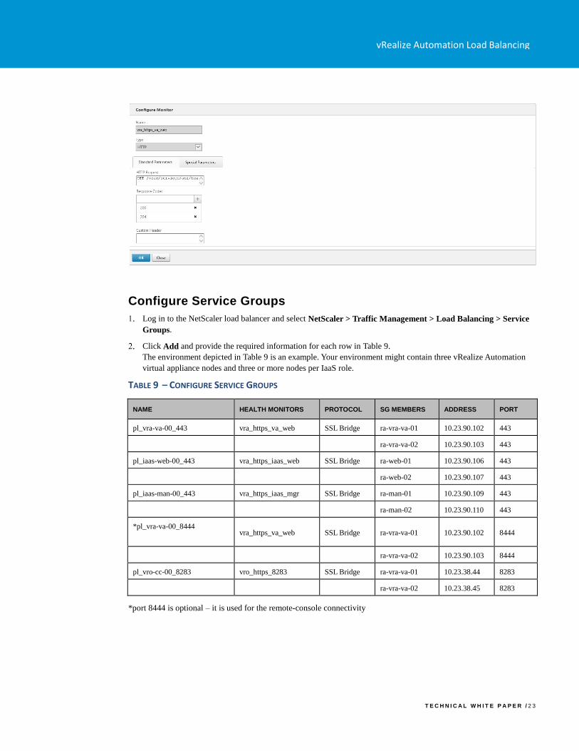
Configure Service Groups
Log in to the NetScaler load balancer and select NetScaler > Traffic Management > Load Balancing > Service
Groups.
Click Add and provide the required information for each row in Table 9.
The environment depicted in Table 9 is an example. Your environment might contain three vRealize Automation
virtual appliance nodes and three or more nodes per IaaS role.
TABLE 9 – CONFIGURE SERVICE GROUPS
NAME HEALTH MONITORS PROTOCOL SG MEMBERS ADDRESS PORT
pl_vra-va-00_443 vra_https_va_web SSL Bridge ra-vra-va-01 10.23.90.102 443
ra-vra-va-02 10.23.90.103 443
pl_iaas-web-00_443 vra_https_iaas_web SSL Bridge ra-web-01 10.23.90.106 443
ra-web-02 10.23.90.107 443
pl_iaas-man-00_443 vra_https_iaas_mgr SSL Bridge ra-man-01 10.23.90.109 443
ra-man-02 10.23.90.110 443
*pl_vra-va-00_8444
vra_https_va_web SSL Bridge ra-vra-va-01 10.23.90.102 8444
ra-vra-va-02 10.23.90.103 8444
pl_vro-cc-00_8283 vro_https_8283 SSL Bridge ra-vra-va-01 10.23.38.44 8283
ra-vra-va-02 10.23.38.45 8283
*port 8444 is optional – it is used for the remote-console connectivity
vRealize Automation Load Balancing
T E C H N I C A L W H I T E P A P E R / 2 4
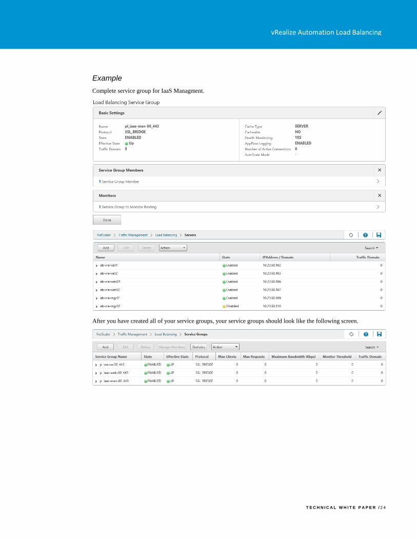
Example
Complete service group for IaaS Managment.
After you have created all of your service groups, your service groups should look like the following screen.
vRealize Automation Load Balancing
T E C H N I C A L W H I T E P A P E R / 2 5
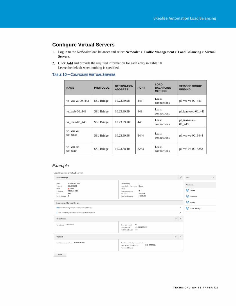
Configure Virtual Servers
Log in to the NetScaler load balancer and select NetScaler > Traffic Management > Load Balancing > Virtual
Servers.
Click Add and provide the required information for each entry in Table 10.
Leave the default when nothing is specified.
TABLE 10 – CONFIGURE VIRTUAL SERVERS
NAME PROTOCOL DESTINATION
ADDRESS PORT
LOAD
BALANCING
METHOD
SERVICE GROUP
BINDING
vs_vra-va-00_443 SSL Bridge 10.23.89.98 443 Least
connections pl_vra-va-00_443
vs_web-00_443 SSL Bridge 10.23.89.99 443 Least
connections pl_iaas-web-00_443
vs_man-00_443 SSL Bridge 10.23.89.100 443 Least
connections
pl_iaas-man-
00_443
vs_vra-va-
00_8444
SSL Bridge 10.23.89.98 8444 Least
connections pl_vra-va-00_8444
vs_vro-cc-
00_8283 SSL Bridge 10,23.38.40 8283
Least
connections pl_vro-cc-00_8283
Example
vRealize Automation Load Balancing
T E C H N I C A L W H I T E P A P E R / 2 6
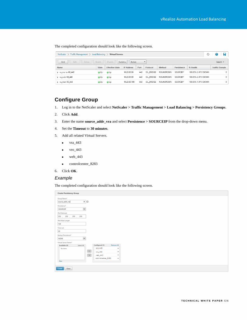
The completed configuration should look like the following screen.
Configure Group
1. Log in to the NetScaler and select NetScaler > Traffic Management > Load Balancing > Persistency Groups.
2. Click Add.
3. Enter the name source_addr_vra and select Persistence > SOURCEIP from the drop-down menu.
4. Set the Timeout to 30 minutes.
5. Add all related Virtual Servers.
• vra_443
• vro_443
• web_443
• controlcenter_8283
6. Click OK.
Example
The completed configuration should look like the following screen.
vRealize Automation Load Balancing
T E C H N I C A L W H I T E P A P E R / 2 7
Troubleshooting
Provisioning failures when using OneConnect with F5 BIG-IP for a virtual server with SSL pass-through
When you use the OneConnect feature with F5 BIG-IP for a virtual server, provisioning tasks sometimes fail.
OneConnect ensures connections from the load balancer to the back-end servers are multiplexed and reused. This
lowers the load on the servers and makes them more resilient.
Using OneConnect with a virtual server that has SSL pass-through is not recommended by F5 and might result in failed
provisioning attempts. This happens because the load balancer attempts to establish a new SSL session over an existing
session while the back-end servers expect the client to either close or renegotiate the existing session, which results in a
dropped connection.
Disable OneConnect to resolve this issue.
1. Log in to the F5 load balancer and select Local Traffic > Virtual Servers > Virtual Server List.
2. Click the name of the virtual server to modify.
3. Choose None for the OneConnect Profile option in the Acceleration section, and click Finish.
F5 BIG-IP license limits network bandwidth
If you experience provisioning failures or issues loading vRealize Automation console pages, especially during periods
of a high utilization, network traffic to and from the load balancer might exceed what the F5 BIG-IP license allows.
To check if the BIG-IP platform is currently experiencing this issue, see How the BIG-IP VE system enforces the
licensed throughput rate.
Proxy Agent ping failure
After starting the Manager Service on a second manager server, the Proxy Agent is unable to reconnect. This happens
because the F5 appliance is still maintaining an SSL session with the agent by sending keepalives while the agent is
trying to establish a new session.
Configure the load balancer to drop all packets and prevent it from sending keepalives to resolve this issue.
1. Log in to the F5 load balancer and select Local Traffic > Pools.
2. Select the Manager Service pool.
3. Click Advanced in the Configuration section.
4. Select Drop for the Action On Service Down option.
5. Click OK and click Finished.
Connection reset errors in the catalina.out log file
When the system is under a heavy load due to many simultaneously requested provisions through the IaaS components,
you might see connection reset errors in the catalina.out log file on the vRealize Automation appliances. This can
happen when a session between the appliances and the Web servers expires You can work around this problem by
increasing the timeout setting for your load balancer.
F5
Use the AskF5 procedure K7166: “Changing the idle timeout for a protocol profile” at
https://support.f5.com/csp/article/K7166 to change the Idle Timeout for a virtual server. Perform this procedure on the
vRealize Automation Load Balancing
T E C H N I C A L W H I T E P A P E R / 2 8
Web Service virtual load balancer server and set the timeout initially to 600 seconds. A best practice is to gradually
increase the timeout until there are no connection reset errors.
NetScaler
Use the Citrix procedure in “Setting a Time-out Value for Idle Client Connections” at https://docs.citrix.com/en-
us/netscaler/11/traffic-management/load-balancing/load-balancing-manage-clienttraffic/client-idle-timeout-value.html
to change the Idle Timeout for a virtual server. Perform this procedure on the Web Service virtual load balancer server
and set the timeout initially to 600 seconds. A best practice is to gradually increase the timeout until there are no
connection reset errors.
NSX
Use the procedure in the Knowledge Base article 2147156 to change the Idle Timeout for a virtual server. Perform this
procedure on the Web Service virtual load balancer server and set the timeout initially to 600 seconds. A best practice
is to gradually increase the timeout until there are no connection reset errors.
Proxy Agents cannot connect to load balanced Manger Service endpoint
With NSX as a load balancing solution, after a Manager Service failover the proxy agents cannot connect to the load
balanced Manager Service.
This issue occurs when the IIS role is installed on the servers that are running the Manager Service. When a Manager
Service is stopped, the monitors configured on NSX are flagged as DOWN. Because IIS is running and accepting
connections on port 443, NSX keeps the established sessions, and the Proxy Agent service keeps trying to reuse the
session.
To resolve this issue, remove the IIS role from the servers that are running the Manager Service. The Manager Service
is a self-hosted service that does not require IIS.

VMware, Inc. 3401 Hillview Avenue Palo Alto CA 94304 USA Tel 877-486-9273 Fax 650-427-5001 www.vmware.com
Copyright © 2015-2018 VMware, Inc. All rights reserved. This product is protected by U.S. and international copyright and intellectual property laws. VMware products are covered by one or more patents listed at
http://www.vmware.com/go/patents. VMware is a registered trademark or trademark of VMware, Inc. in the United States and/or other jurisdictions. All other marks and names mentioned herein may be trademarks of their respective
companies.
Related Documents