HAC-1 VENTILATION, HEATER & AIR CONDITIONER C D E F G H J K L M SECTION HAC A B HAC N O P CONTENTS HEATER & AIR CONDITIONING CONTROL SYSTEM MANUAL AIR CONDITIONER BASIC INSPECTION ................................... 3 DIAGNOSIS AND REPAIR WORKFLOW ......... 3 How to Perform Trouble Diagnosis For Quick And Accurate Repair ....................................................... 3 INSPECTION AND ADJUSTMENT .................... 4 Operational Check ................................................... 4 FUNCTION DIAGNOSIS .............................. 6 FUNCTION INFORMATION ............................... 6 Component Part Location ........................................ 6 Symptom Table ........................................................ 8 REFRIGERATION SYSTEM .............................. 9 Refrigerant Cycle ..................................................... 9 Refrigerant System Protection ................................. 9 MANUAL AIR CONDITIONER SYSTEM ..........10 Control System Diagram ........................................ 10 Control System Description .................................... 10 Discharge Air Flow ................................................. 12 Switches And Their Control Function ..................... 12 DIAGNOSIS SYSTEM (BCM) ...........................14 CONSULT-III Function (BCM - COMMON ITEM) .... 14 CONSULT-III Data Monitor .................................... 14 COMPONENT DIAGNOSIS ........................ 16 MODE DOOR MOTOR ......................................16 System Description ................................................ 16 Mode Door Motor Component Function Check ...... 16 Mode Door Motor Diagnosis Procedure ................. 17 AIR MIX DOOR MOTOR ...................................20 System Description ................................................ 20 Air Mix Door Motor Component Function Check .... 21 Air Mix Door Motor Diagnosis Procedure ............... 22 INTAKE DOOR MOTOR ................................... 24 System Description .................................................24 Intake Door Motor Component Function Check .....24 Intake Door Motor Diagnosis Procedure ................25 BLOWER MOTOR ............................................ 27 System Description .................................................27 Front Blower Motor Component Function Check ....27 Front Blower Motor Diagnosis Procedure ...............28 Front Blower Motor Component Inspection ............32 MAGNET CLUTCH ........................................... 34 System Description .................................................34 Magnet Clutch Component Function Check ...........34 Magnet Clutch Diagnosis Procedure ......................34 INTAKE SENSOR ............................................. 39 System Description .................................................39 Intake Sensor Diagnosis Procedure .......................39 Intake Sensor Component Inspection ....................40 POWER SUPPLY AND GROUND CIRCUIT FOR CONTROLLER ......................................... 41 Component Description ..........................................41 Front Air Control Component Function Check ........41 Front Air Control Power and Ground Diagnosis Procedure ...............................................................42 ECU DIAGNOSIS ........................................ 43 AIR CONDITIONER CONTROL ........................ 43 System Description .................................................43 System Operation ...................................................43 Front Air Control Terminals Reference Values .......44 Wiring Diagram - Air Conditioner Control - Manual ....46 Wiring Diagram - Heater Control ............................53 SYMPTOM DIAGNOSIS ............................. 57 AIR CONDITIONER CONTROL ........................ 57 Symptom Matrix Chart ..........................................57

Welcome message from author
This document is posted to help you gain knowledge. Please leave a comment to let me know what you think about it! Share it to your friends and learn new things together.
Transcript
VENTILATION, HEATER & AIR CONDITIONER
C
D
E
SECTION HACA
B
HEATER & AIR CONDITIONING CONTROL SYSTEM
F
G
H
J
K
L
M
AC
N
O
P
CONTENTS
H
MANUAL AIR CONDITIONER
BASIC INSPECTION .................................... 3
DIAGNOSIS AND REPAIR WORKFLOW .......... 3How to Perform Trouble Diagnosis For Quick And Accurate Repair ........................................................3
INSPECTION AND ADJUSTMENT ..................... 4Operational Check ....................................................4
FUNCTION DIAGNOSIS ............................... 6
FUNCTION INFORMATION ................................ 6Component Part Location .........................................6Symptom Table .........................................................8
REFRIGERATION SYSTEM ............................... 9Refrigerant Cycle ......................................................9Refrigerant System Protection ..................................9
MANUAL AIR CONDITIONER SYSTEM ...........10Control System Diagram .........................................10Control System Description .....................................10Discharge Air Flow ..................................................12Switches And Their Control Function ......................12
DIAGNOSIS SYSTEM (BCM) ............................14CONSULT-III Function (BCM - COMMON ITEM) ....14CONSULT-III Data Monitor .....................................14
COMPONENT DIAGNOSIS .........................16
MODE DOOR MOTOR .......................................16System Description .................................................16Mode Door Motor Component Function Check .......16Mode Door Motor Diagnosis Procedure ..................17
AIR MIX DOOR MOTOR ....................................20System Description .................................................20Air Mix Door Motor Component Function Check .....21Air Mix Door Motor Diagnosis Procedure ................22
INTAKE DOOR MOTOR ...................................24System Description ..................................................24Intake Door Motor Component Function Check ......24Intake Door Motor Diagnosis Procedure .................25
BLOWER MOTOR ............................................27System Description ..................................................27Front Blower Motor Component Function Check ....27Front Blower Motor Diagnosis Procedure ................28Front Blower Motor Component Inspection .............32
MAGNET CLUTCH ...........................................34System Description ..................................................34Magnet Clutch Component Function Check ............34Magnet Clutch Diagnosis Procedure .......................34
INTAKE SENSOR .............................................39System Description ..................................................39Intake Sensor Diagnosis Procedure ........................39Intake Sensor Component Inspection .....................40
POWER SUPPLY AND GROUND CIRCUIT FOR CONTROLLER .........................................41
Component Description ...........................................41Front Air Control Component Function Check .........41Front Air Control Power and Ground Diagnosis Procedure ................................................................42
ECU DIAGNOSIS .........................................43
AIR CONDITIONER CONTROL ........................43System Description ..................................................43System Operation ....................................................43Front Air Control Terminals Reference Values ........44Wiring Diagram - Air Conditioner Control - Manual ....46Wiring Diagram - Heater Control .............................53
SYMPTOM DIAGNOSIS ..............................57
AIR CONDITIONER CONTROL ........................57Symptom Matrix Chart ...........................................57
HAC-1
INSUFFICIENT COOLING ................................. 58Component Function Check ................................... 58Performance Test Diagnoses ................................. 59Performance Chart ................................................. 61Test Reading .......................................................... 62Trouble Diagnoses for Unusual Pressure ............... 63
INSUFFICIENT HEATING ................................. 67Component Function Check ................................... 67
NOISE ................................................................ 69Component Function Check ................................... 69
PRECAUTION ............................................ 71
PRECAUTIONS ................................................. 71Supplemental Restraint System (SRS) "AIR BAG" and "SEAT BELT PRE-TENSIONER" .................... 71Working with HFC-134a (R-134a) ........................... 71Precaution for Service Equipment .......................... 72
HAC-2
DIAGNOSIS AND REPAIR WORKFLOW[MANUAL AIR CONDITIONER]
C
D
E
F
G
H
J
K
L
M
A
B
AC
N
O
P
< BASIC INSPECTION >
H
BASIC INSPECTIONDIAGNOSIS AND REPAIR WORKFLOW
How to Perform Trouble Diagnosis For Quick And Accurate Repair INFOID:0000000003289095
WORK FLOW
1.LISTEN TO CUSTOMER COMPLAINT
Listen to customer complaint. Get detailed information about the conditions and environment when the symp-tom occurs.
>> GO TO 2
2.CHECK FOR SERVICE BULLETINS
Check for any service bulletins.
>> GO TO 3.
3.VERIFY THE SYMPTOM WITH OPERATIONAL CHECK
Verify the symptom with operational check. Refer to HAC-4, "Operational Check". Can a symptom be duplicated?YES >> Go to trouble diagnosis. Refer to HAC-57, "Symptom Matrix Chart"NO >> System OK.
HAC-3
[MANUAL AIR CONDITIONER]INSPECTION AND ADJUSTMENT
< BASIC INSPECTION >
INSPECTION AND ADJUSTMENT
Operational Check INFOID:0000000003289096
The purpose of the operational check is to confirm that the system operates properly.
CHECKING BLOWER1. Turn blower control dial clockwise. Blower should operate on low speed. 2. Turn the blower control dial again, and continue checking each blower speed until all speeds are checked.3. Leave blower on speed 4. If NG, go to trouble diagnosis procedure for HAC-28, "Front Blower Motor Diagnosis Procedure".If OK, continue with next check.
CHECKING DISCHARGE AIR1. Turn the mode switch to each position.
2. Confirm that discharge air comes out according to the air distribution table. Refer to HAC-12, "DischargeAir Flow".
Mode door position is checked in the next step.If NG, go to trouble diagnosis procedure for HAC-17, "Mode Door Motor Diagnosis Procedure".If OK, continue with next check.NOTE:Confirm that the A/C compressor clutch is engaged (sound or visual inspection) and intake door position is atfresh when the DEF ( ) or D/F ( ) is selected.
CHECKING RECIRCULATION1. Press recirculation ( ) switch one time. Recirculation indicator should illuminate.
2. Press recirculation ( ) switch one more time. Recirculation indicator should go off.3. Listen for intake door position change (blower sound should change slightly).If NG, go to trouble diagnosis procedure for HAC-25, "Intake Door Motor Diagnosis Procedure".If OK, continue with next check.NOTE:Confirm that the compressor clutch is engaged (sound or visual inspection) and intake door position is at freshwhen the DEF or D/F is selected.
CHECKING TEMPERATURE DECREASE1. Rotate temperature control dial counterclockwise.2. Check for cold air at appropriate discharge air outlets.If NG, listen for sound of air mix door motor operation if OK, go to trouble diagnosis procedure for HAC-58,"Component Function Check". If air mix door motor appears to be malfunctioning, go to HAC-21, "Air Mix DoorMotor Component Function Check".If OK, continue with next check.
CHECKING TEMPERATURE INCREASE1. Rotate temperature control dial clockwise.2. Check for hot air at appropriate discharge air outlets.If NG, listen for sound of air mix door motor operation. If OK, go to trouble diagnosis procedure for HAC-67,"Component Function Check". If air mix door motor (front) appears to be malfunctioning, go to HAC-21, "AirMix Door Motor Component Function Check".If OK, continue with next check.
CHECK A/C SWITCH (IF EQUIPPED)1. Press A/C switch with the blower switch ON.2. A/C switch indicator will turn ON.
• Confirm that the compressor clutch engages (sound or visual inspection).
Conditions : Engine running and at normal operating temperature
HAC-4
INSPECTION AND ADJUSTMENT[MANUAL AIR CONDITIONER]
C
D
E
F
G
H
J
K
L
M
A
B
AC
N
O
P
< BASIC INSPECTION >
H
If NG, go to trouble diagnosis procedure for HAC-34, "Magnet Clutch Diagnosis Procedure".If OK, continue with next check.
HAC-5
[MANUAL AIR CONDITIONER]FUNCTION INFORMATION
< FUNCTION DIAGNOSIS >
FUNCTION DIAGNOSISFUNCTION INFORMATION
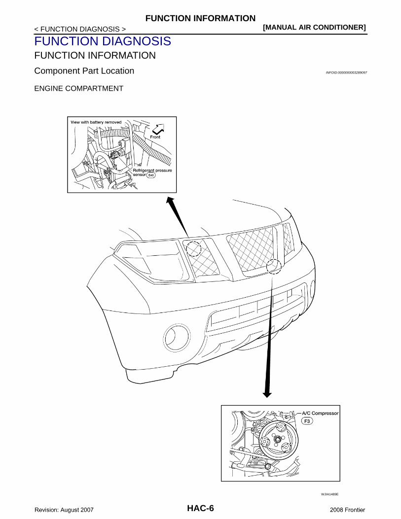
Component Part Location INFOID:0000000003289097
ENGINE COMPARTMENT
WJIA1489E
HAC-6
FUNCTION INFORMATION[MANUAL AIR CONDITIONER]
C
D
E
F
G
H
J
K
L
M
A
B
AC
N
O
P
< FUNCTION DIAGNOSIS >
H
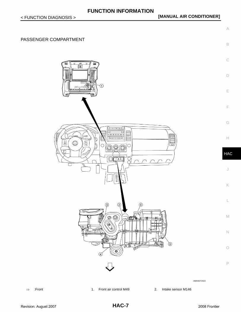
PASSENGER COMPARTMENT
⇒ :Front 1. Front air control M49 2. Intake sensor M146
AWIIA0724ZZ
HAC-7
[MANUAL AIR CONDITIONER]FUNCTION INFORMATION
< FUNCTION DIAGNOSIS >
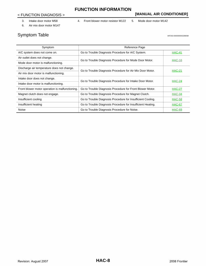
Symptom Table INFOID:0000000003289098
3. Intake door motor M58 4. Front blower motor resistor M122 5. Mode door motor M142
6. Air mix door motor M147
Symptom Reference Page
A/C system does not come on. Go to Trouble Diagnosis Procedure for A/C System. HAC-41
Air outlet does not change.Go to Trouble Diagnosis Procedure for Mode Door Motor. HAC-16
Mode door motor is malfunctioning.
Discharge air temperature does not change.Go to Trouble Diagnosis Procedure for Air Mix Door Motor. HAC-21
Air mix door motor is malfunctioning.
Intake door does not change.Go to Trouble Diagnosis Procedure for Intake Door Motor. HAC-24
Intake door motor is malfunctioning.
Front blower motor operation is malfunctioning. Go to Trouble Diagnosis Procedure for Front Blower Motor. HAC-27
Magnet clutch does not engage. Go to Trouble Diagnosis Procedure for Magnet Clutch. HAC-34
Insufficient cooling Go to Trouble Diagnosis Procedure for Insufficient Cooling. HAC-58
Insufficient heating Go to Trouble Diagnosis Procedure for Insufficient Heating. HAC-67
Noise Go to Trouble Diagnosis Procedure for Noise. HAC-69
HAC-8
REFRIGERATION SYSTEM[MANUAL AIR CONDITIONER]
C
D
E
F
G
H
J
K
L
M
A
B
AC
N
O
P
< FUNCTION DIAGNOSIS >
H
REFRIGERATION SYSTEM
Refrigerant Cycle INFOID:0000000003289099
Refer to HA-16, "Refrigerant Cycle".
Refrigerant System Protection INFOID:0000000003289100
Refer to HA-16, "Refrigerant System Protection".
HAC-9
[MANUAL AIR CONDITIONER]MANUAL AIR CONDITIONER SYSTEM
< FUNCTION DIAGNOSIS >
MANUAL AIR CONDITIONER SYSTEM
Control System Diagram INFOID:0000000003289101
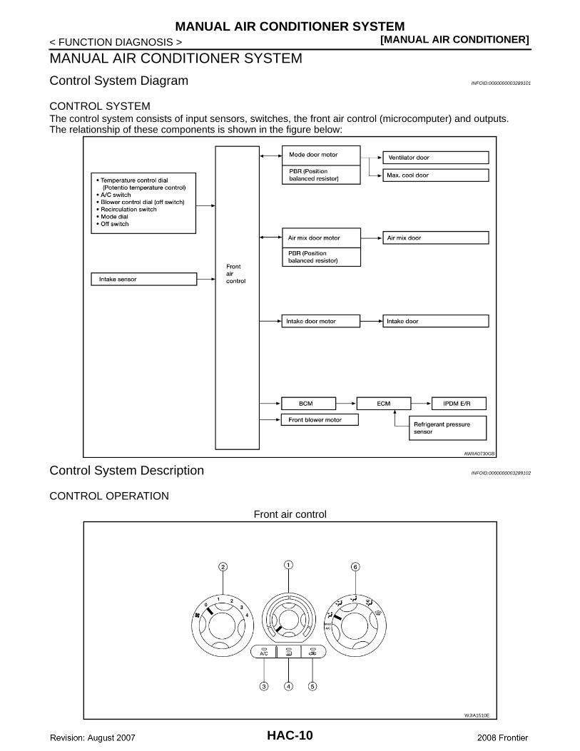
CONTROL SYSTEMThe control system consists of input sensors, switches, the front air control (microcomputer) and outputs.The relationship of these components is shown in the figure below:
Control System Description INFOID:0000000003289102
CONTROL OPERATION
Front air control
AWIIA0730GB
WJIA1510E
HAC-10
MANUAL AIR CONDITIONER SYSTEM[MANUAL AIR CONDITIONER]
C
D
E
F
G
H
J
K
L
M
A
B
AC
N
O
P
< FUNCTION DIAGNOSIS >
H
TEMPERATURE CONTROL DIAL (TEMPERATURE CONTROL)Increases or decreases the set temperature.
RECIRCULATION ( ) SWITCH• When REC switch is ON, REC switch indicator turns ON, and air inlet is set to REC.• When REC switch is turned OFF, or when compressor is turned from ON to OFF, REC switch is automati-
cally turned OFF. REC mode can be re-entered by pressing REC switch again.• REC switch is not operated when DEF switch is turned ON, or at the D/F or FOOT position.
DEFROSTER ( ) SWITCHPositions the air outlet doors to the defrost position. Also positions the intake doors to the outside air position.
REAR WINDOW DEFOGGER SWITCH (IF EQUIPPED)When switch is ON, rear window is defogged.
OFF SWITCH (BLOWER SPEED SET TO 0)The compressor and blower are OFF.
A/C SWITCH (IF EQUIPPED)The compressor is ON or OFF.(Pressing the A/C switch will turn off the A/C switch and compressor.)
MODE DIALControls the air discharge outlets.
FRONT BLOWER CONTROL DIALManually controls the four blower speeds.
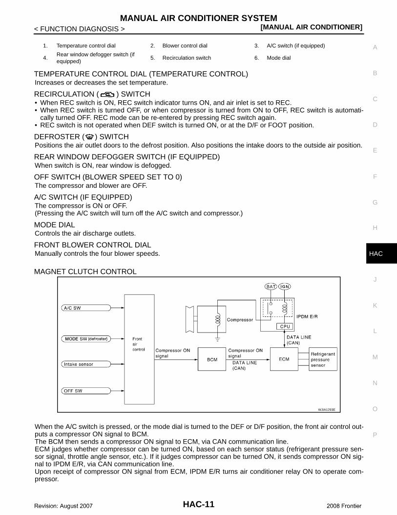
MAGNET CLUTCH CONTROL
When the A/C switch is pressed, or the mode dial is turned to the DEF or D/F position, the front air control out-puts a compressor ON signal to BCM.The BCM then sends a compressor ON signal to ECM, via CAN communication line.ECM judges whether compressor can be turned ON, based on each sensor status (refrigerant pressure sen-sor signal, throttle angle sensor, etc.). If it judges compressor can be turned ON, it sends compressor ON sig-nal to IPDM E/R, via CAN communication line.Upon receipt of compressor ON signal from ECM, IPDM E/R turns air conditioner relay ON to operate com-pressor.
1. Temperature control dial 2. Blower control dial 3. A/C switch (if equipped)
4.Rear window defogger switch (if equipped)
5. Recirculation switch 6. Mode dial
WJIA1293E
HAC-11
[MANUAL AIR CONDITIONER]MANUAL AIR CONDITIONER SYSTEM
< FUNCTION DIAGNOSIS >
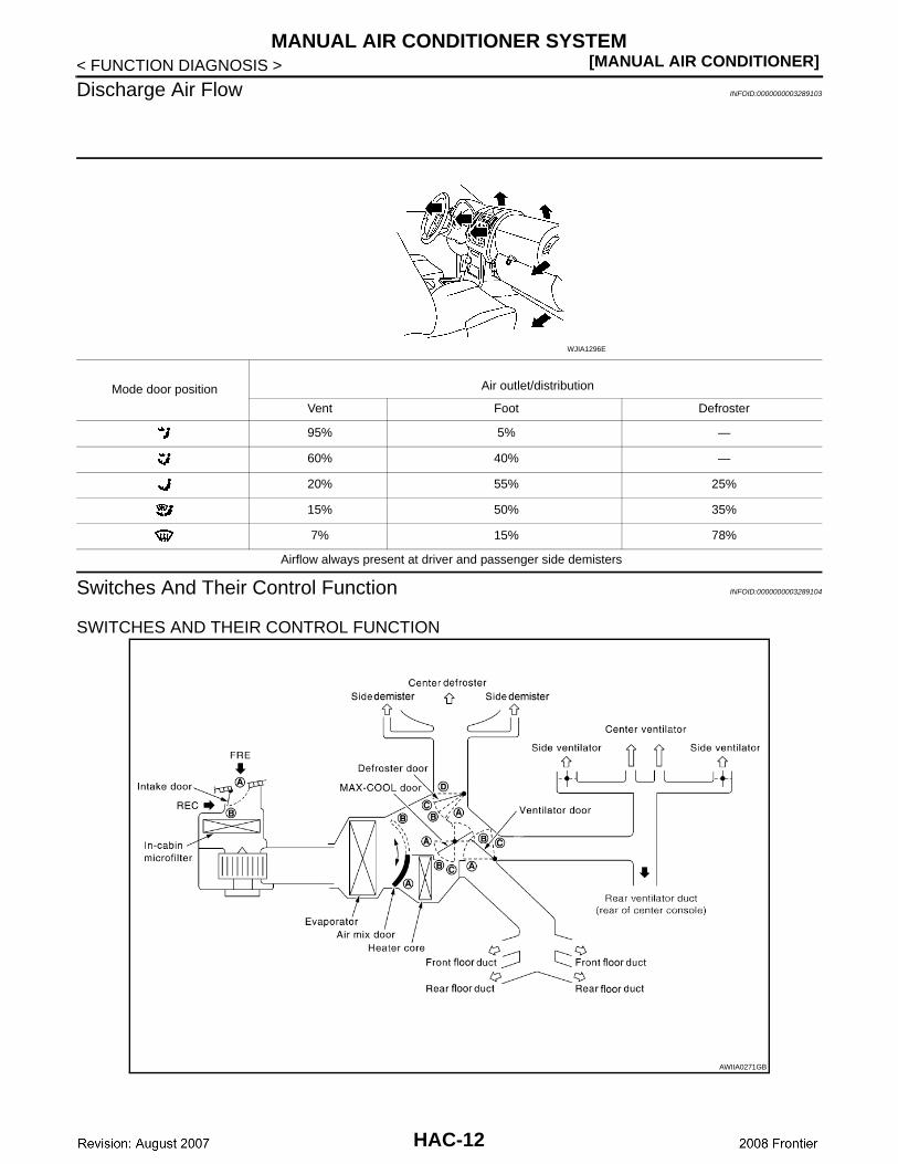
Discharge Air Flow INFOID:0000000003289103
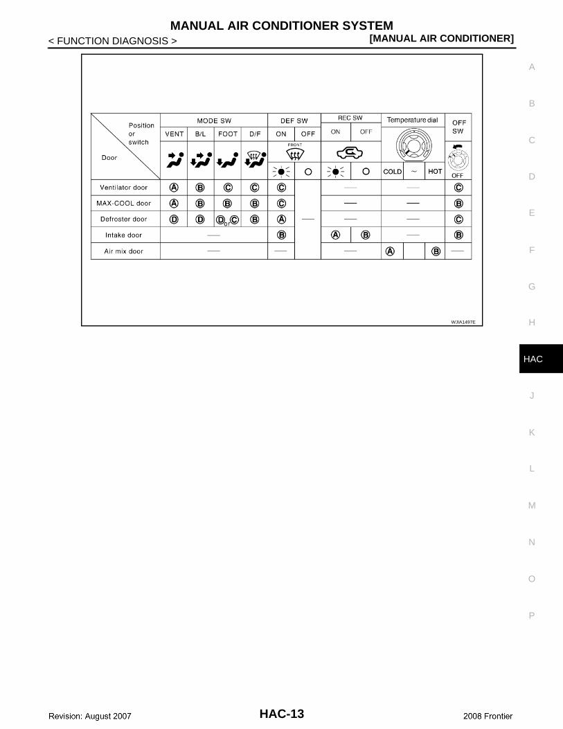
Switches And Their Control Function INFOID:0000000003289104
SWITCHES AND THEIR CONTROL FUNCTION
Mode door position Air outlet/distribution
Vent Foot Defroster
95% 5% —
60% 40% —
20% 55% 25%
15% 50% 35%
7% 15% 78%
Airflow always present at driver and passenger side demisters
WJIA1296E
AWIIA0271GB
HAC-12
MANUAL AIR CONDITIONER SYSTEM[MANUAL AIR CONDITIONER]
C
D
E
F
G
H
J
K
L
M
A
B
AC
N
O
P
< FUNCTION DIAGNOSIS >
H
WJIA1497E
HAC-13
[MANUAL AIR CONDITIONER]DIAGNOSIS SYSTEM (BCM)
< FUNCTION DIAGNOSIS >
DIAGNOSIS SYSTEM (BCM)
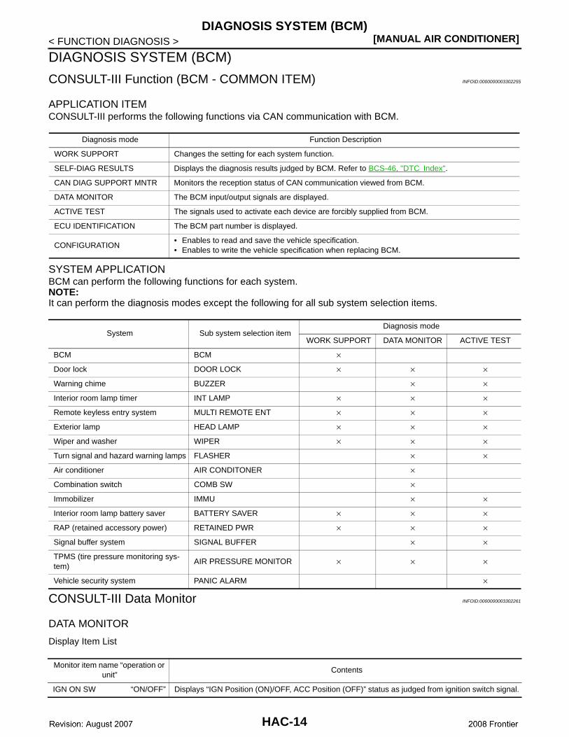
CONSULT-III Function (BCM - COMMON ITEM) INFOID:0000000003302255
APPLICATION ITEMCONSULT-III performs the following functions via CAN communication with BCM.
SYSTEM APPLICATIONBCM can perform the following functions for each system.NOTE:It can perform the diagnosis modes except the following for all sub system selection items.
CONSULT-III Data Monitor INFOID:0000000003302261
DATA MONITOR
Display Item List
Diagnosis mode Function Description
WORK SUPPORT Changes the setting for each system function.
SELF-DIAG RESULTS Displays the diagnosis results judged by BCM. Refer to BCS-46, "DTC Index".
CAN DIAG SUPPORT MNTR Monitors the reception status of CAN communication viewed from BCM.
DATA MONITOR The BCM input/output signals are displayed.
ACTIVE TEST The signals used to activate each device are forcibly supplied from BCM.
ECU IDENTIFICATION The BCM part number is displayed.
CONFIGURATION• Enables to read and save the vehicle specification.• Enables to write the vehicle specification when replacing BCM.
System Sub system selection itemDiagnosis mode
WORK SUPPORT DATA MONITOR ACTIVE TEST
BCM BCM ×
Door lock DOOR LOCK × × ×
Warning chime BUZZER × ×
Interior room lamp timer INT LAMP × × ×
Remote keyless entry system MULTI REMOTE ENT × × ×
Exterior lamp HEAD LAMP × × ×
Wiper and washer WIPER × × ×
Turn signal and hazard warning lamps FLASHER × ×
Air conditioner AIR CONDITONER ×
Combination switch COMB SW ×
Immobilizer IMMU × ×
Interior room lamp battery saver BATTERY SAVER × × ×
RAP (retained accessory power) RETAINED PWR × × ×
Signal buffer system SIGNAL BUFFER × ×
TPMS (tire pressure monitoring sys-tem)
AIR PRESSURE MONITOR × × ×
Vehicle security system PANIC ALARM ×
Monitor item name “operation or unit”
Contents
IGN ON SW “ON/OFF” Displays “IGN Position (ON)/OFF, ACC Position (OFF)” status as judged from ignition switch signal.
HAC-14
DIAGNOSIS SYSTEM (BCM)[MANUAL AIR CONDITIONER]
C
D
E
F
G
H
J
K
L
M
A
B
AC
N
O
P
< FUNCTION DIAGNOSIS >
H
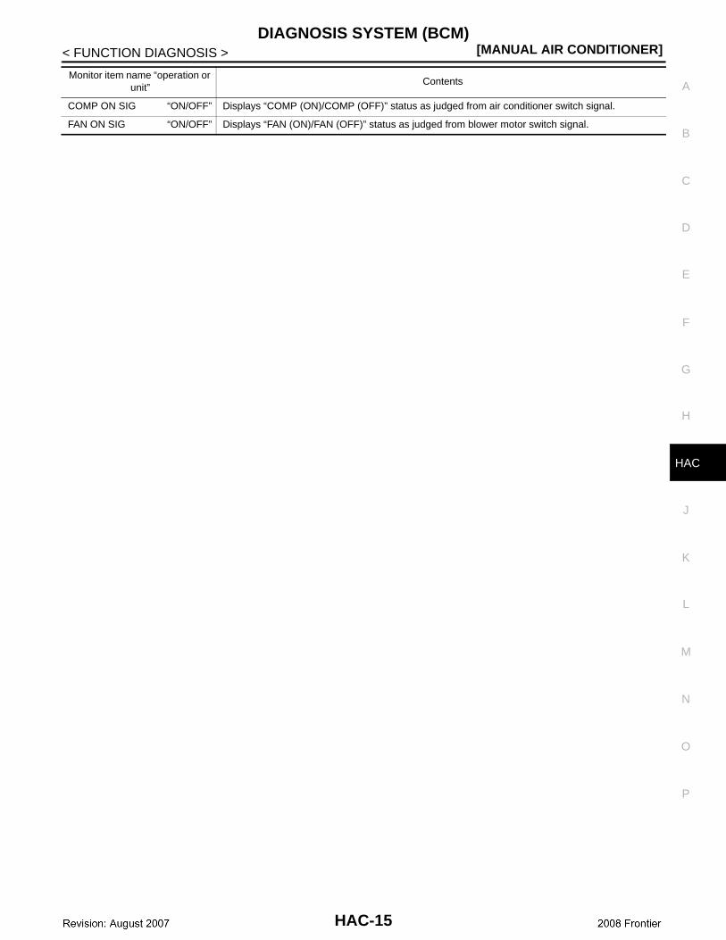
COMP ON SIG “ON/OFF” Displays “COMP (ON)/COMP (OFF)” status as judged from air conditioner switch signal.
FAN ON SIG “ON/OFF” Displays “FAN (ON)/FAN (OFF)” status as judged from blower motor switch signal.
Monitor item name “operation or unit”
Contents
HAC-15
[MANUAL AIR CONDITIONER]MODE DOOR MOTOR
< COMPONENT DIAGNOSIS >
COMPONENT DIAGNOSISMODE DOOR MOTOR
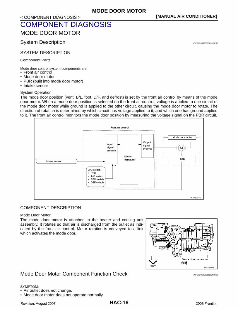
System Description INFOID:0000000003289107
SYSTEM DESCRIPTION
Component Parts
Mode door control system components are:• Front air control• Mode door motor• PBR (built into mode door motor)• Intake sensor
System OperationThe mode door position (vent, B/L, foot, D/F, and defrost) is set by the front air control by means of the modedoor motor. When a mode door position is selected on the front air control, voltage is applied to one circuit ofthe mode door motor while ground is applied to the other circuit, causing the mode door motor to rotate. Thedirection of rotation is determined by which circuit has voltage applied to it, and which one has ground appliedto it. The front air control monitors the mode door position by measuring the voltage signal on the PBR circuit.
COMPONENT DESCRIPTION
Mode Door MotorThe mode door motor is attached to the heater and cooling unitassembly. It rotates so that air is discharged from the outlet as indi-cated by the front air control. Motor rotation is conveyed to a linkwhich activates the mode door.
Mode Door Motor Component Function Check INFOID:0000000003289108
SYMPTOM:• Air outlet does not change.• Mode door motor does not operate normally.
WJIA1314E
WJIA1484E
HAC-16
MODE DOOR MOTOR[MANUAL AIR CONDITIONER]
C
D
E
F
G
H
J
K
L
M
A
B
AC
N
O
P
< COMPONENT DIAGNOSIS >
H
INSPECTION FLOW
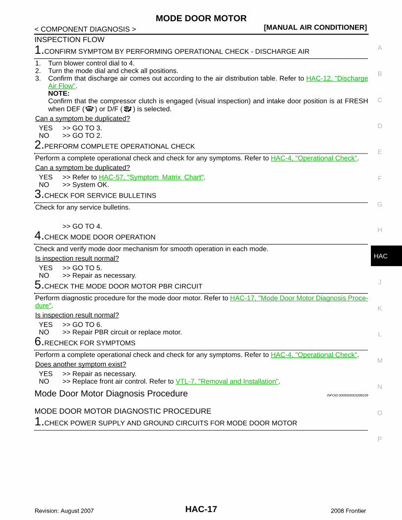
1.CONFIRM SYMPTOM BY PERFORMING OPERATIONAL CHECK - DISCHARGE AIR
1. Turn blower control dial to 4. 2. Turn the mode dial and check all positions. 3. Confirm that discharge air comes out according to the air distribution table. Refer to HAC-12, "Discharge
Air Flow".NOTE:Confirm that the compressor clutch is engaged (visual inspection) and intake door position is at FRESHwhen DEF ( ) or D/F ( ) is selected.
Can a symptom be duplicated?YES >> GO TO 3.NO >> GO TO 2.
2.PERFORM COMPLETE OPERATIONAL CHECK
Perform a complete operational check and check for any symptoms. Refer to HAC-4, "Operational Check".Can a symptom be duplicated?YES >> Refer to HAC-57, "Symptom Matrix Chart".NO >> System OK.
3.CHECK FOR SERVICE BULLETINS
Check for any service bulletins.
>> GO TO 4.
4.CHECK MODE DOOR OPERATION
Check and verify mode door mechanism for smooth operation in each mode.Is inspection result normal?YES >> GO TO 5.NO >> Repair as necessary.
5.CHECK THE MODE DOOR MOTOR PBR CIRCUIT
Perform diagnostic procedure for the mode door motor. Refer to HAC-17, "Mode Door Motor Diagnosis Proce-dure".Is inspection result normal?YES >> GO TO 6.NO >> Repair PBR circuit or replace motor.
6.RECHECK FOR SYMPTOMS
Perform a complete operational check and check for any symptoms. Refer to HAC-4, "Operational Check".Does another symptom exist?YES >> Repair as necessary. NO >> Replace front air control. Refer to VTL-7, "Removal and Installation".
Mode Door Motor Diagnosis Procedure INFOID:0000000003289109
MODE DOOR MOTOR DIAGNOSTIC PROCEDURE
1.CHECK POWER SUPPLY AND GROUND CIRCUITS FOR MODE DOOR MOTOR
HAC-17
[MANUAL AIR CONDITIONER]MODE DOOR MOTOR
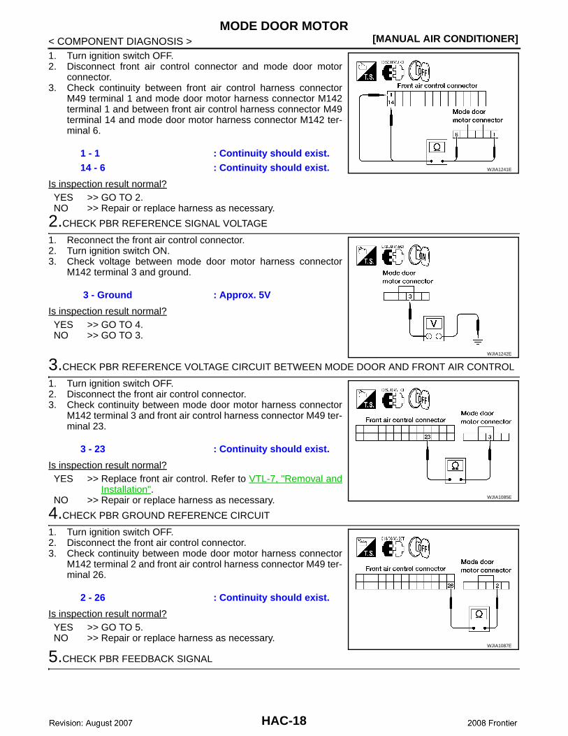
< COMPONENT DIAGNOSIS >1. Turn ignition switch OFF.2. Disconnect front air control connector and mode door motor
connector.3. Check continuity between front air control harness connector
M49 terminal 1 and mode door motor harness connector M142terminal 1 and between front air control harness connector M49terminal 14 and mode door motor harness connector M142 ter-minal 6.
Is inspection result normal?YES >> GO TO 2.NO >> Repair or replace harness as necessary.
2.CHECK PBR REFERENCE SIGNAL VOLTAGE
1. Reconnect the front air control connector.2. Turn ignition switch ON.3. Check voltage between mode door motor harness connector
M142 terminal 3 and ground.
Is inspection result normal?YES >> GO TO 4.NO >> GO TO 3.
3.CHECK PBR REFERENCE VOLTAGE CIRCUIT BETWEEN MODE DOOR AND FRONT AIR CONTROL
1. Turn ignition switch OFF.2. Disconnect the front air control connector.3. Check continuity between mode door motor harness connector
M142 terminal 3 and front air control harness connector M49 ter-minal 23.
Is inspection result normal?YES >> Replace front air control. Refer to VTL-7, "Removal and
Installation".NO >> Repair or replace harness as necessary.
4.CHECK PBR GROUND REFERENCE CIRCUIT
1. Turn ignition switch OFF.2. Disconnect the front air control connector.3. Check continuity between mode door motor harness connector
M142 terminal 2 and front air control harness connector M49 ter-minal 26.
Is inspection result normal?YES >> GO TO 5.NO >> Repair or replace harness as necessary.
5.CHECK PBR FEEDBACK SIGNAL
1 - 1 : Continuity should exist.14 - 6 : Continuity should exist. WJIA1241E
3 - Ground : Approx. 5V
WJIA1242E
3 - 23 : Continuity should exist.
WJIA1085E
2 - 26 : Continuity should exist.
WJIA1087E
HAC-18
MODE DOOR MOTOR[MANUAL AIR CONDITIONER]
C
D
E
F
G
H
J
K
L
M
A
B
AC
N
O
P
< COMPONENT DIAGNOSIS >
H
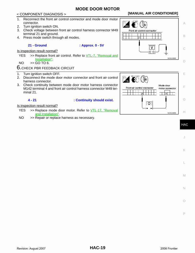
1. Reconnect the front air control connector and mode door motorconnector.
2. Turn ignition switch ON.3. Check voltage between front air control harness connector M49
terminal 21 and ground.4. Press mode switch through all modes.
Is inspection result normal?YES >> Replace front air control. Refer to VTL-7, "Removal and
Installation".NO >> GO TO 6.
6.CHECK PBR FEEDBACK CIRCUIT
1. Turn ignition switch OFF.2. Disconnect the mode door motor connector and front air control
harness connector.3. Check continuity between mode door motor harness connector
M142 terminal 4 and front air control harness connector M49 ter-minal 21.
Is inspection result normal?YES >> Replace mode door motor. Refer to VTL-17, "Removal
and Installation".NO >> Repair or replace harness as necessary.
21 - Ground : Approx. 0 - 5V
WJIA1088E
4 - 21 : Continuity should exist.
WJIA1089E
HAC-19
[MANUAL AIR CONDITIONER]AIR MIX DOOR MOTOR
< COMPONENT DIAGNOSIS >
AIR MIX DOOR MOTOR
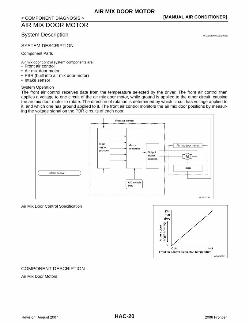
System Description INFOID:0000000003289110
SYSTEM DESCRIPTION
Component Parts
Air mix door control system components are:• Front air control• Air mix door motor • PBR (built into air mix door motor)• Intake sensor
System OperationThe front air control receives data from the temperature selected by the driver. The front air control thenapplies a voltage to one circuit of the air mix door motor, while ground is applied to the other circuit, causingthe air mix door motor to rotate. The direction of rotation is determined by which circuit has voltage applied toit, and which one has ground applied to it. The front air control monitors the air mix door positions by measur-ing the voltage signal on the PBR circuits of each door.
Air Mix Door Control Specification
COMPONENT DESCRIPTION
Air Mix Door Motors
WJIA1316E
WJIA0435E
HAC-20
AIR MIX DOOR MOTOR[MANUAL AIR CONDITIONER]
C
D
E
F
G
H
J
K
L
M
A
B
AC
N
O
P
< COMPONENT DIAGNOSIS >
H
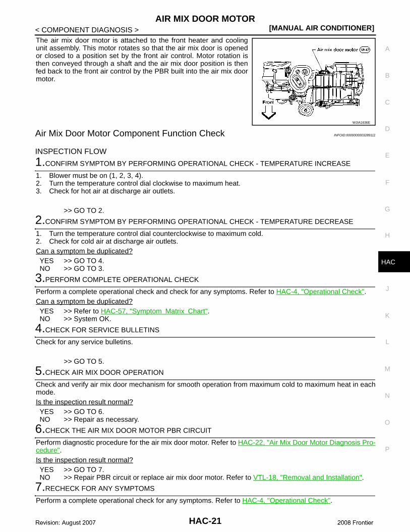
The air mix door motor is attached to the front heater and coolingunit assembly. This motor rotates so that the air mix door is openedor closed to a position set by the front air control. Motor rotation isthen conveyed through a shaft and the air mix door position is thenfed back to the front air control by the PBR built into the air mix doormotor.
Air Mix Door Motor Component Function Check INFOID:0000000003289111
INSPECTION FLOW
1.CONFIRM SYMPTOM BY PERFORMING OPERATIONAL CHECK - TEMPERATURE INCREASE
1. Blower must be on (1, 2, 3, 4).2. Turn the temperature control dial clockwise to maximum heat.3. Check for hot air at discharge air outlets.
>> GO TO 2.
2.CONFIRM SYMPTOM BY PERFORMING OPERATIONAL CHECK - TEMPERATURE DECREASE
1. Turn the temperature control dial counterclockwise to maximum cold.2. Check for cold air at discharge air outlets.Can a symptom be duplicated?YES >> GO TO 4.NO >> GO TO 3.
3.PERFORM COMPLETE OPERATIONAL CHECK
Perform a complete operational check and check for any symptoms. Refer to HAC-4, "Operational Check".Can a symptom be duplicated?YES >> Refer to HAC-57, "Symptom Matrix Chart".NO >> System OK.
4.CHECK FOR SERVICE BULLETINS
Check for any service bulletins.
>> GO TO 5.
5.CHECK AIR MIX DOOR OPERATION
Check and verify air mix door mechanism for smooth operation from maximum cold to maximum heat in eachmode.Is the inspection result normal?YES >> GO TO 6.NO >> Repair as necessary.
6.CHECK THE AIR MIX DOOR MOTOR PBR CIRCUIT
Perform diagnostic procedure for the air mix door motor. Refer to HAC-22, "Air Mix Door Motor Diagnosis Pro-cedure".Is the inspection result normal?YES >> GO TO 7.NO >> Repair PBR circuit or replace air mix door motor. Refer to VTL-18, "Removal and Installation".
7.RECHECK FOR ANY SYMPTOMS
Perform a complete operational check for any symptoms. Refer to HAC-4, "Operational Check".
WJIA1636E
HAC-21
[MANUAL AIR CONDITIONER]AIR MIX DOOR MOTOR
< COMPONENT DIAGNOSIS >Does another symptom exist?YES >> Refer to HAC-57, "Symptom Matrix Chart". NO >> Replace front air control. Refer to VTL-7, "Removal and Installation".
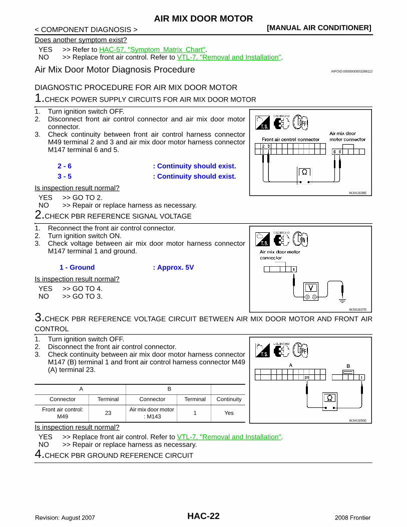
Air Mix Door Motor Diagnosis Procedure INFOID:0000000003289112
DIAGNOSTIC PROCEDURE FOR AIR MIX DOOR MOTOR
1.CHECK POWER SUPPLY CIRCUITS FOR AIR MIX DOOR MOTOR
1. Turn ignition switch OFF.2. Disconnect front air control connector and air mix door motor
connector.3. Check continuity between front air control harness connector
M49 terminal 2 and 3 and air mix door motor harness connectorM147 terminal 6 and 5.
Is inspection result normal?YES >> GO TO 2.NO >> Repair or replace harness as necessary.
2.CHECK PBR REFERENCE SIGNAL VOLTAGE
1. Reconnect the front air control connector.2. Turn ignition switch ON.3. Check voltage between air mix door motor harness connector
M147 terminal 1 and ground.
Is inspection result normal?YES >> GO TO 4.NO >> GO TO 3.
3.CHECK PBR REFERENCE VOLTAGE CIRCUIT BETWEEN AIR MIX DOOR MOTOR AND FRONT AIRCONTROL
1. Turn ignition switch OFF.2. Disconnect the front air control connector.3. Check continuity between air mix door motor harness connector
M147 (B) terminal 1 and front air control harness connector M49(A) terminal 23.
Is inspection result normal?YES >> Replace front air control. Refer to VTL-7, "Removal and Installation".NO >> Repair or replace harness as necessary.
4.CHECK PBR GROUND REFERENCE CIRCUIT
2 - 6 : Continuity should exist.3 - 5 : Continuity should exist.
WJIA1638E
1 - Ground : Approx. 5V
WJIA1637E
A B
Connector Terminal Connector Terminal Continuity
Front air control: M49
23 Air mix door motor
: M1431 Yes
WJIA1656E
HAC-22
AIR MIX DOOR MOTOR[MANUAL AIR CONDITIONER]
C
D
E
F
G
H
J
K
L
M
A
B
AC
N
O
P
< COMPONENT DIAGNOSIS >
H
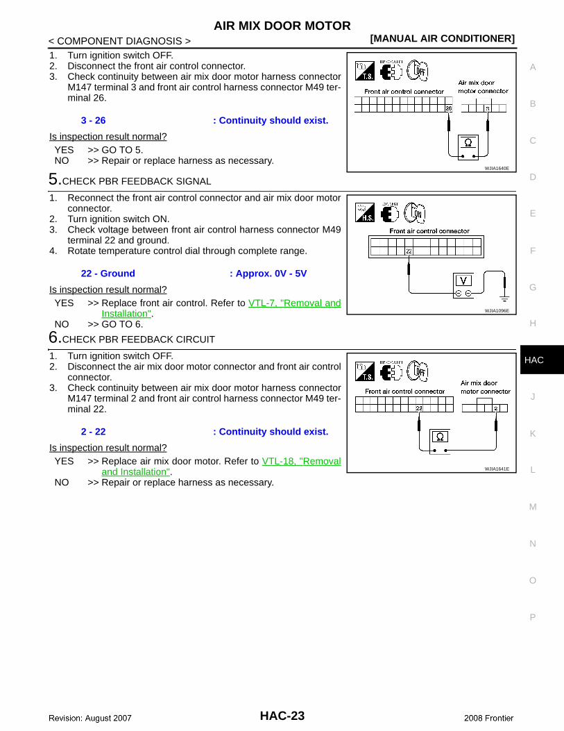
1. Turn ignition switch OFF.2. Disconnect the front air control connector.3. Check continuity between air mix door motor harness connector
M147 terminal 3 and front air control harness connector M49 ter-minal 26.
Is inspection result normal?YES >> GO TO 5.NO >> Repair or replace harness as necessary.
5.CHECK PBR FEEDBACK SIGNAL
1. Reconnect the front air control connector and air mix door motorconnector.
2. Turn ignition switch ON.3. Check voltage between front air control harness connector M49
terminal 22 and ground.4. Rotate temperature control dial through complete range.
Is inspection result normal?YES >> Replace front air control. Refer to VTL-7, "Removal and
Installation".NO >> GO TO 6.
6.CHECK PBR FEEDBACK CIRCUIT
1. Turn ignition switch OFF.2. Disconnect the air mix door motor connector and front air control
connector.3. Check continuity between air mix door motor harness connector
M147 terminal 2 and front air control harness connector M49 ter-minal 22.
Is inspection result normal?YES >> Replace air mix door motor. Refer to VTL-18, "Removal
and Installation".NO >> Repair or replace harness as necessary.
3 - 26 : Continuity should exist.
WJIA1640E
22 - Ground : Approx. 0V - 5V
WJIA1096E
2 - 22 : Continuity should exist.
WJIA1641E
HAC-23
[MANUAL AIR CONDITIONER]INTAKE DOOR MOTOR
< COMPONENT DIAGNOSIS >
INTAKE DOOR MOTOR
System Description INFOID:0000000003289113
SYSTEM DESCRIPTION
Component Parts
Intake door control system components are:• Front air control• Intake door motor• Intake sensor
System OperationThe intake door control determines the intake door position based on the position of the recirculation switch.When the recirculation switch is depressed the intake door motor rotates closing off the fresh air inlet andrecirculating the cabin air. If the recirculation switch is depressed again, the intake door motor rotates in theopposite direction, again allowing fresh air into the cabin.
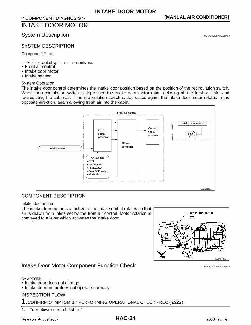
COMPONENT DESCRIPTION
Intake door motorThe intake door motor is attached to the intake unit. It rotates so thatair is drawn from inlets set by the front air control. Motor rotation isconveyed to a lever which activates the intake door.
Intake Door Motor Component Function Check INFOID:0000000003289114
SYMPTOM:• Intake door does not change.• Intake door motor does not operate normally.
INSPECTION FLOW
1.CONFIRM SYMPTOM BY PERFORMING OPERATIONAL CHECK - REC ( )
1. Turn blower control dial to 4.
WJIA1478E
WJIA1486E
HAC-24
INTAKE DOOR MOTOR[MANUAL AIR CONDITIONER]
C
D
E
F
G
H
J
K
L
M
A
B
AC
N
O
P
< COMPONENT DIAGNOSIS >
H
2. Turn mode dial to vent mode ( ).3. Press REC ( ) switch. 4. Press REC ( ) switch again.5. Listen for intake door position change (you should hear blower sound change slightly).Can a symptom be duplicated?YES >> GO TO 3.NO >> GO TO 2.
2.PERFORM COMPLETE OPERATIONAL CHECK
Perform a complete operational check and check for any symptoms. Refer to HAC-4, "Operational Check".Can a symptom be duplicated?YES >> Refer to HAC-57, "Symptom Matrix Chart".NO >> System OK.
3.CHECK FOR SERVICE BULLETINS
Check for any service bulletins.
>> GO TO 4.
4.CHECK INTAKE DOOR OPERATION
Check and verify intake door mechanism for smooth operation. Is inspection result normal?YES >> GO TO 5.NO >> Repair intake door mechanism.
5.RECHECK FOR ANY SYMPTOMS
Perform a complete operational check for any symptoms. Refer to HAC-4, "Operational Check".Does another symptom exist?YES >> Refer to HAC-57, "Symptom Matrix Chart". NO >> Replace front air control. Refer to VTL-7, "Removal and Installation".
Intake Door Motor Diagnosis Procedure INFOID:0000000003289115
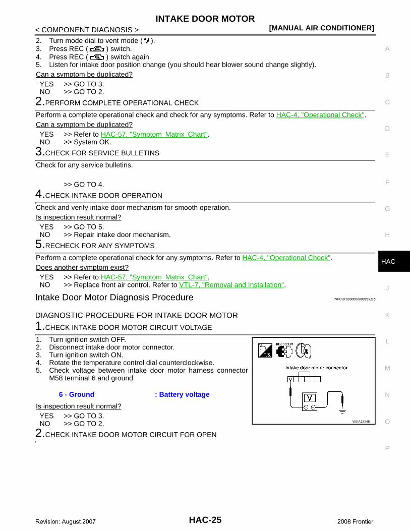
DIAGNOSTIC PROCEDURE FOR INTAKE DOOR MOTOR
1.CHECK INTAKE DOOR MOTOR CIRCUIT VOLTAGE
1. Turn ignition switch OFF.2. Disconnect intake door motor connector.3. Turn ignition switch ON.4. Rotate the temperature control dial counterclockwise.5. Check voltage between intake door motor harness connector
M58 terminal 6 and ground.
Is inspection result normal?YES >> GO TO 3.NO >> GO TO 2.
2.CHECK INTAKE DOOR MOTOR CIRCUIT FOR OPEN
6 - Ground : Battery voltage
WJIA1324E
HAC-25
[MANUAL AIR CONDITIONER]INTAKE DOOR MOTOR
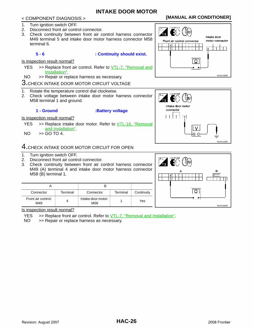
< COMPONENT DIAGNOSIS >1. Turn ignition switch OFF.2. Disconnect front air control connector.3. Check continuity between front air control harness connector
M49 terminal 5 and intake door motor harness connector M58terminal 6.
Is inspection result normal?YES >> Replace front air control. Refer to VTL-7, "Removal and
Installation".NO >> Repair or replace harness as necessary.
3.CHECK INTAKE DOOR MOTOR CIRCUIT VOLTAGE
1. Rotate the temperature control dial clockwise.2. Check voltage between intake door motor harness connector
M58 terminal 1 and ground.
Is inspection result normal?YES >> Replace intake door motor. Refer to VTL-16, "Removal
and Installation".NO >> GO TO 4.
4.CHECK INTAKE DOOR MOTOR CIRCUIT FOR OPEN
1. Turn ignition switch OFF.2. Disconnect front air control connector.3. Check continuity between front air control harness connector
M49 (A) terminal 4 and intake door motor harness connectorM58 (B) terminal 1.
Is inspection result normal?YES >> Replace front air control. Refer to VTL-7, "Removal and Installation".NO >> Repair or replace harness as necessary.
5 - 6 : Continuity should exist.
WJIA1468E
1 - Ground :Battery voltage
WJIA1326E
A B
Connector Terminal Connector Terminal Continuity
Front air control: M49
4 Intake door motor:
M581 Yes
WJIA1684E
HAC-26
BLOWER MOTOR[MANUAL AIR CONDITIONER]
C
D
E
F
G
H
J
K
L
M
A
B
AC
N
O
P
< COMPONENT DIAGNOSIS >
H
BLOWER MOTOR
System Description INFOID:0000000003289116
Component Parts
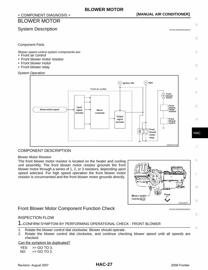
Blower speed control system components are:• Front air control• Front blower motor resistor• Front blower motor• Front blower relay
System Operation
COMPONENT DESCRIPTION
Blower Motor ResistorThe front blower motor resistor is located on the heater and coolingunit assembly. The front blower motor resistor grounds the frontblower motor through a series of 1, 2, or 3 resistors, depending uponspeed selected. For high speed operation the front blower motorresistor is circumvented and the front blower motor grounds directly.
Front Blower Motor Component Function Check INFOID:0000000003289117
INSPECTION FLOW
1.CONFIRM SYMPTOM BY PERFORMING OPERATIONAL CHECK - FRONT BLOWER
1. Rotate the blower control dial clockwise. Blower should operate.2. Rotate the blower control dial clockwise, and continue checking blower speed until all speeds are
checked.Can the symptom be duplicated?YES >> GO TO 3.NO >> GO TO 2.
AWIIA0272GB
WJIA1487E
HAC-27
[MANUAL AIR CONDITIONER]BLOWER MOTOR
< COMPONENT DIAGNOSIS >
2.CHECK FOR ANY SYMPTOMS
Perform a complete operational check for any symptoms. Refer to HAC-4, "Operational Check".Does another symptom exist?YES >> Refer to HAC-57, "Symptom Matrix Chart". NO >> System OK.
3.CHECK FOR SERVICE BULLETINS
Check for any service bulletins.
>> GO TO 4.
4.CHECK BLOWER MOTOR OPERATION
Check and verify blower motor operates in all speeds.Does blower motor operate in all speeds?YES >> GO TO 5.NO >> Refer to HAC-28, "Front Blower Motor Diagnosis Procedure".
5.CHECK ENGINE COOLANT TEMPERATURE SENSOR CIRCUIT
Perform diagnostic procedure for the coolant temperature sensor circuit. Refer to EC-118, "ComponentInspection" EC-118, "Component Inspection" (QR25DE) or EC-566, "Component Inspection" (VQ40DE).Is the inspection result normal?YES >> GO TO 6. NO >> Repair or replace harness as necessary.
6.RECHECK FOR ANY SYMPTOMS
Perform a complete operational check for any symptoms. Refer to HAC-4, "Operational Check".Does another symptom exist?YES >> Refer to HAC-57, "Symptom Matrix Chart". NO >> Replace front air control. Refer to VTL-7, "Removal and Installation".
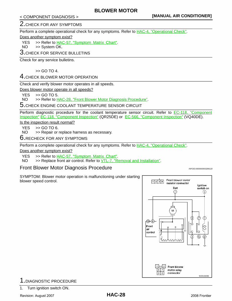
Front Blower Motor Diagnosis Procedure INFOID:0000000003289118
SYMPTOM: Blower motor operation is malfunctioning under startingblower speed control.
1.DIAGNOSTIC PROCEDURE
1. Turn ignition switch ON.
WJIA1503E
HAC-28
BLOWER MOTOR[MANUAL AIR CONDITIONER]
C
D
E
F
G
H
J
K
L
M
A
B
AC
N
O
P
< COMPONENT DIAGNOSIS >
H
2. Turn the front blower switch to each of its four speeds.Does blower motor rotate normally at each speed?
YES or NOYES >> Inspection End.NO >> 1. Does not rotate at any speed, GO TO 2.
2. Does not rotate at 1 - 3 speed, GO TO 13.3. Does not rotate at 4 speed, GO TO 16.
2.CHECK FUSES
1. Check 15A fuses (Nos. 24 and 27, located in the fuse and fusible link box). Refer to PG-75, "TerminalArrangement".
2. Check 10A fuse [No. 8, located in the fuse block (J/B)]. Refer to PG-74, "Terminal Arrangement".Is inspection result normal?YES >> GO TO 3.NO >> GO TO 8.
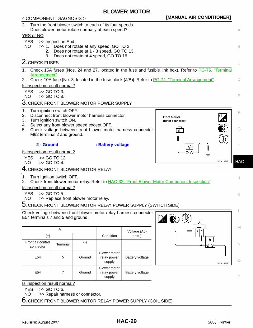
3.CHECK FRONT BLOWER MOTOR POWER SUPPLY
1. Turn ignition switch OFF.2. Disconnect front blower motor harness connector.3. Turn ignition switch ON.4. Select any front blower speed except OFF.5. Check voltage between front blower motor harness connector
M62 terminal 2 and ground.
Is inspection result normal?YES >> GO TO 12.NO >> GO TO 4.
4.CHECK FRONT BLOWER MOTOR RELAY
1. Turn Ignition switch OFF.2. Check front blower motor relay. Refer to HAC-32, "Front Blower Motor Component Inspection".Is inspection result normal?YES >> GO TO 5.NO >> Replace front blower motor relay.
5.CHECK FRONT BLOWER MOTOR RELAY POWER SUPPLY (SWITCH SIDE)
Check voltage between front blower motor relay harness connectorE54 terminals 7 and 5 and ground.
Is inspection result normal?YES >> GO TO 6.NO >> Repair harness or connector.
6.CHECK FRONT BLOWER MOTOR RELAY POWER SUPPLY (COIL SIDE)
2 - Ground : Battery voltage
WJIA1331E
A
ConditionVoltage (Ap-
prox.)(+)
Front air control connector
Terminal (-)
E54 5 GroundBlower motor relay power
supplyBattery voltage
E54 7 GroundBlower motor relay power
supplyBattery voltage
WJIA1634E
HAC-29
[MANUAL AIR CONDITIONER]BLOWER MOTOR
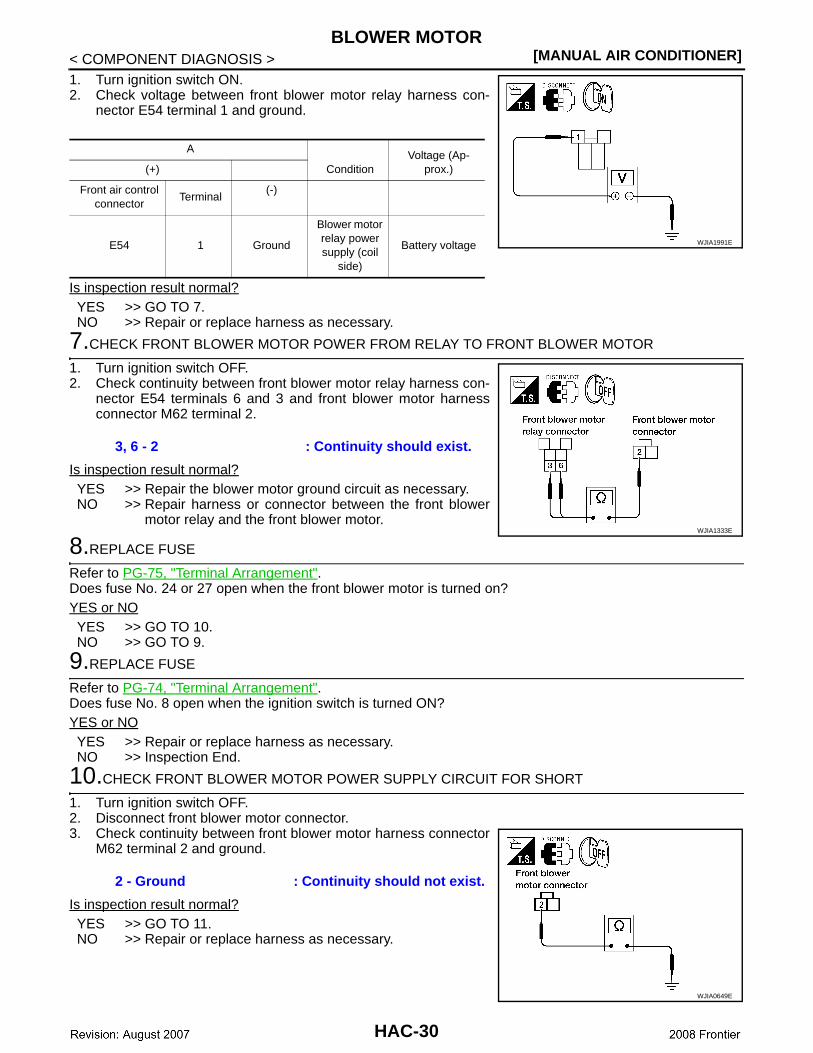
< COMPONENT DIAGNOSIS >1. Turn ignition switch ON.2. Check voltage between front blower motor relay harness con-
nector E54 terminal 1 and ground.
Is inspection result normal?YES >> GO TO 7.NO >> Repair or replace harness as necessary.
7.CHECK FRONT BLOWER MOTOR POWER FROM RELAY TO FRONT BLOWER MOTOR
1. Turn ignition switch OFF.2. Check continuity between front blower motor relay harness con-
nector E54 terminals 6 and 3 and front blower motor harnessconnector M62 terminal 2.
Is inspection result normal?YES >> Repair the blower motor ground circuit as necessary.NO >> Repair harness or connector between the front blower
motor relay and the front blower motor.
8.REPLACE FUSE
Refer to PG-75, "Terminal Arrangement".Does fuse No. 24 or 27 open when the front blower motor is turned on?YES or NOYES >> GO TO 10.NO >> GO TO 9.
9.REPLACE FUSE
Refer to PG-74, "Terminal Arrangement".Does fuse No. 8 open when the ignition switch is turned ON?YES or NOYES >> Repair or replace harness as necessary.NO >> Inspection End.
10.CHECK FRONT BLOWER MOTOR POWER SUPPLY CIRCUIT FOR SHORT
1. Turn ignition switch OFF.2. Disconnect front blower motor connector.3. Check continuity between front blower motor harness connector
M62 terminal 2 and ground.
Is inspection result normal?YES >> GO TO 11.NO >> Repair or replace harness as necessary.
A
ConditionVoltage (Ap-
prox.)(+)
Front air control connector
Terminal (-)
E54 1 Ground
Blower motor relay power supply (coil
side)
Battery voltage WJIA1991E
3, 6 - 2 : Continuity should exist.
WJIA1333E
2 - Ground : Continuity should not exist.
WJIA0649E
HAC-30
BLOWER MOTOR[MANUAL AIR CONDITIONER]
C
D
E
F
G
H
J
K
L
M
A
B
AC
N
O
P
< COMPONENT DIAGNOSIS >
H
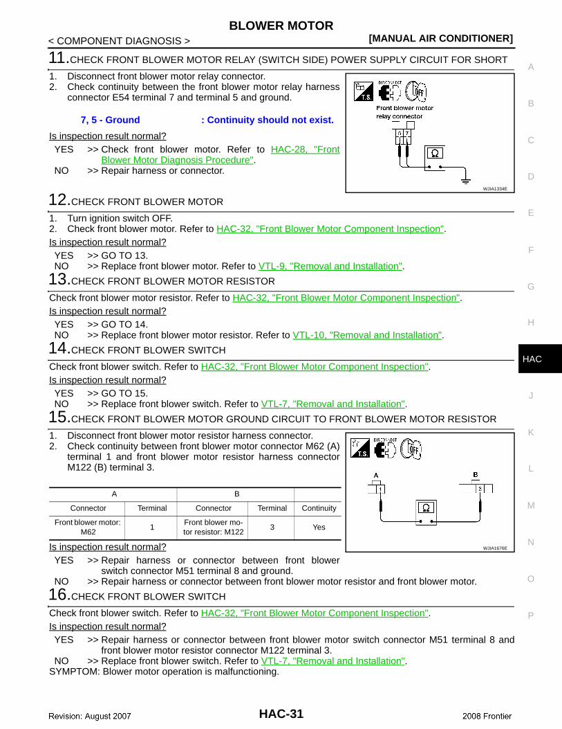
11.CHECK FRONT BLOWER MOTOR RELAY (SWITCH SIDE) POWER SUPPLY CIRCUIT FOR SHORT
1. Disconnect front blower motor relay connector.2. Check continuity between the front blower motor relay harness
connector E54 terminal 7 and terminal 5 and ground.
Is inspection result normal?YES >> Check front blower motor. Refer to HAC-28, "Front
Blower Motor Diagnosis Procedure".NO >> Repair harness or connector.
12.CHECK FRONT BLOWER MOTOR
1. Turn ignition switch OFF.2. Check front blower motor. Refer to HAC-32, "Front Blower Motor Component Inspection".Is inspection result normal?YES >> GO TO 13.NO >> Replace front blower motor. Refer to VTL-9, "Removal and Installation".
13.CHECK FRONT BLOWER MOTOR RESISTOR
Check front blower motor resistor. Refer to HAC-32, "Front Blower Motor Component Inspection".Is inspection result normal?YES >> GO TO 14.NO >> Replace front blower motor resistor. Refer to VTL-10, "Removal and Installation".
14.CHECK FRONT BLOWER SWITCH
Check front blower switch. Refer to HAC-32, "Front Blower Motor Component Inspection".Is inspection result normal?YES >> GO TO 15.NO >> Replace front blower switch. Refer to VTL-7, "Removal and Installation".
15.CHECK FRONT BLOWER MOTOR GROUND CIRCUIT TO FRONT BLOWER MOTOR RESISTOR
1. Disconnect front blower motor resistor harness connector.2. Check continuity between front blower motor connector M62 (A)
terminal 1 and front blower motor resistor harness connectorM122 (B) terminal 3.
Is inspection result normal?YES >> Repair harness or connector between front blower
switch connector M51 terminal 8 and ground.NO >> Repair harness or connector between front blower motor resistor and front blower motor.
16.CHECK FRONT BLOWER SWITCH
Check front blower switch. Refer to HAC-32, "Front Blower Motor Component Inspection".Is inspection result normal?YES >> Repair harness or connector between front blower motor switch connector M51 terminal 8 and
front blower motor resistor connector M122 terminal 3.NO >> Replace front blower switch. Refer to VTL-7, "Removal and Installation".
SYMPTOM: Blower motor operation is malfunctioning.
7, 5 - Ground : Continuity should not exist.
WJIA1334E
A B
Connector Terminal Connector Terminal Continuity
Front blower motor: M62
1 Front blower mo-tor resistor: M122
3 Yes
WJIA1676E
HAC-31
[MANUAL AIR CONDITIONER]BLOWER MOTOR
< COMPONENT DIAGNOSIS >
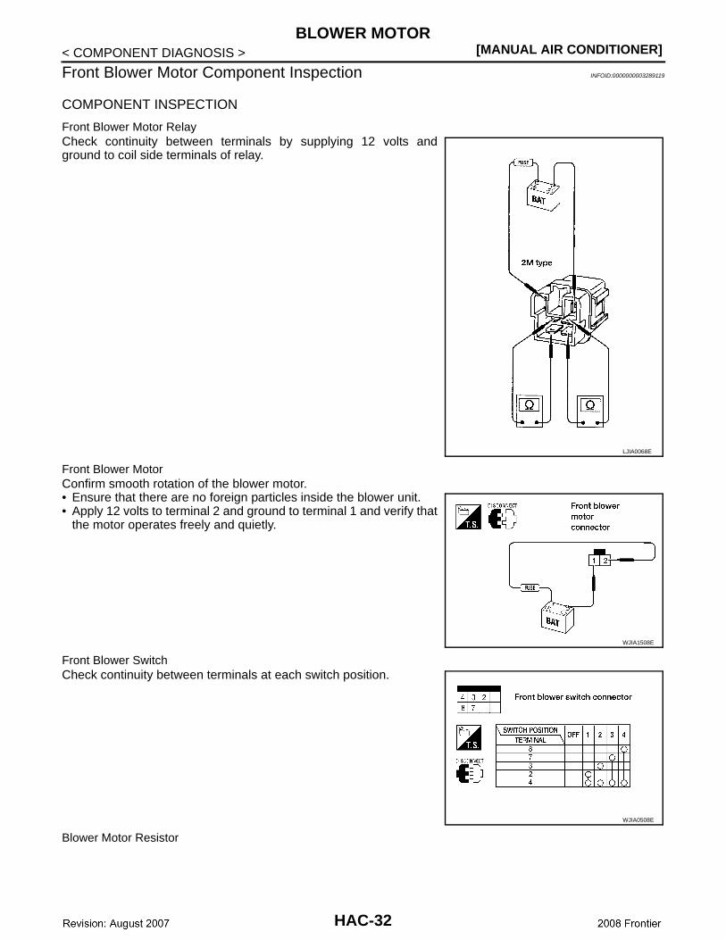
Front Blower Motor Component Inspection INFOID:0000000003289119
COMPONENT INSPECTION
Front Blower Motor RelayCheck continuity between terminals by supplying 12 volts andground to coil side terminals of relay.
Front Blower MotorConfirm smooth rotation of the blower motor.• Ensure that there are no foreign particles inside the blower unit.• Apply 12 volts to terminal 2 and ground to terminal 1 and verify that
the motor operates freely and quietly.
Front Blower SwitchCheck continuity between terminals at each switch position.
Blower Motor Resistor
LJIA0068E
WJIA1508E
WJIA0508E
HAC-32
BLOWER MOTOR[MANUAL AIR CONDITIONER]
C
D
E
F
G
H
J
K
L
M
A
B
AC
N
O
P
< COMPONENT DIAGNOSIS >
H
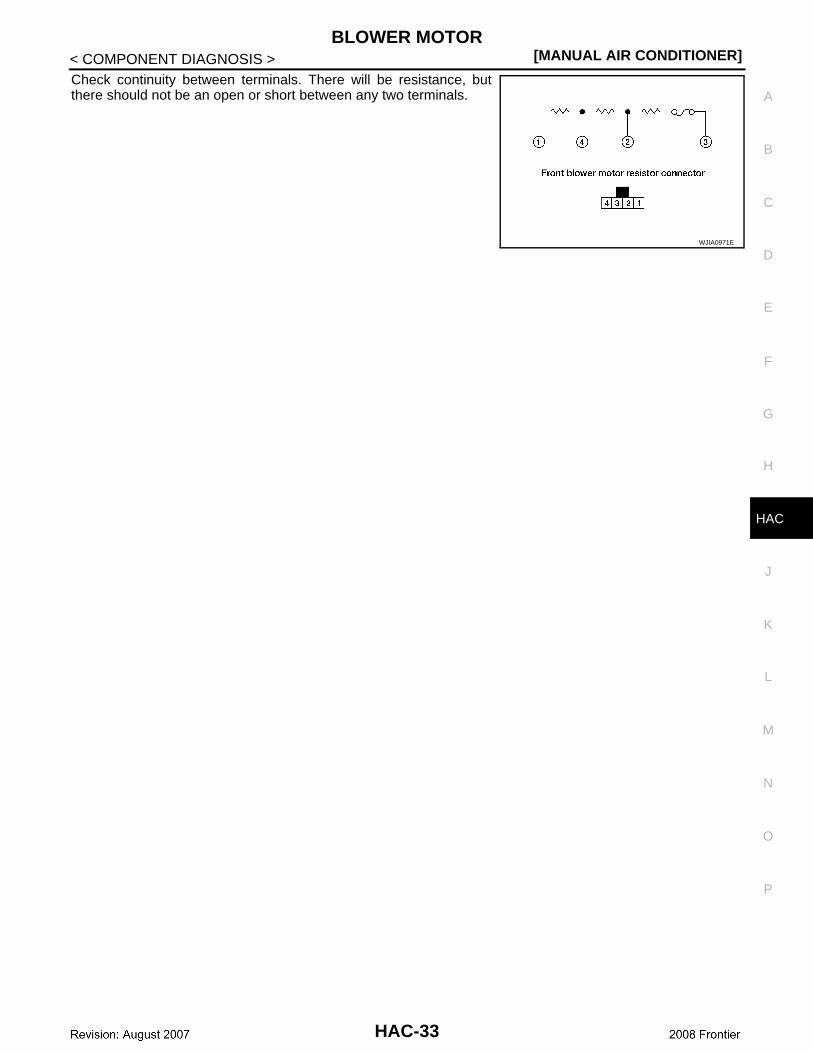
Check continuity between terminals. There will be resistance, butthere should not be an open or short between any two terminals.
WJIA0971E
HAC-33
[MANUAL AIR CONDITIONER]MAGNET CLUTCH
< COMPONENT DIAGNOSIS >
MAGNET CLUTCH
System Description INFOID:0000000003289120
SYSTEM DESCRIPTIONThe front air control controls compressor operation based on ambient and intake temperature and a signalfrom ECM.
Low Temperature Protection ControlThe front air control will turn the compressor ON or OFF as determined by a signal detected by the intake sen-sor and the ambient sensor.When intake air temperature is higher than 3.5° C (38.3° F), the compressor turns ON. The compressor turnsOFF when intake air temperature is lower than 2.5° C (36.5° F).
Magnet Clutch Component Function Check INFOID:0000000003289121
SYMPTOM: Magnet clutch does not engage.
INSPECTION FLOW
1.CONFIRM SYMPTOM BY PERFORMING OPERATIONAL CHECK - MAGNET CLUTCH
1. Rotate blower control dial clockwise. 2. Rotate mode dial to vent ( ) position.3. Press A/C switch. Confirm that the compressor clutch engages (sound or visual inspection). Can the symptom be duplicated?YES >> GO TO 3.NO >> GO TO 2.
2.CHECK FOR ANY SYMPTOMS
Perform a complete operational check for any symptoms. Refer to HAC-4, "Operational Check".Does another symptom exist?YES >> Refer to HAC-57, "Symptom Matrix Chart". NO >> System OK.
3.CHECK FOR SERVICE BULLETINS
Check for any service bulletins.
>> GO TO 4.
4.CHECK INTAKE SENSOR
Check and verify intake sensor circuit. Refer to HAC-40, "Intake Sensor Component Inspection".
>> GO TO 5.
5.RECHECK FOR ANY SYMPTOMS
Perform a complete operational check for any symptoms. Refer to HAC-4, "Operational Check".Does another symptom exist?YES >> Refer to HAC-57, "Symptom Matrix Chart". NO >> Replace front air control. Refer to VTL-7, "Removal and Installation".
Magnet Clutch Diagnosis Procedure INFOID:0000000003289122
DIAGNOSTIC PROCEDURE FOR MAGNET CLUTCH
HAC-34
MAGNET CLUTCH[MANUAL AIR CONDITIONER]
C
D
E
F
G
H
J
K
L
M
A
B
AC
N
O
P
< COMPONENT DIAGNOSIS >
H
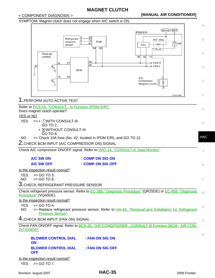
SYMPTOM: Magnet clutch does not engage when A/C switch is ON.
1.PERFORM AUTO ACTIVE TEST
Refer to PCS-15, "CONSULT - III Function (IPDM E/R)".Does magnet clutch operate?YES or NOYES >> • WITH CONSULT-III
GO TO 2.• WITHOUT CONSULT-III
GO TO 8.NO >> Check 10A fuse (No. 42, located in IPDM E/R), and GO TO 12.
2.CHECK BCM INPUT (A/C COMPRESSOR ON) SIGNAL
Check A/C compressor ON/OFF signal. Refer to HAC-14, "CONSULT-III Data Monitor".
Is the inspection result normal?YES >> GO TO 3.NO >> GO TO 8.
3.CHECK REFRIGERANT PRESSURE SENSOR
Check refrigerant pressure sensor. Refer to EC-389, "Diagnosis Procedure" (QR25DE) or EC-859, "DiagnosisProcedure" (VQ40DE).Is the inspection result normal?YES >> GO TO 4.NO >> Replace refrigerant pressure sensor. Refer to HA-44, "Removal and Installation for Refrigerant
Pressure Sensor".
4.CHECK BCM INPUT (FAN ON) SIGNAL
Check FAN ON/OFF signal. Refer to BCS-20, "AIR CONDITIONER : CONSULT-III Function (BCM - AIR CON-DITIONER)"
Is the inspection result normal?YES >> GO TO 7.
WJIA1490E
A/C SW ON : COMP ON SIG ONA/C SW OFF : COMP ON SIG OFF
BLOWER CONTROL DIAL ON
: FAN ON SIG ON
BLOWER CONTROL DIAL OFF
: FAN ON SIG OFF
HAC-35
[MANUAL AIR CONDITIONER]MAGNET CLUTCH
< COMPONENT DIAGNOSIS >NO >> GO TO 5.
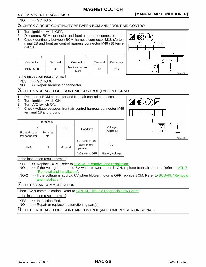
5.CHECK CIRCUIT CONTINUITY BETWEEN BCM AND FRONT AIR CONTROL
1. Turn ignition switch OFF.2. Disconnect BCM connector and front air control connector.3. Check continuity between BCM harness connector M18 (A) ter-
minal 28 and front air control harness connector M49 (B) termi-nal 18.
Is the inspection result normal?YES >> GO TO 6.NO >> Repair harness or connector.
6.CHECK VOLTAGE FOR FRONT AIR CONTROL (FAN ON SIGNAL)
1. Reconnect BCM connector and front air control connector.2. Turn ignition switch ON.3. Turn A/C switch ON.4. Check voltage between front air control harness connector M49
terminal 18 and ground.
Is the inspection result normal?YES >> Replace BCM. Refer to BCS-49, "Removal and Installation".NO-1 >> If the voltage is approx. 5V when blower motor is ON, replace front air control. Refer to VTL-7,
"Removal and Installation".NO-2 >> If the voltage is approx. 0V when blower motor is OFF, replace BCM. Refer to BCS-49, "Removal
and Installation".
7.CHECK CAN COMMUNICATION
Check CAN communication. Refer to LAN-14, "Trouble Diagnosis Flow Chart".Is the inspection result normal?YES >> Inspection End.NO >> Repair or replace malfunctioning part(s).
8.CHECK VOLTAGE FOR FRONT AIR CONTROL (A/C COMPRESSOR ON SIGNAL)
A B
Connector Terminal Connector Terminal Continuity
BCM: M18 28 Front air control:
M4918 Yes
WJIA1627E
Terminals
ConditionVoltage
(Approx.)(+) (-)
Front air con-trol connector
Terminal No.
M49 18 Ground
A/C switch: ONBlower motor operates
0V
A/C switch: OFF Battery voltage
WJIA1628E
HAC-36
MAGNET CLUTCH[MANUAL AIR CONDITIONER]
C
D
E
F
G
H
J
K
L
M
A
B
AC
N
O
P
< COMPONENT DIAGNOSIS >
H
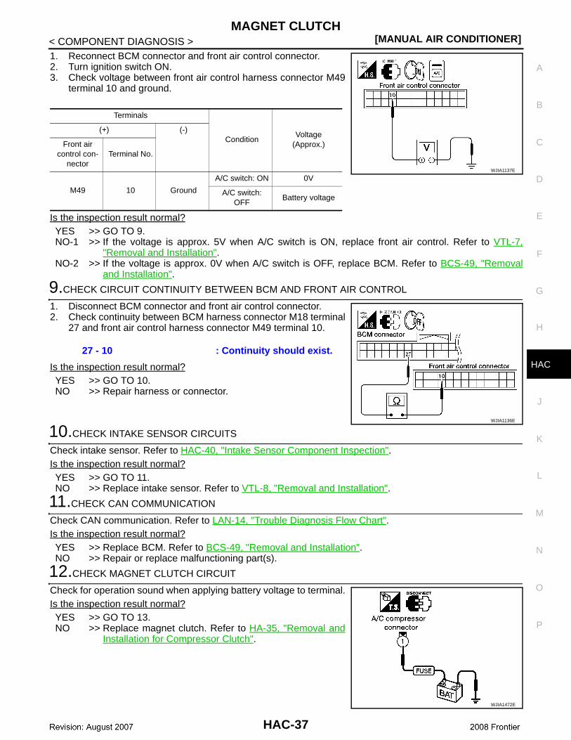
1. Reconnect BCM connector and front air control connector.2. Turn ignition switch ON.3. Check voltage between front air control harness connector M49
terminal 10 and ground.
Is the inspection result normal?YES >> GO TO 9.NO-1 >> If the voltage is approx. 5V when A/C switch is ON, replace front air control. Refer to VTL-7,
"Removal and Installation".NO-2 >> If the voltage is approx. 0V when A/C switch is OFF, replace BCM. Refer to BCS-49, "Removal
and Installation".
9.CHECK CIRCUIT CONTINUITY BETWEEN BCM AND FRONT AIR CONTROL
1. Disconnect BCM connector and front air control connector.2. Check continuity between BCM harness connector M18 terminal
27 and front air control harness connector M49 terminal 10.
Is the inspection result normal?YES >> GO TO 10.NO >> Repair harness or connector.
10.CHECK INTAKE SENSOR CIRCUITS
Check intake sensor. Refer to HAC-40, "Intake Sensor Component Inspection".Is the inspection result normal?YES >> GO TO 11.NO >> Replace intake sensor. Refer to VTL-8, "Removal and Installation".
11.CHECK CAN COMMUNICATION
Check CAN communication. Refer to LAN-14, "Trouble Diagnosis Flow Chart".Is the inspection result normal?YES >> Replace BCM. Refer to BCS-49, "Removal and Installation".NO >> Repair or replace malfunctioning part(s).
12.CHECK MAGNET CLUTCH CIRCUIT
Check for operation sound when applying battery voltage to terminal.Is the inspection result normal?YES >> GO TO 13.NO >> Replace magnet clutch. Refer to HA-35, "Removal and
Installation for Compressor Clutch".
Terminals
ConditionVoltage
(Approx.)
(+) (-)
Front air control con-
nectorTerminal No.
M49 10 Ground
A/C switch: ON 0V
A/C switch: OFF
Battery voltage
WJIA1137E
27 - 10 : Continuity should exist.
WJIA1136E
WJIA1472E
HAC-37
[MANUAL AIR CONDITIONER]MAGNET CLUTCH
< COMPONENT DIAGNOSIS >
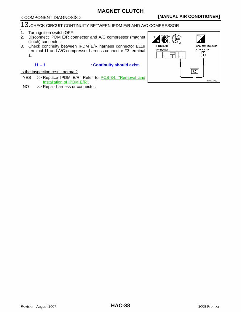
13.CHECK CIRCUIT CONTINUITY BETWEEN IPDM E/R AND A/C COMPRESSOR
1. Turn ignition switch OFF.2. Disconnect IPDM E/R connector and A/C compressor (magnet
clutch) connector.3. Check continuity between IPDM E/R harness connector E119
terminal 11 and A/C compressor harness connector F3 terminal1.
Is the inspection result normal?YES >> Replace IPDM E/R. Refer to PCS-34, "Removal and
Installation of IPDM E/R".NO >> Repair harness or connector.
11 – 1 : Continuity should exist.
WJIA1470E
HAC-38
INTAKE SENSOR[MANUAL AIR CONDITIONER]
C
D
E
F
G
H
J
K
L
M
A
B
AC
N
O
P
< COMPONENT DIAGNOSIS >
H
INTAKE SENSOR
System Description INFOID:0000000003289123
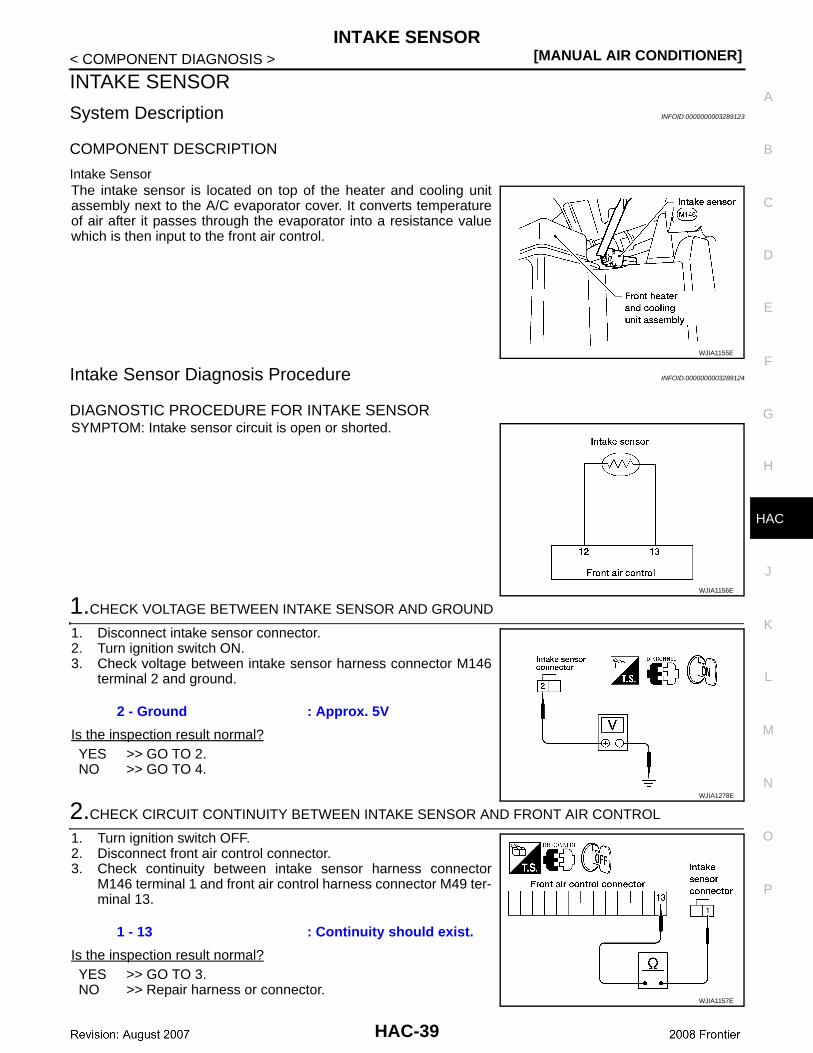
COMPONENT DESCRIPTION
Intake SensorThe intake sensor is located on top of the heater and cooling unitassembly next to the A/C evaporator cover. It converts temperatureof air after it passes through the evaporator into a resistance valuewhich is then input to the front air control.
Intake Sensor Diagnosis Procedure INFOID:0000000003289124
DIAGNOSTIC PROCEDURE FOR INTAKE SENSORSYMPTOM: Intake sensor circuit is open or shorted.
1.CHECK VOLTAGE BETWEEN INTAKE SENSOR AND GROUND
1. Disconnect intake sensor connector.2. Turn ignition switch ON.3. Check voltage between intake sensor harness connector M146
terminal 2 and ground.
Is the inspection result normal?YES >> GO TO 2.NO >> GO TO 4.
2.CHECK CIRCUIT CONTINUITY BETWEEN INTAKE SENSOR AND FRONT AIR CONTROL
1. Turn ignition switch OFF.2. Disconnect front air control connector.3. Check continuity between intake sensor harness connector
M146 terminal 1 and front air control harness connector M49 ter-minal 13.
Is the inspection result normal?YES >> GO TO 3.NO >> Repair harness or connector.
WJIA1155E
WJIA1156E
2 - Ground : Approx. 5V
WJIA1278E
1 - 13 : Continuity should exist.
WJIA1157E
HAC-39
[MANUAL AIR CONDITIONER]INTAKE SENSOR
< COMPONENT DIAGNOSIS >
3.CHECK INTAKE SENSOR
Refer to HAC-40, "Intake Sensor Component Inspection".Is the inspection result normal?YES >> Replace front air control. Refer to VTL-7, "Removal and Installation".NO >> Replace intake sensor. Refer to VTL-8, "Removal and Installation".
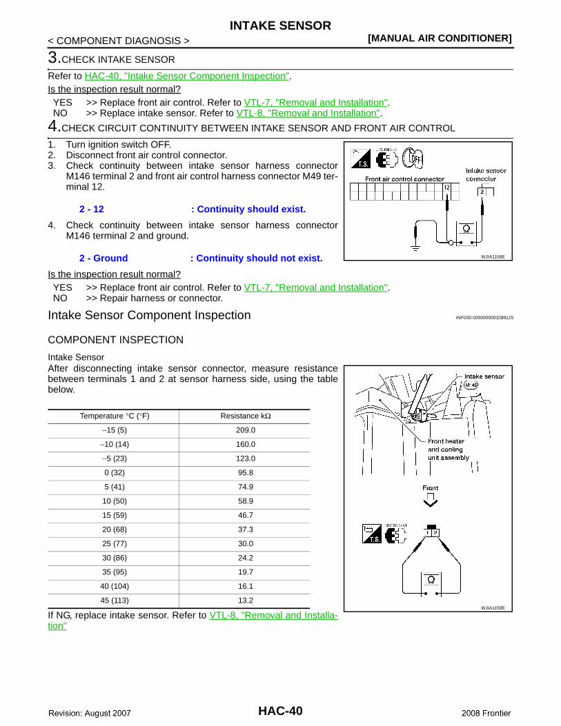
4.CHECK CIRCUIT CONTINUITY BETWEEN INTAKE SENSOR AND FRONT AIR CONTROL
1. Turn ignition switch OFF.2. Disconnect front air control connector.3. Check continuity between intake sensor harness connector
M146 terminal 2 and front air control harness connector M49 ter-minal 12.
4. Check continuity between intake sensor harness connectorM146 terminal 2 and ground.
Is the inspection result normal?YES >> Replace front air control. Refer to VTL-7, "Removal and Installation".NO >> Repair harness or connector.
Intake Sensor Component Inspection INFOID:0000000003289125
COMPONENT INSPECTION
Intake SensorAfter disconnecting intake sensor connector, measure resistancebetween terminals 1 and 2 at sensor harness side, using the tablebelow.
If NG, replace intake sensor. Refer to VTL-8, "Removal and Installa-tion"
2 - 12 : Continuity should exist.
2 - Ground : Continuity should not exist. WJIA1158E
Temperature °C (°F) Resistance kΩ
−15 (5) 209.0
−10 (14) 160.0
−5 (23) 123.0
0 (32) 95.8
5 (41) 74.9
10 (50) 58.9
15 (59) 46.7
20 (68) 37.3
25 (77) 30.0
30 (86) 24.2
35 (95) 19.7
40 (104) 16.1
45 (113) 13.2WJIA1159E
HAC-40
POWER SUPPLY AND GROUND CIRCUIT FOR CONTROLLER[MANUAL AIR CONDITIONER]
C
D
E
F
G
H
J
K
L
M
A
B
AC
N
O
P
< COMPONENT DIAGNOSIS >
H
POWER SUPPLY AND GROUND CIRCUIT FOR CONTROLLER
Component Description INFOID:0000000003289126
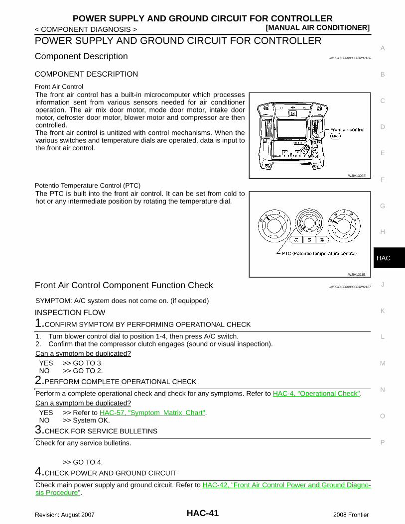
COMPONENT DESCRIPTION
Front Air ControlThe front air control has a built-in microcomputer which processesinformation sent from various sensors needed for air conditioneroperation. The air mix door motor, mode door motor, intake doormotor, defroster door motor, blower motor and compressor are thencontrolled.The front air control is unitized with control mechanisms. When thevarious switches and temperature dials are operated, data is input tothe front air control.
Potentio Temperature Control (PTC)The PTC is built into the front air control. It can be set from cold tohot or any intermediate position by rotating the temperature dial.
Front Air Control Component Function Check INFOID:0000000003289127
SYMPTOM: A/C system does not come on. (if equipped)
INSPECTION FLOW
1.CONFIRM SYMPTOM BY PERFORMING OPERATIONAL CHECK
1. Turn blower control dial to position 1-4, then press A/C switch.2. Confirm that the compressor clutch engages (sound or visual inspection). Can a symptom be duplicated?YES >> GO TO 3.NO >> GO TO 2.
2.PERFORM COMPLETE OPERATIONAL CHECK
Perform a complete operational check and check for any symptoms. Refer to HAC-4, "Operational Check".Can a symptom be duplicated?YES >> Refer to HAC-57, "Symptom Matrix Chart".NO >> System OK.
3.CHECK FOR SERVICE BULLETINS
Check for any service bulletins.
>> GO TO 4.
4.CHECK POWER AND GROUND CIRCUIT
Check main power supply and ground circuit. Refer to HAC-42, "Front Air Control Power and Ground Diagno-sis Procedure".
WJIA1302E
WJIA1311E
HAC-41
[MANUAL AIR CONDITIONER]POWER SUPPLY AND GROUND CIRCUIT FOR CONTROLLER
< COMPONENT DIAGNOSIS >Is the inspection result normal?YES >> System OK.NO >> Replace front air control. Refer to VTL-7, "Removal and Installation".
Front Air Control Power and Ground Diagnosis Procedure INFOID:0000000003289128
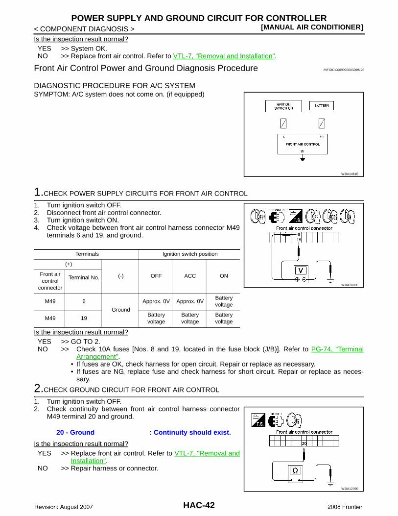
DIAGNOSTIC PROCEDURE FOR A/C SYSTEMSYMPTOM: A/C system does not come on. (if equipped)
1.CHECK POWER SUPPLY CIRCUITS FOR FRONT AIR CONTROL
1. Turn ignition switch OFF.2. Disconnect front air control connector.3. Turn ignition switch ON.4. Check voltage between front air control harness connector M49
terminals 6 and 19, and ground.
Is the inspection result normal?YES >> GO TO 2.NO >> Check 10A fuses [Nos. 8 and 19, located in the fuse block (J/B)]. Refer to PG-74, "Terminal
Arrangement".• If fuses are OK, check harness for open circuit. Repair or replace as necessary.• If fuses are NG, replace fuse and check harness for short circuit. Repair or replace as neces-
sary.
2.CHECK GROUND CIRCUIT FOR FRONT AIR CONTROL
1. Turn ignition switch OFF.2. Check continuity between front air control harness connector
M49 terminal 20 and ground.
Is the inspection result normal?YES >> Replace front air control. Refer to VTL-7, "Removal and
Installation".NO >> Repair harness or connector.
WJIA1461E
Terminals Ignition switch position
(+)
(-) OFF ACC ONFront air control
connector
Terminal No.
M49 6
Ground
Approx. 0V Approx. 0VBattery voltage
M49 19 Battery voltage
Battery voltage
Battery voltage
WJIA1082E
20 - Ground : Continuity should exist.
WJIA1239E
HAC-42
AIR CONDITIONER CONTROL[MANUAL AIR CONDITIONER]
C
D
E
F
G
H
J
K
L
M
A
B
AC
N
O
P
< ECU DIAGNOSIS >
H
ECU DIAGNOSISAIR CONDITIONER CONTROL
System Description INFOID:0000000003289129
The front air control provides regulation of the vehicle's interior temperature. The system is based on the posi-tion of the front air controls temperature switch selected by the driver. This is done by utilizing a microcom-puter, also referred to as the front air control, which receives input signals from the following two sensors:• Intake sensor• PBR (position balanced resistor)The front air control uses these signals (including the set position of the temperature switch) to control:• Outlet air volume• Air temperature• Air distribution
System Operation INFOID:0000000003289130
AIR MIX DOOR CONTROLThe air mix door is controlled so that in-vehicle temperature changed based on the position of the temperaturecontrol dial.
BLOWER SPEED CONTROLBlower speed is controlled based on front blower switch settings.When blower switch is turned, the blower motor starts and increases air flow volume each time the blowerswitch is turned counterclockwise, and decreases air flow volume each time the blower switch is turned coun-terclockwise.When engine coolant temperature is low, the blower motor operation is delayed to prevent cool air from flow-ing.
INTAKE DOORS CONTROLThe intake doors are controlled by the recirculation switch setting, and the mode (defroster) switch setting.
MODE DOOR CONTROLThe mode door is controlled by the position of the mode dial.
DEFROSTER DOOR CONTROLThe defroster door is controlled by the defroster dial set to defroster.
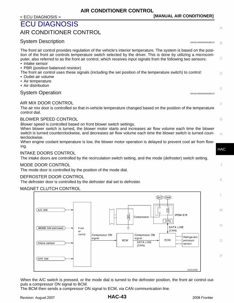
MAGNET CLUTCH CONTROL
When the A/C switch is pressed, or the mode dial is turned to the defroster position, the front air control out-puts a compressor ON signal to BCM.The BCM then sends a compressor ON signal to ECM, via CAN communication line.
WJIA1293E
HAC-43
[MANUAL AIR CONDITIONER]AIR CONDITIONER CONTROL
< ECU DIAGNOSIS >ECM judges whether compressor can be turned ON, based on each sensor status (refrigerant pressure sen-sor signal, throttle angle sensor, etc.). If it judges compressor can be turned ON, it sends compressor ON sig-nal to IPDM E/R, via CAN communication line.Upon receipt of compressor ON signal from ECM, IPDM E/R turns air conditioner relay ON to operate com-pressor.
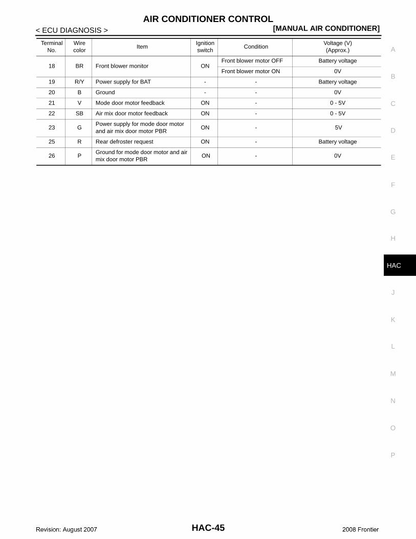
Front Air Control Terminals Reference Values INFOID:0000000003289131
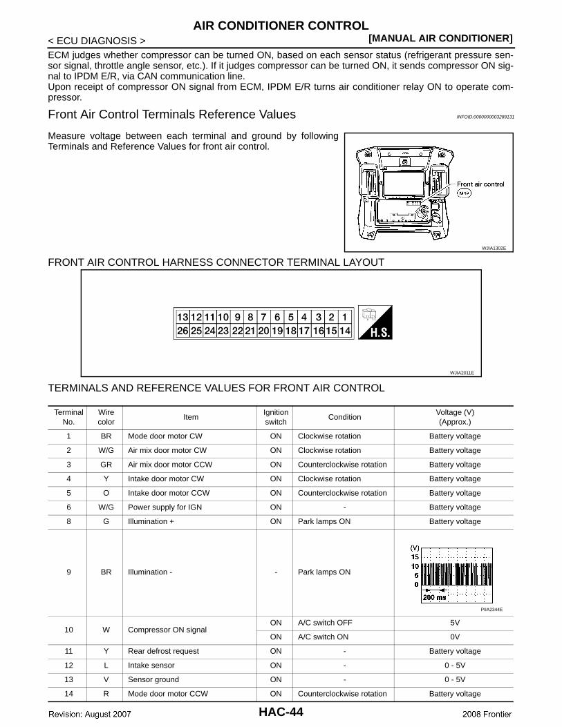
Measure voltage between each terminal and ground by followingTerminals and Reference Values for front air control.
FRONT AIR CONTROL HARNESS CONNECTOR TERMINAL LAYOUT
TERMINALS AND REFERENCE VALUES FOR FRONT AIR CONTROL
WJIA1302E
WJIA2011E
Terminal No.
Wire color
ItemIgnition switch
ConditionVoltage (V)(Approx.)
1 BR Mode door motor CW ON Clockwise rotation Battery voltage
2 W/G Air mix door motor CW ON Clockwise rotation Battery voltage
3 GR Air mix door motor CCW ON Counterclockwise rotation Battery voltage
4 Y Intake door motor CW ON Clockwise rotation Battery voltage
5 O Intake door motor CCW ON Counterclockwise rotation Battery voltage
6 W/G Power supply for IGN ON - Battery voltage
8 G Illumination + ON Park lamps ON Battery voltage
9 BR Illumination - - Park lamps ON
10 W Compressor ON signalON A/C switch OFF 5V
ON A/C switch ON 0V
11 Y Rear defrost request ON - Battery voltage
12 L Intake sensor ON - 0 - 5V
13 V Sensor ground ON - 0 - 5V
14 R Mode door motor CCW ON Counterclockwise rotation Battery voltage
PIIA2344E
HAC-44
AIR CONDITIONER CONTROL[MANUAL AIR CONDITIONER]
C
D
E
F
G
H
J
K
L
M
A
B
AC
N
O
P
< ECU DIAGNOSIS >
H
18 BR Front blower monitor ONFront blower motor OFF Battery voltage
Front blower motor ON 0V
19 R/Y Power supply for BAT - - Battery voltage
20 B Ground - - 0V
21 V Mode door motor feedback ON - 0 - 5V
22 SB Air mix door motor feedback ON - 0 - 5V
23 GPower supply for mode door motor and air mix door motor PBR
ON - 5V
25 R Rear defroster request ON - Battery voltage
26 PGround for mode door motor and air mix door motor PBR
ON - 0V
Terminal No.
Wire color
ItemIgnition switch
ConditionVoltage (V)(Approx.)
HAC-45
[MANUAL AIR CONDITIONER]AIR CONDITIONER CONTROL
< ECU DIAGNOSIS >
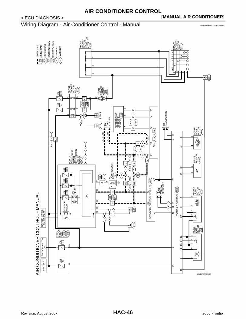
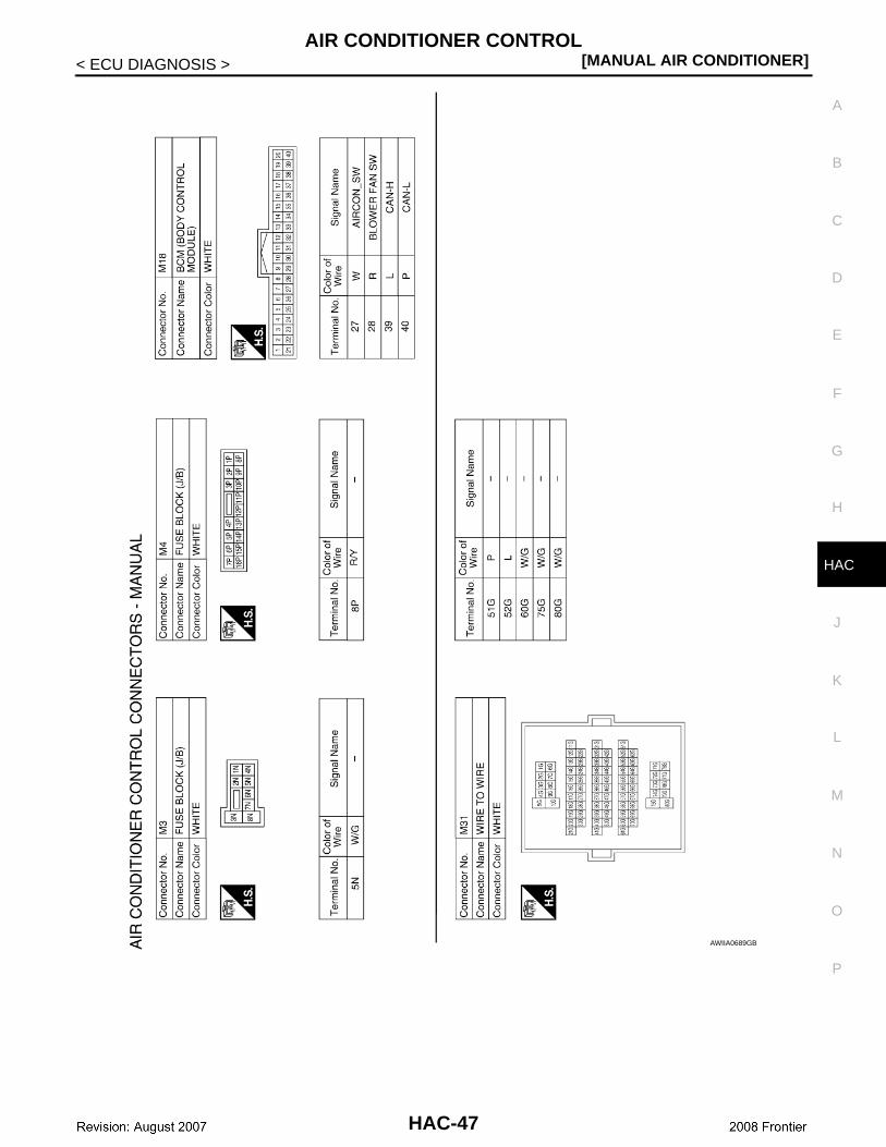
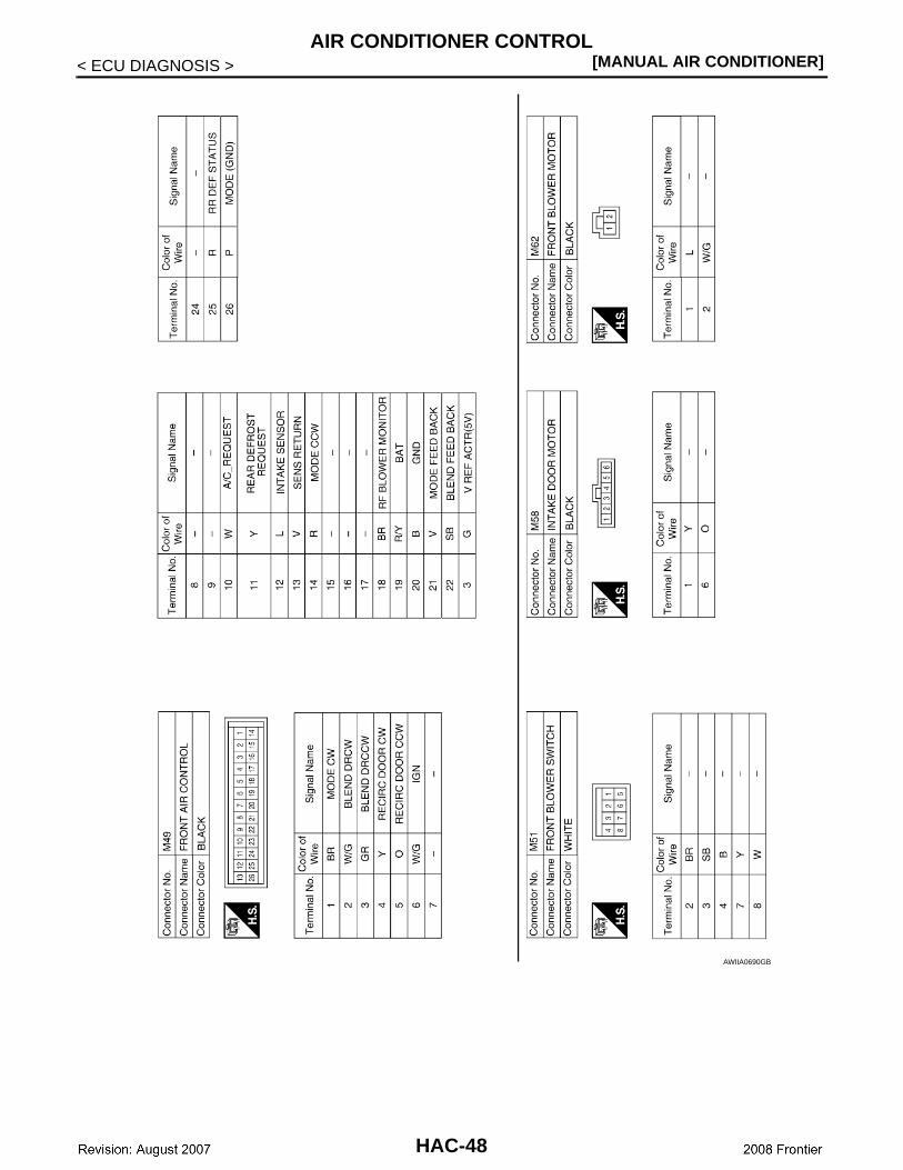
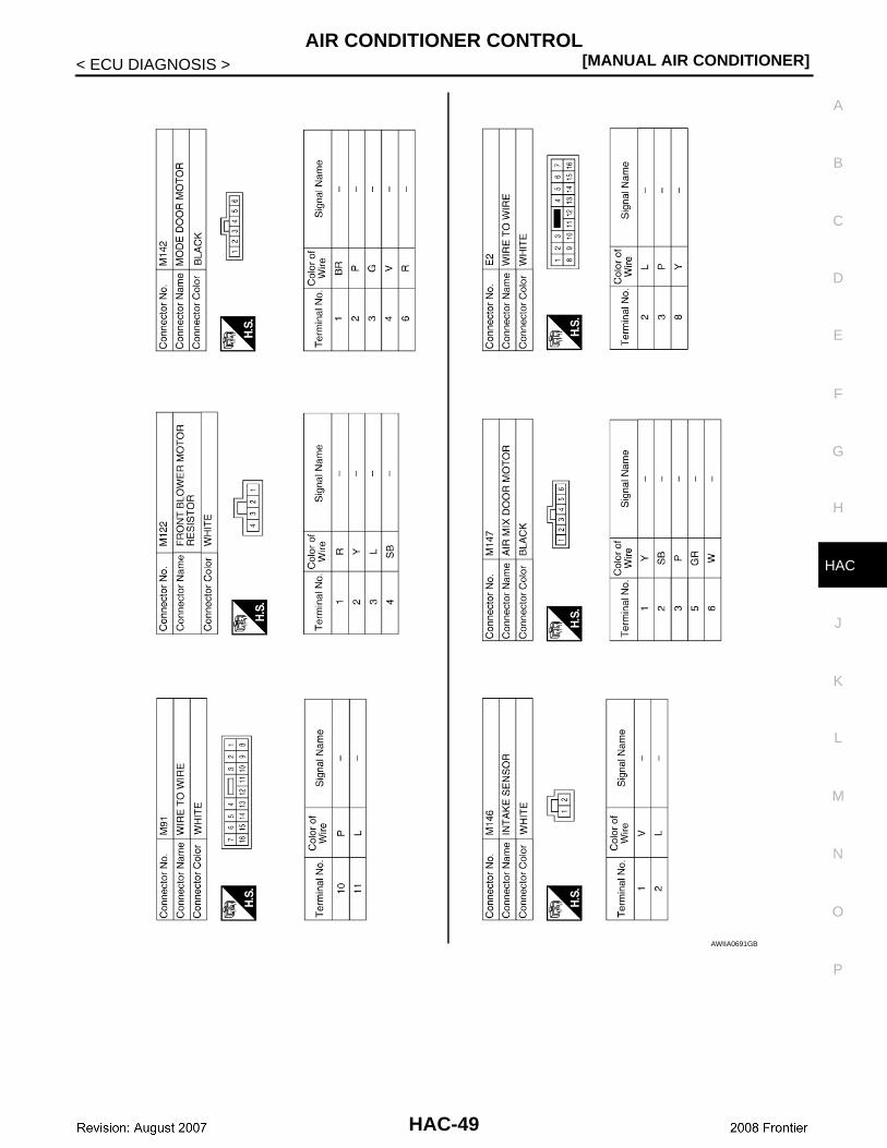
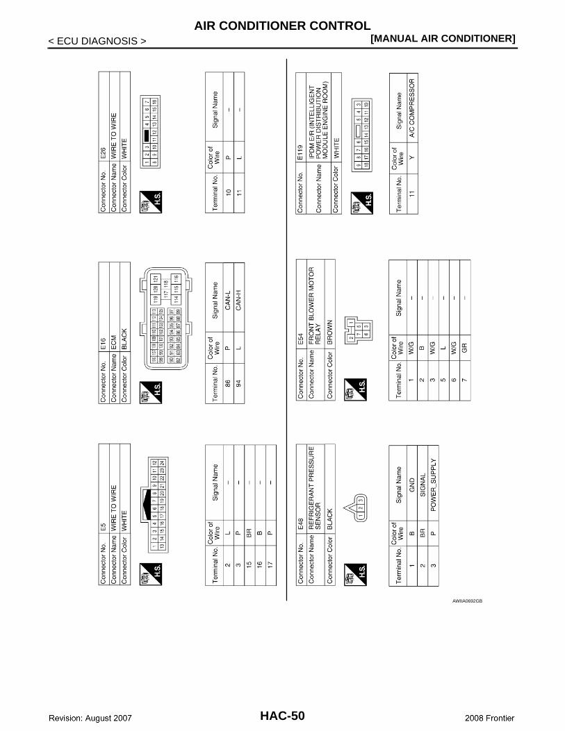
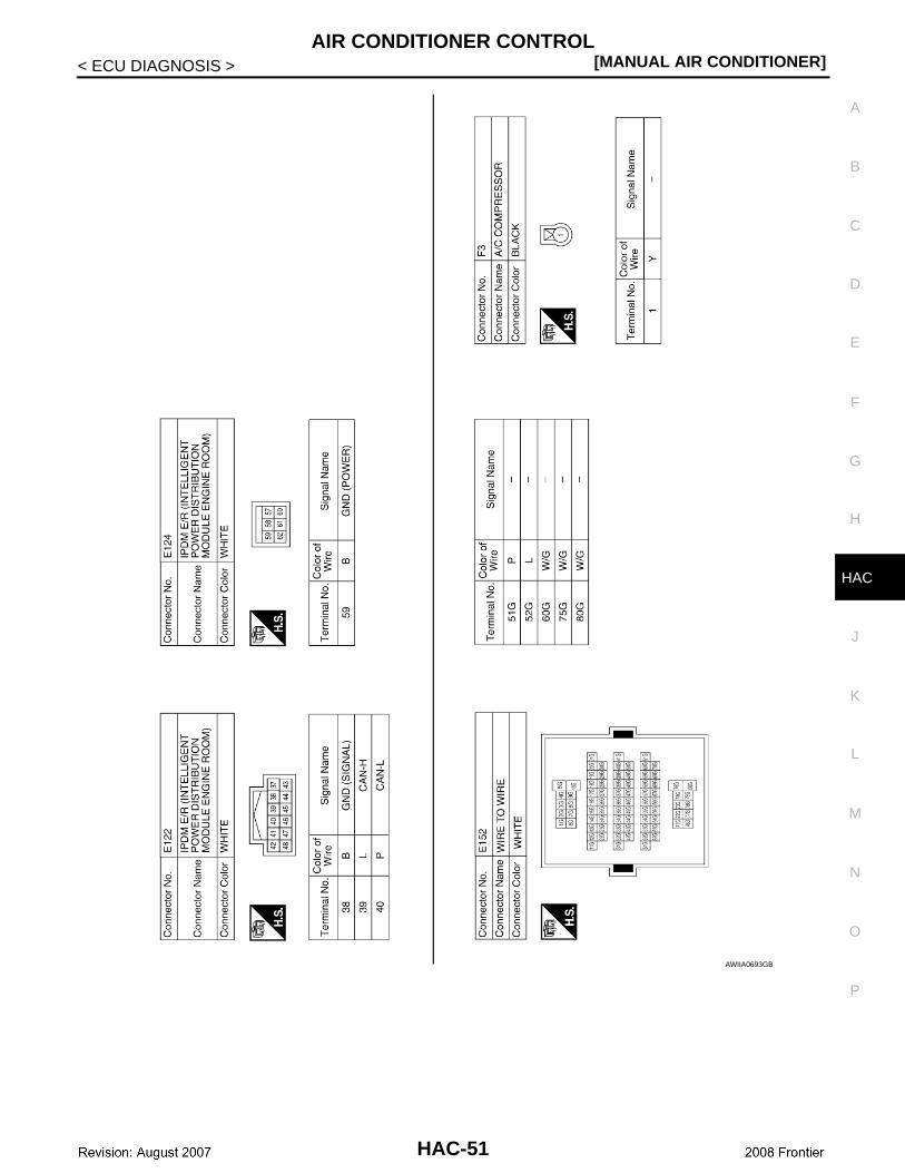
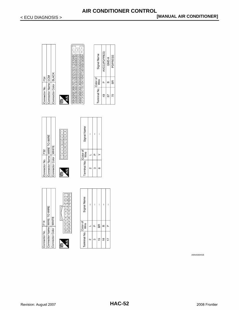
Wiring Diagram - Air Conditioner Control - Manual INFOID:0000000003289132
AWIWA0022GB
HAC-46
AIR CONDITIONER CONTROL[MANUAL AIR CONDITIONER]
C
D
E
F
G
H
J
K
L
M
A
B
AC
N
O
P
< ECU DIAGNOSIS >
H
AWIIA0689GB
HAC-47
[MANUAL AIR CONDITIONER]AIR CONDITIONER CONTROL
< ECU DIAGNOSIS >
AWIIA0690GB
HAC-48
AIR CONDITIONER CONTROL[MANUAL AIR CONDITIONER]
C
D
E
F
G
H
J
K
L
M
A
B
AC
N
O
P
< ECU DIAGNOSIS >
H
AWIIA0691GB
HAC-49
[MANUAL AIR CONDITIONER]AIR CONDITIONER CONTROL
< ECU DIAGNOSIS >
AWIIA0692GB
HAC-50
AIR CONDITIONER CONTROL[MANUAL AIR CONDITIONER]
C
D
E
F
G
H
J
K
L
M
A
B
AC
N
O
P
< ECU DIAGNOSIS >
H
AWIIA0693GB
HAC-51
[MANUAL AIR CONDITIONER]AIR CONDITIONER CONTROL
< ECU DIAGNOSIS >
AWIIA0694GB
HAC-52
AIR CONDITIONER CONTROL[MANUAL AIR CONDITIONER]
C
D
E
F
G
H
J
K
L
M
A
B
AC
N
O
P
< ECU DIAGNOSIS >
H
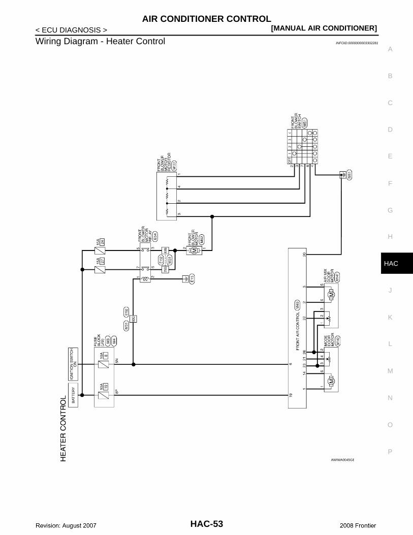
Wiring Diagram - Heater Control INFOID:0000000003302281
AWIWA0045GB
HAC-53
[MANUAL AIR CONDITIONER]AIR CONDITIONER CONTROL
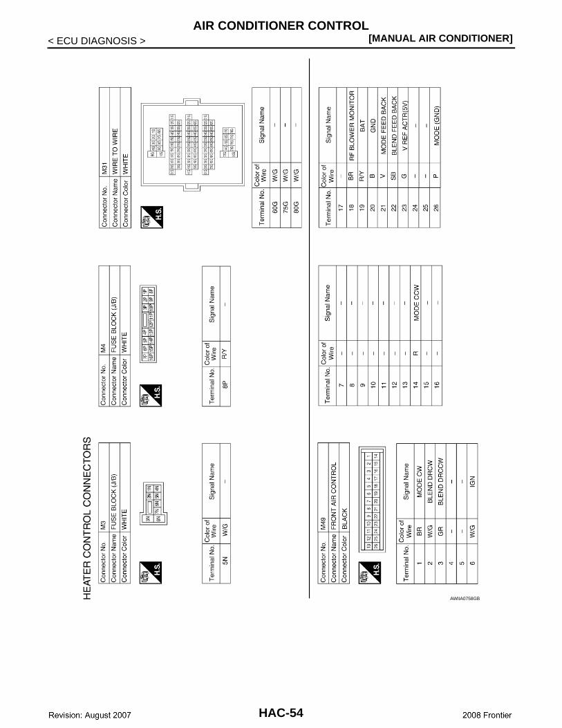
< ECU DIAGNOSIS >
AWIIA0758GB
HAC-54
AIR CONDITIONER CONTROL[MANUAL AIR CONDITIONER]
C
D
E
F
G
H
J
K
L
M
A
B
AC
N
O
P
< ECU DIAGNOSIS >
H
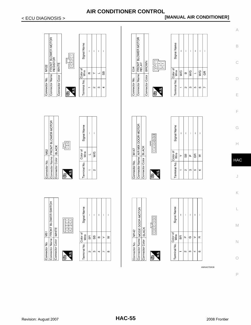
AWIIA0759GB
HAC-55
[MANUAL AIR CONDITIONER]AIR CONDITIONER CONTROL
< ECU DIAGNOSIS >
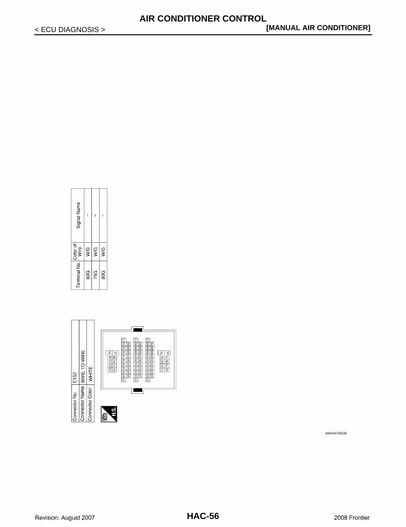
AWIIA0760GB
HAC-56
AIR CONDITIONER CONTROL[MANUAL AIR CONDITIONER]
C
D
E
F
G
H
J
K
L
M
A
B
AC
N
O
P
< SYMPTOM DIAGNOSIS >
H
SYMPTOM DIAGNOSISAIR CONDITIONER CONTROL
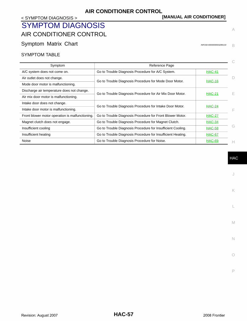
Symptom Matrix Chart INFOID:0000000003289133
SYMPTOM TABLE
Symptom Reference Page
A/C system does not come on. Go to Trouble Diagnosis Procedure for A/C System. HAC-41
Air outlet does not change.Go to Trouble Diagnosis Procedure for Mode Door Motor. HAC-16
Mode door motor is malfunctioning.
Discharge air temperature does not change.Go to Trouble Diagnosis Procedure for Air Mix Door Motor. HAC-21
Air mix door motor is malfunctioning.
Intake door does not change.Go to Trouble Diagnosis Procedure for Intake Door Motor. HAC-24
Intake door motor is malfunctioning.
Front blower motor operation is malfunctioning. Go to Trouble Diagnosis Procedure for Front Blower Motor. HAC-27
Magnet clutch does not engage. Go to Trouble Diagnosis Procedure for Magnet Clutch. HAC-34
Insufficient cooling Go to Trouble Diagnosis Procedure for Insufficient Cooling. HAC-58
Insufficient heating Go to Trouble Diagnosis Procedure for Insufficient Heating. HAC-67
Noise Go to Trouble Diagnosis Procedure for Noise. HAC-69
HAC-57
[MANUAL AIR CONDITIONER]INSUFFICIENT COOLING
< SYMPTOM DIAGNOSIS >
INSUFFICIENT COOLING
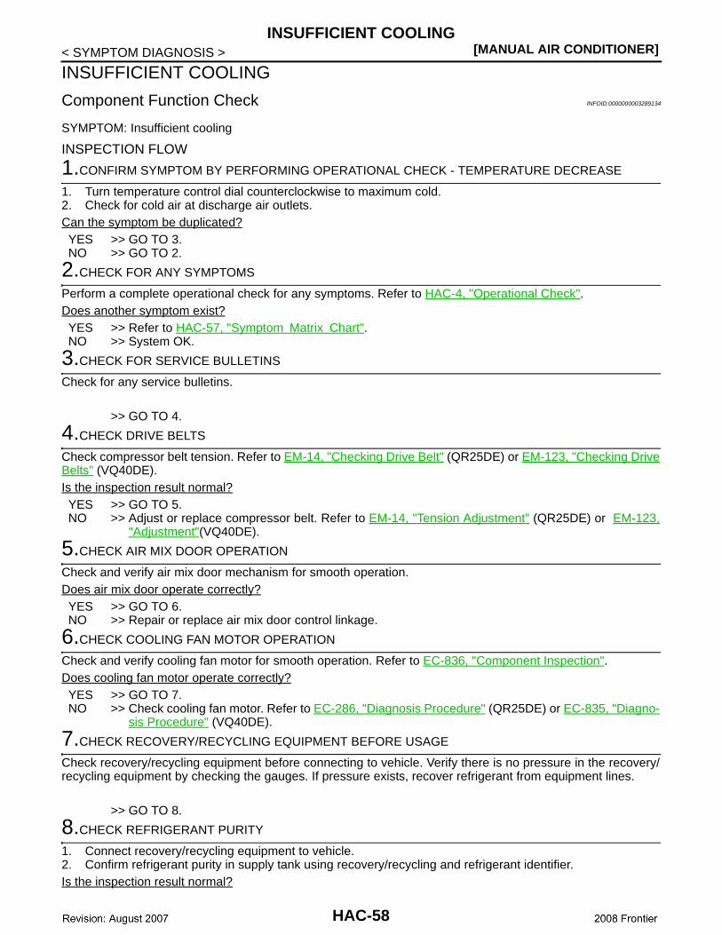
Component Function Check INFOID:0000000003289134
SYMPTOM: Insufficient cooling
INSPECTION FLOW
1.CONFIRM SYMPTOM BY PERFORMING OPERATIONAL CHECK - TEMPERATURE DECREASE
1. Turn temperature control dial counterclockwise to maximum cold.2. Check for cold air at discharge air outlets.Can the symptom be duplicated?YES >> GO TO 3.NO >> GO TO 2.
2.CHECK FOR ANY SYMPTOMS
Perform a complete operational check for any symptoms. Refer to HAC-4, "Operational Check".Does another symptom exist?YES >> Refer to HAC-57, "Symptom Matrix Chart". NO >> System OK.
3.CHECK FOR SERVICE BULLETINS
Check for any service bulletins.
>> GO TO 4.
4.CHECK DRIVE BELTS
Check compressor belt tension. Refer to EM-14, "Checking Drive Belt" (QR25DE) or EM-123, "Checking DriveBelts" (VQ40DE).Is the inspection result normal?YES >> GO TO 5.NO >> Adjust or replace compressor belt. Refer to EM-14, "Tension Adjustment" (QR25DE) or EM-123,
"Adjustment"(VQ40DE).
5.CHECK AIR MIX DOOR OPERATION
Check and verify air mix door mechanism for smooth operation. Does air mix door operate correctly?YES >> GO TO 6.NO >> Repair or replace air mix door control linkage.
6.CHECK COOLING FAN MOTOR OPERATION
Check and verify cooling fan motor for smooth operation. Refer to EC-836, "Component Inspection". Does cooling fan motor operate correctly?YES >> GO TO 7.NO >> Check cooling fan motor. Refer to EC-286, "Diagnosis Procedure" (QR25DE) or EC-835, "Diagno-
sis Procedure" (VQ40DE).
7.CHECK RECOVERY/RECYCLING EQUIPMENT BEFORE USAGE
Check recovery/recycling equipment before connecting to vehicle. Verify there is no pressure in the recovery/recycling equipment by checking the gauges. If pressure exists, recover refrigerant from equipment lines.
>> GO TO 8.
8.CHECK REFRIGERANT PURITY
1. Connect recovery/recycling equipment to vehicle.2. Confirm refrigerant purity in supply tank using recovery/recycling and refrigerant identifier.Is the inspection result normal?
HAC-58
INSUFFICIENT COOLING[MANUAL AIR CONDITIONER]
C
D
E
F
G
H
J
K
L
M
A
B
AC
N
O
P
< SYMPTOM DIAGNOSIS >
H
YES >> GO TO 9.NO >> Check contaminated refrigerant. Refer to HA-3, "Contaminated Refrigerant".
9.CHECK FOR EVAPORATOR FREEZE UP
Start engine and run A/C. Check for evaporator freeze up.Does evaporator freeze up?YES >> Perform performance test diagnoses. Refer to HAC-59, "Performance Test Diagnoses".NO >> GO TO 10.
10.CHECK REFRIGERANT PRESSURE
Check refrigerant pressure with manifold gauge connected. Refer to HAC-62, "Test Reading". Is the inspection result normal?YES >> Perform performance test diagnoses. Refer to HAC-59, "Performance Test Diagnoses".NO >> GO TO 11.
11.CHECK AIR DUCTS
Check ducts for air leaks.Is the inspection result normal?YES >> System OK.NO >> Repair air leaks.
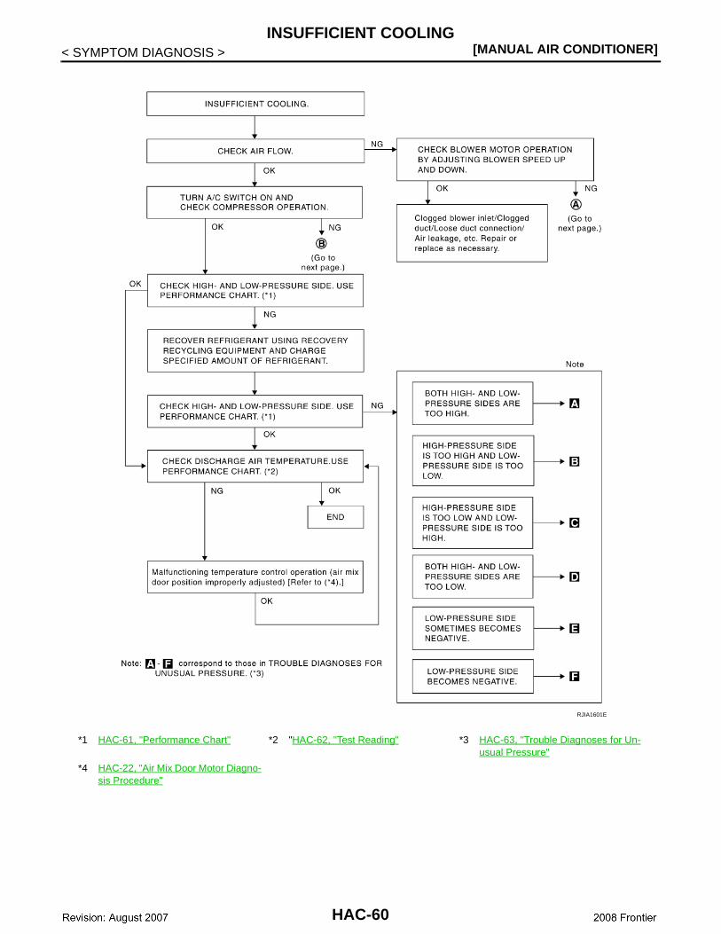
Performance Test Diagnoses INFOID:0000000003289135
PERFORMANCE TEST DIAGNOSES
HAC-59
[MANUAL AIR CONDITIONER]INSUFFICIENT COOLING
< SYMPTOM DIAGNOSIS >
*1 HAC-61, "Performance Chart" *2 "HAC-62, "Test Reading" *3 HAC-63, "Trouble Diagnoses for Un-usual Pressure"
*4 HAC-22, "Air Mix Door Motor Diagno-sis Procedure"
RJIA1601E
HAC-60

INSUFFICIENT COOLING[MANUAL AIR CONDITIONER]
C
D
E
F
G
H
J
K
L
M
A
B
AC
N
O
P
< SYMPTOM DIAGNOSIS >
H
Performance Chart INFOID:0000000003289136
PERFORMANCE CHART
*1 HA-35, "Removal and Installation for Compressor Clutch"
*2 HAC-27, "Front Blower Motor Com-ponent Function Check"
*3 EM-14, "Checking Drive Belt" (QR25DE) or EM-123, "Checking Drive Belts" (VQ40DE)
RJIA3107E
HAC-61
[MANUAL AIR CONDITIONER]INSUFFICIENT COOLING
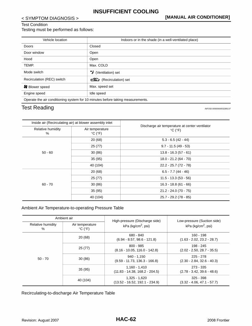
< SYMPTOM DIAGNOSIS >Test ConditionTesting must be performed as follows:
Test Reading INFOID:0000000003289137
Ambient Air Temperature-to-operating Pressure Table
Recirculating-to-discharge Air Temperature Table
Vehicle location Indoors or in the shade (in a well-ventilated place)
Doors Closed
Door window Open
Hood Open
TEMP. Max. COLD
Mode switch (Ventilation) set
Recirculation (REC) switch (Recirculation) set
Blower speed Max. speed set
Engine speed Idle speed
Operate the air conditioning system for 10 minutes before taking measurements.
Inside air (Recirculating air) at blower assembly inletDischarge air temperature at center ventilator
°C (°F)Relative humidity%
Air temperature°C (°F)
50 - 60
20 (68) 5.3 - 6.5 (42 - 44)
25 (77) 9.7 - 11.5 (49 - 53)
30 (86) 13.8 - 16.3 (57 - 61)
35 (95) 18.0 - 21.2 (64 - 70)
40 (104) 22.2 - 25.7 (72 - 78)
60 - 70
20 (68) 6.5 - 7.7 (44 - 46)
25 (77) 11.5 - 13.3 (53 - 56)
30 (86) 16.3 - 18.8 (61 - 66)
35 (95) 21.2 - 24.0 (70 - 75)
40 (104) 25.7 - 29.2 (78 - 85)
Ambient airHigh-pressure (Discharge side)
kPa (kg/cm2, psi)
Low-pressure (Suction side)
kPa (kg/cm2, psi)Relative humidity%
Air temperature°C (°F)
50 - 70
20 (68)680 - 840
(6.94 - 8.57, 98.6 - 121.8)160 - 198
(1.63 - 2.02, 23.2 - 28.7)
25 (77)800 - 985
(8.16 - 10.05, 116.0 - 142.8)198 - 245
(2.02 - 2.50, 28.7 - 35.5)
30 (86)940 - 1,150
(9.59 - 11.73, 136.3 - 166.8)225 - 278
(2.30 - 2.84, 32.6 - 40.3)
35 (95)1,160 - 1,410
(11.83 - 14.38, 168.2 - 204.5)273 - 335
(2.78 - 3.42, 39.6 - 48.6)
40 (104)1,325 - 1,620
(13.52 - 16.52, 192.1 - 234.9)325 - 398
(3.32 - 4.06, 47.1 - 57.7)
HAC-62
INSUFFICIENT COOLING[MANUAL AIR CONDITIONER]
C
D
E
F
G
H
J
K
L
M
A
B
AC
N
O
P
< SYMPTOM DIAGNOSIS >
H
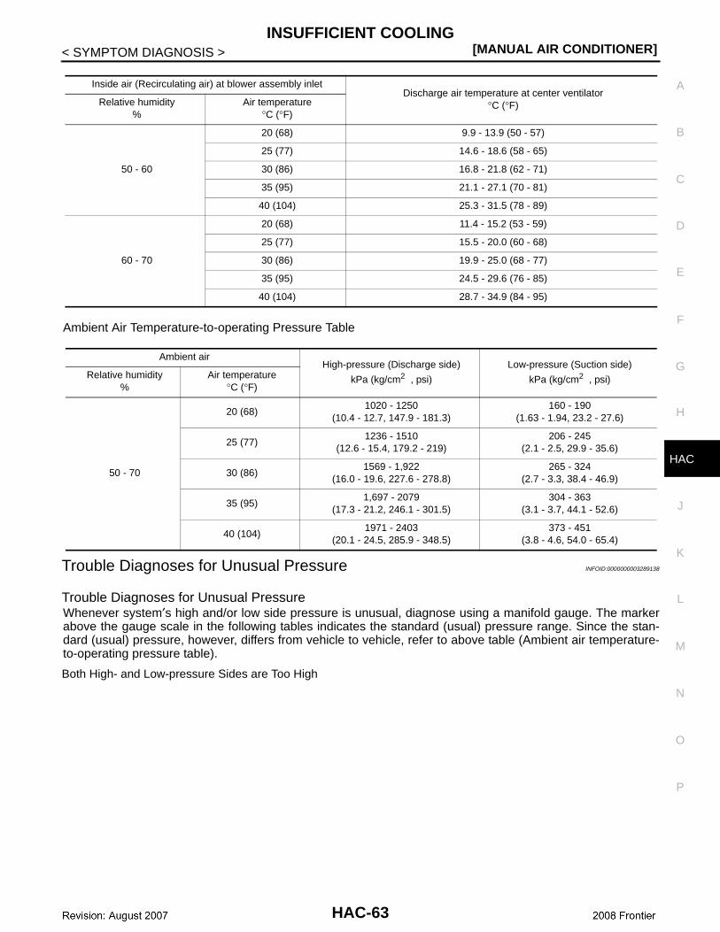
Ambient Air Temperature-to-operating Pressure Table
Trouble Diagnoses for Unusual Pressure INFOID:0000000003289138
Trouble Diagnoses for Unusual PressureWhenever system′s high and/or low side pressure is unusual, diagnose using a manifold gauge. The markerabove the gauge scale in the following tables indicates the standard (usual) pressure range. Since the stan-dard (usual) pressure, however, differs from vehicle to vehicle, refer to above table (Ambient air temperature-to-operating pressure table).
Both High- and Low-pressure Sides are Too High
Inside air (Recirculating air) at blower assembly inletDischarge air temperature at center ventilator
°C (°F)Relative humidity%
Air temperature°C (°F)
50 - 60
20 (68) 9.9 - 13.9 (50 - 57)
25 (77) 14.6 - 18.6 (58 - 65)
30 (86) 16.8 - 21.8 (62 - 71)
35 (95) 21.1 - 27.1 (70 - 81)
40 (104) 25.3 - 31.5 (78 - 89)
60 - 70
20 (68) 11.4 - 15.2 (53 - 59)
25 (77) 15.5 - 20.0 (60 - 68)
30 (86) 19.9 - 25.0 (68 - 77)
35 (95) 24.5 - 29.6 (76 - 85)
40 (104) 28.7 - 34.9 (84 - 95)
Ambient airHigh-pressure (Discharge side)
kPa (kg/cm2 , psi)
Low-pressure (Suction side)
kPa (kg/cm2 , psi)Relative humidity%
Air temperature°C (°F)
50 - 70
20 (68)1020 - 1250
(10.4 - 12.7, 147.9 - 181.3)160 - 190
(1.63 - 1.94, 23.2 - 27.6)
25 (77)1236 - 1510
(12.6 - 15.4, 179.2 - 219)206 - 245
(2.1 - 2.5, 29.9 - 35.6)
30 (86)1569 - 1,922
(16.0 - 19.6, 227.6 - 278.8)265 - 324
(2.7 - 3.3, 38.4 - 46.9)
35 (95)1,697 - 2079
(17.3 - 21.2, 246.1 - 301.5)304 - 363
(3.1 - 3.7, 44.1 - 52.6)
40 (104)1971 - 2403
(20.1 - 24.5, 285.9 - 348.5)373 - 451
(3.8 - 4.6, 54.0 - 65.4)
HAC-63
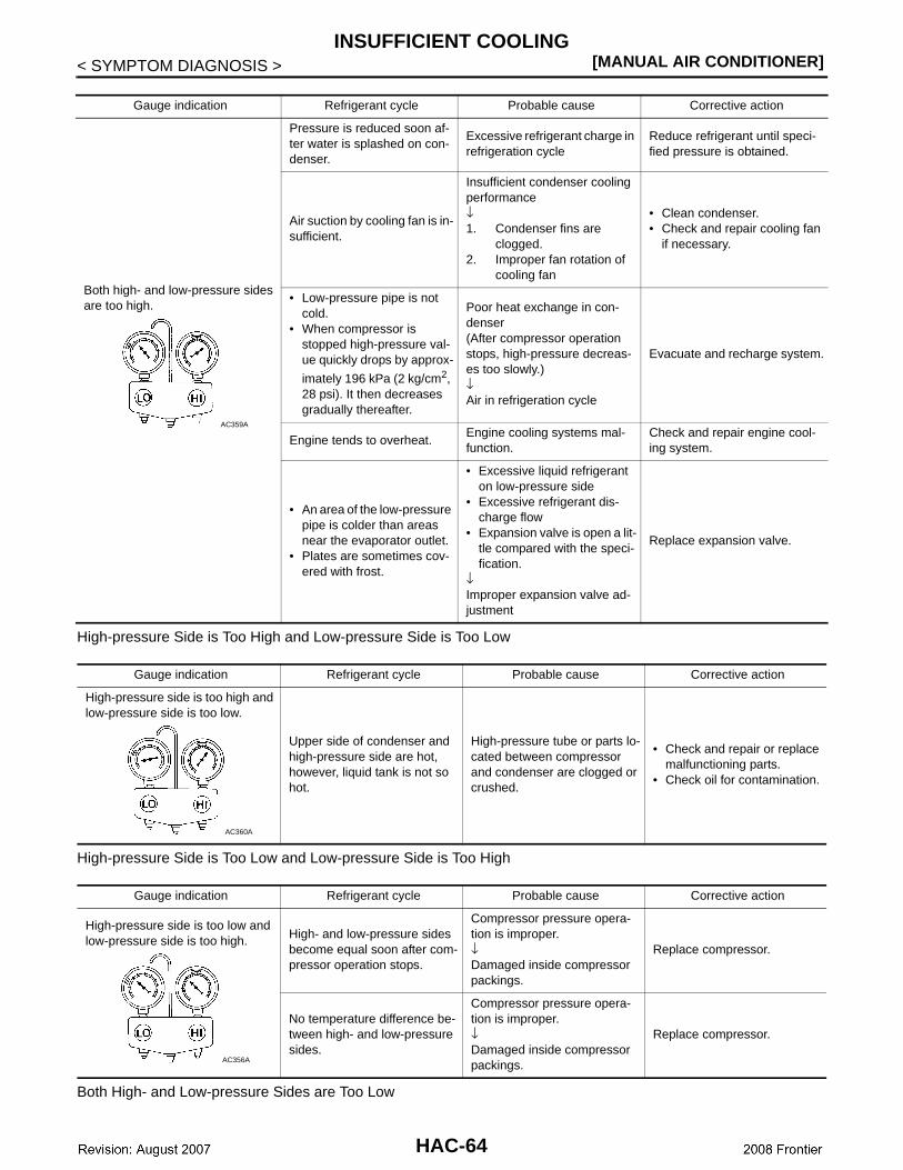
[MANUAL AIR CONDITIONER]INSUFFICIENT COOLING
< SYMPTOM DIAGNOSIS >
High-pressure Side is Too High and Low-pressure Side is Too Low
High-pressure Side is Too Low and Low-pressure Side is Too High
Both High- and Low-pressure Sides are Too Low
Gauge indication Refrigerant cycle Probable cause Corrective action
Both high- and low-pressure sides are too high.
Pressure is reduced soon af-ter water is splashed on con-denser.
Excessive refrigerant charge in refrigeration cycle
Reduce refrigerant until speci-fied pressure is obtained.
Air suction by cooling fan is in-sufficient.
Insufficient condenser cooling performance↓1. Condenser fins are
clogged.2. Improper fan rotation of
cooling fan
• Clean condenser.• Check and repair cooling fan
if necessary.
• Low-pressure pipe is not cold.
• When compressor is stopped high-pressure val-ue quickly drops by approx-
imately 196 kPa (2 kg/cm2, 28 psi). It then decreases gradually thereafter.
Poor heat exchange in con-denser(After compressor operation stops, high-pressure decreas-es too slowly.)↓Air in refrigeration cycle
Evacuate and recharge system.
Engine tends to overheat.Engine cooling systems mal-function.
Check and repair engine cool-ing system.
• An area of the low-pressure pipe is colder than areas near the evaporator outlet.
• Plates are sometimes cov-ered with frost.
• Excessive liquid refrigerant on low-pressure side
• Excessive refrigerant dis-charge flow
• Expansion valve is open a lit-tle compared with the speci-fication.
↓Improper expansion valve ad-justment
Replace expansion valve.
AC359A
Gauge indication Refrigerant cycle Probable cause Corrective action
High-pressure side is too high and low-pressure side is too low.
Upper side of condenser and high-pressure side are hot, however, liquid tank is not so hot.
High-pressure tube or parts lo-cated between compressor and condenser are clogged or crushed.
• Check and repair or replace malfunctioning parts.
• Check oil for contamination.
AC360A
Gauge indication Refrigerant cycle Probable cause Corrective action
High-pressure side is too low and low-pressure side is too high. High- and low-pressure sides
become equal soon after com-pressor operation stops.
Compressor pressure opera-tion is improper.↓Damaged inside compressor packings.
Replace compressor.
No temperature difference be-tween high- and low-pressure sides.
Compressor pressure opera-tion is improper.↓Damaged inside compressor packings.
Replace compressor.
AC356A
HAC-64
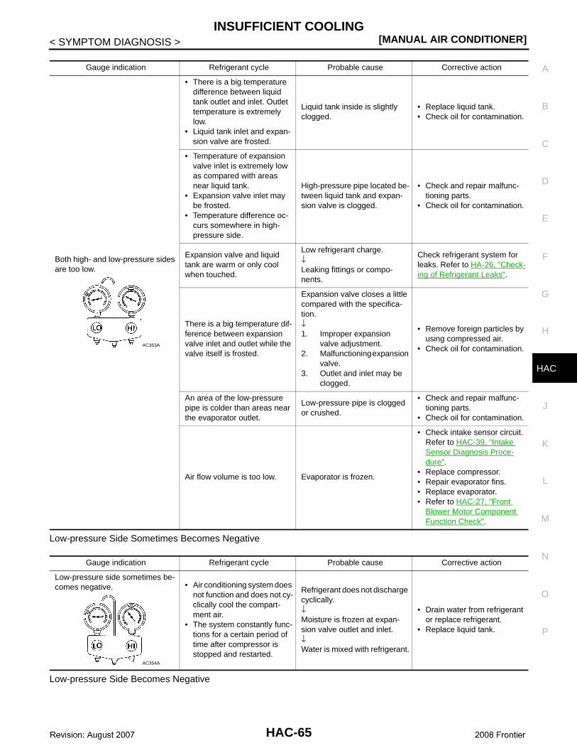
INSUFFICIENT COOLING[MANUAL AIR CONDITIONER]
C
D
E
F
G
H
J
K
L
M
A
B
AC
N
O
P
< SYMPTOM DIAGNOSIS >
H
Low-pressure Side Sometimes Becomes Negative
Low-pressure Side Becomes Negative
Gauge indication Refrigerant cycle Probable cause Corrective action
Both high- and low-pressure sides are too low.
• There is a big temperature difference between liquid tank outlet and inlet. Outlet temperature is extremely low.
• Liquid tank inlet and expan-sion valve are frosted.
Liquid tank inside is slightly clogged.
• Replace liquid tank.• Check oil for contamination.
• Temperature of expansion valve inlet is extremely low as compared with areas near liquid tank.
• Expansion valve inlet may be frosted.
• Temperature difference oc-curs somewhere in high-pressure side.
High-pressure pipe located be-tween liquid tank and expan-sion valve is clogged.
• Check and repair malfunc-tioning parts.
• Check oil for contamination.
Expansion valve and liquid tank are warm or only cool when touched.
Low refrigerant charge.↓Leaking fittings or compo-nents.
Check refrigerant system for leaks. Refer to HA-26, "Check-ing of Refrigerant Leaks".
There is a big temperature dif-ference between expansion valve inlet and outlet while the valve itself is frosted.
Expansion valve closes a little compared with the specifica-tion.↓1. Improper expansion
valve adjustment.2. Malfunctioning expansion
valve.3. Outlet and inlet may be
clogged.
• Remove foreign particles by using compressed air.
• Check oil for contamination.
An area of the low-pressure pipe is colder than areas near the evaporator outlet.
Low-pressure pipe is clogged or crushed.
• Check and repair malfunc-tioning parts.
• Check oil for contamination.
Air flow volume is too low. Evaporator is frozen.
• Check intake sensor circuit.Refer to HAC-39, "Intake Sensor Diagnosis Proce-dure".
• Replace compressor.• Repair evaporator fins.• Replace evaporator.• Refer to HAC-27, "Front
Blower Motor Component Function Check".
AC353A
Gauge indication Refrigerant cycle Probable cause Corrective action
Low-pressure side sometimes be-comes negative. • Air conditioning system does
not function and does not cy-clically cool the compart-ment air.
• The system constantly func-tions for a certain period of time after compressor is stopped and restarted.
Refrigerant does not discharge cyclically.↓Moisture is frozen at expan-sion valve outlet and inlet.↓Water is mixed with refrigerant.
• Drain water from refrigerant or replace refrigerant.
• Replace liquid tank.
AC354A
HAC-65
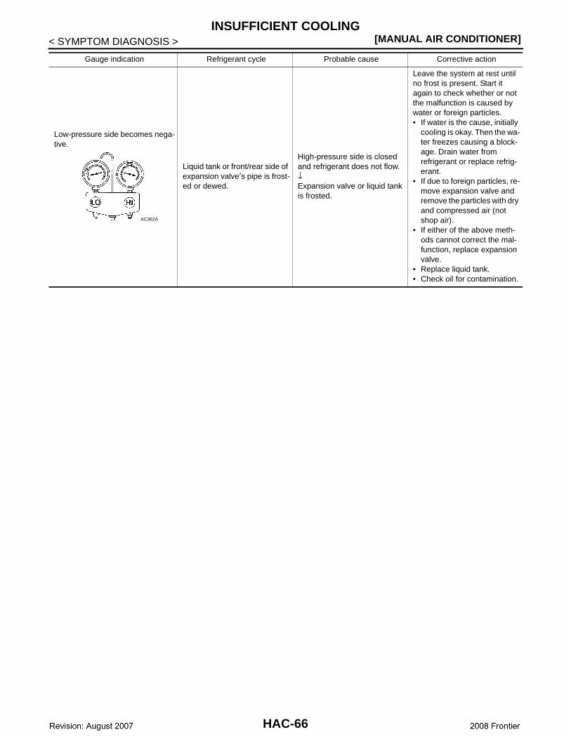
[MANUAL AIR CONDITIONER]INSUFFICIENT COOLING
< SYMPTOM DIAGNOSIS >
Gauge indication Refrigerant cycle Probable cause Corrective action
Low-pressure side becomes nega-tive.
Liquid tank or front/rear side of expansion valve′s pipe is frost-ed or dewed.
High-pressure side is closed and refrigerant does not flow.↓Expansion valve or liquid tank is frosted.
Leave the system at rest until no frost is present. Start it again to check whether or not the malfunction is caused by water or foreign particles.• If water is the cause, initially
cooling is okay. Then the wa-ter freezes causing a block-age. Drain water from refrigerant or replace refrig-erant.
• If due to foreign particles, re-move expansion valve and remove the particles with dry and compressed air (not shop air).
• If either of the above meth-ods cannot correct the mal-function, replace expansion valve.
• Replace liquid tank.• Check oil for contamination.
AC362A
HAC-66
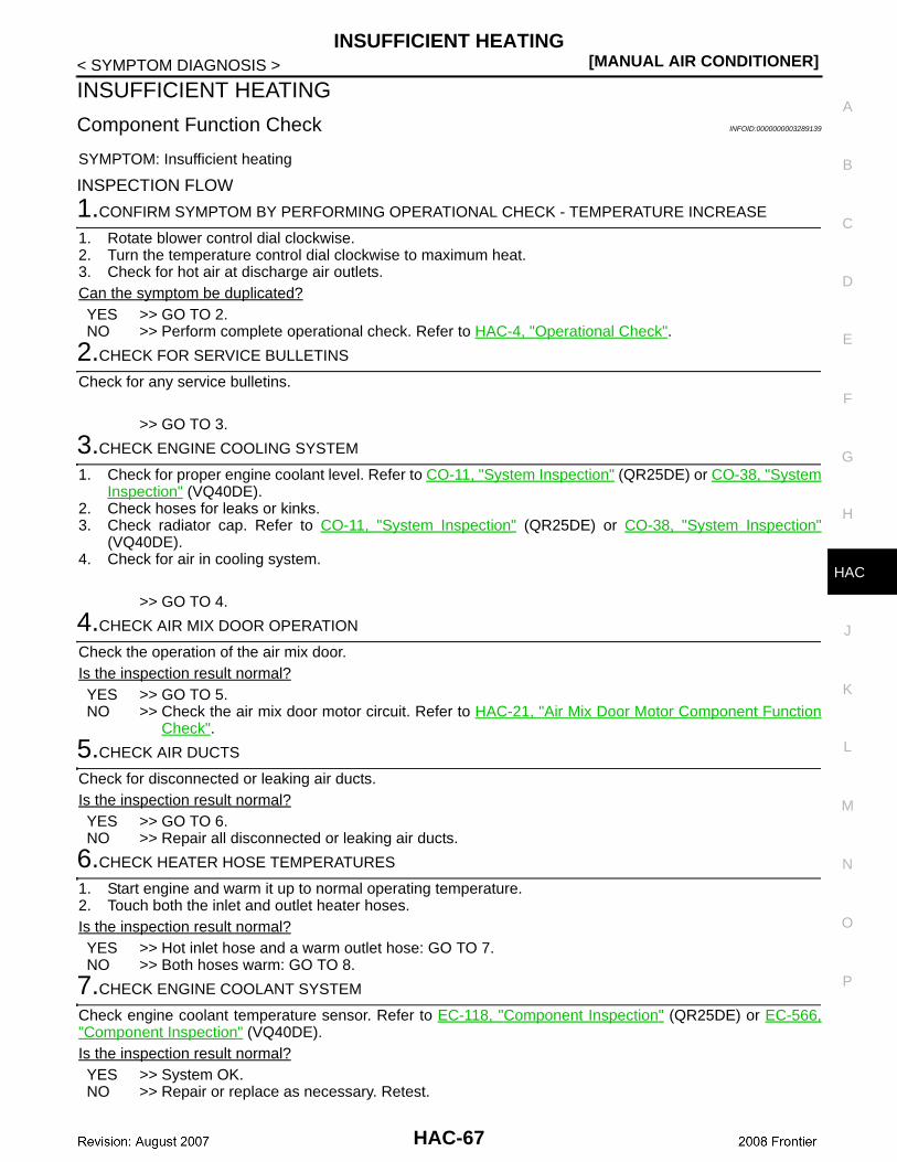
INSUFFICIENT HEATING[MANUAL AIR CONDITIONER]
C
D
E
F
G
H
J
K
L
M
A
B
AC
N
O
P
< SYMPTOM DIAGNOSIS >
H
INSUFFICIENT HEATING
Component Function Check INFOID:0000000003289139
SYMPTOM: Insufficient heating
INSPECTION FLOW
1.CONFIRM SYMPTOM BY PERFORMING OPERATIONAL CHECK - TEMPERATURE INCREASE
1. Rotate blower control dial clockwise.2. Turn the temperature control dial clockwise to maximum heat.3. Check for hot air at discharge air outlets.Can the symptom be duplicated?YES >> GO TO 2. NO >> Perform complete operational check. Refer to HAC-4, "Operational Check".
2.CHECK FOR SERVICE BULLETINS
Check for any service bulletins.
>> GO TO 3.
3.CHECK ENGINE COOLING SYSTEM
1. Check for proper engine coolant level. Refer to CO-11, "System Inspection" (QR25DE) or CO-38, "SystemInspection" (VQ40DE).
2. Check hoses for leaks or kinks.3. Check radiator cap. Refer to CO-11, "System Inspection" (QR25DE) or CO-38, "System Inspection"
(VQ40DE).4. Check for air in cooling system.
>> GO TO 4.
4.CHECK AIR MIX DOOR OPERATION
Check the operation of the air mix door.Is the inspection result normal?YES >> GO TO 5.NO >> Check the air mix door motor circuit. Refer to HAC-21, "Air Mix Door Motor Component Function
Check".
5.CHECK AIR DUCTS
Check for disconnected or leaking air ducts.Is the inspection result normal?YES >> GO TO 6.NO >> Repair all disconnected or leaking air ducts.
6.CHECK HEATER HOSE TEMPERATURES
1. Start engine and warm it up to normal operating temperature.2. Touch both the inlet and outlet heater hoses.Is the inspection result normal?YES >> Hot inlet hose and a warm outlet hose: GO TO 7.NO >> Both hoses warm: GO TO 8.
7.CHECK ENGINE COOLANT SYSTEM
Check engine coolant temperature sensor. Refer to EC-118, "Component Inspection" (QR25DE) or EC-566,"Component Inspection" (VQ40DE).Is the inspection result normal?YES >> System OK.NO >> Repair or replace as necessary. Retest.
HAC-67
[MANUAL AIR CONDITIONER]INSUFFICIENT HEATING
< SYMPTOM DIAGNOSIS >
8.CHECK HEATER HOSES
Check heater hoses for proper installation.Is the inspection result normal?YES >> System OK.NO >> 1. Back flush heater core.
2. Drain the water from the system. 3. Refill system with new engine coolant. Refer to CO-12, "Changing Engine Coolant"
(QR25DE) or CO-39, "Changing Engine Coolant" (VQ40DE). 4. GO TO 9 to retest.
9.CHECK HEATER HOSE TEMPERATURES
1. Start engine and warm it up to normal operating temperature.2. Touch both the inlet and outlet heater hoses.Is the inspection result normal?YES >> System OK.NO >> Replace heater core. Refer to VTL-15, "Removal and Installation".
HAC-68
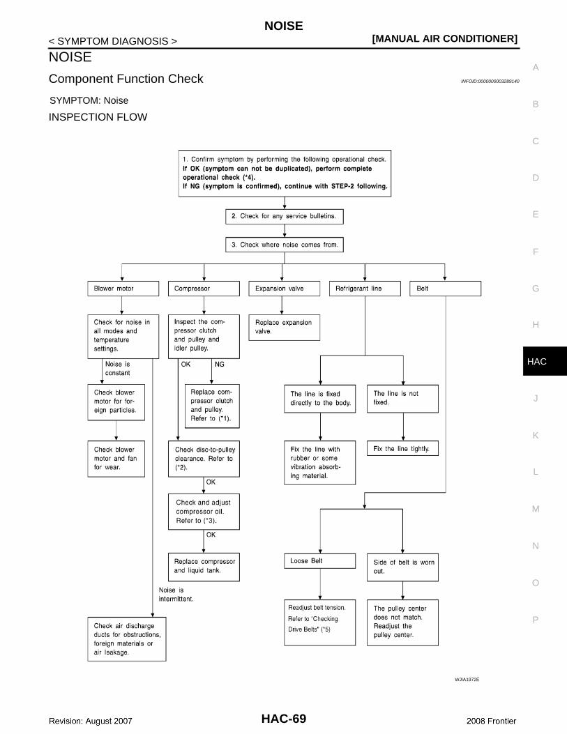
NOISE[MANUAL AIR CONDITIONER]
C
D
E
F
G
H
J
K
L
M
A
B
AC
N
O
P
< SYMPTOM DIAGNOSIS >
H
NOISE
Component Function Check INFOID:0000000003289140
SYMPTOM: Noise
INSPECTION FLOW
WJIA1972E
HAC-69
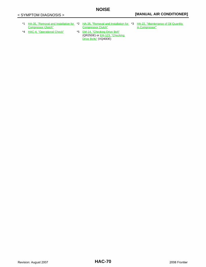
[MANUAL AIR CONDITIONER]NOISE
< SYMPTOM DIAGNOSIS >
*1 HA-35, "Removal and Installation for Compressor Clutch"
*2 HA-35, "Removal and Installation for Compressor Clutch"
*3 HA-22, "Maintenance of Oil Quantity in Compressor"
*4 HAC-4, "Operational Check" *5 EM-14, "Checking Drive Belt" (QR25DE) or EM-123, "Checking Drive Belts" (VQ40DE)
HAC-70
PRECAUTIONS[MANUAL AIR CONDITIONER]
C
D
E
F
G
H
J
K
L
M
A
B
AC
N
O
P
< PRECAUTION >
H
PRECAUTIONPRECAUTIONS
Supplemental Restraint System (SRS) "AIR BAG" and "SEAT BELT PRE-TENSION-ER" INFOID:0000000003289141
The Supplemental Restraint System such as “AIR BAG” and “SEAT BELT PRE-TENSIONER”, used alongwith a front seat belt, helps to reduce the risk or severity of injury to the driver and front passenger for certaintypes of collision. This system includes seat belt switch inputs and dual stage front air bag modules. The SRSsystem uses the seat belt switches to determine the front air bag deployment, and may only deploy one frontair bag, depending on the severity of a collision and whether the front occupants are belted or unbelted.Information necessary to service the system safely is included in the SR and SB section of this Service Man-ual.WARNING:• To avoid rendering the SRS inoperative, which could increase the risk of personal injury or death in
the event of a collision which would result in air bag inflation, all maintenance must be performed byan authorized NISSAN/INFINITI dealer.
• Improper maintenance, including incorrect removal and installation of the SRS, can lead to personalinjury caused by unintentional activation of the system. For removal of Spiral Cable and Air BagModule, see the SR section.
• Do not use electrical test equipment on any circuit related to the SRS unless instructed to in thisService Manual. SRS wiring harnesses can be identified by yellow and/or orange harnesses or har-ness connectors.
Working with HFC-134a (R-134a) INFOID:0000000003289142
WARNING:• CFC-12 (R-12) refrigerant and HFC-134a (R-134a) refrigerant are not compatible. If the refrigerants
are mixed compressor failure is likely to occur. Refer to HA-3, "Contaminated Refrigerant". To deter-mine the purity of HFC-134a (R-134a) in the vehicle and recovery tank, use Refrigerant Recovery/Recycling Recharging equipment and Refrigerant Identifier.
• Use only specified oil for the HFC-134a (R-134a) A/C system and HFC-134a (R-134a) components. Ifoil other than that specified is used, compressor failure is likely to occur.
• The specified HFC-134a (R-134a) oil rapidly absorbs moisture from the atmosphere. The followinghandling precautions must be observed:
- When removing refrigerant components from a vehicle, immediately cap (seal) the component tominimize the entry of moisture from the atmosphere.
- When installing refrigerant components to a vehicle, do not remove the caps (unseal) until justbefore connecting the components. Connect all refrigerant loop components as quickly as possibleto minimize the entry of moisture into system.
- Only use the specified oil from a sealed container. Immediately reseal containers of oil. Withoutproper sealing, oil will become moisture saturated and should not be used.
- Avoid breathing A/C refrigerant and oil vapor or mist. Exposure may irritate eyes, nose and throat.Remove HFC-134a (R-134a) from the A/C system using certified service equipment meeting require-ments of SAE J2210 [HFC-134a (R-134a) recycling equipment], or J2209 [HFC-134a (R-134a) recy-cling equipment], If accidental system discharge occurs, ventilate work area before resumingservice. Additional health and safety information may be obtained from refrigerant and oil manufac-turers.
- Do not allow A/C oil to come in contact with styrofoam parts. Damage may result.
CONTAMINATED REFRIGERANTIf a refrigerant other than pure HFC-134a (R-134a) is identified in a vehicle, your options are:• Explain to the customer that environmental regulations prohibit the release of contaminated refrigerant into
the atmosphere.• Explain that recovery of the contaminated refrigerant could damage your service equipment and refrigerant
supply.• Suggest the customer return the vehicle to the location of previous service where the contamination may
have occurred.• If you choose to perform the repair, recover the refrigerant using only dedicated equipment and contain-
ers. Do not recover contaminated refrigerant into your existing service equipment. If your facility does
HAC-71
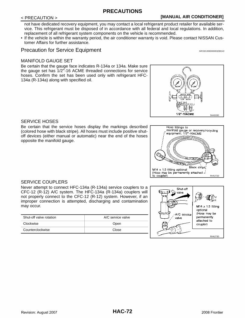
[MANUAL AIR CONDITIONER]PRECAUTIONS
< PRECAUTION >not have dedicated recovery equipment, you may contact a local refrigerant product retailer for available ser-vice. This refrigerant must be disposed of in accordance with all federal and local regulations. In addition,replacement of all refrigerant system components on the vehicle is recommended.
• If the vehicle is within the warranty period, the air conditioner warranty is void. Please contact NISSAN Cus-tomer Affairs for further assistance.
Precaution for Service Equipment INFOID:0000000003289143
MANIFOLD GAUGE SETBe certain that the gauge face indicates R-134a or 134a. Make surethe gauge set has 1/2″-16 ACME threaded connections for servicehoses. Confirm the set has been used only with refrigerant HFC-134a (R-134a) along with specified oil.
SERVICE HOSESBe certain that the service hoses display the markings described(colored hose with black stripe). All hoses must include positive shut-off devices (either manual or automatic) near the end of the hosesopposite the manifold gauge.
SERVICE COUPLERSNever attempt to connect HFC-134a (R-134a) service couplers to aCFC-12 (R-12) A/C system. The HFC-134a (R-134a) couplers willnot properly connect to the CFC-12 (R-12) system. However, if animproper connection is attempted, discharging and contaminationmay occur.
SHA533D
RHA272D
Shut-off valve rotation A/C service valve
Clockwise Open
Counterclockwise Close
RHA273D
HAC-72
Related Documents


![BRAKES BRC Aboredmder.com/FSMs/Nissan/Armada/2008/BRC.pdfBRC-6 < BASIC INSPECTION > [VDC/TCS/ABS] DIAGNOSIS AND REPAIR WORKFLOW 2. PERFORM THE SELF-DIAGNOSIS Check the DTC display](https://static.cupdf.com/doc/110x72/61015251637fb716b84d7f77/brakes-brc-brc-6-basic-inspection-vdctcsabs-diagnosis-and-repair-workflow.jpg)