VECTOR STRUCTURAL SYSTEM TRUSSES

Vector Structural System Trusses
Oct 21, 2015
Welcome message from author
This document is posted to help you gain knowledge. Please leave a comment to let me know what you think about it! Share it to your friends and learn new things together.
Transcript
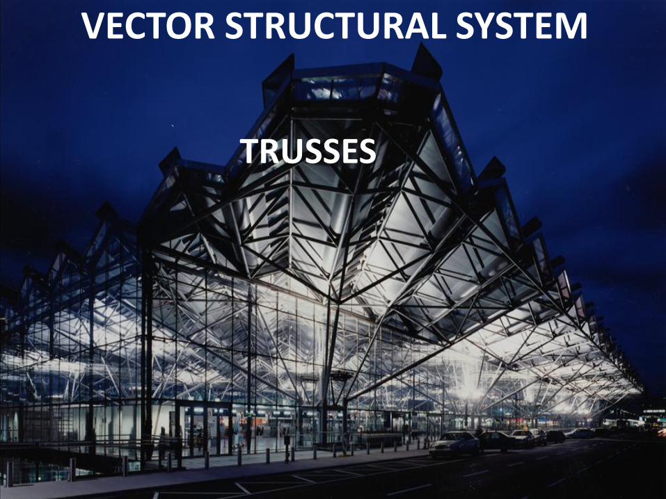
VECTOR STRUCTURAL SYSTEM
TRUSSES
INTRODUCTION TO THE SYSTEM
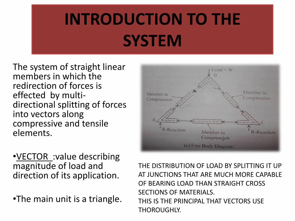
The system of straight linear members in which the redirection of forces is effected by multi-directional splitting of forces into vectors along compressive and tensile elements. •VECTOR :value describing magnitude of load and direction of its application. •The main unit is a triangle.
THE DISTRIBUTION OF LOAD BY SPLITTING IT UP AT JUNCTIONS THAT ARE MUCH MORE CAPABLE OF BEARING LOAD THAN STRAIGHT CROSS SECTIONS OF MATERIALS. THIS IS THE PRINCIPAL THAT VECTORS USE THOROUGHLY.
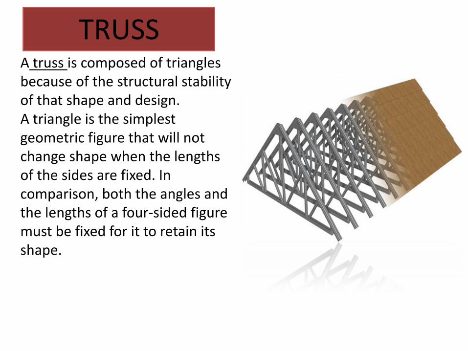
TRUSS A truss is composed of triangles because of the structural stability of that shape and design. A triangle is the simplest geometric figure that will not change shape when the lengths of the sides are fixed. In comparison, both the angles and the lengths of a four-sided figure must be fixed for it to retain its shape.
Evolution of the Vector Structural System
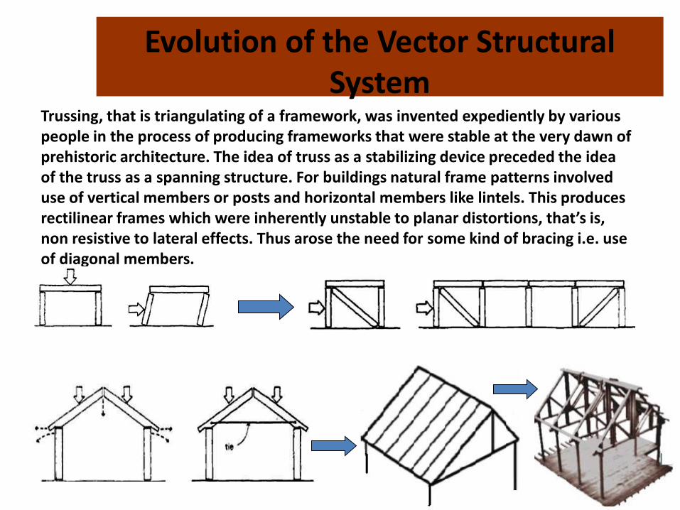
Trussing, that is triangulating of a framework, was invented expediently by various people in the process of producing frameworks that were stable at the very dawn of prehistoric architecture. The idea of truss as a stabilizing device preceded the idea of the truss as a spanning structure. For buildings natural frame patterns involved use of vertical members or posts and horizontal members like lintels. This produces rectilinear frames which were inherently unstable to planar distortions, that’s is, non resistive to lateral effects. Thus arose the need for some kind of bracing i.e. use of diagonal members.
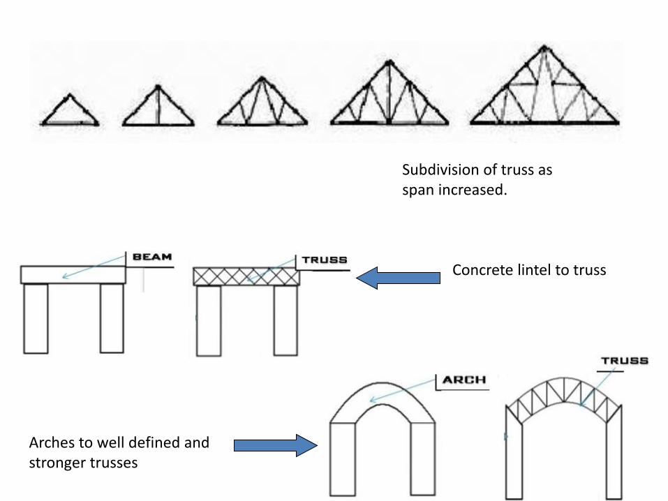
Subdivision of truss as span increased.
Concrete lintel to truss
Arches to well defined and stronger trusses
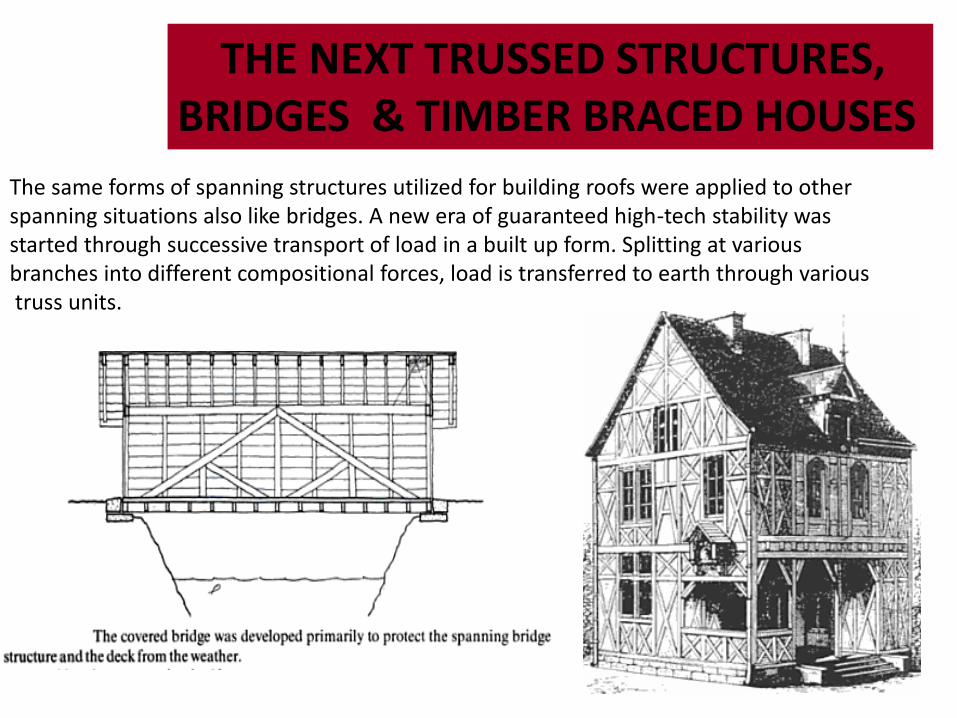
THE NEXT TRUSSED STRUCTURES, BRIDGES & TIMBER BRACED HOUSES
The same forms of spanning structures utilized for building roofs were applied to other spanning situations also like bridges. A new era of guaranteed high-tech stability was started through successive transport of load in a built up form. Splitting at various branches into different compositional forces, load is transferred to earth through various truss units.
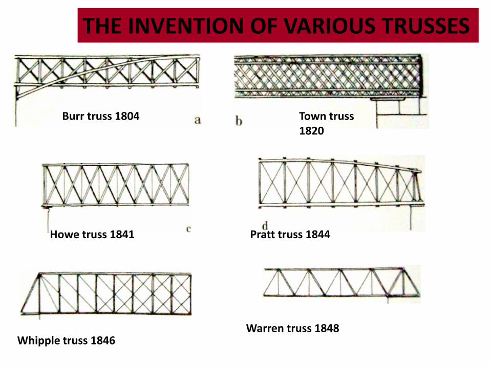
THE INVENTION OF VARIOUS TRUSSES
Burr truss 1804 Town truss 1820
Howe truss 1841 Pratt truss 1844
Whipple truss 1846 Warren truss 1848
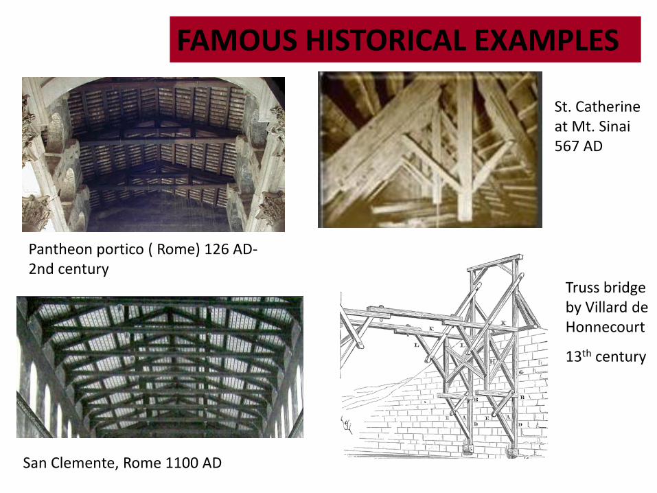
San Clemente, Rome 1100 AD
FAMOUS HISTORICAL EXAMPLES
Pantheon portico ( Rome) 126 AD- 2nd century
St. Catherine at Mt. Sinai 567 AD
Truss bridge by Villard de Honnecourt
13th century
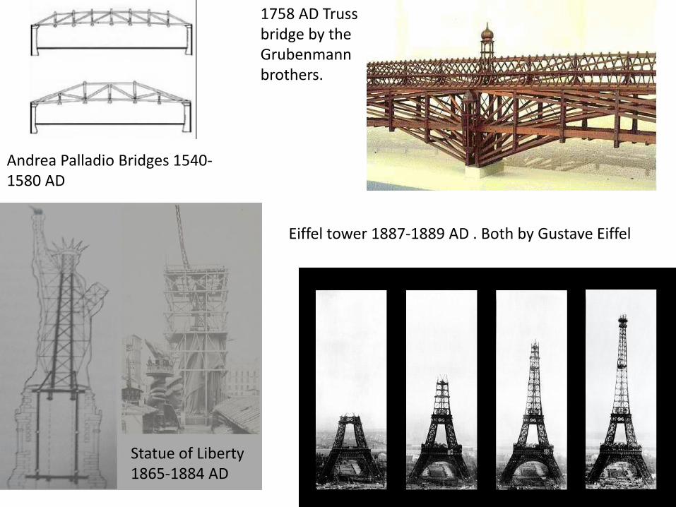
1758 AD Truss bridge by the Grubenmann brothers.
Andrea Palladio Bridges 1540- 1580 AD
Statue of Liberty 1865-1884 AD
Eiffel tower 1887-1889 AD . Both by Gustave Eiffel
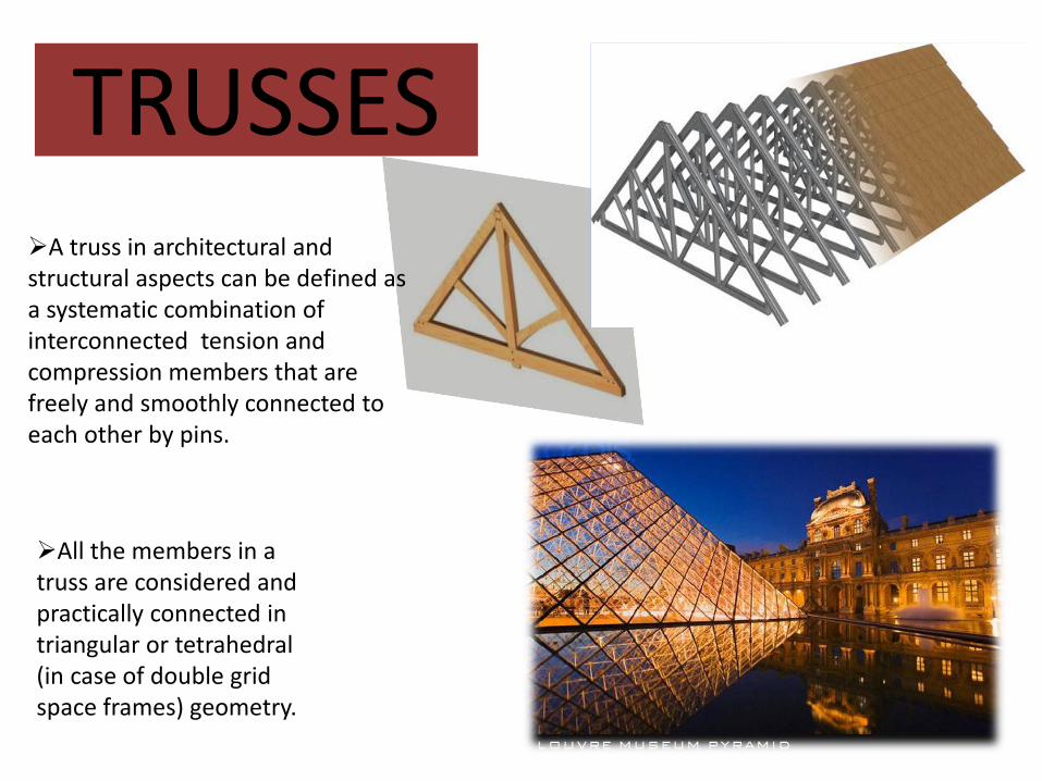
TRUSSES A truss in architectural and structural aspects can be defined as a systematic combination of interconnected tension and compression members that are freely and smoothly connected to each other by pins.
All the members in a truss are considered and practically connected in triangular or tetrahedral (in case of double grid space frames) geometry.
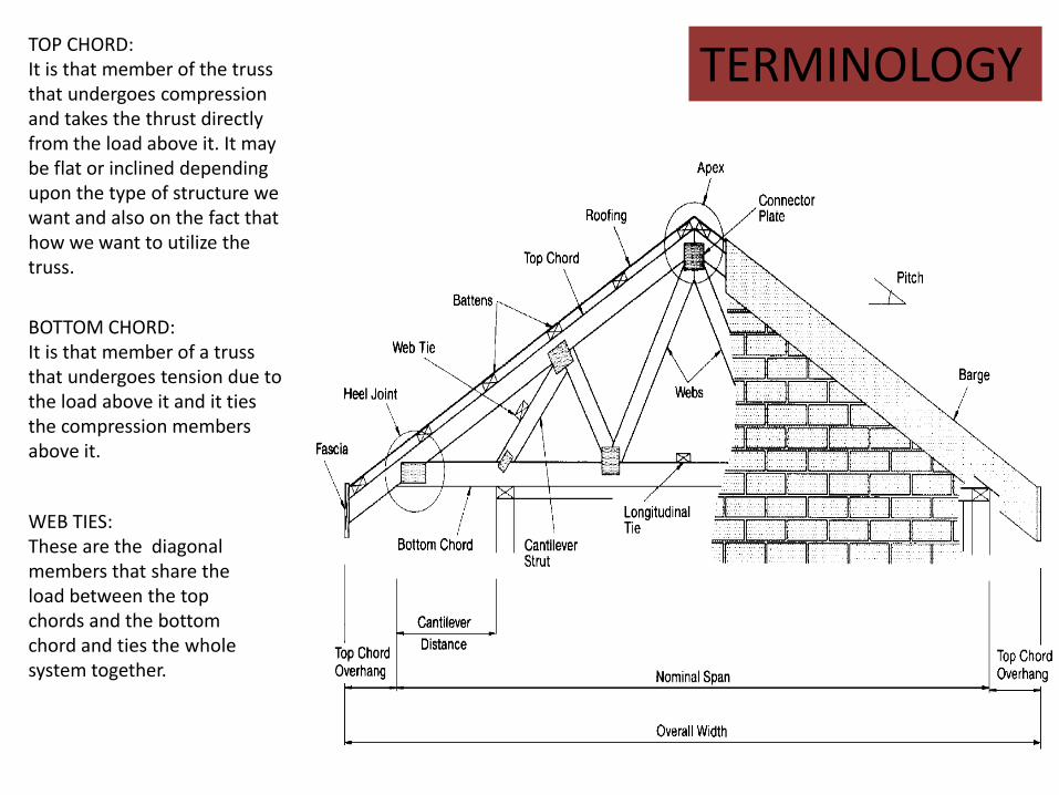
TOP CHORD: It is that member of the truss that undergoes compression and takes the thrust directly from the load above it. It may be flat or inclined depending upon the type of structure we want and also on the fact that how we want to utilize the truss.
BOTTOM CHORD: It is that member of a truss that undergoes tension due to the load above it and it ties the compression members above it.
WEB TIES: These are the diagonal members that share the load between the top chords and the bottom chord and ties the whole system together.
TERMINOLOGY
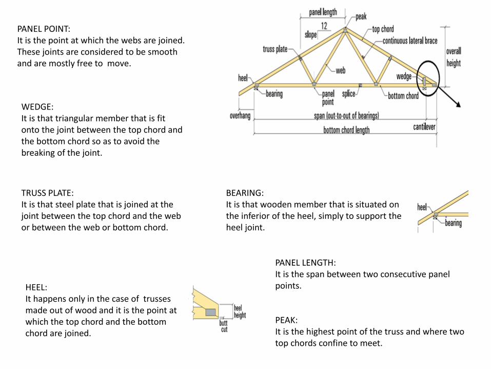
PANEL POINT: It is the point at which the webs are joined. These joints are considered to be smooth and are mostly free to move.
WEDGE: It is that triangular member that is fit onto the joint between the top chord and the bottom chord so as to avoid the breaking of the joint.
TRUSS PLATE: It is that steel plate that is joined at the joint between the top chord and the web or between the web or bottom chord.
HEEL: It happens only in the case of trusses made out of wood and it is the point at which the top chord and the bottom chord are joined.
BEARING: It is that wooden member that is situated on the inferior of the heel, simply to support the heel joint.
PANEL LENGTH: It is the span between two consecutive panel points.
PEAK: It is the highest point of the truss and where two top chords confine to meet.
THEORY OF TRUSSES, TENSION AND COMPRESSION & APPLICATION IN TRUSSES
•All members in a truss are considered to be straight, stiff and upstretched within the elastic limit of the material of which it is made. •The total load acting on a truss is taken to be concentrated upon the joints that it possesses. •All the members are axial load elements which may either exist in tension or compression.
Trusses can be further classified according to an equation between the no. of members the truss possesses and the no. of joints it is bound by. The equation is as follows: Let m be the no. of members the truss has and j be the no. of joints the truss has , then , If 1.2j-3<m then the truss is termed as redundant and, 2.If 2j-3> or =m, then the truss is stable.
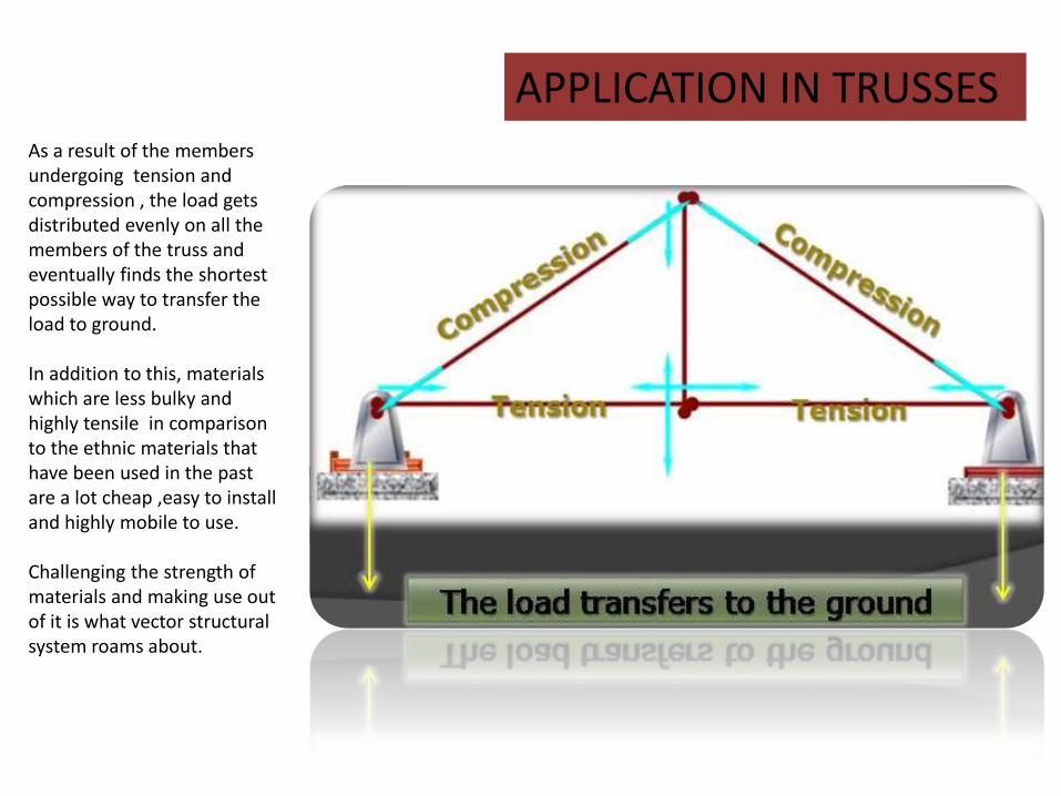
APPLICATION IN TRUSSES As a result of the members undergoing tension and compression , the load gets distributed evenly on all the members of the truss and eventually finds the shortest possible way to transfer the load to ground. In addition to this, materials which are less bulky and highly tensile in comparison to the ethnic materials that have been used in the past are a lot cheap ,easy to install and highly mobile to use. Challenging the strength of materials and making use out of it is what vector structural system roams about.
RELEVANCE OF LAMI’S THEOREM
We first basically need to know what drives us to mention Lami’s theorem in the context of truss. As mentioned earlier in the definition of truss, a truss is a combination of interconnected compression and tension members. But it is highly noticeable a fact , that what exactly must be the geometry of such members that it may actually take that much of compression and tension. Why actually we do not take any form or shape to construct a truss. THE ANSWER RESTS WITHIN THIS
LAMI’S THEOREM.
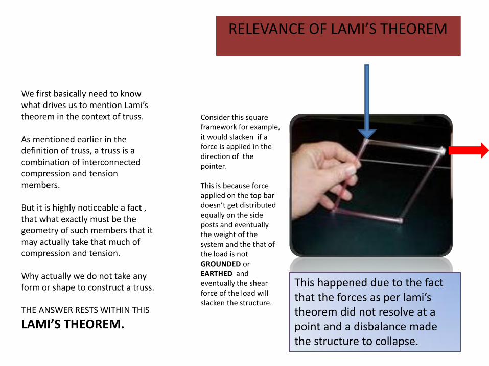
Consider this square framework for example, it would slacken if a force is applied in the direction of the pointer. This is because force applied on the top bar doesn’t get distributed equally on the side posts and eventually the weight of the system and the that of the load is not GROUNDED or EARTHED and eventually the shear force of the load will slacken the structure.
This happened due to the fact that the forces as per lami’s theorem did not resolve at a point and a disbalance made the structure to collapse.
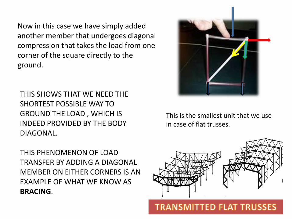
Now in this case we have simply added another member that undergoes diagonal compression that takes the load from one corner of the square directly to the ground.
THIS SHOWS THAT WE NEED THE SHORTEST POSSIBLE WAY TO GROUND THE LOAD , WHICH IS INDEED PROVIDED BY THE BODY DIAGONAL. THIS PHENOMENON OF LOAD TRANSFER BY ADDING A DIAGONAL MEMBER ON EITHER CORNERS IS AN EXAMPLE OF WHAT WE KNOW AS BRACING.
This is the smallest unit that we use in case of flat trusses.

NEED OF TRIANGULATION AND POINT CONNECTION
TRIANGLE according to lami’s theorem is the most rigid and stable of forms due to the fact that being a combination of three coplanar elements i.e. its arms. Any 3 force that are applied at the three corners of the triangle be it a force of compression or tension, nullify at the centroid of the triangle.
NOW HERE WE EXPLAIN THE MECHANISM OF TRIANGULATION.
1. When we apply a force at the junction of the two arms, they tend to slacken due to shear action.
2.Now if I just add a tie chord to tie these ends together it just hold onto the structure. This tie would take all the tension to overcome the shear.
1 2
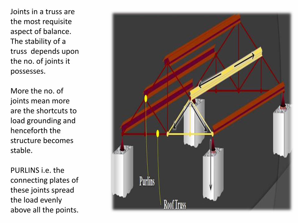
Joints in a truss are the most requisite aspect of balance. The stability of a truss depends upon the no. of joints it possesses. More the no. of joints mean more are the shortcuts to load grounding and henceforth the structure becomes stable. PURLINS i.e. the connecting plates of these joints spread the load evenly above all the points.
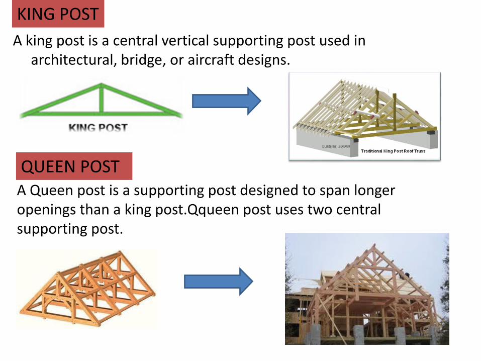
A Queen post is a supporting post designed to span longer openings than a king post.Qqueen post uses two central supporting post.
A king post is a central vertical supporting post used in architectural, bridge, or aircraft designs.
QUEEN POST
KING POST
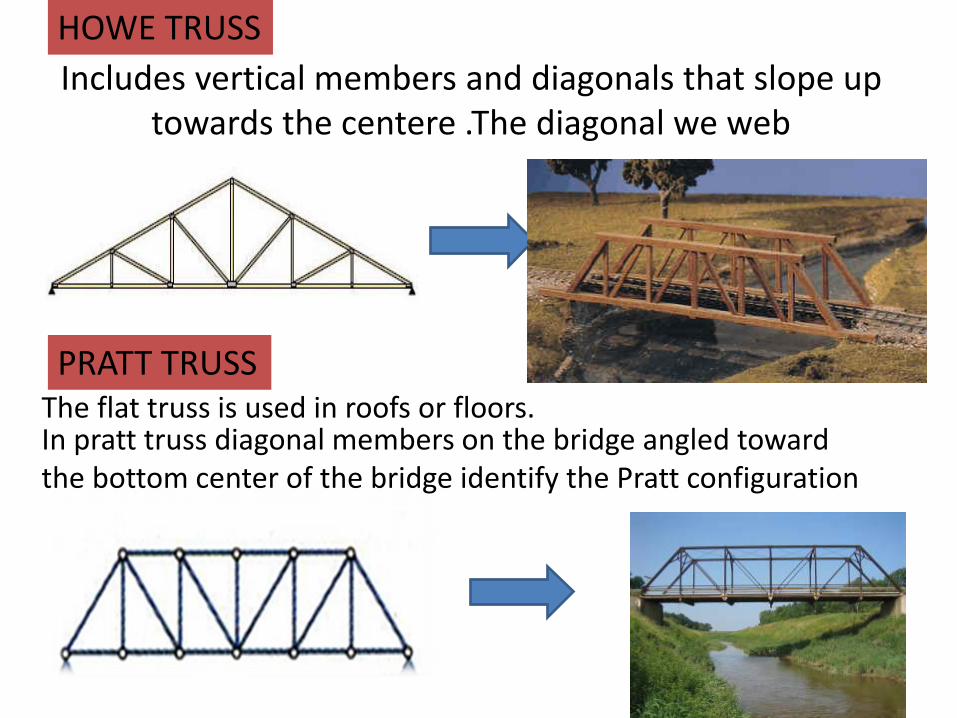
Includes vertical members and diagonals that slope up towards the centere .The diagonal we web
HOWE TRUSS
In pratt truss diagonal members on the bridge angled toward the bottom center of the bridge identify the Pratt configuration
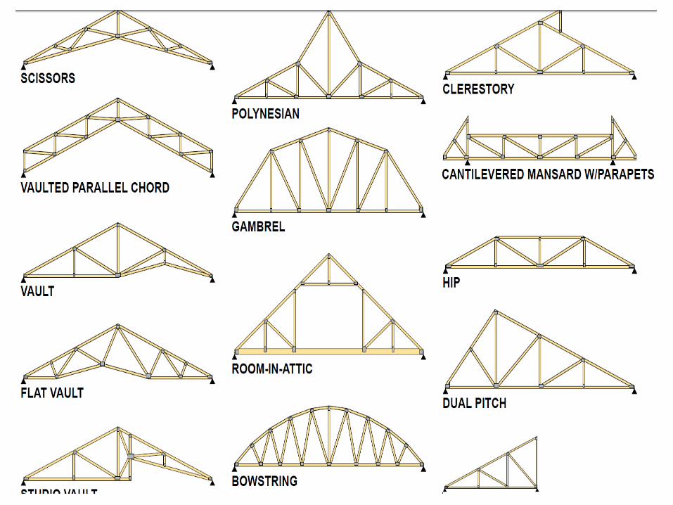
PRATT TRUSS The flat truss is used in roofs or floors.
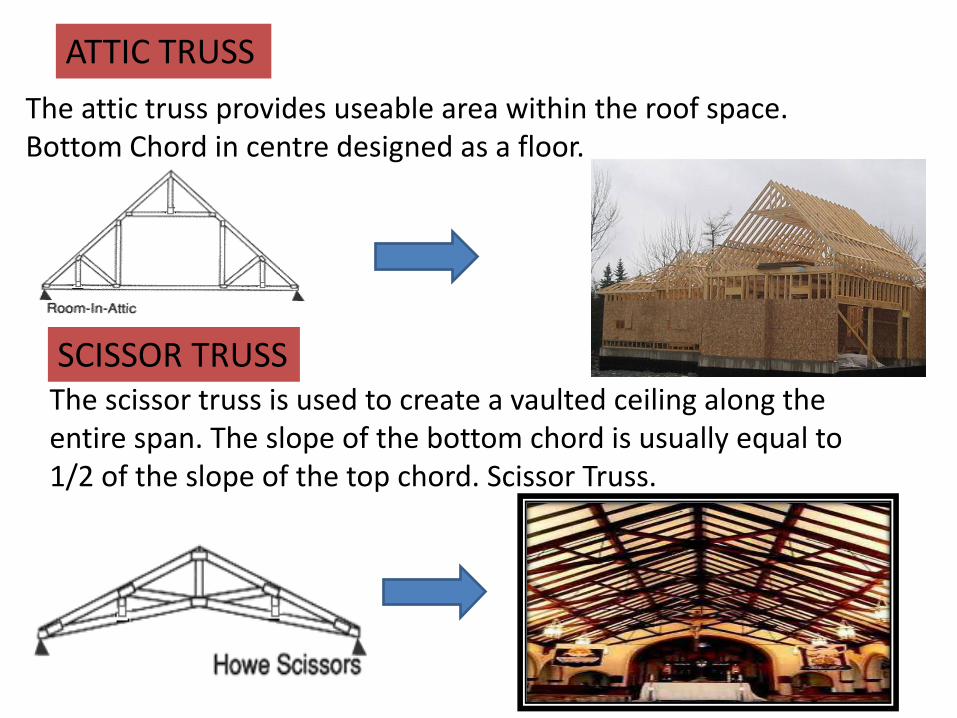
The scissor truss is used to create a vaulted ceiling along the entire span. The slope of the bottom chord is usually equal to 1/2 of the slope of the top chord. Scissor Truss.
SCISSOR TRUSS
The attic truss provides useable area within the roof space. Bottom Chord in centre designed as a floor.
ATTIC TRUSS
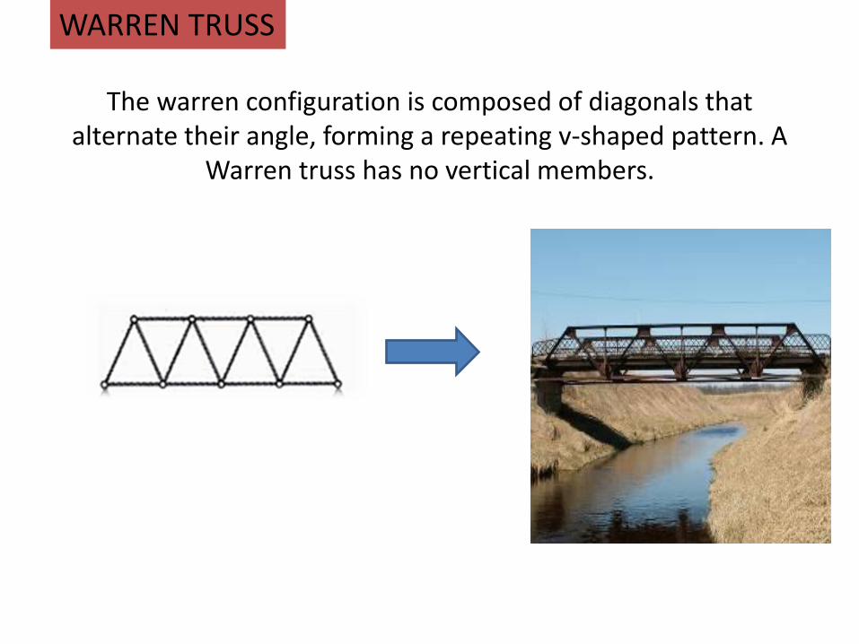
The warren configuration is composed of diagonals that
alternate their angle, forming a repeating v-shaped pattern. A Warren truss has no vertical members.
WARREN TRUSS
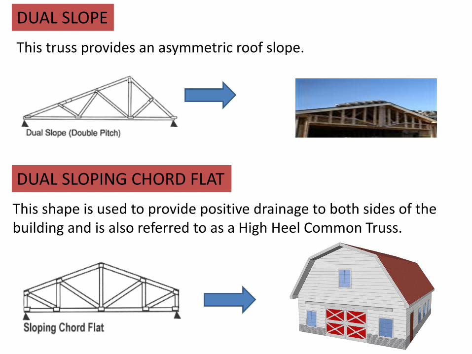
This truss provides an asymmetric roof slope.
This shape is used to provide positive drainage to both sides of the building and is also referred to as a High Heel Common Truss.
DUAL SLOPING CHORD FLAT
DUAL SLOPE
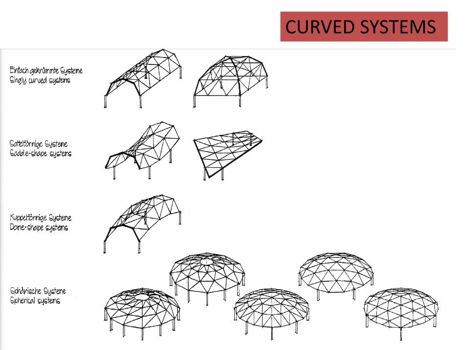
CURVED SYSTEMS
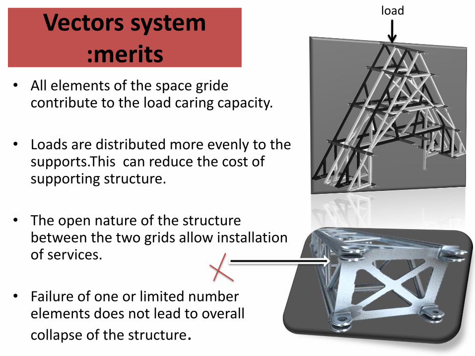
Vectors system :merits
• All elements of the space gride contribute to the load caring capacity.
• Loads are distributed more evenly to the supports.This can reduce the cost of supporting structure.
• The open nature of the structure between the two grids allow installation of services.
• Failure of one or limited number elements does not lead to overall
collapse of the structure.
load
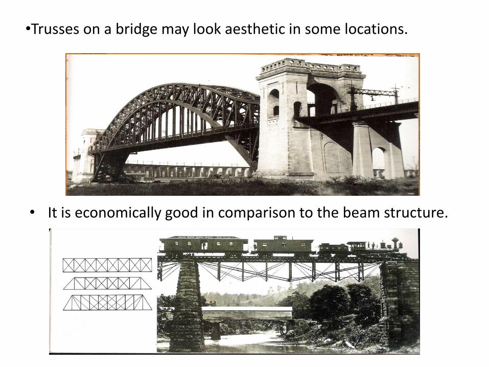
• It is economically good in comparison to the beam structure.
•Trusses on a bridge may look aesthetic in some locations.
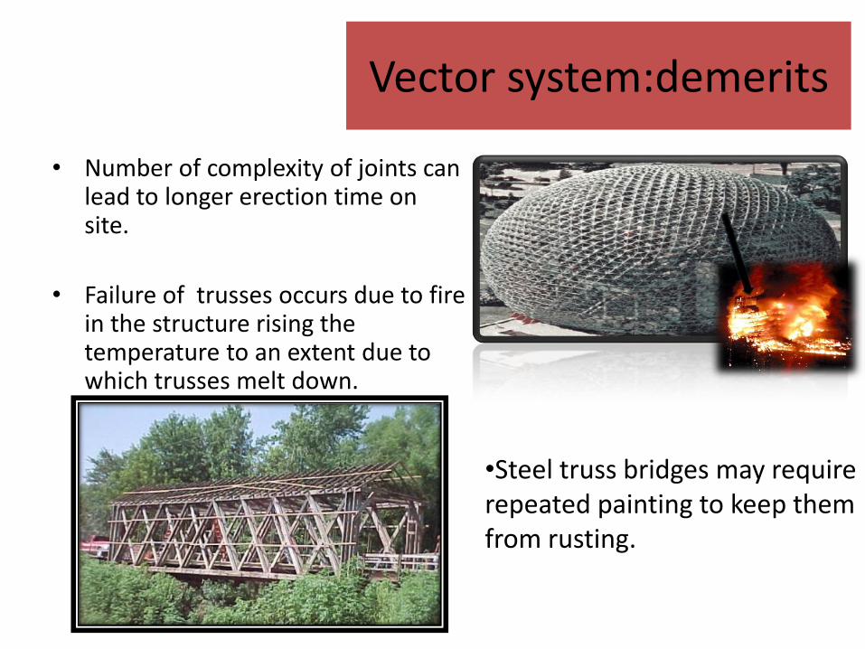
Vector system:demerits
• Number of complexity of joints can lead to longer erection time on site.
• Failure of trusses occurs due to fire in the structure rising the temperature to an extent due to which trusses melt down.
•Steel truss bridges may require repeated painting to keep them from rusting.
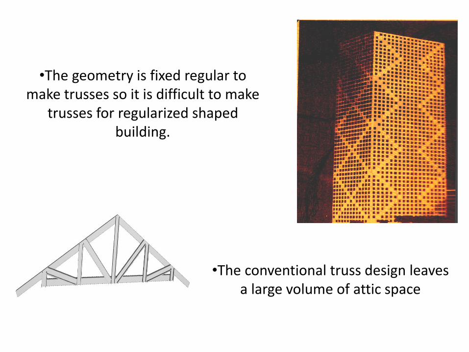
•The geometry is fixed regular to make trusses so it is difficult to make
trusses for regularized shaped building.
•The conventional truss design leaves a large volume of attic space
Related Documents