Valves for the industry n Globe valves n Gate valves n Swing check valves 6100.1.09.14

Welcome message from author
This document is posted to help you gain knowledge. Please leave a comment to let me know what you think about it! Share it to your friends and learn new things together.
Transcript
Valves for the industry
n Globe valves n Gate valves n Swing check valves
6100.1.09.14

Technical alterations reserved 6100.1.09.14
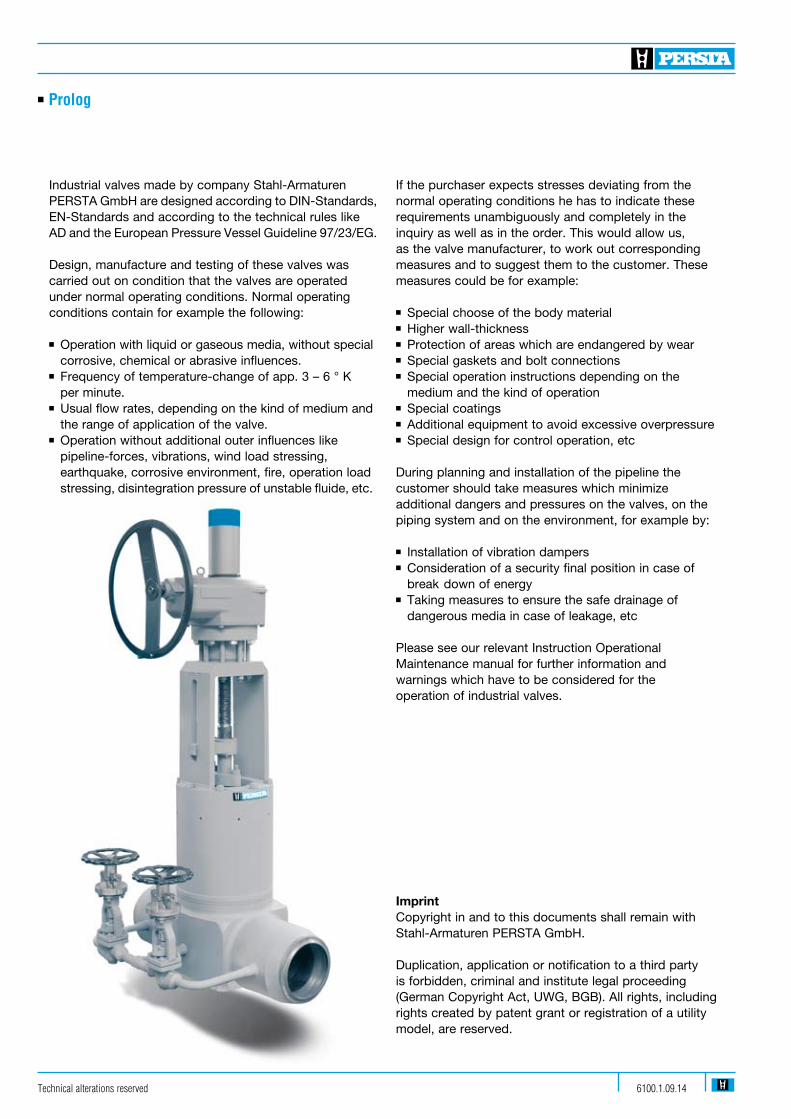
n Prolog
Industrial valves made by company Stahl-Armaturen PERSTA GmbH are designed according to DIN-Standards, EN-Standards and according to the technical rules like AD and the European Pressure Vessel Guideline 97/23/EG.
Design, manufacture and testing of these valves was carried out on condition that the valves are operated under normal operating conditions. Normal operating conditions contain for example the following:
n Operation with liquid or gaseous media, without special corrosive, chemical or abrasive influences. n Frequency of temperature-change of app. 3 – 6 ° K per minute.n Usual flow rates, depending on the kind of medium and the range of application of the valve. n Operation without additional outer influences like pipeline-forces, vibrations, wind load stressing, earthquake, corrosive environment, fire, operation load stressing, disintegration pressure of unstable fluide, etc.
If the purchaser expects stresses deviating from the normal operating conditions he has to indicate these requirements unambiguously and completely in the inquiry as well as in the order. This would allow us, as the valve manufacturer, to work out corresponding measures and to suggest them to the customer. These measures could be for example:
n Special choose of the body materialn Higher wall-thicknessn Protection of areas which are endangered by wear n Special gaskets and bolt connections n Special operation instructions depending on the medium and the kind of operationn Special coatings n Additional equipment to avoid excessive overpressuren Special design for control operation, etc
During planning and installation of the pipeline the customer should take measures which minimize additional dangers and pressures on the valves, on the piping system and on the environment, for example by:
n Installation of vibration dampers n Consideration of a security final position in case of break down of energyn Taking measures to ensure the safe drainage of dangerous media in case of leakage, etc
Please see our relevant Instruction OperationalMaintenance manual for further information and warnings which have to be considered for the operation of industrial valves.
ImprintCopyright in and to this documents shall remain with Stahl-Armaturen PERSTA GmbH.
Duplication, application or notification to a third party is forbidden, criminal and institute legal proceeding (German Copyright Act, UWG, BGB). All rights, including rights created by patent grant or registration of a utility model, are reserved.

Technical alterations reserved6100.1.09.14
n Globe valves
Gobe valve 200 AE/BE/AJ/BJ DN 10-50 PN 10-160 1-4
Lift check valve 240 MT DN 10-50 PN 10-160 1-4
Globe valve 200 AE/BE/AJ/BJ DN 65-200 PN 10-160 5-8
Lift check valve 240 MT DN 65-200 PN 10-160 5-8
Bellow seal globe valve / VALTRA 200 AL DN 15-400 (200) PN 10-160 9-10
High pressure globe valve HD 91 200 JM DN 10-65/50 PN 320 11-14
High pressure globe valve HD 2000 200 LM/202 LM DN 10-65 PN 500 15-20
High pressure globe valve HD 2000 200 LS/200 LJ DN 10-65 PN 500 15-20
with back seat
High pressure lift check valve 240 MT DN 10-65 PN 500 15-20
HD 2000
Stop check valve HD 2000 240 MM DN 10-65 PN 500 15-20
High pressure globe valve DVA 25/40 200 BZ DN 80-250 PD 25/40 21-24
Further standards 25-26
Special globe valve variants 27-28
n Gate valves
Small gate valve 808 GJ DN 10-40 PN 10-100 29-32
Small gate valve / VALTRA 800/808 GJ NPS 1/2 - 2 / DN 15-50 Class 800/10-40 33-36
Gate valve 700 HJ/JJ (GA) DN 50-150 PN 10-100 37-42
Gate valve 700 HJ/JJ (GA) DN 200-250 PN 10-40 43-46
Gate valve 700 HJ/JJ DN 200-300 PN 63-100 47-50
Gate valve 400 JJ DN 350-700 PN 63-100 51-54
Gate valve / VALTRA 700 JJ DN 300-1000 PN 10-25 55-56
Gate valve / VALTRA 700 JJ DN 300-700 PN 40 57-58
Gate valve 700 JJ DN 50-300/250 PN 160/PD 18 59-62
High pressure gate valve DSK 10 700 JT DN 50-150 PD 10 63-66
High pressure gate valve DSK 10 700 JT DN 200-350/300 PD 10 67-70
High pressure gate valve DSK 10 700 JT DN 350-700 PD 10 71-74
High pressure gate valve DSK 26 700 JT DN 65-300 PD 25/40 75-78
High pressure gate valve DSK 16-63 700 JT DN 50-600 PD 16-63 79-82
Overpressure-safety-devices / 83-84
PERSTA Type SV 97, -98, -99
Gate valve variants 85-86
n Table of contentn Designation n Type n Size n Rating n Page
Technical alterations reserved 6100.1.09.14
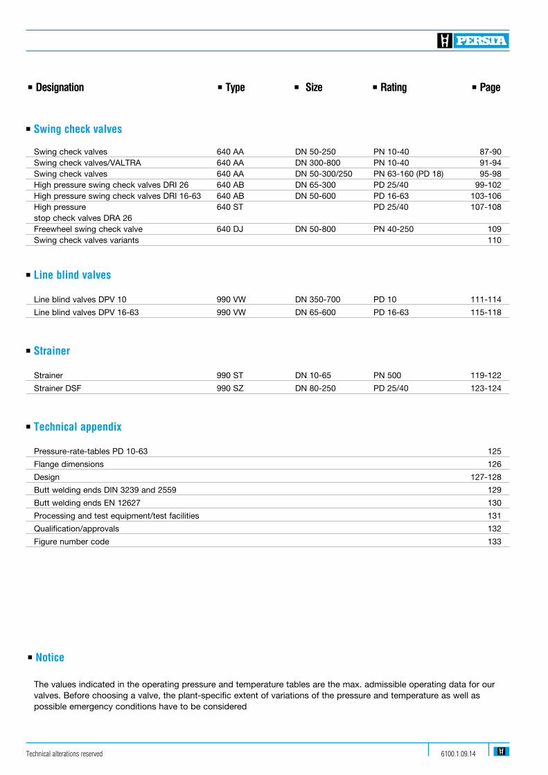
n Swing check valves
Swing check valves 640 AA DN 50-250 PN 10-40 87-90 Swing check valves/VALTRA 640 AA DN 300-800 PN 10-40 91-94 Swing check valves 640 AA DN 50-300/250 PN 63-160 (PD 18) 95-98 High pressure swing check valves DRI 26 640 AB DN 65-300 PD 25/40 99-102 High pressure swing check valves DRI 16-63 640 AB DN 50-600 PD 16-63 103-106 High pressure 640 ST PD 25/40 107-108 stop check valves DRA 26 Freewheel swing check valve 640 DJ DN 50-800 PN 40-250 109 Swing check valves variants 110 n Line blind valves
Line blind valves DPV 10 990 VW DN 350-700 PD 10 111-114
Line blind valves DPV 16-63 990 VW DN 65-600 PD 16-63 115-118
n Strainer
Strainer 990 ST DN 10-65 PN 500 119-122
Strainer DSF 990 SZ DN 80-250 PD 25/40 123-124
n Technical appendix
Pressure-rate-tables PD 10-63 125
Flange dimensions 126
Design 127-128
Butt welding ends DIN 3239 and 2559 129
Butt welding ends EN 12627 130
Processing and test equipment/test facilities 131
Qualification/approvals 132
Figure number code 133
n Notice The values indicated in the operating pressure and temperature tables are the max. admissible operating data for our valves. Before choosing a valve, the plant-specific extent of variations of the pressure and temperature as well as possible emergency conditions have to be considered
n Designation n Type n Size n Rating n Page

n Globe valves n Globe valve n 200 AE/BE/AJ/BJ n PN 10-160 n DN 10-50n Globe valves n Lift check valve n 240 MT n PN 10-160 n DN 10-50
Admissible operating pressure [bar] at design temperature [°C] 1)
Material PN -200 -60 -10 20 120 150 200 250 300 350 400 450 500 510 520 530 540 550
1.0460 10-40 40 40 40 37 35 32 28 24 21 10 63 63 63 63 58 50 45 40 36 32 24 100 100 100 100 90 80 70 60 56 50 38 160 160 160 160 145 130 112 96 90 80 60 1.5415 5) 10-40 40 40 40 40 40 40 35 31 30 28 18 14 11 9 63 63 63 63 63 63 63 56 50 47 45 29 22 16 14 100 100 100 100 100 100 100 87 78 74 70 45 34 27 22 160 160 160 160 160 160 160 139 125 118 112 72 55 43 35 1.7335 10-40 40 40 40 40 40 40 40 38 36 34 29 24 19 15 12 9 63 63 63 63 63 63 63 63 61 58 56 47 40 32 25 20 15 100 100 100 100 100 100 100 100 95 91 87 74 62 49 38 31 24 160 160 160 160 160 160 160 160 153 146 139 118 100 79 62 46 35 1.4571 10-40 2)3)4) 40 40 40 40 40 40 40 40 38 36 34 32 32 32 31 31 31 31 63 2)3)4) 63 63 63 63 63 59 56 53 50 48 47 100 2)3)4) 100 100 100 100 100 92 88 83 79 76 73 160 2)3)4) 160 160 160 160 160 150 142 135 127 123 119 1.0566 10-40 4)6) 40 40 40 40 37 35 32 28 63 4)6) 63 63 63 63 58 50 45 40 100 4)6) 100 100 100 100 92 80 70 60 160 4)6) 160 160 160 160 147 130 112 96 1) Operating temperature = design temperature minus temperature surcharge acc. to DIN regulations. 2) Application at more than 400 °C operating temperature only admissible if no intercrystalline corrosion has to be expected. 3) At operating temperature 400 °C the material of the screws is 1.4986.4) In case of screws A4-70 with > 8 x d screw-length the mechanical strength properties acc. to table 6 of DIN 267 Part 11 have been considered. 5) Butt welding ends 6) At temperature > 50 °C only applicable for short-time service.
Range of application
Technical alterations reserved6100.1.09.141
n Globe valves n Globe valve n 200 AE/BE/AJ/BJ n PN 10-160 n DN 10-50n Globe valves n Lift check valve n 240 MT n PN 10-160 n DN 10-50
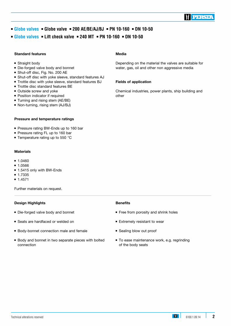
Standard features
n Straight bodyn Die-forged valve body and bonnetn Shut-off disc, Fig. No. 200 AEn Shut-off disc with yoke sleeve, standard features AJn Trottle disc with yoke sleeve, standard features BJ n Trottle disc standard features BEn Outside screw and yoken Position indicator if requiredn Turning and rising stem (AE/BE)n Non-turning, rising stem (AJ/BJ)
Pressure and temperature ratings
n Pressure rating BW-Ends up to 160 barn Pressure rating FL up to 160 barn Temperature rating up to 550 °C
Materials
n 1.0460n 1.0566
n 1.5415 only with BW-Endsn 1.7335 n 1.4571
Further materials on request.
Design Highlights
n Die-forged valve body and bonnet
n Seats are hardfaced or welded on
n Body-bonnet connection male and female n Body and bonnet in two separate pieces with bolted connection
Benefits
n Free from porosity and shrink holes
n Extremely resistant to wear
n Sealing blow out proof
n To ease maintenance work, e.g. regrinding of the body seats
Media
Depending on the material the valves are suitable for water, gas, oil and other non aggressive media
Fields of application
Chemical industries, power plants, ship building and other
Technical alterations reserved 6100.1.09.14 2

n Globe valves n Globe valve n 200 AE/BE/AJ/BJ n PN 10-160 n DN 10-50n Globe valves n Lift check valve n 240 MT n PN 10-160 n DN 10-50
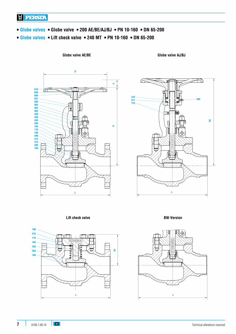
Globe valve AE/BE Globe valve AJ/BJ
210
190
170
160
330
304
100
H1
L
Lift check valve
L
BW-Version
Technical alterations reserved6100.1.09.143
Artikel-Nr: 201597
Aufsatz-Ventil - 200 AE 25.1
Art.Nr. Bezeichnung MengeWerkstoffPosNr202406 Gehäuse DV 160/25 11.0566, Sitz Cr 17100100665 Dichtring 1Grafit160120672 Stiftschraube 4A4-70170122135 Sechskantmutter 4A4-70190107041 Bügeldeckel V 160/25 11.0566200110030 Kegel 25 11.0566, Sitz Cr 17300116034 Spindel 11.4571400118714 Packungshülse 1Grafit420111525 Stopfbuchsbrille 16 11.4571440114653 Nietstift 2A4-50450121207 Klappschraube 21.4571462114080 Scheibe 2A4-50463109571 Sechskantmutter 2A4-70464107015 Spindelmutter 11.0718500108569 Zylinderstift 1Stahl501108703 Handrad 12/180 15.3106600114581 Scheibe 1Stahl609111074 Sechskantmutter 11.1181610
DN 25 PN 160
STAHL-ARMATUREN PERSTA GmbH, POSTFACH 2240, 59567 WARSTEIN
Zeichnungs-Nr.: Angebot/1/0
EigenschaftenFlansch DIN 2501Anschluss Austritt
Flansch DIN 2501Anschluss Eintritt
Dichtl. EN 1092-1 Form B2Form des Anschlusses am Austr.
Dichtl. EN 1092-1 Form B2Form des Anschlusses am Eintr.
12Gewicht [kg]
Tec
hnis
che
Änd
erun
gen
vorb
ehal
ten
Maße Armatur260L
220H
180Ø D
12h
Maße GetriebeMaße Antrieb
Blatt 1/ 1
= E
rsat
ztei
lem
pfeh
lung
Erstellt
Geprüft 01.08.2013
01.08.2013
BECKER
RevisionSYSTEM 0
610
609
600
500
440
420
200
170
190
160
400
300
100
501
464
463
462
450
D
hH
L
Artikel-Nr: 201597
Aufsatz-Ventil - 200 AE 25.1
Art.Nr. Bezeichnung MengeWerkstoffPosNr202406 Gehäuse DV 160/25 11.0566, Sitz Cr 17100100665 Dichtring 1Grafit160120672 Stiftschraube 4A4-70170122135 Sechskantmutter 4A4-70190107041 Bügeldeckel V 160/25 11.0566200110030 Kegel 25 11.0566, Sitz Cr 17300116034 Spindel 11.4571400118714 Packungshülse 1Grafit420111525 Stopfbuchsbrille 16 11.4571440114653 Nietstift 2A4-50450121207 Klappschraube 21.4571462114080 Scheibe 2A4-50463109571 Sechskantmutter 2A4-70464107015 Spindelmutter 11.0718500108569 Zylinderstift 1Stahl501108703 Handrad 12/180 15.3106600114581 Scheibe 1Stahl609111074 Sechskantmutter 11.1181610
DN 25 PN 160
STAHL-ARMATUREN PERSTA GmbH, POSTFACH 2240, 59567 WARSTEIN
Zeichnungs-Nr.: Angebot/1/0
EigenschaftenFlansch DIN 2501Anschluss Austritt
Flansch DIN 2501Anschluss Eintritt
Dichtl. EN 1092-1 Form B2Form des Anschlusses am Austr.
Dichtl. EN 1092-1 Form B2Form des Anschlusses am Eintr.
12Gewicht [kg]
Tec
hnis
che
Änd
erun
gen
vorb
ehal
ten
Maße Armatur260L
220H
180Ø D
12h
Maße GetriebeMaße Antrieb
Blatt 1/ 1
= E
rsat
ztei
lem
pfeh
lung
Erstellt
Geprüft 01.08.2013
01.08.2013
BECKER
RevisionSYSTEM 0
511
510
590
710
H2
L

FL BW Stroke 1.0619 PN DN L L H H1 H2 h D H
10-40 10 130 130 215 85 275 12 140 15 130 130 215 85 275 12 140 20 150 130 220 90 275 12 140 25 160 130 220 90 275 12 140 32 180 160 245 115 305 15 180 40 200 180 250 130 305 15 180 50 230 210 260 120 345 18 180 63-160 10 210 150 220 100 275 12 180 15 210 150 220 100 275 12 180 20 230 150 220 100 275 12 180 25 230 160 220 100 275 12 180 32 260 180 285 140 335 15 225 40 260 210 285 140 335 15 225 63-100 50 300 250 285 150 345 18 150 260160 50 300 250 285 150 345 18 225 260
The valves are also available in angle pattern up DN 100.
n Globe valves n Globe valve n 200 AE/BE/AJ/BJ n PN 10-160 n DN 10-50n Globe valves n Lift check valve n 240 MT n PN 10-160 n DN 10-50
Dimensions/mm
200 AE/BE 240 MT PN DN FL BW FL BW 10-40 10 4,5 3,8 3,2 2,4 15 5,0 4,2 3,2 2,4 20 5,7 3,8 3,9 2,4 25 6,3 4,0 4,7 2,3 32 10,0 7,3 7,9 5,5 40 11,2 7,3 9,1 5,5 50 15,5 11,0 12,1 7,963-160 10 8,7 5,9 6,0 4,0 15 8,6 6,2 6,8 4,0 20 10,4 5,5 9,0 4,0 25 10,9 5,8 9,2 4,0 32 19,0 13,2 15,6 9,0 40 21,0 12,8 16,8 9,063-100 50 24,1 15,0 19,5 11,0 160 50 25,0 15,0 22,0 11,0
Weights/kg
BW-VersionPos. Component 1.0460 (21) 1.0566 (25) 1.5415 (42) 1.7335 (44) 1.4571 (82) 1.4571 (87) 100 Body 1.0460 4)8) 1.0566 4) 1.5415 5) 1.7335 5) 1.4571 7) 1.4571 7)
160 4 Gasket Graphite Graphite Graphite Graphite Teflon Graphite170 Stud 1) 1.1181 A4-70 1.7709 1.7709 A4-70 A4-70170 Stud 2) 1.7709 A4-70 1.4923 1.4923 A4-70 A4-70190 Hexagonal nut 1) 1.1181 A4-70 1.7218 1.7218 A4-70 A4-70190 Hexagonal nut 2) 1.7218 A4-70 1.7218 1.7218 A4-70 A4-70200 Bonnet 1.0460 1.0566 1.7335 1.7335 1.4571 1.4571210 Bonnet 1.0460 1.0566 1.7335 1.7335 1.4571 1.4571300 4Disc 1.4021 3) 1.0566 4) 1.7335 5) 1.7335 5) 1.4571 6) 1.4571 6)
304 4 Disc 1.4021 3) 1.4571 6) 1.4571 5) 1.4571 5) 1.4571 6) 1.4571 6)
330 4 Spring 1.4310 1.4310 1.4310 1.4310 1.4571 1.4571400 4 Stem 1.4021 1.4571 1.4021 1.4021 1.4571 1.4571420 4 Packing Graphite Graphite Graphite Graphite Teflon Graphite440 Gland flange 1.0460 1.4571 1.0460 1.0460 1.4571 1.4571450 Rivet 1.1181 A4-50 1.1181 1.1181 A4-50 A4-50462 Gland bolt 1.1181 1.4571 1.1181 1.1181 1.4571 1.4571463 Washer St A4-50 St St A4-50 A4-50464 Hexagonal nut 1.1181 A4-70 1.1181 1.1181 A4-70 A4-70500 4 Stem nut 1.0718 1.0718 1.0718 1.0718 1.0718 1.0718501 4 Cylindrical pin St St St St St St510 4 Yoke sleeve 1.0718 1.0718 1.0718 1.0718 1.0718 1.0718511 4 Needle bearing WLSt WLSt WLSt WLSt WLSt WLSt590 Grease nipple 5.8 5.8 5.8 5.8 5.8 5.8600 Handwheel 5.3106 5.3106 5.3106 5.3106 5.3106 5.3106609 Washer St St St St A4-50 A4-50610 Hexagonal nut 1.1181 1.1181 1.1181 1.1181 A4-70 A4-70710 Anti-rotation device 5.3106 5.3106 5.3106 5.3106 5.3106 5.3106
4Spare parts Special materials on request; alterations reserved. 1) PN 10-40 4) Seat hard faced with Cr17 7) ≥ PN 63 seat hard faced with hastelloy 2) PN 63-160 5) Seat hard faced with Stellite 8) DN 50 PN 10-160 Flange Version with 1.0619 hard faced with Cr17 3) Seat hard faced 6) ≥ PN 63 seat hard faced with Stellite
Materials
Technical alterations reserved 6100.1.09.14 4
PN 10-40 PN 63-160Line DN 10 DN 15 DN 20 DN 25 DN 32 DN 40 DN 50 DN 10 DN 15 DN 20 DN 25 DN 32 DN 40 DN 50
200 AE (BW) 3,0 4,5 6,2 8,6 16,0 21,0 30,0 3,0 4,5 6,2 8,6 16,0 21,0 30,0
200 AE (FL) 1,8 3,0 5,3 8,6 13,0 21,0 37,2 1,8 4,5 5,3 8,6 13,0 21,0 37,2
200 BE (BW) 2,8 4,2 5,9 7,6 14,5 19,5 26,9 2,8 4,2 5,9 7,6 14,5 19,5 26,9
200 BE (FL) 1,5 2,8 4,9 7,6 11,2 19,5 34,5 2,8 4,2 5,9 7,6 14,5 19,5 34,5
240 MT (BW) 2,7 4,1 5,7 7,9 14,6 19,2 34,0 2,7 4,1 5,7 7,9 14,6 19,2 34,0
240 MT (FL) 1,7 2,7 5,7 7,9 11,9 19,2 25,8 1,7 2,7 5,7 7,9 11,9 19,2 25,8
Kvs-values (m3/h)
n Globe valves n Globe valve n 200 AE/BE/AJ/BJ n PN 10-160 n DN 65-200n Globe valves n Lift check valve n 240 MT n PN 10-160 n DN 65-200
Technical alterations reserved6100.1.09.145
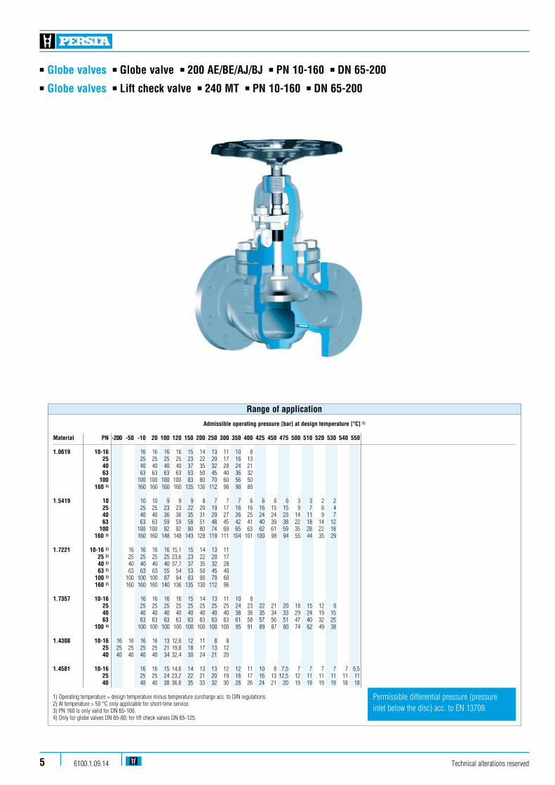
Admissible operating pressure [bar] at design temperature [°C] 1)
Material PN -200 -50 -10 20 100 120 150 200 250 300 350 400 425 450 475 500 510 520 530 540 550
1.0619 10-16 16 16 16 16 15 14 13 11 10 8 25 25 25 25 25 23 22 20 17 16 13 40 40 40 40 40 37 35 32 28 24 21 63 63 63 63 63 53 50 45 40 36 32 100 100 100 100 100 83 80 70 60 56 50 160 3) 160 160 160 160 135 130 112 96 90 80
1.5419 10 10 10 9 9 9 8 7 7 7 6 6 6 6 3 3 2 2 25 25 25 23 23 22 20 19 17 16 16 16 15 15 9 7 6 4 40 40 40 36 36 35 31 29 27 26 25 24 24 23 14 11 9 7 63 63 63 59 59 58 51 48 45 42 41 40 39 38 22 18 14 12 100 100 100 92 92 90 80 74 69 65 63 62 61 59 35 28 22 18 160 3) 160 160 148 148 143 128 119 111 104 101 100 98 94 55 44 35 29
1.7221 10-16 2) 16 16 16 16 15,1 15 14 13 11 25 2) 25 25 25 25 23,6 23 22 20 17 40 2) 40 40 40 40 37,7 37 35 32 28 63 2) 63 63 63 55 54 53 50 45 40 100 2) 100 100 100 87 84 83 80 70 60 160 2) 160 160 160 140 136 135 130 112 96
1.7357 10-16 16 16 16 16 15 14 13 11 10 8 25 25 25 25 25 25 25 25 25 24 23 22 21 20 18 15 12 9 40 40 40 40 40 40 40 40 40 38 36 35 34 33 29 24 19 15 63 63 63 63 63 63 63 63 63 61 58 57 56 51 47 40 32 25 100 4) 100 100 100 100 100 100 100 100 95 91 89 87 80 74 62 49 38 1.4308 10-16 16 16 16 16 13 12,6 12 11 8 8 25 25 25 25 25 21 19,8 18 17 13 12 40 40 40 40 40 34 32,4 30 24 21 20
1.4581 10-16 16 16 15 14,6 14 13 13 12 12 11 10 8 7,5 7 7 7 7 7 6,5 25 25 25 24 23,2 22 21 20 19 18 17 16 13 12,5 12 11 11 11 11 11 40 40 40 38 36,8 35 33 32 30 28 26 24 21 20 19 19 19 19 18 18 1) Operating temperature = design temperature minus temperature surcharge acc. to DIN regulations. 2) At temperature > 50 °C only applicable for short-time service. 3) PN 160 is only valid for DN 65-100. 4) Only for globe valves DN 65-80; for lift check valves DN 65-125.
Range of application
Permissible differential pressure (pressure inlet below the disc) acc. to EN 13709.

n Globe valves n Globe valve n 200 AE/BE/AJ/BJ n PN 10-160 n DN 65-200n Globe valves n Lift check valve n 240 MT n PN 10-160 n DN 65-200
Standard features
n Straight bonnetn Cast steel body and bonnetn Shut-off disc, Fig. No. AEn Shut-off disc with yoke sleeve standard features AJn Throttle disc with yoke sleeve standard features BJ n Throttle disc, Fig. No. 200 BEn Outside screw and yoken Position indicator if requiredn Turning and rising stem (AE/BE)n Non-turning, rising stem (AJ/BJ)
Pressure and temperature ratings
n Pressure rating BW-Ends up to 160 barn Pressure rating FL up to 160 barn Temperature rating up to 550 °C
Materials
n 1.0619n 1.5419n 1.7221n 1.7357n 1.4581n 1.4308
Further materials on request.
Design Highlights
n Seats are welded on
n Body-bonnet connection male and female
n Body and bonnet in two pieces with bolted connection
Benefits
n Extremely resistant to wear
n Sealing blow out proof
n To ease maintenance work, e.g. regrinding
Media
Depending on the material the valves are suitable for water, gas, oil and other non aggressive media
Fields of application
Chemical industries, power plant, ship building and other
Technical alterations reserved 6100.1.09.14 6
n Globe valves n Globe valve n 200 AE/BE/AJ/BJ n PN 10-160 n DN 65-200n Globe valves n Lift check valve n 240 MT n PN 10-160 n DN 65-200
Technical alterations reserved6100.1.09.147
610609600501500464463462440450420200190170160400314310300100
D
L
hH
510511710
H2
590
L
Globe valve AE/BE Globe valve AJ/BJ
L
BW-Version
190
210
170
160
330
304
100
H1
L
Lift check valve
n Globe valves n Globe valve n 200 AE/BE/AJ/BJ n PN 10-160 n DN 65-200n Globe valves n Lift check valve n 240 MT n PN 10-160 n DN 65-200
Technical alterations reserved 6100.1.09.14 8
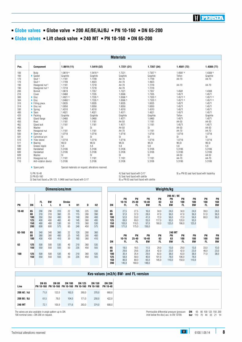
Pos. Component 1.0619 (11) 1.5419 (32) 1.7221 (31) 1.7357 (34) 1.4581 (72) 1.4308 (77) 100 Body 1.0619 4) 1.5419 5) 1.7221 1.7357 5) 1.4581 9) 1.4308 9)
160 4Gasket Graphite Graphite Graphite Graphite Teflon Graphite170 Stud 1) 1.1181 1.7709 A4-70 1.7709 A4-70 A4-70170 Stud 2) 1.7709 1.4923 A4-70 1.4923 190 Hexagonal nut 1) 1.1181 1.7218 A4-70 1.7218 A4-70 A4-70190 Hexagonal nut 2) 1.7218 1.7218 A4-70 1.7218 200 Bonnet 1.0619 1.7357 1.7221 1.7357 1.4581 1.4308210 Cover 1.0460 1.7335 1.0566 1.7335 1.4571 1.4571300 4Disc 1.4021 3) 1.7335 5) 1.0566 4) 1.7335 5) 1.4571 8) 1.4571 8)
304 4Disc 1.0460 3) 1.7335 5) 1.0566 4) 1.7335 5) 1.4571 8) 1.4571 8)
310 4Filling piece 1.0035 1.0035 1.0035 1.0035 1.4571 1.4571314 4Disc nut 1.0050 1.0050 1.0050 1.0050 1.4571 1.4571330 4Spring 1.4310 1.4310 1.4310 1.4310 1.4571 1.4571400 4Stem 1.4021 1.4021 1.4571 1.4021 1.4571 1.4571420 4Packing Graphite Graphite Graphite Graphite Teflon Graphite440 Gland flange 1.0460 1.0460 1.4571 1.0460 1.4571 1.4571450 Rivet 1.1181 1.1181 A4-50 1.1181 A4-50 A4-50462 Gland bolt 1.1181 1.1181 1.4571 1.1181 1.4571 1.4571463 Washer St St A4-50 St A4-50 A4-50464 Hexagonal nut 1.1181 1.1181 A4-70 1.1181 A4-70 A4-70500 4Stem nut 1.0718 1.0718 1.0718 1.0718 1.0718 1.0718501 4Cylindrical pin St St St St St St510 4 Yoke sleeve 1.0718 1.0718 1.0718 1.0718 1.0718 1.0718511 4 Bearing WLSt WLSt WLSt WLSt WLSt WLSt590 Grease nipple 5.8 5.8 5.8 5.8 5.8 5.8600 Handwheel 5.3106 5.3106 5.3106 5.3106 5.3106 5.3106600 Handwheel 5.3106 5.3106 5.3106 5.3106 5.3106 5.3106609 Washer St St St St A4-50 A4-50610 Hexagonal nut 1.1181 1.1181 1.1181 1.1181 A4-70 A4-70710 Anti-rotation device 5.3106 5.3106 5.3106 5.3106 5.3106 5.3106
4Spare parts Special materials on request; alterations reserved. 1) PN 10-40 4) Seat hard faced with Cr17 9) ≥ PN 63 seat hard faced with hastelloy 2) PN 63-160 5) Seat hard faced with stellite 3) Seat hard faced ≥ DN 125, 1.0460 seat hard faced with Cr17 8) ≥ PN 63 seat hard faced with stellite
Materials
DN 65 80 100 125 150 200bar 110 70 44 33 21 14
The valves are also available in angle pattern up to DN 100 nominal sizes > DN 200 on request.
Permissible differential pressure (pressure inlet below the disc) acc. to EN 13709.
DN 65 DN 80 DN 100 DN 125 DN 150 DN 200 Line PN 10-160 PN 10-160 PN 10-160 PN 10-160 PN 10-160 PN 10-40
200 AE / AJ 71,0 122,0 162,0 260,0 370,0 660,0
200 BE / BJ 61,5 78,0 104,0 171,0 250,0 422,0
240 MT 72,1 105,9 171,6 263,0 374,0 688,0
Kvs-values (m3/h) BW- and FL-version
FL BW StrokePN DN L L H h H1 D H2
10-40 65 290 290 310 22 105 225 330 80 310 310 360 25 115 280 390 100 350 350 400 30 140 280 400 125 400 400 465 40 145 360 495 150 480 480 530 50 170 360 530 200 600 600 575 65 240 450 575
63-160 65 340 340 360 22 120 280 360 80 380 380 400 25 145 280 400 100 430 430 410 30 165 360 410 63 125 500 500 535 40 210 360 535 150 550 550 555 50 235 450 555 100 125 500 500 535 40 210 360 535 150 550 550 555 50 235 450 555
Dimensions/mm 200 AE / BE
PN PN PN PN PN PN PN PN PN 10-16 25-40 10-40 63 63 100 100 160 160 DN FL FL BW FL BW FL BW FL BW 65 27,5 27,5 16,0 34,0 24,0 34,0 24,0 39,0 24,080 37,0 37,0 28,0 47,0 36,0 47,0 36,0 51,0 36,0100 52,0 53,0 41,0 72,0 56,0 72,0 56,0 80,0 56,0125 69,0 69,0 55,0 117,0 93,0 120,0 93,0150 103,0 110,5 97,0 160,0 125,0 166,0 125,0200 171,0 175,0 156,0
240 MT PN PN PN PN PN PN PN PN PN 10-16 25-40 10-40 63 63 100 100 160 160 DN FL FL BW FL BW FL BW FL BW
65 18,5 18,5 11,5 29,0 13,0 29,0 13,0 33,0 13,080 29,6 29,6 20,4 42,0 23,0 42,0 23,0 46,0 23,0100 35,4 35,4 29,0 63,0 38,0 63,0 38,0 71,0 38,0125 58,0 58,0 40,0 101,0 78,0 106,0 78,0 150 80,0 80,0 65,0 145,0 110,0 150,0 110,0 200 145,0 160,0 148,0
Weights/kg

D
L
H
D
L
H
DN 15-50
n Globe valves n VALTRA Bellow seal globe valve n 200 AL n PN 10-160 n DN 15-50n Globe valves n VALTRA Bellow seal globe valve n 200 AL n PN 10-40 (63-160) n DN 65-400 (DN 65-200)
Technical alterations reserved6100.1.09.149
DN 65-400
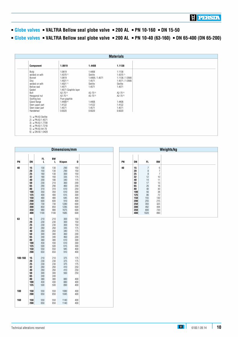
n Globe valves n VALTRA Bellow seal globe valve n 200 AL n PN 10-160 n DN 15-50n Globe valves n VALTRA Bellow seal globe valve n 200 AL n PN 10-40 (63-160) n DN 65-400 (DN 65-200)
Component 1.0619 1.4408 1.1138 Body 1.0619 1.4408 1.1138 welded on with 1.4370 1) Stellite 1.4370 1)
Bonnet 1.0619 1.4408 / 1.4571 1.1138 / 1.0566 Disc 1.4021 2) 1.4571 1.4571 / 1.0566 welded on with 1.4021 1) Stellite Stellite Bellow seal 1.4571 1.4571 1.4571 Gasket 1.4571 Graphite layer Bolt A2-70 3) A2-70 5) A2-70 5)
Hexagonal nut A2-70 4) A2-70 5) A2-70 5)
Stuffing box Pure graphite Gland flange 1.4408 6) 1.4408 1.4408 Stem upper part 1.4122 1.4122 1.4122 Stem lower part 1.4571 1.4571 1.4571 Handwheel 0.6020 0.6020 0.6020
1) ≥ PN 63 Stellite 2) ≥ PN 63 1.4571 3) ≥ PN 63 1.7709 4) ≥ PN 63 1.7218 5) ≥ PN 63 A4-70 6) ≥ DN 65 1.0420
Materials
Technical alterations reserved 6100.1.09.14 10
PN DN FL BW 40 15 7 6 20 8 7 25 8 7 32 12 10 40 14 11 50 17 13 65 26 18 80 40 30 100 56 38 125 86 72 150 155 130 200 255 215 250 393 325 300 492 444 350 800 720 400 1020 890
FL BW PN DN L L H/open D 40 15 130 130 290 150 20 150 130 290 150 25 160 130 300 150 32 180 160 335 175 40 200 180 340 175 50 230 210 360 200 65 290 290 460 200 80 310 310 610 250 100 350 350 610 300 125 400 400 615 300 150 480 480 645 400 200 600 600 910 400 250 730 730 1280 600 300 850 850 1285 600 350 980 980 1675 600 400 1100 1100 1685 600 63 15 210 210 300 150 20 230 230 300 150 25 230 230 300 150 32 260 260 335 175 40 260 260 340 175 50 300 300 360 200 65 340 340 460 200 80 380 380 610 300 100 430 430 610 300 125 500 500 615 300 150 550 550 945 400 200 650 650 910 400 100-160 15 210 210 375 175 20 230 230 375 175 25 230 230 375 175 32 260 260 410 250 40 260 260 410 250 50 300 300 560 250 65 340 340 80 380 380 880 400 100 430 430 880 400 125 500 500 890 400
100 150 550 550 1080 400 200 650 650 1045 400
160 150 550 550 1140 400 200 650 650 1140 400
Dimensions/mm Weights/kg

n Globe valves n High pressure globe valve HD 91 n 200 JM n PN 320 n DN 10-65/50
Technical alterations reserved6100.1.09.1411
Admissible operating pressure [bar] at design temperature [°C] 1)
Material PN -10 20 50 100 120 150 200 250 300 350 400 410 420 430 440 450 460 470 480 490 500 510 520 530 540 550 560 570 5802) 5902) 6002)
1.0460 160 160 160 160 160 160 160 151 132 118 99 80 76 73 69 65 61 54 45 37 250 250 250 250 250 250 250 235 206 184 155 125 119 113 107 102 96 85 71 58 320 320 320 320 320 320 320 302 264 236 198 160 153 145 138 130 123 109 91 75
1.5415 160 192 192 192 192 192 192 179 165 141 137 132 131 130 129 128 127 126 125 124 109 85 64 51 41 250 300 300 300 300 300 300 280 258 221 213 206 205 203 202 200 199 197 196 194 170 132 101 79 64 320 320 320 320 320 320 320 320 320 283 273 264 262 260 258 256 255 253 251 249 217 170 129 102 81 1.7335 160 192 192 192 192 192 192 192 189 174 165 156 154 152 150 148 146 145 144 143 142 129 109 86 70 57 44 36 29 250 300 300 300 300 300 300 300 294 272 258 243 240 237 234 231 228 227 225 224 222 202 170 134 109 88 69 57 46 320 320 320 320 320 320 320 320 320 320 320 311 307 304 300 296 292 290 289 287 285 258 217 172 140 113 88 72 59 1.7383 2) 160 192 192 192 192 192 192 192 192 189 174 165 163 161 159 157 156 154 152 150 143 127 111 97 85 74 64 55 48 41 36 32 250 300 300 300 300 300 300 300 300 294 272 258 255 252 249 246 243 240 237 234 224 199 174 152 132 115 100 85 75 65 56 49 320 320 320 320 320 320 320 320 320 320 320 320 320 320 319 315 311 307 304 300 287 255 223 194 170 147 128 109 96 83 72 63 1) Operating temperature = design temperature minus temperature surcharge acc. to DIN regulations. 2) For temperatures > 570 °C, stem in 1.4923 and hightemperature-packing.
Range of application
ASME v e r s i o n a v a i l a b l e
n Globe valves n High pressure globe valve HD 91 n 200 JM n PN 320 n DN 10-65/50
Standard features
n Disc and stem in one piecen Die-forged valve bodyn Non-turning, rising stemn Position indicatorn Throttle discn Yoke sleeve supported by needle bearingsn Possibility to add an actuator-flange
Pressure and temperature ratings
n Pressure rating 320 barn Temperature rating from -10 °C up to 600 °C
Materials
n 1.0460 n 1.5415n 1.7335n 1.7383
Further materials on request.
Design Highlights
n Body seat: edge seat welded on integratedly with stellite
n Disc / stem single piece of material > 570 °C with stellited edge seat
n Sealing to the outside only means of the gland packing
n Body and bonnet in two separate pieces with bolted connection
n Yoke sleeve supported by needle bearings (axial type)
n Possibility to add an actuator-flange
Benefits
n No pressed in or screwed seat ring, therefore no crevice corrosion or loosening
n No damages between disc and stem because of high flow velocity
n No bonnet gaskets, therefore reduction of possible leakage areas
n To ease maintenance work, e.g. regrinding of the body seats n To minimize the expenditure of effort when operating valve n Simple retrofitting of an electric actuator possible
Media
Depending on the material the globe valves are suitablefor water, gas, oil and other non aggressive media
Fields of application
High temperature steam and water, refining (catalytic reformers and hydrocrackers), petrochemical and chemi-cal industries, power plants
Technical alterations reserved 6100.1.09.14 12
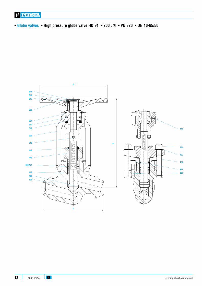
n Globe valves n High pressure globe valve HD 91 n 200 JM n PN 320 n DN 10-65/50
Technical alterations reserved6100.1.09.1413
590
464
463
462
192
172
619
610
613
600
531
511
510
200
716
448
440
420 421
412
400
100
D
L
H
590
464
463
462
192
172
619
610
613
600
531
511
510
200
716
448
440
420 421
412
400
100
D
L
H

n Globe valves n High pressure globe valve HD 91 n 200 JM n PN 320 n DN 10-65/50
Technical alterations reserved 6100.1.09.14 14
Pos. Component 1.0460 (21) 1.5415 (42) 1.7335 (44) 1.7383 (45) 100 Body 1.0460 1.5415 1.7335 1.7383 welded on with Stellite Stellite Stellite Stellite 172 Stud 1.7709 1.7709 1.7709 1.7709 192 Hexagonal nut 1.7218 1.7218 1.7218 1.7218 200 Bonnet 1.7379 1.7379 1.7379 1.7379 400 4Stem 1.4122 1) 1.4122 1) 1.4122 1) 1.4122 1)2) 412 Guide sleeve 0.7660 0.7660 0.7660 0.7660 420 / 421 4Packing Pure graphite Pure graphite Pure graphite Pure graphite 2) 440 Gland flange 1.7379 1.7379 1.7379 1.7379 448 4Dirt scraper Graphite plait Graphite plait Graphite plait Graphite plait 462 Stud 1.7709 1.7709 1.7709 1.7709 463 Washer St St St St 464 Hexagonal nut 1.7218 1.7218 1.7218 1.7218 510 4Yoke sleeve CW 713 R CW 713 R CW 713 R CW 713 R 511 4Bearing WLSt WLSt WLSt WLSt 531 Screwing 1.0460 1.0460 1.0460 1.0460 590 Grease nipple 5.8 5.8 5.8 5.8 600 Handwheel 5.3106 5.3106 5.3106 5.3106 610 Hexagonal nut St St St St 613 Screw pin 45H 45H 45H 45H 619 Lock washer ST ST ST ST 716 4Tension pin 1.0904 1.0904 1.0904 1.0904
4Spare parts 1) On request stem in 1.4923 with stellited seats 2) For temperatures > 570 °C stem with stellited seats in 1.4923 and hightemperature-packing
Materials
Kvs DN BW (m3/h) 10 4 2,315 4 3,420 6,9 6,225 6,9 7,932 23 20,040 23 24,150 23 28,365 / 50 23 28,3
Weights/kg and Kvs-values
DIN/ISODN L H Stroke R/Stroke D 5210
10 150 208 10 5 140 F07/F10 15 150 208 10 5 140 F07/F1020 160 250 16 8 180 F1025 160 250 16 8 180 F1032 250 415 27 9 280 F10/F1440 250 415 27 9 280 F10/F1450 250 415 27 9 280 F10/F1465 / 50 250 415 27 9 280 F10/F14
Attention: In case of welding connections the permissibleoperating overpressure is valid for the corresponding tube dimension.
Dimensions/mm
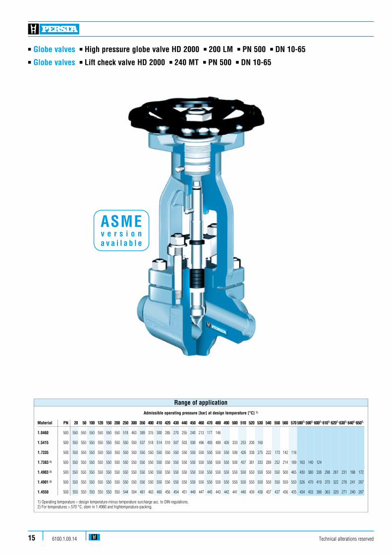
n Globe valves n High pressure globe valve HD 2000 n 200 LM n PN 500 n DN 10-65
Technical alterations reserved6100.1.09.1415
n Globe valves n Lift check valve HD 2000 n 240 MT n PN 500 n DN 10-65
Admissible operating pressure [bar] at design temperature [°C] 1)
Material PN 20 50 100 120 150 200 250 300 350 400 410 420 430 440 450 460 470 480 490 500 510 520 530 540 550 560 570 5802) 5902) 6002) 6102) 6202) 6302) 6402) 6502)
1.0460 500 550 550 550 550 550 550 518 463 389 315 300 285 270 255 240 213 177 146 1.5415 500 550 550 550 550 550 550 550 550 537 518 514 510 507 503 500 496 493 489 426 333 253 200 160 1.7335 500 550 550 550 550 550 550 550 550 550 550 550 550 550 550 550 550 550 550 550 500 426 338 275 222 173 142 116 1.7383 2) 500 550 550 550 550 550 550 550 550 550 550 550 550 550 550 550 550 550 550 550 500 437 381 333 289 252 214 189 163 140 124 1.4903 2) 500 550 550 550 550 550 550 550 550 550 550 550 550 550 550 550 550 550 550 550 550 550 550 550 550 550 500 465 430 380 338 298 261 231 198 172
1.4901 2) 500 550 550 550 550 550 550 550 550 550 550 550 550 550 550 550 550 550 550 550 550 550 550 550 550 550 550 550 526 470 419 370 322 278 241 207
1.4550 500 550 550 550 550 550 550 544 504 481 463 460 456 454 451 449 447 445 443 442 441 440 439 438 437 437 436 435 434 433 396 363 320 271 240 207
1) Operating temperature = design temperature minus temperature surcharge acc. to DIN regulations. 2) For temperatures > 570 °C, stem in 1.4980 and hightemperature-packing.
Range of application
ASME v e r s i o n a v a i l a b l e
n Globe valves n High pressure globe valve HD 2000 n 200 LM n PN 500 n DN 10-65
Technical alterations reserved 6100.1.09.14 16
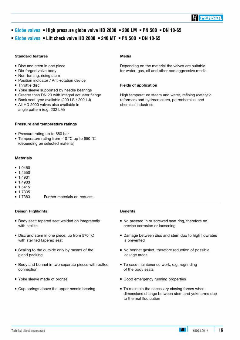
Standard features
n Disc and stem in one piecen Die-forged valve bodyn Non-turning, rising stemn Position indicator / Anti-rotation devicen Throttle discn Yoke sleeve supported by needle bearingsn Greater than DN 20 with integral actuator flangen Back seat type available (200 LS / 200 LJ)n All HD 2000 valves also available in angle pattern (e.g. 202 LM) Pressure and temperature ratings
n Pressure rating up to 550 bar n Temperature rating from -10 °C up to 650 °C (depending on selected material)
Materials
n 1.0460n 1.4550n 1.4901n 1.4903 n 1.5415n 1.7335n 1.7383 Further materials on request.
Design Highlights
n Body seat: tapered seat welded on integratedly with stellite
n Disc and stem in one piece; up from 570 °C with stellited tapered seat
n Sealing to the outside only by means of the gland packing
n Body and bonnet in two separate pieces with bolted connection
n Yoke sleeve made of bronze
n Cup springs above the upper needle bearing
Benefits
n No pressed in or screwed seat ring, therefore no crevice corrosion or loosening
n Damage between disc and stem duo to high flowrates is prevented
n No bonnet gasket, therefore reduction of possible leakage areas
n To ease maintenance work, e.g. regrinding of the body seats
n Good emergency running properties
n To maintain the necessary closing forces when dimensions change between stem and yoke arms due to thermal fluctuation
Media
Depending on the material the valves are suitablefor water, gas, oil and other non aggressive media
Fields of application
High temperature steam and water, refining (catalytic reformers and hydrocrackers, petrochemical and chemical industries
n Globe valves n Lift check valve HD 2000 n 240 MT n PN 500 n DN 10-65
Technical alterations reserved6100.1.09.1417
n Globe valves n High pressure globe valve HD 2000 n 200 LM n PN 500 n DN 10-65
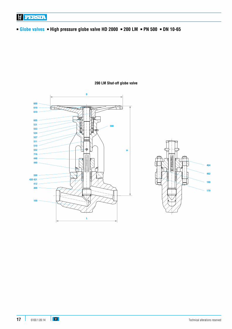
200 LM Shut-off globe valve
590
600
619
610
605
531
553
524
527
511
510
552
716
448
440
200
420 421
412
400
100
464
462
190
170
D
L
H

D
600
619
610
605
531
553
524
527
511
510
552
716
448
440
200
420 421
412
400
100
H
L1
590
L1
Technical alterations reserved 6100.1.09.14 18
n Globe valves n High pressure globe valve HD 2000 n 202 LM n PN 500 n DN 10-65
202 LM Shut-off globe valve

600
619
610
605
531
553
524
527
511
510
552
716
448
440
200
420 421
412
400
330
304
100
D
L
H
590
600
619
610
605
531
553
524
527
511
510
552
716
448
440
200
420 421
412
411
400
100
D
L
H
590
192
172
210
160
308
330
100
304
H
L
Technical alterations reserved6100.1.09.1419
n Globe valves n High pressure globe valve HD 2000 n 200 LS n PN 500 n DN 10-65
n Globe valves n Lift check valve HD 2000 n 240 MT n PN 500 n DN 10-65
n Globe valves n Stop check valve n 240 MM n PN 500 n DN 10-65
240 MM Stop check valve
also available in angle pattern
200 LS globe valve with back seat
also available in angle pattern
240 MT Lift check valve
also available in angle pattern
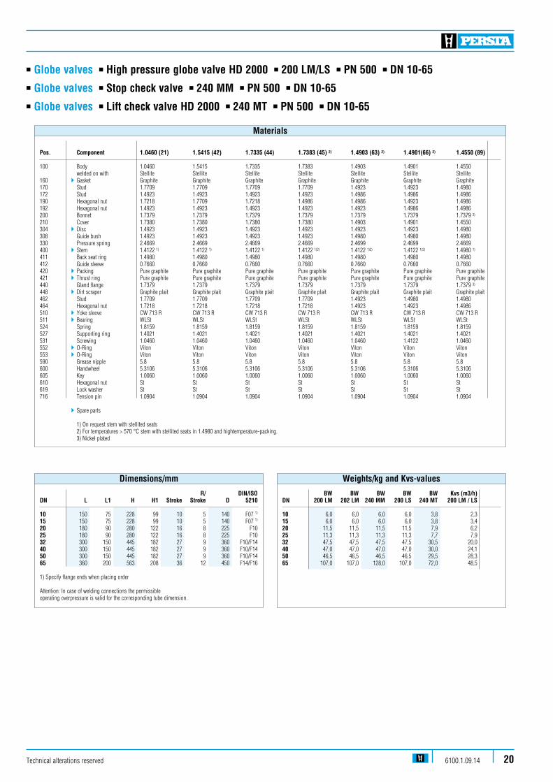
BW BW BW BW BW Kvs (m3/h) DN 200 LM 202 LM 240 MM 200 LS 240 MT 200 LM / LS
10 6,0 6,0 6,0 6,0 3,8 2,315 6,0 6,0 6,0 6,0 3,8 3,420 11,5 11,5 11,5 11,5 7,9 6,225 11,3 11,3 11,3 11,3 7,7 7,932 47,5 47,5 47,5 47,5 30,5 20,040 47,0 47,0 47,0 47,0 30,0 24,150 46,5 46,5 46,5 46,5 29,5 28,365 107,0 107,0 128,0 107,0 72,0 48,5
Weights/kg and Kvs-values
R/ DIN/ISODN L L1 H H1 Stroke Stroke D 5210
10 150 75 228 99 10 5 140 F07 1)
15 150 75 228 99 10 5 140 F07 1)
20 180 90 280 122 16 8 225 F1025 180 90 280 122 16 8 225 F1032 300 150 445 182 27 9 360 F10/F1440 300 150 445 182 27 9 360 F10/F1450 300 150 445 182 27 9 360 F10/F1465 360 200 563 208 36 12 450 F14/F16
1) Specify flange ends when placing order
Attention: In case of welding connections the permissibleoperating overpressure is valid for the corresponding tube dimension.
Dimensions/mm
Technical alterations reserved 6100.1.09.14 20
n Globe valves n High pressure globe valve HD 2000 n 200 LM/LS n PN 500 n DN 10-65
n Globe valves n Lift check valve HD 2000 n 240 MT n PN 500 n DN 10-65
n Globe valves n Stop check valve n 240 MM n PN 500 n DN 10-65
Pos. Component 1.0460 (21) 1.5415 (42) 1.7335 (44) 1.7383 (45) 2) 1.4903 (63) 2) 1.4901(66) 2) 1.4550 (89)
100 Body 1.0460 1.5415 1.7335 1.7383 1.4903 1.4901 1.4550 welded on with Stellite Stellite Stellite Stellite Stellite Stellite Stellite160 4Gasket Graphite Graphite Graphite Graphite Graphite Graphite Graphite170 Stud 1.7709 1.7709 1.7709 1.7709 1.4923 1.4923 1.4980 172 Stud 1.4923 1.4923 1.4923 1.4923 1.4986 1.4986 1.4986190 Hexagonal nut 1.7218 1.7709 1.7218 1.4986 1.4986 1.4923 1.4986192 Hexagonal nut 1.4923 1.4923 1.4923 1.4923 1.4923 1.4986 1.4986200 Bonnet 1.7379 1.7379 1.7379 1.7379 1.7379 1.7379 1.7379 3)
210 Cover 1.7380 1.7380 1.7380 1.7380 1.4903 1.4901 1.4550304 4Disc 1.4923 1.4923 1.4923 1.4923 1.4923 1.4923 1.4980308 Guide bush 1.4923 1.4923 1.4923 1.4923 1.4980 1.4980 1.4980330 Pressure spring 2.4669 2.4669 2.4669 2.4669 2.4699 2.4699 2.4669400 4Stem 1.4122 1) 1.4122 1) 1.4122 1) 1.4122 1)2) 1.4122 1)2) 1.4122 1)2) 1.4980 1)
411 Back seat ring 1.4980 1.4980 1.4980 1.4980 1.4980 1.4980 1.4980412 Guide sleeve 0.7660 0.7660 0.7660 0.7660 0.7660 0.7660 0.7660420 4Packing Pure graphite Pure graphite Pure graphite Pure graphite Pure graphite Pure graphite Pure graphite421 4Thrust ring Pure graphite Pure graphite Pure graphite Pure graphite Pure graphite Pure graphite Pure graphite440 Gland flange 1.7379 1.7379 1.7379 1.7379 1.7379 1.7379 1.7379 3)
448 4Dirt scraper Graphite plait Graphite plait Graphite plait Graphite plait Graphite plait Graphite plait Graphite plait462 Stud 1.7709 1.7709 1.7709 1.7709 1.4923 1.4980 1.4980464 Hexagonal nut 1.7218 1.7218 1.7218 1.7218 1.4923 1.4923 1.4986510 4Yoke sleeve CW 713 R CW 713 R CW 713 R CW 713 R CW 713 R CW 713 R CW 713 R511 4Bearing WLSt WLSt WLSt WLSt WLSt WLSt WLSt524 Spring 1.8159 1.8159 1.8159 1.8159 1.8159 1.8159 1.8159527 Supporting ring 1.4021 1.4021 1.4021 1.4021 1.4021 1.4021 1.4021531 Screwing 1.0460 1.0460 1.0460 1.0460 1.0460 1.4122 1.0460552 4 O-Ring Viton Viton Viton Viton Viton Viton Viton553 4O-Ring Viton Viton Viton Viton Viton Viton Viton590 Grease nipple 5.8 5.8 5.8 5.8 5.8 5.8 5.8600 Handwheel 5.3106 5.3106 5.3106 5.3106 5.3106 5.3106 5.3106605 Key 1.0060 1.0060 1.0060 1.0060 1.0060 1.0060 1.0060610 Hexagonal nut St St St St St St St619 Lock washer St St St St St St St716 Tension pin 1.0904 1.0904 1.0904 1.0904 1.0904 1.0904 1.0904 4Spare parts
1) On request stem with stellited seats 2) For temperatures > 570 °C stem with stellited seats in 1.4980 and hightemperature-packing. 3) Nickel plated
Materials

n Globe valves n High pressure globe valve DVA 25 / DVA 40 n 200 BZ n PD 25 / PD 40 n DN 80-250
Technical alterations reserved6100.1.09.1421
BW- Admissible operating pressure [bar] at design temperature [°C] 1)
VersionMaterial PD 20 50 100 120 150 200 250 300 350 400 410 420 430 440 450 460 470 480 490 500 510 520 530 540 550 560 570 580 590 600 610 620 630 640 650
1.0460 25 250 250 250 250 250 235 206 184 155 125 119 113 107 102 96 85 71 58
1.5415 25 300 300 300 300 300 280 258 221 213 206 205 203 202 200 199 197 196 194 170 132 101 80 64
1.7335 25 300 300 300 300 300 300 294 272 258 243 240 237 234 231 228 227 225 224 222 202 170 134 110 88 69 57 46
1.7380 25 300 300 300 300 300 300 300 294 272 258 255 252 249 246 243 240 237 234 224 199 174 152 132 115 100 85 75 65 56 49
1.6368 25 320 320 320 320 320 320 320 320 320 320 320 320 320 320 320 309 257 205 153 102
1.4903 25 320 320 320 320 320 320 320 320 320 320 320 320 320 320 320 320 320 320 320 320 320 316 290 263 238 213 191 169 150 132 115 100 85 75 65
1.4901 25 320 320 320 320 320 320 320 320 320 320 320 320 320 320 320 320 320 320 320 320 320 320 320 297 275 253 231 209 187 166 147 128 110 96 82 1) Operating temperature = design temperature minus temperature surcharge acc. to DIN regulations.
Attention: Pressure rating of the materials 1.6368, 1.4903 and 1.4901 was reduced in the “cold” range to 320 bar. This pressure rating is only valid for the DVA 25.
BW- Admissible operating pressure [bar] at design temperature [°C] 1)
VersionMaterial PD 20 50 100 120 150 200 250 300 350 400 410 420 430 440 450 460 470 480 490 500 510 520 530 540 550 560 570 580 590 600 610 620 630 640 650
1.0460 40 400 400 400 400 400 377 330 295 248 200 191 182 172 163 153 136 113 93
1.5415 40 480 480 480 480 480 448 413 354 342 330 328 325 323 321 318 316 314 311 272 212 161 127 102
1.7335 40 481 481 481 481 481 481 471 436 413 389 384 380 375 370 365 363 361 358 356 323 272 215 175 141 110 91 74
1.7380 40 480 480 480 480 480 480 480 471 436 413 408 403 398 394 389 384 380 375 358 318 278 243 212 184 160 137 120 104 90 79
1.6368 40 600 600 600 600 600 600 600 600 600 600 600 600 600 600 577 495 412 328 245 163
1.4903 40 600 600 600 600 600 600 600 600 600 600 600 600 600 600 600 600 600 600 600 596 551 506 464 422 382 342 306 271 240 212 184 160 137 120 104
1.4901 40 600 600 600 600 600 600 600 600 600 600 600 600 600 600 600 600 600 600 600 600 600 553 513 475 440 405 369 334 299 266 235 205 177 153 132 1) Operating temperature = design temperature minus temperature surcharge acc. to DIN regulations. Attention: Pressure rating of the materials 1.6368, 1.4903 and 1.4901 was reduced in the “cold” range to 600 bar. This pressure rating is only valid for the DVA 40.
Range of application
Range of application
ASME v e r s i o n a v a i l a b l e

n Globe valves n High pressure globe valve DVA 25 / DVA 40 n 200 BZ n PD 25 / PD 40 n DN 80-250
Technical alterations reserved 6100.1.09.14 22
Design Highlights
n Die-forged body and bonnet
n Pressure sealing bonnet
n Body seat welded on integratedly with stellite
n Extended bonnet
n Outside located anti twist device
n Non-turning, rising stem
n Gland flange and gland ring in two separate pieces
n Yoke sleeve supported by needle bearings
n Cup springs above the upper needle bearing
Benefits
n Free from porosity and shrink holes
n Best possible sealing function
n Extremely resistant to wear
n To reduce temperatures
n Usable as position indicator
n Minimum packing wear
n Damage to the stem by irregular tightening of gland bolts is avoided
n To minimize the expenditure of effort when operating the valve
n To maintain the necessary closing forces at elongation changes between stem and yoke arms due to thermal changes. Also to protect against excess torsion when electric actuators are fitted.
Standard features
n Straight patternn Die-forged valve body and bonnetn Pressure sealing bonnet acc. to VGB-guidelinesn Throttle discn Body seat welded on integratedlyn Outside screw and yoke n Position indicator / Anti-rotation devicen Yoke sleeve supported at the top and the bottom By means of needle bearingsn Non-turning, rising stemn Universal valve head for mounting actuators
Pressure and temperature ratings
n Pressure rating up to 600 barn Temperature rating up to 650 °C
Materials
n 1.0460 n 1.5415 n 1.7335n 1.7383 n 1.6368n 1.4903 n 1.4901 Further materials and sizes on request.
Media
Depending on the material the globe valves are suitablefor water, gas, oil and other non aggressive media
Fields of application
Chemical industries, industries and power plant.

n Globe valves n High pressure globe valve DVA 25 / DVA 40 n 200 BZ n PD 25 / PD 40 n DN 80-250
Technical alterations reserved6100.1.09.1423
L
DS
540
524
510
511
200
464
462
440
190
170
273
420
272
271
160
270
400
311
300
100
H
540
524
510
511
200
464
440
462
190
170
420
273
272
271
160
270
400
311
300
100 DS
L
H
DVA 25 n PD 25 n DN 80-250
DVA 40 n PD 40 n DN 80-200

DIN/ISO DN DS L H Stroke R/Stroke H-Wheel 5210
80 64 305 450 (475) 32 11 450 F10 (F14)100 82 406 575 42 14 500 F14125 100 483 675 (725) 51 17 600 F14 (F16)150 122 559 800 (850) 62 21 720 F16 (F25)200 160 711 950 (1000) 82 27 F25 (F30)250 190 864 1075 (1150) 96 24 F30 (F35)
n Globe valves n High pressure globe valve DVA 25 / DVA 40 n 200 BZ n PD 25 / PD 40 n DN 80-250
Pos. Component 1.0460 (21) 1.5415 (42) 1.7335 (44) 1.7383 (45) 1.6368 (46) 1.4903 (63) 1.4901 (66)
100 Body 1.0460 1.5415 1.7335 1.7383 1.6368 1.4903 1.4901 welded on with Stellite Stellite Stellite Stellite Stellite Stellite Stellite160 4Gasket Graphite Graphite Graphite Graphite Graphite Graphite Graphite170 Stud 1.7709 1.7709 1.7709 1.7709 1.4923 1.4923 1.4923190 Hexagonal nut 1.7218 1.7218 1.7218 1.7218 1.7218 1.7218 1.7218200 Bonnet 1.7379 1.7379 1.7379 1.7379 1.7379 1.7379 1.7379270 Cover 1.7383 1.7383 1.7383 1.7383 1.4903 1.4903 1.4901271 Thrust ring 1.7383 1.7383 1.7383 1.7383 1.4903 1.4903 1.4901272 Segmentring 1.7383 1.7383 1.7383 1.7383 1.4903 1.4903 1.4901273 Cover 1.5419 1.5419 1.5419 1.5419 1.5419 1.5419 1.5419300 4Disc 1.4903 1.4903 1.4903 1.4903 1.4903 1.4903 1.4901 welded on with Stellite Stellite Stellite Stellite Stellite Stellite Stellite311 Grooved pin 1.4571 1.4571 1.4571 1.4571 1.4571 1.4571 1.4571400 4Stem 1.4122 1.4122 1.4122 1.4122 1.4923 1.4923 1.4980400 4Stem up to 500°C 1.4980* 1.4980 1.4980 420 4Packing Graphite Graphite Graphite Graphite Graphite Graphite Graphite440 Gland flange 1.7380 1.7380 1.7380 1.7380 1.7380 1.7380 1.7380462 Stud 1.7709 1.7709 1.7709 1.7709 1.4923 1.4923 1.4923464 Hexagonal nut 1.7218 1.7218 1.7218 1.7218 1.4923 1.4923 1.4923510 4Yoke sleeve CW713R CW713R CW713R CW713R CW713R CW713R CW713R511 4Bearing WLSt WLSt WLSt WLSt WLSt WLSt WLSt524 Spring Spring Steel Spring Steel Spring Steel Spring Steel Spring Steel Spring Steel Spring Steel540 Flange 1.0460 1.0460 1.0460 1.0460 1.0460 1.0460 1.0460 4Spare parts * In PD 25 up to DN 150 * In PD 40 up to DN 125
Materials
Technical alterations reserved 6100.1.09.14 24
Kvs DN BW (m3/h) 80 69 71100 132 95125 200 141150 378 210200 615 362250 1120 510
Weights/kg and Kvs-values DVA 25Dimensions/mm DVA 25
DIN/ISO DN DS L H Stroke R/Stroke H-Wheel 5210
80 57 368 575 28 9 500 F14100 72 359 675 (725) 38 13 600 F14 (F16)125 90 533 800 (850) 45 15 720 F16 (F25)150 111 610 950 (1000) 57 19 F25 (F30)200 146 762 1075 (1150) 75 19 F30 (F35)
Kvs DN BW (m3/h) 80 145 45100 225 73125 430 114150 715 174200 1140 300
Weights/kg and Kvs-values DVA 40Dimensions/mm DVA 40
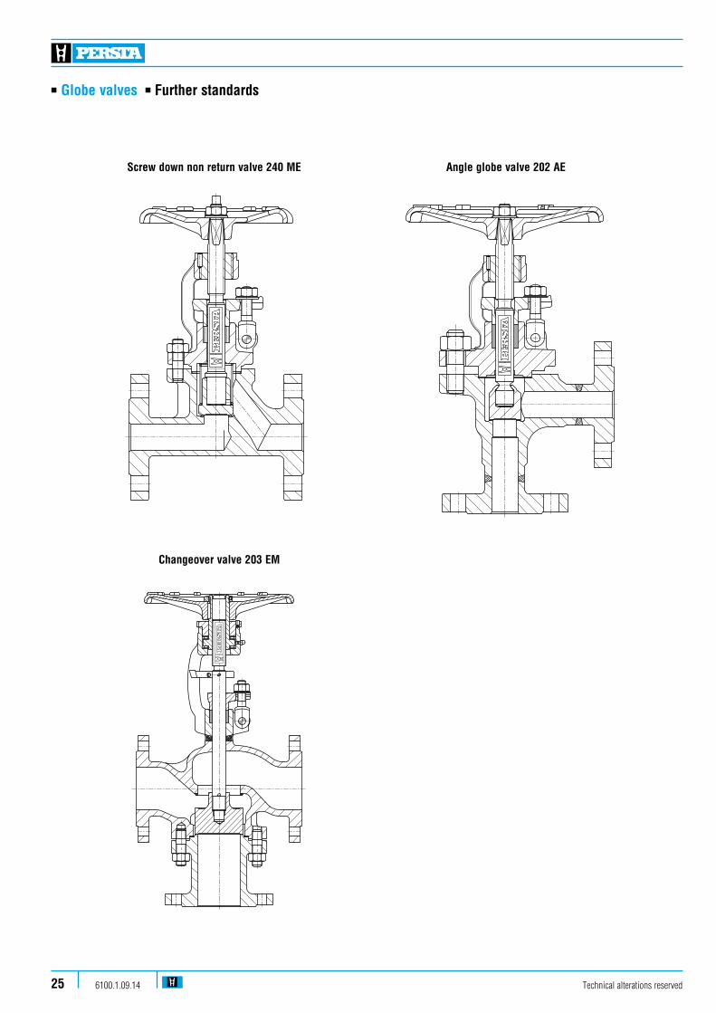
n Globe valves n Further standards
Screw down non return valve 240 ME Angle globe valve 202 AE
Changeover valve 203 EM
Technical alterations reserved6100.1.09.1425
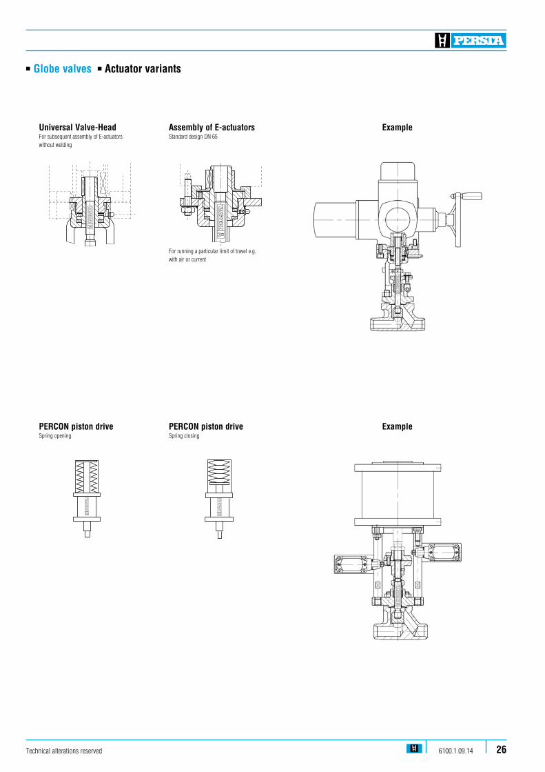
n Globe valves n Actuator variants
Example
ExamplePERCON piston driveSpring opening
Universal Valve-HeadFor subsequent assembly of E-actuators without welding
PERCON piston driveSpring closing
Assembly of E-actuatorsStandard design DN 65
For running a particular limit of travel e.g. with air or current
Technical alterations reserved 6100.1.09.14 26
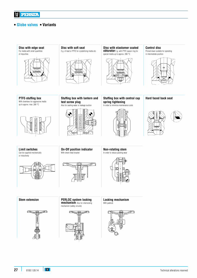
n Globe valves n Variants
Technical alterations reserved6100.1.09.1427
Disc with edge seat For media with small quantities of impurities
Disc with soft seatE.g. of lead or PTFE for crystallizing media etc.
Disc with elastomer coated obturator E.g. with PTFE spacer ring for special media up to approx. 280 °C
Control disc Pinned down suitable for operating in intermediate position
PTFE-stuffing boxWith chambers for aggressive media up to approx. max. 280 °C
Stuffing box with lantern and test screw plugAlso for sealing water or leakage suction
Stuffing box with central cup spring tighteningIn order to minimize maintenance costs
Hard faced back seat
Limit switchesCan be supplied mechanically or inductively
On-Off position indicator With sheet metal bracket
Non-rotating stem In order to reduce packing wear
Stem extension PERLOC system locking mechanism Also for interlocking mechanism (safety circuits)
Locking mechanismWith padlock
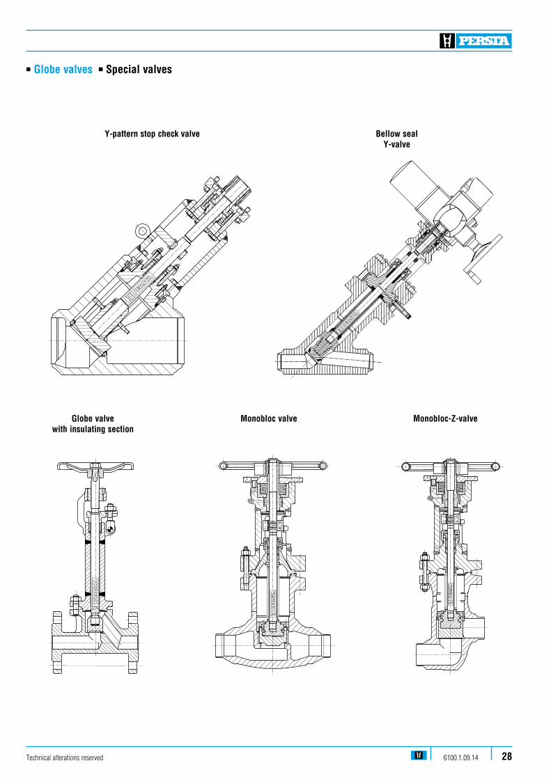
n Globe valves n Special valves
Globe valve with insulating section
Y-pattern stop check valve
Monobloc valve
Bellow sealY-valve
Monobloc-Z-valve
Technical alterations reserved 6100.1.09.14 28
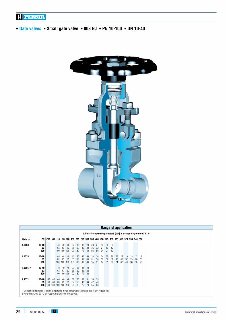
n Gate valves n Small gate valve n 808 GJ n PN 10-100 n DN 10-40
Technical alterations reserved6100.1.09.1429
Admissible operating pressure [bar] at design temperature [°C] 1)
Material PN -200 -60 -10 20 120 150 200 250 300 350 400 450 475 480 500 510 520 530 540 550
1.0460 10-40 40 40 40 37 35 32 28 24 21 13 8 7 63 63 63 63 56 50 45 40 36 32 21 13 12 100 100 100 100 90 80 70 60 56 50 34 21 19 1.7335 10-40 40 40 40 40 40 40 40 38 36 34 32 31 29 24 19 15 12 9 63 63 63 63 63 63 63 63 61 58 56 52 51 47 40 32 25 20 15 100 100 100 100 100 100 100 100 95 91 87 81 79 74 62 49 38 30 23 1.0566 2) 10-40 40 40 40 37 35 34 28 63 63 63 63 58 50 45 40 100 100 100 100 92 80 70 60 1.4571 10-40 40 40 40 40 40 38 35 33 31 30 29 63 63 63 63 63 63 57 50 47 44 42 40 100 100 100 100 100 100 90 80 75 70 65 60
1) Operating temperature = design temperature minus temperature surcharge acc. to DIN regulations.2) At temperature > 50 °C only applicable for short-time service.
Range of application

n Gate valves n Small gate valve n 808 GJ n PN 10-100 n DN 10-40
Standard features
n Die-forged body and bonnetn Full boren Wedgen Outside screw and yoken Non-turning rising stemn Available with flange, socket and buttweld ends
Pressure and temperature ratings
n Pressure rating up to 100 barn Temperature rating up to 550 °C
Materials
n 1.0460 n 1.7335 n 1.0566 n 1.4571 Further materials on request.
Media
Depending on the material the gate valves are suitablefor water, gas, oil and other non aggressive media
Fields of application
Chemical industries, power plants, ship building and other
Design Highlights
n Die-forged body and bonnet
n Wedge made of stellite
n Gasket, male and female face
n Full bore
n Non-turning, rising stem
Benefits
n Free from porosity and shrink holes
n Extremely resistant to wear
n Blow out protection
n No reduction in seat area
n Minimal wear of the gland-packing
Technical alterations reserved 6100.1.09.14 30
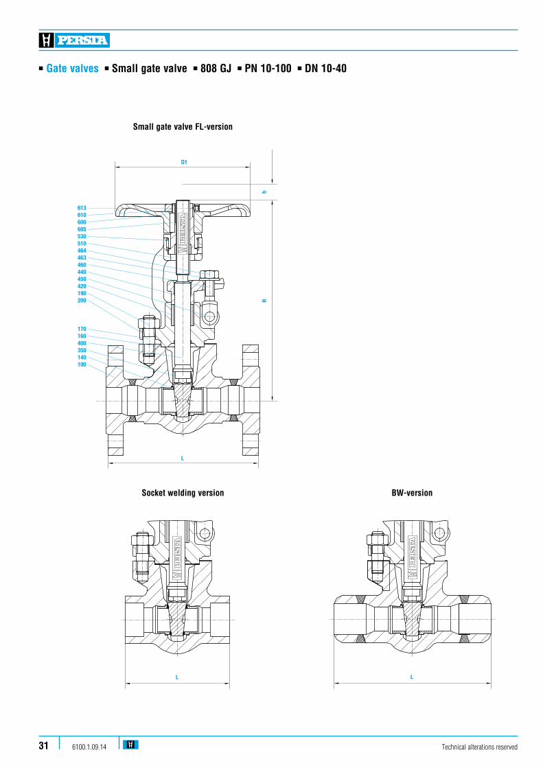
n Gate valves n Small gate valve n 808 GJ n PN 10-100 n DN 10-40
613610600605530510464463460440450420190200
170160400350140100
hH
L
D1
Technical alterations reserved6100.1.09.1431
L L
Small gate valve FL-version
Socket welding version BW-version

n Gate valves n Small gate valve n 808 GJ n PN 10-100 n DN 10-40
FL BW SM KvsPN DN L L L H Stroke D1 (m3/h) 10-100 10 105 205 27 140 15 130 130 105 205 27 140 14,2 20 150 150 105 205 27 140 29,2 25 160 160 105 205 27 140 39,5 32 180 180 115 228 35 180 74,7 40 240 240 115 228 35 180 95,3
Dimensions/mm and Kvs-values
Pos. Component 1.0460 (21) 1.7335 (44) 1.0566 (25) 1.4571 (87)
100 Body 1.0460 1.7335 1.0566 1.4571140 Seat ring 1.4571 1.4571 1) 1.4571 1.4571160 4 Gasket Graphite Graphite Graphite Graphite170 Stud 1.7709 1.4923 A4-70 A4-70190 Hexagonal nut 1.7218 1.4923 A4-70 A4-70200 Bonnet 1.0460 1.7335 1.0566 1.4571350 Wedge 1.4021 2.5788 2.5788 2.5788400 4 Stem 1.4021 1.4021 1.4571 1.4571420 4 Packing Graphite Graphite Graphite Graphite440 Gland flange 1.0460 1.0460 1.4571 1.4571450 Rivet 1.1181 1.1181 A4-50 A4-50460 Gland bolt 1.1181 1.1181 1.4571 1.4571463 Washer St St A4-50 A4-50464 Hexagonal nut 1.1181 1.1181 A4-70 A4-70510 4 Yoke sleeve 1.0718 1.0718 1.0718 1.0718530 Yoke nut 1.0718 1.0718 1.0718 1.0718600 Handwheel 0.7040 0.7040 0.7040 0.7040605 Key 1.0060 1.0060 1.0060 1.0060610 Hexagonal nut St St St St613 Screw pin 45H 45H 45H 45H 4Spare parts
1) Welded on with Stellite
Materials
Technical alterations reserved 6100.1.09.14 32

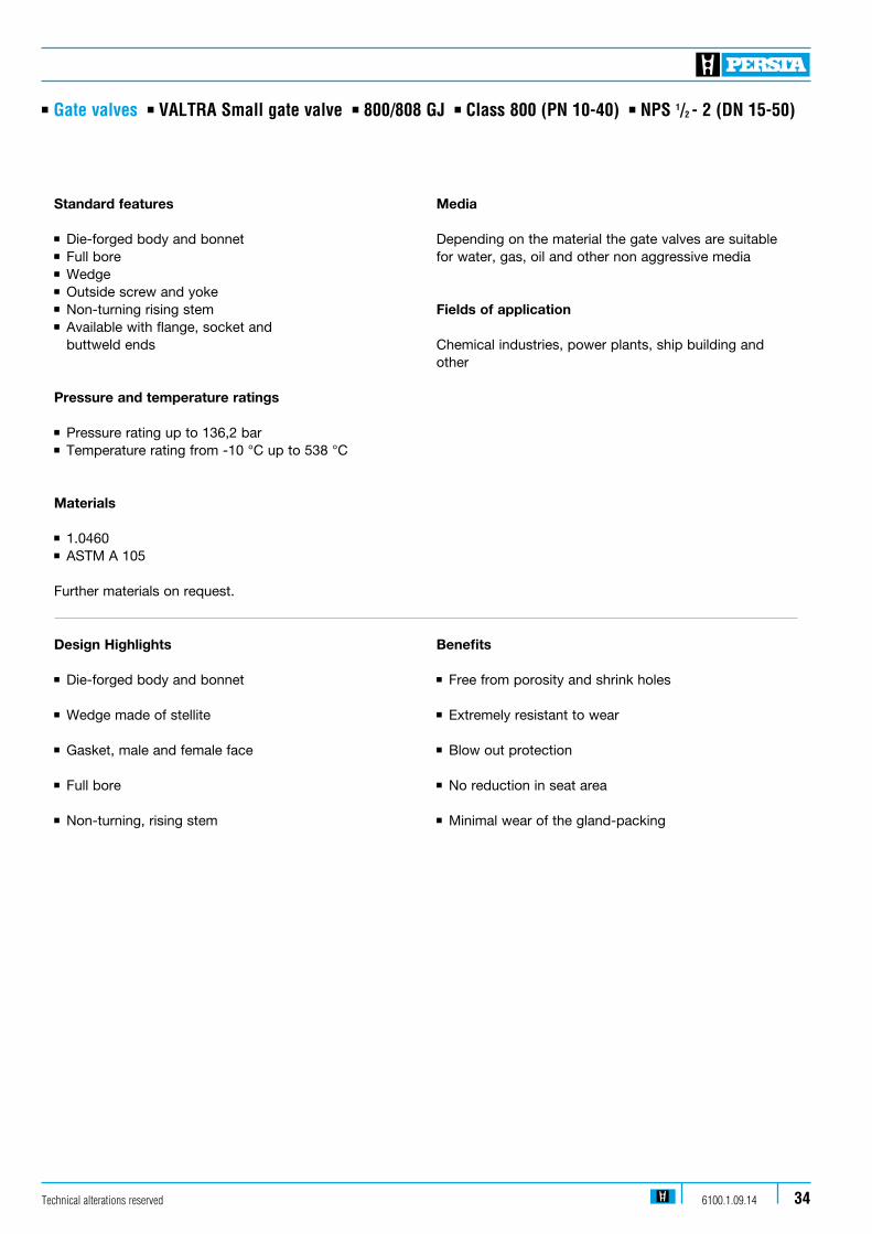
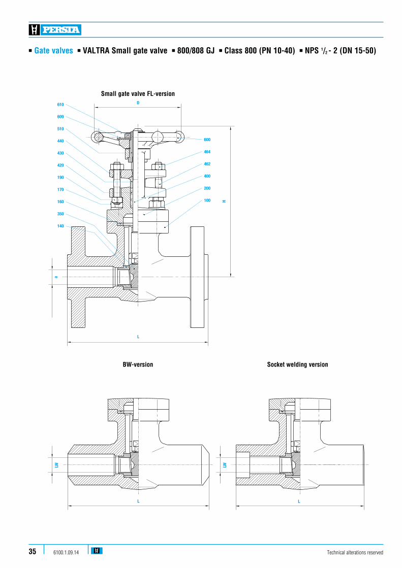
n Gate valves n VALTRA Small gate valve n 800/808 GJ n Class 800 (PN 10-40) n NPS 1/2 - 2 (DN 15-50)
Technical alterations reserved6100.1.09.1433
Admissible operating pressure [bar] at design temperature [°C] 1)
Material PN -10 20 100 150 200 250 300 350 400 450 475 480
1.0460 10-40 40 40 40 37 35 32 28 24 21 13 8 7
1) Operating temperature = design temperature minus temperature surcharge acc. to DIN regulations.
Range of application
Admissible operating pressure [bar] at design temperature [°C] 1)
Material -29 38 93,5 149 204,5 260 315,5 343,5 371 399 426,5 454,5 482 510 538 ASTM A 105 Class 800 136,2 136,2 124,1 120,7 116,6 110,0 100,7 98,6 97,9 92,7 75,9 49,3 31,7 19,0 9,7 1) Operating temperature = design temperature minus temperature surcharge acc. to DIN regulations.
n Gate valves n VALTRA Small gate valve n 800/808 GJ n Class 800 (PN 10-40) n NPS 1/2 - 2 (DN 15-50)
Standard features
n Die-forged body and bonnetn Full boren Wedgen Outside screw and yoken Non-turning rising stemn Available with flange, socket and buttweld ends
Pressure and temperature ratings
n Pressure rating up to 136,2 barn Temperature rating from -10 °C up to 538 °C
Materials
n 1.0460 n ASTM A 105
Further materials on request.
Media
Depending on the material the gate valves are suitablefor water, gas, oil and other non aggressive media
Fields of application
Chemical industries, power plants, ship building and other
Design Highlights
n Die-forged body and bonnet
n Wedge made of stellite
n Gasket, male and female face
n Full bore
n Non-turning, rising stem
Benefits
n Free from porosity and shrink holes
n Extremely resistant to wear
n Blow out protection
n No reduction in seat area
n Minimal wear of the gland-packing
Technical alterations reserved 6100.1.09.14 34
n Gate valves n VALTRA Small gate valve n 800/808 GJ n Class 800 (PN 10-40) n NPS 1/2 - 2 (DN 15-50)
BONNET
SIEKMANN ECONOSTO GMBH &
9021290OP STOCK
DKSR418032E001N
14
071948 008
GATE VALVE OS#Y BB FB FL DIN
DN25 " C22.8/1.4021 NACE PN40 FORM B1
4B 105 LC. TA LUFT 008
0719
48
PACKING
-FLANGES ACCORDING TO DIN 2501.-VALVE CONFORM TO NACE MR 01-75.
PN40
DN25 6,4
27/0
3/20
080 L
VF-
RA
OU
L
NUT CARBON STEEL 11NAMEPLATE ALLUMINIUM 12HANDWHEEL ASTM A105N 13YOKE SLEEVE AISI416 14
SEAT
DIN 17243 (1.0460) C22.8 15GLAND NUT CK35-1.1181 46GLAND STUD EN 10269 - C35 27GLAND FLANGE ASTM A105N 18PACKING GLAND A479 TP316/L 19
EN 10088-3 (1.4021) X20Cr13
QGCTF05-07+TE.GE/CR 110BOLTS
1
411GASKET
21CrMoV 5.7 - 1.7709112 F316+GRAPHITE
15
113
2
DIN 17243 (1.0460) C22.8
114STEM EN 10088-3 (1.4021) X20Cr13
WEDGE EN 10088-3 (1.4021) X20Cr13
BODY
General Notes
16
No.POS MATERIALPART NAME
Fogaroli
DR
AW
:
CH
EC
KE
D:
FIG. No.:
DESCRIPTION:
SIZE: WEIGHT
P.O. No.:
TAG No.:
DOCUMENT:
PO
S.
CLASS:
RE
V.
RE
V.
RE
V.
RE
V.
DA
TE
:
DA
TE
:
DA
TE
:
DA
TE
:
CUSTOMER:
SHEET:
JO
B:
ITEM No.:
KG:
610
609
510
440
430
420
190
170
160
350
140
600
464
462
400
200
100
D
L
H
a
Technical alterations reserved6100.1.09.1435
POS MATERIAL No.PART NAME
Fogaroli
DR
AW
:
CH
EC
KE
D:
FIG. No.:
DESCRIPTION:
SIZE: WEIGHT
P.O. No.:
TAG No.:
DOCUMENT:
PO
S.
CLASS:
RE
V.
RE
V.
RE
V.
RE
V.
DA
TE
:
DA
TE
:
DA
TE
:
DA
TE
:
CUSTOMER:
SHEET:
JO
B:
ITEM No.:
KG:
17GASKET F316+GRAPHITE 1
WEDGE
RING
4
SIEKMANN ECONOSTO GMBH &
9021520OP
DKSR738003E001
20
072106 018
GATE VALVE OS#Y BB FB DIN
SEAT
DN25 " C22.8/1.4021 NACE PN160 BW
7B.100 105 BW33,7x3,6 sc.160
018
0721
06
-BW ACCORDING TO DIN 2559-VALVE CONFORM TO NACE MR 01-75.
PN160
DN25
NUT
27/0
3/20
080 L
VF-
RA
OU
L
21CrMoV 5.7 - 1.7709
ASTM A105N + RILSAN 11EN 10088-3 (1.4021) X20Cr13
BOLTS
12
EN 10088-3 (1.4021) X20Cr13
EN 10088-3 (1.4021) X20Cr13
43
5 DIN 17243 (1.0460) C22.821
STEM1
7GREASE INJECTOR CARBON STEEL 1
HANDWHEELNAMEPLATE ALLUMINIUM 1
10YOKE SLEEVE
ASTM A105N 18
BODY
AISI416 1
6
BONNET100CR6 1
9
13
DIN 17243 (1.0460) C22.8 112 GLAND NUT A194 Gr.2H 411
GLAND STUD CK35-1.1181 2
1GLAND FLANGE ASTM A105N 114PACKING GLAND A479 TP316/L15PACKING GTJ+TE.GRAPHITE 116
6
General Notes
18
LW
L
Small gate valve FL-version
BW-version Socket welding version

n Gate valves n VALTRA Small gate valve n 800/808 GJ n Class 800 (PN 10-40) n NPS 1/2 - 2 (DN 15-50)
Pos. Component 1.0460 (21) ASTM A 105 (B1) FL BW / SM
100 Body 1.0460 ASTM A 105140 Seat ring ASTM A 276 type 410 ASTM A 276 type 410160 4 Gasket Spiral-Grafit Spiral-Grafit170 Stud AISI 410 AISI 410190 Hexagonal nut ASTM A 194 2H ASTM A 194 2H200 Bonnet 1.0460 ASTM A 105350 Wedge ASTM A 182 F6 ASTM A 182 F6400 4 Stem ASTM A 276 type 410 ASTM A 276 type 410420 4 Packing Graphite Graphite430 Gland ring ASTM A 276 type 410 ASTM A 276 type 410440 Gland flange ASTM A 105 ASTM A 105462 Stud AISI 410 AISI 410464 Hexagonal nut ASTM A 194 2H ASTM A 194 2H510 4 Yoke sleeve ASTM A 582 type 416 ASTM A 582 type 416600 Handwheel St St609 Washer St St610 Hexagonal nut St St 4Spare parts
Materials
808 GJ Kvs NPS SM (m3/h)
1/2 2,2 14,23/4 3,5 25,2 1 5,0 37,2 1 1/4 6,5 61,0 1 1/2 8,5 95,3 2 17,0 149,0
800 GJ NPS SM
1/2 1,6 7,23/4 2,2 14,31 3,5 26,31 1/4 5,0 40,91 1/2 6,5 63,92 8,5 100,0
808 GJ DN FL
15 4,5 14,2 20 6,5 25,2 25 7,9 37,2 40 13,0 95,3 50 24,5 149,0
Weights/kg and Kvs-values
808 GJ NPS L H D LW
1/2 90 152 90 14,03/4 110 182 110 19,01 127 214 110 24,01 1/4 127 247 130 30,01 1/2 127 270 130 37,02 150 333 180 48,0
800 GJ NPS L H D LW
1/2 80 145 70 10,03/4 90 152 90 14,01 110 182 110 19,01 1/4 127 214 110 24,01 1/2 127 247 130 30,02 127 270 130 37,0
808 GJ PN 10-40DN L H D a
15 130 152 90 14,0 20 150 182 110 18,0 25 160 214 110 24,0 40 240 270 130 36,550 250 333 180 48,0
Dimensions/mm
Technical alterations reserved 6100.1.09.14 36
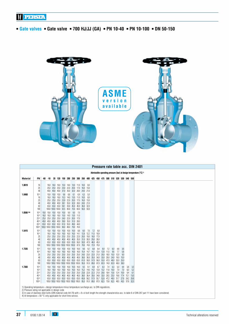
n Gate valves n Gate valve n 700 HJ/JJ (GA) n PN 10-40 n PN 10-100 n DN 50-150
Technical alterations reserved6100.1.09.1437
Admissible operating pressure [bar] at design temperature [°C] 1)
Material PN -60 -10 20 120 150 200 250 300 350 400 425 450 475 500 510 520 530 540 550
1.0619 16 16,0 16,0 16,0 15,0 14,0 13,0 11,0 10,0 8,0 25 25,0 25,0 25,0 23,0 22,0 20,0 17,0 16,0 13,0 40 40,0 40,0 40,0 37,0 35,0 32,0 28,0 24,0 21,0
1.0460 10 2) 10,0 10,0 10,0 9,6 8,8 8,1 6,9 6,3 5,0 16 16,0 16,0 16,0 15,3 14,0 13,0 11,0 10,0 8,0 25 25,0 25,0 25,0 23,9 22,0 20,0 17,0 16,0 13,0 40 40,0 40,0 40,0 38,1 35,0 32,0 28,0 24,0 21,0 63 63,0 63,0 63,0 58,1 50,0 45,0 40,0 36,0 32,0 100 100,0 100,0 100,0 92,5 80,0 70,0 60,0 56,0 50,0
1.0566 3)4) 10 2) 10,0 10,0 10,0 10,0 10,0 9,0 8,0 7,0 16 2) 16,0 16,0 16,0 16,0 15,0 14,0 13,0 11,0 25 2) 25,0 25,0 25,0 25,0 24,0 22,0 20,0 17,0 40 2) 40,0 40,0 40,0 40,0 39,0 35,0 31,0 28,0 63 2) 63,0 63,0 63,0 63,0 61,0 55,0 49,0 44,0 100 2) 100,0 100,0 100,0 100,0 96,0 88,0 79,0 70,0
1.5415 10 2) 10,0 10,0 10,0 10,0 10,0 10,0 8,8 8,0 7,6 7,2 6,8 16 2) 16,0 16,0 16,0 16,0 16,0 16,0 14,1 12,8 12,2 11,5 10,9 25 25,0 25,0 25,0 25,0 25,0 25,0 22,0 20,0 19,0 18,0 17,0 40 40,0 40,0 40,0 40,0 40,0 40,0 35,0 31,0 30,0 29,0 28,0 63 63,0 63,0 63,0 63,0 63,0 63,0 56,0 50,0 47,0 46,0 45,0 100 100,0 100,0 100,0 100,0 100,0 100,0 87,0 78,0 74,0 72,0 70,0
1.7335 10 2) 10,0 10,0 10,0 10,0 10,0 10,0 10,0 9,6 9,2 8,8 8,4 8,0 7,2 6,0 4,8 3,6 16 2) 16,0 16,0 16,0 16,0 16,0 16,0 16,0 15,4 14,7 14,1 13,4 12,8 11,5 9,6 7,7 5,8 25 25,0 25,0 25,0 25,0 25,0 25,0 25,0 24,0 23,0 22,0 21,0 20,0 18,0 15,0 12,0 9,0 40 40,0 40,0 40,0 40,0 40,0 40,0 40,0 38,0 36,0 35,0 34,0 33,0 29,0 24,0 19,0 15,0 63 63,0 63,0 63,0 63,0 63,0 63,0 63,0 61,0 58,0 57,0 56,0 53,0 47,0 40,0 32,0 25,0 100 100,0 100,0 100,0 100,0 100,0 100,0 100,0 95,0 91,0 89,0 87,0 82,0 74,0 62,0 49,0 38,0
1.7383 10 2) 10,0 10,0 10,0 10,0 10,0 10,0 10,0 9,5 9,1 8,9 8,7 8,3 7,4 6,3 5,0 4,4 3,8 3,3 16 2) 16,0 16,0 16,0 16,0 16,0 16,0 16,0 15,2 14,6 14,2 13,9 13,2 11,8 10,0 7,9 7,0 6,0 5,2 25 2) 25,0 25,0 25,0 25,0 25,0 25,0 25,0 23,8 22,8 22,3 21,8 20,6 18,4 15,6 12,4 10,9 9,4 8,1 40 2) 40,0 40,0 40,0 40,0 40,0 40,0 40,0 38,0 36,4 35,6 34,8 33,0 29,5 25,0 19,8 17,4 15,1 13,0 63 2) 63,0 63,0 63,0 63,0 63,0 63,0 63,0 60,8 58,2 57,0 55,7 52,8 47,2 40,0 31,7 27,8 24,2 20,8 100 2) 100,0 100,0 100,0 100,0 100,0 100,0 100,0 95,0 91,0 89,0 87,0 82,5 73,8 62,5 49,5 43,5 37,8 32,5
1) Operating temperature = design temperature minus temperature surcharge acc. to DIN regulations. 2) Pressure rating not applicable in design code3) In case of stainless steel bolts (DIN material code A4-70) with > 8 x d bolt length the strength characteristics acc. to table 6 of DIN 267 part 11 have been considered.4) At temperature > 50 °C only applicable for short time service.
Pressure rate table acc. DIN 2401
ASME v e r s i o n a v a i l a b l e
n Gate valves n Gate valve n 700 HJ/JJ (GA) n PN 10-40 n PN 10-100 n DN 50-150
Technical alterations reserved 6100.1.09.14 38
Admissible operating pressure [bar] at design temperature [°C] 1)
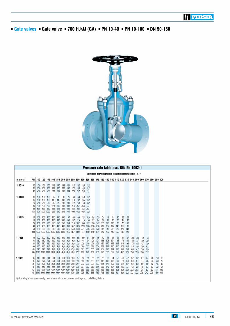
Material PN -10 20 50 100 150 200 250 300 350 400 450 460 470 480 490 500 510 520 530 540 550 560 570 580 590 600 1.0619 16 16,0 16,0 16,0 14,8 14,0 13,3 12,1 11,0 10,2 9,5 5,2 25 25,0 25,0 25,0 23,2 22,0 20,8 19,0 17,2 16,0 14,8 8,2 40 40,0 40,0 40,0 37,1 35,2 33,3 30,4 27,6 25,7 23,8 13,1 1.0460 10 10,0 10,0 10,0 9,2 8,8 8,3 7,6 6,9 6,4 5,9 3,2 16 16,0 16,0 16,0 14,8 14,0 13,3 12,1 11,0 10,2 9,5 5,2 25 25,0 25,0 25,0 23,2 22,0 20,8 19,0 17,2 16,0 14,8 8,2 40 40,0 40,0 40,0 37,1 35,2 33,3 30,4 27,6 25,7 23,8 13,1 63 63,0 63,0 63,0 58,5 55,5 52,5 48,0 43,5 40,5 37,5 20,7 100 100,0 100,0 100,0 92,8 88,0 83,3 76,1 69,0 64,2 59,5 32,8 1.5415 10 10,0 10,0 10,0 10,0 10,0 10,0 9,7 8,5 8,0 7,4 6,9 6,4 5,9 5,4 4,9 4,4 3,5 2,8 2,2 16 16,0 16,0 16,0 16,0 16,0 16,0 15,6 13,7 12,9 11,9 11,0 10,2 9,4 8,6 7,8 7,0 5,6 4,4 3,5 25 25,0 25,0 25,0 25,0 25,0 25,0 24,4 21,4 20,2 18,6 17,2 16,0 14,7 13,5 12,3 11,0 8,8 7,0 5,5 40 40,0 40,0 40,0 40,0 40,0 40,0 39,0 34,2 32,3 29,9 27,6 25,6 23,6 21,6 19,7 17,7 14,0 11,2 8,9 63 63,0 63,0 63,0 63,0 63,0 63,0 61,5 54,0 51,0 47,1 43,5 40,3 37,2 34,1 31,0 27,9 22,2 17,7 14,1 100 100,0 100,0 100,0 100,0 100,0 100,0 97,6 85,7 80,9 74,7 69,0 64,0 59,1 54,2 49,2 44,2 35,2 28,0 22,3 1.7335 10 10,0 10,0 10,0 10,0 10,0 10,0 10,0 10,0 9,5 9,0 8,4 8,0 7,6 7,2 6,8 6,5 5,5 4,4 3,7 2,9 2,3 1,9 1,5 16 16,0 16,0 16,0 16,0 16,0 16,0 16,0 16,0 15,2 14,4 13,4 12,8 12,1 11,5 10,8 10,4 8,8 7,1 5,9 4,6 3,7 3,0 2,5 25 25,0 25,0 25,0 25,0 25,0 25,0 25,0 25,0 23,8 22,5 21,0 20,0 19,0 18,0 17,0 16,3 13,8 11,1 9,3 7,2 5,8 4,7 3,9 40 40,0 40,0 40,0 40,0 40,0 40,0 40,0 40,0 38,0 36,0 33,7 32,0 30,4 28,8 27,2 26,0 22,0 17,9 14,8 11,6 9,3 7,6 6,2 63 63,0 63,0 63,0 63,0 63,0 63,0 63,0 63,0 60,0 56,7 53,1 50,5 47,9 45,4 42,8 41,1 34,8 28,2 23,4 18,3 14,7 12,0 9,9 100 100,0 100,0 100,0 100,0 100,0 100,0 100,0 100,0 95,2 90,0 84,2 80,2 76,1 72,0 68,0 65,2 55,2 44,7 37,1 29,0 23,3 19,0 15,7 1.7383 10 10,0 10,0 10,0 10,0 10,0 10,0 10,0 10,0 9,7 9,2 8,8 8,3 7,8 7,3 6,9 6,4 5,6 4,9 4,2 3,7 3,2 2,7 2,4 2,0 1,8 1,6 16 16,0 16,0 16,0 16,0 16,0 16,0 16,0 16,0 15,6 14,8 14,0 13,3 12,5 11,8 11,0 10,2 8,9 7,8 6,8 5,9 5,1 4,4 3,8 3,3 2,8 2,5 25 25,0 25,0 25,0 25,0 25,0 25,0 25,0 25,0 24,4 23,2 22,0 20,8 19,6 18,4 17,2 16,0 14,0 12,2 10,7 9,2 8,0 6,9 6,0 5,2 4,5 4,0 40 40,0 40,0 40,0 40,0 40,0 40,0 40,0 40,0 39,0 37,1 35,2 33,3 31,4 29,5 27,6 25,7 22,4 19,6 17,1 14,8 12,9 11,0 9,7 8,3 7,2 6,4 63 63,0 63,0 63,0 63,0 63,0 63,0 63,0 63,0 61,5 58,5 55,5 52,5 49,5 46,5 43,5 40,5 35,4 30,9 27,0 23,4 20,4 17,4 15,3 13,2 11,4 10,2 100 100,0 100,0 100,0 100,0 100,0 100,0 100,0 100,0 97,6 92,8 88,0 83,3 78,5 73,8 69,0 64,2 56,1 49,0 42,8 37,1 32,3 27,6 24,2 20,9 18,0 16,1
1) Operating temperature = design temperature minus temperature surcharge acc. to DIN regulations.
Pressure rate table acc. DIN EN 1092-1

Technical alterations reserved6100.1.09.1439
n Gate valves n Gate valve n 700 HJ/JJ (GA) n PN 10-40 n PN 10-100 n DN 50-150
Admissible operating pressure [bar] at design temperature [°C] 1)
Material PD -60 -10 20 100 150 200 250 300 350 400 410 420 430 440 450 460 470 480 490 500 510 520 530 540 550 560 570 580 590 600 1.0460 10 100,0 100,0 100,0 100,0 94,0 82,0 74,0 64,2 59,5 48,0 45,0 43,0 41,0 38,0 34,0 28,0 23,0 1.0566 2)3) 10 100,0 102,1 102,1 100,0 96,0 88,0 79,0 70,0 1.5415 10 120,0 120,0 120,0 120,0 112,0 103,0 88,0 85,0 82,0 82,0 81,0 81,0 80,0 79,0 79,0 78,0 78,0 68,0 53,0 40,0 32,0 25,0 1.7335 10 120,0 120,0 120,0 120,0 120,0 118,0 109,0 103,0 97,0 96,0 95,0 94,0 92,0 91,0 91,0 90,0 89,0 89,0 81,0 68,0 54,0 44,0 35,0 28,0 23,0 18,0 1.7383 10 120,0 120,0 120,0 120,0 120,0 120,0 118,0 109,0 103,0 102,0 101,0 99,0 98,0 97,0 96,0 95,0 94,0 89,0 79,0 69,0 61,0 53,0 46,0 40,0 34,0 30,0 26,0 22,0 20,0 1) Operating temperature = design temperature minus temperature surcharge acc. to DIN regulations. 2) At temperatures > 50 °C only applicable for short time service. 3) In case of stainless steel bolts (DIN material code A4-70) with > 8 x d bolt length the strength characteristics acc. to table 6 of DIN 267 part 11 have been considered.
Pressure rate table only valid for buttweld ends

Technical alterations reserved 6100.1.09.14 40
n Gate valves n Gate valve n 700 HJ/JJ (GA) n PN 10-40 n PN 10-100 n DN 50-150
Design Highlights
n The main valve body is one-piece die-forged incorporating the bonnet flange and the guide for the shut-off device
n Hard faced seats (valve body and shut-off device). Hardness app. 35-37 HRC
n Bolted bonnet with reduced shaft bolts
n Full bore, except DN 65/50 and DN 125/100
n Non - turning rising stem
n Type GA, turning non-rising stem
Benefits
n Die-forged parts, compared with cast steel parts are generally free from porosity and shrink holes. The special of the valve body minimizes the existance of welding seams
n Extremely resistant to wear
n To improve the stress capability when temperature and pressure fluctuate n No reduction in seat area
n Minimum wear to the gland packing compared with ground stem surfaces
n Small dimensions
Standard features
n Split disc gate valve / 2 disc-design = Type JJn Wedge gate valve / Flexible wedge design = Type HJn Die-forged body and bonnetn Full bore, exception DN 65/50 and DN 125/100n Outside screw and yoken Non turning, rising stemn Yoke sleeve n Available with flange and buttweld ends
Option standard features GA
n Wedge gate valve / Flexible wedge designn Inside screwn Non-rising turning stem
Pressure and temperature ratings
n Pressure rating up to 100 barn Acc. to PERSTA PD 10 up to 120 barn Temperature rating up to 600 °C
Materials
n 1.0460n 1.0619 just for flange type PN 10-40n 1.0566n 1.5415n 1.7335n 1.7383
Further materials on request.
Media
Depending on the material the gate valves are suitablefor water, gas, oil and other non aggressive media
Fields of application
Chemical industries, power plants, ship building and other

n Gate valves n Gate valve n 700 HJ/JJ (GA n PN 10-40) n PN 10-100 n DN 50-150
Technical alterations reserved6100.1.09.1441
L
610
613
600
605
510
531
511
590
464
462
440
420
450
200
170
190
160
400
360
363
100
D
Hh
L
H1
L
700 GA
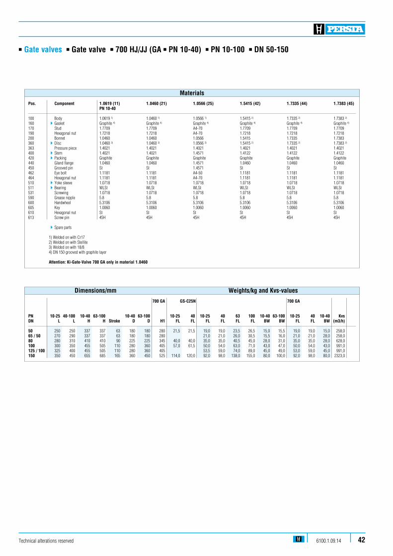
n Gate valves n Gate valve n 700 HJ/JJ (GA n PN 10-40) n PN 10-100 n DN 50-150
Pos. Component 1.0619 (11) 1.0460 (21) 1.0566 (25) 1.5415 (42) 1.7335 (44) 1.7383 (45) PN 10-40
100 Body 1.0619 1) 1.0460 1) 1.0566 1) 1.5415 2) 1.7335 2) 1.7383 2)
160 4Gasket Graphite 4) Graphite 4) Graphite 4) Graphite 4) Graphite 4) Graphite 4)
170 Stud 1.7709 1.7709 A4-70 1.7709 1.7709 1.7709190 Hexagonal nut 1.7218 1.7218 A4-70 1.7218 1.7218 1.7218200 Bonnet 1.0460 1.0460 1.0566 1.5415 1.7335 1.7383360 4Disc 1.0460 3) 1.0460 3) 1.0566 3) 1.5415 2) 1.7335 2) 1.7383 2)
363 Pressure piece 1.4021 1.4021 1.4021 1.4021 1.4021 1.4021400 4Stem 1.4021 1.4021 1.4571 1.4122 1.4122 1.4122420 4Packing Graphite Graphite Graphite Graphite Graphite Graphite440 Gland flange 1.0460 1.0460 1.4571 1.0460 1.0460 1.0460450 Grooved pin St St 1.4571 St St St462 Eye bolt 1.1181 1.1181 A4-50 1.1181 1.1181 1.1181464 Hexagonal nut 1.1181 1.1181 A4-70 1.1181 1.1181 1.1181510 4Yoke sleeve 1.0718 1.0718 1.0718 1.0718 1.0718 1.0718511 4Bearing WLSt WLSt WLSt WLSt WLSt WLSt531 Screwing 1.0718 1.0718 1.0718 1.0718 1.0718 1.0718590 Grease nipple 5.8 5.8 5.8 5.8 5.8 5.8600 Handwheel 5.3106 5.3106 5.3106 5.3106 5.3106 5.3106605 Key 1.0060 1.0060 1.0060 1.0060 1.0060 1.0060610 Hexagonal nut St St St St St St613 Screw pin 45H 45H 45H 45H 45H 45H 4Spare parts 1) Welded on with Cr17 2) Welded on with Stellite 3) Welded on with 18/8 4) DN 150 grooved with graphite layer
Attention: Ki-Gate-Valve 700 GA only in material 1.0460
Materials
700 GA GS-C25N 700 GA
PN 10-25 40-100 10-40 63-100 10-40 63-100 10-25 40 10-25 40 63 100 10-40 63-100 10-25 40 10-40 KvsDN L L H H Stroke D D H1 FL FL FL FL FL FL BW BW FL FL BW (m3/h) 50 250 250 337 337 63 180 180 280 21,5 21,5 19,0 19,0 23,5 26,5 15,0 15,5 19,0 19,0 15,0 258,065 / 50 270 290 337 337 63 180 180 280 21,0 21,0 26,0 30,5 15,5 16,0 21,0 21,0 28,0 258,080 280 310 410 410 90 225 225 345 40,0 40,0 35,0 35,0 40,5 45,0 28,0 31,0 35,0 35,0 28,0 628,0100 300 350 455 505 110 280 360 405 57,0 61,5 50,0 54,0 63,0 71,0 43,0 47,0 50,0 54,0 43,0 991,0125 / 100 325 400 455 505 110 280 360 405 53,5 59,0 74,0 89,0 45,0 49,0 53,0 59,0 45,0 991,0150 350 450 655 685 165 360 450 525 114,0 120,0 92,0 98,0 138,0 155,0 80,0 100,0 92,0 98,0 80,0 2323,0
Dimensions/mm Weights/kg and Kvs-values
Technical alterations reserved 6100.1.09.14 42
n Gate valves n Gate valve n 700 HJ/JJ (GA) n PN 10-40 n DN 200-250
Technical alterations reserved6100.1.09.1443
Admissible operating pressure [bar] at design temperature [°C] 1)
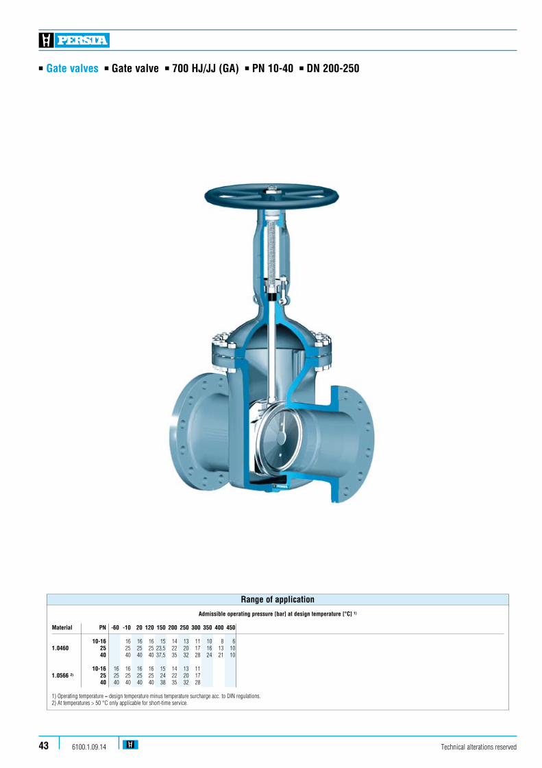
Material PN -60 -10 20 120 150 200 250 300 350 400 450 10-16 16 16 16 15 14 13 11 10 8 6 1.0460 25 25 25 25 23,5 22 20 17 16 13 10 40 40 40 40 37,5 35 32 28 24 21 10 10-16 16 16 16 16 15 14 13 11 1.0566 2) 25 25 25 25 25 24 22 20 17 40 40 40 40 40 38 35 32 28 1) Operating temperature = design temperature minus temperature surcharge acc. to DIN regulations. 2) At temperatures > 50 °C only applicable for short-time service.
Range of application
n Gate valves n Gate valve n 700 HJ/JJ (GA) n PN 10-40 n DN 200-250
Design Highlights
n Die-forged body and bonnet
n Hard faced seats (valve body and shut-off device) Hardness app. 35-37 HRC
n Bolted bonnet with reduced shaft bolts
n Full bore
n Non-turning, rising stem
n Type GA, rotating non-rising stem
n Possibility to add an actuator-flange
Standard features
n Split disc gate valve / 2 disc-design = Type JJn Wedge gate valve / Flexible wedge design = Type HJn Die-forged body and bonnetn Body with full boren Outside screw and yoken Non-turning rising stemn Yoke sleeve n Available with flange and buttweld ends
Option standard features GA
n Wedge gate valve / Flexible wedge designn Inside screwn Non-rising turning stem
Pressure and temperature ratings
n Pressure rating up to 40 barn Temperature rating up to 450 °C
Benefits
n Free from porosity and shrink holes
n Extremely resistant to wear
n To improve the stress capability when temperature and pressure fluctuate n No reduction at seat area
n Minimum wear to the gland packing compared with ground stem surfaces
n Small dimensions
n Simple retrofitting of an actuator possible without welding
Materials
n 1.0460n 1.0566
Further materials on request.
Media
Depending on the material the gate valves are suitableFor water, gas, oil and other non aggressive media
Fields of application
Chemical industries, power plants, ship building and other
Technical alterations reserved 6100.1.09.14 44

610613600605531532510511590464462440450420200
170160190400362
360361100
D
hH
L
n Gate valves n Gate valve n 700 HJ/JJ (GA) n PN 10-40 n DN 200-250
Technical alterations reserved6100.1.09.1445
L
350
L
700 JJ 700 HJ

n Gate valves n Gate valve n 700 HJ/JJ (GA) n PN 10-40 n DN 200-250
Pos. Component 1.0460 (21) 1.0566 (25)
100 Body 1.0460 3) 1.0566 3)
160 4Seat ring Grooved with Grooved with graphite layer graphite layer170 Stud 1.1181 A4-70190 Hexagonal nut 1.1181 A4-70200 Bonnet 1.0460 1.0566350 4Wedge 1.0460 4) 1.0566 4)
360 / 361 4Disc 1.8507 4) 1.0566 4)
362 4Ball WLSt WLSt400 4Stem 1.4021 5) 1.4571420 4Packing Graphite Graphite440 Gland flange 1.0460 1.4571450 Pin St 1.4571462 Eye bolt 1.1181 A4-50464 Hexagonal nut 1.1181 A4-70510 Yoke sleeve 1.0718 1.0718511 4Needle bearing WLSt WLSt531 4Screwing 1.0718 1.0718532 Screw pin 45H 45H590 4Grease nipple 5.8 5.8600 Handwheel 5.3106 5.3106605 Key 1.0060 1.0060610 Hexagonal pipe nut St St613 Screw pin 45H 45H 4Spare parts
3) Welded on with 18/8 4) Welded on with Cr17 5) PN 40 DN 250 = 1.4122 Further materials on request.
Attention: Ki-Gate-Valve 700 GA only in material 1.0460
Materials
FL FL BW BW KvsDN PN 10-25 PN 40 PN 10-25 PN 40 (m3/h)
200 151,5 185 140 140 4000250 285,0 325 245 280 6247
700 GA DN
200 138,5 170 125 125 4000250 263,0 303 223 258 6247
Weights/kg and Kvs-values
PN PN PN PN 10-25 40 Stroke 10-25 40 DN L L H h D D 200 400 550 810 220 360 450 250 450 650 975 285 450 450 700 GADN H1
200 590 250 725
Dimensions/mm
Technical alterations reserved 6100.1.09.14 46

n Gate valves n Gate valve n 700 HJ/JJ n PN 63-100 n DN 200-300
Technical alterations reserved6100.1.09.1447
Admissible operating pressure [bar] at design temperature [°C] 1)
Material PN -60 -10 20 120 150 200 250 300 350 400 450 475 480 500 510 520 530 540 550 560 570 580 590 600 1.0460 63 63 63 63 58 50 45 40 36 32 21 14 12 100 100 100 100 91 80 70 60 56 50 34 21 19 1.5415 63 63 63 63 63 63 63 56 50 47 45 37 35 29 22 16 14 100 100 100 100 100 100 100 87 78 74 70 57 54 45 34 27 22 1.7335 63 63 63 63 63 63 63 63 61 58 56 53 51 47 40 32 25 20 16 13 10 100 100 100 100 100 100 100 100 95 91 87 82 80 74 62 49 38 31 24 19 16 1.7383 63 63 63 63 63 63 63 63 62 62 60 55 53 47 40 35 28 25 22 18 15 12 11 9 100 100 100 100 100 100 100 100 98 96 94 85 82 74 62 53 43 39 33 27 23 19 17 15 1) Operating temperature = design temperature minus temperature surcharge acc. to DIN regulations.
Range of application
n Gate valves n Gate valve n 700 HJ/JJ n PN 63-100 n DN 200-300
Standard features
n Split disc gate valve / 2 disc – design type = Type JJn Wedge gate valve / flexible wedge-design Type HJn Die-forged body and bonnetn Full boren Outside screw and yoken Non-turning, rising stemn Yoke sleeven Available with flange and buttweld ends
Pressure and temperature ratings
n Pressure rating up to 100 barn Temperature rating up to 600 °C
Materials
n 1.0460n 1.5415n 1.7335n 1.7383
For low temperature service available as casting.Other materials on request.
Design Highlights
n Die-forged body and bonnet
n Hard faced seats (valve body and shut-off device)
n Gasket located in gap
n Full bore
n Non-rising stem
Benefits
n Free from porosity and shrink holes
n Extremely resistant to wear
n Blow out protection
n No reduction in seat area
n Minimum wear to the gland packing compared with ground stem surfaces
Media
Depending on the material the gate valves are suitablefor water, gas, oil and other non aggressive media
Fields of application
Chemical industries, power plants, ship building and other
Technical alterations reserved 6100.1.09.14 48

n Gate valves n Gate valve n 700 HJ/JJ n PN 63-100 n DN 200-300
613
610
600
605
531
590
510
511
464
440
462
450
420
190
200
170
160
400
360
361
363
100
D
h
L
H
L L
Technical alterations reserved6100.1.09.1449
700 JJ 700 HJ
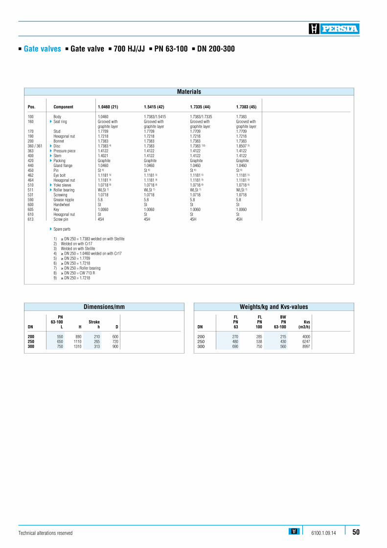
n Gate valves n Gate valve n 700 HJ/JJ n PN 63-100 n DN 200-300
Pos. Component 1.0460 (21) 1.5415 (42) 1.7335 (44) 1.7383 (45) 100 Body 1.0460 1.7383/1.5415 1.7383/1.7335 1.7383160 4Seat ring Grooved with Grooved with Grooved with Grooved with graphite layer graphite layer graphite layer graphite layer 170 Stud 1.7709 1.7709 1.7709 1.7709190 Hexagonal nut 1.7218 1.7218 1.7218 1.7218200 Bonnet 1.7383 1.7383 1.7383 1.7383360 / 361 4Disc 1.7383 4) 1.7383 1.7383 1)3) 1.8507 3)
363 4Pressure piece 1.4122 1.4122 1.4122 1.4122400 4Stem 1.4021 1.4122 1.4122 1.4122420 4Packing Graphite Graphite Graphite Graphite440 Gland flange 1.0460 1.0460 1.0460 1.0460450 Pin St 6) St 6) St 6) St 6)
462 Eye bolt 1.1181 5) 1.1181 5) 1.1181 5) 1.1181 5)
464 Hexagonal nut 1.1181 9) 1.1181 9) 1.1181 9) 1.1181 9)
510 4Yoke sleeve 1.0718 8) 1.0718 8) 1.0718 8) 1.0718 8)
511 4Roller bearing WLSt 7) WLSt 7) WLSt 7) WLSt 7)
531 Screwing 1.0718 1.0718 1.0718 1.0718590 Grease nipple 5.8 5.8 5.8 5.8600 Handwheel St St St St605 Key 1.0060 1.0060 1.0060 1.0060610 Hexagonal nut St St St St613 Screw pin 45H 45H 45H 45H
4Spare parts
1) ≥ DN 250 = 1.7383 welded on with Stellite 2) Welded on with Cr17 3) Welded on with Stellite 4) ≥ DN 250 = 1.0460 welded on with Cr17 5) ≥ DN 250 = 1.7709 6) ≥ DN 250 = 1.7218 7) ≥ DN 250 = Roller bearing 8) ≥ DN 250 = CW 713 R 9) ≥ DN 250 = 1.7218
Materials
FL FL BW PN PN PN KvsDN 63 100 63-100 (m3/h)
200 270 285 215 4000250 480 538 430 6247300 690 750 560 8997
Weights/kg and Kvs-values
PN 63-100 Stroke DN L H h D 200 550 890 210 600250 650 1110 265 720300 750 1310 313 900
Dimensions/mm
Technical alterations reserved 6100.1.09.14 50

Technical alterations reserved6100.1.09.1451
n Gate valves n Gate valve n 400 JJ n PN 63-100 n DN 350-700
Admissible operating pressure [bar] at design temperature [°C] 1)
Material PN -10 20 120 150 200 250 300 350 400 450 475 480 500 510 520 530 540 550 560 570 580 590 600 1.0425 63 63 63 63 58 50 45 40 36 32 21 14,0 12 100 100 100 100 91 80 70 60 56 50 34 21,8 19 1.5415 63 63 63 63 63 63 63 56 50 47 45 37,0 35 29 22 16 14 100 100 100 100 100 100 100 87 78 74 70 57,0 54 45 34 27 22 1.7335 63 63 63 63 63 63 63 63 61 58 56 53,0 51 47 40 32 25 20 16 13 10 100 100 100 100 100 100 100 100 95 91 87 82,0 80 74 62 49 38 31 24 19 16 1.7383 63 63 63 63 63 63 63 63 62 62 60 55,0 53 47 40 35 28 25 22 18 15 12 11 9 100 100 100 100 100 100 100 100 98 96 94 85,0 82 74 62 53 43 39 33 27 23 19 17 15 1) Operating temperature = design temperature minus temperature surcharge acc. to DIN regulations.
Range of application
Technical alterations reserved 6100.1.09.14 52
n Gate valves n Gate valve n 400 JJ n PN 63-100 n DN 350-700
Standard features
n Split disc gate valve n Outside screw and yoke n Possibility to add an actuator
Pressure and temperature ratings
n Pressure rating up to 100 barn Temperature rating up to 600 °C
Materials
n 1.0425n 1.5415n 1.7335n 1.7383
Media
Depending on the material the gate valves are suitablefor water, gas, oil and other non aggressive media
Fields of application
Chemical industries, power plants, ship building and other
Design Highlights
n Seats and faced with stellite
n Non-turning, rising stem
n Gland flange and gland ring in two separate pieces
n Yoke sleeve supported by needle bearing
Benefits
n Best possible sliding performance, minimum wear
n Minimum wear to the gland packing
n Damage to the stem by irregular tightening of gland bolts is avoided
n Minimize the expenditure of effort when operating valve
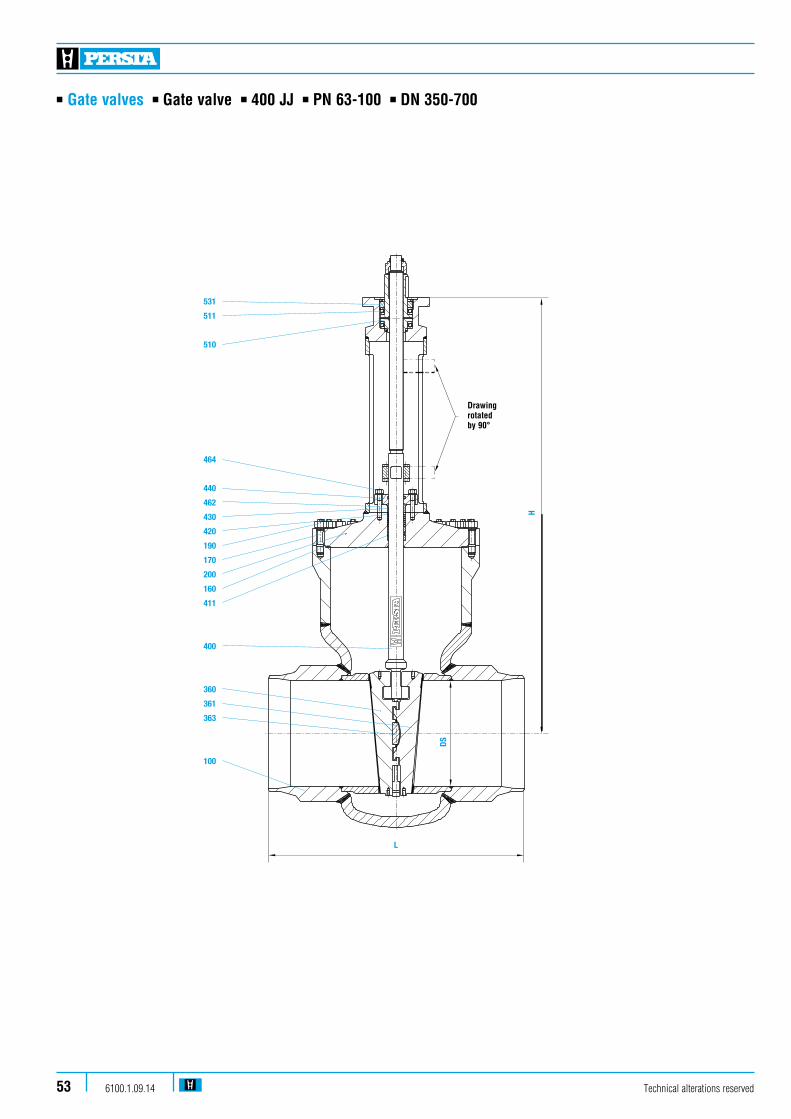
Technical alterations reserved6100.1.09.1453
n Gate valves n Gate valve n 400 JJ n PN 63-100 n DN 350-700
531
511
510
464
440
462
430
420
190
170
200
160
411
400
360
361
363
100
H
DS
L
Drawing rotated by 90°

Technical alterations reserved 6100.1.09.14 54
n Gate valves n Gate valve n 400 JJ n PN 63-100 n DN 350-700
Pos. Component 1.0425 (22) 1.5415 (42) 1.7335 (44) 1.7383 (45)
100 Body 1.0425 1.5415 1.7335 1.7383 welded on with Stellite Stellite Stellite Stellite160 4Seat ring Graphite Graphite Graphite Graphite170 Stud 1.7709 1.7709 1.7709 1.7709190 Hexagonal nut 1.7218 1.7218 1.7218 1.7218200 Bonnet 1.0460 1.5415 1.7335 1.7383360 / 361 4Disc 1.7383 1.7383 1.7383 1.7383 welded on with Stellite Stellite Stellite Stellite363 4 Pressure piece 1.4122 1.4122 1.4122 1.4122400 4Stem 1.4021 1.4122 1.4122 1.4122411 4Guide bushing 1.8507 1.8507 1.8507 1.8507420 4Packing Graphite Graphite Graphite Graphite 430 Gland ring 1.5415 1.5415 1.5415 1.5415440 Gland flange 1.5415 1.5415 1.7383 1.7383462 Stud 1.7709 1.7709 1.7709 1.7709464 Hexagonal nut 1.7218 1.7218 1.7218 1.7218510 4Yoke sleeve CW 713 R CW 713 R CW 713 R CW 713 R511 4Bearing WLSt WLSt WLSt WLSt531 Screwing 1.7335 1.7335 1.7335 1.7335 4Spare parts
Materials
Kvs DN BW (m3/h)
350 950 11243400 1500 14521450 1850 18105500 2350 22353600 4300 32188700 5100 41773
Weights/kg and Kvs-values
DN DS Stroke L H 350 330 365 850 1620400 375 417 950 1745450 419 455 1050 2030500 464 515 1150 2260600 559 625 1350 2560700 640 690 1550 2695
Dimensions/mm
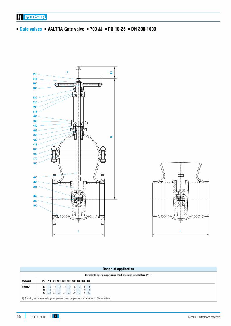
n Gate valves n VALTRA Gate valve n 700 JJ n PN 10-25 n DN 300-1000
100 Gehäuse body corps H II Dichtring gasket joint Grafit160
Schraubenbolzen stud goujon Ck 35180
Sechskantmutter hexagonal nut ecrou C 35190
Bügelhaube bonnet chapeau H II
aufgepanzert mit welded on with apport contact X 8 CrTi 18
360
Spindel stem tige X 20 Cr 13
363
Packung packing garniture Grafit
400
Kerbstift
Stopfbuchsbrille
451
445
420
gland flange
pin
C 22.8fouloir
axe
Datum
Name
Pos. Benennung Designation Designation Material
62.2122 000
Platten-RundschieberDN 300-800 PN 10-40gate valve
vanne passage direct
19.07.01
GF/LR
fig.-no.:
Baureihe: 700 JJ 22.1
Ersatzteil
spare part
piece detachée
Änderungen vorbehalten
alternation reserved
sous reserve de modification
201
aufgepanzert mit welded on with apport contact X 20 CrMo 17 1
Schieberplatte double disc H IIdouble opercule
Druckstück pressure piece X 10 CrNiS 18 9piece de pression
100
Klappschraube460
614
600
464
gland bolt boulon basculant
Handrad handwheel volant
Sicherungsring retaining ring bague de surete
Sechskantmutter hexagonal nut ecrou
610
Gewindebuchse yoke sleeve douille de manoevre
Verschraubung
Nadellager
531
511
510
590
needle bearing
screwing
roulement
vis
Schmiernippel grease nipple graisseur
605 Paßeder key clavette
560 Verdrehsicherung protect.against torsion rondelle anti blockage
561 Senkschraube countersunk screw boulon
Ck 35
CK 35
Ck 35
GGG 40
WLSt
St 52.3
St
St 50-2
8.8
St
St 50-2
FSt
1.0425
1.1181
1.0501
1.0425
1.4021
1.0460
1.0425
1.4305
1.1181
1.1181
1.1181
0.7040
1.0570
1.0050
vom 31.10.97
GF / LR
Typ 90055
360362
365400
160180190201412420451460445463464511590510531
560,561605600614610
Plattenhalter double disc guide support opercule St 52.3365 1.0570
463 Scheibe washer rondelle St
411 Führungshülse guide sleeve doille de guidage GG 25
1.4115
1.4502
362 Kugel ball X 10 CrNiS 18 9bille 1.4305
1.0050
Sechskantmutter hexagonal nut ecrou 5.6
363
300
350
400
PN DN L H D k
800
500
600 1430
kg
560
1160
2035
305
1350
H1
410
330
630
D1
600
450
800
d2 d4 f
565
445
780
515
400
725
16x26
12x22
20x30
482
370
685
4
4
5
b
26
26
28
500
600
550 1260 410355 500 505 460 16x22 430 426
10700 1700 960520 800 670 620 20x26 585 428
700 900 2260 1960735 800 895 840 24x30 800 530
300
350
400
PN DN L H D k
800
500
600 1430
kg
560
1160
2035
305
1350
H1
420
330
650
D1
600
450
800
d2 d4 f
620
485
845
550
430
770
16x36
16x30
20x39
505
395
720
4
4
5
b
40
34
46
500
600
550 1260 410365 500 555 490 16x33 450 438
25700 1700 960535 800 730 660 20x36 615 444
700
300
350
400
PN DN L H D k
800
500
600
kg
560
305
1350
H1 D1 d2 d4 f
580
460
840
525
410
770
16x30
12x26
20x36
490
378
725
4
4
5
b
32
28
36
500
600
550 410520 470 16x26 438 430
16700 960715 650 20x33 610 434
700 900 1960910 840 24x36 795 536
300
350
400
PN DN L H D k
1350
750
950 1585
kg
890
1200
2060
440
2310
H1
450
325
660
D1
600
450
900
d2 d4 f
660
515
890
585
450
795
16x39
16x33
20x48
535
410
735
4
4
5
b
50
42
60
500
600
850 1285 610375 500 580 510 16x36 465 446
401150 1270550 800 755 670 20x42 615 452
1430
1160
2035
410
330
630
600
450
800
1260 355 500
1700 520 800
2260 735 800
1800
PN 10-25
DN 600,700
PN 40
DN 300,350,500
2) Bei TB> 350°C Werkstoff : 1.7258
1) Bei TB> 350°C Werkstoff : 1.7709
1)
2)
VALTRA
Ers.durch dito
Fall der Patenterteilung oder Gebrauchsmustereintragungfolgt (Urheberrechtsgesetz, UWG, BGB).Alle Rechte fuer denPersonen ist unzulaessig, strafbar und wird gerichtlich ver-Jede Vervielfaeltigung, Verwertung oder Mitteilung an dritteWir behalten uns alle Urheberrechte an dieser Unterlage vor.
Datum
/Nam
e N
r. Änd
Geprüft
Geändert
bleiben vorbehalten.
VALTRA ARMATUREN HANDELSGES.MBH-POSTFACH 2249-59567 WARSTEIN-TELEFON(02902)76701-FAX(02902)76703
800 1000 2685 2960845 800 1015 950 24x33 905 532
800 1000 2685 2960845 800 1025 950 24x39 900 538
900 2260 1960745 800 960 875 24x42 820 546
800 1000 2685 2960845 800 1085 990 24x48 930 550
700 1550 2290 2600760 1000 995 900 24x48 840 564
800 1750 2820 2860870 1000 1140 1030 24x56 960 572
610
614
600
605
532
510
590
511
464
463
440
462
450
420
411
200
190
170
160
400
365
363
362
360
100
D H1H
L
100 Gehäuse body corps H II Dichtring gasket joint Grafit160
Schraubenbolzen stud goujon Ck 35180
Sechskantmutter hexagonal nut ecrou C 35190
Bügelhaube bonnet chapeau H II
aufgepanzert mit welded on with apport contact X 8 CrTi 18
360
Spindel stem tige X 20 Cr 13
363
Packung packing garniture Grafit
400
Kerbstift
Stopfbuchsbrille
451
445
420
gland flange
pin
C 22.8fouloir
axe
Datum
Name
Pos. Benennung Designation Designation Material
62.2222 000
Platten-RundschieberDN 300-800 PN 10-40gate valve
vanne passage direct
19.07.01
GF/LR
fig.-no.:
Baureihe: 700 JJ 22.2
Ersatzteil
spare part
piece detachée
Änderungen vorbehalten
alternation reserved
sous reserve de modification
201
aufgepanzert mit welded on with apport contact X 20 CrMo 17 1
Schieberplatte double disc H IIdouble opercule
Druckstück pressure piece X 10 CrNiS 18 9piece de pression
Klappschraube460
614
600
464
gland bolt boulon basculant
Handrad handwheel volant
Sicherungsring retaining ring bague de surete
Sechskantmutter hexagonal nut ecrou
610
Gewindebuchse yoke sleeve douille de manoevre
Verschraubung
Nadellager
531
511
510
590
needle bearing
screwing
roulement
vis
Schmiernippel grease nipple graisseur
605 Paßeder key clavette
560 Verdrehsicherung protect.against torsion rondelle anti blockage
561 Senkschraube countersunk screw boulon
Ck 35
CK 35
Ck 35
GGG 40
WLSt
St 52.3
St
St 50-2
8.8
St
St 50-2
FSt
1.0425
1.1181
1.0501
1.0425
1.4021
1.0460
1.0425
1.4305
1.1181
1.1181
1.1181
0.7040
1.0570
1.0050
vom 31.10.97
GF / LR
Typ 90055
D1
Plattenhalter double disc guide support opercule St 52.3365 1.0570
463 Scheibe washer rondelle St
411 Führungshülse guide sleeve doille de guidage GG 25
1.4115
1.4502
362 Kugel ball X 10 CrNiS 18 9bille 1.4305
1.0050
Sechskantmutter hexagonal nut ecrou 5.6
PN DN L H kgH1 D1
10
PN DN L H kgH1 D1
25
PN DN L H kgH1 D1
16
PN DN L H kgH1 D1
40
2) Bei TB> 350°C Werkstoff : 1.7258
1) Bei TB> 350°C Werkstoff : 1.7709
1)
2)
VALTRA
Ers.durch dito
Fall der Patenterteilung oder Gebrauchsmustereintragungfolgt (Urheberrechtsgesetz, UWG, BGB).Alle Rechte fuer denPersonen ist unzulaessig, strafbar und wird gerichtlich ver-Jede Vervielfaeltigung, Verwertung oder Mitteilung an dritteWir behalten uns alle Urheberrechte an dieser Unterlage vor.
Datum
/Nam
e N
r. Änd
Geprüft
Geändert
bleiben vorbehalten.
VALTRA ARMATUREN HANDELSGES.MBH-POSTFACH 2249-59567 WARSTEIN-TELEFON(02902)76701-FAX(02902)76703
according to order
dimension d1 et d2
suiv. commande
Maß d1 und d2
dimension d1 and d2
gemäß Auftrag
300
350
400
800
500
600 1430
1160
2035
410
330
630
600
450
800
500
600
550 1260 355 500
700 1700 520 800
700 900 2260 735 800
800 1000 2685 845 800
300
350
400
800
500
600
500
600
550
700
700 900
1430
1160
2035
410
330
630
600
450
800
1260 355 500
1700 520 800
2260 735 800
800 1000 2685 845 800
300
350
400
800
500
600 1430
1160
2035
420
330
650
600
450
800
500
600
550 1260 365 500
700 1700 535 800
700
300
350
400
1350
750
950 1585
1200
2060
450
325
660
500
600
850 1285 375
1150 5501800
900 2260 745 800
800 1000 2685 845 800
700 1550 2290 760
800 1750 2820 870
600
450
900
500
800
1000
1000
510
275
1270
370
890
1850
2810PN 10-25
DN 600,700
PN 40
DN 300,350,500
510
275
1270
370
890
1850
2810
510
275
1270
370
890
1850
2810
510
275
1270
370
890
1850
2810
450/400 650 1430 410 600 530
17.02.03
GF / LR
1
L
Technical alterations reserved6100.1.09.1455
Admissible operating pressure [bar] at design temperature [°C] 1)
Material PN -10 20 100 120 200 250 300 350 400
P265GH 10 10 10 10 10 9 8 7 6 5 16 16 16 16 16 14 13 11 10 8 25 25 25 25 25 22 20 17 16 13
1) Operating temperature = design temperature minus temperature surcharge acc. to DIN regulations.
Range of application
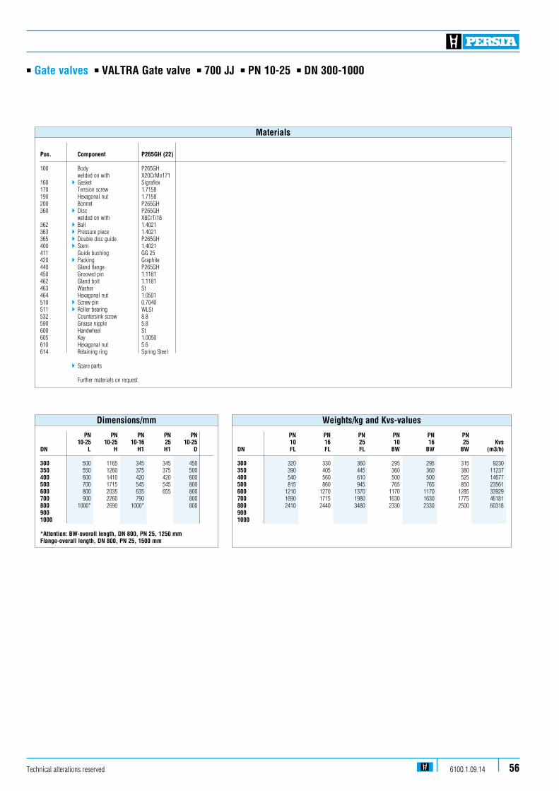
n Gate valves n VALTRA Gate valve n 700 JJ n PN 10-25 n DN 300-1000
Pos. Component P265GH (22)
100 Body P265GH welded on with X20CrMo171 160 4Gasket Sigraflex 170 Tension screw 1.7158 190 Hexagonal nut 1.7158 200 Bonnet P265GH 360 4Disc P265GH welded on with X8CrTi18 362 4Ball 1.4021 363 4Pressure piece 1.4021 365 4Double disc guide P265GH 400 4Stem 1.4021 411 Guide bushing GG 25 420 4Packing Graphite 440 Gland flange P265GH 450 Grooved pin 1.1181 462 Gland bolt 1.1181 463 Washer St 464 Hexagonal nut 1.0501 510 4Screw pin 0.7040 511 4Roller bearing WLSt 532 Countersink screw 8.8 590 Grease nipple 5.8 600 Handwheel St 605 Key 1.0050 610 Hexagonal nut 5.6 614 Retaining ring Spring Steel
4Spare parts Further materials on request.
Materials
PN PN PN PN PN PN 10 16 25 10 16 25 KvsDN FL FL FL BW BW BW (m3/h)
300 320 330 360 295 295 315 9230350 390 405 445 360 360 380 11237400 540 560 610 500 500 525 14677500 815 860 945 765 765 850 23561600 1210 1270 1370 1170 1170 1285 33929700 1690 1715 1980 1630 1630 1775 46181800 2410 2440 3480 2330 2330 2500 60318900 1000
Weights/kg and Kvs-values
PN PN PN PN PN 10-25 10-25 10-16 25 10-25DN L H H1 H1 D 300 500 1165 345 345 450 350 550 1260 375 375 500 400 600 1410 420 420 600 500 700 1715 545 545 800 600 800 2035 635 655 800 700 900 2260 790 800 800 1000* 2690 1000* 800900 1000
*Attention: BW-overall length, DN 800, PN 25, 1250 mmFlange-overall length, DN 800, PN 25, 1500 mm
Dimensions/mm
Technical alterations reserved 6100.1.09.14 56

100 Gehäuse body corps H II Dichtring gasket joint Grafit160
Schraubenbolzen stud goujon Ck 35180
Sechskantmutter hexagonal nut ecrou C 35190
Bügelhaube bonnet chapeau H II
aufgepanzert mit welded on with apport contact X 8 CrTi 18
360
Spindel stem tige X 20 Cr 13
363
Packung packing garniture Grafit
400
Kerbstift
Stopfbuchsbrille
451
445
420
gland flange
pin
C 22.8fouloir
axe
Datum
Name
Pos. Benennung Designation Designation Material
62.2622 025
Platten-Rundschiebergate valve
vanne passage direct
10.12.01
GF/LR
fig.-no.:
Baureihe: 700 JJ 22.2
Ersatzteil
spare part
piece detachée
Änderungen vorbehalten
alternation reserved
sous reserve de modification
201
aufgepanzert mit welded on with apport contact X 20 CrMo 17 1
Schieberplatte double disc H IIdouble opercule
Druckstück pressure piece X 10 CrNiS 18 9piece de pression
100
Klappschraube460
614
600
464
gland bolt boulon basculant
Handrad handwheel volant
Sicherungsring retaining ring bague de surete
Sechskantmutter hexagonal nut ecrou
610
Gewindebuchse yoke sleeve douille de manoevre
Verschraubung
Nadellager
531
511
510
590
needle bearing
screwing
roulement
vis
Schmiernippel grease nipple graisseur
605 Paßeder key clavette
560 Verdrehsicherung protect.against torsion rondelle anti blockage
561 Senkschraube countersunk screw boulon
Ck 35
CK 35
Ck 35
GGG 40
WLSt
St 52.3
St
St 50-2
8.8
St
St 50-2
FSt
1.0425
1.1181
1.0501
1.0425
1.4021
1.0460
1.0425
1.4305
1.1181
1.1181
1.1181
0.7040
1.0570
1.0050
Typ 90055
360362
365400
160180190201412420451460445463464511590510531
560,561605600614610
Plattenhalter double disc guide support opercule St 52.3365 1.0570
463 Scheibe washer rondelle St
411 Führungshülse guide sleeve doille de guidage GG 25
1.4115
1.4502
362 Kugel ball X 10 CrNiS 18 9bille 1.4305
1.0050
Sechskantmutter hexagonal nut ecrou 5.6
3632) Bei TB> 350°C Werkstoff : 1.7258
1) Bei TB> 350°C Werkstoff : 1.7709
1)
2)
VALTRA
Fall der Patenterteilung oder Gebrauchsmustereintragungfolgt (Urheberrechtsgesetz, UWG, BGB).Alle Rechte fuer denPersonen ist unzulaessig, strafbar und wird gerichtlich ver-Jede Vervielfaeltigung, Verwertung oder Mitteilung an dritteWir behalten uns alle Urheberrechte an dieser Unterlage vor.
Datum
/Nam
e N
r. Änd
Geprüft
Geändert
VALTRA ARMATUREN HANDELSGES.MBH-POSTFACH 2249-59567 WARSTEIN-TELEFON(02902)76701-FAX(02902)76703
according to order
dimension d1 et d2
suiv. commande
Maß d1 und d2
dimension d1 and d2
gemäß Auftrag
PN 40 DN 500
Kom. 111049 Pos. 1
TIN : A67G02J62A
KENNZ. : ENSTEDVAERKET T7218 BGR. 96711000 KKS-NR. FEHLT
L
HH1D
610
614
600
605
531
510
511
464
463
440
462
450
420
411
190
200
170
160
400
365
363
362
360
100
n Gate valves n VALTRA Gate valve n 700 JJ n PN 40 n DN 300-700
100 Gehäuse body corps H II Dichtring gasket joint Grafit160
Schraubenbolzen stud goujon Ck 35180
Sechskantmutter hexagonal nut ecrou C 35190
Bügelhaube bonnet chapeau H II
aufgepanzert mit welded on with apport contact X 8 CrTi 18
360
Spindel stem tige X 20 Cr 13
363
Packung packing garniture Grafit
400
Kerbstift
Stopfbuchsbrille
451
445
420
gland flange
pin
C 22.8fouloir
axe
Datum
Name
Pos. Benennung Designation Designation Material
62.2622 025
Platten-Rundschiebergate valve
vanne passage direct
10.12.01
GF/LR
fig.-no.:
Baureihe: 700 JJ 22.2
Ersatzteil
spare part
piece detachée
Änderungen vorbehalten
alternation reserved
sous reserve de modification
201
aufgepanzert mit welded on with apport contact X 20 CrMo 17 1
Schieberplatte double disc H IIdouble opercule
Druckstück pressure piece X 10 CrNiS 18 9piece de pression
100
Klappschraube460
614
600
464
gland bolt boulon basculant
Handrad handwheel volant
Sicherungsring retaining ring bague de surete
Sechskantmutter hexagonal nut ecrou
610
Gewindebuchse yoke sleeve douille de manoevre
Verschraubung
Nadellager
531
511
510
590
needle bearing
screwing
roulement
vis
Schmiernippel grease nipple graisseur
605 Paßeder key clavette
560 Verdrehsicherung protect.against torsion rondelle anti blockage
561 Senkschraube countersunk screw boulon
Ck 35
CK 35
Ck 35
GGG 40
WLSt
St 52.3
St
St 50-2
8.8
St
St 50-2
FSt
1.0425
1.1181
1.0501
1.0425
1.4021
1.0460
1.0425
1.4305
1.1181
1.1181
1.1181
0.7040
1.0570
1.0050
Typ 90055
360362
365400
160180190201412420451460445463464511590510531
560,561605600614610
Plattenhalter double disc guide support opercule St 52.3365 1.0570
463 Scheibe washer rondelle St
411 Führungshülse guide sleeve doille de guidage GG 25
1.4115
1.4502
362 Kugel ball X 10 CrNiS 18 9bille 1.4305
1.0050
Sechskantmutter hexagonal nut ecrou 5.6
3632) Bei TB> 350°C Werkstoff : 1.7258
1) Bei TB> 350°C Werkstoff : 1.7709
1)
2)
VALTRA
Fall der Patenterteilung oder Gebrauchsmustereintragungfolgt (Urheberrechtsgesetz, UWG, BGB).Alle Rechte fuer denPersonen ist unzulaessig, strafbar und wird gerichtlich ver-Jede Vervielfaeltigung, Verwertung oder Mitteilung an dritteWir behalten uns alle Urheberrechte an dieser Unterlage vor.
Datum
/Nam
e N
r. Änd
Geprüft
Geändert
VALTRA ARMATUREN HANDELSGES.MBH-POSTFACH 2249-59567 WARSTEIN-TELEFON(02902)76701-FAX(02902)76703
according to order
dimension d1 et d2
suiv. commande
Maß d1 und d2
dimension d1 and d2
gemäß Auftrag
PN 40 DN 500
Kom. 111049 Pos. 1
TIN : A67G02J62A
KENNZ. : ENSTEDVAERKET T7218 BGR. 96711000 KKS-NR. FEHLT
L
HH1D
Technical alterations reserved6100.1.09.1457
Admissible operating pressure [bar] at design temperature [°C] 1)
Material PN -10 20 100 120 200 250 300 350 400
P265GH 40 40 40 40 40 35 32 28 24 21
1) Operating temperature = design temperature minus temperature surcharge acc. to DIN regulations.
Range of application

n Gate valves n VALTRA Gate valve n 700 JJ n PN 40 n DN 300-700
Pos. Component P265GH (22)
100 Body P265GH welded on with X20CrMo171 160 4Seat ring Sigraflex 170 Tension screw 1.7158 190 Hexagonal nut 1.7158 200 Bonnet P265GH 360 4Disc P265GH welded on with X8CrTi18 362 4Ball 1.4021 363 4Pressure piece 1.4021 365 4Double disc guide P265GH 400 4Stem 1.4021 411 Guide bushing GG 25 420 4Packing Graphite 440 Gland flange P265GH 450 Grooved pin 1.1181 462 Gland bolt 1.1181 463 Washer St 464 Hexagonal nut 1.0501 510 4Yoke sleeve 0.7040 511 4Bearing WLSt 531 Yoke nut S355J2G3 600 Handwheel St 605 Key 1.0050 610 Hexagonal nut 5.6 614 Retaining ring Spring Steel
4Spare parts Further materials on request.
Materials
KvsDN FL BW (m3/h)
300 440 370 9230350 610 460 11237400 890 710 14677500 1270 1050 23561600 2310 1980 33929700 3210 2960 46181800
Weights/kg and Kvs-values
DN L H Stroke D 300 750 1260 345 500 350 850 1295 375 600 400 950 1575 445 800 500 1150 1795 525 800 600 1350 2155 640 800 700 1550 2595 770 800 800 1750
Dimensions/mm
Technical alterations reserved 6100.1.09.14 58
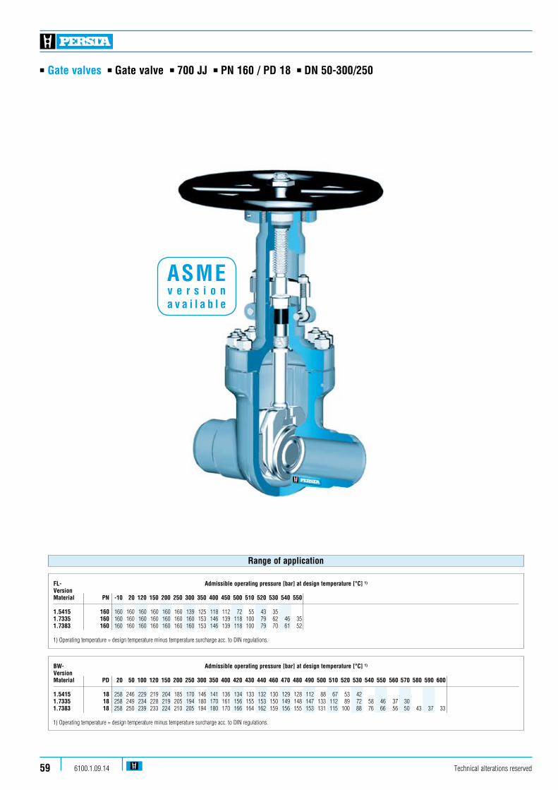
n Gate valves n Gate valve n 700 JJ n PN 160 / PD 18 n DN 50-300/250
Technical alterations reserved6100.1.09.1459
FL- Admissible operating pressure [bar] at design temperature [°C] 1)
Version Material PN -10 20 120 150 200 250 300 350 400 450 500 510 520 530 540 550 1.5415 160 160 160 160 160 160 160 139 125 118 112 72 55 43 35 1.7335 160 160 160 160 160 160 160 160 153 146 139 118 100 79 62 46 351.7383 160 160 160 160 160 160 160 160 153 146 139 118 100 79 70 61 52
1) Operating temperature = design temperature minus temperature surcharge acc. to DIN regulations.
Range of application
BW- Admissible operating pressure [bar] at design temperature [°C] 1)
VersionMaterial PD 20 50 100 120 150 200 250 300 350 400 420 430 440 460 470 480 490 500 510 520 530 540 550 560 570 580 590 600
1.5415 18 258 246 229 219 204 185 170 146 141 136 134 133 132 130 129 128 112 88 67 53 42 1.7335 18 258 249 234 228 219 205 194 180 170 161 156 155 153 150 149 148 147 133 112 89 72 58 46 37 30 1.7383 18 258 250 239 233 224 210 205 194 180 170 166 164 162 159 156 155 153 131 115 100 88 76 66 56 50 43 37 33 1) Operating temperature = design temperature minus temperature surcharge acc. to DIN regulations.
ASME v e r s i o n a v a i l a b l e

n Gate valves n Gate valve n 700 JJ n PN 160 / PD 18 n DN 50-300/250
Technical alterations reserved 6100.1.09.14 60
Design Highlights
n Die-forged valve body with incorporated seats
n Seats and disc faced with stellite
n Non-rising handwheel
n Non-turning, rising stem and burnished stem
n Hammer head connection between wedge and stem
n Gland ring and gland flange in two separate pieces
n Yoke sleeve supported at the top and at the bottom by means of needle bearings (axial type)
n Valve head equipped with dirt scrapers below and above the bearings
Benefits
n Free from porosity and shrink holes
n Best possible sliding performance, minimum wear
n Small dimensions
n Minimum wear to the gland packing
n The wedges are able to move parallel to the axis of the pipeline within the guiding groove. This protects the stem against bending moments
n Damage to the stem by irregular tightening of gland bolts is avoided
n To minimize the expenditure of effort when opening and closing the valve
n To protect against dirt and to avoid the loss of lubricants
Standard features
n Die-forged bodyn Split disc typen Incorporated seatsn Outside screwn Gasket located in a grooven Yoke sleeve with needle bearingsn Universal valve head for mounting actuators
Pressure and temperature ratings
n Pressure rating BW up to 258 bar (PD 18)n Pressure rating FL up to 160 barn Temperature ratings up -10 °C up to 600 °C
Materials
n 1.5415n 1.7335n 1.7383
Further materials on request.
Media
Depending on the material the gate valves are suitablefor water, gas, oil and other non aggressive medi
Fields of application
Chemical industries, power plants, ship building and other

n Gate valves n Gate valve n 700 JJ n PN 160 / PD 18 n DN 50-300/250
Technical alterations reserved6100.1.09.1461
610
613
600
605
540
553
542
510
511
552
464
440
462
430
420
412
200
190
410
170
160
400
360
361
100
363
D
L
Hh
L L
Version DN 50 - 80
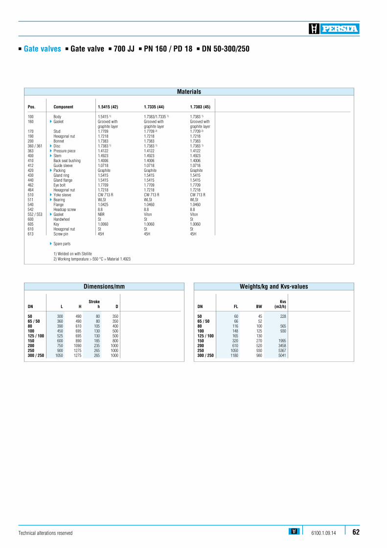
n Gate valves n Gate valve n 700 JJ n PN 160 / PD 18 n DN 50-300/250
KvsDN FL BW (m3/h)
50 60 45 22865 / 50 66 52 80 116 100 565100 148 125 930125 / 100 165 130 150 320 270 1995200 610 520 3458250 1050 930 5367300 / 250 1180 980 5041
Weights/kg and Kvs-values
StrokeDN L H h D
50 300 490 80 35065 / 50 360 490 80 35080 390 610 105 400100 450 695 130 500125 / 100 525 695 130 500150 600 890 185 800200 750 1090 235 1000250 900 1275 265 1000300 / 250 1050 1275 265 1000
Dimensions/mm
Technical alterations reserved 6100.1.09.14 62
Pos. Component 1.5415 (42) 1.7335 (44) 1.7383 (45) 100 Body 1.5415 1) 1.7383/1.7335 1) 1.7383 1)
160 4Gasket Grooved with Grooved with Grooved with graphite layer graphite layer graphite layer170 Stud 1.7709 1.7709 2) 1.7709 2)
190 Hexagonal nut 1.7218 1.7218 1.7218200 Bonnet 1.7383 1.7383 1.7383360 / 361 4 Disc 1.7383 1) 1.7383 1) 1.7383 1)
363 4 Pressure piece 1.4122 1.4122 1.4122400 4 Stem 1.4923 1.4923 1.4923410 Back seat bushing 1.4006 1.4006 1.4006412 Guide sleeve 1.0718 1.0718 1.0718420 4 Packing Graphite Graphite Graphite430 Gland ring 1.5415 1.5415 1.5415440 Gland flange 1.5415 1.5415 1.5415462 Eye bolt 1.7709 1.7709 1.7709464 Hexagonal nut 1.7218 1.7218 1.7218510 4 Yoke sleeve CW 713 R CW 713 R CW 713 R511 4 Bearing WLSt WLSt WLSt540 Flange 1.0425 1.0460 1.0460542 Headcap screw 8.8 8.8 8.8552 / 553 4 Gasket NBR Viton Viton600 Handwheel St St St605 Key 1.0060 1.0060 1.0060610 Hexagonal nut St St St613 Screw pin 45H 45H 45H
4Spare parts
1) Welded on with Stellite 2) Working temperature > 550 °C = Material 1.4923
Materials
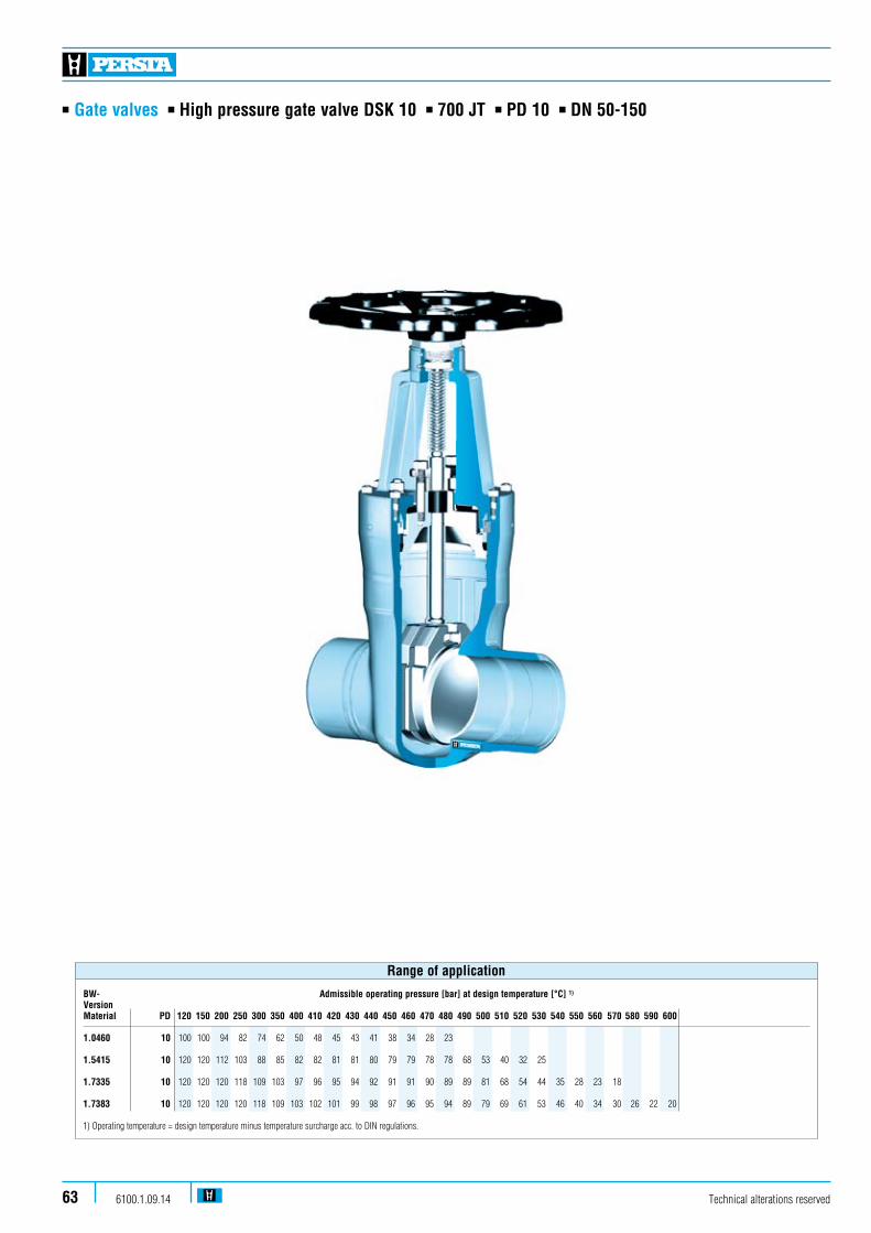
n Gate valves n High pressure gate valve DSK 10 n 700 JT n PD 10 n DN 50-150
Technical alterations reserved6100.1.09.1463
BW- Admissible operating pressure [bar] at design temperature [°C] 1)
VersionMaterial PD 120 150 200 250 300 350 400 410 420 430 440 450 460 470 480 490 500 510 520 530 540 550 560 570 580 590 600
1.0460 10 100 100 94 82 74 62 50 48 45 43 41 38 34 28 23 1.5415 10 120 120 112 103 88 85 82 82 81 81 80 79 79 78 78 68 53 40 32 25 1.7335 10 120 120 120 118 109 103 97 96 95 94 92 91 91 90 89 89 81 68 54 44 35 28 23 18 1.7383 10 120 120 120 120 118 109 103 102 101 99 98 97 96 95 94 89 79 69 61 53 46 40 34 30 26 22 20 1) Operating temperature = design temperature minus temperature surcharge acc. to DIN regulations.
Range of application

n Gate valves n High pressure gate valve DSK 10 n 700 JT n PD 10 n DN 50-150
Design Highlights
n Die-forged valve body with integral seats
n Hard faced seats
n Full bore, except DN 65/50 and DN 125/100
n Non-turning rising stem with burnished shaft
n Rolled stem thread
n Pressure sealing bonnet
n Possibility to add an actuator flange
Benefits
n Compared to cast steel, robust and highly stressable
n Best possible sliding performance, minimum wear
n No reduction in seat area
n Minimum wear of the gland packing
n Optimal surface with higher surface hardness and therefore better wear resistance then cut threads
n Best possible sealing function
n Simple retrofitting of an actuator without welding
Standard features
n Split disc gate valven Die-forged body and bonnet n Full bore (Except DN 65/50 and DN 125/100)n Outside screw and yoke n Non-turning, rising stemn Yoke sleeve supported by needle bearingsn Pressure sealing bonnet acc. VGB-guidelines
Pressure and temperature ratings
n Pressure rating up to 120 barn Temperature rating up to 600 °C
Materials
n 1.0460n 1.5415n 1.7335n 1.7383
Further materials on request.
Media
Depending on the material the gate valves are suitable for water, gas, oil and other non aggressive media
Fields of application
Chemical industries, power plants, ship building and other
Technical alterations reserved 6100.1.09.14 64
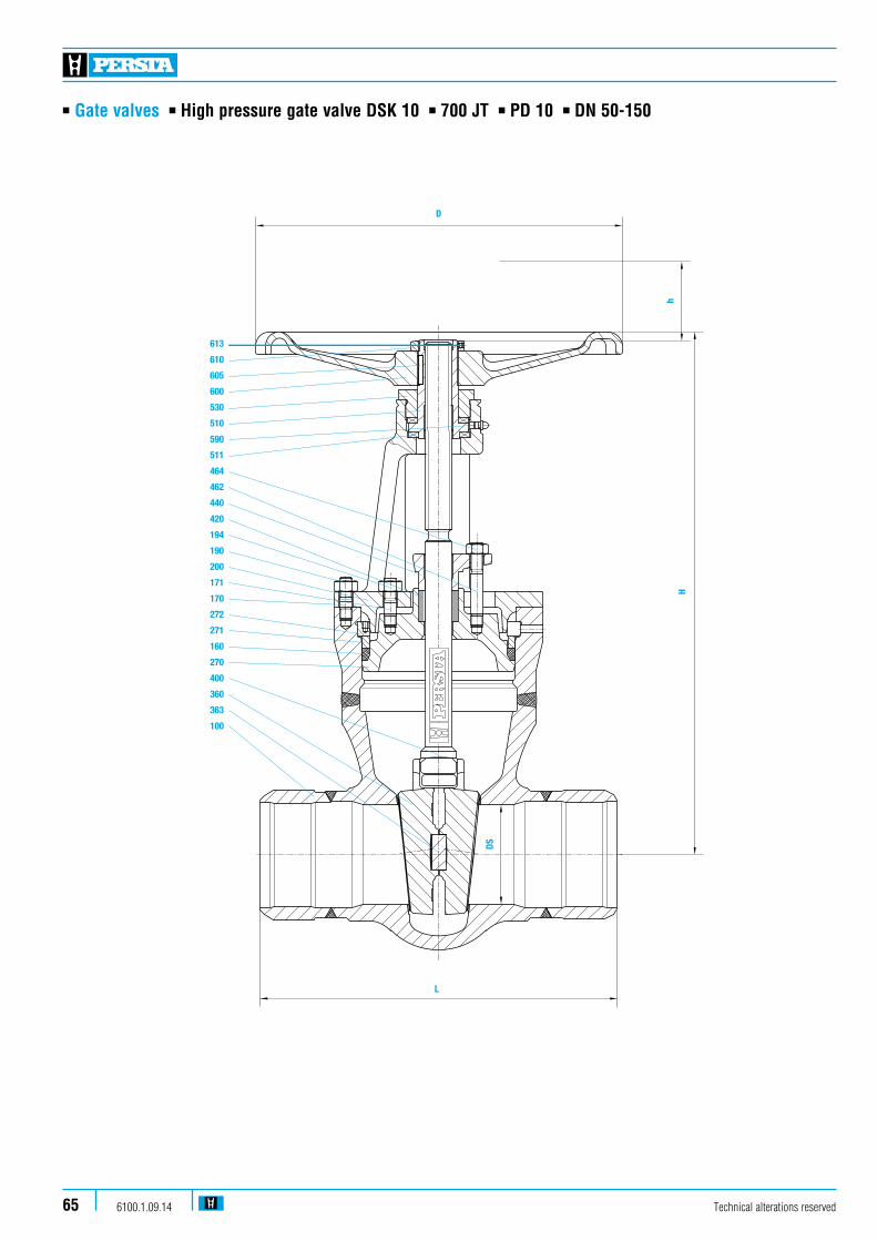
n Gate valves n High pressure gate valve DSK 10 n 700 JT n PD 10 n DN 50-150
Technical alterations reserved6100.1.09.1465
613
610
605
600
530
510
590
511
464
462
440
420
194
190
200
171
170
272
271
160
270
400
360
363
100
D
hH
L
DS

n Gate valves n High pressure gate valve DSK 10 n 700 JT n PD 10 n DN 50-150
Pos. Component 1.0460 (21) 1.5415 (42) 1.7335 (44) 1.7383 (45) 100 Body 1.0460 1.5415 1.7335 1.7383 welded on with Cr17 Stellite Stellite Stellite160 4 Gasket Graphite Graphite Graphite Graphite170 Stud 1.7709 1.7719 1.7709 1.7709171 Stud 1.7709 1.7719 1.7709 1.7709190 Hexagonal nut 1.7218 1.7218 1.7218 1.7218194 Hexagonal nut 1.7218 1.7218 1.7218 1.7218200 Bonnet 1.5419 1.5419 1.5419 1.5419270 Cover 1.0460 1.5415 1.7335 1.7383271 Ring 1.0460 1.5415 1.7335 1.7383272 Segmentring 1.0460 1.5415 1.7335 1.7383360 4 Disc 1.0460 1.5415 1.7335 1.7383 welded on with 18/8 (40) Stellite Stellite Stellite363 4 Pressure piece 1.4021 1.4021 1.4021 1.4021400 4 Stem 1.4021 1.4122 1.4122 1.4122420 4 Packing Graphite Graphite Graphite Graphite440 Gland flange 1.0460 1.0460 1.0460 1.0460462 Stud 1.7709 1.7709 1.7709 1.7709464 Hexagonal nut 1.7218 1.7218 1.7218 1.7218510 4 Yoke sleeve 1.0718 1.0718 1.0718 1.0718511 4 Roller bearing WLSt WLSt WLSt WLSt530 Screwing 1.0718 1.0718 1.0718 1.0718590 Grease nipple 5.8 5.8 5.8 5.8600 Handwheel 0.7040 0.7040 0.7040 0.7040605 Key 1.0060 1.0060 1.0060 1.0060610 Hexagonal nut St St St St613 Screw pin 45H 45H 45H 45H
4Spare parts
Materials
KvsDN FL BW (m3/h)
50 26,5 15,5 258,065 / 50 30,5 16,0 258,080 45,0 31,0 628,0100 71,0 47,0 991,0125 / 100 89,0 49,0 991,0150 155,0 100,0 2323,0
Weights/kg and Kvs-values
Technical alterations reserved 6100.1.09.14 66
Stroke DN DS L H h D 50 50 250 337 63 18065 / 50 50 290 337 63 18080 78 310 410 90 280100 98 350 515 110 360125 / 100 98 400 515 110 360150 150 450 685 165 450
Dimensions/mm

BW- Admissible operating pressure [bar] at design temperature [°C] 1)
VersionMaterial PD 120 150 200 250 300 350 400 410 420 430 440 450 460 470 480 490 500 510 520 530 540 550 560 570 580 590 600
1.0460 10 100 100 94 82 74 62 50 48 45 43 41 38 34 28 23 1.5415 10 120 120 112 103 88 85 82 82 81 81 80 79 79 78 78 68 53 40 32 25 1.7335 10 120 120 120 118 109 103 97 96 95 94 92 91 91 90 89 89 81 68 54 44 35 28 23 18 1.7383 10 120 120 120 120 118 109 103 102 101 99 98 97 96 95 94 89 79 69 61 53 46 40 34 30 26 22 20 1) Operating temperature = design temperature minus temperature surcharge acc. to DIN regulations.
Range of application
n Gate valves n High pressure gate valve DSK 10 n 700 JT n PD 10 n DN 200-350/300
Technical alterations reserved6100.1.09.1467
n Gate valves n High pressure gate valve DSK 10 n 700 JT n PD 10 n DN 200-350/300
Technical alterations reserved 6100.1.09.14 68
Standard features
n Split disc gate valven Die-forged body and bonnet n Full boren Outside screw and yoke n Non-turning, rising stemn Yoke sleeve supported by needle bearingn Pressure sealing bonnet acc. VGB-guidelines
Pressure and temperature ratings
n Pressure rating up to 120 barn Temperature rating up to 600 °C
Materials
n 1.0460 n 1.5415 n 1.7335 n 1.7383
Further materials on request.
Design Highlights
n Die-forged body and bonnet
n Seats and wedge faced with stellite
n Full bore
n Gland ring and gland flange in two separate pieces
n Yoke sleeve supported by needle bearing
n Pressure sealing bonnet
Benefits
n Free from porosity and shrink holes compared to cast steel, robust and highly stressable
n Extremely resistant to wear
n No reduction in seat area
n Damage to the stem by irregular tightening of gland bolts is avoided
n Minimize the expenditure of effort when operating valve
n Best possible sealing function
Media
Depending on the material the gate valves are suitable for water, gas, oil and other non aggressive media
Fields of application
Chemical industries, power plants, ship building and other

n Gate valves n High pressure gate valve DSK 10 n 700 JT n PD 10 n DN 200-350/300
600
610 613
605
530
510
511
590
463 464
440
430
194
190
170
200
462
171
273
272
271
160
420
270
411
400
360
363
100
H
DS
L
Technical alterations reserved6100.1.09.1469

n Gate valves n High pressure gate valve DSK 10 n 700 JT n PD 10 n DN 200-350/300
Pos. Component 1.0460 (21) 1.5415 (42) 1.7335 (44) 1.7383 (45) 100 Body 1.0460 1.7383/1.5415 1.7383/1.7335 1.7383 welded on with 18/8 Stellite Stellite Stellite160 4 Gasket Graphite Graphite Graphite Graphite170 Stud 1.7709 1.7709 1.7709 1.7709171 Stud 1.7709 1.7709 1.7709 1.7709190 Hexagonal nut 1.7218 1.7218 1.7218 1.7218194 Hexagonal nut 1.7218 1.7218 1.7218 1.7218200 Bonnet 1.5415 1.5415 1.5415 1.5415270 Cover 1.0460 1.5415 1.7335 1.7383271 Ring 1.0460 1.5415 1.7335 1.7383272 Segmentring 1.0460 1.5415 1.7335 1.7383273 Cover 1.7383 1.5415 1.7335 1.7383360 4 Disc 1.7383 1.7383 1.7383 1.7383 welded on with Cr17 Stellite Stellite Stellite363 4 Pressure piece 1.4122 1.4122 1.4122 1.4122400 4 Stem 1.4021 1.4122 1.4122 1.4122411 4 Guide bushing 1.8507 1.8507 1.8507 1.8507420 4 Packing Graphite Graphite Graphite Graphite430 Gland ring 1.0718 1.0718 1.0718 1.0718440 Gland flange 1.0460 1.0460 1.0460 1.0460462 Stud 1.7709 1.7709 1.7709 1.7709463 Washer St St St St464 Hexagonal nut 1.7218 1.7218 1.7218 1.7218510 4 Yoke sleeve CW 713 R CW 713 R CW 713 R CW 713 R511 4 Bearing WLSt WLSt WLSt WLSt530 Screwing 1.0718 1.0718 1.0718 1.0718590 Grease nipple 5.8 5.8 5.8 5.8600 Handwheel 0.7040 0.7040 0.7040 0.7040605 Key 1.0060 1.0060 1.0060 1.0060610 Hexagonal nut St St St St613 Screw pin 45H 45H 45H 45H
4Spare parts
Materials
KvsDN BW (m3/h)
200 260 4000225 / 200 270 250 / 200 280 225 / 250 530250 550 6247300 / 250 580300 850 8997350 / 300 870 9257
Weights/kg and Kvs-values
Technical alterations reserved 6100.1.09.14 70
DN DS L H Stroke D
200 198 550 920 210 600225 / 200 198 600 920 210 600250 / 200 198 650 920 210 600225 / 250 235 600 1130 265 720250 235 650 1130 265 720300 / 250 235 750 1130 265 720300 276 750 1300 310 900350 / 300 276 850 1300 310 900
Dimensions/mm

n Gate valves n High pressure gate valve DSK 10 n 700 JT n PD 10 n DN 350-700
Technical alterations reserved6100.1.09.1471
BW- Admissible operating pressure [bar] at design temperature [°C] 1)
VersionMaterial PD 120 150 200 250 300 350 400 410 420 430 440 450 460 470 480 490 500 510 520 530 540 550 560 570 580 590 600 610 620 630 640 650
1.0425 10 100 100 94 82 74 62 50 48 45 43 41 38 34 28 23 1.5415 10 120 120 112 103 88 85 82 82 81 81 80 79 79 78 78 68 53 40 32 25 1.7335 10 120 120 120 118 109 103 97 96 95 94 92 91 91 90 89 89 81 68 54 44 35 28 23 18 1.7383 10 120 120 120 120 118 109 103 102 101 99 98 97 96 95 94 89 79 69 61 53 46 40 34 30 26 22 20
1.4903 10 136 136 136 136 136 136 136 136 136 136 136 136 136 136 134 122 119 110 101 93 84 76 68 61 54 48 42 37 32 27 24 21 1) Operating temperature = design temperature minus temperature surcharge acc. to DIN regulations.
Range of application
ASME v e r s i o n a v a i l a b l e

n Gate valves n High pressure gate valve DSK 10 n 700 JT n PD 10 n DN 350-700
Standard features
n Split disc gate valven Outside screw and yoken Non-turning, rising stemn Yoke sleeve supported by needle bearingsn Pressure sealing bonnet acc. VGB-guidelinesn Easy assembly of an E-actuator
Pressure and temperature ratings
n Pressure rating up to 136 barn Temperature rating up to 650 °C
Materials
n 1.0425n 1.5415n 1.7335n 1.7383n 1.4903
Further materials on request.
Design Highlights
n Seats and disc faced with stellite
n Non-turning, rising stem
n Gland ring and gland flange in two separate pieces
n Yoke sleeve supported by needle bearing
n Pressure sealed bonnet
Benefits
n Best possible sliding performance, minimum wear
n Minimum wear to the gland packing
n Damage to the stem by irregular tightening of gland bolts is avoided
n Minimize the expenditure of effort when operating valve
n Best possible sealing function
Media
Depending on the material the gate valves are suitable for water, gas, oil and other non aggressive media
Fields of application
Chemical industries, power plants, ship building and other
Technical alterations reserved 6100.1.09.14 72
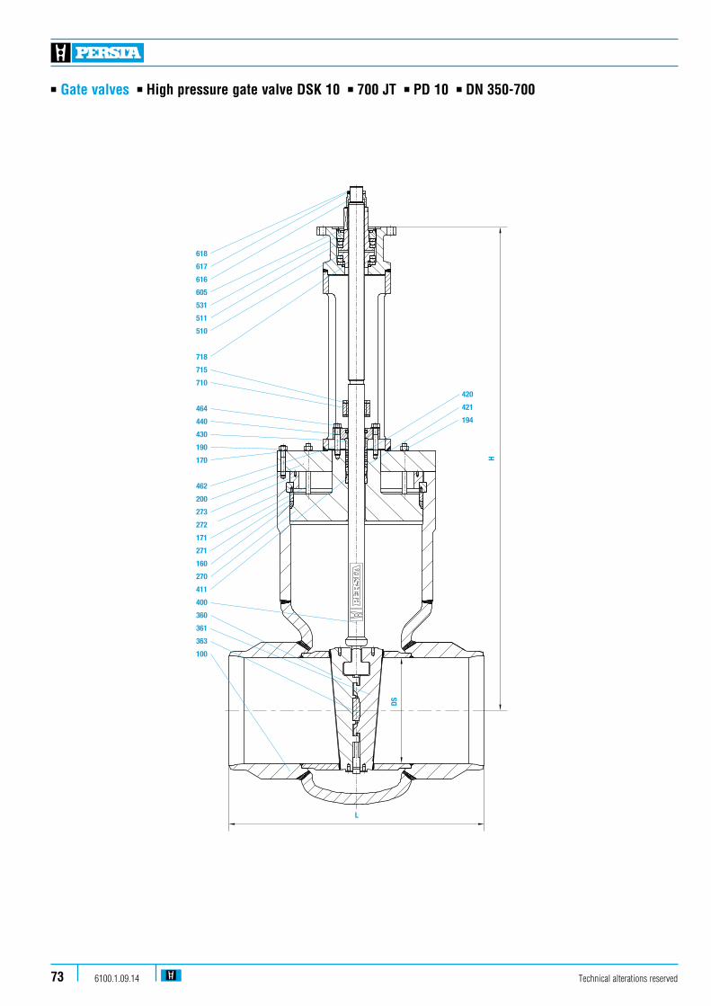
n Gate valves n High pressure gate valve DSK 10 n 700 JT n PD 10 n DN 350-700
618
617
616
605
531
511
510
718
715
710
464
440
430
190
170
462
200
273
272
171
271
160
270
411
400
360
361
363
100
H
DS
L
420
421
194
Technical alterations reserved6100.1.09.1473

n Gate valves n High pressure gate valve DSK 10 n 700 JT n PD 10 n DN 350-700
Pos. Component 1.0425 (22) 1.5415 (42) 1.7335 (44) 1.7383 (45) 1.4903 (63) 100 Body 1.0425 1.5415 1.7335 1.7383 1.4903 welded on with Stellite Stellite Stellite Stellite Stellite 160 4Gasket Graphite Graphite Graphite Graphite Graphite 170 Stud 1.7709 1.7709 1.7709 1.7709 1.7709 171 Stud 1.7709 1.7709 1.7709 1.7709 1.7709 190 Hexagonal nut 1.7218 1.7218 1.7218 1.7218 1.7218 194 Hexagonal nut 1.7255 1.7218 1.7218 1.7218 1.7218 200 Bonnet 1.5415 1.5415 1.5415 1.5415 1.5415 270 Cover 1.0460 1.5415 1.7335 1.7383 1.4903 271 Ring 1.0460 1.5415 1.7335 1.7383 1.4903 272 Segmentring 1.0460 1.5415 1.7335 1.7383 1.4903 273 Cover 1.0460 1.0460 1.0460 1.0460 1.0460 360 / 361 4Disc 1.0460 1.5415 1.7335 1.7383 1.4903 welded on with Stellite Stellite Stellite Stellite Stellite 363 4 Pressure piece 1.4122 1.4122 1.4122 1.4122 1.4122 400 4 Stem 1.4021 1.4923 1.4923 1.4923 1.4923 / 1.4980 411 4 Guide bushing 1.8507 1.8507 1.8507 1.8507 1.8507 420 4 Packing Graphite Graphite Graphite Graphite Graphite 430 Gland ring 1.5415 1.5415 1.5415 1.5415 1.5415 440 Gland flange 1.0460 1.5415 1.7335 1.7383 1.7383 462 Stud 1.7709 1.7709 1.7709 1.7709 1.7709 464 Hexagonal nut 1.7218 1.7218 1.7218 1.7218 1.7218510 4 Yoke sleeve CW 713 R CW 713 R CW 713 R CW 713 R CW 713 R 511 4 Bearing WLSt WLSt WLSt WLSt WLSt 531 Yoke nut 1.7335 1.7335 1.7335 1.7335 1.7335 605 Key 1.0060 1.0060 1.0060 1.0060 1.0060 616 Screw pin 1.0460 1.0460 1.0460 1.0460 1.0460617 Screw pin 45H 45H 45H 45H 45H 618 Hexagonal nut St St St St St 710 Switch bracket 1.0425 1.0425 1.0425 1.0425 1.0425 715 Key 1.4021 1.4021 1.4021 1.4021 1.4021718 Washer 1.0038 1.0038 1.0038 1.0038 1.0038
4Spare parts
Materials
KvsDN BW (m3/h)
350 995 11243400 1600 14521450 2000 18105500 2490 22353600 4550 32188700 5750 41773
Weights/kg and Kvs-values
Technical alterations reserved 6100.1.09.14 74
DN DS L H Stroke 350 330 850 1730 365 400 375 950 1850 415450 419 1050 2070 465500 464 1150 2300 515600 559 1350 2765 625700 640 1550 2895 690
Dimensions/mm
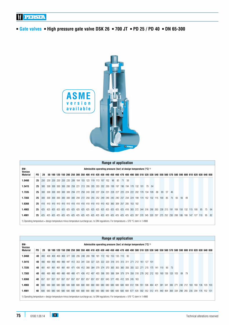
n Gate valves n High pressure gate valve DSK 26 n 700 JT n PD 25 / PD 40 n DN 65-300
Technical alterations reserved6100.1.09.1475
BW- Admissible operating pressure [bar] at design temperature [°C] 1)
VersionMaterial PD 20 50 100 120 150 200 250 300 350 400 410 420 430 440 450 460 470 480 490 500 510 520 530 540 550 560 570 580 590 600 610 620 630 640 650
1.0460 40 400 400 400 400 400 377 330 295 248 200 190 181 172 162 153 135 113 93 1.5415 40 480 480 480 480 480 447 412 353 341 330 327 325 322 320 318 315 313 311 271 212 161 127 101 1.7335 40 481 481 481 481 481 481 471 436 412 388 384 379 374 370 365 363 360 358 355 322 271 215 175 141 110 90 73 1.7383 40 480 480 480 480 480 480 480 471 436 412 407 403 398 393 388 384 379 374 358 318 278 242 212 183 160 136 120 103 89 79 1.6368 40 657 657 657 657 657 657 657 657 657 657 657 657 657 643 577 495 412 328 245 163 1.4903 40 680 680 680 680 680 680 680 680 680 680 680 680 680 680 680 680 680 669 612 596 551 506 464 421 381 341 306 271 240 212 183 160 136 120 103
1.4901 40 680 680 680 680 680 680 680 680 680 680 680 680 680 680 680 680 680 680 677 635 592 552 512 475 440 404 369 334 298 265 235 204 176 152 131 1) Operating temperature = design temperature minus temperature surcharge acc. to DIN regulations. For temperatures > 570 °C stem in 1.4980
Range of application
BW- Admissible operating pressure [bar] at design temperature [°C] 1)
VersionMaterial PD 20 50 100 120 150 200 250 300 350 400 410 420 430 440 450 460 470 480 490 500 510 520 530 540 550 560 570 580 590 600 610 620 630 640 650
1.0460 25 250 250 250 250 250 235 206 184 155 125 119 113 107 102 96 85 71 58 1.5415 25 300 300 300 300 300 280 258 221 213 206 205 203 202 200 199 197 196 194 170 132 101 79 64 1.7335 25 300 300 300 300 300 300 294 272 258 243 240 237 234 231 228 227 225 224 222 202 170 134 109 88 69 57 46 1.7383 25 300 300 300 300 300 300 300 294 272 258 255 252 249 246 243 240 237 234 224 199 174 152 132 115 100 85 75 65 56 49 1.6368 25 410 410 410 410 410 410 410 410 410 410 410 410 410 402 360 309 257 205 153 102 1.4903 25 425 425 425 425 425 425 425 425 425 425 425 425 425 425 425 425 425 418 383 372 344 316 290 263 238 213 191 169 150 132 115 100 85 75 64
1.4901 25 425 425 425 425 425 425 425 425 425 425 425 425 425 425 425 425 425 425 423 397 370 345 320 297 275 252 230 208 186 166 147 127 110 95 82 1) Operating temperature = design temperature minus temperature surcharge acc. to DIN regulations. For temperatures > 570 °C stem in 1.4980
Range of application
ASME v e r s i o n a v a i l a b l e

n Gate valves n High pressure gate valve DSK 26 n 700 JT n PD 25 / PD 40 n DN 65-300
Technical alterations reserved 6100.1.09.14 76
Design Highlights
n Long bonnet
n Seats of the shut-off device and of the valve body generally faced with stellite
n Non-rising handwheel
n Non-turning, rising stem and burnished stem
n Outside located switch-bracket
n Hammer head connection between shut-off device and stem
n Gland ring and gland flange in two separate pieces
n Yoke sleeve supported at the top and at the bottom by means of needle bearings (axial type)
Benefits
n To reduce temperatures
n Best possible sliding performance and minimum wear
n Small dimensions
n Minimum wear to the gland packing
n Protects against torsion of the stem
n The wedges are able to move parallel to the axis of the pipeline within the guiding groove. This protects the stem against bending moments
n Damage to the stem by irregular tightening of gland bolts is avoided
n Minimize the expenditure of effort when operating valve
Standard features
n Body made of forged steeln Disc guided in grooven Welded seat rings n Outside screw and yoken Position indicator / Switch bracketn Pressure sealing bonnet acc. to VGB-guidelinesn Yoke sleeve supported by needle bearingn Possibility to add an actuator
Pressure and temperature ratings
n Pressure rating up to 680 barn Temperature rating up to 650 °C
Materials
n 1.0460 n 1.4901 n 1.4903n 1.5415 n 1.6368n 1.7335n 1.7383
Further materials on request.
Media
Depending on the material the gate valves are suitable for water, gas, oil and other non aggressive media
Fields of application
High temperature steam and water, refining (catalytic reformers and hydrocrackers), petrochemical and chemical industries

n Gate valves n High pressure gate valve DSK 26 n 700 JT n PD 25 / PD 40 n DN 65-300
Technical alterations reserved6100.1.09.1477
DSK 26 n PD 25 nDN 80-300
510
511
200
464
462
440
190
420
170
273
272
271
270
160
400
360
100
L
H2
H
H1
DS
510
511
200
464
440
462
170
190
420
273
272
271
270
160
400
100
360
L
DS
H2
H
H1
DSK 26 n PD 40 nDN 65-250

n Gate valves n High pressure gate valve DSK 26 n 700 JT n PD 25 / PD 40 n DN 65-300
Technical alterations reserved 6100.1.09.14 78
Pos. Component 1.0460 (21) 1.5415 (42) 1.7335 (44) 1.7383 (45) 1.6368 (46) 1.4903 (63) 1.4901 (66) 100 Body 1.0460 1.5415 1.7335 1.7383 1.6368 1.4903 1.4901 welded on with Stellite Stellite Stellite Stellite Stellite Stellite Stellite160 4 Gasket Graphite Graphite Graphite Graphite Graphite Graphite Graphite 170 Stud 1.7709 1.7709 1.7709 1.7709 1.7709 1.7709 1.7709190 Hexagonal nut 1.7218 1.7218 1.7218 1.7218 1.7218 1.7218 1.7218200 Bonnet 1.5419 1.5419 1.5419 1.5419 1.5419 1.5419 1.5419 270 Cover 1.7383 1.7383 1.7383 1.7383 1.4903 1.4903 1.4901271 Ring 1.7383 1.7383 1.7383 1.7383 1.4903 1.4903 1.4901272 Segmentring 1.7383 1.7383 1.7383 1.7383 1.4903 1.4903 1.4901273 Cover 1.5419 1.5419 1.5419 1.5419 1.5419 1.5419 1.5419360 4 Disc 1.7383 1.7383 1.7383 1.7383 1.4903 1.4903 1.4901 welded on with Stellite Stellite Stellite Stellite Stellite Stellite Stellite 400 4 Stem 1.4122 1.4122 1.4122 1.4122 1.4923 1.4923 1.4980400 4 Stem from 570 °C 1.4980 1.4980 420 4 Packing Graphite Graphite Graphite Graphite Graphite Graphite Graphite 440 Gland flange 1.7380 1.7380 1.7380 1.7380 1.7380 1.7380 1.7380462 Stud 1.7709 1.7709 1.7709 1.7709 1.4923 1.4923 1.4923 464 Hexagonal nut 1.7218 1.7218 1.7218 1.7218 1.4923 1.4923 1.4923 510 4 Yoke sleeve CW713R CW713R CW713R CW713R CW713R CW713R CW713R511 4 Bearing WLSt WLSt WLSt WLSt WLSt WLSt WLSt
4Spare parts
Materials
DIN/ISO DN DS L H H1 H2 Stroke R/Stroke H-Wheel 5210 80 70 305 556 605 511 80 16 400 F10 (F14)100 90 406 658 725 606 105 18 450 F14125 111 483 781 861 720 130 21 500 F14150 136 559 952 1045 872 152 22 F16 (F14)200 178 711 1078 1270 1045 192 24 F25 (F16)250 222 864 1267 1515 1240 248 28 F30 (F25)300 263 770 (991) 1528 1815 1497 287 29 F30
Dimensions/mm DSK 26.25
DN BW Kvs (m3/h) 80 72 505100 128 875125 208 1270150 380 1910200 615 3270 250 1160 5080 300 1835 7140
Weights/kg and Kvs-values
DIN/ISODN DS L H H1 H2 Stroke R/Stroke H-Wheel 5210 65 50 330 518 594 466 66 19 400 F10 (F14)80 57 368 638 675 585 73 21 450 F14100 72 457 713 836 656 87 15 500 F14125 90 533 795 870 725 106 15 F16150 111 610 1090 1230 1040 133 15 F25 (F16)200 146 762 1195 1370 1165 174 18 F30 (F25)250 185 1270 1475 1685 1440 212 21 F35 (F30)
Dimensions/mm DSK 26.40
DN BW Kvs (m3/h) 65 83 21080 136 310100 219 505125 411 835150 676 1485200 1188 2200250 2208 3530
Weights/kg and Kvs-values

n Gate valves n High pressure gate valve DSK 16-63 n 700 JT n PD 16-63 n DN 50-600
Technical alterations reserved6100.1.09.1479
BW- Admissible operating pressure [bar] at design temperature [°C] 1)
VersionMaterial PD 120 150 200 250 300 350 400 410 420 430 440 450 460 470 480 490 500 510 520 530 540 550 560 570 580 590 600 610 620 630 640 650
1.0460 16 160 160 151 132 118 99 80 76 73 69 65 61 54 45 37 25 250 250 235 206 184 155 125 119 113 107 102 96 85 71 58 32 320 320 302 264 236 198 160 153 145 138 130 123 109 91 75 40 400 400 377 330 295 248 200 191 182 172 163 153 136 113 93 1.5415 16 192 192 179 165 141 137 132 131 130 129 128 127 126 125 124 109 85 64 51 41 25 300 300 280 258 221 213 206 205 203 202 200 199 197 196 194 170 132 101 79 64 32 385 385 358 330 283 273 264 262 260 258 256 255 253 251 249 217 170 129 102 81 40 480 480 448 413 354 342 330 328 325 323 321 318 316 314 311 272 212 161 127 102 1.7335 16 192 192 192 189 174 165 156 154 152 150 148 146 145 144 143 142 129 109 86 70 57 44 36 29 25 300 300 300 294 272 258 243 240 237 234 231 228 227 225 224 222 202 170 134 109 88 69 57 46 32 385 385 385 377 349 330 311 307 304 300 296 292 290 289 287 285 258 217 172 140 113 88 72 59 40 481 481 481 471 436 413 389 384 380 375 370 365 363 364 358 356 323 272 215 175 141 110 91 74 1.7383 16 192 192 192 192 189 174 165 163 161 159 157 156 154 152 150 143 127 111 97 85 74 64 55 48 41 36 32 25 300 300 300 300 294 272 258 255 252 249 246 243 240 237 234 224 199 174 152 132 115 100 85 75 65 56 49 32 384 384 384 384 377 349 330 326 322 319 315 311 307 304 300 287 255 223 194 170 147 128 109 96 83 72 63 40 480 480 480 480 471 436 413 408 403 398 384 389 384 379 375 358 318 278 243 212 184 160 137 120 104 90 79 1.6368 16 263 263 263 263 263 263 263 263 263 263 257 231 198 165 131 98 65 25 410 410 410 410 410 410 410 410 410 410 402 360 309 257 205 153 102 32 525 525 525 525 525 525 525 525 525 525 515 482 396 330 262 196 130 40 657 657 657 627 657 657 657 657 657 657 643 577 495 412 328 245 163 1.4903 16 272 272 272 272 272 272 272 272 272 272 272 272 272 272 268 245 239 221 203 186 169 153 137 123 108 96 85 74 64 55 48 41 25 425 425 425 425 425 425 425 425 425 425 425 425 425 425 418 383 372 344 316 290 263 238 213 191 169 150 132 115 100 85 75 65 32 544 544 544 544 544 544 544 544 544 544 544 544 544 544 536 490 477 441 405 371 338 305 273 245 217 192 170 147 128 109 96 83 40 680 680 680 680 680 680 680 680 680 680 680 680 680 680 669 613 596 552 507 464 422 382 342 306 271 240 212 184 160 137 120 104
1.4901 16 272 272 272 272 272 272 272 272 272 272 272 272 272 272 272 271 254 237 221 205 190 176 161 147 133 119 106 94 81 70 61 52 25 425 425 425 425 425 425 425 425 425 425 425 425 425 425 425 423 397 370 345 320 297 275 252 230 208 186 166 147 127 110 95 82 32 544 544 544 544 544 544 544 544 544 544 544 544 544 544 544 542 508 474 442 410 380 352 323 295 267 239 212 188 163 141 122 105 40 680 680 680 680 680 680 680 680 680 680 680 680 680 680 680 677 635 592 552 512 475 440 404 369 334 298 265 235 204 176 152 131 1) Operating temperature = design temperature minus temperature surcharge acc. to DIN regulations. Design according to working data PD 63 on request
Range of application
ASME v e r s i o n a v a i l a b l e
n Gate valves n High pressure gate valve DSK 16-63 n 700 JT n PD 16-63 n DN 50-600
Technical alterations reserved 6100.1.09.14 80
Standard features
n Valve body made of forged steeln Split disc typen Welded seatrings and guide barsn Outside screw and yoken Position indicator / non-rotating devicen Pressure sealing bonnet acc. VGB-guidelinesn Yoke sleeve supported by needle bearingn Possibility to add an actuator
Pressure and temperature ratings
n Pressure rating up to 680 barn Temperature rating up to 650 °Cn Higher temperature ratings on request
Materials
n 1.0460n 1.4901n 1.4903n 1.5415n 1.7335n 1.7383n 1.6368
Further materials on request.
Media
Depending on the material the gate valves are suitable for water, gas, oil and other non aggressive media
Fields of application
High temperature steam and water, refining (catalytic reformers and hydrocrackers), petrochemical and chemical industries
Design Highlights
n Long bonnet
n Seats and discs faced with stellite
n Non-turning, rising stem and burnished stem
n Outside located switch bracket
n Hammer head connection between shut-off device and stem
n Gland flange and gland ring in two separate pieces
n Yoke sleeve supported by needle bearing
Benefits
n To reduce temperatures
n Best possible sliding performance and minimum wear
n Minimum wear to the gland packing
n Protects against torsion
n Wedge are able to aligne parallel to the axis of the pipe shut-off device and stem within the guiding groove. This protects the stem against bending moments
n Damage to the stem by irregular tightening of gland bolts is avoided
n Minimize the expenditure of effort when operating valve
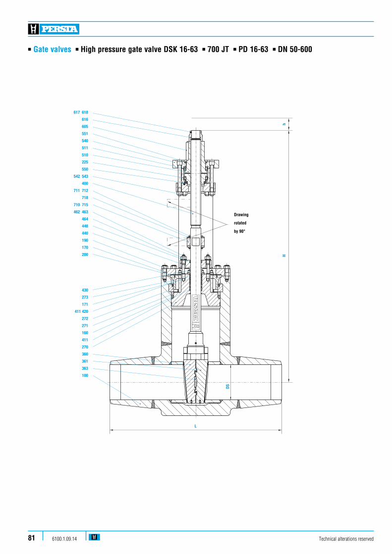
n Gate valves n High pressure gate valve DSK 16-63 n 700 JT n PD 16-63 n DN 50-600
Technical alterations reserved6100.1.09.1481
617 618
616
605
551
540
511
510
225
550
542 543
400
711 712
718
710 715
462 463
464
448
440
190
170
200
430
273
171
411 420
272
271
160
411
270
360
361
363
100
L
DS
Hh
Drawing
rotated
by 90°
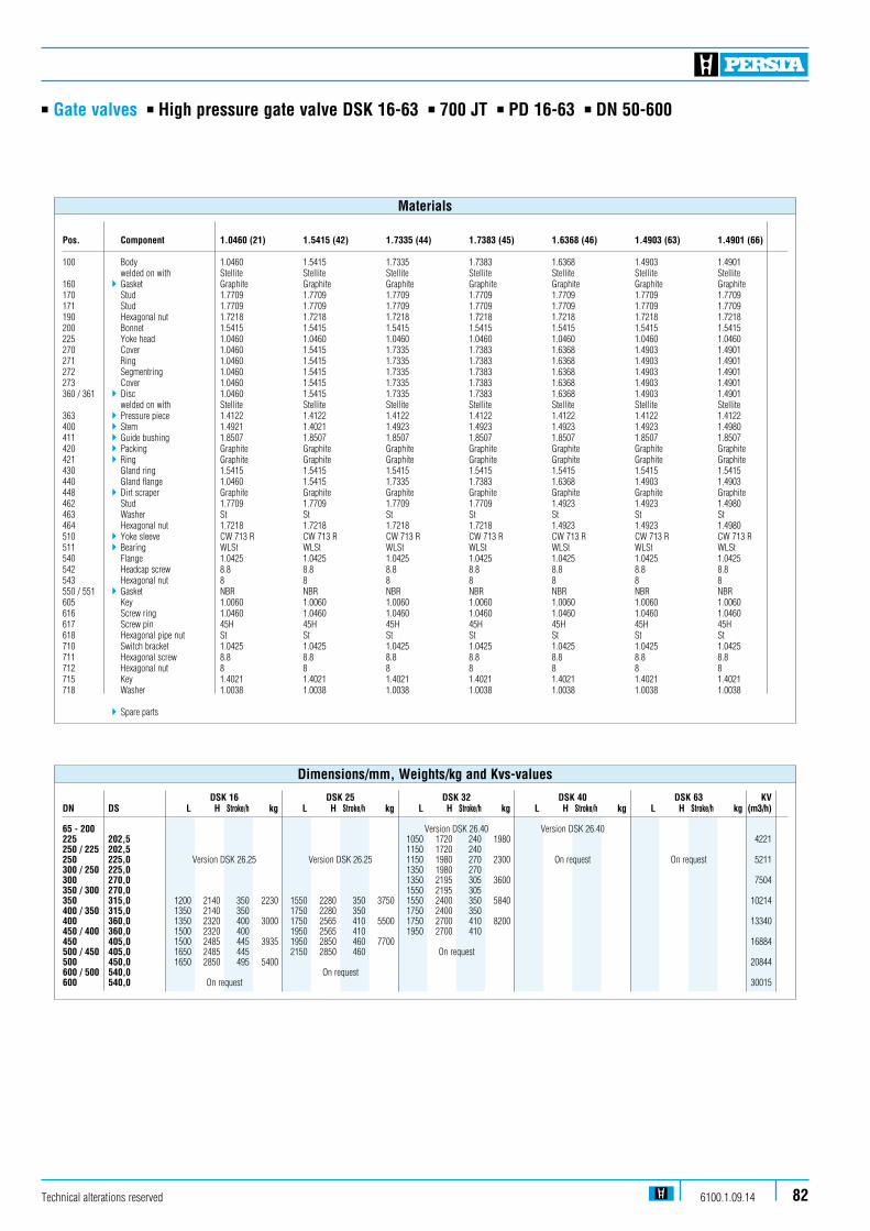
n Gate valves n High pressure gate valve DSK 16-63 n 700 JT n PD 16-63 n DN 50-600
Pos. Component 1.0460 (21) 1.5415 (42) 1.7335 (44) 1.7383 (45) 1.6368 (46) 1.4903 (63) 1.4901 (66) 100 Body 1.0460 1.5415 1.7335 1.7383 1.6368 1.4903 1.4901 welded on with Stellite Stellite Stellite Stellite Stellite Stellite Stellite160 4 Gasket Graphite Graphite Graphite Graphite Graphite Graphite Graphite170 Stud 1.7709 1.7709 1.7709 1.7709 1.7709 1.7709 1.7709171 Stud 1.7709 1.7709 1.7709 1.7709 1.7709 1.7709 1.7709190 Hexagonal nut 1.7218 1.7218 1.7218 1.7218 1.7218 1.7218 1.7218200 Bonnet 1.5415 1.5415 1.5415 1.5415 1.5415 1.5415 1.5415225 Yoke head 1.0460 1.0460 1.0460 1.0460 1.0460 1.0460 1.0460270 Cover 1.0460 1.5415 1.7335 1.7383 1.6368 1.4903 1.4901271 Ring 1.0460 1.5415 1.7335 1.7383 1.6368 1.4903 1.4901272 Segmentring 1.0460 1.5415 1.7335 1.7383 1.6368 1.4903 1.4901273 Cover 1.0460 1.5415 1.7335 1.7383 1.6368 1.4903 1.4901360 / 361 4 Disc 1.0460 1.5415 1.7335 1.7383 1.6368 1.4903 1.4901 welded on with Stellite Stellite Stellite Stellite Stellite Stellite Stellite363 4 Pressure piece 1.4122 1.4122 1.4122 1.4122 1.4122 1.4122 1.4122400 4 Stem 1.4921 1.4021 1.4923 1.4923 1.4923 1.4923 1.4980411 4 Guide bushing 1.8507 1.8507 1.8507 1.8507 1.8507 1.8507 1.8507420 4 Packing Graphite Graphite Graphite Graphite Graphite Graphite Graphite421 4 Ring Graphite Graphite Graphite Graphite Graphite Graphite Graphite430 Gland ring 1.5415 1.5415 1.5415 1.5415 1.5415 1.5415 1.5415440 Gland flange 1.0460 1.5415 1.7335 1.7383 1.6368 1.4903 1.4903448 4 Dirt scraper Graphite Graphite Graphite Graphite Graphite Graphite Graphite462 Stud 1.7709 1.7709 1.7709 1.7709 1.4923 1.4923 1.4980463 Washer St St St St St St St464 Hexagonal nut 1.7218 1.7218 1.7218 1.7218 1.4923 1.4923 1.4980510 4 Yoke sleeve CW 713 R CW 713 R CW 713 R CW 713 R CW 713 R CW 713 R CW 713 R511 4 Bearing WLSt WLSt WLSt WLSt WLSt WLSt WLSt540 Flange 1.0425 1.0425 1.0425 1.0425 1.0425 1.0425 1.0425542 Headcap screw 8.8 8.8 8.8 8.8 8.8 8.8 8.8543 Hexagonal nut 8 8 8 8 8 8 8550 / 551 4 Gasket NBR NBR NBR NBR NBR NBR NBR605 Key 1.0060 1.0060 1.0060 1.0060 1.0060 1.0060 1.0060616 Screw ring 1.0460 1.0460 1.0460 1.0460 1.0460 1.0460 1.0460617 Screw pin 45H 45H 45H 45H 45H 45H 45H618 Hexagonal pipe nut St St St St St St St710 Switch bracket 1.0425 1.0425 1.0425 1.0425 1.0425 1.0425 1.0425711 Hexagonal screw 8.8 8.8 8.8 8.8 8.8 8.8 8.8712 Hexagonal nut 8 8 8 8 8 8 8715 Key 1.4021 1.4021 1.4021 1.4021 1.4021 1.4021 1.4021718 Washer 1.0038 1.0038 1.0038 1.0038 1.0038 1.0038 1.0038
4Spare parts
Materials
Technical alterations reserved 6100.1.09.14 82
DSK 16 DSK 25 DSK 32 DSK 40 DSK 63 KVDN DS L H Stroke/h kg L H Stroke/h kg L H Stroke/h kg L H Stroke/h kg L H Stroke/h kg (m3/h) 65 - 200 Version DSK 26.40 Version DSK 26.40 225 202,5 1050 1720 240 1980 4221250 / 225 202,5 1150 1720 240 250 225,0 Version DSK 26.25 Version DSK 26.25 1150 1980 270 2300 On request On request 5211300 / 250 225,0 1350 1980 270 300 270,0 1350 2195 305 3600 7504350 / 300 270,0 1550 2195 305 350 315,0 1200 2140 350 2230 1550 2280 350 3750 1550 2400 350 5840 10214400 / 350 315,0 1350 2140 350 1750 2280 350 1750 2400 350 400 360,0 1350 2320 400 3000 1750 2565 410 5500 1750 2700 410 8200 13340450 / 400 360,0 1500 2320 400 1950 2565 410 1950 2700 410 450 405,0 1500 2485 445 3935 1950 2850 460 7700 16884500 / 450 405,0 1650 2485 445 2150 2850 460 On request 500 450,0 1650 2850 495 5400 20844600 / 500 540,0 On request 600 540,0 On request 30015
Dimensions/mm, Weights/kg and Kvs-values
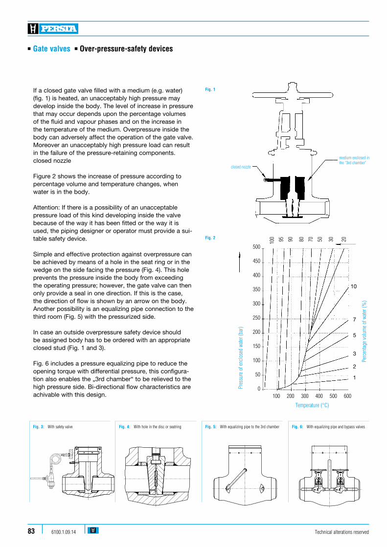
If a closed gate valve filled with a medium (e.g. water) (fig. 1) is heated, an unacceptably high pressure may develop inside the body. The level of increase in pressure that may occur depends upon the percentage volumes of the fluid and vapour phases and on the increase in the temperature of the medium. Overpressure inside the body can adversely affect the operation of the gate valve. Moreover an unacceptably high pressure load can result in the failure of the pressure-retaining components. closed nozzle
Figure 2 shows the increase of pressure according to percentage volume and temperature changes, when water is in the body.
Attention: If there is a possibility of an unacceptable pressure load of this kind developing inside the valve because of the way it has been fitted or the way it is used, the piping designer or operator must provide a sui-table safety device.
Simple and effective protection against over pressure can be achieved by means of a hole in the seat ring or in the wedge on the side facing the pressure (Fig. 4). This hole prevents the pressure inside the body from exceeding the operating pres sure; however, the gate valve can then only provide a seal in one direction. If this is the case, the direction of flow is shown by an arrow on the body. Another possibil ity is an equalizing pipe connection to the third room (Fig. 5) with the pressurized side.
In case an outside overpressure safety device should be assigned body has to be ordered with an appropriate closed stud (Fig. 1 and 3).
Fig. 6 includes a pressure equalizing pipe to reduce the opening torque with differential pressure, this configura-tion also enables the „3rd chamber“ to be relieved to the high pressure side. Bi-directional flow characteristics are achivable with this design.
n Gate valves n Over-pressure-safety devices
medium enclosed inthe “3rd chamber”
closed nozzle
Fig. 1
Fig. 2
10
7
5
3
2
1
500
450
400
350
300
250
200
150
100
50
0
100 95 90 80 70 50 30 20
100 200 300 400 500 600
Perc
enta
ge v
olum
e of
wat
er (%
)
Pres
sure
of e
nclo
sed
wate
r (ba
r)
Temperature (°C)
Technical alterations reserved6100.1.09.1483
Stahl-Armaturen PERSTA GmbHPostfach 2240
59567 Warstein
MAR
Erst.Dat./Name
Gepr.Dat./Name
Änderungs-Nr.
Index-Nr.
zRz 100YRz 25
xRz6.3ws=0.4-0.6
vRmax.3geschli�enuRmax.3geläppt
Werkstückkanten nach Werknorm 84, Form A oder D Maße ohne Toleranzangabe DIN ISO 2768-mk Ober�ächen: DIN ISO 1302
Nenn-maß
ISO-Tole-ranz
Abmaße
Datum Name MARPro/EGezeichnet 08.07.11 Janzen
Geprueft Werksto� / AbnahmeNormgepr. - / -
Maßstab
E-GEH. DSK26.25 - 200 217 UC 34250-2083853:5
Fig. 6: With equalizing pipe and bypass valvesFig. 4: With hole in the disc or seatring Fig. 5: With equalizing pipe to the 3rd chamber
u Rmax.3geläppt
vRmax.3
geschli�en
w
s=0.4-0.6
x Rz6.3
Y Rz 25
z Rz 100
Stahl-Armaturen PERSTA GmbHPostfach 2240
59567 Warstein
MAR
Erst.Dat./Name
Gepr.Dat./Name
Änderungs-Nr.
Index-Nr.
Werkstückkanten nach Werknorm 84, Form A oder D Maße ohne Toleranzangabe DIN ISO 2768-mk Ober�ächen: DIN ISO 1302
Nenn-maß
ISO-Tole-ranz
Abmaße
Datum Name MARPro/EGezeichnet 08.07.11 Janzen
Geprueft Werksto� / AbnahmeNormgepr. - / -
Maßstab
Schieber DSK --1:2
Fig. 3: With safety valve
Stahl-Armaturen PERSTA GmbHPostfach 2240
59567 Warstein
MAR
Erst.Dat./Name
Gepr.Dat./Name
Änderungs-Nr.
Index-Nr.
zRz 100YRz 25
xRz6.3ws=0.4-0.6
vRmax.3geschli�enuRmax.3geläppt
Werkstückkanten nach Werknorm 84, Form A oder D Maße ohne Toleranzangabe DIN ISO 2768-mk Ober�ächen: DIN ISO 1302
Nenn-maß
ISO-Tole-ranz
Abmaße
Datum Name MARPro/EGezeichnet 10.05.11 Janzen
Geprueft 10.05.11 Peck Werksto� / AbnahmeNormgepr. - / -
Maßstab
E-GEH. DSK26.25 - 250 217 UC 34260-2073141:2
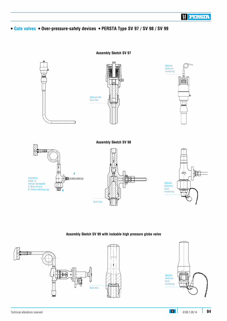
n Gate valves n Over-pressure-safety devices n PERSTA Type SV 97 / SV 98 / SV 99
Technical alterations reserved 6100.1.09.14 84
Assembly Sketch SV 97
Assembly Sketch SV 98
Installation: Outlet „A“ Vertical downwards!A: Blow-off studB: Steam-releasing-pipe
B
Optional with burst disc
Burst disc
Burst disc
Optional electronic burst monitoring
Optional electronic monitoring
Assembly Sketch SV 99 with lockable high pressure globe valveStahl-Arm
aturen PERSTA GmbH
Postfach 224059567 W
arstein
MAR
Erst.Dat./Name
Gepr.Dat./Name
Änderungs-Nr.
Index-Nr.
zRz 100YRz 25
xRz6.3ws=0.4-0.6
vRmax.3geschli�enuRmax.3geläppt
Werkstückkanten nach W
erknorm 84, Form
A oder DMaße ohne Toleranzangabe DIN ISO 2768-m
kOber�ächen: DIN ISO 1302
Nenn-
maßISO-Tole-ranz
Abmaße
DatumNam
eM
ARPro/E
Gezeichnet12.07.11
FrenzGeprueft
Werksto� / Abnahm
eNormgepr.
- / -Maßstab
Überdrucksicherung SV99926 PK 00000-168870
1:2
Optional electronic burst monitoring
A
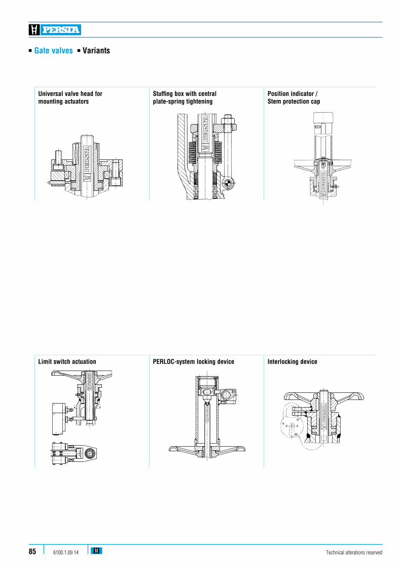
n Gate valves n Variants
Universal valve head for mounting actuators
Stuffing box with central plate-spring tightening
Position indicator / Stem protection cap
Limit switch actuation Interlocking devicePERLOC-system locking device
Technical alterations reserved6100.1.09.1485
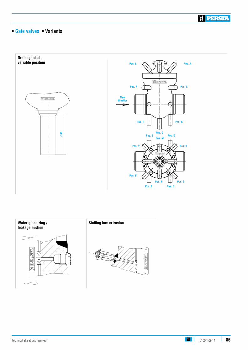
n Gate valves n Variants
Water gland ring / leakage suction
Stuffing box extrusion
Drainage stud, variable position
∼100
Technical alterations reserved 6100.1.09.14 86
Flow direction
Pos. L Pos. A
Pos. H
Pos. C
Pos. M
Pos. E
Pos. N
Pos. K
Pos. B Pos. D
Pos. 0Pos. Y
Pos. F
Pos. G
Pos. F Pos. S
Pos. S
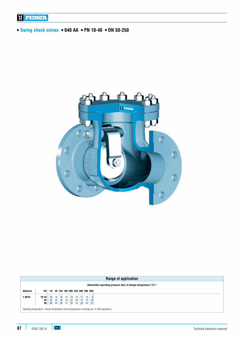
n Swing check valves n 640 AA n PN 10-40 n DN 50-250
Technical alterations reserved6100.1.09.1487
Admissible operating pressure [bar] at design temperature [°C] 1)
Material PN -10 20 120 150 200 250 300 350 400 1.0619 10-16 16 16 16 15 14 13 11 10 8 25 25 25 25 23 22 20 17 16 13 40 40 40 40 37 35 32 28 24 21 Operating temperature = design temperature minus temperature surcharge acc. to DIN regulations.
Range of application

n Swing check valves n 640 AA n PN 10-40 n DN 50-250
Standard features
n Body cast steeln Available with flange and buttweld ends
Pressure and temperature ratings
n Pressure rating up to 40 barn Temperature rating up to 400 °C
Materials
n 1.0619
Further materials on request.
Design Highlights
n Hard faced integral body seat with 13 % Cr-Steel or 17 % Cr-Steel layer
n Shut-off disc with curved journal within lever
n The lever rests on the hinge pin by means of a separate bearing bush
Benefits
n Extremely resistant to wear
n To improve movability and therefore to improve the alignment of the disc to the body seat
n Improved resistance to wear by means of proper material selection
Media
Depending on the material swing check valves are suita-ble for water, gas, oil and other non aggressive media
Fields of application
Chemical industries, power plants, ship building and other
Technical alterations reserved 6100.1.09.14 88

n Swing check valves n 640 AA n PN 10-40 n DN 50-250
L
H
D
190
170
210
160
382
384
385
387
380
100
Technical alterations reserved6100.1.09.1489
470
469
411
405
L
H
EE-Version
FL-Version

n Swing check valves n 640 AA n PN 10-40 n DN 50-250
Pos. Component 1.0619 (11) 100 Body 1.0619 welded on with Cr17160 4 Gasket Graphite 2)
170 Stud 1.1181190 Hexagonal nut 1.1181210 Bonnet 1.0460380 4 Disc 1.4021 welded on with 1)
382 4 Hinge 1.0425384 4 Bushing 1.4006 385 4 Pint 1.4370387 Washer 1.4021405 4 Hinge pin 1.4021411 4 Guide bushing 1.4006469 4 Gasket 2.4066470 Screw plug 1.7709
4Spare parts
Further materials on request. 1) DN 125 1.0460 welded on with Cr17 2) DN 150 grooved with graphite layer
Materials
DN L H D 50 230 165 17265 290 185 21280 310 210 227100 350 225 257125 400 255 292150 480 310 327200 600 370 412250 730 435 462
Dimensions/mm
KvsDN FL BW (m3/h) 50 19 13 65 31 23 170 80 36 27 256 100 52 39 400125 70 53 625150 104 82 900200 146 108 1600250 289 249 2500
Weights/kg and Kvs-values
Technical alterations reserved 6100.1.09.14 90

n Swing check valves n VALTRA Swing check valve n 640 AA n PN 10-40 n DN 300-800
Technical alterations reserved6100.1.09.1491
Admissible operating pressure [bar] at design temperature [°C] 1)
Material PN -10 20 100 120 200 250 300 350 400
P265GH 10 10 10 10 10 9 8 7 6 5 16 16 16 16 16 14 13 11 10 8 25 25 25 25 25 22 20 17 16 13 40 40 40 40 40 35 32 28 24 21
Operating temperature = design temperature minus temperature surcharge acc. to DIN regulations.
Range of application

n Swing check valves n VALTRA Swing check valve n 640 AA n PN 10-40 n DN 300-800
Standard features
n Disc with inside shaftn Body pressed-plate welding constructionn Available with flange and buttweld ends
Pressure and temperature ratings
n Pressure rating up to 40 barn Temperature rating up to 400 °C
Material
n P265GH
Further materials on request.
Design Highlights
n Body- and disc seat welded on
n Disc with flexible shaft at the hinge
n Lever rests on the hinge pin by means of a separate bushing
n Inside shaft
Benefits
n Extemely resistant to wear
n Optimum alignment of the disc to the body seat
n Improved resistance wear by means of an optimal material selection
n Limited leckage due to less sealings
Media
Depending on the material swing check valves are suitable for water, gas, oil and other non aggressive media
Fields of application
Chemical industries, power plants, ship building and other
Technical alterations reserved 6100.1.09.14 92

n Swing check valves n VALTRA Swing check valve n 640 AA n PN 10-40 n DN 300-800
Technical alterations reserved6100.1.09.1493
apport contact
piece centrale
joint
goujon
battant
boulon
douille
goupille
rondelle
axe de battant
rondelle
goupille
Datum
Name
Pos. Benennung Designation Designation Material Nr.
90.1522 004
RückschlagklappeDN 300-800 PN 10-63swing check valve
clapet de retenue
06.12.04
GF /LR
couvercle
scrou
Ersatzteil
spare part
piece detachée
Änderungen vorbehalten
alternation reserved
sous reserve de modi�cation
goupille
300
PN DN L H D k
900
700 385
kg
50040010
100 Mittelstück centre pieceDichtring gasket160
Schraubenbolzen stud180
Sechskantmutter hexagonal nut190
Deckel cover
aufgepanzert mit welded on with
380
Spannstift pin
Klappenwelle
Scheibe
405
386
washer
hinge pin
210
aufgepanzert mit welded on with
Rückschlagplatte disc
Scheibe washer
Ringschraube lifting plug801
388
407
382
384
389
392
419 Splint pin
Splint pin
Bolzen bolt
Buchse bush
Plattenhebel hinge
apport contact
clapet
bague boulon
St 35.8Kammpro�l mit Gra�tau�age
24 CrMo 5
24 CrMo 5
H II
X 8 CrTi 18
A2
X 20 Cr 13
X 20 CrMo 17 1
H II
X 20 Cr 13
X 20 Cr 13
C 15
1.0305
1.7258
1.7258
1.0425
1.0425
1.4021
1.4021
1.0401
A2
A2
X 20 Cr 13 1.4021
GG 25
H II 1.0425
1.4115
1.4502
1.4021
d2 d4 b f
445
565
400
515
12x22
16x26
370
482
26
26
4
4
Typ 90055
Fall der Patenterteilung oder Gebrauchsmustereintragungfolgt (Urheberrechtsgesetz, UWG, BGB).Alle Rechte fuer denPersonen ist unzulaessig, strafbar und wird gerichtlich ver-Jede Vervielfaeltigung, Verwertung oder Mitteilung an dritteWir behalten uns alle Urheberrechte an dieser Unterlage vor.
Datum
/Nam
e N
r. Änd
Geprüft
Geändert
bleiben vorbehalten.
350 800 420 505 460 16x22 430 26 4
1100 605500 670 620 20x26 585 28 4
1300 770600 780 725 20x30 685 28 5
300
PN DN L H D k
900
700 385
kg
50040016
d2 d4 b f
460
580
410
525
12x26
16x30
378
490
28
32
4
4
350 800 420 520 470 16x26 438 30 4
1100 605500 715 650 20x33 610 34 4
1300 770600 840 770 20x36 725 36 5
300
PN DN L H D k
1100
800 395
kg
50540025
d2 d4 b f
485
620
430
550
16x30
16x36
395
505
34
40
4
4
350 980 450 555 490 16x33 450 38 4
1250 675500 730 660 20x36 615 44 4
1450 820600 845 770 20x39 720 46 5
300
PN DN L H D k kg
40040
d2 d4 b f
515
660
450
585
16x33
16x39
410
535
42
50
4
4
350 580 510 16x36 465 46 4
500 755 670 20x42 615 52 4
600 890 795 20x48 735 60 5
1100
850 395
505
980 450
1250 675
1450 820
700 995 900 24x48 840 64 51650 925
1000 525450 615 565 20x26 532 26 4 1200 564450 670 600 20x36 555 42 4
1000 525450 640 585 20x30 550 32 4 450 685 610 20x39 560 50 41200 617
600
630
820
950
PN DN L H D k kg
63
d2 d4 b f250 775 385 470 400 12x36 345 46 3 380
STAHL-ARMATUREN PERSTA GMBH POSTFACH 2240 59579 WARSTEIN TELEFON (02902) 762-02 FAX (02902) 76703
D
L
H
801
190
170
210
160
405
382
385
380
100
100 Gehäuse body H II Dichtring gasket Grafit160
Schraubenbolzen stud Ck 35180
Sechskantmutter hexagonal nut C 35 190
Deckel cover H II
aufgepanzert mit welded on with X 8 CrTi 18
380
Spannstift pin A2
Klappenwelle
Scheibe
405
386
washer
hinge pin
X 20 Cr 13
Datum
Name
Pos. Benennung Designation Designation Material
90.1622 000
RückschlagklappeDN 250-800 PN 10-40swing check valve
clapet de retenue
04.03.02
GF/LR
fig.-no.:
Baureihe: 640 AA 22.2
Ersatzteil
spare partÄnderungen vorbehalten
alternation reserved
210
aufgepanzert mit welded on with X 20 CrMo 17 1
Rückschlagplatte disc H II
Scheibe washer
Ringschraube lifting plug801
X 20 Cr 13
X 20 Cr 13
C 15
1.0425
1.1181
1.0501
1.0425
1.0425
1.4021
1.4021
350
250
600
300
PN DN L H d1 d2
900
600
700
800
385
430
kg360
500
700
40010
450
500
1000 525
1100 585
-
Fall der Patenterteilung oder Gebrauchsmustereintragungfolgt (Urheberrechtsgesetz, UWG, BGB).Alle Rechte fuer denPersonen ist unzulaessig, strafbar und wird gerichtlich ver-Jede Vervielfaeltigung, Verwertung oder Mitteilung an dritteWir behalten uns alle Urheberrechte an dieser Unterlage vor.
Datum
/Nam
e N
r. Änd
Geprüft
Geändert
bleiben vorbehalten.
according to order
Maß d1 und d2
dimension d1 and d2
gemäß Auftrag
16
800
388
407
1.0401
350
250
600
300
PN DN L H d1 d2
1100
980 485
kg
540
700
40025
450
500
1200 565
800
350
250
600
300
PN DN L H d1 d2
1100
850
980
435
485
kg
595
700
40040
450
500
1200 620
1250 670
800
382
384
389
392
419 Splint pin A2
Splint pin A2
Bolzen bolt X 20 Cr 13 1.4021
Buchse bush GG 25
Plattenhebel hinge H II 1.0425
1.4115
1.4502
1.4021
dimension d1 et d2
suiv. Commande
Serie
piece detacheeZachowujemy prawo do zmian
Typ 90055
VALTRA ARMATUREN HANDELSGES.MBH-POSTFACH 2249-59567 WARSTEIN-TELEFON(02902)76701-FAX(02902)76703
VALTRA
Ers. für dito
GF / LR
corpsjoint
goujon
ecrou
couvercle
apport contact
goupille
rondelle
axe de battant
apport contact
clapet
rondelle
bague boulon
goupille
goupille
boulon
douille
bras de battant
850 415
vom 20.11.99
1650 950
1G
F / LR
30.10.03
1250 615
255
860
305
1040
2G
F / LR
16.07.04
3G
F / LR
23.11.04
1300
335
525 395
365
355
1125
745
445
4G
F / LR
26.01.07
5G
F / LR
20.03.07
790
L

n Swing check valves n VALTRA Swing check valve n 640 AA n PN 10-40 n DN 300-800
Pos. Component P265GH (22) 100 Body P265GH welded on with X20CrMo171 160 4 Gasket 1.4541 / Graphite 170 Tension screw 1.7158 190 Hexagonal nut 1.7158 210 Bonnet P265GH 380 4 Disc P265GH welded on with X8CrTi18 382 4 Hinge S235JRG2 385 4 Pint A2-70 405 4 Hinge pin 1.4021 801 Lifting eye bolt S355J2G3
4Spare parts
Further materials on request.
Materials
PN PN PN PN PN PN PN PN 10-16 25-40 10-16 25 40 10-16 25 40DN L L H H H D D D 300 700 850 385 415 435 525 525350 800 980 430 450 485 630 640400 900 1100 500 540 595 745 755500 1100 1250 585 615 670 870 870 890600 1300 1450 1040 1040700 1500 1650 800 1700 1850
Dimensions/mm
PN PN PN PN PN PN PN PN 10 16 25 40 10 16 25 40 KvsDN FL FL FL FL BW BW BW BW (m3/h) 300 275 285 350 430 255 255 305 355 3600350 380 395 475 550 335 345 395 445 4900400 560 575 735 895 525 525 365 745 6400500 910 945 1180 1300 860 860 1040 1125 9996600 14395700 19593800 25591
Weights/kg and Kvs-values
Technical alterations reserved 6100.1.09.14 94
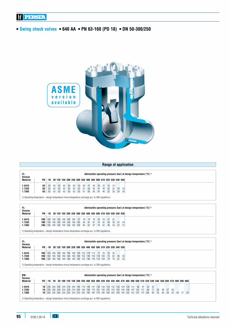
n Swing check valves n 640 AA n PN 63-160 (PD 18) n DN 50-300/250
Technical alterations reserved6100.1.09.1495
FL- Admissible operating pressure [bar] at design temperature [°C] 1)
VersionMaterial PN -10 20 120 150 200 250 300 350 400 450 500 510 520 530 540 550 1.5415 100 100 100 100 100 100 100 87 78 74 70 45 34 27 22 1.7335 100 100 100 100 100 100 100 100 95 91 87 74 62 49 38 31 24 1.7383 100 100 100 100 100 100 100 100 95 91 87 74 62 49 43 37 31
1) Operating temperature = design temperature minus temperature surcharge acc. to DIN regulations.
FL- Admissible operating pressure [bar] at design temperature [°C] 1)
VersionMaterial PN -10 20 120 150 200 250 300 350 400 450 500 510 520 530 540 550 1.5415 63 63 63 63 63 63 63 53 50 47 45 29 22 16 14 1.7335 63 63 63 63 63 63 63 63 61 58 56 47 40 32 25 20 15 1.7383 63 63 63 63 63 63 63 63 61 58 56 47 40 32 28 24 20
1) Operating temperature = design temperature minus temperature surcharge acc. to DIN regulations.
Range of application
FL- Admissible operating pressure [bar] at design temperature [°C] 1)
VersionMaterial PN -10 20 120 150 200 250 300 350 400 450 500 510 520 530 540 550 1.5415 160 160 160 160 160 160 160 139 125 118 112 72 55 43 35 1.7335 160 160 160 160 160 160 160 160 153 146 139 118 100 79 62 46 35 1.7383 160 160 160 160 160 160 160 160 153 146 139 118 100 79 70 61 52
1) Operating temperature = design temperature minus temperature surcharge acc. to DIN regulations.
BW- Admissible operating pressure [bar] at design temperature [°C] 1)
VersionMaterial PD -10 20 50 100 120 150 200 250 300 350 400 420 430 440 460 470 480 490 500 510 520 530 540 550 560 570 580 590 600 1.5415 18 258 258 246 229 219 204 185 170 146 141 136 134 133 132 130 129 128 112 88 67 53 42 1.7335 18 258 258 249 234 228 219 205 194 180 170 161 156 155 153 150 149 148 147 133 112 89 72 58 46 37 30 1.7383 18 258 258 250 239 233 224 210 205 194 180 170 166 164 262 159 156 155 153 131 115 100 88 76 66 56 50 43 37 33 1) Operating temperature = design temperature minus temperature surcharge acc. to DIN regulations.
ASME v e r s i o n a v a i l a b l e

n Swing check valves n 640 AA n PN 63-160 (PD 18) n DN 50-300/250
Technical alterations reserved 6100.1.09.14 96
Standard features
n Die-forged bodyn Disc with inside shaftn Fastening of the disc at the covern Available with flange and buttweld ends
Pressure and temperature ratings
n Pressure rating BW-Ends 258 bar (PD 18)n Pressure rating FL up to 160 bar n Temperature rating up -10 °C to 600 °C
Materials
n 1.5415n 1.7335n 1.7383
Further materials on request.
Design Highlights
n Die-forged body
n Integral seat
n Lever rests on the hinge pin by means of the guide bush
n Bolted bonnet with reduced-shaft bolts
n Fastening of the disc at the cover
Benefits
n Free from porosity and shrink holes
n No contact corrosion
n Optimum adjustment of the disc to the body seat by means of the movability the guide bushing
n To improve the stress capacity when temperature and pressure changes
n Easy to assemble and disassemble
Media
Depending on the material swing check valves are suita-ble for water, gas, oil and other non aggressive media
Fields of application
Chemical industries, power plants, ship building and other

n Swing check valves n 640 AA n PN 63-160 (PD 18) n DN 50-300/250
Stahl-Armaturen PERSTA GmbHPostfach 2240
59567 Warstein
zRz 100YRz 25
xRz6.3ws=0.4-0.6
vRmax.3geschli�enuRmax.3geläppt
MAR
Erst.Dat./Name
Gepr.Dat./Name
Änderungs-Nr.
Index-Nr.
Werkstückkanten nach Werknorm 84, Form A oder D Maße ohne Toleranzangabe DIN ISO 2768-mk Ober�ächen: DIN ISO 1302
Nenn-maß
Abmaße
Datum Name MARPro/EGezeichnet 04.07.11 Janzen
Werksto� / AbnahmeNormgepr. - / -
Maßstab
Rückschlagklappe DN80 --1530017:5
L
H
801
190
210
170
160
405
409
380
100
LH
Technical alterations reserved6100.1.09.1497
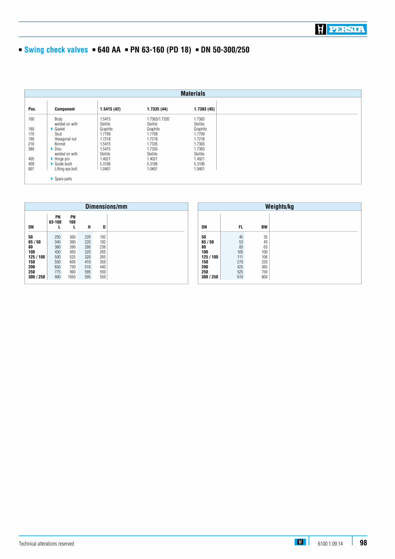
n Swing check valves n 640 AA n PN 63-160 (PD 18) n DN 50-300/250
PN PN 63-100 160DN L L H D
50 250 300 220 19265 / 50 340 360 220 19280 380 390 280 236100 430 450 320 265125 / 100 500 525 320 265150 550 600 410 350200 650 750 510 440250 775 900 595 550300 / 250 900 1050 595 550
Dimensions/mm
DN FL BW
50 45 3565 / 50 53 4380 83 63100 105 100125 / 100 111 106150 270 220200 425 365250 525 750300 / 250 610 800
Weights/kg
Technical alterations reserved 6100.1.09.14 98
Pos. Component 1.5415 (42) 1.7335 (44) 1.7383 (45) 100 Body 1.5415 1.7383/1.7335 1.7383 welded on with Stellite Stellite Stellite160 4 Gasket Graphite Graphite Graphite170 Stud 1.7709 1.7709 1.7709190 Hexagonal nut 1.7218 1.7218 1.7218210 Bonnet 1.5415 1.7335 1.7383380 4 Disc 1.5415 1.7335 1.7383 welded on with Stellite Stellite Stellite405 4 Hinge pin 1.4021 1.4021 1.4021409 4Guide bush 5.3106 5.3106 5.3106801 Lifting eye bolt 1.0401 1.0401 1.0401
4Spare parts
Materials
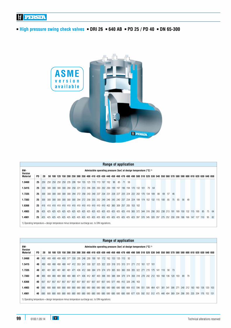
n High pressure swing check valves n DRI 26 n 640 AB n PD 25 / PD 40 n DN 65-300
Technical alterations reserved6100.1.09.1499
BW- Admissible operating pressure [bar] at design temperature [°C] 1)
VersionMaterial PD 20 50 100 120 150 200 250 300 350 400 410 420 430 440 450 460 470 480 490 500 510 520 530 540 550 560 570 580 590 600 610 620 630 640 650
1.0460 40 400 400 400 400 400 377 330 295 248 200 190 181 172 162 153 135 113 93 1.5415 40 480 480 480 480 480 447 412 353 341 330 327 325 322 320 318 315 313 311 271 212 161 127 101 1.7335 40 481 481 481 481 481 481 471 436 412 388 384 379 374 370 365 363 360 358 355 322 271 215 175 141 110 90 73 1.7383 40 480 480 480 480 480 480 480 471 436 412 407 403 398 393 388 384 379 374 358 318 278 242 212 183 160 136 120 103 89 79 1.6368 40 657 657 657 657 657 657 657 657 657 657 657 657 657 643 577 495 412 328 245 163 1.4903 40 680 680 680 680 680 680 680 680 680 680 680 680 680 680 680 680 680 669 612 596 551 506 464 421 381 341 306 271 240 212 183 160 136 120 103
1.4901 40 680 680 680 680 680 680 680 680 680 680 680 680 680 680 680 680 680 680 677 635 592 552 512 475 440 404 369 334 298 265 235 204 176 152 131 1) Operating temperature = design temperature minus temperature surcharge acc. to DIN regulations.
Range of application
BW- Admissible operating pressure [bar] at design temperature [°C] 1)
VersionMaterial PD 20 50 100 120 150 200 250 300 350 400 410 420 430 440 450 460 470 480 490 500 510 520 530 540 550 560 570 580 590 600 610 620 630 640 650
1.0460 25 250 250 250 250 250 235 206 184 155 125 119 113 107 102 96 85 71 58 1.5415 25 300 300 300 300 300 280 258 221 213 206 205 203 202 200 199 197 196 194 170 132 101 79 64 1.7335 25 300 300 300 300 300 300 294 272 258 243 240 237 234 231 228 227 225 224 222 202 170 134 109 88 69 57 46 1.7383 25 300 300 300 300 300 300 300 294 272 258 255 252 249 246 243 240 237 234 224 199 174 152 132 115 100 85 75 65 56 49 1.6368 25 410 410 410 410 410 410 410 410 410 410 410 410 410 402 360 309 257 205 153 102 1.4903 25 425 425 425 425 425 425 425 425 425 425 425 425 425 425 425 425 425 418 383 372 344 316 290 263 238 213 191 169 150 132 115 100 85 75 64
1.4901 25 425 425 425 425 425 425 425 425 425 425 425 425 425 425 425 425 425 425 423 397 370 345 320 297 275 252 230 208 186 166 147 127 110 95 82 1) Operating temperature = design temperature minus temperature surcharge acc. to DIN regulations.
Range of application
ASME v e r s i o n a v a i l a b l e
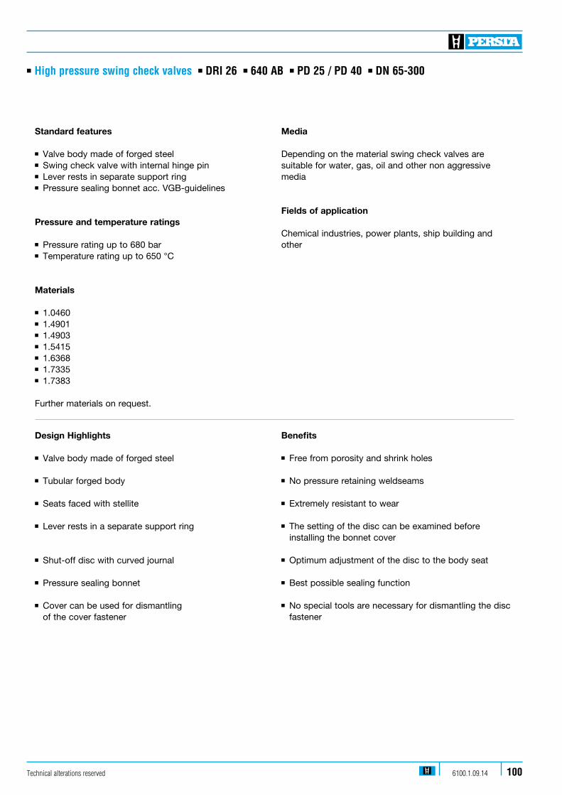
n High pressure swing check valves n DRI 26 n 640 AB n PD 25 / PD 40 n DN 65-300
Standard features
n Valve body made of forged steeln Swing check valve with internal hinge pinn Lever rests in separate support ringn Pressure sealing bonnet acc. VGB-guidelines
Pressure and temperature ratings
n Pressure rating up to 680 barn Temperature rating up to 650 °C
Materials
n 1.0460n 1.4901 n 1.4903n 1.5415n 1.6368 n 1.7335 n 1.7383
Further materials on request.
Design Highlights
n Valve body made of forged steel n Tubular forged body n Seats faced with stellite n Lever rests in a separate support ring
n Shut-off disc with curved journal
n Pressure sealing bonnet
n Cover can be used for dismantling of the cover fastener
Benefits
n Free from porosity and shrink holes
n No pressure retaining weldseams
n Extremely resistant to wear
n The setting of the disc can be examined before installing the bonnet cover
n Optimum adjustment of the disc to the body seat
n Best possible sealing function
n No special tools are necessary for dismantling the disc fastener
Media
Depending on the material swing check valves are suitable for water, gas, oil and other non aggressive media
Fields of application
Chemical industries, power plants, ship building and other
Technical alterations reserved 6100.1.09.14 100

n High pressure swing check valves n DRI 26 n 640 AB n PD 25 / PD 40 n DN 65-300
Technical alterations reserved6100.1.09.14101
171
191
273
272
271
160
270
333
391
305
405 411
382
383
380
100
140
L
DS
H
331
337
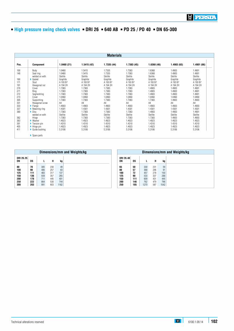
n High pressure swing check valves n DRI 26 n 640 AB n PD 25 / PD 40 n DN 65-300
Technical alterations reserved 6100.1.09.14 102
DRI 26.25 DN DS L H kg
80 70 305 230 49100 90 406 257 83125 111 483 317 137150 136 559 357 265200 178 711 445 401250 222 864 530 744300 263 991 603 1182
Dimensions/mm and Weights/kg
DRI 26.40 DN DS L H kg
65 50 330 231 5980 57 368 246 91100 72 457 278 150125 90 533 337 288150 111 609 431 445200 146 762 479 796250 185 1270 587 1542
Dimensions/mm and Weights/kg
Pos. Component 1.0460 (21) 1.5415 (42) 1.7335 (44) 1.7383 (45) 1.6368 (46) 1.4903 (63) 1.4901 (66)
100 Body 1.0460 1.5415 1.7335 1.7383 1.6368 1.4903 1.4901140 Seat ring 1.0460 1.5415 1.7335 1.7383 1.6368 1.4903 1.4901 welded on with Stellite Stellite Stellite Stellite Stellite Stellite Stellite160 4 Gasket Graphite Graphite Graphite Graphite Graphite Graphite Graphite171 Stud A 193 B7 A 193 B7 A 193 B7 A 193 B7 A 193 B7 A 193 B7 A 193 B7191 Hexagonal nut A 194 2H A 194 2H A 194 2H A 194 2H A 194 2H A 194 2H A 194 2H270 Cover 1.7383 1.7383 1.7383 1.7383 1.4903 1.4903 1.4901271 Ring 1.7383 1.7383 1.7383 1.7383 1.4903 1.4903 1.4901272 Segmentring 1.7383 1.7383 1.7383 1.7383 1.4903 1.4903 1.4901273 Cover 1.0460 1.0460 1.0460 1.0460 1.0460 1.0460 1.0460305 Supportring 1.7383 1.7383 1.7383 1.7383 1.7383 1.4903 1.4903331 Hexagonal screw A4 A4 A4 A4 A4 A4 A4333 4 Flange 1.4903 1.4903 1.4903 1.4903 1.4903 1.4903 1.4903337 4 Retaining ring 1.4301 1.4301 1.4301 1.4301 1.4301 1.4301 1.4301380 4 Disc 1.7383 1.7383 1.7383 1.7383 1.4903 1.4903 1.4901 welded on with Stellite Stellite Stellite Stellite Stellite Stellite Stellite382 Hinge 1.7383 1.7383 1.7383 1.7383 1.7383 1.4903 1.4903383 4 Washer 1.4923 1.4923 1.4923 1.4923 1.4923 1.4923 1.4923391 4 Tension pin 1.4310 1.4310 1.4310 1.4310 1.4310 1.4310 1.4310405 4 Hinge pin 1.4923 1.4923 1.4923 1.4923 1.4923 1.4923 1.4923411 4Guide bushing 5.3106 5.3106 5.3106 5.3106 5.3106 5.3106 5.3106
4Spare parts
Materials
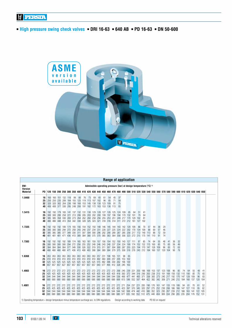
n High pressure swing check valves n DRI 16-63 n 640 AB n PD 16-63 n DN 50-600
Technical alterations reserved6100.1.09.14103
BW- Admissible operating pressure [bar] at design temperature [°C] 1)
VersionMaterial PD 120 150 200 250 300 350 400 410 420 430 440 450 460 470 480 490 500 510 520 530 540 550 560 570 580 590 600 610 620 630 640 650
1.0460 16 160 160 151 132 118 99 80 76 73 69 65 61 54 45 37 25 250 250 235 206 184 155 125 119 113 107 102 96 85 71 58 32 320 320 302 264 236 198 160 153 145 138 130 123 109 91 75 40 400 400 377 330 295 248 200 191 182 172 163 153 136 113 93 1.5415 16 192 192 179 165 141 137 132 131 130 129 128 127 126 125 124 109 85 64 51 41 25 300 300 280 258 221 213 206 205 203 202 200 199 197 196 194 170 132 101 79 64 32 385 385 358 330 283 273 264 262 260 258 256 255 253 251 249 217 170 129 102 81 40 480 480 448 413 354 342 330 328 325 323 321 318 316 314 311 272 212 161 127 102 1.7335 16 192 192 192 189 174 165 156 154 152 150 148 146 145 144 143 142 129 109 86 70 57 44 36 29 25 300 300 300 294 272 258 243 240 237 234 231 228 227 225 224 222 202 170 134 109 88 69 57 46 32 385 385 385 377 349 330 311 307 304 300 296 292 290 289 287 285 258 217 172 140 113 88 72 59 40 481 481 481 471 436 413 389 384 380 375 370 365 363 364 358 356 323 272 215 175 141 110 91 74 1.7383 16 192 192 192 192 189 174 165 163 161 159 157 156 154 152 150 143 127 111 97 85 74 64 55 48 41 36 32 25 300 300 300 300 294 272 258 255 252 249 246 243 240 237 234 224 199 174 152 132 115 100 85 75 65 56 49 32 384 384 384 384 377 349 330 326 322 319 315 311 307 304 300 287 255 223 194 170 147 128 109 96 83 72 63 40 480 480 480 480 471 436 413 408 403 398 384 389 384 379 375 358 318 278 243 212 184 160 137 120 104 90 79 1.6368 16 263 263 263 263 263 263 263 263 263 263 257 231 198 165 131 98 65 25 410 410 410 410 410 410 410 410 410 410 402 360 309 257 205 153 102 32 525 525 525 525 525 525 525 525 525 525 515 482 396 330 262 196 130 40 657 657 657 627 657 657 657 657 657 657 643 577 495 412 328 245 163 1.4903 16 272 272 272 272 272 272 272 272 272 272 272 272 272 272 268 245 239 221 203 186 169 153 137 123 108 96 85 74 64 55 48 41 25 425 425 425 425 425 425 425 425 425 425 425 425 425 425 418 383 372 344 316 290 263 238 213 191 169 150 132 115 100 85 75 65 32 544 544 544 544 544 544 544 544 544 544 544 544 544 544 536 490 477 441 405 371 338 305 273 245 217 192 170 147 128 109 96 83 40 680 680 680 680 680 680 680 680 680 680 680 680 680 680 669 613 596 552 507 464 422 382 342 306 271 240 212 184 160 137 120 104
1.4901 16 272 272 272 272 272 272 272 272 272 272 272 272 272 272 272 271 254 237 221 205 190 176 161 147 133 119 106 94 81 70 61 52 25 425 425 425 425 425 425 425 425 425 425 425 425 425 425 425 423 397 370 345 320 297 275 252 230 208 186 166 147 127 110 95 82 32 544 544 544 544 544 544 544 544 544 544 544 544 544 544 544 542 508 474 442 410 380 352 323 295 267 239 212 188 163 141 122 105 40 680 680 680 680 680 680 680 680 680 680 680 680 680 680 680 677 635 592 552 512 475 440 404 369 334 298 265 235 204 176 152 131 1) Operating temperature = design temperature minus temperature surcharge acc. to DIN regulations. Design according to working data PD 63 on request
Range of application
ASME v e r s i o n a v a i l a b l e

n High pressure swing check valves n DRI 16-63 n 640 AB n PD 16-63 n DN 50-600
Technical alterations reserved 6100.1.09.14 104
Standard features
n Valve body made of forged steeln Swing check valve with internal hinge pinn Lever rests in a separate support ringn Welded seat ringn Pressure sealing bonnet acc. VGB-guidelines
Pressure and temperature ratings
n Pressure rating up to 680 barn Temperature rating up to 650 °Cn Higher ratings on request
Materials
n 1.0460n 1.4901n 1.4903 n 1.5415 n 1.6368n 1.7335n 1.7383 Further materials on request.
Design Highlights
n Valve body made of forged steel
n Seats faced with stellite
n Lever rests in a separate support ring
n Shut-off device with curved journal
n Pressure sealing bonnet
Benefits
n Free from porosity and shrink holes
n Extremely resistant to wear
n The setting of the disc can be examined before installing the bonnet cover
n Optimum alignment of the disc to the body seat
n Best possible sealing function
Media
Depending on the material swing check valves are suita-ble for water, gas, oil and other non aggressive media
Fields of application
High temperature steam and water, refining (catalytic reformers and hydrocrackers), petrochemical and chemical industries
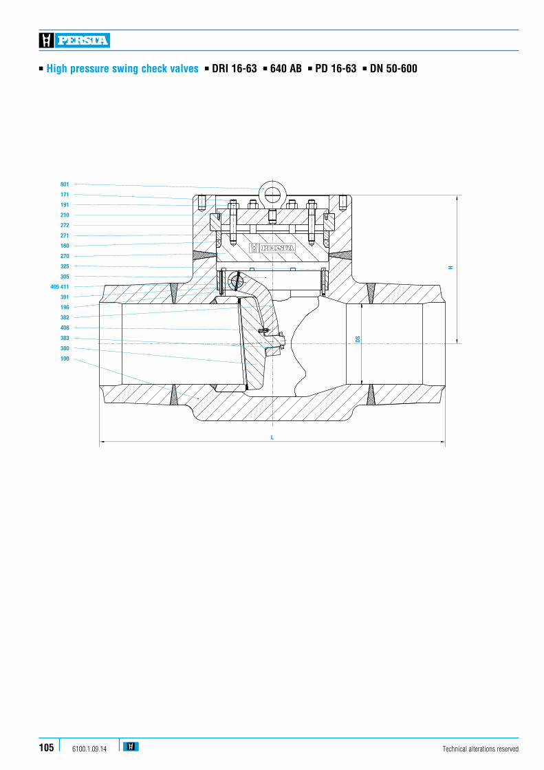
n High pressure swing check valves n DRI 16-63 n 640 AB n PD 16-63 n DN 50-600
801
171
191
210
272
271
160
270
325
305
405 411
391
196
382
408
383
380
100
L
DS
H
Technical alterations reserved6100.1.09.14105
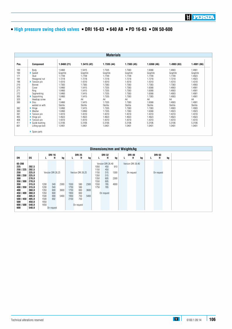
n High pressure swing check valves n DRI 16-63 n 640 AB n PD 16-63 n DN 50-600
Pos. Component 1.0460 (21) 1.5415 (42) 1.7335 (44) 1.7383 (45) 1.6368 (46) 1.4903 (63) 1.4901 (66) 100 Body 1.0460 1.5415 1.7335 1.7383 1.6368 1.4903 1.4901160 4 Gasket Graphite Graphite Graphite Graphite Graphite Graphite Graphite171 Stud 1.7709 1.7709 1.7709 1.7709 1.7709 1.7709 1.4923191 Hexagonal nut 1.7218 1.7218 1.7218 1.7218 1.7218 1.7218 1.4923196 4 Tension pin 1.4310 1.4310 1.4310 1.4310 1.4310 1.4310 1.4310210 Bonnet 1.7383 1.7383 1.7383 1.7383 1.7383 1.7383 1.4903270 Cover 1.0460 1.5415 1.7335 1.7383 1.6368 1.4903 1.4901271 Ring 1.0460 1.5415 1.7335 1.7383 1.6368 1.4903 1.4901272 Segmentring 1.0460 1.5415 1.7335 1.7383 1.6368 1.4903 1.4901305 4 Supportring 1.0460 1.5415 1.7335 1.7383 1.7383 1.4903 1.4901325 Headcap screw A4 A4 A4 A4 A4 A4 A4380 4 Disc 1.0460 1.5415 1.7335 1.7383 1.6368 1.4903 1.4901 welded on with Stellite Stellite Stellite Stellite Stellite Stellite Stellite382 4 Hinge 1.0460 1.5415 1.7335 1.7383 1.7383 1.4903 1.4903383 4 Washer 1.0460 1.0460 1.7335 1.7383 1.6368 1.4923 1.4923391 4 Tension pin 1.4310 1.4310 1.4310 1.4310 1.4310 1.4310 1.4310405 4 Hinge pin 1.4923 1.4923 1.4923 1.4923 1.4923 1.4923 1.4923408 4 Tension pin 1.4310 1.4310 1.4310 1.4310 1.4310 1.4310 1.4310411 4 Guide bushing 5.3106 5.3106 5.3106 5.3106 5.3106 5.3106 5.3106801 Lifting eye bolt 1.0401 1.0401 1.0401 1.0401 1.0401 1.0401 1.0401
4Spare parts
Materials
Technical alterations reserved 6100.1.09.14 106
DRI 16 DRI 25 DRI 32 DRI 40 DRI 63DN DS L H kg L H kg L H kg L H kg L H kg 65-200 Version DRI 26.40 Version DRI 26.40 225 202,5 1050 450 910 250 / 225 202,5 1150 450 250 225,0 Version DRI 26.25 Version DRI 26.25 1150 515 1300 On request On request300 / 250 225,0 1350 515 300 270,0 1350 605 2300 350 / 300 270,0 1550 605 350 315,0 1200 540 2300 1550 580 2300 1550 785 4000 400 / 350 315,0 1200 540 1750 580 1750 785 400 360,0 1350 600 3600 1750 660 3600 450 / 400 360,0 1350 600 1950 660 On request 450 405,0 1500 690 5400 1950 750 5400 500 / 450 405,0 1500 692 2150 750 500 450,0 1650 600 / 500 540,0 1650 On request 600 540,0 On request
Dimensions/mm and Weights/kg

n High pressure stop check valve n DRA 26 n 640 ST n PD 25 / 40 n DN 80-200
BW- Admissible operating pressure [bar] at design temperature [°C] 1)
VersionMaterial PD 20 50 100 120 150 200 250 300 350 400 410 420 430 440 450 460 470 480 490 500 510 520 530 540 550 560 570 580 590 600 610 620 630 640 650
1.0460 40 400 400 400 400 400 377 330 295 248 200 190 181 172 162 153 135 113 93 1.5415 40 480 480 480 480 480 447 412 353 341 330 327 325 322 320 318 315 313 311 271 212 161 127 101 1.7335 40 481 481 481 481 481 481 471 436 412 388 384 379 374 370 365 363 360 358 355 322 271 215 175 141 110 90 73 1.7383 40 480 480 480 480 480 480 480 471 436 412 407 403 398 393 388 384 379 374 358 318 278 242 212 183 160 136 120 103 89 79 1.6368 40 657 657 657 657 657 657 657 657 657 657 657 657 657 643 577 495 412 328 245 163 1.4903 40 680 680 680 680 680 680 680 680 680 680 680 680 680 680 680 680 680 669 612 596 551 506 464 421 381 341 306 271 240 212 183 160 136 120 103
1.4901 40 680 680 680 680 680 680 680 680 680 680 680 680 680 680 680 680 680 680 677 635 592 552 512 475 440 404 369 334 298 265 235 204 176 152 131 1) Operating temperature = design temperature minus temperature surcharge acc. to DIN regulations. For temperatures > 570 °C stem in 1.4980
Range of application
BW- Admissible operating pressure [bar] at design temperature [°C] 1)
VersionMaterial PD 20 50 100 120 150 200 250 300 350 400 410 420 430 440 450 460 470 480 490 500 510 520 530 540 550 560 570 580 590 600 610 620 630 640 650
1.0460 25 250 250 250 250 250 235 206 184 155 125 119 113 107 102 96 85 71 58 1.5415 25 300 300 300 300 300 280 258 221 213 206 205 203 202 200 199 197 196 194 170 132 101 79 64 1.7335 25 300 300 300 300 300 300 294 272 258 243 240 237 234 231 228 227 225 224 222 202 170 134 109 88 69 57 46 1.7383 25 300 300 300 300 300 300 300 294 272 258 255 252 249 246 243 240 237 234 224 199 174 152 132 115 100 85 75 65 56 49 1.6368 25 410 410 410 410 410 410 410 410 410 410 410 410 410 402 360 309 257 205 153 102 1.4903 25 425 425 425 425 425 425 425 425 425 425 425 425 425 425 425 425 425 418 383 372 344 316 290 263 238 213 191 169 150 132 115 100 85 75 64
1.4901 25 425 425 425 425 425 425 425 425 425 425 425 425 425 425 425 425 425 425 423 397 370 345 320 297 275 252 230 208 186 166 147 127 110 95 82 1) Operating temperature = design temperature minus temperature surcharge acc. to DIN regulations. For temperatures > 570 °C stem in 1.4980
Range of application
Technical alterations reserved6100.1.09.14107
ASME v e r s i o n a v a i l a b l e
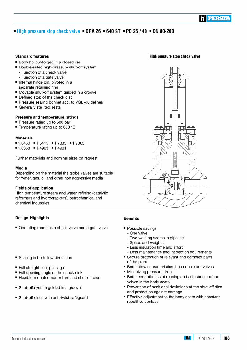
Design-Highlights n Operating mode as a check valve and a gate valve
n Sealing in both flow directions
n Full straight seat passage n Full opening angle of the check diskn Flexible-mounted non-return and shut-off disc
n Shut-off system guided in a groove
n Shut-off discs with anti-twist safeguard
Standard featuresn Body hollow-forged in a closed dien Double-sided high-pressure shut-off system - Function of a check valve - Function of a gate valven Internal hinge pin, pivoted in a separate retaining ringn Movable shut-off system guided in a grooven Defined stop of the check discn Pressure sealing bonnet acc. to VGB-guidelinesn Generally stellited seats
Pressure and temperature ratingsn Pressure rating up to 680 barn Temperature rating up to 650 °C
Materialsn 1.0460 n 1.5415 n 1.7335 n 1.7383 n 1.6368 n 1.4903 n 1.4901 Further materials and nominal sizes on request
MediaDepending on the material the globe valves are suitablefor water, gas, oil and other non aggressive media
Fields of applicationHigh temperature steam and water, refining (catalyticreformers and hydrocrackers), petrochemical andchemical industries
Benefits
n Possible savings: - One valve - Two welding seams in pipeline - Space and weights - Less insulation time and effort - Less maintenance and inspection equirements n Secure protection of relevant and complex parts of the plantn Better flow characteristics than non-return valves n Minimizing pressure dropn Better smoothness of running and adjustment of the valves in the body seatsn Prevention of positional deviations of the shut-off disc and protection against damagen Effective adjustment to the body seats with constant repetitive contact
n High pressure stop check valve n DRA 26 n 640 ST n PD 25 / 40 n DN 80-200
High pressure stop check valve
Technical alterations reserved 6100.1.09.14 108
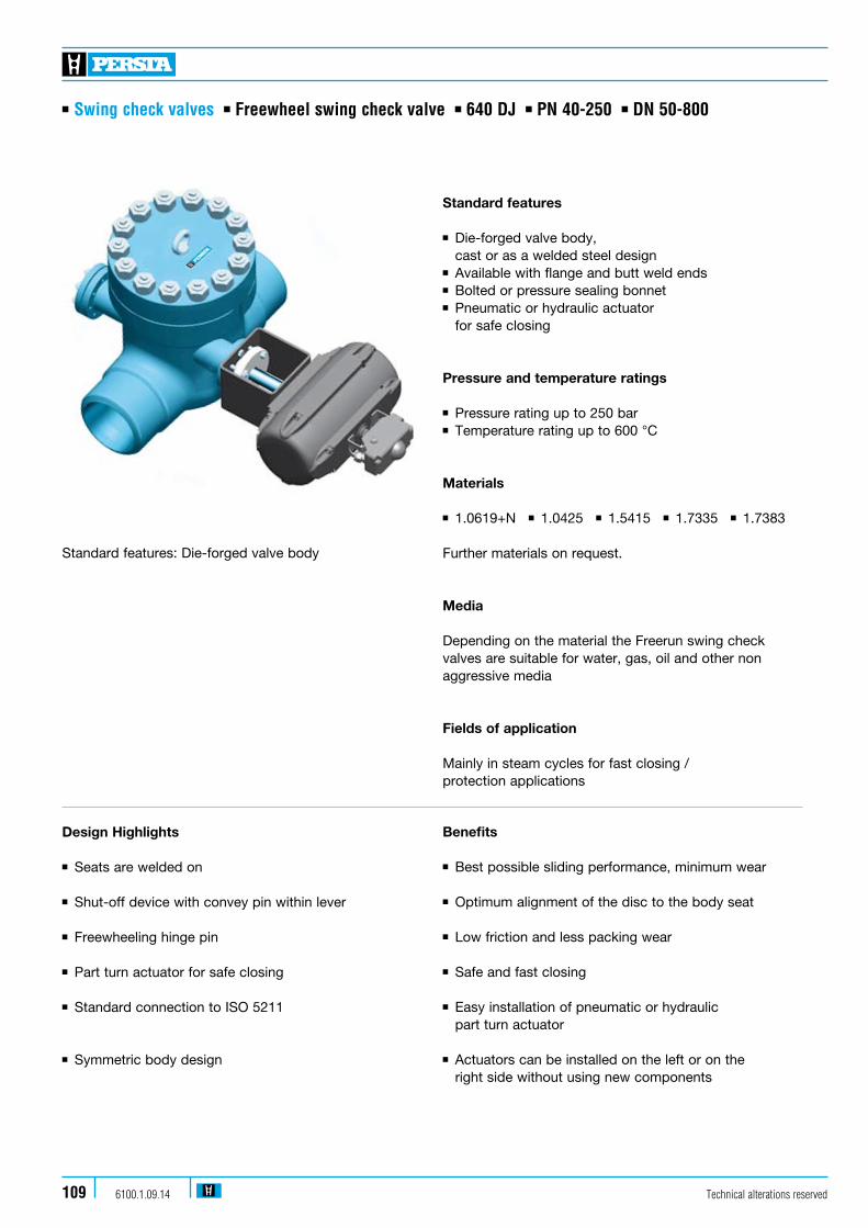
n Swing check valves n Freewheel swing check valve n 640 DJ n PN 40-250 n DN 50-800
Technical alterations reserved6100.1.09.14109
Design Highlights
n Seats are welded on
n Shut-off device with convey pin within lever
n Freewheeling hinge pin
n Part turn actuator for safe closing
n Standard connection to ISO 5211
n Symmetric body design
Benefits
n Best possible sliding performance, minimum wear
n Optimum alignment of the disc to the body seat
n Low friction and less packing wear
n Safe and fast closing
n Easy installation of pneumatic or hydraulic part turn actuator
n Actuators can be installed on the left or on the right side without using new components
Standard features
n Die-forged valve body, cast or as a welded steel design n Available with flange and butt weld ends n Bolted or pressure sealing bonnet n Pneumatic or hydraulic actuator for safe closing
Pressure and temperature ratings
n Pressure rating up to 250 barn Temperature rating up to 600 °C
Materials
n 1.0619+N n1.0425 n1.5415 n1.7335 n1.7383 Further materials on request.
Media
Depending on the material the Freerun swing check valves are suitable for water, gas, oil and other non aggressive media
Fields of application
Mainly in steam cycles for fast closing / protection applications
Standard features: Die-forged valve body

n Swing check valves n Swing check valve variants
Technical alterations reserved 6100.1.09.14 110
Swing check valve with lever and weight
Swing check valve with recuperating spring
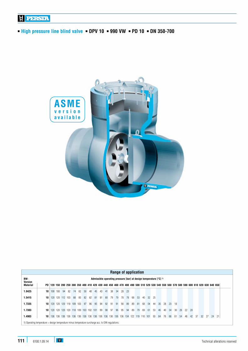
Technical alterations reserved6100.1.09.14111
n High pressure line blind valve n DPV 10 n 990 VW n PD 10 n DN 350-700
BW- Admissible operating pressure [bar] at design temperature [°C] 1)
VersionMaterial PD 120 150 200 250 300 350 400 410 420 430 440 450 460 470 480 490 500 510 520 530 540 550 560 570 580 590 600 610 620 630 640 650
1.0425 10 100 100 94 82 74 62 50 48 45 43 41 38 34 28 23 1.5415 10 120 120 112 103 88 85 82 82 81 81 80 79 79 78 78 68 53 40 32 25 1.7335 10 120 120 120 118 109 103 97 96 95 94 92 91 91 90 89 89 81 68 54 44 35 28 23 18 1.7383 10 120 120 120 120 118 109 103 102 101 99 98 97 96 95 94 89 79 69 61 53 46 40 34 30 26 22 20
1.4903 10 136 136 136 136 136 136 136 136 136 136 136 136 136 136 134 122 119 110 101 93 84 76 68 61 54 48 42 37 32 27 24 21 1) Operating temperature = design temperature minus temperature surcharge acc. to DIN regulations.
Range of application
ASME v e r s i o n a v a i l a b l e
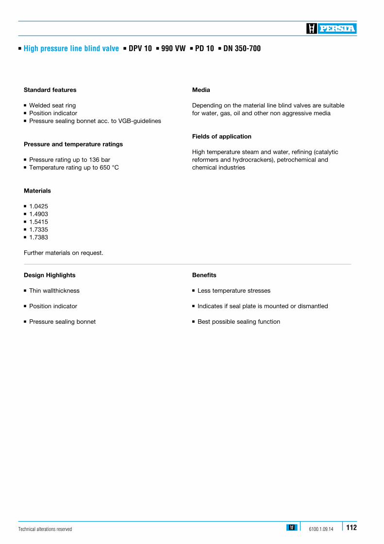
Technical alterations reserved 6100.1.09.14 112
n High pressure line blind valve n DPV 10 n 990 VW n PD 10 n DN 350-700
Standard features
n Welded seat ring n Position indicator n Pressure sealing bonnet acc. to VGB-guidelines
Pressure and temperature ratings
n Pressure rating up to 136 barn Temperature rating up to 650 °C
Materials
n 1.0425n 1.4903n 1.5415n 1.7335n 1.7383 Further materials on request.
Design Highlights
n Thin wallthickness
n Position indicator n Pressure sealing bonnet
Benefits
n Less temperature stresses n Indicates if seal plate is mounted or dismantled n Best possible sealing function
Media
Depending on the material line blind valves are suitable for water, gas, oil and other non aggressive media
Fields of application
High temperature steam and water, refining (catalytic reformers and hydrocrackers), petrochemical and chemical industries
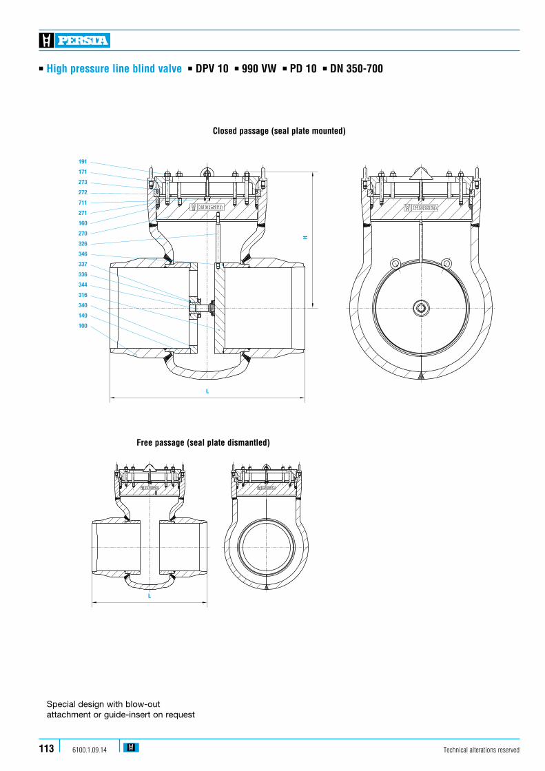
Technical alterations reserved6100.1.09.14113
n High pressure line blind valve n DPV 10 n 990 VW n PD 10 n DN 350-700
191
171
273
272
711
271
160
270
326
346
337
336
344
316
340
140
100
L
H
191
171
273
272
711
271
160
270
326
346
337
336
344
316
340
140
100
L
H
Free passage (seal plate dismantled)
Closed passage (seal plate mounted)
Special design with blow-out attachment or guide-insert on request
L
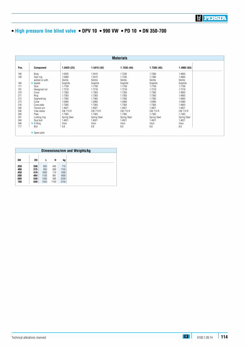
Technical alterations reserved 6100.1.09.14 114
n High pressure line blind valve n DPV 10 n 990 VW n PD 10 n DN 350-700
Pos. Component 1.0425 (22) 1.5415 (42) 1.7335 (44) 1.7383 (45) 1.4903 (63)
100 Body 1.0425 1.5415 1.7335 1.7383 1.4903140 Seat ring 1.0460 1.5415 1.7335 1.7383 1.4903 welded on with Stellite Stellite Stellite Stellite Stellite160 4 Gasket Graphite Graphite Graphite Graphite Graphite171 Stud 1.7709 1.7709 1.7709 1.7709 1.7709191 Hexagonal nut 1.7218 1.7218 1.7218 1.7218 1.7218270 Cover 1.7383 1.7383 1.7383 1.7383 1.4903271 Ring 1.7383 1.7383 1.7383 1.7383 1.4903272 Segmentring 1.7383 1.7383 1.7383 1.7383 1.4903273 Cover 1.0460 1.0460 1.0460 1.0460 1.0460316 Cone plate 1.7383 1.7383 1.7383 1.7383 1.4903326 Tension pin 1.4021 1.4021 1.4021 1.4021 1.4021336 Yoke sleeve CW 713 R CW 713 R CW 713 R CW 713 R CW 713 R340 Plate 1.7383 1.7383 1.7383 1.7383 1.7383337 Locking ring Spring Steel Spring Steel Spring Steel Spring Steel Spring Steel 344 Stud bolt 1.4021 1.4021 1.4021 1.4021 1.4021346 4 O-Ring Viton Viton Viton Viton Viton711 Bolt 8.8 8.8 8.8 8.8 8.8
4Spare parts
Materials
DN DS L H kg
350 330 850 645 710400 375 950 690 1150450 419 1050 710 1400500 464 1150 861 1800600 559 1350 945 2540700 640 1550 1150 3750
Dimensions/mm and Weights/kg
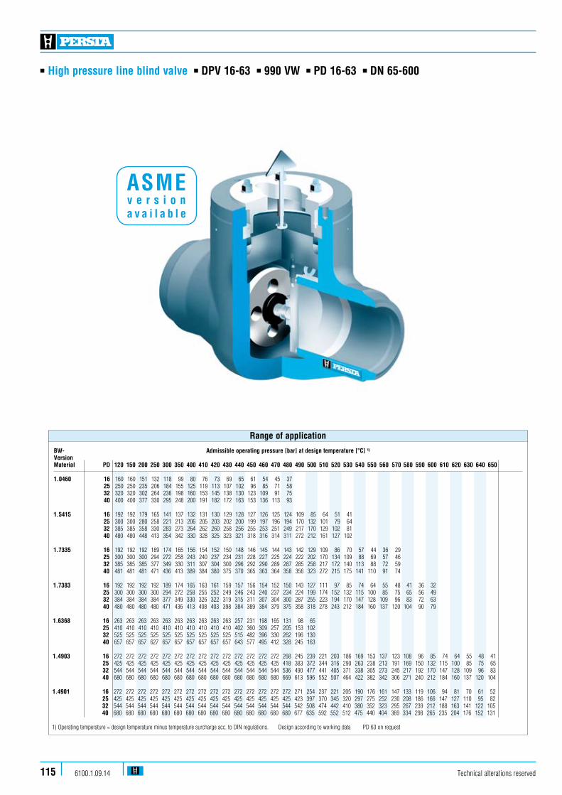
Technical alterations reserved6100.1.09.14115
n High pressure line blind valve n DPV 16-63 n 990 VW n PD 16-63 n DN 65-600
BW- Admissible operating pressure [bar] at design temperature [°C] 1)
VersionMaterial PD 120 150 200 250 300 350 400 410 420 430 440 450 460 470 480 490 500 510 520 530 540 550 560 570 580 590 600 610 620 630 640 650
1.0460 16 160 160 151 132 118 99 80 76 73 69 65 61 54 45 37 25 250 250 235 206 184 155 125 119 113 107 102 96 85 71 58 32 320 320 302 264 236 198 160 153 145 138 130 123 109 91 75 40 400 400 377 330 295 248 200 191 182 172 163 153 136 113 93 1.5415 16 192 192 179 165 141 137 132 131 130 129 128 127 126 125 124 109 85 64 51 41 25 300 300 280 258 221 213 206 205 203 202 200 199 197 196 194 170 132 101 79 64 32 385 385 358 330 283 273 264 262 260 258 256 255 253 251 249 217 170 129 102 81 40 480 480 448 413 354 342 330 328 325 323 321 318 316 314 311 272 212 161 127 102 1.7335 16 192 192 192 189 174 165 156 154 152 150 148 146 145 144 143 142 129 109 86 70 57 44 36 29 25 300 300 300 294 272 258 243 240 237 234 231 228 227 225 224 222 202 170 134 109 88 69 57 46 32 385 385 385 377 349 330 311 307 304 300 296 292 290 289 287 285 258 217 172 140 113 88 72 59 40 481 481 481 471 436 413 389 384 380 375 370 365 363 364 358 356 323 272 215 175 141 110 91 74 1.7383 16 192 192 192 192 189 174 165 163 161 159 157 156 154 152 150 143 127 111 97 85 74 64 55 48 41 36 32 25 300 300 300 300 294 272 258 255 252 249 246 243 240 237 234 224 199 174 152 132 115 100 85 75 65 56 49 32 384 384 384 384 377 349 330 326 322 319 315 311 307 304 300 287 255 223 194 170 147 128 109 96 83 72 63 40 480 480 480 480 471 436 413 408 403 398 384 389 384 379 375 358 318 278 243 212 184 160 137 120 104 90 79 1.6368 16 263 263 263 263 263 263 263 263 263 263 257 231 198 165 131 98 65 25 410 410 410 410 410 410 410 410 410 410 402 360 309 257 205 153 102 32 525 525 525 525 525 525 525 525 525 525 515 482 396 330 262 196 130 40 657 657 657 627 657 657 657 657 657 657 643 577 495 412 328 245 163 1.4903 16 272 272 272 272 272 272 272 272 272 272 272 272 272 272 268 245 239 221 203 186 169 153 137 123 108 96 85 74 64 55 48 41 25 425 425 425 425 425 425 425 425 425 425 425 425 425 425 418 383 372 344 316 290 263 238 213 191 169 150 132 115 100 85 75 65 32 544 544 544 544 544 544 544 544 544 544 544 544 544 544 536 490 477 441 405 371 338 305 273 245 217 192 170 147 128 109 96 83 40 680 680 680 680 680 680 680 680 680 680 680 680 680 680 669 613 596 552 507 464 422 382 342 306 271 240 212 184 160 137 120 104
1.4901 16 272 272 272 272 272 272 272 272 272 272 272 272 272 272 272 271 254 237 221 205 190 176 161 147 133 119 106 94 81 70 61 52 25 425 425 425 425 425 425 425 425 425 425 425 425 425 425 425 423 397 370 345 320 297 275 252 230 208 186 166 147 127 110 95 82 32 544 544 544 544 544 544 544 544 544 544 544 544 544 544 544 542 508 474 442 410 380 352 323 295 267 239 212 188 163 141 122 105 40 680 680 680 680 680 680 680 680 680 680 680 680 680 680 680 677 635 592 552 512 475 440 404 369 334 298 265 235 204 176 152 131 1) Operating temperature = design temperature minus temperature surcharge acc. to DIN regulations. Design according to working data PD 63 on request
Range of application
ASME v e r s i o n a v a i l a b l e
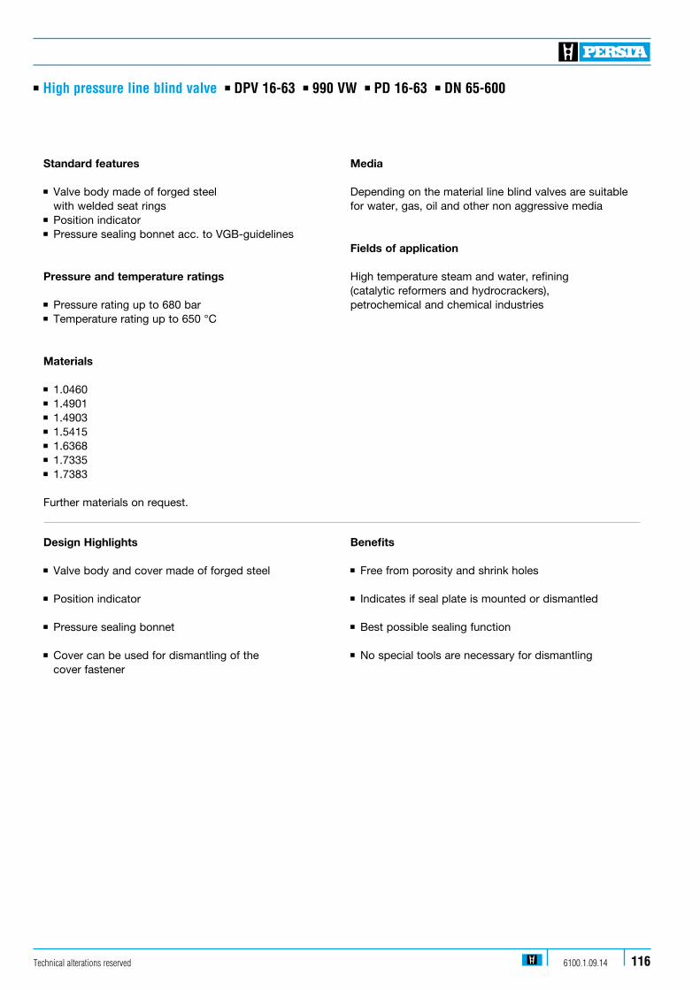
Technical alterations reserved 6100.1.09.14 116
n High pressure line blind valve n DPV 16-63 n 990 VW n PD 16-63 n DN 65-600
Standard features
n Valve body made of forged steel with welded seat rings n Position indicator n Pressure sealing bonnet acc. to VGB-guidelines Pressure and temperature ratings
n Pressure rating up to 680 barn Temperature rating up to 650 °C
Materials
n 1.0460n 1.4901n 1.4903n 1.5415n 1.6368n 1.7335n 1.7383 Further materials on request.
Media
Depending on the material line blind valves are suitable for water, gas, oil and other non aggressive media Fields of application
High temperature steam and water, refining (catalytic reformers and hydrocrackers), petrochemical and chemical industries
Design Highlights
n Valve body and cover made of forged steel
n Position indicator n Pressure sealing bonnet n Cover can be used for dismantling of the cover fastener
Benefits
n Free from porosity and shrink holes n Indicates if seal plate is mounted or dismantled n Best possible sealing function n No special tools are necessary for dismantling
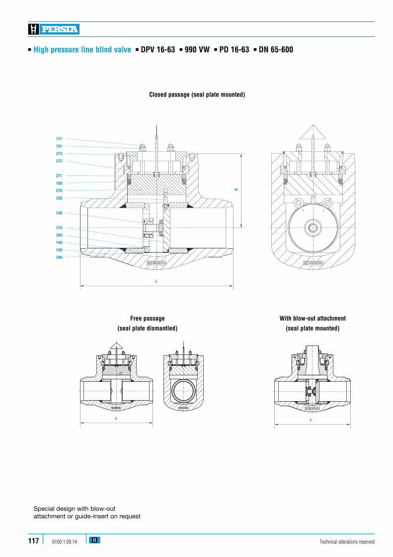
Technical alterations reserved6100.1.09.14117
n High pressure line blind valve n DPV 16-63 n 990 VW n PD 16-63 n DN 65-600
Closed passage (seal plate mounted)
Special design with blow-out attachment or guide-insert on request
171
191
273
272
271
160
270
326
336
316
340
140
100
346
L
H
171
191
273
272
271
160
270
326
336
316
340
140
100
346
L
H
L
Free passage
(seal plate dismantled)
With blow-out attachment
(seal plate mounted)
L
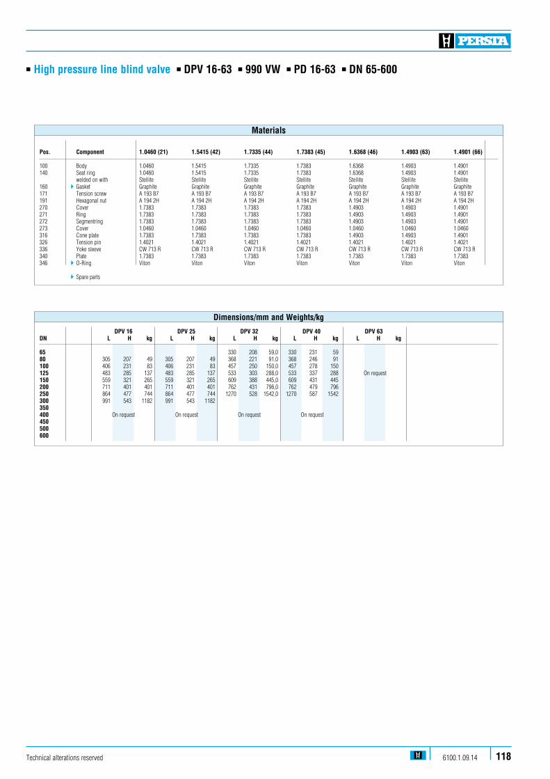
Technical alterations reserved 6100.1.09.14 118
n High pressure line blind valve n DPV 16-63 n 990 VW n PD 16-63 n DN 65-600
Pos. Component 1.0460 (21) 1.5415 (42) 1.7335 (44) 1.7383 (45) 1.6368 (46) 1.4903 (63) 1.4901 (66)
100 Body 1.0460 1.5415 1.7335 1.7383 1.6368 1.4903 1.4901140 Seat ring 1.0460 1.5415 1.7335 1.7383 1.6368 1.4903 1.4901 welded on with Stellite Stellite Stellite Stellite Stellite Stellite Stellite160 4 Gasket Graphite Graphite Graphite Graphite Graphite Graphite Graphite171 Tension screw A 193 B7 A 193 B7 A 193 B7 A 193 B7 A 193 B7 A 193 B7 A 193 B7191 Hexagonal nut A 194 2H A 194 2H A 194 2H A 194 2H A 194 2H A 194 2H A 194 2H270 Cover 1.7383 1.7383 1.7383 1.7383 1.4903 1.4903 1.4901271 Ring 1.7383 1.7383 1.7383 1.7383 1.4903 1.4903 1.4901272 Segmentring 1.7383 1.7383 1.7383 1.7383 1.4903 1.4903 1.4901273 Cover 1.0460 1.0460 1.0460 1.0460 1.0460 1.0460 1.0460316 Cone plate 1.7383 1.7383 1.7383 1.7383 1.4903 1.4903 1.4901326 Tension pin 1.4021 1.4021 1.4021 1.4021 1.4021 1.4021 1.4021336 Yoke sleeve CW 713 R CW 713 R CW 713 R CW 713 R CW 713 R CW 713 R CW 713 R340 Plate 1.7383 1.7383 1.7383 1.7383 1.7383 1.7383 1.7383346 4 O-Ring Viton Viton Viton Viton Viton Viton Viton
4Spare parts
Materials
DPV 16 DPV 25 DPV 32 DPV 40 DPV 63DN L H kg L H kg L H kg L H kg L H kg 65 330 208 59,0 330 231 59 80 305 207 49 305 207 49 368 221 91,0 368 246 91 100 406 231 83 406 231 83 457 250 150,0 457 278 150 125 483 285 137 483 285 137 533 303 288,0 533 337 288 On request150 559 321 265 559 321 265 609 388 445,0 609 431 445 200 711 401 401 711 401 401 762 431 796,0 762 479 796 250 864 477 744 864 477 744 1270 528 1542,0 1270 587 1542 300 991 543 1182 991 543 1182 350 400 On request On request On request On request 450 500 600
Dimensions/mm and Weights/kg
With blow-out attachment
(seal plate mounted)
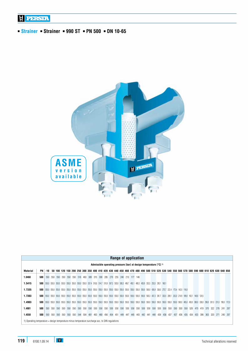
n Strainer n Strainer n 990 ST n PN 500 n DN 10-65
Technical alterations reserved6100.1.09.14119
Admissible operating pressure [bar] at design temperature [°C] 1)
Material PN -10 50 100 120 150 200 250 300 350 400 410 420 430 440 450 460 470 480 490 500 510 520 530 540 550 560 570 580 590 600 610 620 630 640 650
1.0460 500 550 550 550 550 550 550 518 463 389 315 300 285 270 255 240 213 177 146 1.5415 500 550,0 550,0 550,0 550,0 550,0 550,0 550,0 550,0 537,4 518,8 514,7 510,9 507,3 503,8 500,3 496,7 493,1 489,3 426,9 333,5 253,5 200,1 160,1
1.7335 500 550,0 550,0 550,0 550,0 550,0 550,0 550,0 550,0 550,0 550,0 550,0 550,0 550,0 550,0 550,0 550,0 550,0 550,0 550,0 500,0 426,9 338,0 275,7 222,4 173,4 142,0 116,0
1.7383 500 550,0 550,0 550,0 550,0 550,0 550,0 550,0 550,0 550,0 550,0 550,0 550,0 550,0 550,0 550,0 550,0 550,0 550,0 550,0 500,3 437,3 381,7 333,5 289,1 252,0 214,9 189,0 163,1 140,8 124,5
1.4903 500 550,0 550,0 550,0 550,0 550,0 550,0 550,0 550,0 550,0 550,0 550,0 550,0 550,0 550,0 550,0 550,0 550,0 550,0 550,0 550,0 550,0 550,0 550,0 550,0 550,0 500,0 465,0 430,0 380,0 338,0 298,0 261,0 231,0 198,0 172,0
1.4901 500 550 550 550 550 550 550 550 550 550 550 550 550 550 550 550 550 550 550 550 550 550 550 550 550 550 550 550 526 470 419 370 322 278 241 207
1.4550 500 550 550 550 550 550 550 544 504 481 463 460 456 454 451 449 447 445 443 442 441 440 439 438 437 437 436 435 434 433 396 363 320 271 240 207
1) Operating temperature = design temperature minus temperature surcharge acc. to DIN regulations
Range of application
ASME v e r s i o n a v a i l a b l e

n Strainer n Strainer n 990 ST n PN 500 n DN 10-65
Standard features
n Die-forged valve bodyn Screw capn Compact designn Also available in angle pattern (992 ST)
Pressure and temperature ratings
n Pressure rating up to 680 barn Temperature rating up to 650 °Cn Maximum pressure difference between inlet and outlet 2 bar
Materials Screen/filter mesh size
n 1.0460 0,10 mm n 1.4550 0,25 mmn 1.4901 0,50 mmn 1.4903 1,00 mmn 1.5415 n 1.7335 n 1.7383
Further materials and strainer mesh on request
Media
Depending on the material the strainer is suitable for water, gas, oil and other non aggressive media
Fields of application
Chemical industries, power plants, process engineering and other
Design Highlights
n Body and bonnet in forged steel
n Body in two separate pieces with bolted connection
n Body-bonnet connection male and female
n Differences of screen/filter mesh size
Benefits
n In contrast to cast steel parts generally free from porosity and shrink holes
n Improved the service possibilities, for exchanging the screen filter
n Blow out protection
n Individually selectable according to the grade of pollution and medium
Technical alterations reserved 6100.1.09.14 120

Technical alterations reserved6100.1.09.14121
n Strainer n Strainer n 990 ST n PN 500 n DN 10-65
320
100
170
160
321
210
190
L
H
Flow direction
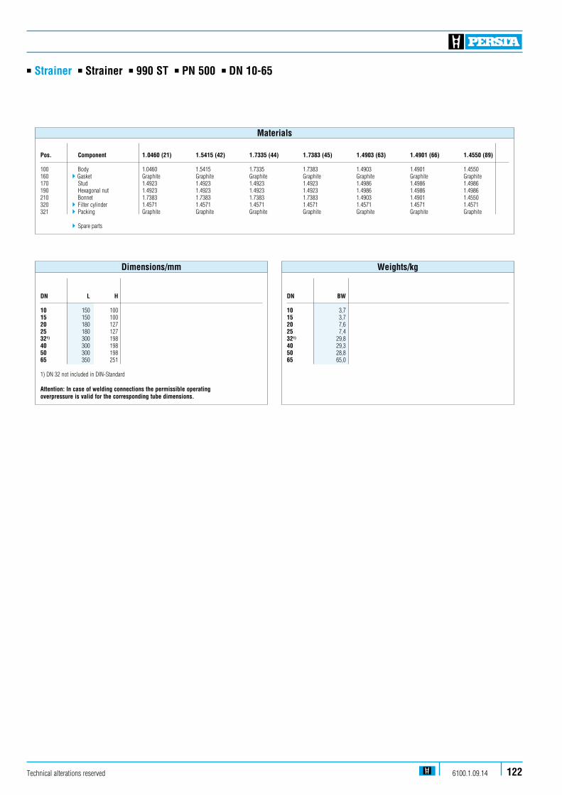
Technical alterations reserved 6100.1.09.14 122
n Strainer n Strainer n 990 ST n PN 500 n DN 10-65
Pos. Component 1.0460 (21) 1.5415 (42) 1.7335 (44) 1.7383 (45) 1.4903 (63) 1.4901 (66) 1.4550 (89) 100 Body 1.0460 1.5415 1.7335 1.7383 1.4903 1.4901 1.4550160 4Gasket Graphite Graphite Graphite Graphite Graphite Graphite Graphite170 Stud 1.4923 1.4923 1.4923 1.4923 1.4986 1.4986 1.4986190 Hexagonal nut 1.4923 1.4923 1.4923 1.4923 1.4986 1.4986 1.4986210 Bonnet 1.7383 1.7383 1.7383 1.7383 1.4903 1.4901 1.4550320 4 Filter cylinder 1.4571 1.4571 1.4571 1.4571 1.4571 1.4571 1.4571321 4 Packing Graphite Graphite Graphite Graphite Graphite Graphite Graphite
4Spare parts
Materials
DN BW 10 3,715 3,720 7,625 7,4321) 29,840 29,350 28,865 65,0
Weights/kg
DN L H
10 150 10015 150 10020 180 12725 180 127321) 300 19840 300 19850 300 19865 350 251
1) DN 32 not included in DIN-Standard Attention: In case of welding connections the permissible operating overpressure is valid for the corresponding tube dimensions.
Dimensions/mm

n Strainer n Strainer DSF n 990 SZ n PD 25 / 40 n DN 80-250
Technical alterations reserved6100.1.09.14123
BW- Admissible operating pressure [bar] at design temperature [°C] 1)
VersionMaterial PD 20 50 100 120 150 200 250 300 350 400 410 420 430 440 450 460 470 480 490 500 510 520 530 540 550 560 570 580 590 600 610 620 630 640 650
1.0460 40 400 400 400 400 400 377 330 295 248 200 190 181 172 162 153 135 113 93 1.5415 40 480 480 480 480 480 447 412 353 341 330 327 325 322 320 318 315 313 311 271 212 161 127 101 1.7335 40 481 481 481 481 481 481 471 436 412 388 384 379 374 370 365 363 360 358 355 322 271 215 175 141 110 90 73 1.7383 40 480 480 480 480 480 480 480 471 436 412 407 403 398 393 388 384 379 374 358 318 278 242 212 183 160 136 120 103 89 79 1.6368 40 657 657 657 657 657 657 657 657 657 657 657 657 657 643 577 495 412 328 245 163 1.4903 40 680 680 680 680 680 680 680 680 680 680 680 680 680 680 680 680 680 669 612 596 551 506 464 421 381 341 306 271 240 212 183 160 136 120 103
1.4901 40 680 680 680 680 680 680 680 680 680 680 680 680 680 680 680 680 680 680 677 635 592 552 512 475 440 404 369 334 298 265 235 204 176 152 131 1) Operating temperature = design temperature minus temperature surcharge acc. to DIN regulations
Range of application
BW- Admissible operating pressure [bar] at design temperature [°C] 1)
VersionMaterial PD 20 50 100 120 150 200 250 300 350 400 410 420 430 440 450 460 470 480 490 500 510 520 530 540 550 560 570 580 590 600 610 620 630 640 650
1.0460 25 250 250 250 250 250 235 206 184 155 125 119 113 107 102 96 85 71 58 1.5415 25 300 300 300 300 300 280 258 221 213 206 205 203 202 200 199 197 196 194 170 132 101 79 64 1.7335 25 300 300 300 300 300 300 294 272 258 243 240 237 234 231 228 227 225 224 222 202 170 134 109 88 69 57 46 1.7383 25 300 300 300 300 300 300 300 294 272 258 255 252 249 246 243 240 237 234 224 199 174 152 132 115 100 85 75 65 56 49 1.6368 25 410 410 410 410 410 410 410 410 410 410 410 410 410 402 360 309 257 205 153 102 1.4903 25 425 425 425 425 425 425 425 425 425 425 425 425 425 425 425 425 425 418 383 372 344 316 290 263 238 213 191 169 150 132 115 100 85 75 64
1.4901 25 425 425 425 425 425 425 425 425 425 425 425 425 425 425 425 425 425 425 423 397 370 345 320 297 275 252 230 208 186 166 147 127 110 95 82 1) Operating temperature = design temperature minus temperature surcharge acc. to DIN regulations
Range of application
ASME v e r s i o n a v a i l a b l e

n Strainer n Strainer DSF n 990 SZ n PD 25 / 40 n DN 80-250
Standard features
n Valve body made of forged steeln Pressure sealing bonnet acc. VGB-guidelines
Pressure and temperature ratings
n Pressure rating up to 680 barn Temperature rating up to 650 °Cn Maximum pressure difference between inlet and outlet 2 bar
Materials Screen/filter mesh size
n 1.0460 0,10 mmn 1.4901 0,25 mmn 1.4903 0,50 mmn 1.5415 1,00 mmn 1.6368 3,00 mmn 1.7335 n 1.7383
Further materials and strainer mesh on request
Media
Depending on the material the strainer is suitable for water, gas, oil and other non aggressive media
Fields of application
Chemical industries, power plants, process engineering and other
Design Highlights
n Body and bonnet in forged steel
n Differences of screen/filter mesh size n Pressure sealing bonnet
n Cover with draining possibility
Benefits
n In contrast to cast steel parts generally free from porosity and shrink holes
n Individually selectable according to the grade of pollution and medium
n Best possible sealing function
n Ease removal filter residues
Technical alterations reserved 6100.1.09.14 124

n Technical appendix n Pressure-rate tables PD 10-63
PERSTA pressure ratings (PD) have been developed close to the standardized PN 100-630 pressure ratings and apply to valves with accordingly designed butt weld ends only. Valves with standard flanges are always marked with the corresponding pressure ratings and can be used within these limits only. The figures refer to all pressure – retaining components including the obturators.
Differential pressure and operation PERSTA gate valves can be operated with a differential pressure up to 50 % of the design pressures given in table 8.1. Always check with PERSTA first if they are to be used with higher differential pressures. The operatingconditions (as specified by the customer) determine the
design of the operating elements such as the handwheel and actuators or gear-boxes. Notice: The maximum differential pressures to which gate valves with bodies made of 1.4901, 1.4903 and 1.6368 can be operated have to be always obtained from PERSTA.
Attention: The wall thickness for butt weld ends may vary for different piping materials and must be checked carefully for every application.
The valves will be marked as working pressure valves.
Admissible operating pressure [bar] at design temperature [°C] 1)
Material PD 120 150 200 250 300 350 400 410 420 430 440 450 460 470 480 490 500 510 520 530 540 550 560 570 580 590 600 610 620 630 640 650
1.0460 10 100 100 94 82 74 62 50 48 45 43 41 38 34 28 23 16 160 160 151 132 118 99 80 76 73 69 65 61 54 45 37 25 250 250 235 206 184 155 125 119 113 107 102 96 85 71 58 32 320 320 302 264 236 198 160 153 145 138 130 123 109 91 75 40 400 400 377 330 295 248 200 191 182 172 163 153 136 113 93 1.5415 10 120 120 112 103 88 85 82 82 81 81 80 79 79 78 78 68 53 40 32 25 16 192 192 179 165 141 137 132 131 130 129 128 127 126 125 124 109 85 64 51 41 25 300 300 280 258 221 213 206 205 203 202 200 199 197 196 194 170 132 101 79 64 32 385 385 358 330 283 273 264 262 260 258 256 255 253 251 249 217 170 129 102 81 40 480 480 448 413 354 342 330 328 325 323 321 318 316 314 311 272 212 161 127 102 1.7335 10 120 120 120 118 109 103 97 96 95 94 92 91 91 90 89 89 81 68 54 44 35 28 23 18 16 192 192 192 189 174 165 156 154 152 150 148 146 145 144 143 142 129 109 86 70 57 44 36 29 25 300 300 300 294 272 258 243 240 237 234 231 228 227 225 224 222 202 170 134 109 88 69 57 46 32 385 385 385 377 349 330 311 307 304 300 296 292 290 289 287 285 258 217 172 140 113 88 72 59 40 481 481 481 471 436 413 389 384 380 375 370 365 363 364 358 356 323 272 215 175 141 110 91 74 1.7383 10 120 120 120 120 118 109 103 102 101 99 98 97 96 95 94 89 79 69 61 53 46 40 34 30 26 22 20 16 192 192 192 192 189 174 165 163 161 159 157 156 154 152 150 143 127 111 97 85 74 64 55 48 41 36 32 25 300 300 300 300 294 272 258 255 252 249 246 243 240 237 234 224 199 174 152 132 115 100 85 75 65 56 49 32 384 384 384 384 377 349 330 326 322 319 315 311 307 304 300 287 255 223 194 170 147 128 109 96 83 72 63 40 480 480 480 480 471 436 413 408 403 398 384 389 384 379 375 358 318 278 243 212 184 160 137 120 104 90 79 1.6368 16 263 263 263 263 263 263 263 263 263 263 257 231 198 165 131 98 65 25 410 410 410 410 410 410 410 410 410 410 402 360 309 257 205 153 102 32 525 525 525 525 525 525 525 525 525 525 515 482 396 330 262 196 130 40 657 657 657 627 657 657 657 657 657 657 643 577 495 412 328 245 163 1.4903 16 272 272 272 272 272 272 272 272 272 272 272 272 272 272 268 245 239 221 203 186 169 153 137 123 108 96 85 74 64 55 48 41 25 425 425 425 425 425 425 425 425 425 425 425 425 425 425 418 383 372 344 316 290 263 238 213 191 169 150 132 115 100 85 75 65 32 544 544 544 544 544 544 544 544 544 544 544 544 544 544 536 490 477 441 405 371 338 305 273 245 217 192 170 147 128 109 96 83 40 680 680 680 680 680 680 680 680 680 680 680 680 680 680 669 613 596 552 507 464 422 382 342 306 271 240 212 184 160 137 120 104
1.4901 16 272 272 272 272 272 272 272 272 272 272 272 272 272 272 272 271 254 237 221 205 190 176 161 147 133 119 106 94 81 70 61 52 25 425 425 425 425 425 425 425 425 425 425 425 425 425 425 425 423 397 370 345 320 297 275 252 230 208 186 166 147 127 110 95 82 32 544 544 544 544 544 544 544 544 544 544 544 544 544 544 544 542 508 474 442 410 380 352 323 295 267 239 212 188 163 141 122 105 40 680 680 680 680 680 680 680 680 680 680 680 680 680 680 680 677 635 592 552 512 475 440 404 369 334 298 265 235 204 176 152 131
PERSTA - pressure ratings (PD) for butt weld valves
1) Operating temperature = design temperature minus temperature surcharge acc. to DIN regulations. * Design according to working data
Technical alterations reserved6100.1.09.14125
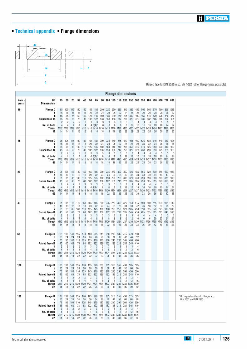
n Technical appendix n Flange dimensions
Nom.- DN 15 20 25 32 40 50 65 80 100 125 150 200 250 300 350 400 500 600 700 800 press Dimaensions 10 Flange D 95 105 115 140 150 165 185 200 220 250 285 340 395 445 505 565 670 780 895 1015 b 16 18 18 18 18 20 22 24 24 26 22 24 26 26 26 26 28 28 30 32 k 65 75 85 100 110 125 145 160 180 210 240 295 350 400 460 515 620 725 840 950 Raised face d4 45 58 68 78 88 102 122 138 158 188 212 268 320 370 430 482 585 685 800 905 f 2 2 2 2 3 3 3 3 3 3 3 3 3 4 4 4 4 5 5 5 No. of bolts 4 4 4 4 4 4 8(4)* 8 8 8 8 8 12 12 16 16 20 20 24 24 Threat M12 M12 M12 M16 M16 M16 M16 M16 M16 M16 M20 M20 M20 M20 M20 M24 M24 M27 M27 M30 d2 14 14 14 18 18 18 18 18 18 18 22 22 22 22 22 26 26 30 30 33
16 Flange D 95 105 115 140 150 165 185 200 220 250 285 340 405 460 520 580 715 840 910 1025 b 16 18 18 18 18 20 22 24 24 26 22 24 26 28 30 32 34 36 36 38 k 65 75 85 100 110 125 145 160 180 210 240 295 355 410 470 525 650 770 840 950 Raised face d4 45 58 68 78 88 102 122 138 158 188 212 268 320 378 438 490 610 725 795 900 f 2 2 2 2 3 3 3 3 3 3 3 3 3 4 4 4 4 5 5 5 No. of bolts 4 4 4 4 4 4 8(4)* 8 8 8 8 12 12 12 16 16 20 20 24 24 Threat M12 M12 M12 M16 M16 M16 M16 M16 M16 M16 M20 M20 M24 M24 M24 M27 M30 M33 M33 M36 d2 14 14 14 18 18 18 18 18 18 18 22 22 26 26 26 30 33 36 36 39
25 Flange D 95 105 115 140 150 165 185 200 235 270 300 360 425 485 555 620 730 845 960 1085 b 16 18 18 18 18 20 22 24 24 26 28 30 32 34 38 40 44 46 46 50 k 65 75 85 100 110 125 145 160 190 220 250 310 370 430 490 550 660 770 875 990 Raised face d4 45 58 68 78 88 102 122 138 162 188 218 278 335 395 450 505 615 720 820 930 f 2 2 2 2 3 3 3 3 3 3 3 3 3 4 4 4 4 5 5 5 No. of bolts 4 4 4 4 4 4 8(4)* 8 8 8 8 12 12 16 16 16 20 20 24 24 Threat M12 M12 M12 M16 M16 M16 M16 M16 M20 M24 M24 M24 M27 M27 M30 M33 M33 M36 M39 M45 d2 14 14 14 18 18 18 18 18 22 26 26 26 30 30 33 36 36 39 42 48
40 Flange D 95 105 115 140 150 165 185 200 235 270 300 375 450 515 580 660 755 890 995 1140 b 16 18 18 18 18 20 22 24 24 26 28 34 38 42 46 50 52 60 64 72 k 65 75 85 100 110 125 145 160 190 220 250 320 385 450 510 585 670 795 900 1030 Raised face d4 45 58 68 78 88 102 122 138 162 188 218 285 345 410 465 535 615 735 840 960 f 2 2 2 2 3 3 3 3 3 3 3 3 3 4 4 4 4 5 5 5 No. of bolts 4 4 4 4 4 4 8 8 8 8 8 12 12 16 16 16 20 20 24 24 Threat M12 M12 M12 M16 M16 M16 M16 M16 M20 M24 M24 M27 M30 M30 M33 M36 M39 M45 M45 M52 d2 14 14 14 18 18 18 18 18 22 26 26 30 33 33 36 39 42 48 48 56
63 Flange D 105 130 140 155 170 180 205 215 250 295 345 415 470 530 b 20 24 24 24 26 26 26 28 30 34 36 42 46 52 k 75 90 100 110 125 135 160 170 200 240 280 345 400 460 Raised face d4 45 60 68 78 88 102 122 138 162 188 218 285 345 410 f 2 2 2 2 3 3 3 3 3 3 3 3 3 4 No. of bolts 4 4 4 4 4 4 8 8 8 8 8 12 12 16 Threat M12 M16 M16 M20 M20 M20 M20 M20 M24 M27 M30 M33 M33 M33 d2 14 18 18 22 22 22 22 22 26 30 33 36 36 36
100 Flange D 105 130 140 155 170 195 220 230 265 315 355 430 505 585 b 20 24 24 24 26 28 30 32 36 40 44 52 60 68 k 75 90 100 110 125 145 170 180 210 250 290 360 430 500 Raised face d4 45 60 68 78 88 102 122 138 162 188 218 285 345 410 f 2 2 2 2 3 3 3 3 3 3 3 3 3 4 No. of bolts 4 4 4 4 4 4 8 8 8 8 12 12 12 16 Threat M12 M16 M16 M20 M20 M24 M24 M24 M27 M30 M30 M33 M36 M39 d2 14 18 18 22 22 26 26 26 30 33 33 36 39 42
160 Flange D 105 130 140 155 170 195 220 230 265 315 355 430 515 585 * On request available for flanges acc. b 20 24 24 24 28 30 34 36 40 44 50 60 68 78 DIN 2632 and DIN 2633. k 75 90 100 110 125 145 170 180 210 250 290 360 430 500 Raised face d4 45 60 68 78 88 102 122 138 162 188 218 285 345 410 f 2 2 2 2 3 3 3 3 3 3 3 3 3 4 No. of bolts 4 4 4 4 4 4 8 8 8 8 12 12 12 16 Threat M12 M16 M16 M20 M20 M24 M24 M24 M27 M30 M30 M33 M39 M39 d2 14 18 18 22 22 26 26 26 30 33 33 36 42 42
Flange dimensions
d2
DS
d4
K
Df b
Raised face to DIN 2526 resp. EN 1092 (other flange-types possible)
Technical alterations reserved 6100.1.09.14 126

n Technical appendix n Design
Body:As a pressure-retaining component, the body, including the bonnet, determines the ranges in which the valves can be used. The demand for valves to withstand higher pressure and temperatures calls for special materials and production processes. In high-pressure applications, pressure ratings, nominal sizes and quantities require different production processes which take account of different conditions of use. Designs therefore vary according to the particular applications. PERSTA forged valve bodies, particularly those designed for power stations, are die-forged or produced as open- die forgings which are then machined. Specific rolling and forming processes give the parts and dense, uniform, fine-structure with no bubbles or pores, and with a fibre orientation that is ideal for their intended use. The modern production methods have increased the use of forged steel for high-pressure applications. However, the development of die-forged bodies has been restricted by the high forming forces and the associated size and cost of the forgings. Machined open-die forgings are therefore used for large bodies.
For PERSTA high pressure valves the following production methods proved excellent results:
1. Hollow one-piece-forgings, mainly for valve bodies in the DSK 26 range, 65 - 300. Connecting flanges or butt weld ends are welded on with a circumferential seam.
2. Bodies for gate valves and swing check valves in the DSK and DRI range, 50 - 600 are produced as solid, open-die forgings which are then machined. Valves are subjected to stress in the following ways:
n mechanically by n operating pressure n operating temperature n temperature gradients during starting up and shut down n erosion and cavitation by the medium n due to the forces exerted by the connected pipes, fastening devices and the weight of mechanical actuators, andn chemically n due to corrosion.
127 Technical alterations reserved6100.1.09.14
smooth transitions between different wall thicknesses. Gate valves are sealed on the downstream side of the body. The required sealing force is provided by the medium by means of the differential pressure. For pressure ratings PD 10-63, PERSTA DSK gate valves are fitted with a mechanical stembarel stop to limit the stress on the stems and the sealing faces caused by the actuation forces. Ledges or grooves are guiding the wedge or the split wedge in the body after about 10 % of the opening lift. The forces which have to be absorbed from the guides are relatively low because there has already been a large degree of pressure compensation at this point. The weld seams are designed for easy radiographic or ultrasonic testing. All PERSTA gate valves and swing check valves can be delivered with buttwelding ends to match the correspondi-ng material and pipe diameter. Stem sealing The gland packing seals the stem guide onto outside. Operational demands of this sealing arise by reason of stem travel, pressure and friction at the gland packing, by thermal cycle stress and by the medium. The design of the gland follower resp. gland ring assures a smooth contact pressure of the packing rings even in the case of an easily irregular tightening of the gland bolts and prevents a sei-zing of the stem.
Mode of operation A power applied by the stud bolts onto the gland follower will be transmitted via the gland ring resp. chamber ring to the packing rings. Thereby the packing rings are pressed together. Upcoming surface pressure towards the wall of the stuffing box chamber and towards the stem surface tightens against the medium.
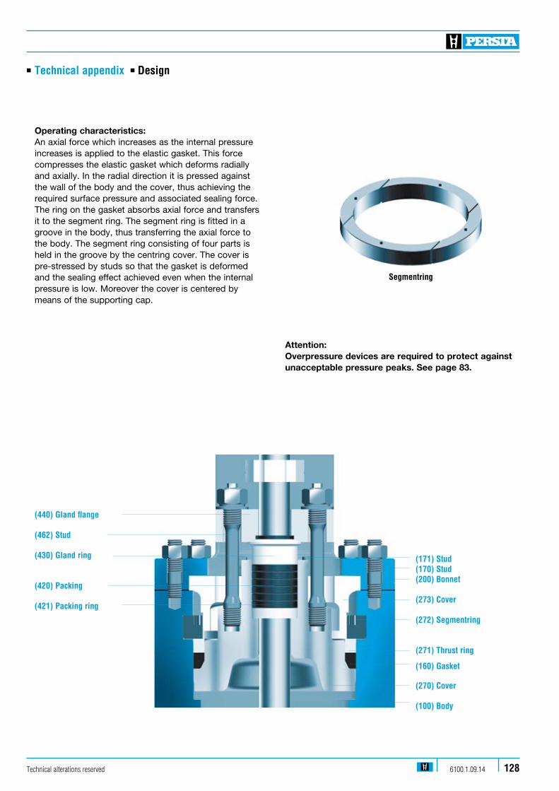
Segmentring
n Technical appendix n Design
128Technical alterations reserved 6100.1.09.14
Operating characteristics: An axial force which increases as the internal pressure increases is applied to the elastic gasket. This force compresses the elastic gasket which deforms radially and axially. In the radial direction it is pressed against the wall of the body and the cover, thus achieving the required surface pressure and associated sealing force. The ring on the gasket absorbs axial force and transfers it to the segment ring. The segment ring is fitted in a groove in the body, thus transferring the axial force to the body. The segment ring consisting of four parts is held in the groove by the centring cover. The cover is pre-stressed by studs so that the gasket is deformed and the sealing effect achieved even when the internal pressure is low. Moreover the cover is centered by means of the supporting cap.
Attention: Overpressure devices are required to protect against unacceptable pressure peaks. See page 83.
(171) Stud(170) Stud(200) Bonnet
(273) Cover
(272) Segmentring
(271) Thrust ring
(160) Gasket
(270) Cover
(100) Body
(440) Gland flange
(462) Stud
(430) Gland ring
(420) Packing
(421) Packing ring
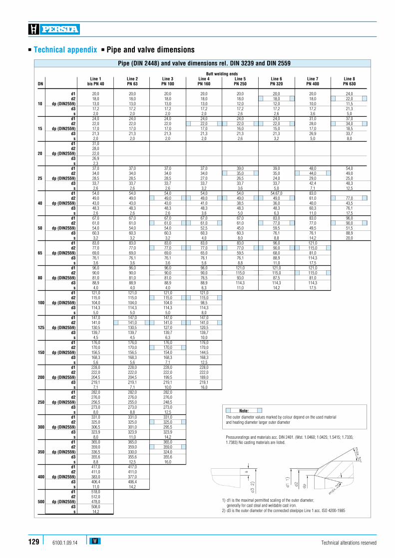
Technical alterations reserved6100.1.09.14129
n Technical appendix n Pipe and valve dimensions
Butt welding ends Line 1 Line 2 Line 3 Line 4 Line 5 Line 6 Line 7 Line 8 DN bis PN 40 PN 63 PN 100 PN 160 PN 250 PN 320 PN 400 PN 630
d1 20,0 20,0 20,0 20,0 20,0 20,0 20,0 24,0 d2 18,0 18,0 18,0 18,0 18,0 18,0 18,0 22,0 10 dp (DIN2559) 13,0 13,0 13,0 13,0 12,0 12,0 10,0 11,5 d3 17,2 17,2 17,2 17,2 17,2 17,2 17,2 21,3 s 2,0 2,0 2,0 2,0 2,6 2,6 3,6 5,0 d1 24,0 24,0 24,0 24,0 24,0 24,0 31,0 37,0 d2 22,0 22,0 22,0 22,0 22,0 22,0 28,0 34,0 15 dp (DIN2559) 17,0 17,0 17,0 17,0 16,0 15,0 17,0 18,5 d3 21,3 21,3 21,3 21,3 21,3 21,3 26,9 33,7 s 2,0 2,0 2,0 2,0 2,6 3,2 5,0 8,0 d1 31,0 d2 28,0 20 dp (DIN2559) 22,0 d3 26,9 s 2,3 d1 37,0 37,0 37,0 37,0 39,0 39,0 48,0 54,0 d2 34,0 34,0 34,0 34,0 35,0 35,0 44,0 49,0 25 dp (DIN2559) 28,5 28,5 28,5 27,0 26,5 24,0 29,0 25,0 d3 33,7 33,7 33,7 33,7 33,7 33,7 42,4 48,3 s 2,6 2,6 2,6 3,2 3,6 5,0 7,1 12,5 d1 54,0 54,0 54,0 54,0 54,0 54,67,0 83,0 d2 49,0 49,0 49,0 49,0 49,0 49,0 61,0 77,0 40 dp (DIN2559) 43,0 43,0 43,0 41,0 38,5 36,0 40,0 43,5 d3 48,3 48,3 48,3 48,3 48,3 48,3 60,3 76,1 s 2,6 2,6 2,6 3,6 5,0 6,3 11,0 17,5 d1 67,0 67,0 67,0 67,0 67,0 83,0 83,0 96,0 d2 61,0 61,0 61,0 61,0 61,0 77,0 77,0 90,0 50 dp (DIN2559) 54,0 54,0 54,0 52,5 45,0 59,5 49,5 51,5 d3 60,3 60,3 60,3 60,3 60,3 76,1 76,1 88,9 s 3,2 3,2 3,2 4,0 8,0 8,8 14,2 20,0 d1 83,0 83,0 83,0 83,0 83,0 96,0 121,0 d2 77,0 77,0 77,0 77,0 77,0 90,0 115,0 65 dp (DIN2559) 69,0 69,0 69,0 65,0 59,5 68,0 81,0 d3 76,1 76,1 76,1 76,1 76,1 88,9 114,3 s 3,6 3,6 3,6 5,6 8,8 11,0 17,5 d1 96,0 96,0 96,0 96,0 121,0 121,0 121,0 d2 90,0 90,0 90,0 90,0 115,0 115,0 115,0 80 dp (DIN2559) 81,0 81,0 81,0 76,5 93,0 87,5 81,0 d3 88,9 88,9 88,9 88,9 114,3 114,3 114,3 s 4,0 4,0 4,0 6,3 11,0 14,2 17,5 d1 121,0 121,0 121,0 121,0 d2 115,0 115,0 115,0 115,0 100 dp (DIN2559) 104,0 104,0 104,0 98,5 d3 114,3 114,3 114,3 114,3 s 5,0 5,0 5,0 8,0 d1 147,0 147,0 147,0 147,0 d2 141,0 141,0 141,0 141,0 125 dp (DIN2559) 130,5 130,5 127,0 120,5 d3 139,7 139,7 139,7 139,7 s 4,5 4,5 6,3 10,0 d1 176,0 176,0 176,0 176,0 d2 170,0 170,0 170,0 170,0 150 dp (DIN2559) 156,5 156,5 154,0 144,5 d3 168,3 168,3 168,3 168,3 s 5,6 5,6 7,1 12,5 d1 228,0 228,0 228,0 228,0 d2 222,0 222,0 222,0 222,0 200 dp (DIN2559) 204,5 204,5 199,5 189,0 d3 219,1 219,1 219,1 219,1 s 7,1 7,1 10,0 16,0 d1 282,0 282,0 282,0 d2 276,0 276,0 276,0 250 dp (DIN2559) 256,5 255,0 248,5 d3 273,0 273,0 273,0 s 8,0 8,8 12,5 d1 331,0 331,0 331,0 d2 325,0 325,0 325,0 300 dp (DIN2559) 306,5 301,0 295,5 d3 323,9 323,9 323,9 s 8,0 11,0 14,2 d1 365,0 365,0 365,0 d2 359,0 359,0 359,0 350 dp (DIN2559) 336,5 330,0 324,0 d3 355,6 355,6 355,6 s 8,8 12,5 16,0 d1 417,0 417,0 d2 411,0 411,0 400 dp (DIN2559) 383,0 377,0 d3 406,4 406,4 s 11,0 14,2 d1 518,0 d2 512,0 500 dp (DIN2559) 478,0 d3 508,0 s 14,2
Pipe (DIN 2448) and valve dimensions rel. DIN 3239 and DIN 2559
1) d1 is the maximal permitted scaling of the outer diameter; generally for cast steal and weldable cast iron.2) d3 is the outer diameter of the connected steelpipe Line 1 acc. ISO 4200-1985
The outer diameter values marked by colour depend on the used material and heating diameter larger outer diameter
Note:
Pressureratings and materials acc. DIN 2401. (Wst. 1.0460; 1.0425; 1.5415; 1.7335; 1.7383) No casting materials are listed.
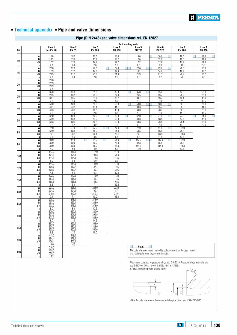
Technical alterations reserved 6100.1.09.14 130
n Technical appendix n Pipe and valve dimensions
Butt welding ends Line 1 Line 2 Line 3 Line 4 Line 5 Line 6 Line 7 Line 8 DN bis PN 40 PN 63 PN 100 PN 160 PN 250 PN 320 PN 400 PN 630
A 18,0 18,0 18,0 18,0 18,0 18,0 18,0 22,0
10 B 13,2 13,2 13,2 13,2 12,0 12,0 10,0 11,3 d3 17,2 17,2 17,2 17,2 17,2 17,2 17,2 21,3 s 2,0 2,0 2,0 2,0 2,6 2,6 3,6 5,0 A 22,0 22,0 22,0 22,0 22,0 22,0 28,0 35,0
15 B 17,3 17,3 17,3 17,3 16,1 14,9 16,9 17,7 d3 21,3 21,3 21,3 21,3 21,3 21,3 26,9 33,7 s 2,0 2,0 2,0 2,0 2,6 3,2 5,0 8,0 A 28,0
20 B 22,3 d3 26,9 s 2,3 A 35,0 35,0 35,0 35,0 35,0 35,0 44,0 50,0
25 B 28,5 28,5 28,5 27,3 26,5 23,7 28,2 23,3 d3 33,7 33,7 33,7 33,7 33,7 33,7 42,4 48,3 s 2,6 2,6 2,6 3,2 3,6 5,0 7,1 12,5 A 50,0 50,0 50,0 50,0 50,0 50,0 62,0 77,0
40 B 43,1 43,1 43,1 41,1 38,3 35,7 38,3 41,1 d3 48,3 48,3 48,3 48,3 48,3 48,3 60,3 76,1 s 2,6 2,6 2,6 3,6 5,0 6,3 11,0 17,5 A 62,0 62,0 62,0 62,0 62,0 77,0 77,0 91,0
50 B 53,9 53,9 53,9 52,3 44,3 58,5 47,7 48,9 d3 60,3 60,3 60,3 60,3 60,3 76,1 76,1 88,9 s 3,2 3,2 3,2 4,0 8,0 8,8 14,2 20,0 A 77,0 77,0 77,0 77,0 77,0 91,0 117,0
65 B 68,9 68,9 68,9 64,9 58,5 66,9 79,3 d3 76,1 76,1 76,1 76,1 76,1 88,9 114,3 s 3,6 3,6 3,6 5,6 8,8 11,0 17,5 A 91,0 91,0 91,0 91,0 117,0 117,0 117,0
80 B 80,9 80,9 80,9 76,3 92,3 85,9 79,3 d3 88,9 88,9 88,9 88,9 114,3 114,3 114,3 s 4,0 4,0 4,0 6,3 11,0 14,2 17,5 A 117,0 117,0 117,0 117,0
100 B 104,3 104,3 104,3 98,3 d3 114,3 114,3 114,3 114,3 s 5,0 5,0 5,0 8,0 A 144,0 144,0 144,0 144,0
125 B 130,7 130,7 127,1 119,7 d3 139,7 139,7 139,7 139,7 s 4,5 4,5 6,3 10,0 A 172,0 172,0 172,0 172,0
150 B 157,1 157,1 154,1 143,3 d3 168,3 168,3 168,3 168,3 s 5,6 5,6 7,1 12,5 A 223,0 223,0 223,0 223,0
200 B 204,9 204,9 199,1 187,1 d3 219,1 219,1 219,1 219,1 s 7,1 7,1 10,0 16,0 A 278,0 278,0 278,0
250 B 257,0 255,4 248,0 d3 273,0 273,0 273,0 s 8,0 8,8 12,5 A 329,0 329,0 329,0
300 B 307,9 301,9 295,5 d3 323,9 323,9 323,9 s 8,0 11,0 14,2 A 362,0 362,0 362,0
350 B 338,0 330,6 323,6 d3 355,6 355,6 355,6 s 8,8 12,5 16,0 A 413,0 413,0
400 B 384,4 378,0 d3 406,4 406,4 s 11,0 14,2 A 516,0
500 B 479,6 d3 508,0 s 14,2
Pipe (DIN 2448) and valve dimensions rel. EN 12627
The outer diameter values marked by colour depend on the used material and heating diameter larger outer diameter.
Note:
Pipe values corelated to pressureratings acc. DIN 3239. Pressureratings and materials acc. DIN 2401. (Wst. 1.0460; 1.0425; 1.5415; 1.7335; 1.7383). No casting materials are listed.
d3 is the outer diameter of the connected steelpipe Line 1 acc. ISO 4200-1985
Technical alterations reserved6100.1.09.14131
n Technical appendix n Processing and test equipment / test facilities
Mechanical workshop 9 Machining centres for drilling, turning and milling operations # CNC-controlled and conventional horizontal and vertical turning machines for workpieces up to app. 20 kN of weight # Drilling and milling machines, CNC-controlled saw, lapping and chipping machines, grinding machines and turning machines
Welding shop # Robot based welding systems for seat hard facing, stelliting and joint welding # Hand and machine-welding # Electric annealing furnaces # Manipulator for submerged arc welding
Assembly 7 Assembly and test equipment for the pressure (tightness) test for valves up to max. DN 800 with a max. test pressure of 1.000 bar
Transport Facilities # Bridge cranes with max. carrying capacity of 160 kN # Slewing cranes with max. carrying of 20 kN # Fork lift trucks with max. carrying capacity of 75 kN Ultrasonic test n Type of equipment: USM35X, companies, GE Krautkrämer
X-ray tests n Type of equipment and capacity 2 ISO Volt 320, ISO Volt 150 all from company GE, Seiffert
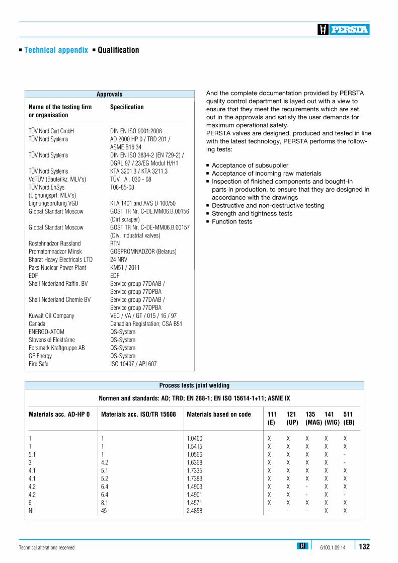
n Technical appendix n Qualification
Technical alterations reserved 6100.1.09.14 132
And the complete documentation provided by PERSTA quality control department is layed out with a view to ensure that they meet the requirements which are set out in the approvals and satisfy the user demands for maximum operational safety. PERSTA valves are designed, produced and tested in line with the latest technology, PERSTA performs the follow-ing tests: n Acceptance of subsuppliern Acceptance of incoming raw materialsn Inspection of finished components and bought-in parts in production, to ensure that they are designed in accordance with the drawingsn Destructive and non-destructive testingn Strength and tightness testsn Function tests
Normen and standards: AD; TRD; EN 288-1; EN ISO 15614-1+11; ASME IX
Materials acc. AD-HP 0 Materials acc. ISO/TR 15608 Materials based on code 111 121 135 141 511 (E) (UP) (MAG) (WIG) (EB) 1 1 1.0460 X X X X X1 1 1.5415 X X X X X5.1 1 1.0566 X X X X - 3 4.2 1.6368 X X X X -4.1 5.1 1.7335 X X X X X4.1 5.2 1.7383 X X X X X4.2 6.4 1.4903 X X - X X4.2 6.4 1.4901 X X - X -6 8.1 1.4571 X X X X XNi 45 2.4858 - - - X X
Process tests joint welding
Name of the testing firm Specification or organisation TÜV Nord Cert GmbH DIN EN ISO 9001:2008 TÜV Nord Systems AD 2000 HP 0 / TRD 201 / ASME B16.34 TÜV Nord Systems DIN EN ISO 3834-2 (EN 729-2) / DGRL 97 / 23/EG Modul H/H1 TÜV Nord Systems KTA 3201.3 / KTA 3211.3 VdTÜV (Bauteilkz. MLV‘s) TÜV . A . 030 - 08 TÜV Nord EnSys T08-85-03 (Eignungsprf. MLV‘s) Eignungsprüfung VGB KTA 1401 and AVS D 100/50 Global Standart Moscow GOST TR Nr. C-DE.MM06.B.00156 (Dirt scraper) Global Standart Moscow GOST TR Nr. C-DE-MM06.B.00157 (Div. industrial valves) Rostehnadzor Russland RTN Promatomnadzor Minsk GOSPROMNADZOR (Belarus) Bharat Heavy Electricals LTD 24 NRV Paks Nuclear Power Plant KM51 / 2011 EDF EDF Shell Nederland Raffin. BV Service group 77DAAB / Service group 77DPBA Shell Nederland Chemie BV Service group 77DAAB / Service group 77DPBA Kuwait Oil Company VEC / VA / GT / 015 / 16 / 97 Canada Canadian Registration; CSA B51 ENERGO-ATOM QS-System Slovenské Elektrárne QS-System Forsmark Kraftgruppe AB QS-System GE Energy QS-System Fire Safe ISO 10497 / API 607
Approvals

Technical alterations reserved6100.1.09.14133
n Technical appendix n Figure number code
Type PERSTA Code
Small globe valve (inside screw and yoke) 200 ABSmall globe valve (outside screw and yoke) 200 AF/BFSmall lift check valve 240 MUPressure gauge valve 200 AD
Globe valve 200 AE / AJ Globe valve with throttle disc 200 BE / BJ Globe valve with non-rotating stem 200 AJ Bellow seal globe valve 200 AL Globe valve with throttle disc and non-rotating stem 200 BJ Bellow seal globe valve with throttle disc 200 BL Highpressure valve DVA 25 / 40 200 BZ Highpressure valve HD 91 200 JM Highpressure valve HD 2000 200 LM / 202 LM Highpressure valve HD 2000 with back seat 200 LS / 200 LJ Screw down non return valve 240 ME Stop check valve HD 2000 240 MM Lift check valve 240 MT Changeover valve DN 10-50 203 EH
Changeover valve DN 65-200 203 EM Gate valve 400 JJ Swing check valve 640 AA Highpressure swing check valve DRI 16 - 63 640 AB Swing check valve with lever and weight 640 AE High pressure stop check valve DRA 640 AT Freewheel swing check valve 640 DJ
Gate valve, flexible wedge type, inside screw and yoke 700 GA Gate valve, flexible wedge type 700 HJ Gate valve, split wedge type 700 JJ High pressure gate valve DSK 16 - 63 700 JT
Small gate valve, full bore 808 GJSmall gate valve, reduced bore 800 GJStrainer 990 ST / SZ
High pressure line blind valve 990 VW
Figure
DIN-Nr. EN-Bez. Material code Material code PERSTA Code (new) (old) 1.0425 1.0425 P265 GH H II 22 1.0460 1.0460 P250 GH C22.8 21 1.0566 1.0566 P355NL1 TStE 355 25 1.0619 1.0619+N GP240 GH+N GS-C25N 11 1.4308 1.4308 GX5CrNi19-10 G-X6CrNi 18 9 77 1.4550 1.4550 X6CrNiNb18-10 X6CrNiNb18-10 89 1.4571 1.4571 X6CrNiMoTi17-12-2 X 6 CrNiMoTi 17 12 2 82 (up to max. 280 °C) 1.4571 1.4571 X6CrNiMoTi17-12-2 X 6 CrNiMoTi 17 12 2 85 1.4581 1.4581 GX5CrNiMoNb19-11-2 G-X5CrNiMoNb18 10 72 1.4901 1.4901 X10CrWMoVNb 9-2 66 1.4903 1.4903 X10CrMoVNb 9-1 X 10 CrMoVNb 9-1 63 1.5415 1.5415 16Mo3 15 Mo 3 42 1.5419 1.5419 GS-22 MO4 G 20 Mo5 32 1.6368 1.6368 15NiCuMoNb5 15 NiCuMoNb 5 46 1.7221 1.7221 G26CrMo4 GS-26 CrMo 4 31 1.7335 1.7335 13CrMo4-5 13 CrMo 44 44 1.7357 1.7357 G17CrMo5-5 GS-17 CrMo 5 5 34 1.7380 1.7383 11CrMo9-10 10 CrMo 9 10 45
Materials
Designation PERSTA Code
Flange 1BW Ends 2Threaded sleeves 3Threaded journals 4Weld nipples 5Pressure gauge connection 6Ermeto-connection 7Socket weld ends 8Special connection 9
Connection type
Figure number Materials Connections
Figure number code Example
XXX XX XX. X
Figure number code Result
700 HJ 21. 1


6100.1.09.14
Experience
the differen
ce
Stahl-Armaturen PERSTA GmbHMülheimer Straße 1859581 Warstein, Germany Phone +49 29 02 7 62 - 02Fax +49 29 02 7 67 [email protected]
Related Documents