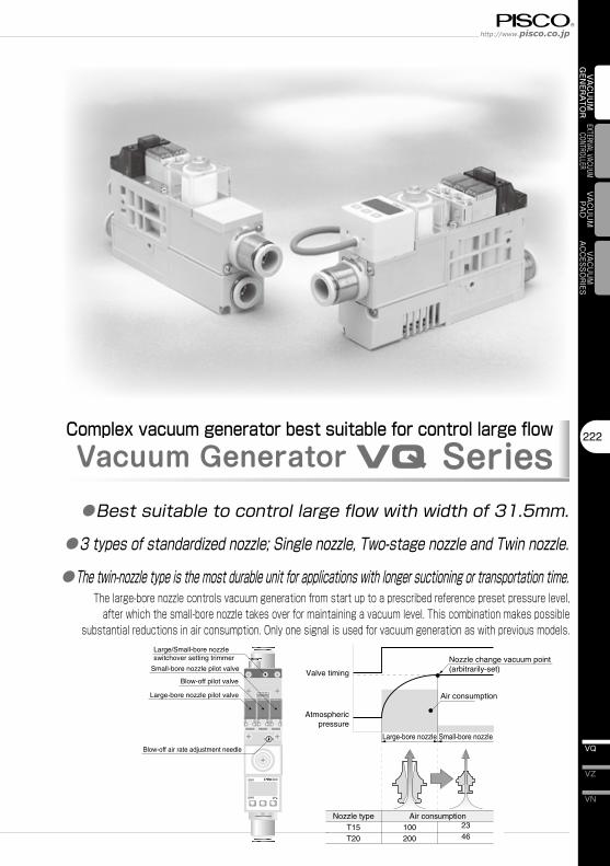
SW2 SW1 kPa 100 200 23 46 Nozzle change vacuum point (arbitrarily-set) Valve timing Atmospheric pressure Air consumption Nozzle type T15 T20 Air consumption Small-bore nozzle pilot valve Blow-off pilot valve Blow-off air rate adjustment needle Large-bore nozzle pilot valve Large/Small-bore nozzle switchover setting trimmer Large-bore nozzle Small-bore nozzle 222 VN VZ VQ VACUUM GENERATOR EXTERNAL VACUUM CONTROLLER VACUUM PAD VACUUM ACCESSORIES Complex vacuum generator best suitable for control large flow Vacuum Generator VQ Series ● Bestsuitabletocontrollargeflowwithwidthof31.5mm. ● 3typesofstandardizednozzle;Singlenozzle,Two-stagenozzleandTwinnozzle. ● Thetwin-nozzletypeisthemostdurableunitforapplicationswithlongersuctioningortransportationtime. The large-bore nozzle controls vacuum generation from start up to a prescribed reference preset pressure level, after which the small-bore nozzle takes over for maintaining a vacuum level. This combination makes possible substantial reductions in air consumption. Only one signal is used for vacuum generation as with previous models.

Welcome message from author
This document is posted to help you gain knowledge. Please leave a comment to let me know what you think about it! Share it to your friends and learn new things together.
Transcript
SW2
SW1
kPa
100200
2346
Nozzle change vacuum point (arbitrarily-set)Valve timing
Atmosphericpressure
Air consumption
Nozzle typeT15T20
Air consumption
Small-bore nozzle pilot valve
Blow-off pilot valve
Blow-off air rate adjustment needle
Large-bore nozzle pilot valve
Large/Small-bore nozzle switchover setting trimmer
Large-bore nozzle Small-bore nozzle
222
VN
VZ
VQ
VAC
UU
M
GEN
ERA
TOR
EXTERNAL VACUUM CONTROLLER
VAC
UU
MPA
DVACUUM
ACCESSORIES
Complex vacuum generator best suitable for control large flowVacuum Generator VQ Series●Best�suitable�to�control�large�flow�with�width�of�31.5mm.
●3�types�of�standardized�nozzle;�Single�nozzle,�Two-stage�nozzle�and�Twin�nozzle.
●The�twin-nozzle�type�is�the�most�durable�unit�for�applications�with�longer�suctioning�or�transportation�time.The large-bore nozzle controls vacuum generation from start up to a prescribed reference preset pressure level,
after which the small-bore nozzle takes over for maintaining a vacuum level. This combination makes possible substantial reductions in air consumption. Only one signal is used for vacuum generation as with previous models.
Vacuum Generator SeriesVacuum Generator VQ
VH · VS
223
VU
VB
VM · VC
VG
VK
VJ
VX
VQ
VY
VUM
VRL
■ Characteristics
Suction flow
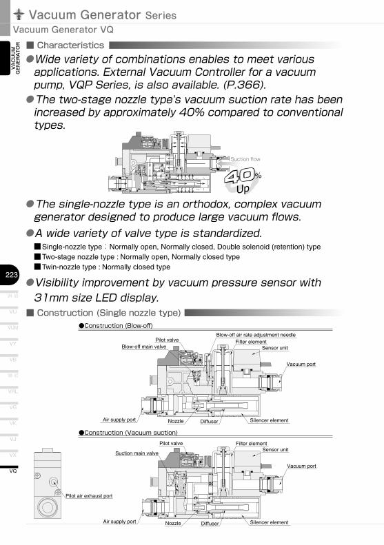
■ Construction (Single nozzle type)●Construction (Blow-off)
Silencer elementNozzleAir supply port
Pilot air exhaust port
Blow-off main valve
Vacuum port
Pilot valve
Blow-off air rate adjustment needle
Silencer elementNozzle DiffuserAir supply port
Filter elementSensor unit
Vacuum port
Pilot valve
Filter elementSensor unit
Diffuser
Suction main valve
●Construction (Vacuum suction)
VAC
UU
M
GEN
ERA
TOR
●�The�two-stage�nozzle�type's�vacuum�suction�rate�has�been�increased�by�approximately�40%�compared�to�conventional�types.
● �The�single-nozzle�type�is�an�orthodox,�complex�vacuum�generator�designed�to�produce�large�vacuum�flows.●A�wide�variety�of�valve�type�is�standardized.
■Single-nozzle type:Normally open, Normally closed, Double solenoid (retention) type■Two-stage nozzle type : Normally open, Normally closed type■Twin-nozzle type : Normally closed type
●�Visibility�improvement�by�vacuum�pressure�sensor�with�31mm�size�LED�display.
●�Wide�variety�of�combinations�enables�to�meet�various�applications.�External�Vacuum�Controller�for�a�vacuum�pump,�VQP�Series,�is�also�available.�(P.366).
Silencer elementAir supply port
Pilot air exhaust port
Filter elementSensor unit
Vacuum port
Blow-off air rate adjustment needle
Blow-off main valve
Check valve
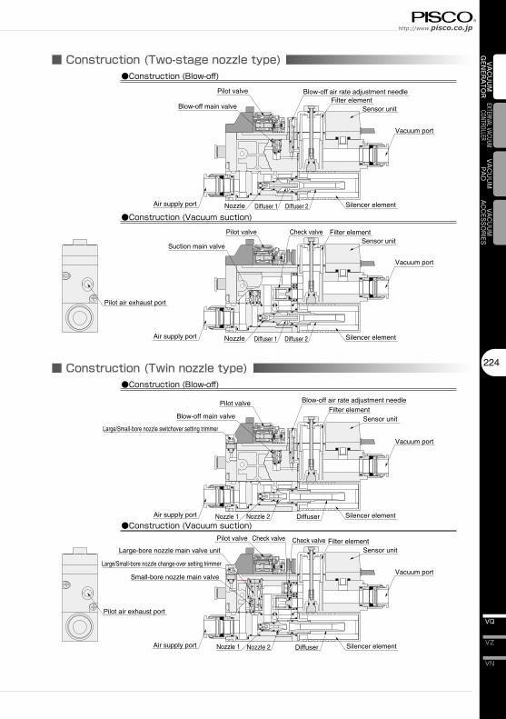
Silencer elementNozzle Diffuser 1 Diffuser 2Air supply port
Filter elementSensor unit
Vacuum port
Pilot valve
Suction main valve
Pilot valve
●Construction (Blow-off)
●Construction (Vacuum suction)
Nozzle Diffuser 1 Diffuser 2
■ Construction (Two-stage nozzle type)
Pilot air exhaust port
Silencer elementNozzle 1 Nozzle 2
Large-bore nozzle main valve unit
DiffuserAir supply port
Filter elementSensor unit
Blow-off main valve
Vacuum port
Pilot valve
Blow-off air rate adjustment needle
Silencer elementNozzle 1 Nozzle 2 DiffuserAir supply port
Filter elementSensor unit
Vacuum port
Pilot valve
Small-bore nozzle main valve
Check valve Check valve
Large/Small-bore nozzle switchover setting trimmer
Large/Small-bore nozzle change-over setting trimmer
●Construction (Blow-off)
●Construction (Vacuum suction)
■ Construction (Twin nozzle type) 224
VN
VZ
VQ
VAC
UU
M
GEN
ERA
TOR
EXTERNAL VACUUM CONTROLLER
VAC
UU
MPA
DVACUUM
ACCESSORIES
Vacuum Generator SeriesVacuum Generator VQ
VH�·�VS
225
VU
VB
VM�·�VC
VG
VK
VJ
VX
VQ
VY
VUM
VRL
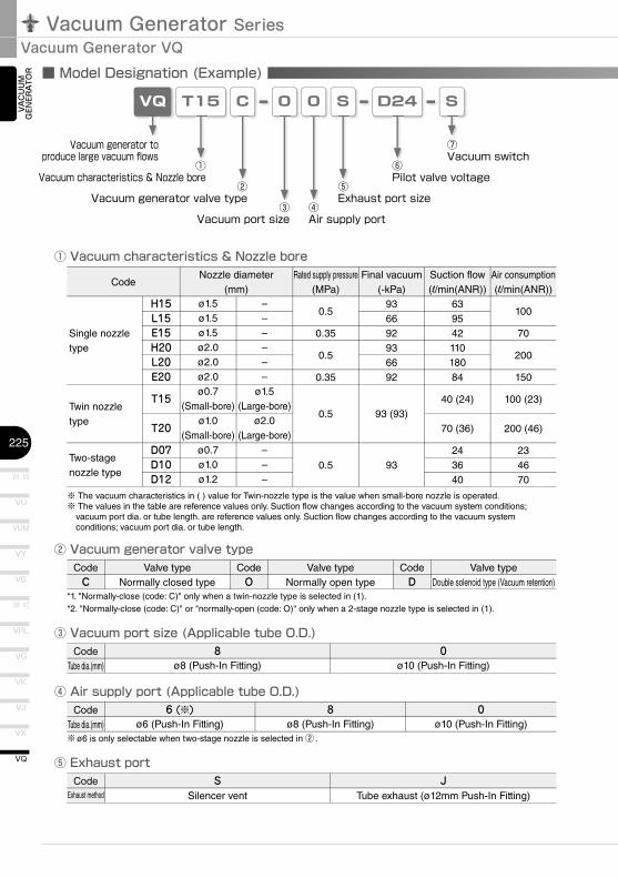
■ Model Designation (Example)
VQ 0
③Vacuum�port�size
T15
①Vacuum�characteristics�&�Nozzle�bore
0
④Air�supply�port
Vacuum�generator�to�produce�large�vacuum�fl�ows
S
⑦Vacuum�switch
③ Vacuum port size (Applicable tube O.D.)
C
②Vacuum�generator�valve�type
S
⑤Exhaust�port�size
D24
⑥Pilot�valve�voltage
① Vacuum characteristics & Nozzle bore
② Vacuum generator valve type
④ Air supply port (Applicable tube O.D.)
⑤ Exhaust port
VAC
UU
M
GEN
ERA
TOR
※ The vacuum characteristics in ( ) value for Twin-nozzle type is the value when small-bore nozzle is operated.※ The values in the table are reference values only. Suction flow changes according to the vacuum system conditions;
vacuum port dia. or tube length. are reference values only. Suction flow changes according to the vacuum system conditions; vacuum port dia. or tube length.
CodeTube dia.(mm)
6 (※)ø6 (Push-In Fitting)
Code
CodeC
Valve typeNormally closed type
8ø8 (Push-In Fitting)
0ø10 (Push-In Fitting)
CodeTube dia.(mm)
8ø8 (Push-In Fitting)
0ø10 (Push-In Fitting)
CodeExhaust method
SSilencer vent
JTube exhaust (ø12mm Push-In Fitting)
Nozzle diameter(mm)
ø1.5ø1.5ø1.5ø2.0ø2.0ø2.0ø0.7
(Small-bore)ø1.0
(Small-bore)ø0.7ø1.0ø1.2
H15L15E15H20L20E20
T15
T20
D07D10D12
Single nozzle type
Twin nozzle type
Two-stage nozzle type
––––––
ø1.5(Large-bore)
ø2.0(Large-bore)
–––
Rated supply pressure(MPa)
0.5
0.35
0.5
0.35
0.5
0.5
Final vacuum(-kPa)
936692936692
93 (93)
93
Suction flow(l/min(ANR))
63954211018084
40 (24)
70 (36)
243640
Air consumption(l/min(ANR))
100
70
200
150
100 (23)
200 (46)
234670
CodeO
Valve typeNormally open type
CodeD
Valve typeDouble solenoid type (Vacuum retention)
*1. "Normally-close (code: C)" only when a twin-nozzle type is selected in (1).*2. "Normally-close (code: C)" or "normally-open (code: O)" only when a 2-stage nozzle type is selected in (1).
※ ø6 is only selectable when two-stage nozzle is selected in ② .
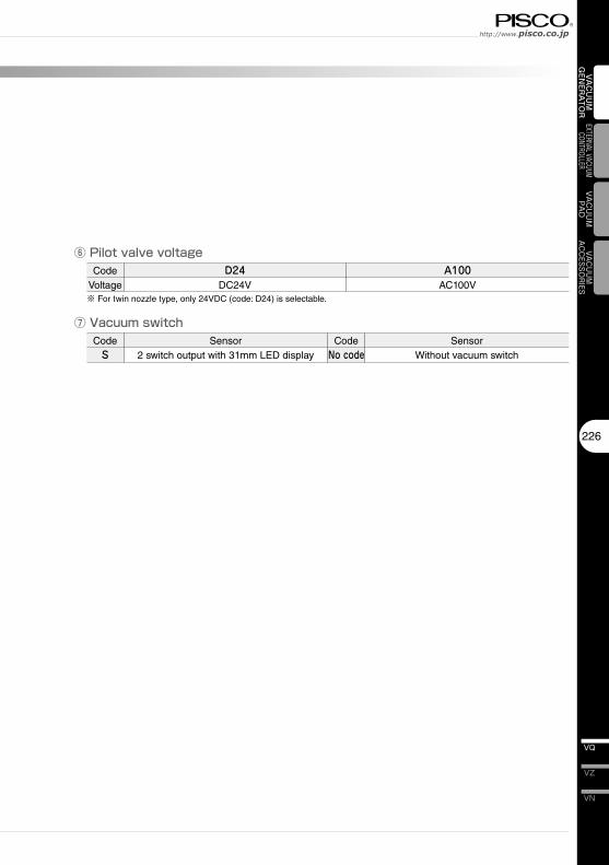
⑥ Pilot valve voltage
⑦ Vacuum switch
226
VN
VZ
VQ
VAC
UU
M
GEN
ERA
TOR
EXTERNAL VACUUM CONTROLLER
VAC
UU
MPA
DVACUUM
ACCESSORIES
CodeVoltage
D24DC24V
A100AC100V
CodeS
Sensor2 switch output with 31mm LED display
CodeNo code
SensorWithout vacuum switch
※ For twin nozzle type, only 24VDC (code: D24) is selectable.
Vacuum Generator SeriesVacuum Generator VQ
VH · VS
227
VU
VB
VM · VC
VG
VK
VJ
VX
VQ
VY
VUM
VRL
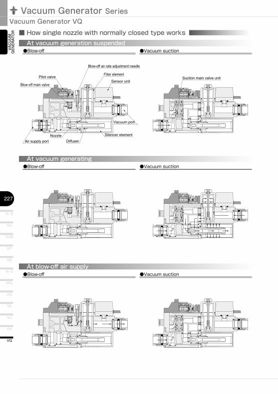
Blow-off main valve
Blow-off air rate adjustment needle
Silencer elementNozzle
DiffuserAir supply port
Filter element
Sensor unit
Vacuum port
Pilot valve Suction main valve unit
●Blow-off ●Vacuum suctionAt vacuum generation suspended
●Blow-off ●Vacuum suctionAt vacuum generating
●Blow-off ●Vacuum suctionAt blow-off air supply
■ How single nozzle with normally closed type works
VAC
UU
M
GEN
ERA
TOR
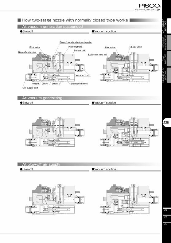
■ How two-stage nozzle with normally closed type works
Blow-off air rate adjustment needle
Blow-off main valve
Check valve
Silencer elementNozzle Diffuser 1 Diffuser 2
Air supply port
Filter element
Sensor unitPilot valve
Suction main valve unit
Pilot valve
●Blow-off ●Vacuum suctionAt vacuum generation suspended
●Blow-off ●Vacuum suctionAt vacuum generating
●Blow-off ●Vacuum suctionAt blow-off air supply
Vacuum port
228
VN
VZ
VQ
VAC
UU
M
GEN
ERA
TOR
EXTERNAL VACUUM CONTROLLER
VAC
UU
MPA
DVACUUM
ACCESSORIES
Vacuum Generator SeriesVacuum Generator VQ
VH · VS
229
VU
VB
VM · VC
VG
VK
VJ
VX
VQ
VY
VUM
VRL
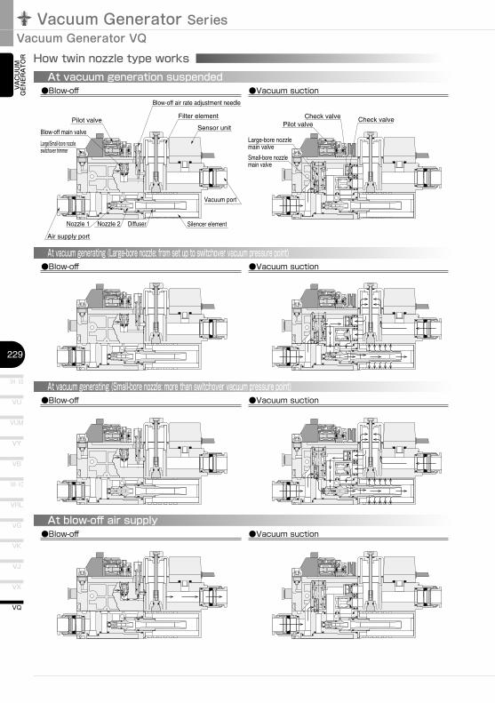
How twin nozzle type works
Large-bore nozzle main valve
Blow-off main valvePilot valve
Blow-off air rate adjustment needle
Silencer elementNozzle 1 Nozzle 2 Diffuser
Air supply port
Filter element
Sensor unit
Vacuum port
Pilot valveCheck valve Check valve
Large/Small-bore nozzle switchover trimmer
Small-bore nozzle main valve
●Blow-off ●Vacuum suctionAt vacuum generation suspended
●Blow-off ●Vacuum suctionAt vacuum generating (Large-bore nozzle: from set up to switchover vacuum pressure point)
●Blow-off ●Vacuum suctionAt vacuum generating (Small-bore nozzle: more than switchover vacuum pressure point)
●Blow-off ●Vacuum suctionAt blow-off air supply
VAC
UU
M
GEN
ERA
TOR
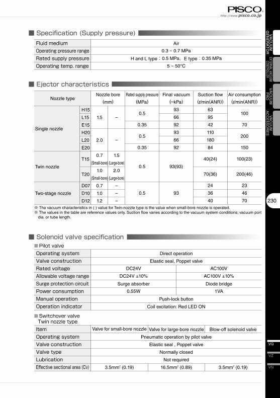
■ Specification (Supply pressure)
■ Ejector characteristics
■ Solenoid valve specification
230
VN
VZ
VQ
VAC
UU
M
GEN
ERA
TOR
EXTERNAL VACUUM CONTROLLER
VAC
UU
MPA
DVACUUM
ACCESSORIES
Fluid�medium Air
Operating�pressure�range 0.3 ~ 0.7 MPa
Rated�supply�pressure H and L type:0.5 MPa、E type:0.35 MPa
Operating�temp.�range 5 ~ 50°C
Nozzle type
H15
L15
Single nozzle E15
H20
L20
E20
T15
Twin nozzle
T20
D07
Two-stage nozzle D10
D12
Nozzle bore
(mm)
Final vacuum
(–kPa)
93
66
92
93
66
92
93(93)
93
Suction flow
(l/min(ANR))
63
95
42
110
180
84
40(24)
70(36)
24
36
40
Air consumption
(l/min(ANR))
100
70
200
150
100(23)
200(46)
23
46
70
※ The vacuum characteristics in ( ) value for Twin-nozzle type is the value when small-bore nozzle is operated.※ The values in the table are reference values only. Suction flow varies according to the vacuum system conditions; vacuum port
dia. or tube length.
Operating�systemValve�constructionRated�voltageAllowable�voltage�rangeSurge�protection�circuitPower�consumptionManual�operationOperation�indicator
Push-lock button
Coil excitation: Red LED ON
DC24V
DC24V ±10%
Surge absorber
0.55W
AC100V
AC100V ±10%
Diode bridge
1VA
■Pilot�valveDirect operation
Elastic seal, Poppet valve
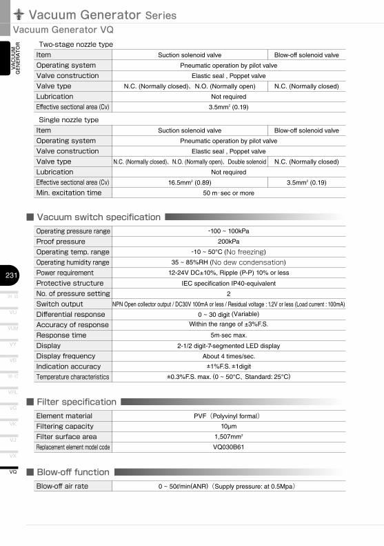
ItemOperating�systemValve�constructionValve�typeLubricationEffective�sectional�area�(Cv)
Valve for small-bore nozzle
■Switchover�valveTwin�nozzle�type
Pneumatic operation by pilot valve
Elastic seal , Poppet valve
Normally closed
Not required
Rated supply pressure
(MPa)
0.5
0.35
0.5
0.35
0.5
0.5
1.5
2.0
0.7
(Small-bore)
1.0
(Small-bore)
0.7
1.0
1.2
–
–
1.5
(Large-bore)
2.0
(Large-bore)
–
–
–
Valve for large-bore nozzle Blow-off solenoid valve
3.5mm2 (0.19) 16.5mm2 (0.89) 3.5mm2 (0.19)
Vacuum Generator SeriesVacuum Generator VQ
VH · VS
231
VU
VB
VM · VC
VG
VK
VJ
VX
VQ
VY
VUM
VRL
■ Filter specification
■ Vacuum switch specification
■ Blow-off function
VAC
UU
M
GEN
ERA
TOR
Element�material PVF(Polyvinyl formal)Filtering�capacity 10µm
Filter�surface�area 1,507mm2
Replacement�element�model�code VQ030B61
Blow-off�air�rate 0 ~ 50l/min(ANR)(Supply pressure: at 0.5Mpa)
ItemOperating�systemValve�constructionValve�typeLubricationEffective�sectional�area�(Cv)
Suction solenoid valve
Two-stage�nozzle�type
Pneumatic operation by pilot valve
Elastic seal , Poppet valve
N.C. (Normally closed)、N.O. (Normally open) N.C. (Normally closed)
Not required
Blow-off solenoid valve
3.5mm2 (0.19)
ItemOperating�systemValve�constructionValve�typeLubricationEffective�sectional�area�(Cv)Min.�excitation�time
Suction solenoid valve
Single�nozzle�type
Pneumatic operation by pilot valve
Elastic seal , Poppet valve
N.C. (Normally closed)、N.O. (Normally open)、Double solenoid N.C. (Normally closed)
Not required
Blow-off solenoid valve
16.5mm2 (0.89) 3.5mm2 (0.19)
50 m・sec or more
-100 ~ 100kPa
200kPa
-10 ~ 50°C (No freezing)
35 ~ 85%RH (No dew condensation)
12-24V DC±10%, Ripple (P-P) 10% or less
IEC specification IP40-equivalent
2
NPN Open collector output / DC30V 100mA or less / Residual voltage : 1.2V or less (Load current : 100mA)
0 ~ 30 digit (Variable)
Within the range of ±3%F.S.
5m·sec max.
2-1/2 digit-7-segmented LED display
About 4 times/sec.
±1%F.S. ±1digit
±0.3%F.S. max. (0 ~ 50°C、Standard: 25°C)
Operating�pressure�rangeProof�pressureOperating�temp.�rangeOperating�humidity�rangePower�requirementProtective�structureNo.�of�pressure�settingSwitch�outputDifferential�responseAccuracy�of�responseResponse�timeDisplayDisplay�frequencyIndication�accuracyTemperature�characteristics
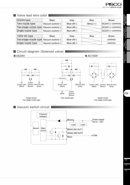
■ Valve lead wire color
■ Circuit diagram (Solenoid valve)
0VSuction valve
(Black)
DC24Vcommon(Brown)
0VBlow-off valve
(Gray)
DC24Vcommon(Brown)
0VSuction valve
(Black)
0V(Blue)
0VBlow-off valve
(Gray)
~Suction valve
(Black)
~common(Brown)
~Blow-off valve
(Gray)
+ — + —
■ DC24V ■ AC100V
Single nozzleTwo-stage nozzle type
Twin nozzle type Single nozzleTwo-stage nozzle type
Internal circuit
■ Vacuum switch circuit
Pressureindicator
Load Load
(Brown)
(Black) SW OUT1
(White) SW OUT2
(Blue)
Power supplyDC12 ~ 24V
COM
Sensor Maincircuit
232
VN
VZ
VQ
VAC
UU
M
GEN
ERA
TOR
EXTERNAL VACUUM CONTROLLER
VAC
UU
MPA
DVACUUM
ACCESSORIES
DC24V�typeTwin�nozzle�typeTwo-stage�nozzle�typeSingle�nozzle�type
Black
Vacuum suction(–)
Vacuum suction(–)
Vacuum suction(–)
Gray
Blow-off(–)
Blow-off(–)
Blow-off(–)
Blue
Minus (–)
Brown
DC24V (+ common)
DC24V (+ common)
DC24V (+ common)
100V�AC�typeTwo-stage�nozzle�typeSingle�nozzle�type
Black
Vacuum suction(–)
Vacuum suction(–)
Gray
Blow-off(–)
Blow-off(–)
Blue Brown
common
common
Vacuum Generator SeriesVacuum Generator VQ
VH · VS
233
VU
VB
VM · VC
VG
VK
VJ
VX
VQ
VY
VUM
VRL
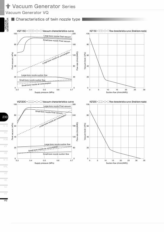
■ Characteristics of twin nozzle type
100
80
60
40
20
00.3 0.4 0.5 0.6 0.7
Supply pressure (MPa)
Fin
al v
acuu
m (
-kP
a)
Flo
w r
ate
(l/m
in(A
NR
))40
80
120
160
200
0
VQT15C-□□□-□-□ Vacuum characteristics curve
Small-bore nozzle suction flow
Large-bore nozzle suction flow
Large-bore nozzle air consumption
Small-bore nozzle air consumption
Small-bore nozzle Final vacuum
Large-bore nozzle Final vacuum
100
80
60
40
20
00 5 10 15 20 25 30
Suction flow (l/min(ANR))
Vac
uum
leve
l (-k
Pa)
VQT15C-□□□-□-□ Flow characteristics curve (Small-bore nozzle)
100
80
60
40
20
00 5 10 15 20 25 3530
Suction flow (l/min(ANR))
Vac
uum
leve
l (-k
Pa)
VQT20C-□□□-□-□ Flow characteristics curve (Small-bore nozzle)100
80
60
40
20
00.3 0.4 0.5 0.6 0.7
Supply pressure (MPa)
Fin
al v
acuu
m (
-kP
a)
Flo
w r
ate
(l/m
in(A
NR
))
60
120
180
240
300
0
VQT20C-□□□-□-□ Vacuum characteristics curve
Small-bore nozzle suction flow
Small-bore nozzle air consumptionLarge-bore nozzle suction flow
Large-bore nozzle air consumption
Large-bore nozzle Final vacuum
Small-bore nozzle Final vacuum
VAC
UU
M
GEN
ERA
TOR
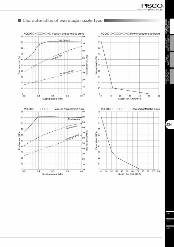
■ Characteristics of two-stage nozzle type
VQD07□-□□□-□-□ Vacuum characteristic curve VQD07□-□□□-□-□ Flow characteristic curve
0
10
20
30
40
50
60
70
80
90
100
0.3 0.4 0.5 0.6 0.7Supply pressure (MPa)
Fin
al v
acuu
m (
-kP
a)
Flo
w r
ate
(l/m
in(A
NR
))
0
10
20
30
40
50
60
70
80
Suction flow
Air consumption
Final vacuum
0
10
20
30
40
50
60
70
80
90
100
0 10 20 30 40 50 60Suction flow (l/min(ANR))
Vac
uum
leve
l (-k
Pa)
VQD10□-□□□-□-□ Vacuum characteristic curve VQD10□-□□□-□-□ Flow characteristic curve
0
10
20
30
40
50
60
70
80
90
100
0.3 0.4 0.5 0.6 0.7Supply pressure (MPa)
Fin
al v
acuu
m (
-kP
a)
Flo
w r
ate
(l/m
in(A
NR
))
0
10
20
30
40
50
60
70
80
90
100
110
Suction flow
Air consumption
Final vacuum
0
10
20
30
40
50
60
70
80
90
100
0 10 20 30 40 50 60 70 80 90 100 110Suction flow (l/min(ANR))
Vac
uum
leve
l (-k
Pa)
234
VN
VZ
VQ
VAC
UU
M
GEN
ERA
TOR
EXTERNAL VACUUM CONTROLLER
VAC
UU
MPA
DVACUUM
ACCESSORIES
Vacuum Generator SeriesVacuum Generator VQ
VH�·�VS
235
VU
VB
VM�·�VC
VG
VK
VJ
VX
VQ
VY
VUM
VRL
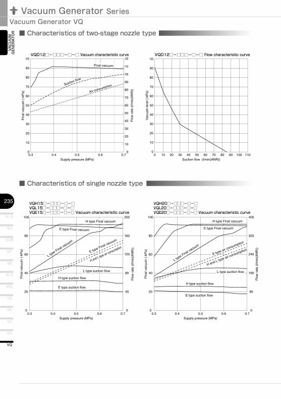
■ Characteristics of two-stage nozzle type
VQD12□-□□□-□-□ Vacuum characteristic curve VQD12□-□□□-□-□ Flow characteristic curve
0
10
20
30
40
50
60
70
80
90
100
0.3 0.4 0.5 0.6 0.7Supply pressure (MPa)
Fin
al v
acuu
m (
-kP
a)
Flo
w r
ate
(l/m
in(A
NR
))
0
10
20
30
40
50
60
70
80
90
100
120
110
Suction flow
Air consumption
Final vacuum
0
10
20
30
40
50
60
70
80
90
100
0 10 20 30 40 50 60 70 80 90 100 110Suction flow (l/min(ANR))
Vac
uum
leve
l (-k
Pa)
■ Characteristics of single nozzle type
100
80
60
40
20
00.3 0.4 0.5 0.6 0.7
Supply pressure (MPa)
Fin
al v
acuu
m (
-kP
a)
Flo
w r
ate
(l/m
in(A
NR
))
40
80
120
160
200
0
VQH15□-□□□-□-□VQL15□-□□□-□-□VQE15□-□□□-□-□ Vacuum characteristic curve
H type Final vacuum
H type suction flow
E type suction flow
L type suction flow
E type Final vacuum
H and L type air consumption
E type Final vacuum
L type Final vacuum
100
80
60
40
20
00.3 0.4 0.5 0.6 0.7
Supply pressure (MPa)
Fin
al v
acuu
m (
-kP
a)
Flo
w r
ate
(l/m
in(A
NR
))
80
160
240
320
400
0
VQH20□-□□□-□-□VQL20□-□□□-□-□VQE20□-□□□-□-□ Vacuum characteristic curve
H type Final vacuum
H type suction flow
E type suction flow
L type suction flow
E type air consumption
H and L type air consumption
E type Final vacuum
L type Final vacuum
VAC
UU
M
GEN
ERA
TOR
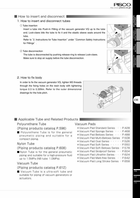
■ How to insert and disconnect
■ Applicable Tube and Related Products
236
VN
VZ
VQ
VAC
UU
M
GEN
ERA
TOR
EXTERNAL VACUUM CONTROLLER
VAC
UU
MPA
DVACUUM
ACCESSORIES
1.�How�to�insert�and�disconnect�tubes① Tube insertion
Insert a tube into Push-In Fitting of the vacuum generator VQ up to the tube
end. Lock-claws bite the tube to fix it and the elastic sleeve seals around the
tube.
Refer to “2. Instructions for Tube Insertion” under “Common Safety Instructions
for Fittings” .
② Tube disconnection
The tube is disconnected by pushing release-ring to release Lock-claws.
Make sure to stop air supply before the tube disconnection.
2.�How�to�fix�bodyIn order to fix the vacuum generator VQ, tighten M3 threads
through the fixing holes on the resin body with tightening
torque 0.3 to 0.35Nm. Refer to the outer dimensional
drawings for the hole pitch.
Polyurethane Tube(Piping products catalog P.596)■ Polyurethane Tube is for the general
pneumatic pip ing and suitable for a compact piping.
Nylon Tube(Piping products catalog P.608)■ Nylon Tube is for the general pneumatic
piping and suitable for a high-pressure fluid up to 1.5MPa (NB tube: 1.0MPa).
Vacuum Tube(Piping products catalog P.612)■ Vacuum Tube is a ultra-soft tube and
suitable for piping of vacuum generators or actuators.
Vacuum Pads ● Vacuum Pad Standard Series ・・ P.428 ● Vacuum Pad Sponge Series ・・・ P.468 ● Vacuum Pad Bellows Series ・・・ P.488 ● Vacuum Pad Multi-Bellows Series P.508 ● Vacuum Pad Oval Series ・・・・・ P.526 ● Vacuum Pad Soft Series ・・・・・ P.550 ● Vacuum Pad Soft Bellows Series ・ P.578 ● Vacuum Pad Skidproof Series ・・ P.604 ● Vacuum Pad Ultrathin Series ・・・ P.624 ● Vacuum Pad Mark-free Series ・・ P.642 ● Vacuum Pad Long Stroke Series ・ P.658
Vacuum Generator SeriesVacuum Generator VQ
VH · VS
237
VU
VB
VM · VC
VG
VK
VJ
VX
VQ
VY
VUM
VRL
V
EXP
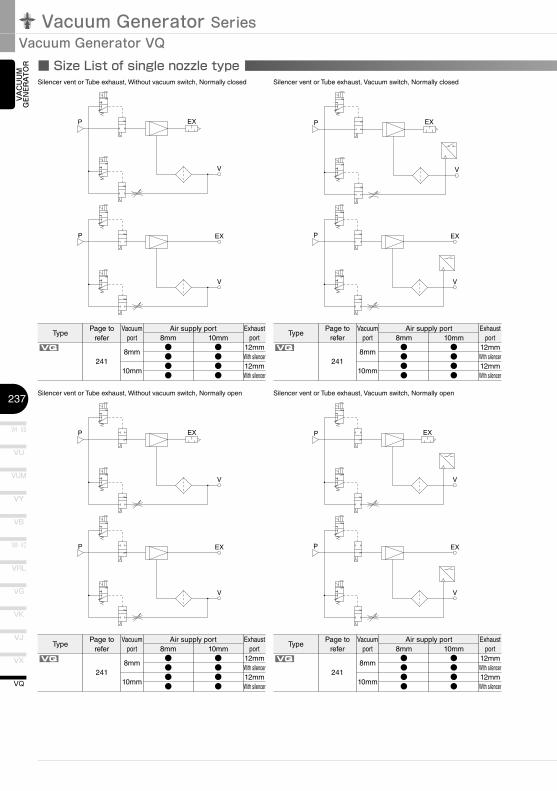
■ Size List of single nozzle type
V
EXP
V
EXP
V
EXP
V
EXP
V
EXP
V
EXP
V
EXP
VAC
UU
M
GEN
ERA
TOR
TypePage to
referVacuum
portAir supply port
8mmVQ
2418mm
10mm
●●●●
Silencer vent or Tube exhaust, Without vacuum switch, Normally closed
Exhaust port
12mmWith silencer12mmWith silencer
Silencer vent or Tube exhaust, Vacuum switch, Normally closed
10mm●●●●
TypePage to
referVacuum
portAir supply port
8mmVQ
2418mm
10mm
●●●●
Exhaust port
12mmWith silencer12mmWith silencer
10mm●●●●
TypePage to
referVacuum
portAir supply port
8mmVQ
2418mm
10mm
●●●●
Silencer vent or Tube exhaust, Without vacuum switch, Normally open
Exhaust port
12mmWith silencer12mmWith silencer
Silencer vent or Tube exhaust, Vacuum switch, Normally open
10mm●●●●
TypePage to
referVacuum
portAir supply port
8mmVQ
2418mm
10mm
●●●●
Exhaust port
12mmWith silencer12mmWith silencer
10mm●●●●
V
EXP
V
EXP
V
EXP
V
EXP
238
VN
VZ
VQ
VAC
UU
M
GEN
ERA
TOR
EXTERNAL VACUUM CONTROLLER
VAC
UU
MPA
DVACUUM
ACCESSORIES
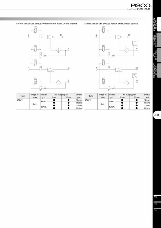
TypePage to
referVacuum
portAir supply port
8mmVQ
2418mm
10mm
●●●●
Silencer vent or Tube exhaust, Without vacuum switch, Double solenoid
Exhaust port
12mmWith silencer12mmWith silencer
Silencer vent or Tube exhaust, Vacuum switch, Double solenoid
10mm●●●●
TypePage to
referVacuum
portAir supply port
8mmVQ
2418mm
10mm
●●●●
Exhaust port
12mmWith silencer12mmWith silencer
10mm●●●●
Vacuum Generator SeriesVacuum Generator VQ
VH · VS
239
VU
VB
VM · VC
VG
VK
VJ
VX
VQ
VY
VUM
VRL
V
EXP
V
EXP
V
EXP
V
EXP
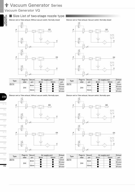
■ Size List of two-stage nozzle type
V
EXP
V
EXP
V
EXP
V
EXP
VAC
UU
M
GEN
ERA
TOR
Silencer vent or Tube exhaust, Without vacuum switch, Normally closed Silencer vent or Tube exhaust, Vacuum switch, Normally closed
TypePage to
referVacuum
portAir supply port
8mmVQD
2448mm
10mm
●●●●
Exhaust port
12mmWith silencer12mmWith silencer
10mm●●●●
TypePage to
referVacuum
portAir supply port
8mmVQD
2448mm
10mm
●●●●
Exhaust port
12mmWith silencer12mmWith silencer
10mm●●●●
Silencer vent or Tube exhaust, Without vacuum switch, Normally open Silencer vent or Tube exhaust, Vacuum switch, Normally open
TypePage to
referVacuum
portAir supply port
8mmVQD
2448mm
10mm
●●●●
Exhaust port
12mmWith silencer12mmWith silencer
10mm●●●●
TypePage to
referVacuum
portAir supply port
8mmVQD
2448mm
10mm
●●●●
Exhaust port
12mmWith silencer12mmWith silencer
10mm●●●●
V
EX
P
V
EX
P
V
EX
P
V
EX
P
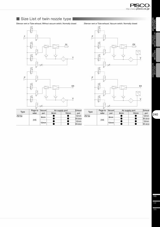
■ Size List of twin nozzle type
240
VN
VZ
VQ
VAC
UU
M
GEN
ERA
TOR
EXTERNAL VACUUM CONTROLLER
VAC
UU
MPA
DVACUUM
ACCESSORIES
Silencer vent or Tube exhaust, Without vacuum switch, Normally closed Silencer vent or Tube exhaust, Vacuum switch, Normally closed
TypePage to
referVacuum
portAir supply port
8mmVQT
2458mm
10mm
●●●●
Exhaust port
12mmWith silencer12mmWith silencer
10mm●●●●
TypePage to
referVacuum
portAir supply port
8mmVQT
2458mm
10mm
●●●●
Exhaust port
12mmWith silencer12mmWith silencer
10mm●●●●
Vacuum Generator SeriesVacuum Generator VQ
VH�·�VS
241
VU
VB
VM�·�VC
VG
VK
VJ
VX
VQ
VY
VUM
VRL
VQ
Blow-off air rate adjustment needle
5
Blow-off pilot valve
Suction pilot valveManual button
LED43
7940
7
øD1(Air supply port) 31.529
2120
.3
2-ø3.5
1361.8
833.
9
ø6 (Pilot air exhaust port)
120 6.5 L214.7
L1
9.1
øD2(Vacuum port)22.1
20 Abou
t 500
330
Exhaust port
PV
V
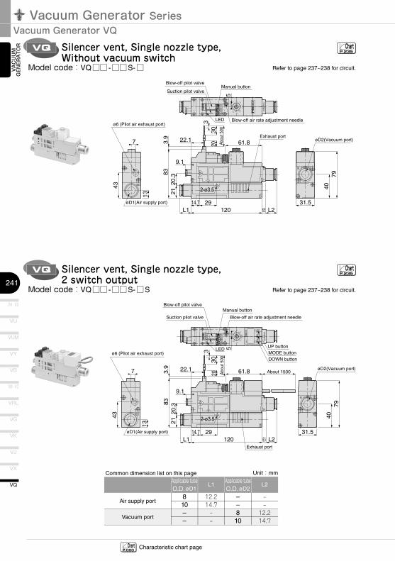
Silencer vent, Single nozzle type, Without vacuum switch
VQ Silencer vent, Single nozzle type, 2 switch output
SW
2
SW
1
kPa
5LED
Manual button
Suction pilot valve
Blow-off pilot valve
Blow-off air rate adjustment needle
DOWN buttonMODE buttonUP button
43
7940
7
øD1(Air supply port) 31.529
2120
.3
2-ø3.5
13
61.8
833.
9
ø6 (Pilot air exhaust port)
120 6.5 L214.7
L1
9.1
øD2(Vacuum port)About 150022.1
20 Abo
ut 5
00
330
Exhaust port
PV
V
ChartP.235
ChartP.235
ChartP.000 Characteristic chart page
VAC
UU
M
GEN
ERA
TOR
Refer to page 237~238 for circuit.Model�code:VQ□□ -□□S-□
Model�code:VQ□□ -□□S-□S
Air supply port
Vacuum port
Applicable�tube�O.D.�øD1
810––
Applicable�tube�O.D.�øD2
––810
Unit:mm
L1
12.214.7‒‒
L2
‒‒12.214.7
Common dimension list on this page
Refer to page 237~238 for circuit.
VQ
Blow-off air rate adjustment needle
5
Blow-off pilot valve
Suction pilot valve Manual button
LED43
7940
13
7
øD1(Air supply port) 31.529
2120
.3
2-ø3.5
1361.8
833.
9
ø6 (Pilot air exhaust port)
120 6.55.2
L214.7
L1
9.1
øD2(Vacuum port)22.1
20 Abo
ut 5
00
330
ø12 (v)
EX
PV
V
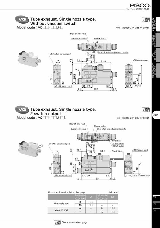
Tube exhaust, Single nozzle type, Without vacuum switch
VQ Tube exhaust, Single nozzle type, 2 switch output
SW
2
SW
1
kPa
5LED
Manual button
Suction pilot valve
Blow-off pilot valve
Blow-off air rate adjustment needle
DOWN buttonMODE buttonUP button
43
7940
13
7
øD1(Air supply port) 31.529
2120
.3
2-ø3.5
13
61.8
833.
9
ø6 (Pilot air exhaust port)
120 6.55.2
L214.7
L1
9.1
øD2(Vacuum port)About 150022.1
20 Abo
ut 5
00
330
ø12 (Exhaust port)
EX
PV
V
ChartP.235
ChartP.235
ChartP.000 Characteristic chart page
242
VN
VZ
VQ
VAC
UU
M
GEN
ERA
TOR
EXTERNAL VACUUM CONTROLLER
VAC
UU
MPA
DVACUUM
ACCESSORIES
Model�code:VQ□□ -□□J-□
Model�code:VQ□□ -□□J-□S
Air supply port
Vacuum port
Applicable�tube�O.D.�øD1
810––
Applicable�tube�O.D.�øD2
––810
Unit:mm
L1
12.214.7‒‒
L2
‒‒12.214.7
Common dimension list on this page
Refer to page 237~238 for circuit.
Refer to page 237~238 for circuit.
Vacuum Generator SeriesVacuum Generator VQ
VH�·�VS
243
VU
VB
VM�·�VC
VG
VK
VJ
VX
VQ
VY
VUM
VRL
VQD
Suction pilot valve
Blow-off pilot valve Manual button
LED Blow-off air rate adjustment needle
5
43
7940
7
øD1(Air supply port)
31.529
2120
.3
2-ø3.5
13
61.883
3.9
ø6 (Pilot air exhaust port)
120 L26.514.7
L1
9.1
øD2(Vacuum port)22.1
20 Abo
ut 5
00
330 Exhaust port
PV
V
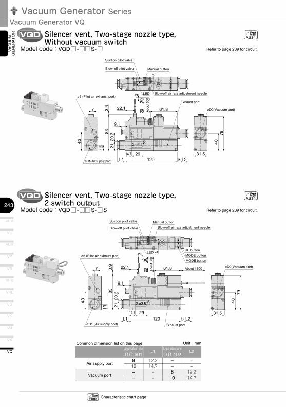
Silencer vent, Two-stage nozzle type, Without vacuum switch
VQD Silencer vent, Two-stage nozzle type, 2 switch output
SW
2
SW
1
kPa
5LED
Manual buttonSuction pilot valve
Blow-off air rate adjustment needle
MODE button
MODE button
UP button
43
7940
7
31.529
2120
.3
2-ø3.5
13
61.8
833.
9
ø6 (Pilot air exhaust port)
120 6.5 L214.7
L1
9.1
øD2(Vacuum port)About 150022.1
20 Abo
ut 5
00
330
Blow-off pilot valve
øD1 (Air supply port) Exhaust port
PV
V
ChartP.234
ChartP.234
ChartP.000 Characteristic chart page
VAC
UU
M
GEN
ERA
TOR
Model�code:VQD□ -□□S-□
Model�code:VQD□ -□□S-□S
Air supply port
Vacuum port
Applicable�tube�O.D.�øD1
810––
Applicable�tube�O.D.�øD2
––810
Unit:mm
L1
12.214.7‒‒
L2
‒‒12.214.7
Common dimension list on this page
Refer to page 239 for circuit.
Refer to page 239 for circuit.
VQD
Suction pilot valve
Blow-off pilot valve Manual button
LED Blow-off air rate adjustment needle
5
43
7940
13
7
øD1(Air supply port)
31.529
2120
.3
2-ø3.5
1361.8
833.
9
ø6 (Pilot air exhaust port)
120 6.55.2
L214.7
L1
9.1
øD2(Vacuum port)22.1
20 Abo
ut 5
00
330
ø12 (Exhaust port)
EX
PV
V
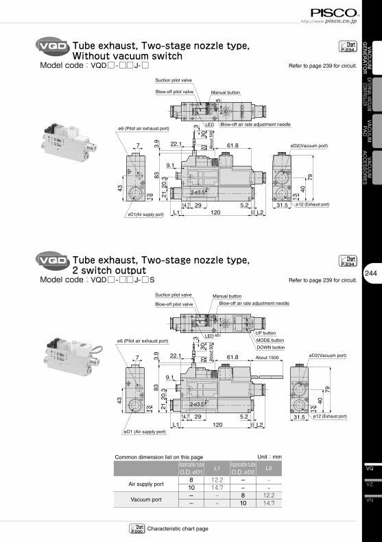
Tube exhaust, Two-stage nozzle type, Without vacuum switch
VQD Tube exhaust, Two-stage nozzle type, 2 switch output
SW
2
SW
1
kPa
5LED
Manual buttonSuction pilot valve
Blow-off air rate adjustment needle
DOWN button
MODE button
UP button
43
7940
13
7
31.529
2120
.3
2-ø3.5
13
61.8
833.
9
ø6 (Pilot air exhaust port)
120 6.55.2
L214.7
L1
9.1
øD2(Vacuum port)About 150022.1
20 Abo
ut 5
00
330
ø12 (Exhaust port)
Blow-off pilot valve
øD1 (Air supply port)
EX
PV
V
ChartP.234
ChartP.234
ChartP.000 Characteristic chart page
244
VN
VZ
VQ
VAC
UU
M
GEN
ERA
TOR
EXTERNAL VACUUM CONTROLLER
VAC
UU
MPA
DVACUUM
ACCESSORIES
Model�code:VQD□ -□□J-□
Model�code:VQD□ -□□J-□S
Air supply port
Vacuum port
Applicable�tube�O.D.�øD1
810––
Applicable�tube�O.D.�øD2
––810
Unit:mm
L1
12.214.7‒‒
L2
‒‒12.214.7
Common dimension list on this page
Refer to page 239 for circuit.
Refer to page 239 for circuit.
Vacuum Generator SeriesVacuum Generator VQ
VH�·�VS
245
VU
VB
VM�·�VC
VG
VK
VJ
VX
VQ
VY
VUM
VRL
VQT
43
5
7940
LED
Manual button
Large-bore nozzle pilot valve
Blow-off pilot valve
Small-bore nozzle pilot valve
Large/Small-bore nozzle switchover trimmer
Blow-off air rate adjustment needle
7
31.529
2120
.3
2-ø3.5
13
61.883
3.9
ø6 (Pilot air exhaust port)
120 6.5 L214.7
L1
9.1
øD2(Vacuum port)
22.1
20 Abo
ut 5
00
330
Exhaust port
øD1(Air supply port)
V
PV
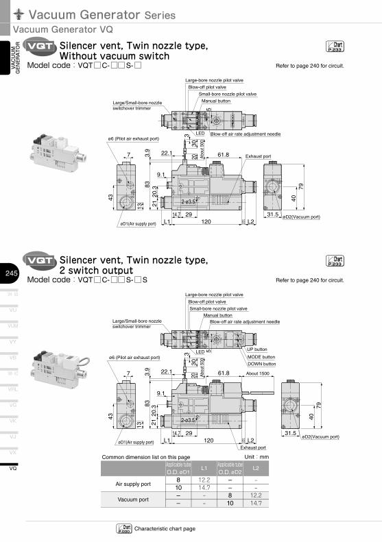
Silencer vent, Twin nozzle type, Without vacuum switch
VQT Silencer vent, Twin nozzle type, 2 switch output
SW
2
SW
1
kPa
43
5
7940
LED
Manual button
Large-bore nozzle pilot valve
Blow-off pilot valve
Small-bore nozzle pilot valve
Blow-off air rate adjustment needle
7
øD1(Air supply port)
31.5
DOWN button
MODE button
UP button
29
2120
.3
2-ø3.5
13
61.8
833.
9
ø6 (Pilot air exhaust port)
120 6.5Exhaust port
L214.7
L1
9.1
øD2(Vacuum port)
About 150022.1
20 Abo
ut 5
00
330
PV
V
Large/Small-bore nozzle switchover trimmer
ChartP.233
ChartP.233
ChartP.000 Characteristic chart page
VAC
UU
M
GEN
ERA
TOR
Model�code:VQT□C-□□S-□
Model�code:VQT□C-□□S-□S
Air supply port
Vacuum port
Applicable�tube�O.D.�øD1
810––
Applicable�tube�O.D.�øD2
––810
Unit:mm
L1
12.214.7‒‒
L2
‒‒12.214.7
Common dimension list on this page
Refer to page 240 for circuit.
Refer to page 240 for circuit.
VQT
43
5
7940
13
LED
Manual button
Large-bore nozzle pilot valve
Blow-off pilot valve
Small-bore nozzle pilot valve
Blow-off air rate adjustment needle
7
31.529
2120
.3
2-ø3.5
1361.8
833.
9
ø6 (Pilot air exhaust port)
120 6.55.2
L214.7
L1
9.1
øD2(Vacuum port)
22.1
20 Abo
ut 5
00
330
ø12 (Exhaust port)
øD1(Air supply port)
EX
PV
V
Large/Small-bore nozzle switchover trimmer
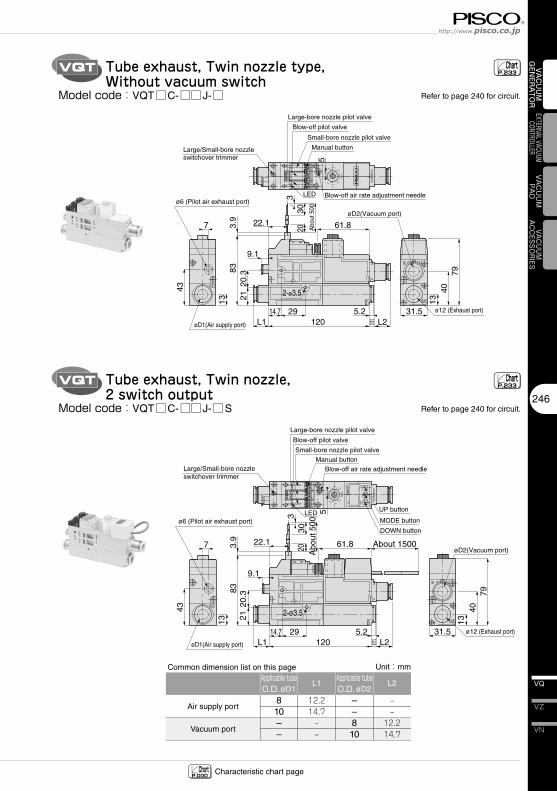
Tube exhaust, Twin nozzle type, Without vacuum switch
VQT Tube exhaust, Twin nozzle, 2 switch output
SW
2
SW
1
kPa
43
5
7940
13
LED
Manual button
Large-bore nozzle pilot valve
Blow-off pilot valve
Small-bore nozzle pilot valve
Blow-off air rate adjustment needle
7
øD1(Air supply port)
31.5
DOWN button
MODE button
UP button
29
2120
.3
2-ø3.5
13
61.8
833.
9
ø6 (Pilot air exhaust port)
120 6.55.2
L214.7
L1
9.1
øD2(Vacuum port)About 150022.1
20 Abo
ut 5
00
330
ø12 (Exhaust port)
EX
PV
V
Large/Small-bore nozzle switchover trimmer
ChartP.233
ChartP.233
ChartP.000 Characteristic chart page
246
VN
VZ
VQ
VAC
UU
M
GEN
ERA
TOR
EXTERNAL VACUUM CONTROLLER
VAC
UU
MPA
DVACUUM
ACCESSORIES
Model�code:VQT□C-□□J-□
Model�code:VQT□C-□□J-□S
Air supply port
Vacuum port
Applicable�tube�O.D.�øD1
810––
Applicable�tube�O.D.�øD2
––810
Unit:mm
L1
12.214.7‒‒
L2
‒‒12.214.7
Common dimension list on this page
Refer to page 240 for circuit.
Refer to page 240 for circuit.
Vacuum Generator SeriesVacuum Generator VQ
VH · VS
247
VU
VB
VM · VC
VG
VK
VJ
VX
VQ
VY
VUM
VRL
Detailed Safety InstructionsBefore� using�PISCO�products,� be� sure� to� read� “Safety� Instructions”� and� “Safety� Instruction�Manual”�on�page�35-39�and�“Common�Safety�Instructions�for�Vacuum�Series”�on�page�47-49.
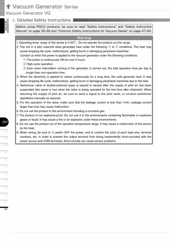
Warning1. Operating temp. range of this series is 5-50℃ . Do not operate the product out this range.
2. The coil in a pilot solenoid valve generates heat under the following ① to ③ conditions. The heat may
cause dropping life cycle, malfunctions, getting burnt or damaging peripheral machines.
Contact us when the power is applied to the vacuum generator under the following conditions:
① The power is continuously ON for over 2 hours.
② High-cycle operation.
③ Even when intermittent running of the generator is carried out, the total operation time per day is
longer than non-operation time.
3. When the electricity is applied to valves continuously for a long time, the coils generate heat. It may
cause dropping life cycle, malfunctions, getting burnt or damaging peripheral machines due to the heat.
4. Switchover valve of double-solenoid types is placed in neutral after the supply of pilot air has been
suspended (the same is true when the valve is being operated for the first time after shipment). When
resuming the supply of pilot air, be sure to send a signal to the pilot valve, or conduct switchover
operations manually as required.
5. For the operation of the valve, make sure that the leakage current is less than 1mA. Leakage current
larger than that may cause malfunction.
6. Do not use the product in the environment including a corrosive gas.
7. The product is not explosive-proof. Do not use it in the environments containing flammable or explosive
gases or liquid. It may cause a fire or an explosion under these environments.
8. Do not use the product out of the operation temperature range. It may cause a malfunction of the sensor
by the heat.
9. When wiring, be sure to 1) switch OFF the power, and 2) confirm the color of each lead wire, terminal
numbers, etc. in order to prevent the output terminal from being inadvertently short-circuited with the
power source and COM terminals. Short-circuits can cause sensor problems.
VAC
UU
M
GEN
ERA
TOR
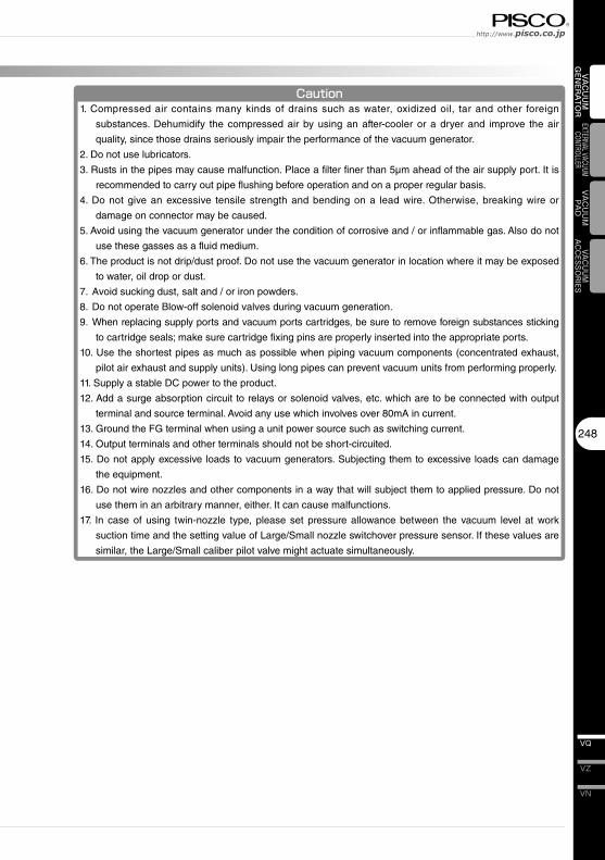
Caution1. Compressed air contains many kinds of drains such as water, oxidized oil, tar and other foreign
substances. Dehumidify the compressed air by using an after-cooler or a dryer and improve the air
quality, since those drains seriously impair the performance of the vacuum generator.
2. Do not use lubricators.
3. Rusts in the pipes may cause malfunction. Place a filter finer than 5μm ahead of the air supply port. It is
recommended to carry out pipe flushing before operation and on a proper regular basis.
4. Do not give an excessive tensile strength and bending on a lead wire. Otherwise, breaking wire or
damage on connector may be caused.
5. Avoid using the vacuum generator under the condition of corrosive and / or inflammable gas. Also do not
use these gasses as a fluid medium.
6. The product is not drip/dust proof. Do not use the vacuum generator in location where it may be exposed
to water, oil drop or dust.
7. Avoid sucking dust, salt and / or iron powders.
8. Do not operate Blow-off solenoid valves during vacuum generation.
9. When replacing supply ports and vacuum ports cartridges, be sure to remove foreign substances sticking
to cartridge seals; make sure cartridge fixing pins are properly inserted into the appropriate ports.
10. Use the shortest pipes as much as possible when piping vacuum components (concentrated exhaust,
pilot air exhaust and supply units). Using long pipes can prevent vacuum units from performing properly.
11. Supply a stable DC power to the product.
12. Add a surge absorption circuit to relays or solenoid valves, etc. which are to be connected with output
terminal and source terminal. Avoid any use which involves over 80mA in current.
13. Ground the FG terminal when using a unit power source such as switching current.
14. Output terminals and other terminals should not be short-circuited.
15. Do not apply excessive loads to vacuum generators. Subjecting them to excessive loads can damage
the equipment.
16. Do not wire nozzles and other components in a way that will subject them to applied pressure. Do not
use them in an arbitrary manner, either. It can cause malfunctions.
17. In case of using twin-nozzle type, please set pressure allowance between the vacuum level at work
suction time and the setting value of Large/Small nozzle switchover pressure sensor. If these values are
similar, the Large/Small caliber pilot valve might actuate simultaneously.
248
VN
VZ
VQ
VAC
UU
M
GEN
ERA
TOR
EXTERNAL VACUUM CONTROLLER
VAC
UU
MPA
DVACUUM
ACCESSORIES
Vacuum Generator SeriesVacuum Generator VQ
VH · VS
249
VU
VB
VM · VC
VG
VK
VJ
VX
VQ
VY
VUM
VRL
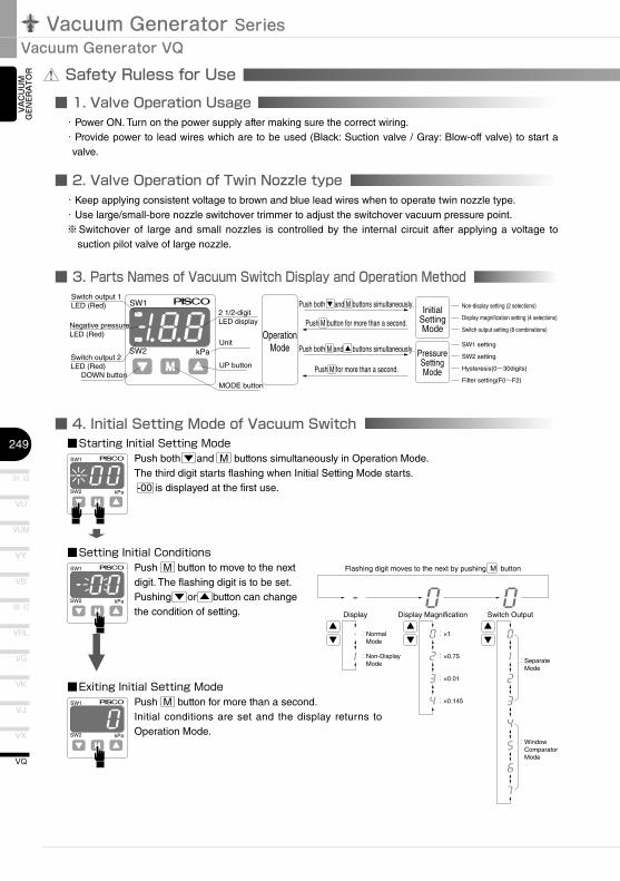
Safety Ruless for Use■ 1. Valve Operation Usage
SW2
SW1
kPa
Switch output 1LED (Red)
Negative pressureLED (Red)
Switch output 2LED (Red)
DOWN button
2 1/2-digitLED display
Unit
UP button
MODE button
Push both ▼ and M buttons simultaneously.
Push M button for more than a second.
Push M for more than a second.
Push both M and ▲ buttons simultaneously.
InitialSettingMode
PressureSettingMode
Non-display setting (2 selections)
Display magnification setting (4 selections)
Switch output setting (8 combinations)
SW1 setting
SW2 setting
Hysteresis(0~30digits)
Filter setting(F0~F2)
OperationMode
SW2
SW1
kPa
■ 2. Valve Operation of Twin Nozzle type
■ 3. Parts Names of Vacuum Switch Display and Operation Method
■ 4. Initial Setting Mode of Vacuum Switch
SW2
SW1
kPa
Flashing digit moves to the next by pushing M button
:Normal Mode
:Non-Display Mode
:×1
:×0.75 :Separate Mode :×0.01
:×0.145
:Window Comparator Mode
Display Display Magnification Switch Output
SW2
SW1
kPa
VAC
UU
M
GEN
ERA
TOR
■Starting�Initial�Setting�ModePush both ▼ and M buttons simultaneously in Operation Mode.The third digit starts flashing when Initial Setting Mode starts. -00 is displayed at the first use.
・Power ON. Turn on the power supply after making sure the correct wiring.・ Provide power to lead wires which are to be used (Black: Suction valve / Gray: Blow-off valve) to start a
valve.
・Keep applying consistent voltage to brown and blue lead wires when to operate twin nozzle type.・Use large/small-bore nozzle switchover trimmer to adjust the switchover vacuum pressure point.※ Switchover of large and small nozzles is controlled by the internal circuit after applying a voltage to
suction pilot valve of large nozzle.
⬇■Setting�Initial�Conditions
Push M button to move to the next digit. The flashing digit is to be set. Pushing ▼ or ▲ button can change the condition of setting.
■Exiting�Initial�Setting�ModePush M button for more than a second.Initial conditions are set and the display returns to Operation Mode.
SW2
SW1
kPa
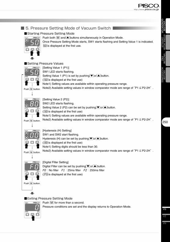
■ 5. Pressure Setting Mode of Vacuum Switch
SW2
SW1
kPa
SW2
SW1
kPa
SW2
SW1
kPa
SW2
SW1
kPa
Push M button.
Push M button.
Push M button.
Push M button.
SW2
SW1
kPa
250
VN
VZ
VQ
VAC
UU
M
GEN
ERA
TOR
EXTERNAL VACUUM CONTROLLER
VAC
UU
MPA
DVACUUM
ACCESSORIES
■Starting�Pressure�Setting�ModePush both M and ▲ buttons simultaneously in Operation Mode.Once Pressure Setting Mode starts, SW1 starts flashing and Setting Value 1 is indicated. 50 is displayed at the first use.
■Setting�Pressure�Values[Setting Value 1 (P1)]SW1 LED starts flashing.Setting Value 1 (P1) is set by pushing ▼ or ▲ button.( 50 is displayed at the first use)Note1) Setting values are available within operating pressure range.Note2) Available setting values in window comparator mode are range of “P1≦P2-2H” .
■Exiting�Pressure�Setting�ModePush M for more than a second.Pressure conditions are set and the display returns to Operation Mode.
[Setting Value 2 (P2)]SW2 LED starts flashing.Setting Value 2 (P2) can be set by pushing ▼ or ▲ button.( 50 is displayed at the first use)Note1) Setting values are available within operating pressure range.Note2) Available setting values in window comparator mode are range of “P1≦P2-2H” .
[Hysteresis (H) Setting]SW1 and SW2 start flashing.Hysteresis (H) can be set by pushing ▼ or ▲ button.( 00 is displayed at the first use)Note1) Setting digits should be less than 30.Note2) Available setting values in window comparator mode are range of “P1≦P2-2H” .
[Digital Filter Setting]Digital Filter can be set by pushing ▼ or ▲ button.F0:No filter F1:25ms filter F2:250ms filter( F0 is displayed at the first use)
Vacuum Generator SeriesVacuum Generator VQ
VH · VS
251
VU
VB
VM · VC
VG
VK
VJ
VX
VQ
VY
VUM
VRL
SW2
SW1
kPa
■ 6. Vacuum Switch Functions
OFF
OFF
-Pr Pr
ON ON
P1:SW1
P1
H H
P2:SW2 P2
(HI)
ON
-Pr PrOFF
P1:SW1
ON
P1
H H
P2:SW2OFF
P2
-Pr Pr
H
OFF
ON
H
-Pr
H H
(LO)
(A)
(B)
VAC
UU
M
GEN
ERA
TOR
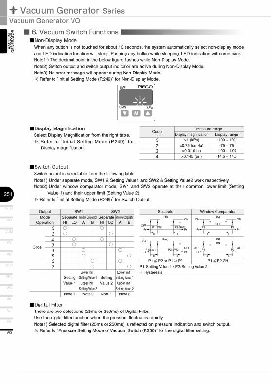
■Non-Display�ModeWhen any button is not touched for about 10 seconds, the system automatically select non-display mode and LED indication function will sleep. Pushing any button while sleeping, LED indication will come back.Note1 ) The decimal point in the below figure flashes while Non-Display Mode.Note2) Switch output and switch output indicator are active during Non-Display Mode.Note3) No error message will appear during Non-Display Mode.※ Refer to “Initial Setting Mode (P.249)” for Non-Display Mode.
■Display�MagnificationSelect Display Magnification from the right table.※ Refer to “Initial Setting Mode (P.249)” for
Display magnification.
Code
0234
Pressure rangeDisplay magnification
×1 (kPa)×0.75 (cmHg)
×0.01 (bar)×0.145 (psi)
Display range-100 ~ 100-75 ~ 75
-1.00 ~ 1.00-14.5 ~ 14.5
■Switch�OutputSwitch output is selectable from the following table.Note1) Under separate mode, SW1 & Setting Value1 and SW2 & Setting Value2 work respectively.
Note2) Under window comparator mode, SW1 and SW2 operate at their common lower limit (Setting Value 1) and their upper limit (Setting Value 2).
※ Refer to “Initial Setting Mode (P.249)” for Switch Output.
OutputMode
Operation
SW1Separate
SW2
HI○○
LO
○○
Window ComparatorA
○○
B
○○
SeparateHI○
○
LO
○
○
Window ComparatorA
○
○
B
○
○
01234567
Setting Value 1
Note 1
Lower limit:Setting Value 1Upper limit:
Setting Value 2Note 2
Setting Value 2
Note 1
Lower limit:Setting Value 1Upper limit:
Setting Value 2Note 2
Separate
P1≦P2 or P1≧P2 P1≦P2-2H
P1: Setting Value 1 / P2: Setting Value 2H: Hysteresis
■Digital�FilterThere are two selections (25ms or 250ms) of Digital Filter.Use the digital filter function when the pressure fluctuates rapidly.Note1) Selected digital filter (25ms or 250ms) is reflected on pressure indication and switch output.※ Refer to “Pressure Setting Mode of Vacuum Switch (P.250)” for the digital filter setting.
Window Comparator
Code
SW2
SW1
kPa
■ 7. Zero Point Adjustment and Error Message of Vacuum Switch
SW2
SW1
kPa
SW2
SW1
kPa
252
VN
VZ
VQ
VAC
UU
M
GEN
ERA
TOR
EXTERNAL VACUUM CONTROLLER
VAC
UU
MPA
DVACUUM
ACCESSORIES
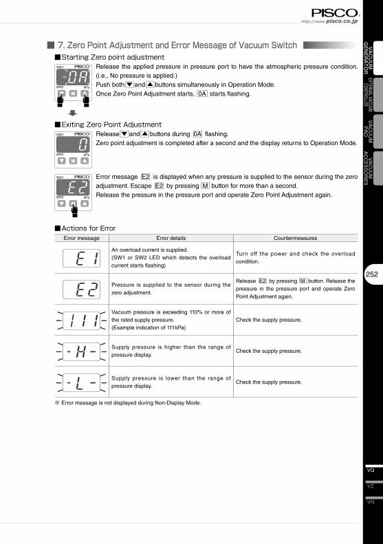
■Starting�Zero�point�adjustmentRelease the applied pressure in pressure port to have the atmospheric pressure condition. (i.e., No pressure is applied.)Push both ▼ and ▲ buttons simultaneously in Operation Mode.Once Zero Point Adjustment starts, 0A starts flashing.
■Exiting�Zero�Point�AdjustmentRelease ▼ and ▲ buttons during 0A flashing.Zero point adjustment is completed after a second and the display returns to Operation Mode.
Error message E2 is displayed when any pressure is supplied to the sensor during the zero adjustment. Escape E2 by pressing M button for more than a second.Release the pressure in the pressure port and operate Zero Point Adjustment again.
■Actions�for�ErrorError message Error details
An overload current is supplied.(SW1 or SW2 LED which detects the overload current starts flashing)
Pressure is supplied to the sensor during the zero adjustment.
Vacuum pressure is exceeding 110% or more of the rated supply pressure.(Example indication of 111kPa)
Supply pressure is higher than the range of pressure display.
Supply pressure is lower than the range of pressure display.
Countermeasures
Turn off the power and check the overload condition.
Release E2 by pressing M button. Release the pressure in the pressure port and operate Zero Point Adjustment again.
Check the supply pressure.
Check the supply pressure.
Check the supply pressure.
※ Error message is not displayed during Non-Display Mode.

Vacuum Generator SeriesVacuum Generator VQ
VH · VS
253
VU
VB
VM · VC
VG
VK
VJ
VX
VQ
VY
VUM
VRL
■ 8. How to replace Filter Elements
Filter elementModel code:VQ030B61
Fixing screw
Filter cover
■ 9. Replacement of Silencer Element
Silencer elementModel code:SED2212
Fixing screw
Silencer cover
VAC
UU
M
GEN
ERA
TOR
■Remove the fixing screw to replace filter elements. Make sure to place the filter seal rubber properly and tighten the screw to fix the filter cover with 0.3-0.5Nm of the tightening torque after the replacement.
■Replace silencer elements following the instructions below.① Remove 2 fixing screws of silencer cover.② Take out the silencer element③ Replace with a new element and tighten the screws to fix the filter cover with 0.4-0.5Nm of the
tightening torque.
■ 10. How to replace and clean Nozzles and Diffusers
Nozzle1(Nozzle)Nozzle2(Diffuser 1) Diffuser(Diffuser2)
Diffuser retainer
Fixing screw
Silencer element
Silencer cover
※ ( ) is for two-stage nozzle.
■ 11. How to replace Cartridge Fittings
Fixing Pin
Cartridge fitting
Fixing Pin
Cartridge fitting
254
VN
VZ
VQ
VAC
UU
M
GEN
ERA
TOR
EXTERNAL VACUUM CONTROLLER
VAC
UU
MPA
DVACUUM
ACCESSORIES
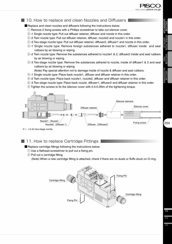
■Replace and clean nozzles and diffusers following the instructions below.① Remove 2 fixing screws with a Phillips screwdriver to take out silencer cover.② -1 Single nozzle type: Pull out diffuser retainer, diffuser and nozzle in this order. ② -2 Twin nozzle type: Pull out diffuser retainer, diffuser, nozzle2 and nozzle1 in this order.② -3 Two-stage nozzle type: Pull out diffuser retainer, diffuser2, diffuser1 and nozzle in this order.③ -1 Single nozzle type: Remove foreign substances adhered to nozzle1, diffuser inside and seal
rubbers by air blowing or wiping.③ -2 Twin nozzle type: Remove the substances adhered to nozzle1 & 2, diffuser2 inside and seal rubbers
by air blowing or wiping.③ -3 Two-stage nozzle type: Remove the substances adhered to nozzle, inside of diffuser1 & 2 and seal
rubbers by air blowing or wiping.(Note) Pay special attention not to damage inside of nozzle & diffuser and seal rubbers.
④ -1 Single nozzle type: Place back nozzle1, diffuser and diffuser retainer in this order.④ -2 Twin nozzle type: Place back nozzle1, nozzle2, diffuser and diffuser retainer in this order.④ -3 Two-stage nozzle type: Place back nozzle, diffuser1, diffuser2 and diffuser retainer in this order.⑤ Tighten the screws to fix the silencer cover with 0.4-0.5Nm of the tightening torque.
■Replace cartridge fittings following the instructions below.① Use a flathead screwdriver to pull out a fixing pin.② Pull out a cartridge fitting.
(Note) When a new cartridge fitting is attached, check if there are no dusts or fluffs stuck on O-ring.
Vacuum Generator SeriesVacuum Generator VQ
VH · VS
255
VU
VB
VM · VC
VG
VK
VJ
VX
VQ
VY
VUM
VRL
VAC
UU
M
GEN
ERA
TOR
35
Safety Instructions
SAFETY Instructions
Warning
This safety instructions aim to prevent personal injury and damage to properties by requiring proper use of PISCO products. Be certain to follow ISO 4414 and JIS B 8370
ISO 4414:Pneumatic fluid power…Recomendations for the application of equipment to transmission and control systems.
JIS B 8370:General rules and safety requirements for systems and their components.This safety instructions is classified into “Danger”, “Warning” and “Caution” depending on the degree of danger or damages caused by improper use of PISCO products.
1. Selection of pneumatic products① A user who is a pneumatic system designer or has sufficient experience
and technical expertise should select PISCO products.② Due to wide variety of operating conditions and applications for PISCO
products, carry out the analysis and evaluation on PISCO products. The pneumatic system designer is solely responsible for assuring that the user's requirements are met and that the application presents no health or safety hazards. All designers are required to fully understand the specifications of PISCO products and constitute all systems based on the latest catalog or information, considering any malfunctions.
2. Handle the pneumatic equipment with enough knowledge and experience① Improper use of compressed air is dangerous. Assembly, operation
and maintenance of machines using pneumatic equipment should be conducted by a person with enough knowledge and experience.
3. Do not operate machine / equipment or remove pneumatic equipment until safety is confirmed.① Make sure that preventive measures against falling work-pieces or
sudden movements of machine are completed before inspection or maintenance of these machine.
② Make sure the above preventive measures are completed. A compressed air supply and the power supply to the machine must be off, and also the compressed air in the systems must be exhausted.
③ Restart the machines with care after ensuring to take all preventive measures against sudden movements.
Danger Hazardous conditions. It can cause death or serious personal injury.
Warning Hazardous conditions depending on usages. Improper use of PISCO products can cause death or serious personal injury.
Caution Hazardous conditions depending on usages. Improper use of PISCO products can cause personal injury or damages to properties.
※ . This safety instructions are subject to change without notice.
http://www.pisco.co.jphttp://www.pisco.co.jp
36
Disclaimer1. PISCO does not take any responsibility for any incidental or indirect
loss, such as production line stop, interruption of business, loss of benefits, personal injury, etc., caused by any failure on use or application of PISCO products.
2. PISCO does not take any responsibility for any loss caused by natural disasters, fires not related to PISCO products, acts by third parties, and intentional or accidental damages of PISCO products due to incorrect usage.
3. PISCO does not take any responsibility for any loss caused by improper usage of PISCO products such as exceeding the specification limit or not following the usage the published instructions and catalog allow.
4. PISCO does not take any responsibility for any loss caused by remodeling of PISCO products, or by combinational use with non-PISCO products and other software systems.
5. The damages caused by the defect of Pisco products shall be covered but limited to the full amount of the PISCO products paid by the customer.
37
Safety Instructions
SAFETY INSTRUCTION MANUAL
Danger1. Do not use PISCO products for the following applications.
① Equipment used for maintaining / handling human life and body.② Equipment used for moving / transporting human.③ Equipment specifically used for safety purposes.
Warning1. Do not use PISCO products under the following conditions.
① Beyond the specifications or conditions stated in the catalog, or the instructions.② Under the direct sunlight or outdoors.③ Excessive vibrations and impacts.④ Exposure / adhere to corrosive gas, inflammable gas, chemicals, seawater, water and vapor. *
* Some products can be used under the condition above(④), refer to the details of specification and condition of each product.
2. Do not disassemble or modify PISCO products, which affect the performance, function, and basic structure of the product.
3. Turn off the power supply, stop the air supply to PISCO products, and make sure there is no residual air pressure in the pipes before maintenance and inspection.
4. Do not touch the release-ring of push-in fitting when there is a working pressure. The lock may be released by the physical contact, and tube may fly out or slip out.
5. Frequent switchover of compressed air may generate heat, and there is a risk of causing burn injury.
6. Avoid any load on PISCO products, such as a tensile strength, twisting and bending. Otherwise, there is a risk of causing damage to the products.
7. As for applications where threads or tubes swing / rotate, use Rotary Joints, High Rotary Joints or Multi-Circuit Rotary Block only. The other PISCO products can be damaged in these applications.
8. Use only Die Temperature Control Fitting Series, Tube Fitting Stainless SUS316 Series, Tube Fitting Stainless SUS316 Compression Fitting Series or Tube Fitting Brass Series under the condition of over 60℃ (140°F) water or thermal oil. Other PISCO products can be damaged by heat and hydrolysis under the condition above.
9. As for the condition required to dissipate static electricity or provide an antistatic performance, use EG series fitting and antistatic products only, and do not use other PISCO products. There is a risk that static electricity can cause system defects or failures.
10. Use only Fittings with a characteristic of spatter-proof such as Anti-spatter or Brass series in a place where flame and weld spatter is produced. There is a risk of causing fire by sparks.
11. Turn off the power supply to PISCO products, and make sure there is no residual air pressure in the pipes and equipment before maintenance. Follow the instructions below in order to ensure safety.① Make sure the safety of all systems related to PISCO products before maintenance.② Restart of operation after maintenance shall be proceeded with care after
ensuring safety of the system by preventive measures against unexpected movements of machines and devices where pneumatic equipment is used.
③ Keep enough space for maintenance when designing a circuit.12. Take safety measures such as providing a protection cover if there is a
risk of causing damages or fires on machine / facilities by a fluid leakage.
PISCO products are designed and manufactured for use in general industrial machines. Be sure to read and follow the instructions below.
http://www.pisco.co.jphttp://www.pisco.co.jp
38
Caution1. Remove dusts or drain before piping. They may get into the peripheral
machine / facilities and cause malfunction.2. When inserting an ultra-soft tube into push-in fitting, make sure to place
an Insert Ring into the tube edge. There is a risk of causing the escape of tube and a fluid leakage without using an Insert Ring.
3. The product incorporating NBR as seal rubber material has a risk of malfunction caused by ozone crack. Ozone exists in high concentrations in static elimination air, clean-room, and near the high-voltage motors, etc. As a countermeasure, material change from NBR to HNBR or FKM is necessary. Consult with PISCO for more information.
4. Special option “Oil-free” products may cause a very small amount of a fluid leakage. When a fluid medium is liquid or the products are required to be used in harsh environments, contact us for further information.
5. In case of using non-PISCO brand tubes, make sure the tolerance of the outer tube diameter is within the limits of Table 1.
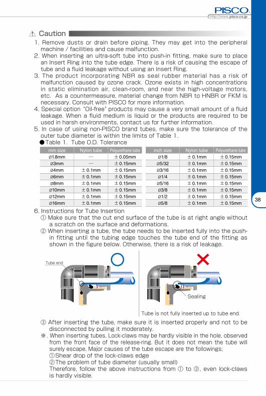
●Table 1. Tube O.D. Tolerancemm size Nylon tube Polyurethane tube inch size Nylon tube Polyurethane tubeø1.8mm ─ ±0.05mm ø1/8 ±0.1mm ±0.15mmø3mm ─ ±0.15mm ø5/32 ±0.1mm ±0.15mmø4mm ±0.1mm ±0.15mm ø3/16 ±0.1mm ±0.15mmø6mm ±0.1mm ±0.15mm ø1/4 ±0.1mm ±0.15mmø8mm ±0.1mm ±0.15mm ø5/16 ±0.1mm ±0.15mmø10mm ±0.1mm ±0.15mm ø3/8 ±0.1mm ±0.15mmø12mm ±0.1mm ±0.15mm ø1/2 ±0.1mm ±0.15mmø16mm ±0.1mm ±0.15mm ø5/8 ±0.1mm ±0.15mm
6. Instructions for Tube Insertion① Make sure that the cut end surface of the tube is at right angle without
a scratch on the surface and deformations.② When inserting a tube, the tube needs to be inserted fully into the push-
in fitting until the tubing edge touches the tube end of the fitting as shown in the figure below. Otherwise, there is a risk of leakage.
Tube end
Sealing
Tube is not fully inserted up to tube end.
③ After inserting the tube, make sure it is inserted properly and not to be disconnected by pulling it moderately.
※. When inserting tubes, Lock-claws may be hardly visible in the hole, observed from the front face of the release-ring. But it does not mean the tube will surely escape. Major causes of the tube escape are the followings; ①Shear drop of the lock-claws edge②The problem of tube diameter (usually small)Therefore, follow the above instructions from ① to ③, even lock-claws is hardly visible.
39
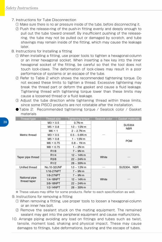
7. Instructions for Tube Disconnection① Make sure there is no air pressure inside of the tube, before disconnecting it.② Push the release-ring of the push-in fitting evenly and deeply enough to
pull out the tube toward oneself. By insufficient pushing of the release-ring, the tube may not be pulled out or damaged by scratch, and tube shavings may remain inside of the fitting, which may cause the leakage later.
8. Instructions for Installing a fitting① When installing a fitting, use proper tools to tighten a hexagonal-column
or an inner hexagonal socket. When inserting a hex key into the inner hexagonal socket of the fitting, be careful so that the tool does not touch lock-claws. The deformation of lock-claws may result in a poor performance of systems or an escape of the tube.
② Refer to Table 2 which shows the recommended tightening torque. Do not exceed these limits to tighten a thread. Excessive tightening may break the thread part or deform the gasket and cause a fluid leakage. Tightening thread with tightening torque lower than these limits may cause a loosened thread or a fluid leakage.
③ Adjust the tube direction while tightening thread within these limits, since some PISCO products are not rotatable after the installation.
●Table 2: Recommended tightening torque / Sealock color / Gasket materialsThread type Thread size Tightening torque Sealock color Gasket materials
Metric thread
M3×0.5 0.7N·m
─
SUS304NBR
M5×0.8 1.0 ~ 1.5N·mM6×1 2 ~ 2.7N·m
M3×0.5 0.5 ~ 0.6N·m
POMM5×0.8 1 ~ 1.5N·mM6×0.75 0.8 ~ 1N·mM8×0.75 1 ~ 2N·m
Taper pipe thread
R1/8 7 ~ 9N·m
White ─R1/4 12 ~ 14N·mR3/8 22 ~ 24N·mR1/2 28 ~ 30N·m
Unified thread No.10-32UNF 1.0 ~ 1.5N·m ─ SUS304、NBR
National pipe thread taper
1/16-27NPT 7 ~ 9N·m
White ─1/8-27NPT 7 ~ 9N·m1/4-18NPT 12 ~ 14N·m3/8-18NPT 22 ~ 24N·m1/2-14NPT 28 ~ 30N·m
※ These values may differ for some products. Refer to each specification as well.9. Instructions for removing a fitting
① When removing a fitting, use proper tools to loosen a hexagonal-column or an inner hex bolt.
② Remove the sealant stuck on the mating equipment. The remained sealant may get into the peripheral equipment and cause malfunctions.
10. Arrange piping avoiding any load on fittings and tubes such as twist, tensile, moment load, shaking and physical impact. These may cause damages to fittings, tube deformations, bursting and the escape of tubes.
Safety Instructions
Vacuum Generator SeriesVacuum Generator
47
VAC
UU
M
GEN
ERA
TOR
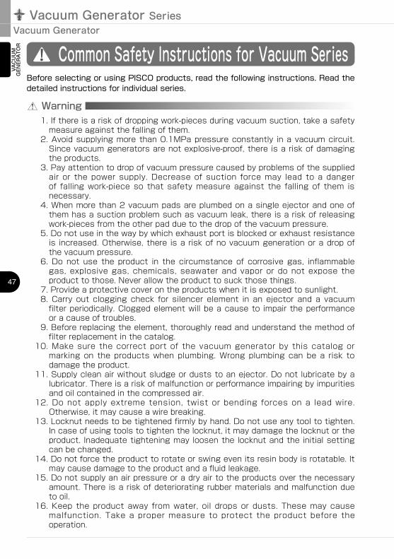
Common Safety Instructions for Vacuum Series
Warning
Before selecting or using PISCO products, read the following instructions. Read the detailed instructions for individual series.
1. If there is a risk of dropping work-pieces during vacuum suction, take a safety measure against the falling of them.
2. Avoid supplying more than 0.1MPa pressure constantly in a vacuum circuit. Since vacuum generators are not explosive-proof, there is a risk of damaging the products.
3. Pay attention to drop of vacuum pressure caused by problems of the supplied air or the power supply. Decrease of suction force may lead to a danger of falling work-piece so that safety measure against the falling of them is necessary.
4. When more than 2 vacuum pads are plumbed on a single ejector and one of them has a suction problem such as vacuum leak, there is a risk of releasing work-pieces from the other pad due to the drop of the vacuum pressure.
5. Do not use in the way by which exhaust port is blocked or exhaust resistance is increased. Otherwise, there is a risk of no vacuum generation or a drop of the vacuum pressure.
6. Do not use the product in the circumstance of corrosive gas, inflammable gas, explosive gas, chemicals, seawater and vapor or do not expose the product to those. Never allow the product to suck those things.
7. Provide a protective cover on the products when it is exposed to sunlight.8. Carry out clogging check for silencer element in an ejector and a vacuum
filter periodically. Clogged element will be a cause to impair the performance or a cause of troubles.
9. Before replacing the element, thoroughly read and understand the method of filter replacement in the catalog.
10. Make sure the correct port of the vacuum generator by this catalog or marking on the products when plumbing. Wrong plumbing can be a risk to damage the product.
11. Supply clean air without sludge or dusts to an ejector. Do not lubricate by a lubricator. There is a risk of malfunction or performance impairing by impurities and oil contained in the compressed air.
12. Do not apply extreme tension, twist or bending forces on a lead wire. Otherwise, it may cause a wire breaking.
13. Locknut needs to be tightened firmly by hand. Do not use any tool to tighten. In case of using tools to tighten the locknut, it may damage the locknut or the product. Inadequate tightening may loosen the locknut and the initial setting can be changed.
14. Do not force the product to rotate or swing even its resin body is rotatable. It may cause damage to the product and a fluid leakage.
15. Do not supply an air pressure or a dry air to the products over the necessary amount. There is a risk of deteriorating rubber materials and malfunction due to oil.
16. Keep the product away from water, oil drops or dusts. These may cause malfunction. Take a proper measure to protect the product before the operation.
Chemical NameThinner
Carbon tetrachlorideChloroform
AcetateAniline
CyclohexaneTrichloroethylene
Sulfuric acidLactic acid
Water soluble cutting oil (alkaline)
* There are more chemicals which should be avoided. Contact us for the use under chemical circumstance.
48
VN
VZ
VQ
VX
VJ
VK
VG
VM · VC
VB
VU
VH · VS
VY
VUM
VRL
VAC
UU
M
GEN
ERA
TOR
EXTERNAL VACUUM CONTROLLER
VAC
UU
MPA
DVACUUM
ACCESSORIES
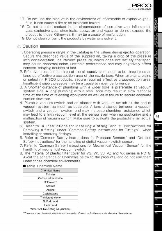
Caution1. Operating pressure range in the catalog is the values during ejector operation.
Secure the described value of the supplied air, taking a drop of the pressure into consideration. Insufficient pressure, which does not satisfy the spec, may cause abnormal noise, unstable performance and may negatively affect sensors, bringing troubles at last.
2. Effective cross-section area of the air supply side needs to be three times as large as effective cross-section area of the nozzle bore. When arranging piping or selecting PISCO products, secure required effective cross-section area. Insufficient supply pressure may be a cause to impair performance.
3. A Shorter distance of plumbing with a wider bore is preferable at vacuum system side. A long plumbing with a small bore may result in slow response time at the time of releasing work-piece as well as in failure to secure adequate suction flow rate.
4. Plumb a vacuum switch and an ejector with vacuum switch at the end of vacuum system as much as possible. A long distance between a vacuum switch and a vacuum system end may increase plumbing resistance which may lead to a high vacuum level at the sensor even when no suctioning and a malfunction of vacuum switch. Make sure to evaluate the products in an actual system.
5. Refer to “4. Instructions for Installing a fitting” and “5. Instructions for Removing a fitting” under “Common Safety Instructions for Fittings” , when installing or removing Fittings.
6. Refer to “Common Safety Instructions for Pressure Sensors” and “Detailed Safety Instructions” for the handling of digital vacuum switch sensor.
7. Refer to “Common Safety Instructions for Mechanical Vacuum Sensor” for the handling of mechanical vacuum switch.
8. The material of plastic filter cover for VG, VK, VJ, VZ and VX series is PCTG. Avoid the adherence of Chemicals below to the products, and do not use them under those chemical environments.
●Table Chemical Name
17. Do not use the product in the environment of inflammable or explosive gas / fluid. It can cause a fire or an explosion hazard.
18. Do not use the product in the circumstance of corrosive gas, inflammable gas, explosive gas, chemicals, seawater and vapor or do not expose the product to those. Otherwise, it may be a cause of malfunction.
19. Do not clean or paint the products by water or a solvent.
Chemical NameMethanolEthanol
Nitric acidSulfuric acid
Hydrochloric acidLactic acidAcetone
ChloroformAniline
TrichloroethyleneHydrogen peroxide
Vacuum Generator SeriesVacuum Generator
49
VAC
UU
M
GEN
ERA
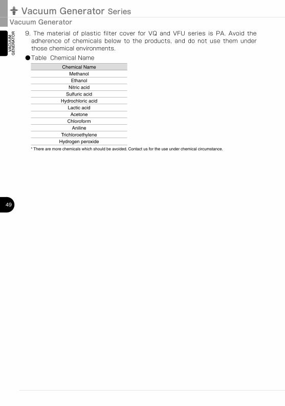
TOR 9. The material of plastic filter cover for VQ and VFU series is PA. Avoid the
adherence of chemicals below to the products, and do not use them under those chemical environments.
●Table Chemical Name
* There are more chemicals which should be avoided. Contact us for the use under chemical circumstance.
Related Documents