1241 Bundy Boulevard., Winona, Minnesota USA 55987 Phone: +1 (507) 454-5300, Fax: +1 (507) 452-4507 http://www.watlow.com User’s Guide 60A to 210A Power Controller 1917-1409 Rev D March 2019 Registered Company Winona, Minnesota USA ISO 9001

Welcome message from author
This document is posted to help you gain knowledge. Please leave a comment to let me know what you think about it! Share it to your friends and learn new things together.
Transcript
1241 Bundy Boulevard., Winona, Minnesota USA 55987Phone: +1 (507) 454-5300, Fax: +1 (507) 452-4507
http://www.watlow.com
User’s Guide60A to 210A Power Controller
1917-1409 Rev D
March 2019
Registered Company Winona, Minnesota USA
ISO 9001
Watlow - ASPYRE 60A to 210A Power Contro l ler • 2 •
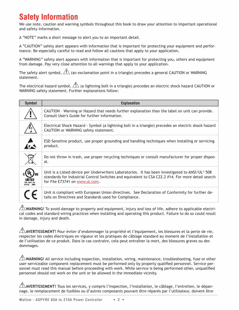
Safety InformationWe use note, caution and warning symbols throughout this book to draw your attention to important operational and safety information.
A “NOTE” marks a short message to alert you to an important detail.
A “CAUTION” safety alert appears with information that is important for protecting your equipment and perfor-mance. Be especially careful to read and follow all cautions that apply to your application.
A “WARNING” safety alert appears with information that is important for protecting you, others and equipment from damage. Pay very close attention to all warnings that apply to your application.
The safety alert symbol, (an exclamation point in a triangle) precedes a general CAUTION or WARNING statement.
The electrical hazard symbol, (a lightning bolt in a triangle) precedes an electric shock hazard CAUTION or WARNING safety statement. Further explanations follow:
Symbol Explanation
CAUTION – Warning or Hazard that needs further explanation than the label on unit can provide. Consult User's Guide for further information.
Electrical Shock Hazard - Symbol (a lightning bolt in a triangle) precedes an electric shock hazard CAUTION or WARNING safety statement.
ESD Sensitive product, use proper grounding and handling techniques when installing or servicing product.
Do not throw in trash, use proper recycling techniques or consult manufacturer for proper dispos-al.
Unit is a Listed device per Underwriters Laboratories. It has been investigated to ANSI/UL® 508 standards for Industrial Control Switches and equivalent to CSA C22.2 #14. For more detail search for File E73741 on www.ul.com.
Unit is compliant with European Union directives. See Declaration of Conformity for further de-tails on Directives and Standards used for Compliance.
WARNING! To avoid damage to property and equipment, injury and loss of life, adhere to applicable electri-cal codes and standard wiring practices when installing and operating this product. Failure to do so could result in damage, injury and death.
AVERTISSEMENT! Pour éviter d’endommager la propriété et l’équipement, les blessures et la perte de vie, respecter les codes électriques en vigueur et les pratiques de câblage standard au moment de l’installation et de l’utilisation de ce produit. Dans le cas contraire, cela peut entraîner la mort, des blessures graves ou des dommages.
WARNING! All service including inspection, installation, wiring, maintenance, troubleshooting, fuse or other user-serviceable component replacement must be performed only by properly qualified personnel. Service per-sonnel must read this manual before proceeding with work. While service is being performed other, unqualified personnel should not work on the unit or be allowed in the immediate vicinity.
AVERTISSEMENT! Tous les services, y compris l’inspection, l’installation, le câblage, l’entretien, le dépan-nage, le remplacement de fusibles ou d’autres composants pouvant être réparés par l’utilisateur, doivent être
Watlow - ASPYRE 60A to 210A Power Contro l ler • 3 •
effectués uniquement par un personnel dûment qualifié. Le personnel de service doit lire ce manuel avant d’ef-fectuer tout travail. Pendant que l’entretien est exécuté, tout personnel non qualifié ne doit effectuer de travail sur l’appareil ni se trouver à proximité.
WARNING! When in use the power controller is connected to dangerous voltages. Do not remove the protec-tive covers without first disconnecting and preventing power from being restored while servicing the unit.
AVERTISSEMENT! Au moment de l’utilisation, le régulateur de puissance est connecté à des tensions dan-gereuses. Ne retirer aucun couvercle de protection sans d’abord débrancher l’appareil et ainsi empêcher l’ali-mentation d’être rétablie pendant l’entretien.
WARNING! Do not use in aerospace or nuclear applications.
AVERTISSEMENT! Ne pas utiliser pour les applications aérospatiales ou nucléaires.
WARNING! The power controller’s protection rating is IP20 with all covers installed and closed. It must be installed in an enclosure that provides all the necessary additional protections appropriate for the environment and application.
AVERTISSEMENT! L’indice de protection du régulateur de puissance est de IP20 lorsque les couvercles sont installés et fermés. L’appareil doit être installé dans une enceinte qui assure toute la protection supplémentaire nécessaire pour l’environnement et l’application.
WARNING! Ground the power controller via the provided protective earth grounding terminal. Verify ground is within impedance specifications. This should be verified periodically.
AVERTISSEMENT! Mise à la terre du régulateur de puissance par le biais de la borne de prise de terre de protection fournie. Vérifier que la prise de terre est conforme aux spécifications de l’impédance. Cela doit être vérifié périodiquement.
WARNING! Electric Shock Hazard: when the power controller has been energized, after shutting off the pow-er, wait at least one minute for internal capacitors to discharge before commencing work that brings you in to contact with power connections or internal components.
AVERTISSEMENT! Risque de décharges électriques : lorsque le régulateur de puissance est mis sous tension, après avoir été éteint, attendre au moins une minute pour que les condensateurs internes se déchargent avant de commencer tout travail incluant le contact avec les connexions électriques ou les composants internes.
WARNING! The installation must be protected by electromagnetic circuit breakers or by fuses. The semicon-ductor fuses located inside the power controller are classified for UL® as supplementary protection for semicon-ductor devices. They are not approved for branch circuit protection.
AVERTISSEMENT! L’installation doit être protégée par des disjoncteurs électromagnétiques ou des fusibles. Les fusibles pour semi-conducteurs situés à l’intérieur du régulateur de puissance sont classés UL® comme pro-tection supplémentaire pour les dispositifs pour semi-conducteurs. Ils ne sont pas approuvés pour la protection des circuits de dérivation.
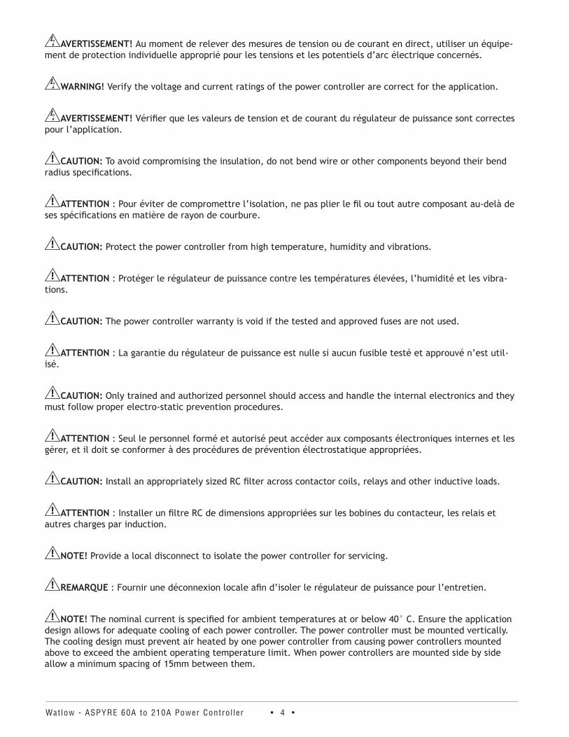
WARNING! When making live voltage or current measurements, use proper personal protective equipment for the voltages and arc-flash potentials involved.
Watlow - ASPYRE 60A to 210A Power Contro l ler • 4 •
AVERTISSEMENT! Au moment de relever des mesures de tension ou de courant en direct, utiliser un équipe-ment de protection individuelle approprié pour les tensions et les potentiels d’arc électrique concernés.
WARNING! Verify the voltage and current ratings of the power controller are correct for the application.
AVERTISSEMENT! Vérifier que les valeurs de tension et de courant du régulateur de puissance sont correctes pour l’application.
CAUTION: To avoid compromising the insulation, do not bend wire or other components beyond their bend radius specifications.
ATTENTION : Pour éviter de compromettre l’isolation, ne pas plier le fil ou tout autre composant au-delà de ses spécifications en matière de rayon de courbure.
CAUTION: Protect the power controller from high temperature, humidity and vibrations.
ATTENTION : Protéger le régulateur de puissance contre les températures élevées, l’humidité et les vibra-tions.
CAUTION: The power controller warranty is void if the tested and approved fuses are not used.
ATTENTION : La garantie du régulateur de puissance est nulle si aucun fusible testé et approuvé n’est util-isé.
CAUTION: Only trained and authorized personnel should access and handle the internal electronics and they must follow proper electro-static prevention procedures.
ATTENTION : Seul le personnel formé et autorisé peut accéder aux composants électroniques internes et les gérer, et il doit se conformer à des procédures de prévention électrostatique appropriées.
CAUTION: Install an appropriately sized RC filter across contactor coils, relays and other inductive loads.
ATTENTION : Installer un filtre RC de dimensions appropriées sur les bobines du contacteur, les relais et autres charges par induction.
NOTE! Provide a local disconnect to isolate the power controller for servicing.
REMARQUE : Fournir une déconnexion locale afin d’isoler le régulateur de puissance pour l’entretien.
NOTE! The nominal current is specified for ambient temperatures at or below 40° C. Ensure the application design allows for adequate cooling of each power controller. The power controller must be mounted vertically. The cooling design must prevent air heated by one power controller from causing power controllers mounted above to exceed the ambient operating temperature limit. When power controllers are mounted side by side allow a minimum spacing of 15mm between them.
Watlow - ASPYRE 60A to 210A Power Contro l ler • 5 •
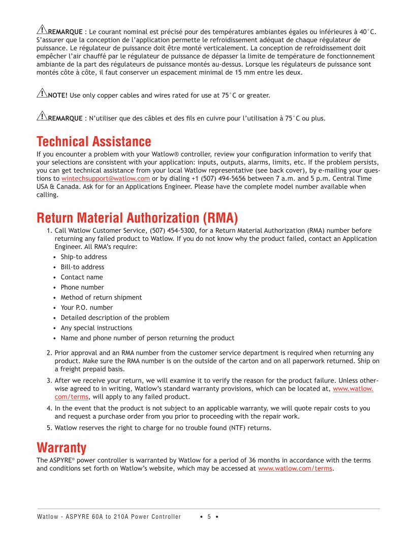
REMARQUE : Le courant nominal est précisé pour des températures ambiantes égales ou inférieures à 40°C. S’assurer que la conception de l’application permette le refroidissement adéquat de chaque régulateur de puissance. Le régulateur de puissance doit être monté verticalement. La conception de refroidissement doit empêcher l’air chauffé par le régulateur de puissance de dépasser la limite de température de fonctionnement ambiante de la part des régulateurs de puissance montés au-dessus. Lorsque les régulateurs de puissance sont montés côte à côte, il faut conserver un espacement minimal de 15 mm entre les deux.
NOTE! Use only copper cables and wires rated for use at 75°C or greater.
REMARQUE : N’utiliser que des câbles et des fils en cuivre pour l’utilisation à 75°C ou plus.
Technical AssistanceIf you encounter a problem with your Watlow® controller, review your configuration information to verify that your selections are consistent with your application: inputs, outputs, alarms, limits, etc. If the problem persists, you can get technical assistance from your local Watlow representative (see back cover), by e-mailing your ques-tions to [email protected] or by dialing +1 (507) 494-5656 between 7 a.m. and 5 p.m. Central Time USA & Canada. Ask for for an Applications Engineer. Please have the complete model number available when calling.
Return Material Authorization (RMA) 1. Call Watlow Customer Service, (507) 454-5300, for a Return Material Authorization (RMA) number before
returning any failed product to Watlow. If you do not know why the product failed, contact an Application Engineer. All RMA’s require:• Ship-to address• Bill-to address• Contact name• Phone number• Method of return shipment• Your P.O. number• Detailed description of the problem • Any special instructions• Name and phone number of person returning the product
2. Prior approval and an RMA number from the customer service department is required when returning any product. Make sure the RMA number is on the outside of the carton and on all paperwork returned. Ship on a freight prepaid basis.
3. After we receive your return, we will examine it to verify the reason for the product failure. Unless other-wise agreed to in writing, Watlow’s standard warranty provisions, which can be located at, www.watlow.com/terms, will apply to any failed product.
4. In the event that the product is not subject to an applicable warranty, we will quote repair costs to you and request a purchase order from you prior to proceeding with the repair work.
5. Watlow reserves the right to charge for no trouble found (NTF) returns.
WarrantyThe ASPYRE® power controller is warranted by Watlow for a period of 36 months in accordance with the terms and conditions set forth on Watlow’s website, which may be accessed at www.watlow.com/terms.

Watlow - ASPYRE 60A to 210A Power Contro l ler • 6 •
Document Number: 10-03359 Rev. D ©2019 Watlow Electric Manufacturing Company, all rights reserved. Watlow® and ASPYRE® are registered trademarks of Watlow Electric and Manufacturing Company. Cooper Bussman® is a registered trademark of Cooper Industries Inc. EtherNet/IP™ is a trademark of Open DeviceNet Vendors Association. Kanthal® is a registered trademark of Bulten-Kanthal Aktiebolag Joint Stock Company Windows® is a registered trademark of Microsoft Corporation. Modbus® is a registered trademark of Schneider Automation Incorporated. Siemens® is a registered trademark of Siemens Aktiengesellschaft Corporation. UL® is a registered trademarks of Underwriter’s Laboratories, Inc.
TC Contents
Watlow - ASPYRE 60A to 210A Power Contro l ler • 7 •
Safety Information . . . . . . . . . . . . . . . . . . . . . . . . . . . . . . . . . . . . . . . . . . . . . . . . . . . . . . 2Technical Assistance . . . . . . . . . . . . . . . . . . . . . . . . . . . . . . . . . . . . . . . . . . . . . . . . . . . . 5Return Material Authorization (RMA) . . . . . . . . . . . . . . . . . . . . . . . . . . . . . . . . . . . . . . . 5Warranty . . . . . . . . . . . . . . . . . . . . . . . . . . . . . . . . . . . . . . . . . . . . . . . . . . . . . . . . . . . . . . 5
Overview . . . . . . . . . . . . . . . . . . . . . . . . . . . . . . . . . . . . . . . . . . .11Recognizing Product Features . . . . . . . . . . . . . . . . . . . . . . . . . . . . . . . . . . . . . . . . . . . . 11Identifying the Product . . . . . . . . . . . . . . . . . . . . . . . . . . . . . . . . . . . . . . . . . . . . . . . . . . 11Product Selection . . . . . . . . . . . . . . . . . . . . . . . . . . . . . . . . . . . . . . . . . . . . . . . . . . . . . . 12Features and Benefits . . . . . . . . . . . . . . . . . . . . . . . . . . . . . . . . . . . . . . . . . . . . . . . . . . . 14Product Block Diagram . . . . . . . . . . . . . . . . . . . . . . . . . . . . . . . . . . . . . . . . . . . . . . . . . 15
Installation . . . . . . . . . . . . . . . . . . . . . . . . . . . . . . . . . . . . . . . . . .17Installing the ASPYRE Power Controller . . . . . . . . . . . . . . . . . . . . . . . . . . . . . . . . . . . . 17Environmental Conditions . . . . . . . . . . . . . . . . . . . . . . . . . . . . . . . . . . . . . . . . . . . . . . . 17Cooling Requirements . . . . . . . . . . . . . . . . . . . . . . . . . . . . . . . . . . . . . . . . . . . . . . . . . . 18Mounting Dimensions 480V and 600V . . . . . . . . . . . . . . . . . . . . . . . . . . . . . . . . . . . . . . 19Mounting Dimensions 690V . . . . . . . . . . . . . . . . . . . . . . . . . . . . . . . . . . . . . . . . . . . . . . 20
Wiring 480V and 600V Units . . . . . . . . . . . . . . . . . . . . . . . . . . . . . .21Wiring the ASPYRE Power Controller . . . . . . . . . . . . . . . . . . . . . . . . . . . . . . . . . . . . . . 21Good Wiring Practices . . . . . . . . . . . . . . . . . . . . . . . . . . . . . . . . . . . . . . . . . . . . . . . . . . 21Wiring Overview 480V and 600V Units . . . . . . . . . . . . . . . . . . . . . . . . . . . . . . . . . . . . . 22Wire Selection, Prep and Torque . . . . . . . . . . . . . . . . . . . . . . . . . . . . . . . . . . . . . . . . . . 23Terminal Strip Connections . . . . . . . . . . . . . . . . . . . . . . . . . . . . . . . . . . . . . . . . . . . . . . 24Connecting Control Signals . . . . . . . . . . . . . . . . . . . . . . . . . . . . . . . . . . . . . . . . . . . . . . 25Powering the Cooling Fans . . . . . . . . . . . . . . . . . . . . . . . . . . . . . . . . . . . . . . . . . . . . . . . 28Connecting the Auxiliary Power (DT1 and DT2 Only) . . . . . . . . . . . . . . . . . . . . . . . . . . . 28Opening The Covers . . . . . . . . . . . . . . . . . . . . . . . . . . . . . . . . . . . . . . . . . . . . . . . . . . . . 29Wiring the Line Power and Load . . . . . . . . . . . . . . . . . . . . . . . . . . . . . . . . . . . . . . . . . . 29
Wiring 690V Units . . . . . . . . . . . . . . . . . . . . . . . . . . . . . . . . . . . . .31Wiring the ASPYRE Power Controller . . . . . . . . . . . . . . . . . . . . . . . . . . . . . . . . . . . . . . 31Good Wiring Practices . . . . . . . . . . . . . . . . . . . . . . . . . . . . . . . . . . . . . . . . . . . . . . . . . . 31Wiring Overview 690V Units . . . . . . . . . . . . . . . . . . . . . . . . . . . . . . . . . . . . . . . . . . . . . 32Wire Selection, Prep and Torque . . . . . . . . . . . . . . . . . . . . . . . . . . . . . . . . . . . . . . . . . . 34Removing the Covers . . . . . . . . . . . . . . . . . . . . . . . . . . . . . . . . . . . . . . . . . . . . . . . . . . . 35Connecting Control Signals . . . . . . . . . . . . . . . . . . . . . . . . . . . . . . . . . . . . . . . . . . . . . . 35Powering the Cooling Fans . . . . . . . . . . . . . . . . . . . . . . . . . . . . . . . . . . . . . . . . . . . . . . . 39Connecting the Auxiliary Power . . . . . . . . . . . . . . . . . . . . . . . . . . . . . . . . . . . . . . . . . . . 40Wiring the Line Power and Load . . . . . . . . . . . . . . . . . . . . . . . . . . . . . . . . . . . . . . . . . . 40
Initial Setup . . . . . . . . . . . . . . . . . . . . . . . . . . . . . . . . . . . . . . . . .43Using the ASPYRE Configurator Software . . . . . . . . . . . . . . . . . . . . . . . . . . . . . . . . . . . 43Configuring the ASPYRE Power Controller . . . . . . . . . . . . . . . . . . . . . . . . . . . . . . . . . . 43
Watlow - ASPYRE 60A to 210A Power Contro l ler • 8 •
Operation . . . . . . . . . . . . . . . . . . . . . . . . . . . . . . . . . . . . . . . . . . .47Control Panel . . . . . . . . . . . . . . . . . . . . . . . . . . . . . . . . . . . . . . . . . . . . . . . . . . . . . . . . . 47Menu Navigation . . . . . . . . . . . . . . . . . . . . . . . . . . . . . . . . . . . . . . . . . . . . . . . . . . . . . . 48Indicators (LEDs) . . . . . . . . . . . . . . . . . . . . . . . . . . . . . . . . . . . . . . . . . . . . . . . . . . . . . . 49Alarms and Messages . . . . . . . . . . . . . . . . . . . . . . . . . . . . . . . . . . . . . . . . . . . . . . . . . . 50
Using ASPYRE Configurator . . . . . . . . . . . . . . . . . . . . . . . . . . . . . .51Overview . . . . . . . . . . . . . . . . . . . . . . . . . . . . . . . . . . . . . . . . . . . . . . . . . . . . . . . . . . . . 51How To . . . . . . . . . . . . . . . . . . . . . . . . . . . . . . . . . . . . . . . . . . . . . . . . . . . . . . . . . . . . . . 51Reference . . . . . . . . . . . . . . . . . . . . . . . . . . . . . . . . . . . . . . . . . . . . . . . . . . . . . . . . . . . . 56
Parameter Reference . . . . . . . . . . . . . . . . . . . . . . . . . . . . . . . . . . .65Alarm Function . . . . . . . . . . . . . . . . . . . . . . . . . . . . . . . . . . . . . . . . . . . . . . . . . . . . . . . . 65Analog In 1 [Signal Type] . . . . . . . . . . . . . . . . . . . . . . . . . . . . . . . . . . . . . . . . . . . . . . . . 65Analog In 1 [Value] . . . . . . . . . . . . . . . . . . . . . . . . . . . . . . . . . . . . . . . . . . . . . . . . . . . . 66Analog In 2 [Signal Type] . . . . . . . . . . . . . . . . . . . . . . . . . . . . . . . . . . . . . . . . . . . . . . . . 66Analog In 2 [Value] . . . . . . . . . . . . . . . . . . . . . . . . . . . . . . . . . . . . . . . . . . . . . . . . . . . . 66Analog In 2 Function . . . . . . . . . . . . . . . . . . . . . . . . . . . . . . . . . . . . . . . . . . . . . . . . . . . 66Aux Voltage . . . . . . . . . . . . . . . . . . . . . . . . . . . . . . . . . . . . . . . . . . . . . . . . . . . . . . . . . . 66Bakeout Current (Models with Current Limit) . . . . . . . . . . . . . . . . . . . . . . . . . . . . . . . . 66Bakeout Off Time (Models with Current Limit) . . . . . . . . . . . . . . . . . . . . . . . . . . . . . . . . 67Bakeout Ramp Time (Models with Current Limit) . . . . . . . . . . . . . . . . . . . . . . . . . . . . . 67Command Bits . . . . . . . . . . . . . . . . . . . . . . . . . . . . . . . . . . . . . . . . . . . . . . . . . . . . . . . . 67Cycle Time . . . . . . . . . . . . . . . . . . . . . . . . . . . . . . . . . . . . . . . . . . . . . . . . . . . . . . . . . . . 68Delay . . . . . . . . . . . . . . . . . . . . . . . . . . . . . . . . . . . . . . . . . . . . . . . . . . . . . . . . . . . . . . . 68Digital In 1 . . . . . . . . . . . . . . . . . . . . . . . . . . . . . . . . . . . . . . . . . . . . . . . . . . . . . . . . . . . 68Digital In 1 Function . . . . . . . . . . . . . . . . . . . . . . . . . . . . . . . . . . . . . . . . . . . . . . . . . . . . 68Digital In 2 . . . . . . . . . . . . . . . . . . . . . . . . . . . . . . . . . . . . . . . . . . . . . . . . . . . . . . . . . . . 69Digital In 2 Function . . . . . . . . . . . . . . . . . . . . . . . . . . . . . . . . . . . . . . . . . . . . . . . . . . . . 69Enable . . . . . . . . . . . . . . . . . . . . . . . . . . . . . . . . . . . . . . . . . . . . . . . . . . . . . . . . . . . . . . . 69Ethernet Address . . . . . . . . . . . . . . . . . . . . . . . . . . . . . . . . . . . . . . . . . . . . . . . . . . . . . . 69Ethernet Subnet . . . . . . . . . . . . . . . . . . . . . . . . . . . . . . . . . . . . . . . . . . . . . . . . . . . . . . . 70Ethernet Gateway . . . . . . . . . . . . . . . . . . . . . . . . . . . . . . . . . . . . . . . . . . . . . . . . . . . . . . 70Feedback . . . . . . . . . . . . . . . . . . . . . . . . . . . . . . . . . . . . . . . . . . . . . . . . . . . . . . . . . . . . 70Firing . . . . . . . . . . . . . . . . . . . . . . . . . . . . . . . . . . . . . . . . . . . . . . . . . . . . . . . . . . . . . . . 70Frequency . . . . . . . . . . . . . . . . . . . . . . . . . . . . . . . . . . . . . . . . . . . . . . . . . . . . . . . . . . . 71Half Cycles to Delay . . . . . . . . . . . . . . . . . . . . . . . . . . . . . . . . . . . . . . . . . . . . . . . . . . . . 71Heater Bakeout (Models with Current Limit) . . . . . . . . . . . . . . . . . . . . . . . . . . . . . . . . . 71HH:MM:SS . . . . . . . . . . . . . . . . . . . . . . . . . . . . . . . . . . . . . . . . . . . . . . . . . . . . . . . . . . . 71Host Name . . . . . . . . . . . . . . . . . . . . . . . . . . . . . . . . . . . . . . . . . . . . . . . . . . . . . . . . . . . 71Htr Break Delay . . . . . . . . . . . . . . . . . . . . . . . . . . . . . . . . . . . . . . . . . . . . . . . . . . . . . . . 71Htr Break Sensitivity . . . . . . . . . . . . . . . . . . . . . . . . . . . . . . . . . . . . . . . . . . . . . . . . . . . . 71I Limit (Models with Current Limit) . . . . . . . . . . . . . . . . . . . . . . . . . . . . . . . . . . . . . . . . 72I Limit Local / Remote (Models with Current Limit) . . . . . . . . . . . . . . . . . . . . . . . . . . . . 72I Output . . . . . . . . . . . . . . . . . . . . . . . . . . . . . . . . . . . . . . . . . . . . . . . . . . . . . . . . . . . . . 72Integral Current (Models with Current Limit) . . . . . . . . . . . . . . . . . . . . . . . . . . . . . . . . 72Integral Power . . . . . . . . . . . . . . . . . . . . . . . . . . . . . . . . . . . . . . . . . . . . . . . . . . . . . . . . 72kVA Real Time . . . . . . . . . . . . . . . . . . . . . . . . . . . . . . . . . . . . . . . . . . . . . . . . . . . . . . . . 72kW Real Time . . . . . . . . . . . . . . . . . . . . . . . . . . . . . . . . . . . . . . . . . . . . . . . . . . . . . . . . . 72
Watlow - ASPYRE 60A to 210A Power Contro l ler • 9 •
kW Total . . . . . . . . . . . . . . . . . . . . . . . . . . . . . . . . . . . . . . . . . . . . . . . . . . . . . . . . . . . . . 73Leg 1 I Output (DT2 and DT3 Models) . . . . . . . . . . . . . . . . . . . . . . . . . . . . . . . . . . . . . . 73Leg 2 I Output (DT2 and DT3 Models) . . . . . . . . . . . . . . . . . . . . . . . . . . . . . . . . . . . . . . 73Leg 3 I Output (DT2 and DT3 Models) . . . . . . . . . . . . . . . . . . . . . . . . . . . . . . . . . . . . . . 73Limit Peak Current (Models with Current Limit) . . . . . . . . . . . . . . . . . . . . . . . . . . . . . . 73Load Ω . . . . . . . . . . . . . . . . . . . . . . . . . . . . . . . . . . . . . . . . . . . . . . . . . . . . . . . . . . . . . . 73Logging . . . . . . . . . . . . . . . . . . . . . . . . . . . . . . . . . . . . . . . . . . . . . . . . . . . . . . . . . . . . . 73Logging Interval . . . . . . . . . . . . . . . . . . . . . . . . . . . . . . . . . . . . . . . . . . . . . . . . . . . . . . . 74Max Current . . . . . . . . . . . . . . . . . . . . . . . . . . . . . . . . . . . . . . . . . . . . . . . . . . . . . . . . . 74Max Voltage . . . . . . . . . . . . . . . . . . . . . . . . . . . . . . . . . . . . . . . . . . . . . . . . . . . . . . . . . . 74Min Cycles . . . . . . . . . . . . . . . . . . . . . . . . . . . . . . . . . . . . . . . . . . . . . . . . . . . . . . . . . . . 74MM/DD/YY . . . . . . . . . . . . . . . . . . . . . . . . . . . . . . . . . . . . . . . . . . . . . . . . . . . . . . . . . . . 74Neutral Connected (DT2 and DT3 Models) . . . . . . . . . . . . . . . . . . . . . . . . . . . . . . . . . . . 74Nominal I . . . . . . . . . . . . . . . . . . . . . . . . . . . . . . . . . . . . . . . . . . . . . . . . . . . . . . . . . . . . 74Nominal V . . . . . . . . . . . . . . . . . . . . . . . . . . . . . . . . . . . . . . . . . . . . . . . . . . . . . . . . . . . . 75Out Scale . . . . . . . . . . . . . . . . . . . . . . . . . . . . . . . . . . . . . . . . . . . . . . . . . . . . . . . . . . . . 75Port 1 Address . . . . . . . . . . . . . . . . . . . . . . . . . . . . . . . . . . . . . . . . . . . . . . . . . . . . . . . . 75Port 1 Baud . . . . . . . . . . . . . . . . . . . . . . . . . . . . . . . . . . . . . . . . . . . . . . . . . . . . . . . . . . 75Port 2 . . . . . . . . . . . . . . . . . . . . . . . . . . . . . . . . . . . . . . . . . . . . . . . . . . . . . . . . . . . . . . . 75Port 2 Access . . . . . . . . . . . . . . . . . . . . . . . . . . . . . . . . . . . . . . . . . . . . . . . . . . . . . . . . . 76Port 2 Address . . . . . . . . . . . . . . . . . . . . . . . . . . . . . . . . . . . . . . . . . . . . . . . . . . . . . . . . 76Port 2 Baud . . . . . . . . . . . . . . . . . . . . . . . . . . . . . . . . . . . . . . . . . . . . . . . . . . . . . . . . . . 76Power . . . . . . . . . . . . . . . . . . . . . . . . . . . . . . . . . . . . . . . . . . . . . . . . . . . . . . . . . . . . . . 76Power Factor . . . . . . . . . . . . . . . . . . . . . . . . . . . . . . . . . . . . . . . . . . . . . . . . . . . . . . . . . 76Prop Band Current (Models with Current Limit) . . . . . . . . . . . . . . . . . . . . . . . . . . . . . . 76Prop Band Power . . . . . . . . . . . . . . . . . . . . . . . . . . . . . . . . . . . . . . . . . . . . . . . . . . . . . . 77Release . . . . . . . . . . . . . . . . . . . . . . . . . . . . . . . . . . . . . . . . . . . . . . . . . . . . . . . . . . . . . . 77Remote SP . . . . . . . . . . . . . . . . . . . . . . . . . . . . . . . . . . . . . . . . . . . . . . . . . . . . . . . . . . . 77Retransmit (Models with Retransmit) . . . . . . . . . . . . . . . . . . . . . . . . . . . . . . . . . . . . . . 77Retransmit Scale (Models with Retransmit) . . . . . . . . . . . . . . . . . . . . . . . . . . . . . . . . . . 78Retransmit Type (Models with Retransmit) . . . . . . . . . . . . . . . . . . . . . . . . . . . . . . . . . . 78Safety Ramp Duration . . . . . . . . . . . . . . . . . . . . . . . . . . . . . . . . . . . . . . . . . . . . . . . . . . 78Safety Ramp Off Time . . . . . . . . . . . . . . . . . . . . . . . . . . . . . . . . . . . . . . . . . . . . . . . . . . 78SCR Temperature . . . . . . . . . . . . . . . . . . . . . . . . . . . . . . . . . . . . . . . . . . . . . . . . . . . . . . 79Serial Number . . . . . . . . . . . . . . . . . . . . . . . . . . . . . . . . . . . . . . . . . . . . . . . . . . . . . . . . 79Set Point . . . . . . . . . . . . . . . . . . . . . . . . . . . . . . . . . . . . . . . . . . . . . . . . . . . . . . . . . . . . 79Set Point Source . . . . . . . . . . . . . . . . . . . . . . . . . . . . . . . . . . . . . . . . . . . . . . . . . . . . . . 79Soft Start . . . . . . . . . . . . . . . . . . . . . . . . . . . . . . . . . . . . . . . . . . . . . . . . . . . . . . . . . . . . 79Start Ramp . . . . . . . . . . . . . . . . . . . . . . . . . . . . . . . . . . . . . . . . . . . . . . . . . . . . . . . . . . . 79Startup Display . . . . . . . . . . . . . . . . . . . . . . . . . . . . . . . . . . . . . . . . . . . . . . . . . . . . . . . . 80Status Bits . . . . . . . . . . . . . . . . . . . . . . . . . . . . . . . . . . . . . . . . . . . . . . . . . . . . . . . . . . . 80Thermal Alarm Counter . . . . . . . . . . . . . . . . . . . . . . . . . . . . . . . . . . . . . . . . . . . . . . . . . 80Unit Type . . . . . . . . . . . . . . . . . . . . . . . . . . . . . . . . . . . . . . . . . . . . . . . . . . . . . . . . . . . . 80User Access Level . . . . . . . . . . . . . . . . . . . . . . . . . . . . . . . . . . . . . . . . . . . . . . . . . . . . . 81V Input . . . . . . . . . . . . . . . . . . . . . . . . . . . . . . . . . . . . . . . . . . . . . . . . . . . . . . . . . . . . . 81V Output . . . . . . . . . . . . . . . . . . . . . . . . . . . . . . . . . . . . . . . . . . . . . . . . . . . . . . . . . . . . . 81Version . . . . . . . . . . . . . . . . . . . . . . . . . . . . . . . . . . . . . . . . . . . . . . . . . . . . . . . . . . . . . . 81Watchdog . . . . . . . . . . . . . . . . . . . . . . . . . . . . . . . . . . . . . . . . . . . . . . . . . . . . . . . . . . . . 81
Watlow - ASPYRE 60A to 210A Power Contro l ler • 10 •
Watchdog Reset Time . . . . . . . . . . . . . . . . . . . . . . . . . . . . . . . . . . . . . . . . . . . . . . . . . . 81Wi-Fi . . . . . . . . . . . . . . . . . . . . . . . . . . . . . . . . . . . . . . . . . . . . . . . . . . . . . . . . . . . . . . . . 82Wi-Fi Address . . . . . . . . . . . . . . . . . . . . . . . . . . . . . . . . . . . . . . . . . . . . . . . . . . . . . . . . . 82
Features . . . . . . . . . . . . . . . . . . . . . . . . . . . . . . . . . . . . . . . . . . .83Closed Loop Control . . . . . . . . . . . . . . . . . . . . . . . . . . . . . . . . . . . . . . . . . . . . . . . . . . . . 83Feedback . . . . . . . . . . . . . . . . . . . . . . . . . . . . . . . . . . . . . . . . . . . . . . . . . . . . . . . . . . . . 84Current Limit . . . . . . . . . . . . . . . . . . . . . . . . . . . . . . . . . . . . . . . . . . . . . . . . . . . . . . . . . 86Configurable Inputs and Outputs . . . . . . . . . . . . . . . . . . . . . . . . . . . . . . . . . . . . . . . . . . 86Firing Types . . . . . . . . . . . . . . . . . . . . . . . . . . . . . . . . . . . . . . . . . . . . . . . . . . . . . . . . . . 88Soft Start . . . . . . . . . . . . . . . . . . . . . . . . . . . . . . . . . . . . . . . . . . . . . . . . . . . . . . . . . . . . 94Start Ramp (DT1 and DT3 Models) . . . . . . . . . . . . . . . . . . . . . . . . . . . . . . . . . . . . . . . . 94Safety Ramp (DT1 and DT3 Models) . . . . . . . . . . . . . . . . . . . . . . . . . . . . . . . . . . . . . . . 95Heater Bakeout Function (Models with Current Limit) . . . . . . . . . . . . . . . . . . . . . . . . . . 95Totalizer . . . . . . . . . . . . . . . . . . . . . . . . . . . . . . . . . . . . . . . . . . . . . . . . . . . . . . . . . . . . . 95Data Logging . . . . . . . . . . . . . . . . . . . . . . . . . . . . . . . . . . . . . . . . . . . . . . . . . . . . . . . . . 96
Maintenance & Troubleshooting . . . . . . . . . . . . . . . . . . . . . . . . . . .97Routine Maintenance . . . . . . . . . . . . . . . . . . . . . . . . . . . . . . . . . . . . . . . . . . . . . . . . . . . 97Alarms and Indicators . . . . . . . . . . . . . . . . . . . . . . . . . . . . . . . . . . . . . . . . . . . . . . . . . . 97Opening The Covers . . . . . . . . . . . . . . . . . . . . . . . . . . . . . . . . . . . . . . . . . . . . . . . . . . . . 99Replacement Fuses . . . . . . . . . . . . . . . . . . . . . . . . . . . . . . . . . . . . . . . . . . . . . . . . . . . 100Replacing the Battery . . . . . . . . . . . . . . . . . . . . . . . . . . . . . . . . . . . . . . . . . . . . . . . . . . 100Calibration Procedures . . . . . . . . . . . . . . . . . . . . . . . . . . . . . . . . . . . . . . . . . . . . . . . . . 101Updating the Firmware . . . . . . . . . . . . . . . . . . . . . . . . . . . . . . . . . . . . . . . . . . . . . . . . . 103Troubleshooting . . . . . . . . . . . . . . . . . . . . . . . . . . . . . . . . . . . . . . . . . . . . . . . . . . . . . . 104Troubleshooting Schematics . . . . . . . . . . . . . . . . . . . . . . . . . . . . . . . . . . . . . . . . . . . . 105
Communication . . . . . . . . . . . . . . . . . . . . . . . . . . . . . . . . . . . . . . 111Overview . . . . . . . . . . . . . . . . . . . . . . . . . . . . . . . . . . . . . . . . . . . . . . . . . . . . . . . . . . . 111Enabling the Secondary Port . . . . . . . . . . . . . . . . . . . . . . . . . . . . . . . . . . . . . . . . . . . . 112Ethernet Network Setup . . . . . . . . . . . . . . . . . . . . . . . . . . . . . . . . . . . . . . . . . . . . . . . . 112Modbus® TCP . . . . . . . . . . . . . . . . . . . . . . . . . . . . . . . . . . . . . . . . . . . . . . . . . . . . . . . . 113EtherNet/IP™ Setup . . . . . . . . . . . . . . . . . . . . . . . . . . . . . . . . . . . . . . . . . . . . . . . . . . . 113Profinet IO Setup . . . . . . . . . . . . . . . . . . . . . . . . . . . . . . . . . . . . . . . . . . . . . . . . . . . . . 116Profibus DP Setup . . . . . . . . . . . . . . . . . . . . . . . . . . . . . . . . . . . . . . . . . . . . . . . . . . . . 121Holding Registers . . . . . . . . . . . . . . . . . . . . . . . . . . . . . . . . . . . . . . . . . . . . . . . . . . . . . 127Input Registers . . . . . . . . . . . . . . . . . . . . . . . . . . . . . . . . . . . . . . . . . . . . . . . . . . . . . . . 128Modbus® RTU . . . . . . . . . . . . . . . . . . . . . . . . . . . . . . . . . . . . . . . . . . . . . . . . . . . . . . . 130Modbus® RTU Holding Registers . . . . . . . . . . . . . . . . . . . . . . . . . . . . . . . . . . . . . . . . . 131
Specifications . . . . . . . . . . . . . . . . . . . . . . . . . . . . . . . . . . . . . . . 135Declaration of Conformity . . . . . . . . . . . . . . . . . . . . . . . . . . . . . . . . . . . . . . . . . . . . . . 141
Watlow - ASPYRE 60A to 210A Power Contro l ler • 11 • Chapter 1 Overv iew
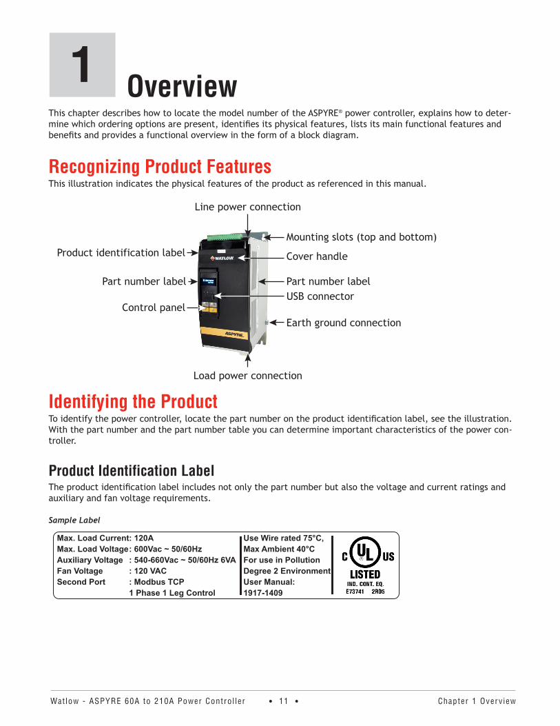
This chapter describes how to locate the model number of the ASPYRE® power controller, explains how to deter-mine which ordering options are present, identifies its physical features, lists its main functional features and benefits and provides a functional overview in the form of a block diagram.
Recognizing Product FeaturesThis illustration indicates the physical features of the product as referenced in this manual.
Mounting slots (top and bottom)
Line power connection
Product identification label
Load power connection
Earth ground connectionControl panel
Cover handle
Part number label Part number labelUSB connector
Identifying the ProductTo identify the power controller, locate the part number on the product identification label, see the illustration. With the part number and the part number table you can determine important characteristics of the power con-troller.
Product Identification LabelThe product identification label includes not only the part number but also the voltage and current ratings and auxiliary and fan voltage requirements.
Sample Label
Use Wire rated 75°C,Max Ambient 40°CFor use in PollutionDegree 2 EnvironmentUser Manual:1917-1409
Max. Load CurrentMax. Load VoltageAuxiliary VoltageFan VoltageSecond Port
: 120A: 600Vac ~ 50/60Hz: 540-660Vac ~ 50/60Hz 6VA: 120 VAC: Modbus TCP1 Phase 1 Leg Control
Overview1
Watlow - ASPYRE 60A to 210A Power Contro l ler • 12 • Chapter 1 Overv iew
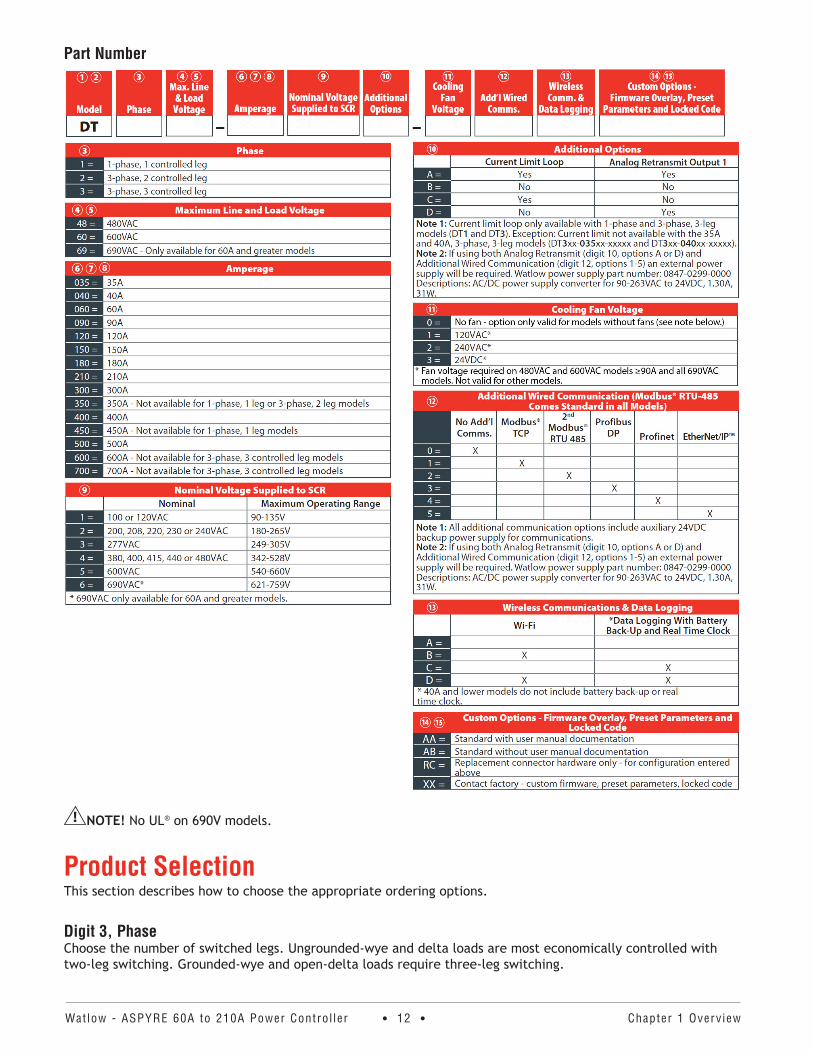
Part Number
NOTE! No UL® on 690V models.
Product SelectionThis section describes how to choose the appropriate ordering options.
Digit 3, PhaseChoose the number of switched legs. Ungrounded-wye and delta loads are most economically controlled with two-leg switching. Grounded-wye and open-delta loads require three-leg switching.
Watlow - ASPYRE 60A to 210A Power Contro l ler • 13 • Chapter 1 Overv iew
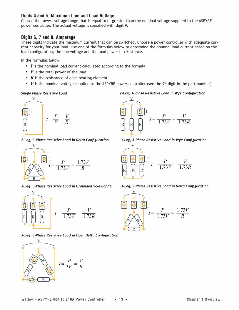
Digits 4 and 5, Maximum Line and Load VoltageChoose the lowest voltage range that is equal to or greater than the nominal voltage supplied to the ASPYRE power controller. The actual voltage is specified with digit 9.
Digits 6, 7 and 8, AmperageThese digits indicate the maximum current that can be switched. Choose a power controller with adequate cur-rent capacity for your load. Use one of the formulas below to determine the nominal load current based on the load configuration, the line voltage and the load power or resistance.
In the formulas below: • I is the nominal load current calculated according to the formula • P is the total power of the load• R is the resistance of each heating element• V is the nominal voltage supplied to the ASPYRE power controller (see the 9th digit in the part number)
Single Phase Resistive Load
V
R=I
PV = V
R
I
2-Leg, 3-Phase Resistive Load in Delta Configuration
R
RR
V
=IP
1.73V = R1.73VI
3-Leg, 3-Phase Resistive Load in Grounded Wye Config.
V
R R R=I
P1.73V = V
1.73R
I
3-Leg, 3-Phase Resistive Load in Open Delta Configuration
R
RI
R
V
=IP
3V = VR
2-Leg, 3-Phase Resistive Load in Wye ConfigurationV
R R R=I
P1.73V = V
1.73R
I
3-Leg, 3-Phase Resistive Load in Wye Configuration
I
V
R R R=I
P1.73V = V
1.73R
3-Leg, 3-Phase Resistive Load in Delta ConfigurationV
R
R R
=IP
1.73V = R1.73V
I
Watlow - ASPYRE 60A to 210A Power Contro l ler • 14 • Chapter 1 Overv iew
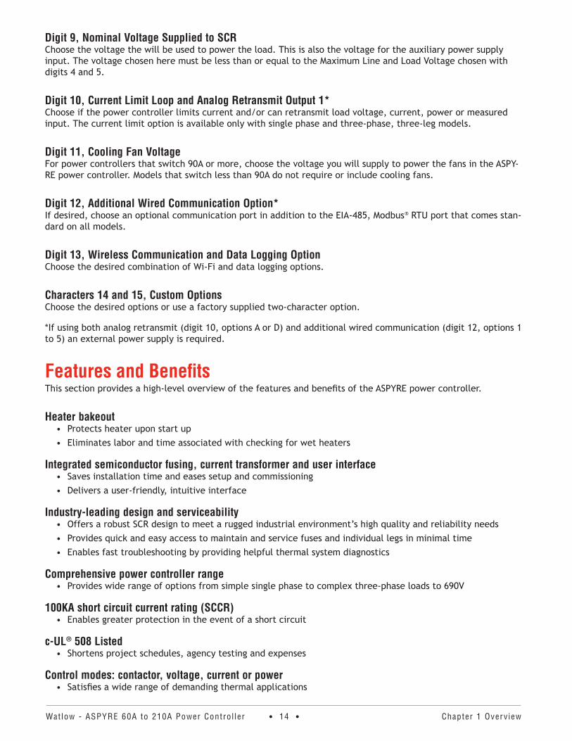
Digit 9, Nominal Voltage Supplied to SCRChoose the voltage the will be used to power the load. This is also the voltage for the auxiliary power supply input. The voltage chosen here must be less than or equal to the Maximum Line and Load Voltage chosen with digits 4 and 5.
Digit 10, Current Limit Loop and Analog Retransmit Output 1*Choose if the power controller limits current and/or can retransmit load voltage, current, power or measured input. The current limit option is available only with single phase and three-phase, three-leg models.
Digit 11, Cooling Fan VoltageFor power controllers that switch 90A or more, choose the voltage you will supply to power the fans in the ASPY-RE power controller. Models that switch less than 90A do not require or include cooling fans.
Digit 12, Additional Wired Communication Option*If desired, choose an optional communication port in addition to the EIA-485, Modbus® RTU port that comes stan-dard on all models.
Digit 13, Wireless Communication and Data Logging OptionChoose the desired combination of Wi-Fi and data logging options.
Characters 14 and 15, Custom OptionsChoose the desired options or use a factory supplied two-character option.
*If using both analog retransmit (digit 10, options A or D) and additional wired communication (digit 12, options 1 to 5) an external power supply is required.
Features and BenefitsThis section provides a high-level overview of the features and benefits of the ASPYRE power controller.
Heater bakeout• Protects heater upon start up• Eliminates labor and time associated with checking for wet heaters
Integrated semiconductor fusing, current transformer and user interface• Saves installation time and eases setup and commissioning• Delivers a user-friendly, intuitive interface
Industry-leading design and serviceability• Offers a robust SCR design to meet a rugged industrial environment’s high quality and reliability needs• Provides quick and easy access to maintain and service fuses and individual legs in minimal time• Enables fast troubleshooting by providing helpful thermal system diagnostics
Comprehensive power controller range• Provides wide range of options from simple single phase to complex three-phase loads to 690V
100KA short circuit current rating (SCCR)• Enables greater protection in the event of a short circuit
c-UL® 508 Listed• Shortens project schedules, agency testing and expenses
Control modes: contactor, voltage, current or power • Satisfies a wide range of demanding thermal applications
Watlow - ASPYRE 60A to 210A Power Contro l ler • 15 • Chapter 1 Overv iew
Load firing modes: zero-cross, burst fire, phase angle, soft start, half-cycle, single-cycle, delayed trig-gering
• Handles a wide range of load types including nichrome, medium and long waveform infrared lamps, moly, transformers, silicon carbide, UV lamps and tungsten
• Protects and extends the life of connected loads
Wide range of communication protocols• Enable factory and process automation with connectivity to process and equipment data via Modbus® RTU,
Modbus® TCP, EtherNet/IP™ , Wi-Fi, Profibus, Profinet, USB device (configuration and data file transfers)
Open heater and shorted SCR indication• Minimizes production downtime with easy to understand, intelligent, troubleshooting diagnostics
Integrated USB and user interface for configuration• Easily and safely program configuration settings as the user interface can be powered through USB connec-
tion• Eliminates need to work in a high voltage hazard environment. High voltage to the power controller and
system panel can be shut off and locked out for safety while configuring controller.
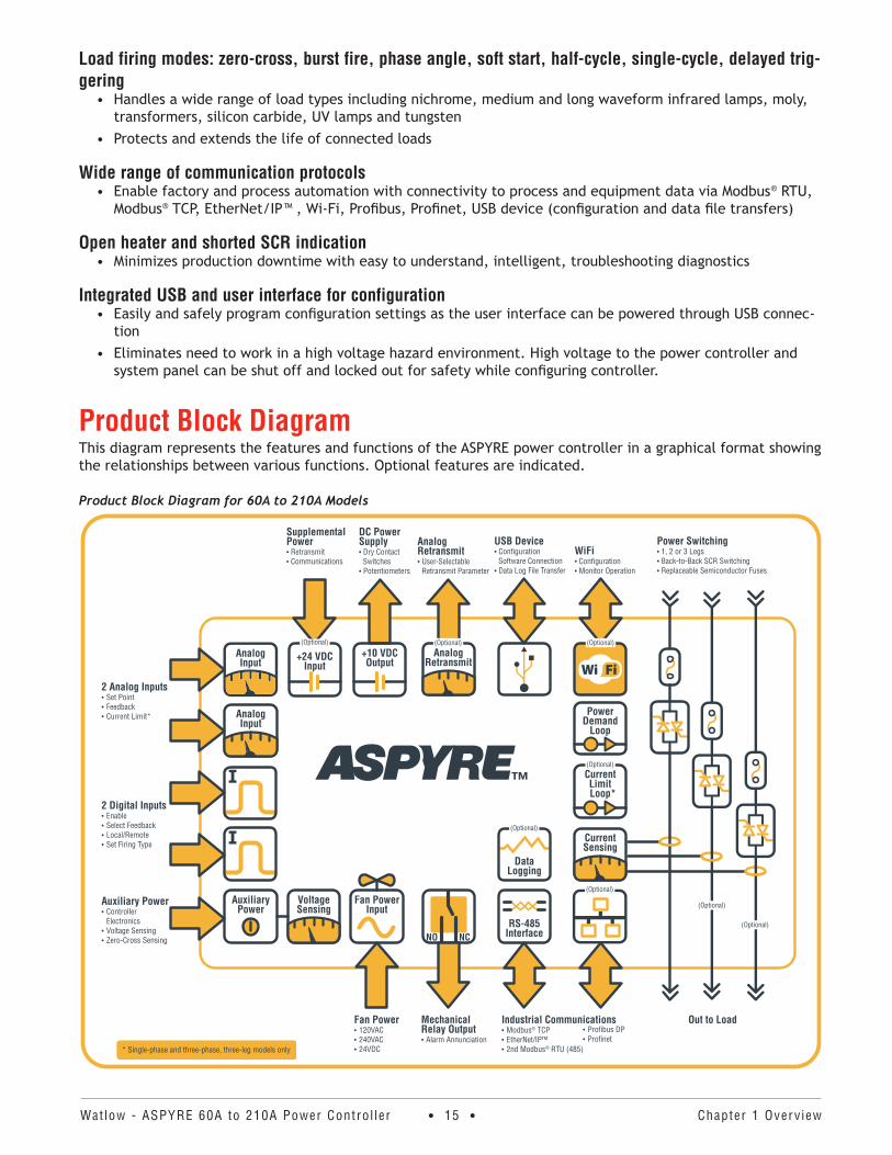
Product Block DiagramThis diagram represents the features and functions of the ASPYRE power controller in a graphical format showing the relationships between various functions. Optional features are indicated.
Product Block Diagram for 60A to 210A Models
VoltageSensing
Analog Input
USB Device• Configuration
Software Connection• Data Log File Transfer
AnalogRetransmit• User-Selectable Retransmit Parameter
DC Power Supply• Dry Contact
Switches• Potentiometers
WiFi• Configuration• Monitor Operation
2 Analog Inputs• Set Point• Feedback• Current Limit*
2 Digital Inputs• Enable• Select Feedback• Local/Remote• Set Firing Type
Auxiliary Power• Controller Electronics• Voltage Sensing• Zero-Cross Sensing
Mechanical Relay Output• Alarm Annunciation
Fan Power• 120VAC• 240VAC• 24VDC
Out to LoadIndustrial Communications• Modbus® TCP• EtherNet/IP™• 2nd Modbus® RTU (485)
Analog Input
DataLogging
RS-485InterfaceNCNO
Analog Retransmit
CurrentSensing
PowerDemand
Loop
(Optional)
(Optional)
(Optional)
• Profibus DP• Profinet
(Optional)
(Optional)
+10 VDCOutput
CurrentLimit
Loop*
Fan PowerInput
AuxiliaryPower
Supplemental Power• Retransmit• Communications
+24 VDCInput
* Single-phase and three-phase, three-leg models only
Power Switching• 1, 2 or 3 Legs• Back-to-Back SCR Switching• Replaceable Semiconductor Fuses
(Optional)
(Optional)
(Optional)

Watlow - ASPYRE 60A to 210A Power Contro l ler • 16 • Chapter 1 Overv iew
Wi-Fi Transmitter ModuleModels DT_ _ _-_ _ _ _-_ _ _[B or D]_ _ contain a Wi-Fi transmitter module. See the label on the module to determine which of the following modules is installed. The transmitter module is mounted on the top of the microprocessor board visible when the center cover is tipped forward.
Module FCC ID: 2ADUIESP-12-F WiFi module 802 .11b/g/n 2412-2462 MHzOutput power:
• 802.11b: 15.58 dBm (Max.)• 802.11g: 13.72 dBm (Max.)• 802.11n: 12.53 dBm (Max.)
Antenna gain: 1.0 dBi PCB antenna 11 channels.
Module FCC ID: 2AL3B-ESP-F 802 .11b/g/n 2412-2462 MHzOutput power:
• 802.11b: 14.0 dBm (Max.)• 802.11g: 12.8 dBm (Max.)• 802.11n: 13.6 dBm (Max.)
Antenna gain: 1.0 dBi PCB antenna 11 channels.
Unit is assembled from tested components, complete system not tested.
This equipment has been tested and found to comply with the limits for a Class B digital device, pursuant to Part 15 of the FCC Rules. These limits are designed to provide reasonable protection against harmful interference in a residential installation. This equipment generates, uses and can radiate radio frequency energy and, if not in-stalled and used in accordance with the instructions, may cause harmful interference to radio communications. However, there is no guarantee that interference will not occur in a particular installation.
If this equipment does cause harmful interference to radio or television reception, which can be determined by turning the equipment off and on, the user is encouraged to try to correct the interference by one or more of the following measures:
• Reorient or relocate the receiving antenna.• Increase the separation between the equipment and receiver.• Connect the equipment into an outlet on a circuit different from that to which the receiver is connected.• Consult the dealer or an experienced radio/TV technician for help.

Watlow - ASPYRE 60A to 210A Power Contro l ler • 17 • Chapter 2 Insta l la t ion
WARNING: To avoid damage to property and equipment, injury and loss of life, adhere to applicable electri-cal codes and standard wiring practices when installing and operating this product. Failure to do so could result in damage, injury and death.
AVERTISSEMENT! Pour éviter d’endommager la propriété et l’équipement, les blessures et la perte de vie, respecter les codes électriques en vigueur et les pratiques de câblage standard au moment de l’installation et de l’utilisation de ce produit. Dans le cas contraire, cela peut entraîner la mort, des blessures graves ou des dommages.
Installing the ASPYRE Power ControllerThis chapter provides the information necessary to select and prepare a location and to mount one or more ASPYRE power controllers.
Consider the spacing required for power, load, and control signal wiring before mounting the power controller. Take in to account the controller dimensions, wire bending radius, and cooling requirements. Use good wiring practices to minimize electrical noise problems.
Peripheral ComponentsAllow room for fuses and fuse holders for the auxiliary input power and fans (if present).
Mounting Orientation Mount power controllers vertically.
Bend RadiusAllow adequate space to route cables without requiring bending more than permitted for the type of cable.
Environmental ConditionsMount ASPYRE power controllers in a suitable electrical enclosure. Allow adequate wire bending space and cool-ing. The maximum ambient temperature in the enclosure must not exceed 104°F (40°C).
Ambient Temperature 32° to 104°F (0° to 40°C)
Storage Temperature -13° to 158°F (-25°to 70°C)
Installation Location Install away from direct sun light, conductive dust, corrosive gas, vibration, water and corrosive salts.
AltitudeUp to 6560 feet (2000m) above sea levelAt altitudes above 3280 feet (1000m) reduce the nominal current by 2% for each 328 feet (100m).
Humidity From 5 to 95% relative humidity, non-condensing and without ice
Pollution degree Installation Category III, Pollution degree 2
Installation2
Watlow - ASPYRE 60A to 210A Power Contro l ler • 18 • Chapter 2 Insta l la t ion
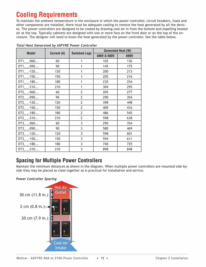
Cooling RequirementsTo maintain the ambient temperature in the enclosure in which the power controller, circuit breakers, fuses and other components are installed, there must be adequate cooling to remove the heat generated by all the devic-es. The power controllers are designed to be cooled by drawing cool air in from the bottom and expelling heated air at the top. Typically cabinets are designed with one or more fans on the front door or on the top of the en-closure. The designer will need to know the heat generated by the power controller. See the table below.
Total Heat Generated by ASPYRE Power Controller
Model Current (A) Switched LegsGenerated Heat (W)
480V & 600V 690VDT1_ _-060... 60 1 102 136
DT1_ _-090... 90 1 145 175
DT1_ _-120... 120 1 200 213
DT1_ _-150... 150 1 205 216
DT1_ _-180... 180 1 235 254
DT1_ _-210... 210 1 304 295
DT2_ _-060... 60 2 205 277
DT2_ _-090... 90 2 290 354
DT2_ _-120... 120 2 398 448
DT2_ _-150... 150 2 409 416
DT2_ _-180... 180 2 486 545
DT2_ _-210... 210 2 598 638
DT3_ _-060... 60 3 290 354
DT3_ _-090... 90 3 580 469
DT3_ _-120... 120 3 598 601
DT3_ _-150... 150 3 594 611
DT3_ _-180... 180 3 740 725
DT3_ _-210... 210 3 898 848
Spacing for Multiple Power ControllersMaintain the minimum distances as shown in the diagram. When multiple power controllers are mounted side-by-side they may be placed as close together as is practical for installation and service.
Power Controller Spacing
30 cm (11.8 in.)
20 cm (7.9 in.)
2 cm (0.8 in.)
Hot Air Outlet
Cool Air Intake
Watlow - ASPYRE 60A to 210A Power Contro l ler • 19 • Chapter 2 Insta l la t ion
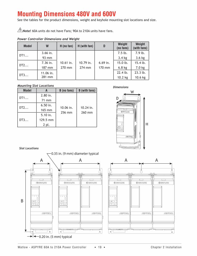
Mounting Dimensions 480V and 600VSee the tables for the product dimensions, weight and keyhole mounting slot locations and size.
Note! 60A units do not have Fans; 90A to 210A units have fans.
Power Controller Dimensions and Weight
Model W H (no fan) H (with fan) D Weight (no fans)
Weight (with fans)
DT1...3.66 in.93 mm
10.61 in.270 mm
10.79 in.274 mm
6.69 in.170 mm
7.5 lb.3.4 kg
7.9 lb.3.6 kg
DT2...7.36 in.187 mm
15.0 lb.6.8 kg
15.4 lb.7.0 kg
DT3... 11.06 in. 281 mm
22.4 lb.10.2 kg
23.3 lb.10.6 kg
Mounting Slot LocationsModel A B (no fans) B (with fans)
DT1...2.80 in.71 mm
10.06 in.256 mm
10.24 in.260 mm
DT2...6.50 in.165 mm
DT3...5.10 in.
129.5 mm2 pl.
Dimensions
D
H
W
Slot Locations
B
A
0.20 in. (5 mm) typical
0.35 in. (9 mm) diameter typical
A A A
Watlow - ASPYRE 60A to 210A Power Contro l ler • 20 • Chapter 2 Insta l la t ion
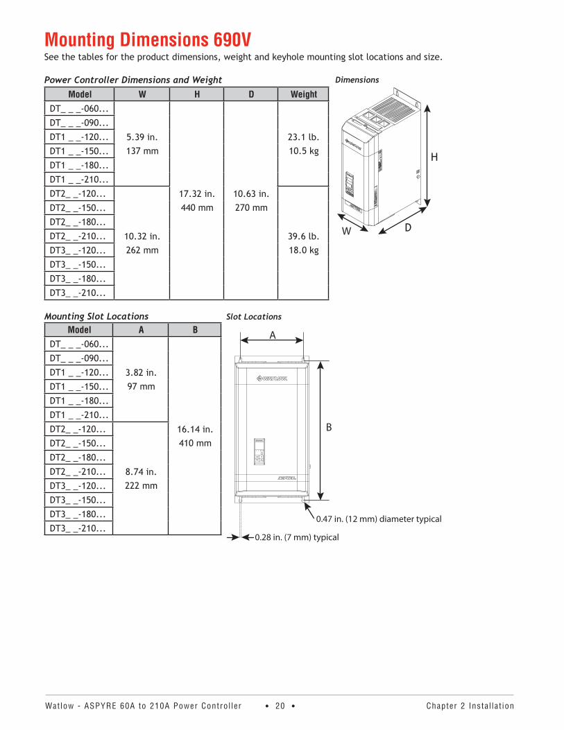
Mounting Dimensions 690VSee the tables for the product dimensions, weight and keyhole mounting slot locations and size.
Power Controller Dimensions and WeightModel W H D Weight
DT_ _ _-060...
5.39 in.137 mm
17.32 in.440 mm
10.63 in.270 mm
23.1 lb.10.5 kg
DT_ _ _-090...
DT1 _ _-120...
DT1 _ _-150...
DT1 _ _-180...
DT1 _ _-210...
DT2_ _-120...
10.32 in.262 mm
39.6 lb.18.0 kg
DT2_ _-150...
DT2_ _-180...
DT2_ _-210...
DT3_ _-120...
DT3_ _-150...
DT3_ _-180...
DT3_ _-210...
Mounting Slot LocationsModel A B
DT_ _ _-060...
3.82 in.97 mm
16.14 in.410 mm
DT_ _ _-090...
DT1 _ _-120...
DT1 _ _-150...
DT1 _ _-180...
DT1 _ _-210...
DT2_ _-120...
8.74 in.222 mm
DT2_ _-150...
DT2_ _-180...
DT2_ _-210...
DT3_ _-120...
DT3_ _-150...
DT3_ _-180...
DT3_ _-210...
Dimensions
D
H
W
Slot Locations
A
B
0.28 in. (7 mm) typical
0.47 in. (12 mm) diameter typical

Watlow - ASPYRE 60A to 210A Power Contro l ler • 21 • Chapter 3 Wir ing 480V and 600V Uni ts
WARNING: To avoid damage to property and equipment, injury and loss of life, adhere to applicable electri-cal codes and standard wiring practices when installing and operating this product. Failure to do so could result in damage, injury and death.
AVERTISSEMENT! Pour éviter d’endommager la propriété et l’équipement, les blessures et la perte de vie, respecter les codes électriques en vigueur et les pratiques de câblage standard au moment de l’installation et de l’utilisation de ce produit. Dans le cas contraire, cela peut entraîner la mort, des blessures graves ou des dommages.
WARNING: The installation must be protected by electromagnetic circuit breakers or by fuses. The semicon-ductor fuses located inside the power controller are classified for UL® as supplementary protection for semicon-ductor devices. They are not approved for branch circuit protection.
AVERTISSEMENT! L’installation doit être protégée par des disjoncteurs électromagnétiques ou des fusibles. Les fusibles pour semi-conducteurs situés à l’intérieur du régulateur de puissance sont classés UL® comme pro-tection supplémentaire pour les dispositifs pour semi-conducteurs. Ils ne sont pas approuvés pour la protection des circuits de dérivation.
Wiring the ASPYRE Power ControllerThis chapter describes how to select, prepare and attach power and signal wires to the power controller.
Good Wiring PracticesFollow good wiring practices to minimize the effects of interference from nearby equipment and the line power on the operation of the power controller:
• Install an appropriately sized RC filter across contactor coils, relays and other inductive loads• Use shielded twisted-pair cables for input, output and communication signals• Route control and signal cables away from motors and other sources of electromagnetic interference and
not parallel to power cables• Follow all local regulations applicable to electrical installations
NOTE: Use only copper cables and wires rated for use at 75°C or greater.
REMARQUE : N’utiliser que des câbles et des fils en cuivre pour l’utilisation à 75 °C ou plus.
Wiring 480V and 600V Units3
Watlow - ASPYRE 60A to 210A Power Contro l ler • 22 • Chapter 3 Wir ing 480V and 600V Uni ts
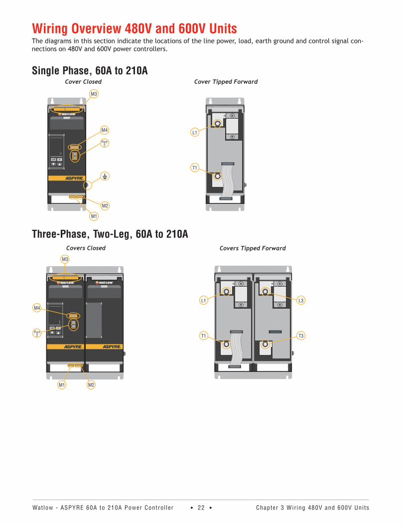
Wiring Overview 480V and 600V UnitsThe diagrams in this section indicate the locations of the line power, load, earth ground and control signal con-nections on 480V and 600V power controllers.
Single Phase, 60A to 210A
Three-Phase, Two-Leg, 60A to 210A
Cover Tipped Forward
T1
L1
Cover Closed
Port2
M4
M2
M1
M3
Covers Closed
Port2
M4
M2M1
M3
Covers Tipped Forward
L1
T1
L3
T3
Watlow - ASPYRE 60A to 210A Power Contro l ler • 23 • Chapter 3 Wir ing 480V and 600V Uni ts
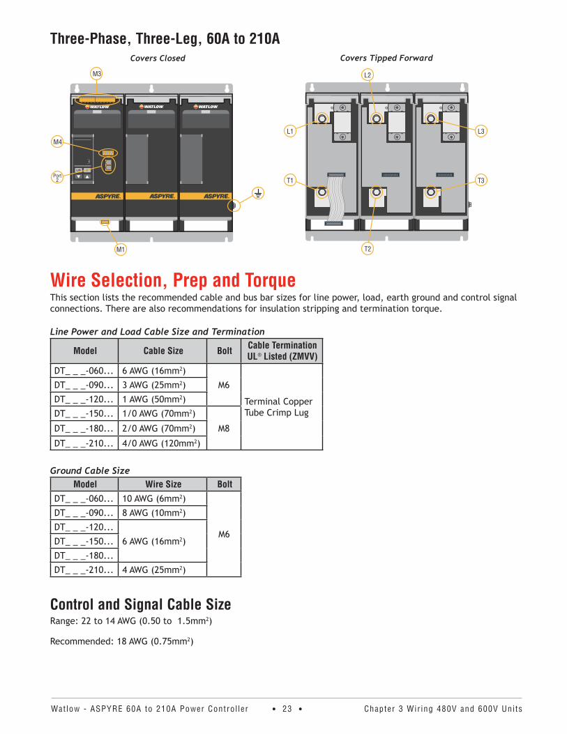
Three-Phase, Three-Leg, 60A to 210A
Wire Selection, Prep and TorqueThis section lists the recommended cable and bus bar sizes for line power, load, earth ground and control signal connections. There are also recommendations for insulation stripping and termination torque.
Line Power and Load Cable Size and Termination
Model Cable Size Bolt Cable Termination UL® Listed (ZMVV)
DT_ _ _-060... 6 AWG (16mm2)
M6
Terminal Copper Tube Crimp Lug
DT_ _ _-090... 3 AWG (25mm2)
DT_ _ _-120... 1 AWG (50mm2)
DT_ _ _-150... 1/0 AWG (70mm2)
M8DT_ _ _-180... 2/0 AWG (70mm2)
DT_ _ _-210... 4/0 AWG (120mm2)
Ground Cable SizeModel Wire Size Bolt
DT_ _ _-060... 10 AWG (6mm2)
M6
DT_ _ _-090... 8 AWG (10mm2)
DT_ _ _-120...
6 AWG (16mm2)DT_ _ _-150...
DT_ _ _-180...
DT_ _ _-210... 4 AWG (25mm2)
Control and Signal Cable SizeRange: 22 to 14 AWG (0.50 to 1.5mm2)
Recommended: 18 AWG (0.75mm2)
Covers Closed
Port2
M4
M1
M3
Covers Tipped Forward
L1
T1
L2
T2
L3
T3
Watlow - ASPYRE 60A to 210A Power Contro l ler • 24 • Chapter 3 Wir ing 480V and 600V Uni ts
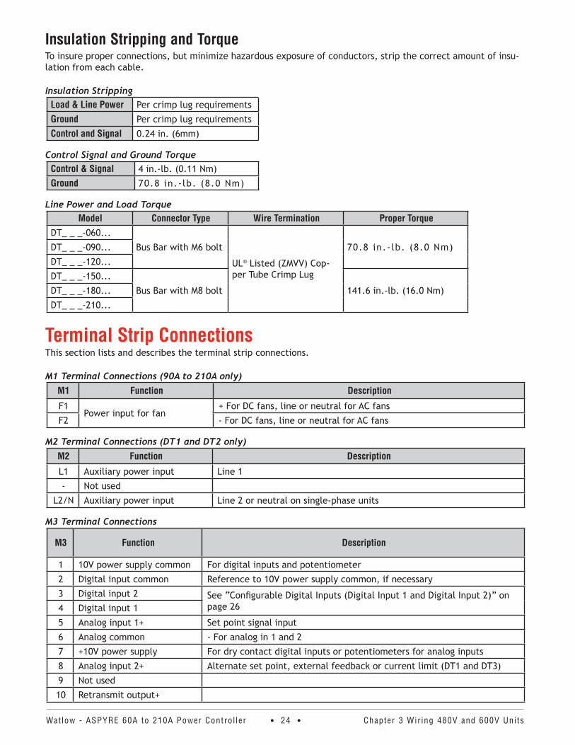
Insulation Stripping and TorqueTo insure proper connections, but minimize hazardous exposure of conductors, strip the correct amount of insu-lation from each cable.
Insulation StrippingLoad & Line Power Per crimp lug requirements
Ground Per crimp lug requirements
Control and Signal 0.24 in. (6mm)
Control Signal and Ground TorqueControl & Signal 4 in.-lb. (0.11 Nm)
Ground 70.8 in.-lb. (8.0 Nm)
Line Power and Load TorqueModel Connector Type Wire Termination Proper Torque
DT_ _ _-060...
Bus Bar with M6 bolt
UL® Listed (ZMVV) Cop-per Tube Crimp Lug
70.8 in.-lb. (8.0 Nm)DT_ _ _-090...
DT_ _ _-120...
DT_ _ _-150...
Bus Bar with M8 bolt 141.6 in.-lb. (16.0 Nm)DT_ _ _-180...
DT_ _ _-210...
Terminal Strip ConnectionsThis section lists and describes the terminal strip connections.
M1 Terminal Connections (90A to 210A only)M1 Function Description
F1Power input for fan
+ For DC fans, line or neutral for AC fans
F2 - For DC fans, line or neutral for AC fans
M2 Terminal Connections (DT1 and DT2 only)M2 Function Description
L1 Auxiliary power input Line 1
- Not used
L2/N Auxiliary power input Line 2 or neutral on single-phase units
M3 Terminal Connections
M3 Function Description
1 10V power supply common For digital inputs and potentiometer
2 Digital input common Reference to 10V power supply common, if necessary
3 Digital input 2 See “Configurable Digital Inputs (Digital Input 1 and Digital Input 2)” on page 264 Digital input 1
5 Analog input 1+ Set point signal input
6 Analog common - For analog in 1 and 2
7 +10V power supply For dry contact digital inputs or potentiometers for analog inputs
8 Analog input 2+ Alternate set point, external feedback or current limit (DT1 and DT3)
9 Not used
10 Retransmit output+
Watlow - ASPYRE 60A to 210A Power Contro l ler • 25 • Chapter 3 Wir ing 480V and 600V Uni ts
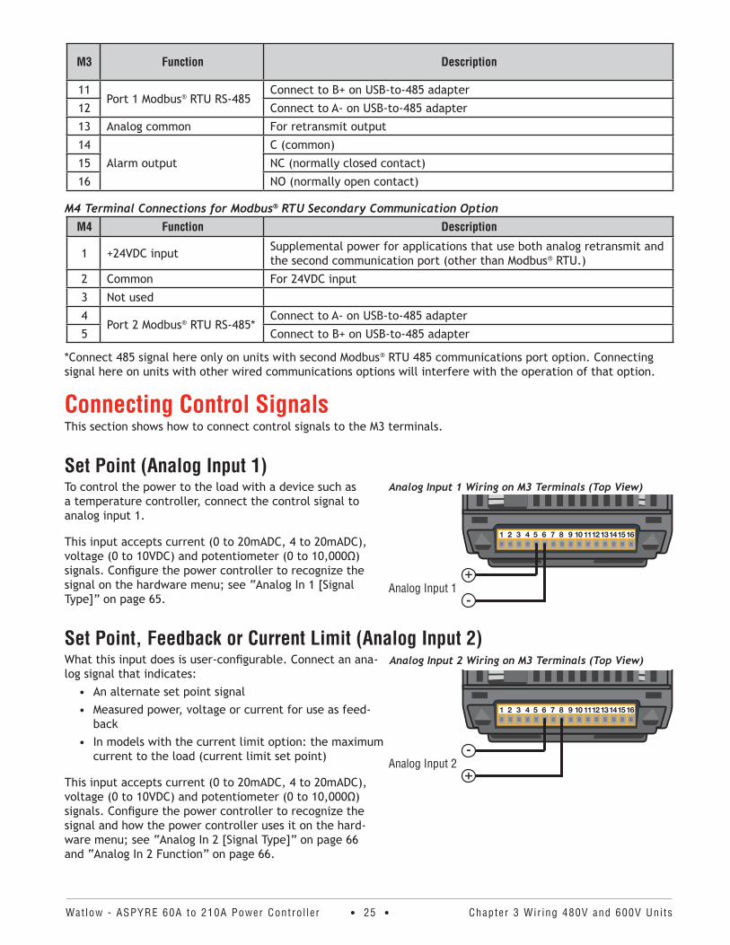
M3 Function Description
11Port 1 Modbus® RTU RS-485
Connect to B+ on USB-to-485 adapter
12 Connect to A- on USB-to-485 adapter
13 Analog common For retransmit output
14
Alarm output
C (common)
15 NC (normally closed contact)
16 NO (normally open contact)
M4 Terminal Connections for Modbus® RTU Secondary Communication OptionM4 Function Description
1 +24VDC input Supplemental power for applications that use both analog retransmit and the second communication port (other than Modbus® RTU.)
2 Common For 24VDC input
3 Not used
4Port 2 Modbus® RTU RS-485*
Connect to A- on USB-to-485 adapter
5 Connect to B+ on USB-to-485 adapter
*Connect 485 signal here only on units with second Modbus® RTU 485 communications port option. Connecting signal here on units with other wired communications options will interfere with the operation of that option.
Connecting Control SignalsThis section shows how to connect control signals to the M3 terminals.
Set Point (Analog Input 1)To control the power to the load with a device such as a temperature controller, connect the control signal to analog input 1.
This input accepts current (0 to 20mADC, 4 to 20mADC), voltage (0 to 10VDC) and potentiometer (0 to 10,000Ω) signals. Configure the power controller to recognize the signal on the hardware menu; see “Analog In 1 [Signal Type]” on page 65.
Set Point, Feedback or Current Limit (Analog Input 2)What this input does is user-configurable. Connect an ana-log signal that indicates:
• An alternate set point signal• Measured power, voltage or current for use as feed-
back• In models with the current limit option: the maximum
current to the load (current limit set point)
This input accepts current (0 to 20mADC, 4 to 20mADC), voltage (0 to 10VDC) and potentiometer (0 to 10,000Ω) signals. Configure the power controller to recognize the signal and how the power controller uses it on the hard-ware menu; see “Analog In 2 [Signal Type]” on page 66 and “Analog In 2 Function” on page 66.
Analog Input 1 Wiring on M3 Terminals (Top View)
Analog Input 1-+
Analog Input 2 Wiring on M3 Terminals (Top View)
Analog Input 2+-
Watlow - ASPYRE 60A to 210A Power Contro l ler • 26 • Chapter 3 Wir ing 480V and 600V Uni ts
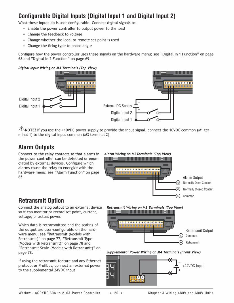
Configurable Digital Inputs (Digital Input 1 and Digital Input 2)What these inputs do is user-configurable. Connect digital signals to:
• Enable the power controller to output power to the load • Change the feedback to voltage• Change whether the local or remote set point is used• Change the firing type to phase angle
Configure how the power controller uses these signals on the hardware menu; see “Digital In 1 Function” on page 68 and “Digital In 2 Function” on page 69.
Digital Input Wiring on M3 Terminals (Top View)
Digital Input 1
Digital Input 2
NOTE! If you use the +10VDC power supply to provide the input signal, connect the 10VDC common (M1 ter-minal 1) to the digital input common (M3 terminal 2).
Alarm OutputsConnect to the relay contacts so that alarms in the power controller can be detected or enun-ciated by external devices. Configure which alarms cause the relay to energize with the hardware menu; see “Alarm Function” on page 65.
Retransmit OptionConnect the analog output to an external device so it can monitor or record set point, current, voltage, or actual power.
Which data is retransmitted and the scaling of the output are user-configurable on the hard-ware menu; see “Retransmit (Models with Retransmit)” on page 77, “Retransmit Type (Models with Retransmit)” on page 78 and “Retransmit Scale (Models with Retransmit)” on page 78.
If using the retransmit feature and any Ethernet protocol or Profibus, connect an external power to the supplemental 24VDC input.
Digital Input 1
Digital Input 2+
–External DC Supply
Alarm Wiring on M3Terminals (Top View)
NO
NC
C
Alarm OutputNormally Open Contact
Normally Closed Contact
Common
Retransmit Wiring on M3 Terminals (Top View)
C
Retransmit Output
+Common
Retransmit
Supplemental Power Wiring on M4 Terminals (Front View)
+
–+24VDC Input
12
Watlow - ASPYRE 60A to 210A Power Contro l ler • 27 • Chapter 3 Wir ing 480V and 600V Uni ts
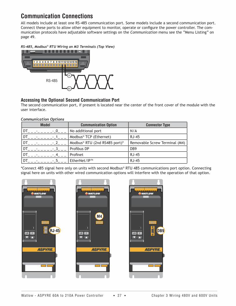
Communication ConnectionsAll models include at least one RS-485 communication port. Some models include a second communication port. Connect these ports to allow other equipment to monitor, operate or configure the power controller. The com-munication protocols have adjustable software settings on the Communication menu see the “Menu Listing” on page 49.
RS-485, Modbus® RTU Wiring on M3 Terminals (Top View)
RS-485
B+
A-
Accessing the Optional Second Communication PortThe second communication port, if present is located near the center of the front cover of the module with the user interface.
Communication OptionsModel Communication Option Connector Type
DT_ _ _-_ _ _ _ _-_0_ _ _ No additional port N/A
DT_ _ _-_ _ _ _ _-_1_ _ _ Modbus® TCP (Ethernet) RJ-45
DT_ _ _-_ _ _ _ _-_2_ _ _ Modbus® RTU (2nd RS485 port)* Removable Screw Terminal (M4)
DT_ _ _-_ _ _ _ _-_3_ _ _ Profibus DP DB9
DT_ _ _-_ _ _ _ _-_4_ _ _ Profinet RJ-45
DT_ _ _-_ _ _ _ _-_5_ _ _ EtherNet/IP™ RJ-45
*Connect 485 signal here only on units with second Modbus® RTU 485 communications port option. Connecting signal here on units with other wired communication options will interfere with the operation of that option.
M4
DB9RJ-45
Watlow - ASPYRE 60A to 210A Power Contro l ler • 28 • Chapter 3 Wir ing 480V and 600V Uni ts
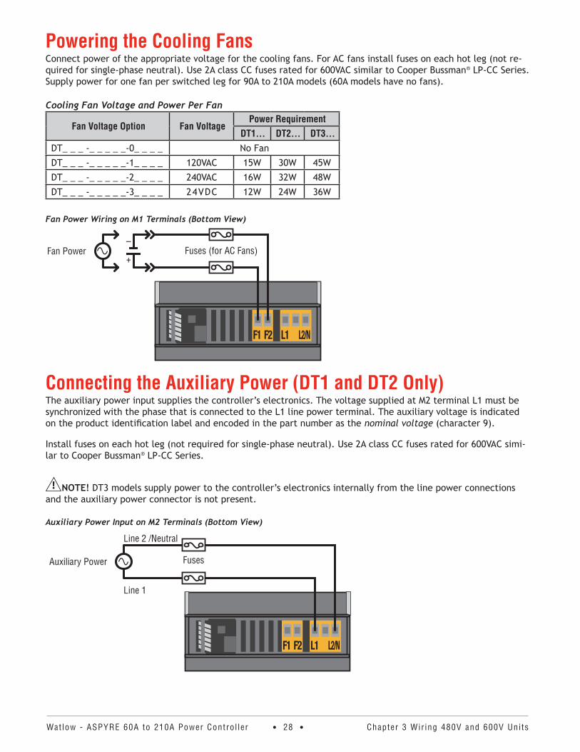
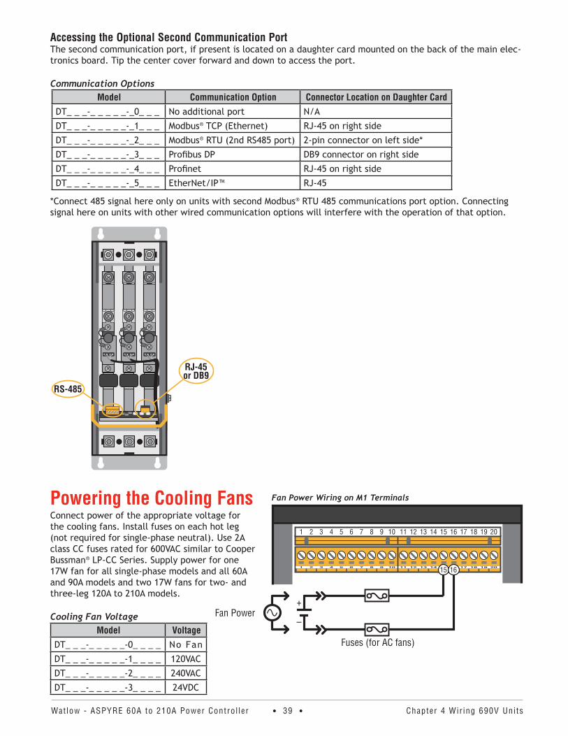
Powering the Cooling FansConnect power of the appropriate voltage for the cooling fans. For AC fans install fuses on each hot leg (not re-quired for single-phase neutral). Use 2A class CC fuses rated for 600VAC similar to Cooper Bussman® LP-CC Series. Supply power for one fan per switched leg for 90A to 210A models (60A models have no fans).
Cooling Fan Voltage and Power Per Fan
Fan Voltage Option Fan VoltagePower Requirement
DT1 . . . DT2 . . . DT3 . . .DT_ _ _ -_ _ _ _ _-0_ _ _ _ No Fan
DT_ _ _ -_ _ _ _ _-1_ _ _ _ 120VAC 15W 30W 45W
DT_ _ _ -_ _ _ _ _-2_ _ _ _ 240VAC 16W 32W 48W
DT_ _ _ -_ _ _ _ _-3_ _ _ _ 24VDC 12W 24W 36W
Fan Power Wiring on M1 Terminals (Bottom View)
Fan Power Fuses (for AC Fans)+
–
Connecting the Auxiliary Power (DT1 and DT2 Only)The auxiliary power input supplies the controller’s electronics. The voltage supplied at M2 terminal L1 must be synchronized with the phase that is connected to the L1 line power terminal. The auxiliary voltage is indicated on the product identification label and encoded in the part number as the nominal voltage (character 9).
Install fuses on each hot leg (not required for single-phase neutral). Use 2A class CC fuses rated for 600VAC simi-lar to Cooper Bussman® LP-CC Series.
NOTE! DT3 models supply power to the controller’s electronics internally from the line power connections and the auxiliary power connector is not present.
Auxiliary Power Input on M2 Terminals (Bottom View)
Auxiliary Power
Line 2 /Neutral
Line 1
Fuses

Watlow - ASPYRE 60A to 210A Power Contro l ler • 29 • Chapter 3 Wir ing 480V and 600V Uni ts
Opening The CoversWARNING: To prevent injury and loss of life, shut off power and ensure it cannot be restored while perform-
ing work with the covers open or removed.
AVERTISSEMENT : Pour éviter les blessures et les pertes de vie, couper l’alimentation électrique et s’assurer qu’elle ne peut être restaurée pendant l’exécution du travail avec les couvercles ouverts ou enlevés.
To open the front cover to access line power, load and other connections:1. Grip the cover by the handle .
2. Pull the cover firmly toward you and down.
Wiring the Line Power and LoadLine Power Connection LocationsThe following illustrations indicate how to connect line power and loads.
Single-Phase Line Power and Load Wiring Three-Phase. Two-Leg Line Power and Load Wiring
L2
L1
L2
L3
L1
L2
L3
L1 L3
T1 T3
Watlow - ASPYRE 60A to 210A Power Contro l ler • 30 • Chapter 3 Wir ing 480V and 600V Uni ts
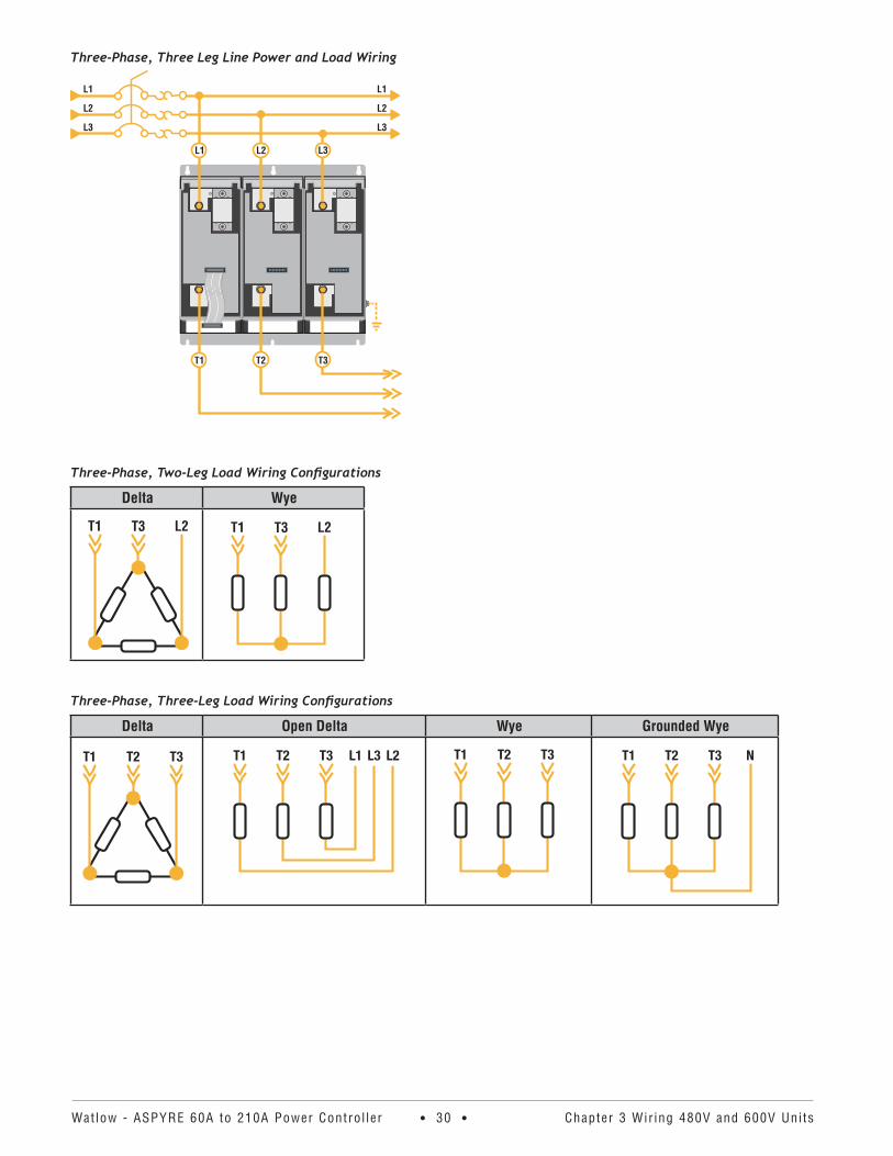
Three-Phase, Three Leg Line Power and Load Wiring
L1
L2
L3
L1
L2
L3
L1 L2
T1 T2
L3
T3
Three-Phase, Two-Leg Load Wiring Configurations
Delta Wye
L2T3T1 L2T3T1
Three-Phase, Three-Leg Load Wiring Configurations
Delta Open Delta Wye Grounded Wye
Watlow - ASPYRE 60A to 210A Power Contro l ler • 31 • Chapter 4 Wir ing 690V Uni ts
WARNING: To avoid damage to property and equipment, injury and loss of life, adhere to applicable electri-cal codes and standard wiring practices when installing and operating this product. Failure to do so could result in damage, injury and death.
AVERTISSEMENT! Pour éviter d’endommager la propriété et l’équipement, les blessures et la perte de vie, respecter les codes électriques en vigueur et les pratiques de câblage standard au moment de l’installation et de l’utilisation de ce produit. Dans le cas contraire, cela peut entraîner la mort, des blessures graves ou des dommages.
WARNING: The installation must be protected by electromagnetic circuit breakers or by fuses. The semicon-ductor fuses located inside the power controller are classified for UL® as supplementary protection for semicon-ductor devices. They are not approved for branch circuit protection.
AVERTISSEMENT! L’installation doit être protégée par des disjoncteurs électromagnétiques ou des fusibles. Les fusibles pour semi-conducteurs situés à l’intérieur du régulateur de puissance sont classés UL® comme pro-tection supplémentaire pour les dispositifs pour semi-conducteurs. Ils ne sont pas approuvés pour la protection des circuits de dérivation.
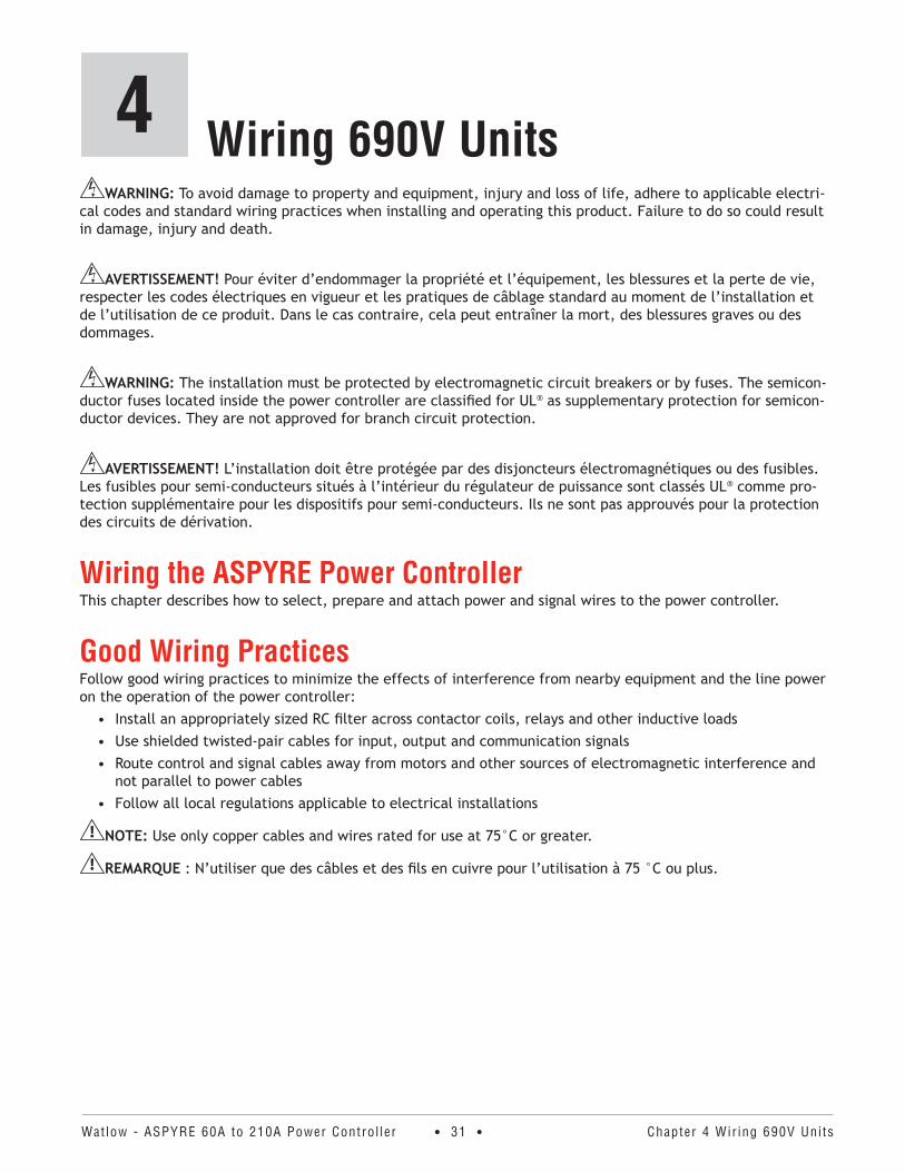
Wiring the ASPYRE Power ControllerThis chapter describes how to select, prepare and attach power and signal wires to the power controller.
Good Wiring PracticesFollow good wiring practices to minimize the effects of interference from nearby equipment and the line power on the operation of the power controller:
• Install an appropriately sized RC filter across contactor coils, relays and other inductive loads• Use shielded twisted-pair cables for input, output and communication signals• Route control and signal cables away from motors and other sources of electromagnetic interference and
not parallel to power cables• Follow all local regulations applicable to electrical installations
NOTE: Use only copper cables and wires rated for use at 75°C or greater.
REMARQUE : N’utiliser que des câbles et des fils en cuivre pour l’utilisation à 75 °C ou plus.
Wiring 690V Units4
Watlow - ASPYRE 60A to 210A Power Contro l ler • 32 • Chapter 4 Wir ing 690V Uni ts
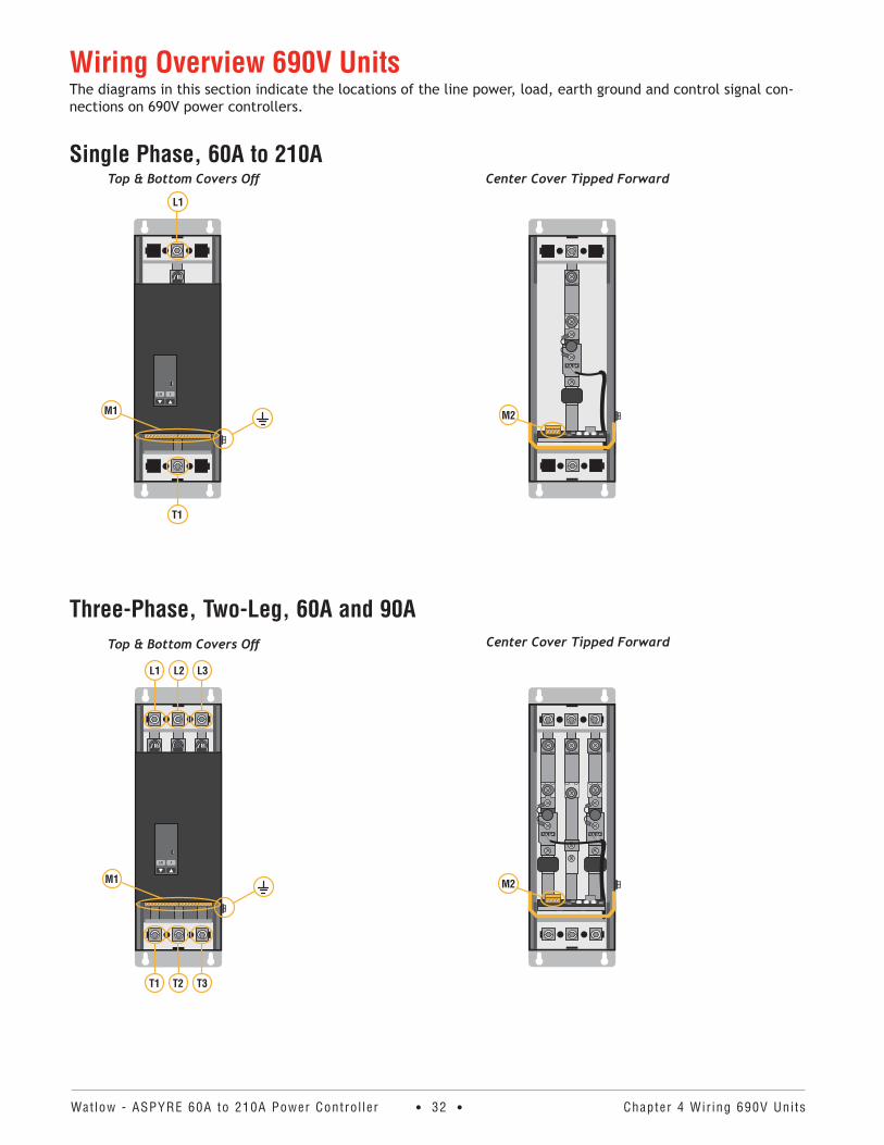
Wiring Overview 690V UnitsThe diagrams in this section indicate the locations of the line power, load, earth ground and control signal con-nections on 690V power controllers.
Single Phase, 60A to 210A
Three-Phase, Two-Leg, 60A and 90A
Center Cover Tipped Forward
M2
Top & Bottom Covers Off
L/R F
M1
L1
T1
Top & Bottom Covers Off
L/R F
M1
L1 L2 L3
T1 T2 T3
Center Cover Tipped Forward
M2
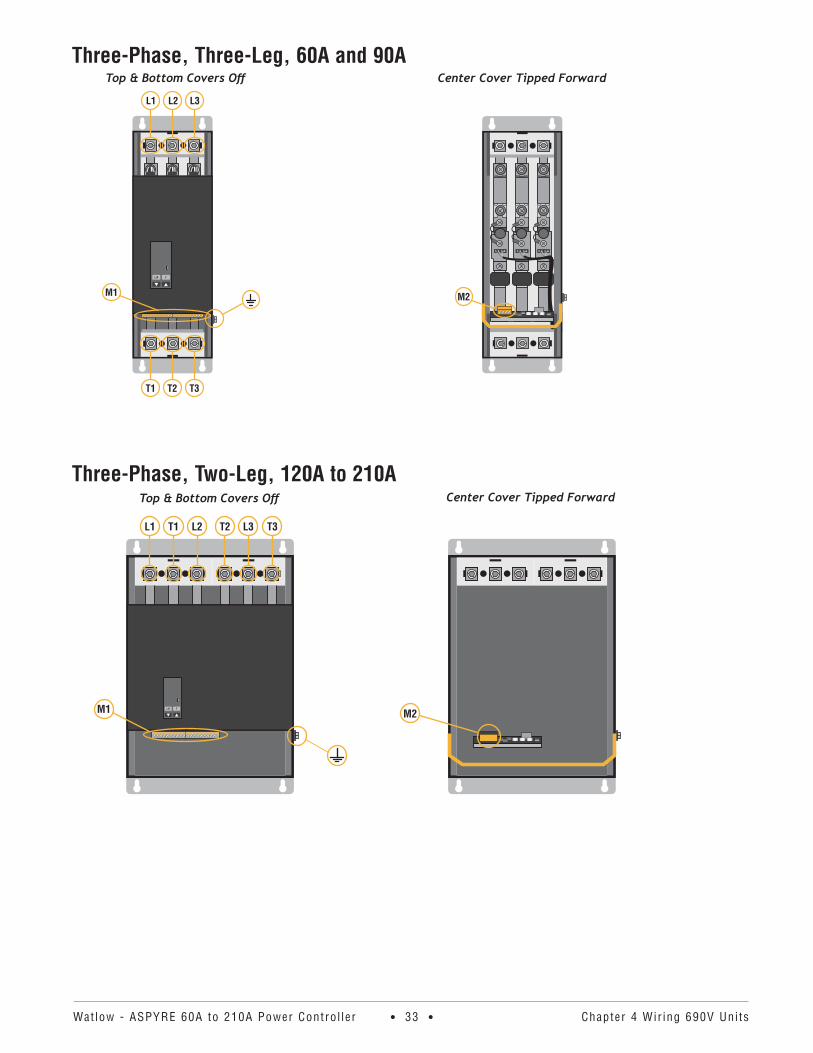
Watlow - ASPYRE 60A to 210A Power Contro l ler • 33 • Chapter 4 Wir ing 690V Uni ts
Three-Phase, Three-Leg, 60A and 90A
Three-Phase, Two-Leg, 120A to 210A
Center Cover Tipped Forward
M2
Top & Bottom Covers Off
L/R F
M1
L1 L2 L3
T1 T2 T3
Center Cover Tipped Forward
M2
Top & Bottom Covers Off
L/R FM1
T3L3T2L2T1L1
Watlow - ASPYRE 60A to 210A Power Contro l ler • 34 • Chapter 4 Wir ing 690V Uni ts
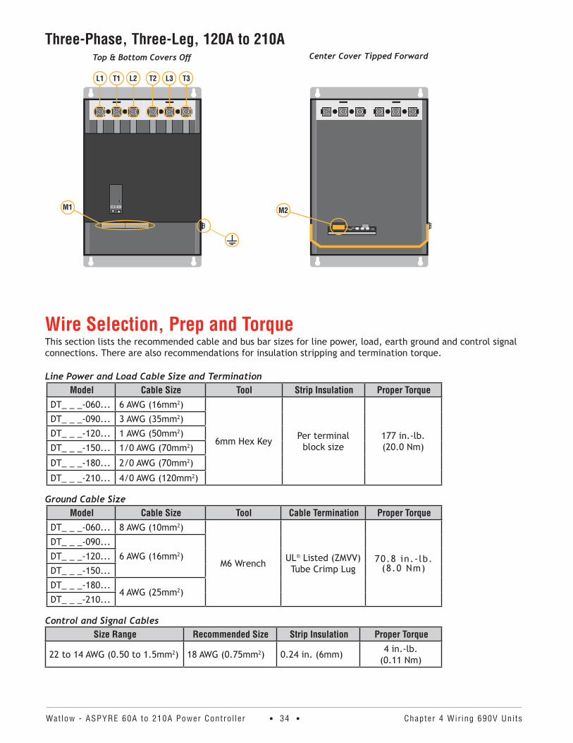
Three-Phase, Three-Leg, 120A to 210A
Wire Selection, Prep and TorqueThis section lists the recommended cable and bus bar sizes for line power, load, earth ground and control signal connections. There are also recommendations for insulation stripping and termination torque.
Line Power and Load Cable Size and Termination Model Cable Size Tool Strip Insulation Proper Torque
DT_ _ _-060... 6 AWG (16mm2)
6mm Hex Key Per terminal block size
177 in.-lb. (20.0 Nm)
DT_ _ _-090... 3 AWG (35mm2)
DT_ _ _-120... 1 AWG (50mm2)
DT_ _ _-150... 1/0 AWG (70mm2)
DT_ _ _-180... 2/0 AWG (70mm2)
DT_ _ _-210... 4/0 AWG (120mm2)
Ground Cable SizeModel Cable Size Tool Cable Termination Proper Torque
DT_ _ _-060... 8 AWG (10mm2)
M6 Wrench UL® Listed (ZMVV) Tube Crimp Lug
70.8 in.-lb. (8.0 Nm)
DT_ _ _-090...
6 AWG (16mm2)DT_ _ _-120...
DT_ _ _-150...
DT_ _ _-180...4 AWG (25mm2)
DT_ _ _-210...
Control and Signal CablesSize Range Recommended Size Strip Insulation Proper Torque
22 to 14 AWG (0.50 to 1.5mm2) 18 AWG (0.75mm2) 0.24 in. (6mm) 4 in.-lb. (0.11 Nm)
Center Cover Tipped Forward
M2
Top & Bottom Covers Off
L/R FM1
T3L3T2L2T1L1
Watlow - ASPYRE 60A to 210A Power Contro l ler • 35 • Chapter 4 Wir ing 690V Uni ts
Insulation Stripping and TorqueTo insure proper connections, but minimize hazardous exposure of conductors, strip the correct amount of insu-lation from each cable. For ground strip cable insulation per crimp lug requirements. For load, line power and control and signal cables see tables above.
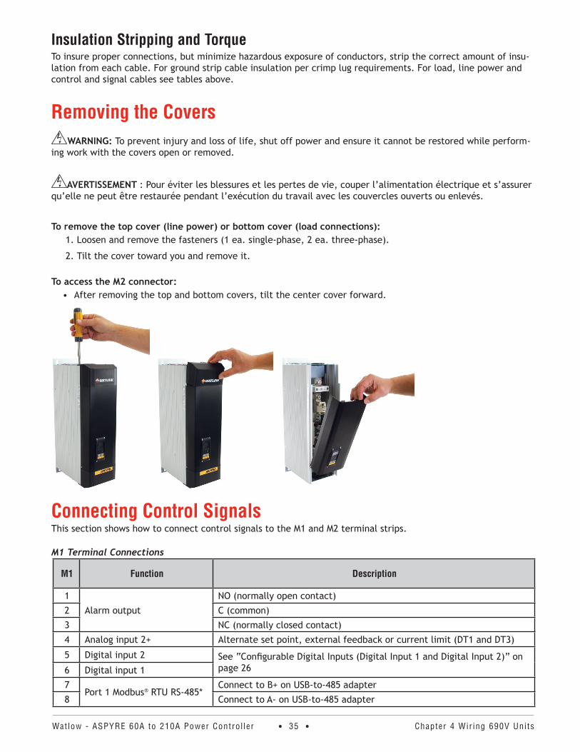
Removing the CoversWARNING: To prevent injury and loss of life, shut off power and ensure it cannot be restored while perform-
ing work with the covers open or removed.
AVERTISSEMENT : Pour éviter les blessures et les pertes de vie, couper l’alimentation électrique et s’assurer qu’elle ne peut être restaurée pendant l’exécution du travail avec les couvercles ouverts ou enlevés.
To remove the top cover (line power) or bottom cover (load connections):1. Loosen and remove the fasteners (1 ea. single-phase, 2 ea. three-phase).
2. Tilt the cover toward you and remove it.
To access the M2 connector:• After removing the top and bottom covers, tilt the center cover forward.
Connecting Control SignalsThis section shows how to connect control signals to the M1 and M2 terminal strips.
M1 Terminal Connections
M1 Function Description
1
Alarm output
NO (normally open contact)
2 C (common)
3 NC (normally closed contact)
4 Analog input 2+ Alternate set point, external feedback or current limit (DT1 and DT3)
5 Digital input 2 See “Configurable Digital Inputs (Digital Input 1 and Digital Input 2)” on page 266 Digital input 1
7Port 1 Modbus® RTU RS-485*
Connect to B+ on USB-to-485 adapter
8 Connect to A- on USB-to-485 adapter
Watlow - ASPYRE 60A to 210A Power Contro l ler • 36 • Chapter 4 Wir ing 690V Uni ts
M1 Function Description
9 +10V power supplyFor dry contact digital inputs or potentiometers for analog inputs
10 10V power supply common
11 Analog common - For analog in 1 and 2
12 Analog input 1+ Set point signal input
13 Digital input common Reference to 10V power supply common, if necessary
14 Not Used
15Power input for fan
+ For DC fans, line or neutral for AC fans
16 - For DC fans, line or neutral for AC fans
17 Not used
18 Auxiliary power input Line 1
19 Not used
20 Auxiliary power input Line 2 or neutral on single phase units
M2 Terminal ConnectionsM2 Function
1 +24VDC supplemental power for applications that use both analog retransmit and the sec-ond communication port (other than Modbus® RTU)
2 Unused
3 Retransmit output+
4 Common for retransmit and 24VDC input
Secondary Modbus® RTU Terminal Connections* Function Description
A+Port 2 Modbus® RTU RS-485
Connect to B+ on USB-to-485 adapter
B- Connect to A- on USB-to-485 adapter
*Connect 485 signal here only on units with second Modbus® RTU 485 communications port option. Connecting signal here on units with other wired communications options will interfere with the operation of that option.
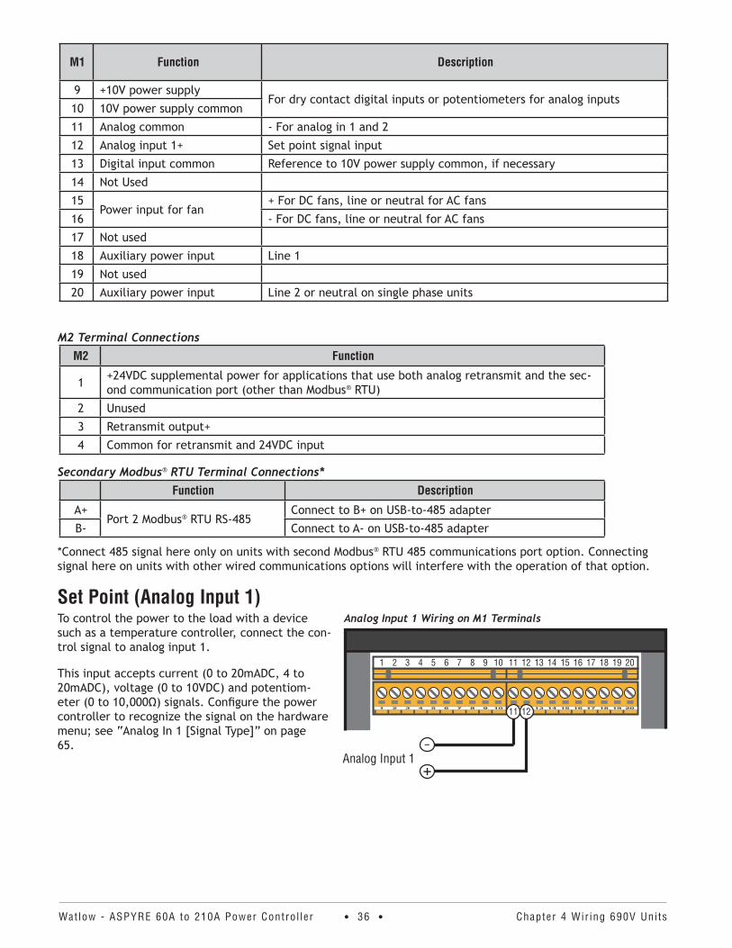
Set Point (Analog Input 1)To control the power to the load with a device such as a temperature controller, connect the con-trol signal to analog input 1.
This input accepts current (0 to 20mADC, 4 to 20mADC), voltage (0 to 10VDC) and potentiom-eter (0 to 10,000Ω) signals. Configure the power controller to recognize the signal on the hardware menu; see “Analog In 1 [Signal Type]” on page 65.
Analog Input 1 Wiring on M1 Terminals
1 2 3 4 5 6 7 8 9 10 11 12 13 14 15 16 17 18 19 20
Analog Input 1
11 12
+–
Watlow - ASPYRE 60A to 210A Power Contro l ler • 37 • Chapter 4 Wir ing 690V Uni ts
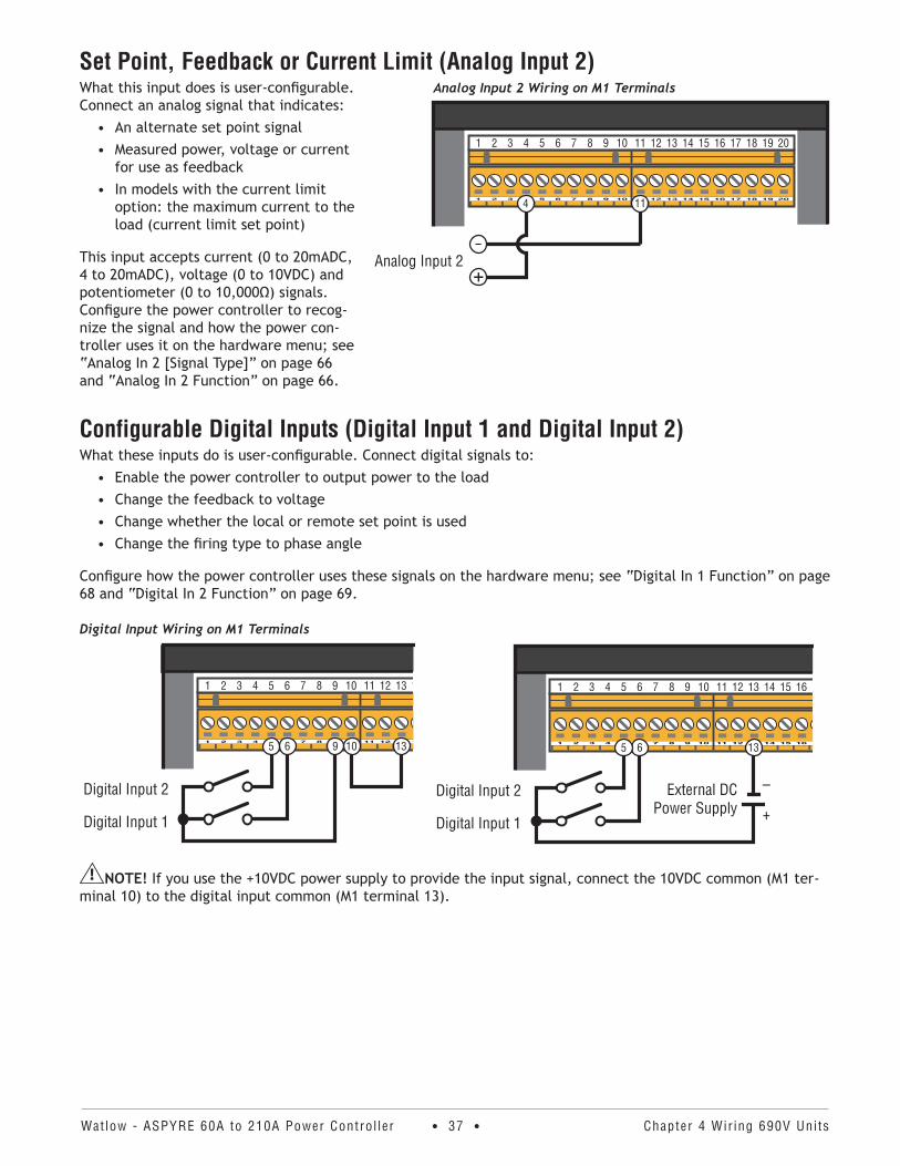
Set Point, Feedback or Current Limit (Analog Input 2)What this input does is user-configurable. Connect an analog signal that indicates:
• An alternate set point signal• Measured power, voltage or current
for use as feedback• In models with the current limit
option: the maximum current to the load (current limit set point)
This input accepts current (0 to 20mADC, 4 to 20mADC), voltage (0 to 10VDC) and potentiometer (0 to 10,000Ω) signals. Configure the power controller to recog-nize the signal and how the power con-troller uses it on the hardware menu; see “Analog In 2 [Signal Type]” on page 66 and “Analog In 2 Function” on page 66.
Configurable Digital Inputs (Digital Input 1 and Digital Input 2)What these inputs do is user-configurable. Connect digital signals to:
• Enable the power controller to output power to the load • Change the feedback to voltage• Change whether the local or remote set point is used• Change the firing type to phase angle
Configure how the power controller uses these signals on the hardware menu; see “Digital In 1 Function” on page 68 and “Digital In 2 Function” on page 69.
Digital Input Wiring on M1 Terminals
1 2 3 4 5 6 7 8 9 10 11 12 13 14 15 16 17 18 19 20
Digital Input 2
Digital Input 1
10 13965
NOTE! If you use the +10VDC power supply to provide the input signal, connect the 10VDC common (M1 ter-minal 10) to the digital input common (M1 terminal 13).
Analog Input 2 Wiring on M1 Terminals
1 2 3 4 5 6 7 8 9 10 11 12 13 14 15 16 17 18 19 20
Analog Input 2
114
+–
1 2 3 4 5 6 7 8 9 10 11 12 13 14 15 16 17 18 19 20
Digital Input 2
Digital Input 1
1365
+
–External DC
Power Supply
Watlow - ASPYRE 60A to 210A Power Contro l ler • 38 • Chapter 4 Wir ing 690V Uni ts
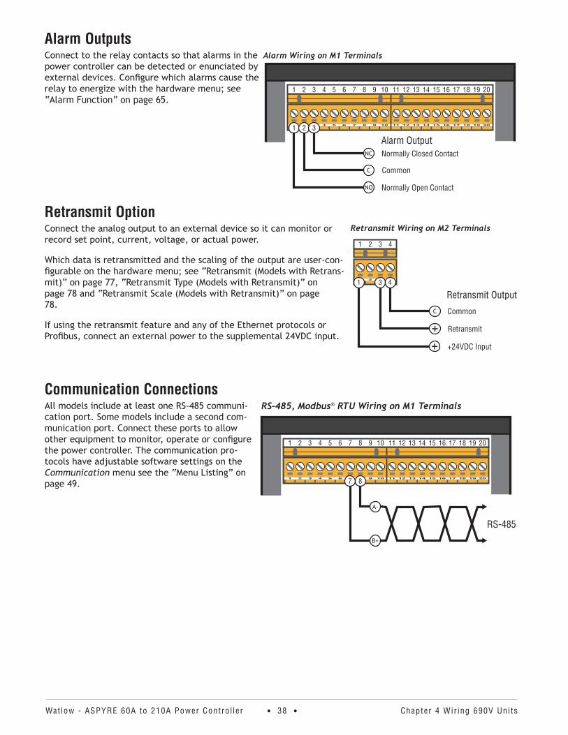
Alarm OutputsConnect to the relay contacts so that alarms in the power controller can be detected or enunciated by external devices. Configure which alarms cause the relay to energize with the hardware menu; see “Alarm Function” on page 65.
Retransmit OptionConnect the analog output to an external device so it can monitor or record set point, current, voltage, or actual power.
Which data is retransmitted and the scaling of the output are user-con-figurable on the hardware menu; see “Retransmit (Models with Retrans-mit)” on page 77, “Retransmit Type (Models with Retransmit)” on page 78 and “Retransmit Scale (Models with Retransmit)” on page 78.
If using the retransmit feature and any of the Ethernet protocols or Profibus, connect an external power to the supplemental 24VDC input.
Communication ConnectionsAll models include at least one RS-485 communi-cation port. Some models include a second com-munication port. Connect these ports to allow other equipment to monitor, operate or configure the power controller. The communication pro-tocols have adjustable software settings on the Communication menu see the “Menu Listing” on page 49.
Alarm Wiring on M1 Terminals
1 2 3 4 5 6 7 8 9 10 11 12 13 14 15 16 17 18 19 20
1 2 3
NC
C
NO
Alarm OutputNormally Closed Contact
Common
Normally Open Contact
Retransmit Wiring on M2 Terminals
1 2 3 4
3 4
C
Retransmit Output
+Common
Retransmit
1
+ +24VDC Input
RS-485, Modbus® RTU Wiring on M1 Terminals
1 2 3 4 5 6 7 8 9 10 11 12 13 14 15 16 17 18 19 20
7 8
A-
B+
RS-485
Watlow - ASPYRE 60A to 210A Power Contro l ler • 39 • Chapter 4 Wir ing 690V Uni ts
Accessing the Optional Second Communication PortThe second communication port, if present is located on a daughter card mounted on the back of the main elec-tronics board. Tip the center cover forward and down to access the port.
Communication OptionsModel Communication Option Connector Location on Daughter Card
DT_ _ _-_ _ _ _ _-_0_ _ _ No additional port N/A
DT_ _ _-_ _ _ _ _-_1_ _ _ Modbus® TCP (Ethernet) RJ-45 on right side
DT_ _ _-_ _ _ _ _-_2_ _ _ Modbus® RTU (2nd RS485 port) 2-pin connector on left side*
DT_ _ _-_ _ _ _ _-_3_ _ _ Profibus DP DB9 connector on right side
DT_ _ _-_ _ _ _ _-_4_ _ _ Profinet RJ-45 on right side
DT_ _ _-_ _ _ _ _-_5_ _ _ EtherNet/IP™ RJ-45
*Connect 485 signal here only on units with second Modbus® RTU 485 communications port option. Connecting signal here on units with other wired communication options will interfere with the operation of that option.
Powering the Cooling FansConnect power of the appropriate voltage for the cooling fans. Install fuses on each hot leg (not required for single-phase neutral). Use 2A class CC fuses rated for 600VAC similar to Cooper Bussman® LP-CC Series. Supply power for one 17W fan for all single-phase models and all 60A and 90A models and two 17W fans for two- and three-leg 120A to 210A models.
Cooling Fan VoltageModel Voltage
DT_ _ _-_ _ _ _ _-0_ _ _ _ No Fan
DT_ _ _-_ _ _ _ _-1_ _ _ _ 120VAC
DT_ _ _-_ _ _ _ _-2_ _ _ _ 240VAC
DT_ _ _-_ _ _ _ _-3_ _ _ _ 24VDC
RS-485
RJ-45or DB9
Fan Power Wiring on M1 Terminals
1 2 3 4 5 6 7 8 9 10 11 12 13 14 15 16 17 18 19 20
Fan Power
15 16
Fuses (for AC fans)
+
–
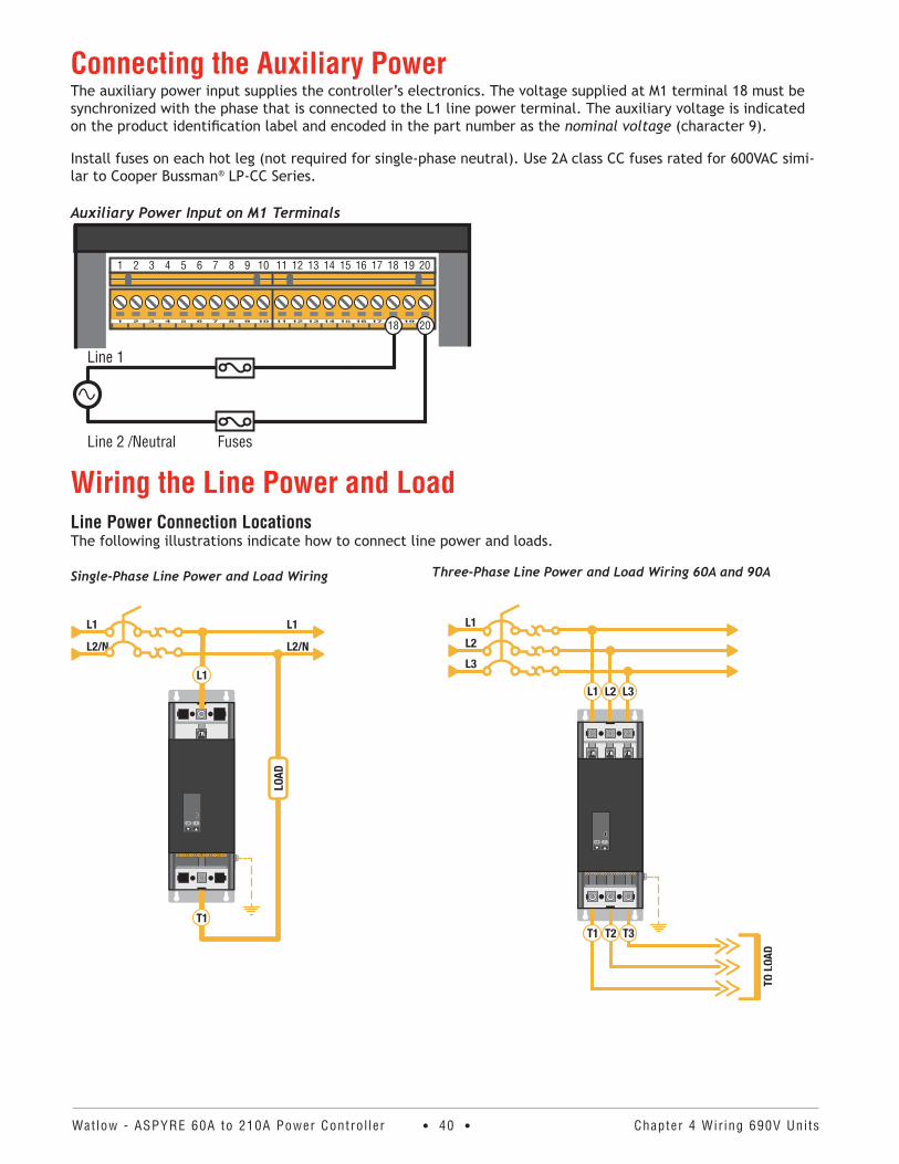
Watlow - ASPYRE 60A to 210A Power Contro l ler • 40 • Chapter 4 Wir ing 690V Uni ts
Connecting the Auxiliary PowerThe auxiliary power input supplies the controller’s electronics. The voltage supplied at M1 terminal 18 must be synchronized with the phase that is connected to the L1 line power terminal. The auxiliary voltage is indicated on the product identification label and encoded in the part number as the nominal voltage (character 9).
Install fuses on each hot leg (not required for single-phase neutral). Use 2A class CC fuses rated for 600VAC simi-lar to Cooper Bussman® LP-CC Series.
Auxiliary Power Input on M1 Terminals
1 2 3 4 5 6 7 8 9 10 11 12 13 14 15 16 17 18 19 20
Auxiliary Power
18 20
Fuses
Line 1
Line 2 /Neutral
Wiring the Line Power and LoadLine Power Connection LocationsThe following illustrations indicate how to connect line power and loads.
Single-Phase Line Power and Load Wiring
L/R F
Three-Phase Line Power and Load Wiring 60A and 90A
L/R F
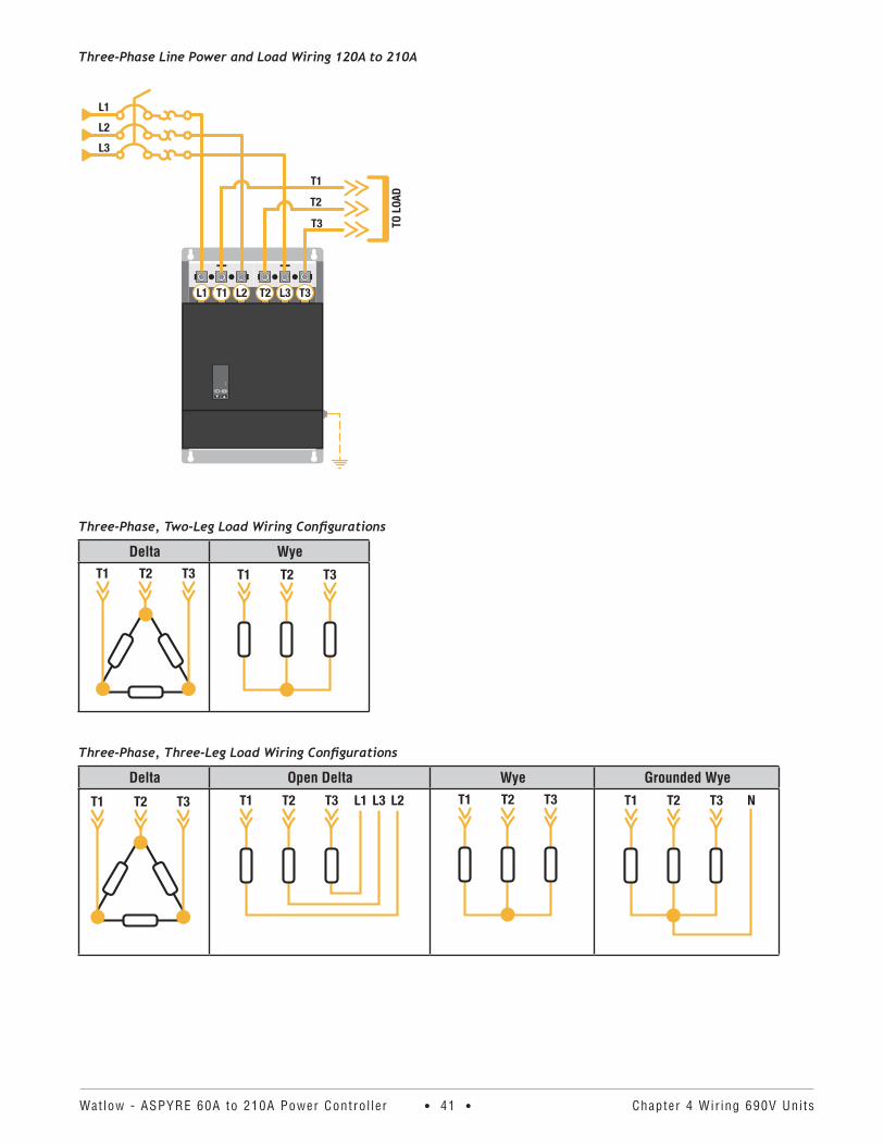
Watlow - ASPYRE 60A to 210A Power Contro l ler • 41 • Chapter 4 Wir ing 690V Uni ts
Three-Phase Line Power and Load Wiring 120A to 210A
Three-Phase, Two-Leg Load Wiring Configurations
Delta Wye
Three-Phase, Three-Leg Load Wiring Configurations
Delta Open Delta Wye Grounded Wye
L/R F

Watlow - ASPYRE 60A to 210A Power Contro l ler • 42 • Chapter 4 Wir ing 690V Uni ts
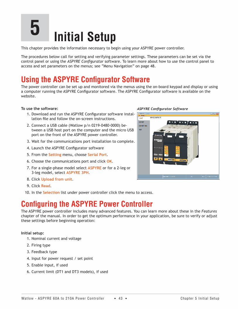
Watlow - ASPYRE 60A to 210A Power Contro l ler • 43 • Chapter 5 In i t ia l Setup
This chapter provides the information necessary to begin using your ASPYRE power controller.
The procedures below call for setting and verifying parameter settings. These parameters can be set via the control panel or using the ASPYRE Configurator software. To learn more about how to use the control panel to access and set parameters on the menus; see “Menu Navigation” on page 48.
Using the ASPYRE Configurator SoftwareThe power controller can be set up and monitored via the menus using the on-board keypad and display or using a computer running the ASPYRE Configurator software. The ASPYRE Configurator software is available on the website.
To use the software:1. Download and run the ASPYRE Configurator software instal-
lation file and follow the on-screen instructions.
2. Connect a USB cable (Watlow p/n 0219-0480-0000) be-tween a USB host port on the computer and the micro USB port on the front of the ASPYRE power controller.
3. Wait for the communications port installation to complete.
4. Launch the ASPYRE Configurator software
5. From the Setting menu, choose Serial Port.
6. Choose the communications port and click OK.
7. For a single-phase model select ASPYRE or for a 2-leg or 3-leg model, select ASPYRE 3PH.
8. Click Upload from unit.
9. Click Read.
10. In the Selection list under power controller click the menu to access.
Configuring the ASPYRE Power ControllerThe ASPYRE power controller includes many advanced features. You can learn more about these in the Features chapter of the manual. In order to get the optimum performance in your application, be sure to verify or adjust these settings before beginning operation:
Initial setup:1. Nominal current and voltage
2. Firing type
3. Feedback type
4. Input for power request / set point
5. Enable input, if used
6. Current limit (DT1 and DT3 models), if used
ASPYRE Configurator Software
Initial Setup5
Watlow - ASPYRE 60A to 210A Power Contro l ler • 44 • Chapter 5 In i t ia l Setup
Set Nominal Current and VoltageIn order for the power controller to function correctly, set the nominal line voltage and load current. To calcu-late the nominal load current see “Digits 6, 7 and 8, Amperage” on page 13. Otherwise it can be determined empirically after completing the installation and other setup steps by applying 100% power and measuring the resulting current.
On this menu . . . set this parameter . . . to the . . .
1 Setup Nominal V nominal line voltage (RMS)
2 Setup Nominal I nominal current (RMS), each leg of the load at 100% power
Set the Firing TypeChoose the firing type in order to optimize the performance of the load.
On this menu . . . set this parameter . . . to the . . .Adv Setup Firing type of power switching appropriate for your load
Also on the Adv Setup menu set the parameters that adjust the behavior of the firing type you chose.For . . . set this parameter . . . to the . . .
Phase Angle Soft Start Soft Start amount of time for the output to ramp to the set point
Burst Fire Start Ramp Start Ramp number of half cycles over which each burst should ramp
Burst FireBurst Fire Start RampBurst Fire Delay TriggerBF Strt Rmp Delay Trigger
Min Cycles fewest number of cycles the output should be on or off
Burst Fire Delay TriggerBF Strt Rmp Delay Trigger
Delay firing delay from zero cross in degrees
Half Cycles to Delay number of half cycles to which to apply the delayed firing
Zero Crossing Cycle Time duration of each on-off cycle
Half Cycle Safety Ramp
Safety Ramp Duration amount of time for the output to ramp to the set point
Safety Ramp Off Time minimum amount of off-time before ramping is needed
Set the FeedbackChoose the variable to use for feedback to optimize the performance of the application.
On this menu . . . set this parameter . . . to the . . .Adv Setup Feedback type of measured feedback appropriate for your application
Configure the Input for Power Demand / Set PointThe signal to analog input 1 indicates the desired percent of full output the power control should deliver to the load.
Configure the power request / set point signal:On this menu . . . set this parameter . . . to the type of signal and range . . .
Hardware Analog In 1
0-10 V / 10k pot (0 to 10 VDC or potentiometer)
4-20mA (4 to 20 mADC)
0-20mA (0 to 20 mADC)
NOTE! This procedure assumes the analog input signal wiring, if used has been connected and that the signal can be set to various values as needed to perform the procedure. See “Set Point” on page 79.
Watlow - ASPYRE 60A to 210A Power Contro l ler • 45 • Chapter 5 In i t ia l Setup
Configure the Enable InputBy default digital input 1 is used to enable the power controller.
To verify that digital input 1 is configured to enable the power controller:• On the Hardware menu verify that Digital In 1 Function is set to Enable.
NOTE! If the power controller is used to switch power on and off simply following an on-off or time propor-tioned signal, that signal can be connected to the enable input and the set point can be set to 100%.
Configure the Current LimitFor models with this option the current limit feature prevents the current from exceeding the user-set current limit. As the current approaches the limit, the power controller decreases its output to avoid exceeding the cur-rent limit. The current limit set point can be set with the I Limit parameter or by an analog input.
CAUTION: This procedure must be performed only by qualified persons.
ATTENTION : Cette procédure ne doit être effectuée que par le personnel qualifié.
CAUTION: This procedure requires turning on full power to the load. This should only be performed once the installation is complete and when it is safe to provide full power.
ATTENTION : Cette procédure nécessite la mise sous tension totale de la charge. Cela ne doit être effectué qu’une fois l’installation terminée et lorsque la puissance maximale peut être fournie en toute sécurité.
To limit the current using the parameter setting:1. On the Hardware menu set I Limit Local / Remote to Local.
2. On the Operator menu set I Limit to 0%.
3. Enable the power controller and set the power demand set point to 100%.
4. Gradually increase the current limit set point until the RMS current is at the maximum desired value.
5. Disable the power controller.
To limit the current using the signal to analog input 2:1. On the Hardware menu set Analog In 2 for the type of signal and range:
0 to 10 VDC or 10k potentiometer 0-10 V / 10k
4 to 20 mADC 4-20mA
0 to 20 mADC 0-20mA
2. On the Hardware menu set the Analog In 2 Function to I Limit.
3. On the Hardware menu set the I Limit Local / Remote to Analog In 2.
4. Set the signal to the analog input to the minimum value (typically 0 V).
5. Enable the power controller and set the power demand / set point to 100%.
6. Gradually increase the signal to the analog input until the RMS current is at the maximum desired value.
7. Disable the power controller.

Watlow - ASPYRE 60A to 210A Power Contro l ler • 46 • Chapter 5 In i t ia l Setup
NOTE! this procedure assumes the analog input signal wiring, if used has been connected and that the signal can be set to various values as needed to perform the procedure. See “Set Point, Feedback or Current Limit (Analog Input 2)” on page 25.
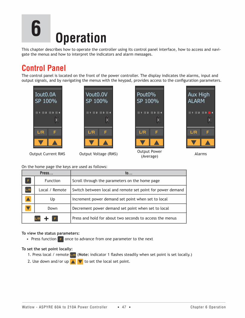
Watlow - ASPYRE 60A to 210A Power Contro l ler • 47 • Chapter 6 Operat ion
This chapter describes how to operate the controller using its control panel interface, how to access and navi-gate the menus and how to interpret the indicators and alarm messages.
Control PanelThe control panel is located on the front of the power controller. The display indicates the alarms, input and output signals, and by navigating the menus with the keypad, provides access to the configuration parameters.
Iout0.0ASP 100%
Vout0.0VSP 100%
Pout0%SP 100%
Aux HighALARM
Output Current RMS Output Voltage (RMS) Output Power (Average) Alarms
On the home page the keys are used as follows:
Press . . . to . . .
Function Scroll through the parameters on the home page
Local / Remote Switch between local and remote set point for power demand
Up Increment power demand set point when set to local
Down Decrement power demand set point when set to local
+ Press and hold for about two seconds to access the menus
To view the status parameters:• Press function once to advance from one parameter to the next
To set the set point locally:1. Press local / remote (Note: indicator 1 flashes steadily when set point is set locally.)
2. Use down and/or up to set the local set point.
Operation6
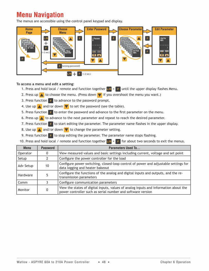
Watlow - ASPYRE 60A to 210A Power Contro l ler • 48 • Chapter 6 Operat ion
Menu NavigationThe menus are accessible using the control panel keypad and display.
HomePage
ChooseMenu
Enter Password Choose Parameter Edit Parameter
+
+
(~2 sec.)
(~2 sec.)
(wrong password)
To access a menu and edit a setting:1. Press and hold local / remote and function together + until the upper display flashes Menu.
2. Press up to choose the menu. (Press down if you overshoot the menu you want.)
3. Press function to advance to the password prompt.
4. Use up and/or down to set the password (see the table).
5. Press function to enter the password and advance to the first parameter on the menu.
6. Press up to advance to the next parameter and repeat to reach the desired parameter.
7. Press function to start editing the parameter. The parameter name flashes in the upper display.
8. Use up and/or down to change the parameter setting.
9. Press function to stop editing the parameter. The parameter name stops flashing.
10. Press and hold local / remote and function together + for about two seconds to exit the menus.
Menu Password Parameters Used To . . .Operator 0 View measured values and basic settings including current, voltage and set point
Setup 2 Configure the power controller for the load
Adv Setup 10 Configure power switching, closed-loop control of power and adjustable settings for data logging and heater bakeout
Hardware 5 Configure the functions of the analog and digital inputs and outputs, and the re-transmission parameters
Comm 3 Configure communication parameters
Monitor 0 View the states of digital inputs, values of analog inputs and information about the power controller such as serial number and software version
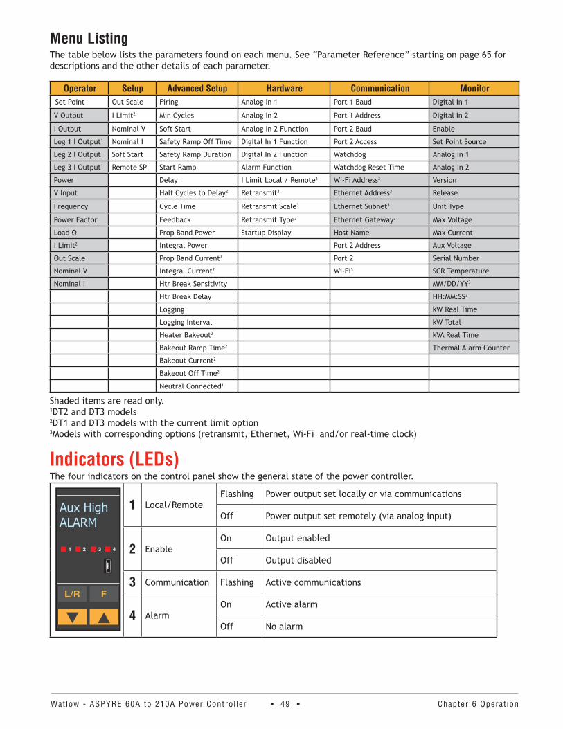
Watlow - ASPYRE 60A to 210A Power Contro l ler • 49 • Chapter 6 Operat ion
Menu ListingThe table below lists the parameters found on each menu. See “Parameter Reference” starting on page 65 for descriptions and the other details of each parameter.
Operator Setup Advanced Setup Hardware Communication MonitorSet Point Out Scale Firing Analog In 1 Port 1 Baud Digital In 1
V Output I Limit2 Min Cycles Analog In 2 Port 1 Address Digital In 2
I Output Nominal V Soft Start Analog In 2 Function Port 2 Baud Enable
Leg 1 I Output1 Nominal I Safety Ramp Off Time Digital In 1 Function Port 2 Access Set Point Source
Leg 2 I Output1 Soft Start Safety Ramp Duration Digital In 2 Function Watchdog Analog In 1
Leg 3 I Output1 Remote SP Start Ramp Alarm Function Watchdog Reset Time Analog In 2
Power Delay I Limit Local / Remote2 Wi-Fi Address3 Version
V Input Half Cycles to Delay2 Retransmit3 Ethernet Address3 Release
Frequency Cycle Time Retransmit Scale3 Ethernet Subnet3 Unit Type
Power Factor Feedback Retransmit Type3 Ethernet Gateway3 Max Voltage
Load Ω Prop Band Power Startup Display Host Name Max Current
I Limit2 Integral Power Port 2 Address Aux Voltage
Out Scale Prop Band Current2 Port 2 Serial Number
Nominal V Integral Current2 Wi-Fi3 SCR Temperature
Nominal I Htr Break Sensitivity MM/DD/YY3
Htr Break Delay HH:MM:SS3
Logging kW Real Time
Logging Interval kW Total
Heater Bakeout2 kVA Real Time
Bakeout Ramp Time2 Thermal Alarm Counter
Bakeout Current2
Bakeout Off Time2
Neutral Connected1
Shaded items are read only. 1DT2 and DT3 models 2DT1 and DT3 models with the current limit option 3Models with corresponding options (retransmit, Ethernet, Wi-Fi and/or real-time clock)
Indicators (LEDs)The four indicators on the control panel show the general state of the power controller.
Aux HighALARM
1 Local/RemoteFlashing Power output set locally or via communications
Off Power output set remotely (via analog input)
2 EnableOn Output enabled
Off Output disabled
3 Communication Flashing Active communications
4 AlarmOn Active alarm
Off No alarm
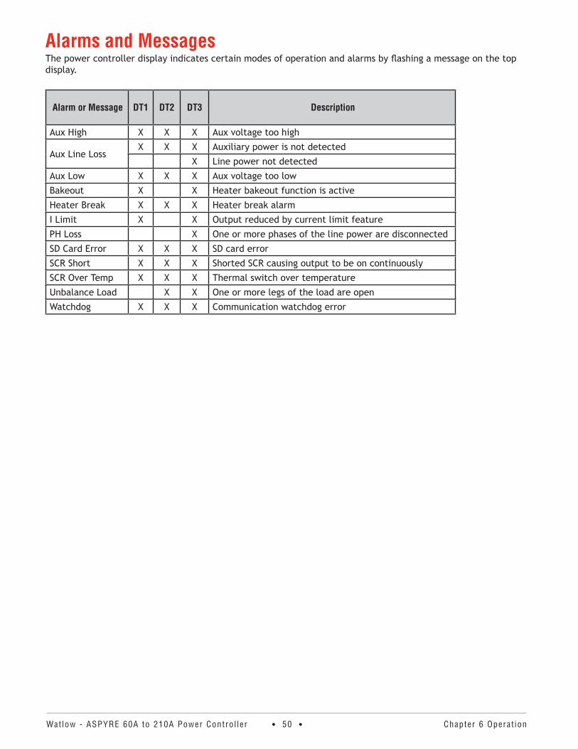
Watlow - ASPYRE 60A to 210A Power Contro l ler • 50 • Chapter 6 Operat ion
Alarms and MessagesThe power controller display indicates certain modes of operation and alarms by flashing a message on the top display.
Alarm or Message DT1 DT2 DT3 Description
Aux High X X X Aux voltage too high
Aux Line LossX X X Auxiliary power is not detected
X Line power not detected
Aux Low X X X Aux voltage too low
Bakeout X X Heater bakeout function is active
Heater Break X X X Heater break alarm
I Limit X X Output reduced by current limit feature
PH Loss X One or more phases of the line power are disconnected
SD Card Error X X X SD card error
SCR Short X X X Shorted SCR causing output to be on continuously
SCR Over Temp X X X Thermal switch over temperature
Unbalance Load X X One or more legs of the load are open
Watchdog X X X Communication watchdog error
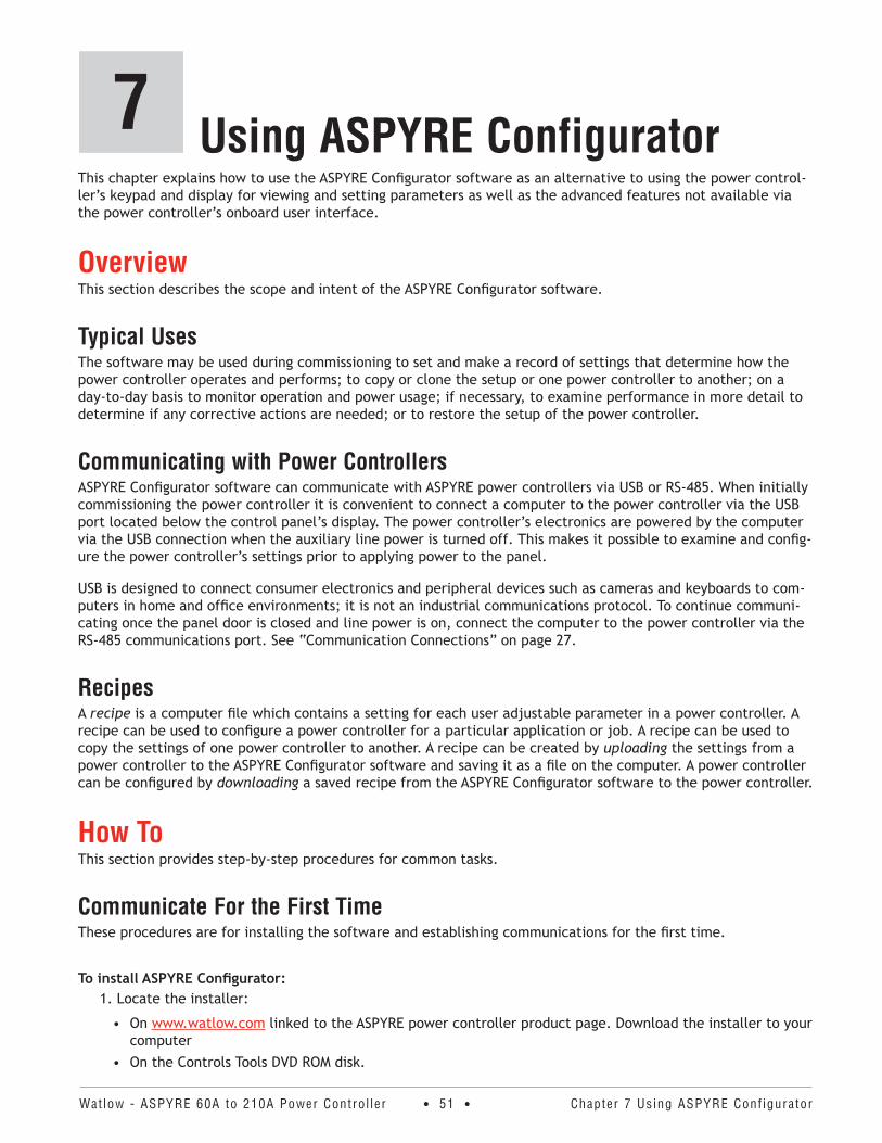
Watlow - ASPYRE 60A to 210A Power Contro l ler • 51 • Chapter 7 Using ASPYRE Conf igurator
Using ASPYRE Configurator7This chapter explains how to use the ASPYRE Configurator software as an alternative to using the power control-ler’s keypad and display for viewing and setting parameters as well as the advanced features not available via the power controller’s onboard user interface.
OverviewThis section describes the scope and intent of the ASPYRE Configurator software.
Typical UsesThe software may be used during commissioning to set and make a record of settings that determine how the power controller operates and performs; to copy or clone the setup or one power controller to another; on a day-to-day basis to monitor operation and power usage; if necessary, to examine performance in more detail to determine if any corrective actions are needed; or to restore the setup of the power controller.
Communicating with Power ControllersASPYRE Configurator software can communicate with ASPYRE power controllers via USB or RS-485. When initially commissioning the power controller it is convenient to connect a computer to the power controller via the USB port located below the control panel’s display. The power controller’s electronics are powered by the computer via the USB connection when the auxiliary line power is turned off. This makes it possible to examine and config-ure the power controller’s settings prior to applying power to the panel.
USB is designed to connect consumer electronics and peripheral devices such as cameras and keyboards to com-puters in home and office environments; it is not an industrial communications protocol. To continue communi-cating once the panel door is closed and line power is on, connect the computer to the power controller via the RS-485 communications port. See “Communication Connections” on page 27.
RecipesA recipe is a computer file which contains a setting for each user adjustable parameter in a power controller. A recipe can be used to configure a power controller for a particular application or job. A recipe can be used to copy the settings of one power controller to another. A recipe can be created by uploading the settings from a power controller to the ASPYRE Configurator software and saving it as a file on the computer. A power controller can be configured by downloading a saved recipe from the ASPYRE Configurator software to the power controller.
How ToThis section provides step-by-step procedures for common tasks.
Communicate For the First TimeThese procedures are for installing the software and establishing communications for the first time.
To install ASPYRE Configurator:1. Locate the installer:
• On www.watlow.com linked to the ASPYRE power controller product page. Download the installer to your computer
• On the Controls Tools DVD ROM disk.
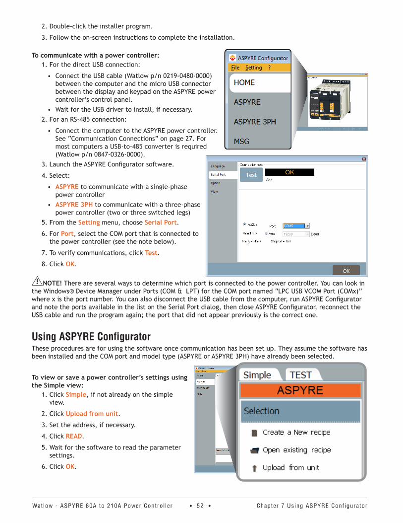
Watlow - ASPYRE 60A to 210A Power Contro l ler • 52 • Chapter 7 Using ASPYRE Conf igurator
2. Double-click the installer program.
3. Follow the on-screen instructions to complete the installation.
To communicate with a power controller:1. For the direct USB connection:
• Connect the USB cable (Watlow p/n 0219-0480-0000) between the computer and the micro USB connector between the display and keypad on the ASPYRE power controller’s control panel.
• Wait for the USB driver to install, if necessary.2. For an RS-485 connection:
• Connect the computer to the ASPYRE power controller. See “Communication Connections” on page 27. For most computers a USB-to-485 converter is required (Watlow p/n 0847-0326-0000).
3. Launch the ASPYRE Configurator software.
4. Select:
• ASPYRE to communicate with a single-phase power controller
• ASPYRE 3PH to communicate with a three-phase power controller (two or three switched legs)
5. From the Setting menu, choose Serial Port.
6. For Port, select the COM port that is connected to the power controller (see the note below).
7. To verify communications, click Test.
8. Click OK.
NOTE! There are several ways to determine which port is connected to the power controller. You can look in the Windows® Device Manager under Ports (COM & LPT) for the COM port named “LPC USB VCOM Port (COMx)” where x is the port number. You can also disconnect the USB cable from the computer, run ASPYRE Configurator and note the ports available in the list on the Serial Port dialog, then close ASPYRE Configurator, reconnect the USB cable and run the program again; the port that did not appear previously is the correct one.
Using ASPYRE ConfiguratorThese procedures are for using the software once communication has been set up. They assume the software has been installed and the COM port and model type (ASPYRE or ASPYRE 3PH) have already been selected.
To view or save a power controller’s settings using the Simple view:
1. Click Simple, if not already on the simple view.
2. Click Upload from unit.
3. Set the address, if necessary.
4. Click READ.
5. Wait for the software to read the parameter settings.
6. Click OK.
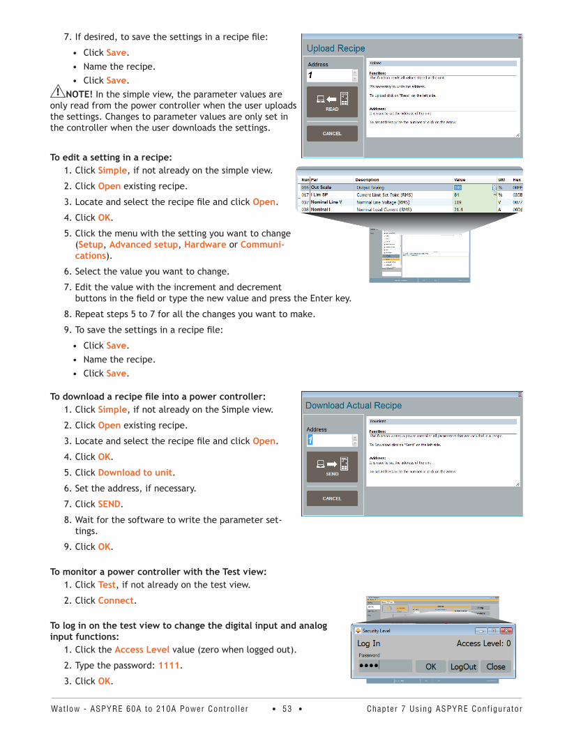
Watlow - ASPYRE 60A to 210A Power Contro l ler • 53 • Chapter 7 Using ASPYRE Conf igurator
7. If desired, to save the settings in a recipe file:
• Click Save.• Name the recipe.• Click Save.
NOTE! In the simple view, the parameter values are only read from the power controller when the user uploads the settings. Changes to parameter values are only set in the controller when the user downloads the settings.
To edit a setting in a recipe:1. Click Simple, if not already on the simple view.
2. Click Open existing recipe.
3. Locate and select the recipe file and click Open.
4. Click OK.
5. Click the menu with the setting you want to change (Setup, Advanced setup, Hardware or Communi-cations).
6. Select the value you want to change.
7. Edit the value with the increment and decrement buttons in the field or type the new value and press the Enter key.
8. Repeat steps 5 to 7 for all the changes you want to make.
9. To save the settings in a recipe file:
• Click Save.• Name the recipe.• Click Save.
To download a recipe file into a power controller: 1. Click Simple, if not already on the Simple view.
2. Click Open existing recipe.
3. Locate and select the recipe file and click Open.
4. Click OK.
5. Click Download to unit.
6. Set the address, if necessary.
7. Click SEND.
8. Wait for the software to write the parameter set-tings.
9. Click OK.
To monitor a power controller with the Test view:1. Click Test, if not already on the test view.
2. Click Connect.
To log in on the test view to change the digital input and analog input functions:
1. Click the Access Level value (zero when logged out).
2. Type the password: 1111.
3. Click OK.
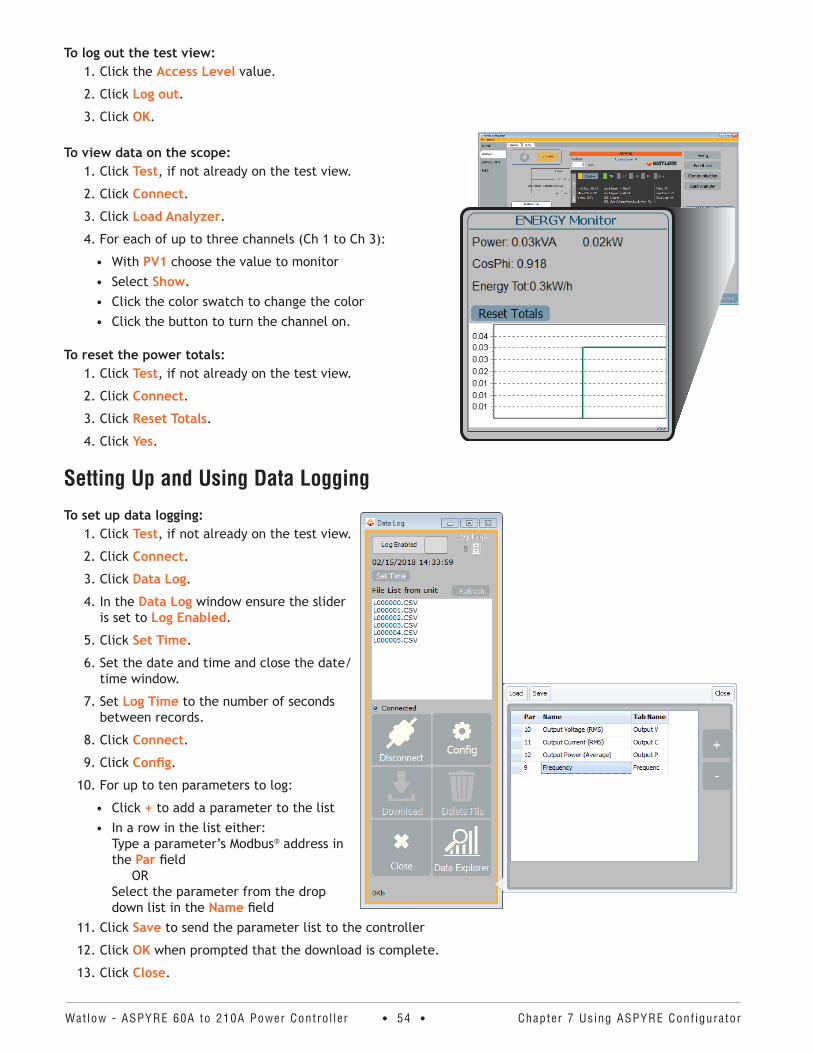
Watlow - ASPYRE 60A to 210A Power Contro l ler • 54 • Chapter 7 Using ASPYRE Conf igurator
To log out the test view: 1. Click the Access Level value.
2. Click Log out.
3. Click OK.
To view data on the scope: 1. Click Test, if not already on the test view.
2. Click Connect.
3. Click Load Analyzer.
4. For each of up to three channels (Ch 1 to Ch 3):
• With PV1 choose the value to monitor• Select Show.• Click the color swatch to change the color• Click the button to turn the channel on.
To reset the power totals:1. Click Test, if not already on the test view.
2. Click Connect.
3. Click Reset Totals.
4. Click Yes.
Setting Up and Using Data Logging
To set up data logging:1. Click Test, if not already on the test view.
2. Click Connect.
3. Click Data Log.
4. In the Data Log window ensure the slider is set to Log Enabled.
5. Click Set Time.
6. Set the date and time and close the date/time window.
7. Set Log Time to the number of seconds between records.
8. Click Connect.
9. Click Config.
10. For up to ten parameters to log:
• Click + to add a parameter to the list• In a row in the list either:
Type a parameter’s Modbus® address in the Par field OR Select the parameter from the drop down list in the Name field
11. Click Save to send the parameter list to the controller
12. Click OK when prompted that the download is complete.
13. Click Close.
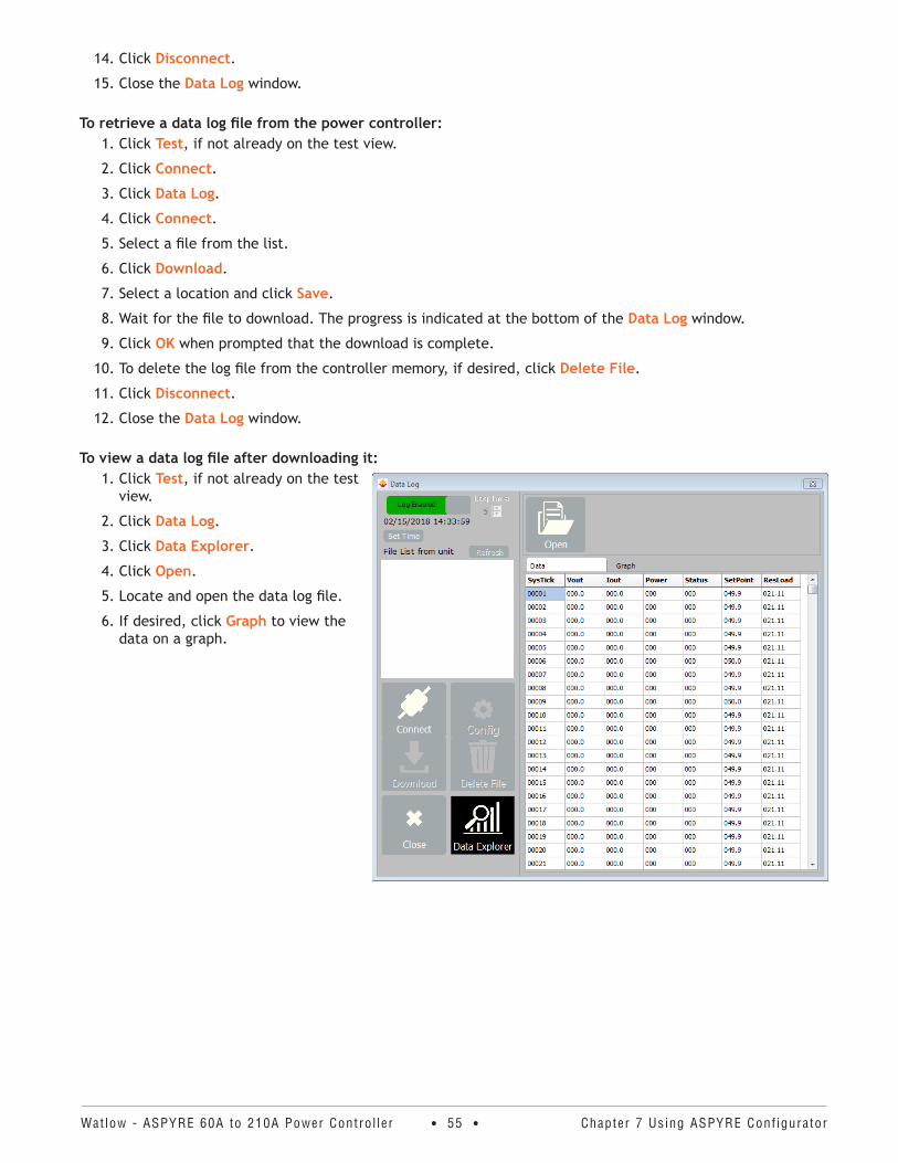
Watlow - ASPYRE 60A to 210A Power Contro l ler • 55 • Chapter 7 Using ASPYRE Conf igurator
14. Click Disconnect.
15. Close the Data Log window.
To retrieve a data log file from the power controller:1. Click Test, if not already on the test view.
2. Click Connect.
3. Click Data Log.
4. Click Connect.
5. Select a file from the list.
6. Click Download.
7. Select a location and click Save.
8. Wait for the file to download. The progress is indicated at the bottom of the Data Log window.
9. Click OK when prompted that the download is complete.
10. To delete the log file from the controller memory, if desired, click Delete File.
11. Click Disconnect.
12. Close the Data Log window.
To view a data log file after downloading it:1. Click Test, if not already on the test
view.
2. Click Data Log.
3. Click Data Explorer.
4. Click Open.
5. Locate and open the data log file.
6. If desired, click Graph to view the data on a graph.
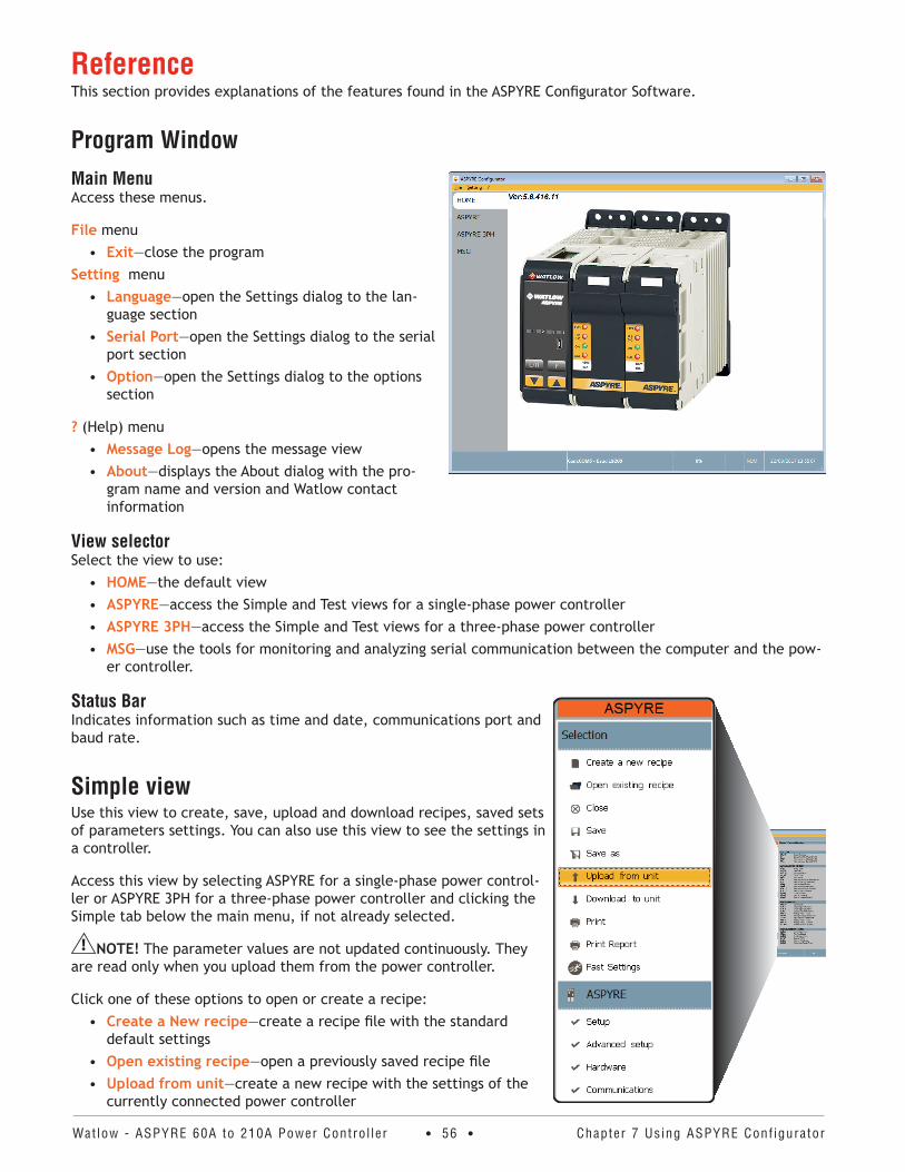
Watlow - ASPYRE 60A to 210A Power Contro l ler • 56 • Chapter 7 Using ASPYRE Conf igurator
ReferenceThis section provides explanations of the features found in the ASPYRE Configurator Software.
Program WindowMain MenuAccess these menus.
File menu• Exit—close the program
Setting menu• Language—open the Settings dialog to the lan-
guage section• Serial Port—open the Settings dialog to the serial
port section• Option—open the Settings dialog to the options
section
? (Help) menu• Message Log—opens the message view• About—displays the About dialog with the pro-
gram name and version and Watlow contact information
View selectorSelect the view to use:
• HOME—the default view• ASPYRE—access the Simple and Test views for a single-phase power controller• ASPYRE 3PH—access the Simple and Test views for a three-phase power controller• MSG—use the tools for monitoring and analyzing serial communication between the computer and the pow-
er controller.
Status BarIndicates information such as time and date, communications port and baud rate.
Simple viewUse this view to create, save, upload and download recipes, saved sets of parameters settings. You can also use this view to see the settings in a controller.
Access this view by selecting ASPYRE for a single-phase power control-ler or ASPYRE 3PH for a three-phase power controller and clicking the Simple tab below the main menu, if not already selected.
NOTE! The parameter values are not updated continuously. They are read only when you upload them from the power controller.
Click one of these options to open or create a recipe:• Create a New recipe—create a recipe file with the standard
default settings• Open existing recipe—open a previously saved recipe file• Upload from unit—create a new recipe with the settings of the
currently connected power controller
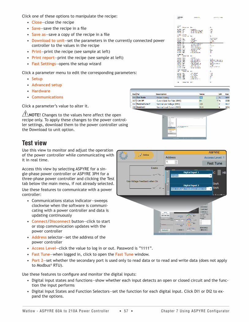
Watlow - ASPYRE 60A to 210A Power Contro l ler • 57 • Chapter 7 Using ASPYRE Conf igurator
Click one of these options to manipulate the recipe:• Close—close the recipe• Save—save the recipe in a file• Save as—save a copy of the recipe in a file• Download to unit—set the parameters in the currently connected power
controller to the values in the recipe• Print—print the recipe (see sample at left)• Print report—print the recipe (see sample at left)• Fast Settings—opens the setup wizard
Click a parameter menu to edit the corresponding parameters:• Setup• Advanced setup• Hardware• Communications
Click a parameter’s value to alter it.
NOTE! Changes to the values here affect the open recipe only. To apply these changes to the power control-ler settings, download them to the power controller using the Download to unit option.
Test viewUse this view to monitor and adjust the operation of the power controller while communicating with it in real time.
Access this view by selecting ASPYRE for a sin-gle-phase power controller or ASPYRE 3PH for a three-phase power controller and clicking the Test tab below the main menu, if not already selected.Use these features to communicate with a power controller:
• Communications status indicator—sweeps clockwise when the software is communi-cating with a power controller and data is updating continuously
• Connect/Disconnect button—click to start or stop communication updates with the power controller
• Address selector—set the address of the power controller
• Access Level—click the value to log in or out. Password is “1111”.• Fast Tune—when logged in, click to open the Fast Tune window.• Port 2—set whether the secondary port is used only to read data or to read and write data (does not apply
to Modbus® RTU).
Use these features to configure and monitor the digital inputs:• Digital input states and functions—show whether each input detects an open or closed circuit and the func-
tion the input performs• Digital Input States and Function Selectors—set the function for each digital input. Click DI1 or DI2 to ex-
pand the options.
1
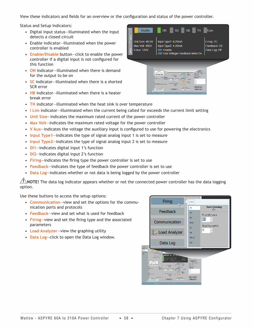
Watlow - ASPYRE 60A to 210A Power Contro l ler • 58 • Chapter 7 Using ASPYRE Conf igurator
View these indicators and fields for an overview or the configuration and status of the power controller.
Status and Setup Indicators:• Digital input status—illuminated when the input
detects a closed circuit• Enable indicator—illuminated when the power
controller is enabled• Enable/Disable button—click to enable the power
controller if a digital input is not configured for this function
• ON indicator—illuminated when there is demand for the output to be on
• SC indicator—illuminated when there is a shorted SCR error
• HB indicator—illuminated when there is a heater break error
• TH indicator—illuminated when the heat sink is over temperature• I Lim indicator—illuminated when the current being called for exceeds the current limit setting• Unit Size—indicates the maximum rated current of the power controller• Max Volt—indicates the maximum rated voltage for the power controller• V Aux—indicates the voltage the auxiliary input is configured to use for powering the electronics• Input Type1—indicates the type of signal analog input 1 is set to measure• Input Type2—indicates the type of signal analog input 2 is set to measure• DI1—indicates digital input 1’s function• DI2—indicates digital input 2’s function • Firing—indicates the firing type the power controller is set to use• Feedback—indicates the type of feedback the power controller is set to use• Data Log—indicates whether or not data is being logged by the power controller
NOTE! The data log indicator appears whether or not the connected power controller has the data logging option.
Use these buttons to access the setup options:• Communication—view and set the options for the commu-
nication ports and protocols• Feedback—view and set what is used for feedback• Firing—view and set the firing type and the associated
parameters• Load Analyzer—view the graphing utility• Data Log—click to open the Data Log window.
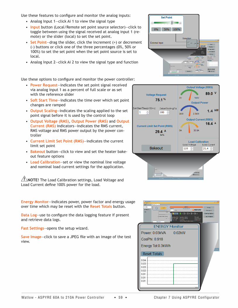
Watlow - ASPYRE 60A to 210A Power Contro l ler • 59 • Chapter 7 Using ASPYRE Conf igurator
Use these features to configure and monitor the analog inputs:• Analog Input 1—click Ai 1 to view the signal type• Input button (Local/Remote set point source selector)—click to
toggle between using the signal received at analog input 1 (re-mote) or the slider (local) to set the set point.
• Set Point—drag the slider, click the increment (+) or decrement (-) buttons or click one of the three percentages (0%, 50% or 100%) to set the set point when the set point source is set to local.
• Analog Input 2—click Ai 2 to view the signal type and function
Use these options to configure and monitor the power controller:• Power Request—indicates the set point signal received
via analog input 1 as a percent of full scale or as set with the reference slider
• Soft Start Time—indicates the time over which set point changes are ramped
• Output Scaling—indicates the scaling applied to the set point signal before it is used by the control loop
• Output Voltage (RMS), Output Power (RMS) and Output Current (RMS) indicators—indicates the RMS current, RMS voltage and RMS power output by the power con-troller
• Current Limit Set Point (RMS)—indicates the current limit set point
• Bakeout button—click to view and set the heater bake-out feature options
• Load Calibration—set or view the nominal line voltage and nominal load current settings for the application.
NOTE! The Load Calibration settings, Load Voltage and Load Current define 100% power for the load.
Energy Monitor—indicates power, power factor and energy usage over time which may be reset with the Reset Totals button.
Data Log—use to configure the data logging feature if present and retrieve data logs.
Fast Settings—opens the setup wizard.
Save Image—click to save a JPEG file with an image of the test view.
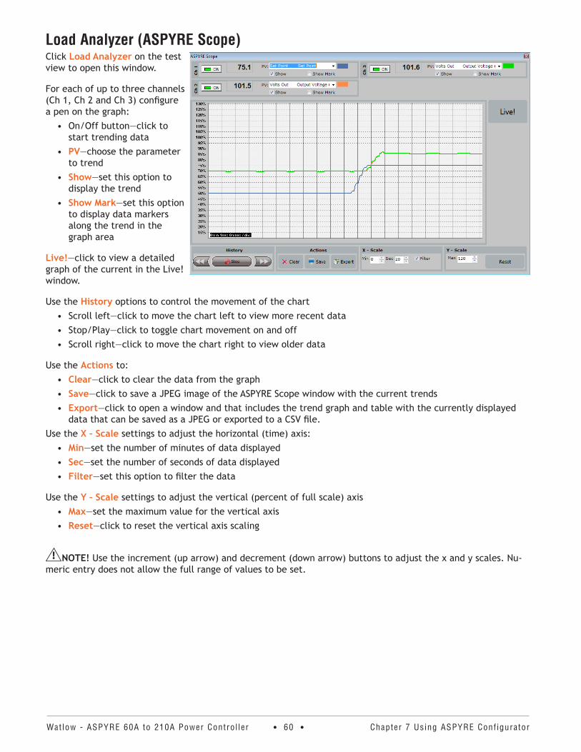
Watlow - ASPYRE 60A to 210A Power Contro l ler • 60 • Chapter 7 Using ASPYRE Conf igurator
Load Analyzer (ASPYRE Scope)Click Load Analyzer on the test view to open this window.
For each of up to three channels (Ch 1, Ch 2 and Ch 3) configure a pen on the graph:
• On/Off button—click to start trending data
• PV—choose the parameter to trend
• Show—set this option to display the trend
• Show Mark—set this option to display data markers along the trend in the graph area
Live!—click to view a detailed graph of the current in the Live! window.
Use the History options to control the movement of the chart• Scroll left—click to move the chart left to view more recent data• Stop/Play—click to toggle chart movement on and off• Scroll right—click to move the chart right to view older data
Use the Actions to:• Clear—click to clear the data from the graph• Save—click to save a JPEG image of the ASPYRE Scope window with the current trends• Export—click to open a window and that includes the trend graph and table with the currently displayed
data that can be saved as a JPEG or exported to a CSV file.Use the X – Scale settings to adjust the horizontal (time) axis:
• Min—set the number of minutes of data displayed• Sec—set the number of seconds of data displayed• Filter—set this option to filter the data
Use the Y – Scale settings to adjust the vertical (percent of full scale) axis• Max—set the maximum value for the vertical axis• Reset—click to reset the vertical axis scaling
NOTE! Use the increment (up arrow) and decrement (down arrow) buttons to adjust the x and y scales. Nu-meric entry does not allow the full range of values to be set.
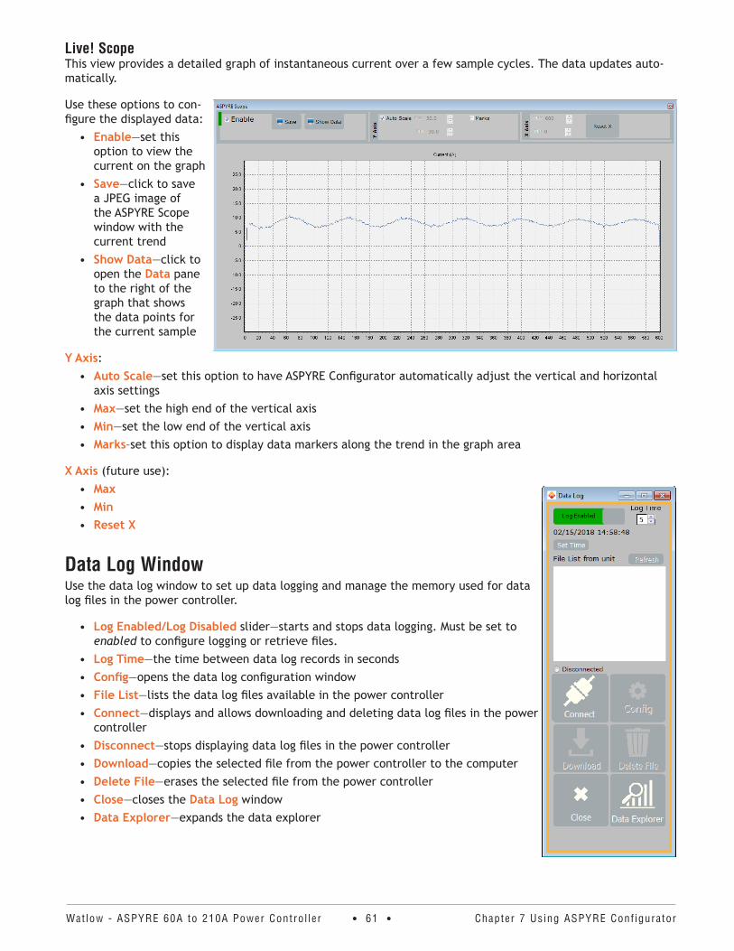
Watlow - ASPYRE 60A to 210A Power Contro l ler • 61 • Chapter 7 Using ASPYRE Conf igurator
Live! ScopeThis view provides a detailed graph of instantaneous current over a few sample cycles. The data updates auto-matically.
Use these options to con-figure the displayed data:
• Enable—set this option to view the current on the graph
• Save—click to save a JPEG image of the ASPYRE Scope window with the current trend
• Show Data—click to open the Data pane to the right of the graph that shows the data points for the current sample
Y Axis:• Auto Scale—set this option to have ASPYRE Configurator automatically adjust the vertical and horizontal
axis settings• Max—set the high end of the vertical axis• Min—set the low end of the vertical axis• Marks–set this option to display data markers along the trend in the graph area
X Axis (future use):• Max• Min• Reset X
Data Log WindowUse the data log window to set up data logging and manage the memory used for data log files in the power controller.
• Log Enabled/Log Disabled slider—starts and stops data logging. Must be set to enabled to configure logging or retrieve files.
• Log Time—the time between data log records in seconds• Config—opens the data log configuration window• File List—lists the data log files available in the power controller• Connect—displays and allows downloading and deleting data log files in the power
controller• Disconnect—stops displaying data log files in the power controller• Download—copies the selected file from the power controller to the computer• Delete File—erases the selected file from the power controller• Close—closes the Data Log window• Data Explorer—expands the data explorer
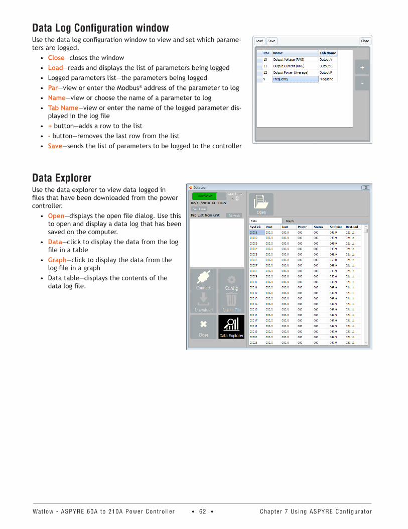
Watlow - ASPYRE 60A to 210A Power Contro l ler • 62 • Chapter 7 Using ASPYRE Conf igurator
Data Log Configuration windowUse the data log configuration window to view and set which parame-ters are logged.
• Close—closes the window• Load—reads and displays the list of parameters being logged• Logged parameters list—the parameters being logged• Par—view or enter the Modbus® address of the parameter to log• Name—view or choose the name of a parameter to log• Tab Name—view or enter the name of the logged parameter dis-
played in the log file• + button—adds a row to the list• - button—removes the last row from the list• Save—sends the list of parameters to be logged to the controller
Data ExplorerUse the data explorer to view data logged in files that have been downloaded from the power controller.
• Open—displays the open file dialog. Use this to open and display a data log that has been saved on the computer.
• Data—click to display the data from the log file in a table
• Graph—click to display the data from the log file in a graph
• Data table—displays the contents of the data log file.
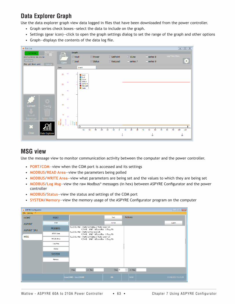
Watlow - ASPYRE 60A to 210A Power Contro l ler • 63 • Chapter 7 Using ASPYRE Conf igurator
Data Explorer GraphUse the data explorer graph view data logged in files that have been downloaded from the power controller.
• Graph series check boxes—select the data to include on the graph.• Settings (gear icon)—click to open the graph settings dialog to set the range of the graph and other options• Graph—displays the contents of the data log file.
MSG viewUse the message view to monitor communication activity between the computer and the power controller.
• PORT/COM—view when the COM port is accessed and its settings• MODBUS/READ Area—view the parameters being polled• MODBUS/WRITE Area—view what parameters are being set and the values to which they are being set• MODBUS/Log Msg—view the raw Modbus® messages (in hex) between ASPYRE Configurator and the power
controller• MODBUS/Status—view the status and settings of the COM port• SYSTEM/Memory—view the memory usage of the ASPYRE Configurator program on the computer
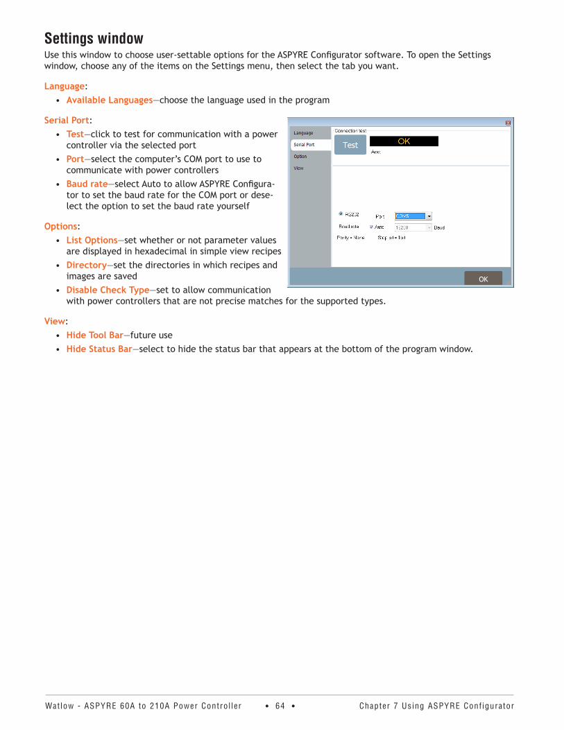
Watlow - ASPYRE 60A to 210A Power Contro l ler • 64 • Chapter 7 Using ASPYRE Conf igurator
Settings windowUse this window to choose user-settable options for the ASPYRE Configurator software. To open the Settings window, choose any of the items on the Settings menu, then select the tab you want.
Language:• Available Languages—choose the language used in the program
Serial Port:• Test—click to test for communication with a power
controller via the selected port• Port—select the computer’s COM port to use to
communicate with power controllers• Baud rate—select Auto to allow ASPYRE Configura-
tor to set the baud rate for the COM port or dese-lect the option to set the baud rate yourself
Options:• List Options—set whether or not parameter values
are displayed in hexadecimal in simple view recipes• Directory—set the directories in which recipes and
images are saved• Disable Check Type—set to allow communication
with power controllers that are not precise matches for the supported types.
View:• Hide Tool Bar—future use• Hide Status Bar—select to hide the status bar that appears at the bottom of the program window.
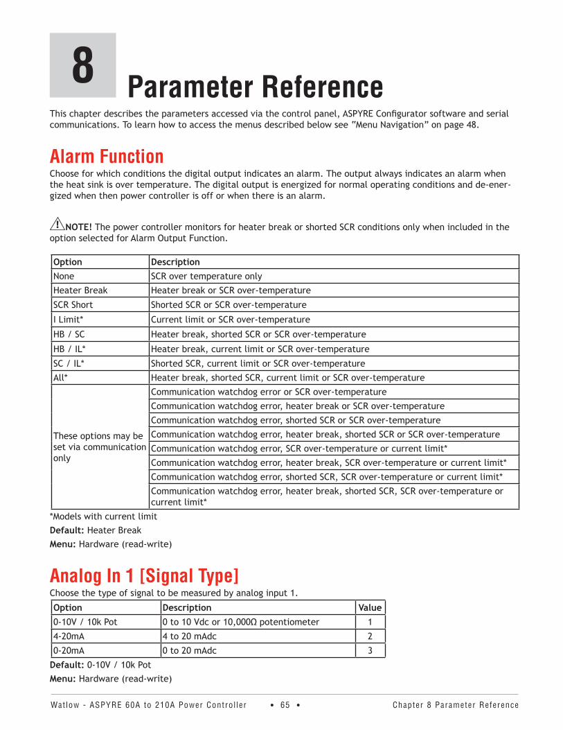
Watlow - ASPYRE 60A to 210A Power Contro l ler • 65 • Chapter 8 Parameter Reference
Parameter ReferenceThis chapter describes the parameters accessed via the control panel, ASPYRE Configurator software and serial communications. To learn how to access the menus described below see “Menu Navigation” on page 48.
Alarm FunctionChoose for which conditions the digital output indicates an alarm. The output always indicates an alarm when the heat sink is over temperature. The digital output is energized for normal operating conditions and de-ener-gized when then power controller is off or when there is an alarm.
NOTE! The power controller monitors for heater break or shorted SCR conditions only when included in the option selected for Alarm Output Function.
Option DescriptionNone SCR over temperature only
Heater Break Heater break or SCR over-temperature
SCR Short Shorted SCR or SCR over-temperature
I Limit* Current limit or SCR over-temperature
HB / SC Heater break, shorted SCR or SCR over-temperature
HB / IL* Heater break, current limit or SCR over-temperature
SC / IL* Shorted SCR, current limit or SCR over-temperature
All* Heater break, shorted SCR, current limit or SCR over-temperature
These options may be set via communication only
Communication watchdog error or SCR over-temperature
Communication watchdog error, heater break or SCR over-temperature
Communication watchdog error, shorted SCR or SCR over-temperature
Communication watchdog error, heater break, shorted SCR or SCR over-temperature
Communication watchdog error, SCR over-temperature or current limit*
Communication watchdog error, heater break, SCR over-temperature or current limit*
Communication watchdog error, shorted SCR, SCR over-temperature or current limit*
Communication watchdog error, heater break, shorted SCR, SCR over-temperature or current limit*
*Models with current limitDefault: Heater BreakMenu: Hardware (read-write)
Analog In 1 [Signal Type]Choose the type of signal to be measured by analog input 1.
Option Description Value0-10V / 10k Pot 0 to 10 Vdc or 10,000Ω potentiometer 1
4-20mA 4 to 20 mAdc 2
0-20mA 0 to 20 mAdc 3
Default: 0-10V / 10k PotMenu: Hardware (read-write)
8
Watlow - ASPYRE 60A to 210A Power Contro l ler • 66 • Chapter 8 Parameter Reference
Analog In 1 [Value]Indicates the percent of full scale measured by analog input 1.Range: 0 to 100.0%Menu: Monitor (read-only)
Analog In 2 [Signal Type]Choose the type of signal to be measured by analog input 2.
Option Description0-10V / 10k Pot 0 to 10 Vdc or 10,000Ω potentiometer
4-20mA 4 to 20 mAdc
0-20mA 0 to 20 mAdc
Default: 0-10V / 10k PotMenu: Hardware (read-write)
Analog In 2 [Value] Indicates the percent of full scale measured by analog input 2.Range: 0 to 100.0%Menu: Monitor (read-only)
Analog In 2 FunctionChoose how the signal measured by analog input 2 is used.
Option DescriptionI Limit* Current limit set point
Feedback External feedback
Set Point Power demand set point
*DT1 and DT3 modelsDefault: I Limit or Feedback (models without current limit feature)Menu: Hardware (read-write)
Aux VoltageIndicates the measured line voltage.Range: 0 to 1023VMenu: Monitor (read-only)
Bakeout Current (Models with Current Limit)Set the maximum current for the heater bakeout.Range: 0 to 999.9 ADefault: 0Menu: Advanced Setup (read-write)
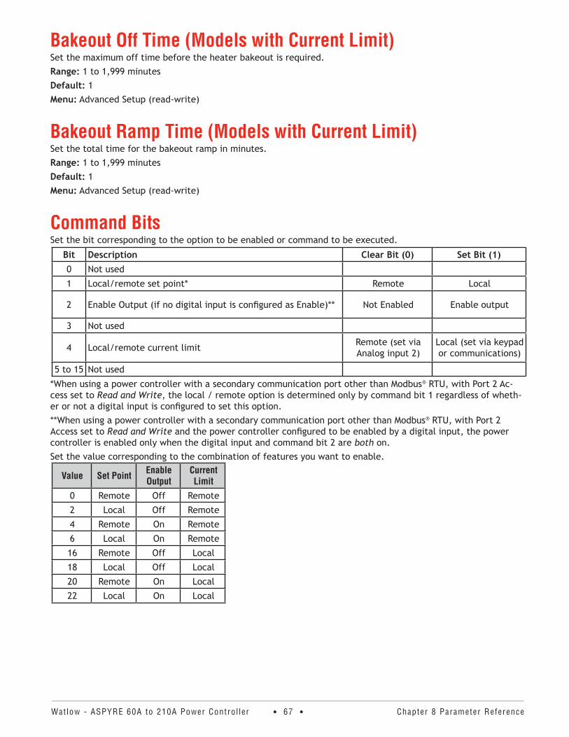
Watlow - ASPYRE 60A to 210A Power Contro l ler • 67 • Chapter 8 Parameter Reference
Bakeout Off Time (Models with Current Limit)Set the maximum off time before the heater bakeout is required.Range: 1 to 1,999 minutesDefault: 1Menu: Advanced Setup (read-write)
Bakeout Ramp Time (Models with Current Limit)Set the total time for the bakeout ramp in minutes.Range: 1 to 1,999 minutesDefault: 1Menu: Advanced Setup (read-write)
Command BitsSet the bit corresponding to the option to be enabled or command to be executed.
Bit Description Clear Bit (0) Set Bit (1)0 Not used
1 Local/remote set point* Remote Local
2 Enable Output (if no digital input is configured as Enable)** Not Enabled Enable output
3 Not used
4 Local/remote current limit Remote (set via Analog input 2)
Local (set via keypad or communications)
5 to 15 Not used
*When using a power controller with a secondary communication port other than Modbus® RTU, with Port 2 Ac-cess set to Read and Write, the local / remote option is determined only by command bit 1 regardless of wheth-er or not a digital input is configured to set this option.**When using a power controller with a secondary communication port other than Modbus® RTU, with Port 2 Access set to Read and Write and the power controller configured to be enabled by a digital input, the power controller is enabled only when the digital input and command bit 2 are both on.Set the value corresponding to the combination of features you want to enable.
Value Set Point Enable Output
Current Limit
0 Remote Off Remote
2 Local Off Remote
4 Remote On Remote
6 Local On Remote
16 Remote Off Local
18 Local Off Local
20 Remote On Local
22 Local On Local
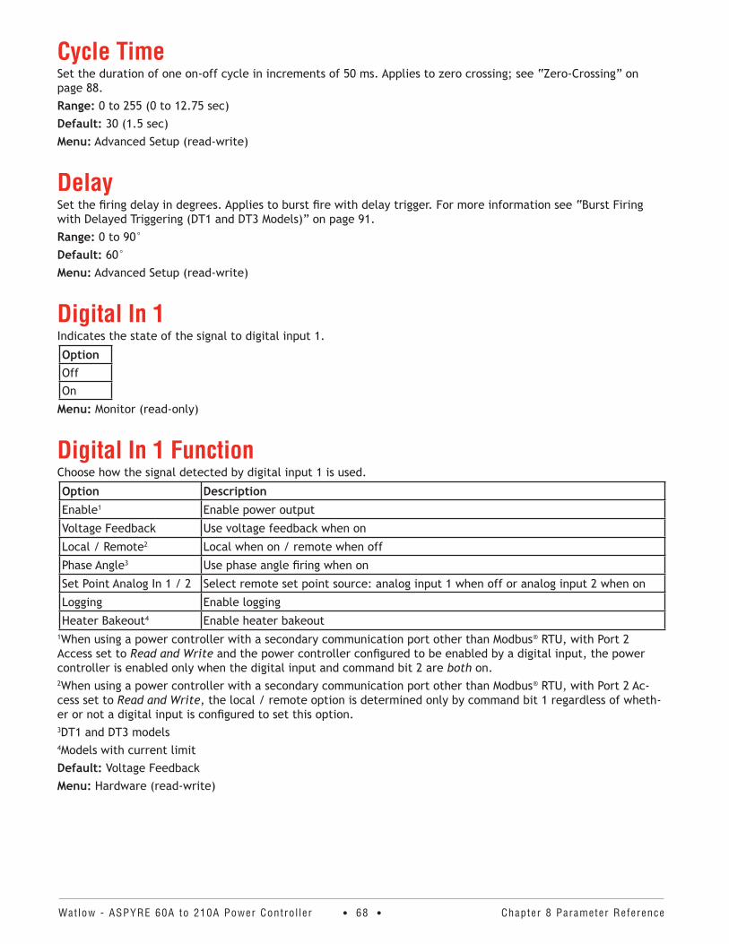
Watlow - ASPYRE 60A to 210A Power Contro l ler • 68 • Chapter 8 Parameter Reference
Cycle TimeSet the duration of one on-off cycle in increments of 50 ms. Applies to zero crossing; see “Zero-Crossing” on page 88. Range: 0 to 255 (0 to 12.75 sec) Default: 30 (1.5 sec)Menu: Advanced Setup (read-write)
DelaySet the firing delay in degrees. Applies to burst fire with delay trigger. For more information see “Burst Firing with Delayed Triggering (DT1 and DT3 Models)” on page 91.Range: 0 to 90° Default: 60°Menu: Advanced Setup (read-write)
Digital In 1Indicates the state of the signal to digital input 1.
OptionOffOn
Menu: Monitor (read-only)
Digital In 1 FunctionChoose how the signal detected by digital input 1 is used.
Option DescriptionEnable1 Enable power output
Voltage Feedback Use voltage feedback when on
Local / Remote2 Local when on / remote when off
Phase Angle3 Use phase angle firing when on
Set Point Analog In 1 / 2 Select remote set point source: analog input 1 when off or analog input 2 when on
Logging Enable logging
Heater Bakeout4 Enable heater bakeout1When using a power controller with a secondary communication port other than Modbus® RTU, with Port 2 Access set to Read and Write and the power controller configured to be enabled by a digital input, the power controller is enabled only when the digital input and command bit 2 are both on.2When using a power controller with a secondary communication port other than Modbus® RTU, with Port 2 Ac-cess set to Read and Write, the local / remote option is determined only by command bit 1 regardless of wheth-er or not a digital input is configured to set this option.3DT1 and DT3 models4Models with current limitDefault: Voltage FeedbackMenu: Hardware (read-write)
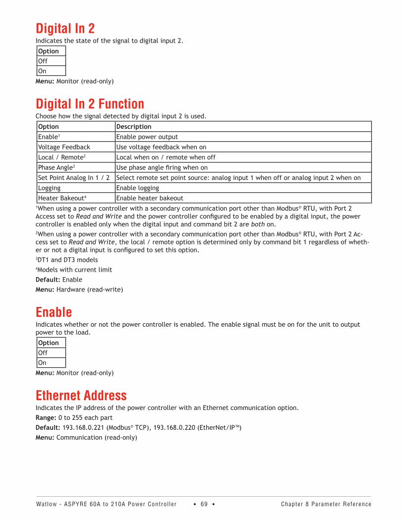
Watlow - ASPYRE 60A to 210A Power Contro l ler • 69 • Chapter 8 Parameter Reference
Digital In 2Indicates the state of the signal to digital input 2.
OptionOffOn
Menu: Monitor (read-only)
Digital In 2 FunctionChoose how the signal detected by digital input 2 is used.
Option DescriptionEnable1 Enable power output
Voltage Feedback Use voltage feedback when on
Local / Remote2 Local when on / remote when off
Phase Angle3 Use phase angle firing when on
Set Point Analog In 1 / 2 Select remote set point source: analog input 1 when off or analog input 2 when on
Logging Enable logging
Heater Bakeout4 Enable heater bakeout1When using a power controller with a secondary communication port other than Modbus® RTU, with Port 2 Access set to Read and Write and the power controller configured to be enabled by a digital input, the power controller is enabled only when the digital input and command bit 2 are both on.2When using a power controller with a secondary communication port other than Modbus® RTU, with Port 2 Ac-cess set to Read and Write, the local / remote option is determined only by command bit 1 regardless of wheth-er or not a digital input is configured to set this option.3DT1 and DT3 models4Models with current limitDefault: EnableMenu: Hardware (read-write)
EnableIndicates whether or not the power controller is enabled. The enable signal must be on for the unit to output power to the load.
OptionOffOn
Menu: Monitor (read-only)
Ethernet AddressIndicates the IP address of the power controller with an Ethernet communication option.Range: 0 to 255 each partDefault: 193.168.0.221 (Modbus® TCP), 193.168.0.220 (EtherNet/IP™)Menu: Communication (read-only)
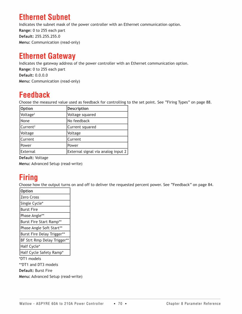
Watlow - ASPYRE 60A to 210A Power Contro l ler • 70 • Chapter 8 Parameter Reference
Ethernet SubnetIndicates the subnet mask of the power controller with an Ethernet communication option.Range: 0 to 255 each partDefault: 255.255.255.0Menu: Communication (read-only)
Ethernet GatewayIndicates the gateway address of the power controller with an Ethernet communication option.Range: 0 to 255 each partDefault: 0.0.0.0Menu: Communication (read-only)
FeedbackChoose the measured value used as feedback for controlling to the set point. See “Firing Types” on page 88.
Option DescriptionVoltage2 Voltage squared
None No feedback
Current2 Current squared
Voltage Voltage
Current Current
Power Power
External External signal via analog input 2
Default: VoltageMenu: Advanced Setup (read-write)
FiringChoose how the output turns on and off to deliver the requested percent power. See “Feedback” on page 84.
OptionZero Cross
Single Cycle*
Burst Fire
Phase Angle**
Burst Fire Start Ramp**
Phase Angle Soft Start**
Burst Fire Delay Trigger**
BF Strt Rmp Delay Trigger**
Half Cycle*
Half Cycle Safety Ramp*
*DT1 models**DT1 and DT3 modelsDefault: Burst FireMenu: Advanced Setup (read-write)
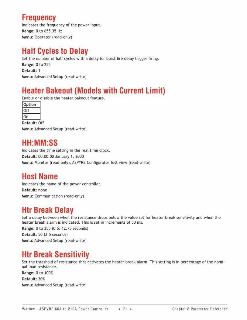
Watlow - ASPYRE 60A to 210A Power Contro l ler • 71 • Chapter 8 Parameter Reference
Frequency Indicates the frequency of the power input.Range: 0 to 655.35 HzMenu: Operator (read-only)
Half Cycles to DelaySet the number of half cycles with a delay for burst fire delay trigger firing.Range: 0 to 255Default: 1Menu: Advanced Setup (read-write)
Heater Bakeout (Models with Current Limit)Enable or disable the heater bakeout feature.
OptionOffOn
Default: OffMenu: Advanced Setup (read-write)
HH:MM:SSIndicates the time setting in the real time clock.Default: 00:00:00 January 1, 2000Menu: Monitor (read-only), ASPYRE Configurator Test view (read-write)
Host NameIndicates the name of the power controller.Default: noneMenu: Communication (read-only)
Htr Break DelaySet a delay between when the resistance drops below the value set for heater break sensitivity and when the heater break alarm is indicated. This is set in increments of 50 ms.Range: 0 to 255 (0 to 12.75 seconds)Default: 50 (2.5 seconds)Menu: Advanced Setup (read-write)
Htr Break SensitivitySet the threshold of resistance that activates the heater break alarm. This setting is in percentage of the nomi-nal load resistance.Range: 0 to 100%Default: 20%Menu: Advanced Setup (read-write)
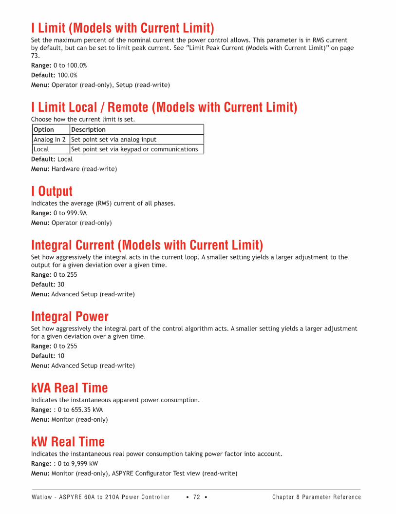
Watlow - ASPYRE 60A to 210A Power Contro l ler • 72 • Chapter 8 Parameter Reference
I Limit (Models with Current Limit)Set the maximum percent of the nominal current the power control allows. This parameter is in RMS current by default, but can be set to limit peak current. See “Limit Peak Current (Models with Current Limit)” on page 73.Range: 0 to 100.0%Default: 100.0%Menu: Operator (read-only), Setup (read-write)
I Limit Local / Remote (Models with Current Limit)Choose how the current limit is set.
Option DescriptionAnalog In 2 Set point set via analog inputLocal Set point set via keypad or communications
Default: LocalMenu: Hardware (read-write)
I Output Indicates the average (RMS) current of all phases.Range: 0 to 999.9AMenu: Operator (read-only)
Integral Current (Models with Current Limit) Set how aggressively the integral acts in the current loop. A smaller setting yields a larger adjustment to the output for a given deviation over a given time.Range: 0 to 255Default: 30Menu: Advanced Setup (read-write)
Integral PowerSet how aggressively the integral part of the control algorithm acts. A smaller setting yields a larger adjustment for a given deviation over a given time.Range: 0 to 255Default: 10Menu: Advanced Setup (read-write)
kVA Real TimeIndicates the instantaneous apparent power consumption.Range: : 0 to 655.35 kVAMenu: Monitor (read-only)
kW Real TimeIndicates the instantaneous real power consumption taking power factor into account.Range: : 0 to 9,999 kW Menu: Monitor (read-only), ASPYRE Configurator Test view (read-write)
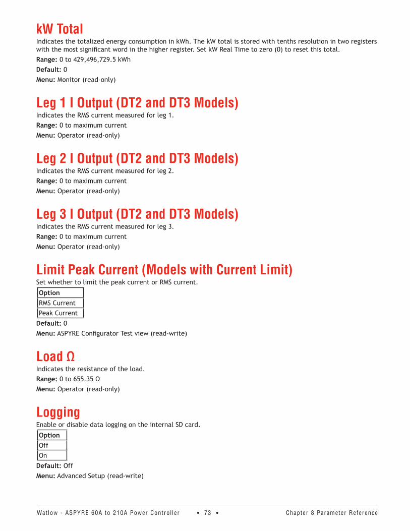
Watlow - ASPYRE 60A to 210A Power Contro l ler • 73 • Chapter 8 Parameter Reference
kW TotalIndicates the totalized energy consumption in kWh. The kW total is stored with tenths resolution in two registers with the most significant word in the higher register. Set kW Real Time to zero (0) to reset this total.Range: 0 to 429,496,729.5 kWh Default: 0 Menu: Monitor (read-only)
Leg 1 I Output (DT2 and DT3 Models)Indicates the RMS current measured for leg 1.Range: 0 to maximum currentMenu: Operator (read-only)
Leg 2 I Output (DT2 and DT3 Models)Indicates the RMS current measured for leg 2.Range: 0 to maximum currentMenu: Operator (read-only)
Leg 3 I Output (DT2 and DT3 Models)Indicates the RMS current measured for leg 3.Range: 0 to maximum currentMenu: Operator (read-only)
Limit Peak Current (Models with Current Limit)Set whether to limit the peak current or RMS current.
OptionRMS CurrentPeak Current
Default: 0Menu: ASPYRE Configurator Test view (read-write)
Load ΩIndicates the resistance of the load.Range: 0 to 655.35 ΩMenu: Operator (read-only)
LoggingEnable or disable data logging on the internal SD card.
OptionOffOn
Default: OffMenu: Advanced Setup (read-write)
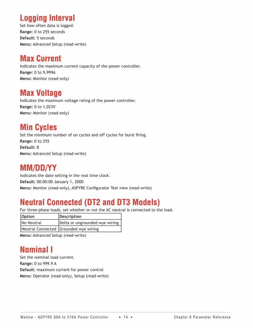
Watlow - ASPYRE 60A to 210A Power Contro l ler • 74 • Chapter 8 Parameter Reference
Logging IntervalSet how often data is logged.Range: 0 to 255 secondsDefault: 5 secondsMenu: Advanced Setup (read-write)
Max Current Indicates the maximum current capacity of the power controller.Range: 0 to 9,999AMenu: Monitor (read-only)
Max VoltageIndicates the maximum voltage rating of the power controller.Range: 0 to 1,023VMenu: Monitor (read-only)
Min CyclesSet the minimum number of on cycles and off cycles for burst firing.Range: 0 to 255Default: 8Menu: Advanced Setup (read-write)
MM/DD/YYIndicates the date setting in the real time clock. Default: 00:00:00 January 1, 2000Menu: Monitor (read-only), ASPYRE Configurator Test view (read-write)
Neutral Connected (DT2 and DT3 Models)For three-phase loads, set whether or not the AC neutral is connected to the load.
Option DescriptionNo Neutral Delta or ungrounded wye wiringNeutral Connected Grounded wye wiring
Menu: Advanced Setup (read-write)
Nominal ISet the nominal load current.Range: 0 to 999.9 ADefault: maximum current for power controlMenu: Operator (read-only), Setup (read-write)
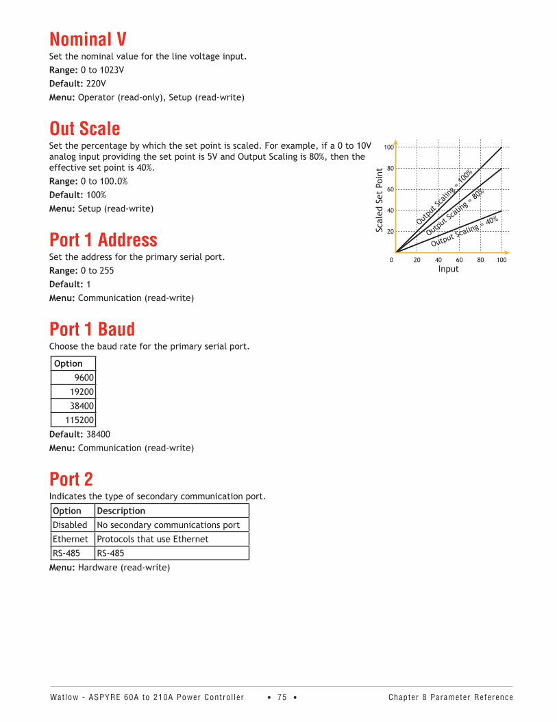
Watlow - ASPYRE 60A to 210A Power Contro l ler • 75 • Chapter 8 Parameter Reference
Nominal VSet the nominal value for the line voltage input.Range: 0 to 1023V Default: 220V Menu: Operator (read-only), Setup (read-write)
Out ScaleSet the percentage by which the set point is scaled. For example, if a 0 to 10V analog input providing the set point is 5V and Output Scaling is 80%, then the effective set point is 40%.Range: 0 to 100.0% Default: 100% Menu: Setup (read-write)
Port 1 AddressSet the address for the primary serial port.Range: 0 to 255Default: 1Menu: Communication (read-write)
Port 1 BaudChoose the baud rate for the primary serial port.
Option9600
19200
38400
115200
Default: 38400Menu: Communication (read-write)
Port 2Indicates the type of secondary communication port.
Option DescriptionDisabled No secondary communications port
Ethernet Protocols that use Ethernet
RS-485 RS-485
Menu: Hardware (read-write)
Scal
ed S
et P
oint
Input0 20 40 60 80 100
20
40
60
80
100
Outpu
t Sca
ling =
100%
Output
Scalin
g = 80
%
Output Scaling = 40%
Watlow - ASPYRE 60A to 210A Power Contro l ler • 76 • Chapter 8 Parameter Reference
Port 2 AccessUse this parameter to disable writing data via port 2 and disable the secondary communication watchdog. Note for protocols other than Modbus® RTU the output from the power controller will be disabled if data is not written at least as often as the communications watchdog is set to expect communications. See “Communication Watch-dog” on page 111.
Option DescriptionRead and Write Data may be written via port 2 and the watchdog function is enabled.
Read Only Data may not be written via port 2 and the watchdog function is disabled.
Default: Read and WriteMenu: Communication (read-write)
Port 2 AddressSet the address for the secondary serial port or the Profibus address.Range: 0 to 255 Default: 0 Menu: Communication (read-write)
Port 2 BaudChoose the baud rate for the secondary serial port.
Option9600
19200
38400
115200
Default: 9600Menu: Communication (read-write)
Power Indicates the average power output as a percent of full power.Range: 0 to 100% Menu: Operator (read-only)
Power FactorIndicates the power factor of the output power.Range: 0 to 1.000 Menu: Operator (read-only)
Prop Band Current (Models with Current Limit)Set the proportional relationship between the output and the feedback for the current limit control loop. This setting determines how big a correction the proportional part of the control algorithm makes when the feedback deviates from set point. Set the gain for the current loop. A smaller proportional band yields a larger adjustment for a given deviation.Range: 0 to 255% Default: 15% Menu: Advanced Setup (read-write)
Watlow - ASPYRE 60A to 210A Power Contro l ler • 77 • Chapter 8 Parameter Reference
Prop Band PowerSet the proportional relationship between the output and the feedback for the power demand control loop. This setting determines how big a correction the proportional part of the control algorithm makes when the feedback deviates from set point. A smaller proportional band yields a larger adjustment for a given deviation.Range: 0 to 255% Default: 5% Menu: Advanced Setup (read-write)
ReleaseIndicates the software release date year and week (yyww).Range: 0 to 65535 Menu: Monitor (read-only)
Remote SPChoose the source for the remote set point. If a digital input is configured to select between the analog inputs as the source of the set point, the digital input takes precedence and this parameter indicates the analog input selected with the digital input.
OptionAnalog Input 1
Analog Input 2
Default: Analog Input 1 Menu: Setup (read-write)
Retransmit (Models with Retransmit)Choose which parameter is retransmitted by the analog output.
Option DescriptionNone Do not retransmit a valueSet Point Set pointV Output RMS voltage outputI Output RMS current outputPower Average output power
Default: PowerMenu: Hardware (read-write)
Watlow - ASPYRE 60A to 210A Power Contro l ler • 78 • Chapter 8 Parameter Reference
Retransmit Scale (Models with Retransmit)Set the value of the retransmitted parameter to be represented by the full scale of the analog output. See the table below.Range: 0 to 9,999 Default: 0 Menu: Hardware (read-write)
Retransmit Settings
Retransmit Recommended Retransmit Scaling
Resulting Signal (4 to 20mADC)
Resulting Signal (0 to 20mADC)
Resulting Signal (0 to 10VDC)
Set point 1004mADC = 0%20mADC = 100%
0mADC = 0%20mADC = 100%
0VDC = 0%10VDC = 100%
V Output xV where x is the Nominal Line Voltage
4mADC = 0% 20mADC = xV
0mADC = 0% 20mADC = xV
0VDC = 0% 10VDC = xV
I OutputxA where x is the Nominal Load Cur-rent
4mADC = 0A 20mADC = xA
0mADC = 0A 20mADC = xA
0VDC = 0A 10VDC = xA
Power 1004mADC = 0%20mADC = 100%
0mADC = 0%20mADC = 100%
0VDC = 0%10VDC = 100%
Retransmit Type (Models with Retransmit)Choose the type of signal for the retransmit output.
Option0-10V
4-20mA
0-20mA
Default: 4-20mA Menu: Hardware (read-write)
Safety Ramp DurationEnable the safety ramp feature and set how long the ramp takes by setting a value greater than zero in incre-ments of 50ms.Range: 0 to 65,535 x50ms Default: 10 (500 ms)Menu: Advanced Setup (read-write)
Safety Ramp Off TimeSet the minimum amount of time the power to the load is off before the safety ramp occurs in increments of 50ms.Range: 0 to 65,535 x50ms Default: 200 (10 seconds) Menu: Advanced Setup (read-write)
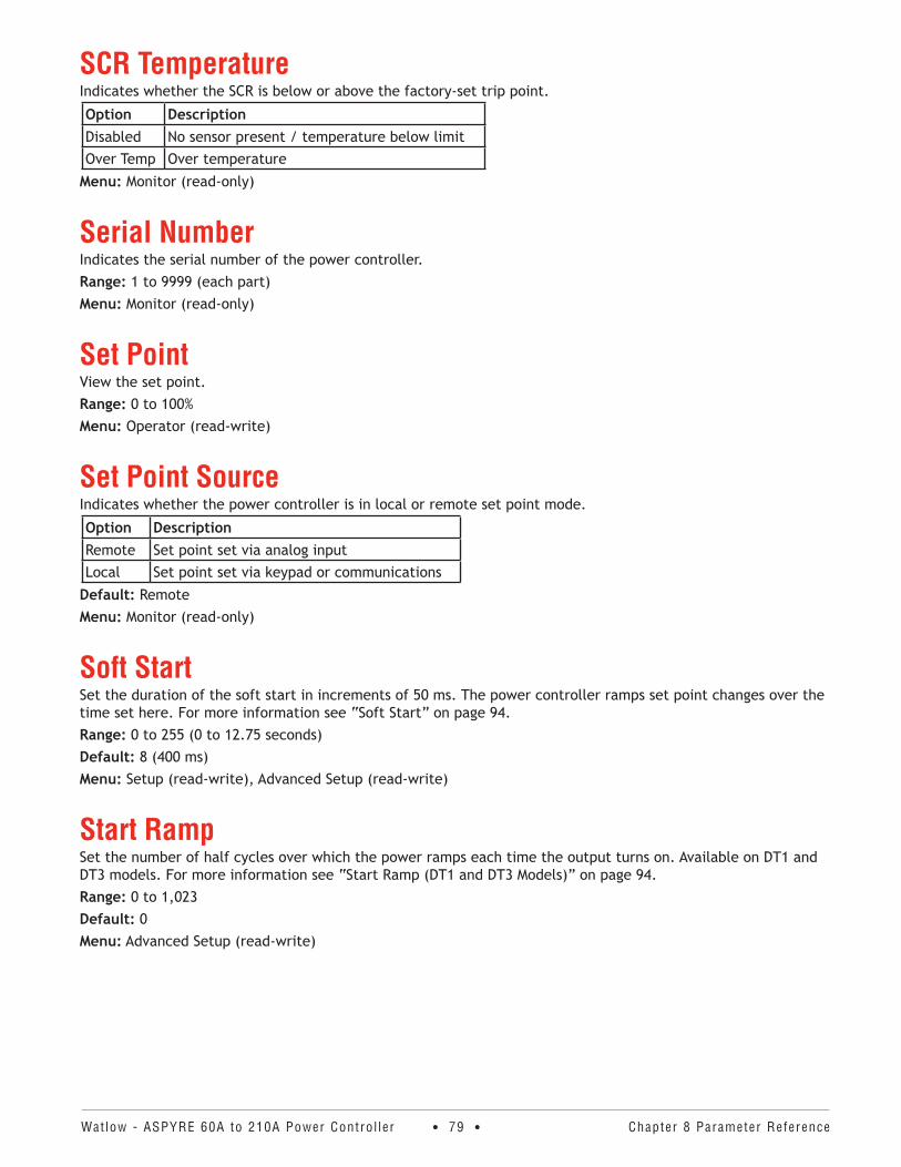
Watlow - ASPYRE 60A to 210A Power Contro l ler • 79 • Chapter 8 Parameter Reference
SCR TemperatureIndicates whether the SCR is below or above the factory-set trip point.
Option DescriptionDisabled No sensor present / temperature below limitOver Temp Over temperature
Menu: Monitor (read-only)
Serial NumberIndicates the serial number of the power controller.Range: 1 to 9999 (each part) Menu: Monitor (read-only)
Set Point View the set point.Range: 0 to 100% Menu: Operator (read-write)
Set Point SourceIndicates whether the power controller is in local or remote set point mode.
Option DescriptionRemote Set point set via analog inputLocal Set point set via keypad or communications
Default: Remote Menu: Monitor (read-only)
Soft StartSet the duration of the soft start in increments of 50 ms. The power controller ramps set point changes over the time set here. For more information see “Soft Start” on page 94.Range: 0 to 255 (0 to 12.75 seconds)Default: 8 (400 ms) Menu: Setup (read-write), Advanced Setup (read-write)
Start RampSet the number of half cycles over which the power ramps each time the output turns on. Available on DT1 and DT3 models. For more information see “Start Ramp (DT1 and DT3 Models)” on page 94.Range: 0 to 1,023 Default: 0 Menu: Advanced Setup (read-write)
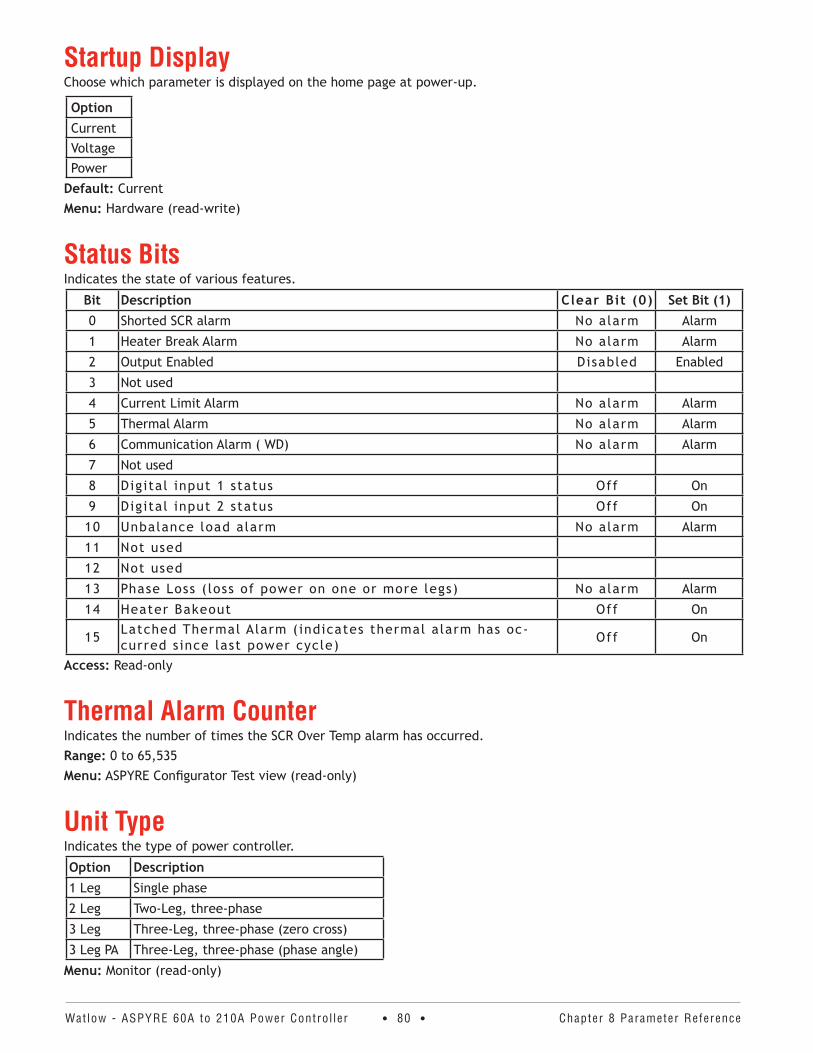
Watlow - ASPYRE 60A to 210A Power Contro l ler • 80 • Chapter 8 Parameter Reference
Startup DisplayChoose which parameter is displayed on the home page at power-up.
OptionCurrentVoltagePower
Default: CurrentMenu: Hardware (read-write)
Status BitsIndicates the state of various features.
Bit Description Clear Bit (0) Set Bit (1)0 Shorted SCR alarm No alarm Alarm
1 Heater Break Alarm No alarm Alarm
2 Output Enabled Disabled Enabled
3 Not used
4 Current Limit Alarm No alarm Alarm
5 Thermal Alarm No alarm Alarm
6 Communication Alarm ( WD) No alarm Alarm
7 Not used
8 Digital input 1 status Off On
9 Digital input 2 status Off On
10 Unbalance load alarm No alarm Alarm
11 Not used
12 Not used
13 Phase Loss ( loss of power on one or more legs) No alarm Alarm
14 Heater Bakeout Off On
15 Latched Thermal Alarm (indicates thermal alarm has oc-curred since last power cycle) Off On
Access: Read-only
Thermal Alarm CounterIndicates the number of times the SCR Over Temp alarm has occurred.Range: 0 to 65,535 Menu: ASPYRE Configurator Test view (read-only)
Unit TypeIndicates the type of power controller.
Option Description1 Leg Single phase
2 Leg Two-Leg, three-phase
3 Leg Three-Leg, three-phase (zero cross)
3 Leg PA Three-Leg, three-phase (phase angle)
Menu: Monitor (read-only)
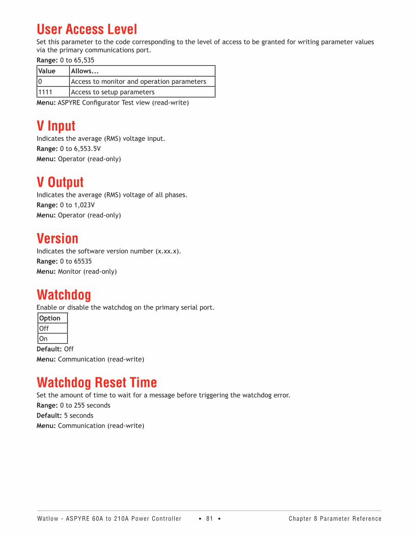
Watlow - ASPYRE 60A to 210A Power Contro l ler • 81 • Chapter 8 Parameter Reference
User Access LevelSet this parameter to the code corresponding to the level of access to be granted for writing parameter values via the primary communications port. Range: 0 to 65,535
Value Allows...0 Access to monitor and operation parameters
1111 Access to setup parameters
Menu: ASPYRE Configurator Test view (read-write)
V Input Indicates the average (RMS) voltage input.Range: 0 to 6,553.5V Menu: Operator (read-only)
V OutputIndicates the average (RMS) voltage of all phases.Range: 0 to 1,023V Menu: Operator (read-only)
VersionIndicates the software version number (x.xx.x).Range: 0 to 65535 Menu: Monitor (read-only)
WatchdogEnable or disable the watchdog on the primary serial port.
OptionOffOn
Default: Off Menu: Communication (read-write)
Watchdog Reset TimeSet the amount of time to wait for a message before triggering the watchdog error.Range: 0 to 255 seconds Default: 5 seconds Menu: Communication (read-write)

Watlow - ASPYRE 60A to 210A Power Contro l ler • 82 • Chapter 8 Parameter Reference
Wi-FiEnable or disable Wi-Fi communication.
OptionOffOn
Default: Off Menu: Communication (read-write)
Wi-Fi AddressIndicates the IP address of the WiFi connection in the power controller.Range: 0 to 255 (each part)Default: 192.168.4.1Menu: Communication (read-only)
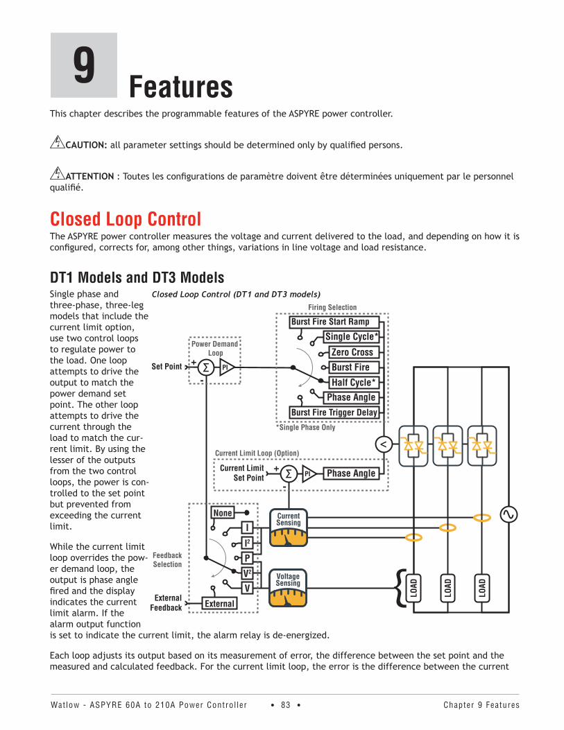
Watlow - ASPYRE 60A to 210A Power Contro l ler • 83 • Chapter 9 Features
9 FeaturesThis chapter describes the programmable features of the ASPYRE power controller.
CAUTION: all parameter settings should be determined only by qualified persons.
ATTENTION : Toutes les configurations de paramètre doivent être déterminées uniquement par le personnel qualifié.
Closed Loop ControlThe ASPYRE power controller measures the voltage and current delivered to the load, and depending on how it is configured, corrects for, among other things, variations in line voltage and load resistance.
DT1 Models and DT3 ModelsSingle phase and three-phase, three-leg models that include the current limit option, use two control loops to regulate power to the load. One loop attempts to drive the output to match the power demand set point. The other loop attempts to drive the current through the load to match the cur-rent limit. By using the lesser of the outputs from the two control loops, the power is con-trolled to the set point but prevented from exceeding the current limit.
While the current limit loop overrides the pow-er demand loop, the output is phase angle fired and the display indicates the current limit alarm. If the alarm output function is set to indicate the current limit, the alarm relay is de-energized.
Each loop adjusts its output based on its measurement of error, the difference between the set point and the measured and calculated feedback. For the current limit loop, the error is the difference between the current
Closed Loop Control (DT1 and DT3 models)
FeedbackSelection
External
VV2
P
I2
I
None
ExternalFeedback
{VoltageSensing
CurrentSensing
Σ+
-
Current Limit Set Point PI
Current Limit Loop (Option)
LOAD
LOAD
LOAD
<
PIΣ+
-Set Point
Power Demand Loop
Burst Fire Trigger Delay
Phase AngleHalf Cycle*
Burst Fire
Zero Cross
Single Cycle*
Burst Fire Start Ramp
Firing Selection
Phase Angle
*Single Phase Only
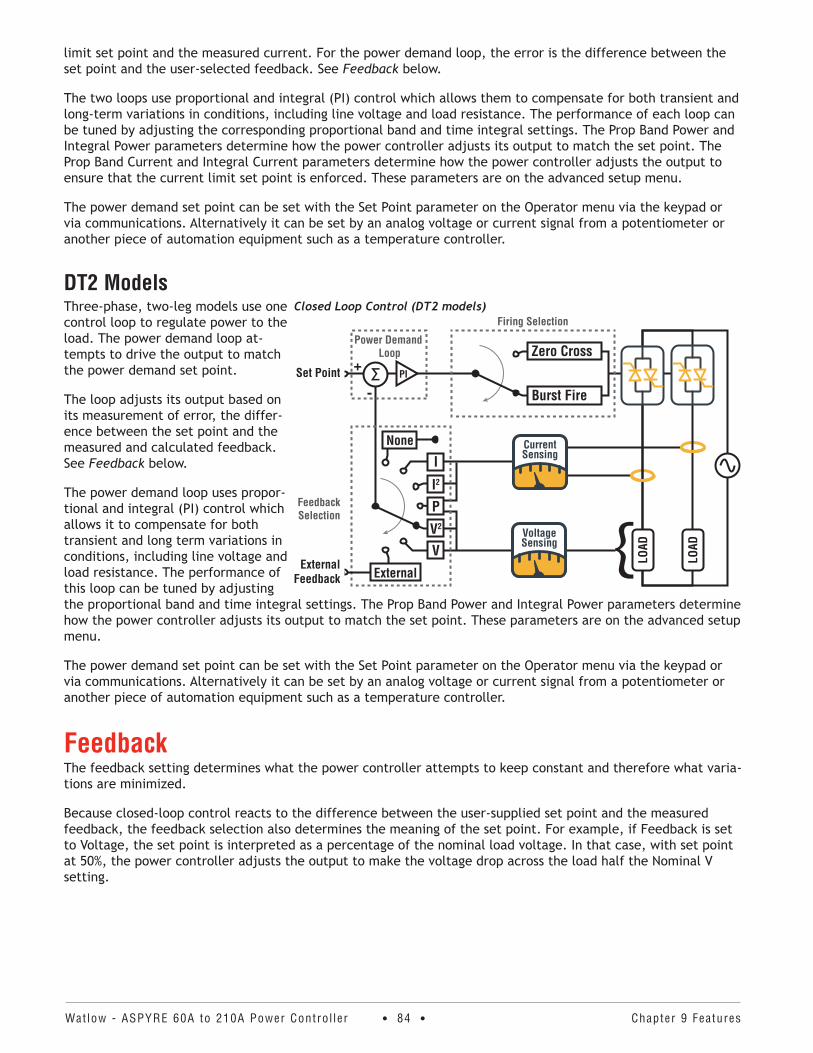
Watlow - ASPYRE 60A to 210A Power Contro l ler • 84 • Chapter 9 Features
limit set point and the measured current. For the power demand loop, the error is the difference between the set point and the user-selected feedback. See Feedback below.
The two loops use proportional and integral (PI) control which allows them to compensate for both transient and long-term variations in conditions, including line voltage and load resistance. The performance of each loop can be tuned by adjusting the corresponding proportional band and time integral settings. The Prop Band Power and Integral Power parameters determine how the power controller adjusts its output to match the set point. The Prop Band Current and Integral Current parameters determine how the power controller adjusts the output to ensure that the current limit set point is enforced. These parameters are on the advanced setup menu.
The power demand set point can be set with the Set Point parameter on the Operator menu via the keypad or via communications. Alternatively it can be set by an analog voltage or current signal from a potentiometer or another piece of automation equipment such as a temperature controller.
DT2 ModelsThree-phase, two-leg models use one control loop to regulate power to the load. The power demand loop at-tempts to drive the output to match the power demand set point.
The loop adjusts its output based on its measurement of error, the differ-ence between the set point and the measured and calculated feedback. See Feedback below.
The power demand loop uses propor-tional and integral (PI) control which allows it to compensate for both transient and long term variations in conditions, including line voltage and load resistance. The performance of this loop can be tuned by adjusting the proportional band and time integral settings. The Prop Band Power and Integral Power parameters determine how the power controller adjusts its output to match the set point. These parameters are on the advanced setup menu.
The power demand set point can be set with the Set Point parameter on the Operator menu via the keypad or via communications. Alternatively it can be set by an analog voltage or current signal from a potentiometer or another piece of automation equipment such as a temperature controller.
FeedbackThe feedback setting determines what the power controller attempts to keep constant and therefore what varia-tions are minimized.
Because closed-loop control reacts to the difference between the user-supplied set point and the measured feedback, the feedback selection also determines the meaning of the set point. For example, if Feedback is set to Voltage, the set point is interpreted as a percentage of the nominal load voltage. In that case, with set point at 50%, the power controller adjusts the output to make the voltage drop across the load half the Nominal V setting.
Closed Loop Control (DT2 models)
FeedbackSelection
External
VV2
P
I2
I
None
ExternalFeedback
VoltageSensing {
CurrentSensing
PIΣ+
-Set Point
Power Demand Loop
LOAD
LOAD
Burst Fire
Zero Cross
Firing Selection
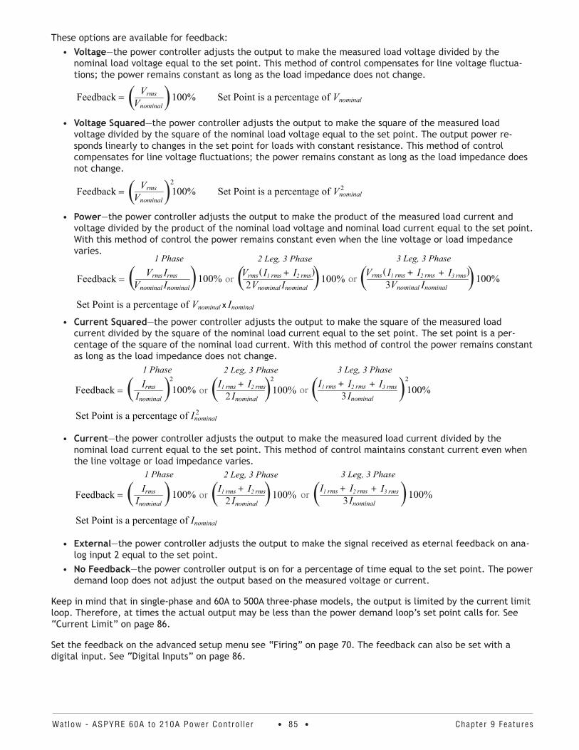
Watlow - ASPYRE 60A to 210A Power Contro l ler • 85 • Chapter 9 Features
These options are available for feedback:• Voltage—the power controller adjusts the output to make the measured load voltage divided by the
nominal load voltage equal to the set point. This method of control compensates for line voltage fluctua-tions; the power remains constant as long as the load impedance does not change.
• Voltage Squared—the power controller adjusts the output to make the square of the measured load voltage divided by the square of the nominal load voltage equal to the set point. The output power re-sponds linearly to changes in the set point for loads with constant resistance. This method of control compensates for line voltage fluctuations; the power remains constant as long as the load impedance does not change.
• Power—the power controller adjusts the output to make the product of the measured load current and voltage divided by the product of the nominal load voltage and nominal load current equal to the set point. With this method of control the power remains constant even when the line voltage or load impedance varies.
• Current Squared—the power controller adjusts the output to make the square of the measured load current divided by the square of the nominal load current equal to the set point. The set point is a per-centage of the square of the nominal load current. With this method of control the power remains constant as long as the load impedance does not change.
• Current—the power controller adjusts the output to make the measured load current divided by the nominal load current equal to the set point. This method of control maintains constant current even when the line voltage or load impedance varies.
• External—the power controller adjusts the output to make the signal received as eternal feedback on ana-log input 2 equal to the set point.
• No Feedback—the power controller output is on for a percentage of time equal to the set point. The power demand loop does not adjust the output based on the measured voltage or current.
Keep in mind that in single-phase and 60A to 500A three-phase models, the output is limited by the current limit loop. Therefore, at times the actual output may be less than the power demand loop’s set point calls for. See “Current Limit” on page 86.
Set the feedback on the advanced setup menu see “Firing” on page 70. The feedback can also be set with a digital input. See “Digital Inputs” on page 86.
Vnominal
Vrms=Feedback 100%( ) Set Point is a percentage of Vnominal
Vnominal
Vrms=Feedback 100%( )2Set Point is a percentage of Vnominal
2
=Feedback
1 Phase
or
2 Leg, 3 Phase
or
3 Leg, 3 Phase
100%Vrms IrmsVnominal Inominal( ) 100%Vrms I1 rms + I2 rms( )
Vnominal Inominal2( ) 100%Vnominal Inominal3Vrms I1 rms + I2 rms( )+ I3 rms( )
Set Point is a percentage of Vnominal x Inominal
=Feedback
1 Phase
or
2 Leg, 3 Phase
or
3 Leg, 3 Phase
100%I1 rms + I2 rmsInominal2( ) 100%Inominal3
I1 rms + I2 rms + I3 rms( )100%IrmsInominal
( )2 2 2
Set Point is a percentage of Inominal2
=Feedback
1 Phase
or
2 Leg, 3 Phase
or
3 Leg, 3 Phase
100%I1 rms + I2 rmsInominal2( ) 100%Inominal3
I1 rms + I2 rms + I3 rms( )100%IrmsInominal
( )Set Point is a percentage of Inominal

Watlow - ASPYRE 60A to 210A Power Contro l ler • 86 • Chapter 9 Features
Current LimitFor models that include current limiting, this feature is always active. By default it limits the RMS load current by reducing the output whenever the power demand control loop would tend to drive current above the current limit set point.
You can configure the power controller to limit peak rather than RMS current. The controller limits peak current by switching to phase angle firing whenever the peak current would otherwise exceed the limit. When peak current limiting is enabled, the current limit set point is interpreted as peak rather than RMS current. See “Limit Peak Current (Models with Current Limit)” on page 73.
Set the current limit set point, I Limit, on the setup menu. To determine the current limit set point empirically, see “Configure the Current Limit” on page 45.
Configurable Inputs and OutputsThe ASPYRE power controller features two digital inputs, up to two analog inputs and a relay output. Some models also include an analog output for retransmitting a measured value to other automation equipment. This section describes the various functions of these inputs and outputs and how they interact with other features of the power controller.
Digital InputsThe ASPYRE power controller has two optically-isolated, digital inputs that can be connected to control panel switches or other automation equipment such as a temperature controller or programmable logic controller. See “Configurable Digital Inputs (Digital Input 1 and Digital Input 2)” on page 26 for information on connecting to the digital inputs.
Using Digital In 1 Function and Digital In 2 Function on the hardware menu each digital input can be configured to perform one of the following:
• Enable—the power output is off unless this signal is on. If both digital inputs are set to this option, the state of digital input 2 takes precedence.
• Voltage Feedback—this signal overrides the feedback setting. When this signal is on, the control loop uses voltage feedback. When the signal is off, the loop reverts to the feedback parameter setting.
• Local / Remote—this signal selects how the set point is set. When this signal is on, the control loop’s set point is set using the keypad or through communications. When this signal is off, the set point is set by the an analog input. When a digital input is set to this function, the Local/Remote (L/R) button on the front panel cannot be used to choose the source of the set point.
• Phase Angle—this signal overrides the Firing setting. When this signal is on, the power controller uses phase-angle firing. When the signal is off, the controller uses the method set with the firing parameter on the advanced setup menu. This option is available with single-phase and 60A to 500A three-phase models.
• SP Analog In 1 / 2—this signal chooses which of the two analog inputs is used as the source of the set point when the remote set point is in effect. When this signal is off, analog input 1 is the source of the remote set point. When the signal is on, analog input 2 is the source of the remote set point.
• Logging—this signal turns data logging on or off. When the signal is on, data is logged. When the signal is off, data is not logged. When this signal is on, it supersedes the setting of the Logging parameter on the advanced setup menu.
• Heater Bakeout—this signal turns the heater bakeout feature on or off. When the signal is on, the heater bakeout feature is enabled. When the signal is off, the heater bakeout feature is disabled. When this signal is on, it supersedes the setting of the Heater Bakeout parameter on the advanced setup menu. This option is available with single-phase and 60A to 500A three-phase models.
To configure how the power controller uses these signals, see “Digital In 1 Function” on page 68 and “Digital In 2 Function” on page 69.

Watlow - ASPYRE 60A to 210A Power Contro l ler • 87 • Chapter 9 Features
Analog Input 1: Set Point To control the power to the load with a device such as a temperature controller, connect the control signal to analog input 1.
This input accepts current, voltage and potentiometer signals. The signal is interpreted as set point by compar-ing the measured value to the input’s full scale. For example, the set point is 50% when the analog input detects 5V and the input is configured to receive 0 to 10VDC.
Configure the power controller to recognize the signal with the hardware menu; see “Analog In 1 [Signal Type]” on page 65. For instructions for wiring this input see “Set Point (Analog Input 1)” on page 25.
Analog Input 2: Set Point, Feedback or Current Limit Set PointWhat this input does is user-configurable. Connect an analog signal that indicates:
• An alternate set point signal• Measured power, voltage or current from an external device used as feedback• Maximum current to the load (current limit) in single-phase and 60A to 500A three-phase models
This input accepts current, voltage and potentiometer signals. The signal is interpreted by comparing its mea-sured value to the input’s full scale. For example, the signal is 50% when the analog input detects 12mADC and the input is configured to receive 4 to 20mADC.
Configure the power controller to recognize the signal and how the power controller uses it on the hardware menu; see “Analog In 2 [Signal Type]” on page 66 and “Analog In 2 Function” on page 66. For instructions for wiring this input see “Set Point, Feedback or Current Limit (Analog Input 2)” on page 25.
Alarms and Alarm Relay OutputWhen an alarm occurs and while the condition persists, the alarm relay is de-energized. The alarm relay is ener-gized when power is supplied to the controller’s electron-ics via the auxiliary power input and there are no alarms.
Choose which conditions determine the alarm relay output with the Alarm Function setting on the hardware menu. See “Alarm Function” on page 65.
NOTE! The alarm relay output indicates an alarm whenever the temperature of the heat sink is too high even when Alarm Function on the hardware menu is set to None.
NOTE! The power controller monitors for heater break or short circuit conditions only when included in the option selected for Alarm Function.
Alarm Function OptionsAlarm Output Energizes for . . .
Heat
er B
reak
Shor
ted
SCR
Curr
ent L
imit
Com
mun
icat
ion
W
atch
dog
Erro
r
Heat
Sin
k Ov
er
Tem
pera
ture
None X
Heater Break(HB) X X
SCR Short (SC) X X
I Limit (IL)* X X
Hb / SC X X X
Hb / IL* X X X
SC / IL* X X X
HB / SC / IL* X X X X
Watchdog X X
WE / HB X X X
WE / SC X X X
WE / SC / HB X X X X
WE / IL* X X X
WE / IL / HB* X X X X
WE / IL / HB* X X X X
WE / IL or SC / HB* X X X X X
*Models with current limit
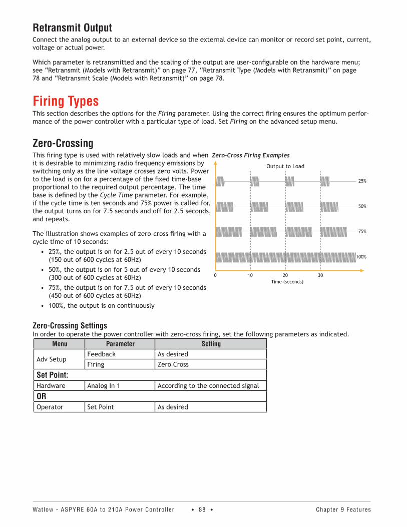
Watlow - ASPYRE 60A to 210A Power Contro l ler • 88 • Chapter 9 Features
Retransmit OutputConnect the analog output to an external device so the external device can monitor or record set point, current, voltage or actual power.
Which parameter is retransmitted and the scaling of the output are user-configurable on the hardware menu; see “Retransmit (Models with Retransmit)” on page 77, “Retransmit Type (Models with Retransmit)” on page 78 and “Retransmit Scale (Models with Retransmit)” on page 78.
Firing TypesThis section describes the options for the Firing parameter. Using the correct firing ensures the optimum perfor-mance of the power controller with a particular type of load. Set Firing on the advanced setup menu.
Zero-CrossingThis firing type is used with relatively slow loads and when it is desirable to minimizing radio frequency emissions by switching only as the line voltage crosses zero volts. Power to the load is on for a percentage of the fixed time-base proportional to the required output percentage. The time base is defined by the Cycle Time parameter. For example, if the cycle time is ten seconds and 75% power is called for, the output turns on for 7.5 seconds and off for 2.5 seconds, and repeats.
The illustration shows examples of zero-cross firing with a cycle time of 10 seconds:
• 25%, the output is on for 2.5 out of every 10 seconds (150 out of 600 cycles at 60Hz)
• 50%, the output is on for 5 out of every 10 seconds (300 out of 600 cycles at 60Hz)
• 75%, the output is on for 7.5 out of every 10 seconds (450 out of 600 cycles at 60Hz)
• 100%, the output is on continuously
Zero-Crossing SettingsIn order to operate the power controller with zero-cross firing, set the following parameters as indicated.
Menu Parameter Setting
Adv SetupFeedback As desired
Firing Zero Cross
Set Point:Hardware Analog In 1 According to the connected signal
OROperator Set Point As desired
Zero-Cross Firing Examples
Time (seconds)0 10 20 30
100%
75%
50%
25%
Output to Load
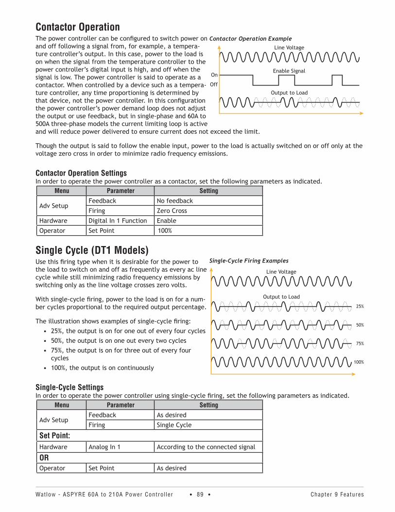
Watlow - ASPYRE 60A to 210A Power Contro l ler • 89 • Chapter 9 Features
Contactor OperationThe power controller can be configured to switch power on and off following a signal from, for example, a tempera-ture controller’s output. In this case, power to the load is on when the signal from the temperature controller to the power controller’s digital input is high, and off when the signal is low. The power controller is said to operate as a contactor. When controlled by a device such as a tempera-ture controller, any time proportioning is determined by that device, not the power controller. In this configuration the power controller’s power demand loop does not adjust the output or use feedback, but in single-phase and 60A to 500A three-phase models the current limiting loop is active and will reduce power delivered to ensure current does not exceed the limit.
Though the output is said to follow the enable input, power to the load is actually switched on or off only at the voltage zero cross in order to minimize radio frequency emissions.
Contactor Operation SettingsIn order to operate the power controller as a contactor, set the following parameters as indicated.
Menu Parameter Setting
Adv SetupFeedback No feedback
Firing Zero Cross
Hardware Digital In 1 Function Enable
Operator Set Point 100%
Single Cycle (DT1 Models)Use this firing type when it is desirable for the power to the load to switch on and off as frequently as every ac line cycle while still minimizing radio frequency emissions by switching only as the line voltage crosses zero volts.
With single-cycle firing, power to the load is on for a num-ber cycles proportional to the required output percentage.
The illustration shows examples of single-cycle firing:• 25%, the output is on for one out of every four cycles• 50%, the output is on one out every two cycles• 75%, the output is on for three out of every four
cycles• 100%, the output is on continuously
Single-Cycle SettingsIn order to operate the power controller using single-cycle firing, set the following parameters as indicated.
Menu Parameter Setting
Adv SetupFeedback As desired
Firing Single Cycle
Set Point:Hardware Analog In 1 According to the connected signal
OROperator Set Point As desired
Contactor Operation Example
Output to Load
On
Off
Enable Signal
Line Voltage
Single-Cycle Firing Examples
100%
75%
50%
25%
Output to Load
Line Voltage
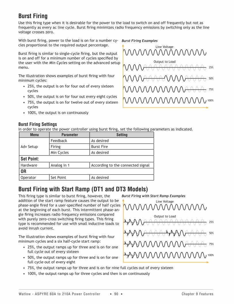
Watlow - ASPYRE 60A to 210A Power Contro l ler • 90 • Chapter 9 Features
Burst FiringUse this firing type when it is desirable for the power to the load to switch on and off frequently but not as frequently as every ac line cycle. Burst firing minimizes radio frequency emissions by switching only as the line voltage crosses zero.
With burst firing, power to the load is on for a number cy-cles proportional to the required output percentage.
Burst firing is similar to single-cycle firing, but the output is on and off for a minimum number of cycles specified by the user with the Min Cycles setting on the advanced setup menu.
The illustration shows examples of burst firing with four minimum cycles:
• 25%, the output is on for four out of every sixteen cycles
• 50%, the output is on for four out every eight cycles• 75%, the output is on for twelve out of every sixteen
cycles• 100%, the output is on continuously
Burst Firing SettingsIn order to operate the power controller using burst firing, set the following parameters as indicated.
Menu Parameter Setting
Adv Setup
Feedback As desired
Firing Burst Fire
Min Cycles As desired
Set Point:Hardware Analog In 1 According to the connected signal
OROperator Set Point As desired
Burst Firing with Start Ramp (DT1 and DT3 Models)This firing type is similar to burst firing, however, the addition of the start ramp feature causes the output to be phase-angle fired for a user-specified number of half cycles at the beginning of each burst. This intermittent phase-an-gle firing increases radio frequency emissions compared with purely zero-cross switching firing types. This firing type is recommended for use with small inductive loads to avoid inrush current.
The illustration shows examples of burst firing with four minimum cycles and a six half-cycle start ramp:
• 25%, the output ramps up for three and is on for one full cycle out of every sixteen
• 50%, the output ramps up for three and is on for one full cycle out of every eight
• 75%, the output ramps up for three and is on for nine full cycles out of every sixteen• 100%, the output ramps up for three cycles and then is on continuously
Burst Firing Examples
100%
75%
50%
25%
Output to Load
Line Voltage
100%
75%
50%
25%
Output to Load
Line Voltage
Burst Firing with Start Ramp Examples
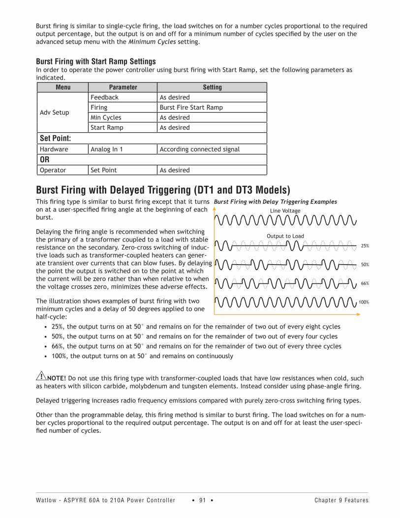
Watlow - ASPYRE 60A to 210A Power Contro l ler • 91 • Chapter 9 Features
Burst firing is similar to single-cycle firing, the load switches on for a number cycles proportional to the required output percentage, but the output is on and off for a minimum number of cycles specified by the user on the advanced setup menu with the Minimum Cycles setting.
Burst Firing with Start Ramp SettingsIn order to operate the power controller using burst firing with Start Ramp, set the following parameters as indicated.
Menu Parameter Setting
Adv Setup
Feedback As desired
Firing Burst Fire Start Ramp
Min Cycles As desired
Start Ramp As desired
Set Point:Hardware Analog In 1 According connected signal
OROperator Set Point As desired
Burst Firing with Delayed Triggering (DT1 and DT3 Models)This firing type is similar to burst firing except that it turns on at a user-specified firing angle at the beginning of each burst.
Delaying the firing angle is recommended when switching the primary of a transformer coupled to a load with stable resistance on the secondary. Zero-cross switching of induc-tive loads such as transformer-coupled heaters can gener-ate transient over currents that can blow fuses. By delaying the point the output is switched on to the point at which the current will be zero rather than when relative to when the voltage crosses zero, minimizes these adverse effects.
The illustration shows examples of burst firing with two minimum cycles and a delay of 50 degrees applied to one half-cycle:
• 25%, the output turns on at 50° and remains on for the remainder of two out of every eight cycles• 50%, the output turns on at 50° and remains on for the remainder of two out of every four cycles• 66%, the output turns on at 50° and remains on for the remainder of two out of every three cycles• 100%, the output turns on at 50° and remains on continuously
NOTE! Do not use this firing type with transformer-coupled loads that have low resistances when cold, such as heaters with silicon carbide, molybdenum and tungsten elements. Instead consider using phase-angle firing.
Delayed triggering increases radio frequency emissions compared with purely zero-cross switching firing types.
Other than the programmable delay, this firing method is similar to burst firing. The load switches on for a num-ber cycles proportional to the required output percentage. The output is on and off for at least the user-speci-fied number of cycles.
Burst Firing with Delay Triggering Examples
100%
66%
50%
25%
Output to Load
Line Voltage
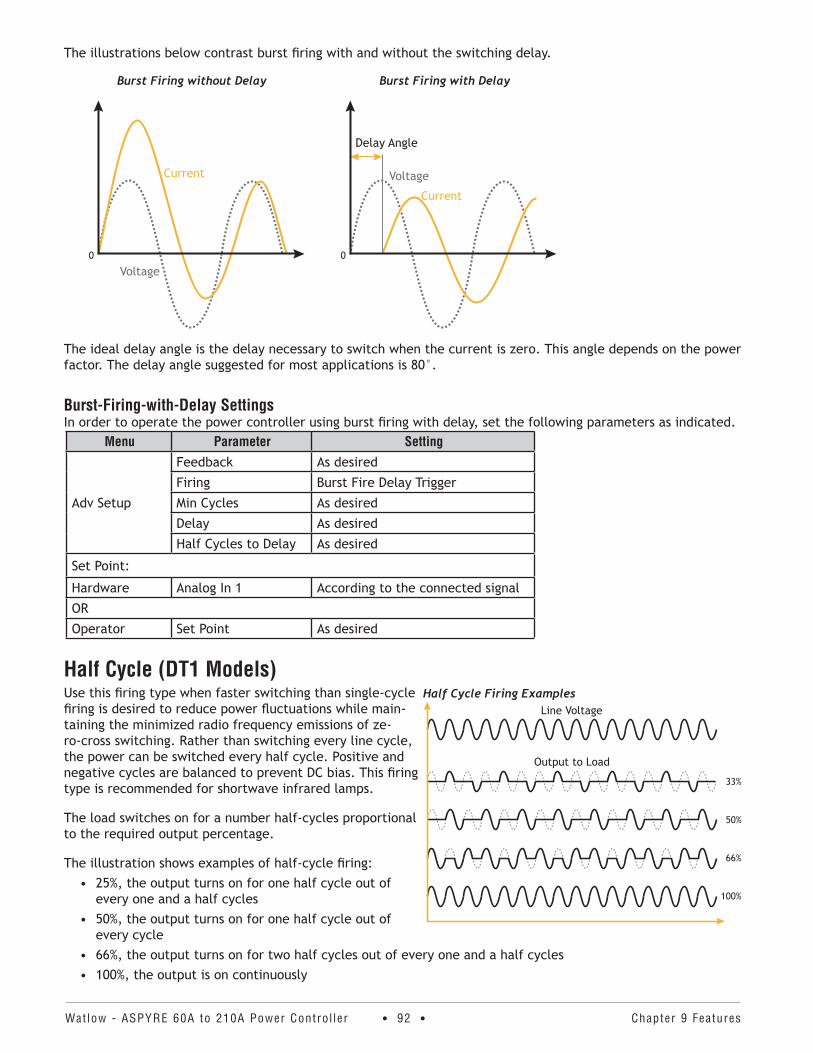
Watlow - ASPYRE 60A to 210A Power Contro l ler • 92 • Chapter 9 Features
The illustrations below contrast burst firing with and without the switching delay.
Burst Firing without Delay Burst Firing with Delay
0
Current
Voltage
Voltage
Current
Delay Angle
0
The ideal delay angle is the delay necessary to switch when the current is zero. This angle depends on the power factor. The delay angle suggested for most applications is 80°.
Burst-Firing-with-Delay SettingsIn order to operate the power controller using burst firing with delay, set the following parameters as indicated.
Menu Parameter Setting
Adv Setup
Feedback As desired
Firing Burst Fire Delay Trigger
Min Cycles As desired
Delay As desired
Half Cycles to Delay As desired
Set Point:
Hardware Analog In 1 According to the connected signal
OR
Operator Set Point As desired
Half Cycle (DT1 Models) Use this firing type when faster switching than single-cycle firing is desired to reduce power fluctuations while main-taining the minimized radio frequency emissions of ze-ro-cross switching. Rather than switching every line cycle, the power can be switched every half cycle. Positive and negative cycles are balanced to prevent DC bias. This firing type is recommended for shortwave infrared lamps.
The load switches on for a number half-cycles proportional to the required output percentage.
The illustration shows examples of half-cycle firing:• 25%, the output turns on for one half cycle out of
every one and a half cycles• 50%, the output turns on for one half cycle out of
every cycle• 66%, the output turns on for two half cycles out of every one and a half cycles• 100%, the output is on continuously
Half Cycle Firing Examples
100%
66%
50%
33%
Output to Load
Line Voltage
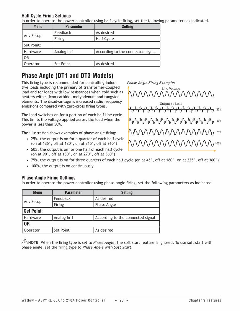
Watlow - ASPYRE 60A to 210A Power Contro l ler • 93 • Chapter 9 Features
Half Cycle Firing SettingsIn order to operate the power controller using half-cycle firing, set the following parameters as indicated.
Menu Parameter Setting
Adv SetupFeedback As desired
Firing Half Cycle
Set Point:
Hardware Analog In 1 According to the connected signal
OR
Operator Set Point As desired
Phase Angle (DT1 and DT3 Models) This firing type is recommended for controlling induc-tive loads including the primary of transformer-coupled load and for loads with low resistances when cold such as heaters with silicon carbide, molybdenum and tungsten elements. The disadvantage is increased radio frequency emissions compared with zero-cross firing types.
The load switches on for a portion of each half line cycle. This limits the voltage applied across the load when the power is less than 50%.
The illustration shows examples of phase-angle firing:• 25%, the output is on for a quarter of each half cycle
(on at 135°, off at 180°, on at 315°, off at 360°)• 50%, the output is on for one half of each half cycle
(on at 90°, off at 180°, on at 270°, off at 360°)• 75%, the output is on for three quarters of each half cycle (on at 45°, off at 180°, on at 225°, off at 360°)• 100%, the output is on continuously
Phase-Angle Firing SettingsIn order to operate the power controller using phase-angle firing, set the following parameters as indicated.
Menu Parameter Setting
Adv SetupFeedback As desired
Firing Phase Angle
Set Point:Hardware Analog In 1 According to the connected signal
OROperator Set Point As desired
NOTE! When the firing type is set to Phase Angle, the soft start feature is ignored. To use soft start with phase angle, set the firing type to Phase Angle with Soft Start.
Phase-Angle Firing Examples
100%
75%
50%
25%
Output to Load
Line Voltage
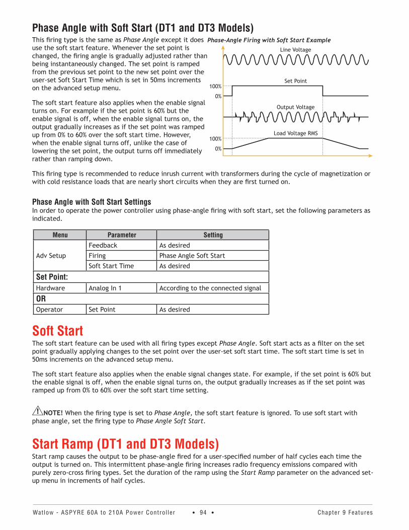
Watlow - ASPYRE 60A to 210A Power Contro l ler • 94 • Chapter 9 Features
Phase Angle with Soft Start (DT1 and DT3 Models)This firing type is the same as Phase Angle except it does use the soft start feature. Whenever the set point is changed, the firing angle is gradually adjusted rather than being instantaneously changed. The set point is ramped from the previous set point to the new set point over the user-set Soft Start Time which is set in 50ms increments on the advanced setup menu.
The soft start feature also applies when the enable signal turns on. For example if the set point is 60% but the enable signal is off, when the enable signal turns on, the output gradually increases as if the set point was ramped up from 0% to 60% over the soft start time. However, when the enable signal turns off, unlike the case of lowering the set point, the output turns off immediately rather than ramping down.
This firing type is recommended to reduce inrush current with transformers during the cycle of magnetization or with cold resistance loads that are nearly short circuits when they are first turned on.
Phase Angle with Soft Start SettingsIn order to operate the power controller using phase-angle firing with soft start, set the following parameters as indicated.
Menu Parameter Setting
Adv Setup
Feedback As desired
Firing Phase Angle Soft Start
Soft Start Time As desired
Set Point:Hardware Analog In 1 According to the connected signal
OROperator Set Point As desired
Soft StartThe soft start feature can be used with all firing types except Phase Angle. Soft start acts as a filter on the set point gradually applying changes to the set point over the user-set soft start time. The soft start time is set in 50ms increments on the advanced setup menu.
The soft start feature also applies when the enable signal changes state. For example, if the set point is 60% but the enable signal is off, when the enable signal turns on, the output gradually increases as if the set point was ramped up from 0% to 60% over the soft start time setting.
NOTE! When the firing type is set to Phase Angle, the soft start feature is ignored. To use soft start with phase angle, set the firing type to Phase Angle Soft Start.
Start Ramp (DT1 and DT3 Models)Start ramp causes the output to be phase-angle fired for a user-specified number of half cycles each time the output is turned on. This intermittent phase-angle firing increases radio frequency emissions compared with purely zero-cross firing types. Set the duration of the ramp using the Start Ramp parameter on the advanced set-up menu in increments of half cycles.
Phase-Angle Firing with Soft Start Example
Load Voltage RMS
0%
100%
Output Voltage
100%
0%
Set Point
Line Voltage
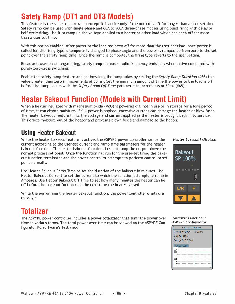
Watlow - ASPYRE 60A to 210A Power Contro l ler • 95 • Chapter 9 Features
Safety Ramp (DT1 and DT3 Models)This feature is the same as start ramp except it is active only if the output is off for longer than a user-set time. Safety ramp can be used with single-phase and 60A to 500A three-phase models using burst firing with delay or half cycle firing. Use it to ramp up the voltage applied to a heater or other load which has been off for more than a user set time.
With this option enabled, after power to the load has been off for more than the user-set time, once power is called for, the firing type is temporarily changed to phase angle and the power is ramped up from zero to the set point over the safety ramp time. Once the ramp is complete, the firing type reverts to the user setting.
Because it uses phase-angle firing, safety ramp increases radio frequency emissions when active compared with purely zero-cross switching.
Enable the safety ramp feature and set how long the ramp takes by setting the Safety Ramp Duration (#66) to a value greater than zero (in increments of 50ms). Set the minimum amount of time the power to the load is off before the ramp occurs with the Safety Ramp Off Time parameter in increments of 50ms (#65).
Heater Bakeout Function (Models with Current Limit)When a heater insulated with magnesium oxide (MgO) is powered off, not in use or in storage for a long period of time, it can absorb moisture. If full power is applied, excessive current can damage the heater or blow fuses. The heater bakeout feature limits the voltage and current applied as the heater is brought back in to service. This drives moisture out of the heater and prevents blown fuses and damage to the heater.
Using Heater BakeoutWhile the heater bakeout feature is active, the ASPYRE power controller ramps the current according to the user-set current and ramp time parameters for the heater bakeout function. The heater bakeout function does not ramp the output above the normal process set point. Once the function has run for the user-set time, the bake-out function terminates and the power controller attempts to perform control to set point normally.
Use Heater Bakeout Ramp Time to set the duration of the bakeout in minutes. Use Heater Bakeout Current to set the current to which the function attempts to ramp in Amperes. Use Heater Bakeout Off Time to set how many minutes the heater can be off before the bakeout fuction runs the next time the heater is used.
While the performing the heater bakeout function, the power controller displays a message.
Totalizer The ASPYRE power controller includes a power totalizator that sums the power over time in various terms. The total power over time can be viewed on the ASPYRE Con-figurator PC software’s Test view.
Heater Bakeout Indication
BakeoutSP 100%
Totalizer Function in ASPYRE Configurator
Watlow - ASPYRE 60A to 210A Power Contro l ler • 96 • Chapter 9 Features
Data Logging The ASPYRE power controller offers an optional data logging feature. Record up to ten parameters as often as once per second. Use ASPYRE Configurator software to set the real-time clock, to select which parameters to log, to retrieve data log files and to manage the logging memory. See “Setting Up and Using Data Logging” on page 54. The ASPYRE Configurator software also supports viewing the data in log files after downloading them from the power controller.
Data logging can be turned on and off using:• ASPYRE Configurator software (see “Setting Up and Using Data Logging” on page 54.)• The advanced setup menu in the power controller’s user interface (see “Logging” on page 73)• A digital input (see “Digital In 1 Function” on page 68, “Digital In 2 Function” on page 69 and “Digital
Inputs” on page 86)
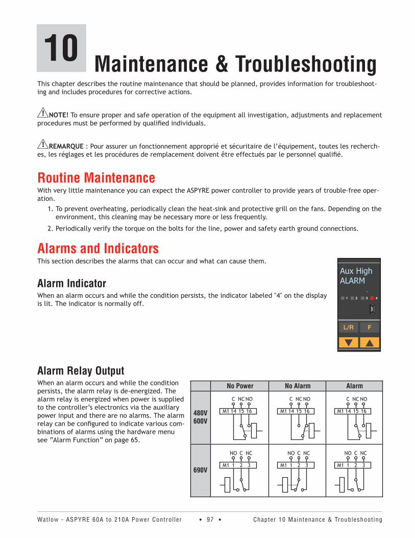
Watlow - ASPYRE 60A to 210A Power Contro l ler • 97 • Chapter 10 Maintenance & Troubleshoot ing
Maintenance & Troubleshooting10This chapter describes the routine maintenance that should be planned, provides information for troubleshoot-ing and includes procedures for corrective actions.
NOTE! To ensure proper and safe operation of the equipment all investigation, adjustments and replacement procedures must be performed by qualified individuals.
REMARQUE : Pour assurer un fonctionnement approprié et sécuritaire de l’équipement, toutes les recherch-es, les réglages et les procédures de remplacement doivent être effectués par le personnel qualifié.
Routine MaintenanceWith very little maintenance you can expect the ASPYRE power controller to provide years of trouble-free oper-ation.
1. To prevent overheating, periodically clean the heat-sink and protective grill on the fans. Depending on the environment, this cleaning may be necessary more or less frequently.
2. Periodically verify the torque on the bolts for the line, power and safety earth ground connections.
Alarms and IndicatorsThis section describes the alarms that can occur and what can cause them.
Alarm IndicatorWhen an alarm occurs and while the condition persists, the indicator labeled "4" on the display is lit. The indicator is normally off.
Alarm Relay OutputWhen an alarm occurs and while the condition persists, the alarm relay is de-energized. The alarm relay is energized when power is supplied to the controller’s electronics via the auxiliary power input and there are no alarms. The alarm relay can be configured to indicate various com-binations of alarms using the hardware menu see “Alarm Function” on page 65.
Aux HighALARM
No Power No Alarm Alarm
480V 600V
C NC NO
161514M1
C NC NO
161514M1
C NC NO
161514M1
690V
NO C NC
321M1
NO C NC
321M1
NO C NC
321M1
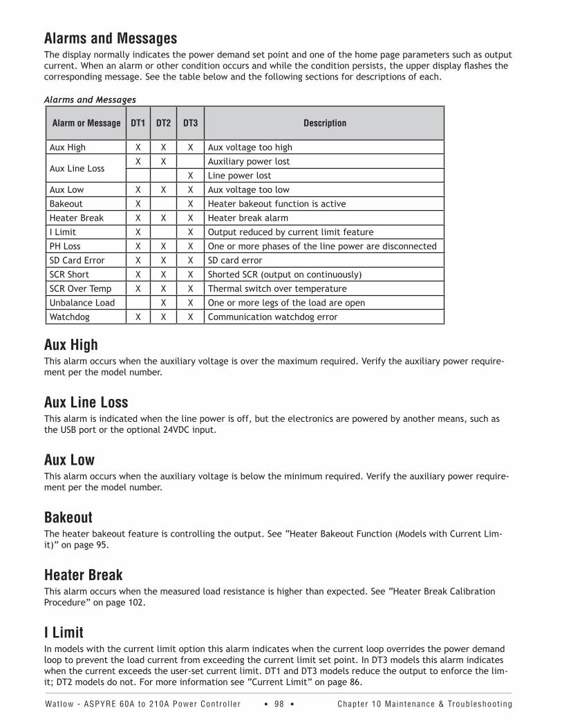
Watlow - ASPYRE 60A to 210A Power Contro l ler • 98 • Chapter 10 Maintenance & Troubleshoot ing
Alarms and MessagesThe display normally indicates the power demand set point and one of the home page parameters such as output current. When an alarm or other condition occurs and while the condition persists, the upper display flashes the corresponding message. See the table below and the following sections for descriptions of each.
Alarms and Messages
Alarm or Message DT1 DT2 DT3 Description
Aux High X X X Aux voltage too high
Aux Line LossX X Auxiliary power lost
X Line power lost
Aux Low X X X Aux voltage too low
Bakeout X X Heater bakeout function is active
Heater Break X X X Heater break alarm
I Limit X X Output reduced by current limit feature
PH Loss X X X One or more phases of the line power are disconnected
SD Card Error X X X SD card error
SCR Short X X X Shorted SCR (output on continuously)
SCR Over Temp X X X Thermal switch over temperature
Unbalance Load X X One or more legs of the load are open
Watchdog X X X Communication watchdog error
Aux HighThis alarm occurs when the auxiliary voltage is over the maximum required. Verify the auxiliary power require-ment per the model number.
Aux Line LossThis alarm is indicated when the line power is off, but the electronics are powered by another means, such as the USB port or the optional 24VDC input.
Aux LowThis alarm occurs when the auxiliary voltage is below the minimum required. Verify the auxiliary power require-ment per the model number.
BakeoutThe heater bakeout feature is controlling the output. See “Heater Bakeout Function (Models with Current Lim-it)” on page 95.
Heater BreakThis alarm occurs when the measured load resistance is higher than expected. See “Heater Break Calibration Procedure” on page 102.
I LimitIn models with the current limit option this alarm indicates when the current loop overrides the power demand loop to prevent the load current from exceeding the current limit set point. In DT3 models this alarm indicates when the current exceeds the user-set current limit. DT1 and DT3 models reduce the output to enforce the lim-it; DT2 models do not. For more information see “Current Limit” on page 86.
Watlow - ASPYRE 60A to 210A Power Contro l ler • 99 • Chapter 10 Maintenance & Troubleshoot ing
PH LossOne or more phases of the line power are disconnected. For DT3 models this message appears only with the loss of line power to phase 3; if phase 1 or 2 are lost, because the auxiliary power is connected internally, it also is lost and the control electronics looses power or if powered by the USB port or the optional 24VDC input the Aux Line Loss error is displayed.
SD Card ErrorThis error occurs when the SD memory card option is present but does not work properly or when it is impossible to read or write data. Contact your supplier.
SCR ShortThis alarm occurs when the SCR is stuck on and the output is on continuously.
SCR Over TempThis alarm occurs when the temperature sensor on the heat sink indicates it is too hot. The thermal switch alarm triggers the alarm relay output. Until the temperature is reduced, power to the load is turned off. Correct the environmental conditions that caused the over temperature or reduce the load current to resume operation. Operating the unit at temperatures outside the specified range can void the warranty. For information on proper cooling see “Cooling Requirements” on page 18.
Unbalanced LoadThe resistance of one or more legs of the load has gone outside the tolerance for a balanced load. The alarm indication specifies which leg of the load is outside the tolerance. This likely indicates one or more legs of the load are open.
WatchdogThis error occurs when the communications watchdog feature is enabled but no transmission has been received for longer than the user-set watchdog reset time. When this error occurs, power to the load is turned off. See “Watchdog” on page 81 and “Watchdog Reset Time” on page 81.
Opening The CoversWARNING: Before opening the cover, disconnect and lock out the line power and control signals to the unit
and verify that power and control cables are isolated from voltage sources.
AVERTISSEMENT : Avant d’ouvrir le couvercle, débrancher et verrouiller les signaux d’alimentation de ligne et de commande, puis vérifier que les câbles d’alimentation et de commande sont isolés des sources de tension.
CAUTION: Take appropriate precautions to prevent electrostatic discharges from damaging electronic com-ponents when handling the boards.
ATTENTION : Prendre les précautions appropriées pour empêcher que les décharges électrostatiques n’en-dommagent les composants électroniques au moment de la manipulation des cartes de circuits.
To open the front cover:1. Grip the cover by the handle .
2. Pull the cover firmly toward you and down.
Watlow - ASPYRE 60A to 210A Power Contro l ler • 100 • Chapter 10 Maintenance & Troubleshoot ing
Replacement FusesThe ASPYRE power controller contains fast-blow fuses protecting the SCR power switches. These fuses are critical to safe operation of the power controller particularly in preventing catastrophic failure in the event of a shorted load. The agency approvals are contingent upon the use of the same fuses (manufacturer and model) that were tested. The table below lists the tested and approved fuses for the various models.
Replacement Fuses
ASPYRE Model Qty .480V and 600V 690V
Watlow Siba Watlow Siba
DT_ _ _-060...
1 to 3*
0808-0363-0160 20 559 20.1602048-2760 20 282 20.160DT_ _ _-090...
DT_ _ _-120... 0808-0363-0180 20 559 20.180
DT_ _ _-150... 0808-0363-0200 20 559 20.200 2048-4405 20 282 20.200
DT_ _ _-180... 0808-0363-0250 20 559 20.250 2048-4418 20 282 20.250
DT_ _ _-210... 0808-0363-0315 20 559 20.315 2048-4426 20 282 20.315
*One fuse per switched leg for 480V and 600V models. For 690V models one fuse for single-phase models and three fuses for all three-phase models.
Replacement Fuse Torque480V and 600V 690V
60A to 120A 26.6 in.-lb. (3 Nm)44.3 in.-lb. (5 Nm)
150A to 210A 44.3 in.-lb. (5 Nm)
CAUTION: These fuses protect life and property against catastrophic failure in the event of a shorted load. They do not provide and are not approved for branch circuit protection.
ATTENTION : Ces fusibles protègent la vie et la propriété contre des pannes catastrophiques en cas de charge en court-circuit. Ils n’assurent aucune protection des circuits de dérivation et ne sont pas approuvés à cette fin.
CAUTION: The power controller warranty is void if the tested and approved fuses are not used.
ATTENTION : La garantie du régulateur de puissance est nulle si aucun fusible testé et approuvé n’est util-isé.
WARNING: Before opening the cover, disconnect and lock out the line power and control signals to the unit and verify that power and control cables are isolated from voltage sources.
AVERTISSEMENT : Avant d’ouvrir le couvercle, débrancher et verrouiller les signaux d’alimentation de ligne et de commande, puis vérifier que les câbles d’alimentation et de commande sont isolés des sources de tension.
Replacing the BatteryThe real time clock option includes a battery so that the time and date settings and the clock function persist when line power is shut off. The battery is expected to provide years of service, but must be replace when the clock fails to keep time when the power is off.
WARNING: Before opening the cover, disconnect and lock out the line power and control signals to the unit and verify that power and control cables are isolated from voltage sources.
Watlow - ASPYRE 60A to 210A Power Contro l ler • 101 • Chapter 10 Maintenance & Troubleshoot ing
AVERTISSEMENT : Avant d’ouvrir le couvercle, débrancher et verrouiller les signaux d’alimentation de ligne et de commande, puis vérifier que les câbles d’alimentation et de commande sont isolés des sources de tension.
CAUTION: Take appropriate precautions to prevent electrostatic discharges from damaging electronic com-ponents when handling the boards.
ATTENTION : Prendre les précautions appropriées pour empêcher que les décharges électrostatiques n’en-dommagent les composants électroniques au moment de la manipulation des cartes de circuits.
NOTE! Dispose of the battery properly.
REMARQUE : Éliminer la batterie de manière appropriée.
To replace the battery:1. Shut off the line power and auxiliary power to the power controller.
2. Open the cover on the left most module to access the electronics.
3. Replace the battery on the board attached to the cover.
4. Close the cover.
5. Dispose of the battery properly.
Calibration ProceduresThe procedures in this section can be used to adjust the performance of the corresponding features.
Configure the Current LimitThe current limit feature acts to prevent the RMS current from exceeding the user-set current limit. As the cur-rent approaches the limit, the power controller decreases its output. The current limit set point can be set with the I Limit parameter or by an analog input. For help with entering and accessing the menus see “Menu Naviga-tion” on page 48.
CAUTION: This procedure must be performed only by qualified persons.
ATTENTION : Cette procédure ne doit être effectuée que par le personnel qualifié.
CAUTION: This procedure requires turning on full power to the load. This should only be performed once the installation is complete and when it is safe to provide full power.
ATTENTION : Cette procédure nécessite la mise sous tension totale de la charge. Cela ne doit être effectué qu’une fois l’installation terminée et lorsque la puissance maximale peut être fournie en toute sécurité.
To limit the current using the parameter setting:1. On the Hardware menu set I Limit Local / Remote to Local.
2. On the Operator menu set the I Limit to 0%.
3. Enable the power controller and set the power demand / set point to 100%.
4. Gradually increase the current limit set point until the RMS current is at the maximum desired value.
5. Disable the power controller.
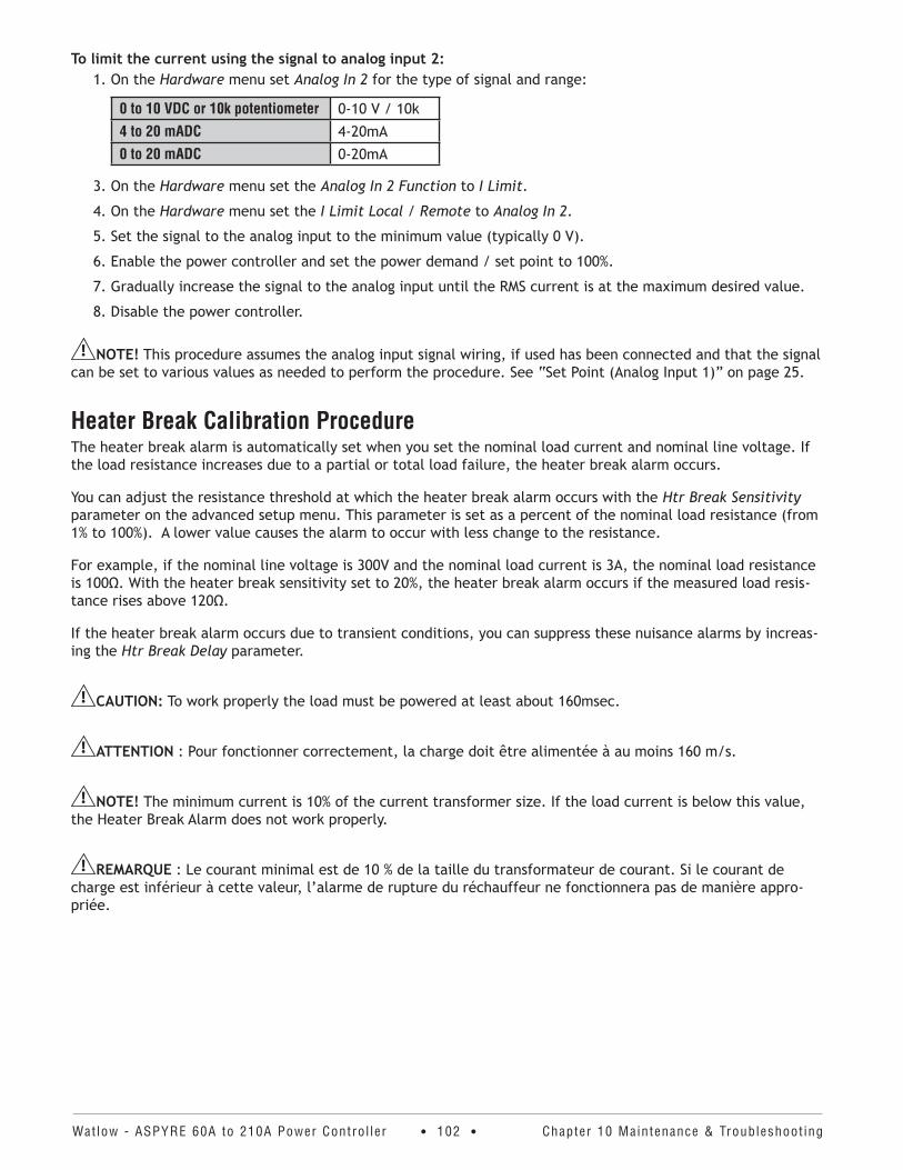
Watlow - ASPYRE 60A to 210A Power Contro l ler • 102 • Chapter 10 Maintenance & Troubleshoot ing
To limit the current using the signal to analog input 2:1. On the Hardware menu set Analog In 2 for the type of signal and range:
0 to 10 VDC or 10k potentiometer 0-10 V / 10k
4 to 20 mADC 4-20mA
0 to 20 mADC 0-20mA
3. On the Hardware menu set the Analog In 2 Function to I Limit.
4. On the Hardware menu set the I Limit Local / Remote to Analog In 2.
5. Set the signal to the analog input to the minimum value (typically 0 V).
6. Enable the power controller and set the power demand / set point to 100%.
7. Gradually increase the signal to the analog input until the RMS current is at the maximum desired value.
8. Disable the power controller.
NOTE! This procedure assumes the analog input signal wiring, if used has been connected and that the signal can be set to various values as needed to perform the procedure. See “Set Point (Analog Input 1)” on page 25.
Heater Break Calibration ProcedureThe heater break alarm is automatically set when you set the nominal load current and nominal line voltage. If the load resistance increases due to a partial or total load failure, the heater break alarm occurs.
You can adjust the resistance threshold at which the heater break alarm occurs with the Htr Break Sensitivity parameter on the advanced setup menu. This parameter is set as a percent of the nominal load resistance (from 1% to 100%). A lower value causes the alarm to occur with less change to the resistance.
For example, if the nominal line voltage is 300V and the nominal load current is 3A, the nominal load resistance is 100Ω. With the heater break sensitivity set to 20%, the heater break alarm occurs if the measured load resis-tance rises above 120Ω.
If the heater break alarm occurs due to transient conditions, you can suppress these nuisance alarms by increas-ing the Htr Break Delay parameter.
CAUTION: To work properly the load must be powered at least about 160msec.
ATTENTION : Pour fonctionner correctement, la charge doit être alimentée à au moins 160 m/s.
NOTE! The minimum current is 10% of the current transformer size. If the load current is below this value, the Heater Break Alarm does not work properly.
REMARQUE : Le courant minimal est de 10 % de la taille du transformateur de courant. Si le courant de charge est inférieur à cette valeur, l’alarme de rupture du réchauffeur ne fonctionnera pas de manière appro-priée.
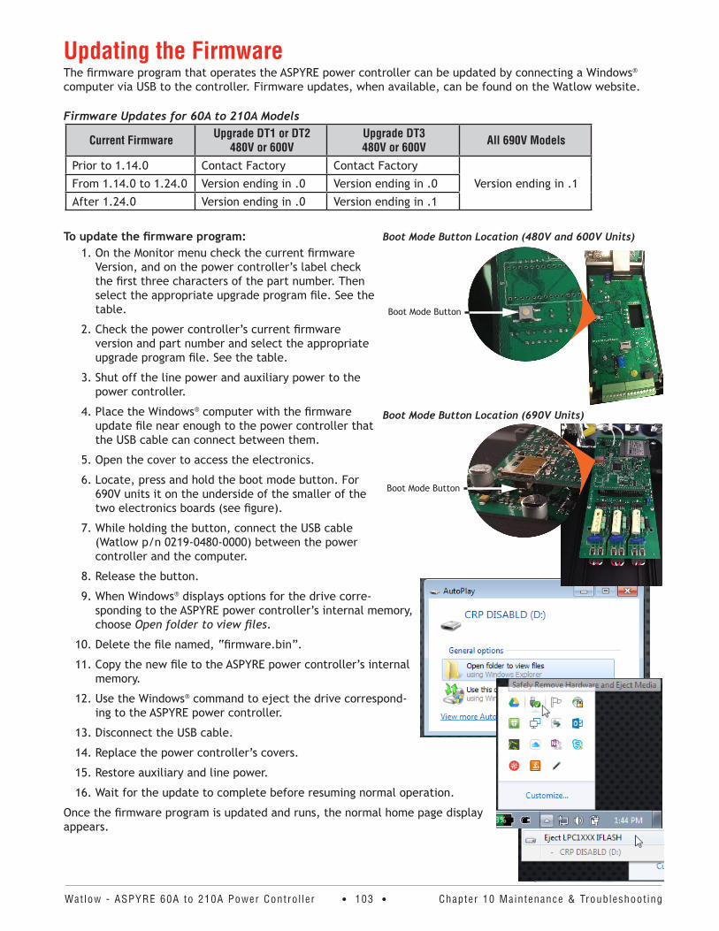
Watlow - ASPYRE 60A to 210A Power Contro l ler • 103 • Chapter 10 Maintenance & Troubleshoot ing
Updating the FirmwareThe firmware program that operates the ASPYRE power controller can be updated by connecting a Windows® computer via USB to the controller. Firmware updates, when available, can be found on the Watlow website.
Firmware Updates for 60A to 210A Models
Current Firmware Upgrade DT1 or DT2 480V or 600V
Upgrade DT3 480V or 600V All 690V Models
Prior to 1.14.0 Contact Factory Contact Factory
Version ending in .1From 1.14.0 to 1.24.0 Version ending in .0 Version ending in .0
After 1.24.0 Version ending in .0 Version ending in .1
To update the firmware program:1. On the Monitor menu check the current firmware
Version, and on the power controller’s label check the first three characters of the part number. Then select the appropriate upgrade program file. See the table.
2. Check the power controller’s current firmware version and part number and select the appropriate upgrade program file. See the table.
3. Shut off the line power and auxiliary power to the power controller.
4. Place the Windows® computer with the firmware update file near enough to the power controller that the USB cable can connect between them.
5. Open the cover to access the electronics.
6. Locate, press and hold the boot mode button. For 690V units it on the underside of the smaller of the two electronics boards (see figure).
7. While holding the button, connect the USB cable (Watlow p/n 0219-0480-0000) between the power controller and the computer.
8. Release the button.
9. When Windows® displays options for the drive corre-sponding to the ASPYRE power controller’s internal memory, choose Open folder to view files.
10. Delete the file named, “firmware.bin”.
11. Copy the new file to the ASPYRE power controller’s internal memory.
12. Use the Windows® command to eject the drive correspond-ing to the ASPYRE power controller.
13. Disconnect the USB cable.
14. Replace the power controller’s covers.
15. Restore auxiliary and line power.
16. Wait for the update to complete before resuming normal operation.
Once the firmware program is updated and runs, the normal home page display appears.
Boot Mode Button Location (480V and 600V Units)
Boot Mode Button
Boot Mode Button Location (690V Units)
Boot Mode Button
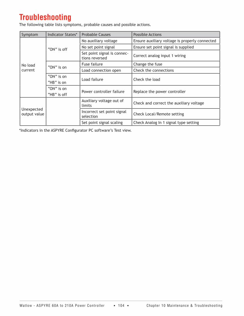
Watlow - ASPYRE 60A to 210A Power Contro l ler • 104 • Chapter 10 Maintenance & Troubleshoot ing
TroubleshootingThe following table lists symptoms, probable causes and possible actions.
Symptom Indicator States* Probable Causes Possible Actions
No load current
“ON” is off
No auxiliary voltage Ensure auxiliary voltage is properly connected
No set point signal Ensure set point signal is supplied
Set point signal is connec-tions reversed Correct analog input 1 wiring
“ON” is onFuse failure Change the fuse
Load connection open Check the connections
“ON” is on“HB” is on
Load failure Check the load
“ON” is on“HB” is off
Power controller failure Replace the power controller
Unexpected output value
Auxiliary voltage out of limits Check and correct the auxiliary voltage
Incorrect set point signal selection Check Local/Remote setting
Set point signal scaling Check Analog In 1 signal type setting
*Indicators in the ASPYRE Configurator PC software’s Test view.
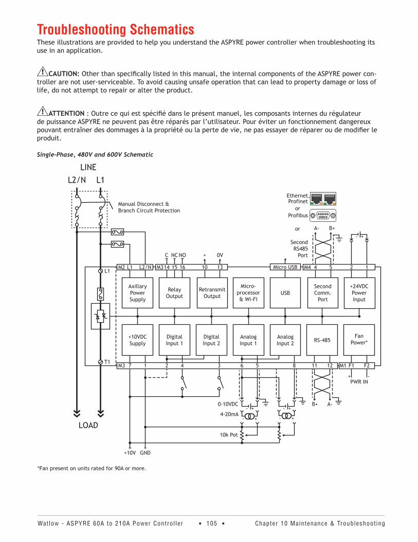
Watlow - ASPYRE 60A to 210A Power Contro l ler • 105 • Chapter 10 Maintenance & Troubleshoot ing
Troubleshooting SchematicsThese illustrations are provided to help you understand the ASPYRE power controller when troubleshooting its use in an application.
CAUTION: Other than specifically listed in this manual, the internal components of the ASPYRE power con-troller are not user-serviceable. To avoid causing unsafe operation that can lead to property damage or loss of life, do not attempt to repair or alter the product.
ATTENTION : Outre ce qui est spécifié dans le présent manuel, les composants internes du régulateur de puissance ASPYRE ne peuvent pas être réparés par l’utilisateur. Pour éviter un fonctionnement dangereux pouvant entraîner des dommages à la propriété ou la perte de vie, ne pas essayer de réparer ou de modifier le produit.
Single-Phase, 480V and 600V Schematic
LOAD
LINE
L1
T1
L1L2/N
L2/NL1M2
Axillary Power Supply
*Fan present on units rated for 90A or more.
FanPower*RS-485
AnalogInput 2
AnalogInput 1
DigitalInput 2
DigitalInput 1
+10VDCSupply
USB+24VDCPowerInput
RetransmitOutput
Second Comm.
Port
Micro-processor& Wi-FI
RelayOutput
+10V GND
PWR IN+ -
B+ A-
- +
- +
10k Pot
4-20mA- +
0-10VDC- +
- +
0V+
A- B+
Second RS485
Port
Profibus
or
Profinetor
C NC NO
2 154M4
7 1 2 4 3 6 5 8 11 12 F1 F2M3
Micro USB10161514M3 13
M1
Manual Disconnect & Branch Circuit Protection
Ethernet,
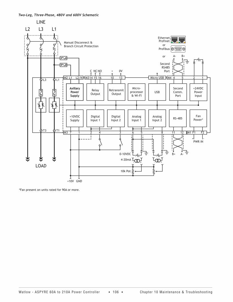
Watlow - ASPYRE 60A to 210A Power Contro l ler • 106 • Chapter 10 Maintenance & Troubleshoot ing
Two-Leg, Three-Phase, 480V and 600V Schematic
LOAD
LINE
L1
T1
L1
L3
T3
L3L2
L2/NL1M2
Axillary Power Supply
L2/NL1M2
Axillary Power Supply
*Fan present on units rated for 90A or more.
FanPower*RS-485
AnalogInput 2
AnalogInput 1
DigitalInput 2
DigitalInput 1
+10VDCSupply
USB+24VDCPowerInput
RetransmitOutput
Second Comm.
Port
Micro-processor& Wi-FI
RelayOutput
+10V GND
PWR IN+ -
B+ A-
- +
- +
10k Pot
4-20mA- +
0-10VDC- +
- +
0V+
A- B+
Second RS485
Port
Profibus
or
Profinetor
C NC NO
2 154M4
7 1 2 4 3 6 5 8 11 12 F1 F2M3
Micro USB10161514M3 13
M1
Manual Disconnect & Branch Circuit Protection
Ethernet,
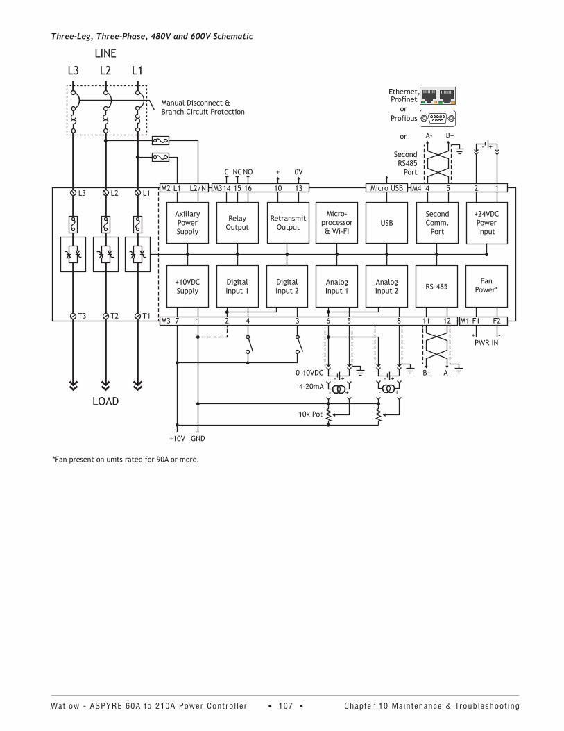
Watlow - ASPYRE 60A to 210A Power Contro l ler • 107 • Chapter 10 Maintenance & Troubleshoot ing
Three-Leg, Three-Phase, 480V and 600V Schematic
LOAD
LINE
L1
T1
L1
L2
T2
L2
L3
T3
L3
L2/NL1M2
Axillary Power Supply
*Fan present on units rated for 90A or more.
FanPower*RS-485
AnalogInput 2
AnalogInput 1
DigitalInput 2
DigitalInput 1
+10VDCSupply
USB+24VDCPowerInput
RetransmitOutput
Second Comm.
Port
Micro-processor& Wi-FI
RelayOutput
+10V GND
PWR IN+ -
B+ A-
- +
- +
10k Pot
4-20mA- +
0-10VDC- +
- +
0V+
A- B+
Second RS485
Port
Profibus
or
Profinetor
C NC NO
2 154M4
7 1 2 4 3 6 5 8 11 12 F1 F2M3
Micro USB10161514M3 13
M1
Manual Disconnect & Branch Circuit Protection
Ethernet,
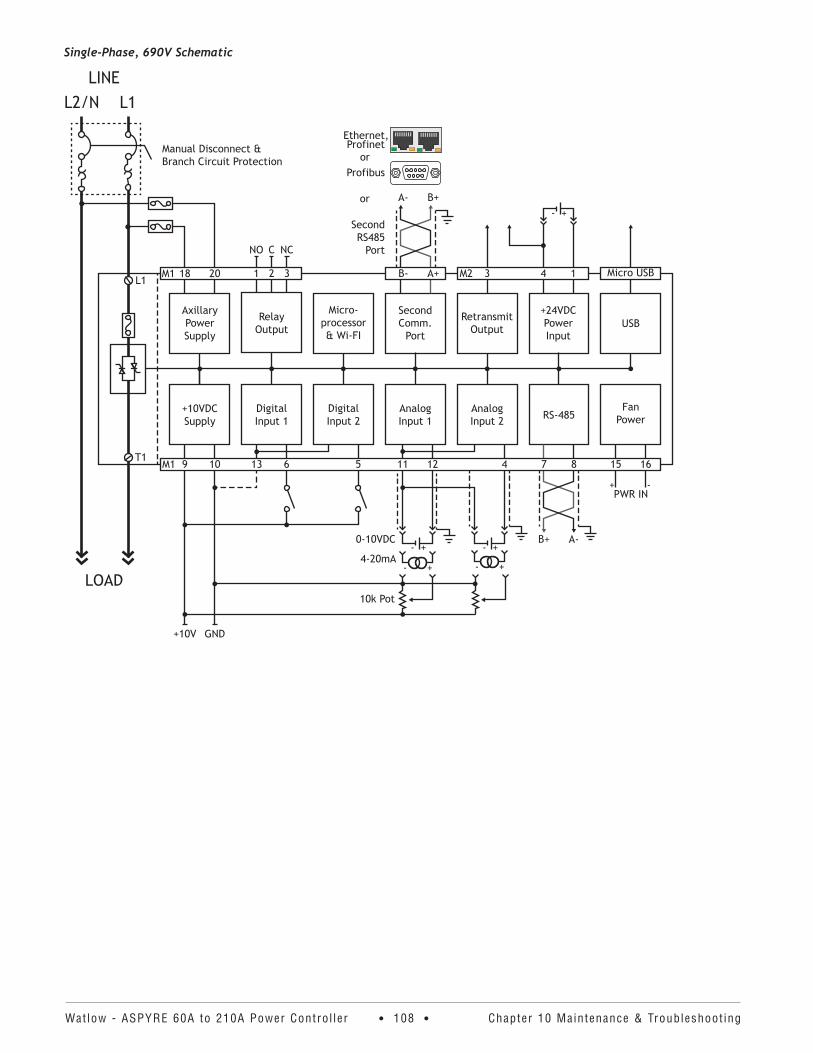
Watlow - ASPYRE 60A to 210A Power Contro l ler • 108 • Chapter 10 Maintenance & Troubleshoot ing
Single-Phase, 690V Schematic
LOAD
LINE
L1
T1
L1L2/N
3212018M1
Axillary Power Supply
FanPowerRS-485Analog
Input 2AnalogInput 1
DigitalInput 2
DigitalInput 1
+10VDCSupply
USB+24VDCPowerInput
RetransmitOutput
Second Comm.
Port
Micro-processor& Wi-FI
RelayOutput
+10V GND
PWR IN-+
A-B+
- +
- +
10k Pot
4-20mA- +
0-10VDC- +
- +A- B+
A+B-
Second RS485
Port
Profibus
or
Ethernet,
or
NO C NC
9 10 13 6 5 11 12 4 7 8 15 16M1
Micro USB3 4 1M2
Manual Disconnect & Branch Circuit Protection
Profinet
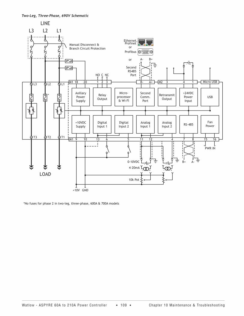
Watlow - ASPYRE 60A to 210A Power Contro l ler • 109 • Chapter 10 Maintenance & Troubleshoot ing
Two-Leg, Three-Phase, 690V Schematic
*No fuses for phase 2 in two-leg, three-phase, 600A & 700A models
M1 321
LOAD
LINE
L1
T1
L1
L2
T2
L2
L3
T3
L3
*
3212018M1
Axillary Power Supply
FanPowerRS-485Analog
Input 2AnalogInput 1
DigitalInput 2
DigitalInput 1
+10VDCSupply
USB+24VDCPowerInput
RetransmitOutput
Second Comm.
Port
Micro-processor& Wi-FI
RelayOutput
+10V GND
PWR IN-+
A-B+
- +
- +
10k Pot
4-20mA- +
0-10VDC- +
- +A- B+
A+B-
Second RS485
Port
Profibus
or
Ethernet,
or
NO C NC
9 10 13 6 5 11 12 4 7 8 15 16M1
Micro USB3 4 1M2
Manual Disconnect & Branch Circuit Protection
Profinet
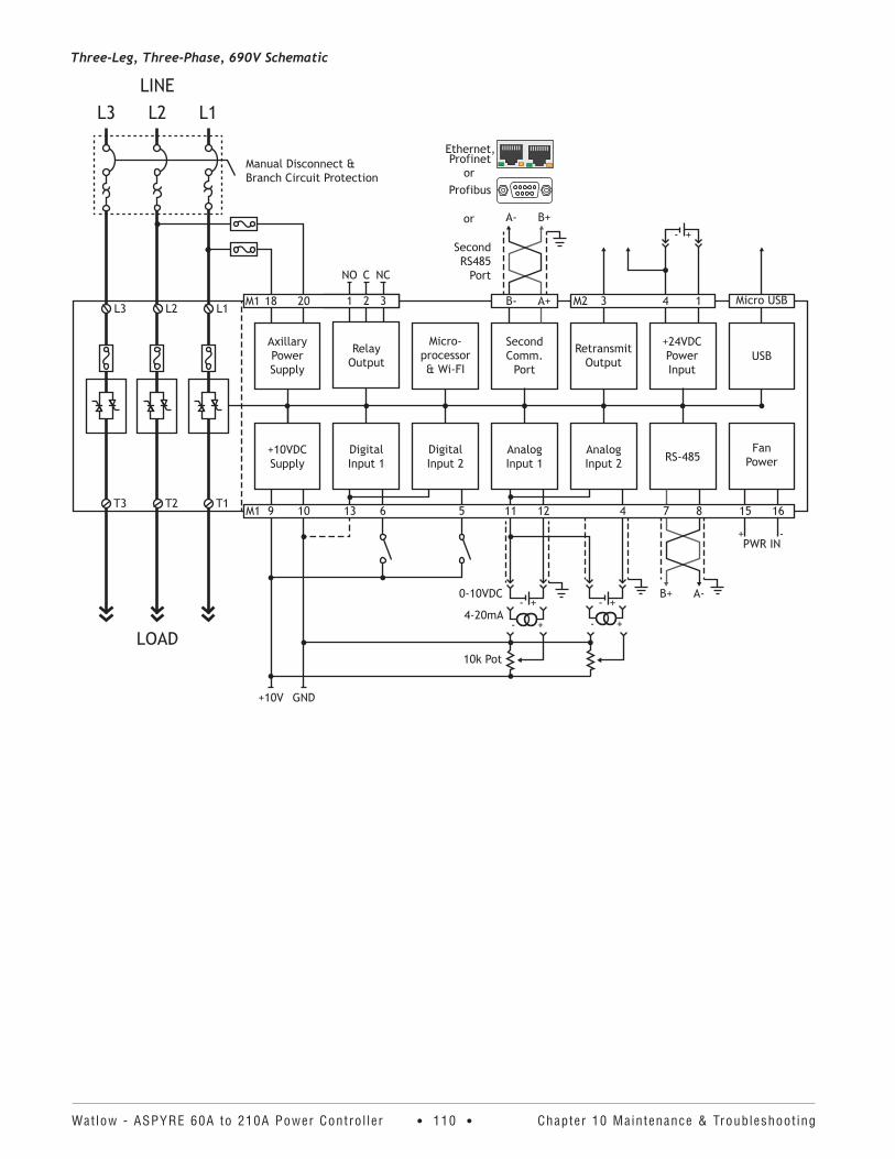
Watlow - ASPYRE 60A to 210A Power Contro l ler • 110 • Chapter 10 Maintenance & Troubleshoot ing
Three-Leg, Three-Phase, 690V Schematic
M1 321
LOAD
LINE
L1
T1
L1
L2
T2
L2
L3
T3
L3
3212018M1
Axillary Power Supply
FanPowerRS-485Analog
Input 2AnalogInput 1
DigitalInput 2
DigitalInput 1
+10VDCSupply
USB+24VDCPowerInput
RetransmitOutput
Second Comm.
Port
Micro-processor& Wi-FI
RelayOutput
+10V GND
PWR IN-+
A-B+
- +
- +
10k Pot
4-20mA- +
0-10VDC- +
- +A- B+
A+B-
Second RS485
Port
Profibus
or
Ethernet,
or
NO C NC
9 10 13 6 5 11 12 4 7 8 15 16M1
Micro USB3 4 1M2
Manual Disconnect & Branch Circuit Protection
Profinet
Watlow - ASPYRE 60A to 210A Power Contro l ler • 111 • Chapter 11 Communicat ion
11 CommunicationOverviewThis chapter describes using the various options for communicating between an ASPYRE power controller and third-party devices and software.
WiringFor information about wiring for the communication ports see “Communication Connections” on page 27.
Data TypesEach memory register contains an unsigned, 16-bit integer value. In a few cases the values from more than one register must be combined to read a single parameter value. For example, the kW Total parameter is stored in two 16-bit registers which must be combined in to a 32-bit long for display to users. These cases are indicated in the tables found later in this chapter. Any protocol specific types are indicated in the corresponding section.
Implied Decimals and Linear ScalingSome values must be scaled from the units of measure in which they are displayed before being transmitted to the power controller, and conversely when read from the power controller via communications, these values must be scaled to the units of measure for display to users.
In some cases the value read via communications must be divided by a factor of ten because decimal precision is implied. For example, Frequency is measured and stored with two decimal place accuracy, but is transmitted via Modbus® TCP as a whole number with two implied decimal places.
In other cases the value read via communication must be scaled linearly from the range over which it is stored in the power controller to the range of values in the units of measure presented to the user. For example, the Set Point range 0% to 100% is stored in the power controller as value that ranges from 0 to 1023. When the set point is 50% the value read from the power controller is 511, not 500.
In all cases the necessary scaling is indicated in the tables found later in this chapter.
Enumerated ValuesSome values represent data that is indicated by a word or short phrase. These enumerated values are listed in the tables found later in this chapter. For more thorough explanations see the parameter descriptions in the “Parameter Reference” chapter starting on page 65.
Bitwise ValuesThe Status Bits parameter indicates the states of alarms, digital inputs and other features with bits that corre-spond to each state. The Command Bits parameter supports switching features such as local or remote current limit on or off. For more details see “Status Bits” on page 80 and “Command Bits” on page 67.
To set a command bit without making other changes, read the command bits register, then write the value cor-responding to the current setting with the one bit of interest changed.
Communication WatchdogWhile a host device or software is connected via Modbus® TCP, Profibus DP or Profinet, the ASPYRE power con-troller must receive a message from the master at least once every 35 seconds. If the time between messages
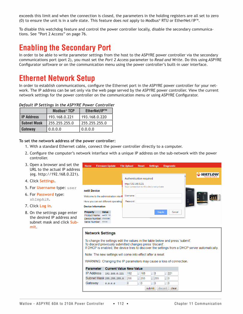
Watlow - ASPYRE 60A to 210A Power Contro l ler • 112 • Chapter 11 Communicat ion
exceeds this limit and when the connection is closed, the parameters in the holding registers are all set to zero (0) to ensure the unit is in a safe state. This feature does not apply to Modbus® RTU or EtherNet/IP™.
To disable this watchdog feature and control the power controller locally, disable the secondary communica-tions. See “Port 2 Access” on page 76.
Enabling the Secondary PortIn order to be able to write parameter settings from the host to the ASPYRE power controller via the secondary communications port (port 2), you must set the Port 2 Access parameter to Read and Write. Do this using ASPYRE Configurator software or on the communication menu using the power controller’s built-in user interface.
Ethernet Network SetupIn order to establish communications, configure the Ethernet port in the ASPYRE power controller for your net-work. The IP address can be set only via the web page served by the ASPYRE power controller. View the current network settings for the power controller on the communication menu or using ASPYRE Configurator.
Default IP Settings in the ASPYRE Power ControllerModbus® TCP EtherNet/IP™
IP Address 193.168.0.221 193.168.0.220
Subnet Mask 255.255.255.0 255.255.255.0
Gateway 0.0.0.0 0.0.0.0
To set the network address of the power controller:1. With a standard Ethernet cable, connect the power controller directly to a computer.
2. Configure the computer’s network interface with a unique IP address on the sub-network with the power controller.
3. Open a browser and set the URL to the actual IP address (eg. http://192.168.0.221).
4. Click Settings.
5. For Username type: user
6. For Password type: shImpAiR.
7. Click Log in.
8. On the settings page enter the desired IP address and subnet mask and click Sub-mit.
Watlow - ASPYRE 60A to 210A Power Contro l ler • 113 • Chapter 11 Communicat ion
Modbus® TCPThis section describes communicating with an ASPYRE power controller via the Modbus® TCP communications option. The typical application for this protocol is using a programmable logic controller or other automation equipment to control the power controller.
FeaturesThe Modbus® TCP option supports the following features.
Broadcast MessagesThe ASPYRE power controller supports Modbus® TCP broadcast messages. Send broadcast messages using station address 0. All ASPYRE power controllers on the local area network act on the message contents without sending back any reply.
NOTE! When the Command Bits parameter is set to zero, the Set Point Source and I Limit Local / Remote parameters are each set to accept signal from the analog inputs. If the application normally uses the secondary communication port to set the Set Point and I Limit values, the Command Bits parameter must be initialized accordingly each time the master connects to the power controller.
Supported FunctionsThe ASPYRE power controller supports the Modbus® TCP functions listed below.
Function Description04 Read the input registers (30,001 to 39,999)
03 Read the holding registers (40,001 to 49,999)
06 Write a single holding register
16 Write multiple holding registers
EtherNet/IP™ SetupThis section describes communicating with an ASPYRE power controller via the EtherNet/IP™ communication option. The typical application for this protocol is using a programmable logic controller or other automation equipment to control the power controller.
FeaturesThe ASPYRE power controller supports two instances of the assembly class.
Instance Tag Letter DescriptionInput 100 I Data produced by the power controller
Output 101 O Data consumed by the power controller
Data TypesEach value is a 16-bit integer unless specified as a BOOL array.
Necessary ToolsThe following instructions were created using a Windows® PC with Rockwell® Automation RSLogix® 5000 version 20.04.
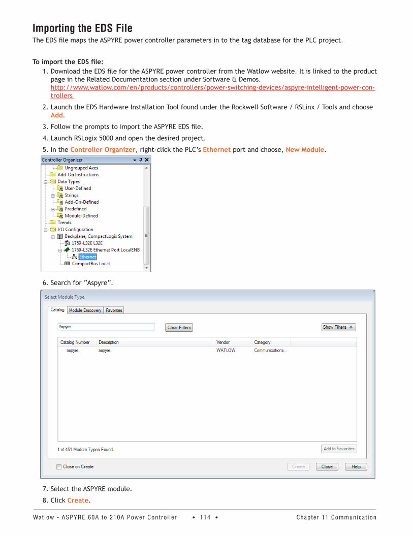
Watlow - ASPYRE 60A to 210A Power Contro l ler • 114 • Chapter 11 Communicat ion
Importing the EDS FileThe EDS file maps the ASPYRE power controller parameters in to the tag database for the PLC project.
To import the EDS file:1. Download the EDS file for the ASPYRE power controller from the Watlow website. It is linked to the product
page in the Related Documentation section under Software & Demos. http://www.watlow.com/en/products/controllers/power-switching-devices/aspyre-intelligent-power-con-trollers
2. Launch the EDS Hardware Installation Tool found under the Rockwell Software / RSLinx / Tools and choose Add.
3. Follow the prompts to import the ASPYRE EDS file.
4. Launch RSLogix 5000 and open the desired project.
5. In the Controller Organizer, right-click the PLC’s Ethernet port and choose, New Module.
6. Search for “Aspyre”.
7. Select the ASPYRE module.
8. Click Create.
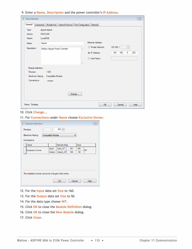
Watlow - ASPYRE 60A to 210A Power Contro l ler • 115 • Chapter 11 Communicat ion
9. Enter a Name, Description and the power controller’s IP Address.
10. Click Change...
11. For Connections under Name choose Exclusive Owner.
12. For the Input data set Size to 160.
13. For the Output data set Size to 50.
14. For the data type choose INT.
15. Click OK to close the Module Definition dialog.
16. Click OK to close the New Module dialog.
17. Click Close.
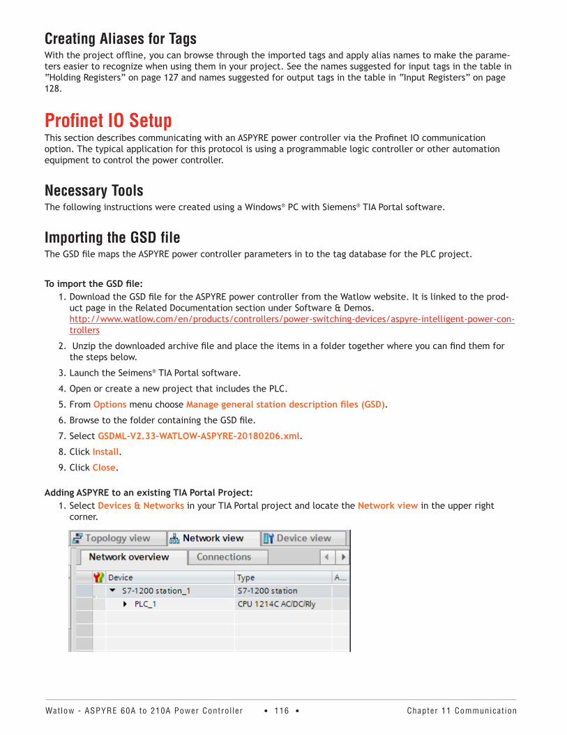
Watlow - ASPYRE 60A to 210A Power Contro l ler • 116 • Chapter 11 Communicat ion
Creating Aliases for TagsWith the project offline, you can browse through the imported tags and apply alias names to make the parame-ters easier to recognize when using them in your project. See the names suggested for input tags in the table in “Holding Registers” on page 127 and names suggested for output tags in the table in “Input Registers” on page 128.
Profinet IO SetupThis section describes communicating with an ASPYRE power controller via the Profinet IO communication option. The typical application for this protocol is using a programmable logic controller or other automation equipment to control the power controller.
Necessary ToolsThe following instructions were created using a Windows® PC with Siemens® TIA Portal software.
Importing the GSD fileThe GSD file maps the ASPYRE power controller parameters in to the tag database for the PLC project.
To import the GSD file:1. Download the GSD file for the ASPYRE power controller from the Watlow website. It is linked to the prod-
uct page in the Related Documentation section under Software & Demos. http://www.watlow.com/en/products/controllers/power-switching-devices/aspyre-intelligent-power-con-trollers
2. Unzip the downloaded archive file and place the items in a folder together where you can find them for the steps below.
3. Launch the Seimens® TIA Portal software.
4. Open or create a new project that includes the PLC.
5. From Options menu choose Manage general station description files (GSD).
6. Browse to the folder containing the GSD file.
7. Select GSDML-V2.33-WATLOW-ASPYRE-20180206.xml.
8. Click Install.
9. Click Close.
Adding ASPYRE to an existing TIA Portal Project:1. Select Devices & Networks in your TIA Portal project and locate the Network view in the upper right
corner.
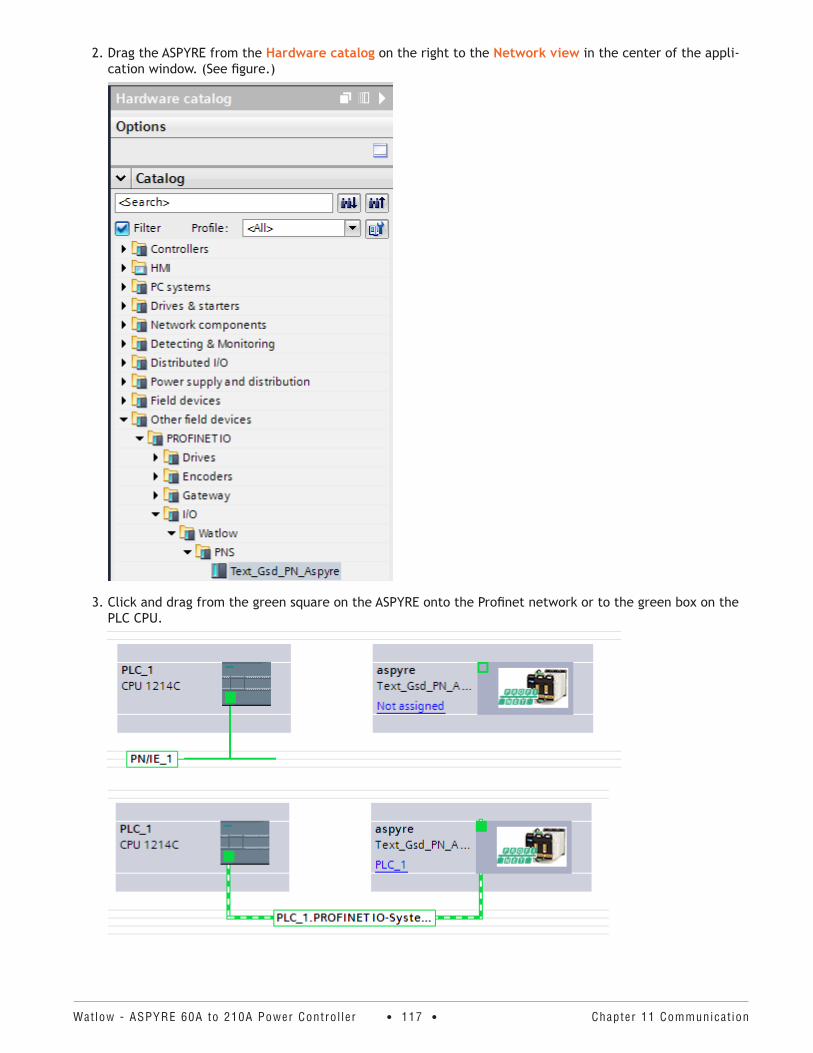
Watlow - ASPYRE 60A to 210A Power Contro l ler • 117 • Chapter 11 Communicat ion
2. Drag the ASPYRE from the Hardware catalog on the right to the Network view in the center of the appli-cation window. (See figure.)
3. Click and drag from the green square on the ASPYRE onto the Profinet network or to the green box on the PLC CPU.
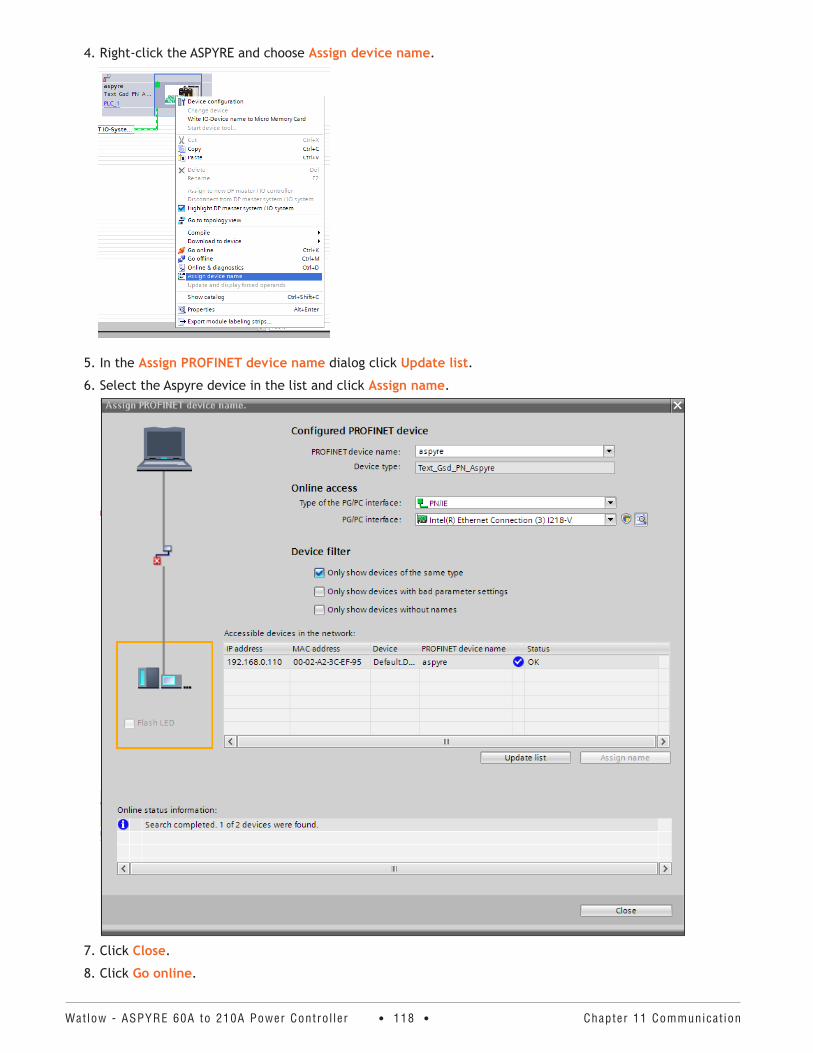
Watlow - ASPYRE 60A to 210A Power Contro l ler • 118 • Chapter 11 Communicat ion
4. Right-click the ASPYRE and choose Assign device name.
5. In the Assign PROFINET device name dialog click Update list.
6. Select the Aspyre device in the list and click Assign name.
7. Click Close.
8. Click Go online.
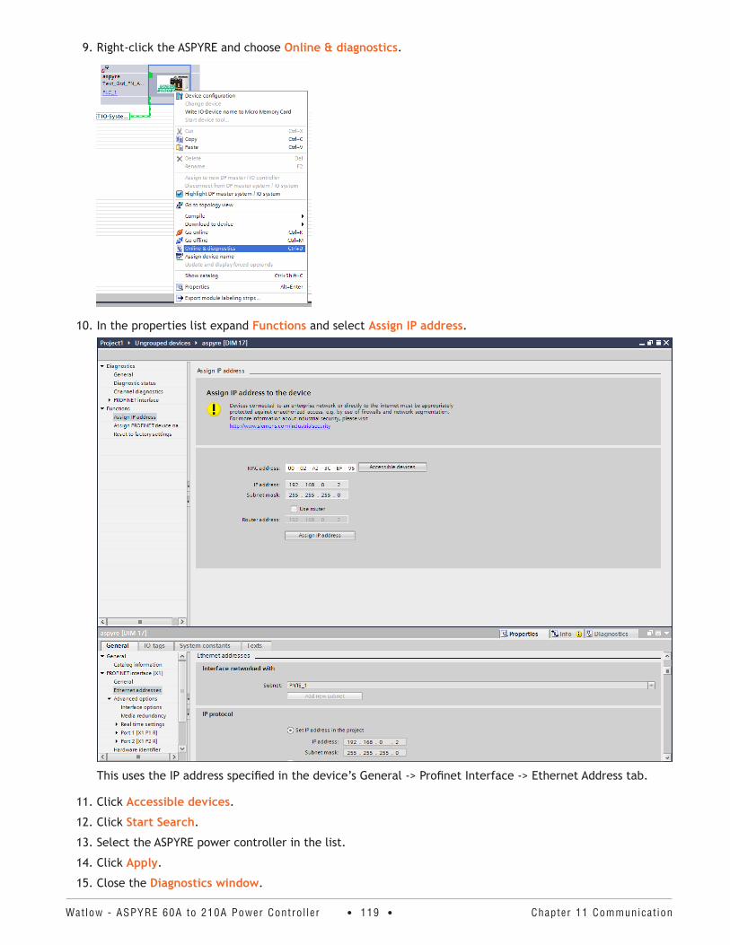
Watlow - ASPYRE 60A to 210A Power Contro l ler • 119 • Chapter 11 Communicat ion
9. Right-click the ASPYRE and choose Online & diagnostics.
10. In the properties list expand Functions and select Assign IP address.
This uses the IP address specified in the device’s General -> Profinet Interface -> Ethernet Address tab.
11. Click Accessible devices.
12. Click Start Search.
13. Select the ASPYRE power controller in the list.
14. Click Apply.
15. Close the Diagnostics window.
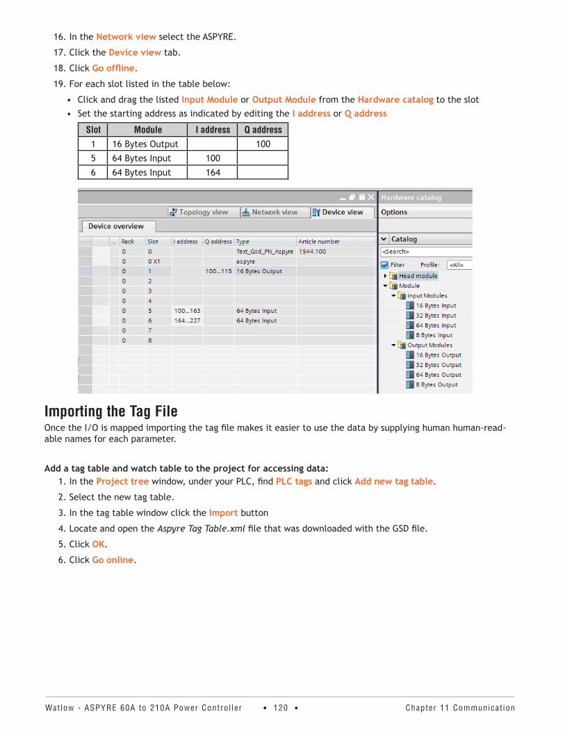
Watlow - ASPYRE 60A to 210A Power Contro l ler • 120 • Chapter 11 Communicat ion
16. In the Network view select the ASPYRE.
17. Click the Device view tab.
18. Click Go offline.
19. For each slot listed in the table below:
• Click and drag the listed Input Module or Output Module from the Hardware catalog to the slot• Set the starting address as indicated by editing the I address or Q address
Slot Module I address Q address1 16 Bytes Output 100
5 64 Bytes Input 100
6 64 Bytes Input 164
Importing the Tag FileOnce the I/O is mapped importing the tag file makes it easier to use the data by supplying human human-read-able names for each parameter.
Add a tag table and watch table to the project for accessing data:1. In the Project tree window, under your PLC, find PLC tags and click Add new tag table.
2. Select the new tag table.
3. In the tag table window click the Import button
4. Locate and open the Aspyre Tag Table.xml file that was downloaded with the GSD file.
5. Click OK.
6. Click Go online.
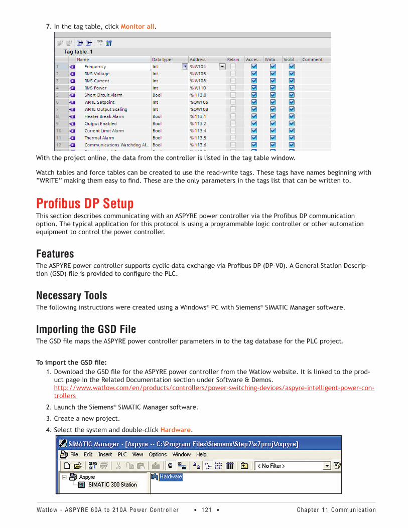
Watlow - ASPYRE 60A to 210A Power Contro l ler • 121 • Chapter 11 Communicat ion
7. In the tag table, click Monitor all.
With the project online, the data from the controller is listed in the tag table window.
Watch tables and force tables can be created to use the read-write tags. These tags have names beginning with “WRITE” making them easy to find. These are the only parameters in the tags list that can be written to.
Profibus DP SetupThis section describes communicating with an ASPYRE power controller via the Profibus DP communication option. The typical application for this protocol is using a programmable logic controller or other automation equipment to control the power controller.
FeaturesThe ASPYRE power controller supports cyclic data exchange via Profibus DP (DP-V0). A General Station Descrip-tion (GSD) file is provided to configure the PLC.
Necessary ToolsThe following instructions were created using a Windows® PC with Siemens® SIMATIC Manager software.
Importing the GSD FileThe GSD file maps the ASPYRE power controller parameters in to the tag database for the PLC project.
To import the GSD file:1. Download the GSD file for the ASPYRE power controller from the Watlow website. It is linked to the prod-
uct page in the Related Documentation section under Software & Demos. http://www.watlow.com/en/products/controllers/power-switching-devices/aspyre-intelligent-power-con-trollers
2. Launch the Siemens® SIMATIC Manager software.
3. Create a new project.
4. Select the system and double-click Hardware.
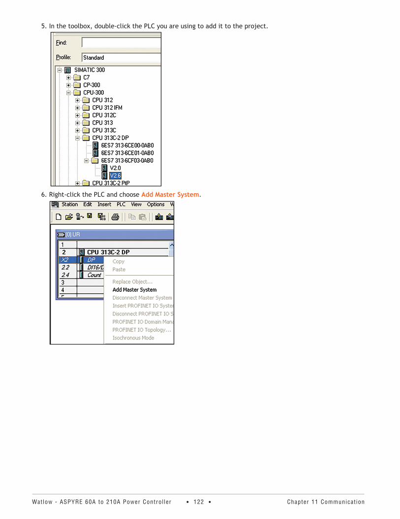
Watlow - ASPYRE 60A to 210A Power Contro l ler • 122 • Chapter 11 Communicat ion
5. In the toolbox, double-click the PLC you are using to add it to the project.
6. Right-click the PLC and choose Add Master System.
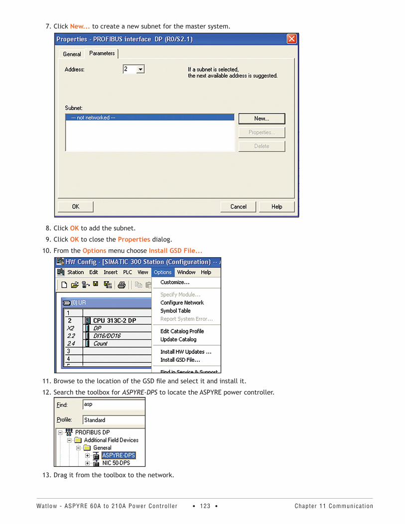
Watlow - ASPYRE 60A to 210A Power Contro l ler • 123 • Chapter 11 Communicat ion
7. Click New... to create a new subnet for the master system.
8. Click OK to add the subnet.
9. Click OK to close the Properties dialog.
10. From the Options menu choose Install GSD File...
11. Browse to the location of the GSD file and select it and install it.
12. Search the toolbox for ASPYRE-DPS to locate the ASPYRE power controller.
13. Drag it from the toolbox to the network.
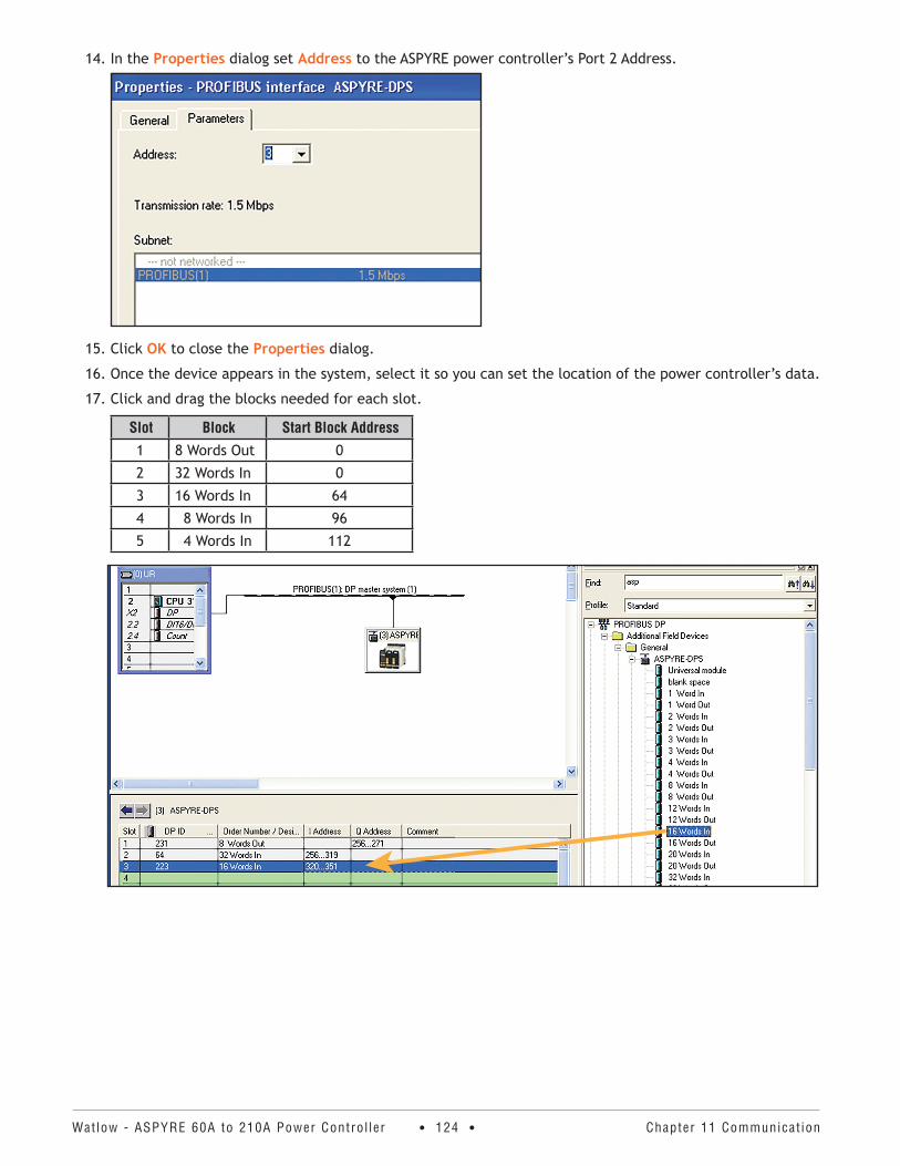
Watlow - ASPYRE 60A to 210A Power Contro l ler • 124 • Chapter 11 Communicat ion
14. In the Properties dialog set Address to the ASPYRE power controller’s Port 2 Address.
15. Click OK to close the Properties dialog.
16. Once the device appears in the system, select it so you can set the location of the power controller’s data.
17. Click and drag the blocks needed for each slot.
Slot Block Start Block Address1 8 Words Out 0
2 32 Words In 0
3 16 Words In 64
4 8 Words In 96
5 4 Words In 112
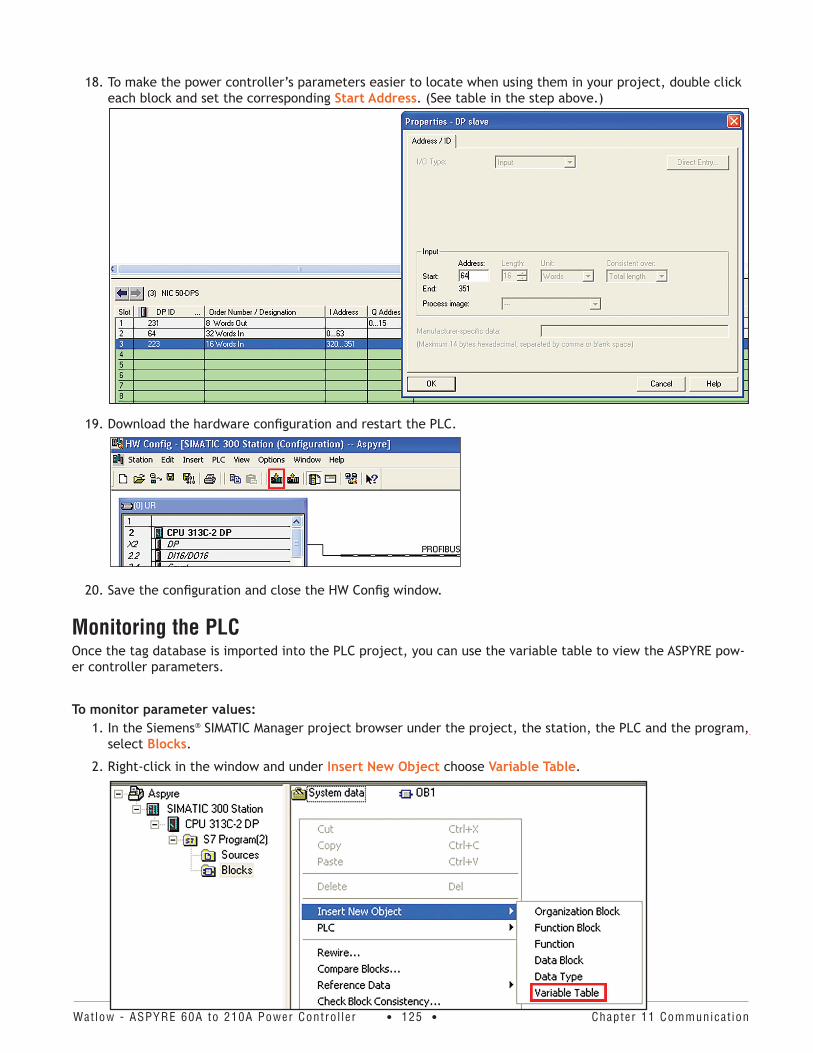
Watlow - ASPYRE 60A to 210A Power Contro l ler • 125 • Chapter 11 Communicat ion
18. To make the power controller’s parameters easier to locate when using them in your project, double click each block and set the corresponding Start Address. (See table in the step above.)
19. Download the hardware configuration and restart the PLC.
20. Save the configuration and close the HW Config window.
Monitoring the PLCOnce the tag database is imported into the PLC project, you can use the variable table to view the ASPYRE pow-er controller parameters.
To monitor parameter values:1. In the Siemens® SIMATIC Manager project browser under the project, the station, the PLC and the program,
select Blocks.
2. Right-click in the window and under Insert New Object choose Variable Table.
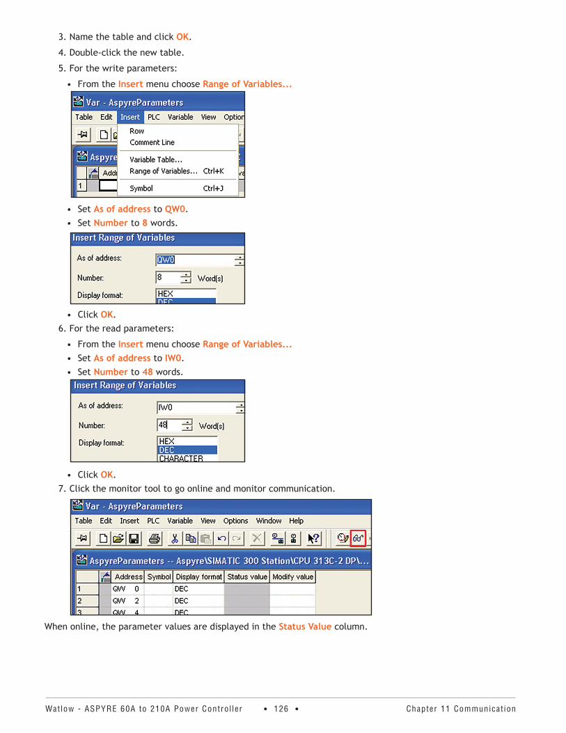
Watlow - ASPYRE 60A to 210A Power Contro l ler • 126 • Chapter 11 Communicat ion
3. Name the table and click OK.
4. Double-click the new table.
5. For the write parameters:
• From the Insert menu choose Range of Variables...
• Set As of address to QW0.• Set Number to 8 words.
• Click OK.6. For the read parameters:
• From the Insert menu choose Range of Variables...• Set As of address to IW0.• Set Number to 48 words.
• Click OK.7. Click the monitor tool to go online and monitor communication.
When online, the parameter values are displayed in the Status Value column.
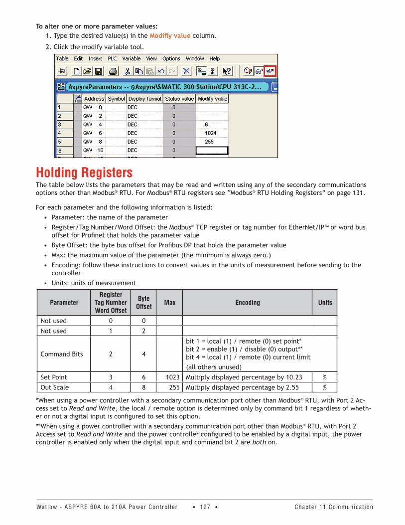
Watlow - ASPYRE 60A to 210A Power Contro l ler • 127 • Chapter 11 Communicat ion
To alter one or more parameter values:1. Type the desired value(s) in the Modifiy value column.
2. Click the modify variable tool.
Holding RegistersThe table below lists the parameters that may be read and written using any of the secondary communications options other than Modbus® RTU. For Modbus® RTU registers see “Modbus® RTU Holding Registers” on page 131.
For each parameter and the following information is listed:• Parameter: the name of the parameter• Register/Tag Number/Word Offset: the Modbus® TCP register or tag number for EtherNet/IP™ or word bus
offset for Profinet that holds the parameter value• Byte Offset: the byte bus offset for Profibus DP that holds the parameter value • Max: the maximum value of the parameter (the minimum is always zero.)• Encoding: follow these instructions to convert values in the units of measurement before sending to the
controller• Units: units of measurement
ParameterRegister
Tag Number Word Offset
Byte Offset Max Encoding Units
Not used 0 0
Not used 1 2
Command Bits 2 4
bit 1 = local (1) / remote (0) set point* bit 2 = enable (1) / disable (0) output** bit 4 = local (1) / remote (0) current limit(all others unused)
Set Point 3 6 1023 Multiply displayed percentage by 10.23 %
Out Scale 4 8 255 Multiply displayed percentage by 2.55 %
*When using a power controller with a secondary communication port other than Modbus® RTU, with Port 2 Ac-cess set to Read and Write, the local / remote option is determined only by command bit 1 regardless of wheth-er or not a digital input is configured to set this option.**When using a power controller with a secondary communication port other than Modbus® RTU, with Port 2 Access set to Read and Write and the power controller configured to be enabled by a digital input, the power controller is enabled only when the digital input and command bit 2 are both on.
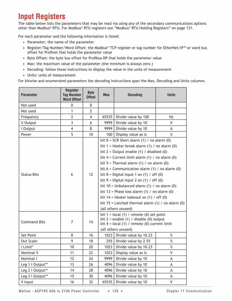
Watlow - ASPYRE 60A to 210A Power Contro l ler • 128 • Chapter 11 Communicat ion
Input RegistersThe table below lists the parameters that may be read via using any of the secondary communications options other than Modbus® RTU. For Modbus® RTU registers see “Modbus® RTU Holding Registers” on page 131.
For each parameter and the following information is listed:• Parameter: the name of the parameter• Register/Tag Number/Word Offset: the Modbus® TCP register or tag number for EtherNet/IP™ or word bus
offset for Profinet that holds the parameter value• Byte Offset: the byte bus offset for Profibus DP that holds the parameter value • Max: the maximum value of the parameter (the minimum is always zero.)• Decoding: follow these instructions to display the value in the units of measurement• Units: units of measurement
For bitwise and enumerated parameters the decoding instructions span the Max, Decoding and Units columns.
ParameterRegister
Tag Number Word Offset
Byte Offset Max Decoding Units
Not used 0 0
Not used 1 2
Frequency 2 4 65535 Divide value by 100 Hz
V Output 3 6 9999 Divide value by 10 V
I Output 4 8 9999 Divide value by 10 A
Power 5 10 100 Display value as is %
Status Bits 6 12
bit 0 = SCR Short alarm (1) / no alarm (0)bit 1 = Heater break alarm (1) / no alarm (0)bit 2 = Output enable (1) / disabled (0)bit 4 = Current limit alarm (1) / no alarm (0)bit 5 = Thermal alarm (1) / no alarm (0)bit 6 = Communication alarm (1) / no alarm (0) bit 8 = Digital input 1 on (1) / off (0)bit 9 = Digital input 2 on (1) / off (0)bit 10 = Unbalanced alarm (1) / no alarm (0)bit 13 = Phase loss alarm (1) / no alarm (0)bit 14 = Heater bakeout on (1) / off (0)bit 15 = Latched thermal alarm (1) / no alarm (0)(all others unused)
Command Bits 7 14
bit 1 = local (1) / remote (0) set point bit 2 = enable (1) / disable (0) output bit 4 = local (1) / remote (0) current limit(all others unused)
Set Point 8 16 1023 Divide value by 10.23 %
Out Scale 9 18 255 Divide value by 2.55 %
I Limit* 10 20 1023 Divide value by 10.23 %
Nominal V 11 22 1023 Display value as is V
Nominal I 12 24 9999 Divide value by 10 A
Leg 1 I Output** 13 26 4096 Divide value by 10 A
Leg 2 I Output** 14 28 4096 Divide value by 10 A
Leg 3 I Output** 15 30 4096 Divide value by 10 A
V Input 16 32 65535 Divide value by 10 V
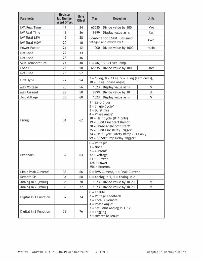
Watlow - ASPYRE 60A to 210A Power Contro l ler • 129 • Chapter 11 Communicat ion
ParameterRegister
Tag Number Word Offset
Byte Offset Max Decoding Units
kVA Real Time 17 34 65535 Divide value by 100 kVA
kW Real Time 18 36 9999 Display value as is kW
kW Total LSW 19 38 Combine for 32-bit, unsigned integer and divide by 10 kWh
kW Total MSW 20 40
Power Factor 21 42 1000 Divide value by 1000 ratio
Not used 22 44
Not used 23 46
SCR Temperature 24 48 0 = OK, 130 = Over Temp
Load Ω 25 50 65535 Divide value by 100 Ohm
Not used 26 52
Unit Type 27 54 7 = 1 Leg, 8 = 2 Leg, 9 = 3 Leg (zero cross), 10 = 3 Leg (phase angle)
Max Voltage 28 56 1023 Display value as is V
Max Current 29 58 9999 Divide value by 10 A
Aux Voltage 30 60 1023 Display value as is V
Firing 31 62
1 = Zero Cross 2 = Single Cycle* 3 = Burst Fire 4 = Phase Angle* 10 = Half Cycle (DT1 only) 19 = Burst Fire Start Ramp* 20 = Phase Angle Soft Start* 35 = Burst Fire Delay Trigger* 74 = Half Cycle Safety Ramp (DT1 only) 99 = BF Strt Rmp Delay Trigger*
Feedback 32 64
0 = Voltage2 1 = None 2 = Current2 32 = Voltage 64 = Current 128 = Power 256 = External
Limit Peak Current* 33 66 0 = RMS Current, 1 = Peak Current
Remote SP 34 68 0 = Analog In 1, 1 = Analog In 2
Analog In 1 [Value] 35 70 1023 Divide value by 10.23 %
Analog In 2 [Value] 36 72 1023 Divide value by 10.23 %
Digital In 1 Function 37 74
0 = Enable 2 = Voltage Feedback 3 = Local / Remote 4 = Phase Angle* 5 = Set Point Analog In 1 / 2 6 = Logging 7 = Heater Bakeout*
Digital In 2 Function 38 76
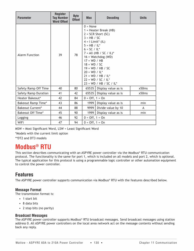
Watlow - ASPYRE 60A to 210A Power Contro l ler • 130 • Chapter 11 Communicat ion
ParameterRegister
Tag Number Word Offset
Byte Offset Max Decoding Units
Alarm Function 39 78
0 = None 1 = Heater Break (HB) 2 = SCR Short (SC) 3 = HB / SC 4 = I Limit* (IL) 5 = HB / IL* 6 = SC / IL* 7 = All (HB / SC / IL)* 16 = Watchdog (WD) 17 = WD / HB 18 = WD / SC 19 = WD / HB / SC 20 = WD / IL* 21 = WD / HB / IL* 22 = WD / SC / IL* 23 = WD / HB / SC / IL*
Safety Ramp Off Time 40 80 65535 Display value as is x50ms
Safety Ramp Duration 41 42 65535 Display value as is x50ms
Heater Bakeout* 42 84 0 = Off, 1 = On
Bakeout Ramp Time* 43 86 1999 Display value as is min
Bakeout Current* 44 88 9999 Divide value by 10 A
Bakeout Off Time* 45 90 1999 Display value as is min
Logging 46 92 0 = Off, 1 = On
WiFi 47 94 0 = Off, 1 = On
MSW = Most Significant Word, LSW = Least Significant Word*Models with the current limit option**DT2 and DT3 models
Modbus® RTUThis section describes communicating with an ASPYRE power controller via the Modbus® RTU communication protocol. The functionality is the same for port 1, which is included on all models and port 2, which is optional. The typical application for this protocol is using a programmable logic controller or other automation equipment to control the power controller.
FeaturesThe ASPYRE power controller supports communication via Modbus® RTU with the features described below.
Message FormatThe transmission format is:
• 1 start bit• 8 data bits• 2 stop bits (no parity)
Broadcast MessagesThe ASPYRE power controller supports Modbus® RTU broadcast messages. Send broadcast messages using station address 0. All ASPYRE power controllers on the local area network act on the message contents without sending back any reply.

Watlow - ASPYRE 60A to 210A Power Contro l ler • 131 • Chapter 11 Communicat ion
Supported FunctionsThe ASPYRE power controller supports the Modbus® RTU functions listed below. Note the limits to the number of registers that can be read and written with a single message from the host for each function.
Function Description Maximum Registers03 Read the holding registers (40,001 to 49,999) 121
06 Write a single holding register 1
16 Write multiple holding registers 25
Communication ErrorsMessages contain CRC error checking. If a message from the host fails the CRC test, or if the received message contains a syntax error, for example, the number of bytes or words is not correct, then the power controller will ignore the message.
If the received message is correct but contains an invalid value, the power controller responds with an error code. The supported error codes are listed in the table below.
Error Code Description1 Function code not supported
2 Incorrect data address
4 Too many registers (parameters) requested
Access LevelThe ASPYRE power controller supports access to its parameters via the Modbus® RTU holding registers (40,001 to 49,999). The values of all the defined parameters may be read, some parameters are read-only and some param-eters may be changed only after entering the correct password for the Access Level parameter.
Level zero (0) parameters do not require a password be entered. The level 1 password is “1111”.
Which parameters are read-only and the access level of each parameter is indicated in table in the “Modbus® RTU Holding Registers” section below.
Modbus® RTU Holding RegistersThe table below lists the parameters that may be read via Modbus® RTU via port 1 or if the secondary communi-cations option is Modbus® RTU via port 2.
For each parameter and the following information is listed:• Parameter: the name of the parameter• Register: the memory register that holds the parameter value• Max: the maximum value of the parameter (the minimum is always zero.)• Decoding: follow these instructions to display the value in the units of measurement• Units: units of measurement• RO: parameters marked with “RO” are read-only, all others allow reading and writing• Level: Access level required to write a new value (not listed for read-only parameters)
For bitwise and enumerated parameters the decoding instructions span the Max, Decoding and Units columns.
Parameter Register Max Decoding Units RO LevelAccess Level 1 65535 Display value as is none 0
Port 2 Access 2 0 = Read and Write, 1 = Read Only 1
Frequency 9 65535 Divide value by 100 Hz RO
V Output 10 9999 Divide value by 10 V RO
I Output 11 9999 Divide value by 10 A RO
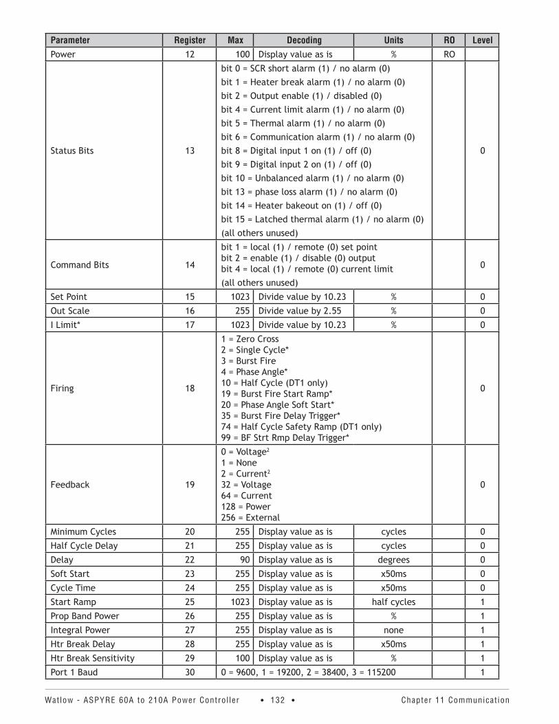
Watlow - ASPYRE 60A to 210A Power Contro l ler • 132 • Chapter 11 Communicat ion
Parameter Register Max Decoding Units RO LevelPower 12 100 Display value as is % RO
Status Bits 13
bit 0 = SCR short alarm (1) / no alarm (0)bit 1 = Heater break alarm (1) / no alarm (0)bit 2 = Output enable (1) / disabled (0)bit 4 = Current limit alarm (1) / no alarm (0)bit 5 = Thermal alarm (1) / no alarm (0)bit 6 = Communication alarm (1) / no alarm (0) bit 8 = Digital input 1 on (1) / off (0)bit 9 = Digital input 2 on (1) / off (0)bit 10 = Unbalanced alarm (1) / no alarm (0)bit 13 = phase loss alarm (1) / no alarm (0)bit 14 = Heater bakeout on (1) / off (0)bit 15 = Latched thermal alarm (1) / no alarm (0)(all others unused)
0
Command Bits 14
bit 1 = local (1) / remote (0) set point bit 2 = enable (1) / disable (0) output bit 4 = local (1) / remote (0) current limit(all others unused)
0
Set Point 15 1023 Divide value by 10.23 % 0
Out Scale 16 255 Divide value by 2.55 % 0
I Limit* 17 1023 Divide value by 10.23 % 0
Firing 18
1 = Zero Cross 2 = Single Cycle* 3 = Burst Fire 4 = Phase Angle* 10 = Half Cycle (DT1 only) 19 = Burst Fire Start Ramp* 20 = Phase Angle Soft Start* 35 = Burst Fire Delay Trigger* 74 = Half Cycle Safety Ramp (DT1 only) 99 = BF Strt Rmp Delay Trigger*
0
Feedback 19
0 = Voltage2 1 = None 2 = Current2 32 = Voltage 64 = Current 128 = Power 256 = External
0
Minimum Cycles 20 255 Display value as is cycles 0
Half Cycle Delay 21 255 Display value as is cycles 0
Delay 22 90 Display value as is degrees 0
Soft Start 23 255 Display value as is x50ms 0
Cycle Time 24 255 Display value as is x50ms 0
Start Ramp 25 1023 Display value as is half cycles 1
Prop Band Power 26 255 Display value as is % 1
Integral Power 27 255 Display value as is none 1
Htr Break Delay 28 255 Display value as is x50ms 1
Htr Break Sensitivity 29 100 Display value as is % 1
Port 1 Baud 30 0 = 9600, 1 = 19200, 2 = 38400, 3 = 115200 1
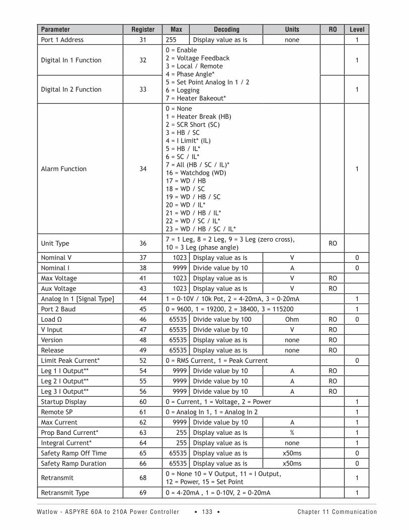
Watlow - ASPYRE 60A to 210A Power Contro l ler • 133 • Chapter 11 Communicat ion
Parameter Register Max Decoding Units RO LevelPort 1 Address 31 255 Display value as is none 1
Digital In 1 Function 32
0 = Enable 2 = Voltage Feedback 3 = Local / Remote 4 = Phase Angle* 5 = Set Point Analog In 1 / 2 6 = Logging 7 = Heater Bakeout*
1
Digital In 2 Function 33 1
Alarm Function 34
0 = None 1 = Heater Break (HB) 2 = SCR Short (SC) 3 = HB / SC 4 = I Limit* (IL) 5 = HB / IL* 6 = SC / IL* 7 = All (HB / SC / IL)* 16 = Watchdog (WD) 17 = WD / HB 18 = WD / SC 19 = WD / HB / SC 20 = WD / IL* 21 = WD / HB / IL* 22 = WD / SC / IL* 23 = WD / HB / SC / IL*
1
Unit Type 36 7 = 1 Leg, 8 = 2 Leg, 9 = 3 Leg (zero cross), 10 = 3 Leg (phase angle) RO
Nominal V 37 1023 Display value as is V 0
Nominal I 38 9999 Divide value by 10 A 0
Max Voltage 41 1023 Display value as is V RO
Aux Voltage 43 1023 Display value as is V RO
Analog In 1 [Signal Type] 44 1 = 0-10V / 10k Pot, 2 = 4-20mA, 3 = 0-20mA 1
Port 2 Baud 45 0 = 9600, 1 = 19200, 2 = 38400, 3 = 115200 1
Load Ω 46 65535 Divide value by 100 Ohm RO 0
V Input 47 65535 Divide value by 10 V RO
Version 48 65535 Display value as is none RO
Release 49 65535 Display value as is none RO
Limit Peak Current* 52 0 = RMS Current, 1 = Peak Current 0
Leg 1 I Output** 54 9999 Divide value by 10 A RO
Leg 2 I Output** 55 9999 Divide value by 10 A RO
Leg 3 I Output** 56 9999 Divide value by 10 A RO
Startup Display 60 0 = Current, 1 = Voltage, 2 = Power 1
Remote SP 61 0 = Analog In 1, 1 = Analog In 2 1
Max Current 62 9999 Divide value by 10 A 1
Prop Band Current* 63 255 Display value as is % 1
Integral Current* 64 255 Display value as is none 1
Safety Ramp Off Time 65 65535 Display value as is x50ms 0
Safety Ramp Duration 66 65535 Display value as is x50ms 0
Retransmit 68 0 = None 10 = V Output, 11 = I Output, 12 = Power, 15 = Set Point 1
Retransmit Type 69 0 = 4-20mA , 1 = 0-10V, 2 = 0-20mA 1
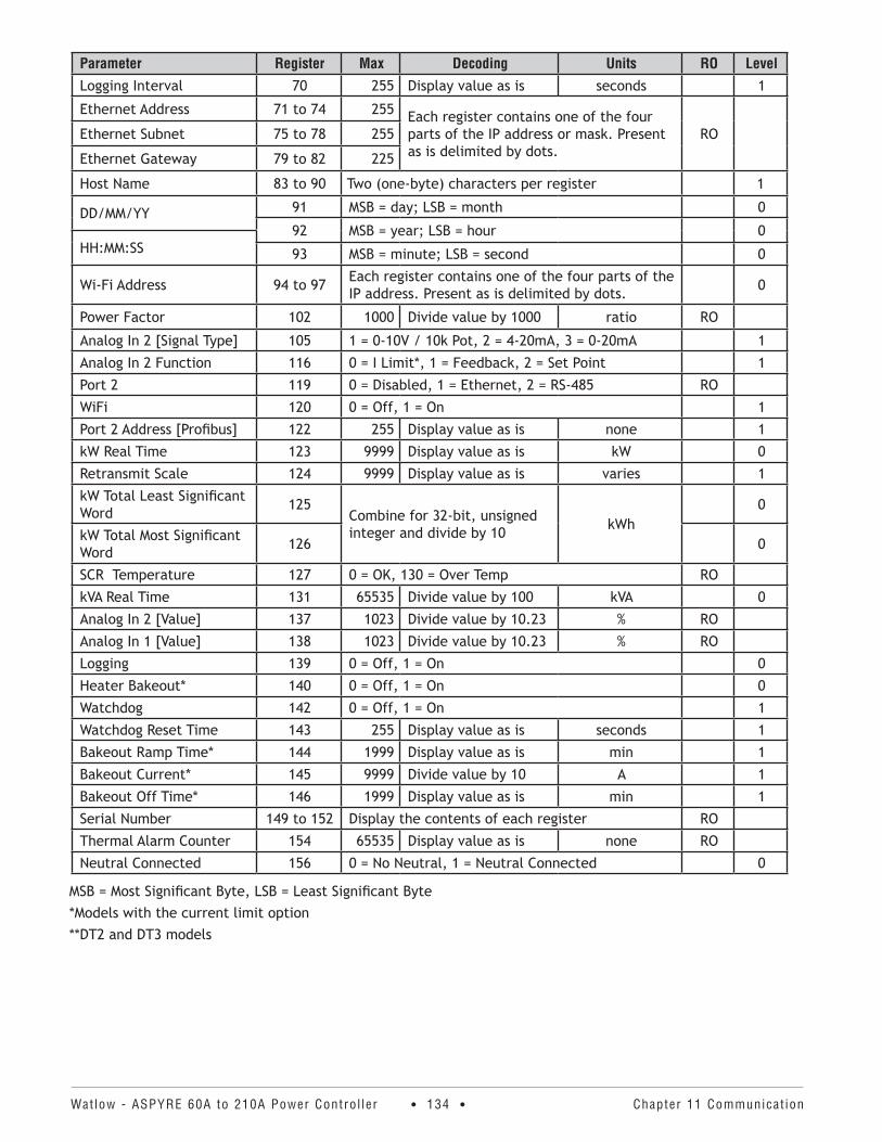
Watlow - ASPYRE 60A to 210A Power Contro l ler • 134 • Chapter 11 Communicat ion
Parameter Register Max Decoding Units RO LevelLogging Interval 70 255 Display value as is seconds 1
Ethernet Address 71 to 74 255 Each register contains one of the four parts of the IP address or mask. Present as is delimited by dots.
ROEthernet Subnet 75 to 78 255
Ethernet Gateway 79 to 82 225
Host Name 83 to 90 Two (one-byte) characters per register 1
DD/MM/YY 91 MSB = day; LSB = month 0
92 MSB = year; LSB = hour 0HH:MM:SS 93 MSB = minute; LSB = second 0
Wi-Fi Address 94 to 97 Each register contains one of the four parts of the IP address. Present as is delimited by dots. 0
Power Factor 102 1000 Divide value by 1000 ratio RO
Analog In 2 [Signal Type] 105 1 = 0-10V / 10k Pot, 2 = 4-20mA, 3 = 0-20mA 1
Analog In 2 Function 116 0 = I Limit*, 1 = Feedback, 2 = Set Point 1
Port 2 119 0 = Disabled, 1 = Ethernet, 2 = RS-485 RO
WiFi 120 0 = Off, 1 = On 1
Port 2 Address [Profibus] 122 255 Display value as is none 1
kW Real Time 123 9999 Display value as is kW 0
Retransmit Scale 124 9999 Display value as is varies 1
kW Total Least Significant Word 125
Combine for 32-bit, unsigned integer and divide by 10 kWh
0
kW Total Most Significant Word 126 0
SCR Temperature 127 0 = OK, 130 = Over Temp RO
kVA Real Time 131 65535 Divide value by 100 kVA 0
Analog In 2 [Value] 137 1023 Divide value by 10.23 % RO
Analog In 1 [Value] 138 1023 Divide value by 10.23 % RO
Logging 139 0 = Off, 1 = On 0
Heater Bakeout* 140 0 = Off, 1 = On 0
Watchdog 142 0 = Off, 1 = On 1
Watchdog Reset Time 143 255 Display value as is seconds 1
Bakeout Ramp Time* 144 1999 Display value as is min 1
Bakeout Current* 145 9999 Divide value by 10 A 1
Bakeout Off Time* 146 1999 Display value as is min 1
Serial Number 149 to 152 Display the contents of each register RO
Thermal Alarm Counter 154 65535 Display value as is none RO
Neutral Connected 156 0 = No Neutral, 1 = Neutral Connected 0
MSB = Most Significant Byte, LSB = Least Significant Byte*Models with the current limit option**DT2 and DT3 models
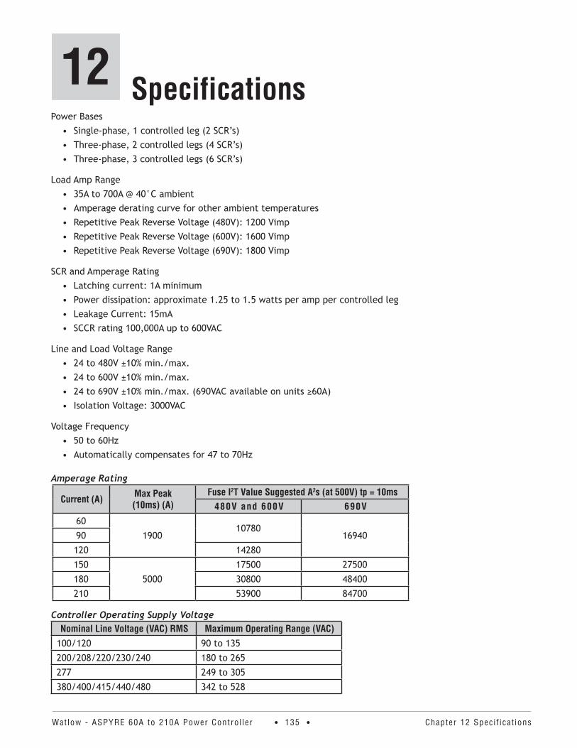
Watlow - ASPYRE 60A to 210A Power Contro l ler • 135 • Chapter 12 Speci f icat ions
12 SpecificationsPower Bases
• Single-phase, 1 controlled leg (2 SCR’s)• Three-phase, 2 controlled legs (4 SCR’s)• Three-phase, 3 controlled legs (6 SCR’s)
Load Amp Range• 35A to 700A @ 40°C ambient• Amperage derating curve for other ambient temperatures• Repetitive Peak Reverse Voltage (480V): 1200 Vimp• Repetitive Peak Reverse Voltage (600V): 1600 Vimp• Repetitive Peak Reverse Voltage (690V): 1800 Vimp
SCR and Amperage Rating• Latching current: 1A minimum• Power dissipation: approximate 1.25 to 1.5 watts per amp per controlled leg• Leakage Current: 15mA• SCCR rating 100,000A up to 600VAC
Line and Load Voltage Range• 24 to 480V ±10% min./max.• 24 to 600V ±10% min./max.• 24 to 690V ±10% min./max. (690VAC available on units ≥60A)• Isolation Voltage: 3000VAC
Voltage Frequency• 50 to 60Hz• Automatically compensates for 47 to 70Hz
Amperage Rating
Current (A) Max Peak (10ms) (A)
Fuse I2T Value Suggested A2s (at 500V) tp = 10ms480V and 600V 690V
60
190010780
1694090
120 14280
150
5000
17500 27500
180 30800 48400
210 53900 84700
Controller Operating Supply VoltageNominal Line Voltage (VAC) RMS Maximum Operating Range (VAC)
100/120 90 to 135
200/208/220/230/240 180 to 265
277 249 to 305
380/400/415/440/480 342 to 528
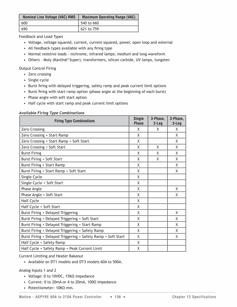
Watlow - ASPYRE 60A to 210A Power Contro l ler • 136 • Chapter 12 Speci f icat ions
Nominal Line Voltage (VAC) RMS Maximum Operating Range (VAC)600 540 to 660
690 621 to 759
Feedback and Load Types• Voltage, voltage squared, current, current squared, power, open loop and external• All feedback types available with any firing type• Normal resistive loads - nichrome, infrared lamps; medium and long waveform• Others – Moly (Kanthal® Super), transformers, silicon carbide, UV lamps, tungsten
Output Control Firing• Zero crossing• Single cycle• Burst firing with delayed triggering, safety ramp and peak current limit options• Burst firing with start ramp option (phase angle at the beginning of each burst)• Phase angle with soft start option• Half cycle with start ramp and peak current limit options
Available Firing Type Combinations
Firing Type Combinations Single Phase
3-Phase, 2-Leg
3-Phase, 3-Leg
Zero Crossing X X X
Zero Crossing + Start Ramp X X
Zero Crossing + Start Ramp + Soft Start X X
Zero Crossing + Soft Start X X X
Burst Firing X X X
Burst Firing + Soft Start X X X
Burst Firing + Start Ramp X X
Burst Firing + Start Ramp + Soft Start X X
Single Cycle X
Single Cycle + Soft Start X
Phase Angle X X
Phase Angle + Soft Start X X
Half Cycle X
Half Cycle + Soft Start X
Burst Firing + Delayed Triggering X X
Burst Firing + Delayed Triggering + Soft Start X X
Burst Firing + Delayed Triggering + Start Ramp X X
Burst Firing + Delayed Triggering + Safety Ramp X X
Burst Firing + Delayed Triggering + Safety Ramp + Soft Start X X
Half Cycle + Safety Ramp X
Half Cycle + Safety Ramp + Peak Current Limit X
Current Limiting and Heater Bakeout• Available on DT1 models and DT3 models 60A to 500A.
Analog Inputs 1 and 2• Voltage: 0 to 10VDC, 15KΩ impedance• Current: 0 to 20mA or 4 to 20mA, 100Ω impedance• Potentiometer: 10KΩ min.
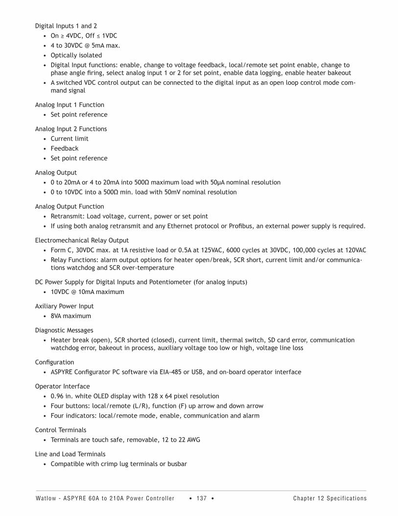
Watlow - ASPYRE 60A to 210A Power Contro l ler • 137 • Chapter 12 Speci f icat ions
Digital Inputs 1 and 2• On ≥ 4VDC, Off ≤ 1VDC• 4 to 30VDC @ 5mA max.• Optically isolated• Digital Input functions: enable, change to voltage feedback, local/remote set point enable, change to
phase angle firing, select analog input 1 or 2 for set point, enable data logging, enable heater bakeout• A switched VDC control output can be connected to the digital input as an open loop control mode com-
mand signal
Analog Input 1 Function• Set point reference
Analog Input 2 Functions• Current limit• Feedback• Set point reference
Analog Output • 0 to 20mA or 4 to 20mA into 500Ω maximum load with 50μA nominal resolution• 0 to 10VDC into a 500Ω min. load with 50mV nominal resolution
Analog Output Function• Retransmit: Load voltage, current, power or set point• If using both analog retransmit and any Ethernet protocol or Profibus, an external power supply is required.
Electromechanical Relay Output• Form C, 30VDC max. at 1A resistive load or 0.5A at 125VAC, 6000 cycles at 30VDC, 100,000 cycles at 120VAC• Relay Functions: alarm output options for heater open/break, SCR short, current limit and/or communica-
tions watchdog and SCR over-temperature
DC Power Supply for Digital Inputs and Potentiometer (for analog inputs)• 10VDC @ 10mA maximum
Axiliary Power Input• 8VA maximum
Diagnostic Messages• Heater break (open), SCR shorted (closed), current limit, thermal switch, SD card error, communication
watchdog error, bakeout in process, auxiliary voltage too low or high, voltage line loss
Configuration• ASPYRE Configurator PC software via EIA-485 or USB, and on-board operator interface
Operator Interface• 0.96 in. white OLED display with 128 x 64 pixel resolution• Four buttons: local/remote (L/R), function (F) up arrow and down arrow• Four indicators: local/remote mode, enable, communication and alarm
Control Terminals• Terminals are touch safe, removable, 12 to 22 AWG
Line and Load Terminals• Compatible with crimp lug terminals or busbar
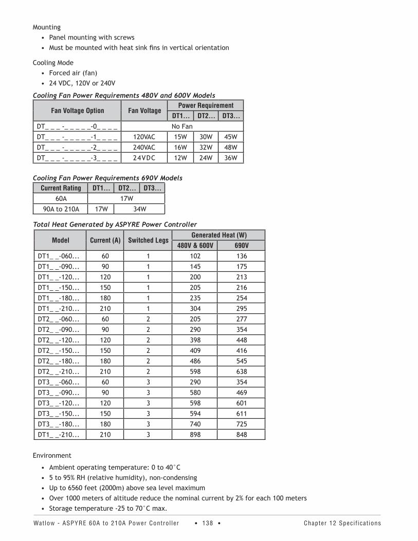
Watlow - ASPYRE 60A to 210A Power Contro l ler • 138 • Chapter 12 Speci f icat ions
Mounting• Panel mounting with screws• Must be mounted with heat sink fins in vertical orientation
Cooling Mode• Forced air (fan)• 24 VDC, 120V or 240V
Cooling Fan Power Requirements 480V and 600V Models
Fan Voltage Option Fan VoltagePower Requirement
DT1 . . . DT2 . . . DT3 . . .DT_ _ _ -_ _ _ _ _-0_ _ _ _ No Fan
DT_ _ _ -_ _ _ _ _-1_ _ _ _ 120VAC 15W 30W 45W
DT_ _ _ -_ _ _ _ _-2_ _ _ _ 240VAC 16W 32W 48W
DT_ _ _ -_ _ _ _ _-3_ _ _ _ 24VDC 12W 24W 36W
Cooling Fan Power Requirements 690V ModelsCurrent Rating DT1 . . . DT2 . . . DT3 . . .
60A 17W
90A to 210A 17W 34W
Total Heat Generated by ASPYRE Power Controller
Model Current (A) Switched LegsGenerated Heat (W)
480V & 600V 690VDT1_ _-060... 60 1 102 136
DT1_ _-090... 90 1 145 175
DT1_ _-120... 120 1 200 213
DT1_ _-150... 150 1 205 216
DT1_ _-180... 180 1 235 254
DT1_ _-210... 210 1 304 295
DT2_ _-060... 60 2 205 277
DT2_ _-090... 90 2 290 354
DT2_ _-120... 120 2 398 448
DT2_ _-150... 150 2 409 416
DT2_ _-180... 180 2 486 545
DT2_ _-210... 210 2 598 638
DT3_ _-060... 60 3 290 354
DT3_ _-090... 90 3 580 469
DT3_ _-120... 120 3 598 601
DT3_ _-150... 150 3 594 611
DT3_ _-180... 180 3 740 725
DT1_ _-210... 210 3 898 848
Environment
• Ambient operating temperature: 0 to 40°C• 5 to 95% RH (relative humidity), non-condensing• Up to 6560 feet (2000m) above sea level maximum• Over 1000 meters of altitude reduce the nominal current by 2% for each 100 meters• Storage temperature -25 to 70°C max.
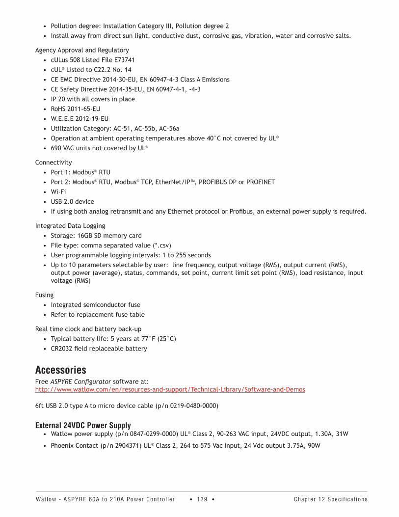
Watlow - ASPYRE 60A to 210A Power Contro l ler • 139 • Chapter 12 Speci f icat ions
• Pollution degree: Installation Category III, Pollution degree 2• Install away from direct sun light, conductive dust, corrosive gas, vibration, water and corrosive salts.
Agency Approval and Regulatory• cULus 508 Listed File E73741• cUL® Listed to C22.2 No. 14• CE EMC Directive 2014-30-EU, EN 60947-4-3 Class A Emissions• CE Safety Directive 2014-35-EU, EN 60947-4-1, -4-3• IP 20 with all covers in place• RoHS 2011-65-EU• W.E.E.E 2012-19-EU• Utilization Category: AC-51, AC-55b, AC-56a• Operation at ambient operating temperatures above 40°C not covered by UL®
• 690 VAC units not covered by UL®
Connectivity• Port 1: Modbus® RTU• Port 2: Modbus® RTU, Modbus® TCP, EtherNet/IP™, PROFIBUS DP or PROFINET• Wi-Fi• USB 2.0 device• If using both analog retransmit and any Ethernet protocol or Profibus, an external power supply is required.
Integrated Data Logging• Storage: 16GB SD memory card• File type: comma separated value (*.csv)• User programmable logging intervals: 1 to 255 seconds• Up to 10 parameters selectable by user: line frequency, output voltage (RMS), output current (RMS),
output power (average), status, commands, set point, current limit set point (RMS), load resistance, input voltage (RMS)
Fusing• Integrated semiconductor fuse• Refer to replacement fuse table
Real time clock and battery back-up• Typical battery life: 5 years at 77°F (25°C)• CR2032 field replaceable battery
AccessoriesFree ASPYRE Configurator software at: http://www.watlow.com/en/resources-and-support/Technical-Library/Software-and-Demos
6ft USB 2.0 type A to micro device cable (p/n 0219-0480-0000)
External 24VDC Power Supply• Watlow power supply (p/n 0847-0299-0000) UL® Class 2, 90-263 VAC input, 24VDC output, 1.30A, 31W
• Phoenix Contact (p/n 2904371) UL® Class 2, 264 to 575 Vac input, 24 Vdc output 3.75A, 90W
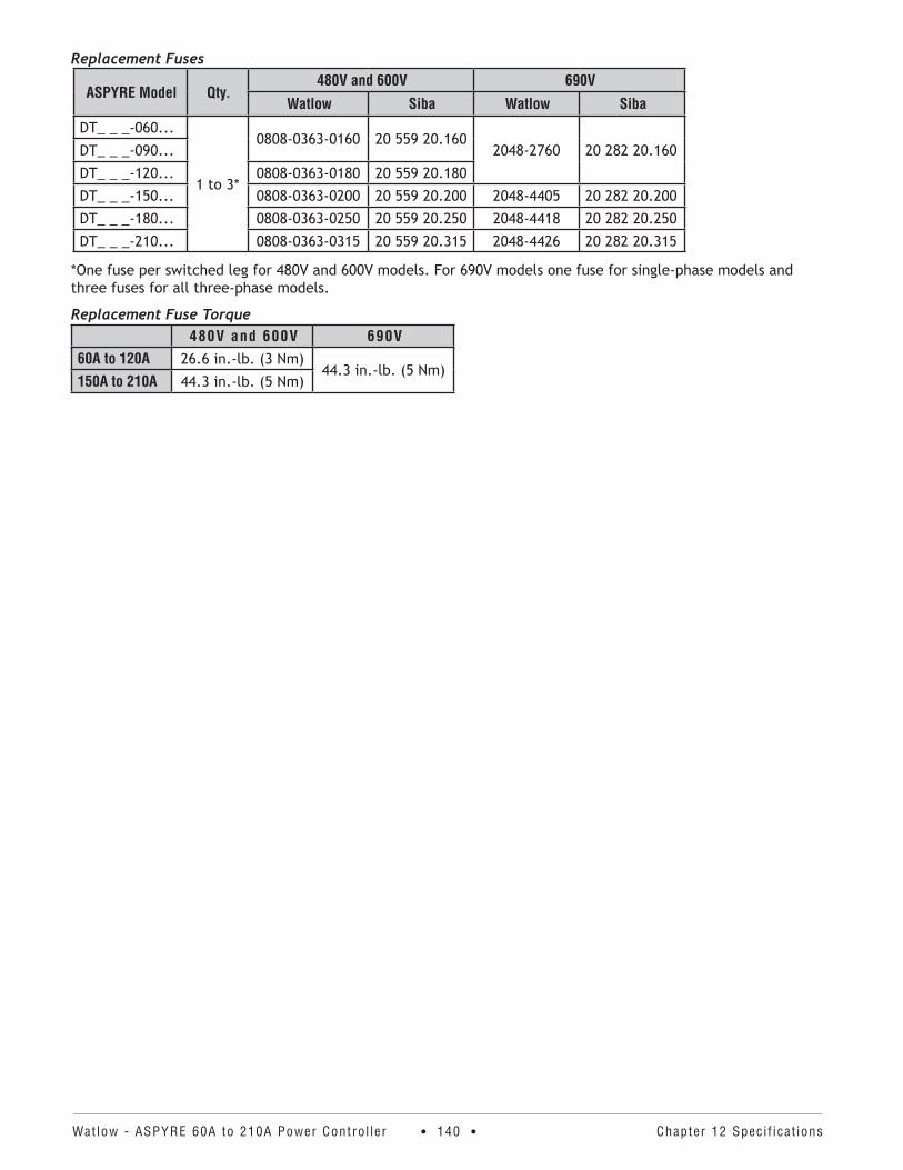
Watlow - ASPYRE 60A to 210A Power Contro l ler • 140 • Chapter 12 Speci f icat ions
Replacement Fuses
ASPYRE Model Qty .480V and 600V 690V
Watlow Siba Watlow Siba
DT_ _ _-060...
1 to 3*
0808-0363-0160 20 559 20.1602048-2760 20 282 20.160DT_ _ _-090...
DT_ _ _-120... 0808-0363-0180 20 559 20.180
DT_ _ _-150... 0808-0363-0200 20 559 20.200 2048-4405 20 282 20.200
DT_ _ _-180... 0808-0363-0250 20 559 20.250 2048-4418 20 282 20.250
DT_ _ _-210... 0808-0363-0315 20 559 20.315 2048-4426 20 282 20.315
*One fuse per switched leg for 480V and 600V models. For 690V models one fuse for single-phase models and three fuses for all three-phase models.
Replacement Fuse Torque480V and 600V 690V
60A to 120A 26.6 in.-lb. (3 Nm)44.3 in.-lb. (5 Nm)
150A to 210A 44.3 in.-lb. (5 Nm)
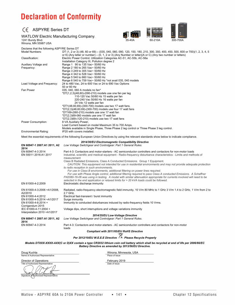
Watlow - ASPYRE 60A to 210A Power Contro l ler • 141 • Chapter 12 Speci f icat ions
ASPYRE Series DT WATLOW Electric Manufacturing Company. 1241 Bundy Blvd. 35-40A 60-210A 300-700A Winona, MN 55987 USA
Declares that the following ASPYRE Series DT Model Numbers: DT (1, 2 or 3) (48, 60 or 69) – (035, 040, 060, 090, 120, 150, 180, 210, 300, 350, 400, 450, 500, 600 or 700)(1, 2, 3, 4, 5
or 6) (Any letter or number) – (0, 1, 2 or 3) (Any Number or letter)(A or C) (Any two number or letters) Classification: Electric Power Control, Utilization Categories AC-51, AC-55b, AC-56a
Installation Category III, Pollution degree 2 Auxiliary Voltage and Frequency:
Range 1 90 to 135 Vac~ 50/60 Hz Range 2 180 to 265 Vac~ 50/60 Hz Range 3 249 to 305 Vac~ 50/60 Hz Range 4 342 to 528 Vac~ 50/60 Hz Range 5 540 to 660 Vac~ 50/60 Hz Range 6 540 to 759 Vac~ 50/60 Hz *not avail 035, 040 models
Load Voltage and Frequency: 24 to 480 Vac, 24 to 600 Vac or 24 to 690 Vac Options 50 or 60 Hz
Fan Power 035, 040, 060 A models no fan* *DT(1,2,3)(48,60)-(090-210) models use one fan per leg
110-120 Vac 50/60 Hz 15 watts per fan 220-240 Vac 50/60 Hz 16 watts per fan 24 Vdc 12 watts per fan
*DT1(48,60,69)-(300-700) models use two 17 watt fans. *DT(2,3)(48,60,69)-(300-700) models use four 17 watt fans *DT169-(060-210) models use one 17 watt fan *DT(2,3)69-060 models use one 17 watt fan *DT(2,3)69-(120-210) models use two 17 watt fans
Power Consumption: 8 VA Auxiliary Power, Load Current based on model Maximum 35 to 700 Amps. Models available in Single Phase, Three Phase 2 leg control or Three Phase 3 leg control.
Environmental Rating: IP20 with covers installed.
Meet the essential requirements of the following European Union Directives by using the relevant standards show below to indicate compliance.
2014/30/EU Electromagnetic Compatibility Directive EN 60947-1 2007:A1 2011, A2 2014 EN 60947-4-3 2014
Low Voltage Switchgear and Controlgear: Part 1 General Rules. Part 4-3: Contactors and motor-starters - AC semiconductor controllers and contactors for non-motor loads
EN 55011 2016:A1 2017 Industrial, scientific and medical equipment - Radio-frequency disturbance characteristics - Limits and methods of measurement Class B Radiated Emissions, Class A Conducted Emissions. Group 1 Equipment. CAUTION: This equipment not intended for use in residential environments and may not provide adequate protection to radio reception in such environments. For use in Class B environments, additional filtering on power lines required. For use with Phase Angle control, additional filtering required to pass Class A conducted Emissions. A Schaffner FN2080-16-06 was using in testing. A model with similar attenuation appropriate for currents involved will need to be selected in the end application or relaxed limits for > 20 kVA loads could be followed.
EN 61000-4-2:2009 Electrostatic discharge immunity EN 61000-4-3:2006 +A1/2008, A2/2010
Radiated, radio-frequency electromagnetic field immunity, 10 V/m 80 MHz to 1 GHz 3 V/m 1.4 to 2 GHz, 1 V/m from 2 to 2.7 GHz.
EN 61000-4-4:2012 Electrical fast-transient / burst immunity EN 61000-4-5:2014 +A1/2017 Surge immunity EN 61000-4-6:2014 + Corrigendum 2015
Immunity to conducted disturbances induced by radio-frequency fields 10 Vrms.
IEC 61000-4-11:2004 + Interpretation 2010 +A1/2017
Voltage dips, short interruptions and voltage variations immunity
2014/35/EU Low-Voltage Directive EN 60947-1 2007:A1 2011, A2 2014 EN 60947-4-3 2014
Low Voltage Switchgear and Controlgear: Part 1 General Rules. Part 4-3: Contactors and motor-starters - AC semiconductor controllers and contactors for non-motor loads
Compliant with 2011/65/EU RoHS Directive
Per 2012/19/EU W.E.E.E Directive Please Recycle Properly
Models DTXXX-XXXX-AXX(C or D)XX contain a type CR2032 lithium coin cell battery which shall be recycled at end of life per 2006/66/EC Battery Directive as amended by 2013/56/EU Directive.
Doug Kuchta Winona, Minnesota, USA Name of Authorized Representative Place of Issue Director of Operations February 2019 Title of Authorized Representative Date of Issue Signature of Authorized Representative
Declaration of Conformity
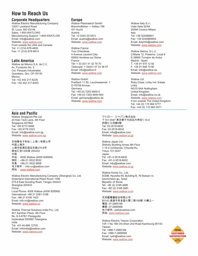
How to Reach UsCorporate HeadquartersWatlow Electric Manufacturing Company12001 Lackland RoadSt. Louis, MO 63146Sales: 1-800-WATLOW2Manufacturing Support: 1-800-4WATLOWEmail: [email protected]: www.watlow.comFrom outside the USA and Canada:Tel: +1 (314) 878-4600Fax: +1 (314) 878-6814
Latin AmericaWatlow de México S.A. de C.V.Av. Fundición No. 5Col. Parques IndustrialesQuerétaro, Qro. CP-76130 Mexico Tel: +52 442 217-6235Fax: +52 442 217-6403
EuropeWatlow Plasmatech GmbHBrennhoflehan — Kellau 156431 KuchlAustriaTel: +3 0244 20129 0 Email: [email protected]: www.watlow.com
Watlow France Tour d'Asnières.4 Avenue Laurent Cély92600 Asnières sur SeineFranceTél: + 33 (0)1 41 32 79 70Télécopie: + 33(0)1 47 33 36 57Email: [email protected]: www.watlow.com
Watlow GmbHPostfach 11 65, Lauchwasenstr. 1D-76709 KronauGermanyTel: +49 (0) 7253 9400-0Fax: +49 (0) 7253 9400-900Email: [email protected]: www.watlow.com
Watlow Italy S.r.l.Viale Italia 52/5420094 Corsico MilanoItalyTel: +39 024588841 Fax: +39 0245869954Email: [email protected]: www.watlow.com
Watlow Ibérica, S.L.U.C/Marte 12, Posterior, Local 9E-28850 Torrejón de ArdozMadrid - SpainT. +34 91 675 12 92F. +34 91 648 73 80Email: [email protected]: www.watlow.com
Watlow Ltd. Roby Close, Linby Ind. EstateLinbyNG15 8AA NottinghamUnited Kingdom Email: [email protected]: www.watlow.comFrom outside The United Kingdom:Tel: +44 (0) 115 964 0777Fax: +44 (0) 115 964 0071
Asia and PacificWatlow Singapore Pte Ltd.20 Kian Teck Lane, 4th FloorSingapore 627854Tel: +65 6773 9488 Fax: +65 6778 0323Email: [email protected] Website: www.watlow.com.sg
瓦特隆电子科技(上海)有限公司中国上海市上海市杨浦区国定东路275-8号绿地汇创1306室 200433中国本地: 4006 Watlow (4006 928569)国际: +86-21-3532 8532传真: +86-21-3532 8568电子邮件: [email protected]网站: www.watlow.com
Watlow Electric Manufacturing Company (Shanghai) Co. Ltd.Greenland International Plaza Room 1306275-8 East Guoding Road, Yangpu DistrictShanghai 200433ChinaLocal Phone: 4006 Watlow (4006 928569)International: +86 21 3381 0188 Fax: +86 21 6106 1423Email: [email protected]: www.watlow.cn
Watlow Thermal Solutions India Pvt., Ltd.401 Aarohan Plaza, 4th FloorNo. 6-3-678/1 PanjaguttaHyderabad 500082 TelanganaIndiaTel: +91-40-666 12700Email: [email protected]: www.watlow.com
ワトロー・ジャパン株式会社 〒101-0047 東京都千代田区内神田1-14-4 四国ビル別館9階Tel: 03-3518-6630 Fax: 03-3518-6632Email: [email protected] Website: www.watlow.co.jp
Watlow Japan Ltd.Shikoku Building Annex 9th Floor1-14-4 Uchikanda, Chiyoda-KuTokyo 101-0047JapanTel: +81-3-3518-6630 Fax: +81-3-3518-6632Email: [email protected] Website: www.watlow.co.jp
Watlow Korea Co., Ltd.#2208, Hyundia KIC Building B, 70 Doosan-roGeumcheon-gu, SeoulRepublic of KoreaTel: +82 (2) 2169-2600Fax: +82 (2) 2169-2601Website: www.watlow.co.kr
瓦特龍電機股份有限公司80143 高雄市前金區七賢二路189號 10樓之一電話: 07-2885168 傳真: 07-2885568 电子邮件: [email protected] 网站: www.watlow.com
Watlow Electric Taiwan Corporation10F-1 No.189 Chi-Shen 2nd Road Kaohsiung 80143 TaiwanTel: +886-7-2885168 Fax: +886-7-2885568Email: [email protected] Website: www.watlow.com
Related Documents