Experience In Motion USER INSTRUCTIONS Installation Operation Maintenance Limitorque ® Actuation Systems L120 Series For L120-10 through L120-40 FCD LMENIM1201-04-AQ – 05/15

Welcome message from author
This document is posted to help you gain knowledge. Please leave a comment to let me know what you think about it! Share it to your friends and learn new things together.
Transcript
Experience In Motion
USER INSTRUCTIONS
InstallationOperation
Maintenance
Limitorque ® Actuation Systems L120 SeriesFor L120-10 through L120-40
FCD LMENIM1201-04-AQ – 05/15
Limitorque Actuation Systems L120 Series FCD LMENIM1201-04-AQ – 05/15
2
Contents1 Introduction 4
1.1 Purpose 41.2 User Safety 4
2 Product Capabilities and Features 52.1 Initial Inspection and Storage Instructions 5
2.1.1 Inspection and Recording 62.1.2 Short-Term Storage (less than 1 year) 6
2.2 Product Identification 73 Actuator Weights 84 Installation Instructions 9
4.1 Safety Precautions 94.2 Safety Practices 94.3 Initial Actuator Preparation 10
4.3.1 Mounting Base 104.3.2 Stem Acceptance 10
4.4 Torque Switch 114.4.1 Setting Torque Switch 114.4.2 Balancing Torque Switch 12
4.5 Geared Limit Switch 124.5.1 Setting Limit Switch 124.5.2 Setting Procedure (Refer to Figure 4.2) 134.5.3 Combination of Contacts (Refer to Figure 4.2) 14
4.6 Position Indication 144.6.1 Local position indication 144.6.2 Remote Position Indication 15
4.7 Optional Side-Mounted Handwheel 165 Operation 19
3
Limitorque Actuation Systems L120 Series FCD LMENIM1201-04-AQ – 05/15
flowserve.com
5.1 Electrical Start-up 195.2 Manual Operation 205.3 Motor Operation 255.4 Torque and Travel Limiting 25
6 Maintenance 266.1 Lubrication 26
6.1.1 Lubrication Inspection 266.1.2 Factory Lubricant 27
6.2 Minimum Lubricant Qualities Required 276.3 Disassembly and Reassembly 286.4 Disassembly of the L120-10, 20, and 40 286.5 Drive Sleeve and Housing Cover Disassembly 296.6 Torque Nut Disassembly (Drive 1 Option) 296.7 Thrust Base Disassembly (Drive 2 Option) 306.8 Stem Nut Replacement – Thrust Base Applications 306.9 Reassembly 31
6.9.1 Declutch Assembly (L120-10) 326.9.2 Declutch Assembly (L120-20/40) (Refer to Figure 6.3) 326.9.3 Install the Motor (Refer to Figure 5.2) 336.9.4 Lubrication Procedure 336.9.5 Install Geared Limit Switch, Torque Switch and Finish Assembly 33
7 How to Order Parts 348 EC Declaration of Conformity 35
Limitorque Actuation Systems L120 Series FCD LMENIM1201-04-AQ – 05/15
4
1 Introduction
1.1 PurposeThis Installation and Maintenance Manual explains how to install and maintain the L120-10, L120-20, and L120-40 actuators. Information on installation, disassembly, reassembly, lubrication, and parts is provided.
1.2 User Safety Safety notices in this manual detail precautions the user must take to reduce the risk of personal injury and damage to the equipment. The user must read and be familiar with these instructions before attempting installation, operation, or maintenance. Work to be performed on the actuator should be carried out by a qualified tradesman familiar with the operation and maintenance of electric actuators. Failure to observe these precautions could result in serious bodily injury or death, damage to the equip-ment, voiding of the warranty, or operational difficulty.
Safety notices are presented in this manual in three forms:
c WARNING: Refers to personal safety. Alerts the user to potential danger. Failure to follow warning notices could result in personal injury or death.
a CAUTION: Directs the user’s attention to general precautions that, if not followed, could result in personal injury and/or equipment damage.
NOTE: Highlights information critical to the user’s understanding of the actuator’s installation and operation.
5
Limitorque Actuation Systems L120 Series FCD LMENIM1201-04-AQ – 05/15
flowserve.com
2 Product Capabilities and Features
L120 Series actuators operate without modification in any rising or non-rising stem application for linear action valves.
The actuators meet rigid safety requirements. The actuators are available in weatherproof, explosion-proof, and submersible configurations.
The actuators are compatible with a wide range of control options from stand-alone units with local pushbutton to open standards-based DDC-100 networks with up to 250 actuators.
The actuators are designed with integral control packages including plug-in interconnect boards that increase control functionality for stand-alone or networked units.
Durable torque overload is provided in both directions of travel.
2.1 Initial Inspection and Storage Instructions c WARNING: Read this Installation and Maintenance Manual carefully and completely before
attempting to store the actuator. Be aware of the electrical hazards.
2.1.1 Inspection and RecordingUpon receipt of the actuator, inspect the condition of the equipment and record nameplate information:
1. Carefully remove actuator from shipping carton or skid. Thoroughly examine the equipment for any physical damage that may have occurred during shipment. If damaged, immediately report the damage to the transport company.
2. Record the actuator nameplate information for future reference; i.e. ordering parts, obtaining further information.
Limitorque Actuation Systems L120 Series FCD LMENIM1201-04-AQ – 05/15
6
2.1.2 Short Term Storage Procedures (less than 1 year)NOTE: The following are our recommended storage procedures to retain maximum product integrity during short-term storage. Failure to comply with recommended procedures will void the warranty. For longer-term storage, contact Limitorque for procedures and recommendations.
Actuators are not weatherproof until properly installed on the valve or prepared for storage.
Store actuators in a clean, dry, protected warehouse away from excessive vibration and rapid tempera-ture changes. If the actuators must be stored outside, they must be stored off the ground, high enough to prevent them from being immersed in water or buried by snow.
1. Position the actuator in storage with motor and switch compartment horizontal.
2. Connect the internal heaters (if supplied) or place desiccant in the switch compartment.
3. Replace all plastic caps or plugs with pipe plugs and ensure that all covers are tight.
4. If the actuator is mounted on a valve and the stem protrudes from the unit, a suitable stem cover must be provided.
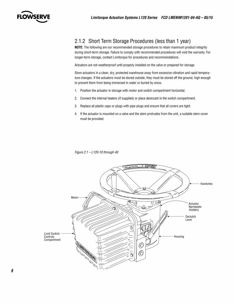
Figure 2.1 – L120-10 through 40
Motor
Limit Switch/ControlsCompartment
Housing
DeclutchLever
Handwheel
ActuatorNameplate(hidden)
7
Limitorque Actuation Systems L120 Series FCD LMENIM1201-04-AQ – 05/15
flowserve.com
2.2 Product IdentificationThe actuator unit nameplate is located on the back of the unit, opposite the limit switch compartment. The nameplate contains the following information:
• Limitorque name
• Point of Manufacture
• Unit Size
• Order Number
• Serial Number
• Customer Tagging
• CE Stamp
The motor nameplate is located on the motor. The nameplate contains the following information:
• ID Number
• Start Torque
• Run Torque
• Enclosure Type
• RPM
• Volts
• Full Load Amps
• Locked Rotor Amps
• Insulation Class
• Duty
• Horsepower
• Service Factor
• Phase
• Cycles
• Motor Code
• Ambient Temperature
• Connection Diagram
Limitorque Actuation Systems L120 Series FCD LMENIM1201-04-AQ – 05/15
8
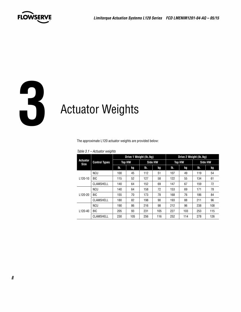
3 Actuator Weights
The approximate L120 actuator weights are provided below:
Table 3.1 – Actuator weights
Actuator Size Control Types
Drive 1 Weight (lb./kg) Drive 2 Weight (lb./kg)
Top HW Side HW Top HW Side HW
lb. kg lb. kg lb. kg lb. kg
L120-10
NCU 100 45 112 51 107 49 119 54
BIC 115 52 127 58 122 55 134 61
CLAMSHELL 140 64 152 69 147 67 159 72
L120-20
NCU 140 64 158 72 153 69 171 78
BIC 155 70 173 78 168 76 186 84
CLAMSHELL 180 82 198 90 193 88 211 96
L120-40
NCU 190 86 216 98 212 96 238 108
BIC 205 93 231 105 227 103 253 115
CLAMSHELL 230 105 256 116 252 114 278 126
9
Limitorque Actuation Systems L120 Series FCD LMENIM1201-04-AQ – 05/15
flowserve.com
4 Installation Instructions
4.1 Safety Precautions c WARNING: Read this Installation and Maintenance Manual carefully and completely before
attempting to install, operate, or troubleshoot the Limitorque L120 actuator.
c WARNING: Be aware of electrical hazards. Turn off incoming power before working on the actuator and before opening the switch compartment.
c WARNING: Potential HIGH-PRESSURE vessel – Be aware of high-pressure hazards associated with the attached valve or other actuated device when installing or performing maintenance on your L120 actuator. Do not remove the actuator mounting bolts when the actuator is mounted on a rising stem valve unless the valve is in the FULLY OPEN position and there is NO pressure in the line.
c WARNING: Do not manually operate the actuator with devices other than installed Handwheel and Declutch Lever. Using force beyond the ratings of the unit and/or using additive force devices such as cheater bars, wheel wrenches, pipe wrenches, or other devices on the actuator Handwheel or Declutch Lever may cause serious personal injury and/or damage to the actuator or valve.
c WARNING: Do not work on the actuator while it is mounted on a torque-seated valve.
4.2 Safety PracticesThe following checks should be performed to maintain safe operation of the L120 actuator.
• Mount motors on a horizontal plane, if possible.
• Keep the switch compartment clean and dry.
• Keep the valve stem clean and lubricated.
• Set up periodic operating schedule for infrequently used valves.
Limitorque Actuation Systems L120 Series FCD LMENIM1201-04-AQ – 05/15
10
• Carefully check for correct motor rotation direction. If the motor is driving the valve in the wrong direction, interchange any two leads on three-phase motors or switch the armature leads on DC and single-phase motors.
• Use a protective stem cover. Check valve stem travel and clearance before mounting covers on rising stem valves.
• Verify all actuator wiring is in accordance with the applicable wiring diagram, national and local codes, and Table 4.1.
Table 4.1 – Required Rating for External Wiring
Up to: Use wire rated at least:
40°C 60°C
60°C 75°C
4.3 Initial Actuator PreparationReplace all molded plastic conduit and top protectors (installed for shipping purposes only) with pipe plugs when installation wiring is complete.
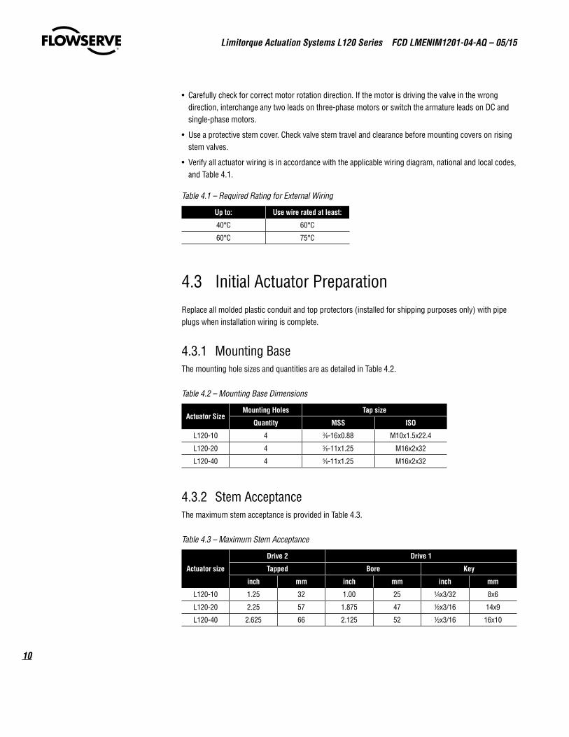
4.3.1 Mounting BaseThe mounting hole sizes and quantities are as detailed in Table 4.2.
Table 4.2 – Mounting Base Dimensions
Actuator SizeMounting Holes Tap size
Quantity MSS ISO
L120-10 4 3⁄8-16x0.88 M10x1.5x22.4
L120-20 4 5⁄8-11x1.25 M16x2x32
L120-40 4 5⁄8-11x1.25 M16x2x32
4.3.2 Stem AcceptanceThe maximum stem acceptance is provided in Table 4.3.
Table 4.3 – Maximum Stem Acceptance
Actuator size
Drive 2 Drive 1
Tapped Bore Key
inch mm inch mm inch mm
L120-10 1.25 32 1.00 25 1/4x3/32 8x6
L120-20 2.25 57 1.875 47 1/2x3/16 14x9
L120-40 2.625 66 2.125 52 1/2x3/16 16x10
11
Limitorque Actuation Systems L120 Series FCD LMENIM1201-04-AQ – 05/15
flowserve.com
4.4 Torque SwitchThe torque switch is designed to protect the actuator in open and close directions.
a CAUTION: Disconnect all incoming power before opening limit switch compartment or working on the torque switch.
• Do not use abrasive cloth to clean the contacts on the torque switch.
• Do not torque seat 90° operation valves nor run them against the stops. This may cause damage to the valve.
NOTE: If the actuator has “torqued out,” release torque buildup by operating the actuator manually.
4.4.1 Setting Torque SwitchThe torque switch was set at the factory according to customer-supplied information regarding neces-sary torque or thrust output that was provided at the time of the order. However, if the setting needs to be adjusted, perform the following procedure:
a CAUTION: A torque switch limiter plate is provided on most actuators.
• Removal or modification of the torque switch limiter plate will void the actuator warranty.
• Do not exceed the setting indicated by this plate without contacting the Limitorque service department.
• Installing or adjusting the torque switch with the actuator in a loaded condition will result in a loss of torque protection.
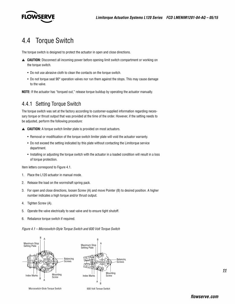
Item letters correspond to Figure 4.1.
1. Place the L120 actuator in manual mode.
2. Release the load on the wormshaft spring pack.
3. For open and close directions, loosen Screw (A) and move Pointer (B) to desired position. A higher number indicates a high torque and/or thrust output.
4. Tighten Screw (A).
5. Operate the valve electrically to seat valve and to ensure tight shutoff.
6. Rebalance torque switch if required.
Figure 4.1 – Microswitch-Style Torque Switch and 600 Volt Torque Switch
MountingScrewIndex Marks
Maximum StopSetting Plate
AB
BalancingScrews
600 Volt Torque Switch
AB
B A
B A
Microswitch-Style Torque Switch
MountingScrewIndex Marks
Maximum StopSetting Plate
BalancingScrews
-10-
20
CLOSE
OPEN
-10-
20
Limitorque Actuation Systems L120 Series FCD LMENIM1201-04-AQ – 05/15
12
4.4.2 Balancing Torque SwitchItem letters correspond to Figure 4.1.
1. Place the actuator in manual mode.
2. Remove the load from the wormshaft spring pack.
3. Note the open and close torque switch settings prior to reinstalling the torque switch.
4. Loosen Screws (A) and position both Pointers (B) at the #1 setting, tighten Screw (A). In this position the index marks should be aligned.
5. Loosen balancing screws and install the torque switch. The base of the torque switch should be flush against the compartment and the hole for the mounting screw should be aligned.
6. Install the mounting screw.
7. Tighten the balancing screws.
a CAUTION: The balancing screws should not be touched except during the balancing procedure.
The switch is now balanced and ready for the pointers to be returned to their original settings.
4.5 Geared Limit Switch a CAUTION: The geared limit switch is not preset at the factory and must be adjusted after the
actuator has been mounted on associated equipment.
• Disconnect all incoming power to the actuator prior to opening the limit switch compartment and adjusting the switch.
• Consult the relevant wiring diagram for limit switch contact development. All L120 units are supplied with 16-contact limit switches - four switches on each of the four rotors. Two rotors are used for end of travel indication. The remaining two rotors may be adjusted for any intermediate point of travel.
• Do not use abrasive cloth to clean the contacts on the limit switch.
• Do not attempt to repair gearing in the limit switch. Replace entire gear frame assembly if necessary.
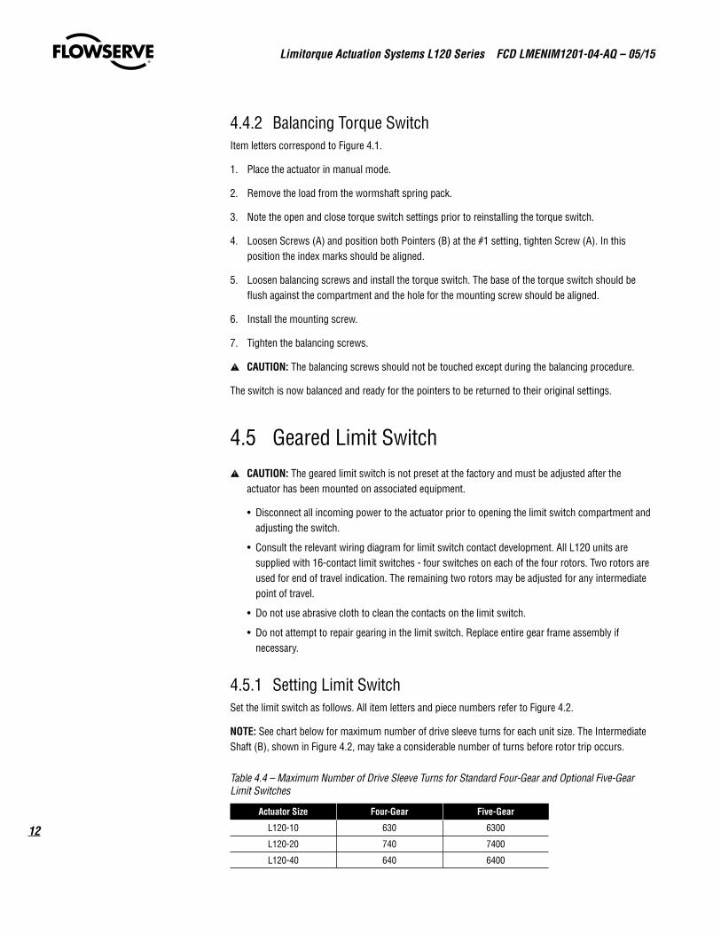
4.5.1 Setting Limit SwitchSet the limit switch as follows. All item letters and piece numbers refer to Figure 4.2.
NOTE: See chart below for maximum number of drive sleeve turns for each unit size. The Intermediate Shaft (B), shown in Figure 4.2, may take a considerable number of turns before rotor trip occurs.
Table 4.4 – Maximum Number of Drive Sleeve Turns for Standard Four-Gear and Optional Five-Gear Limit Switches
Actuator Size Four-Gear Five-Gear
L120-10 630 6300
L120-20 740 7400
L120-40 640 6400
13
Limitorque Actuation Systems L120 Series FCD LMENIM1201-04-AQ – 05/15
flowserve.com
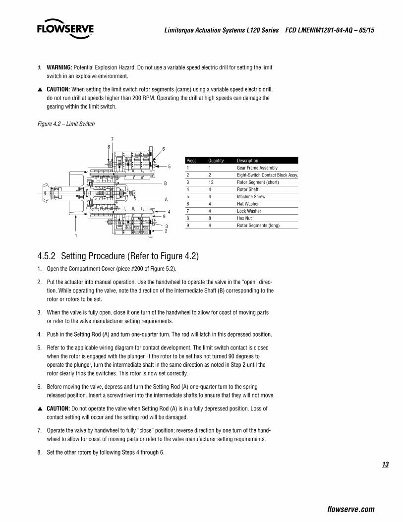
c WARNING: Potential Explosion Hazard. Do not use a variable speed electric drill for setting the limit switch in an explosive environment.
a CAUTION: When setting the limit switch rotor segments (cams) using a variable speed electric drill, do not run drill at speeds higher than 200 RPM. Operating the drill at high speeds can damage the gearing within the limit switch.
Figure 4.2 – Limit Switch
4.5.2 Setting Procedure (Refer to Figure 4.2)1. Open the Compartment Cover (piece #200 of Figure 5.2).
2. Put the actuator into manual operation. Use the handwheel to operate the valve in the “open” direc-tion. While operating the valve, note the direction of the Intermediate Shaft (B) corresponding to the rotor or rotors to be set.
3. When the valve is fully open, close it one turn of the handwheel to allow for coast of moving parts or refer to the valve manufacturer setting requirements.
4. Push in the Setting Rod (A) and turn one-quarter turn. The rod will latch in this depressed position.
5. Refer to the applicable wiring diagram for contact development. The limit switch contact is closed when the rotor is engaged with the plunger. If the rotor to be set has not turned 90 degrees to operate the plunger, turn the intermediate shaft in the same direction as noted in Step 2 until the rotor clearly trips the switches. This rotor is now set correctly.
6. Before moving the valve, depress and turn the Setting Rod (A) one-quarter turn to the spring released position. Insert a screwdriver into the intermediate shafts to ensure that they will not move.
a CAUTION: Do not operate the valve when Setting Rod (A) is in a fully depressed position. Loss of contact setting will occur and the setting rod will be damaged.
7. Operate the valve by handwheel to fully “close” position; reverse direction by one turn of the hand-wheel to allow for coast of moving parts or refer to the valve manufacturer setting requirements.
8. Set the other rotors by following Steps 4 through 6.
12
9
3
4
B
A
6
5
7
8
Piece Quantity Description1 1 Gear Frame Assembly2 2 Eight-Switch Contact Block Assy.3 12 Rotor Segment (short)4 4 Rotor Shaft5 4 Machine Screw6 4 Flat Washer7 4 Lock Washer8 8 Hex Nut9 4 Rotor Segments (long)
Limitorque Actuation Systems L120 Series FCD LMENIM1201-04-AQ – 05/15
14
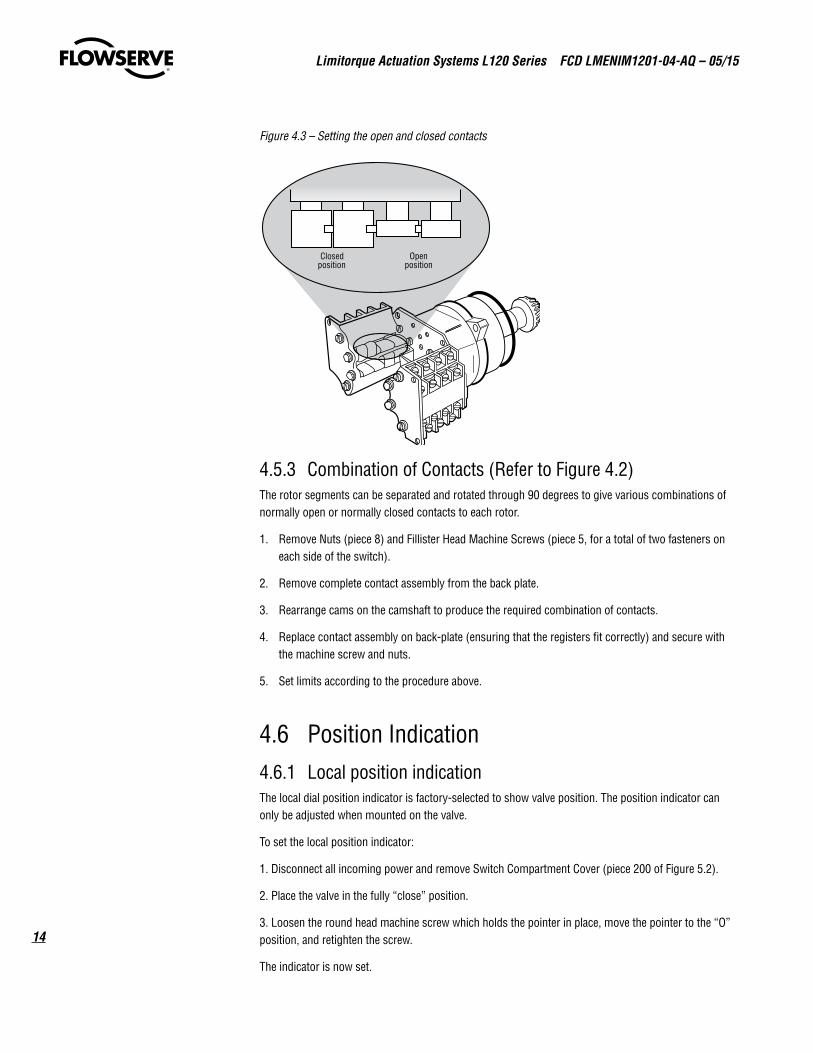
Figure 4.3 – Setting the open and closed contacts
4.5.3 Combination of Contacts (Refer to Figure 4.2)The rotor segments can be separated and rotated through 90 degrees to give various combinations of normally open or normally closed contacts to each rotor.
1. Remove Nuts (piece 8) and Fillister Head Machine Screws (piece 5, for a total of two fasteners on each side of the switch).
2. Remove complete contact assembly from the back plate.
3. Rearrange cams on the camshaft to produce the required combination of contacts.
4. Replace contact assembly on back-plate (ensuring that the registers fit correctly) and secure with the machine screw and nuts.
5. Set limits according to the procedure above.
4.6 Position Indication4.6.1 Local position indicationThe local dial position indicator is factory-selected to show valve position. The position indicator can only be adjusted when mounted on the valve.
To set the local position indicator:
1. Disconnect all incoming power and remove Switch Compartment Cover (piece 200 of Figure 5.2).
2. Place the valve in the fully “close” position.
3. Loosen the round head machine screw which holds the pointer in place, move the pointer to the “O” position, and retighten the screw.
The indicator is now set.
Closedposition
Openposition
15
Limitorque Actuation Systems L120 Series FCD LMENIM1201-04-AQ – 05/15
flowserve.com
NOTE: The end-of-travel rotors of the geared limit switch activate “Flip-flop” type indicators. This type of indicator will require no further setting after the geared limit switch has been adjusted.
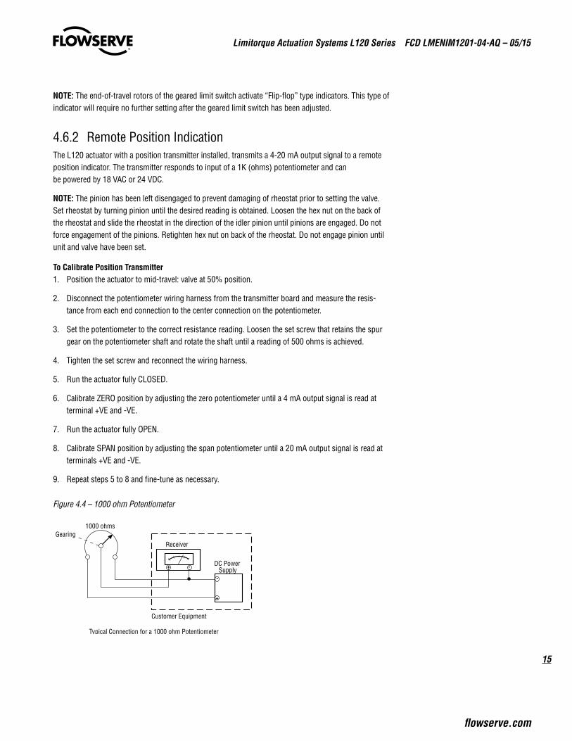
4.6.2 Remote Position IndicationThe L120 actuator with a position transmitter installed, transmits a 4-20 mA output signal to a remote position indicator. The transmitter responds to input of a 1K (ohms) potentiometer and can be powered by 18 VAC or 24 VDC.
NOTE: The pinion has been left disengaged to prevent damaging of rheostat prior to setting the valve. Set rheostat by turning pinion until the desired reading is obtained. Loosen the hex nut on the back of the rheostat and slide the rheostat in the direction of the idler pinion until pinions are engaged. Do not force engagement of the pinions. Retighten hex nut on back of the rheostat. Do not engage pinion until unit and valve have been set.
To Calibrate Position Transmitter1. Position the actuator to mid-travel: valve at 50% position.
2. Disconnect the potentiometer wiring harness from the transmitter board and measure the resis-tance from each end connection to the center connection on the potentiometer.
3. Set the potentiometer to the correct resistance reading. Loosen the set screw that retains the spur gear on the potentiometer shaft and rotate the shaft until a reading of 500 ohms is achieved.
4. Tighten the set screw and reconnect the wiring harness.
5. Run the actuator fully CLOSED.
6. Calibrate ZERO position by adjusting the zero potentiometer until a 4 mA output signal is read at terminal +VE and -VE.
7. Run the actuator fully OPEN.
8. Calibrate SPAN position by adjusting the span potentiometer until a 20 mA output signal is read at terminals +VE and -VE.
9. Repeat steps 5 to 8 and fine-tune as necessary.
Figure 4.4 – 1000 ohm Potentiometer
DC PowerSupply
-
+
-+
ReceiverGearing
1000 ohms
Customer Equipment
Typical Connection for a 1000 ohm Potentiometer
Limitorque Actuation Systems L120 Series FCD LMENIM1201-04-AQ – 05/15
16
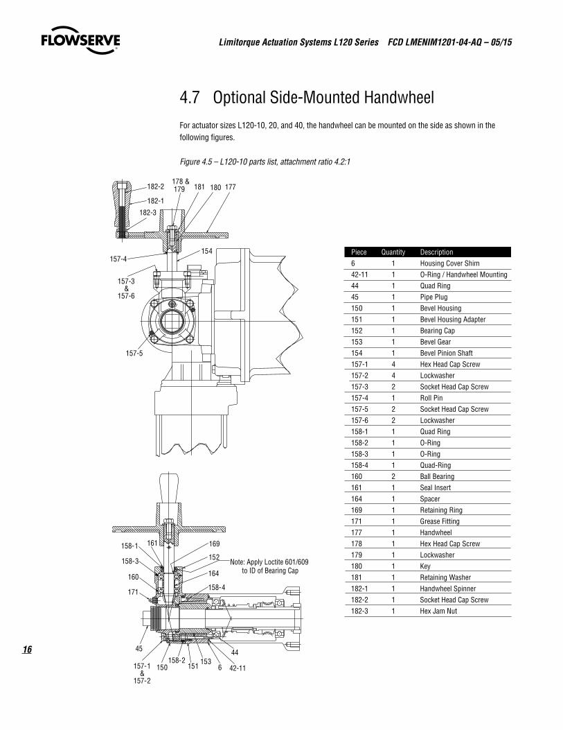
4.7 Optional Side-Mounted HandwheelFor actuator sizes L120-10, 20, and 40, the handwheel can be mounted on the side as shown in the following figures.
Figure 4.5 – L120-10 parts list, attachment ratio 4.2:1
Piece Quantity Description6 1 Housing Cover Shim42-11 1 O-Ring / Handwheel Mounting44 1 Quad Ring45 1 Pipe Plug150 1 Bevel Housing151 1 Bevel Housing Adapter152 1 Bearing Cap153 1 Bevel Gear154 1 Bevel Pinion Shaft157-1 4 Hex Head Cap Screw157-2 4 Lockwasher157-3 2 Socket Head Cap Screw157-4 1 Roll Pin157-5 2 Socket Head Cap Screw157-6 2 Lockwasher158-1 1 Quad Ring158-2 1 O-Ring158-3 1 O-Ring158-4 1 Quad-Ring160 2 Ball Bearing161 1 Seal Insert164 1 Spacer169 1 Retaining Ring171 1 Grease Fitting177 1 Handwheel178 1 Hex Head Cap Screw179 1 Lockwasher180 1 Key181 1 Retaining Washer182-1 1 Handwheel Spinner182-2 1 Socket Head Cap Screw182-3 1 Hex Jam Nut
157-1&
157-2
150158-2
151
45
1536 42-11
44
158-4
164
Note: Apply Loctite 601/609to ID of Bearing Cap
152
169161158-1
158-3
160
171
182-2
182-1
182-3
178 & 179 181 180 177
154157-4
157-3&
157-6
157-5
17
Limitorque Actuation Systems L120 Series FCD LMENIM1201-04-AQ – 05/15
flowserve.com
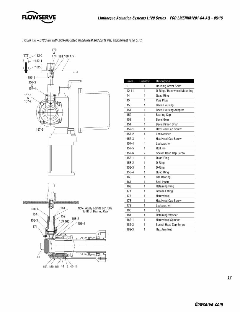
Figure 4.6 – L120-20 with side-mounted handwheel and parts list, attachment ratio 5.7:1
154
150 151
45
153 6 42-11
158-4
158-2
Note: Apply Loctite 601/609 to ID of Bearing Cap
152
169
161 158-1
158-3 160
171
44
182-2
182-1
182-3
179 &
178 181 180
157-5 157-3
& 157-4
157-6
177
157-1 &
157-2
Piece Quantity Description 6 1 Housing Cover Shim 42-11 1 O-Ring / Handwheel Mounting 44 1 Quad Ring 45 1 Pipe Plug 150 1 Bevel Housing 151 1 Bevel Housing Adapter 152 1 Bearing Cap 153 1 Bevel Gear 154 1 Bevel Pinion Shaft 157-1 4 Hex Head Cap Screw 157-2 4 Lockwasher 157-3 4 Hex Head Cap Screw 157-4 4 Lockwasher 157-5 1 Roll Pin 157-6 2 Socket Head Cap Screw 158-1 1 Quad-Ring 158-2 1 O-Ring 158-3 1 O-Ring 158-4 1 Quad Ring 160 1 Ball Bearing 161 1 Seal Insert 169 1 Retaining Ring 171 1 Grease Fitting 177 1 Handwheel 178 1 Hex Head Cap Screw 179 1 Lockwasher 180 1 Key 181 1 Retaining Washer 182-1 1 Handwheel Spinner 182-2 1 Socket Head Cap Screw 182-3 1 Hex Jam Nut
Limitorque Actuation Systems L120 Series FCD LMENIM1201-04-AQ – 05/15
18
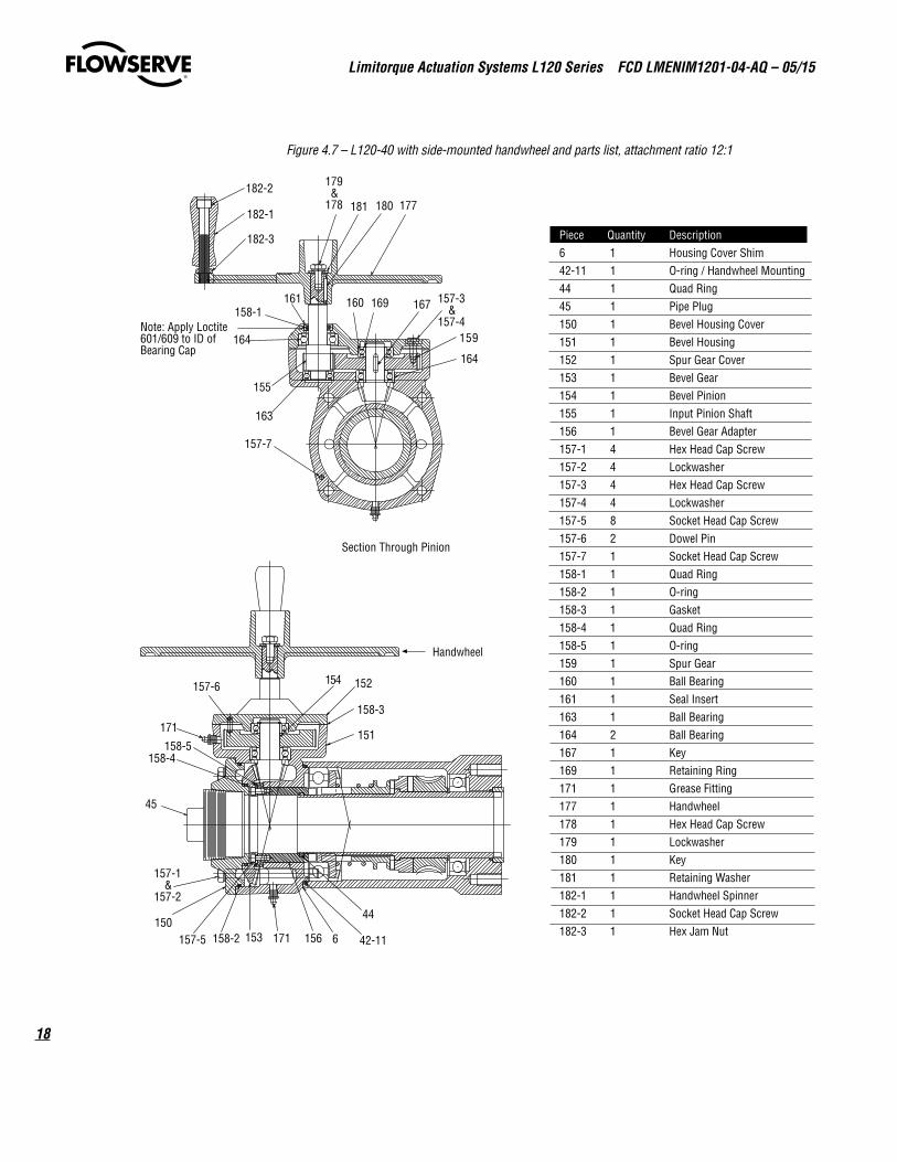
Figure 4.7 – L120-40 with side-mounted handwheel and parts list, attachment ratio 12:1
Handwheel
182-2
182-1
182-3
179&
178 181 180
157-3&
157-4
157-7
155
163
164
Note: Apply Loctite601/609 to ID ofBearing Cap
169161158-1
159
177
167160
164
Section Through Pinion
154
157-5
157-1&
157-2
158-2150
44
6 42-11
45
156153
158-4
171
171
157-6 152
158-3
151158-5
Piece Quantity Description6 1 Housing Cover Shim42-11 1 O-ring / Handwheel Mounting44 1 Quad Ring45 1 Pipe Plug150 1 Bevel Housing Cover151 1 Bevel Housing152 1 Spur Gear Cover153 1 Bevel Gear154 1 Bevel Pinion155 1 Input Pinion Shaft156 1 Bevel Gear Adapter157-1 4 Hex Head Cap Screw157-2 4 Lockwasher157-3 4 Hex Head Cap Screw157-4 4 Lockwasher157-5 8 Socket Head Cap Screw157-6 2 Dowel Pin157-7 1 Socket Head Cap Screw158-1 1 Quad Ring158-2 1 O-ring158-3 1 Gasket158-4 1 Quad Ring158-5 1 O-ring159 1 Spur Gear160 1 Ball Bearing161 1 Seal Insert163 1 Ball Bearing164 2 Ball Bearing167 1 Key169 1 Retaining Ring171 1 Grease Fitting177 1 Handwheel178 1 Hex Head Cap Screw179 1 Lockwasher180 1 Key181 1 Retaining Washer182-1 1 Handwheel Spinner182-2 1 Socket Head Cap Screw182-3 1 Hex Jam Nut
19
Limitorque Actuation Systems L120 Series FCD LMENIM1201-04-AQ – 05/15
flowserve.com
5 Operation
c WARNING: Do not manually operate the actuator with devices other than installed Handwheel and Declutch Lever. Using force beyond the ratings of the unit and/or using additive force devices such as cheater bars, wheel wrenches, pipe wrenches or other devices on the actuator Handwheel or Declutch Lever may cause serious personal injury and/or damage to the actuator or valve.
a CAUTION: Do not motor-operate the valve without first setting or checking the limit switch setting and motor direction.
• Do not force the declutch lever into hand operation. If the clutch does not easily engage, rotate handwheel slowly while operating the declutch lever.
• Do not alternately start/stop the motor to open or close a valve which is too tight for normal operation.
5.1 Electrical Start-up1. Verify that the actuator has been correctly lubricated. This is particularly important if the actuator
has been in long-term storage.
2. Verify that the geared limit switch has been correctly set (see Section 4.5.1, Setting Limit Switch).
3. If the valve stem is not visible, remove the stem cover or handwheel cover plate to observe output direction of the drive sleeve.
4. Engage manual operation and hand crank the valve well away from end of travel positions.
5. Turn on power supply and push button to “open.”
6. Check output rotation:
• If phase rotation is correct, the valve should begin to open.
• If valve begins to CLOSE, STOP immediately. Incorrect phase rotation will lead to serious damage if the valve seats.
Limitorque Actuation Systems L120 Series FCD LMENIM1201-04-AQ – 05/15
20
7. Correct the phase rotation one of two ways:
• Switch any two of the three power leads for three-phase power, or
• Reverse the armature leads for single-phase or DC power.
The actuator should operate correctly and will be stopped at the end of travel positions by torque or limit switch functions.
Table 5.1 – Required Rating for External Wiring
Up to Use wire rated at least
40°C 60°C
60°C 75°C
Figure 5.1 is a representation of a typical application and may not be applicable to your specific actuator. Please refer to the wiring diagram supplied with your actuator to confirm the actual equipment supplied.
5.2 Manual OperationPiece numbers refer to Figure 5.2.
Counterclockwise rotation of the Declutch Lever (piece 9) causes the declutch actuator to lift the clutch sleeve out of engagement with the worm gear. Drive lugs on top of the clutch sleeve engage matching lugs in the Handwheel Adapter (piece 26) and then latches engage the clutch sleeve in this position. The actuator is now in the handwheel driving option. Energizing the motor at this point will cause the latches to drop out and the spring-loaded clutch sleeve reengages with the lugs on the worm gear. The actuator is once more in motor operation.
NOTE 1: The shift from manual operation to motor operation is automatic and does not require external positioning of the declutch shaft.
NOTE 2: If the declutch mechanism does not engage, rotate handwheel approximately 30-45° and attempt manual engagement. There is a chance that the lugs on the Clutch Sleeve (piece 19) and Handwheel Adapter (piece 26) are not correctly aligned.
21
Limitorque Actuation Systems L120 Series FCD LMENIM1201-04-AQ – 05/15
flowserve.com
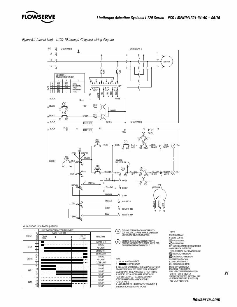
Figure 5.1 (one of two) – L120-10 through 40 typical wiring diagram
MOTOR
7
3(7) (7C)
(3) (3C)
R
G
(18) (18C)
(17) (17C)
(5) (5C)
(1) (1C)
PB1OPEN
PB2STOP
PB3CLOSE
(8) (8C)
8
1
17
LOCAL REMOTE
O
CO
C
O
C
C
C
C
O
O
O
T1
T2
T3
L1
L2
L3
4 18
5
(4) (4C)
TH.OL
SSOFF
ELEC HTR
MTR HTR
JUMPERSEE NOTE #5
18
OPEN
STOP
4
2CLOSE
3
COMMO N
YELLOWRED
YELLOW
BLUE
YELLOW
BROWN
ORANGE
BLUEWHITE
YELLOWWHITE
BROWN
YELLOWBLACK
BLUEBLACK
P1
P1
BROWNRED
RED
RED
WHITE
BLUERED
P1
PURPLE
BLACK
BLACK
POT(OPTIONAL)
1716
1
BLAC
K
BROW
N
RED
11
12
13
GREENBLACK
P2H2H1
6
5
REMOTE IND
GRAY
PINKGRAY
REMOTE IND
21/22
BLACK
BLACK
GND 10
GREEN/WHITE
GREEN/WHITE GREEN/WHITE
19/20
WHITE
RED
230 V500H1 AND H3TO L1H2 AND H4TO L2
480460415380
1ABEDE
ALTERNATETRANSFORMER TYPES
600575550
--
32
TAPS
CPT
18 V115 VRE
D
WHI
TE BLU
FUSE
FUSE
A B C D E
BLUE BLUE
BLACK
WHITE
RES
RES
18 V
YEL
YEL
BLU
BYPASS CIR
IND LIGHTOPEN LIMITBY-PASS CIR
IND LIGHTCLOSE LIMIT
SPARESPARESPARESPARESPARESPARESPARESPARE
FULLYOPEN A B FULLY
CLOSED
SPARE
SPARE
LIMIT SWITCH CONTACT DEVELOPMENTVALVE POSITION
ROTOR
OPEN
CLOSE
INT.1
INT.2
FUNCTION
12345678910111213141516
CONT
ACT
A B
OPENING TORQUE SWITCH INTERRUPTSCONTROL CIRCUIT IF MECHANICAL OVERLOADOCCURS DURING OPENING CYCLE
CLOSING TORQUE SWITCH INTERRUPTSCONTROL CIRCUIT IF MECHANICAL OVERLOADOCCURS DURING CLOSING CYCLE
18
17
5. ADD JUMPER ON LS#8 BETWEEN TERMINALS (8)
Notes
3. SEE CERTIFICATION SHEET FOR VOLTAGE SUPPLIED.2.1.
CLOSE CONTACTOPEN CONTACT
TRANSFORMER UNUSED WIRES TO BE SEPARATELYCOVERED WITH INSULATING HEAT SHRINK TUBING.4. ROTORS INT.1 & INT.2 CAN BE SET AT VALVEPOSITION FULL OPEN, FULL CLOSED OR ANYPOSITION IN BETWEEN AS INDICATED BYPOINTS A AND B.
& (8C) FOR TORQUE-SEATING VALVES.
OC
RG
O-OPEN CONTACTC-CLOSE CONTACT
CPT-CONTROL POWER TRANSFORMER+-MECHANICAL INTERLOCKTH.OL-THERMAL OVERLOAD CONTACTS
SS-SELECTOR SWITCH(LOCAL-OFF-REMOTE)PB1-OPEN PUSHBUTTONPB2-STOP PUSHBUTTONPB3-CLOSE PUSHBUTTONELEC HTR-COMPARTMENT HEATERMTR HTR-MOTOR HEATERPOT-POTENTIOMETER (OPTIONAL, SEECERTIFICATION SHEET IF SUPPLIED)RES-LAMP RESISTORS˛
RED INDICATING LIGHTGREEN INDICATING LIGHT
OPENING COILCLOSING COIL
Legend
Valve shown in full open position
Limitorque Actuation Systems L120 Series FCD LMENIM1201-04-AQ – 05/15
22
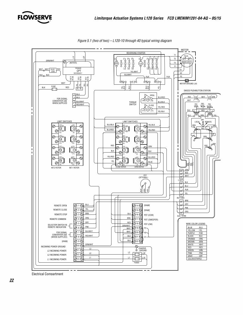
Figure 5.1 (two of two) – L120-10 through 40 typical wiring diagram
P2
H2
H1
SPARE
SPARE
POT (CCW)
POT (SWEEPER)
POT (CW)
Electrical Compartment
18
17
OPEN
CLOSE
(17C) (17)
(18C) (18)TORQUESWITCH
TH.OL
MOTOR
LIMIT SWITCHES
MTR HTR
(1)
(1C)
5
(5C)
(5)
(4)
(4C)
(3)
(3C)
(2)
(2C)
(8)
8
(8C)
7
(7C)
(6)
6
(6C)
(12)
12
(12C)
(11)
11
(11C)
(10)
10
(10C)
(9)
9
(9C)
(16)
16
(16C)
(15)
15
(15C)
(14)
14
(14C)
(13)
13
(13C)
1
2
3
4
(7)
YEL/BLK
YEL/RED
GRN
BLK
BLU/RED
BLUE
BLU/BLK
BLU/RED
RED
BLK
YEL/RED
YEL
T1
T2
T3
P1
H1
H2
P2
LIMIT SWITCHES
INT.2 ROTOR INT.1 ROTOR
YEL
YEL
115
V75
VA
18 V
10 V
A
PRIMARY
SECONDARYCPT
WHT
FOR SIGNALCONVERTER USEWHEN SUPPLIED
FUSE REDBLK
BLK/WHTRED/WHT
RED
WHT
BLK
BLU
PUR
YEL
PNK
ORG
BRN
GRY
SW323 PUSHBUTTON STATION
R G
PB3CLOSE
PB2STOP
PB1OPEN
LOCALOFF
REMOTE
BRNPUR
GRYPNK
BLU YEL
ORG
RED
BRN
RED
BRN
BLK
RED WHT GRN
WHT
GRN
BLU/BLK
BLU/RED
YEL/BLK
YEL/RED
ELECHTR
WHT BLK
BLUEYELLOWPURPLEBLACKORANGEBROWNWHITEREDGREENPINKGRAYCOLOR/STRIPED
WIRE COLOR LEGEND
MOTOR GROUND LUG
(NOTE#3)GRN/WHT
LIGHTS
BUTTONS
AUX. TERM.
1 BLU
YEL
BRN
ORG
GRY
PNK
BLK/WHT
RED/WHT
BLK
BRN
RED
BLK
GRN/WHT
BLK
WHT
GRN/WHT
L1
L2
L3
L1
L2
FUSES
POT(OPTIONAL)
BLK
BRN
RED
CHASSISGROUND
BLU/WHT
P1
L3T3
L2T2
L1T1
YEL/WHT
P1
L1T3
L2T2
L3T1
CO
YEL
PUR
BLU
BLU
BLK
YEL
BLK
WHT
2
3
4
5
6
7
8
9
10
11
12
13
14
15
16
17
18
19
20
21
22
REMOTE OPEN
REMOTE CLOSE
REMOTE STOP
REMOTE COMMON
SELECTOR SWITCH INREMOTE INDICATION
FOR SIGNALCONVERTER USE
(WHEN SUPPLIED)
SPARE
INCOMING POWER GROUND
L3 INCOMING POWER
L2 INCOMING POWER
L1 INCOMING POWER
: BLU: YEL: PUR: BLK: ORG: BRN: WHT: RED: GRN: PNK: GRY
BLK
WHT
BLKPUR
L1F
L2F
REVERSING STARTER
L2F
L1F
CLOSE ROTOR OPEN ROTOR
2
3
1
1
2
3
4
1
2
3
4
RES
RES
BLU
BLU
21
1
2
BLU
BLU1
2
18 V
10 V
A
23
Limitorque Actuation Systems L120 Series FCD LMENIM1201-04-AQ – 05/15
flowserve.com
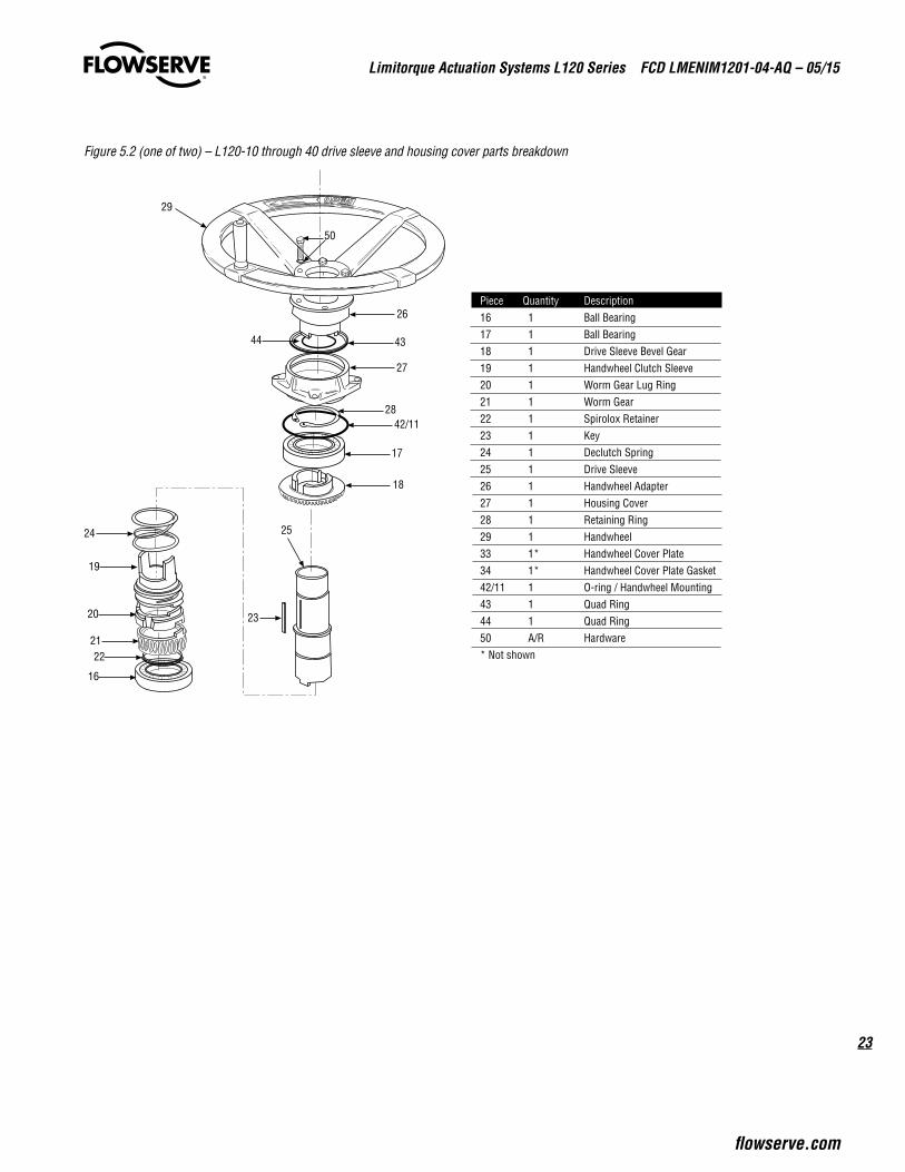
Figure 5.2 (one of two) – L120-10 through 40 drive sleeve and housing cover parts breakdown
25
23
44
29
50
18
17
42/1128
27
43
26
24
19
20
2122
16
Piece Quantity Description16 1 Ball Bearing17 1 Ball Bearing18 1 Drive Sleeve Bevel Gear19 1 Handwheel Clutch Sleeve20 1 Worm Gear Lug Ring21 1 Worm Gear22 1 Spirolox Retainer23 1 Key24 1 Declutch Spring25 1 Drive Sleeve26 1 Handwheel Adapter Piece Quantity Description27 1 Housing Cover28 1 Retaining Ring29 1 Handwheel33 1* Handwheel Cover Plate34 1* Handwheel Cover Plate Gasket42/11 1 O-ring / Handwheel Mounting43 1 Quad Ring44 1 Quad Ring50 A/R Hardware* Not shown
Limitorque Actuation Systems L120 Series FCD LMENIM1201-04-AQ – 05/15
24
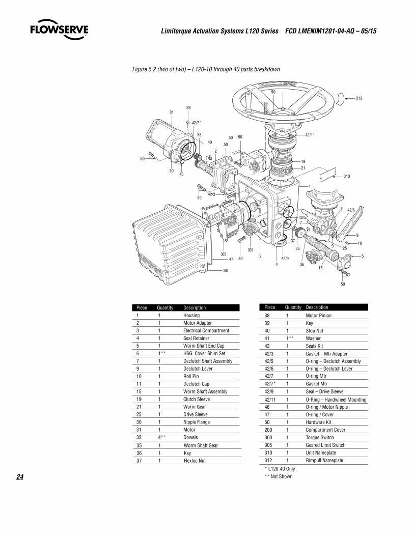
Figure 5.2 (two of two) – L120-10 through 40 parts breakdown
39
42/7*
31
40 50
5038
30
50
46
50
50
42/5
1
11
9
5
50
50
35
37
36442/9
42/3
3
200
47
50
300305
7
310
312
2
9
15
42/11
21
19
1025
42/6
Piece Quantity Description1 1 Housing2 1 Motor Adapter3 1 Electrical Compartment4 1 Seal Retainer5 1 Worm Shaft End Cap6 1** HSG. Cover Shim Set7 1 Declutch Shaft Assembly9 1 Declutch Lever10 1 Roll Pin11 1 Declutch Cap15 1 Worm Shaft Assembly19 1 Clutch Sleeve21 1 Worm Gear25 1 Drive Sleeve30 1 Nipple Flange31 1 Motor32 4** Dowels
Piece Quantity Description
35 1 Worm Shaft Gear36 1 Key37 1 Flexloc Nut
38 1 Motor Pinion39 1 Key40 1 Stop Nut41 1** Washer42 1 Seals Kit
42/7 1 O-ring Mtr
42/7* 1 Gasket Mtr
42/3 1 Gasket – Mtr Adapter
42/11 1 O-Ring – Handwheel Mounting
42/9 1 Seal – Drive Sleeve
42/5 1 O-ring – Declutch Assembly42/6 1 O-ring – Declutch Lever
* L120-40 Only** Not Shown
46 1 O-ring / Motor Nipple47 1 O-ring / Cover50 1 Hardware Kit200 1 Compartment Cover300 1 Torque Switch305 1 Geared Limit Switch310 1 Unit Nameplate312 1 Rimpull Nameplate
25
Limitorque Actuation Systems L120 Series FCD LMENIM1201-04-AQ – 05/15
flowserve.com
5.3 Motor OperationThe actuator is always available for motor operation whenever the motor is energized
a CAUTION: Do not force the declutch lever into motor operation. Lever will automatically return to motor operation when the motor is energized.
Reset the travel limit switches prior to motor operation if the actuator has been dismantled or removed from the valve.
Piece numbers refer to Figure 5.2.
In motor operation, the Motor Gear Set (piece 35 and 38) drives the Wormshaft (piece 15) and Worm Gear (piece 21) which in turn rotates the Clutch Sleeve (piece 19) by means of driving the lugs. The clutch sleeve and worm gear may be assembled to produce either a “no lost motion” or “hammerblow” effect. The Drive Sleeve (piece 25) is keyed to the clutch sleeve and hence rotates, producing the required output rotary motion.
5.4 Torque and Travel LimitingThe geared limit switch is driven by a bevel gear connected to the upper drive lugs of the clutch sleeve. The limit switch is directly connected to the output of the actuator. Once properly set, the limit switch remains in step with the valve position regardless of electric or manual operation of the Limitorque actuator.
The worm and wormshaft are supported by two rotating spring packs. As torque is generated by the actuator, the worm moves axially against one of the spring packs. Each pack is precalibrated and hence a finite compression represents a finite torque output. Movement of the worm operates the torque switch, which interrupts the power to the motor. The torque switch is adjustable and can be set to operate at predetermined torque levels.
Limitorque Actuation Systems L120 Series FCD LMENIM1201-04-AQ – 05/15
26
6 Maintenance
6.1 LubricationThe L120 series actuators have a sealed gear case, factory-lubricated with grease. The thrust base, when supplied, is factory-lubricated with the same grease as the gear case if the stem nut is factory-machined for the customer's driven shaft. If a blank stem nut is installed in the thrust base, a tag is provided on the actuator advising that the base is not lubricated. The gear case can be mounted in any position. However, mounting of the motor or the switch compartment in the down position is not recommended. These mounting positions may result in the motor or switch compartment being saturated with lubricant if the seal fails.
No seal can remain absolutely tight at all times. Therefore, it is not unusual to find a very small amount of weeping around shaft seals—especially during long periods of idleness such as storage. Using grease minimizes this condition as much as possible. If a small amount is weeping at start-up, remove it with a clean cloth. Once the equipment is operating on a regular basis, the weeping should stop.
6.1.1 Lubrication InspectionInspect Limitorque L120 series actuators for correct lubrication prior to operating - particularly following a long storage period.
Each application has its own effect on the actuator and the frequency of these inspections should be based on the application and the operating experience. The following lubrication inspection schedule is recommended until operating experience indicates otherwise.
For Gear Case, inspect lubrication every 18 months or 500 cycles, whichever occurs first.
During an inspection consider the following:
• Quantity – Ensure there is enough lubricant so that the Worm and the Worm Gear are totally immersed in grease regardless of the position. To verify, pull out geared limit switch. Level of grease should be within 1/2" from bottom of geared limit switch opening.
27
Limitorque Actuation Systems L120 Series FCD LMENIM1201-04-AQ – 05/15
flowserve.com
• Quality – Inspect lubricant for dirt, water or other foreign matter. If any one of these is found:
1. Flush the actuator with a commercial degreaser/cleaner such as Exxon Varsol #18. This degreaser/cleaner is not corrosive and does not affect the seal materials.
2. Repack the actuator with fresh lubricant allowing room for grease thermal expansion.
• Consistency – Ensure the lubricant is fluid approximating a standard NLGI-0 grade consistency or less. Thinners such as Amoco WAYTAC #31 oil may be added provided the volume of thinner does not exceed 20% of the total lubricant.
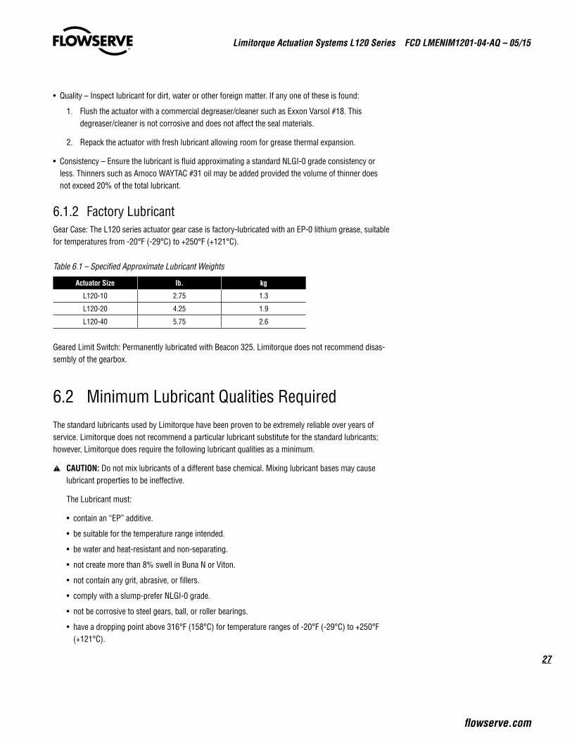
6.1.2 Factory LubricantGear Case: The L120 series actuator gear case is factory-lubricated with an EP-0 lithium grease, suitable for temperatures from -20°F (-29°C) to +250°F (+121°C).
Table 6.1 – Specified Approximate Lubricant Weights
Actuator Size lb. kg
L120-10 2.75 1.3
L120-20 4.25 1.9
L120-40 5.75 2.6
Geared Limit Switch: Permanently lubricated with Beacon 325. Limitorque does not recommend disas-sembly of the gearbox.
6.2 Minimum Lubricant Qualities RequiredThe standard lubricants used by Limitorque have been proven to be extremely reliable over years of service. Limitorque does not recommend a particular lubricant substitute for the standard lubricants; however, Limitorque does require the following lubricant qualities as a minimum.
a CAUTION: Do not mix lubricants of a different base chemical. Mixing lubricant bases may cause lubricant properties to be ineffective.
The Lubricant must:
• contain an “EP” additive.
• be suitable for the temperature range intended.
• be water and heat-resistant and non-separating.
• not create more than 8% swell in Buna N or Viton.
• not contain any grit, abrasive, or fillers.
• comply with a slump-prefer NLGI-0 grade.
• not be corrosive to steel gears, ball, or roller bearings.
• have a dropping point above 316°F (158°C) for temperature ranges of -20°F (-29°C) to +250°F (+121°C).
Limitorque Actuation Systems L120 Series FCD LMENIM1201-04-AQ – 05/15
28
6.3 Disassembly and Reassembly a CAUTION: Turn off all power services before attempting to perform service on the actuator.
• Remove the actuator from the valve for complex work. Minor work, such as replacing geared limit switch, torque switch, or motor, may be readily performed while the actuator is still on the valve.
• Potential High-Pressure Vessel. Before removing or disassembling your actuator, ensure that the valve or other actuated device is isolated and is not under pressure.
NOTE: If the actuator is fitted with a Thrust Base (piece 100 of Figure 6.2), it is possible to remove the actuator housing while leaving the base on the valve to accept valve thrust. However, it is preferred that the valve be isolated from service and, if it is a rising stem, that the valve be fully open.
6.4 Disassembly of the L120-10, 20, and 40 Unless otherwise noted, piece numbers refer to the Illustrated Parts Breakdown of Figure 5.2.
1. Turn off power to the actuator.
2. Remove electrical Compartment Cover (piece 200).
3. Disconnect all electrical leads from the Torque Switch (piece 300) and Geared Limit Switch (piece 305). Ensure that all leads and terminals are clearly marked to facilitate reassembly.
4. Remove two screws holding limit switch and one holding torque switch. Remove both items.
5. Remove four bolts holding Motor (piece 31) and three bolts holding conduit Nipple Flange (piece 30). Remove motor, drawing motor leads through switch compartment.
6. Remove Motor Pinion (piece 38) by removing Stop Nut (piece 40).
7. Remove Worm Shaft Gear (piece 35), Flexloc Nut (piece 37), and Worm Shaft End Cap (piece 5) and draw complete wormshaft assembly from housing.
NOTE: The wormshaft has been assembled at the factory to obtain the correct preload on the spring packs. Do not attempt to disassemble further. If the worm shaft is worn or damaged, it is suggested that the complete wormshaft subassembly be replaced. The actuator must be in motor operation to remove the wormshaft assembly. When the wormshaft is partially out, the disc springs will hit the worm gear. Pull the declutch lever forward slightly without fully engaging the declutch mechanism and the wormshaft will come out.
8. Remove Declutch Cap (piece 11).
9. For unit size L120-10, completely withdraw the Declutch Assembly (piece 7 of Figure 6.3) from the housing. For unit sizes L120-20 and 40, remove Declutch Input Pinion (piece 12 of Figure 6.3) followed by the Declutch Assembly (piece 7 of Figure 6.3).
10. Remove Handwheel (piece 29) and Housing Cover (piece 27) and lift complete drive sleeve subas-sembly from housing.
29
Limitorque Actuation Systems L120 Series FCD LMENIM1201-04-AQ – 05/15
flowserve.com
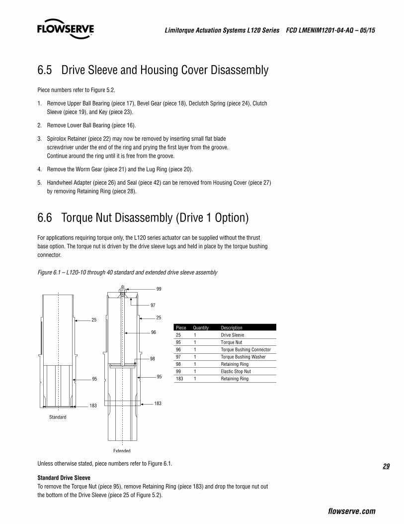
6.5 Drive Sleeve and Housing Cover DisassemblyPiece numbers refer to Figure 5.2.
1. Remove Upper Ball Bearing (piece 17), Bevel Gear (piece 18), Declutch Spring (piece 24), Clutch Sleeve (piece 19), and Key (piece 23).
2. Remove Lower Ball Bearing (piece 16).
3. Spirolox Retainer (piece 22) may now be removed by inserting small flat blade screwdriver under the end of the ring and prying the first layer from the groove. Continue around the ring until it is free from the groove.
4. Remove the Worm Gear (piece 21) and the Lug Ring (piece 20).
5. Handwheel Adapter (piece 26) and Seal (piece 42) can be removed from Housing Cover (piece 27) by removing Retaining Ring (piece 28).
6.6 Torque Nut Disassembly (Drive 1 Option)For applications requiring torque only, the L120 series actuator can be supplied without the thrust base option. The torque nut is driven by the drive sleeve lugs and held in place by the torque bushing connector.
Figure 6.1 – L120-10 through 40 standard and extended drive sleeve assembly
Unless otherwise stated, piece numbers refer to Figure 6.1.
Standard Drive SleeveTo remove the Torque Nut (piece 95), remove Retaining Ring (piece 183) and drop the torque nut out the bottom of the Drive Sleeve (piece 25 of Figure 5.2).
25
95
183
25
95
183
97
99
96
98
Extended
Standard
Piece Quantity Description25 1 Drive Sleeve95 1 Torque Nut96 1 Torque Bushing Connector97 1 Torque Bushing Washer98 1 Retaining Ring99 1 Elastic Stop Nut183 1 Retaining Ring
Limitorque Actuation Systems L120 Series FCD LMENIM1201-04-AQ – 05/15
30
Optional Drive Sleeve1. Remove the Handwheel (piece 29 of Figure 5.2), Handwheel Cover Plate (piece 33 of Figure 5.2)
and Gasket (piece 34) to provide access to the Elastic Stop Nut (piece 99).
2. Remove the Elastic Stop Nut (piece 99) from the Rod (piece 1). The Torque Nut (piece 95) can now be removed from the bottom of the Drive Sleeve (piece 25 of Figure 5.2).
3. The Torque Bushing Connector (piece 96) can be removed from the torque nut by removing the Retaining Ring (piece 98).
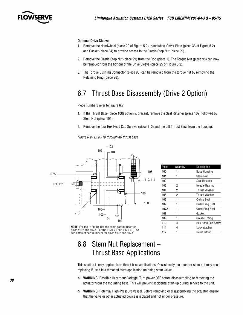
6.7 Thrust Base Disassembly (Drive 2 Option)Piece numbers refer to Figure 6.2.
1. If the Thrust Base (piece 100) option is present, remove the Seal Retainer (piece 102) followed by Stem Nut (piece 101).
2. Remove the four Hex Head Cap Screws (piece 110) and the Lift Thrust Base from the housing.
Figure 6.2– L120-10 through 40 thrust base
6.8 Stem Nut Replacement – Thrust Base Applications
This section is only applicable to thrust base applications. Occasionally the operator stem nut may need replacing if used in a threaded stem application on rising stem valves.
c WARNING: Possible Hazardous Voltage. Turn power OFF before disassembling or removing the actuator from the mounting base. This will prevent accidental start-up during service to the unit.
c WARNING: Potential High-Pressure Vessel. Before removing or disassembling the actuator, ensure that the valve or other actuated device is isolated and not under pressure.
107A
109, 112
108
110, 111
106
100
102101
104
105
103
104
103105
Piece Quantity Description100 1 Base Housing101 1 Stem Nut102 1 Seal Retainer103 2 Needle Bearing104 2 Thrust Washer105 2 Thrust Washer106 1 O-ring Seal107 1 Quad Ring Seal107A 1 Quad Ring Seal108 1 Gasket109 1 Grease Fitting110 4 Hex Head Cap Screw111 4 Lock Washer112 1 Relief Fitting
107
NOTE: For the L120-10, use the same part number forpiece #107 and 107A. For the L120-20 and L120-40, usetwo different part numbers for piece #107 and 107A.
31
Limitorque Actuation Systems L120 Series FCD LMENIM1201-04-AQ – 05/15
flowserve.com
a CAUTION: The L120-10 through 40 thrust base contains lubrication. Ensure that EP-00 is replaced when reassembling thrust base.
NOTE: Installation and retention of O-rings and quad rings can be eased by applying a small quantity of EP grease to the ring during assembly.
To replace the stem nut:
1. Disconnect all incoming power to the actuator.
2. Remove actuator from the valve.
3. Remove Seal Retainer (piece 102 of Figure 6.2) followed by stem nut, bearings, and seals.
4. Check the fit of the new stem nut on the valve stem - ensure that the nut travels freely without binding.
5. Reassemble the thrust base and remount the actuator on the valve.
6. Remount the actuator on the thrust base.
7. Removing the actuator from the valve will change the limit switch settings. Reset the limit switch in accordance with Section 4.5.1, Setting Limit Switch.
8. Reconnect power.
9. Test for correct functioning.
6.9 ReassemblyPiece numbers refer to Figures 5.1, 5.2, 6.1, 6.2, and 6.3.
1. Install Lug Ring (piece 20) onto Drive Sleeve (piece 25) followed by the Worm Gear (piece 21). Ensure that the worm gear lugs engage with recesses on lug ring.
2. Install Spirolox Retainer (separate layers of retainer sufficiently to begin threading the retainer into the drive sleeve groove. Continue threading until the retainer is firmly located in the groove).
3. Install Key (piece 23) and Clutch Sleeve (piece 19).
4. Add the Declutch Spring (piece 24), Bevel Gear (piece 18), Upper Bearing (piece 17), and Lower Bearing (piece 16) to complete the assembly.
5. Replace the drive sleeve assembly into main housing, and secure with the Housing Cover (piece 27). Ensure that all the seals are in place.
6. Insert Wormshaft Assembly (piece 15) into the housing and locate the bearings in the housing journals. Replace the Wormshaft Cap (piece 5).
7. Install the Wormshaft Gear (piece 35) and Flex Loc Nut (piece 37).
NOTE: It is recommended that a new flex loc nut be used during reassembly.
Limitorque Actuation Systems L120 Series FCD LMENIM1201-04-AQ – 05/15
32
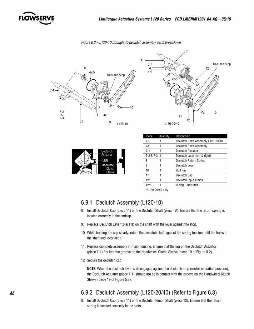
Figure 6.3 – L120-10 through 40 declutch assembly parts breakdown
6.9.1 Declutch Assembly (L120-10) 8. Install Declutch Cap (piece 11) on the Declutch Shaft (piece 7A). Ensure that the return spring is
located correctly in the endcap.
9. Replace Declutch Lever (piece 9) on the shaft with the lever against the stop.
10. While holding the cap steady, rotate the declutch shaft against the spring tension until the holes in the shaft and lever align.
11. Replace complete assembly in main housing. Ensure that the lug on the Declutch Actuator (piece 7-1) fits into the groove on the Handwheel Clutch Sleeve (piece 19 of Figure 5.2).
12. Secure the declutch cap.
NOTE: When the declutch lever is disengaged against the declutch stop (motor operation position), the Declutch Actuator (piece 7-1) should not be in contact with the groove on the Handwheel Clutch Sleeve (piece 19 of Figure 5.2).
6.9.2 Declutch Assembly (L120-20/40) (Refer to Figure 6.3)8. Install Declutch Cap (piece 11) on the Declutch Pinion Shaft (piece 12). Ensure that the return
spring is located correctly in the slots.
10
4211
42/5
12
7
7-2&
7-3
7-1Declutch Stop
8
97A L120-10 L120-20/409
8
10
4211
42/5Declutch Stop
Piece Quantity Description7* 1 Declutch Shaft Assembly L120-20/407A 1 Declutch Shaft Assembly7-1 1 Declutch Actuator7-2 & 7-3 1 Declutch Latch (left & right)8 1 Declutch Return Spring9 1 Declutch Lever10 1 Roll Pin11 1 Declutch Cap12* 1 Declutch Input Pinion42/5 1 O-ring – Declutch*L120-20/40 only
7-2&
7-3
7-1
LUG
DeclutchActuator
HandwheelClutchSleeve
33
Limitorque Actuation Systems L120 Series FCD LMENIM1201-04-AQ – 05/15
flowserve.com
9. Replace Declutch Lever (piece 9) on the pinion and against the stop.
10. While holding the cap steady, rotate the Pinion Shaft (piece 12) against the spring tension until the holes in the shaft and lever align.
11. Insert Roll Pin (piece 10).
12. Slide Declutch Shaft (piece 7) into the housing, ensuring that the Declutch Shaft (piece 7) fits correctly into the groove in the Handwheel Clutch Sleeve (piece 19 of Figure 5.2).
13. Install the declutch cap assembly into the housing, finding the nearest tooth on the internal spur gear which will allow the cap to be secured without placing tension on the Declutch Actuator (piece 7-1) causing it to rub against the groove in the Handwheel Declutch Sleeve (piece 19 of Figure 5.2).
6.9.3 Install the Motor (Refer to Figure 5.2)1. Install the Motor Pinion (piece 38) and Elastic Stop Nut (piece 40) onto the motor shaft.
NOTE: The elastic stop nut should not be reused. It is recommended that a new nut be used during reassembly.
2. Install conduit Nipple Flange (piece 30) and Seal (piece 42) onto the conduit nipple in the flange and secure the motor. Secure the nipple flange.
6.9.4 Lubrication Procedure1. Set unit on mounting base.
2. Grease through the grease fitting located on the motor adapter, watch for grease entering the housing cavity.
3. Grease through the grease fitting in the housing cover until the adapter has been completely greased and grease can be seen entering the drive sleeve compartment.
4. Reposition the unit “nameplate down”.
5. Finish filling housing cavity through the gear limit switch opening to within 1/2” from the bottom of the gear limit switch opening.
6.9.5 Install Geared Limit Switch, Torque Switch and Finish Assembly
1. Install torque and limit switch into the switch compartment housing.
NOTE: The limit switch must be reset before the actuator is placed back into service. The Torque Switch may need to be rebalanced. If required see Section 4.4.2, Balancing Torque Switch.
2. Connect all electrical leads in the switch compartment.
3. Replace the compartment cover, handwheel and thrust base, if applicable, to complete the assembly.
Limitorque Actuation Systems L120 Series FCD LMENIM1201-04-AQ – 05/15
34
7 How to Order Parts
To order parts or obtain further information about your Limitorque L120 valve actuators, contact your local Limitorque distributor sales office, or:
Flowserve Limitorque 5114 Woodall Road P.O. Box 11318 Lynchburg, VA 24506-1318 Telephone (434) 528-4400 Fax (434) 845-9736
All inquiries or orders must be accompanied by the following information:
1. Actuator Size
2. Limitorque Order Number
3. Limitorque Serial Number
35
Limitorque Actuation Systems L120 Series FCD LMENIM1201-04-AQ – 05/15
flowserve.com
8 EC Declaration of Conformity
Application of Council Directives
2004/108/EC; EMC Directive
2006/42/EC; Machinery Directive
2003/10/EC; Airborne Noise Directive
Standards to which Conformity is Declared
Machinery; EN 60204-1
EMC; Emissions; EN 55022; 2006
Immunity; IEC 61000-4-6;2007, IEC 61000-4-8: 2001
ESD; IEC 61000-4-2: 2001
EFT Bursts; IEC 61000-4-4: 2004
Surge Immunity; IEC 61000-4-5: 2006
Airborne Noise; MIL-STD-740-1, Table 1, EN 60204
Manufacturer’s Name
Flowserve Limitorque
Manufacturer’s Address
5114 Woodall Rd Lynchburg, VA 24502 USA
Importer’s Name
Flowserve Limitorque
Importer’s Address
Flowserve Limitorque
Euro House
Abex Road
Newbury
Berkshire, RG14 5EY
United Kingdom
Type & Description of Equipment
Valve Actuators
Model Number
L120-10,20,40, 85
Note: Tested with Limitorque products only and with standards applicable at
time of tests.
I, the undersigned, hereby declare that the equipment specified above
conforms to the above Directives and Standards.
John Thilking
Senior Engineer – Certifications, ATEX/IEC-Ex Authorized Person
Flowserve Limitorque 5114 Woodall Road Lynchburg, VA 24502 USA
Date; December 4, 2012
flowserve.com
To find your local Flowserve representative or for more information about Flowserve Corporation, visit www.flowserve.com.
FCD LMENIM1201-04-AQ Printed in USA. May 2015
Flowserve Corporation has established industry leadership in the design and manufacture of its products. When properly selected, this Flowserve product is designed to perform its intended function safely during its useful life. However, the purchaser or user of Flowserve products should be aware that Flowserve products might be used in numerous applications under a wide variety of industrial service conditions. Although Flowserve can (and often does) provide general guidelines, it cannot provide specific data and warnings for all possible applications. The pur-chaser/user must therefore assume the ultimate responsibility for the proper sizing and selection, installation, operation, and maintenance of Flowserve products. The purchaser/user should read and understand the Installation Operation Maintenance (IOM) instructions included with the product, and train its employees and contractors in the safe use of Flowserve products in connection with the specific application.
While the information and specifications contained in this literature are believed to be accurate, they are supplied for informative purposes only and should not be considered certified or as a guarantee of satisfactory results by reliance thereon. Nothing contained herein is to be construed as a warranty or guarantee, express or implied, regarding any matter with respect to this product. Because Flowserve is continually improving and upgrading its product design, the specifications, dimensions and information contained herein are subject to change without notice. Should any question arise concerning these provisions, the purchaser/user should contact Flowserve Corporation at any one of its worldwide operations or offices.
© 2015 Flowserve Corporation, Irving, Texas, USA. Flowserve is a registered trademark of Flowserve Corporation.
Flowserve Corporation
United States Flowserve Limitorque 5114 Woodall Road P.O. Box 11318 Lynchburg, VA 24506-1318 Phone: 434-528-4400 Fax: 434-845-9736
England Flowserve Limitorque Euro House Abex Road Newbury Berkshire, RG14 5EY United Kingdom Phone: 44-1-635-46999 Fax: 44-1-635-36034
Singapore Limitorque Asia, Pte., Ltd. 12, Tuas Avenue 20 Singapore 638824 Phone: 65-6868-4628 Fax: 65-6862-4940
China Limitorque Beijing, Pte., Ltd. RM A1/A2 22/F, East Area, Hanwei Plaza No. 7 Guanghua Road, Chaoyang District Beijing 100004, Peoples Republic of China Phone: 86-10-5921-0606 Fax: 86-10-6561-2702
India Flowserve Limitorque Plot No. #4, 1 A, Road No. 8, EPIP Whitefield, Bangalore – 560066 Karnataka India Phone: 91-80-40146200 Fax: 91-80-28410286
Italy Flowserve Limitorque Fluid Power Systems Via Rio Vallone 17 20883 Mezzago MB Italy Phone: 39-039-620601 Fax: 39-039-62060 213
Related Documents