US Beam Test Results and ORCA validation for CMS EMU CSC front-end electronics N. Terentiev Carnegie Mellon University CMS EMU Meeting, CERN June 18, 2005

US Beam Test Results and ORCA validation for CMS EMU CSC front-end electronics N. Terentiev Carnegie Mellon University CMS EMU Meeting, CERN June 18, 2005.
Dec 19, 2015
Welcome message from author
This document is posted to help you gain knowledge. Please leave a comment to let me know what you think about it! Share it to your friends and learn new things together.
Transcript
US
Beam Test Results and ORCA validation for CMS EMU CSC
front-end electronics
N. Terentiev
Carnegie Mellon University
CMS EMU Meeting, CERN
June 18, 2005
N. Terentiev (CMU) CMS EMU meeting, CERN June 18, 2005
2
OutlineOutline
• Motivation.
• CSC cathode strip pulse shape fit.
• Comparison with ORCA simulation.
• Conclusion.
N. Terentiev (CMU) CMS EMU meeting, CERN June 18, 2005
3
MotivationMotivation
• Why to validate ORCA CSC simulation:• importance of realistic simulation of CSC input signals and electronics
response (the coordinate and time resolution, L1 trigger primitives, pile-up, neutron background);
• ORCA simulates input and output CSC signals in great details based on the beam test data and available design parameters;
• no changes in relevant part of ORCA code since year 2000 (see latest status in CMS Note 2001/013 by R. Wilkinson and T. Cox);
• old (prototype) front-end electronics parameters are still in use in ORCA simulation;
• plenty of data available from recent 25 ns structured beam tests of CSC chambers with final set of front - end electronics;
• validation of ORCA simulation is a part of Physics TDR, Vol. 1.
N. Terentiev (CMU) CMS EMU meeting, CERN June 18, 2005
4
Motivation (cont’d)Motivation (cont’d)
• Latest developments :• track fitting, comparator and cross-talk results from beam test data
( Y. Zheng, UCLA, Feb 2005 EMU meeting);• pulser cross-talk measurements in SX5 ,
S. Durkin, J. Gilmore, F. Geurts, April 2005, http://www.physics.ohio-state.edu/~durkin/file_transfer/crosstalkdoc.pdf ;
• new code matching final cathode amplifier design and pulser
cross-talk data, S. Durkin, OSU, May 2005, http://www.physics.ohio-state.edu/~durkin/software/buckeye_utils/Buckeye.htm ;
• S. Durkin's code creating CSC track segments with use of Digis from 2003 and 2004 test beam data plus Y. Zheng's cross-talk and correlation code were committed by J. Mumford to CVS repository (EmuDAQ/AnalysisUtilities) and in use now in slice test at SX5;
• input and output signal simulation is now to be moved from ORCA to OSCAR package.
N. Terentiev (CMU) CMS EMU meeting, CERN June 18, 2005
5
CSC cathode strip pulse shape fit.CSC cathode strip pulse shape fit.
• How to compare cathode amplifier output signal in beam test data with ORCA simulation:• amplitude of the output signal is sampled in a Switch Capacitor Array
(SCA) in 8 time bins each 50 ns long;
• the 1-st SCA time bin defined as (L1 Accept) * LCT coincidence, details in note by A. Korytov,
http://www.phys.ufl.edu/cms/emu/dqm/data_formats/CFEB_data_format_notes.pdf ; • the phase of signal (time offset) in the beam test data is different in
different CSC’s (different DMB/TMB settings);• ORCA has its own phase too (max. SCA is always in the 5-th time bin);• due to 25 ns beam structure and 50 ns SCA sampling period, can have
two positions of signal in time (muon comes with odd/even L1 Accept);• therefore fit the SCA pulse shape in beam test data and ORCA
simulation data and compare relevant fit parameters;• for direct data comparison with simulation choose the signals with the
same phase.
N. Terentiev (CMU) CMS EMU meeting, CERN June 18, 2005
6
CSC cathode strip pulse shape fit (cont’d)CSC cathode strip pulse shape fit (cont’d)
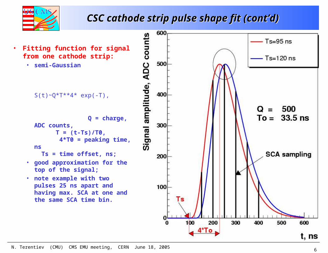
• Fitting function for signal from one cathode strip:
• semi-Gaussian
S(t)~Q*T**4* exp(-T),
Q = charge, ADC counts, T = (t-Ts)/T0, 4*T0 = peaking time, ns Ts = time offset, ns;
• good approximation for the top of the signal;
• note example with two pulses 25 ns apart and having max. SCA at one and the same SCA time bin.
N. Terentiev (CMU) CMS EMU meeting, CERN June 18, 2005
7
CSC cathode strip pulse shape fit (cont’d)CSC cathode strip pulse shape fit (cont’d)
• Including strip to strip cross-talk:• based on recent external pulser data taken at SX5
(S. Durkin, J. Gilmore, F. Geurts, April 2005), http://www.physics.ohiostate.edu/~durkin/file_transfer/crosstalkdoc.pdf;
• cross-talk from pulser data, convoluted by S. Durkin with ion drift time 1/(t+2.1) and a 50 ns square wave (drift electron arrival);
• hint from S. Durkin to use his function buckeye_pulse_full(t,P0,P1,Z1) approximating the cross-talk to ~1% near the peak;
• cross-talk from the strip with charge Q to the side strip: cross-talk = Q * Ct * Fc, Fc = buckeye_pulse_full(t,P0,P1,Z1)/N,
N = fixed normalization factor, depending on P0,P1,Z1, Ct = cross-talk coefficient (to be fitted with the beam test data and ORCA simulation);
• separate fit of the cross-talk pulser data with free P0,P1,Z1 and Ct (Q =1) yields Ct ~ 0.1, in agreement with beam test data.
N. Terentiev (CMU) CMS EMU meeting, CERN June 18, 2005
8
CSC cathode strip pulse shape fit (cont’d)CSC cathode strip pulse shape fit (cont’d)
• Events selection:• single hit in anode and cathode layer;• pedestals as SCA in the first time bin (RMS=2.7);• fit SCA using 3 time bins each from 3 cathode strips,
9 in total, with max. SCA time bin in the middle:
Ql(-50) ,Ql(0) ,Ql(+50) - SCA for left strip,
Qm(-50),Qm(0),Qm(+50) - SCA for middle strip,
Qr(-50) ,Qr(0) ,Qr(+50) - SCA for right strip,
where the largest SCA corresponds to max. charge deposition Qm(0) and the time bin is 50 ns long.
N. Terentiev (CMU) CMS EMU meeting, CERN June 18, 2005
9
CSC cathode strip pulse shape fit (cont’d)CSC cathode strip pulse shape fit (cont’d)
• Fitting function for 9 SCA time bins in 3 strips:SCA_left(t) = Q_left *S+Ct*Fc*(0 + Q_middle) SCA_middle(t)= Q_middle*S+Ct*Fc*(Q_left + Q_right )SCA_right(t) = Q_right *S+Ct*Fc*(Q_middle+ 0 )
where S – semi-Gaussian, Fc – cross-talk shape. Six fitted parameters (NDF=3): Q_left, Q_middle, Q_right, T0, Ts and Ct.
• for good measurement of the cross-talk coefficient Ct, select hits with large signal and close to the center of the middle strip:
Q_middle > 200 Q_middle/(Q_left+Q_middle+Q_right) > 0.7
N. Terentiev (CMU) CMS EMU meeting, CERN June 18, 2005
10
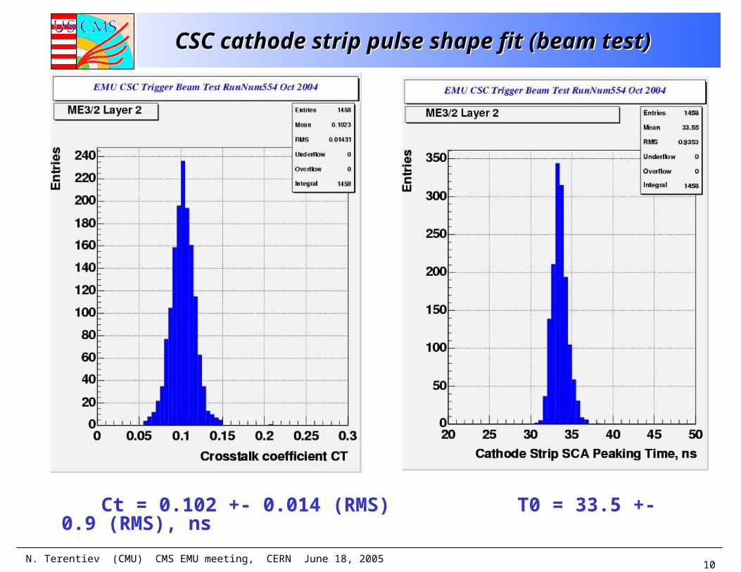
CSC cathode strip pulse shape fit (beam test)CSC cathode strip pulse shape fit (beam test)
Ct = 0.102 +- 0.014 (RMS) T0 = 33.5 +- 0.9 (RMS), ns
N. Terentiev (CMU) CMS EMU meeting, CERN June 18, 2005
11
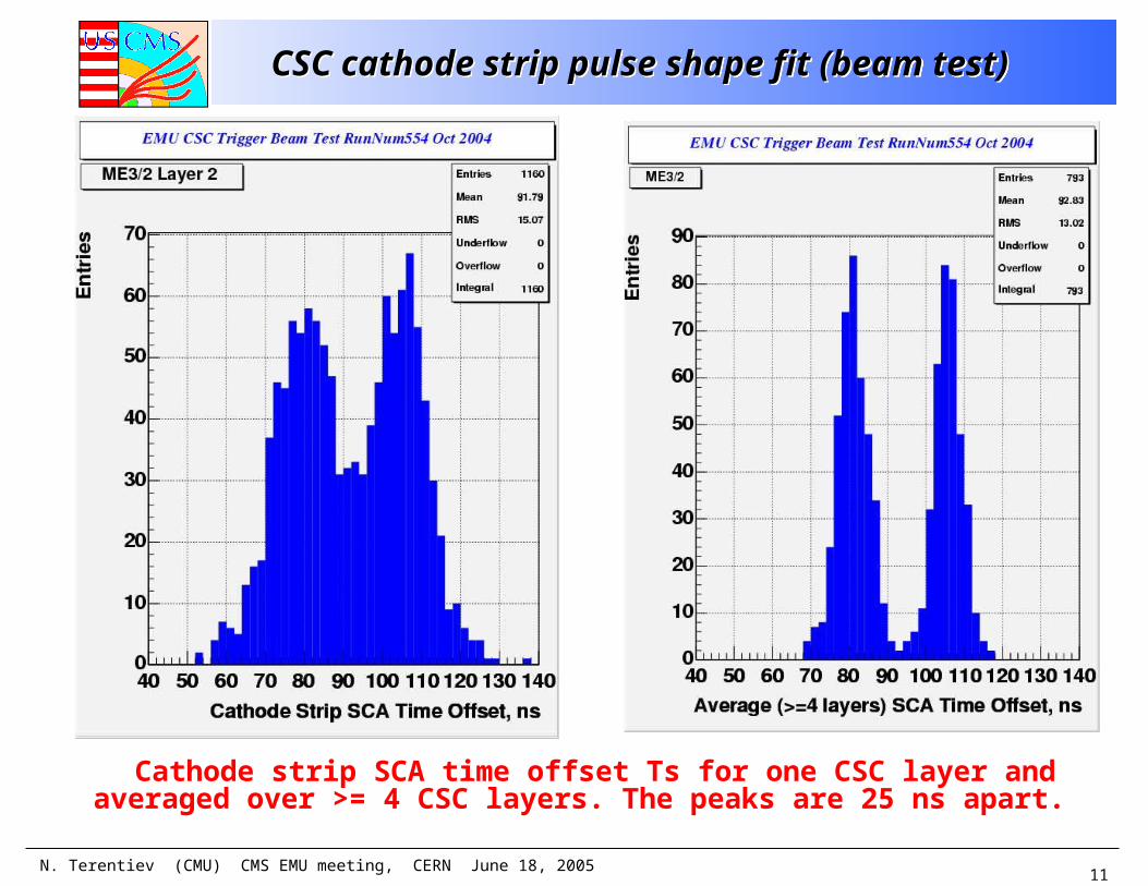
CSC cathode strip pulse shape fit (beam test)CSC cathode strip pulse shape fit (beam test)
Cathode strip SCA time offset Ts for one CSC layer and averaged over >= 4 CSC layers. The peaks are 25 ns apart.
N. Terentiev (CMU) CMS EMU meeting, CERN June 18, 2005
12
Comparison with ORCA simulationComparison with ORCA simulation
• ORCA (for EMU CSC simulated digitization in full CMS detector, not yet available for beam test geometry):• the single muon particle gun sample, Pt=100 GeV;• used OSCAR versions 3_2_2 and ORCA versions 8_1_3
(newer versions have the same code for the CSC raw data).
• Events selection in ORCA simulation:• cut 1.3 < EtaGen < 1.6 (~ as in the beam test);• all ME234/2 CSC (Station 1 with ME1/1 CSC is excluded);• Q_middle > 150, Q_middle/(Q_left+Q_middle+Q_right) >
0.7 to look at strong signal from track close to strip center.
• Fit by the same function.
N. Terentiev (CMU) CMS EMU meeting, CERN June 18, 2005
13
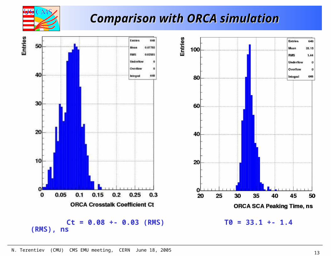
Comparison with ORCA simulationComparison with ORCA simulation
Ct = 0.08 +- 0.03 (RMS) T0 = 33.1 +- 1.4 (RMS), ns
N. Terentiev (CMU) CMS EMU meeting, CERN June 18, 2005
14
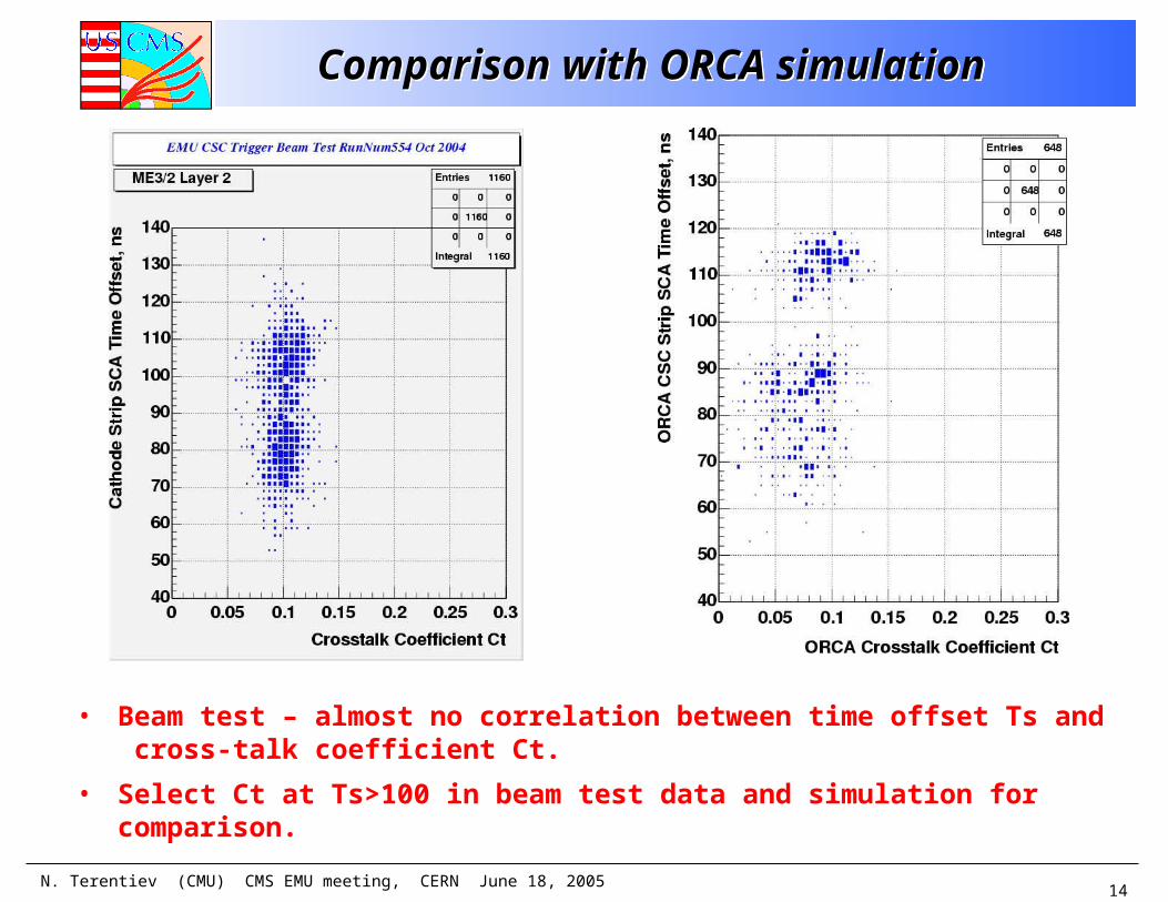
Comparison with ORCA simulationComparison with ORCA simulation
• Beam test – almost no correlation between time offset Ts and cross-talk coefficient Ct.
• Select Ct at Ts>100 in beam test data and simulation for comparison.
N. Terentiev (CMU) CMS EMU meeting, CERN June 18, 2005
15
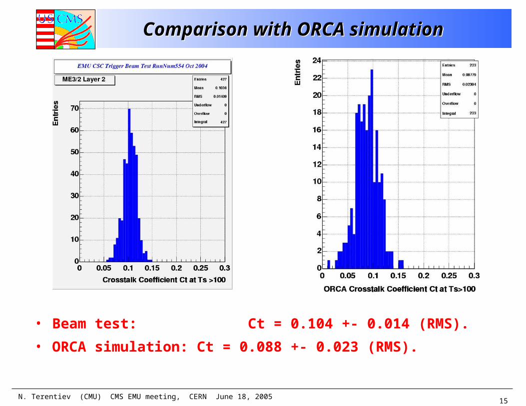
Comparison with ORCA simulationComparison with ORCA simulation
• Beam test: Ct = 0.104 +- 0.014 (RMS).
• ORCA simulation: Ct = 0.088 +- 0.023 (RMS).
N. Terentiev (CMU) CMS EMU meeting, CERN June 18, 2005
16
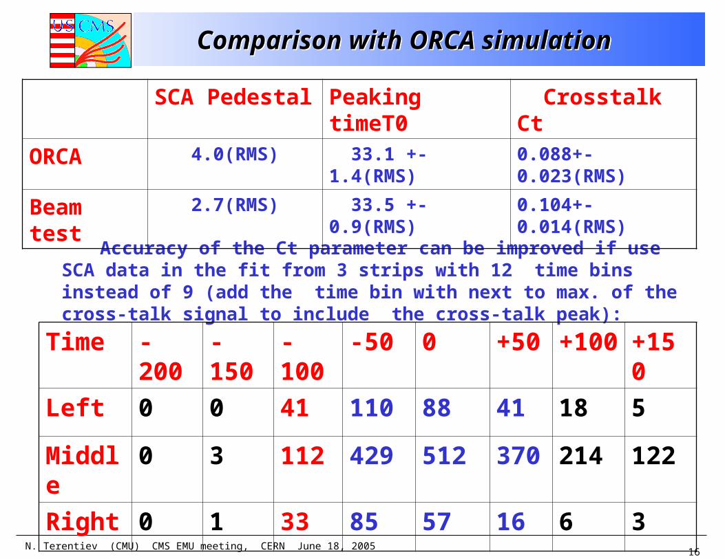
Comparison with ORCA simulationComparison with ORCA simulation
Accuracy of the Ct parameter can be improved if use SCA data in the fit from 3 strips with 12 time bins instead of 9 (add the time bin with next to max. of the cross-talk signal to include the cross-talk peak):
SCA Pedestal Peaking timeT0 Crosstalk Ct
ORCA 4.0(RMS) 33.1 +- 1.4(RMS) 0.088+-0.023(RMS)
Beam test 2.7(RMS) 33.5 +- 0.9(RMS) 0.104+-0.014(RMS)
Time -200 -150 -100 -50 0 +50 +100 +150
Left 0 0 41 110 88 41 18 5
Middle 0 3 112 429 512 370 214 122
Right 0 1 33 85 57 16 6 3
N. Terentiev (CMU) CMS EMU meeting, CERN June 18, 2005
17
ConclusionConclusion
• The beam test data and ORCA simulation for the CSC cathode strip output pulses were compared using a fitted function and cross-talk from pulser data.
• Data and simulation seem to agree for the peaking time T0 and cross-talk coefficient Ct. To be confirmed with larger statistics.
• For future use the cross-talk coefficient should be found from pulser data and fixed.
• The ORCA code should be updated to include parameters from the final design of front-end electronics.
• Thanks to S. Durkin and T. Ferguson for helpful discussions.
Related Documents