University of South Carolina H27-6082-NA South Tower Mechanical Renovations Addendum Three April 5, 2012 NOTE: The following amendments, additions, and deletions shall be made to the Construction Documents and Contract Documents. Insofar as those documents are at variance with this Addendum, this Addendum shall govern. Clarifications Item No. Description 1. Clarification: Reference Specification Section 230548 Vibration Isolation and Seismic Restraint. Exposed cabinet fan coil units shall be suspended directly to the structural floor slab above and additional sway bracing cables are not required. Seismic anchors and attachments are required and calculations are required. 2. Clarification: It was asked what the weight was of the existing elevator equipment room unit. According to the manufacturer’s published data the unit is approximately 2,000 pounds. Contractor should verify this weight before lifting. 3. Clarification: There is pipe that is shown on Sheet M2.00B on the Phase B drawing. Please reference the notes and Sheet M2.00A for pipe that is to be installed in Phase A. Pipe shown installed in Phase A is not installed again in Phase B. 4. Clarification: Reference Drawing E1.1 Power Riser Diagram and Schedules. All work shown on this drawing shall be accomplished in Phase A construction except that the feeder conductors that serve the rooftop HVAC unit and associated riser wedges shall be installed in Phase B construction. 5. Clarification: Reference Drawings E5.01A, E5.1A, E5.2A, and E5.2B. All equipment, outlets, raceways, and associated cables shown on plans are existing to remain in place. 6. Clarification: Reference Drawings E5.01A, E5.1A, E5.2A, and E5.2B. General demolition notes shown on each of these plans apply to both demolition and renovations work.

Welcome message from author
This document is posted to help you gain knowledge. Please leave a comment to let me know what you think about it! Share it to your friends and learn new things together.
Transcript

University of South Carolina H27-6082-NA South Tower Mechanical Renovations Addendum Three April 5, 2012 NOTE: The following amendments, additions, and deletions shall be made to the Construction Documents and Contract Documents. Insofar as those documents are at variance with this Addendum, this Addendum shall govern. Clarifications Item No. Description 1. Clarification: Reference Specification Section 230548 Vibration Isolation
and Seismic Restraint. Exposed cabinet fan coil units shall be suspended directly to the structural floor slab above and additional sway bracing cables are not required. Seismic anchors and attachments are required and calculations are required.
2. Clarification: It was asked what the weight was of the existing elevator equipment room unit. According to the manufacturer’s published data the unit is approximately 2,000 pounds. Contractor should verify this weight before lifting.
3. Clarification: There is pipe that is shown on Sheet M2.00B on the Phase B
drawing. Please reference the notes and Sheet M2.00A for pipe that is to be installed in Phase A. Pipe shown installed in Phase A is not installed again in Phase B.
4. Clarification: Reference Drawing E1.1 Power Riser Diagram and
Schedules. All work shown on this drawing shall be accomplished in Phase A construction except that the feeder conductors that serve the rooftop HVAC unit and associated riser wedges shall be installed in Phase B construction.
5. Clarification: Reference Drawings E5.01A, E5.1A, E5.2A, and E5.2B. All
equipment, outlets, raceways, and associated cables shown on plans are existing to remain in place.
6. Clarification: Reference Drawings E5.01A, E5.1A, E5.2A, and E5.2B.
General demolition notes shown on each of these plans apply to both demolition and renovations work.
7. Clarification: Reference Drawings E5.01A, E5.1A, E5.2A, and E5.2B. Contractor shall provide/allow access to the building for USC UTS technicians to remove existing data switches, UPS units, and fiber units from existing data relay racks before demolition work begins for both Phase A and Phase B construction. Contractor shall also provide/allow access to the building for USC UTS technicians to re-install data switches, UPS units, and fiber units in existing data relay racks for a period of one week prior to the Date of Substantial Completion for both Phase A and Phase B construction.
8. Clarification: Reference Drawings E5.01A, E5.1A, E5.2A, and E5.2B.
There are existing AT&T wireless access point modules installed above existing ceilings (4 maximum per floor) on the Ground Floor and Floors 1 through 18. Contractor shall provide/allow access to the building for AT&T technicians to remove existing wireless access point modules before demolition work begins for both Phase A and Phase B construction. Contractor shall also provide/allow access to the building for AT&T technicians to re-install data wireless access point modules for a period of one week prior to the Date of Substantial Completion for both Phase A and Phase B construction. Existing Category 6 cables and associated connection hardware that serve AT&T wireless access point modules shall be supported and protected during demolition and renovation work for both Phase A and Phase B construction. Coordinate with AT&T technicians to locate existing cables and modules located above existing drop ceilings and to ensure that at the end of construction the cable ends are located where the modules will be re-installed. Any damage to the existing Category 6 cables and associated connection hardware during demolition and renovation work shall be properly repaired (per Category 6 Standards) by the Contractor at no additional cost to the Owner.
9. Clarification: Reference Drawings E5.01A, E5.1A, E5.2A, and E5.2B. There is an existing access control system, a CCTV security system, and public television monitors located on the first floor. Contractor shall support and protect existing systems during demolition and renovations work for both Phase A and Phase B construction. Any damage to the equipment, boxes, raceways, devices, conductors, etc. shall be properly repaired by the Contractor at no additional cost to the Owner.
Drawings Item No. Description 1. Revision: Reference Drawing D2.2, Typical Demolition Reflected Ceiling
Plan, Levels 2-17. Under Phase B – Reflected Ceiling Plan Keynotes, at note G, delete “new skim coat” from the sentence.
2. Revision: Reference Drawings D2.2, Typical Demolition Reflected
Ceiling Plan, Levels 2-17 and D2.3 18th Floor Demolition Reflected Ceiling Plan. Add the following to Phase B – Demo Reflected Ceiling Plan Keynotes, Note A: Selective removal of textured ceiling to be confined to perimeter of mechanical unit, metal pipe enclosure, metal soffits or light fixture required to be relocated above. Selective removal to be coordinated with demolition/asbestos abatement contractor, mechanical, plumbing, electrical subcontractors in field. Removal/selective demolition outside perimeter of installed equipment and exposed to view shall be refinished with new spray texture finish to match existing per specifications.
3. Revision: Reference Drawing A1.00, Basement Floor Plan. Reference SK-A-1. A new wall has been added in Basement S101 to protect new electrical equipment.
4. Revision: Reference Drawing A2.2, Typical Reflected Ceiling Plan Levels
2-17 and A2.3 18th Floor Reflected Ceiling Plan. Add the following note to Phase B – General Notes RCP: 12. All areas of existing spray textured ceilings disturbed during selective removal/demolition of spray texture ceiling that are exposed to view shall be refinished with new spray texture ceiling finish to match existing per specifications.
5. Revision: Reference Drawing A2.2, Typical Reflected Ceiling Plan Levels
2-17 and A2.3 18th Floor Reflected Ceiling Plan. Reference SK-A-2. A keynote G has been added to clarify the extent of the new spray texture finish. This keynote applies to levels 2 – 18.
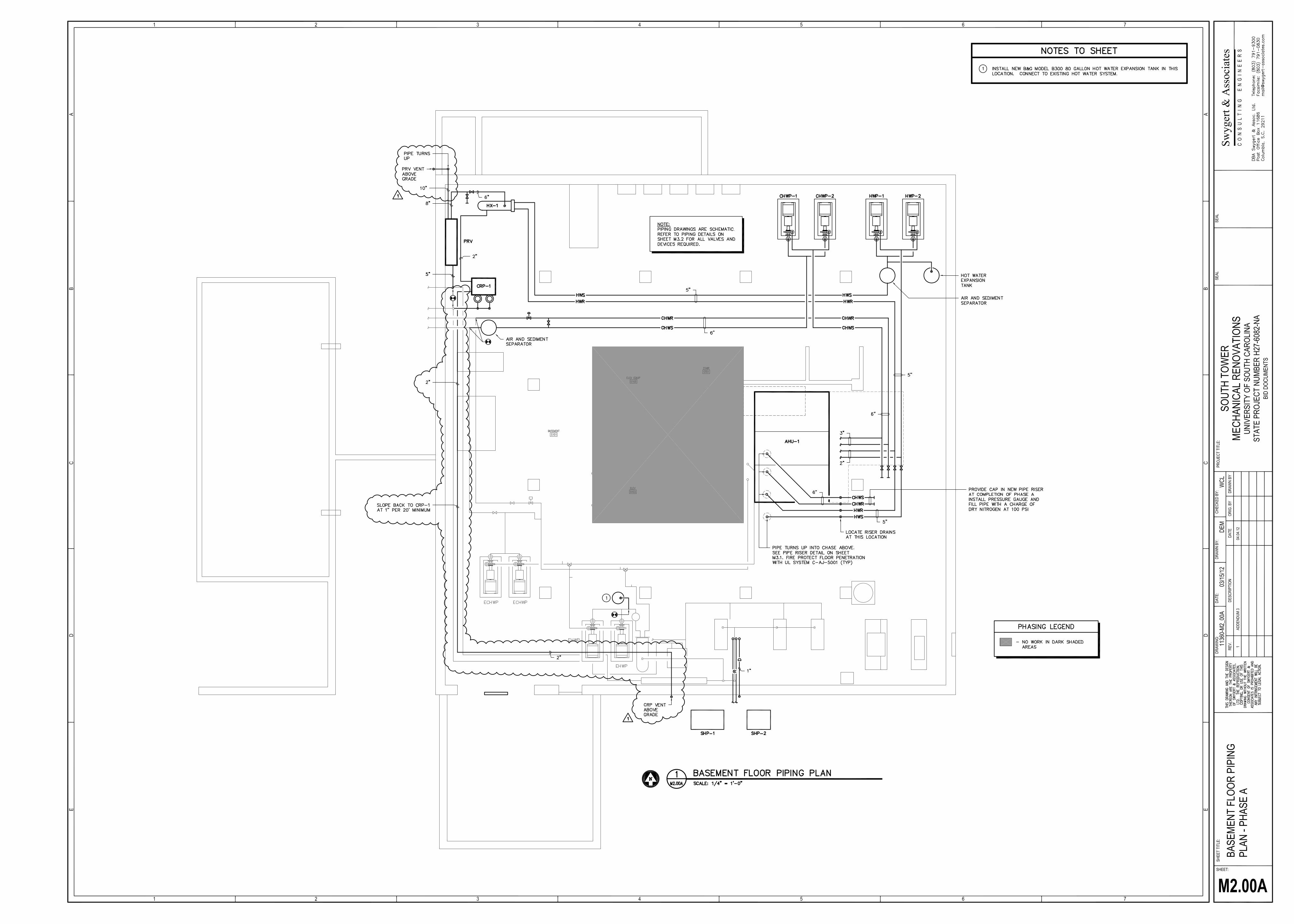
6. Revision: Reference Drawing M2.00A, Basement Floor Plan Phase A. See
attached revised sheet M2.00A showing the PRV vent and CRP-1 vent to be installed in Phase A.
7. Revision: Reference Drawing M2.00B, Basement Floor Plan Phase B.
Change PRV vent size to 10”.
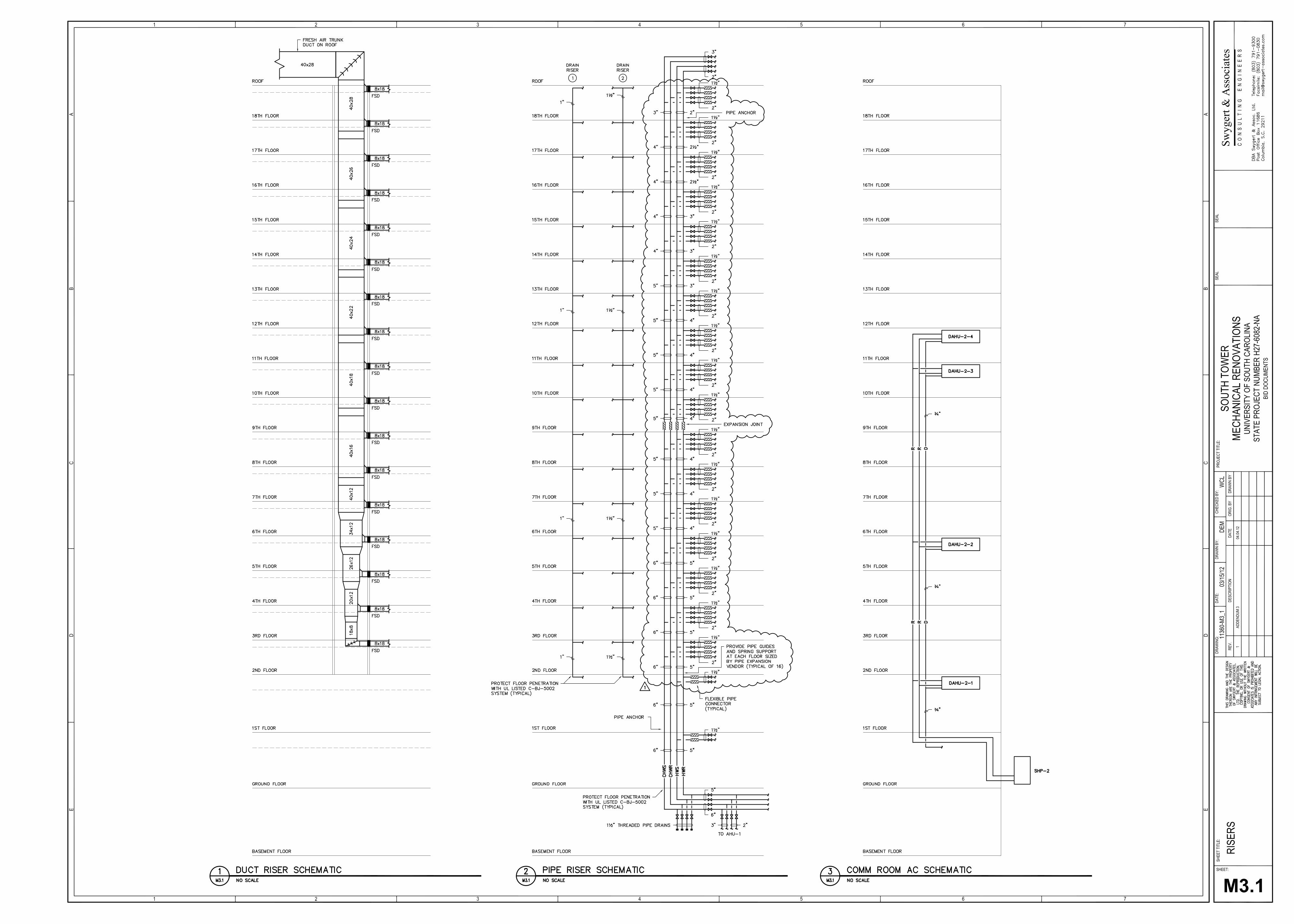
8. Revision: Reference Drawing M3.1, Risers. See attached revised sheet M3.1 showing revisions to the pipe riser detail.
9. Revision: Reference Drawing M3.2 Piping Details. Reference SK-M-1.
This sketch revises the PRV valve and vent sizes.
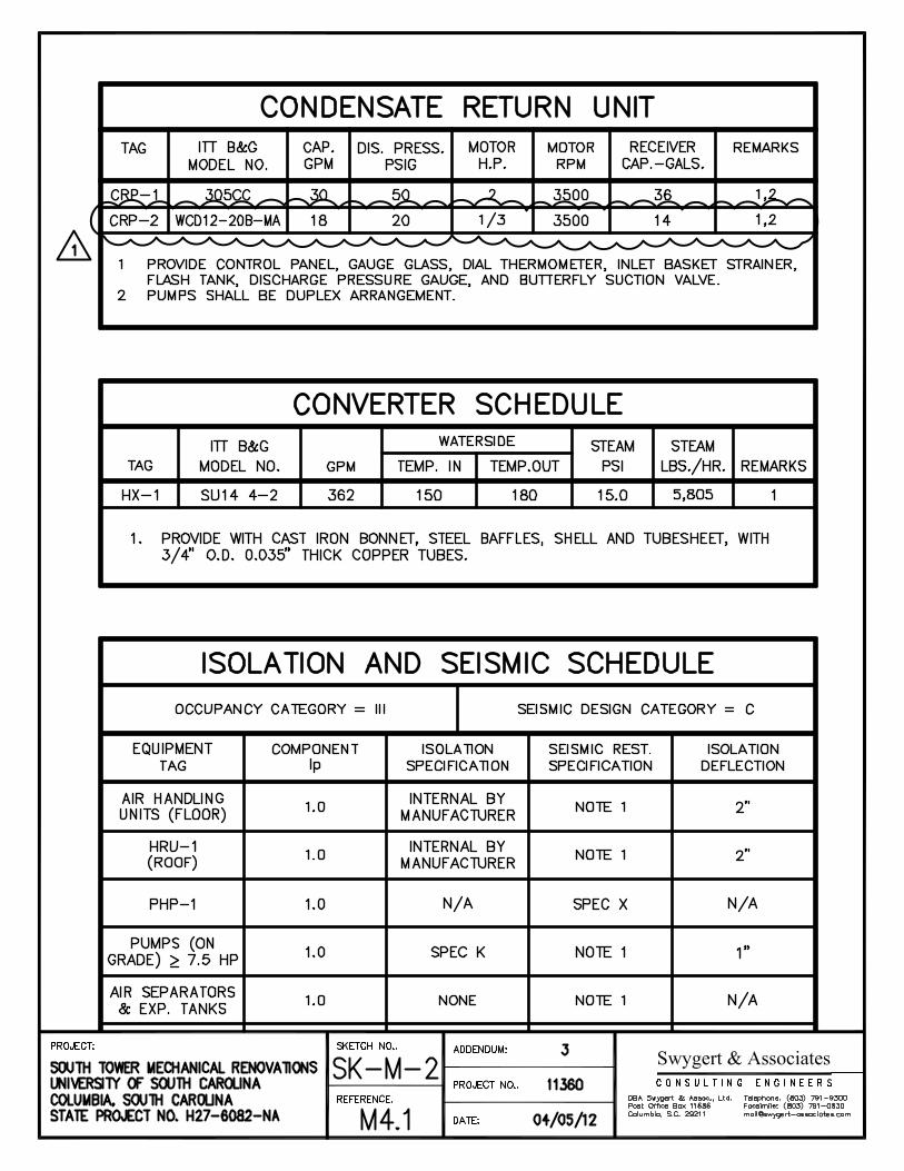
10. Revision: Reference Drawing M4.1 Notes and Schedules. Reference SK-M-2. This sketch revises the Condensate Return Pump Schedule and shows information for CRP-2.

11. Revision: Reference Drawing E1.0 General Notes, Legend, Schedules and Details. General Notes: Delete General Note 9 in its entirety.
12. Revision: Reference Drawing E1.0 General Notes, Legend, Schedules and
Details. Electrical Symbol Legend: Symbol shown with the letter “M” and indicated to be a safety disconnect switch may also be a variable frequency drive (VFD) unit furnished by the mechanical and/or plumbing Contractor. Mount switch/VSD unit and route power wiring through it to serve the associated motor load.
13. Revision: Reference Drawing E1.1 Power Riser Diagram and Schedules.
Change the requirement in Note to have the breaker rated for 100,000 AIC symmetrical instead of 65,000.
14. Revision: Reference Drawing E1.1 Power Riser Diagram and Schedules.
New feeder shown to serve Panel 1B shall be changed to three #8 AWG THWN conductors with one #10 AWG ground wire in 1” EMT raceway.
15. Revision: Reference Drawing E2.00A Power Plans – Basement Phase A.
Refer to Power Demolition Plan Basement – Phase A: remove existing split heat pump unit as shown on sheet MD1.01A.
16. Revision: Reference Drawing E3.01A Lighting Plans – Ground Floor
Phase A. In Living 003, the existing wall mounted lighting fixture shall remain; delete reference to new type T fixtures shown on renovation plan. In Living 003, change type J downlight in northeast corner of space (kitchen area) to a type C 2’x2’ fixture. In Living 003, there are two existing single pole switches in one single gang box at doorway. These switches shall remain – one switch shall control wall fixture and the other switch shall control the ceiling fixtures.
17. Revision: Reference Drawing E3.01A Lighting Plans – Ground Floor
Phase A. In Bedroom 005, the two existing wall mounted fixtures on the east and west walls shall remain; delete references to new type T fixtures shown on renovation plan. On north wall near entry doorway, there is an existing wall mounted lighting fixture that is not operating. Replace that fixture with a new type T lighting fixture and connect to existing branch circuit as other wall mounted lighting fixtures. In Bedroom 005, add one type C 2’x2’ fixture over kitchen area.
18. Revision: Reference Drawing E3.01A Lighting Plans – Ground Floor
Phase A. Add note D2 that reads, “In Halls H001, H002, H003, H004, and H005, remove existing wall mounted lighting fixtures and associated branch circuits. Provide blank cover plates on boxes.” Change note R3 to read, “In Halls H001, H002, H003, H004, and H005, locate and modify/extend existing generator-backed corridor lighting branch circuit

to feed all new grid mounted corridor lighting fixtures.” Delete the six (6) GTDs shown in those hallways. Lighting shall operate 24/7.
19. Revision: Reference Drawing E3.1A Lighting Plans – First Floor Phase A.
In RA Living 103, RA Bedroom 103A, and RA Kitchen 103D, existing switching shall remain and be used to control new lighting fixtures.
20. Revision: Reference Drawing E3.1A Lighting Plans – First Floor Phase A.
Delete Note R3 and referenced GTDs on this drawing (total of 11 GTDs). Lighting in lobby and corridors shall operate 24/7.
21. Revision: Reference Drawing E3.1A Lighting Plans – First Floor Phase A.
All new exit signs shown on Renovation Plan shall be type XA (edge-lit type). Verify mounted and chevron configuration in field before ordering.
22. Revision: Reference Drawing E3.2A Lighting Plans – 2nd - 10th Floors
Phase A. All existing exit signs on 2nd thru 18th floors shall remain in place. Protect during demolition and renovation work; replace any damaged units with new type X (thermoplastic housing type).
23. Revision: Reference Drawing E3.2A Lighting Plans – 2nd - 10th Floors
Phase A. Delete all GTDs shown in corridors. These fixtures shall operate 24/7 and shall be fed with generator-backed circuits.
Specifications Item No. Description
24. Revision: Reference Section 230500, Heating Ventilation and Air
Conditioning. Under Part 2 Products, add the following material specification: EXPANSION JOINTS: Furnish and install as show on the drawings the Flex-Hose Co.’s FLEXPRESS externally pressurized expansion joints or equal. The design shall incorporate a totally enclosed, externally pressurized stainless steel bellows that is protected from external damage by a heavy-walled shroud designed for full line pressure. The bellows is isolated from flow impingement by an internal schedule 40 carbon steel sleeve. Standard design operating pressure is 150 PSIG. (300 PSIG is also available.) As a result of the externally pressurized design, the operating pressure shall be transferred to the outside of the bellows through a gap between the internal guide flange and the housing (shroud). End fittings shall be flat-face plate carbon steel flanges with 150# ANSI drilling and outside diameter. The
bellows may be of single-ply, or laminated (multi-ply) construction to provide a low spring rate with minimal deflection stresses that assure long life. Drain port is provided for convenient location of steam trap, or used to drain liquids when pipeline is shutdown. Packless design eliminates the need for routine maintenance. Cycle life: 10,000 minimum at full travel. The externally pressurized design will eliminate the need for one set of pipe guides on each side of the expansion joint (4 pipe diameters from the expansion joint) thus permitting the first set of pipe guides to be up to 14 diameters from the expansion joint.
25. Revision: Reference Section 230500, Heating Ventilation and Air Conditioning. Under Part 2 Products, add the following material specification: FLEXIBLE PIPE CONNECTOR ON RISER: Provide 24” long flexible connectors on all pipe riser branch connections as shown on pipe riser detail on sheet M3.1. Furnish and install PUMPSAVER SMP braided stainless steel pump connectors manufactured by the Flex-Hose Co., Inc. or equal. Construction to be of annular corrugated stainless steel close-pitch hose (made in USA) with stainless steel overbraid (made in USA). The corrugated metal hose, braid(s), and a stainless steel ring-ferrule/band (material gauge not less than .048") must be integrally seal-welded using a 100% circumferential, full-penetration TIG weld. End fittings shall be flat-face plate steel flanges with 150# ANSI drilling and outside diameter or carbon steel schedule 40 male NPT thread. Fittings must be attached using a 100% circumferential TIG weld. Braided stainless steel pump connector(s) must be suitable for operating temperatures up to 850oF (455oC). The rated working pressure of the braided metal hose must have a minimum 4:1 safety factor. Each braided stainless steel pump connector shall be individually leak tested by the manufacturer using air-under-water or hydrostatic pressure. Flanged pump connectors shall be prepared for shipment using cut-to-length spacers, securely positioned between the flanges to prevent axial compression damage and maintain the manufactured length. Spacers must be removed prior to system start up.
26. Revision: Reference Section 230548 Vibration Isolation and Seismic Restraint. All anchors that are to be set into existing concrete structure and slabs shall comply with the following: Seismic anchors should have an ICC-ES Evaluation Report (an example number is ESR-1917) showing that the anchor has been tested and approved for use in cracked concrete based on ACI 355.2.

27. Revision: Reference Section 230010, General Provisions HVAC. The following manufacturers are prior approved.
Pressure Independent Control Valves: Johnson Controls, Danfoss, Delta Flow, Belimo Air Handling Units: Carrier Variable Air Volume Boxes: Kreuger Automatic Flow Control Valves: Nexus
28. Revision: The following Electrical items are listed as prior approved: Lighting Fixtures: Type Manufacturer Catalog Number A Lithonia 2RTL4 48L LP840 B Lithonia 2RTL2 33L LP840 D Kenall MLHA8 48 F MW PP 50L40K DCC DV F H.E. Williams 76 8 432 (2)WG 7614 VBY 2 EB4 UNV J Lithonia Gotham ALED 41 18 6AR 120 TRW K Advent AIP11706 L52W 120 M New Star NWLNKL 50 WH 120 X Lithonia LQM S W 3 R 120/277 XA Lithonia LRP 1(2) RW 120/277 Lighting Controls: Lithonia (Acuity Brands Control Devices)
END OF ADDENDUM Attachments: SK-A-1 SK-A-2 SK-M-1 SK-M-2 M2.00A-REV1 M3.1-REV1

C O N S U L T I N G E N G I N E E R S
Swygert & Associates
BASEMENT
S101
1
M3A
ALIGN
REFERENCED ON: 1/4" = 1'-0"SK-A-11 PARTIAL BASEMENT FLOOR PLAN
SK-A-1
A1.00
3
04.04.12
SOUTH TOWER MECHANICAL RENOVATIONSUNIVERSITY OF SOUTH CAROLINACOLUMBIA, SOUTH CAROLINASTATE PROJECT NO. H27-6082-NA
PROJECT: SKETCH NO:
REFERENCE:
ADDENDUM:
PROJECT NO:
DATE:
11360DBA Swygert & Assoc., Ltd.Post Office Box 11686Columbia, SC 29211
Telephone (803) 791-9300Fax (803) [email protected]

C O N S U L T I N G E N G I N E E R S
Swygert & Associates
8' - 6"
H
E
RESIDENT
FL#06
8' - 1"
7' - 6"
D
F
G
G
REFERENCED ON: 1/4" = 1'-0"SK-A-21 PARTIAL TYPICAL REFLECTED CEILING PLAN - LEVELS 2-18
SK-A-2
A2.2 &A2.3
3
04.04.12
NOTE : A KEYNOTE G WAS ADDED TO CLARIFY EXTENT OF NEWSPRAY TEXTURE FINISH. THIS APPLIES TO FLOORS 2-18.
SOUTH TOWER MECHANICAL RENOVATIONSUNIVERSITY OF SOUTH CAROLINACOLUMBIA, SOUTH CAROLINASTATE PROJECT NO. H27-6082-NA
PROJECT: SKETCH NO:
REFERENCE:
ADDENDUM:
PROJECT NO:
DATE:
DBA Swygert & Assoc., Ltd.Post Office Box 11686Columbia, SC 29211
Telephone (803) 791-9300Fax (803) [email protected]
11360

Related Documents