Unit 7 Discrete Controllers Assigned Core Text Reading for this Unit: Groover, M. P. (2008), Automation, Production Systems, and Computer- Integrated Manufacturing, 3 rd ed., Chapter 9. 7.1 Unit Introduction 7.2 Unit Learning Objectives 7.3 Discrete Process Control 7.4 Ladder Logic Diagrams 7.5 Programmable Logic Controllers 7.6 Personal Computers Using Soft Logic 7.7 Unit Review 7.8 Self-Assessment Questions 7.9 Self-Assessment Answers Section 7.1 Unit Introduction Automation is possible because of sensors, actuators, machine tools such as robots or machines and controllers that execute a program of instructions. Many controllers in manufacturing are specific to the machine tool that in turn is specific to a particular machine tool supplier (e.g. Bridgeport, Kuka Robotics, Siemens and so on). In this unit we examine general controllers that are typically not linked to machine tools or robots and are used to control a variety of independently configured sensors and actuators using discrete control. Discrete control is implemented via two principle industrial controllers: BULLETLIST Programmable Logic Controllers (PLCs) Personal Computers (PCs). ENDLIST KEYPOINT Discrete control is implemented via two principle industrial controllers: the programmable logic controller, and the personal computer. END KEYPOINT LEARNING ACTIVITY 7.1 Learn more about PLCs and PCs at the following web-sites: http://en.wikipedia.org/wiki/Programmable_logic_controller http://en.wikipedia.org/wiki/Personal_computer END LEARNING ACTIVITY 7.1

Welcome message from author
This document is posted to help you gain knowledge. Please leave a comment to let me know what you think about it! Share it to your friends and learn new things together.
Transcript
Unit 7 Discrete Controllers Assigned Core Text Reading for this Unit: Groover, M. P. (2008), Automation, Production Systems, and Computer-Integrated Manufacturing, 3rd ed., Chapter 9. 7.1 Unit Introduction 7.2 Unit Learning Objectives 7.3 Discrete Process Control 7.4 Ladder Logic Diagrams 7.5 Programmable Logic Controllers 7.6 Personal Computers Using Soft Logic 7.7 Unit Review 7.8 Self-Assessment Questions 7.9 Self-Assessment Answers Section 7.1 Unit Introduction Automation is possible because of sensors, actuators, machine tools such as robots or machines and controllers that execute a program of instructions. Many controllers in manufacturing are specific to the machine tool that in turn is specific to a particular machine tool supplier (e.g. Bridgeport, Kuka Robotics, Siemens and so on). In this unit we examine general controllers that are typically not linked to machine tools or robots and are used to control a variety of independently configured sensors and actuators using discrete control. Discrete control is implemented via two principle industrial controllers: BULLETLIST Programmable Logic Controllers (PLCs) Personal Computers (PCs). ENDLIST KEYPOINT Discrete control is implemented via two principle industrial controllers: the programmable logic controller, and the personal computer. END KEYPOINT LEARNING ACTIVITY 7.1 Learn more about PLCs and PCs at the following web-sites: http://en.wikipedia.org/wiki/Programmable_logic_controller http://en.wikipedia.org/wiki/Personal_computer END LEARNING ACTIVITY 7.1
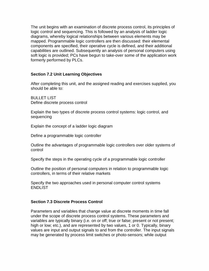
The unit begins with an examination of discrete process control, its principles of logic control and sequencing. This is followed by an analysis of ladder logic diagrams, whereby logical relationships between various elements may be mapped. Programmable logic controllers are then discussed: their elemental components are specified, their operative cycle is defined, and their additional capabilities are outlined. Subsequently an analysis of personal computers using soft logic is provided; PCs have begun to take-over some of the application work formerly performed by PLCs. Section 7.2 Unit Learning Objectives After completing this unit, and the assigned reading and exercises supplied, you should be able to: BULLET LIST Define discrete process control Explain the two types of discrete process control systems: logic control, and sequencing Explain the concept of a ladder logic diagram Define a programmable logic controller Outline the advantages of programmable logic controllers over older systems of control Specify the steps in the operating cycle of a programmable logic controller Outline the position of personal computers in relation to programmable logic controllers, in terms of their relative markets Specify the two approaches used in personal computer control systems ENDLIST Section 7.3 Discrete Process Control Parameters and variables that change value at discrete moments in time fall under the scope of discrete process control systems. These parameters and variables are typically binary (i.e. on or off; true or false; present or not present; high or low; etc.), and are represented by two values, 1 or 0. Typically, binary values are input and output signals to and from the controller. The input signals may be generated by process limit switches or photo-sensors; while output
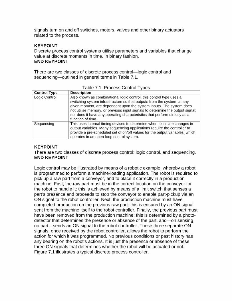
signals turn on and off switches, motors, valves and other binary actuators related to the process. KEYPOINT Discrete process control systems utilise parameters and variables that change value at discrete moments in time, in binary fashion. END KEYPOINT There are two classes of discrete process control—logic control and sequencing—outlined in general terms in Table 7.1.
Table 7.1: Process Control Types Control Type Description Logic Control Also known as combinational logic control, this control type uses a
switching system infrastructure so that outputs from the system, at any given moment, are dependent upon the system inputs. The system does not utilise memory, or previous input signals to determine the output signal; nor does it have any operating characteristics that perform directly as a function of time.
Sequencing This uses internal timing devices to determine when to initiate changes in output variables. Many sequencing applications require the controller to provide a pre-scheduled set of on/off values for the output variables, which operates in an open-loop control system.
KEYPOINT There are two classes of discrete process control: logic control, and sequencing. END KEYPOINT Logic control may be illustrated by means of a robotic example, whereby a robot is programmed to perform a machine-loading application. The robot is required to pick up a raw part from a conveyor, and to place it correctly in a production machine. First, the raw part must be in the correct location on the conveyor for the robot to handle it: this is achieved by means of a limit switch that senses a part’s presence and proceeds to stop the conveyor to enable part-pickup via an ON signal to the robot controller. Next, the production machine must have completed production on the previous raw part: this is ensured by an ON signal sent from the machine itself to the robot controller. Finally, the previous part must have been removed from the production machine: this is determined by a photo-detector that determines the presence or absence of the part, and—on sensing no part—sends an ON signal to the robot controller. These three separate ON signals, once received by the robot controller, allows the robot to perform the action for which it was programmed. No previous conditions or past history has any bearing on the robot’s actions. It is just the presence or absence of these three ON signals that determines whether the robot will be actuated or not. Figure 7.1 illustrates a typical discrete process controller.
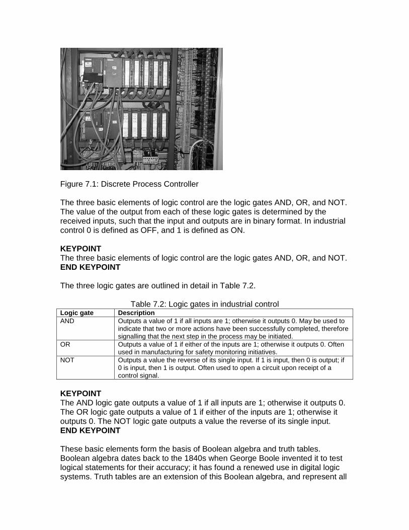
Figure 7.1: Discrete Process Controller The three basic elements of logic control are the logic gates AND, OR, and NOT. The value of the output from each of these logic gates is determined by the received inputs, such that the input and outputs are in binary format. In industrial control 0 is defined as OFF, and 1 is defined as ON. KEYPOINT The three basic elements of logic control are the logic gates AND, OR, and NOT. END KEYPOINT The three logic gates are outlined in detail in Table 7.2.
Table 7.2: Logic gates in industrial control Logic gate Description AND Outputs a value of 1 if all inputs are 1; otherwise it outputs 0. May be used to
indicate that two or more actions have been successfully completed, therefore signalling that the next step in the process may be initiated.
OR Outputs a value of 1 if either of the inputs are 1; otherwise it outputs 0. Often used in manufacturing for safety monitoring initiatives.
NOT Outputs a value the reverse of its single input. If 1 is input, then 0 is output; if 0 is input, then 1 is output. Often used to open a circuit upon receipt of a control signal.
KEYPOINT The AND logic gate outputs a value of 1 if all inputs are 1; otherwise it outputs 0. The OR logic gate outputs a value of 1 if either of the inputs are 1; otherwise it outputs 0. The NOT logic gate outputs a value the reverse of its single input. END KEYPOINT These basic elements form the basis of Boolean algebra and truth tables. Boolean algebra dates back to the 1840s when George Boole invented it to test logical statements for their accuracy; it has found a renewed use in digital logic systems. Truth tables are an extension of this Boolean algebra, and represent all
possible logical combinations in a particular instance. In Boolean algebra the AND logic gate is expressed as:
Y = X1 . X2
that is, Y is true if both X1 and X2 are true; otherwise it is false. The corresponding truth table, showing all logical conditions for Y, is as follows:
Inputs Output X1 X2 Y = X1 . X2 0 0 0 0 1 0 1 0 0 1 1 1
In a similar fashion we can outline the OR function in Boolean logic (Y = X1 + X2) and its truth table as:
Inputs Output X1 X2 Y = X1 + X2 0 0 0 0 1 1 1 0 1 1 1 1
Finally, the NOT function in Boolean logic (Y = X1), and truth table:
Input Output X1 Y = Xˉ1 0 1 1 0
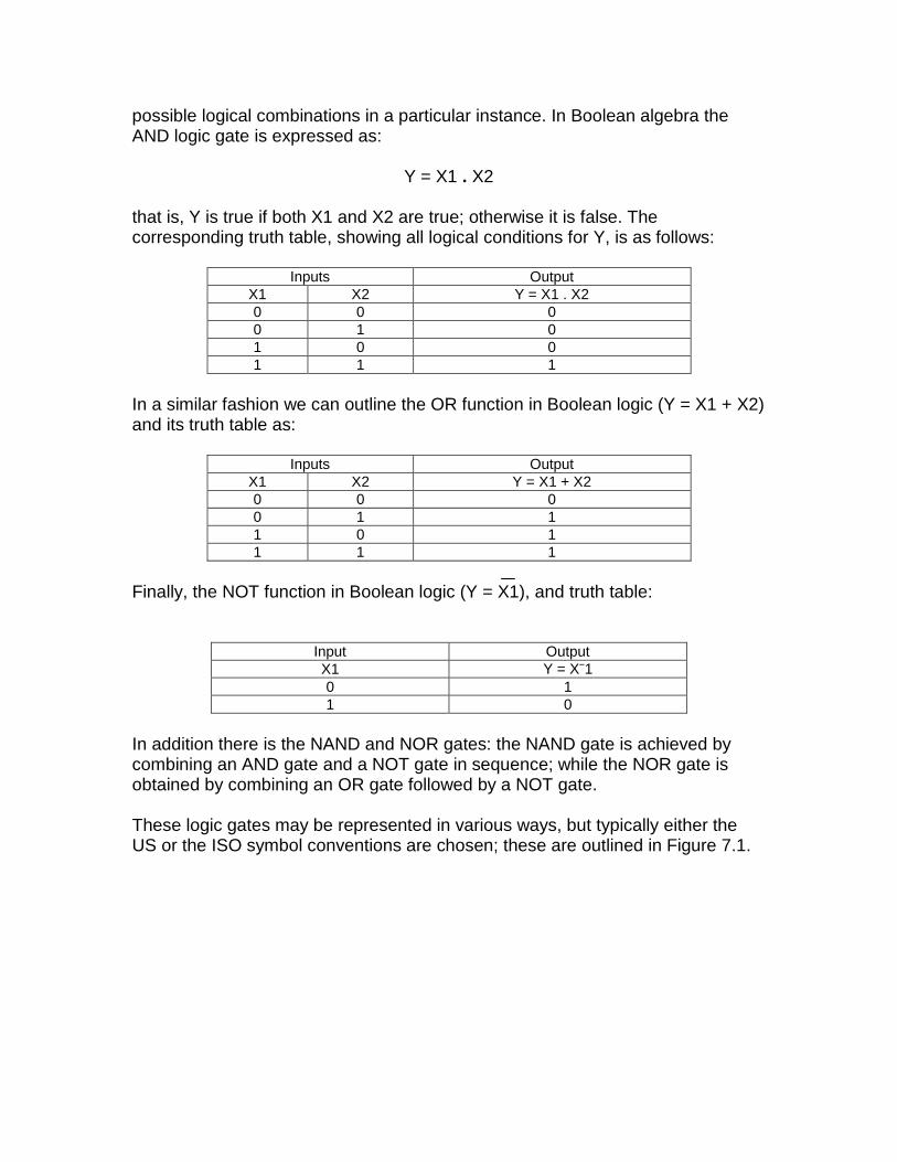
In addition there is the NAND and NOR gates: the NAND gate is achieved by combining an AND gate and a NOT gate in sequence; while the NOR gate is obtained by combining an OR gate followed by a NOT gate. These logic gates may be represented in various ways, but typically either the US or the ISO symbol conventions are chosen; these are outlined in Figure 7.1.
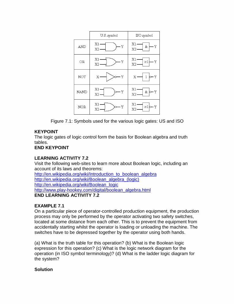
Figure 7.1: Symbols used for the various logic gates: US and ISO
KEYPOINT The logic gates of logic control form the basis for Boolean algebra and truth tables. END KEYPOINT LEARNING ACTIVITY 7.2 Visit the following web-sites to learn more about Boolean logic, including an account of its laws and theorems: http://en.wikipedia.org/wiki/Introduction_to_boolean_algebra http://en.wikipedia.org/wiki/Boolean_algebra_(logic) http://en.wikipedia.org/wiki/Boolean_logic http://www.play-hookey.com/digital/boolean_algebra.html END LEARNING ACTIVITY 7.2 EXAMPLE 7.1 On a particular piece of operator-controlled production equipment, the production process may only be performed by the operator activating two safety switches, located at some distance from each other. This is to prevent the equipment from accidentally starting whilst the operator is loading or unloading the machine. The switches have to be depressed together by the operator using both hands. (a) What is the truth table for this operation? (b) What is the Boolean logic expression for this operation? (c) What is the logic network diagram for the operation (in ISO symbol terminology)? (d) What is the ladder logic diagram for the system? Solution
(a) Truth table for the operation is as follows: Where X1 is first switch, and X2 is second switch, and Y is the output of switch activation.
Inputs Output X1 X2 Y 0 0 0 0 1 0 1 0 0 1 1 1
(b) Boolean logic expression for this operation corresponds to the AND logic gate, thus:
Y = X1 . X2 (c) The logic network diagram for the operation (in ISO symbol terminology) is as follows:
X1
X2
Y&
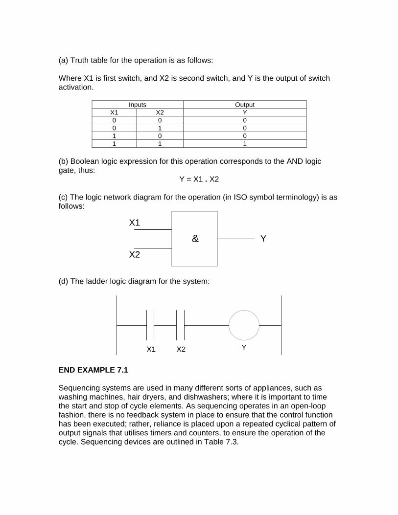
(d) The ladder logic diagram for the system:
X2X1 Y
END EXAMPLE 7.1 Sequencing systems are used in many different sorts of appliances, such as washing machines, hair dryers, and dishwashers; where it is important to time the start and stop of cycle elements. As sequencing operates in an open-loop fashion, there is no feedback system in place to ensure that the control function has been executed; rather, reliance is placed upon a repeated cyclical pattern of output signals that utilises timers and counters, to ensure the operation of the cycle. Sequencing devices are outlined in Table 7.3.
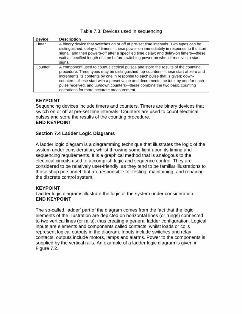
Table 7.3: Devices used in sequencing
KEYPOINT Sequencing devices include timers and counters. Timers are binary devices that switch on or off at pre-set time intervals. Counters are used to count electrical pulses and store the results of the counting procedure. END KEYPOINT Section 7.4 Ladder Logic Diagrams A ladder logic diagram is a diagramming technique that illustrates the logic of the system under consideration, whilst throwing some light upon its timing and sequencing requirements. It is a graphical method that is analogous to the electrical circuits used to accomplish logic and sequence control. They are considered to be relatively user-friendly, as they tend to be familiar illustrations to those shop personnel that are responsible for testing, maintaining, and repairing the discrete control system. KEYPOINT Ladder logic diagrams illustrate the logic of the system under consideration. END KEYPOINT The so-called ‘ladder’ part of the diagram comes from the fact that the logic elements of the illustration are depicted on horizontal lines (or rungs) connected to two vertical lines (or rails), thus creating a general ladder configuration. Logical inputs are elements and components called contacts; whilst loads or coils represent logical outputs in the diagram. Inputs include switches and relay contacts, outputs include motors, lamps and alarms. Power to the components is supplied by the vertical rails. An example of a ladder logic diagram is given in Figure 7.2.
Device Description Timer A binary device that switches on or off at pre-set time intervals. Two types can be
distinguished: delay-off timers—these power-on immediately in response to the start signal, and then powers-off after a specified time delay; and delay-on timers—these wait a specified length of time before switching power on when it receives a start signal.
Counter A component used to count electrical pulses and store the results of the counting procedure. Three types may be distinguished: up-counters—these start at zero and increments its contents by one in response to each pulse that is given; down-counters—these start with a preset value and decrements the total by one for each pulse received; and up/down counters—these combine the two basic counting operations for more accurate measurement.
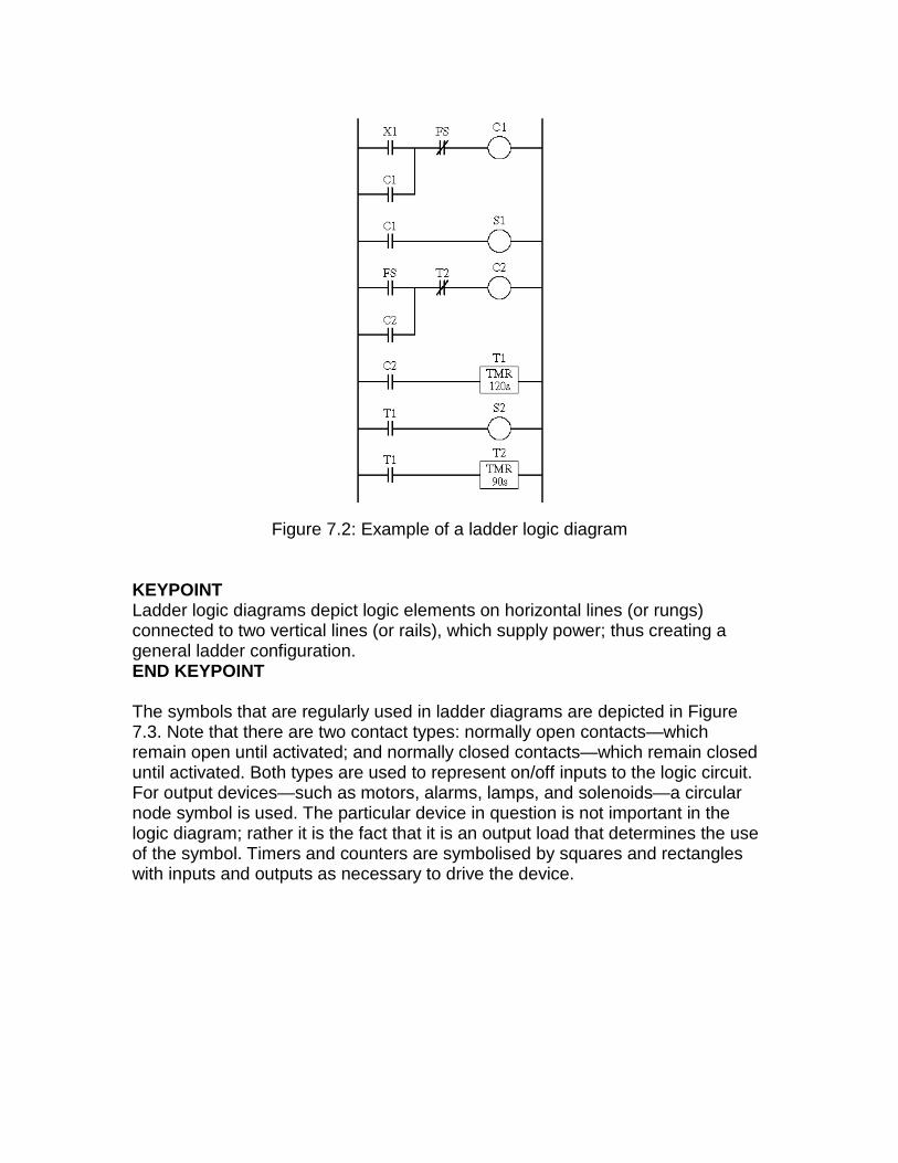
Figure 7.2: Example of a ladder logic diagram
KEYPOINT Ladder logic diagrams depict logic elements on horizontal lines (or rungs) connected to two vertical lines (or rails), which supply power; thus creating a general ladder configuration. END KEYPOINT The symbols that are regularly used in ladder diagrams are depicted in Figure 7.3. Note that there are two contact types: normally open contacts—which remain open until activated; and normally closed contacts—which remain closed until activated. Both types are used to represent on/off inputs to the logic circuit. For output devices—such as motors, alarms, lamps, and solenoids—a circular node symbol is used. The particular device in question is not important in the logic diagram; rather it is the fact that it is an output load that determines the use of the symbol. Timers and counters are symbolised by squares and rectangles with inputs and outputs as necessary to drive the device.
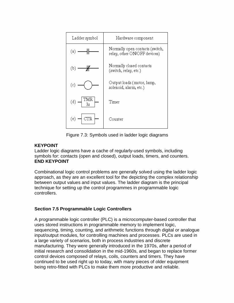
Figure 7.3: Symbols used in ladder logic diagrams
KEYPOINT Ladder logic diagrams have a cache of regularly-used symbols, including symbols for: contacts (open and closed), output loads, timers, and counters. END KEYPOINT Combinational logic control problems are generally solved using the ladder logic approach, as they are an excellent tool for the depicting the complex relationship between output values and input values. The ladder diagram is the principal technique for setting up the control programmes in programmable logic controllers. Section 7.5 Programmable Logic Controllers A programmable logic controller (PLC) is a microcomputer-based controller that uses stored instructions in programmable memory to implement logic, sequencing, timing, counting, and arithmetic functions through digital or analogue input/output modules, for controlling machines and processes. PLCs are used in a large variety of scenarios, both in process industries and discrete manufacturing. They were generally introduced in the 1970s, after a period of initial research and consolidation in the mid-1960s, and began to replace former control devices composed of relays, coils, counters and timers. They have continued to be used right up to today, with many pieces of older equipment being retro-fitted with PLCs to make them more productive and reliable.
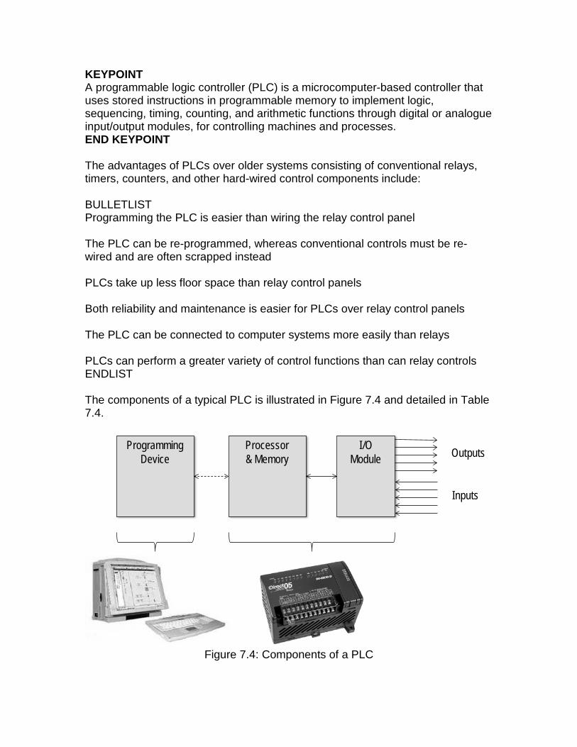
KEYPOINT A programmable logic controller (PLC) is a microcomputer-based controller that uses stored instructions in programmable memory to implement logic, sequencing, timing, counting, and arithmetic functions through digital or analogue input/output modules, for controlling machines and processes. END KEYPOINT The advantages of PLCs over older systems consisting of conventional relays, timers, counters, and other hard-wired control components include: BULLETLIST Programming the PLC is easier than wiring the relay control panel The PLC can be re-programmed, whereas conventional controls must be re-wired and are often scrapped instead PLCs take up less floor space than relay control panels Both reliability and maintenance is easier for PLCs over relay control panels The PLC can be connected to computer systems more easily than relays PLCs can perform a greater variety of control functions than can relay controls ENDLIST The components of a typical PLC is illustrated in Figure 7.4 and detailed in Table 7.4.
I/OModule Outputs
Inputs
Processor& Memory
ProgrammingDevice
Figure 7.4: Components of a PLC
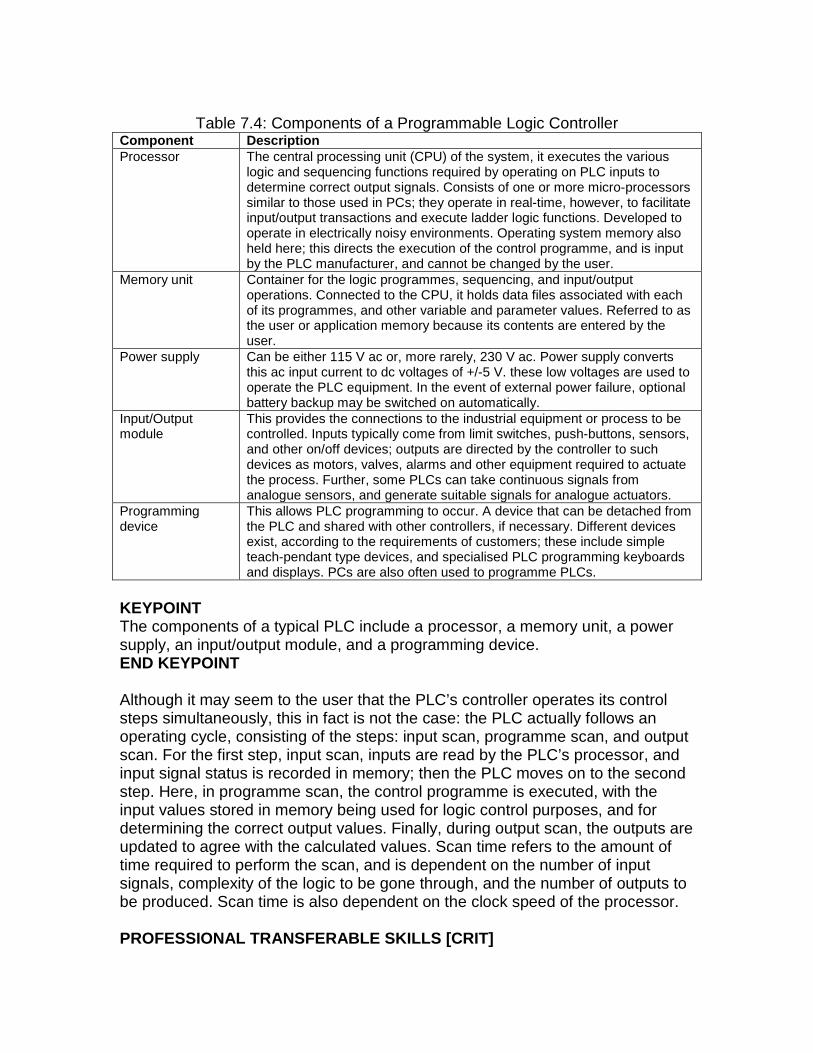
Table 7.4: Components of a Programmable Logic Controller
Component Description Processor The central processing unit (CPU) of the system, it executes the various
logic and sequencing functions required by operating on PLC inputs to determine correct output signals. Consists of one or more micro-processors similar to those used in PCs; they operate in real-time, however, to facilitate input/output transactions and execute ladder logic functions. Developed to operate in electrically noisy environments. Operating system memory also held here; this directs the execution of the control programme, and is input by the PLC manufacturer, and cannot be changed by the user.
Memory unit Container for the logic programmes, sequencing, and input/output operations. Connected to the CPU, it holds data files associated with each of its programmes, and other variable and parameter values. Referred to as the user or application memory because its contents are entered by the user.
Power supply Can be either 115 V ac or, more rarely, 230 V ac. Power supply converts this ac input current to dc voltages of +/-5 V. these low voltages are used to operate the PLC equipment. In the event of external power failure, optional battery backup may be switched on automatically.
Input/Output module
This provides the connections to the industrial equipment or process to be controlled. Inputs typically come from limit switches, push-buttons, sensors, and other on/off devices; outputs are directed by the controller to such devices as motors, valves, alarms and other equipment required to actuate the process. Further, some PLCs can take continuous signals from analogue sensors, and generate suitable signals for analogue actuators.
Programming device
This allows PLC programming to occur. A device that can be detached from the PLC and shared with other controllers, if necessary. Different devices exist, according to the requirements of customers; these include simple teach-pendant type devices, and specialised PLC programming keyboards and displays. PCs are also often used to programme PLCs.
KEYPOINT The components of a typical PLC include a processor, a memory unit, a power supply, an input/output module, and a programming device. END KEYPOINT Although it may seem to the user that the PLC’s controller operates its control steps simultaneously, this in fact is not the case: the PLC actually follows an operating cycle, consisting of the steps: input scan, programme scan, and output scan. For the first step, input scan, inputs are read by the PLC’s processor, and input signal status is recorded in memory; then the PLC moves on to the second step. Here, in programme scan, the control programme is executed, with the input values stored in memory being used for logic control purposes, and for determining the correct output values. Finally, during output scan, the outputs are updated to agree with the calculated values. Scan time refers to the amount of time required to perform the scan, and is dependent on the number of input signals, complexity of the logic to be gone through, and the number of outputs to be produced. Scan time is also dependent on the clock speed of the processor. PROFESSIONAL TRANSFERABLE SKILLS [CRIT]
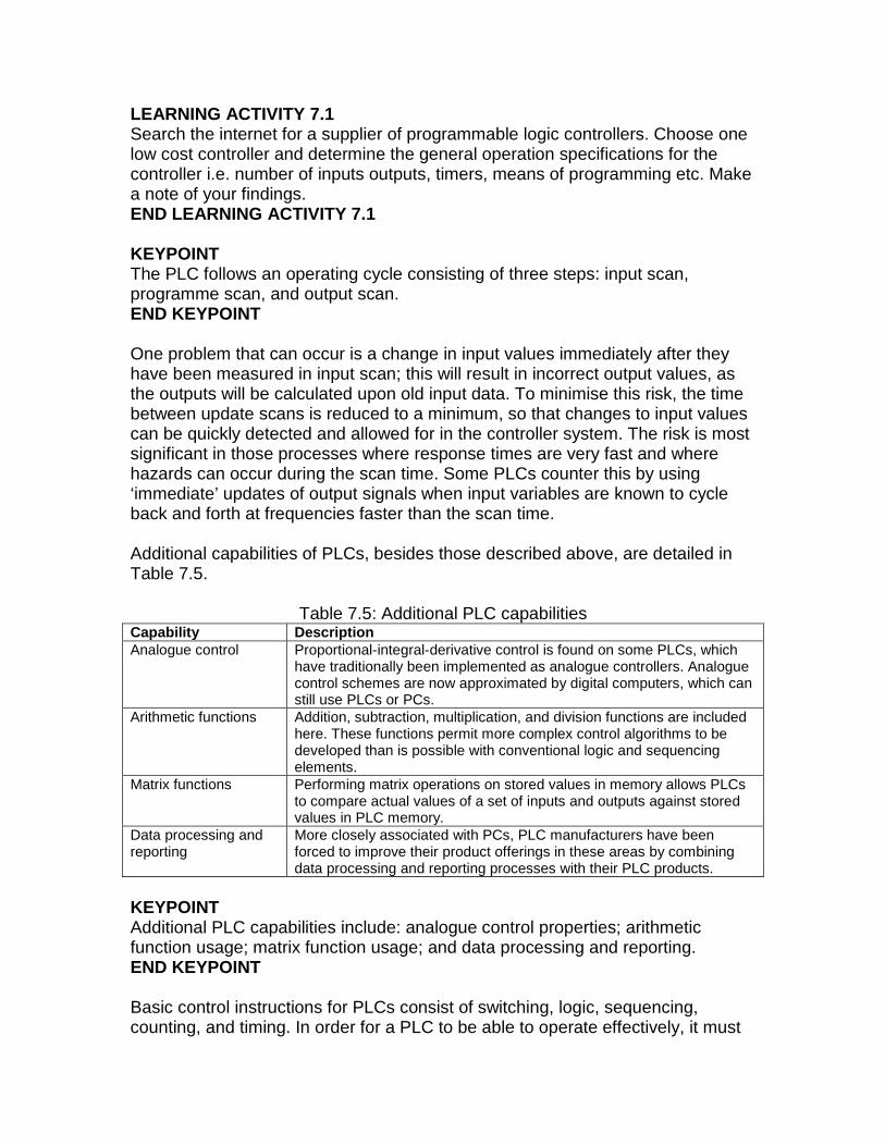
LEARNING ACTIVITY 7.1 Search the internet for a supplier of programmable logic controllers. Choose one low cost controller and determine the general operation specifications for the controller i.e. number of inputs outputs, timers, means of programming etc. Make a note of your findings. END LEARNING ACTIVITY 7.1 KEYPOINT The PLC follows an operating cycle consisting of three steps: input scan, programme scan, and output scan. END KEYPOINT One problem that can occur is a change in input values immediately after they have been measured in input scan; this will result in incorrect output values, as the outputs will be calculated upon old input data. To minimise this risk, the time between update scans is reduced to a minimum, so that changes to input values can be quickly detected and allowed for in the controller system. The risk is most significant in those processes where response times are very fast and where hazards can occur during the scan time. Some PLCs counter this by using ‘immediate’ updates of output signals when input variables are known to cycle back and forth at frequencies faster than the scan time. Additional capabilities of PLCs, besides those described above, are detailed in Table 7.5.
Table 7.5: Additional PLC capabilities Capability Description Analogue control Proportional-integral-derivative control is found on some PLCs, which
have traditionally been implemented as analogue controllers. Analogue control schemes are now approximated by digital computers, which can still use PLCs or PCs.
Arithmetic functions Addition, subtraction, multiplication, and division functions are included here. These functions permit more complex control algorithms to be developed than is possible with conventional logic and sequencing elements.
Matrix functions Performing matrix operations on stored values in memory allows PLCs to compare actual values of a set of inputs and outputs against stored values in PLC memory.
Data processing and reporting
More closely associated with PCs, PLC manufacturers have been forced to improve their product offerings in these areas by combining data processing and reporting processes with their PLC products.
KEYPOINT Additional PLC capabilities include: analogue control properties; arithmetic function usage; matrix function usage; and data processing and reporting. END KEYPOINT Basic control instructions for PLCs consist of switching, logic, sequencing, counting, and timing. In order for a PLC to be able to operate effectively, it must
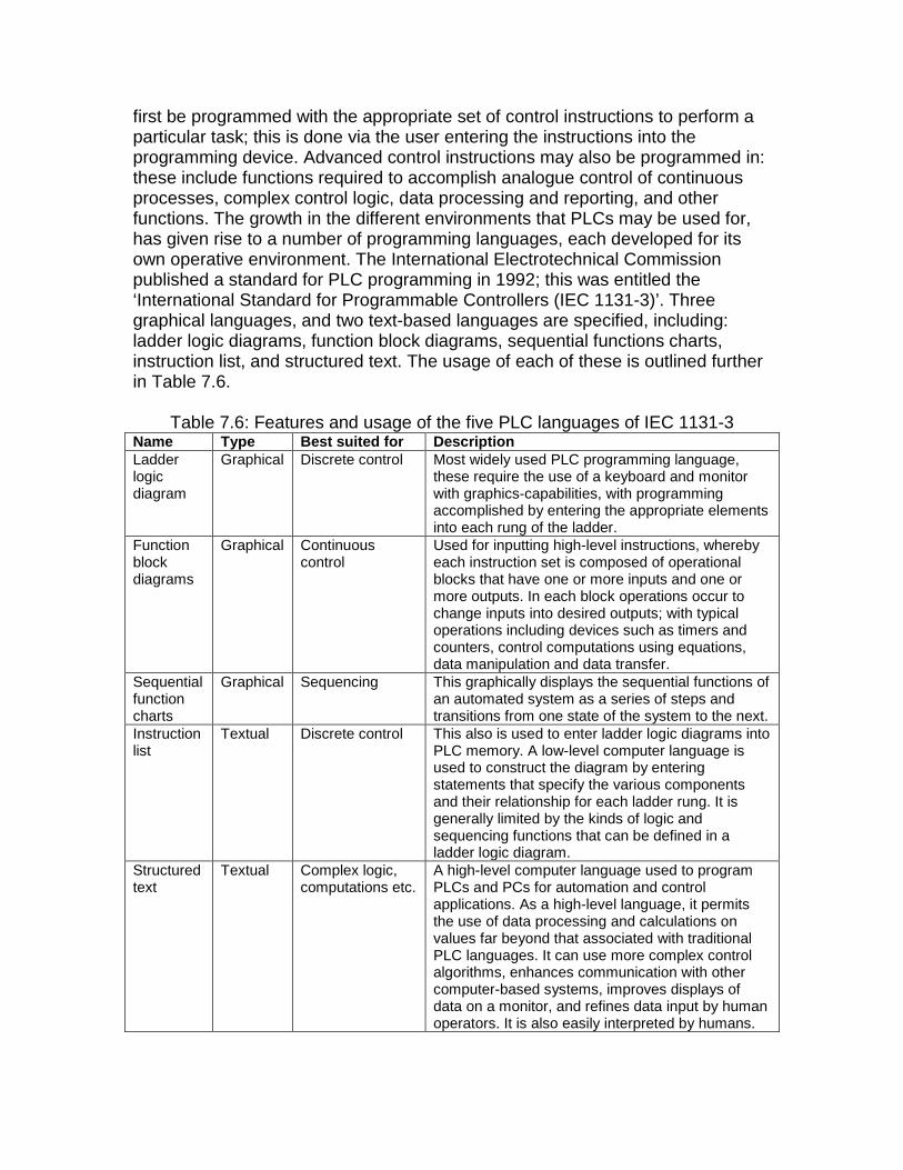
first be programmed with the appropriate set of control instructions to perform a particular task; this is done via the user entering the instructions into the programming device. Advanced control instructions may also be programmed in: these include functions required to accomplish analogue control of continuous processes, complex control logic, data processing and reporting, and other functions. The growth in the different environments that PLCs may be used for, has given rise to a number of programming languages, each developed for its own operative environment. The International Electrotechnical Commission published a standard for PLC programming in 1992; this was entitled the ‘International Standard for Programmable Controllers (IEC 1131-3)’. Three graphical languages, and two text-based languages are specified, including: ladder logic diagrams, function block diagrams, sequential functions charts, instruction list, and structured text. The usage of each of these is outlined further in Table 7.6.
Table 7.6: Features and usage of the five PLC languages of IEC 1131-3 Name Type Best suited for Description Ladder logic diagram
Graphical Discrete control Most widely used PLC programming language, these require the use of a keyboard and monitor with graphics-capabilities, with programming accomplished by entering the appropriate elements into each rung of the ladder.
Function block diagrams
Graphical Continuous control
Used for inputting high-level instructions, whereby each instruction set is composed of operational blocks that have one or more inputs and one or more outputs. In each block operations occur to change inputs into desired outputs; with typical operations including devices such as timers and counters, control computations using equations, data manipulation and data transfer.
Sequential function charts
Graphical Sequencing This graphically displays the sequential functions of an automated system as a series of steps and transitions from one state of the system to the next.
Instruction list
Textual Discrete control This also is used to enter ladder logic diagrams into PLC memory. A low-level computer language is used to construct the diagram by entering statements that specify the various components and their relationship for each ladder rung. It is generally limited by the kinds of logic and sequencing functions that can be defined in a ladder logic diagram.
Structured text
Textual Complex logic, computations etc.
A high-level computer language used to program PLCs and PCs for automation and control applications. As a high-level language, it permits the use of data processing and calculations on values far beyond that associated with traditional PLC languages. It can use more complex control algorithms, enhances communication with other computer-based systems, improves displays of data on a monitor, and refines data input by human operators. It is also easily interpreted by humans.
KEYPOINT Recommended PLC languages include: ladder logic diagrams, function block diagrams, sequential functions charts, instruction list, and structured text. END KEYPOINT Section 7.6 Personal Computers using Soft Logic Since the 1990s, PCs have encroached upon the territory formerly the province of PLCs alone. With the emergence of robust, trouble-free PCs that were designed to operate in harsh factory environments, came a realisation that PCs could usefully perform much of the work formerly left to PLCs, with the result that PC technology—the growth of which has outstripped PLC technology—is to be found performing more and more control work upon the factory floor. Formerly, the advantages of PLCs over PCs included: BULLETLIST PLCs were more robust than PCs, built at one time for office environments, not for factory environments PCs were not as flexible as PLCs with regards input/output interfaces, which were built-into PLCs PCs were sometimes unreliable, and could simply ‘lockup’ for no apparent cause; such a disadvantage would make it unsuitable for factory use END LIST KEYPOINT PCs have encroached upon the territory of PLCs, and now perform much of the work once done solely by PLCs alone. END KEYPOINT However, with its faster technological evolution, PC manufacturers were able to overcome these issues, and were able to provide a PC solution that put traditional PLC products at a disadvantage. Further, much proprietary software and architecture is used in PLCs which makes it difficult to mix and match components from different vendors, and to extend the PLC operative environment if necessary; such a problem does not exist with PCs. This has all resulted in a performance disadvantage for PLCs, with as much as a two year performance lag being noted between the PC and the most advanced PLC. Not only that the rate of technical evolutions promises new PC speeds doubling every 18 months or so, so that the performance lag is actually increasing rather than decreasing. PC adaptations for the factory environment include:
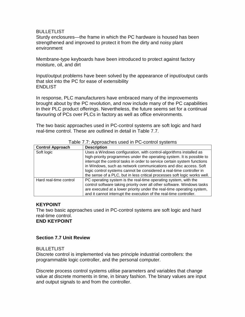
BULLETLIST Sturdy enclosures—the frame in which the PC hardware is housed has been strengthened and improved to protect it from the dirty and noisy plant environment Membrane-type keyboards have been introduced to protect against factory moisture, oil, and dirt Input/output problems have been solved by the appearance of input/output cards that slot into the PC for ease of extensibility ENDLIST In response, PLC manufacturers have embraced many of the improvements brought about by the PC revolution, and now include many of the PC capabilities in their PLC product offerings. Nevertheless, the future seems set for a continual favouring of PCs over PLCs in factory as well as office environments. The two basic approaches used in PC-control systems are soft logic and hard real-time control. These are outlined in detail in Table 7.7.
Table 7.7: Approaches used in PC-control systems Control Approach Description Soft logic Uses a Windows configuration, with control-algorithms installed as
high-priority programmes under the operating system. It is possible to interrupt the control tasks in order to service certain system functions in Windows, such as network communications and disc access. Soft logic control systems cannot be considered a real-time controller in the sense of a PLC, but in less critical processes soft logic works well.
Hard real-time control PC operating system is the real-time operating system, with the control software taking priority over all other software. Windows tasks are executed at a lower priority under the real-time operating system, and it cannot interrupt the execution of the real-time controller.
KEYPOINT The two basic approaches used in PC-control systems are soft logic and hard real-time control. END KEYPOINT Section 7.7 Unit Review BULLETLIST Discrete control is implemented via two principle industrial controllers: the programmable logic controller, and the personal computer. Discrete process control systems utilise parameters and variables that change value at discrete moments in time, in binary fashion. The binary values are input and output signals to and from the controller.
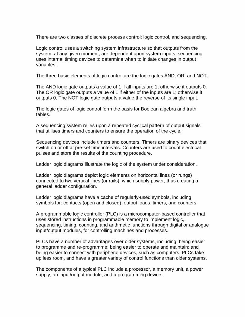
There are two classes of discrete process control: logic control, and sequencing. Logic control uses a switching system infrastructure so that outputs from the system, at any given moment, are dependent upon system inputs; sequencing uses internal timing devices to determine when to initiate changes in output variables. The three basic elements of logic control are the logic gates AND, OR, and NOT. The AND logic gate outputs a value of 1 if all inputs are 1; otherwise it outputs 0. The OR logic gate outputs a value of 1 if either of the inputs are 1; otherwise it outputs 0. The NOT logic gate outputs a value the reverse of its single input. The logic gates of logic control form the basis for Boolean algebra and truth tables. A sequencing system relies upon a repeated cyclical pattern of output signals that utilises timers and counters to ensure the operation of the cycle. Sequencing devices include timers and counters. Timers are binary devices that switch on or off at pre-set time intervals. Counters are used to count electrical pulses and store the results of the counting procedure. Ladder logic diagrams illustrate the logic of the system under consideration. Ladder logic diagrams depict logic elements on horizontal lines (or rungs) connected to two vertical lines (or rails), which supply power; thus creating a general ladder configuration. Ladder logic diagrams have a cache of regularly-used symbols, including symbols for: contacts (open and closed), output loads, timers, and counters. A programmable logic controller (PLC) is a microcomputer-based controller that uses stored instructions in programmable memory to implement logic, sequencing, timing, counting, and arithmetic functions through digital or analogue input/output modules, for controlling machines and processes. PLCs have a number of advantages over older systems, including: being easier to programme and re-programme; being easier to operate and maintain; and being easier to connect with peripheral devices, such as computers. PLCs take up less room, and have a greater variety of control functions than older systems. The components of a typical PLC include a processor, a memory unit, a power supply, an input/output module, and a programming device.
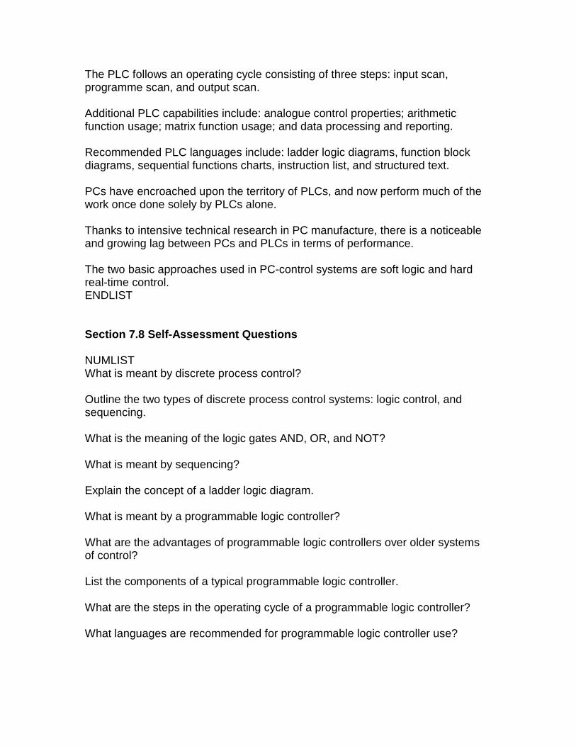
The PLC follows an operating cycle consisting of three steps: input scan, programme scan, and output scan. Additional PLC capabilities include: analogue control properties; arithmetic function usage; matrix function usage; and data processing and reporting. Recommended PLC languages include: ladder logic diagrams, function block diagrams, sequential functions charts, instruction list, and structured text. PCs have encroached upon the territory of PLCs, and now perform much of the work once done solely by PLCs alone. Thanks to intensive technical research in PC manufacture, there is a noticeable and growing lag between PCs and PLCs in terms of performance. The two basic approaches used in PC-control systems are soft logic and hard real-time control. ENDLIST Section 7.8 Self-Assessment Questions NUMLIST What is meant by discrete process control? Outline the two types of discrete process control systems: logic control, and sequencing. What is the meaning of the logic gates AND, OR, and NOT? What is meant by sequencing? Explain the concept of a ladder logic diagram. What is meant by a programmable logic controller? What are the advantages of programmable logic controllers over older systems of control? List the components of a typical programmable logic controller. What are the steps in the operating cycle of a programmable logic controller? What languages are recommended for programmable logic controller use?
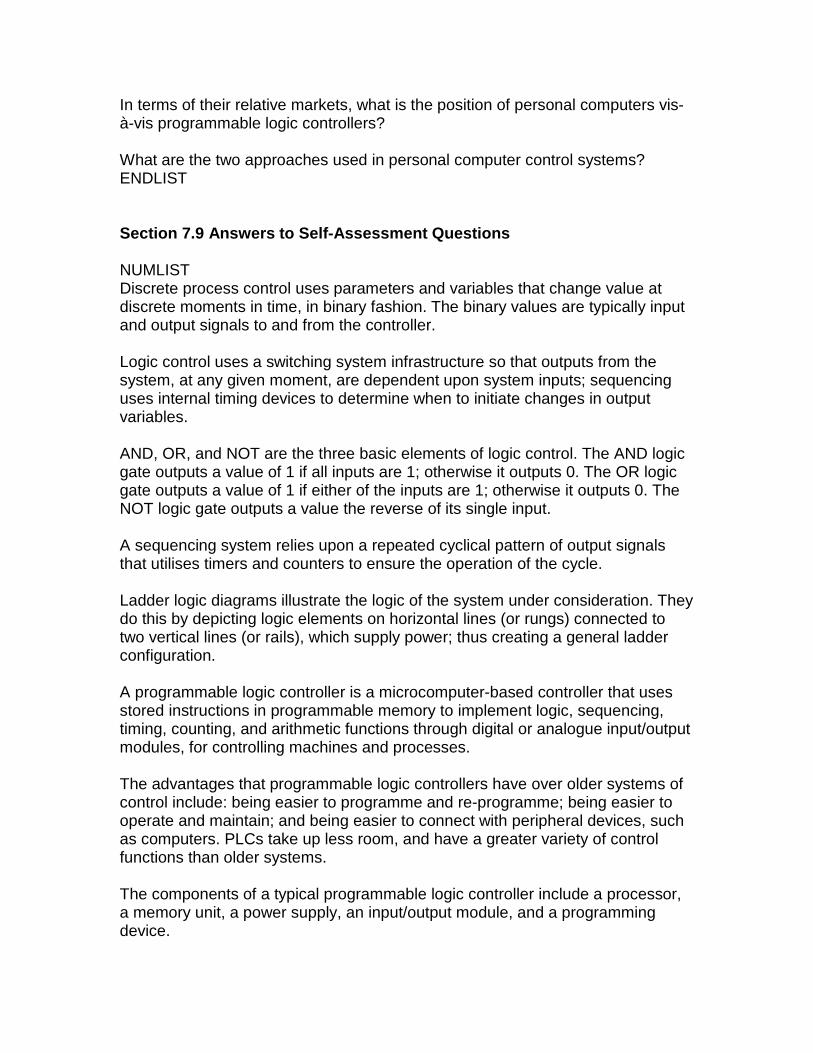
In terms of their relative markets, what is the position of personal computers vis-à-vis programmable logic controllers? What are the two approaches used in personal computer control systems? ENDLIST Section 7.9 Answers to Self-Assessment Questions NUMLIST Discrete process control uses parameters and variables that change value at discrete moments in time, in binary fashion. The binary values are typically input and output signals to and from the controller. Logic control uses a switching system infrastructure so that outputs from the system, at any given moment, are dependent upon system inputs; sequencing uses internal timing devices to determine when to initiate changes in output variables. AND, OR, and NOT are the three basic elements of logic control. The AND logic gate outputs a value of 1 if all inputs are 1; otherwise it outputs 0. The OR logic gate outputs a value of 1 if either of the inputs are 1; otherwise it outputs 0. The NOT logic gate outputs a value the reverse of its single input. A sequencing system relies upon a repeated cyclical pattern of output signals that utilises timers and counters to ensure the operation of the cycle. Ladder logic diagrams illustrate the logic of the system under consideration. They do this by depicting logic elements on horizontal lines (or rungs) connected to two vertical lines (or rails), which supply power; thus creating a general ladder configuration. A programmable logic controller is a microcomputer-based controller that uses stored instructions in programmable memory to implement logic, sequencing, timing, counting, and arithmetic functions through digital or analogue input/output modules, for controlling machines and processes. The advantages that programmable logic controllers have over older systems of control include: being easier to programme and re-programme; being easier to operate and maintain; and being easier to connect with peripheral devices, such as computers. PLCs take up less room, and have a greater variety of control functions than older systems. The components of a typical programmable logic controller include a processor, a memory unit, a power supply, an input/output module, and a programming device.
There are three steps in the operating cycle of a programmable logic controller; these are: input scan, programme scan, and output scan. The languages recommended for programmable logic controller use are: ladder logic diagrams, function block diagrams, sequential functions charts, instruction list, and structured text. PCs have encroached upon the territory of PLCs, and now perform much of the work once done solely by PLCs alone. Thanks to intensive technical research in PC manufacture, there is a noticeable and growing lag between PCs and PLCs in terms of performance. In response, PLC manufacturers have embraced many of the improvements brought about by the PC revolution, and now include many of the PC capabilities in their PLC product offerings. Nevertheless, the future seems set for a continual favouring of PCs over PLCs in factory as well as office environments. The two basic approaches used in PC-control systems are soft logic and hard real-time control. END LIST
Related Documents