Index Introductory information 2 1. General 2 2. Security guidelines 2 3. Scope of supply 4 Installation of the hands-free car kit 4 4. Positioning and mounting 6 5. Connections on the electronics box 11 6. Installation of the loudspeaker switch box AC 5120 15 7. Installation instructions for the fuses 19 Operating guidelines 20 8. Using the hands-free car kit for the first time 20 9. Automatic switch off 21 10. Electronic driver‘s logbook 22 Further Information 25 11. Service 25 UNI CarTalk Time

Welcome message from author
This document is posted to help you gain knowledge. Please leave a comment to let me know what you think about it! Share it to your friends and learn new things together.
Transcript
IndexIntroductory information 2
1. General 2 2. Security guidelines 2 3. Scope of supply 4
Installation of the hands-free car kit 4 4. Positioning and mounting 6 5. Connections on the electronics box 11 6. Installation of the loudspeaker switch box AC 5120 15 7. Installation instructions for the fuses 19
Operating guidelines 20 8. Using the hands-free car kit for the first time 20 9. Automatic switch off 2110. Electronic driver‘s logbook 22
Further Information 2511. Service 25
UNI CarTalk Time
2 Introductory information
1. General
Dear customer,
Congratulation on purchasing a BURY hands-free car kit. You have cho-sen a high quality product that is extremely easy to use. All aspects of BURY production through to sales and service are subject to strict qua-lity management according to DIN EN ISO 9001. All BURY hands-free car kits meet CE and e1 security standards. Furthermore, we provide a two-year warranty on all components.Please read the operating manual carefully so that you can fully enjoy your BURY hands-free car kit. If you have any further questions concer-ning installation or operation of your car kit, please contact your dealer. He will be happy to give you reliable advice. You can also contact our hotline. Our phone and fax numbers are listed in the chapter Service at the end of the operating instructions.
Have a good trip!
2. Security guidelines
Installation – who and whereThe installation of this system can be carried out by yourself but please observe the installation requirements of the automotive manufacturer (VAS 1978). During the installation, park the car at a place where the road traffic is not impaired. We recommend to let a specialised work-shop perform the installation.
Power supplyThis system has been designed for the use in vehicles with an on-board supply system of 12 volts (passenger car). If you intend to install the device in a vehicle with an on-board supply system of 24 volts (lorry), please use a voltage converter. If you have queries regarding this sub-ject, please contact our hotline.
3
Position, volumeInstall the components of the device in the vehicle so that your field of vision is not impaired and the components are not mounted in the im-pact zone of the passenger compartment or in the airbag inflation zones. The removal of coverings (with and without airbags) or compo-nents of the dashboard requires – in some cases – special tools and special knowledge.
Intended useWe shall not be liable for damages or malfunctions due to improper use of the hands-free system. Therefore, do not expose the device to moi-sture, extreme temperatures or shocks and carefully follow the proce-dure described in the installation and operating guidelines.
Use while drivingOperate the system only when the situation allows it and when you do not endanger, harm, constrain, or annoy other road users. The volume of the device has to be set in a way that exterior noise is still audible.
FaultsDo not commission the device if you detect or assume a defect. In this case, contact a BURY specialised dealer or our hotline. Improper repair efforts can be dangerous for you. Therefore, only skilled personnel may perform inspections.
Important:The driver is ultimately responsible for the safe operation X
and control of their vehicle at all times. You should never use a hand held phone, including sending or reading text or picture messages, while driving.
Research indicates that there is a risk to safety when the Xdriver of a motor vehicle is distracted and using a mobile phone while driving can be a distriction.
The manufacturer strongly recommends that you use a Xhands-free solution when driving.
4 Installation of the hands-free car kit
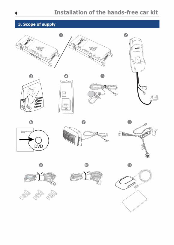
3. Scope of supply
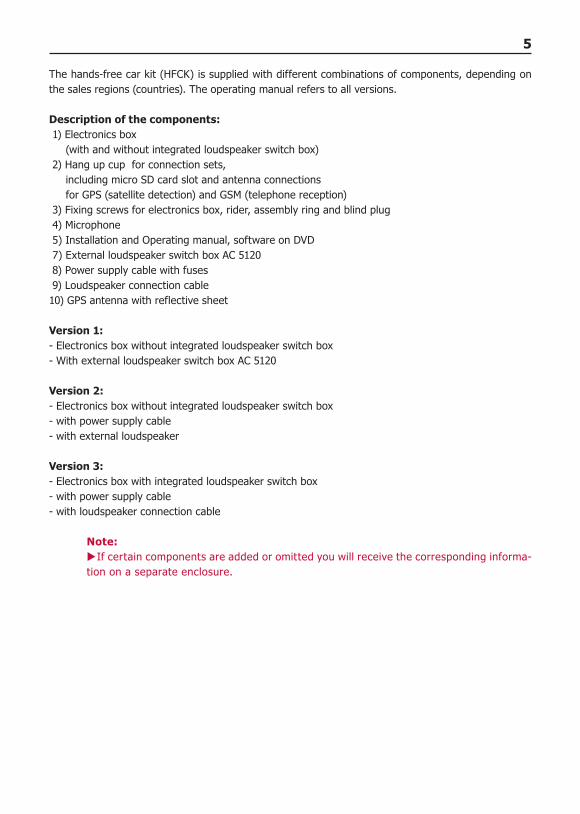
150 cm
5
The hands-free car kit (HFCK) is supplied with different combinations of components, depending on the sales regions (countries). The operating manual refers to all versions.
Description of the components: 1) Electronics box (with and without integrated loudspeaker switch box) 2) Hang up cup for connection sets, including micro SD card slot and antenna connections for GPS (satellite detection) and GSM (telephone reception) 3) Fixing screws for electronics box, rider, assembly ring and blind plug 4) Microphone 5) Installation and Operating manual, software on DVD 7) External loudspeaker switch box AC 5120 8) Power supply cable with fuses 9) Loudspeaker connection cable10) GPS antenna with reflective sheet
Version 1:- Electronics box without integrated loudspeaker switch box- With external loudspeaker switch box AC 5120
Version 2:- Electronics box without integrated loudspeaker switch box- with power supply cable- with external loudspeaker
Version 3:- Electronics box with integrated loudspeaker switch box- with power supply cable- with loudspeaker connection cable
Note:If certain components are added or omitted you will receive the corresponding informa- X
tion on a separate enclosure.
6 Installation of the hands-free car kit
4. Positioning and mounting
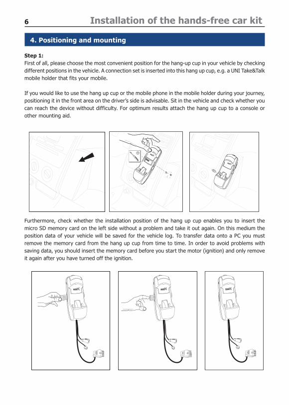
Step 1:First of all, please choose the most convenient position for the hang-up cup in your vehicle by checking different positions in the vehicle. A connection set is inserted into this hang up cup, e.g. a UNI Take&Talk mobile holder that fits your mobile.
If you would like to use the hang up cup or the mobile phone in the mobile holder during your journey, positioning it in the front area on the driver’s side is advisable. Sit in the vehicle and check whether you can reach the device without difficulty. For optimum results attach the hang up cup to a console or other mounting aid.
Furthermore, check whether the installation position of the hang up cup enables you to insert the micro SD memory card on the left side without a problem and take it out again. On this medium the position data of your vehicle will be saved for the vehicle log. To transfer data onto a PC you must remove the memory card from the hang up cup from time to time. In order to avoid problems with saving data, you should insert the memory card before you start the motor (ignition) and only remove it again after you have turned off the ignition.
SD
SD
7
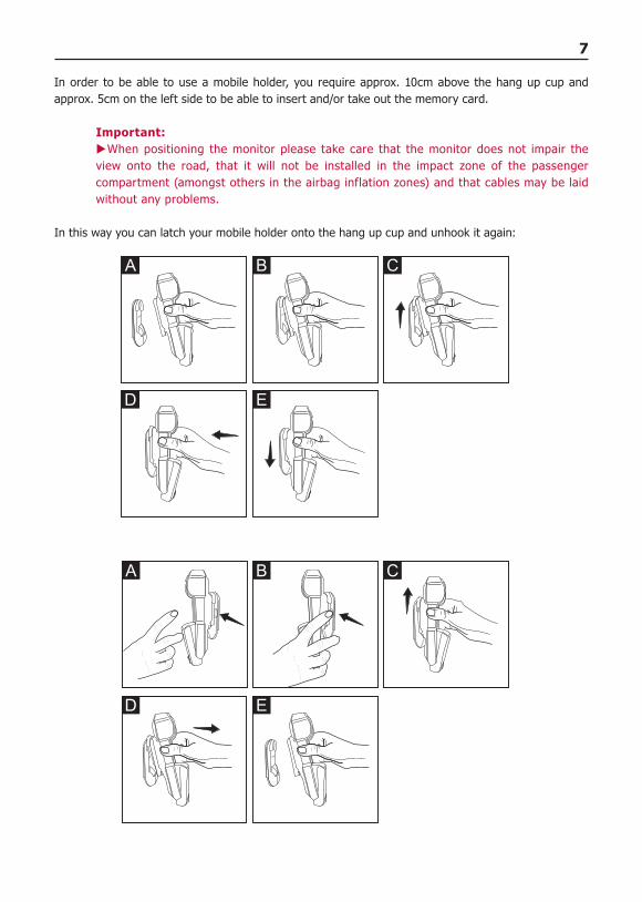
In order to be able to use a mobile holder, you require approx. 10cm above the hang up cup and approx. 5cm on the left side to be able to insert and/or take out the memory card.
Important:When positioning the monitor please take care that the monitor does not impair the X
view onto the road, that it will not be installed in the impact zone of the passenger compartment (amongst others in the airbag inflation zones) and that cables may be laid without any problems.
In this way you can latch your mobile holder onto the hang up cup and unhook it again:
A B C
D E
C
D
BA
E
8 Installation of the hands-free car kit
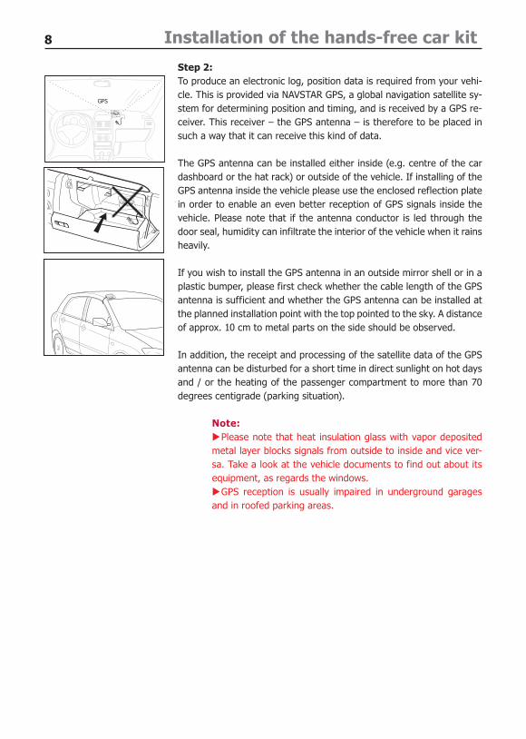
GPS
Step 2:To produce an electronic log, position data is required from your vehi-cle. This is provided via NAVSTAR GPS, a global navigation satellite sy-stem for determining position and timing, and is received by a GPS re-ceiver. This receiver – the GPS antenna – is therefore to be placed in such a way that it can receive this kind of data.
The GPS antenna can be installed either inside (e.g. centre of the car dashboard or the hat rack) or outside of the vehicle. If installing of the GPS antenna inside the vehicle please use the enclosed reflection plate in order to enable an even better reception of GPS signals inside the vehicle. Please note that if the antenna conductor is led through the door seal, humidity can infiltrate the interior of the vehicle when it rains heavily.
If you wish to install the GPS antenna in an outside mirror shell or in a plastic bumper, please first check whether the cable length of the GPS antenna is sufficient and whether the GPS antenna can be installed at the planned installation point with the top pointed to the sky. A distance of approx. 10 cm to metal parts on the side should be observed.
In addition, the receipt and processing of the satellite data of the GPS antenna can be disturbed for a short time in direct sunlight on hot days and / or the heating of the passenger compartment to more than 70 degrees centigrade (parking situation).
Note:Please note that heat insulation glass with vapor deposited X
metal layer blocks signals from outside to inside and vice ver-sa. Take a look at the vehicle documents to find out about its equipment, as regards the windows.
GPS reception is usually impaired in underground garages Xand in roofed parking areas.
9
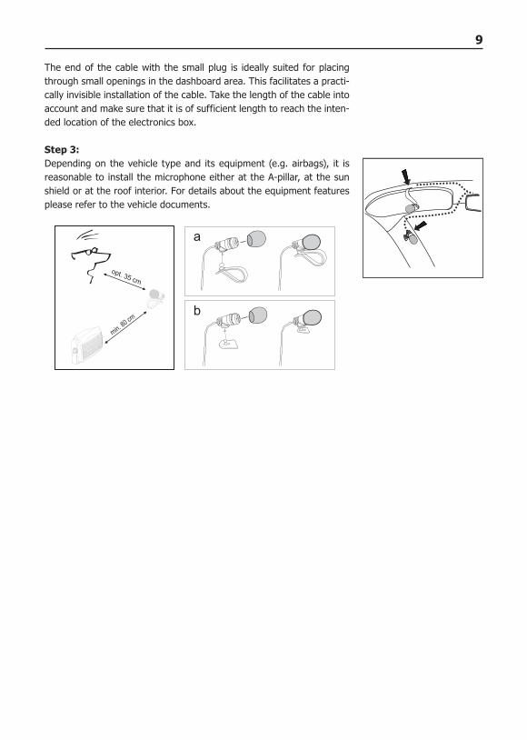
The end of the cable with the small plug is ideally suited for placing through small openings in the dashboard area. This facilitates a practi-cally invisible installation of the cable. Take the length of the cable into account and make sure that it is of sufficient length to reach the inten-ded location of the electronics box.
Step 3:Depending on the vehicle type and its equipment (e.g. airbags), it is reasonable to install the microphone either at the A-pillar, at the sun shield or at the roof interior. For details about the equipment features please refer to the vehicle documents.
10 Installation of the hands-free car kit
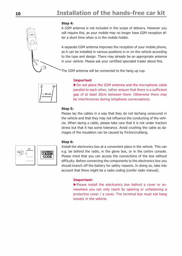
Step 4:A GSM antenna is not included in the scope of delivery. However you will require this, as your mobile may no longer have GSM reception af-ter a short time when is in the mobile holder.
A separate GSM antenna improves the reception of your mobile phone, as it can be installed in various positions in or on the vehicle according to the type and design. There may already be an appropriate antenna in your vehicle. Please ask your certified specialist trader about this.
The GSM antenna will be connected to the hang up cup.
ImportantDo not place the GSM antenna and the microphone cable X
parallel to each other, rather ensure that there is a sufficient gap of at least 20cm between them. Otherwise there may be interferences during telephone conversations.
Step 5:Please lay the cables in a way that they do not lie/hang unsecured in the vehicle and that they may not influence the conducting of the vehi-cle. When laying a cable, please take care that it is not under traction stress but that it has some tolerance. Avoid crushing the cable as da-mages of the insulation can be caused by friction/rubbing.
Step 6:Install the electronics box at a convenient place in the vehicle. This can e.g. be behind the radio, in the glove box, or in the centre console. Please mind that you can access the connections of the box without difficulty. Before connecting the components to the electronics box you should branch off the battery for safety reasons. In doing so, take into account that there might be a radio coding (confer radio manual).
Important:Please install the electronics box behind a cover or so- X
mewhere you can only reach by opening or unfastening a protective cover / a cover. The terminal box must not hang loosely in the vehicle.
11
5. Connections on the electronics box
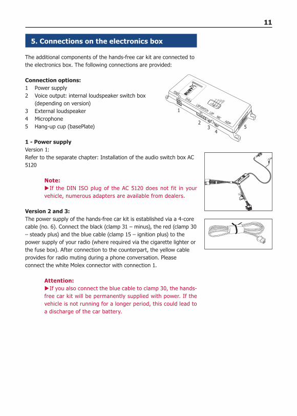
The additional components of the hands-free car kit are connected to the electronics box. The following connections are provided:
Connection options:1 Power supply2 Voice output: internal loudspeaker switch box (depending on version)3 External loudspeaker4 Microphone5 Hang-up cup (basePlate)
1 - Power supplyVersion 1:Refer to the separate chapter: Installation of the audio switch box AC 5120
Note:If the DIN ISO plug of the AC 5120 does not fit in your X
vehicle, numerous adapters are available from dealers.
Version 2 and 3:The power supply of the hands-free car kit is established via a 4-core cable (no. 6). Connect the black (clamp 31 – minus), the red (clamp 30 – steady plus) and the blue cable (clamp 15 – ignition plus) to the power supply of your radio (where required via the cigarette lighter or the fuse box). After connection to the counterpart, the yellow cable provides for radio muting during a phone conversation. Please connect the white Molex connector with connection 1.
Attention:If you also connect the blue cable to clamp 30, the hands- X
free car kit will be permanently supplied with power. If the vehicle is not running for a longer period, this could lead to a discharge of the car battery.
1
23
45
12 Installation of the hands-free car kit
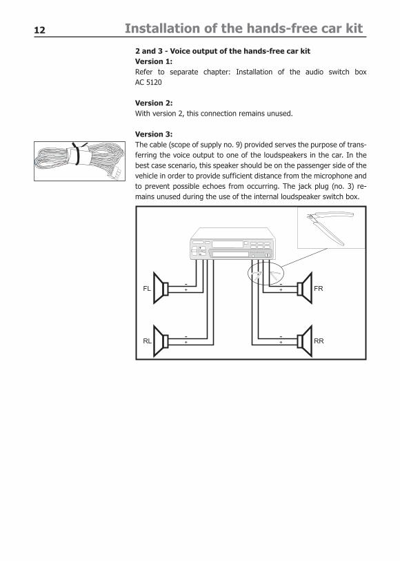
2 and 3 - Voice output of the hands-free car kitVersion 1:Refer to separate chapter: Installation of the audio switch box AC 5120
Version 2:With version 2, this connection remains unused.
Version 3:The cable (scope of supply no. 9) provided serves the purpose of trans-ferring the voice output to one of the loudspeakers in the car. In the best case scenario, this speaker should be on the passenger side of the vehicle in order to provide sufficient distance from the microphone and to prevent possible echoes from occurring. The jack plug (no. 3) re-mains unused during the use of the internal loudspeaker switch box.
RR
FL
RL
FR
13
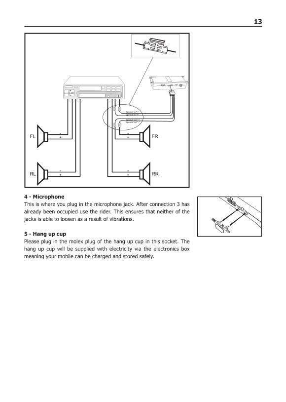
4 - MicrophoneThis is where you plug in the microphone jack. After connection 3 has already been occupied use the rider. This ensures that neither of the jacks is able to loosen as a result of vibrations.
5 - Hang up cupPlease plug in the molex plug of the hang up cup in this socket. The hang up cup will be supplied with electricity via the electronics box meaning your mobile can be charged and stored safely.
RR
FL
RL
FR
14 Installation of the hands-free car kit
Volume setting on the electronics box Ensure the right volume setting of the slide control on the top of the electronics box. This depends on how the hands-free car kit is installed in the vehicle.We recommend the following volume settings: Use with line-in radio Use with a line in radio Use with vehicle loud speaker - with integrated loud speaker switch box - with external switch box AC 5120 - with external BURY loud speaker Use of vehicle loud speaker - with integrated loud speaker switch box - with external switch box AC 5120
Carry out a test call to check the volume and change the volume setting as required before you reattach facings to the vehicle.
Important:Check the volume setting of your radio. XCheck the volume setting of your mobile. XWith many mobiles an individual volume setting can be X
selected for the hands-free profile. This is independent of the setting in normal telephone conversations. If you have further questions about this topic, then please look it up in the instruction manual of your mobile or contact our hot-line.
15
143
6. Installation of the loudspeaker switch box AC 5120
With the AC 5120 speaker switch box, you get the possibility of being able to mute the feedback of your car radio / CD player etc. and to transfer the voice output of your conversation partner during a tele-phone call to your vehicle’s speakers. This means that the installation of additional speakers isn‘t re-quired. If your radio has a mute function, then the vehicle speakers are turned onto mute using the radio. If your car radio doesn‘t have this function, then the signals will be suppressed by the speaker switch box. You can use the AC 5120 through the connections that your BURY hands free car kit offers, which guarantee voltage supply via molex plugs and also have a speaker output.
If you want to make a telephone call in the hands-free mode, your car radio will be automatically swit-ched on to mute. The Audio switch box now uses one or two loudspeakers in your car for the telephone conversation, even if your radio is switched off. This function will be automatically activated after the installation of the unit, there are no subsequent manual settings required.
Some mobile phones do not support a radio mute function. Please read your telephone user manual for more details. You can find out more detailed information at your specialist retailer, in the internet under www.bury.com, or over our telephone hotline.
After checking that all the cable lengths are sufficient, decide where you are able to attach the Audio switch box. Now secure the Audio switch box so that it isn’t able to flap about and/or rattle against other parts of your vehicle.
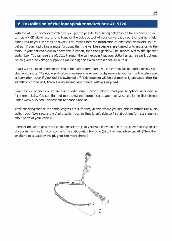
Connect the white power out cable connector (1) of your Audio switch box to the power supply socket of your hands-free kit. Now connect the audio switch box plug (3) to the hands-free car kit. (The other, smaller box is used by the plug for the microphone.)
16 Installation of the hands-free car kit
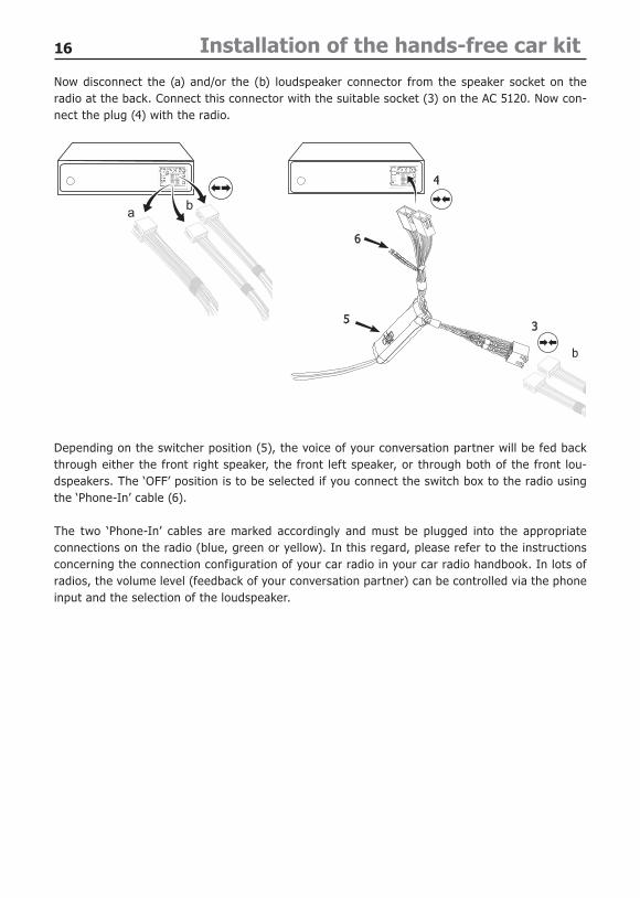
Now disconnect the (a) and/or the (b) loudspeaker connector from the speaker socket on the radio at the back. Connect this connector with the suitable socket (3) on the AC 5120. Now con-nect the plug (4) with the radio.
Depending on the switcher position (5), the voice of your conversation partner will be fed back through either the front right speaker, the front left speaker, or through both of the front lou-dspeakers. The ‘OFF’ position is to be selected if you connect the switch box to the radio using the ‘Phone-In’ cable (6).
The two ‘Phone-In’ cables are marked accordingly and must be plugged into the appropriate connections on the radio (blue, green or yellow). In this regard, please refer to the instructions concerning the connection configuration of your car radio in your car radio handbook. In lots of radios, the volume level (feedback of your conversation partner) can be controlled via the phone input and the selection of the loudspeaker.
17
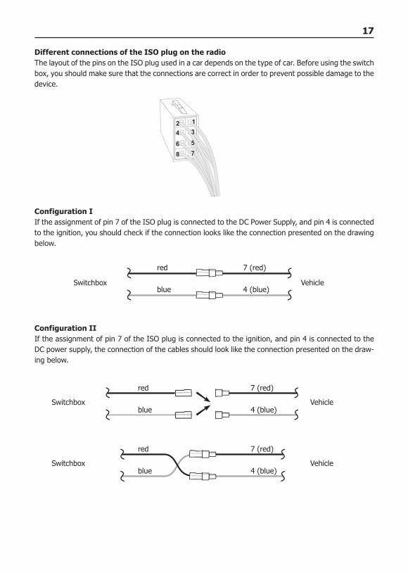
Different connections of the ISO plug on the radioThe layout of the pins on the ISO plug used in a car depends on the type of car. Before using the switch box, you should make sure that the connections are correct in order to prevent possible damage to the device.
Configuration IIf the assignment of pin 7 of the ISO plug is connected to the DC Power Supply, and pin 4 is connected to the ignition, you should check if the connection looks like the connection presented on the drawing below.
Configuration IIIf the assignment of pin 7 of the ISO plug is connected to the ignition, and pin 4 is connected to the DC power supply, the connection of the cables should look like the connection presented on the draw-ing below.
Switchbox Vehicle
red 7 (red)
blue 4 (blue)
red 7 (red)
blue 4 (blue)Switchbox
red 7 (red)
blue 4 (blue)Switchbox
Vehicle
Vehicle
18 Installation of the hands-free car kit
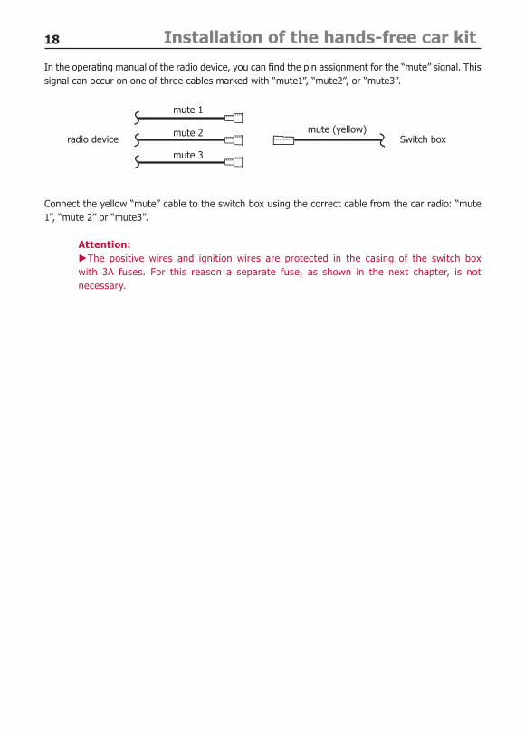
In the operating manual of the radio device, you can find the pin assignment for the “mute” signal. This signal can occur on one of three cables marked with “mute1”, “mute2”, or “mute3”.
Connect the yellow “mute” cable to the switch box using the correct cable from the car radio: “mute 1”, “mute 2” or “mute3”.
Attention:The positive wires and ignition wires are protected in the casing of the switch box X
with 3A fuses. For this reason a separate fuse, as shown in the next chapter, is not necessary.
mute 1
radio device Switch boxmute 2
mute 3
mute (yellow)
19
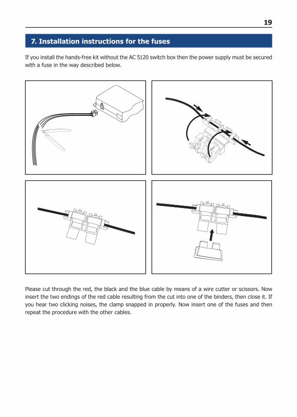
7. Installation instructions for the fuses
If you install the hands-free kit without the AC 5120 switch box then the power supply must be secured with a fuse in the way described below.
Please cut through the red, the black and the blue cable by means of a wire cutter or scissors. Now insert the two endings of the red cable resulting from the cut into one of the binders, then close it. If you hear two clicking noises, the clamp snapped in properly. Now insert one of the fuses and then repeat the procedure with the other cables.
20
8. Using the hands-free car kit for the first time
After power supply of the hands free car kit (HFCK) is successful con-nected, the HFCK is activated when you have started the vehicle.
The hands-free car kit now tries to receive GPS data as quickly as pos-sible. According to the set route mode, the red, green or both LEDs will flash until the GPS data is received. The flashing during the signal search is slower than at the start of the hands-free car kit. After suffi-cient satellites have been found to determine a position, a long ack-nowledgement tone will sound and the LED(s) will be constantly lit.
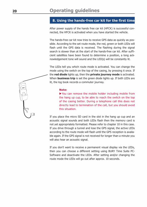
The LEDs tell you which route mode is activated. You can change the mode using the switch on the top of the casing, by pressing it once. If the red diode lights up, then the private journey mode is activated. When business trip is set the green diode lights up. If both LEDs are lit, the log book records a commuter journey.
Note:You can remove the mobile holder including mobile from X
the hang up cup, to be able to reach the switch on the top of the casing better. During a telephone call this does not directly lead to termination of the call, but you should avoid this situation.
If you place the micro SD card in the slot in the hang up cup and an acoustic signal sounds and both LEDs flash then the memory card is not yet appropriately formatted. Please refer to chapter 10 in this case. If you drive through a tunnel and lose the GPS signal, the active LEDs according to the route mode will flash until the GPS reception is availa-ble again. If the GPS signal is not received for longer than a minute you will also hear an acoustic signal.
If you don’t want to receive a permanent visual display via the LEDs, then you can choose a different setting using BURY Time Suite PC-Software and deactivate the LEDs. After setting and/or changing the route mode the LEDs will go out after approx. 10 seconds.
Operating guidelines
21
9. Automatic switch off
The hands-free car kit is active as long as the motor and/or the ignition of the vehicle is turned on. If you turn off the motor, the collected log book data will be transferred onto the micro SF card, if this is inserted.
The hands-free car kit has an automatic switch off for weekends and other situations, in which you don’t use the vehicle over a longer period of time. In this way it will permanently look for a GPS signal over a period of 72 hours after “motor turned off”. Then the hands-free car kit will go into sleep mode and will wake up every 12 hours and search for a GPS signal again. If the hands-free car kit finds no signal three times in a row, it will be completely deactivated. This helps to save battery power but requires a so called cold start.
Note:In the case of a cold start phase it may take more than 30 seconds until the current X
satellite data is received and can be processed. Please take this into account before you begin a new journey.
The automatic switch off only affects the search function for the GPS signal. If you have installed a mobile phone holder and a mobile phone is inside it, then this will be loaded according to its settings. The time required for this can be an hour or up to a week depending on the type of mobile phone. If this type of setting is not set or activated on your phone, the mobile will be loaded for a maximum of 30 minutes. Please refer to the instruction manual of your mobile. If possible take the mobile out of the mobile holder if you are leaving the vehicle for a longer period of time.
22 Operating guidelines
10. Electronic driver‘s logbook
The hands-free equipment will save the GPS co-ordinates of your vehicle after activation. Using road map data, these coordinates can then display a specific route along which the vehicle has travelled. This serves the purpose of setting an electronic log book which you can then subsequently edit or supplement with a special PC software (BURY Time Suite) programme. You can find this software on the DVD.
Important:Many German tax offices recognise this electronic log book as being proof of pro- X
fessional mobility. If problems with such recognition should occur within the scope of either German or international laws however, the company BURY GmbH & Co. KG is not able to accept an obligation for the provision, rectification or adaptation of the software that is provided, or other software, in as far as you, as the user, present its data for settlement / as proof of your professional activity at a tax office.
We are, however, prepared to assist you with any problems you experience with the tax Xauthorities in this context. Please contact us.
Short explanation of the BURY Time Suite:Install the BURY Time Suite on a PC or laptop. Follow the instructions during installation. Installation time is depending on hardware and can take up to 10 - 15 minutes.Technical requirements for the administrative programme:
Processor: Intel Pentium (or equivalent) with 1.5 GHzOperating system: Windows XP with Service Pack 2 or higher.NET 3.5 Service Pack 1 (supplied on DVD)Datenbank: Firebird SQL 2.1 (supplied on DVD)Working memory: at least 512 MBHard disk drive: at least 3 GBScreen resolution: at least 1024x768 pixelsUSB interface
When you open the BURY Time Suite for the first time, you must set an administrator and enter a user name and password. If you use the software on a private basis then this will be no problem. If you use the software in a network and several people need to be able to work with it, than the roles of the persons (who is the administrator) should be defined in advance. Also set the menu language that you want to use the BURY Time Suite in.
23
Familiarise yourself with the programme and read the descriptions about the menu points. Set up a vehicle to practice. Please be aware that some menus can only be used when data from the memory card has been transferred.
Important:Format the memory card under the configuration section - UNI CarTalk Time card. X
Then generate some example log book data by travelling a few kilometres with the vehicle and chan-ging the journey mode several times. When the data is read in, the memory card will be firmly alloca-ted to a vehicle.
The internal memory capacity of the system is sufficient to save approx. 1 million separate sets of log-data. The saving of this information occurs on a dynamic basis and is based on, for e.g., the speed travelled by, or the stationary nature of the vehicle. The advantage of this is that you don’t have to complete a read-out of the data of the system on a daily or weekly basis. The storage capacity in this context is sufficient for approx. 10,000 kilometres driven or for a minimum of 3 months. The following data is saved:- Date and time- Vehicle position- Speed- Height above sea level- The number of satellites located.
Note:Depending on the number of your appointments and contacts visited, it can be X
advisable to sort and maintain the data using the management software every week at the latest.
Then you can read in this data and experiment with it. Detailed route data will not be recorded when the journey mode “private journey” is set. Loaded data will remain saved even after ending the soft-ware.
If you want to delete the old data after the test phase, please separate the memory card in the soft-ware from the vehicle. Delete the old vehicle and set up a new one.
Note:All route data will be deleted from the memory card. XIf you need to change a vehicle (change of driver or new vehicle) you must first of all X
download the route data for the old vehicle.
24 Operating guidelines
Using the BURY Time Suite you can also transfer data about danger zones onto the memory card and release the warning function for this, under the configuration section.
Note:The danger zones that are included are provided by the X
third party company Eifrig Media. You can download up-dates to this data against payment at the internet site www.scdb.info.
A warning sound is emitted every time you approach a Xdanger zone.
Please ensure you pay attention to and comply with the Xroad traffic laws and regulations which are in force in the countries in which you want to use this software! You don’t have to worry, however, if you use the system in the conditi-on as it is supplied, as this function is not yet activated.
If you have any further questions about this or another BURY product then please do not hesitate to contact us. You can find all the appropri-ate contact information in the chapter Service.
25
11. Service
In case of general or technical queries, suggestions and comments, please do not hesitate to contact our team at any time:
BURY GmbH & Co. KGRobert-Koch-Straße 1-732584 Löhne
Hotline: +49(0)180 5 - 842 468*Faxline: +49(0)180 5 - 842 329** 0.14 €/min. Deutsche Telekom AG landlineE-Mail: [email protected]
Service desk:In case of complaints, please return the product directly to our service desk:
BURY GmbH & Co. KGIm Hause DPD Depot 103RobinienwegD-03222 Lübbenau
Suggestions and feedback are always welcomed.
Information on the disposal of electrical goods in the EUThe crossed out wheelie bin symbol means that electrical and electronic products, batteries and accu-mulators must be disposed of separately in the European Union. Please do not dispose of any such products in your normal household waste. As the owner of a product of this sort you are legally obliged to dispose of it at your local dumping site or recycling centre, where you are able to leave your waste electrical goods free of charge.
Version 09/200925.1190.0-01-280909
Subject to change. Errors and omissions excepted.
Further Information

26
Related Documents