Historical Constructions, P.B. Lourenço, P. Roca (Eds.), Guimarães, 2001 1003 1 INTRODUCTION The development of new underpinning techniques has allowed the adoption of a wide number of solutions, progressively more adapted to the singularities and restraints of each scenario, spe- cially when sensitive, old or historic, constructions founded on weak soils have to be underpinned. In this context, the solutions comprising micropiling and jet grouting techniques should be pointed out due to their versatility and advantages related to the limitation of vibrations, as well as the possibility to be adopted in small spaces with low head rooms and restricted access. These tech- niques also allow the soil improvement, minimising the soil disturbance due to the boreholes small diameter, drilled with suitable equipment (Bullivant and Bradbury 1996). On the following chapters, after the presentation of the main aspects of these two techniques, some practical case histories, where micropiling and jet grouting underpinning techniques were used, are presented. In each case, the following topics are presented: scenario, main restraints, main conception and execution criteria. 2 UNDERPINNING TECHNIQUES 2.1 Micropiling Micropiling is a very old technique initially adopted with wood driven piles, which has been de- veloped in the last years mainly due to the bearing capacity improvement (lateral friction at the bond length) related with the use of high pressure grout injection techniques (bigger than 4MPa) and high resistance steel hollow tubes (see Fig. 1). These improvements have allowed to design micropiles with steel hollow tubes (external diameter lesser than 130mm) to carry axial service loads greater than 700kN (Bustamante et al. 1997, Bustamante and Doix 1985). 2.2 Jet Grouting Jet grouting technology have initially been developed in Japan, the UK and Italy. For about 20 years it has been applied worldwide. In Portugal the technology has been applied in the last 6 years, mainly on Lisbon Metro extension works. Recently, vertical jet grouting solutions have Underpinning solutions of historical constructions Alexandre Pinto Tecnasol FGE – Fundações e Geotecnia S.A., R. das Fontainhas nº 58, 2700 – 391, Amadora, Portugal Sandra Ferreira Tecnasol FGE – Fundações e Geotecnia S.A., R. das Fontainhas nº 58, 2700 – 391, Amadora, Portugal Vasco Barros Tecnasol FGE – Fundações e Geotecnia S.A., R. das Fontainhas nº 58, 2700 – 391, Amadora, Portugal ABSTRACT: The aim of this paper is to present the main design and construction criteria con- sidered on some underpinning solutions performed by Tecnasol FGE. After a brief description of micropiling and jet grouting underpinning techniques, some practical case histories where these techniques were adopted are presented. Finally the main advantages and limitations of the pre- sented techniques are pointed out.

Underpinning Hystorical Buildings
Oct 27, 2015
Welcome message from author
This document is posted to help you gain knowledge. Please leave a comment to let me know what you think about it! Share it to your friends and learn new things together.
Transcript
Historical Constructions, P.B. Lourenço, P. Roca (Eds.), Guimarães, 2001 1003
1 INTRODUCTION
The development of new underpinning techniques has allowed the adoption of a wide number of solutions, progressively more adapted to the singularities and restraints of each scenario, spe-cially when sensitive, old or historic, constructions founded on weak soils have to be underpinned. In this context, the solutions comprising micropiling and jet grouting techniques should be pointed out due to their versatility and advantages related to the limitation of vibrations, as well as the possibility to be adopted in small spaces with low head rooms and restricted access. These tech-niques also allow the soil improvement, minimising the soil disturbance due to the boreholes small diameter, drilled with suitable equipment (Bullivant and Bradbury 1996).
On the following chapters, after the presentation of the main aspects of these two techniques, some practical case histories, where micropiling and jet grouting underpinning techniques were used, are presented. In each case, the following topics are presented: scenario, main restraints, main conception and execution criteria.
2 UNDERPINNING TECHNIQUES
2.1 Micropiling
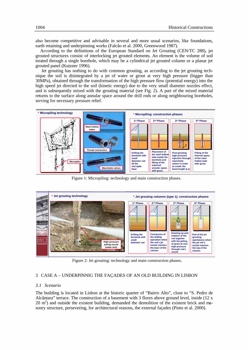
Micropiling is a very old technique initially adopted with wood driven piles, which has been de-veloped in the last years mainly due to the bearing capacity improvement (lateral friction at the bond length) related with the use of high pressure grout injection techniques (bigger than 4MPa) and high resistance steel hollow tubes (see Fig. 1). These improvements have allowed to design micropiles with steel hollow tubes (external diameter lesser than 130mm) to carry axial service loads greater than 700kN (Bustamante et al. 1997, Bustamante and Doix 1985).
2.2 Jet Grouting
Jet grouting technology have initially been developed in Japan, the UK and Italy. For about 20 years it has been applied worldwide. In Portugal the technology has been applied in the last 6 years, mainly on Lisbon Metro extension works. Recently, vertical jet grouting solutions have
Underpinning solutions of historical constructions
Alexandre Pinto Tecnasol FGE – Fundações e Geotecnia S.A., R. das Fontainhas nº 58, 2700 – 391, Amadora, Portugal
Sandra Ferreira Tecnasol FGE – Fundações e Geotecnia S.A., R. das Fontainhas nº 58, 2700 – 391, Amadora, Portugal
Vasco Barros Tecnasol FGE – Fundações e Geotecnia S.A., R. das Fontainhas nº 58, 2700 – 391, Amadora, Portugal
ABSTRACT: The aim of this paper is to present the main design and construction criteria con-sidered on some underpinning solutions performed by Tecnasol FGE. After a brief description of micropiling and jet grouting underpinning techniques, some practical case histories where these techniques were adopted are presented. Finally the main advantages and limitations of the pre-sented techniques are pointed out.
1004 Historical Constructions
also become competitive and advisable in several and more usual scenarios, like foundations, earth retaining and underpinning works (Falcão et al. 2000, Greenwood 1987).
According to the definitions of the European Standard on Jet Grouting (CEN/TC 288), jet grouted structures consist of interlocking jet grouted elements. An element is the volume of soil treated through a single borehole, which may be a cylindrical jet grouted column or a planar jet grouted panel (Kutzner 1996).
Jet grouting has nothing to do with common grouting, as according to the jet grouting tech-nique the soil is disintegrated by a jet of water or grout at very high pressure (bigger than 30MPa), obtained through the transformation of the high pressure flow (potential energy) into the high speed jet directed to the soil (kinetic energy) due to the very small diameter nozzles effect, and is subsequently mixed with the grouting material (see Fig. 2). A part of the mixed material returns to the surface along annular space around the drill rods or along neighbouring boreholes, serving for necessary pressure relief.
Figure 1: Micropiling: technology and main construction phases.
Figure 2: Jet grouting: technology and main construction phases.
3 CASE A – UNDERPINNIG THE FAÇADES OF AN OLD BUILDING IN LISBON
3.1 Scenario
The building is located in Lisbon at the historic quarter of “Bairro Alto”, close to “S. Pedro de Alcântara” terrace. The construction of a basement with 3 floors above ground level, inside (12 x 20 m2) and outside the existent building, demanded the demolition of the existent brick and ma-sonry structure, persevering, for architectural reasons, the external façades (Pinto et al. 2000).
Micropiles
Thread connectors
Manchette valves
hMicropiling technology
Steel hollowtubes
hJet grouting technology
High pressurejetting nozzle(water test)
1st Phase 2nd Phase 3rd Phase 4th Phase
Drilling theborehole withsmalldiameter rodtill themicropilebase
Placement ofthe steel hollowtube inside theborehole andfilling of thetube/soilannular spacewith grout
Post-groutinghigh pressureinjection throughmanchettevalves in orderto create thebond length (Ls)
Filling of theinternal spaceof the steelhollow tubewith grout
L S
hMicropiling: construction phases
1st Phase 2nd Phase 3rd Phase 4th Phase
Conclusion ofthe drillingoperation whenthe rod’s jetnozzle reachesthe base of thecolumn
Drawing up androtation of therod togetherwith the jettingof grout at veryhigh pressurethrough rod’snozzle
End of the jetgroutingopertations whenthe jet rod´snozzle reachesthe top of thecolumn
hJet grouting columns (type 1): construction phases
Drilling theborehole withsmalldiameter rod
A. Pinto, S. Ferreira and V. Barros 1005
3.2 Main restraints
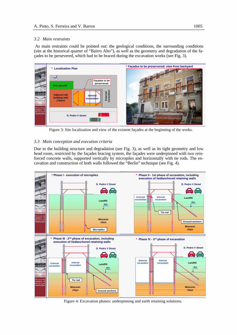
As main restraints could be pointed out: the geological conditions, the surrounding conditions (site at the historical quarter of “Bairro Alto”), as well as the geometry and degradation of the fa-çades to be persevered, which had to be braced during the excavation works (see Fig. 3).
Figure 3: Site localization and view of the existent façades at the beginning of the works.
3.3 Main conception and execution criteria
Due to the building structure and degradation (see Fig. 3), as well as its tight geometry and low head room, restricted by the façades bracing system, the façades were underpinned with two rein-forced concrete walls, supported vertically by micropiles and horizontally with tie rods. The ex-cavation and construction of both walls followed the “Berlin” technique (see Fig. 4).
Figure 4: Excavation phases: underpinning and earth retaining solutions.
D. Pedro V Street
Adjacent oldbuilding with
3 floors Ext
ern
alex
cava
tio
n
Free ground
Façades to beperservered
Internalexcavation
h Localization Plan
N
hFaçades to be preservered: view from backyard
Miocenicclays
-6m
Micropiles
hPhase I - execution of micropiles
Landfill
D. Pedro V Street
Miocenicclays
-6m
Tie rod
Ground anchors
LandfillInternal
excavationExternal
excavation
D. Pedro V Street
h Phase III - 2nd phase of excavation, includingexecution of tied/anchored retaining walls
Landfill
Miocenicclays
-6m
D. Pedro V Street
Internalexcavation
Externalexcavation
h Phase IV - 3rd phase of excavation
Miocenicclays
-6m
Ground anchors
Internalexcavation
Externalexcavation
Tie rod
h Phase II - 1st phase of excavation, includingexecution of tied/anchored retaining walls
Landfill
D. Pedro V Street
1006 Historical Constructions
4 CASE B – UNDERPINNIG OF AN HISTORIC BUILDING IN AVEIRO
4.1 Scenario
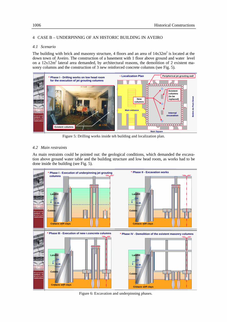
The building with brick and masonry structure, 4 floors and an area of 14x32m2 is located at the down town of Aveiro. The construction of a basement with 1 floor above ground and water level on a 12x12m2 lateral area demanded, by architectural reasons, the demolition of 2 existent ma-sonry columns and the construction of 3 new reinforced concrete columns (see Fig. 5).
Figure 5: Drilling works inside teh building and localization plan.
4.2 Main restraints
As main restraints could be pointed out: the geological conditions, which demanded the excava-tion above ground water table and the building structure and low head room, as works had to be done inside the building (see Fig. 5).
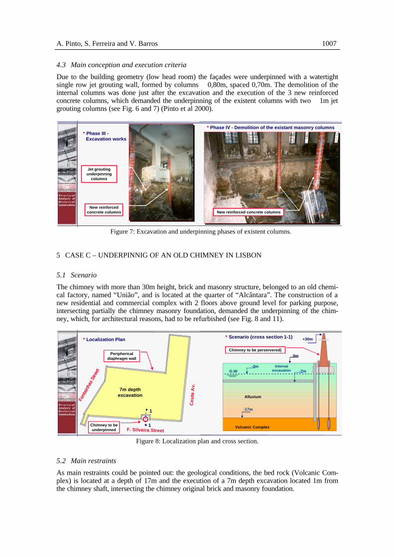
Figure 6: Excavation and underpinning phases.
Existent columns
hPhase I - Drilling works on low head roomfor the execution of jet grouting columns
G.W.
Cobble
-2m
Landfill
Cretacic stiff clays
hPhase I - Execution of underpinning jet groutingcolumns
G.W.
-2m
hPhase II - Excavation works
Cretacic stiff clays
Landfill
Cobble
G.W.
-2m
hPhase III - Execution of new r.concrete columns
Landfill
Cobble
Cretacic stiff clays
• Localization Plan
Bel
ém d
o P
ará
Str
eet
Internalexcavation
Existentcolumns(to bereplaced)New
columns
Main Square
Main entrance
Peripherical jet grouting wall
G.W.
-2m
hPhase IV - Demolition of the existent masonry columns
Landfill
Cobble
Cretacic stiff clays
A. Pinto, S. Ferreira and V. Barros 1007
4.3 Main conception and execution criteria
Due to the building geometry (low head room) the façades were underpinned with a watertight single row jet grouting wall, formed by columns ∅0,80m, spaced 0,70m. The demolition of the internal columns was done just after the excavation and the execution of the 3 new reinforced concrete columns, which demanded the underpinning of the existent columns with two ∅1m jet grouting columns (see Fig. 6 and 7) (Pinto et al 2000).
Figure 7: Excavation and underpinning phases of existent columns.
5 CASE C – UNDERPINNIG OF AN OLD CHIMNEY IN LISBON
5.1 Scenario
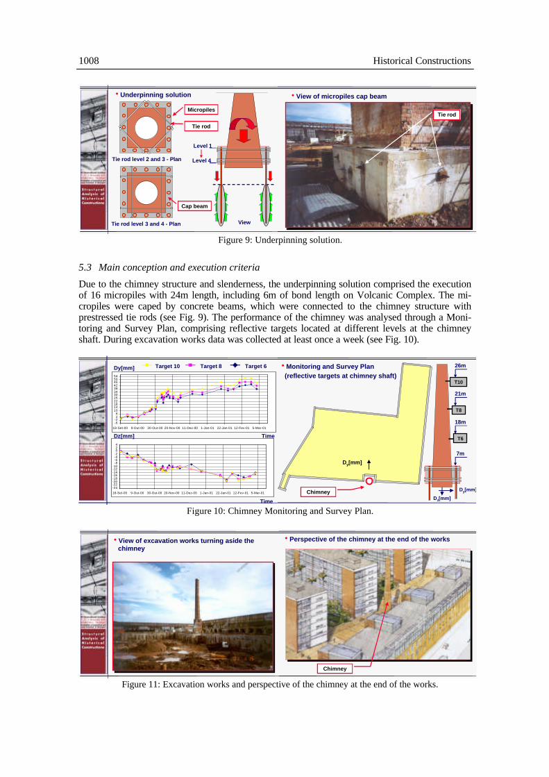
The chimney with more than 30m height, brick and masonry structure, belonged to an old chemi-cal factory, named “União”, and is located at the quarter of “Alcântara”. The construction of a new residential and commercial complex with 2 floors above ground level for parking purpose, intersecting partially the chimney masonry foundation, demanded the underpinning of the chim-ney, which, for architectural reasons, had to be refurbished (see Fig. 8 and 11).
Figure 8: Localization plan and cross section.
5.2 Main restraints
As main restraints could be pointed out: the geological conditions, the bed rock (Volcanic Com-plex) is located at a depth of 17m and the execution of a 7m depth excavation located 1m from the chimney shaft, intersecting the chimney original brick and masonry foundation.
New reinforcedconcrete columns
Jet groutingunderpinning
columns
hPhase III -Excavation works
New reinforced concrete columns
hPhase IV - Demolition of the existant masonry columns
G.W.-3m
-17m
Chimney to be perservered)
Internalexcavation
hScenario (cross section 1-1)
Volcanic Complex
Alluvium
0m
+30m
-7m
hLocalization Plan
Ceu
ta A
v.
7m depthexcavation
Chimney to beunderpinned F. Silveira Street
Font
ainh
as S
treet
Periphericaldiaphragm wall
1
1
1008 Historical Constructions
Figure 9: Underpinning solution.
5.3 Main conception and execution criteria
Due to the chimney structure and slenderness, the underpinning solution comprised the execution of 16 micropiles with 24m length, including 6m of bond length on Volcanic Complex. The mi-cropiles were caped by concrete beams, which were connected to the chimney structure with prestressed tie rods (see Fig. 9). The performance of the chimney was analysed through a Moni-toring and Survey Plan, comprising reflective targets located at different levels at the chimney shaft. During excavation works data was collected at least once a week (see Fig. 10).
Figure 10: Chimney Monitoring and Survey Plan.
Figure 11: Excavation works and perspective of the chimney at the end of the works.
-6-226
101418222630343842465054
18-Set-00 9-Out-00 30-Out-00 20-Nov-00 11-Dez-00 1-Jan-01 22-Jan-01 12-Fev-01 5-Mar-01
-24-22-20-18-16-14-12-10
-8-6-4-2024
18-Set-00 9-Out-00 30-Out-00 20-Nov-00 11-Dez-00 1-Jan-01 22-Jan-01 12-Fev-01 5-Mar-01
Time
Time
Dy[mm]
Dz[mm]
Target 10 Target 8 Target 6 hMonitoring and Survey Plan
Chimney
Dy[mm]
7m
18m
21m
26m
T10
T8
T6
Dy[mm]
(reflective targets at chimney shaft)
Dz[mm]Chimney
hPerspective of the chimney at the end of the works
Chimney
hUnderpinning solution
Tie rod level 2 and 3 - Plan
Tie rod level 3 and 4 - Plan
Micropiles
Tie rod
View
Level 1
Level 4
Cap beam
hView of micropiles cap beam
Tie rod
hView of excavation works turning aside thechimney
A. Pinto, S. Ferreira and V. Barros 1009
6 CASE D – UNDERPINNIG OF AN OLD PALACE IN LISBON
6.1 Scenario
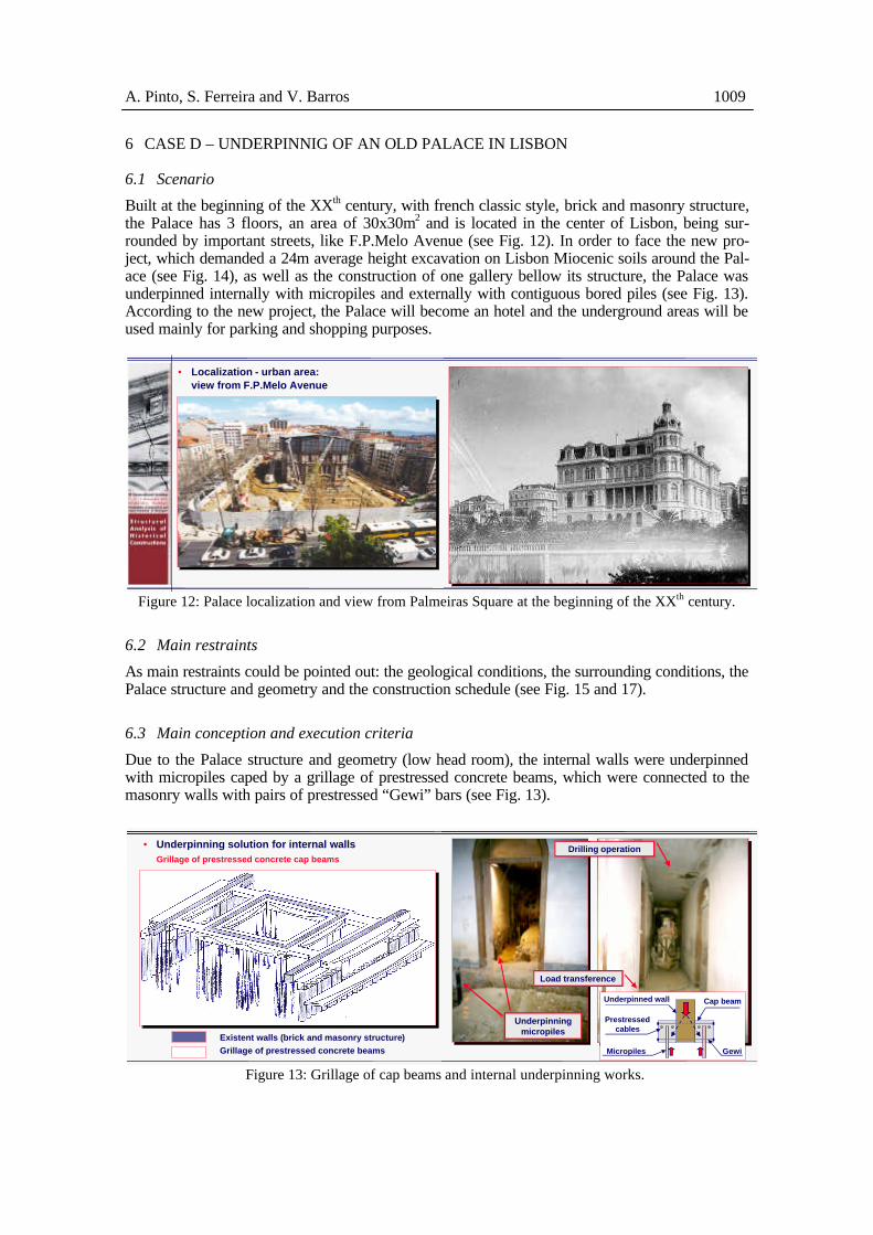
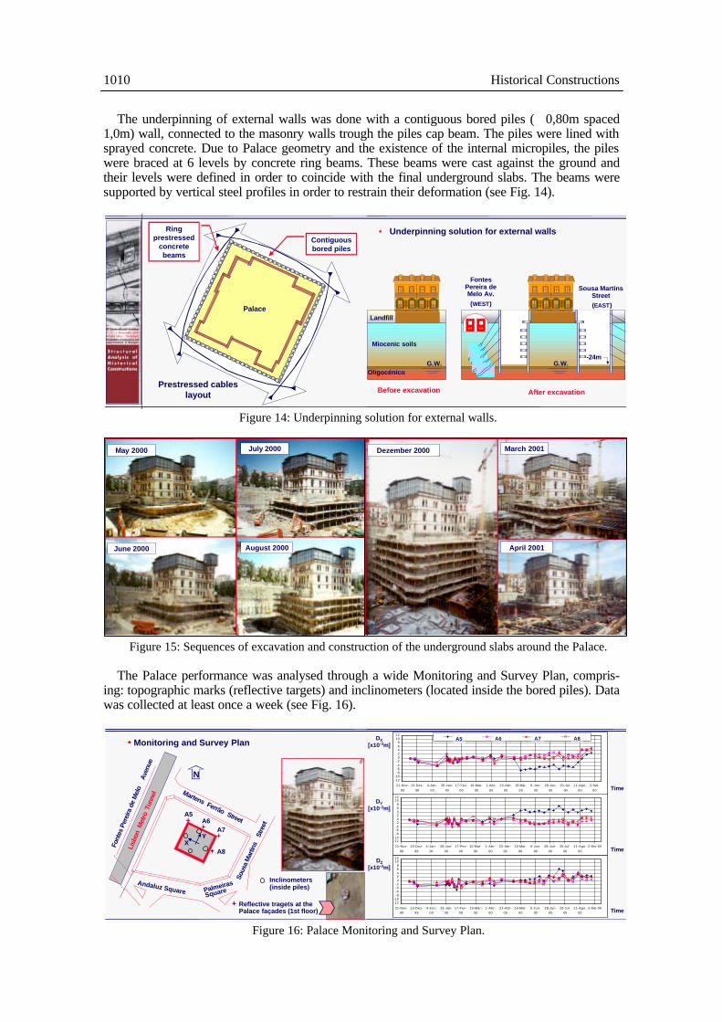
Built at the beginning of the XXth century, with french classic style, brick and masonry structure, the Palace has 3 floors, an area of 30x30m2 and is located in the center of Lisbon, being sur-rounded by important streets, like F.P.Melo Avenue (see Fig. 12). In order to face the new pro-ject, which demanded a 24m average height excavation on Lisbon Miocenic soils around the Pal-ace (see Fig. 14), as well as the construction of one gallery bellow its structure, the Palace was underpinned internally with micropiles and externally with contiguous bored piles (see Fig. 13). According to the new project, the Palace will become an hotel and the underground areas will be used mainly for parking and shopping purposes.
Figure 12: Palace localization and view from Palmeiras Square at the beginning of the XXth century.
6.2 Main restraints
As main restraints could be pointed out: the geological conditions, the surrounding conditions, the Palace structure and geometry and the construction schedule (see Fig. 15 and 17).
6.3 Main conception and execution criteria
Due to the Palace structure and geometry (low head room), the internal walls were underpinned with micropiles caped by a grillage of prestressed concrete beams, which were connected to the masonry walls with pairs of prestressed “Gewi” bars (see Fig. 13).
Figure 13: Grillage of cap beams and internal underpinning works.
Grillage of prestressed concrete cap beams
Existent walls (brick and masonry structure)Grillage of prestressed concrete beams
• Underpinning solution for internal walls
Underpinningmicropiles
Drilling operation
GewiMicropiles
Load transference
Cap beamUnderpinned wall
Prestressedcables
• Localization - urban area:view from F.P.Melo Avenue
1010 Historical Constructions
The underpinning of external walls was done with a contiguous bored piles (∅0,80m spaced 1,0m) wall, connected to the masonry walls trough the piles cap beam. The piles were lined with sprayed concrete. Due to Palace geometry and the existence of the internal micropiles, the piles were braced at 6 levels by concrete ring beams. These beams were cast against the ground and their levels were defined in order to coincide with the final underground slabs. The beams were supported by vertical steel profiles in order to restrain their deformation (see Fig. 14).
Figure 14: Underpinning solution for external walls.
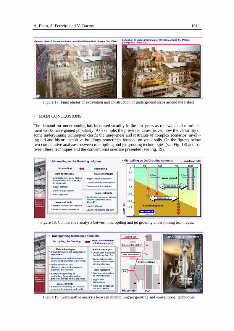
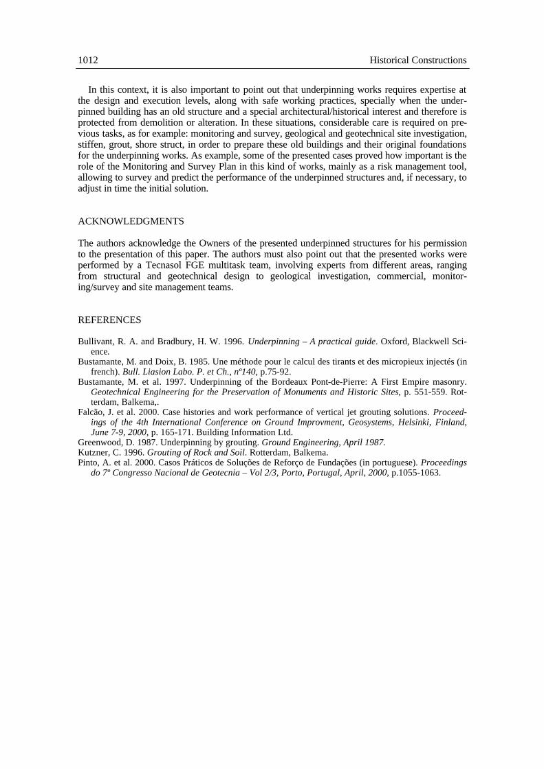
Figure 15: Sequences of excavation and construction of the underground slabs around the Palace. The Palace performance was analysed through a wide Monitoring and Survey Plan, compris-
ing: topographic marks (reflective targets) and inclinometers (located inside the bored piles). Data was collected at least once a week (see Fig. 16).
Figure 16: Palace Monitoring and Survey Plan.
May 2000
June 2000
July 2000
August 2000
Vista da cortina de estacas e das vigas de cintagemMarch 2001
April 2001
Dezember 2000
Landfill
Miocenic soils
OligocénicoG.W. G.W.
-24m
FontesPereira deMelo Av.(WEST)
After excavationBefore excavation
Sousa MartinsStreet (EAST)
• Underpinning solution for external walls
-12-10
-8-6-4-202468
1012
21-Nov-
99
13-Dez-
99
4-Jan-
00
26-Jan-
00
17-Fev-
00
10-Mar-
00
1-Abr-
00
23-Abr-
00
15-Mai-
00
6-Jun-
00
28-Jun-
00
20-Jul-
00
11-Ago-
00
2-Set-
00
Alvo 5 Alvo 6 Alvo 7 Alvo 8
-12-10
-8-6-4-202468
1012
21-Nov-
99
13-Dez-
99
4-Jan-
00
26-Jan-
00
17-Fev-
00
10-Mar-
00
1-Abr-
00
23-Abr-
00
15-Mai-
00
6-Jun-
00
28-Jun-
00
20-Jul-
00
11-Ago-
00
2-Set-00
-12-10-8-6-4-202468
1012
21-Nov-99
13-Dez-99
4-Jan-00
26-Jan-00
17-Fev-00
10-Mar-00
1-Abr-00
23-Abr-00
15-Mai-00
6-Jun-00
28-Jun-00
20-Jul-00
11-Ago-00
2-Set-00
A5 A6 A7 A8
DZ[x10-3m]
Time
Time
Time
DY[x10-3m]
DX[x10-3m]
Font
es P
erei
ra d
e M
elo
Ave
nue
Reflective tragets at thePalace façades (1st floor)
Martens Ferrão Street
Andaluz Square Palmeiras
Square
Sou
sa M
artin
s St
reet
Lisb
on M
etro
Tun
nel
N
A5A6
A7
A8
YX
• Monitoring and Survey Plan
Inclinometers(inside piles)
Palace
Contiguousbored piles
Ringprestressed
concretebeams
Prestressed cableslayout
A. Pinto, S. Ferreira and V. Barros 1011
Figure 17: Final phases of excavation and construction of underground slabs around the Palace.
7 MAIN CONCLUSIONS
The demand for underpinning has increased steadily in the last years as renewals and refurbish-ment works have gained popularity. As example, the presented cases proved how the versatility of some underpinning techniques can fit the uniqueness and restraints of complex scenarios, involv-ing old and historic sensitive buildings, sometimes founded on weak soils. On the figures below two comparative analyses between micropiling and jet grouting technologies (see Fig. 18) and be-tween these techniques and the conventional ones are presented (see Fig. 19).
Figure 18: Comparative analysis between micropiling and jet grouting underpinning techniques.
Figure 19: Comparative analysis between micropiling/jet grouting and conventional techniques.
General view of the excavation around the Palace (final phase - Dez 2000) Execution of underground concrete slabs around the Palace(final phase - May 2001)
Main restraints
4 Mobilization of lateral frictiononly on competent soils(NSPT>40 )
4 Lower stiffness
4 Lower end bearing capacity
Main advantages
4 Bigger tensile resistance
4 Lower cement consumption
4 Easier execution control
Main advantages
4 Mobilization of lateral frictionin any kind of soil, speciallyon weak soils
4 Bigger stiffness
4 End bearing capacity
4 Water tightness
Main restraints4 Higher cement consumption
4 Difficult execution control
Jet grouting Micropiling
• Micropiling vs Jet Grouting columns
Weak ground
Axial load [kN]
Dep
th [
m]
500 750250 10000
2,5
5,0
7,5
10,0
12,5
15,0
∅0,5m ∅0,8m
0
Micropiles
Foundation ground
Jet Grouting type 1
• Micropiling vs Jet Grouting columns
Cross section 1-1
1 1
Plan
Existent wall
Existent foundation
New foundation
Pit solution
Jet Grouting equipment
Pit
h Underpinning techniques solutions
Main restraints4 Solutions depending
on workmanship
4 Bigger soildisturbance
4 More risk and longerworks schedule
Main advantages4 Lower cost at shallow
depth (less than 2m)
4 Easier constructioncontrol of the under-pinning elements
Main advantages4 Small dimension and versatility of
equipment
4 Minimization of soil disturbancedue to small diameter of boreholes
4 Improvemente of soilcharacteristics, including watertightness (jet grouting)
4 Solutions depending ontechnology (specialist under-pinners): shorter works schedule
Main estraints4 Solutions depending on technical
expertise (equipment and staff)
Micropiling, Jet Grouting Other conventionalsolutions (ex: pits)
1012 Historical Constructions
In this context, it is also important to point out that underpinning works requires expertise at the design and execution levels, along with safe working practices, specially when the under-pinned building has an old structure and a special architectural/historical interest and therefore is protected from demolition or alteration. In these situations, considerable care is required on pre-vious tasks, as for example: monitoring and survey, geological and geotechnical site investigation, stiffen, grout, shore struct, in order to prepare these old buildings and their original foundations for the underpinning works. As example, some of the presented cases proved how important is the role of the Monitoring and Survey Plan in this kind of works, mainly as a risk management tool, allowing to survey and predict the performance of the underpinned structures and, if necessary, to adjust in time the initial solution.
ACKNOWLEDGMENTS
The authors acknowledge the Owners of the presented underpinned structures for his permission to the presentation of this paper. The authors must also point out that the presented works were performed by a Tecnasol FGE multitask team, involving experts from different areas, ranging from structural and geotechnical design to geological investigation, commercial, monitor-ing/survey and site management teams.
REFERENCES
Bullivant, R. A. and Bradbury, H. W. 1996. Underpinning – A practical guide. Oxford, Blackwell Sci-ence.
Bustamante, M. and Doix, B. 1985. Une méthode pour le calcul des tirants et des micropieux injectés (in french). Bull. Liasion Labo. P. et Ch., nº140, p.75-92.
Bustamante, M. et al. 1997. Underpinning of the Bordeaux Pont-de-Pierre: A First Empire masonry. Geotechnical Engineering for the Preservation of Monuments and Historic Sites, p. 551-559. Rot-terdam, Balkema,.
Falcão, J. et al. 2000. Case histories and work performance of vertical jet grouting solutions. Proceed-ings of the 4th International Conference on Ground Improvment, Geosystems, Helsinki, Finland, June 7-9, 2000, p. 165-171. Building Information Ltd.
Greenwood, D. 1987. Underpinning by grouting. Ground Engineering, April 1987. Kutzner, C. 1996. Grouting of Rock and Soil. Rotterdam, Balkema. Pinto, A. et al. 2000. Casos Práticos de Soluções de Reforço de Fundações (in portuguese). Proceedings
do 7º Congresso Nacional de Geotecnia – Vol 2/3, Porto, Portugal, April, 2000, p.1055-1063.
Related Documents