New Approach to Casting Defects Classification and Analysis Supported by Simulation V.V.Mane 1 , Amit Sata 2 and M. Y. Khire 3 1 Senior Lecturer, Mechanical Engineering Department, College of Engineering, Osmanabad, E-mail: [email protected] 2 Lecturer, Mechanical Engineering Department, V.V.P. Engineering College, Rajkot, E-Mail: [email protected] 3 Principal, Padmashri Dr. Vitthalrao Vikhe Patil, College of Engineering, Ahmednagar, E-mail: [email protected] Abstract Foundry industry suffers from poor quality and productivity due to the large number of process parameters, combined with lower penetration of manufacturing automation and shortage of skilled workers compared to other industries. Global buyers demand defect-free castings and strict delivery schedule, which foundries are finding it very difficult to meet. Casting defects result in increased unit cost and lower morale of shop floor personnel. The defects need to be diagnosed correctly for appropriate remedial measures, otherwise new defects may be introduced. Unfortunately, this is not an easy task, since casting process involves complex interactions among various parameters and operations related to metal composition, methods design, molding, melting, pouring, shake-out, fettling and machining. For example, if shrinkage porosity is identified as gas porosity, and the pouring temperature is lowered to reduce the same, it may lead to another defect, namely cold shut. So far, casting defect analysis has been carried out using techniques like cause- effect diagrams, design of experiments, if-then rules (expert systems), and artificial neural networks. Most of the previous work is focused on finding process-related causes for individual defects, and optimizing the parameter values to reduce the defects. This is not sufficient for completely eliminating the defects, since parameters

Welcome message from author
This document is posted to help you gain knowledge. Please leave a comment to let me know what you think about it! Share it to your friends and learn new things together.
Transcript
New Approach to Casting Defects Classification and
Analysis Supported by Simulation
V.V.Mane1, Amit Sata2 and M. Y. Khire3
1Senior Lecturer, Mechanical Engineering Department, College of Engineering, Osmanabad,
E-mail: [email protected] 2Lecturer, Mechanical Engineering Department, V.V.P. Engineering College, Rajkot,
E-Mail: [email protected] 3Principal, Padmashri Dr. Vitthalrao Vikhe Patil, College of Engineering, Ahmednagar,
E-mail: [email protected]
Abstract
Foundry industry suffers from poor quality and productivity due to the large number of
process parameters, combined with lower penetration of manufacturing automation
and shortage of skilled workers compared to other industries. Global buyers demand
defect-free castings and strict delivery schedule, which foundries are finding it very
difficult to meet.
Casting defects result in increased unit cost and lower morale of shop floor
personnel. The defects need to be diagnosed correctly for appropriate remedial
measures, otherwise new defects may be introduced. Unfortunately, this is not an
easy task, since casting process involves complex interactions among various
parameters and operations related to metal composition, methods design, molding,
melting, pouring, shake-out, fettling and machining. For example, if shrinkage porosity
is identified as gas porosity, and the pouring temperature is lowered to reduce the
same, it may lead to another defect, namely cold shut.
So far, casting defect analysis has been carried out using techniques like cause-
effect diagrams, design of experiments, if-then rules (expert systems), and artificial
neural networks. Most of the previous work is focused on finding process-related
causes for individual defects, and optimizing the parameter values to reduce the
defects. This is not sufficient for completely eliminating the defects, since parameters
related to part, tooling and methods design also affect casting quality, and these are
not considered in conventional defect analysis approaches.
In this work, we present a 3-step approach to casting defect identification, analysis
and rectification. The defects are classified in terms of their appearance, size,
location, consistency, discovery stage and inspection method. This helps in correct
identification of the defects. For defect analysis, the possible causes are grouped into
design, material and process parameters. The effect of suspected cause parameters
on casting quality is ascertained through simulation. Based on the results and their
interpretation, the optimal values of the parameters are determined to eliminate the
defects.
The proposed approach overcomes the difficulty of controlling process parameters in
foundries with manual processes and unskilled labor, by making the design more
robust (less sensitive) with respect to process parameters. This will especially help
SME foundries to significantly improve their quality levels.
1. Introduction
Metal casting is one of the direct methods of manufacturing the desired geometry of
component. The method is also called as near net shape process. It is one of the
primary processes for several years and one of important process even today in the
21st century. Early applications of casting are in making jewellery items and golden
idols. Today, casting applications include automotive components, spacecraft
components and many industrial & domestic components, apart from the art and
jewellery items.
The principle of manufacturing a casting involves creating a cavity inside a sand
mould and then pouring the molten metal directly into the mould. Casting is a very
versatile process and capable of being used in mass production. The size of
components is varied from very large to small, with intricate designs. Out of the
several steps involved in the casting process, moulding and melting processes are
the most important stages. Improper control at these stages results in defective
castings, which reduces the productivity of a foundry industry. Generally, foundry
industry suffers from poor quality and productivity due to the large number of process
parameters, combined with lower penetration of manufacturing automation and
shortage of skilled workers compared to other industries. Also, Global buyers demand
defect-free castings and strict delivery schedule, which foundries are finding it very
difficult to meet.
Casting process is also known as process of uncertainty. Even in a completely
controlled process, defects in casting are found out which challenges explanation
about the cause of casting defects. The complexity of the process is due to the
involvement of the various disciplines of science and engineering with casting. The
cause of defects is often a combination of several factors rather than a single one.
When these various factors are combined, the root cause of a casting defect can
actually become a mystery. It is important to correctly identify the defect symptoms
prior to assigning the cause to the problem. False remedies not only fail to solve the
problem, they can confuse the issues and make it more difficult to cure the defect.
The defects need to be diagnosed correctly for appropriate remedial measures,
otherwise new defects may be introduced. Unfortunately, this is not an easy task,
since casting process involves complex interactions among various parameters and
operations related to metal composition, methods design, molding, melting, pouring,
shake-out, fettling and machining. The proper classification and identification of a
particular defect is the basic need to correct and control the quality of casting.
2. Present Approaches for Analysis of Casting Defects
At present, casting defect analysis is carried out using techniques like historical data
analysis, cause-effect diagrams, design of experiments, if-then rules (expert
systems), and artificial neural networks (ANN). They are briefly explained in this
section.
2.3
2.11
1.85
1.38
0.62
0.47
0.45
0.36
0.34
0.25
0.21
0.17
0.14
0.11
0.07
0.07
0.04
0.03
0.003
0.01
0.01
0.01
0
1
2
Cold …
Crush
Knock …
Blowhole
Houlin…
Bad …
Scab
Fet. …
Shrink
Slag
Bad …
Cores …
Misma…
Fettlin…
Runout
Hard
Slurry …
Low …
Others
Core …
Swell
Sink
Percentage Rejection
Defects
2.1 Historical Data Analysis
To understand this concept, data for occurrence of defects are collected from one of
leading casting manufacturer in Maharashtra for one year. From this data,
occurrence chart has been prepared which further helps to identify occurrence major
defects in castings. These data further help to prepare the chart for occurrence of
defect. The details are shown in table 1 and fig. 1.
Table1.Historical Data of casting defects
Figure 1: Pareto Analysis of Casting Defects
Defects Rejected Quantity
Job Rejection %
Defects Rejected Quantity
Job Rejection %
Cold Shut 205 2.30 Cores Broken 16 0.17
Crush 188 2.11 Mismatch 13 0.14
Knock Crack 165 1.85 Sub. Contract Fettling Fault
10 0.11
Blowhole 123 1.38 Runout 7 0.07
Contractor’s Houling Cracks
55 0.62 Hard 7 0.07
Bad Mold 42 0.47 Slurry Penetration
4 0.04
Scab 40 0.45 Low Hardness 3 0.03
Fet. Crack 32 0.36 Core Scab 1 0.01
Shrinkage 31 0.34 Swell 1 0.01
Slag 23 0.25 Sink 1 0.01
Bad Core 19 0.21 Others 3 0.003
Total 989 11.1012 %
2.2 Cause- Effect diagram
Cause- effect diagram is one of the approaches to enumerate the possible causes.
When all possible causes are known to us, the operating conditions are verified and
applied to determine the potential cause item by item. As the primary factors are
identified, they are further examined to find the specific problems that cause the
defects. After the particular cause has been identified, remedies are suggested to
eliminate the defects. Examples (data collected for various defects occurred during
sand casting for one year at one of leading casting manufacture in Maharashtra) for
checking the individual cause-effect for some of the defects are listed below.
Material: FC 200 (Gray cast iron) & Production: 18000 casting /month (Approximate)
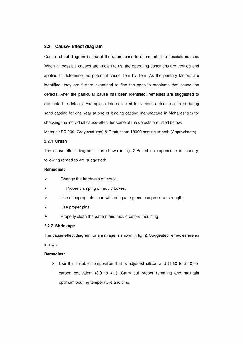
2.2.1 Crush
The cause-effect diagram is as shown in fig. 2.Based on experience in foundry,
following remedies are suggested:
Remedies:
� Change the hardness of mould.
� Proper clamping of mould boxes.
� Use of appropriate sand with adequate green compressive strength,
� Use proper pins.
� Properly clean the pattern and mould before moulding.
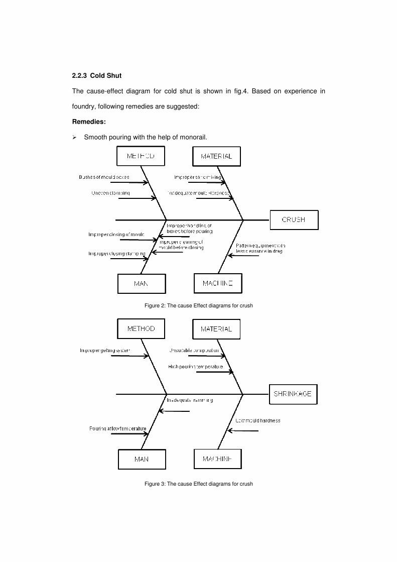
2.2.2 Shrinkage
The cause-effect diagram for shrinkage is shown in fig. 2. Suggested remedies are as
follows:
Remedies:
� Use the suitable composition that is adjusted silicon and (1.80 to 2.10) or
carbon equivalent (3.9 to 4.1) .Carry out proper ramming and maintain
optimum pouring temperature and time.
2.2.3 Cold Shut
The cause-effect diagram for cold shut is shown in fig.4. Based on experience in
foundry, following remedies are suggested:
Remedies:
� Smooth pouring with the help of monorail.
Figure 2: The cause Effect diagrams for crush
Figure 3: The cause Effect diagrams for crush
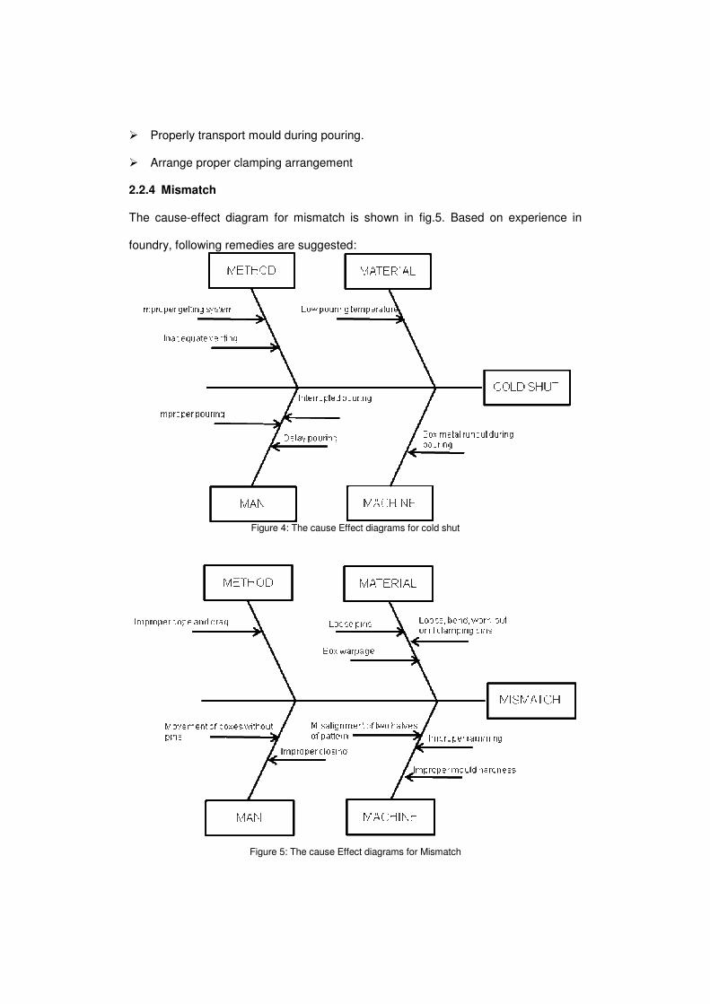
� Properly transport mould during pouring.
� Arrange proper clamping arrangement
2.2.4 Mismatch
The cause-effect diagram for mismatch is shown in fig.5. Based on experience in
foundry, following remedies are suggested:
Figure 4: The cause Effect diagrams for cold shut
Figure 5: The cause Effect diagrams for Mismatch
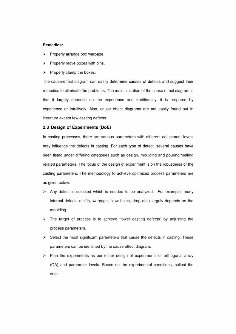
Remedies:
� Properly arrange box warpage.
� Properly move boxes with pins.
� Properly clamp the boxes.
The cause-effect diagram can easily determine causes of defects and suggest their
remedies to eliminate the problems. The main limitation of the cause effect diagram is
that it largely depends on the experience and traditionally, it is prepared by
experience or intuitively. Also, cause effect diagrams are not easily found out in
literature except few casting defects.
2.3 Design of Experiments (DoE)
In casting processes, there are various parameters with different adjustment levels
may influence the defects in casting. For each type of defect, several causes have
been listed under differing categories such as design, moulding and pouring/melting
related parameters. The focus of the design of experiment is on the robustness of the
casting parameters. The methodology to achieve optimized process parameters are
as given below:
� Any defect is selected which is needed to be analyzed. For example, many
internal defects (shifts, warpage, blow holes, drop etc.) largely depends on the
moulding.
� The target of process is to achieve “lower casting defects” by adjusting the
process parameters.
� Select the most significant parameters that cause the defects in casting. These
parameters can be identified by the cause effect diagram.
� Plan the experiments as per either design of experiments or orthogonal array
(OA) and parameter levels. Based on the experimental conditions, collect the
data.
� Analyze the data. An analysis of variance (ANOVA) table can be generated to
determine the statistical significance of the parameters. Response graphs can be
plotted to determine the preferred levels for each parameter of the process.
� Decide optimum settings of the control parameters. Verify the optimum settings
result in the predicted reduction in the casting defects.
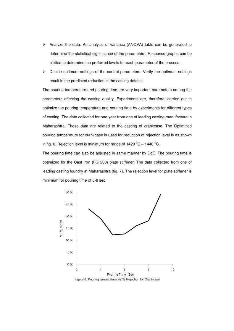
The pouring temperature and pouring time are very important parameters among the
parameters affecting the casting quality. Experiments are, therefore, carried out to
optimize the pouring temperature and pouring time by experiments for different types
of casting. The data collected for one year from one of leading casting manufacture in
Maharashtra. These data are related to the casting of crankcase. The Optimized
pouring temperature for crankcase is used for reduction of rejection level is as shown
in fig. 6. Rejection level is minimum for range of 1420 0C – 1440
0C.
The pouring time can also be adjusted in same manner by DoE. The pouring time is
optimized for the Cast iron (FG 200) plate stiffener. The data collected from one of
leading casting foundry at Maharashtra (fig. 7). The rejection level for plate stiffener is
minimum for pouring time of 5-6 sec.
Figure 6: Pouring temperature v/s % Rejection for Crankcase
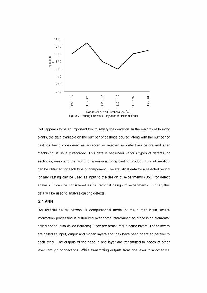
Figure 7: Pouring time v/s % Rejection for Plate stiffener
DoE appears to be an important tool to satisfy the condition. In the majority of foundry
plants, the data available on the number of castings poured, along with the number of
castings being considered as accepted or rejected as defectives before and after
machining, is usually recorded. This data is set under various types of defects for
each day, week and the month of a manufacturing casting product. This information
can be obtained for each type of component. The statistical data for a selected period
for any casting can be used as input to the design of experiments (DoE) for defect
analysis. It can be considered as full factorial design of experiments. Further, this
data will be used to analyze casting defects.
2.4 ANN
An artificial neural network is computational model of the human brain, where
information processing is distributed over some interconnected processing elements,
called nodes (also called neurons). They are structured in some layers. These layers
are called as input, output and hidden layers and they have been operated parallel to
each other. The outputs of the node in one layer are transmitted to nodes of other
layer through connections. While transmitting outputs from one layer to another via
some connections, they may be amplified (if necessary) through weight factors. The
net input to each node (other than input node) is net sum of the weighted output of
the nodes feeding that node.
Several researchers have attempted to use neural networks in analysis of casting
process. Kulkarni et al. (1992) developed an expert system that could analyze casting
defects in steel castings. This defect analysis expert system was user friendly and
asks a sequence of questions that require a “yes” or “no” answer. Eventually, the
expert system would draw a conclusion stating the nature of defect. It then lists all
possible causes and remedies for the defect. During the interrogation process, if the
program reaches a dead-end and no conclusion can be made, it may then be
presumed that the nature and complexity of the defect is beyond the knowledge of
the expert system. After the human expert determines the cause of this new defect,
this new knowledge can be added to the knowledge base of the expert system.
However, the knowledge domain of this expert system includes only the area of green
sand moulding for steel castings.
A review of the literature clearly indicates that most of the investigators had aimed at
finding out the causes of the defects, factors influencing defects, and optimum
process parameters to avoid occurrence of defects in casting. They have developed
expert systems based on ANN and these expert systems can be considered as a
good method to capture expert logic on casting defect diagnosis and prevention of
defects.
3. Proposed Approaches for Analysis of Casting Defects
Foundries are still using trial and error methods to solve defect related problems. It is
very common to have different names for the same defects, it makes very difficult to
solve the problems related to casting defects. It is always preferable to use more
disciplined approach to define, identify and find out the root cause of a defect.
3.1 Proposed Classification
It is important to correctly identify the defect symptoms prior to assigning the cause to
the problem. False remedies not only fail to solve the problem, they can confuse the
issues and make it more difficult to cure the defect. So, the proper classification and
identification of a particular defect is the basic need to correct and control the quality
of castings. The nature of casting defects can be determined by correctly categorizing
the shape, appearance, location and size of defects. Once casting defects are
properly classified, the possible causes can be identified and the corrective action
can be taken. Then a controlled and complete defect analysis can be done.
Defect classification of cast components proposed in literature or currently adopted
by foundries are either on the basis of their geometry/location or on the basis of their
metallurgical origin or specific causes. The International Atlas of Casting Defects
(AFS, 1974) has described 30 defect types which are generally applicable to gray iron
casting in sand mould. Classification of defects in certain broad categories which is
based on origin of defects is also an accepted practice.
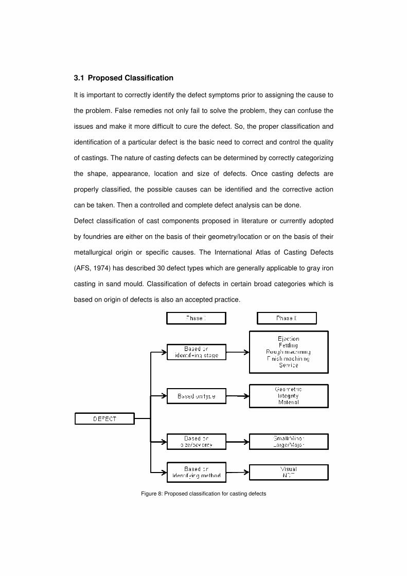
Figure 8: Proposed classification for casting defects
The proposed classification classifies casting defects in terms of their appearance,
size, location, consistency, discovery stage and identifying method. This helps in
correct identification of the defects.
The proposed classification of defects is of mixed type and multi-phase, as
schematically shown in Fig. 8. In the first phase (phase I) the defect identifying stage,
type, size/severity and identifying method is followed, taking into account the different
types of controls performed on cast parts to reveal defects. Phase II is based on the
sub category of the defects of phase I. Actual defect types are covered in the phase
III (not shown in fig.). The final document on the classification, now in progress, a
short description for each defect with illustrations and reference macro/micrographs
to help readers and foundries in identifying the defects found in cast parts. One of the
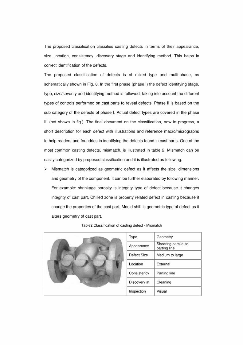
most common casting defects, mismatch, is illustrated in table 2. Mismatch can be
easily categorized by proposed classification and it is illustrated as following.
� Mismatch is categorized as geometric defect as it affects the size, dimensions
and geometry of the component. It can be further elaborated by following manner.
For example: shrinkage porosity is integrity type of defect because it changes
integrity of cast part, Chilled zone is property related defect in casting because it
change the properties of the cast part, Mould shift is geometric type of defect as it
alters geometry of cast part.
Table2.Classification of casting defect - Mismatch
Type Geometry
Appearance Shearing parallel to parting line
Defect Size Medium to large
Location External
Consistency Parting line
Discovery at Cleaning
Inspection Visual
� It can be categorized as medium to large size defect as size of defect is medium
to large.
� It is generally discovered during cleaning operation of casting process and it can
be easily identified visually so it can also be categorized under category of visual.
3.2 Proposed Approach for Analysis
For analyzing casting defects, two approaches are found in literature, one is
knowledge based and other is simulation based. Being rich in experience and
expertise, casting process is suitable for knowledge based analysis as casting
conditions mainly relies on the experience and expertise of individuals working in
production industries. But it is not safe to presume that rules of thumb which are
widely used on the shop floor are accurate. Systematic knowledge accumulation
regarding the manufacturing process is essential in order to study casting defects.
Simulation based defect analysis also feasible but they may be limited to predict few
filling related defects (blow holes) and solidification related defects (shrinkage
porosity, gas porosity and hot tear). Also, simulation software is often inefficient,
especially in cases where a large number of parameters are to be examined. To
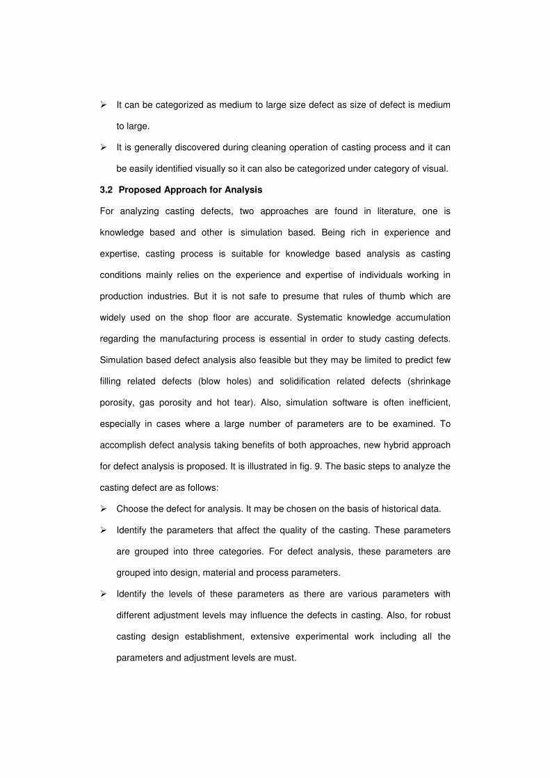
accomplish defect analysis taking benefits of both approaches, new hybrid approach
for defect analysis is proposed. It is illustrated in fig. 9. The basic steps to analyze the
casting defect are as follows:
� Choose the defect for analysis. It may be chosen on the basis of historical data.
� Identify the parameters that affect the quality of the casting. These parameters
are grouped into three categories. For defect analysis, these parameters are
grouped into design, material and process parameters.
� Identify the levels of these parameters as there are various parameters with
different adjustment levels may influence the defects in casting. Also, for robust
casting design establishment, extensive experimental work including all the
parameters and adjustment levels are must.
Figure 9 : Proposed approach of Defect Analysis
� Apply DoE as it is very difficult to perform experiments, in the foundry by varying
so many parameters to different levels and collect the sufficient data from
foundry. In the majority of foundry plants, the data available on the number of
castings poured, along with the number of castings being considered as accepted
or rejected as defectives before and after machining, is usually recorded. The
statistical data for a selected period for any casting can be used as input to the
ANN or simulation for defect analysis. It can be considered as full factorial design
of experiments.
� Further, the results of defect analysis are compared with actual results. If the
results are varied from actual results then these results are used to either train
ANN algorithm or tune the simulation program.
The proposed approach overcomes the difficulty of controlling process parameters in
foundries with manual processes and unskilled labor, by making the design more
robust (less sensitive) with respect to process parameters. This will especially help
SME foundries to significantly improve their quality levels.
4. Conclusions
Presently, casting defect analysis has been carried out using techniques like cause-
effect diagrams, design of experiments, if-then rules (expert systems), and artificial
neural networks. Most of the previous work is focused on finding process-related
causes for individual defects, and optimizing the parameter values to reduce the
defects. This is not sufficient for completely eliminating the defects, since parameters
related to part, tooling and methods design also affect casting quality, and these are
not considered in conventional defect analysis approaches. Also, defect classification
of cast components proposed in literature or currently adopted by foundries are either
on the basis of their geometry/location or on the basis of their metallurgical origin or
specific causes. The one of the limitation of the present approach for defect analysis
is that it considers only the effect of material and process parameters on occurrence
of defects. It is also required to consider effect of design parameters on occurrence of
defects as they play a very important role in DFM.
In a new classification methodology, classification is made based on effect of defects
on casting. Accordingly, the types of defects are geometry, integrity and property
related defects. In this work, we presented a 3-step approach to classify the casting
defects. The defects have been classified in terms of their appearance, size, location,
consistency, discovery stage and inspection method. This helps in correct
identification of the defects. For defect analysis, the possible causes are grouped into
design, material and process parameters. Also, to accomplish defect analysis taking
benefits of both approaches, new hybrid approach for defect analysis is proposed. It
helps SME foundries to significantly improve their quality levels.
5. References
1. B. Chokkalingam & S.S. Mohamed Nazirudeen,"Analysis of Casting Defect
Through Defect Diagnostic Study Approach", Journal of Engineering Annals of
Faculty of Engineering Hunedoara, Vol. 2, pg no. 209-212, 2009
2. B.Ravi, “Casting Simulation and Optimization:Benefits,Bottlenacks and Best
Pratices”, Indian foundry journal, Spcial Issue,January 2008.
3. B.Ravi,“Computer-aided Casting Design and Simulation”,
STTP,Nagpur,July21,2009.
4. Ben V. Takach, “The zero Defect Syndrome”, Foundry, A Journal for progressive
metal casters, vol. –xi, No.-1, p.p. 11-13. January/ February 1999
5. B.S. Pendse, “Foundry men-Prepare for the future”, Foundry, An Indian Journal
for progressive metal caters, Vol. Xi, no.-3, p.p. 45-48,May/June, 1999
6. Dr. Sumit Roy, “Total Quality Management means of survival for Indian industry,
a special focus on foundries”, Foundry, An Indian journal for progressive metal
caters, p.p. 11-23.July / August 2003,
7. D.N. Prasad and P.K. Panda, “Production of quality castings in handfield Mn
Steel”, Indian foundry journal, vol. 46, no.1, p.p. 30-38January 2000.
8. Dr. P.N. Rao (2000), “Manufacturing Technology” Tata Mc-Graw-Hill publishing
Company Ltd., New Delhi
9. D. Paranthaman (2000) “Quality Control” Technical Teachers Training Institute,
Madras.
10. E. Gariboldi et al.," Proposal of a Classification of Defects of High Pressure Die
Cast Products", la metallurgia italiana, pg. no. 39-46, 2007
11. Jiadi Wang et al.," Expert Network for Die Casting Defect Analysis", Journal of
Material Science And Technology, Vol. 19 (4), pg. no. 320-323 ,2003
12. John H. Mortimer,”Foundry Technology and Market Trends into the 21 st
Century”, A Journal for progressive metal casters, vol. –xi, No.-2, pp27-29
January/ Februar 1999
13. K.sieansk,S Borkowsk, “Analysis of foundry defects and preventive activities for
qulity improvements of castings.”
14. K.Siekanski,S.Borkowski,”Analysis of foundry defects and preventive activities for
quality improment of casting”,Metalurgija 42,57-59,2003
15. Kulkarni et al., "Casting Defect Analysis Expert System", AFS Transaction, 92-21,
pg. no. 881-886.
16. M. Mahajan (1986), “Statistical Quality Control”, Dhanpat Rai & Co. (P) Ltd.
17. M.V. Kavade (1999), “Quality Management”, ISTD.
18. R.Zalewski, A.Graczyk, G.Kruszynski: “Analysis in defect in metal industry with
pareto method”, problmy jakosci pp, 23-28, 1996.
19. S.N.Lyengar,“Gating and Risiring System part-2: Design of Gating System”,
Foundry , An Indian Journal for progeressive Metal –caster, Vol-xi,no-1, pp-21-
24, Jan/Feb. 1999.
20. Sohrab, “Quality management in foundry industry”, Indian foundry journal, vol. 41,
no.-4, 11-14,April 1995
Related Documents


![[TS I-3A.4] Cyclic plastic deformation behaviour of PHT ...eprints.nmlindia.org/4627/1/SMiRT_2011_Shiva... · Figure 1: Cyclic hardening: strain amplitude versus number of cycles](https://static.cupdf.com/doc/110x72/5f5e0c12dd3c8c6da904c349/ts-i-3a4-cyclic-plastic-deformation-behaviour-of-pht-figure-1-cyclic-hardening.jpg)