ETSI TS 136 213 V12.4.0 (2015-02) LTE; Evolved Universal Terrestrial Radio Access (E-UTRA); Physical layer procedures (3GPP TS 36.213 version 12.4.0 Release 12) TECHNICAL SPECIFICATION

Welcome message from author
This document is posted to help you gain knowledge. Please leave a comment to let me know what you think about it! Share it to your friends and learn new things together.
Transcript
ETSI TS 136 213 V12.4.0 (2015-02)
LTE; Evolved Universal Terrestrial Radio Access (E-UTRA);
Physical layer procedures (3GPP TS 36.213 version 12.4.0 Release 12)
TECHNICAL SPECIFICATION
ETSI
ETSI TS 136 213 V12.4.0 (2015-02)13GPP TS 36.213 version 12.4.0 Release 12
Reference RTS/TSGR-0136213vc40
Keywords LTE
ETSI
650 Route des Lucioles F-06921 Sophia Antipolis Cedex - FRANCE
Tel.: +33 4 92 94 42 00 Fax: +33 4 93 65 47 16
Siret N° 348 623 562 00017 - NAF 742 C
Association à but non lucratif enregistrée à la Sous-Préfecture de Grasse (06) N° 7803/88
Important notice
The present document can be downloaded from: http://www.etsi.org/standards-search
The present document may be made available in electronic versions and/or in print. The content of any electronic and/or print versions of the present document shall not be modified without the prior written authorization of ETSI. In case of any
existing or perceived difference in contents between such versions and/or in print, the only prevailing document is the print of the Portable Document Format (PDF) version kept on a specific network drive within ETSI Secretariat.
Users of the present document should be aware that the document may be subject to revision or change of status. Information on the current status of this and other ETSI documents is available at
http://portal.etsi.org/tb/status/status.asp
If you find errors in the present document, please send your comment to one of the following services: https://portal.etsi.org/People/CommiteeSupportStaff.aspx
Copyright Notification
No part may be reproduced or utilized in any form or by any means, electronic or mechanical, including photocopying and microfilm except as authorized by written permission of ETSI.
The content of the PDF version shall not be modified without the written authorization of ETSI. The copyright and the foregoing restriction extend to reproduction in all media.
© European Telecommunications Standards Institute 2015.
All rights reserved.
DECTTM, PLUGTESTSTM, UMTSTM and the ETSI logo are Trade Marks of ETSI registered for the benefit of its Members. 3GPPTM and LTE™ are Trade Marks of ETSI registered for the benefit of its Members and
of the 3GPP Organizational Partners. GSM® and the GSM logo are Trade Marks registered and owned by the GSM Association.
ETSI
ETSI TS 136 213 V12.4.0 (2015-02)23GPP TS 36.213 version 12.4.0 Release 12
Intellectual Property Rights IPRs essential or potentially essential to the present document may have been declared to ETSI. The information pertaining to these essential IPRs, if any, is publicly available for ETSI members and non-members, and can be found in ETSI SR 000 314: "Intellectual Property Rights (IPRs); Essential, or potentially Essential, IPRs notified to ETSI in respect of ETSI standards", which is available from the ETSI Secretariat. Latest updates are available on the ETSI Web server (http://ipr.etsi.org).
Pursuant to the ETSI IPR Policy, no investigation, including IPR searches, has been carried out by ETSI. No guarantee can be given as to the existence of other IPRs not referenced in ETSI SR 000 314 (or the updates on the ETSI Web server) which are, or may be, or may become, essential to the present document.
Foreword This Technical Specification (TS) has been produced by ETSI 3rd Generation Partnership Project (3GPP).
The present document may refer to technical specifications or reports using their 3GPP identities, UMTS identities or GSM identities. These should be interpreted as being references to the corresponding ETSI deliverables.
The cross reference between GSM, UMTS, 3GPP and ETSI identities can be found under http://webapp.etsi.org/key/queryform.asp.
Modal verbs terminology In the present document "shall", "shall not", "should", "should not", "may", "may not", "need", "need not", "will", "will not", "can" and "cannot" are to be interpreted as described in clause 3.2 of the ETSI Drafting Rules (Verbal forms for the expression of provisions).
"must" and "must not" are NOT allowed in ETSI deliverables except when used in direct citation.
ETSI
ETSI TS 136 213 V12.4.0 (2015-02)33GPP TS 36.213 version 12.4.0 Release 12
Contents
Intellectual Property Rights ................................................................................................................................ 2
Foreword ............................................................................................................................................................. 2
Modal verbs terminology .................................................................................................................................... 2
Foreword ............................................................................................................................................................. 6
1 Scope ........................................................................................................................................................ 7
2 References ................................................................................................................................................ 7
3 Symbols and abbreviations ....................................................................................................................... 8
3.1 Symbols .............................................................................................................................................................. 8
3.2 Abbreviations ..................................................................................................................................................... 8
4 Synchronization procedures ................................................................................................................... 10
4.1 Cell search ........................................................................................................................................................ 10
4.2 Timing synchronization .................................................................................................................................... 10
4.2.1 Radio link monitoring ................................................................................................................................. 10
4.2.2 Inter-cell synchronization ........................................................................................................................... 10
4.2.3 Transmission timing adjustments ............................................................................................................... 10
4.3 Timing for Secondary Cell Activation / Deactivation ...................................................................................... 11
5 Power control ......................................................................................................................................... 12
5.1 Uplink power control........................................................................................................................................ 12
5.1.1 Physical uplink shared channel ................................................................................................................... 12
5.1.1.1 UE behaviour ........................................................................................................................................ 12
5.1.1.2 Power headroom ................................................................................................................................... 19
5.1.2 Physical uplink control channel .................................................................................................................. 21
5.1.2.1 UE behaviour ........................................................................................................................................ 21
5.1.3 Sounding Reference Symbol (SRS) ............................................................................................................ 25
5.1.3.1 UE behaviour ........................................................................................................................................ 25
5.1.4 Power allocation for dual connectivity ....................................................................................................... 26
5.1.4.1 Dual connectivity power control Mode 1 .............................................................................................. 26
5.1.4.2 Dual connectivity power control Mode 2 .............................................................................................. 33
5.2 Downlink power allocation .............................................................................................................................. 38
5.2.1 eNodeB Relative Narrowband TX Power (RNTP) restrictions .................................................................. 40
6 Random access procedure ...................................................................................................................... 41
6.1 Physical non-synchronized random access procedure ...................................................................................... 41
6.1.1 Timing ........................................................................................................................................................ 41
6.2 Random Access Response Grant ...................................................................................................................... 42
7 Physical downlink shared channel related procedures ........................................................................... 43
7.1 UE procedure for receiving the physical downlink shared channel ................................................................. 44
7.1.1 Single-antenna port scheme ........................................................................................................................ 52
7.1.2 Transmit diversity scheme .......................................................................................................................... 53
7.1.3 Large delay CDD scheme ........................................................................................................................... 53
7.1.4 Closed-loop spatial multiplexing scheme ................................................................................................... 53
7.1.5 Multi-user MIMO scheme .......................................................................................................................... 53
7.1.5A Dual layer scheme ....................................................................................................................................... 53
7.1.5B Up to 8 layer transmission scheme ............................................................................................................. 53
7.1.6 Resource allocation ..................................................................................................................................... 53
7.1.6.1 Resource allocation type 0 .................................................................................................................... 54
7.1.6.2 Resource allocation type 1 .................................................................................................................... 54
7.1.6.3 Resource allocation type 2 .................................................................................................................... 55
7.1.6.4 PDSCH starting position ....................................................................................................................... 56
7.1.6.5 Physical Resource Block (PRB) bundling............................................................................................. 58
7.1.7 Modulation order and transport block size determination .......................................................................... 59
7.1.7.1 Modulation order determination ............................................................................................................ 59
ETSI
ETSI TS 136 213 V12.4.0 (2015-02)43GPP TS 36.213 version 12.4.0 Release 12
7.1.7.2 Transport block size determination ....................................................................................................... 61
7.1.7.2.1 Transport blocks not mapped to two or more layer spatial multiplexing ........................................ 62
7.1.7.2.2 Transport blocks mapped to two-layer spatial multiplexing ............................................................ 69
7.1.7.2.3 Transport blocks mapped for DCI Format 1C ................................................................................. 69
7.1.7.2.4 Transport blocks mapped to three-layer spatial multiplexing .......................................................... 70
7.1.7.2.5 Transport blocks mapped to four-layer spatial multiplexing ........................................................... 71
7.1.7.3 Redundancy Version determination for Format 1C .............................................................................. 71
7.1.8 Storing soft channel bits ............................................................................................................................. 72
7.1.9 PDSCH resource mapping parameters ........................................................................................................ 72
7.1.10 Antenna ports quasi co-location for PDSCH .............................................................................................. 73
7.2 UE procedure for reporting Channel State Information (CSI) ......................................................................... 74
7.2.1 Aperiodic CSI Reporting using PUSCH ..................................................................................................... 77
7.2.2 Periodic CSI Reporting using PUCCH ....................................................................................................... 85
7.2.3 Channel Quality Indicator (CQI) definition .............................................................................................. 102
7.2.4 Precoding Matrix Indicator (PMI) definition ............................................................................................ 108
7.2.5 Channel-State Information – Reference Signal (CSI-RS) definition ........................................................ 113
7.2.6 Channel-State Information – Interference Measurement (CSI-IM) Resource definition .......................... 114
7.2.7 Zero Power CSI-RS Resource definition .................................................................................................. 114
7.3 UE procedure for reporting HARQ-ACK ...................................................................................................... 114
7.3.1 FDD HARQ-ACK reporting procedure .................................................................................................... 115
7.3.2 TDD HARQ-ACK reporting procedure .................................................................................................... 115
7.3.2.1 TDD HARQ-ACK reporting procedure for same UL/DL configuration ............................................ 116
7.3.2.2 TDD HARQ-ACK reporting procedure for different UL/DL configurations ..................................... 122
7.3.3 FDD-TDD HARQ-ACK reporting procedure for primary cell frame structure type 1 ............................. 126
7.3.4 FDD-TDD HARQ-ACK reporting procedure for primary cell frame structure type 2 ............................. 126
8 Physical uplink shared channel related procedures .............................................................................. 127
8.0 UE procedure for transmitting the physical uplink shared channel ................................................................ 127
8.0.1 Single-antenna port scheme ...................................................................................................................... 133
8.0.2 Closed-loop spatial multiplexing scheme ................................................................................................. 133
8.1 Resource allocation for PDCCH/EPDCCH with uplink DCI format ............................................................. 134
8.1.1 Uplink resource allocation type 0 ........................................................................................................ 134
8.1.2 Uplink resource allocation type 1 ........................................................................................................ 134
8.2 UE sounding procedure .................................................................................................................................. 135
8.3 UE HARQ-ACK procedure ............................................................................................................................ 141
8.4 UE PUSCH hopping procedure ...................................................................................................................... 143
8.4.1 Type 1 PUSCH hopping ........................................................................................................................... 144
8.4.2 Type 2 PUSCH hopping ........................................................................................................................... 144
8.5 UE Reference Symbol (RS) procedure ........................................................................................................... 144
8.6 Modulation order, redundancy version and transport block size determination ............................................. 145
8.6.1 Modulation order and redundancy version determination ........................................................................ 145
8.6.2 Transport block size determination ........................................................................................................... 146
8.6.3 Control information MCS offset determination ........................................................................................ 148
8.7 UE transmit antenna selection ........................................................................................................................ 151
9 Physical downlink control channel procedures .................................................................................... 151
9.1 UE procedure for determining physical downlink control channel assignment ............................................. 151
9.1.1 PDCCH assignment procedure ................................................................................................................. 151
9.1.2 PHICH assignment procedure................................................................................................................... 153
9.1.3 Control Format Indicator (CFI) assignment procedure ............................................................................. 155
9.1.4 EPDCCH assignment procedure ............................................................................................................... 156
9.1.4.1 EPDCCH starting position .................................................................................................................. 161
9.1.4.2 Antenna ports quasi co-location for EPDCCH .................................................................................... 162
9.1.4.3 Resource mapping parameters for EPDCCH ...................................................................................... 162
9.1.4.4 PRB-pair indication for EPDCCH ...................................................................................................... 163
9.2 PDCCH/EPDCCH validation for semi-persistent scheduling ........................................................................ 164
9.3 PDCCH/EPDCCH control information procedure ......................................................................................... 165
10 Physical uplink control channel procedures ......................................................................................... 165
10.1 UE procedure for determining physical uplink control channel assignment .................................................. 165
10.1.1 PUCCH format information ...................................................................................................................... 168
10.1.2 FDD HARQ-ACK feedback procedures ................................................................................................... 169
10.1.2.1 FDD HARQ-ACK procedure for one configured serving cell ............................................................ 170
ETSI
ETSI TS 136 213 V12.4.0 (2015-02)53GPP TS 36.213 version 12.4.0 Release 12
10.1.2.2 FDD HARQ-ACK procedures for more than one configured serving cell ......................................... 171
10.1.2.2.1 PUCCH format 1b with channel selection HARQ-ACK procedure .............................................. 171
10.1.2.2.2 PUCCH format 3 HARQ-ACK procedure .................................................................................... 175
10.1.3 TDD HARQ-ACK feedback procedures .................................................................................................. 177
10.1.3.1 TDD HARQ-ACK procedure for one configured serving cell ............................................................ 178
10.1.3.2 TDD HARQ-ACK procedure for more than one configured serving cell ........................................... 188
10.1.3.2.1 PUCCH format 1b with channel selection HARQ-ACK procedure .............................................. 188
10.1.3.2.2 PUCCH format 3 HARQ-ACK procedure .................................................................................... 203
10.1.3A FDD-TDD HARQ-ACK feedback procedures for primary cell frame structure type 2 ........................... 209
10.1.4 HARQ-ACK Repetition procedure ........................................................................................................... 210
10.1.5 Scheduling Request (SR) procedure ......................................................................................................... 212
10.2 Uplink HARQ-ACK timing ........................................................................................................................... 213
11 Physical Multicast Channel (PMCH) related procedures ..................................................................... 216
11.1 UE procedure for receiving the PMCH .......................................................................................................... 216
11.2 UE procedure for receiving MCCH change notification ................................................................................ 216
12 Assumptions independent of physical channel..................................................................................... 216
13 Uplink/Downlink configuration determination procedure for Frame Structure Type 2 ....................... 216
13.1 UE procedure for determining eIMTA-uplink/downlink configuration ......................................................... 217
Annex A (informative): Change history ............................................................................................. 219
History ............................................................................................................................................................ 226

ETSI
ETSI TS 136 213 V12.4.0 (2015-02)63GPP TS 36.213 version 12.4.0 Release 12
Foreword This Technical Specification (TS) has been produced by the 3rd Generation Partnership Project (3GPP).
The contents of the present document are subject to continuing work within the TSG and may change following formal TSG approval. Should the TSG modify the contents of this present document, it will be re-released by the TSG with an identifying change of release date and an increase in version number as follows:
Version x.y.z
where:
x the first digit:
1 presented to TSG for information;
2 presented to TSG for approval;
3 or greater indicates TSG approved document under change control.
y the second digit is incremented for all changes of substance, i.e. technical enhancements, corrections, updates, etc.
z the third digit is incremented when editorial only changes have been incorporated in the document.
ETSI
ETSI TS 136 213 V12.4.0 (2015-02)73GPP TS 36.213 version 12.4.0 Release 12
1 Scope The present document specifies and establishes the characteristics of the physicals layer procedures in the FDD and TDD modes of E-UTRA.
2 References The following documents contain provisions which, through reference in this text, constitute provisions of the present document.
• References are either specific (identified by date of publication, edition number, version number, etc.) or non-specific.
• For a specific reference, subsequent revisions do not apply.
• For a non-specific reference, the latest version applies. In the case of a reference to a 3GPP document (including a GSM document), a non-specific reference implicitly refers to the latest version of that document in the same Release as the present document.
[1] 3GPP TR 21.905: "Vocabulary for 3GPP Specifications".
[2] 3GPP TS 36.201: "Evolved Universal Terrestrial Radio Access (E-UTRA); Physical Layer – General Description".
[3] 3GPP TS 36.211: "Evolved Universal Terrestrial Radio Access (E-UTRA); Physical channels and modulation".
[4] 3GPP TS 36.212: "Evolved Universal Terrestrial Radio Access (E-UTRA); Multiplexing and channel coding".
[5] 3GPP TS 36.214: "Evolved Universal Terrestrial Radio Access (E-UTRA); Physical layer – Measurements".
[6] 3GPP TS 36.101: "Evolved Universal Terrestrial Radio Access (E-UTRA); User Equipment (UE) radio transmission and reception".
[7] 3GPP TS 36.104: "Evolved Universal Terrestrial Radio Access (E-UTRA); Base Station (BS) radio transmission and reception".
[8] 3GPP TS 36.321, "Evolved Universal Terrestrial Radio Access (E-UTRA); Medium Access Control (MAC) protocol specification".
[9] 3GPP TS 36.423, "Evolved Universal Terrestrial Radio Access (E-UTRA); X2 Application Protocol (X2AP)".
[10] 3GPP TS 36.133, "Evolved Universal Terrestrial Radio Access (E-UTRA); Requirements for support of radio resource management".
[11] 3GPP TS 36.331, "Evolved Universal Terrestrial Radio Access (E-UTRA); Radio Resource Control (RRC) protocol specification".
[12] 3GPP TS 36.306: "Evolved Universal Terrestrial Radio Access (E-UTRA); User Equipment (UE) radio access capabilities".
ETSI
ETSI TS 136 213 V12.4.0 (2015-02)83GPP TS 36.213 version 12.4.0 Release 12
3 Symbols and abbreviations
3.1 Symbols For the purposes of the present document, the following symbols apply:
fn System frame number as defined in [3]
sn Slot number within a radio frame as defined in [3]
DLcellsN Number of configured cells DLRBN Downlink bandwidth configuration, expressed in units of RB
scN as defined in [3] ULRBN Uplink bandwidth configuration, expressed in units of RB
scN as defined in [3] ULsymbN Number of SC-FDMA symbols in an uplink slot as defined in [3]
RBscN Resource block size in the frequency domain, expressed as a number of subcarriers as defined in
[3]
sT Basic time unit as defined in [3]
3.2 Abbreviations For the purposes of the present document, the abbreviations given in TR 21.905 [1] and the following apply. An abbreviation defined in the present document takes precedence over the definition of the same abbreviation, if any, in TR 21.905 [1].
ACK Acknowledgement BCH Broadcast Channel CCE Control Channel Element CDD Cyclic Delay Diversity CG Cell Group CIF Carrier Indicator Field CQI Channel Quality Indicator CRC Cyclic Redundancy Check CSI Channel State Information CSI-IM CSI-interference measurement DAI Downlink Assignment Index DCI Downlink Control Information DL Downlink DL-SCH Downlink Shared Channel DTX Discontinuous Transmission EPDCCH Enhanced Physical Downlink Control Channel EPRE Energy Per Resource Element MCG Master Cell Group MCS Modulation and Coding Scheme NACK Negative Acknowledgement PBCH Physical Broadcast Channel PCFICH Physical Control Format Indicator Channel PDCCH Physical Downlink Control Channel PDSCH Physical Downlink Shared Channel PHICH Physical Hybrid ARQ Indicator Channel PMCH Physical Multicast Channel PMI Precoding Matrix Indicator PRACH Physical Random Access Channel PRS Positioning Reference Signal PRB Physical Resource Block PSBCH Physical Sidelink Broadcast Channel PSCCH Physical Sidelink Control Channel
ETSI
ETSI TS 136 213 V12.4.0 (2015-02)93GPP TS 36.213 version 12.4.0 Release 12
PSCell Primary Secondary cell PSDCH Physical Sidelink Discovery Channel PSSCH Physical Sidelink Shared Channel PSSS Primary Sidelink Synchronisation Signal PUCCH Physical Uplink Control Channel PUSCH Physical Uplink Shared Channel PTI Precoding Type Indicator RBG Resource Block Group RE Resource Element RI Rank Indication RS Reference Signal SCG Secondary Cell Group SINR Signal to Interference plus Noise Ratio SPS C-RNTI Semi-Persistent Scheduling C-RNTI SR Scheduling Request SRS Sounding Reference Symbol SSSS Secondary Sidelink Synchronisation Signal TAG Timing Advance Group TBS Transport Block Size UCI Uplink Control Information UE User Equipment UL Uplink UL-SCH Uplink Shared Channel VRB Virtual Resource Block
ETSI
ETSI TS 136 213 V12.4.0 (2015-02)103GPP TS 36.213 version 12.4.0 Release 12
4 Synchronization procedures
4.1 Cell search Cell search is the procedure by which a UE acquires time and frequency synchronization with a cell and detects the physical layer Cell ID of that cell. E-UTRA cell search supports a scalable overall transmission bandwidth corresponding to 6 resource blocks and upwards.
The following signals are transmitted in the downlink to facilitate cell search: the primary and secondary synchronization signals.
A UE may assume the antenna ports 0 – 3 and the antenna port for the primary/secondary synchronization signals of a serving cell are quasi co-located (as defined in [3]) with respect to Doppler shift and average delay.
4.2 Timing synchronization
4.2.1 Radio link monitoring
The downlink radio link quality of the primary cell shall be monitored by the UE for the purpose of indicating out-of-sync/in-sync status to higher layers.
If the UE is configured with a SCG [11], the downlink radio link quality of the PSCell [11] of the SCG shall be monitored by the UE for the purpose of indicating out-of-sync/in-sync status to higher layers.
In non-DRX mode operation, the physical layer in the UE shall every radio frame assess the radio link quality, evaluated over the previous time period defined in [10], against thresholds (Qout and Qin) defined by relevant tests in [10].
In DRX mode operation, the physical layer in the UE shall at least once every DRX period assess the radio link quality, evaluated over the previous time period defined in [10], against thresholds (Qout and Qin) defined by relevant tests in [10].
If higher-layer signalling indicates certain subframes for restricted radio link monitoring, the radio link quality shall not be monitored in any subframe other than those indicated.
The physical layer in the UE shall in radio frames where the radio link quality is assessed indicate out-of-sync to higher layers when the radio link quality is worse than the threshold Qout. When the radio link quality is better than the threshold Qin, the physical layer in the UE shall in radio frames where the radio link quality is assessed indicate in-sync to higher layers.
4.2.2 Inter-cell synchronization
No functionality is specified in this subclause in this release.
4.2.3 Transmission timing adjustments
Upon reception of a timing advance command for a TAG containing the primary cell or PSCell, the UE shall adjust uplink transmission timing for PUCCH/PUSCH/SRS of the primary cell or PSCell based on the received timing advance command.
The UL transmission timing for PUSCH/SRS of a secondary cell is the same as the primary cell if the secondary cell and the primary cell belong to the same TAG. If the primary cell in a TAG has a frame structure type 1 and a secondary cell in the same TAG has a frame structure type 2, UE may assume that NTA ≥ 624.
If the UE is configured with a SCG, the UL transmission timing for PUSCH/SRS of a secondary cell other than the PSCell is the same as the PScell if the secondary cell and the PSCell belong to the same TAG.
ETSI
ETSI TS 136 213 V12.4.0 (2015-02)113GPP TS 36.213 version 12.4.0 Release 12
Upon reception of a timing advance command for a TAG not containing the primary cell or PSCell, if all the serving cells in the TAG have the same frame structure type, the UE shall adjust uplink transmission timing for PUSCH/SRS of all the secondary cells in the TAG based on the received timing advance command where the UL transmission timing for PUSCH /SRS is the same for all the secondary cells in the TAG.
Upon reception of a timing advance command for a TAG not containing the primary cell or PSCell, if a serving cell in the TAG has a different frame structure type compared to the frame structure type of another serving cell in the same TAG, the UE shall adjust uplink transmission timing for PUSCH/SRS of all the secondary cells in the TAG by using NTAoffset = 624 regardless of the frame structure type of the serving cells and based on the received timing advance command where the UL transmission timing for PUSCH /SRS is the same for all the secondary cells in the TAG. NTAoffset is described in [3].
The timing advance command for a TAG indicates the change of the uplink timing relative to the current uplink timing for the TAG as multiples of 16 sT . The start timing of the random access preamble is specified in [3].
In case of random access response, an 11-bit timing advance command [8], TA, for a TAG indicates NTA values by index values of TA = 0, 1, 2, ..., 1282, where an amount of the time alignment for the TAG is given by NTA = TA ×16. NTA is defined in [3].
In other cases, a 6-bit timing advance command [8], TA, for a TAG indicates adjustment of the current NTA value, NTA,old, to the new NTA value, NTA,new, by index values of TA = 0, 1, 2,..., 63, where NTA,new = NTA,old + (TA −31)×16. Here, adjustment of NTA value by a positive or a negative amount indicates advancing or delaying the uplink transmission timing for the TAG by a given amount respectively.
For a timing advance command received on subframe n, the corresponding adjustment of the uplink transmission timing shall apply from the beginning of subframe n+6. For serving cells in the same TAG, when the UE's uplink PUCCH/PUSCH/SRS transmissions in subframe n and subframe n+1 are overlapped due to the timing adjustment, the UE shall complete transmission of subframe n and not transmit the overlapped part of subframe n+1.
If the received downlink timing changes and is not compensated or is only partly compensated by the uplink timing adjustment without timing advance command as specified in [10], the UE changes NTA accordingly.
4.3 Timing for Secondary Cell Activation / Deactivation When a UE receives an activation command [8] for a secondary cell in subframe n, the corresponding actions in [8] shall be applied no later than the minimum requirement defined in [10] and no earlier than subframe n+8, except for the following:
- the actions related to CSI reporting
- the actions related to the sCellDeactivationTimer associated with the secondary cell [8]
which shall be applied in subframe n+8.
When a UE receives a deactivation command [8] for a secondary cell or the sCellDeactivationTimer associated with the secondary cell expires in subframe n, the corresponding actions in [8] shall apply no later than the minimum requirement defined in [10], except for the actions related to CSI reporting which shall be applied in subframe n+8.
ETSI
ETSI TS 136 213 V12.4.0 (2015-02)123GPP TS 36.213 version 12.4.0 Release 12
5 Power control Downlink power control determines the Energy Per Resource Element (EPRE). The term resource element energy denotes the energy prior to CP insertion. The term resource element energy also denotes the average energy taken over all constellation points for the modulation scheme applied. Uplink power control determines the average power over a SC-FDMA symbol in which the physical channel is transmitted.
5.1 Uplink power control Uplink power control controls the transmit power of the different uplink physical channels.
For PUSCH, the transmit power )(ˆ,PUSCH iP c defined in subclause 5.1.1, is first scaled by the ratio of the number of
antennas ports with a non-zero PUSCH transmission to the number of configured antenna ports for the transmission scheme. The resulting scaled power is then split equally across the antenna ports on which the non-zero PUSCH is transmitted.
For PUCCH or SRS, the transmit power )(ˆPUCCH iP , defined in subclause 5.1.1.1, or )(ˆ
cSRS, iP is split equally across
the configured antenna ports for PUCCH or SRS. )(ˆcSRS, iP is the linear value of )(cSRS, iP defined in subclause 5.1.3.
A cell wide overload indicator (OI) and a High Interference Indicator (HII) to control UL interference are defined in [9].
For a serving cell with frame structure type 1, a UE is not expected to be configured with UplinkPowerControlDedicated-v12x0.
5.1.1 Physical uplink shared channel
If the UE is configured with a SCG, the UE shall apply the procedures described in this clause for both MCG and SCG
- When the procedures are applied for MCG, the terms ‘secondary cell’, ‘secondary cells’ , ‘serving cell’, ‘serving cells’ in this clause refer to secondary cell, secondary cells, serving cell, serving cells belonging to the MCG respectively.
- When the procedures are applied for SCG, the terms ‘secondary cell’, ‘secondary cells’, ‘serving cell’, ‘serving cells’ in this clause refer to secondary cell, secondary cells (not including PSCell), serving cell, serving cells belonging to the SCG respectively. The term ‘primary cell’ in this clause refers to the PSCell of the SCG.
5.1.1.1 UE behaviour
The setting of the UE Transmit power for a Physical Uplink Shared Channel (PUSCH) transmission is defined as follows.
If the UE transmits PUSCH without a simultaneous PUCCH for the serving cell c , then the UE transmit power )(,PUSCH iP c for PUSCH transmission in subframe i for the serving cell c is given by
⎪⎭
⎪⎬⎫
⎪⎩
⎪⎨⎧
+Δ+⋅++=
)()()()())((log10
),(min)(
cTF,cO_PUSCH,cPUSCH,10
,CMAXcPUSCH, ifiPLjjPiM
iPiP
ccc
c
α [dBm]
If the UE transmits PUSCH simultaneous with PUCCH for the serving cell c , then the UE transmit power )(,PUSCH iP c for the PUSCH transmission in subframe i for the serving cell c is given by
( )⎪⎭
⎪⎬⎫
⎪⎩
⎪⎨⎧
+Δ+⋅++
−=
)()()()())((log10
,)(ˆ)(ˆlog10min)(
cTF,cO_PUSCH,cPUSCH,10
PUCCH,CMAX10cPUSCH,
ifiPLjjPiM
iPiPiP
ccc
c
α [dBm]

ETSI
ETSI TS 136 213 V12.4.0 (2015-02)133GPP TS 36.213 version 12.4.0 Release 12
If the UE is not transmitting PUSCH for the serving cell c, for the accumulation of TPC command received with DCI format 3/3A for PUSCH, the UE shall assume that the UE transmit power )(,PUSCH iP c for the PUSCH transmission in
subframe i for the serving cell c is computed by
{ })()1()1(),(min)( O_PUSCH,cCMAX,cPUSCH,c ifPLPiPiP ccc +⋅+= α [dBm]
where,
- )(cCMAX, iP is the configured UE transmit power defined in [6] in subframe i for serving cell c and
)(ˆcCMAX, iP is the linear value of )(cCMAX, iP . If the UE transmits PUCCH without PUSCH in subframe i for
the serving cell c, for the accumulation of TPC command received with DCI format 3/3A for PUSCH, the UE shall assume )(cCMAX, iP as given by subclause 5.1.2.1. If the UE does not transmit PUCCH and PUSCH in
subframe i for the serving cell c, for the accumulation of TPC command received with DCI format 3/3A for PUSCH, the UE shall compute )(cCMAX, iP assuming MPR=0dB, A-MPR=0dB, P-MPR=0dB and ΔTC =0dB,
where MPR, A-MPR, P-MPR and ΔTC are defined in [6].
- )(ˆPUCCH iP is the linear value of )(PUCCH iP defined in subclause 5.1.2.1
- )(cPUSCH, iM is the bandwidth of the PUSCH resource assignment expressed in number of resource blocks valid
for subframe i and serving cell c .
- If the UE is configured with higher layer parameter UplinkPowerControlDedicated-v12x0 for serving cell c and if subframe i belongs to uplink power control subframe set 2 as indicated by the higher layer parameter tpc-SubframeSet-r12,
- when j=0, O_PUSCH,c O_UE_PUSCH,c,2 O_NOMINAL_PUSCH,c,2(0) (0) (0)P P P= + , where j=0 is used for PUSCH
(re)transmissions corresponding to a semi-persistent grant. O_UE_PUSCH,c,2(0)P and O_NOMINAL_PUSCH,c,2 (0)P
are the parameters p0-UE-PUSCH-Persistent-SubframeSet2-r12 and p0-NominalPUSCH-Persistent -SubframeSet2-r12 respectively provided by higher layers, for each serving cell c .
- when j=1, O_PUSCH,c O_UE_PUSCH,c,2 O_NOMINAL_PUSCH,c,2(1) (1) (1)P P P= + , where j=1 is used for PUSCH
(re)transmissions corresponding to a dynamic scheduled grant. O_UE_PUSCH,c,2(1)P and
O_NOMINAL_PUSCH,c,2 (1)P are the parameters p0-UE-PUSCH-SubframeSet2-r12 and p0-NominalPUSCH-
SubframeSet2-r12 respectively, provided by higher layers for serving cell c .
- when j=2, )2()2()2( PUSCH,cO_NOMINAL_,cO_UE_PUSCHO_PUSCH,c PPP += where 0)2(,cO_UE_PUSCH =P and
3_O_PREPUSCH,cO_NOMINAL_ )2( MsgPREAMBLEPP Δ+= , where the parameter
preambleInitialReceivedTargetPower [8] ( O_PREP ) and 3_ MsgPREAMBLEΔ are signalled from higher layers
for serving cell c , where j=2 is used for PUSCH (re)transmissions corresponding to the random access response grant.
Otherwise
- )(cO_PUSCH, jP is a parameter composed of the sum of a component )(cPUSCH, O_NOMINAL_ jP provided
from higher layers for j=0 and 1 and a component )(c,O_UE_PUSCH jP provided by higher layers for j=0 and
1 for serving cell c . For PUSCH (re)transmissions corresponding to a semi-persistent grant then j=0 , for PUSCH (re)transmissions corresponding to a dynamic scheduled grant then j=1 and for PUSCH (re)transmissions corresponding to the random access response grant then j=2. 0)2(,cO_UE_PUSCH =P and
3_O_PREcPUSCH,O_NOMINAL_ )2( MsgPREAMBLEPP Δ+= , where the parameter
preambleInitialReceivedTargetPower [8] ( O_PREP ) and 3_ MsgPREAMBLEΔ are signalled from higher layers
for serving cell c .
ETSI
ETSI TS 136 213 V12.4.0 (2015-02)143GPP TS 36.213 version 12.4.0 Release 12
- If the UE is configured with higher layer parameter UplinkPowerControlDedicated-v12x0 for serving cell c and if subframe i belongs to uplink power control subframe set 2 as indicated by the higher layer parameter tpc-SubframeSet-r12,
- For j=0 or 1, { }1,9.0,8.0,7.0,6.0,5.0,4.0,0)( 2, ∈= cc j αα . 2,cα is the parameter alpha-
SubframeSet2-r12 provided by higher layers for each serving cell c .
- For j=2, ( ) 1c jα = .
Otherwise
- For j =0 or 1, { }1,9.0,8.0,7.0,6.0,5.0,4.0,0∈cα is a 3-bit parameter provided by higher layers for
serving cell c . For j=2, .1)( =jcα
- cPL is the downlink path loss estimate calculated in the UE for serving cell c in dB and cPL =
referenceSignalPower – higher layer filtered RSRP, where referenceSignalPower is provided by higher layers and RSRP is defined in [5] for the reference serving cell and the higher layer filter configuration is defined in [11] for the reference serving cell. If serving cell c belongs to a TAG containing the primary cell then, for the uplink of the primary cell, the primary cell is used as the reference serving cell for determining referenceSignalPower and higher layer filtered RSRP. For the uplink of the secondary cell, the serving cell configured by the higher layer parameter pathlossReferenceLinking defined in [11] is used as the reference serving cell for determining referenceSignalPower and higher layer filtered RSRP. If serving cell c belongs to a TAG containing the PSCell then, for the uplink of the PSCell, the PSCell is used as the reference serving cell for determining referenceSignalPower and higher layer filtered RSRP; for the uplink of the secondary cell other than PSCell, the serving cell configured by the higher layer parameter pathlossReferenceLinking defined in [11] is used as the reference serving cell for determining referenceSignalPower and higher layer filtered RSRP. If serving cell c belongs to a TAG not containing the primary cell or PSCell then serving cell c is used as the reference serving cell for determining referenceSignalPower and higher layer filtered RSRP.
- ( )( )PUSCHoffset
KBPREcTF
si β⋅−=Δ ⋅ 12log10)( 10, for 25.1=SK and 0 for 0=SK where SK is given by the
parameter deltaMCS-Enabled provided by higher layers for each serving cell c . BPRE and PUSCHoffsetβ , for
each serving cell c , are computed as below. 0=SK for transmission mode 2.
- RECQI / NOBPRE = for control data sent via PUSCH without UL-SCH data and RE
1
0
/ NKr
C
r∑
−
=
for other
cases.
- where C is the number of code blocks, rK is the size for code block r , CQIO is the number of
CQI/PMI bits including CRC bits and REN is the number of resource elements determined as
initial-PUSCHsymbRE NMN initialPUSCH
sc ⋅= − , where C , rK , initialPUSCHscM − and initial-PUSCH
symbN are defined in
[4].
- PUSCH CQIoffset offsetβ β= for control data sent via PUSCH without UL-SCH data and 1 for other cases.
- cPUSCH,δ is a correction value, also referred to as a TPC command and is included in PDCCH/EPDCCH with
DCI format 0/4 for serving cell c or jointly coded with other TPC commands in PDCCH with DCI format 3/3A whose CRC parity bits are scrambled with TPC-PUSCH-RNTI. If the UE is configured with higher layer parameter UplinkPowerControlDedicated-v12x0 for serving cell c and if subframe i belongs to uplink power control subframe set 2 as indicated by the higher layer parameter tpc-SubframeSet-r12, the current PUSCH
power control adjustment state for serving cell c is given by )(2, if c , and the UE shall use )(2, if c instead of
)(ifc to determine )(,PUSCH iP c . Otherwise, the current PUSCH power control adjustment state for serving cell
c is given by )(ifc . )(2, if c and )(ifc are defined by:
ETSI
ETSI TS 136 213 V12.4.0 (2015-02)153GPP TS 36.213 version 12.4.0 Release 12
- )()1()( PUSCHcPUSCH, Kiifif cc −+−= δ and )()1()( PUSCHPUSCH,c2,2, Kiifif cc −+−= δ if accumulation
is enabled based on the parameter Accumulation-enabled provided by higher layers or if the TPC command cPUSCH,δ is included in a PDCCH/EPDCCH with DCI format 0 for serving cell c where the
CRC is scrambled by the Temporary C-RNTI
- where )( PUSCHcPUSCH, Ki −δ was signalled on PDCCH/EPDCCH with DCI format 0/4 or PDCCH with
DCI format 3/3A on subframe PUSCHKi − , and where )0(cf is the first value after reset of
accumulation.
- The value of PUSCHK is
- For FDD or FDD-TDD and serving cell frame structure type 1, PUSCHK = 4
- For TDD, if the UE is configured with more than one serving cell and the TDD UL/DL configuration of at least two configured serving cells is not the same, or if the UE is configured with the parameter EIMTA-MainConfigServCell-r12 for at least one serving cell, or for FDD-TDD and serving cell frame structure type 2, the "TDD UL/DL configuration" refers to the UL-reference UL/DL configuration (defined in subclause 8.0) for serving cell c .
- For TDD UL/DL configurations 1-6, PUSCHK is given in Table 5.1.1.1-1
- For TDD UL/DL configuration 0
- If the PUSCH transmission in subframe 2 or 7 is scheduled with a PDCCH/EPDCCH of DCI format 0/4 in which the LSB of the UL index is set to 1, PUSCHK = 7
- For all other PUSCH transmissions, PUSCHK is given in Table 5.1.1.1-1.
- For serving cell c the UE attempts to decode a PDCCH/EPDCCH of DCI format 0/4 with the UE's C-RNTI or DCI format 0 for SPS C-RNTI and a PDCCH of DCI format 3/3A with this UE's TPC-PUSCH-RNTI in every subframe except when in DRX or where serving cell c is deactivated.
- If DCI format 0/4 for serving cell c and DCI format 3/3A are both detected in the same subframe, then the UE shall use the cPUSCH,δ provided in DCI format 0/4.
- 0cPUSCH, =δ dB for a subframe where no TPC command is decoded for serving cell c or where DRX
occurs or i is not an uplink subframe in TDD or FDD-TDD and serving cell c frame structure type 2.
- The cPUSCH,δ dB accumulated values signalled on PDCCH/EPDCCH with DCI format 0/4 are given in
Table 5.1.1.1-2. If the PDCCH/EPDCCH with DCI format 0 is validated as a SPS activation or release PDCCH/EPDCCH, then cPUSCH,δ is 0dB.
- The PUSCHδ dB accumulated values signalled on PDCCH with DCI format 3/3A are one of SET1 given
in Table 5.1.1.1-2 or SET2 given in Table 5.1.1.1-3 as determined by the parameter TPC-Index provided by higher layers.
- If UE has reached )(cCMAX, iP for serving cell c , positive TPC commands for serving cell c shall not
be accumulated
- If UE has reached minimum power, negative TPC commands shall not be accumulated
- If the UE is not configured with higher layer parameter UplinkPowerControlDedicated-v12x0 for serving cell c , the UE shall reset accumulation
- For serving cell c , when c,O_UE_PUSCHP value is changed by higher layers
- For serving cell c , when the UE receives random access response message for serving cell c
ETSI
ETSI TS 136 213 V12.4.0 (2015-02)163GPP TS 36.213 version 12.4.0 Release 12
- If the UE is configured with higher layer parameter UplinkPowerControlDedicated-v12x0 for serving cell c ,
- the UE shall reset accumulation corresponding to )(∗cf for serving cell c
- when c,O_UE_PUSCHP value is changed by higher layers
- when the UE receives random access response message for serving cell c
- the UE shall reset accumulation corresponding to )(2, ∗cf for serving cell c
- when ,c,2O_UE_PUSCHP value is changed by higher layers
- If the UE is configured with higher layer parameter UplinkPowerControlDedicated-v12x0 for serving cell c and
- if subframe i belongs to uplink power control subframe set 2 as indicated by the higher layer
parameter tpc-SubframeSet-r12 )1()( −= ifif cc
- if subframe i does not belong to uplink power control subframe set 2 as indicated by the higher layer
parameter tpc-SubframeSet-r12 )1()( 2,2, −= ifif cc
- )()( PUSCHcPUSCH, Kiifc −= δ and ,2 PUSCH,c PUSCH( ) ( )cf i i Kδ= − if accumulation is not enabled for
serving cell c based on the parameter Accumulation-enabled provided by higher layers
- where )( PUSCHcPUSCH, Ki −δ was signalled on PDCCH/EPDCCH with DCI format 0/4 for serving cell
c on subframe PUSCHKi −
- The value of PUSCHK is
- For FDD or FDD-TDD and serving cell frame structure type 1, PUSCHK = 4
- For TDD, if the UE is configured with more than one serving cell and the TDD UL/DL configuration of at least two configured serving cells is not the same, or if the UE is configured with the parameter EIMTA-MainConfigServCell-r12 for at least one serving cell, or FDD-TDD and serving cell frame structure type 2, the "TDD UL/DL configuration" refers to the UL-reference UL/DL configuration (defined in subclause 8.0) for serving cell c .
- For TDD UL/DL configurations 1-6, PUSCHK is given in Table 5.1.1.1-1.
- For TDD UL/DL configuration 0
- If the PUSCH transmission in subframe 2 or 7 is scheduled with a PDCCH/EPDCCH of DCI format 0/4 in which the LSB of the UL index is set to 1, PUSCHK = 7
- For all other PUSCH transmissions, PUSCHK is given in Table 5.1.1.1-1.
- The cPUSCH,δ dB absolute values signalled on PDCCH/EPDCCH with DCI format 0/4 are given in
Table 5.1.1.1-2. If the PDCCH/EPDCCH with DCI format 0 is validated as a SPS activation or release PDCCH/EPDCCH, then cPUSCH,δ is 0dB.
- )1()( −= ifif cc and ,2 ,2( ) ( 1)c cf i f i= − for a subframe where no PDCCH/EPDCCH with DCI
format 0/4 is decoded for serving cell c or where DRX occurs or i is not an uplink subframe in TDD or FDD-TDD and serving cell c frame structure type 2.
- If the UE is configured with higher layer parameter UplinkPowerControlDedicated-v12x0 for serving cell c and
ETSI
ETSI TS 136 213 V12.4.0 (2015-02)173GPP TS 36.213 version 12.4.0 Release 12
- if subframe i belongs to uplink power control subframe set 2 as indicated by the higher layer
parameter tpc-SubframeSet-r12 )1()( −= ifif cc
- if subframe i does not belong to uplink power control subframe set 2 as indicated by the higher layer
parameter tpc-SubframeSet-r12 )1()( 2,2, −= ifif cc
- For both types of )(∗cf (accumulation or current absolute) the first value is set as follows:
- If c,O_UE_PUSCHP value is changed by higher layers and serving cell c is the primary cell or, if
c,O_UE_PUSCHP value is received by higher layers and serving cell c is a Secondary cell
- 0)0( =cf
- Else
- If the UE receives the random access response message for a serving cell c
- cmsgcrampupc Pf ,2,)0( δ+Δ= , where
- cmsg ,2δ is the TPC command indicated in the random access response corresponding to the
random access preamble transmitted in the serving cell c , see subclause 6.2, and
,
)0()2(
)2(
))0((log10
,0maxmin
,
2,_
,10
,,
⎪⎭
⎪⎬
⎫
⎟⎟⎟
⎠
⎞
⎢⎢⎢
⎣
⎡
⎪⎩
⎪⎨
⎧
⎜⎜⎜
⎝
⎛
⎟⎟⎟
⎠
⎞
Δ+⋅+++−
⎜⎜⎜
⎝
⎛
=Δ
cTFc
msgcPUSCHO
cPUSCH
cCMAXcrampup
PL
P
M
PP
αδ
⎥⎥⎥
⎦
⎤
Δ cestedrampuprequP , and cestedrampuprequP ,Δ is provided by higher layers and
corresponds to the total power ramp-up requested by higher layers from the first to the last
preamble in the serving cell c , )0(cPUSCH,M is the bandwidth of the PUSCH resource
assignment expressed in number of resource blocks valid for the subframe of first PUSCH transmission in the serving cell c , and ΔTF,c(0) is the power adjustment of first PUSCH transmission in the serving cell c.
- If ,c,2O_UE_PUSCHP value is received by higher layers for a serving cell c.
- 0)0(2, =cf
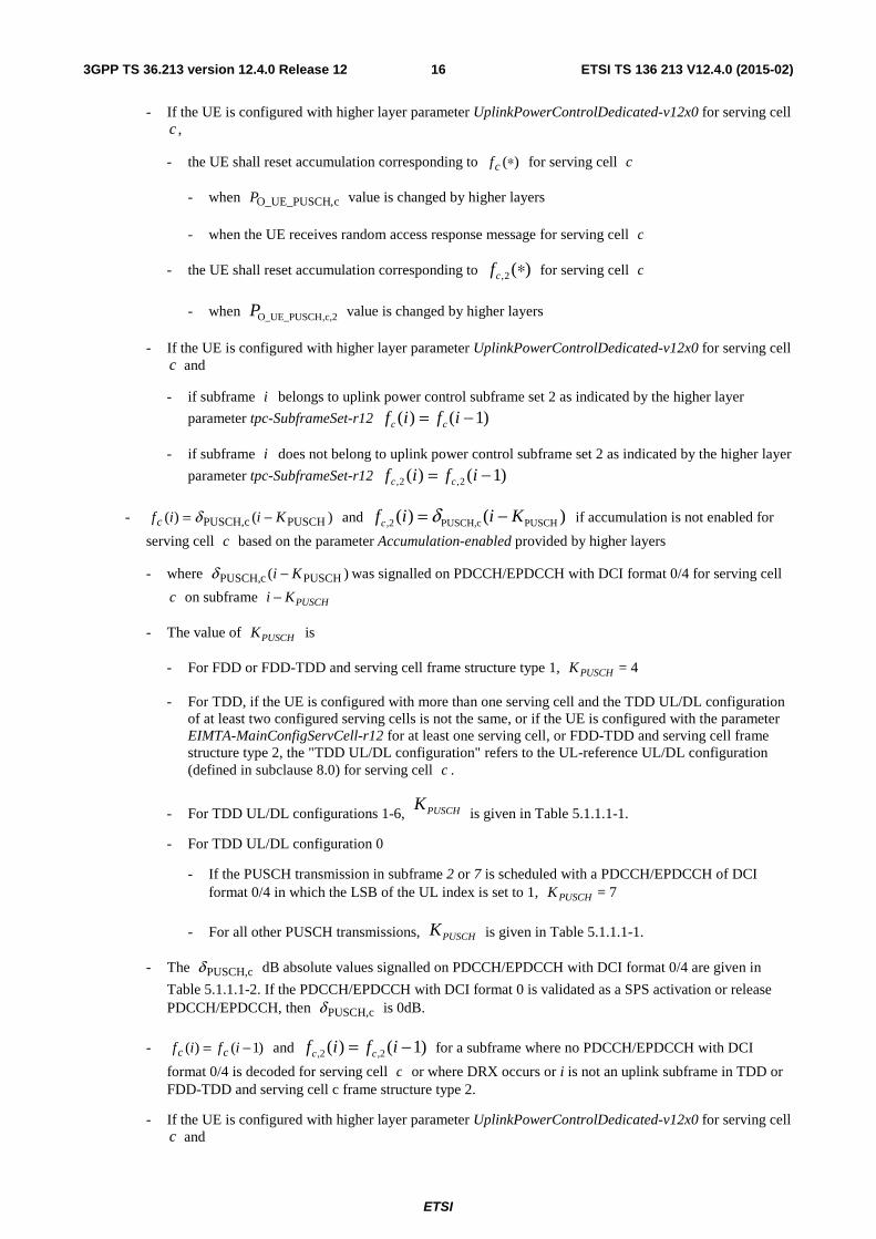
Table 5.1.1.1-1: PUSCHK for TDD configuration 0-6
TDD UL/DL Configuration
subframe number i 0 1 2 3 4 5 6 7 8 9
0 - - 6 7 4 - - 6 7 4 1 - - 6 4 - - - 6 4 - 2 - - 4 - - - - 4 - - 3 - - 4 4 4 - - - - - 4 - - 4 4 - - - - - - 5 - - 4 - - - - - - - 6 - - 7 7 5 - - 7 7 -
ETSI
ETSI TS 136 213 V12.4.0 (2015-02)183GPP TS 36.213 version 12.4.0 Release 12
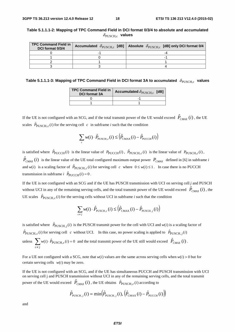
Table 5.1.1.1-2: Mapping of TPC Command Field in DCI format 0/3/4 to absolute and accumulated
cPUSCH,δ values
TPC Command Field in DCI format 0/3/4
Accumulated cPUSCH,δ [dB] Absolute cPUSCH,δ [dB] only DCI format 0/4
0 -1 -4 1 0 -1 2 1 1 3 3 4
Table 5.1.1.1-3: Mapping of TPC Command Field in DCI format 3A to accumulated cPUSCH,δ values
TPC Command Field in DCI format 3A
Accumulated cPUSCH,δ [dB]
0 -1 1 1
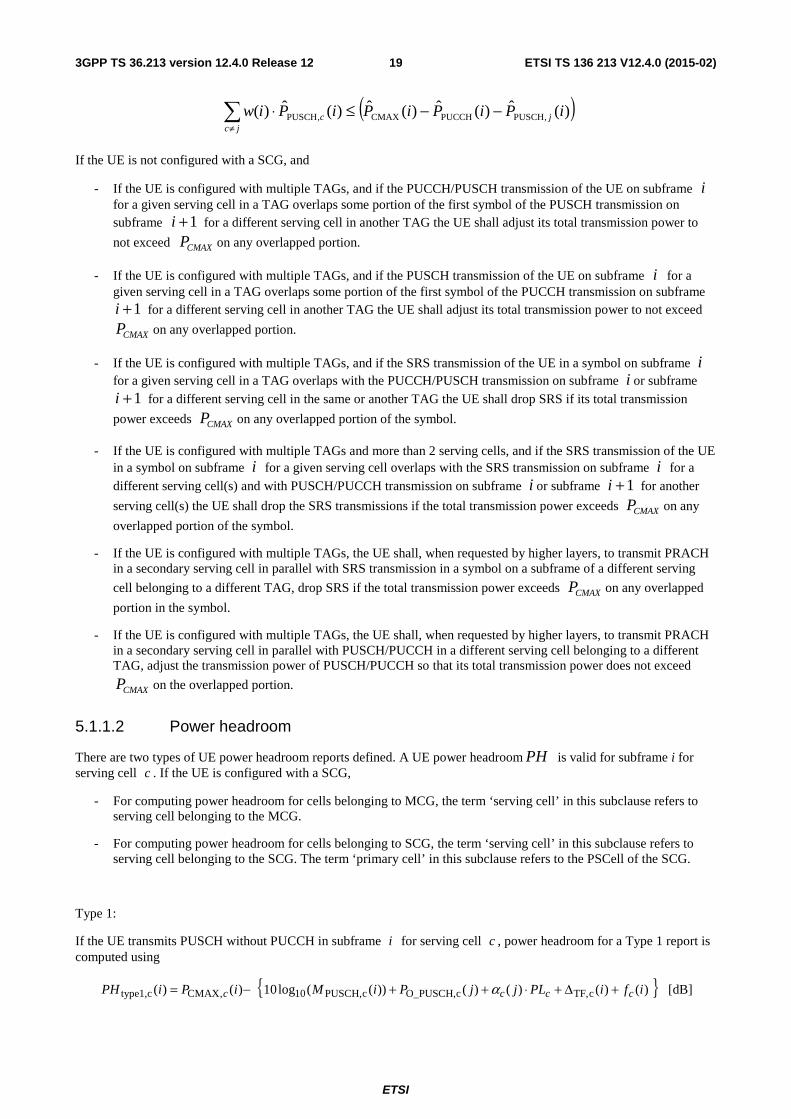
If the UE is not configured with an SCG, and if the total transmit power of the UE would exceed )(ˆ iPCMAX , the UE
scales )(ˆ,PUSCH iP c for the serving cell c in subframe i such that the condition
( ))(ˆ)(ˆ)(ˆ)( PUCCHCMAX,PUSCH iPiPiPiwc
c −≤⋅∑
is satisfied where )(ˆPUCCH iP is the linear value of )(PUCCH iP , )(ˆ
,PUSCH iP c is the linear value of )(,PUSCH iP c ,
)(ˆ iPCMAX is the linear value of the UE total configured maximum output power CMAXP defined in [6] in subframe i
and )(iw is a scaling factor of )(ˆ,PUSCH iP c for serving cell c where 1)(0 ≤≤ iw . In case there is no PUCCH
transmission in subframe i 0)(ˆPUCCH =iP .
If the UE is not configured with an SCG and if the UE has PUSCH transmission with UCI on serving cell j and PUSCH
without UCI in any of the remaining serving cells, and the total transmit power of the UE would exceed )(ˆ iPCMAX , the
UE scales )(ˆ,PUSCH iP c for the serving cells without UCI in subframe i such that the condition
( ))(ˆ)(ˆ)(ˆ)( ,PUSCHCMAX,PUSCH iPiPiPiw jjc
c −≤⋅∑≠
is satisfied where )(ˆ,PUSCH iP j is the PUSCH transmit power for the cell with UCI and )(iw is a scaling factor of
)(ˆ,PUSCH iP c for serving cell c without UCI. In this case, no power scaling is applied to )(ˆ
,PUSCH iP j
unless 0)(ˆ)( ,PUSCH =⋅∑≠ jc
c iPiw and the total transmit power of the UE still would exceed )(ˆ iPCMAX .
For a UE not configured with a SCG, note that )(iw values are the same across serving cells when 0)( >iw but for
certain serving cells )(iw may be zero.
If the UE is not configured with an SCG, and if the UE has simultaneous PUCCH and PUSCH transmission with UCI on serving cell j and PUSCH transmission without UCI in any of the remaining serving cells, and the total transmit
power of the UE would exceed )(ˆ iPCMAX , the UE obtains )(ˆ,PUSCH iP c according to
( )( ))(ˆ)(ˆ),(ˆmin)(ˆPUCCHCMAX,PUSCH,PUSCH iPiPiPiP jj −=
and
ETSI
ETSI TS 136 213 V12.4.0 (2015-02)193GPP TS 36.213 version 12.4.0 Release 12
( ))(ˆ)(ˆ)(ˆ)(ˆ)( ,PUSCHPUCCHCMAX,PUSCH iPiPiPiPiw jjc
c −−≤⋅∑≠
If the UE is not configured with a SCG, and
- If the UE is configured with multiple TAGs, and if the PUCCH/PUSCH transmission of the UE on subframe i for a given serving cell in a TAG overlaps some portion of the first symbol of the PUSCH transmission on subframe 1+i for a different serving cell in another TAG the UE shall adjust its total transmission power to
not exceed CMAXP on any overlapped portion.
- If the UE is configured with multiple TAGs, and if the PUSCH transmission of the UE on subframe i for a given serving cell in a TAG overlaps some portion of the first symbol of the PUCCH transmission on subframe
1+i for a different serving cell in another TAG the UE shall adjust its total transmission power to not exceed
CMAXP on any overlapped portion.
- If the UE is configured with multiple TAGs, and if the SRS transmission of the UE in a symbol on subframe i for a given serving cell in a TAG overlaps with the PUCCH/PUSCH transmission on subframe i or subframe
1+i for a different serving cell in the same or another TAG the UE shall drop SRS if its total transmission
power exceeds CMAXP on any overlapped portion of the symbol.
- If the UE is configured with multiple TAGs and more than 2 serving cells, and if the SRS transmission of the UE in a symbol on subframe i for a given serving cell overlaps with the SRS transmission on subframe i for a different serving cell(s) and with PUSCH/PUCCH transmission on subframe i or subframe 1+i for another
serving cell(s) the UE shall drop the SRS transmissions if the total transmission power exceeds CMAXP on any
overlapped portion of the symbol.
- If the UE is configured with multiple TAGs, the UE shall, when requested by higher layers, to transmit PRACH in a secondary serving cell in parallel with SRS transmission in a symbol on a subframe of a different serving
cell belonging to a different TAG, drop SRS if the total transmission power exceeds CMAXP on any overlapped
portion in the symbol.
- If the UE is configured with multiple TAGs, the UE shall, when requested by higher layers, to transmit PRACH in a secondary serving cell in parallel with PUSCH/PUCCH in a different serving cell belonging to a different TAG, adjust the transmission power of PUSCH/PUCCH so that its total transmission power does not exceed
CMAXP on the overlapped portion.
5.1.1.2 Power headroom
There are two types of UE power headroom reports defined. A UE power headroom PH is valid for subframe i for serving cell c . If the UE is configured with a SCG,
- For computing power headroom for cells belonging to MCG, the term ‘serving cell’ in this subclause refers to serving cell belonging to the MCG.
- For computing power headroom for cells belonging to SCG, the term ‘serving cell’ in this subclause refers to serving cell belonging to the SCG. The term ‘primary cell’ in this subclause refers to the PSCell of the SCG.
Type 1:
If the UE transmits PUSCH without PUCCH in subframe i for serving cell c , power headroom for a Type 1 report is computed using
{ })()()()())((log10)()( cTF,cO_PUSCH,cPUSCH,10,CMAXctype1, ifiPLjjPiMiPiPH cccc +Δ+⋅++−= α [dB]
ETSI
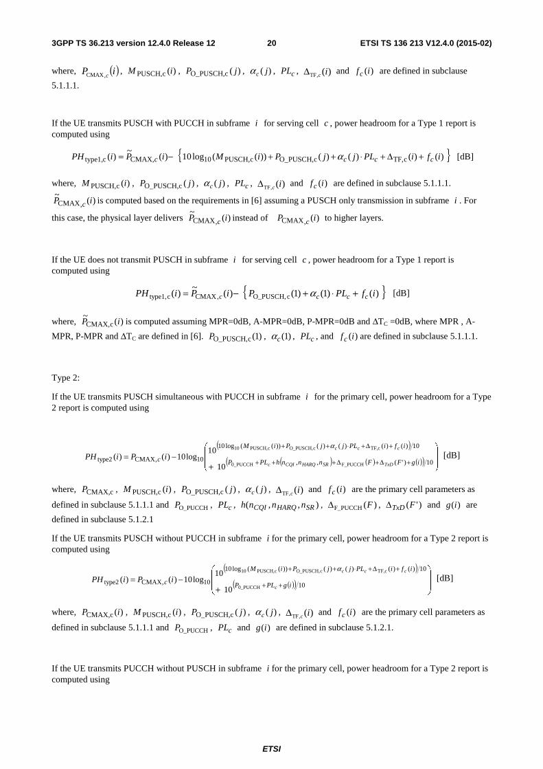
ETSI TS 136 213 V12.4.0 (2015-02)203GPP TS 36.213 version 12.4.0 Release 12
where, ( )iP c,CMAX , )(cPUSCH, iM , )(cO_PUSCH, jP , )( jcα , cPL , )(,TF icΔ and )(ifc are defined in subclause
5.1.1.1.
If the UE transmits PUSCH with PUCCH in subframe i for serving cell c , power headroom for a Type 1 report is computed using
{ })()()()())((log10)(~
)( cTF,cO_PUSCH,cPUSCH,10,CMAXctype1, ifiPLjjPiMiPiPH cccc +Δ+⋅++−= α [dB]
where, )(cPUSCH, iM , )(cO_PUSCH, jP , )( jcα , cPL , )(,TF icΔ and )(ifc are defined in subclause 5.1.1.1.
)(~
,CMAX iP c is computed based on the requirements in [6] assuming a PUSCH only transmission in subframe i . For
this case, the physical layer delivers )(~
,CMAX iP c instead of )(,CMAX iP c to higher layers.
If the UE does not transmit PUSCH in subframe i for serving cell c , power headroom for a Type 1 report is computed using
{ })()1()1()(~
)( cO_PUSCH,,CMAXctype1, ifPLPiPiPH cccc +⋅+−= α [dB]
where, )(~
cCMAX, iP is computed assuming MPR=0dB, A-MPR=0dB, P-MPR=0dB and ΔTC =0dB, where MPR , A-
MPR, P-MPR and ΔTC are defined in [6]. )1(cO_PUSCH,P , )1(cα , cPL , and )(ifc are defined in subclause 5.1.1.1.
Type 2:
If the UE transmits PUSCH simultaneous with PUCCH in subframe i for the primary cell, power headroom for a Type 2 report is computed using
( )( ) ( ) ( )( ) ⎟
⎟
⎠
⎞
⎜⎜
⎝
⎛
+−=
+Δ+Δ+++
+Δ+⋅++
10)'(,,
10)()()()())((log10
10,CMAXtype2F_PUCCH0_PUCCH
cTF,cO_PUSCH,cPUSCH,10
10
10log10)()(
igFFnnnhPLP
ifiPLjjPiM
cTxDSRHARQCQIc
ccc
iPiPHα
[dB]
where, cCMAX,P , )(cPUSCH, iM , )(cO_PUSCH, jP , )( jcα , )(,TF icΔ and )(ifc are the primary cell parameters as
defined in subclause 5.1.1.1 and O_PUCCHP , cPL , ),,( SRHARQCQI nnnh , F_PUCCH ( )FΔ , )'(FTxDΔ and )(ig are
defined in subclause 5.1.2.1
If the UE transmits PUSCH without PUCCH in subframe i for the primary cell, power headroom for a Type 2 report is computed using
( )( )( ) ⎟
⎟
⎠
⎞
⎜⎜
⎝
⎛
+−=
++
+Δ+⋅++
10
10)()()()())((log10
10,CMAXtype20_PUCCH
cTF,cO_PUSCH,cPUSCH,10
10
10log10)()(
igPLP
ifiPLjjPiM
cc
ccc
iPiPHα
[dB]
where, )(CMAX,c iP , )(cPUSCH, iM , )(cO_PUSCH, jP , )( jcα , )(,TF icΔ and )(ifc are the primary cell parameters as
defined in subclause 5.1.1.1 and O_PUCCHP , cPL and )(ig are defined in subclause 5.1.2.1.
If the UE transmits PUCCH without PUSCH in subframe i for the primary cell, power headroom for a Type 2 report is computed using
ETSI
ETSI TS 136 213 V12.4.0 (2015-02)213GPP TS 36.213 version 12.4.0 Release 12
( )( ) ( ) ( )( ) ⎟
⎟
⎠
⎞
⎜⎜
⎝
⎛
+−=
+Δ+Δ+++
+⋅+
10)'(,,
10)()1()1(
10,CMAXtype2F_PUCCH0_PUCCH
cO_PUSCH,
10
10log10)()(
igFFnnnhPLP
ifPLP
cTxDSRHARQCQIc
ccc
iPiPHα
[dB]
where, )1(cO_PUSCH,P , )1(cα and )(ifc are the primary cell parameters as defined in subclause 5.1.1.1,
)(CMAX,c iP , O_PUCCHP , cPL , ),,( SRHARQCQI nnnh , F_PUCCH ( )FΔ , )'(FTxDΔ and )(ig are also defined in
subclause 5.1.2.1.
If the UE does not transmit PUCCH or PUSCH in subframe i for the primary cell, power headroom for a Type 2 report is computed using
( )( )( ) ⎟
⎟
⎠
⎞
⎜⎜
⎝
⎛
+−=
++
+⋅+
10
10)()1()1(
10,CMAXtype20_PUCCH
cO_PUSCH,
10
10log10)(
~)(
igPLP
ifPLP
cc
ccc
iPiPHα
[dB]
where, )(~
, iP cCMAX is computed assuming MPR=0dB, A-MPR=0dB, P-MPR=0dB and ΔTC =0dB, where MPR ,
A-MPR, P-MPR and ΔTC are defined in [6], )1(cO_PUSCH,P , )1(cα and )(ifc are the primary cell parameters as
defined in subclause 5.1.1.1 and O_PUCCHP , cPL and )(ig are defined in subclause 5.1.2.1.
The power headroom shall be rounded to the closest value in the range [40; -23] dB with steps of 1 dB and is delivered by the physical layer to higher layers.
If the UE is configured with higher layer parameter UplinkPowerControlDedicated-v12x0 for serving cell c and if subframe i belongs to uplink power control subframe set 2 as indicated by the higher layer parameter tpc-
SubframeSet-r12, the UE shall use )(2, if c instead of )(ifc to compute )(type1,c iPH and )(type2,c iPH for
subframe i and serving cell c , where )(2, if c is defined in subclause 5.1.1.1.
5.1.2 Physical uplink control channel
If the UE is configured with a SCG, the UE shall apply the procedures described in this subclause for both MCG and SCG.
- When the procedures are applied for MCG, the term ‘serving cell’ in this subclause refers to serving cell belonging to the MCG.
- When the procedures are applied for SCG, the term ‘serving cell’ in this subclause refers to serving cell belonging to the SCG. The term ‘primary cell’ in this subclause refers to the PSCell of the SCG.
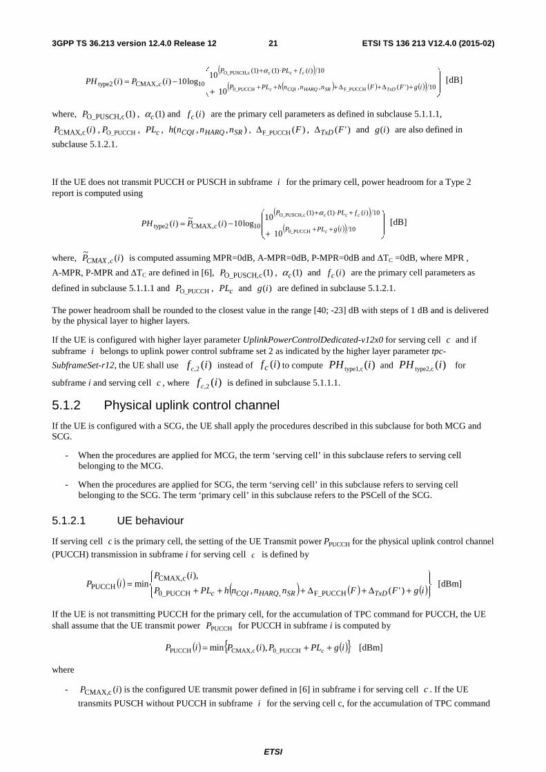
5.1.2.1 UE behaviour
If serving cell c is the primary cell, the setting of the UE Transmit power PUCCHP for the physical uplink control channel
(PUCCH) transmission in subframe i for serving cell c is defined by
( ) ( ) ( ) ( )⎪⎭⎪⎬⎫
⎪⎩
⎪⎨⎧
+Δ+Δ+++=
igFFnnnhPLP
iPiP
TxDSRHARQCQIc )'(,
),(min
F_PUCCH,0_PUCCH
cCMAX,PUCCH [dBm]
If the UE is not transmitting PUCCH for the primary cell, for the accumulation of TPC command for PUCCH, the UE shall assume that the UE transmit power PUCCHP for PUCCH in subframe i is computed by
( ) ( ){ }igPLPiPiP c ++= 0_PUCCHCMAX,cPUCCH ),(min [dBm]
where
- )(cCMAX, iP is the configured UE transmit power defined in [6] in subframe i for serving cell c . If the UE
transmits PUSCH without PUCCH in subframe i for the serving cell c, for the accumulation of TPC command
ETSI
ETSI TS 136 213 V12.4.0 (2015-02)223GPP TS 36.213 version 12.4.0 Release 12
for PUCCH, the UE shall assume )(cCMAX, iP as given by subclause 5.1.1.1. If the UE does not transmit
PUCCH and PUSCH in subframe i for the serving cell c, for the accumulation of TPC command for PUCCH, the UE shall compute )(cCMAX, iP assuming MPR=0dB, A-MPR=0dB, P-MPR=0dB and ΔTC =0dB, where
MPR, A-MPR, P-MPR and ΔTC are defined in [6].
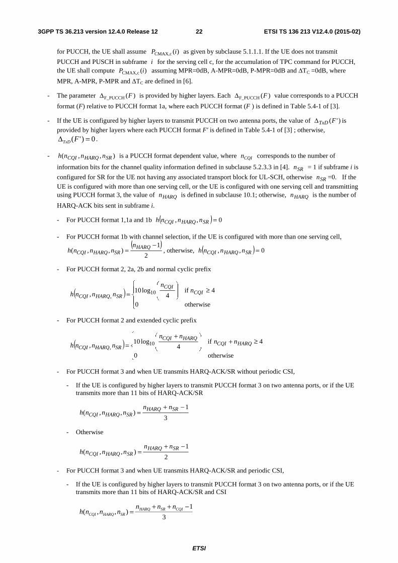
- The parameter F_PUCCH ( )FΔ is provided by higher layers. Each F_PUCCH ( )FΔ value corresponds to a PUCCH
format (F) relative to PUCCH format 1a, where each PUCCH format (F ) is defined in Table 5.4-1 of [3].
- If the UE is configured by higher layers to transmit PUCCH on two antenna ports, the value of )'(FTxDΔ is
provided by higher layers where each PUCCH format F' is defined in Table 5.4-1 of [3] ; otherwise, 0)'( =Δ FTxD .
- ),,( SRHARQCQI nnnh is a PUCCH format dependent value, where CQIn corresponds to the number of
information bits for the channel quality information defined in subclause 5.2.3.3 in [4]. SRn = 1 if subframe i is
configured for SR for the UE not having any associated transport block for UL-SCH, otherwise SRn =0. If the
UE is configured with more than one serving cell, or the UE is configured with one serving cell and transmitting using PUCCH format 3, the value of HARQn is defined in subclause 10.1; otherwise, HARQn is the number of
HARQ-ACK bits sent in subframe i.
- For PUCCH format 1,1a and 1b ( ) 0,, =SRHARQCQI nnnh
- For PUCCH format 1b with channel selection, if the UE is configured with more than one serving cell, ( )
2
1),,(
−= HARQ
SRHARQCQIn
nnnh , otherwise, ( ) 0,, =SRHARQCQI nnnh
- For PUCCH format 2, 2a, 2b and normal cyclic prefix
( )⎪⎩
⎪⎨
⎧≥⎟
⎟⎠
⎞⎜⎜⎝
⎛
=otherwise0
4if4
log10, 10
,CQI
CQI
SRHARQCQIn
n
nnnh
- For PUCCH format 2 and extended cyclic prefix
( )⎪⎩
⎪⎨
⎧≥+⎟
⎟⎠
⎞⎜⎜⎝
⎛ +=
otherwise0
4if4
log10, 10
,HARQCQI
HARQCQI
SRHARQCQInn
nn
nnnh
- For PUCCH format 3 and when UE transmits HARQ-ACK/SR without periodic CSI,
- If the UE is configured by higher layers to transmit PUCCH format 3 on two antenna ports, or if the UE transmits more than 11 bits of HARQ-ACK/SR
3
1),,(
−+= SRHARQ
SRHARQCQInn
nnnh
- Otherwise
2
1),,(
−+= SRHARQ
SRHARQCQInn
nnnh
- For PUCCH format 3 and when UE transmits HARQ-ACK/SR and periodic CSI,
- If the UE is configured by higher layers to transmit PUCCH format 3 on two antenna ports, or if the UE transmits more than 11 bits of HARQ-ACK/SR and CSI
3
1),,(
−++= CQISRHARQ
SRHARQCQI
nnnnnnh
ETSI
ETSI TS 136 213 V12.4.0 (2015-02)233GPP TS 36.213 version 12.4.0 Release 12
- Otherwise
2
1),,(
−++= CQISRHARQ
SRHARQCQI
nnnnnnh
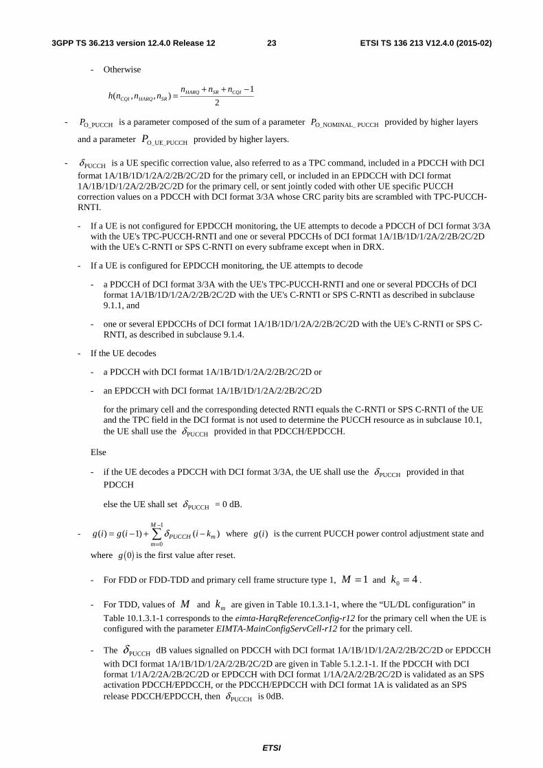
- O_PUCCHP is a parameter composed of the sum of a parameter PUCCH O_NOMINAL_P provided by higher layers
and a parameter O_UE_PUCCHP provided by higher layers.
- PUCCHδ is a UE specific correction value, also referred to as a TPC command, included in a PDCCH with DCI
format 1A/1B/1D/1/2A/2/2B/2C/2D for the primary cell, or included in an EPDCCH with DCI format 1A/1B/1D/1/2A/2/2B/2C/2D for the primary cell, or sent jointly coded with other UE specific PUCCH correction values on a PDCCH with DCI format 3/3A whose CRC parity bits are scrambled with TPC-PUCCH-RNTI.
- If a UE is not configured for EPDCCH monitoring, the UE attempts to decode a PDCCH of DCI format 3/3A with the UE's TPC-PUCCH-RNTI and one or several PDCCHs of DCI format 1A/1B/1D/1/2A/2/2B/2C/2D with the UE's C-RNTI or SPS C-RNTI on every subframe except when in DRX.
- If a UE is configured for EPDCCH monitoring, the UE attempts to decode
- a PDCCH of DCI format 3/3A with the UE's TPC-PUCCH-RNTI and one or several PDCCHs of DCI format 1A/1B/1D/1/2A/2/2B/2C/2D with the UE's C-RNTI or SPS C-RNTI as described in subclause 9.1.1, and
- one or several EPDCCHs of DCI format 1A/1B/1D/1/2A/2/2B/2C/2D with the UE's C-RNTI or SPS C-RNTI, as described in subclause 9.1.4.
- If the UE decodes
- a PDCCH with DCI format 1A/1B/1D/1/2A/2/2B/2C/2D or
- an EPDCCH with DCI format 1A/1B/1D/1/2A/2/2B/2C/2D
for the primary cell and the corresponding detected RNTI equals the C-RNTI or SPS C-RNTI of the UE and the TPC field in the DCI format is not used to determine the PUCCH resource as in subclause 10.1, the UE shall use the PUCCHδ provided in that PDCCH/EPDCCH.
Else
- if the UE decodes a PDCCH with DCI format 3/3A, the UE shall use the PUCCHδ provided in that
PDCCH
else the UE shall set PUCCHδ = 0 dB.
- 1
0
( ) ( 1) ( )M
PUCCH mm
g i g i i kδ−
== − + −∑ where )(ig is the current PUCCH power control adjustment state and
where ( )0g is the first value after reset.
- For FDD or FDD-TDD and primary cell frame structure type 1, 1=M and 40 =k .
- For TDD, values of M and mk are given in Table 10.1.3.1-1, where the “UL/DL configuration” in
Table 10.1.3.1-1 corresponds to the eimta-HarqReferenceConfig-r12 for the primary cell when the UE is configured with the parameter EIMTA-MainConfigServCell-r12 for the primary cell.
- The PUCCHδ dB values signalled on PDCCH with DCI format 1A/1B/1D/1/2A/2/2B/2C/2D or EPDCCH
with DCI format 1A/1B/1D/1/2A/2/2B/2C/2D are given in Table 5.1.2.1-1. If the PDCCH with DCI format 1/1A/2/2A/2B/2C/2D or EPDCCH with DCI format 1/1A/2A/2/2B/2C/2D is validated as an SPS activation PDCCH/EPDCCH, or the PDCCH/EPDCCH with DCI format 1A is validated as an SPS release PDCCH/EPDCCH, then PUCCHδ is 0dB.
ETSI
ETSI TS 136 213 V12.4.0 (2015-02)243GPP TS 36.213 version 12.4.0 Release 12
- The PUCCHδ dB values signalled on PDCCH with DCI format 3/3A are given in Table 5.1.2.1-1 or in
Table 5.1.2.1-2 as semi-statically configured by higher layers.
- If O_UE_PUCCHP value is changed by higher layers,
- ( )0 0g =
- Else
- 2(0) rampup msgg P δ= Δ + , where
- 2msgδ is the TPC command indicated in the random access response corresponding to the random
access preamble transmitted in the primary cell, see subclause 6.2 and
- if UE is transmitting PUCCH in subframe i,
,
)'()(
)(,0maxmin
_
,,
_0
,
⎪⎭
⎪⎬
⎫
⎢⎢⎢⎢
⎣
⎡
⎪⎩
⎪⎨
⎧
⎜⎜⎜⎜
⎝
⎛
⎟⎟⎟
⎠
⎞
⎟⎟⎟
⎠
⎞
Δ+Δ+++−
⎜⎜⎜
⎝
⎛
=ΔFF
nnnhPL
P
PP
TxDPUCCHF
SRHARQCQIc
PUCCH
cCMAXrampup
⎥⎥⎥
⎦
⎤
Δ estedrampuprequP .
Otherwise,
( )( ){ }[ ]estedrampuprequcPUCCHcCMAXrampup PPLPPP Δ+−=Δ ,,0maxmin _0,and estedrampuprequPΔ
is provided by higher layers and corresponds to the total power ramp-up requested by higher layers from the first to the last preamble in the primary cell.
- If UE has reached )(cCMAX, iP for the primary cell, positive TPC commands for the primary cell shall
not be accumulated.
- If UE has reached minimum power, negative TPC commands shall not be accumulated.
- UE shall reset accumulation
- when O_UE_PUCCHP value is changed by higher layers
- when the UE receives a random access response message for the primary cell
- ( ) ( 1)g i g i= − if i is not an uplink subframe in TDD or FDD-TDD and primary cell frame structure
type 2.
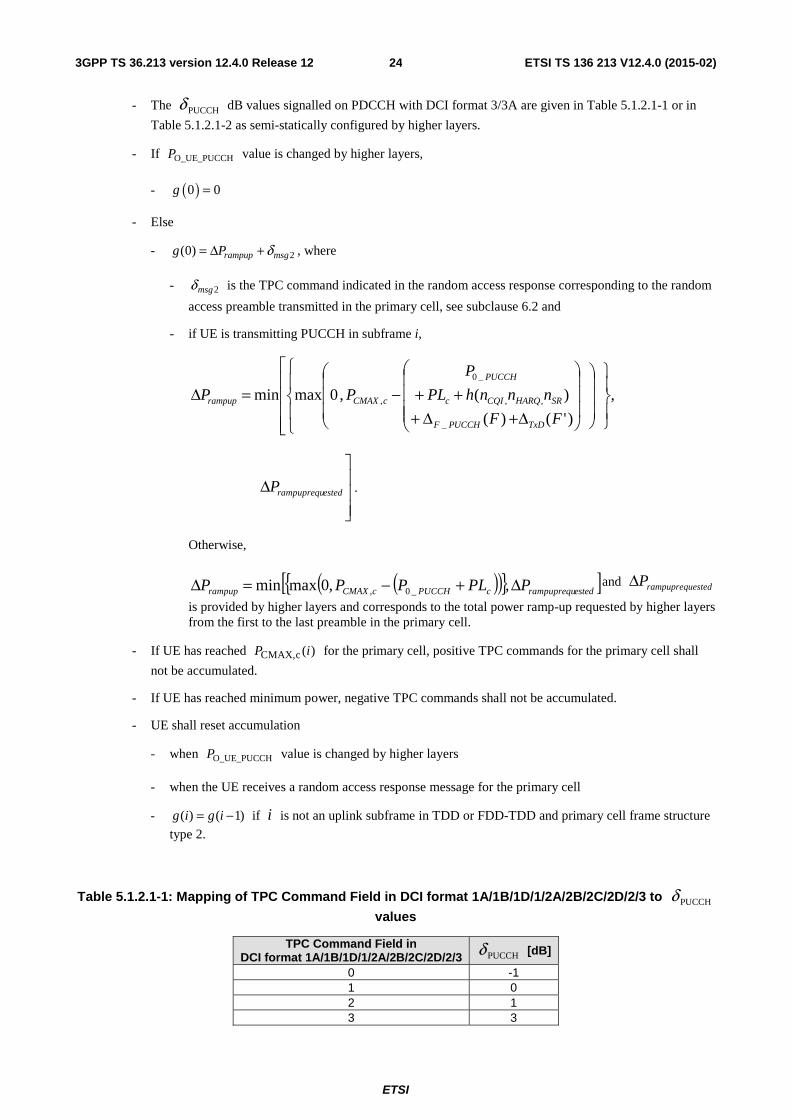
Table 5.1.2.1-1: Mapping of TPC Command Field in DCI format 1A/1B/1D/1/2A/2B/2C/2D/2/3 to PUCCHδ
values
TPC Command Field in DCI format 1A/1B/1D/1/2A/2B/2C/2D/2/3 PUCCHδ [dB]
0 -1 1 0 2 1 3 3
ETSI
ETSI TS 136 213 V12.4.0 (2015-02)253GPP TS 36.213 version 12.4.0 Release 12
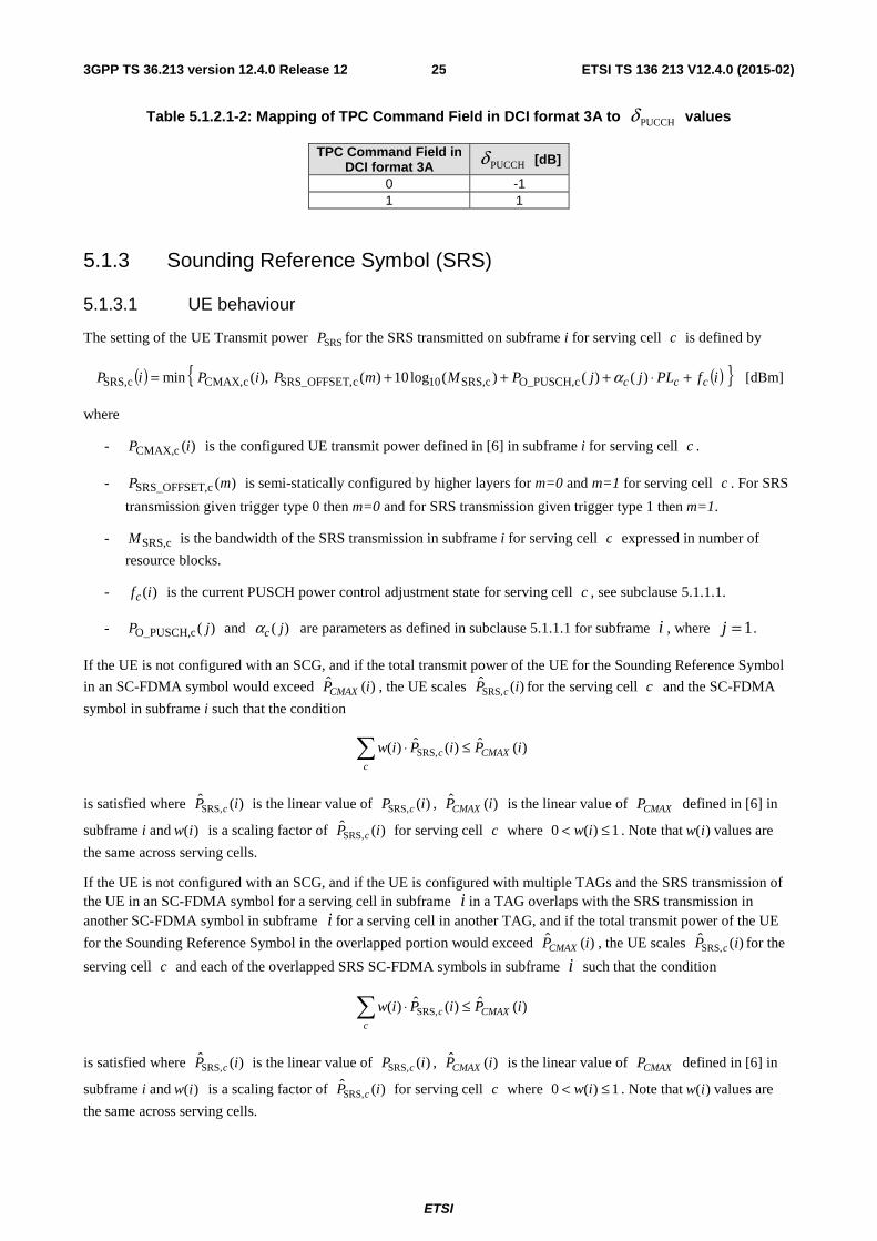
Table 5.1.2.1-2: Mapping of TPC Command Field in DCI format 3A to PUCCHδ values
TPC Command Field in DCI format 3A PUCCHδ [dB]
0 -1 1 1
5.1.3 Sounding Reference Symbol (SRS)
5.1.3.1 UE behaviour
The setting of the UE Transmit power SRSP for the SRS transmitted on subframe i for serving cell c is defined by
( ) ( ){ }ifPLjjPMmPiPiP ccc +⋅+++= )()()(log10)(),(min cO_PUSCH,cSRS,10c,SRS_OFFSETcCMAX,cSRS, α [dBm]
where
- )(cCMAX, iP is the configured UE transmit power defined in [6] in subframe i for serving cell c .
- )(c,SRS_OFFSET mP is semi-statically configured by higher layers for m=0 and m=1 for serving cell c . For SRS
transmission given trigger type 0 then m=0 and for SRS transmission given trigger type 1 then m=1.
- cSRS,M is the bandwidth of the SRS transmission in subframe i for serving cell c expressed in number of
resource blocks.
- )(ifc is the current PUSCH power control adjustment state for serving cell c , see subclause 5.1.1.1.
- )(cO_PUSCH, jP and )( jcα are parameters as defined in subclause 5.1.1.1 for subframe i , where 1=j .
If the UE is not configured with an SCG, and if the total transmit power of the UE for the Sounding Reference Symbol
in an SC-FDMA symbol would exceed )(ˆ iPCMAX , the UE scales )(ˆ,SRS iP c for the serving cell c and the SC-FDMA
symbol in subframe i such that the condition
)(ˆ)(ˆ)( ,SRS iPiPiw CMAXc
c ≤⋅∑
is satisfied where )(ˆ,SRS iP c is the linear value of )(,SRS iP c , )(ˆ iPCMAX is the linear value of CMAXP defined in [6] in
subframe i and )(iw is a scaling factor of )(ˆ,SRS iP c for serving cell c where 1)(0 ≤< iw . Note that )(iw values are
the same across serving cells.
If the UE is not configured with an SCG, and if the UE is configured with multiple TAGs and the SRS transmission of the UE in an SC-FDMA symbol for a serving cell in subframe i in a TAG overlaps with the SRS transmission in another SC-FDMA symbol in subframe i for a serving cell in another TAG, and if the total transmit power of the UE
for the Sounding Reference Symbol in the overlapped portion would exceed )(ˆ iPCMAX , the UE scales )(ˆ,SRS iP c for the
serving cell c and each of the overlapped SRS SC-FDMA symbols in subframe i such that the condition
)(ˆ)(ˆ)( ,SRS iPiPiw CMAXc
c ≤⋅∑
is satisfied where )(ˆ,SRS iP c is the linear value of )(,SRS iP c , )(ˆ iPCMAX is the linear value of CMAXP defined in [6] in
subframe i and )(iw is a scaling factor of )(ˆ,SRS iP c for serving cell c where 1)(0 ≤< iw . Note that )(iw values are
the same across serving cells.
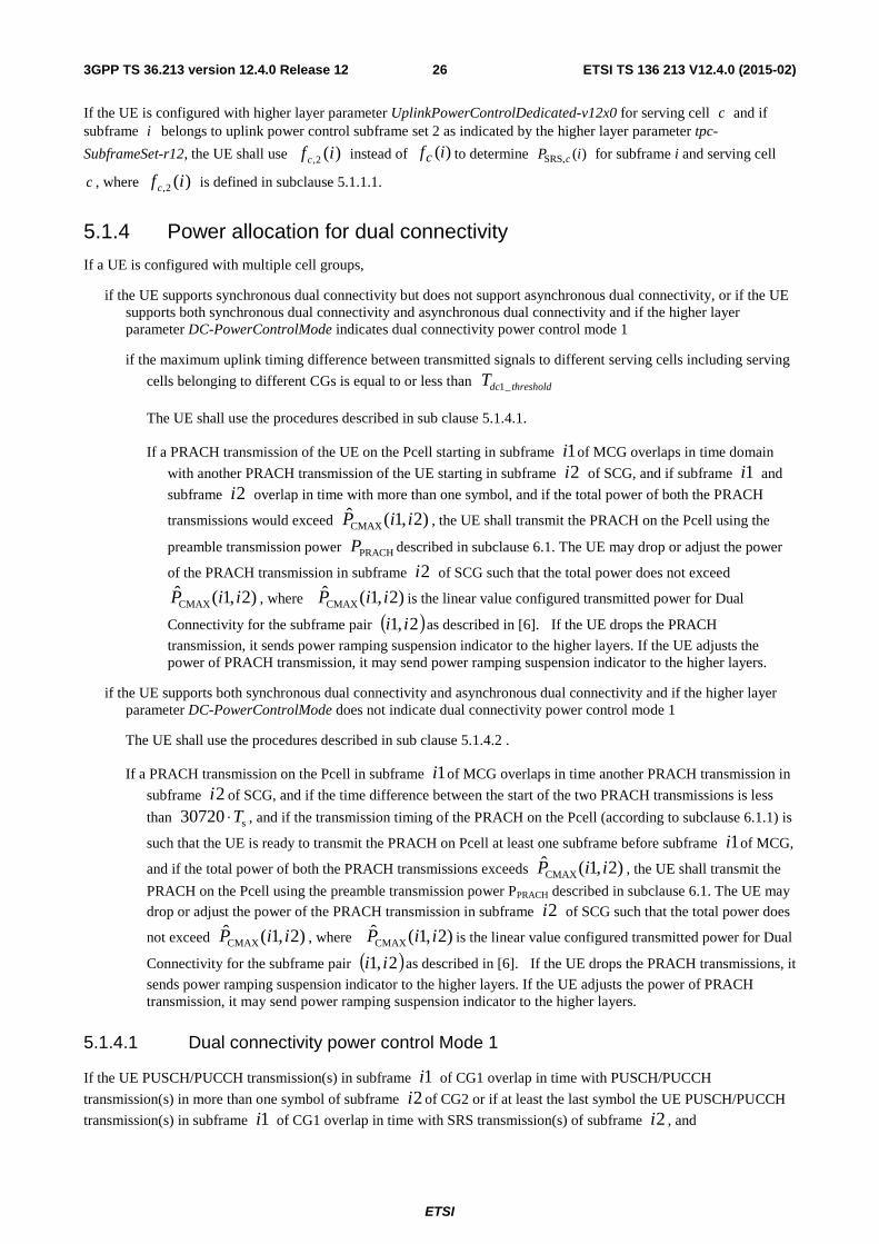
ETSI
ETSI TS 136 213 V12.4.0 (2015-02)263GPP TS 36.213 version 12.4.0 Release 12
If the UE is configured with higher layer parameter UplinkPowerControlDedicated-v12x0 for serving cell c and if subframe i belongs to uplink power control subframe set 2 as indicated by the higher layer parameter tpc-
SubframeSet-r12, the UE shall use )(2, if c instead of )(ifc to determine )(,SRS iP c for subframe i and serving cell
c , where )(2, if c is defined in subclause 5.1.1.1.
5.1.4 Power allocation for dual connectivity
If a UE is configured with multiple cell groups,
if the UE supports synchronous dual connectivity but does not support asynchronous dual connectivity, or if the UE supports both synchronous dual connectivity and asynchronous dual connectivity and if the higher layer parameter DC-PowerControlMode indicates dual connectivity power control mode 1
if the maximum uplink timing difference between transmitted signals to different serving cells including serving
cells belonging to different CGs is equal to or less than thresholddcT _1
The UE shall use the procedures described in sub clause 5.1.4.1.
If a PRACH transmission of the UE on the Pcell starting in subframe 1i of MCG overlaps in time domain
with another PRACH transmission of the UE starting in subframe 2i of SCG, and if subframe 1i and
subframe 2i overlap in time with more than one symbol, and if the total power of both the PRACH
transmissions would exceed )2,1(CMAX iiP , the UE shall transmit the PRACH on the Pcell using the
preamble transmission power PRACHP described in subclause 6.1. The UE may drop or adjust the power
of the PRACH transmission in subframe 2i of SCG such that the total power does not exceed
)2,1(CMAX iiP , where )2,1(CMAX iiP is the linear value configured transmitted power for Dual
Connectivity for the subframe pair ( )2,1 ii as described in [6]. If the UE drops the PRACH
transmission, it sends power ramping suspension indicator to the higher layers. If the UE adjusts the power of PRACH transmission, it may send power ramping suspension indicator to the higher layers.
if the UE supports both synchronous dual connectivity and asynchronous dual connectivity and if the higher layer parameter DC-PowerControlMode does not indicate dual connectivity power control mode 1
The UE shall use the procedures described in sub clause 5.1.4.2 .
If a PRACH transmission on the Pcell in subframe 1i of MCG overlaps in time another PRACH transmission in
subframe 2i of SCG, and if the time difference between the start of the two PRACH transmissions is less
than s30720 T⋅ , and if the transmission timing of the PRACH on the Pcell (according to subclause 6.1.1) is
such that the UE is ready to transmit the PRACH on Pcell at least one subframe before subframe 1i of MCG,
and if the total power of both the PRACH transmissions exceeds )2,1(CMAX iiP , the UE shall transmit the
PRACH on the Pcell using the preamble transmission power PPRACH described in subclause 6.1. The UE may
drop or adjust the power of the PRACH transmission in subframe 2i of SCG such that the total power does
not exceed )2,1(CMAX iiP , where )2,1(CMAX iiP is the linear value configured transmitted power for Dual
Connectivity for the subframe pair ( )2,1 ii as described in [6]. If the UE drops the PRACH transmissions, it
sends power ramping suspension indicator to the higher layers. If the UE adjusts the power of PRACH transmission, it may send power ramping suspension indicator to the higher layers.
5.1.4.1 Dual connectivity power control Mode 1
If the UE PUSCH/PUCCH transmission(s) in subframe 1i of CG1 overlap in time with PUSCH/PUCCH
transmission(s) in more than one symbol of subframe 2i of CG2 or if at least the last symbol the UE PUSCH/PUCCH
transmission(s) in subframe 1i of CG1 overlap in time with SRS transmission(s) of subframe 2i , and
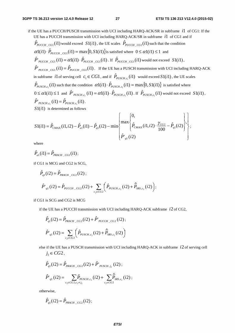
ETSI
ETSI TS 136 213 V12.4.0 (2015-02)273GPP TS 36.213 version 12.4.0 Release 12
if the UE has a PUCCH/PUSCH transmission with UCI including HARQ-ACK/SR in subframe 1i of CG1: If the
UE has a PUCCH transmission with UCI including HARQ-ACK/SR in subframe 1i of CG1 and if
)1(ˆ1_ iP CGPUCCH would exceed )1(1 iS , the UE scales )1(ˆ
1_ iP CGPUCCH such that the condition
{ })1(1,0max)1(ˆ)1(1 1_ iSiPi CGPUCCH =⋅α is satisfied where 1)1(10 ≤≤ iα and
)1(ˆ)1(1)1('ˆ1_1_ iPiiP CGPUCCHCGPUCCH ⋅= α . If )1(ˆ
1_ iP CGPUCCH would not exceed )1(1 iS ,
)1(ˆ)1('ˆ1_1_ iPiP CGPUCCHCGPUCCH = . If the UE has a PUSCH transmission with UCI including HARQ-ACK
in subframe 1i of serving cell 11 CGc ∈ , and if )1(ˆ1, iP cPUSCH would exceed )1(1 iS , the UE scales
)1(ˆ1, iP cPUSCH such that the condition { })1(1,0max)1(ˆ)1(1
1, iSiPi cPUSCH =⋅α is satisfied where
1)1(10 ≤≤ iα and )1(ˆ)1(1)1('ˆ11 ,, iPiiP cPUSCHcPUSCH ⋅= α . If )1(ˆ
1, iP cPUSCH would not exceed )1(1 iS ,
)1(ˆ)1('ˆ11 ,, iPiP cPUSCHcPUSCH = .
)1(1 iS is determined as follows
⎪⎪
⎭
⎪⎪
⎬
⎫
⎪⎪
⎩
⎪⎪
⎨
⎧
⎪⎭
⎪⎬
⎫
⎪⎩
⎪⎨
⎧
−⋅−−−=
)2('ˆ
,)2(ˆ
100)2,1(ˆ
,0max
min)2(ˆ)1(ˆ)2,1(ˆ)1(1
1
12
CMAX11CMAX
iP
iPiiPiPiPiiPiS
q
qCG
qu
γ;
where
)1(ˆ)1(ˆ1_1 iPiP CGPRACHu = ;
if CG1 is MCG and CG2 is SCG,
)2(ˆ)2(ˆ2_1 iPiP CGPRACHq = ;
∑∈
⎟⎠⎞⎜
⎝⎛ ++=
2,,2_1
2
22)2(
~)2(ˆ)2(ˆ)2('ˆ
CGccSRScPUSCHCGPUCCHq iPiPiPiP ;
if CG1 is SCG and CG2 is MCG
if the UE has a PUCCH transmission with UCI including HARQ-ACK subframe 2i of CG2,
)2('ˆ)2(ˆ)2(ˆ2_2_1 iPiPiP CGPUCCHCGPRACHq += ;
∑∈
⎟⎠⎞⎜
⎝⎛ +=
2,,1
2
22)2(
~)2(ˆ)2('ˆ
CGccSRScPUSCHq iPiPiP
else if the UE has a PUSCH transmission with UCI including HARQ-ACK in subframe 2i of serving cell
22 CGj ∈ ,
)2('ˆ)2(ˆ)2(ˆ2,2_1 iPiPiP jPUSCHCGPRACHq += ;
∑∑∈≠∈
+=2
,,2
,1
2
2
222
2)2(
~)2(ˆ)2('ˆ
CGccSRS
jcCGccPUSCHq iPiPiP ;
otherwise,
)2(ˆ)2(ˆ2_1 iPiP CGPRACHq = ;
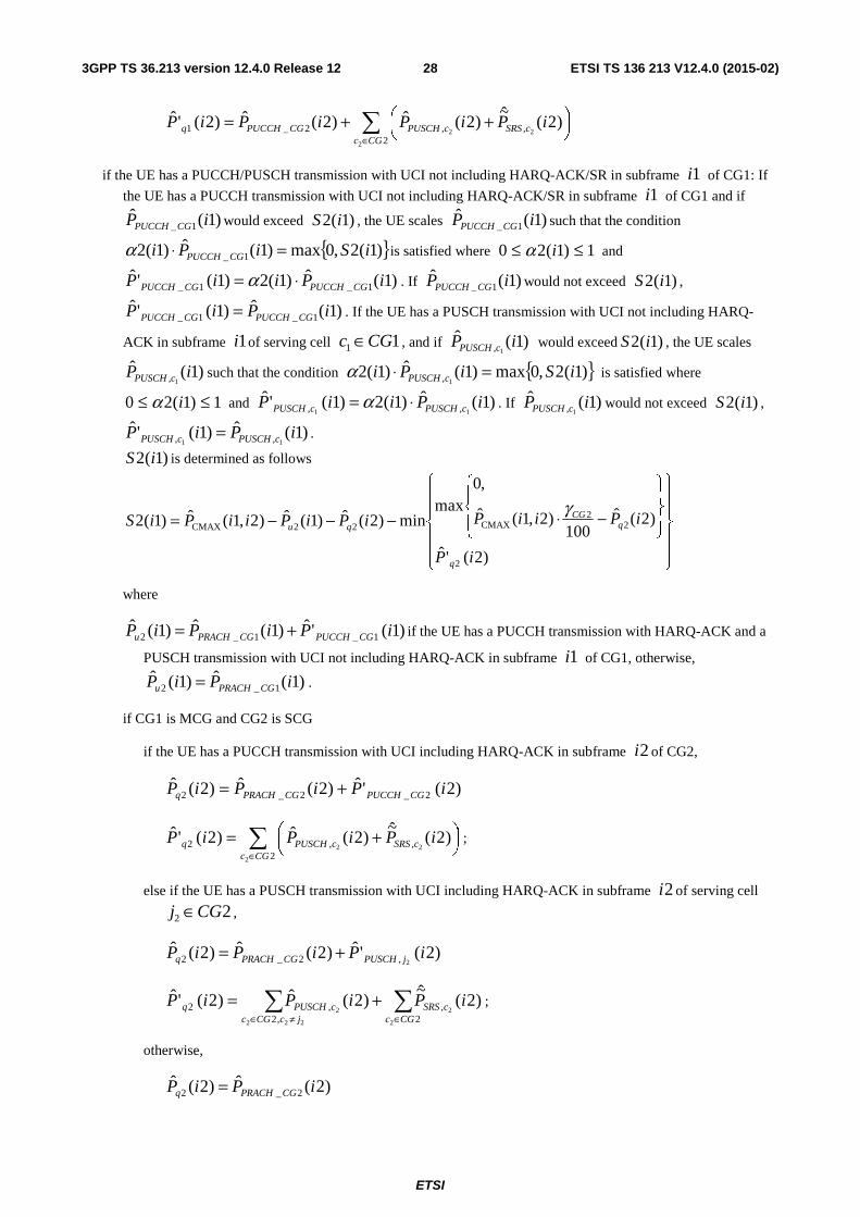
ETSI
ETSI TS 136 213 V12.4.0 (2015-02)283GPP TS 36.213 version 12.4.0 Release 12
∑∈
⎟⎠⎞⎜
⎝⎛ ++=
2,,2_1
2
22)2(
~)2(ˆ)2(ˆ)2('ˆ
CGccSRScPUSCHCGPUCCHq iPiPiPiP
if the UE has a PUCCH/PUSCH transmission with UCI not including HARQ-ACK/SR in subframe 1i of CG1: If
the UE has a PUCCH transmission with UCI not including HARQ-ACK/SR in subframe 1i of CG1 and if
)1(ˆ1_ iP CGPUCCH would exceed )1(2 iS , the UE scales )1(ˆ
1_ iP CGPUCCH such that the condition
{ })1(2,0max)1(ˆ)1(2 1_ iSiPi CGPUCCH =⋅α is satisfied where 1)1(20 ≤≤ iα and
)1(ˆ)1(2)1('ˆ1_1_ iPiiP CGPUCCHCGPUCCH ⋅= α . If )1(ˆ
1_ iP CGPUCCH would not exceed )1(2 iS ,
)1(ˆ)1('ˆ1_1_ iPiP CGPUCCHCGPUCCH = . If the UE has a PUSCH transmission with UCI not including HARQ-
ACK in subframe 1i of serving cell 11 CGc ∈ , and if )1(ˆ1, iP cPUSCH would exceed )1(2 iS , the UE scales
)1(ˆ1, iP cPUSCH such that the condition { })1(2,0max)1(ˆ)1(2
1, iSiPi cPUSCH =⋅α is satisfied where
1)1(20 ≤≤ iα and )1(ˆ)1(2)1('ˆ11 ,, iPiiP cPUSCHcPUSCH ⋅= α . If )1(ˆ
1, iP cPUSCH would not exceed )1(2 iS ,
)1(ˆ)1('ˆ11 ,, iPiP cPUSCHcPUSCH = .
)1(2 iS is determined as follows
⎪⎪
⎭
⎪⎪
⎬
⎫
⎪⎪
⎩
⎪⎪
⎨
⎧
⎪⎭
⎪⎬
⎫
⎪⎩
⎪⎨
⎧
−⋅−−−=
)2('ˆ
)2(ˆ100
)2,1(ˆ
,0max
min)2(ˆ)1(ˆ)2,1(ˆ)1(2
2
22
CMAX22CMAX
iP
iPiiPiPiPiiPiS
q
qCG
qu
γ
where
)1('ˆ)1(ˆ)1(ˆ1_1_2 iPiPiP CGPUCCHCGPRACHu += if the UE has a PUCCH transmission with HARQ-ACK and a
PUSCH transmission with UCI not including HARQ-ACK in subframe 1i of CG1, otherwise,
)1(ˆ)1(ˆ1_2 iPiP CGPRACHu = .
if CG1 is MCG and CG2 is SCG
if the UE has a PUCCH transmission with UCI including HARQ-ACK in subframe 2i of CG2,
)2('ˆ)2(ˆ)2(ˆ2_2_2 iPiPiP CGPUCCHCGPRACHq +=
∑∈
⎟⎠⎞⎜
⎝⎛ +=
2,,2
2
22)2(
~)2(ˆ)2('ˆ
CGccSRScPUSCHq iPiPiP ;
else if the UE has a PUSCH transmission with UCI including HARQ-ACK in subframe 2i of serving cell
22 CGj ∈ ,
)2('ˆ)2(ˆ)2(ˆ2,2_2 iPiPiP jPUSCHCGPRACHq +=
∑∑∈≠∈
+=2
,,2
,2
2
2
222
2)2(
~)2(ˆ)2('ˆ
CGccSRS
jcCGccPUSCHq iPiPiP ;
otherwise,
)2(ˆ)2(ˆ2_2 iPiP CGPRACHq =
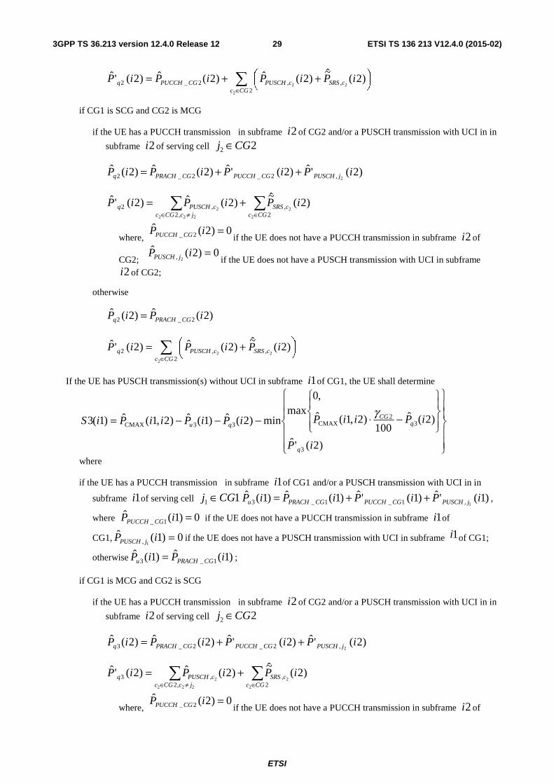
ETSI
ETSI TS 136 213 V12.4.0 (2015-02)293GPP TS 36.213 version 12.4.0 Release 12
∑∈
⎟⎠⎞⎜
⎝⎛ ++=
2,,2_2
2
22)2(
~)2(ˆ)2(ˆ)2('ˆ
CGccSRScPUSCHCGPUCCHq iPiPiPiP
if CG1 is SCG and CG2 is MCG
if the UE has a PUCCH transmission in subframe 2i of CG2 and/or a PUSCH transmission with UCI in in
subframe 2i of serving cell 22 CGj ∈
)2('ˆ)2('ˆ)2(ˆ)2(ˆ2,2_2_2 iPiPiPiP jPUSCHCGPUCCHCGPRACHq ++=
∑∑∈≠∈
+=2
,,2
,2
2
2
222
2)2(
~)2(ˆ)2('ˆ
CGccSRS
jcCGccPUSCHq iPiPiP
where, 0)2(ˆ
2_ =iP CGPUCCH if the UE does not have a PUCCH transmission in subframe 2i of
CG2; 0)2(ˆ
2, =iP jPUSCH if the UE does not have a PUSCH transmission with UCI in subframe 2i of CG2;
otherwise
)2(ˆ)2(ˆ2_2 iPiP CGPRACHq =
∑∈
⎟⎠⎞⎜
⎝⎛ +=
2,,2
2
22)2(
~)2(ˆ)2('ˆ
CGccSRScPUSCHq iPiPiP
If the UE has PUSCH transmission(s) without UCI in subframe 1i of CG1, the UE shall determine
⎪⎪
⎭
⎪⎪
⎬
⎫
⎪⎪
⎩
⎪⎪
⎨
⎧
⎪⎭
⎪⎬
⎫
⎪⎩
⎪⎨
⎧
−⋅−−−=
)2('ˆ
)2(ˆ100
)2,1(ˆ
,0max
min)2(ˆ)1(ˆ)2,1(ˆ)1(3
3
32
CMAX33CMAX
iP
iPiiPiPiPiiPiS
q
qCG
qu
γ
where
if the UE has a PUCCH transmission in subframe 1i of CG1 and/or a PUSCH transmission with UCI in in
subframe 1i of serving cell 11 CGj ∈ )1('ˆ)1('ˆ)1(ˆ)1(ˆ1,1_1_3 iPiPiPiP jPUSCHCGPUCCHCGPRACHu ++= ,
where 0)1(ˆ1_ =iP CGPUCCH if the UE does not have a PUCCH transmission in subframe 1i of
CG1, 0)1(ˆ1, =iP jPUSCH if the UE does not have a PUSCH transmission with UCI in subframe 1i of CG1;
otherwise )1(ˆ)1(ˆ1_3 iPiP CGPRACHu = ;
if CG1 is MCG and CG2 is SCG
if the UE has a PUCCH transmission in subframe 2i of CG2 and/or a PUSCH transmission with UCI in in
subframe 2i of serving cell 22 CGj ∈
)2('ˆ)2('ˆ)2(ˆ)2(ˆ2,2_2_3 iPiPiPiP jPUSCHCGPUCCHCGPRACHq ++=
∑∑∈≠∈
+=2
,,2
,3
2
2
222
2)2(
~)2(ˆ)2('ˆ
CGccSRS
jcCGccPUSCHq iPiPiP
where, 0)2(ˆ
2_ =iP CGPUCCH if the UE does not have a PUCCH transmission in subframe 2i of
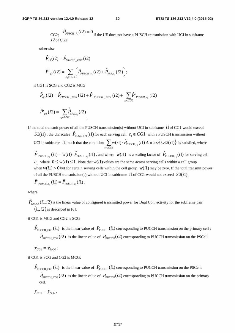
ETSI
ETSI TS 136 213 V12.4.0 (2015-02)303GPP TS 36.213 version 12.4.0 Release 12
CG2; 0)2(ˆ
2, =iP jPUSCH if the UE does not have a PUSCH transmission with UCI in subframe 2i of CG2;
otherwise
)2(ˆ)2(ˆ2_3 iPiP CGPRACHq =
∑∈
⎟⎠⎞⎜
⎝⎛ +=
2,,3
2
22)2(
~)2(ˆ)2('ˆ
CGccSRScPUSCHq iPiPiP ;
if CG1 is SCG and CG2 is MCG
∑∈
++=2
,2_2_3
2
2)2('ˆ)2('ˆ)2(ˆ)2(ˆ
CGccPUSCHCGPUCCHCGPRACHq iPiPiPiP
∑∈
=2
,3
2
2)2(
~)2('ˆ
CGccSRSq iPiP
;
If the total transmit power of all the PUSCH transmission(s) without UCI in subframe 1i of CG1 would exceed
)1(3 iS , the UE scales )1(ˆ1,PUSCH iP c for each serving cell 11 CGc ∈ with a PUSCH transmission without
UCI in subframe 1i such that the condition { })1(3,0max)1(ˆ)1(1
,PUSCH
1
1iSiPiw
CGcc ≤⋅∑
∈
is satisfied, where
)1(ˆ)1()1('ˆ11 ,PUSCH,PUSCH iPiwiP cc ⋅= , and where )1(iw is a scaling factor of )1(ˆ
1,PUSCH iP c for serving cell
1c where 1)1(0 ≤≤ iw . Note that )1(iw values are the same across serving cells within a cell group
when 0)1( >iw but for certain serving cells within the cell group )1(iw may be zero. If the total transmit power
of all the PUSCH transmission(s) without UCI in subframe 1i of CG1 would not exceed )1(3 iS ,
)1(ˆ)1('ˆ11 ,PUSCH,PUSCH iPiP cc = .
where
)2,1(CMAX iiP is the linear value of configured transmitted power for Dual Connectivity for the subframe pair
( )2,1 ii as described in [6];
if CG1 is MCG and CG2 is SCG
)1(ˆPUCCH_CG1 iP is the linear value of )1(PUCCH iP corresponding to PUCCH transmission on the primary cell ;
)2(ˆPUCCH_CG2 iP is the linear value of )2(PUCCH iP corresponding to PUCCH transmission on the PSCell.
MCGCG γγ =1 ;
if CG1 is SCG and CG2 is MCG;
)1(ˆPUCCH_CG1 iP is the linear value of )1(PUCCH iP corresponding to PUCCH transmission on the PSCell;
)2(ˆPUCCH_CG2 iP is the linear value of )2(PUCCH iP corresponding to PUCCH transmission on the primary
cell.
SCGCG γγ =1 ;
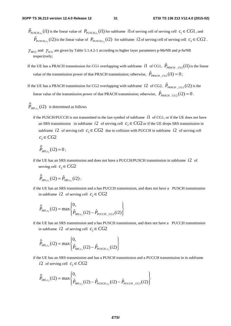
ETSI
ETSI TS 136 213 V12.4.0 (2015-02)313GPP TS 36.213 version 12.4.0 Release 12
)1(ˆ1,PUSCH iP c is the linear value of )1(
1,PUSCH iP c for subframe 1i of serving cell of serving cell 11 CGc ∈ , and
)2(ˆ2,PUSCH iP c is the linear value of )2(
2,PUSCH iP c for subframe 2i of serving cell of serving cell 22 CGc ∈ .
MCGγ and SCGγ are given by Table 5.1.4.2-1 according to higher layer parameters p-MeNB and p-SeNB
respectively;
If the UE has a PRACH transmission for CG1 overlapping with subframe 1i of CG1, )1(ˆ1_ iP CGPRACH is the linear
value of the transmission power of that PRACH transmission; otherwise, 0)1(ˆ1_ =iP CGPRACH ;
If the UE has a PRACH transmission for CG2 overlapping with subframe 2i of CG2, )2(ˆ2_ iP CGPRACH is the
linear value of the transmission power of that PRACH transmission; otherwise, 0)2(ˆ2_ =iP CGPRACH .
)2(~
2, iP cSRS is determined as follows
if the PUSCH/PUCCH is not transmitted in the last symbol of subframe 1i of CG1, or if the UE does not have
an SRS transmission in subframe 2i of serving cell 22 CGc ∈ or if the UE drops SRS transmission in
subframe 2i of serving cell 22 CGc ∈ due to collision with PUCCH in subframe 2i of serving cell
22 CGc ∈
0)2(~
2, =iP cSRS ;
if the UE has an SRS transmission and does not have a PUCCH/PUSCH transmission in subframe 2i of
serving cell 22 CGc ∈
)2(ˆ)2(~
22 ,, iPiP cSRScSRS = ;
if the UE has an SRS transmission and a has PUCCH transmission, and does not have a PUSCH transmission
in subframe 2i of serving cell 22 CGc ∈
⎪⎭
⎪⎬⎫
⎪⎩
⎪⎨⎧
−=
)2(ˆ)2(ˆ
,0max)2(
~
2_,,
2
2 iPiPiP
CGPUCCHcSRScSRS
if the UE has an SRS transmission and a has PUSCH transmission, and does not have a PUCCH transmission
in subframe 2i of serving cell 22 CGc ∈
⎪⎭
⎪⎬⎫
⎪⎩
⎪⎨⎧
−=
)2(ˆ)2(ˆ
,0max)2(
~
22
2
,,, iPiP
iPcPUSCHcSRS
cSRS
if the UE has an SRS transmission and has a PUSCH transmission and a PUCCH transmission in in subframe
2i of serving cell 22 CGc ∈
⎪⎭
⎪⎬⎫
⎪⎩
⎪⎨⎧
−−=
)2(ˆ)2(ˆ)2(ˆ
,0max)2(
~
2_,,,
22
2 iPiPiPiP
CGPUCCHcPUSCHcSRScSRS
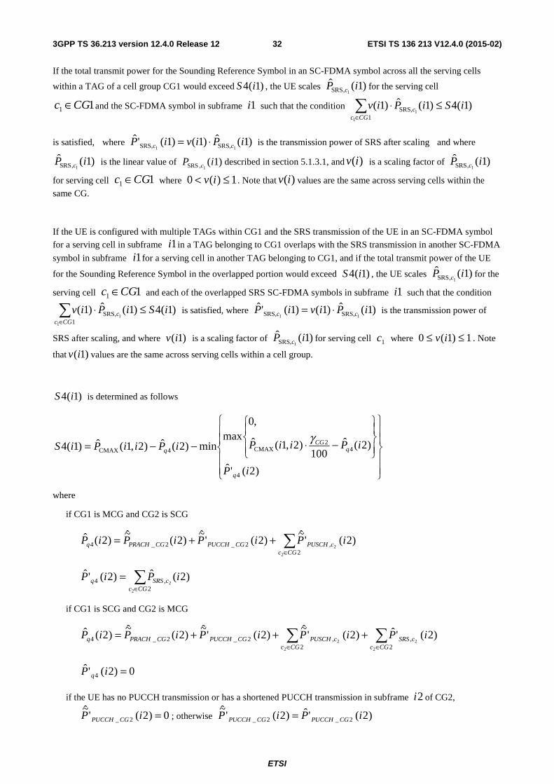
ETSI
ETSI TS 136 213 V12.4.0 (2015-02)323GPP TS 36.213 version 12.4.0 Release 12
If the total transmit power for the Sounding Reference Symbol in an SC-FDMA symbol across all the serving cells
within a TAG of a cell group CG1 would exceed )1(4 iS , the UE scales )1(ˆ1,SRS iP c for the serving cell
11 CGc ∈ and the SC-FDMA symbol in subframe 1i such that the condition )1(4)1(ˆ)1(1
,SRS
1
1iSiPiv
CGcc ≤⋅∑
∈
is satisfied, where )1(ˆ)1()1('ˆ11 ,SRS,SRS iPiviP cc ⋅= is the transmission power of SRS after scaling and where
)1(ˆ1,SRS iP c is the linear value of )1(
1,SRS iP c described in section 5.1.3.1, and )(iv is a scaling factor of )1(ˆ1,SRS iP c
for serving cell 11 CGc ∈ where 1)(0 ≤< iv . Note that )(iv values are the same across serving cells within the
same CG.
If the UE is configured with multiple TAGs within CG1 and the SRS transmission of the UE in an SC-FDMA symbol
for a serving cell in subframe 1i in a TAG belonging to CG1 overlaps with the SRS transmission in another SC-FDMA
symbol in subframe 1i for a serving cell in another TAG belonging to CG1, and if the total transmit power of the UE
for the Sounding Reference Symbol in the overlapped portion would exceed )1(4 iS , the UE scales )1(ˆ1,SRS iP c for the
serving cell 11 CGc ∈ and each of the overlapped SRS SC-FDMA symbols in subframe 1i such that the condition
)1(4)1(ˆ)1(1
,SRS
1
1iSiPiv
CGcc ≤⋅∑
∈
is satisfied, where )1(ˆ)1()1('ˆ11 ,SRS,SRS iPiviP cc ⋅= is the transmission power of
SRS after scaling, and where )1(iv is a scaling factor of )1(ˆ1,SRS iP c for serving cell 1c where 1)1(0 ≤≤ iv . Note
that )1(iv values are the same across serving cells within a cell group.
)1(4 iS is determined as follows
⎪⎪
⎭
⎪⎪
⎬
⎫
⎪⎪
⎩
⎪⎪
⎨
⎧
⎪⎭
⎪⎬
⎫
⎪⎩
⎪⎨
⎧
−⋅−−=
)2('ˆ
)2(ˆ100
)2,1(ˆ
,0max
min)2(ˆ)2,1(ˆ)1(4
4
42
CMAX4CMAX
iP
iPiiPiPiiPiS
q
qCG
q
γ
where
if CG1 is MCG and CG2 is SCG
∑∈
++=2
,2_2_4
2
2)2('
~)2('
~)2(
~)2(ˆ
CGccPUSCHCGPUCCHCGPRACHq iPiPiPiP
∑∈
=2
,4
2
2)2(ˆ)2('ˆ
CGccSRSq iPiP
if CG1 is SCG and CG2 is MCG
∑∑∈∈
+++=2
,2
,2_2_4
2
2
2
2)2('ˆ)2('
~)2('
~)2(
~)2(ˆ
CGccSRS
CGccPUSCHCGPUCCHCGPRACHq iPiPiPiPiP
0)2('ˆ4 =iP q
if the UE has no PUCCH transmission or has a shortened PUCCH transmission in subframe 2i of CG2,
0)2('~
2_ =iP CGPUCCH ; otherwise )2('ˆ)2('~
2_2_ iPiP CGPUCCHCGPUCCH =
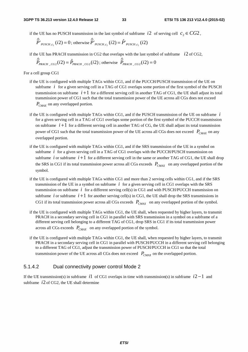
ETSI
ETSI TS 136 213 V12.4.0 (2015-02)333GPP TS 36.213 version 12.4.0 Release 12
if the UE has no PUSCH transmission in the last symbol of subframe 2i of serving cell 22 CGc ∈ ,
0)2('~
2, =iP cPUSCH ; otherwise )2('ˆ)2('~
22 ,, iPiP cPUSCHcPUSCH =
if the UE has PRACH transmission in CG2 that overlaps with the last symbol of subframe 2i of CG2,
)2(ˆ)2(~
2_2_ iPiP CGPRACHCGPRACH = ; otherwise 0)2(~
2_ =iP CGPRACH
For a cell group CG1
if the UE is configured with multiple TAGs within CG1, and if the PUCCH/PUSCH transmission of the UE on subframe i for a given serving cell in a TAG of CG1 overlaps some portion of the first symbol of the PUSCH
transmission on subframe 1+i for a different serving cell in another TAG of CG1, the UE shall adjust its total transmission power of CG1 such that the total transmission power of the UE across all CGs does not exceed
CMAXP on any overlapped portion.
if the UE is configured with multiple TAGs within CG1, and if the PUSCH transmission of the UE on subframe i for a given serving cell in a TAG of CG1 overlaps some portion of the first symbol of the PUCCH transmission
on subframe 1+i for a different serving cell in another TAG of CG, the UE shall adjust its total transmission
power of CG1 such that the total transmission power of the UE across all CGs does not exceed CMAXP on any
overlapped portion.
if the UE is configured with multiple TAGs within CG1, and if the SRS transmission of the UE in a symbol on subframe i for a given serving cell in a TAG of CG1 overlaps with the PUCCH/PUSCH transmission on
subframe i or subframe 1+i for a different serving cell in the same or another TAG of CG1, the UE shall drop
the SRS in CG1 if its total transmission power across all CGs exceeds CMAXP on any overlapped portion of the
symbol.
if the UE is configured with multiple TAGs within CG1 and more than 2 serving cells within CG1, and if the SRS transmission of the UE in a symbol on subframe i for a given serving cell in CG1 overlaps with the SRS transmission on subframe i for a different serving cell(s) in CG1 and with PUSCH/PUCCH transmission on
subframe i or subframe 1+i for another serving cell(s) in CG1, the UE shall drop the SRS transmissions in
CG1 if its total transmission power across all CGs exceeds CMAXP on any overlapped portion of the symbol.
if the UE is configured with multiple TAGs within CG1, the UE shall, when requested by higher layers, to transmit PRACH in a secondary serving cell in CG1 in parallel with SRS transmission in a symbol on a subframe of a different serving cell belonging to a different TAG of CG1, drop SRS in CG1 if its total transmission power
across all CGs exceeds CMAXP on any overlapped portion of the symbol.
if the UE is configured with multiple TAGs within CG1, the UE shall, when requested by higher layers, to transmit PRACH in a secondary serving cell in CG1 in parallel with PUSCH/PUCCH in a different serving cell belonging to a different TAG of CG1, adjust the transmission power of PUSCH/PUCCH in CG1 so that the total
transmission power of the UE across all CGs does not exceed CMAXP on the overlapped portion.
5.1.4.2 Dual connectivity power control Mode 2
If the UE transmission(s) in subframe 1i of CG1 overlaps in time with transmission(s) in subframe 12 −i and
subframe 2i of CG2, the UE shall determine
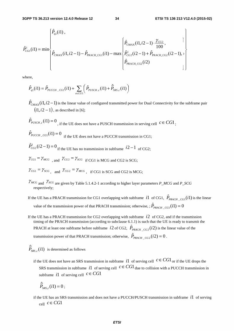
ETSI
ETSI TS 136 213 V12.4.0 (2015-02)343GPP TS 36.213 version 12.4.0 Release 12
⎪⎪⎪⎪
⎭
⎪⎪⎪⎪
⎬
⎫
⎪⎪⎪⎪
⎩
⎪⎪⎪⎪
⎨
⎧
⎪⎪⎪
⎭
⎪⎪⎪
⎬
⎫
⎪⎪⎪
⎩
⎪⎪⎪
⎨
⎧
−+−
⋅−
−−−=
)2(ˆ
),12(ˆ)12(ˆ
,100
)12,1(ˆ
max)1(ˆ)12,1(ˆ
,)1(ˆ
min)1(ˆ
PRACH_CG2
PRACH_CG21
2
2CMAX
PRACH_CG1CMAX
q1
11
iP
iPiP
iiP
iPiiP
iP
iPCG
CG
CG
γ
where,
∑∈
⎟⎠⎞⎜
⎝⎛ ++=
1,,1_1 )1(
~)1(ˆ)1(ˆ)1(ˆ
CGccSRScPUSCHCGPUCCHq iPiPiPiP
)12,1(CMAX −iiP is the linear value of configured transmitted power for Dual Connectivity for the subframe pair
( )12,1 −ii , as described in [6];
0)1(ˆ, =iP cPUSCH , if the UE does not have a PUSCH transmission in serving cell 1CGc ∈ ;
0)1(ˆ1_ =iP CGPUCCH if the UE does not have a PUCCH transmission in CG1;
0)12(ˆ12 =−iPCG if the UE has no transmission in subframe 12 −i of CG2;
MCGCG γγ =1 , and SCGCG γγ =2 if CG1 is MCG and CG2 is SCG;
SCGCG γγ =1 , and MCGCG γγ =2 , if CG1 is SCG and CG2 is MCG;
MCGγand SCGγ
are given by Table 5.1.4.2-1 according to higher layer parameters P_MCG and P_SCG respectively;
If the UE has a PRACH transmission for CG1 overlapping with subframe 1i of CG1, )1(ˆ1_ iP CGPRACH is the linear
value of the transmission power of that PRACH transmission; otherwise, ; 0)1(ˆ1_ =iP CGPRACH
If the UE has a PRACH transmission for CG2 overlapping with subframe 2i of CG2, and if the transmission timing of the PRACH transmission (according to subclause 6.1.1) is such that the UE is ready to transmit the
PRACH at least one subframe before subframe 2i of CG2, )2(ˆ2_ iP CGPRACH is the linear value of the
transmission power of that PRACH transmission; otherwise, 0)2(ˆ2_ =iP CGPRACH .
)1(~
, iP cSRS is determined as follows
if the UE does not have an SRS transmission in subframe 1i of serving cell 1CGc ∈ or if the UE drops the
SRS transmission in subframe 1i of serving cell 1CGc ∈ due to collision with a PUCCH transmission in
subframe 1i of serving cell 1CGc ∈
0)1(~
, =iP cSRS ;
if the UE has an SRS transmission and does not have a PUCCH/PUSCH transmission in subframe 1i of serving
cell 1CGc ∈
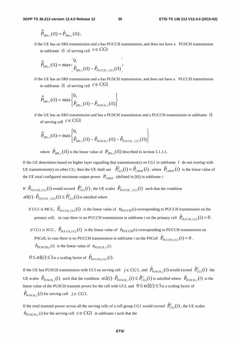
ETSI
ETSI TS 136 213 V12.4.0 (2015-02)353GPP TS 36.213 version 12.4.0 Release 12
)1(ˆ)1(~
,, iPiP cSRScSRS = ;
if the UE has an SRS transmission and a has PUCCH transmission, and does not have a PUSCH transmission
in subframe 1i of serving cell 1CGc ∈
⎪⎭
⎪⎬⎫
⎪⎩
⎪⎨⎧
−=
)1(ˆ)1(ˆ
,0max)1(
~
1_,, iPiP
iPCGPUCCHcSRS
cSRS
if the UE has an SRS transmission and a has PUSCH transmission, and does not have a PUCCH transmission
in subframe 1i of serving cell 1CGc ∈
⎪⎭
⎪⎬⎫
⎪⎩
⎪⎨⎧
−=
)1(ˆ)1(ˆ
,0max)1(
~
,,, iPiP
iPcPUSCHcSRS
cSRS
if the UE has an SRS transmission and has a PUSCH transmission and a PUCCH transmission in subframe 1i
of serving cell 1CGc ∈
⎪⎭
⎪⎬⎫
⎪⎩
⎪⎨⎧
−−=
)1(ˆ)1(ˆ)1(ˆ
,0max)1(
~
1_,,, iPiPiP
iPCGPUCCHcPUSCHcSRS
cSRS
where )1(ˆ, iP cSRS is the linear value of )1(, iP cSRS described in section 5.1.3.1.
If the UE determines based on higher layer signalling that transmission(s) on CG1 in subframe i do not overlap with
UE transmission(s) on other CG, then the UE shall use )(ˆ)(ˆ11 iPiP CMAXCG = , where )(ˆ iPCMAX is the linear value of
the UE total configured maximum output power CMAXP (defined in [6]) in subframe i.
If )(PUCCH_CG1 iP would exceed )(ˆ11 iPCG , the UE scales )(ˆ
1_ iP CGPUCCH such that the condition
)(ˆ)(ˆ)(1 111_ iPiPi CGCGPUCCH ≤⋅α is satisfied where
if CG1 is MCG, )(PUCCH_CG1 iP is the linear value of )(PUCCH iP corresponding to PUCCH transmission on the
primary cell, in case there is no PUCCH transmission in subframe i on the primary cell 0)(PUCCH_CG1 =iP .
if CG1 is SCG , )(PUCCH_CG1 iP is the linear value of )(PUCCH iP corresponding to PUCCH transmission on
PSCell, in case there is no PUCCH transmission in subframe i on the PSCell 0)(PUCCH_CG1 =iP .
)(ˆ,PUSCH iP c is the linear value of )(,PUSCH iP c
1)(10 ≤≤ iα is a scaling factor of )(PUCCH_CG1 iP .
If the UE has PUSCH transmission with UCI on serving cell 1CGj ∈ , and )(ˆ,PUSCH iP j would exceed )(ˆ1
1 iPCG the
UE scales )(ˆ,PUSCH iP j such that the condition )(ˆ)(ˆ)(2 1
1,PUSCH iPiPi CGj ≤⋅α is satisfied where )(ˆ,PUSCH iP j is the
linear value of the PUSCH transmit power for the cell with UCI, and 1)(20 ≤≤ iα is a scaling factor of
)(ˆ,PUSCH iP j for serving cell 1CGj ∈ .
If the total transmit power across all the serving cells of a cell group CG1 would exceed )(ˆ11 iPCG , the UE scales
)(ˆ,PUSCH iP c for the serving cell 1CGc ∈ in subframe i such that the
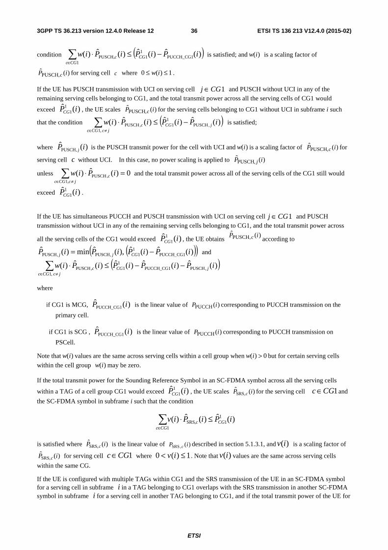
ETSI
ETSI TS 136 213 V12.4.0 (2015-02)363GPP TS 36.213 version 12.4.0 Release 12
condition ( ))(ˆ)(ˆ)(ˆ)( PUCCH_CG11
11
,PUSCH iPiPiPiw CGCGc
c −≤⋅∑∈
is satisfied; and )(iw is a scaling factor of
)(ˆ,PUSCH iP c for serving cell c where 1)(0 ≤≤ iw .
If the UE has PUSCH transmission with UCI on serving cell 1CGj ∈ and PUSCH without UCI in any of the
remaining serving cells belonging to CG1, and the total transmit power across all the serving cells of CG1 would
exceed )(ˆ11 iPCG , the UE scales )(ˆ
,PUSCH iP c for the serving cells belonging to CG1 without UCI in subframe i such
that the condition ( ))(ˆ)(ˆ)(ˆ)( ,PUSCH1
1 ,1
,PUSCH iPiPiPiw jCGjcCGc
c −≤⋅∑≠∈
is satisfied;
where )(ˆ,PUSCH iP j is the PUSCH transmit power for the cell with UCI and )(iw is a scaling factor of )(ˆ
,PUSCH iP c for
serving cell c without UCI. In this case, no power scaling is applied to )(ˆ,PUSCH iP j
unless 0)(ˆ)(,1
,PUSCH =⋅∑≠∈ jcCGc
c iPiw and the total transmit power across all of the serving cells of the CG1 still would
exceed )(ˆ11 iPCG .
If the UE has simultaneous PUCCH and PUSCH transmission with UCI on serving cell 1CGj ∈ and PUSCH
transmission without UCI in any of the remaining serving cells belonging to CG1, and the total transmit power across
all the serving cells of the CG1 would exceed )(ˆ11 iPCG , the UE obtains
)(ˆ,PUSCH iP c according to
( )( ))(ˆ)(ˆ),(ˆmin)(ˆPUCCH_CG1
11,PUSCH,PUSCH iPiPiPiP CGjj −= and
( ))(ˆ)(ˆ)(ˆ)(ˆ)( ,PUSCHPUCCH_CG11
1,1
,PUSCH iPiPiPiPiw jCGjcCGc
c −−≤⋅∑≠∈
where
if CG1 is MCG, )(PUCCH_CG1 iP is the linear value of )(PUCCH iP corresponding to PUCCH transmission on the
primary cell.
if CG1 is SCG , )(PUCCH_CG1 iP is the linear value of )(PUCCH iP corresponding to PUCCH transmission on
PSCell.
Note that )(iw values are the same across serving cells within a cell group when 0)( >iw but for certain serving cells
within the cell group )(iw may be zero.
If the total transmit power for the Sounding Reference Symbol in an SC-FDMA symbol across all the serving cells
within a TAG of a cell group CG1 would exceed )(ˆ11 iPCG , the UE scales )(ˆ
,SRS iP c for the serving cell 1CGc ∈ and
the SC-FDMA symbol in subframe i such that the condition
)(ˆ)(ˆ)( 11
1,SRS iPiPiv CG
CGcc ≤⋅∑
∈
is satisfied where )(ˆ,SRS iP c is the linear value of )(,SRS iP c described in section 5.1.3.1, and )(iv is a scaling factor of
)(ˆ,SRS iP c for serving cell 1CGc ∈ where 1)(0 ≤< iv . Note that )(iv values are the same across serving cells
within the same CG.
If the UE is configured with multiple TAGs within CG1 and the SRS transmission of the UE in an SC-FDMA symbol for a serving cell in subframe i in a TAG belonging to CG1 overlaps with the SRS transmission in another SC-FDMA symbol in subframe i for a serving cell in another TAG belonging to CG1, and if the total transmit power of the UE for
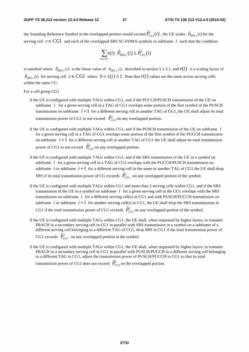
ETSI
ETSI TS 136 213 V12.4.0 (2015-02)373GPP TS 36.213 version 12.4.0 Release 12
the Sounding Reference Symbol in the overlapped portion would exceed )(ˆ11 iPCG , the UE scales )(ˆ
,SRS iP c for the
serving cell 1CGc ∈ and each of the overlapped SRS SC-FDMA symbols in subframe i such that the condition
)(ˆ)(ˆ)( 11
1,SRS iPiPiv CG
CGcc ≤⋅∑
∈
is satisfied where )(ˆ,SRS iP c is the linear value of )(,SRS iP c described in section 5.1.3.1, and )(iv is a scaling factor of
)(ˆ,SRS iP c for serving cell 1CGc ∈ where 1)(0 ≤< iv . Note that )(iv values are the same across serving cells
within the same CG.
For a cell group CG1
if the UE is configured with multiple TAGs within CG1, and if the PUCCH/PUSCH transmission of the UE on subframe i for a given serving cell in a TAG of CG1 overlaps some portion of the first symbol of the PUSCH
transmission on subframe 1+i for a different serving cell in another TAG of CG1, the UE shall adjust its total
transmission power of CG1 to not exceed 1
1CGP on any overlapped portion.
if the UE is configured with multiple TAGs within CG1, and if the PUSCH transmission of the UE on subframe i for a given serving cell in a TAG of CG1 overlaps some portion of the first symbol of the PUCCH transmission
on subframe 1+i for a different serving cell in another TAG of CG1 the UE shall adjust its total transmission
power of CG1 to not exceed 1
1CGP on any overlapped portion.
if the UE is configured with multiple TAGs within CG1, and if the SRS transmission of the UE in a symbol on subframe i for a given serving cell in a TAG of CG1 overlaps with the PUCCH/PUSCH transmission on
subframe i or subframe 1+i for a different serving cell in the same or another TAG of CG1 the UE shall drop
SRS if its total transmission power of CG exceeds 1
1CGP on any overlapped portion of the symbol.
if the UE is configured with multiple TAGs within CG1 and more than 2 serving cells within CG1, and if the SRS transmission of the UE in a symbol on subframe i for a given serving cell in the CG1 overlaps with the SRS transmission on subframe i for a different serving cell(s) in CG1 and with PUSCH/PUCCH transmission on
subframe i or subframe 1+i for another serving cell(s) in CG1, the UE shall drop the SRS transmissions in
CG1 if the total transmission power of CG1 exceeds 1
1CGP on any overlapped portion of the symbol.
if the UE is configured with multiple TAGs within CG1, the UE shall, when requested by higher layers, to transmit PRACH in a secondary serving cell in CG1 in parallel with SRS transmission in a symbol on a subframe of a different serving cell belonging to a different TAG of CG1, drop SRS in CG1 if the total transmission power of
CG1 exceeds 1
1CGP on any overlapped portion in the symbol.
if the UE is configured with multiple TAGs within CG1, the UE shall, when requested by higher layers, to transmit PRACH in a secondary serving cell in CG1 in parallel with PUSCH/PUCCH in a different serving cell belonging to a different TAG in CG1, adjust the transmission power of PUSCH/PUCCH in CG1 so that its total
transmission power of CG1 does not exceed 1
1CGP on the overlapped portion.
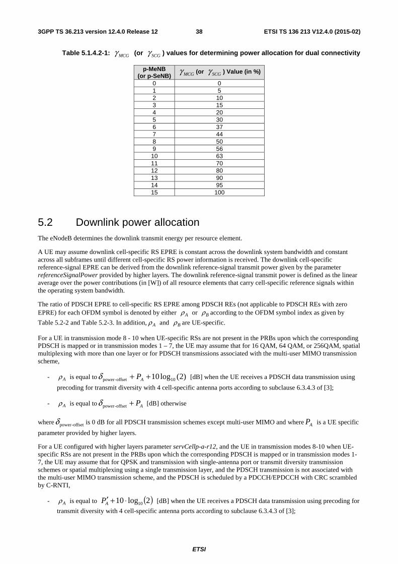
ETSI
ETSI TS 136 213 V12.4.0 (2015-02)383GPP TS 36.213 version 12.4.0 Release 12
Table 5.1.4.2-1: MCGγ (or SCGγ ) values for determining power allocation for dual connectivity
p-MeNB (or p-SeNB) MCGγ (or SCGγ ) Value (in %)
0 0 1 5 2 10 3 15 4 20 5 30 6 37 7 44 8 50 9 56 10 63 11 70 12 80 13 90 14 95 15 100
5.2 Downlink power allocation The eNodeB determines the downlink transmit energy per resource element.
A UE may assume downlink cell-specific RS EPRE is constant across the downlink system bandwidth and constant across all subframes until different cell-specific RS power information is received. The downlink cell-specific reference-signal EPRE can be derived from the downlink reference-signal transmit power given by the parameter referenceSignalPower provided by higher layers. The downlink reference-signal transmit power is defined as the linear average over the power contributions (in [W]) of all resource elements that carry cell-specific reference signals within the operating system bandwidth.
The ratio of PDSCH EPRE to cell-specific RS EPRE among PDSCH REs (not applicable to PDSCH REs with zero EPRE) for each OFDM symbol is denoted by either Aρ or Bρ according to the OFDM symbol index as given by
Table 5.2-2 and Table 5.2-3. In addition, Aρ and Bρ are UE-specific.
For a UE in transmission mode 8 - 10 when UE-specific RSs are not present in the PRBs upon which the corresponding PDSCH is mapped or in transmission modes 1 – 7, the UE may assume that for 16 QAM, 64 QAM, or 256QAM, spatial multiplexing with more than one layer or for PDSCH transmissions associated with the multi-user MIMO transmission scheme,
- Aρ is equal to )2(log10 10offset-power ++ APδ [dB] when the UE receives a PDSCH data transmission using
precoding for transmit diversity with 4 cell-specific antenna ports according to subclause 6.3.4.3 of [3];
- Aρ is equal to AP+offset-powerδ [dB] otherwise
where offset-powerδ is 0 dB for all PDSCH transmission schemes except multi-user MIMO and where AP is a UE specific
parameter provided by higher layers.
For a UE configured with higher layers parameter servCellp-a-r12, and the UE in transmission modes 8-10 when UE-specific RSs are not present in the PRBs upon which the corresponding PDSCH is mapped or in transmission modes 1-7, the UE may assume that for QPSK and transmission with single-antenna port or transmit diversity transmission schemes or spatial multiplexing using a single transmission layer, and the PDSCH transmission is not associated with the multi-user MIMO transmission scheme, and the PDSCH is scheduled by a PDCCH/EPDCCH with CRC scrambled by C-RNTI,
- Aρ is equal to ( )2log10 10⋅+′AP [dB] when the UE receives a PDSCH data transmission using precoding for
transmit diversity with 4 cell-specific antenna ports according to subclause 6.3.4.3 of [3];
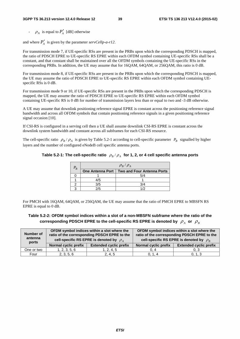
ETSI
ETSI TS 136 213 V12.4.0 (2015-02)393GPP TS 36.213 version 12.4.0 Release 12
- Aρ is equal to AP′ [dB] otherwise
and where AP′ is given by the parameter servCellp-a-r12.
For transmission mode 7, if UE-specific RSs are present in the PRBs upon which the corresponding PDSCH is mapped, the ratio of PDSCH EPRE to UE-specific RS EPRE within each OFDM symbol containing UE-specific RSs shall be a constant, and that constant shall be maintained over all the OFDM symbols containing the UE-specific RSs in the corresponding PRBs. In addition, the UE may assume that for 16QAM, 64QAM, or 256QAM, this ratio is 0 dB.
For transmission mode 8, if UE-specific RSs are present in the PRBs upon which the corresponding PDSCH is mapped, the UE may assume the ratio of PDSCH EPRE to UE-specific RS EPRE within each OFDM symbol containing UE-specific RSs is 0 dB.
For transmission mode 9 or 10, if UE-specific RSs are present in the PRBs upon which the corresponding PDSCH is mapped, the UE may assume the ratio of PDSCH EPRE to UE-specific RS EPRE within each OFDM symbol containing UE-specific RS is 0 dB for number of transmission layers less than or equal to two and -3 dB otherwise.
A UE may assume that downlink positioning reference signal EPRE is constant across the positioning reference signal bandwidth and across all OFDM symbols that contain positioning reference signals in a given positioning reference signal occasion [10].
If CSI-RS is configured in a serving cell then a UE shall assume downlink CSI-RS EPRE is constant across the downlink system bandwidth and constant across all subframes for each CSI-RS resource.
The cell-specific ratio AB ρρ / is given by Table 5.2-1 according to cell-specific parameter BP signalled by higher
layers and the number of configured eNodeB cell specific antenna ports.
Table 5.2-1: The cell-specific ratio AB ρρ / for 1, 2, or 4 cell specific antenna ports
BP AB ρρ /
One Antenna Port Two and Four Antenna Ports 0 1 5/4 1 4/5 1 2 3/5 3/4 3 2/5 1/2
For PMCH with 16QAM, 64QAM, or 256QAM, the UE may assume that the ratio of PMCH EPRE to MBSFN RS EPRE is equal to 0 dB.
Table 5.2-2: OFDM symbol indices within a slot of a non-MBSFN subframe where the ratio of the corresponding PDSCH EPRE to the cell-specific RS EPRE is denoted by Aρ or Bρ
Number of antenna
ports
OFDM symbol indices within a slot where the ratio of the corresponding PDSCH EPRE to the
cell-specific RS EPRE is denoted by Aρ
OFDM symbol indices within a slot where the ratio of the corresponding PDSCH EPRE to the
cell-specific RS EPRE is denoted by Bρ
Normal cyclic prefix Extended cyclic prefix Normal cyclic prefix Extended cyclic prefix One or two 1, 2, 3, 5, 6 1, 2, 4, 5 0, 4 0, 3
Four 2, 3, 5, 6 2, 4, 5 0, 1, 4 0, 1, 3
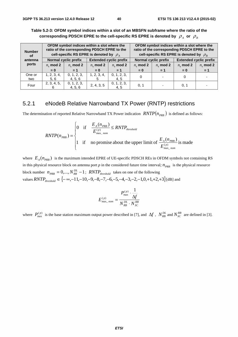
ETSI
ETSI TS 136 213 V12.4.0 (2015-02)403GPP TS 36.213 version 12.4.0 Release 12
Table 5.2-3: OFDM symbol indices within a slot of an MBSFN subframe where the ratio of the corresponding PDSCH EPRE to the cell-specific RS EPRE is denoted by Aρ or Bρ
Number of
antenna ports
OFDM symbol indices within a slot where the ratio of the corresponding PDSCH EPRE to the
cell-specific RS EPRE is denoted by Aρ
OFDM symbol indices within a slot where the ratio of the corresponding PDSCH EPRE to the
cell-specific RS EPRE is denoted by Bρ
Normal cyclic prefix Extended cyclic prefix Normal cyclic prefix Extended cyclic prefix
sn mod 2 = 0
sn mod 2 = 1
sn mod 2 = 0
sn mod 2 = 1
sn mod 2 = 0
sn mod 2 = 1
sn mod 2 = 0
sn mod 2 = 1
One or two
1, 2, 3, 4, 5, 6
0, 1, 2, 3, 4, 5, 6
1, 2, 3, 4, 5
0, 1, 2, 3, 4, 5 0 - 0 -
Four 2, 3, 4, 5, 6
0, 1, 2, 3, 4, 5, 6 2, 4, 3, 5 0, 1, 2, 3,
4, 5 0, 1 - 0, 1 -
5.2.1 eNodeB Relative Narrowband TX Power (RNTP) restrictions
The determination of reported Relative Narrowband TX Power indication ( )PRBnRNTP is defined as follows:
⎪⎪
⎩
⎪⎪
⎨
⎧ ≤
=made is
)( oflimit upper about the promise noif1
)(if0
)(
)(max_
)(max_
pnom
PRBA
thresholdpnom
PRBA
PRB
E
nE
RNTPE
nE
nRNTP
where )( PRBA nE is the maximum intended EPRE of UE-specific PDSCH REs in OFDM symbols not containing RS
in this physical resource block on antenna port p in the considered future time interval; PRBn is the physical resource
block number 1,...,0 −= DLRBPRB Nn ; thresholdRNTP takes on one of the following
values { }3,2,1,0,1,2,3,4,5,6,7,8,9,10,11, +++−−−−−−−−−−−∞−∈thresholdRNTP [dB] and
RBSC
DLRB
p
pnom NN
fP
E⋅
Δ⋅
=
1)(max
)(max_
where )(max
pP is the base station maximum output power described in [7], and fΔ , DLRBN and RB
SCN are defined in [3].
ETSI
ETSI TS 136 213 V12.4.0 (2015-02)413GPP TS 36.213 version 12.4.0 Release 12
6 Random access procedure If the UE is configured with a SCG, the UE shall apply the procedures described in this clause for both MCG and SCG
- − When the procedures are applied for MCG, the terms ‘secondary cell’, ‘secondary cells’ , ‘serving cell’, ‘serving cells’ in this clause refer to secondary cell, secondary cells, serving cell, serving cells belonging to the MCG respectively.
- − When the procedures are applied for SCG, the terms ‘secondary cell’, ‘secondary cells’, ‘serving cell’, ‘serving cells’ in this clause refer to secondary cell, secondary cells (not including PSCell), serving cell, serving cells belonging to the SCG respectively. The term ‘primary cell’ in this clause refers to the PSCell of the SCG
Prior to initiation of the non-synchronized physical random access procedure, Layer 1 shall receive the following information from the higher layers:
1. Random access channel parameters (PRACH configuration and frequency position)
2. Parameters for determining the root sequences and their cyclic shifts in the preamble sequence set for the
primary cell (index to logical root sequence table, cyclic shift ( CSN ), and set type (unrestricted or restricted
set))
6.1 Physical non-synchronized random access procedure From the physical layer perspective, the L1 random access procedure encompasses the transmission of random access preamble and random access response. The remaining messages are scheduled for transmission by the higher layer on the shared data channel and are not considered part of the L1 random access procedure. A random access channel occupies 6 resource blocks in a subframe or set of consecutive subframes reserved for random access preamble transmissions. The eNodeB is not prohibited from scheduling data in the resource blocks reserved for random access channel preamble transmission.
The following steps are required for the L1 random access procedure:
1. Layer 1 procedure is triggered upon request of a preamble transmission by higher layers.
2. A preamble index, a target preamble received power (PREAMBLE_RECEIVED_TARGET_POWER), a corresponding RA-RNTI and a PRACH resource are indicated by higher layers as part of the request.
3. A preamble transmission power PPRACH is determined as PPRACH = min{ )(cCMAX, iP , PREAMBLE_RECEIVED_TARGET_POWER + cPL }_[dBm], where
)(cCMAX, iP is the configured UE transmit power defined in [6] for subframe i of serving cell c and cPL is
the downlink path loss estimate calculated in the UE for serving cell c .
4. A preamble sequence is selected from the preamble sequence set using the preamble index.
5. A single preamble is transmitted using the selected preamble sequence with transmission power PPRACH on the indicated PRACH resource.
6. Detection of a PDCCH with the indicated RA-RNTI is attempted during a window controlled by higher layers (see [8], subclause 5.1.4). If detected, the corresponding DL-SCH transport block is passed to higher layers. The higher layers parse the transport block and indicate the 20-bit uplink grant to the physical layer, which is processed according to subclause 6.2.
6.1.1 Timing
For the L1 random access procedure, UE's uplink transmission timing after a random access preamble transmission is as follows.
a) If a PDCCH with associated RA-RNTI is detected in subframe n, and the corresponding DL-SCH transport block contains a response to the transmitted preamble sequence, the UE shall, according to the information in the
ETSI
ETSI TS 136 213 V12.4.0 (2015-02)423GPP TS 36.213 version 12.4.0 Release 12
response, transmit an UL-SCH transport block in the first subframe 1kn + , 61 ≥k , if the UL delay field in
subclause 6.2 is set to zero where 1kn + is the first available UL subframe for PUSCH transmission, where for TDD
serving cell, the first UL subframe for PUSCH transmission is determined based on the UL/DL configuration (i.e., the parameter subframeAssignment) indicated by higher layers. The UE shall postpone the PUSCH transmission to the next available UL subframe after 1kn + if the field is set to 1.
b) If a random access response is received in subframe n, and the corresponding DL-SCH transport block does not contain a response to the transmitted preamble sequence, the UE shall, if requested by higher layers, be ready to transmit a new preamble sequence no later than in subframe 5n + .
c) If no random access response is received in subframe n, where subframe n is the last subframe of the random access response window, the UE shall, if requested by higher layers, be ready to transmit a new preamble sequence no later than in subframe 4n + .
In case a random access procedure is initiated by a "PDCCH order" in subframe n, the UE shall, if requested by higher layers, transmit random access preamble in the first subframe 2n k+ , 2 6k ≥ , where a PRACH resource is available.
If a UE is configured with multiple TAGs, and if the UE is configured with the carrier indicator field for a given serving cell, the UE shall use the carrier indicator field value from the detected "PDCCH order" to determine the serving cell for the corresponding random access preamble transmission.
6.2 Random Access Response Grant The higher layers indicate the 20-bit UL Grant to the physical layer, as defined in 3GPP TS 36.321 [8]. This is referred to the Random Access Response Grant in the physical layer. The content of these 20 bits starting with the MSB and ending with the LSB are as follows:
- Hopping flag – 1 bit
- Fixed size resource block assignment – 10 bits
- Truncated modulation and coding scheme – 4 bits
- TPC command for scheduled PUSCH – 3 bits
- UL delay – 1 bit
- CSI request – 1 bit
The UE shall use the single-antenna port uplink transmission scheme for the PUSCH transmission corresponding to the Random Access Response Grant and the PUSCH retransmission for the same transport block.
The UE shall perform PUSCH frequency hopping if the single bit frequency hopping (FH) field in a corresponding Random Access Response Grant is set as 1 and the uplink resource block assignment is type 0, otherwise no PUSCH frequency hopping is performed. When the hopping flag is set, the UE shall perform PUSCH hopping as indicated via the fixed size resource block assignment detailed below.
The fixed size resource block assignment field is interpreted as follows:
if 44ULRB ≤N
Truncate the fixed size resource block assignment to its b least significant bits, where
( )( )⎡ ⎤2/1log ULRB
ULRB2 +⋅= NNb , and interpret the truncated resource block assignment according to the rules for a
regular DCI format 0
else
Insert b most significant bits with value set to '0' after the NUL_hop hopping bits in the fixed size resource block assignment, where the number of hopping bits NUL_hop is zero when the hopping flag bit is not set to 1, and is defined
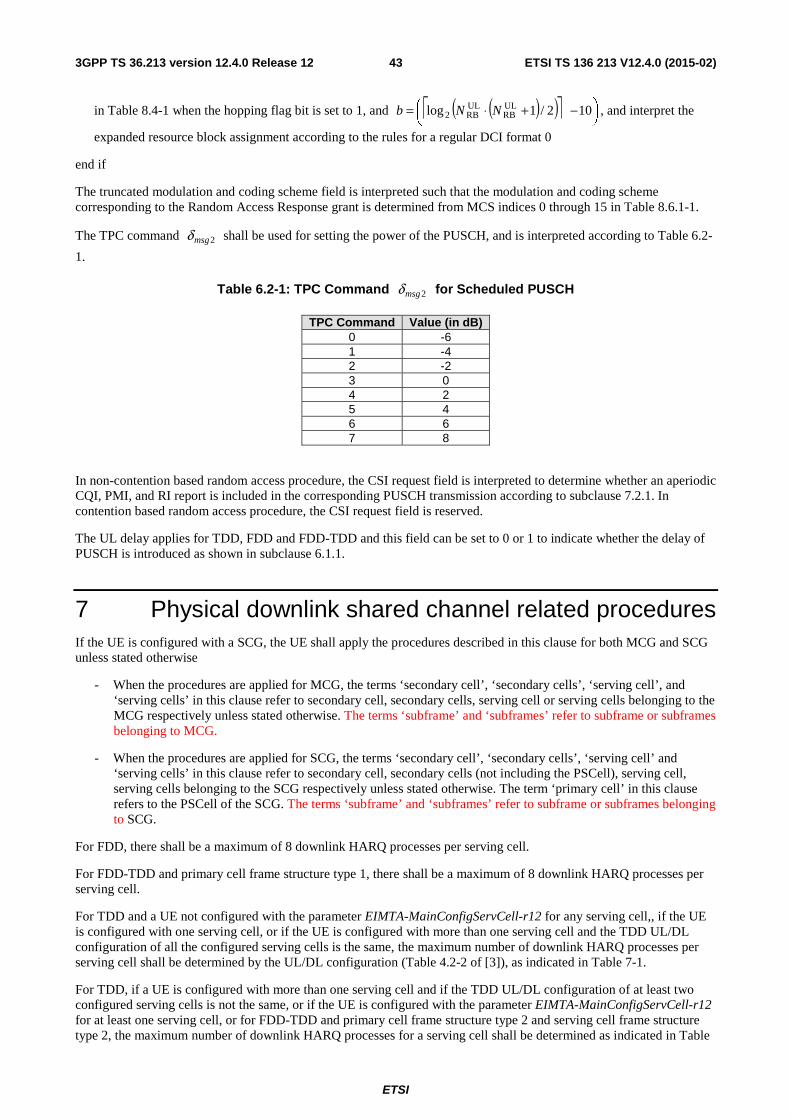
ETSI
ETSI TS 136 213 V12.4.0 (2015-02)433GPP TS 36.213 version 12.4.0 Release 12
in Table 8.4-1 when the hopping flag bit is set to 1, and ( )( )⎡ ⎤ ⎟⎠⎞
⎜⎝⎛ −+⋅= 102/1log UL
RBULRB2 NNb , and interpret the
expanded resource block assignment according to the rules for a regular DCI format 0
end if
The truncated modulation and coding scheme field is interpreted such that the modulation and coding scheme corresponding to the Random Access Response grant is determined from MCS indices 0 through 15 in Table 8.6.1-1.
The TPC command 2msgδ shall be used for setting the power of the PUSCH, and is interpreted according to Table 6.2-
1.
Table 6.2-1: TPC Command 2msgδ for Scheduled PUSCH
TPC Command Value (in dB) 0 -6 1 -4 2 -2 3 0 4 2 5 4 6 6 7 8
In non-contention based random access procedure, the CSI request field is interpreted to determine whether an aperiodic CQI, PMI, and RI report is included in the corresponding PUSCH transmission according to subclause 7.2.1. In contention based random access procedure, the CSI request field is reserved.
The UL delay applies for TDD, FDD and FDD-TDD and this field can be set to 0 or 1 to indicate whether the delay of PUSCH is introduced as shown in subclause 6.1.1.
7 Physical downlink shared channel related procedures If the UE is configured with a SCG, the UE shall apply the procedures described in this clause for both MCG and SCG unless stated otherwise
- When the procedures are applied for MCG, the terms ‘secondary cell’, ‘secondary cells’, ‘serving cell’, and ‘serving cells’ in this clause refer to secondary cell, secondary cells, serving cell or serving cells belonging to the MCG respectively unless stated otherwise. The terms ‘subframe’ and ‘subframes’ refer to subframe or subframes belonging to MCG.
- When the procedures are applied for SCG, the terms ‘secondary cell’, ‘secondary cells’, ‘serving cell’ and ‘serving cells’ in this clause refer to secondary cell, secondary cells (not including the PSCell), serving cell, serving cells belonging to the SCG respectively unless stated otherwise. The term ‘primary cell’ in this clause refers to the PSCell of the SCG. The terms ‘subframe’ and ‘subframes’ refer to subframe or subframes belonging to SCG.
For FDD, there shall be a maximum of 8 downlink HARQ processes per serving cell.
For FDD-TDD and primary cell frame structure type 1, there shall be a maximum of 8 downlink HARQ processes per serving cell.
For TDD and a UE not configured with the parameter EIMTA-MainConfigServCell-r12 for any serving cell,, if the UE is configured with one serving cell, or if the UE is configured with more than one serving cell and the TDD UL/DL configuration of all the configured serving cells is the same, the maximum number of downlink HARQ processes per serving cell shall be determined by the UL/DL configuration (Table 4.2-2 of [3]), as indicated in Table 7-1.
For TDD, if a UE is configured with more than one serving cell and if the TDD UL/DL configuration of at least two configured serving cells is not the same, or if the UE is configured with the parameter EIMTA-MainConfigServCell-r12 for at least one serving cell, or for FDD-TDD and primary cell frame structure type 2 and serving cell frame structure type 2, the maximum number of downlink HARQ processes for a serving cell shall be determined as indicated in Table
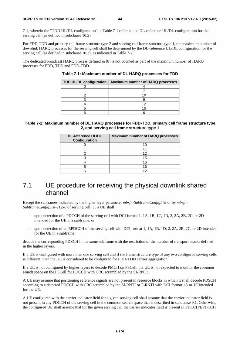
ETSI
ETSI TS 136 213 V12.4.0 (2015-02)443GPP TS 36.213 version 12.4.0 Release 12
7-1, wherein the "TDD UL/DL configuration" in Table 7-1 refers to the DL-reference UL/DL configuration for the serving cell (as defined in subclause 10.2).
For FDD-TDD and primary cell frame structure type 2 and serving cell frame structure type 1, the maximum number of downlink HARQ processes for the serving cell shall be determined by the DL-reference UL/DL configuration for the serving cell (as defined in subclause 10.2), as indicated in Table 7-2.
The dedicated broadcast HARQ process defined in [8] is not counted as part of the maximum number of HARQ processes for FDD, TDD and FDD-TDD.
Table 7-1: Maximum number of DL HARQ processes for TDD
TDD UL/DL configuration Maximum number of HARQ processes 0 4 1 7 2 10 3 9 4 12 5 15 6 6
Table 7-2: Maximum number of DL HARQ processes for FDD-TDD, primary cell frame structure type 2, and serving cell frame structure type 1
DL-reference UL/DL Configuration
Maximum number of HARQ processes
0 10 1 11 2 12 3 15 4 16 5 16 6 12
7.1 UE procedure for receiving the physical downlink shared channel
Except the subframes indicated by the higher layer parameter mbsfn-SubframeConfigList or by mbsfn-SubframeConfigList-v12x0 of serving cell c , a UE shall
- upon detection of a PDCCH of the serving cell with DCI format 1, 1A, 1B, 1C, 1D, 2, 2A, 2B, 2C, or 2D intended for the UE in a subframe, or
- upon detection of an EPDCCH of the serving cell with DCI format 1, 1A, 1B, 1D, 2, 2A, 2B, 2C, or 2D intended for the UE in a subframe
decode the corresponding PDSCH in the same subframe with the restriction of the number of transport blocks defined in the higher layers.
If a UE is configured with more than one serving cell and if the frame structure type of any two configured serving cells is different, then the UE is considered to be configured for FDD-TDD carrier aggregation.
If a UE is not configured by higher layers to decode PMCH on PSCell, the UE is not expected to monitor the common search space on the PSCell for PDCCH with CRC scrambled by the SI-RNTI.
A UE may assume that positioning reference signals are not present in resource blocks in which it shall decode PDSCH according to a detected PDCCH with CRC scrambled by the SI-RNTI or P-RNTI with DCI format 1A or 1C intended for the UE.
A UE configured with the carrier indicator field for a given serving cell shall assume that the carrier indicator field is not present in any PDCCH of the serving cell in the common search space that is described in subclause 9.1. Otherwise, the configured UE shall assume that for the given serving cell the carrier indicator field is present in PDCCH/EPDCCH
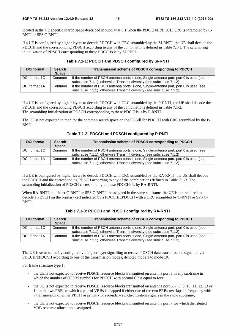
ETSI
ETSI TS 136 213 V12.4.0 (2015-02)453GPP TS 36.213 version 12.4.0 Release 12
located in the UE specific search space described in subclause 9.1 when the PDCCH/EPDCCH CRC is scrambled by C-RNTI or SPS C-RNTI.
If a UE is configured by higher layers to decode PDCCH with CRC scrambled by the SI-RNTI, the UE shall decode the PDCCH and the corresponding PDSCH according to any of the combinations defined in Table 7.1-1. The scrambling initialization of PDSCH corresponding to these PDCCHs is by SI-RNTI.
Table 7.1-1: PDCCH and PDSCH configured by SI-RNTI
DCI format Search Space
Transmission scheme of PDSCH corresponding to PDCCH
DCI format 1C Common If the number of PBCH antenna ports is one, Single-antenna port, port 0 is used (see subclause 7.1.1), otherwise Transmit diversity (see subclause 7.1.2).
DCI format 1A Common If the number of PBCH antenna ports is one, Single-antenna port, port 0 is used (see subclause 7.1.1), otherwise Transmit diversity (see subclause 7.1.2).
If a UE is configured by higher layers to decode PDCCH with CRC scrambled by the P-RNTI, the UE shall decode the PDCCH and the corresponding PDSCH according to any of the combinations defined in Table 7.1-2. The scrambling initialization of PDSCH corresponding to these PDCCHs is by P-RNTI.
The UE is not expected to monitor the common search space on the PSCell for PDCCH with CRC scrambled by the P-RNTI.
Table 7.1-2: PDCCH and PDSCH configured by P-RNTI
DCI format Search Space
Transmission scheme of PDSCH corresponding to PDCCH
DCI format 1C Common If the number of PBCH antenna ports is one, Single-antenna port, port 0 is used (see subclause 7.1.1), otherwise Transmit diversity (see subclause 7.1.2)
DCI format 1A Common If the number of PBCH antenna ports is one, Single-antenna port, port 0 is used (see subclause 7.1.1), otherwise Transmit diversity (see subclause 7.1.2)
If a UE is configured by higher layers to decode PDCCH with CRC scrambled by the RA-RNTI, the UE shall decode the PDCCH and the corresponding PDSCH according to any of the combinations defined in Table 7.1-3. The scrambling initialization of PDSCH corresponding to these PDCCHs is by RA-RNTI.
When RA-RNTI and either C-RNTI or SPS C-RNTI are assigned in the same subframe, the UE is not required to decode a PDSCH on the primary cell indicated by a PDCCH/EPDCCH with a CRC scrambled by C-RNTI or SPS C-RNTI.
Table 7.1-3: PDCCH and PDSCH configured by RA-RNTI
DCI format Search Space
Transmission scheme of PDSCH corresponding to PDCCH
DCI format 1C Common If the number of PBCH antenna ports is one, Single-antenna port, port 0 is used (see subclause 7.1.1), otherwise Transmit diversity (see subclause 7.1.2)
DCI format 1A Common If the number of PBCH antenna ports is one, Single-antenna port, port 0 is used (see subclause 7.1.1), otherwise Transmit diversity (see subclause 7.1.2)
The UE is semi-statically configured via higher layer signalling to receive PDSCH data transmissions signalled via PDCCH/EPDCCH according to one of the transmission modes, denoted mode 1 to mode 10.
For frame structure type 1,
- the UE is not expected to receive PDSCH resource blocks transmitted on antenna port 5 in any subframe in which the number of OFDM symbols for PDCCH with normal CP is equal to four;
- the UE is not expected to receive PDSCH resource blocks transmitted on antenna port 5, 7, 8, 9, 10, 11, 12, 13 or 14 in the two PRBs to which a pair of VRBs is mapped if either one of the two PRBs overlaps in frequency with a transmission of either PBCH or primary or secondary synchronization signals in the same subframe;
- the UE is not expected to receive PDSCH resource blocks transmitted on antenna port 7 for which distributed VRB resource allocation is assigned.
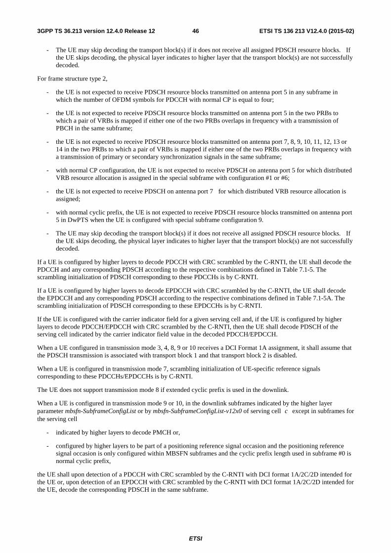
ETSI
ETSI TS 136 213 V12.4.0 (2015-02)463GPP TS 36.213 version 12.4.0 Release 12
- The UE may skip decoding the transport block(s) if it does not receive all assigned PDSCH resource blocks. If the UE skips decoding, the physical layer indicates to higher layer that the transport block(s) are not successfully decoded.
For frame structure type 2,
- the UE is not expected to receive PDSCH resource blocks transmitted on antenna port 5 in any subframe in which the number of OFDM symbols for PDCCH with normal CP is equal to four;
- the UE is not expected to receive PDSCH resource blocks transmitted on antenna port 5 in the two PRBs to which a pair of VRBs is mapped if either one of the two PRBs overlaps in frequency with a transmission of PBCH in the same subframe;
- the UE is not expected to receive PDSCH resource blocks transmitted on antenna port 7, 8, 9, 10, 11, 12, 13 or 14 in the two PRBs to which a pair of VRBs is mapped if either one of the two PRBs overlaps in frequency with a transmission of primary or secondary synchronization signals in the same subframe;
- with normal CP configuration, the UE is not expected to receive PDSCH on antenna port 5 for which distributed VRB resource allocation is assigned in the special subframe with configuration #1 or #6;
- the UE is not expected to receive PDSCH on antenna port 7 for which distributed VRB resource allocation is assigned;
- with normal cyclic prefix, the UE is not expected to receive PDSCH resource blocks transmitted on antenna port 5 in DwPTS when the UE is configured with special subframe configuration 9.
- The UE may skip decoding the transport block(s) if it does not receive all assigned PDSCH resource blocks. If the UE skips decoding, the physical layer indicates to higher layer that the transport block(s) are not successfully decoded.
If a UE is configured by higher layers to decode PDCCH with CRC scrambled by the C-RNTI, the UE shall decode the PDCCH and any corresponding PDSCH according to the respective combinations defined in Table 7.1-5. The scrambling initialization of PDSCH corresponding to these PDCCHs is by C-RNTI.
If a UE is configured by higher layers to decode EPDCCH with CRC scrambled by the C-RNTI, the UE shall decode the EPDCCH and any corresponding PDSCH according to the respective combinations defined in Table 7.1-5A. The scrambling initialization of PDSCH corresponding to these EPDCCHs is by C-RNTI.
If the UE is configured with the carrier indicator field for a given serving cell and, if the UE is configured by higher layers to decode PDCCH/EPDCCH with CRC scrambled by the C-RNTI, then the UE shall decode PDSCH of the serving cell indicated by the carrier indicator field value in the decoded PDCCH/EPDCCH.
When a UE configured in transmission mode 3, 4, 8, 9 or 10 receives a DCI Format 1A assignment, it shall assume that the PDSCH transmission is associated with transport block 1 and that transport block 2 is disabled.
When a UE is configured in transmission mode 7, scrambling initialization of UE-specific reference signals corresponding to these PDCCHs/EPDCCHs is by C-RNTI.
The UE does not support transmission mode 8 if extended cyclic prefix is used in the downlink.
When a UE is configured in transmission mode 9 or 10, in the downlink subframes indicated by the higher layer parameter mbsfn-SubframeConfigList or by mbsfn-SubframeConfigList-v12x0 of serving cell c except in subframes for the serving cell
- indicated by higher layers to decode PMCH or,
- configured by higher layers to be part of a positioning reference signal occasion and the positioning reference signal occasion is only configured within MBSFN subframes and the cyclic prefix length used in subframe #0 is normal cyclic prefix,
the UE shall upon detection of a PDCCH with CRC scrambled by the C-RNTI with DCI format 1A/2C/2D intended for the UE or, upon detection of an EPDCCH with CRC scrambled by the C-RNTI with DCI format 1A/2C/2D intended for the UE, decode the corresponding PDSCH in the same subframe.

ETSI
ETSI TS 136 213 V12.4.0 (2015-02)473GPP TS 36.213 version 12.4.0 Release 12
A UE configured in transmission mode 10 can be configured with scrambling identities, inDMRS,ID , 1,0=i by higher
layers for UE-specific reference signal generation as defined in subclause 6.10.3.1 of [3] to decode PDSCH according to a detected PDCCH/EPDCCH with CRC scrambled by the C-RNTI with DCI format 2D intended for the UE.
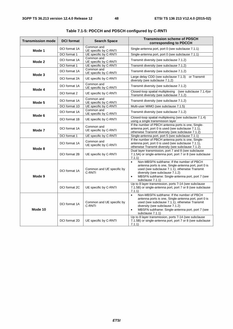
ETSI
ETSI TS 136 213 V12.4.0 (2015-02)483GPP TS 36.213 version 12.4.0 Release 12
Table 7.1-5: PDCCH and PDSCH configured by C-RNTI
Transmission mode DCI format Search Space Transmission scheme of PDSCH corresponding to PDCCH
Mode 1 DCI format 1A Common and UE specific by C-RNTI
Single-antenna port, port 0 (see subclause 7.1.1)
DCI format 1 UE specific by C-RNTI Single-antenna port, port 0 (see subclause 7.1.1)
Mode 2 DCI format 1A Common and UE specific by C-RNTI Transmit diversity (see subclause 7.1.2)
DCI format 1 UE specific by C-RNTI Transmit diversity (see subclause 7.1.2)
Mode 3 DCI format 1A Common and
UE specific by C-RNTI Transmit diversity (see subclause 7.1.2)
DCI format 2A UE specific by C-RNTI Large delay CDD (see subclause 7.1.3) or Transmit diversity (see subclause 7.1.2)
Mode 4 DCI format 1A Common and
UE specific by C-RNTI Transmit diversity (see subclause 7.1.2)
DCI format 2 UE specific by C-RNTI Closed-loop spatial multiplexing (see subclause 7.1.4)or Transmit diversity (see subclause 7.1.2)
Mode 5 DCI format 1A Common and UE specific by C-RNTI Transmit diversity (see subclause 7.1.2)
DCI format 1D UE specific by C-RNTI Multi-user MIMO (see subclause 7.1.5)
Mode 6 DCI format 1A Common and
UE specific by C-RNTI Transmit diversity (see subclause 7.1.2)
DCI format 1B UE specific by C-RNTI Closed-loop spatial multiplexing (see subclause 7.1.4) using a single transmission layer
Mode 7 DCI format 1A Common and UE specific by C-RNTI
If the number of PBCH antenna ports is one, Single-antenna port, port 0 is used (see subclause 7.1.1), otherwise Transmit diversity (see subclause 7.1.2)
DCI format 1 UE specific by C-RNTI Single-antenna port, port 5 (see subclause 7.1.1)
Mode 8
DCI format 1A Common and UE specific by C-RNTI
If the number of PBCH antenna ports is one, Single-antenna port, port 0 is used (see subclause 7.1.1), otherwise Transmit diversity (see subclause 7.1.2)
DCI format 2B UE specific by C-RNTI Dual layer transmission, port 7 and 8 (see subclause 7.1.5A) or single-antenna port, port 7 or 8 (see subclause 7.1.1)
Mode 9
DCI format 1A Common and UE specific by C-RNTI
• Non-MBSFN subframe: If the number of PBCH antenna ports is one, Single-antenna port, port 0 is used (see subclause 7.1.1), otherwise Transmit diversity (see subclause 7.1.2)
• MBSFN subframe: Single-antenna port, port 7 (see subclause 7.1.1)
DCI format 2C UE specific by C-RNTI Up to 8 layer transmission, ports 7-14 (see subclause 7.1.5B) or single-antenna port, port 7 or 8 (see subclause 7.1.1)
Mode 10
DCI format 1A Common and UE specific by C-RNTI
• Non-MBSFN subframe: If the number of PBCH antenna ports is one, Single-antenna port, port 0 is used (see subclause 7.1.1), otherwise Transmit diversity (see subclause 7.1.2)
• MBSFN subframe: Single-antenna port, port 7 (see subclause 7.1.1)
DCI format 2D UE specific by C-RNTI Up to 8 layer transmission, ports 7-14 (see subclause 7.1.5B) or single-antenna port, port 7 or 8 (see subclause 7.1.1)
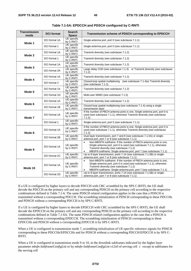
ETSI
ETSI TS 136 213 V12.4.0 (2015-02)493GPP TS 36.213 version 12.4.0 Release 12
Table 7.1-5A: EPDCCH and PDSCH configured by C-RNTI
Transmission mode DCI format Search
Space Transmission scheme of PDSCH corresponding to EPDCCH
Mode 1 DCI format 1A UE specific
by C-RNTI Single-antenna port, port 0 (see subclause 7.1.1)
DCI format 1 UE specific by C-RNTI Single-antenna port, port 0 (see subclause 7.1.1)
Mode 2 DCI format 1A UE specific
by C-RNTI Transmit diversity (see subclause 7.1.2)
DCI format 1 UE specific by C-RNTI Transmit diversity (see subclause 7.1.2)
Mode 3 DCI format 1A UE specific
by C-RNTI Transmit diversity (see subclause 7.1.2)
DCI format 2A UE specific by C-RNTI
Large delay CDD (see subclause 7.1.3) or Transmit diversity (see subclause 7.1.2)
Mode 4 DCI format 1A UE specific
by C-RNTI Transmit diversity (see subclause 7.1.2)
DCI format 2 UE specific by C-RNTI
Closed-loop spatial multiplexing (see subclause 7.1.4)or Transmit diversity (see subclause 7.1.2)
Mode 5 DCI format 1A UE specific
by C-RNTI Transmit diversity (see subclause 7.1.2)
DCI format 1D UE specific by C-RNTI Multi-user MIMO (see subclause 7.1.5)
Mode 6 DCI format 1A UE specific
by C-RNTI Transmit diversity (see subclause 7.1.2)
DCI format 1B UE specific by C-RNTI
Closed-loop spatial multiplexing (see subclause 7.1.4) using a single transmission layer
Mode 7 DCI format 1A
UE specific by C-RNTI
If the number of PBCH antenna ports is one, Single-antenna port, port 0 is used (see subclause 7.1.1), otherwise Transmit diversity (see subclause 7.1.2)
DCI format 1 UE specific by C-RNTI
Single-antenna port, port 5 (see subclause 7.1.1)
Mode 8 DCI format 1A UE specific
by C-RNTI
If the number of PBCH antenna ports is one, Single-antenna port, port 0 is used (see subclause 7.1.1), otherwise Transmit diversity (see subclause 7.1.2)
DCI format 2B UE specific by C-RNTI
Dual layer transmission, port 7 and 8 (see subclause 7.1.5A) or single-antenna port, port 7 or 8 (see subclause 7.1.1)
Mode 9 DCI format 1A
UE specific by C-RNTI
• Non-MBSFN subframe: If the number of PBCH antenna ports is one, Single-antenna port, port 0 is used (see subclause 7.1.1), otherwise Transmit diversity (see subclause 7.1.2)
• MBSFN subframe: Single-antenna port, port 7 (see subclause 7.1.1)
DCI format 2C UE specific by C-RNTI
Up to 8 layer transmission, ports 7-14 (see subclause 7.1.5B) or single-antenna port, port 7 or 8 (see subclause 7.1.1)
Mode 10 DCI format 1A UE specific
by C-RNTI
• Non-MBSFN subframe: If the number of PBCH antenna ports is one, Single-antenna port, port 0 is used (see subclause 7.1.1), otherwise Transmit diversity (see subclause 7.1.2)
• MBSFN subframe: Single-antenna port, port 7 (see subclause 7.1.1)
DCI format 2D UE specific by C-RNTI
Up to 8 layer transmission, ports 7-14 (see subclause 7.1.5B) or single-antenna port, port 7 or 8 (see subclause 7.1.1)
If a UE is configured by higher layers to decode PDCCH with CRC scrambled by the SPS C-RNTI, the UE shall decode the PDCCH on the primary cell and any corresponding PDSCH on the primary cell according to the respective combinations defined in Table 7.1-6. The same PDSCH related configuration applies in the case that a PDSCH is transmitted without a corresponding PDCCH. The scrambling initialization of PDSCH corresponding to these PDCCHs and PDSCH without a corresponding PDCCH is by SPS C-RNTI.
If a UE is configured by higher layers to decode EPDCCH with CRC scrambled by the SPS C-RNTI, the UE shall decode the EPDCCH on the primary cell and any corresponding PDSCH on the primary cell according to the respective combinations defined in Table 7.1-6A. The same PDSCH related configuration applies in the case that a PDSCH is transmitted without a corresponding EPDCCH. The scrambling initialization of PDSCH corresponding to these EPDCCHs and PDSCH without a corresponding EPDCCH is by SPS C-RNTI.
When a UE is configured in transmission mode 7, scrambling initialization of UE-specific reference signals for PDSCH corresponding to these PDCCHs/EPDCCHs and for PDSCH without a corresponding PDCCH/EPDCCH is by SPS C-RNTI.
When a UE is configured in transmission mode 9 or 10, in the downlink subframes indicated by the higher layer parameter mbsfn-SubframeConfigList or by mbsfn-SubframeConfigList-v12x0 of serving cell c except in subframes for the serving cell
ETSI
ETSI TS 136 213 V12.4.0 (2015-02)503GPP TS 36.213 version 12.4.0 Release 12
- indicated by higher layers to decode PMCH or,
- configured by higher layers to be part of a positioning reference signal occasion and the positioning reference signal occasion is only configured within MBSFN subframes and the cyclic prefix length used in subframe #0 is normal cyclic prefix,
the UE shall upon detection of a PDCCH with CRC scrambled by the SPS C-RNTI with DCI format 1A/2C/2D, or upon detection of a EPDCCH with CRC scrambled by the SPS C-RNTI with DCI format 1A/2C/2D, or for a configured PDSCH without PDCCH intended for the UE, decode the corresponding PDSCH in the same subframe.
A UE configured in transmission mode 10 can be configured with scrambling identities, inDMRS,ID , 1,0=i by higher
layers for UE-specific reference signal generation as defined in subclause 6.10.3.1 of [3] to decode PDSCH according to a detected PDCCH/EPDCCH with CRC scrambled by the SPS C-RNTI with DCI format 2D intended for the UE.
For PDSCH without a corresponding PDCCH/EPDCCH, the UE shall use the value of SCIDn and the scrambling
identity of ( )SCIDIDnn (as defined in subclause 6.10.3.1 of [3]) derived from the DCI format 2D corresponding to the
associated SPS activation for UE-specific reference signal generation.
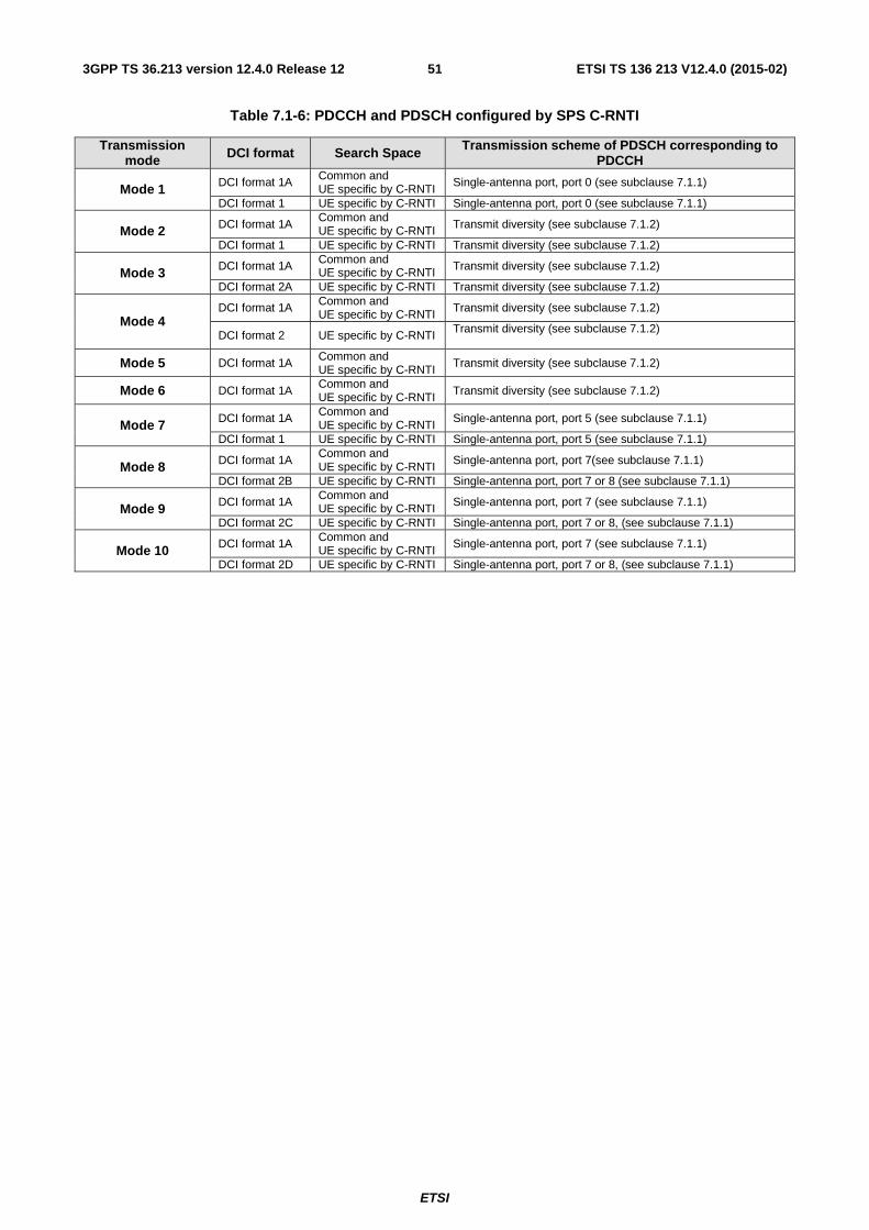
ETSI
ETSI TS 136 213 V12.4.0 (2015-02)513GPP TS 36.213 version 12.4.0 Release 12
Table 7.1-6: PDCCH and PDSCH configured by SPS C-RNTI
Transmission mode DCI format Search Space Transmission scheme of PDSCH corresponding to
PDCCH
Mode 1 DCI format 1A Common and UE specific by C-RNTI
Single-antenna port, port 0 (see subclause 7.1.1)
DCI format 1 UE specific by C-RNTI Single-antenna port, port 0 (see subclause 7.1.1)
Mode 2 DCI format 1A Common and UE specific by C-RNTI Transmit diversity (see subclause 7.1.2)
DCI format 1 UE specific by C-RNTI Transmit diversity (see subclause 7.1.2)
Mode 3 DCI format 1A Common and UE specific by C-RNTI Transmit diversity (see subclause 7.1.2)
DCI format 2A UE specific by C-RNTI Transmit diversity (see subclause 7.1.2)
Mode 4 DCI format 1A Common and
UE specific by C-RNTI Transmit diversity (see subclause 7.1.2)
DCI format 2 UE specific by C-RNTI Transmit diversity (see subclause 7.1.2)
Mode 5 DCI format 1A Common and UE specific by C-RNTI
Transmit diversity (see subclause 7.1.2)
Mode 6 DCI format 1A Common and UE specific by C-RNTI Transmit diversity (see subclause 7.1.2)
Mode 7 DCI format 1A Common and UE specific by C-RNTI
Single-antenna port, port 5 (see subclause 7.1.1)
DCI format 1 UE specific by C-RNTI Single-antenna port, port 5 (see subclause 7.1.1)
Mode 8 DCI format 1A Common and UE specific by C-RNTI Single-antenna port, port 7(see subclause 7.1.1)
DCI format 2B UE specific by C-RNTI Single-antenna port, port 7 or 8 (see subclause 7.1.1)
Mode 9 DCI format 1A Common and UE specific by C-RNTI Single-antenna port, port 7 (see subclause 7.1.1)
DCI format 2C UE specific by C-RNTI Single-antenna port, port 7 or 8, (see subclause 7.1.1)
Mode 10 DCI format 1A Common and UE specific by C-RNTI
Single-antenna port, port 7 (see subclause 7.1.1)
DCI format 2D UE specific by C-RNTI Single-antenna port, port 7 or 8, (see subclause 7.1.1)
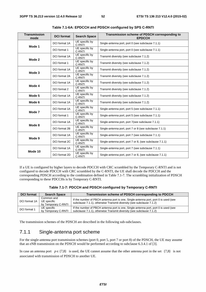
ETSI
ETSI TS 136 213 V12.4.0 (2015-02)523GPP TS 36.213 version 12.4.0 Release 12
Table 7.1-6A: EPDCCH and PDSCH configured by SPS C-RNTI
Transmission mode DCI format Search Space Transmission scheme of PDSCH corresponding to
EPDCCH
Mode 1 DCI format 1A UE specific by
C-RNTI Single-antenna port, port 0 (see subclause 7.1.1)
DCI format 1 UE specific by C-RNTI Single-antenna port, port 0 (see subclause 7.1.1)
Mode 2 DCI format 1A UE specific by
C-RNTI Transmit diversity (see subclause 7.1.2)
DCI format 1 UE specific by C-RNTI Transmit diversity (see subclause 7.1.2)
Mode 3 DCI format 1A UE specific by
C-RNTI Transmit diversity (see subclause 7.1.2)
DCI format 2A UE specific by C-RNTI Transmit diversity (see subclause 7.1.2)
Mode 4 DCI format 1A UE specific by
C-RNTI Transmit diversity (see subclause 7.1.2)
DCI format 2 UE specific by C-RNTI Transmit diversity (see subclause 7.1.2)
Mode 5 DCI format 1A UE specific by C-RNTI
Transmit diversity (see subclause 7.1.2)
Mode 6 DCI format 1A UE specific by C-RNTI Transmit diversity (see subclause 7.1.2)
Mode 7 DCI format 1A UE specific by
C-RNTI Single-antenna port, port 5 (see subclause 7.1.1)
DCI format 1 UE specific by C-RNTI Single-antenna port, port 5 (see subclause 7.1.1)
Mode 8 DCI format 1A UE specific by
C-RNTI Single-antenna port, port 7(see subclause 7.1.1)
DCI format 2B UE specific by C-RNTI Single-antenna port, port 7 or 8 (see subclause 7.1.1)
Mode 9 DCI format 1A UE specific by
C-RNTI Single-antenna port, port 7 (see subclause 7.1.1)
DCI format 2C UE specific by C-RNTI Single-antenna port, port 7 or 8, (see subclause 7.1.1)
Mode 10 DCI format 1A UE specific by
C-RNTI Single-antenna port, port 7 (see subclause 7.1.1)
DCI format 2D UE specific by C-RNTI Single-antenna port, port 7 or 8, (see subclause 7.1.1)
If a UE is configured by higher layers to decode PDCCH with CRC scrambled by the Temporary C-RNTI and is not configured to decode PDCCH with CRC scrambled by the C-RNTI, the UE shall decode the PDCCH and the corresponding PDSCH according to the combination defined in Table 7.1-7. The scrambling initialization of PDSCH corresponding to these PDCCHs is by Temporary C-RNTI.
Table 7.1-7: PDCCH and PDSCH configured by Temporary C-RNTI
DCI format Search Space Transmission scheme of PDSCH corresponding to PDCCH
DCI format 1A Common and UE specific by Temporary C-RNTI
If the number of PBCH antenna port is one, Single-antenna port, port 0 is used (see subclause 7.1.1), otherwise Transmit diversity (see subclause 7.1.2)
DCI format 1 UE specific by Temporary C-RNTI
If the number of PBCH antenna port is one, Single-antenna port, port 0 is used (see subclause 7.1.1), otherwise Transmit diversity (see subclause 7.1.2)
The transmission schemes of the PDSCH are described in the following sub-subclauses.
7.1.1 Single-antenna port scheme
For the single-antenna port transmission schemes (port 0, port 5, port 7 or port 8) of the PDSCH, the UE may assume that an eNB transmission on the PDSCH would be performed according to subclause 6.3.4.1 of [3].
In case an antenna port }8,7{∈p is used, the UE cannot assume that the other antenna port in the set }8,7{ is not
associated with transmission of PDSCH to another UE.
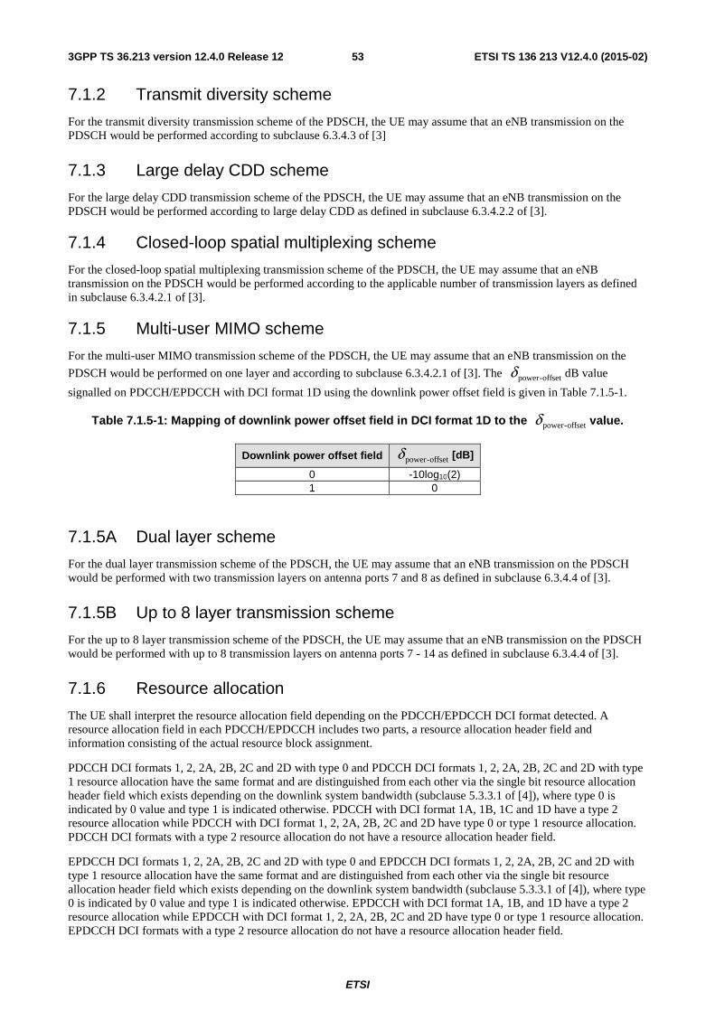
ETSI
ETSI TS 136 213 V12.4.0 (2015-02)533GPP TS 36.213 version 12.4.0 Release 12
7.1.2 Transmit diversity scheme
For the transmit diversity transmission scheme of the PDSCH, the UE may assume that an eNB transmission on the PDSCH would be performed according to subclause 6.3.4.3 of [3]
7.1.3 Large delay CDD scheme
For the large delay CDD transmission scheme of the PDSCH, the UE may assume that an eNB transmission on the PDSCH would be performed according to large delay CDD as defined in subclause 6.3.4.2.2 of [3].
7.1.4 Closed-loop spatial multiplexing scheme
For the closed-loop spatial multiplexing transmission scheme of the PDSCH, the UE may assume that an eNB transmission on the PDSCH would be performed according to the applicable number of transmission layers as defined in subclause 6.3.4.2.1 of [3].
7.1.5 Multi-user MIMO scheme
For the multi-user MIMO transmission scheme of the PDSCH, the UE may assume that an eNB transmission on the
PDSCH would be performed on one layer and according to subclause 6.3.4.2.1 of [3]. The offset-powerδ dB value
signalled on PDCCH/EPDCCH with DCI format 1D using the downlink power offset field is given in Table 7.1.5-1.
Table 7.1.5-1: Mapping of downlink power offset field in DCI format 1D to the offset-powerδ value.
Downlink power offset field offset-powerδ [dB]
0 -10log10(2) 1 0
7.1.5A Dual layer scheme
For the dual layer transmission scheme of the PDSCH, the UE may assume that an eNB transmission on the PDSCH would be performed with two transmission layers on antenna ports 7 and 8 as defined in subclause 6.3.4.4 of [3].
7.1.5B Up to 8 layer transmission scheme
For the up to 8 layer transmission scheme of the PDSCH, the UE may assume that an eNB transmission on the PDSCH would be performed with up to 8 transmission layers on antenna ports 7 - 14 as defined in subclause 6.3.4.4 of [3].
7.1.6 Resource allocation
The UE shall interpret the resource allocation field depending on the PDCCH/EPDCCH DCI format detected. A resource allocation field in each PDCCH/EPDCCH includes two parts, a resource allocation header field and information consisting of the actual resource block assignment.
PDCCH DCI formats 1, 2, 2A, 2B, 2C and 2D with type 0 and PDCCH DCI formats 1, 2, 2A, 2B, 2C and 2D with type 1 resource allocation have the same format and are distinguished from each other via the single bit resource allocation header field which exists depending on the downlink system bandwidth (subclause 5.3.3.1 of [4]), where type 0 is indicated by 0 value and type 1 is indicated otherwise. PDCCH with DCI format 1A, 1B, 1C and 1D have a type 2 resource allocation while PDCCH with DCI format 1, 2, 2A, 2B, 2C and 2D have type 0 or type 1 resource allocation. PDCCH DCI formats with a type 2 resource allocation do not have a resource allocation header field.
EPDCCH DCI formats 1, 2, 2A, 2B, 2C and 2D with type 0 and EPDCCH DCI formats 1, 2, 2A, 2B, 2C and 2D with type 1 resource allocation have the same format and are distinguished from each other via the single bit resource allocation header field which exists depending on the downlink system bandwidth (subclause 5.3.3.1 of [4]), where type 0 is indicated by 0 value and type 1 is indicated otherwise. EPDCCH with DCI format 1A, 1B, and 1D have a type 2 resource allocation while EPDCCH with DCI format 1, 2, 2A, 2B, 2C and 2D have type 0 or type 1 resource allocation. EPDCCH DCI formats with a type 2 resource allocation do not have a resource allocation header field.
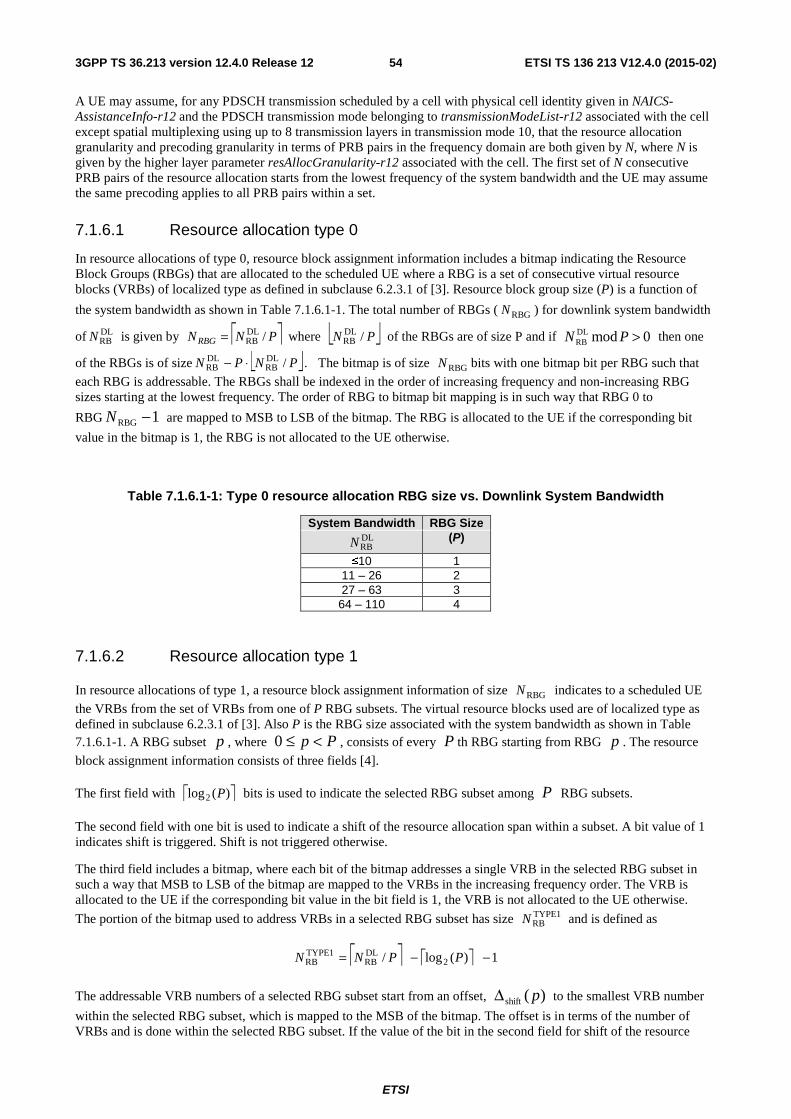
ETSI
ETSI TS 136 213 V12.4.0 (2015-02)543GPP TS 36.213 version 12.4.0 Release 12
A UE may assume, for any PDSCH transmission scheduled by a cell with physical cell identity given in NAICS-AssistanceInfo-r12 and the PDSCH transmission mode belonging to transmissionModeList-r12 associated with the cell except spatial multiplexing using up to 8 transmission layers in transmission mode 10, that the resource allocation granularity and precoding granularity in terms of PRB pairs in the frequency domain are both given by N, where N is given by the higher layer parameter resAllocGranularity-r12 associated with the cell. The first set of N consecutive PRB pairs of the resource allocation starts from the lowest frequency of the system bandwidth and the UE may assume the same precoding applies to all PRB pairs within a set.
7.1.6.1 Resource allocation type 0
In resource allocations of type 0, resource block assignment information includes a bitmap indicating the Resource Block Groups (RBGs) that are allocated to the scheduled UE where a RBG is a set of consecutive virtual resource blocks (VRBs) of localized type as defined in subclause 6.2.3.1 of [3]. Resource block group size (P) is a function of
the system bandwidth as shown in Table 7.1.6.1-1. The total number of RBGs ( RBGN ) for downlink system bandwidth
of DLRBN is given by ⎡ ⎤PNNRBG /DL
RB= where ⎣ ⎦PN /DLRB of the RBGs are of size P and if 0modDL
RB >PN then one
of the RBGs is of size ⎣ ⎦PNPN /DLRB
DLRB ⋅− . The bitmap is of size RBGN bits with one bitmap bit per RBG such that
each RBG is addressable. The RBGs shall be indexed in the order of increasing frequency and non-increasing RBG sizes starting at the lowest frequency. The order of RBG to bitmap bit mapping is in such way that RBG 0 to
RBG 1RBG −N are mapped to MSB to LSB of the bitmap. The RBG is allocated to the UE if the corresponding bit
value in the bitmap is 1, the RBG is not allocated to the UE otherwise.
Table 7.1.6.1-1: Type 0 resource allocation RBG size vs. Downlink System Bandwidth
System Bandwidth RBG Size DLRBN (P)
≤10 1 11 – 26 2 27 – 63 3
64 – 110 4
7.1.6.2 Resource allocation type 1
In resource allocations of type 1, a resource block assignment information of size RBGN indicates to a scheduled UE
the VRBs from the set of VRBs from one of P RBG subsets. The virtual resource blocks used are of localized type as defined in subclause 6.2.3.1 of [3]. Also P is the RBG size associated with the system bandwidth as shown in Table 7.1.6.1-1. A RBG subset p , where Pp <≤0 , consists of every P th RBG starting from RBG p . The resource
block assignment information consists of three fields [4].
The first field with ⎡ ⎤)(log2 P bits is used to indicate the selected RBG subset among P RBG subsets.
The second field with one bit is used to indicate a shift of the resource allocation span within a subset. A bit value of 1 indicates shift is triggered. Shift is not triggered otherwise.
The third field includes a bitmap, where each bit of the bitmap addresses a single VRB in the selected RBG subset in such a way that MSB to LSB of the bitmap are mapped to the VRBs in the increasing frequency order. The VRB is allocated to the UE if the corresponding bit value in the bit field is 1, the VRB is not allocated to the UE otherwise.
The portion of the bitmap used to address VRBs in a selected RBG subset has size TYPE1RBN and is defined as
⎡ ⎤ ⎡ ⎤ 1)(log/ 2DLRB
TYPE1RB −−= PPNN
The addressable VRB numbers of a selected RBG subset start from an offset, )(shift pΔ to the smallest VRB number
within the selected RBG subset, which is mapped to the MSB of the bitmap. The offset is in terms of the number of VRBs and is done within the selected RBG subset. If the value of the bit in the second field for shift of the resource
ETSI
ETSI TS 136 213 V12.4.0 (2015-02)553GPP TS 36.213 version 12.4.0 Release 12
allocation span is set to 0, the offset for RBG subset p is given by 0)(shift =Δ p . Otherwise, the offset for RBG
subset p is given by TYPE1RB
subsetRBG RBshift )()( NpNp −=Δ , where the LSB of the bitmap is justified with the
highest VRB number within the selected RBG subset. )(subset RBG RB pN is the number of VRBs in RBG subset p and
can be calculated by the following equation,
DL DL RB RB
2
DL DL RBG subset DL RB RBRB RB2
DL DL RB RB
2
1 1, mod
1 1( ) ( 1) mod 1 , mod
1 1, mod
N NP P p P
PP
N NN p P N P p P
PP
N NP p P
PP
⎧⎢ ⎥ ⎢ ⎥− −⋅ + <⎪⎢ ⎥ ⎢ ⎥⎪⎢ ⎥ ⎢ ⎥⎣ ⎦ ⎣ ⎦⎪⎢ ⎥ ⎢ ⎥− −⎪= ⋅ + − + =⎢ ⎥ ⎢ ⎥⎨⎢ ⎥ ⎢ ⎥⎪⎣ ⎦ ⎣ ⎦
⎪⎢ ⎥ ⎢ ⎥− −⎪ ⋅ >⎢ ⎥ ⎢ ⎥⎪⎢ ⎥ ⎢ ⎥⎣ ⎦ ⎣ ⎦⎩
Consequently, when RBG subset p is indicated, bit i for TYPE1RB0,1, , 1i N= −L in the bitmap field indicates VRB
number,
( )RBG subset 2shiftVRB shift
( )( ) ( ) mod
i pn p P p P i p P
P
+ Δ⎢ ⎥= + ⋅ + + Δ⎢ ⎥⎣ ⎦
.
7.1.6.3 Resource allocation type 2
In resource allocations of type 2, the resource block assignment information indicates to a scheduled UE a set of contiguously allocated localized virtual resource blocks or distributed virtual resource blocks. In case of resource allocation signalled with PDCCH DCI format 1A, 1B or 1D, or for resource allocation signalled with EPDCCH DCI format 1A, 1B, or 1D, one bit flag indicates whether localized virtual resource blocks or distributed virtual resource blocks are assigned (value 0 indicates Localized and value 1 indicates Distributed VRB assignment) while distributed virtual resource blocks are always assigned in case of resource allocation signalled with PDCCH DCI format 1C. Localized VRB allocations for a UE vary from a single VRB up to a maximum number of VRBs spanning the system bandwidth. For DCI format 1A the distributed VRB allocations for a UE vary from a single VRB up to DL
VRBN VRBs,
where DLVRBN is defined in [3], if the DCI CRC is scrambled by P-RNTI, RA-RNTI, or SI-RNTI. With PDCCH DCI
format 1B, 1D with a CRC scrambled by C-RNTI, or with DCI format 1A with a CRC scrambled with C-RNTI, SPS C-RNTI or Temporary C-RNTI distributed VRB allocations for a UE vary from a single VRB up to DL
VRBN VRBs if DLRBN is 6-49 and vary from a single VRB up to 16 if DL
RBN is 50-110. With EPDCCH DCI format 1B, 1D with a CRC
scrambled by C-RNTI, or with DCI format 1A with a CRC scrambled with C-RNTI, SPS C-RNTI distributed VRB allocations for a UE vary from a single VRB up to DL
VRBN VRBs if DLRBN is 6-49 and vary from a single VRB up to 16
if DLRBN is 50-110. With PDCCH DCI format 1C, distributed VRB allocations for a UE vary from step
RBN VRB(s) up to
⎣ ⎦ stepRB
stepRB
DLVRB / NNN ⋅ VRBs with an increment step of step
RBN , where stepRBN value is determined depending on the
downlink system bandwidth as shown in Table 7.1.6.3-1.
Table 7.1.6.3-1: stepRBN values vs. Downlink System Bandwidth
System BW ( DLRBN )
stepRBN
DCI format 1C 6-49 2
50-110 4
For PDCCH DCI format 1A, 1B or 1D, or for EPDCCH DCI format 1A, 1B, or 1D, a type 2 resource allocation field consists of a resource indication value (RIV) corresponding to a starting resource block ( startRB ) and a length in terms
of virtually contiguously allocated resource blocks CRBsL . The resource indication value is defined by
ETSI
ETSI TS 136 213 V12.4.0 (2015-02)563GPP TS 36.213 version 12.4.0 Release 12
if ⎣ ⎦2/)1( DLRBCRBs NL ≤− then
startCRBsDLRB RBLNRIV +−= )1(
else
)1()1( startDLRBCRBs
DLRB
DLRB RBNLNNRIV −−++−=
where CRBsL ≥ 1 and shall not exceed startDL
VRB RBN − .
For PDCCH DCI format 1C, a type 2 resource block assignment field consists of a resource indication value (RIV) corresponding to a starting resource block ( startRB = 0 , step
RBN , stepRB2N ,…, ⎣ ⎦ step
RBstepRB
DLVRB )1/( NNN − ) and a length in terms
of virtually contiguously allocated resource blocks ( CRBsL = stepRBN , step
RB2N ,…, ⎣ ⎦ stepRB
stepRB
DLVRB / NNN ⋅ ).
The resource indication value is defined by:
if ⎣ ⎦2/)1( DLVRBCRBs NL ′≤−′ then
startCRBsDL
VRB BRLNRIV ′+−′′= )1(
else
)1()1( startDL
VRBCRBsDL
VRBDL
VRB BRNLNNRIV ′−−′++′−′′=
where stepRBCRBsCRBs NLL /=′ , step
RBstartstart NRBBR /=′ and ⎣ ⎦stepRB
DLVRB
DLVRB NNN /=′ . Here,
CRBsL′ ≥ 1 and shall not exceed startDL
VRB BRN ′−′ .
7.1.6.4 PDSCH starting position
The starting OFDM symbol for the PDSCH of each activated serving cell is given by index DataStartl in the first slot in a
subframe.
For a UE configured in transmission mode 1-9, for a given activated serving cell
- if the PDSCH is assigned by EPDCCH received in the same serving cell, or if the UE is configured to monitor EPDCCH in the subframe and the PDSCH is not assigned by a PDCCH/EPDCCH, and if the UE is configured with the higher layer parameter epdcch-StartSymbol-r11
- DataStartl is given by the higher-layer parameter epdcch-StartSymbol-r11.
- else if PDSCH and the corresponding PDCCH/EPDCCH are received on different serving cells
- DataStartl is given by the higher-layer parameter pdsch-Start-r10 for the serving cell on which PDSCH is received,
- Otherwise
- DataStartl is given by the CFI value in the subframe of the given serving cell when 10DLRB >N , and DataStartl is
given by the CFI value + 1 in the subframe of the given serving cell when 10DLRB ≤N .
For a UE configured in transmission mode 10, for a given activated serving cell
- if the PDSCH is assigned by a PDCCH with DCI format 1C or by a PDCCH with DCI format 1A and with CRC scrambled with P-RNTI/RA-RNTI/SI-RNTI/Temporary C-RNTI
ETSI
ETSI TS 136 213 V12.4.0 (2015-02)573GPP TS 36.213 version 12.4.0 Release 12
- DataStartl is given by the span of the DCI given by the CFI value in the subframe of the given serving cell according to subclause 5.3.4 of [4].
- if the PDSCH is assigned by a PDCCH/EPDCCH with DCI format 1A and with CRC scrambled with C-RNTI and if the PDSCH transmission is on antenna ports 0 - 3
- if the PDSCH is assigned by EPDCCH received in the same serving cell
- DataStartl is given by tEPDCCHStarl for the EPDCCH-PRB-set where EPDCCH with the DCI format 1A was
received ( tEPDCCHStarl as defined in subclause 9.1.4.1),
- else if PDSCH and the corresponding PDCCH/EPDCCH are received on different serving cells
- DataStartl is given by the higher-layer parameter pdsch-Start-r10 for the serving cell on which PDSCH is received.
- otherwise
- DataStartl is given by the CFI value in the subframe of the given serving cell when 10DLRB >N , and DataStartl
is given by the CFI value+1 in the subframe of the given serving cell when 10DLRB ≤N .
- if the PDSCH is assigned by or semi-statically scheduled by a PDCCH/EPDCCH with DCI format 1A and if the PDSCH transmission is on antenna port 7
- if the value of the higher layer parameter pdsch-Start-r11 determined from parameter set 1 in table 7.1.9-1 for the serving cell on which PDSCH is received belongs to {1,2,3,4},
- 'DataStartl is given by the higher layer parameter pdsch-Start-r11 determined from parameter set 1 in table
7.1.9-1 for the serving cell on which PDSCH is received.
- else,
- if PDSCH and the corresponding PDCCH/EPDCCH are received on different serving cells,
- 'DataStartl is given by the higher-layer parameter pdsch-Start-r10 for the serving cell on which PDSCH is
received
- otherwise
- 'DataStartl is given by the CFI value in the subframe of the given serving cell when 10DL
RB >N , and
DataStartl is given by the CFI value + 1 in the subframe of the given serving cell when 10DLRB ≤N .
- if the subframe on which PDSCH is received is indicated by the higher layer parameter mbsfn-SubframeConfigList-r11 determined from parameter set 1 in table 7.1.9-1 for the serving cell on which PDSCH is received, or if the PDSCH is received on subframe 1 or 6 for the frame structure type 2,
- ),2min( 'DataStartDataStart ll = ,
- otherwise
- 'DataStartDataStart ll = .
- if the PDSCH is assigned by or semi-persistently scheduled by a PDCCH/EPDCCH with DCI format 2D,
- if the value of the higher layer parameter pdsch-Start-r11 determined from the DCI (according to subclause 7.1.9) for the serving cell on which PDSCH is received belongs to {1,2,3,4},
- 'DataStartl is given by parameter pdsch-Start-r11 determined from the DCI (according to subclause 7.1.9) for
the serving cell on which PDSCH is received
ETSI
ETSI TS 136 213 V12.4.0 (2015-02)583GPP TS 36.213 version 12.4.0 Release 12
- else,
- if PDSCH and the corresponding PDCCH/EPDCCH are received on different serving cells,
- 'DataStartl is given by the higher-layer parameter pdsch-Start-r10 for the serving cell on which PDSCH is
received
- Otherwise
- 'DataStartl is given by the CFI value in the subframe of the given serving cell when 10DL
RB >N , and
DataStartl is given by the CFI value+1 in the subframe of the given serving cell when 10DLRB ≤N .
- if the subframe on which PDSCH is received is indicated by the higher layer parameter mbsfn-SubframeConfigList-r11 determined from the DCI (according to subclause 7.1.9) for the serving cell on which PDSCH is received, or if the PDSCH is received on subframe 1 or 6 for frame structure type 2,
- ),2min( 'DataStartDataStart ll = ,
- otherwise
- 'DataStartDataStart ll = .
7.1.6.5 Physical Resource Block (PRB) bundling
A UE configured for transmission mode 9 for a given serving cell c may assume that precoding granularity is multiple resource blocks in the frequency domain when PMI/RI reporting is configured.
For a given serving cell c, if a UE is configured for transmission mode 10
- if PMI/RI reporting is configured for all configured CSI processes for the serving cell c, the UE may assume that precoding granularity is multiple resource blocks in the frequency domain,
- otherwise, the UE shall assume the precoding granularity is one resource block in the frequency domain.
Fixed system bandwidth dependent Precoding Resource block Groups (PRGs) of size P′ partition the system
bandwidth and each PRG consists of consecutive PRBs. If 0modDLRB >′PN then one of the PRGs is of size
⎣ ⎦PNPN ′′− /DLRB
DLRB . The PRG size is non-increasing starting at the lowest frequency. The UE may assume that the
same precoder applies on all scheduled PRBs within a PRG.
The PRG size a UE may assume for a given system bandwidth is given by:
Table 7.1.6.5-1
System Bandwidth
( DLRBN )
PRG Size ( P′ ) (PRBs)
≤10 1
11 – 26 2
27 – 63 3
64 – 110 2
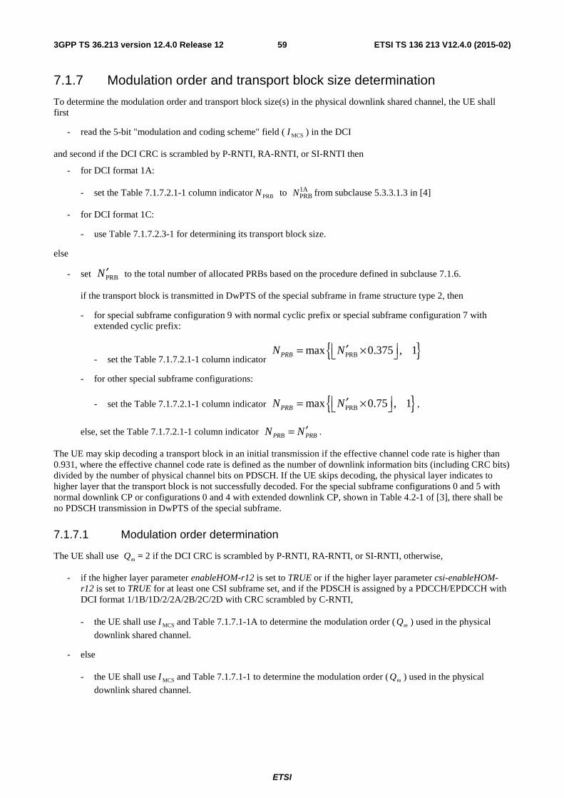
ETSI
ETSI TS 136 213 V12.4.0 (2015-02)593GPP TS 36.213 version 12.4.0 Release 12
7.1.7 Modulation order and transport block size determination
To determine the modulation order and transport block size(s) in the physical downlink shared channel, the UE shall first
- read the 5-bit "modulation and coding scheme" field ( MCSI ) in the DCI
and second if the DCI CRC is scrambled by P-RNTI, RA-RNTI, or SI-RNTI then
- for DCI format 1A:
- set the Table 7.1.7.2.1-1 column indicator PRBN to 1APRBN from subclause 5.3.3.1.3 in [4]
- for DCI format 1C:
- use Table 7.1.7.2.3-1 for determining its transport block size.
else
- set PRBN ′ to the total number of allocated PRBs based on the procedure defined in subclause 7.1.6.
if the transport block is transmitted in DwPTS of the special subframe in frame structure type 2, then
- for special subframe configuration 9 with normal cyclic prefix or special subframe configuration 7 with extended cyclic prefix:
- set the Table 7.1.7.2.1-1 column indicator { }PRBmax 0.375 , 1PRBN N ′⎢ ⎥= ×⎣ ⎦
- for other special subframe configurations:
- set the Table 7.1.7.2.1-1 column indicator { }PRBmax 0.75 , 1PRBN N ′⎢ ⎥= ×⎣ ⎦ ,
else, set the Table 7.1.7.2.1-1 column indicator PRBPRB NN ′= .
The UE may skip decoding a transport block in an initial transmission if the effective channel code rate is higher than 0.931, where the effective channel code rate is defined as the number of downlink information bits (including CRC bits) divided by the number of physical channel bits on PDSCH. If the UE skips decoding, the physical layer indicates to higher layer that the transport block is not successfully decoded. For the special subframe configurations 0 and 5 with normal downlink CP or configurations 0 and 4 with extended downlink CP, shown in Table 4.2-1 of [3], there shall be no PDSCH transmission in DwPTS of the special subframe.
7.1.7.1 Modulation order determination
The UE shall use mQ = 2 if the DCI CRC is scrambled by P-RNTI, RA-RNTI, or SI-RNTI, otherwise,
- if the higher layer parameter enableHOM-r12 is set to TRUE or if the higher layer parameter csi-enableHOM-r12 is set to TRUE for at least one CSI subframe set, and if the PDSCH is assigned by a PDCCH/EPDCCH with DCI format 1/1B/1D/2/2A/2B/2C/2D with CRC scrambled by C-RNTI,
- the UE shall use MCSI and Table 7.1.7.1-1A to determine the modulation order ( mQ ) used in the physical
downlink shared channel.
- else
- the UE shall use MCSI and Table 7.1.7.1-1 to determine the modulation order ( mQ ) used in the physical
downlink shared channel.
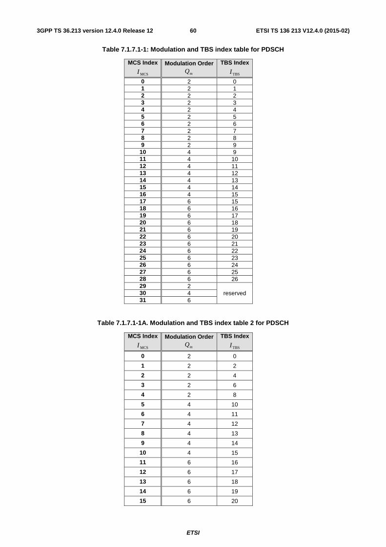
ETSI
ETSI TS 136 213 V12.4.0 (2015-02)603GPP TS 36.213 version 12.4.0 Release 12
Table 7.1.7.1-1: Modulation and TBS index table for PDSCH
MCS Index
MCSI Modulation Order
mQ TBS Index
TBSI
0 2 0 1 2 1 2 2 2 3 2 3 4 2 4 5 2 5 6 2 6 7 2 7 8 2 8 9 2 9
10 4 9 11 4 10 12 4 11 13 4 12 14 4 13 15 4 14 16 4 15 17 6 15 18 6 16 19 6 17 20 6 18 21 6 19 22 6 20 23 6 21 24 6 22 25 6 23 26 6 24 27 6 25 28 6 26 29 2
reserved 30 4 31 6
Table 7.1.7.1-1A. Modulation and TBS index table 2 for PDSCH
MCS Index
MCSI Modulation Order
mQ TBS Index
TBSI
0 2 0
1 2 2
2 2 4
3 2 6
4 2 8
5 4 10
6 4 11
7 4 12
8 4 13
9 4 14
10 4 15
11 6 16
12 6 17
13 6 18
14 6 19
15 6 20
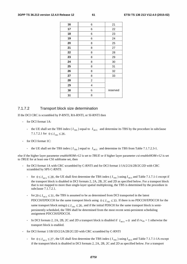
ETSI
ETSI TS 136 213 V12.4.0 (2015-02)613GPP TS 36.213 version 12.4.0 Release 12
16 6 21
17 6 22
18 6 23
19 6 24
20 8 25
21 8 27
22 8 28
23 8 29
24 8 30
25 8 31
26 8 32
27 8 33
28 2
reserved
29 4
30 6
31 8
7.1.7.2 Transport block size determination
If the DCI CRC is scrambled by P-RNTI, RA-RNTI, or SI-RNTI then
- for DCI format 1A:
- the UE shall set the TBS index ( TBSI ) equal to MCSI and determine its TBS by the procedure in subclause
7.1.7.2.1 for 260 TBS ≤≤ I .
- for DCI format 1C:
- the UE shall set the TBS index ( TBSI ) equal to MCSI and determine its TBS from Table 7.1.7.2.3-1.
else if the higher layer parameter enableHOM-r12 is set to TRUE or if higher layer parameter csi-enableHOM-r12 is set to TRUE for at least one CSI subframe set, then
- for DCI format 1A with CRC scrambled by C-RNTI and for DCI format 1/1A/2/2A/2B/2C/2D with CRC scrambled by SPS C-RNTI:
- for 280 MCS ≤≤ I , the UE shall first determine the TBS index ( TBSI ) using MCSI and Table 7.1.7.1-1 except if
the transport block is disabled in DCI formats 2, 2A, 2B, 2C and 2D as specified below. For a transport block that is not mapped to more than single-layer spatial multiplexing, the TBS is determined by the procedure in subclause 7.1.7.2.1.
- for 3129 MCS ≤≤ I , the TBS is assumed to be as determined from DCI transported in the latest
PDCCH/EPDCCH for the same transport block using 330 TBS ≤≤ I . If there is no PDCCH/EPDCCH for the
same transport block using 260 TBS ≤≤ I , and if the initial PDSCH for the same transport block is semi-
persistently scheduled, the TBS shall be determined from the most recent semi-persistent scheduling assignment PDCCH/EPDCCH.
- In DCI formats 2, 2A, 2B, 2C and 2D a transport block is disabled if 0MCS =I and if rvidx = 1 otherwise the
transport block is enabled.
- for DCI format 1/1B/1D/2/2A/2B/2C/2D with CRC scrambled by C-RNTI
- for 270 MCS ≤≤ I , the UE shall first determine the TBS index ( TBSI ) using MCSI and Table 7.1.7.1-1A except
if the transport block is disabled in DCI formats 2, 2A, 2B, 2C and 2D as specified below. For a transport
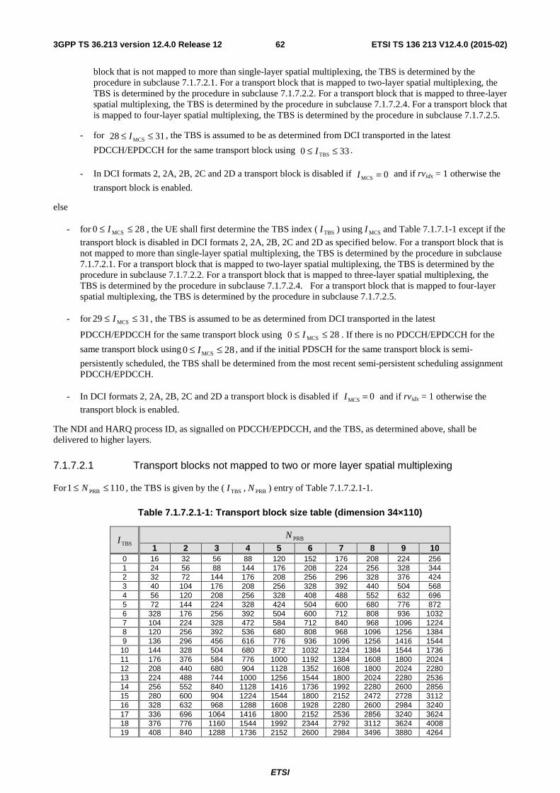
ETSI
ETSI TS 136 213 V12.4.0 (2015-02)623GPP TS 36.213 version 12.4.0 Release 12
block that is not mapped to more than single-layer spatial multiplexing, the TBS is determined by the procedure in subclause 7.1.7.2.1. For a transport block that is mapped to two-layer spatial multiplexing, the TBS is determined by the procedure in subclause 7.1.7.2.2. For a transport block that is mapped to three-layer spatial multiplexing, the TBS is determined by the procedure in subclause 7.1.7.2.4. For a transport block that is mapped to four-layer spatial multiplexing, the TBS is determined by the procedure in subclause 7.1.7.2.5.
- for 3128 MCS ≤≤ I , the TBS is assumed to be as determined from DCI transported in the latest
PDCCH/EPDCCH for the same transport block using 330 TBS ≤≤ I .
- In DCI formats 2, 2A, 2B, 2C and 2D a transport block is disabled if 0MCS =I and if rvidx = 1 otherwise the
transport block is enabled.
else
- for 280 MCS ≤≤ I , the UE shall first determine the TBS index ( TBSI ) using MCSI and Table 7.1.7.1-1 except if the
transport block is disabled in DCI formats 2, 2A, 2B, 2C and 2D as specified below. For a transport block that is not mapped to more than single-layer spatial multiplexing, the TBS is determined by the procedure in subclause 7.1.7.2.1. For a transport block that is mapped to two-layer spatial multiplexing, the TBS is determined by the procedure in subclause 7.1.7.2.2. For a transport block that is mapped to three-layer spatial multiplexing, the TBS is determined by the procedure in subclause 7.1.7.2.4. For a transport block that is mapped to four-layer spatial multiplexing, the TBS is determined by the procedure in subclause 7.1.7.2.5.
- for 3129 MCS ≤≤ I , the TBS is assumed to be as determined from DCI transported in the latest
PDCCH/EPDCCH for the same transport block using 280 MCS ≤≤ I . If there is no PDCCH/EPDCCH for the
same transport block using 280 MCS ≤≤ I , and if the initial PDSCH for the same transport block is semi-
persistently scheduled, the TBS shall be determined from the most recent semi-persistent scheduling assignment PDCCH/EPDCCH.
- In DCI formats 2, 2A, 2B, 2C and 2D a transport block is disabled if 0MCS =I and if rvidx = 1 otherwise the
transport block is enabled.
The NDI and HARQ process ID, as signalled on PDCCH/EPDCCH, and the TBS, as determined above, shall be delivered to higher layers.
7.1.7.2.1 Transport blocks not mapped to two or more layer spatial multiplexing
For 1101 PRB ≤≤ N , the TBS is given by the ( TBSI , PRBN ) entry of Table 7.1.7.2.1-1.
Table 7.1.7.2.1-1: Transport block size table (dimension 34×110)
TBSI PRBN
1 2 3 4 5 6 7 8 9 10 0 16 32 56 88 120 152 176 208 224 256 1 24 56 88 144 176 208 224 256 328 344 2 32 72 144 176 208 256 296 328 376 424 3 40 104 176 208 256 328 392 440 504 568 4 56 120 208 256 328 408 488 552 632 696 5 72 144 224 328 424 504 600 680 776 872 6 328 176 256 392 504 600 712 808 936 1032 7 104 224 328 472 584 712 840 968 1096 1224 8 120 256 392 536 680 808 968 1096 1256 1384 9 136 296 456 616 776 936 1096 1256 1416 1544
10 144 328 504 680 872 1032 1224 1384 1544 1736 11 176 376 584 776 1000 1192 1384 1608 1800 2024 12 208 440 680 904 1128 1352 1608 1800 2024 2280 13 224 488 744 1000 1256 1544 1800 2024 2280 2536 14 256 552 840 1128 1416 1736 1992 2280 2600 2856 15 280 600 904 1224 1544 1800 2152 2472 2728 3112 16 328 632 968 1288 1608 1928 2280 2600 2984 3240 17 336 696 1064 1416 1800 2152 2536 2856 3240 3624 18 376 776 1160 1544 1992 2344 2792 3112 3624 4008 19 408 840 1288 1736 2152 2600 2984 3496 3880 4264
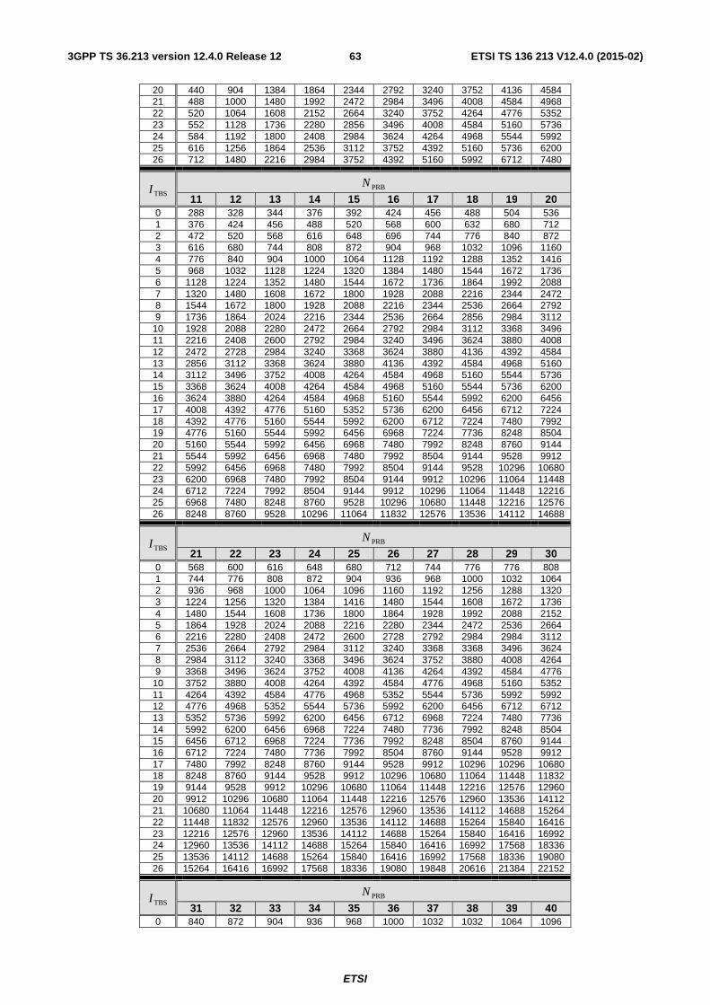
ETSI
ETSI TS 136 213 V12.4.0 (2015-02)633GPP TS 36.213 version 12.4.0 Release 12
20 440 904 1384 1864 2344 2792 3240 3752 4136 4584 21 488 1000 1480 1992 2472 2984 3496 4008 4584 4968 22 520 1064 1608 2152 2664 3240 3752 4264 4776 5352 23 552 1128 1736 2280 2856 3496 4008 4584 5160 5736 24 584 1192 1800 2408 2984 3624 4264 4968 5544 5992 25 616 1256 1864 2536 3112 3752 4392 5160 5736 6200 26 712 1480 2216 2984 3752 4392 5160 5992 6712 7480
TBSI PRBN
11 12 13 14 15 16 17 18 19 20 0 288 328 344 376 392 424 456 488 504 536 1 376 424 456 488 520 568 600 632 680 712 2 472 520 568 616 648 696 744 776 840 872 3 616 680 744 808 872 904 968 1032 1096 1160 4 776 840 904 1000 1064 1128 1192 1288 1352 1416 5 968 1032 1128 1224 1320 1384 1480 1544 1672 1736 6 1128 1224 1352 1480 1544 1672 1736 1864 1992 2088 7 1320 1480 1608 1672 1800 1928 2088 2216 2344 2472 8 1544 1672 1800 1928 2088 2216 2344 2536 2664 2792 9 1736 1864 2024 2216 2344 2536 2664 2856 2984 3112
10 1928 2088 2280 2472 2664 2792 2984 3112 3368 3496 11 2216 2408 2600 2792 2984 3240 3496 3624 3880 4008 12 2472 2728 2984 3240 3368 3624 3880 4136 4392 4584 13 2856 3112 3368 3624 3880 4136 4392 4584 4968 5160 14 3112 3496 3752 4008 4264 4584 4968 5160 5544 5736 15 3368 3624 4008 4264 4584 4968 5160 5544 5736 6200 16 3624 3880 4264 4584 4968 5160 5544 5992 6200 6456 17 4008 4392 4776 5160 5352 5736 6200 6456 6712 7224 18 4392 4776 5160 5544 5992 6200 6712 7224 7480 7992 19 4776 5160 5544 5992 6456 6968 7224 7736 8248 8504 20 5160 5544 5992 6456 6968 7480 7992 8248 8760 9144 21 5544 5992 6456 6968 7480 7992 8504 9144 9528 9912 22 5992 6456 6968 7480 7992 8504 9144 9528 10296 10680 23 6200 6968 7480 7992 8504 9144 9912 10296 11064 11448 24 6712 7224 7992 8504 9144 9912 10296 11064 11448 12216 25 6968 7480 8248 8760 9528 10296 10680 11448 12216 12576 26 8248 8760 9528 10296 11064 11832 12576 13536 14112 14688
TBSI PRBN
21 22 23 24 25 26 27 28 29 30 0 568 600 616 648 680 712 744 776 776 808 1 744 776 808 872 904 936 968 1000 1032 1064 2 936 968 1000 1064 1096 1160 1192 1256 1288 1320 3 1224 1256 1320 1384 1416 1480 1544 1608 1672 1736 4 1480 1544 1608 1736 1800 1864 1928 1992 2088 2152 5 1864 1928 2024 2088 2216 2280 2344 2472 2536 2664 6 2216 2280 2408 2472 2600 2728 2792 2984 2984 3112 7 2536 2664 2792 2984 3112 3240 3368 3368 3496 3624 8 2984 3112 3240 3368 3496 3624 3752 3880 4008 4264 9 3368 3496 3624 3752 4008 4136 4264 4392 4584 4776
10 3752 3880 4008 4264 4392 4584 4776 4968 5160 5352 11 4264 4392 4584 4776 4968 5352 5544 5736 5992 5992 12 4776 4968 5352 5544 5736 5992 6200 6456 6712 6712 13 5352 5736 5992 6200 6456 6712 6968 7224 7480 7736 14 5992 6200 6456 6968 7224 7480 7736 7992 8248 8504 15 6456 6712 6968 7224 7736 7992 8248 8504 8760 9144 16 6712 7224 7480 7736 7992 8504 8760 9144 9528 9912 17 7480 7992 8248 8760 9144 9528 9912 10296 10296 10680 18 8248 8760 9144 9528 9912 10296 10680 11064 11448 11832 19 9144 9528 9912 10296 10680 11064 11448 12216 12576 12960 20 9912 10296 10680 11064 11448 12216 12576 12960 13536 14112 21 10680 11064 11448 12216 12576 12960 13536 14112 14688 15264 22 11448 11832 12576 12960 13536 14112 14688 15264 15840 16416 23 12216 12576 12960 13536 14112 14688 15264 15840 16416 16992 24 12960 13536 14112 14688 15264 15840 16416 16992 17568 18336 25 13536 14112 14688 15264 15840 16416 16992 17568 18336 19080 26 15264 16416 16992 17568 18336 19080 19848 20616 21384 22152
TBSI PRBN
31 32 33 34 35 36 37 38 39 40 0 840 872 904 936 968 1000 1032 1032 1064 1096
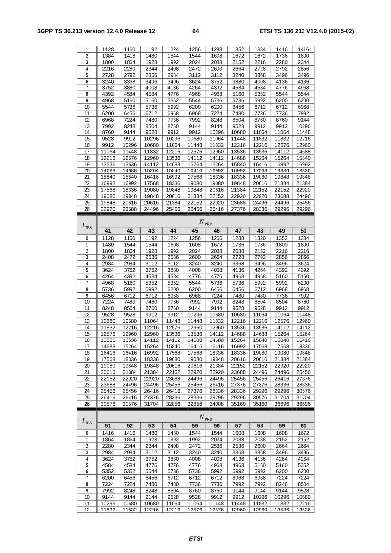
ETSI
ETSI TS 136 213 V12.4.0 (2015-02)643GPP TS 36.213 version 12.4.0 Release 12
1 1128 1160 1192 1224 1256 1288 1352 1384 1416 1416 2 1384 1416 1480 1544 1544 1608 1672 1672 1736 1800 3 1800 1864 1928 1992 2024 2088 2152 2216 2280 2344 4 2216 2280 2344 2408 2472 2600 2664 2728 2792 2856 5 2728 2792 2856 2984 3112 3112 3240 3368 3496 3496 6 3240 3368 3496 3496 3624 3752 3880 4008 4136 4136 7 3752 3880 4008 4136 4264 4392 4584 4584 4776 4968 8 4392 4584 4584 4776 4968 4968 5160 5352 5544 5544 9 4968 5160 5160 5352 5544 5736 5736 5992 6200 6200
10 5544 5736 5736 5992 6200 6200 6456 6712 6712 6968 11 6200 6456 6712 6968 6968 7224 7480 7736 7736 7992 12 6968 7224 7480 7736 7992 8248 8504 8760 8760 9144 13 7992 8248 8504 8760 9144 9144 9528 9912 9912 10296 14 8760 9144 9528 9912 9912 10296 10680 11064 11064 11448 15 9528 9912 10296 10296 10680 11064 11448 11832 11832 12216 16 9912 10296 10680 11064 11448 11832 12216 12216 12576 12960 17 11064 11448 11832 12216 12576 12960 13536 13536 14112 14688 18 12216 12576 12960 13536 14112 14112 14688 15264 15264 15840 19 13536 13536 14112 14688 15264 15264 15840 16416 16992 16992 20 14688 14688 15264 15840 16416 16992 16992 17568 18336 18336 21 15840 15840 16416 16992 17568 18336 18336 19080 19848 19848 22 16992 16992 17568 18336 19080 19080 19848 20616 21384 21384 23 17568 18336 19080 19848 19848 20616 21384 22152 22152 22920 24 19080 19848 19848 20616 21384 22152 22920 22920 23688 24496 25 19848 20616 20616 21384 22152 22920 23688 24496 24496 25456 26 22920 23688 24496 25456 25456 26416 27376 28336 29296 29296
TBSI PRBN
41 42 43 44 45 46 47 48 49 50 0 1128 1160 1192 1224 1256 1256 1288 1320 1352 1384 1 1480 1544 1544 1608 1608 1672 1736 1736 1800 1800 2 1800 1864 1928 1992 2024 2088 2088 2152 2216 2216 3 2408 2472 2536 2536 2600 2664 2728 2792 2856 2856 4 2984 2984 3112 3112 3240 3240 3368 3496 3496 3624 5 3624 3752 3752 3880 4008 4008 4136 4264 4392 4392 6 4264 4392 4584 4584 4776 4776 4968 4968 5160 5160 7 4968 5160 5352 5352 5544 5736 5736 5992 5992 6200 8 5736 5992 5992 6200 6200 6456 6456 6712 6968 6968 9 6456 6712 6712 6968 6968 7224 7480 7480 7736 7992
10 7224 7480 7480 7736 7992 7992 8248 8504 8504 8760 11 8248 8504 8760 8760 9144 9144 9528 9528 9912 9912 12 9528 9528 9912 9912 10296 10680 10680 11064 11064 11448 13 10680 10680 11064 11448 11448 11832 12216 12216 12576 12960 14 11832 12216 12216 12576 12960 12960 13536 13536 14112 14112 15 12576 12960 12960 13536 13536 14112 14688 14688 15264 15264 16 13536 13536 14112 14112 14688 14688 15264 15840 15840 16416 17 14688 15264 15264 15840 16416 16416 16992 17568 17568 18336 18 16416 16416 16992 17568 17568 18336 18336 19080 19080 19848 19 17568 18336 18336 19080 19080 19848 20616 20616 21384 21384 20 19080 19848 19848 20616 20616 21384 22152 22152 22920 22920 21 20616 21384 21384 22152 22920 22920 23688 24496 24496 25456 22 22152 22920 22920 23688 24496 24496 25456 25456 26416 27376 23 23688 24496 24496 25456 25456 26416 27376 27376 28336 28336 24 25456 25456 26416 26416 27376 28336 28336 29296 29296 30576 25 26416 26416 27376 28336 28336 29296 29296 30576 31704 31704 26 30576 30576 31704 32856 32856 34008 35160 35160 36696 36696
TBSI PRBN
51 52 53 54 55 56 57 58 59 60 0 1416 1416 1480 1480 1544 1544 1608 1608 1608 1672 1 1864 1864 1928 1992 1992 2024 2088 2088 2152 2152 2 2280 2344 2344 2408 2472 2536 2536 2600 2664 2664 3 2984 2984 3112 3112 3240 3240 3368 3368 3496 3496 4 3624 3752 3752 3880 4008 4008 4136 4136 4264 4264 5 4584 4584 4776 4776 4776 4968 4968 5160 5160 5352 6 5352 5352 5544 5736 5736 5992 5992 5992 6200 6200 7 6200 6456 6456 6712 6712 6712 6968 6968 7224 7224 8 7224 7224 7480 7480 7736 7736 7992 7992 8248 8504 9 7992 8248 8248 8504 8760 8760 9144 9144 9144 9528
10 9144 9144 9144 9528 9528 9912 9912 10296 10296 10680 11 10296 10680 10680 11064 11064 11448 11448 11832 11832 12216 12 11832 11832 12216 12216 12576 12576 12960 12960 13536 13536
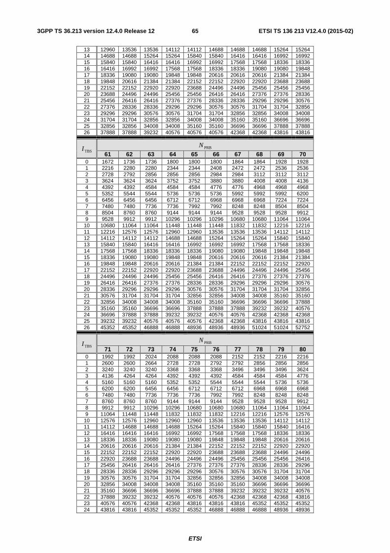
ETSI
ETSI TS 136 213 V12.4.0 (2015-02)653GPP TS 36.213 version 12.4.0 Release 12
13 12960 13536 13536 14112 14112 14688 14688 14688 15264 15264 14 14688 14688 15264 15264 15840 15840 16416 16416 16992 16992 15 15840 15840 16416 16416 16992 16992 17568 17568 18336 18336 16 16416 16992 16992 17568 17568 18336 18336 19080 19080 19848 17 18336 19080 19080 19848 19848 20616 20616 20616 21384 21384 18 19848 20616 21384 21384 22152 22152 22920 22920 23688 23688 19 22152 22152 22920 22920 23688 24496 24496 25456 25456 25456 20 23688 24496 24496 25456 25456 26416 26416 27376 27376 28336 21 25456 26416 26416 27376 27376 28336 28336 29296 29296 30576 22 27376 28336 28336 29296 29296 30576 30576 31704 31704 32856 23 29296 29296 30576 30576 31704 31704 32856 32856 34008 34008 24 31704 31704 32856 32856 34008 34008 35160 35160 36696 36696 25 32856 32856 34008 34008 35160 35160 36696 36696 37888 37888 26 37888 37888 39232 40576 40576 40576 42368 42368 43816 43816
TBSI PRBN
61 62 63 64 65 66 67 68 69 70 0 1672 1736 1736 1800 1800 1800 1864 1864 1928 1928 1 2216 2280 2280 2344 2344 2408 2472 2472 2536 2536 2 2728 2792 2856 2856 2856 2984 2984 3112 3112 3112 3 3624 3624 3624 3752 3752 3880 3880 4008 4008 4136 4 4392 4392 4584 4584 4584 4776 4776 4968 4968 4968 5 5352 5544 5544 5736 5736 5736 5992 5992 5992 6200 6 6456 6456 6456 6712 6712 6968 6968 6968 7224 7224 7 7480 7480 7736 7736 7992 7992 8248 8248 8504 8504 8 8504 8760 8760 9144 9144 9144 9528 9528 9528 9912 9 9528 9912 9912 10296 10296 10296 10680 10680 11064 11064
10 10680 11064 11064 11448 11448 11448 11832 11832 12216 12216 11 12216 12576 12576 12960 12960 13536 13536 13536 14112 14112 12 14112 14112 14112 14688 14688 15264 15264 15264 15840 15840 13 15840 15840 16416 16416 16992 16992 16992 17568 17568 18336 14 17568 17568 18336 18336 18336 19080 19080 19848 19848 19848 15 18336 19080 19080 19848 19848 20616 20616 20616 21384 21384 16 19848 19848 20616 20616 21384 21384 22152 22152 22152 22920 17 22152 22152 22920 22920 23688 23688 24496 24496 24496 25456 18 24496 24496 24496 25456 25456 26416 26416 27376 27376 27376 19 26416 26416 27376 27376 28336 28336 29296 29296 29296 30576 20 28336 29296 29296 29296 30576 30576 31704 31704 31704 32856 21 30576 31704 31704 31704 32856 32856 34008 34008 35160 35160 22 32856 34008 34008 34008 35160 35160 36696 36696 36696 37888 23 35160 35160 36696 36696 37888 37888 37888 39232 39232 40576 24 36696 37888 37888 39232 39232 40576 40576 42368 42368 42368 25 39232 39232 40576 40576 40576 42368 42368 43816 43816 43816 26 45352 45352 46888 46888 48936 48936 48936 51024 51024 52752
TBSI PRBN
71 72 73 74 75 76 77 78 79 80 0 1992 1992 2024 2088 2088 2088 2152 2152 2216 2216 1 2600 2600 2664 2728 2728 2792 2792 2856 2856 2856 2 3240 3240 3240 3368 3368 3368 3496 3496 3496 3624 3 4136 4264 4264 4392 4392 4392 4584 4584 4584 4776 4 5160 5160 5160 5352 5352 5544 5544 5544 5736 5736 5 6200 6200 6456 6456 6712 6712 6712 6968 6968 6968 6 7480 7480 7736 7736 7736 7992 7992 8248 8248 8248 7 8760 8760 8760 9144 9144 9144 9528 9528 9528 9912 8 9912 9912 10296 10296 10680 10680 10680 11064 11064 11064 9 11064 11448 11448 11832 11832 11832 12216 12216 12576 12576
10 12576 12576 12960 12960 12960 13536 13536 13536 14112 14112 11 14112 14688 14688 14688 15264 15264 15840 15840 15840 16416 12 16416 16416 16416 16992 16992 17568 17568 17568 18336 18336 13 18336 18336 19080 19080 19080 19848 19848 19848 20616 20616 14 20616 20616 20616 21384 21384 22152 22152 22152 22920 22920 15 22152 22152 22152 22920 22920 23688 23688 23688 24496 24496 16 22920 23688 23688 24496 24496 24496 25456 25456 25456 26416 17 25456 26416 26416 26416 27376 27376 27376 28336 28336 29296 18 28336 28336 29296 29296 29296 30576 30576 30576 31704 31704 19 30576 30576 31704 31704 32856 32856 32856 34008 34008 34008 20 32856 34008 34008 34008 35160 35160 35160 36696 36696 36696 21 35160 36696 36696 36696 37888 37888 39232 39232 39232 40576 22 37888 39232 39232 40576 40576 40576 42368 42368 42368 43816 23 40576 40576 42368 42368 43816 43816 43816 45352 45352 45352 24 43816 43816 45352 45352 45352 46888 46888 46888 48936 48936
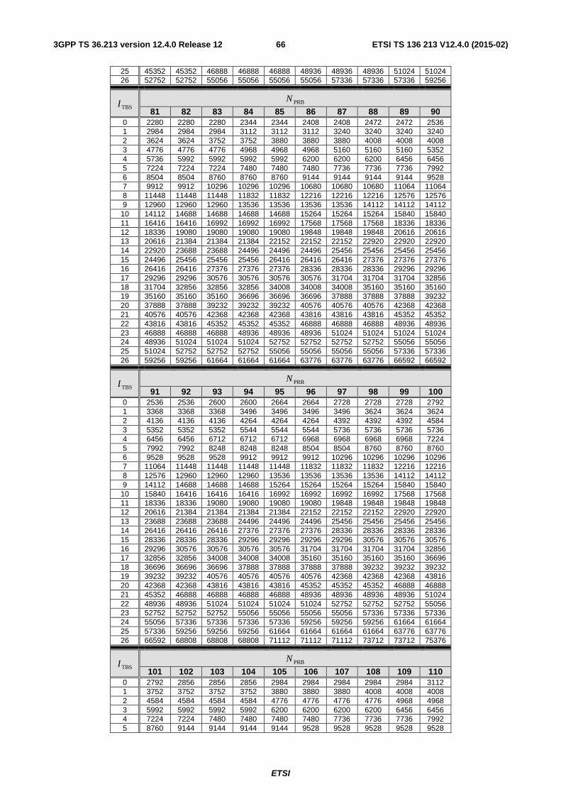
ETSI
ETSI TS 136 213 V12.4.0 (2015-02)663GPP TS 36.213 version 12.4.0 Release 12
25 45352 45352 46888 46888 46888 48936 48936 48936 51024 51024 26 52752 52752 55056 55056 55056 55056 57336 57336 57336 59256
TBSI PRBN
81 82 83 84 85 86 87 88 89 90 0 2280 2280 2280 2344 2344 2408 2408 2472 2472 2536 1 2984 2984 2984 3112 3112 3112 3240 3240 3240 3240 2 3624 3624 3752 3752 3880 3880 3880 4008 4008 4008 3 4776 4776 4776 4968 4968 4968 5160 5160 5160 5352 4 5736 5992 5992 5992 5992 6200 6200 6200 6456 6456 5 7224 7224 7224 7480 7480 7480 7736 7736 7736 7992 6 8504 8504 8760 8760 8760 9144 9144 9144 9144 9528 7 9912 9912 10296 10296 10296 10680 10680 10680 11064 11064 8 11448 11448 11448 11832 11832 12216 12216 12216 12576 12576 9 12960 12960 12960 13536 13536 13536 13536 14112 14112 14112
10 14112 14688 14688 14688 14688 15264 15264 15264 15840 15840 11 16416 16416 16992 16992 16992 17568 17568 17568 18336 18336 12 18336 19080 19080 19080 19080 19848 19848 19848 20616 20616 13 20616 21384 21384 21384 22152 22152 22152 22920 22920 22920 14 22920 23688 23688 24496 24496 24496 25456 25456 25456 25456 15 24496 25456 25456 25456 26416 26416 26416 27376 27376 27376 16 26416 26416 27376 27376 27376 28336 28336 28336 29296 29296 17 29296 29296 30576 30576 30576 30576 31704 31704 31704 32856 18 31704 32856 32856 32856 34008 34008 34008 35160 35160 35160 19 35160 35160 35160 36696 36696 36696 37888 37888 37888 39232 20 37888 37888 39232 39232 39232 40576 40576 40576 42368 42368 21 40576 40576 42368 42368 42368 43816 43816 43816 45352 45352 22 43816 43816 45352 45352 45352 46888 46888 46888 48936 48936 23 46888 46888 46888 48936 48936 48936 51024 51024 51024 51024 24 48936 51024 51024 51024 52752 52752 52752 52752 55056 55056 25 51024 52752 52752 52752 55056 55056 55056 55056 57336 57336 26 59256 59256 61664 61664 61664 63776 63776 63776 66592 66592
TBSI PRBN
91 92 93 94 95 96 97 98 99 100 0 2536 2536 2600 2600 2664 2664 2728 2728 2728 2792 1 3368 3368 3368 3496 3496 3496 3496 3624 3624 3624 2 4136 4136 4136 4264 4264 4264 4392 4392 4392 4584 3 5352 5352 5352 5544 5544 5544 5736 5736 5736 5736 4 6456 6456 6712 6712 6712 6968 6968 6968 6968 7224 5 7992 7992 8248 8248 8248 8504 8504 8760 8760 8760 6 9528 9528 9528 9912 9912 9912 10296 10296 10296 10296 7 11064 11448 11448 11448 11448 11832 11832 11832 12216 12216 8 12576 12960 12960 12960 13536 13536 13536 13536 14112 14112 9 14112 14688 14688 14688 15264 15264 15264 15264 15840 15840
10 15840 16416 16416 16416 16992 16992 16992 16992 17568 17568 11 18336 18336 19080 19080 19080 19080 19848 19848 19848 19848 12 20616 21384 21384 21384 21384 22152 22152 22152 22920 22920 13 23688 23688 23688 24496 24496 24496 25456 25456 25456 25456 14 26416 26416 26416 27376 27376 27376 28336 28336 28336 28336 15 28336 28336 28336 29296 29296 29296 29296 30576 30576 30576 16 29296 30576 30576 30576 30576 31704 31704 31704 31704 32856 17 32856 32856 34008 34008 34008 35160 35160 35160 35160 36696 18 36696 36696 36696 37888 37888 37888 37888 39232 39232 39232 19 39232 39232 40576 40576 40576 40576 42368 42368 42368 43816 20 42368 42368 43816 43816 43816 45352 45352 45352 46888 46888 21 45352 46888 46888 46888 46888 48936 48936 48936 48936 51024 22 48936 48936 51024 51024 51024 51024 52752 52752 52752 55056 23 52752 52752 52752 55056 55056 55056 55056 57336 57336 57336 24 55056 57336 57336 57336 57336 59256 59256 59256 61664 61664 25 57336 59256 59256 59256 61664 61664 61664 61664 63776 63776 26 66592 68808 68808 68808 71112 71112 71112 73712 73712 75376
TBSI PRBN
101 102 103 104 105 106 107 108 109 110 0 2792 2856 2856 2856 2984 2984 2984 2984 2984 3112 1 3752 3752 3752 3752 3880 3880 3880 4008 4008 4008 2 4584 4584 4584 4584 4776 4776 4776 4776 4968 4968 3 5992 5992 5992 5992 6200 6200 6200 6200 6456 6456 4 7224 7224 7480 7480 7480 7480 7736 7736 7736 7992 5 8760 9144 9144 9144 9144 9528 9528 9528 9528 9528
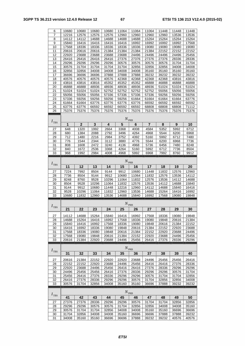
ETSI
ETSI TS 136 213 V12.4.0 (2015-02)673GPP TS 36.213 version 12.4.0 Release 12
6 10680 10680 10680 10680 11064 11064 11064 11448 11448 11448 7 12216 12576 12576 12576 12960 12960 12960 12960 13536 13536 8 14112 14112 14688 14688 14688 14688 15264 15264 15264 15264 9 15840 16416 16416 16416 16416 16992 16992 16992 16992 17568
10 17568 18336 18336 18336 18336 18336 19080 19080 19080 19080 11 20616 20616 20616 21384 21384 21384 21384 22152 22152 22152 12 22920 23688 23688 23688 23688 24496 24496 24496 24496 25456 13 26416 26416 26416 26416 27376 27376 27376 27376 28336 28336 14 29296 29296 29296 29296 30576 30576 30576 30576 31704 31704 15 30576 31704 31704 31704 31704 32856 32856 32856 34008 34008 16 32856 32856 34008 34008 34008 34008 35160 35160 35160 35160 17 36696 36696 36696 37888 37888 37888 39232 39232 39232 39232 18 40576 40576 40576 40576 42368 42368 42368 42368 43816 43816 19 43816 43816 43816 45352 45352 45352 46888 46888 46888 46888 20 46888 46888 48936 48936 48936 48936 48936 51024 51024 51024 21 51024 51024 51024 52752 52752 52752 52752 55056 55056 55056 22 55056 55056 55056 57336 57336 57336 57336 59256 59256 59256 23 57336 59256 59256 59256 59256 61664 61664 61664 61664 63776 24 61664 61664 63776 63776 63776 63776 66592 66592 66592 66592 25 63776 63776 66592 66592 66592 66592 68808 68808 68808 71112 26 75376 75376 75376 75376 75376 75376 75376 75376 75376 75376
TBSI PRBN
1 2 3 4 5 6 7 8 9 10 27 648 1320 1992 2664 3368 4008 4584 5352 5992 6712 28 680 1384 2088 2792 3496 4264 4968 5544 6200 6968 29 712 1480 2216 2984 3752 4392 5160 5992 6712 7480 30 776 1544 2344 3112 3880 4776 5544 6200 6968 7736 31 808 1608 2472 3240 4136 4968 5736 6456 7480 8248 32 840 1672 2536 3368 4264 5160 5992 6712 7736 8504 33 968 1992 2984 4008 4968 5992 6968 7992 8760 9912
TBSI PRBN
11 12 13 14 15 16 17 18 19 20 27 7224 7992 8504 9144 9912 10680 11448 11832 12576 12960 28 7736 8504 9144 9912 10680 11064 11832 12576 13536 14112 29 8248 8760 9528 10296 11064 11832 12576 13536 14112 14688 30 8504 9528 10296 11064 11832 12576 13536 14112 14688 15840 31 9144 9912 10680 11448 12216 12960 14112 14688 15840 16416 32 9528 10296 11064 11832 12960 13536 14688 15264 16416 16992 33 10680 11832 12960 13536 14688 15840 16992 17568 19080 19848
TBSI PRBN
21 22 23 24 25 26 27 28 29 30
27 14112 14688 15264 15840 16416 16992 17568 18336 19080 19848 28 14688 15264 16416 16992 17568 18336 19080 19848 20616 21384 29 15840 16416 16992 17568 18336 19080 19848 20616 21384 22152 30 16416 16992 18336 19080 19848 20616 21384 22152 22920 23688 31 17568 18336 19080 19848 20616 21384 22152 22920 23688 24496 32 17568 19080 19848 20616 21384 22152 22920 23688 24496 25456 33 20616 21384 22920 23688 24496 25456 26416 27376 28336 29296
TBSI PRBN
31 32 33 34 35 36 37 38 39 40
27 20616 21384 22152 22920 22920 23688 24496 25456 25456 26416 28 22152 22152 22920 23688 24496 25456 26416 26416 27376 28336 29 22920 23688 24496 25456 26416 26416 27376 28336 29296 29296 30 24496 25456 25456 26416 27376 28336 29296 29296 30576 31704 31 25456 26416 27376 28336 29296 29296 30576 31704 31704 32856 32 26416 27376 28336 29296 29296 30576 31704 32856 32856 34008 33 30576 31704 32856 34008 35160 35160 36696 37888 39232 39232
TBSI PRBN
41 42 43 44 45 46 47 48 49 50 27 27376 27376 28336 29296 29296 30576 31704 31704 32856 32856 28 29296 29296 30576 30576 31704 32856 32856 34008 34008 35160 29 30576 31704 31704 32856 34008 34008 35160 35160 36696 36696 30 31704 32856 34008 34008 35160 36696 36696 37888 37888 39232 31 34008 35160 35160 36696 36696 37888 39232 39232 40576 40576
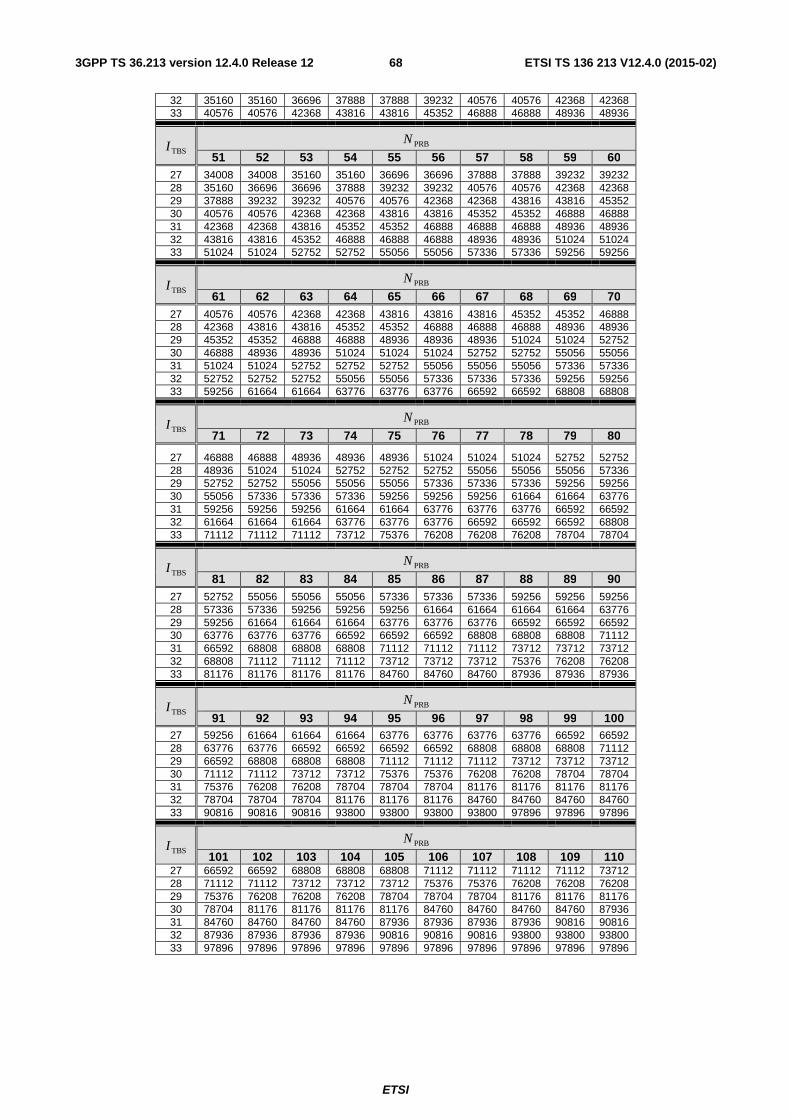
ETSI
ETSI TS 136 213 V12.4.0 (2015-02)683GPP TS 36.213 version 12.4.0 Release 12
32 35160 35160 36696 37888 37888 39232 40576 40576 42368 42368 33 40576 40576 42368 43816 43816 45352 46888 46888 48936 48936
TBSI PRBN
51 52 53 54 55 56 57 58 59 60 27 34008 34008 35160 35160 36696 36696 37888 37888 39232 39232 28 35160 36696 36696 37888 39232 39232 40576 40576 42368 42368 29 37888 39232 39232 40576 40576 42368 42368 43816 43816 45352 30 40576 40576 42368 42368 43816 43816 45352 45352 46888 46888 31 42368 42368 43816 45352 45352 46888 46888 46888 48936 48936 32 43816 43816 45352 46888 46888 46888 48936 48936 51024 51024 33 51024 51024 52752 52752 55056 55056 57336 57336 59256 59256
TBSI PRBN
61 62 63 64 65 66 67 68 69 70 27 40576 40576 42368 42368 43816 43816 43816 45352 45352 46888 28 42368 43816 43816 45352 45352 46888 46888 46888 48936 48936 29 45352 45352 46888 46888 48936 48936 48936 51024 51024 52752 30 46888 48936 48936 51024 51024 51024 52752 52752 55056 55056 31 51024 51024 52752 52752 52752 55056 55056 55056 57336 57336 32 52752 52752 52752 55056 55056 57336 57336 57336 59256 59256 33 59256 61664 61664 63776 63776 63776 66592 66592 68808 68808
TBSI PRBN
71 72 73 74 75 76 77 78 79 80
27 46888 46888 48936 48936 48936 51024 51024 51024 52752 52752 28 48936 51024 51024 52752 52752 52752 55056 55056 55056 57336 29 52752 52752 55056 55056 55056 57336 57336 57336 59256 59256 30 55056 57336 57336 57336 59256 59256 59256 61664 61664 63776 31 59256 59256 59256 61664 61664 63776 63776 63776 66592 66592 32 61664 61664 61664 63776 63776 63776 66592 66592 66592 68808 33 71112 71112 71112 73712 75376 76208 76208 76208 78704 78704
TBSI PRBN
81 82 83 84 85 86 87 88 89 90 27 52752 55056 55056 55056 57336 57336 57336 59256 59256 59256 28 57336 57336 59256 59256 59256 61664 61664 61664 61664 63776 29 59256 61664 61664 61664 63776 63776 63776 66592 66592 66592 30 63776 63776 63776 66592 66592 66592 68808 68808 68808 71112 31 66592 68808 68808 68808 71112 71112 71112 73712 73712 73712 32 68808 71112 71112 71112 73712 73712 73712 75376 76208 76208 33 81176 81176 81176 81176 84760 84760 84760 87936 87936 87936
TBSI PRBN
91 92 93 94 95 96 97 98 99 100 27 59256 61664 61664 61664 63776 63776 63776 63776 66592 66592 28 63776 63776 66592 66592 66592 66592 68808 68808 68808 71112 29 66592 68808 68808 68808 71112 71112 71112 73712 73712 73712 30 71112 71112 73712 73712 75376 75376 76208 76208 78704 78704 31 75376 76208 76208 78704 78704 78704 81176 81176 81176 81176 32 78704 78704 78704 81176 81176 81176 84760 84760 84760 84760 33 90816 90816 90816 93800 93800 93800 93800 97896 97896 97896
TBSI PRBN
101 102 103 104 105 106 107 108 109 110 27 66592 66592 68808 68808 68808 71112 71112 71112 71112 73712 28 71112 71112 73712 73712 73712 75376 75376 76208 76208 76208 29 75376 76208 76208 76208 78704 78704 78704 81176 81176 81176 30 78704 81176 81176 81176 81176 84760 84760 84760 84760 87936 31 84760 84760 84760 84760 87936 87936 87936 87936 90816 90816 32 87936 87936 87936 87936 90816 90816 90816 93800 93800 93800 33 97896 97896 97896 97896 97896 97896 97896 97896 97896 97896
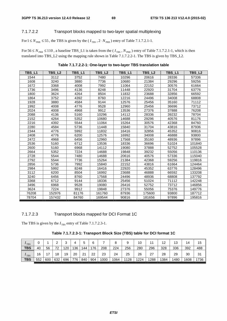
ETSI
ETSI TS 136 213 V12.4.0 (2015-02)693GPP TS 36.213 version 12.4.0 Release 12
7.1.7.2.2 Transport blocks mapped to two-layer spatial multiplexing
For 551 PRB ≤≤ N , the TBS is given by the ( TBSI , PRB2 N⋅ ) entry of Table 7.1.7.2.1-1.
For 11056 PRB ≤≤ N , a baseline TBS_L1 is taken from the ( TBSI , PRBN ) entry of Table 7.1.7.2.1-1, which is then
translated into TBS_L2 using the mapping rule shown in Table 7.1.7.2.2-1. The TBS is given by TBS_L2.
Table 7.1.7.2.2-1: One-layer to two-layer TBS translation table
TBS_L1 TBS_L2 TBS_L1 TBS_L2 TBS_L1 TBS_L2 TBS_L1 TBS_L2 1544 3112 3752 7480 10296 20616 28336 57336 1608 3240 3880 7736 10680 21384 29296 59256 1672 3368 4008 7992 11064 22152 30576 61664 1736 3496 4136 8248 11448 22920 31704 63776 1800 3624 4264 8504 11832 23688 32856 66592 1864 3752 4392 8760 12216 24496 34008 68808 1928 3880 4584 9144 12576 25456 35160 71112 1992 4008 4776 9528 12960 25456 36696 73712 2024 4008 4968 9912 13536 27376 37888 76208 2088 4136 5160 10296 14112 28336 39232 78704 2152 4264 5352 10680 14688 29296 40576 81176 2216 4392 5544 11064 15264 30576 42368 84760 2280 4584 5736 11448 15840 31704 43816 87936 2344 4776 5992 11832 16416 32856 45352 90816 2408 4776 6200 12576 16992 34008 46888 93800 2472 4968 6456 12960 17568 35160 48936 97896 2536 5160 6712 13536 18336 36696 51024 101840 2600 5160 6968 14112 19080 37888 52752 105528 2664 5352 7224 14688 19848 39232 55056 110136 2728 5544 7480 14688 20616 40576 57336 115040 2792 5544 7736 15264 21384 42368 59256 119816 2856 5736 7992 15840 22152 43816 61664 124464 2984 5992 8248 16416 22920 45352 63776 128496 3112 6200 8504 16992 23688 46888 66592 133208 3240 6456 8760 17568 24496 48936 68808 137792 3368 6712 9144 18336 25456 51024 71112 142248 3496 6968 9528 19080 26416 52752 73712 146856 3624 7224 9912 19848 27376 55056 75376 149776
76208 152976 81176 161760 87936 175600 93800 187712 78704 157432 84760 169544 90816 181656 97896 195816
7.1.7.2.3 Transport blocks mapped for DCI Format 1C
The TBS is given by the TBSI entry of Table 7.1.7.2.3-1.
Table 7.1.7.2.3-1: Transport Block Size (TBS) table for DCI format 1C
TBSI 0 1 2 3 4 5 6 7 8 9 10 11 12 13 14 15
TBS 40 56 72 120 136 144 176 208 224 256 280 296 328 336 392 488
TBSI 16 17 18 19 20 21 22 23 24 25 26 27 28 29 30 31
TBS 552 600 632 696 776 840 904 1000 1064 1128 1224 1288 1384 1480 1608 1736
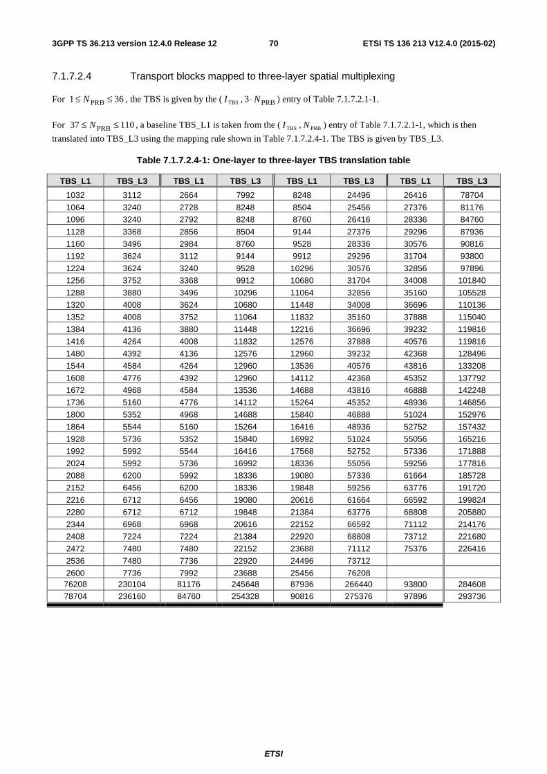
ETSI
ETSI TS 136 213 V12.4.0 (2015-02)703GPP TS 36.213 version 12.4.0 Release 12
7.1.7.2.4 Transport blocks mapped to three-layer spatial multiplexing
For 361 PRB ≤≤ N , the TBS is given by the ( TBSI , PRB3 N⋅ ) entry of Table 7.1.7.2.1-1.
For 11037 PRB ≤≤ N , a baseline TBS_L1 is taken from the ( TBSI , PRBN ) entry of Table 7.1.7.2.1-1, which is then
translated into TBS_L3 using the mapping rule shown in Table 7.1.7.2.4-1. The TBS is given by TBS_L3.
Table 7.1.7.2.4-1: One-layer to three-layer TBS translation table
TBS_L1 TBS_L3 TBS_L1 TBS_L3 TBS_L1 TBS_L3 TBS_L1 TBS_L3
1032 3112 2664 7992 8248 24496 26416 78704
1064 3240 2728 8248 8504 25456 27376 81176
1096 3240 2792 8248 8760 26416 28336 84760
1128 3368 2856 8504 9144 27376 29296 87936
1160 3496 2984 8760 9528 28336 30576 90816
1192 3624 3112 9144 9912 29296 31704 93800
1224 3624 3240 9528 10296 30576 32856 97896
1256 3752 3368 9912 10680 31704 34008 101840
1288 3880 3496 10296 11064 32856 35160 105528
1320 4008 3624 10680 11448 34008 36696 110136
1352 4008 3752 11064 11832 35160 37888 115040
1384 4136 3880 11448 12216 36696 39232 119816
1416 4264 4008 11832 12576 37888 40576 119816
1480 4392 4136 12576 12960 39232 42368 128496
1544 4584 4264 12960 13536 40576 43816 133208
1608 4776 4392 12960 14112 42368 45352 137792
1672 4968 4584 13536 14688 43816 46888 142248
1736 5160 4776 14112 15264 45352 48936 146856
1800 5352 4968 14688 15840 46888 51024 152976
1864 5544 5160 15264 16416 48936 52752 157432
1928 5736 5352 15840 16992 51024 55056 165216
1992 5992 5544 16416 17568 52752 57336 171888
2024 5992 5736 16992 18336 55056 59256 177816
2088 6200 5992 18336 19080 57336 61664 185728
2152 6456 6200 18336 19848 59256 63776 191720
2216 6712 6456 19080 20616 61664 66592 199824
2280 6712 6712 19848 21384 63776 68808 205880
2344 6968 6968 20616 22152 66592 71112 214176
2408 7224 7224 21384 22920 68808 73712 221680
2472 7480 7480 22152 23688 71112 75376 226416
2536 7480 7736 22920 24496 73712
2600 7736 7992 23688 25456 76208 76208 230104 81176 245648 87936 266440 93800 284608
78704 236160 84760 254328 90816 275376 97896 293736
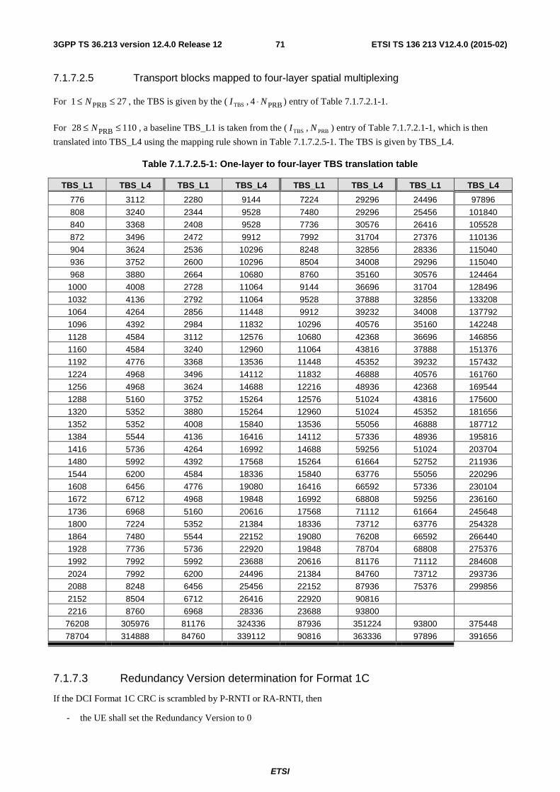
ETSI
ETSI TS 136 213 V12.4.0 (2015-02)713GPP TS 36.213 version 12.4.0 Release 12
7.1.7.2.5 Transport blocks mapped to four-layer spatial multiplexing
For 271 PRB ≤≤ N , the TBS is given by the ( TBSI , PRB4 N⋅ ) entry of Table 7.1.7.2.1-1.
For 11028 PRB ≤≤ N , a baseline TBS_L1 is taken from the ( TBSI , PRBN ) entry of Table 7.1.7.2.1-1, which is then
translated into TBS_L4 using the mapping rule shown in Table 7.1.7.2.5-1. The TBS is given by TBS_L4.
Table 7.1.7.2.5-1: One-layer to four-layer TBS translation table
TBS_L1 TBS_L4 TBS_L1 TBS_L4 TBS_L1 TBS_L4 TBS_L1 TBS_L4
776 3112 2280 9144 7224 29296 24496 97896
808 3240 2344 9528 7480 29296 25456 101840
840 3368 2408 9528 7736 30576 26416 105528
872 3496 2472 9912 7992 31704 27376 110136
904 3624 2536 10296 8248 32856 28336 115040
936 3752 2600 10296 8504 34008 29296 115040
968 3880 2664 10680 8760 35160 30576 124464
1000 4008 2728 11064 9144 36696 31704 128496
1032 4136 2792 11064 9528 37888 32856 133208
1064 4264 2856 11448 9912 39232 34008 137792
1096 4392 2984 11832 10296 40576 35160 142248
1128 4584 3112 12576 10680 42368 36696 146856
1160 4584 3240 12960 11064 43816 37888 151376
1192 4776 3368 13536 11448 45352 39232 157432
1224 4968 3496 14112 11832 46888 40576 161760
1256 4968 3624 14688 12216 48936 42368 169544
1288 5160 3752 15264 12576 51024 43816 175600
1320 5352 3880 15264 12960 51024 45352 181656
1352 5352 4008 15840 13536 55056 46888 187712
1384 5544 4136 16416 14112 57336 48936 195816
1416 5736 4264 16992 14688 59256 51024 203704
1480 5992 4392 17568 15264 61664 52752 211936
1544 6200 4584 18336 15840 63776 55056 220296
1608 6456 4776 19080 16416 66592 57336 230104
1672 6712 4968 19848 16992 68808 59256 236160
1736 6968 5160 20616 17568 71112 61664 245648
1800 7224 5352 21384 18336 73712 63776 254328
1864 7480 5544 22152 19080 76208 66592 266440
1928 7736 5736 22920 19848 78704 68808 275376
1992 7992 5992 23688 20616 81176 71112 284608
2024 7992 6200 24496 21384 84760 73712 293736
2088 8248 6456 25456 22152 87936 75376 299856
2152 8504 6712 26416 22920 90816
2216 8760 6968 28336 23688 93800
76208 305976 81176 324336 87936 351224 93800 375448
78704 314888 84760 339112 90816 363336 97896 391656
7.1.7.3 Redundancy Version determination for Format 1C
If the DCI Format 1C CRC is scrambled by P-RNTI or RA-RNTI, then
- the UE shall set the Redundancy Version to 0
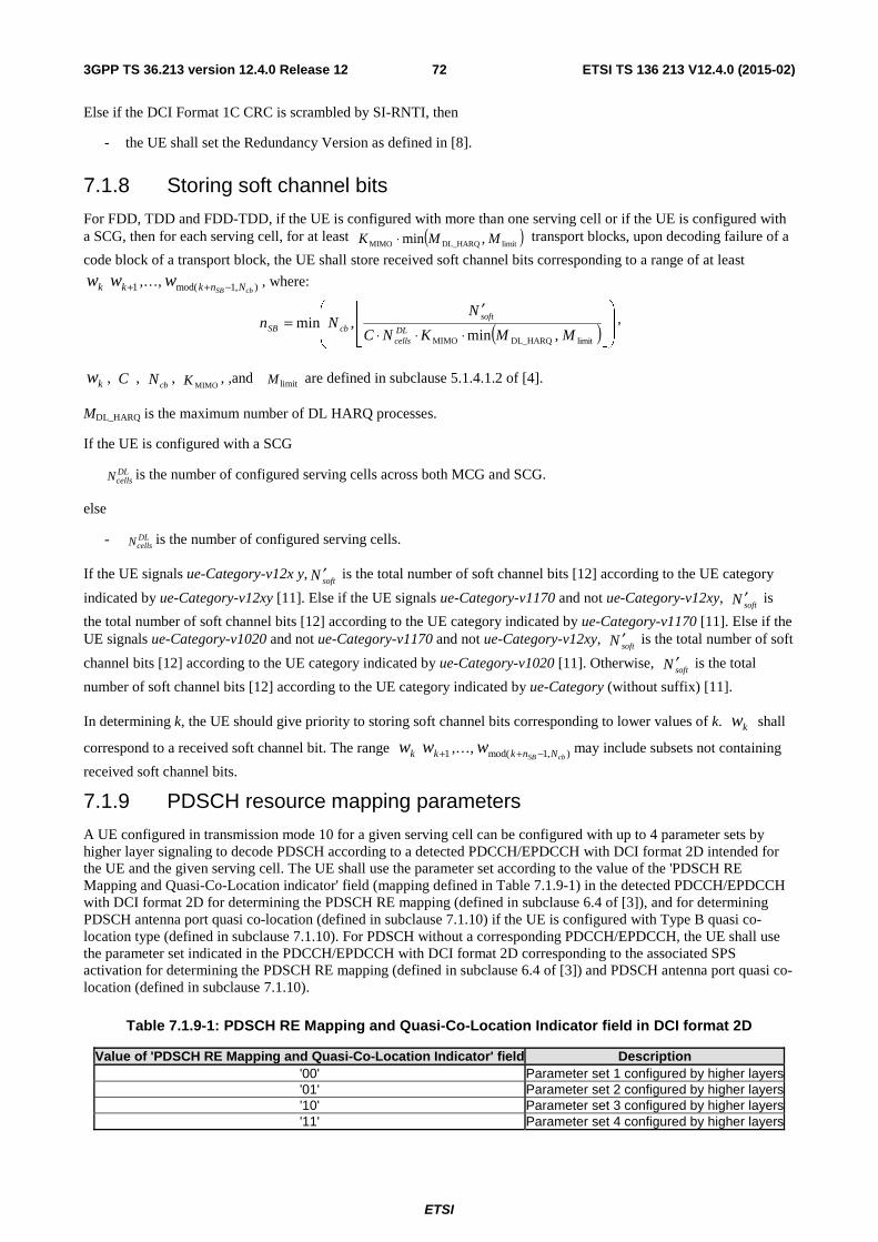
ETSI
ETSI TS 136 213 V12.4.0 (2015-02)723GPP TS 36.213 version 12.4.0 Release 12
Else if the DCI Format 1C CRC is scrambled by SI-RNTI, then
- the UE shall set the Redundancy Version as defined in [8].
7.1.8 Storing soft channel bits
For FDD, TDD and FDD-TDD, if the UE is configured with more than one serving cell or if the UE is configured with a SCG, then for each serving cell, for at least ( )limitDL_HARQMIMO ,min MMK ⋅ transport blocks, upon decoding failure of a
code block of a transport block, the UE shall store received soft channel bits corresponding to a range of at least
kw 1+kw ,…, ),1mod( cbSB Nnkw −+ , where:
( ) ⎟⎟
⎠
⎞
⎜⎜
⎝
⎛
⎥⎥⎦
⎥
⎢⎢⎣
⎢
⋅⋅⋅
′=
limitDL_HARQMIMO ,min,min
MMKNC
NNn
DLcells
softcbSB
,
kw , C , cbN ,
MIMOK , ,and limitM are defined in subclause 5.1.4.1.2 of [4].
MDL_HARQ is the maximum number of DL HARQ processes.
If the UE is configured with a SCG
DLcellsN is the number of configured serving cells across both MCG and SCG.
else
- DLcellsN is the number of configured serving cells.
If the UE signals ue-Category-v12x y,softN ′ is the total number of soft channel bits [12] according to the UE category
indicated by ue-Category-v12xy [11]. Else if the UE signals ue-Category-v1170 and not ue-Category-v12xy, softN ′ is
the total number of soft channel bits [12] according to the UE category indicated by ue-Category-v1170 [11]. Else if the UE signals ue-Category-v1020 and not ue-Category-v1170 and not ue-Category-v12xy,
softN ′ is the total number of soft
channel bits [12] according to the UE category indicated by ue-Category-v1020 [11]. Otherwise, softN ′ is the total
number of soft channel bits [12] according to the UE category indicated by ue-Category (without suffix) [11].
In determining k, the UE should give priority to storing soft channel bits corresponding to lower values of k. kw shall
correspond to a received soft channel bit. The range kw 1+kw ,…, ),1mod( cbSB Nnkw −+ may include subsets not containing
received soft channel bits.
7.1.9 PDSCH resource mapping parameters
A UE configured in transmission mode 10 for a given serving cell can be configured with up to 4 parameter sets by higher layer signaling to decode PDSCH according to a detected PDCCH/EPDCCH with DCI format 2D intended for the UE and the given serving cell. The UE shall use the parameter set according to the value of the 'PDSCH RE Mapping and Quasi-Co-Location indicator' field (mapping defined in Table 7.1.9-1) in the detected PDCCH/EPDCCH with DCI format 2D for determining the PDSCH RE mapping (defined in subclause 6.4 of [3]), and for determining PDSCH antenna port quasi co-location (defined in subclause 7.1.10) if the UE is configured with Type B quasi co-location type (defined in subclause 7.1.10). For PDSCH without a corresponding PDCCH/EPDCCH, the UE shall use the parameter set indicated in the PDCCH/EPDCCH with DCI format 2D corresponding to the associated SPS activation for determining the PDSCH RE mapping (defined in subclause 6.4 of [3]) and PDSCH antenna port quasi co-location (defined in subclause 7.1.10).
Table 7.1.9-1: PDSCH RE Mapping and Quasi-Co-Location Indicator field in DCI format 2D
Value of 'PDSCH RE Mapping and Quasi-Co-Location Indicator' field Description '00' Parameter set 1 configured by higher layers'01' Parameter set 2 configured by higher layers'10' Parameter set 3 configured by higher layers'11' Parameter set 4 configured by higher layers
ETSI
ETSI TS 136 213 V12.4.0 (2015-02)733GPP TS 36.213 version 12.4.0 Release 12
The following parameters for determining PDSCH RE mapping and PDSCH antenna port quasi co-location are configured via higher layer signaling for each parameter set:
- crs-PortsCount-r11.
- crs-FreqShift-r11.
- mbsfn-SubframeConfigList-r11.
- csi-RS-ConfigZPId-r11.
- pdsch-Start-r11.
- qcl-CSI-RS-ConfigNZPId-r11.
To decode PDSCH according to a detected PDCCH/EPDCCH with DCI format 1A with CRC scrambled with C-RNTI intended for the UE and the given serving cell and for PDSCH transmission on antenna port 7, a UE configured in transmission mode 10 for a given serving cell shall use the parameter set 1 in table 7.1.9-1 for determining the PDSCH RE mapping (defined in subclause 6.4 of [3]), and for determining PDSCH antenna port quasi co-location (defined in subclause 7.1.10) if the UE is configured with Type B quasi co-location type (defined in subclause 7.1.10).
To decode PDSCH corresponding to detected PDCCH/EPDCCH with DCI format 1A with CRC scrambled with SPS C-RNTI and PDSCH without a corresponding PDCCH/EPDCCH associated with SPS activation indicated in PDCCH/EPDCCH with DCI format 1A, a UE configured in transmission mode 10 for a given serving cell shall use the parameter set 1 in table 7.1.9-1 for determining the PDSCH RE mapping (defined in subclause 6.4 of [3]), and for determining PDSCH antenna port quasi co-location (defined in subclause 7.1.10) if the UE is configured with Type B quasi co-location type (defined in subclause 7.1.10).
To decode PDSCH according to a detected PDCCH/EPDCCH with DCI format 1A intended for the UE on a given serving cell and for PDSCH transmission on antenna port 0 – 3, a UE configured in transmission mode 10 for the given serving cell shall determine the PDSCH RE mapping (as described in subclause 6.4 of [3]) using the lowest indexed zero-power CSI-RS resource.
7.1.10 Antenna ports quasi co-location for PDSCH
A UE configured in transmission mode 8-10 for a serving cell may assume the antenna ports 7 – 14 of the serving cell are quasi co-located (as defined in [3]) for a given subframe with respect to delay spread, Doppler spread, Doppler shift, average gain, and average delay.
A UE configured in transmission mode 1-9 for a serving cell may assume the antenna ports 0 – 3, 5, 7 – 22 of the serving cell are quasi co-located (as defined in [3]) with respect to Doppler shift, Doppler spread, average delay, and delay spread.
A UE configured in transmission mode 10 for a serving cell is configured with one of two quasi co-location types for the serving cell by higher layer parameter qcl-Operation to decode PDSCH according to transmission scheme associated with antenna ports 7-14:
- Type A: The UE may assume the antenna ports 0 – 3, 7 – 22 of a serving cell are quasi co-located (as defined in [3]) with respect to delay spread, Doppler spread, Doppler shift, and average delay.
- Type B: The UE may assume the antenna ports 15 – 22 corresponding to the CSI-RS resource configuration identified by the higher layer parameter qcl-CSI-RS-ConfigNZPId-r11 (defined in subclause 7.1.9) and the antenna ports 7 – 14 associated with the PDSCH are quasi co-located (as defined in [3]) with respect to Doppler shift, Doppler spread, average delay, and delay spread.
ETSI
ETSI TS 136 213 V12.4.0 (2015-02)743GPP TS 36.213 version 12.4.0 Release 12
7.2 UE procedure for reporting Channel State Information (CSI) The time and frequency resources that can be used by the UE to report CSI which consists of Channel Quality Indicator (CQI), precoding matrix indicator (PMI), precoding type indicator (PTI), and/or rank indication (RI) are controlled by the eNB. For spatial multiplexing, as given in [3], the UE shall determine a RI corresponding to the number of useful transmission layers. For transmit diversity as given in [3], RI is equal to one.
A UE in transmission mode 8 or 9 is configured with or without PMI/RI reporting by the higher layer parameter pmi-RI-Report.
A UE in transmission mode 10 can be configured with one or more CSI processes per serving cell by higher layers. Each CSI process is associated with a CSI-RS resource (defined in subclause 7.2.5) and a CSI-interference measurement (CSI-IM) resource (defined in subclause 7.2.6). A UE can be configured with up to two CSI-IM resources for a CSI process if the UE is configured with CSI subframe sets CSI,0C and CSI,1C by the higher layer parameter csi-
SubFramePatternConfig-r12 for the CSI process. A CSI reported by the UE corresponds to a CSI process configured by higher layers. Each CSI process can be configured with or without PMI/RI reporting by higher layer signalling.
A UE is configured with resource-restricted CSI measurements if the subframe sets CSI,0C and CSI,1C are configured
by higher layers.
For a serving cell with frame structure type 1, a UE is not expected to be configured with csi-SubframePatternConfig-r12.
CSI reporting is periodic or aperiodic.
If the UE is configured with more than one serving cell, it transmits CSI for activated serving cell(s) only.
If a UE is not configured for simultaneous PUSCH and PUCCH transmission, it shall transmit periodic CSI reporting on PUCCH as defined hereafter in subframes with no PUSCH allocation.
If a UE is not configured for simultaneous PUSCH and PUCCH transmission, it shall transmit periodic CSI reporting on PUSCH of the serving cell with smallest ServCellIndex as defined hereafter in subframes with a PUSCH allocation, where the UE shall use the same PUCCH-based periodic CSI reporting format on PUSCH.
A UE shall transmit aperiodic CSI reporting on PUSCH if the conditions specified hereafter are met. For aperiodic CQI/PMI reporting, RI reporting is transmitted only if the configured CSI feedback type supports RI reporting.
Table 7.2-1: Void
In case both periodic and aperiodic CSI reporting would occur in the same subframe, the UE shall only transmit the aperiodic CSI report in that subframe.
If the higher layer parameter enableHOM-r12 is set to TRUE,
- the UE shall report CQI according to Table 7.2.3-2.
Else if the higher layer parameter csi-enableHOM-r12 for at least one CSI subframe set is set to TRUE,
- if the parameter csi-enableHOM-r12 for a given CSI subframe set is set to TRUE,
- the UE shall report CQI for the given CSI subframe set according to Table 7.2.3-2.
- else
- the UE shall report CQI for the given CSI subframe set according to Table 7.2.3-1.
Else
- the UE shall report CQI according to Table 7.2.3-1.
When reporting RI the UE reports a single instance of the number of useful transmission layers. For each RI reporting interval when the UE is configured in transmission modes 4 or when the UE is configured in transmission mode 8, 9 or
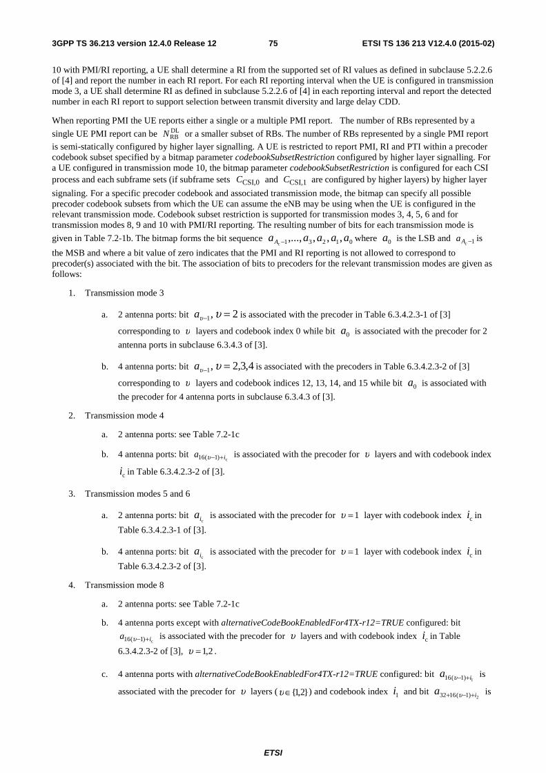
ETSI
ETSI TS 136 213 V12.4.0 (2015-02)753GPP TS 36.213 version 12.4.0 Release 12
10 with PMI/RI reporting, a UE shall determine a RI from the supported set of RI values as defined in subclause 5.2.2.6 of [4] and report the number in each RI report. For each RI reporting interval when the UE is configured in transmission mode 3, a UE shall determine RI as defined in subclause 5.2.2.6 of [4] in each reporting interval and report the detected number in each RI report to support selection between transmit diversity and large delay CDD.
When reporting PMI the UE reports either a single or a multiple PMI report. The number of RBs represented by a
single UE PMI report can be DLRBN or a smaller subset of RBs. The number of RBs represented by a single PMI report
is semi-statically configured by higher layer signalling. A UE is restricted to report PMI, RI and PTI within a precoder codebook subset specified by a bitmap parameter codebookSubsetRestriction configured by higher layer signalling. For a UE configured in transmission mode 10, the bitmap parameter codebookSubsetRestriction is configured for each CSI process and each subframe sets (if subframe sets CSI,0C and CSI,1C are configured by higher layers) by higher layer
signaling. For a specific precoder codebook and associated transmission mode, the bitmap can specify all possible precoder codebook subsets from which the UE can assume the eNB may be using when the UE is configured in the relevant transmission mode. Codebook subset restriction is supported for transmission modes 3, 4, 5, 6 and for transmission modes 8, 9 and 10 with PMI/RI reporting. The resulting number of bits for each transmission mode is
given in Table 7.2-1b. The bitmap forms the bit sequence 01231 ,,,,...,c
aaaaaA − where 0a is the LSB and 1−cAa is
the MSB and where a bit value of zero indicates that the PMI and RI reporting is not allowed to correspond to precoder(s) associated with the bit. The association of bits to precoders for the relevant transmission modes are given as follows:
1. Transmission mode 3
a. 2 antenna ports: bit 2,1 =− υυa is associated with the precoder in Table 6.3.4.2.3-1 of [3]
corresponding to υ layers and codebook index 0 while bit 0a is associated with the precoder for 2
antenna ports in subclause 6.3.4.3 of [3].
b. 4 antenna ports: bit 4,3,2,1 =− υυa is associated with the precoders in Table 6.3.4.2.3-2 of [3]
corresponding to υ layers and codebook indices 12, 13, 14, and 15 while bit 0a is associated with
the precoder for 4 antenna ports in subclause 6.3.4.3 of [3].
2. Transmission mode 4
a. 2 antenna ports: see Table 7.2-1c
b. 4 antenna ports: bit c)1(16 ia +−υ is associated with the precoder for υ layers and with codebook index
ci in Table 6.3.4.2.3-2 of [3].
3. Transmission modes 5 and 6
a. 2 antenna ports: bit ci
a is associated with the precoder for 1=υ layer with codebook index ci in
Table 6.3.4.2.3-1 of [3].
b. 4 antenna ports: bit ci
a is associated with the precoder for 1=υ layer with codebook index ci in
Table 6.3.4.2.3-2 of [3].
4. Transmission mode 8
a. 2 antenna ports: see Table 7.2-1c
b. 4 antenna ports except with alternativeCodeBookEnabledFor4TX-r12=TRUE configured: bit
c)1(16 ia +−υ is associated with the precoder for υ layers and with codebook index ci in Table
6.3.4.2.3-2 of [3], 2,1=υ .
c. 4 antenna ports with alternativeCodeBookEnabledFor4TX-r12=TRUE configured: bit 1)1(16 ia +−υ is
associated with the precoder for υ layers ( }2,1{∈υ ) and codebook index 1i and bit 2)1(1632 ia +−+ υ is
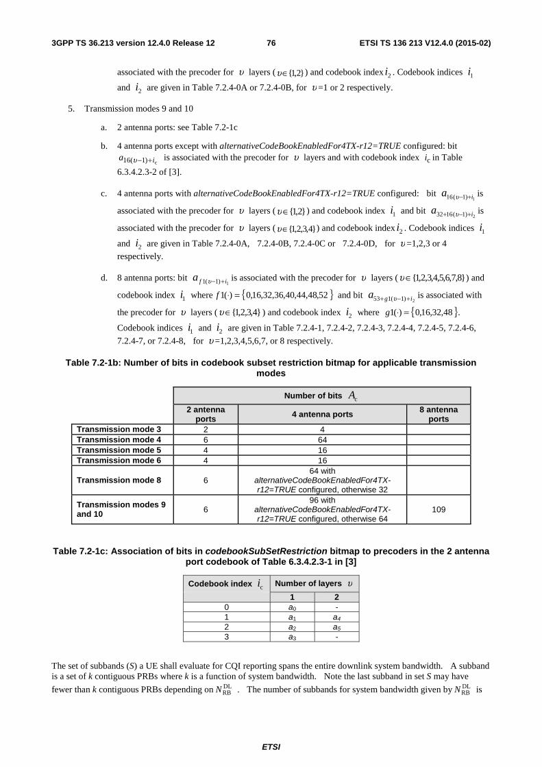
ETSI
ETSI TS 136 213 V12.4.0 (2015-02)763GPP TS 36.213 version 12.4.0 Release 12
associated with the precoder for υ layers ( }2,1{∈υ ) and codebook index 2i . Codebook indices 1i
and 2i are given in Table 7.2.4-0A or 7.2.4-0B, for υ =1 or 2 respectively.
5. Transmission modes 9 and 10
a. 2 antenna ports: see Table 7.2-1c
b. 4 antenna ports except with alternativeCodeBookEnabledFor4TX-r12=TRUE configured: bit
c)1(16 ia +−υ is associated with the precoder for υ layers and with codebook index ci in Table
6.3.4.2.3-2 of [3].
c. 4 antenna ports with alternativeCodeBookEnabledFor4TX-r12=TRUE configured: bit 1)1(16 ia +−υ is
associated with the precoder for υ layers ( }2,1{∈υ ) and codebook index 1i and bit 2)1(1632 ia +−+ υ is
associated with the precoder for υ layers ( }4,3,2,1{∈υ ) and codebook index 2i . Codebook indices 1i
and 2i are given in Table 7.2.4-0A, 7.2.4-0B, 7.2.4-0C or 7.2.4-0D, for υ =1,2,3 or 4
respectively.
d. 8 antenna ports: bit 1)1(1 ifa +−υ is associated with the precoder for υ layers ( }8,7,6,5,4,3,2,1{∈υ ) and
codebook index 1i where { }52,48,44,40,36,32,16,0)(1 =⋅f and bit 2)1(153 iga +−+ υ is associated with
the precoder for υ layers ( }4,3,2,1{∈υ ) and codebook index 2i where { }48,32,16,0)(1 =⋅g .
Codebook indices 1i and 2i are given in Table 7.2.4-1, 7.2.4-2, 7.2.4-3, 7.2.4-4, 7.2.4-5, 7.2.4-6,
7.2.4-7, or 7.2.4-8, for υ =1,2,3,4,5,6,7, or 8 respectively.
Table 7.2-1b: Number of bits in codebook subset restriction bitmap for applicable transmission modes
Number of bits cA
2 antenna ports 4 antenna ports 8 antenna
ports Transmission mode 3 2 4 Transmission mode 4 6 64 Transmission mode 5 4 16 Transmission mode 6 4 16
Transmission mode 8 6 64 with
alternativeCodeBookEnabledFor4TX-r12=TRUE configured, otherwise 32
Transmission modes 9 and 10 6
96 with alternativeCodeBookEnabledFor4TX-r12=TRUE configured, otherwise 64
109
Table 7.2-1c: Association of bits in codebookSubSetRestriction bitmap to precoders in the 2 antenna port codebook of Table 6.3.4.2.3-1 in [3]
Codebook index ci Number of layers υ
1 2 0 a0 - 1 a1 a4 2 a2 a5 3 a3 -
The set of subbands (S) a UE shall evaluate for CQI reporting spans the entire downlink system bandwidth. A subband is a set of k contiguous PRBs where k is a function of system bandwidth. Note the last subband in set S may have
fewer than k contiguous PRBs depending on DLRBN . The number of subbands for system bandwidth given by DL
RBN is
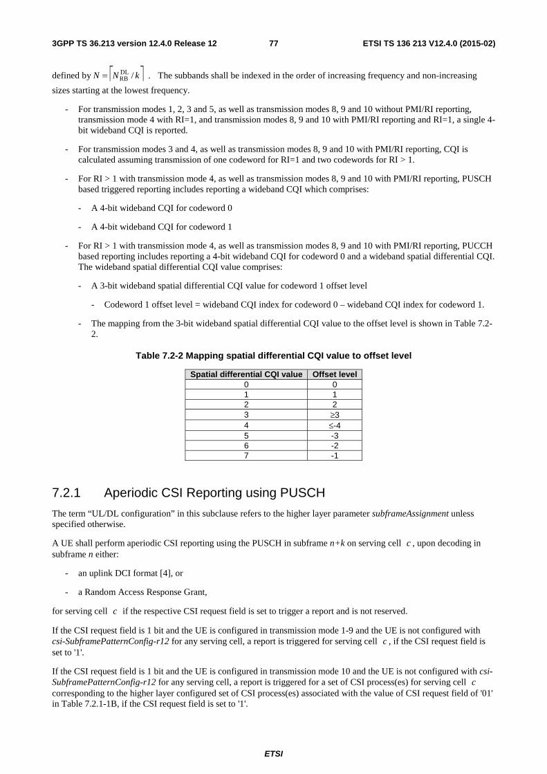
ETSI
ETSI TS 136 213 V12.4.0 (2015-02)773GPP TS 36.213 version 12.4.0 Release 12
defined by ⎡ ⎤kNN /DLRB= . The subbands shall be indexed in the order of increasing frequency and non-increasing
sizes starting at the lowest frequency.
- For transmission modes 1, 2, 3 and 5, as well as transmission modes 8, 9 and 10 without PMI/RI reporting, transmission mode 4 with RI=1, and transmission modes 8, 9 and 10 with PMI/RI reporting and RI=1, a single 4-bit wideband CQI is reported.
- For transmission modes 3 and 4, as well as transmission modes 8, 9 and 10 with PMI/RI reporting, CQI is calculated assuming transmission of one codeword for RI=1 and two codewords for RI > 1.
- For RI > 1 with transmission mode 4, as well as transmission modes 8, 9 and 10 with PMI/RI reporting, PUSCH based triggered reporting includes reporting a wideband CQI which comprises:
- A 4-bit wideband CQI for codeword 0
- A 4-bit wideband CQI for codeword 1
- For RI > 1 with transmission mode 4, as well as transmission modes 8, 9 and 10 with PMI/RI reporting, PUCCH based reporting includes reporting a 4-bit wideband CQI for codeword 0 and a wideband spatial differential CQI. The wideband spatial differential CQI value comprises:
- A 3-bit wideband spatial differential CQI value for codeword 1 offset level
- Codeword 1 offset level = wideband CQI index for codeword 0 – wideband CQI index for codeword 1.
- The mapping from the 3-bit wideband spatial differential CQI value to the offset level is shown in Table 7.2-2.
Table 7.2-2 Mapping spatial differential CQI value to offset level
Spatial differential CQI value Offset level 0 0 1 1 2 2 3 ≥3 4 ≤-4 5 -3 6 -2 7 -1
7.2.1 Aperiodic CSI Reporting using PUSCH
The term “UL/DL configuration” in this subclause refers to the higher layer parameter subframeAssignment unless specified otherwise.
A UE shall perform aperiodic CSI reporting using the PUSCH in subframe n+k on serving cell c , upon decoding in subframe n either:
- an uplink DCI format [4], or
- a Random Access Response Grant,
for serving cell c if the respective CSI request field is set to trigger a report and is not reserved.
If the CSI request field is 1 bit and the UE is configured in transmission mode 1-9 and the UE is not configured with csi-SubframePatternConfig-r12 for any serving cell, a report is triggered for serving cell c , if the CSI request field is set to '1'.
If the CSI request field is 1 bit and the UE is configured in transmission mode 10 and the UE is not configured with csi-SubframePatternConfig-r12 for any serving cell, a report is triggered for a set of CSI process(es) for serving cell c corresponding to the higher layer configured set of CSI process(es) associated with the value of CSI request field of '01' in Table 7.2.1-1B, if the CSI request field is set to '1'.
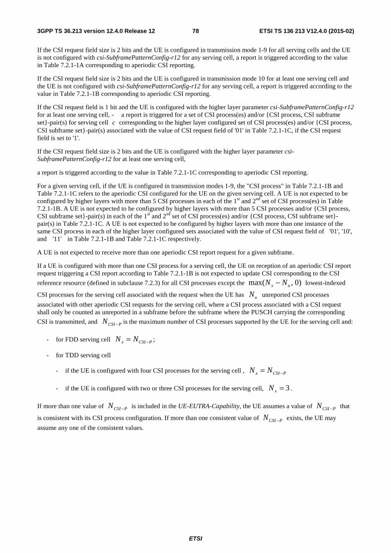
ETSI
ETSI TS 136 213 V12.4.0 (2015-02)783GPP TS 36.213 version 12.4.0 Release 12
If the CSI request field size is 2 bits and the UE is configured in transmission mode 1-9 for all serving cells and the UE is not configured with csi-SubframePatternConfig-r12 for any serving cell, a report is triggered according to the value in Table 7.2.1-1A corresponding to aperiodic CSI reporting.
If the CSI request field size is 2 bits and the UE is configured in transmission mode 10 for at least one serving cell and the UE is not configured with csi-SubframePatternConfig-r12 for any serving cell, a report is triggered according to the value in Table 7.2.1-1B corresponding to aperiodic CSI reporting.
If the CSI request field is 1 bit and the UE is configured with the higher layer parameter csi-SubframePatternConfig-r12 for at least one serving cell, - a report is triggered for a set of CSI process(es) and/or {CSI process, CSI subframe set}-pair(s) for serving cell c corresponding to the higher layer configured set of CSI process(es) and/or {CSI process, CSI subframe set}-pair(s) associated with the value of CSI request field of '01' in Table 7.2.1-1C, if the CSI request field is set to '1'.
If the CSI request field size is 2 bits and the UE is configured with the higher layer parameter csi-SubframePatternConfig-r12 for at least one serving cell,
a report is triggered according to the value in Table 7.2.1-1C corresponding to aperiodic CSI reporting.
For a given serving cell, if the UE is configured in transmission modes 1-9, the "CSI process" in Table 7.2.1-1B and Table 7.2.1-1C refers to the aperiodic CSI configured for the UE on the given serving cell. A UE is not expected to be configured by higher layers with more than 5 CSI processes in each of the 1st and 2nd set of CSI process(es) in Table 7.2.1-1B. A UE is not expected to be configured by higher layers with more than 5 CSI processes and/or {CSI process, CSI subframe set}-pair(s) in each of the 1st and 2nd set of CSI process(es) and/or {CSI process, CSI subframe set}-pair(s) in Table 7.2.1-1C. A UE is not expected to be configured by higher layers with more than one instance of the same CSI process in each of the higher layer configured sets associated with the value of CSI request field of '01', '10', and '11' in Table 7.2.1-1B and Table 7.2.1-1C respectively.
A UE is not expected to receive more than one aperiodic CSI report request for a given subframe.
If a UE is configured with more than one CSI process for a serving cell, the UE on reception of an aperiodic CSI report request triggering a CSI report according to Table 7.2.1-1B is not expected to update CSI corresponding to the CSI
reference resource (defined in subclause 7.2.3) for all CSI processes except the )0,max( ux NN − lowest-indexed
CSI processes for the serving cell associated with the request when the UE has uN unreported CSI processes
associated with other aperiodic CSI requests for the serving cell, where a CSI process associated with a CSI request shall only be counted as unreported in a subframe before the subframe where the PUSCH carrying the corresponding
CSI is transmitted, and PCSIN − is the maximum number of CSI processes supported by the UE for the serving cell and:
- for FDD serving cell PCSIx NN −= ;
- for TDD serving cell
- if the UE is configured with four CSI processes for the serving cell , PCSIx NN −=
- if the UE is configured with two or three CSI processes for the serving cell, 3=xN .
If more than one value of PCSIN − is included in the UE-EUTRA-Capability, the UE assumes a value of PCSIN − that
is consistent with its CSI process configuration. If more than one consistent value of PCSIN − exists, the UE may
assume any one of the consistent values.
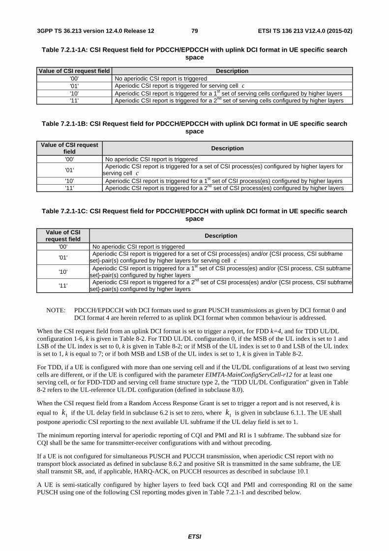
ETSI
ETSI TS 136 213 V12.4.0 (2015-02)793GPP TS 36.213 version 12.4.0 Release 12
Table 7.2.1-1A: CSI Request field for PDCCH/EPDCCH with uplink DCI format in UE specific search space
Value of CSI request field Description '00' No aperiodic CSI report is triggered '01' Aperiodic CSI report is triggered for serving cell c '10' Aperiodic CSI report is triggered for a 1st set of serving cells configured by higher layers '11' Aperiodic CSI report is triggered for a 2nd set of serving cells configured by higher layers
Table 7.2.1-1B: CSI Request field for PDCCH/EPDCCH with uplink DCI format in UE specific search space
Value of CSI request field Description
'00' No aperiodic CSI report is triggered
'01' Aperiodic CSI report is triggered for a set of CSI process(es) configured by higher layers for serving cell c
'10' Aperiodic CSI report is triggered for a 1st set of CSI process(es) configured by higher layers '11' Aperiodic CSI report is triggered for a 2nd set of CSI process(es) configured by higher layers
Table 7.2.1-1C: CSI Request field for PDCCH/EPDCCH with uplink DCI format in UE specific search space
Value of CSI request field Description
'00' No aperiodic CSI report is triggered
'01' Aperiodic CSI report is triggered for a set of CSI process(es) and/or {CSI process, CSI subframe set}-pair(s) configured by higher layers for serving cell c
'10' Aperiodic CSI report is triggered for a 1st set of CSI process(es) and/or {CSI process, CSI subframe set}-pair(s) configured by higher layers
'11' Aperiodic CSI report is triggered for a 2nd set of CSI process(es) and/or {CSI process, CSI subframe set}-pair(s) configured by higher layers
NOTE: PDCCH/EPDCCH with DCI formats used to grant PUSCH transmissions as given by DCI format 0 and DCI format 4 are herein referred to as uplink DCI format when common behaviour is addressed.
When the CSI request field from an uplink DCI format is set to trigger a report, for FDD k=4, and for TDD UL/DL configuration 1-6, k is given in Table 8-2. For TDD UL/DL configuration 0, if the MSB of the UL index is set to 1 and LSB of the UL index is set to 0, k is given in Table 8-2; or if MSB of the UL index is set to 0 and LSB of the UL index is set to 1, k is equal to 7; or if both MSB and LSB of the UL index is set to 1, k is given in Table 8-2.
For TDD, if a UE is configured with more than one serving cell and if the UL/DL configurations of at least two serving cells are different, or if the UE is configured with the parameter EIMTA-MainConfigServCell-r12 for at least one serving cell, or for FDD-TDD and serving cell frame structure type 2, the "TDD UL/DL Configuration" given in Table 8-2 refers to the UL-reference UL/DL configuration (defined in subclause 8.0).
When the CSI request field from a Random Access Response Grant is set to trigger a report and is not reserved, k is
equal to 1k if the UL delay field in subclause 6.2 is set to zero, where 1k is given in subclause 6.1.1. The UE shall
postpone aperiodic CSI reporting to the next available UL subframe if the UL delay field is set to 1.
The minimum reporting interval for aperiodic reporting of CQI and PMI and RI is 1 subframe. The subband size for CQI shall be the same for transmitter-receiver configurations with and without precoding.
If a UE is not configured for simultaneous PUSCH and PUCCH transmission, when aperiodic CSI report with no transport block associated as defined in subclause 8.6.2 and positive SR is transmitted in the same subframe, the UE shall transmit SR, and, if applicable, HARQ-ACK, on PUCCH resources as described in subclause 10.1
A UE is semi-statically configured by higher layers to feed back CQI and PMI and corresponding RI on the same PUSCH using one of the following CSI reporting modes given in Table 7.2.1-1 and described below.
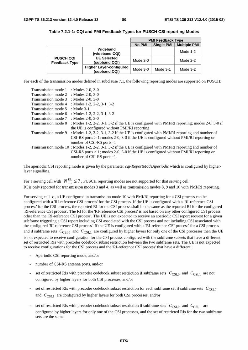
ETSI
ETSI TS 136 213 V12.4.0 (2015-02)803GPP TS 36.213 version 12.4.0 Release 12
Table 7.2.1-1: CQI and PMI Feedback Types for PUSCH CSI reporting Modes
PMI Feedback Type No PMI Single PMI Multiple PMI
PUSCH CQI Feedback Type
Wideband (wideband CQI) Mode 1-2
UE Selected (subband CQI) Mode 2-0 Mode 2-2
Higher Layer-configured (subband CQI) Mode 3-0 Mode 3-1 Mode 3-2
For each of the transmission modes defined in subclause 7.1, the following reporting modes are supported on PUSCH:
Transmission mode 1 : Modes 2-0, 3-0 Transmission mode 2 : Modes 2-0, 3-0 Transmission mode 3 : Modes 2-0, 3-0 Transmission mode 4 : Modes 1-2, 2-2, 3-1, 3-2 Transmission mode 5 : Mode 3-1 Transmission mode 6 : Modes 1-2, 2-2, 3-1, 3-2 Transmission mode 7 : Modes 2-0, 3-0 Transmission mode 8 : Modes 1-2, 2-2, 3-1, 3-2 if the UE is configured with PMI/RI reporting; modes 2-0, 3-0 if
the UE is configured without PMI/RI reporting Transmission mode 9 : Modes 1-2, 2-2, 3-1, 3-2 if the UE is configured with PMI/RI reporting and number of
CSI-RS ports > 1; modes 2-0, 3-0 if the UE is configured without PMI/RI reporting or number of CSI-RS ports=1
Transmission mode 10 : Modes 1-2, 2-2, 3-1, 3-2 if the UE is configured with PMI/RI reporting and number of CSI-RS ports > 1; modes 2-0, 3-0 if the UE is configured without PMI/RI reporting or number of CSI-RS ports=1.
The aperiodic CSI reporting mode is given by the parameter cqi-ReportModeAperiodic which is configured by higher-layer signalling.
For a serving cell with 7DLRB ≤N , PUSCH reporting modes are not supported for that serving cell.
RI is only reported for transmission modes 3 and 4, as well as transmission modes 8, 9 and 10 with PMI/RI reporting. For serving cell c , a UE configured in transmission mode 10 with PMI/RI reporting for a CSI process can be configured with a 'RI-reference CSI process' for the CSI process. If the UE is configured with a 'RI-reference CSI process' for the CSI process, the reported RI for the CSI process shall be the same as the reported RI for the configured 'RI-reference CSI process'. The RI for the 'RI-reference CSI process' is not based on any other configured CSI process other than the 'RI-reference CSI process'. The UE is not expected to receive an aperiodic CSI report request for a given subframe triggering a CSI report including CSI associated with the CSI process and not including CSI associated with the configured 'RI-reference CSI process'. If the UE is configured with a 'RI-reference CSI process' for a CSI process and if subframe sets CSI,0C and CSI,1C are configured by higher layers for only one of the CSI processes then the UE
is not expected to receive configuration for the CSI process configured with the subframe subsets that have a different set of restricted RIs with precoder codebook subset restriction between the two subframe sets. The UE is not expected to receive configurations for the CSI process and the 'RI-reference CSI process' that have a different:
- Aperiodic CSI reporting mode, and/or
- number of CSI-RS antenna ports, and/or
- set of restricted RIs with precoder codebook subset restriction if subframe sets CSI,0C and CSI,1C are not
configured by higher layers for both CSI processes, and/or
- set of restricted RIs with precoder codebook subset restriction for each subframe set if subframe sets CSI,0C
and CSI,1C are configured by higher layers for both CSI processes, and/or
- set of restricted RIs with precoder codebook subset restriction if subframe sets CSI,0C and CSI,1C are
configured by higher layers for only one of the CSI processes, and the set of restricted RIs for the two subframe sets are the same.
ETSI
ETSI TS 136 213 V12.4.0 (2015-02)813GPP TS 36.213 version 12.4.0 Release 12
A RI report for a serving cell on an aperiodic reporting mode is valid only for CQI/PMI report for that serving cell on that aperiodic reporting mode
• Wideband feedback
o Mode 1-2 description:
� For each subband a preferred precoding matrix is selected from the codebook subset assuming transmission only in the subband
� A UE shall report one wideband CQI value per codeword which is calculated assuming the use of the corresponding selected precoding matrix in each subband and transmission on set S subbands.
� The UE shall report the selected precoding matrix indicator for each set S subband except with 8 CSI-RS ports configured for transmission modes 9 and 10 or with alternativeCodeBookEnabledFor4TX-r12=TRUE configured for transmission modes 8, 9 and 10, in which case a first precoding matrix indicator 1i is reported for the set S
subbands and a second precoding matrix indicator 2i is reported for each set S
subband.
� Subband size is given by Table 7.2.1-3.
� For transmission modes 4, 8, 9 and 10, the reported PMI and CQI values are calculated conditioned on the reported RI. For other transmission modes they are reported conditioned on rank 1.
• Higher Layer-configured subband feedback
o Mode 3-0 description:
� A UE shall report a wideband CQI value which is calculated assuming transmission on set S subbands
� The UE shall also report one subband CQI value for each set S subband. The subband CQI value is calculated assuming transmission only in the subband
� Both the wideband and subband CQI represent channel quality for the first codeword, even when RI>1.
� For transmission mode 3 the reported CQI values are calculated conditioned on the reported RI. For other transmission modes they are reported conditioned on rank 1.
o Mode 3-1 description:
� A single precoding matrix is selected from the codebook subset assuming transmission on set S subbands
� A UE shall report one subband CQI value per codeword for each set S subband which are calculated assuming the use of the single precoding matrix in all subbands and assuming transmission in the corresponding subband.
� A UE shall report a wideband CQI value per codeword which is calculated assuming the use of the single precoding matrix in all subbands and transmission on set S subbands
� The UE shall report the selected single precoding matrix indicator except with 8 CSI-RS ports configured for transmission modes 9 and 10 or with alternativeCodeBookEnabledFor4TX-r12=TRUE configured for transmission modes 8, 9 and 10, in which case a first and second precoding matrix indicator are reported corresponding to the selected single precoding matrix.
� For transmission modes 4, 8, 9 and 10, the reported PMI and CQI values are calculated conditioned on the reported RI. For other transmission modes they are reported conditioned on rank 1.
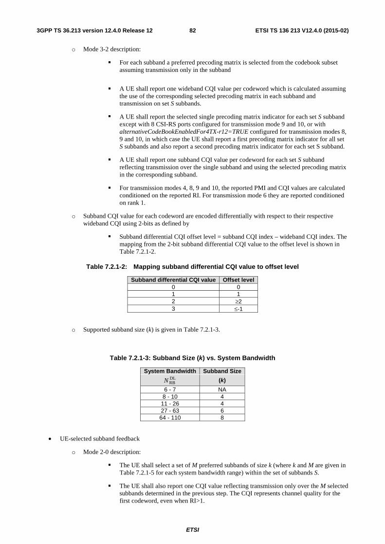
ETSI
ETSI TS 136 213 V12.4.0 (2015-02)823GPP TS 36.213 version 12.4.0 Release 12
o Mode 3-2 description:
� For each subband a preferred precoding matrix is selected from the codebook subset assuming transmission only in the subband
� A UE shall report one wideband CQI value per codeword which is calculated assuming the use of the corresponding selected precoding matrix in each subband and transmission on set S subbands.
� A UE shall report the selected single precoding matrix indicator for each set S subband except with 8 CSI-RS ports configured for transmission mode 9 and 10, or with alternativeCodeBookEnabledFor4TX-r12=TRUE configured for transmission modes 8, 9 and 10, in which case the UE shall report a first precoding matrix indicator for all set S subbands and also report a second precoding matrix indicator for each set S subband.
� A UE shall report one subband CQI value per codeword for each set S subband reflecting transmission over the single subband and using the selected precoding matrix in the corresponding subband.
� For transmission modes 4, 8, 9 and 10, the reported PMI and CQI values are calculated conditioned on the reported RI. For transmission mode 6 they are reported conditioned on rank 1.
o Subband CQI value for each codeword are encoded differentially with respect to their respective wideband CQI using 2-bits as defined by
� Subband differential CQI offset level = subband CQI index – wideband CQI index. The mapping from the 2-bit subband differential CQI value to the offset level is shown in Table 7.2.1-2.
Table 7.2.1-2: Mapping subband differential CQI value to offset level
Subband differential CQI value Offset level 0 0 1 1 2 ≥2 3 ≤-1
o Supported subband size (k) is given in Table 7.2.1-3.
Table 7.2.1-3: Subband Size (k) vs. System Bandwidth
System Bandwidth Subband Size DLRBN (k)
6 - 7 NA 8 - 10 4
11 - 26 4 27 - 63 6 64 - 110 8
• UE-selected subband feedback
o Mode 2-0 description:
� The UE shall select a set of M preferred subbands of size k (where k and M are given in Table 7.2.1-5 for each system bandwidth range) within the set of subbands S.
� The UE shall also report one CQI value reflecting transmission only over the M selected subbands determined in the previous step. The CQI represents channel quality for the first codeword, even when RI>1.
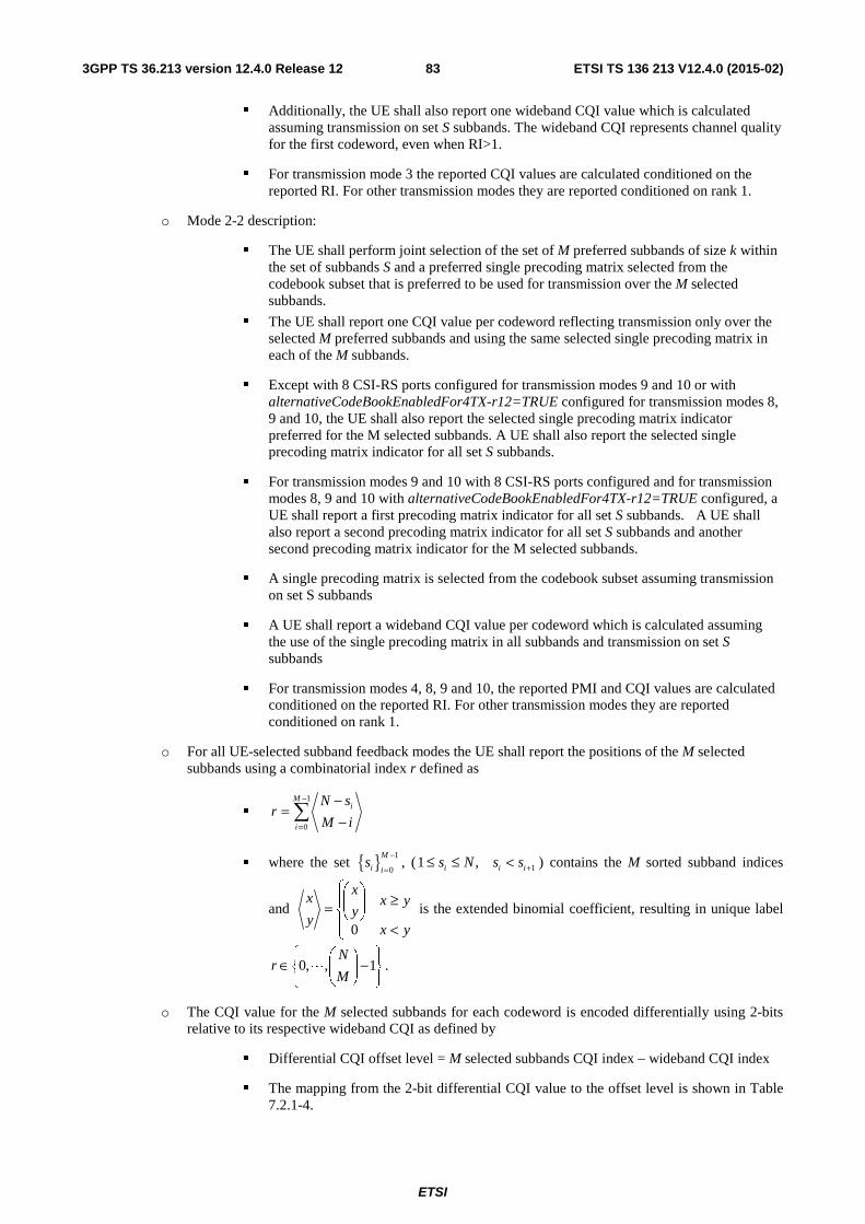
ETSI
ETSI TS 136 213 V12.4.0 (2015-02)833GPP TS 36.213 version 12.4.0 Release 12
� Additionally, the UE shall also report one wideband CQI value which is calculated assuming transmission on set S subbands. The wideband CQI represents channel quality for the first codeword, even when RI>1.
� For transmission mode 3 the reported CQI values are calculated conditioned on the reported RI. For other transmission modes they are reported conditioned on rank 1.
o Mode 2-2 description:
� The UE shall perform joint selection of the set of M preferred subbands of size k within the set of subbands S and a preferred single precoding matrix selected from the codebook subset that is preferred to be used for transmission over the M selected subbands.
� The UE shall report one CQI value per codeword reflecting transmission only over the selected M preferred subbands and using the same selected single precoding matrix in each of the M subbands.
� Except with 8 CSI-RS ports configured for transmission modes 9 and 10 or with alternativeCodeBookEnabledFor4TX-r12=TRUE configured for transmission modes 8, 9 and 10, the UE shall also report the selected single precoding matrix indicator preferred for the M selected subbands. A UE shall also report the selected single precoding matrix indicator for all set S subbands.
� For transmission modes 9 and 10 with 8 CSI-RS ports configured and for transmission modes 8, 9 and 10 with alternativeCodeBookEnabledFor4TX-r12=TRUE configured, a UE shall report a first precoding matrix indicator for all set S subbands. A UE shall also report a second precoding matrix indicator for all set S subbands and another second precoding matrix indicator for the M selected subbands.
� A single precoding matrix is selected from the codebook subset assuming transmission on set S subbands
� A UE shall report a wideband CQI value per codeword which is calculated assuming the use of the single precoding matrix in all subbands and transmission on set S subbands
� For transmission modes 4, 8, 9 and 10, the reported PMI and CQI values are calculated conditioned on the reported RI. For other transmission modes they are reported conditioned on rank 1.
o For all UE-selected subband feedback modes the UE shall report the positions of the M selected subbands using a combinatorial index r defined as
� 1
0
Mi
i
N sr
M i
−
=
−=
−∑
� where the set { } 1
0
M
i is
−
=, ( 11 ,i i is N s s +≤ ≤ < ) contains the M sorted subband indices
and ⎪⎩
⎪⎨
⎧
<
≥⎟⎟⎠
⎞⎜⎜⎝
⎛=
yx
yxy
x
y
x
0
is the extended binomial coefficient, resulting in unique label
⎪⎭
⎪⎬⎫
⎪⎩
⎪⎨⎧
−⎟⎟⎠
⎞⎜⎜⎝
⎛∈ 1,,0
M
Nr L .
o The CQI value for the M selected subbands for each codeword is encoded differentially using 2-bits relative to its respective wideband CQI as defined by
� Differential CQI offset level = M selected subbands CQI index – wideband CQI index
� The mapping from the 2-bit differential CQI value to the offset level is shown in Table 7.2.1-4.
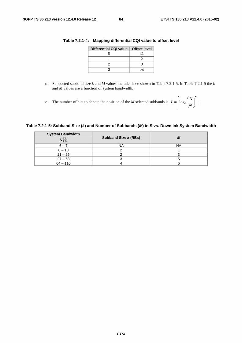
ETSI
ETSI TS 136 213 V12.4.0 (2015-02)843GPP TS 36.213 version 12.4.0 Release 12
Table 7.2.1-4: Mapping differential CQI value to offset level
Differential CQI value Offset level 0 ≤1 1 2
2 3
3 ≥4
o Supported subband size k and M values include those shown in Table 7.2.1-5. In Table 7.2.1-5 the k and M values are a function of system bandwidth.
o The number of bits to denote the position of the M selected subbands is ⎥⎥⎥
⎤
⎢⎢⎢
⎡⎟⎟⎠
⎞⎜⎜⎝
⎛=
M
NL 2log .
Table 7.2.1-5: Subband Size (k) and Number of Subbands (M) in S vs. Downlink System Bandwidth
System Bandwidth Subband Size k (RBs) M DL
RBN
6 – 7 NA NA 8 – 10 2 1
11 – 26 2 3 27 – 63 3 5
64 – 110 4 6
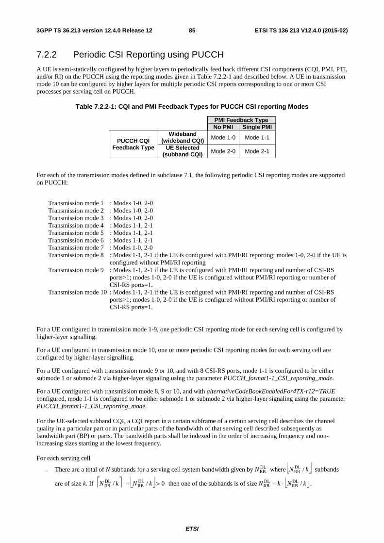
ETSI
ETSI TS 136 213 V12.4.0 (2015-02)853GPP TS 36.213 version 12.4.0 Release 12
7.2.2 Periodic CSI Reporting using PUCCH
A UE is semi-statically configured by higher layers to periodically feed back different CSI components (CQI, PMI, PTI, and/or RI) on the PUCCH using the reporting modes given in Table 7.2.2-1 and described below. A UE in transmission mode 10 can be configured by higher layers for multiple periodic CSI reports corresponding to one or more CSI processes per serving cell on PUCCH.
Table 7.2.2-1: CQI and PMI Feedback Types for PUCCH CSI reporting Modes
PMI Feedback Type No PMI Single PMI
PUCCH CQI Feedback Type
Wideband (wideband CQI) Mode 1-0 Mode 1-1
UE Selected (subband CQI) Mode 2-0 Mode 2-1
For each of the transmission modes defined in subclause 7.1, the following periodic CSI reporting modes are supported on PUCCH:
Transmission mode 1 : Modes 1-0, 2-0 Transmission mode 2 : Modes 1-0, 2-0 Transmission mode 3 : Modes 1-0, 2-0 Transmission mode 4 : Modes 1-1, 2-1 Transmission mode 5 : Modes 1-1, 2-1 Transmission mode 6 : Modes 1-1, 2-1 Transmission mode 7 : Modes 1-0, 2-0 Transmission mode 8 : Modes 1-1, 2-1 if the UE is configured with PMI/RI reporting; modes 1-0, 2-0 if the UE is
configured without PMI/RI reporting Transmission mode 9 : Modes 1-1, 2-1 if the UE is configured with PMI/RI reporting and number of CSI-RS
ports>1; modes 1-0, 2-0 if the UE is configured without PMI/RI reporting or number of CSI-RS ports=1.
Transmission mode 10 : Modes 1-1, 2-1 if the UE is configured with PMI/RI reporting and number of CSI-RS ports>1; modes 1-0, 2-0 if the UE is configured without PMI/RI reporting or number of CSI-RS ports=1.
For a UE configured in transmission mode 1-9, one periodic CSI reporting mode for each serving cell is configured by higher-layer signalling.
For a UE configured in transmission mode 10, one or more periodic CSI reporting modes for each serving cell are configured by higher-layer signalling.
For a UE configured with transmission mode 9 or 10, and with 8 CSI-RS ports, mode 1-1 is configured to be either submode 1 or submode 2 via higher-layer signaling using the parameter PUCCH_format1-1_CSI_reporting_mode.
For a UE configured with transmission mode 8, 9 or 10, and with alternativeCodeBookEnabledFor4TX-r12=TRUE configured, mode 1-1 is configured to be either submode 1 or submode 2 via higher-layer signaling using the parameter PUCCH_format1-1_CSI_reporting_mode. For the UE-selected subband CQI, a CQI report in a certain subframe of a certain serving cell describes the channel quality in a particular part or in particular parts of the bandwidth of that serving cell described subsequently as bandwidth part (BP) or parts. The bandwidth parts shall be indexed in the order of increasing frequency and non-increasing sizes starting at the lowest frequency. For each serving cell
- There are a total of N subbands for a serving cell system bandwidth given by DLRBN where ⎣ ⎦kN /DL
RB subbands
are of size k. If ⎡ ⎤ ⎣ ⎦ 0// DLRB
DLRB >− kNkN then one of the subbands is of size ⎣ ⎦kNkN /DL
RBDLRB ⋅− .
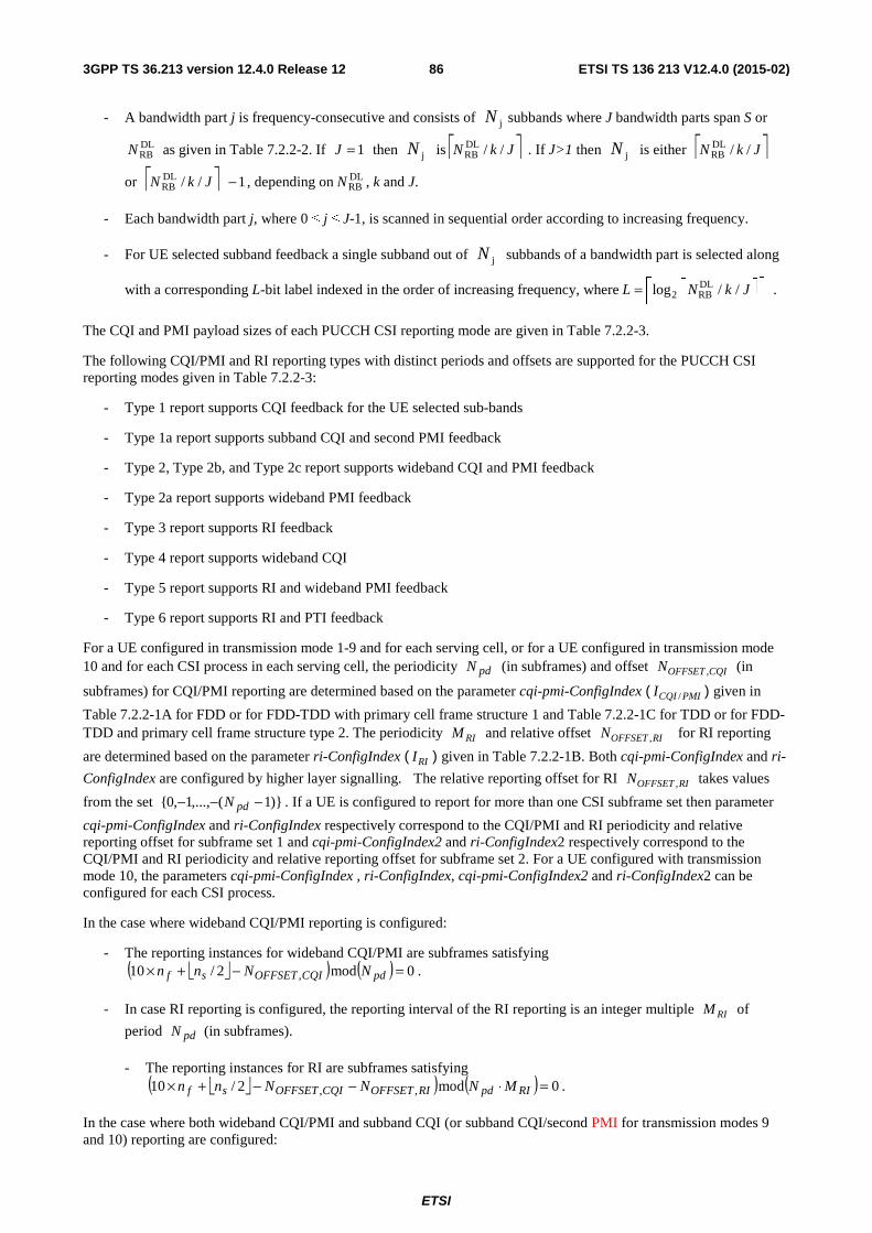
ETSI
ETSI TS 136 213 V12.4.0 (2015-02)863GPP TS 36.213 version 12.4.0 Release 12
- A bandwidth part j is frequency-consecutive and consists of jN subbands where J bandwidth parts span S or
DLRBN as given in Table 7.2.2-2. If 1J = then jN is ⎡ ⎤JkN //DL
RB . If J>1 then jN is either ⎡ ⎤JkN //DLRB
or ⎡ ⎤ 1//DLRB −JkN , depending on DL
RBN , k and J.
- Each bandwidth part j, where 0 ≤ j ≤ J-1, is scanned in sequential order according to increasing frequency.
- For UE selected subband feedback a single subband out of jN subbands of a bandwidth part is selected along
with a corresponding L-bit label indexed in the order of increasing frequency, where DL2 RBlog / /L N k J⎡ ⎤⎡ ⎤= ⎢ ⎥⎢ ⎥
.
The CQI and PMI payload sizes of each PUCCH CSI reporting mode are given in Table 7.2.2-3.
The following CQI/PMI and RI reporting types with distinct periods and offsets are supported for the PUCCH CSI reporting modes given in Table 7.2.2-3:
- Type 1 report supports CQI feedback for the UE selected sub-bands
- Type 1a report supports subband CQI and second PMI feedback
- Type 2, Type 2b, and Type 2c report supports wideband CQI and PMI feedback
- Type 2a report supports wideband PMI feedback
- Type 3 report supports RI feedback
- Type 4 report supports wideband CQI
- Type 5 report supports RI and wideband PMI feedback
- Type 6 report supports RI and PTI feedback
For a UE configured in transmission mode 1-9 and for each serving cell, or for a UE configured in transmission mode 10 and for each CSI process in each serving cell, the periodicity pdN (in subframes) and offset ,OFFSET CQIN (in
subframes) for CQI/PMI reporting are determined based on the parameter cqi-pmi-ConfigIndex ( /CQI PMII ) given in
Table 7.2.2-1A for FDD or for FDD-TDD with primary cell frame structure 1 and Table 7.2.2-1C for TDD or for FDD-TDD and primary cell frame structure type 2. The periodicity RIM and relative offset ,OFFSET RIN for RI reporting
are determined based on the parameter ri-ConfigIndex ( RII ) given in Table 7.2.2-1B. Both cqi-pmi-ConfigIndex and ri-
ConfigIndex are configured by higher layer signalling. The relative reporting offset for RI ,OFFSET RIN takes values
from the set )}1(,...,1,0{ −−− pdN . If a UE is configured to report for more than one CSI subframe set then parameter
cqi-pmi-ConfigIndex and ri-ConfigIndex respectively correspond to the CQI/PMI and RI periodicity and relative reporting offset for subframe set 1 and cqi-pmi-ConfigIndex2 and ri-ConfigIndex2 respectively correspond to the CQI/PMI and RI periodicity and relative reporting offset for subframe set 2. For a UE configured with transmission mode 10, the parameters cqi-pmi-ConfigIndex , ri-ConfigIndex, cqi-pmi-ConfigIndex2 and ri-ConfigIndex2 can be configured for each CSI process.
In the case where wideband CQI/PMI reporting is configured:
- The reporting instances for wideband CQI/PMI are subframes satisfying
⎣ ⎦( ) ( ) 0mod2/10 , =−+× pdCQIOFFSETsf NNnn .
- In case RI reporting is configured, the reporting interval of the RI reporting is an integer multiple RIM of
period pdN (in subframes).
- The reporting instances for RI are subframes satisfying
⎣ ⎦( ) ( ) 0mod2/10 ,, =⋅−−+× RIpdRIOFFSETCQIOFFSETsf MNNNnn .
In the case where both wideband CQI/PMI and subband CQI (or subband CQI/second PMI for transmission modes 9 and 10) reporting are configured:
ETSI
ETSI TS 136 213 V12.4.0 (2015-02)873GPP TS 36.213 version 12.4.0 Release 12
- The reporting instances for wideband CQI/PMI and subband CQI (or subband CQI/second PMI for transmission modes 9 and 10) are subframes satisfying ⎣ ⎦( ) 0mod2/10 , =−+× pdCQIOFFSETsf NNnn .
� When PTI is not transmitted (due to not being configured) or the most recently transmitted PTI is equal to 1 for a UE configured in transmission modes 8 and 9, or for a UE configured in transmission mode 10 without a 'RI-reference CSI process' for a CSI process, or the transmitted PTI is equal to 1 reported in the most recent RI reporting instance for a CSI process when a UE is configured in transmission mode 10 with a 'RI-reference CSI process' for the CSI process, or the transmitted PTI is equal to 1 for a 'RI-reference CSI process' reported in the most recent RI reporting instance for a CSI process when a UE is configured in transmission mode 10 with the 'RI-reference CSI process' for the CSI process, and the most recent type 6 report for the CSI process is dropped:
� The wideband CQI/ wideband PMI (or wideband CQI/wideband second PMI for transmission modes 8, 9 and 10) report has period pdNH ⋅ , and is reported on the
subframes satisfying ⎣ ⎦( ) ( ) 0mod2/10 , =⋅−+× pdCQIOFFSETsf NHNnn . The
integer H is defined as 1H J K= ⋅ + , where J is the number of bandwidth parts.
� Between every two consecutive wideband CQI/ wideband PMI (or wideband CQI/wideband second PMI for transmission modes 8, 9 and 10) reports, the remaining J K⋅ reporting instances are used in sequence for subband CQI (or subband CQI/second PMI for transmission modes 9 and 10) reports on K full cycles of bandwidth parts except when the gap between two consecutive wideband CQI/PMI reports contains less than J K⋅ reporting instances due to a system frame number transition to 0, in which case the UE shall not transmit the remainder of the subband CQI (or subband CQI/second PMI for transmission modes 9 and 10) reports which have not been transmitted before the second of the two wideband CQI/ wideband PMI (or wideband CQI/wideband second PMI for transmission modes 8, 9 and 10) reports. Each full cycle of bandwidth parts shall be in increasing order starting from bandwidth part 0 to bandwidth part 1J − . The parameter K is configured by higher-layer signalling.
� When the most recently transmitted PTI is 0 for a UE configured in transmission modes 8 and 9 or for a UE configured in transmission mode 10 without a 'RI-reference CSI process' for a CSI process, or the transmitted PTI is 0 reported in the most recent RI reporting instance for a CSI process when a UE is configured in transmission mode 10 with a 'RI-reference CSI process' for the CSI process, or the transmitted PTI is 0 for a 'RI-reference CSI process' reported in the most recent RI reporting instance for a CSI process when a UE is configured in transmission mode 10 with the 'RI-reference CSI process' for the CSI process, and the most recent type 6 report for the CSI process is dropped:
� The wideband first precoding matrix indicator report has period pdNH ⋅′ , and is
reported on the subframes satisfying
⎣ ⎦( ) ( ) 0mod2/10 , =⋅′−+× pdCQIOFFSETsf NHNnn , where H ′ is signalled by
higher layers.
� Between every two consecutive wideband first precoding matrix indicator reports, the remaining reporting instances are used for a wideband second precoding matrix indicator with wideband CQI as described below
- In case RI reporting is configured, the reporting interval of RI is RIM times the wideband CQI/PMI period
pdNH ⋅ , and RI is reported on the same PUCCH cyclic shift resource as both the wideband CQI/PMI and
subband CQI reports.
� The reporting instances for RI are subframes satisfying
⎣ ⎦( ) ( ) 0mod2/10 ,, =⋅⋅−−+× RIpdRIOFFSETCQIOFFSETsf MNHNNnn
In case of collision of a CSI report with PUCCH reporting type 3, 5, or 6 of one serving cell with a CSI report with PUCCH reporting type 1, 1a, 2, 2a, 2b, 2c, or 4 of the same serving cell the latter CSI report with PUCCH reporting type (1, 1a, 2, 2a, 2b, 2c, or 4) has lower priority and is dropped.
ETSI
ETSI TS 136 213 V12.4.0 (2015-02)883GPP TS 36.213 version 12.4.0 Release 12
For a serving cell and UE configured in transmission mode 10, in case of collision between CSI reports of same serving cell with PUCCH reporting type of the same priority, and the CSI reports corresponding to different CSI processes, the CSI reports corresponding to all CSI processes except the CSI process with the lowest csi-ProcessId-r11 are dropped. For a serving cell and UE configured in transmission mode 1-9 and configured with CSI subframe sets CSI,0C and
CSI,1C by the higher layer parameter csi-SubframePatternConfig-r12 for the serving cell, in case of collision between
CSI reports of same serving cell with PUCCH reporting type of the same priority, the CSI report corresponding to CSI subframe set CSI,1C is dropped.
For a serving cell and UE configured in transmission mode 10 and configured with CSI subframe sets CSI,0C and
CSI,1C by the higher layer parameter csi-SubframePatternConfig-r12 for the serving cell, in case of collision between
CSI reports of same serving cell with PUCCH reporting type of the same priority and the CSI reports corresponding to CSI processes with same csi-ProcessId-r11, the CSI report corresponding to CSI subframe set CSI,1C is dropped.
If the UE is configured with more than one serving cell, the UE transmits a CSI report of only one serving cell in any given subframe. For a given subframe, in case of collision of a CSI report with PUCCH reporting type 3, 5, 6, or 2a of one serving cell with a CSI report with PUCCH reporting type 1, 1a, 2, 2b, 2c, or 4 of another serving cell, the latter CSI with PUCCH reporting type (1, 1a, 2, 2b, 2c, or 4) has lower priority and is dropped. For a given subframe, in case of collision of CSI report with PUCCH reporting type 2, 2b, 2c, or 4 of one serving cell with CSI report with PUCCH reporting type 1 or 1a of another serving cell, the latter CSI report with PUCCH reporting type 1, or 1a has lower priority and is dropped. For a given subframe and serving cells with UE configured in transmission mode 1-9, in case of collision between CSI reports of these different serving cells with PUCCH reporting type of the same priority, the CSI reports for all these serving cells except the serving cell with lowest ServCellIndex are dropped. For a given subframe and serving cells with UE configured in transmission mode 10, in case of collision between CSI reports of different serving cells with PUCCH reporting type of the same priority and the CSI reports corresponding to CSI processes with same csi-ProcessId-r11, the CSI reports of all serving cells except the serving cell with lowest ServCellIndex are dropped. For a given subframe and serving cells with UE configured in transmission mode 10, in case of collision between CSI reports of different serving cells with PUCCH reporting type of the same priority and the CSI reports corresponding to CSI processes with different csi-ProcessId-r11, the CSI reports of all serving cells except the serving cell with CSI reports corresponding to CSI process with the lowest csi-ProcessId-r11 are dropped. For a given subframe, in case of collision between CSI report of a given serving cell with UE configured in transmission mode 1-9, and CSI report(s) corresponding to CSI process(es) of a different serving cell with the UE configured in transmission mode 10, and the CSI reports of the serving cells with PUCCH reporting type of the same priority, the CSI report(s) corresponding to CSI process(es) with csi-ProcessId-r11 > 1 of the different serving cell are dropped. For a given subframe, in case of collision between CSI report of a given serving cell with UE configured in transmission mode 1-9, and CSI report corresponding to CSI process with csi-ProcessId-r11 = 1 of a different serving cell with the UE configured in transmission mode 10, and the CSI reports of the serving cells with PUCCH reporting type of the same priority, the CSI report of the serving cell with highest ServCellIndex is dropped. See subclause 10.1 for UE behaviour regarding collision between CSI and HARQ-ACK and the corresponding PUCCH format assignment.
The CSI report of a given PUCCH reporting type shall be transmitted on the PUCCH resource )~,2(PUCCH
pn as defined in
[3], where )~,2(PUCCH
pn is UE specific and configured by higher layers for each serving cell.
If the UE is not configured for simultaneous PUSCH and PUCCH transmission or, if the UE is configured for simultaneous PUSCH and PUCCH transmission and not transmitting PUSCH, in case of collision between CSI and positive SR in a same subframe, CSI is dropped.
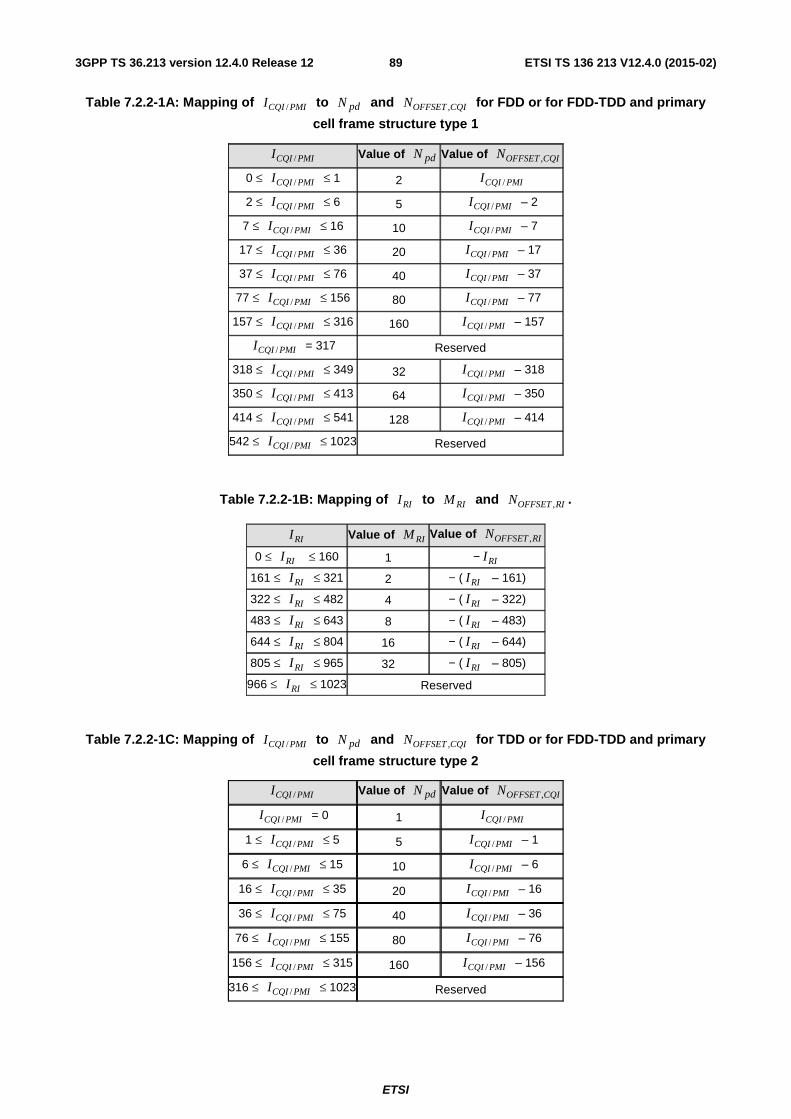
ETSI
ETSI TS 136 213 V12.4.0 (2015-02)893GPP TS 36.213 version 12.4.0 Release 12
Table 7.2.2-1A: Mapping of /CQI PMII to pdN and ,OFFSET CQIN for FDD or for FDD-TDD and primary
cell frame structure type 1
/CQI PMII Value of pdN Value of ,OFFSET CQIN
0 ≤ /CQI PMII ≤ 1 2 /CQI PMII
2 ≤ /CQI PMII ≤ 6 5 /CQI PMII – 2
7 ≤ /CQI PMII ≤ 16 10 /CQI PMII – 7
17 ≤ /CQI PMII ≤ 36 20 /CQI PMII – 17
37 ≤ /CQI PMII ≤ 76 40 /CQI PMII – 37
77 ≤ /CQI PMII ≤ 156 80 /CQI PMII – 77
157 ≤ /CQI PMII ≤ 316 160 /CQI PMII – 157
/CQI PMII = 317 Reserved
318 ≤ /CQI PMII ≤ 349 32 /CQI PMII – 318
350 ≤ /CQI PMII ≤ 413 64 /CQI PMII – 350
414 ≤ /CQI PMII ≤ 541 128 /CQI PMII – 414
542 ≤ /CQI PMII ≤ 1023 Reserved
Table 7.2.2-1B: Mapping of RII to RIM and ,OFFSET RIN .
RII Value of RIM Value of ,OFFSET RIN
0 ≤ RII ≤ 160 1 − RII
161 ≤ RII ≤ 321 2 − ( RII – 161)
322 ≤ RII ≤ 482 4 − ( RII – 322)
483 ≤ RII ≤ 643 8 − ( RII – 483)
644 ≤ RII ≤ 804 16 − ( RII – 644)
805 ≤ RII ≤ 965 32 − ( RII – 805)
966 ≤ RII ≤ 1023 Reserved
Table 7.2.2-1C: Mapping of /CQI PMII to pdN and ,OFFSET CQIN for TDD or for FDD-TDD and primary
cell frame structure type 2
/CQI PMII Value of pdN Value of ,OFFSET CQIN
/CQI PMII = 0 1 /CQI PMII
1 ≤ /CQI PMII ≤ 5 5 /CQI PMII – 1
6 ≤ /CQI PMII ≤ 15 10 /CQI PMII – 6
16 ≤ /CQI PMII ≤ 35 20 /CQI PMII – 16
36 ≤ /CQI PMII ≤ 75 40 /CQI PMII – 36
76 ≤ /CQI PMII ≤ 155 80 /CQI PMII – 76
156 ≤ /CQI PMII ≤ 315 160 /CQI PMII – 156
316 ≤ /CQI PMII ≤ 1023 Reserved
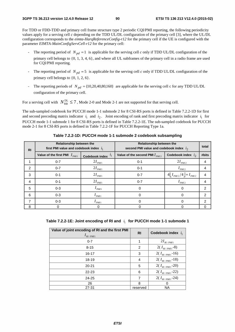
ETSI
ETSI TS 136 213 V12.4.0 (2015-02)903GPP TS 36.213 version 12.4.0 Release 12
For TDD or FDD-TDD and primary cell frame structure type 2 periodic CQI/PMI reporting, the following periodicity values apply for a serving cell c depending on the TDD UL/DL configuration of the primary cell [3], where the UL/DL configuration corresponds to the eimta-HarqReferenceConfig-r12 for the primary cell if the UE is configured with the parameter EIMTA-MainConfigServCell-r12 for the primary cell:
- The reporting period of 1=pdN is applicable for the serving cell c only if TDD UL/DL configuration of the
primary cell belongs to {0, 1, 3, 4, 6}, and where all UL subframes of the primary cell in a radio frame are used for CQI/PMI reporting.
- The reporting period of 5=pdN is applicable for the serving cell c only if TDD UL/DL configuration of the
primary cell belongs to {0, 1, 2, 6}.
- The reporting periods of }160,80,40,20,10{=pdN are applicable for the serving cell c for any TDD UL/DL
configuration of the primary cell.
For a serving cell with 7DLRB ≤N , Mode 2-0 and Mode 2-1 are not supported for that serving cell.
The sub-sampled codebook for PUCCH mode 1-1 submode 2 for 8 CSI-RS ports is defined in Table 7.2.2-1D for first and second precoding matrix indicator 1i and 2i . Joint encoding of rank and first precoding matrix indicator 1i for
PUCCH mode 1-1 submode 1 for 8 CSI-RS ports is defined in Table 7.2.2-1E. The sub-sampled codebook for PUCCH mode 2-1 for 8 CSI-RS ports is defined in Table 7.2.2-1F for PUCCH Reporting Type 1a.
Table 7.2.2-1D: PUCCH mode 1-1 submode 2 codebook subsampling
RI
Relationship between the first PMI value and codebook index 1i
Relationship between the second PMI value and codebook index 2i total
Value of the first PMI 1PMII Codebook index 1i Value of the second PMI 2PMII Codebook index 2i #bits
1 0-7 12 PMII 0-1 22 PMII 4
2 0-7 12 PMII 0-1 2PMII 4
3 0-1 12 PMII 0-7 2 24 4PMI PMII I+⎢ ⎥⎣ ⎦ 4
4 0-1 12 PMII 0-7 2PMII 4
5 0-3 1PMII 0 0 2
6 0-3 1PMII 0 0 2
7 0-3 1PMII 0 0 2
8 0 0 0 0 0
Table 7.2.2-1E: Joint encoding of RI and 1i for PUCCH mode 1-1 submode 1
Value of joint encoding of RI and the first PMI
/ 1RI PMII RI Codebook index 1i
0-7 1 / 12 RI PMII
8-15 2 / 12( -8)RI PMII
16-17 3 / 12( -16)RI PMII
18-19 4 / 12( -18)RI PMII
20-21 5 / 12( -20)RI PMII
22-23 6 / 12( -22)RI PMII
24-25 7 / 12( -24)RI PMII
26 8 0 27-31 reserved NA
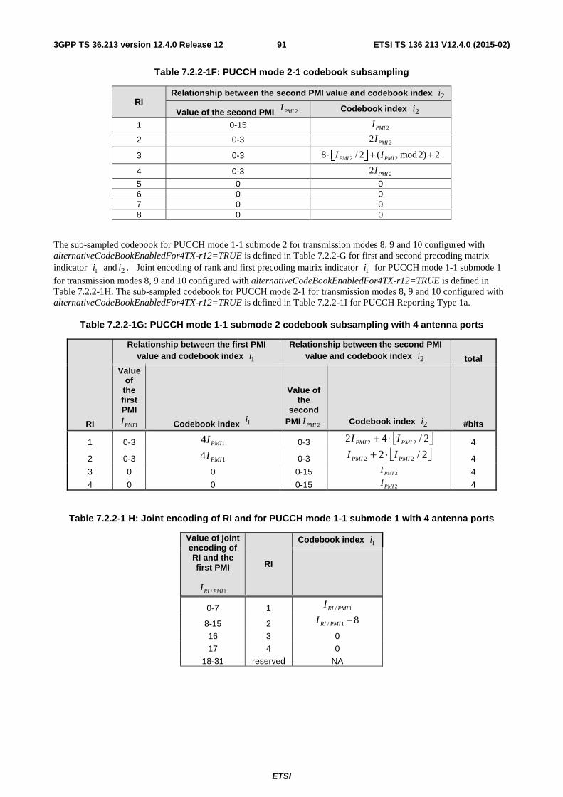
ETSI
ETSI TS 136 213 V12.4.0 (2015-02)913GPP TS 36.213 version 12.4.0 Release 12
Table 7.2.2-1F: PUCCH mode 2-1 codebook subsampling
RI Relationship between the second PMI value and codebook index 2i
Value of the second PMI 2PMII Codebook index 2i
1 0-15 2PMII
2 0-3 22 PMII
3 0-3 2 28 / 2 ( mod 2) 2PMI PMII I⋅ + +⎢ ⎥⎣ ⎦
4 0-3 22 PMII
5 0 0 6 0 0 7 0 0 8 0 0
The sub-sampled codebook for PUCCH mode 1-1 submode 2 for transmission modes 8, 9 and 10 configured with alternativeCodeBookEnabledFor4TX-r12=TRUE is defined in Table 7.2.2-G for first and second precoding matrix indicator 1i and 2i . Joint encoding of rank and first precoding matrix indicator 1i for PUCCH mode 1-1 submode 1
for transmission modes 8, 9 and 10 configured with alternativeCodeBookEnabledFor4TX-r12=TRUE is defined in Table 7.2.2-1H. The sub-sampled codebook for PUCCH mode 2-1 for transmission modes 8, 9 and 10 configured with alternativeCodeBookEnabledFor4TX-r12=TRUE is defined in Table 7.2.2-1I for PUCCH Reporting Type 1a.
Table 7.2.2-1G: PUCCH mode 1-1 submode 2 codebook subsampling with 4 antenna ports
RI
Relationship between the first PMI value and codebook index 1i
Relationship between the second PMI value and codebook index 2i total
Value of
the first PMI
1PMII Codebook index 1i
Value of the
second PMI 2PMII Codebook index 2i #bits
1 0-3 14 PMII 0-3 ⎣ ⎦2/42 22 PMIPMI II ⋅+ 4
2 0-3 14 PMII 0-3 ⎣ ⎦2/2 22 PMIPMI II ⋅+ 4
3 0 0 0-15 2PMII 4
4 0 0 0-15 2PMII 4
Table 7.2.2-1 H: Joint encoding of RI and for PUCCH mode 1-1 submode 1 with 4 antenna ports
Value of joint encoding of RI and the first PMI
/ 1RI PMII
RI
Codebook index 1i
0-7 1 1/ PMIRII
8-15 2 81/ −PMIRII
16 3 0
17 4 0
18-31 reserved NA
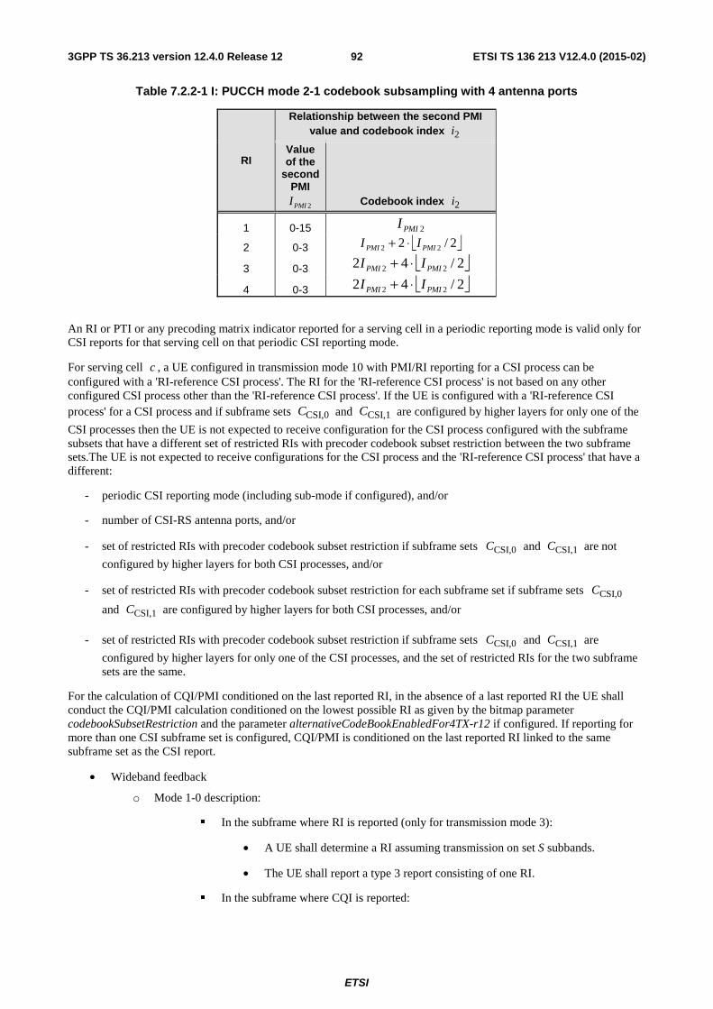
ETSI
ETSI TS 136 213 V12.4.0 (2015-02)923GPP TS 36.213 version 12.4.0 Release 12
Table 7.2.2-1 I: PUCCH mode 2-1 codebook subsampling with 4 antenna ports
RI
Relationship between the second PMI value and codebook index 2i
Value of the
second PMI
2PMII Codebook index 2i
1 0-15 2PMII
2 0-3 ⎣ ⎦2/2 22 PMIPMI II ⋅+
3 0-3 ⎣ ⎦2/42 22 PMIPMI II ⋅+
4 0-3 ⎣ ⎦2/42 22 PMIPMI II ⋅+
An RI or PTI or any precoding matrix indicator reported for a serving cell in a periodic reporting mode is valid only for CSI reports for that serving cell on that periodic CSI reporting mode.
For serving cell c , a UE configured in transmission mode 10 with PMI/RI reporting for a CSI process can be configured with a 'RI-reference CSI process'. The RI for the 'RI-reference CSI process' is not based on any other configured CSI process other than the 'RI-reference CSI process'. If the UE is configured with a 'RI-reference CSI process' for a CSI process and if subframe sets CSI,0C and CSI,1C are configured by higher layers for only one of the
CSI processes then the UE is not expected to receive configuration for the CSI process configured with the subframe subsets that have a different set of restricted RIs with precoder codebook subset restriction between the two subframe sets.The UE is not expected to receive configurations for the CSI process and the 'RI-reference CSI process' that have a different:
- periodic CSI reporting mode (including sub-mode if configured), and/or
- number of CSI-RS antenna ports, and/or
- set of restricted RIs with precoder codebook subset restriction if subframe sets CSI,0C and CSI,1C are not
configured by higher layers for both CSI processes, and/or
- set of restricted RIs with precoder codebook subset restriction for each subframe set if subframe sets CSI,0C
and CSI,1C are configured by higher layers for both CSI processes, and/or
- set of restricted RIs with precoder codebook subset restriction if subframe sets CSI,0C and CSI,1C are
configured by higher layers for only one of the CSI processes, and the set of restricted RIs for the two subframe sets are the same.
For the calculation of CQI/PMI conditioned on the last reported RI, in the absence of a last reported RI the UE shall conduct the CQI/PMI calculation conditioned on the lowest possible RI as given by the bitmap parameter codebookSubsetRestriction and the parameter alternativeCodeBookEnabledFor4TX-r12 if configured. If reporting for more than one CSI subframe set is configured, CQI/PMI is conditioned on the last reported RI linked to the same subframe set as the CSI report.
• Wideband feedback
o Mode 1-0 description:
� In the subframe where RI is reported (only for transmission mode 3):
• A UE shall determine a RI assuming transmission on set S subbands.
• The UE shall report a type 3 report consisting of one RI.
� In the subframe where CQI is reported:
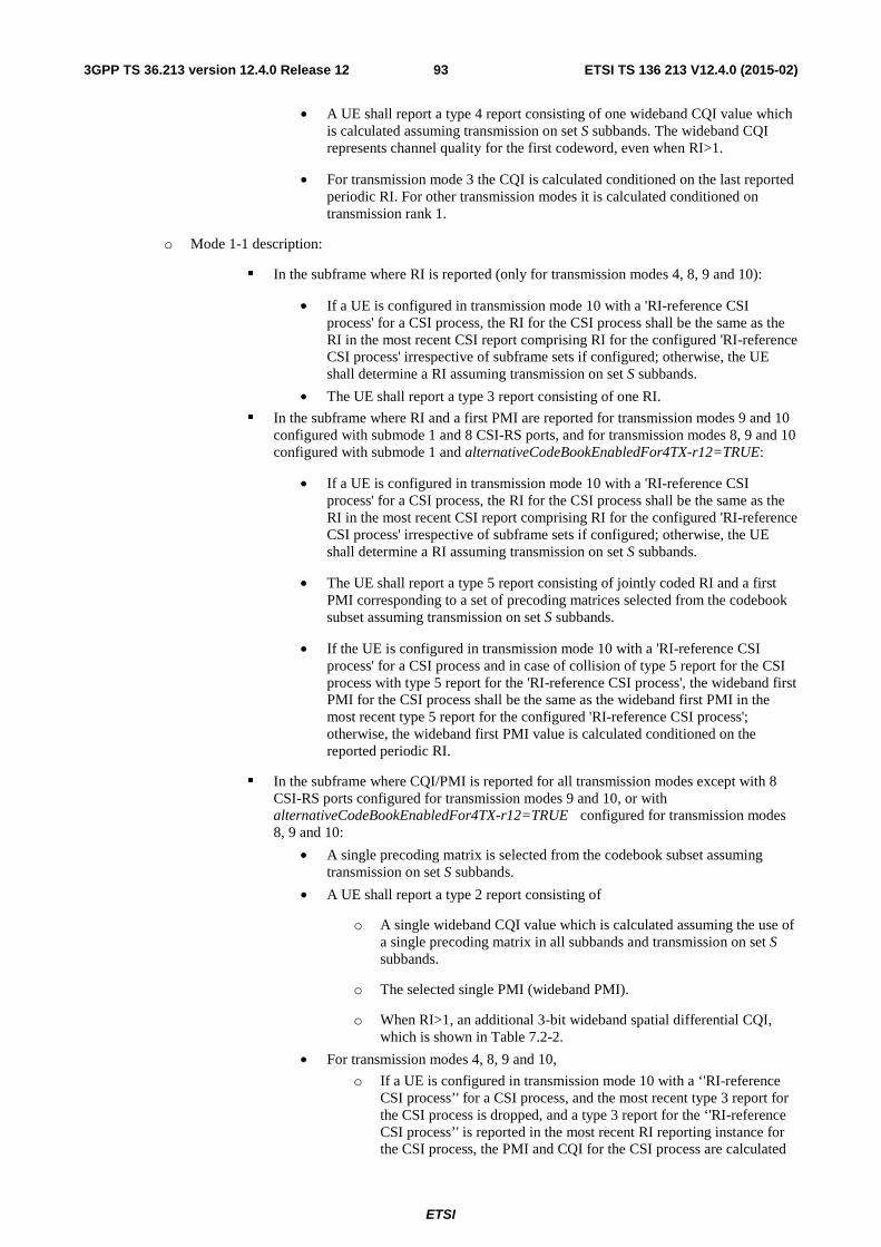
ETSI
ETSI TS 136 213 V12.4.0 (2015-02)933GPP TS 36.213 version 12.4.0 Release 12
• A UE shall report a type 4 report consisting of one wideband CQI value which is calculated assuming transmission on set S subbands. The wideband CQI represents channel quality for the first codeword, even when RI>1.
• For transmission mode 3 the CQI is calculated conditioned on the last reported periodic RI. For other transmission modes it is calculated conditioned on transmission rank 1.
o Mode 1-1 description:
� In the subframe where RI is reported (only for transmission modes 4, 8, 9 and 10):
• If a UE is configured in transmission mode 10 with a 'RI-reference CSI process' for a CSI process, the RI for the CSI process shall be the same as the RI in the most recent CSI report comprising RI for the configured 'RI-reference CSI process' irrespective of subframe sets if configured; otherwise, the UE shall determine a RI assuming transmission on set S subbands.
• The UE shall report a type 3 report consisting of one RI.
� In the subframe where RI and a first PMI are reported for transmission modes 9 and 10 configured with submode 1 and 8 CSI-RS ports, and for transmission modes 8, 9 and 10 configured with submode 1 and alternativeCodeBookEnabledFor4TX-r12=TRUE:
• If a UE is configured in transmission mode 10 with a 'RI-reference CSI process' for a CSI process, the RI for the CSI process shall be the same as the RI in the most recent CSI report comprising RI for the configured 'RI-reference CSI process' irrespective of subframe sets if configured; otherwise, the UE shall determine a RI assuming transmission on set S subbands.
• The UE shall report a type 5 report consisting of jointly coded RI and a first PMI corresponding to a set of precoding matrices selected from the codebook subset assuming transmission on set S subbands.
• If the UE is configured in transmission mode 10 with a 'RI-reference CSI process' for a CSI process and in case of collision of type 5 report for the CSI process with type 5 report for the 'RI-reference CSI process', the wideband first PMI for the CSI process shall be the same as the wideband first PMI in the most recent type 5 report for the configured 'RI-reference CSI process'; otherwise, the wideband first PMI value is calculated conditioned on the reported periodic RI.
� In the subframe where CQI/PMI is reported for all transmission modes except with 8 CSI-RS ports configured for transmission modes 9 and 10, or with alternativeCodeBookEnabledFor4TX-r12=TRUE configured for transmission modes 8, 9 and 10:
• A single precoding matrix is selected from the codebook subset assuming transmission on set S subbands.
• A UE shall report a type 2 report consisting of
o A single wideband CQI value which is calculated assuming the use of a single precoding matrix in all subbands and transmission on set S subbands.
o The selected single PMI (wideband PMI).
o When RI>1, an additional 3-bit wideband spatial differential CQI, which is shown in Table 7.2-2.
• For transmission modes 4, 8, 9 and 10,
o If a UE is configured in transmission mode 10 with a ‘'RI-reference CSI process’' for a CSI process, and the most recent type 3 report for the CSI process is dropped, and a type 3 report for the ‘'RI-reference CSI process’' is reported in the most recent RI reporting instance for the CSI process, the PMI and CQI for the CSI process are calculated
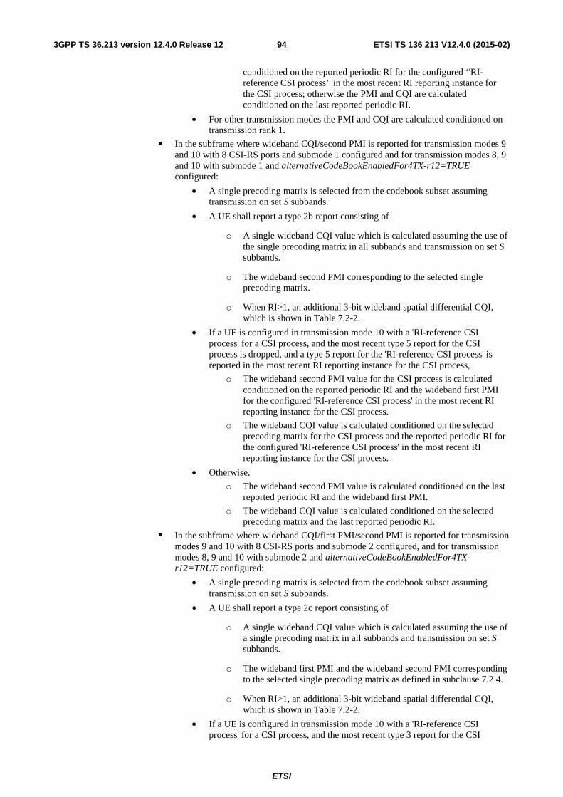
ETSI
ETSI TS 136 213 V12.4.0 (2015-02)943GPP TS 36.213 version 12.4.0 Release 12
conditioned on the reported periodic RI for the configured ‘'RI-reference CSI process’' in the most recent RI reporting instance for the CSI process; otherwise the PMI and CQI are calculated conditioned on the last reported periodic RI.
• For other transmission modes the PMI and CQI are calculated conditioned on transmission rank 1.
� In the subframe where wideband CQI/second PMI is reported for transmission modes 9 and 10 with 8 CSI-RS ports and submode 1 configured and for transmission modes 8, 9 and 10 with submode 1 and alternativeCodeBookEnabledFor4TX-r12=TRUE configured:
• A single precoding matrix is selected from the codebook subset assuming transmission on set S subbands.
• A UE shall report a type 2b report consisting of
o A single wideband CQI value which is calculated assuming the use of the single precoding matrix in all subbands and transmission on set S subbands.
o The wideband second PMI corresponding to the selected single precoding matrix.
o When RI>1, an additional 3-bit wideband spatial differential CQI, which is shown in Table 7.2-2.
• If a UE is configured in transmission mode 10 with a 'RI-reference CSI process' for a CSI process, and the most recent type 5 report for the CSI process is dropped, and a type 5 report for the 'RI-reference CSI process' is reported in the most recent RI reporting instance for the CSI process,
o The wideband second PMI value for the CSI process is calculated conditioned on the reported periodic RI and the wideband first PMI for the configured 'RI-reference CSI process' in the most recent RI reporting instance for the CSI process.
o The wideband CQI value is calculated conditioned on the selected precoding matrix for the CSI process and the reported periodic RI for the configured 'RI-reference CSI process' in the most recent RI reporting instance for the CSI process.
• Otherwise,
o The wideband second PMI value is calculated conditioned on the last reported periodic RI and the wideband first PMI.
o The wideband CQI value is calculated conditioned on the selected precoding matrix and the last reported periodic RI.
� In the subframe where wideband CQI/first PMI/second PMI is reported for transmission modes 9 and 10 with 8 CSI-RS ports and submode 2 configured, and for transmission modes 8, 9 and 10 with submode 2 and alternativeCodeBookEnabledFor4TX-r12=TRUE configured:
• A single precoding matrix is selected from the codebook subset assuming transmission on set S subbands.
• A UE shall report a type 2c report consisting of
o A single wideband CQI value which is calculated assuming the use of a single precoding matrix in all subbands and transmission on set S subbands.
o The wideband first PMI and the wideband second PMI corresponding to the selected single precoding matrix as defined in subclause 7.2.4.
o When RI>1, an additional 3-bit wideband spatial differential CQI, which is shown in Table 7.2-2.
• If a UE is configured in transmission mode 10 with a 'RI-reference CSI process' for a CSI process, and the most recent type 3 report for the CSI
ETSI
ETSI TS 136 213 V12.4.0 (2015-02)953GPP TS 36.213 version 12.4.0 Release 12
process is dropped, and a type 3 report for the 'RI-reference CSI process' is reported in the most recent RI reporting instance for the CSI process, the wideband first PMI, the wideband second PMI and the wideband CQI for the CSI process are calculated conditioned on the reported periodic RI for the configured 'RI-reference CSI process' in the most recent RI reporting instance for the CSI process; otherwise the wideband first PMI, the wideband second PMI and the wideband CQI are calculated conditioned on the last reported periodic RI.
• UE Selected subband feedback
o Mode 2-0 description:
� In the subframe where RI is reported (only for transmission mode 3):
• A UE shall determine a RI assuming transmission on set S subbands.
• The UE shall report a type 3 report consisting of one RI.
� In the subframe where wideband CQI is reported:
• The UE shall report a type 4 report on each respective successive reporting opportunity consisting of one wideband CQI value which is calculated assuming transmission on set S subbands. The wideband CQI represents channel quality for the first codeword, even when RI>1.
• For transmission mode 3 the CQI is calculated conditioned on the last reported periodic RI. For other transmission modes it is calculated conditioned on transmission rank 1.
� In the subframe where CQI for the selected subbands is reported:
• The UE shall select the preferred subband within the set of jN subbands in
each of the J bandwidth parts where J is given in Table 7.2.2-2.
• The UE shall report a type 1 report consisting of one CQI value reflecting transmission only over the selected subband of a bandwidth part determined in the previous step along with the corresponding preferred subband L-bit label. A type 1 report for each bandwidth part will in turn be reported in respective successive reporting opportunities. The CQI represents channel quality for the first codeword, even when RI>1.
• For transmission mode 3 the preferred subband selection and CQI values are calculated conditioned on the last reported periodic RI. For other transmission modes they are calculated conditioned on transmission rank 1.
o Mode 2-1 description:
� In the subframe where RI is reported for transmission mode 4, transmission mode 8 except with alternativeCodeBookEnabledFor4TX-r12=TRUE configured, transmission modes 9 and 10 with 2 CSI-RS ports, and transmission modes 9 and 10 with 4 CSI-RS ports except with alternativeCodeBookEnabledFor4TX-r12=TRUE configured:
• Ifa UE is configured in transmission mode 10 with a 'RI-reference CSI process' for a CSI process, the RI for the CSI process shall be the same as the RI in the most recent CSI report comprising RI for the configured 'RI-reference CSI process' irrespective of subframe sets if configured; otherwise, the UE shall determine a RI assuming transmission on set S subbands.
• The UE shall report a type 3 report consisting of one RI.
� In the subframe where RI is reported for transmission modes 9 and 10 with 8 CSI-RS ports configured and for transmission modes 8, 9 and 10 with alternativeCodeBookEnabledFor4TX-r12=TRUE configured then:
ETSI
ETSI TS 136 213 V12.4.0 (2015-02)963GPP TS 36.213 version 12.4.0 Release 12
• If a UE is configured in transmission mode 10 with a 'RI-reference CSI process' for a CSI process, the RI for the CSI process shall be the same as the RI in the most recent CSI report comprising RI for the configured 'RI-reference CSI process' irrespective of subframe sets if configured; otherwise, the UE shall determine a RI assuming transmission on set S subbands.
• If a UE is configured in transmission mode 10 with a 'RI-reference CSI process' for a CSI process, the PTI for the CSI process shall be the same as the PTI in the most recent type 6 report for the configured 'RI-reference CSI process'; otherwise, the UE shall determine a precoder type indication (PTI).
• The PTI for the CSI process shall be equal to 1 if the RI reported jointly with the PTI is greater than 2 for transmission modes 8, 9, 10 with alternativeCodeBookEnabledFor4TX-r12=TRUE configured.
• The UE shall report a type 6 report consisting of one RI and the PTI.
� In the subframe where wideband CQI/PMI is reported for all transmission modes except with 8 CSI-RS ports configured for transmission modes 9 and 10, or with alternativeCodeBookEnabledFor4TX-r12=TRUE configured for transmission modes 8, 9 and 10:
• A single precoding matrix is selected from the codebook subset assuming transmission on set S subbands.
• A UE shall report a type 2 report on each respective successive reporting opportunity consisting of:
o A wideband CQI value which is calculated assuming the use of a single precoding matrix in all subbands and transmission on set S subbands.
o The selected single PMI (wideband PMI).
o When RI>1, an additional 3-bit wideband spatial differential CQI, which is shown in Table 7.2-2.
• For transmission modes 4, 8, 9 and 10,
o If a UE is configured in transmission mode 10 with a 'RI-reference CSI process' for a CSI process, and the most recent type 3 report for the CSI process is dropped, and a type 3 report for the 'RI-reference CSI process' is reported in the most recent RI reporting instance for the CSI process, the PMI and CQI values for the CSI process are calculated conditioned on the reported periodic RI for the configured 'RI-reference CSI process' in the most recent RI reporting instance for the CSI process; otherwise the PMI and CQI values are calculated conditioned on the last reported periodic RI.
• For other transmission modes the PMI and CQI values are calculated conditioned on transmission rank 1.
� In the subframe where the wideband first PMI is reported for transmission modes 9 and 10 with 8 CSI-RS ports configured and for transmission modes 8, 9 and 10 with alternativeCodeBookEnabledFor4TX-r12=TRUE configured:
• A set of precoding matrices corresponding to the wideband first PMI is selected from the codebook subset assuming transmission on set S subbands.
• A UE shall report a type 2a report on each respective successive reporting opportunity consisting of the wideband first PMI corresponding to the selected set of precoding matrices.
• If a UE is configured in transmission mode 10 with a 'RI-reference CSI process' for a CSI process, and the most recent type 6 report for the CSI process is dropped, and a type 6 report for the 'RI-reference CSI process' with PTI=0 is reported in the most recent RI reporting instance for the CSI process, the wideband first PMI value for the CSI process is calculated conditioned on
ETSI
ETSI TS 136 213 V12.4.0 (2015-02)973GPP TS 36.213 version 12.4.0 Release 12
the reported periodic RI for the configured 'RI-reference CSI process' in the most recent RI reporting instance for the CSI process; otherwise with the last reported PTI=0, the wideband first PMI value is calculated conditioned on the last reported periodic RI.
� In the subframe where wideband CQI/second PMI is reported for transmission modes 9 and 10 with 8 CSI-RS ports configured and for transmission modes 8,9, and 10 with alternativeCodeBookEnabledFor4TX-r12=TRUE configured:
• A single precoding matrix is selected from the codebook subset assuming transmission on set S subbands.
• A UE shall report a type 2b report on each respective successive reporting opportunity consisting of:
o A wideband CQI value which is calculated assuming the use of the selected single precoding matrix in all subbands and transmission on set S subbands.
o The wideband second PMI corresponding to the selected single precoding matrix.
o When RI>1, an additional 3-bit wideband spatial differential CQI, which is shown in Table 7.2-2.
• If a UE is configured in transmission mode 10 with a 'RI-reference CSI process' for a CSI process, and the most recent type 6 report for the CSI process is dropped, and a type 6 report for the 'RI-reference CSI process' with PTI=1 is reported in the most recent RI reporting instance for the CSI process,
o The wideband second PMI value for the CSI process is calculated conditioned on the reported periodic RI for the configured 'RI-reference CSI process' in the most recent RI reporting instance for the CSI process and the last reported wideband first PMI for the CSI process,
o The wideband CQI value is calculated conditioned on the selected precoding matrix for the CSI process and the reported periodic RI for the configured 'RI-reference CSI process' in the most recent RI reporting instance for the CSI process.
• Otherwise, with the last reported PTI=1,
o The wideband second PMI value is calculated conditioned on the last reported periodic RI and the wideband first PMI.
o The wideband CQI value is calculated conditioned on the selected precoding matrix and the last reported periodic RI.
• If the last reported first PMI was computed under an RI assumption that differs from the last reported periodic RI, or in the absence of a last reported first PMI, the conditioning of the second PMI value is not specified.
� In the subframe where CQI for the selected subband is reported for all transmission modes except with 8 CSI-RS ports configured for transmission modes 9 and 10, or with alternativeCodeBookEnabledFor4TX-r12=TRUE configured for transmission modes 8, 9 and 10:
• The UE shall select the preferred subband within the set of Nj subbands in each of the J bandwidth parts where J is given in Table 7.2.2-2.
• The UE shall report a type 1 report per bandwidth part on each respective successive reporting opportunity consisting of:
ETSI
ETSI TS 136 213 V12.4.0 (2015-02)983GPP TS 36.213 version 12.4.0 Release 12
o CQI value for codeword 0 reflecting transmission only over the selected subband of a bandwidth part determined in the previous step along with the corresponding preferred subband L-bit label.
o When RI>1, an additional 3-bit subband spatial differential CQI value for codeword 1 offset level
� Codeword 1 offset level = subband CQI index for codeword 0 – subband CQI index for codeword 1.
� Assuming the use of the most recently reported single precoding matrix in all subbands and transmission on the selected subband within the applicable bandwidth part.
o The mapping from the 3-bit subband spatial differential CQI value to the offset level is shown in Table 7.2-2.
• For transmission modes 4, 8, 9 and 10,
o If a UE is configured in transmission mode 10 with a 'RI-reference CSI process' for a CSI process, and the most recent type 3 report for the CSI process is dropped, and a type 3 report for the 'RI-reference CSI process' is reported in the most recent RI reporting instance for the CSI process, the subband selection and CQI values for the CSI process are calculated conditioned on the last reported periodic wideband PMI for the CSI process and the reported periodic RI for the configured 'RI-reference CSI process' in the most recent RI reporting instance for the CSI process; otherwise the subband selection and CQI values are calculated conditioned on the last reported periodic wideband PMI and RI.
• For other transmission modes the subband selection and CQI values are calculated conditioned on the last reported PMI and transmission rank 1.
� In the subframe where wideband CQI/second PMI is reported for transmission modes 9 and 10 with 8 CSI-RS ports configured and for transmission modes 8, 9 and 10 with alternativeCodeBookEnabledFor4TX-r12=TRUE configured:
• A single precoding matrix is selected from the codebook subset assuming transmission on set S subbands.
• The UE shall report a type 2b report on each respective successive reporting opportunity consisting of:
o A wideband CQI value which is calculated assuming the use of the selected single precoding matrix in all subbands and transmission on set S subbands.
o The wideband second PMI corresponding to the selected single precoding matrix.
o When RI>1, an additional 3-bit wideband spatial differential CQI, which is shown in Table 7.2-2.
• If a UE is configured in transmission mode 10 with a 'RI-reference CSI process' for a CSI process, and the most recent type 6 report for the CSI process is dropped, and a type 6 report for the 'RI-reference CSI process' with PTI=0 is reported in the most recent RI reporting instance for the CSI process,
o The wideband second PMI value for the CSI process is calculated conditioned on the reported periodic RI for the configured 'RI-reference CSI process' in the most recent RI reporting instance for the CSI process and the last reported wideband first PMI for the CSI process.
ETSI
ETSI TS 136 213 V12.4.0 (2015-02)993GPP TS 36.213 version 12.4.0 Release 12
o The wideband CQI value is calculated conditioned on the selected precoding matrix for the CSI process and the reported periodic RI for the configured 'RI-reference CSI process' in the most recent RI reporting instance for the CSI process.
• Otherwise, with the last reported PTI=0,
o The wideband second PMI value is calculated conditioned on the last reported periodic RI and the wideband first PMI. The wideband CQI value is calculated conditioned on the selected precoding matrix and the last reported periodic RI.
• If the last reported first PMI was computed under an RI assumption that differs from the last reported periodic RI, or in the absence of a last reported first PMI, the conditioning of the second PMI value is not specified.
� In the subframe where subband CQI/second PMI for the selected subband is reported for transmission modes 9 and 10 with 8 CSI-RS ports configured and for transmission modes 8, 9 and 10 with alternativeCodeBookEnabledFor4TX-r12=TRUE configured:
• The UE shall select the preferred subband within the set of Nj subbands in each of the J bandwidth parts where J is given in Table 7.2.2-2.
• The UE shall report a type 1a report per bandwidth part on each respective successive reporting opportunity consisting of:
o CQI value for codeword 0 reflecting transmission only over the selected subband of a bandwidth part determined in the previous step along with the corresponding preferred subband L-bit label.
o When RI>1, an additional 3-bit subband spatial differential CQI value for codeword 1 offset level
� Codeword 1 offset level = subband CQI index for codeword 0 – subband CQI index for codeword 1.
� Assuming the use of the precoding matrix corresponding to the selected second PMI and the most recently reported first PMI and transmission on the selected subband within the applicable bandwidth part.
o The mapping from the 3-bit subband spatial differential CQI value to the offset level is shown in Table 7.2-2.
o A second PMI of the preferred precoding matrix selected from the codebook subset assuming transmission only over the selected subband within the applicable bandwidth part determined in the previous step.
• If a UE is configured in transmission mode 10 with a 'RI-reference CSI process' for a CSI process, and the most recent type 6 report for the CSI process is dropped, and a type 6 report for the 'RI-reference CSI process' with PTI=1 is reported in the most recent RI reporting instance for the CSI process,
o The subband second PMI values for the CSI process are calculated conditioned on the reported periodic RI for the configured 'RI-reference CSI process' in the most recent RI reporting instance for the CSI process and the last reported wideband first PMI for the CSI process.
o The subband selection and CQI values are calculated conditioned on the selected precoding matrix for the CSI process and the reported periodic RI for the configured 'RI-reference CSI process' in the most recent RI reporting instance for the CSI process.
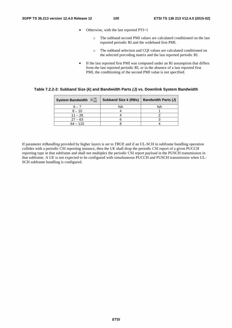
ETSI
ETSI TS 136 213 V12.4.0 (2015-02)1003GPP TS 36.213 version 12.4.0 Release 12
• Otherwise, with the last reported PTI=1
o The subband second PMI values are calculated conditioned on the last reported periodic RI and the wideband first PMI.
o The subband selection and CQI values are calculated conditioned on the selected precoding matrix and the last reported periodic RI.
• If the last reported first PMI was computed under an RI assumption that differs from the last reported periodic RI, or in the absence of a last reported first PMI, the conditioning of the second PMI value is not specified.
Table 7.2.2-2: Subband Size (k) and Bandwidth Parts (J) vs. Downlink System Bandwidth
System Bandwidth DLRBN Subband Size k (RBs) Bandwidth Parts (J)
6 – 7 NA NA 8 – 10 4 1
11 – 26 4 2 27 – 63 6 3
64 – 110 8 4
If parameter ttiBundling provided by higher layers is set to TRUE and if an UL-SCH in subframe bundling operation collides with a periodic CSI reporting instance, then the UE shall drop the periodic CSI report of a given PUCCH reporting type in that subframe and shall not multiplex the periodic CSI report payload in the PUSCH transmission in that subframe. A UE is not expected to be configured with simultaneous PUCCH and PUSCH transmission when UL-SCH subframe bundling is configured.
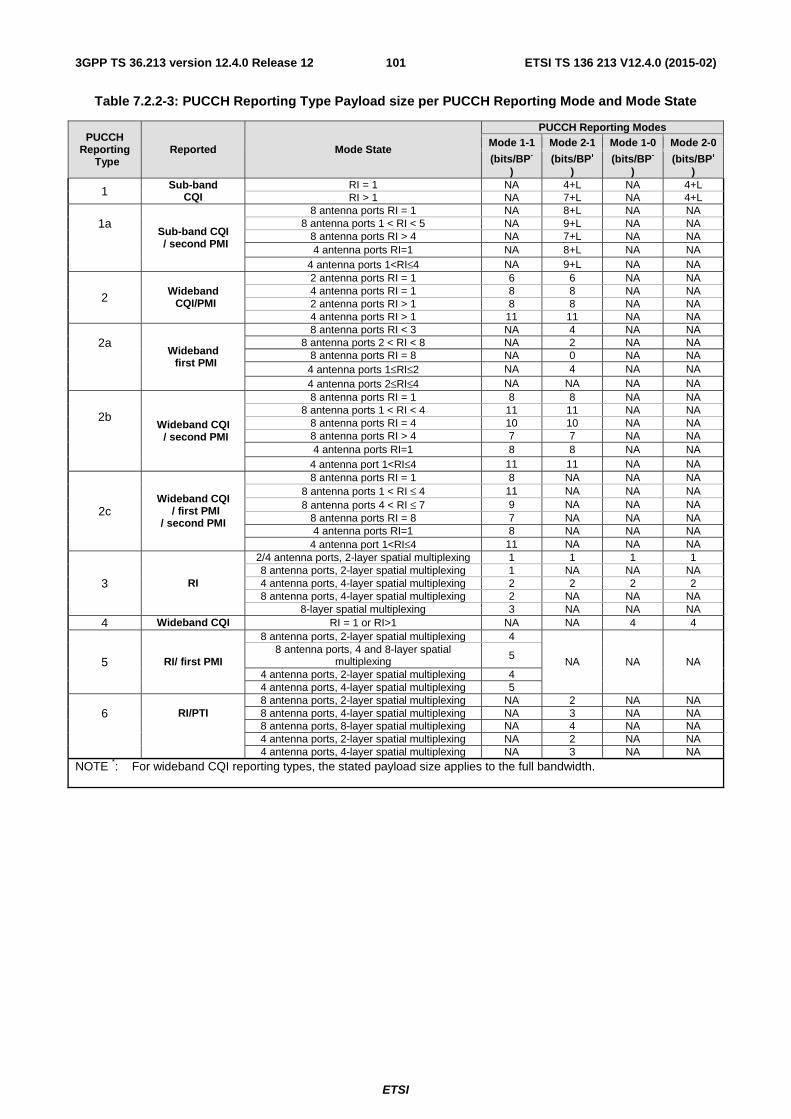
ETSI
ETSI TS 136 213 V12.4.0 (2015-02)1013GPP TS 36.213 version 12.4.0 Release 12
Table 7.2.2-3: PUCCH Reporting Type Payload size per PUCCH Reporting Mode and Mode State
PUCCH Reporting
Type Reported Mode State
PUCCH Reporting Modes Mode 1-1 Mode 2-1 Mode 1-0 Mode 2-0
(bits/BP*
) (bits/BP*
) (bits/BP*
) (bits/BP*
)
1 Sub-band CQI
RI = 1 NA 4+L NA 4+L RI > 1 NA 7+L NA 4+L
1a Sub-band CQI / second PMI
8 antenna ports RI = 1 NA 8+L NA NA 8 antenna ports 1 < RI < 5 NA 9+L NA NA
8 antenna ports RI > 4 NA 7+L NA NA 4 antenna ports RI=1 NA 8+L NA NA 4 antenna ports 1<RI≤4 NA 9+L NA NA
2 Wideband CQI/PMI
2 antenna ports RI = 1 6 6 NA NA 4 antenna ports RI = 1 8 8 NA NA 2 antenna ports RI > 1 8 8 NA NA 4 antenna ports RI > 1 11 11 NA NA
2a Wideband first PMI
8 antenna ports RI < 3 NA 4 NA NA 8 antenna ports 2 < RI < 8 NA 2 NA NA
8 antenna ports RI = 8 NA 0 NA NA 4 antenna ports 1≤RI≤2 NA 4 NA NA 4 antenna ports 2≤RI≤4 NA NA NA NA
2b Wideband CQI / second PMI
8 antenna ports RI = 1 8 8 NA NA 8 antenna ports 1 < RI < 4 11 11 NA NA
8 antenna ports RI = 4 10 10 NA NA 8 antenna ports RI > 4 7 7 NA NA
4 antenna ports RI=1 8 8 NA NA 4 antenna port 1<RI≤4 11 11 NA NA
2c Wideband CQI
/ first PMI / second PMI
8 antenna ports RI = 1 8 NA NA NA 8 antenna ports 1 < RI ≤ 4 11 NA NA NA 8 antenna ports 4 < RI ≤ 7 9 NA NA NA
8 antenna ports RI = 8 7 NA NA NA 4 antenna ports RI=1 8 NA NA NA
4 antenna port 1<RI≤4 11 NA NA NA
3 RI
2/4 antenna ports, 2-layer spatial multiplexing 1 1 1 1 8 antenna ports, 2-layer spatial multiplexing 1 NA NA NA 4 antenna ports, 4-layer spatial multiplexing 2 2 2 2 8 antenna ports, 4-layer spatial multiplexing 2 NA NA NA
8-layer spatial multiplexing 3 NA NA NA 4 Wideband CQI RI = 1 or RI>1 NA NA 4 4
5 RI/ first PMI
8 antenna ports, 2-layer spatial multiplexing 4
NA NA NA 8 antenna ports, 4 and 8-layer spatial
multiplexing 5
4 antenna ports, 2-layer spatial multiplexing 4 4 antenna ports, 4-layer spatial multiplexing 5
6 RI/PTI 8 antenna ports, 2-layer spatial multiplexing NA 2 NA NA 8 antenna ports, 4-layer spatial multiplexing NA 3 NA NA 8 antenna ports, 8-layer spatial multiplexing NA 4 NA NA
4 antenna ports, 2-layer spatial multiplexing NA 2 NA NA 4 antenna ports, 4-layer spatial multiplexing NA 3 NA NA
NOTE *: For wideband CQI reporting types, the stated payload size applies to the full bandwidth.

ETSI
ETSI TS 136 213 V12.4.0 (2015-02)1023GPP TS 36.213 version 12.4.0 Release 12
7.2.3 Channel Quality Indicator (CQI) definition
The CQI indices and their interpretations are given in Table 7.2.3-1 for reporting CQI based on QPSK, 16QAM and 64QAM. The CQI indices and their interpretations are given in Table 7.2.3-2 for reporting CQI based on QPSK, 16QAM, 64QAM and 256QAM.
Based on an unrestricted observation interval in time and frequency, the UE shall derive for each CQI value reported in uplink subframe n the highest CQI index between 1 and 15 in Table 7.2.3-1 or Table 7.2.3-2 which satisfies the following condition, or CQI index 0 if CQI index 1 does not satisfy the condition:
- A single PDSCH transport block with a combination of modulation scheme and transport block size corresponding to the CQI index, and occupying a group of downlink physical resource blocks termed the CSI reference resource, could be received with a transport block error probability not exceeding 0.1.
If CSI subframe sets CSI,0C and CSI,1C are configured by higher layers, each CSI reference resource belongs to either
CSI,0C or CSI,1C but not to both. When CSI subframe sets CSI,0C and CSI,1C are configured by higher layers a UE
is not expected to receive a trigger for which the CSI reference resource is in subframe that does not belong to either subframe set. For a UE in transmission mode 10 and periodic CSI reporting, the CSI subframe set for the CSI reference resource is configured by higher layers for each CSI process.
For a UE in transmission mode 9 when parameter pmi-RI-Report is configured by higher layers, the UE shall derive the channel measurements for computing the CQI value reported in uplink subframe n based on only the Channel-State Information (CSI) reference signals (CSI-RS) defined in [3] for which the UE is configured to assume non-zero power for the CSI-RS. For a UE in transmission mode 9 when the parameter pmi-RI-Report is not configured by higher layers or in transmission modes 1-8 the UE shall derive the channel measurements for computing CQI based on CRS.
For a UE in transmission mode 10, the UE shall derive the channel measurements for computing the CQI value reported in uplink subframe n and corresponding to a CSI process, based on only the non-zero power CSI-RS (defined in [3]) within a configured CSI-RS resource associated with the CSI process.
For a UE in transmission mode 10 , the UE shall derive the interference measurements for computing the CQI value reported in uplink subframe n and corresponding to a CSI process, based on only the zero power CSI-RS (defined in [3]) within the configured CSI-IM resource associated with the CSI process. If the UE in transmission mode 10 is configured by higher layers for CSI subframe sets CSI,0C and CSI,1C for the CSI process, the configured CSI-IM
resource within the subframe subset belonging to the CSI reference resource is used to derive the interference measurement. For a UE configured with the parameter EIMTA-MainConfigServCell-r12 for a serving cell, configured CSI-IM resource(s) within only downlink subframe(s) of a radio frame that are indicated by UL/DL configuration of the serving cell can be used to derive the interference measurement for the serving cell.
A combination of modulation scheme and transport block size corresponds to a CQI index if:
- the combination could be signalled for transmission on the PDSCH in the CSI reference resource according to the relevant Transport Block Size table, and
- the modulation scheme is indicated by the CQI index, and
- the combination of transport block size and modulation scheme when applied to the reference resource results in the effective channel code rate which is the closest possible to the code rate indicated by the CQI index. If more than one combination of transport block size and modulation scheme results in an effective channel code rate equally close to the code rate indicated by the CQI index, only the combination with the smallest of such transport block sizes is relevant.
The CSI reference resource for a serving cell is defined as follows:
- In the frequency domain, the CSI reference resource is defined by the group of downlink physical resource blocks corresponding to the band to which the derived CQI value relates.
- In the time domain,
- for a UE configured in transmission mode 1-9 or transmission mode 10 with a single configured CSI process for the serving cell, the CSI reference resource is defined by a single downlink or special subframe n-nCQI_ref,
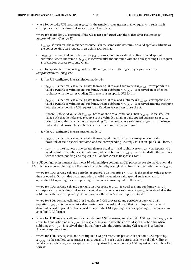
ETSI
ETSI TS 136 213 V12.4.0 (2015-02)1033GPP TS 36.213 version 12.4.0 Release 12
- where for periodic CSI reporting nCQI_ref is the smallest value greater than or equal to 4, such that it corresponds to a valid downlink or valid special subframe,
- where for aperiodic CSI reporting, if the UE is not configured with the higher layer parameter csi-SubframePatternConfig-r12,.
- nCQI_ref is such that the reference resource is in the same valid downlink or valid special subframe as the corresponding CSI request in an uplink DCI format.
- nCQI_ref is equal to 4 and subframe n-nCQI_ref corresponds to a valid downlink or valid special subframe, where subframe n-nCQI_ref is received after the subframe with the corresponding CSI request in a Random Access Response Grant.
- where for aperiodic CSI reporting, and the UE configured with the higher layer parameter csi-SubframePatternConfig-r12,
- for the UE configured in transmission mode 1-9,
- nCQI_ref is the smallest value greater than or equal to 4 and subframe n-nCQI_ref corresponds to a valid downlink or valid special subframe, where subframe n-nCQI_ref is received on or after the subframe with the corresponding CSI request in an uplink DCI format;
- nCQI_ref is the smallest value greater than or equal to 4, and subframe n-nCQI_ref corresponds to a valid downlink or valid special subframe, where subframe n-nCQI_ref is received after the subframe with the corresponding CSI request in an Random Access Response Grant;
- if there is no valid value for nCQI_ref based on the above conditions, then nCQI_ref is the smallest value such that the reference resource is in a valid downlink or valid special subframe n-nCQI_ref prior to the subframe with the corresponding CSI request, where subframe n-nCQI_ref is the lowest indexed valid downlink or valid special subframe within a radio frame;
- for the UE configured in transmission mode 10,
- nCQI_ref is the smallest value greater than or equal to 4, such that it corresponds to a valid downlink or valid special subframe, and the corresponding CSI request is in an uplink DCI format;
- nCQI_ref is the smallest value greater than or equal to 4, and subframe n-nCQI_ref corresponds to a valid downlink or valid special subframe, where subframe n-nCQI_ref is received after the subframe with the corresponding CSI request in a Random Access Response Grant;
- for a UE configured in transmission mode 10 with multiple configured CSI processes for the serving cell, the CSI reference resource for a given CSI process is defined by a single downlink or special subframe n-nCQI_ref,
- where for FDD serving cell and periodic or aperiodic CSI reporting nCQI_ref is the smallest value greater than or equal to 5, such that it corresponds to a valid downlink or valid special subframe, and for aperiodic CSI reporting the corresponding CSI request is in an uplink DCI format;
- where for FDD serving cell and aperiodic CSI reporting nCQI_ref is equal to 5 and subframe n-nCQI_ref corresponds to a valid downlink or valid special subframe, where subframe n-nCQI_ref is received after the subframe with the corresponding CSI request in a Random Access Response Grant.
- where for TDD serving cell, and 2 or 3 configured CSI processes, and periodic or aperiodic CSI reporting, nCQI_ref is the smallest value greater than or equal to 4, such that it corresponds to a valid downlink or valid special subframe, and for aperiodic CSI reporting the corresponding CSI request is in an uplink DCI format;
- where for TDD serving cell, and 2 or 3 configured CSI processes, and aperiodic CSI reporting, nCQI_ref is equal to 4 and subframe n-nCQI_ref corresponds to a valid downlink or valid special subframe, where subframe n-nCQI_ref is received after the subframe with the corresponding CSI request in a Random Access Response Grant;
- where for TDD serving cell, and 4 configured CSI processes, and periodic or aperiodic CSI reporting, nCQI_ref is the smallest value greater than or equal to 5, such that it corresponds to a valid downlink or valid special subframe, and for aperiodic CSI reporting the corresponding CSI request is in an uplink DCI format;
ETSI
ETSI TS 136 213 V12.4.0 (2015-02)1043GPP TS 36.213 version 12.4.0 Release 12
- where for TDD serving cell, and 4 configured CSI processes, and aperiodic CSI reporting, nCQI_ref is equal to 5 and subframe n-nCQI_ref corresponds to a valid downlink or valid special subframe, where subframe n-nCQI_ref is received after the subframe with the corresponding CSI request in a Random Access Response Grant.
A subframe in a serving cell shall be considered to be a valid downlink or a valid special subframe if:
- it is configured as a downlink subframe or a special subframe for that UE, and
- in case multiple cells with different uplink-downlink configurations are aggregated and the UE is not capable of simultaneous reception and transmission in the aggregated cells, the subframe in the primary cell is a downlink subframe or a special subframe with the length of DwPTS more than s7680 T⋅ , and
- except for transmission mode 9 or 10, it is not an MBSFN subframe, and
- it does not contain a DwPTS field in case the length of DwPTS is s7680 T⋅ and less, and
- it does not fall within a configured measurement gap for that UE, and
- for periodic CSI reporting, it is an element of the CSI subframe set linked to the periodic CSI report when that UE is configured with CSI subframe sets, and
- for a UE configured in transmission mode 10 with multiple configured CSI processes, and aperiodic CSI reporting for a CSI process, it is an element of the CSI subframe set linked to the downlink or special subframe with the corresponding CSI request in an uplink DCI format, when that UE is configured with CSI subframe sets for the CSI process and UE is not configured with the higher layer parameter csi-SubframePatternConfig-r12, and
- for a UE configured in transmission mode 1-9, and aperiodic CSI reporting, it is an element of the CSI subframe set associated with the corresponding CSI request in an uplink DCI format, when that UE is configured with CSI subframe sets by the higher layer parameter csi-SubframePatternConfig-r12, and
- for a UE configured in transmission mode 10, and aperiodic CSI reporting for a CSI process, it is an element of the CSI subframe set associated with the corresponding CSI request in an uplink DCI format, when that UE is configured with CSI subframe sets by the higher layer parameter csi-SubframePatternConfig-r12 for the CSI process.
If there is no valid downlink or no valid special subframe for the CSI reference resource in a serving cell, CSI reporting is omitted for the serving cell in uplink subframe n.
In the layer domain, the CSI reference resource is defined by any RI and PMI on which the CQI is conditioned.
In the CSI reference resource, the UE shall assume the following for the purpose of deriving the CQI index, and if also configured, PMI and RI:
- The first 3 OFDM symbols are occupied by control signalling
- No resource elements used by primary or secondary synchronization signals or PBCH or EPDCCH
- CP length of the non-MBSFN subframes
- Redundancy Version 0
- If CSI-RS is used for channel measurements, the ratio of PDSCH EPRE to CSI-RS EPRE is as given in subclause 7.2.5
- For transmission mode 9 CSI reporting:
- CRS REs are as in non-MBSFN subframes;
- If the UE is configured for PMI/RI reporting, the UE-specific reference signal overhead is consistent with the most recent reported rank if more than one CSI-RS port is configured, and is consistent with rank 1 transmission if only one CSI-RS port is configured; and PDSCH signals on antenna ports }67{ υ+K for
υ layers would result in signals equivalent to corresponding symbols transmitted on antenna ports
ETSI
ETSI TS 136 213 V12.4.0 (2015-02)1053GPP TS 36.213 version 12.4.0 Release 12
}1415{ P+K , as given by
⎥⎥⎥
⎦
⎤
⎢⎢⎢
⎣
⎡
=⎥⎥⎥
⎦
⎤
⎢⎢⎢
⎣
⎡
−+ )(
)(
)(
)(
)(
)1(
)0(
)14(
)15(
ix
ix
iW
iy
iy
P υ
MM , where [ ]Tixixix )(...)()( )1()0( −= υ is a
vector of symbols from the layer mapping in subclause 6.3.3.2 of [3], }8,4,2,1{∈P is the number of CSI-
RS ports configured, and if only one CSI-RS port is configured, )(iW is 1, otherwise )(iW is the precoding
matrix corresponding to the reported PMI applicable to )(ix . The corresponding PDSCH signals transmitted
on antenna ports }1415{ P+K would have a ratio of EPRE to CSI-RS EPRE equal to the ratio given in
subclause 7.2.5.
- For transmission mode 10 CSI reporting, if a CSI process is configured without PMI/RI reporting:
- If the number of antenna ports of the associated CSI-RS resource is one, a PDSCH transmission is on single-antenna port, port 7. The channel on antenna port {7} is inferred from the channel on antenna port {15} of the associated CSI-RS resource.
- CRS REs are as in non-MBSFN subframes. The CRS overhead is assumed to be the same as the CRS overhead corresponding to the number of CRS antenna ports of the serving cell;
- The UE-specific reference signal overhead is 12 REs per PRB pair.
- Otherwise,
- If the number of antenna ports of the associated CSI-RS resource is 2, the PDSCH transmission scheme assumes the transmit diversity scheme defined in subclause 7.1.2 on antenna ports {0,1} except that the channels on antenna ports {0,1} are inferred from the channels on antenna port {15, 16} of the associated CSI resource respectively.
- If the number of antenna ports of the associated CSI-RS resource is 4, the PDSCH transmission scheme assumes the transmit diversity scheme defined in subclause 7.1.2 on antenna ports {0,1,2,3} except that the channels on antenna ports {0,1,2,3} are inferred from the channels on antenna ports {15, 16, 17, 18} of the associated CSI-RS resource respectively.
- The UE is not expected to be configured with more than 4 antenna ports for the CSI-RS resource associated with the CSI process configured without PMI/RI reporting.
- The overhead of CRS REs is assuming the same number of antenna ports as that of the associated CSI-RS resource.
- UE-specific reference signal overhead is zero.
- For transmission mode 10 CSI reporting, if a CSI process is configured with PMI/RI reporting:
- CRS REs are as in non-MBSFN subframes. The CRS overhead is assumed to be the same as the CRS overhead corresponding to the number of CRS antenna ports of the serving cell;
- The UE-specific reference signal overhead is consistent with the most recent reported rank for the CSI process if more than one CSI-RS port is configured, and is consistent with rank 1 transmission if only one CSI-RS port is configured; and PDSCH signals on antenna ports }67{ υ+K for υ layers would result in
signals equivalent to corresponding symbols transmitted on antenna ports }1415{ P+K , as given by
⎥⎥⎥
⎦
⎤
⎢⎢⎢
⎣
⎡
=⎥⎥⎥
⎦
⎤
⎢⎢⎢
⎣
⎡
−+ )(
)(
)(
)(
)(
)1(
)0(
)14(
)15(
ix
ix
iW
iy
iy
P υ
MM , where [ ]Tixixix )(...)()( )1()0( −= υ is a vector of symbols from the
layer mapping in subclause 6.3.3.2 of [3], }8,4,2,1{∈P is the number of antenna ports of the associated
CSI-RS resource, and if P=1, )(iW is 1, otherwise )(iW is the precoding matrix corresponding to the
reported PMI applicable to )(ix . The corresponding PDSCH signals transmitted on antenna ports
}1415{ P+K would have a ratio of EPRE to CSI-RS EPRE equal to the ratio given in subclause 7.2.5
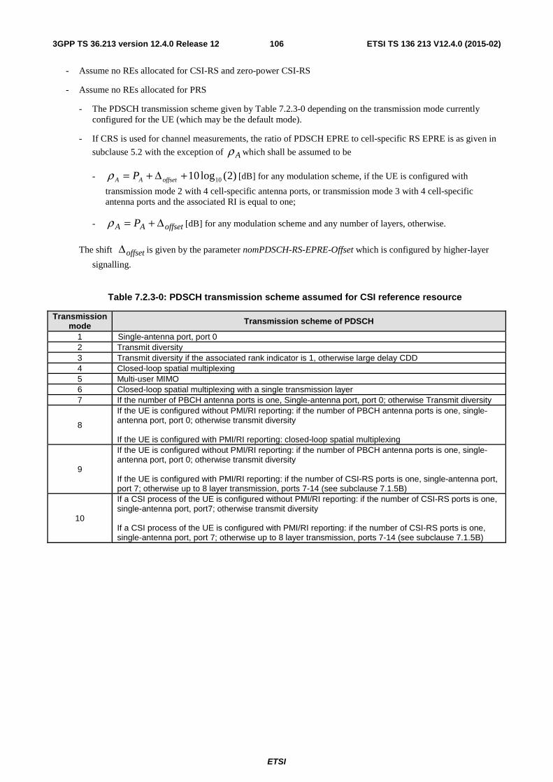
ETSI
ETSI TS 136 213 V12.4.0 (2015-02)1063GPP TS 36.213 version 12.4.0 Release 12
- Assume no REs allocated for CSI-RS and zero-power CSI-RS
- Assume no REs allocated for PRS
- The PDSCH transmission scheme given by Table 7.2.3-0 depending on the transmission mode currently configured for the UE (which may be the default mode).
- If CRS is used for channel measurements, the ratio of PDSCH EPRE to cell-specific RS EPRE is as given in
subclause 5.2 with the exception of Aρ which shall be assumed to be
- )2(log10 10+Δ+= offsetAA Pρ [dB] for any modulation scheme, if the UE is configured with
transmission mode 2 with 4 cell-specific antenna ports, or transmission mode 3 with 4 cell-specific antenna ports and the associated RI is equal to one;
- offsetAA P Δ+=ρ [dB] for any modulation scheme and any number of layers, otherwise.
The shift offsetΔ is given by the parameter nomPDSCH-RS-EPRE-Offset which is configured by higher-layer
signalling.
Table 7.2.3-0: PDSCH transmission scheme assumed for CSI reference resource
Transmission mode Transmission scheme of PDSCH
1 Single-antenna port, port 0 2 Transmit diversity 3 Transmit diversity if the associated rank indicator is 1, otherwise large delay CDD 4 Closed-loop spatial multiplexing 5 Multi-user MIMO 6 Closed-loop spatial multiplexing with a single transmission layer 7 If the number of PBCH antenna ports is one, Single-antenna port, port 0; otherwise Transmit diversity
8
If the UE is configured without PMI/RI reporting: if the number of PBCH antenna ports is one, single-antenna port, port 0; otherwise transmit diversity If the UE is configured with PMI/RI reporting: closed-loop spatial multiplexing
9
If the UE is configured without PMI/RI reporting: if the number of PBCH antenna ports is one, single-antenna port, port 0; otherwise transmit diversity If the UE is configured with PMI/RI reporting: if the number of CSI-RS ports is one, single-antenna port, port 7; otherwise up to 8 layer transmission, ports 7-14 (see subclause 7.1.5B)
10
If a CSI process of the UE is configured without PMI/RI reporting: if the number of CSI-RS ports is one, single-antenna port, port7; otherwise transmit diversity If a CSI process of the UE is configured with PMI/RI reporting: if the number of CSI-RS ports is one, single-antenna port, port 7; otherwise up to 8 layer transmission, ports 7-14 (see subclause 7.1.5B)
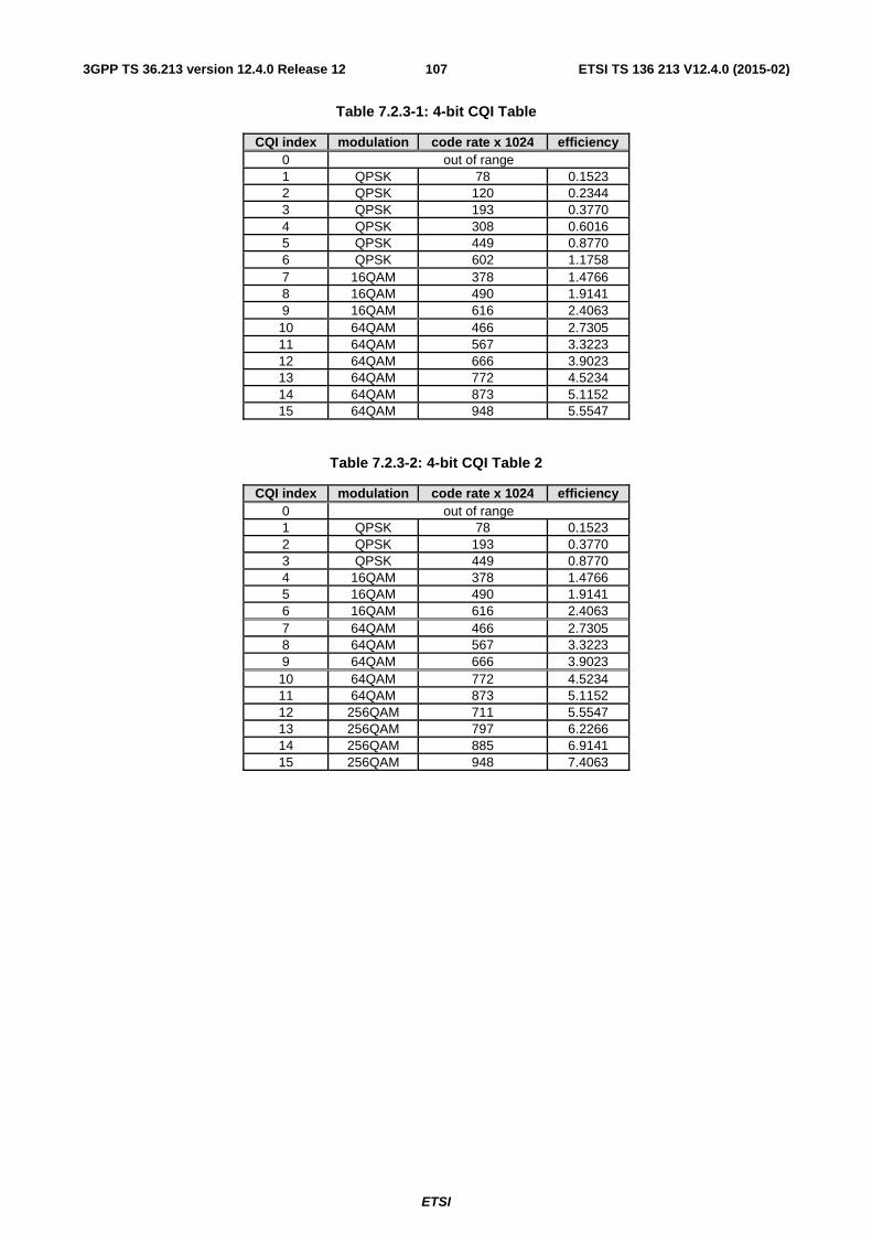
ETSI
ETSI TS 136 213 V12.4.0 (2015-02)1073GPP TS 36.213 version 12.4.0 Release 12
Table 7.2.3-1: 4-bit CQI Table
CQI index modulation code rate x 1024 efficiency 0 out of range 1 QPSK 78 0.1523 2 QPSK 120 0.2344 3 QPSK 193 0.3770 4 QPSK 308 0.6016 5 QPSK 449 0.8770 6 QPSK 602 1.1758 7 16QAM 378 1.4766 8 16QAM 490 1.9141 9 16QAM 616 2.4063 10 64QAM 466 2.7305 11 64QAM 567 3.3223 12 64QAM 666 3.9023 13 64QAM 772 4.5234 14 64QAM 873 5.1152 15 64QAM 948 5.5547
Table 7.2.3-2: 4-bit CQI Table 2
CQI index modulation code rate x 1024 efficiency 0 out of range 1 QPSK 78 0.1523 2 QPSK 193 0.3770 3 QPSK 449 0.8770 4 16QAM 378 1.4766 5 16QAM 490 1.9141 6 16QAM 616 2.4063 7 64QAM 466 2.7305 8 64QAM 567 3.3223 9 64QAM 666 3.9023 10 64QAM 772 4.5234 11 64QAM 873 5.1152 12 256QAM 711 5.5547 13 256QAM 797 6.2266 14 256QAM 885 6.9141 15 256QAM 948 7.4063
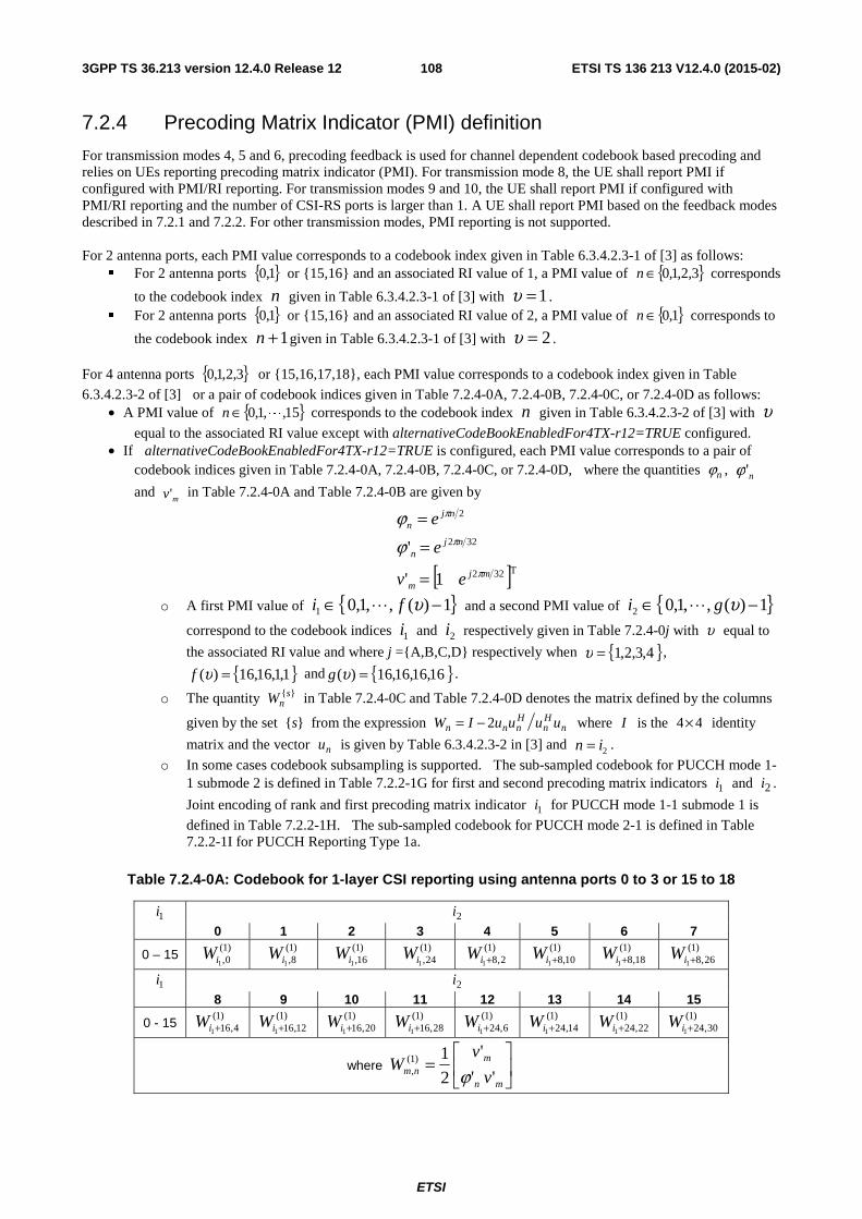
ETSI
ETSI TS 136 213 V12.4.0 (2015-02)1083GPP TS 36.213 version 12.4.0 Release 12
7.2.4 Precoding Matrix Indicator (PMI) definition
For transmission modes 4, 5 and 6, precoding feedback is used for channel dependent codebook based precoding and relies on UEs reporting precoding matrix indicator (PMI). For transmission mode 8, the UE shall report PMI if configured with PMI/RI reporting. For transmission modes 9 and 10, the UE shall report PMI if configured with PMI/RI reporting and the number of CSI-RS ports is larger than 1. A UE shall report PMI based on the feedback modes described in 7.2.1 and 7.2.2. For other transmission modes, PMI reporting is not supported. For 2 antenna ports, each PMI value corresponds to a codebook index given in Table 6.3.4.2.3-1 of [3] as follows:
� For 2 antenna ports { }1,0 or {15,16} and an associated RI value of 1, a PMI value of { }3,2,1,0∈n corresponds
to the codebook index n given in Table 6.3.4.2.3-1 of [3] with 1=υ . � For 2 antenna ports { }1,0 or {15,16} and an associated RI value of 2, a PMI value of { }1,0∈n corresponds to
the codebook index 1+n given in Table 6.3.4.2.3-1 of [3] with 2=υ . For 4 antenna ports { }3,2,1,0 or {15,16,17,18}, each PMI value corresponds to a codebook index given in Table
6.3.4.2.3-2 of [3] or a pair of codebook indices given in Table 7.2.4-0A, 7.2.4-0B, 7.2.4-0C, or 7.2.4-0D as follows: • A PMI value of { }15,,1,0 L∈n corresponds to the codebook index n given in Table 6.3.4.2.3-2 of [3] with υ
equal to the associated RI value except with alternativeCodeBookEnabledFor4TX-r12=TRUE configured. • If alternativeCodeBookEnabledFor4TX-r12=TRUE is configured, each PMI value corresponds to a pair of
codebook indices given in Table 7.2.4-0A, 7.2.4-0B, 7.2.4-0C, or 7.2.4-0D, where the quantities nϕ , n'ϕ
and mv' in Table 7.2.4-0A and Table 7.2.4-0B are given by
[ ]T322
322
2
1'
'
mjm
njn
njn
ev
e
e
π
π
π
ϕϕ
=
=
=
o A first PMI value of { }1)(,,1,01 −∈ υfi L and a second PMI value of { }1)(,,1,02 −∈ υgi L
correspond to the codebook indices 1i and 2i respectively given in Table 7.2.4-0j with υ equal to
the associated RI value and where j ={A,B,C,D} respectively when { }4,3,2,1=υ ,
{ }1,1,16,16)( =υf and { }16,16,16,16)( =υg .
o The quantity }{snW in Table 7.2.4-0C and Table 7.2.4-0D denotes the matrix defined by the columns
given by the set }{s from the expression nHn
Hnnn uuuuIW 2−= where I is the 44× identity
matrix and the vector nu is given by Table 6.3.4.2.3-2 in [3] and 2in = .
o In some cases codebook subsampling is supported. The sub-sampled codebook for PUCCH mode 1-1 submode 2 is defined in Table 7.2.2-1G for first and second precoding matrix indicators 1i and 2i .
Joint encoding of rank and first precoding matrix indicator 1i for PUCCH mode 1-1 submode 1 is
defined in Table 7.2.2-1H. The sub-sampled codebook for PUCCH mode 2-1 is defined in Table 7.2.2-1I for PUCCH Reporting Type 1a.
Table 7.2.4-0A: Codebook for 1-layer CSI reporting using antenna ports 0 to 3 or 15 to 18
1i 2i 0 1 2 3 4 5 6 7
0 – 15 )1(0,1i
W )1(8,1i
W )1(
16,1iW
)1(24,1i
W )1(
2,81+iW )1(
10,81+iW )1(
18,81+iW )1(
26,81+iW
1i 2i 8 9 10 11 12 13 14 15
0 - 15 )1(
4,161+iW )1(
12,161+iW )1(
20,161+iW )1(
28,161+iW )1(
6,241+iW )1(
14,241+iW )1(
22,241+iW )1(
30,241+iW
where ⎥⎦
⎤⎢⎣
⎡=
mn
mnm v
vW
''
'
2
1)1(, ϕ
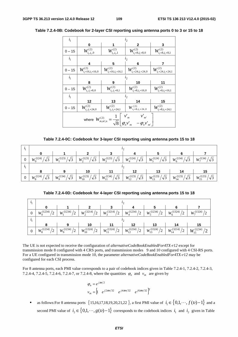
ETSI
ETSI TS 136 213 V12.4.0 (2015-02)1093GPP TS 36.213 version 12.4.0 Release 12
Table 7.2.4-0B: Codebook for 2-layer CSI reporting using antenna ports 0 to 3 or 15 to 18
1i 2i 0 1 2 3
0 – 15 )2(
0,, 11 iiW )2(1,, 11 iiW
)2(0,8,8 11 ++ iiW
)2(1,8,8 11 ++ iiW
1i 2i 4 5 6 7
0 – 15 )2(
0,16,16 11 ++ iiW )2(
1,16,16 11 ++ iiW )2(
0,24,24 11 ++ iiW )2(
1,24,24 11 ++ iiW
1i 2i 8 9 10 11
0 – 15 )2(
0,8, 11 +iiW )2(
1,8, 11 +iiW )2(
0,16,8 11 ++ iiW )2(
1,16,8 11 ++ iiW
1i 2i 12 13 14 15
0 – 15 )2(
0,24, 11 +iiW )2(
1,24, 11 +iiW )2(
0,24,8 11 ++ iiW )2(1,24,8 11 ++ iiW
where ⎥⎦
⎤⎢⎣
⎡
−=
'
')2(,', ''
''
8
1
mnmn
mmnmm vv
vvW
ϕϕ
Table 7.2.4-0C: Codebook for 3-layer CSI reporting using antenna ports 15 to 18
1i 2i 0 1 2 3 4 5 6 7
0 3}124{0W 3}123{
1W 3}123{2W 3}123{
3W 3}124{4W 3}124{
5W 3}134{6W 3}134{
7W
1i 2i 8 9 10 11 12 13 14 15
0 3}124{8W 3}134{
9W 3}123{10W 3}134{
11W 3}123{12W 3}123{
13W 3}123{14W 3}123{
15W
Table 7.2.4-0D: Codebook for 4-layer CSI reporting using antenna ports 15 to 18
1i 2i 0 1 2 3 4 5 6 7
0 2}1234{0W 2}1234{
1W 2}3214{2W 2}3214{
3W 2}1234{4W 2}1234{
5W 2}1324{6W 2}1324{
7W
1i 2i 8 9 10 11 12 13 14 15
0 2}1234{8W 2}1234{
9W 2}1324{10W 2}1324{
11W 2}1234{12W 2}1324{
13W 2}3214{14W 2}1234{
15W
The UE is not expected to receive the configuration of alternativeCodeBookEnabledFor4TX-r12 except for transmission mode 8 configured with 4 CRS ports, and transmission modes 9 and 10 configured with 4 CSI-RS ports. For a UE configured in transmission mode 10, the parameter alternativeCodeBookEnabledFor4TX-r12 may be configured for each CSI process. For 8 antenna ports, each PMI value corresponds to a pair of codebook indices given in Table 7.2.4-1, 7.2.4-2, 7.2.4-3, 7.2.4-4, 7.2.4-5, 7.2.4-6, 7.2.4-7, or 7.2.4-8, where the quantities nϕ and mv are given by
[ ]T326324322
2
1 mjmjmjm
njn
eeev
e
πππ
πϕ
=
=
� as follows:For 8 antenna ports { }22,21,20,19,18,17,16,15 , a first PMI value of { }1)(,,1,01 −∈ υfi L and a
second PMI value of { }1)(,,1,02 −∈ υgi L corresponds to the codebook indices 1i and 2i given in Table
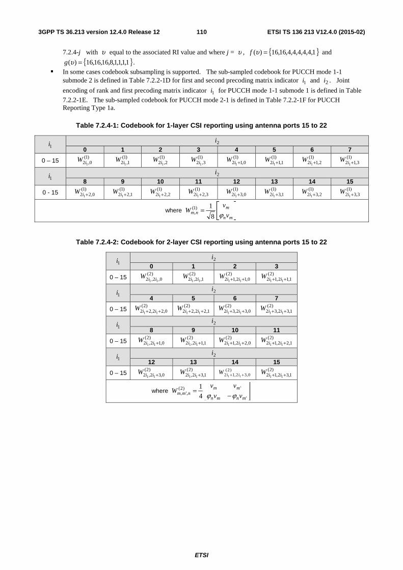
ETSI
ETSI TS 136 213 V12.4.0 (2015-02)1103GPP TS 36.213 version 12.4.0 Release 12
7.2.4-j with υ equal to the associated RI value and where j = υ , { }1,4,4,4,4,4,16,16)( =υf and
{ }1,1,1,1,8,16,16,16)( =υg .
� In some cases codebook subsampling is supported. The sub-sampled codebook for PUCCH mode 1-1 submode 2 is defined in Table 7.2.2-1D for first and second precoding matrix indicator 1i and 2i . Joint
encoding of rank and first precoding matrix indicator 1i for PUCCH mode 1-1 submode 1 is defined in Table
7.2.2-1E. The sub-sampled codebook for PUCCH mode 2-1 is defined in Table 7.2.2-1F for PUCCH Reporting Type 1a.
Table 7.2.4-1: Codebook for 1-layer CSI reporting using antenna ports 15 to 22
1i 2i
0 1 2 3 4 5 6 7
0 – 15 )1(0,2 1i
W )1(1,2 1i
W )1(2,2 1i
W )1(3,2 1i
W )1(0,12 1 +iW )1(
1,12 1+iW )1(2,12 1 +iW )1(
3,12 1 +iW
1i 2i
8 9 10 11 12 13 14 15
0 - 15 )1(
0,22 1+iW )1(1,22 1 +iW )1(
2,22 1+iW )1(3,22 1+iW )1(
0,32 1+iW )1(1,32 1 +iW )1(
2,32 1+iW )1(3,32 1 +iW
where ⎥⎦
⎤⎢⎣
⎡=
mn
mnm v
vW
ϕ8
1)1(,
Table 7.2.4-2: Codebook for 2-layer CSI reporting using antenna ports 15 to 22
1i 2i
0 1 2 3
0 – 15 )2(
0,2,2 11 iiW )2(1,2,2 11 iiW )2(
0,12,12 11 ++ iiW )2(1,12,12 11 ++ iiW
1i 2i
4 5 6 7
0 – 15 )2(
0,22,22 11 ++ iiW )2(1,22,22 11 ++ iiW )2(
0,32,32 11 ++ iiW )2(1,32,32 11 ++ iiW
1i 2i
8 9 10 11
0 – 15 )2(
0,12,2 11 +iiW )2(1,12,2 11 +iiW )2(
0,22,12 11 ++ iiW )2(1,22,12 11 ++ iiW
1i 2i
12 13 14 15
0 – 15 )2(
0,32,2 11 +iiW )2(1,32,2 11 +iiW )2(
0,32,12 11 ++ iiW )2(1,32,12 11 ++ iiW
where ⎥⎦
⎤⎢⎣
⎡
−=
'
')2(,', 4
1
mnmn
mmnmm vv
vvW
ϕϕ
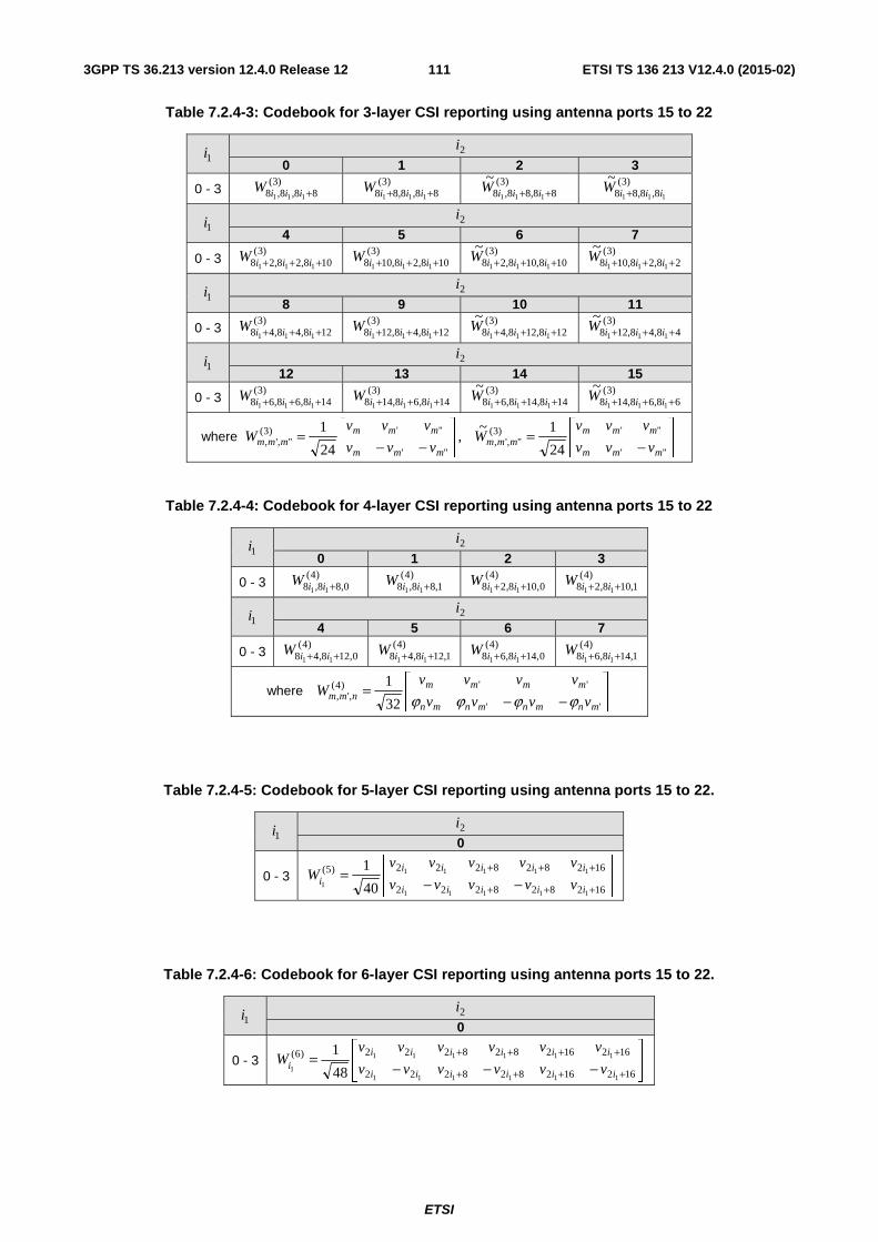
ETSI
ETSI TS 136 213 V12.4.0 (2015-02)1113GPP TS 36.213 version 12.4.0 Release 12
Table 7.2.4-3: Codebook for 3-layer CSI reporting using antenna ports 15 to 22
1i 2i
0 1 2 3
0 - 3 )3(
88,8,8 111 +iiiW )3(88,8,88 111 ++ iiiW )3(
88,88,8 111
~++ iiiW )3(
8,8,88 111
~iiiW +
1i 2i
4 5 6 7
0 - 3 )3(
108,28,28 111 +++ iiiW )3(108,28,108 111 +++ iiiW )3(
108,108,28 111
~+++ iiiW )3(
28,28,108 111
~+++ iiiW
1i 2i
8 9 10 11
0 - 3 )3(
128,48,48 111 +++ iiiW )3(128,48,128 111 +++ iiiW )3(
128,128,48 111
~+++ iiiW )3(
48,48,128 111
~+++ iiiW
1i 2i
12 13 14 15
0 - 3 )3(
148,68,68 111 +++ iiiW )3(148,68,148 111 +++ iiiW )3(
148,148,68 111
~+++ iiiW )3(
68,68,148 111
~+++ iiiW
where ⎥⎦
⎤⎢⎣
⎡
−=⎥
⎦
⎤⎢⎣
⎡
−−=
"'
"')3(",',
"'
"')3(",',
24
1~ ,
24
1
mmm
mmmmmm
mmm
mmmmmm vvv
vvvW
vvv
vvvW
Table 7.2.4-4: Codebook for 4-layer CSI reporting using antenna ports 15 to 22
1i 2i
0 1 2 3
0 - 3 )4(
0,88,8 11 +iiW )4(1,88,8 11 +iiW )4(
0,108,28 11 ++ iiW )4(1,108,28 11 ++ iiW
1i 2i
4 5 6 7
0 - 3 )4(
0,128,48 11 ++ iiW )4(1,128,48 11 ++ iiW )4(
0,148,68 11 ++ iiW )4(1,148,68 11 ++ iiW
where ⎥⎦
⎤⎢⎣
⎡
−−=
''
'')4(,',
32
1
mnmnmnmn
mmmmnmm vvvv
vvvvW
ϕϕϕϕ
Table 7.2.4-5: Codebook for 5-layer CSI reporting using antenna ports 15 to 22.
1i 2i 0
0 - 3 ⎥⎦
⎤⎢⎣
⎡
−−=
+++
+++
162828222
162828222)5(
11111
11111
1 40
1
iiiii
iiiiii vvvvv
vvvvvW
Table 7.2.4-6: Codebook for 6-layer CSI reporting using antenna ports 15 to 22.
1i 2i 0
0 - 3 ⎥⎦
⎤⎢⎣
⎡
−−−=
++++
++++
162162828222
162162828222)6(
111111
111111
1 48
1
iiiiii
iiiiiii vvvvvv
vvvvvvW
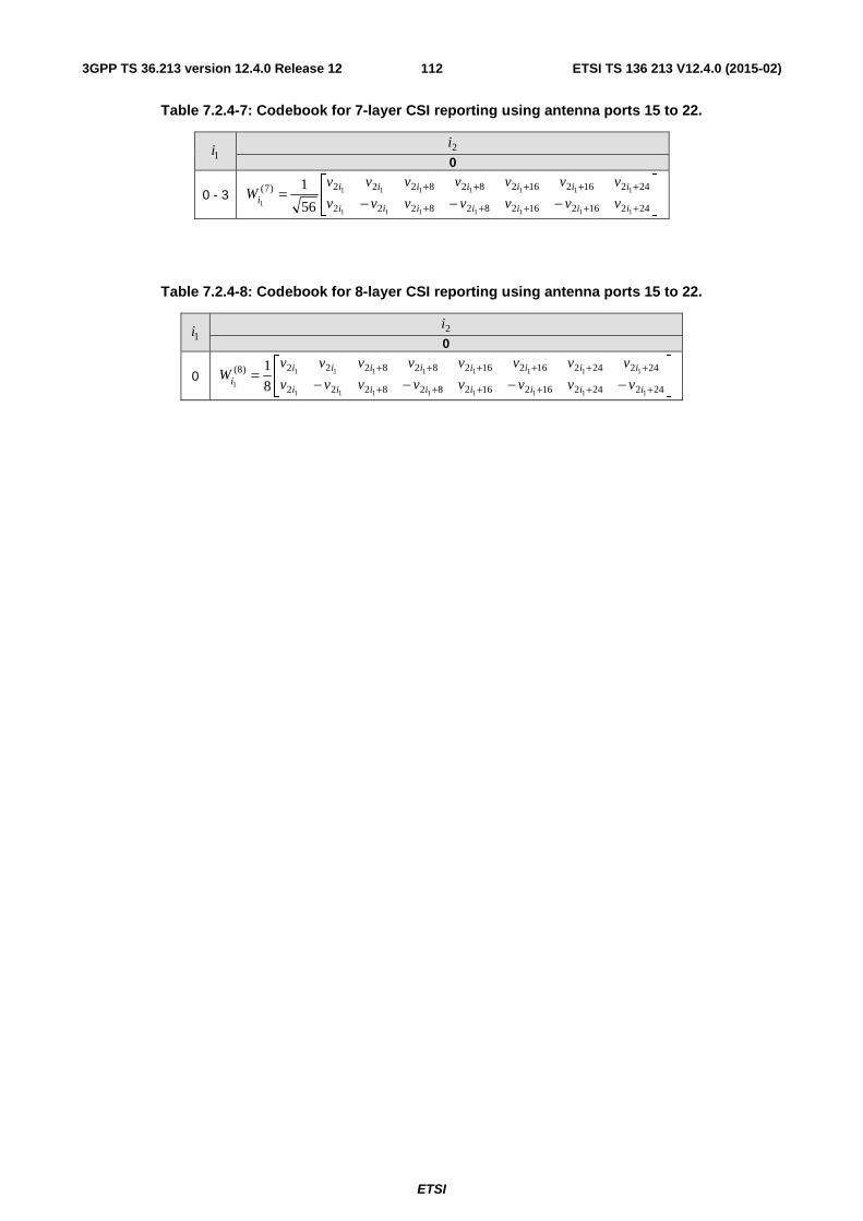
ETSI
ETSI TS 136 213 V12.4.0 (2015-02)1123GPP TS 36.213 version 12.4.0 Release 12
Table 7.2.4-7: Codebook for 7-layer CSI reporting using antenna ports 15 to 22.
1i 2i 0
0 - 3 ⎥⎦
⎤⎢⎣
⎡
−−−=
+++++
+++++
242162162828222
242162162828222)7(
1111111
1111111
1 56
1
iiiiiii
iiiiiiii vvvvvvv
vvvvvvvW
Table 7.2.4-8: Codebook for 8-layer CSI reporting using antenna ports 15 to 22.
1i 2i 0
0 ⎥⎦
⎤⎢⎣
⎡
−−−−=
++++++
++++++
242242162162828222
242242162162828222)8(
11111111
11111111
1 8
1
iiiiiiii
iiiiiiiii vvvvvvvv
vvvvvvvvW
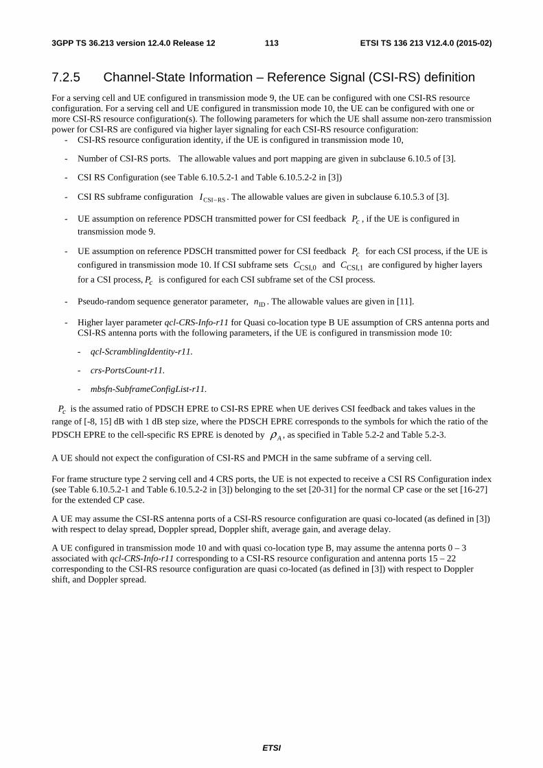
ETSI
ETSI TS 136 213 V12.4.0 (2015-02)1133GPP TS 36.213 version 12.4.0 Release 12
7.2.5 Channel-State Information – Reference Signal (CSI-RS) definition
For a serving cell and UE configured in transmission mode 9, the UE can be configured with one CSI-RS resource configuration. For a serving cell and UE configured in transmission mode 10, the UE can be configured with one or more CSI-RS resource configuration(s). The following parameters for which the UE shall assume non-zero transmission power for CSI-RS are configured via higher layer signaling for each CSI-RS resource configuration:
- CSI-RS resource configuration identity, if the UE is configured in transmission mode 10,
- Number of CSI-RS ports. The allowable values and port mapping are given in subclause 6.10.5 of [3].
- CSI RS Configuration (see Table 6.10.5.2-1 and Table 6.10.5.2-2 in [3])
- CSI RS subframe configuration RSCSI−I . The allowable values are given in subclause 6.10.5.3 of [3].
- UE assumption on reference PDSCH transmitted power for CSI feedback cP , if the UE is configured in
transmission mode 9.
- UE assumption on reference PDSCH transmitted power for CSI feedback cP for each CSI process, if the UE is
configured in transmission mode 10. If CSI subframe sets CSI,0C and CSI,1C are configured by higher layers
for a CSI process, cP is configured for each CSI subframe set of the CSI process.
- Pseudo-random sequence generator parameter, IDn . The allowable values are given in [11].
- Higher layer parameter qcl-CRS-Info-r11 for Quasi co-location type B UE assumption of CRS antenna ports and CSI-RS antenna ports with the following parameters, if the UE is configured in transmission mode 10:
- qcl-ScramblingIdentity-r11.
- crs-PortsCount-r11.
- mbsfn-SubframeConfigList-r11.
cP is the assumed ratio of PDSCH EPRE to CSI-RS EPRE when UE derives CSI feedback and takes values in the
range of [-8, 15] dB with 1 dB step size, where the PDSCH EPRE corresponds to the symbols for which the ratio of the
PDSCH EPRE to the cell-specific RS EPRE is denoted by Aρ , as specified in Table 5.2-2 and Table 5.2-3.
A UE should not expect the configuration of CSI-RS and PMCH in the same subframe of a serving cell. For frame structure type 2 serving cell and 4 CRS ports, the UE is not expected to receive a CSI RS Configuration index (see Table 6.10.5.2-1 and Table 6.10.5.2-2 in [3]) belonging to the set [20-31] for the normal CP case or the set [16-27] for the extended CP case.
A UE may assume the CSI-RS antenna ports of a CSI-RS resource configuration are quasi co-located (as defined in [3]) with respect to delay spread, Doppler spread, Doppler shift, average gain, and average delay.
A UE configured in transmission mode 10 and with quasi co-location type B, may assume the antenna ports 0 – 3 associated with qcl-CRS-Info-r11 corresponding to a CSI-RS resource configuration and antenna ports 15 – 22 corresponding to the CSI-RS resource configuration are quasi co-located (as defined in [3]) with respect to Doppler shift, and Doppler spread.
ETSI
ETSI TS 136 213 V12.4.0 (2015-02)1143GPP TS 36.213 version 12.4.0 Release 12
7.2.6 Channel-State Information – Interference Measurement (CSI-IM) Resource definition
For a serving cell and UE configured in transmission mode 10, the UE can be configured with one or more CSI-IM resource configuration(s). The following parameters are configured via higher layer signaling for each CSI-IM resource configuration:
- Zero-power CSI RS Configuration (see Table 6.10.5.2-1 and Table 6.10.5.2-2 in [3])
- Zero-power CSI RS subframe configuration RSCSI−I . The allowable values are given in subclause 6.10.5.3 of
[3].
For a serving cell, if a UE is not configured with the higher layer parameter csi-SubframePatternConfig-r12, the UE is not expected to receive CSI-IM resource configuration(s) that are not all completely overlapping with one zero-power CSI-RS resource configuration which can be configured for the UE.
A UE is not expected to receive a CSI-IM resource configuration that is not completely overlapping with one of the zero-power CSI-RS resource configurations defined in subclause 7.2.7.
For a serving cell, if a UE is not configured with CSI subframe sets CSI,0C and CSI,1C for any CSI process, and the
UE is configured with four CSI-IM resources, then the UE is not expected to be configured with CSI processes that are associated with all of the four CSI-IM resources.
A UE should not expect the configuration of CSI-IM resource and PMCH in the same subframe of a serving cell.
7.2.7 Zero Power CSI-RS Resource definition
For a serving cell and UE configured in transmission mode 1-9 and UE not configured with csi-SubframePatternConfig-r12 for the serving cell, the UE can be configured with one zero-power CSI-RS resource configuration. For a serving cell and UE configured in transmission mode 1-9 and UE configured with csi-SubframePatternConfig-r12 for the serving cell, the UE can be configured with up to two zero-power CSI-RS resource configurations. For a serving cell and UE configured in transmission mode 10, the UE can be configured with one or more zero-power CSI-RS resource configuration(s).
For a serving cell, the UE can be configured with up to 5 additional zero-power CSI-RS resource configurations according to the higher layer parameter ds-ZeroTxPowerCSI-RS-r12.
The following parameters are configured via higher layer signaling for each zero-power CSI-RS resource configuration:
- Zero-power CSI RS Configuration list (16-bit bitmap ZeroPowerCSI-RS in [3])
- Zero-power CSI RS subframe configuration RSCSI−I . The allowable values are given in subclause 6.10.5.3 of
[3].
A UE should not expect the configuration of zero-power CSI-RS and PMCH in the same subframe of a serving cell.
For frame structure type 1 serving cell, the UE is not expected to receive the 16-bit bitmap ZeroPowerCSI-RS with any one of the 6 LSB bits set to 1 for the normal CP case, or with any one of the 8 LSB bits set to 1 for the extended CP case.
For frame structure type 2 serving cell and 4 CRS ports, the UE is not expected to receive the 16-bit bitmap ZeroPowerCSI-RS with any one of the 6 LSB bits set to 1 for the normal CP case, or with any one of the 8 LSB bits set to 1 for the extended CP case.
7.3 UE procedure for reporting HARQ-ACK If each of the serving cell(s) configured for the UE has frame structure type 1, the UE procedure for HARQ-ACK reporting for frame structure type 1 is given in subclause 7.3.1.
If each of the serving cell(s) configured for the UE has frame structure type 2, the UE procedure for HARQ-ACK reporting for frame structure type 2 is given in subclause 7.3.2.
ETSI
ETSI TS 136 213 V12.4.0 (2015-02)1153GPP TS 36.213 version 12.4.0 Release 12
If the UE is configured with more than one serving cell, and if the frame structure type of any two configured serving cells is different, and if the primary cell is frame structure type 1, UE procedure for HARQ-ACK reporting is given in subclause 7.3.3.
If the UE is configured for more than one serving cell, and if the frame structure type of any two configured serving cells is different, and if the primary cell is frame structure type 2, UE procedure for HARQ-ACK reporting is given in subclause 7.3.4.
7.3.1 FDD HARQ-ACK reporting procedure
For FDD with PUCCH format 1a/1b transmission, when both HARQ-ACK and SR are transmitted in the same sub-frame, a UE shall transmit the HARQ-ACK on its assigned HARQ-ACK PUCCH format 1a/1b resource for a negative SR transmission and transmit the HARQ-ACK on its assigned SR PUCCH resource for a positive SR transmission.
For FDD with PUCCH format 1b with channel selection, when both HARQ-ACK and SR are transmitted in the same sub-frame a UE shall transmit the HARQ-ACK on its assigned HARQ-ACK PUCCH resource with channel selection as defined in subclause 10.1.2.2.1 for a negative SR transmission and transmit one HARQ-ACK bit per serving cell on its assigned SR PUCCH resource for a positive SR transmission according to the following:
− if only one transport block or a PDCCH/EPDCCH indicating downlink SPS release is detected on a serving cell, the HARQ-ACK bit for the serving cell is the HARQ-ACK bit corresponding to the transport block or the PDCCH/EPDCCH indicating downlink SPS release;
− if two transport blocks are received on a serving cell, the HARQ-ACK bit for the serving cell is generated by spatially bundling the HARQ-ACK bits corresponding to the transport blocks;
− if neither PDSCH transmission for which HARQ-ACK response shall be provided nor PDCCH/EPDCCH indicating downlink SPS release is detected for a serving cell, the HARQ-ACK bit for the serving cell is set to NACK;
and the HARQ-ACK bits for the primary cell and the secondary cell are mapped to )0(b and )1(b , respectively, where
)0(b and )1(b are specified in subclause 5.4.1 in [3].
For FDD, when a PUCCH format 3 transmission of HARQ-ACK coincides with a sub-frame configured to the UE by higher layers for transmission of a scheduling request, the UE shall multiplex HARQ-ACK and SR bits on HARQ-ACK PUCCH resource as defined in subclause 5.2.3.1 in [4], unless the HARQ-ACK corresponds to a PDSCH transmission on the primary cell only or a PDCCH/EPDCCH indicating downlink SPS release on the primary cell only, in which case the SR shall be transmitted as for FDD with PUCCH format 1a/1b.
For FDD and for a PUSCH transmission, a UE shall not transmit HARQ-ACK on PUSCH in subframe n if the UE does not receive PDSCH or PDCCH indicating downlink SPS release in subframe n-4.
When only a positive SR is transmitted, a UE shall use PUCCH Format 1 for the SR resource as defined in subclause 5.4.1 in [3].
7.3.2 TDD HARQ-ACK reporting procedure
For TDD and a UE not configured with the parameter EIMTA-MainConfigServCell-r12 for any serving cell, if the UE is configured with one serving cell, or if the UE is configured with more than one serving cell and the TDD UL/DL configuration of all the configured serving cells is the same, UE procedure for reporting HARQ-ACK is given in subclause 7.3.2.1.
For TDD, if a UE is configured with more than one serving cell and the TDD UL/DL configuration of at least two configured serving cells is not the same, or if the UE is configured with the parameter EIMTA-MainConfigServCell-r12 for at least one serving cell, UE procedure for reporting HARQ-ACK is given in subclause 7.3.2.2.
When only a positive SR is transmitted, a UE shall use PUCCH Format 1 for the SR resource as defined in subclause 5.4.1 in [3].
ETSI
ETSI TS 136 213 V12.4.0 (2015-02)1163GPP TS 36.213 version 12.4.0 Release 12
7.3.2.1 TDD HARQ-ACK reporting procedure for same UL/DL configuration
For TDD, the UE shall upon detection of a PDSCH transmission or a PDCCH/EPDCCH indicating downlink SPS release (defined in subclause 9.2) within subframe(s) kn − , where Kk ∈ and K is defined in Table 10.1.3.1-1 intended for the UE and for which HARQ-ACK response shall be provided, transmit the HARQ-ACK response in UL subframe n.
For TDD, when PUCCH format 3 is configured for transmission of HARQ-ACK, for special subframe configurations 0 and 5 with normal downlink CP or configurations 0 and 4 with extended downlink CP in a serving cell, shown in table 4.2-1 [3], the special subframe of the serving cell is excluded from the HARQ-ACK codebook size determination. In this case, if the serving cell is the primary cell, there is no PDCCH/EPDCCH indicating downlink SPS release in the special subframe.
For TDD UL/DL configurations 1-6 and one configured serving cell, if the UE is not configured with PUCCH format 3,
the value of the Downlink Assignment Index (DAI) in DCI format 0/4, ULDAIV , detected by the UE according to Table
7.3-X in subframe 'kn − , where 'k is defined in Table 7.3-Y, represents the total number of subframes with PDSCH transmissions and with PDCCH/EPDCCH indicating downlink SPS release to the corresponding UE within all the
subframe(s) kn − , where Kk ∈ . The value ULDAIV includes all PDSCH transmission with and without corresponding
PDCCH/EPDCCH within all the subframe(s) kn − . In case neither PDSCH transmission, nor PDCCH/EPDCCH indicating the downlink SPS resource release is intended to the UE, the UE can expect that the value of the DAI in DCI
format 0/4, ULDAIV , if transmitted, is set to 4.
For TDD UL/DL configuration 1-6 and a UE configured with more than one serving cell, or for TDD UL/DL
configuration 1-6 and a UE configured with one serving cell and PUCCH format 3, a value ULDAIW is determined by the
Downlink Assignment Index (DAI) in DCI format 0/4 according to Table 7.3-Z in subframe 'kn − , where 'k is defined in Table 7.3-Y. In case neither PDSCH transmission, nor PDCCH/EPDCCH indicating the downlink SPS
resource release is intended to the UE, the UE can expect that the value of ULDAIW is set to 4 by the DAI in DCI format
0/4 if transmitted.
For TDD UL/DL configurations 1-6, the value of the DAI in DCI format 1/1A/1B/1D/2/2A/2B/2C/2D denotes the accumulative number of PDCCH/EPDCCH (s) with assigned PDSCH transmission(s) and PDCCH/EPDCCH indicating downlink SPS release up to the present subframe within subframe(s) kn − of each configured serving cell, where
Kk ∈ , and shall be updated from subframe to subframe. Denote DLcDAIV , as the value of the DAI in PDCCH/EPDCCH
with DCI format 1/1A/1B/1D/2/2A/2B/2C/2D detected by the UE according to Table 7.3-X in subframe mkn − in
serving cell c , where mk is the smallest value in the set K (defined in Table 10.1.3.1-1) such that the UE detects a
DCI format 1/1A/1B/1D/2/2A/2B/2C/2D. When configured with one serving cell, the subscript of c in DLcDAIV , can be
omitted.
For all TDD UL/DL configurations, denote cDAIU , as the total number of PDCCH/EPDCCH (s) with assigned
PDSCH transmission(s) and PDCCH/EPDCCH indicating downlink SPS release detected by the UE within the subframe(s) kn − in serving cell c , where Kk ∈ . When configured with one serving cell, the subscript of c in
cDAIU , can be omitted. Denote SPSN , which can be zero or one, as the number of PDSCH transmissions without a
corresponding PDCCH/EPDCCH within the subframe(s) kn − , where Kk ∈ .
For TDD HARQ-ACK bundling or HARQ-ACK multiplexing and a subframe n with 1=M , the UE shall generate one or two HARQ-ACK bits by performing a logical AND operation per codeword across M downlink and special
subframes associated with a single UL subframe, of all the corresponding SPSDAI NU + individual PDSCH
transmission HARQ-ACKs and individual ACK in response to received PDCCH/EPDCCH indicating downlink SPS release, where M is the number of elements in the set K defined in Table 10.1.3.1-1. The UE shall detect if at least one downlink assignment has been missed, and for the case that the UE is transmitting on PUSCH the UE shall also
determine the parameter bundledN .
- For TDD UL/DL configuration 0, bundledN shall be 1 if the UE detects the PDSCH transmission with or
without corresponding PDCCH/EPDCCH, or detects PDCCH indicating downlink SPS release within the
ETSI
ETSI TS 136 213 V12.4.0 (2015-02)1173GPP TS 36.213 version 12.4.0 Release 12
subframe kn − , where Kk ∈ . The UE shall not transmit HARQ-ACK on PUSCH if the UE does not receive
PDSCH or PDCCH indicating downlink SPS release within the subframe(s) kn − , where Kk ∈ .
- For the case that the UE is not transmitting on PUSCH in subframe n and TDD UL/DL configurations 1-6, if
0>DAIU and ( ) 14mod1 +−≠ DAIDL
DAI UV , the UE detects that at least one downlink assignment has been
missed.
- For the case that the UE is transmitting on PUSCH and the PUSCH transmission is adjusted based on a detected PDCCH/EPDCCH with DCI format 0/4 intended for the UE and TDD UL/DL configurations 1-6, if
( ) 14mod1 +−+≠ SPSDAIULDAI NUV the UE detects that at least one downlink assignment has been missed
and the UE shall generate NACK for all codewords where bundledN is determined by the UE as
2bundled += ULDAIVN . If the UE does not detect any downlink assignment missing, bundledN is determined by
the UE as ULDAIVN =bundled . UE shall not transmit HARQ-ACK if 0=+ SPSDAI NU and 4=UL
DAIV .
- For the case that the UE is transmitting on PUSCH, and the PUSCH transmission is not based on a detected PDCCH/EPDCCH with DCI format 0/4 intended for the UE and TDD UL/DL configurations 1-6, if
0>DAIU and ( ) 14mod1 +−≠ DAIDL
DAI UV , the UE detects that at least one downlink assignment has been
missed and the UE shall generate NACK for all codewords. The UE determines )(bundled SPSDAI NUN +=
as the number of assigned subframes. The UE shall not transmit HARQ-ACK if 0=+ SPSDAI NU .
For TDD, when PUCCH format 3 is configured for transmission of HARQ-ACK, the HARQ-ACK feedback bits ACK
OcACKc
ACKc ACK
cooo
1,1,0, ,..., −
for the c-th serving cell configured by RRC are constructed as follows, where c≥0,
DLc
ACKc BO = if transmission mode configured in the c-th serving cell supports one transport block or spatial HARQ-
ACK bundling is applied and DLc
ACKc BO 2= otherwise, where DL
cB is the number of downlink and special subframes
for which the UE needs to feedback HARQ-ACK bits for the c-th serving cell.
- For the case that the UE is transmitting on PUCCH, MBDLc = where M is the number of elements in the set
K defined in Table 10.1.3.1-1 associated with subframe n and the set K does not include a special subframe of configurations 0 and 5 with normal downlink CP or of configurations 0 and 4 with extended downlink CP;
otherwise 1−= MBDLc .
- For TDD UL/DL configuration 0 or for a PUSCH transmission not adjusted based on a detected
PDCCH/EPDCCH with DCI format 0/4, the UE shall assume MBDLc = where M is the number of elements
in the set K defined in Table 10.1.3.1-1 associated with subframe n and the set K does not include a special subframe of configurations 0 and 5 with normal downlink CP or of configurations 0 and 4 with extended
downlink CP; otherwise 1−= MBDLc . The UE shall not transmit HARQ-ACK on PUSCH if the UE does not
receive PDSCH or PDCCH/EPDCCH indicating downlink SPS release in subframe(s) kn − , where Kk ∈ .
- For TDD UL/DL configurations {1, 2, 3, 4, 6} and a PUSCH transmission adjusted based on a detected
PDCCH/EPDCCH with DCI format 0/4, the UE shall assume ULDAI
DLc WB = . The UE shall not transmit HARQ-
ACK on PUSCH if the UE does not receive PDSCH or PDCCH/EPDCCH indicating downlink SPS release in
subframe(s) kn − where Kk ∈ and 4=ULDAIW .
- For TDD UL/DL configurations 5 and a PUSCH transmission adjusted based on a detected PDCCH/EPDCCH
with DCI format 0/4, the UE shall assume ( )4 / 4DL UL ULc DAI DAIB W U W⎡ ⎤= + −⎢ ⎥ , where U denotes the
maximum value of cU among all the configured serving cells, cU is the total number of received PDSCHs and
PDCCH/EPDCCH indicating downlink SPS release in subframe(s) kn − on the c-th serving cell, Kk ∈ . The UE shall not transmit HARQ-ACK on PUSCH if the UE does not receive PDSCH or PDCCH/EPDCCH
indicating downlink SPS release in subframe(s) kn − where Kk ∈ and 4=ULDAIW .
ETSI
ETSI TS 136 213 V12.4.0 (2015-02)1183GPP TS 36.213 version 12.4.0 Release 12
For TDD, when PUCCH format 3 is configured for transmission of HARQ-ACK,
- for TDD UL/DL configurations 1-6, the HARQ-ACK for a PDSCH transmission with a corresponding PDCCH/EPDCCH or for a PDCCH/EPDCCH indicating downlink SPS release in subframe kn − is
associated with ACKkDAIco 1)(, − if transmission mode configured in the c-th serving cell supports one transport
block or spatial HARQ-ACK bundling is applied, or associated with ACKkDAIco 2)(2, − and ACK
kDAIco 1)(2, −
otherwise, where DAI(k) is the value of DAI in DCI format 1A/1B/1D/1/2/2A/2B/2C/2D detected in subframe
kn − , ACKkDAIco 2)(2, − and ACK
kDAIco 1)(2, − are the HARQ-ACK feedback for codeword 0 and codeword 1,
respectively. For the case with 0>SPSN , the HARQ-ACK associated with a PDSCH transmission without a
corresponding PDCCH/EPDCCH is mapped to ACKOc ACK
co
1, − The HARQ-ACK feedback bits without any
detected PDSCH transmission or without detected PDCCH/EPDCCH indicating downlink SPS release are set to NACK;
- for TDD UL/DL configuration 0, the HARQ-ACK for a PDSCH transmission or for a PDCCH/EPDCCH
indicating downlink SPS release in subframe kn − is associated with ,0ACKco if transmission mode configured
in the c-th serving cell supports one transport block or associated with ,0ACKco and ,1
ACKco otherwise, where
,0ACKco and ,1
ACKco are the HARQ-ACK feedback for codeword 0 and codeword 1, respectively. The HARQ-
ACK feedback bits without any detected PDSCH transmission or without detected PDCCH/EPDCCH indicating downlink SPS release are set to NACK.
For TDD when format 1b with channel selection is configured for transmission of HARQ-ACK and for 2 configured
serving cells, the HARQ-ACK feedback bits ACK
O
ACKACKACKooo
110 ,..., − on PUSCH are constructed as follows.
- For TDD UL/DL configuration 0, ACKjo = HARQ-ACK(j), 10 −≤≤ Aj as defined in subclause 10.1.3.2.1. The
UE shall not transmit HARQ-ACK on PUSCH if the UE does not receive PDSCH or PDCCH/EPDCCH indicating downlink SPS release in subframe(s) kn − where Kk ∈ .
- For TDD UL/DL configurations {1, 2, 3, 4, 6} and a PUSCH transmission adjusted based on a detected
PDCCH/EPDCCH with DCI format 0/4 with ULDAIW =1 or 2, ACK
jo is determined as if PUCCH format 3 is
configured for transmission of HARQ-ACK, except that spatial HARQ-ACK bundling across multiple codewords within a downlink or special subframe is performed for all serving cells configured with a downlink
transmission mode that supports up to two transport blocks in case ULDAIW =2.
- For TDD UL/DL configurations {1, 2, 3, 4, 6} and a PUSCH transmission adjusted based on a detected
PDCCH/EPDCCH with DCI format 0/4 with ULDAIW =3 or 4, )( jooACK
j = , 30 ≤≤ j as defined in Table
10.1.3.2-5 or in Table 10.1.3.2-6 respectively, where the value of M is replaced by ULDAIW . The UE shall not
transmit HARQ-ACK on PUSCH if the UE does not receive PDSCH or PDCCH/EPDCCH indicating downlink
SPS release in subframe(s) kn − where Kk ∈ and 4=ULDAIW .
- For TDD UL/DL configurations {1, 2, 3, 4, 6} and a PUSCH transmission not adjusted based on a detected
PDCCH/EPDCCH with DCI format 0/4 and a subframe n with M =1 or 2, ACKjo = HARQ-ACK(j),
10 −≤≤ Aj as defined in subclause 10.1.3.2.1. The UE shall not transmit HARQ-ACK on PUSCH if the UE
does not receive PDSCH or PDCCH/EPDCCH indicating downlink SPS release in subframe(s) kn − where Kk ∈ .
- For TDD UL/DL configurations {1, 2, 3, 4, 6} and a PUSCH transmission not adjusted based on a detected
PDCCH/EPDCCH with DCI format 0/4 and a subframe n with M =3 or 4, )( jooACKj = , 30 ≤≤ j as
defined in Table 10.1.3.2-5 or in Table 10.1.3.2-6 respectively. The UE shall not transmit HARQ-ACK on PUSCH if the UE does not receive PDSCH or PDCCH/EPDCCH indicating downlink SPS release in subframe(s) kn − where Kk ∈ .
ETSI
ETSI TS 136 213 V12.4.0 (2015-02)1193GPP TS 36.213 version 12.4.0 Release 12
For TDD HARQ-ACK bundling, when the UE is configured by transmission mode 3, 4, 8, 9 or 10 defined in subclause 7.1 and HARQ-ACK bits are transmitted on PUSCH, the UE shall always generate 2 HARQ-ACK bits assuming both codeword 0 and 1 are enabled. For the case that the UE detects only the PDSCH transmission associated with codeword 0 within the bundled subframes, the UE shall generate NACK for codeword 1.
Table 7.3-X: Value of Downlink Assignment Index
DAI MSB, LSB
ULDAIV or DL
DAIV Number of subframes with PDSCH transmission and
with PDCCH/EPDCCH indicating DL SPS release 0,0 1 1 or 5 or 9 0,1 2 2 or 6 or 10 1,0 3 3 or 7 1,1 4 0 or 4 or 8
Table 7.3-Y: Uplink association index k' for TDD
TDD UL/DL Configuration
subframe number n 0 1 2 3 4 5 6 7 8 9
1 6 4 6 4 2 4 4 3 4 4 4 4 4 4 5 4 6 7 7 5 7 7
Table 7.3-Z: Value of ULDAIW determined by the DAI field in DCI format 0/4
DAI MSB, LSB
ULDAIW
0,0 1 0,1 2 1,0 3 1,1 4
For TDD HARQ-ACK multiplexing and a subframe n with 1>M , spatial HARQ-ACK bundling across multiple codewords within a downlink or special subframe is performed by a logical AND operation of all the corresponding individual HARQ-ACKs. In case the UE is transmitting on PUSCH, the UE shall determine the number of HARQ-ACK
feedback bits ACKO and the HARQ-ACK feedback bits ACKno , 1,,0 −= ACKOn K to be transmitted in
subframe n.
- If the PUSCH transmission is adjusted based on a detected PDCCH/EPDCCH with DCI format 0/4 intended for
the UE, then ULDAI
ACK VO = unless 4=ULDAIV and 0=+ SPSDAI NU in which case the UE shall not
transmit HARQ-ACK. The spatially bundled HARQ-ACK for a PDSCH transmission with a corresponding PDCCH/EPDCCH or for a PDCCH/EPDCCH indicating downlink SPS release in subframe kn − is associated
with ACKkDAIo 1)( − where DAI(k) is the value of DAI in DCI format 1A/1B/1D/1/2/2A/2B/2C/2D detected in
subframe kn − . For the case with 0>SPSN , the HARQ-ACK associated with a PDSCH transmission
without a corresponding PDCCH/EPDCCH is mapped to ACK
O ACKo1− . The HARQ-ACK feedback bits without any
detected PDSCH transmission or without detected PDCCH/EPDCCH indicating downlink SPS release are set to NACK.
- If the PUSCH transmission is not adjusted based on a detected PDCCH/EPDCCH with DCI format 0/4 intended
for the UE, MO ACK = , and ACKio is associated with the spatially bundled HARQ-ACK for downlink or
ETSI
ETSI TS 136 213 V12.4.0 (2015-02)1203GPP TS 36.213 version 12.4.0 Release 12
special subframe ikn − , where Kki ∈ . The HARQ-ACK feedback bits without any detected PDSCH
transmission or without detected PDCCH/EPDCCH indicating downlink SPS release are set to NACK. The UE shall not transmit HARQ-ACK if 0=+ SPSDAI NU .
For TDD when a PUCCH format 3 transmission of HARQ-ACK coincides with a sub-frame configured to the UE by higher layers for transmission of a scheduling request, the UE shall multiplex HARQ-ACK and SR bits on HARQ-ACK PUCCH resource as defined in subclause 5.2.3.1 in [4], unless the HARQ-ACK corresponds to one of the following cases
- a single PDSCH transmission only on the primary cell indicated by the detection of a corresponding PDCCH/EPDCCH in subframe
mkn − , where Kkm ∈ , and for TDD UL/DL configurations 1-6 the DAI value
in the PDCCH/EPDCCH is equal to '1' (defined in Table 7.3-X), or a PDCCH/EPDCCH indicating downlink SPS release (defined in subclause 9.2) in subframe
mkn − , where Kkm ∈ , and for TDD UL/DL configurations
1-6 the DAI value in the PDCCH/EPDCCH is equal to '1', or
- a single PDSCH transmission only on the primary cell where there is not a corresponding PDCCH/EPDCCH detected within subframe(s) kn − , where Kk ∈ and no PDCCH/EPDCCH indicating downlink SPS release (defined in subclause 9.2) within subframe(s) kn − , where Kk ∈ , or
- a PDSCH transmission only on the primary cell where there is not a corresponding PDCCH/EPDCCH detected within subframe(s) kn − , where Kk ∈ and an additional PDSCH transmission only on the primary cell indicated by the detection of a corresponding PDCCH/EPDCCH in subframe
mkn − , where Kkm ∈ with the
DAI value in the PDCCH/EPDCCH equal to '1' (defined in Table 7.3-X) or a PDCCH/EPDCCH indicating downlink SPS release (defined in subclause 9.2) in the subframe
mkn − , where Kkm ∈ with the DAI value in
the PDCCH/EPDCCH equal to '1',
in which case the UE shall transmit the HARQ-ACK and scheduling request according to the procedure for PUCCH format 1b with channel selection in TDD.
For TDD when the UE is configured with HARQ-ACK bundling, HARQ-ACK multiplexing or PUCCH format 1b with channel selection, and when both HARQ-ACK and SR are transmitted in the same sub-frame, a UE shall transmit the bundled HARQ-ACK or the multiple HARQ-ACK responses (according to subclause 10.1) on its assigned HARQ-ACK PUCCH resources for a negative SR transmission. For a positive SR, the UE shall transmit )1(),0( bb on its
assigned SR PUCCH resource using PUCCH format 1b according to subclause 5.4.1 in [3]. The value of )1(),0( bb are
generated according to Table 7.3-1 from the ∑−
=
+1
0
,
DLcellsN
c
cDAISPS UN HARQ-ACK responses including ACK in response
to PDCCH/EPDCCH indicating downlink SPS release by spatial HARQ-ACK bundling across multiple codewords
within each PDSCH transmission for all serving cells DLcellsN . For TDD UL/DL configurations 1-6, if 0
1
0, >∑
−
=
DLcellsN
ccDAIU
and ( ) 14mod1,, +−≠ cDAIDL
cDAI UV for a serving cell c, the UE detects that at least one downlink assignment has been
missed.
ETSI
ETSI TS 136 213 V12.4.0 (2015-02)1213GPP TS 36.213 version 12.4.0 Release 12
Table 7.3-1: Mapping between multiple HARQ-ACK responses and )1(),0( bb
Number of ACK among multiple ( ∑−
=
+1
0
,
DLcellsN
c
cDAISPS UN ) HARQ-ACK responses )1(),0( bb
0 or None (UE detect at least one DL assignment is missed) 0, 0 1 1, 1 2 1, 0 3 0, 1 4 1, 1 5 1, 0 6 0, 1 7 1, 1 8 1, 0 9 0, 1
For TDD if the parameter simultaneousAckNackAndCQI provided by higher layers is set TRUE, and if the UE is configured with HARQ-ACK bundling, HARQ-ACK multiplexing or PUCCH format 1b with channel selection, and if the UE receives PDSCH and/or PDCCH/EPDCCH indicating downlink SPS release only on the primary cell within subframe(s) kn − , where Kk ∈ , a UE shall transmit the CSI and )1(),0( bb using PUCCH format 2b for normal CP
or PUCCH format 2 for extended CP, according to subclause 5.2.3.4 in [4] with 10 ,aa ′′′′ replaced by )1(),0( bb . The
value of )1(),0( bb are generated according to Table 7.3-1 from the ∑−
=
+1
0
,
DLcellsN
c
cDAISPS UN HARQ-ACK responses
including ACK in response to PDCCH/EPDCCH indicating downlink SPS release by spatial HARQ-ACK bundling
across multiple codewords within each PDSCH transmission for all serving cells DLcellsN . For TDD UL/DL
configurations 1-6, if 0
1
0, >∑
−
=
DLcellsN
ccDAIU and ( ) 14mod1,, +−≠ cDAI
DLcDAI UV for a serving cell c, the UE detects that at
least one downlink assignment has been missed.
For TDD if the parameter simultaneousAckNackAndCQI provided by higher layers is set TRUE, and if the UE is configured with PUCCH format 1b with channel selection and receives at least one PDSCH on the secondary cell within subframe(s) kn − , where Kk ∈ , the UE shall drop the CSI and transmit HARQ-ACK according to subclause 10.1.3.
For TDD and a UE is configured with PUCCH format 3,
if the parameter simultaneousAckNackAndCQI is set TRUE and if the UE receives,
- a single PDSCH transmission only on the primary cell indicated by the detection of a corresponding PDCCH/EPDCCH in subframe
mkn − , where Kkm ∈ , and for TDD UL/DL configurations 1-6 the DAI value
in the PDCCH/EPDCCH is equal to '1' (defined in Table 7.3-X), or a PDCCH/EPDCCH indicating downlink SPS release (defined in subclause 9.2) in subframe
mkn − , where Kkm ∈ , and for TDD UL/DL configurations
1-6 the DAI value in the PDCCH/EPDCCH is equal to '1', or
- a single PDSCH transmission only on the primary cell where there is not a corresponding PDCCH/EPDCCH detected within subframe(s) kn − , where Kk ∈ and no PDCCH/EPDCCH indicating downlink SPS release (defined in subclause 9.2) within subframe(s) kn − , where Kk ∈ ,
then the UE shall transmit the CSI and HARQ-ACK using PUCCH format 2/2a/2b according to subclause 5.2.3.4 in [4]; else if
- the parameter simultaneousAckNackAndCQI-Format3-r11 is set TRUE and if PUCCH format 3 resource is determined according to subclause 10.1.3.1 or subclause 10.1.3.2.2 and
o if the total number of bits in the subframe corresponding to HARQ-ACKs, SR (if any), and the CSI is not larger than 22, or
ETSI
ETSI TS 136 213 V12.4.0 (2015-02)1223GPP TS 36.213 version 12.4.0 Release 12
o if the total number of bits in the subframe corresponding to spatially bundled HARQ-ACKs, SR (if any), and the CSI is not larger than 22
then the UE shall transmit the HARQ-ACKs, SR (if any) and the CSI using the determined PUCCH format 3 resource according to [4];
else,
the UE shall drop the CSI and transmit the HARQ-ACK according to subclause 10.1.3.
7.3.2.2 TDD HARQ-ACK reporting procedure for different UL/DL configurations
For a configured serving cell, the DL-reference UL/DL configuration as defined in subclause 10.2 is referred to as the "DL-reference UL/DL configuration" in the rest of this subclause.
For a configured serving cell, if the DL-reference UL/DL configuration is 0, then the DAI in DCI format 1/1A/1B/1D/2/2A/2B/2C/2D is not used.
The UE shall upon detection of a PDSCH transmission or a PDCCH/EPDCCH indicating downlink SPS release
(defined in subclause 9.2) within subframe(s) kn − for serving cell c, where cKk ∈ intended for the UE and for
which HARQ-ACK response shall be provided, transmit the HARQ-ACK response in UL subframe n, wherein set
cK contains values of Kk ∈ such that subframe n-k corresponds to a downlink subframe or a special subframe for
serving cell c, where DL subframe or special subframe of serving cell c is according to the higher layer parameter eimta-HarqReferenceConfig-r12 if the UE is configured with the higher layer parameter EIMTA-MainConfigServCell-r12 for serving cell c; K defined in Table 10.1.3.1-1 (where "UL/DL configuration" in Table 10.1.3.1-1 refers to the DL-reference UL/DL configuration) is associated with subframe n.
cM is the number of elements in set
cK associated with subframe n for serving cell c.
For the remainder of this subclause cKK = .
If the UE is configured with the parameter EIMTA-MainConfigServCell-r12 for the primary cell, “UL/DL configuration of the primary cell” in the rest of this subclause refers to “DL-reference UL/DL configuration of the primary cell”.
When PUCCH format 3 is configured for transmission of HARQ-ACK, for special subframe configurations 0 and 5 with normal downlink CP or configurations 0 and 4 with extended downlink CP in a serving cell, shown in table 4.2-1 [3], the special subframe of the serving cell is excluded from the HARQ-ACK codebook size determination. In this case, if the serving cell is the primary cell, there is no PDCCH/EPDCCH indicating downlink SPS release in the special subframe.
If the UL-reference UL/DL configuration (defined in Sec 8.0) belongs to {1,2,3,4,5,6} for a serving cell, a value ULDAIW is determined by the Downlink Assignment Index (DAI) in DCI format 0/4 corresponding to a PUSCH on the
serving cell according to Table 7.3-Z in subframe 'kn − , where 'k is defined in Table 7.3-Y and the "TDD UL/DL Configuration" in Table 7.3-Y refers to the UL-reference UL/DL configuration (defined in subclause 8.0) for the serving cell. In case neither PDSCH transmission, nor PDCCH/EPDCCH indicating the downlink SPS resource release
is intended to the UE, the UE can expect that the value of ULDAIW is set to 4 by the DAI in DCI format 0/4 if transmitted.
If the DL-reference UL/DL configuration belongs to {1,2,3,4,5,6}, the value of the DAI in DCI format 1/1A/1B/1D/2/2A/2B/2C/2D denotes the accumulative number of PDCCH/EPDCCH (s) with assigned PDSCH transmission(s) and PDCCH/EPDCCH indicating downlink SPS release up to the present subframe within subframe(s)
kn − of each configured serving cell, where Kk ∈ , and shall be updated from subframe to subframe. Denote DLcDAIV ,
as the value of the DAI in PDCCH/EPDCCH with DCI format 1/1A/1B/1D/2/2A/2B/2C/2D detected by the UE
according to Table 7.3-X in subframe mkn − in serving cell c , where mk is the smallest value in the set K such
that the UE detects a DCI format 1/1A/1B/1D/2/2A/2B/2C/2D.
For all TDD UL/DL configurations, denote cDAIU , as the total number of PDCCH/EPDCCH (s) with assigned
PDSCH transmission(s) and PDCCH/EPDCCH indicating downlink SPS release detected by the UE within the
subframe(s) kn − in serving cell c , where Kk ∈ . Denote SPSN , which can be zero or one, as the number of
PDSCH transmissions without a corresponding PDCCH/EPDCCH within the subframe(s) kn − , where Kk ∈ .
ETSI
ETSI TS 136 213 V12.4.0 (2015-02)1233GPP TS 36.213 version 12.4.0 Release 12
If PUCCH format 3 is configured for transmission of HARQ-ACK, the HARQ-ACK feedback bits ACK
OcACKc
ACKc ACK
cooo
1,1,0, ,..., −
for the c-th serving cell configured by RRC are constructed as follows, where c≥0,
DLc
ACKc BO = if transmission mode configured in the c-th serving cell supports one transport block or spatial HARQ-
ACK bundling is applied and DLc
ACKc BO 2= otherwise, where DL
cB is the number of downlink and special subframes
for which the UE needs to feedback HARQ-ACK bits for the c-th serving cell.
- For the case that the UE is transmitting in subframe n on PUCCH or a PUSCH transmission not adjusted based on a detected DCI format 0/4 or a PUSCH transmission adjusted based on an associated detected DCI format 0/4
with UL-reference UL/DL configuration 0 (defined in Sec 8.0), then cDLc MB = . The UE shall not transmit
HARQ-ACK on PUSCH if the UE does not receive PDSCH or PDCCH/EPDCCH indicating downlink SPS release in subframe(s) kn − , where Kk ∈ .
- If DL-reference UL/DL configuration of each of the configured serving cells belongs to {0, 1, 2, 3, 4, 6} and for a PUSCH transmission in a subframe n adjusted based on a detected PDCCH/EPDCCH with DCI format 0/4 using UL-reference UL/DL configuration belonging to {1,2,3,4,5,6} (defined in Sec 8.0), the UE shall assume
( )cULDAI
DLc MWB ,min= . The UE shall not transmit HARQ-ACK on PUSCH if the UE does not receive
PDSCH or PDCCH/EPDCCH indicating downlink SPS release in subframe(s) kn − where Kk ∈ and
4=ULDAIW .
- If DL-reference UL/DL configuration of at least one configured serving cell belongs to {5} and for a PUSCH transmission adjusted based on an associated detected PDCCH/EPDCCH with DCI format 0/4 using UL-reference UL/DL configuration belonging to {1,2,3,4,5,6} (defined in Sec 8.0), the UE shall assume
( )⎡ ⎤( )cULDAI
ULDAI
DLc MWUWB ,44min −+= , where U denotes the maximum value of cU among all the
configured serving cells, cU is the total number of received PDSCHs and PDCCH/EPDCCH indicating
downlink SPS release in subframe(s) kn − for the c-th serving cell, Kk ∈ . The UE shall not transmit HARQ-ACK on PUSCH if the UE does not receive PDSCH or PDCCH/EPDCCH indicating downlink SPS release in
subframe(s) kn − where Kk ∈ and 4=ULDAIW .
When PUCCH format 3 is configured for transmission of HARQ-ACK,
- if DL-reference UL/DL configuration belongs to {1,2,3,4,5,6}, the HARQ-ACK for a PDSCH transmission with a corresponding PDCCH/EPDCCH or for a PDCCH/EPDCCH indicating downlink SPS release in
subframe kn − is associated with ACKkDAIco 1)(, − if transmission mode configured in the c-th serving cell
supports one transport block or spatial HARQ-ACK bundling is applied, or associated with ACKkDAIco 2)(2, − and
ACKkDAIco 1)(2, − otherwise, where DAI(k) is the value of DAI in DCI format 1A/1B/1D/1/2/2A/2B/2C/2D detected
in subframe kn − , ACKkDAIco 2)(2, − and ACK
kDAIco 1)(2, − are the HARQ-ACK feedback for codeword 0 and
codeword 1, respectively. For the case with 0>SPSN , the HARQ-ACK associated with a PDSCH
transmission without a corresponding PDCCH/EPDCCH is mapped to ACKOc ACK
co
1, − The HARQ-ACK feedback
bits without any detected PDSCH transmission or without detected PDCCH/EPDCCH indicating downlink SPS release are set to NACK;
- if DL-reference UL/DL configuration is 0, the HARQ-ACK for a PDSCH transmission or for a
PDCCH/EPDCCH indicating downlink SPS release in subframe kn − is associated with ,0ACKco if transmission
mode configured in the c-th serving cell supports one transport block or spatial HARQ-ACK bundling is applied,
or associated with ,0ACKco and ,1
ACKco otherwise, where ,0
ACKco and ,1
ACKco are the HARQ-ACK feedback for
codeword 0 and codeword 1, respectively. The HARQ-ACK feedback bits without any detected PDSCH transmission or without detected PDCCH/EPDCCH indicating downlink SPS release are set to NACK.
ETSI
ETSI TS 136 213 V12.4.0 (2015-02)1243GPP TS 36.213 version 12.4.0 Release 12
If DL-reference UL/DL configuration of each of the serving cells belongs to {0,1,2,3,4,6} and if PUCCH format 1b with channel selection is configured for transmission of HARQ-ACK and for two configured serving cells, the HARQ-
ACK feedback bits ACK
O
ACKACKACKooo
110 ,..., − on PUSCH are constructed as follows
- if UL-reference UL/DL configuration (defined in Sec 8.0) belongs to {1, 2, 3, 4, 6}, for a PUSCH transmission
adjusted based on a detected PDCCH/EPDCCH with DCI format 0/4 with ULDAIW =1 or 2, ACK
jo is determined
as if PUCCH format 3 is configured for transmission of HARQ-ACK, except that spatial HARQ-ACK bundling across multiple codewords within a downlink or special subframe is performed for all serving cells configured
with a downlink transmission mode that supports up to two transport blocks in case ULDAIW =2, where the UL-
reference UL/DL configuration is the UL-reference UL/DL configuration of the serving cell corresponding to the PUSCH transmission.
- if UL-reference UL/DL configuration (defined in Sec 8.0) belongs to {1, 2, 3, 4, 6}, for a PUSCH transmission
adjusted based on a detected PDCCH/EPDCCH with DCI format 0/4 with ULDAIW =3 or 4, )( jooACK
j = ,
30 ≤≤ j as defined in Table 10.1.3.2-5 or in Table 10.1.3.2-6 respectively, where the value of M is replaced by ULDAIW where the UL-reference UL/DL configuration is the UL-reference UL/DL configuration of the serving
cell corresponding to the PUSCH transmission. The UE shall not transmit HARQ-ACK on PUSCH if the UE does not receive PDSCH or PDCCH/EPDCCH indicating downlink SPS release in subframe(s) kn − where
Kk ∈ and 4=ULDAIW .
- if UL-reference UL/DL configuration (defined in Sec 8.0) is 0, or if UL-reference UL/DL configuration (defined in Sec 8.0) belongs to {1, 2, 3, 4, 6}, for a PUSCH transmission not adjusted based on a detected PDCCH/EPDCCH with DCI format 0/4, for a subframe n with M =1 or 2 ( M defined in Sec 10.1.3.2.1),
ACKjo = HARQ-ACK(j), 10 −≤≤ Aj as defined in subclause 10.1.3.2.1, where the UL-reference UL/DL
configuration is the UL-reference UL/DL configuration of the serving cell corresponding to the PUSCH transmission. The UE shall not transmit HARQ-ACK on PUSCH if the UE does not receive PDSCH or PDCCH/EPDCCH indicating downlink SPS release in subframe(s) kn − where Kk ∈ .
- if UL-reference UL/DL configuration (defined in Sec 8.0) is 0, or if UL-reference UL/DL configuration (defined in Sec 8.0) belongs to {1, 2, 3, 4, 6} and, for a PUSCH transmission not adjusted based on a detected PDCCH/EPDCCH with DCI format 0/4, for a subframe n with M =3 or 4 ( M defined in Sec 10.1.3.2.1),
)( jooACKj = , 30 ≤≤ j as defined in Table 10.1.3.2-5 or in Table 10.1.3.2-6 respectively, where the UL-
reference UL/DL configuration is the UL-reference UL/DL configuration of the serving cell corresponding to the PUSCH transmission. The UE shall not transmit HARQ-ACK on PUSCH if the UE does not receive PDSCH or PDCCH/EPDCCH indicating downlink SPS release in subframe(s) kn − where Kk ∈ .
When a PUCCH format 3 transmission of HARQ-ACK coincides with a sub-frame configured to the UE by higher layers for transmission of a scheduling request, the UE shall multiplex HARQ-ACK and SR bits on HARQ-ACK PUCCH resource as defined in subclause 5.2.3.1 in [4], unless the HARQ-ACK corresponds to one of the following cases
- a single PDSCH transmission only on the primary cell indicated by the detection of a corresponding PDCCH/EPDCCH in subframe
mkn − , where Kkm ∈ , and for UL/DL configuration of the primary cell
belonging to {1,2,3,4,5,6}, the DAI value in the PDCCH/EPDCCH is equal to '1' (defined in Table 7.3-X), or a PDCCH/EPDCCH indicating downlink SPS release (defined in subclause 9.2) in subframe
mkn − , where
Kkm ∈ , and for UL/DL configuration of the primary cell belonging to {1,2,3,4,5,6} the DAI value in the
PDCCH/EPDCCH is equal to '1', or
- a single PDSCH transmission only on the primary cell where there is not a corresponding PDCCH/EPDCCH detected within subframe(s) kn − , where Kk ∈ and no PDCCH/EPDCCH indicating downlink SPS release (defined in subclause 9.2) within subframe(s) kn − , where Kk ∈ , or
- a PDSCH transmission only on the primary cell where there is not a corresponding PDCCH/EPDCCH detected within subframe(s) kn − , where Kk ∈ and an additional PDSCH transmission only on the primary cell indicated by the detection of a corresponding PDCCH/EPDCCH in subframe
mkn − , where Kkm ∈ with the
ETSI
ETSI TS 136 213 V12.4.0 (2015-02)1253GPP TS 36.213 version 12.4.0 Release 12
DAI value in the PDCCH/EPDCCH equal to '1' (defined in Table 7.3-X) or a PDCCH/EPDCCH indicating downlink SPS release (defined in subclause 9.2) in the subframe
mkn − , where Kkm ∈ with the DAI value in
the PDCCH/EPDCCH equal to '1',
in which case the UE shall transmit the HARQ-ACK and scheduling request according to the procedure for PUCCH format 1b with channel selection in TDD.
If the parameter simultaneousAckNackAndCQI provided by higher layers is set TRUE, and if the UE is configured with PUCCH format 1b with channel selection, and if the UE receives PDSCH and/or PDCCH/EPDCCH indicating downlink SPS release only on the primary cell within subframe(s) kn − , where Kk ∈ , a UE shall transmit the CSI and )1(),0( bb using PUCCH format 2b for normal CP or PUCCH format 2 for extended CP, according to subclause
5.2.3.4 in [4] with 10 ,aa ′′′′ replaced by )1(),0( bb . The value of )1(),0( bb are generated according to Table 7.3-1 from
the ∑−
=
+1
0
,
DLcellsN
c
cDAISPS UN HARQ-ACK responses including ACK in response to PDCCH/EPDCCH indicating
downlink SPS release by spatial HARQ-ACK bundling across multiple codewords within each PDSCH transmission for
all serving cells DLcellsN . If DL-reference UL/DL configuration belongs to {1,2,3,4,5,6} and, if 0
1
0, >∑
−
=
DLcellsN
ccDAIU and
( ) 14mod1,, +−≠ cDAIDL
cDAI UV for a serving cell c, the UE detects that at least one downlink assignment has been
missed.
If the parameter simultaneousAckNackAndCQI provided by higher layers is set TRUE, and if the UE is configured with PUCCH format 1b with channel selection and receives at least one PDSCH on the secondary cell within subframe(s)
kn − , where Kk ∈ , the UE shall drop the CSI and transmit HARQ-ACK according to subclause 10.1.3.
When both HARQ-ACK and CSI are configured to be transmitted in the same sub-frame and if a UE is configured with PUCCH format 3,
if the parameter simultaneousAckNackAndCQI is set TRUE and if the UE receives
- a single PDSCH transmission only on the primary cell indicated by the detection of a corresponding PDCCH/EPDCCH in subframe
mkn − , where Kkm ∈ , and for UL/DL configuration of the primary cell
belonging to {1,2,3,4,5,6} the DAI value in the PDCCH/EPDCCH is equal to '1' (defined in Table 7.3-X), or a PDCCH/EPDCCH indicating downlink SPS release (defined in subclause 9.2) in subframe
mkn − , where
Kkm ∈ , and for UL/DL configuration of the primary cell belonging to {1,2,3,4,5,6} the DAI value in the
PDCCH/EPDCCH is equal to '1', or
- a single PDSCH transmission only on the primary cell where there is not a corresponding PDCCH detected within subframe(s) kn − , where Kk ∈ and no PDCCH/EPDCCH indicating downlink SPS release (defined in subclause 9.2) within subframe(s) kn − , where Kk ∈ ,
then the UE shall transmit the CSI and HARQ-ACK using PUCCH format 2/2a/2b according to subclause 5.2.3.4 in [4];
else if
- the parameter simultaneousAckNackAndCQI-Format3-r11 is set TRUE and if PUCCH format 3 resource is determined according to subclause 10.1.3.1 or subclause 10.1.3.2.2 and
o if the total number of bits in the subframe corresponding to HARQ-ACKs, SR (if any), and the CSI is not larger than 22, or
o if the total number of bits in the subframe corresponding to spatially bundled HARQ-ACKs, SR (if any), and the CSI is not larger than 22
then the UE shall transmit the HARQ-ACKs, SR (if any) and the CSI using the determined PUCCH format 3 resource according to [4];
else,
the UE shall drop the CSI and transmit the HARQ-ACK according to subclause 10.1.3.
ETSI
ETSI TS 136 213 V12.4.0 (2015-02)1263GPP TS 36.213 version 12.4.0 Release 12
7.3.3 FDD-TDD HARQ-ACK reporting procedure for primary cell frame structure type 1
For FDD-TDD and the primary cell is frame structure type 1, with PUCCH format 1b with channel selection,
- for a negative SR transmission,
- UE shall transmit the HARQ-ACK on its assigned HARQ-ACK PUCCH resource with channel selection as defined in subclause 10.1.2A.
- for a positive SR transmission,
- if one transport block or two transport blocks or a PDCCH/EPDCCH indicating downlink SPS release is detected on the primary cell in subframe i , and if subframe i is an uplink subframe for the secondary cell according to the higher layer parameter subframeAssignment for UE not configured with the higher layer parameter EIMTA-MainConfigServCell-r12 and according to the higher layer parameter eimta-HarqReferenceConfig-r12 for UE configured with the higher layer parameter EIMTA-MainConfigServCell-r12,
- UE shall transmit the HARQ-ACK and SR as for FDD with PUCCH format 1a/1b as described in subclause 7.3.1.
- otherwise
- UE shall transmit the HARQ-ACK and SR as for FDD with PUCCH format 1b with channel selection as described in subclause 7.3.1.
For FDD-TDD and the primary cell is frame structure type 1, when a PUCCH format 3 transmission of HARQ-ACK coincides with a sub-frame configured to the UE by higher layers for transmission of a scheduling request, the UE shall multiplex HARQ-ACK and SR bits on HARQ-ACK PUCCH resource as defined in subclause 5.2.3.1 in [4], unless the HARQ-ACK corresponds to a PDSCH transmission on the primary cell only or a PDCCH/EPDCCH indicating downlink SPS release on the primary cell only, in which case the SR shall be transmitted as for FDD with PUCCH format 1a/1b as described in subclause 7.3.1.
For FDD-TDD and for a PUSCH transmission, a UE shall not transmit HARQ-ACK on PUSCH in subframe n if the UE does not receive PDSCH or PDCCH indicating downlink SPS release in subframe n-4.
When only a positive SR is transmitted, a UE shall use PUCCH Format 1 for the SR resource as defined in subclause 5.4.1 in [3].
7.3.4 FDD-TDD HARQ-ACK reporting procedure for primary cell frame structure type 2
When only a positive SR is transmitted, a UE shall use PUCCH Format 1 for the SR resource as defined in subclause 5.4.1 in [3].
The FDD-TDD HARQ-ACK reporting procedure follows the HARQ-ACK procedure described in subclause 7.3.2.2 with the following exceptions:
- for a serving cell with frame structure type 1, and a UE not configured to monitor PDCCH/EPDCCH in another serving cell for scheduling the serving cell, K is defined in Table 10.1.3A-1, otherwise K is defined in Table 10.1.3.1-1.
- for a serving cell with frame structure type 1 and a UE not configured to monitor PDCCH/EPDCCH in another serving cell for scheduling the serving cell, if the DL-reference UL/DL configuration of the serving cell in Table
10.1.3A-1 belongs to {2,3,4}, DLcB is determined as in subclause 7.3.2.2 for a serving cell with DL-reference
UL/DL configuration {5}.
- for a serving cell with frame structure type 1, and if PUCCH format 3 is configured for transmission of HARQ-ACK, and for a PUSCH transmission in a subframe n adjusted based on a detected PDCCH/EPDCCH with DCI format 0/4, the UE shall assume the UL-reference UL/DL configuration of the serving cell belongs to {1,2,3,4,5,6}.
ETSI
ETSI TS 136 213 V12.4.0 (2015-02)1273GPP TS 36.213 version 12.4.0 Release 12
- for a serving cell with frame structure type 1, and if DL-reference UL/DL configuration of each of the serving cells belongs to {0,1,2,3,4,6}, and if PUCCH format 1b with channel selection is configured for transmission of HARQ-ACK and for two configured serving cells, the UE shall assume the UL-reference UL/DL configuration of the serving cell belongs to {1,2,3,4,6}.
- for a serving cell with frame structure type 1, a value ULDAIW is determined by the Downlink Assignment Index
(DAI) in DCI format 0/4 corresponding to a PUSCH on the serving cell according to Table 7.3-Z in subframe 'kn − , where 'k =4.
- for a serving cell with frame structure type 1, when PUCCH format 3 is configured for transmission of HARQ-ACK, if the DL-reference UL/DL configuration of the serving cell is 0, the HARQ-ACK for a PDSCH
transmission with a corresponding PDCCH/EPDCCH in subframe kn − is associated with ACKkDAIco 1)(, − if
transmission mode configured in the c-th serving cell supports one transport block or spatial HARQ-ACK
bundling is applied, or associated with ACKkDAIco 2)(2, − and ACK
kDAIco 1)(2, − otherwise, where DAI(k) is the value of
DAI in DCI format 1A/1B/1D/1/2/2A/2B/2C/2D detected in subframe kn − , ACKkDAIco 2)(2, − and ACK
kDAIco 1)(2, −
are the HARQ-ACK feedback for codeword 0 and codeword 1, respectively. For the case with 0>SPSN , the
HARQ-ACK associated with a PDSCH transmission without a corresponding PDCCH/EPDCCH is mapped to ACK
Oc ACKc
o1, −
. The HARQ-ACK feedback bits without any detected PDSCH transmission are set to NACK.
8 Physical uplink shared channel related procedures If the UE is configured with a SCG, the UE shall apply the procedures described in this clause for both MCG and SCG
- When the procedures are applied for MCG, the terms ‘secondary cell’, ‘secondary cells’ , ‘serving cell’, ‘serving cells’ in this clause refer to secondary cell, secondary cells, serving cell, serving cells belonging to the MCG respectively.
- When the procedures are applied for SCG, the terms ‘secondary cell’, ‘secondary cells’, ‘serving cell’, ‘serving cells’ in this clause refer to secondary cell, secondary cells (not including PSCell), serving cell, serving cells belonging to the SCG respectively. The term ‘primary cell’ in this clause refers to the PSCell of the SCG.
For FDD and transmission mode 1, there shall be 8 uplink HARQ processes per serving cell for non-subframe bundling operation, i.e. normal HARQ operation, and 3 uplink HARQ processes for subframe bundling operation when parameter e-HARQ-Pattern-r12 is set to TRUE and 4 uplink HARQ processes for subframe bundling operation otherwise. For FDD and transmission mode 2, there shall be 16 uplink HARQ processes per serving cell for non-subframe bundling operation and there are two HARQ processes associated with a given subframe as described in [8]. The subframe bundling operation is configured by the parameter ttiBundling provided by higher layers.
In case higher layers configure the use of subframe bundling for FDD and TDD, the subframe bundling operation is only applied to UL-SCH, such that four consecutive uplink subframes are used.
8.0 UE procedure for transmitting the physical uplink shared channel
The term “UL/DL configuration” in this subclause refers to the higher layer parameter subframeAssignment unless specified otherwise.
For FDD and normal HARQ operation, the UE shall upon detection on a given serving cell of a PDCCH/EPDCCH with DCI format 0/4 and/or a PHICH transmission in subframe n intended for the UE, adjust the corresponding PUSCH transmission in subframe n+4 according to the PDCCH/EPDCCH and PHICH information.
For FDD-TDD and normal HARQ operation and a PUSCH for serving cell c with frame structure type 1, the UE shall upon detection of a PDCCH/EPDCCH with DCI format 0/4 and/or a PHICH transmission in subframe n intended for the UE, adjust the corresponding PUSCH transmission for serving cell c in subframe n+4 according to the PDCCH/EPDCCH and PHICH information.
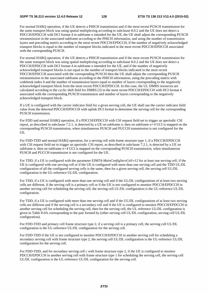
ETSI
ETSI TS 136 213 V12.4.0 (2015-02)1283GPP TS 36.213 version 12.4.0 Release 12
For normal HARQ operation, if the UE detects a PHICH transmission and if the most recent PUSCH transmission for the same transport block was using spatial multiplexing according to subclause 8.0.2 and the UE does not detect a PDCCH/EPDCCH with DCI format 4 in subframe n intended for the UE, the UE shall adjust the corresponding PUSCH retransmission in the associated subframe according to the PHICH information, and using the number of transmission layers and precoding matrix according to the most recent PDCCH/EPDCCH, if the number of negatively acknowledged transport blocks is equal to the number of transport blocks indicated in the most recent PDCCH/EPDCCH associated with the corresponding PUSCH.
For normal HARQ operation, if the UE detects a PHICH transmission and if the most recent PUSCH transmission for the same transport block was using spatial multiplexing according to subclause 8.0.2 and the UE does not detect a PDCCH/EPDCCH with DCI format 4 in subframe n intended for the UE, and if the number of negatively acknowledged transport blocks is not equal to the number of transport blocks indicated in the most recent PDCCH/EPDCCH associated with the corresponding PUSCH then the UE shall adjust the corresponding PUSCH retransmission in the associated subframe according to the PHICH information, using the precoding matrix with codebook index 0 and the number of transmission layers equal to number of layers corresponding to the negatively acknowledged transport block from the most recent PDCCH/EPDCCH. In this case, the UL DMRS resources are calculated according to the cyclic shift field for DMRS [3] in the most recent PDCCH/EPDCCH with DCI format 4 associated with the corresponding PUSCH transmission and number of layers corresponding to the negatively acknowledged transport block.
If a UE is configured with the carrier indicator field for a given serving cell, the UE shall use the carrier indicator field value from the detected PDCCH/EPDCCH with uplink DCI format to determine the serving cell for the corresponding PUSCH transmission.
For FDD and normal HARQ operation, if a PDCCH/EPDCCH with CSI request field set to trigger an aperiodic CSI report, as described in subclause 7.2.1, is detected by a UE on subframe n, then on subframe n+4 UCI is mapped on the corresponding PUSCH transmission, when simultaneous PUSCH and PUCCH transmission is not configured for the UE. For FDD-TDD and normal HARQ operation, for a serving cell with frame structure type 1, if a PDCCH/EPDCCH with CSI request field set to trigger an aperiodic CSI report, as described in subclause 7.2.1, is detected by a UE on subframe n, then on subframe n+4 UCI is mapped on the corresponding PUSCH transmission, when simultaneous PUSCH and PUCCH transmission is not configured for the UE. For TDD, if a UE is configured with the parameter EIMTA-MainConfigServCell-r12 for at least one serving cell, if the UE is configured with one serving cell or if the UE is configured with more than one serving cell and the TDD UL/DL configuration of all the configured serving cells is the same, then for a given serving cell, the serving cell UL/DL configuration is the UL-reference UL/DL configuration. For TDD, if a UE is configured with more than one serving cell and if the UL/DL configurations of at least two serving cells are different, if the serving cell is a primary cell or if the UE is not configured to monitor PDCCH/EPDCCH in another serving cell for scheduling the serving cell, the serving cell UL/DL configuration is the UL-reference UL/DL configuration. For TDD, if a UE is configured with more than one serving cell and if the UL/DL configurations of at least two serving cells are different and if the serving cell is a secondary cell and if the UE is configured to monitor PDCCH/EPDCCH in another serving cell for scheduling the serving cell, then for the serving cell, the UL reference UL/DL configuration is given in Table 8-0A corresponding to the pair formed by (other serving cell UL/DL configuration, serving cell UL/DL configuration).
For FDD-TDD and primary cell frame structure type 2, if a serving cell is a primary cell, the serving cell UL/DL configuration is the UL-reference UL/DL configuration for the serving cell.
For FDD-TDD if the UE is not configured to monitor PDCCH/EPDCCH in another serving cell for scheduling a secondary serving cell with frame structure type 2, the serving cell UL/DL configuration is the UL-reference UL/DL configuration for the serving cell. For FDD-TDD, and for secondary serving cell c with frame structure type 2, if the UE is configured to monitor PDCCH/EPDCCH in another serving cell with frame structure type 1 for scheduling the serving cell, the serving cell UL/DL configuration is the UL-reference UL/DL configuration for the serving cell.
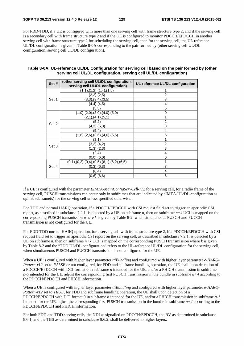
ETSI
ETSI TS 136 213 V12.4.0 (2015-02)1293GPP TS 36.213 version 12.4.0 Release 12
For FDD-TDD, if a UE is configured with more than one serving cell with frame structure type 2, and if the serving cell is a secondary cell with frame structure type 2 and if the UE is configured to monitor PDCCH/EPDCCH in another serving cell with frame structure type 2 for scheduling the serving cell, then for the serving cell, the UL reference UL/DL configuration is given in Table 8-0A corresponding to the pair formed by (other serving cell UL/DL configuration, serving cell UL/DL configuration).
Table 8-0A: UL-reference UL/DL Configuration for serving cell based on the pair formed by (other serving cell UL/DL configuration, serving cell UL/DL configuration)
Set # (other serving cell UL/DL configuration, serving cell UL/DL configuration) UL-reference UL/DL configuration
Set 1
(1,1),(1,2),(1,4),(1,5) 1 (2,2),(2,5) 2
(3,3),(3,4),(3,5) 3 (4,4),(4,5) 4
(5,5) 5
Set 2
(1,0),(2,0),(3,0),(4,0),(5,0) 0 (2,1),(4,1),(5,1) 1
(5,2) 2 (4,3),(5,3) 3
(5,4) 4 (1,6),(2,6),(3,6),(4,6),(5,6) 6
Set 3
(3,1) 1 (3,2),(4,2) 2 (1,3),(2,3) 3
(2,4) 4
Set 4
(0,0),(6,0) 0 (0,1),(0,2),(0,4),(0,5),(6,1),(6,2),(6,5) 1
(0,3),(6,3) 3 (6,4) 4
(0,6),(6,6) 6
If a UE is configured with the parameter EIMTA-MainConfigServCell-r12 for a serving cell, for a radio frame of the serving cell, PUSCH transmissions can occur only in subframes that are indicated by eIMTA-UL/DL-configuration as uplink subframe(s) for the serving cell unless specified otherwise. For TDD and normal HARQ operation, if a PDCCH/EPDCCH with CSI request field set to trigger an aperiodic CSI report, as described in subclause 7.2.1, is detected by a UE on subframe n, then on subframe n+k UCI is mapped on the corresponding PUSCH transmission where k is given by Table 8-2, when simultaneous PUSCH and PUCCH transmission is not configured for the UE. For FDD-TDD normal HARQ operation, for a serving cell with frame structure type 2, if a PDCCH/EPDCCH with CSI request field set to trigger an aperiodic CSI report on the serving cell, as described in subclause 7.2.1, is detected by a UE on subframe n, then on subframe n+k UCI is mapped on the corresponding PUSCH transmission where k is given by Table 8-2 and the “TDD UL/DL configuration” refers to the UL-reference UL/DL configuration for the serving cell, when simultaneous PUSCH and PUCCH transmission is not configured for the UE. When a UE is configured with higher layer parameter ttiBundling and configured with higher layer parameter e-HARQ-Pattern-r12 set to FALSE or not configured, for FDD and subframe bundling operation, the UE shall upon detection of a PDCCH/EPDCCH with DCI format 0 in subframe n intended for the UE, and/or a PHICH transmission in subframe n-5 intended for the UE, adjust the corresponding first PUSCH transmission in the bundle in subframe n+4 according to the PDCCH/EPDCCH and PHICH information.
When a UE is configured with higher layer parameter ttiBundling and configured with higher layer parameter e-HARQ-Pattern-r12 set to TRUE, for FDD and subframe bundling operation, the UE shall upon detection of a PDCCH/EPDCCH with DCI format 0 in subframe n intended for the UE, and/or a PHICH transmission in subframe n-1 intended for the UE, adjust the corresponding first PUSCH transmission in the bundle in subframe n+4 according to the PDCCH/EPDCCH and PHICH information.
For both FDD and TDD serving cells, the NDI as signalled on PDCCH/EPDCCH, the RV as determined in subclause 8.6.1, and the TBS as determined in subclause 8.6.2, shall be delivered to higher layers.
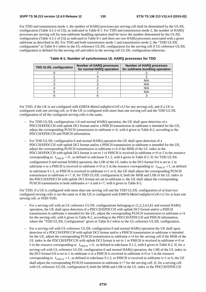
ETSI
ETSI TS 136 213 V12.4.0 (2015-02)1303GPP TS 36.213 version 12.4.0 Release 12
For TDD and transmission mode 1, the number of HARQ processes per serving cell shall be determined by the UL/DL configuration (Table 4.2-2 of [3]), as indicated in Table 8-1. For TDD and transmission mode 2, the number of HARQ processes per serving cell for non-subframe bundling operation shall be twice the number determined by the UL/DL configuration (Table 4.2-2 of [3]) as indicated in Table 8-1 and there are two HARQ processes associated with a given subframe as described in [8]. For TDD and both transmission mode 1 and transmission mode 2, the “TDD UL/DL configuration” in Table 8-1 refers to the UL-reference UL/DL configuration for the serving cell if UL-reference UL/DL configuration is defined for the serving cell and refers to the serving cell UL/DL configuration otherwise.
Table 8-1: Number of synchronous UL HARQ processes for TDD
TDD UL/DL configuration Number of HARQ processes for normal HARQ operation
Number of HARQ processes for subframe bundling operation
0 7 3 1 4 2 2 2 N/A 3 3 N/A 4 2 N/A 5 1 N/A 6 6 3
For TDD, if the UE is not configured with EIMTA-MainConfigServCell-r12 for any serving cell, and if a UE is configured with one serving cell, or if the UE is configured with more than one serving cell and the TDD UL/DL configuration of all the configured serving cells is the same,
- For TDD UL/DL configurations 1-6 and normal HARQ operation, the UE shall upon detection of a PDCCH/EPDCCH with uplink DCI format and/or a PHICH transmission in subframe n intended for the UE, adjust the corresponding PUSCH transmission in subframe n+k, with k given in Table 8-2, according to the PDCCH/EPDCCH and PHICH information.
- For TDD UL/DL configuration 0 and normal HARQ operation the UE shall upon detection of a PDCCH/EPDCCH with uplink DCI format and/or a PHICH transmission in subframe n intended for the UE, adjust the corresponding PUSCH transmission in subframe n+k if the MSB of the UL index in the PDCCH/EPDCCH with uplink DCI format is set to 1 or PHICH is received in subframe n=0 or 5 in the resource corresponding to 0PHICHI = , as defined in subclause 9.1.2, with k given in Table 8-2. If, for TDD UL/DL
configuration 0 and normal HARQ operation, the LSB of the UL index in the DCI format 0/4 is set to 1 in subframe n or a PHICH is received in subframe n=0 or 5 in the resource corresponding to 1PHICHI = , as defined
in subclause 9.1.2, or PHICH is received in subframe n=1 or 6, the UE shall adjust the corresponding PUSCH transmission in subframe n+7. If, for TDD UL/DL configuration 0, both the MSB and LSB of the UL index in the PDCCH/EPDCCH with uplink DCI format are set in subframe n, the UE shall adjust the corresponding PUSCH transmission in both subframes n+ k and n+7, with k given in Table 8-2.
For TDD, if a UE is configured with more than one serving cell and the TDD UL/DL configuration of at least two configured serving cells is not the same or if the UE is configured with EIMTA-MainConfigServCell-r12 for at least one serving cell, or FDD-TDD,
- For a serving cell with an UL-reference UL/DL configurations belonging to {1,2,3,4,5,6} and normal HARQ operation, the UE shall upon detection of a PDCCH/EPDCCH with uplink DCI format and/or a PHICH transmission in subframe n intended for the UE, adjust the corresponding PUSCH transmission in subframe n+k for the serving cell, with k given in Table 8-2, according to the PDCCH/EPDCCH and PHICH information, where the "TDD UL/DL Configuration" given in Table 8-2 refers to the UL-reference UL/DL configuration.
- For a serving cell with UL-reference UL/DL configuration 0 and normal HARQ operation the UE shall upon detection of a PDCCH/EPDCCH with uplink DCI format and/or a PHICH transmission in subframe n intended for the UE, adjust the corresponding PUSCH transmission in subframe n+k for the serving cell if the MSB of the UL index in the PDCCH/EPDCCH with uplink DCI format is set to 1 or PHICH is received in subframe n=0 or 5 in the resource corresponding to 0PHICHI = , as defined in subclause 9.1.2, with k given in Table 8-2. If, for a
serving cell with UL-reference UL/DL configuration 0 and normal HARQ operation, the LSB of the UL index in the DCI format 0/4 is set to 1 in subframe n or a PHICH is received in subframe n=0 or 5 in the resource corresponding to 1PHICHI = , as defined in subclause 9.1.2, or PHICH is received in subframe n=1 or 6, the UE
shall adjust the corresponding PUSCH transmission in subframe n+7 for the serving cell. If, for a serving cell with UL-reference UL/DL configuration 0, both the MSB and LSB of the UL index in the PDCCH/EPDCCH
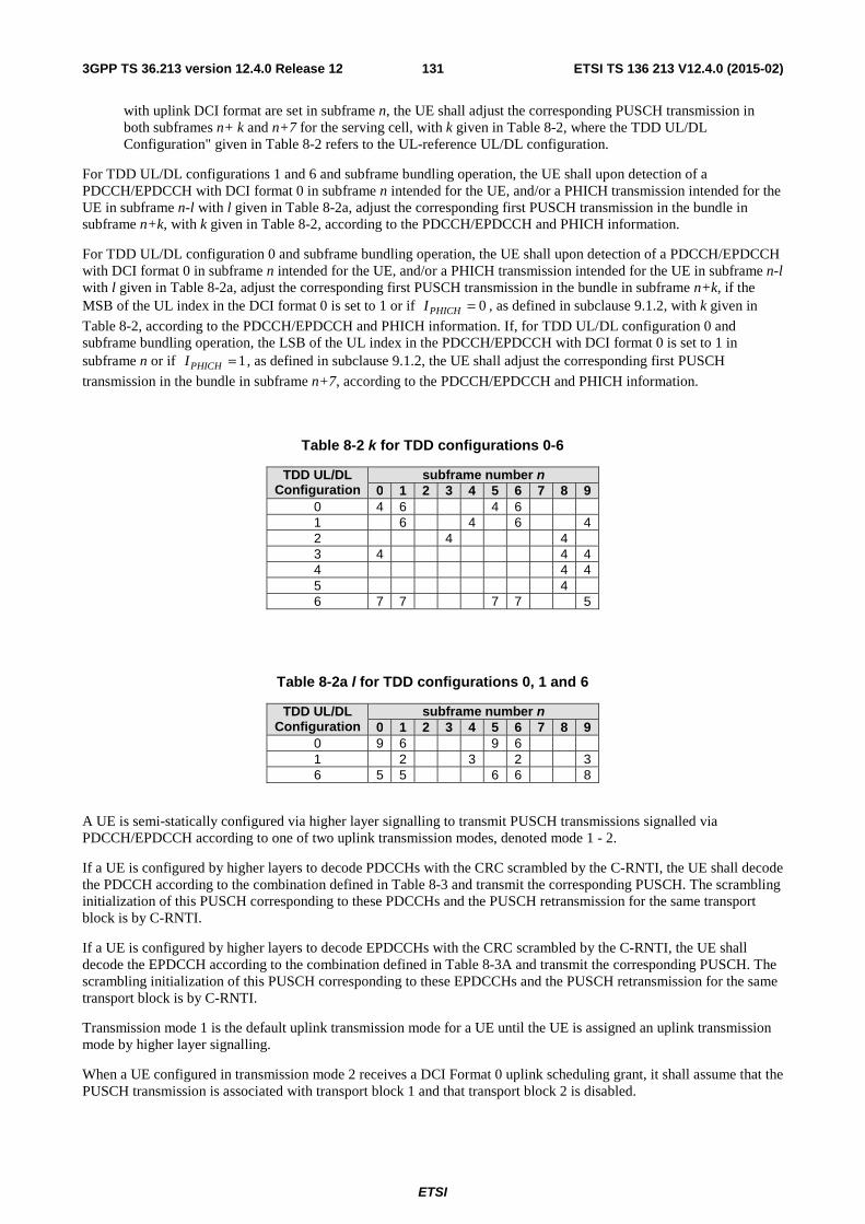
ETSI
ETSI TS 136 213 V12.4.0 (2015-02)1313GPP TS 36.213 version 12.4.0 Release 12
with uplink DCI format are set in subframe n, the UE shall adjust the corresponding PUSCH transmission in both subframes n+ k and n+7 for the serving cell, with k given in Table 8-2, where the TDD UL/DL Configuration" given in Table 8-2 refers to the UL-reference UL/DL configuration.
For TDD UL/DL configurations 1 and 6 and subframe bundling operation, the UE shall upon detection of a PDCCH/EPDCCH with DCI format 0 in subframe n intended for the UE, and/or a PHICH transmission intended for the UE in subframe n-l with l given in Table 8-2a, adjust the corresponding first PUSCH transmission in the bundle in subframe n+k, with k given in Table 8-2, according to the PDCCH/EPDCCH and PHICH information.
For TDD UL/DL configuration 0 and subframe bundling operation, the UE shall upon detection of a PDCCH/EPDCCH with DCI format 0 in subframe n intended for the UE, and/or a PHICH transmission intended for the UE in subframe n-l with l given in Table 8-2a, adjust the corresponding first PUSCH transmission in the bundle in subframe n+k, if the MSB of the UL index in the DCI format 0 is set to 1 or if 0PHICHI = , as defined in subclause 9.1.2, with k given in
Table 8-2, according to the PDCCH/EPDCCH and PHICH information. If, for TDD UL/DL configuration 0 and subframe bundling operation, the LSB of the UL index in the PDCCH/EPDCCH with DCI format 0 is set to 1 in subframe n or if 1PHICHI = , as defined in subclause 9.1.2, the UE shall adjust the corresponding first PUSCH
transmission in the bundle in subframe n+7, according to the PDCCH/EPDCCH and PHICH information.
Table 8-2 k for TDD configurations 0-6
TDD UL/DL Configuration
subframe number n 0 1 2 3 4 5 6 7 8 9
0 4 6 4 6 1 6 4 6 4 2 4 4 3 4 4 4 4 4 4 5 4 6 7 7 7 7 5
Table 8-2a l for TDD configurations 0, 1 and 6
TDD UL/DL Configuration
subframe number n 0 1 2 3 4 5 6 7 8 9
0 9 6 9 6 1 2 3 2 3 6 5 5 6 6 8
A UE is semi-statically configured via higher layer signalling to transmit PUSCH transmissions signalled via PDCCH/EPDCCH according to one of two uplink transmission modes, denoted mode 1 - 2.
If a UE is configured by higher layers to decode PDCCHs with the CRC scrambled by the C-RNTI, the UE shall decode the PDCCH according to the combination defined in Table 8-3 and transmit the corresponding PUSCH. The scrambling initialization of this PUSCH corresponding to these PDCCHs and the PUSCH retransmission for the same transport block is by C-RNTI.
If a UE is configured by higher layers to decode EPDCCHs with the CRC scrambled by the C-RNTI, the UE shall decode the EPDCCH according to the combination defined in Table 8-3A and transmit the corresponding PUSCH. The scrambling initialization of this PUSCH corresponding to these EPDCCHs and the PUSCH retransmission for the same transport block is by C-RNTI.
Transmission mode 1 is the default uplink transmission mode for a UE until the UE is assigned an uplink transmission mode by higher layer signalling.
When a UE configured in transmission mode 2 receives a DCI Format 0 uplink scheduling grant, it shall assume that the PUSCH transmission is associated with transport block 1 and that transport block 2 is disabled.
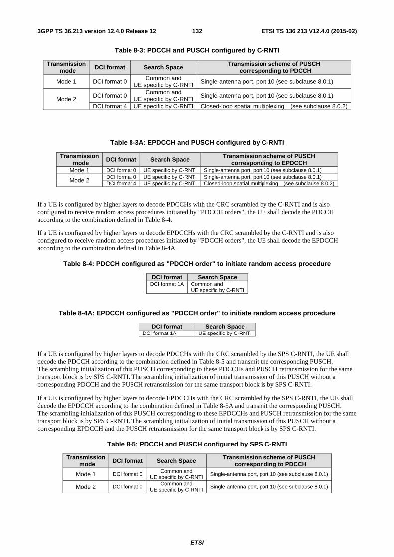
ETSI
ETSI TS 136 213 V12.4.0 (2015-02)1323GPP TS 36.213 version 12.4.0 Release 12
Table 8-3: PDCCH and PUSCH configured by C-RNTI
Transmission mode DCI format Search Space Transmission scheme of PUSCH
corresponding to PDCCH
Mode 1 DCI format 0 Common and UE specific by C-RNTI Single-antenna port, port 10 (see subclause 8.0.1)
Mode 2 DCI format 0 Common and
UE specific by C-RNTI Single-antenna port, port 10 (see subclause 8.0.1)
DCI format 4 UE specific by C-RNTI Closed-loop spatial multiplexing (see subclause 8.0.2)
Table 8-3A: EPDCCH and PUSCH configured by C-RNTI
Transmission mode DCI format Search Space Transmission scheme of PUSCH
corresponding to EPDCCH Mode 1 DCI format 0 UE specific by C-RNTI Single-antenna port, port 10 (see subclause 8.0.1)
Mode 2 DCI format 0 UE specific by C-RNTI Single-antenna port, port 10 (see subclause 8.0.1) DCI format 4 UE specific by C-RNTI Closed-loop spatial multiplexing (see subclause 8.0.2)
If a UE is configured by higher layers to decode PDCCHs with the CRC scrambled by the C-RNTI and is also configured to receive random access procedures initiated by "PDCCH orders", the UE shall decode the PDCCH according to the combination defined in Table 8-4.
If a UE is configured by higher layers to decode EPDCCHs with the CRC scrambled by the C-RNTI and is also configured to receive random access procedures initiated by "PDCCH orders", the UE shall decode the EPDCCH according to the combination defined in Table 8-4A.
Table 8-4: PDCCH configured as "PDCCH order" to initiate random access procedure
DCI format Search Space DCI format 1A Common and
UE specific by C-RNTI
Table 8-4A: EPDCCH configured as "PDCCH order" to initiate random access procedure
DCI format Search Space DCI format 1A UE specific by C-RNTI
If a UE is configured by higher layers to decode PDCCHs with the CRC scrambled by the SPS C-RNTI, the UE shall decode the PDCCH according to the combination defined in Table 8-5 and transmit the corresponding PUSCH. The scrambling initialization of this PUSCH corresponding to these PDCCHs and PUSCH retransmission for the same transport block is by SPS C-RNTI. The scrambling initialization of initial transmission of this PUSCH without a corresponding PDCCH and the PUSCH retransmission for the same transport block is by SPS C-RNTI.
If a UE is configured by higher layers to decode EPDCCHs with the CRC scrambled by the SPS C-RNTI, the UE shall decode the EPDCCH according to the combination defined in Table 8-5A and transmit the corresponding PUSCH. The scrambling initialization of this PUSCH corresponding to these EPDCCHs and PUSCH retransmission for the same transport block is by SPS C-RNTI. The scrambling initialization of initial transmission of this PUSCH without a corresponding EPDCCH and the PUSCH retransmission for the same transport block is by SPS C-RNTI.
Table 8-5: PDCCH and PUSCH configured by SPS C-RNTI
Transmission mode DCI format Search Space Transmission scheme of PUSCH
corresponding to PDCCH
Mode 1 DCI format 0 Common and UE specific by C-RNTI Single-antenna port, port 10 (see subclause 8.0.1)
Mode 2 DCI format 0 Common and UE specific by C-RNTI
Single-antenna port, port 10 (see subclause 8.0.1)
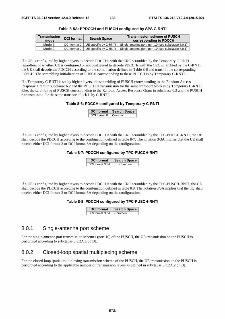
ETSI
ETSI TS 136 213 V12.4.0 (2015-02)1333GPP TS 36.213 version 12.4.0 Release 12
Table 8-5A: EPDCCH and PUSCH configured by SPS C-RNTI
Transmission mode DCI format Search Space Transmission scheme of PUSCH
corresponding to PDCCH Mode 1 DCI format 0 UE specific by C-RNTI Single-antenna port, port 10 (see subclause 8.0.1) Mode 2 DCI format 0 UE specific by C-RNTI Single-antenna port, port 10 (see subclause 8.0.1)
If a UE is configured by higher layers to decode PDCCHs with the CRC scrambled by the Temporary C-RNTI regardless of whether UE is configured or not configured to decode PDCCHs with the CRC scrambled by the C-RNTI, the UE shall decode the PDCCH according to the combination defined in Table 8-6 and transmit the corresponding PUSCH. The scrambling initialization of PUSCH corresponding to these PDCCH is by Temporary C-RNTI.
If a Temporary C-RNTI is set by higher layers, the scrambling of PUSCH corresponding to the Random Access Response Grant in subclause 6.2 and the PUSCH retransmission for the same transport block is by Temporary C-RNTI. Else, the scrambling of PUSCH corresponding to the Random Access Response Grant in subclause 6.2 and the PUSCH retransmission for the same transport block is by C-RNTI.
Table 8-6: PDCCH configured by Temporary C-RNTI
DCI format Search Space DCI format 0 Common
If a UE is configured by higher layers to decode PDCCHs with the CRC scrambled by the TPC-PUCCH-RNTI, the UE shall decode the PDCCH according to the combination defined in table 8-7. The notation 3/3A implies that the UE shall receive either DCI format 3 or DCI format 3A depending on the configuration.
Table 8-7: PDCCH configured by TPC-PUCCH-RNTI
DCI format Search Space DCI format 3/3A Common
If a UE is configured by higher layers to decode PDCCHs with the CRC scrambled by the TPC-PUSCH-RNTI, the UE shall decode the PDCCH according to the combination defined in table 8.8. The notation 3/3A implies that the UE shall receive either DCI format 3 or DCI format 3A depending on the configuration.
Table 8-8: PDCCH configured by TPC-PUSCH-RNTI
DCI format Search Space DCI format 3/3A Common
8.0.1 Single-antenna port scheme
For the single-antenna port transmission schemes (port 10) of the PUSCH, the UE transmission on the PUSCH is performed according to subclause 5.3.2A.1 of [3].
8.0.2 Closed-loop spatial multiplexing scheme
For the closed-loop spatial multiplexing transmission scheme of the PUSCH, the UE transmission on the PUSCH is performed according to the applicable number of transmission layers as defined in subclause 5.3.2A.2 of [3].
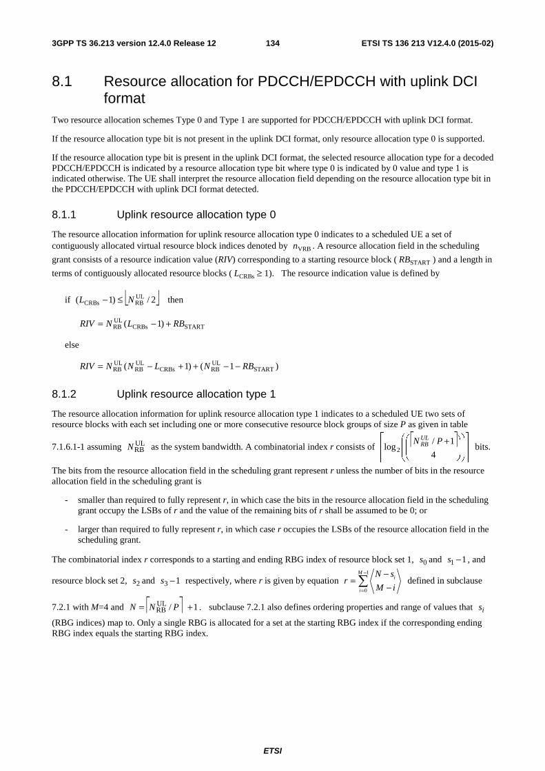
ETSI
ETSI TS 136 213 V12.4.0 (2015-02)1343GPP TS 36.213 version 12.4.0 Release 12
8.1 Resource allocation for PDCCH/EPDCCH with uplink DCI format
Two resource allocation schemes Type 0 and Type 1 are supported for PDCCH/EPDCCH with uplink DCI format.
If the resource allocation type bit is not present in the uplink DCI format, only resource allocation type 0 is supported.
If the resource allocation type bit is present in the uplink DCI format, the selected resource allocation type for a decoded PDCCH/EPDCCH is indicated by a resource allocation type bit where type 0 is indicated by 0 value and type 1 is indicated otherwise. The UE shall interpret the resource allocation field depending on the resource allocation type bit in the PDCCH/EPDCCH with uplink DCI format detected.
8.1.1 Uplink resource allocation type 0
The resource allocation information for uplink resource allocation type 0 indicates to a scheduled UE a set of contiguously allocated virtual resource block indices denoted by VRBn . A resource allocation field in the scheduling
grant consists of a resource indication value (RIV) corresponding to a starting resource block ( STARTRB ) and a length in
terms of contiguously allocated resource blocks ( CRBsL ≥ 1). The resource indication value is defined by
if ⎣ ⎦2/)1( ULRBCRBs NL ≤− then
STARTCRBsULRB )1( RBLNRIV +−=
else
)1()1( STARTULRBCRBs
ULRB
ULRB RBNLNNRIV −−++−=
8.1.2 Uplink resource allocation type 1
The resource allocation information for uplink resource allocation type 1 indicates to a scheduled UE two sets of resource blocks with each set including one or more consecutive resource block groups of size P as given in table
7.1.6.1-1 assuming ULRBN as the system bandwidth. A combinatorial index r consists of ⎡ ⎤
⎥⎥
⎥
⎤
⎢⎢
⎢
⎡
⎟⎟
⎠
⎞
⎜⎜
⎝
⎛
⎟⎟
⎠
⎞
⎜⎜
⎝
⎛ +4
1/log 2
PN ULRB bits.
The bits from the resource allocation field in the scheduling grant represent r unless the number of bits in the resource allocation field in the scheduling grant is
- smaller than required to fully represent r, in which case the bits in the resource allocation field in the scheduling grant occupy the LSBs of r and the value of the remaining bits of r shall be assumed to be 0; or
- larger than required to fully represent r, in which case r occupies the LSBs of the resource allocation field in the scheduling grant.
The combinatorial index r corresponds to a starting and ending RBG index of resource block set 1, 0s and 11 −s , and
resource block set 2, 2s and 13 −s respectively, where r is given by equation 1
0
Mi
i
N sr
M i
−
=
−=
−∑ defined in subclause
7.2.1 with M=4 and ⎡ ⎤ 1/ULRB += PNN . subclause 7.2.1 also defines ordering properties and range of values that is
(RBG indices) map to. Only a single RBG is allocated for a set at the starting RBG index if the corresponding ending RBG index equals the starting RBG index.
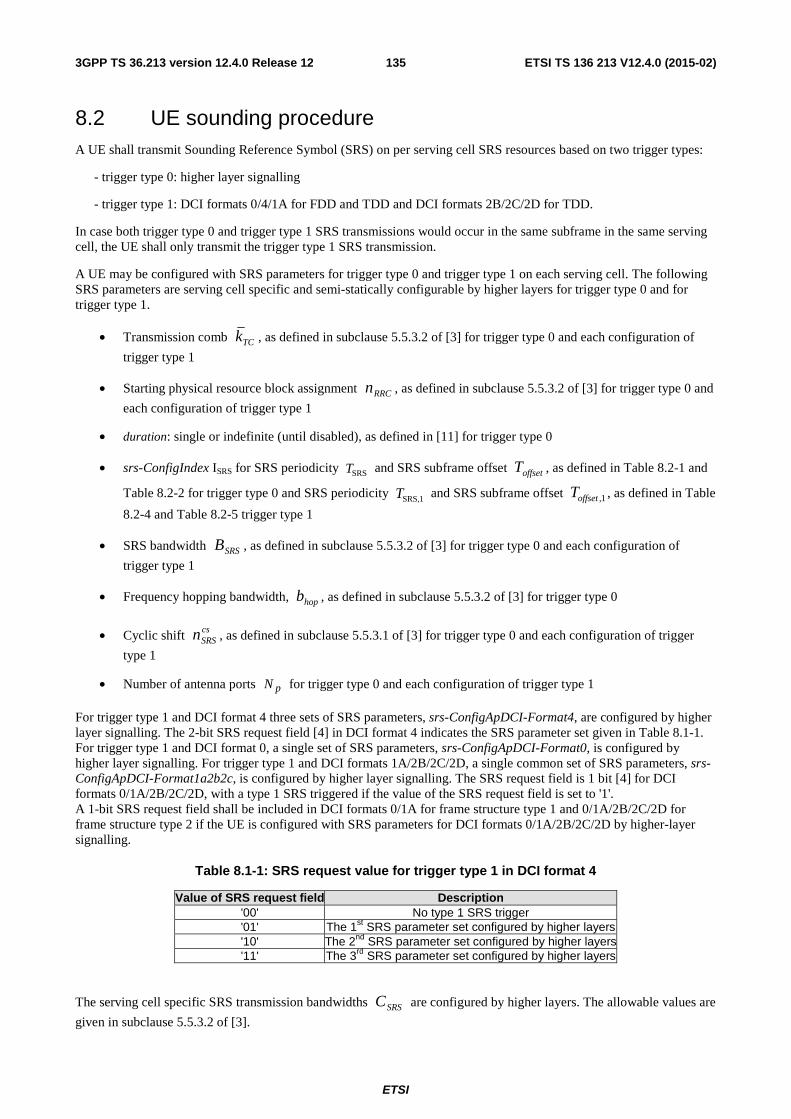
ETSI
ETSI TS 136 213 V12.4.0 (2015-02)1353GPP TS 36.213 version 12.4.0 Release 12
8.2 UE sounding procedure A UE shall transmit Sounding Reference Symbol (SRS) on per serving cell SRS resources based on two trigger types:
- trigger type 0: higher layer signalling
- trigger type 1: DCI formats 0/4/1A for FDD and TDD and DCI formats 2B/2C/2D for TDD.
In case both trigger type 0 and trigger type 1 SRS transmissions would occur in the same subframe in the same serving cell, the UE shall only transmit the trigger type 1 SRS transmission.
A UE may be configured with SRS parameters for trigger type 0 and trigger type 1 on each serving cell. The following SRS parameters are serving cell specific and semi-statically configurable by higher layers for trigger type 0 and for trigger type 1.
• Transmission comb TCk , as defined in subclause 5.5.3.2 of [3] for trigger type 0 and each configuration of
trigger type 1
• Starting physical resource block assignment RRCn , as defined in subclause 5.5.3.2 of [3] for trigger type 0 and
each configuration of trigger type 1
• duration: single or indefinite (until disabled), as defined in [11] for trigger type 0
• srs-ConfigIndex ISRS for SRS periodicity SRST and SRS subframe offset offsetT , as defined in Table 8.2-1 and
Table 8.2-2 for trigger type 0 and SRS periodicity SRS,1T and SRS subframe offset 1,offsetT , as defined in Table
8.2-4 and Table 8.2-5 trigger type 1
• SRS bandwidth SRSB , as defined in subclause 5.5.3.2 of [3] for trigger type 0 and each configuration of
trigger type 1
• Frequency hopping bandwidth, hopb , as defined in subclause 5.5.3.2 of [3] for trigger type 0
• Cyclic shift csSRSn , as defined in subclause 5.5.3.1 of [3] for trigger type 0 and each configuration of trigger
type 1
• Number of antenna ports pN for trigger type 0 and each configuration of trigger type 1
For trigger type 1 and DCI format 4 three sets of SRS parameters, srs-ConfigApDCI-Format4, are configured by higher layer signalling. The 2-bit SRS request field [4] in DCI format 4 indicates the SRS parameter set given in Table 8.1-1. For trigger type 1 and DCI format 0, a single set of SRS parameters, srs-ConfigApDCI-Format0, is configured by higher layer signalling. For trigger type 1 and DCI formats 1A/2B/2C/2D, a single common set of SRS parameters, srs-ConfigApDCI-Format1a2b2c, is configured by higher layer signalling. The SRS request field is 1 bit [4] for DCI formats 0/1A/2B/2C/2D, with a type 1 SRS triggered if the value of the SRS request field is set to '1'. A 1-bit SRS request field shall be included in DCI formats 0/1A for frame structure type 1 and 0/1A/2B/2C/2D for frame structure type 2 if the UE is configured with SRS parameters for DCI formats 0/1A/2B/2C/2D by higher-layer signalling.
Table 8.1-1: SRS request value for trigger type 1 in DCI format 4
Value of SRS request field Description '00' No type 1 SRS trigger '01' The 1st SRS parameter set configured by higher layers '10' The 2nd SRS parameter set configured by higher layers'11' The 3rd SRS parameter set configured by higher layers
The serving cell specific SRS transmission bandwidths SRSC are configured by higher layers. The allowable values are
given in subclause 5.5.3.2 of [3].
ETSI
ETSI TS 136 213 V12.4.0 (2015-02)1363GPP TS 36.213 version 12.4.0 Release 12
The serving cell specific SRS transmission sub-frames are configured by higher layers. The allowable values are given in subclause 5.5.3.3 of [3].
For a TDD serving cell, SRS transmissions can occur in UpPTS and uplink subframes of the UL/DL configuration indicated by the higher layer parameter subframeAssignment for the serving cell.
When closed-loop UE transmit antenna selection is enabled for a given serving cell for a UE that supports transmit antenna selection, the index ( )SRSna , of the UE antenna that transmits the SRS at time nSRS is given by
( ) 2modSRSSRS nna = , for both partial and full sounding bandwidth, and when frequency hopping is disabled (i.e.,
SRShop Bb ≥ ),
⎣ ⎦ ⎣ ⎦( )
odd is when 2mod
even is when 2mod/2/)(
⎩⎨⎧ ⋅++
=Kn
KKnnnna
SRS
SRSSRSSRSSRS
β,
otherwise 0
04mod where1
⎩⎨⎧ =
=K
β
when frequency hopping is enabled (i.e., SRShop Bb < ),
where values BSRS, bhop, Nb, and nSRS are given in subclause 5.5.3.2 of [3], and ∏=
=SRS
hop
B
bbbNK
'' (where 1=
hopbN
regardless of the bN value), except when a single SRS transmission is configured for the UE. If a UE is configured
with more than one serving cell, the UE is not expected to transmit SRS on different antenna ports simultaneously.
A UE may be configured to transmit SRS on pN antenna ports of a serving cell where pN may be configured by
higher layer signalling. For PUSCH transmission mode 1 }4,2,1,0{∈pN and for PUSCH transmission mode 2
}2,1,0{∈pN with two antenna ports configured for PUSCH and }4,1,0{∈pN with 4 antenna ports configured for
PUSCH. A UE configured for SRS transmission on multiple antenna ports of a serving cell shall transmit SRS for all the configured transmit antenna ports within one SC-FDMA symbol of the same subframe of the serving cell. The SRS transmission bandwidth and starting physical resource block assignment are the same for all the configured antenna ports of a given serving cell.
A UE not configured with multiple TAGs shall not transmit SRS in a symbol whenever SRS and PUSCH transmissions happen to overlap in the same symbol.
For TDD serving cell, when one SC-FDMA symbol exists in UpPTS of the given serving cell, it can be used for SRS transmission. When two SC-FDMA symbols exist in UpPTS of the given serving cell, both can be used for SRS transmission and for trigger type 0 SRS both can be assigned to the same UE.
If a UE is not configured with multiple TAGs, or if a UE is configured with multiple TAGs and SRS and PUCCH format 2/2a/2b happen to coincide in the same subframe in the same serving cell,
- The UE shall not transmit type 0 triggered SRS whenever type 0 triggered SRS and PUCCH format 2/2a/2b transmissions happen to coincide in the same subframe;
- The UE shall not transmit type 1 triggered SRS whenever type 1 triggered SRS and PUCCH format 2a/2b or format 2 with HARQ-ACK transmissions happen to coincide in the same subframe;
- The UE shall not transmit PUCCH format 2 without HARQ-ACK whenever type 1 triggered SRS and PUCCH format 2 without HARQ-ACK transmissions happen to coincide in the same subframe.
If a UE is not configured with multiple TAGs, or if a UE is configured with multiple TAGs and SRS and PUCCH happen to coincide in the same subframe in the same serving cell,
- The UE shall not transmit SRS whenever SRS transmission and PUCCH transmission carrying HARQ-ACK and/or positive SR happen to coincide in the same subframe if the parameter ackNackSRS-SimultaneousTransmission is FALSE;
ETSI
ETSI TS 136 213 V12.4.0 (2015-02)1373GPP TS 36.213 version 12.4.0 Release 12
- For FDD-TDD and primary cell frame structure 1, the UE shall not transmit SRS in a symbol whenever SRS transmission and PUCCH transmission carrying HARQ-ACK and/or positive SR using shortened format as defined in subclauses 5.4.1 and 5.4.2A of [3] happen to overlap in the same symbol if the parameter ackNackSRS-SimultaneousTransmission is TRUE.
- Unless otherwise prohibited, the UE shall transmit SRS whenever SRS transmission and PUCCH transmission carrying HARQ-ACK and/or positive SR using shortened format as defined in subclauses 5.4.1 and 5.4.2A of [3] happen to coincide in the same subframe if the parameter ackNackSRS-SimultaneousTransmission is TRUE.
A UE not configured with multiple TAGs shall not transmit SRS whenever SRS transmission on any serving cells and PUCCH transmission carrying HARQ-ACK and/or positive SR using normal PUCCH format as defined in subclauses 5.4.1 and 5.4.2A of [3] happen to coincide in the same subframe.
In UpPTS, whenever SRS transmission instance overlaps with the PRACH region for preamble format 4 or exceeds the range of uplink system bandwidth configured in the serving cell, the UE shall not transmit SRS.
The parameter ackNackSRS-SimultaneousTransmission provided by higher layers determines if a UE is configured to support the transmission of HARQ-ACK on PUCCH and SRS in one subframe. If it is configured to support the transmission of HARQ-ACK on PUCCH and SRS in one subframe, then in the cell specific SRS subframes of the primary cell UE shall transmit HARQ-ACK and SR using the shortened PUCCH format as defined in subclauses 5.4.1 and 5.4.2A of [3], where the HARQ-ACK or the SR symbol corresponding to the SRS location is punctured. This shortened PUCCH format shall be used in a cell specific SRS subframe of the primary cell even if the UE does not transmit SRS in that subframe. The cell specific SRS subframes are defined in subclause 5.5.3.3 of [3]. Otherwise, the UE shall use the normal PUCCH format 1/1a/1b as defined in subclause 5.4.1 of [3] or normal PUCCH format 3 as defined in subclause 5.4.2A of [3] for the transmission of HARQ-ACK and SR.
Trigger type 0 SRS configuration of a UE in a serving cell for SRS periodicity, SRST , and SRS subframe offset, offsetT , is
defined in Table 8.2-1 and Table 8.2-2, for FDD and TDD serving cell, respectively. The periodicity SRST of the SRS
transmission is serving cell specific and is selected from the set {2, 5, 10, 20, 40, 80, 160, 320} ms or subframes. For the SRS periodicity SRST of 2 ms in TDD serving cell, two SRS resources are configured in a half frame containing
UL subframe(s) of the given serving cell.
Type 0 triggered SRS transmission instances in a given serving cell for TDD serving cell with 2SRS >T and for FDD
serving cell are the subframes satisfying 0mod)10( SRSSRS =−+⋅ TTkn offsetf , where for FDD { }9,...,1,0SRS =k is the
subframe index within the frame, for TDD serving cell SRSk is defined in Table 8.2-3. The SRS transmission instances
for TDD serving cell with 2SRS =T are the subframes satisfying 05mod)( SRS =− offsetTk .
For TDD serving cell, and a UE configured for type 0 triggered SRS transmission in serving cell c, and the UE configured with the parameter EIMTA-MainConfigServCell-r12 for serving cell c, if the UE does not detect an UL/DL configuration indication for radio frame m (as described in section 13.1), the UE shall not transmit trigger type 0 SRS in a subframe of radio frame m that is indicated by the parameter eimta-HarqReferenceConfig-r12 as a downlink subframe unless the UE transmits PUSCH in the same subframe.
Trigger type 1 SRS configuration of a UE in a serving cell for SRS periodicity, SRS,1T , and SRS subframe offset, 1,offsetT ,
is defined in Table 8.2-4 and Table 8.2-5, for FDD and TDD serving cell, respectively. The periodicity SRS,1T of the
SRS transmission is serving cell specific and is selected from the set {2, 5, 10} ms or subframes. For the SRS periodicity SRS,1T of 2 ms in TDD serving cell, two SRS resources are configured in a half frame
containing UL subframe(s) of the given serving cell.
A UE configured for type 1 triggered SRS transmission in serving cell c and not configured with a carrier indicator field shall transmit SRS on serving cell c upon detection of a positive SRS request in PDCCH/EPDCCH scheduling PUSCH/PDSCH on serving cell c.
A UE configured for type 1 triggered SRS transmission in serving cell c and configured with a carrier indicator field shall transmit SRS on serving cell c upon detection of a positive SRS request in PDCCH/EPDCCH scheduling PUSCH/PDSCH with the value of carrier indicator field corresponding to serving cell c.
A UE configured for type 1 triggered SRS transmission on serving cell c upon detection of a positive SRS request in subframe n of serving cell c shall commence SRS transmission in the first subframe satisfying 4, ≥+ kkn and
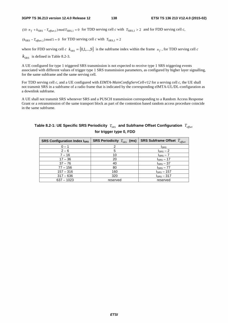
ETSI
ETSI TS 136 213 V12.4.0 (2015-02)1383GPP TS 36.213 version 12.4.0 Release 12
0mod)10( SRS,11,SRS =−+⋅ TTkn offsetf for TDD serving cell c with 2SRS,1 >T and for FDD serving cell c,
05mod)( 1,SRS =− offsetTk for TDD serving cell c with 2SRS,1 =T
where for FDD serving cell c { }9,...,1,0SRS =k is the subframe index within the frame fn , for TDD serving cell c
SRSk is defined in Table 8.2-3.
A UE configured for type 1 triggered SRS transmission is not expected to receive type 1 SRS triggering events associated with different values of trigger type 1 SRS transmission parameters, as configured by higher layer signalling, for the same subframe and the same serving cell.
For TDD serving cell c, and a UE configured with EIMTA-MainConfigServCell-r12 for a serving cell c, the UE shall not transmit SRS in a subframe of a radio frame that is indicated by the corresponding eIMTA-UL/DL-configuration as a downlink subframe.
A UE shall not transmit SRS whenever SRS and a PUSCH transmission corresponding to a Random Access Response Grant or a retransmission of the same transport block as part of the contention based random access procedure coincide in the same subframe.
Table 8.2-1: UE Specific SRS Periodicity SRST and Subframe Offset Configuration offsetT
for trigger type 0, FDD
SRS Configuration Index ISRS SRS Periodicity SRST (ms) SRS Subframe Offset offsetT
0 – 1 2 ISRS 2 – 6 5 ISRS – 2
7 – 16 10 ISRS – 7 17 – 36 20 ISRS – 17 37 – 76 40 ISRS – 37
77 – 156 80 ISRS – 77 157 – 316 160 ISRS – 157 317 – 636 320 ISRS – 317
637 – 1023 reserved reserved
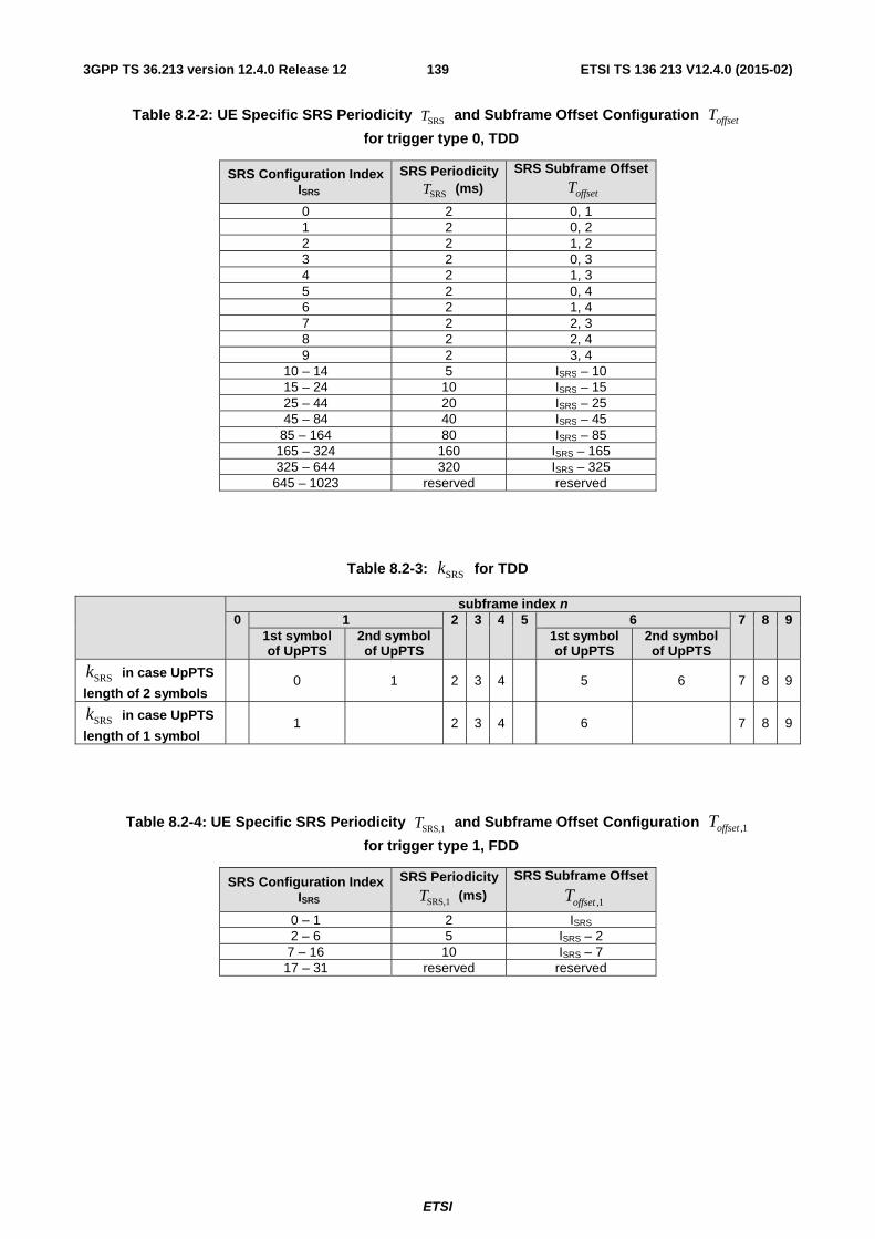
ETSI
ETSI TS 136 213 V12.4.0 (2015-02)1393GPP TS 36.213 version 12.4.0 Release 12
Table 8.2-2: UE Specific SRS Periodicity SRST and Subframe Offset Configuration offsetT
for trigger type 0, TDD
SRS Configuration Index ISRS
SRS Periodicity SRST (ms)
SRS Subframe Offset offsetT
0 2 0, 1 1 2 0, 2 2 2 1, 2 3 2 0, 3 4 2 1, 3 5 2 0, 4 6 2 1, 4 7 2 2, 3 8 2 2, 4 9 2 3, 4
10 – 14 5 ISRS – 10 15 – 24 10 ISRS – 15 25 – 44 20 ISRS – 25 45 – 84 40 ISRS – 45
85 – 164 80 ISRS – 85 165 – 324 160 ISRS – 165 325 – 644 320 ISRS – 325
645 – 1023 reserved reserved
Table 8.2-3: SRSk for TDD
subframe index n 0 1 2 3 4 5 6 7 8 9
1st symbol of UpPTS
2nd symbol of UpPTS
1st symbol of UpPTS
2nd symbol of UpPTS
SRSk in case UpPTS
length of 2 symbols 0 1 2 3 4 5 6 7 8 9
SRSk in case UpPTS
length of 1 symbol 1 2 3 4 6 7 8 9
Table 8.2-4: UE Specific SRS Periodicity SRS,1T and Subframe Offset Configuration 1,offsetT
for trigger type 1, FDD
SRS Configuration Index ISRS
SRS Periodicity SRS,1T (ms)
SRS Subframe Offset
1,offsetT
0 – 1 2 ISRS 2 – 6 5 ISRS – 2
7 – 16 10 ISRS – 7 17 – 31 reserved reserved
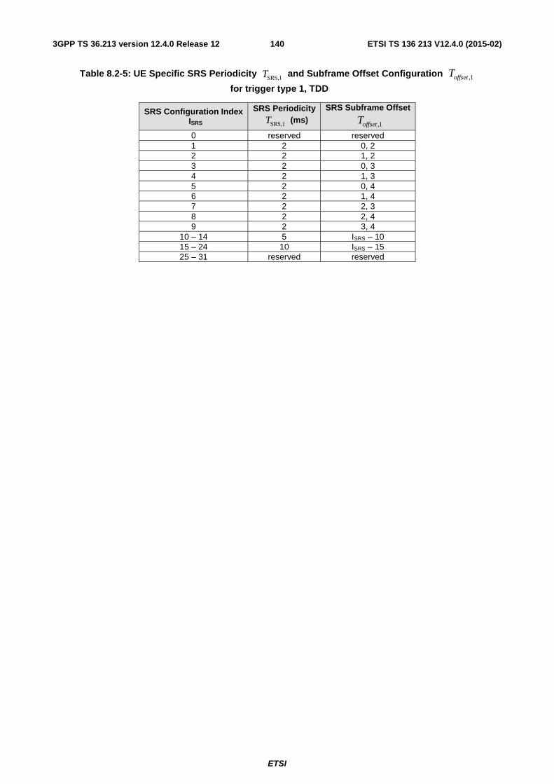
ETSI
ETSI TS 136 213 V12.4.0 (2015-02)1403GPP TS 36.213 version 12.4.0 Release 12
Table 8.2-5: UE Specific SRS Periodicity SRS,1T and Subframe Offset Configuration 1,offsetT
for trigger type 1, TDD
SRS Configuration Index ISRS
SRS Periodicity SRS,1T (ms)
SRS Subframe Offset
1,offsetT
0 reserved reserved 1 2 0, 2 2 2 1, 2 3 2 0, 3 4 2 1, 3 5 2 0, 4 6 2 1, 4 7 2 2, 3 8 2 2, 4 9 2 3, 4
10 – 14 5 ISRS – 10 15 – 24 10 ISRS – 15 25 – 31 reserved reserved
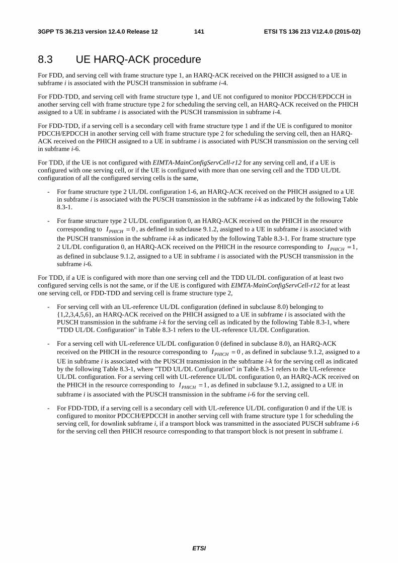
ETSI
ETSI TS 136 213 V12.4.0 (2015-02)1413GPP TS 36.213 version 12.4.0 Release 12
8.3 UE HARQ-ACK procedure For FDD, and serving cell with frame structure type 1, an HARQ-ACK received on the PHICH assigned to a UE in subframe i is associated with the PUSCH transmission in subframe i-4.
For FDD-TDD, and serving cell with frame structure type 1, and UE not configured to monitor PDCCH/EPDCCH in another serving cell with frame structure type 2 for scheduling the serving cell, an HARQ-ACK received on the PHICH assigned to a UE in subframe i is associated with the PUSCH transmission in subframe i-4.
For FDD-TDD, if a serving cell is a secondary cell with frame structure type 1 and if the UE is configured to monitor PDCCH/EPDCCH in another serving cell with frame structure type 2 for scheduling the serving cell, then an HARQ-ACK received on the PHICH assigned to a UE in subframe i is associated with PUSCH transmission on the serving cell in subframe i-6.
For TDD, if the UE is not configured with EIMTA-MainConfigServCell-r12 for any serving cell and, if a UE is configured with one serving cell, or if the UE is configured with more than one serving cell and the TDD UL/DL configuration of all the configured serving cells is the same,
- For frame structure type 2 UL/DL configuration 1-6, an HARQ-ACK received on the PHICH assigned to a UE in subframe i is associated with the PUSCH transmission in the subframe i-k as indicated by the following Table 8.3-1.
- For frame structure type 2 UL/DL configuration 0, an HARQ-ACK received on the PHICH in the resource corresponding to 0PHICHI = , as defined in subclause 9.1.2, assigned to a UE in subframe i is associated with
the PUSCH transmission in the subframe i-k as indicated by the following Table 8.3-1. For frame structure type 2 UL/DL configuration 0, an HARQ-ACK received on the PHICH in the resource corresponding to 1PHICHI = ,
as defined in subclause 9.1.2, assigned to a UE in subframe i is associated with the PUSCH transmission in the subframe i-6.
For TDD, if a UE is configured with more than one serving cell and the TDD UL/DL configuration of at least two configured serving cells is not the same, or if the UE is configured with EIMTA-MainConfigServCell-r12 for at least one serving cell, or FDD-TDD and serving cell is frame structure type 2,
- For serving cell with an UL-reference UL/DL configuration (defined in subclause 8.0) belonging to {1,2,3,4,5,6}, an HARQ-ACK received on the PHICH assigned to a UE in subframe i is associated with the PUSCH transmission in the subframe i-k for the serving cell as indicated by the following Table 8.3-1, where "TDD UL/DL Configuration" in Table 8.3-1 refers to the UL-reference UL/DL Configuration.
- For a serving cell with UL-reference UL/DL configuration 0 (defined in subclause 8.0), an HARQ-ACK received on the PHICH in the resource corresponding to 0PHICHI = , as defined in subclause 9.1.2, assigned to a
UE in subframe i is associated with the PUSCH transmission in the subframe i-k for the serving cell as indicated by the following Table 8.3-1, where "TDD UL/DL Configuration" in Table 8.3-1 refers to the UL-reference UL/DL configuration. For a serving cell with UL-reference UL/DL configuration 0, an HARQ-ACK received on the PHICH in the resource corresponding to 1PHICHI = , as defined in subclause 9.1.2, assigned to a UE in
subframe i is associated with the PUSCH transmission in the subframe i-6 for the serving cell.
- For FDD-TDD, if a serving cell is a secondary cell with UL-reference UL/DL configuration 0 and if the UE is configured to monitor PDCCH/EPDCCH in another serving cell with frame structure type 1 for scheduling the serving cell, for downlink subframe i, if a transport block was transmitted in the associated PUSCH subframe i-6 for the serving cell then PHICH resource corresponding to that transport block is not present in subframe i.
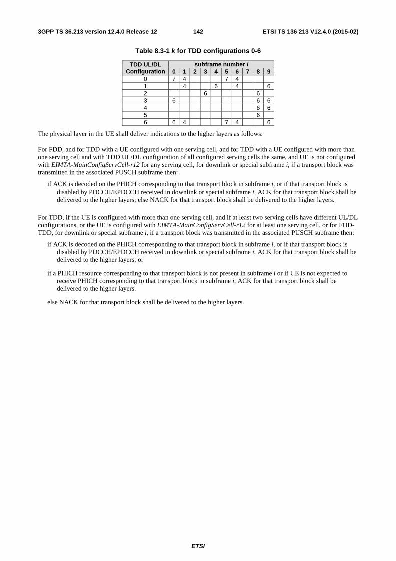
ETSI
ETSI TS 136 213 V12.4.0 (2015-02)1423GPP TS 36.213 version 12.4.0 Release 12
Table 8.3-1 k for TDD configurations 0-6
TDD UL/DL Configuration
subframe number i 0 1 2 3 4 5 6 7 8 9
0 7 4 7 4 1 4 6 4 6 2 6 6 3 6 6 6 4 6 6 5 6 6 6 4 7 4 6
The physical layer in the UE shall deliver indications to the higher layers as follows:
For FDD, and for TDD with a UE configured with one serving cell, and for TDD with a UE configured with more than one serving cell and with TDD UL/DL configuration of all configured serving cells the same, and UE is not configured with EIMTA-MainConfigServCell-r12 for any serving cell, for downlink or special subframe i, if a transport block was transmitted in the associated PUSCH subframe then:
if ACK is decoded on the PHICH corresponding to that transport block in subframe i, or if that transport block is disabled by PDCCH/EPDCCH received in downlink or special subframe i, ACK for that transport block shall be delivered to the higher layers; else NACK for that transport block shall be delivered to the higher layers.
For TDD, if the UE is configured with more than one serving cell, and if at least two serving cells have different UL/DL configurations, or the UE is configured with EIMTA-MainConfigServCell-r12 for at least one serving cell, or for FDD-TDD, for downlink or special subframe i, if a transport block was transmitted in the associated PUSCH subframe then:
if ACK is decoded on the PHICH corresponding to that transport block in subframe i, or if that transport block is disabled by PDCCH/EPDCCH received in downlink or special subframe i, ACK for that transport block shall be delivered to the higher layers; or
if a PHICH resource corresponding to that transport block is not present in subframe i or if UE is not expected to receive PHICH corresponding to that transport block in subframe i, ACK for that transport block shall be delivered to the higher layers.
else NACK for that transport block shall be delivered to the higher layers.
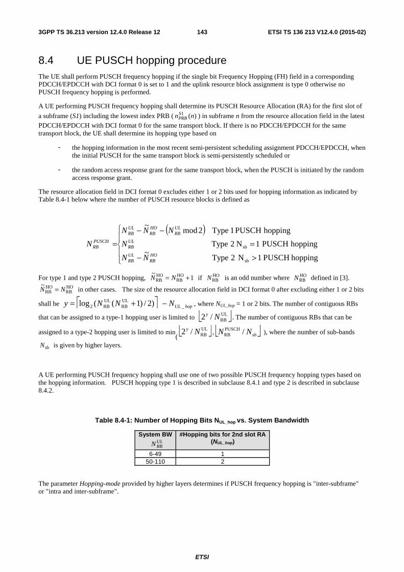
ETSI
ETSI TS 136 213 V12.4.0 (2015-02)1433GPP TS 36.213 version 12.4.0 Release 12
8.4 UE PUSCH hopping procedure The UE shall perform PUSCH frequency hopping if the single bit Frequency Hopping (FH) field in a corresponding PDCCH/EPDCCH with DCI format 0 is set to 1 and the uplink resource block assignment is type 0 otherwise no PUSCH frequency hopping is performed.
A UE performing PUSCH frequency hopping shall determine its PUSCH Resource Allocation (RA) for the first slot of
a subframe (S1) including the lowest index PRB ( )(1 nnSPRB ) in subframe n from the resource allocation field in the latest
PDCCH/EPDCCH with DCI format 0 for the same transport block. If there is no PDCCH/EPDCCH for the same transport block, the UE shall determine its hopping type based on
- the hopping information in the most recent semi-persistent scheduling assignment PDCCH/EPDCCH, when the initial PUSCH for the same transport block is semi-persistently scheduled or
- the random access response grant for the same transport block, when the PUSCH is initiated by the random access response grant.
The resource allocation field in DCI format 0 excludes either 1 or 2 bits used for hopping information as indicated by Table 8.4-1 below where the number of PUSCH resource blocks is defined as
( )
⎪⎩
⎪⎨
⎧
>−
=
−−
=
hoppingPUSCH1N2Type~
hoppingPUSCH1N2Type
hoppingPUSCH1Type2mod~
sb
sb
HORB
ULRB
ULRB
ULRB
HORB
ULRB
PUSCHRB
NN
N
NNN
N
For type 1 and type 2 PUSCH hopping, 1~ HO
RBHORB += NN if HO
RBN is an odd number where HORBN defined in [3].
HORB
HORB
~NN = in other cases. The size of the resource allocation field in DCI format 0 after excluding either 1 or 2 bits
shall be ⎡ ⎤ hopULNNNy _ULRB
ULRB2 )2/)1((log −+= , where NUL_hop = 1 or 2 bits. The number of contiguous RBs
that can be assigned to a type-1 hopping user is limited to ⎣ ⎦UL
RB/2 Ny . The number of contiguous RBs that can be
assigned to a type-2 hopping user is limited to min
( ⎣ ⎦ULRB/2 Ny , ⎣ ⎦sbNN /PUSCH
RB ), where the number of sub-bands
sbN is given by higher layers.
A UE performing PUSCH frequency hopping shall use one of two possible PUSCH frequency hopping types based on the hopping information. PUSCH hopping type 1 is described in subclause 8.4.1 and type 2 is described in subclause 8.4.2.
Table 8.4-1: Number of Hopping Bits NUL_hop vs. System Bandwidth
System BW
ULRBN
#Hopping bits for 2nd slot RA (NUL_hop)
6-49 1 50-110 2
The parameter Hopping-mode provided by higher layers determines if PUSCH frequency hopping is "inter-subframe" or "intra and inter-subframe".
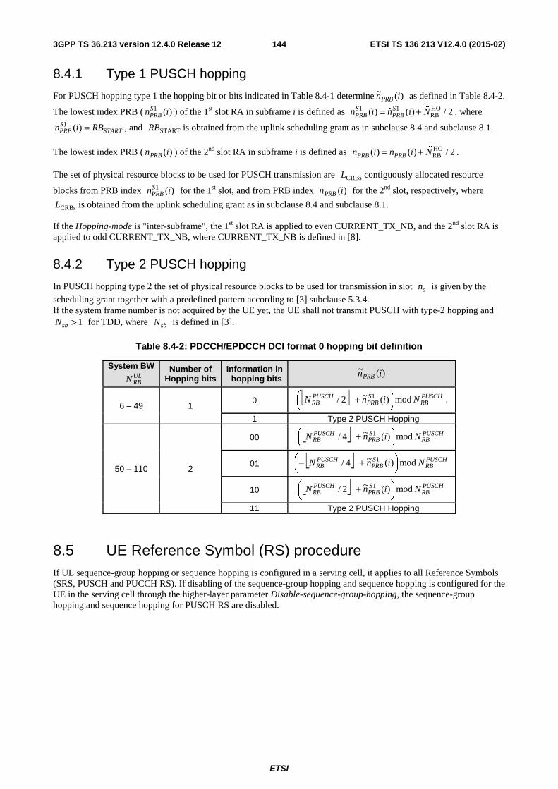
ETSI
ETSI TS 136 213 V12.4.0 (2015-02)1443GPP TS 36.213 version 12.4.0 Release 12
8.4.1 Type 1 PUSCH hopping
For PUSCH hopping type 1 the hopping bit or bits indicated in Table 8.4-1 determine )(~ inPRB as defined in Table 8.4-2.
The lowest index PRB ( 1 ( )SPRBn i ) of the 1st slot RA in subframe i is defined as 1 1 HO
RB( ) ( ) / 2S SPRB PRBn i n i N= + %
% , where 1 ( )S
PRB STARTn i RB= , and STARTRB is obtained from the uplink scheduling grant as in subclause 8.4 and subclause 8.1.
The lowest index PRB ( )(inPRB ) of the 2nd slot RA in subframe i is defined as HORB( ) ( ) / 2PRB PRBn i n i N= + %
% .
The set of physical resource blocks to be used for PUSCH transmission are CRBsL contiguously allocated resource
blocks from PRB index 1 ( )SPRBn i for the 1st slot, and from PRB index )(inPRB for the 2nd slot, respectively, where
CRBsL is obtained from the uplink scheduling grant as in subclause 8.4 and subclause 8.1.
If the Hopping-mode is "inter-subframe", the 1st slot RA is applied to even CURRENT_TX_NB, and the 2nd slot RA is applied to odd CURRENT_TX_NB, where CURRENT_TX_NB is defined in [8].
8.4.2 Type 2 PUSCH hopping
In PUSCH hopping type 2 the set of physical resource blocks to be used for transmission in slot sn is given by the
scheduling grant together with a predefined pattern according to [3] subclause 5.3.4. If the system frame number is not acquired by the UE yet, the UE shall not transmit PUSCH with type-2 hopping and
1sbN > for TDD, where sbN is defined in [3].
Table 8.4-2: PDCCH/EPDCCH DCI format 0 hopping bit definition
System BW
ULRBN
Number of Hopping bits
Information in hopping bits
)(~ inPRB
6 – 49 1 0 ⎣ ⎦ PUSCH
RBSPRB
PUSCHRB NinN mod)(~2/ 1
⎟⎠⎞
⎜⎝⎛ + ,
1 Type 2 PUSCH Hopping
50 – 110 2
00 ⎣ ⎦ PUSCHRB
SPRB
PUSCHRB NinN mod)(~4/ 1
⎟⎠⎞
⎜⎝⎛ +
01 ⎣ ⎦ PUSCHRB
SPRB
PUSCHRB NinN mod)(~4/ 1
⎟⎠⎞
⎜⎝⎛ +−
10 ⎣ ⎦ PUSCHRB
SPRB
PUSCHRB NinN mod)(~2/ 1
⎟⎠⎞
⎜⎝⎛ +
11 Type 2 PUSCH Hopping
8.5 UE Reference Symbol (RS) procedure If UL sequence-group hopping or sequence hopping is configured in a serving cell, it applies to all Reference Symbols (SRS, PUSCH and PUCCH RS). If disabling of the sequence-group hopping and sequence hopping is configured for the UE in the serving cell through the higher-layer parameter Disable-sequence-group-hopping, the sequence-group hopping and sequence hopping for PUSCH RS are disabled.
ETSI
ETSI TS 136 213 V12.4.0 (2015-02)1453GPP TS 36.213 version 12.4.0 Release 12
8.6 Modulation order, redundancy version and transport block size determination
To determine the modulation order, redundancy version and transport block size for the physical uplink shared channel, the UE shall first
− read the "modulation and coding scheme and redundancy version" field ( MCSI ), and
− check the "CSI request" bit field, and
− compute the total number of allocated PRBs ( PRBN ) based on the procedure defined in subclause 8.1, and
− compute the number of coded symbols for control information.
8.6.1 Modulation order and redundancy version determination
For 280 MCS ≤≤ I , the modulation order ( mQ ) is determined as follows:
- If the UE is capable of supporting 64QAM in PUSCH and has not been configured by higher layers to transmit
only QPSK and 16QAM, the modulation order is given by 'mQ in Table 8.6.1-1.
- If the UE is not capable of supporting 64QAM in PUSCH or has been configured by higher layers to transmit
only QPSK and 16QAM, 'mQ is first read from Table 8.6.1-1. The modulation order is set to ),4min( '
mm QQ = .
- If the parameter ttiBundling provided by higher layers is set to TRUE, then the modulation order is set to
2=mQ . Resource allocation size is restricted to 3PRB ≤N applies in this case if the UE does not indicate
support by higher layers to operate without it.
For 3129 MCS ≤≤ I the modulation order ( mQ ) is determined as follows:
- if DCI format 0 is used and 29MCS =I or, if DCI format 4 is used and only 1 TB is enabled and 29MCS =I for
the enabled TB and the signalled number of transmission layers is 1, and if
- the "CSI request" bit field is 1 bit and the bit is set to trigger an aperiodic report and, 4PRB ≤N or,
- the "CSI request" bit field is 2 bits and is triggering an aperiodic CSI report for one serving cell according to
Table 7.2.1-1A, and, 4PRB ≤N or,
- the "CSI request" bit field is 2 bits and is triggering an aperiodic CSI report for more than one serving cell
according to Table 7.2.1-1A and, 20PRB ≤N , or,
- the "CSI request" bit field is 2 bits and is triggering an aperiodic CSI report for one CSI process according to
Table 7.2.1-1B and 4PRB ≤N , or,
- the "CSI request" bit field is 2 bits and is triggering an aperiodic CSI report for more than one CSI process
according to Table 7.2.1-1B and 20PRB ≤N ,
then the modulation order is set to 2=mQ .
- Otherwise, the modulation order shall be determined from the DCI transported in the latest PDCCH/EPDCCH with DCI format 0/4 for the same transport block using 280 MCS ≤≤ I . If there is no PDCCH/EPDCCH with
DCI format 0/4 for the same transport block using 280 MCS ≤≤ I , the modulation order shall be determined from
- the most recent semi-persistent scheduling assignment PDCCH/EPDCCH, when the initial PUSCH for the same transport block is semi-persistently scheduled, or,
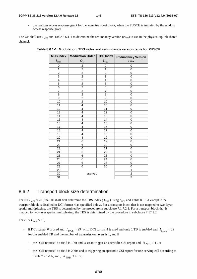
ETSI
ETSI TS 136 213 V12.4.0 (2015-02)1463GPP TS 36.213 version 12.4.0 Release 12
- the random access response grant for the same transport block, when the PUSCH is initiated by the random access response grant.
The UE shall use MCSI and Table 8.6.1-1 to determine the redundancy version (rvidx) to use in the physical uplink shared
channel.
Table 8.6.1-1: Modulation, TBS index and redundancy version table for PUSCH
MCS Index
MCSI
Modulation Order 'mQ
TBS Index
TBSI Redundancy Version
rvidx
0 2 0 0 1 2 1 0 2 2 2 0 3 2 3 0 4 2 4 0 5 2 5 0 6 2 6 0 7 2 7 0 8 2 8 0 9 2 9 0
10 2 10 0 11 4 10 0 12 4 11 0 13 4 12 0 14 4 13 0 15 4 14 0 16 4 15 0 17 4 16 0 18 4 17 0 19 4 18 0 20 4 19 0 21 6 19 0 22 6 20 0 23 6 21 0 24 6 22 0 25 6 23 0 26 6 24 0 27 6 25 0 28 6 26 0 29
reserved 1
30 2 31 3
8.6.2 Transport block size determination
For 280 MCS ≤≤ I , the UE shall first determine the TBS index ( TBSI ) using MCSI and Table 8.6.1-1 except if the
transport block is disabled in DCI format 4 as specified below. For a transport block that is not mapped to two-layer spatial multiplexing, the TBS is determined by the procedure in subclause 7.1.7.2.1. For a transport block that is mapped to two-layer spatial multiplexing, the TBS is determined by the procedure in subclause 7.17.2.2.
For 3129 MCS ≤≤ I ,
- if DCI format 0 is used and 29MCS =I or, if DCI format 4 is used and only 1 TB is enabled and 29MCS =I
for the enabled TB and the number of transmission layers is 1, and if
- the "CSI request" bit field is 1 bit and is set to trigger an aperiodic CSI report and 4PRB ≤N , or
- the "CSI request" bit field is 2 bits and is triggering an aperiodic CSI report for one serving cell according to
Table 7.2.1-1A, and , 4PRB ≤N or,
ETSI
ETSI TS 136 213 V12.4.0 (2015-02)1473GPP TS 36.213 version 12.4.0 Release 12
- the "CSI request" bit field is 2 bits and is triggering aperiodic CSI report for more than one serving cell
according to Table 7.2.1-1A and, 20PRB ≤N , or,
- the "CSI request" bit field is 2 bits and is triggering an aperiodic CSI report for one CSI process according to
Table 7.2.1-1B and 4PRB ≤N , or,
- the "CSI request" bit field is 2 bits and is triggering an aperiodic CSI report for more than one CSI process
according to Table 7.2.1-1B and, 20PRB ≤N
then there is no transport block for the UL-SCH and only the control information feedback for the current PUSCH reporting mode is transmitted by the UE.
- Otherwise, the transport block size shall be determined from the initial PDCCH/EPDCCH for the same transport block using 280 MCS ≤≤ I . If there is no initial PDCCH/EPDCCH with an uplink DCI format for the same
transport block using 280 MCS ≤≤ I , the transport block size shall be determined from
- the most recent semi-persistent scheduling assignment PDCCH/EPDCCH, when the initial PUSCH for the same transport block is semi-persistently scheduled, or,
- the random access response grant for the same transport block, when the PUSCH is initiated by the random access response grant.
In DCI format 4 a transport block is disabled if either the combination of 0MCS =I and 1PRB >N or the combination
of 28MCS =I and 1PRB =N is signalled, otherwise the transport block is enabled.

ETSI
ETSI TS 136 213 V12.4.0 (2015-02)1483GPP TS 36.213 version 12.4.0 Release 12
8.6.3 Control information MCS offset determination
Offset values are defined for single codeword PUSCH transmission and multiple codeword PUSCH transmission.
Single codeword PUSCH transmission offsets ACKHARQoffset
−β , RIoffsetβ and CQI
offsetβ shall be configured to values
according to Table 8.6.3-1,2,3 with the higher layer signalled indexes ACKHARQoffsetI − , RI
offsetI , and CQIoffsetI , respectively.
Multiple codeword PUSCH transmission offsets ACKHARQoffset
−β , RIoffsetβ and CQI
offsetβ shall be configured to values
according to Table 8.6.3-1,2,3 with the higher layer signalled indexes ACKHARQMCoffsetI −
, , RIMCoffsetI , and CQI
MCoffsetI , ,
respectively.
If the UE is configured with higher layer parameter UplinkPowerControlDedicated-v12x0 for serving cell c , and if a subframe belongs to uplink power control subframe set 2 as indicated by the higher layer parameter tpc-SubframeSet-r12, then for that subframe, the UE shall use
- the higher layer indexes ACKHARQ
set2offset,I −, RI
setoffsetI 2, and CQIsetoffsetI 2, in place of ACKHARQ
offsetI − , RIoffsetI , and CQI
offsetI
respectively in Tables 8.6.3-1,2,3, to determine ACKHARQoffset
−β , RIoffsetβ and CQI
offsetβ respectively for single
codeword PUSCH transmissions, and
- the higher layer indexes ACKHARQ
set2MC,offset,I −, RI
setMCoffsetI 2,, and CQIsetMCoffsetI 2,, in place of ACKHARQ
MCoffsetI −, , RI
MCoffsetI , and
CQIMCoffsetI , respectively in Tables 8.6.3-1,2,3, to determine ACKHARQ
offset−β , RI
offsetβ and CQIoffsetβ respectively for
multiple codeword PUSCH transmissions.
Table 8.6.3-1: Mapping of HARQ-ACK offset values and the index signalled by higher layers
ACKHARQoffsetI −
or ACKHARQ
MCoffsetI −,
ACKHARQoffset
−β
0 2.000
1 2.500
2 3.125
3 4.000
4 5.000
5 6.250
6 8.000
7 10.000
8 12.625
9 15.875
10 20.000
11 31.000
12 50.000
13 80.000
14 126.000
15 1.0
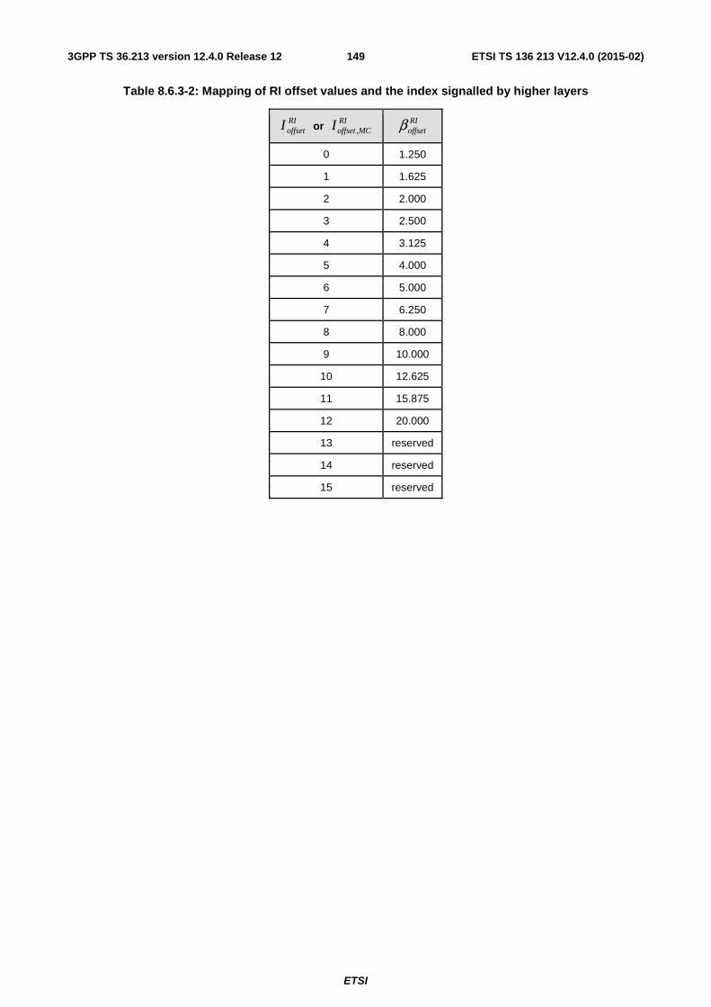
ETSI
ETSI TS 136 213 V12.4.0 (2015-02)1493GPP TS 36.213 version 12.4.0 Release 12
Table 8.6.3-2: Mapping of RI offset values and the index signalled by higher layers
RIoffsetI or
RIMCoffsetI ,
RIoffsetβ
0 1.250
1 1.625
2 2.000
3 2.500
4 3.125
5 4.000
6 5.000
7 6.250
8 8.000
9 10.000
10 12.625
11 15.875
12 20.000
13 reserved
14 reserved
15 reserved
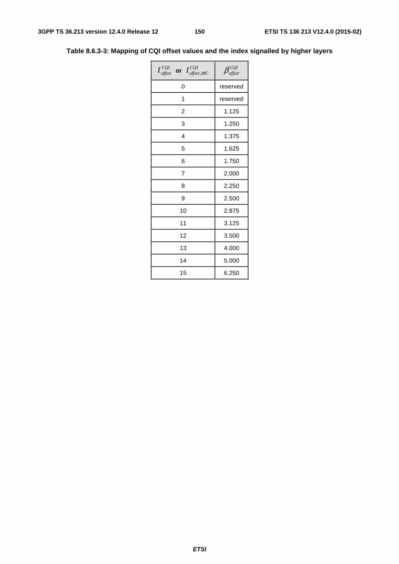
ETSI
ETSI TS 136 213 V12.4.0 (2015-02)1503GPP TS 36.213 version 12.4.0 Release 12
Table 8.6.3-3: Mapping of CQI offset values and the index signalled by higher layers
CQIoffsetI or
CQIMCoffsetI ,
CQIoffsetβ
0 reserved
1 reserved
2 1.125
3 1.250
4 1.375
5 1.625
6 1.750
7 2.000
8 2.250
9 2.500
10 2.875
11 3.125
12 3.500
13 4.000
14 5.000
15 6.250
ETSI
ETSI TS 136 213 V12.4.0 (2015-02)1513GPP TS 36.213 version 12.4.0 Release 12
8.7 UE transmit antenna selection UE transmit antenna selection is configured by higher layers via parameter ue-TransmitAntennaSelection.
A UE configured with transmit antenna selection for a serving cell is not expected to
• be configured with more than one antenna port for any uplink physical channel or signal for any configured serving cell, or
• be configured with trigger type 1 SRS transmission on any configured serving cell, or
• be configured with simultaneous PUCCH and PUSCH transmission, or
• be configured with demodulation reference signal for PUSCH with OCC for any configured serving cell (see [3], subclause 5.5.2.1.1), or
• receive DCI Format 0 indicating uplink resource allocation type 1 for any serving cell.
If UE transmit antenna selection is disabled or not supported by the UE, the UE shall transmit from UE port 0.
If closed-loop UE transmit antenna selection is enabled by higher layers the UE shall perform transmit antenna selection for PUSCH in response to the most recent command received via DCI Format 0 in subclause 5.3.3.2 of [4]. If a UE is configured with more than one serving cell, the UE may assume the same transmit antenna port value is indicated in each PDCCH/EPDCCH with DCI format 0 in a given subframe.
If open-loop UE transmit antenna selection is enabled by higher layers, the transmit antenna for PUSCH/SRS to be selected by the UE is not specified.
9 Physical downlink control channel procedures If the UE is configured with a SCG, the UE shall apply the procedures described in this clause for both MCG and SCG
- When the procedures are applied for MCG, the terms ‘secondary cell’, ‘secondary cells’ , ‘serving cell’, ‘serving cells’ in this clause refer to secondary cell, secondary cells, serving cell, serving cells belonging to the MCG respectively.
- When the procedures are applied for SCG, the terms ‘secondary cell’, ‘secondary cells’, ‘serving cell’, ‘serving cells’ in this clause refer to secondary cell, secondary cells (not including PSCell), serving cell, serving cells belonging to the SCG respectively. The term ‘primary cell’ in this clause refers to the PSCell of the SCG.
9.1 UE procedure for determining physical downlink control channel assignment
9.1.1 PDCCH assignment procedure
The control region of each serving cell consists of a set of CCEs, numbered from 0 to 1,CCE −kN according to
subclause 6.8.1 in [3], where kN ,CCE is the total number of CCEs in the control region of subframe k .
The UE shall monitor a set of PDCCH candidates on one or more activated serving cells as configured by higher layer signalling for control information, where monitoring implies attempting to decode each of the PDCCHs in the set according to all the monitored DCI formats.
The set of PDCCH candidates to monitor are defined in terms of search spaces, where a search space )(LkS at
aggregation level { }8,4,2,1∈L is defined by a set of PDCCH candidates. For each serving cell on which PDCCH is
monitored, the CCEs corresponding to PDCCH candidate m of the search space )(LkS are given by
⎣ ⎦{ } iLNmYL kk +′+ /mod)( ,CCE
ETSI
ETSI TS 136 213 V12.4.0 (2015-02)1523GPP TS 36.213 version 12.4.0 Release 12
where kY is defined below, 0, , 1i L= −L . For the common search space mm =′ . For the PDCCH UE specific search
space, for the serving cell on which PDCCH is monitored, if the monitoring UE is configured with carrier indicator field
then CIL nMmm ⋅+=′ )( where CIn is the carrier indicator field value, else if the monitoring UE is not configured
with carrier indicator field then mm =′ , where ( )0, , 1Lm M= −L . )(LM is the number of PDCCH candidates to monitor in the given search space.
Note that the carrier indicator field value is the same as ServCellIndex given in [11].
The UE shall monitor one common search space in every non-DRX subframe at each of the aggregation levels 4 and 8 on the primary cell.
The UE shall monitor common search space on a cell to decode the PDCCHs necessary to decode PMCH on that cell if configured to decode PMCH by higher layers.
If a UE is not configured for EPDCCH monitoring, and if the UE is not configured with a carrier indicator field, then the UE shall monitor one PDCCH UE-specific search space at each of the aggregation levels 1, 2, 4, 8 on each activated serving cell in every non-DRX subframe.
If a UE is not configured for EPDCCH monitoring, and if the UE is configured with a carrier indicator field, then the UE shall monitor one or more UE-specific search spaces at each of the aggregation levels 1, 2, 4, 8 on one or more activated serving cells as configured by higher layer signalling in every non-DRX subframe.
If a UE is configured for EPDCCH monitoring on a serving cell, and if that serving cell is activated, and if the UE is not configured with a carrier indicator field, then the UE shall monitor one PDCCH UE-specific search space at each of the aggregation levels 1, 2, 4, 8 on that serving cell in all non-DRX subframes where EPDCCH is not monitored on that serving cell.
If a UE is configured for EPDCCH monitoring on a serving cell, and if that serving cell is activated, and if the UE is configured with a carrier indicator field, then the UE shall monitor one or more PDCCH UE-specific search spaces at each of the aggregation levels 1, 2, 4, 8 on that serving cell as configured by higher layer signalling in all non-DRX subframes where EPDCCH is not monitored on that serving cell.
The common and PDCCH UE-specific search spaces on the primary cell may overlap.
A UE configured with the carrier indicator field associated with monitoring PDCCH on serving cell c shall monitor PDCCH configured with carrier indicator field and with CRC scrambled by C-RNTI in the PDCCH UE specific search space of serving cell c.
A UE configured with the carrier indicator field associated with monitoring PDCCH on the primary cell shall monitor PDCCH configured with carrier indicator field and with CRC scrambled by SPS C-RNTI in the PDCCH UE specific search space of the primary cell.
The UE shall monitor the common search space for PDCCH without carrier indicator field.
For the serving cell on which PDCCH is monitored, if the UE is not configured with a carrier indicator field, it shall monitor the PDCCH UE specific search space for PDCCH without carrier indicator field, if the UE is configured with a carrier indicator field it shall monitor the PDCCH UE specific search space for PDCCH with carrier indicator field.
A UE is not expected to monitor the PDCCH of a secondary cell if it is configured to monitor PDCCH with carrier indicator field corresponding to that secondary cell in another serving cell. For the serving cell on which PDCCH is monitored, the UE shall monitor PDCCH candidates at least for the same serving cell.
A UE configured to monitor PDCCH candidates with CRC scrambled by C-RNTI or SPS C-RNTI with a common payload size and with the same first CCE index CCEn (as described in subclause 10.1) but with different sets of DCI
information fields as defined in [4] in the
- common search space
- PDCCH UE specific search space
on the primary cell shall assume that for the PDCCH candidates with CRC scrambled by C-RNTI or SPS C-RNTI,
- if the UE is configured with the carrier indicator field associated with monitoring the PDCCH on the primary cell, only the PDCCH in the common search space is transmitted by the primary cell;
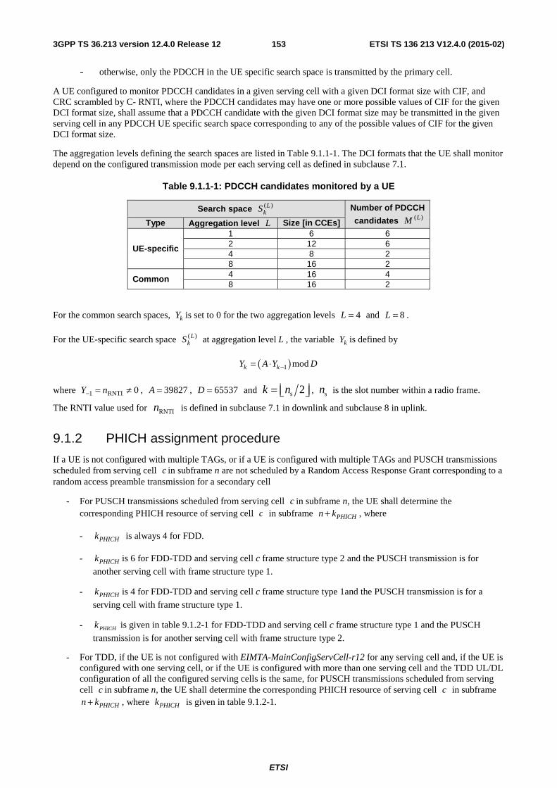
ETSI
ETSI TS 136 213 V12.4.0 (2015-02)1533GPP TS 36.213 version 12.4.0 Release 12
- otherwise, only the PDCCH in the UE specific search space is transmitted by the primary cell.
A UE configured to monitor PDCCH candidates in a given serving cell with a given DCI format size with CIF, and CRC scrambled by C- RNTI, where the PDCCH candidates may have one or more possible values of CIF for the given DCI format size, shall assume that a PDCCH candidate with the given DCI format size may be transmitted in the given serving cell in any PDCCH UE specific search space corresponding to any of the possible values of CIF for the given DCI format size.
The aggregation levels defining the search spaces are listed in Table 9.1.1-1. The DCI formats that the UE shall monitor depend on the configured transmission mode per each serving cell as defined in subclause 7.1.
Table 9.1.1-1: PDCCH candidates monitored by a UE
Search space )(LkS Number of PDCCH
candidates )(LM Type Aggregation level L Size [in CCEs]
UE-specific
1 6 6 2 12 6 4 8 2 8 16 2
Common 4 16 4 8 16 2
For the common search spaces, kY is set to 0 for the two aggregation levels 4=L and 8=L .
For the UE-specific search space )(LkS at aggregation level L , the variable kY is defined by
( )1 modk kY A Y D−= ⋅
where 0RNTI1 ≠=− nY , 39827=A , 65537=D and s 2k n= ⎢ ⎥⎣ ⎦ , sn is the slot number within a radio frame.
The RNTI value used for RNTIn is defined in subclause 7.1 in downlink and subclause 8 in uplink.
9.1.2 PHICH assignment procedure
If a UE is not configured with multiple TAGs, or if a UE is configured with multiple TAGs and PUSCH transmissions scheduled from serving cell c in subframe n are not scheduled by a Random Access Response Grant corresponding to a random access preamble transmission for a secondary cell
- For PUSCH transmissions scheduled from serving cell c in subframe n, the UE shall determine the corresponding PHICH resource of serving cell c in subframe PHICHn k+ , where
- PHICHk is always 4 for FDD.
- PHICHk is 6 for FDD-TDD and serving cell c frame structure type 2 and the PUSCH transmission is for
another serving cell with frame structure type 1.
- PHICHk is 4 for FDD-TDD and serving cell c frame structure type 1and the PUSCH transmission is for a
serving cell with frame structure type 1.
- PHICHk is given in table 9.1.2-1 for FDD-TDD and serving cell c frame structure type 1 and the PUSCH
transmission is for another serving cell with frame structure type 2.
- For TDD, if the UE is not configured with EIMTA-MainConfigServCell-r12 for any serving cell and, if the UE is configured with one serving cell, or if the UE is configured with more than one serving cell and the TDD UL/DL configuration of all the configured serving cells is the same, for PUSCH transmissions scheduled from serving cell c in subframe n, the UE shall determine the corresponding PHICH resource of serving cell c in subframe
PHICHn k+ , where PHICHk is given in table 9.1.2-1.
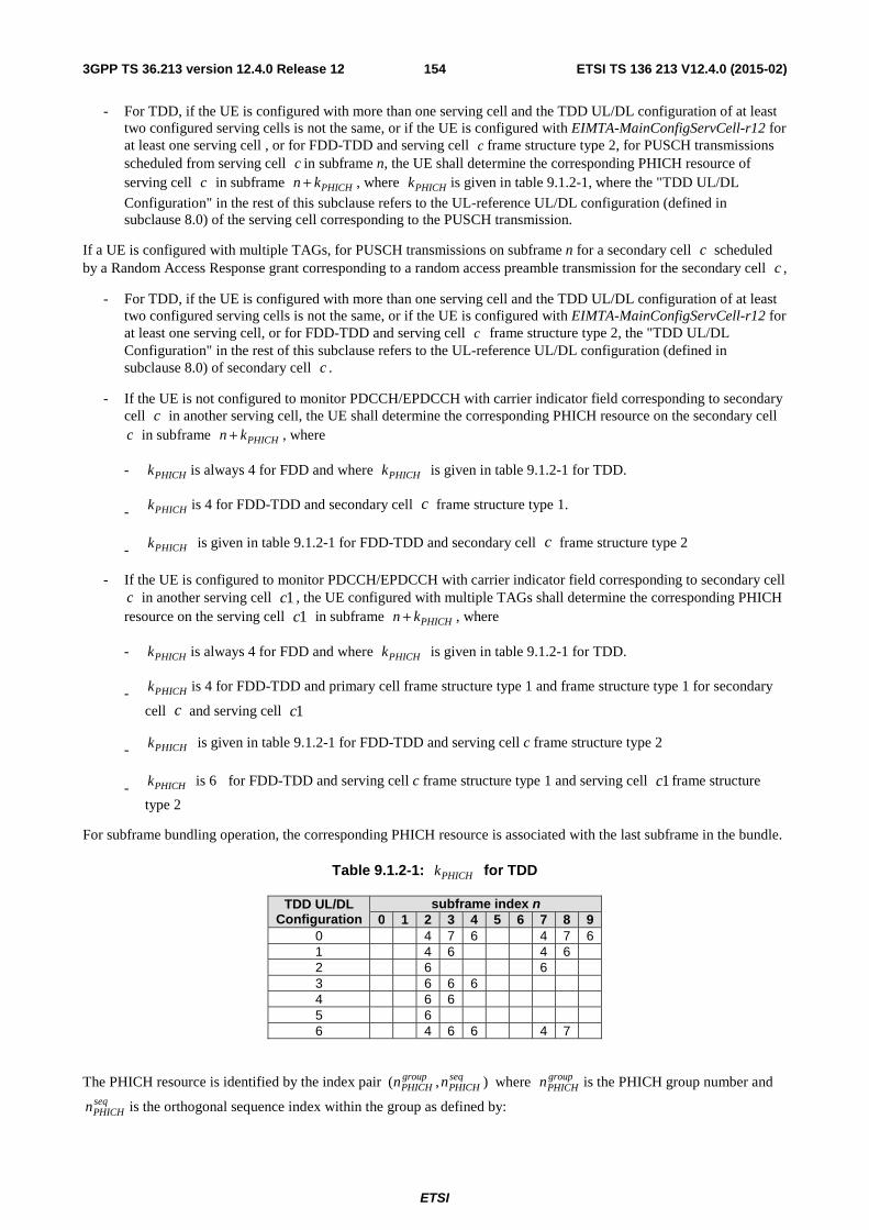
ETSI
ETSI TS 136 213 V12.4.0 (2015-02)1543GPP TS 36.213 version 12.4.0 Release 12
- For TDD, if the UE is configured with more than one serving cell and the TDD UL/DL configuration of at least two configured serving cells is not the same, or if the UE is configured with EIMTA-MainConfigServCell-r12 for at least one serving cell , or for FDD-TDD and serving cell c frame structure type 2, for PUSCH transmissions scheduled from serving cell c in subframe n, the UE shall determine the corresponding PHICH resource of serving cell c in subframe PHICHn k+ , where PHICHk is given in table 9.1.2-1, where the "TDD UL/DL
Configuration" in the rest of this subclause refers to the UL-reference UL/DL configuration (defined in subclause 8.0) of the serving cell corresponding to the PUSCH transmission.
If a UE is configured with multiple TAGs, for PUSCH transmissions on subframe n for a secondary cell c scheduled by a Random Access Response grant corresponding to a random access preamble transmission for the secondary cell c ,
- For TDD, if the UE is configured with more than one serving cell and the TDD UL/DL configuration of at least two configured serving cells is not the same, or if the UE is configured with EIMTA-MainConfigServCell-r12 for at least one serving cell, or for FDD-TDD and serving cell c frame structure type 2, the "TDD UL/DL Configuration" in the rest of this subclause refers to the UL-reference UL/DL configuration (defined in subclause 8.0) of secondary cell c .
- If the UE is not configured to monitor PDCCH/EPDCCH with carrier indicator field corresponding to secondary cell c in another serving cell, the UE shall determine the corresponding PHICH resource on the secondary cell c in subframe PHICHn k+ , where
- PHICHk is always 4 for FDD and where PHICHk is given in table 9.1.2-1 for TDD.
- PHICHk is 4 for FDD-TDD and secondary cell c frame structure type 1.
- PHICHk is given in table 9.1.2-1 for FDD-TDD and secondary cell c frame structure type 2
- If the UE is configured to monitor PDCCH/EPDCCH with carrier indicator field corresponding to secondary cell c in another serving cell 1c , the UE configured with multiple TAGs shall determine the corresponding PHICH resource on the serving cell 1c in subframe PHICHn k+ , where
- PHICHk is always 4 for FDD and where PHICHk is given in table 9.1.2-1 for TDD.
- PHICHk is 4 for FDD-TDD and primary cell frame structure type 1 and frame structure type 1 for secondary
cell c and serving cell 1c
- PHICHk is given in table 9.1.2-1 for FDD-TDD and serving cell c frame structure type 2
- PHICHk is 6 for FDD-TDD and serving cell c frame structure type 1 and serving cell 1c frame structure
type 2
For subframe bundling operation, the corresponding PHICH resource is associated with the last subframe in the bundle.
Table 9.1.2-1: PHICHk for TDD
TDD UL/DL Configuration
subframe index n 0 1 2 3 4 5 6 7 8 9
0 4 7 6 4 7 6 1 4 6 4 6 2 6 6 3 6 6 6 4 6 6 5 6 6 4 6 6 4 7
The PHICH resource is identified by the index pair ),( seqPHICH
groupPHICH nn where group
PHICHn is the PHICH group number and seqPHICHn is the orthogonal sequence index within the group as defined by:
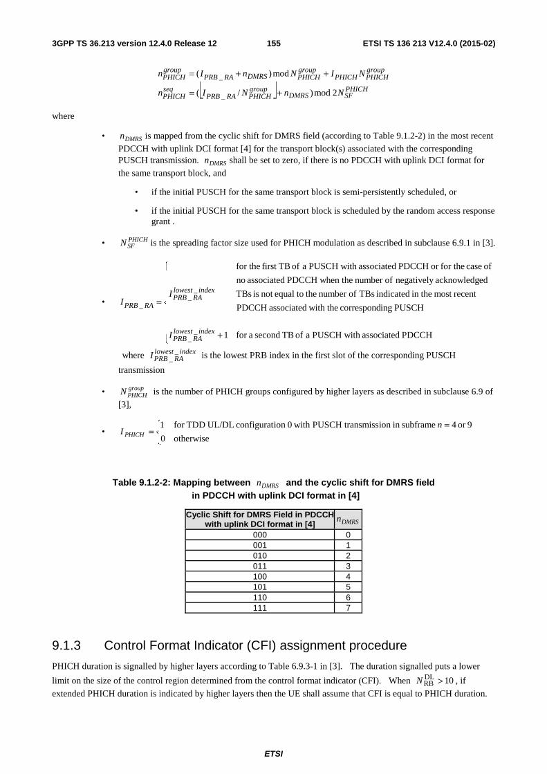
ETSI
ETSI TS 136 213 V12.4.0 (2015-02)1553GPP TS 36.213 version 12.4.0 Release 12
⎣ ⎦ PHICHSFDMRS
groupPHICHRAPRB
seqPHICH
groupPHICHPHICH
groupPHICHDMRSRAPRB
groupPHICH
NnNIn
NINnIn
2mod)/(
mod)(
_
_
+=
++=
where
• DMRSn is mapped from the cyclic shift for DMRS field (according to Table 9.1.2-2) in the most recent
PDCCH with uplink DCI format [4] for the transport block(s) associated with the corresponding PUSCH transmission. DMRSn shall be set to zero, if there is no PDCCH with uplink DCI format for
the same transport block, and
• if the initial PUSCH for the same transport block is semi-persistently scheduled, or
• if the initial PUSCH for the same transport block is scheduled by the random access response grant .
• PHICHSFN is the spreading factor size used for PHICH modulation as described in subclause 6.9.1 in [3].
•
⎪⎪⎪⎪
⎩
⎪⎪⎪⎪
⎨
⎧
+
=
PDCCHassociated tha PUSCH wi of TB seconda for 1
PUSCHingcorrespond the withassociatedPDCCH
recentmost thein indicated TBs ofnumber the toequalnot is TBs
edacknowledg negatively ofnumber thewhen PDCCH associated no
of case for theor PDCCHassociated tha PUSCH wi of TBfirst for the
__
__
_
indexlowestRAPRB
indexlowestRAPRB
RAPRB
I
II
where indexlowestRAPRBI _
_ is the lowest PRB index in the first slot of the corresponding PUSCH
transmission
• groupPHICHN is the number of PHICH groups configured by higher layers as described in subclause 6.9 of
[3],
• ⎩⎨⎧ =
=otherwise0
9or 4 subframein ion transmissPUSCH with 0ion configurat UL/DLTDDfor 1 nI PHICH
Table 9.1.2-2: Mapping between DMRSn and the cyclic shift for DMRS field in PDCCH with uplink DCI format in [4]
Cyclic Shift for DMRS Field in PDCCH with uplink DCI format in [4] DMRSn
000 0 001 1 010 2 011 3 100 4 101 5 110 6 111 7
9.1.3 Control Format Indicator (CFI) assignment procedure
PHICH duration is signalled by higher layers according to Table 6.9.3-1 in [3]. The duration signalled puts a lower
limit on the size of the control region determined from the control format indicator (CFI). When 10DLRB >N , if
extended PHICH duration is indicated by higher layers then the UE shall assume that CFI is equal to PHICH duration.
ETSI
ETSI TS 136 213 V12.4.0 (2015-02)1563GPP TS 36.213 version 12.4.0 Release 12
In subframes indicated by higher layers to decode PMCH, when 10DLRB >N , a UE may assume that CFI is equal to the
value of the higher layer parameter non-MBSFNregionLength [11].
9.1.4 EPDCCH assignment procedure
For each serving cell, higher layer signalling can configure a UE with one or two EPDCCH-PRB-sets for EPDCCH monitoring. The PRB-pairs corresponding to an EPDCCH-PRB-set are indicated by higher layers as described in
subclause 9.1.4.4. Each EPDCCH-PRB-set consists of set of ECCEs numbered from 0 to 1,,ECCE −kpN where
kpN ,,ECCE is the number of ECCEs in EPDCCH-PRB-set p of subframe k . Each EPDCCH-PRB-set can be
configured for either localized EPDCCH transmission or distributed EPDCCH transmission.
The UE shall monitor a set of EPDCCH candidates on one or more activated serving cells as configured by higher layer signalling for control information, where monitoring implies attempting to decode each of the EPDCCHs in the set according to the monitored DCI formats.
The set of EPDCCH candidates to monitor are defined in terms of EPDCCH UE-specific search spaces.
For each serving cell, the subframes in which the UE monitors EPDCCH UE-specific search spaces are configured by higher layers.
The UE shall not monitor EPDCCH
• For TDD and normal downlink CP, in special subframes for the special subframe configurations 0 and 5 shown in Table 4.2-1 of [3].
• For TDD and extended downlink CP, in special subframes for the special subframe configurations 0, 4 and 7 shown in Table 4.2-1 of [3].
• In subframes indicated by higher layers to decode PMCH.
• For TDD and if the UE is configured with different UL/DL configurations for the primary and a secondary cell, in a downlink subframe on the secondary cell when the same subframe on the primary cell is a special subframe and the UE is not capable of simultaneous reception and transmission on the primary and secondary cells.
An EPDCCH UE-specific search space )(LkES at aggregation level { }32,16,8,4,2,1∈L is defined by a set of
EPDCCH candidates.
For an EPDCCH-PRB-set p , the ECCEs corresponding to EPDCCH candidate m of the search space )( LkES are
given by
⎣ ⎦ iLNbML
NmYL kpL
p
kpECCEkp +
⎪⎭
⎪⎬⎫
⎪⎩
⎪⎨⎧
+⎥⎥⎦
⎥
⎢⎢⎣
⎢
⋅⋅
+ /mod)( ,,ECCE)(,,
,
where
kpY ,is defined below,
0, , 1i L= −L
CInb = if the UE is configured with a carrier indicator field for the serving cell on which EPDCCH is monitored,
otherwise 0=b
CIn is the carrier indicator field value,
1,1,0 )( −= LpMm K ,
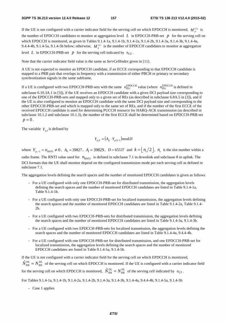
ETSI
ETSI TS 136 213 V12.4.0 (2015-02)1573GPP TS 36.213 version 12.4.0 Release 12
If the UE is not configured with a carrier indicator field for the serving cell on which EPDCCH is monitored, )( LpM is
the number of EPDCCH candidates to monitor at aggregation level L in EPDCCH-PRB-set p for the serving cell on
which EPDCCH is monitored, as given in Tables 9.1.4-1a, 9.1.4-1b, 9.1.4-2a, 9.1.4-2b, 9.1.4-3a, 9.1.4-3b, 9.1.4-4a, 9.4.4-4b, 9.1.4-5a, 9.1.4-5b below; otherwise, )( L
pM is the number of EPDCCH candidates to monitor at aggregation
level L in EPDCCH-PRB-set p for the serving cell indicated by CIn .
Note that the carrier indicator field value is the same as ServCellIndex given in [11].
A UE is not expected to monitor an EPDCCH candidate, if an ECCE corresponding to that EPDCCH candidate is mapped to a PRB pair that overlaps in frequency with a transmission of either PBCH or primary or secondary synchronization signals in the same subframe.
If a UE is configured with two EPDCCH-PRB-sets with the same EPDCCHID,in value (where EPDCCH
ID,in is defined in
subclause 6.10.3A.1 in [3]), if the UE receives an EPDCCH candidate with a given DCI payload size corresponding to one of the EPDCCH-PRB-sets and mapped only to a given set of REs (as described in subclause 6.8A.5 in [3]), and if the UE is also configured to monitor an EPDCCH candidate with the same DCI payload size and corresponding to the other EPDCCH-PRB-set and which is mapped only to the same set of REs, and if the number of the first ECCE of the received EPDCCH candidate is used for determining PUCCH resource for HARQ-ACK transmission (as described in subclause 10.1.2 and subclause 10.1.3), the number of the first ECCE shall be determined based on EPDCCH-PRB-set
0=p .
The variable kpY ,is defined by
( ) DYAY kppkp mod1,, −⋅=
where 0RNTI1, ≠=− nYp , 398270 =A , 398291 =A , 65537=D and s 2k n= ⎢ ⎥⎣ ⎦ , sn is the slot number within a
radio frame. The RNTI value used for RNTIn is defined in subclause 7.1 in downlink and subclause 8 in uplink. The
DCI formats that the UE shall monitor depend on the configured transmission mode per each serving cell as defined in subclause 7.1.
The aggregation levels defining the search spaces and the number of monitored EPDCCH candidates is given as follows
- For a UE configured with only one EPDCCH-PRB-set for distributed transmission, the aggregation levels defining the search spaces and the number of monitored EPDCCH candidates are listed in Table 9.1.4-1a, Table 9.1.4-1b.
- For a UE configured with only one EPDCCH-PRB-set for localized transmission, the aggregation levels defining the search spaces and the number of monitored EPDCCH candidates are listed in Table 9.1.4-2a, Table 9.1.4-2b.
- For a UE configured with two EPDCCH-PRB-sets for distributed transmission, the aggregation levels defining the search spaces and the number of monitored EPDCCH candidates are listed in Table 9.1.4-3a, 9.1.4-3b.
- For a UE configured with two EPDCCH-PRB-sets for localized transmission, the aggregation levels defining the search spaces and the number of monitored EPDCCH candidates are listed in Table 9.1.4-4a, 9.4.4-4b.
- For a UE configured with one EPDCCH-PRB-set for distributed transmission, and one EPDCCH-PRB-set for localized transmission, the aggregation levels defining the search spaces and the number of monitored EPDCCH candidates are listed in Table 9.1.4-5a, 9.1.4-5b.
If the UE is not configured with a carrier indicator field for the serving cell on which EPDCCH is monitored, DL DLRB RBN N= of the serving cell on which EPDCCH is monitored. If the UE is configured with a carrier indicator field
for the serving cell on which EPDCCH is monitored, DL DLRB RBN N= of the serving cell indicated by CIn .
For Tables 9.1.4-1a, 9.1.4-1b, 9.1.4-2a, 9.1.4-2b, 9.1.4-3a, 9.1.4-3b, 9.1.4-4a, 9.4.4-4b, 9.1.4-5a, 9.1.4-5b
- Case 1 applies
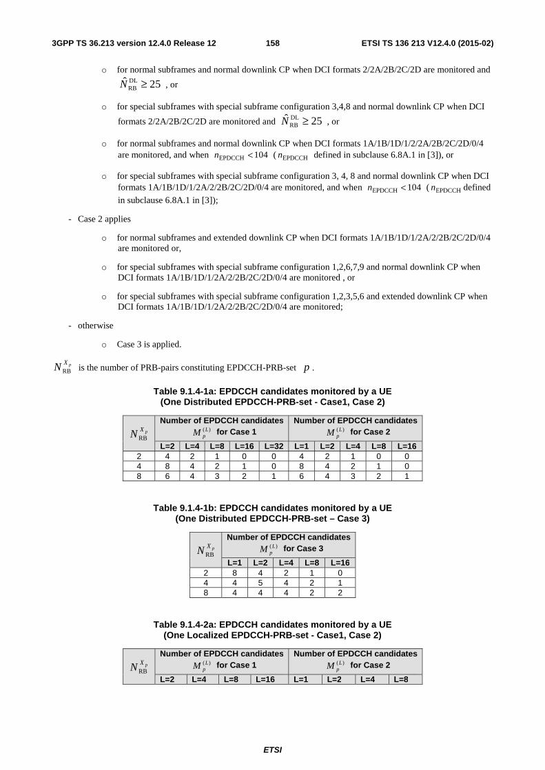
ETSI
ETSI TS 136 213 V12.4.0 (2015-02)1583GPP TS 36.213 version 12.4.0 Release 12
o for normal subframes and normal downlink CP when DCI formats 2/2A/2B/2C/2D are monitored and DLRB
ˆ 25N ≥ , or
o for special subframes with special subframe configuration 3,4,8 and normal downlink CP when DCI
formats 2/2A/2B/2C/2D are monitored and DLRB
ˆ 25N ≥ , or
o for normal subframes and normal downlink CP when DCI formats 1A/1B/1D/1/2/2A/2B/2C/2D/0/4 are monitored, and when 104EPDCCH <n ( EPDCCHn defined in subclause 6.8A.1 in [3]), or
o for special subframes with special subframe configuration 3, 4, 8 and normal downlink CP when DCI formats 1A/1B/1D/1/2A/2/2B/2C/2D/0/4 are monitored, and when 104EPDCCH <n ( EPDCCHn defined
in subclause 6.8A.1 in [3]);
- Case 2 applies
o for normal subframes and extended downlink CP when DCI formats 1A/1B/1D/1/2A/2/2B/2C/2D/0/4 are monitored or,
o for special subframes with special subframe configuration 1,2,6,7,9 and normal downlink CP when DCI formats 1A/1B/1D/1/2A/2/2B/2C/2D/0/4 are monitored , or
o for special subframes with special subframe configuration 1,2,3,5,6 and extended downlink CP when DCI formats 1A/1B/1D/1/2A/2/2B/2C/2D/0/4 are monitored;
- otherwise
o Case 3 is applied.
pXN RB is the number of PRB-pairs constituting EPDCCH-PRB-set p .
Table 9.1.4-1a: EPDCCH candidates monitored by a UE (One Distributed EPDCCH-PRB-set - Case1, Case 2)
pXN RB
Number of EPDCCH candidates )( L
pM for Case 1
Number of EPDCCH candidates )( L
pM for Case 2
L=2 L=4 L=8 L=16 L=32 L=1 L=2 L=4 L=8 L=16 2 4 2 1 0 0 4 2 1 0 0 4 8 4 2 1 0 8 4 2 1 0 8 6 4 3 2 1 6 4 3 2 1
Table 9.1.4-1b: EPDCCH candidates monitored by a UE (One Distributed EPDCCH-PRB-set – Case 3)
pXN RB
Number of EPDCCH candidates )( L
pM for Case 3
L=1 L=2 L=4 L=8 L=16 2 8 4 2 1 0 4 4 5 4 2 1 8 4 4 4 2 2
Table 9.1.4-2a: EPDCCH candidates monitored by a UE (One Localized EPDCCH-PRB-set - Case1, Case 2)
pXN RB
Number of EPDCCH candidates )( L
pM for Case 1
Number of EPDCCH candidates )( L
pM for Case 2
L=2 L=4 L=8 L=16 L=1 L=2 L=4 L=8
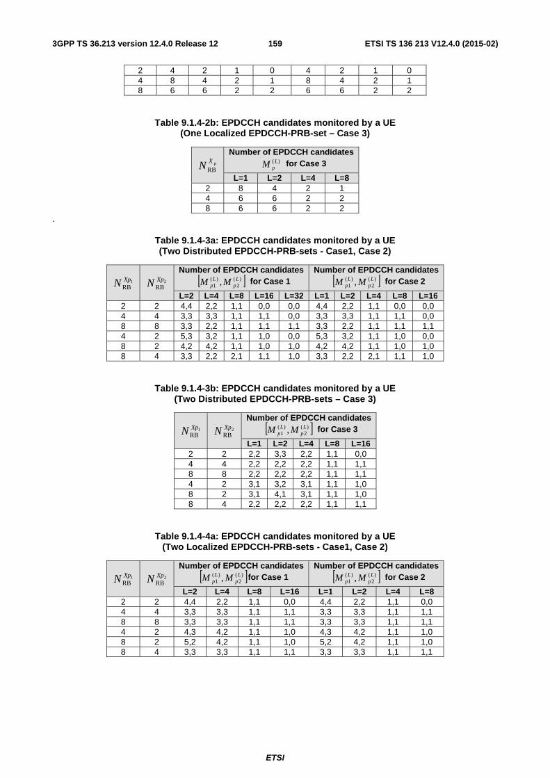
ETSI
ETSI TS 136 213 V12.4.0 (2015-02)1593GPP TS 36.213 version 12.4.0 Release 12
2 4 2 1 0 4 2 1 0 4 8 4 2 1 8 4 2 1 8 6 6 2 2 6 6 2 2
Table 9.1.4-2b: EPDCCH candidates monitored by a UE (One Localized EPDCCH-PRB-set – Case 3)
pXN RB
Number of EPDCCH candidates )( L
pM for Case 3
L=1 L=2 L=4 L=8 2 8 4 2 1 4 6 6 2 2 8 6 6 2 2
.
Table 9.1.4-3a: EPDCCH candidates monitored by a UE (Two Distributed EPDCCH-PRB-sets - Case1, Case 2)
1RBXpN 2
RBXpN
Number of EPDCCH candidates [ ])(
2)(
1 , Lp
Lp MM for Case 1
Number of EPDCCH candidates [ ])(
2)(
1 , Lp
Lp MM for Case 2
L=2 L=4 L=8 L=16 L=32 L=1 L=2 L=4 L=8 L=16 2 2 4,4 2,2 1,1 0,0 0,0 4,4 2,2 1,1 0,0 0,0 4 4 3,3 3,3 1,1 1,1 0,0 3,3 3,3 1,1 1,1 0,0 8 8 3,3 2,2 1,1 1,1 1,1 3,3 2,2 1,1 1,1 1,1 4 2 5,3 3,2 1,1 1,0 0,0 5,3 3,2 1,1 1,0 0,0 8 2 4,2 4,2 1,1 1,0 1,0 4,2 4,2 1,1 1,0 1,0 8 4 3,3 2,2 2,1 1,1 1,0 3,3 2,2 2,1 1,1 1,0
Table 9.1.4-3b: EPDCCH candidates monitored by a UE (Two Distributed EPDCCH-PRB-sets – Case 3)
1RBXpN 2
RBXpN
Number of EPDCCH candidates [ ])(
2)(
1 , Lp
Lp MM for Case 3
L=1 L=2 L=4 L=8 L=16 2 2 2,2 3,3 2,2 1,1 0,0 4 4 2,2 2,2 2,2 1,1 1,1 8 8 2,2 2,2 2,2 1,1 1,1 4 2 3,1 3,2 3,1 1,1 1,0 8 2 3,1 4,1 3,1 1,1 1,0 8 4 2,2 2,2 2,2 1,1 1,1
Table 9.1.4-4a: EPDCCH candidates monitored by a UE (Two Localized EPDCCH-PRB-sets - Case1, Case 2)
1RBXpN 2
RBXpN
Number of EPDCCH candidates [ ])(
2)(
1 , Lp
Lp MM for Case 1
Number of EPDCCH candidates [ ])(
2)(
1 , Lp
Lp MM for Case 2
L=2 L=4 L=8 L=16 L=1 L=2 L=4 L=8 2 2 4,4 2,2 1,1 0,0 4,4 2,2 1,1 0,0 4 4 3,3 3,3 1,1 1,1 3,3 3,3 1,1 1,1 8 8 3,3 3,3 1,1 1,1 3,3 3,3 1,1 1,1 4 2 4,3 4,2 1,1 1,0 4,3 4,2 1,1 1,0 8 2 5,2 4,2 1,1 1,0 5,2 4,2 1,1 1,0 8 4 3,3 3,3 1,1 1,1 3,3 3,3 1,1 1,1
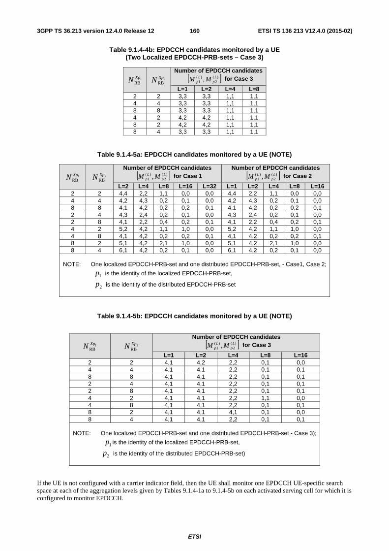
ETSI
ETSI TS 136 213 V12.4.0 (2015-02)1603GPP TS 36.213 version 12.4.0 Release 12
Table 9.1.4-4b: EPDCCH candidates monitored by a UE (Two Localized EPDCCH-PRB-sets – Case 3)
1RBXpN 2
RBXpN
Number of EPDCCH candidates [ ])(
2)(
1 , Lp
Lp MM for Case 3
L=1 L=2 L=4 L=8 2 2 3,3 3,3 1,1 1,1 4 4 3,3 3,3 1,1 1,1 8 8 3,3 3,3 1,1 1,1 4 2 4,2 4,2 1,1 1,1 8 2 4,2 4,2 1,1 1,1 8 4 3,3 3,3 1,1 1,1
Table 9.1.4-5a: EPDCCH candidates monitored by a UE (NOTE)
1RBXpN 2
RBXpN
Number of EPDCCH candidates [ ])(
2)(
1 , Lp
Lp MM for Case 1
Number of EPDCCH candidates [ ])(
2)(
1 , Lp
Lp MM for Case 2
L=2 L=4 L=8 L=16 L=32 L=1 L=2 L=4 L=8 L=16 2 2 4,4 2,2 1,1 0,0 0,0 4,4 2,2 1,1 0,0 0,0 4 4 4,2 4,3 0,2 0,1 0,0 4,2 4,3 0,2 0,1 0,0 8 8 4,1 4,2 0,2 0,2 0,1 4,1 4,2 0,2 0,2 0,1 2 4 4,3 2,4 0,2 0,1 0,0 4,3 2,4 0,2 0,1 0,0 2 8 4,1 2,2 0,4 0,2 0,1 4,1 2,2 0,4 0,2 0,1 4 2 5,2 4,2 1,1 1,0 0,0 5,2 4,2 1,1 1,0 0,0 4 8 4,1 4,2 0,2 0,2 0,1 4,1 4,2 0,2 0,2 0,1 8 2 5,1 4,2 2,1 1,0 0,0 5,1 4,2 2,1 1,0 0,0 8 4 6,1 4,2 0,2 0,1 0,0 6,1 4,2 0,2 0,1 0,0
NOTE: One localized EPDCCH-PRB-set and one distributed EPDCCH-PRB-set, - Case1, Case 2;
1p is the identity of the localized EPDCCH-PRB-set,
2p is the identity of the distributed EPDCCH-PRB-set
Table 9.1.4-5b: EPDCCH candidates monitored by a UE (NOTE)
1RBXpN 2
RBXpN
Number of EPDCCH candidates [ ])(
2)(
1 , Lp
Lp MM for Case 3
L=1 L=2 L=4 L=8 L=16 2 2 4,1 4,2 2,2 0,1 0,0 4 4 4,1 4,1 2,2 0,1 0,1 8 8 4,1 4,1 2,2 0,1 0,1 2 4 4,1 4,1 2,2 0,1 0,1 2 8 4,1 4,1 2,2 0,1 0,1 4 2 4,1 4,1 2,2 1,1 0,0 4 8 4,1 4,1 2,2 0,1 0,1 8 2 4,1 4,1 4,1 0,1 0,0 8 4 4,1 4,1 2,2 0,1 0,1
NOTE: One localized EPDCCH-PRB-set and one distributed EPDCCH-PRB-set - Case 3);
1p is the identity of the localized EPDCCH-PRB-set,
2p is the identity of the distributed EPDCCH-PRB-set)
If the UE is not configured with a carrier indicator field, then the UE shall monitor one EPDCCH UE-specific search space at each of the aggregation levels given by Tables 9.1.4-1a to 9.1.4-5b on each activated serving cell for which it is configured to monitor EPDCCH.
ETSI
ETSI TS 136 213 V12.4.0 (2015-02)1613GPP TS 36.213 version 12.4.0 Release 12
If a UE is configured for EPDCCH monitoring, and if the UE is configured with a carrier indicator field, then the UE shall monitor one or more EPDCCH UE-specific search spaces at each of the aggregation levels given by Tables 9.1.4-1a to 9.1.4-5b on one or more activated serving cells as configured by higher layer signalling.
A UE configured with the carrier indicator field associated with monitoring EPDCCH on serving cell c shall monitor EPDCCH configured with carrier indicator field and with CRC scrambled by C-RNTI in the EPDCCH UE specific search space of serving cell c.
A UE configured with the carrier indicator field associated with monitoring EPDCCH on the primary cell shall monitor EPDCCH configured with carrier indicator field and with CRC scrambled by SPS C-RNTI in the EPDCCH UE specific search space of the primary cell.
For the serving cell on which EPDCCH is monitored, if the UE is not configured with a carrier indicator field, it shall monitor the EPDCCH UE specific search space for EPDCCH without carrier indicator field, if the UE is configured with a carrier indicator field it shall monitor the EPDCCH UE specific search space for EPDCCH with carrier indicator field.
A UE is not expected to monitor the EPDCCH of a secondary cell if it is configured to monitor EPDCCH with carrier indicator field corresponding to that secondary cell in another serving cell. For the serving cell on which EPDCCH is monitored, the UE shall monitor EPDCCH candidates at least for the same serving cell.
A UE configured to monitor EPDCCH candidates in a given serving cell with a given DCI format size with CIF, and CRC scrambled by C- RNTI, where the EPDCCH candidates may have one or more possible values of CIF for the given DCI format size, shall assume that an EPDCCH candidate with the given DCI format size may be transmitted in the given serving cell in any EPDCCH UE specific search space corresponding to any of the possible values of CIF for the given DCI format size.
For the serving cell on which EPDCCH is monitored, a UE is not required to monitor the EPDCCH in a subframe which is configured by higher layers to be part of a positioning reference signal occasion if the positioning reference signal occasion is only configured within MBSFN subframes and the cyclic prefix length used in subframe #0 is normal cyclic prefix.
A UE may assume the same initc value (described in subclause 6.10.3A.1 of [3]) is used for antenna ports 107,108
while monitoring an EPDCCH candidate associated with either antenna port 107 or antenna port 108.
A UE may assume the same initc value (described in subclause 6.10.3A.1 of [3]) is used for antenna ports 109,110
while monitoring an EPDCCH candidate associated with either antenna port 109 or antenna port 110.
9.1.4.1 EPDCCH starting position
For a given serving cell, if the UE is configured via higher layer signalling to receive PDSCH data transmissions according to transmission modes 1-9,
− if the UE is configured with a higher layer parameter epdcch-StartSymbol-r11,
o the starting OFDM symbol for EPDCCH given by index tEPDCCHStarl in the first slot in a subframe is
determined from the higher layer parameter,
− otherwise
o the starting OFDM symbol for EPDCCH given by index tEPDCCHStarl in the first slot in a subframe is
given by the CFI value in the subframe of the given serving cell when 10DLRB >N , and tEPDCCHStarl
is given by the CFI value+1 in the subframe of the given serving cell when 10DLRB ≤N
For a given serving cell, if the UE is configured via higher layer signalling to receive PDSCH data transmissions according to transmission mode 10, for each EPDCCH-PRB-set, the starting OFDM symbol for monitoring EPDCCH in subframe k is determined from the higher layer parameter pdsch-Start-r11 (defined in subclause 9.1.4.3) as follows
− if the value of the parameter pdsch-Start-r11 belongs to {1,2,3,4},
o tEPDCCHStarl ' is given by the higher layer parameter pdsch-Start-r11
− otherwise
ETSI
ETSI TS 136 213 V12.4.0 (2015-02)1623GPP TS 36.213 version 12.4.0 Release 12
o tEPDCCHStarl ' is given by the CFI value in subframe k of the given serving cell when 10DLRB >N , and
tEPDCCHStarl ' is given by the CFI value+1 in subframe k of the given serving cell when 10DLRB ≤N
− if subframe k is indicated by the higher layer parameter mbsfn-SubframeConfigList-r11 (defined in subclause 9.1.4.3), or if subframe k is subframe 1 or 6 for frame structure type 2,
o )',2min( tEPDCCHStartEPDCCHStar ll = ,
− otherwise
o 'tEPDCCHStartEPDCCHStar ll = .
9.1.4.2 Antenna ports quasi co-location for EPDCCH
For a given serving cell, if the UE is configured via higher layer signalling to receive PDSCH data transmissions according to transmission modes 1-9, and if the UE is configured to monitor EPDCCH,
- the UE may assume the antenna ports 0 – 3, 107 – 110 of the serving cell are quasi co-located (as defined in [3]) with respect to Doppler shift, Doppler spread, average delay, and delay spread.
For a given serving cell, if the UE is configured via higher layer signalling to receive PDSCH data transmissions according to transmission mode 10, and if the UE is configured to monitor EPDCCH, for each EPDCCH-PRB-set,
- if the UE is configured by higher layers to decode PDSCH according to quasi co-location Type-A as described in subclause 7.1.10
- the UE may assume the antenna ports 0 – 3, 107 – 110 of the serving cell are quasi co-located (as defined in [3]) with respect to Doppler shift, Doppler spread, average delay, and delay spread.
- if the UE is configured by higher layers to decode PDSCH according to quasi co-location Type-B as described in subclause 7.1.10
- the UE may assume antenna ports 15 – 22 corresponding to the higher layer parameter qcl-CSI-RS-ConfigNZPId-r11 (defined in subclause 9.1.4.3) and antenna ports 107-110 are quasi co-located (as defined in [3]) with respect to Doppler shift, Doppler spread, average delay, and delay spread.
9.1.4.3 Resource mapping parameters for EPDCCH
For a given serving cell, if the UE is configured via higher layer signalling to receive PDSCH data transmissions according to transmission mode 10, and if the UE is configured to monitor EPDCCH, for each EPDCCH-PRB-set, the UE shall use the parameter set indicated by the higher layer parameter re-MappingQCL-ConfigId-r11 for determining the EPDCCH RE mapping (defined in subclause 6.8A.5 of [3]) and EPDCCH antenna port quasi co-location. The following parameters for determining EPDCCH RE mapping (as described in subclause 6.8A.5 of [3]) and EPDCCH antenna port quasi co-location are included in the parameter set:
- crs-PortsCount-r11.
- crs-FreqShift-r11.
- mbsfn-SubframeConfigList-r11.
- csi-RS-ConfigZPId-r11.
- pdsch-Start-r11.
- qcl-CSI-RS-ConfigNZPId-r11.
- csi-RS-ConfigZPId-Second-r12 if the UE is configured with CSI subframe sets CSI,0C and CSI,1C by the higher
layer parameter csi-SubframePatternConfig-r12 for the serving cell.
ETSI
ETSI TS 136 213 V12.4.0 (2015-02)1633GPP TS 36.213 version 12.4.0 Release 12
9.1.4.4 PRB-pair indication for EPDCCH
For a given serving cell, for each EPDCCH-PRB-pair set p , the UE is configured with a higher layer parameter
resourceBlockAssignment-r11 indicating a combinatorial index r corresponding to the PRB index { } 1
0
−=
pXRBN
iik ,
( 11 , +≤ ≤ <DLi RB i ik N k k ) and given by equation ∑
−
= −
−=
1
0
pXRB
p
N
iXRB
iDLRB
iN
kNr , where DL
RBN is the number of PRB pairs
associated with the downlink bandwidth, pXN RB is the number of PRB-pairs constituting EPDCCH-PRB-set p , and is
configured by the higher layer parameter numberPRBPairs-r11, and ⎪⎩
⎪⎨
⎧
<
≥⎟⎟⎠
⎞⎜⎜⎝
⎛=
yx
yxy
x
y
x
0
is the extended binomial
coefficient, resulting in unique label ⎪⎭
⎪⎬⎫
⎪⎩
⎪⎨⎧
−⎟⎟⎠
⎞⎜⎜⎝
⎛∈ 1,...,0
pXRB
DLRB
N
Nr
.
ETSI
ETSI TS 136 213 V12.4.0 (2015-02)1643GPP TS 36.213 version 12.4.0 Release 12
9.2 PDCCH/EPDCCH validation for semi-persistent scheduling A UE shall validate a Semi-Persistent Scheduling assignment PDCCH only if all the following conditions are met:
- the CRC parity bits obtained for the PDCCH payload are scrambled with the Semi-Persistent Scheduling C-RNTI
- the new data indicator field is set to '0'. In case of DCI formats 2, 2A, 2B, 2C and 2D, the new data indicator field refers to the one for the enabled transport block.
A UE shall validate a Semi-Persistent Scheduling assignment EPDCCH only if all the following conditions are met:
- the CRC parity bits obtained for the EPDCCH payload are scrambled with the Semi-Persistent Scheduling C-RNTI
- the new data indicator field is set to '0'. In case of DCI formats 2, 2A, 2B, 2C and 2D, the new data indicator field refers to the one for the enabled transport block.
Validation is achieved if all the fields for the respective used DCI format are set according to Table 9.2-1 or Table 9.2-1A.
If validation is achieved, the UE shall consider the received DCI information accordingly as a valid semi-persistent activation or release.
If validation is not achieved, the received DCI format shall be considered by the UE as having been received with a non-matching CRC.
Table 9.2-1: Special fields for Semi-Persistent Scheduling Activation PDCCH/EPDCCH Validation
DCI format 0 DCI format 1/1A DCI format 2/2A/2B/2C/2D
TPC command for scheduled PUSCH set to '00' N/A N/A Cyclic shift DM RS set to '000' N/A N/A Modulation and coding scheme and redundancy version MSB is set to '0' N/A N/A
HARQ process number N/A FDD: set to '000' TDD: set to '0000'
FDD: set to '000' TDD: set to '0000'
Modulation and coding scheme N/A MSB is set to '0' For the enabled transport block: MSB is set to '0'
Redundancy version N/A set to '00' For the enabled transport block: set to '00'
Table 9.2-1A: Special fields for Semi-Persistent Scheduling Release PDCCH/EPDCCH Validation
DCI format 0 DCI format 1A
TPC command for scheduled PUSCH set to '00' N/A
Cyclic shift DM RS set to '000' N/A
Modulation and coding scheme and redundancy version set to '11111' N/A
Resource block assignment and hopping resource allocation Set to all '1's N/A
HARQ process number N/A FDD: set to '000' TDD: set to '0000'
Modulation and coding scheme N/A set to '11111' Redundancy version N/A set to '00' Resource block assignment N/A Set to all '1's
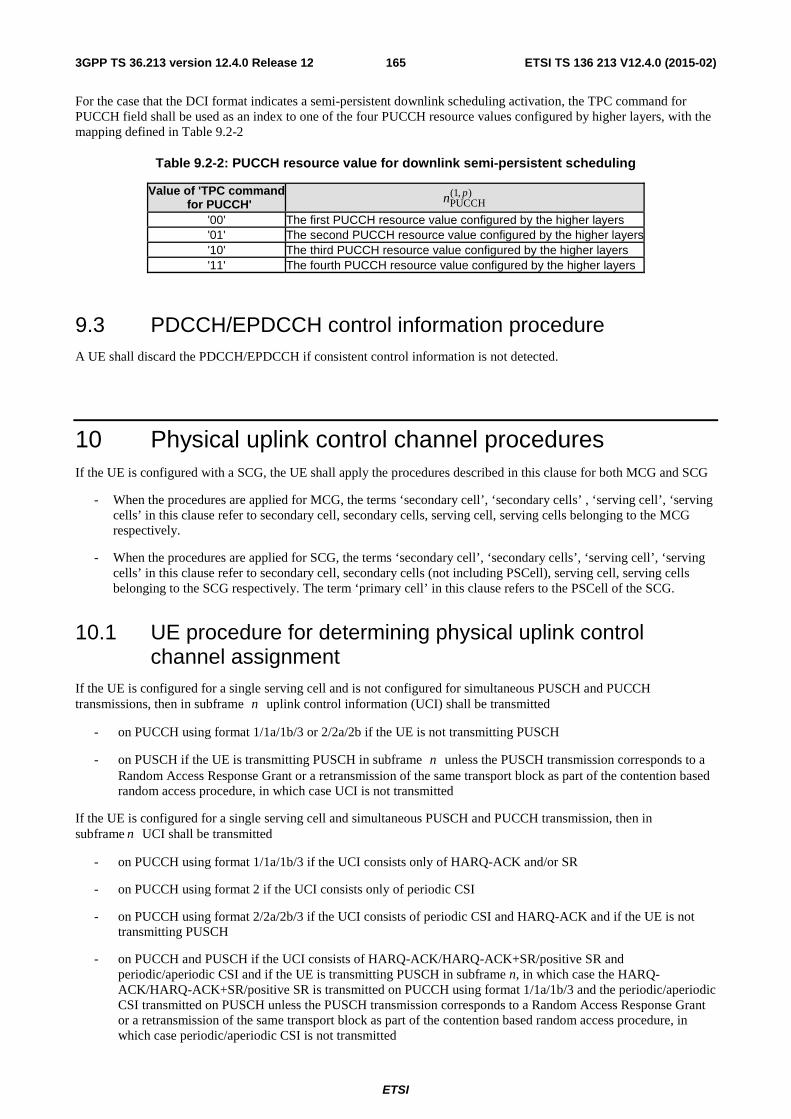
ETSI
ETSI TS 136 213 V12.4.0 (2015-02)1653GPP TS 36.213 version 12.4.0 Release 12
For the case that the DCI format indicates a semi-persistent downlink scheduling activation, the TPC command for PUCCH field shall be used as an index to one of the four PUCCH resource values configured by higher layers, with the mapping defined in Table 9.2-2
Table 9.2-2: PUCCH resource value for downlink semi-persistent scheduling
Value of 'TPC command for PUCCH'
),1(PUCCH
pn
'00' The first PUCCH resource value configured by the higher layers '01' The second PUCCH resource value configured by the higher layers'10' The third PUCCH resource value configured by the higher layers '11' The fourth PUCCH resource value configured by the higher layers
9.3 PDCCH/EPDCCH control information procedure A UE shall discard the PDCCH/EPDCCH if consistent control information is not detected.
10 Physical uplink control channel procedures If the UE is configured with a SCG, the UE shall apply the procedures described in this clause for both MCG and SCG
- When the procedures are applied for MCG, the terms ‘secondary cell’, ‘secondary cells’ , ‘serving cell’, ‘serving cells’ in this clause refer to secondary cell, secondary cells, serving cell, serving cells belonging to the MCG respectively.
- When the procedures are applied for SCG, the terms ‘secondary cell’, ‘secondary cells’, ‘serving cell’, ‘serving cells’ in this clause refer to secondary cell, secondary cells (not including PSCell), serving cell, serving cells belonging to the SCG respectively. The term ‘primary cell’ in this clause refers to the PSCell of the SCG.
10.1 UE procedure for determining physical uplink control channel assignment
If the UE is configured for a single serving cell and is not configured for simultaneous PUSCH and PUCCH transmissions, then in subframe n uplink control information (UCI) shall be transmitted
- on PUCCH using format 1/1a/1b/3 or 2/2a/2b if the UE is not transmitting PUSCH
- on PUSCH if the UE is transmitting PUSCH in subframe n unless the PUSCH transmission corresponds to a Random Access Response Grant or a retransmission of the same transport block as part of the contention based random access procedure, in which case UCI is not transmitted
If the UE is configured for a single serving cell and simultaneous PUSCH and PUCCH transmission, then in subframe n UCI shall be transmitted
- on PUCCH using format 1/1a/1b/3 if the UCI consists only of HARQ-ACK and/or SR
- on PUCCH using format 2 if the UCI consists only of periodic CSI
- on PUCCH using format 2/2a/2b/3 if the UCI consists of periodic CSI and HARQ-ACK and if the UE is not transmitting PUSCH
- on PUCCH and PUSCH if the UCI consists of HARQ-ACK/HARQ-ACK+SR/positive SR and periodic/aperiodic CSI and if the UE is transmitting PUSCH in subframe n, in which case the HARQ-ACK/HARQ-ACK+SR/positive SR is transmitted on PUCCH using format 1/1a/1b/3 and the periodic/aperiodic CSI transmitted on PUSCH unless the PUSCH transmission corresponds to a Random Access Response Grant or a retransmission of the same transport block as part of the contention based random access procedure, in which case periodic/aperiodic CSI is not transmitted
ETSI
ETSI TS 136 213 V12.4.0 (2015-02)1663GPP TS 36.213 version 12.4.0 Release 12
If the UE is configured with more than one serving cell and is not configured for simultaneous PUSCH and PUCCH transmission, then in subframe n UCI shall be transmitted
- on PUCCH using format 1/1a/1b/3 or 2/2a/2b if the UE is not transmitting PUSCH
- on PUSCH of the serving cell given in subclause 7.2.1 if the UCI consists of aperiodic CSI or aperiodic CSI and HARQ-ACK
- on primary cell PUSCH if the UCI consists of periodic CSI and/or HARQ-ACK and if the UE is transmitting on the primary cell PUSCH in subframe n unless the primary cell PUSCH transmission corresponds to a Random Access Response Grant or a retransmission of the same transport block as part of the contention based random access procedure, in which case UCI is not transmitted
- on PUSCH of the secondary cell with smallest SCellIndex if the UCI consists of periodic CSI and/or HARQ-ACK and if the UE is not transmitting PUSCH on primary cell but is transmitting PUSCH on at least one secondary cell
If the UE is configured with more than one serving cell and simultaneous PUSCH and PUCCH transmission, then in subframe n UCI shall be transmitted
- on PUCCH using format 1/1a/1b/3 if the UCI consists only of HARQ-ACK and/or SR
- on PUCCH using format 2 if the UCI consists only of periodic CSI
- as described in subclause 10.1.1, if the UCI consists of periodic CSI and HARQ-ACK and if the UE is not transmitting on PUSCH
- on PUCCH and primary cell PUSCH if the UCI consists of HARQ-ACK and periodic CSI and the UE is transmitting PUSCH on the primary cell, in which case the HARQ-ACK is transmitted on PUCCH using format 1a/1b/3 and the periodic CSI is transmitted on PUSCH unless the primary cell PUSCH transmission corresponds to a Random Access Response Grant or a retransmission of the same transport block as part of the contention based random access procedure, in which case periodic CSI is not transmitted
- on PUCCH and PUSCH of the secondary cell with the smallest SCellIndex if the UCI consists of HARQ-ACK and periodic CSI and if the UE is not transmitting PUSCH on primary cell but is transmitting PUSCH on at least one secondary cell, in which case, the HARQ-ACK is transmitted on PUCCH using format 1a/1b/3 and the periodic CSI is transmitted on PUSCH
- on PUCCH and PUSCH if the UCI consists of HARQ-ACK/HARQ-ACK+SR/positive SR and aperiodic CSI in which case the HARQ-ACK/HARQ-ACK+SR/positive SR is transmitted on PUCCH using format 1/1a/1b/3 and the aperiodic CSI is transmitted on PUSCH of the serving cell given in subclause 7.2.1
If the UE is configured with more than one serving cell, then reporting prioritization and collision handling of periodic CSI reports of a certain PUCCH reporting type is given in subclause 7.2.2.
A UE transmits PUCCH only on the primary cell.
A UE is configured by higher layers to transmit PUCCH on one antenna port )( 0pp = or two antenna ports
]),[( 10 ppp ∈ .
For FDD or FDD-TDD and primary cell frame structure 1, with two configured serving cells and PUCCH format 1b with channel selection or for FDD with two or more configured serving cells and PUCCH format 3,
∑−
=
=1
0
receivedHARQ
DLcellsN
c
cNn where DLcellsN is the number of configured cells and received
cN is the number of transport
blocks or the SPS release PDCCH/EPDCCH, if any, received in subframe 4−n in serving cell c .
For TDD and a UE not configured with the parameter EIMTA-MainConfigServCell-r12 for any serving cell, if a UE is configured with one serving cell, or the UE is configured with more than one serving cell and the UL/DL configurations of all serving cells are the same, then
ETSI
ETSI TS 136 213 V12.4.0 (2015-02)1673GPP TS 36.213 version 12.4.0 Release 12
- For TDD with two configured serving cells and PUCCH format 1b with channel selection and a subframe n with
M = 1, or for TDD UL/DL configuration 0 and PUCCH format 3, ∑ ∑−
= ∈
=1
0
received,HARQ
DLcellsN
c Kk
ckNn , where
received, ckN is the number of transport blocks or the SPS release PDCCH/EPDCCH, if any, received in subframe
kn − in serving cell c , where Kk ∈ , and M is the number of elements in K.
- For TDD UL/DL configurations 1-6 and PUCCH format 3, or for TDD with two configured serving cells and PUCCH format 1b with channel selection and M = 2,
( )( )∑ ∑−
= ∈⎟⎟⎟
⎠
⎞
⎜⎜⎜
⎝
⎛+⋅−=
1
0
received,
ACK,DAI
DL,DAIHARQ 4mod
DLcellsN
c Kk
ckccc NnUVn where DLcDAI,V is the DL
DAIV in serving cell c ,
cDAI,U is the DAIU in serving cell c , and KcnAC is the number of HARQ-ACK bits corresponding to the
configured DL transmission mode on serving cell c . In case spatial HARQ-ACK bundling is applied,
1AC =Kcn and received
, ckN is the number of PDCCH/EPDCCH or PDSCH without a corresponding
PDCCH/EPDCCH received in subframe kn − and serving cell c , where Kk ∈ and M is the number of
elements in K. In case spatial HARQ-ACK bundling is not applied, received, ckN is the number of transport blocks
received or the SPS release PDCCH/EPDCCH received in subframe kn − in serving cell c , where Kk ∈
and M is the number of elements in K. DLcDAI,V =0 if no transport block or SPS release PDCCH/EPDCCH is
detected in subframe(s) kn − in serving cell c , where Kk ∈ .
- For TDD with two configured serving cells and PUCCH format 1b with channel selection and M = 3 or 4,
HARQ 2n = if UE receives PDSCH or PDCCH/EPDCCH indicating downlink SPS release only on one serving
cell within subframes kn − ,where Kk ∈ ;otherwise HARQ 4n = .
For TDD if the UE is configured with more than one serving cell and if at least two serving cells have different UL/DL configurations, or if the UE is configured with the parameter EIMTA-MainConfigServCell-r12 for at least one serving cell, or for FDD-TDD and primary cell frame structure 2, then
- For PUCCH format 3, or for two configured serving cells and PUCCH format 1b with channel selection and 2≤M (defined in subclause 10.1.3.2.1 for TDD and subclause 10.1.3A for FDD-TDD),
( )( )∑ ∑−
= ∈⎟⎟⎟
⎠
⎞
⎜⎜⎜
⎝
⎛+⋅−=
1
0
received,
ACK,DAI
DL,DAIHARQ 4mod
DLcellsN
c Kk
ckccc NnUVn where DLcDAI,V is the DL
DAIV in serving cell c ,
cDAI,U is the DAIU in serving cell c , and KcnAC is the number of HARQ-ACK bits corresponding to the
configured DL transmission mode on serving cell c . In case spatial HARQ-ACK bundling is applied,
1AC =Kcn and received
, ckN is the number of PDCCH/EPDCCH or PDSCH without a corresponding
PDCCH/EPDCCH received in subframe kn − and serving cell c , where Kk ∈ and cKK = (defined in
subclause 7.3.2.2 for TDD and subclause 7.3.4 for FDD-TDD). In case spatial HARQ-ACK bundling is not
applied, received, ckN is the number of transport blocks received or the SPS release PDCCH/EPDCCH received in
subframe kn − in serving cell c , where Kk ∈ and cKK = (defined in subclause 7.3.2.2 for TDD and
subclause 7.3.4 for FDD-TDD). DLcDAI,V =0 if no transport block or SPS release PDCCH/EPDCCH is detected
in subframe(s) kn − in serving cell c , where Kk ∈ and cKK = (defined in subclause 7.3.2.2 for TDD and
subclause 7.3.4 for FDD-TDD). For a serving cell c , set DLDAI, c DAI, cV U= if the DL-reference UL/DL
configuration (defined in subclause 10.2) for serving cell c is TDD UL/DL configuration 0,
- For two configured serving cells and PUCCH format 1b with channel selection and M = 3 or 4 (defined in subclause 10.1.3.2.1 for TDD and subclause 10.1.3A for FDD-TDD), HARQ 2n = if UE receives PDSCH or
PDCCH/EPDCCH indicating downlink SPS release only on one serving cell within subframes kn − ,where
ETSI
ETSI TS 136 213 V12.4.0 (2015-02)1683GPP TS 36.213 version 12.4.0 Release 12
Kk ∈ and cKK = (defined in subclause 7.3.2.2 for TDD and subclause 7.3.4 for FDD-TDD); otherwise
HARQ 4n = .
Throughout the following subclauses, subframes are numbered in monotonically increasing order; if the last subframe of a radio frame is denoted as k , the first subframe of the next radio frame is denoted as 1+k .
Throughout the following subclauses, if the UE is configured with higher layer parameter n1PUCCH-AN-r11 then (1)PUCCHN is given by n1PUCCH-AN-r11, else (1)
PUCCHN is given by higher layer parameter n1PUCCH-AN .
10.1.1 PUCCH format information
Using the PUCCH formats defined in subclause 5.4.1 and 5.4.2 in [3], the following combinations of UCI on PUCCH are supported:
- Format 1a for 1-bit HARQ-ACK or in case of FDD or FDD-TDD primary cell frame structure type 1 for 1-bit HARQ-ACK with positive SR.
- Format 1b for 2-bit HARQ-ACK or for 2-bit HARQ-ACK with positive SR.
- Format 1b for up to 4-bit HARQ-ACK with channel selection when the UE is configured with more than one serving cell or, in the case of TDD, when the UE is configured with a single serving cell.
- Format 1 for positive SR.
- Format 2 for a CSI report when not multiplexed with HARQ-ACK.
- Format 2a for a CSI report multiplexed with 1-bit HARQ-ACK for normal cyclic prefix.
- Format 2b for a CSI report multiplexed with 2-bit HARQ-ACK for normal cyclic prefix.
- Format 2 for a CSI report multiplexed with HARQ-ACK for extended cyclic prefix.
- Format 3 for up to 10-bit HARQ-ACK for FDD or FDD-TDD primary cell frame structure type 1 and for up to 20-bit HARQ-ACK for TDD and for up to 21 bit HARQ-ACK for FDD-TDD primary cell frame structure type 2.
- Format 3 for up to 11-bit corresponding to 10-bit HARQ-ACK and 1-bit positive/negative SR for FDD or FDD-TDD and for up to 21-bit corresponding to 20-bit HARQ-ACK and 1-bit positive/negative SR for TDD and for up to 22-bit corresponding to 21-bit HARQ-ACK and 1-bit positive/negative SR for FDD-TDD primary cell frame structure type 2.
- Format 3 for HARQ-ACK, 1-bit positive/negative SR (if any) and a CSI report for one serving cell.
For a UE configured with PUCCH format 3 and HARQ-ACK transmission on PUSCH or using PUCCH format 3, or for a UE configured with two serving cells and PUCCH format 1b with channel selection and HARQ-ACK transmission on PUSCH, or for UE configured with one serving cell and PUCCH format 1b with channel selection according to Tables 10.1.3-5, 10.1.3-6, 10.1.3-7 and HARQ-ACK transmission on PUSCH:
- if the configured downlink transmission mode for a serving cell supports up to 2 transport blocks and only one transport block is received in a subframe, the UE shall generate a NACK for the other transport block if spatial HARQ-ACK bundling is not applied.
- if neither PDSCH nor PDCCH/EPDCCH indicating downlink SPS release is detected in a subframe for a serving cell, the UE shall generate two NACKs when the configured downlink transmission mode supports up to 2 transport blocks and the UE shall generate a single NACK when the configured downlink transmission mode supports a single transport block.
The scrambling initialization of PUCCH format 2, 2a, 2b and 3 is by C-RNTI.
For a UE that is configured with a single serving cell and is not configured with PUCCH format 3, in case of collision between a periodic CSI report and an HARQ-ACK in a same subframe without PUSCH, the periodic CSI report is multiplexed with HARQ-ACK on PUCCH if the parameter simultaneousAckNackAndCQI provided by higher layers is set TRUE, otherwise the CSI is dropped.
ETSI
ETSI TS 136 213 V12.4.0 (2015-02)1693GPP TS 36.213 version 12.4.0 Release 12
For TDD and for a UE that is configured with a single serving cell and with PUCCH format 3, in case of collision between a periodic CSI report and an HARQ-ACK in a same subframe without PUSCH, if the parameter simultaneousAckNackAndCQI provided by higher layers is set TRUE or if the parameter simultaneousAckNackAndCQI-Format3-r11 provided by higher layers is set TRUE, the periodic CSI report is multiplexed with HARQ-ACK or dropped as described in subclause 7.3, otherwise the CSI is dropped. For FDD or for FDD-TDD and primary cell frame structure type 1 and for a UE that is configured with more than one serving cell, in case of collision between a periodic CSI report and an HARQ-ACK in a same subframe without PUSCH,
- if the parameter simultaneousAckNackAndCQI provided by higher layers is set TRUE and if the HARQ-ACK corresponds to a PDSCH transmission or PDCCH/EPDCCH indicating downlink SPS release only on the primary cell,
then the periodic CSI report is multiplexed with HARQ-ACK on PUCCH using PUCCH format 2/2a/2b
- else if the UE is configured with PUCCH format 3 and if the parameter simultaneousAckNackAndCQI-Format3-r11 provided by higher layers is set TRUE, and if PUCCH resource is determined according to subclause 10.1.2.2.2, and
- if the total number of bits in the subframe corresponding to HARQ-ACKs, SR (if any), and the CSI is not larger than 22 or
- if the total number of bits in the subframe corresponding to spatially bundled HARQ-ACKs, SR (if any), and the CSI is not larger than 22
then the periodic CSI report is multiplexed with HARQ-ACK on PUCCH using the determined PUCCH format 3 resource according to [4]
- otherwise,
CSI is dropped.
For TDD or for FDD-TDD and primary cell frame structure type 2 and for a UE that is configured with more than one serving cell, in case of collision between a periodic CSI report and an HARQ-ACK in a same subframe without PUSCH, if the parameter simultaneousAckNackAndCQI provided by higher layers is set TRUE or if the parameter simultaneousAckNackAndCQI-Format3-r11 provided by higher layers is set TRUE, the periodic CSI report is multiplexed with HARQ-ACK or dropped as described in subclause 7.3, otherwise the CSI is dropped.
In case of collision between a periodic CSI report and an HARQ-ACK in a same subframe with PUSCH, the periodic CSI is multiplexed with the HARQ-ACK in the PUSCH transmission in that subframe if the UE is not configured by higher layers for simultaneous PUCCH and PUSCH transmissions. Otherwise, if the UE is configured by higher layers for simultaneous PUCCH and PUSCH transmissions, the HARQ-ACK is transmitted in the PUCCH and the periodic CSI is transmitted in the PUSCH.
If each of the serving cells configured for the UE has frame structure type 1, UE procedures for HARQ-ACK feedback are given in subclause 10.1.2.
If each of the serving cells configured for the UE has frame structure type 2, UE procedures for HARQ-ACK feedback are given in subclause 10.1.3.
If the UE is configured for more than one serving cell, and if the frame structure type of any two configured serving cells is different, and if the primary cell is frame structure type 1, UE procedure for HARQ-ACK feedback is given in subclause 10.1.2A.
If the UE is configured for more than one serving cell, and if the frame structure type of any two configured serving cells is different, and if the primary cell is frame structure type 2, UE procedure for HARQ-ACK feedback is given in subclause 10.1.3A.
10.1.2 FDD HARQ-ACK feedback procedures
For FDD and for a UE transmitting HARQ-ACK using PUCCH format 1b with channel selection or PUCCH format 3, the UE shall determine the number of HARQ-ACK bits, O , based on the number of configured serving cells and the
ETSI
ETSI TS 136 213 V12.4.0 (2015-02)1703GPP TS 36.213 version 12.4.0 Release 12
downlink transmission modes configured for each serving cell. The UE shall use two HARQ-ACK bits for a serving cell configured with a downlink transmission mode that support up to two transport blocks; and one HARQ-ACK bit otherwise.
A UE that supports aggregating at most 2 serving cells with frame structure type 1 shall use PUCCH format 1b with channel selection for transmission of HARQ-ACK when configured with more than one serving cell with frame structure type 1.
A UE that supports aggregating more than 2 serving cells with frame structure type 1 is configured by higher layers to use either PUCCH format 1b with channel selection or PUCCH format 3 for transmission of HARQ-ACK when configured with more than one serving cell with frame structure type 1.
The FDD HARQ-ACK feedback procedure for one configured serving cell is given in subclause 10.1.2.1 and procedures for more than one configured serving cell are given in subclause 10.1.2.2.
10.1.2.1 FDD HARQ-ACK procedure for one configured serving cell
HARQ-ACK transmission on two antenna ports ]),[( 10 ppp ∈ is supported for PUCCH format 1a/1b.
For FDD and one configured serving cell, the UE shall use PUCCH resource )~,1(PUCCH
pn for transmission of HARQ-ACK
in subframe n for p~ mapped to antenna port p for PUCCH format 1a/1b [3], where
- for a PDSCH transmission indicated by the detection of a corresponding PDCCH in subframe 4−n , or for a PDCCH indicating downlink SPS release (defined in subclause 9.2) in subframe 4−n , the UE shall use
(1)PUCCHCCE
)~,1(PUCCH
0 Nnn p += for antenna port 0p , where CCEn is the number of the first CCE (i.e. lowest CCE
index used to construct the PDCCH) used for transmission of the corresponding DCI assignment and (1)PUCCHN
is configured by higher layers. For two antenna port transmission the PUCCH resource for antenna port 1p is
given by (1)PUCCHCCE
)~,1(PUCCH 11 Nnn p ++= .
- for a PDSCH transmission on the primary cell where there is not a corresponding PDCCH/EPDCCH detected in
subframe 4−n , the value of )~,1(PUCCH
pn is determined according to higher layer configuration and Table 9.2-2.
For a UE configured for two antenna port transmission, a PUCCH resource value in Table 9.2-2 maps to two
PUCCH resources with the first PUCCH resource )~,1(PUCCH
0pn for antenna port 0p and the second PUCCH
resource )~,1(PUCCH
1pn for antenna port 1p , otherwise, the PUCCH resource value maps to a single PUCCH
resource )~,1(PUCCH
0pn for antenna port 0p .
- for a PDSCH transmission indicated by the detection of a corresponding EPDCCH in subframe 4−n , or for an EPDCCH indicating downlink SPS release (defined in subclause 9.2) in subframe 4−n , the UE shall use
o if EPDCCH-PRB-set q is configured for distributed transmission (e1)PUCCH,qECCE,q
)~,1(PUCCH
0 Nnn AROp +Δ+=
o if EPDCCH-PRB-set q is configured for localized transmission
(e1)PUCCH,q
,,
ECCE,q)~,1(PUCCH '0 NnN
N
nn ARO
qECCERBqECCE
RB
p +Δ++⋅⎥⎦
⎥⎢⎣
⎢=
for antenna port 0p , where ECCE,qn is the number of the first ECCE (i.e. lowest ECCE index used to construct
the EPDCCH) used for transmission of the corresponding DCI assignment in EPDCCH-PRB-set q , AROΔ is
determined from the HARQ-ACK resource offset field in the DCI format of the corresponding EPDCCH as
given in Table 10.1.2.1-1, (e1)PUCCH,qN for EPDCCH-PRB-set q is configured by the higher layer parameter
pucch-ResourceStartOffset-r11 , qECCERBN , for EPDCCH-PRB-set q is given in subclause 6.8A.1 in [3], 'n is
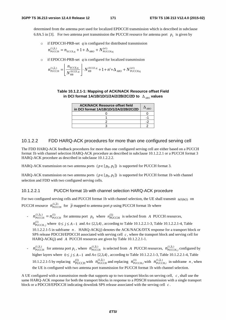
ETSI
ETSI TS 136 213 V12.4.0 (2015-02)1713GPP TS 36.213 version 12.4.0 Release 12
determined from the antenna port used for localized EPDCCH transmission which is described in subclause
6.8A.5 in [3]. For two antenna port transmission the PUCCH resource for antenna port 1p is given by
o if EPDCCH-PRB-set q is configured for distributed transmission (e1)PUCCH,qECCE,q
)~,1(PUCCH 11 Nnn ARO
p +Δ++=
o if EPDCCH-PRB-set q is configured for localized transmission
(e1)qPUCCH,
,,
qECCE,)~,1(PUCCH '11 NnN
N
nn ARO
qECCERBqECCE
RB
p +Δ+++⋅⎥⎦
⎥⎢⎣
⎢=
Table 10.1.2.1-1: Mapping of ACK/NACK Resource offset Field in DCI format 1A/1B/1D/1/2A/2/2B/2C/2D to AROΔ values
ACK/NACK Resource offset field in DCI format 1A/1B/1D/1/2A/2/2B/2C/2D AROΔ
0 0 1 -1 2 -2 3 2
10.1.2.2 FDD HARQ-ACK procedures for more than one configured serving cell
The FDD HARQ-ACK feedback procedures for more than one configured serving cell are either based on a PUCCH format 1b with channel selection HARQ-ACK procedure as described in subclause 10.1.2.2.1 or a PUCCH format 3 HARQ-ACK procedure as described in subclause 10.1.2.2.2.
HARQ-ACK transmission on two antenna ports ]),[( 10 ppp ∈ is supported for PUCCH format 3.
HARQ-ACK transmission on two antenna ports ]),[( 10 ppp ∈ is supported for PUCCH format 1b with channel
selection and FDD with two configured serving cells.
10.1.2.2.1 PUCCH format 1b with channel selection HARQ-ACK procedure
For two configured serving cells and PUCCH format 1b with channel selection, the UE shall transmit )1()0( bb on
PUCCH resource )~,1(PUCCH
pn for p~ mapped to antenna port p using PUCCH format 1b where
- )1(PUCCH
)~,1(PUCCH
0 nn p = for antenna port 0p where )1(PUCCHn is selected from A PUCCH resources,
)1(PUCCH, jn where 10 −≤≤ Aj and }4,3,2{∈A , according to Table 10.1.2.2.1-3, Table 10.1.2.2.1-4, Table
10.1.2.2.1-5 in subframe n . HARQ-ACK(j) denotes the ACK/NACK/DTX response for a transport block or SPS release PDCCH/EPDCCH associated with serving cell c , where the transport block and serving cell for HARQ-ACK(j) and A PUCCH resources are given by Table 10.1.2.2.1-1.
- )~,1(PUCCH
1pn for antenna port 1p , where )~,1(PUCCH
1pn is selected from A PUCCH resources, )~,1(PUCCH,
1pjn configured by
higher layers where 10 −≤≤ Aj and }4,3,2{∈A , according to Table 10.1.2.2.1-3, Table 10.1.2.2.1-4, Table
10.1.2.2.1-5 by replacing )1(PUCCHn with
)~,1(PUCCH
1pn and replacing )1(PUCCH,in with )~,1(
PUCCH,1p
in in subframe n , when
the UE is configured with two antenna port transmission for PUCCH format 1b with channel selection.
A UE configured with a transmission mode that supports up to two transport blocks on serving cell, c , shall use the same HARQ-ACK response for both the transport blocks in response to a PDSCH transmission with a single transport block or a PDCCH/EPDCCH indicating downlink SPS release associated with the serving cell c .
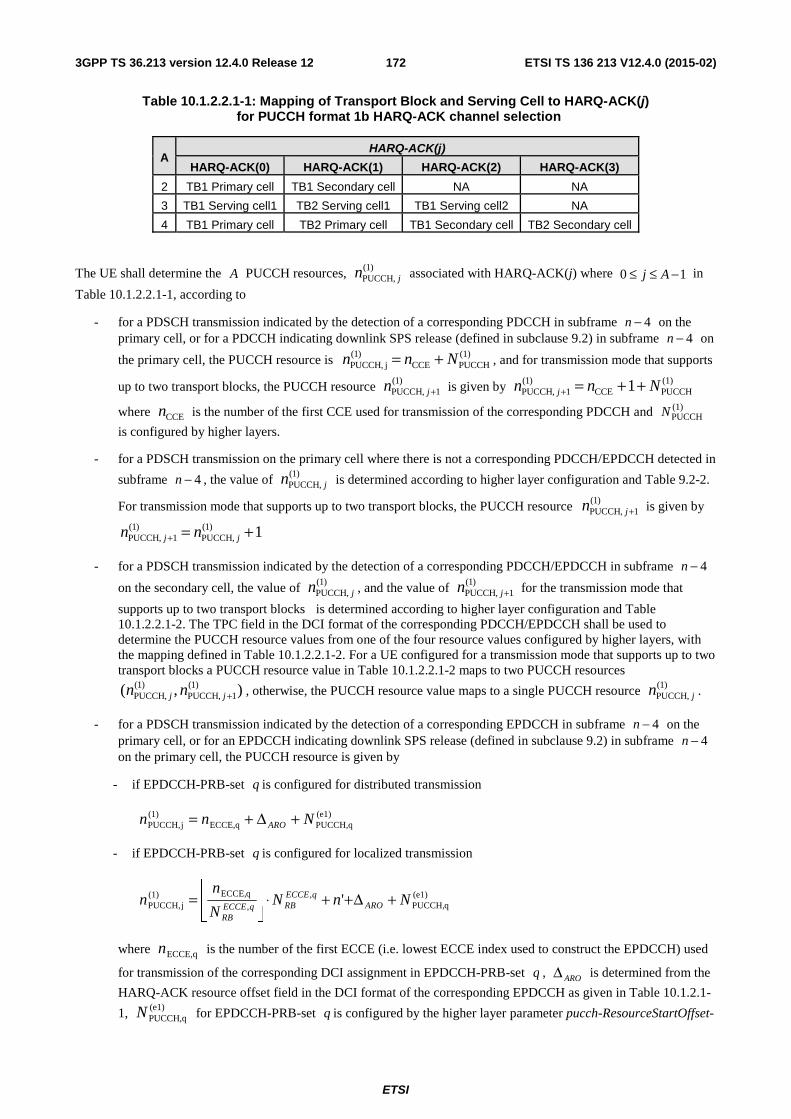
ETSI
ETSI TS 136 213 V12.4.0 (2015-02)1723GPP TS 36.213 version 12.4.0 Release 12
Table 10.1.2.2.1-1: Mapping of Transport Block and Serving Cell to HARQ-ACK(j) for PUCCH format 1b HARQ-ACK channel selection
A HARQ-ACK(j)
HARQ-ACK(0) HARQ-ACK(1) HARQ-ACK(2) HARQ-ACK(3)
2 TB1 Primary cell TB1 Secondary cell NA NA
3 TB1 Serving cell1 TB2 Serving cell1 TB1 Serving cell2 NA
4 TB1 Primary cell TB2 Primary cell TB1 Secondary cell TB2 Secondary cell
The UE shall determine the A PUCCH resources, )1(PUCCH, jn associated with HARQ-ACK(j) where 10 −≤≤ Aj in
Table 10.1.2.2.1-1, according to
- for a PDSCH transmission indicated by the detection of a corresponding PDCCH in subframe 4−n on the primary cell, or for a PDCCH indicating downlink SPS release (defined in subclause 9.2) in subframe 4−n on
the primary cell, the PUCCH resource is (1)PUCCHCCE
)1(jPUCCH, Nnn += , and for transmission mode that supports
up to two transport blocks, the PUCCH resource )1(1PUCCH, +jn is given by (1)
PUCCHCCE)1(
1PUCCH, 1 Nnn j ++=+
where CCEn is the number of the first CCE used for transmission of the corresponding PDCCH and (1)PUCCHN
is configured by higher layers.
- for a PDSCH transmission on the primary cell where there is not a corresponding PDCCH/EPDCCH detected in
subframe 4−n , the value of )1(PUCCH, jn is determined according to higher layer configuration and Table 9.2-2.
For transmission mode that supports up to two transport blocks, the PUCCH resource )1(1PUCCH, +jn is given by
1)1(PUCCH,
)1(1PUCCH, +=+ jj nn
- for a PDSCH transmission indicated by the detection of a corresponding PDCCH/EPDCCH in subframe 4−n
on the secondary cell, the value of )1(PUCCH, jn , and the value of )1(
1PUCCH, +jn for the transmission mode that
supports up to two transport blocks is determined according to higher layer configuration and Table 10.1.2.2.1-2. The TPC field in the DCI format of the corresponding PDCCH/EPDCCH shall be used to determine the PUCCH resource values from one of the four resource values configured by higher layers, with the mapping defined in Table 10.1.2.2.1-2. For a UE configured for a transmission mode that supports up to two transport blocks a PUCCH resource value in Table 10.1.2.2.1-2 maps to two PUCCH resources
),( )1(1PUCCH,
)1(PUCCH, +jj nn , otherwise, the PUCCH resource value maps to a single PUCCH resource )1(
PUCCH, jn .
- for a PDSCH transmission indicated by the detection of a corresponding EPDCCH in subframe 4−n on the primary cell, or for an EPDCCH indicating downlink SPS release (defined in subclause 9.2) in subframe 4−n on the primary cell, the PUCCH resource is given by
- if EPDCCH-PRB-set q is configured for distributed transmission
(e1)PUCCH,qECCE,q
)1(jPUCCH, Nnn ARO +Δ+=
- if EPDCCH-PRB-set q is configured for localized transmission
(e1)qPUCCH,
,,
qECCE,)1(jPUCCH, ' NnN
N
nn ARO
qECCERBqECCE
RB
+Δ++⋅⎥⎦
⎥⎢⎣
⎢=
where ECCE,qn is the number of the first ECCE (i.e. lowest ECCE index used to construct the EPDCCH) used
for transmission of the corresponding DCI assignment in EPDCCH-PRB-set q , AROΔ is determined from the
HARQ-ACK resource offset field in the DCI format of the corresponding EPDCCH as given in Table 10.1.2.1-
1, (e1)PUCCH,qN for EPDCCH-PRB-set q is configured by the higher layer parameter pucch-ResourceStartOffset-
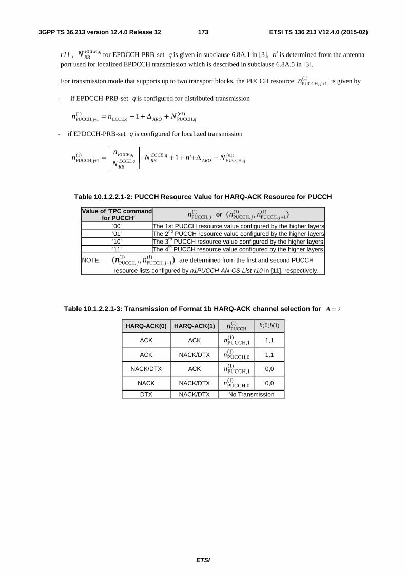
ETSI
ETSI TS 136 213 V12.4.0 (2015-02)1733GPP TS 36.213 version 12.4.0 Release 12
r11 , qECCERBN , for EPDCCH-PRB-set q is given in subclause 6.8A.1 in [3], 'n is determined from the antenna
port used for localized EPDCCH transmission which is described in subclause 6.8A.5 in [3].
For transmission mode that supports up to two transport blocks, the PUCCH resource )1(1PUCCH, +jn is given by
- if EPDCCH-PRB-set q is configured for distributed transmission
(e1)PUCCH,qECCE,q
)1(1jPUCCH, 1 Nnn ARO +Δ++=+
- if EPDCCH-PRB-set q is configured for localized transmission
(e1)qPUCCH,
,,
,)1(1jPUCCH, '1 NnN
N
nn ARO
qECCERBqECCE
RB
qECCE +Δ+++⋅⎥⎦
⎥⎢⎣
⎢=+
Table 10.1.2.2.1-2: PUCCH Resource Value for HARQ-ACK Resource for PUCCH
Value of 'TPC command for PUCCH'
)1(PUCCH, jn or
),( )1(
1PUCCH,)1(
PUCCH, +jj nn
'00' The 1st PUCCH resource value configured by the higher layers'01' The 2nd PUCCH resource value configured by the higher layers '10' The 3rd PUCCH resource value configured by the higher layers '11' The 4th PUCCH resource value configured by the higher layers
NOTE: ),( )1(1PUCCH,
)1(PUCCH, +jj nn are determined from the first and second PUCCH
resource lists configured by n1PUCCH-AN-CS-List-r10 in [11], respectively.
Table 10.1.2.2.1-3: Transmission of Format 1b HARQ-ACK channel selection for 2=A
HARQ-ACK(0) HARQ-ACK(1) )1(PUCCHn )1()0( bb
ACK ACK )1(PUCCH,1n 1,1
ACK NACK/DTX )1(PUCCH,0n 1,1
NACK/DTX ACK )1(PUCCH,1n 0,0
NACK NACK/DTX )1(PUCCH,0n 0,0
DTX NACK/DTX No Transmission
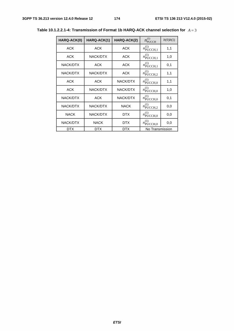
ETSI
ETSI TS 136 213 V12.4.0 (2015-02)1743GPP TS 36.213 version 12.4.0 Release 12
Table 10.1.2.2.1-4: Transmission of Format 1b HARQ-ACK channel selection for 3=A
HARQ-ACK(0) HARQ-ACK(1) HARQ-ACK(2) )1(PUCCHn )1()0( bb
ACK ACK ACK )1(PUCCH,1n 1,1
ACK NACK/DTX ACK )1(PUCCH,1n 1,0
NACK/DTX ACK ACK )1(PUCCH,1n 0,1
NACK/DTX NACK/DTX ACK )1(PUCCH,2n 1,1
ACK ACK NACK/DTX )1(PUCCH,0n 1,1
ACK NACK/DTX NACK/DTX )1(PUCCH,0n 1,0
NACK/DTX ACK NACK/DTX )1(PUCCH,0n 0,1
NACK/DTX NACK/DTX NACK )1(PUCCH,2n 0,0
NACK NACK/DTX DTX )1(PUCCH,0n 0,0
NACK/DTX NACK DTX )1(PUCCH,0n 0,0
DTX DTX DTX No Transmission
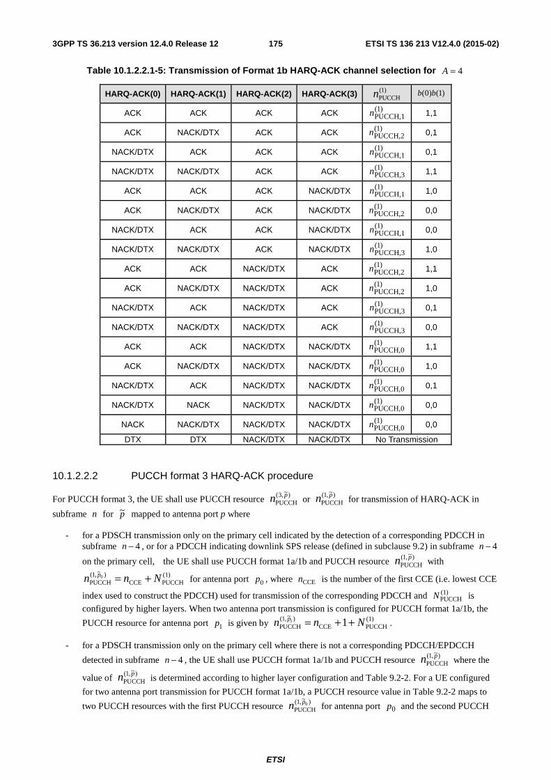
ETSI
ETSI TS 136 213 V12.4.0 (2015-02)1753GPP TS 36.213 version 12.4.0 Release 12
Table 10.1.2.2.1-5: Transmission of Format 1b HARQ-ACK channel selection for 4=A
HARQ-ACK(0) HARQ-ACK(1) HARQ-ACK(2) HARQ-ACK(3) )1(PUCCHn )1()0( bb
ACK ACK ACK ACK )1(PUCCH,1n 1,1
ACK NACK/DTX ACK ACK )1(PUCCH,2n 0,1
NACK/DTX ACK ACK ACK )1(PUCCH,1n 0,1
NACK/DTX NACK/DTX ACK ACK )1(PUCCH,3n 1,1
ACK ACK ACK NACK/DTX )1(PUCCH,1n 1,0
ACK NACK/DTX ACK NACK/DTX )1(PUCCH,2n 0,0
NACK/DTX ACK ACK NACK/DTX )1(PUCCH,1n 0,0
NACK/DTX NACK/DTX ACK NACK/DTX )1(PUCCH,3n 1,0
ACK ACK NACK/DTX ACK )1(PUCCH,2n 1,1
ACK NACK/DTX NACK/DTX ACK )1(PUCCH,2n 1,0
NACK/DTX ACK NACK/DTX ACK )1(PUCCH,3n 0,1
NACK/DTX NACK/DTX NACK/DTX ACK )1(PUCCH,3n 0,0
ACK ACK NACK/DTX NACK/DTX )1(PUCCH,0n 1,1
ACK NACK/DTX NACK/DTX NACK/DTX )1(PUCCH,0n 1,0
NACK/DTX ACK NACK/DTX NACK/DTX )1(PUCCH,0n 0,1
NACK/DTX NACK NACK/DTX NACK/DTX )1(PUCCH,0n 0,0
NACK NACK/DTX NACK/DTX NACK/DTX )1(PUCCH,0n 0,0
DTX DTX NACK/DTX NACK/DTX No Transmission
10.1.2.2.2 PUCCH format 3 HARQ-ACK procedure
For PUCCH format 3, the UE shall use PUCCH resource )~,3(PUCCH
pn or )~,1(PUCCH
pn for transmission of HARQ-ACK in
subframe n for p~ mapped to antenna port p where
- for a PDSCH transmission only on the primary cell indicated by the detection of a corresponding PDCCH in subframe 4−n , or for a PDCCH indicating downlink SPS release (defined in subclause 9.2) in subframe 4−n
on the primary cell, the UE shall use PUCCH format 1a/1b and PUCCH resource )~,1(PUCCH
pn with (1)PUCCHCCE
)~,1(PUCCH
0 Nnn p += for antenna port 0p , where CCEn is the number of the first CCE (i.e. lowest CCE
index used to construct the PDCCH) used for transmission of the corresponding PDCCH and (1)PUCCHN is
configured by higher layers. When two antenna port transmission is configured for PUCCH format 1a/1b, the
PUCCH resource for antenna port 1p is given by (1)PUCCHCCE
)~,1(PUCCH 11 Nnn p ++= .
- for a PDSCH transmission only on the primary cell where there is not a corresponding PDCCH/EPDCCH
detected in subframe 4−n , the UE shall use PUCCH format 1a/1b and PUCCH resource )~,1(PUCCH
pn where the
value of )~,1(PUCCH
pn is determined according to higher layer configuration and Table 9.2-2. For a UE configured
for two antenna port transmission for PUCCH format 1a/1b, a PUCCH resource value in Table 9.2-2 maps to
two PUCCH resources with the first PUCCH resource )~,1(PUCCH
0pn for antenna port 0p and the second PUCCH
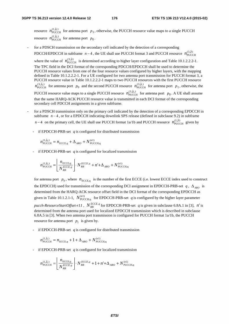
ETSI
ETSI TS 136 213 V12.4.0 (2015-02)1763GPP TS 36.213 version 12.4.0 Release 12
resource )~,1(PUCCH
1pn for antenna port 1p , otherwise, the PUCCH resource value maps to a single PUCCH
resource )~,1(PUCCH
0pn for antenna port 0p .
- for a PDSCH transmission on the secondary cell indicated by the detection of a corresponding
PDCCH/EPDCCH in subframe 4−n , the UE shall use PUCCH format 3 and PUCCH resource )~,3(PUCCH
pn
where the value of )~,3(PUCCH
pn is determined according to higher layer configuration and Table 10.1.2.2.2-1.
The TPC field in the DCI format of the corresponding PDCCH/EPDCCH shall be used to determine the PUCCH resource values from one of the four resource values configured by higher layers, with the mapping defined in Table 10.1.2.2.2-1. For a UE configured for two antenna port transmission for PUCCH format 3, a PUCCH resource value in Table 10.1.2.2.2-1 maps to two PUCCH resources with the first PUCCH resource
)~,3(PUCCH
0pn for antenna port 0p and the second PUCCH resource )~,3(PUCCH
1pn for antenna port 1p , otherwise, the
PUCCH resource value maps to a single PUCCH resource )~,3(PUCCH
0pn for antenna port 0p . A UE shall assume
that the same HARQ-ACK PUCCH resource value is transmitted in each DCI format of the corresponding secondary cell PDCCH assignments in a given subframe.
- for a PDSCH transmission only on the primary cell indicated by the detection of a corresponding EPDCCH in subframe 4−n , or for a EPDCCH indicating downlink SPS release (defined in subclause 9.2) in subframe
4−n on the primary cell, the UE shall use PUCCH format 1a/1b and PUCCH resource )~,1(PUCCH
pn given by
- if EPDCCH-PRB-set q is configured for distributed transmission
(e1)PUCCH,qECCE,q
)~,1(PUCCH
0 Nnn AROp +Δ+=
- if EPDCCH-PRB-set q is configured for localized transmission
(e1)qPUCCH,
,,
qECCE,)~,1(PUCCH '0 NnN
N
nn ARO
qECCERBqECCE
RB
p +Δ++⋅⎥⎦
⎥⎢⎣
⎢=
for antenna port 0p , where ECCE,qn is the number of the first ECCE (i.e. lowest ECCE index used to construct
the EPDCCH) used for transmission of the corresponding DCI assignment in EPDCCH-PRB-set q , AROΔ is
determined from the HARQ-ACK resource offset field in the DCI format of the corresponding EPDCCH as
given in Table 10.1.2.1-1, (e1)PUCCH,qN for EPDCCH-PRB-set q is configured by the higher layer parameter
pucch-ResourceStartOffset-r11 , qECCERBN , for EPDCCH-PRB-set q is given in subclause 6.8A.1 in [3], 'n is
determined from the antenna port used for localized EPDCCH transmission which is described in subclause 6.8A.5 in [3]. When two antenna port transmission is configured for PUCCH format 1a/1b, the PUCCH
resource for antenna port 1p is given by.
- if EPDCCH-PRB-set q is configured for distributed transmission
(e1)PUCCH,qECCE,q
)~,1(PUCCH 11 Nnn ARO
p +Δ++=
- if EPDCCH-PRB-set q is configured for localized transmission
(e1)qPUCCH,
,,
qECCE,)~,1(PUCCH '11 NnN
N
nn ARO
qECCERBqECCE
RB
p +Δ+++⋅⎥⎦
⎥⎢⎣
⎢=
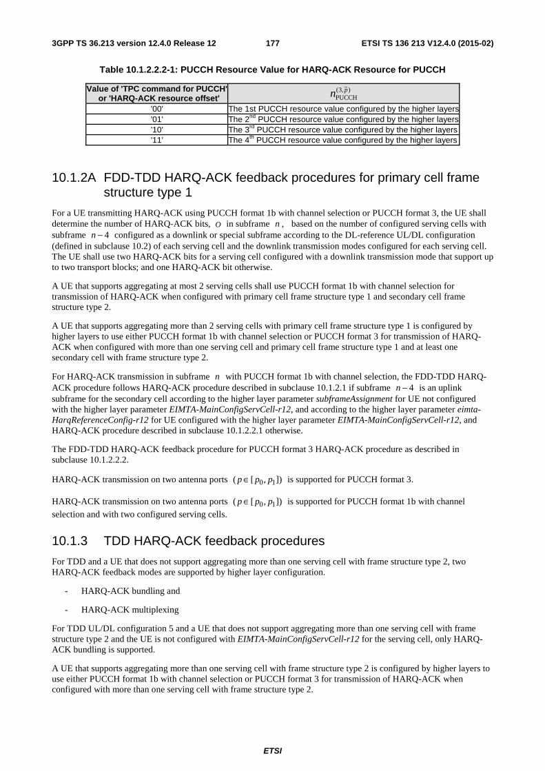
ETSI
ETSI TS 136 213 V12.4.0 (2015-02)1773GPP TS 36.213 version 12.4.0 Release 12
Table 10.1.2.2.2-1: PUCCH Resource Value for HARQ-ACK Resource for PUCCH
Value of 'TPC command for PUCCH' or 'HARQ-ACK resource offset'
)~,3(PUCCH
pn
'00' The 1st PUCCH resource value configured by the higher layers'01' The 2nd PUCCH resource value configured by the higher layers '10' The 3rd PUCCH resource value configured by the higher layers '11' The 4th PUCCH resource value configured by the higher layers
10.1.2A FDD-TDD HARQ-ACK feedback procedures for primary cell frame structure type 1
For a UE transmitting HARQ-ACK using PUCCH format 1b with channel selection or PUCCH format 3, the UE shall determine the number of HARQ-ACK bits, O in subframe n , based on the number of configured serving cells with subframe 4−n configured as a downlink or special subframe according to the DL-reference UL/DL configuration (defined in subclause 10.2) of each serving cell and the downlink transmission modes configured for each serving cell. The UE shall use two HARQ-ACK bits for a serving cell configured with a downlink transmission mode that support up to two transport blocks; and one HARQ-ACK bit otherwise.
A UE that supports aggregating at most 2 serving cells shall use PUCCH format 1b with channel selection for transmission of HARQ-ACK when configured with primary cell frame structure type 1 and secondary cell frame structure type 2.
A UE that supports aggregating more than 2 serving cells with primary cell frame structure type 1 is configured by higher layers to use either PUCCH format 1b with channel selection or PUCCH format 3 for transmission of HARQ-ACK when configured with more than one serving cell and primary cell frame structure type 1 and at least one secondary cell with frame structure type 2.
For HARQ-ACK transmission in subframe n with PUCCH format 1b with channel selection, the FDD-TDD HARQ-ACK procedure follows HARQ-ACK procedure described in subclause 10.1.2.1 if subframe 4−n is an uplink subframe for the secondary cell according to the higher layer parameter subframeAssignment for UE not configured with the higher layer parameter EIMTA-MainConfigServCell-r12, and according to the higher layer parameter eimta-HarqReferenceConfig-r12 for UE configured with the higher layer parameter EIMTA-MainConfigServCell-r12, and HARQ-ACK procedure described in subclause 10.1.2.2.1 otherwise.
The FDD-TDD HARQ-ACK feedback procedure for PUCCH format 3 HARQ-ACK procedure as described in subclause 10.1.2.2.2.
HARQ-ACK transmission on two antenna ports ]),[( 10 ppp ∈ is supported for PUCCH format 3.
HARQ-ACK transmission on two antenna ports ]),[( 10 ppp ∈ is supported for PUCCH format 1b with channel
selection and with two configured serving cells.
10.1.3 TDD HARQ-ACK feedback procedures
For TDD and a UE that does not support aggregating more than one serving cell with frame structure type 2, two HARQ-ACK feedback modes are supported by higher layer configuration.
- HARQ-ACK bundling and
- HARQ-ACK multiplexing
For TDD UL/DL configuration 5 and a UE that does not support aggregating more than one serving cell with frame structure type 2 and the UE is not configured with EIMTA-MainConfigServCell-r12 for the serving cell, only HARQ-ACK bundling is supported.
A UE that supports aggregating more than one serving cell with frame structure type 2 is configured by higher layers to use either PUCCH format 1b with channel selection or PUCCH format 3 for transmission of HARQ-ACK when configured with more than one serving cell with frame structure type 2.
ETSI
ETSI TS 136 213 V12.4.0 (2015-02)1783GPP TS 36.213 version 12.4.0 Release 12
A UE that supports aggregating more than one serving cell with frame structure type 2 and is not configured with the parameter EIMTA-MainConfigServCell-r12 for any serving cell is configured by higher layers to use HARQ-ACK bundling, PUCCH format 1b with channel selection according to the set of Tables 10.1.3-2/3/4 or according to the set of Tables 10.1.3-5/6/7, or PUCCH format 3 for transmission of HARQ-ACK when configured with one serving cell with frame structure type 2.
A UE that is configured with the parameter EIMTA-MainConfigServCell-r12 for at least one serving cell is configured by higher layers to use PUCCH format 1b with channel selection according to the set of Tables 10.1.3-5/6/7, or PUCCH format 3 for transmission of HARQ-ACK.
PUCCH format 1b with channel selection according to the set of Tables 10.1.3-2/3/4 or according to the set of Tables 10.1.3-5/6/7 is not supported for TDD UL/DL configuration 5.
TDD HARQ-ACK bundling is performed per codeword across M multiple downlink or special subframes associated with a single UL subframe n, where M is the number of elements in the set K defined in Table 10.1.3.1-1, by a logical AND operation of all the individual PDSCH transmission (with and without corresponding PDCCH/EPDCCH) HARQ-ACKs and ACK in response to PDCCH/EPDCCH indicating downlink SPS release. For one configured serving cell the bundled 1 or 2 HARQ-ACK bits are transmitted using PUCCH format 1a or PUCCH format 1b, respectively.
For TDD HARQ-ACK multiplexing and a subframe n with 1>M , where M is the number of elements in the set K defined in Table 10.1.3.1-1, spatial HARQ-ACK bundling across multiple codewords within a downlink or special subframe is performed by a logical AND operation of all the corresponding individual HARQ-ACKs. PUCCH format 1b with channel selection is used in case of one configured serving cell. For TDD HARQ-ACK multiplexing and a subframe n with 1=M , spatial HARQ-ACK bundling across multiple codewords within a downlink or special subframe is not performed, 1 or 2 HARQ-ACK bits are transmitted using PUCCH format 1a or PUCCH format 1b, respectively for one configured serving cell.
In the case of TDD and more than one configured serving cell with PUCCH format 1b with channel selection and more than 4 HARQ-ACK bits for M multiple downlink or special subframes associated with a single UL subframe n, where M is defined in subclause 10.1.3.2.1, and for the configured serving cells, spatial HARQ-ACK bundling across multiple codewords within a downlink or special subframe for all configured cells is performed and the bundled HARQ-ACK bits for each configured serving cell is transmitted using PUCCH format 1b with channel selection. For TDD and more than one configured serving cell with PUCCH format 1b with channel selection and up to 4 HARQ-ACK bits for M multiple downlink or special subframes associated with a single UL subframe n, where M is defined in subclause 10.1.3.2.1, and for the configured serving cells, spatial HARQ-ACK bundling is not performed and the HARQ-ACK bits are transmitted using PUCCH format 1b with channel selection.
In the case of TDD and more than one configured serving cell with PUCCH format 3 and more than 20 HARQ-ACK bits for M multiple downlink or special subframes associated with a single UL subframe n, where M is the number of elements in the set K defined in subclause 10.1.3.2.2 and for the configured serving cells, spatial HARQ-ACK bundling across multiple codewords within a downlink or special subframe is performed for each serving cell by a logical AND operation of all of the corresponding individual HARQ-ACKs and PUCCH format 3 is used. For TDD and more than one configured serving cell with PUCCH format 3 and up to 20 HARQ-ACK bits for M multiple downlink or special subframes associated with a single UL subframe n, where M is the number of elements in the set K defined in subclause 10.1.3.2.2 and for the configured serving cells, spatial HARQ-ACK bundling is not performed and the HARQ-ACK bits are transmitted using PUCCH format 3.
For TDD with PUCCH format 3, a UE shall determine the number of HARQ-ACK bits, O , associated with an UL subframe n
according to ∑=
=
DLcellsN
c
ACKcOO
1
where DLcellsN is the number of configured cells, and ACK
cO is the number of HARQ-bits
for the c-th serving cell defined in subclause 7.3.
TDD HARQ-ACK feedback procedures for one configured serving cell are given in subclause 10.1.3.1 and procedures for more than one configured serving cell are given in subclause 10.1.3.2.
10.1.3.1 TDD HARQ-ACK procedure for one configured serving cell
HARQ-ACK transmission on two antenna ports ]),[( 10 ppp ∈ is supported for PUCCH format 1a/1b with TDD
HARQ-ACK bundling feedback mode and for PUCCH format 3.
ETSI
ETSI TS 136 213 V12.4.0 (2015-02)1793GPP TS 36.213 version 12.4.0 Release 12
A UE that supports aggregating more than one serving cell with frame structure type 2 can be configured by higher layers for HARQ-ACK transmission on two antenna ports ]),[( 10 ppp ∈ for PUCCH format 1b with channel
selection.
The TDD HARQ-ACK procedure for a UE configured with PUCCH format 3 is as described in subclause 10.1.3.2.2 when the UE receives PDSCH and/or SPS release PDCCH/EPDCCH only on the primary cell.
If the UE is not configured with the higher layer parameter EIMTA-MainConfigServCell-r12, for TDD HARQ-ACK bundling or TDD HARQ-ACK multiplexing for one configured serving cell and a subframe n with 1=M where M
is the number of elements in the set K defined in Table 10.1.3.1-1, the UE shall use PUCCH resource )~,1(PUCCH
pn for
transmission of HARQ-ACK in subframe n for p~ mapped to antenna port p for PUCCH format 1a/1b, where
- If there is PDSCH transmission indicated by the detection of corresponding PDCCH/EPDCCH or there is PDCCH/EPDCCH indicating downlink SPS release within subframe(s) kn − , where Kk ∈ and K (defined
in Table 10.1.3.1-1) is a set of M elements { }0 1 1, , Mk k k −L depending on the subframe n and the UL/DL
configuration (defined in Table 4.2-2 in [3]), and if PDCCH indicating PDSCH transmission or downlink SPS release is detected in subframe mn k− , where mk is the smallest value in set K such that UE detects a
PDCCH/EPDCCH indicating PDSCH transmission or downlink SPS release within subframe(s) kn − and Kk ∈ , the UE first selects a c value out of {0, 1, 2, 3} which makes 1CCE +<≤ cc NnN and shall use
(1)PUCCHCCE1
)~,1(PUCCH )1(0 NnNmNmMn cc
p ++⋅+⋅−−= + for antenna port 0p , where (1)PUCCHN is
configured by higher layers, ⎣ ⎦{ }36/)]4([,0max RBsc
DLRB −⋅⋅= cNNNc , and CCEn is the number of the first
CCE used for transmission of the corresponding PDCCH in subframe mn k− and the corresponding m. When
two antenna port transmission is configured for PUCCH format 1a/1b, the PUCCH resource for HARQ-ACK
bundling for antenna port 1p is given by (1)PUCCHCCE1
)~,1(PUCCH 1)1(1 NnNmNmMn cc
p +++⋅+⋅−−= + .
- If there is only a PDSCH transmission where there is not a corresponding PDCCH/EPDCCH detected within subframe(s) kn − , where Kk ∈ and K is defined in Table 10.1.3.1-1, the UE shall use PUCCH format 1a/1b
and PUCCH resource )~,1(PUCCH
pn with the value of )~,1(PUCCH
pn is determined according to higher layer configuration
and Table 9.2-2. For a UE configured for two antenna port transmission for PUCCH format 1a/1b and HARQ-ACK bundling, a PUCCH resource value in Table 9.2-2 maps to two PUCCH resources with the first PUCCH
resource )~,1(PUCCH
0pn for antenna port 0p and the second PUCCH resource )~,1(PUCCH
1pn for antenna port 1p ,
otherwise, the PUCCH resource value maps to a single PUCCH resource )~,1(PUCCH
0pn for antenna port 0p .
- If there is PDSCH transmission indicated by the detection of corresponding PDCCH/EPDCCH or there is PDCCH/EPDCCH indicating downlink SPS release within subframe(s) kn − , where Kk ∈ and K (defined in Table 10.1.3.1-1) is a set of M elements { }0 1 1, , Mk k k −L depending on the subframe n and the UL/DL
configuration (defined in Table 4.2-2 in [3]), and if EPDCCH indicating PDSCH transmission or downlink SPS release is detected in subframe mn k− , where mk is the smallest value in set K such that UE detects a
PDCCH/EPDCCH indicating PDSCH transmission or downlink SPS release within subframe(s) kn − and Kk ∈ , the UE shall use
- if EPDCCH-PRB-set q is configured for distributed transmission
(e1)PUCCH,q
1
01,,ECCE,q
)~,1(PUCCH 1
0 NNnn ARO
m
iknqECCE
p
i+Δ++= ∑
−
=−
- if EPDCCH-PRB-set q is configured for localized transmission
(e1)PUCCH,q
1
01,,
,,
ECCE,q)~,1(PUCCH '
1
0 NnNNN
nn ARO
m
iknqECCE
qECCERBqECCE
RB
p
i+Δ+++⋅⎥
⎦
⎥⎢⎣
⎢= ∑
−
=−
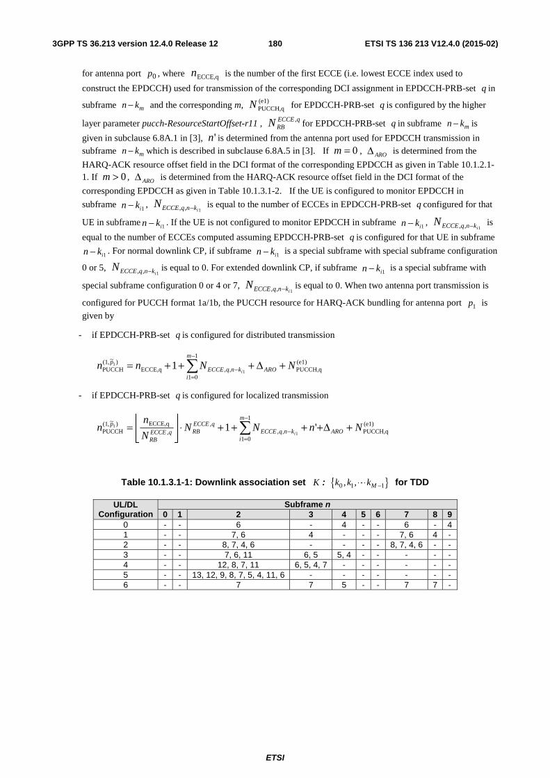
ETSI
ETSI TS 136 213 V12.4.0 (2015-02)1803GPP TS 36.213 version 12.4.0 Release 12
for antenna port 0p , where ECCE,qn is the number of the first ECCE (i.e. lowest ECCE index used to
construct the EPDCCH) used for transmission of the corresponding DCI assignment in EPDCCH-PRB-set q in
subframe mn k− and the corresponding m, (e1)PUCCH,qN for EPDCCH-PRB-set q is configured by the higher
layer parameter pucch-ResourceStartOffset-r11 , qECCERBN , for EPDCCH-PRB-set q in subframe mn k− is
given in subclause 6.8A.1 in [3], 'n is determined from the antenna port used for EPDCCH transmission in subframe mn k− which is described in subclause 6.8A.5 in [3]. If 0=m , AROΔ is determined from the
HARQ-ACK resource offset field in the DCI format of the corresponding EPDCCH as given in Table 10.1.2.1-1. If 0>m , AROΔ is determined from the HARQ-ACK resource offset field in the DCI format of the
corresponding EPDCCH as given in Table 10.1.3.1-2. If the UE is configured to monitor EPDCCH in
subframe 1ikn − , 1,, iknqECCEN − is equal to the number of ECCEs in EPDCCH-PRB-set q configured for that
UE in subframe 1ikn − . If the UE is not configured to monitor EPDCCH in subframe 1ikn − , 1,, iknqECCEN − is
equal to the number of ECCEs computed assuming EPDCCH-PRB-set q is configured for that UE in subframe
1ikn − . For normal downlink CP, if subframe 1ikn − is a special subframe with special subframe configuration
0 or 5, 1,, iknqECCEN − is equal to 0. For extended downlink CP, if subframe 1ikn − is a special subframe with
special subframe configuration 0 or 4 or 7, 1,, iknqECCEN − is equal to 0. When two antenna port transmission is
configured for PUCCH format 1a/1b, the PUCCH resource for HARQ-ACK bundling for antenna port 1p is
given by
- if EPDCCH-PRB-set q is configured for distributed transmission
(e1)PUCCH,q
1
01,,ECCE,q
)~,1(PUCCH 1
1 1 NNnn ARO
m
iknqECCE
p
i+Δ+++= ∑
−
=−
- if EPDCCH-PRB-set q is configured for localized transmission
(e1)PUCCH,q
1
01,,
,,
ECCE,q)~,1(PUCCH '1
1
1 NnNNN
nn ARO
m
iknqECCE
qECCERBqECCE
RB
p
i+Δ++++⋅⎥
⎦
⎥⎢⎣
⎢= ∑
−
=−
Table 10.1.3.1-1: Downlink association set K : { }0 1 1, , Mk k k −L for TDD
UL/DL Configuration
Subframe n 0 1 2 3 4 5 6 7 8 9
0 - - 6 - 4 - - 6 - 4 1 - - 7, 6 4 - - - 7, 6 4 - 2 - - 8, 7, 4, 6 - - - - 8, 7, 4, 6 - - 3 - - 7, 6, 11 6, 5 5, 4 - - - - - 4 - - 12, 8, 7, 11 6, 5, 4, 7 - - - - - - 5 - - 13, 12, 9, 8, 7, 5, 4, 11, 6 - - - - - - - 6 - - 7 7 5 - - 7 7 -
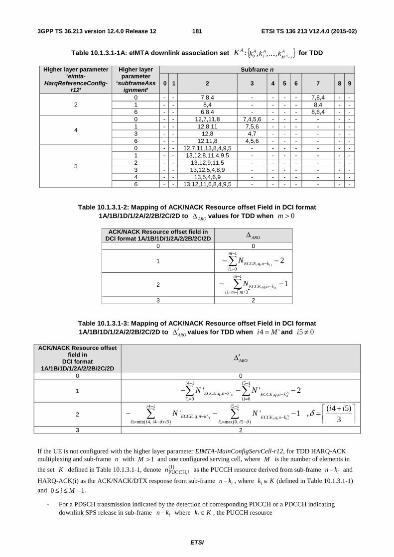
ETSI
ETSI TS 136 213 V12.4.0 (2015-02)1813GPP TS 36.213 version 12.4.0 Release 12
Table 10.1.3.1-1A: eIMTA downlink association set AK :{ }A
M
AAAkkk
110 ,,,−
K for TDD
Higher layer parameter ‘eimta-
HarqReferenceConfig-r12’
Higher layer parameter
‘subframeAssignment’
Subframe n
0 1 2 3 4 5 6 7 8 9
2 0 - - 7,8,4 - - - - 7,8,4 - - 1 - - 8,4 - - - - 8,4 - - 6 - - 6,8,4 - - - - 8,6,4 - -
4
0 - - 12,7,11,8 7,4,5,6 - - - - - - 1 - - 12,8,11 7,5,6 - - - - - - 3 - - 12,8 4,7 - - - - - - 6 - - 12,11,8 4,5,6 - - - - - -
5
0 - - 12,7,11,13,8,4,9,5 - - - - - - - 1 - - 13,12,8,11,4,9,5 - - - - - - - 2 - - 13,12,9,11,5 - - - - - - - 3 - - 13,12,5,4,8,9 - - - - - - - 4 - - 13,5,4,6,9 - - - - - - - 6 - - 13,12,11,6,8,4,9,5 - - - - - - -
Table 10.1.3.1-2: Mapping of ACK/NACK Resource offset Field in DCI format 1A/1B/1D/1/2A/2/2B/2C/2D to AROΔ values for TDD when 0>m
ACK/NACK Resource offset field in DCI format 1A/1B/1D/1/2A/2/2B/2C/2D AROΔ
0 0
1 21
01,, 1
−−∑−
=−
m
iknqECCE i
N
2 ⎡ ⎤
11
3/1,, 1
−− ∑−
−=−
m
mmiknqECCE i
N
3 2
Table 10.1.3.1-3: Mapping of ACK/NACK Resource offset Field in DCI format 1A/1B/1D/1/2A/2/2B/2C/2D to ARO′Δ values for TDD when '4 Mi = and 05 ≠i
ACK/NACK Resource offset field in
DCI format 1A/1B/1D/1/2A/2/2B/2C/2D
ARO′Δ
0 0
1 1 1
4 1 5 1
, , ' , ,1 0 1 0
' ' 2Ai i
i i
ECCE q n k ECCE q n ki i
N N− −
− −= =
− − −∑ ∑
2 ( ) ( )
1 1
4 1 5 1
, , ' , ,1 min 4, 4 5 1 max 0, 5
( 4 5)' ' 1 ,
3A
i i
i i
ECCE q n k ECCE q n ki i i i i i
i iN N
δ δδ
− −
− −= − + = −
+⎡ ⎤− − − = ⎢ ⎥⎢ ⎥∑ ∑
3 2
If the UE is not configured with the higher layer parameter EIMTA-MainConfigServCell-r12, for TDD HARQ-ACK multiplexing and sub-frame n with 1>M and one configured serving cell, where M is the number of elements in
the set K defined in Table 10.1.3.1-1, denote )1(PUCCH,in as the PUCCH resource derived from sub-frame in k− and
HARQ-ACK(i) as the ACK/NACK/DTX response from sub-frame in k− , where ik K∈ (defined in Table 10.1.3.1-1)
and 10 −≤≤ Mi .
- For a PDSCH transmission indicated by the detection of corresponding PDCCH or a PDCCH indicating downlink SPS release in sub-frame in k− where ik K∈ , the PUCCH resource
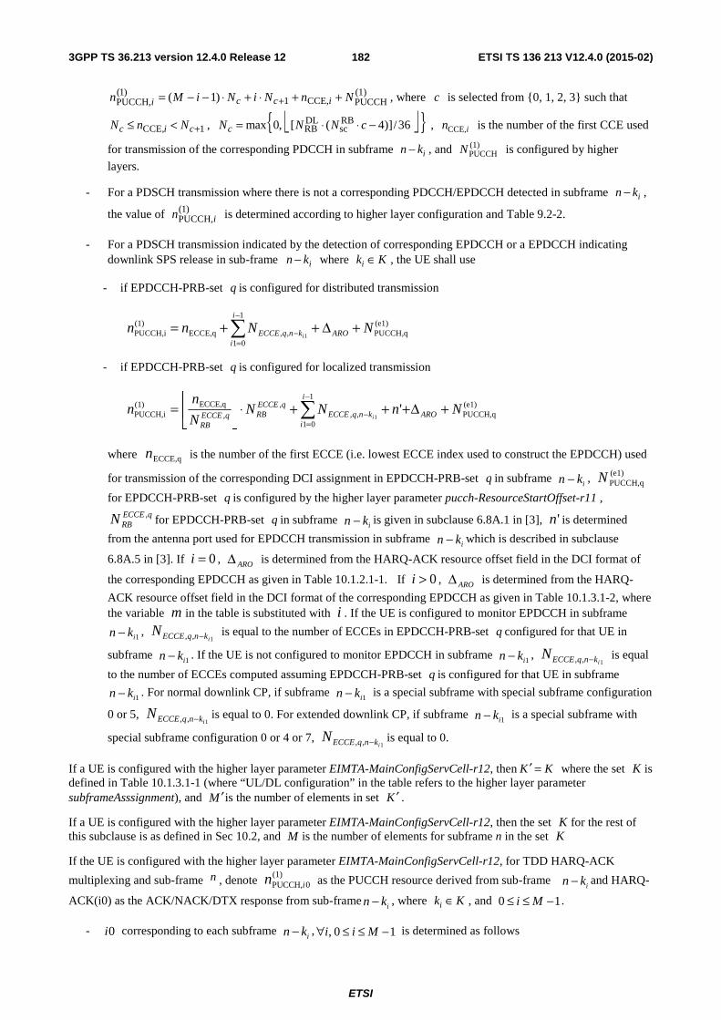
ETSI
ETSI TS 136 213 V12.4.0 (2015-02)1823GPP TS 36.213 version 12.4.0 Release 12
(1)PUCCHCCE,1
)1(PUCCH, )1( NnNiNiMn icci ++⋅+⋅−−= + , where c is selected from {0, 1, 2, 3} such that
1CCE, +<≤ cic NnN , ⎣ ⎦{ }36/)]4([,0max RBsc
DLRB −⋅⋅= cNNNc , CCE,in is the number of the first CCE used
for transmission of the corresponding PDCCH in subframe in k− , and (1)PUCCHN is configured by higher
layers.
- For a PDSCH transmission where there is not a corresponding PDCCH/EPDCCH detected in subframe in k− ,
the value of )1(PUCCH,in is determined according to higher layer configuration and Table 9.2-2.
- For a PDSCH transmission indicated by the detection of corresponding EPDCCH or a EPDCCH indicating downlink SPS release in sub-frame in k− where ik K∈ , the UE shall use
- if EPDCCH-PRB-set q is configured for distributed transmission
(e1)PUCCH,q
1
01,,ECCE,q
)1(PUCCH,i 1
NNnn ARO
i
iknqECCE i
+Δ++= ∑−
=−
- if EPDCCH-PRB-set q is configured for localized transmission
(e1)PUCCH,q
1
01,,
,,
ECCE,q)1(PUCCH,i '
1NnNN
N
nn ARO
i
iknqECCE
qECCERBqECCE
RBi
+Δ+++⋅⎥⎦
⎥⎢⎣
⎢= ∑
−
=−
where ECCE,qn is the number of the first ECCE (i.e. lowest ECCE index used to construct the EPDCCH) used
for transmission of the corresponding DCI assignment in EPDCCH-PRB-set q in subframe ikn − , (e1)
PUCCH,qN
for EPDCCH-PRB-set q is configured by the higher layer parameter pucch-ResourceStartOffset-r11 , qECCE
RBN , for EPDCCH-PRB-set q in subframe ikn − is given in subclause 6.8A.1 in [3], 'n is determined
from the antenna port used for EPDCCH transmission in subframe ikn − which is described in subclause
6.8A.5 in [3]. If 0=i , AROΔ is determined from the HARQ-ACK resource offset field in the DCI format of
the corresponding EPDCCH as given in Table 10.1.2.1-1. If 0>i , AROΔ is determined from the HARQ-
ACK resource offset field in the DCI format of the corresponding EPDCCH as given in Table 10.1.3.1-2, where the variable m in the table is substituted with i . If the UE is configured to monitor EPDCCH in subframe
1ikn − , 1,, iknqECCEN − is equal to the number of ECCEs in EPDCCH-PRB-set q configured for that UE in
subframe 1ikn − . If the UE is not configured to monitor EPDCCH in subframe 1ikn − , 1,, iknqECCEN − is equal
to the number of ECCEs computed assuming EPDCCH-PRB-set q is configured for that UE in subframe
1ikn − . For normal downlink CP, if subframe 1ikn − is a special subframe with special subframe configuration
0 or 5, 1,, iknqECCEN − is equal to 0. For extended downlink CP, if subframe 1ikn − is a special subframe with
special subframe configuration 0 or 4 or 7, 1,, iknqECCEN − is equal to 0.
If a UE is configured with the higher layer parameter EIMTA-MainConfigServCell-r12, then K K′ = where the set K is defined in Table 10.1.3.1-1 (where “UL/DL configuration” in the table refers to the higher layer parameter subframeAsssignment), and M ′is the number of elements in set K ′ .
If a UE is configured with the higher layer parameter EIMTA-MainConfigServCell-r12, then the set K for the rest of this subclause is as defined in Sec 10.2, and M is the number of elements for subframe n in the set K
If the UE is configured with the higher layer parameter EIMTA-MainConfigServCell-r12, for TDD HARQ-ACK
multiplexing and sub-frame n , denote (1)PUCCH, 0in as the PUCCH resource derived from sub-frame
in k− and HARQ-
ACK(i0) as the ACK/NACK/DTX response from sub-framein k− , where ik K∈ , and 10 −≤≤ Mi .
- 0i corresponding to each subframe in k− , , 0 1i i M∀ ≤ ≤ − is determined as follows
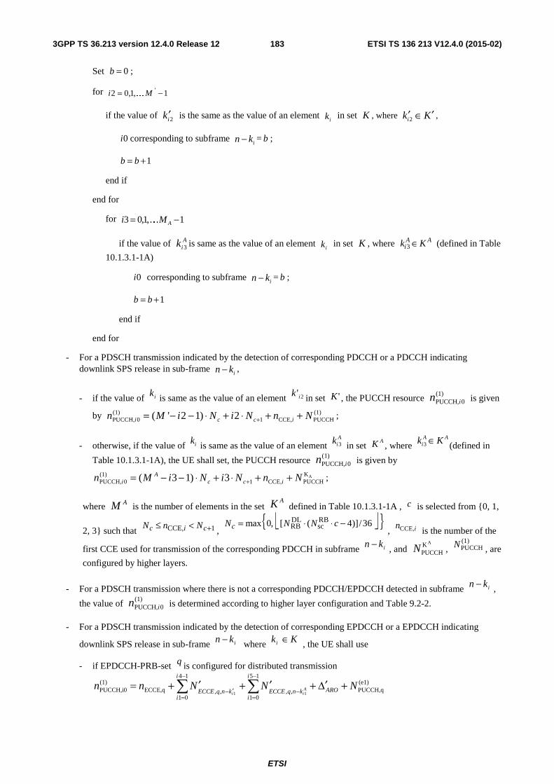
ETSI
ETSI TS 136 213 V12.4.0 (2015-02)1833GPP TS 36.213 version 12.4.0 Release 12
Set 0b = ;
for 1,1,02 ' −= Mi K
if the value of 2ik ′ is the same as the value of an element ik in set K , where Kki ′∈′2 ,
0i corresponding to subframe in k− = b ;
1b b= +
end if
end for
for 1,1,03 −= AMi K
if the value of Aik 3 is same as the value of an element
ik in set K , where 3A Aik K∈ (defined in Table
10.1.3.1-1A)
0i corresponding to subframe in k− = b ;
1b b= +
end if
end for
- For a PDSCH transmission indicated by the detection of corresponding PDCCH or a PDCCH indicating downlink SPS release in sub-frame
in k− ,
- if the value of ik is same as the value of an element 2'ik in set 'K , the PUCCH resource (1)PUCCH, 0in is given
by (1) (1)PUCCH, 0 1 CCE, PUCCH( ' 2 1) 2i c c in M i N i N n N+= − − ⋅ + ⋅ + + ;
- otherwise, if the value of ik is same as the value of an element A
ik 3 in set AK , where
AAi Kk ∈3 (defined in
Table 10.1.3.1-1A), the UE shall set, the PUCCH resource (1)PUCCH, 0in is given by
AK(1)PUCCH, 0 1 CCE, PUCCH( 3 1) 3A
i c c in M i N i N n N+= − − ⋅ + ⋅ + + ;
where AM is the number of elements in the set AK defined in Table 10.1.3.1-1A , c is selected from {0, 1,
2, 3} such that 1CCE, +<≤ cic NnN,
⎣ ⎦{ }36/)]4([,0max RBsc
DLRB −⋅⋅= cNNNc , CCE,in
is the number of the
first CCE used for transmission of the corresponding PDCCH in subframe ikn − , and AK
PUCCHN , (1)PUCCHN , are
configured by higher layers.
- For a PDSCH transmission where there is not a corresponding PDCCH/EPDCCH detected in subframe ikn − ,
the value of (1)PUCCH, 0in is determined according to higher layer configuration and Table 9.2-2.
- For a PDSCH transmission indicated by the detection of corresponding EPDCCH or a EPDCCH indicating
downlink SPS release in sub-frame ikn − where Kki ∈ , the UE shall use
- if EPDCCH-PRB-set q is configured for distributed transmission
1 1
4 1 5 1(1) (e1)PUCCH,i0 ECCE,q PUCCH,q, , , ,
1 0 1 0
Ai i
i i
AROECCE q n k ECCE q n ki i
n n N N N− −
′− −= =
′ ′ ′= + + + Δ +∑ ∑
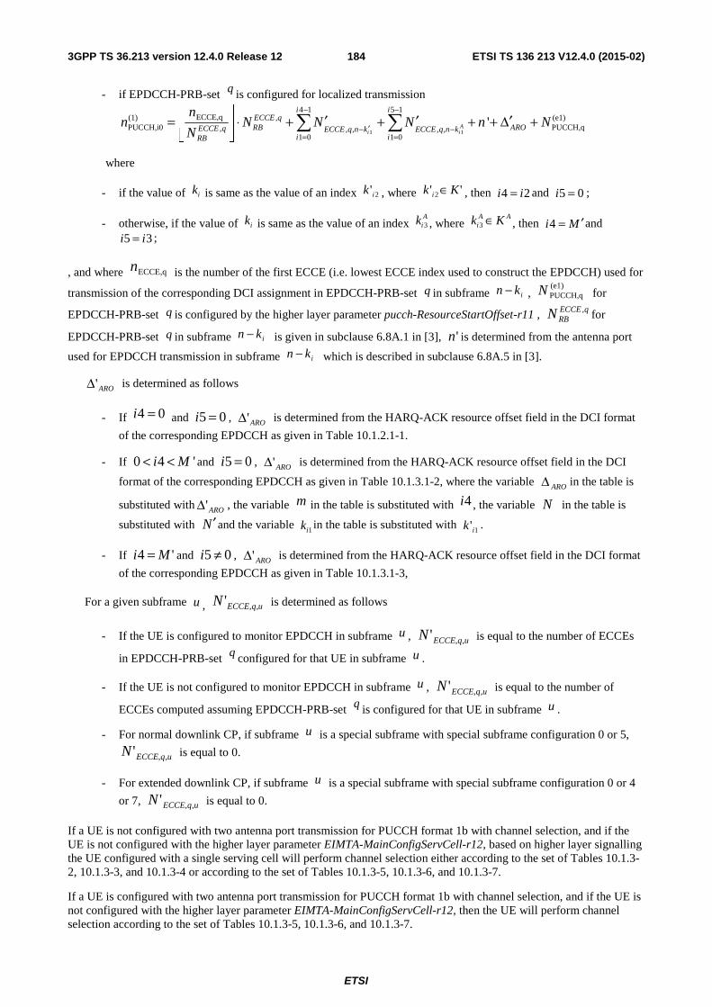
ETSI
ETSI TS 136 213 V12.4.0 (2015-02)1843GPP TS 36.213 version 12.4.0 Release 12
- if EPDCCH-PRB-set q is configured for localized transmission
1 1
4 1 5 1ECCE,q(1) , (e1)
PUCCH,i0 PUCCH,q, , , , ,1 0 1 0
'Ai i
i iECCE qRB AROECCE q ECCE q n k ECCE q n k
i iRB
nn N N N n N
N
− −
′− −= =
⎢ ⎥ ′ ′ ′= ⋅ + + + + Δ +⎢ ⎥⎣ ⎦
∑ ∑
where
- if the value of ik is same as the value of an index 2'ik , where '' 2 Kk i ∈ , then 24 ii = and 5 0i = ;
- otherwise, if the value of ik is same as the value of an index A
ik 3 , where AA
i Kk ∈3 , then 4i M ′= and 5 3i i= ;
, and where ECCE,qn is the number of the first ECCE (i.e. lowest ECCE index used to construct the EPDCCH) used for
transmission of the corresponding DCI assignment in EPDCCH-PRB-set q in subframe ikn − , (e1)PUCCH,qN for
EPDCCH-PRB-set q is configured by the higher layer parameter pucch-ResourceStartOffset-r11 , qECCERBN , for
EPDCCH-PRB-set q in subframe ikn − is given in subclause 6.8A.1 in [3], 'n is determined from the antenna port
used for EPDCCH transmission in subframe ikn − which is described in subclause 6.8A.5 in [3].
ARO'Δ is determined as follows
- If 04 =i and 05 =i , ARO'Δ is determined from the HARQ-ACK resource offset field in the DCI format
of the corresponding EPDCCH as given in Table 10.1.2.1-1.
- If 0 4 'i M< < and 05 =i , ARO'Δ is determined from the HARQ-ACK resource offset field in the DCI
format of the corresponding EPDCCH as given in Table 10.1.3.1-2, where the variable AROΔ in the table is
substituted with ARO'Δ , the variable m in the table is substituted with 4i , the variable N in the table is
substituted with N′ and the variable 1ik in the table is substituted with 1'ik .
- If '4 Mi = and 05 ≠i , ARO'Δ is determined from the HARQ-ACK resource offset field in the DCI format
of the corresponding EPDCCH as given in Table 10.1.3.1-3,
For a given subframe u , uqECCEN ,,' is determined as follows
- If the UE is configured to monitor EPDCCH in subframe u , uqECCEN ,,' is equal to the number of ECCEs
in EPDCCH-PRB-set q configured for that UE in subframe u .
- If the UE is not configured to monitor EPDCCH in subframe u , uqECCEN ,,' is equal to the number of
ECCEs computed assuming EPDCCH-PRB-set q is configured for that UE in subframe u .
- For normal downlink CP, if subframe u is a special subframe with special subframe configuration 0 or 5,
uqECCEN ,,' is equal to 0.
- For extended downlink CP, if subframe u is a special subframe with special subframe configuration 0 or 4
or 7, uqECCEN ,,' is equal to 0.
If a UE is not configured with two antenna port transmission for PUCCH format 1b with channel selection, and if the UE is not configured with the higher layer parameter EIMTA-MainConfigServCell-r12, based on higher layer signalling the UE configured with a single serving cell will perform channel selection either according to the set of Tables 10.1.3-2, 10.1.3-3, and 10.1.3-4 or according to the set of Tables 10.1.3-5, 10.1.3-6, and 10.1.3-7.
If a UE is configured with two antenna port transmission for PUCCH format 1b with channel selection, and if the UE is not configured with the higher layer parameter EIMTA-MainConfigServCell-r12, then the UE will perform channel selection according to the set of Tables 10.1.3-5, 10.1.3-6, and 10.1.3-7.
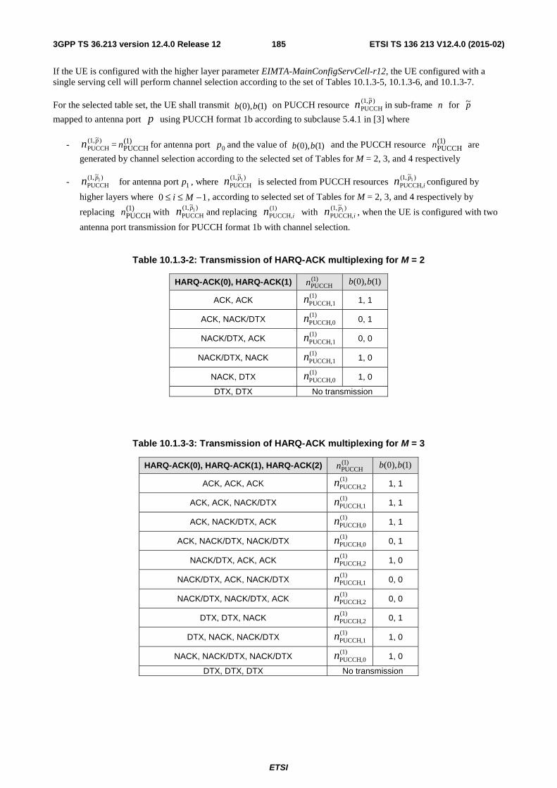
ETSI
ETSI TS 136 213 V12.4.0 (2015-02)1853GPP TS 36.213 version 12.4.0 Release 12
If the UE is configured with the higher layer parameter EIMTA-MainConfigServCell-r12, the UE configured with a single serving cell will perform channel selection according to the set of Tables 10.1.3-5, 10.1.3-6, and 10.1.3-7.
For the selected table set, the UE shall transmit )1(),0( bb on PUCCH resource )~,1(PUCCH
pn in sub-frame n for p~
mapped to antenna port p using PUCCH format 1b according to subclause 5.4.1 in [3] where
- )~,1(PUCCH
pn = )1(PUCCHn for antenna port 0p and the value of )1(),0( bb and the PUCCH resource )1(
PUCCHn are
generated by channel selection according to the selected set of Tables for M = 2, 3, and 4 respectively
- )~,1(PUCCH
1pn for antenna port 1p , where )~,1(PUCCH
1pn is selected from PUCCH resources )~,1(PUCCH,
1pin configured by
higher layers where 10 −≤≤ Mi , according to selected set of Tables for M = 2, 3, and 4 respectively by
replacing )1(PUCCHn with
)~,1(PUCCH
1pn and replacing )1(PUCCH,in with )~,1(
PUCCH,1p
in , when the UE is configured with two
antenna port transmission for PUCCH format 1b with channel selection.
Table 10.1.3-2: Transmission of HARQ-ACK multiplexing for M = 2
HARQ-ACK(0), HARQ-ACK(1) )1(PUCCHn )1(),0( bb
ACK, ACK (1)PUCCH,1n 1, 1
ACK, NACK/DTX (1)PUCCH,0n 0, 1
NACK/DTX, ACK (1)PUCCH,1n 0, 0
NACK/DTX, NACK (1)PUCCH,1n 1, 0
NACK, DTX (1)PUCCH,0n 1, 0
DTX, DTX No transmission
Table 10.1.3-3: Transmission of HARQ-ACK multiplexing for M = 3
HARQ-ACK(0), HARQ-ACK(1), HARQ-ACK(2) )1(PUCCHn )1(),0( bb
ACK, ACK, ACK (1)PUCCH,2n 1, 1
ACK, ACK, NACK/DTX (1)PUCCH,1n 1, 1
ACK, NACK/DTX, ACK (1)PUCCH,0n 1, 1
ACK, NACK/DTX, NACK/DTX (1)PUCCH,0n 0, 1
NACK/DTX, ACK, ACK (1)PUCCH,2n 1, 0
NACK/DTX, ACK, NACK/DTX (1)PUCCH,1n 0, 0
NACK/DTX, NACK/DTX, ACK (1)PUCCH,2n 0, 0
DTX, DTX, NACK (1)PUCCH,2n 0, 1
DTX, NACK, NACK/DTX (1)PUCCH,1n 1, 0
NACK, NACK/DTX, NACK/DTX (1)PUCCH,0n 1, 0
DTX, DTX, DTX No transmission
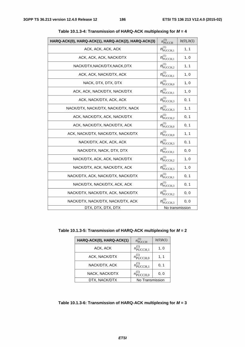
ETSI
ETSI TS 136 213 V12.4.0 (2015-02)1863GPP TS 36.213 version 12.4.0 Release 12
Table 10.1.3-4: Transmission of HARQ-ACK multiplexing for M = 4
HARQ-ACK(0), HARQ-ACK(1), HARQ-ACK(2), HARQ-ACK(3) )1(PUCCHn )1(),0( bb
ACK, ACK, ACK, ACK (1)PUCCH,1n 1, 1
ACK, ACK, ACK, NACK/DTX (1)PUCCH,1n 1, 0
NACK/DTX,NACK/DTX,NACK,DTX (1)PUCCH,2n 1, 1
ACK, ACK, NACK/DTX, ACK (1)PUCCH,1n 1, 0
NACK, DTX, DTX, DTX (1)PUCCH,0n 1, 0
ACK, ACK, NACK/DTX, NACK/DTX (1)PUCCH,1n 1, 0
ACK, NACK/DTX, ACK, ACK (1)PUCCH,3n 0, 1
NACK/DTX, NACK/DTX, NACK/DTX, NACK (1)PUCCH,3n 1, 1
ACK, NACK/DTX, ACK, NACK/DTX (1)PUCCH,2n 0, 1
ACK, NACK/DTX, NACK/DTX, ACK (1)PUCCH,0n 0, 1
ACK, NACK/DTX, NACK/DTX, NACK/DTX (1)PUCCH,0n 1, 1
NACK/DTX, ACK, ACK, ACK (1)PUCCH,3n 0, 1
NACK/DTX, NACK, DTX, DTX (1)PUCCH,1n 0, 0
NACK/DTX, ACK, ACK, NACK/DTX (1)PUCCH,2n 1, 0
NACK/DTX, ACK, NACK/DTX, ACK (1)PUCCH,3n 1, 0
NACK/DTX, ACK, NACK/DTX, NACK/DTX (1)PUCCH,1n 0, 1
NACK/DTX, NACK/DTX, ACK, ACK (1)PUCCH,3n 0, 1
NACK/DTX, NACK/DTX, ACK, NACK/DTX (1)PUCCH,2n 0, 0
NACK/DTX, NACK/DTX, NACK/DTX, ACK (1)PUCCH,3n 0, 0
DTX, DTX, DTX, DTX No transmission
Table 10.1.3-5: Transmission of HARQ-ACK multiplexing for M = 2
HARQ-ACK(0), HARQ-ACK(1) )1(PUCCHn )1()0( bb
ACK, ACK )1(PUCCH,1n 1, 0
ACK, NACK/DTX )1(PUCCH,0n 1, 1
NACK/DTX, ACK )1(PUCCH,1n 0, 1
NACK, NACK/DTX )1(PUCCH,0n 0, 0
DTX, NACK/DTX No Transmission
Table 10.1.3-6: Transmission of HARQ-ACK multiplexing for M = 3
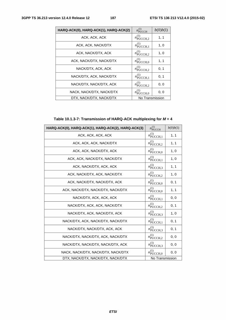
ETSI
ETSI TS 136 213 V12.4.0 (2015-02)1873GPP TS 36.213 version 12.4.0 Release 12
HARQ-ACK(0), HARQ-ACK(1), HARQ-ACK(2) )1(PUCCHn )1()0( bb
ACK, ACK, ACK )1(PUCCH,2n 1, 1
ACK, ACK, NACK/DTX )1(PUCCH,1n 1, 0
ACK, NACK/DTX, ACK )1(PUCCH,2n 1, 0
ACK, NACK/DTX, NACK/DTX )1(PUCCH,0n 1, 1
NACK/DTX, ACK, ACK )1(PUCCH,2n 0, 1
NACK/DTX, ACK, NACK/DTX )1(PUCCH,1n 0, 1
NACK/DTX, NACK/DTX, ACK )1(PUCCH,2n 0, 0
NACK, NACK/DTX, NACK/DTX )1(PUCCH,0n 0, 0
DTX, NACK/DTX, NACK/DTX No Transmission
Table 10.1.3-7: Transmission of HARQ-ACK multiplexing for M = 4
HARQ-ACK(0), HARQ-ACK(1), HARQ-ACK(2), HARQ-ACK(3) )1(PUCCHn )1()0( bb
ACK, ACK, ACK, ACK )1(PUCCH,1n 1, 1
ACK, ACK, ACK, NACK/DTX )1(PUCCH,2n 1, 1
ACK, ACK, NACK/DTX, ACK )1(PUCCH,0n 1, 0
ACK, ACK, NACK/DTX, NACK/DTX )1(PUCCH,1n 1, 0
ACK, NACK/DTX, ACK, ACK )1(PUCCH,3n 1, 1
ACK, NACK/DTX, ACK, NACK/DTX )1(PUCCH,2n 1, 0
ACK, NACK/DTX, NACK/DTX, ACK )1(PUCCH,0n 0, 1
ACK, NACK/DTX, NACK/DTX, NACK/DTX )1(PUCCH,0n 1, 1
NACK/DTX, ACK, ACK, ACK )1(PUCCH,1n 0, 0
NACK/DTX, ACK, ACK, NACK/DTX )1(PUCCH,2n 0, 1
NACK/DTX, ACK, NACK/DTX, ACK )1(PUCCH,3n 1, 0
NACK/DTX, ACK, NACK/DTX, NACK/DTX )1(PUCCH,1n 0, 1
NACK/DTX, NACK/DTX, ACK, ACK )1(PUCCH,3n 0, 1
NACK/DTX, NACK/DTX, ACK, NACK/DTX )1(PUCCH,2n 0, 0
NACK/DTX, NACK/DTX, NACK/DTX, ACK )1(PUCCH,3n 0, 0
NACK, NACK/DTX, NACK/DTX, NACK/DTX )1(PUCCH,0n 0, 0
DTX, NACK/DTX, NACK/DTX, NACK/DTX No Transmission
ETSI
ETSI TS 136 213 V12.4.0 (2015-02)1883GPP TS 36.213 version 12.4.0 Release 12
10.1.3.2 TDD HARQ-ACK procedure for more than one configured serving cell
If a UE configured with EIMTA-MainConfigServCell-r12 for a serving cell, “UL/DL configuration” of the serving cell in the rest of this subclause refers to the UL/DL configuration given by the parameter eimta-HarqReferenceConfig-r12 for the serving cell unless specified otherwise.
The TDD HARQ-ACK feedback procedures for more than one configured serving cell are either based on a PUCCH format 1b with channel selection HARQ-ACK procedure as described in subclause 10.1.3.2.1 or a PUCCH format 3 HARQ-ACK procedure as described in subclause 10.1.3.2.2.
HARQ-ACK transmission on two antenna ports ]),[( 10 ppp ∈ is supported for PUCCH format 3 and TDD with more
than one configured serving cell.
If a UE is configured with more than one serving cell and the TDD UL/DL configurations of all serving cells are the same, TDD UL/DL configuration 5 with PUCCH format 3 is only supported for up to two configured serving cells. If a UE is configured with two serving cells and the TDD UL/DL configuration of the two serving cells is the same, TDD UL/DL configuration 5 with PUCCH format 1b with channel selection for two configured serving cells is not supported. If a UE is configured with two serving cells and if the TDD UL/DL configuration of the two serving cells are not the same and if the DL-reference UL/DL configuration (as defined in subclause 10.2) of at least one serving cell is TDD UL/DL Configuration 5, PUCCH format 1b with channel selection is not supported.
If a UE is configured with the parameter EIMTA-MainConfigServCell-r12 for at least one serving cell, the UE is not expected to be configured with more than two serving cells having UL/DL Configuration 5 as a DL-reference UL/DL configuration.
HARQ-ACK transmission on two antenna ports ]),[( 10 ppp ∈ is supported for PUCCH format 1b with channel
selection and TDD with two configured serving cells.
10.1.3.2.1 PUCCH format 1b with channel selection HARQ-ACK procedure
If a UE is configured with the higher layer parameter EIMTA-MainConfigServCell-r12, then KK =' where the set K is defined in Table 10.1.3.1-1 (where "UL/DL configuration" in the table refers to the higher layer parameter subframeAssignment), and 'M is the number of elements in set 'K .
If a UE is configured with two serving cells with the same UL/DL configurations, then in the rest of this subcaluse, K is as defined in Sec 10.2 and M is the number of elements for subframe n in the set K , and MM primary = .
If a UE is configured with two serving cells with different UL/DL configurations,
- then the UE shall determine M for a subframe n in this subclause as ( )ondaryprimary MMM sec,max= , where
- primaryM denotes the number of elements for subframe n in the set K for the primary cell (as defined in
subclause 10.2)
- ondaryM sec
denotes the number of elements for subframe n in the set cK for the secondary serving cell (as
defined in subclause 10.2)
- if MM ondary <sec , then the UE shall, for the secondary serving cell, set HARQ-ACK(j) to DTX for j =
ondaryM secto 1−M .
- if MM primary < , then the UE shall, for the primary cell, set HARQ-ACK(j) to DTX for j = primaryM to
1−M
If the UE is configured with two serving cells with different UL/DL configurations, then in the rest of this subclause,
K = cK where cK is defined in subclause 10.2.
For TDD HARQ-ACK multiplexing with PUCCH format 1b with channel selection and two configured serving cells and a subframe n with 1=M , a UE shall determine the number of HARQ-ACK bits, O , based on the number of
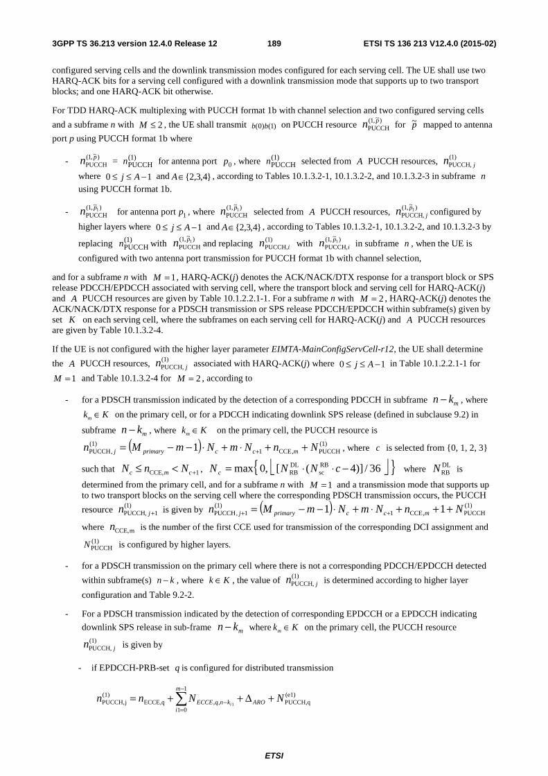
ETSI
ETSI TS 136 213 V12.4.0 (2015-02)1893GPP TS 36.213 version 12.4.0 Release 12
configured serving cells and the downlink transmission modes configured for each serving cell. The UE shall use two HARQ-ACK bits for a serving cell configured with a downlink transmission mode that supports up to two transport blocks; and one HARQ-ACK bit otherwise.
For TDD HARQ-ACK multiplexing with PUCCH format 1b with channel selection and two configured serving cells
and a subframe n with 2≤M , the UE shall transmit )1()0( bb on PUCCH resource )~,1(PUCCH
pn for p~ mapped to antenna
port p using PUCCH format 1b where
- )~,1(PUCCH
pn = )1(PUCCHn for antenna port 0p , where )1(
PUCCHn selected from A PUCCH resources, )1(PUCCH, jn
where 10 −≤≤ Aj and }4,3,2{∈A , according to Tables 10.1.3.2-1, 10.1.3.2-2, and 10.1.3.2-3 in subframe n
using PUCCH format 1b.
- )~,1(PUCCH
1pn for antenna port 1p , where )~,1(PUCCH
1pn selected from A PUCCH resources, )~,1(PUCCH,
1pjn configured by
higher layers where 10 −≤≤ Aj and }4,3,2{∈A , according to Tables 10.1.3.2-1, 10.1.3.2-2, and 10.1.3.2-3 by
replacing )1(PUCCHn with
)~,1(PUCCH
1pn and replacing )1(PUCCH,in with )~,1(
PUCCH,1p
in in subframe n , when the UE is
configured with two antenna port transmission for PUCCH format 1b with channel selection,
and for a subframe n with 1=M , HARQ-ACK(j) denotes the ACK/NACK/DTX response for a transport block or SPS release PDCCH/EPDCCH associated with serving cell, where the transport block and serving cell for HARQ-ACK(j) and A PUCCH resources are given by Table 10.1.2.2.1-1. For a subframe n with 2=M , HARQ-ACK(j) denotes the ACK/NACK/DTX response for a PDSCH transmission or SPS release PDCCH/EPDCCH within subframe(s) given by set K on each serving cell, where the subframes on each serving cell for HARQ-ACK(j) and A PUCCH resources are given by Table 10.1.3.2-4.
If the UE is not configured with the higher layer parameter EIMTA-MainConfigServCell-r12, the UE shall determine
the A PUCCH resources, )1(PUCCH, jn associated with HARQ-ACK(j) where 10 −≤≤ Aj in Table 10.1.2.2.1-1 for
1=M and Table 10.1.3.2-4 for 2=M , according to
- for a PDSCH transmission indicated by the detection of a corresponding PDCCH in subframe mkn − , where
mk K∈ on the primary cell, or for a PDCCH indicating downlink SPS release (defined in subclause 9.2) in
subframe mkn − , where mk K∈ on the primary cell, the PUCCH resource is
( ) (1)PUCCH,CCE1
(1),PUCCH 1 NnNmNmMn mccprimaryj ++⋅+⋅−−= + , where c is selected from {0, 1, 2, 3}
such that 1CCE, +<≤ cmc NnN , ⎣ ⎦{ }36/)]4([,0max RBsc
DLRB −⋅⋅= cNNN c where DL
RBN is
determined from the primary cell, and for a subframe n with 1=M and a transmission mode that supports up to two transport blocks on the serving cell where the corresponding PDSCH transmission occurs, the PUCCH
resource )1(1PUCCH, +jn is given by ( ) (1)
PUCCH,CCE1(1)
1,PUCCH 11 NnNmNmMn mccprimaryj +++⋅+⋅−−= ++
where mCCE,n is the number of the first CCE used for transmission of the corresponding DCI assignment and
(1)PUCCHN is configured by higher layers.
- for a PDSCH transmission on the primary cell where there is not a corresponding PDCCH/EPDCCH detected
within subframe(s) kn − , where Kk ∈ , the value of )1(PUCCH, jn is determined according to higher layer
configuration and Table 9.2-2.
- For a PDSCH transmission indicated by the detection of corresponding EPDCCH or a EPDCCH indicating
downlink SPS release in sub-frame mkn − where mk K∈ on the primary cell, the PUCCH resource )1(
PUCCH, jn is given by
- if EPDCCH-PRB-set q is configured for distributed transmission
(e1)PUCCH,q
1
01,,ECCE,q
)1(jPUCCH, 1
NNnn ARO
m
iknqECCE i
+Δ++= ∑−
=−
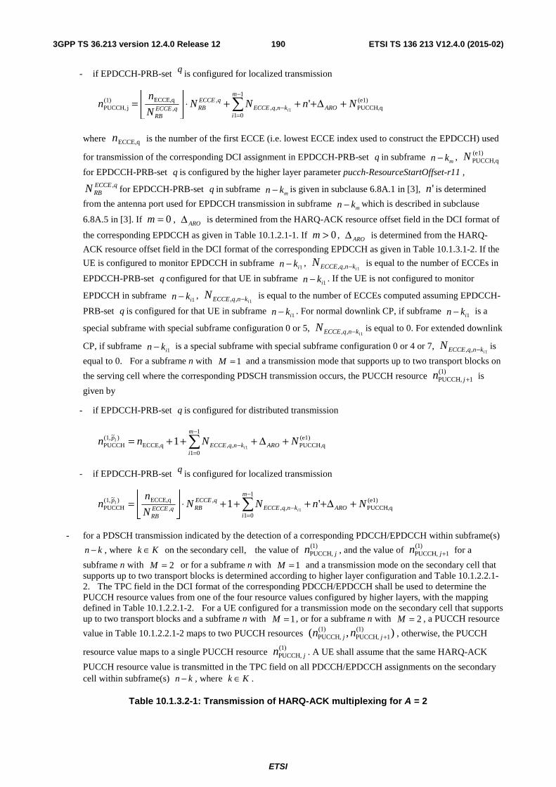
ETSI
ETSI TS 136 213 V12.4.0 (2015-02)1903GPP TS 36.213 version 12.4.0 Release 12
- if EPDCCH-PRB-set q is configured for localized transmission
(e1)PUCCH,q
1
01,,
,,
ECCE,q)1(jPUCCH, '
1NnNN
N
nn ARO
m
iknqECCE
qECCERBqECCE
RBi
+Δ+++⋅⎥⎦
⎥⎢⎣
⎢= ∑
−
=−
where ECCE,qn is the number of the first ECCE (i.e. lowest ECCE index used to construct the EPDCCH) used
for transmission of the corresponding DCI assignment in EPDCCH-PRB-set q in subframe mkn − , (e1)
PUCCH,qN
for EPDCCH-PRB-set q is configured by the higher layer parameter pucch-ResourceStartOffset-r11 , qECCE
RBN , for EPDCCH-PRB-set q in subframe mkn − is given in subclause 6.8A.1 in [3], 'n is determined
from the antenna port used for EPDCCH transmission in subframe mkn − which is described in subclause
6.8A.5 in [3]. If 0=m , AROΔ is determined from the HARQ-ACK resource offset field in the DCI format of
the corresponding EPDCCH as given in Table 10.1.2.1-1. If 0>m , AROΔ is determined from the HARQ-
ACK resource offset field in the DCI format of the corresponding EPDCCH as given in Table 10.1.3.1-2. If the
UE is configured to monitor EPDCCH in subframe 1ikn − , 1,, iknqECCEN − is equal to the number of ECCEs in
EPDCCH-PRB-set q configured for that UE in subframe 1ikn − . If the UE is not configured to monitor
EPDCCH in subframe 1ikn − , 1,, iknqECCEN − is equal to the number of ECCEs computed assuming EPDCCH-
PRB-set q is configured for that UE in subframe 1ikn − . For normal downlink CP, if subframe 1ikn − is a
special subframe with special subframe configuration 0 or 5, 1,, iknqECCEN − is equal to 0. For extended downlink
CP, if subframe 1ikn − is a special subframe with special subframe configuration 0 or 4 or 7, 1,, iknqECCEN − is
equal to 0. For a subframe n with 1=M and a transmission mode that supports up to two transport blocks on
the serving cell where the corresponding PDSCH transmission occurs, the PUCCH resource )1(
1PUCCH, +jn is
given by
- if EPDCCH-PRB-set q is configured for distributed transmission
(e1)PUCCH,q
1
01,,ECCE,q
)~,1(PUCCH 1
1 1 NNnn ARO
m
iknqECCE
p
i+Δ+++= ∑
−
=−
- if EPDCCH-PRB-set q is configured for localized transmission
(e1)PUCCH,q
1
01,,
,,
ECCE,q)~,1(PUCCH '1
1
1 NnNNN
nn ARO
m
iknqECCE
qECCERBqECCE
RB
p
i+Δ++++⋅⎥
⎦
⎥⎢⎣
⎢= ∑
−
=−
- for a PDSCH transmission indicated by the detection of a corresponding PDCCH/EPDCCH within subframe(s)
kn − , where Kk ∈ on the secondary cell, the value of )1(PUCCH, jn , and the value of )1(
1PUCCH, +jn for a
subframe n with 2=M or for a subframe n with 1=M and a transmission mode on the secondary cell that supports up to two transport blocks is determined according to higher layer configuration and Table 10.1.2.2.1-2. The TPC field in the DCI format of the corresponding PDCCH/EPDCCH shall be used to determine the PUCCH resource values from one of the four resource values configured by higher layers, with the mapping defined in Table 10.1.2.2.1-2. For a UE configured for a transmission mode on the secondary cell that supports up to two transport blocks and a subframe n with 1=M , or for a subframe n with 2=M , a PUCCH resource
value in Table 10.1.2.2.1-2 maps to two PUCCH resources ),( )1(1PUCCH,
)1(PUCCH, +jj nn , otherwise, the PUCCH
resource value maps to a single PUCCH resource )1(PUCCH, jn . A UE shall assume that the same HARQ-ACK
PUCCH resource value is transmitted in the TPC field on all PDCCH/EPDCCH assignments on the secondary cell within subframe(s) kn − , where Kk ∈ .
Table 10.1.3.2-1: Transmission of HARQ-ACK multiplexing for A = 2
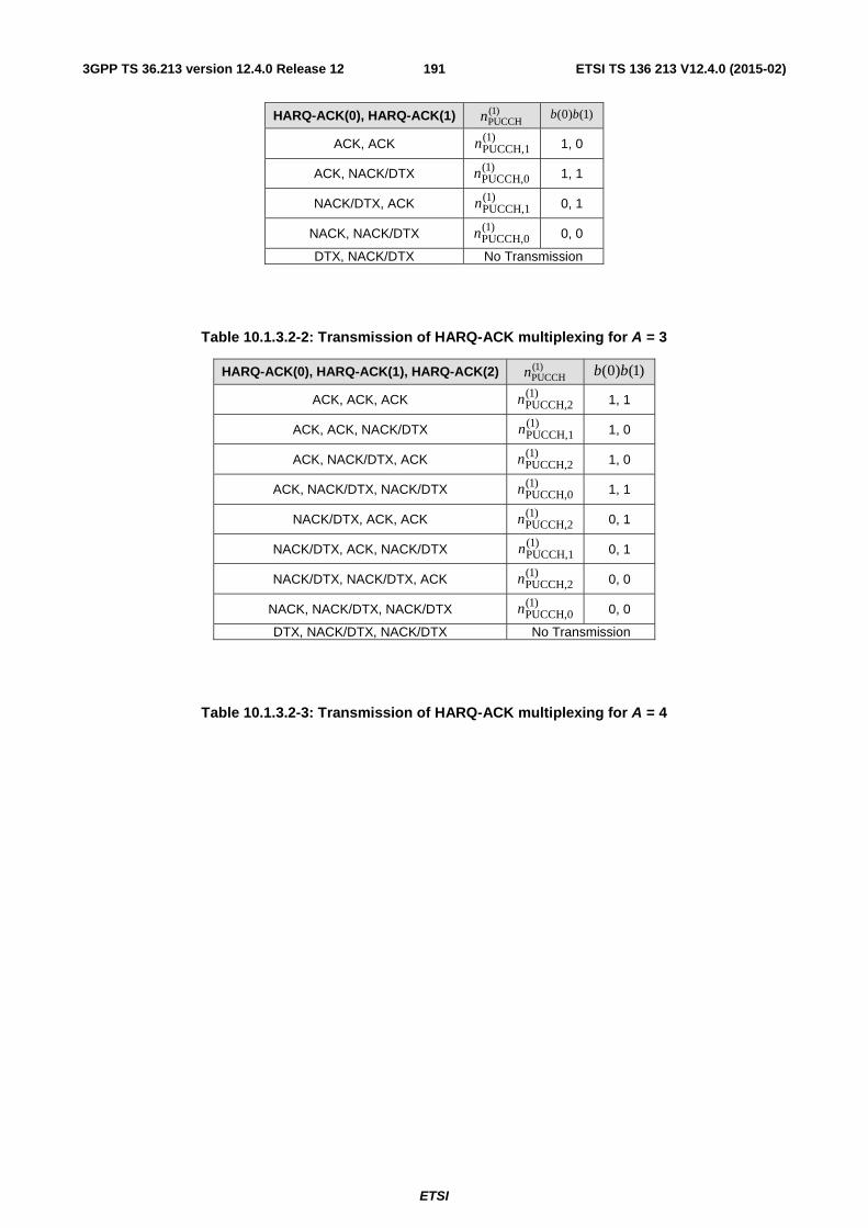
ETSI
ETSI TS 136 213 V12.4.0 (2015-02)1913GPP TS 36.213 version 12.4.0 Release 12
HARQ-ACK(0), HARQ-ACK(1) )1(PUCCHn )1()0( bb
ACK, ACK )1(PUCCH,1n 1, 0
ACK, NACK/DTX )1(PUCCH,0n 1, 1
NACK/DTX, ACK )1(PUCCH,1n 0, 1
NACK, NACK/DTX )1(PUCCH,0n 0, 0
DTX, NACK/DTX No Transmission
Table 10.1.3.2-2: Transmission of HARQ-ACK multiplexing for A = 3
HARQ-ACK(0), HARQ-ACK(1), HARQ-ACK(2) )1(PUCCHn )1()0( bb
ACK, ACK, ACK )1(PUCCH,2n 1, 1
ACK, ACK, NACK/DTX )1(PUCCH,1n 1, 0
ACK, NACK/DTX, ACK )1(PUCCH,2n 1, 0
ACK, NACK/DTX, NACK/DTX )1(PUCCH,0n 1, 1
NACK/DTX, ACK, ACK )1(PUCCH,2n 0, 1
NACK/DTX, ACK, NACK/DTX )1(PUCCH,1n 0, 1
NACK/DTX, NACK/DTX, ACK )1(PUCCH,2n 0, 0
NACK, NACK/DTX, NACK/DTX )1(PUCCH,0n 0, 0
DTX, NACK/DTX, NACK/DTX No Transmission
Table 10.1.3.2-3: Transmission of HARQ-ACK multiplexing for A = 4
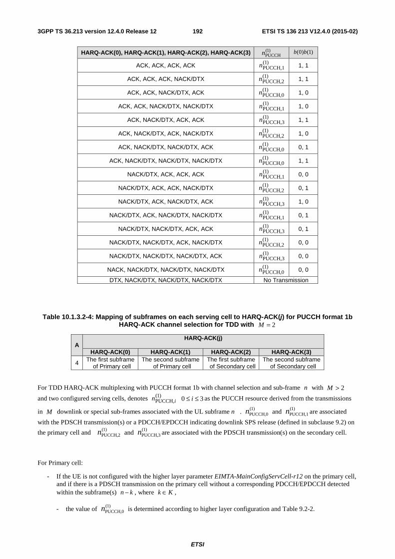
ETSI
ETSI TS 136 213 V12.4.0 (2015-02)1923GPP TS 36.213 version 12.4.0 Release 12
HARQ-ACK(0), HARQ-ACK(1), HARQ-ACK(2), HARQ-ACK(3) )1(PUCCHn )1()0( bb
ACK, ACK, ACK, ACK )1(PUCCH,1n 1, 1
ACK, ACK, ACK, NACK/DTX )1(PUCCH,2n 1, 1
ACK, ACK, NACK/DTX, ACK )1(PUCCH,0n 1, 0
ACK, ACK, NACK/DTX, NACK/DTX )1(PUCCH,1n 1, 0
ACK, NACK/DTX, ACK, ACK )1(PUCCH,3n 1, 1
ACK, NACK/DTX, ACK, NACK/DTX )1(PUCCH,2n 1, 0
ACK, NACK/DTX, NACK/DTX, ACK )1(PUCCH,0n 0, 1
ACK, NACK/DTX, NACK/DTX, NACK/DTX )1(PUCCH,0n 1, 1
NACK/DTX, ACK, ACK, ACK )1(PUCCH,1n 0, 0
NACK/DTX, ACK, ACK, NACK/DTX )1(PUCCH,2n 0, 1
NACK/DTX, ACK, NACK/DTX, ACK )1(PUCCH,3n 1, 0
NACK/DTX, ACK, NACK/DTX, NACK/DTX )1(PUCCH,1n 0, 1
NACK/DTX, NACK/DTX, ACK, ACK )1(PUCCH,3n 0, 1
NACK/DTX, NACK/DTX, ACK, NACK/DTX )1(PUCCH,2n 0, 0
NACK/DTX, NACK/DTX, NACK/DTX, ACK )1(PUCCH,3n 0, 0
NACK, NACK/DTX, NACK/DTX, NACK/DTX )1(PUCCH,0n 0, 0
DTX, NACK/DTX, NACK/DTX, NACK/DTX No Transmission
Table 10.1.3.2-4: Mapping of subframes on each serving cell to HARQ-ACK(j) for PUCCH format 1b HARQ-ACK channel selection for TDD with 2=M
A HARQ-ACK(j)
HARQ-ACK(0) HARQ-ACK(1) HARQ-ACK(2) HARQ-ACK(3)
4 The first subframe of Primary cell
The second subframe of Primary cell
The first subframe of Secondary cell
The second subframe of Secondary cell
For TDD HARQ-ACK multiplexing with PUCCH format 1b with channel selection and sub-frame n with 2>M
and two configured serving cells, denotes )1(PUCCH,in 30 ≤≤ i as the PUCCH resource derived from the transmissions
in M downlink or special sub-frames associated with the UL subframe n . )1(PUCCH,0n and )1(
PUCCH,1n are associated
with the PDSCH transmission(s) or a PDCCH/EPDCCH indicating downlink SPS release (defined in subclause 9.2) on
the primary cell and )1(PUCCH,2n and )1(
PUCCH,3n are associated with the PDSCH transmission(s) on the secondary cell.
For Primary cell:
- If the UE is not configured with the higher layer parameter EIMTA-MainConfigServCell-r12 on the primary cell, and if there is a PDSCH transmission on the primary cell without a corresponding PDCCH/EPDCCH detected within the subframe(s) kn − , where Kk ∈ ,
- the value of )1(PUCCH,0n is determined according to higher layer configuration and Table 9.2-2.
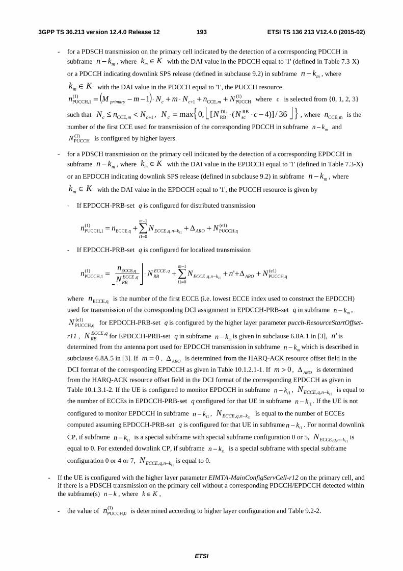
ETSI
ETSI TS 136 213 V12.4.0 (2015-02)1933GPP TS 36.213 version 12.4.0 Release 12
- for a PDSCH transmission on the primary cell indicated by the detection of a corresponding PDCCH in
subframe mkn − , where mk K∈ with the DAI value in the PDCCH equal to '1' (defined in Table 7.3-X)
or a PDCCH indicating downlink SPS release (defined in subclause 9.2) in subframe mkn − , where
mk K∈ with the DAI value in the PDCCH equal to '1', the PUCCH resource
( ) (1)PUCCH,CCE1
(1)PUCCH,1 1 NnNmNmMn mccprimary ++⋅+⋅−−= + where c is selected from {0, 1, 2, 3}
such that 1CCE, +<≤ cmc NnN , ⎣ ⎦{ }36/)]4([,0max RBsc
DLRB −⋅⋅= cNNN c , where mCCE,n is the
number of the first CCE used for transmission of the corresponding PDCCH in subframe mn k− and (1)PUCCHN is configured by higher layers.
- for a PDSCH transmission on the primary cell indicated by the detection of a corresponding EPDCCH in
subframe mkn − , where mk K∈ with the DAI value in the EPDCCH equal to '1' (defined in Table 7.3-X)
or an EPDCCH indicating downlink SPS release (defined in subclause 9.2) in subframe mkn − , where
mk K∈ with the DAI value in the EPDCCH equal to '1', the PUCCH resource is given by
- If EPDCCH-PRB-set q is configured for distributed transmission
(e1)PUCCH,q
1
01,,ECCE,q
)1(PUCCH,1 1
NNnn ARO
m
iknqECCE i
+Δ++= ∑−
=−
- If EPDCCH-PRB-set q is configured for localized transmission
(e1)PUCCH,q
1
01,,
,,
ECCE,q)1(PUCCH,1 '
1NnNN
N
nn ARO
m
iknqECCE
qECCERBqECCE
RBi
+Δ+++⋅⎥⎦
⎥⎢⎣
⎢= ∑
−
=−
where ECCE,qn is the number of the first ECCE (i.e. lowest ECCE index used to construct the EPDCCH)
used for transmission of the corresponding DCI assignment in EPDCCH-PRB-set q in subframe mkn − ,
(e1)PUCCH,qN for EPDCCH-PRB-set q is configured by the higher layer parameter pucch-ResourceStartOffset-
r11 , qECCERBN , for EPDCCH-PRB-set q in subframe
mkn − is given in subclause 6.8A.1 in [3], 'n is
determined from the antenna port used for EPDCCH transmission in subframe mkn − which is described in
subclause 6.8A.5 in [3]. If 0=m , AROΔ is determined from the HARQ-ACK resource offset field in the
DCI format of the corresponding EPDCCH as given in Table 10.1.2.1-1. If 0>m , AROΔ is determined
from the HARQ-ACK resource offset field in the DCI format of the corresponding EPDCCH as given in
Table 10.1.3.1-2. If the UE is configured to monitor EPDCCH in subframe 1ikn − , 1,, iknqECCEN − is equal to
the number of ECCEs in EPDCCH-PRB-set q configured for that UE in subframe 1ikn − . If the UE is not
configured to monitor EPDCCH in subframe 1ikn − , 1,, iknqECCEN − is equal to the number of ECCEs
computed assuming EPDCCH-PRB-set q is configured for that UE in subframe 1ikn − . For normal downlink
CP, if subframe 1ikn − is a special subframe with special subframe configuration 0 or 5, 1,, iknqECCEN − is
equal to 0. For extended downlink CP, if subframe 1ikn − is a special subframe with special subframe
configuration 0 or 4 or 7, 1,, iknqECCEN − is equal to 0.
- If the UE is configured with the higher layer parameter EIMTA-MainConfigServCell-r12 on the primary cell, and if there is a PDSCH transmission on the primary cell without a corresponding PDCCH/EPDCCH detected within the subframe(s) kn − , where Kk ∈ ,
- the value of )1(PUCCH,0n is determined according to higher layer configuration and Table 9.2-2.
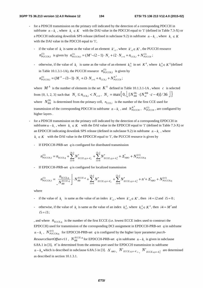
ETSI
ETSI TS 136 213 V12.4.0 (2015-02)1943GPP TS 36.213 version 12.4.0 Release 12
- for a PDSCH transmission on the primary cell indicated by the detection of a corresponding PDCCH in subframe
ikn − , where Kki ∈ with the DAI value in the PDCCH equal to '1' (defined in Table 7.3-X) or
a PDCCH indicating downlink SPS release (defined in subclause 9.2) in subframe ikn − , where Kki ∈
with the DAI value in the PDCCH equal to '1',
- if the value of ik is same as the value of an element 2'ik , where '' 2 Kk i ∈ , the PUCCH resource
)1(1PUCCH,n is given by (1)
PUCCHCCE,1)1(
1PUCCH, 2)12'( NnNiNiMn icc ++⋅+⋅−−= + ;
- otherwise, if the value of ik is same as the value of an element A
ik 3 in set AK , where AAi Kk ∈3 (defined
in Table 10.1.3.1-1A), the PUCCH resource )1(1PUCCH,n is given by
AKPUCCHCCE,1
)1(1PUCCH, 3)13( NnNiNiMn icc
A ++⋅+⋅−−= + ;
where AM is the number of elements in the set AK defined in Table 10.1.3.1-1A , where c is selected
from {0, 1, 2, 3} such that 1CCE, +<≤ cic NnN , ⎣ ⎦{ }36/)]4([,0max RBsc
DLRB −⋅⋅= cNNN c
where DLRBN is determined from the primary cell, CCE,in is the number of the first CCE used for
transmission of the corresponding PDCCH in subframe ikn − , and
AKPUCCHN , (1)
PUCCHN , are configured by
higher layers .
- for a PDSCH transmission on the primary cell indicated by the detection of a corresponding EPDCCH in subframe
ikn − , where Kki ∈ with the DAI value in the EPDCCH equal to '1' (defined in Table 7.3-X) or
an EPDCCH indicating downlink SPS release (defined in subclause 9.2) in subframe ikn − , where
Kki ∈ with the DAI value in the EPDCCH equal to '1', the PUCCH resource is given by
- If EPDCCH-PRB-set q is configured for distributed transmission
1 1
4 1 5 1(1) (e1)PUCCH,1 ECCE,q PUCCH,q, , , ,
1 0 1 0
Ai i
i i
AROECCE q n k ECCE q n ki i
n n N N N− −
′− −= =
′ ′ ′= + + + Δ +∑ ∑
- If EPDCCH-PRB-set q is configured for localized transmission
1 1
4 1 5 1ECCE,q(1) , (e1)
PUCCH,1 PUCCH,q, , , , ,1 0 1 0
'Ai i
i iECCE qRB AROECCE q ECCE q n k ECCE q n k
i iRB
nn N N N n N
N
− −
′− −= =
⎢ ⎥ ′ ′ ′= ⋅ + + + + Δ +⎢ ⎥⎣ ⎦
∑ ∑
where
- if the value of ik is same as the value of an index 2'ik , where '' 2 Kk i ∈ , then 24 ii = and 5 0i = ;
- otherwise, if the value of ik is same as the value of an index A
ik 3 , where AAi Kk ∈3 , then 4i M ′= and
5 3i i= ;
, and where ECCE,qn is the number of the first ECCE (i.e. lowest ECCE index used to construct the
EPDCCH) used for transmission of the corresponding DCI assignment in EPDCCH-PRB-set q in subframe
ikn − , (e1)PUCCH,qN for EPDCCH-PRB-set q is configured by the higher layer parameter pucch-
ResourceStartOffset-r11 , qECCERBN , for EPDCCH-PRB-set q in subframe
ikn − is given in subclause
6.8A.1 in [3], 'n is determined from the antenna port used for EPDCCH transmission in subframe
mkn − which is described in subclause 6.8A.5 in [3]. ARO'Δ , 1',,'iknqECCEN − , A
iknqECCEN
1,,'
− are determined
as described in section 10.1.3.1.
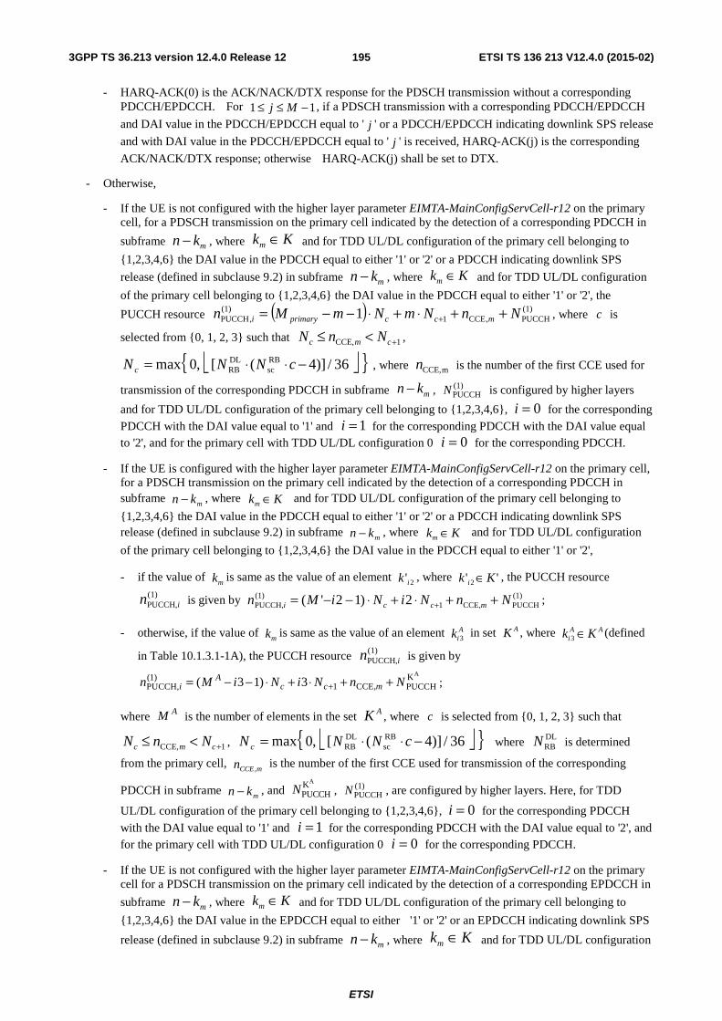
ETSI
ETSI TS 136 213 V12.4.0 (2015-02)1953GPP TS 36.213 version 12.4.0 Release 12
- HARQ-ACK(0) is the ACK/NACK/DTX response for the PDSCH transmission without a corresponding PDCCH/EPDCCH. For 11 −≤≤ Mj , if a PDSCH transmission with a corresponding PDCCH/EPDCCH
and DAI value in the PDCCH/EPDCCH equal to ' j ' or a PDCCH/EPDCCH indicating downlink SPS release
and with DAI value in the PDCCH/EPDCCH equal to ' j ' is received, HARQ-ACK(j) is the corresponding
ACK/NACK/DTX response; otherwise HARQ-ACK(j) shall be set to DTX.
- Otherwise,
- If the UE is not configured with the higher layer parameter EIMTA-MainConfigServCell-r12 on the primary cell, for a PDSCH transmission on the primary cell indicated by the detection of a corresponding PDCCH in
subframe mkn − , where mk K∈ and for TDD UL/DL configuration of the primary cell belonging to
{1,2,3,4,6} the DAI value in the PDCCH equal to either '1' or '2' or a PDCCH indicating downlink SPS
release (defined in subclause 9.2) in subframe mkn − , where mk K∈ and for TDD UL/DL configuration
of the primary cell belonging to {1,2,3,4,6} the DAI value in the PDCCH equal to either '1' or '2', the
PUCCH resource ( ) (1)PUCCH,CCE1
(1),PUCCH 1 NnNmNmMn mccprimaryi ++⋅+⋅−−= + , where c is
selected from {0, 1, 2, 3} such that 1CCE, +<≤ cmc NnN ,
⎣ ⎦{ }36/)]4([,0max RBsc
DLRB −⋅⋅= cNNN c , where mCCE,n is the number of the first CCE used for
transmission of the corresponding PDCCH in subframe mn k− , (1)PUCCHN is configured by higher layers
and for TDD UL/DL configuration of the primary cell belonging to {1,2,3,4,6}, 0=i for the corresponding
PDCCH with the DAI value equal to '1' and 1=i for the corresponding PDCCH with the DAI value equal to '2', and for the primary cell with TDD UL/DL configuration 0 0=i for the corresponding PDCCH.
- If the UE is configured with the higher layer parameter EIMTA-MainConfigServCell-r12 on the primary cell, for a PDSCH transmission on the primary cell indicated by the detection of a corresponding PDCCH in subframe
mkn − , where Kkm ∈ and for TDD UL/DL configuration of the primary cell belonging to
{1,2,3,4,6} the DAI value in the PDCCH equal to either '1' or '2' or a PDCCH indicating downlink SPS release (defined in subclause 9.2) in subframe
mkn − , where Kkm ∈ and for TDD UL/DL configuration
of the primary cell belonging to {1,2,3,4,6} the DAI value in the PDCCH equal to either '1' or '2',
- if the value of mk is same as the value of an element 2'ik , where '' 2 Kk i ∈ , the PUCCH resource
)1(PUCCH,in is given by (1)
PUCCHCCE,1)1(
PUCCH, 2)12'( NnNiNiMn mcci ++⋅+⋅−−= + ;
- otherwise, if the value of mk is same as the value of an element A
ik 3 in set AK , where AAi Kk ∈3 (defined
in Table 10.1.3.1-1A), the PUCCH resource )1(PUCCH,in is given by
AK(1)1 CCE,PUCCH, PUCCH( 3 1) 3A
c c min M i N i N n N+= − − ⋅ + ⋅ + + ;
where AM is the number of elements in the set AK , where c is selected from {0, 1, 2, 3} such that
1CCE, +<≤ cmc NnN , ⎣ ⎦{ }36/)]4([,0max RBsc
DLRB −⋅⋅= cNNN c where DL
RBN is determined
from the primary cell, mCCEn ,
is the number of the first CCE used for transmission of the corresponding
PDCCH in subframe mkn − , and
AKPUCCHN , (1)
PUCCHN , are configured by higher layers. Here, for TDD
UL/DL configuration of the primary cell belonging to {1,2,3,4,6}, 0=i for the corresponding PDCCH
with the DAI value equal to '1' and 1=i for the corresponding PDCCH with the DAI value equal to '2', and for the primary cell with TDD UL/DL configuration 0 0=i for the corresponding PDCCH.
- If the UE is not configured with the higher layer parameter EIMTA-MainConfigServCell-r12 on the primary cell for a PDSCH transmission on the primary cell indicated by the detection of a corresponding EPDCCH in
subframe mkn − , where mk K∈ and for TDD UL/DL configuration of the primary cell belonging to
{1,2,3,4,6} the DAI value in the EPDCCH equal to either '1' or '2' or an EPDCCH indicating downlink SPS
release (defined in subclause 9.2) in subframe mkn − , where mk K∈ and for TDD UL/DL configuration
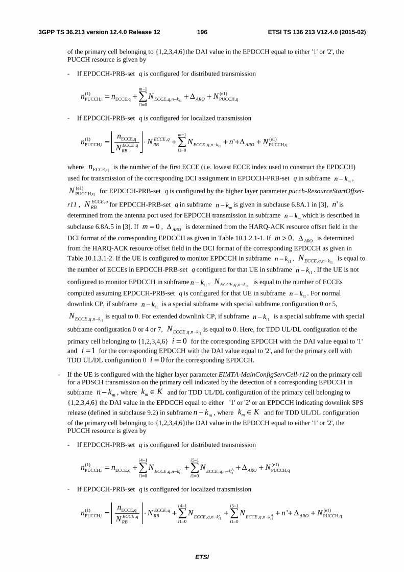
ETSI
ETSI TS 136 213 V12.4.0 (2015-02)1963GPP TS 36.213 version 12.4.0 Release 12
of the primary cell belonging to {1,2,3,4,6}the DAI value in the EPDCCH equal to either '1' or '2', the PUCCH resource is given by
- If EPDCCH-PRB-set q is configured for distributed transmission
(e1)PUCCH,q
1
01,,ECCE,q
)1(PUCCH,i 1
NNnn ARO
m
iknqECCE i
+Δ++= ∑−
=−
- If EPDCCH-PRB-set q is configured for localized transmission
(e1)PUCCH,q
1
01,,
,,
ECCE,q)1(PUCCH,i '
1NnNN
N
nn ARO
m
iknqECCE
qECCERBqECCE
RBi
+Δ+++⋅⎥⎦
⎥⎢⎣
⎢= ∑
−
=−
where ECCE,qn is the number of the first ECCE (i.e. lowest ECCE index used to construct the EPDCCH)
used for transmission of the corresponding DCI assignment in EPDCCH-PRB-set q in subframe mkn − ,
(e1)PUCCH,qN for EPDCCH-PRB-set q is configured by the higher layer parameter pucch-ResourceStartOffset-
r11 , qECCERBN , for EPDCCH-PRB-set q in subframe
mkn − is given in subclause 6.8A.1 in [3], 'n is
determined from the antenna port used for EPDCCH transmission in subframe mkn − which is described in
subclause 6.8A.5 in [3]. If 0=m , AROΔ is determined from the HARQ-ACK resource offset field in the
DCI format of the corresponding EPDCCH as given in Table 10.1.2.1-1. If 0>m , AROΔ is determined
from the HARQ-ACK resource offset field in the DCI format of the corresponding EPDCCH as given in
Table 10.1.3.1-2. If the UE is configured to monitor EPDCCH in subframe 1ikn − , 1,, iknqECCEN − is equal to
the number of ECCEs in EPDCCH-PRB-set q configured for that UE in subframe 1ikn − . If the UE is not
configured to monitor EPDCCH in subframe 1ikn − , 1,, iknqECCEN − is equal to the number of ECCEs
computed assuming EPDCCH-PRB-set q is configured for that UE in subframe 1ikn − . For normal
downlink CP, if subframe 1ikn − is a special subframe with special subframe configuration 0 or 5,
1,, iknqECCEN − is equal to 0. For extended downlink CP, if subframe 1ikn − is a special subframe with special
subframe configuration 0 or 4 or 7, 1,, iknqECCEN − is equal to 0. Here, for TDD UL/DL configuration of the
primary cell belonging to {1,2,3,4,6} 0=i for the corresponding EPDCCH with the DAI value equal to '1' and 1=i for the corresponding EPDCCH with the DAI value equal to '2', and for the primary cell with TDD UL/DL configuration 0 0=i for the corresponding EPDCCH.
- If the UE is configured with the higher layer parameter EIMTA-MainConfigServCell-r12 on the primary cell for a PDSCH transmission on the primary cell indicated by the detection of a corresponding EPDCCH in
subframe mkn − , where mk K∈ and for TDD UL/DL configuration of the primary cell belonging to
{1,2,3,4,6} the DAI value in the EPDCCH equal to either '1' or '2' or an EPDCCH indicating downlink SPS
release (defined in subclause 9.2) in subframe mkn − , where mk K∈ and for TDD UL/DL configuration
of the primary cell belonging to {1,2,3,4,6}the DAI value in the EPDCCH equal to either '1' or '2', the PUCCH resource is given by
- If EPDCCH-PRB-set q is configured for distributed transmission
1 1
4 1 5 1(1) (e1)PUCCH,i ECCE,q PUCCH,q, , , ,
1 0 1 0
Ai i
i i
AROECCE q n k ECCE q n ki i
n n N N N− −
′− −= =
= + + + Δ +∑ ∑
- If EPDCCH-PRB-set q is configured for localized transmission
1 1
4 1 5 1ECCE,q(1) , (e1)
PUCCH,i PUCCH,q, , , , ,1 0 1 0
'Ai i
i iECCE qRB AROECCE q ECCE q n k ECCE q n k
i iRB
nn N N N n N
N
− −
′− −= =
⎢ ⎥= ⋅ + + + + Δ +⎢ ⎥
⎣ ⎦∑ ∑
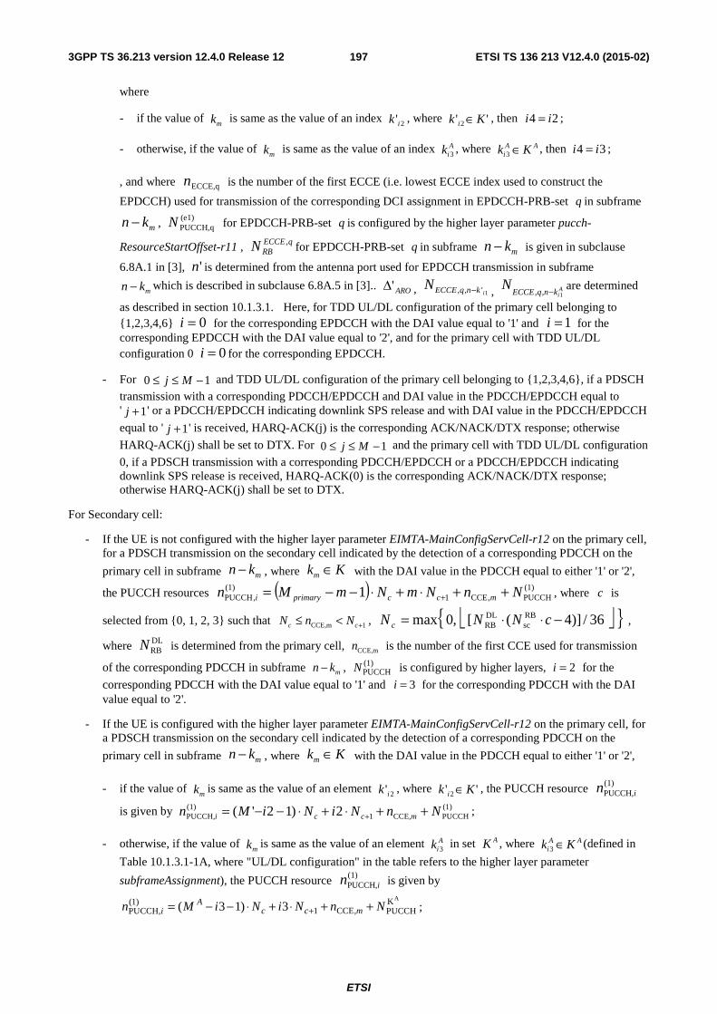
ETSI
ETSI TS 136 213 V12.4.0 (2015-02)1973GPP TS 36.213 version 12.4.0 Release 12
where
- if the value of mk is same as the value of an index 2'ik , where '' 2 Kk i ∈ , then 24 ii = ;
- otherwise, if the value of mk is same as the value of an index A
ik 3 , where AAi Kk ∈3 , then 34 ii = ;
, and where ECCE,qn is the number of the first ECCE (i.e. lowest ECCE index used to construct the
EPDCCH) used for transmission of the corresponding DCI assignment in EPDCCH-PRB-set q in subframe
mkn − , (e1)PUCCH,qN for EPDCCH-PRB-set q is configured by the higher layer parameter pucch-
ResourceStartOffset-r11 , qECCERBN , for EPDCCH-PRB-set q in subframe mkn − is given in subclause
6.8A.1 in [3], 'n is determined from the antenna port used for EPDCCH transmission in subframe
mkn − which is described in subclause 6.8A.5 in [3].. ARO'Δ , 1',, iknqECCEN − , AiknqECCE
N1,, − are determined
as described in section 10.1.3.1. Here, for TDD UL/DL configuration of the primary cell belonging to {1,2,3,4,6} 0=i for the corresponding EPDCCH with the DAI value equal to '1' and 1=i for the corresponding EPDCCH with the DAI value equal to '2', and for the primary cell with TDD UL/DL configuration 0 0=i for the corresponding EPDCCH.
- For 10 −≤≤ Mj and TDD UL/DL configuration of the primary cell belonging to {1,2,3,4,6}, if a PDSCH
transmission with a corresponding PDCCH/EPDCCH and DAI value in the PDCCH/EPDCCH equal to ' 1+j ' or a PDCCH/EPDCCH indicating downlink SPS release and with DAI value in the PDCCH/EPDCCH
equal to ' 1+j ' is received, HARQ-ACK(j) is the corresponding ACK/NACK/DTX response; otherwise
HARQ-ACK(j) shall be set to DTX. For 10 −≤≤ Mj and the primary cell with TDD UL/DL configuration
0, if a PDSCH transmission with a corresponding PDCCH/EPDCCH or a PDCCH/EPDCCH indicating downlink SPS release is received, HARQ-ACK(0) is the corresponding ACK/NACK/DTX response; otherwise HARQ-ACK(j) shall be set to DTX.
For Secondary cell:
- If the UE is not configured with the higher layer parameter EIMTA-MainConfigServCell-r12 on the primary cell, for a PDSCH transmission on the secondary cell indicated by the detection of a corresponding PDCCH on the
primary cell in subframe mn k− , where mk K∈ with the DAI value in the PDCCH equal to either '1' or '2',
the PUCCH resources ( ) (1)PUCCH,CCE1
(1),PUCCH 1 NnNmNmMn mccprimaryi ++⋅+⋅−−= + , where c is
selected from {0, 1, 2, 3} such that CCE,m 1c cN n N +≤ < , ⎣ ⎦{ }36/)]4([,0max RBsc
DLRB −⋅⋅= cNNN c ,
where DLRBN is determined from the primary cell, CCE,mn is the number of the first CCE used for transmission
of the corresponding PDCCH in subframe mn k− , (1)PUCCHN is configured by higher layers, 2=i for the
corresponding PDCCH with the DAI value equal to '1' and 3=i for the corresponding PDCCH with the DAI value equal to '2'.
- If the UE is configured with the higher layer parameter EIMTA-MainConfigServCell-r12 on the primary cell, for a PDSCH transmission on the secondary cell indicated by the detection of a corresponding PDCCH on the
primary cell in subframe mn k− , where mk K∈ with the DAI value in the PDCCH equal to either '1' or '2',
- if the value of mk is same as the value of an element 2'ik , where '' 2 Kk i ∈ , the PUCCH resource )1(
PUCCH,in
is given by (1)PUCCHCCE,1
)1(PUCCH, 2)12'( NnNiNiMn mcci ++⋅+⋅−−= + ;
- otherwise, if the value of mk is same as the value of an element A
ik 3 in set AK , where AAi Kk ∈3 (defined in
Table 10.1.3.1-1A, where "UL/DL configuration" in the table refers to the higher layer parameter
subframeAssignment), the PUCCH resource )1(PUCCH,in is given by
AK(1)1 CCE,PUCCH, PUCCH( 3 1) 3A
c c min M i N i N n N+= − − ⋅ + ⋅ + + ;
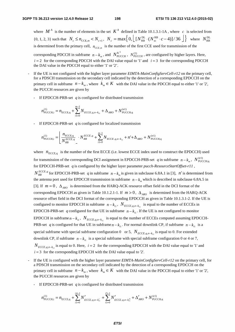
ETSI
ETSI TS 136 213 V12.4.0 (2015-02)1983GPP TS 36.213 version 12.4.0 Release 12
where AM is the number of elements in the set AK defined in Table 10.1.3.1-1A , where c is selected from
{0, 1, 2, 3} such that 1CCE, +<≤ cmc NnN , ⎣ ⎦{ }36/)]4([,0max RBsc
DLRB −⋅⋅= cNNN c where DL
RBN
is determined from the primary cell, mCCEn ,
is the number of the first CCE used for transmission of the
corresponding PDCCH in subframe mkn − , and
AKPUCCHN , (1)
PUCCHN , are configured by higher layers. Here,
2=i for the corresponding PDCCH with the DAI value equal to '1' and 3=i for the corresponding PDCCH the DAI value in the PDCCH equal to either '1' or '2’.
- If the UE is not configured with the higher layer parameter EIMTA-MainConfigServCell-r12 on the primary cell, for a PDSCH transmission on the secondary cell indicated by the detection of a corresponding EPDCCH on the
primary cell in subframe mn k− , where mk K∈ with the DAI value in the PDCCH equal to either '1' or '2',
the PUCCH resources are given by
- If EPDCCH-PRB-set q is configured for distributed transmission
(e1)PUCCH,q
1
01,,ECCE,q
)1(PUCCH,i 1
NNnn ARO
m
iknqECCE i
+Δ++= ∑−
=−
- If EPDCCH-PRB-set q is configured for localized transmission
(e1)PUCCH,q
1
01,,
,,
ECCE,q)1(PUCCH,i '
1NnNN
N
nn ARO
m
iknqECCE
qECCERBqECCE
RBi
+Δ+++⋅⎥⎦
⎥⎢⎣
⎢= ∑
−
=−
where ECCE,qn is the number of the first ECCE (i.e. lowest ECCE index used to construct the EPDCCH) used
for transmission of the corresponding DCI assignment in EPDCCH-PRB-set q in subframe mkn − , (e1)
PUCCH,qN
for EPDCCH-PRB-set q is configured by the higher layer parameter pucch-ResourceStartOffset-r11 , qECCE
RBN , for EPDCCH-PRB-set q in subframe mkn − is given in subclause 6.8A.1 in [3], 'n is determined from
the antenna port used for EPDCCH transmission in subframe mkn − which is described in subclause 6.8A.5 in
[3]. If 0=m , AROΔ is determined from the HARQ-ACK resource offset field in the DCI format of the
corresponding EPDCCH as given in Table 10.1.2.1-1. If 0>m , AROΔ is determined from the HARQ-ACK
resource offset field in the DCI format of the corresponding EPDCCH as given in Table 10.1.3.1-2. If the UE is
configured to monitor EPDCCH in subframe 1ikn − , 1,, iknqECCEN − is equal to the number of ECCEs in
EPDCCH-PRB-set q configured for that UE in subframe 1ikn − . If the UE is not configured to monitor
EPDCCH in subframe 1ikn − , 1,, iknqECCEN − is equal to the number of ECCEs computed assuming EPDCCH-
PRB-set q is configured for that UE in subframe 1ikn − . For normal downlink CP, if subframe 1ikn − is a
special subframe with special subframe configuration 0 or 5, 1,, iknqECCEN − is equal to 0. For extended
downlink CP, if subframe 1ikn − is a special subframe with special subframe configuration 0 or 4 or 7,
1,, iknqECCEN − is equal to 0. Here, 2=i for the corresponding EPDCCH with the DAI value equal to '1' and
3=i for the corresponding EPDCCH with the DAI value equal to '2'.
- If the UE is configured with the higher layer parameter EIMTA-MainConfigServCell-r12 on the primary cell, for a PDSCH transmission on the secondary cell indicated by the detection of a corresponding EPDCCH on the
primary cell in subframe mn k− , where mk K∈ with the DAI value in the PDCCH equal to either '1' or '2',
the PUCCH resources are given by
- If EPDCCH-PRB-set q is configured for distributed transmission
1 1
4 1 5 1(1) (e1)PUCCH,i ECCE,q PUCCH,q, , , ,
1 0 1 0
Ai i
i i
AROECCE q n k ECCE q n ki i
n n N N N− −
′− −= =
′ ′ ′= + + + Δ +∑ ∑
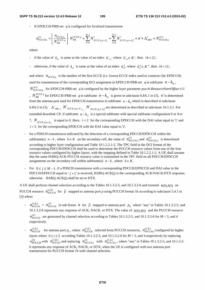
ETSI
ETSI TS 136 213 V12.4.0 (2015-02)1993GPP TS 36.213 version 12.4.0 Release 12
- If EPDCCH-PRB-set q is configured for localized transmission
1 1
4 1 5 1ECCE,q(1) , (e1)
PUCCH,i PUCCH,q, , , , ,1 0 1 0
'Ai i
i iECCE qRB AROECCE q ECCE q n k ECCE q n k
i iRB
nn N N N n N
N
− −
′− −= =
⎢ ⎥ ′ ′ ′= ⋅ + + + + Δ +⎢ ⎥⎣ ⎦
∑ ∑
where
- if the value of mk is same as the value of an index 2'ik , where '' 2 Kk i ∈ , then 24 ii = ;
- otherwise, if the value of mk is same as the value of an index A
ik 3 , where AAi Kk ∈3 , then 34 ii = ;
and where ECCE,qn is the number of the first ECCE (i.e. lowest ECCE index used to construct the EPDCCH)
used for transmission of the corresponding DCI assignment in EPDCCH-PRB-set q in subframe mkn − , (e1)PUCCH,qN for EPDCCH-PRB-set q is configured by the higher layer parameter pucch-ResourceStartOffset-r11
, qECCERBN , for EPDCCH-PRB-set q in subframe mkn − is given in subclause 6.8A.1 in [3], 'n is determined
from the antenna port used for EPDCCH transmission in subframe mkn − which is described in subclause
6.8A.5 in [3]. ARO'Δ , 1',,'iknqECCEN − , A
iknqECCEN
1,,'
− are determined as described in subclause 10.1.3.1. For
extended downlink CP, if subframe 1ikn − is a special subframe with special subframe configuration 0 or 4 or
7, 1,, iknqECCE
N−
is equal to 0. Here, 2=i for the corresponding EPDCCH with the DAI value equal to '1' and
3=i for the corresponding EPDCCH with the DAI value equal to '2'.
- for a PDSCH transmission indicated by the detection of a corresponding PDCCH/EPDCCH within the
subframe(s) kn − , where Kk ∈ on the secondary cell, the value of )1(2PUCCH,n and )1(
3PUCCH,n is determined
according to higher layer configuration and Table 10.1.2.2.1-2. The TPC field in the DCI format of the corresponding PDCCH/EPDCCH shall be used to determine the PUCCH resource values from one of the four resource values configured by higher layers, with the mapping defined in Table 10.1.2.2.1-2. A UE shall assume that the same HARQ-ACK PUCCH resource value is transmitted in the TPC field on all PDCCH/EPDCCH assignments on the secondary cell within subframe(s) kn − , where Kk ∈ .
- For 10 −≤≤ Mj , if a PDSCH transmission with a corresponding PDCCH/EPDCCH and DAI value in the
PDCCH/EPDCCH equal to ' 1+j ' is received, HARQ-ACK(j) is the corresponding ACK/NACK/DTX response;
otherwise HARQ-ACK(j) shall be set to DTX.
A UE shall perform channel selection according to the Tables 10.1.3.2-5, and 10.1.3.2-6 and transmit )1(),0( bb on
PUCCH resource )~,1(PUCCH
pn for p~ mapped to antenna port p using PUCCH format 1b according to subclause 5.4.1 in
[3] where
- )~,1(PUCCH
0pn = )1(PUCCHn in sub-frame n for p~ mapped to antenna port 0p where "any" in Tables 10.1.3.2-5, and
10.1.3.2-6 represents any response of ACK, NACK, or DTX. The value of )1(),0( bb and the PUCCH resource )1(
PUCCHn are generated by channel selection according to Tables 10.1.3.2-5, and 10.1.3.2-6 for M = 3, and 4
respectively.
- )~,1(PUCCH
1pn for antenna port 1p , where )~,1(PUCCH
1pn selected from PUCCH resources, )~,1(PUCCH,
1pin configured by higher
layers where 30 ≤≤ i according Tables 10.1.3.2-5, and 10.1.3.2-6 for M = 3, and 4 respectively by replacing )1(
PUCCHn with )~,1(
PUCCH1pn and replacing )1(
PUCCH,in with )~,1(PUCCH,
1pin , where "any" in Tables 10.1.3.2-5, and 10.1.3.2-
6 represents any response of ACK, NACK, or DTX, when the UE is configured with two antenna port transmission for PUCCH format 1b with channel selection.
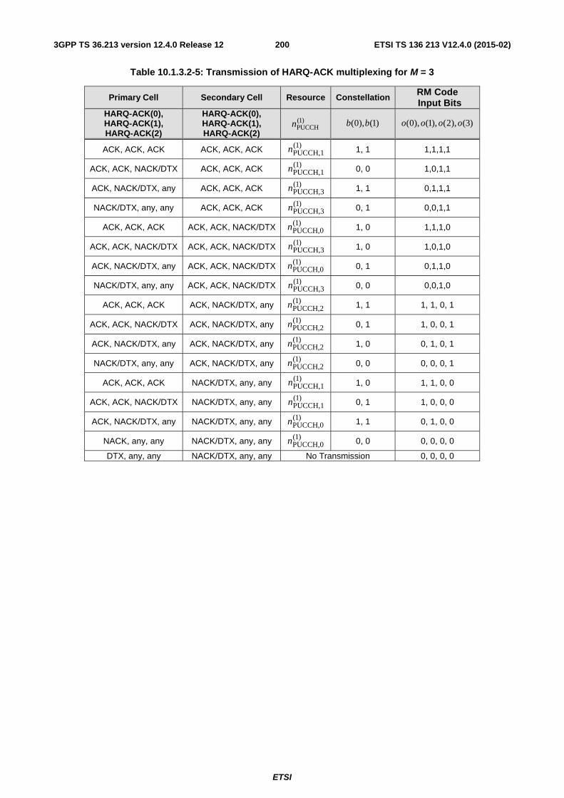
ETSI
ETSI TS 136 213 V12.4.0 (2015-02)2003GPP TS 36.213 version 12.4.0 Release 12
Table 10.1.3.2-5: Transmission of HARQ-ACK multiplexing for M = 3
Primary Cell Secondary Cell Resource Constellation RM Code
Input Bits HARQ-ACK(0), HARQ-ACK(1), HARQ-ACK(2)
HARQ-ACK(0), HARQ-ACK(1), HARQ-ACK(2)
)1(PUCCHn )1(),0( bb )3(),2(),1(),0( oooo
ACK, ACK, ACK ACK, ACK, ACK )1(PUCCH,1n 1, 1 1,1,1,1
ACK, ACK, NACK/DTX ACK, ACK, ACK )1(PUCCH,1n 0, 0 1,0,1,1
ACK, NACK/DTX, any ACK, ACK, ACK )1(PUCCH,3n 1, 1 0,1,1,1
NACK/DTX, any, any ACK, ACK, ACK )1(PUCCH,3n 0, 1 0,0,1,1
ACK, ACK, ACK ACK, ACK, NACK/DTX )1(PUCCH,0n 1, 0 1,1,1,0
ACK, ACK, NACK/DTX ACK, ACK, NACK/DTX )1(PUCCH,3n 1, 0 1,0,1,0
ACK, NACK/DTX, any ACK, ACK, NACK/DTX )1(PUCCH,0n 0, 1 0,1,1,0
NACK/DTX, any, any ACK, ACK, NACK/DTX )1(PUCCH,3n 0, 0 0,0,1,0
ACK, ACK, ACK ACK, NACK/DTX, any )1(PUCCH,2n 1, 1 1, 1, 0, 1
ACK, ACK, NACK/DTX ACK, NACK/DTX, any )1(PUCCH,2n 0, 1 1, 0, 0, 1
ACK, NACK/DTX, any ACK, NACK/DTX, any )1(PUCCH,2n 1, 0 0, 1, 0, 1
NACK/DTX, any, any ACK, NACK/DTX, any )1(PUCCH,2n 0, 0 0, 0, 0, 1
ACK, ACK, ACK NACK/DTX, any, any )1(PUCCH,1n 1, 0 1, 1, 0, 0
ACK, ACK, NACK/DTX NACK/DTX, any, any )1(PUCCH,1n 0, 1 1, 0, 0, 0
ACK, NACK/DTX, any NACK/DTX, any, any )1(PUCCH,0n 1, 1 0, 1, 0, 0
NACK, any, any NACK/DTX, any, any )1(PUCCH,0n 0, 0 0, 0, 0, 0
DTX, any, any NACK/DTX, any, any No Transmission 0, 0, 0, 0
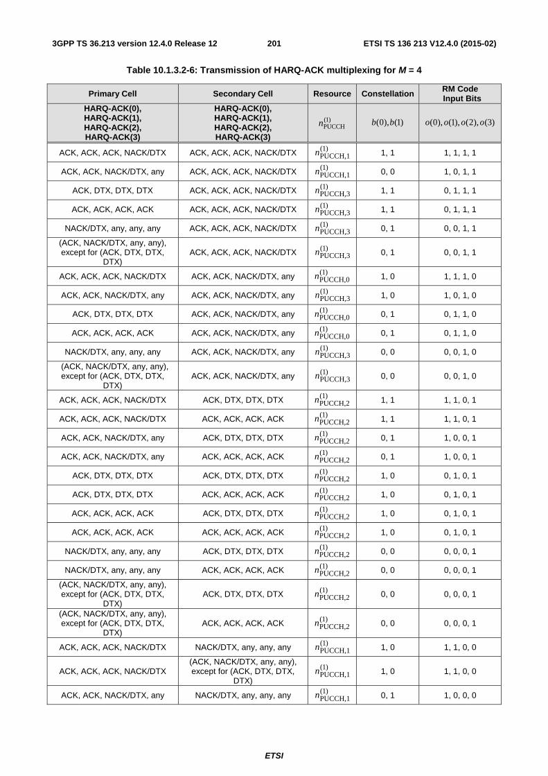
ETSI
ETSI TS 136 213 V12.4.0 (2015-02)2013GPP TS 36.213 version 12.4.0 Release 12
Table 10.1.3.2-6: Transmission of HARQ-ACK multiplexing for M = 4
Primary Cell Secondary Cell Resource Constellation RM Code Input Bits
HARQ-ACK(0), HARQ-ACK(1), HARQ-ACK(2), HARQ-ACK(3)
HARQ-ACK(0), HARQ-ACK(1), HARQ-ACK(2), HARQ-ACK(3)
)1(PUCCHn )1(),0( bb )3(),2(),1(),0( oooo
ACK, ACK, ACK, NACK/DTX ACK, ACK, ACK, NACK/DTX )1(PUCCH,1n 1, 1 1, 1, 1, 1
ACK, ACK, NACK/DTX, any ACK, ACK, ACK, NACK/DTX )1(PUCCH,1n 0, 0 1, 0, 1, 1
ACK, DTX, DTX, DTX ACK, ACK, ACK, NACK/DTX )1(PUCCH,3n 1, 1 0, 1, 1, 1
ACK, ACK, ACK, ACK ACK, ACK, ACK, NACK/DTX )1(PUCCH,3n 1, 1 0, 1, 1, 1
NACK/DTX, any, any, any ACK, ACK, ACK, NACK/DTX )1(PUCCH,3n 0, 1 0, 0, 1, 1
(ACK, NACK/DTX, any, any), except for (ACK, DTX, DTX,
DTX) ACK, ACK, ACK, NACK/DTX )1(
PUCCH,3n 0, 1 0, 0, 1, 1
ACK, ACK, ACK, NACK/DTX ACK, ACK, NACK/DTX, any )1(PUCCH,0n 1, 0 1, 1, 1, 0
ACK, ACK, NACK/DTX, any ACK, ACK, NACK/DTX, any )1(PUCCH,3n 1, 0 1, 0, 1, 0
ACK, DTX, DTX, DTX ACK, ACK, NACK/DTX, any )1(PUCCH,0n 0, 1 0, 1, 1, 0
ACK, ACK, ACK, ACK ACK, ACK, NACK/DTX, any )1(PUCCH,0n 0, 1 0, 1, 1, 0
NACK/DTX, any, any, any ACK, ACK, NACK/DTX, any )1(PUCCH,3n 0, 0 0, 0, 1, 0
(ACK, NACK/DTX, any, any), except for (ACK, DTX, DTX,
DTX) ACK, ACK, NACK/DTX, any )1(
PUCCH,3n 0, 0 0, 0, 1, 0
ACK, ACK, ACK, NACK/DTX ACK, DTX, DTX, DTX )1(PUCCH,2n 1, 1 1, 1, 0, 1
ACK, ACK, ACK, NACK/DTX ACK, ACK, ACK, ACK )1(PUCCH,2n 1, 1 1, 1, 0, 1
ACK, ACK, NACK/DTX, any ACK, DTX, DTX, DTX )1(PUCCH,2n 0, 1 1, 0, 0, 1
ACK, ACK, NACK/DTX, any ACK, ACK, ACK, ACK )1(PUCCH,2n 0, 1 1, 0, 0, 1
ACK, DTX, DTX, DTX ACK, DTX, DTX, DTX )1(PUCCH,2n 1, 0 0, 1, 0, 1
ACK, DTX, DTX, DTX ACK, ACK, ACK, ACK )1(PUCCH,2n 1, 0 0, 1, 0, 1
ACK, ACK, ACK, ACK ACK, DTX, DTX, DTX )1(PUCCH,2n 1, 0 0, 1, 0, 1
ACK, ACK, ACK, ACK ACK, ACK, ACK, ACK )1(PUCCH,2n 1, 0 0, 1, 0, 1
NACK/DTX, any, any, any ACK, DTX, DTX, DTX )1(PUCCH,2n 0, 0 0, 0, 0, 1
NACK/DTX, any, any, any ACK, ACK, ACK, ACK )1(PUCCH,2n 0, 0 0, 0, 0, 1
(ACK, NACK/DTX, any, any), except for (ACK, DTX, DTX,
DTX) ACK, DTX, DTX, DTX )1(
PUCCH,2n 0, 0 0, 0, 0, 1
(ACK, NACK/DTX, any, any), except for (ACK, DTX, DTX,
DTX) ACK, ACK, ACK, ACK )1(
PUCCH,2n 0, 0 0, 0, 0, 1
ACK, ACK, ACK, NACK/DTX NACK/DTX, any, any, any )1(PUCCH,1n 1, 0 1, 1, 0, 0
ACK, ACK, ACK, NACK/DTX (ACK, NACK/DTX, any, any), except for (ACK, DTX, DTX,
DTX)
)1(PUCCH,1n 1, 0 1, 1, 0, 0
ACK, ACK, NACK/DTX, any NACK/DTX, any, any, any )1(PUCCH,1n 0, 1 1, 0, 0, 0
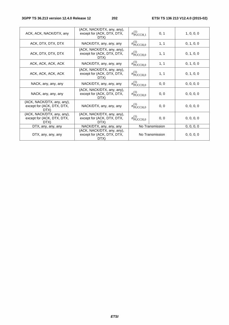
ETSI
ETSI TS 136 213 V12.4.0 (2015-02)2023GPP TS 36.213 version 12.4.0 Release 12
ACK, ACK, NACK/DTX, any (ACK, NACK/DTX, any, any), except for (ACK, DTX, DTX,
DTX)
)1(PUCCH,1n 0, 1 1, 0, 0, 0
ACK, DTX, DTX, DTX NACK/DTX, any, any, any )1(PUCCH,0n 1, 1 0, 1, 0, 0
ACK, DTX, DTX, DTX (ACK, NACK/DTX, any, any), except for (ACK, DTX, DTX,
DTX)
)1(PUCCH,0n 1, 1 0, 1, 0, 0
ACK, ACK, ACK, ACK NACK/DTX, any, any, any )1(PUCCH,0n 1, 1 0, 1, 0, 0
ACK, ACK, ACK, ACK (ACK, NACK/DTX, any, any), except for (ACK, DTX, DTX,
DTX)
)1(PUCCH,0n 1, 1 0, 1, 0, 0
NACK, any, any, any NACK/DTX, any, any, any )1(PUCCH,0n 0, 0 0, 0, 0, 0
NACK, any, any, any (ACK, NACK/DTX, any, any), except for (ACK, DTX, DTX,
DTX)
)1(PUCCH,0n 0, 0 0, 0, 0, 0
(ACK, NACK/DTX, any, any), except for (ACK, DTX, DTX,
DTX) NACK/DTX, any, any, any )1(
PUCCH,0n 0, 0 0, 0, 0, 0
(ACK, NACK/DTX, any, any), except for (ACK, DTX, DTX,
DTX)
(ACK, NACK/DTX, any, any), except for (ACK, DTX, DTX,
DTX)
)1(PUCCH,0n 0, 0 0, 0, 0, 0
DTX, any, any, any NACK/DTX, any, any, any No Transmission 0, 0, 0, 0
DTX, any, any, any (ACK, NACK/DTX, any, any), except for (ACK, DTX, DTX,
DTX) No Transmission 0, 0, 0, 0
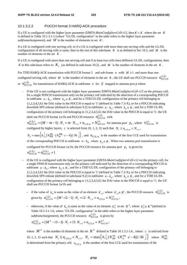
ETSI
ETSI TS 136 213 V12.4.0 (2015-02)2033GPP TS 36.213 version 12.4.0 Release 12
10.1.3.2.2 PUCCH format 3 HARQ-ACK procedure
If a UE is configured with the higher layer parameter EIMTA-MainConfigServCell-r12, then KK =' where the set K is defined in Table 10.1.3.1-1 (where "UL/DL configuration" in the table refers to the higher layer parameter subframeAssignment), and 'M is the number of elements in set 'K .
If a UE is configured with one serving cell, or if a UE is configured with more than one serving cells and the UL/DL configuration of all serving cells is same, then in the rest of this subclause K is as defined in Sec 10.2, and M is the number of elements in the set K .
If a UE is configured with more than one serving cell and if at least two cells have different UL/DL configurations, then
K in this subclause refers to cK (as defined in subclause 10.2) , and M is the number of elements in the set K .
For TDD HARQ-ACK transmission with PUCCH format 3 and sub-frame n with 1≥M and more than one
configured serving cell, where M is the number of elements in the set K , the UE shall use PUCCH resource )~,3(PUCCH
pn
or )~,1(PUCCH
pn for transmission of HARQ-ACK in subframe n for p~ mapped to antenna port p where
- If the UE is not configured with the higher layer parameter EIMTA-MainConfigServCell-r12 on the primary cell, for a single PDSCH transmission only on the primary cell indicated by the detection of a corresponding PDCCH in subframe
mkn − , where Kkm ∈ , and for a TDD UL/DL configuration of the primary cell belonging to
{1,2,3,4,5,6} the DAI value in the PDCCH is equal to '1' (defined in Table 7.3-X), or for a PDCCH indicating downlink SPS release (defined in subclause 9.2) in subframe
mkn − , where Kkm ∈ , and for a TDD UL/DL
configuration of the primary cell belonging to {1,2,3,4,5,6} the DAI value in the PDCCH is equal to '1', the UE
shall use PUCCH format 1a/1b and PUCCH resource )~,1(PUCCH
pn with (1)PUCCHCCE,1
)~,1(PUCCH )1(0 NnNmNmMn mcc
p ++⋅+⋅−−= + for antenna port 0p , where (1)PUCCHN is
configured by higher layers, c is selected from {0, 1, 2, 3} such that 1CCE, +<≤ cmc NnN ,
⎣ ⎦{ }36/)]4([,0max RBsc
DLRB −⋅⋅= cNNNc , and mCCE,n is the number of the first CCE used for transmission
of the corresponding PDCCH in subframe mn k− where Kkm ∈ . When two antenna port transmission is
configured for PUCCH format 1a/1b, the PUCCH resource for antenna port 1p is given by
1)~,1(PUCCH
)~,1(PUCCH
01 += pp nn
- If the UE is configured with the higher layer parameter EIMTA-MainConfigServCell-r12 on the primary cell, for a single PDSCH transmission only on the primary cell indicated by the detection of a corresponding PDCCH in subframe
mkn − , where Kkm ∈ , and for a TDD UL/DL configuration of the primary cell belonging to
{1,2,3,4,5,6} the DAI value in the PDCCH is equal to '1' (defined in Table 7.3-X), or for a PDCCH indicating downlink SPS release (defined in subclause 9.2) in subframe
mkn − , where Kkm ∈ , and for a TDD UL/DL
configuration of the primary cell belonging to {1,2,3,4,5,6} the DAI value in the PDCCH is equal to '1', the UE shall use PUCCH format 1a/1b and
- if the value of mk is same as the value of an element 2'ik , where '' 2 Kk i ∈ , the PUCCH resource )~,1(
PUCCHpn is
given by (1)PUCCHCCE,1
)~,1(PUCCH 2)12'( NnNiNiMn mcc
p ++⋅+⋅−−= + ;
- otherwise, if the value of mk is same as the value of an element A
ik 3 in set AK , where AAi Kk ∈3 (defined in
Table 10.1.3.1-1A, where "UL/DL configuration" in the table refers to the higher layer parameter
subframeAssignment), the PUCCH resource )~,1(PUCCH
pn is given by AK
PUCCHCCE,1)~,1(
PUCCH 3)13( NnNiNiMn mccAp ++⋅+⋅−−= + ;
where AM is the number of elements in the set AK defined in Table 10.1.3.1-1A , where c is selected from
{0, 1, 2, 3} such that 1CCE, +<≤ cmc NnN , ⎣ ⎦{ }36/)]4([,0max RBsc
DLRB −⋅⋅= cNNN c where DL
RBN
is determined from the primary cell, mCCEn ,
is the number of the first CCE used for transmission of the
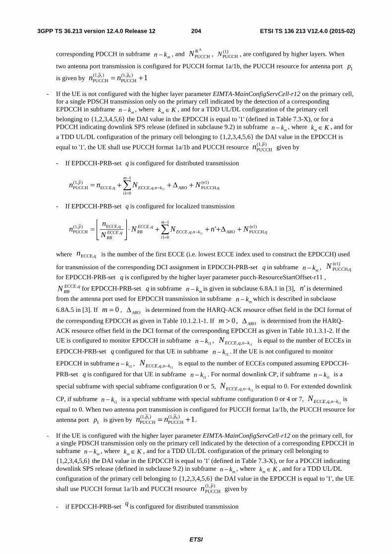
ETSI
ETSI TS 136 213 V12.4.0 (2015-02)2043GPP TS 36.213 version 12.4.0 Release 12
corresponding PDCCH in subframe mkn − , and
AKPUCCHN , (1)
PUCCHN , are configured by higher layers. When
two antenna port transmission is configured for PUCCH format 1a/1b, the PUCCH resource for antenna port 1p
is given by 1)~,1(PUCCH
)~,1(PUCCH
01 += pp nn
- If the UE is not configured with the higher layer parameter EIMTA-MainConfigServCell-r12 on the primary cell, for a single PDSCH transmission only on the primary cell indicated by the detection of a corresponding EPDCCH in subframe
mkn − , where Kkm ∈ , and for a TDD UL/DL configuration of the primary cell
belonging to {1,2,3,4,5,6} the DAI value in the EPDCCH is equal to '1' (defined in Table 7.3-X), or for a PDCCH indicating downlink SPS release (defined in subclause 9.2) in subframe
mkn − , where Kkm ∈ , and for
a TDD UL/DL configuration of the primary cell belonging to {1,2,3,4,5,6} the DAI value in the EPDCCH is
equal to '1', the UE shall use PUCCH format 1a/1b and PUCCH resource )~,1(PUCCH
pn given by
- If EPDCCH-PRB-set q is configured for distributed transmission
(e1)PUCCH,q
1
01,,ECCE,q
)~,1(PUCCH 1
NNnn ARO
m
iknqECCE
p
i+Δ++= ∑
−
=−
- If EPDCCH-PRB-set q is configured for localized transmission
(e1)PUCCH,q
1
01,,
,,
ECCE,q)~,1(PUCCH '
1NnNN
N
nn ARO
m
iknqECCE
qECCERBqECCE
RB
p
i+Δ+++⋅⎥
⎦
⎥⎢⎣
⎢= ∑
−
=−
where ECCE,qn is the number of the first ECCE (i.e. lowest ECCE index used to construct the EPDCCH) used
for transmission of the corresponding DCI assignment in EPDCCH-PRB-set q in subframe mn k− ,
(e1)PUCCH,qN
for EPDCCH-PRB-set q is configured by the higher layer parameter pucch-ResourceStartOffset-r11 , qECCE
RBN , for EPDCCH-PRB-set q in subframe mn k− is given in subclause 6.8A.1 in [3], 'n is determined
from the antenna port used for EPDCCH transmission in subframe mn k− which is described in subclause
6.8A.5 in [3]. If 0=m , AROΔ is determined from the HARQ-ACK resource offset field in the DCI format of
the corresponding EPDCCH as given in Table 10.1.2.1-1. If 0>m , AROΔ is determined from the HARQ-
ACK resource offset field in the DCI format of the corresponding EPDCCH as given in Table 10.1.3.1-2. If the
UE is configured to monitor EPDCCH in subframe 1ikn − , 1,, iknqECCEN − is equal to the number of ECCEs in
EPDCCH-PRB-set q configured for that UE in subframe 1ikn − . If the UE is not configured to monitor
EPDCCH in subframe 1ikn − , 1,, iknqECCEN − is equal to the number of ECCEs computed assuming EPDCCH-
PRB-set q is configured for that UE in subframe 1ikn − . For normal downlink CP, if subframe 1ikn − is a
special subframe with special subframe configuration 0 or 5, 1,, iknqECCEN − is equal to 0. For extended downlink
CP, if subframe 1ikn − is a special subframe with special subframe configuration 0 or 4 or 7, 1,, iknqECCEN − is
equal to 0. When two antenna port transmission is configured for PUCCH format 1a/1b, the PUCCH resource for
antenna port 1p is given by 1)~,1(PUCCH
)~,1(PUCCH
01 += pp nn .
- If the UE is configured with the higher layer parameter EIMTA-MainConfigServCell-r12 on the primary cell, for a single PDSCH transmission only on the primary cell indicated by the detection of a corresponding EPDCCH in subframe
mkn − , where Kkm ∈ , and for a TDD UL/DL configuration of the primary cell belonging to
{1,2,3,4,5,6} the DAI value in the EPDCCH is equal to '1' (defined in Table 7.3-X), or for a PDCCH indicating downlink SPS release (defined in subclause 9.2) in subframe
mkn − , where Kkm ∈ , and for a TDD UL/DL
configuration of the primary cell belonging to {1,2,3,4,5,6} the DAI value in the EPDCCH is equal to '1', the UE
shall use PUCCH format 1a/1b and PUCCH resource )~,1(PUCCH
pn given by
- if EPDCCH-PRB-set q is configured for distributed transmission
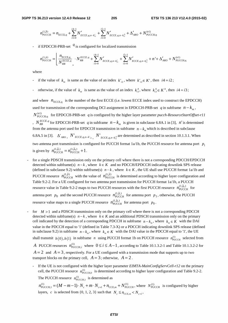
ETSI
ETSI TS 136 213 V12.4.0 (2015-02)2053GPP TS 36.213 version 12.4.0 Release 12
1 1
4 1 5 1(1, ) (e1)PUCCH ECCE,q PUCCH,q, , , ,
1 0 1 0
Ai i
i ip
AROECCE q n k ECCE q n ki i
n n N N N− −
′− −= =
′ ′ ′= + + + Δ +∑ ∑%
- if EPDCCH-PRB-set q is configured for localized transmission
1 1
4 1 5 1ECCE,q(1, ) , (e1)
PUCCH PUCCH,q, , , , ,1 0 1 0
'Ai i
i ip ECCE q
RB AROECCE q ECCE q n k ECCE q n ki iRB
nn N N N n N
N
− −
′− −= =
⎢ ⎥ ′ ′ ′= ⋅ + + + + Δ +⎢ ⎥⎣ ⎦
∑ ∑%
where
- if the value of mk is same as the value of an index 2'ik , where '' 2 Kk i ∈ , then 24 ii = ;
- otherwise, if the value of mk is same as the value of an index A
ik 3 , where AAi Kk ∈3 , then 34 ii = ;
and where ECCE,qn is the number of the first ECCE (i.e. lowest ECCE index used to construct the EPDCCH)
used for transmission of the corresponding DCI assignment in EPDCCH-PRB-set q in subframe mkn − , (e1)PUCCH,qN for EPDCCH-PRB-set q is configured by the higher layer parameter pucch-ResourceStartOffset-r11
, qECCERBN , for EPDCCH-PRB-set q in subframe mkn − is given in subclause 6.8A.1 in [3], 'n is determined
from the antenna port used for EPDCCH transmission in subframe mkn − which is described in subclause
6.8A.5 in [3]. ARO'Δ , 1',,'iknqECCEN − , A
iknqECCEN
1,,'
− are determined as described in section 10.1.3.1. When
two antenna port transmission is configured for PUCCH format 1a/1b, the PUCCH resource for antenna port 1p
is given by 1)~,1(PUCCH
)~,1(PUCCH
01 += pp nn .
- for a single PDSCH transmission only on the primary cell where there is not a corresponding PDCCH/EPDCCH detected within subframe(s) kn − , where Kk ∈ and no PDCCH/EPDCCH indicating downlink SPS release (defined in subclause 9.2) within subframe(s) kn − , where Kk ∈ , the UE shall use PUCCH format 1a/1b and
PUCCH resource )~,1(PUCCH
pn with the value of )~,1(PUCCH
pn is determined according to higher layer configuration and
Table 9.2-2. For a UE configured for two antenna port transmission for PUCCH format 1a/1b, a PUCCH
resource value in Table 9.2-2 maps to two PUCCH resources with the first PUCCH resource )~,1(PUCCH
0pn for
antenna port 0p and the second PUCCH resource )~,1(PUCCH
1pn for antenna port 1p , otherwise, the PUCCH
resource value maps to a single PUCCH resource )~,1(PUCCH
0pn for antenna port 0p .
- for 1>M and a PDSCH transmission only on the primary cell where there is not a corresponding PDCCH detected within subframe(s) kn − , where Kk ∈ and an additional PDSCH transmission only on the primary cell indicated by the detection of a corresponding PDCCH in subframe
mkn − , where Kkm ∈ with the DAI
value in the PDCCH equal to '1' (defined in Table 7.3-X) or a PDCCH indicating downlink SPS release (defined in subclause 9.2) in subframe
mkn − , where Kkm ∈ with the DAI value in the PDCCH equal to '1', the UE
shall transmit ( ) ( )0 , 1b b in subframe n using PUCCH format 1b on PUCCH resource (1)PUCCHn selected from
A PUCCH resources (1)PUCCH,in where 0 1i A≤ ≤ − , according to Table 10.1.3.2-1 and Table 10.1.3.2-2 for
2=A and 3=A , respectively. For a UE configured with a transmission mode that supports up to two
transport blocks on the primary cell, 3=A ; otherwise, 2=A .
- If the UE is not configured with the higher layer parameter EIMTA-MainConfigServCell-r12 on the primary cell, the PUCCH resource )1(
PUCCH,0n is determined according to higher layer configuration and Table 9.2-2.
The PUCCH resource )1(PUCCH,1n is determined as
(1) (1)PUCCH,1 1 CCE, PUCCH( 1) c c mn M m N m N n N+= − − ⋅ + ⋅ + + , where (1)
PUCCHN is configured by higher
layers, c is selected from {0, 1, 2, 3} such that 1CCE, +<≤ cmc NnN ,
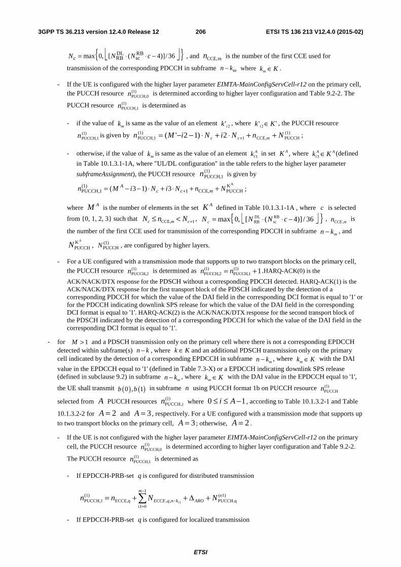
ETSI
ETSI TS 136 213 V12.4.0 (2015-02)2063GPP TS 36.213 version 12.4.0 Release 12
⎣ ⎦{ }36/)]4([,0max RBsc
DLRB −⋅⋅= cNNNc , and mCCE,n is the number of the first CCE used for
transmission of the corresponding PDCCH in subframe mn k− where Kkm ∈ .
- If the UE is configured with the higher layer parameter EIMTA-MainConfigServCell-r12 on the primary cell, the PUCCH resource )1(
PUCCH,0n is determined according to higher layer configuration and Table 9.2-2. The
PUCCH resource )1(PUCCH,1n is determined as
- if the value of mk is same as the value of an element 2'ik , where '' 2 Kk i ∈ , the PUCCH resource
)1(PUCCH,1n is given by (1)
PUCCHCCE,1)1(
PUCCH,1 2)12'( NnNiNiMn mcc ++⋅+⋅−−= + ;
- otherwise, if the value of mk is same as the value of an element A
ik 3 in set AK , where AAi Kk ∈3 (defined
in Table 10.1.3.1-1A, where "UL/DL configuration" in the table refers to the higher layer parameter
subframeAssignment), the PUCCH resource )1(PUCCH,1n is given by
AK(1)1 CCE,PUCCH,1 PUCCH( 3 1) 3A
c c mn M i N i N n N+= − − ⋅ + ⋅ + + ;
where AM is the number of elements in the set AK defined in Table 10.1.3.1-1A , where c is selected
from {0, 1, 2, 3} such that 1CCE, +<≤ cmc NnN , ⎣ ⎦{ }36/)]4([,0max RBsc
DLRB −⋅⋅= cNNN c
, mCCEn ,
is
the number of the first CCE used for transmission of the corresponding PDCCH in subframe mkn − , and
AKPUCCHN , (1)
PUCCHN , are configured by higher layers.
- For a UE configured with a transmission mode that supports up to two transport blocks on the primary cell, the PUCCH resource )1(
PUCCH,2n is determined as 1)1(PUCCH,1
)1(PUCCH,2 += nn .HARQ-ACK(0) is the
ACK/NACK/DTX response for the PDSCH without a corresponding PDCCH detected. HARQ-ACK(1) is the ACK/NACK/DTX response for the first transport block of the PDSCH indicated by the detection of a corresponding PDCCH for which the value of the DAI field in the corresponding DCI format is equal to '1' or for the PDCCH indicating downlink SPS release for which the value of the DAI field in the corresponding DCI format is equal to '1'. HARQ-ACK(2) is the ACK/NACK/DTX response for the second transport block of the PDSCH indicated by the detection of a corresponding PDCCH for which the value of the DAI field in the corresponding DCI format is equal to '1'.
- for 1>M and a PDSCH transmission only on the primary cell where there is not a corresponding EPDCCH detected within subframe(s) kn − , where Kk ∈ and an additional PDSCH transmission only on the primary cell indicated by the detection of a corresponding EPDCCH in subframe
mkn − , where Kkm ∈ with the DAI
value in the EPDCCH equal to '1' (defined in Table 7.3-X) or a EPDCCH indicating downlink SPS release (defined in subclause 9.2) in subframe
mkn − , where Kkm ∈ with the DAI value in the EPDCCH equal to '1',
the UE shall transmit ( ) ( )0 , 1b b in subframe n using PUCCH format 1b on PUCCH resource (1)PUCCHn
selected from A PUCCH resources (1)PUCCH,in where 0 1i A≤ ≤ − , according to Table 10.1.3.2-1 and Table
10.1.3.2-2 for 2=A and 3=A , respectively. For a UE configured with a transmission mode that supports up
to two transport blocks on the primary cell, 3=A ; otherwise, 2=A .
- If the UE is not configured with the higher layer parameter EIMTA-MainConfigServCell-r12 on the primary cell, the PUCCH resource )1(
PUCCH,0n is determined according to higher layer configuration and Table 9.2-2.
The PUCCH resource )1(PUCCH,1n is determined as
- If EPDCCH-PRB-set q is configured for distributed transmission
(e1)PUCCH,q
1
01,,ECCE,q
)1(PUCCH,1 1
NNnn ARO
m
iknqECCE i
+Δ++= ∑−
=−
- If EPDCCH-PRB-set q is configured for localized transmission
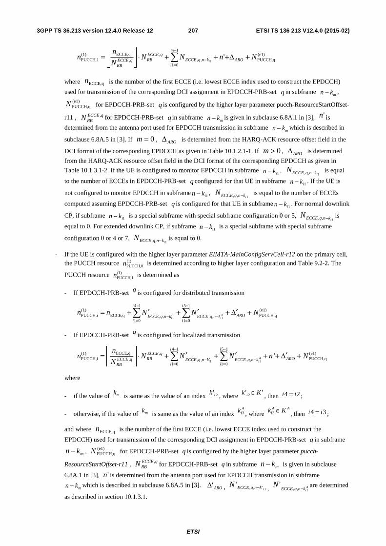
ETSI
ETSI TS 136 213 V12.4.0 (2015-02)2073GPP TS 36.213 version 12.4.0 Release 12
(e1)PUCCH,q
1
01,,
,,
ECCE,q)1(PUCCH,1 '
1NnNN
N
nn ARO
m
iknqECCE
qECCERBqECCE
RBi
+Δ+++⋅⎥⎦
⎥⎢⎣
⎢= ∑
−
=−
where ECCE,qn is the number of the first ECCE (i.e. lowest ECCE index used to construct the EPDCCH)
used for transmission of the corresponding DCI assignment in EPDCCH-PRB-set q in subframe mn k− ,
(e1)PUCCH,qN for EPDCCH-PRB-set q is configured by the higher layer parameter pucch-ResourceStartOffset-
r11 , qECCERBN , for EPDCCH-PRB-set q in subframe
mn k− is given in subclause 6.8A.1 in [3], 'n is
determined from the antenna port used for EPDCCH transmission in subframe mn k− which is described in
subclause 6.8A.5 in [3]. If 0m = , AROΔ is determined from the HARQ-ACK resource offset field in the
DCI format of the corresponding EPDCCH as given in Table 10.1.2.1-1. If 0m > , AROΔ is determined
from the HARQ-ACK resource offset field in the DCI format of the corresponding EPDCCH as given in
Table 10.1.3.1-2. If the UE is configured to monitor EPDCCH in subframe 1ikn − , 1,, iknqECCEN − is equal
to the number of ECCEs in EPDCCH-PRB-set q configured for that UE in subframe 1ikn − . If the UE is
not configured to monitor EPDCCH in subframe 1ikn − , 1,, iknqECCEN − is equal to the number of ECCEs
computed assuming EPDCCH-PRB-set q is configured for that UE in subframe 1ikn − . For normal downlink
CP, if subframe 1ikn − is a special subframe with special subframe configuration 0 or 5, 1,, iknqECCEN − is
equal to 0. For extended downlink CP, if subframe 1ikn − is a special subframe with special subframe
configuration 0 or 4 or 7, 1,, iknqECCEN − is equal to 0.
- If the UE is configured with the higher layer parameter EIMTA-MainConfigServCell-r12 on the primary cell, the PUCCH resource )1(
PUCCH,0n is determined according to higher layer configuration and Table 9.2-2. The
PUCCH resource )1(PUCCH,1n is determined as
- If EPDCCH-PRB-set q is configured for distributed transmission
1 1
4 1 5 1(1) (e1)PUCCH,i ECCE,q PUCCH,q, , , ,
1 0 1 0
Ai i
i i
AROECCE q n k ECCE q n ki i
n n N N N− −
′− −= =
′ ′ ′= + + + Δ +∑ ∑
- If EPDCCH-PRB-set q is configured for localized transmission
1 1
4 1 5 1ECCE,q(1) , (e1)
PUCCH,i PUCCH,q, , , , ,1 0 1 0
'Ai i
i iECCE qRB AROECCE q ECCE q n k ECCE q n k
i iRB
nn N N N n N
N
− −
′− −= =
⎢ ⎥ ′ ′ ′= ⋅ + + + + Δ +⎢ ⎥⎣ ⎦
∑ ∑
where
- if the value of mk is same as the value of an index 2'ik , where '' 2 Kk i ∈ , then 24 ii = ;
- otherwise, if the value of mk is same as the value of an index A
ik 3 , where AA
i Kk ∈3 , then 34 ii = ;
and where ECCE,qn is the number of the first ECCE (i.e. lowest ECCE index used to construct the
EPDCCH) used for transmission of the corresponding DCI assignment in EPDCCH-PRB-set q in subframe
mkn − , (e1)PUCCH,qN for EPDCCH-PRB-set q is configured by the higher layer parameter pucch-
ResourceStartOffset-r11 , qECCERBN , for EPDCCH-PRB-set q in subframe mkn − is given in subclause
6.8A.1 in [3], 'n is determined from the antenna port used for EPDCCH transmission in subframe
mkn − which is described in subclause 6.8A.5 in [3]. ARO'Δ , 1',,'iknqECCEN − , A
iknqECCEN
1,,'
− are determined
as described in section 10.1.3.1.
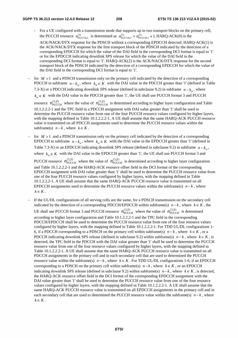
ETSI
ETSI TS 136 213 V12.4.0 (2015-02)2083GPP TS 36.213 version 12.4.0 Release 12
- For a UE configured with a transmission mode that supports up to two transport blocks on the primary cell, the PUCCH resource )1(
PUCCH,2n is determined as 1)1(PUCCH,1
)1(PUCCH,2 += nn .HARQ-ACK(0) is the
ACK/NACK/DTX response for the PDSCH without a corresponding EPDCCH detected. HARQ-ACK(1) is the ACK/NACK/DTX response for the first transport block of the PDSCH indicated by the detection of a corresponding EPDCCH for which the value of the DAI field in the corresponding DCI format is equal to '1' or for the EPDCCH indicating downlink SPS release for which the value of the DAI field in the corresponding DCI format is equal to '1'. HARQ-ACK(2) is the ACK/NACK/DTX response for the second transport block of the PDSCH indicated by the detection of a corresponding EPDCCH for which the value of the DAI field in the corresponding DCI format is equal to '1'.
- for 1>M and a PDSCH transmission only on the primary cell indicated by the detection of a corresponding PDCCH in subframe
mkn − , where Kkm ∈ with the DAI value in the PDCCH greater than '1' (defined in Table
7.3-X) or a PDCCH indicating downlink SPS release (defined in subclause 9.2) in subframe mkn − , where
Kkm ∈ with the DAI value in the PDCCH greater than '1', the UE shall use PUCCH format 3 and PUCCH
resource )~,3(PUCCH
pn where the value of )~,3(PUCCH
pn is determined according to higher layer configuration and Table
10.1.2.2.2-1 and the TPC field in a PDCCH assignment with DAI value greater than '1' shall be used to determine the PUCCH resource value from one of the four PUCCH resource values configured by higher layers, with the mapping defined in Table 10.1.2.2.2-1. A UE shall assume that the same HARQ-ACK PUCCH resource value is transmitted on all PDCCH assignments used to determine the PUCCH resource values within the subframe(s) kn − , where Kk ∈ .
- for 1>M and a PDSCH transmission only on the primary cell indicated by the detection of a corresponding EPDCCH in subframe
mkn − , where Kkm ∈ with the DAI value in the EPDCCH greater than '1' (defined in
Table 7.3-X) or an EPDCCH indicating downlink SPS release (defined in subclause 9.2) in subframe mkn − ,
where Kkm ∈ with the DAI value in the EPDCCH greater than '1', the UE shall use PUCCH format 3 and
PUCCH resource )~,3(PUCCH
pn where the value of )~,3(PUCCH
pn is determined according to higher layer configuration
and Table 10.1.2.2.2-1 and the HARQ-ACK resource offset field in the DCI format of the corresponding EPDCCH assignment with DAI value greater than '1' shall be used to determine the PUCCH resource value from one of the four PUCCH resource values configured by higher layers, with the mapping defined in Table 10.1.2.2.2-1. A UE shall assume that the same HARQ-ACK PUCCH resource value is transmitted on all EPDCCH assignments used to determine the PUCCH resource values within the subframe(s) kn − , where
Kk ∈ .
- If the UL/DL configurations of all serving cells are the same, for a PDSCH transmission on the secondary cell indicated by the detection of a corresponding PDCCH/EPDCCH within subframe(s) kn − , where Kk ∈ , the
UE shall use PUCCH format 3 and PUCCH resource )~,3(PUCCH
pn where the value of )~,3(PUCCH
pn is determined
according to higher layer configuration and Table 10.1.2.2.2-1 and the TPC field in the corresponding PDCCH/EPDCCH shall be used to determine the PUCCH resource value from one of the four resource values configured by higher layers, with the mapping defined in Table 10.1.2.2.2-1. For TDD UL/DL configurations 1-6, if a PDCCH corresponding to a PDSCH on the primary cell within subframe(s) kn − , where Kk ∈ , or a PDCCH indicating downlink SPS release (defined in subclause 9.2) within subframe(s) kn − , where Kk ∈ , is detected, the TPC field in the PDCCH with the DAI value greater than '1' shall be used to determine the PUCCH resource value from one of the four resource values configured by higher layers, with the mapping defined in Table 10.1.2.2.2-1. A UE shall assume that the same HARQ-ACK PUCCH resource value is transmitted on all PDCCH assignments in the primary cell and in each secondary cell that are used to determined the PUCCH resource value within the subframe(s) kn − , where Kk ∈ . For TDD UL/DL configurations 1-6, if an EPDCCH corresponding to a PDSCH on the primary cell within subframe(s) kn − , where Kk ∈ , or an EPDCCH indicating downlink SPS release (defined in subclause 9.2) within subframe(s) kn − , where Kk ∈ , is detected, the HARQ-ACK resource offset field in the DCI format of the corresponding EPDCCH assignment with the DAI value greater than '1' shall be used to determine the PUCCH resource value from one of the four resource values configured by higher layers, with the mapping defined in Table 10.1.2.2.2-1. A UE shall assume that the same HARQ-ACK PUCCH resource value is transmitted on all EPDCCH assignments in the primary cell and in each secondary cell that are used to determined the PUCCH resource value within the subframe(s) kn − , where
Kk ∈ .
ETSI
ETSI TS 136 213 V12.4.0 (2015-02)2093GPP TS 36.213 version 12.4.0 Release 12
- If the UL/DL configurations of at least two serving cells are different, for a PDSCH transmission on the secondary cell indicated by the detection of a corresponding PDCCH/EPDCCH within subframe(s) kn − , where
Kk ∈ , the UE shall use PUCCH format 3 and PUCCH resource )~,3(PUCCH
pn where the value of )~,3(PUCCH
pn is
determined according to higher layer configuration and Table 10.1.2.2.2-1 and the TPC field in the corresponding PDCCH/EPDCCH shall be used to determine the PUCCH resource value from one of the four resource values configured by higher layers, with the mapping defined in Table 10.1.2.2.2-1. For a UL/DL configuration of the primary cell belonging to {1,2,3,4,5,6} as defined in subclause 10.2, if a PDCCH corresponding to a PDSCH on the primary cell within subframe(s) kn − , where Kk ∈ , or a PDCCH indicating downlink SPS release (defined in subclause 9.2) within subframe(s) kn − , where Kk ∈ , is detected, the TPC field in the PDCCH with the DAI value greater than '1' shall be used to determine the PUCCH resource value from one of the four resource values configured by higher layers, with the mapping defined in Table 10.1.2.2.2-1. A UE shall assume that the same HARQ-ACK PUCCH resource value is transmitted on all PDCCH assignments in the primary cell and in each secondary cell that are used to determined the PUCCH resource value within the subframe(s) kn − , where Kk ∈ . For a UL/DL configuration of the primary cell belonging to {1,2,3,4,5,6} as defined in subclause 10.2, if an EPDCCH corresponding to a PDSCH on the primary cell within subframe(s) kn − , where Kk ∈ , or an EPDCCH indicating downlink SPS release (defined in subclause 9.2) within subframe(s) kn − , where Kk ∈ , is detected, the HARQ-ACK resource offset field in the DCI format of the corresponding EPDCCH assignment with the DAI value greater than '1' shall be used to determine the PUCCH resource value from one of the four resource values configured by higher layers, with the mapping defined in Table 10.1.2.2.2-1. A UE shall assume that the same HARQ-ACK PUCCH resource value is transmitted on all EPDCCH assignments in the primary cell and in each secondary cell that are used to determined the PUCCH resource value within the subframe(s) kn − , where Kk ∈ .
- For PUCCH format 3 and PUCCH resource )~,3(PUCCH
pn and a UE configured for two antenna port transmission, a
PUCCH resource value in Table 10.1.2.2.2-1 maps to two PUCCH resources with the first PUCCH resource )~,3(
PUCCH0pn for antenna port 0p and the second PUCCH resource )~,3(
PUCCH1pn for antenna port 1p , otherwise, the
PUCCH resource value maps to a single PUCCH resource )~,3(PUCCH
0pn for antenna port 0p .
10.1.3A FDD-TDD HARQ-ACK feedback procedures for primary cell frame structure type 2
A UE is configured by higher layers to use either PUCCH format 1b with channel selection or PUCCH format 3 for transmission of HARQ-ACK.
For a serving cell, if the serving cell is frame structure type 1, and a UE is not configured to monitor PDCCH/EPDCCH in another serving cell for scheduling the serving cell, set K is defined in Table 10.1.3A-1, otherwise set K is defined in Table 10.1.3.1-1.
PUCCH format 1b with channel selection is not supported if a UE is configured with more than two serving cells, or if the DL-reference UL/DL configuration 5 (as defined in subclause 10.2) is defined for any serving cell, or if the DL-reference UL/DL configuration of a serving cell with frame structure type 1 belongs to {2, 3, 4} and the UE is not configured to monitor PDCCH/EPDCCH in another serving cell for scheduling the serving cell.
If a UE is configured with the parameter EIMTA-MainConfigServCell-r12 for at least one serving cell, the UE is not expected to be configured with more than two serving cells having DL-reference UL/DL configuration 5.
If a UE is configured to use PUCCH format 1b with channel selection for HARQ-ACK transmission, for the serving cells,
- if more than 4 HARQ-ACK bits for M multiple downlink and special subframes associated with a single UL subframe n, where M is as defined in subclause 10.1.3.2.1 for case where the UE is configured with two serving cells with different UL/DL configurations,
- spatial HARQ-ACK bundling across multiple codewords within a downlink or special subframe is performed for each serving cell by a logical AND operation of all the corresponding individual HARQ-ACKs, and the bundled HARQ-ACK bits for each serving cell is transmitted using PUCCH format 1b with channel selection,
- otherwise,
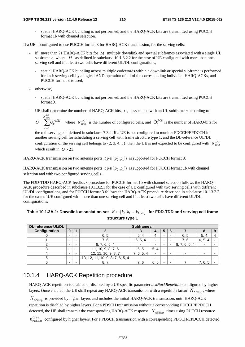
ETSI
ETSI TS 136 213 V12.4.0 (2015-02)2103GPP TS 36.213 version 12.4.0 Release 12
- spatial HARQ-ACK bundling is not performed, and the HARQ-ACK bits are transmitted using PUCCH format 1b with channel selection.
If a UE is configured to use PUCCH format 3 for HARQ-ACK transmission, for the serving cells,
- if more than 21 HARQ-ACK bits for M multiple downlink and special subframes associated with a single UL subframe n, where M as defined in subclause 10.1.3.2.2 for the case of UE configured with more than one serving cell and if at least two cells have different UL/DL configurations,
- spatial HARQ-ACK bundling across multiple codewords within a downlink or special subframe is performed for each serving cell by a logical AND operation of all of the corresponding individual HARQ-ACKs, and PUCCH format 3 is used,
- otherwise,
- spatial HARQ-ACK bundling is not performed, and the HARQ-ACK bits are transmitted using PUCCH format 3.
- UE shall determine the number of HARQ-ACK bits, O , associated with an UL subframe n according to
∑=
=
DLcellsN
c
ACKcOO
1
where DLcellsN is the number of configured cells, and ACK
cO is the number of HARQ-bits for
the c-th serving cell defined in subclause 7.3.4. If a UE is not configured to monitor PDCCH/EPDCCH in another serving cell for scheduling a serving cell with frame structure type 1, and the DL-reference UL/DL
configuration of the serving cell belongs to {2, 3, 4, 5}, then the UE is not expected to be configured with DLcellsN
which result in 21O > .
HARQ-ACK transmission on two antenna ports ]),[( 10 ppp ∈ is supported for PUCCH format 3.
HARQ-ACK transmission on two antenna ports ]),[( 10 ppp ∈ is supported for PUCCH format 1b with channel
selection and with two configured serving cells.
The FDD-TDD HARQ-ACK feedback procedure for PUCCH format 1b with channel selection follows the HARQ-ACK procedure described in subclause 10.1.3.2.1 for the case of UE configured with two serving cells with different UL/DL configurations, and for PUCCH format 3 follows the HARQ-ACK procedure described in subclause 10.1.3.2.2 for the case of UE configured with more than one serving cell and if at least two cells have different UL/DL configurations.
Table 10.1.3A-1: Downlink association set K : { }0 1 1, , Mk k k −L for FDD-TDD and serving cell frame
structure type 1
DL-reference UL/DL Configuration
Subframe n 0 1 2 3 4 5 6 7 8 9
0 - - 6, 5 5, 4 4 - - 6, 5 5, 4 4 1 - - 7, 6 6, 5, 4 - - - 7, 6 6, 5, 4 - 2 - - 8, 7, 6, 5, 4 - - - - 8, 7, 6, 5, 4 - - 3 - - 11, 10, 9, 8, 7, 6 6, 5 5, 4 - - - - - 4 - - 12, 11, 10, 9, 8, 7 7, 6, 5, 4 - - - - - - 5 - - 13, 12, 11, 10, 9, 8, 7, 6, 5, 4 - - - - - - - 6 - - 8, 7 7, 6 6, 5 - - 7 7, 6, 5 -
10.1.4 HARQ-ACK Repetition procedure
HARQ-ACK repetition is enabled or disabled by a UE specific parameter ackNackRepetition configured by higher
layers. Once enabled, the UE shall repeat any HARQ-ACK transmission with a repetition factor ANRepN , where
ANRepN is provided by higher layers and includes the initial HARQ-ACK transmission, until HARQ-ACK
repetition is disabled by higher layers. For a PDSCH transmission without a corresponding PDCCH/EPDCCH
detected, the UE shall transmit the corresponding HARQ-ACK response ANRepN times using PUCCH resource
)~,1(PUCCH
pn configured by higher layers. For a PDSCH transmission with a corresponding PDCCH/EPDCCH detected,
ETSI
ETSI TS 136 213 V12.4.0 (2015-02)2113GPP TS 36.213 version 12.4.0 Release 12
or for a PDCCH/EPDCCH indicating downlink SPS release, the UE shall first transmit the corresponding HARQ-ACK response once using PUCCH resource derived from the corresponding PDCCH CCE index or EPDCCH ECCE index (as described in subclauses 10.1.2 and 10.1.3), and repeat the transmission of the corresponding
HARQ-ACK response 1ANRep −N times always using PUCCH resource )~,1(ANRep PUCCH,
pn , where )~,1(ANRep PUCCH,
pn is
configured by higher layers.
HARQ-ACK repetition is only applicable for UEs configured with one serving cell for FDD and TDD. For TDD, HARQ-ACK repetition is only applicable for HARQ-ACK bundling.
HARQ-ACK repetition can be enabled with PUCCH format 1a/1b on two antenna ports. For a UE configured for two antenna port transmission for HARQ-ACK repetition with PUCCH format 1a/1b, a PUCCH resource value
)~,1(ANRep PUCCH,
pn maps to two PUCCH resources with the first PUCCH resource )~,1(
ANRep PUCCH,0pn for antenna port 0p
and the second PUCCH resource )~,1(ANRep PUCCH,
1pn for antenna port 1p , otherwise, the PUCCH resource value maps to
a single PUCCH resource )~,1(
ANRep PUCCH,0pn for antenna port 0p .
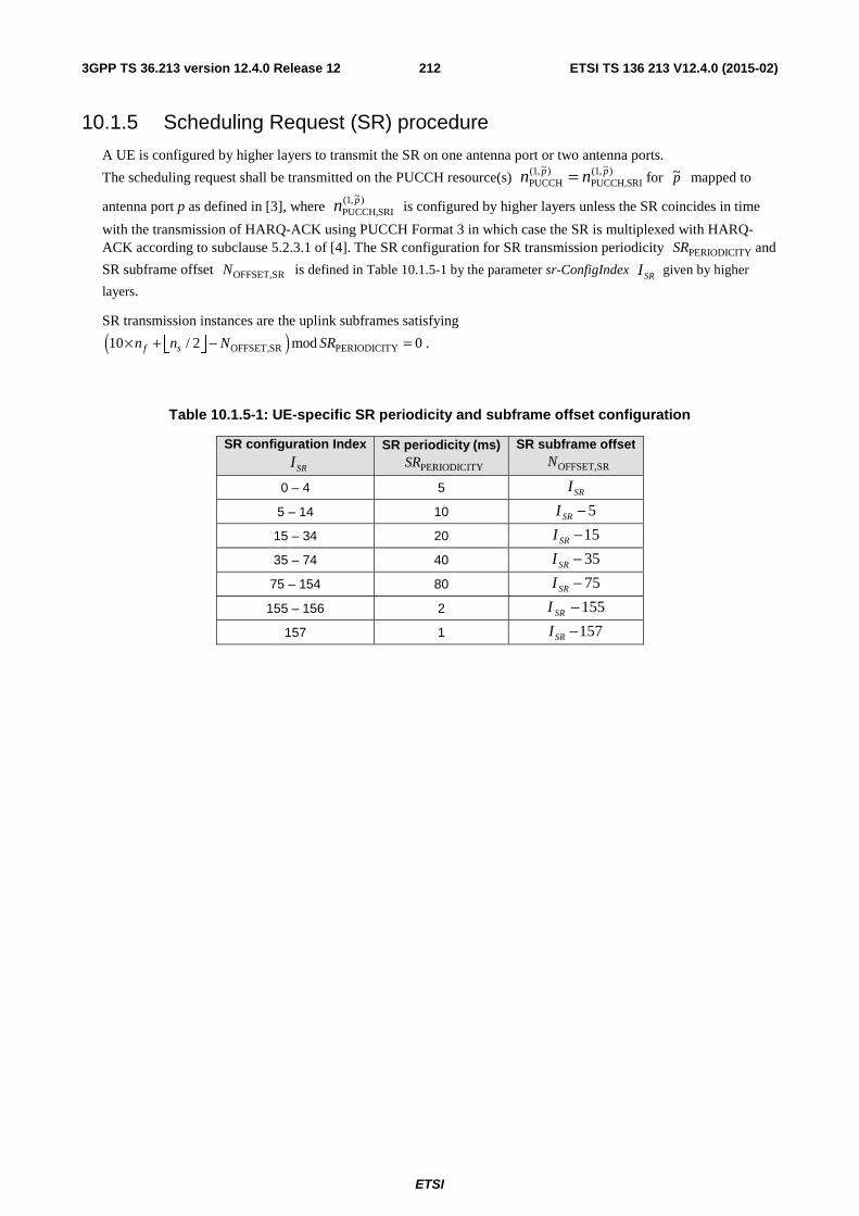
ETSI
ETSI TS 136 213 V12.4.0 (2015-02)2123GPP TS 36.213 version 12.4.0 Release 12
10.1.5 Scheduling Request (SR) procedure
A UE is configured by higher layers to transmit the SR on one antenna port or two antenna ports.
The scheduling request shall be transmitted on the PUCCH resource(s) )~,1(SRIPUCCH,
)~,1(PUCCH
pp nn = for p~ mapped to
antenna port p as defined in [3], where )~,1(SRIPUCCH,
pn is configured by higher layers unless the SR coincides in time
with the transmission of HARQ-ACK using PUCCH Format 3 in which case the SR is multiplexed with HARQ-ACK according to subclause 5.2.3.1 of [4]. The SR configuration for SR transmission periodicity PERIODICITYSR and
SR subframe offset OFFSET,SRN is defined in Table 10.1.5-1 by the parameter sr-ConfigIndex SRI given by higher
layers.
SR transmission instances are the uplink subframes satisfying
( )OFFSET,SR PERIODICITY10 / 2 mod 0f sn n N SR× + − =⎢ ⎥⎣ ⎦ .
Table 10.1.5-1: UE-specific SR periodicity and subframe offset configuration
SR configuration Index SRI
SR periodicity (ms) PERIODICITYSR
SR subframe offset OFFSET,SRN
0 – 4 5 SRI
5 – 14 10 5−SRI
15 – 34 20 15−SRI
35 – 74 40 35−SRI
75 – 154 80 75−SRI
155 – 156 2 155−SRI
157 1 157−SRI
ETSI
ETSI TS 136 213 V12.4.0 (2015-02)2133GPP TS 36.213 version 12.4.0 Release 12
10.2 Uplink HARQ-ACK timing For TDD or for FDD-TDD and primary cell frame structure type 2, if a UE configured with EIMTA-MainConfigServCell-r12 for a serving cell, “UL/DL configuration” of the serving cell in subclause 10.2 refers to the UL/DL configuration given by the parameter eimta-HarqReferenceConfig-r12 for the serving cell unless specified otherwise.
For FDD or for FDD-TDD and primary cell frame structure type 1, the UE shall upon detection of a PDSCH transmission in subframe n-4 intended for the UE and for which an HARQ-ACK shall be provided, transmit the HARQ-ACK response in subframe n. If HARQ-ACK repetition is enabled, upon detection of a PDSCH transmission in subframe n-4 intended for the UE and for which HARQ-ACK response shall be provided, and if the UE is not repeating the transmission of any HARQ-ACK in subframe n corresponding to a PDSCH transmission in subframes
3ANRep −− Nn , … , 5−n , the UE:
- shall transmit only the HARQ-ACK response (corresponding to the detected PDSCH transmission in subframe 4−n ) on PUCCH in subframes n , 1+n , …, 1ANRep −+ Nn ;
- shall not transmit any other signal in subframes n , 1+n , …, 1ANRep −+ Nn ; and
- shall not transmit any HARQ-ACK response repetitions corresponding to any detected PDSCH transmission in subframes 3−n , …, 5ANRep −+ Nn .
For TDD and a UE configured with EIMTA-MainConfigServCell-r12 for at least one serving cell, if the UE is configured with one serving cell or if the UE is configured with more than one serving cell and the TDD UL/DL configuration of all the configured serving cells is the same, the DL-reference UL/DL configuration for a serving cell is the UL/DL configuration of the serving cell
For TDD, if the UE is configured with more than one serving cell and if at least two serving cells have different UL/DL configurations and if a serving cell is a primary cell, then the primary cell UL/DL configuration is the DL-reference UL/DL configuration for the serving cell.
For FDD-TDD and primary cell frame structure type 2, if a serving cell is a primary cell or if a serving cell is a secondary cell with frame structure type 1, then the primary cell UL/DL configuration is the DL-reference UL/DL configuration for the serving cell.
For TDD and if the UE is configured with more than one serving cell and if at least two serving cells have different UL/DL configurations and if a serving cell is a secondary cell, or for FDD-TDD and primary cell frame structure type 2 and if a serving cell is a secondary cell with frame structure type 2
- if the pair formed by (primary cell UL/DL configuration, serving cell UL/DL configuration ) belongs to Set 1 in Table 10.2-1 or
- if the UE is not configured to monitor PDCCH/EPDCCH in another serving cell for scheduling the serving cell, and if the pair formed by (primary cell UL/DL configuration, serving cell UL/DL configuration ) belongs to Set 2 or Set 3 in Table 10.2-1 or
- if the UE is configured to monitor PDCCH/EPDCCH in another serving cell for scheduling the serving cell, and if the pair formed by (primary cell UL/DL configuration, serving cell UL/DL configuration) belongs to Set 4 or Set 5 in Table 10.2-1
then the DL-reference UL/DL configuration for the serving cell is defined in the corresponding Set in Table 10.2-1.
For TDD and if a UE is configured with more than one serving cell and if at least two serving cells have different UL/DL configurations or for FDD-TDD and primary cell frame structure type 2, if the DL-reference UL/DL configuration for at least one serving cell is TDD UL/DL Configuration 5, then the UE is not expected to be configured with more than two serving cells.
For TDD and a UE not configured with EIMTA-MainConfigServCell-r12 for any serving cell, if the UE is configured with one serving cell, or the UE is configured with more than one serving cell and the UL/DL configurations of all serving cells is same, then the UE shall upon detection of a PDSCH transmission within subframe(s) kn − , where
ETSI
ETSI TS 136 213 V12.4.0 (2015-02)2143GPP TS 36.213 version 12.4.0 Release 12
Kk ∈ and K is defined in Table 10.1.3.1-1 intended for the UE and for which HARQ-ACK response shall be provided, transmit the HARQ-ACK response in UL subframe n.
For TDD and if a UE is configured with more than one serving cell and if at least two serving cells have different UL/DL configurations, or if a UE is configured with EIMTA-MainConfigServCell-r12 for at least one serving cell. or for FDD-TDD and primary cell frame structure type 2 and if a serving cell c is frame structure type 2, then the UE shall
upon detection of a PDSCH transmission within subframe(s) kn − for serving cell c , where cKk ∈ intended for
the UE and for which HARQ-ACK response shall be provided, transmit the HARQ-ACK response in UL subframe n,
wherein set cK contains values of Kk ∈ such that subframe n-k corresponds to a DL subframe or a special subframe
for serving cell c , where DL subframe or special subframe of serving cell c is according to the higher layer parameter eimta-HarqReferenceConfig-r12 if the UE is configured with the higher layer parameter EIMTA-MainConfigServCell-r12 for serving cell c ; K defined in Table 10.1.3.1-1 (where "UL/DL configuration" in Table 10.1.3.1-1 refers to the "DL-reference UL/DL configuration") is associated with subframe n.
For FDD-TDD and primary cell frame structure type 2, if a serving cell c is frame structure type 1 and a UE is not configured to monitor PDCCH/EPDCCH in another serving cell for scheduling the serving cell c , then the UE shall
upon detection of a PDSCH transmission within subframe(s) kn − for serving cell c , where cKk ∈ , cK K= and
K is defined in Table 10.1.3A-1 intended for the UE and for which HARQ-ACK response shall be provided, transmit the HARQ-ACK response in subframe n.
For FDD-TDD and primary cell frame structure type 2, if a serving cell c is frame structure type 1 and a UE is configured to monitor PDCCH/EPDCCH in another serving cell for scheduling serving cell c , then the UE shall upon
detection of a PDSCH transmission within subframe(s) kn − for serving cell c , where cKk ∈ , cK K= and K is
defined in Table 10.1.3.1-1, intended for the UE and for which HARQ-ACK response shall be provided, transmit the HARQ-ACK response in subframe n, where "UL/DL configuration" in Table 10.1.3.1-1 refers to the "DL-reference UL/DL configuration" of serving cell c .
For TDD, if HARQ-ACK repetition is enabled, upon detection of a PDSCH transmission within subframe(s) kn − , where Kk ∈ and K is defined in Table 10.1.3.1-1 intended for the UE and for which HARQ-ACK response shall be provided, and if the UE is not repeating the transmission of any HARQ-ACK in subframe n corresponding to a PDSCH transmission in a downlink or special subframe earlier than subframe kn − , the UE:
- shall transmit only the HARQ-ACK response (corresponding to the detected PDSCH transmission in
subframe kn − ) on PUCCH in UL subframe n and the next 1ANRep −N UL subframes denoted as 1n ,
…, 1ANRep −Nn ;
- shall not transmit any other signal in UL subframe n , 1n , …, 1ANRep −Nn ; and
- shall not transmit any HARQ-ACK response repetitions corresponding to any detected PDSCH transmission in
subframes kni − , where iKk ∈ , iK is the set defined in Table 10.1.3.1-1 corresponding to UL subframe
in , and 11 ANRep −≤≤ Ni .
For TDD, HARQ-ACK bundling, if the UE detects that at least one downlink assignment has been missed as described in subclause 7.3, the UE shall not transmit HARQ-ACK on PUCCH if HARQ-ACK is the only UCI present in a given subframe.
The uplink timing for the ACK corresponding to a detected PDCCH/EPDCCH indicating downlink SPS release shall be the same as the uplink timing for the HARQ-ACK corresponding to a detected PDSCH, as defined above.
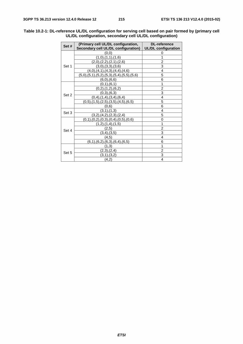
ETSI
ETSI TS 136 213 V12.4.0 (2015-02)2153GPP TS 36.213 version 12.4.0 Release 12
Table 10.2-1: DL-reference UL/DL configuration for serving cell based on pair formed by (primary cell UL/DL configuration, secondary cell UL/DL configuration)
Set # (Primary cell UL/DL configuration, Secondary cell UL/DL configuration)
DL-reference UL/DL configuration
Set 1
(0,0) 0 (1,0),(1,1),(1,6) 1
(2,0),(2,2),(2,1),(2,6) 2 (3,0),(3,3),(3,6) 3
(4,0),(4,1),(4,3),(4,4),(4,6) 4 (5,0),(5,1),(5,2),(5,3),(5,4),(5,5),(5,6) 5
(6,0),(6,6) 6
Set 2
(0,1),(6,1) 1 (0,2),(1,2),(6,2) 2
(0,3),(6,3) 3 (0,4),(1,4),(3,4),(6,4) 4
(0,5),(1,5),(2,5),(3,5),(4,5),(6,5) 5 (0,6) 6
Set 3 (3,1),(1,3) 4
(3,2),(4,2),(2,3),(2,4) 5
Set 4
(0,1),(0,2),(0,3),(0,4),(0,5),(0,6) 0 (1,2),(1,4),(1,5) 1
(2,5) 2 (3,4),(3,5) 3
(4,5) 4 (6,1),(6,2),(6,3),(6,4),(6,5) 6
Set 5
(1,3) 1 (2,3),(2,4) 2 (3,1),(3,2) 3
(4,2) 4
ETSI
ETSI TS 136 213 V12.4.0 (2015-02)2163GPP TS 36.213 version 12.4.0 Release 12
11 Physical Multicast Channel (PMCH) related procedures
11.1 UE procedure for receiving the PMCH
The UE shall decode the PMCH when configured by higher layers. The UE may assume that an eNB transmission on the PMCH is performed according to subclause 6.5 of [3].
The MCSI for the PMCH is configured by higher layers. If the UE is configured by higher layers to decode the PMCH
based on QPSK, 16QAM, 64QAM, and 256QAM then the UE shall use MCSI and Table 7.1.7.1-1A to determine the
modulation order ( mQ ) and TBS index ( TBSI ) used in the PMCH. Else the UE shall use MCSI for the PMCH and Table
7.1.7.1-1 to determine the modulation order ( mQ ) and TBS index ( TBSI ) used in the PMCH.
The UE shall then follow the procedure in subclause 7.1.7.2.1 to determine the transport block size, assuming PRBN is
equal to DLRBN . The UE shall set the redundancy version to 0 for the PMCH.
11.2 UE procedure for receiving MCCH change notification If a UE is configured by higher layers to decode PDCCHs with the CRC scrambled by the M-RNTI, the UE shall decode the PDCCH according to the combination defined in Table 11.2-1.
Table 11.2-1: PDCCH configured by M-RNTI
DCI format Search Space DCI format 1C Common
The 8-bit information for MCCH change notification [11], as signalled on the PDCCH, shall be delivered to higher layers.
12 Assumptions independent of physical channel A UE shall not assume that two antenna ports are quasi co-located unless specified otherwise.
A UE may assume the antenna ports 0 – 3 of a serving cell are quasi co-located (as defined in [3]) with respect to delay spread, Doppler spread, Doppler shift, average gain, and average delay.
If a UE supports discoverySignalsInDeactSCell-r12, and if the UE is configured with discovery-signal-based RRM measurements on a carrier frequency applicable for a secondary cell on the same carrier frequency, and if the secondary cell is deactivated, and if the UE is not configured by higher layers to receive MBMS on the secondary cell, the UE shall, except for discovery-signal transmissions, assume that PSS, SSS, PBCH, CRS, PCFICH, PDSCH, PDCCH, EPDCCH, PHICH, DMRS and CSI-RS may be not transmitted by the secondary cell until the subframe where an activation command is received for the secondary cell.
13 Uplink/Downlink configuration determination procedure for Frame Structure Type 2
If the UE is configured with a SCG, the UE shall apply the procedures described in this clause for both MCG and SCG
ETSI
ETSI TS 136 213 V12.4.0 (2015-02)2173GPP TS 36.213 version 12.4.0 Release 12
- When the procedures are applied for MCG, the terms ‘secondary cell’, ‘secondary cells’ , ‘serving cell’, ‘serving cells’ in this clause refer to secondary cell, secondary cells, serving cell, serving cells belonging to the MCG respectively.
- When the procedures are applied for SCG, the terms ‘secondary cell’, ‘secondary cells’, ‘serving cell’, ‘serving cells’ in this clause refer to secondary cell, secondary cells (not including PSCell), serving cell, serving cells belonging to the SCG respectively. The term ‘primary cell’ in this clause refers to the PSCell of the SCG.
For each serving cell
If the UE is not configured with the higher layer parameter EIMTA-MainConfigServCell-r12,
- the UE shall set the UL/DL configuration equal to the UL/DL configuration (i.e., the parameter subframeAssignment) indicated by higher layers.
If the UE is configured by higher layers with the parameter EIMTA-MainConfigServCell-r12, then for each radio frame,
- the UE shall determine eIMTA-UL/DL-configuration as described in subclause 13.1.
- the UE shall set the UL/DL configuration for each radio frame equal to the eIMTA-UL/DL-configuration of that radio frame.
13.1 UE procedure for determining eIMTA-uplink/downlink configuration
If a UE is configured by higher layers to decode PDCCHs with the CRC scrambled by the eIMTA-RNTI, the UE shall decode the PDCCH according to the combination defined in Table 13.1-1.
Table 13.1-1: PDCCH configured by eIMTA-RNTI
DCI format Search Space DCI format 1C Common
The subframes in which the UE monitors PDCCH with CRC scrambled by eIMTA-RNTI are configured by higher layers.
For each serving cell,
- if T= 10,
- if the UE detects PDCCH with CRC scrambled by eIMTA-RNTI in subframe 0 of a radio frame m or if the UE detects PDCCH with CRC scrambled by eIMTA-RNTI in a subframe other than subframe 0 of a radio frame m-1,
- the eIMTA-UL/DL-configuration for radio frame m is given by the UL/DL configuration indication signalled on the PDCCH as described in [4],
- the UE may assume that the same UL/DL configuration indication is indicated by PDCCH with CRC scrambled by eIMTA-RNTI in subframe 0 of radio frame m and in all the subframes other than subframe 0 of radio frame m-1 in which PDCCH with CRC scrambled by eIMTA-RNTI is monitored,
- otherwise
- the eIMTA-UL/DL-configuration for radio frame m is same as the UL/DL configuration (i.e., the parameter subframeAssignment) indicated by higher layers;
- if T is a value other than 10,
- if the UE detects PDCCH with CRC scrambled by eIMTA-RNTI in a subframe in radio frame mT/10,
ETSI
ETSI TS 136 213 V12.4.0 (2015-02)2183GPP TS 36.213 version 12.4.0 Release 12
- the eIMTA-UL/DL-configuration for radio frames {mT/10+1 , mT/10+2,…. (m + 1)T/10} is given by the UL/DL configuration indication signalled on the PDCCH as described [4],
- the UE may assume that the same UL/DL configuration indication is indicated by PDCCH with CRC scrambled by eIMTA-RNTI in all the subframes of radio frame mT/10 in which PDCCH with CRC scrambled by eIMTA-RNTI is monitored,
- otherwise
- the eIMTA-UL/DL-configuration for radio frames {mT/10+1 , mT/10+2,…. (m +1) T/10} is same as the UL/DL configuration (i.e., the parameter subframeAssignment) indicated by higher layers.
where T denotes the value of parameter eimta-CommandPeriodicity-r12.
For a serving cell c , if subframe i is indicated as uplink subframe or a special subframe by higher layer parameter eimta-HarqReferenceConfig-r12, the UE is not expected to receive a PDCCH with CRC scrambled by eIMTA-RNTI containing an UL/DL configuration for serving cell c that would indicate subframe i as a downlink subframe.
For a serving cell c , if subframe i is indicated as downlink subframe or a special subframe by higher layer parameter subframeAssignment, the UE is not expected to receive a PDCCH with CRC scrambled by eIMTA-RNTI containing an UL/DL configuration for serving cell c that would indicate subframe i as an uplink subframe.
For a serving cell c , a UE is not expected to be configured with parameter eimta-HarqReferenceConfig-r12 if a subframe indicated as an uplink subframe by eimta-HarqReferenceConfig-r12 is not indicated as an uplink subframe by the UL-reference UL/DL configuration.
If UE is not configured with the parameter EIMTA-MainConfigServCell-r12 for any activated serving cell, the UE is not expected to monitor PDCCH with CRC scrambled by eIMTA-RNTI.
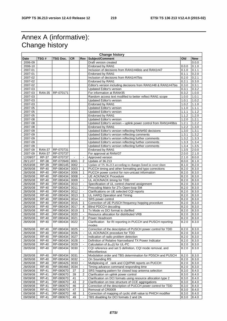
ETSI
ETSI TS 136 213 V12.4.0 (2015-02)2193GPP TS 36.213 version 12.4.0 Release 12
Annex A (informative): Change history
Change history Date TSG # TSG Doc. CR Rev Subject/Comment Old New 2006-09 Draft version created 0.0.0 2006-10 Endorsed by RAN1 0.0.0 0.1.0 2007-01 Inclusion of decisions from RAN1#46bis and RAN1#47 0.1.0 0.1.1 2007-01 Endorsed by RAN1 0.1.1 0.2.0 2007-02 Inclusion of decisions from RAN1#47bis 0.2.0 0.2.1 2007-02 Endorsed by RAN1 0.2.1 0.3.0 2007-02 Editor's version including decisions from RAN1#48 & RAN1#47bis 0.3.0 0.3.1 2007-03 Updated Editor's version 0.3.1 0.3.2 2007-03 RAN-35 RP-070171 For information at RAN#35 0.3.2 1.0.0 2007-03 Random access text modified to better reflect RAN1 scope 1.0.0 1.0.1 2007-03 Updated Editor's version 1.0.1 1.0.2 2007-03 Endorsed by RAN1 1.0.2 1.1.0 2007-05 Updated Editor's version 1.1.0 1.1.1 2007-05 Updated Editor's version 1.1.1 1.1.2 2007-05 Endorsed by RAN1 1.1.2 1.2.0 2007-08 Updated Editor's version 1.2.0 1.2.1 2007-08 Updated Editor's version – uplink power control from RAN1#49bis 1.2.1 1.2.2 2007-08 Endorsed by RAN1 1.2.2 1.3.0 2007-09 Updated Editor's version reflecting RAN#50 decisions 1.3.0 1.3.1 2007-09 Updated Editor's version reflecting comments 1.3.1 1.3.2 2007-09 Updated Editor's version reflecting further comments 1.3.2 1.3.3 2007-09 Updated Editor's version reflecting further comments 1.3.3 1.3.4 2007-09 Updated Edtior's version reflecting further comments 1.3.4 1.3.5 2007-09 RAN-37 RP-070731 Endorsed by RAN1 1.3.5 2.0.0 2007-09 RAN-37 RP-070737 For approval at RAN#37 2.0.0 2.1.0 12/09/07 RP-37 RP-070737 - - Approved version 2.1.0 8.0.0 28/11/07 RP-38 RP-070949 0001 2 Update of 36.213 8.0.0 8.1.0 05/03/08 RP-39 RP-080145 0002 - Update of TS 36.213 according to changes listed in cover sheet 8.1.0 8.2.0 28/05/08 RP-40 RP-080434 0003 1 PUCCH timing and other formatting and typo corrections 8.2.0 8.3.0 28/05/08 RP-40 RP-080434 0006 1 PUCCH power control for non-unicast information 8.2.0 8.3.0 28/05/08 RP-40 RP-080434 0008 - UE ACK/NACK Procedure 8.2.0 8.3.0 28/05/08 RP-40 RP-080434 0009 - UL ACK/NACK timing for TDD 8.2.0 8.3.0 28/05/08 RP-40 RP-080434 0010 - Specification of UL control channel assignment 8.2.0 8.3.0 28/05/08 RP-40 RP-080434 0011 - Precoding Matrix for 2Tx Open-loop SM 8.2.0 8.3.0 28/05/08 RP-40 RP-080434 0012 - Clarifications on UE selected CQI reports 8.2.0 8.3.0 28/05/08 RP-40 RP-080434 0013 1 UL HARQ Operation and Timing 8.2.0 8.3.0 28/05/08 RP-40 RP-080434 0014 - SRS power control 8.2.0 8.3.0 28/05/08 RP-40 RP-080434 0015 1 Correction of UE PUSCH frequency hopping procedure 8.2.0 8.3.0 28/05/08 RP-40 RP-080434 0017 4 Blind PDCCH decoding 8.2.0 8.3.0 28/05/08 RP-40 RP-080434 0019 1 Tx Mode vs DCI format is clarified 8.2.0 8.3.0 28/05/08 RP-40 RP-080434 0020 - Resource allocation for distributed VRB 8.2.0 8.3.0 28/05/08 RP-40 RP-080434 0021 2 Power Headroom 8.2.0 8.3.0 28/05/08 RP-40 RP-080434 0022 - Clarification for RI reporting in PUCCH and PUSCH reporting
modes 8.2.0 8.3.0
28/05/08 RP-40 RP-080434 0025 - Correction of the description of PUSCH power control for TDD 8.2.0 8.3.0 28/05/08 RP-40 RP-080434 0026 - UL ACK/NACK procedure for TDD 8.2.0 8.3.0 28/05/08 RP-40 RP-080434 0027 - Indication of radio problem detection 8.2.0 8.3.0 28/05/08 RP-40 RP-080434 0028 - Definition of Relative Narrowband TX Power Indicator 8.2.0 8.3.0 28/05/08 RP-40 RP-080434 0029 - Calculation of ∆TF(i) for UL-PC 8.2.0 8.3.0 28/05/08 RP-40 RP-080434 0030 - CQI reference and set S definition, CQI mode removal, and
Miscellanious 8.2.0 8.3.0
28/05/08 RP-40 RP-080434 0031 - Modulation order and TBS determination for PDSCH and PUSCH 8.2.0 8.3.0 28/05/08 RP-40 RP-080434 0032 - On Sounding RS 8.2.0 8.3.0 28/05/08 RP-40 RP-080426 0033 - Multiplexing of rank and CQI/PMI reports on PUCCH 8.2.0 8.3.0 28/05/08 RP-40 RP-080466 0034 - Timing advance command responding time 8.2.0 8.3.0 09/09/08 RP-41 RP-080670 37 2 SRS hopping pattern for closed loop antenna selection 8.3.0 8.4.0 09/09/08 RP-41 RP-080670 39 2 Clarification on uplink power control 8.3.0 8.4.0 09/09/08 RP-41 RP-080670 41 - Clarification on DCI formats using resource allocation type 2 8.3.0 8.4.0 09/09/08 RP-41 RP-080670 43 2 Clarification on tree structure of CCE aggregations 8.3.0 8.4.0 09/09/08 RP-41 RP-080670 46 2 Correction of the description of PUCCH power control for TDD 8.3.0 8.4.0 09/09/08 RP-41 RP-080670 47 1 Removal of CR0009 8.3.0 8.4.0 09/09/08 RP-41 RP-080670 48 1 Correction of mapping of cyclic shift value to PHICH modifier 8.3.0 8.4.0 09/09/08 RP-41 RP-080670 49 - TBS disabling for DCI formats 2 and 2A 8.3.0 8.4.0
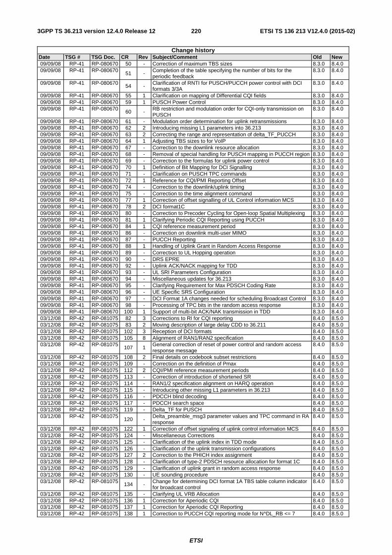
ETSI
ETSI TS 136 213 V12.4.0 (2015-02)2203GPP TS 36.213 version 12.4.0 Release 12
Change history Date TSG # TSG Doc. CR Rev Subject/Comment Old New 09/09/08 RP-41 RP-080670 50 - Correction of maximum TBS sizes 8.3.0 8.4.0 09/09/08 RP-41 RP-080670 51 - Completion of the table specifying the number of bits for the
periodic feedback 8.3.0 8.4.0
09/09/08 RP-41 RP-080670 54 - Clarification of RNTI for PUSCH/PUCCH power control with DCI formats 3/3A
8.3.0 8.4.0
09/09/08 RP-41 RP-080670 55 1 Clarification on mapping of Differential CQI fields 8.3.0 8.4.0 09/09/08 RP-41 RP-080670 59 1 PUSCH Power Control 8.3.0 8.4.0 09/09/08 RP-41 RP-080670 60 - RB restriction and modulation order for CQI-only transmission on
PUSCH 8.3.0 8.4.0
09/09/08 RP-41 RP-080670 61 - Modulation order determination for uplink retransmissions 8.3.0 8.4.0 09/09/08 RP-41 RP-080670 62 2 Introducing missing L1 parameters into 36.213 8.3.0 8.4.0 09/09/08 RP-41 RP-080670 63 2 Correcting the range and representation of delta_TF_PUCCH 8.3.0 8.4.0 09/09/08 RP-41 RP-080670 64 1 Adjusting TBS sizes to for VoIP 8.3.0 8.4.0 09/09/08 RP-41 RP-080670 67 - Correction to the downlink resource allocation 8.3.0 8.4.0 09/09/08 RP-41 RP-080670 68 - Removal of special handling for PUSCH mapping in PUCCH region 8.3.0 8.4.0 09/09/08 RP-41 RP-080670 69 - Correction to the formulas for uplink power control 8.3.0 8.4.0 09/09/08 RP-41 RP-080670 70 1 Definition of Bit Mapping for DCI Signalling 8.3.0 8.4.0 09/09/08 RP-41 RP-080670 71 - Clarification on PUSCH TPC commands 8.3.0 8.4.0 09/09/08 RP-41 RP-080670 72 1 Reference for CQI/PMI Reporting Offset 8.3.0 8.4.0 09/09/08 RP-41 RP-080670 74 - Correction to the downlink/uplink timing 8.3.0 8.4.0 09/09/08 RP-41 RP-080670 75 - Correction to the time alignment command 8.3.0 8.4.0 09/09/08 RP-41 RP-080670 77 1 Correction of offset signalling of UL Control information MCS 8.3.0 8.4.0 09/09/08 RP-41 RP-080670 78 2 DCI format1C 8.3.0 8.4.0 09/09/08 RP-41 RP-080670 80 - Correction to Precoder Cycling for Open-loop Spatial Multiplexing 8.3.0 8.4.0 09/09/08 RP-41 RP-080670 81 1 Clarifying Periodic CQI Reporting using PUCCH 8.3.0 8.4.0 09/09/08 RP-41 RP-080670 84 1 CQI reference measurement period 8.3.0 8.4.0 09/09/08 RP-41 RP-080670 86 - Correction on downlink multi-user MIMO 8.3.0 8.4.0 09/09/08 RP-41 RP-080670 87 - PUCCH Reporting 8.3.0 8.4.0 09/09/08 RP-41 RP-080670 88 1 Handling of Uplink Grant in Random Access Response 8.3.0 8.4.0 09/09/08 RP-41 RP-080670 89 - Correction to UL Hopping operation 8.3.0 8.4.0 09/09/08 RP-41 RP-080670 90 - DRS EPRE 8.3.0 8.4.0 09/09/08 RP-41 RP-080670 92 - Uplink ACK/NACK mapping for TDD 8.3.0 8.4.0 09/09/08 RP-41 RP-080670 93 - UL SRI Parameters Configuration 8.3.0 8.4.0 09/09/08 RP-41 RP-080670 94 - Miscellaneous updates for 36.213 8.3.0 8.4.0 09/09/08 RP-41 RP-080670 95 - Clarifying Requirement for Max PDSCH Coding Rate 8.3.0 8.4.0 09/09/08 RP-41 RP-080670 96 - UE Specific SRS Configuration 8.3.0 8.4.0 09/09/08 RP-41 RP-080670 97 - DCI Format 1A changes needed for scheduling Broadcast Control 8.3.0 8.4.0 09/09/08 RP-41 RP-080670 98 - Processing of TPC bits in the random access response 8.3.0 8.4.0 09/09/08 RP-41 RP-080670 100 1 Support of multi-bit ACK/NAK transmission in TDD 8.3.0 8.4.0 03/12/08 RP-42 RP-081075 82 3 Corrections to RI for CQI reporting 8.4.0 8.5.0 03/12/08 RP-42 RP-081075 83 2 Moving description of large delay CDD to 36.211 8.4.0 8.5.0 03/12/08 RP-42 RP-081075 102 3 Reception of DCI formats 8.4.0 8.5.0 03/12/08 RP-42 RP-081075 105 8 Alignment of RAN1/RAN2 specification 8.4.0 8.5.0 03/12/08 RP-42 RP-081075
107 1 General correction of reset of power control and random access response message
8.4.0 8.5.0
03/12/08 RP-42 RP-081075 108 2 Final details on codebook subset restrictions 8.4.0 8.5.0 03/12/08 RP-42 RP-081075 109 - Correction on the definition of Pmax 8.4.0 8.5.0 03/12/08 RP-42 RP-081075 112 2 CQI/PMI reference measurement periods 8.4.0 8.5.0 03/12/08 RP-42 RP-081075 113 - Correction of introduction of shortened SR 8.4.0 8.5.0 03/12/08 RP-42 RP-081075 114 - RAN1/2 specification alignment on HARQ operation 8.4.0 8.5.0 03/12/08 RP-42 RP-081075 115 - Introducing other missing L1 parameters in 36.213 8.4.0 8.5.0 03/12/08 RP-42 RP-081075 116 - PDCCH blind decoding 8.4.0 8.5.0 03/12/08 RP-42 RP-081075 117 - PDCCH search space 8.4.0 8.5.0 03/12/08 RP-42 RP-081075 119 - Delta_TF for PUSCH 8.4.0 8.5.0 03/12/08 RP-42 RP-081075
120 - Delta_preamble_msg3 parameter values and TPC command in RA response
8.4.0 8.5.0
03/12/08 RP-42 RP-081075 122 1 Correction of offset signaling of uplink control information MCS 8.4.0 8.5.0 03/12/08 RP-42 RP-081075 124 - Miscellaneous Corrections 8.4.0 8.5.0 03/12/08 RP-42 RP-081075 125 - Clarification of the uplink index in TDD mode 8.4.0 8.5.0 03/12/08 RP-42 RP-081075 126 - Clarification of the uplink transmission configurations 8.4.0 8.5.0 03/12/08 RP-42 RP-081075 127 2 Correction to the PHICH index assignment 8.4.0 8.5.0 03/12/08 RP-42 RP-081075 128 - Clarification of type-2 PDSCH resource allocation for format 1C 8.4.0 8.5.0 03/12/08 RP-42 RP-081075 129 - Clarification of uplink grant in random access response 8.4.0 8.5.0 03/12/08 RP-42 RP-081075 130 - UE sounding procedure 8.4.0 8.5.0 03/12/08 RP-42 RP-081075 134 - Change for determining DCI format 1A TBS table column indicator
for broadcast control 8.4.0 8.5.0
03/12/08 RP-42 RP-081075 135 - Clarifying UL VRB Allocation 8.4.0 8.5.0 03/12/08 RP-42 RP-081075 136 1 Correction for Aperiodic CQI 8.4.0 8.5.0 03/12/08 RP-42 RP-081075 137 1 Correction for Aperiodic CQI Reporting 8.4.0 8.5.0 03/12/08 RP-42 RP-081075 138 1 Correction to PUCCH CQI reporting mode for N^DL_RB <= 7 8.4.0 8.5.0
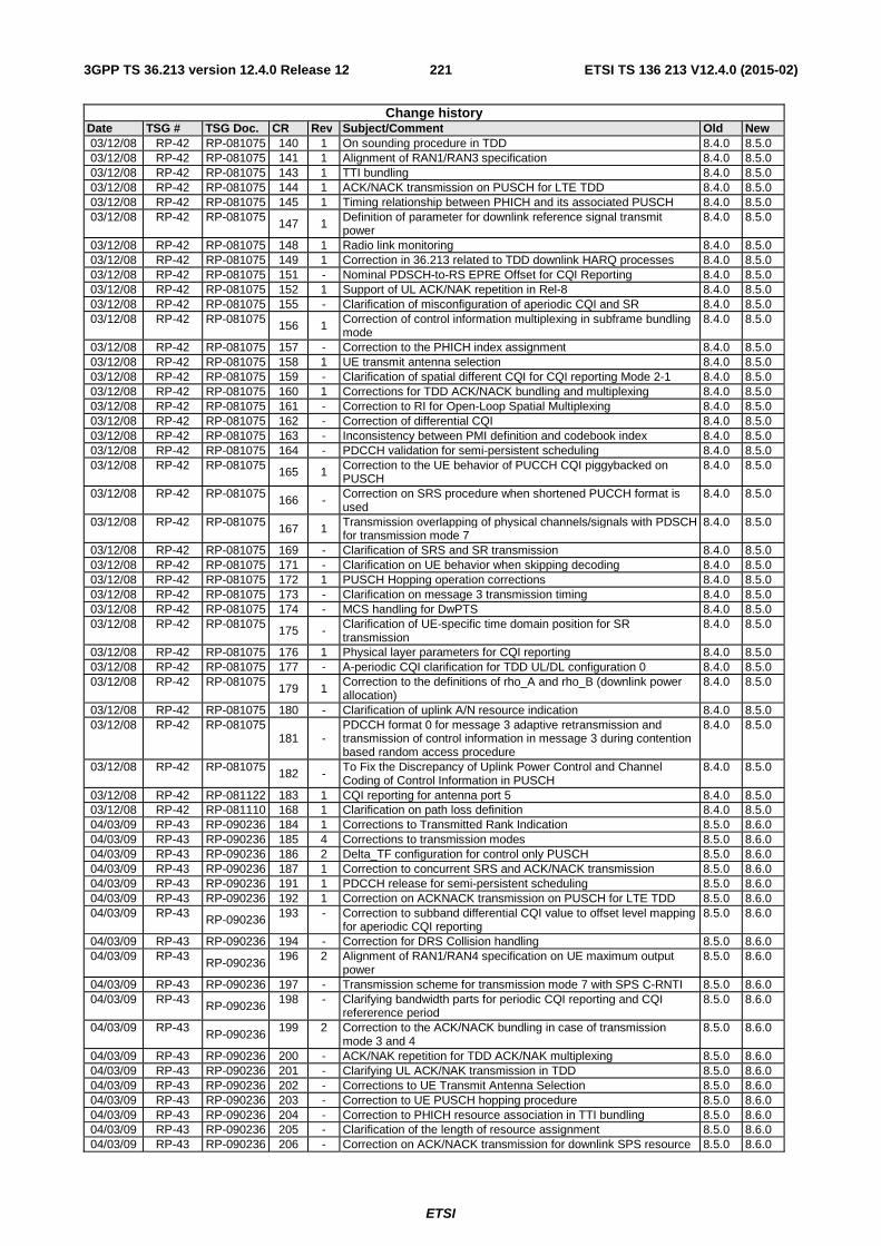
ETSI
ETSI TS 136 213 V12.4.0 (2015-02)2213GPP TS 36.213 version 12.4.0 Release 12
Change history Date TSG # TSG Doc. CR Rev Subject/Comment Old New 03/12/08 RP-42 RP-081075 140 1 On sounding procedure in TDD 8.4.0 8.5.0 03/12/08 RP-42 RP-081075 141 1 Alignment of RAN1/RAN3 specification 8.4.0 8.5.0 03/12/08 RP-42 RP-081075 143 1 TTI bundling 8.4.0 8.5.0 03/12/08 RP-42 RP-081075 144 1 ACK/NACK transmission on PUSCH for LTE TDD 8.4.0 8.5.0 03/12/08 RP-42 RP-081075 145 1 Timing relationship between PHICH and its associated PUSCH 8.4.0 8.5.0 03/12/08 RP-42 RP-081075 147 1 Definition of parameter for downlink reference signal transmit
power 8.4.0 8.5.0
03/12/08 RP-42 RP-081075 148 1 Radio link monitoring 8.4.0 8.5.0 03/12/08 RP-42 RP-081075 149 1 Correction in 36.213 related to TDD downlink HARQ processes 8.4.0 8.5.0 03/12/08 RP-42 RP-081075 151 - Nominal PDSCH-to-RS EPRE Offset for CQI Reporting 8.4.0 8.5.0 03/12/08 RP-42 RP-081075 152 1 Support of UL ACK/NAK repetition in Rel-8 8.4.0 8.5.0 03/12/08 RP-42 RP-081075 155 - Clarification of misconfiguration of aperiodic CQI and SR 8.4.0 8.5.0 03/12/08 RP-42 RP-081075 156 1 Correction of control information multiplexing in subframe bundling
mode 8.4.0 8.5.0
03/12/08 RP-42 RP-081075 157 - Correction to the PHICH index assignment 8.4.0 8.5.0 03/12/08 RP-42 RP-081075 158 1 UE transmit antenna selection 8.4.0 8.5.0 03/12/08 RP-42 RP-081075 159 - Clarification of spatial different CQI for CQI reporting Mode 2-1 8.4.0 8.5.0 03/12/08 RP-42 RP-081075 160 1 Corrections for TDD ACK/NACK bundling and multiplexing 8.4.0 8.5.0 03/12/08 RP-42 RP-081075 161 - Correction to RI for Open-Loop Spatial Multiplexing 8.4.0 8.5.0 03/12/08 RP-42 RP-081075 162 - Correction of differential CQI 8.4.0 8.5.0 03/12/08 RP-42 RP-081075 163 - Inconsistency between PMI definition and codebook index 8.4.0 8.5.0 03/12/08 RP-42 RP-081075 164 - PDCCH validation for semi-persistent scheduling 8.4.0 8.5.0 03/12/08 RP-42 RP-081075 165 1 Correction to the UE behavior of PUCCH CQI piggybacked on
PUSCH 8.4.0 8.5.0
03/12/08 RP-42 RP-081075 166 - Correction on SRS procedure when shortened PUCCH format is used
8.4.0 8.5.0
03/12/08 RP-42 RP-081075 167 1 Transmission overlapping of physical channels/signals with PDSCH for transmission mode 7
8.4.0 8.5.0
03/12/08 RP-42 RP-081075 169 - Clarification of SRS and SR transmission 8.4.0 8.5.0 03/12/08 RP-42 RP-081075 171 - Clarification on UE behavior when skipping decoding 8.4.0 8.5.0 03/12/08 RP-42 RP-081075 172 1 PUSCH Hopping operation corrections 8.4.0 8.5.0 03/12/08 RP-42 RP-081075 173 - Clarification on message 3 transmission timing 8.4.0 8.5.0 03/12/08 RP-42 RP-081075 174 - MCS handling for DwPTS 8.4.0 8.5.0 03/12/08 RP-42 RP-081075 175 - Clarification of UE-specific time domain position for SR
transmission 8.4.0 8.5.0
03/12/08 RP-42 RP-081075 176 1 Physical layer parameters for CQI reporting 8.4.0 8.5.0 03/12/08 RP-42 RP-081075 177 - A-periodic CQI clarification for TDD UL/DL configuration 0 8.4.0 8.5.0 03/12/08 RP-42 RP-081075
179 1 Correction to the definitions of rho_A and rho_B (downlink power allocation)
8.4.0 8.5.0
03/12/08 RP-42 RP-081075 180 - Clarification of uplink A/N resource indication 8.4.0 8.5.0 03/12/08 RP-42 RP-081075
181 - PDCCH format 0 for message 3 adaptive retransmission and transmission of control information in message 3 during contention based random access procedure
8.4.0 8.5.0
03/12/08 RP-42 RP-081075 182 - To Fix the Discrepancy of Uplink Power Control and Channel Coding of Control Information in PUSCH
8.4.0 8.5.0
03/12/08 RP-42 RP-081122 183 1 CQI reporting for antenna port 5 8.4.0 8.5.0 03/12/08 RP-42 RP-081110 168 1 Clarification on path loss definition 8.4.0 8.5.0 04/03/09 RP-43 RP-090236 184 1 Corrections to Transmitted Rank Indication 8.5.0 8.6.0 04/03/09 RP-43 RP-090236 185 4 Corrections to transmission modes 8.5.0 8.6.0 04/03/09 RP-43 RP-090236 186 2 Delta_TF configuration for control only PUSCH 8.5.0 8.6.0 04/03/09 RP-43 RP-090236 187 1 Correction to concurrent SRS and ACK/NACK transmission 8.5.0 8.6.0 04/03/09 RP-43 RP-090236 191 1 PDCCH release for semi-persistent scheduling 8.5.0 8.6.0 04/03/09 RP-43 RP-090236 192 1 Correction on ACKNACK transmission on PUSCH for LTE TDD 8.5.0 8.6.0 04/03/09 RP-43 RP-090236 193 - Correction to subband differential CQI value to offset level mapping
for aperiodic CQI reporting 8.5.0 8.6.0
04/03/09 RP-43 RP-090236 194 - Correction for DRS Collision handling 8.5.0 8.6.0 04/03/09 RP-43
RP-090236 196 2 Alignment of RAN1/RAN4 specification on UE maximum output
power 8.5.0 8.6.0
04/03/09 RP-43 RP-090236 197 - Transmission scheme for transmission mode 7 with SPS C-RNTI 8.5.0 8.6.0 04/03/09 RP-43 RP-090236 198 - Clarifying bandwidth parts for periodic CQI reporting and CQI
refererence period 8.5.0 8.6.0
04/03/09 RP-43 RP-090236
199 2 Correction to the ACK/NACK bundling in case of transmission mode 3 and 4
8.5.0 8.6.0
04/03/09 RP-43 RP-090236 200 - ACK/NAK repetition for TDD ACK/NAK multiplexing 8.5.0 8.6.0 04/03/09 RP-43 RP-090236 201 - Clarifying UL ACK/NAK transmission in TDD 8.5.0 8.6.0 04/03/09 RP-43 RP-090236 202 - Corrections to UE Transmit Antenna Selection 8.5.0 8.6.0 04/03/09 RP-43 RP-090236 203 - Correction to UE PUSCH hopping procedure 8.5.0 8.6.0 04/03/09 RP-43 RP-090236 204 - Correction to PHICH resource association in TTI bundling 8.5.0 8.6.0 04/03/09 RP-43 RP-090236 205 - Clarification of the length of resource assignment 8.5.0 8.6.0 04/03/09 RP-43 RP-090236 206 - Correction on ACK/NACK transmission for downlink SPS resource 8.5.0 8.6.0
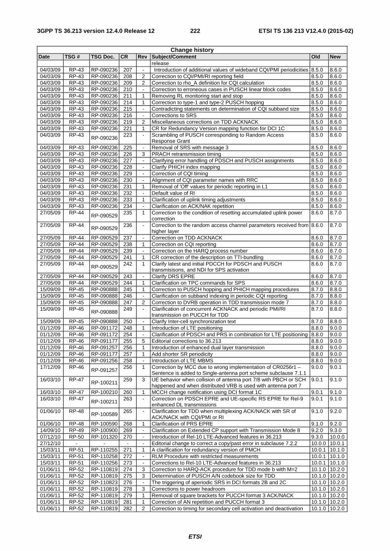
ETSI
ETSI TS 136 213 V12.4.0 (2015-02)2223GPP TS 36.213 version 12.4.0 Release 12
Change history Date TSG # TSG Doc. CR Rev Subject/Comment Old New
release 04/03/09 RP-43 RP-090236 207 - Introduction of additional values of wideband CQI/PMI periodicities 8.5.0 8.6.0 04/03/09 RP-43 RP-090236 208 2 Correction to CQI/PMI/RI reporting field 8.5.0 8.6.0 04/03/09 RP-43 RP-090236 209 2 Correction to rho_A definition for CQI calculation 8.5.0 8.6.0 04/03/09 RP-43 RP-090236 210 - Correction to erroneous cases in PUSCH linear block codes 8.5.0 8.6.0 04/03/09 RP-43 RP-090236 211 1 Removing RL monitoring start and stop 8.5.0 8.6.0 04/03/09 RP-43 RP-090236 214 1 Correction to type-1 and type-2 PUSCH hopping 8.5.0 8.6.0 04/03/09 RP-43 RP-090236 215 - Contradicting statements on determination of CQI subband size 8.5.0 8.6.0 04/03/09 RP-43 RP-090236 216 - Corrections to SRS 8.5.0 8.6.0 04/03/09 RP-43 RP-090236 219 2 Miscellaneous corrections on TDD ACKNACK 8.5.0 8.6.0 04/03/09 RP-43 RP-090236 221 1 CR for Redundancy Version mapping function for DCI 1C 8.5.0 8.6.0 04/03/09 RP-43 RP-090236 223 - Scrambling of PUSCH corresponding to Random Access
Response Grant 8.5.0 8.6.0
04/03/09 RP-43 RP-090236 225 - Removal of SRS with message 3 8.5.0 8.6.0 04/03/09 RP-43 RP-090236 226 3 PRACH retransmission timing 8.5.0 8.6.0 04/03/09 RP-43 RP-090236 227 - Clarifying error handling of PDSCH and PUSCH assignments 8.5.0 8.6.0 04/03/09 RP-43 RP-090236 228 - Clarify PHICH index mapping 8.5.0 8.6.0 04/03/09 RP-43 RP-090236 229 - Correction of CQI timing 8.5.0 8.6.0 04/03/09 RP-43 RP-090236 230 - Alignment of CQI parameter names with RRC 8.5.0 8.6.0 04/03/09 RP-43 RP-090236 231 1 Removal of 'Off' values for periodic reporting in L1 8.5.0 8.6.0 04/03/09 RP-43 RP-090236 232 - Default value of RI 8.5.0 8.6.0 04/03/09 RP-43 RP-090236 233 1 Clarification of uplink timing adjustments 8.5.0 8.6.0 04/03/09 RP-43 RP-090236 234 - Clarification on ACK/NAK repetition 8.5.0 8.6.0 27/05/09 RP-44 RP-090529 235 1 Correction to the condition of resetting accumulated uplink power
correction 8.6.0 8.7.0
27/05/09 RP-44 RP-090529
236 - Correction to the random access channel parameters received from higher layer
8.6.0 8.7.0
27/05/09 RP-44 RP-090529 237 - Correction on TDD ACKNACK 8.6.0 8.7.0 27/05/09 RP-44 RP-090529 238 1 Correction on CQI reporting 8.6.0 8.7.0 27/05/09 RP-44 RP-090529 239 - Correction on the HARQ process number 8.6.0 8.7.0 27/05/09 RP-44 RP-090529 241 1 CR correction of the description on TTI-bundling 8.6.0 8.7.0 27/05/09 RP-44 RP-090529 242 1 Clarify latest and initial PDCCH for PDSCH and PUSCH
transmisisons, and NDI for SPS activation 8.6.0 8.7.0
27/05/09 RP-44 RP-090529 243 - Clarify DRS EPRE 8.6.0 8.7.0 27/05/09 RP-44 RP-090529 244 1 Clarification on TPC commands for SPS 8.6.0 8.7.0 15/09/09 RP-45 RP-090888 245 1 Correction to PUSCH hopping and PHICH mapping procedures 8.7.0 8.8.0 15/09/09 RP-45 RP-090888 246 - Clarification on subband indexing in periodic CQI reporting 8.7.0 8.8.0 15/09/09 RP-45 RP-090888 247 2 Correction to DVRB operation in TDD transmission mode 7 8.7.0 8.8.0 15/09/09 RP-45 RP-090888 249 - Clarification of concurrent ACKNACK and periodic PMI/RI
transmission on PUCCH for TDD 8.7.0 8.8.0
15/09/09 RP-45 RP-090888 250 - Clarify Inter-cell synchronization text 8.7.0 8.8.0 01/12/09 RP-46 RP-091172 248 1 Introduction of LTE positioning 8.8.0 9.0.0 01/12/09 RP-46 RP-091172 254 - Clarification of PDSCH and PRS in combination for LTE positioning 8.8.0 9.0.0 01/12/09 RP-46 RP-091177 255 5 Editorial corrections to 36.213 8.8.0 9.0.0 01/12/09 RP-46 RP-091257 256 1 Introduction of enhanced dual layer transmission 8.8.0 9.0.0 01/12/09 RP-46 RP-091177 257 1 Add shorter SR periodicity 8.8.0 9.0.0 01/12/09 RP-46 RP-091256 258 - Introduction of LTE MBMS 8.8.0 9.0.0 17/12/09 RP-46 RP-091257 256 1 Correction by MCC due to wrong implementation of CR0256r1 –
Sentence is added to Single-antenna port scheme subclause 7.1.1 9.0.0 9.0.1
16/03/10 RP-47 RP-100211 259 3 UE behavior when collision of antenna port 7/8 with PBCH or SCH happened and when distributed VRB is used with antenna port 7
9.0.1 9.1.0
16/03/10 RP-47 RP-100210 260 1 MCCH change notification using DCI format 1C 9.0.1 9.1.0 16/03/10 RP-47 RP-100211 263 - Correction on PDSCH EPRE and UE-specific RS EPRE for Rel-9
enhanced DL transmissions 9.0.1 9.1.0
01/06/10 RP-48 RP-100589
265 - Clarification for TDD when multiplexing ACK/NACK with SR of ACK/NACK with CQI/PMI or RI
9.1.0 9.2.0
01/06/10 RP-48 RP-100590 268 1 Clarification of PRS EPRE 9.1.0 9.2.0 14/09/10 RP-49 RP-100900 269 - Clarification on Extended CP support with Transmission Mode 8 9.2.0 9.3.0 07/12/10 RP-50 RP-101320 270 - Introduction of Rel-10 LTE-Advanced features in 36.213 9.3.0 10.0.0 27/12/10 - - - - Editorial change to correct a copy/past error in subclause 7.2.2 10.0.0 10.0.1 15/03/11 RP-51 RP-110255 271 1 A clarification for redundancy version of PMCH 10.0.1 10.1.0 15/03/11 RP-51 RP-110258 272 - RLM Procedure with restricted measurements 10.0.1 10.1.0 15/03/11 RP-51 RP-110256 273 - Corrections to Rel-10 LTE-Advanced features in 36.213 10.0.1 10.1.0 01/06/11 RP-52 RP-110819 274 3 Correction to HARQ-ACK procedure for TDD mode b with M=2 10.1.0 10.2.0 01/06/11 RP-52 RP-110819 275 3 Determination of PUSCH A/N codebook size for TDD 10.1.0 10.2.0 01/06/11 RP-52 RP-110823 276 - The triggering of aperiodic SRS in DCI formats 2B and 2C 10.1.0 10.2.0 01/06/11 RP-52 RP-110819 278 3 Corrections to power headroom 10.1.0 10.2.0 01/06/11 RP-52 RP-110819 279 1 Removal of square brackets for PUCCH format 3 ACK/NACK 10.1.0 10.2.0 01/06/11 RP-52 RP-110819 281 1 Correction of AN repetition and PUCCH format 3 10.1.0 10.2.0 01/06/11 RP-52 RP-110819 282 2 Correction to timing for secondary cell activation and deactivation 10.1.0 10.2.0
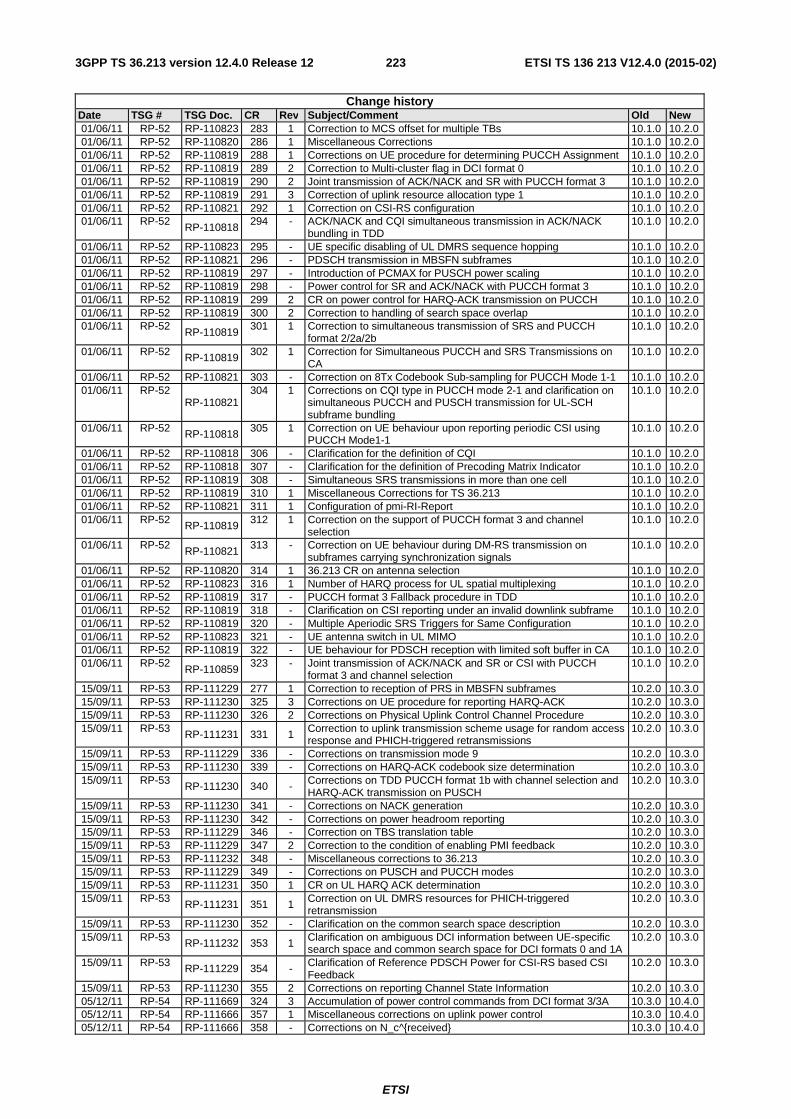
ETSI
ETSI TS 136 213 V12.4.0 (2015-02)2233GPP TS 36.213 version 12.4.0 Release 12
Change history Date TSG # TSG Doc. CR Rev Subject/Comment Old New 01/06/11 RP-52 RP-110823 283 1 Correction to MCS offset for multiple TBs 10.1.0 10.2.0 01/06/11 RP-52 RP-110820 286 1 Miscellaneous Corrections 10.1.0 10.2.0 01/06/11 RP-52 RP-110819 288 1 Corrections on UE procedure for determining PUCCH Assignment 10.1.0 10.2.0 01/06/11 RP-52 RP-110819 289 2 Correction to Multi-cluster flag in DCI format 0 10.1.0 10.2.0 01/06/11 RP-52 RP-110819 290 2 Joint transmission of ACK/NACK and SR with PUCCH format 3 10.1.0 10.2.0 01/06/11 RP-52 RP-110819 291 3 Correction of uplink resource allocation type 1 10.1.0 10.2.0 01/06/11 RP-52 RP-110821 292 1 Correction on CSI-RS configuration 10.1.0 10.2.0 01/06/11 RP-52
RP-110818 294 - ACK/NACK and CQI simultaneous transmission in ACK/NACK
bundling in TDD 10.1.0 10.2.0
01/06/11 RP-52 RP-110823 295 - UE specific disabling of UL DMRS sequence hopping 10.1.0 10.2.0 01/06/11 RP-52 RP-110821 296 - PDSCH transmission in MBSFN subframes 10.1.0 10.2.0 01/06/11 RP-52 RP-110819 297 - Introduction of PCMAX for PUSCH power scaling 10.1.0 10.2.0 01/06/11 RP-52 RP-110819 298 - Power control for SR and ACK/NACK with PUCCH format 3 10.1.0 10.2.0 01/06/11 RP-52 RP-110819 299 2 CR on power control for HARQ-ACK transmission on PUCCH 10.1.0 10.2.0 01/06/11 RP-52 RP-110819 300 2 Correction to handling of search space overlap 10.1.0 10.2.0 01/06/11 RP-52
RP-110819 301 1 Correction to simultaneous transmission of SRS and PUCCH
format 2/2a/2b 10.1.0 10.2.0
01/06/11 RP-52 RP-110819 302 1 Correction for Simultaneous PUCCH and SRS Transmissions on CA
10.1.0 10.2.0
01/06/11 RP-52 RP-110821 303 - Correction on 8Tx Codebook Sub-sampling for PUCCH Mode 1-1 10.1.0 10.2.0 01/06/11 RP-52
RP-110821 304 1 Corrections on CQI type in PUCCH mode 2-1 and clarification on
simultaneous PUCCH and PUSCH transmission for UL-SCH subframe bundling
10.1.0 10.2.0
01/06/11 RP-52 RP-110818 305 1 Correction on UE behaviour upon reporting periodic CSI using PUCCH Mode1-1
10.1.0 10.2.0
01/06/11 RP-52 RP-110818 306 - Clarification for the definition of CQI 10.1.0 10.2.0 01/06/11 RP-52 RP-110818 307 - Clarification for the definition of Precoding Matrix Indicator 10.1.0 10.2.0 01/06/11 RP-52 RP-110819 308 - Simultaneous SRS transmissions in more than one cell 10.1.0 10.2.0 01/06/11 RP-52 RP-110819 310 1 Miscellaneous Corrections for TS 36.213 10.1.0 10.2.0 01/06/11 RP-52 RP-110821 311 1 Configuration of pmi-RI-Report 10.1.0 10.2.0 01/06/11 RP-52 RP-110819 312 1 Correction on the support of PUCCH format 3 and channel
selection 10.1.0 10.2.0
01/06/11 RP-52 RP-110821
313 - Correction on UE behaviour during DM-RS transmission on subframes carrying synchronization signals
10.1.0 10.2.0
01/06/11 RP-52 RP-110820 314 1 36.213 CR on antenna selection 10.1.0 10.2.0 01/06/11 RP-52 RP-110823 316 1 Number of HARQ process for UL spatial multiplexing 10.1.0 10.2.0 01/06/11 RP-52 RP-110819 317 - PUCCH format 3 Fallback procedure in TDD 10.1.0 10.2.0 01/06/11 RP-52 RP-110819 318 - Clarification on CSI reporting under an invalid downlink subframe 10.1.0 10.2.0 01/06/11 RP-52 RP-110819 320 - Multiple Aperiodic SRS Triggers for Same Configuration 10.1.0 10.2.0 01/06/11 RP-52 RP-110823 321 - UE antenna switch in UL MIMO 10.1.0 10.2.0 01/06/11 RP-52 RP-110819 322 - UE behaviour for PDSCH reception with limited soft buffer in CA 10.1.0 10.2.0 01/06/11 RP-52
RP-110859 323 - Joint transmission of ACK/NACK and SR or CSI with PUCCH
format 3 and channel selection 10.1.0 10.2.0
15/09/11 RP-53 RP-111229 277 1 Correction to reception of PRS in MBSFN subframes 10.2.0 10.3.0 15/09/11 RP-53 RP-111230 325 3 Corrections on UE procedure for reporting HARQ-ACK 10.2.0 10.3.0 15/09/11 RP-53 RP-111230 326 2 Corrections on Physical Uplink Control Channel Procedure 10.2.0 10.3.0 15/09/11 RP-53 RP-111231 331 1 Correction to uplink transmission scheme usage for random access
response and PHICH-triggered retransmissions 10.2.0 10.3.0
15/09/11 RP-53 RP-111229 336 - Corrections on transmission mode 9 10.2.0 10.3.0 15/09/11 RP-53 RP-111230 339 - Corrections on HARQ-ACK codebook size determination 10.2.0 10.3.0 15/09/11 RP-53 RP-111230 340 - Corrections on TDD PUCCH format 1b with channel selection and
HARQ-ACK transmission on PUSCH 10.2.0 10.3.0
15/09/11 RP-53 RP-111230 341 - Corrections on NACK generation 10.2.0 10.3.0 15/09/11 RP-53 RP-111230 342 - Corrections on power headroom reporting 10.2.0 10.3.0 15/09/11 RP-53 RP-111229 346 - Correction on TBS translation table 10.2.0 10.3.0 15/09/11 RP-53 RP-111229 347 2 Correction to the condition of enabling PMI feedback 10.2.0 10.3.0 15/09/11 RP-53 RP-111232 348 - Miscellaneous corrections to 36.213 10.2.0 10.3.0 15/09/11 RP-53 RP-111229 349 - Corrections on PUSCH and PUCCH modes 10.2.0 10.3.0 15/09/11 RP-53 RP-111231 350 1 CR on UL HARQ ACK determination 10.2.0 10.3.0 15/09/11 RP-53 RP-111231 351 1 Correction on UL DMRS resources for PHICH-triggered
retransmission 10.2.0 10.3.0
15/09/11 RP-53 RP-111230 352 - Clarification on the common search space description 10.2.0 10.3.0 15/09/11 RP-53 RP-111232 353 1 Clarification on ambiguous DCI information between UE-specific
search space and common search space for DCI formats 0 and 1A 10.2.0 10.3.0
15/09/11 RP-53 RP-111229 354 - Clarification of Reference PDSCH Power for CSI-RS based CSI Feedback
10.2.0 10.3.0
15/09/11 RP-53 RP-111230 355 2 Corrections on reporting Channel State Information 10.2.0 10.3.0 05/12/11 RP-54 RP-111669 324 3 Accumulation of power control commands from DCI format 3/3A 10.3.0 10.4.0 05/12/11 RP-54 RP-111666 357 1 Miscellaneous corrections on uplink power control 10.3.0 10.4.0 05/12/11 RP-54 RP-111666 358 - Corrections on N_c^{received} 10.3.0 10.4.0
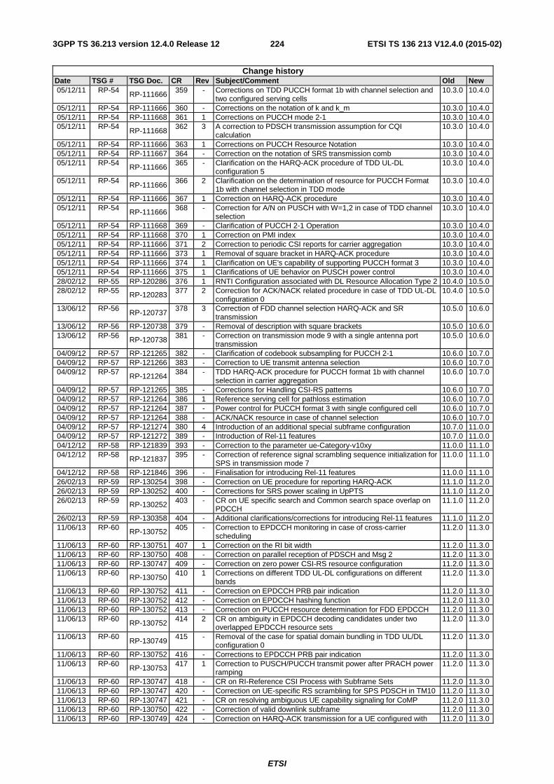
ETSI
ETSI TS 136 213 V12.4.0 (2015-02)2243GPP TS 36.213 version 12.4.0 Release 12
Change history Date TSG # TSG Doc. CR Rev Subject/Comment Old New 05/12/11 RP-54 RP-111666 359 - Corrections on TDD PUCCH format 1b with channel selection and
two configured serving cells 10.3.0 10.4.0
05/12/11 RP-54 RP-111666 360 - Corrections on the notation of k and k_m 10.3.0 10.4.0 05/12/11 RP-54 RP-111668 361 1 Corrections on PUCCH mode 2-1 10.3.0 10.4.0 05/12/11 RP-54
RP-111668 362 3 A correction to PDSCH transmission assumption for CQI
calculation 10.3.0 10.4.0
05/12/11 RP-54 RP-111666 363 1 Corrections on PUCCH Resource Notation 10.3.0 10.4.0 05/12/11 RP-54 RP-111667 364 - Correction on the notation of SRS transmission comb 10.3.0 10.4.0 05/12/11 RP-54 RP-111666 365 - Clarification on the HARQ-ACK procedure of TDD UL-DL
configuration 5 10.3.0 10.4.0
05/12/11 RP-54 RP-111666
366 2 Clarification on the determination of resource for PUCCH Format 1b with channel selection in TDD mode
10.3.0 10.4.0
05/12/11 RP-54 RP-111666 367 1 Correction on HARQ-ACK procedure 10.3.0 10.4.0 05/12/11 RP-54 RP-111666 368 - Correction for A/N on PUSCH with W=1,2 in case of TDD channel
selection 10.3.0 10.4.0
05/12/11 RP-54 RP-111668 369 - Clarification of PUCCH 2-1 Operation 10.3.0 10.4.0 05/12/11 RP-54 RP-111668 370 1 Correction on PMI index 10.3.0 10.4.0 05/12/11 RP-54 RP-111666 371 2 Correction to periodic CSI reports for carrier aggregation 10.3.0 10.4.0 05/12/11 RP-54 RP-111666 373 1 Removal of square bracket in HARQ-ACK procedure 10.3.0 10.4.0 05/12/11 RP-54 RP-111666 374 1 Clarification on UE's capability of supporting PUCCH format 3 10.3.0 10.4.0 05/12/11 RP-54 RP-111666 375 1 Clarifications of UE behavior on PUSCH power control 10.3.0 10.4.0 28/02/12 RP-55 RP-120286 376 1 RNTI Configuration associated with DL Resource Allocation Type 2 10.4.0 10.5.0 28/02/12 RP-55 RP-120283 377 2 Correction for ACK/NACK related procedure in case of TDD UL-DL
configuration 0 10.4.0 10.5.0
13/06/12 RP-56 RP-120737
378 3 Correction of FDD channel selection HARQ-ACK and SR transmission
10.5.0 10.6.0
13/06/12 RP-56 RP-120738 379 - Removal of description with square brackets 10.5.0 10.6.0 13/06/12 RP-56 RP-120738 381 - Correction on transmission mode 9 with a single antenna port
transmission 10.5.0 10.6.0
04/09/12 RP-57 RP-121265 382 - Clarification of codebook subsampling for PUCCH 2-1 10.6.0 10.7.0 04/09/12 RP-57 RP-121266 383 - Correction to UE transmit antenna selection 10.6.0 10.7.0 04/09/12 RP-57
RP-121264 384 - TDD HARQ-ACK procedure for PUCCH format 1b with channel
selection in carrier aggregation 10.6.0 10.7.0
04/09/12 RP-57 RP-121265 385 - Corrections for Handling CSI-RS patterns 10.6.0 10.7.0 04/09/12 RP-57 RP-121264 386 1 Reference serving cell for pathloss estimation 10.6.0 10.7.0 04/09/12 RP-57 RP-121264 387 - Power control for PUCCH format 3 with single configured cell 10.6.0 10.7.0 04/09/12 RP-57 RP-121264 388 - ACK/NACK resource in case of channel selection 10.6.0 10.7.0 04/09/12 RP-57 RP-121274 380 4 Introduction of an additional special subframe configuration 10.7.0 11.0.0 04/09/12 RP-57 RP-121272 389 - Introduction of Rel-11 features 10.7.0 11.0.0 04/12/12 RP-58 RP-121839 393 - Correction to the parameter ue-Category-v10xy 11.0.0 11.1.0 04/12/12 RP-58
RP-121837 395 - Correction of reference signal scrambling sequence initialization for
SPS in transmission mode 7 11.0.0 11.1.0
04/12/12 RP-58 RP-121846 396 - Finalisation for introducing Rel-11 features 11.0.0 11.1.0 26/02/13 RP-59 RP-130254 398 - Correction on UE procedure for reporting HARQ-ACK 11.1.0 11.2.0 26/02/13 RP-59 RP-130252 400 - Corrections for SRS power scaling in UpPTS 11.1.0 11.2.0 26/02/13 RP-59 RP-130252 403 - CR on UE specific search and Common search space overlap on
PDCCH 11.1.0 11.2.0
26/02/13 RP-59 RP-130358 404 - Additional clarifications/corrections for introducing Rel-11 features 11.1.0 11.2.0 11/06/13 RP-60 RP-130752 405 - Correction to EPDCCH monitoring in case of cross-carrier
scheduling 11.2.0 11.3.0
11/06/13 RP-60 RP-130751 407 1 Correction on the RI bit width 11.2.0 11.3.0 11/06/13 RP-60 RP-130750 408 - Correction on parallel reception of PDSCH and Msg 2 11.2.0 11.3.0 11/06/13 RP-60 RP-130747 409 - Correction on zero power CSI-RS resource configuration 11.2.0 11.3.0 11/06/13 RP-60
RP-130750 410 1 Corrections on different TDD UL-DL configurations on different
bands 11.2.0 11.3.0
11/06/13 RP-60 RP-130752 411 - Correction on EPDCCH PRB pair indication 11.2.0 11.3.0 11/06/13 RP-60 RP-130752 412 - Correction on EPDCCH hashing function 11.2.0 11.3.0 11/06/13 RP-60 RP-130752 413 - Correction on PUCCH resource determination for FDD EPDCCH 11.2.0 11.3.0 11/06/13 RP-60 RP-130752 414 2 CR on ambiguity in EPDCCH decoding candidates under two
overlapped EPDCCH resource sets 11.2.0 11.3.0
11/06/13 RP-60 RP-130749
415 - Removal of the case for spatial domain bundling in TDD UL/DL configuration 0
11.2.0 11.3.0
11/06/13 RP-60 RP-130752 416 - Corrections to EPDCCH PRB pair indication 11.2.0 11.3.0 11/06/13 RP-60 RP-130753 417 1 Correction to PUSCH/PUCCH transmit power after PRACH power
ramping 11.2.0 11.3.0
11/06/13 RP-60 RP-130747 418 - CR on RI-Reference CSI Process with Subframe Sets 11.2.0 11.3.0 11/06/13 RP-60 RP-130747 420 - Correction on UE-specific RS scrambling for SPS PDSCH in TM10 11.2.0 11.3.0 11/06/13 RP-60 RP-130747 421 - CR on resolving ambiguous UE capability signaling for CoMP 11.2.0 11.3.0 11/06/13 RP-60 RP-130750 422 - Correction of valid downlink subframe 11.2.0 11.3.0 11/06/13 RP-60 RP-130749 424 - Correction on HARQ-ACK transmission for a UE configured with 11.2.0 11.3.0
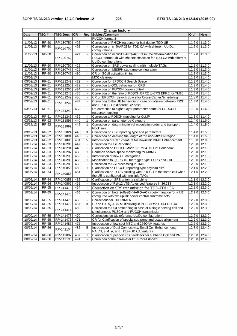
ETSI
ETSI TS 136 213 V12.4.0 (2015-02)2253GPP TS 36.213 version 12.4.0 Release 12
Change history Date TSG # TSG Doc. CR Rev Subject/Comment Old New
PUCCH format 3 11/06/13 RP-60 RP-130750 425 - Correction of PHICH resource for half duplex TDD UE 11.2.0 11.3.0 11/06/13 RP-60 RP-130750 426 - Correction on n_{HARQ} for TDD CA with different UL-DL
configurations 11.2.0 11.3.0
11/06/13 RP-60 RP-130750
427 - Correction on implicit HARQ-ACK resource determination for PUCCH format 1b with channel selection for TDD CA with different UL-DL configurations
11.2.0 11.3.0
11/06/13 RP-60 RP-130750 428 - Correction on SRS power scaling with multiple TAGs 11.2.0 11.3.0 11/06/13 RP-60 RP-130747 429 - Correction on MBSFN subframe configuration 11.2.0 11.3.0 11/06/13 RP-60 RP-130749 430 - CR on SCell activation timing 11.2.0 11.3.0 03/09/13 MCC clean-up 11.3.0 11.4.0 03/09/13 RP-61 RP-131249 432 - Correction for EPDCCH Search Space 11.3.0 11.4.0 03/09/13 RP-61 RP-131250 433 - Correction to QCL behaviour on CRS 11.3.0 11.4.0 03/09/13 RP-61 RP-131250 434 - Correction on PUCCH power control 11.3.0 11.4.0 03/09/13 RP-61 RP-131248 435 - Correction on the ratio of PDSCH EPRE to CRS EPRE for TM10 11.3.0 11.4.0 03/09/13 RP-61 RP-131249 436 - CR on EPDCCH Search Space for Cross-Carrier Scheduling 11.3.0 11.4.0 03/09/13 RP-61 RP-131249 437 - Correction to the UE behaviour in case of collision between PRS
and EPDCCH in different CP case 11.3.0 11.4.0
03/09/13 RP-61 RP-131249
438 - On correction to higher layer parameter name for EPDCCH resource mapping
11.3.0 11.4.0
03/09/13 RP-61 RP-131248 439 - Correction to PDSCH mapping for CoMP 11.3.0 11.4.0 03/12/13 RP-62 RP-131893 440 1 Correction on parameter ue-Category 11.4.0 11.5.0 03/12/13 RP-62 RP-131892 442 1 Correction on determination of modulation order and transport
block size 11.4.0 11.5.0
03/12/13 RP-62 RP-132024 445 3 Correction on CSI reporting type and parameters 11.4.0 11.5.0 03/12/13 RP-62 RP-131894 446 - Correction on deriving the length of the non-MBSFN region 11.4.0 11.5.0 03/12/13 RP-62 RP-131896 431 5 Introduction of Rel 12 feature for Downlink MIMO Enhancement 11.5.0 12.0.0 03/03/14 RP-63 RP-140286 447 - Correction to CSI Reporting 12.0.0 12.1.0 03/03/14 RP-63 RP-140291 448 - Clarification on PUCCH Mode 1-1 for 4Tx Dual Codebook 12.0.0 12.1.0 03/03/14 RP-63 RP-140287 450 1 Common search space monitoring for MBMS 12.0.0 12.1.0 03/03/14 RP-63 RP-140290 452 - Introduction of new UE categories 12.0.0 12.1.0 03/03/14 RP-63 RP-140288 455 1 Modification to I_SRS = 0 for trigger type 1 SRS and TDD 12.0.0 12.1.0 03/03/14 RP-63 RP-140289 458 - Correction to CSI processing in TM10 12.0.0 12.1.0 10/06/14 RP-64 RP-140858 459 1 Clarification on PUCCH reporting type payload size 12.1.0 12.2.0 10/06/14 RP-64 RP-140858 461 - Clarification on SRS colliding with PUCCH in the same cell when
the UE is configured with multiple TAGs 12.1.0 12.2.0
10/06/14 RP-64 RP-140858 462 1 Clarification on SRS antenna switching 12.1.0 12.2.0 10/06/14 RP-64 RP-140862 463 - Introduction of Rel-12 LTE-Advanced features in 36.213 12.1.0 12.2.0 10/09/14 RP-65 RP-141479 464 - Correction on SRS transmission for TDD-FDD CA 12.2.0 12.3.0
10/09/14 RP-65 RP-141478 465 - Correction on beta_{offset}^{HARQ-ACK} determination for a UE configured with two uplink power control subframe sets
12.2.0 12.3.0
10/09/14 RP-65 RP-141478 466 - Corrections for TDD eIMTA 12.2.0 12.3.0 10/09/14 RP-65 RP-141479 467 3 CR on HARQ-ACK Multiplexing in PUSCH for TDD-FDD CA 12.2.0 12.3.0 10/09/14 RP-65
RP-141474 469 - Correction to UCI embedding in case of a single serving cell and
simultaneous PUSCH and PUCCH transmission 12.2.0 12.3.0
10/09/14 RP-65 RP-141478 470 - Corrections on UL-reference UL/DL configuration 12.2.0 12.3.0 10/09/14 RP-65 RP-141473 471 - CR for Clarification of special subframe and usage alignment 12.2.0 12.3.0 10/09/14 RP-65 RP-141485 472 - Introduction of low-cost MTC and 256QAM features 12.2.0 12.3.0 08/12/14 RP-66 RP-142104 482 5 Introduction of Dual Connectivity, Small Cell Enhancements,
NAICS, eIMTA, and TDD-FDD CA features 12.3.0 12.4.0
08/12/14 RP-66 RP-142097 487 1 Clarification of periodic CSI feedback for subband CQI and PMI 12.3.0 12.4.0 08/12/14 RP-66 RP-142100 491 - Correction of the parameter CSIProcessIndex 12.3.0 12.4.0

ETSI
ETSI TS 136 213 V12.4.0 (2015-02)2263GPP TS 36.213 version 12.4.0 Release 12
History
Document history
V12.3.0 October 2014 Publication
V12.4.0 February 2015 Publication
Related Documents