ETSI TS 133 401 V10.3.0 (2012-07) Digital cellular telecommunications system (Phase 2+); Universal Mobile Telecommunications System (UMTS); LTE; 3GPP System Architecture Evolution (SAE); Security architecture (3GPP TS 33.401 version 10.3.0 Release 10) Technical Specification

Welcome message from author
This document is posted to help you gain knowledge. Please leave a comment to let me know what you think about it! Share it to your friends and learn new things together.
Transcript
ETSI TS 133 401 V10.3.0 (2012-07)
Digital cellular telecommunications system (Phase 2+); Universal Mobile Telecommunications System (UMTS);
LTE; 3GPP System Architecture Evolution (SAE);
Security architecture (3GPP TS 33.401 version 10.3.0 Release 10)
Technical Specification
ETSI
ETSI TS 133 401 V10.3.0 (2012-07)13GPP TS 33.401 version 10.3.0 Release 10
Reference RTS/TSGS-0333401va30
Keywords GSM,LTE,SECURITY,UMTS
ETSI
650 Route des Lucioles F-06921 Sophia Antipolis Cedex - FRANCE
Tel.: +33 4 92 94 42 00 Fax: +33 4 93 65 47 16
Siret N° 348 623 562 00017 - NAF 742 C
Association à but non lucratif enregistrée à la Sous-Préfecture de Grasse (06) N° 7803/88
Important notice
Individual copies of the present document can be downloaded from: http://www.etsi.org
The present document may be made available in more than one electronic version or in print. In any case of existing or perceived difference in contents between such versions, the reference version is the Portable Document Format (PDF).
In case of dispute, the reference shall be the printing on ETSI printers of the PDF version kept on a specific network drive within ETSI Secretariat.
Users of the present document should be aware that the document may be subject to revision or change of status. Information on the current status of this and other ETSI documents is available at
http://portal.etsi.org/tb/status/status.asp
If you find errors in the present document, please send your comment to one of the following services: http://portal.etsi.org/chaircor/ETSI_support.asp
Copyright Notification
No part may be reproduced except as authorized by written permission. The copyright and the foregoing restriction extend to reproduction in all media.
© European Telecommunications Standards Institute 2012.
All rights reserved.
DECTTM, PLUGTESTSTM, UMTSTM and the ETSI logo are Trade Marks of ETSI registered for the benefit of its Members. 3GPPTM and LTE™ are Trade Marks of ETSI registered for the benefit of its Members and
of the 3GPP Organizational Partners. GSM® and the GSM logo are Trade Marks registered and owned by the GSM Association.
ETSI
ETSI TS 133 401 V10.3.0 (2012-07)23GPP TS 33.401 version 10.3.0 Release 10
Intellectual Property Rights IPRs essential or potentially essential to the present document may have been declared to ETSI. The information pertaining to these essential IPRs, if any, is publicly available for ETSI members and non-members, and can be found in ETSI SR 000 314: "Intellectual Property Rights (IPRs); Essential, or potentially Essential, IPRs notified to ETSI in respect of ETSI standards", which is available from the ETSI Secretariat. Latest updates are available on the ETSI Web server (http://ipr.etsi.org).
Pursuant to the ETSI IPR Policy, no investigation, including IPR searches, has been carried out by ETSI. No guarantee can be given as to the existence of other IPRs not referenced in ETSI SR 000 314 (or the updates on the ETSI Web server) which are, or may be, or may become, essential to the present document.
Foreword This Technical Specification (TS) has been produced by ETSI 3rd Generation Partnership Project (3GPP).
The present document may refer to technical specifications or reports using their 3GPP identities, UMTS identities or GSM identities. These should be interpreted as being references to the corresponding ETSI deliverables.
The cross reference between GSM, UMTS, 3GPP and ETSI identities can be found under http://webapp.etsi.org/key/queryform.asp.
ETSI
ETSI TS 133 401 V10.3.0 (2012-07)33GPP TS 33.401 version 10.3.0 Release 10
Contents
Intellectual Property Rights ................................................................................................................................ 2
Foreword ............................................................................................................................................................. 2
Foreword ............................................................................................................................................................. 8
1 Scope ........................................................................................................................................................ 9
2 References ................................................................................................................................................ 9
3 Definitions, symbols and abbreviations ................................................................................................. 10
3.1 Definitions ........................................................................................................................................................ 10
3.2 Symbols ............................................................................................................................................................ 12
3.3 Abbreviations ................................................................................................................................................... 12
3.4 Conventions ...................................................................................................................................................... 13
4 Overview of Security Architecture ......................................................................................................... 14
5 Security Features .................................................................................................................................... 15
5.1 User-to-Network security ................................................................................................................................. 15
5.1.0 General ........................................................................................................................................................ 15
5.1.1 User identity and device confidentiality ..................................................................................................... 15
5.1.2 Entity authentication ................................................................................................................................... 15
5.1.3 User data and signalling data confidentiality .............................................................................................. 16
5.1.3.1 Ciphering requirements ......................................................................................................................... 16
5.1.3.2 Algorithm Identifier Values .................................................................................................................. 16
5.1.4 User data and signalling data integrity ........................................................................................................ 17
5.1.4.1 Integrity requirements ........................................................................................................................... 17
5.1.4.2 Algorithm Identifier Values .................................................................................................................. 17
5.2 Security visibility and configurability .............................................................................................................. 18
5.3 Security requirements on eNodeB .................................................................................................................... 18
5.3.1 General ........................................................................................................................................................ 18
5.3.2 Requirements for eNB setup and configuration .......................................................................................... 18
5.3.3 Requirements for key management inside eNB .......................................................................................... 18
5.3.4 Requirements for handling User plane data for the eNB ............................................................................ 19
5.3.4a Requirements for handling Control plane data for the eNB ........................................................................ 19
5.3.5 Requirements for secure environment of the eNB ...................................................................................... 19
5.4 Void .................................................................................................................................................................. 19
6 Security Procedures between UE and EPC Network Elements ............................................................. 20
6.0 General ............................................................................................................................................................. 20
6.1 Authentication and key agreement ................................................................................................................... 20
6.1.1 AKA procedure ........................................................................................................................................... 20
6.1.2 Distribution of authentication data from HSS to serving network .............................................................. 21
6.1.3 User identification by a permanent identity ................................................................................................ 22
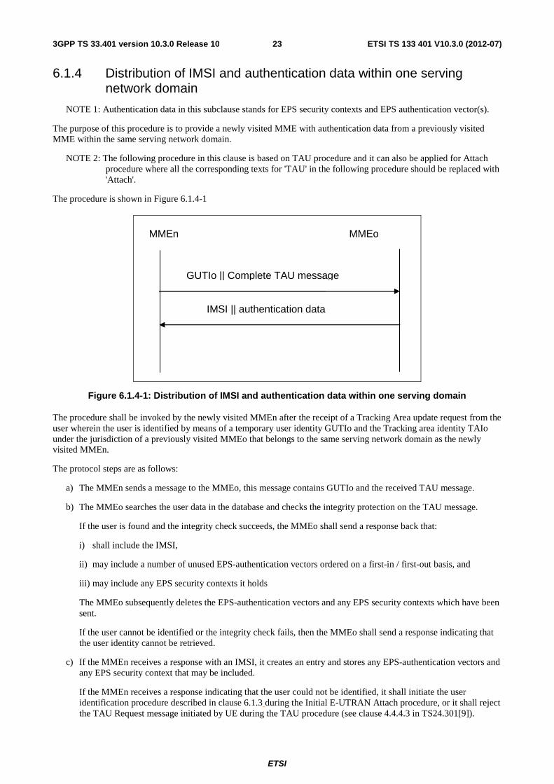
6.1.4 Distribution of IMSI and authentication data within one serving network domain .................................... 23
6.1.5 Distribution of IMSI and authentication data between different serving network domains........................ 24
6.1.6 Distribution of IMSI and UMTS authentication vectors between MMEs or between MME and SGSN .......................................................................................................................................................... 24
6.2 EPS key hierarchy ............................................................................................................................................ 24
6.3 EPS key identification ...................................................................................................................................... 27
6.4 Handling of EPS security contexts ................................................................................................................... 28
6.5 Handling of NAS COUNTs.............................................................................................................................. 28
7 Security Procedures between UE and EPS Access Network Elements .................................................. 30
7.0 General ............................................................................................................................................................. 30
7.1 Mechanism for user identity confidentiality ..................................................................................................... 30
7.2 Handling of user-related keys in E-UTRAN .................................................................................................... 30
7.2.1 E-UTRAN key setting during AKA ........................................................................................................... 30
7.2.2 E-UTRAN key identification ...................................................................................................................... 30
ETSI
ETSI TS 133 401 V10.3.0 (2012-07)43GPP TS 33.401 version 10.3.0 Release 10
7.2.3 E-UTRAN key lifetimes ............................................................................................................................. 31
7.2.4 Security mode command procedure and algorithm negotiation .................................................................. 31
7.2.4.1 Requirements for algorithm selection ................................................................................................... 31
7.2.4.2 Procedures for AS algorithm selection .................................................................................................. 32
7.2.4.2.1 Initial AS security context establishment ........................................................................................ 32
7.2.4.2.2 X2-handover .................................................................................................................................... 32
7.2.4.2.3 S1-handover ..................................................................................................................................... 32
7.2.4.2.4 Intra-eNB handover ......................................................................................................................... 32
7.2.4.3 Procedures for NAS algorithm selection ............................................................................................... 32
7.2.4.3.1 Initial NAS security context establishment ..................................................................................... 32
7.2.4.3.2 MME change ................................................................................................................................... 33
7.2.4.4 NAS security mode command procedure .............................................................................................. 33
7.2.4.5 AS security mode command procedure ................................................................................................. 34
7.2.4a Algorithm negotiation for unauthenticated UEs in LSM ............................................................................ 35
7.2.5 Key handling at state transitions to and away from EMM-DEREGISTERED ........................................... 36
7.2.5.1 Transition to EMM-DEREGISTERED ................................................................................................. 36
7.2.5.2 Transition away from EMM-DEREGISTERED ................................................................................... 37
7.2.5.2.1 General ............................................................................................................................................ 37
7.2.5.2.2 With existing native EPS NAS security context .............................................................................. 37
7.2.5.2.3 With run of EPS AKA ..................................................................................................................... 38
7.2.6 Key handling in ECM-IDLE to ECM-CONNECTED and ECM-CONNECTED to ECM-IDLE transitions .................................................................................................................................................... 38
7.2.6.1 ECM-IDLE to ECM-CONNECTED transition..................................................................................... 38
7.2.6.2 Establishment of keys for cryptographically protected radio bearers ................................................... 38
7.2.6.3 ECM-CONNECTED to ECM-IDLE transition..................................................................................... 39
7.2.7 Key handling for the TAU procedure when registered in E-UTRAN ........................................................ 39
7.2.8 Key handling in handover ........................................................................................................................... 39
7.2.8.1 General .................................................................................................................................................. 39
7.2.8.1.1 Access stratum ................................................................................................................................. 39
7.2.8.1.2 Non access stratum .......................................................................................................................... 41
7.2.8.2 Void....................................................................................................................................................... 41
7.2.8.3 Key derivations for context modification procedure ............................................................................. 41
7.2.8.4 Key derivations during handovers ......................................................................................................... 41
7.2.8.4.1 Intra-eNB Handover ........................................................................................................................ 41
7.2.8.4.2 X2-handover .................................................................................................................................... 41
7.2.8.4.3 S1-Handover .................................................................................................................................... 42
7.2.8.4.4 UE handling ..................................................................................................................................... 42
7.2.9 Key-change-on-the fly ................................................................................................................................ 43
7.2.9.1 General .................................................................................................................................................. 43
7.2.9.2 KeNB re-keying ....................................................................................................................................... 43
7.2.9.3 KeNB refresh ........................................................................................................................................ 44
7.2.9.4 NAS key re-keying ................................................................................................................................ 44
7.2.10 Rules on Concurrent Running of Security Procedures ............................................................................... 44
7.3 UP security mechanisms .................................................................................................................................. 45
7.3.1 UP confidentiality mechanisms .................................................................................................................. 45
7.3.2 UP integrity mechanisms ............................................................................................................................ 45
7.4 RRC security mechanisms ................................................................................................................................ 45
7.4.1 RRC integrity mechanisms ......................................................................................................................... 45
7.4.2 RRC confidentiality mechanisms ............................................................................................................... 46
7.4.3 KeNB* and Token Preparation for the RRCConnectionRe-establishment Procedure .................................. 46
7.5 Signalling procedure for periodic local authentication ..................................................................................... 47
8 Security mechanisms for non-access stratum signalling ........................................................................ 49
8.0 General ............................................................................................................................................................. 49
8.1 NAS integrity mechanisms ............................................................................................................................... 49
8.1.1 NAS input parameters and mechanism ....................................................................................................... 49
8.1.2 NAS integrity activation ............................................................................................................................. 49
8.2 NAS confidentiality mechanisms ..................................................................................................................... 50
9 Security interworking between E-UTRAN and UTRAN ....................................................................... 50
9.1 RAU and TAU procedures ............................................................................................................................... 50
9.1.1 RAU procedures in UTRAN ....................................................................................................................... 50
ETSI
ETSI TS 133 401 V10.3.0 (2012-07)53GPP TS 33.401 version 10.3.0 Release 10
9.1.2 TAU procedures in E-UTRAN ................................................................................................................... 51
9.2 Handover .......................................................................................................................................................... 52
9.2.1 From E-UTRAN to UTRAN ...................................................................................................................... 52
9.2.2 From UTRAN to E-UTRAN ...................................................................................................................... 53
9.2.2.1 Procedure .............................................................................................................................................. 53
9.2.2.2 Derivation of NAS keys and KeNB during Handover from UTRAN to E-UTRAN ............................... 58
9.3 Recommendations on AKA at IRAT-mobility to E-UTRAN .......................................................................... 58
9.4 Attach procedures ............................................................................................................................................. 58
9.4.1 Attach in UTRAN ....................................................................................................................................... 58
10 Security interworking between E-UTRAN and GERAN ....................................................................... 60
10.1 General ............................................................................................................................................................. 60
10.2 RAU and TAU procedures ............................................................................................................................... 60
10.2.1 RAU procedures in GERAN ....................................................................................................................... 60
10.2.2 TAU procedures in E-UTRAN ................................................................................................................... 60
10.3 Handover .......................................................................................................................................................... 60
10.3.1 From E-UTRAN to GERAN ...................................................................................................................... 60
10.3.2 From GERAN to E-UTRAN ...................................................................................................................... 61
10.3.2.1 Procedures ............................................................................................................................................. 61
10.4 Recommendations on AKA at IRAT-mobility to E-UTRAN .......................................................................... 61
10.5 Attach procedures ............................................................................................................................................. 61
10.5.1 Attach in GERAN ....................................................................................................................................... 61
11 Network Domain Control Plane protection ............................................................................................ 62
12 Backhaul link user plane protection ....................................................................................................... 62
13 Management plane protection over the S1 interface .............................................................................. 63
14 SRVCC between E-UTRAN and Circuit Switched UTRAN/GERAN .................................................. 64
14.1 From E-UTRAN to Circuit Switched UTRAN/GERAN ................................................................................. 64
14.2 Emergency call in SRVCC ............................................................................................................................... 65
15 Security Aspects of IMS Emergency Session Handling ........................................................................ 66
15.1 General ............................................................................................................................................................. 66
15.2 Security procedures and their applicability ...................................................................................................... 66
15.2.1 Authenticated IMS Emergency Sessions .................................................................................................... 66
15.2.1.1 General .................................................................................................................................................. 66
15.2.1.2 UE and MME share a current security context ..................................................................................... 66
15.2.2 Unauthenticated IMS Emergency Sessions ................................................................................................ 68
15.2.2.1 General .................................................................................................................................................. 68
15.2.2.2 UE and MME share no security context ............................................................................................... 68
15.2.3 Void ............................................................................................................................................................ 69
15.2.4 Key generation procedures for unauthenticated IMS Emergency Sessions ................................................ 69
15.2.4.1 General .................................................................................................................................................. 69
15.2.4.2 Handover ............................................................................................................................................... 69
Annex A (normative): Key derivation functions ............................................................................... 71
A.1 KDF interface and input parameter construction ................................................................................... 71
A.1.1 General ............................................................................................................................................................. 71
A.1.2 FC value allocations ......................................................................................................................................... 71
A.2 KASME derivation function ...................................................................................................................... 72
A.3 KeNB derivation function ......................................................................................................................... 73
A.4 NH derivation function ........................................................................................................................... 73
A.5 KeNB* derivation function ....................................................................................................................... 73
A.6 Void ........................................................................................................................................................ 73
A.7 Algorithm key derivation functions ....................................................................................................... 74
A.8 KASME to CK', IK' derivation at handover ............................................................................................... 74
ETSI
ETSI TS 133 401 V10.3.0 (2012-07)63GPP TS 33.401 version 10.3.0 Release 10
A.9 NAS token derivation for inter-RAT mobility ....................................................................................... 75
A.10 K"ASME from CK, IK derivation during handover .................................................................................... 75
A.11 K"ASME from CK, IK derivation during idle mode mobility .................................................................... 75
A.12 KASME to CKSRVCC, IKSRVCC derivation ................................................................................................... 76
A.13 KASME to CK', IK' derivation at idle mobility ......................................................................................... 76
Annex B (normative): Algorithms for ciphering and integrity protection ..................................... 77
B.0 Null ciphering and integrity protection algorithms ................................................................................ 77
B.1 128-bit ciphering algorithm .................................................................................................................... 77
B.1.1 Inputs and outputs ............................................................................................................................................ 77
B.1.2 128-EEA1 ......................................................................................................................................................... 78
B.1.3 128-EEA2 ......................................................................................................................................................... 78
B.2 128-Bit integrity algorithm ..................................................................................................................... 78
B.2.1 Inputs and outputs ............................................................................................................................................ 78
B.2.2 128-EIA1 .......................................................................................................................................................... 79
B.2.3 128-EIA2 .......................................................................................................................................................... 79
Annex C (informative): Algorithm test data ........................................................................................ 80
C.1 128-EEA2 ............................................................................................................................................... 80
C.1.1 Test Set 1 .......................................................................................................................................................... 80
C.1.2 Test Set 2 .......................................................................................................................................................... 81
C.1.3 Test Set 3 .......................................................................................................................................................... 82
C.1.4 Test Set 4 .......................................................................................................................................................... 82
C.1.5 Test Set 5 .......................................................................................................................................................... 83
C.1.6 Test Set 6 .......................................................................................................................................................... 84
C.2 128-EIA2 ................................................................................................................................................ 87
C.2.1 Test Set 1 .......................................................................................................................................................... 87
C.2.2 Test Set 2 .......................................................................................................................................................... 88
C.2.3 Test Set 3 .......................................................................................................................................................... 89
C.2.4 Test Set 4 .......................................................................................................................................................... 90
C.2.5 Test Set 5 .......................................................................................................................................................... 91
C.2.6 Test Set 6 .......................................................................................................................................................... 92
C.2.7 Test Set 7 .......................................................................................................................................................... 93
C.2.8 Test Set 8 .......................................................................................................................................................... 95
Annex D (normative): Security for Relay Node Architectures ...................................................... 106
D.1 Introduction .......................................................................................................................................... 106
D.2 Solution ................................................................................................................................................ 106
D.2.1 General ........................................................................................................................................................... 106
D.2.2 Security Procedures ........................................................................................................................................ 106
D.2.3 USIM Binding Aspects .................................................................................................................................. 109
D.2.4 Enrolment procedures for RNs ....................................................................................................................... 109
D.2.5 Secure management procedures for RNs ........................................................................................................ 110
D.2.6 Certificate and subscription handling ............................................................................................................. 110
D.3 Secure channel profiles ........................................................................................................................ 112
D.3.1 General ........................................................................................................................................................... 112
D.3.2 APDU secure channel profile ......................................................................................................................... 112
D.3.3 Key agreement based on certificate exchange ................................................................................................ 112
D.3.3.1 TLS profile................................................................................................................................................ 112
D.3.3.2 Common profile for RN and UICC certificate .......................................................................................... 112
D.3.3.3 RN certificate profile ................................................................................................................................ 113
D.3.3.4 UICC certificate profile ............................................................................................................................ 113
D.3.4 Key agreement for pre-shared key (psk) case................................................................................................. 113
D.3.5 Identities used in key agreement .................................................................................................................... 114

ETSI
ETSI TS 133 401 V10.3.0 (2012-07)73GPP TS 33.401 version 10.3.0 Release 10
Annex E (informative): Change history ............................................................................................. 115
History ............................................................................................................................................................ 117

ETSI
ETSI TS 133 401 V10.3.0 (2012-07)83GPP TS 33.401 version 10.3.0 Release 10
Foreword This Technical Specification has been produced by the 3rd Generation Partnership Project (3GPP).
The contents of the present document are subject to continuing work within the TSG and may change following formal TSG approval. Should the TSG modify the contents of the present document, it will be re-released by the TSG with an identifying change of release date and an increase in version number as follows:
Version x.y.z
where:
x the first digit:
1 presented to TSG for information;
2 presented to TSG for approval;
3 or greater indicates TSG approved document under change control.
y the second digit is incremented for all changes of substance, i.e. technical enhancements, corrections, updates, etc.
z the third digit is incremented when editorial only changes have been incorporated in the document.
ETSI
ETSI TS 133 401 V10.3.0 (2012-07)93GPP TS 33.401 version 10.3.0 Release 10
1 Scope The present document specifies the security architecture, i.e., the security features and the security mechanisms for the Evolved Packet System and the Evolved Packet Core, and the security procedures performed within the evolved Packet System (EPS) including the Evolved Packet Core (EPC) and the Evolved UTRAN (E-UTRAN).
2 References The following documents contain provisions which, through reference in this text, constitute provisions of the present document.
• References are either specific (identified by date of publication, edition number, version number, etc.) or non-specific.
• For a specific reference, subsequent revisions do not apply.
• For a non-specific reference, the latest version applies. In the case of a reference to a 3GPP document (including a GSM document), a non-specific reference implicitly refers to the latest version of that document in the same Release as the present document.
[1] 3GPP TR 21.905: "Vocabulary for 3GPP Specifications".
[2] 3GPP TS 23.401: "General Packet Radio Service (GPRS) enhancements for Evolved Universal Terrestrial Radio Access Network (E-UTRAN) access".
[3] 3GPP TS 23.003: "Numbering, addressing and identification".
[4] 3GPP TS 33.102: "3G security; Security architecture".
[5] 3GPP TS 33.210: "3G security; Network Domain Security (NDS); IP network layer security".
[6] 3GPP TS 33.310: "Network Domain Security (NDS); Authentication Framework (AF)".
[7] IETF RFC 4303: "IP Encapsulating Security Payload (ESP)".
[8] 3GPP TS 33.220: "Generic Authentication Architecture (GAA); Generic bootstrapping architecture".
[9] 3GPP TS 24.301: "Non-Access-Stratum (NAS) protocol for Evolved Packet System (EPS); Stage 3".
[10] – [11] Void.
[12] 3GPP TS 36.323: "Evolved Universal Terrestrial Radio Access (E-UTRA); Packet Data Convergence Protocol (PDCP) specification"
[13] 3GPP TS 31.102: "Characteristics of the Universal Subscriber Identity Module (USIM) application".
[14] 3GPP TS 35.215: "Confidentiality and Integrity Algorithms UEA2 & UIA2; Document 1: UEA2 and UIA2 specifications"
[15] NIST: "Advanced Encryption Standard (AES) (FIPS PUB 197) "
[16] NIST Special Publication 800-38A (2001): "Recommendation for Block Cipher Modes of Operation".
[17] NIST Special Publication 800-38B (2001): "Recommendation for Block Cipher Modes of Operation: The CMAC Mode for Authentication".
[18] – [20] Void.
ETSI
ETSI TS 133 401 V10.3.0 (2012-07)103GPP TS 33.401 version 10.3.0 Release 10
[21] 3GPP TS 36.331:"Evolved Universal Terrestrial Radio Access (E-UTRA) Radio Resource Control (RRC); Protocol specification".
[22] 3GPP TS 23.216: "Single Radio Voice Call Continuity (SRVCC); Stage 2".
[23] 3GPP TS 22.101: "3rd Generation Partnership Project; Technical Specification Group Services and System Aspects; Service aspects; Service principles".
[24] 3GPP TS 25.331: "3rd Generation Partnership Project; Technical Specification Group Radio Access Network; Radio Resource Control (RRC); Protocol Specification ".
[25] 3GPP TS 44.060: "3rd Generation Partnership Project; Technical Specification Group GSM/EDGE Radio Access Network; General Packet Radio Service (GPRS); Mobile Station (MS) - Base Station System (BSS) interface; Radio Link Control/Medium Access Control (RLC/MAC) protocol.
[26] 3GPP TS 23.122: "3rd Generation Partnership Project; Technical Specification Group Core Network and Terminals; Non-Access-Stratum (NAS) functions related to Mobile Station (MS) in idle mode".
[27] 3GPP TS 33.320: "3rd Generation Partnership Project; Technical Specification Group Services and System Aspects; Security of Home Node B (HNB) / Home evolved Node B (HeNB)".
[28] IETF RFC 5280: "Internet X.509 Public Key Infrastructure Certificate and Certificate Revocation List (CRL) Profile".
[29] ETSI TS 102 484 V10.0.0: "Smart Cards; Secure channel between a UICC and an end-point terminal".
[30] 3GPP TS 36.300: "Evolved Universal Terrestrial Radio Access (E-UTRA) and Evolved Universal Terrestrial Radio Access Network (E-UTRAN); Overall description; Stage 2".
[31] 3GPP TS 31.116 "Remote APDU Structure for (Universal) Subscriber Identity Module (U)SIM Toolkit applications".
[32] ETSI TS 102 221 V9.2.0: "Smart Cards; UICC-Terminal interface; Physical and logical characteristics".
3 Definitions, symbols and abbreviations
3.1 Definitions For the purposes of the present document, the terms and definitions given in TR 21.905 [1], in TS 33.102 [4] and the following apply. A term defined in the present document takes precedence over the definition of the same term, if any, in TR 21.905 [1].
Access Security Management Entity: entity which receives the top-level keys in an access network from the HSS. For E-UTRAN access networks, the role of the ASME is assumed by the MME
Activation of security context: the process of taking into use a security context.
Authentication data: Data that is part of a security context or of authentication vectors.
Chaining of KeNB: derivation of a new KeNB from another KeNB (i.e., at cell handover)
Current EPS security context: The security context which has been activated most recently. Note that a current EPS security context originating from either a mapped or native EPS security context may exist simultaneously with a native non-current EPS security context.
ECM-CONNECTED state: This is as defined in TS 23.401 [2]. The term ECM-CONNECTED state corresponds to the term EMM-CONNECTED mode used in TS 24.301 [9].

ETSI
ETSI TS 133 401 V10.3.0 (2012-07)113GPP TS 33.401 version 10.3.0 Release 10
ECM-IDLE state: As defined in TS 23.401 [2]. The term ECM-IDLE state corresponds to the term EMM-IDLE mode used in TS 24.301 [9].
EPS-Authentication Vector: KASME, RAND, AUTN, XRES
EPS security context: A state that is established locally at the UE and a serving network domain. At both ends "EPS security context data" is stored, that consists of the EPS NAS security context, and the EPS AS security context.
NOTE 1: An EPS security context has type 'mapped', 'full native' or 'partial native'. Its state can either be 'current' or 'non-current'. A context can be of one type only and be in one state at a time. The state of a particular context type can change over time. A partial native context can be transformed into a full native. No other type transformations are possible.
EPS AS security context: the cryptographic keys at AS level with their identifiers, the Next Hop parameter NH, the Next Hop Chaining Counter parameter NCC used for next hop access key derivation, the identifiers of the selected AS level cryptographic algorithms and counters used for replay protection. Note that the EPS AS security context only exists when cryptographically protected radio bearers are established and is otherwise void.
NOTE 2: NH and NCC need to be stored also at the MME during connected mode.
EPS NAS security context: This context consists of KASME with the associated key set identifier, the UE security capabilities, and the uplink and downlink NAS COUNT values. In particular, separate pairs of NAS COUNT values are used for each EPS NAS security contexts, respectively. The distinction between native and mapped EPS security contexts also applies to EPS NAS security contexts. The EPS NAS security context is called 'full' if it additionally contains the keys KNASint and KNASenc and the identifiers of the selected NAS integrity and encryption algorithms.
Full native EPS security context: A native EPS security context for which the EPS NAS security context is full according to the above definition. A full native EPS security context is either in state 'current' or state 'non-current'.
Forward security: In the context of KeNB key derivation, forward security refers to the property that, for an eNB with knowledge of a KeNB, shared with a UE, it shall be computationally infeasible to predict any future KeNB, that will be used between the same UE and another eNB. More specifically, n hop forward security refers to the property that an eNB is unable to compute keys that will be used between a UE and another eNB to which the UE is connected after n or more handovers (n=1 or 2).
Legacy security context: A security context which has been established according to TS 33.102 [4].
Mapped security context: Security context created by converting the current security context in the source system to a security context for the target system in inter-system mobility, e.g., UMTS keys created from EPS keys. The EPS NAS security context of a mapped security context is full and current.
Native EPS security context: An EPS security context whose KASME was created by a run of EPS AKA.
Non-current EPS security context: A native EPS security context that is not the current one. A non-current EPS security context may be stored along with a current EPS security context in the UE and the MME. A non-current EPS security context does not contain an EPS AS security context. A non-current EPS security context is either of type 'full native' or of type 'partial native'.
Partial native EPS security context: A partial native EPS security context consists of KASME with the associated key set identifier, the UE security capabilities, and the uplink and downlink NAS COUNT values, which are initially set to zero before the first NAS SMC procedure for this security context. A partial native EPS security context is created by an EPS AKA, for which no corresponding successful NAS SMC has been run. A partial native context is always in state 'non-current'.
Re-derivation of NAS keys: derivation of new NAS keys from the same KASME but including different algorithms (and no freshness parameter)
Refresh of KeNB: derivation of a new KeNB from the same KASME and including a freshness parameter
Re-keying of KeNB: derivation of a new KeNB from a new KASME in ECM-CONNECTED (i.e., . to activate a partial native EPS security context, or to re-activate a non-current full EPS security context)
Re-keying of NAS keys: derivation of new NAS keys from a new KASME
ETSI
ETSI TS 133 401 V10.3.0 (2012-07)123GPP TS 33.401 version 10.3.0 Release 10
UE security capabilities: The set of identifiers corresponding to the ciphering and integrity algorithms implemented in the UE. This includes capabilities for EPS AS and NAS, and includes capabilities for UTRAN and GERAN if these access types are supported by the UE.
UE EPS security capabilities: The UE security capabilities for EPS AS and NAS.
3.2 Symbols For the purposes of the present document, the following symbols apply:
|| Concatenation
⊕ Bitwise Exclusive Or (XOR) operation
3.3 Abbreviations For the purposes of the present document, the abbreviations given in TR 21.905 [1] and the following apply. An abbreviation defined in the present document takes precedence over the definition of the same abbreviation, if any, in TR 21.905 [1].
AES Advanced Encryption Standard AK Anonymity Key AKA Authentication and Key Agreement AMF Authentication Management Field AN Access Network AS Access Stratum AUTN Authentication token AV Authentication Vector ASME Access Security Management Entity Cell-ID Cell Identity as used in TS 36.331 [21] CK Cipher Key CKSN Cipher Key Sequence Number C-RNTI Cell RNTI as used in TS 36.331 [21] CRL Certificate Revocation List DeNB Donor eNB DoS Denial of Service EARFCN-DL E-UTRA Absolute Radio Frequency Channel Number-Down Link ECM EPS Connection Management EEA EPS Encryption Algorithm EIA EPS Integrity Algorithm eKSI Key Set Identifier in E-UTRAN EMM EPS Mobility Management eNB Evolved Node-B EPC Evolved Packet Core EPS Evolved Packet System EPS-AV EPS authentication vector E-UTRAN Evolved UTRAN GERAN GSM EDGE Radio Access Network GUTI Globally Unique Temporary Identity HE Home Environment HFN Hyper Frame Number HO Hand Over HSS Home Subscriber Server IK Integrity Key IKE Internet Key Exchange IMEI International Mobile Station Equipment Identity IMEISV International Mobile Station Equipment Identity and Software Version number IMSI International Mobile Subscriber Identity IRAT Inter-Radio Access Technology ISR Idle Mode Signaling Reduction KDF Key Derivation Function
ETSI
ETSI TS 133 401 V10.3.0 (2012-07)133GPP TS 33.401 version 10.3.0 Release 10
KSI Key Set Identifier LSB Least Significant Bit LSM Limited Service Mode MAC-I Message Authentication Code for Integrity (terminology of TS36.323 [12]) MACT Message Authentication Code T used in AES CMAC calculation ME Mobile Equipment MME Mobility Management Entity MME-RN MME serving the RN MS Mobile Station MSC Mobile Switching Center MSIN Mobile Station Identification Number NAS Non Access Stratum NAS-MAC Message Authentication Code for NAS for Integrity (called MAC in TS24.301 [9]) NCC Next hop Chaining Counter NH Next Hop OCSP Online Certificate Status Protocol OTA Over-The-Air (update of UICCs) PCI Physical Cell Identity as used in TS 36.331 [21] PDCP Packet Data Convergence Protocol PLMN Public Land Mobile Network PRNG Pseudo Random Number Generator PSK Pre-shared Key P-TMSI Packet- Temporary Mobile Subscriber Identity RAND RANDom number RAU Routing Area Update RN Relay Node RRC Radio Resource Control SGSN Serving GPRS Support Node SIM Subscriber Identity Module SMC Security Mode Command SN Serving Network SN id Serving Network identity SQN Sequence Number SRB Source Route Bridge SRVCC Single Radio Voice Call Continuity S-TMSI S-Temporary Mobile Subscriber Identity TAI Tracking Area Identity TAU Tracking Area Update UE User Equipment UEA UMTS Encryption Algorithm UIA UMTS Integrity Algorithm UICC Universal Integrated Circuit Card UMTS Universal Mobile Telecommunication System UP User Plane USIM Universal Subscriber Identity Module UTRAN Universal Terrestrial Radio Access Network XRES Expected Response
3.4 Conventions All data variables in the present document are presented with the most significant substring on the left hand side and the least significant substring on the right hand side. A substring may be a bit, byte or other arbitrary length bitstring. Where a variable is broken down into a number of substrings, the leftmost (most significant) substring is numbered 0, the next most significant is numbered 1, and so on through to the least significant.
ETSI
ETSI TS 133 401 V10.3.0 (2012-07)143GPP TS 33.401 version 10.3.0 Release 10
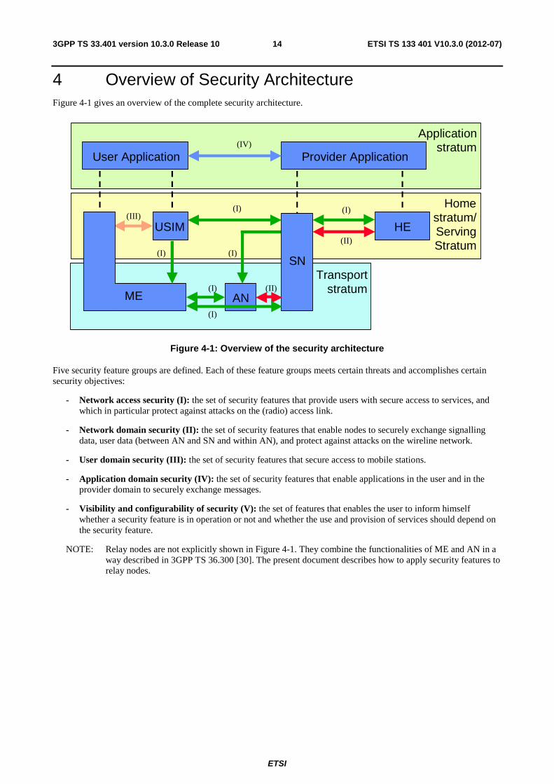
4 Overview of Security Architecture Figure 4-1 gives an overview of the complete security architecture.
Home
stratum/ Serving
Stratum
Transport stratum ME
Application
stratum User Application Provider Application
(IV)
(III)
(II)
(I)
(I)
(I)
(I)
(I)
SN
AN
(I)
USIM
(II)
HE
Figure 4-1: Overview of the security architecture
Five security feature groups are defined. Each of these feature groups meets certain threats and accomplishes certain security objectives:
- Network access security (I): the set of security features that provide users with secure access to services, and which in particular protect against attacks on the (radio) access link.
- Network domain security (II): the set of security features that enable nodes to securely exchange signalling data, user data (between AN and SN and within AN), and protect against attacks on the wireline network.
- User domain security (III): the set of security features that secure access to mobile stations.
- Application domain security (IV): the set of security features that enable applications in the user and in the provider domain to securely exchange messages.
- Visibility and configurability of security (V): the set of features that enables the user to inform himself whether a security feature is in operation or not and whether the use and provision of services should depend on the security feature.
NOTE: Relay nodes are not explicitly shown in Figure 4-1. They combine the functionalities of ME and AN in a way described in 3GPP TS 36.300 [30]. The present document describes how to apply security features to relay nodes.
ETSI
ETSI TS 133 401 V10.3.0 (2012-07)153GPP TS 33.401 version 10.3.0 Release 10
5 Security Features
5.1 User-to-Network security
5.1.0 General
The statements relating to eNBs in clause 5.1 apply also to RNs regarding the security between a UE and a relay node.
The statements relating to UEs in clause 5.1 apply also to RNs regarding the security between a relay node and a Donor eNB and between a relay node and its MME unless stated otherwise.
5.1.1 User identity and device confidentiality
User identity confidentiality is as defined by TS 33.102 [4] subclause 5.1.1
From subscriber's privacy point of view, the MSIN, the IMEI, and the IMEISV should be confidentiality protected.
The UE shall provide its equipment identifier IMEI or IMEISV to the network, if the network asks for it in an integrity-protected request.
The IMEI and IMEISV shall be securely stored in the terminal.
The UE shall not send IMEI or IMEISV to the network on a network request before the NAS security has been activated.
NOTE 1: When the UE has no IMSI, no valid GUTI, or no valid P-TMSI during emergency attach, the IMEI is included before the NAS security has been activated.
The IMEI or IMEISV shall be sent in the NAS protocol.
NOTE 2: In some cases, e.g., the very first attach procedure, MSIN has to be sent to network in cleartext. When NAS confidentiality protection is beyond an operator option, IMEI and IMEISV can not be confidentiality protected.
5.1.2 Entity authentication
Entity authentication is as defined by TS 33.102 [4] subclause 5.1.2
ETSI
ETSI TS 133 401 V10.3.0 (2012-07)163GPP TS 33.401 version 10.3.0 Release 10
5.1.3 User data and signalling data confidentiality
5.1.3.1 Ciphering requirements
Ciphering may be provided to RRC-signalling to prevent UE tracking based on cell level measurement reports, handover message mapping, or cell level identity chaining. RRC signalling confidentiality is an operator option.
All S1 and X2 messages carried between RN and DeNB should be confidentiality-protected.
NOTE 0: Confidentiality protection is subject to national regulation. If S1 and X2 messages are not confidentiality-protected there is the risk of exposing cryptographic keys carried in these messages.
Synchronization of the input parameters for ciphering shall be ensured for the protocols involved in the ciphering.
The NAS signalling may be confidentiality protected. NAS signalling confidentiality is an operator option.
NOTE 1: RRC and NAS signalling confidentiality protection is recommended to be used.
When authentication of the credentials on the UICC during Emergency Calling in Limited Service Mode, as defined in the TS 23.401 [2], can not be successfully performed, the confidentiality protection of the RRC and NAS signaling, and user plane shall be omitted (see clause 15). This shall be accomplished by the network by selecting EEA0 for confidentiality protection of NAS, RRC and user plane.
User plane confidentiality protection shall be done at PDCP layer and is an operator option.
NOTE 2: User plane confidentiality protection is recommended to be used.
NOTE 3: Confidentiality protection for RRC and UP is applied at the PDCP layer, and no layers below PDCP are confidentiality protected. Confidentiality protection for NAS is provided by the NAS protocol.
5.1.3.2 Algorithm Identifier Values
All algorithms specified in this subclause are algorithms with a 128-bit input key except Null ciphering algorithm.
NOTE: Deviations from the above requirement have to be indicated explicitly in the algorithm identifier list below.
Each EPS Encryption Algorithm (EEA) will be assigned a 4-bit identifier. Currently, the following values have been defined for NAS, RRC and UP ciphering:
"00002" EEA0 Null ciphering algorithm
"00012" 128-EEA1 SNOW 3G based algorithm
"00102" 128-EEA2 AES based algorithm
The remaining values have been reserved for future use.
UEs and eNBs shall implement EEA0, 128-EEA1 and 128-EEA2 for both RRC signalling ciphering and UP ciphering.
UEs and MMEs shall implement EEA0, 128-EEA1 and 128-EEA2 for NAS signalling ciphering.
ETSI
ETSI TS 133 401 V10.3.0 (2012-07)173GPP TS 33.401 version 10.3.0 Release 10
5.1.4 User data and signalling data integrity
5.1.4.1 Integrity requirements
Synchronization of the input parameters for integrity protection shall be ensured for the protocols involved in the integrity protection.
Integrity protection, and replay protection, shall be provided to NAS and RRC-signalling.
All NAS signaling messages except those explicitly listed in TS 24.301 [9] as exceptions shall be integrity-protected. All RRC signaling messages except those explicitly listed in TS 36.331 [21] as exceptions shall be integrity-protected.
When authentication of the credentials on the UICC during Emergency Calling in Limited Service Mode, as defined in the TS 23.401 [2], can not be successfully performed, the integrity and replay protection of the RRC and NAS signaling shall be omitted (see clause 15). This shall be accomplished by the network by selecting EIA0 for integrity protection of NAS and RRC. EIA0 shall only be used for unauthenticated emergency calls.
User plane packets between the eNB and the UE shall not be integrity protected on the Uu interface. User plane packets between the RN and the UE shall not be integrity protected. All user plane packets carrying S1 and X2 messages between RN and DeNB shall be integrity-protected. Integrity protection for all other user plane packets between RN and DeNB may be supported.
5.1.4.2 Algorithm Identifier Values
All algorithms specified in this subclause are algorithms with a 128-bit input key.
NOTE: Deviations from the above requirement have to be indicated explicitly in the algorithm identifier list below.
Each EPS Integrity Algorithm (EIA) will be assigned a 4-bit identifier. Currently, the following values have been defined:
"00002" EIA0 Null Integrity Protection algorithm
"00012" 128-EIA1 SNOW 3G
"00102" 128-EIA2 AES
The remaining values have been reserved for future use.
UEs and eNBs shall implement 128-EIA1 and 128-EIA2 for RRC signalling integrity protection.
UEs and MMEs shall implement 128-EIA1 and 128-EIA2 for NAS signalling integrity protection.
UEs shall implement EIA0 for integrity protection of NAS and RRC signalling. As specified in clause 5.1.4.1 of this specification, EIA0 is only allowed for unauthenticated emergency calls. EIA0 shall not be used for integrity protection between RN and DeNB.
Implementation of EIA0 in MMEs and eNBs is optional, EIA0, if implemented, shall be disabled in MMEs and eNBs in the deployments where support of unauthenticated emergency calling is not a regulatory requirement.
ETSI
ETSI TS 133 401 V10.3.0 (2012-07)183GPP TS 33.401 version 10.3.0 Release 10
5.2 Security visibility and configurability Although in general the security features should be transparent to the user, for certain events and according to the user's concern, greater user visibility of the operation of following security feature shall be provided:
- indication of access network encryption: the property that the user is informed whether the confidentiality of user data is protected on the radio access link, in particular when non-ciphered calls are set-up;
The ciphering indicator feature is specified in 3GPP TS 22.101 [23].
Configurability is the property that the user can configure whether the use or the provision of a service should depend on whether a security feature is in operation. A service can only be used if all security features, which are relevant to that service and which are required by the configurations of the user, are in operation. The following configurability features are suggested:
- enabling/disabling user-USIM authentication: the user should be able to control the operation of user-USIM authentication, e.g., for some events, services or use.
5.3 Security requirements on eNodeB
5.3.1 General
The security requirements given in this section apply to all types of eNodeBs. More stringent requirements for specific types of eNodeBs may be defined in other 3GPP specifications.
5.3.2 Requirements for eNB setup and configuration
Setting up and configuring eNBs shall be authenticated and authorized so that attackers shall not be able to modify the eNB settings and software configurations via local or remote access.
1. Security associations are required between the Evolved Packet Core (EPC) and the eNB and between adjacent eNBs, connected via X2. These security association establishments shall be mutually authenticated and used for user and control plane communication between the entities. However, in cases when a DeNB acts as proxy for control or user plane messages to and from a RN, hop-by-hop security associations shall be used for user and control plane. The security associations shall be realized according to clauses 11 and 12 of the present document except for the Un interface between RN and DeNB. The decision on whether or not to use the certificate enrolment mechanism specified in TS 33.310 [6] for eNB is left to operators.
2. Communication between the O&M systems and the eNB shall be confidentiality, integrity and replay protected from unauthorized parties. Security associations are required between the eNB and an entity in the Evolved Packet Core (EPC) or in an O&M domain trusted by the operator. These security association establishments shall be mutually authenticated. The security associations shall be realized according to clause 13 for eNBs and clause D.2.5 for RN.
3. The eNB shall be able to ensure that software/data change attempts are authorized
4. The eNB shall use authorized data/software.
5. Sensitive parts of the boot-up process shall be executed with the help of the secure environment.
6. Confidentiality of software transfer towards the eNB shall be ensured.
7. Integrity protection of software transfer towards the eNB shall be ensured.
5.3.3 Requirements for key management inside eNB
The EPC provides subscriber specific session keying material for the eNBs, which also hold long term keys used for authentication and security association setup purposes. Protecting all these keys is important.

ETSI
ETSI TS 133 401 V10.3.0 (2012-07)193GPP TS 33.401 version 10.3.0 Release 10
1. Keys stored inside eNBs shall never leave a secure environment within the eNB except when done in accordance with this or other 3GPP specifications.
5.3.4 Requirements for handling User plane data for the eNB
It is eNB's task to cipher and decipher user plane packets between the Uu reference point and the S1/X2 reference points.
1. User plane data ciphering/deciphering shall take place inside the secure environment where the related keys are stored.
2. The transport of user data over S1-U and X2-U shall be integrity, confidentially and replay-protected from unauthorized parties. If this is to be accomplished by cryptographic means, clause 12 shall be applied except for the Un interface between RN and DeNB.
NOTE: The use of cryptographic protection on S1-U and X2-U is an operator's decision. In case the eNB has been placed in a physically secured environment then the 'secure environment' may include other nodes and links beside the eNB.
5.3.4a Requirements for handling Control plane data for the eNB
It is eNB's task to provide confidentiality and integrity protection for control plane packets on the S1/X2 reference points.
1. Control plane data ciphering/deciphering shall take place inside the secure environment where the related keys are stored.
2. The transport of control plane data over S1-MME and X2-C shall be integrity-, confidentiality- and replay-protected from unauthorized parties. If this is to be accomplished by cryptographic means, clause 11 shall be applied except for the Un interface between RN and DeNB.
NOTE: The use of cryptographic protection on S1-MME and X2-C is an operator's decision. In case the eNB has been placed in a physically secured environment then the 'secure environment' may include other nodes and links beside the eNB.
5.3.5 Requirements for secure environment of the eNB
The secure environment is logically defined within the eNB and is a composition of functions for the support of sensitive operations.
1. The secure environment shall support secure storage of sensitive data, e.g. long term cryptographic secrets and vital configuration data.
2. The secure environment shall support the execution of sensitive functions, e.g. en-/decryption of user data and the basic steps within protocols which use long term secrets (e.g. in authentication protocols).
3. Sensitive data used within the secure environment shall not be exposed to external entities.
4. The secure environment shall support the execution of sensitive parts of the boot process.
5. The secure environment's integrity shall be assured.
6. Only authorised access shall be granted to the secure environment, i.e. to data stored and used within, and to functions executed within.
5.4 Void
ETSI
ETSI TS 133 401 V10.3.0 (2012-07)203GPP TS 33.401 version 10.3.0 Release 10
6 Security Procedures between UE and EPC Network Elements
6.0 General The statements relating to eNBs in clause 6 apply also to RNs regarding the security between a UE and a relay node.
The statements relating to UEs and MEs in clause 6 apply also to RNs regarding the security between a relay node and a Donor eNB and between a relay node and its MME unless stated otherwise.
6.1 Authentication and key agreement
6.1.1 AKA procedure
NOTE 1: Authentication data in this subclause stands for EPS Authentication vector(s).
EPS AKA is the authentication and key agreement procedure that shall be used over E-UTRAN.
A Rel-99 or later USIM application on a UICC shall be sufficient for accessing E-UTRAN, provided the USIM application does not make use of the separation bit of the AMF in a way described in TS 33.102 [4] Annex F. Access to E-UTRAN with a 2G SIM or a SIM application on a UICC shall not be granted.
An ME that has E-UTRAN radio capability shall support the USIM-ME interface as specified in TS 31.102 [13]
EPS AKA shall produce keying material forming a basis for user plane (UP), RRC, and NAS ciphering keys as well as RRC and NAS integrity protection keys.
NOTE 2: Key derivation requirements of AS and NAS keys can be found in subclause 7.2.1.
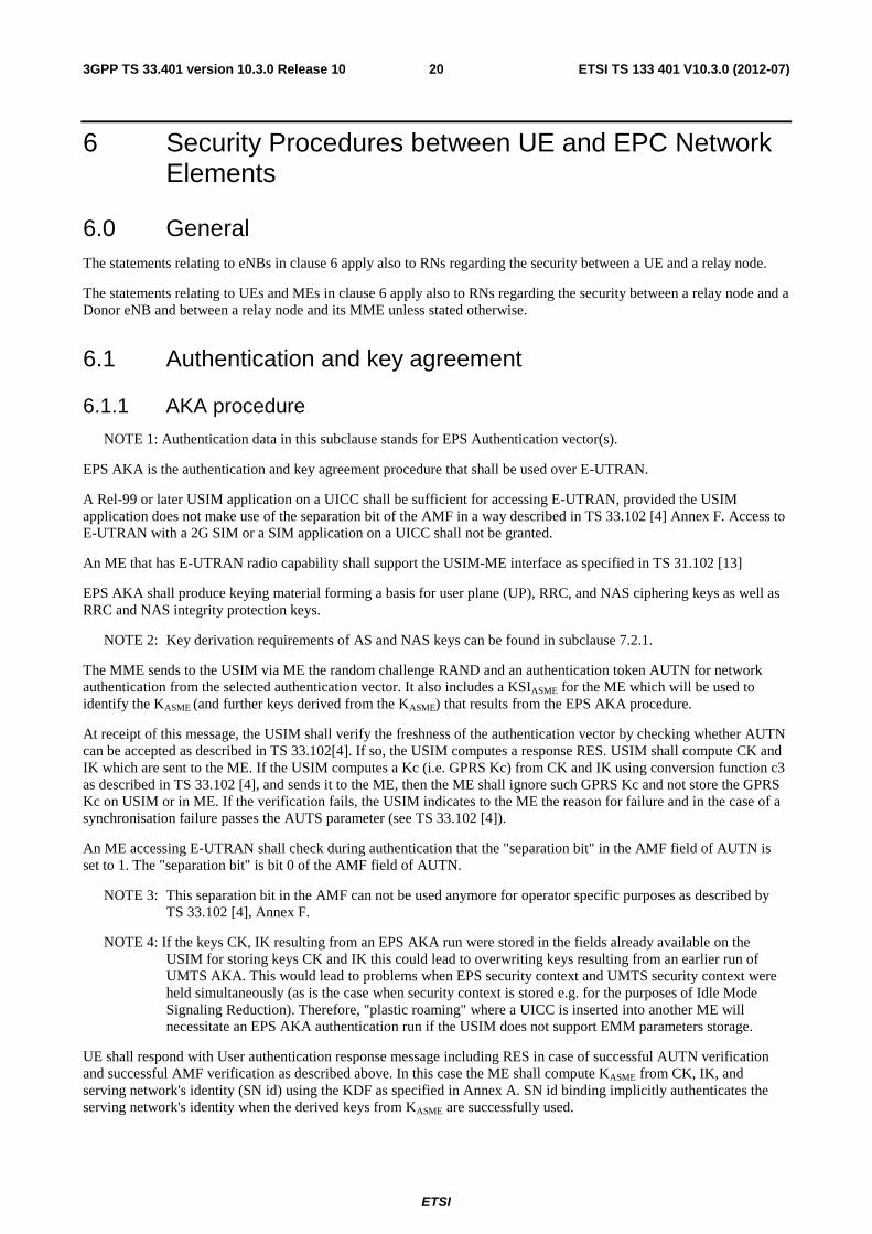
The MME sends to the USIM via ME the random challenge RAND and an authentication token AUTN for network authentication from the selected authentication vector. It also includes a KSIASME for the ME which will be used to identify the KASME (and further keys derived from the KASME) that results from the EPS AKA procedure.
At receipt of this message, the USIM shall verify the freshness of the authentication vector by checking whether AUTN can be accepted as described in TS 33.102[4]. If so, the USIM computes a response RES. USIM shall compute CK and IK which are sent to the ME. If the USIM computes a Kc (i.e. GPRS Kc) from CK and IK using conversion function c3 as described in TS 33.102 [4], and sends it to the ME, then the ME shall ignore such GPRS Kc and not store the GPRS Kc on USIM or in ME. If the verification fails, the USIM indicates to the ME the reason for failure and in the case of a synchronisation failure passes the AUTS parameter (see TS 33.102 [4]).
An ME accessing E-UTRAN shall check during authentication that the "separation bit" in the AMF field of AUTN is set to 1. The "separation bit" is bit 0 of the AMF field of AUTN.
NOTE 3: This separation bit in the AMF can not be used anymore for operator specific purposes as described by TS 33.102 [4], Annex F.
NOTE 4: If the keys CK, IK resulting from an EPS AKA run were stored in the fields already available on the USIM for storing keys CK and IK this could lead to overwriting keys resulting from an earlier run of UMTS AKA. This would lead to problems when EPS security context and UMTS security context were held simultaneously (as is the case when security context is stored e.g. for the purposes of Idle Mode Signaling Reduction). Therefore, "plastic roaming" where a UICC is inserted into another ME will necessitate an EPS AKA authentication run if the USIM does not support EMM parameters storage.
UE shall respond with User authentication response message including RES in case of successful AUTN verification and successful AMF verification as described above. In this case the ME shall compute KASME from CK, IK, and serving network's identity (SN id) using the KDF as specified in Annex A. SN id binding implicitly authenticates the serving network's identity when the derived keys from KASME are successfully used.
ETSI
ETSI TS 133 401 V10.3.0 (2012-07)213GPP TS 33.401 version 10.3.0 Release 10
NOTE 5: This does not preclude a USIM (see TS 31.102 [13]) in later releases having the capability of deriving KASME.
Otherwise UE shall send an authentication failure message with a CAUSE value indicating the reason for failure. In case of a synchronisation failure of AUTN (as described in TS 33.102 [4]), the UE also includes AUTS that was provided by the USIM. Upon receipt of an authentication failure message, the MME may initiate further identity requests and authentications towards the UE. (see TS 24.301 [9]).
The MME checks that the RES equals XRES. If so the authentication is successful. If not, depending on type of identity used by the UE in the initial NAS message, the MME may initiate further identity requests or send an authentication reject message towards the UE (see TS 24.301 [9]).
Figure 6.1.1-1 describes EPS AKA procedure, which is based on UMTS AKA (see TS 33.102[4]). The following keys are shared between UE and HSS:
• K is the permanent key stored on the USIM on a UICC and in the Authentication Centre AuC.
• CK, IK is the pair of keys derived in the AuC and on the USIM during an AKA run. CK, IK shall be handled differently depending on whether they are used in an EPS security context or a legacy security context, as described in subclause 6.1.2.
As a result of the authentication and key agreement, an intermediate key KASME shall be shared between UE and MME i.e. the ASME for EPS.
ME/USIM MME
User authentication request (RAND, AUTN, KSIASME)
User authentication response (RES)
Figure 6.1.1-1: Successful EPS AKA authentication
6.1.2 Distribution of authentication data from HSS to serving network
NOTE 1: Authentication data in this subclause stands for EPS Authentication vector(s).
The purpose of this procedure is to provide the MME with one or more EPS authentication vectors (RAND, AUTN, XRES, KASME) from the user's HE (HSS) to perform user authentication. Each EPS authentication vector can be used to authenticate the UE.
NOTE 2: It is recommended that the MME fetch only one EPS authentication vector at a time as the need to perform AKA runs has been reduced in EPS through the use of a more elaborate key hierarchy. In particular, service requests can be authenticated using a stored KASME without the need to perform AKA. Furthermore, the sequence number management schemes in TS 33.102, Annex C [4], designed to avoid re-synchronisation problems caused by interleaving use of batches of authentication vectors, are only optional. Re-synchronisation problems in EPS can be avoided, independently of the sequence number management scheme, by immediately using an authentication vector retrieved from the HSS in an authentication procedure between UE and MME.
ETSI
ETSI TS 133 401 V10.3.0 (2012-07)223GPP TS 33.401 version 10.3.0 Release 10
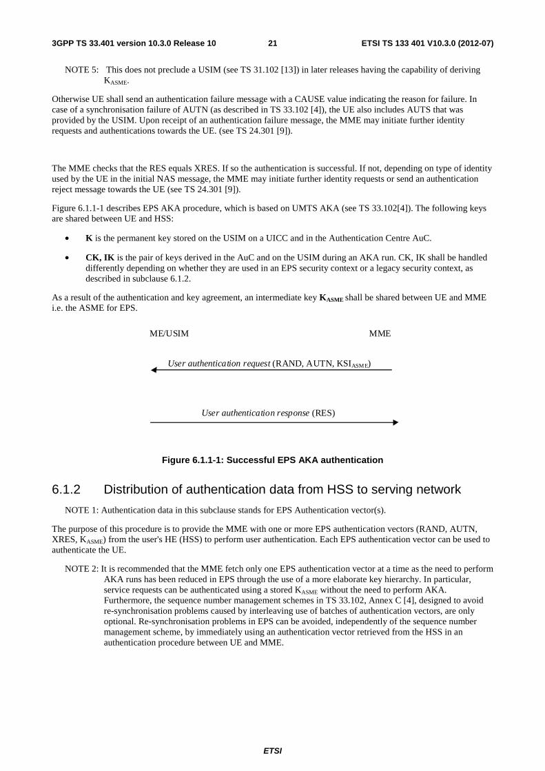
MME HE
Authentication data request IMSI, SN identity, Network Type
Type
Authentication data response EPS-Authentication Vector (s)
Figure 6.1.2-1: Distribution of authentication data from HE to MME
An EPS authentication vector is derived from the authentication vector defined in TS 33.102 [4] clause 6.3.2. To derive the key KASME in the HE, the KDF as specified in Annex A is used which shall contain following mandatory input parameters: CK, IK and SN identity.
If the Network Type equals E-UTRAN then the "separation bit" in the AMF field of AUTN shall be set to 1 to indicate to the UE that the authentication vector is only usable for AKA in an EPS context, if the "separation bit" is set to 0, the vector is usable in a non-EPS context only (e.g. GSM, UMTS). For authentication vectors with the "separation bit" set to 1, the secret keys CK and IK generated during AKA shall never leave the HSS.
The MME invokes the procedures by requesting authentication vectors from the HE (Home environment).
The authentication data request shall include the IMSI, the Serving Network identity i.e. MCC + MNC, and the Network Type (i.e. E-UTRAN). In the case of a synchronisation failure, the MME shall also include RAND and AUTS. In this case the HE checks the AUTS parameter before sending new authentication vectors to the MME (see TS 33.102 [4]).
Upon the receipt of the authentication data request from the MME, the HE may have pre-computed the required number of EPS authentication vectors and retrieve them from the HSS database or may compute them on demand.
NOTE 3: For KASME the possibilities for pre-computation are restricted due to the PLMN-binding.
NOTE 4: The HSS needs to ensure that the MME requesting the authentication data is entitled to use the SN id used to calculate KASME. The exact details of how to achieve this are not covered in this specification.
The HE sends an authentication response back to the MME that contains the requested information. If multiple EPS authentication vectors had been requested then they are ordered based on their sequence numbers. The MME shall be aware of the order of the EPS authentication vectors and shall use that the EPS authentication vectors in order.
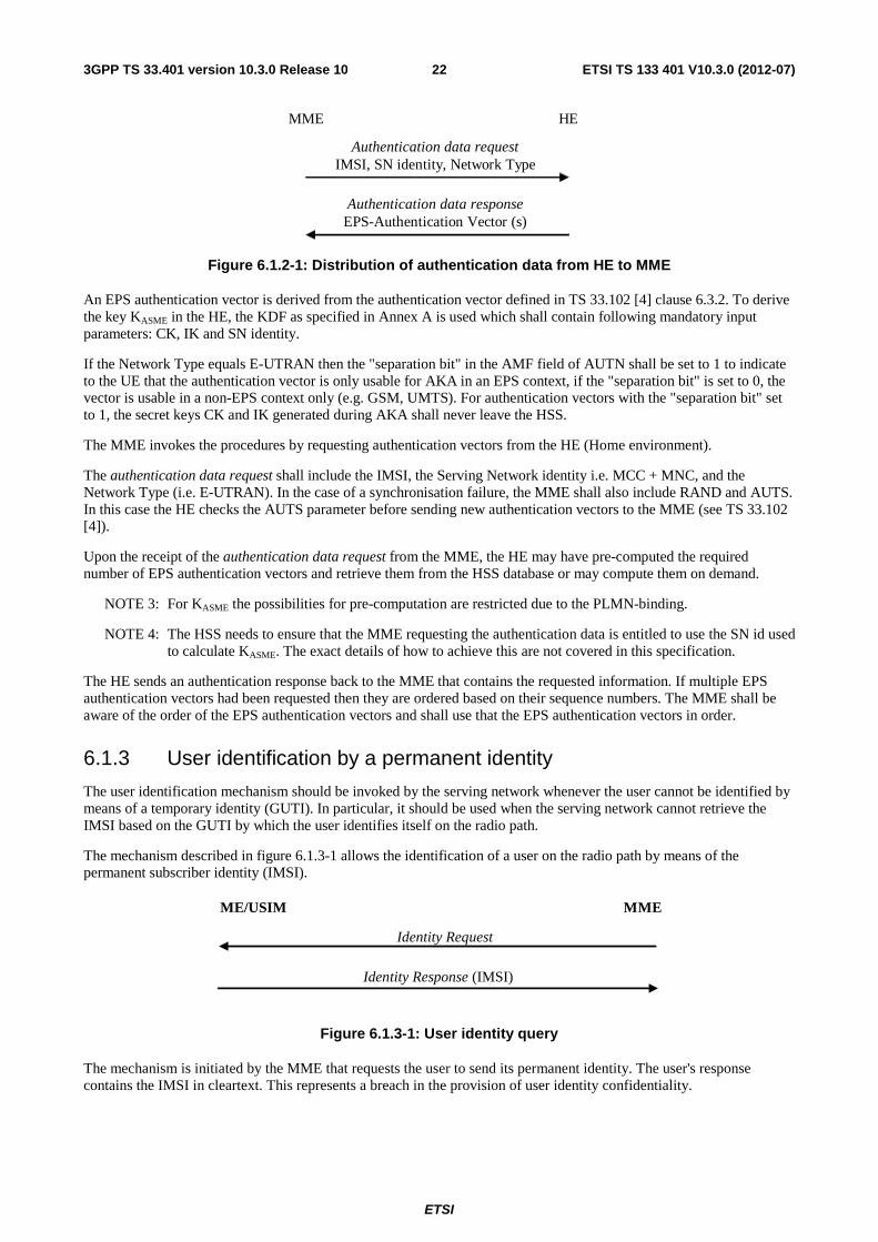
6.1.3 User identification by a permanent identity
The user identification mechanism should be invoked by the serving network whenever the user cannot be identified by means of a temporary identity (GUTI). In particular, it should be used when the serving network cannot retrieve the IMSI based on the GUTI by which the user identifies itself on the radio path.
The mechanism described in figure 6.1.3-1 allows the identification of a user on the radio path by means of the permanent subscriber identity (IMSI).
ME/USIM MME
Identity Request
Identity Response (IMSI)
Figure 6.1.3-1: User identity query
The mechanism is initiated by the MME that requests the user to send its permanent identity. The user's response contains the IMSI in cleartext. This represents a breach in the provision of user identity confidentiality.
ETSI
ETSI TS 133 401 V10.3.0 (2012-07)233GPP TS 33.401 version 10.3.0 Release 10
6.1.4 Distribution of IMSI and authentication data within one serving network domain
NOTE 1: Authentication data in this subclause stands for EPS security contexts and EPS authentication vector(s).
The purpose of this procedure is to provide a newly visited MME with authentication data from a previously visited MME within the same serving network domain.
NOTE 2: The following procedure in this clause is based on TAU procedure and it can also be applied for Attach procedure where all the corresponding texts for 'TAU' in the following procedure should be replaced with 'Attach'.
The procedure is shown in Figure 6.1.4-1
MMEn MMEo
GUTIo || Complete TAU message
IMSI || authentication data
Figure 6.1.4-1: Distribution of IMSI and authentication data within one serving domain
The procedure shall be invoked by the newly visited MMEn after the receipt of a Tracking Area update request from the user wherein the user is identified by means of a temporary user identity GUTIo and the Tracking area identity TAIo under the jurisdiction of a previously visited MMEo that belongs to the same serving network domain as the newly visited MMEn.
The protocol steps are as follows:
a) The MMEn sends a message to the MMEo, this message contains GUTIo and the received TAU message.
b) The MMEo searches the user data in the database and checks the integrity protection on the TAU message.
If the user is found and the integrity check succeeds, the MMEo shall send a response back that:
i) shall include the IMSI,
ii) may include a number of unused EPS-authentication vectors ordered on a first-in / first-out basis, and
iii) may include any EPS security contexts it holds
The MMEo subsequently deletes the EPS-authentication vectors and any EPS security contexts which have been sent.
If the user cannot be identified or the integrity check fails, then the MMEo shall send a response indicating that the user identity cannot be retrieved.
c) If the MMEn receives a response with an IMSI, it creates an entry and stores any EPS-authentication vectors and any EPS security context that may be included.
If the MMEn receives a response indicating that the user could not be identified, it shall initiate the user identification procedure described in clause 6.1.3 during the Initial E-UTRAN Attach procedure, or it shall reject the TAU Request message initiated by UE during the TAU procedure (see clause 4.4.4.3 in TS24.301[9]).
ETSI
ETSI TS 133 401 V10.3.0 (2012-07)243GPP TS 33.401 version 10.3.0 Release 10
The same procedure does not apply to distribution of EPS authentication data between MME and SGSN in the same serving network domain, i.e. EPS authentication data shall not be forwarded from an MME towards an SGSN.
NOTE 3: This is due to the fact that EPS authentication data does not contain CK and IK and, hence, is not useful for the SGSN.
6.1.5 Distribution of IMSI and authentication data between different serving network domains
NOTE 1: Authentication data in this subclause stands for EPS security contexts and EPS authentication vector(s).
In general, the distribution of IMSI and authentication data between MMEs belonging to different serving network domains of shall be performed as described for the distribution of IMSI and authentication data within the same service network domain in subclause 6.1.4. In particular, the current EPS security context data may be transferred between MMEs belonging to different serving network domains. However, there is the following restriction:
- Unused EPS authentication vectors, or non-current EPS security contexts, shall not be distributed between MMEs belonging to different serving domains (PLMNs).
The same procedure does not apply to distribution of EPS authentication data between MME and SGSN in different serving network domains, i.e. EPS authentication data shall not be forwarded from an MME towards an SGSN.
NOTE 2: This is due to the fact that EPS authentication data does not contain CK and IK and, hence, is not useful for the SGSN.
6.1.6 Distribution of IMSI and UMTS authentication vectors between MMEs or between MME and SGSN
This subclause applies to both distribution of UMTS authentication vectors within one serving network domain and distribution of UMTS authentication vectors between different serving network domains. The following rules apply to the distribution of UMTS authentication vectors between two MMEs, and between an SGSN and an MME:
a) MME to MME
UMTS authentication vectors that were previously received from an SGSN shall not be forwarded between MME's.
b) SGSN to MME
An SGSN may forward unused UMTS authentication vectors to an MME. only if MME and SGSN are in the same serving network domain.
c) MME to SGSN
UMTS AVs which were previously stored in the MME may be forwarded back towards the same SGSN.
UMTS AVs which were previously stored in the MME shall not be forwarded towards other SGSNs.
6.2 EPS key hierarchy Requirements on EPC and E-UTRAN related to keys:
a) The EPC and E-UTRAN shall allow for use of encryption and integrity protection algorithms for AS and NAS protection having keys of length 128 bits and for future use the network interfaces shall be prepared to support 256 bit keys.
b) The keys used for UP, NAS and AS protection shall be dependent on the algorithm with which they are used.
ETSI
ETSI TS 133 401 V10.3.0 (2012-07)253GPP TS 33.401 version 10.3.0 Release 10
USIM / AuC
UE / MME KASME
K
KUPenc
KeNB / NH
KNASint
UE / HSS
UE / eNB
KNASenc
CK, IK
KRRCint KRRCenc KUPint
Figure 6.2-1: Key hierarchy in E-UTRAN
The key hierarchy (see Figure 6.2-1) includes following keys: KeNB, KNASint, KNASenc, KUPenc, KRRCint and KRRCenc
• KeNB is a key derived by ME and MME from KASME or by ME and target eNB.
Keys for NAS traffic:
• KNASint is a key, which shall only be used for the protection of NAS traffic with a particular integrity algorithm This key is derived by ME and MME from KASME, as well as an identifier for the integrity algorithm using the KDF as specified in Annex A.
• KNASenc is a key, which shall only be used for the protection of NAS traffic with a particular encryption algorithm. This key is derived by ME and MME from KASME, as well as an identifier for the encryption algorithm using the KDF as specified in Annex A.
Keys for UP traffic:
• KUPenc is a key, which shall only be used for the protection of UP traffic with a particular encryption algorithm. This key is derived by ME and eNB from KeNB, as well as an identifier for the encryption algorithm using the KDF as specified in Annex A.
• KUPint is a key, which shall only be used for the protection of UP traffic between RN and DeNB with a particular integrity algorithm. This key is derived by RN and DeNB from KeNB, as well as an identifier for the integrity algorithm using the KDF as specified in Annex A.
Keys for RRC traffic:
• KRRCint is a key, which shall only be used for the protection of RRC traffic with a particular integrity algorithm. KRRCint is derived by ME and eNB from KeNB, as well as an identifier for the integrity algorithm using the KDF as specified in Annex A.
• KRRCenc is a key, which shall only be used for the protection of RRC traffic with a particular encryption algorithm. KRRCenc is derived by ME and eNB from KeNB as well as an identifier for the encryption algorithm using the KDF as specified in Annex A.
Intermediate keys:
ETSI
ETSI TS 133 401 V10.3.0 (2012-07)263GPP TS 33.401 version 10.3.0 Release 10
- NH is a key derived by ME and MME to provide forward security as described in clause 7.2.8.
- KeNB* is a key derived by ME and eNB when performing an horizontal or vertical key derivation as specified in clause 7.2.8 using a KDF as specified in Annex A.
Figure 6.2-2 shows the dependencies between the different keys, and how they are derived from the network nodes point of view. Figure 6.2-3 shows the corresponding relations and derivations as performed in the ME. Two dashed inputs to a KDF means one of the inputs is used depending on the circumstances of the key derivation.
NOTE: Figures 6.2-2 and 6.2-3 do not cover the derivations at IRAT mobility (see clauses 9 and 10).
Figure 6.2-2: Key distribution and key derivation scheme for EPS (in particular E-UTRAN) for network nodes.
MME HSS CK,IK
KDF
256
256
SN id, SQN ⊕ AK
KeNB
KASME
256
KDF K
DF
KDF KDF
KNASenc KNASint
KNASenc KNASint
Trunc Trunc
256 256
128 128
256
256 256
NAS-enc-alg, Alg-ID
NAS-int-alg, Alg-ID
NAS UPLINK COUNT
KDF KDF
KUPenc KRRCint
KUPenc KRRCint
Trunc Trunc
256 256
128 128
256
UP-enc-alg, Alg-ID
RRC-int-alg, Alg-ID
RRC-enc-alg, Alg-ID
256 256
Physical cell ID, EARFCN-DL
256
KeNB
eNB
eNB
KeNB*
KDF
KRRCenc
KRRCenc
256
256
128
Trunc
KD
F
NH
NH
KeNB
256
256
KDF
Trunc
UP-int-alg, Alg-ID
KUPint
256
256
KUPint
128
ETSI
ETSI TS 133 401 V10.3.0 (2012-07)273GPP TS 33.401 version 10.3.0 Release 10
Figure 6.2-3: Key derivation scheme for EPS (in particular E-UTRAN) for the ME.
As the figures 6.2-2 and 6.2-3 show, the length of KASME, KeNB and NH is 256 bits, 256-bit NAS, UP and RRC keys are always derived from KASME and KeNB respectively. In case the encryption or integrity algorithm used to protect NAS, UP or RRC requires a 128-bit key as input, the key is truncated and the 128 least significant bits are used. Figures 6.2-2 and 6.2-3 illustrate the truncation to 128 bits keys.
The function Trunc takes as input a 256-bit string, and returns a truncated output as defined in Annex A.7.
6.3 EPS key identification The key KASME shall be identified by the key set identifier eKSI. eKSI may be either of type KSIASME or of type KSISGSN. An eKSI shall be stored in the UE and the MME together with KASME and the temporary identifier GUTI, if available.
NOTE 1: The GUTI points to the MME where the KASME is stored.
The key set identifier KSIASME is a parameter which is associated with the KASME derived during EPS AKA authentication. The key set identifier KSIASME is allocated by the MME and sent with the authentication request message to the mobile station where it is stored together with the KASME. The purpose of the KSIASME is to make it possible for the UE and the MME to identify a native KASME without invoking the authentication procedure. This is used to allow re-use of the KASME during subsequent connection set-ups.
The key set identifier KSISGSN is a parameter which is associated with the mapped KASME derived from UMTS keys during inter-RAT mobility, cf. clauses 9 and 10 of the present specification. The key set identifier KSISGSN is generated in both the UE and the MME respectively when deriving the mapped KASME during idle procedures in E-UTRAN and during handover from GERAN/UTRAN to E-UTRAN. The KSISGSN is stored together with the mapped KASME.
ME CK,IK
KDF
256
256
SN id, SQN ⊕ AK
KeNB
KASME
256
KDF
KD
F
KDF KDF
KNASenc KNASint
KNASenc KNASint
Trunc Trunc
256 256
128 128
256
256 256
NAS-enc-alg, Alg-ID
NAS-int-alg, Alg-ID
NAS UPLINK COUNT
KDF KDF
KUPenc KRRCint
KUPenc KRRCint
Trunc Trunc
256 256
128 128
256
UP-enc-alg, Alg-ID
RRC-int-alg, Alg-ID
RRC-enc-alg, Alg-ID
256
256 Physical cell ID, EARFCN-DL
256
KeNB*
KDF
KRRCenc
KRRCenc
256
256
128
Trunc
KD
F
NH
NH
KeNB
256
256
KDF
Trunc
KUPint
256
256
KUPint
128
UP-int-alg, Alg-ID
ETSI
ETSI TS 133 401 V10.3.0 (2012-07)283GPP TS 33.401 version 10.3.0 Release 10
The purpose of the KSISGSN is to make it possible for the UE and the MME to indicate the use of the mapped KASME in inter-RAT mobility procedures (for details cf. clauses 9 and 10).
The format of eKSI shall allow a recipient of such a parameter to distinguish whether the parameter is of type 'KSIASME' or of type 'KSISGSN'. The format shall further contain a value field. KSIASME and KSISGSN have the same format. The value fields of KSIASME and KSISGSN are three bits each. Seven values are used to identify the key set. A value of '111' is used by the UE to indicate that a valid KASME is not available for use. Format of eKSI is described in [9].
The value '111' in the other direction from network to mobile station is reserved.
NOTE 2: In addition to EPS security contexts, the UE may also cache UMTS security contexts. These UMTS security contexts are identified by the KSI, as defined in TS 33.102 [4].
6.4 Handling of EPS security contexts Any EPS security context shall be deleted from the ME if:
a) the UICC is removed from the ME when the ME is in power on state;
b) the ME is powered up and the ME discovers that a UICC different from the one which was used to create the EPS security context has been inserted to the ME;
c) the ME is powered up and the ME discovers that no UICC has been inserted to the ME.
KASME shall never be transferred from the EPC to an entity outside the EPC.
Both the ME and MME shall be capable of storing one non-current EPS security context and one current EPS security context in volatile memory. In addition, while connected to E-UTRAN the ME and MME shall be capable of storing in volatile memory the NCC, NH and the related KASME used to compute keying material for the current EPS AS security context.
Any successful run of an EPS AKA creates, by the definition in clause 3, a partial native EPS security context. This context shall overwrite any existing non-current EPS security context.
UE shall use its current EPS security context to protect the TAU Request or Attach Request. However, there may be cases in which this EPS security context is not the current one in the MME. In such cases, if the MME receives a TAU Request or Attach Request protected with a non-current full EPS security context, then this context becomes the current EPS security context and the MME shall delete any existing current EPS security context.
After a successful run of a NAS SMC relating to the eKSI associated with an EPS security context, this context becomes the current EPS security context and shall overwrite any existing current EPS security context.
NOTE 1: The ME ensures that, whenever the native EPS NAS security context stored on the USIM (if supported by USIM) or in non-volatile memory of the ME is marked as valid during the process of changing state to EMM-DEREGISTERED, it is consistent with the security context stored in the volatile memory of the ME. This is described in clause 7.2.5.
The rules for handling security contexts after a handover to E-UTRAN are given in clause 9.2.2.1.
The full native EPS NAS security context (except for KNASenc and KNASint) shall be stored on the USIM (if the USIM supports EMM parameters storage) or in the non-volatile memory of the ME (if the USIM does not support EMM parameters storage) only during the process of transitioning to EMM-DEREGISTERED state or when an attempt to transition away from EMM-DEREGISTERED state fails, as described in clause 7.2.5. The ME shall under no other circumstances store the EPS NAS security context parameters on the USIM or non-volatile ME memory.
NOTE 2: Only native EPS NAS security context is stored in the EMM parameters file on the USIM or in non-volatile ME memory. A mapped EPS NAS security context is never stored in these two places.
6.5 Handling of NAS COUNTs Each separate KASME has a distinct pair of NAS COUNTs associated with it. It is essential that the NAS COUNTs for a particular KASME are not reset to the start values (that is the NAS COUNTs only have their start value when a new

ETSI
ETSI TS 133 401 V10.3.0 (2012-07)293GPP TS 33.401 version 10.3.0 Release 10
KASME is created). This prevents the security issue of using the same NAS COUNTs with the same NAS keys, e.g. key stream re-use, in the case a UE moves back and forth between two MMEs and the same NAS keys are re-derived.
The NAS COUNTs shall only be set to the start value in the following cases:
- for a partial native EPS NAS security context created by a successful AKA run,
NOTE: The NAS COUNTs are not actually needed at the UE for a native context until it has successfully received the first NAS Security Mode Command for that security context. The NAS COUNTs are not needed at the MME until it sends the first NAS Security Mode Command for that security context. Before the MME sends the first NAS Security Mode Command for a given partial native security context, the MME sets the NAS COUNTs for the security context to 0. After the NAS SMC message is sent for that partial native security context the NAS COUNTs for that partial native context are increased for each following sent NAS message as specified in TS 24.301.
- or for an EPS NAS security context created through a context mapping during a handover from UTRAN/GERAN to E-UTRAN,
- or for an EPS NAS security context created through a context mapping during idle mode mobility from UTRAN/GERAN to E-UTRAN.
The NAS COUNTs shall not be reset during idle mode mobility or handover for an already existing native EPS NAS security context.
The start value of NAS COUNT shall be zero (0).
ETSI
ETSI TS 133 401 V10.3.0 (2012-07)303GPP TS 33.401 version 10.3.0 Release 10
7 Security Procedures between UE and EPS Access Network Elements
7.0 General The statements relating to eNBs in clause 7 apply also to RNs regarding the security between a UE and a relay node.
The statements relating to UEs in clause 7 apply also to RNs regarding the security between a relay node and a Donor eNB and between a relay node and its MME unless stated otherwise.
7.1 Mechanism for user identity confidentiality The MME shall allocate a GUTI to a UE in order to support the subscriber identity confidentiality. The GUTI is defined in TS 23.003 [3].
S-TMSI, the shortened form of the GUTI, is used to support the subscriber identity confidentiality with more efficient radio signalling procedures (e.g. paging and Service Request). A new GUTI shall be sent to the UE only after a successful activation of NAS security.
7.2 Handling of user-related keys in E-UTRAN
7.2.1 E-UTRAN key setting during AKA
Authentication and key setting are triggered by the authentication procedure. Authentication and key setting may be initiated by the network as often as the network operator wishes. Key setting can occur as soon as the identity of the mobile subscriber (i.e. GUTI or IMSI) is known by the MME. A successful run of AKA results in a new KASME that is stored in the UE and MME.
NAS keys, KeNB and the RRC and UP keys are derived from KASME using the KDFs specified in Annex A.
The NAS keys derived from the new KASME are taken in use in the MME and the UE by means of the NAS security mode set-up procedure (see subclause 7.2.4.4). The AS keys are taken into use with the AS security mode set-up procedure (see subclause 7.2.4.5) or with the key change on the fly procedure (see subclause 7.2.9.2).
7.2.2 E-UTRAN key identification
Clause 6.3 of this specification states how the key KASME is identified, namely by the key set identifier eKSI. Keys KNASenc and KNASint in the E-UTRAN key hierarchy specified in clause 6.2, which are derived from KASME, can be uniquely identified by eKSI together with those parameters from the set {algorithm distinguisher, algorithm identifier}, which are used to derive these keys from KASME according to Annex A.
The initial KeNB can be uniquely determined by the key set identifier, i.e. eKSI, together with the uplink NAS COUNT are used to derive it. The intermediate key NH as defined in clause 7 can be uniquely determined by the key set identifier, i.e. eKSI, together with the initial KeNB derived from the current NAS security context for use during the ongoing CONNECTED state and a counter counting how many NH-derivations have already been performed from this initial KeNB.according to Annex A.4. The next hop chaining count, NCC, represents the 3 least significant bits of this counter.
Intermediate key KeNB*, defined in clause 7, as well as keys non-initial KeNB, KRRCint, KRRCenc, KUPint, and KUPenc in the E-UTRAN key hierarchy specified in clause 6.2 can be uniquely identified by eKSI together with those parameters from the set {Initial KeNB or NH, algorithm distinguisher, algorithm identifier, and sequence of PCIs and EARFCN-DLs used in horizontal key derivations from the initial KeNB or NH}, which are used to derive these keys from KASME according to clause 7 and Annex A.
It is specified in the remainder of clause 7, as well as in clause 9 and 10, which of the above parameters need to be included in a security-relevant message to allow the entity receiving the message to uniquely identify a certain key.
ETSI
ETSI TS 133 401 V10.3.0 (2012-07)313GPP TS 33.401 version 10.3.0 Release 10
7.2.3 E-UTRAN key lifetimes
All E-UTRAN keys are derived based on a KASME. The key hierarchy which is described in clause 6.2 does not allow direct update to RRC and UP keys, but fresh RRC and UP keys are derived based on a fresh KeNB, which is bound to certain dynamic parameters (like PCI) or fresh key derivation parameter(s) in state transitions (like NAS uplink COUNT). This results as fresh RRC and UP keys in the eNB between inter-eNB handovers and state transitions (see subclauses 7.2.6 to 7.2.8). The handling (creation, modification and update) of the E-UTRAN keys in the various state transitions is described in clauses 7.2.5, 7.2.6, 7.2.7 and 7.2.8.
KASME shall be created only by running a successful AKA or by the inter-RAT procedures towards E-UTRAN (cf clauses 9 and 10). In case the UE does not have a valid KASME, a KSIASME with value "111" shall be sent by the UE to the network, which can initiate (re-)authentication procedure to get a new KASME based on a successful AKA authentication.
7.2.4 Security mode command procedure and algorithm negotiation
7.2.4.1 Requirements for algorithm selection
a) An active UE and a serving network shall agree upon algorithms for
- RRC ciphering and RRC integrity protection (to be used between UE and eNB)
- UP ciphering (to be used between UE and eNB)
- NAS ciphering and NAS integrity protection (to be used between UE and MME)
An active RN and a network serving the RN shall additionally agree upon algorithms for UP integrity.
b) The serving network shall select the algorithms to use dependent on
- the UE security capabilities of the UE,
- the configured allowed list of security capabilities of the currently serving network entity
c) The same set of ciphering and integrity algorithms shall be supported by the UE both for AS and NAS level.
d) Each selected algorithm shall be acknowledged to the UE in an integrity protected way such that the UE is ensured that the algorithm selection was not manipulated, i.e. that the UE security capabilities were not bidden down.
e) The UE security capabilities the ME sent to the network shall be repeated in an integrity protected NAS level message to the ME such that "bidding down attacks" against the UE's security capabilities can be detected by the ME. The UE security capabilities apply to both AS and NAS level security.
f) Separate AS and NAS level security mode command procedures are required. AS level security mode command procedure shall configure AS security (RRC and UP) and NAS level security mode command procedure shall configure NAS security.
a. Both integrity protection and ciphering for RRC shall be activated within the same AS SMC procedure, but not necessarily within the same message.
b. User plane ciphering shall be activated at the same time as RRC ciphering.
c. User plane integrity shall be activated at the same time as RRC ciphering. User plane integrity shall be applied to a data radio bearer if integrity protection is configured for that data radio bearer at the time of data radio bearer set-up.
ETSI
ETSI TS 133 401 V10.3.0 (2012-07)323GPP TS 33.401 version 10.3.0 Release 10
g) It shall be possible that the selected AS and NAS algorithms are different at a given point of time.
7.2.4.2 Procedures for AS algorithm selection
7.2.4.2.1 Initial AS security context establishment
Each eNB shall be configured via network management with lists of algorithms which are allowed for usage. There shall be one list for integrity algorithms, and one for ciphering algorithms. These lists shall be ordered according to a priority decided by the operator. When AS security context is established in the eNB, the MME shall send the UE EPS security capabilities to the eNB. The eNB shall choose the ciphering algorithm which has the highest priority from its configured list and is also present in the UE EPS security capabilities. The eNB shall choose the integrity algorithm which has the highest priority from its configured list and is also present in the UE EPS security capabilities. The chosen algorithms shall be indicated to the UE in the AS SMC. The ciphering algorithm is used for ciphering of the user plane and RRC traffic. The integrity algorithm is used for integrity protection of the RRC traffic, and, if applicable, for the integrity protection of user plane traffic between RN and DeNB.
7.2.4.2.2 X2-handover
At handover from a source eNB over X2 to a target eNB, the source eNB shall include the UE EPS security capabilities and ciphering and integrity algorithms used in the source cell in the handover request message. The target eNB shall select the algorithm with highest priority from the UE EPS security capabilities according to the prioritized locally configured list of algorithms (this applies for both integrity and ciphering algorithms). The chosen algorithms shall be indicated to the UE in the handover command if the target eNB selects different algorithms compared to the source eNB. If the UE does not receive any selection of integrity and ciphering algorithms it continues to use the same algorithms as before the handover (see TS 36.331 [21]). In the path-switch message, the target eNB shall send the UE EPS security capabilities received from the source eNB to the MME. The MME shall verify that the UE EPS security capabilities received from the eNB are the same as the UE EPS security capabilities that the MME has stored. If there is a mismatch, the MME may log the event and may take additional measures, such as raising an alarm.
NOTE: Transferring the ciphering and integrity algorithms used in the source cell to the target eNB in the handover request message is for the target eNB to decipher and integrity verify the RRCReestablishmentComplete message on SRB1 in the potential RRCConnectionRe-establishment procedure. The information is also used by the target eNB to decide if it is necessary to include a new selection of security algorithms in the handover command.
7.2.4.2.3 S1-handover
At handover from a source eNB to a target eNB over S1 (possibly including an MME change and hence a transfer of the UE security capabilities from source MME to target MME), the target MME shall send the UE EPS security capabilities to the target eNB in the S1 AP HANDOVER REQUEST message. The target eNB shall select the algorithm with highest priority from the UE EPS security capabilities according to the prioritized locally configured list of algorithms (this applies for both integrity and ciphering algorithms). The chosen algorithms shall be indicated to the UE in the handover command if the target eNB selects different algorithms compared to the source eNB. If the UE does not receive any selection of integrity and ciphering algorithms it continues to use the same algorithms as before the handover (see TS 36.331 [21]).
7.2.4.2.4 Intra-eNB handover
It is not required to change the AS security algorithm during intra-eNB handover. If the UE does not receive any selection of new AS security algorithms during an intra-eNB handover, the UE continues to use the same algorithms as before the handover (see TS 36.331 [21]).
7.2.4.3 Procedures for NAS algorithm selection
7.2.4.3.1 Initial NAS security context establishment
Each MME shall be configured via network management with lists of algorithms which are allowed for usage. There shall be one list for NAS integrity algorithms, and one for NAS ciphering algorithms. These lists shall be ordered according to a priority decided by the operator.
ETSI
ETSI TS 133 401 V10.3.0 (2012-07)333GPP TS 33.401 version 10.3.0 Release 10
To establish the NAS security context, the MME shall choose one NAS ciphering algorithm and one NAS integrity protection algorithm. The MME shall then initiate a NAS security mode command procedure, and include the chosen algorithms and UE security capabilities (to detect modification of the UE security capabilities by an attacker) in the message to the UE (see clause 7.2.4.4). The MME shall select the NAS algorithms which have the highest priority according to the ordered lists.
7.2.4.3.2 MME change
In case there is change of MMEs and algorithms to be used for NAS, the target MME shall initiate a NAS security mode command procedure and include the chosen algorithms and the UE security capabilities (to detect modification of the UE security capabilities by an attacker) in the message to the UE (see clause 7.2.4.4). The MME shall select the NAS algorithms which have the highest priority according to the ordered lists (see 7.2.4.3.1).
NOTE: After an S1-handover with MME change a TAU procedure is executed. The same is true for an inter-RAT handover to E-UTRAN and for both inter- and intra-RAT idle mode mobility resulting in a change of MMEs.
7.2.4.4 NAS security mode command procedure
The NAS SMC procedure consists of a roundtrip of messages between MME and UE. The MME sends the NAS security mode command to the UE and the UE replies with the NAS security mode complete message.
The NAS security mode command message from MME to UE shall contain the replayed UE security capabilities, the selected NAS algorithms, the eKSI for identifying KASME, and both NONEUE and NONCEMME in the case of creating a mapped context in idle mobility (see clause 9.1.2). This message shall be integrity protected (but not ciphered) with NAS integrity key based on KASME indicated by the eKSI in the message (see figure 7.2.4.4-1).
The UE shall verify the integrity of the NAS security mode command message. This includes ensuring that the UE security capabilities sent by the MME match the ones stored in the UE to ensure that these were not modified by an attacker and checking the integrity protection using the indicated NAS integrity algorithm and the NAS integrity key based on KASME indicated by the eKSI. In addition, when creating a mapped context for the case described in clause 9.1.2, the UE shall ensure the received NONCEUE is the same as the NONCEUE sent in the TAU Request and also calculate K'ASME from CK, IK and the two nonces (see Annex A.11).
If the MME receives no response to a NAS Security Mode Command that included nonces to create a mapped context and it wishes to try again to create the mapped context, the MME shall use the same values of NONCEUE and NONCEMME.
If the UE receives a re-transmitted NAS Security Mode Command, i.e one containing the nonces, after it has successfully received a previous one (and hence created a mapped EPS NAS security context), the UE shall process the message as above, except that it is not required to re-generate the K'ASME or check the NONCE UE if it does not re-generate the K'ASME.
If the checks of the NAS Security Mode Command pass the UE shall respond with a NAS Security Mode Complete.
The UE shall delete NONCE_UE once the TAU procedure is complete.
If successfully verified, the UE shall start NAS integrity protection and ciphering/deciphering with this security context and sends the NAS security mode complete message to MME ciphered and integrity protected The NAS security mode complete message shall include IMEISV in case MME requested it in the NAS SMC Command message.
The MME shall de-cipher and check the integrity protection on the NAS Security Mode Complete using the keys and algorithms indicated in the NAS Security Mode Command. NAS downlink ciphering at the MME with this security context shall start after receiving the NAS security mode complete message. NAS uplink deciphering at the MME with this context starts after sending the NAS security mode command message.
If any verification of the NAS security mode command is not successful in the ME, the ME shall reply with a NAS security mode reject message (see TS 24.301 [9]). The NAS security mode reject message and all following NAS messages shall be protected with the EPS NAS security context, i.e., the EPS NAS security context used prior to the NAS security mode command that failed (until a new EPS NAS security context is established, e.g., via a new NAS security mode command procedure). If no EPS NAS security context existed prior to the NAS security mode command, the NAS security mode reject message cannot be protected.
ETSI
ETSI TS 133 401 V10.3.0 (2012-07)343GPP TS 33.401 version 10.3.0 Release 10
NOTE: If the uplink NAS COUNT will wrap around by sending the security mode reject message, the UE releases the NAS connection as specified in TS 24.301 [9] instead of sending the security mode reject message.
ME MME
NAS Security Mode Command (eKSI, UE sec capabilities, Ciphering algorithm, Integrity algorithm,
[IMEISV request,] [NONCEUE, NONCEMME,] NAS-MAC)
Verify NAS SMC integrity. If succesful, start ciphering/ deciphering and integrity protection and send NAS Security Mode Complete.
Start uplink deciphering
Start integrity protection
NAS Security Mode Complete ([IMEISV,] NAS-MAC)
Start downlink ciphering
Figure 7.2.4.4-1: NAS security mode command procedure
7.2.4.5 AS security mode command procedure
The AS SMC procedure consists of a roundtrip of messages between eNB and UE. The eNB sends the AS security mode command to the UE and the UE replies with the AS security mode complete message. See figure 7.2.4.5-1.
The AS security mode command message from eNB to UE shall contain the selected AS algorithms. This message shall be integrity protected with RRC integrity key based on the current KASME.
The AS security mode complete message from UE to eNB shall be integrity protected with the selected RRC algorithm indicated in the AS security mode command message and RRC integrity key based on the current KASME.
RRC and UP downlink ciphering (encryption) at the eNB shall start after sending the AS security mode command message. RRC and UP uplink deciphering (decryption) at the eNB shall start after receiving and successful verification of the AS security mode complete message.
RRC and UP uplink ciphering (encryption) at the UE shall start after sending the AS security mode complete message. RRC and UP downlink deciphering (decryption) at the UE shall start after receiving and successful verification of the AS security mode command message
If any control of the AS security mode command is not successful in the ME, the ME shall reply with an unprotected security mode failure message (see TS 36.331[21]).
AS security mode command always changes the AS keys.
ETSI
ETSI TS 133 401 V10.3.0 (2012-07)353GPP TS 33.401 version 10.3.0 Release 10
ME eNB
AS Security Mode Command (Integrity algorithm, Ciphering algorithm, MAC-I)
AS Security Mode Complete (MAC-I)
Verify AS SMC integrity. If succesful, start RRC integrity protection, RRC/UP downlink deciphering, and send AS Security Mode Complete.
Start RRC/UP uplink ciphering
Start RRC/UP uplink deciphering
Start RRC integrity protection
Start RRC/UP downlink ciphering
Figure 7.2.4.5-1: AS security setup
7.2.4a Algorithm negotiation for unauthenticated UEs in LSM
UEs that are in limited service mode (LSM) and that cannot be authenticated by the MME (for whatever reason) may still be allowed to establish emergency calls by sending the emergency attach request message. It shall be possible to configure whether the MME allows unauthenticated UEs in LSM to establish bearers for emergency calls or not. If an MME allows unauthenticated UEs in LSM to establish bearers for an emergency call, the MME shall for the NAS protocol use EIA0 and EEA0 as the integrity and ciphering algorithm respectively.
If the MME allows an unauthenticated UE in LSM to establish bearers for emergency calls after it has received the emergency attach request message from the UE, the MME shall:
- Select EIA0 and EEA0 as the NAS algorithms and signal this to the UE via the NAS security mode command procedure when activating the EPS NAS security context.
- Set the UE EPS security capabilities to only contain EIA0 and EEA0 when sending these to the eNB in the following messages:
- S1 UE INITIAL CONTEXT SETUP
- S1 UE CONTEXT MODIFICATION REQUEST
- S1 HANDOVER REQUEST
NOTE 1: As a result of that the MME only sends a UE EPS security capability containing EIA0 and EEA0 to the eNB when selecting EIA0 for NAS integrity protection is that the eNB is only capable of selecting EIA0 for AS integrity protection and EEA0 for AS confidentiality protection. That is, if EIA0 is used for NAS integrity protection, then EIA0 will always be used for AS integrity protection.
The rules for when the MME shall select EIA0 for NAS integrity protection, and when the UE shall accept a NAS security mode command selecting EIA0 for NAS integrity protection depends on whether the UE and MME can be certain that no EPS NAS security context can be established. The rules for determining this is defined in clause 15 of this specification. If the MME has selected EIA0 as the NAS integrity protection algorithm, the UE shall accept selection of EIA0 as the AS integrity protection algorithm. Selection of AS integrity protection algorithm happens via the AS security mode command procedure or via a handover command. The UE shall under no other circumstances accept selection of EIA0 as the AS integrity protection algorithm.
NOTE 2: A Rel-8 eNB that is the target eNB of a handover, where EIA0 is the only integrity protection algorithm in the UE's EPS security capabilities, rejects the handover since the eNB does not support EIA0.

ETSI
ETSI TS 133 401 V10.3.0 (2012-07)363GPP TS 33.401 version 10.3.0 Release 10
7.2.5 Key handling at state transitions to and away from EMM-DEREGISTERED
7.2.5.1 Transition to EMM-DEREGISTERED
There are different reasons for transition to the EMM-DEREGISTERED state. If a NAS messages leads to state transition to EMM-DEREGISTERED, it shall be security protected by the current EPS NAS security context (mapped or native), if such exists in the UE or MME.
NOTE: The present specification only considers the states EMM-DEREGISTERED and EMM-REGISTERED and transitions between these two states. Other specifications define additional EMM states (see, e.g., TS 24.301 [9]).
On transitioning to EMM-DEREGISTERED, the UE and MME shall do the following:
1. If they have a full non-current native EPS NAS security context and a current mapped EPS NAS security context, then they shall make the non-current native EPS NAS security context the current one.
2. They shall delete any mapped or partial EPS NAS security contexts they hold.
Handling of the remaining authentication data for each of these cases are given below:
1. Attach reject: All authentication data shall be removed from the UE and MME
2. Detach:
a. UE-initiated
i. If the reason is switch off then all the remaining authentication data shall be removed from the UE and MME with the exception of:
- the current native EPS NAS security context (as in clause 6.1.1), which should remain stored in the MME and UE, and
- any unused authentication vectors, which may remain stored in the MME.
ii. If the reason is not switch off then MME and UE shall keep all the remaining authentication data.
b. MME-initiated
i. Explicit: all the remaining authentication data shall be kept in the UE and MME if the detach type is re-attach.
ii. Implicit: all the remaining authentication data shall be kept in the UE and MME.
c. HSS-initiated: If the message is "subscription withdrawn" then all the remaining authentication data shall be removed from the UE and MME.
3. TAU reject: There are various reasons for TAU reject. The action to be taken shall be as given in TS 24.301.
Storage of the full native EPS NAS security context, excluding the UE security capabilities and the keys KNASint and KNASenc, in the UE when the UE transitions to EMM-DEREGISTERED state is done as follows:
a) If the ME does not have a full native EPS NAS security context in volatile memory, any existing native EPS NAS security context stored on the UICC or in non-volatile memory of the ME shall be marked as invalid.
b) If the USIM supports EMM parameters storage, then the ME shall store the full native EPS NAS security context parameters on the USIM (except for KNASenc and KNASint), mark the native EPS NAS security context on the USIM as valid, and not keep any native EPS NAS security context in non-volatile ME memory.
c) If the USIM does not support EMM parameters storage, then the ME shall store the full native EPS NAS security context (except for KNASenc and KNASint) in a non-volatile part of its memory, and mark the native EPS NAS security context in its non-volatile memory as valid.

ETSI
ETSI TS 133 401 V10.3.0 (2012-07)373GPP TS 33.401 version 10.3.0 Release 10
For the case that the MME or the UE enter EMM-DEREGISTERED state without using any of the above procedures, the handling of the remaining authentication data shall be as specified in TS 24.301 [9].
7.2.5.2 Transition away from EMM-DEREGISTERED
7.2.5.2.1 General
When starting the transition away from EMM-DEREGISTERED state with the intent to eventually transitioning to EMM-REGISTERED state, if no current EPS NAS security context is available in the ME, the ME shall retrieve native EPS NAS security context stored on the USIM if the USIM supports EMM parameters storage and if the stored native EPS NAS security context on the USIM is marked as valid. If the USIM does not support EMM parameters storage the ME shall retrieve stored native EPS NAS security context from its non-volatile memory if the native EPS NAS security context is marked as valid. The ME shall derive the KNASint and KNASenc after retrieving the stored EPS NAS security context; see Annex A on NAS key derivation. The retrieved native EPS NAS security context with the derived KNASint and KNASenc shall then become the current EPS NAS security context.
When the ME is transitioning away from EMM-DEREGISTERED state with the intent to eventually transitioning to EMM-REGISTERED state, if the USIM supports EMM parameters storage, the ME shall mark the stored EPS NAS security context on the USIM as invalid. If the USIM does not support EMM parameters storage, the ME shall mark the stored EPS NAS security context in its non-volatile memory as invalid.
If the ME uses an EPS NAS security context to protect NAS messages, the NAS COUNT values are updated in the volatile memory of the ME. If the attempt to transition away from EMM-DEREGISTERED state with the intent to eventually transitioning to EMM-REGISTERED state fails, the ME shall store the (possibly updated) EPS NAS security context on the USIM or non-volatile ME memory and mark it as valid.
NOTE: The present specification only considers the states EMM-DEREGISTERED and EMM-REGISTERED and transitions between these two states. Other specifications define additional EMM states (see, e.g., TS 24.301 [9]).
When the UE transits from EMM-DEREGISTERED to EMM-REGISTERED/ECM-CONNECTED, there are two cases to consider, either a full native EPS NAS security context exists, or it does not.
7.2.5.2.2 With existing native EPS NAS security context
The UE shall transmit a NAS Attach Request message. This message is integrity protected and for the case that the EPS NAS security context used by the UE is non-current in the MME, the rules in clause 6.4 apply. Furthermore provided there is no NAS SMC procedure before the AS SMC the NAS COUNT of the Attach Request message shall be used to derive the KeNB with the KDF as specified in Annex A. As a result of the NAS Attach Request, the eNB shall send an AS SMC to the UE to activate AS security. The KeNB used, is derived in the current EPS NAS security context.
When the UE receives the AS SMC without having received a NAS Security Mode Command after the Attach Request, it shall use the NAS COUNT of the Attach Request message (i.e. the uplink NAS COUNT) that triggered the AS SMC to be sent as freshness parameter in the derivation of the KeNB. From this KeNB the RRC protection keys and the UP protection keys shall be derived as described in subclause 7.2.1.
The same procedure for refreshing KeNB can be used regardless of the fact if the UE is connecting to the same MME to which it was connected previously or to a different MME. In case UE connects to a different MME and this MME supports different NAS algorithms, the NAS keys have to be re-derived in the MME with the new algorithm IDs as input using the KDF as specified in Annex A.
In addition, there is a need for the MME to send a NAS SMC to the UE to indicate the change of NAS algorithms and to take the re-derived NAS keys into use. The UE shall assure that the NAS keys used to verify the integrity of the NAS SMC are derived using the algorithm ID specified in the NAS SMC. The NAS SMC Command and NAS SMC Complete messages are protected with the new NAS keys.
If there is a NAS Security Mode Command after the Attach Request but before the AS SMC, the UE and MME use the NAS COUNT of the most recent NAS Security Mode Complete (i.e. the uplink NAS COUNT) and the related KASME as the parameter in the derivation of the KeNB. From this KeNB the RRC protection keys and the UP protection keys are derived as described in subclause 7.2.1.
ETSI
ETSI TS 133 401 V10.3.0 (2012-07)383GPP TS 33.401 version 10.3.0 Release 10
7.2.5.2.3 With run of EPS AKA
If in the process described in clause 7.2.5.2.2, there is no full native EPS NAS security context available in the MME (i.e. either the UE has sent an unprotected Attach Request message or the UE has protected the Attach Request message with a current native EPS security context which no longer is stored in the MME) an EPS AKA run is required. If there is a full native EPS NAS security context available in the MME, then the MME may (according to MME policy) decide to run a new EPS AKA and a NAS SMC procedure (which activates the new EPS NAS security context based on the KASME derived during the EPS AKA run) after the Attach Request but before the corresponding AS SMC. The NAS (uplink and downlink) COUNTs are set to start values, and the start value of the uplink NAS COUNT shall be used as freshness parameter in the KeNB derivation from the fresh KASME (after AKA) when UE receives AS SMC the KeNB is derived from the current EPS NAS security context, i.e., the fresh KASME is used to derive the KeNB The KDF as specified in Annex A shall be used to derive the KeNB.
NOTE: Using the start value for the uplink NAS COUNT in this case cannot lead to the same combination of KASME and NAS COUNT being used twice. This is guaranteed by the fact that the first integrity protected NAS message the UE sends to the MME after AKA is the NAS SMC complete message.
The NAS SMC complete message shall include the start value of the uplink NAS COUNT that is used as freshness parameter in the KeNB derivation and the KASME is fresh. After an AKA, a NAS SMC needs to be sent from the MME to the UE in order to take the new NAS keys into use. Both NAS SMC and NAS SMC Complete messages are protected with the new NAS keys.
7.2.6 Key handling in ECM-IDLE to ECM-CONNECTED and ECM-CONNECTED to ECM-IDLE transitions
7.2.6.1 ECM-IDLE to ECM-CONNECTED transition
The UE sends an initial NAS message to initiate transition from ECM-IDLE to ECM-CONNECTED state [9]. On transitions to ECM-CONNECTED, the MME should be able to check whether a new authentication is required, e.g. because of prior inter-provider handover.
When cryptographic protection for radio bearers is established RRC protection keys and UP protection keys shall be generated as described in subclause 7.2.1 while KASME is assumed to be already available in the MME.
The initial NAS message shall be integrity protected by the current EPS NAS security context if such exists. If no current EPS NAS security context exists the ME shall signal "no key available" in the initial NAS message.
KASME may have been established in the MME as a result of an AKA run, or as a result of a security context transfer from another MME during handover or idle mode mobility. When the eNB releases the RRC connection the UE and the eNB shall delete the keys they store such that state in the network for ECM-IDLE state UEs will only be maintained in the MME.
7.2.6.2 Establishment of keys for cryptographically protected radio bearers
The procedure the UE uses to establish cryptographic protection for radio bearers is initiated by an (extended) NAS Service Request message or TAU Request message with the active flag set from the UE to the MME.
Upon receipt of the NAS message, if the MME does not require a NAS SMC procedure before initiating the S1-AP procedure INITIAL CONTEXT SETUP, the MME shall derive key KeNB as specified in subclause A.3 using the NAS COUNT [9] corresponding to the NAS message and the KASME of the current EPS NAS security context. The MME shall further initialize the value of the Next hop Chaining Counter (NCC) to zero. The MME shall further derive a next hop parameter NH as specified in subclause A.4 using the newly derived KeNB and the KASME as basis for the derivation. The MME shall further set the the value of the Next hop Chaining Counter (NCC) to one. This fresh {NH, NCC=1} pair shall be stored in the MME and shall be used for the next forward security key derivation. The MME shall communicate the KeNB to the serving eNB in the S1-AP procedure INITIAL CONTEXT SETUP. The UE shall derive the KeNB from the KASME of the current EPS NAS security context.
As a result of the (extended) NAS Service Request or TAU procedure, radio bearers are established, and the eNB sends an AS SMC to the UE. When the UE receives the AS SMC without having received a NAS Security Mode Command, it shall use the NAS uplink COUNT of the NAS message that triggered the AS SMC as freshness parameter in the derivation of the KeNB. The KDF as specified in Annex A.3 shall be used for the KeNB derivation using the KASME of the current EPS NAS security context. The UE shall further derive the NH parameter from the newly derived KeNB and the
ETSI
ETSI TS 133 401 V10.3.0 (2012-07)393GPP TS 33.401 version 10.3.0 Release 10
KASME in the same way as the MME. From the KeNB the RRC protection keys and the UP protection keys are derived by the UE and the eNB as described in subclause 6.2.
NOTE: At the UE, the NH derivation associated with NCC=1 could be delayed until the first handover performing vertical key derivation.
If the NAS procedure establishing radio bearers contains an EPS AKA run (which is optional), the NAS uplink and downlink COUNT for the new KASME shall be set to the start values (i.e. zero). If the NAS procedure establishing radio bearers contains a NAS SMC (which is optional), the value of the uplink NAS COUNT from the most recent NAS Security Mode Complete shall be used as freshness parameter in the KeNB derivation from fresh KASME of the current EPS NAS security context when executing an AS SMC. The KDF as specified in Annex A.3 shall be used for the KeNB derivation also in this case.
7.2.6.3 ECM-CONNECTED to ECM-IDLE transition
On ECM-CONNECTED to ECM-IDLE transitions the eNB does no longer need to store state information about the corresponding UE.
In particular, on ECM-CONNECTED to ECM-IDLE transitions:
- The eNB and the UE shall release all radio bearers and delete the AS security context.
- MME and the UE shall keep the EPS NAS security context stored with the following exception: if there is a new and an old KASME according to rules 3, 4, 8 or 9 in clause 7.2.10 of this specification then the MME and the UE shall delete the old KASME and the corresponding eKSI. The MME shall delete NH and NCC.
7.2.7 Key handling for the TAU procedure when registered in E-UTRAN
Before the UE can initiate the TAU procedure, the UE needs to transition to ECM-CONNECTED state. The UE shall use the current EPS security context to protect the TAU Request and include the corresponding GUTI and eKSI value. The TAU Request shall be integrity-protected, but not confidentiality-protected. UE shall use the current EPS security context algorithms to protect the TAU Request message. For the case that this security context is non-current in the MME, the rules in clause 6.4 apply.
If the "active flag" is not set in the TAU request, the TAU procedure does not establish any RRC or UP level security. Because of this, there is no need to derive any KeNB in this case. If the "active flag" is set in the TAU request message, radio bearers will be established as part of the TAU procedure. In this case a KeNB derivation is necessary, and if there was no subsequent NAS SMC, the uplink NAS COUNTof the TAU request message sent from the UE to the MME is used as freshness parameter in the KeNB derivation using the KDF as specified in Annex A. The TAU request shall be integrity protected.
In the case an AKA is run successfully, the uplink and downlink NAS COUNT shall be set to the start values (i.e. zero).
In the case source and target MME use different NAS algorithms, the target MME re-derives the NAS keys from KASME with the new algorithm identities as input and provides the new algorithm identifiers within a NAS SMC. The UE shall assure that the NAS keys used to verify the integrity of the NAS SMC are derived using the algorithm identity specified in the NAS SMC.
If there is a NAS Security Mode Command after the TAU Request but before the AS SMC, the UE and MME use the NAS COUNT of the most recent NAS Security Mode Complete (i.e. the uplink NAS COUNT) and the related KASME as the parameter in the derivation of the KeNB. From this KeNB the RRC protection keys and the UP protection keys are derived as described in subclause 7.2.1.
7.2.8 Key handling in handover
7.2.8.1 General
7.2.8.1.1 Access stratum
The general principle of key handling at handovers is depicted in Figure 7.2.8.1-1.
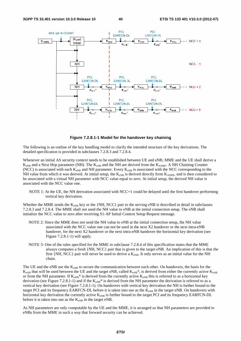
ETSI
ETSI TS 133 401 V10.3.0 (2012-07)403GPP TS 33.401 version 10.3.0 Release 10
Figure 7.2.8.1-1 Model for the handover key chaining
The following is an outline of the key handling model to clarify the intended structure of the key derivations. The detailed specification is provided in subclauses 7.2.8.3 and 7.2.8.4.
Whenever an initial AS security context needs to be established between UE and eNB, MME and the UE shall derive a KeNB and a Next Hop parameter (NH). The KeNB and the NH are derived from the KASME. A NH Chaining Counter (NCC) is associated with each KeNB and NH parameter. Every KeNB is associated with the NCC corresponding to the NH value from which it was derived. At initial setup, the KeNB is derived directly from KASME, and is then considered to be associated with a virtual NH parameter with NCC value equal to zero. At initial setup, the derived NH value is associated with the NCC value one.
NOTE 1: At the UE, the NH derivation associated with NCC=1 could be delayed until the first handover performing vertical key derivation.
Whether the MME sends the KeNB key or the {NH, NCC} pair to the serving eNB is described in detail in subclauses 7.2.8.3 and 7.2.8.4. The MME shall not send the NH value to eNB at the initial connection setup. The eNB shall initialize the NCC value to zero after receiving S1-AP Initial Context Setup Request message.
NOTE 2: Since the MME does not send the NH value to eNB at the initial connection setup, the NH value associated with the NCC value one can not be used in the next X2 handover or the next intra-eNB handover, for the next X2 handover or the next intra-eNB handover the horizontal key derivation (see Figure 7.2.8.1-1) will apply.
NOTE 3: One of the rules specified for the MME in subclause 7.2.8.4 of this specification states that the MME always computes a fresh {NH, NCC} pair that is given to the target eNB. An implication of this is that the first {NH, NCC} pair will never be used to derive a KeNB. It only serves as an initial value for the NH chain.
The UE and the eNB use the KeNB to secure the communication between each other. On handovers, the basis for the KeNB that will be used between the UE and the target eNB, called KeNB*, is derived from either the currently active KeNB or from the NH parameter. If KeNB* is derived from the currently active KeNB this is referred to as a horizontal key derivation (see Figure 7.2.8.1-1) and if the KeNB* is derived from the NH parameter the derivation is referred to as a vertical key derivation (see Figure 7.2.8.1-1). On handovers with vertical key derivation the NH is further bound to the target PCI and its frequency EARFCN-DL before it is taken into use as the KeNB in the target eNB. On handovers with horizontal key derivation the currently active KeNB is further bound to the target PCI and its frequency EARFCN-DL before it is taken into use as the KeNB in the target eNB.
As NH parameters are only computable by the UE and the MME, it is arranged so that NH parameters are provided to eNBs from the MME in such a way that forward security can be achieved.
ETSI
ETSI TS 133 401 V10.3.0 (2012-07)413GPP TS 33.401 version 10.3.0 Release 10
7.2.8.1.2 Non access stratum
A NAS aspect that needs to be considered is possible NAS algorithm change at MME change that could occur at a handover. At an eNB handover with MME relocation, there is the possibility that the source MME and the target MME do not support the same set of NAS algorithms or have different priorities regarding the use of NAS algorithms. In this case, the target MME re-derives the NAS keys from KASME using the NAS algorithm identities as input to the NAS key derivation functions (see Annex A) and sends NAS SMC. All inputs, in particular the KASME, will be the same in the re-derivation except for the NAS algorithm identity.
In case the target MME decides to use NAS algorithms different from the ones used by the source MME, a NAS SMC including eKSI (new or current value depending on whether AKA was run or not) shall be sent from the MME to the UE.
This NAS Key and algorithm handling also applies to other MME changes e.g. TAU with MME changes.
NOTE: It is per operator's policy how to configure selection of handover types. Depending on an operator's security requirements, the operator can decide whether to have X2 or S1 handovers for a particular eNB according to the security characteristics of a particular eNB.
7.2.8.2 Void
7.2.8.3 Key derivations for context modification procedure
As outlined in subclause 7.2.8.1, whenever a fresh KeNB is calculated from the KASME (as described in Annex A.3), the MME shall transfer the KeNB to the serving eNB in a message modifying the security context in the eNB. The MME and the UE shall also compute the NH parameter from the KASME and the fresh KeNB as described in Annex A.4 according to the rules in clause 7.2.9.2. An NCC value 1 is associated with the NH parameter derived from the fresh KeNB and NCC value 0 with the KeNB. The UE shall compute KeNB and NH in the same way as the MME. From the newly computed KeNB, the eNB and the UE shall compute the temporary KeNB* and then the final KeNB from that KeNB* as described in clause 7.2.9.2.
NOTE 1: Since MME does not send the NH value to eNB in S1 UE CONTEXT MODIFICATION REQUEST, the NH value associated with the NCC value one can not be used in the next X2 handover or the next intra-eNB handover. So for the next X2 handover or the next intra-eNB handover the horizontal key derivation (see Figure 7.2.8.1-1) will apply.
NOTE 2: One of the rules specified for the MME in subclause 7.2.8.4 of this specification states that the MME always computes a fresh {NH, NCC} pair that is given to the target eNB. An implication of this is that the first {NH, NCC} pair, i.e., the one with NCC equal to 1 will never be used to derive a KeNB. It only serves as an initial value for the NH chain.
NOTE 3: At the UE, the NH derivation associated with NCC=1 could be delayed until the first handover performing vertical key derivation.
7.2.8.4 Key derivations during handovers
7.2.8.4.1 Intra-eNB Handover
When the eNB decides to perform an intra-eNB handover it shall derive KeNB* as in Annex A.5 using target PCI, its frequency EARFCN-DL, and either NH or the current KeNB depending on the following criteria: the eNB shall use the NH for deriving KeNB* if an unused {NH, NCC} pair is available in the eNB (this is referred to as a vertical key derivation), otherwise if no unused {NH, NCC} pair is available in the eNB, the eNB shall derive KeNB* from the current KeNB (this is referred to as a horizontal key derivation).
The eNB shall use the KeNB* as the KeNB after handover. The eNB shall send the NCC used for KeNB* derivation to UE in HO Command message.
7.2.8.4.2 X2-handover
As in intra-eNB handovers, for X2 handovers the source eNB shall perform a vertical key derivation in case it has an unused {NH, NCC} pair. The source eNB shall first compute KeNB* from target PCI, its frequency EARFCN-DL, and
ETSI
ETSI TS 133 401 V10.3.0 (2012-07)423GPP TS 33.401 version 10.3.0 Release 10
either from currently active KeNB in case of horizontal key derivation or from the NH in case of vertical key derivation as described in Annex A.5.
Next the source eNB shall forward the {KeNB*, NCC} pair to the target eNB. The target eNB shall use the received KeNB* directly as KeNB to be used with the UE. The target eNB shall associate the NCC value received from source eNB with the KeNB. The target eNB shall include the received NCC into the prepared HO Command message, which is sent back to the source eNB in a transparent container and forwarded to the UE by source eNB.
When the target eNB has completed the handover signaling with the UE, it shall send a S1 PATH SWITCH REQUEST to the MME. Upon reception of the S1 PATH SWITCH REQUEST, the MME shall increase its locally kept NCC value by one and compute a new fresh NH by using the KASME and its locally kept NH value as input to the function defined in Annex A.4. The MME shall then send the newly computed {NH, NCC} pair to the target eNB in the S1 PATH SWITCH REQUEST ACKNOWLEDGE message. The target eNB shall store the received {NH, NCC} pair for further handovers and remove other existing unused stored {NH, NCC} pairs if any.
NOTE: Because the path switch message is transmitted after the radio link handover, it can only be used to provide keying material for the next handover procedure and target eNB. Thus, for X2-handovers key separation happens only after two hops because the source eNB knows the target eNB keys. The target eNB can immediately initiate an intra-cell handover to take the new NH into use once the new NH has arrived in the S1 PATH SWITCH REQUEST ACKNOWLEDGE.
7.2.8.4.3 S1-Handover
Upon reception of the HANDOVER REQUIRED message the source MME shall increase its locally kept NCC value by one and compute a fresh NH from its stored data using the function defined in Annex A.4. The source MME shall store that fresh pair and send it to the target MME in the S10 FORWARD RELOCATION REQUEST message. The S10 FORWARD RELOCATION REQUEST message shall in addition contain the KASME that is currently used to compute {NH, NCC} pairs and its corresponding eKSI.
The target MME shall store locally the {NH, NCC} pair received from the source MME.
The target MME shall then send the received {NH, NCC} pair to the target eNB within the S1 HANDOVER REQUEST.
Upon receipt of the S1 HANDOVER REQUEST from the target MME, the target eNB shall compute the KeNB to be used with the UE by performing the key derivation defined in Annex A.5 with the fresh{NH, NCC} pair in the S1 HANDOVER REQUEST and the target PCI and its frequency EARFCN-DL. The target eNB shall associate the NCC value received from MME with the KeNB. The target eNB shall include the NCC value from the received {NH, NCC} pair into the HO Command to the UE and remove any existing unused stored {NH, NCC} pairs.
NOTE: The source MME may be the same as the target MME in the description in this subclause. If so the single MME performs the roles of both the source and target MME, i.e. the MME calculates and stores the fresh {NH, NCC} pair and sends this to the target eNB.
For S1-handover, the source eNB shall include AS algorithms used in the source cell (ciphering and integrity algorithms) in the source to target transparent container that shall be sent to the target eNB. The AS algorithms used by in the source cell are provided to the target eNB so that it can decipher and integrity verify the RRCReestablishmentComplete message on SRB1 in the potential RRCConnectionRe-establishment procedure.
7.2.8.4.4 UE handling
The UE behaviour is the same regardless if the handover is S1, X2 or intra-eNB.
If the NCC value the UE received in the HO Command message from target eNB via source eNB is equal to the NCC value associated with the currently active KeNB, the UE shall derive the KeNB* from the currently active KeNB and the target PCI and its frequency EARFCN-DL using the function defined in Annex A.5.
If the UE received an NCC value that was different from the NCC associated with the currently active KeNB, the UE shall first synchronize the locally kept NH parameter by computing the function defined in Annex A.4 iteratively (and increasing the NCC value until it matches the NCC value received from the source eNB via the HO command message. When the NCC values match, the UE shall compute the KeNB* from the synchronized NH parameter and the target PCI and its frequency EARFCN-DL using the function defined in Annex A.5.
The UE shall use the KeNB* as the KeNB when communicating with the target eNB.

ETSI
ETSI TS 133 401 V10.3.0 (2012-07)433GPP TS 33.401 version 10.3.0 Release 10
7.2.9 Key-change-on-the fly
7.2.9.1 General
Key-change-on-the fly consists of re-keying or key-refresh.
Key refresh shall be possible for KeNB, KRRC-enc, KRRC-int, KUP-int, and KUP-enc and shall be initiated by the eNB when a PDCP COUNTs is about to be re-used with the same Radio Bearer identity and with the same KeNB. The procedure is described in clause 7.2.9.3.
Re-keying shall be possible for the KeNB, KRRC-enc, KRRC-int, KUP-int, and KUP-enc. This re-keying shall be initiated by the MME when an EPS AS security context different from the currently active one shall be activated. The procedures for doing this are described in clause 7.2.9.2.
Re-keying shall be possible for KNAS-enc and KNAS-int. Re-keying of KNAS-enc and KNAS-int shall be initiated by the MME when a EPS NAS security context different from the currently active one shall be activated. The procedures for doing this are described in clause 7.2.9.4.
Re-keying of the entire EPS key hierarchy including KASME shall be achieved by first re-keying KASME, then KNAS-enc and KNAS-int, followed by re-keying of the KeNB and derived keys. For NAS key change-on-on-the fly, activation of NAS keys is accomplished by a NAS SMC procedure.
AS Key change on-the-fly is accomplished using a procedure based on intra-cell handover. The following AS key changes on-the-fly shall be possible: local KeNB refresh (performed when PDCP COUNTs are about to wrap around), KeNB re-keying performed after an AKA run, activation of a native context after handover from UTRAN or GERAN.
7.2.9.2 KeNB re-keying
The re-keying procedure is initiated by the MME after a successful AKA run with the UE to activate a partial native EPS security context, or to re-activate a non-current full native EPS security context after handover from GERAN or UTRAN according to subclauses 9.2.2.1 and 10.3.2.
In case the procedure is initiated by the MME after a successful AKA run with the UE, the MME derives the new KeNB using the key derivation function as specified in Annex A.3 using the new KASME and the uplink NAS COUNT used in the most recent NAS Security Mode Complete message. The KeNB is sent to the eNB after a successfully completed NAS SMC in a S1 AP UE CONTEXT MODIFICATION REQUEST message triggering the eNB to perform the re-keying. The eNB runs the key-change-on-the-fly procedure with the UE. During this procedure the eNB shall indicate to the UE that a key change on-the-fly is taking place. The procedure used is based on an intra-cell handover, and hence the same KeNB derivation steps shall be taken as in a normal handover procedure.
When the UE receives an indication that the procedure is a key change on-the-fly procedure, the UE shall use the KASME from the current EPS NAS security context as the basis for KeNB derivations.
NOTE 1: To perform a key change on-the-fly of the entire key hierarchy, the MME has to change the EPS NAS security context before changing the AS security context.
If the UE has determined that the eKSI has changed, the UE shall derive a temporary KeNB by applying the key derivation function as specified in Annex A.3, using the uplink NAS COUNT in the most recent NAS Security Mode Complete message and the new KASME as input. From this temporary KeNB the UE shall derive the KeNB* as normal (see Annex A). The eNB shall take the KeNB it received from the MME, which is equal to the temporary KeNB, as basis for its KeNB* derivations. From this step onwards, the key derivations continue as in a normal handover.
If the AS level re-keying fails, then the MME shall complete another NAS security mode procedure before initiating a new AS level re-keying. This ensures that a fresh KeNB is used.
In case the re-keying procedure is initiated by the MME to re-activate a non-current full native EPS security context after handover from GERAN or UTRAN the same procedure as above applies.
The NH parameter shall be handled according to the following rules:
- UE and MME shall use NH derived from old KASME before the context modification is complete, i.e. for the UE when it sends the RRC Connection Reconfiguration Complete, and for the MME when it receives the UE CONTEXT MODIFICATION RESPONSE. In particular, the MME shall send an NH derived from old KASME in
ETSI
ETSI TS 133 401 V10.3.0 (2012-07)443GPP TS 33.401 version 10.3.0 Release 10
the S1AP HANDOVER RESOURCE ALLOCATION, S10 FORWARD RELOCATION, and S1AP PATH SWITCH REQUEST ACKNOWLEDGE messages before the context modification is complete.
- The eNB shall delete any old NH upon completion of the context modification.
- The UE and MME shall delete any old NH upon completion of the context modification. After the completion of the context modification, the UE and the MME shall derive any new NH parameters from the new KeNB and the new KASME according to Annex A.4.
7.2.9.3 KeNB refresh
This procedure is based on an intra-cell handover. The KeNB chaining that is performed during a handover ensures that the KeNB is re-freshed w.r.t. the RRC and UP COUNT after the procedure.
7.2.9.4 NAS key re-keying
After an AKA has taken place, new NAS keys from a new KASME shall be derived, according to Annex A.7.
To re-activate a non-current full native EPS security context after handover from GERAN or UTRAN, cf. clause 9.2.2 B step 7, the UE and the MME take the NAS keys into use by running a NAS SMC procedure according to clause 7.2.4.5.
MME shall activate fresh NAS keys from an EPS AKA run or activate native security context with sufficiently low NAS COUNT values before the NAS uplink or downlink COUNT wraps around with the current security context.
7.2.10 Rules on Concurrent Running of Security Procedures
Concurrent runs of security procedures may, in certain situations, lead to mismatches between security contexts in the network and the UE. In order to avoid such mismatches, the following rules shall be adhered to:
1. MME shall not initiate any of the S1 procedures Initial Context Setup or UE Context Modification including a new KeNB towards a UE if a NAS Security Mode Command procedure is ongoing with the UE.
2. The MME shall not initiate a NAS Security Mode Command towards a UE if one of the S1 procedures Initial Context Setup or UE Context Modification including a new KeNB is ongoing with the UE.
3. When the UE has cryptographically protected radio bearers established and the MME has initiated a NAS SMC procedure in order to take a new KASME into use, the MME shall continue to include AS security context parameters based on the old KASME in the HANDOVER REQUEST or PATH SWITCH REQUEST ACKNOWLEDGE message, until the MME takes a KeNB derived from the new KASME into use by means of a UE Context Modification procedure.
4. When the UE has cryptographically protected radio bearers established and has received a NAS SMC message in order to take a new KASME into use, the UE shall continue to use AS security context parameters based on the old KASME in handover until the network indicates in an RRCConnectionReconfiguration procedure to take a KeNB derived from the new KASME into use.
5. The source eNB shall reject an S1 UE Context Modification Request when the eNB has initiated, but not yet completed, an inter-eNB handover. When a RRCConnectionReconfiguration procedure triggered by a UE Context Modification is ongoing the source eNB shall wait for the completion of this procedure before initiating any further handover procedure.
6. When the MME has initiated a NAS SMC procedure in order to take a new KASME into use and receives a request for an inter-MME handover or an inter-RAT handover from the serving eNB, the MME shall wait for the completion of the NAS SMC procedure before sending an S10 FORWARD RELOCATION message or initiating an inter-RAT handover.
7. When the MME has initiated a UE Context Modification procedure in order to take a new KeNB into use and receives a request for an inter-MME handover from the serving eNB, the MME shall wait for the (successful or unsuccessful) completion of the UE Context Modification procedure before sending an S10 FORWARD RELOCATION message.
ETSI
ETSI TS 133 401 V10.3.0 (2012-07)453GPP TS 33.401 version 10.3.0 Release 10
8. When the MME has successfully performed a NAS SMC procedure taking a new KASME into use, but has not yet successfully performed a UE Context Modification procedure, which takes a KeNB derived from the new KASME into use, the MME shall include both the old KASME with the corresponding eKSI, NH, and NCC, and a full EPS NAS security context based on the new KASME in the S10 FORWARD RELOCATION message.
9. When an MME receives a S10 FORWARD RELOCATION message including both the old KASME with the corresponding eKSI, NH, and NCC, and a full EPS NAS security context based on the new KASME the MME shall use the new KASME in NAS procedures, but shall continue to include AS security context parameters based on the old KASME in the HANDOVER REQUEST or PATH SWITCH REQUEST ACKNOWLEDGE message until the completion of a UE Context Modification procedure, which takes a KeNB derived from the new KASME into use.
10. Once the source MME has sent an S10 FORWARD RELOCATION message to the target MME at an inter-MME handover, the source MME shall not send any downlink NAS messages to the UE until it is aware that the handover has either failed or has been cancelled.
7.3 UP security mechanisms
7.3.1 UP confidentiality mechanisms
The user plane data is ciphered by the PDCP protocol between the UE and the eNB as specified in TS 36.323 [12]..
The use and mode of operation of the 128-EEA algorithms are specified in Annex B.
The input parameters to the 128-bit EEA algorithms as described in Annex B are an 128-bit cipher key KUPenc as KEY, a 5-bit bearer identity BEARER which value is assigned as specified by TS 36.323 [12], the 1-bit direction of transmission DIRECTION, the length of the keystream required LENGTH and a bearer specific, time and direction dependent 32-bit input COUNT which corresponds to the 32-bit PDCP COUNT.
7.3.2 UP integrity mechanisms
This subclause applies only to the user plane on the Un interface between RN and DeNB:
The user plane data is integrity-protected by the PDCP protocol between the RN and the DeNB as specified in TS 36.323 [12]. Replay protection shall be activated when integrity protection is activated. Replay protection shall ensure that the receiver only accepts each particular incoming PDCP COUNT value once using the same AS security context.
The use and mode of operation of the 128-EIA algorithms are specified in Annex B.
The input parameters to the 128-bit EIA algorithms as described in Annex B are a 128-bit cipher key KUPint as KEY, a 5-bit bearer identity BEARER which value is assigned as specified by TS 36.323 [12], the 1-bit direction of transmission DIRECTION, and a bearer specific, time and direction dependent 32-bit input COUNT which corresponds to the 32-bit PDCP COUNT.
The supervision of failed UP integrity checks shall be performed both in the RN and the DeNB. In case of failed integrity check (i.e. faulty or missing MAC-I) is detected after the start of integrity protection, the concerned message shall be discarded. This can happen on the DeNB side or on the RN side.
NOTE: The handling of UP integrity check failures by an RN is an implementation issue TS 36.323 [12] intentionally does not mandate any action for a failed integrity check (not even sending an indication of failure to higher layers). Consequently, depending on the implementation, the message failing integrity check is, or is not, silently discarded. This is in contrast to the handling of a failed RRC integrity check by a UE, cf. the NOTE in clause 7.4.1 of the present document.
7.4 RRC security mechanisms
7.4.1 RRC integrity mechanisms
RRC integrity protection shall be provided by the PDCP layer between UE and eNB and no layers below PDCP shall be integrity protected. Replay protection shall be activated when integrity protection is activated (except for when the
ETSI
ETSI TS 133 401 V10.3.0 (2012-07)463GPP TS 33.401 version 10.3.0 Release 10
selected integrity protection algorithm is EIA0, see Annex B). Replay protection shall ensure that the receiver only accepts each particular incoming PDCP COUNT value once using the same AS security context.
The use and mode of operation of the 128-EIA algorithms are specified in Annex B.
The input parameters to the 128-bit EIA algorithms as described in Annex B are an 128-bit integrity key KRRCint as KEY,, a 5-bit bearer identity BEARER which value is assigned as specified by TS 36.323 [12], the 1-bit direction of transmission DIRECTION and a bearer specific, time and direction dependent 32-bit input COUNT which corresponds to the 32-bit PDCP COUNT.
The supervision of failed RRC integrity checks shall be performed both in the ME and the eNB. In case of failed integrity check (i.e. faulty or missing MAC-I) is detected after the start of integrity protection, the concerned message shall be discarded. This can happen on the eNB side or on the ME side.
NOTE: This text does not imply that the concerned message is silently discarded. In fact, TS 36.331 [21] specifies that the UE shall trigger a recovery procedure upon detection of a failed RRC integrity check. When the cause for integrity protection failure is not a context mismatch, such as a key or HFN mismatch, the run of a recovery procedure unnecessarily adds load to the system. However, in the absence of a means for the UE to reliably detect the cause of an integrity protection failure and the fact that the only identified consequence of an active attack is limited to non-persistent DoS effects, priority was given to a procedure allowing recovery from the deadlock caused by a context mismatch.
7.4.2 RRC confidentiality mechanisms
RRC confidentiality protection is provided by the PDCP layer between UE and eNB.
The use and mode of operation of the 128-EEA algorithms are specified in Annex B.
The input parameters to the 128-bit EEA algorithms as described in Annex B are an 128-bit cipher Key KRRCenc as KEY, a 5-bit bearer identity BEARER which corresponds to the radio bearer identity, the 1-bit direction of transmission DIRECTION, the length of the keystream required LENGTH and a bearer specific, time and direction dependent 32-bit input COUNT which corresponds to the 32-bit PDCP COUNT.
7.4.3 KeNB* and Token Preparation for the RRCConnectionRe-establishment Procedure
The KeNB* and token calculation at handover preparation are cell specific instead of eNB specific. At potential RRC Connection re-establishment (e.g, in handover failure case), the UE may select a cell different from the target cell to initiate the re-establishment procedure. To ensure that the UE RRCConnectionRe-establishment attempt is successful when the UE selects another cell under the control of the target eNB at handover preparation, the serving eNB could prepare multiple KeNB*s and tokens for multiple cells which are under the control of the target eNB. The serving eNB may prepare cells belonging to the serving eNB itself.
The preparation of these cells includes sending security context containing KeNB*s and tokens for each cell to be prepared, as well as the corresponding NCC, the UE EPS security capabilities, and the security algorithms used in the source cell for computing the token, to the target eNB. The source eNB shall derive the KeNB*s as described in Annex A.5 based on the corresponding target cell"s physical cell ID and frequency EARFCN-DL.
In order to calculate the token, the source eNB shall use the negotiated EIA-algorithm from the AS Security context from the source eNB with the following inputs: source C-RNTI, source PCI and target Cell-ID as defined by VarShortMAC-Input in TS 36.331 [21], where source PCI and source C-RNTI are associated with the cell the UE last had an active RRC connection with and target cell ID is the identity of the target cell where the RRCConnectionReestablishmentRequest is sent to.
- KEY shall be set to KRRCint of the source cell;
- all BEARER bits shall be set to 1;
- DIRECTION bit shall be set to 1;
- all COUNT bits shall be set to 1.
The token shall be the 16 least significant bits of the output of the used integrity algorithm.
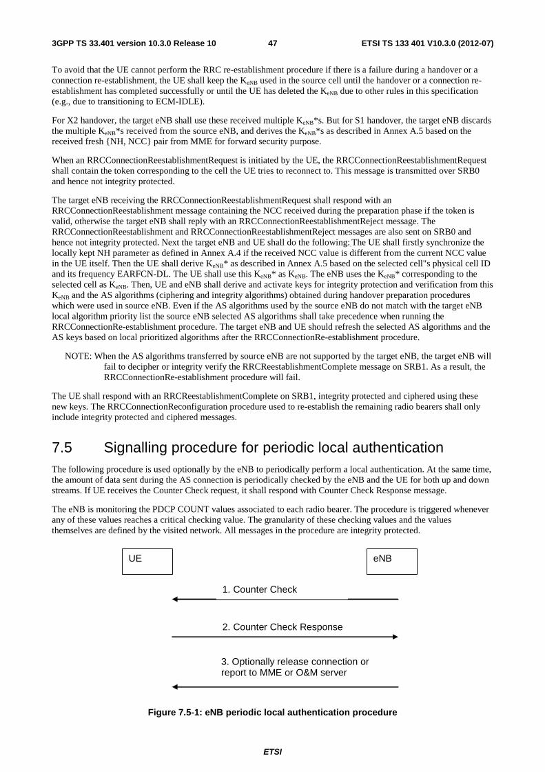
ETSI
ETSI TS 133 401 V10.3.0 (2012-07)473GPP TS 33.401 version 10.3.0 Release 10
To avoid that the UE cannot perform the RRC re-establishment procedure if there is a failure during a handover or a connection re-establishment, the UE shall keep the KeNB used in the source cell until the handover or a connection re-establishment has completed successfully or until the UE has deleted the KeNB due to other rules in this specification (e.g., due to transitioning to ECM-IDLE).
For X2 handover, the target eNB shall use these received multiple KeNB*s. But for S1 handover, the target eNB discards the multiple KeNB*s received from the source eNB, and derives the KeNB*s as described in Annex A.5 based on the received fresh {NH, NCC} pair from MME for forward security purpose.
When an RRCConnectionReestablishmentRequest is initiated by the UE, the RRCConnectionReestablishmentRequest shall contain the token corresponding to the cell the UE tries to reconnect to. This message is transmitted over SRB0 and hence not integrity protected.
The target eNB receiving the RRCConnectionReestablishmentRequest shall respond with an RRCConnectionReestablishment message containing the NCC received during the preparation phase if the token is valid, otherwise the target eNB shall reply with an RRCConnectionReestablishmentReject message. The RRCConnectionReestablishment and RRCConnectionReestablishmentReject messages are also sent on SRB0 and hence not integrity protected. Next the target eNB and UE shall do the following:.The UE shall firstly synchronize the locally kept NH parameter as defined in Annex A.4 if the received NCC value is different from the current NCC value in the UE itself. Then the UE shall derive KeNB* as described in Annex A.5 based on the selected cell"s physical cell ID and its frequency EARFCN-DL. The UE shall use this KeNB* as KeNB. The eNB uses the KeNB* corresponding to the selected cell as KeNB. Then, UE and eNB shall derive and activate keys for integrity protection and verification from this KeNB and the AS algorithms (ciphering and integrity algorithms) obtained during handover preparation procedures which were used in source eNB. Even if the AS algorithms used by the source eNB do not match with the target eNB local algorithm priority list the source eNB selected AS algorithms shall take precedence when running the RRCConnectionRe-establishment procedure. The target eNB and UE should refresh the selected AS algorithms and the AS keys based on local prioritized algorithms after the RRCConnectionRe-establishment procedure.
NOTE: When the AS algorithms transferred by source eNB are not supported by the target eNB, the target eNB will fail to decipher or integrity verify the RRCReestablishmentComplete message on SRB1. As a result, the RRCConnectionRe-establishment procedure will fail.
The UE shall respond with an RRCReestablishmentComplete on SRB1, integrity protected and ciphered using these new keys. The RRCConnectionReconfiguration procedure used to re-establish the remaining radio bearers shall only include integrity protected and ciphered messages.
7.5 Signalling procedure for periodic local authentication The following procedure is used optionally by the eNB to periodically perform a local authentication. At the same time, the amount of data sent during the AS connection is periodically checked by the eNB and the UE for both up and down streams. If UE receives the Counter Check request, it shall respond with Counter Check Response message.
The eNB is monitoring the PDCP COUNT values associated to each radio bearer. The procedure is triggered whenever any of these values reaches a critical checking value. The granularity of these checking values and the values themselves are defined by the visited network. All messages in the procedure are integrity protected.
UE eNB
1. Counter Check
2. Counter Check Response
3. Optionally release connection or report to MME or O&M server
Figure 7.5-1: eNB periodic local authentication procedure

ETSI
ETSI TS 133 401 V10.3.0 (2012-07)483GPP TS 33.401 version 10.3.0 Release 10
1. When a checking value is reached (e.g. the value in some fixed bit position in the hyperframe number is changed), a Counter Check message is sent by the eNB. The Counter Check message contains the most significant parts of the PDCP COUNT values (which reflect amount of data sent and received) from each active radio bearer.
2. The UE compares the PDCP COUNT values received in the Counter Check message with the values of its radio bearers. Different UE PDCP COUNT values are included within the Counter Check Response message.
3. If the eNB receives a counter check response message that does not contain any PDCP COUNT values, the procedure ends. If the eNB receives a counter check response that contains one or several PDCP COUNT values, the eNB may release the connection or report the difference of the PDCP COUNT values for the serving MME or O&M server for further traffic analysis for e.g. detecting the attacker.
ETSI
ETSI TS 133 401 V10.3.0 (2012-07)493GPP TS 33.401 version 10.3.0 Release 10
8 Security mechanisms for non-access stratum signalling
8.0 General The statements relating to UEs in clause 8 apply also to RNs regarding the security between a relay node and its MME.
8.1 NAS integrity mechanisms Integrity protection for NAS signalling messages shall be provided as part of the NAS protocol.
8.1.1 NAS input parameters and mechanism
Input parameters to the NAS 128-bit integrity algorithms as described in Annex B are an 128-bit integrity key KNASint as KEY, an 5-bit bearer identity BEARER which shall equal the constant value 0x00, the direction of transmission DIRECTION, and a bearer specific, time and direction dependent 32-bit input COUNT which is constructed as follows:
COUNT := 0x00 || NAS OVERFLOW || NAS SQN
Where
- the leftmost 8 bits are padding bits including all zeros.
- NAS OVERFLOW is a 16-bit value which is incremented each time the NAS SQN is incremented from the maximum value.
- NAS SQN is the 8-bit sequence number carried within each NAS message.
NOTE: The BEARER identity is not necessary since there is only one NAS signalling connection per pair of MME and UE, but is included as a constant value so that the input parameters for AS and NAS will be the same, which simplifies specification and implementation work.
The use and mode of operation of the 128-bit integrity algorithms are specified in Annex B.
The supervision of failed NAS integrity checks shall be performed both in the ME and the MME. In case of failed integrity check (i.e. faulty or missing NAS-MAC) is detected after the start of NAS integrity protection, the concerned message shall be discarded except for some NAS messages specified in TS 24.301 [9]. For those exceptions the MME shall take the actions specified in TS 24.301 [9] when receiving a NAS message with faulty or missing NAS-MAC. Discarding NAS messages can happen on the MME side or on the ME side.
8.1.2 NAS integrity activation
NAS integrity shall be activated using the NAS SMC procedure or after a handover to E-UTRAN from UTRAN/GERAN. Replay protection shall be activated when integrity protection is activated (except for when the selected integrity protection algorithm is EIA0, see Annex B). Replay protection shall ensure that the receiver only accepts each particular incoming NAS COUNT value once using the same NAS security context. Once NAS integrity has been activated, NAS messages without integrity protection shall not be accepted by the UE or MME. Before NAS integrity has been activated, NAS messages without integrity protection shall only be accepted by the UE or MME in certain cases where it is not possible to apply integrity protection as specified in TS 24.301 [9]. While some NAS messages such as reject messages need to be accepted by the UE without integrity protection, the MME shall only send a reject message that causes the CSG list on the UE to be modified after the start of NAS security. The UE shall discard any message modifying the CSG list if it is not integrity protected.
NAS integrity stays activated until the EPS security context is deleted in either the UE or MME. In particular the NAS service request shall always be integrity protected and the NAS attach request message shall be integrity protected if the EPS security context is not deleted while UE is in EMM-DEREGISTERED. The length of the NAS-MAC is 32 bit. The full NAS-MAC shall be appended to all integrity protected messages except for the NAS service request. Only the 16 least significant bits of the 32 bit NAS-MAC shall be appended to the NAS service request message.
ETSI
ETSI TS 133 401 V10.3.0 (2012-07)503GPP TS 33.401 version 10.3.0 Release 10
The use and mode of operation of the 128-EIA algorithms are specified in Annex B.
8.2 NAS confidentiality mechanisms The input parameters for the NAS 128-bit ciphering algorithms shall be the same as the ones used for NAS integrity protection as described in clause 8.1, with the exception that a different key, KNASenc , is used as KEY, and there is an additional input parameter, namely the length of the key stream to be generated by the encryption algorithms.
The use and mode of operation of the 128-bit ciphering algorithms are specified in Annex B.
9 Security interworking between E-UTRAN and UTRAN
9.1 RAU and TAU procedures
9.1.1 RAU procedures in UTRAN
This subclause covers both the cases of idle mode mobility from E-UTRAN to UTRAN and of Idle Mode Signaling Reduction (ISR), as defined in TS 23.401 [2].
NOTE 1: TS 23.401 states conditions under which a valid P-TMSI or a P-TMSI that is mapped from a valid GUTI ('mapped GUTI') is inserted in the Information Element 'old P-TMSI' in the Routing Area Update Request. It depends on the old P-TMSI which security context can be taken into use after completion of the Routing Area Update procedure.
Use of an existingUMTS security context
If the UE sends the RAU Request with the "old P-TMSI" Information Element including a valid P-TMSI it shall also include the KSI relating to this P-TMSI. This KSI is associated with the UMTS security context stored on the UE, and it indicates this fact to the SGSN. In this case the UE shall include P-TMSI signature into the RAU Request if a P-TMSI signature was assigned by the old SGSN. If the network does not have a valid security context for this KSI it shall run AKA. In case of an SGSN change keys from the old SGSN shall overwrite keys in the new SGSN if any.
NOTE 2: if the UE has a valid UMTS security context then this context is stored on the USIM according to TS 33.102 [4].
Mapping of EPS security context to UMTS security context
If the UE sends the RAU Request with the "old P-TMSI" Information Element including mapped GUTI it shall also include the KSI equal to the value of the eKSI associated with the current EPS security context (cf. clause 3). The UE shall include a truncated NAS-token, as defined in this clause further below, into the P-TMSI signature IE. The MME shall transfer UE's UTRAN and GERAN security capabilities and CK' || IK' with KSI equal to the value of the eKSI associated with the current EPS security context to SGSN with Context Response/SGSN Context Response message. The MME and UE shall derive CK' and IK' from the KASME and the NAS uplink COUNT value corresponding to the truncated NAS-token received by the MME from SGSN as specified in Annex A. Keys CK' and IK' and KSI sent from the MME shall replace all the UTRAN PS key parameters CK, IK, s KSI in the target SGSN if any. Keys CK' and IK' and the KSI shall replace all the currently stored UTRAN PS key parameters CK, IK, KSI values on both USIM and ME. The handling of STARTPS shall comply with the rules in 3GPP TS 25.331 [24]. The UE may set the STARTPS value to 0 if it is done before establishment of the RRC connection.
The ME shall use CK' and IK' to derive the GPRS Kc using the c3 function specified in 3GPP TS 33.102 [4]. The ME shall assign the eKSI value (associated with CK" and IK") to the GPRS CKSN. The ME shall update the USIM and ME with the new GPRS Kc and GPRS CKSN.
NOTE 3: The new derived security context (including CK" and IK") replacing the old stored values in the USIM is for allowing to reuse the derived security context without invoking the authentication procedure in the subsequent connection set-ups , and also for avoiding that one KSI indicates to two different key sets and consequently leads to security context desynchronization.
ETSI
ETSI TS 133 401 V10.3.0 (2012-07)513GPP TS 33.401 version 10.3.0 Release 10
NOTE 4: An operator concerned about the security of keys received from another operator may want to enforce a policy in SGSN to run a UMTS AKA as soon as possible after the run of an idle mode mobility procedure. An example of ensuring this is the deletion of the mapped UMTS security context in the SGSN after the completion of the idle mode mobility procedure.
NOTE 5: Due to replacing all the UTRAN PS key parameters CK, IK, KSI with CK", IK" and eKSI on USIM and in ME, a new GPRS Kc needs to be derived from the new UTRAN PS key parameters CK and IK (i.e. CK" and IK"), which is part of the new UMTS security context as well, as any old GPRS Kc stored on USIM and in ME belongs to an old UMTS security context and can no longer be taken into use.
SGSN shall include the allowed security algorithm and transfer them to RNC. An SMC shall be sent to the UE containing the selected algorithms.
The x bits available in the P-TMSI signature field (at minimum 16 bits) shall be filled with the truncated NAS-token, which is defined as the x least significant bits of the NAS-token.
The NAS-token is derived as specified in Annex A.9. The UE shall use the uplink NAS COUNT value that it would use in the next NAS message to calculate the NAS-token and increase the stored uplink NAS COUNT value by 1.
SGSN shall forward the P-TMSI signature including the truncated NAS token to the old MME, which compares the received bits of the truncated NAS-token with the corresponding bits of a NAS-token generated in the MME, for the UE identified within the context request. If they match, the context request message is authenticated and authorized and MME shall provide the needed information for the SGSN. Old MME shall respond with an appropriate error cause if it does not match the value stored in the old MME. This should initiate the security functions in the new SGSN.
To avoid possible race condition problems, the MME shall compare the received truncated NAS-token with the x least significant bits of NAS-tokens generated from the current NAS uplink COUNT value up to current NAS uplink COUNT value +L, i.e. the interval [current NAS uplink COUNT, current NAS uplink COUNT+L]. A suitable value for the parameter L can be configured by the network operator. MME shall not accept the same NAS-token for the same UE twice except in retransmission cases happening for the same mobility event. If the MME finds a match, it shall set the stored uplink NAS COUNT value as though it had successfully received an integrity protected NAS message with the uplink NAS COUNT value that created the match.
9.1.2 TAU procedures in E-UTRAN
This subclause covers both the cases of idle mode mobility from UTRAN to E-UTRAN and of Idle Mode Signaling Reduction, as defined in TS 23.401 [2].
The TAU Request and ATTACH Request message shall include the UE security capabilities. The MME shall store these UE security capabilities for future use. The MME shall not make use of any UE security capabilities received from the SGSN.
NOTE 1: TS 23.401 states conditions under which a valid GUTI or a GUTI that is mapped from a valid P-TMSI is inserted in the Information Element 'old GUTI' in the Tracking Area Update Request. The value in the 'old' GUTI IE informs the MME, which SGSN/MME to fetch the UE context from.
Case 1: P-TMSI not included in 'old GUTI' IE in TAU Request
This case is identical to that described in clause 7.2.7.
Case 2: Mapped P-TMSI included in 'old GUTI' IE in TAU Request
The UE shall include in the TAU Request:
- the KSI with corresponding P-TMSI and old RAI to point to the right source SGSN and key set there. This allows the UE and MME to generate the mapped EPS NAS security context, as described below, if current EPS NAS security context is not available in the UE and network. The KSI shall correspond to the set of keys most recently generated (either by a successful UMTS AKA run in UTRAN (which may or may not yet have been taken into use by the UE and SGSN) or a UMTS security context mapped from an EPS NAS security context during a previous visit in UTRAN).
- a P-TMSI signature, if the UE was previously connected to UTRAN where the SGSN assigned a P-TMSI signature to the UE
ETSI
ETSI TS 133 401 V10.3.0 (2012-07)523GPP TS 33.401 version 10.3.0 Release 10
- a 32bit NONCEUE (see clause A.11 for requirements on the randomness of NONCEUE).
If the UE has a current EPS NAS security context, then it shall include the corresponding GUTI and eKSI value in the TAU Request. The TAU Request shall be integrity-protected, but not confidentiality-protected. The UE shall use the current EPS NAS security context algorithms to protect the TAU Request message.
NOTE 2: The current EPS NAS security context may be of type "mapped", and hence the value of the eKSI be of type "KSISGSN". This value of KSISGSN may be different from the KSI pointing to the set of keys most recently generated in UTRAN as an UMTS AKA run may have happened in UTRAN after the current mapped EPS NAS security context indicated by the eKSI with the value KSISGSN was generated
NOTE 3: The UE has a current EPS NAS security context in the following scenario: a UE established a current EPS NAS security context during a previous visit to EPS, then moves to UTRAN/GERAN from E-UTRAN and storing the current EPS NAS security context. When the UE moves back to E-UTRAN there is a current EPS NAS security context.
If a current EPS NAS security context is not available in the UE, the UE shall send the TAU request unprotected.
If the MME received a P-TMSI signature from the UE, the MME shall include that P-TMSI signature in the Context Request message sent to the SGSN. The SGSN shall transfer CK || IK to MME in the Context Response/SGSN Context Response message. In case the MM context in the Context Response/SGSN Context Response indicates GSM security mode, the MME shall abort the procedure.
In case the TAU Request was protected and the MME has the indicated EPS NAS security context it shall verify the TAU Request message. If it is successful, the UE and the MME share a current EPS NAS security context. In case the TAU Request had the active flag set or there is pending downlink UP data, KeNB is calculated as described in clause 7.2.7.
If the MME wants to change the algorithms, the MME shall use a NAS security mode procedure (see clause 7.2.4.4).
If the MME does not have the EPS NAS security context indicated by the eKSI by the UE in the TAU request, or the TAU request was received unprotected, the MME shall create a new mapped EPS NAS security context (that shall become the current EPS NAS security context). In this case, the MME shall generate a 32bit NONCEMME (see clause A.10 for requirements on the randomness of NONCEMME). and use the received NONCEUE with the NONCEMME to generate a fresh mapped K'ASME from CK and IK, where CK, IK were identified by the KSI and P-TMSI in the TAU Request. See Annex A.11 for more information on how to derive the fresh K'ASME. The MME initiates a NAS Security mode command procedure with the UE as described in clause 7.2.4.4 including the KSISGSN, NONCEUE, and NONCEMME in the NAS Security mode command. The uplink and downlink NAS COUNT for mapped EPS NAS security context shall be set to start value (i.e., 0) when new mapped EPS NAS security context is created in UE and MME.
If the TAU Request had the active flag set or there is pending downlink UP data, the uplink NAS Count which is set to zero shall be used to derive the KeNB in MME and UE as specified in Annex A. MME shall deliver the KeNB to the target eNB on the S1 interface.
The TAU Accept shall be protected using the current EPS NAS security context.
9.2 Handover
9.2.1 From E-UTRAN to UTRAN
NAS and AS security shall always be activated before handover from E-UTRAN to UTRAN can take place. Consequently the source system in the handover shall always send a key set to the target system during handover. The security policy of the target PLMN determines the selected algorithms to be used within the UTRAN HO command.
The MME shall select the current NAS downlink COUNT value to use in the handover and then increase the stored NAS downlink COUNT value by 1.
NOTE 0: Increasing the NAS downlink COUNT by 1 is to ensure that a fresh NAS downlink COUNT is used for any future purposes.
ETSI
ETSI TS 133 401 V10.3.0 (2012-07)533GPP TS 33.401 version 10.3.0 Release 10
UE and MME shall derive a confidentiality key CK', and an integrity key IK' from the KASME and the selected NAS downlink COUNT value of the current EPS key security context with the help of a one-way key derivation function KDF as specified in Annex A.
Whether UTRAN PS key ciphering is considered active in the target UTRAN after handover from E-UTRAN shall be determined according to the principles for handover to UTRAN in TS 25.331 [24].
UE and MME shall assign the value of eKSI to KSI. MME shall transfer CK' || IK' with KSI to SGSN. The target SGSN shall replace all stored parameters CK, IK, KSI, if any, with CK' , IK', KSI received from the MME. The UE shall replace all stored parameters CK, IK, KSI, if any, with CK' , IK', KSI in both ME and USIM. STARTPS shall comply with the rules in 3GPP TS 25.331 [24]. For the definition of the Key Derivation Function see Annex A. The ME shall use CK" and IK" to derive the GPRS Kc using the c3 function specified in 3GPP TS 33.102 [4]. The ME shall assign the eKSI value (associated with CK" and IK") to the GPRS CKSN. The ME shall update the USIM and ME with the GPRS Kc and GPRS CKSN.
NOTE 1: The new mapped UMTS security context (including CK", and IK" ) replacing the stored values in the USIM and ME, is for allowing to reuse the mapped UMTS security context without invoking the authentication procedure in subsequent connection set-ups, and also for avoiding that one KSI value gets associated with two different key sets and consequently leads to UMTS security context desynchronization.
NOTE 2: An operator concerned about the security of keys received from an E-UTRAN of another operator may want to enforce a policy in SGSN to run a UMTS AKA as soon as possible after the handover. One example of ensuring this is the deletion of the mapped UMTS security context in the SGSN after the UE has left active state in UMTS.
NOTE 3: Due to replacing all the UTRAN PS key parameters CK, IK, KSI with CK", IK" and eKSI on USIM and in ME, a new GPRS Kc needs to be derived from the new UTRAN PS key parameters CK and IK (i.e. CK" and IK"), which is part of the new UMTS security context as well, as any old GPRS Kc stored on USIM and in ME, belongs to an old UMTS security context and can no longer be taken into use.
After HO from E-UTRAN to UTRAN the current EPS NAS security context shall (if it is kept ) be considered as the current one in E-UTRAN in the UE and the MME.
MME shall also provide at least the 4 LSB of the selected NAS downlink COUNT value to the source eNB, which then shall include the bits in the MobilityFromE-UTRANCommand to the UE. The UE shall use the received 4 LSB and its stored NAS downlink COUNT to estimate the NAS downlink COUNT selected by the MME.
NOTE 4: It is left to the implementation how to estimate the NAS downlink COUNT.
The UE shall ensure that the estimated NAS downlink COUNT has not been used to calculate a CK' and IK' in a previous successful or unsuccessful PS or SRVCC handover. If the estimated NAS downlink COUNT is greater than all the estimated NAS downlink COUNTs either used by the UE for key derivation in a handover or received in a NAS message that passed its integrity check, the UE shall update its stored NAS downlink COUNT as though it has successfully integrity checked a NAS message with that estimated NAS downlink COUNT. In particular, the stored NAS downlink COUNT shall never be decreased.
MME shall transfer the UE security capabilities to the SGSN. The selection of the algorithms in the target system proceeds as described in TS 33.102 [4] for UTRAN.
If the handover is not completed successfully, the new mapped UMTS security context can not be used in the future. The SGSN shall delete the new mapped UMTS security context and the stored UMTS security context which has the same KSI as the new mapped UMTS security context.
9.2.2 From UTRAN to E-UTRAN
9.2.2.1 Procedure
The procedure for handover from UTRAN to E-UTRAN, as far as relevant for security, proceeds in the following two consecutive steps:
A) Handover signalling using the mapped EPS security context (cf. also Figure 9.2.2.1-1);
ETSI
ETSI TS 133 401 V10.3.0 (2012-07)543GPP TS 33.401 version 10.3.0 Release 10
B) Subsequent NAS signalling to determine whether a native EPS security context is taken in use (not shown in Figure).
The activation of NAS and AS security in E-UTRAN, and selection of the key set from the source system for the handover shall be according to following principles:
i) As described for inter-SGSN PS handover cases in TS 33.102 [4], the source SGSN shall select the key set most recently generated (either by a successful UMTS AKA run in UTRAN (which may or may not yet have been taken into use by the UE and SGSN) or a UMTS security context mapped from an EPS security context during a previous visit to UTRAN) and transfer this key set to the MME in the Forward Relocation Request.
NOTE 0: The MME is considered as a target SGSN in case of Gn/Gp interface.
ii) Activation of AS security (for details cf. TS 36.331 [21]):
The E-UTRAN HO command received at the UE shall activate AS security.
The HO Complete received at the eNB shall activate AS security.
iii) Activation of NAS security (for details cf. TS 24.301 [9]):
The E-UTRAN HO command received at the UE shall activate NAS security.
The HO Notify received at the MME shall activate NAS security. In case the MME does not have the UE security capabilities stored from a previous visit, then no NAS message shall be sent or accepted by the MME other than a TAU request before a successful check of the UE security capabilities in the TAU request was performed by the MME.
iv) Both AS and NAS ciphering and integrity protection algorithms shall be selected according to the policy of the target PLMN.
The above four principles consequentially always activate ciphering (potentially NULL ciphering) in E-UTRAN even if it was not active in the source system.
ETSI
ETSI TS 133 401 V10.3.0 (2012-07)553GPP TS 33.401 version 10.3.0 Release 10
UE Source RNC
eNB SGSN MME
Relocation Required
FW relocation Request (security context from source system, MM context)
K'ASME = KDF (CK, IK, NONCE)
S1 HO Request Ack (RRCConnectionReconfiguration in TS 36.331)
S1 HO Request (NONCE; KeNB based on K'ASME )
FW relocation Response (RRCConnectionReconfiguration)
Relocation command (RRCConnectionReconfiguration) UTRAN HO
Command (RRCConnectionReconfiguration)
K'ASME = KDF (CK, IK, NONCE)
HO complete (equals RRCConnectionReconfiguration complete in TS 36.331)
HO notify
FW relocation complete
FW relocation Complete Ack
Create transparent container i.e. RRCConnectionReconfiguration with NONCE included
Figure 9.2.2.1-1: Handover from UTRAN to E-UTRAN
A) Handover signalling in case of successful handover
Before attempting a handover for a UE, the source RNC may check if the UE is authenticated using UMTS AKA. If the UE is not authenticated using UMTS AKA and the UE does not have an ongoing emergency call, then the source RNC may decide not to perform a handover to E-UTRAN (to avoid triggering unnecessary handover attempts to E-UTRAN which will be rejected by the target MME). The check can be performed by analysing the active CK and IK as follows:
• If the 64 most significant bits of the CK are not identical to the 64 least significant bits of the CK, the RNC can deduce that the UE was authenticated via UMTS AKA. (The bits are identical if the CK is derived from a Kc via the c4 key conversion function [4], and it is very unlikely that they are equal for a CK derived from UMTS AKA.)
• If the 64 most significant bits of the CK are identical to the 64 list significant bits of the CK, the RNC can further check if the IK fulfils the equation given by the c5 key conversion function [4]. If the IK does not fulfil this equation, the RNC can deduce that the UE was authenticated with UMTS AKA, and if the IK does, then the RNC can deduce that the UE was authenticated using GSM AKA.
If the source RNC does not conclude that the UE is authenticated using UMTS AKA, the source RNC may select an appropriate network for the UE at the handover decision stage and may send a Relocation Required message to the SGSN. This message does not contain any security-relevant parameters.
1. The SGSN shall transfer MM context (including CK and IK (or the Kc), KSI and the UE security capabilities) to MME in the Forward relocation request message. In case the MM context in the Forward relocation request message indicates GSM security mode(i.e., it contains a Kc), the MME shall abort the non-emergency call procedure. The UE security capabilities, including the UE EPS security capabilities, were sent by the UE to the SGSN via the UE Network Capability IE, in Attach Request and RAU Request. It is possible that an SGSN
ETSI
ETSI TS 133 401 V10.3.0 (2012-07)563GPP TS 33.401 version 10.3.0 Release 10
does not forward the UE EPS security capabilities to the MME. When the MME does not receive UE EPS security capabilities from the SGSN, the MME shall assume that the following default set of EPS security algorithms is supported by the UE (and shall set the UE EPS security capabilities in the mapped EPS NAS security context according to this default set):
a. EEA0, 128-EEA1 and 128-EEA2 for NAS signalling ciphering, RRC signalling ciphering and UP ciphering;
b. 128-EIA1 and 128-EIA2 for NAS signalling integrity protection and RRC signalling integrity protection.
NOTE 1: Subclauses 5.1.3.2 and 5.1.4.2 of this specification mandate the UE to support the default set of EPS security algorithms, so, for the Rel-8 version of this specification, the default set of EPS security algorithms includes all security algorithms standardised for EPS. The notion of default set of EPS security algorithms is introduced here in order to make this specification future-proof as more security algorithms may be standardised for EPS in future releases.
NOTE 1a: If the UE has an unauthenticated IMS Emergency Service without integrity protection ongoing before the IRAT handover to LTE, the SGSN must be Rel-9 + and thus be able to forward the UE EPS security capabilities including EIA0 to the MME. In this case the MME would select EIA0 algorithm.
2. The MME shall create a NONCEMME to be used in the K'ASME derivation (see clause A.10 for requirements on the randomness of NONCEMME).. MME shall derive K'ASME from CK and IK with the help of a one-way key derivation function as defined in Annex A and associate it with a Key Set Identifier KSISGSN. The value field of the KSISGSN shall be derived by assigning the KSI corresponding to the set of keys most recently generated (either by a successful UMTS AKA run in UTRAN (which may or may not yet have been taken into use by the UE and the SGSN) or a UMTS security context mapped from an EPS security context during a previous visit in UTRAN). MME shall derive KeNB from K'ASME. The uplink and downlink NAS COUNT values for the mapped EPS security context shall be set to start value (i.e. 0) in the UE and the MME.
3. MME shall select the NAS security algorithms (including ciphering and integrity protection) which have the highest priority from its configured list and are also present in the UE EPS security capabilities, MME shall derive the NAS keys from K'ASME using the algorithm types and algorithm IDs as input to the NAS key derivation functions(see Annex A.7), MME shall include KSISGSN, NONCEMME , the selected NAS security algorithms in the NAS Security Transparent Container IE of S1 HO Request message to the target eNB. MME further shall include KeNB and the UE EPS security capabilities, either the capabilities received from the SGSN or, in the absence of these, the default set of EPS security algorithms, in the S1 HO Request message to the target eNB.
4. The target eNB shall select the AS algorithms (including ciphering for both RRC and UP, and integrity protection for RRC ) which have the highest priority from its configured list and is also present in the UE EPS security capabilities. The target eNB shall create a transparent container (RRCConnectionReconfiguration) including the selected RRC, UP algorithms and the NAS Security Transparent Container IE, and send it in the S1 HO Request Ack message towards the MME.
NOTE 2: This transparent container is not protected by the target eNB.
5. MME shall include the transparent container received from the target eNB in the FW Relocation Response message sent to SGSN.
6. SGSN shall include the transparent container in the relocation command sent to the RNC.
7. The RNC shall include the transparent container in the UTRAN HO command sent to the UE.
NOTE 3: The UTRAN HO command is integrity protected and optionally ciphered as specified by TS 33.102 [4].
8. The UE shall derive K'ASME in the same way the MME did in step 2, associate it with KSISGSN and derive NAS, RRC and UP keys accordingly. The UE shall send a RRCConnectionReconfiguration Complete messages to the eNB. The uplink and downlink NAS COUNT values for the mapped EPS security context shall be set to start value (i.e. 0) in the UE and the MME.
9. The mapped EPS security context shall become the current (cf. subclause 3.1) EPS security context at AS and NAS level and overwrite any existing current mapped EPS security context. If the current EPS security context is of type native, then it shall become the non-current native EPS security context and overwrite any existing
ETSI
ETSI TS 133 401 V10.3.0 (2012-07)573GPP TS 33.401 version 10.3.0 Release 10
non-current EPS security context. The HO Complete messages and all following AS messages in E-UTRAN shall be ciphered and integrity protected according to the policy of the target PLMN.
If the handover is not completed successfully, the new mapped EPS security context can not be used in the future. The MME shall delete the new mapped EPS security context. B) Subsequent NAS signalling
In order to prevent that successful bidding down on the UE security capabilities in a previous RAT have an effect on the selection of EPS security algorithm for NAS and AS, the UE security capabilities shall be included in the TAU request after IRAT-HO and be verified by the MME.
NOTE 4: Any TAU request following the handover will be integrity protected. Details are described in subclause 9.2.2.1
In any case UE security capability information received from the UE overwrites any capabilities received with the context transfer as specified in TS 23.401 [2].
It can happen that the MME receives different UE EPS security capabilities in the TAU Request from the already stored UE EPS security capabilities in MME (received from the source SGSN or the default UE EPS security capabilities when MME uses the default set of EPS security algorithms for the UE according to A) step 1 above). If it happens, the MME shall perform as follows:
- In case the TAU Request contains a higher priority NAS algorithm (according to the priority list stored in the MME), the MME run a NAS security mode command procedure to change the NAS algorithms according to subclause 7.2.4.4.
- MME shall send an S1 CONTEXT MODIFICATION REQUEST message to inform the eNB about the correct UE EPS security capabilities.
The eNB shall trigger a change of AS algorithms if the received UE EPS security capabilities from the S1 CONTEXT MODIFICATION REQUEST message would contain higher priority AS algorithm (according to the priority list stored in the eNB).
1. If the MME has native security context for the UE and does not receive a TAU request within a certain period after the HO it shall assume that UE and MME share a native security context.
NOTE 5: A TAU procedure following handover from UTRAN to E-UTRAN is mandatory if the Tracking Area has changed, but optional otherwise, cf. TS 23.401[2].
2. When the UE sends a TAU request it shall protect the request using the mapped EPS security context identified by KSISGSN. The UE shall also include KSIASME in the TAU request if and only if it has native EPS security context. The KSIASME shall be accompanied by a GUTI. When the MME receives a TAU request with a KSIASME and GUTI corresponding to the non-current native EPS security context stored on that MME it knows that UE and MME share a non-current native EPS security context.
3. Void. 4. When the MME receives a TAU request without a KSIASME it shall delete any non-current native EPS security
context for any GUTI it may have for the user who sent the TAU request. 5. If the MME shares the non-current native EPS security context indexed by the KSIASME and GUTI from the
TAU Request with the UE, the MME may run a NAS security mode command procedure with the UE to activate the non-current native EPS NAS security context according to clause 7.2.9.4. The MME may in addition change the KeNB on the fly according to clause 7.2.9.2. In case the GUTI received in the TAU Request message pointed to a different MME, the allocation of a new GUTI, replacing the received GUTI, and the association of this new GUTI with KSIASME is required.
6. Void.
NOTE 6: The TAU Request is integrity protected with the mapped EPS security context even if the UE and the MME share a non-current native EPSsecurity context since the UE cannot know for sure if the MME still has the non-current native EPS security context at the time of sending the TAU Request.
7. When the MME knows, after having completed the TAU procedure in the preceding steps, that it shares a non-current native EPS security context with the UE, the MME may (depending on configured policy and if the
ETSI
ETSI TS 133 401 V10.3.0 (2012-07)583GPP TS 33.401 version 10.3.0 Release 10
MME did not do it already in step 5) activate this non-current native EPS security context. This activation may occur in three ways:
a. When the UE has cryptographically protected radio bearers established: the MME shall initiate a key change on the fly procedure according to subclause 7.2.9 for the entire EPS key hierarchy.
b. After the next transition to ECM-IDLE state following the handover from UTRAN: Upon receiving the first message from the UE after the UE has gone to ECM-IDLE state the MME shall use the procedures defined in subclauses 7.2.4.4 and 7.2.4.5 to activate the non-current native EPS security context if such exists.
c. At the next transition to EMM-DEREGISTERED (see clause 7.2.5.1).
8. If a non-current native EPS security context has been established, then the UE and the MME shall delete the mapped EPS security context and set the non-cur rent native EPS security context to the current EPS security context.
NOTE 7: The run of a NAS SMC procedure ensures that the uplink NAS COUNT has increased since the last time
a KeNB was derived from the KASME.
NOTE 8: For the handling of native and mapped EPS NAS security contexts after a state transition to EMM-DEREGISTERED cf. subclause 7.2.5.1.
9.2.2.2 Derivation of NAS keys and KeNB during Handover from UTRAN to E-UTRAN
MME and UE shall derive the NAS keys from the mapped key K'ASME as specified in Annex A.
The MME and UE shall derive KeNB by applying the KDF defined in Annex A.3 ED transition using the mapped key K'ASME and 232-1 as the value of the uplink NAS COUNT parameter.
NOTE: The MME and UE only uses the 232-1 as the value of the uplink NAS COUNT for the purpose of deriving KeNB and do not actually set the uplink NAS COUNT to 232-1. The reason for choosing such a value not in the normal NAS COUNT range, i.e., [0, 224-1] is to avoid any possibility that the value may be used to derive the same KeNB again.
9.3 Recommendations on AKA at IRAT-mobility to E-UTRAN After a handover from GERAN or UTRAN into E-UTRAN, it is strongly recommended to run an AKA and perform a key change on-the-fly of the entire key hierarchy as soon as possible after the handover if there is no native security context in E-UTRAN.
When a UE moves in IDLE mode from GERAN or UTRAN into E-UTRAN, it is strongly recommended to run an AKA if there is no native security context in E-UTRAN, either after the TAU procedure that establishes an EPS security context in the MME and UE, or when the UE establishes cryptographically protected radio bearers.
9.4 Attach procedures
9.4.1 Attach in UTRAN
This subclause covers ths case that the UE include a mapped GUTI into the 'old P-TMSI' Information Element of the Attach Request.
NOTE 1: TS 23.060 states conditions under which a valid P-TMSI or a P-TMSI that is mapped from a valid GUTI ('mapped GUTI') is inserted in the Information Element 'old P-TMSI' in the Attach Request.
If the UE has a current EPS NAS security context, it shall include a truncated NAS-token, as defined in subclause 9.1.1, into the P-TMSI signature IE of the Attach Request. It shall also include the KSI equal to the value of the eKSI associated with the current EPS security context.
If the UE does not have a current EPS NAS security context, the UE shall set the truncated NAS-token to all zero and the KSI to "111" to indicate the UE has no keys available.
ETSI
ETSI TS 133 401 V10.3.0 (2012-07)593GPP TS 33.401 version 10.3.0 Release 10
The SGSN shall forward the P-TMSI signature including the truncated NAS-token to the old MME. The MME may check a non-zero NAS-token as described in subclause 9.1.1. If successful, the MME responds with an Identification Response to the SGSN. If unsuccessful the MME responds with an appropriate error cause which should initiate the security functions in the SGSN.
If P-TMSI Signature includes an all zero NAS-token or the MME chooses not to check the NAS-token, the MME may respond with an Identification Request that does not include keys.
If needed, the MME and UE shall derive CK' and IK' from the KASME as in subclause 9.1.1. Keys CK' and IK' and KSI sent from the MME shall replace all the UTRAN PS key parameters CK, IK and KSI in the target SGSN if any. Keys CK' and IK' and the KSI shall replace all the currently stored UTRAN PS key parameters CK, IK, KSI values on both the USIM and ME. The handling of STARTPS shall comply with the rules in 3GPP TS 25.331 [24]. The UE may set the STARTPS value to 0 if it is done before establishment of the RRC connection.
The ME shall use CK" and IK" to derive the GPRS Kc using the c3 function specified in 3GPP TS 33.102 [4]. The ME shall assign the eKSI value (associated with CK" and IK") to the GPRS CKSN. The ME shall update the USIM and ME with the GPRS Kc and GPRS CKSN.
NOTE 2: Due to replacing all the UTRAN PS key parameters CK, IK, KSI with CK", IK" and eKSI on USIM and in ME, a new GPRS Kc needs to be derived from the new UTRAN PS key parameters CK and IK (i.e. CK" and IK"), which is part of the new UMTS security context as well, as any old GPRS Kc stored on USIM and in ME, belongs to an old UMTS security context and can no longer be taken into use.
ETSI
ETSI TS 133 401 V10.3.0 (2012-07)603GPP TS 33.401 version 10.3.0 Release 10
10 Security interworking between E-UTRAN and GERAN
10.1 General An SGSN supporting interworking between E-UTRAN and GERAN is capable of handling UMTS security contexts and supports the key conversion function c3 specified in TS 33.102 [4]. Such a SGSN is, according to TS 33.102, required to ensure that the UE is authenticated using UMTS AKA, if the UE supports UMTS AKA. Furthermore, the UE must have a USIM to be able to access EPS, except for unauthenticated emergency calls if allowed by regulations. Hence, UMTS AKA is used when the UE is authenticated to the SGSN supporting interworking between E-UTRAN and GERAN even when attached to GERAN, and UMTS security contexts are available. The security procedures for interworking between E-UTRAN and GERAN are therefore quite similar to those between E-UTRAN and UTRAN.
10.2 RAU and TAU procedures
10.2.1 RAU procedures in GERAN
This subclause covers both the cases of idle mode mobility from E-UTRAN to GERAN and of Idle Mode Signaling Reduction, as defined in TS 23.401 [2].
As the target SGSN and UE are capable of handling UMTS security contexts clause 9.1.1 applies here with the following changes
- the target SGSN shall derive GPRS cipher key Kc from CK" and IK" with the help of the key conversion function c3 defined by TS 33.102 [4] , and the target SGSN and UE shall derive GPRS Kc128 as defined by TS 33.102 [4] from CK' and IK' when the new encryption algorithm selected by the target SGSN requires Kc128; the target SGSN and UE shall assign the eKSI value (associated with the CK" and IK") to the GPRS CKSN associated with the GPRS Kc128 .
- the target SGSN shall select the encryption algorithm to use in GERAN.
10.2.2 TAU procedures in E-UTRAN
This subclause covers both the cases of idle mode mobility from GERAN to E-UTRAN and of Idle Mode Signaling Reduction, as defined in TS 23.401 [2].
As the SGSN shares a UMTS security context with the UE clause 9.1.2 applies here without changes.
10.3 Handover
10.3.1 From E-UTRAN to GERAN
As the target SGSN and the UE are capable of handling UMTS security contexts clause 9. 2.1 applies here with the following changes:
- the target SGSN shall derive GPRS cipher key Kc from CK' and IK' with the help of the key conversion function c3 as defined by TS 33.102 [4], and target SGSN and UE shall derive GPRS Kc128 as defined by TS 33.102 [4] from CK' and IK' when the new encryption algorithm selected by the target SGSN requires Kc128. The target SGSN and UE shall assign the eKSI value (associated with the CK" and IK") to the GPRS CKSN associated with the GPRS Kc128 .
- the target SGSN shall select the encryption algorithm to use in GERAN after handover.
- Whether ciphering is considered active in the target GERAN after handover from E-UTRAN shall be determined according to the principles for handover to GERAN in TS 44.060 [25].
ETSI
ETSI TS 133 401 V10.3.0 (2012-07)613GPP TS 33.401 version 10.3.0 Release 10
10.3.2 From GERAN to E-UTRAN
10.3.2.1 Procedures
As the SGSN shares a UMTS security context with the UE clause 9.2.2 applies here without changes.
10.4 Recommendations on AKA at IRAT-mobility to E-UTRAN See recommendation provided by subclause 9.3.
10.5 Attach procedures
10.5.1 Attach in GERAN
As the SGSN is capable of handling UMTS security contexts clause 9.1.1 applies here with the following changes
- the SGSN and UE shall derive GSM cipher key Kc as defined by TS 33.102 [4] from CK' and IK' , and the SGSN and UE shall derive Kc128 as defined by TS 33.102 [4] from CK' and IK' when the new encryption algorithm selected by the target SGSN requires Kc128;
- SGSN shall select the encryption algorithm to use in GERAN.
ETSI
ETSI TS 133 401 V10.3.0 (2012-07)623GPP TS 33.401 version 10.3.0 Release 10
11 Network Domain Control Plane protection The protection of IP based control plane signalling for EPS and E-UTRAN shall be done according to NDS/IP as specified in TS 33.210 [5]. S3, S6a and S10 interfaces carry subscriber specific sensitive data, e.g. cryptographic keys. Thus in addition to the mandatory integrity protection according to NDS/IP, traffic on these interfaces shall be confidentiality-protected according to NDS/IP.
In order to protect the S1 and X2 control plane as required by clause 5.3.4a, it is required to implement IPsec ESP according to RFC 4303 [7] as specified by TS 33.210 [5]. For both S1-MME and X2-C, IKEv2 certificates based authentication according to TS 33.310 [6] shall be implemented. For S1-MME and X2-C, tunnel mode IPsec is mandatory to implement on the eNB. On the core network side a SEG may be used to terminate the IPsec tunnel.
NOTE 1: In case control plane interfaces are trusted (e.g. physically protected), there is no need to use protection according to TS 33.210 [5] and TS 33.310 [6].
Transport mode IPsec is optional for implementation on the X2-C and S1-MME.
NOTE 2: Transport mode can be used for reducing the protocol overhead added by IPsec.
Other 3GPP specifications may specify other IKEv2 and certificate profiles and IPsec implementation details for specific types of eNBs. The provisions in such other 3GPP specifications shall take precedence over the provisions in the present clause for those specific eNB types only if explicitly listed here. In particular, the provisions for HeNBs specified in TS 33.320 [27] shall take precedence over the provisions in this clause.
12 Backhaul link user plane protection The protection of user plane data between the eNB and the UE by user specific security associations is covered by clause 5.1.3 and 5.1.4.
In order to protect the S1 and X2 user plane as required by clause 5.3.4, it is required to implement IPsec ESP according to RFC 4303 [7] as profiled by TS 33.210 [5], with confidentiality, integrity and replay protection.
On the X2-U and S1-U, transport mode IPsec is optional for implementation.
NOTE 1: Transport mode can be used for reducing the protocol overhead added by IPsec.
Tunnel mode IPsec is mandatory to implement on the eNB for X2-U and S1-U. On the core network side a SEG may be used to terminate the IPsec tunnel..
For both S1 and X2 user plane, IKEv2 with certificates based authentication shall be implemented. The certificates shall be implemented according to the profile described by TS 33.310 [6]. IKEv2 shall be implemented conforming to the IKEv2 profile described in TS 33.310 [6]. Other 3GPP specifications may specify other IKEv2 and certificate profiles and IPsec implementation details for specific types of eNBs. The provisions in such other 3GPP specifications shall take precedence over the provisions in the present clause for those specific eNB types only if explicitly listed here. In particular, the provisions for HeNBs specified in TS 33.320 [27] shall take precedence over the provisions in this clause.
NOTE 2: In case S1 and X2 user plane interfaces are trusted (e.g. physically protected), the use of IPsec/IKEv2 based protection is not needed.

ETSI
ETSI TS 133 401 V10.3.0 (2012-07)633GPP TS 33.401 version 10.3.0 Release 10
13 Management plane protection over the S1 interface For the management plane protection of relay nodes the provisions in clause D.2.5 apply instead of the provisions given in this clause.
For management plane protection the requirements in clause 5.3.2 apply.
In order to achieve such protection, IPsec ESP according to RFC 4303 [7] as profiled by TS 33.210 [5] shall be implemented for all O&M related traffic, i.e. the management plane, with confidentiality, integrity and replay protection.
Tunnel mode IPsec shall be implemented on the eNB for supporting the management plane. On the core network side a SEG may be used to terminate the IPsec tunnel. If no SEG is used, the IPsec tunnel may be terminated in the element manager.
For the management plane, IKEv2 with certificates based authentication shall be implemented on the eNB. The certificates shall be implemented according to the profile described by TS 33.310 [6]. IKEv2 shall be implemented conforming to the IKEv2 profile described in TS 33.310 [6]. Other 3GPP specifications may specify other IKEv2 and certificate profiles and IPsec implementation details for specific types of eNBs.
Other 3GPP specifications may specify other security mechanisms and certificate profiles for specific types of eNBs for the case when the management traffic is not carried over the same backhaul link as S1 traffic. If other security mechanisms are specified, they shall provide mutual authentication based on certificates, as well as confidentiality, integrity and replay protection. These functions shall have at least equal strength as that provided by the use of IKEv2/IPsec.
The provisions in such other 3GPP specifications shall take precedence over the provisions in the present clause for those specific eNB types only if explicitly listed here. In particular, the provisions for HeNBs specified in TS 33.320 [27] shall take precedence over the provisions in this clause.
NOTE 1: X2 does not carry management plane traffic.
NOTE 2: In case the S1 management plane interfaces are trusted (e.g. physically protected), the use of protection based on IPsec/IKEv2 or equivalent mechanisms is not needed
ETSI
ETSI TS 133 401 V10.3.0 (2012-07)643GPP TS 33.401 version 10.3.0 Release 10
14 SRVCC between E-UTRAN and Circuit Switched UTRAN/GERAN
14.1 From E-UTRAN to Circuit Switched UTRAN/GERAN Single Radio Voice Call Continuity (SRVCC) is specified in 3GPP TS 23.216 [22].
The MME shall select the current NAS downlink COUNT value to use in the handover and then increase the stored NAS downlink COUNT value by 1.
NOTE 0: Increasing the NAS downlink COUNT by 1 is to ensure that a fresh NAS downlink COUNT is used for any future purposes.
The MME and the UE shall derive a confidentiality key CKSRVCC, and an integrity key IKSRVCC from KASME of the current EPS security context and the selected NAS downlink COUNT with the help of a one-way key derivation function KDF as specified in Annex A.
The KDF returns a 256-bit output, where the 128 most significant bits are identified with CKSRVCC and the 128 least significant bits are identified with IKSRVCC.
The MME shall also provide the 4 LSB of the selected NAS downlink COUNT value to the source eNB, which then includes the bits to the HO Command to the UE. The UE shall use the received 4 LSB and its stored NAS downlink COUNT to estimate the NAS downlink COUNT selected by the MME.
NOTE 1: It is left to the implementation how to estimate the NAS downlink COUNT.
The UE shall ensure that the estimated NAS downlink COUNT has not been used to calculate a CK' and IK' in a previous successful or unsuccessful PS or SRVCC handover. If the estimated NAS downlink COUNT is greater than all the estimated NAS downlink COUNTs either used by the UE for key derivation in a handover or received in a NAS message that passed its integrity check, the UE shall update its stored NAS downlink COUNT as though it has successfully integrity checked a NAS message with that estimated NAS downlink COUNT. In particular, the stored NAS downlink COUNT shall never be decreased.
UE and MME shall assign the value of eKSI to KSI. MME shall transfer CKSRVCC, IKSRVCC with KSI and the UE security capability to the MSC server enhanced for SRVCC. The MSC server enhanced for SRVCC shall replace all the stored UTRAN CS key parameters CK, IK, KSI, if any, with CKSRVCC, IKSRVCC, KSI received from the MME when the SRVCC handover is successful. The UE shall replace all the stored UTRAN CS key parameters CK, IK, KSI, if any, with CKSRVCC, IKSRVCC, KSI in both ME and USIM. STARTCS shall comply with the rules in 3GPP TS 25.331 [24].
The ME shall use CKSRVCC and IKSRVCC to derive the GSM CS Kc using the c3 function specified in 3GPP TS 33.102 [4]. The ME shall assign the eKSI value (associated with CKSRVCC and IKSRVCC) to the GSM CS CKSN (associated with the GSM CS Kc). The ME shall update the USIM and ME with the GSM CS Kc and GSM CS CKSN.
NOTE 2: The new derived security context (including CKSRVCC, IKSRVCC, and KSI) replacing the stored values in the USIM is for allowing to reuse the derived security context without invoking the authentication procedure in subsequent connection set-ups, and also for avoiding that one KSI value indicates to two different key sets and consequently leads to security context desynchronization.
NOTE 3: An operator concerned about the security of keys received from an E-UTRAN of another operator may want to enforce a policy in the MSC server enhanced for SRVCC to run a UMTS AKA as soon as possible after the handover. One example of ensuring this is the deletion of the mapped UMTS security context in the enhanced MSC server after the UE has left active state.
NOTE 4: Due to replacing all the UTRAN CS key parameters CK, IK, KSI with CKSRVCC, IKSRVCC and KSI on USIM and in ME, a new GSM CS Kc needs to be derived from the new UTRAN CS key parameters CK and IK (i.e. CKSRVCC and IKSRVCC), which is part of the new UMTS security context as well, as any old GSM CS Kc stored on USIM and in ME, belongs to an old UMTS security context and can no longer be taken into use.
ETSI
ETSI TS 133 401 V10.3.0 (2012-07)653GPP TS 33.401 version 10.3.0 Release 10
If the SRVCC is from E-UTRAN to GERAN, the above description in this section applies as well for the MME, the enhanced MSC server and the UE. The enhanced MSC server shall in addition derive GSM CS cipher key Kc from CKSRVCC and IKSRVCC with the help of the key conversion function c3 as specified in TS 33.102 [4], and assign the value of eKSI to GSM CS CKSN associated with the GSM CS Kc, and the target MSC server and UE shall compute the 128-bit GSM CS cipher key Kc128 as specified in TS 33.102 [4] when the new encryption algorithm selected by the target BSS requires Kc128. The UE and the enhanced MSC Server shall assign the value of eKSI to GSM CS CKSN associated with the GSM CS Kc128.
NOTE 5: Non-voice bearers may be handed over during the SRVCC handover operation. Key derivation for non-voice bearers is specified in clause 9 of the present specification.
If the SRVCC handover is not completed successfully, the new mapped CKSRVCC, IKSRVCC and KSISRVCC can not be used in the future. The MSC server enhanced for SRVCC shall delete the new mapped CKSRVCC, IKSRVCC and KSISRVCC and the stored parameters CKCS and IKCS which has the same KSI as the new mapped CKSRVCC, IKSRVCC (if such exist).
14.2 Emergency call in SRVCC If the SRVCC is for an emergency call and the session in EUTRAN complies with clause 15.2.1, the security procedure in clause 14.1 shall be applied.
If the SRVCC is for an emergency call and the session in EUTRAN complies with clause 15.2.2, the security procedure in clause 14.1 shall not be applied, i.e., no key derivation is needed.

ETSI
ETSI TS 133 401 V10.3.0 (2012-07)663GPP TS 33.401 version 10.3.0 Release 10
15 Security Aspects of IMS Emergency Session Handling
15.1 General Support for IMS Emergency Sessions is defined in the TS 23.401 [2]. Limited service state of a UE is defined in TS 23.122 [26]. IMS Emergency Sessions can be made by normally attached UEs or UEs attached for EPS emergency bearer services. IMS Emergency Services can be authenticated or unauthenticated as defined in clauses below. It depends on the serving network policy if unauthenticated IMS Emergency Sessions are allowed. Any behaviour not explicitly specified as being special to IMS Emergency Sessions is handled in accordance to normal procedures.
The E-UTRAN Initial Attach procedure, with Attach Type "Emergency", is used by UEs that need to receive EPS emergency bearer services but cannot receive normal services from the network.
For an Initial Attach with Attach Type "Emergency" the UE includes the IMSI in the Attach request if the UE does not have a valid GUTI. The UE shall include the IMEI when the UE has no IMSI, no valid GUTI according to [2].
When involved in an Attach for EPS emergency bearer services the MME applies the parameters from MME Emergency Configuration Data for the EPS emergency bearer establishment. Any potentially stored IMSI related subscription data is ignored by the MME according to [2].
When involved in an Attach for EPS emergency bearer services the MME does not send any Notify Request to an HSS.
A UE attached for EPS emergency bearer services using NULL algorithms shall keep the NULL algorithms and corresponding NAS COUNTs when in EMM-IDLE mode so that it is reachable for subsequent IMS Emergency Sessions without the need to attach for EPS emergency bearer services again. The NULL algorithms shall be de-selected and corresponding NAS COUNTs shall be removed when the UE goes to EMM-DEREGISTERED state or when another EPS NAS security context is activated.
The MME or UE shall always release any established non-emergency bearers, when the authentication fails in the UE or in the MME.
15.2 Security procedures and their applicability
15.2.1 Authenticated IMS Emergency Sessions
15.2.1.1 General
UEs that are not in limited service state, shall initiate normal initial attach when not already attached to receive EPS emergency bearer services.
The security mode control procedure shall be applied as part of EPS emergency bearer establishment as defined in TS 23.401 [2]. Thus, integrity protection (and optionally ciphering) shall be applied as for normal EPS bearers. If authentication fails for any reason, the handling of the EPS emergency bearer services shall be handled as specified in clauses 15.2.1 and 15.2.2 below. Once the IMS Emergency Session is in progress with NAS and AS integrity protection (and optionally ciphering) applied, failure of integrity checking or ciphering (for both NAS and AS) is an unusual circumstance and shall be treated as in the case of a normal EPS bearer.
15.2.1.2 UE and MME share a current security context
If the UE already has a current EPS security context and attempts to set up an IMS Emergency Session, the UE shall use this EPS security context to protect NAS, RRC and UP traffic. If the MME successfully validates a request for EPS emergency bearer services using the current EPS security context, the MME should accept this request. A request for EPS emergency bearer services is defined to be, for the purposes of this document, an Attach request message for EPS emergency bearer services or a PDN Connectivity request message for EPS emergency bearer services.

ETSI
ETSI TS 133 401 V10.3.0 (2012-07)673GPP TS 33.401 version 10.3.0 Release 10
NOTE 1: It is defined in TS 23.401 [2] and TS 24.301 [9] how Attach requests and/or PDN Connectivity requests are used to set up EPS emergency bearer services.
If the authentication fails during a normal Attach procedure, or a Service request procedure, while the UE is in normal service mode, and the UE intends to set up an IMS Emergency Session, the UE shall retry by sending an Attach request for EPS emergency bearer services.
If the MME attempts to authenticate the UE after receiving a request for EPS emergency bearer services which was integrity protected by the current EPS NAS security context and the authentication failed and if the serving network policy does not allow unauthenticated IMS Emergency Sessions, the UE and MME shall proceed as for set up of normal EPS bearers as described in clause 6.1.1.
If the MME attempts to authenticate the UE after receiving a request for EPS emergency bearer services which was integrity protected by the current EPS NAS security context and the authentication failed and the serving network policy allows unauthenticated IMS Emergency Sessions, then the UE and the MME behaviours are described in the paragraph below.
If the authentication failure is detected in the UE or in the MME during an attach procedure for EPS emergency bearer services or a PDN connectivity request procedure for EPS emergency bearer services, and the related signalling messages were correctly integrity-protected by the current EPS security context, the set up of the EPS emergency bearers shall then proceed in one of two ways:
a) The set-up proceeds according to clause 15.2.2. In this case, there is no need for the UE to re-attach, and the MME requests the use of the NULL ciphering and integrity algorithms in the same way as described in clause 15.2.2.2 for the case that UE and MME share no EPS security context.
NOTE 2: If the authentication failure is detected in the MME then the UE is not aware of the failure in the MME, but still needs to be prepared, according to the conditions specified in TS 24.301, to accept a NAS SMC from the MME requesting the use of the NULL ciphering and integrity algorithms.
b) Or else, if the serving network policy allows unauthenticated IMS Emergency Sessions and MME continues using the current security context, the use of the EPS emergency bearers may proceed as described below for the case of an AKA run while a PDN connection for emergency bearer services exists.
NOTE 3: Regardless of if the authentication failed in the UE or in the MME, the MME can assume that the UE will accept that NULL integrity and ciphering algorithms are selected in the security mode control procedure.
If AKA is run while a PDN connection for emergency bearer services exists, the MME and UE shall behave as follows:
UE behavior:
- Upon successful authentication verification in the UE, the UE shall send RES to the MME.
NOTE 4: If the authentication failure is detected in the MME, the UE is not aware of the failure in the MME if the MME continues to use the current security context with the UE. The UE consider itself to be in normal service, if it was normal attached before the PDN connectivity request procedure for EPS emergency bearer services was initiated, until the MME releases the non-emergency bearers established with the UE.
- Alternatively, upon authentication verification failure in the UE, the UE shall send an Authentication Failure message to the MME. The UE shall continue using the current EPS security context. If the UE receives a NAS security mode command selecting NULL integrity and ciphering algorithms, the UE shall accept this as long as the IMS Emergency session progresses.
MME behavior:
- If the serving network policy requires IMS Emergency Sessions to be authenticated, the MME shall, after the unsuccessful comparison of RES to XRES, i.e. AKA failure, proceed as if the request for EPS emergency bearers was a request for normal EPS bearer services. The MME should not send an Authentication Reject message if authentication failed in the MME and the serving network policy allows unauthenticated IMS Emergency Sessions. If the MME does not send an Authentication Reject message it shall continue using the current security context with the UE.
- After receiving both, the EC Indication and the Authentication Failure message, the MME shall continue using the current security context with the UE for establishing an EPS emergency bearer.
ETSI
ETSI TS 133 401 V10.3.0 (2012-07)683GPP TS 33.401 version 10.3.0 Release 10
NOTE : In the case that NAS COUNT values are about to wrap around, and AKA fails, or if the MME is unable to fetch new authentication vectors, the handling of the EPS emergency beares are as described by TS 24.301 [9].
15.2.2 Unauthenticated IMS Emergency Sessions
15.2.2.1 General
Authentication may fail for a UE attached for EPS emergency bearer services just as for a UE attached for normal EPS bearer services when the UE tries to establish an IMS Emergency Session.
As defined in TS 23.401 [2] and as a serving network option, IMS Emergency Sessions may be established in limited service state without the network having to authenticate the UE or apply ciphering or integrity protection for either AS or NAS.
The following are the only identified cases where the "security procedure not applied" option may be used:
a) Authentication is impossible because the USIM is absent;
b) Authentication is impossible because the serving network cannot obtain authentication vectors due to a network failure;
c) Authentication is impossible because the USIM is in limited service mode in the serving network (e.g. there is no roaming agreement or the IMSI is barred, etc.);
d) Authentication is possible but the serving network cannot successfully authenticate the USIM.
If the ME receives a NAS SMC selecting EIA0 (NULL integrity) for integrity protection, and EEA0 (NULL ciphering) for encryption protection, then:
- the ME shall mark any stored native EPS NAS security context on the USIM /non-volatile ME memory as invalid; and
- the ME shall not update the USIM/non-volatile ME memory with the current EPS NAS security context.
These two rules override all other rules regarding updating the EPS NAS security context on the USIM/non-volatile ME memory, in this specification.
If EIA0 is used, and the NAS COUNT values wrap around, and a new KASME has not been established before the NAS COUNT wrap around, the NAS connection shall be kept.
NOTE: For unauthenticated emergency calls, EIA0, i.e., null integrity algorithm, is used for integrity protection. Additionally, as the NAS COUNT values are allowed to wrap around, the initialization of the NAS COUNT values are not crucial. Uplink and downlink NAS COUNT are incremented for NAS message that use EIA0, as for any other NAS messages.
Since a UE with a 2G SIM cannot be in authenticated via EPS AKA, it shall be considered by the MME to be unauthenticated in E-UTRAN. A UE with a 2G SIM shall at an IRAT handover to E-UTRAN when an IMS Emergency Service is active, be considered by the MME to be unauthenticated. In such a scenario, EIA0 shall be used in E-UTRAN after handover if the target network policy allows unauthenticated IMS Emergency Sessions.
A handover from E-UTRAN to another RAT, of an unauthenticated IMS Emergency Session, shall result in an unauthenticated IMS Emergency Session or a circuit switched emergency call (depending on if it is a PS handover or SRVCC) in the other RAT.
15.2.2.2 UE and MME share no security context
If the MME attempts to authenticate the UE after receiving the EPS emergency bearer setup request and the authentication failed and if the serving network policy does not allow unauthenticated IMS Emergency Sessions, the UE and MME shall proceed as for normal EPS bearer setup requests as described in clause 6.1.1.
If the UE is not yet authenticated and while the UE is trying to setup an IMS Emergency Session, the authentication failed in the UE, the UE shall wait for a NAS SMC command to set up an unauthenticated emergency bearer. If the serving network policy supports unauthenticated IMS Emergency Sessions, only then the MME shall support

ETSI
ETSI TS 133 401 V10.3.0 (2012-07)693GPP TS 33.401 version 10.3.0 Release 10
unauthenticated EPS emergency bearer setup. In this case, the behaviours of the UE and the MME are as described below.
The confluence of EPS emergency bearer setup and authentication failure means that the UE is considered by the MME and UE itself to be in LSM even though the UE could have been in normal service mode before the EPS emergency bearer setup.
UE behavior:
After sending EC Indication to the serving network the UE shall know of its own intent to establish an IMS Emergency Session.
- The UE will proceed as specified for the non-emergency case in clauses 6 and 7 of this specification except that the UE shall accept a NAS SMC selecting EEA0 and EIA0 algorithms from the MME.
NOTE: In case of authentication success the MME will send a NAS SMC selecting algorithms as defined in clause 7 of this specification, i.e. with a non-NULL integrity algorithm, and the UE will accept it.
MME behavior:
After receiving EC Indication from the UE, the MME knows of that UE"s intent to establish an IMS Emergency Session.
- If the MME cannot identify the subscriber, or cannot obtain authentication vectors, the MME shall send NAS SMC with NULL algorithms to the UE.
- After the unsuccessful comparison of RES to XRES, i.e. AKA failure, the MME shall send NAS SMC with NULL algorithms to the UE.
- After the receiving of both, the EC Indication and the Authentication Failure messages, the MME shall send NAS SMC with NULL algorithms to the UE.
If the serving network policy does not allow unauthenticated IMS Emergency Sessions, the MME shall reject the unauthenticated EPS emergency bearer setup request from the UE.
15.2.3 Void
15.2.4 Key generation procedures for unauthenticated IMS Emergency Sessions
15.2.4.1 General
An unauthenticated UE does not share a complete EPS NAS security context with the network. Since there has been no successful EPS AKA run, the UE and the MME does not share a KASME. When the UE and the MME does not share a KASME the only possibility for an MME that allows unauthenticated IMS Emergency Sessions is to run with the NULL integrity algorithm EIA0 and the NULL ciphering algorithm EEA0. These algorithms are not affected by the choice of key. Therefore the UE and the MME independently generate a KASME in an implementation defined way and populate the EPS NAS security context with this KASME to be used when activating an EPS NAS security context for which no successful EPS AKA run has been made. After this EPS NAS security context is activated all key derivations proceed as if they were based on a KASME generated from an EPS AKA run.
Even if no confidentiality or integrity protection is provided by EIA0 and EEA0, the UE and network treat the EPS security context with the independently generated KASME as if it contained a normally generated KASME and hence share an EPS security context (see TS 24.301[9]).
15.2.4.2 Handover
When UE attempts to make X2/S1 handover, UE and eNB derive and transfer the keys as normal to re-use the normal handover mechanism. Since the derived keys have no ability to affect the output of the NULL algorithms it is irrelevant that the network and the UE derive different keys. Furthermore, section 7.2.4a describes how the algorithm selection is handled for unauthenticated emergency call. This implies that source eNB will forward UE EPS security capability which contains EIA0 and EEA0 only to target eNB. So the target eNB can only select EIA0 for integrity protection and

ETSI
ETSI TS 133 401 V10.3.0 (2012-07)703GPP TS 33.401 version 10.3.0 Release 10
EEA0 for confidential protection. If the UE does not receive any selection of new AS security algorithms during a intra-eNB handover, the UE continues to use the same algorithms as before the handover (see TS 36.331 [21]).
NOTE: If the target eNB is a Rel-8 eNB, it can"t support EIA0 and EEA0. The handover will be rejected because of the failure of algorithm negotiation.

ETSI
ETSI TS 133 401 V10.3.0 (2012-07)713GPP TS 33.401 version 10.3.0 Release 10
Annex A (normative): Key derivation functions
A.1 KDF interface and input parameter construction
A.1.1 General All key derivations (including input parameter encoding) for EPS shall be performed using the key derivation function (KDF) specified in TS 33.220 [8]. This clause specifies how to construct the input string, S, to the KDF (which is input together with the relevant key). For each of the distinct usages of the KDF, the input parameters S are specified below.
A.1.2 FC value allocations The FC number space used is controlled by TS 33.220 [8], FC values allocated for this specification are in range of 0x10 – 0x1F.
ETSI
ETSI TS 133 401 V10.3.0 (2012-07)723GPP TS 33.401 version 10.3.0 Release 10
A.2 KASME derivation function When deriving a KASME from CK, IK and SN id when producing authentication vectors, and when the UE computes KASME during AKA, the following parameters shall be used to form the input S to the KDF.
- FC = 0x10,
- P0 = SN id,
- L0 = length of SN id (i.e. 0x00 0x03),
- P1 = SQN ⊕ AK
- L1 = length of SQN ⊕ AK (i.e. 0x00 0x06)
The exclusive or of the Sequence Number (SQN) and the Anonymity Key (AK) is sent to the UE as a part of the Authentication Token (AUTN), see TS 33.102. If AK is not used, AK shall be treated in accordance with TS 33.102, i.e. as 000…0.
The SN id consists of MCC and MNC, and shall be encoded as an octet string according to Figure A.2-1.
8 7 6 5 4 3 2 1
MCC digit 2
MCC digit 1
octet 1
MNC digit 3
MCC digit 3
octet 2
MNC digit 2
MNC digit 1
octet 3
Figure A.2-1 Encoding of SN id as an octet string
The coding of the digits of MCC and MNC shall be done according to TS 24.301 [9].
The input key Key shall be equal to the concatenation CK || IK of CK and IK.

ETSI
ETSI TS 133 401 V10.3.0 (2012-07)733GPP TS 33.401 version 10.3.0 Release 10
A.3 KeNB derivation function When deriving a KeNB from KASME and the uplink NAS COUNT in the UE and the MME the following parameters shall be used to form the input S to the KDF.
- FC = 0x11,
- P0 = Uplink NAS COUNT,
- L0 = length of uplink NAS COUNT (i.e. 0x00 0x04)
The input key shall be the 256-bit KASME.
This function is applied when cryptographically protected E-UTRAN radio bearers are established and when a key change on-the-fly is performed.
A.4 NH derivation function When deriving a NH from KASME the following parameters shall be used to form the input S to the KDF.
- FC = 0x12
- P0 = SYNC-input
- L0 = length of SYNC-input (i.e. 0x00 0x20)
The SYNC-input parameter shall be the newly derived KeNB for the initial NH derivation, and the previous NH for all subsequent derivations. This results in a NH chain, where the next NH is always fresh and derived from the previous NH.
The input key shall be the 256-bit KASME.
A.5 KeNB* derivation function When deriving a KeNB* from current KeNB or from fresh NH and the target physical cell ID in the UE and eNB as specified in clause 7.2.8 for handover purposes the following parameters shall be used to form the input S to the KDF.
- FC = 0x13
- P0 = PCI (target physical cell id)
- L0 = length of PCI (i.e. 0x00 0x02)
- P1 = EARFCN-DL (target physical cell downlink frequency)
- L1 length of EARFCN-DL (i.e. 0x00 0x02)
The input key shall be the 256-bit NH when the index in the handover increases, otherwise the current 256-bit KeNB.
A.6 Void

ETSI
ETSI TS 133 401 V10.3.0 (2012-07)743GPP TS 33.401 version 10.3.0 Release 10
A.7 Algorithm key derivation functions When deriving keys for NAS integrity and NAS encryption algorithms from KASME and algorithm types and algorithm IDs, and keys for RRC integrity, UP integrity in the case of relay nodes, and RRC/UP encryption algorithms from KeNB, in the UE, MME and eNB the following parameters shall be used to form the string S.
- FC = 0x15
- P0 = algorithm type distinguisher
- L0 = length of algorithm type distinguisher (i.e. 0x00 0x01)
- P1 = algorithm identity
- L1 = length of algorithm identity (i.e. 0x00 0x01)
The algorithm type distinguisher shall be NAS-enc-alg for NAS encryption algorithms and NAS-int-alg for NAS integrity protection algorithms. The algorithm type distinguisher shall be RRC-enc-alg for RRC encryption algorithms, RRC-int-alg for RRC integrity protection algorithms, UP-enc-alg for UP encryption algorithms and, in the case of relay nodes, UP-int-alg for UP integrity protection algorithms (see table A.7-1). The values 0x07 to 0xf0 are reserved for future use, and the values 0xf1 to 0xff are reserved for private use.
Table A.7-1: Algorithm type distinguishers
Algorithm distinguisher
Value
NAS-enc-alg 0x01 NAS-int-alg 0x02
RRC-enc-alg 0x03 RRC-int-alg 0x04 UP-enc-alg 0x05 UP-int-alg 0x06
The algorithm identity (as specified in clause 5) shall be put in the four least significant bits of the octet. The two least significant bits of the four most significant bits are reserved for future use, and the two most significant bits of the most significant nibble are reserved for private use. The entire four most significant bits shall be set to all zeros.
For NAS algorithm key derivations, the input key shall be the 256-bit KASME, and for UP and RRC algorithm key derivations, the input key shall be the 256-bit KeNB.
For an algorithm key of length n bits, where n is less or equal to 256, the n least significant bits of the 256 bits of the KDF output shall be used as the algorithm key.
A.8 KASME to CK', IK' derivation at handover This input string is used when there is a need to derive CK' || IK' from KASME during mapping of security contexts from E-UTRAN to GERAN/UTRAN at handover. KASME is a 256-bit entity, and so is the concatenation of CK and IK (which are 128 bits each). The following input parameters shall be used.
- FC = 0x16
- P0 = NAS downlink COUNT value
- L0 = length of NAS downlink COUNT value (i.e. 0x00 0x04)
The input key shall be KASME.
ETSI
ETSI TS 133 401 V10.3.0 (2012-07)753GPP TS 33.401 version 10.3.0 Release 10
A.9 NAS token derivation for inter-RAT mobility The NAS-token used to ensure that a RAU is originating from the correct UE during IDLE mode mobility from E-UTRAN to UTRAN and GERAN, shall use the following input parameters.
- FC = 0x17
- P0 = Uplink NAS COUNT
- L0 = length of uplink NAS COUNT (i.e. 0x00 0x04)
The input key shall be the 256-bit KASME.
A.10 K"ASME from CK, IK derivation during handover This input string is used when there is a need to derive a K'ASME from concatenation of CK and IK and a NONCEMME during mapping of security contexts between GERAN/UTRAN and E-UTRAN during handover to E-UTRAN.
K'ASME is a 256-bit value. The NONCEMME is a 32-bit value. The following input parameters shall be used.
- FC = 0x18
- P0 = NONCEMME
- L0 = length of NONCEMME (i.e. 0x00 0x04)
The input key shall be the concatenation of CK || IK.
The generation of NONCEMME shall be sufficiently random such that both the probability of the MME generating equal values of NONCEMME and the probability of an attacker being able to predict future values of NONCEMME over the duration of practical eavesdropping attacks on a particular user are extremely low.
NOTE: A well-seeded strong PRNG would meet this requirement. A true RNG is not required.
A.11 K"ASME from CK, IK derivation during idle mode mobility This input string is used when there is a need to derive a K"ASME from CK || IK, NONCEUE, and NONCEMME during mapping of security contexts from GERAN/UTRAN to E-UTRAN. K"ASME is a 256-bit entity, and so is the concatenation of CK and IK (which are 128 bits each). The following input parameters shall be used, where NONCEs are 32 bits long.
- FC = 0x19,
- P0 = NONCEUE
- L0 = length of the NONCEUE (i.e. 0x00 0x04)
- P1 = NONCEMME
- L1 = length of the NONCEMME (i.e. 0x00 0x04)
The input key shall be the concatenation of CK || IK.
The generation of NONCEUE shall be sufficiently random such that both the probability of the UE generating equal values of NONCEUE and the probability of an attacker being able to predict future values of NONCEUE over the duration of practical eavesdropping attacks on a particular user are extremely low.
NOTE: A well-seeded strong PRNG would meet this requirement. A true RNG is not required.
The generation of NONCEMME shall be as defined in clause A.10.

ETSI
ETSI TS 133 401 V10.3.0 (2012-07)763GPP TS 33.401 version 10.3.0 Release 10
A.12 KASME to CKSRVCC, IKSRVCC derivation This input string is used when there is a need to derive CKSRVCC|| IKSRVCC used in CS domain from KASME during mapping of security contexts between E-UTRAN and GERAN/UTRAN. KASME is a 256-bit element, and so is the concatenation of CKSRVCC and IKSRVCC (which are 128 bits each).
- FC = 0x1A
- P0 = NAS downlink COUNT value
- L0 = length of NAS downlink COUNT value (i.e. 0x00 0x04)
The input key shall be KASME.
A.13 KASME to CK', IK' derivation at idle mobility This input string is used when there is a need to derive CK' || IK' from KASME during mapping of security contexts from E-UTRAN to GERAN/UTRAN at idle mobility. KASME is a 256-bit entity, and so is the concatenation of CK and IK (which are 128 bits each). The following input parameters shall be used.
- FC = 0x1B
- P0 = NAS uplink COUNT value
- L0 = length of NAS uplink COUNT value (i.e. 0x00 0x04)
The input key shall be KASME.
ETSI
ETSI TS 133 401 V10.3.0 (2012-07)773GPP TS 33.401 version 10.3.0 Release 10
Annex B (normative): Algorithms for ciphering and integrity protection
B.0 Null ciphering and integrity protection algorithms The EEA0 algorithm shall be implemented such that it has the same effect as if it generates a KEYSTREAM of all zeroes (see subclause B.1.1). The length of the KEYSTREAM generated shall be equal to the LENGTH input parameter. The generated KEYSTREAM requires no other input parameters but the LENGTH. Apart from this, all processing performed in association with ciphering shall be exactly the same as with any of the ciphering algorithms specified in this Annex.
The EIA0 algorithm shall be implemented in such way that it shall generate a 32 bit MAC-I/NAS-MAC and XMAC-I/XNAS-MAC of all zeroes (see subclause B.2.1). Replay protection shall not be activated when EIA0 is activated. All processing performed in association with integrity (except for replay protection) shall be exactly the same as with any of the integrity algorithms specified in this annex except that the receiver does not check the received MAC.
NOTE 1: The reason for mentioning the replay protection here is that replay protection is associated with integrity.
EIA0 shall be used only for emergency calling for unauthenticated UEs in LSM.
NOTE 2: a UE with a 2G SIM is considered to be in LSM in E-UTRAN.
NOTE 3: EEA0 and EIA0 provide no security.
B.1 128-bit ciphering algorithm
B.1.1 Inputs and outputs The input parameters to the ciphering algorithm are a 128-bit cipher key named KEY, a 32-bit COUNT, a 5-bit bearer identity BEARER, the 1-bit direction of the transmission i.e. DIRECTION, and the length of the keystream required i.e. LENGTH. The DIRECTION bit shall be 0 for uplink and 1 for downlink.
Figure B.1-1 illustrates the use of the ciphering algorithm EEA to encrypt plaintext by applying a keystream using a bit per bit binary addition of the plaintext and the keystream. The plaintext may be recovered by generating the same keystream using the same input parameters and applying a bit per bit binary addition with the ciphertext.
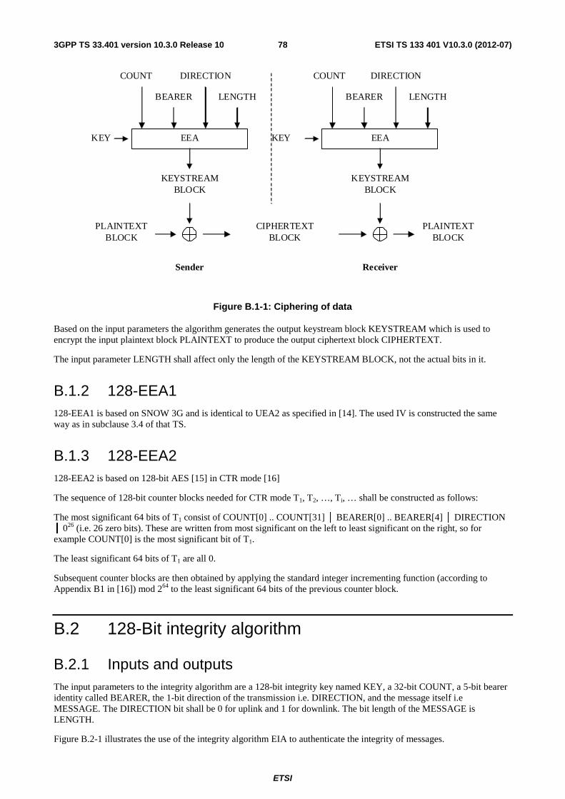
ETSI
ETSI TS 133 401 V10.3.0 (2012-07)783GPP TS 33.401 version 10.3.0 Release 10
PLAINTEXT BLOCK
EEA
COUNT DIRECTION
BEARER LENGTH
KEY
KEYSTREAM BLOCK
CIPHERTEXT BLOCK
EEA
COUNT DIRECTION
BEARER LENGTH
KEY
KEYSTREAM BLOCK
PLAINTEXT BLOCK
Sender
Receiver
Figure B.1-1: Ciphering of data
Based on the input parameters the algorithm generates the output keystream block KEYSTREAM which is used to encrypt the input plaintext block PLAINTEXT to produce the output ciphertext block CIPHERTEXT.
The input parameter LENGTH shall affect only the length of the KEYSTREAM BLOCK, not the actual bits in it.
B.1.2 128-EEA1 128-EEA1 is based on SNOW 3G and is identical to UEA2 as specified in [14]. The used IV is constructed the same way as in subclause 3.4 of that TS.
B.1.3 128-EEA2 128-EEA2 is based on 128-bit AES [15] in CTR mode [16]
The sequence of 128-bit counter blocks needed for CTR mode T1, T2, …, Ti, … shall be constructed as follows:
The most significant 64 bits of T1 consist of COUNT[0] .. COUNT[31] │ BEARER[0] .. BEARER[4] │ DIRECTION │ 026 (i.e. 26 zero bits). These are written from most significant on the left to least significant on the right, so for example COUNT[0] is the most significant bit of T1.
The least significant 64 bits of T1 are all 0.
Subsequent counter blocks are then obtained by applying the standard integer incrementing function (according to Appendix B1 in [16]) mod 264 to the least significant 64 bits of the previous counter block.
B.2 128-Bit integrity algorithm
B.2.1 Inputs and outputs The input parameters to the integrity algorithm are a 128-bit integrity key named KEY, a 32-bit COUNT, a 5-bit bearer identity called BEARER, the 1-bit direction of the transmission i.e. DIRECTION, and the message itself i.e MESSAGE. The DIRECTION bit shall be 0 for uplink and 1 for downlink. The bit length of the MESSAGE is LENGTH.
Figure B.2-1 illustrates the use of the integrity algorithm EIA to authenticate the integrity of messages.
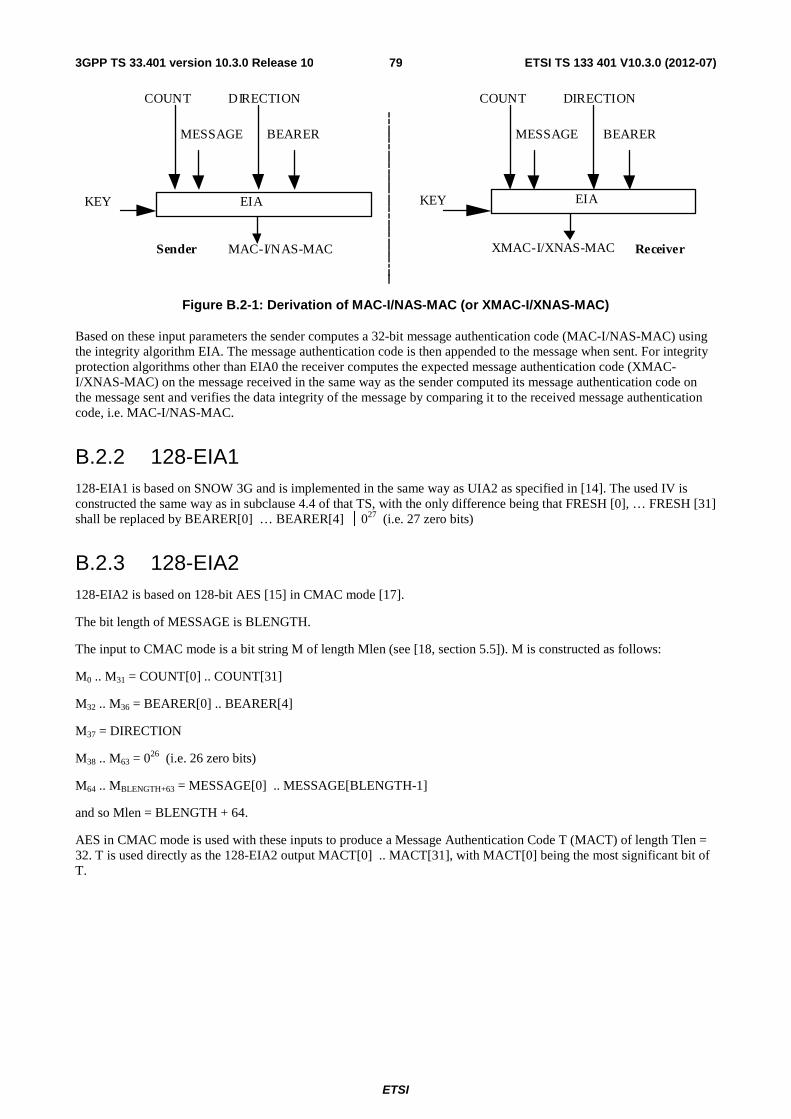
ETSI
ETSI TS 133 401 V10.3.0 (2012-07)793GPP TS 33.401 version 10.3.0 Release 10
EIA KEY
MAC-I/NAS-MAC Sender
COUNT DIRECTION
MESSAGE BEARER
EIA
XMAC-I/XNAS-MAC
COUNT DIRECTION
MESSAGE BEARER
KEY
Receiver
Figure B.2-1: Derivation of MAC-I/NAS-MAC (or XMAC-I/XNAS-MAC)
Based on these input parameters the sender computes a 32-bit message authentication code (MAC-I/NAS-MAC) using the integrity algorithm EIA. The message authentication code is then appended to the message when sent. For integrity protection algorithms other than EIA0 the receiver computes the expected message authentication code (XMAC-I/XNAS-MAC) on the message received in the same way as the sender computed its message authentication code on the message sent and verifies the data integrity of the message by comparing it to the received message authentication code, i.e. MAC-I/NAS-MAC.
B.2.2 128-EIA1 128-EIA1 is based on SNOW 3G and is implemented in the same way as UIA2 as specified in [14]. The used IV is constructed the same way as in subclause 4.4 of that TS, with the only difference being that FRESH [0], … FRESH [31] shall be replaced by BEARER[0] … BEARER[4] │ 0
27 (i.e. 27 zero bits)
B.2.3 128-EIA2 128-EIA2 is based on 128-bit AES [15] in CMAC mode [17].
The bit length of MESSAGE is BLENGTH.
The input to CMAC mode is a bit string M of length Mlen (see [18, section 5.5]). M is constructed as follows:
M0 .. M31 = COUNT[0] .. COUNT[31]
M32 .. M36 = BEARER[0] .. BEARER[4]
M37 = DIRECTION
M38 .. M63 = 026 (i.e. 26 zero bits)
M64 .. MBLENGTH+63 = MESSAGE[0] .. MESSAGE[BLENGTH-1]
and so Mlen = BLENGTH + 64.
AES in CMAC mode is used with these inputs to produce a Message Authentication Code T (MACT) of length Tlen = 32. T is used directly as the 128-EIA2 output MACT[0] .. MACT[31], with MACT[0] being the most significant bit of T.
ETSI
ETSI TS 133 401 V10.3.0 (2012-07)803GPP TS 33.401 version 10.3.0 Release 10
Annex C (informative): Algorithm test data
C.1 128-EEA2 This section includes six test data sets; all are presented in hex, while the first is also presented in binary. Some intermediate computational values are included to assist implementers in tracing bugs. Some notation is taken from the specification of CTR mode [16].
Bit ordering should be largely self explanatory, but in particular:
- The 5-bit BEARER is written in hex in a 'right aligned' form, i.e. as a two-hex-digit value in the range 00 to 1F inclusive, with BEARER [0] as the msb of the first digit.
- Similarly the single DIRECTION bit is written in hex in 'right aligned' form, i.e. the DIRECTION bit is the lsb of the hex digit.
- Where the length of plaintext and ciphertext is not a multiple of 32 bits, they are written in hex in a 'left aligned' form, i.e. the least significant few bits of the last word will be zero.
C.1.1 Test Set 1 Key = (hex) d3c5d592 327fb11c 4035c668 0af8c6d1
Key = (bin) 11010011 11000101 11010101 10010010 00110010 01111111 10110001 00011100
01000000 00110101 11000110 01101000 00001010 11111000 11000110 11010001
Count = (hex) 398a59b4
Count = (bin) 00111001 10001010 01011001 10110100
Bearer = (hex) 15
Bearer = (bin) 10101
Direction = (hex) 1
Direction = (bin) 1
Length = 253 bits
Plaintext = (hex) 981ba682 4c1bfb1a b4854720 29b71d80 8ce33e2c c3c0b5fc 1f3de8a6 dc66b1f0
Plaintext = (bin) 10011000 00011011 10100110 10000010 01001100 00011011 11111011 00011010
10110100 10000101 01000111 00100000 00101001 10110111 00011101 10000000
10001100 11100011 00111110 00101100 11000011 11000000 10110101 11111100
00011111 00111101 11101000 10100110 11011100 01100110 10110001 11110
Counter block T1 = (hex) 398a59b4 ac000000 00000000 00000000
Counter block T1 = (bin) 00111001 10001010 01011001 10110100 10101100 00000000 00000000 00000000
00000000 00000000 00000000 00000000 00000000 00000000 00000000 00000000
Keystream block 1 = (hex) 71e57e24 710ea81e 6398b52b da5f3f94
Keystream block 1 = (bin) 01110001 11100101 01111110 00100100 01110001 00001110 10101000 00011110
01100011 10011000 10110101 00101011 11011010 01011111 00111111 10010100
Counter block T2 = (hex) 398a59b4 ac000000 00000000 00000001
ETSI
ETSI TS 133 401 V10.3.0 (2012-07)813GPP TS 33.401 version 10.3.0 Release 10
Counter block T2 = (bin) 00111001 10001010 01011001 10110100 10101100 00000000 00000000 00000000
00000000 00000000 00000000 00000000 00000000 00000000 00000000 00000001
Keystream block 2 = (hex) 3eede9f6 11328620 231f3f1b 328b3f88
Keystream block 2 = (bin) 00111110 11101101 11101001 11110110 00010001 00110010 10000110 00100000
00100011 00011111 00111111 00011011 00110010 10001011 00111111 10001000
Ciphertext = (hex) e9fed8a6 3d155304 d71df20b f3e82214 b20ed7da d2f233dc 3c22d7bd eeed8e78
Ciphertext = (bin) 11101001 11111110 11011000 10100110 00111101 00010101 01010011 00000100
11010111 00011101 11110010 00001011 11110011 11101000 00100010 00010100
10110010 00001110 11010111 11011010 11010010 11110010 00110011 11011100
00111100 00100010 11010111 10111101 11101110 11101101 10001110 01111
C.1.2 Test Set 2 Key = 2bd6459f 82c440e0 952c4910 4805ff48
Count = c675a64b
Bearer = 0c
Direction = 1
Length = 798 bits
Plaintext = 7ec61272 743bf161 4726446a 6c38ced1 66f6ca76 eb543004 4286346c ef130f92
922b0345 0d3a9975 e5bd2ea0 eb55ad8e 1b199e3e c4316020 e9a1b285 e7627953
59b7bdfd 39bef4b2 484583d5 afe082ae e638bf5f d5a60619 3901a08f 4ab41aab
9b134880
Counter block T1 = c675a64b 64000000 00000000 00000000
Keystream block 1 = 27a77221 27fdbabd e67d5d34 44bd9d78
Counter block T2 = c675a64b 64000000 00000000 00000001
Keystream block 2 = 7695ef70 3d743aa3 d242fc6a 268a0b5d
Counter block T3 = c675a64b 64000000 00000000 00000002
Keystream block 3 = b66ecf15 b626681d 412b5dd3 a55db6d9
Counter block T4 = c675a64b 64000000 00000000 00000003
Keystream block 4 = f83d506c 9df187ad a578c902 ee14296f
Counter block T5 = c675a64b 64000000 00000000 00000004
Keystream block 5 = 50f44f36 635604e0 8ff25047 8c750516
Counter block T6 = c675a64b 64000000 00000000 00000005
Keystream block 6 = 735839e3 7ebe8579 7be34641 08f730bc
Counter block T7 = c675a64b 64000000 00000000 00000006
Keystream block 7 = 8b4f1b53 87da3277 a56f567d 8066fce2
Ciphertext = 59616053 53c64bdc a15b195e 288553a9 10632506 d6200aa7 90c4c806 c99904cf
2445cc50 bb1cf168 a4967373 4e081b57 e324ce52 59c0e78d 4cd97b87 0976503c
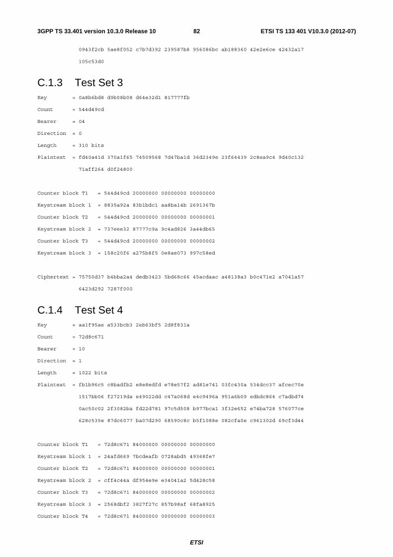
ETSI
ETSI TS 133 401 V10.3.0 (2012-07)823GPP TS 33.401 version 10.3.0 Release 10
0943f2cb 5ae8f052 c7b7d392 239587b8 956086bc ab188360 42e2e6ce 42432a17
105c53d0
C.1.3 Test Set 3 Key = 0a8b6bd8 d9b08b08 d64e32d1 817777fb
Count = 544d49cd
Bearer = 04
Direction = 0
Length = 310 bits
Plaintext = fd40a41d 370a1f65 74509568 7d47ba1d 36d2349e 23f64439 2c8ea9c4 9d40c132
71aff264 d0f24800
Counter block T1 = 544d49cd 20000000 00000000 00000000
Keystream block 1 = 8835a92a 83b1bdc1 aa8ba14b 2691367b
Counter block T2 = 544d49cd 20000000 00000000 00000001
Keystream block 2 = 737eee32 87777c9a 9c4ad826 3a44db65
Counter block T3 = 544d49cd 20000000 00000000 00000002
Keystream block 3 = 158c20f6 a275b8f5 0e8ae073 997c58ed
Ciphertext = 75750d37 b4bba2a4 dedb3423 5bd68c66 45acdaac a48138a3 b0c471e2 a7041a57
6423d292 7287f000
C.1.4 Test Set 4 Key = aa1f95ae a533bcb3 2eb63bf5 2d8f831a
Count = 72d8c671
Bearer = 10
Direction = 1
Length = 1022 bits
Plaintext = fb1b96c5 c8badfb2 e8e8edfd e78e57f2 ad81e741 03fc430a 534dcc37 afcec70e
1517bb06 f27219da e49022dd c47a068d e4c9496a 951a6b09 edbdc864 c7adbd74
0ac50c02 2f3082ba fd22d781 97c5d508 b977bca1 3f32e652 e74ba728 576077ce
628c535e 87dc6077 ba07d290 68590c8c b5f1088e 082cfa0e c961302d 69cf3d44
Counter block T1 = 72d8c671 84000000 00000000 00000000
Keystream block 1 = 24afd669 7bcdeafb 0728abd5 49368fe7
Counter block T2 = 72d8c671 84000000 00000000 00000001
Keystream block 2 = cff4c44a df954e9e e34041a2 5d428c58
Counter block T3 = 72d8c671 84000000 00000000 00000002
Keystream block 3 = 2568dbf2 3827f27c 857b98af 68fa8925
Counter block T4 = 72d8c671 84000000 00000000 00000003
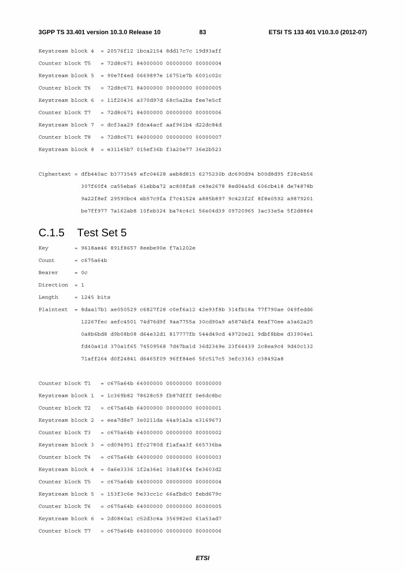
ETSI
ETSI TS 133 401 V10.3.0 (2012-07)833GPP TS 33.401 version 10.3.0 Release 10
Keystream block 4 = 20576f12 1bca2154 8dd17c7c 19d93aff
Counter block T5 = 72d8c671 84000000 00000000 00000004
Keystream block 5 = 90e7f4ed 0669897e 16751e7b 6001c02c
Counter block T6 = 72d8c671 84000000 00000000 00000005
Keystream block 6 = 11f20436 a370d97d 68c5a2ba fee7e5cf
Counter block T7 = 72d8c671 84000000 00000000 00000006
Keystream block 7 = dcf3aa29 fdca4acf aaf961b4 d22dc84d
Counter block T8 = 72d8c671 84000000 00000000 00000007
Keystream block 8 = e31145b7 015ef36b f3a20e77 36e2b523
Ciphertext = dfb440ac b3773549 efc04628 aeb8d815 6275230b dc690d94 b00d8d95 f28c4b56
307f60f4 ca55eba6 61ebba72 ac808fa8 c49e2678 8ed04a5d 606cb418 de74878b
9a22f8ef 29590bc4 eb57c9fa f7c41524 a885b897 9c423f2f 8f8e0592 a9879201
be7ff977 7a162ab8 10feb324 ba74c4c1 56e04d39 09720965 3ac33e5a 5f2d8864
C.1.5 Test Set 5 Key = 9618ae46 891f8657 8eebe90e f7a1202e
Count = c675a64b
Bearer = 0c
Direction = 1
Length = 1245 bits
Plaintext = 8daa17b1 ae050529 c6827f28 c0ef6a12 42e93f8b 314fb18a 77f790ae 049fedd6
12267fec aefc4501 74d76d9f 9aa7755a 30cd90a9 a5874bf4 8eaf70ee a3a62a25
0a8b6bd8 d9b08b08 d64e32d1 817777fb 544d49cd 49720e21 9dbf8bbe d33904e1
fd40a41d 370a1f65 74509568 7d47ba1d 36d2349e 23f64439 2c8ea9c4 9d40c132
71aff264 d0f24841 d6465f09 96ff84e6 5fc517c5 3efc3363 c38492a8
Counter block T1 = c675a64b 64000000 00000000 00000000
Keystream block 1 = 1c369b82 78628c59 fb87dfff 0e6dc8bc
Counter block T2 = c675a64b 64000000 00000000 00000001
Keystream block 2 = eea7d8e7 3e0211da 44a91a2a e3169673
Counter block T3 = c675a64b 64000000 00000000 00000002
Keystream block 3 = cd094951 ffc2780d f1afaa3f 665736ba
Counter block T4 = c675a64b 64000000 00000000 00000003
Keystream block 4 = 0a6e3336 1f2a36e1 30a83f44 fe3603d2
Counter block T5 = c675a64b 64000000 00000000 00000004
Keystream block 5 = 153f3c6e 9e33cc1c 66afbdc0 febd679c
Counter block T6 = c675a64b 64000000 00000000 00000005
Keystream block 6 = 2d0840a1 c52d3c4a 356982e0 61a53ad7
Counter block T7 = c675a64b 64000000 00000000 00000006
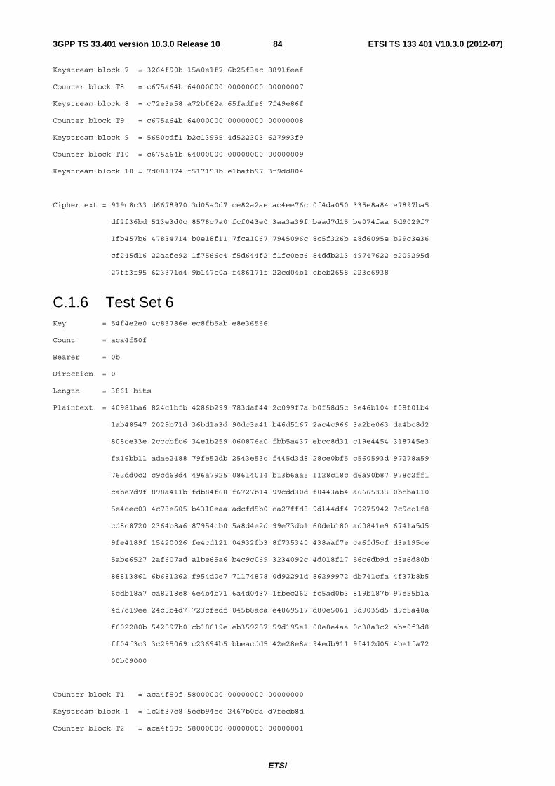
ETSI
ETSI TS 133 401 V10.3.0 (2012-07)843GPP TS 33.401 version 10.3.0 Release 10
Keystream block 7 = 3264f90b 15a0e1f7 6b25f3ac 8891feef
Counter block T8 = c675a64b 64000000 00000000 00000007
Keystream block 8 = c72e3a58 a72bf62a 65fadfe6 7f49e86f
Counter block T9 = c675a64b 64000000 00000000 00000008
Keystream block 9 = 5650cdf1 b2c13995 4d522303 627993f9
Counter block T10 = c675a64b 64000000 00000000 00000009
Keystream block 10 = 7d081374 f517153b e1bafb97 3f9dd804
Ciphertext = 919c8c33 d6678970 3d05a0d7 ce82a2ae ac4ee76c 0f4da050 335e8a84 e7897ba5
df2f36bd 513e3d0c 8578c7a0 fcf043e0 3aa3a39f baad7d15 be074faa 5d9029f7
1fb457b6 47834714 b0e18f11 7fca1067 7945096c 8c5f326b a8d6095e b29c3e36
cf245d16 22aafe92 1f7566c4 f5d644f2 f1fc0ec6 84ddb213 49747622 e209295d
27ff3f95 623371d4 9b147c0a f486171f 22cd04b1 cbeb2658 223e6938
C.1.6 Test Set 6 Key = 54f4e2e0 4c83786e ec8fb5ab e8e36566
Count = aca4f50f
Bearer = 0b
Direction = 0
Length = 3861 bits
Plaintext = 40981ba6 824c1bfb 4286b299 783daf44 2c099f7a b0f58d5c 8e46b104 f08f01b4
1ab48547 2029b71d 36bd1a3d 90dc3a41 b46d5167 2ac4c966 3a2be063 da4bc8d2
808ce33e 2cccbfc6 34e1b259 060876a0 fbb5a437 ebcc8d31 c19e4454 318745e3
fa16bb11 adae2488 79fe52db 2543e53c f445d3d8 28ce0bf5 c560593d 97278a59
762dd0c2 c9cd68d4 496a7925 08614014 b13b6aa5 1128c18c d6a90b87 978c2ff1
cabe7d9f 898a411b fdb84f68 f6727b14 99cdd30d f0443ab4 a6665333 0bcba110
5e4cec03 4c73e605 b4310eaa adcfd5b0 ca27ffd8 9d144df4 79275942 7c9cc1f8
cd8c8720 2364b8a6 87954cb0 5a8d4e2d 99e73db1 60deb180 ad0841e9 6741a5d5
9fe4189f 15420026 fe4cd121 04932fb3 8f735340 438aaf7e ca6fd5cf d3a195ce
5abe6527 2af607ad a1be65a6 b4c9c069 3234092c 4d018f17 56c6db9d c8a6d80b
88813861 6b681262 f954d0e7 71174878 0d92291d 86299972 db741cfa 4f37b8b5
6cdb18a7 ca8218e8 6e4b4b71 6a4d0437 1fbec262 fc5ad0b3 819b187b 97e55b1a
4d7c19ee 24c8b4d7 723cfedf 045b8aca e4869517 d80e5061 5d9035d5 d9c5a40a
f602280b 542597b0 cb18619e eb359257 59d195e1 00e8e4aa 0c38a3c2 abe0f3d8
ff04f3c3 3c295069 c23694b5 bbeacdd5 42e28e8a 94edb911 9f412d05 4be1fa72
00b09000
Counter block T1 = aca4f50f 58000000 00000000 00000000
Keystream block 1 = 1c2f37c8 5ecb94ee 2467b0ca d7fecb8d
Counter block T2 = aca4f50f 58000000 00000000 00000001
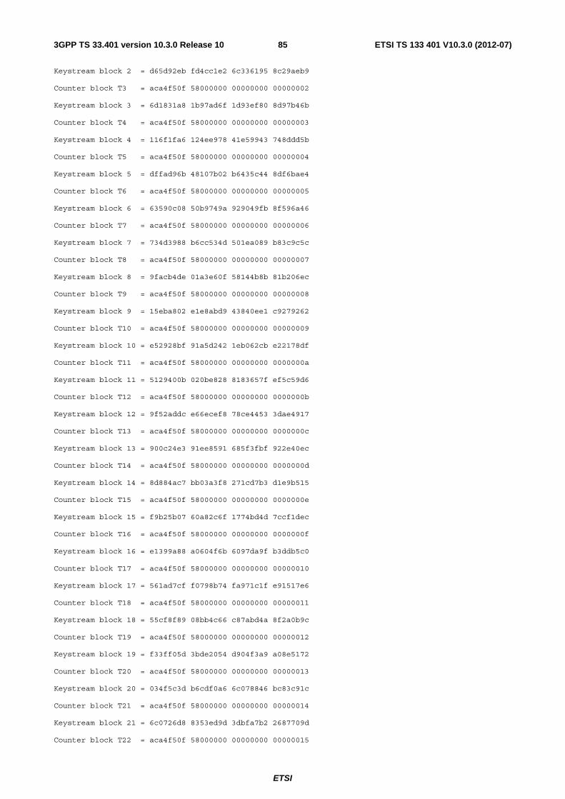
ETSI
ETSI TS 133 401 V10.3.0 (2012-07)853GPP TS 33.401 version 10.3.0 Release 10
Keystream block 2 = d65d92eb fd4cc1e2 6c336195 8c29aeb9
Counter block T3 = aca4f50f 58000000 00000000 00000002
Keystream block 3 = 6d1831a8 1b97ad6f 1d93ef80 8d97b46b
Counter block T4 = aca4f50f 58000000 00000000 00000003
Keystream block 4 = 116f1fa6 124ee978 41e59943 748ddd5b
Counter block T5 = aca4f50f 58000000 00000000 00000004
Keystream block 5 = dffad96b 48107b02 b6435c44 8df6bae4
Counter block T6 = aca4f50f 58000000 00000000 00000005
Keystream block 6 = 63590c08 50b9749a 929049fb 8f596a46
Counter block T7 = aca4f50f 58000000 00000000 00000006
Keystream block 7 = 734d3988 b6cc534d 501ea089 b83c9c5c
Counter block T8 = aca4f50f 58000000 00000000 00000007
Keystream block 8 = 9facb4de 01a3e60f 58144b8b 81b206ec
Counter block T9 = aca4f50f 58000000 00000000 00000008
Keystream block 9 = 15eba802 e1e8abd9 43840ee1 c9279262
Counter block T10 = aca4f50f 58000000 00000000 00000009
Keystream block 10 = e52928bf 91a5d242 1eb062cb e22178df
Counter block T11 = aca4f50f 58000000 00000000 0000000a
Keystream block 11 = 5129400b 020be828 8183657f ef5c59d6
Counter block T12 = aca4f50f 58000000 00000000 0000000b
Keystream block 12 = 9f52addc e66ecef8 78ce4453 3dae4917
Counter block T13 = aca4f50f 58000000 00000000 0000000c
Keystream block 13 = 900c24e3 91ee8591 685f3fbf 922e40ec
Counter block T14 = aca4f50f 58000000 00000000 0000000d
Keystream block 14 = 8d884ac7 bb03a3f8 271cd7b3 d1e9b515
Counter block T15 = aca4f50f 58000000 00000000 0000000e
Keystream block 15 = f9b25b07 60a82c6f 1774bd4d 7ccf1dec
Counter block T16 = aca4f50f 58000000 00000000 0000000f
Keystream block 16 = e1399a88 a0604f6b 6097da9f b3ddb5c0
Counter block T17 = aca4f50f 58000000 00000000 00000010
Keystream block 17 = 561ad7cf f0798b74 fa971c1f e91517e6
Counter block T18 = aca4f50f 58000000 00000000 00000011
Keystream block 18 = 55cf8f89 08bb4c66 c87abd4a 8f2a0b9c
Counter block T19 = aca4f50f 58000000 00000000 00000012
Keystream block 19 = f33ff05d 3bde2054 d904f3a9 a08e5172
Counter block T20 = aca4f50f 58000000 00000000 00000013
Keystream block 20 = 034f5c3d b6cdf0a6 6c078846 bc83c91c
Counter block T21 = aca4f50f 58000000 00000000 00000014
Keystream block 21 = 6c0726d8 8353ed9d 3dbfa7b2 2687709d
Counter block T22 = aca4f50f 58000000 00000000 00000015
ETSI
ETSI TS 133 401 V10.3.0 (2012-07)863GPP TS 33.401 version 10.3.0 Release 10
Keystream block 22 = 74b698ea 0d1783ab d0df36fd c82cca6e
Counter block T23 = aca4f50f 58000000 00000000 00000016
Keystream block 23 = 32348e64 fe86518e b5477cbb 97578dd2
Counter block T24 = aca4f50f 58000000 00000000 00000017
Keystream block 24 = 7bd4f7e2 173eb542 a047f1b0 1f3d008c
Counter block T25 = aca4f50f 58000000 00000000 00000018
Keystream block 25 = 825fd522 f0e0b3b0 ccd4106d 39ddd88c
Counter block T26 = aca4f50f 58000000 00000000 00000019
Keystream block 26 = f930dc26 db0e6bce d465d457 b82fe7c2
Counter block T27 = aca4f50f 58000000 00000000 0000001a
Keystream block 27 = bc90c3f4 abc1072d 0f74300c 13106527
Counter block T28 = aca4f50f 58000000 00000000 0000001b
Keystream block 28 = 39da03e3 c5bf5152 b809045f ee778e01
Counter block T29 = aca4f50f 58000000 00000000 0000001c
Keystream block 29 = 3b1f75fe 95c81280 c2165b65 cf3c5fae
Counter block T30 = aca4f50f 58000000 00000000 0000001d
Keystream block 30 = 385138f8 c9f7d62e 07f8e4df e379d08d
Counter block T31 = aca4f50f 58000000 00000000 0000001e
Keystream block 31 = 06c8b899 06c71bb9 2e834ee7 e81cd109
Ciphertext = 5cb72c6e dc878f15 66e10253 afc364c9 fa540d91 4db94cbe e275d091 7ca6af0d
77acb4ef 3bbe1a72 2b2ef5bd 1d4b8e2a a5024ec1 388a201e 7bce7920 aec61589
5f763a55 64dcc4c4 82a2ee1d 8bfecc44 98eca83f bb75f9ab 530e0daf bede2fa5
895b8299 1b6277c5 29e0f252 9d7f7960 6be96706 296dedfa 9d7412b6 16958cb5
63c678c0 2825c30d 0aee77c4 c146d276 5412421a 808d13ce c819694c 75ad572e
9b973d94 8b81a933 7c3b2a17 192e22c2 069f7ed1 162af44c dea81760 3665e807
ce40c8e0 dd9d6394 dc6e3115 3fe1955c 47afb51f 2617ee0c 5e3b8ef1 ad7574ed
343edc27 43cc94c9 90e1f1fd 264253c1 78dea739 c0befeeb cd9f9b76 d49c1015
c9fecf50 e53b8b52 04dbcd3e ed863855 dabcdcc9 4b31e318 02156885 5c8b9e52
a981957a 112827f9 78ba960f 1447911b 317b5511 fbcc7fb1 3ac153db 74251117
e4861eb9 e83bffff c4eb7755 579038e5 7924b1f7 8b3e1ad9 0bab2a07 871b72db
5eef96c3 34044966 db0c37ca fd1a89e5 646a3580 eb6465f1 21dce9cb 88d85b96
cf23cccc d4280767 bee8eeb2 3d865246 1db64931 03003baf 89f5e182 61ea43c8
4a92ebff ffe4909d c46c5192 f825f770 600b9602 c557b5f8 b431a79d 45977dd9
c41b863d a9e142e9 0020cfd0 74d6927b 7ab3b672 5d1a6f3f 98b9c9da a8982aff
06782800
ETSI
ETSI TS 133 401 V10.3.0 (2012-07)873GPP TS 33.401 version 10.3.0 Release 10
C.2 128-EIA2 This section includes eight test data sets; all are presented in hex, while the first is also presented in binary. Many intermediate computational values are included to assist implementers in tracing bugs. Some notation is taken from the specification of CMAC mode [17].
Bit ordering should be largely self explanatory, but in particular:
- The 5-bit BEARER is written in hex in a 'right aligned' form, i.e. as a two-hex-digit value in the range 00 to 1F inclusive, with BEARER [0] as the msb of the first digit.
- Similarly the single DIRECTION bit is written in hex in 'right aligned' form, i.e. the DIRECTION bit is the lsb of the hex digit.
- Where the length of the message, or of a message sub-block, is not a multiple of 32 bits, it is written in hex in a 'left aligned' form, i.e. the least significant few bits of the last word will be zero.
NOTE: This section provides both byte aligned and non byte aligned test data sets. For EPS implementation verification, byte alignment test data sets (2, 5 and 8) can be used, as EPS RRC and EPS NAS messages are byte aligned. The non byte aligned test data sets may be used to verify implementations that support non byte aligned messages.
C.2.1 Test Set 1 Count-I = (hex) 38a6f056
Count-I = (bin) 00111000 10100110 11110000 01010110
Bearer = (hex) 18
Bearer = (bin) 11000
Direction = (hex) 0
Direction = (bin) 0
IK = (hex) 2bd6459f 82c5b300 952c4910 4881ff48
IK = (bin) 00101011 11010110 01000101 10011111 10000010 11000101 10110011 00000000
10010101 00101100 01001001 00010000 01001000 10000001 11111111 01001000
Length = 58 bits
Message = (hex) 33323462 63393840
Message = (bin) 00110011 00110010 00110100 01100010 01100011 00111001 00111000 01
CMAC(K, M):
K = (hex) 2bd6459f 82c5b300 952c4910 4881ff48
K = (bin) 00101011 11010110 01000101 10011111 10000010 11000101 10110011 00000000
10010101 00101100 01001001 00010000 01001000 10000001 11111111 01001000
Mlen = 122
M = (hex) 38a6f056 c0000000 33323462 63393840
M = (bin) 00111000 10100110 11110000 01010110 11000000 00000000 00000000 00000000
00110011 00110010 00110100 01100010 01100011 00111001 00111000 01
Subkey Generation:
L = (hex) 6e426138 5adfc1fc b7c85f0c 469fb20c
ETSI
ETSI TS 133 401 V10.3.0 (2012-07)883GPP TS 33.401 version 10.3.0 Release 10
L = (bin) 01101110 01000010 01100001 00111000 01011010 11011111 11000001 11111100
10110111 11001000 01011111 00001100 01000110 10011111 10110010 00001100
K1 = (hex) dc84c270 b5bf83f9 6f90be18 8d3f6418
K1 = (bin) 11011100 10000100 11000010 01110000 10110101 10111111 10000011 11111001
01101111 10010000 10111110 00011000 10001101 00111111 01100100 00011000
K2 = (hex) b90984e1 6b7f07f2 df217c31 1a7ec8b7
K2 = (bin) 10111001 00001001 10000100 11100001 01101011 01111111 00000111 11110010
11011111 00100001 01111100 00110001 00011010 01111110 11001000 10110111
MAC Generation:
n = 1
Mn* = (hex) 38a6f056 c0000000 33323462 63393840
Mn* = (bin) 00111000 10100110 11110000 01010110 11000000 00000000 00000000 00000000
00110011 00110010 00110100 01100010 01100011 00111001 00111000 01
Mn = (hex) 81af74b7 ab7f07f2 ec134853 7947f0d7
Mn = (bin) 10000001 10101111 01110100 10110111 10101011 01111111 00000111 11110010
11101100 00010011 01001000 01010011 01111001 01000111 11110000 11010111
C0 = (hex) 00000000 00000000 00000000 00000000
C0 = (bin) 00000000 00000000 00000000 00000000 00000000 00000000 00000000 00000000
00000000 00000000 00000000 00000000 00000000 00000000 00000000 00000000
M1 = (hex) 81af74b7 ab7f07f2 ec134853 7947f0d7
M1 = (bin) 10000001 10101111 01110100 10110111 10101011 01111111 00000111 11110010
11101100 00010011 01001000 01010011 01111001 01000111 11110000 11010111
C1 = (hex) 118c6eb8 b775144b 0b831110 54c96eb6
C1 = (bin) 00010001 10001100 01101110 10111000 10110111 01110101 00010100 01001011
00001011 10000011 00010001 00010000 01010100 11001001 01101110 10110110
MACT = (hex) 118c6eb8
MACT = (bin) 00010001 10001100 01101110 10111000
C.2.2 Test Set 2 Count-I = 398a59b4
Bearer = 1a
Direction = 1
IK = d3c5d592 327fb11c 4035c668 0af8c6d1
Length = 64 bits
Message = 484583d5 afe082ae
CMAC(K, M):
ETSI
ETSI TS 133 401 V10.3.0 (2012-07)893GPP TS 33.401 version 10.3.0 Release 10
K = d3c5d592 327fb11c 4035c668 0af8c6d1
Mlen = 128
M = 398a59b4 d4000000 484583d5 afe082ae
Subkey Generation:
L = 9b71f299 132915d3 605211b5 e5df8632
K1 = 36e3e532 26522ba6 c0a4236b cbbf0ce3
K2 = 6dc7ca64 4ca4574d 814846d7 977e19c6
MAC Generation:
n = 1
Mn* = 398a59b4 d4000000 484583d5 afe082ae
Mn = 0f69bc86 f2522ba6 88e1a0be 645f8e4d
C0 = 00000000 00000000 00000000 00000000
M1 = 0f69bc86 f2522ba6 88e1a0be 645f8e4d
C1 = b93787e6 493ff113 ad73d3e0 1e826d73
MACT = b93787e6
C.2.3 Test Set 3 Count-I = 36af6144
Bearer = 18
Direction = 1
IK = 7e5e9443 1e11d738 28d739cc 6ced4573
Length = 254 bits
Message = b3d3c917 0a4e1632 f60f8610 13d22d84 b726b6a2 78d802d1 eeaf1321 ba5929dc
CMAC(K, M):
K = 7e5e9443 1e11d738 28d739cc 6ced4573
Mlen = 318
M = 36af6144 c4000000 b3d3c917 0a4e1632 f60f8610 13d22d84 b726b6a2 78d802d1
eeaf1321 ba5929dc
Subkey Generation:
L = d78b4628 35781e79 d2255f8d 309a60ef
K1 = af168c50 6af03cf3 a44abf1a 6134c159
K2 = 5e2d18a0 d5e079e7 48957e34 c2698235
MAC Generation:
ETSI
ETSI TS 133 401 V10.3.0 (2012-07)903GPP TS 33.401 version 10.3.0 Release 10
n = 3
Mn* = eeaf1321 ba5929dc
Mn = b0820b81 6fb95039 48957e34 c2698235
C0 = 00000000 00000000 00000000 00000000
M1 = 36af6144 c4000000 b3d3c917 0a4e1632
C1 = 3bb0e1d8 2cb96273 64a7cfd3 a52eed15
M2 = f60f8610 13d22d84 b726b6a2 78d802d1
C2 = e3a6446d fae7f10f e3e3320d a8e49955
M3 = b0820b81 6fb95039 48957e34 c2698235
C3 = 1f60b01d e05aa666 3bda32c6 1771e70b
MACT = 1f60b01d
C.2.4 Test Set 4 Count-I = c7590ea9
Bearer = 17
Direction = 0
IK = d3419be8 21087acd 02123a92 48033359
Length = 511 bits
Message = bbb05703 8809496b cff86d6f bc8ce5b1 35a06b16 6054f2d5 65be8ace 75dc851e
0bcdd8f0 7141c495 872fb5d8 c0c66a8b 6da55666 3e4e4612 05d84580 bee5bc7e
CMAC(K, M):
K = d3419be8 21087acd 02123a92 48033359
Mlen = 575
M = c7590ea9 b8000000 bbb05703 8809496b cff86d6f bc8ce5b1 35a06b16 6054f2d5
65be8ace 75dc851e 0bcdd8f0 7141c495 872fb5d8 c0c66a8b 6da55666 3e4e4612
05d84580 bee5bc7e
Subkey Generation:
L = 054dd008 2d9ecd21 a3f32b0a a7369be4
K1 = 0a9ba010 5b3d9a43 47e65615 4e6d37c8
K2 = 15374020 b67b3486 8fccac2a 9cda6f90
MAC Generation:
n = 5
Mn* = 05d84580 bee5bc7e
Mn = 10ef05a0 089e88f9 8fccac2a 9cda6f90
C0 = 00000000 00000000 00000000 00000000

ETSI
ETSI TS 133 401 V10.3.0 (2012-07)913GPP TS 33.401 version 10.3.0 Release 10
M1 = c7590ea9 b8000000 bbb05703 8809496b
C1 = cb36ed77 e49bd772 ac410f25 eea31084
M2 = cff86d6f bc8ce5b1 35a06b16 6054f2d5
C2 = e44baf91 d48ba92c 542f3b14 a8a496d9
M3 = 65be8ace 75dc851e 0bcdd8f0 7141c495
C3 = c3542869 eed00692 e3b4ef1a 6b324aaf
M4 = 872fb5d8 c0c66a8b 6da55666 3e4e4612
C4 = 5054d998 92675b0f 989d3b0f 3c043c4e
M5 = 10ef05a0 089e88f9 8fccac2a 9cda6f90
C5 = 6846a2f0 a0b6be7a 4fb26a15 7e914c53
MACT = 6846a2f0
C.2.5 Test Set 5 Count-I = 36af6144
Bearer = 0f
Direction = 1
IK = 83fd23a2 44a74cf3 58da3019 f1722635
Length = 768 bits
Message = 35c68716 633c66fb 750c2668 65d53c11 ea05b1e9 fa49c839 8d48e1ef a5909d39
47902837 f5ae96d5 a05bc8d6 1ca8dbef 1b13a4b4 abfe4fb1 006045b6 74bb5472
9304c382 be53a5af 05556176 f6eaa2ef 1d05e4b0 83181ee6 74cda5a4 85f74d7a
CMAC(K, M):
K = 83fd23a2 44a74cf3 58da3019 f1722635
Mlen = 832
M = 36af6144 7c000000 35c68716 633c66fb 750c2668 65d53c11 ea05b1e9 fa49c839
8d48e1ef a5909d39 47902837 f5ae96d5 a05bc8d6 1ca8dbef 1b13a4b4 abfe4fb1
006045b6 74bb5472 9304c382 be53a5af 05556176 f6eaa2ef 1d05e4b0 83181ee6
74cda5a4 85f74d7a
Subkey Generation:
L = 9df61c57 3c86acac 704db9d5 b0dea444
K1 = 3bec38ae 790d5958 e09b73ab 61bd480f
K2 = 77d8715c f21ab2b1 c136e756 c37a901e
MAC Generation:
n = 7
Mn* = 74cda5a4 85f74d7a

ETSI
ETSI TS 133 401 V10.3.0 (2012-07)923GPP TS 33.401 version 10.3.0 Release 10
Mn = 0315d4f8 77edffcb 4136e756 c37a901e
C0 = 00000000 00000000 00000000 00000000
M1 = 36af6144 7c000000 35c68716 633c66fb
C1 = 57c5a916 e19d7747 c2a69283 5eed0015
M2 = 750c2668 65d53c11 ea05b1e9 fa49c839
C2 = 7937651c b2c34e23 646b4396 f77bca0d
M3 = 8d48e1ef a5909d39 47902837 f5ae96d5
C3 = dfa3c570 d7b4dd08 2533b643 f82f646c
M4 = a05bc8d6 1ca8dbef 1b13a4b4 abfe4fb1
C4 = 7a8e64c0 eb34df52 e4236368 0f019ddd
M5 = 006045b6 74bb5472 9304c382 be53a5af
C5 = 3f5f08a2 5a6a8ba8 9a5dd816 626a26ef
M6 = 05556176 f6eaa2ef 1d05e4b0 83181ee6
C6 = 9fe7991a 50c5f542 e0bf0da0 9dec1456
M7 = 0315d4f8 77edffcb 4136e756 c37a901e
C7 = e657e182 5298f2fa ee2ca1e0 7373bc7e
MACT = e657e182
C.2.6 Test Set 6 Count-I = 36af6144
Bearer = 18
Direction = 0
IK = 6832a65c ff447362 1ebdd4ba 26a921fe
Length = 383 bits
Message = d3c53839 62682071 77656676 20323837 63624098 1ba6824c 1bfb1ab4 85472029
b71d808c e33e2cc3 c0b5fc1f 3de8a6dc
CMAC(K, M):
K = 6832a65c ff447362 1ebdd4ba 26a921fe
Mlen = 447
M = 36af6144 c0000000 d3c53839 62682071 77656676 20323837 63624098 1ba6824c
1bfb1ab4 85472029 b71d808c e33e2cc3 c0b5fc1f 3de8a6dc
Subkey Generation:
L = e50123c3 87e13fd6 8d8bf0d0 a4581685
K1 = ca024787 0fc27fad 1b17e1a1 48b02d8d
K2 = 94048f0e 1f84ff5a 362fc342 91605b9d
ETSI
ETSI TS 133 401 V10.3.0 (2012-07)933GPP TS 33.401 version 10.3.0 Release 10
MAC Generation:
n = 4
Mn* = c0b5fc1f 3de8a6dc
Mn = 54b17311 226c5987 362fc342 91605b9d
C0 = 00000000 00000000 00000000 00000000
M1 = 36af6144 c0000000 d3c53839 62682071
C1 = 263dd98f beccb69a 428e92d4 21fbed9e
M2 = 77656676 20323837 63624098 1ba6824c
C2 = 1838cb78 cb2d32dc ec486c79 d9007a19
M3 = 1bfb1ab4 85472029 b71d808c e33e2cc3
C3 = 5ebf1009 f663be7b 68373072 4c20271f
M4 = 54b17311 226c5987 362fc342 91605b9d
C4 = f0668c1e 4197300b 1243f834 25d06c25
MACT = f0668c1e
C.2.7 Test Set 7 Count-I = 7827fab2
Bearer = 05
Direction = 1
IK = 5d0a80d8 134ae196 77824b67 1e838af4
Length = 2558 bits
Message = 70dedf2d c42c5cbd 3a96f8a0 b11418b3 608d5733 604a2cd3 6aabc70c e3193bb5
153be2d3 c06dfdb2 d16e9c35 7158be6a 41d6b861 e491db3f bfeb518e fcf048d7
d5895373 0ff30c9e c470ffcd 663dc342 01c36add c0111c35 b38afee7 cfdb582e
3731f8b4 baa8d1a8 9c06e811 99a97162 27be344e fcb436dd d0f096c0 64c3b5e2
c399993f c77394f9 e09720a8 11850ef2 3b2ee05d 9e617360 9d86e1c0 c18ea51a
012a00bb 413b9cb8 188a703c d6bae31c c67b34b1 b00019e6 a2b2a690 f02671fe
7c9ef8de c0094e53 3763478d 58d2c5f5 b827a014 8c5948a9 6931acf8 4f465a64
e62ce740 07e991e3 7ea823fa 0fb21923 b79905b7 33b631e6 c7d6860a 3831ac35
1a9c730c 52ff72d9 d308eedb ab21fde1 43a0ea17 e23edc1f 74cbb363 8a2033aa
a15464ea a733385d bbeb6fd7 3509b857 e6a419dc a1d8907a f977fbac 4dfa35ec
CMAC(K, M):
K = 5d0a80d8 134ae196 77824b67 1e838af4
Mlen = 2622
M = 7827fab2 2c000000 70dedf2d c42c5cbd 3a96f8a0 b11418b3 608d5733 604a2cd3
6aabc70c e3193bb5 153be2d3 c06dfdb2 d16e9c35 7158be6a 41d6b861 e491db3f
bfeb518e fcf048d7 d5895373 0ff30c9e c470ffcd 663dc342 01c36add c0111c35
ETSI
ETSI TS 133 401 V10.3.0 (2012-07)943GPP TS 33.401 version 10.3.0 Release 10
b38afee7 cfdb582e 3731f8b4 baa8d1a8 9c06e811 99a97162 27be344e fcb436dd
d0f096c0 64c3b5e2 c399993f c77394f9 e09720a8 11850ef2 3b2ee05d 9e617360
9d86e1c0 c18ea51a 012a00bb 413b9cb8 188a703c d6bae31c c67b34b1 b00019e6
a2b2a690 f02671fe 7c9ef8de c0094e53 3763478d 58d2c5f5 b827a014 8c5948a9
6931acf8 4f465a64 e62ce740 07e991e3 7ea823fa 0fb21923 b79905b7 33b631e6
c7d6860a 3831ac35 1a9c730c 52ff72d9 d308eedb ab21fde1 43a0ea17 e23edc1f
74cbb363 8a2033aa a15464ea a733385d bbeb6fd7 3509b857 e6a419dc a1d8907a
f977fbac 4dfa35ec
Subkey Generation:
L = 9832e229 fbb93970 bcf7b282 3ee4fe5d
K1 = 3065c453 f77272e1 79ef6504 7dc9fc3d
K2 = 60cb88a7 eee4e5c2 f3deca08 fb93f87a
MAC Generation:
n = 21
Mn* = f977fbac 4dfa35ec
Mn = 99bc730b a31ed02c f3deca08 fb93f87a
C0 = 00000000 00000000 00000000 00000000
M1 = 7827fab2 2c000000 70dedf2d c42c5cbd
C1 = 6c9b07c0 35b7a016 3aad1405 1f57f3e0
M2 = 3a96f8a0 b11418b3 608d5733 604a2cd3
C2 = ec9c6b75 1d027216 3412fad4 f01cebba
M3 = 6aabc70c e3193bb5 153be2d3 c06dfdb2
C3 = 3c83db67 ff87c86b 57ae4742 42c9816b
M4 = d16e9c35 7158be6a 41d6b861 e491db3f
C4 = e6e894ee 7e148494 44afcb75 9752e555
M5 = bfeb518e fcf048d7 d5895373 0ff30c9e
C5 = cbf27df1 0fd514f0 489dd303 d2dbee51
M6 = c470ffcd 663dc342 01c36add c0111c35
C6 = 6989143a 39de09ab 2680fe6c 41f0a7c1
M7 = b38afee7 cfdb582e 3731f8b4 baa8d1a8
C7 = fe4049fa 655ee010 49299c58 c91024ff
M8 = 9c06e811 99a97162 27be344e fcb436dd
C8 = 1e9dab32 48d5ee47 c7e3a420 6f18b17b
M9 = d0f096c0 64c3b5e2 c399993f c77394f9
C9 = 9da578a5 00a0c7f1 e825a4ca 71557055
M10 = e09720a8 11850ef2 3b2ee05d 9e617360
C10 = 4141c882 a23da353 2b11642a 85fea2bf
ETSI
ETSI TS 133 401 V10.3.0 (2012-07)953GPP TS 33.401 version 10.3.0 Release 10
M11 = 9d86e1c0 c18ea51a 012a00bb 413b9cb8
C11 = 18467572 0bdfcb5b 6bb71899 a6cafcc7
M12 = 188a703c d6bae31c c67b34b1 b00019e6
C12 = 156a70e5 af77f9a4 74d08303 e8c0412a
M13 = a2b2a690 f02671fe 7c9ef8de c0094e53
C13 = dba504a1 26fa047f 8b8c295f 73e90a5c
M14 = 3763478d 58d2c5f5 b827a014 8c5948a9
C14 = ab1a2703 3472acc8 e36c221b b7a0e530
M15 = 6931acf8 4f465a64 e62ce740 07e991e3
C15 = 04ceffcd e7618885 43c7e837 0f3bce6d
M16 = 7ea823fa 0fb21923 b79905b7 33b631e6
C16 = 215ec3bf 5f3a303e 53db5269 e6c99fc2
M17 = c7d6860a 3831ac35 1a9c730c 52ff72d9
C17 = 8622e51b 45a660f3 d98fcf74 e5cc36b3
M18 = d308eedb ab21fde1 43a0ea17 e23edc1f
C18 = 6e998fa6 196d5a4c 1ded2973 c09c0f8c
M19 = 74cbb363 8a2033aa a15464ea a733385d
C19 = 1710bc91 22e54289 244a87ce 23438f41
M20 = bbeb6fd7 3509b857 e6a419dc a1d8907a
C20 = 3e18b029 a8ef18da b9968614 96552fd7
M21 = 99bc730b a31ed02c f3deca08 fb93f87a
C21 = f4cc8fa3 59e6e2e7 6e09c45d 6ea5e0de
MACT = f4cc8fa3
C.2.8 Test Set 8 Count-I = 296f393c
Bearer = 0b
Direction = 1
IK = b3120ffd b2cf6af4 e73eaf2e f4ebec69
Length = 16448 bits
Message = 00000000 00000000 01010101 01010101 e0958045 f3a0bba4 e3968346 f0a3b8a7
c02a018a e6407652 26b987c9 13e6cbf0 83570016 cf83efbc 61c08251 3e21561a
427c009d 28c298ef ace78ed6 d56c2d45 05ad032e 9c04dc60 e73a8169 6da665c6
c48603a5 7b45ab33 221585e6 8ee31691 87fb0239 528632dd 656c807e a3248b7b
46d002b2 b5c7458e b85b9ce9 5879e034 0859055e 3b0abbc3 eace8719 caa80265
c97205d5 dc4bcc90 2fe18396 29ed7132 8a0f0449 f588557e 6898860e 042aecd8
4b2404c2 12c9222d a5bf8a89 ef679787 0cf50771 a60f66a2 ee628536 57addf04
cdde07fa 414e11f1 2b4d81b9 b4e8ac53 8ea30666 688d881f 6c348421 992f31b9
4f8806ed 8fccff4c 9123b896 42527ad6 13b109bf 75167485 f1268bf8 84b4cd23

ETSI
ETSI TS 133 401 V10.3.0 (2012-07)963GPP TS 33.401 version 10.3.0 Release 10
d29a0934 925703d6 34098f77 67f1be74 91e708a8 bb949a38 73708aef 4a36239e
50cc0823 5cd5ed6b be578668 a17b58c1 171d0b90 e813a9e4 f58a89d7 19b11042
d6360b1b 0f52deb7 30a58d58 faf46315 954b0a87 26914759 77dc88c0 d733feff
54600a0c c1d0300a aaeb9457 2c6e95b0 1ae90de0 4f1dce47 f87e8fa7 bebf77e1
dbc20d6b a85cb914 3d518b28 5dfa04b6 98bf0cf7 819f20fa 7a288eb0 703d995c
59940c7c 66de57a9 b70f8237 9b70e203 1e450fcf d2181326 fcd28d88 23baaa80
df6e0f44 35596475 39fd8907 c0ffd9d7 9c130ed8 1c9afd9b 7e848c9f ed38443d
5d380e53 fbdb8ac8 c3d3f068 76054f12 2461107d e92fea09 c6f6923a 188d53af
e54a10f6 0e6e9d5a 03d996b5 fbc820f8 a637116a 27ad04b4 44a0932d d60fbd12
671c11e1 c0ec73e7 89879faa 3d42c64d 20cd1252 742a3768 c25a9015 85888ece
e1e612d9 936b403b 0775949a 66cdfd99 a29b1345 baa8d9d5 400c9102 4b0a6073
63b013ce 5de9ae86 9d3b8d95 b0570b3c 2d391422 d32450cb cfae9665 2286e96d
ec1214a9 34652798 0a8192ea c1c39a3a af6f1535 1da6be76 4df89772 ec0407d0
6e4415be fae7c925 80df9bf5 07497c8f 2995160d 4e218daa cb02944a bf83340c
e8be1686 a960faf9 0e2d90c5 5cc6475b abc3171a 80a36317 4954955d 7101dab1
6ae81791 67e21444 b443a9ea aa7c91de 36d118c3 9d389f8d d4469a84 6c9a262b
f7fa1848 7a79e8de 11699e0b 8fdf557c b48719d4 53ba7130 56109b93 a218c896
75ac195f b4fb0663 9b379714 4955b3c9 327d1aec 003d42ec d0ea98ab f19ffb4a
f3561a67 e77c35bf 15c59c24 12da881d b02b1bfb cebfac51 52bc99bc 3f1d15f7
71001b70 29fedb02 8f8b852b c4407eb8 3f891c9c a733254f dd1e9edb 56919ce9
fea21c17 4072521c 18319a54 b5d4efbe bddf1d8b 69b1cbf2 5f489fcc 98137254
7cf41d00 8ef0bca1 926f934b 735e090b 3b251eb3 3a36f82e d9b29cf4 cb944188
fa0e1e38 dd778f7d 1c9d987b 28d132df b9731fa4 f4b41693 5be49de3 0516af35
78581f2f 13f561c0 66336194 1eab249a 4bc123f8 d15cd711 a956a1bf 20fe6eb7
8aea2373 361da042 6c79a530 c3bb1de0 c99722ef 1fde39ac 2b00a0a8 ee7c800a
08bc2264 f89f4eff e627ac2f 0531fb55 4f6d21d7 4c590a70 adfaa390 bdfbb3d6
8e46215c ab187d23 68d5a71f 5ebec081 cd3b20c0 82dbe4cd 2faca287 73795d6b
0c10204b 659a939e f29bbe10 88243624 429927a7 eb576dd3 a00ea5e0 1af5d475
83b2272c 0c161a80 6521a16f f9b0a722 c0cf26b0 25d5836e 2258a4f7 d4773ac8
01e4263b c294f43d ef7fa870 3f3a4197 46352588 7652b0b2 a4a2a7cf 87f00914
871e2503 9113c7e1 618da340 64b57a43 c463249f b8d05e0f 26f4a6d8 4972e7a9
05482414 5f91295c dbe39a6f 920facc6 59712b46 a54ba295 bbe6a901 54e91b33
985a2bcd 420ad5c6 7ec9ad8e b7ac6864 db272a51 6bc94c28 39b0a816 9a6bf58e
1a0c2ada 8c883b7b f497a491 71268ed1 5ddd2969 384e7ff4 bf4aab2e c9ecc652
9cf629e2 df0f08a7 7a65afa1 2aa9b505 df8b287e f6cc9149 3d1caa39 076e28ef
1ea028f5 118de61a e02bb6ae fc3343a0 50292f19 9f401857 b2bead5e 6ee2a1f1
91022f92 78016f04 7791a9d1 8da7d2a6 d27f2e0e 51c2f6ea 30e8ac49 a0604f4c
13542e85 b68381b9 fdcfa0ce 4b2d3413 54852d36 0245c536 b612af71 f3e77c90
95ae2dbd e504b265 733dabfe 10a20fc7 d6d32c21 ccc72b8b 3444ae66 3d65922d
17f82caa 2b865cd8 8913d291 a6589902 6ea13284 39723c19 8c36b0c3 c8d085bf
ETSI
ETSI TS 133 401 V10.3.0 (2012-07)973GPP TS 33.401 version 10.3.0 Release 10
af8a320f de334b4a 4919b44c 2b95f6e8 ecf73393 f7f0d2a4 0e60b1d4 06526b02
2ddc3318 10b1a5f7 c347bd53 ed1f105d 6a0d30ab a477e178 889ab2ec 55d558de
ab263020 4336962b 4db5b663 b6902b89 e85b31bc 6af50fc5 0accb3fb 9b57b663
29703137 8db47896 d7fbaf6c 600add2c 67f936db 037986db 856eb49c f2db3f7d
a6d23650 e438f188 4041b013 119e4c2a e5af37cc cdfb6866 0738b58b 3c59d1c0
24843747 2aba1f35 ca1fb90c d714aa9f 635534f4 9e7c5bba 81c2b6b3 6fdee21c
a27e347f 793d2ce9 44edb23c 8c9b914b e10335e3 50feb507 0394b7a4 a15c0ca1
20283568 b7bfc254 fe838b13 7a2147ce 7c113a3a 4d65499d 9e86b87d bcc7f03b
bd3a3ab1 aa243ece 5ba9bcf2 5f82836c fe473b2d 83e7a720 1cd0b96a 72451e86
3f6c3ba6 64a6d073 d1f7b5ed 990865d9 78bd3815 d06094fc 9a2aba52 21c22d5a
b996389e 3721e3af 5f05bedd c2875e0d faeb3902 1ee27a41 187cbb45 ef40c3e7
3bc03989 f9a30d12 c54ba7d2 141da8a8 75493e65 776ef35f 97debc22 86cc4af9
b4623eee 902f840c 52f1b8ad 658939ae f71f3f72 b9ec1de2 1588bd35 484ea444
36343ff9 5ead6ab1 d8afb1b2 a303df1b 71e53c4a ea6b2e3e 9372be0d 1bc99798
b0ce3cc1 0d2a596d 565dba82 f88ce4cf f3b33d5d 24e9c083 1124bf1a d54b7925
32983dd6 c3a8b7d0
CMAC(K, M):
K = b3120ffd b2cf6af4 e73eaf2e f4ebec69
Mlen = 16512
M = 296f393c 5c000000 00000000 00000000 01010101 01010101 e0958045 f3a0bba4
e3968346 f0a3b8a7 c02a018a e6407652 26b987c9 13e6cbf0 83570016 cf83efbc
61c08251 3e21561a 427c009d 28c298ef ace78ed6 d56c2d45 05ad032e 9c04dc60
e73a8169 6da665c6 c48603a5 7b45ab33 221585e6 8ee31691 87fb0239 528632dd
656c807e a3248b7b 46d002b2 b5c7458e b85b9ce9 5879e034 0859055e 3b0abbc3
eace8719 caa80265 c97205d5 dc4bcc90 2fe18396 29ed7132 8a0f0449 f588557e
6898860e 042aecd8 4b2404c2 12c9222d a5bf8a89 ef679787 0cf50771 a60f66a2
ee628536 57addf04 cdde07fa 414e11f1 2b4d81b9 b4e8ac53 8ea30666 688d881f
6c348421 992f31b9 4f8806ed 8fccff4c 9123b896 42527ad6 13b109bf 75167485
f1268bf8 84b4cd23 d29a0934 925703d6 34098f77 67f1be74 91e708a8 bb949a38
73708aef 4a36239e 50cc0823 5cd5ed6b be578668 a17b58c1 171d0b90 e813a9e4
f58a89d7 19b11042 d6360b1b 0f52deb7 30a58d58 faf46315 954b0a87 26914759
77dc88c0 d733feff 54600a0c c1d0300a aaeb9457 2c6e95b0 1ae90de0 4f1dce47
f87e8fa7 bebf77e1 dbc20d6b a85cb914 3d518b28 5dfa04b6 98bf0cf7 819f20fa
7a288eb0 703d995c 59940c7c 66de57a9 b70f8237 9b70e203 1e450fcf d2181326
fcd28d88 23baaa80 df6e0f44 35596475 39fd8907 c0ffd9d7 9c130ed8 1c9afd9b
7e848c9f ed38443d 5d380e53 fbdb8ac8 c3d3f068 76054f12 2461107d e92fea09
c6f6923a 188d53af e54a10f6 0e6e9d5a 03d996b5 fbc820f8 a637116a 27ad04b4
44a0932d d60fbd12 671c11e1 c0ec73e7 89879faa 3d42c64d 20cd1252 742a3768
c25a9015 85888ece e1e612d9 936b403b 0775949a 66cdfd99 a29b1345 baa8d9d5

ETSI
ETSI TS 133 401 V10.3.0 (2012-07)983GPP TS 33.401 version 10.3.0 Release 10
400c9102 4b0a6073 63b013ce 5de9ae86 9d3b8d95 b0570b3c 2d391422 d32450cb
cfae9665 2286e96d ec1214a9 34652798 0a8192ea c1c39a3a af6f1535 1da6be76
4df89772 ec0407d0 6e4415be fae7c925 80df9bf5 07497c8f 2995160d 4e218daa
cb02944a bf83340c e8be1686 a960faf9 0e2d90c5 5cc6475b abc3171a 80a36317
4954955d 7101dab1 6ae81791 67e21444 b443a9ea aa7c91de 36d118c3 9d389f8d
d4469a84 6c9a262b f7fa1848 7a79e8de 11699e0b 8fdf557c b48719d4 53ba7130
56109b93 a218c896 75ac195f b4fb0663 9b379714 4955b3c9 327d1aec 003d42ec
d0ea98ab f19ffb4a f3561a67 e77c35bf 15c59c24 12da881d b02b1bfb cebfac51
52bc99bc 3f1d15f7 71001b70 29fedb02 8f8b852b c4407eb8 3f891c9c a733254f
dd1e9edb 56919ce9 fea21c17 4072521c 18319a54 b5d4efbe bddf1d8b 69b1cbf2
5f489fcc 98137254 7cf41d00 8ef0bca1 926f934b 735e090b 3b251eb3 3a36f82e
d9b29cf4 cb944188 fa0e1e38 dd778f7d 1c9d987b 28d132df b9731fa4 f4b41693
5be49de3 0516af35 78581f2f 13f561c0 66336194 1eab249a 4bc123f8 d15cd711
a956a1bf 20fe6eb7 8aea2373 361da042 6c79a530 c3bb1de0 c99722ef 1fde39ac
2b00a0a8 ee7c800a 08bc2264 f89f4eff e627ac2f 0531fb55 4f6d21d7 4c590a70
adfaa390 bdfbb3d6 8e46215c ab187d23 68d5a71f 5ebec081 cd3b20c0 82dbe4cd
2faca287 73795d6b 0c10204b 659a939e f29bbe10 88243624 429927a7 eb576dd3
a00ea5e0 1af5d475 83b2272c 0c161a80 6521a16f f9b0a722 c0cf26b0 25d5836e
2258a4f7 d4773ac8 01e4263b c294f43d ef7fa870 3f3a4197 46352588 7652b0b2
a4a2a7cf 87f00914 871e2503 9113c7e1 618da340 64b57a43 c463249f b8d05e0f
26f4a6d8 4972e7a9 05482414 5f91295c dbe39a6f 920facc6 59712b46 a54ba295
bbe6a901 54e91b33 985a2bcd 420ad5c6 7ec9ad8e b7ac6864 db272a51 6bc94c28
39b0a816 9a6bf58e 1a0c2ada 8c883b7b f497a491 71268ed1 5ddd2969 384e7ff4
bf4aab2e c9ecc652 9cf629e2 df0f08a7 7a65afa1 2aa9b505 df8b287e f6cc9149
3d1caa39 076e28ef 1ea028f5 118de61a e02bb6ae fc3343a0 50292f19 9f401857
b2bead5e 6ee2a1f1 91022f92 78016f04 7791a9d1 8da7d2a6 d27f2e0e 51c2f6ea
30e8ac49 a0604f4c 13542e85 b68381b9 fdcfa0ce 4b2d3413 54852d36 0245c536
b612af71 f3e77c90 95ae2dbd e504b265 733dabfe 10a20fc7 d6d32c21 ccc72b8b
3444ae66 3d65922d 17f82caa 2b865cd8 8913d291 a6589902 6ea13284 39723c19
8c36b0c3 c8d085bf af8a320f de334b4a 4919b44c 2b95f6e8 ecf73393 f7f0d2a4
0e60b1d4 06526b02 2ddc3318 10b1a5f7 c347bd53 ed1f105d 6a0d30ab a477e178
889ab2ec 55d558de ab263020 4336962b 4db5b663 b6902b89 e85b31bc 6af50fc5
0accb3fb 9b57b663 29703137 8db47896 d7fbaf6c 600add2c 67f936db 037986db
856eb49c f2db3f7d a6d23650 e438f188 4041b013 119e4c2a e5af37cc cdfb6866
0738b58b 3c59d1c0 24843747 2aba1f35 ca1fb90c d714aa9f 635534f4 9e7c5bba
81c2b6b3 6fdee21c a27e347f 793d2ce9 44edb23c 8c9b914b e10335e3 50feb507
0394b7a4 a15c0ca1 20283568 b7bfc254 fe838b13 7a2147ce 7c113a3a 4d65499d
9e86b87d bcc7f03b bd3a3ab1 aa243ece 5ba9bcf2 5f82836c fe473b2d 83e7a720
1cd0b96a 72451e86 3f6c3ba6 64a6d073 d1f7b5ed 990865d9 78bd3815 d06094fc
9a2aba52 21c22d5a b996389e 3721e3af 5f05bedd c2875e0d faeb3902 1ee27a41
ETSI
ETSI TS 133 401 V10.3.0 (2012-07)993GPP TS 33.401 version 10.3.0 Release 10
187cbb45 ef40c3e7 3bc03989 f9a30d12 c54ba7d2 141da8a8 75493e65 776ef35f
97debc22 86cc4af9 b4623eee 902f840c 52f1b8ad 658939ae f71f3f72 b9ec1de2
1588bd35 484ea444 36343ff9 5ead6ab1 d8afb1b2 a303df1b 71e53c4a ea6b2e3e
9372be0d 1bc99798 b0ce3cc1 0d2a596d 565dba82 f88ce4cf f3b33d5d 24e9c083
1124bf1a d54b7925 32983dd6 c3a8b7d0
Subkey Generation:
L = 2c645dcd 72114961 d8b9c864 7aac2c5b
K1 = 58c8bb9a e42292c3 b17390c8 f55858b6
K2 = b1917735 c8452587 62e72191 eab0b16c
MAC Generation:
n = 129
Mn* = 1124bf1a d54b7925 32983dd6 c3a8b7d0
Mn = 49ec0480 3169ebe6 83ebad1e 36f0ef66
C0 = 00000000 00000000 00000000 00000000
M1 = 296f393c 5c000000 00000000 00000000
C1 = 2c174eee b856df54 a2e3ce41 116181e0
M2 = 01010101 01010101 e0958045 f3a0bba4
C2 = 7a923db9 b053f844 9e706b27 378aeae0
M3 = e3968346 f0a3b8a7 c02a018a e6407652
C3 = 59d30ebc 8eb2314c 74fe3a04 1a248463
M4 = 26b987c9 13e6cbf0 83570016 cf83efbc
C4 = 78db898b 6396784c 34f8edbd e7a747c5
M5 = 61c08251 3e21561a 427c009d 28c298ef
C5 = 7c29e481 44ac6afa 3aca8a4a 7208ce99
M6 = ace78ed6 d56c2d45 05ad032e 9c04dc60
C6 = 7220fde3 3a769298 c9406349 6ad867d3
M7 = e73a8169 6da665c6 c48603a5 7b45ab33
C7 = 46e63f6e c6529a3b 2a7aa97c 0e280443
M8 = 221585e6 8ee31691 87fb0239 528632dd
C8 = 79803306 ad490c46 3d971205 dc99a211
M9 = 656c807e a3248b7b 46d002b2 b5c7458e
C9 = 4d74cec4 f07795ab f6127db4 529dfb57
M10 = b85b9ce9 5879e034 0859055e 3b0abbc3
C10 = a6eb9d1e 93820f49 d9c5f9e1 760cb686
M11 = eace8719 caa80265 c97205d5 dc4bcc90
C11 = 8f95155b d32ad9a3 463e905d 7ba480ee
M12 = 2fe18396 29ed7132 8a0f0449 f588557e
ETSI
ETSI TS 133 401 V10.3.0 (2012-07)1003GPP TS 33.401 version 10.3.0 Release 10
C12 = 6f120bf0 e6f4c66f a5c67815 65133712
M13 = 6898860e 042aecd8 4b2404c2 12c9222d
C13 = db74500e 895db74a ef3b3b87 25087f2b
M14 = a5bf8a89 ef679787 0cf50771 a60f66a2
C14 = f5879d17 7c0ddf7d 5772993a c137aeab
M15 = ee628536 57addf04 cdde07fa 414e11f1
C15 = b18a88a1 bceb93e0 a4b7ae95 4479bbfe
M16 = 2b4d81b9 b4e8ac53 8ea30666 688d881f
C16 = 7d75c4a5 e87bff2f 07471eb4 46fcdb73
M17 = 6c348421 992f31b9 4f8806ed 8fccff4c
C17 = b3456ccb e8f3e8d7 33568c84 f89d2145
M18 = 9123b896 42527ad6 13b109bf 75167485
C18 = b5363e85 edabc25d bd1a400d 5952742e
M19 = f1268bf8 84b4cd23 d29a0934 925703d6
C19 = 55abea1b 574ea033 45df9cd1 46f1c8e9
M20 = 34098f77 67f1be74 91e708a8 bb949a38
C20 = 8efc00fd 5d245efc de807875 cd46423d
M21 = 73708aef 4a36239e 50cc0823 5cd5ed6b
C21 = aa07abd7 b26d40b0 53945cfa 6aafab45
M22 = be578668 a17b58c1 171d0b90 e813a9e4
C22 = 4739c2bb 17ae5960 7ac250e2 c4c172fa
M23 = f58a89d7 19b11042 d6360b1b 0f52deb7
C23 = eda48d2b 146feccf 11c45d3b 2aac4c37
M24 = 30a58d58 faf46315 954b0a87 26914759
C24 = 4dbbb4e3 9e344d41 d05ca472 50186527
M25 = 77dc88c0 d733feff 54600a0c c1d0300a
C25 = ecda3d93 5776d708 42c9c5da 9a09dbe3
M26 = aaeb9457 2c6e95b0 1ae90de0 4f1dce47
C26 = 58a010aa f0149da7 5dfe9049 4676b663
M27 = f87e8fa7 bebf77e1 dbc20d6b a85cb914
C27 = d611b8cb bb9fb2ac f82aa88b fd6aab42
M28 = 3d518b28 5dfa04b6 98bf0cf7 819f20fa
C28 = a23131a6 d7352c69 e9790a6b 26b0292a
M29 = 7a288eb0 703d995c 59940c7c 66de57a9
C29 = 9026e0dd c60dc7fe 3ff024e4 5c853be8
M30 = b70f8237 9b70e203 1e450fcf d2181326
C30 = af09e79e 54d8c2e1 85b08d12 d638d687
M31 = fcd28d88 23baaa80 df6e0f44 35596475
C31 = f7bc7632 8b116b03 f5d1fd78 3f4d866d
M32 = 39fd8907 c0ffd9d7 9c130ed8 1c9afd9b
ETSI
ETSI TS 133 401 V10.3.0 (2012-07)1013GPP TS 33.401 version 10.3.0 Release 10
C32 = 0c2a4710 a2362a1f 7967fd45 1a7d188d
M33 = 7e848c9f ed38443d 5d380e53 fbdb8ac8
C33 = df3fc64e ff5998be 926a71d8 7836cf38
M34 = c3d3f068 76054f12 2461107d e92fea09
C34 = 11133bc0 6cdef5b2 0ba5cf12 b293ea83
M35 = c6f6923a 188d53af e54a10f6 0e6e9d5a
C35 = fe95113c c42ac4c4 bd53dfcb 41d01f1a
M36 = 03d996b5 fbc820f8 a637116a 27ad04b4
C36 = fbd5a26b 824d7a62 bdcad592 0ef8d4c8
M37 = 44a0932d d60fbd12 671c11e1 c0ec73e7
C37 = e75a94c8 e5b631b8 6e0f1153 f88b87aa
M38 = 89879faa 3d42c64d 20cd1252 742a3768
C38 = 773a8452 8fb77154 baaa0445 d517de8f
M39 = c25a9015 85888ece e1e612d9 936b403b
C39 = b53b90f0 6dce6530 593171f8 42eb5ab7
M40 = 0775949a 66cdfd99 a29b1345 baa8d9d5
C40 = 2d211e99 76cad436 d37bb281 74fd9aaf
M41 = 400c9102 4b0a6073 63b013ce 5de9ae86
C41 = 71f3983e 65f0af4d 028c1308 6488de12
M42 = 9d3b8d95 b0570b3c 2d391422 d32450cb
C42 = 0d292597 f79f9c95 f213724a 55e54437
M43 = cfae9665 2286e96d ec1214a9 34652798
C43 = 9b3ba456 072cdaa2 5bc5dae7 ab5e5c36
M44 = 0a8192ea c1c39a3a af6f1535 1da6be76
C44 = 0a3b8e65 0bf406a9 267783f1 69979a3e
M45 = 4df89772 ec0407d0 6e4415be fae7c925
C45 = 6a6cb8da bfaca611 7b7f1996 b83d4c92
M46 = 80df9bf5 07497c8f 2995160d 4e218daa
C46 = 6ed66263 70b356c4 bea4e69b fa281190
M47 = cb02944a bf83340c e8be1686 a960faf9
C47 = 65cf4cda 156b2025 b5b43852 022b0211
M48 = 0e2d90c5 5cc6475b abc3171a 80a36317
C48 = 96cff0a9 6e209fd5 065c9f34 e0edc899
M49 = 4954955d 7101dab1 6ae81791 67e21444
C49 = 61158848 8fb6a12b a2a155bc fa279420
M50 = b443a9ea aa7c91de 36d118c3 9d389f8d
C50 = 79a1892a 63751231 f45163bb cb8a7729
M51 = d4469a84 6c9a262b f7fa1848 7a79e8de
C51 = 25c71838 32d36692 22379a7b a086716c
M52 = 11699e0b 8fdf557c b48719d4 53ba7130
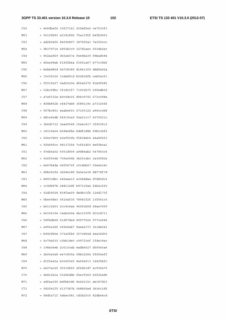
ETSI
ETSI TS 133 401 V10.3.0 (2012-07)1023GPP TS 33.401 version 10.3.0 Release 10
C52 = 466dbaf4 10f27161 202bd3e2 ce7fc5f3
M53 = 56109b93 a218c896 75ac195f b4fb0663
C53 = adcb04f6 86696807 38756fa3 7a350ccc
M54 = 9b379714 4955b3c9 327d1aec 003d42ec
C54 = 802a2d59 0b3a457a f449ba39 f8bad584
M55 = d0ea98ab f19ffb4a f3561a67 e77c35bf
C55 = b6bbd86d 5e708389 d18413f9 ddd9a92a
M56 = 15c59c24 12da881d b02b1bfb cebfac51
C56 = ff010e37 0ad1420e df6a5276 81b9f685
M57 = 52bc99bc 3f1d15f7 71001b70 29fedb02
C57 = a7af152e b0c0dc25 d96c9792 672c098e
M58 = 8f8b852b c4407eb8 3f891c9c a733254f
C58 = 957bc801 eaabe60c 27193122 a94cccb8
M59 = dd1e9edb 56919ce9 fea21c17 4072521c
C59 = 3b6d3712 3ea45568 15a4c417 3f903fc3
M60 = 18319a54 b5d4efbe bddf1d8b 69b1cbf2
C60 = 656e7869 42ef502b f5838dc4 44a89253
M61 = 5f489fcc 98137254 7cf41d00 8ef0bca1
C61 = 934b5a02 5051d909 a9d84ab2 547853c6
M62 = 926f934b 735e090b 3b251eb3 3a36f82e
C62 = b667b4da 06f5670f c014bb27 09e6e18c
M63 = d9b29cf4 cb944188 fa0e1e38 dd778f7d
C63 = 88033db1 446aaa10 a348ddaa d7d80d16
M64 = 1c9d987b 28d132df b9731fa4 f4b41693
C64 = 52d29028 818fae29 dad8c1fb 124d173f
M65 = 5be49de3 0516af35 78581f2f 13f561c0
C65 = b6131b03 2cc9c6ae 96051b5d 68aa7659
M66 = 66336194 1eab249a 4bc123f8 d15cd711
C66 = 58fbdb68 61d57ded 89977624 977ce584
M67 = a956a1bf 20fe6eb7 8aea2373 361da042
C67 = b9929b5e 371a0fb6 357c864d 4ea36d30
M68 = 6c79a530 c3bb1de0 c99722ef 1fde39ac
C68 = 198a06eb 2c013cab eadb6627 d555e3a6
M69 = 2b00a0a8 ee7c800a 08bc2264 f89f4eff
C69 = d1f0a42a b3045545 8e69a513 14825bfc
M70 = e627ac2f 0531fb55 4f6d21d7 4c590a70
C70 = 6b8c1b1a 03286dde f4ecf569 66f264d0
M71 = adfaa390 bdfbb3d6 8e46215c ab187d23
C71 = 082fe1f5 61373b7b 048b92ed 3b36c1d5
M72 = 68d5a71f 5ebec081 cd3b20c0 82dbe4cd
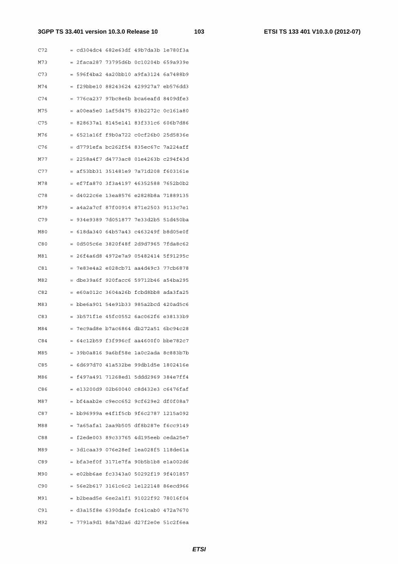
ETSI
ETSI TS 133 401 V10.3.0 (2012-07)1033GPP TS 33.401 version 10.3.0 Release 10
C72 = cd304dc4 682e63df 49b7da3b 1e780f3a
M73 = 2faca287 73795d6b 0c10204b 659a939e
C73 = 596f4ba2 4a20bb10 a9fa3124 6a7488b9
M74 = f29bbe10 88243624 429927a7 eb576dd3
C74 = 776ca237 97bc8e6b bca6eafd 8409dfe3
M75 = a00ea5e0 1af5d475 83b2272c 0c161a80
C75 = 828637a1 8145e141 83f331c6 606b7d86
M76 = 6521a16f f9b0a722 c0cf26b0 25d5836e
C76 = d7791efa bc262f54 835ec67c 7a224aff
M77 = 2258a4f7 d4773ac8 01e4263b c294f43d
C77 = af53bb31 351481e9 7a71d208 f603161e
M78 = ef7fa870 3f3a4197 46352588 7652b0b2
C78 = d4022c6e 13ea8576 e2828b8a 71889135
M79 = a4a2a7cf 87f00914 871e2503 9113c7e1
C79 = 934e9389 7d051877 7e33d2b5 51d450ba
M80 = 618da340 64b57a43 c463249f b8d05e0f
C80 = 0d505c6e 3820f48f 2d9d7965 7fda8c62
M81 = 26f4a6d8 4972e7a9 05482414 5f91295c
C81 = 7e83e4a2 e028cb71 aa4d49c3 77cb6878
M82 = dbe39a6f 920facc6 59712b46 a54ba295
C82 = e60a012c 3604a26b fcbd8bb8 ada3fa25
M83 = bbe6a901 54e91b33 985a2bcd 420ad5c6
C83 = 3b571f1e 45fc0552 6ac062f6 e38133b9
M84 = 7ec9ad8e b7ac6864 db272a51 6bc94c28
C84 = 64c12b59 f3f996cf aa4600f0 bbe782c7
M85 = 39b0a816 9a6bf58e 1a0c2ada 8c883b7b
C85 = 6d697d70 41a532be 99db1d5e 1802416e
M86 = f497a491 71268ed1 5ddd2969 384e7ff4
C86 = e13200d9 02b60040 c8d432e3 c6476faf
M87 = bf4aab2e c9ecc652 9cf629e2 df0f08a7
C87 = bb96999a e4f1f5cb 9f6c2787 1215a092
M88 = 7a65afa1 2aa9b505 df8b287e f6cc9149
C88 = f2ede003 89c33765 4d195eeb ceda25e7
M89 = 3d1caa39 076e28ef 1ea028f5 118de61a
C89 = bfa3ef0f 3171e7fa 90b5b1b8 e1a002d6
M90 = e02bb6ae fc3343a0 50292f19 9f401857
C90 = 56e2b617 3161c6c2 1e122148 86ecd966
M91 = b2bead5e 6ee2a1f1 91022f92 78016f04
C91 = d3a15f8e 6390dafe fc41cab0 472a7670
M92 = 7791a9d1 8da7d2a6 d27f2e0e 51c2f6ea
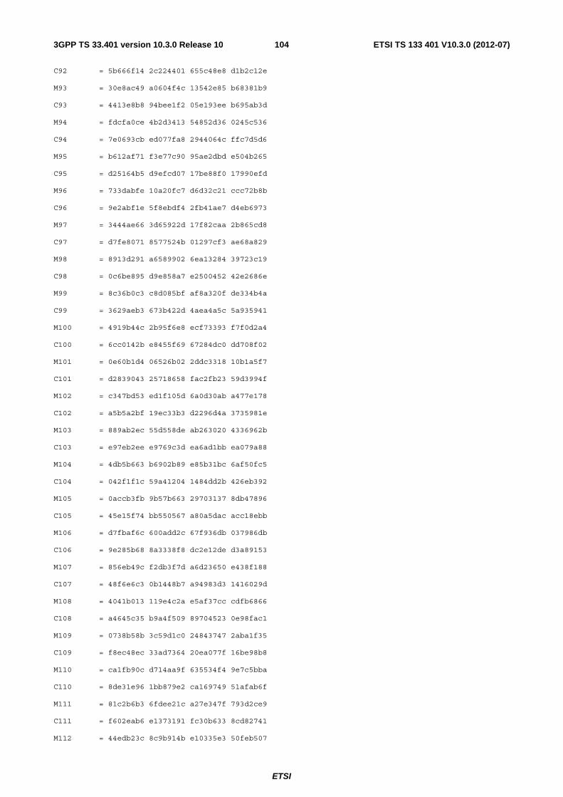
ETSI
ETSI TS 133 401 V10.3.0 (2012-07)1043GPP TS 33.401 version 10.3.0 Release 10
C92 = 5b666f14 2c224401 655c48e8 d1b2c12e
M93 = 30e8ac49 a0604f4c 13542e85 b68381b9
C93 = 4413e8b8 94bee1f2 05e193ee b695ab3d
M94 = fdcfa0ce 4b2d3413 54852d36 0245c536
C94 = 7e0693cb ed077fa8 2944064c ffc7d5d6
M95 = b612af71 f3e77c90 95ae2dbd e504b265
C95 = d25164b5 d9efcd07 17be88f0 17990efd
M96 = 733dabfe 10a20fc7 d6d32c21 ccc72b8b
C96 = 9e2abf1e 5f8ebdf4 2fb41ae7 d4eb6973
M97 = 3444ae66 3d65922d 17f82caa 2b865cd8
C97 = d7fe8071 8577524b 01297cf3 ae68a829
M98 = 8913d291 a6589902 6ea13284 39723c19
C98 = 0c6be895 d9e858a7 e2500452 42e2686e
M99 = 8c36b0c3 c8d085bf af8a320f de334b4a
C99 = 3629aeb3 673b422d 4aea4a5c 5a935941
M100 = 4919b44c 2b95f6e8 ecf73393 f7f0d2a4
C100 = 6cc0142b e8455f69 67284dc0 dd708f02
M101 = 0e60b1d4 06526b02 2ddc3318 10b1a5f7
C101 = d2839043 25718658 fac2fb23 59d3994f
M102 = c347bd53 ed1f105d 6a0d30ab a477e178
C102 = a5b5a2bf 19ec33b3 d2296d4a 3735981e
M103 = 889ab2ec 55d558de ab263020 4336962b
C103 = e97eb2ee e9769c3d ea6ad1bb ea079a88
M104 = 4db5b663 b6902b89 e85b31bc 6af50fc5
C104 = 042f1f1c 59a41204 1484dd2b 426eb392
M105 = 0accb3fb 9b57b663 29703137 8db47896
C105 = 45e15f74 bb550567 a80a5dac acc18ebb
M106 = d7fbaf6c 600add2c 67f936db 037986db
C106 = 9e285b68 8a3338f8 dc2e12de d3a89153
M107 = 856eb49c f2db3f7d a6d23650 e438f188
C107 = 48f6e6c3 0b1448b7 a94983d3 1416029d
M108 = 4041b013 119e4c2a e5af37cc cdfb6866
C108 = a4645c35 b9a4f509 89704523 0e98fac1
M109 = 0738b58b 3c59d1c0 24843747 2aba1f35
C109 = f8ec48ec 33ad7364 20ea077f 16be98b8
M110 = ca1fb90c d714aa9f 635534f4 9e7c5bba
C110 = 8de31e96 1bb879e2 ca169749 51afab6f
M111 = 81c2b6b3 6fdee21c a27e347f 793d2ce9
C111 = f602eab6 e1373191 fc30b633 8cd82741
M112 = 44edb23c 8c9b914b e10335e3 50feb507
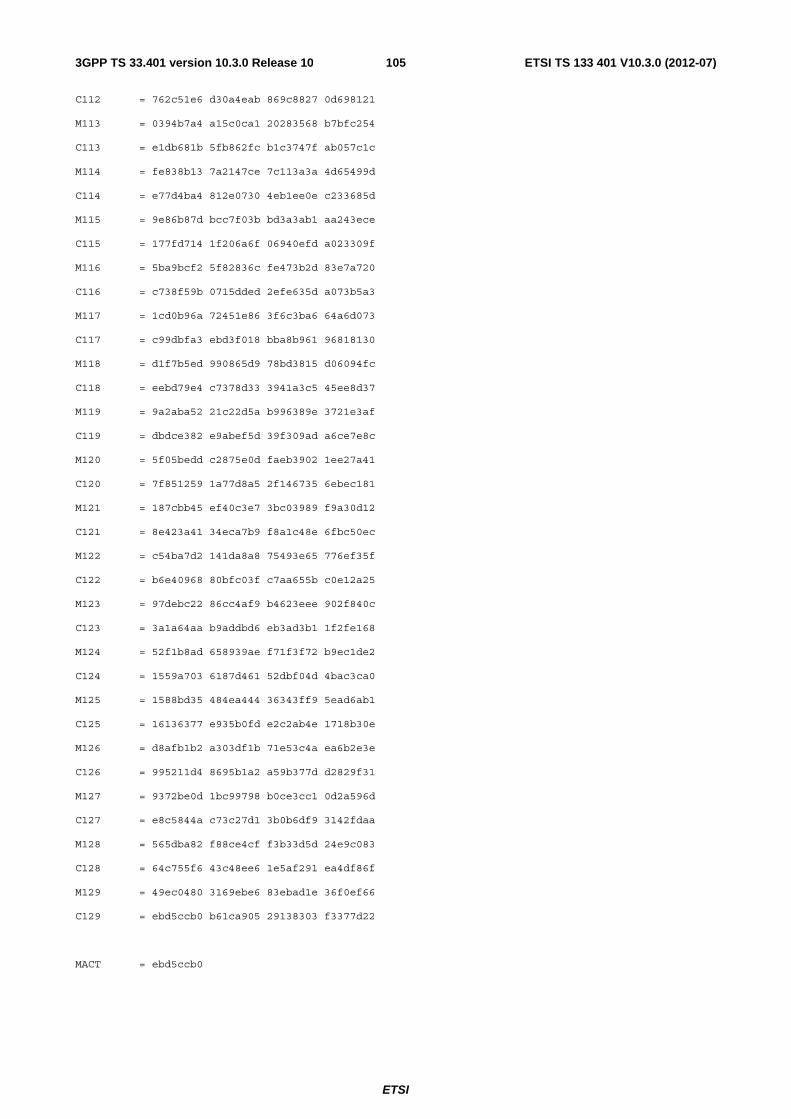
ETSI
ETSI TS 133 401 V10.3.0 (2012-07)1053GPP TS 33.401 version 10.3.0 Release 10
C112 = 762c51e6 d30a4eab 869c8827 0d698121
M113 = 0394b7a4 a15c0ca1 20283568 b7bfc254
C113 = e1db681b 5fb862fc b1c3747f ab057c1c
M114 = fe838b13 7a2147ce 7c113a3a 4d65499d
C114 = e77d4ba4 812e0730 4eb1ee0e c233685d
M115 = 9e86b87d bcc7f03b bd3a3ab1 aa243ece
C115 = 177fd714 1f206a6f 06940efd a023309f
M116 = 5ba9bcf2 5f82836c fe473b2d 83e7a720
C116 = c738f59b 0715dded 2efe635d a073b5a3
M117 = 1cd0b96a 72451e86 3f6c3ba6 64a6d073
C117 = c99dbfa3 ebd3f018 bba8b961 96818130
M118 = d1f7b5ed 990865d9 78bd3815 d06094fc
C118 = eebd79e4 c7378d33 3941a3c5 45ee8d37
M119 = 9a2aba52 21c22d5a b996389e 3721e3af
C119 = dbdce382 e9abef5d 39f309ad a6ce7e8c
M120 = 5f05bedd c2875e0d faeb3902 1ee27a41
C120 = 7f851259 1a77d8a5 2f146735 6ebec181
M121 = 187cbb45 ef40c3e7 3bc03989 f9a30d12
C121 = 8e423a41 34eca7b9 f8a1c48e 6fbc50ec
M122 = c54ba7d2 141da8a8 75493e65 776ef35f
C122 = b6e40968 80bfc03f c7aa655b c0e12a25
M123 = 97debc22 86cc4af9 b4623eee 902f840c
C123 = 3a1a64aa b9addbd6 eb3ad3b1 1f2fe168
M124 = 52f1b8ad 658939ae f71f3f72 b9ec1de2
C124 = 1559a703 6187d461 52dbf04d 4bac3ca0
M125 = 1588bd35 484ea444 36343ff9 5ead6ab1
C125 = 16136377 e935b0fd e2c2ab4e 1718b30e
M126 = d8afb1b2 a303df1b 71e53c4a ea6b2e3e
C126 = 995211d4 8695b1a2 a59b377d d2829f31
M127 = 9372be0d 1bc99798 b0ce3cc1 0d2a596d
C127 = e8c5844a c73c27d1 3b0b6df9 3142fdaa
M128 = 565dba82 f88ce4cf f3b33d5d 24e9c083
C128 = 64c755f6 43c48ee6 1e5af291 ea4df86f
M129 = 49ec0480 3169ebe6 83ebad1e 36f0ef66
C129 = ebd5ccb0 b61ca905 29138303 f3377d22
MACT = ebd5ccb0
ETSI
ETSI TS 133 401 V10.3.0 (2012-07)1063GPP TS 33.401 version 10.3.0 Release 10
Annex D (normative): Security for Relay Node Architectures
D.1 Introduction This Annex provides the security procedures applied to relay nodes. Security requirements and security features applied to relay nodes can be found in the main body of the present specification.
The overall stage 2 description for relay nodes can be found in 3GPP TS 23.401 [2] and 3GPP TS 36.300 [30].
D.2 Solution
D.2.1 General The basic idea of the solution for relay node security presented in this Annex is realizing a one-to-one binding of an RN and a USIM called USIM-RN. Such a one-to-one binding is realized in this solution either by using symmetric pre-shared keys (psk) or by certificates. In the psk case, the binding needs to be pre-established in the UICC and in the RN prior to deployment; in the certificate case, the binding needs to be pre-established only in the UICC prior to deployment. The use of certificates has the advantage that there is a standardized procedure for enrolling the private key corresponding to the certificate in the secure environment of the RN while the use of a psk requires manual operation for establishing the psk. A further advantage is that the name (identity) in the certificate can be given at time of enrolment, and does not have to be pre-established. On the other hand, the use of a psk has the advantage that no PKI is required and the procedure after pre-establishment of the psk is simpler. When using certificates for this one-to-one binding, a part of the usual certificate handling is replaced by subscription handling, as explained in Annex D.2.6.
The certificate-based procedures are mandatory to support.
The pre-shared-key-based procedures are mandatory to support.
NOTE 1: The provisioning of pre-shared keys is out of the scope of this document.
When using certificates the UICC inserted in the RN shall contain two USIMs: a USIM-RN which shall perform any communication only via a secure channel, and a USIM-INI communicating with the RN without secure channel and used for initial IP connectivity purposes prior to RN attachment. The UICC shall establish a secure channel only with a particular relay node, as detailed in the procedures described in D.2.2. The UICC verifies this relay node by means of data pre-established in the UICC.
When using psk only the USIM-RN is required. This USIM-RN shall perform any communication only via a secure channel.
NOTE 2: USIM-INI and USIM-RN are described in TS 31.102 [3].
D.2.2 Security Procedures The start-up of an RN shall proceed in the following steps, which are arranged in three phases. The Preparation Phase and Phase II procedures are the same for the certificate-based and the psk-based case. Phase I procedures differ between the certificate-based case and the pre-shared key based case. If one of the steps fails in any of the involved entities the procedure shall be aborted by that entity, and the steps that follow the failed step shall not be executed (but the sending of failure messages is possible).
Preparation Phase:
The RN platform secure environment shall perform an integrity check of the RN platform. This shall include checking the integrity of the sensitive parts of the boot process and proceeding with the boot process only if the integrity checks of all these parts are successful.
ETSI
ETSI TS 133 401 V10.3.0 (2012-07)1073GPP TS 33.401 version 10.3.0 Release 10
Phase I: Procedures prior to the RN attach procedure (certificate-based case)
For the certificate-based case, the RN may skip Phase I attachment if the RN has an operator certificate available and a valid CRL list (if needed).
NOTE: There may be reasons to perform Phase I attachment even if operator certificate and valid CRL are available.
Ec1. Void
Ec2. The RN shall attach as a UE using USIM-INI if step Ec3 needs to be performed.
Ec3. The RN shall obtain an operator certificate through the enrolment procedure defined in TS 33.310 [6] unless an operator certificate is already available. Details can be found in clause D.2.4. The RN may optionally establish a secure connection to an OAM server. Details can be found in clause D.2.5. The RN shall retrieve a CRL from a suitable server if no valid CRL is available locally in the RN and the RN supports and is configured to perform CRL checks. For revocation checking of UICC certificates see clause D.2.6. For the handling of CRLs for UICC certificates see also clause D.3.3.4.
Ec4. After completing step Ec3, the RN shall detach from the network and de-activate the USIM-INI if it attached in step Ec2. If the UICC needs to be configured over the air (OTA) this may also be done in this step.
Ec5. The RN platform secure environment and the UICC shall establish a Secure Channel between RN and USIM-RN according to ETSI TS 102 484 [29] clause 7 'Secured APDU' with TLS handshake. This TLS handshake shall be initiated by the RN and use certificates on both sides. The RN shall either use a pre-established certificate or the certificate enrolled in step Ec3. The UICC shall verify that this certificate belongs to the relay node the USIM-RN is bound to . The UICC shall be pre-provisioned with an operator root certificate to verify the RN certificate. The UICC certificate shall be pre-installed in the UICC by the operator. The RN shall be provisioned with a root certificate to verify the UICC certificate.
Ec6. A certificate validation client on the UICC shall verify the signatures in the RN certificate chain up to the root certificate. The check of revocation status and expiry time shall be omitted. A certificate validation client on the RN shall check the verification of the signatures in the UICC certificate chain up to the root certificate as well as the expiry time. The revocation status of the UICC certificate should be checked by means of CRLs. Furthermore, the requirements in clause D.2.3 on "USIM Binding Aspects" shall apply.
NOTE 1: The root certificate, and potentially other data required, that need to be stored in the UICC could be provisioned in the UICC during its personalization. The operator provides to smart card manufacturer a list of data (e.g. IMSI, key K, etc) to be provisioned in the UICC during its personalization phase, before issuance of the UICC. The root certificate, and potentially other data, could be provided by the operator as part of the data to be personalized in the UICC by the smart card manufacturer. In the field, the root certificate, and potentially other data, could also be updated by OTA means, if needed.
The private key corresponding to the RN certificate and the root certificate used to verify the UICC certificate shall be stored in the secure environment of the RN platform validated in the Preparation Phase, and the TLS connection as well as the secure channel with the UICC shall terminate there. From the completion of this step onwards, all communication between the USIM-RN and the RN shall be protected by the Secure Channel.
The USIM-RN shall not engage in any communication with any entity prior to the the completion of establishment of the Secure Channel according to steps Ec5 and Ec6 other than messages for establishing the Secure Channel according to ETSI TS 102 484 [29] clause 7 'Secured APDU'.
NOTE 2: Certificate use restriction may be made possible e.g. through a suitable name structure, or a particular intermediate CA in the verification path, or policy information terms, e.g. by a suitable object identifier (OID) in the certificate policies extension.
ETSI
ETSI TS 133 401 V10.3.0 (2012-07)1083GPP TS 33.401 version 10.3.0 Release 10
NOTE 3: ETSI TS 102 484 [29] states in clause 6.2.2: 'The UICC may present a self-signed certificate. The terminal or terminal application should temporarily accept such a certificate during the TLS handshake protocol, if it is able to establish by other means (e.g. successful network authentication) that the handshake protocol is conducted with an authentic UICC.' Similar considerations apply when the method in ETSI TS 102 484 [29] in clause 7 'Secured APDU' with TLS handshake is used as is the case in the present document. And in the present solution for relay node security, the RN indeed verifies the authenticity of the USIM-RN by means of a successful RN attach procedure. However, the use of a self-signed UICC certificate, or no UICC certificate at all, is not allowed here as this would weaken the protection against certain attacks, cf. clause D.2.6.
NOTE 4: It is proposed here that the RN assumes the role of TLS client in line with ETSI TS 102 484 [29], clause 7, on 'Secured APDU' with TLS handshake.
NOTE 5: One may want to limit the lifetime of a secure channel between USIM-RN and RN for security reasons. Suitable counters providing such a limit include a transaction counter, cf. clause 5 of ETSI TS 102 484 [29]. Details can be found in stage 3 specifications.
NOTE 6: Having two USIMs on one UICC is a standard feature available today (but only one USIM can be active at a time in current 3GPP specifications).
NOTE 7: The RN could distinguish a USIM-RN from a USIM-INI e.g. by the use of so-called 'Application Identifiers (AID)' for UICC applications.
Phase I: Procedures prior to the RN attach procedure (pre-shared key based case)
For the psk-based case, there may be some cases when skipping of Phase I attachment is possible. Such cases are outside the scope of the present document.
Ep1. Void.
Ep2. The RN platform secure environment and the UICC shall establish a Secure Channel between RN and USIM-RN according to ETSI TS 102 484 [29] clause 7 'Secured APDU' using a pre-shared key. Furthermore, the requirements in clause D.2.3 on "USIM Binding Aspects" shall apply.
The pre-shared key shall be stored in the secure environment of the RN platform validated in the Preparation Phase, and the secure channel with the UICC shall terminate there. From the completion of this step onwards, all communication between the USIM-RN and the RN shall be protected by the Secure Channel.
The USIM-RN shall not engage in any communication with any entity prior to the completion of the establishment of the Secure Channel according to step Ep2 other than messages for establishing the Secure Channel according to ETSI TS 102 484 [29] clause 7 "Secured APDU".
Ep3. The RN may optionally establish a secure connection to an OAM server. Details can be found in clause D.2.5.
Ep4. The RN shall detach from to the network if it attached for performing step Ep3.
NOTE 8: The use of the pre-shared key variant requires that the RN is configured with this pre-shared key e.g. in the factory, or at the operator"s premises or in the field during RN installation. The corresponding procedures are out of scope of the present document. For the UICC, the regular personalization procedures are expected to apply.
NOTE 9: One may want to limit the lifetime of a secure channel between USIM-RN and RN for security reasons. Suitable counters providing such a limit include a record counter, cf. clause 6.4 of ETSI TS 102 484 [29], or a transaction counter, cf. clause 5 of ETSI TS 102 484 [29]. Details can be found in stage 3 specifications.
Phase II: RN attach procedure (pre-shared key case and certificate-based case)
It is required that a secure channel between RN and USIM-RN exists throughout the execution of phase II.
The RN shall perform the RN attach procedure for EPS as defined in TS 36.300 [30], using the USIM-RN. In addition, the following security-related steps shall be performed:
ETSI
ETSI TS 133 401 V10.3.0 (2012-07)1093GPP TS 33.401 version 10.3.0 Release 10
A1. If the USIM-RN is not already active the RN shall activate it and shall establish a new secure channel according to Ec5, Ec6 in the certificate-based case and Ep1, Ep2 in the pre-shared key based case respectively. The RN shall use the IMSI (or a related GUTI) pertaining to the USIM-RN in the RN attach procedure.
NOTE 10: In the certificate-based case this IMSI differs from the one pertaining to the USIM-INI, therefore the network can distinguish the handling of the two USIMs.
A2. The S1 Initial UE message shall indicate that the attachment is for an RN. Upon receipt of this message the MME-RN shall run EPS AKA with the RN and the USIM-RN. The RN shall accept only authentication responses and keys in an RN attach procedure that were received from the USIM-RN over the Secure Channel.
A3. The MME-RN shall check from the RN-specific subscription data received from the HSS that the USIM-RN is permitted for use in RN attach procedures. When this is not the case, but the S1 Initial UE message indicated that the attachment is for an RN, the MME-RN shall reject the Attach request and indicate to the DeNB that the set-up has failed.
A4. The MME-RN and RN shall establish NAS security. Upon receipt of the S1 INITIAL CONTEXT SETUP message the DeNB and the RN shall set up AS security over Un as specified in the present document.
A5. The RN may establish a secure connection to an OAM server in this phase to complete the configuration. Details can be found in Clause D.2.5.
The RN start-up is now complete from a security point of view, and UEs can start attaching to the RN.
D.2.3 USIM Binding Aspects There shall be a one-to-one association between the USIM-RN and the RN.
In the pre-shared key case, this one-to-one association is ensured by the fact that the key that is pre-shared between the USIM-RN and the RN shall not be available in any other entity.
In the certificate-based case, this one-to-one association is ensured by the following requirements:
- The UICC shall verify the RN identity, represented by the RN identity in the certificate, through the TLS handshake as part of the secure channel set-up, and shall check whether it coincides with the locally stored identity of the RN authorized to set up a secure channel with the USIM-RN;
- the identity in an RN certificate shall be unique;
- a particular RN identity shall be available in only one UICC.
The procedures for managing the binding between USIM-RN and the RN are out of scope of the present document.
The UICC may know the identity of the RN authorized to set up a secure channel with the USIM-RN by configuration. The standard secure OTA mechanisms (TS 31.116 [31]) can be used to update the configuration of UICC and renew the stored identities if required.
NOTE: The RN identity is contained in the subject name of the RN certificate. It is described in detail in clause D.3.3 of the present document and in TS 31.102 [13].
D.2.4 Enrolment procedures for RNs This subclause applies only to the certificate-based case.
The RN may enroll a device certificate as with macro eNBs according to TS 33.310 [6] prior to the RN attach procedure with the DeNB. This certificate may then be used for establishing the secure channel between RN and USIM-RN.
The certificate enrolment procedure does not rely on the security at the AS level, but is secured at the application layer. It can be therefore executed before security on the Un interface has been established. However, the RN requires IP connectivity for the enrolment procedure to be able to reach the Registration Authority RA.
The IP connectivity required for enrolment may be established in the following ways:
(1) The RN may use offline means for enrolment purposes. No USIM is required.
ETSI
ETSI TS 133 401 V10.3.0 (2012-07)1103GPP TS 33.401 version 10.3.0 Release 10
(2) The RN may attach to an eNB like a normal UE using a USIM, called USIM-INI, different from the one used in the RN attach procedure to the DeNB, called USIM-RN. No secure channel between RN and USIM-INI is required.
In both cases, the network shall ensure that the destinations the RN can reach are restricted to only the PDN(s) where the RA (Registration Authority for the certificate enrolment) and other servers to be contacted during phase I, e.g. the OAM server are located. In case (2) this shall be ensured by restricting IP traffic originating from the RN and sent only to certain destinations (APNs). The restrictions are assumed to be part of the profile relating to the subscription associated with the USIM-INI.
D.2.5 Secure management procedures for RNs The requirements on communication between the OAM systems and the eNB from clause 5.3.2 shall apply for relay nodes in both phases I and II. The mechanisms used to fulfil these requirements shall include applying security association(s) that extend between the RN and an entity in the Evolved Packet Core (EPC) or in an OAM domain trusted by the operator.
NOTE 1: No mechanisms used to fulfil these requirements are mandated in the present document. But example mechanisms are given in NOTE 3 below. NOTE 3 is followed by normative text, which applies if the example mechanisms are used.
NOTE 2: In case of offline configuration of the RN, the security measures used to fulfil the requirements from clause 5.3.2 are out of scope of the present document.
NOTE 3: Examples for mechanisms to secure OAM communication to and from RNs are: - end-to-end security terminated within or just in front of the OAM server; - hop-by-hop security via SEG in EPC which is particularly suited for multiple management connections to separate OAM servers located within one "management domain".
If IKEv2/IPsec or TLS with authentication based on certificates is used for the security association(s), the protocol profiles for IPsec in TS 33.210 [5] and for IKEv2 and TLS in TS 33.310 [6] and the certificate profiles given in TS 33.310 [6] should be followed.
NOTE 4: As the USIM-INI can be accessed by any UE, an attacker can use the USIM-INI to connect to the APN used for OAM in phase I. In case of end-to-end security the OAM server itself has to be secured accordingly. In the hop-by-hop case the SEG can defend against attacks (e.g. DoS attacks) carried out via this channel.
The RN requires IP connectivity for the management procedure to be able to reach the OAM server.
For the pre-shared key case in Phase I, IP connectivity can be established after step Ep2 with the RN attaching to an eNB like a normal UE using the USIM-RN.
For the certificate-based case in Phase I, IP connectivity established for enrolment purposes according to clause D.2.4 may be re-used, or, if not available, it may be established in the same ways as described in clause D.2.4.
Restrictions on the destinations the RN can reach shall apply if the communication with the OAM server prior to the RN attach procedure is based on USIM-INI. They shall be realized in the same way as described in clause D.2.4.
D.2.6 Certificate and subscription handling Whenever the operator intends to prevent the RN from attaching to the network the operator shall bar the subscription relating to the USIM-RN in the HSS.
In the certificate-based case the barring of the subscription relating to the USIM-RN shall be performed also whenever the RN certificate has to be revoked, or whenever the UICC certificate has to be revoked and the RN is not configured to always check the UICC certificate against a CRL, cf. below.
In the pre-shared key case, the barring of the subscription relating to the USIM-RN may be performed also whenever the operator sees a risk that the pre-shared key between the USIM-RN and RN has been compromised.

ETSI
ETSI TS 133 401 V10.3.0 (2012-07)1113GPP TS 33.401 version 10.3.0 Release 10
NOTE 0: In the certificate-based case, checking the UICC certificate against a CRL and barring the subscription relating to the USIM-RN are not equivalent. The former could prevent the following attack while the latter could not: an attacker in possession of a compromised private key relating to the UICC certificate could get stolen RNs to work in his own network as then the attacker could use a fake UICC, with subscription data generated by himself, towards the RN to set up a secure channel. Subscription barring would not be effective in the attacker"s network while the CRL check by the RN would ensure that the RN cannot attach as an RN to a network other than the one of the operator who provisioned the root certificate in the RN. If the operator deems the risk of such an attack low he may configure his RNs to not use CRL checks against UICC certificates.
NOTE 0a: In the pre-shared key case, the proprietary measures may need to consider the attack described in the preceding NOTE 0.
The remainder of the present subclause applies only to the certificate-based case.
As described in Annex D.2.2, step Ec6, the certificate validation client on the UICC verifies the signatures in the RN certificate chain up to the root certificate, but omits the check of revocation status and expiry time. To achieve the same effect as checking RN certificate"s revocation status and expiry time, the associated USIM-RN subscription shall be barred in the HSS. This process is called "invalidation" in this document and is explained further below. A certificate validation client on the RN shall check the verification of the signatures in the UICC certificate chain up to the root certificate as well as the expiry time. The revocation status of the UICC certificate should be checked by means of the CRL obtained by the RN in clause D.2.2, step Ec3. The CRL check is optional to support by the RN
Further considerations on RN certificate and USIM-RN subscription handling:
By using the one-to-one binding of RN and USIM-RN, a part of the usual certificate handling is replaced by subscription handling, as explained below:
Binding in network: The one-to-one binding of RN and USIM-RN shall be expressed by a one-to-one mapping of the RN identity in any certificate issued to the RN and the IMSI in the USIM-RN. The operator shall maintain a table with this mapping (the 'mapping table').
Binding in UICC: cf. clause D.2.3.
Lifetime: The subscription shall have a limit on its lifetime. When the lifetime of the subscription is exceeded the subscription shall be barred in the HSS. The lifetime shall not be greater than the lifetime of the RN certificate. The latter is not checked in the UICC, cf. clause D.2.2.
RN Certificate revocation and invalidation: Whenever the operator decides that the RN certificate shall no longer be used for setting up a secure channel with the USIM-RN the operator does not use CRLs or OCSP, but shall retrieve the IMSI associated with the subject name in the RN certificate and bar the subscription corresponding to the IMSI in the HSS. The certificate shall also be revoked, but the operator does not need to use CRLs or OCSP in this context. This implies that no new certificate shall be issued for the same RN identity from that point onwards. In case the RN certificate is also used for other purposes, e.g. for protecting an OAM connection, then, additionally, the usual PKI revocation procedures apply.
RN compromise: If the operator has reason to believe that an RN has been compromised the RN certificate shall be invalidated and revoked as described above.
RN Certificate renewal: This process may be used as normal as long as the RN identity in the RN certificate remains the same.
NOTE 1: Certificate renewal with private key change may be useful even if the UICC does not check the expiry time of the certificate as, in this way, the use of the private key can be limited if desired.
RN Certificate expiry:
NOTE 2: As the UICC has no clock it cannot check the expiry time and, hence, the RN could also use an expired certificate in the secure channel set-up. As the certificate is only checked by the UICC for RN platform authentication in the secure channel set-up this is not a problem as long as the corresponding private key has not left the secure environment of the RN. More generally, if there is a risk that it has been compromised the operator will bar the corresponding subscription in the HSS. The use of the certificate is limited by the lifetime of the subscription bound to the RN. However, a UICC can be re-used with a different RN after having been re-configured with a different RN identity.
ETSI
ETSI TS 133 401 V10.3.0 (2012-07)1123GPP TS 33.401 version 10.3.0 Release 10
D.3 Secure channel profiles
D.3.1 General The clause D.3 profiles the algorithms to be used on the APDU secure channel, cf. ETSI TS 102 484 [29]. In addition it specifies the profiles for the different key agreement methods.
For the case when certificates are used for key agreement, the profiles are given for the TLS handshake used to provide key material for the Master SA of the secure channel between USIM-RN and RN, and for the certificates used in UICC and RN for mutual authentication during TLS handshake. For the psk case requirements on the key agreement with pre-shared keys are given.
D.3.2 APDU secure channel profile For communication between the USIM-RN and the RN a secure channel according to the APDU secure channel as specified in ETSI TS 102 484 [29] shall be used. Further detailing of the secure channel is given in TS 31.102 [13].
For encryption, AES-CBC as specified in ETSI TS 102 484 [29] shall be mandatory to support. Other encryption algorithms specified in ETSI TS 102 484 [29] may be supported. The algorithm "3DES - outer CBC using 2 keys" shall not be used.
NOTE 1: The algorithm "3DES - outer CBC using 2 keys" is outdated.
For integrity protection, AES-CMAC as specified in ETSI TS 102 484 [29] shall be mandatory to support. Other integrity protection algorithms specified in ETSI TS 102 484 [29] shall not be used.
NOTE 2: The algorithm CRC32 is for redundancy check only, and not a cryptographic checksum. The algorithm "ANSI Retail MAC" is not fit for long-term usage in the scope of the present document.
D.3.3 Key agreement based on certificate exchange
D.3.3.1 TLS profile
The key agreement for the certificate exchange case shall follow the mechanism "Certificate exchange" as specified in ETSI TS 102 484 [29].
During key agreement based on certificate exchange a TLS handshake is used to provide key material for the Master SA of the APDU secure channel between USIM-RN and RN.
The TLS profile shall follow the profile given in Annex E of TS 33.310 [6] with the following restrictions and extensions:
- the support of the ciphersuite mandatory for TLS 1.1 as described in TS 33.310 [6] is not required;
- the support of fallback to TLS 1.0 as described in TS 33.310 [6] is not required;
- neither UICC nor RN shall use TLS session resumption.
D.3.3.2 Common profile for RN and UICC certificate
The certificate profile for both RN and UICC certificates shall follow the TLS entity certificate profile given in clause 6.1.3a of TS 33.310 [6] with the following restrictions and extensions:
- the support of the SHA-1 algorithm for use before signing the certificate as described in TS 33.310 [6] is not required;
- the support of public key length of 1024-bit is not required;
ETSI
ETSI TS 133 401 V10.3.0 (2012-07)1133GPP TS 33.401 version 10.3.0 Release 10
- only the subject name format with "(C=<country>), O=<Organization Name>, CN=<Some distinguishing name>" is mandatory to support.
D.3.3.3 RN certificate profile
The RN certificate is used as client certificate in the TLS handshake between RN and UICC.
The certificate profile for the RN certificate shall follow clause D.3.3.2 of the present document with the following restrictions and extensions:
- the subject name shall be unique within all subject names issued by CAs under the same root CA;
- the subject name may additionally contain the attribute "serialNumber=<serial number>";
- the support of the countryName (C) and serialNumber attributes in the subject name is mandatory;
NOTE 1: The usage of the countryName (C) and serialNumber attributes can support the operator in generating a unique identity for an RN.
- the CRL distribution point is not used if the RN certificate is only used in the setup of the secure channel with the UICC. Therefore the CRL distribution point is optional in this case.
NOTE 2: It may be desired to deploy the same RN certificate also for RN platform authentication to other network elements of the operator, e.g. if TLS with mutual authentication is used for an OAM connection. The profile given above is intended to allow such usage. Regarding the implementation of certificate handling in the UICC it should be noted that for this additional usage of the RN certificate the existence of additional fields in the certificate is possible, e.g. of the subjectAltName and/or the CRL distribution point, which are not relevant for the secure channel between RN and UICC.
D.3.3.4 UICC certificate profile
The UICC certificate is used as server certificate in the TLS handshake between RN and UICC.
The certificate profile for the UICC certificate shall follow clause D.3.3.2 of the present document with the following additional provisions:
- the CRL distribution point in the UICC certificate is optional.
NOTE 1: The CRL distribution point and the support for CRL infrastructure for the UICC certificate is only needed if the revocation check of the UICC certificate is performed during setup of the secure channel (cf. clause D.2.6).
NOTE 2: In common TLS usage, the RN learns the UICC certificate only during TLS handshake, when the IP connectivity to the core network using USIM-INI may no longer be available. Thus the CRL distribution point for CRLs having UICC certificates in scope would be known too late to allow the RN to retrieve an up-to-date CRL from the network. By reading the UICC certificate from the UICC before the establishment of the secure channel starts, the RN may learn the CRL distribution point while it still has IP connectivity based on USIM-INI, cf. step Ec3 in clause D.2.2. For access to the UICC certificate see the definition of the EF for UICC certificate in TS 31.102 [13].
D.3.4 Key agreement for pre-shared key (psk) case The key agreement for the psk case shall follow the mechanism "Strong Pre-shared Keys - Proprietary Pre-agreed keys" as specified in ETSI TS 102 484 [29]. The pre-shared key shall be used directly to derive a Master secret for the Master SA.
NOTE: The above requirement includes that the pre-shared key fulfills the requirements for WeakKey=0 as specified in clause 7.2 of ETSI TS 102 484 [29].
ETSI
ETSI TS 133 401 V10.3.0 (2012-07)1143GPP TS 33.401 version 10.3.0 Release 10
D.3.5 Identities used in key agreement The key agreement mechanisms specified in ETSI TS 102 484 [29] produce a value Ks_Local_Ref, which is a reference to Ks_local. It is transferred from the RN to the UICC during the Master SA setup and is used as input to the derivation of the 256 bit Master secret (MS) of the Master SA in the certificate exchange case.
Ks_Local_Ref is specified in ETSI TS 102 484 [29] as the concatenation of identities as follows:
Ks_Local_Ref = Terminal_ID || Terminal_appli_ID || UICC_ID || UICC_appli_ID.
The identities used in the scope of the present document for Ks_Local_Ref are specified as follows:
- UICC_ID: This unique identifier for the UICC shall be the ICCID for the UICC as specified in ETSI TS 102 221 [32].
NOTE: The UICC_ID may be read by the RN from the UICC before establishment of the secure channel.
- UICC_appli_ID: This unique identifier for the UICC application that hosts the UICC endpoint shall be the USIM-RN AID as specified in TS 31.102 [13].
- Terminal_ID: This unique identifier for the RN shall be the subject name of the RN certificate as specified in clause D.3.3.3. In the psk case, where no certificate is used, the same definition as for the certificate exchange case shall apply.
- Terminal_appli_ID: This unique identifier for the application that hosts the RN side endpoint shall be set to the UTF-8 encoded string "Relay_Node_appli".
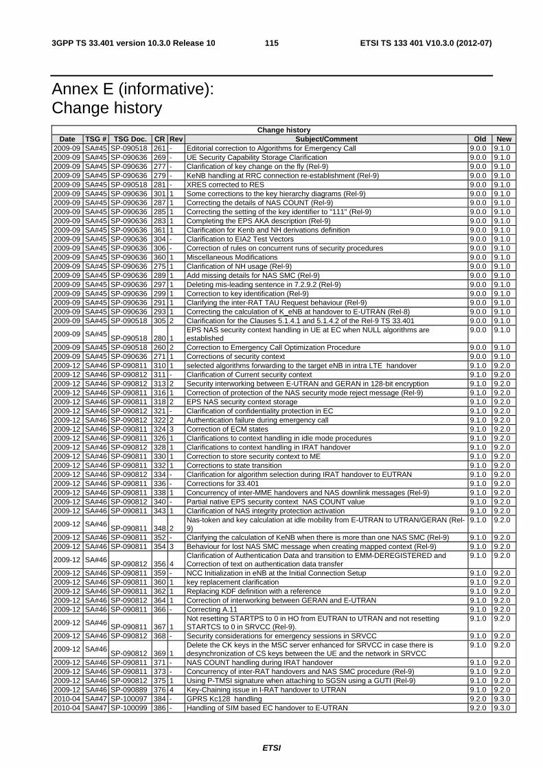
ETSI
ETSI TS 133 401 V10.3.0 (2012-07)1153GPP TS 33.401 version 10.3.0 Release 10
Annex E (informative): Change history
Change history Date TSG # TSG Doc. CR Rev Subject/Comment Old New
2009-09 SA#45 SP-090518 261 - Editorial correction to Algorithms for Emergency Call 9.0.0 9.1.0 2009-09 SA#45 SP-090636 269 - UE Security Capability Storage Clarification 9.0.0 9.1.0 2009-09 SA#45 SP-090636 277 - Clarification of key change on the fly (Rel-9) 9.0.0 9.1.0 2009-09 SA#45 SP-090636 279 - KeNB handling at RRC connection re-establishment (Rel-9) 9.0.0 9.1.0 2009-09 SA#45 SP-090518 281 - XRES corrected to RES 9.0.0 9.1.0 2009-09 SA#45 SP-090636 301 1 Some corrections to the key hierarchy diagrams (Rel-9) 9.0.0 9.1.0 2009-09 SA#45 SP-090636 287 1 Correcting the details of NAS COUNT (Rel-9) 9.0.0 9.1.0 2009-09 SA#45 SP-090636 285 1 Correcting the setting of the key identifier to "111" (Rel-9) 9.0.0 9.1.0 2009-09 SA#45 SP-090636 283 1 Completing the EPS AKA description (Rel-9) 9.0.0 9.1.0 2009-09 SA#45 SP-090636 361 1 Clarification for Kenb and NH derivations definition 9.0.0 9.1.0 2009-09 SA#45 SP-090636 304 - Clarification to EIA2 Test Vectors 9.0.0 9.1.0 2009-09 SA#45 SP-090636 306 - Correction of rules on concurrent runs of security procedures 9.0.0 9.1.0 2009-09 SA#45 SP-090636 360 1 Miscellaneous Modifications 9.0.0 9.1.0 2009-09 SA#45 SP-090636 275 1 Clarification of NH usage (Rel-9) 9.0.0 9.1.0 2009-09 SA#45 SP-090636 289 1 Add missing details for NAS SMC (Rel-9) 9.0.0 9.1.0 2009-09 SA#45 SP-090636 297 1 Deleting mis-leading sentence in 7.2.9.2 (Rel-9) 9.0.0 9.1.0 2009-09 SA#45 SP-090636 299 1 Correction to key identification (Rel-9) 9.0.0 9.1.0 2009-09 SA#45 SP-090636 291 1 Clarifying the inter-RAT TAU Request behaviour (Rel-9) 9.0.0 9.1.0 2009-09 SA#45 SP-090636 293 1 Correcting the calculation of K_eNB at handover to E-UTRAN (Rel-8) 9.0.0 9.1.0 2009-09 SA#45 SP-090518 305 2 Clarification for the Clauses 5.1.4.1 and 5.1.4.2 of the Rel-9 TS 33.401 9.0.0 9.1.0
2009-09 SA#45 SP-090518 280 1
EPS NAS security context handling in UE at EC when NULL algorithms are established
9.0.0 9.1.0
2009-09 SA#45 SP-090518 260 2 Correction to Emergency Call Optimization Procedure 9.0.0 9.1.0 2009-09 SA#45 SP-090636 271 1 Corrections of security context 9.0.0 9.1.0 2009-12 SA#46 SP-090811 310 1 selected algorithms forwarding to the target eNB in intra LTE handover 9.1.0 9.2.0 2009-12 SA#46 SP-090812 311 - Clarification of Current security context 9.1.0 9.2.0 2009-12 SA#46 SP-090812 313 2 Security interworking between E-UTRAN and GERAN in 128-bit encryption 9.1.0 9.2.0 2009-12 SA#46 SP-090811 316 1 Correction of protection of the NAS security mode reject message (Rel-9) 9.1.0 9.2.0 2009-12 SA#46 SP-090811 318 2 EPS NAS security context storage 9.1.0 9.2.0 2009-12 SA#46 SP-090812 321 - Clarification of confidentiality protection in EC 9.1.0 9.2.0 2009-12 SA#46 SP-090812 322 2 Authentication failure during emergency call 9.1.0 9.2.0 2009-12 SA#46 SP-090811 324 3 Correction of ECM states 9.1.0 9.2.0 2009-12 SA#46 SP-090811 326 1 Clarifications to context handling in idle mode procedures 9.1.0 9.2.0 2009-12 SA#46 SP-090812 328 1 Clarifications to context handling in IRAT handover 9.1.0 9.2.0 2009-12 SA#46 SP-090811 330 1 Correction to store security context to ME 9.1.0 9.2.0 2009-12 SA#46 SP-090811 332 1 Corrections to state transition 9.1.0 9.2.0 2009-12 SA#46 SP-090812 334 - Clarification for algorithm selection during IRAT handover to EUTRAN 9.1.0 9.2.0 2009-12 SA#46 SP-090811 336 - Corrections for 33.401 9.1.0 9.2.0 2009-12 SA#46 SP-090811 338 1 Concurrency of inter-MME handovers and NAS downlink messages (Rel-9) 9.1.0 9.2.0 2009-12 SA#46 SP-090812 340 - Partial native EPS security context NAS COUNT value 9.1.0 9.2.0 2009-12 SA#46 SP-090811 343 1 Clarification of NAS integrity protection activation 9.1.0 9.2.0
2009-12 SA#46 SP-090811 348 2
Nas-token and key calculation at idle mobility from E-UTRAN to UTRAN/GERAN (Rel-9)
9.1.0 9.2.0
2009-12 SA#46 SP-090811 352 - Clarifying the calculation of KeNB when there is more than one NAS SMC (Rel-9) 9.1.0 9.2.0 2009-12 SA#46 SP-090811 354 3 Behaviour for lost NAS SMC message when creating mapped context (Rel-9) 9.1.0 9.2.0
2009-12 SA#46 SP-090812 356 4 Clarification of Authentication Data and transition to EMM-DEREGISTERED and Correction of text on authentication data transfer
9.1.0 9.2.0
2009-12 SA#46 SP-090811 359 - NCC Initialization in eNB at the Initial Connection Setup 9.1.0 9.2.0 2009-12 SA#46 SP-090811 360 1 key replacement clarification 9.1.0 9.2.0 2009-12 SA#46 SP-090811 362 1 Replacing KDF definition with a reference 9.1.0 9.2.0 2009-12 SA#46 SP-090812 364 1 Correction of interworking between GERAN and E-UTRAN 9.1.0 9.2.0 2009-12 SA#46 SP-090811 366 - Correcting A.11 9.1.0 9.2.0
2009-12 SA#46 SP-090811 367 1 Not resetting STARTPS to 0 in HO from EUTRAN to UTRAN and not resetting STARTCS to 0 in SRVCC (Rel-9).
9.1.0 9.2.0
2009-12 SA#46 SP-090812 368 - Security considerations for emergency sessions in SRVCC 9.1.0 9.2.0
2009-12 SA#46 SP-090812 369 1
Delete the CK keys in the MSC server enhanced for SRVCC in case there is desynchronization of CS keys between the UE and the network in SRVCC
9.1.0 9.2.0
2009-12 SA#46 SP-090811 371 - NAS COUNT handling during IRAT handover 9.1.0 9.2.0 2009-12 SA#46 SP-090811 373 - Concurrency of inter-RAT handovers and NAS SMC procedure (Rel-9) 9.1.0 9.2.0 2009-12 SA#46 SP-090812 375 1 Using P-TMSI signature when attaching to SGSN using a GUTI (Rel-9) 9.1.0 9.2.0 2009-12 SA#46 SP-090889 376 4 Key-Chaining issue in I-RAT handover to UTRAN 9.1.0 9.2.0 2010-04 SA#47 SP-100097 384 - GPRS Kc128 handling 9.2.0 9.3.0 2010-04 SA#47 SP-100099 386 - Handling of SIM based EC handover to E-UTRAN 9.2.0 9.3.0
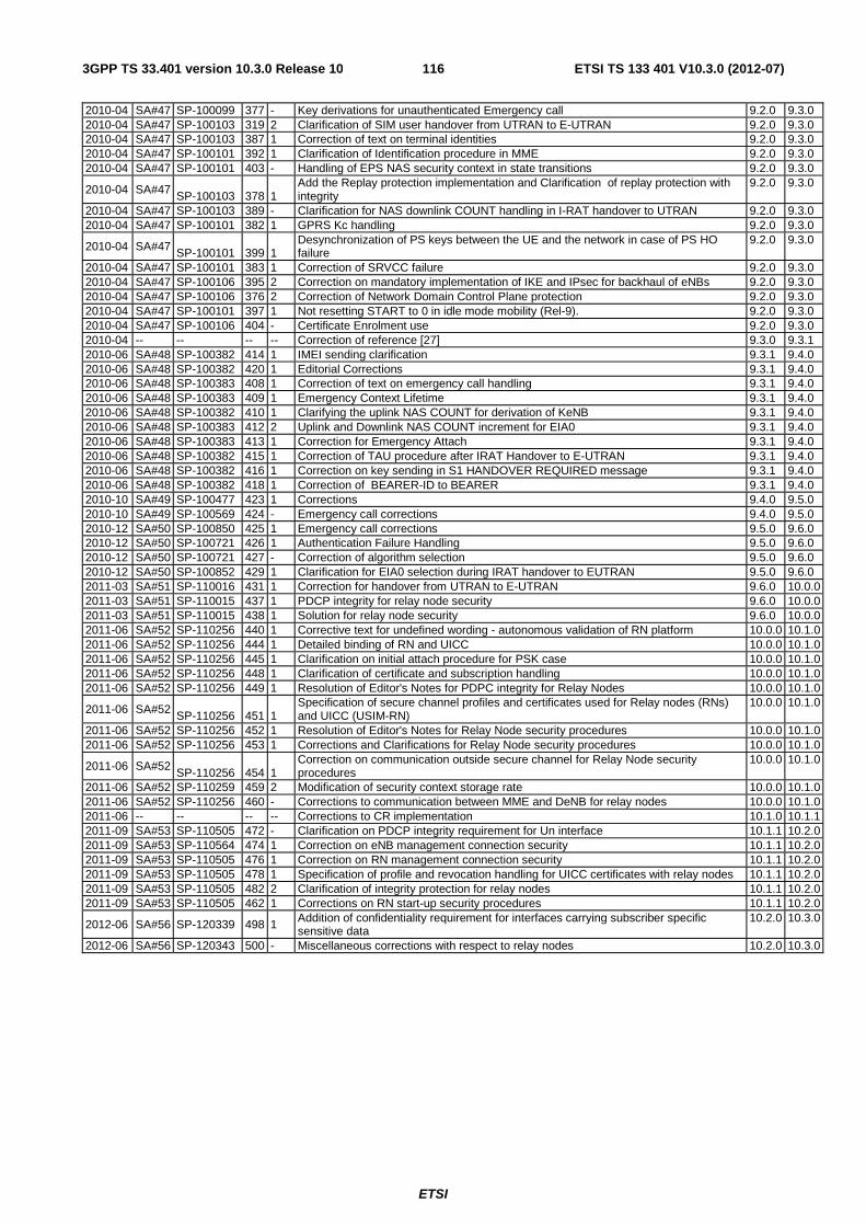
ETSI
ETSI TS 133 401 V10.3.0 (2012-07)1163GPP TS 33.401 version 10.3.0 Release 10
2010-04 SA#47 SP-100099 377 - Key derivations for unauthenticated Emergency call 9.2.0 9.3.0 2010-04 SA#47 SP-100103 319 2 Clarification of SIM user handover from UTRAN to E-UTRAN 9.2.0 9.3.0 2010-04 SA#47 SP-100103 387 1 Correction of text on terminal identities 9.2.0 9.3.0 2010-04 SA#47 SP-100101 392 1 Clarification of Identification procedure in MME 9.2.0 9.3.0 2010-04 SA#47 SP-100101 403 - Handling of EPS NAS security context in state transitions 9.2.0 9.3.0
2010-04 SA#47 SP-100103 378 1 Add the Replay protection implementation and Clarification of replay protection with integrity
9.2.0 9.3.0
2010-04 SA#47 SP-100103 389 - Clarification for NAS downlink COUNT handling in I-RAT handover to UTRAN 9.2.0 9.3.0 2010-04 SA#47 SP-100101 382 1 GPRS Kc handling 9.2.0 9.3.0
2010-04 SA#47 SP-100101 399 1 Desynchronization of PS keys between the UE and the network in case of PS HO failure
9.2.0 9.3.0
2010-04 SA#47 SP-100101 383 1 Correction of SRVCC failure 9.2.0 9.3.0 2010-04 SA#47 SP-100106 395 2 Correction on mandatory implementation of IKE and IPsec for backhaul of eNBs 9.2.0 9.3.0 2010-04 SA#47 SP-100106 376 2 Correction of Network Domain Control Plane protection 9.2.0 9.3.0 2010-04 SA#47 SP-100101 397 1 Not resetting START to 0 in idle mode mobility (Rel-9). 9.2.0 9.3.0 2010-04 SA#47 SP-100106 404 - Certificate Enrolment use 9.2.0 9.3.0 2010-04 -- -- -- -- Correction of reference [27] 9.3.0 9.3.1 2010-06 SA#48 SP-100382 414 1 IMEI sending clarification 9.3.1 9.4.0 2010-06 SA#48 SP-100382 420 1 Editorial Corrections 9.3.1 9.4.0 2010-06 SA#48 SP-100383 408 1 Correction of text on emergency call handling 9.3.1 9.4.0 2010-06 SA#48 SP-100383 409 1 Emergency Context Lifetime 9.3.1 9.4.0 2010-06 SA#48 SP-100382 410 1 Clarifying the uplink NAS COUNT for derivation of KeNB 9.3.1 9.4.0 2010-06 SA#48 SP-100383 412 2 Uplink and Downlink NAS COUNT increment for EIA0 9.3.1 9.4.0 2010-06 SA#48 SP-100383 413 1 Correction for Emergency Attach 9.3.1 9.4.0 2010-06 SA#48 SP-100382 415 1 Correction of TAU procedure after IRAT Handover to E-UTRAN 9.3.1 9.4.0 2010-06 SA#48 SP-100382 416 1 Correction on key sending in S1 HANDOVER REQUIRED message 9.3.1 9.4.0 2010-06 SA#48 SP-100382 418 1 Correction of BEARER-ID to BEARER 9.3.1 9.4.0 2010-10 SA#49 SP-100477 423 1 Corrections 9.4.0 9.5.0 2010-10 SA#49 SP-100569 424 - Emergency call corrections 9.4.0 9.5.0 2010-12 SA#50 SP-100850 425 1 Emergency call corrections 9.5.0 9.6.0 2010-12 SA#50 SP-100721 426 1 Authentication Failure Handling 9.5.0 9.6.0 2010-12 SA#50 SP-100721 427 - Correction of algorithm selection 9.5.0 9.6.0 2010-12 SA#50 SP-100852 429 1 Clarification for EIA0 selection during IRAT handover to EUTRAN 9.5.0 9.6.0 2011-03 SA#51 SP-110016 431 1 Correction for handover from UTRAN to E-UTRAN 9.6.0 10.0.0 2011-03 SA#51 SP-110015 437 1 PDCP integrity for relay node security 9.6.0 10.0.0 2011-03 SA#51 SP-110015 438 1 Solution for relay node security 9.6.0 10.0.0 2011-06 SA#52 SP-110256 440 1 Corrective text for undefined wording - autonomous validation of RN platform 10.0.0 10.1.0 2011-06 SA#52 SP-110256 444 1 Detailed binding of RN and UICC 10.0.0 10.1.0 2011-06 SA#52 SP-110256 445 1 Clarification on initial attach procedure for PSK case 10.0.0 10.1.0 2011-06 SA#52 SP-110256 448 1 Clarification of certificate and subscription handling 10.0.0 10.1.0 2011-06 SA#52 SP-110256 449 1 Resolution of Editor's Notes for PDPC integrity for Relay Nodes 10.0.0 10.1.0
2011-06 SA#52 SP-110256 451 1 Specification of secure channel profiles and certificates used for Relay nodes (RNs) and UICC (USIM-RN)
10.0.0 10.1.0
2011-06 SA#52 SP-110256 452 1 Resolution of Editor's Notes for Relay Node security procedures 10.0.0 10.1.0 2011-06 SA#52 SP-110256 453 1 Corrections and Clarifications for Relay Node security procedures 10.0.0 10.1.0
2011-06 SA#52 SP-110256 454 1
Correction on communication outside secure channel for Relay Node security procedures
10.0.0 10.1.0
2011-06 SA#52 SP-110259 459 2 Modification of security context storage rate 10.0.0 10.1.0 2011-06 SA#52 SP-110256 460 - Corrections to communication between MME and DeNB for relay nodes 10.0.0 10.1.0 2011-06 -- -- -- -- Corrections to CR implementation 10.1.0 10.1.1 2011-09 SA#53 SP-110505 472 - Clarification on PDCP integrity requirement for Un interface 10.1.1 10.2.0 2011-09 SA#53 SP-110564 474 1 Correction on eNB management connection security 10.1.1 10.2.0 2011-09 SA#53 SP-110505 476 1 Correction on RN management connection security 10.1.1 10.2.0 2011-09 SA#53 SP-110505 478 1 Specification of profile and revocation handling for UICC certificates with relay nodes 10.1.1 10.2.0 2011-09 SA#53 SP-110505 482 2 Clarification of integrity protection for relay nodes 10.1.1 10.2.0 2011-09 SA#53 SP-110505 462 1 Corrections on RN start-up security procedures 10.1.1 10.2.0
2012-06 SA#56 SP-120339 498 1 Addition of confidentiality requirement for interfaces carrying subscriber specific sensitive data
10.2.0 10.3.0
2012-06 SA#56 SP-120343 500 - Miscellaneous corrections with respect to relay nodes 10.2.0 10.3.0

ETSI
ETSI TS 133 401 V10.3.0 (2012-07)1173GPP TS 33.401 version 10.3.0 Release 10
History
Document history
V10.0.0 April 2011 Publication
V10.1.1 June 2011 Publication
V10.2.0 October 2011 Publication
V10.3.0 July 2012 Publication
Related Documents