ETSI TS 129 235 V8.4.0 (2009-10) Technical Specification Digital cellular telecommunications system (Phase 2+); Universal Mobile Telecommunications System (UMTS); LTE; Interworking between SIP-I based circuit-switched core network and other networks (3GPP TS 29.235 version 8.4.0 Release 8)

Welcome message from author
This document is posted to help you gain knowledge. Please leave a comment to let me know what you think about it! Share it to your friends and learn new things together.
Transcript
ETSI TS 129 235 V8.4.0 (2009-10)
Technical Specification
Digital cellular telecommunications system (Phase 2+);Universal Mobile Telecommunications System (UMTS);
LTE;Interworking between SIP-I based circuit-switched core
network and other networks(3GPP TS 29.235 version 8.4.0 Release 8)
ETSI
ETSI TS 129 235 V8.4.0 (2009-10)13GPP TS 29.235 version 8.4.0 Release 8
Reference RTS/TSGC-0329235v840
Keywords GSM, LTE, UMTS
ETSI
650 Route des Lucioles F-06921 Sophia Antipolis Cedex - FRANCE
Tel.: +33 4 92 94 42 00 Fax: +33 4 93 65 47 16
Siret N° 348 623 562 00017 - NAF 742 C
Association à but non lucratif enregistrée à la Sous-Préfecture de Grasse (06) N° 7803/88
Important notice
Individual copies of the present document can be downloaded from: http://www.etsi.org
The present document may be made available in more than one electronic version or in print. In any case of existing or perceived difference in contents between such versions, the reference version is the Portable Document Format (PDF).
In case of dispute, the reference shall be the printing on ETSI printers of the PDF version kept on a specific network drive within ETSI Secretariat.
Users of the present document should be aware that the document may be subject to revision or change of status. Information on the current status of this and other ETSI documents is available at
http://portal.etsi.org/tb/status/status.asp
If you find errors in the present document, please send your comment to one of the following services: http://portal.etsi.org/chaircor/ETSI_support.asp
Copyright Notification
No part may be reproduced except as authorized by written permission. The copyright and the foregoing restriction extend to reproduction in all media.
© European Telecommunications Standards Institute 2009.
All rights reserved.
DECTTM, PLUGTESTSTM, UMTSTM, TIPHONTM, the TIPHON logo and the ETSI logo are Trade Marks of ETSI registered for the benefit of its Members.
3GPPTM is a Trade Mark of ETSI registered for the benefit of its Members and of the 3GPP Organizational Partners. LTE™ is a Trade Mark of ETSI currently being registered
for the benefit of its Members and of the 3GPP Organizational Partners. GSM® and the GSM logo are Trade Marks registered and owned by the GSM Association.
ETSI
ETSI TS 129 235 V8.4.0 (2009-10)23GPP TS 29.235 version 8.4.0 Release 8
Intellectual Property Rights IPRs essential or potentially essential to the present document may have been declared to ETSI. The information pertaining to these essential IPRs, if any, is publicly available for ETSI members and non-members, and can be found in ETSI SR 000 314: "Intellectual Property Rights (IPRs); Essential, or potentially Essential, IPRs notified to ETSI in respect of ETSI standards", which is available from the ETSI Secretariat. Latest updates are available on the ETSI Web server (http://webapp.etsi.org/IPR/home.asp).
Pursuant to the ETSI IPR Policy, no investigation, including IPR searches, has been carried out by ETSI. No guarantee can be given as to the existence of other IPRs not referenced in ETSI SR 000 314 (or the updates on the ETSI Web server) which are, or may be, or may become, essential to the present document.
Foreword This Technical Specification (TS) has been produced by ETSI 3rd Generation Partnership Project (3GPP).
The present document may refer to technical specifications or reports using their 3GPP identities, UMTS identities or GSM identities. These should be interpreted as being references to the corresponding ETSI deliverables.
The cross reference between GSM, UMTS, 3GPP and ETSI identities can be found under http://webapp.etsi.org/key/queryform.asp.
ETSI
ETSI TS 129 235 V8.4.0 (2009-10)33GPP TS 29.235 version 8.4.0 Release 8
Contents
Intellectual Property Rights ................................................................................................................................ 2
Foreword ............................................................................................................................................................. 2
Foreword ............................................................................................................................................................. 8
1 Scope ........................................................................................................................................................ 9
2 References ................................................................................................................................................ 9
3 Definitions, symbols and abbreviations ................................................................................................. 10
3.1 Definitions ........................................................................................................................................................ 10
3.2 Abbreviations ................................................................................................................................................... 11
4 Interworking between a SIP-I based circuit-switched core network and an external SIP-I based network ................................................................................................................................................... 11
4.1 Reference Model .............................................................................................................................................. 11
4.2 Signalling Interworking of a Call from the external SIP-I based network towards the SIP-I based circuit-switched core network ...................................................................................................................................... 12
4.2.1 Interworking of SIP-I messages received from external SIP-I network ..................................................... 12
4.2.1.1 General .................................................................................................................................................. 12
4.2.1.2 Call Release from external SIP-I network when encapsulated REL is missing .................................... 12
4.2.2 Special Procedures for the reception of initial SIP INVITE requests ......................................................... 13
4.2.2.1 Receipt of SIP INVITE request ............................................................................................................. 13
4.2.2.2 Receipt of SIP INVITE requests with SDP ........................................................................................... 13
4.2.2.3 Receipt of SIP INVITE request without SDP ....................................................................................... 13
4.2.2.4 MGW Selection ..................................................................................................................................... 13
4.2.3 Interworking of SIP-I messages received from succeeding 3GPP node ..................................................... 14
4.2.4 Special Procedures for Profile Interworking ............................................................................................... 14
4.2.4.1 Support of 100Rel ................................................................................................................................. 14
4.2.4.2 Support for UPDATE method ............................................................................................................... 14
4.2.4.3 Support for Preconditions ..................................................................................................................... 14
4.2.5 Support for Codec Negotiation ................................................................................................................... 15
4.2.6 Special Procedures for the reception of SIP Re-INVITE requests .............................................................. 15
4.2.6.1 Receipt of SIP Re-INVITE request without SDP.................................................................................. 15
4.3 Signalling Interworking of a Call from SIP-I based circuit-switched core network towards the external SIP-I based network ......................................................................................................................................... 15
4.3.1 Interworking of SIP-I messages received from preceding 3GPP node ....................................................... 15
4.3.1.1 General .................................................................................................................................................. 15
4.3.1.2 Call Release from external SIP-I network when encapsulated REL is missing .................................... 15
4.3.2 Special Procedures for the reception of SIP INVITE requests ................................................................... 16
4.3.3 Special Procedures for Profile Interworking ............................................................................................... 16
4.3.3.1 Support of 100Rel ................................................................................................................................. 16
4.3.3.2 Support for UPDATE method ............................................................................................................... 16
4.3.3.3 Support for Preconditions ..................................................................................................................... 17
4.3.4 Support for Codec Negotiation ................................................................................................................... 18
4.3.5 MGW Selection .......................................................................................................................................... 18
4.4 DMTF Signalling Interworking applicable for all Calls between an external SIP-I based network and a SIP-I based circuit-switched core network ....................................................................................................... 18
4.4.1 General ........................................................................................................................................................ 18
4.4.2 DTMF support in SDP offer sent to External SIP-I network ...................................................................... 19
4.4.3 DTMF support in SDP offer received from External SIP-I network .......................................................... 19
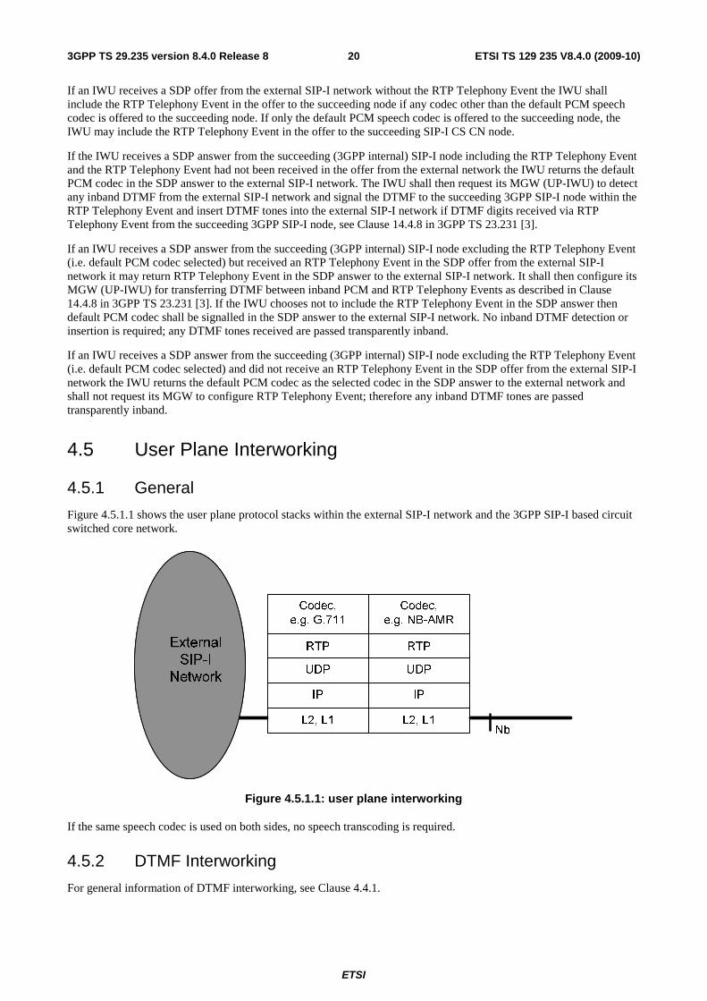
4.5 User Plane Interworking ................................................................................................................................... 20
4.5.1 General ........................................................................................................................................................ 20
4.5.2 DTMF Interworking ................................................................................................................................... 20
4.6 Example Call flows .......................................................................................................................................... 21
4.6.1 General ........................................................................................................................................................ 21
4.6.2 Incoming Call flows.................................................................................................................................... 21
4.6.2.1 Incoming Call – no preconditions in external network ......................................................................... 21
ETSI
ETSI TS 129 235 V8.4.0 (2009-10)43GPP TS 29.235 version 8.4.0 Release 8
4.6.2.2 Incoming Call with preconditions not met ............................................................................................ 23
4.6.3 Outgoing Call flows .................................................................................................................................... 25
4.6.3.1 Outgoing Call with support for preconditions ....................................................................................... 25
4.6.3.2 Outgoing Call with support of 100rel but no support for preconditions ............................................... 27
4.6.3.3 Outgoing Call without support for 100rel and preconditions ................................................................ 29
5 Interworking between a SIP-I based circuit-switched core network and an ISUP based network ......... 31
5.1 Reference Model .............................................................................................................................................. 31
5.2 Control Plane Interworking .............................................................................................................................. 31
5.3 Signalling Interworking of a Call from the ISUP based network towards the SIP-I based circuit-switched core network ...................................................................................................................................... 33
5.3.1 General ........................................................................................................................................................ 33
5.3.1.1 Sending of ISUP information to adjacent SIP nodes ............................................................................. 33
5.3.1.2 Receipt of encapsulated ISUP information within SIP-I ....................................................................... 33
5.3.1.3 Special procedures related to outgoing INVITE ................................................................................... 33
5.3.1.3.1 Overlap Signalling ........................................................................................................................... 33
5.3.1.3.2 Coding of encapsulated ISUP IAM parameters in outgoing INVITE ............................................. 34
5.3.1.3.3 Media offered in SDP of outgoing INVITE .................................................................................... 34
5.4 Signalling Interworking of a Call from SIP-I based circuit-switched core network towards the ISUP based network ................................................................................................................................................... 34
5.4.1 General ........................................................................................................................................................ 34
5.4.2 Interworking of received ISUP messages to SIP messages ........................................................................ 34
5.4.3 Interworking of received SIP messages to ISUP messages ........................................................................ 34
5.4.3.1 Receipt of encapsulated ISUP information within SIP ......................................................................... 34
5.4.3.2 Special Procedures for the Reception of SIP INVITE request .............................................................. 35
5.4.3.2.1 Propagation of overlap signalling toward the 3GPP CS domain ..................................................... 35
5.4.3.2.2 Derivation of TMR, USI and HLC parameters within sent IAM message ...................................... 35
5.4.3.2.3 Receipt of SIP INVITE without SDP offer ..................................................................................... 35
5.4.3.2.4 Special Procedures for deferred MGW selection procedure. ........................................................... 35
5.5 Supplementary services .................................................................................................................................... 35
5.5.1 Special procedures for supplementary service interworking ...................................................................... 35
5.5.2 Interworking of CLIP/CLIR supplementary service ................................................................................... 35
5.5.3 Interworking of Call Hold (HOLD) supplementary service ....................................................................... 35
5.5.4 Interworking of Completion of Calls to Busy Subscriber (CCBS) supplementary service to SIP networks ...................................................................................................................................................... 36
5.6 User Plane Interworking ................................................................................................................................... 36
5.6.1 General ........................................................................................................................................................ 36
5.6.2 DTMF ......................................................................................................................................................... 36
5.7 Example Call flows .......................................................................................................................................... 36
6 Interworking between a SIP-I based circuit-switched core network and a BICC based network .......... 37
6.1 Reference Model .............................................................................................................................................. 37
6.2 Control Plane Interworking .............................................................................................................................. 37
6.3 Signalling Interworking of a Call from the BICC based network towards the SIP-I based circuit-switched core network ...................................................................................................................................... 38
6.4 Signalling Interworking of a Call from SIP-I based circuit-switched core network towards the BICC based network ................................................................................................................................................... 39
6.5 Supplementary services .................................................................................................................................... 39
6.6 Codec Negotiation between a BICC based network and a SIP-I based circuit-switched core network ........... 39
6.6.1 General ........................................................................................................................................................ 39
6.6.2 Codec Negotiation from SIP-I on Nc to BICC Network ............................................................................ 39
6.6.2.1 Sending of IAM .................................................................................................................................... 39
6.6.2.2 Sending of SDP Answer ........................................................................................................................ 40
6.6.2.3 Mid-call Codec Negotiation initiated from SIP-I on Nc ....................................................................... 40
6.6.3 Codec Negotiation from BICC Network to SIP-I on Nc ............................................................................ 40
6.6.3.1 Sending of initial SDP Offer ................................................................................................................. 40
6.6.3.2 Responding to Serving Node initiating Codec Negotiation .................................................................. 40
6.6.3.3 Mid-call Codec Negotiation initiated from BICC ................................................................................. 40
6.7 DMTF Signalling Interworking applicable for all Calls between a BICC network and a SIP-I based circuit-switched core network .......................................................................................................................... 40
6.7.1 General ........................................................................................................................................................ 40
6.7.2 DTMF transfer from SIP-I on Nc to BICC network (Out-of-Band DTMF) ............................................... 41
ETSI
ETSI TS 129 235 V8.4.0 (2009-10)53GPP TS 29.235 version 8.4.0 Release 8
6.7.3 DTMF transfer from BICC network (Out-of-Band DTMF) to SIP-I on Nc ............................................... 42
6.7.4 SIP-I on Nc interworking with BICC for Inband DTMF ............................................................................ 42
6.8 User Plane Interworking ................................................................................................................................... 42
6.8.1 General ........................................................................................................................................................ 42
6.8.2 DTMF Interworking ................................................................................................................................... 42
6.9 Example Call flows .......................................................................................................................................... 43
7 Interworking between a SIP-I based circuit-switched core network and the IP Multimedia (IM) Core Network (CN) Subsystem .............................................................................................................. 43
7.1 Reference Model .............................................................................................................................................. 43
7.2 Signalling Interworking of a Call from the IP Multimedia Subsystem towards the SIP-I based circuit-switched core network ...................................................................................................................................... 44
7.2.1 General ........................................................................................................................................................ 44
7.2.2 Exceptions from forwarding received SIP messages .................................................................................. 44
7.2.3 Sending SIP INVITE request ...................................................................................................................... 45
7.2.4 Updating Precondition Information ............................................................................................................ 45
7.2.5 SDP Codec Negotiation .............................................................................................................................. 46
7.2.6 MGW Selection .......................................................................................................................................... 46
7.2.7 Autonomous Release .................................................................................................................................. 46
7.2.8 Further setting of SIP header values ........................................................................................................... 46
7.3 Signalling Interworking of a Call from SIP-I based circuit-switched core network towards the IP Multimedia Subsystem ..................................................................................................................................... 47
7.3.1 General ........................................................................................................................................................ 47
7.3.2 Exceptions from forwarding received SIP messages .................................................................................. 48
7.3.3 Sending SIP INVITE request ...................................................................................................................... 48
7.3.4 Updating Precondition Information ............................................................................................................ 49
7.3.5 Receipt of SIP redirect (3xx) response ....................................................................................................... 49
7.3.6 SDP Codec Negotiation ............................................................................................................................ 49
7.3.7 MGW Selection .......................................................................................................................................... 49
7.3.8 Autonomous Release .................................................................................................................................. 50
7.3.9 Handling of forked SIP Responses ............................................................................................................. 50
7.3.9.1 SIP Dialogues ........................................................................................................................................ 50
7.3.9.2 Reception of non-100 provisional Responses to initial INVITE ........................................................... 50
7.3.9.3 Reception of final Responses to initial INVITE .................................................................................... 50
7.3.10 Further setting of SIP header values ........................................................................................................... 50
7.4 DMTF Signalling Interworking applicable for all Calls between an IP Multimedia CN Subsystem and a SIP-I based circuit-switched core network ....................................................................................................... 52
7.5 User Plane Interworking ................................................................................................................................... 52
7.5.1 General ........................................................................................................................................................ 52
7.5.2 DTMF Interworking ................................................................................................................................... 52
7.6 Example Call flows .......................................................................................................................................... 53
7.6.1 General ........................................................................................................................................................ 53
7.6.2 Incoming Call flows.................................................................................................................................... 53
7.6.2.1 Successful Call Establishment and Call Release ................................................................................... 53
7.6.2.2 Autonomous Release at MGCF ............................................................................................................. 55
7.6.3 Outgoing Call flows .................................................................................................................................... 56
7.6.3.1 Outgoing Call, Sending of INVITE is deferred..................................................................................... 56
7.6.3.2 Outgoing Call, Sending of INVITE is not deferred .............................................................................. 57
7.6.3.3 Interworking with forked SIP INVITE Requests .................................................................................. 59
7.7 CS CN Supplementary Services and IMS Supplementary Services .............................................................. 61
7.7.0 General ........................................................................................................................................................ 61
7.7.1 Number Identification Services .................................................................................................................. 62
7.7.1.1 CS CN Supplementary Service - Calling Line Identification Presentation/Restriction (CLIP/CLIR) ......................................................................................................................................... 62
7.7.1.2 CS CN Supplementary Service - Connected Line Identification Presentation /Restriction (COLP/COLR) ...................................................................................................................................... 62
7.7.1.3 IMS Supplementary Service - Originating Identification Presentation (OIP) and Originating Identification Restriction (OIR) ............................................................................................................ 62
7.7.1.4 IMS Supplementary Service - Terminating Identification Presentation (TIP) and Terminating Identification Restriction (TIR) ............................................................................................................. 62
7.7.1.5 CS CN Supplementary Service – Direct Dialling In ............................................................................. 62
7.7.1.6 CS CN Supplementary Service – Malicious Call Identification ........................................................... 62
ETSI
ETSI TS 129 235 V8.4.0 (2009-10)63GPP TS 29.235 version 8.4.0 Release 8
7.7.1.7 IMS Supplementary Service – Malicious Communication Identification (MCID) ............................... 62
7.7.1.8 CS CN Supplementary Service – Subaddressing .................................................................................. 63
7.7.2 Diversion Services ...................................................................................................................................... 63
7.7.2.1 CS CN Supplementary Service - Call Forwarding Services (CFU, CFB, CFNRy, CFNRc) ................ 63
7.7.2.2 CS CN Supplementary Service – Call Deflection (CD) ........................................................................ 63
7.7.2.3 IMS Supplementary Service – Communication Diversion (CDIV) ...................................................... 63
7.7.3 Waiting Services ......................................................................................................................................... 63
7.7.3.1 CS CN Supplementary Service – Call Waiting ..................................................................................... 63
7.7.3.2 IMS Supplementary Service – Communication Waiting (CW) ............................................................ 63
7.7.4 Hold Services .............................................................................................................................................. 63
7.7.4.1 CS CN Supplementary Service – Call Hold .......................................................................................... 63
7.7.4.2 IMS Supplementary Service – Communication Hold (HOLD) ............................................................ 63
7.7.5 Multiparty Services ..................................................................................................................................... 64
7.7.5.1 CS CN Supplementary Services – Conference Calling (CONF) and Three-Party (3PTY) ................... 64
7.7.5.2 IMS Supplementary Service – Conference (CONF) ............................................................................. 64
7.7.6 Closed User Group Service ......................................................................................................................... 64
7.7.6.1 CS CN Supplementary Service – Closed User Group (CUG) ............................................................... 64
7.7.6.2 IMS Supplementary Service - Closed User Group (CUG).................................................................... 64
7.7.7 Charging Services ....................................................................................................................................... 64
7.7.7.1 CS CN Supplementary Service – Advice of Charge (AoC) .................................................................. 64
7.7.7.2 IMS Supplementary Service – Advice of Charge (AOC) ..................................................................... 64
7.7.7.3 CS CN Supplementary Service – International Telecommunication Charge Card (ITCC) .................. 64
7.7.7.4 CS CN Supplementary Service – Reverse Charging (REV) ................................................................. 64
7.7.8 Barring Services .......................................................................................................................................... 64
7.7.8.1 CS CN Supplementary Service - Barring of Outgoing Calls ................................................................ 64
7.7.8.2 CS CN Supplementary Service - Barring of Incoming Calls ................................................................ 65
7.7.8.3 CS CN Supplementary Service - Anonymous Call Rejection (ACR) ................................................... 65
7.7.8.4 IMS Supplementary Service – Communication Barring (CB) .............................................................. 65
7.7.8.5 IMS Supplementary Service – Anonymous Communication Rejection (ACR) .................................... 65
7.7.9 Transfer Services ........................................................................................................................................ 65
7.7.9.1 CS CN Supplementary Service – Explicit Call Transfer (ECT) ........................................................... 65
7.7.9.2 IMS Supplementary Service – Explicit CommunicationTransfer (ECT) .............................................. 65
7.7.10 Call Completion Services ........................................................................................................................... 65
7.7.10.1 CS CN Supplementary Service – Completion of Calls to Busy Subscriber (CCBS) ............................ 65
7.7.10.2 CS CN Supplementary Service – Completion of Calls on No Reply (CCNR) ..................................... 65
7.7.10.3 IMS Supplementary Service – Completion of Communications to Busy Subscriber (CCBS) and Completion of Communication on No Reply (CCNR) ......................................................................... 66
7.7.11 Miscellaneous Services ............................................................................................................................... 66
7.7.11.1 CS CN Supplementary Service - Multi-Level Precedence and Pre-emption (MLPP) .......................... 66
7.7.11.2 CS CN Supplementary Service - Multiple Subscriber Profile (MSP) ................................................... 66
7.7.11.3 CS CN Supplementary Service - Multicall ........................................................................................... 66
7.7.11.4 CS CN Supplementary Service - Calling Name Presentation ............................................................... 66
7.7.11.5 CS CN Supplementary Service – User-to-User Signalling (UUS) ........................................................ 66
7.7.11.6 IMS Supplementary Service – Message Waiting Indication (MWI) ..................................................... 66
7.7.11.7 CS CN Supplementary Service - Global Virtual Network Service (GVNS) ......................................... 66
7.7.11.8 CS CN Supplementary Service - Terminal Portability (TP) ................................................................. 66
Annex A (normative): Interconnecting functionalities in SIP-I based CS domain ........................ 67
A.1 General ................................................................................................................................................... 67
A.2 Stage 2 Requirements ............................................................................................................................. 67
A.3 Border Control architecture .................................................................................................................... 67
A.4 Void ........................................................................................................................................................ 68
A.5 Procedures at the CS-IBCF .................................................................................................................... 68
A.5.1 General ............................................................................................................................................................. 68
A.5.2 CS-IBCF as an exit point .................................................................................................................................. 69
A.5.2.1 Initial requests ............................................................................................................................................. 69
A.5.2.2 Subsequent requests .................................................................................................................................... 69
A.5.2.3 CS-IBCF-initiated call release .................................................................................................................... 70
A.5.2.4 THIG functionality in the CS-IBCF ........................................................................................................... 70
ETSI
ETSI TS 129 235 V8.4.0 (2009-10)73GPP TS 29.235 version 8.4.0 Release 8
A.5.2.4.1 General .................................................................................................................................................. 70
A.5.2.4.2 Encryption for network topology hiding ............................................................................................... 70
A.5.2.5 ALG functionality in the CS-IBCF ............................................................................................................. 71
A.5.2.6 Screening of SIP-I signalling ...................................................................................................................... 71
A.5.2.6.1 General .................................................................................................................................................. 71
A.5.2.6.2 CS-IBCF procedures for SIP headers .................................................................................................... 71
A.5.2.6.3 CS-IBCF procedures for SIP message bodies ....................................................................................... 72
A.5.2.7 Charging functionality in the CS-IBCF ...................................................................................................... 72
A.5.3 CS-IBCF as an entry point ............................................................................................................................... 72
A.5.3.1 Initial requests ............................................................................................................................................. 72
A.5.3.2 Subsequent requests .................................................................................................................................... 72
A.5.3.3 CS-IBCF-initiated call release .................................................................................................................... 73
A.5.3.4 THIG functionality in the CS-IBCF ........................................................................................................... 73
A.5.3.4.1 General .................................................................................................................................................. 73
A.5.3.4.2 Decryption for network topology hiding ............................................................................................... 74
A.5.3.5 ALG functionality in the CS-IBCF ............................................................................................................. 74
A.5.3.6 Screening of SIP-I signalling ...................................................................................................................... 74
A.5.3.7 Charging functionality in the CS-IBCF ...................................................................................................... 74
Annex B (informative): Change history ............................................................................................... 75
History .............................................................................................................................................................. 77
ETSI
ETSI TS 129 235 V8.4.0 (2009-10)83GPP TS 29.235 version 8.4.0 Release 8
Foreword This Technical Specification has been produced by the 3rd Generation Partnership Project (3GPP).
The contents of the present document are subject to continuing work within the TSG and may change following formal TSG approval. Should the TSG modify the contents of the present document, it will be re-released by the TSG with an identifying change of release date and an increase in version number as follows:
Version x.y.z
where:
x the first digit:
1 presented to TSG for information;
2 presented to TSG for approval;
3 or greater indicates TSG approved document under change control.
y the second digit is incremented for all changes of substance, i.e. technical enhancements, corrections, updates, etc.
z the third digit is incremented when editorial only changes have been incorporated in the document.
ETSI
ETSI TS 129 235 V8.4.0 (2009-10)93GPP TS 29.235 version 8.4.0 Release 8
1 Scope The present document specifies the interworking between SIP-I based circuit-switched core network, as specified in 3GPP TS 23.231 [3] and 3GPP TS 29.231 [4], with out-of-band transcoder control related procedures in 3GPP TS 23.153 [5], and:
- an external SIP-I based signalling network compliant to ITU-T Q.1912.5 [6]
- an ISUP (ITU-T Recommendations Q.761 to Q.764 [7]) based network such as an ISUP based 3GPP CS Domain or a PSTN
- a BICC (ITU-T Recommendations Q.1902.1 to Q.1902.6 [8]) based network such as an BICC based 3GPP CS Domain as specified in 3GPP TS 23.205 [9] and 3GPP TS 29.205 [10]
- an IP Multimedia Subsystem, as specified in 3GPP TS 23.228 [11] and 3GPP TS 24.229 [12]
2 References The following documents contain provisions which, through reference in this text, constitute provisions of the present document.
• References are either specific (identified by date of publication, edition number, version number, etc.) or non-specific.
• For a specific reference, subsequent revisions do not apply.
• For a non-specific reference, the latest version applies. In the case of a reference to a 3GPP document (including a GSM document), a non-specific reference implicitly refers to the latest version of that document in the same Release as the present document.
[1] 3GPP TR 21.905: "Vocabulary for 3GPP Specifications".
[2] 3GPP TS 23.002: "Network architecture".
[3] 3GPP TS 23.231: " SIP-I based circuit-switched core network; Stage 2".
[4] 3GPP TS 29.231: "Application of SIP-I Protocols to Circuit Switched (CS) core network architecture; Stage 3".
[5] 3GPP TS 23.153: "Out of Band Transcoder Control; Stage 2".
[6] ITU-T Recommendation Q.1912.5: "Interworking between Session Initiation Protocol (SIP) and Bearer Independent Call Control Protocol or ISDN User Part".
[7] ITU-T Recommendations Q.761 to Q.764 (2000): "Specifications of Signalling System No.7 ISDN User Part (ISUP)".
[8] ITU-T Recommendations Q.1902.1 to Q.1902.6 (07/2001): "Bearer Independent Call Control".
[9] 3GPP TS 23.205: "Bearer-independent circuit-switched core network; Stage 2".
[10] 3GPP TS 29.205: "Application of Q.1900 series to Bearer Independent CS Network architecture; Stage 3".
[11] 3GPP TS 23.228: "IP Multimedia subsystem (IMS)".
[12] 3GPP TS 24.229: "IP Multimedia Call Control Protocol based on SIP and SDP".
[13] 3GPP TS 29.163: "Interworking between the IP Multimedia (IM) Core Network (CN) subsystem and Circuit Switched (CS) networks"
[14] IETF RFC 791: "Internet Protocol".
ETSI
ETSI TS 129 235 V8.4.0 (2009-10)103GPP TS 29.235 version 8.4.0 Release 8
[15] IETF RFC 768: "User Datagram Protocol".
[16] IETF RFC 793: "Transmission Control Protocol".
[17] IETF RFC 2460: "Internet Protocol, Version 6 (IPv6) Specification"
[18] IETF RFC 2960: "Stream Control Transmission Protocol".
[19] IETF RFC 3204: "MIME media types for ISUP and QSIG Objects"
[20] IETF RFC 3261: "SIP: Session Initiation Protocol".
[21] IETF RFC 3262: "Reliability of Provisional Responses in the Session Initiation Protocol (SIP)"
[22] IETF RFC 3264: "An Offer/Answer Model with the Session Description Protocol (SDP)"
[23] IETF RFC 3312: "Integration of Resource Management and Session Initiation Protocol (SIP)".
[24] 3GPP TS 23.014: "Support of Dual Tone Multi-Frequency (DTMF) signalling".
[25] 3GPP TS 24.629: "Explicit Communication Transfer (ECT) using IP Multimedia (IM) Core Network (CN) subsystem"
[26] 3GPP TS 24.610: "Communication HOLD (HOLD) using IP Multimedia (IM) Core Network (CN) subsystem"
[27] ITU-T Recommendation Q.765 (2000): "Signalling System No. 7 – Application transport mechanism"
[28] ITU-T Recommendation Q.765.5 (2000): "Signalling system No. 7 – Application transport mechanism: Bearer Independent Call Control (BICC)"
[29] Void
[30] IETF RFC 3263: "Session Initiation Protocol (SIP): Locating SIP Servers"
[31] IETF RFC 4028: "Session Timers in the Session Initiation Protocol (SIP)"
[32] IETF RFC 3325: "Private Extensions to the Session Initiation Protocol (SIP) for Asserted Identity within Trusted Networks"
[33] ITU-T Recommendation H.248.1 (2002): "Gateway control protocol: Version 3".
[34] 3GPP TS 23.205: "Bearer-independent circuit-switched core network; Stage 2".
[35] Void
[36] IETF RFC 5079: "Rejecting Anonymous Requests in the Session Initiation Protocol (SIP)"
[37] 3GPP TS 29.162: "Interworking between the IM CN subsystem and IP networks"
3 Definitions, symbols and abbreviations
3.1 Definitions For the purposes of the present document, the terms and definitions given in 3GPP TR 21.905 [1] and the following apply.
Interworking Unit (IWU): Logical entity that interworks SIP-I signalling in the 3GPP CS Domain with any of the following signalling: (a) SIP-I signalling of an external SIP-I network, (b) ISUP signalling of a PSTN, and (c) BICC or ISUP signalling of a 3GPP CS Domain.
User Plane Interworking Unit (UP-IWU): Logical entity that performs user plane interworking between the SIP-I based CS Domain and an external SIP-I network, or external ISUP network, or BICC/ISUP based 3GPP CS network.
ETSI
ETSI TS 129 235 V8.4.0 (2009-10)113GPP TS 29.235 version 8.4.0 Release 8
3.2 Abbreviations For the purposes of the present document, the abbreviations given in TR 21.905 [1] and the following apply: An abbreviation defined in the present document takes precedence over the definition of the same abbreviation, if any, in 3GPP TR 21.905 [1].
ANM ANswer Message APM Application Transport Mechanism B2BUA (SIP) Back-to-Back User Agent BGCF Breakout Gateway Control Function BICC Bearer Independent Call Control CON Connect message COT Continuity message CPG Call ProGress message CS-IBCF CS (domain) IBCF CS-TrGW CS (domain) TrGW IBCF Interconnection Border Control Function IM-MGW IP Multimedia Media Gateway Function MIME Multi-purpose Internet Mail Extensions MRFP Multimedia Resource Function Processor NA(P)T Network Address Translation / Network Address and Port Translation OoBTC Out of Band Transcoder Control SCTP Stream Control Transmission Protocol TDM Time-Division Multiplexing TrGW Transition Gateway UA (SIP) User Agent
4 Interworking between a SIP-I based circuit-switched core network and an external SIP-I based network
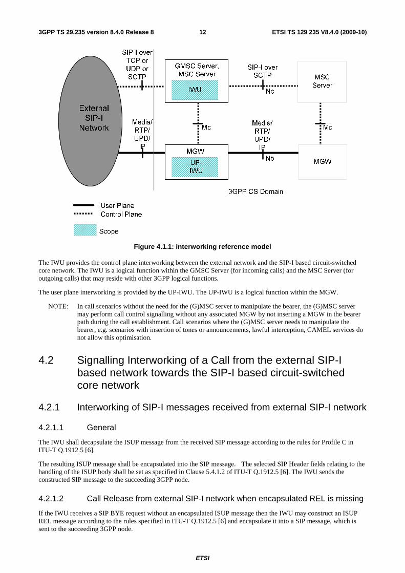
4.1 Reference Model Figure 4.1.1 shows the interworking reference model for the interworking between a SIP-I based circuit-switched core network and an external SIP-I based network:
ETSI
ETSI TS 129 235 V8.4.0 (2009-10)123GPP TS 29.235 version 8.4.0 Release 8
Figure 4.1.1: interworking reference model
The IWU provides the control plane interworking between the external network and the SIP-I based circuit-switched core network. The IWU is a logical function within the GMSC Server (for incoming calls) and the MSC Server (for outgoing calls) that may reside with other 3GPP logical functions.
The user plane interworking is provided by the UP-IWU. The UP-IWU is a logical function within the MGW.
NOTE: In call scenarios without the need for the (G)MSC server to manipulate the bearer, the (G)MSC server may perform call control signalling without any associated MGW by not inserting a MGW in the bearer path during the call establishment. Call scenarios where the (G)MSC server needs to manipulate the bearer, e.g. scenarios with insertion of tones or announcements, lawful interception, CAMEL services do not allow this optimisation.
4.2 Signalling Interworking of a Call from the external SIP-I based network towards the SIP-I based circuit-switched core network
4.2.1 Interworking of SIP-I messages received from external SIP-I network
4.2.1.1 General
The IWU shall decapsulate the ISUP message from the received SIP message according to the rules for Profile C in ITU-T Q.1912.5 [6].
The resulting ISUP message shall be encapsulated into the SIP message. The selected SIP Header fields relating to the handling of the ISUP body shall be set as specified in Clause 5.4.1.2 of ITU-T Q.1912.5 [6]. The IWU sends the constructed SIP message to the succeeding 3GPP node.
4.2.1.2 Call Release from external SIP-I network when encapsulated REL is missing
If the IWU receives a SIP BYE request without an encapsulated ISUP message then the IWU may construct an ISUP REL message according to the rules specified in ITU-T Q.1912.5 [6] and encapsulate it into a SIP message, which is sent to the succeeding 3GPP node.
ETSI
ETSI TS 129 235 V8.4.0 (2009-10)133GPP TS 29.235 version 8.4.0 Release 8
NOTE: A SIP BYE request without an encapsulated ISUP message can be received from a CS-IBCF or from a node of an interconnect network when they initiate autonomous call release. It is expected that a generated ISUP REL won't add any additional information which is not available in the received SIP BYE request.
The IWU shall send a 200 OK final response to the BYE request without an encapsulated RLC message towards the external SIP-I network.
4.2.2 Special Procedures for the reception of initial SIP INVITE requests
4.2.2.1 Receipt of SIP INVITE request
If the initial SIP-I INVITE request does not provide a complete number, then the IWU shall collect all digits required to identify the called subscriber in subsequent SIP INVITE requests as specified for Profile C in Q.1912.5 [6]. The IWU shall not propagate overlap signalling as described for Profile C in Q.1912.5 [6].
The IWU shall trigger GMSC functions after having constructed the ISUP message, as described in 4.2.1 above. The GMSC interrogates the HLR to get a roaming number (MSRN). The Called Party Number in the ISUP IAM message is changed by the GMSC function to the MSRN. The IWU shall include the MSRN into the Request-URI as the new target.
4.2.2.2 Receipt of SIP INVITE requests with SDP
Based on configuration the IWU may choose to transcode media. But the IWU shall always provide the TMR/USI/HLC parameters as received on the incoming side.
4.2.2.3 Receipt of SIP INVITE request without SDP
An IWU may reject receipt of SIP INVITE requests without SDP offer. Otherwise the rules of Clause 4.2.2.1 apply with the following deviations:
The IWU shall construct an SDP offer with contents according to local policy, e.g. SDP for a G.711speech call. The IWU may use the TMR and USI parameters of the encapsulated IAM to determine the desired service and construct the SDP offer accordingly. The IWU may then send to the succeeding 3GPP node the SIP INVITE request with the constructed SDP offer and encapsulated IAM.
If reliable provisional responses (see IETF RFC 3262 [21]) are supported in the external SIP-I network, the IWU may immediately send the SDP offer within a 183 Session Progress message to the preceding node. When the IWU receives the SDP answer then the IWU should send to the succeeding 3GPP node the SIP INVITE request with an encapsulated IAM message. Otherwise, the IWU shall behave in accordance with the paragraph above.
4.2.2.4 MGW Selection
The IWU may apply the optional "optimised MGW selection", "deferred MGW selection" or "MGW bypass" procedures towards the succeeding SIP-I based circuit switched core network as described in Clause 4.4 of TS 23.231 [3].
If MGW bypass is implemented and the IWU receives a MGW identifier in a SDP answer from the succeeding 3GPP node the IWU shall remove the MGW identifier from the SDP answer before propagating back the SDP answer to the external network.
NOTE: If MGW bypass is implemented and the external network does not include a specified connection address (0.0.0.0 for IPv4) then this will be interpreted as supporting deferred MGW selection by the succeeding node. The succeeding node will select a MGW accordingly and may return the MGW Identifier to the IWU).
Otherwise the IWU shall seize a MGW and shall include the MGW connection address into the SDP offer of the initial SIP INVITE request it will send to the succeeding 3GPP node.
ETSI
ETSI TS 129 235 V8.4.0 (2009-10)143GPP TS 29.235 version 8.4.0 Release 8
4.2.3 Interworking of SIP-I messages received from succeeding 3GPP node
Whenever the IWU receives from the succeeding 3GPP node a SIP message with an encapsulated CON, ACM, CPG, ANM, SUS, RES message then the IWU sends the SIP message in accordance with rules in accordance with Q.1912.5 [6] to the external SIP-I network and the encapsulated ISUP message shall not be modified.
4.2.4 Special Procedures for Profile Interworking
4.2.4.1 Support of 100Rel
The IWU receiving a SIP INVITE with or without tag "100Rel" in the SUPPORTED or the REQUIRED header from the external SIP-I network shall advertise its preference of provisional reliable responses to the succeeding 3GPP node via a SUPPORTED header in the initial SIP INVITE request.
As an option the IWU may consider a received SIP INVITE request without "100Rel" as erroneous and reject the INVITE request with a 421 "Extension Required" response.
NOTE: The option to forward a SIP INVITE request to the succeeding 3GPP node with or without tag "100Rel", if the external network does not support reliable provisional responses, is not specified in the present specification.
4.2.4.2 Support for UPDATE method
The IWU receiving a SIP INVITE with or without the UPDATE method included in the ALLOW header shall advertise its support for the UPDATE method to the succeeding 3GPP node by listing the UPDATE method in the ALLOW header field.
As an option the IWU may consider a received initial SIP INVITE request without listing UPDATE in the ALLOW header field as erroneous and reject the INVITE request with a 403 "Forbidden" response.
NOTE: The option to forward a SIP INVITE request to the succeeding 3GPP node without indicating support of the UPDATE method, if the external network does not support the UPDATE method, is not specified in the present specification.
4.2.4.3 Support for Preconditions
When the incoming SIP INVITE request indicates that remote preconditions are met and local preconditions are met then the IWU may either not include the tag "precondition" and exclude appropriate SDP lines, or include the tag "preconditions" in the SUPPORTED header and provide an SDP offer indicating that preconditions are met.
When the incoming SIP INVITE request does not contain a "precondition" tag the IWU shall assume the preconditions have been met within the external SIP-I network. If local preconditions are met then the IWU may either not include the tag "precondition" and exclude appropriate SDP lines, or include the tag "precondition" in the SUPPORTED header and provide an SDP offer indicating that preconditions are met.
When the incoming SIP INVITE request indicates that remote preconditions are not met or when local preconditions are not met then the IWU shall include the tag "precondition" in the REQUIRE header or SUPPORTED header in the SIP INVITE request and shall encode preconditions in the SDP offer that the related local preconditions for QoS are not met, using the segmented status type, as defined in IETF RFC 3312 [23], as well as the strength-tag value "mandatory" for the local segment and the strength-tag value "optional" for the remote segment when sending the message to the succeeding 3GPP node. Or the IWU may defer forwarding the SIP INVITE request until remote local preconditions are met.
When the incoming SIP INVITE request indicates that preconditions have not been met and the IWU will not include a MGW the SDP with preconditions information shall be transited unchanged and the "precondition" tag shall be transited in the same header as received.
NOTE 1: The use of the SUPPORTED header is a deviation from IETF RFC 3312 [23] when the strength-tag contains a "mandatory" value.
ETSI
ETSI TS 129 235 V8.4.0 (2009-10)153GPP TS 29.235 version 8.4.0 Release 8
NOTE 2: The support of preconditions is mandated at the Nc interface. Therefore a response without "precondition" can be considered as erroneous if preconditions were not met.
NOTE 3: The setting of the "Continuity Check Indicator" in the "Nature of Connection Indicators" parameter within the encapsulated IAM by the IWU is of no significance. The value is ignored by the succeeding 3GPP node.
4.2.5 Support for Codec Negotiation
If the IWU uses the MGW bypass option as defined in 3GPP TS 23.231 [3], then the IWU is not involved in the codec negotiation procedure and transits SDP offers and answers unchanged. Otherwise, the remaining text of this sub-clause applies:
If the IWU receives from the external SIP-I based network a SIP request with an SDP offer containing a codec list with or without the 3GPP_OoBTC_Indicator, the IWU shall follow the procedures defined for a 3GPP Intermediate Node in Clause 9 of 3GPP TS 23.153 [5].
If the IWU receives from the external SIP-I based network an INVITE or re-INVITE request without any codec information, the IWU shall send an SDP offer to the succeeding 3GPP SIP-I node, where it either shall follow the procedures defined for a 3GPP node originating SDP offer in Clause 9 of 3GPP TS 23.153 [5], or shall create an SDP offer with the default PCM codec. The IWU shall send the selected codec within an SDP offer towards the preceding external node.
NOTE: Which codecs are negotiable with the external SIP-I network may depend on operator choices and preferences (local policy).
4.2.6 Special Procedures for the reception of SIP Re-INVITE requests
4.2.6.1 Receipt of SIP Re-INVITE request without SDP
Upon receipt of a SIP Re-INVITE request without SDP, the IWU shall
- construct an SDP offer with contents reflecting the SDP already negotiated with the external SIP-I network for the call, including codec information as specified in subclause 4.2.5, and send the SDP offer within a 200 OK (INVITE) message to the external SIP-I network; or
- reject the SIP Re-INVITE request.
4.3 Signalling Interworking of a Call from SIP-I based circuit-switched core network towards the external SIP-I based network
4.3.1 Interworking of SIP-I messages received from preceding 3GPP node
4.3.1.1 General
An IWU receiving SIP messages with encapsulated ISUP information shall apply any interworking procedures detailed for Profile C in Q.1912.5 [6] affecting parameters within the ISUP, and then proceed to encapsulate any ISUP information received (with the exception of the excluded messages detailed in 5.4.3 of ITU-T Q.1912.5 [6]) in a SIP message in a MIME body according to IETF RFC 3204 [19]. The selected SIP Header fields relating to the handling of the ISUP body shall be set as specified in ITU-T Q.1912.5 [6].
4.3.1.2 Call Release from external SIP-I network when encapsulated REL is missing
If the IWU receives a SIP BYE request or 4XX, 5XX, 6XX final response to the initial INVITE request without an encapsulated ISUP REL message then the IWU may construct the ISUP REL message according to the rules specified in ITU-T Q.1912.5 [6] and encapsulate it into the SIP message, which is sent to the preceding 3GPP node.
ETSI
ETSI TS 129 235 V8.4.0 (2009-10)163GPP TS 29.235 version 8.4.0 Release 8
NOTE: A SIP BYE request without an encapsulated ISUP message can be received from a CS-IBCF or from a node of an interconnect network when they initiate autonomous call release. It is expected that a generated ISUP REL message won't add any additional information which is not available in the received SIP BYE request.
The IWU shall send a 200 OK final response to the BYE request without an encapsulated ISUP RLC message towards the external SIP-I network.
4.3.2 Special Procedures for the reception of SIP INVITE requests
The IWU shall decapsulate the ISUP message. The IWU forwards the ISUP information to the 'IW-MSC' functions, which may result in a modified ISUP message.
Based on configuration the IWU may choose to transcode media. If the IWU transcodes, it should set the TMR/USI/HLC parameters according to the codec applied in the SIP-I network. Otherwise, it should provide the TMR/USI/HLC parameters as received in the encapsulated IAM.
The IWU shall proceed to encapsulate the ISUP message into the SIP-INVITE request. The request URI shall be aligned with the called party number.
4.3.3 Special Procedures for Profile Interworking
4.3.3.1 Support of 100Rel
An IWU shall consider an initial SIP INVITE request received from the preceding 3GPP node without the tag "100Rel" in the SUPPORTED header or REQUIRED header as erroneous and shall reject the call accordingly.
An IWU sending a SIP INVITE request towards the external SIP-I network shall advertise its preference of provisional reliable responses via a SUPPORTED header containing the tag "100Rel".
If an IWU receives a provisional 101-199 response from the external SIP-I network with a REQUIRE header present with tag "100rel" then it shall include the tag "100Rel" into the REQUIRE header when the IWU propagates the response to the preceding 3GPP node.
If an IWU receives from the external SIP-I network a provisional 101-199 response without tag "100rel" in the REQUIRE header then the IWU shall
- either includes the tag "100Rel" into the REQUIRE header when it forwards the response to the preceding 3GPP node,
- or consider the response as erroneous and reject the call accordingly.
NOTE: The option to forward the response to the preceding 3GPP node without tag "100Rel", if the external network does not support reliable provisional responses, is not specified in the present specification.
4.3.3.2 Support for UPDATE method
An IWU sending a SIP INVITE towards the external SIP-I network shall advertise its support of the UPDATE method via the ALLOW header listing the UPDATE method.
The IWU receiving a response to a SIP INVITE request is allowed to generate the UPDATE method towards the external network if an ALLOW header is present listing the UPDATE method. Otherwise, the IWU is not allowed to generate UPDATE requests towards the external SIP-I network and one of the following options applies:
- The IWU shall return the response to the preceding 3GPP node containing an ALLOW header listing the UPDATE method.
- The IWU shall consider the response received from the external network as erroneous and reject the call accordingly.
NOTE: The option to forward the response to the preceding 3GPP node without UPDATE in the ALLOW header field, if the external network does not support the UPDATE method, is not specified in the present specification.
ETSI
ETSI TS 129 235 V8.4.0 (2009-10)173GPP TS 29.235 version 8.4.0 Release 8
4.3.3.3 Support for Preconditions
When the incoming SIP INVITE request indicates that preconditions have not been met or when local preconditions are not met, the IWU shall use one of the following options:
a) The IWU shall send a SIP INVITE request to a succeeding external SIP-I network and include the tag "precondition" in the SUPPORTED header. The IWU shall encode preconditions in the SDP offer indicating that the related local preconditions for QoS are not met, using the segmented status type, as defined in IETF RFC 3312 [23], as well as the strength-tag value "mandatory" for the local segment and the strength-tag value "optional" for the remote segment. The "precondition" tag shall be included in the SUPPORTED header. The IWU shall encapsulate the IAM message into the SIP INVITE request and should insert "continuity check not required" as the value of the Continuity check indicator within the Nature of Connection Indicators parameter in order to avoid that an external node, which does not support preconditions, is waiting for a COT message when the IWU is not able to send the COT message.
NOTE 1: Such an external node is not compliant to ITU-T Q.1912.5 [6].
NOTE 2: The use of the SUPPORTED header is a deviation from IETF RFC 3312 [23] when a 'mandatory' strength-tag is used.
The subsequent action depends on whether the response indicates support of preconditions:
i) If the IWU receives from the external SIP-I network a provisional 101-199 response with a REQUIRE header or SUPPORTED header containing tag "precondition", then the IWU shall progress the call and when preconditions are met it shall send an UPDATE message or PRACK message indicating that preconditions have been fulfilled. Preconditions are fulfilled when local preconditions are met and, if the incoming SIP INVITE request indicated that preconditions had not been met, the IWU has received an indication from the preceding 3GPP node that the preconditions are subsequently met.
ii) If the IWU receives from the external SIP-I network a provisional 101-199 response without a REQUIRE header or SUPPORTED header containing tag "precondition" and if a provisional response or successful final response carrying an encapsulated ISUP message is received from external SIP-I network prior to preconditions being met, then these responses shall be queued and later be propagated to the preceding 3GPP node once preconditions are met. If responses carrying encapsulated ISUP are to be queued and the response carrying an encapsulated ISUP message is the first response carrying an SDP answer then the IWU shall generated a 183 Progress with the SDP answer and send it to the preceding node. The IWU shall not encapsulate an ISUP message into the 183 Progress.
NOTE: The option to allow the SIP response to be immediately forwarded is not specified in the present will result in the O-MSC receiving encapsulated ISUP prior to preconditions being met. In addition, reception of response without indication of support for preconditions at the O-MSC is not specified in the present specification.
If the IWU receives a failure response from the external network, then this shall immediately be forwarded to the preceding 3GPP node.
b) Before sending the INVITE request to the external network the IWU shall wait until local preconditions are met and, if the incoming SIP INVITE request indicated that preconditions have not been met, it has received an indication from the preceding 3GPP node that the preconditions are met.
The initial INVITE request to the external SIP-I network may include a precondition tag in SUPPORTED header and indicate that preconditions have been met.
c) The IWU shall send a SIP INVITE request to a succeeding external SIP-I network and include the tag "precondition" in the REQUIRE header. The IWU shall encode preconditions in the SDP offer indicating that the related local preconditions for QoS are not met, using the segmented status type, as defined in IETF RFC 3312 [23], as well as the strength-tag value "mandatory" for the local segment and the strength-tag value "optional" for the remote segment. The IWU shall encapsulate the IAM message into the SIP INVITE request and should insert "continuity check not required" as the value of the Continuity check indicator within the Nature of Connection Indicators parameter in order to avoid that an external node, which does not support preconditions, is waiting for a COT message when the IWU is not able to send the COT message.
NOTE 1: Such an external node is not compliant to ITU-T Q.1912.5 [6].
ETSI
ETSI TS 129 235 V8.4.0 (2009-10)183GPP TS 29.235 version 8.4.0 Release 8
The subsequent action depends on whether the response indicates support of preconditions:
i) If the IWU receives from the external SIP-I network a provisional 101-199 response with a REQUIRE header or SUPPORTED header containing tag "precondition", then the IWU shall continue the call per response handling procedures described in option a) above.
ii) If the IWU receives a 420 Bad Extension final response, then the IWU shall continue per option b) above by waiting for preconditions to be met before repeating the initial INVITE request.
When the incoming SIP INVITE request indicates that precondition are met and local preconditions are met, the IWU shall set up the session and may include a precondition tag in the SUPPORTED header and indicate that preconditions have been met.
When the incoming SIP INVITE request indicates that preconditions have not been met and the IWU will not include a MGW the SDP with preconditions information shall be transited unchanged and the "precondition" tag shall be transited in the same header as received.
4.3.4 Support for Codec Negotiation
When the IWU receives an INVITE with an SDP offer containing a structured codec list, the IWU shall follow the procedures defined for a 3GPP Intermediate Node in Clause 9 of 3GPP TS 23.153 [5], unless the IWU uses the MGW bypass option.
NOTE: Which codecs are negotiable with the external SIP-I network may depend on operator choices and preferences (local policy).
4.3.5 MGW Selection
The IWU shall not perform "optimised MGW selection", or "deferred MGW selection" towards an external SIP-I network. The IWU shall select a MGW and include the MGW connection address in the SDP offer of the initial SIP INVITE request it sends to the external SIP-I network. The "MGW bypass" option may be deployed but in the case that the preceding 3GPP node signals the MGW identifier this one shall not be signalled to the external SIP-I network.
4.4 DMTF Signalling Interworking applicable for all Calls between an external SIP-I based network and a SIP-I based circuit-switched core network
4.4.1 General
DTMF signalling via the RTP Telephony Event (RTP Telephony Event) is mandated to be supported over the Nb interface for SIP-I based Circuit Switched Core Network on Nc Interface, see 3GPP TS 23.231 [3].
NOTE 1: According to TS 23.231 it is an option to choose either the RTP Telephony Event or inband DTMF transport within the PCM codec when only the default PCM codec is selected, however once RTP Telephony Event is chosen (indicated in the SDP answer) it must be used for any selected codec.
If MGW bypass is supported within the CS CN (see 3GPP TS 23.231, Clause 4.4.5 [3]), a terminating MSC or a 3GPP SIP-I intermediate node controlling a MGW that interfaces directly to the external network shall behave as an IWU, as its MGW is providing an UP-IWU function and therefore the SIP-I Server shall also comply with the procedures in this clause. A GMSC Server or SIP-I intermediate node which is applying the MGW Bypass option shall then relay the SDP media lines for codecs and RTP Telephony Event in the SDP offers and answers transparently between the external SIP-I network and the 3GPP CS CN and is therefore not constrained by the procedures described in this clause.
If the SDP answer sent towards the external SIP-I network or received from the external SIP-I network includes the RTP Telephony event, then the IWU shall request its MGW to transmit and receive the DTMF to/from the external SIP-I node within the RTP Telephony Event.
If the SDP answer sent towards or received from the SIP-I based CS CN includes the RTP Telephony event, then the IWU shall request its MGW to transmit and receive the DTMF to/from the SIP-I based CS CN within the RTP Telephony Event.
ETSI
ETSI TS 129 235 V8.4.0 (2009-10)193GPP TS 29.235 version 8.4.0 Release 8
DTMF interworking is specified for interworking towards an external SIP-I network with the assumption that the following applies:
- External SIP-I network includes RTP Telephony event within SDP offers or SDP answers together with non-PCM speech codecs;
- External SIP-I network includes default PCM codec in SDP offers or SDP answers.
Therefore only the case where the external SIP-I network includes default PCM codec when not including the RTP Telephony event is described.
4.4.2 DTMF support in SDP offer sent to External SIP-I network
If an IWU receives an initial SDP offer from a preceding 3GPP SIP-I node with the RTP Telephony Event it shall forward the RTP Telephony Event in the offer to the succeeding (external) node. If the IWU then receives a SDP answer from the succeeding node (external network) including the RTP Telephony Event, the IWU shall include the RTP Telephony Event in the SDP answer it forwards to the SIP-I based CS CN independently of the selected codec type, i.e. any DTMF payload received would then be simply relayed through the interworking MGW, and the IWU shall also include the RTP-telephony event in possible subsequent SDP offers it sends towards the succeeding external network node.
If an IWU receives an SDP offer from a preceding 3GPP SIP-I node without the RTP Telephony Event (only permitted if only default PCM codec offered) then it may:
- Include additional non-PCM speech codecs and shall then include the RTP Telephony Event in the subsequent offer to the succeeding external SIP-I node.
NOTE: If the answer from the external SIP-I node does not include the RTP Telephony Event then no interworking of DTMF Telephony Events or tones is required by the MGW.
or:
- send the SDP Offer to the external SIP-I node without the RTP Telephony Event (no compressed codecs included in the offer) and then no inband DTMF detection/insertion is required, or:
- Send the SDP Offer to the external SIP-I node without any additional non-PCM speech codecs and include the RTP Telephony Event.
If the answer from the external SIP-I node includes the RTP Telephony event and the RTP Telephony event has not been offered by the preceding 3GPP SIP-I network then the IWU shall request its MGW (UP-IWU) to detect/insert inband DTMF tones to/from its preceding 3GPP SIP-I node and send/receive the DTMF to the external SIP-I node within the RTP Telephony Event, see Clause 14.4.8 in 3GPP TS 23.231 [3],
If an IWU receives a SDP offer from a preceding 3GPP SIP-I node with the RTP Telephony Event and then receives a SDP answer from the external SIP-I network which includes only the PCM speech codec and excludes the RTP Telephony Event the IWU may:
- apply "transcoding at the PLMN border" by selecting another speech codec than the default PCM codec for the interface toward the SIP-I based CS CN (if included in the offer) and then the IWU shall include the RTP Telephony Event in the answer it forwards to the SIP-I based CS CN, or:
- select default PCM codec towards the SIP-I CS CN and may include the RTP Telephony Event in the reply to the preceding (3GPP SIP-I) node and shall then request its MGW to relay inband DTMF to the RTP Telephony Event to/from the external network, see Clause 14.4.8 in 3GPP TS 23.231 [3], or:
- select default PCM codec towards the SIP-I CS CN and exclude the RTP Telephony Event in the reply to the preceding (3GPP SIP-I) node and then no inband DTMF detection/insertion is required.
4.4.3 DTMF support in SDP offer received from External SIP-I network
If an IWU receives an SDP offer from the external SIP-I network with the RTP Telephony Event it shall forward the RTP Telephony Event in the offer to the succeeding node. If the SDP answer from the succeeding (3GPP internal) SIP-I node includes the RTP Telephony Event the IWU shall configure its MGW to relay the RTP Telephony Events transparently as described in Clause 14.4.3 of TS 23.231.
ETSI
ETSI TS 129 235 V8.4.0 (2009-10)203GPP TS 29.235 version 8.4.0 Release 8
If an IWU receives a SDP offer from the external SIP-I network without the RTP Telephony Event the IWU shall include the RTP Telephony Event in the offer to the succeeding node if any codec other than the default PCM speech codec is offered to the succeeding node. If only the default PCM speech codec is offered to the succeeding node, the IWU may include the RTP Telephony Event in the offer to the succeeding SIP-I CS CN node.
If the IWU receives a SDP answer from the succeeding (3GPP internal) SIP-I node including the RTP Telephony Event and the RTP Telephony Event had not been received in the offer from the external network the IWU returns the default PCM codec in the SDP answer to the external SIP-I network. The IWU shall then request its MGW (UP-IWU) to detect any inband DTMF from the external SIP-I network and signal the DTMF to the succeeding 3GPP SIP-I node within the RTP Telephony Event and insert DTMF tones into the external SIP-I network if DTMF digits received via RTP Telephony Event from the succeeding 3GPP SIP-I node, see Clause 14.4.8 in 3GPP TS 23.231 [3].
If an IWU receives a SDP answer from the succeeding (3GPP internal) SIP-I node excluding the RTP Telephony Event (i.e. default PCM codec selected) but received an RTP Telephony Event in the SDP offer from the external SIP-I network it may return RTP Telephony Event in the SDP answer to the external SIP-I network. It shall then configure its MGW (UP-IWU) for transferring DTMF between inband PCM and RTP Telephony Events as described in Clause 14.4.8 in 3GPP TS 23.231 [3]. If the IWU chooses not to include the RTP Telephony Event in the SDP answer then default PCM codec shall be signalled in the SDP answer to the external SIP-I network. No inband DTMF detection or insertion is required; any DTMF tones received are passed transparently inband.
If an IWU receives a SDP answer from the succeeding (3GPP internal) SIP-I node excluding the RTP Telephony Event (i.e. default PCM codec selected) and did not receive an RTP Telephony Event in the SDP offer from the external SIP-I network the IWU returns the default PCM codec as the selected codec in the SDP answer to the external network and shall not request its MGW to configure RTP Telephony Event; therefore any inband DTMF tones are passed transparently inband.
4.5 User Plane Interworking
4.5.1 General
Figure 4.5.1.1 shows the user plane protocol stacks within the external SIP-I network and the 3GPP SIP-I based circuit switched core network.
Figure 4.5.1.1: user plane interworking
If the same speech codec is used on both sides, no speech transcoding is required.
4.5.2 DTMF Interworking
For general information of DTMF interworking, see Clause 4.4.1.
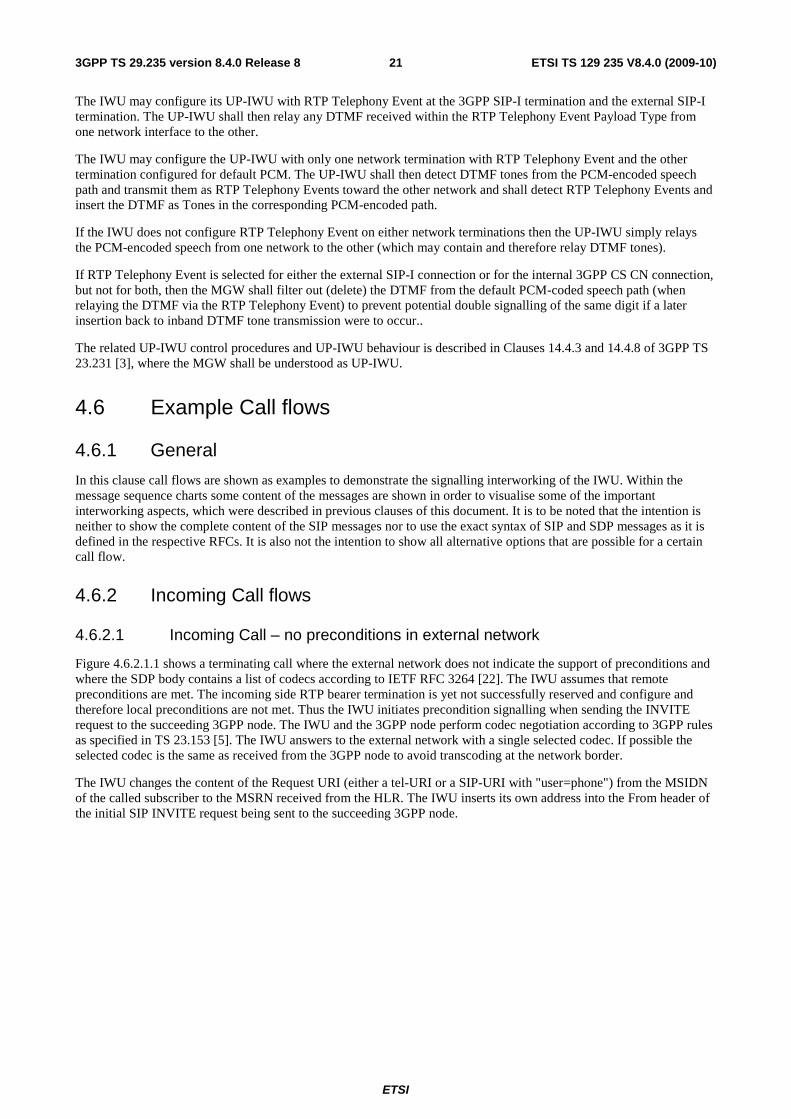
ETSI
ETSI TS 129 235 V8.4.0 (2009-10)213GPP TS 29.235 version 8.4.0 Release 8
The IWU may configure its UP-IWU with RTP Telephony Event at the 3GPP SIP-I termination and the external SIP-I termination. The UP-IWU shall then relay any DTMF received within the RTP Telephony Event Payload Type from one network interface to the other.
The IWU may configure the UP-IWU with only one network termination with RTP Telephony Event and the other termination configured for default PCM. The UP-IWU shall then detect DTMF tones from the PCM-encoded speech path and transmit them as RTP Telephony Events toward the other network and shall detect RTP Telephony Events and insert the DTMF as Tones in the corresponding PCM-encoded path.
If the IWU does not configure RTP Telephony Event on either network terminations then the UP-IWU simply relays the PCM-encoded speech from one network to the other (which may contain and therefore relay DTMF tones).
If RTP Telephony Event is selected for either the external SIP-I connection or for the internal 3GPP CS CN connection, but not for both, then the MGW shall filter out (delete) the DTMF from the default PCM-coded speech path (when relaying the DTMF via the RTP Telephony Event) to prevent potential double signalling of the same digit if a later insertion back to inband DTMF tone transmission were to occur..
The related UP-IWU control procedures and UP-IWU behaviour is described in Clauses 14.4.3 and 14.4.8 of 3GPP TS 23.231 [3], where the MGW shall be understood as UP-IWU.
4.6 Example Call flows
4.6.1 General
In this clause call flows are shown as examples to demonstrate the signalling interworking of the IWU. Within the message sequence charts some content of the messages are shown in order to visualise some of the important interworking aspects, which were described in previous clauses of this document. It is to be noted that the intention is neither to show the complete content of the SIP messages nor to use the exact syntax of SIP and SDP messages as it is defined in the respective RFCs. It is also not the intention to show all alternative options that are possible for a certain call flow.
4.6.2 Incoming Call flows
4.6.2.1 Incoming Call – no preconditions in external network
Figure 4.6.2.1.1 shows a terminating call where the external network does not indicate the support of preconditions and where the SDP body contains a list of codecs according to IETF RFC 3264 [22]. The IWU assumes that remote preconditions are met. The incoming side RTP bearer termination is yet not successfully reserved and configure and therefore local preconditions are not met. Thus the IWU initiates precondition signalling when sending the INVITE request to the succeeding 3GPP node. The IWU and the 3GPP node perform codec negotiation according to 3GPP rules as specified in TS 23.153 [5]. The IWU answers to the external network with a single selected codec. If possible the selected codec is the same as received from the 3GPP node to avoid transcoding at the network border.
The IWU changes the content of the Request URI (either a tel-URI or a SIP-URI with "user=phone") from the MSIDN of the called subscriber to the MSRN received from the HLR. The IWU inserts its own address into the From header of the initial SIP INVITE request being sent to the succeeding 3GPP node.
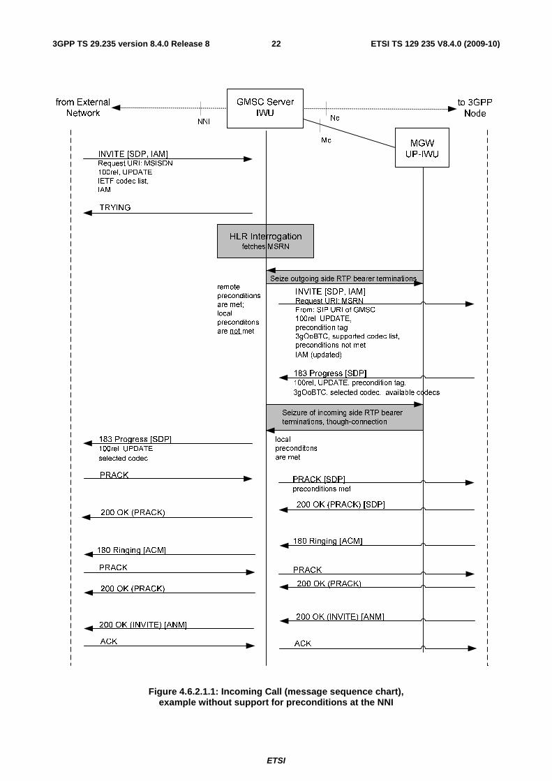
ETSI
ETSI TS 129 235 V8.4.0 (2009-10)223GPP TS 29.235 version 8.4.0 Release 8
NNINc
Mc
to 3GPP
Node
MGW
UP-IWU
GMSC Server
IWU
INVITE [SDP, IAM]Request URI: MSISDN
100rel, UPDATE
IETF codec list,
IAM
TRYING
INVITE [SDP, IAM]Request URI: MSRN
From: SIP URI of GMSC
100rel, UPDATE,
precondition tag
3gOoBTC, supported codec list,
preconditions not met
IAM (updated)
183 Progress [SDP]100rel, UPDATE, precondition tag,
3gOoBTC, selected codec, available codecs
remote
preconditions
are met;
local
preconditons
are not met
PRACK [SDP]preconditions met
200 OK (PRACK) [SDP]
HLR Interrogationfetches MSRN
Seizure of incoming side RTP bearer
terminations, though-connection
183 Progress [SDP]100rel, UPDATE
selected codec
PRACK
200 OK (PRACK)
180 Ringing [ACM] 180 Ringing [ACM]
200 OK (INVITE) [ANM]200 OK (INVITE) [ANM]
ACK
from External
Network
PRACK
200 OK (PRACK)
PRACK
200 OK (PRACK)
ACK
Seize outgoing side RTP bearer terminations
local
preconditons
are met
Figure 4.6.2.1.1: Incoming Call (message sequence chart), example without support for preconditions at the NNI

ETSI
ETSI TS 129 235 V8.4.0 (2009-10)233GPP TS 29.235 version 8.4.0 Release 8
4.6.2.2 Incoming Call with preconditions not met
In figure 4.6.2.2.1 the external network indicates that its preconditions are not met. Because support for preconditions is mandated at the interface to the succeeding 3GPP node, the IWU can immediately send the INVITE towards the destination.
The IWU receives from the external network the information that preconditions are met either in the PRACK or UPDATE request, where the SDP parameters are set accordingly. The IWU sends the information that preconditions are met either within the PRACK or with an UPDATE request to the 3GPP node such that the called subscriber can be alerted.
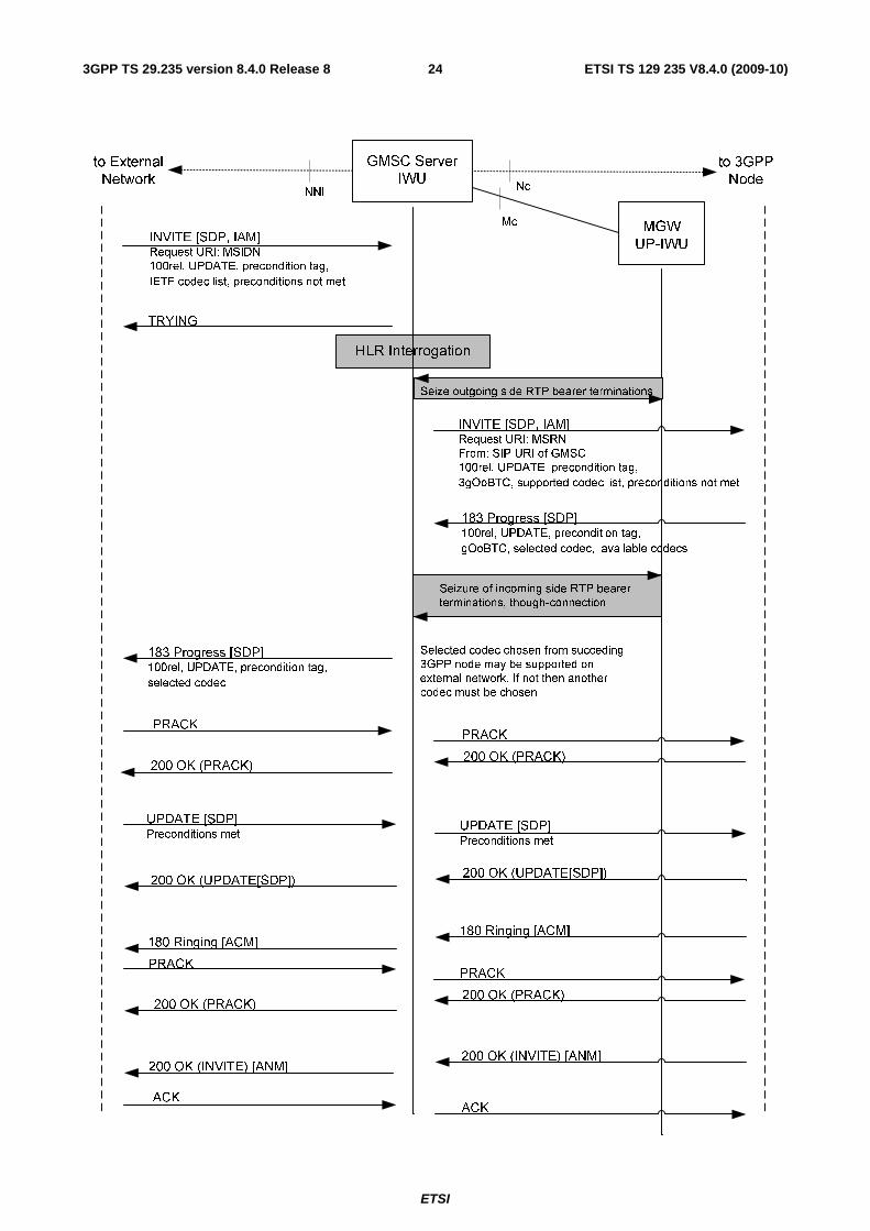
ETSI
ETSI TS 129 235 V8.4.0 (2009-10)243GPP TS 29.235 version 8.4.0 Release 8
NNINc
to External
Network
Mc
to 3GPP
Node
MGW
UP-IWU
GMSC Server
IWU
INVITE [SDP, IAM]Request URI: MSIDN
100rel, UPDATE, precondition tag,
IETF codec list, preconditions not met
TRYING
INVITE [SDP, IAM]Request URI: MSRN
From: SIP URI of GMSC
100rel, UPDATE, precondition tag,
3gOoBTC, supported codec list, preconditions not met
183 Progress [SDP]100rel, UPDATE, precondition tag,
gOoBTC, selected codec, available codecs
HLR Interrogation
Seizure of incoming side RTP bearer
terminations, though-connection
183 Progress [SDP]100rel, UPDATE, precondition tag,
selected codec
PRACK
200 OK (PRACK)
Selected codec chosen from succeding
3GPP node may be supported on
external network. If not then another
codec must be chosen
180 Ringing [ACM] 180 Ringing [ACM]
200 OK (INVITE) [ANM]200 OK (INVITE) [ANM]
ACKACK
UPDATE [SDP]Preconditions met
200 OK (UPDATE[SDP])
PRACK
200 OK (PRACK)
PRACK
200 OK (PRACK)
PRACK
200 OK (PRACK)
Seize outgoing side RTP bearer terminations
UPDATE [SDP]Preconditions met
200 OK (UPDATE[SDP])
ETSI
ETSI TS 129 235 V8.4.0 (2009-10)253GPP TS 29.235 version 8.4.0 Release 8
Figure 4.6.2.2.1: Incoming Call (message sequence chart), example with precondition update
4.6.3 Outgoing Call flows
4.6.3.1 Outgoing Call with support for preconditions
Figure 4.6.3.1.1 shows an outgoing call where the preconditions are not met when the IWU receives the initial SIP INVITE. Support for preconditions is confirmed from the external network. Within this example the external node provides a single codec, therefore no second SDP offer/answer is needed for codec negotiation.
When the IWU receives from the preceding 3GPP node that preconditions are met, then it informs the external node that called subscriber can be alerted with an UPDATE request, where the SDP contains the appropriate precondition offer and the selected codec.
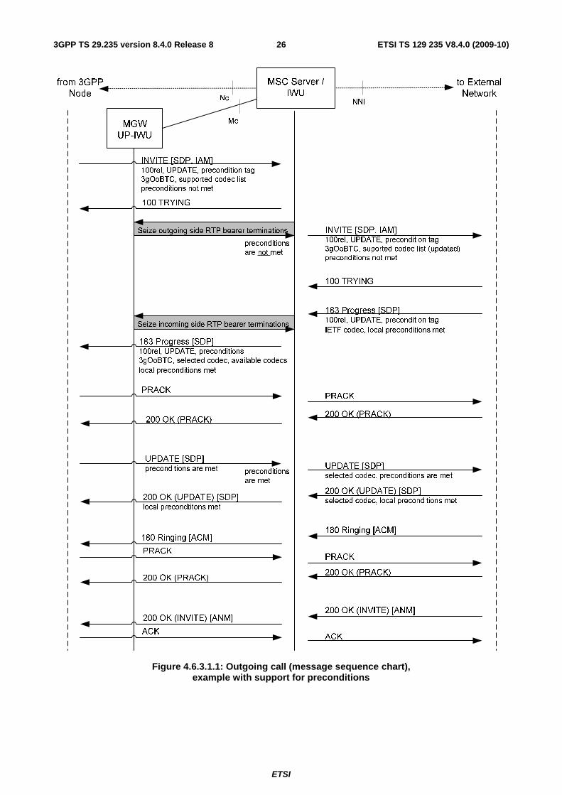
ETSI
ETSI TS 129 235 V8.4.0 (2009-10)263GPP TS 29.235 version 8.4.0 Release 8
INVITE [SDP, IAM]100rel, UPDATE, precondition tag
3gOoBTC, supported codec list
preconditions not met
100 TRYING
INVITE [SDP, IAM]100rel, UPDATE, precondition tag
3gOoBTC, suported codec list (updated)
preconditions not met
183 Progress [SDP]100rel, UPDATE, precondition tag
IETF codec, local preconditions met
200 OK (PRACK)
183 Progress [SDP]100rel, UPDATE, preconditions
3gOoBTC, selected codec, available codecs
local preconditions met
PRACK
200 OK (PRACK)
180 Ringing [ACM]
NNINc
to External
Network
Mc
from 3GPP
Node
MGW
UP-IWU
MSC Server /
IWU
preconditions
are not met
PRACK
PRACK
200 OK (PRACK)
180 Ringing [ACM]
200 OK (INVITE) [ANM]200 OK (INVITE) [ANM]
ACKACK
PRACK
200 OK (PRACK)
200 OK (UPDATE) [SDP]selected codec, local preconditions met
preconditions
are met
Seize outgoing side RTP bearer terminations
Seize incoming side RTP bearer terminations
UPDATE [SDP]selected codec, preconditions are met
UPDATE [SDP]preconditions are met
200 OK (UPDATE) [SDP]local precondtitons met
100 TRYING
Figure 4.6.3.1.1: Outgoing call (message sequence chart), example with support for preconditions
ETSI
ETSI TS 129 235 V8.4.0 (2009-10)273GPP TS 29.235 version 8.4.0 Release 8
4.6.3.2 Outgoing Call with support of 100rel but no support for preconditions
Figure 4.6.3.2.1 depicts an outgoing call where the external network supports reliable provisional responses and the UPDATE method but does not support preconditions. Therefore the IWU cannot exchange SDP precondition offers/answers with the external node.
In this example the IWU receives more than one single codec in the 183 Progress from the external node. Therefore the IWU selects one of the received codecs and makes a second SDP offer to the external node in the PRACK in order to lock the codec.
The IWU receives a 180 Ringing provisional response from the external network before preconditions are fulfilled. The IWU forwards the 180 Ringing response after preconditions have been fulfilled.
NOTE 1: The IWU may also have received a successful final response to the INVITE before preconditions have been met. In this case the forwarding of the 180 Ringing response and of the final successful response towards the preceding 3GPP node is delayed until preconditions are fulfilled.
NOTE 2: As an alternative the IWU could send PRACK to the external node when PRACK is received from the preceding 3GPP node acknowledging the 180 Ringing response. Since the sending of the 180 Ringing response to the 3GPP network may be delayed, this may lead to the retransmission of 180 Ringing response sent by the external node.
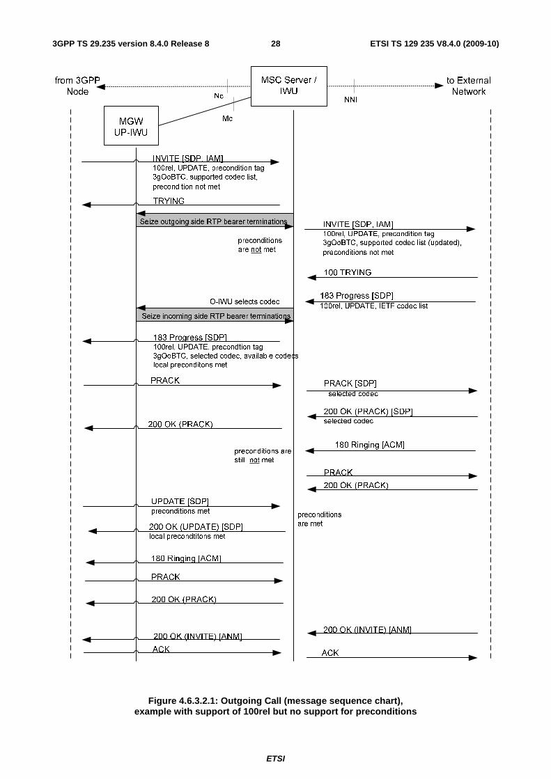
ETSI
ETSI TS 129 235 V8.4.0 (2009-10)283GPP TS 29.235 version 8.4.0 Release 8
INVITE [SDP, IAM]100rel, UPDATE, precondition tag
3gOoBTC, supported codec list,
precondition not met
TRYING
183 Progress [SDP]
100rel, UPDATE, IETF codec list
183 Progress [SDP]100rel, UPDATE, precondtion tag
3gOoBTC, selected codec, available codecs
local preconditons met
O-IWU selects codec
180 Ringing [ACM]
NNINc
to External
Network
Mc
from 3GPP
Node
MGW
UP-IWU
MSC Server /
IWU
preconditions
are not met
180 Ringing [ACM]
200 OK (INVITE) [ANM]200 OK (INVITE) [ANM]
ACKACK
PRACK
200 OK (PRACK)
Seize outgoing side RTP bearer terminations
Seize incoming side RTP bearer terminations
preconditions are
still not met
UPDATE [SDP]preconditions met
preconditions
are met
INVITE [SDP, IAM]100rel, UPDATE, precondition tag
3gOoBTC, supported codec list (updated),
preconditions not met
200 OK (PRACK) [SDP]selected codec200 OK (PRACK)
PRACK [SDP]
selected codec
PRACK
PRACK
200 OK (PRACK)
100 TRYING
200 OK (UPDATE) [SDP]local precondtitons met
Figure 4.6.3.2.1: Outgoing Call (message sequence chart), example with support of 100rel but no support for preconditions

ETSI
ETSI TS 129 235 V8.4.0 (2009-10)293GPP TS 29.235 version 8.4.0 Release 8
4.6.3.3 Outgoing Call without support for 100rel and preconditions
Figure 4.6.3.3.1 depicts an outgoing call where the external network does not support reliable provisional responses and therefore no SDP precondition signalling can be performed with the UPDATE method. With the 183 Progress the IWU receives an IETF codec list "unreliably". If the answer includes more than one codec the IWU cannot make a second offer to the external node (to lock the selected codec) during the early dialogue. However, the IWU can make use of the received information and start codec negotiation when forwarding the 183 Progress to the preceding 3GPP node.
The IWU immediately sends 200 OK to PRACKs received from the 3GPP node, because it cannot forward them to the external node. The reliable provisional responses cannot be signalled end-to-end.
The final response from the external network should include the same codecs as received previously within the Progress message. If this answer includes more than one codec the IWU makes a second offer to the external network with a re-INVITE request.
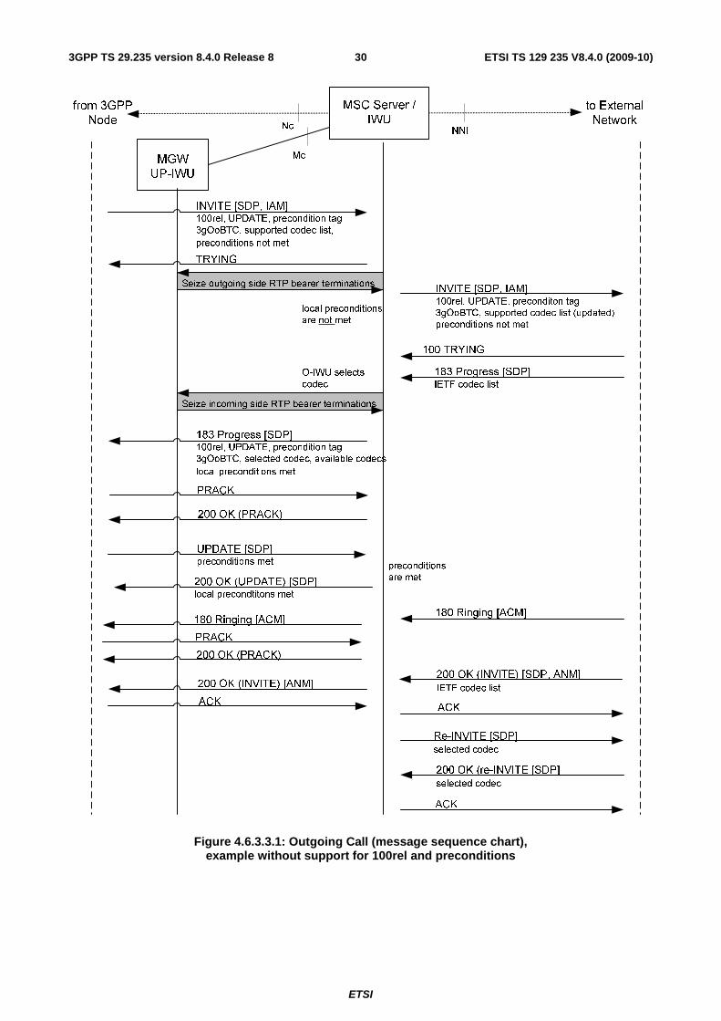
ETSI
ETSI TS 129 235 V8.4.0 (2009-10)303GPP TS 29.235 version 8.4.0 Release 8
INVITE [SDP, IAM]100rel, UPDATE, precondition tag
3gOoBTC, supported codec list,
preconditions not met
TRYING
INVITE [SDP, IAM]100rel, UPDATE, preconditon tag
3gOoBTC, supported codec list (updated)
preconditions not met
183 Progress [SDP]IETF codec list
183 Progress [SDP]100rel, UPDATE, precondition tag
3gOoBTC, selected codec, available codecs
local preconditions met
PRACK
200 OK (PRACK)
O-IWU selects
codec
180 Ringing [ACM]
NNINc
to External
Network
Mc
from 3GPP
Node
MGW
UP-IWU
MSC Server /
IWU
local preconditions
are not met
180 Ringing [ACM]
200 OK (INVITE) [SDP, ANM]
IETF codec list200 OK (INVITE) [ANM]
ACKACK
PRACK
200 OK (PRACK)
Re-INVITE [SDP]
selected codec
200 OK (re-INVITE [SDP]
selected codec
Seize outgoing side RTP bearer terminations
Seize incoming side RTP bearer terminations
ACK
100 TRYING
UPDATE [SDP]preconditions met preconditions
are met200 OK (UPDATE) [SDP]local precondtitons met
Figure 4.6.3.3.1: Outgoing Call (message sequence chart), example without support for 100rel and preconditions
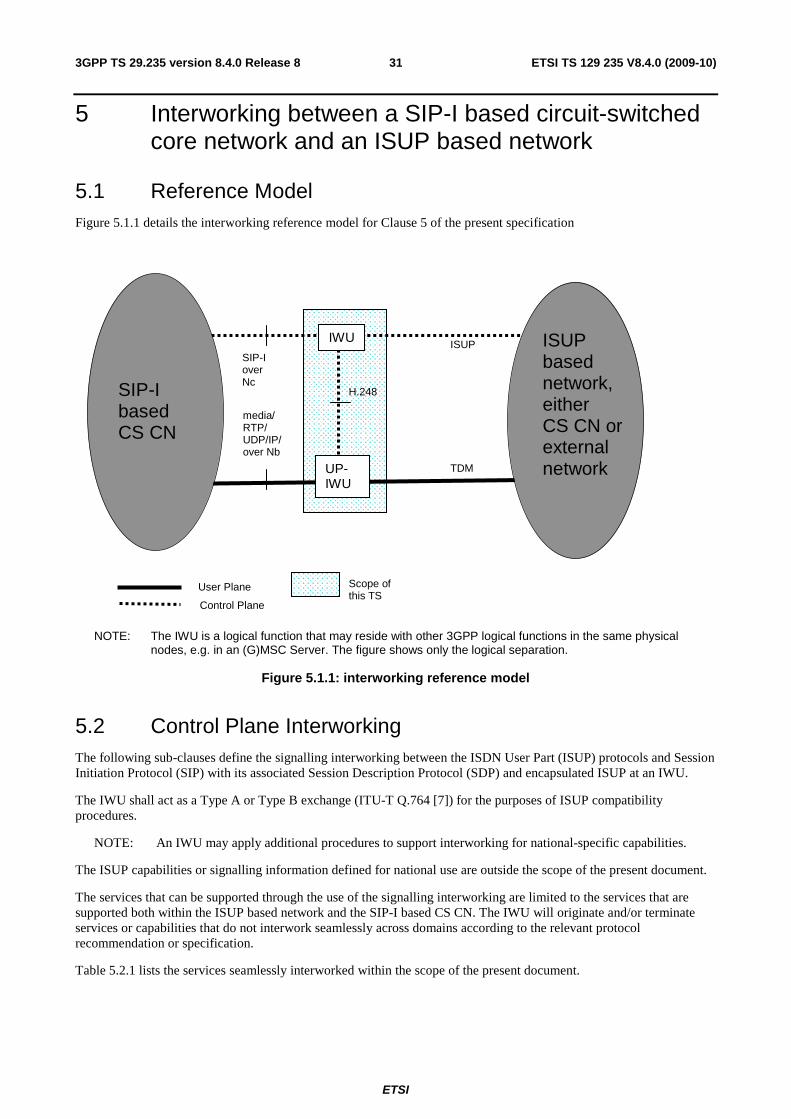
ETSI
ETSI TS 129 235 V8.4.0 (2009-10)313GPP TS 29.235 version 8.4.0 Release 8
5 Interworking between a SIP-I based circuit-switched core network and an ISUP based network
5.1 Reference Model Figure 5.1.1 details the interworking reference model for Clause 5 of the present specification
SIP-I based CS CN Network
IWU
UP- IWU
ISUP SIP-I over Nc
media/ RTP/ UDP/IP/ over Nb
H.248
TDM
User Plane
Control Plane
Scope of this TS
ISUP based network, either CS CN or external network
NOTE: The IWU is a logical function that may reside with other 3GPP logical functions in the same physical nodes, e.g. in an (G)MSC Server. The figure shows only the logical separation.
Figure 5.1.1: interworking reference model
5.2 Control Plane Interworking The following sub-clauses define the signalling interworking between the ISDN User Part (ISUP) protocols and Session Initiation Protocol (SIP) with its associated Session Description Protocol (SDP) and encapsulated ISUP at an IWU.
The IWU shall act as a Type A or Type B exchange (ITU-T Q.764 [7]) for the purposes of ISUP compatibility procedures.
NOTE: An IWU may apply additional procedures to support interworking for national-specific capabilities.
The ISUP capabilities or signalling information defined for national use are outside the scope of the present document.
The services that can be supported through the use of the signalling interworking are limited to the services that are supported both within the ISUP based network and the SIP-I based CS CN. The IWU will originate and/or terminate services or capabilities that do not interwork seamlessly across domains according to the relevant protocol recommendation or specification.
Table 5.2.1 lists the services seamlessly interworked within the scope of the present document.
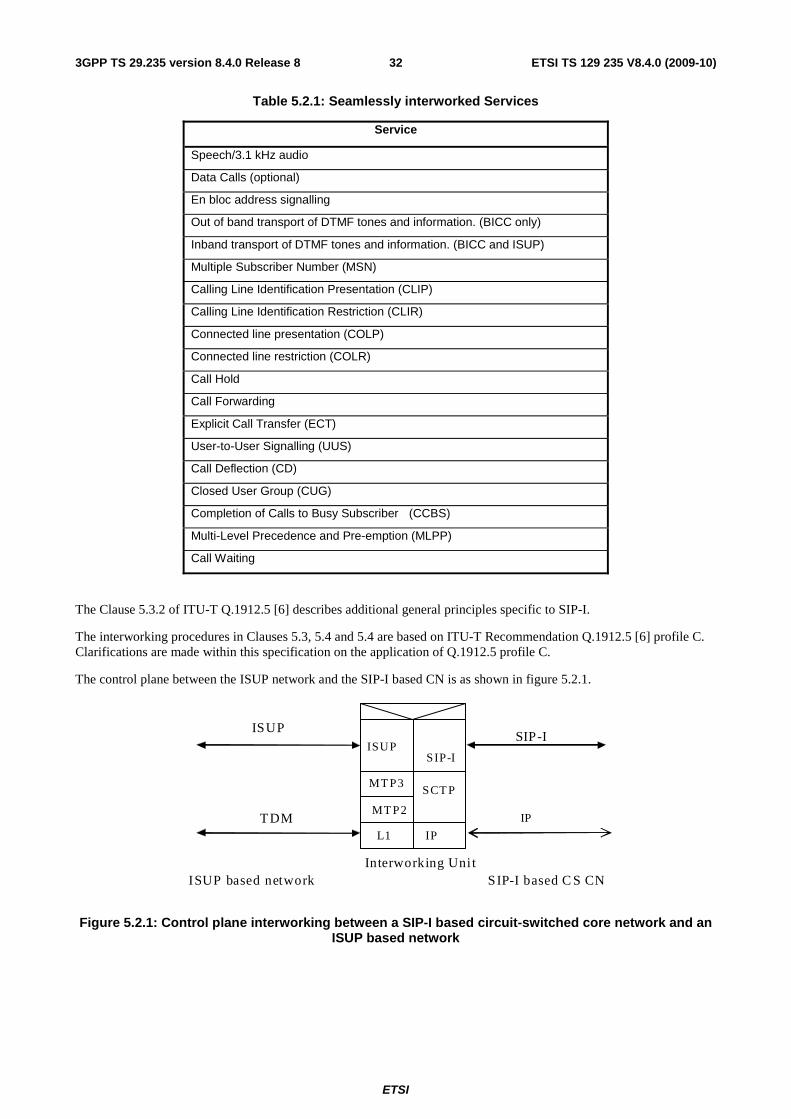
ETSI
ETSI TS 129 235 V8.4.0 (2009-10)323GPP TS 29.235 version 8.4.0 Release 8
Table 5.2.1: Seamlessly interworked Services
Service
Speech/3.1 kHz audio
Data Calls (optional)
En bloc address signalling
Out of band transport of DTMF tones and information. (BICC only)
Inband transport of DTMF tones and information. (BICC and ISUP)
Multiple Subscriber Number (MSN)
Calling Line Identification Presentation (CLIP)
Calling Line Identification Restriction (CLIR)
Connected line presentation (COLP)
Connected line restriction (COLR)
Call Hold
Call Forwarding
Explicit Call Transfer (ECT)
User-to-User Signalling (UUS)
Call Deflection (CD)
Closed User Group (CUG)
Completion of Calls to Busy Subscriber (CCBS)
Multi-Level Precedence and Pre-emption (MLPP)
Call Waiting
The Clause 5.3.2 of ITU-T Q.1912.5 [6] describes additional general principles specific to SIP-I.
The interworking procedures in Clauses 5.3, 5.4 and 5.4 are based on ITU-T Recommendation Q.1912.5 [6] profile C. Clarifications are made within this specification on the application of Q.1912.5 profile C.
The control plane between the ISUP network and the SIP-I based CN is as shown in figure 5.2.1.
Interworking Unit
TDM
SIP-I
IPL1
MT P2
MT P3
ISUP
SCT P
IP
ISUP SIP-I
ISUP based network SIP-I based C S CN
Figure 5.2.1: Control plane interworking between a SIP-I based circuit-switched core network and an ISUP based network
ETSI
ETSI TS 129 235 V8.4.0 (2009-10)333GPP TS 29.235 version 8.4.0 Release 8
5.3 Signalling Interworking of a Call from the ISUP based network towards the SIP-I based circuit-switched core network
5.3.1 General
The procedures for Profile C in Clause 7 of ITU-T Q.1912.5 [6] shall be applied with the modifications provided in this Clause.
5.3.1.1 Sending of ISUP information to adjacent SIP nodes
The IWU receiving ISUP information shall apply any interworking procedures detailed in Clause 7 of ITU-T Q.1912.5 [6] affecting parameters within the ISUP, and then proceed to encapsulate any ISUP information received (with the exception of the excluded messages detailed in 5.4.3 of ITU-T Q.1912.5 [6]) in a SIP message in a MIME body according to IETF RFC 3204 [19]. SIP Header fields relating to the handling of the ISUP body shall be set as specified in Clause 5.4.1.2 of ITU-T Q.1912.5 [6].
NOTE: The text in the preceding paragraph has been derived from ITU-T Q.1912.5 [6], Clause 5.4.1.
For a basic call setup, the SIP message used to encapsulate the ISUP message shall be the SIP message that was first triggered to be sent from the IWU as a result of the interworking specified in Clause 7 of ITU-T Q.1912.5 [6]. As an example, this means that an ISUP IAM will be encapsulated within the INVITE message that is sent out from the IWU. For the ISUP messages listed in Table 1 of ITU-T Q.1912.5 [6], the special procedures in Clause 5.4.3 of ITU-T Q.1912.5 are applicable.
NOTE: The text in the preceding paragraph has been derived from ITU-T Q.1912.5 [6], Clause 5.4.1.3.
5.3.1.2 Receipt of encapsulated ISUP information within SIP-I
On receipt of a SIP message containing encapsulated ISUP, the IWU shall de-encapsulate the ISUP message from the SIP message body. The received SIP message shall be mapped to an ISUP message and merged with the de-encapsulated ISUP information according to the rules in Clause 7 of ITU-T Q.1912.5 [6].
NOTE: The text in the preceding paragraph has been derived from ITU-T Q.1912.5 [6], Clause 5.4.2.
NOTE: These precedence rules have been derived from the following principles, which can also be applied for any ISUP information not covered by the present specification:
1 Where a SIP header mapping to ISUP field(s) is possible (for example the mapping of Request-URI to Called Party Number), the SIP header is given precedence over the encapsulated ISUP value in the alignment process. (Conflicts can be caused by a possible service invocation within the SIP network.)
2 De-encapsulated ISUP information overrides ISUP information derived from default values (rather than SIP information).
3 Local ISUP procedures may modify information derived from SIP or default values.
This Note has been derived from text in ITU-T Q.1912.5 [6], Clause 5.4.2
NOTE There is a certain change against Q.1912.5, where the above note is formulated as normative procedures. However, this is very high level and not required if you look at the real interworking procedures later on. Therefore formulating this as a Note makes much more sense.
5.3.1.3 Special procedures related to outgoing INVITE
5.3.1.3.1 Overlap Signalling
The IWU does not need to support procedures related to overlap signalling in Clause 7 of ITU-T Q.1912.5 [6].
ETSI
ETSI TS 129 235 V8.4.0 (2009-10)343GPP TS 29.235 version 8.4.0 Release 8
NOTE: No overlap signalling is used in a 3GPP CS domain. A G-MSC acting as IWU will collect all digits required to identify the called party and not propagate the overlap signalling further.
5.3.1.3.2 Coding of encapsulated ISUP IAM parameters in outgoing INVITE
The IWU may choose to transcode media, or attempt to interwork media without transcoding. If the IWU transcodes, it should set the TMR/USI/HLC parameters according to the codec applied in the SIP-I network. Otherwise, it should provide the TMR/USI/HLC parameters as received in the incoming IAM. If the IWU offers several codecs within SDP, it should set the TMR/USI/HLC parameters according to the preferred codec, applying the rules above for this codec.
NOTE: ITU-T Q.1912.5 [6] does not describe the relationship between TMR/USI/HLC and SDP codec negotiation.
5.3.1.3.3 Media offered in SDP of outgoing INVITE
The IWU should offer codecs known to be supported within the SIP-I based CS CN network. If multiple speech codecs are offered, Out of Band Transcoder Control (OoBTC) procedures shall be applied by the IWU in accordance with 3GPP TS 23.153 [5]. Otherwise only the default PCM speech codec shall be signalled in an SDP offer; auxiliary payload types such as the Telephony Event RTP payload type may be included in addition.
If the IWU applies the optional "optimised MGW selection" procedure, it shall include a MGW Identifier in the SDP. Related signalling procedures are described in Clause 4.4 of 3GPP TS 23.231 [3] and the encoding of the MGW Identifier is defined in 3GPP TS 29.231 [4].
5.4 Signalling Interworking of a Call from SIP-I based circuit-switched core network towards the ISUP based network
5.4.1 General
The procedures for Profile C in Clause 6 of ITU-T Q.1912.5 [6] shall be applied with the modifications provided in this Clause.
5.4.2 Interworking of received ISUP messages to SIP messages
The IWU receiving backwards ISUP information shall apply any interworking procedures detailed in Clause 6 of ITU-T Q.1912.5 [6] affecting parameters within the ISUP, and then proceed to encapsulate any ISUP information received (with the exception of the excluded messages detailed in 5.4.3 of ITU-T Q.1912.5 [6]) in a SIP message in a MIME body according to IETF RFC 3204 [19]. The selected SIP Header fields relating to the handling of the ISUP body shall be set as specified in Clause 5.4.1.2 of ITU-T Q.1912.5 [6].
5.4.3 Interworking of received SIP messages to ISUP messages
5.4.3.1 Receipt of encapsulated ISUP information within SIP
On receipt of a SIP message containing encapsulated ISUP, the IWU shall de-encapsulate the ISUP message from the SIP message body. The received SIP message shall be mapped to an ISUP message and merged with the de-encapsulated ISUP message according to the rules for Profile C in Clause 6 of ITU-T Q.1912.5 [6].
NOTE 1: These precedence rules have been derived from the following principles, which can also be applied for any ISUP information not covered by the present specification:
1 Where a SIP header mapping to ISUP field(s) is possible (for example the mapping of Request-URI to Called Party Number), the SIP header is given precedence over the encapsulated ISUP value in the alignment process.
2 De-encapsulated ISUP information overrides ISUP information derived from default values (rather than SIP information).
3 Local ISUP procedures may modify information derived from SIP or default values.
ETSI
ETSI TS 129 235 V8.4.0 (2009-10)353GPP TS 29.235 version 8.4.0 Release 8
This note has been derived from text in ITU-T Q.1912.5 [6], Clause 5.4.2.
NOTE 2: There is a certain change against Q.1912.5, where the above note is formulated as normative procedures. However, this is very high level and not required if you look at the real interworking procedures later on. Therefore formulating this as a note makes much more sense.
5.4.3.2 Special Procedures for the Reception of SIP INVITE request
5.4.3.2.1 Propagation of overlap signalling toward the 3GPP CS domain
The procedures in Clause 6 of ITU-T Q.1912.5 [6] related to the propagation of overlap signalling are not applicable, since no overlap signalling is used within the CS CN.
5.4.3.2.2 Derivation of TMR, USI and HLC parameters within sent IAM message
The IWU may choose to transcode media and shall then set the parameters according to the coding applied within the CS Domain. Otherwise, the IWU shall select a codec for the SIP side termination using SDP offer-answer procedures, IETF RFC 3264 [34], and shall map the SDP information of this codec to the TMR/USI/HLC parameters according to table 2a of 3GPP TS 29.163 [13]. If the information derived from this mapping matches the information in the TMR/USI/HLC parameters in the encapsulated ISUP, the TMR/USI/HLC parameters from the encapsulated ISUP should be used as they may contain additional information. If the information derived from this mapping contradicts the information in the TMR/USI/HLC parameters in the encapsulated ISUP, the TMR/USI/HLC parameters derived by the mapping shall be used.
NOTE: The procedures in this note are an amendment compared to ITU-T Q.1912.5, which simply states the TMR parameters in encapsulated ISUP shall take precedence, However this is inappropriate if an incompatible codec is selected.
5.4.3.2.3 Receipt of SIP INVITE without SDP offer
An IWU may reject receipt of SIP INVITE without SDP offer, otherwise the procedures in section 4.2.2.3 shall be followed.
NOTE: A SIP INVITE without SDP offer is not used within the CS CN.
5.4.3.2.4 Special Procedures for deferred MGW selection procedure.
If the IWU supports the optional "deferred MGW selection" procedure and receives an unspecified connection address in the SDP offer contained in the INVITE request, it should include a MGW Identifier for the IWU-UP it selects in the corresponding SDP answer. Related signalling procedures are described in Clause 4.4 of 3GPP TS 23.231 [3] and the encoding of the MGW Identifier is defined in 3GPP TS 29.231 [4].
5.5 Supplementary services
5.5.1 Special procedures for supplementary service interworking
The supplementary services described in Table 5.2.1 are interworked by using the parameters of the (de)encapsulated ISUP. No other interworking is required, except if otherwise described within the clauses below.
5.5.2 Interworking of CLIP/CLIR supplementary service
For the interworking of call towards the SIP-I based CS CN: the service shall be supported by encapsulation.
For the interworking of call from the SIP-I based CS CN: ITU-T Q.1912.5 [6], Annex B.1, shall apply.
5.5.3 Interworking of Call Hold (HOLD) supplementary service
The Profile C procedures in ITU-T Q.1912.5 [6], Clause B10, shall be followed.
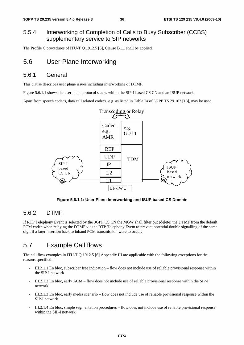
ETSI
ETSI TS 129 235 V8.4.0 (2009-10)363GPP TS 29.235 version 8.4.0 Release 8
5.5.4 Interworking of Completion of Calls to Busy Subscriber (CCBS) supplementary service to SIP networks
The Profile C procedures of ITU-T Q.1912.5 [6], Clause B.11 shall be applied.
5.6 User Plane Interworking
5.6.1 General
This clause describes user plane issues including interworking of DTMF.
Figure 5.6.1.1 shows the user plane protocol stacks within the SIP-I based CS CN and an ISUP network.
Apart from speech codecs, data call related codecs, e.g. as listed in Table 2a of 3GPP TS 29.163 [13], may be used.
Codec, e.g. AMR
UP-IWU
L1
L2
IP
UDP
RTP
e.g. G.711
TDM
Transcoding or Relay
SIP-I based CS CN
ISUP based network
Figure 5.6.1.1: User Plane Interworking and ISUP based CS Domain
5.6.2 DTMF
If RTP Telephony Event is selected by the 3GPP CS CN the MGW shall filter out (delete) the DTMF from the default PCM codec when relaying the DTMF via the RTP Telephony Event to prevent potential double signalling of the same digit if a later insertion back to inband PCM transmission were to occur.
5.7 Example Call flows The call flow examples in ITU-T Q.1912.5 [6] Appendix III are applicable with the following exceptions for the reasons specified:
- III.2.1.1 En bloc, subscriber free indication – flow does not include use of reliable provisional response within the SIP-I network
- III.2.1.2 En bloc, early ACM – flow does not include use of reliable provisional response within the SIP-I network
- III.2.1.3 En bloc, early media scenario – flow does not include use of reliable provisional response within the SIP-I network
- III.2.1.4 En bloc, simple segmentation procedures – flow does not include use of reliable provisional response within the SIP-I network
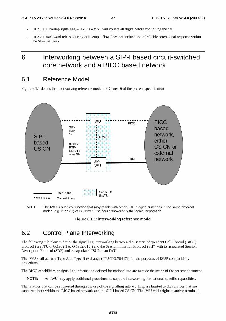
ETSI
ETSI TS 129 235 V8.4.0 (2009-10)373GPP TS 29.235 version 8.4.0 Release 8
- III.2.1.10 Overlap signalling – 3GPP G-MSC will collect all digits before continuing the call
- III.2.2.1 Backward release during call setup – flow does not include use of reliable provisional response within the SIP-I network
6 Interworking between a SIP-I based circuit-switched core network and a BICC based network
6.1 Reference Model Figure 6.1.1 details the interworking reference model for Clause 6 of the present specification
SIP-I based CS CN Network
IWU
UP- IWU
BICC SIP-I over Nc
media/ RTP/ UDP/IP/ over Nb
H.248
TDM
User Plane
Control Plane
Scope Of thisTS
BICC based network, either CS CN or external network
NOTE: The IWU is a logical function that may reside with other 3GPP logical functions in the same physical nodes, e.g. in an (G)MSC Server. The figure shows only the logical separation.
Figure 6.1.1: interworking reference model
6.2 Control Plane Interworking The following sub-clauses define the signalling interworking between the Bearer Independent Call Control (BICC) protocol (see ITU-T Q.1902.1 to Q.1902.6 [8]) and the Session Initiation Protocol (SIP) with its associated Session Description Protocol (SDP) and encapsulated ISUP at an IWU.
The IWU shall act as a Type A or Type B exchange (ITU-T Q.764 [7]) for the purposes of ISUP compatibility procedures.
The BICC capabilities or signalling information defined for national use are outside the scope of the present document.
NOTE: An IWU may apply additional procedures to support interworking for national-specific capabilities.
The services that can be supported through the use of the signalling interworking are limited to the services that are supported both within the BICC based network and the SIP-I based CS CN. The IWU will originate and/or terminate
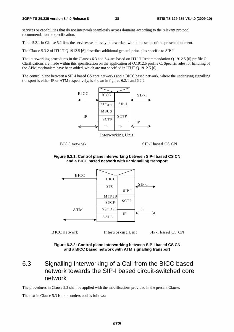
ETSI
ETSI TS 129 235 V8.4.0 (2009-10)383GPP TS 29.235 version 8.4.0 Release 8
services or capabilities that do not interwork seamlessly across domains according to the relevant protocol recommendation or specification.
Table 5.2.1 in Clause 5.2 lists the services seamlessly interworked within the scope of the present document.
The Clause 5.3.2 of ITU-T Q.1912.5 [6] describes additional general principles specific to SIP-I.
The interworking procedures in the Clauses 6.3 and 6.4 are based on ITU-T Recommendation Q.1912.5 [6] profile C. Clarifications are made within this specification on the application of Q.1912.5 profile C. Specific rules for handling of the APM mechanism have been added, which are not specified in ITUT Q.1912.5 [6].
The control plane between a SIP-I based CS core networks and a BICC based network, where the underlying signalling transport is either IP or ATM respectively, is shown in figures 6.2.1 and 6.2.2.
Interworking U nit
IP
SIP-I
IPIP
SCT P
M 3US
BICC
SCT P
IP
B ICC SIP-I
SIP-I based CS CN
STCM TP
B ICC network
Figure 6.2.1: Control plane interworking between SIP-I based CS CN and a BICC based network with IP signalling transport
Interworking U nit
ATM
SIP-I
IP
SCT P
IP
BICC
SIP-I
B ICC network
SSC OP
SSCF
M TP3B
B IC C
STC
AAL 5
SIP-I based CS CN
Figure 6.2.2: Control plane interworking between SIP-I based CS CN and a BICC based network with ATM signalling transport
6.3 Signalling Interworking of a Call from the BICC based network towards the SIP-I based circuit-switched core network
The procedures in Clause 5.3 shall be applied with the modifications provided in the present Clause.
The text in Clause 5.3 is to be understood as follows:
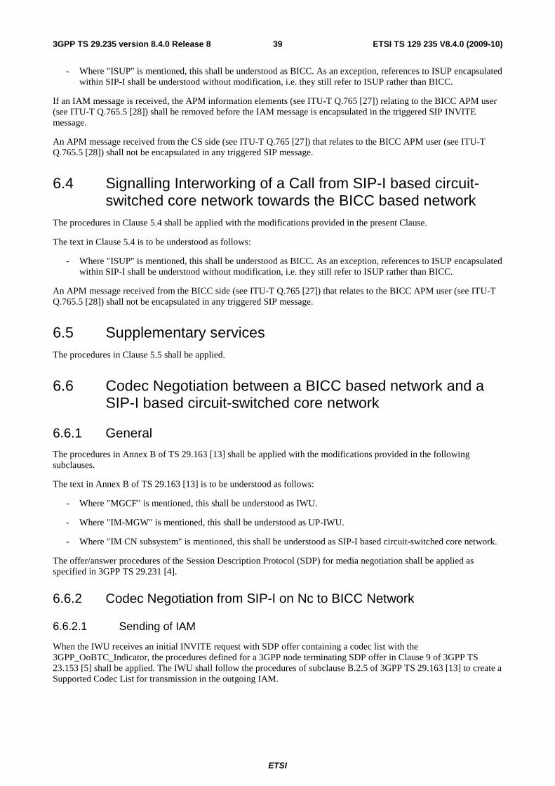
ETSI
ETSI TS 129 235 V8.4.0 (2009-10)393GPP TS 29.235 version 8.4.0 Release 8
- Where "ISUP" is mentioned, this shall be understood as BICC. As an exception, references to ISUP encapsulated within SIP-I shall be understood without modification, i.e. they still refer to ISUP rather than BICC.
If an IAM message is received, the APM information elements (see ITU-T Q.765 [27]) relating to the BICC APM user (see ITU-T Q.765.5 [28]) shall be removed before the IAM message is encapsulated in the triggered SIP INVITE message.
An APM message received from the CS side (see ITU-T Q.765 [27]) that relates to the BICC APM user (see ITU-T Q.765.5 [28]) shall not be encapsulated in any triggered SIP message.
6.4 Signalling Interworking of a Call from SIP-I based circuit-switched core network towards the BICC based network
The procedures in Clause 5.4 shall be applied with the modifications provided in the present Clause.
The text in Clause 5.4 is to be understood as follows:
- Where "ISUP" is mentioned, this shall be understood as BICC. As an exception, references to ISUP encapsulated within SIP-I shall be understood without modification, i.e. they still refer to ISUP rather than BICC.
An APM message received from the BICC side (see ITU-T Q.765 [27]) that relates to the BICC APM user (see ITU-T Q.765.5 [28]) shall not be encapsulated in any triggered SIP message.
6.5 Supplementary services The procedures in Clause 5.5 shall be applied.
6.6 Codec Negotiation between a BICC based network and a SIP-I based circuit-switched core network
6.6.1 General
The procedures in Annex B of TS 29.163 [13] shall be applied with the modifications provided in the following subclauses.
The text in Annex B of TS 29.163 [13] is to be understood as follows:
- Where "MGCF" is mentioned, this shall be understood as IWU.
- Where "IM-MGW" is mentioned, this shall be understood as UP-IWU.
- Where "IM CN subsystem" is mentioned, this shall be understood as SIP-I based circuit-switched core network.
The offer/answer procedures of the Session Description Protocol (SDP) for media negotiation shall be applied as specified in 3GPP TS 29.231 [4].
6.6.2 Codec Negotiation from SIP-I on Nc to BICC Network
6.6.2.1 Sending of IAM
When the IWU receives an initial INVITE request with SDP offer containing a codec list with the 3GPP_OoBTC_Indicator, the procedures defined for a 3GPP node terminating SDP offer in Clause 9 of 3GPP TS 23.153 [5] shall be applied. The IWU shall follow the procedures of subclause B.2.5 of 3GPP TS 29.163 [13] to create a Supported Codec List for transmission in the outgoing IAM.
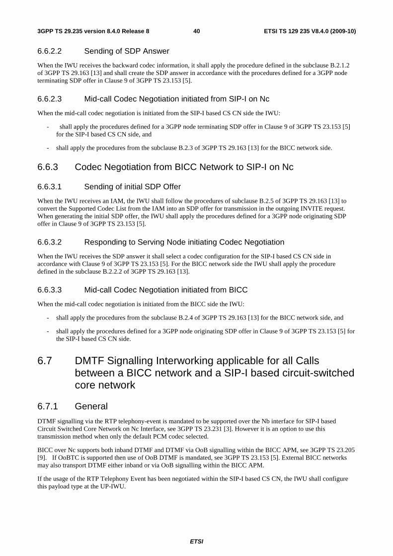
ETSI
ETSI TS 129 235 V8.4.0 (2009-10)403GPP TS 29.235 version 8.4.0 Release 8
6.6.2.2 Sending of SDP Answer
When the IWU receives the backward codec information, it shall apply the procedure defined in the subclause B.2.1.2 of 3GPP TS 29.163 [13] and shall create the SDP answer in accordance with the procedures defined for a 3GPP node terminating SDP offer in Clause 9 of 3GPP TS 23.153 [5].
6.6.2.3 Mid-call Codec Negotiation initiated from SIP-I on Nc
When the mid-call codec negotiation is initiated from the SIP-I based CS CN side the IWU:
- shall apply the procedures defined for a 3GPP node terminating SDP offer in Clause 9 of 3GPP TS 23.153 [5] for the SIP-I based CS CN side, and
- shall apply the procedures from the subclause B.2.3 of 3GPP TS 29.163 [13] for the BICC network side.
6.6.3 Codec Negotiation from BICC Network to SIP-I on Nc
6.6.3.1 Sending of initial SDP Offer
When the IWU receives an IAM, the IWU shall follow the procedures of subclause B.2.5 of 3GPP TS 29.163 [13] to convert the Supported Codec List from the IAM into an SDP offer for transmission in the outgoing INVITE request. When generating the initial SDP offer, the IWU shall apply the procedures defined for a 3GPP node originating SDP offer in Clause 9 of 3GPP TS 23.153 [5].
6.6.3.2 Responding to Serving Node initiating Codec Negotiation
When the IWU receives the SDP answer it shall select a codec configuration for the SIP-I based CS CN side in accordance with Clause 9 of 3GPP TS 23.153 [5]. For the BICC network side the IWU shall apply the procedure defined in the subclause B.2.2.2 of 3GPP TS 29.163 [13].
6.6.3.3 Mid-call Codec Negotiation initiated from BICC
When the mid-call codec negotiation is initiated from the BICC side the IWU:
- shall apply the procedures from the subclause B.2.4 of 3GPP TS 29.163 [13] for the BICC network side, and
- shall apply the procedures defined for a 3GPP node originating SDP offer in Clause 9 of 3GPP TS 23.153 [5] for the SIP-I based CS CN side.
6.7 DMTF Signalling Interworking applicable for all Calls between a BICC network and a SIP-I based circuit-switched core network
6.7.1 General
DTMF signalling via the RTP telephony-event is mandated to be supported over the Nb interface for SIP-I based Circuit Switched Core Network on Nc Interface, see 3GPP TS 23.231 [3]. However it is an option to use this transmission method when only the default PCM codec selected.
BICC over Nc supports both inband DTMF and DTMF via OoB signalling within the BICC APM, see 3GPP TS 23.205 [9]. If OoBTC is supported then use of OoB DTMF is mandated, see 3GPP TS 23.153 [5]. External BICC networks may also transport DTMF either inband or via OoB signalling within the BICC APM.
If the usage of the RTP Telephony Event has been negotiated within the SIP-I based CS CN, the IWU shall configure this payload type at the UP-IWU.
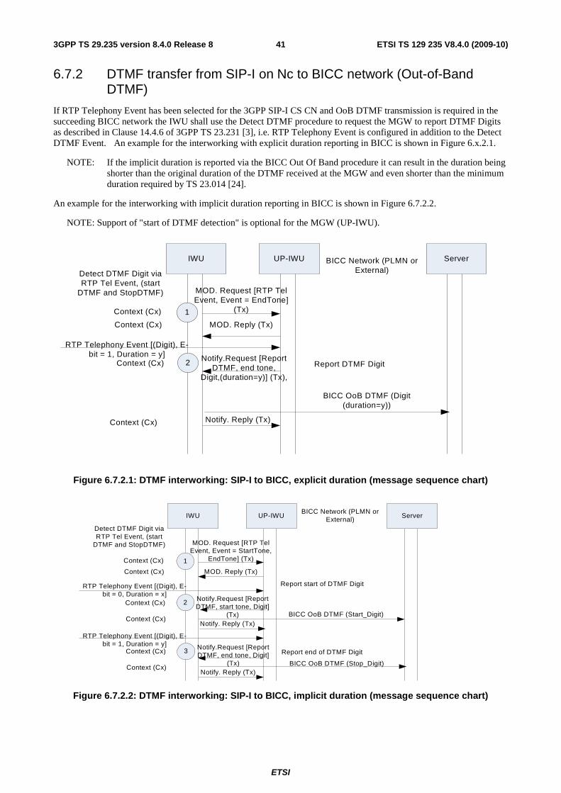
ETSI
ETSI TS 129 235 V8.4.0 (2009-10)413GPP TS 29.235 version 8.4.0 Release 8
6.7.2 DTMF transfer from SIP-I on Nc to BICC network (Out-of-Band DTMF)
If RTP Telephony Event has been selected for the 3GPP SIP-I CS CN and OoB DTMF transmission is required in the succeeding BICC network the IWU shall use the Detect DTMF procedure to request the MGW to report DTMF Digits as described in Clause 14.4.6 of 3GPP TS 23.231 [3], i.e. RTP Telephony Event is configured in addition to the Detect DTMF Event. An example for the interworking with explicit duration reporting in BICC is shown in Figure 6.x.2.1.
NOTE: If the implicit duration is reported via the BICC Out Of Band procedure it can result in the duration being shorter than the original duration of the DTMF received at the MGW and even shorter than the minimum duration required by TS 23.014 [24].
An example for the interworking with implicit duration reporting in BICC is shown in Figure 6.7.2.2.
NOTE: Support of "start of DTMF detection" is optional for the MGW (UP-IWU).
ServerIWU UP-IWU
Context (Cx) 1
MOD. Request [RTP Tel Event, Event = EndTone]
(Tx)
MOD. Reply (Tx)
Detect DTMF Digit via RTP Tel Event, (start
DTMF and StopDTMF)
Context (Cx)
RTP Telephony Event [(Digit), E-bit = 1, Duration = y]
Context (Cx) 2 Notify.Request [Report DTMF, end tone,
Digit,(duration=y)] (Tx),
Notify. Reply (Tx)
Report DTMF Digit
Context (Cx)
BICC OoB DTMF (Digit (duration=y))
BICC Network (PLMN or External)
Figure 6.7.2.1: DTMF interworking: SIP-I to BICC, explicit duration (message sequence chart)
Server IWU UP-IWU
Context (Cx) 1
RTP Telephony Event [(Digit), E-bit = 0, Duration = x]
MOD. Request [RTP Tel Event, Event = StartTone,
EndTone] (Tx)
MOD. Reply (Tx)
Detect DTMF Digit via RTP Tel Event, (start
DTMF and StopDTMF)
Context (Cx)
Context (Cx) 2 Notify.Request [Report DTMF, start tone, Digit]
(Tx)Notify. Reply (Tx)
Report start of DTMF Digit
Context (Cx)
RTP Telephony Event [(Digit), E-bit = 1, Duration = y]
Context (Cx) 3 Notify.Request [Report DTMF, end tone, Digit]
(Tx)Notify. Reply (Tx)
Report end of DTMF Digit
Context (Cx)
BICC OoB DTMF (Start_Digit)
BICC Network (PLMN or External)
BICC OoB DTMF (Stop_Digit)
Figure 6.7.2.2: DTMF interworking: SIP-I to BICC, implicit duration (message sequence chart)
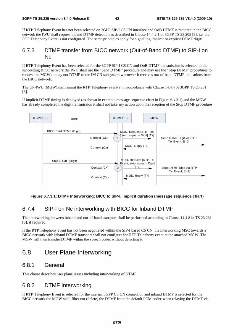
ETSI
ETSI TS 129 235 V8.4.0 (2009-10)423GPP TS 29.235 version 8.4.0 Release 8
If RTP Telephony Event has not been selected on 3GPP SIP-I CS CN interface and OoB DTMF is required in the BICC network the IWU shall request inband DTMF detection as described in Clause 14.4.2.1 of 3GPP TS 23.205 [9], i.e. the RTP Telephony Event is not configured. The same principles apply for signalling implicit or explicit DTMF digits.
6.7.3 DTMF transfer from BICC network (Out-of-Band DTMF) to SIP-I on Nc
If RTP Telephony Event has been selected for the 3GPP SIP-I CS CN and OoB DTMF transmission is selected in the succeeding BICC network the IWU shall use the "Send DTMF" procedure and may use the "Stop DTMF" procedures to request the MGW to play out DTMF to the IM CN subsystem whenever it receives out-of-band DTMF indications from the BICC network.
The UP-IWU (MGW) shall signal the RTP Telephony event(s) in accordance with Clause 14.4.4 of 3GPP TS 23.231 [3].
If implicit DTMF timing is deployed (as shown in example message sequence chart in Figure 6.x.3.1) and the MGW has already completed the digit transmission it shall not take any action upon the reception of the Stop DTMF procedure
(G)MSC-S (G)MSC-S MGW
Context (Cx) 1
BICC Start DTMF (Digit) MOD. Request [RTP Tel Event, signal = Digit] (Tx)
MOD. Reply (Tx)
Send DTMF Digit via RTP Tel Event, E=0)
Context (Cx)
Context (Cx) 2
Stop DTMF (Digit) MOD. Request [RTP Tel Event, stop signal = Digit]
(Tx)
MOD. Reply (Tx)
Stop DTMF Digit via RTP Tel Event, E=1)
Context (Cx)
BICC
Figure 6.7.3.1: DTMF Interworking: BICC to SIP-I, implicit duration (message sequence chart)
6.7.4 SIP-I on Nc interworking with BICC for Inband DTMF
The interworking between inband and out-of-band transport shall be performed according to Clause 14.4.8 in TS 23.231 [3], if required.
If the RTP Telephony event has not been negotiated within the SIP-I based CS CN, the interworking MSC towards a BICC network with inband DTMF transport shall not configure the RTP Telephony event at the attached MGW. The MGW will then transfer DTMF within the speech codec without detecting it.
6.8 User Plane Interworking
6.8.1 General
This clause describes user plane issues including interworking of DTMF.
6.8.2 DTMF Interworking
If RTP Telephony Event is selected for the internal 3GPP CS CN connection and inband DTMF is selected for the BICC network the MGW shall filter out (delete) the DTMF from the default PCM codec when relaying the DTMF via
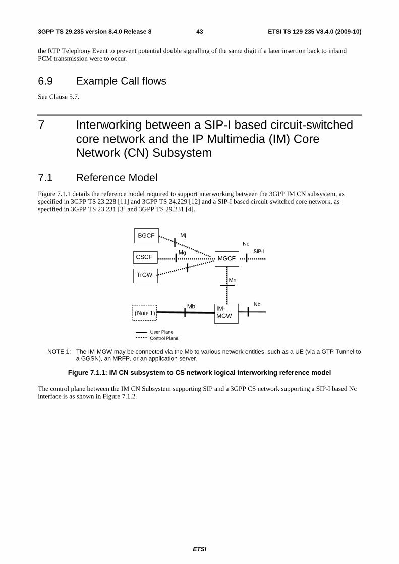
ETSI
ETSI TS 129 235 V8.4.0 (2009-10)433GPP TS 29.235 version 8.4.0 Release 8
the RTP Telephony Event to prevent potential double signalling of the same digit if a later insertion back to inband PCM transmission were to occur.
6.9 Example Call flows See Clause 5.7.
7 Interworking between a SIP-I based circuit-switched core network and the IP Multimedia (IM) Core Network (CN) Subsystem
7.1 Reference Model Figure 7.1.1 details the reference model required to support interworking between the 3GPP IM CN subsystem, as specified in 3GPP TS 23.228 [11] and 3GPP TS 24.229 [12] and a SIP-I based circuit-switched core network, as specified in 3GPP TS 23.231 [3] and 3GPP TS 29.231 [4].
(Note 1)
CSCF
IM- MGW
MGCF
Mb
Mn
User Plane Control Plane
SIP-I Mg
BGCF Mj Nc
Nb
TrGW
NOTE 1: The IM-MGW may be connected via the Mb to various network entities, such as a UE (via a GTP Tunnel to a GGSN), an MRFP, or an application server.
Figure 7.1.1: IM CN subsystem to CS network logical interworking reference model
The control plane between the IM CN Subsystem supporting SIP and a 3GPP CS network supporting a SIP-I based Nc interface is as shown in Figure 7.1.2.
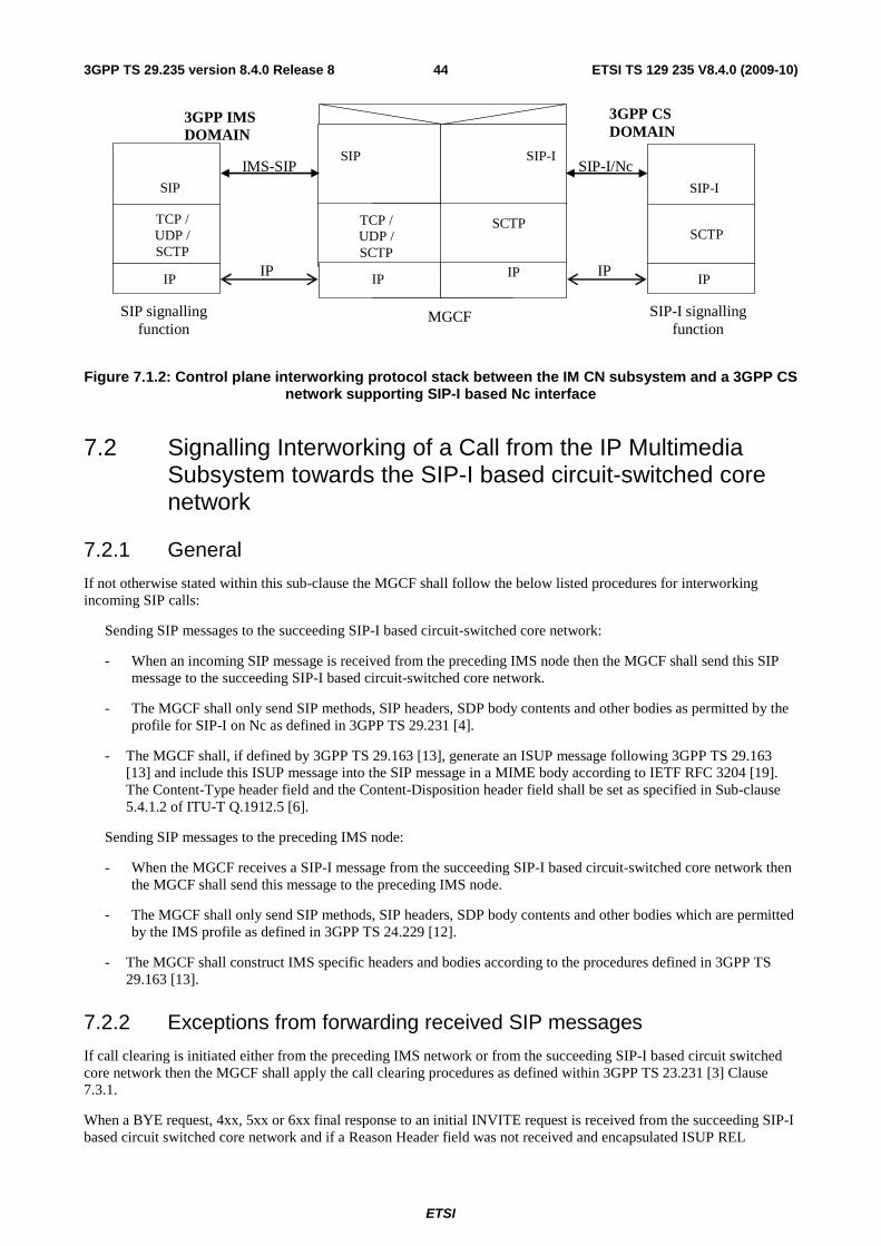
ETSI
ETSI TS 129 235 V8.4.0 (2009-10)443GPP TS 29.235 version 8.4.0 Release 8
MGCF SIP-I signalling function
SIP-I
SCTP
IP
SCTP
SIP-I
IP
SIP-I/Nc
SIP signalling function
SIP
IP
TCP / UDP / SCTP
SIP
IP
IMS-SIP
TCP / UDP /SCTP
IP IP
3GPP IMS DOMAIN
3GPP CS DOMAIN
Figure 7.1.2: Control plane interworking protocol stack between the IM CN subsystem and a 3GPP CS network supporting SIP-I based Nc interface
7.2 Signalling Interworking of a Call from the IP Multimedia Subsystem towards the SIP-I based circuit-switched core network
7.2.1 General
If not otherwise stated within this sub-clause the MGCF shall follow the below listed procedures for interworking incoming SIP calls:
Sending SIP messages to the succeeding SIP-I based circuit-switched core network:
- When an incoming SIP message is received from the preceding IMS node then the MGCF shall send this SIP message to the succeeding SIP-I based circuit-switched core network.
- The MGCF shall only send SIP methods, SIP headers, SDP body contents and other bodies as permitted by the profile for SIP-I on Nc as defined in 3GPP TS 29.231 [4].
- The MGCF shall, if defined by 3GPP TS 29.163 [13], generate an ISUP message following 3GPP TS 29.163 [13] and include this ISUP message into the SIP message in a MIME body according to IETF RFC 3204 [19]. The Content-Type header field and the Content-Disposition header field shall be set as specified in Sub-clause 5.4.1.2 of ITU-T Q.1912.5 [6].
Sending SIP messages to the preceding IMS node:
- When the MGCF receives a SIP-I message from the succeeding SIP-I based circuit-switched core network then the MGCF shall send this message to the preceding IMS node.
- The MGCF shall only send SIP methods, SIP headers, SDP body contents and other bodies which are permitted by the IMS profile as defined in 3GPP TS 24.229 [12].
- The MGCF shall construct IMS specific headers and bodies according to the procedures defined in 3GPP TS 29.163 [13].
7.2.2 Exceptions from forwarding received SIP messages
If call clearing is initiated either from the preceding IMS network or from the succeeding SIP-I based circuit switched core network then the MGCF shall apply the call clearing procedures as defined within 3GPP TS 23.231 [3] Clause 7.3.1.
When a BYE request, 4xx, 5xx or 6xx final response to an initial INVITE request is received from the succeeding SIP-I based circuit switched core network and if a Reason Header field was not received and encapsulated ISUP REL
ETSI
ETSI TS 129 235 V8.4.0 (2009-10)453GPP TS 29.235 version 8.4.0 Release 8
message is included, then the ISUP Cause value received in the encapsulated ISUP REL message shall be mapped into SIP Reason header fields as specified in 3GPP TS 29.163 [13]. If SIP message did not contain neither a Reason header nor encapsulated ISUP REL message, then a 4xx, 5xx, or 6xx final response shall be mapped to an ISUP cause value as specified in 3GPP TS 29.163 [13] Table 18 or BYE request shall be mapped to cause value 16; this cause value shall be mapped into the SIP Reason header fields as specified in 3GPP TS 29.163[13].
When a SIP failure response to an initial INVITE request is to be sent to the preceding IMS node, the cause value contained in the Reason header to be sent shall be used to determine the SIP failure response code as specified in 3GPP TS 29.163 [13] Table 9.
If different SIP methods are used within the SIP-I based circuit switched core network and within the IMS network for basic call signalling or supplementary service signalling, then the MGCF shall map the received SIP message into the appropriate SIP message of the network the message is sent to.
If the interworking procedures within 3GPP TS 29.163 [13] do not result in any mapping then the MGCF shall not send the SIP message, which is received either from the SIP-I based circuit switched core network or from the IMS network, towards the other side.
If the MGCF supports overlap signalling from the preceding IMS node and the first incoming SIP INVITE request does not provide a complete number, then the MGCF shall not forward this first SIP INVITE request and additional SIP INVITE requests or SIP INFO requests, which are used by the MGCF to collect all digits required to identify the called subscriber.
7.2.3 Sending SIP INVITE request
The MGCF shall forward the SIP-INVITE request and encapsulate an IAM message after the reception of the SIP INVITE request irrespective of the status of local and remote preconditions:
When the incoming SIP INVITE request indicates that remote preconditions are not met or when local preconditions are not met then the MGCF shall include the tag "precondition" in the SUPPORTED header and shall encode preconditions in the SDP offer that the related local preconditions for QoS are not met.
If the incoming SIP INVITE request indicates that remote preconditions are met, or if the incoming SIP INVITE request does not contain a precondition tag, and if local preconditions are met then the MGCF may either not include the tag "precondition" and exclude appropriate SDP lines, or include the tag "preconditions" in the SUPPORTED header and provide an SDP offer indicating that preconditions are met.
NOTE1: The use of SUPPORTED header is a deviation from RFC 3312 [23] when the strength-tag contains a 'mandatory' value.
NOTE2: The setting of the "Continuity Check Indicator" in the "Nature of Connection Indicators" parameter within the encapsulated IAM is of no significance. The value is ignored by the succeeding node of the SIP-I based circuit-switched core network.
The MGCF shall not use the MGW bypass option, because some functions will not work as the succeeding SIP-I node does not know that it is interworking any IMS function. For example an incoming multimedia call from IMS does not result in a CS multimedia telephony service on the SIP-I based circuit switched core network.
If the incoming SIP INVITE request does not provide a complete number, then the MGCF shall defer sending the SIP INVITE request until the MGCF has collected all digits required to identify the called subscriber. The additional digits may either, as a network option, be received in in-dialog SIP INFO requests or in additional SIP INVITE requests with the same Call-ID and From tag as a previous SIP INVITE. The MGCF shall apply the signalling procedures on the IMS side as specified in 3GPP TS 29.163 [13].
7.2.4 Updating Precondition Information
If the MGCF previously indicated to the succeeding SIP-I based circuit-switched core network that preconditions were not met, the MGCF shall send to the succeeding SIP-I based circuit-switched core network appropriate SDP lines indicating that local preconditions are met
- when the MGCF receives from the preceding IMS network SDP indication that preconditions are met and local preconditions are met,
ETSI
ETSI TS 129 235 V8.4.0 (2009-10)463GPP TS 29.235 version 8.4.0 Release 8
- or when remote preconditions at the preceding IMS network were already met and local precondition status of the MGCF changes to be met.
NOTE: ISUP COT is not supported within SIP-I on Nc and therefore the ISUP COT message shall not be included into the SIP message.
7.2.5 SDP Codec Negotiation
When sending an SDP offer/answer to negotiate codecs with the succeeding SIP-I based circuit-switched core network the MGCF shall follow the procedures defined for a 3GPP Intermediate Node in Clause 9 of 3GPP TS 23.153 [5].
When sending an SDP offer/answer to negotiate codecs with the preceding IMS network the MGCF shall send codec information in accordance to 3GPP TS 24.229 [12].
NOTE 1: Which codecs are negotiable with the IMS network may depend on operator choices and preferences (local policy).
7.2.6 MGW Selection
If the MGCF supports either the optional "Optimised MGW Selection" or the optional "Deferred MGW Selection" then the MGCF may include the SDP MGW Identifier into the SIP message being sent to the succeeding SIP-I based circuit switched core network in accordance to Clause 4.4 of 3GPP TS 23.231 [3].
Otherwise the MGCF shall seize a MGW and shall include the MGW connection address into the SDP offer of the initial SIP INVITE request it will send to the succeeding 3GPP SIP-I based circuit switched core network node.
7.2.7 Autonomous Release
For interworking towards the preceding IMS node the MGCF shall use the procedure as defined in 3GPP TS 29.163 [13].
For call clearing towards the succeeding SIP-I based circuit switched core network the MGCF shall use the procedures as defined within 3GPP TS 23.231[3] Clause 7.3.
7.2.8 Further setting of SIP header values
The MGCF shall act as a B2BUA as defined in IETF RFC 3261 [20]. The MGCF shall terminate the incoming SIP session and the MGCF shall originate an outgoing SIP-I call towards the SIP-I based circuit switched core network. Therefore the MGCF shall generate the SIP headers and values of Cseq, Call-ID, Via, Record-Route, Route and Contact independently from the received SIP message. For the generation of the Request-URI of an initial INVITE request and header fields To, From, Max-Forwards, and P-Asserted-Identity the MGCF shall use the information received from the preceding IMS node and perform the procedures specified below.
The Request-URI of in-dialogue SIP requests will be populated with information received within the Contact header of previous responses according to SIP procedures. When sending a request towards the SIP-I based circuit switched core network the MGCF shall generate a From tag independent of the value received from the IMS. Furthermore, when sending a response towards the IMS, the MGCF shall generate a To tag independent of the value received from the SIP-I based circuit switched core network.
The procedures for population of the Request-URI and header fields To, From, Max-Forwards, and P-Asserted-Identity are based on the mapping procedures specified in 3GPP TS 29.163 [13]. The text in 3GPP TS 29.163 [13] is to be understood as follows:
- Where ISUP called party number is mentioned, this shall be understood as internal ISUP called party number.
- Where ISUP calling party number is mentioned, this shall be understood as internal ISUP calling party number.
- Where ISUP Generic Number (additional calling party number) is mentioned, this shall be understood as internal Generic Number (additional calling party number).
- Where ISUP Hop Counter parameter is mentioned, this shall be understood as internal ISUP Hop Counter parameter.
ETSI
ETSI TS 129 235 V8.4.0 (2009-10)473GPP TS 29.235 version 8.4.0 Release 8
NOTE: Only the userinfo component of the received SIP URI is used by mapping procedures according to 3GPP TS 29.163 [13] while the received host part is ignored and a new value is generated by the MGCF.
When sending an initial INVITE request towards the SIP-I based circuit switched core network the MGCF shall perform the following actions to generate the Request-URI and the To header field:
- Create an internal ISUP called party number from the received Request URI according to 3GPP TS 29.163 [13]. When Number Portability is supported the MGCF shall follow the procedures specified in subclause 7.2.3.1.2A of 3GPP TS 29.163 [13]. Otherwise the ISUP called party number is generated as specified in subclause 7.2.3.1.2.1 of 3GPP TS 29.163 [13].
- Generate the new Request-URI and the new To header field from the internal ISUP called party number according to 3GPP TS 29.163 [13]. When Number Portability is supported the MGCF shall follow the procedures specified in subclause 7.2.3.2.2A of 3GPP TS 29.163 [13]. Otherwise the Request-URI and the To header field are generated as specified in subclause 7.2.3.2.2.1 of 3GPP TS 29.163 [13].
When sending an initial INVITE request towards the SIP-I based circuit switched core network the MGCF shall perform the following actions to generate the P-Asserted-Identity and the From header fields:
- create an internal ISUP calling party number and an internal Generic Number (additional calling party number) as specified in subclauses 7.2.3.1.2.6 and 7.2.3.1.2.7of 3GPP TS 29.163 [13]; and
- generate the new P-Asserted-Identity and the From header from the internal ISUP calling party number and the internal Generic Number (additional calling party number) as specified in subclause 7.2.3.2.2.3 of 3GPP TS 29.163 [13].
When sending the initial SIP INVITE request to the SIP-I based circuit-switched core network and if the Hop Counter procedure is supported in the SIP-I based circuit switched core network (national option), then the MGCF shall perform the following actions:
- create an internal ISUP Hop Counter parameter from the received Max-Forwards value according to subclause 7.2.3.1.2.9 of 3GPP TS 29.163 [13]; and
- either generate the new Max-Forwards value from the internal ISUP Hop Counter parameter by applying the rules in subclause 7.2.3.2.2.4 of 3GPP TS 29.163 [13] and decrementing the resulting value by one or forward the received Max-Forwards value decremented by one.
Otherwise if the MGCF forwards SIP request, it shall either set the Max-Forwards header to a default value or forward the received Max-Forwards value decremented by one.
When receiving any SIP request with a Max-Forwards field value of zero, and if request shall be propagated to the other side, the MGCF shall reject the request with a 483 (Too Many Hops) SIP final response, in accordance with IETF RFC 3261 [20].
7.3 Signalling Interworking of a Call from SIP-I based circuit-switched core network towards the IP Multimedia Subsystem
7.3.1 General
If not otherwise stated within this Clause the MGCF shall follow the below listed procedures for interworking outgoing SIP calls:
Sending SIP messages to the succeeding IMS node:
- When the MGCF receives a SIP-I message from the preceding SIP-I based circuit-switched core network then the MGCF shall send this message to the succeeding IMS network.
- The MGCF shall only send SIP methods, SIP headers, SDP body contents and other bodies which are permitted by the IMS profile as defined in 3GPP TS 24.229 [12].
ETSI
ETSI TS 129 235 V8.4.0 (2009-10)483GPP TS 29.235 version 8.4.0 Release 8
- The MGCF shall construct IMS specific headers and bodies according to the procedures defined in 3GPP TS 29.163 [13].
NOTE: This implies that if the incoming SIP-I message contained an encapsulated ISUP message then the ISUP message is removed from the forwarded SIP message. But the ISUP information may be mapped into a PSTN XML body, if supported as a network option.
- Within IMS the initial INVITE request may be routed to a forking proxy. The MGCF shall be ready to receive responses generated due to a forked request and behave according to the procedures specified in IETF RFC 3261 [20] and clause 7.3.9 of the present specification.
NOTE: The multiple early dialogues are not propagated to the preceding SIP-I based circuit-switched core network.
NOTE: The MGCF does not, itself, perform forking.
Sending SIP messages to the preceding SIP-I based circuit switched core network:
- When the MGCF receives a SIP message from the succeeding IMS node then the MGCF shall send this SIP message to the preceding SIP-I based circuit-switched core network.
- The MGCF shall only send SIP methods, SIP headers, SDP body contents and other bodies as permitted by the profile for SIP-I on Nc as defined in 3GPP TS 29.231 [4].
- The MGCF shall, if defined by 3GPP TS 29.163 [13], construct an ISUP message following 3GPP TS 29.163 [13] and include this ISUP message into the SIP message in a MIME body according to IETF RFC 3204 [19]. The Content-Type header field and the Content-Disposition header field shall be set as specified in Clause 5.4.1.2 of ITU-T Q.19.12.5 [6].
- When sending an encapsulated ISUP ACM message or ISUP CPG message the MGCF shall follow the procedures defined within 3GPP TS 29.163 [13] for the handling of the ring tone and therefore may request the IM-MGW to send ring tone in the backwards direction.
7.3.2 Exceptions from forwarding received SIP messages
If call clearing is initiated either from the succeeding IMS node or from the preceding SIP-I based circuit switched core network then the MGCF shall apply the call clearing procedures as defined within 3GPP TS 23.231[3] Clause 7.3.1.
When a BYE request is sent to the succeeding IMS node and if a Reason Header field was not received, then the received ISUP Cause value being received in the encapsulated ISUP REL message shall be mapped into SIP Reason header fields as defined by 3GPP TS 29.163 [13].
When a BYE request, 4xx, 5xx or 6xx final response to an initial INVITE request is received from the succeeding IMS Node and the SIP message did not contain a Reason header, then a 4xx, 5xx, or 6xx final response shall be mapped to an ISUP cause value as specified in 3GPP TS 29.163 [13] Table 18 or BYE shall be mapped to cause value 16; this cause value shall be included in the encapsulated ISUP REL messages as specified in 3GPP TS 29.163[13].
When a SIP failure response to an initial INVITE request is to be sent to the preceding SIP-I node, the cause value contained in the encapsulated ISUP REL message to be sent shall be used to determine the SIP failure response code as specified in 3GPP TS 29.163 [13] Table 9.
If different SIP methods are used within the SIP-I based circuit switched core network and within the IMS network for basic call signalling or supplementary service signalling, then the MGCF shall map the received SIP message into the appropriate SIP message of the network the message is sent to.
7.3.3 Sending SIP INVITE request
When the MGCF receives an incoming SIP INVITE request the MGCF shall ignore the value of the Continuity Check indicator in the Nature of Connection Indicators parameter in the included IAM. If the incoming SIP INVITE request indicates that remote preconditions are not met or when local preconditions are not met then the MGCF should defer sending the INVITE request until remote and local preconditions are met.
NOTE: This recommendation follows 3GPP TS 29.163 [13] to avoid clipping and other obstacles, when the receiving IMS terminal does not supportSIP preconditions and the SIP UPDATE method.
ETSI
ETSI TS 129 235 V8.4.0 (2009-10)493GPP TS 29.235 version 8.4.0 Release 8
As an option, instead of following the above procedure, the MGCF may include the tag "precondition" in the SUPPORTED header and encode preconditions in the SDP offer that the related local preconditions for QoS are not met.
7.3.4 Updating Precondition Information
If the MGCF previously indicated to the succeeding IMS node that preconditions were not met and a provisional response from the succeeding node indicated support for preconditions, then the MGCF shall send to the succeeding IMS node appropriate SDP lines indicating that local preconditions are met
- when the MGCF receives from the preceding SIP-I based circuit-switched core network an SDP indication that preconditions are met and local preconditions are met,
- or when remote preconditions at the preceding SIP-I based circuit-switched core network were already met and local precondition status of the MGCF changes to be met.
For each early SIP dialogue for which a provisional response has been received from the succeeding node indicating support for preconditions the MGCF, using an UPDATE or a PRACK request, shall send a confirmation that all the required preconditions have been met. This applies regardless of whether the early SIP dialogue existed prior to the preconditions being met or is subsequently created.
A 580 Precondition failure response might be received from the succeeding IMS node as a response either to the INVITE request, to the UPDATE request or to the PRACK request. All early dialogues are considered terminated upon reception of the 580 Precondition failure response to the INVITE request. The MGCF shall release the call in accordance with 3GPP TS 29.163 [13], which also defines the coding of the REL message with Cause Code '127 Interworking' to be sent to the SIP-I based circuit-switched core network. The MGCF shall encapsulate the REL message into the 480 Temporarily unavailable response and send it to the SIP-I based circuit-switched 3GPP core network.
Upon reception of the 580 Precondition failure response to the UPDATE or to the PRACK request within early dialogue MGCF shall immediately send a BYE request to terminate this early dialogue. Only if there is no more early dialogues, the MGCF shall encapsulate the REL message with Cause Code '127 Interworking' into the 480 Temporarily unavailable response and send it to the SIP-I based circuit-switched 3GPP core network.
7.3.5 Receipt of SIP redirect (3xx) response
When receiving a SIP response with a response code 3xx, the default behaviour of the MGCF is to release the call, where the MGCF sends to the preceding SIP-I based circuit-switched core network 480 Temporarily unavailable and encapsulate an ISUP REL message with a cause code value 127 (Interworking unspecified).
NOTE1: The MGCF may also decide for example to redirect the call towards the URIs in the Contact header field of the response as an operator option, but such handling is outside of the scope of the present document.
NOTE2: Above default behaviour and Note 1 is adopted from 3GPP TS 29.163 [13].
7.3.6 SDP Codec Negotiation
When sending an SDP offer/answer to negotiate codecs with the succeeding IMS network the MGCF shall send codec information in accordance with 3GPP TS 24.229 [12].
When sending an SDP offer/answer to negotiate codecs with the preceding SIP-I based circuit-switched core network the MGCF shall follow the procedures defined for a 3GPP Intermediate Node in Clause 9 of 3GPP TS 23.153 [5].
NOTE 1: Which codecs are negotiable with the IMS network may depend on operator choices and preferences (local policy).
7.3.7 MGW Selection
If the MGCF supports either the optional "Optimised MGW Selection" or the optional "Deferred MGW Selection" then the MGCF shall not send a SDP MGW Identifier towards the succeeding IMS network. The MGCF shall seize a IM-MGW and shall then include the connection address in the SDP offer of the initial SIP INVITE request it will send to the succeeding IMS node.
ETSI
ETSI TS 129 235 V8.4.0 (2009-10)503GPP TS 29.235 version 8.4.0 Release 8
If the MGCF supports the optional "deferred MGW selection" procedure and receives an unspecified connection address in the SDP offer contained in the SIP INVITE request, it should include a MGW_Identifier for the IM-MGW it selects in the corresponding answer. The encoding of the MGW_Identifier is defined in TS 29.231[4].
The MGCF shall not use the "MGW bypass" option.
7.3.8 Autonomous Release
For interworking towards the succeeding IMS node the MGCF shall use the procedure as defined in 3GPP TS 29.163 [13].
For call clearing towards the preceding SIP-I based circuit switched core network the MGCF shall use the procedures as defined within 3GPP TS 23.231[3] Clause 7.3 for call clearing towards the originating side.
7.3.9 Handling of forked SIP Responses
7.3.9.1 SIP Dialogues
The MGCF shall inspect the tag in the 'To' header field of a non-100 provisional and a 2xx final responses in accordance to SIP procedures specified in IETF RFC 3261 [20] to identify the SIP dialogue the response belongs to. If responses belonging to different dialogues are received, the initial INVITE request has been forked.
7.3.9.2 Reception of non-100 provisional Responses to initial INVITE
Since the MGCF does not know that forking has occurred until a second non-100 provisional response creating a new early dialogue arrives the MGCF shall request the bearer resources as required by the first received SDP answer.
For each subsequent non-100 provisional response that is received, depending on the requirements in the SDP answer and the presence of P-Early-Media header the MGCF may either refrain from reconfiguring the IM-MGW, or it may use the Configure IMS Resources procedure. In addition the MGCF shall construct an ISUP message in accordance to 3GPP TS 29.163 [13], and send it within the SIP message to the SIP-I based circuit-switched 3GPP core network.
7.3.9.3 Reception of final Responses to initial INVITE
Upon reception of a non-2xx final response to initial INVITE all early dialogues are considered terminated. The MGCF shall acknowledge it with an ACK request. In addition the MGCF shall create an encapsulated REL message as described in 3GPP TS 29.163 [13] and shall send it within a non-2xx final response (initial INVITE) to the SIP-I based circuit-switched 3GPP core network.
When a first 2xx final response is received for one of the early dialogues, the MGCF shall acknowledge it with the ACK request. If the remote IMS resources configured at the IM-MGW do not match the remote resources selected for the confirmed dialogue MGCF shall require updating the allocated resources. In addition the MGCF shall create an encapsulated ANM or CON message as described in 3GPP TS 29.163 [13] and shall send it within a final 200 OK response to the initial INVITE to the SIP-I based circuit-switched 3GPP core network.
Upon the reception of a subsequent final 2xx response for any further dialogue for an INVITE request due to forking, the MGCF shall:
1) acknowledge the response with the ACK request; and
2) send a BYE request to this dialogue in order to terminate it.
The INVITE transaction is completed 64*T1 seconds after the reception of the first 2xx response. At this point the MGCF shall terminate all early dialogs that have not been already transitioned to confirmed or terminated state.
7.3.10 Further setting of SIP header values
The MGCF shall act as a B2BUA as defined in IETF RFC 3261 [20]. The MGCF shall terminate the incoming SIP-I session and the MGCF shall originate an outgoing SIP session towards the succeeding IMS node. Therefore the MGCF shall generate the SIP headers and values of Cseq, Call-ID, Via, Record-Route, Route and Contact independently from the received SIP-I message. For the generation of the Request-URI of an initial INVITE requests and header fields To,
ETSI
ETSI TS 129 235 V8.4.0 (2009-10)513GPP TS 29.235 version 8.4.0 Release 8
From, Max-Forwards, and P-Asserted-Identity the MGCF shall use the information received from the SIP-I based circuit switched core network node and perform the procedures specified below.
The Request-URI of in-dialogue SIP requests will be populated with information received within the Contact header of previous responses according to SIP procedures. When sending a request towards the IMS the MGCF shall generate a From tag independent of the value received from the SIP-I based circuit switched core network. Furthermore, when sending a response towards the SIP-I based circuit switched core network, the MGCF shall generate a To tag independent of the value received from the IMS.
The procedures for population of the Request-URI and header fields To, From, Max-Forwards, and P-Asserted-Identity are based on the mapping procedures specified in 3GPP TS 29.163 [13].The text in 3GPP TS 29.163 [13] is to be understood as follows:
- Where ISUP called party number is mentioned, this shall be understood as internal ISUP called party number.
- Where ISUP calling party number is mentioned, this shall be understood as internal ISUP calling party number.
- Where ISUP Generic Number (additional calling party number) is mentioned, this shall be understood as internal ISUP Generic Number (additional calling party number).
NOTE: Only the userinfo component of the received SIP URI is used by mapping procedures according to 3GPP TS 29.163 [13] while the received host part is ignored and a new value is generated by the MGCF.
When sending an initial INVITE request towards the IMS network the MGCF shall perform the following actions to generate the Request-URI and the To header field:
- Create an internal ISUP called party number from the received Request URI according to 3GPP TS 29.163 [13]. When Number Portability is supported the MGCF shall follow the procedures specified in subclause 7.2.3.1.2A of 3GPP TS 29.163 [13]. Otherwise the internal ISUP called party number is generated as specified in subclause 7.2.3.1.2.1 of 3GPP TS 29.163 [13].
- Generate the new Request-URI and the new To header field from the internal ISUP called party number according to 3GPP TS 29.163 [13]. When Number Portability is supported the MGCF shall follow the procedures specified in subclause 7.2.3.2.2A of 3GPP TS 29.163 [13]. Otherwise the Request-URI and the To header field are generated as specified in subclause 7.2.3.2.2.1 of 3GPP TS 29.163 [13].
When sending an initial INVITE request towards the IMS network the MGCF shall perform the following actions to generate the P-Asserted-Identity and the From header fields:
- create an internal ISUP calling party number and an internal Generic Number (additional calling party number) as specified in subclauses 7.2.3.1.2.6 and 7.2.3.1.2.7of 3GPP TS 29.163 [13]; and
- generate the new P-Asserted-Identity and the From header from the internal ISUP calling party number and the internal Generic Number (additional calling party number) as specified in subclause 7.2.3.2.2.3 of 3GPP TS 29.163 [13].
When sending the initial SIP INVITE request to the IMS network and if the Hop Counter procedure is supported in the SIP-I based circuit switched core network (national option), then the MGCF shall either generate the Max-Forwards value from the received ISUP Hop Counter parameter by applying the rules in subclause 7.2.3.2.2.4 of 3GPP TS 29.163 [13] and decrementing the resulting value by one or forward the received Max-Forwards value decremented by one.
Otherwise if the MGCF forwards SIP request, it shall either set the Max-Forwards header to a default value or forward the received Max-Forwards value decremented by one.
When receiving any SIP request with a Max-Forwards field value of zero, and if request shall be propagated to the other side, the MGCF shall reject the request with a 483 (Too Many Hops) SIP final response, in accordance with IETF RFC 3261 [20].
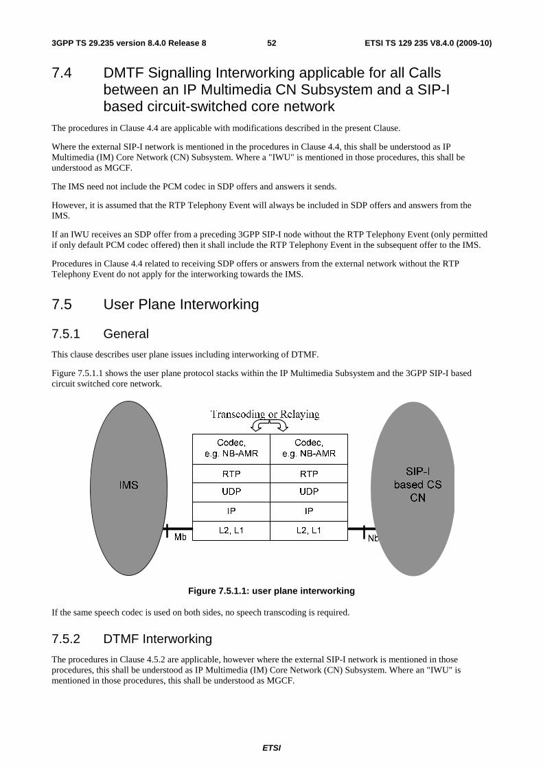
ETSI
ETSI TS 129 235 V8.4.0 (2009-10)523GPP TS 29.235 version 8.4.0 Release 8
7.4 DMTF Signalling Interworking applicable for all Calls between an IP Multimedia CN Subsystem and a SIP-I based circuit-switched core network
The procedures in Clause 4.4 are applicable with modifications described in the present Clause.
Where the external SIP-I network is mentioned in the procedures in Clause 4.4, this shall be understood as IP Multimedia (IM) Core Network (CN) Subsystem. Where a "IWU" is mentioned in those procedures, this shall be understood as MGCF.
The IMS need not include the PCM codec in SDP offers and answers it sends.
However, it is assumed that the RTP Telephony Event will always be included in SDP offers and answers from the IMS.
If an IWU receives an SDP offer from a preceding 3GPP SIP-I node without the RTP Telephony Event (only permitted if only default PCM codec offered) then it shall include the RTP Telephony Event in the subsequent offer to the IMS.
Procedures in Clause 4.4 related to receiving SDP offers or answers from the external network without the RTP Telephony Event do not apply for the interworking towards the IMS.
7.5 User Plane Interworking
7.5.1 General
This clause describes user plane issues including interworking of DTMF.
Figure 7.5.1.1 shows the user plane protocol stacks within the IP Multimedia Subsystem and the 3GPP SIP-I based circuit switched core network.
Figure 7.5.1.1: user plane interworking
If the same speech codec is used on both sides, no speech transcoding is required.
7.5.2 DTMF Interworking
The procedures in Clause 4.5.2 are applicable, however where the external SIP-I network is mentioned in those procedures, this shall be understood as IP Multimedia (IM) Core Network (CN) Subsystem. Where an "IWU" is mentioned in those procedures, this shall be understood as MGCF.
ETSI
ETSI TS 129 235 V8.4.0 (2009-10)533GPP TS 29.235 version 8.4.0 Release 8
7.6 Example Call flows
7.6.1 General
In this Sub-clause call flows are shown as examples to demonstrate the signalling interworking of the MGCF. Within the message sequence charts some contents of the messages are shown in order to visualise some of the important interworking aspects, which were described in previous clauses of this document. It is to be noted that the intention is neither to show the complete content of the SIP messages nor to use the exact syntax of SIP and SDP messages as it is defined in the respective RFCs. It is also not the intention to show all alternative options that are possible for a certain call flow.
7.6.2 Incoming Call flows
The first call flow shows the signalling for a successful basic call establishment and the later call release. The second call flow visualises a failed call setup.
7.6.2.1 Successful Call Establishment and Call Release
Figure 7.6.2.1.1 shows the first part of the incoming call signalling until the called party is alerted and the MGCF is waiting for an answer message.
Before the received SIP INVITE request is forwarded to SIP-I based circuit switched core network the MGCF removes the PSTN XML body (after content mapped into SIP-I message), replaces the received codec list by a 3GPP structured codec list, and encapsulates the ISUP IAM message, which the MGCF mapped from the received SIP INVITE request.
The incoming side RTP bearer termination is not yet successfully reserved and configured and therefore local preconditions are not met. Thus the MGCF initiates precondition signalling when sending the INVITE request to the succeeding SIP-I based circuit-switched network.
The MGCF and the succeeding node perform codec negotiation according to 3GPP rules as specified in 3GPP TS 23.153 [5]. The MGCF answers to the preceding IMS node with a single selected codec. If possible, the selected codec is the same as received from the 3GPP node to avoid transcoding at the network border.
With the 183 Progress the MGCF authorizes the preceding node to use early media. Therefore, it is not necessary to include the P-Early-Media header in the 180 Ringing response.
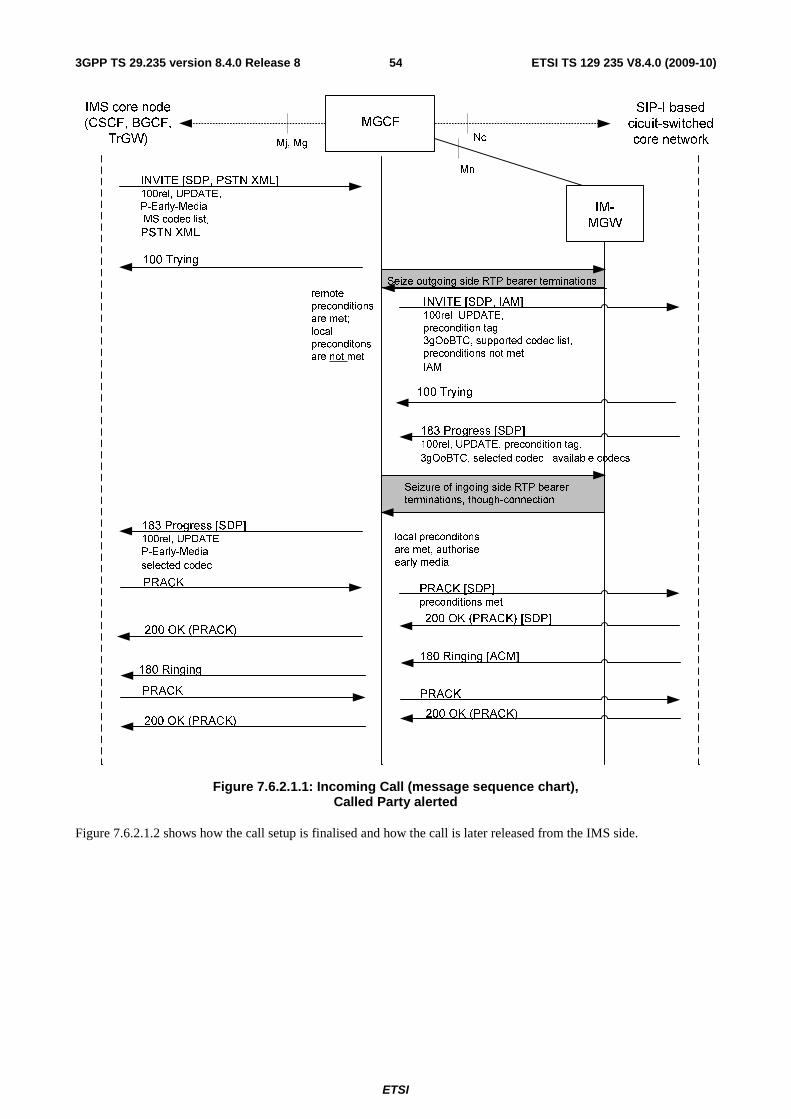
ETSI
ETSI TS 129 235 V8.4.0 (2009-10)543GPP TS 29.235 version 8.4.0 Release 8
Mj, MgNc
Mn
SIP-I based
cicuit-switched
core network
IM-
MGW
INVITE [SDP, PSTN XML]100rel, UPDATE,
P-Early-Media
IMS codec list,
PSTN XML
100 Trying
INVITE [SDP, IAM]100rel, UPDATE,
precondition tag
3gOoBTC, supported codec list,
preconditions not met
IAM
183 Progress [SDP]100rel, UPDATE, precondition tag,
3gOoBTC, selected codec, available codecs
remote
preconditions
are met;
local
preconditons
are not met
PRACK [SDP]preconditions met
200 OK (PRACK) [SDP]
Seizure of ingoing side RTP bearer
terminations, though-connection
183 Progress [SDP]100rel, UPDATE
P-Early-Media
selected codec
PRACK
200 OK (PRACK)
180 Ringing [ACM] 180 Ringing
IMS core node
(CSCF, BGCF,
TrGW)
PRACK
200 OK (PRACK)
PRACK
200 OK (PRACK)
Seize outgoing side RTP bearer terminations
local preconditons
are met, authorise
early media
MGCF
100 Trying
Figure 7.6.2.1.1: Incoming Call (message sequence chart), Called Party alerted
Figure 7.6.2.1.2 shows how the call setup is finalised and how the call is later released from the IMS side.
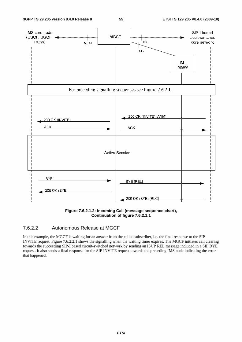
ETSI
ETSI TS 129 235 V8.4.0 (2009-10)553GPP TS 29.235 version 8.4.0 Release 8
Mj, MgNc
Mn
SIP-I based
cicuit-switched
core network
200 OK (INVITE) [ANM]200 OK (INVITE)
ACK
IMS core node
(CSCF, BGCF,
TrGW)
ACK
MGCF
BYEBYE [REL]
200 OK (BYE) [RLC]
200 OK (BYE)
Active Session
For preceding signalling sequences see Figure 7.6.2.1.1
IM-
MGW
Figure 7.6.2.1.2: Incoming Call (message sequence chart), Continuation of figure 7.6.2.1.1
7.6.2.2 Autonomous Release at MGCF
In this example, the MGCF is waiting for an answer from the called subscriber, i.e. the final response to the SIP INVITE request. Figure 7.6.2.2.1 shows the signalling when the waiting timer expires. The MGCF initiates call clearing towards the succeeding SIP-I based circuit-switched network by sending an ISUP REL message included in a SIP BYE request. It also sends a final response for the SIP INVITE request towards the preceding IMS node indicating the error that happened.
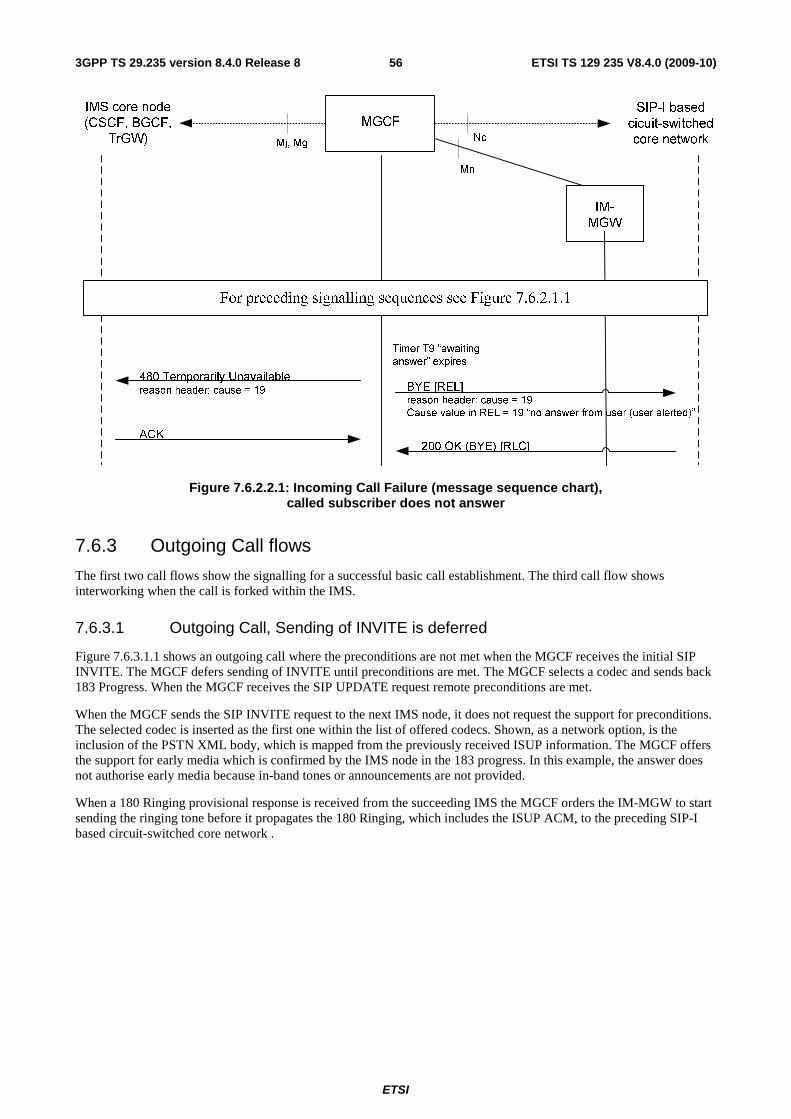
ETSI
ETSI TS 129 235 V8.4.0 (2009-10)563GPP TS 29.235 version 8.4.0 Release 8
Mj, MgNc
Mn
SIP-I based
cicuit-switched
core network
IM-
MGW
IMS core node
(CSCF, BGCF,
TrGW)
MGCF
Timer T9 “awaiting
answer” expires
480 Temporarily Unavailablereason header: cause = 19 BYE [REL]
reason header: cause = 19
Cause value in REL = 19 “no answer from user (user alerted)”
200 OK (BYE) [RLC]
For preceding signalling sequences see Figure 7.6.2.1.1
ACK
Figure 7.6.2.2.1: Incoming Call Failure (message sequence chart), called subscriber does not answer
7.6.3 Outgoing Call flows
The first two call flows show the signalling for a successful basic call establishment. The third call flow shows interworking when the call is forked within the IMS.
7.6.3.1 Outgoing Call, Sending of INVITE is deferred
Figure 7.6.3.1.1 shows an outgoing call where the preconditions are not met when the MGCF receives the initial SIP INVITE. The MGCF defers sending of INVITE until preconditions are met. The MGCF selects a codec and sends back 183 Progress. When the MGCF receives the SIP UPDATE request remote preconditions are met.
When the MGCF sends the SIP INVITE request to the next IMS node, it does not request the support for preconditions. The selected codec is inserted as the first one within the list of offered codecs. Shown, as a network option, is the inclusion of the PSTN XML body, which is mapped from the previously received ISUP information. The MGCF offers the support for early media which is confirmed by the IMS node in the 183 progress. In this example, the answer does not authorise early media because in-band tones or announcements are not provided.
When a 180 Ringing provisional response is received from the succeeding IMS the MGCF orders the IM-MGW to start sending the ringing tone before it propagates the 180 Ringing, which includes the ISUP ACM, to the preceding SIP-I based circuit-switched core network .
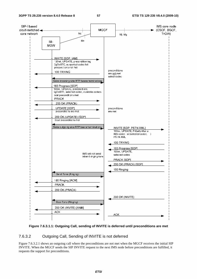
ETSI
ETSI TS 129 235 V8.4.0 (2009-10)573GPP TS 29.235 version 8.4.0 Release 8
Mj, MgNc
Mn
MGCF
SIP-I based
cicuit-switched
core network
IMS core node
(CSCF, BGCF,
TrGW)
IM-
MGW
INVITE [SDP, IAM]100rel, UPDATE, precondition tag
3gOoBTC, supported codec list
preconditions not met
100 TRYING
INVITE [SDP, PSTN XML]100rel, UPDATE, P-Early-Media
IMS codec list (selected codec, …)
PSTN XML
183 Progress [SDP]100rel, UPDATE,
selected codec
200 OK (PRACK) [SDP]
183 Progress [SDP]100rel, UPDATE, preconditions
3gOoBTC, selected codec, available codecs
local preconditions met
PRACK
200 OK (PRACK)
180 Ringing
preconditions
are not met,
select codec
PRACK [SDP]
180 Ringing [ACM]
200 OK (INVITE)
200 OK (INVITE) [ANM]
ACKACK
PRACK
200 OK (PRACK)
preconditions
are met
Seize incoming side RTP bearer terminations
Seize outgoing side RTP bearer terminations
UPDATE [SDP]preconditions are met
200 OK (UPDATE) [SDP]local preconditions met
100 TRYING
IMS will not send
inband ringing tone
Stop Tone (Ringing)
Send Tone (Ringing)
Figure 7.6.3.1.1: Outgoing Call, sending of INVITE is deferred until preconditions are met
7.6.3.2 Outgoing Call, Sending of INVITE is not deferred
Figure 7.6.3.2.1 shows an outgoing call where the preconditions are not met when the MGCF receives the initial SIP INVITE. When the MGCF sends the SIP INVITE request to the next IMS node before preconditions are fulfilled, it requests the support for preconditions.

ETSI
ETSI TS 129 235 V8.4.0 (2009-10)583GPP TS 29.235 version 8.4.0 Release 8
Support for preconditions is confirmed from the IMS node. The MGCF receives more than one codec in the 183 Progress from the external node. Therefore the MGCF selects one of the received codecs and makes a second SDP offer to the external node in the SIP PRACK request in order to lock the codec.
When the MGCF receives from the incoming side an UPDATE message indicating that preconditions are fulfilled, it propagates the UPDATE message towards the IMS.
When a 180 Ringing provisional response is received from the succeeding IMS the MGCF orders the IM-MGW to start sending the ringing tone before it propagates the 180 Ringing, which includes the ISUP ACM, to the preceding SIP-I based circuit-switched core network .
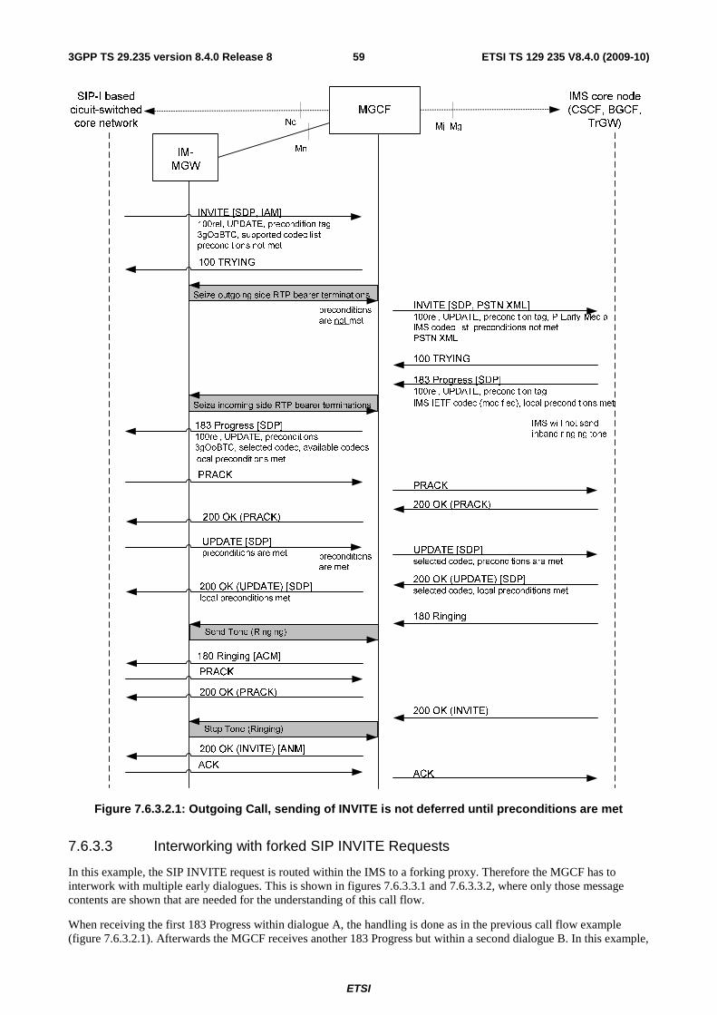
ETSI
ETSI TS 129 235 V8.4.0 (2009-10)593GPP TS 29.235 version 8.4.0 Release 8
Mj, MgNc
Mn
MGCF
SIP-I based
cicuit-switched
core network
IMS core node
(CSCF, BGCF,
TrGW)
IM-
MGW
INVITE [SDP, IAM]100rel, UPDATE, precondition tag
3gOoBTC, supported codec list
preconditions not met
100 TRYING
INVITE [SDP, PSTN XML]100rel, UPDATE, precondition tag, P-Early-Media
IMS codec list, preconditions not met
PSTN XML
183 Progress [SDP]100rel, UPDATE, precondition tag
IMS IETF codec (modified), local preconditions met
200 OK (PRACK)
183 Progress [SDP]100rel, UPDATE, preconditions
3gOoBTC, selected codec, available codecs
local preconditions met
PRACK
200 OK (PRACK)
180 Ringing
preconditions
are not met
PRACK
180 Ringing [ACM]
200 OK (INVITE)
200 OK (INVITE) [ANM]
ACKACK
PRACK
200 OK (PRACK)
200 OK (UPDATE) [SDP]selected codec, local preconditions met
preconditions
are met
Seize outgoing side RTP bearer terminations
Seize incoming side RTP bearer terminations
UPDATE [SDP]selected codec, preconditions are met
UPDATE [SDP]preconditions are met
200 OK (UPDATE) [SDP]local preconditions met
100 TRYING
IMS will not send
inband ringing tone
Stop Tone (Ringing)
Send Tone (Ringing)
Figure 7.6.3.2.1: Outgoing Call, sending of INVITE is not deferred until preconditions are met
7.6.3.3 Interworking with forked SIP INVITE Requests
In this example, the SIP INVITE request is routed within the IMS to a forking proxy. Therefore the MGCF has to interwork with multiple early dialogues. This is shown in figures 7.6.3.3.1 and 7.6.3.3.2, where only those message contents are shown that are needed for the understanding of this call flow.
When receiving the first 183 Progress within dialogue A, the handling is done as in the previous call flow example (figure 7.6.3.2.1). Afterwards the MGCF receives another 183 Progress but within a second dialogue B. In this example,
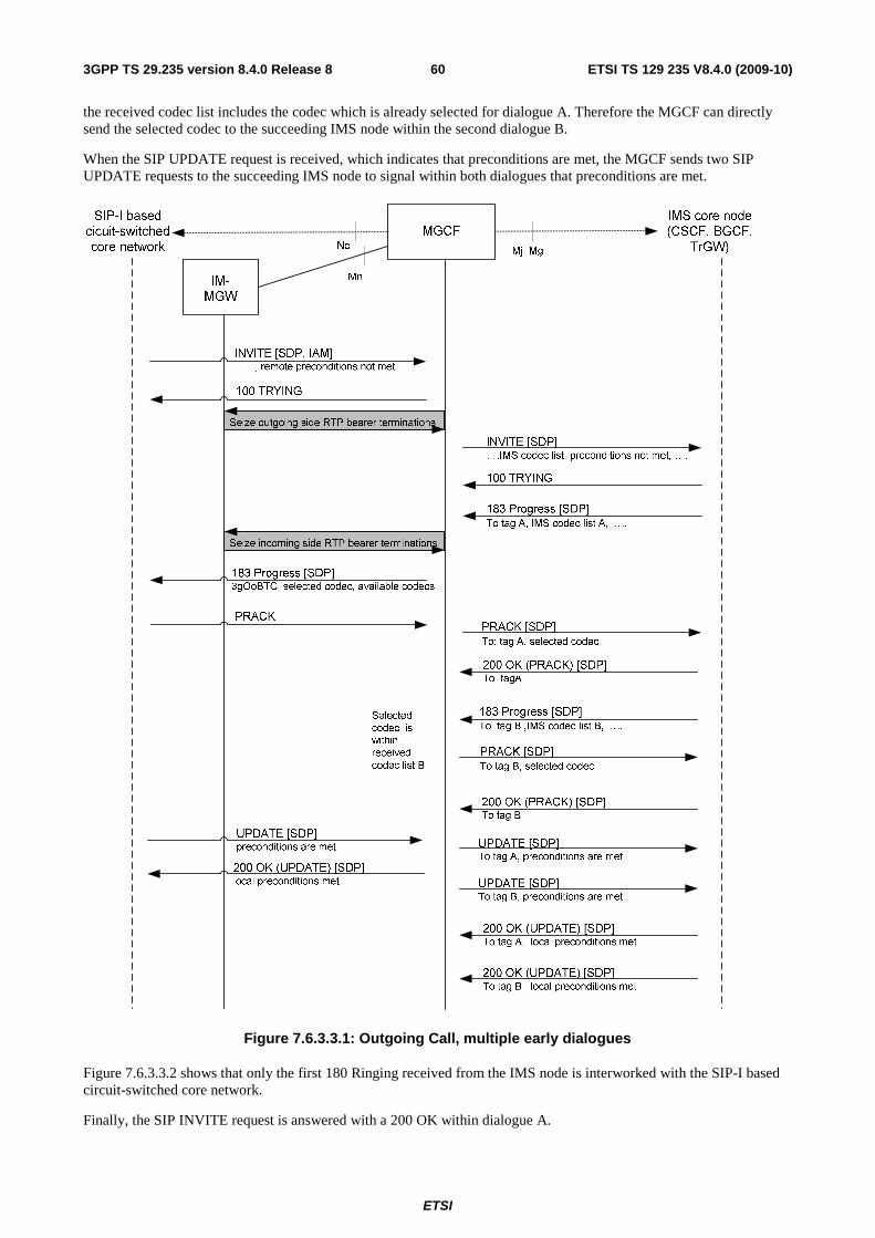
ETSI
ETSI TS 129 235 V8.4.0 (2009-10)603GPP TS 29.235 version 8.4.0 Release 8
the received codec list includes the codec which is already selected for dialogue A. Therefore the MGCF can directly send the selected codec to the succeeding IMS node within the second dialogue B.
When the SIP UPDATE request is received, which indicates that preconditions are met, the MGCF sends two SIP UPDATE requests to the succeeding IMS node to signal within both dialogues that preconditions are met.
Figure 7.6.3.3.1: Outgoing Call, multiple early dialogues
Figure 7.6.3.3.2 shows that only the first 180 Ringing received from the IMS node is interworked with the SIP-I based circuit-switched core network.
Finally, the SIP INVITE request is answered with a 200 OK within dialogue A.
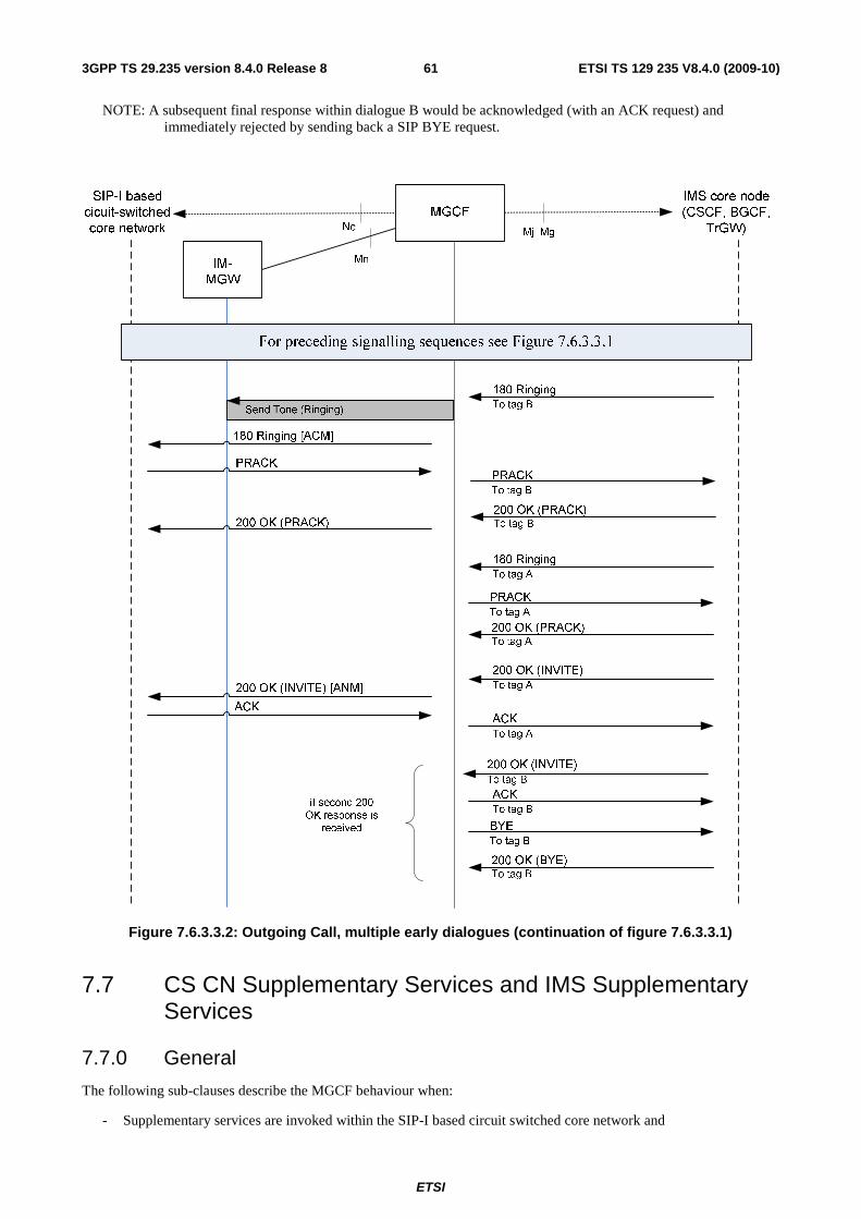
ETSI
ETSI TS 129 235 V8.4.0 (2009-10)613GPP TS 29.235 version 8.4.0 Release 8
NOTE: A subsequent final response within dialogue B would be acknowledged (with an ACK request) and immediately rejected by sending back a SIP BYE request.
Mj, MgNc
Mn
MGCF
SIP-I based
cicuit-switched
core network
IMS core node
(CSCF, BGCF,
TrGW)
IM-
MGW
For preceding signalling sequences see Figure 7.6.3.3.1
180 RingingTo tag B
180 Ringing [ACM]
200 OK (INVITE)
To tag A200 OK (INVITE) [ANM]
ACK
To tag A
ACK
PRACK
200 OK (PRACK)
PRACK
To tag B
200 OK (PRACK)To tag B
Send Tone (Ringing)
180 Ringing
To tag A
PRACK
To tag A
200 OK (PRACK)To tag A
200 OK (INVITE)
To tag B
ACKTo tag B
BYETo tag B
200 OK (BYE)To tag B
if second 200
OK response is
received
Figure 7.6.3.3.2: Outgoing Call, multiple early dialogues (continuation of figure 7.6.3.3.1)
7.7 CS CN Supplementary Services and IMS Supplementary Services
7.7.0 General
The following sub-clauses describe the MGCF behaviour when:
- Supplementary services are invoked within the SIP-I based circuit switched core network and
ETSI
ETSI TS 129 235 V8.4.0 (2009-10)623GPP TS 29.235 version 8.4.0 Release 8
- Supplementary services are invoked within the IMS.
The support of these supplementary services is optional. If the supplementary services are supported, the procedures described within this clause shall be applied.
Within the SIP-I based circuit switched core network:
- Service information is carried within encapsulated ISUP messages.
- The procedures specified for the ISUP side in 3GPP TS 29.163 [13] clauses 7.4 and 7.5 shall be applied to the encapsulated ISUP.
7.7.1 Number Identification Services
7.7.1.1 CS CN Supplementary Service - Calling Line Identification Presentation/Restriction (CLIP/CLIR)
There is no additional interworking beyond clauses 7.2 and 7.3 when the Calling Line Identification Presentation or a Calling Line Identification Restriction supplementary service is invoked within the SIP-I based circuit switched core network.
7.7.1.2 CS CN Supplementary Service - Connected Line Identification Presentation /Restriction (COLP/COLR)
When the Connected Line Identification Presentation or Connected Line Identification Restriction supplementary service is invoked within the SIP-I based circuit switched core network, the MGCF shall perform the mapping to the Terminating Identification Presentation / Restriction service as specified in 3GPP TS 29.163 [13] clause 7.5.2.
7.7.1.3 IMS Supplementary Service - Originating Identification Presentation (OIP) and Originating Identification Restriction (OIR)
There is no additional interworking beyond clauses 7.2 and 7.3, when the Originating Identification Presentation or Originating Identification Restriction supplementary service is invoked within the IMS network.
7.7.1.4 IMS Supplementary Service - Terminating Identification Presentation (TIP) and Terminating Identification Restriction (TIR)
When the Terminating Identification Presentation or Terminating Identification Restriction supplementary service is invoked within the IMS network, the MGCF shall perform the mapping to the Connected Line Identification Presentation / Restriction supplementary service as specified in 3GPP TS 29.163 [13] clause 7.5.2.
7.7.1.5 CS CN Supplementary Service – Direct Dialling In
There is no additional interworking beyond subclauses 7.2 and 7.3, when the Direct Dialling In supplementary service is invoked within the SIP-I based circuit switched core network.
7.7.1.6 CS CN Supplementary Service – Malicious Call Identification
When the Malicious Call Identification supplementary service is invoked within the SIP-I based circuit switched core network the MGCF shall perform the mapping as specified in 3GPP TS 29.163 [13] subclause 7.5.9.
7.7.1.7 IMS Supplementary Service – Malicious Communication Identification (MCID)
When Malicious Communication Identification service is invoked within the IMS network, then as specified in 3GPP TS 29.163 [13] subclause 7.5.9.2, the interworking to the Malicious Call Identification supplementary service shall not be applied.
ETSI
ETSI TS 129 235 V8.4.0 (2009-10)633GPP TS 29.235 version 8.4.0 Release 8
7.7.1.8 CS CN Supplementary Service – Subaddressing
When the Subaddressing supplementary service is invoked within the SIP-I based circuit switched core network, the procedures specified in 3GPP TS 29.163 [13] subclause 7.4.5 shall be applied.
7.7.2 Diversion Services
7.7.2.1 CS CN Supplementary Service - Call Forwarding Services (CFU, CFB, CFNRy, CFNRc)
When any of the call forwarding supplementary services (CFU, CFB, CFNRy, and CFNRc) is invoked within the SIP-I based circuit switched core network, the MGCF shall perform the mapping to the Communication Diversion service as specified in 3GPP TS 29.163 [13] clauses 7.5.4.2.2 and 7.5.4.3.
7.7.2.2 CS CN Supplementary Service – Call Deflection (CD)
When the Call Deflection supplementary service is invoked within the SIP-I based circuit switched core network the MGCF shall perform the mapping to the Communication Diversion service as specified in 3GPP TS 29.163 [13] clauses 7.5.4.2.2 and 7.5.4.3.
7.7.2.3 IMS Supplementary Service – Communication Diversion (CDIV)
When a Communication Diversion supplementary service is invoked within the IMS network, the MGCF shall perform the mapping to a Call Diversion supplementary service as specified in 3GPP TS 29.163 [13] clauses 7.5.4.2.1 and 7.5.4.3.
7.7.3 Waiting Services
7.7.3.1 CS CN Supplementary Service – Call Waiting
When the Call Waiting supplementary service is invoked within the SIP-I based circuit switched core network, the MGCF shall perform the mapping to the Communication Waiting service as specified in 3GPP TS 29.163 [13] clause 7.5.12.1.
7.7.3.2 IMS Supplementary Service – Communication Waiting (CW)
When the Communication Waiting supplementary service is invoked within the IMS network, the MGCF shall perform the mapping to the Call Waiting supplementary service as specified in 3GPP TS 29.163 [13] clause 7.5.12.2.
7.7.4 Hold Services
7.7.4.1 CS CN Supplementary Service – Call Hold
There is no additional interworking beyond Clauses 7.2 and 7.3, when the Call Hold supplementary service is invoked within the SIP-I based circuit switched core network.
7.7.4.2 IMS Supplementary Service – Communication Hold (HOLD)
There is no additional interworking beyond Clauses 7.2 and 7.3, when the Communication Hold supplementary service is invoked within the IMS network.
NOTE: Call hold for IMS is specified in 3GPP TS 24.610 [26].
ETSI
ETSI TS 129 235 V8.4.0 (2009-10)643GPP TS 29.235 version 8.4.0 Release 8
7.7.5 Multiparty Services
7.7.5.1 CS CN Supplementary Services – Conference Calling (CONF) and Three-Party (3PTY)
When the Conference Calling and Three-Party supplementary services are invoked within the SIP-I based circuit switched core network, the procedures specified in 3GPP TS 29.163 [13] clause 7.4.14 shall be applied.
7.7.5.2 IMS Supplementary Service – Conference (CONF)
When the Conference supplementary service is invoked within the IMS network, the procedures specified in 3GPP TS 29.163 [13] clause 7.5.6 shall be applied.
7.7.6 Closed User Group Service
7.7.6.1 CS CN Supplementary Service – Closed User Group (CUG)
When the Closed User Group supplementary service is invoked within the SIP-I based circuit switched core network, the procedures specified in 3GPP TS 29.163 [13] clause 7.5.10.2 shall be applied.
7.7.6.2 IMS Supplementary Service - Closed User Group (CUG)
When the Closed User Group supplementary service is invoked within the IMS network, the procedures specified in 3GPP TS 29.163 [13] clause 7.5.10.1 shall be applied.
7.7.7 Charging Services
7.7.7.1 CS CN Supplementary Service – Advice of Charge (AoC)
Editor's note: interworking for AoC is FFS.
7.7.7.2 IMS Supplementary Service – Advice of Charge (AOC)
Editor's note: interworking for AOC is FFS.
7.7.7.3 CS CN Supplementary Service – International Telecommunication Charge Card (ITCC)
When the International Telecommunication Charge Card supplementary service is invoked within the SIP-I based circuit switched core network no additional treatment is required by the MGCF.
7.7.7.4 CS CN Supplementary Service – Reverse Charging (REV)
When the Reverse Charging supplementary service is invoked within the SIP-I based circuit switched core network, the procedures specified in 3GPP TS 29.163 [13] subclause 7.4.17 shall be applied.
7.7.8 Barring Services
7.7.8.1 CS CN Supplementary Service - Barring of Outgoing Calls
There is no additional interworking beyond Clauses 7.2 and 7.3, when the Barring of Outgoing Call supplementary service is invoked within the SIP-I based circuit switched core network.
ETSI
ETSI TS 129 235 V8.4.0 (2009-10)653GPP TS 29.235 version 8.4.0 Release 8
7.7.8.2 CS CN Supplementary Service - Barring of Incoming Calls
There is no additional interworking beyond Clauses 7.2 and 7.3, when the Barring of Incoming Calls supplementary service is invoked within the SIP-I based circuit switched core network.
7.7.8.3 CS CN Supplementary Service - Anonymous Call Rejection (ACR)
When the Anonymous Call Rejection supplementary service is invoked within the SIP-I based circuit switched core network, the procedures specified in 3GPP TS 29.163 [13] clause 7.4.23.1 shall be applied.
7.7.8.4 IMS Supplementary Service – Communication Barring (CB)
Editor's note: interworking of Communication Barring is FFS.
7.7.8.5 IMS Supplementary Service – Anonymous Communication Rejection (ACR)
When the Anonymous Communication Rejection supplementary service is invoked within the IMS network, the procedures specified in 3GPP TS 29.163 [13] clause 7.4.23.2 shall be followed with the following modifications at the SIP-I on Nc side:
- The response code 433 (Anonymity Disallowed) defined by IETF RFC 5079 [36] is supported on SIP-I on Nc.
7.7.9 Transfer Services
7.7.9.1 CS CN Supplementary Service – Explicit Call Transfer (ECT)
When the Explicit Call Transfer supplementary service is invoked within the SIP-I based circuit switched core network and the MGCF receives from the SIP-I based circuit-switched core network an INFO message with encapsulated ISUP FAC for the notification of ECT invocation, then the MGCF shall:
- map the FAC into a SIP re-INVITE request or SIP UPDATE request according to 3GPP TS 29.163 [13] if the call is in active state (after answer).
- map the FAC into a SIP UPDATE request according to 3GPP TS 29.163 [13] if the call is in active state (before answer).
7.7.9.2 IMS Supplementary Service – Explicit CommunicationTransfer (ECT)
When the Explicit CommunicationTransfer supplementary service is invoked within the IMS network and if the transferee is another IMS terminal and the transfer target is a CS terminal, then the MGCF will receive a SIP INVITE request. No special interworking is required at the MGCF.
NOTE: The protocol for ECT within IMS is specified in 3GPP TS 24.629 [25]. The IMS terminal, which invokes the ECT service, sends a SIP REFER request to the transferee. The transferee sends a SIP INVITE request to the transfer target.
7.7.10 Call Completion Services
7.7.10.1 CS CN Supplementary Service – Completion of Calls to Busy Subscriber (CCBS)
When the Completion of Calls to Busy Subscriber supplementary service is invoked within the SIP-I based circuit switched core network, the procedures specified in 3GPP TS 29.163 [13] clause 7.4.11 shall be applied.
7.7.10.2 CS CN Supplementary Service – Completion of Calls on No Reply (CCNR)
When the Completion of Calls on No Reply supplementary service is invoked within the SIP-I based circuit switched core network, the procedures specified in 3GPP TS 29.163 [13] clause 7.4.12 shall be applied.
ETSI
ETSI TS 129 235 V8.4.0 (2009-10)663GPP TS 29.235 version 8.4.0 Release 8
7.7.10.3 IMS Supplementary Service – Completion of Communications to Busy Subscriber (CCBS) and Completion of Communication on No Reply (CCNR)
When the Completion of Communications to Busy Subscriber or Completion of Communication on No Reply supplementary service is invoked within the IMS network, the procedures specified in 3GPP TS 29.163 [13] clause 7.5.11.1 shall be applied.
7.7.11 Miscellaneous Services
7.7.11.1 CS CN Supplementary Service - Multi-Level Precedence and Pre-emption (MLPP)
When the Multi-Level Precedence and Pre-emption (MLPP) supplementary service is invoked within the SIP-I based circuit switched core network the procedures specified in 3GPP TS 29.163 [13] clause 7.4.17 shall be applied.
7.7.11.2 CS CN Supplementary Service - Multiple Subscriber Profile (MSP)
There is no additional interworking beyond clauses 7.2 and 7.3 when a Multiple Subscriber Profile supplementary service is invoked within the SIP-I based circuit switched core network.
7.7.11.3 CS CN Supplementary Service - Multicall
There is no additional interworking beyond clauses 7.2 and 7.3 when the Multicall supplementary service is invoked within the SIP-I based circuit switched core network.
7.7.11.4 CS CN Supplementary Service - Calling Name Presentation
There is no additional interworking beyond clauses 7.2 and 7.3, when the Calling Name Presentation supplementary service is invoked within the SIP-I based circuit switched core network.
7.7.11.5 CS CN Supplementary Service – User-to-User Signalling (UUS)
Editor's note: interworking for User-to-User Signalling is FFS.
7.7.11.6 IMS Supplementary Service – Message Waiting Indication (MWI)
Editor's note: interworking for Message Waiting Indication is FFS.
7.7.11.7 CS CN Supplementary Service - Global Virtual Network Service (GVNS)
When the Global Virtual Network Service supplementary service is invoked within the SIP-I based circuit switched core network the procedures specified in 3GPP TS 29.163 [13] subclause 7.4.18 shall be applied.
7.7.11.8 CS CN Supplementary Service - Terminal Portability (TP)
When the Terminal Portability supplementary service is invoked within the SIP-I based circuit switched core network, the procedures specified in 3GPP TS 29.163 [13] subclause 7.4.13 shall be applied.
ETSI
ETSI TS 129 235 V8.4.0 (2009-10)673GPP TS 29.235 version 8.4.0 Release 8
Annex A (normative): Interconnecting functionalities in SIP-I based CS domain
A.1 General This annex describes a collection of functions that can be performed on interconnection boundaries between two SIP-I based 3GPP CS networks or between a SIP-I based CS network and other SIP-I based external network, based on operator configuration.
In Clauses A.2 and A.3 Stage 2 requirements and border control architecture are described.
A.2 Stage 2 Requirements Based on operator preference, border control functions may be applied between two SIP-I based 3GPP CS domains or between a SIP-I based 3GPP CS domain and other SIP-I based external network. These functions, provided by the CS-IBCF, are:
- Controlling transport plane functions;
- Supporting functions to allow establishing communication between disparate address realms' SIP-I applications;
- Providing network configuration hiding to restrict the following information from being passed outside of an operator's network: exact number of MSC servers, capacity and topology of the network, naming and addressing of the network nodes;
- Screening SIP signalling information based on source/destination and operator policy (e.g. remove information that is of local significance to an operator);
- Generation of CDRs;
Editor's Note: Need of generating CDRs to CS-IBCF may require further evaluation.
- Selecting the appropriate signalling interconnections (e.g. domain based routing). The IP interconnection between core networks may be supported either by direct connection or by using an intermediate carrier;
- Supporting network resources allocation taking into consideration the codec negotiation performed by (G)MSCs across one or multiple interconnects, remaining transparent to the SDP negotiation.
In case border control concepts are to be applied in a SIP-I based CS network, the CS-IBCF acts as an entry point for this network, and also acts as an exit point for this network.
On the media plane the CS-TrGW is controlled by the CS-IBCF and provides the following functions for the NNI:
- Opening/closing of gates;
- QoS packet marking;
- Resource allocation per flow;
- NA(P)T;
- Media policing;
A.3 Border Control architecture Figure A.3.1 presents a high-level architecture diagram showing how CS-IBCF and CS-TrGW logical functions fit into the SIP-I based CS domain.
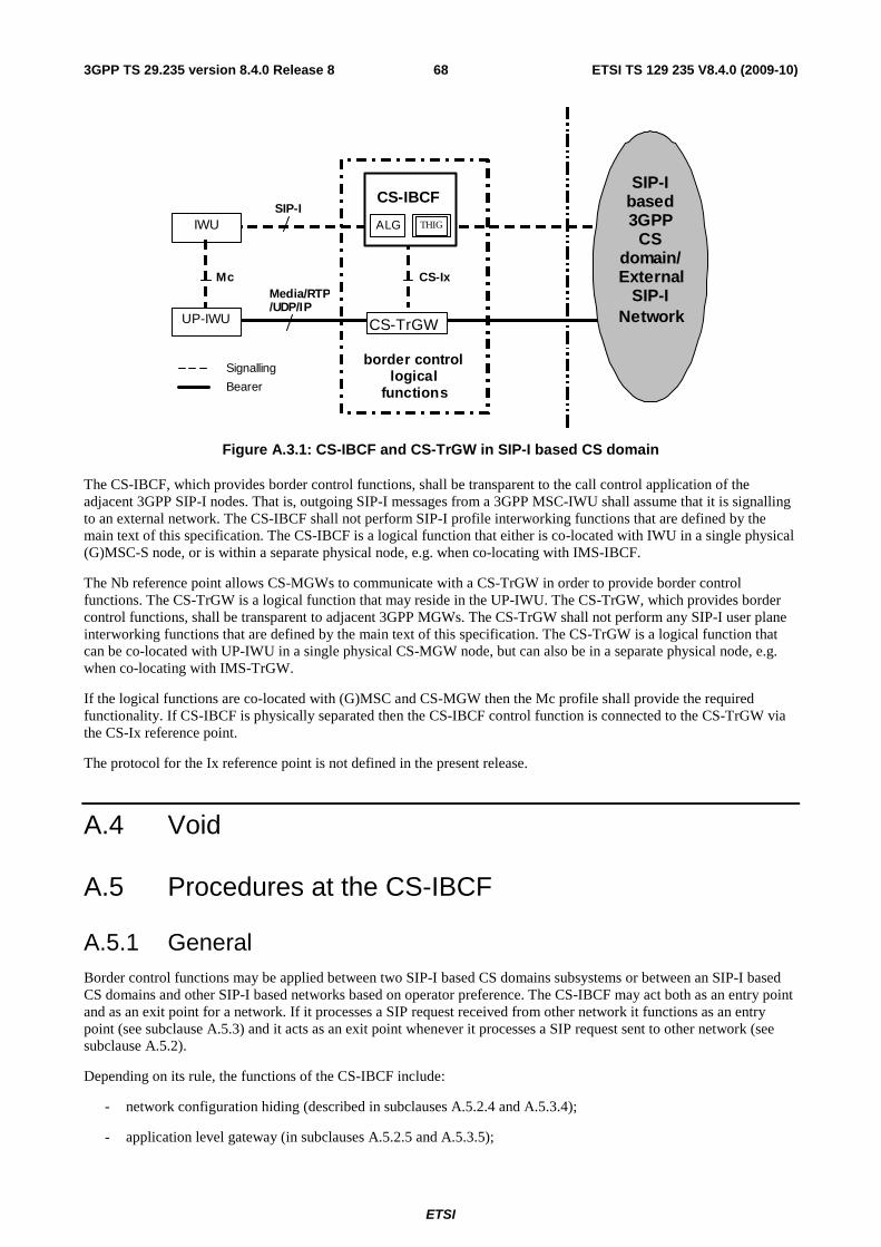
ETSI
ETSI TS 129 235 V8.4.0 (2009-10)683GPP TS 29.235 version 8.4.0 Release 8
Signalling Bearer
CS-Ix
CS-TrGW
CS-IBCF THIG
ALG
SIP-I based 3GPP
CS domain/External
SIP-I Network
IWU
UP-IWU
SIP-I
Media/RTP /UDP/IP
Mc
border control logical
functions
Figure A.3.1: CS-IBCF and CS-TrGW in SIP-I based CS domain
The CS-IBCF, which provides border control functions, shall be transparent to the call control application of the adjacent 3GPP SIP-I nodes. That is, outgoing SIP-I messages from a 3GPP MSC-IWU shall assume that it is signalling to an external network. The CS-IBCF shall not perform SIP-I profile interworking functions that are defined by the main text of this specification. The CS-IBCF is a logical function that either is co-located with IWU in a single physical (G)MSC-S node, or is within a separate physical node, e.g. when co-locating with IMS-IBCF.
The Nb reference point allows CS-MGWs to communicate with a CS-TrGW in order to provide border control functions. The CS-TrGW is a logical function that may reside in the UP-IWU. The CS-TrGW, which provides border control functions, shall be transparent to adjacent 3GPP MGWs. The CS-TrGW shall not perform any SIP-I user plane interworking functions that are defined by the main text of this specification. The CS-TrGW is a logical function that can be co-located with UP-IWU in a single physical CS-MGW node, but can also be in a separate physical node, e.g. when co-locating with IMS-TrGW.
If the logical functions are co-located with (G)MSC and CS-MGW then the Mc profile shall provide the required functionality. If CS-IBCF is physically separated then the CS-IBCF control function is connected to the CS-TrGW via the CS-Ix reference point.
The protocol for the Ix reference point is not defined in the present release.
A.4 Void
A.5 Procedures at the CS-IBCF
A.5.1 General Border control functions may be applied between two SIP-I based CS domains subsystems or between an SIP-I based CS domains and other SIP-I based networks based on operator preference. The CS-IBCF may act both as an entry point and as an exit point for a network. If it processes a SIP request received from other network it functions as an entry point (see subclause A.5.3) and it acts as an exit point whenever it processes a SIP request sent to other network (see subclause A.5.2).
Depending on its rule, the functions of the CS-IBCF include:
- network configuration hiding (described in subclauses A.5.2.4 and A.5.3.4);
- application level gateway (in subclauses A.5.2.5 and A.5.3.5);
ETSI
ETSI TS 129 235 V8.4.0 (2009-10)693GPP TS 29.235 version 8.4.0 Release 8
- screening of SIP signalling (in subclauses A.5.2.6 and A.5.3.6);
- charging (in subclauses A.5.2.7 and A.5.3.7).
NOTE: The functions performed by the CS-IBCF are configured by the operator, and they are network specific.
A.5.2 CS-IBCF as an exit point
A.5.2.1 Initial requests
Upon receipt of any request, the CS-IBCF shall:
1) if the request is an INVITE request, respond with a 100 (Trying) provisional response;
2) if the request is an INVITE request and the CS-IBCF is configured to perform application level gateway and/or transport plane control functionalities, save the Contact, CSeq and Record-Route header field values received in the request such that the CS-IBCF is able to release the session if needed;
Editor's Note: It is FFS whether similar procedures apply when a response to an initial INVITE is received.
3) if network topology hiding is required, apply the procedures as described in subclause A.5.2.4;
4) if screening of SIP signalling is required, apply the procedures as described in subclause A.5.2.6;
5) select an entry point of the destination network and forward the request to that entry point;
NOTE : The list of the entry points can be either obtained as specified in RFC 3263 [30] or provisioned in the CS-IBCF. The entry point can be an CS-IBCF or an (G)MSC server.
When the CS-IBCF receives an INVITE request, the CS-IBCF may require the periodic refreshment of the session to avoid hung states in the CS-IBCF. If the CS-IBCF requires the session to be refreshed, the CS-IBCF shall apply the procedures described in RFC 4028 [31] clause 8.
RFC 3325 [32] provides for the existence and trust of an asserted identity within a trust domain. A CS-IBCF at the boundary of the trust domain will need to determine whether to remove the P-Asserted-Identity header according to RFC 3325 [32] when SIP signalling crosses the boundary of the trust domain.
When the CS-IBCF receives a response to the initial request and network topology hiding is required, then the CS-IBCF shall apply the procedures as described in subclause A.5.2.4.
When the CS-IBCF receives a response to the initial request and screening of SIP signalling is applied, then the CS-IBCF shall apply the procedures as described in subclause A.5.2.6.
A.5.2.2 Subsequent requests
Upon receipt of any request, the CS-IBCF shall:
1) if the request is an INVITE request, respond with a 100 (Trying) provisional response;
2) if the request is a target refresh request and the CS-IBCF is configured to perform application level gateway and/or transport plane control functions, save the Contact and CSeq header field values received in the request such that the CS-IBCF is able to release the session if needed;
3) if the subsequent request is other than a target refresh request (including requests relating to an existing dialogue where the method is unknown) and the CS-IBCF is configured to perform application level gateway and/or transport plane control functionalities, save the Contact and CSeq header field values received in the request such that the CS-IBCF is able to release the session if needed;
4) if network topology hiding is required, apply the procedures as described in subclause A.5.2.4;
5) if screening of SIP signalling is required, apply the procedures as described in subclause A.5.2.6;
When the CS-IBCF receives a response to the subsequent request and network topology hiding is required, then the CS-IBCF shall apply the procedures as described in subclause A.5.2.4.
ETSI
ETSI TS 129 235 V8.4.0 (2009-10)703GPP TS 29.235 version 8.4.0 Release 8
When the CS-IBCF receives a response to the subsequent request and screening of SIP signalling is required, then the CS-IBCF shall apply the procedures as described in subclause A.5.2.6.
A.5.2.3 CS-IBCF-initiated call release
If the CS-IBCF provides transport plane control functionality and receives an indication of a transport plane related error the CS-IBCF may:
1) generate a BYE request for the terminating side based on information saved for the related dialogue; and
2) generate a BYE request for the originating side based on the information saved for the related dialogue.
NOTE 1: Transport plane related errors can be indicated from TrGW.
NOTE 2: Since the CS-IBCF does not handle the encapsulated ISUP, the BYE message(s) generated by the CS-IBCF will not contain any encapsulated ISUP REL message.
If the CS-IBCF is able to determine an appropriate Q.850 cause value, then this may be included in a Reason header in the BYE message(s).
Upon receipt of the 2xx responses for both BYE requests, the CS-IBCF shall release all information related to the dialogue and the related session.
Editor's Note: It is FFS if the use of CANCEL must also be included.
Editor's Note: It is FFS if the use of unsuccessful final responses to the initial INVITE must also be included
A.5.2.4 THIG functionality in the CS-IBCF
A.5.2.4.1 General
The following procedures shall only be applied if network topology hiding is required by the network. The network requiring network topology hiding is called the hiding network.
NOTE: Requests and responses are handled independently; therefore, no state information is needed for that purpose within a CS-IBCF.
The CS-IBCF shall apply network topology hiding to all headers which reveal topology information, such as Via, Route, Record-Route, and Path. Therefore, the CS-IBCF shall:
- either act as a B2BUA, i.e. set above headers as defined for a SIP user agent client by IETF RFC 3261 [20],
- or as an option follow the procedures defined in A.5.2.4.2.
The CS-IBCF shall not screen SIP parameters for which there is a related ISUP parameter defined within ITU-T Q.1912.5 [6].
NOTE: SIP-I screening is normally done by the MSC, where the encapsulated ISUP message and the SIP headers are consistently screened.
Upon receiving an incoming initial request for which network topology hiding has to be applied and which includes a Record-Route header, the CS-IBCF shall add its own routeable SIP URI to the top of the Record-Route header.
A.5.2.4.2 Encryption for network topology hiding
Upon receiving a request/response, outgoing from the hiding network the CS-IBCF shall perform the encryption for network topology hiding purposes, i.e. the CS-IBCF shall:
1) use the whole header values which were added by one or more specific entity of the hiding network as input to encryption;
2) not change the order of the headers subject to encryption when performing encryption;
ETSI
ETSI TS 129 235 V8.4.0 (2009-10)713GPP TS 29.235 version 8.4.0 Release 8
3) use for one encrypted string all received consecutive header entries subject to encryption, regardless if they appear in separate consecutive headers or if they are consecutive entries in a comma separated list in one header;
4) construct a hostname that is the encrypted string;
5) append a "tokenized-by" parameter and set it to the value of the encrypting network's name, after the constructed hostname;
6) form one valid entry for the specific header out of the resulting NAI, e.g. prepend "SIP/2.0/UDP" for Via headers or "sip:" for Path, Route and Record-Route headers;
7) if the CS-IBCF encrypted an entry in the Route header, then it also inserts its own URI before the topmost encrypted entry; and
8) if the CS-IBCF encrypted an entry in the Via header, then it also inserts its own URI before the topmost encrypted entry.
NOTE: Even if consecutive entries of the same network in a specific header are encrypted, they will result in only one encrypted header entry. For example:
Via: SIP/2.0/UDP ibcf1.home1.net;lr, SIP/2.0/UDP Token( SIP/2.0/UDP msc2.home1.net;lr, SIP/2.0/UDP msc1.home1.net;lr); tokenized-by=home1.net, SIP/2.0/UDP [5555::aaa:bbb:ccc:ddd]
A.5.2.5 ALG functionality in the CS-IBCF
The CS-IBCF shall only apply the following procedures if application level gateway functionality is required by the network.
The CS-IBCF acts as a B2BUA when it performs ALG functionality. The CS-IBCF, although acting as a UA, does not initiate any registration of its associated addresses. These are assumed to be known by peer-to-peer arrangements within the SIP-I based CS domain.
In case the initial INVITE request is received from own network, i.e. the CS-IBCF acts as an exit point, the CS-IBCF shall generate a new initial INVITE request and forward it to the entry point of the other network.
The internal function of the CS-IBCF as an ALG is equal to that one defined in 3GPP TS 29.162 [37].
Editor"s Note: it is FFS if 3GPP TS 29.162 needs to be updated in order to reuse in CS domain the already specified 'IP Version Interworking at the IMS-ALG/TrGW'.
A.5.2.6 Screening of SIP-I signalling
A.5.2.6.1 General
This section relates to the screening of the SIP headers and SDP of the SIP-I signalling for policing purposes. Inspection of ISUP MIME bodies is out of the scope of this specification.
The CS-IBCF shall act as a B2BUA when it performs screening of SIP signalling functionality. In this case the B2BUA behaviour of the CS-IBCF shall comply with the description given in subclause A.5.2.5 for the ALG functionality.
NOTE: Many headers are intended for end-to-end operation; removal of such headers will impact the intended end-to-end operation between nodes. Additionally security mechanisms covering SIP headers are not precluded; any such removal can prevent validation of all headers covered by the security mechanism.
NOTE: SIP-I screening is normally done by the MSC, where the encapsulated ISUP message and the SIP headers are consistently screened.
A.5.2.6.2 CS-IBCF procedures for SIP headers
If specified by local policy rules, the CS-IBCF may omit or modify any received SIP headers prior to forwarding SIP messages, with some exceptions.
ETSI
ETSI TS 129 235 V8.4.0 (2009-10)723GPP TS 29.235 version 8.4.0 Release 8
NOTE 1: If the CS-IBCF modifies SIP information elements (SIP headers, SIP message bodies) other than as specified by SIP procedures (e.g., IETF RFC 3261 [20]) caution needs to be taken that SIP functionality (e.g., routeing using Route, Record-Route and Via) is not impacted in a way that could create interoperability problems with networks that assume that this information is not modified.
NOTE 2: Where operator requirements can be achieved by configuration hiding, then these procedures can be used in preference to screening.
A.5.2.6.3 CS-IBCF procedures for SIP message bodies
If IP address translation (NA(P)T or IP version interworking) occurs on the user plane, the CS-IBCF shall modify SDP according to 3GPP TS 29.162 [37].
Editor"s Note: it is FFS if 3GPP TS 29.162 [37] needs to be updated in order to reuse in CS domain the already specified 'IP Version Interworking at the IMS-ALG/TrGW'.
A.5.2.7 Charging functionality in the CS-IBCF
Editor"s Note: This section relates to the charging/accounting functionality based on information included in the SIP headers and/or in SDP of the SIP-I signalling.
A.5.3 CS-IBCF as an entry point
A.5.3.1 Initial requests
Upon receipt of any request, the CS-IBCF shall:
1) if the request is an INVITE request, then respond with a 100 (Trying) provisional response;
2) if the request is an INVITE request and the CS-IBCF is configured to perform application level gateway and/or transport plane control functionalities, save the Contact, Cseq and Record-Route header field values received in the request such that the CS-IBCF is able to release the session if needed;
Editor"s Note: It is FFS whether similar procedures apply when a response to an initial INVITE is received.
3) if network topology hiding is required, then apply the procedures as described in subclause A.5.3.4;
4) if screening of SIP signalling is required, apply the procedures as described in subclause A.5.3.6;
5) If CS-IBCF receives an initial request for a dialogue or standalone transaction, that contains a single Route header pointing to itself, and it is co-located with an (G)MSC server, or it has a preconfigured (G)MSC server to be contacted, then forward the request to that (G)MSC server. Otherwise select an (G)MSC server and forward the request to that (G)MSC server.
When the CS-IBCF receives an INVITE request, the CS-IBCF may require the periodic refreshment of the session to avoid hung states in the CS-IBCF. If the CS-IBCF requires the session to be refreshed, the CS-IBCF shall apply the procedures described in RFC 4028 [31] clause 8.
When the CS-IBCF receives a response to an initial request (e.g. 183 or 2xx), the CS-IBCF shall:
1) if network topology hiding is required, apply the procedures as described in subclause A.5.3.4.
2) if screening of SIP signalling is applied, apply the procedures as described in subclause A.5.3.6.
A.5.3.2 Subsequent requests
Upon receipt of any request, the CS-IBCF shall:
1) if the request is an INVITE request, then respond with a 100 (Trying) provisional response;
ETSI
ETSI TS 129 235 V8.4.0 (2009-10)733GPP TS 29.235 version 8.4.0 Release 8
2) if the request is a target refresh request and the CS-IBCF is configured to perform application level gateway and/or transport plane control functions, save the Contact and Cseq header field values received in the request such that the CS-IBCF is able to release the session if needed;
3) if the subsequent request is other than a target refresh request (including requests relating to an existing dialogue where the method is unknown) and the CS-IBCF is configured to perform application level gateway and/or transport plane control functions, save the Contact and Cseq header field values received in the request such that the CS-IBCF is able to release the session if needed;
4) if network topology hiding is required, then apply the procedures as described in subclause A.5.3.4;
5) if screening of SIP signalling is required, apply the procedures as described in subclause A.5.3.6.
When the CS-IBCF receives a response to the subsequent request and network topology hiding is required, then the CS-IBCF shall apply the procedures as described in subclause A.5.3.4.
When the CS-IBCF receives a response to the subsequent request and screening of SIP signalling is required, then the CS-IBCF shall apply the procedures as described in subclause A.5.3.6.
A.5.3.3 CS-IBCF-initiated call release
If the CS-IBCF provides transport plane control functionality and receives an indication of a transport plane related error the CS-IBCF may:
1) generate a BYE request for the terminating side based on information saved for the related dialogue; and
2) generate a BYE request for the originating side based on the information saved for the related dialogue.
NOTE 1: Transport plane related errors can be indicated from e.g. TrGW.
NOTE 2: Since the CS-IBCF does not handle the encapsulated ISUP, the BYE message(s) generated by the CS-IBCF will not contain any encapsulated ISUP REL message.
If the CS-IBCF is able to determine an appropriate Q.850 cause value, then this may be included in a Reason header in the BYE message(s).
Upon receipt of the 2xx responses for both BYE requests, the CS-IBCF shall release all information related to the dialogue and the related session.
Editor"s Note: It is FFS if the use of CANCEL must also be included.
Editor"s Note: It is FFS if the use of unsuccessful final responses to the initial INVITE must also be included
A.5.3.4 THIG functionality in the CS-IBCF
A.5.3.4.1 General
The following procedures shall only be applied if network topology hiding is required by the network. The network requiring network topology hiding is called the hiding network.
NOTE: Requests and responses are handled independently; therefore, no state information is needed for that purpose within a CS-IBCF.
The CS-IBCF shall apply network topology hiding to all headers which reveal topology information, such as Via, Route, Record-Route, and Path. Therefore, the CS-IBCF shall
- either act as a B2BUA, i.e. set above headers as defined for a SIP user agent client by IETF RFC 3261 [20],
- or as an option follow the procedures defined in A.5.3.4.2.
The CS-IBCF shall not screen SIP parameters for which there is a related ISUP parameter defined within ITU-T Q.1912.5 [6].
ETSI
ETSI TS 129 235 V8.4.0 (2009-10)743GPP TS 29.235 version 8.4.0 Release 8
NOTE: SIP-I screening is normally done by the GMSC, where the encapsulated ISUP message and the SIP headers are consistently screened.
Upon receiving an incoming initial request for which network topology hiding has to be applied and which includes a Record-Route header, the CS-IBCF shall add its own routeable SIP URI to the top of the Record-Route header.
A.5.3.4.2 Decryption for network topology hiding
Upon receiving a request/response, incoming to the hiding network, the CS-IBCF shall perform the decryption for network topology hiding purposes, i.e. the CS-IBCF shall:
1) identify hostnames encrypted by the network this CS-IBCF belongs to within all headers of the incoming message;
2) use those hostnames that carry the identification of the hiding network within the value of the 'tokenized-by' parameter as input to decryption;
3) use as encrypted string the hostname which follows the sent-protocol (for Via Headers, e.g. 'SIP/2.0/UDP') or the URI scheme (for Route and Record-Route Headers, e.g. 'sip:');
4) replace all content of the received header which carries encrypted information with the entries resulting from decryption.
EXAMPLE: An encrypted entry to a Via header that looks like:
Via: SIP/2.0/UDP Token(SIP/2.0/UDP msc2.home1.net;lr, SIP/2.0/UDP msc1.home1.net;lr);tokenized-by=home1.net
will be replaced with the following entries:
Via: SIP/2.0/UDP msc2.home1.net;lr, SIP/2.0/UDP msc1.home1.net;lr
NOTE: Motivations for these decryption procedures are e.g. to allow the correct routeing of a response through the hiding network, to enable loop avoidance within the hiding network, or to allow the entities of the hiding network to change their entries within e.g. the Record-Route header.
A.5.3.5 ALG functionality in the CS-IBCF
The CS-IBCF shall only apply the following procedures if application level gateway functionality is required by the network.
The CS-IBCF acts as a B2BUA when it performs ALG functionality. The CS-IBCF, although acting as a UA, does not initiate any registration of its associated addresses. These are assumed to be known by peer-to-peer arrangements within the SIP-I based CS domain.
When the CS-IBCF receives an initial INVITE request from another SIP network,the CS-IBCF shall generate a new initial INVITE request and forward it to the (G)MSC Server.
The internal function of the CS-IBCF as an ALG is equal to that one defined in 3GPP TS 29.162 [37].
Editor"s Note: it is FFS if 3GPP TS 29.162 [37] needs to be updated in order to reuse in CS domain the already specified 'IP Version Interworking at the IMS-ALG/TrGW'.
A.5.3.6 Screening of SIP-I signalling
The text in subclause A.5.2.6 applies without changes.
A.5.3.7 Charging functionality in the CS-IBCF
Editor"s Note: This section relates to the charging/accounting functionality based on information included in the SIP headers and/or in SDP of the SIP-I signalling.
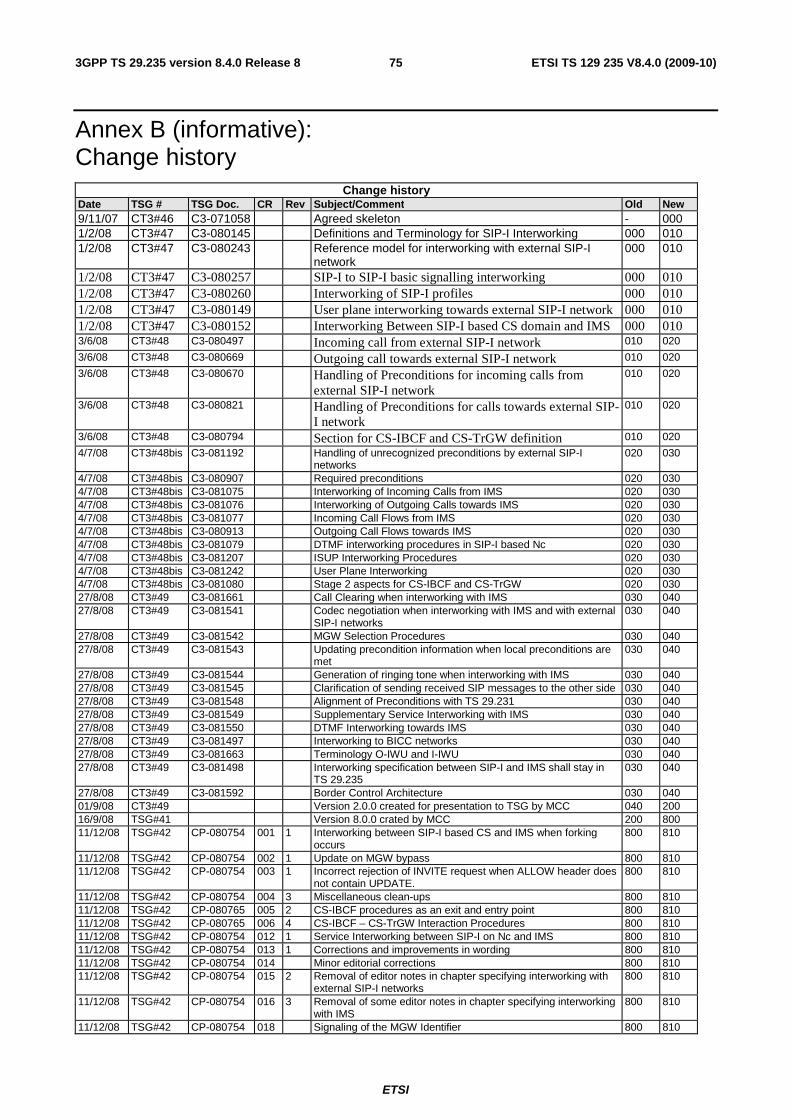
ETSI
ETSI TS 129 235 V8.4.0 (2009-10)753GPP TS 29.235 version 8.4.0 Release 8
Annex B (informative): Change history
Change history Date TSG # TSG Doc. CR Rev Subject/Comment Old New 9/11/07 CT3#46 C3-071058 Agreed skeleton - 000 1/2/08 CT3#47 C3-080145 Definitions and Terminology for SIP-I Interworking 000 010 1/2/08 CT3#47 C3-080243 Reference model for interworking with external SIP-I
network 000 010
1/2/08 CT3#47 C3-080257 SIP-I to SIP-I basic signalling interworking 000 010 1/2/08 CT3#47 C3-080260 Interworking of SIP-I profiles 000 010 1/2/08 CT3#47 C3-080149 User plane interworking towards external SIP-I network 000 010 1/2/08 CT3#47 C3-080152 Interworking Between SIP-I based CS domain and IMS 000 010 3/6/08 CT3#48 C3-080497 Incoming call from external SIP-I network 010 020
3/6/08 CT3#48 C3-080669 Outgoing call towards external SIP-I network 010 020
3/6/08 CT3#48 C3-080670 Handling of Preconditions for incoming calls from external SIP-I network
010 020
3/6/08 CT3#48 C3-080821 Handling of Preconditions for calls towards external SIP-I network
010 020
3/6/08 CT3#48 C3-080794 Section for CS-IBCF and CS-TrGW definition 010 020
4/7/08 CT3#48bis C3-081192 Handling of unrecognized preconditions by external SIP-I networks
020 030
4/7/08 CT3#48bis C3-080907 Required preconditions 020 030 4/7/08 CT3#48bis C3-081075 Interworking of Incoming Calls from IMS 020 030 4/7/08 CT3#48bis C3-081076 Interworking of Outgoing Calls towards IMS 020 030 4/7/08 CT3#48bis C3-081077 Incoming Call Flows from IMS 020 030 4/7/08 CT3#48bis C3-080913 Outgoing Call Flows towards IMS 020 030 4/7/08 CT3#48bis C3-081079 DTMF interworking procedures in SIP-I based Nc 020 030 4/7/08 CT3#48bis C3-081207 ISUP Interworking Procedures 020 030 4/7/08 CT3#48bis C3-081242 User Plane Interworking 020 030 4/7/08 CT3#48bis C3-081080 Stage 2 aspects for CS-IBCF and CS-TrGW 020 030 27/8/08 CT3#49 C3-081661 Call Clearing when interworking with IMS 030 040 27/8/08 CT3#49 C3-081541 Codec negotiation when interworking with IMS and with external
SIP-I networks 030 040
27/8/08 CT3#49 C3-081542 MGW Selection Procedures 030 040 27/8/08 CT3#49 C3-081543 Updating precondition information when local preconditions are
met 030 040
27/8/08 CT3#49 C3-081544 Generation of ringing tone when interworking with IMS 030 040 27/8/08 CT3#49 C3-081545 Clarification of sending received SIP messages to the other side 030 040 27/8/08 CT3#49 C3-081548 Alignment of Preconditions with TS 29.231 030 040 27/8/08 CT3#49 C3-081549 Supplementary Service Interworking with IMS 030 040 27/8/08 CT3#49 C3-081550 DTMF Interworking towards IMS 030 040 27/8/08 CT3#49 C3-081497 Interworking to BICC networks 030 040 27/8/08 CT3#49 C3-081663 Terminology O-IWU and I-IWU 030 040 27/8/08 CT3#49 C3-081498 Interworking specification between SIP-I and IMS shall stay in
TS 29.235 030 040
27/8/08 CT3#49 C3-081592 Border Control Architecture 030 040 01/9/08 CT3#49 Version 2.0.0 created for presentation to TSG by MCC 040 200 16/9/08 TSG#41 Version 8.0.0 crated by MCC 200 800 11/12/08 TSG#42 CP-080754 001 1 Interworking between SIP-I based CS and IMS when forking
occurs 800 810
11/12/08 TSG#42 CP-080754 002 1 Update on MGW bypass 800 810 11/12/08 TSG#42 CP-080754 003 1 Incorrect rejection of INVITE request when ALLOW header does
not contain UPDATE. 800 810
11/12/08 TSG#42 CP-080754 004 3 Miscellaneous clean-ups 800 810 11/12/08 TSG#42 CP-080765 005 2 CS-IBCF procedures as an exit and entry point 800 810 11/12/08 TSG#42 CP-080765 006 4 CS-IBCF – CS-TrGW Interaction Procedures 800 810 11/12/08 TSG#42 CP-080754 012 1 Service Interworking between SIP-I on Nc and IMS 800 810 11/12/08 TSG#42 CP-080754 013 1 Corrections and improvements in wording 800 810 11/12/08 TSG#42 CP-080754 014 Minor editorial corrections 800 810 11/12/08 TSG#42 CP-080754 015 2 Removal of editor notes in chapter specifying interworking with
external SIP-I networks 800 810
11/12/08 TSG#42 CP-080754 016 3 Removal of some editor notes in chapter specifying interworking with IMS
800 810
11/12/08 TSG#42 CP-080754 018 Signaling of the MGW Identifier 800 810

ETSI
ETSI TS 129 235 V8.4.0 (2009-10)763GPP TS 29.235 version 8.4.0 Release 8
11/12/08 TSG#42 CP-080754 019 5 Call release from external SIP-I network without encapsulated ISUP REL
800 810
11/12/08 TSG#42 CP-080754 020 1 Interworking with overlap signalling in IMS 800 810 11/12/08 TSG#42 CP-080765 021 2 CS-IBCF procedures 800 810 03/2009 TSG#43 CP-090092 023 2 CS-Ix – Minor corrections 810 820 03/2009 TSG#43 CP-090092 024 2 CS-Ix Update proposal for clause A.4 810 820 03/2009 TSG#43 CP-090092 028 2 Clean-up of Annex A 810 820 03/2009 TSG#43 CP-090080 030 2 Receipt of Re-Invite with no SDP 810 820 03/2009 TSG#43 CP-090080 031 2 B2BUA: setting of SIP header values when interworking with
IMS 810 820
03/2009 TSG#43 CP-090080 032 1 Supplementary Service Interworking with IMS 810 820 03/2009 TSG#43 CP-090080 033 3 Exception to message transiting when interworking failure
response 810 820
03/2009 TSG#43 CP-090093 035 2 Removal of Ix interface protocol 810 820 05/2009 TSG#44 CP-090335 036 2 Codec negotiation when interworking with BICC based network 820 830 09/2009 TSG#45 CP-090570 044 Text relates to wrong call direction 830 840 09/2009 TSG#45 CP-090570 046 Text relates to wrong message direction 830 840

ETSI
ETSI TS 129 235 V8.4.0 (2009-10)773GPP TS 29.235 version 8.4.0 Release 8
History
Document history
V8.1.0 January 2009 Publication
V8.2.0 April 2009 Publication
V8.3.0 June 2009 Publication
V8.4.0 October 2009 Publication
Related Documents