ETSI TS 127 060 V9.1.0 (2011-01) Technical Specification Digital cellular telecommunications system (Phase 2+); Universal Mobile Telecommunications System (UMTS); LTE; Packet domain; Mobile Station (MS) supporting Packet Switched services (3GPP TS 27.060 version 9.1.0 Release 9)

Welcome message from author
This document is posted to help you gain knowledge. Please leave a comment to let me know what you think about it! Share it to your friends and learn new things together.
Transcript

ETSI TS 127 060 V9.1.0 (2011-01)
Technical Specification
Digital cellular telecommunications system (Phase 2+);Universal Mobile Telecommunications System (UMTS);
LTE;Packet domain;
Mobile Station (MS) supporting Packet Switched services (3GPP TS 27.060 version 9.1.0 Release 9)
ETSI
ETSI TS 127 060 V9.1.0 (2011-01)13GPP TS 27.060 version 9.1.0 Release 9
Reference RTS/TSGC-0327060v910
Keywords GSM, LTE, UMTS
ETSI
650 Route des Lucioles F-06921 Sophia Antipolis Cedex - FRANCE
Tel.: +33 4 92 94 42 00 Fax: +33 4 93 65 47 16
Siret N° 348 623 562 00017 - NAF 742 C
Association à but non lucratif enregistrée à la Sous-Préfecture de Grasse (06) N° 7803/88
Important notice
Individual copies of the present document can be downloaded from: http://www.etsi.org
The present document may be made available in more than one electronic version or in print. In any case of existing or perceived difference in contents between such versions, the reference version is the Portable Document Format (PDF).
In case of dispute, the reference shall be the printing on ETSI printers of the PDF version kept on a specific network drive within ETSI Secretariat.
Users of the present document should be aware that the document may be subject to revision or change of status. Information on the current status of this and other ETSI documents is available at
http://portal.etsi.org/tb/status/status.asp
If you find errors in the present document, please send your comment to one of the following services: http://portal.etsi.org/chaircor/ETSI_support.asp
Copyright Notification
No part may be reproduced except as authorized by written permission. The copyright and the foregoing restriction extend to reproduction in all media.
© European Telecommunications Standards Institute 2011.
All rights reserved.
DECTTM, PLUGTESTSTM, UMTSTM, TIPHONTM, the TIPHON logo and the ETSI logo are Trade Marks of ETSI registered for the benefit of its Members.
3GPPTM is a Trade Mark of ETSI registered for the benefit of its Members and of the 3GPP Organizational Partners. LTE™ is a Trade Mark of ETSI currently being registered
for the benefit of its Members and of the 3GPP Organizational Partners. GSM® and the GSM logo are Trade Marks registered and owned by the GSM Association.

ETSI
ETSI TS 127 060 V9.1.0 (2011-01)23GPP TS 27.060 version 9.1.0 Release 9
Intellectual Property Rights IPRs essential or potentially essential to the present document may have been declared to ETSI. The information pertaining to these essential IPRs, if any, is publicly available for ETSI members and non-members, and can be found in ETSI SR 000 314: "Intellectual Property Rights (IPRs); Essential, or potentially Essential, IPRs notified to ETSI in respect of ETSI standards", which is available from the ETSI Secretariat. Latest updates are available on the ETSI Web server (http://webapp.etsi.org/IPR/home.asp).
Pursuant to the ETSI IPR Policy, no investigation, including IPR searches, has been carried out by ETSI. No guarantee can be given as to the existence of other IPRs not referenced in ETSI SR 000 314 (or the updates on the ETSI Web server) which are, or may be, or may become, essential to the present document.
Foreword This Technical Specification (TS) has been produced by ETSI 3rd Generation Partnership Project (3GPP).
The present document may refer to technical specifications or reports using their 3GPP identities, UMTS identities or GSM identities. These should be interpreted as being references to the corresponding ETSI deliverables.
The cross reference between GSM, UMTS, 3GPP and ETSI identities can be found under http://webapp.etsi.org/key/queryform.asp.
ETSI
ETSI TS 127 060 V9.1.0 (2011-01)33GPP TS 27.060 version 9.1.0 Release 9
Contents
Intellectual Property Rights ................................................................................................................................ 2
Foreword ............................................................................................................................................................. 2
Foreword ............................................................................................................................................................. 5
Introduction ........................................................................................................................................................ 5
1 Scope ........................................................................................................................................................ 6
2 References ................................................................................................................................................ 6
3 Definitions abbreviations and symbols .................................................................................................... 8
3.1 Definitions .......................................................................................................................................................... 8
3.2 Abbreviations ..................................................................................................................................................... 8
3.3 Symbols .............................................................................................................................................................. 9
4 Access reference configuration ................................................................................................................ 9
5 Functions to support data services .......................................................................................................... 10
6 Interface to Packet Domain Bearer Services .......................................................................................... 10
6.1 A/Gb mode ....................................................................................................................................................... 10
6.2 Iu mode ............................................................................................................................................................. 11
7 Functions common to all configurations of a MS supporting Packet Switched Services ...................... 11
7.1 Mobile Station Modes of Operation ................................................................................................................. 11
7.2 Physical Interface ............................................................................................................................................. 11
7.3 Terminal context procedures ............................................................................................................................ 11
7.3.1 PS Attach .................................................................................................................................................... 11
7.3.2 PS Detach ................................................................................................................................................... 12
7.3.3 MS Originated PDP Context Activation ..................................................................................................... 12
7.3.4 MS Originated Secondary PDP Context Activation ................................................................................... 12
7.3.5 Network Requested PDP Context Activation. ............................................................................................ 12
7.3.6 MS-Initiated PDP Context Modification .................................................................................................... 12
7.3.7 PDP Context Deactivation .......................................................................................................................... 12
7.3.8 PDP context related parameters .................................................................................................................. 12
7.3.8.1 MS in A/Gb mode ................................................................................................................................. 12
7.3.8.2 MS in Iu mode ....................................................................................................................................... 13
8 <VOID> ................................................................................................................................................. 13
9 IP Based Services ................................................................................................................................... 13
9.1 Example mapping of functions between the R reference point and the Packet Domain bearer for IP over PPP ................................................................................................................................................................... 14
9.1.1 IPv4 over PPP ............................................................................................................................................. 15
9.1.2 IPv6 over PPP ............................................................................................................................................. 17
9.2 Example mapping of functions between the R reference point and the Packet Domain bearer for IP over MCML PPP ...................................................................................................................................................... 19
10 PPP Based Services ................................................................................................................................ 20
10.1 Example mapping of functions between the R reference point and the Packet Domain bearer (transparent PPP negotiation) ........................................................................................................................... 21
10.2 Example mapping of functions between the R reference point and the Packet Domain bearer (relayed PPP negotiation) ............................................................................................................................................... 22
11 Internet Hosted Octet Stream Service (IHOSS) ..................................................................................... 23
12 AT commands ........................................................................................................................................ 23
12.1 General on AT commands ................................................................................................................................ 24
12.1.1 Interaction of AT commands, Packet Domain management and PDPs ...................................................... 24
12.1.1.1 AT commands and responses ................................................................................................................ 24
12.1.1.2 PDP and layer 2 protocol operation ...................................................................................................... 24

ETSI
ETSI TS 127 060 V9.1.0 (2011-01)43GPP TS 27.060 version 9.1.0 Release 9
12.1.1.3 Management of Packet Switched services ............................................................................................ 24
12.1.1.3.1 PS attachment .................................................................................................................................. 24
12.1.1.3.2 PDP context activation .................................................................................................................... 25
12.1.2 Use of default context parameter values ..................................................................................................... 25
12.1.2.1 PDP type ............................................................................................................................................... 25
12.1.2.2 PDP address (of the MS) ....................................................................................................................... 25
12.1.2.3 Access Point Name ............................................................................................................................... 25
12.1.2.4 QoS Requested ...................................................................................................................................... 25
12.1.2.5 PDP Configuration Options .................................................................................................................. 26
12.2 Example command sequences for dial-compatibility mode ............................................................................. 26
12.2.1 PPP in dial compatibility mode................................................................................................................... 26
12.2.1.1 Mobile initiated IP context activation ................................................................................................... 26
12.2.1.2 Network requested IP context activation............................................................................................... 27
13 IMS related functions ............................................................................................................................. 29
13.1 General ............................................................................................................................................................. 29
13.2 DNS Server Discovery ..................................................................................................................................... 29
13.3 P-CSCF Server Discovery ................................................................................................................................ 29
13.4 PDP Context used for IMS Signalling .............................................................................................................. 29
13.5 Binding Information ......................................................................................................................................... 29
13.6 Mapping of SDP to QoS Attributes .................................................................................................................. 30
13.7 Authorization of QoS Attributes ...................................................................................................................... 30
13.8 Support for forking ........................................................................................................................................... 30
13.9 Multiplexing of IMS media components to PDP contexts ............................................................................... 30
13.10 Policy control rejection of PDP context ........................................................................................................... 30
Annex A (informative): Summary of AT commands for the Packet Domain ................................... 31
Annex B (informative): Octet Stream Protocol (OSP) PDP type ....................................................... 32
Annex C (informative): Change history ............................................................................................... 33
History .............................................................................................................................................................. 34

ETSI
ETSI TS 127 060 V9.1.0 (2011-01)53GPP TS 27.060 version 9.1.0 Release 9
Foreword This Technical Specification (TS) has been produced by the 3rd Generation Partnership Project (3GPP).
The present document defines the requirements for TE-MT interworking over the R-reference point for the Packet Domain, within the 3GPP systems.
The contents of the present document are subject to continuing work within the TSG and may change following formal TSG approval. Should the TSG modify the contents of the present document, it will be re-released by the TSG with an identifying change of release date and an increase in version number as follows:
Version x.y.z
where:
x the first digit:
1 presented to TSG for information;
2 presented to TSG for approval;
3 or greater indicates TSG approved document under change control.
y the second digit is incremented for all changes of substance, i.e. technical enhancements, corrections, updates, etc.
z the third digit is incremented when editorial only changes have been incorporated in the document.
Introduction The present document defines the requirements for TE-MT interworking over the R-reference point for the Packet Domain, within the 3GPP systems. It is up to the manufacturer how to implement the various functions but the present document and existing 3GPP TS 27.001, 27.002, and 27.003 shall be followed where applicable.
It is the intention that the present document shall remain as the specification to develop a MS for support of Packet Switched services and its text includes references to 3GPP standards.

ETSI
ETSI TS 127 060 V9.1.0 (2011-01)63GPP TS 27.060 version 9.1.0 Release 9
1 Scope The (A/Gb and Iu mode) PLMN supports a wide range of voice and non-voice services in the same network. In order to enable non-voice traffic in the PLMN there is a need to connect various kinds of terminal equipments to the Mobile Station (MS). The present document defines the requirements for TE-MT interworking over the R-reference point for the Packet Domain , including the protocols and signalling needed to support Packet Switched services, as defined in 3GPP TS 22.060 and 3GPP TS 23.060.
The present document is valid for PLMN in A/Gb mode as well as for PLMN in Iu mode. If text applies only for one of these systems it is explicitly mentioned by using the terms "A/Gb mode" and "Iu mode". Please note, that the A interface does not play any role in the scope of this document although the term "A/Gb mode" is used.
2 References The following documents contain provisions which, through reference in this text, constitute provisions of the present document.
• References are either specific (identified by date of publication, edition number, version number, etc.) or non-specific.
• For a specific reference, subsequent revisions do not apply.
• For a non-specific reference, the latest version applies.
[1] Void.
[2] Void.
[3] 3GPP TS 22.060: "General Packet Radio Service (GPRS); Service Description Stage 1".
[4] Void.
[5] Void.
[6] Void.
[7] Void.
[8] Void.
[9] 3GPP TS 23.060: "General Packet Radio Service (GPRS) Service Description Stage 2".
[10] Void.
[11] Void.
[12] 3GPP TS 24.008: "Mobile radio interface layer 3 specification; Core Network protocols; Stage 3".
[13] Void.
[14] Void.
[15] Void.
[16] 3GPP TS 27.007: "AT command set for 3GPP User Equipment (UE)".
[17] 3GPP TS 29.061: "Packet Domain; Interworking between the Public Land Mobile Network (PLMN) supporting Packet Based Services and Packet Data Networks (PDN)".
[18] ITU-T Recommendation E.164 (02/05): "Numbering plan for the ISDN era".

ETSI
ETSI TS 127 060 V9.1.0 (2011-01)73GPP TS 27.060 version 9.1.0 Release 9
[19] ITU-T Recommendation V.42 bis (01/90): "Data communication over the telephone network – Data compression procedures for data circuit-terminating equipment (DCE) using error correction procedures".
[20] Void.
[21] Void.
[22] Void.
[23] Void.
[24] Void.
[25] Void.
[26] IETF RFC 768 (1980): "User Datagram Protocol" (STD 6).
[27] IETF RFC 791 (1981): "Internet Protocol" (STD 5).
[28] IETF RFC 792 (1981): "Internet Control Message Protocol" (STD 5).
[29] IETF RFC 793 (1981): "Transmission Control Protocol" (STD 7).
[30] ITU-T Recommendation V.250 (ex V.25ter) (05/99): "Serial asynchronous automatic dialling and control".
[31] ITU-T Recommendation V.24 (10/96): "List of definitions for interchange circuits between data terminal equipment (DTE) and data circuit-terminating equipment (DCE)".
[32] ITU-T Recommendation V.28 (03/93): "Electrical Characteristics for unbalanced double-current interchange circuits".
[33] ITU-T Recommendation V.80 (08/96): "In-band DCE control and synchronous data modes for asynchronous DTE".
[34] IETF RFC 1661 (1994): "The Point-to-Point Protocol (PPP)" (STD 51).
[35] IETF RFC 1662 (1994): "PPP in HDLC-like framing" (STD 51).
[36] IETF RFC 1700 (1994): "Assigned Numbers" (STD 2).
[37] IETF RFC 1570 (1994): "PPP LCP Extensions".
[38] IETF RFC 1989 (1996): "PPP Link Quality Monitoring".
[39] IETF RFC 1332 (1992): "The PPP Internet Protocol Control Protocol (IPCP)".
[40] IETF RFC 1877 (1995): "PPP IPCP Extensions for Name Server Addresses ".
[41] IETF RFC 2153 (1997): "PPP Vendor Extensions".
[42] IETF RFC 1334 (1992): "PPP Authentication Protocols".
[43] IETF RFC 1994 (1996): "PPP Challenge Handshake Authentication Protocol".
[44] IETF RFC 2686 (1999): "The Multi-Class Extension to Multi-Link PPP".
[45] IETF RFC 1990 (1996): "The PPP Multilink Protocol (MP)".
[46] IETF RFC 2472 (1998): "IP Version 6 over PPP".
[47] 3GPP TR 21.905: "Vocabulary for 3GPP Specifications".
[48] 3GPP TS 23.221: "Architectural requirements".
[49] IETF RFC 2373 (1998): "IP version 6 Addressing Architecture".

ETSI
ETSI TS 127 060 V9.1.0 (2011-01)83GPP TS 27.060 version 9.1.0 Release 9
[50] 3GPP TS 24.228: "Signalling flows for the IP multimedia call control based on SIP and SDP; Stage 3"
[51] 3GPP TS 24.229: " IP Multimedia Call Control Protocol based on SIP and SDP; Stage 3".
[52] 3GPP TS 29.207: "Policy control over Go interface".
[53] 3GPP TS 29.208: "End-to-end QoS signalling flows".
[54] IETF RFC 3261 (March 2002): "SIP: Session Initiation Protocol".
[55] IETF RFC 3315 (2003): "Dynamic Host Configuration Protocol for IPv6 (DHCPv6)" R. Droms, J. Bound, B. Volz, T. Lemon, C. Perkins, M. Carney.
[56] IETF RFC 1034 (1987): "Domain Names - Concepts and Facilities" (STD 13).
[57] IETF RFC 1035 (1987): "Domain Names - Implementation and Specification" (STD 13).
[58] IETF RFC 1886 (1995): "DNS Extensions to support IP version 6".
3 Definitions abbreviations and symbols
3.1 Definitions For the purposes of the present document, the following terms and definitions given in 3GPP TS 22.060 and 3GPP TS 23.060 and the following apply:
2G- / 3G-: prefixes 2G- and 3G- refers to functionality that supports only A/Gb mode or Iu mode, respectively, e.g., 2G-SGSN refers only to the A/Gb mode functionality of an SGSN. When the prefix is omitted, reference is made independently from the A/Gb mode or Iu mode functionality.
A/Gb mode: indicates that the text applies only to a system or sub-system which operate in A/Gb mode of operation, i.e. with a functional division that is in accordance with the use of an A or a Gb interface between the radio access network and the core network
Iu mode: indicates that the text applies only to a system or a sub-system which operates in Iu mode of operation, i.e. with a functional division that is in accordance with the use of an Iu-CS or Iu-PS interface between the radio access network and the core network
3.2 Abbreviations For the purposes of the present document, the following abbreviations apply:
APN Access Point Name DHCPv6 Dynamic Host Configuration Protocol Ipv6 DNS Domain Name System GGSN Gateway GPRS Support Node GPRS General Packet Radio Service GSN GPRS Support Node GTP-U GPRS Tunnelling Protocol for user plane HDLC High Level Data Link Control ICMP Internet Control Message Protocol IETF Internet Engineering Task Force IMS IP Multimedia Core Network Subsystem IP Internet Protocol IPv4 Internet Protocol version 4 IPv6 Internet Protocol version 6 IPV6CP IPv6 Control Protocol LA Location Area LCP Link Control Protocol
ETSI
ETSI TS 127 060 V9.1.0 (2011-01)93GPP TS 27.060 version 9.1.0 Release 9
LLC Logical Link Control MAC Medium Access Control MCML Multi-Class Multi-Link PPP ME Mobile Equipment MP Multilink PPP MS Mobile Station MT Mobile Termination NCP Network Control Protocol PCF Policy Control Function P-CSCF Proxy Call Session Control Function PDCP Packet Data Convergence Protocol PDN Packet Data Network PDP Packet Data Protocol , e.g., IP or PPP PDU Protocol Data Unit PPP Point-to-Point Protocol PS Packet Switched PTM Point To Multipoint PTP Point To Point PVC Permanent Virtual Circuit QoS Quality of Service RA Routing Area SDP Session Description Protocol SGSN Serving GPRS Support Node SIP Session Initiation Protocol SNDCP SubNetwork Dependent Convergence Protocol TCP Transmission Control Protocol TE Terminal Equipment TFT Traffic Flow Template UDP User Datagram Protocol
3.3 Symbols For the purposes of the present document, the following symbols apply:
Gb Interface between a SGSN and a BSC. Gi Reference point between the Packet Domain and an external packet data network. Gn Interface between two GSNs within the same PLMN. Gp Interface between two GSNs in different PLMNs. The Gp interface allows support of Packet
Domain network services across areas served by the co-operating PLMNs. Gs Interface between an SGSN and MSC. Iu Interface between the RNS and the core network. It is also considered as a reference point. R The reference point between a non-ISDN compatible TE and MT. Typically this reference point
supports a standard serial interface. Um The interface between the MS and the fixed network part in A/Gb mode. The Um interface is the
in A/Gb mode network interface for providing packet data services over the radio to the MS. The MT part of the MS is used to access the GSM services through this interface.
Uu Interface between the mobile station (MS) and the fixed network part in Iu mode. The Uu interface is the Iu mode network interface for providing packet data services over the radio to the MS. The MT part of the MS is used to access the UMTS services through this interface.
4 Access reference configuration Figure 1 shows the relationship between the MS, its terminal equipment and the PLMN in the overall Packet Domain environment.

ETSI
ETSI TS 127 060 V9.1.0 (2011-01)103GPP TS 27.060 version 9.1.0 Release 9
TE
Rreference point
Gp
PDN orother networkMT
Um or Uu Packet Domain
network 1
MS
Gireference point
Packet Domainnetwork 2
Figure 1: Packet Domain Access Interfaces and Reference Points
5 Functions to support data services The main functions of the MT to support data services are:
- physical connection at the reference point R;
- flow control between TE and MT;
- mapping of user signalling to/from the Packet Domain bearer;
- mapping of packets belonging to different flows to appropriate PDP contexts;
- support of data integrity between the terminal equipment and the Packet Domain bearer;
- functions to support packet based data.
6 Interface to Packet Domain Bearer Services
6.1 A/Gb mode The following figure 2 shows the relationship of the Packet Domain Bearer in A/Gb mode, terminating at the SNDCP layer, to the rest of the Packet Domain environment in A/Gb mode. It is shown for reference purposes only and detailed information can be found in 3GPP TS 23.060.
Relay
NetworkService
GTP-USNDCP
LLC
RLC
MAC
GSM RF
SNDCP
LLC
BSSGP
L1bis
RLC
MAC
GSM RF
BSSGP
L1bis
Relay
L2
L1
IP
L2
L1
IP
GTP-U
Um Gb Gn GiMS BSS SGSN GGSN
NetworkService
UDPUDP
Accesspoint
Accesspoint
Figure 2: User Plane for Packet Domain services in A/Gb mode
ETSI
ETSI TS 127 060 V9.1.0 (2011-01)113GPP TS 27.060 version 9.1.0 Release 9
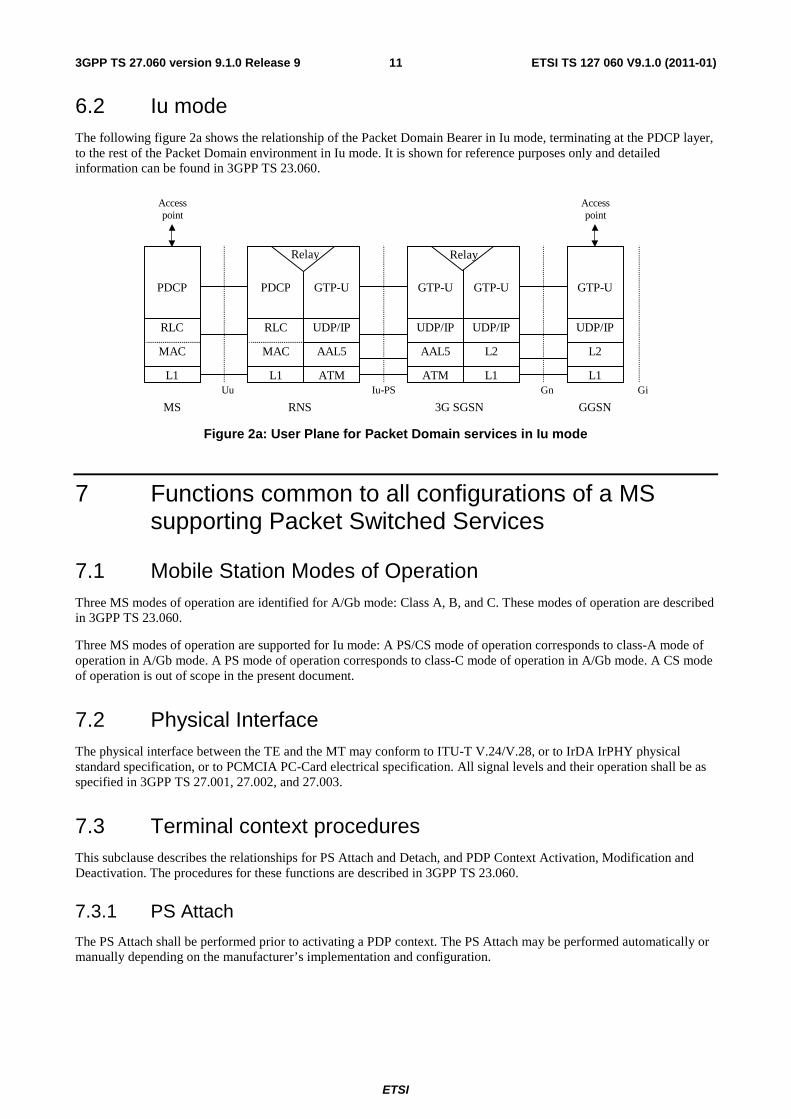
6.2 Iu mode The following figure 2a shows the relationship of the Packet Domain Bearer in Iu mode, terminating at the PDCP layer, to the rest of the Packet Domain environment in Iu mode. It is shown for reference purposes only and detailed information can be found in 3GPP TS 23.060.
L1
RLC
PDCP
MAC
L1
RLC
PDCP
MAC
ATM
UDP/IP
GTP-U
AAL5
Relay
ATM
UDP/IP
AAL5
GGSN
GTP-U
L1
UDP/IP
L2
GTP-U
L1
UDP/IP
L2
GTP-U
3G SGSNRNSMS
Iu-PSUu Gn Gi
Relay
Accesspoint
Accesspoint
Figure 2a: User Plane for Packet Domain services in Iu mode
7 Functions common to all configurations of a MS supporting Packet Switched Services
7.1 Mobile Station Modes of Operation Three MS modes of operation are identified for A/Gb mode: Class A, B, and C. These modes of operation are described in 3GPP TS 23.060.
Three MS modes of operation are supported for Iu mode: A PS/CS mode of operation corresponds to class-A mode of operation in A/Gb mode. A PS mode of operation corresponds to class-C mode of operation in A/Gb mode. A CS mode of operation is out of scope in the present document.
7.2 Physical Interface The physical interface between the TE and the MT may conform to ITU-T V.24/V.28, or to IrDA IrPHY physical standard specification, or to PCMCIA PC-Card electrical specification. All signal levels and their operation shall be as specified in 3GPP TS 27.001, 27.002, and 27.003.
7.3 Terminal context procedures This subclause describes the relationships for PS Attach and Detach, and PDP Context Activation, Modification and Deactivation. The procedures for these functions are described in 3GPP TS 23.060.
7.3.1 PS Attach
The PS Attach shall be performed prior to activating a PDP context. The PS Attach may be performed automatically or manually depending on the manufacturer’s implementation and configuration.

ETSI
ETSI TS 127 060 V9.1.0 (2011-01)123GPP TS 27.060 version 9.1.0 Release 9
7.3.2 PS Detach
The PS Detach may be performed automatically or manually depending on the manufacturer’s implementation and configuration. The following cases are valid:
- if the connection between the TE and MT is broken then the MT may perform the PS Detach procedure;
- if the network originates a PS Detach the MT may inform the TE;
- if the radio connection is broken then the MT may inform the TE;
- if the TE deactivates the last PDP context then the MT may perform the PS Detach procedure.
7.3.3 MS Originated PDP Context Activation
The PDP Context Activation procedure may be performed automatically or manually depending on the manufacturer’s implementation and configuration. Depending on the manufacturer’s implementation and configuration, 0, 1, or more PDP contexts can be active simultaneously.
7.3.4 MS Originated Secondary PDP Context Activation
The Secondary PDP Context Activation procedure may be performed automatically or manually depending on the manufacturer’s implementation and configuration. Depending on the manufacturer’s implementation and configuration, 0, 1, or more PDP contexts can be active simultaneously for the same PDP address.
7.3.5 Network Requested PDP Context Activation.
The network can request a PS attached MS to activate a specific PDP context.
7.3.6 MS-Initiated PDP Context Modification
The MS-Initiated PDP Context Modification procedure may be performed automatically or manually depending on the manufacturer’s implementation and configuration.
7.3.7 PDP Context Deactivation
The PDP Deactivation may be performed automatically or manually depending on the manufacturer’s implementation and configuration. The following cases are valid:
- if the connection between the MT and the TE is broken then the MT may perform the PDP Context Deactivation procedure;
- if the radio connection is broken then the MT may inform the TE;
- if the DHCP lease expires or the renewal is rejected by the DHCP server or the IP Address is changed during DHCP lease renewal, the TE may deactivate the PDP context.
- if the TE deactivates the last PDP context then the MT may perform the PS Detach procedure.
7.3.8 PDP context related parameters
7.3.8.1 MS in A/Gb mode
It shall be possible to enquire and/or set the following parameters:
- requested quality of service;
- traffic flow template;
- compression on or off;
ETSI
ETSI TS 127 060 V9.1.0 (2011-01)133GPP TS 27.060 version 9.1.0 Release 9
- TCP/IP header compression on or off;
- PDP address;
- PDP type;
- Access Point Name (APN);
- protocol configuration options (if required by the PDP type).
7.3.8.2 MS in Iu mode
It shall be possible to enquire and/or set the following parameters:
- requested quality of service;
- traffic flow template;
- protocol control information compression, on or off;
- PDP address;
- PDP type;
- Access Point Name (APN);
- protocol configuration options (if required by the PDP type).
8 <VOID>
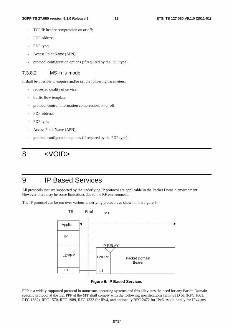
9 IP Based Services All protocols that are supported by the underlying IP protocol are applicable in the Packet Domain environment. However there may be some limitations due to the RF environment.
The IP protocol can be run over various underlying protocols as shown in the figure 6.
Packet DomainBearer
R ref
L1
L2/PPP
MT TE
IP RELAY
L1
IP
Applic.
L2/PPP
Figure 6: IP Based Services
PPP is a widely supported protocol in numerous operating systems and this alleviates the need for any Packet Domain specific protocol at the TE. PPP at the MT shall comply with the following specifications IETF STD 51 (RFC 1661, RFC 1662), RFC 1570, RFC 1989, RFC 1332 for IPv4, and optionally RFC 2472 for IPv6. Additionally for IPv4 any
ETSI
ETSI TS 127 060 V9.1.0 (2011-01)143GPP TS 27.060 version 9.1.0 Release 9
Domain Name Server information shall be delivered as defined in RFC 1877, and the delivery of any vendor-specific packets and options shall conform to RFC 2153.
As an alternative to PPP, an L2 protocol can be used which is defined as a manufacturer’s operating system dependent protocol capable of carrying IP frames over the R reference point. An example for such an L2 protocol is the Multi-Class Multi-Link (MCML) PPP. The MCML is defined in RFC 2686 and is based on Multi-Link (MP) PPP which is defined in RFC 1990. For IPv6 the L2 protocol shall support negotiation of the IPv6 Interface-Identifier between the TE and the MT.
With IPv6, the process of setting up the IP connectivity is somewhat different than with IPv4 as it involves two distinct signalling phases. The first signalling phase is done in the control plane, followed by a second signalling phase done in the user plane. The control plane signalling phase, in the case of IPv6 over PPP, is described in section 9.1.2. The user plane signalling phase can be either stateless or stateful and is described in 3GPP TS 29.061 [17]. Support of the stateful address autoconfiguration procedure in the MS is optional.
Stateful and Stateless Autoconfiguration may also co-exist. In that case, the MS shall use Stateless to configure the address and Stateful to configure additional parameters only. The MS shall not use Stateless and Stateful Address Autoconfiguration simultaneously since GPRS only supports one prefix per PDP Context (see 3GPP TS 29.061 [17]).
Besides what is specified in the present document and in 3GPP TS 29.061, an MS supporting IPv6 shall comply with the guidelines specified in 3GPP TS 23.221 [48], subclause "UE support of IPv6".
9.1 Example mapping of functions between the R reference point and the Packet Domain bearer for IP over PPP
The following examples illustrate the case when the IP over PPP functionality is used in the MT. The example does not include all the details of PPP, but only describes the logical operation of PPP connection establishment, host authentication and IP configuration.
Each interface at the R reference point can support only one PPP connection and each PPP connection can support only one IP session. Therefore, in PPP mode only one IP PDP context can be activated per interface at the R reference point. However, it is possible for a PCMCIA card (or other multiplexed interfaces) to support multiple virtual interfaces (communications ports) at the R reference point. Multiple PPP connections and IP contexts are possible in this case.

ETSI
ETSI TS 127 060 V9.1.0 (2011-01)153GPP TS 27.060 version 9.1.0 Release 9
9.1.1 IPv4 over PPP
Um/Uu MTTE R
10. PDP context Activation
11. NCP Configure Ack
8. NCP Configure-Request
3. LCP Configure-Request
4. LCP Configure Ack
9. PS Attach
2. AT response
1. AT command
7. Host authentication
5. LCP Configure-Request
6. LCP Configure Ack
Figure 7a: IPv4 Over PPP Based Service
1) The TE issues AT commands to set up parameters and enter PPP mode (refer to subclause on AT commands for further details).
2) The MT sends AT responses to the TE.
3) The PPP protocol in the TE sends a LCP Configure-Request. This command is to establish a PPP link between the TE and the MT.
4) The MT returns LCP Configure-Ack to the TE to confirm that the PPP link has been established. The MT might previously have sent a LCP Configure-Nak in order to reject some options proposed by the TE. This in turn might have triggered a retransmission of the LCP Configure-Request with different options.
5) The PPP protocol in the MT sends a LCP Configure-Request in order to negotiate for the authentication protocol used for authentication of the host TE towards the MT. The MT shall initially negotiate for CHAP, and if this is unsuccessful, for PAP.
6) The TE returns a LCP Configure-Ack to the MT to confirm the use of the specified authentication protocol. The MT might previously have sent a LCP Configure-Nak in order to reject the protocol proposed by the TE. This in turn might have triggered a retransmission of the LCP Configure-Request with different options.
7) If the negotiated authentication protocol is either of CHAP or PAP, the TE authenticates itself towards the MT by means of that protocol. The MT stores the necessary authentication data and sends a locally generated positive acknowledgement of the authentication to the TE. If none of the protocols is supported by the host TE no authentication shall be performed. Refer to 3GPP TS 29.061 for further details on the authentication.
8) The PPP protocol in the TE sends to the MT a NCP Configure-Request. This command activates the IP protocol.

ETSI
ETSI TS 127 060 V9.1.0 (2011-01)163GPP TS 27.060 version 9.1.0 Release 9
9) If the MS is not yet PS attached, the MT performs the PS Attach procedure as described in 3GPP TS 23.060.
10) The MT performs a PDP Context Activation as described in 3GPP TS 23.60. IP configuration parameters may be carried between the MT and the network in the Protocol Configuration Options IE in PDP Context Activation messages. The Protocol Configuration Options IE sent to the network may contain zero or one NCP Configure-Request packet (in addition to any LCP and authentication packets). The Protocol Configuration Options IE received from the network may contain zero or one NCP Configure-Ack, zero or one Configure-Nak and/or zero or one Configure-Reject packets (in addition to any LCP and authentication packets).
11) Based on the information received in the Protocol Configuration Options IE, the MT acknowledges to the PPP protocol in the TE that the IP protocol is now activated by sending a NCP Configure-Ack command. Before sending a NCP Configure-Ack, the MT might previously have sent a NCP Configure-Nak and/or Configure-Reject in order to reject some IP parameters proposed by the TE. This in turn might have triggered a retransmission of the NCP Configure-Request with different parameter values. The decision to reject a specific parameter or parameter value may be based on the information received from the network in the Protocol Configuration Options IE. NCP Configure-Ack may also carry IP protocol related parameters such as dynamic IP address to the TE. The MT shall also pass name server information to the TE if the TE has requested for it and if this information is provided by the GGSN. Other packet types and options may optionally be delivered. The MT may choose to immediately deactivate the PDP context due to the information received from the network in the Protocol Configurations Options IE.

ETSI
ETSI TS 127 060 V9.1.0 (2011-01)173GPP TS 27.060 version 9.1.0 Release 9
9.1.2 IPv6 over PPP
Um/Uu MT TE R
10. PDP context Activation
11. IPV6CP Configure-Ack
3. LCP Configure-Request
4. LCP Configure Ack
9. PS Attach
2. AT response
1. AT command
7. Host authentication
5. LCP Configure-Request
6. LCP Configure Ack
8. IPV6CP Configure-request
[Interface Id, Compression]
[PDP Type, PDP Addr, PCO]
IPV6CP Configure-Nak
[Interface Id]
IPV6CP Configure-request
[Interface Id, Compression]
IPV6CP Configure-Ack
[Interface Id, Compression]
[Interface Id, Compression]
Figure 7b: PDP Context Activation for the IPv6 over PPP based services
1) The TE issues AT commands to set up parameters and enter PPP mode (refer to subclause on AT commands for further details).
2) The MT sends AT responses to the TE.
3) The PPP protocol in the TE sends a LCP Configure-Request. This command is to establish a PPP link between the TE and the MT.
4) The MT returns LCP Configure-Ack to the TE to confirm that the PPP link has been established. The MT might previously have sent a LCP Configure-Nak in order to reject some options proposed by the TE. This in turn might have triggered a retransmission of the LCP Configure-Request with different options.
5) The PPP protocol in the MT sends a LCP Configure-Request in order to negotiate for the authentication protocol used for authentication of the host TE towards the MT. The MT shall initially negotiate for CHAP, and if this is unsuccessful, for PAP.

ETSI
ETSI TS 127 060 V9.1.0 (2011-01)183GPP TS 27.060 version 9.1.0 Release 9
6) The TE returns a LCP Configure-Ack to the MT to confirm the use of the specified authentication protocol. The MT might previously have sent a LCP Configure-Nak in order to reject the protocol proposed by the TE. This in turn might have triggered a retransmission of the LCP Configure-Request with different options.
7) If the negotiated authentication protocol is either of CHAP or PAP, the TE authenticates itself towards the MT by means of that protocol. The MT stores the necessary authentication data and sends a locally generated positive acknowledgement of the authentication to the TE. If none of the protocols is supported by the host TE no authentication shall be performed. Refer to 3GPP TS 29.061 for further details on the authentication.
8) The TE requests IPv6 Interface-Identifier negotiation by sending the IPV6CP Configure-Request message to the MT indicating the tentative Interface-Identifier chosen by the TE. The tentative Interface-Identifier has only local significance in the MT and shall not forwarded to the GGSN.
9) If the MS is not yet PS attached, the MT performs the PS Attach procedure as described in 3GPP TS 23.060.
10) The MT sends the Activate PDP context request message to the network, including the PDP Type, PDP Address and Protocol Configuration Options. The Protocol Configuration Options IE may contain negotiated LCP options such as negotiated Authentication Protocol as well as any authentication data previously stored in the MT. It may also contain a request for dynamic configuration of DNS server IPv6 addresses as described in 3GPP TS 29.061 [17]. The MS shall leave PDP Address empty and set PDP Type to ‘IPv6’. Note: The protocol between the TE and MT may not support the same set of information as the interface from the MT to the network (e.g. DNS).
The network responds with an Activate PDP Context Accept or an Activate PDP Context Reject, to the MS. The Protocol Configuration Options IE may contain configuration data such as a list of DNS server IPv6 addresses as described in 3GPP TS 29.061 [17]. In cases where the MS receives more than one server address, the MS shall adhere to the explicit prioritisation order of the list. The PDP Address shall contain an IPv6 address composed of a Prefix and an Interface-Identifier. The size of the Prefix shall be according to the maximum prefix length for a global IPv6 address as specified in the IPv6 Addressing Architecture, see RFC 2373 [49]. The Interface-Identifier shall be used to create a link-local IPv6 address, to be used in continued MS – GGSN user-plane signalling. The Prefix in the PDP Address shall be ignored by the MS.
11) In case a PDP Context Accept was sent to the MS, the MT extracts the Interface-Identifier from the address received in the PDP Address IE and ignores the Prefix part. If this Interface-Identifier is identical to the tentative Interface-Identifier indicated in the IPV6CP Configure-Request message sent from the TE, the MT sends an IPV6CP Configure Ack packet, indicating this Interface-Identifier, to the TE.
If the Interface-Identifier extracted from the address contained in the PDP Address IE is not identical to the tentative Interface-Identifier indicated in the IPV6CP Configure-Request message sent from the TE, the MT sends an IPV6CP Configure Nak packet, indicating the Interface-Identifier extracted from the address contained in the PDP Address IE, to the TE. The TE then sends a new IPV6CP Configure-Request message to the MT, indicating the same Interface-Identifier as was indicated in the received IPV6CP Configure Nak. Finally the MT responds with an IPV6CP Configure Ack packet. The negotiated Interface-Identifier shall be used in the TE to create a link-local address.
After finalisation of the IPV6CP negotiations between TE and MT, the user plane link is established. Before the MS can communicate with other hosts on the Intranet/ISP it shall obtain an IPv6 Global or a Site-Local Unicast address. Given that exactly one Prefix is included in the Router Advertisement, depending upon whether the advertised Prefix is globally unique or Site-local unique, the MS can only generate either IPv6 Global address(es) or Site-local address(es) using this Prefix during the lifetime of a particular PDP Context. This is done using either Stateless or Stateful Address Autoconfiguration as described in 3GPP TS 29.061 [17].
When creating a Global or Site-Local Unicast Address, the MS may use the Interface-Identifier received during the PDP Context Activation phase or it may generate a new Interface-Identifier. There is no restriction on the uniqueness of the Interface-Identifier of the Global or Site-Local Unicast Address, since the Prefix itself is unique. Interface-Identifiers shall in any case be 64-bit long and follow standard interface-identifier guidelines as per IETF RFC 2373 [49] and RFC 2472 [46].
In case a PDP Context Reject was sent to the MS the MT sends an LCP Terminate-Request to the TE, the TE and MT negotiate for link termination. The MT may then send a final AT-response to inform the TE about the rejected PDP Context activation.
ETSI
ETSI TS 127 060 V9.1.0 (2011-01)193GPP TS 27.060 version 9.1.0 Release 9
9.2 Example mapping of functions between the R reference point and the Packet Domain bearer for IP over MCML PPP
When MCML is used instead of standard PPP [34] at the R-reference point, it is possible to support multiple IP sessions on one MCML connection. This is achieved by using an additional MP header after the standard PPP header. MCML provides two different MP headers, a 2-byte header to have four IP sessions and a 4-byte header to have sixteen IP sessions multiplexed over the MCML connection.
Since both MP and MCML closely follow the PPP connection establishment and negotiation model described in subclause 9.1, it is not replicated in this subclause. The major difference is the additional negotiation capabilities used during the LCP configuration negotiation [44], [45].

ETSI
ETSI TS 127 060 V9.1.0 (2011-01)203GPP TS 27.060 version 9.1.0 Release 9
10 PPP Based Services By means of the PDP type ‘PPP’ the Packet Domain may support interworking with networks based on the point-to-point protocol (PPP), as well as with networks based on any protocol supported by PPP through one of its Network Control Protocols (NCPs). It may also support interworking by means of tunnelled PPP, by e.g. the Layer Two Tunnelling Protocol (L2TP). The protocol configurations are depicted in figures 8a and 8b.
Packet DomainBearer
R ref
L1 L1
L2
L3
Application
MT
L2
TE Gi refGGSN
PPPPPP
Figure 8a: PPP Based Services (transparent PPP negotiation)
Packet Domain Bearer
R ref
L1 L1
L2
L3
Application
MT
L2
TE Gi refGGSN
PPPPPP PPPPPP
NOTE. In the above case the 'L2' protocol is compliant with [35].
Figure 8b: PPP Based Services (relayed PPP negotiation)
The ‘L3’ protocol is a network layer protocol supported by one of the PPP NCP’s. All protocols currently supported by NCP’s are listed in [36].
The PPP is a widely supported protocol in numerous operating systems and this alleviates the need for any Packet Domain specific protocol at the TE. PPP at the GGSN shall comply with [34]. The Domain Name Server information shall be delivered as defined in [40]. The delivery of any vendor-specific packets and options shall conform to [41].
The ‘L2’ protocol may be the link layer protocol defined for the PPP suite [35]. As an alternative an 'L2' protocol can be used which is defined as a manufacturer’s operating system dependent protocol capable of carrying PPP frames over the R reference point. In case the link layer protocol defined for the PPP suite [35] is used as 'L2' protocol, the MT may negotiate LCP options related to the 'L2' framing (e.g. 'ACCM' [35], 'ACFC' [34] and 'FCS-Alternatives' [37]), with the TE. The MT shall remove the 'L1' and 'L2' specific framing from PPP frames in the uplink direction and add it in the downlink direction (see figure 8b).
ETSI
ETSI TS 127 060 V9.1.0 (2011-01)213GPP TS 27.060 version 9.1.0 Release 9
10.1 Example mapping of functions between the R reference point and the Packet Domain bearer (transparent PPP negotiation)
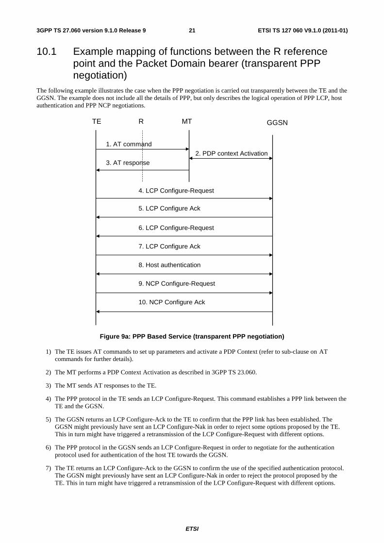
The following example illustrates the case when the PPP negotiation is carried out transparently between the TE and the GGSN. The example does not include all the details of PPP, but only describes the logical operation of PPP LCP, host authentication and PPP NCP negotiations.
MTTE R
2. PDP context Activation
3. AT response
1. AT command
10. NCP Configure Ack
9. NCP Configure-Request
4. LCP Configure-Request
5. LCP Configure Ack
8. Host authentication
6. LCP Configure-Request
7. LCP Configure Ack
GGSN
Figure 9a: PPP Based Service (transparent PPP negotiation)
1) The TE issues AT commands to set up parameters and activate a PDP Context (refer to sub-clause on AT commands for further details).
2) The MT performs a PDP Context Activation as described in 3GPP TS 23.060.
3) The MT sends AT responses to the TE.
4) The PPP protocol in the TE sends an LCP Configure-Request. This command establishes a PPP link between the TE and the GGSN.
5) The GGSN returns an LCP Configure-Ack to the TE to confirm that the PPP link has been established. The GGSN might previously have sent an LCP Configure-Nak in order to reject some options proposed by the TE. This in turn might have triggered a retransmission of the LCP Configure-Request with different options.
6) The PPP protocol in the GGSN sends an LCP Configure-Request in order to negotiate for the authentication protocol used for authentication of the host TE towards the GGSN.
7) The TE returns an LCP Configure-Ack to the GGSN to confirm the use of the specified authentication protocol. The GGSN might previously have sent an LCP Configure-Nak in order to reject the protocol proposed by the TE. This in turn might have triggered a retransmission of the LCP Configure-Request with different options.

ETSI
ETSI TS 127 060 V9.1.0 (2011-01)223GPP TS 27.060 version 9.1.0 Release 9
8) The TE authenticates itself towards the GGSN by means of the negotiated protocol. If no authentication protocol can be negotiated the GGSN may reject the PPP connection. Refer to 3GPP TS 09.61 for further details on the authentication.
9) The PPP protocol in the TE sends to the GGSN an NCP Configure-Request. This command activates the network layer protocol.
10) The GGSN acknowledges to the PPP protocol in the TE that the network layer protocol is now activated by sending an NCP Configure-Ack command. Before sending an NCP Configure-Ack, the GGSN might previously have sent an NCP Configure-Nak in order to reject some parameters proposed by the TE. This in turn might have triggered a retransmission of the NCP Configure-Request with different parameter values.
10.2 Example mapping of functions between the R reference point and the Packet Domain bearer (relayed PPP negotiation)
The following example illustrates the case where the link layer protocol defined for the PPP suite [35] is used as 'L2' protocol. The LCP options related to the 'L2' framing (e.g. 'ACCM', 'ACFC' and 'FCS-Alternatives') are negotiated between the TE and the MT. All other PPP negotiation is relayed transparently between the TE and the GGSN. The example does not include all the details of PPP, but only describes the logical operation of PPP LCP, host authentication and PPP NCP negotiations.
MTTE R
2. PDP context Activation3. AT response
1. AT command
10. NCP Configure Ack
9. NCP Configure-Request
4. LCP Configure-Request
5. LCP Configure Ack
8. Host authentication
6. LCP Configure-Request
7. LCP Configure Ack
GGSN
Figure 9b: PPP Based Service (relayed PPP negotiation)
1) The TE issues AT commands to set up parameters and activate a PDP Context (refer to sub-clause on AT commands for further details).
2) The MT performs a PDP Context Activation as described in 3GPP TS 23.060.

ETSI
ETSI TS 127 060 V9.1.0 (2011-01)233GPP TS 27.060 version 9.1.0 Release 9
3) The MT sends AT responses to the TE.
4) The PPP protocol in the TE sends an LCP Configure-Request. If the request contains options related to the 'L2' framing these are negotiated by the MT. The LCP Configure-Request shall subsequently be relayed to the GGSN.
5) The GGSN returns an LCP Configure-Ack to the MT. The MT may change the value(s) of any options related to 'L2' framing and thereafter return an LCP Configure-Ack to the TE to confirm that the PPP link has been established. The MT might previously have sent an LCP Configure-Nak to the TE in order to reject some options proposed by the TE. This in turn might have triggered a retransmission of the LCP Configure-Request with different options.
6) The PPP protocol in the GGSN sends an LCP Configure-Request in order to negotiate for e.g. the authentication protocol used for authentication of the host TE towards the GGSN. The request is relayed to the TE.
7) The TE returns an LCP Configure-Ack to the MT to confirm the use of e.g. the specified authentication protocol. The acknowledgement is relayed to the GGSN. The GGSN might previously have sent an LCP Configure-Nak in order to reject the protocol proposed by the TE. This in turn might have triggered a retransmission of the LCP Configure-Request with different options.
8) The TE authenticates itself towards the GGSN by means of the negotiated protocol. The messages are relayed transparently by the MT. If no authentication protocol can be negotiated the GGSN may reject the PPP connection. Refer to 3GPP TS 29.061 for further details on the authentication.
9) The PPP protocol in the TE sends an NCP Configure-Request to the MT, which relays it transparently to the GGSN.
10) The GGSN acknowledges to the PPP protocol in the TE that the network layer protocol is now activated, by sending an NCP Configure-Ack command, transparently relayed by the MT. Before sending an NCP Configure-Ack, the GGSN might previously have sent an NCP Configure-Nak in order to reject some parameters proposed by the TE. This in turn might have triggered a retransmission of the NCP Configure-Request with different parameter values.
11 Internet Hosted Octet Stream Service (IHOSS) Void.
12 AT commands 3GPP TS 27.007 defines commands that a TE may use to control a MT supporting Packet Switched services, via either a non-multiplexed character-stream interface or a mutliplexed character stream interface (27.010). A non-multiplexed character stream interface places certain limitations on the functionality of the interface. For example, it is not possible for the MT to send control information to the TE or for the TE to send commands to the MT whilst the interface is in the V.250 online data state unless the layer 2 protocol itself supports this feature. However, a manufacturer-specific escape mechanism may be provided to enable the TE to switch the MT into the V.250 online command state. It is anticipated that MTs will vary widely in functionality. At one extreme, a class A or PS/CS MT might support multiple PDP types as well as circuit switched data, and use multiple external networks and QoS profiles. At the other extreme a class C or PS MT might support only a single PDP type using a single external network, and rely on the HLR to contain the context definition.
A comprehensive set of Packet Domain -specific AT commands is defined in 3GPP TS 27.007 to provide the flexibility needed by the more complex MT. The commands are designed to be expandable to accommodate new PDP types and interface protocols, merely by defining new values for many of the parameters. Multiple contexts may be activated if the interface link-layer protocol is able to support them. The commands use the extended information and error message capabilities described in 3GPP TS 27.007.
For MTs of intermediate complexity, most commands have simplified forms where certain parameters may be omitted.
ETSI
ETSI TS 127 060 V9.1.0 (2011-01)243GPP TS 27.060 version 9.1.0 Release 9
For the simplest MTs, and for backwards compatibility with existing communications software, it is possible to control access to the Packet Domain using existing modem-compatible commands. A special dial-string syntax is defined for use with the D command. This "modem compatible" mode of operation is described in 3GPP TS 27.007.
Subclause 12.2 contains examples of command sequences for a number of applications.
Annex A of the present document lists the AT commands for the Packet Domain. They are fully defined in 3GPP TS 27.007.
12.1 General on AT commands The following subclauses describe how the AT commands are used for the Packet Domain. The AT commands themselves are fully described in 3GPP TS 27.007. Reference to the particular AT command names are shown only for clarity. In all case refer to 3GPP TS 27.007 for the latest descriptions.
12.1.1 Interaction of AT commands, Packet Domain management and PDPs
State machines may be used to describe the behaviour of:
- AT commands (ITU-T V.250);
- PDP context management (3GPP TS 23.060);
- PDP startup, data transfer and termination (Packet Data Protocol specifications);
- the layer 2 protocol (if any) used across the TE-MT interface (layer 2 protocol specifications).
This subclause does not attempt to describe in detail how these state machines interact but rather to give some general guidance on their relationships.
12.1.1.1 AT commands and responses
AT commands may be issued and responses received by the TE only when the TE and MT are in V.250 command state.
The possibility of suspending the PDP and/or layer 2 protocol and entering V.250 online command state is not considered here; neither is the use of a multiplexed interface where the PDP and the AT commands use separate logical channels.
12.1.1.2 PDP and layer 2 protocol operation
The PDP (across the TE-MT interface) may startup, transfer data and terminate only when the TE and MT are in V.250 online data state. It may be necessary to startup a layer 2 protocol across the interface before starting the PDP. The PDP startup procedure may provide information needed for the PDP context activation procedure (see subclause 10.1.1.3.2).
12.1.1.3 Management of Packet Switched services
A particular PDP may be used to transfer data only when a context is active for that PDP. Before a context can be activated, the MT must be attached to the Packet Domain network.
In order to provide flexibility and support a variety of types of MT and PDP, AT commands are provided which give the TE explicit control over attachment and detachment (+CGATT), and context activation and deactivation (+CGACT) procedures. These commands allow the TE to retain control of the MT, and receive status information from the MT, after these actions have been performed.
12.1.1.3.1 PS attachment
The MT may be attached and detached using the +CGATT command. However, it may not be necessary to use the command since attachment may occur:
- on power up or reset;
ETSI
ETSI TS 127 060 V9.1.0 (2011-01)253GPP TS 27.060 version 9.1.0 Release 9
- when an attempt is made to activate a context either explicitly (+CGACT) or as a result of a PDP startup -procedure;
- when the mobile class is changed (+CGCLASS).
Similarly, detachment may occur:
- as a result of a PDP termination procedure (if no other Packet Switched services are active);
- when the mobile class is changed (+CGCLASS).
12.1.1.3.2 PDP context activation
Certain information must be provided to the network in order for a context activation attempt to be successful. The TE may provide some of this information to the MT during the PDP startup procedure rather than through AT command procedures. In this case the context activation cannot be initiated by the +CGACT command but rather on receipt of the appropriate information during the PDP startup.
12.1.2 Use of default context parameter values
The activate context request message sent by the MT to the network contains a number of parameters whose values can usefully be set by the TE. Under certain circumstances the values for some or all of the parameters need not be provided by the TE, either via AT commands or the PDP startup procedure. The storage of context information in the SIM is not considered in the present document. Rules concerning what values shall be sent by the MT to the network under various circumstances are given in 3GPP TS 23.060.
One particular rule that is designed to simplify operation in modem compatibility mode is that if there is only one PDP context subscription in the HLR then all of PDP type, PDP address and APN may be omitted.
12.1.2.1 PDP type
This may be omitted:
- when the MT supports only one PDP type (it will be provided by the MT); or
- according to the rules given in 3GPP TS 23.060.
12.1.2.2 PDP address (of the MS)
This shall be omitted when:
- a dynamic address is required; or
- according to the rules given in 3GPP TS 23.060.
12.1.2.3 Access Point Name
This may be omitted:
- according to the rules given in 3GPP TS 23.060.
12.1.2.4 QoS Requested
This may be omitted when:
- the default subscribed QoS is acceptable.
When the application in the TE requires streaming or conversational QoS, then the MS shall at least explicitly request the traffic class and should explicitly request the guaranteed bit rate and the maximum bit rate.

ETSI
ETSI TS 127 060 V9.1.0 (2011-01)263GPP TS 27.060 version 9.1.0 Release 9
12.1.2.5 PDP Configuration Options
These shall be omitted:
- when none are required for the PDP concerned; or
- according to the rules given for the PDP.
12.2 Example command sequences for dial-compatibility mode
12.2.1 PPP in dial compatibility mode
12.2.1.1 Mobile initiated IP context activation
In this mode of operation, the MT behaves like an originating modem and accepts the normal V.250 commands associated with placing and clearing a call to a dial-up PPP server. Although the procedures for setting up the IP context are initiated from the mobile end, IP-based sessions, for example the File Transfer Protocol (FTP), may be initiated from either end once the context is active.
For this example it is assumed that:
- the user has subscribed to only one PDP context (of type IP) and therefore no context parameter values are needed;
- the MT supports only PPP at the MT-TE interface and therefore no layer 2 protocol need be specified.
A possible sequence of events is:
- the MT begins in V.25 command state:
- TE -> MT: AT<Packet Domain-specific configuration commands, if required>;
- MT -> TE: OK.
- the TE sends a dial command requesting the Packet Switched service:
- TE -> MT: ATD*99#;
- MT -> TE CONNECT.
- the MT enters V.250 online data state:
- TE starts up PPP (LCP exchange);
- TE -> MT: LCP Configure-request;
- MT -> TE: LCP Configure-ack:
- PPP Authentication may take place (optional);
- TE starts up IP (NCP for IP exchange):
- TE -> MT: NCP(IP) Configure-request;
- MT <-> network: MT performs the PS-attach procedure if the MT is not currently attached;
- MT <-> network: MT performs the IP context activation procedure;
- MT -> TE: NCP(IP) Configure-ack;
- TE <-> MT< - > network: IP packets may now be transferred.
- TE stops IP (optional):
- TE-> MT: NCP(IP) Terminate-Request ); this

ETSI
ETSI TS 127 060 V9.1.0 (2011-01)273GPP TS 27.060 version 9.1.0 Release 9
- MT<-> network: MT performs the IP context deactivation procedure); is
- MT -> TE: NCP(IP) Terminate-Ack ) optional.
- TE stops PPP:
- TE-> MT: LCP Terminate-Request;
- MT <-> network: MT performs the IP context deactivation procedure if it has not already done so;
- MT <-> network: MT may perform the PS-detach procedure if no other Packet Switched services are active;
- MT -> TE: LCP Terminate-Ack.
- the MT returns to V.250 command state and issues the final result code :
- MT -> TE NO CARRIER.
The TE may recognise this as a return to V.250 command state. However, if it is using procedures intended for controlling modems, it may attempt to force a disconnect since in the modem case it cannot rely on the remote modem dropping the carrier. It will use some combination of:
- TE -> MT: TE drops circuit 108/2 (Data Terminal Ready);
- TE -> MT: escape sequence (e.g. +++);
- TE -> MT: ATH.
The MT should respond according to V.250 even if it is already in command state.
If the connection is lost at any time, the MT shuts down PPP, returns to V.250 command state and issues the final result code:
- MT -> TE NO CARRIER.
12.2.1.2 Network requested IP context activation
In this mode of operation, the MT behaves like an answering modem and accepts the normal V.250 commands associated with answering a call to a PPP server. Although the procedures for setting up the IP context are initiated from the network end, IP-based sessions, for example the File Transfer Protocol (FTP), may be initiated from either end once the context is active.
Two example sequences of events are given, for the cases of automatic and manual answering:
Case 1: automatic answering
The MT begins in V.250 command state:
- TE -> MT: AT<Packet Domain -specific configuration commands, if required >.
The TE sets automatic answering mode:
- TE -> MT: ATS0=1:
- MT <- > network: MT performs the PS-attach procedure if the MT is not currently attached.
Subsequently:
- network -> MT: Request PDP Context Activation message;
- MT -> TE: RING.
The MT returns the intermediate result code:
- MT -> TE CONNECT,

ETSI
ETSI TS 127 060 V9.1.0 (2011-01)283GPP TS 27.060 version 9.1.0 Release 9
and enters V.250 online data state.
The TE and MT perform the PPP and IP startup procedures which include the MT requesting the network to activate the IP context.
Case 2: manual answering
The MT begins in V.250 command state:
- TE -> MT: AT<Packet Domain -specific configuration commands, if required >.
The TE sets manual answering mode and requests a PS-attach (if necessary):
- TE -> MT: ATS0=0;
- TE -> MT: AT+CGATT=1;
- MT <- > network: MT performs the PS-attach procedure if the MT is not currently attached;
- network -> MT: Request PDP Context Activation message;
- MT -> TE: RING.
The TE answers manually:
- TE -> MT: ATA;
- MT -> TE CONNECT,
and enters V.250 online data state.
The TE and MT perform the PPP and IP startup procedures which include the MT requesting the network to activate the IP context:
or the TE rejects the connection:
- TE -> MT: ATH.
and remains in V.250 command state.

ETSI
ETSI TS 127 060 V9.1.0 (2011-01)293GPP TS 27.060 version 9.1.0 Release 9
13 IMS related functions
13.1 General IP Multimedia Core Network Subsystem (IMS) related functions affects the way the MS sets up some Session Management information elements when activating or modifying PDP context(s).
IMS is based on IETF protocols with SIP as described in RFC 3261 [54] as the framework. Example signalling flows can be found in 3GPP TS 24.228 [50], while differences between standard SIP and IMS are specified in 3GPP TS 24.229 [51].
GPRS aspects within the MS when connected to IMS are specified in 3GPP TS 24.229 [51], while the corresponding functionality within the GGSN, PCF and P-CSCF is specified in 3GPP TS 29.061 [17] and 3GPP TS 29.207 [52]. Encoding of the session management information elements relevant for IMS are specified in 3GPP TS 24.008 [12].
Mapping of SDP to QoS attributes and authorisation of QoS attributes is specified in 3GPP TS 29.208 [53].
13.2 DNS Server Discovery In the IMS the MS can request a DNS Server IPv6 address(es) via normal IETF DHCPv6 [55] request/response signalling or by using the Protocol Configuration Option information element when requesting PDP context activation. The corresponding procedure is specified in 3GPP TS 29.061 [17]
13.3 P-CSCF Server Discovery In the IMS the MS can request a P-CSCF IPv6 address(es) for SIP signalling via normal IETF DHCPv6 request/response signalling in combination with normal IETF DNS request/response signalling or by using the Protocol Configuration Option information element when requesting PDP context activation. The P-CSCF discovery procedure is specified in 3GPP TS 24.229 [51].
13.4 PDP Context used for IMS Signalling Before the MS can request IMS services, a PDP context is activated to carry the IMS signalling. This PDP context can be for IMS signalling only or a general-purpose PDP context (i.e. may also carry the media). The MS can request that a PDP context is for IMS signalling only by setting the IM CN subsystem signalling flag in the Protocol Configuration Option information element when activating a PDP context. Whether or not a PDP context is activated to be used for general purpose or for IMS signalling only, the MS can request that a PDP context will be prioritised by setting the QoS attribute Signalling Indication. The encoding of the IM CN subsystem signalling flag and the Signalling Indication information elements are specified in 3GPP TS 24.008 [12]. The corresponding procedures are specified in 3GPP TS 24.229 [51] and 3GPP TS 29.061 [17].
13.5 Binding Information The MS supports the binding mechanism for service-based local policy control. When an authorization token is included in an IMS SIP message, the MS will include binding information in the Traffic Flow Template information element when activating or modifying a PDP context intended to carry certain IMS IP flow(s). The binding information consists of the authorization token and the flow identifier(s) of the IMS IP flow(s) the MS puts on the same PDP context, e.g. due to the same QoS requirements for those IMS IP flows. The authorization token and the flow identifier are specified in 3GPP TS 29.207 [52].
If the MS multiplexes media flows from different IMS sessions in the same PDP Context, the MS shall include the binding information of all multiplexed sessions, i.e. the media authorization tokens of all multiplexed IMS sessions and the flow identifiers of all multiplexed IP flows, in the PDP Context Activation/Modification request.
If the MS includes binding information, it shall populate the TFT filters with wildcard values.

ETSI
ETSI TS 127 060 V9.1.0 (2011-01)303GPP TS 27.060 version 9.1.0 Release 9
13.6 Mapping of SDP to QoS Attributes The type of application and the users choice of perceived quality are often fully enough information to set the requested QoS attributes when activating or modifying the PDP context(s) carrying the applications IMS IP flow(s). However, if the application receives SDP parameters, the MS can take guidance and map some of the SDP parameters, e.g. b=AS:<bandwidth-value>, to the corresponding requested QoS attributes, e.g. Maximum and Guaranteed Bitrate for uplink and downlink. The rules for mapping SDP parameters to QoS attributes are specified in 3GPP TS 29.208 [53].
13.7 Authorization of QoS Attributes When the PDP context is activated or modified, for an IMS session where service-based local policy is applied, the MS can check that the values of some requested QoS attributes, e.g. Guaranteed or Maximum Bitrate uplink and downlink, do not exceed the values of the corresponding Maximum Authorized QoS attributes, e.g. Maximum Authorized Bandwidth uplink and downlink. The values of the Maximum Authorized QoS attributes are derived from the SDP parameters of the IMS media components identified. The rules for deriving the Maximum Authorized QoS attributes per flow identifier and per PDP context are specified in 3GPP TS 29.208 [53].
13.8 Support for forking A MS originating a SIP session is able to handle several forked responses. Forking can occur in a downstream SIP proxy outside the 3GPP network. In case of service-based local policy, the same authorization token is received for all the forked responses for that session.
Detailed call control procedures for forking are specified in 3GPP TS 24.229 [51]. Specific procedures for setting the Maximum Authorized QoS attributes in relation to several forked responses are specified in 3GPP TS 29.207 [52] and 3GPP TS 29.208 [53].
13.9 Multiplexing of IMS media components to PDP contexts The IMS network may use the SDP attribute "a=group:SRF" to order the MS to multiplex certain IMS media components within the same session on the same PDP context. If this attribute is not present then multiplexing the media components on PDP contexts is entirely MS specific. The rules for multiplexing IMS media components to PDP contexts are specified in 3GPP TS 24.229 [51].
13.10 Policy control rejection of PDP context The GGSN rejects a PDP context activation or modification if service-based local policy cannot be exercised, e.g. erroneous binding information, or will not be exercised, e.g. binding information available although the current APN is not subject for policy control. The GGSN puts the actual Policy Control rejection code in the Protocol Configuration Option information element in the rejection message. An MS receiving a rejection message shall check the Protocol Configuration Option information element and take proper action.
The rejection cases as well as the Policy Control rejection codes are specified in 3GPP TS 29.207 [52]. Rules for the MS when receiving policy control rejections of a PDP context activation or modification are specified in 3GPP TS 24.229 [51].
ETSI
ETSI TS 127 060 V9.1.0 (2011-01)313GPP TS 27.060 version 9.1.0 Release 9
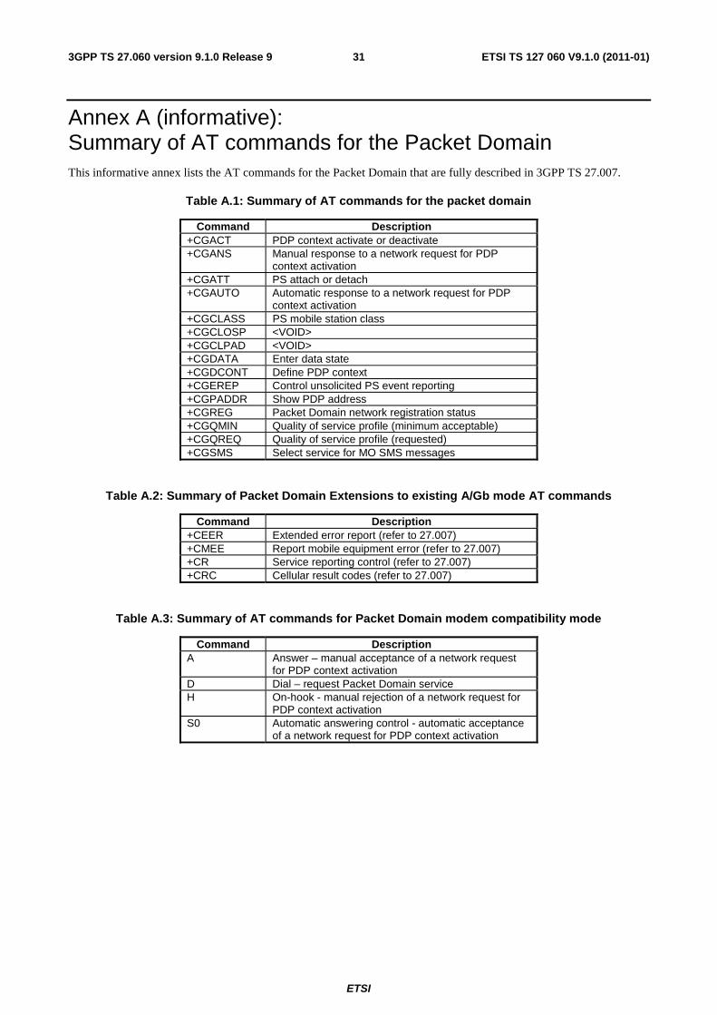
Annex A (informative): Summary of AT commands for the Packet Domain This informative annex lists the AT commands for the Packet Domain that are fully described in 3GPP TS 27.007.
Table A.1: Summary of AT commands for the packet domain
Command Description +CGACT PDP context activate or deactivate +CGANS Manual response to a network request for PDP
context activation +CGATT PS attach or detach +CGAUTO Automatic response to a network request for PDP
context activation +CGCLASS PS mobile station class +CGCLOSP <VOID> +CGCLPAD <VOID> +CGDATA Enter data state +CGDCONT Define PDP context +CGEREP Control unsolicited PS event reporting +CGPADDR Show PDP address +CGREG Packet Domain network registration status +CGQMIN Quality of service profile (minimum acceptable) +CGQREQ Quality of service profile (requested) +CGSMS Select service for MO SMS messages
Table A.2: Summary of Packet Domain Extensions to existing A/Gb mode AT commands
Command Description +CEER Extended error report (refer to 27.007) +CMEE Report mobile equipment error (refer to 27.007) +CR Service reporting control (refer to 27.007) +CRC Cellular result codes (refer to 27.007)
Table A.3: Summary of AT commands for Packet Domain modem compatibility mode
Command Description A Answer – manual acceptance of a network request
for PDP context activation D Dial – request Packet Domain service H On-hook - manual rejection of a network request for
PDP context activation S0 Automatic answering control - automatic acceptance
of a network request for PDP context activation

ETSI
ETSI TS 127 060 V9.1.0 (2011-01)323GPP TS 27.060 version 9.1.0 Release 9
Annex B (informative): Octet Stream Protocol (OSP) PDP type Void

ETSI
ETSI TS 127 060 V9.1.0 (2011-01)333GPP TS 27.060 version 9.1.0 Release 9
Annex C (informative): Change history
Change history Date TSG # TSG Doc. CR Rev Subject/Comment Old New 06-2004 TSG#24 NP-040247 089 2 Multiple IMS sessions using the same PDP context 5.6.0 6.0.0 06-2007 TSG#36 Upgraded to v7.0.0 6.0.0 7.0.0 12-2008 TSG#42 Upgraded to v8.0.0 due to simple upgrade without no technical
change 7.0.0 8.0.0
12-2009 TSG#46 Automatic upgrade from previous Release 8.0.0 9.0.0 12-2010 TSG#50 CP-100779 91 1 Correcting non-specific external references 9.0.0 9.1.0

ETSI
ETSI TS 127 060 V9.1.0 (2011-01)343GPP TS 27.060 version 9.1.0 Release 9
History
Document history
V9.0.0 January 2010 Publication
V9.1.0 January 2011 Publication
Related Documents