©2011 Advanced Engine Management, Inc. AEM Performance Electronics 2205 W. 126 th Street, Unit A, Hawthorne, CA 90250 Phone: (310) 484-2322 Fax: (310) 484-0152 http://www.aemelectronics.com Instruction Part Number: 10-7031 Rev C . TRU-TIME ADJUSTABLE CAM GEAR Part Number: 23-801BK & 23-802BK Legal in California only for racing vehicles which may never be used upon a public highway. WARNING: ,! This installation is not for the mechanically challenged! If you are not mechanically inclined or do not understand the procedure please do not attempt the installation. Refer the installation to a reputable mechanic. It is highly recommended to purchase the factory service manual to use as a guide along with these instruction sheets.

Welcome message from author
This document is posted to help you gain knowledge. Please leave a comment to let me know what you think about it! Share it to your friends and learn new things together.
Transcript
©2011 Advanced Engine Management, Inc. AEM Performance Electronics
2205 W. 126th Street, Unit A, Hawthorne, CA 90250 Phone: (310) 484-2322 Fax: (310) 484-0152
http://www.aemelectronics.com Instruction Part Number: 10-7031 Rev C
.
TRU-TIME ADJUSTABLE
CAM GEAR Part Number:
23-801BK & 23-802BK
Legal in California only for racing vehicles which may never be used upon a public highway.
WARNING:
!
This installation is not for the mechanically challenged! If you are not mechanically inclined or do not understand the procedure please do not attempt the installation. Refer the installation to a reputable mechanic. It is highly recommended to purchase the factory service manual to use as a guide along with these instruction sheets.
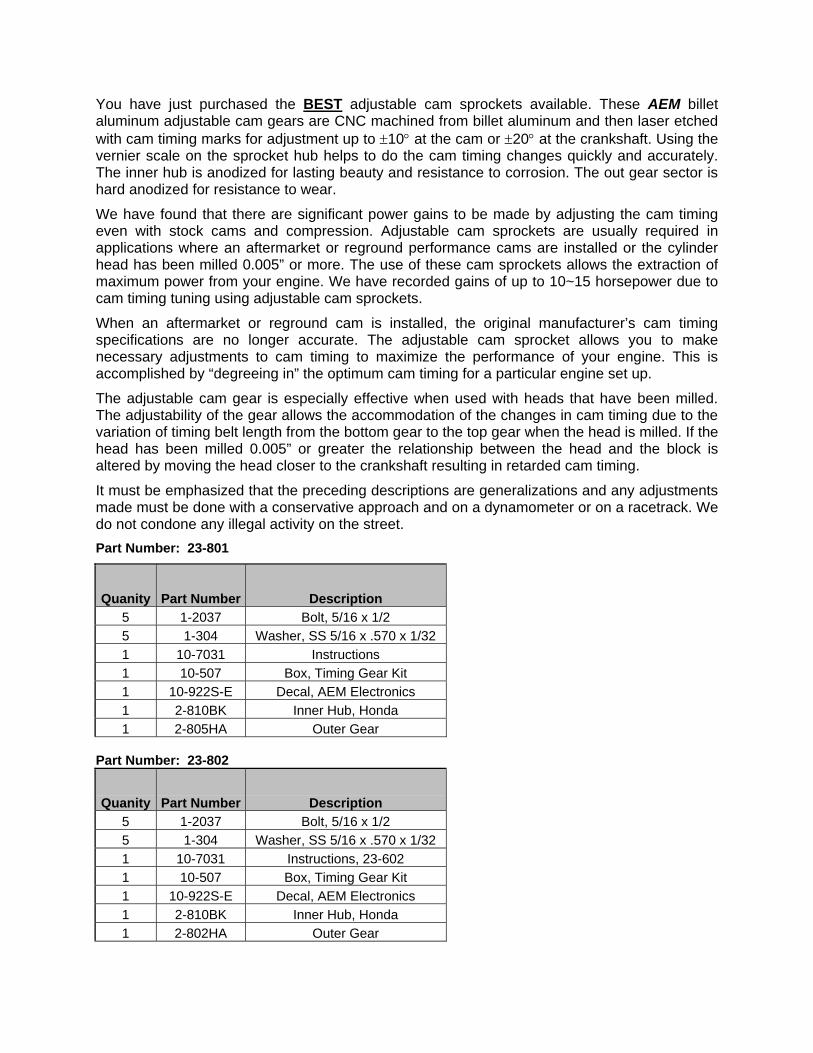
You have just purchased the BEST adjustable cam sprockets available. These AEM billet aluminum adjustable cam gears are CNC machined from billet aluminum and then laser etched with cam timing marks for adjustment up to ±10° at the cam or ±20° at the crankshaft. Using the vernier scale on the sprocket hub helps to do the cam timing changes quickly and accurately. The inner hub is anodized for lasting beauty and resistance to corrosion. The out gear sector is hard anodized for resistance to wear.
We have found that there are significant power gains to be made by adjusting the cam timing even with stock cams and compression. Adjustable cam sprockets are usually required in applications where an aftermarket or reground performance cams are installed or the cylinder head has been milled 0.005” or more. The use of these cam sprockets allows the extraction of maximum power from your engine. We have recorded gains of up to 10~15 horsepower due to cam timing tuning using adjustable cam sprockets.
When an aftermarket or reground cam is installed, the original manufacturer’s cam timing specifications are no longer accurate. The adjustable cam sprocket allows you to make necessary adjustments to cam timing to maximize the performance of your engine. This is accomplished by “degreeing in” the optimum cam timing for a particular engine set up.
The adjustable cam gear is especially effective when used with heads that have been milled. The adjustability of the gear allows the accommodation of the changes in cam timing due to the variation of timing belt length from the bottom gear to the top gear when the head is milled. If the head has been milled 0.005” or greater the relationship between the head and the block is altered by moving the head closer to the crankshaft resulting in retarded cam timing.
It must be emphasized that the preceding descriptions are generalizations and any adjustments made must be done with a conservative approach and on a dynamometer or on a racetrack. We do not condone any illegal activity on the street. Part Number: 23-801
Quanity Part Number Description 5 1-2037 Bolt, 5/16 x 1/2 5 1-304 Washer, SS 5/16 x .570 x 1/32 1 10-7031 Instructions 1 10-507 Box, Timing Gear Kit 1 10-922S-E Decal, AEM Electronics 1 2-810BK Inner Hub, Honda 1 2-805HA Outer Gear
Part Number: 23-802
Quanity Part Number Description 5 1-2037 Bolt, 5/16 x 1/2 5 1-304 Washer, SS 5/16 x .570 x 1/32 1 10-7031 Instructions, 23-602 1 10-507 Box, Timing Gear Kit 1 10-922S-E Decal, AEM Electronics 1 2-810BK Inner Hub, Honda 1 2-802HA Outer Gear

Getting started a) The procedure to change the gears is similar to the timing belt replacement procedure outlined in
the factory service manual. i) Note: This would be an appropriate time to replace the timing belt if replacement is
due or is close to the replacement interval. b) Obtain a suitable box or container to hold the hardware that will be removed from the engine
during this installation. This will aid in the prevention of lost nuts and bolts. c) Disconnect the negative battery terminal before starting these procedures. d) Raise the front of the vehicle and support on jack stands. To ensure maximum safety use jack
stands that are properly rated for the task. e) Remove the four nuts securing the driver side wheel and tire. Remove wheel and tire and set
aside. 2) Removal of the stock cam Gear
a) Remove the spark plug wires. Remove the cap nuts and washers securing the valve cover to the cylinder head. Remove valve cover. Remove the bolts securing the middle cover. Remove the middle cover. Remove the rubber plug to expose the belt tensioner adjustment bolt.
B18B & H23A
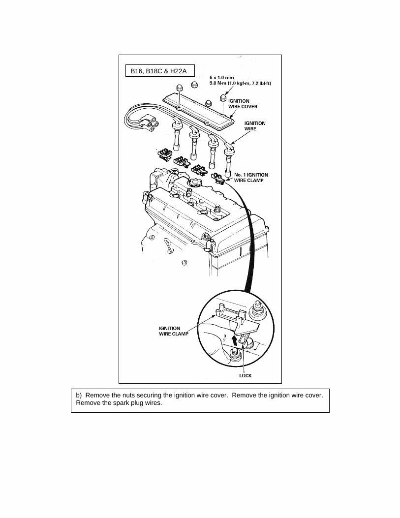
b) Remove the nuts securing the ignition wire cover. Remove the ignition wire cover. Remove the spark plug wires.
B16, B18C & H22A

c) Remove the cap nuts, nuts and washers securing the valve cover to the cylinder head. Remove valve cover. Remove the bolts securing the middle cover. Remove the middle cover. Remove the rubber plug to expose the belt tensioner adjustment bolt.
B16, B18C & H22A

B18B & H23A
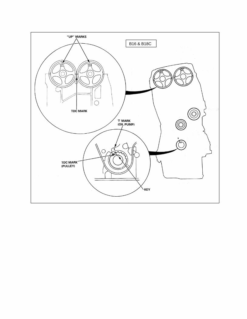
B16 & B18C

c) Align the motor to TDC. Always rotate motor in a counter-clockwise motion.
H22A B-Series
H-Series
3) Installation of the AEM Cam Gear.
a) Inspect the AEM Tru-Time Adjustable Cam Gear: i) The laser etched timing marks on inner hub and the outer gear should be clear and easy to
read. ii) Loosen the cam gear bolts on the AEM cam gear and rotate the hub clockwise and counter
clockwise. It should move freely without any binding. Set the timing mark to 0° and tighten the five cam gear bolts to 15 lb. ft.
iii) Compare the AEM cam gear to the O.E. cam gear. Make sure the major features of the two cam gears are identical. This will include the timing belt tooth profile, keyway location and laser etched TDC marks.
b) If the AEM cam gear does not function as described or look to be dimensionally correct in any way do not continue with this installation.
c) Install the AEM cam gear using the instructions for the removal of the O.E. cam gear in the opposite order.
d) Apply engine oil to the threads of the camshaft bolt and crankshaft bolt. Torque to factory specifications.
e) Tension Adjustment i) The tensioner is spring-loaded to apply proper tension to the belt automatically after making
the following adjustment. ii) Always rotate the crankshaft counterclockwise when viewed from the pulley side. Rotating it
clockwise may result in improper adjustment of the belt tension.
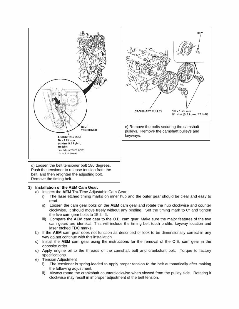
d) Loosen the belt tensioner bolt 180 degrees. Push the tensioner to release tension from the belt, and then retighten the adjusting bolt. Remove the timing belt.
e) Remove the bolts securing the camshaft pulleys. Remove the camshaft pulleys and keyways.
iii) Set the engine to TDC. iv) Loosen the adjusting bolt 180°. v) Rotate the crankshaft counterclockwise so that the timing belt moves 3-teeth on the camshaft
pulley to create tension on the timing belt. vi) Make sure the timing belt and camshaft pulley are engaged securely. vii) Torque the adjusting bolt.
f) Rotate the crankshaft 6 complete revolutions and return it to the TDC mark on the crankshaft pulley. The TDC marks on the AEM cam gear should align with the diagrams above. Note: If marks do not line up the timing belt must be removed, the cam gear repositioned and the timing belt re-installed. Repeat this step until the TDC marks on the AEM cam gear line up properly.
4) Calibration of the Tru-Time Adjustable Cam Gear Adjustment of an AEM cam gear is best carried out on a dynamometer so that quantifiable results can be measured.
a) Loosen the cam gear bolts. b) To change the cam timing, place a wrench on the camshaft bolt. Turn the wrench counter
clockwise to advance the cam timing or clockwise to retard the cam timing. c) Rotate the cam timing to the desired position and retighten the cam gear bolts to 15 lb. ft. Note: If
the head has been milled, take extreme caution when retarding the cam timing. There must be a minimum clearance of 0.06” between the piston and the valve.
d) The cam timing directly affects the ignition timing in your vehicle. Once the adjustment of the cam gear has been made you must reset the ignition timing back to the original location.
e) After changing the cam timing, perform a dyno run. If the results are positive then proceed further in the direction of the timing change. If the performance decreased, then adjust the cam timing in the opposite direction. Repeat this step until the optimum setting is found for your vehicle.
f) Apply Locite Red, or other suitable thread-locking compound; to the threads of the cam gear bolts. Torque the bolts to 15 lb. ft.
The calibration of the AEM Tru-Time Adjustable Cam Gear is now complete.
Important information for the proper use of the Cam Bolts!
• The recommended torque specification is 15 lb. ft. • Do not over torque. The maximum torque specification is 20 lb. ft. • Anything less than the recommended torque value will allow the gear to slip.

12 Month Limited Warranty Advanced Engine Management, Inc. warrants to the consumer that all AEM High Performance products will be free from defects in material and workmanship for a period of twelve (12) months from date of the original purchase. Products that fail within this 12 month warranty period will be repaired or replaced at AEM’s option, when determined by AEM that the product failed due to defects in material or workmanship. This warranty is limited to the repair or replacement of the AEM part. In no event shall this warranty exceed the original purchase price of the AEM part nor shall AEM be responsible for special, incidental or consequential damages or cost incurred due to the failure of this product. Warranty claims to AEM must be transportation prepaid and accompanied with dated proof of purchase. This warranty applies only to the original purchaser of product and is non-transferable. All implied warranties shall be limited in duration to the said 12 month warranty period. Improper use or installation, accident, abuse, unauthorized repairs or alterations voids this warranty. An AEM Warranty Claim Form Must Accompany All Warranty Claims. Products returned to AEM with no Return Goods Authorization and or No Warranty Claim Form may be rejected and returned to sender. AEM disclaims any liability for consequential damages due to breach of any written or implied warranty on all products manufactured by AEM. Warranty returns will only be accepted be AEM when accompanied by a valid Return Goods Authorization (RGA) number. Credit for defective products will be issued pending inspection. Product must be received by AEM within 30 days of the date RGA was issued.
Related Documents