ETSI TR 137 900 V12.0.0 (2014-10) Digital cellular telecommunications system (Phase 2+); Universal Mobile Telecommunications System (UMTS); LTE; Radio Frequency (RF) requirements for Multicarrier and Multiple Radio Access Technology (Multi-RAT) Base Station (BS) (3GPP TR 37.900 version 12.0.0 Release 12) TECHNICAL REPORT

Welcome message from author
This document is posted to help you gain knowledge. Please leave a comment to let me know what you think about it! Share it to your friends and learn new things together.
Transcript
ETSI TR 137 900 V12.0.0 (2014-10)
Digital cellular telecommunications system (Phase 2+); Universal Mobile Telecommunications System (UMTS);
LTE; Radio Frequency (RF) requirements for
Multicarrier and Multiple Radio Access Technology (Multi-RAT) Base Station (BS)
(3GPP TR 37.900 version 12.0.0 Release 12)
�
TECHNICAL REPORT
ETSI
ETSI TR 137 900 V12.0.0 (2014-10)13GPP TR 37.900 version 12.0.0 Release 12
Reference RTR/TSGR-0437900vc00
Keywords GSM,LTE,UMTS
ETSI
650 Route des Lucioles F-06921 Sophia Antipolis Cedex - FRANCE
Tel.: +33 4 92 94 42 00 Fax: +33 4 93 65 47 16
Siret N° 348 623 562 00017 - NAF 742 C
Association à but non lucratif enregistrée à la Sous-Préfecture de Grasse (06) N° 7803/88
Important notice
The present document can be downloaded from: http://www.etsi.org
The present document may be made available in electronic versions and/or in print. The content of any electronic and/or print versions of the present document shall not be modified without the prior written authorization of ETSI. In case of any
existing or perceived difference in contents between such versions and/or in print, the only prevailing document is the print of the Portable Document Format (PDF) version kept on a specific network drive within ETSI Secretariat.
Users of the present document should be aware that the document may be subject to revision or change of status. Information on the current status of this and other ETSI documents is available at
http://portal.etsi.org/tb/status/status.asp
If you find errors in the present document, please send your comment to one of the following services: http://portal.etsi.org/chaircor/ETSI_support.asp
Copyright Notification
No part may be reproduced or utilized in any form or by any means, electronic or mechanical, including photocopying and microfilm except as authorized by written permission of ETSI.
The content of the PDF version shall not be modified without the written authorization of ETSI. The copyright and the foregoing restriction extend to reproduction in all media.
© European Telecommunications Standards Institute 2014.
All rights reserved.
DECTTM, PLUGTESTSTM, UMTSTM and the ETSI logo are Trade Marks of ETSI registered for the benefit of its Members. 3GPPTM and LTE™ are Trade Marks of ETSI registered for the benefit of its Members and
of the 3GPP Organizational Partners. GSM® and the GSM logo are Trade Marks registered and owned by the GSM Association.
ETSI
ETSI TR 137 900 V12.0.0 (2014-10)23GPP TR 37.900 version 12.0.0 Release 12
Intellectual Property Rights IPRs essential or potentially essential to the present document may have been declared to ETSI. The information pertaining to these essential IPRs, if any, is publicly available for ETSI members and non-members, and can be found in ETSI SR 000 314: "Intellectual Property Rights (IPRs); Essential, or potentially Essential, IPRs notified to ETSI in respect of ETSI standards", which is available from the ETSI Secretariat. Latest updates are available on the ETSI Web server (http://ipr.etsi.org).
Pursuant to the ETSI IPR Policy, no investigation, including IPR searches, has been carried out by ETSI. No guarantee can be given as to the existence of other IPRs not referenced in ETSI SR 000 314 (or the updates on the ETSI Web server) which are, or may be, or may become, essential to the present document.
Foreword This Technical Report (TR) has been produced by ETSI 3rd Generation Partnership Project (3GPP).
The present document may refer to technical specifications or reports using their 3GPP identities, UMTS identities or GSM identities. These should be interpreted as being references to the corresponding ETSI deliverables.
The cross reference between GSM, UMTS, 3GPP and ETSI identities can be found under http://webapp.etsi.org/key/queryform.asp.
Modal verbs terminology In the present document "shall", "shall not", "should", "should not", "may", "may not", "need", "need not", "will", "will not", "can" and "cannot" are to be interpreted as described in clause 3.2 of the ETSI Drafting Rules (Verbal forms for the expression of provisions).
"must" and "must not" are NOT allowed in ETSI deliverables except when used in direct citation.
ETSI
ETSI TR 137 900 V12.0.0 (2014-10)33GPP TR 37.900 version 12.0.0 Release 12
Contents
Intellectual Property Rights ................................................................................................................................ 2
Foreword ............................................................................................................................................................. 2
Modal verbs terminology .................................................................................................................................... 2
Foreword ............................................................................................................................................................. 6
1 Scope ........................................................................................................................................................ 7
2 References ................................................................................................................................................ 7
3 Definitions, symbols and abbreviations ................................................................................................... 8
3.1 Definitions .......................................................................................................................................................... 8
3.2 Symbols .............................................................................................................................................................. 9
3.3 Abbreviations ................................................................................................................................................... 10
4 General ................................................................................................................................................... 11
4.1 Work item objective ......................................................................................................................................... 11
4.2 Relation to other RAN and GERAN specifications ......................................................................................... 12
4.3 Relationship between minimum requirements and test requirements .............................................................. 12
4.3.1 Relationship for requirements developed for MSR .................................................................................... 12
4.4 Base Station classes .......................................................................................................................................... 12
4.5 Regional requirements ...................................................................................................................................... 13
4.6 Manufacturer"s declaration .............................................................................................................................. 13
5 Multi-Standard Radio scenarios ............................................................................................................. 14
5.1 Definitions ........................................................................................................................................................ 14
5.1.1 Frequency bands and arrangements ............................................................................................................ 14
5.1.1.1 General .................................................................................................................................................. 14
5.1.1.2 Frequency bands ................................................................................................................................... 14
5.1.1.3 Channel spacing .................................................................................................................................... 15
5.1.1.4 Channel raster ....................................................................................................................................... 15
5.1.1.5 Carrier frequency and channel numbers ................................................................................................ 15
5.1.2 RF bandwidth in MSR specification ........................................................................................................... 16
5.2 FDD multi-RAT and multicarrier scenarios ..................................................................................................... 17
5.2.1 Band category 1 scenarios (BC1) ............................................................................................................... 18
5.2.2 Band category 2 scenarios (BC2) ............................................................................................................... 18
5.3 TDD multi-RAT and multicarrier scenarios ..................................................................................................... 18
5.3.1 Band category 3 scenarios (1.28 Mcps UTRA TDD and E-UTRA TDD) .................................................. 18
5.3.2 Foffset, RAT of band category 3 ....................................................................................................................... 19
6 Transmitter characteristics ..................................................................................................................... 19
6.1 General ............................................................................................................................................................. 19
6.2 Base Station output power ................................................................................................................................ 20
6.3 Output power dynamics .................................................................................................................................... 21
6.4 Transmit ON/OFF power ................................................................................................................................. 21
6.4.1 Transmitter OFF power .............................................................................................................................. 21
6.4.2 Transmitter transient period ........................................................................................................................ 22
6.5 Transmitted signal quality ................................................................................................................................ 22
6.5.1 Modulation quality ...................................................................................................................................... 22
6.5.2 Frequency error ........................................................................................................................................... 22
6.5.2.1 Minimum requirement .......................................................................................................................... 23
6.6 Unwanted emissions ......................................................................................................................................... 23
6.6.1 Operating band unwanted emissions .......................................................................................................... 23
6.6.1.1 Existing regulatory requirements .......................................................................................................... 23
6.6.1.1.1 FCC requirements ............................................................................................................................ 23
6.6.1.1.2 WAPECS requirements for Europe ................................................................................................. 23
6.6.1.1.3 Co-existence with services in adjacent frequency bands ................................................................. 24
6.6.1.2 Application of necessary bandwidth ..................................................................................................... 24
ETSI
ETSI TR 137 900 V12.0.0 (2014-10)43GPP TR 37.900 version 12.0.0 Release 12
6.6.1.3 RF bandwidth scenarios ........................................................................................................................ 25
6.6.1.4 Derivation of requirement ..................................................................................................................... 25
6.6.1.4.1 Requirement for band category 1 .................................................................................................... 25
6.6.1.4.2 Requirement for band category 2 .................................................................................................... 26
6.6.1.5 Minimum requirement (band category 1) ............................................................................................. 27
6.6.1.6 Minimum requirement (band category 2) ............................................................................................. 28
6.6.1.7 Additional requirements (BC1 and BC2) .............................................................................................. 29
6.6.1.8 Minimum requirement (band category 3) ............................................................................................. 29
6.6.1.9 Additional requirement (BC3) .............................................................................................................. 30
6.6.2 Transmitter spurious emissions ................................................................................................................... 30
6.6.2.1 Band category 1 .................................................................................................................................... 31
6.6.2.1.1 Mandatory requirements .................................................................................................................. 31
6.6.2.1.2 Co-existence in the same geographical area .................................................................................... 31
6.6.2.1.3 Co-location ...................................................................................................................................... 32
6.6.2.1.4 Protection of the BS receiver of own or different BS ...................................................................... 33
6.6.2.2 Band category 2 .................................................................................................................................... 34
6.6.2.2.1 Mandatory requirements .................................................................................................................. 34
6.6.2.2.2 Co-existence in the same geographical area .................................................................................... 34
6.6.2.2.3 Co-location ...................................................................................................................................... 35
6.6.2.2.4 Protection of the BS receiver of own or different BS ...................................................................... 35
6.6.2.3 Band category 3 .................................................................................................................................... 35
6.6.2.3.1 Mandatory requirements .................................................................................................................. 35
6.6.2.3.2 Co-existence in the same geographical area .................................................................................... 35
6.6.2.3.3 Co-location ...................................................................................................................................... 36
6.6.3 Occupied bandwidth ................................................................................................................................... 36
6.6.3.1 Definition .............................................................................................................................................. 36
6.6.3.2 Minimum requirement .......................................................................................................................... 36
6.6.4 Adjacent Channel Leakage Ratio (ACLR) ................................................................................................. 36
6.7 Transmitter intermodulation ............................................................................................................................. 37
6.7.1 Minimum requirement ................................................................................................................................ 37
7 Receiver characteristics .......................................................................................................................... 39
7.1 General ............................................................................................................................................................. 39
7.2 Reference sensitivity level ................................................................................................................................ 39
7.2.1 Minimum requirement ................................................................................................................................ 40
7.3 Dynamic range ................................................................................................................................................. 40
7.3.1 Minimum requirement ................................................................................................................................ 40
7.4 In-band selectivity and blocking ...................................................................................................................... 40
7.4.1 Band category 1 .......................................................................................................................................... 40
7.4.1.1 Blocking ................................................................................................................................................ 40
7.4.1.1.1 Minimum requirement ..................................................................................................................... 41
7.4.1.2 Narrowband blocking ............................................................................................................................ 41
7.4.1.2.1 Minimum requirement ..................................................................................................................... 41
7.4.2 Band category 2 .......................................................................................................................................... 42
7.4.2.1 Blocking requirement ............................................................................................................................ 42
7.4.2.1.1 Minimum requirement ..................................................................................................................... 42
7.4.2.2 Narrowband blocking ............................................................................................................................ 42
7.4.2.2.1 Minimum requirement ..................................................................................................................... 43
7.4.3 band category 3 ........................................................................................................................................... 43
7.4.3.1 Blocking ................................................................................................................................................ 43
7.4.3.1.1 Minimum requirement .......................................................................................................................... 43
7.4.3.2 Narrowband blocking ............................................................................................................................ 44
7.4.3.2.1 Minimum requirement ..................................................................................................................... 44
7.5 Out-of-band blocking ....................................................................................................................................... 45
7.5.1 Band category 1 .......................................................................................................................................... 45
7.5.1.1 General 'out-of-band' blocking .............................................................................................................. 45
7.5.1.2 Co-location ............................................................................................................................................ 45
7.5.2 Band category 2 .......................................................................................................................................... 46
7.5.2.1 General 'out-of-band' blocking .............................................................................................................. 46
7.5.2.2 Co-location ............................................................................................................................................ 46
7.5.3 Band category 3 .......................................................................................................................................... 47
7.5.3.1 General 'out-of-band' blocking .............................................................................................................. 47
ETSI
ETSI TR 137 900 V12.0.0 (2014-10)53GPP TR 37.900 version 12.0.0 Release 12
7.5.3.2 Co-location ............................................................................................................................................ 47
7.6 Receiver spurious emissions............................................................................................................................. 47
7.6.1 Band category 1 .......................................................................................................................................... 48
7.6.1.1 Minimum requirement (BC1)................................................................................................................ 48
7.6.2 Band category 2 .......................................................................................................................................... 48
7.6.2.1 Minimum requirement (BC2)................................................................................................................ 49
7.6.3 Band category 3 .......................................................................................................................................... 49
7.6.3.1 Minimum requirement (BC3)................................................................................................................ 49
7.7 Receiver intermodulation ................................................................................................................................. 50
7.7.1 Band category 1 .......................................................................................................................................... 50
7.7.1.1 Intermodulation requirement ................................................................................................................. 50
7.7.1.1.1 Minimum requirement ..................................................................................................................... 50
7.7.1.2 Narrowband intermodulation ................................................................................................................ 51
7.7.1.2.1 Minimum requirement ..................................................................................................................... 51
7.7.2 Band category 2 .......................................................................................................................................... 52
7.7.2.1 Intermodulation requirement ................................................................................................................. 52
7.7.2.1.1 Minimum requirement ..................................................................................................................... 52
7.7.2.2 Narrowband intermodulation ................................................................................................................ 53
7.7.2.2.1 Minimum requirement ..................................................................................................................... 53
7.7.3 Band category 3 .......................................................................................................................................... 54
7.7.3.1 Intermodulation requirement ................................................................................................................. 54
7.7.3.1.1 Minimum requirement ..................................................................................................................... 55
7.7.3.2 Narrowband intermodulation ................................................................................................................ 55
7.7.3.2.1 Minimum requirement ..................................................................................................................... 56
7.8 In-channel selectivity ....................................................................................................................................... 57
7.8.1 Minimum requirement ................................................................................................................................ 57
8 Other requirements ................................................................................................................................. 57
8.1 EMC ................................................................................................................................................................. 57
8.2 Performance requirements ................................................................................................................................ 57
9 Test specification .................................................................................................................................... 58
9.1 BS test configurations ...................................................................................................................................... 58
9.1.1 Definition of Capability Sets (CS) .............................................................................................................. 58
9.1.2 Definition of Test Configurations (TC) ...................................................................................................... 59
9.1.3 Mapping from test requirement to test configuration ................................................................................. 59
Annex A: Characteristics of interfering signals .................................................................................. 71
A.1 UTRA interfering signal ......................................................................................................................... 71
A.2 E-UTRA interfering signal ..................................................................................................................... 71
Annex B: Change history ...................................................................................................................... 72
History .............................................................................................................................................................. 75
ETSI
ETSI TR 137 900 V12.0.0 (2014-10)63GPP TR 37.900 version 12.0.0 Release 12
Foreword This Technical Report has been produced by the 3rd Generation Partnership Project (3GPP).
The contents of the present document are subject to continuing work within the TSG and may change following formal TSG approval. Should the TSG modify the contents of the present document, it will be re-released by the TSG with an identifying change of release date and an increase in version number as follows:
Version x.y.z
where:
x the first digit:
1 presented to TSG for information;
2 presented to TSG for approval;
3 or greater indicates TSG approved document under change control.
Y the second digit is incremented for all changes of substance, i.e. technical enhancements, corrections, updates, etc.
z the third digit is incremented when editorial only changes have been incorporated in the document.
ETSI
ETSI TR 137 900 V12.0.0 (2014-10)73GPP TR 37.900 version 12.0.0 Release 12
1 Scope The present document is the technical report for the work item on Multi-Standard Radio (MSR), which was approved at TSG RAN#41. The objective of the WI is to first identify relevant scenarios and then write an RF requirements specification that is applicable to Multi-Standard Radio (MSR) Base Station with multiple carriers and/or multiple 3GPP Radio Access Technologies (RAT).
2 References The following documents contain provisions which, through reference in this text, constitute provisions of the present document.
- References are either specific (identified by date of publication, edition number, version number, etc.) or non-specific.
- For a specific reference, subsequent revisions do not apply.
- For a non-specific reference, the latest version applies. In the case of a reference to a 3GPP document (including a GSM document), a non-specific reference implicitly refers to the latest version of that document in the same Release as the present document.
[1] 3GPP TR 21.905: 'Vocabulary for 3GPP Specifications'.
[2] 3GPP TS 25.104: 'Base Station (BS) radio transmission and reception (FDD)'.
[3] 3GPP TS 25.105: 'Base Station (BS) radio transmission and reception (TDD)'.
[4] 3GPP TS 36.104: 'Base Station (BS) radio transmission and reception'.
[5] 3GPP TS 45.005: 'Radio transmission and reception'.
[6] ITU-R SM.329-10 Recommendation, 'Unwanted emissions in the spurious domain'.
[7] 3GPP TR 25.942: 'Radio Frequency (RF) system scenarios'.
[8] R4-99997, 'BS Spurious Emission Requirements for Co-Existence UTRA-FDD/ UTRA-TDD and for Protection of BS receiver in TS 25.104' (Ericsson).
[9] RP-020781, 'FDD – GSM co-existence in the Same Geographic Area', CR149 to TS 25.104 (RAN WG4).
[10] RP-030214, 'General corrections on co-existence and co-location requirements for UTRA-FDD BS', CR191 to TS25.104 (RAN WG4).
[11] 'Title 47 of the Code of Federal Regulations (CFR)', Federal Communications Commission.
[12] 3GPP TR 36.804: 'Evolved Universal Terrestrial Radio Access (E-UTRA); Base Station (BS) radio transmission and reception'.
[13] 'Commission Decision of 13 June 2008 on the � hannelizatio of the 2 500-2 690 MHz frequency band for terrestrial systems capable of providing electronic communications services in the Community', Decision 2008/477/EC.
[14] ETSI TR 102 748: 'Electromagnetic compatibility and Radio spectrum Matters (ERM); Impact of the trend towards flexibility in spectrum usage on the principles for drafting Harmonized Standards and the ETSI work programme for Harmonized Standards'.
[15] CEPT/ERC/Recommendation 74-01E, 'Unwanted Emissions In The Spurious Domain' (Hradec Kralove 05) Edition of October, 2005.
[16] 3GPP TR 45.050: 'Background for Radio Frequency (RF) requirements'.
ETSI
ETSI TR 137 900 V12.0.0 (2014-10)83GPP TR 37.900 version 12.0.0 Release 12
[17] 3GPP TS 25.141: 'Base Station (BS) conformance testing (FDD)'.
[18] 3GPP TS 25.142: 'Base Station (BS) conformance testing (TDD)'.
[19] 3GPP TS 36.141: 'Evolved Universal Terrestrial Radio Access (E-UTRA) ; Base Station (BS) conformance testing'.
[20] 3GPP TS 51.021: 'Base Station System (BSS) equipment specification; Radio aspects'.
[21] ITU-R Recommendation M.1545: 'Measurement uncertainty as it applies to test limits for the terrestrial component of International Mobile Telecommunications-2000'.
[22] ITU-R Recommendation SM.328-11: 'Spectra and bandwidth of emissions'.
[23] 3GPP TR 36.942'Evolved Universal Terrestrial Radio Access (E-UTRA); Radio Frequency (RF) system scenarios'.
[24] 3GPP TS 25.113: 'Base Station (BS) and repeater ElectroMagnetic Compatibility (EMC)'.
[25] 3GPP TS 36.113: 'Evolved Universal Terrestrial Radio Access (E-UTRA); Base Station (BS) and repeater ElectroMagnetic Compatibility (EMC)'.
[26] ETSI EN 301 489-8: 'ElectroMagnetic Compatibility (EMC) standard for radio equipment and services – Part 8: Specific conditions for GSM Base Stations'.
[27] ETSI EN 301 489-23: 'ElectroMagnetic Compatibility (EMC) standard for radio equipment and services – Part 23: Specific conditions for IMT-2000 CDMA Direct Spread (UTRA) Base Station (BS) radio, repeater and ancillary equipment'
[28] R4-100806, ' LS from ETSI TFES: LS on Spurious emission limits for MCBTS and MSR'.
[29] Recommendation ITU-R SM.1539-1: 'Variation of the boundary between the out-of-band and spurious domains required for the application of Recommendations ITU-R SM.1541 and ITU-R SM.329' (2001).
[30] 'Adjacent Band Compatibility between UMTS and Other Services in the 2 GHz Band', ERC Report 65, Menton, May 1999, revised in Helsinki, November 1999.
Note: The 3GPP meeting contributions referenced above are included with the current document.
3 Definitions, symbols and abbreviations
3.1 Definitions For the purposes of the present document, the terms and definitions given in TR 21.905 [1] and the following apply. A term defined in the present document takes precedence over the definition of the same term, if any, in TR 21.905 [1].
Band category: A group of operating bands for which the same MSR scenarios apply
Base Station RF bandwidth: The bandwidth in which a Base Station transmits and receives multiple carriers and/or RATs simultaneously
Base Station RF bandwidth edge: The frequency of one of the edges of the Base Station RF bandwidth
Carrier: The modulated waveform conveying the E-UTRA, UTRA or GSM physical channels
Channel bandwidth: The bandwidth supporting a single E-UTRA RF carrier with the transmission bandwidth configured in the uplink or downlink of a cell. The channel bandwidth is measured in MHz and is used as a reference for transmitter and receiver RF requirements.
Carrier power: The power at the antenna connector in the channel bandwidth of the carrier averaged over at least one subframe for E-UTRA, at least one slot for UTRA and the useful part of the burst for GSM.
ETSI
ETSI TR 137 900 V12.0.0 (2014-10)93GPP TR 37.900 version 12.0.0 Release 12
Downlink operating band: The part of the operating band designated for downlink.
Lower RF bandwidth edge: The frequency of the lower edge of the Base Station RF bandwidth, used as a frequency reference point for transmitter and receiver requirements
Maximum Base Station RF bandwidth: The maximum RF bandwidth supported by a BS within an operating band.
Maximum carrier power: Carrier power available at the antenna connector for a specified reference condition.
Maximum RAT power: RAT power available at the antenna connector for a specified reference condition.
Maximum throughput: The maximum achievable throughput for a reference measurement channel.
Maximum total output power: Total output power available at the antenna connector for a specified reference condition.
Measurement bandwidth: The bandwidth in which an emission level is specified.
MSR Base Station: Base Station characterized by the ability of its receiver and transmitter to process two or more carriers in common active RF components simultaneously in a declared RF bandwidth, where at least one carrier is of a different RAT than the other carrier(s).
Multi-carrier transmission configuration: A set of one or more contiguous carriers that a BS is able to transmit simultaneously according to the manufacturer"s specification.
Necessary bandwidth: The width of the frequency band which is just sufficient to ensure the transmission of information at the rate and with the quality required under specified conditions (as defined in [6]).
Occupied bandwidth: The width of a frequency band such that, below the lower and above the upper frequency limits, the mean powers emitted are each equal to a specified percentage β/2 of the total mean power of a given emission.
Operating band: A frequency range in which E-UTRA, UTRA or GSM operates (paired or unpaired), that is defined with a specific set of technical requirements.
NOTE: The operating band(s) for a BS is declared by the manufacturer.
RAT power: The sum of all carrier powers for all carriers of the same type.
RRC filtered mean power: The mean power of a UTRA carrier as measured through a root raised cosine filter with roll-off factor α and a bandwidth equal to the chip rate of the radio access mode.
NOTE: The RRC filtered mean power of a perfectly modulated UTRA signal is 0.246 dB lower than the mean power of the same signal.
Throughput: The number of payload bits successfully received per second for a reference measurement channel in a specified reference condition.
Total output power: The sum of all carrier powers for all carriers transmitted by the BS.
Transmission bandwidth: Bandwidth of an instantaneous E-UTRA transmission from a UE or BS, measured in Resource Block units.
Transmission bandwidth configuration: The highest E-UTRA transmission bandwidth allowed for uplink or downlink in a given channel bandwidth, measured in Resource Block units.
Uplink operating band: The part of the operating band designated for uplink.
Upper RF bandwidth edge: The frequency of the upper edge of the Base Station RF bandwidth, used as a frequency reference point for transmitter and receiver requirements
3.2 Symbols For the purposes of the present document, the following symbols apply:
2012− Roll-off factor 2012− Percentage of the mean transmitted power emitted outside the occupied bandwidth on the assigned channel
ETSI
ETSI TR 137 900 V12.0.0 (2014-10)103GPP TR 37.900 version 12.0.0 Release 12
BWChannel Channel bandwidth (for E-UTRA) BWConfig Transmission bandwidth configuration (for E-UTRA), expressed in MHz, where BWConfig = NRB x
180 kHz in the uplink and BWConfig = 15 kHz + NRB x 180 kHz in the downlink. BWRF Base Station RF bandwidth, where BWRF = FBW RF,high – FBW RF,low BWRF,max Maximum Base Station RF bandwidth f Frequency Δf Separation between the Base Station RF bandwidth edge frequency and the nominal -3dB point of
the measuring filter closest to the carrier frequency Δfmax The largest value of Δf used for defining the requirement FC Carrier centre frequency f_offset Separation between the Base Station RF bandwidth edge frequency and the centre of the
measuring filter f_offsetmax The maximum value of f_offset used for defining the requirement FBW RF,high Upper RF bandwidth edge, where FBW RF,high = FC,high + Foffset, RAT FBW RF,low Lower RF bandwidth edge, where FBW RF,low = FC,low – Foffset, RAT FC,high Center frequency of the highest transmitted/received carrier. FC,low Center frequency of the lowest transmitted/received carrier. Foffset, RAT Frequency offset from FC,high to the upper RF bandwidth edge or FC,low to the lower RF bandwidth
edge for a specific RAT. FDL_low The lowest frequency of the downlink operating band FDL_high The highest frequency of the downlink operating band FUL_low The lowest frequency of the uplink operating band FUL_high The highest frequency of the uplink operating band NRB Transmission bandwidth configuration, expressed in units of resource blocks (for E-UTRA) PREFSENS Reference Sensitivity power level
3.3 Abbreviations For the purposes of the present document, the abbreviations given in TR 21.905 [1] and the following apply. An abbreviation defined in the present document takes precedence over the definition of the same abbreviation, if any, in TR 21.905 [1].
ACIR Adjacent Channel Interference Ratio ACLR Adjacent Channel Leakage Ratio ACK Acknowledgement (in HARQ protocols) ACS Adjacent Channel Selectivity ARFCN Absolute Radio Frequency Channel Number AWGN Additive White Gaussian Noise BC Band Category BER Bit Error Ratio BS Base Station BTS Base Transceiver Station CP Cyclic prefix CRC Cyclic Redundancy Check CS Capability Set CW Continuous Wave DC Direct Current DB-DC-HSDPA Dual Band Dual Cell HSDPA DC-HSDPA Dual Cell HSDPA DTX Discontinuous Transmission DTT Digital Terrestrial Television EARFCN E-UTRA Absolute Radio Frequency Channel Number EVM Error Vector Magnitude FDD Frequency Division Duplex FRC Fixed Reference Channel GP Guard Period (for E-UTRA TDD operation) GSM Global System for Mobile Communications HSDPA High Speed Downlink Packet Access ICS In-Channel Selectivity ITU-R Radiocommunication Sector of the ITU LNA Low Noise Amplifier MC Multi-Carrier (in single RAT)
ETSI
ETSI TR 137 900 V12.0.0 (2014-10)113GPP TR 37.900 version 12.0.0 Release 12
MCL Minimum Coupling Loss MCS Modulation and Coding Scheme MIMO Multiple Input Multiple Output MR Multi-RAT MS Mobile Station MSR Multi-standard Radio OFDM Orthogonal Frequency Division Multiplex OOB Out-of-band PA Power Amplifier PHS Personal Handyphone System QAM Quadrature Amplitude Modulation QPSK Quadrature Phase-Shift Keying RAT Radio Access Technology RB Resource Block RF Radio Frequency RMS Root Mean Square (value) RS Reference Symbol RX Receiver RRC Root Raised Cosine SC Single Carrier SNR Signal-to-Noise Ratio SR single-RAT TC Test Configuration TDD Time Division Duplex TD-SCDMA Time Division Synchronous Code Division Multiple Access TX Transmitter UARFCN UTRA Absolute Radio Frequency Channel Number UE User Equipment
4 General
4.1 Work item objective The objective the TSG RAN Work Item is to first identify relevant scenarios and then write an RF requirements specification that is applicable to Multi-Standard Radio (MSR) Base Station with multiple carriers and/or multiple 3GPP Radio Access Technologies (RAT), according to the following:
- The new specification will cover RF requirements for GSM, UTRA, and E-UTRA (both FDD and TDD modes), for relevant single and multicarrier scenarios and will take into account the regulatory framework in different regions.
- The new specification will include BS transmission and reception requirements, but no baseband performance requirements.
- Existing RF specifications will remain and be applicable within their current scope.
- For a multi-RAT/multi-carrier Base Station, the new RF requirements specification will be applicable for that equipment, together with the baseband requirements of the relevant existing specifications.
The objective of the TSG GERAN Work Task is to support the RAN4 Work Item Building Block, which has the objective to first identify relevant technology migration scenarios and then write an RF requirements specification that is applicable to Multi-Standard Radio (MSR) Base Station.
The Work Task will review the GERAN relevant parts and prepare input for adapting the existing GERAN requirements to an MSR specification with a goal to minimize changes to these requirements.
ETSI
ETSI TR 137 900 V12.0.0 (2014-10)123GPP TR 37.900 version 12.0.0 Release 12
4.2 Relation to other RAN and GERAN specifications The requirements for MSR are in most parts specified in the present document, while many requirements are also specified through normative references to the respective single-RAT specifications in [2], [3], [4] and [5]. The resulting set of requirements for an MSR BS can be divided into three types, depending on their relation to the single-RAT specifications:
1. Generic MSR requirement: A common generic requirement is specified in the present document that applies for all RATs and for BS configured for both multi-RAT and single-RAT operation. In some cases, there are additional requirement(s) that apply only in some Band Category. There are no references to the single-RAT specifications.
2. Generic MSR requirement, with additional single-RAT requirements: A common generic requirement is specified in the present document which applies as in point 1. In addition some single RAT requirement(s) apply, included by normative reference(s) to the single-RAT specification(s).
3. Single-RAT only requirements: In this case, no common generic requirement is defined. The existing single-RAT requirement applies for each RAT, included by normative reference(s) to the single-RAT specification(s).
4.3 Relationship between minimum requirements and test requirements
For UTRA and E-UTRA, the Minimum Requirements given in the core specifications [2][3][4] make no allowance for measurement uncertainty. The test specifications [17][18][19] define Test Tolerances. These Test Tolerances are individually calculated for each test. The Test Tolerances are used to relax the Minimum Requirements in the core specifications to create Test Requirements.
For some regulatory requirements taken directly from international or regional recommendations or other regulatory references, the test tolerance is set to zero. This concerns the requirements for Spurious emissions and Operating band unwanted emissions.
The measurement results returned by the Test System are compared – without any modification – against the Test Requirements as defined by the shared risk principle. The Shared Risk principle is defined in ITU-R M.1545 [21].
For GSM, the shared risk principle is also applied, with the test requirement in TS 51.021 [20] normally being the same as the requirement defined in the core specification [5].
4.3.1 Relationship for requirements developed for MSR
For the minimum requirements developed in the present Technical Report with the purpose to set MSR multi-RAT requirements in the MSR specification, no allowance is given for measurement uncertainty. For the test specification, test Tolerances will be individually calculated for each test and be used to relax the Minimum Requirements in the core specification to create Test Requirements. For some requirements, including regulatory requirements, the test tolerance is set to zero.
For MSR single-RAT requirements, the principle used to define the test requirement remains from the existing specifications.
For both MSR single-RAT and multi-RAT requirements, the measurement results returned by the Test System are compared – without any modification – against the Test Requirements as defined by the shared risk principle.
4.4 Base Station classes The requirements presented in this TR apply to MSR Base Stations intended for general purpose applications. MSR BS requirements for general purpose applications will be based on Wide Area scenarios.
For GSM operation of an MSR BS, a BS intended for general purpose applications corresponds to a normal BTS, including Multicarrier BTS classes. MSR requirements for multi-RAT operation only apply for the highest GSM static power step.
ETSI
ETSI TR 137 900 V12.0.0 (2014-10)133GPP TR 37.900 version 12.0.0 Release 12
Other Base Station classes are for further study. The requirements for these may be different than those for general purpose applications, or not applicable at all.
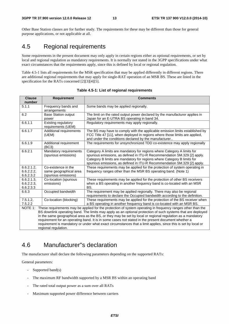
4.5 Regional requirements Some requirements in the present document may only apply in certain regions either as optional requirements, or set by local and regional regulation as mandatory requirements. It is normally not stated in the 3GPP specifications under what exact circumstances that the requirements apply, since this is defined by local or regional regulation.
Table 4.5-1 lists all requirements for the MSR specification that may be applied differently in different regions. There are additional regional requirements that may apply for single-RAT operation of an MSR BS. These are listed in the specification for the RATs concerned [2][3][4][5].
Table 4.5-1: List of regional requirements
Clause number
Requirement Comments
5.1.1 Frequency bands and arrangements
Some bands may be applied regionally.
6.2 Base Station output power
The limit on the rated output power declared by the manufacturer applies in Japan for an E-UTRA BS operating in band 34.
6.6.1.1 Existing regulatory requirements (UEM)
Regulatory requirements may apply regionally.
6.6.1.7 Additional requirements (UEM)
The BS may have to comply with the applicable emission limits established by FCC Title 47 [11], when deployed in regions where those limits are applied, and under the conditions declared by the manufacturer..
6.6.1.9 Additional requirement (BC3)
The requirements for unsynchronized TDD co-existence may apply regionally
6.6.2.1 Mandatory requirements (spurious emissions)
Category A limits are mandatory for regions where Category A limits for spurious emissions, as defined in ITU-R Recommendation SM.329 [2] apply. Category B limits are mandatory for regions where Category B limits for spurious emissions, as defined in ITU-R Recommendation SM.329 [2] apply.
6.6.2.1.2, 6.6.2.2.2, 6.6.2.3.2
Co-existence in the same geographical area (spurious emissions)
These requirements may be applied for the protection of system operating in frequency ranges other than the MSR BS operating band. (Note 1)
6.6.2.1.3, 6.6.2.2.3, 6.6.2.3.3
Co-location (spurious emissions)
These requirements may be applied for the protection of other BS receivers when a BS operating in another frequency band is co-located with an MSR BS.
6.6.3 Occupied bandwidth The requirement may be applied regionally. There may also be regional requirements to declare the Occupied bandwidth according to the definition.
7.5.1.2, 7.5.2.2
Co-location (blocking) These requirements may be applied for the protection of the BS receiver when a BS operating in another frequency band is co-located with an MSR BS.
NOTE 1: These requirements may be applied for the protection of system operating in frequency ranges other than the BS downlink operating band. The limits may apply as an optional protection of such systems that are deployed in the same geographical area as the BS, or they may be set by local or regional regulation as a mandatory requirement for an operating band. It is in some cases not stated in the present document whether a requirement is mandatory or under what exact circumstances that a limit applies, since this is set by local or regional regulation.
4.6 Manufacturer"s declaration The manufacturer shall declare the following parameters depending on the supported RATs:
General parameters:
- Supported band(s)
- The maximum RF bandwidth supported by a MSR BS within an operating band
- The rated total output power as a sum over all RATs
- Maximum supported power difference between carriers
ETSI
ETSI TR 137 900 V12.0.0 (2014-10)143GPP TR 37.900 version 12.0.0 Release 12
- Total number of supported carriers
GSM specific parameters:
- Whether the MSR BS supports GSM carriers
- The maximum number of supported GSM carriers
- The maximum RF bandwidth supported by the MSR BS when configured with GSM carriers only
- The rated output power for GSM as a sum of all GSM carriers
- The rated output power per GSM carrier
UTRA specific parameters:
- Whether the MSR BS supports UTRA carriers
- The maximum number of supported UTRA carriers
- The maximum RF bandwidth supported by the MSR BS when configured with UTRA carriers only
- The rated output power for UTRA as a sum of all UTRA carriers
- The rated output power per UTRA carrier
E-UTRA specific parameters:
- Whether the MSR BS supports E-UTRA carriers
- Which of the E-UTRA channel bandwidths specified in TS36.104 subclause 5.6 are supported
- The maximum number of supported E-UTRA carriers
- The maximum RF bandwidth supported by the MSR BS when configured with E-UTRA carriers only
- The rated output power for E-UTRA as a sum of all E-UTRA carriers
- The rated output power per E-UTRA carrier
5 Multi-Standard Radio scenarios
5.1 Definitions
5.1.1 Frequency bands and arrangements
5.1.1.1 General
The channel arrangements presented in this clause are based on the operating bands and channel bandwidths defined in the present release of specifications [2-5]. E-UTRA related requirements in the present document are specified for the channel bandwidths listed in subclause 5.6 of [4].
NOTE: Other operating bands and channel bandwidths may be considered in future releases.
5.1.1.2 Frequency bands
In the present version of the UTRA specifications, there are 15 operating bands defined for UTRA FDD [2] designated with Roman numerals and 6 operating bands defined for UTRA TDD [3] designated alphabetically.
In the present version of the E-UTRA specifications [4], there are 19 paired and 8 unpaired operating bands defined, all designated with Arabic numerals.
ETSI
ETSI TR 137 900 V12.0.0 (2014-10)153GPP TR 37.900 version 12.0.0 Release 12
In the present version of the GSM specifications [5], there are 14 operating bands defined, all designated with individual names.
In the context of MSR, the operating bands are grouped into Band Categories (BC). The relation between the operating bands for each RAT and how these are categorized is shown in Table 5.2-1 for the paired bands and in Table 5.3-1 for the unpaired bands. The RAT-specific operating band designations for each operating band remain unchanged for MSR.
5.1.1.3 Channel spacing
The GSM/EDGE carrier spacing is 200 kHz [5].
The nominal UTRA channel spacing is 5 MHz for FDD. The nominal channel spacing is 1.6MHz for 1.28 Mcps UTRA TDD Option (TD-SCDMA). These can be adjusted to optimise performance in a particular deployment scenario [2,3].
In E-UTRA the spacing between carriers will depend on the deployment scenario, the size of the frequency block available and the channel bandwidths. The nominal channel spacing between two adjacent E-UTRA carriers is defined as following:
Nominal Channel spacing = (BWChannel(1) + BWChannel(2))/2
where BWChannel(1) and BWChannel(2) are the channel bandwidths of the two respective E-UTRA carriers. The channel spacing can be adjusted to optimize performance in a particular deployment scenario [4].
5.1.1.4 Channel raster
The GSM/EDGE channel raster is 200 kHz for all bands [5].
The UTRA FDD and TDD channel raster is 200 kHz for all bands, which means that the centre frequency must be an integer multiple of 200 kHz. In addition a number of additional centre frequencies are specified according to [2,3], which means that the centre frequencies for these channels are shifted 100 kHz relative to the general raster.
The E-UTRA channel raster is 100 kHz for all bands, which means that the carrier centre frequency must be an integer multiple of 100 kHz [4].
The channel raster for E-UTRA, UTRA and GSM overlap in such a way that all RATs support a common 200 kHz raster in Band Category 1, 2 and 3. For UTRA and E-UTRA in Band Category 1 and 3, there are also some common carrier frequencies on a 100 kHz raster.
5.1.1.5 Carrier frequency and channel numbers
The GSM/EDGE carrier frequency is designated by the absolute radio frequency channel number (ARFCN) [5]. Channel numbers are defined in a way that is uniquely defined for most operating bands, while there is also a possibility for dynamically mapped ARFCNs in some bands as described in clause 2 of [5].
The UTRA carrier frequency is designated by the UTRA Absolute Radio Frequency Channel Number (UARFCN) [2,3]. Channel numbers are uniquely defined for each operating band (except for Band V and VI) as described in subclause 5.4 of [2]. The UARFCN scheme with unique numbers supports inter-band mobility and inter-RAT inter-working.
The UTRA TDD channel numbers have a one-to-one mapping to the carrier frequency as described in subclause 5.4 of [2]. This implies that in case of operating bands that overlap in frequency, the UARFCN are not uniquely defined for each band. It should be noted that numbering schemes for UTRA FDD and TDD are not coordinated, while both are called UARFCN.
The E-UTRA carrier frequency in the uplink and downlink is designated by the E-UTRA Absolute Radio Frequency Channel Number (EARFCN) [4]. Channel numbers are uniquely defined for each operating band (paired and unpaired) as described in subclause 5.7 of [4]. The EARFCN scheme with unique numbers supports inter-band mobility and inter-RAT inter-working.
In the context of MSR, the frequency numbering scheme for each RAT will remain.
ETSI
ETSI TR 137 900 V12.0.0 (2014-10)163GPP TR 37.900 version 12.0.0 Release 12
5.1.2 RF bandwidth in MSR specification
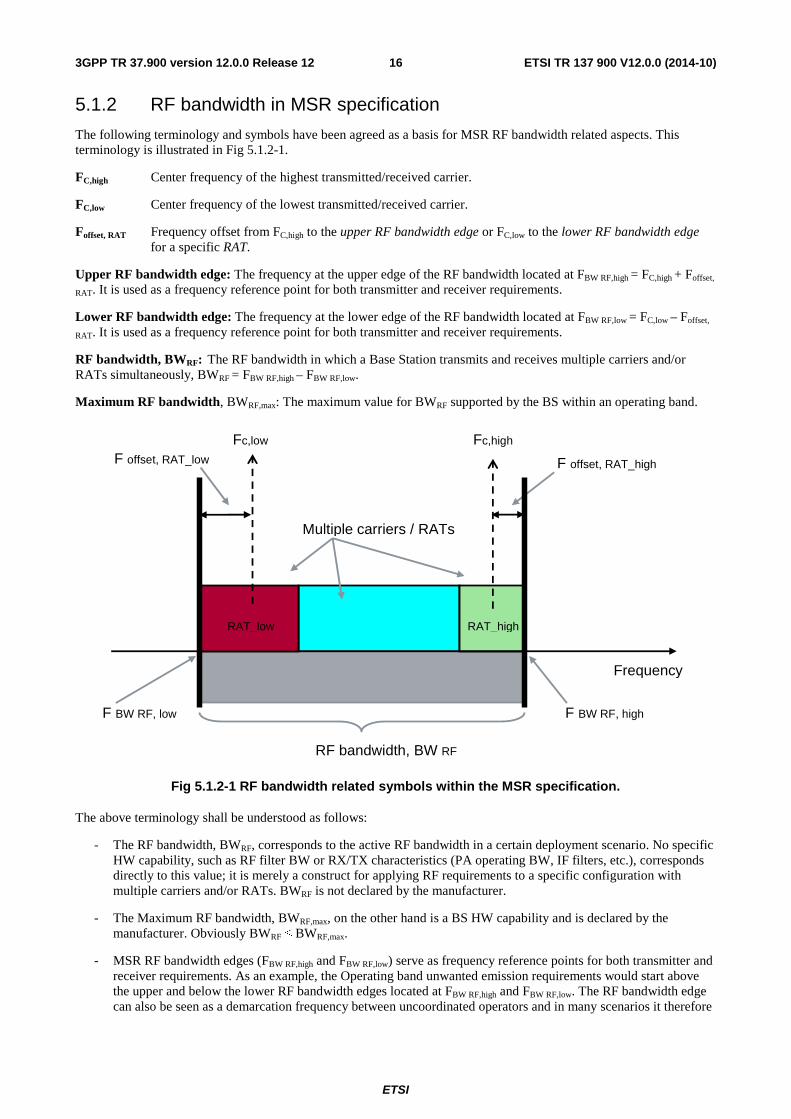
The following terminology and symbols have been agreed as a basis for MSR RF bandwidth related aspects. This terminology is illustrated in Fig 5.1.2-1.
FC,high Center frequency of the highest transmitted/received carrier.
FC,low Center frequency of the lowest transmitted/received carrier.
Foffset, RAT Frequency offset from FC,high to the upper RF bandwidth edge or FC,low to the lower RF bandwidth edge for a specific RAT.
Upper RF bandwidth edge: The frequency at the upper edge of the RF bandwidth located at FBW RF,high = FC,high + Foffset,
RAT. It is used as a frequency reference point for both transmitter and receiver requirements.
Lower RF bandwidth edge: The frequency at the lower edge of the RF bandwidth located at FBW RF,low = FC,low – Foffset,
RAT. It is used as a frequency reference point for both transmitter and receiver requirements.
RF bandwidth, BWRF: The RF bandwidth in which a Base Station transmits and receives multiple carriers and/or RATs simultaneously, BWRF = FBW RF,high – FBW RF,low.
Maximum RF bandwidth, BWRF,max: The maximum value for BWRF supported by the BS within an operating band.
RF bandwidth, BW RF
F BW RF, high
Fc,high
F offset, RAT_high
Frequency
Fc,low F offset, RAT_low
F BW RF, low
Multiple carriers / RATs
RAT_low RAT_high
Fig 5.1.2-1 RF bandwidth related symbols within the MSR specification.
The above terminology shall be understood as follows:
- The RF bandwidth, BWRF, corresponds to the active RF bandwidth in a certain deployment scenario. No specific HW capability, such as RF filter BW or RX/TX characteristics (PA operating BW, IF filters, etc.), corresponds directly to this value; it is merely a construct for applying RF requirements to a specific configuration with multiple carriers and/or RATs. BWRF is not declared by the manufacturer.
- The Maximum RF bandwidth, BWRF,max, on the other hand is a BS HW capability and is declared by the manufacturer. Obviously BWRF ≤ BWRF,max.
- MSR RF bandwidth edges (FBW RF,high and FBW RF,low) serve as frequency reference points for both transmitter and receiver requirements. As an example, the Operating band unwanted emission requirements would start above the upper and below the lower RF bandwidth edges located at FBW RF,high and FBW RF,low. The RF bandwidth edge can also be seen as a demarcation frequency between uncoordinated operators and in many scenarios it therefore
ETSI
ETSI TR 137 900 V12.0.0 (2014-10)173GPP TR 37.900 version 12.0.0 Release 12
coincides with the license block edge, while in other scenarios the license block edge may be located outside or even slightly inside the RF bandwidth.
The rationale for this is as follows. The channel edge within the E-UTRA (UTRA) specifications is assumed to coincide with the license block edge of uncoordinated 3GPP systems. This is a worst-case from an interference point of view and gives the operator the assurance that no additional guard bands need to be reserved to facilitate mutual co-existence of same-band uncoordinated 3GPP systems.
Furthermore, the additional FCC Title 47 requirements [11] applicable at the license block edge, are also included within the E-UTRA (UTRA) specifications, they are however defined in reference to the channel edge.
It seems natural to assume for the MSR RF bandwidth edges (FBW RF,high and FBW RF,low) the same role, i.e. to serve as the default demarcation frequency between uncoordinated operators and as a frequency reference point for additional license block edge related regulatory requirements (e.g. FCC Title 47 emission limits [11]). Note however that while serving as a frequency reference point for RF requirements, the RF bandwidth edge may in some scenarios not coincide with the license block edge.
While TS 45.005 [5] uses different concepts for specifying OOB limits and in particular, has no definition corresponding to the E-UTRA (UTRA) channel edge, the above principle is seen also as meaningful for RF scenarios involving uncoordinated GSM systems.
- Values for Foffset, RAT needed in order to meet TX and RX requirements will be part of the MSR specifications. Foffset, RAT will be specific for each RAT in each Band Category.
5.2 FDD multi-RAT and multicarrier scenarios To structure the possible FDD scenarios and resulting requirements, the bands divided into two categories:
- Band category 1: Bands for UTRA FDD and E-UTRA FDD operation
- Band category 2: Bands for UTRA FDD, E-UTRA FDD and GSM operation
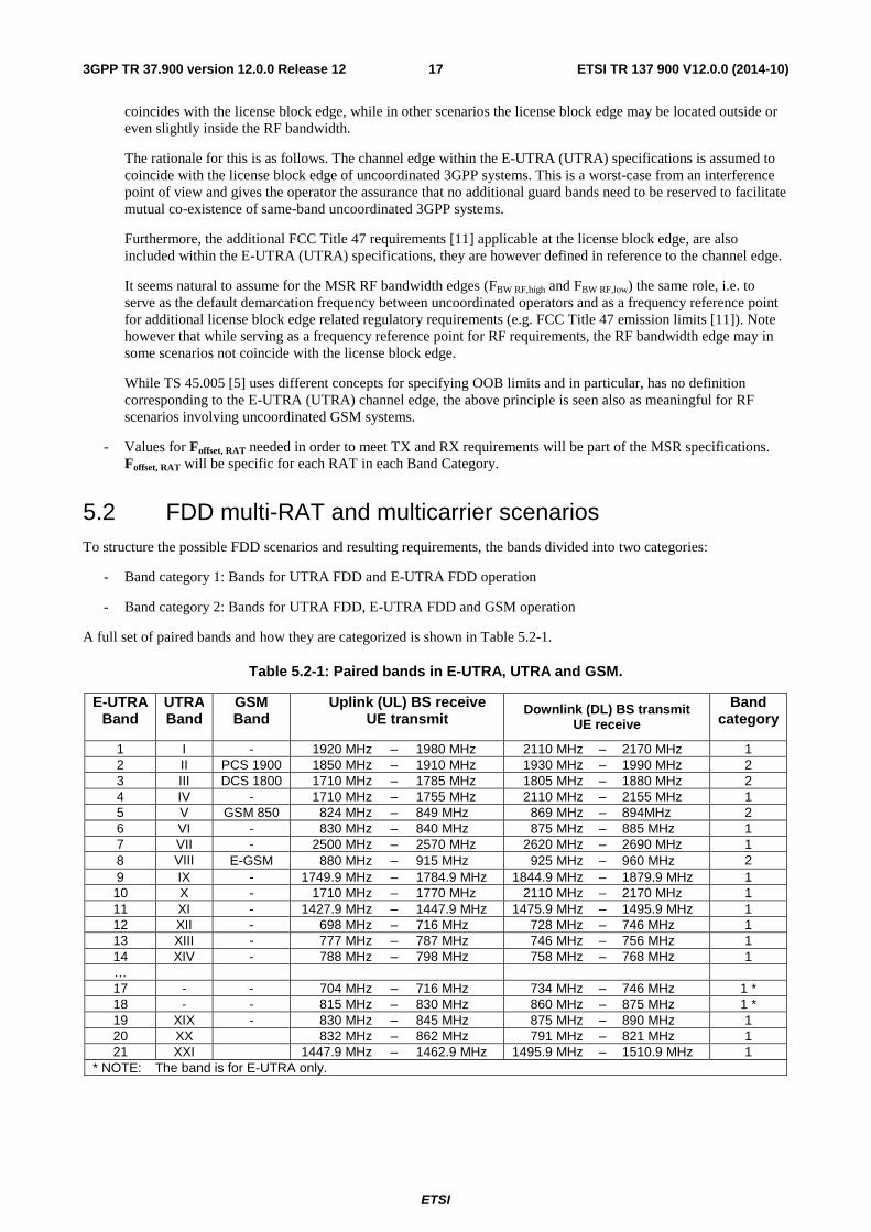
A full set of paired bands and how they are categorized is shown in Table 5.2-1.
Table 5.2-1: Paired bands in E-UTRA, UTRA and GSM.
E-UTRA Band
UTRA Band
GSM Band
Uplink (UL) BS receive UE transmit
Downlink (DL) BS transmit UE receive
Band category
1 I - 1920 MHz – 1980 MHz 2110 MHz – 2170 MHz 1 2 II PCS 1900 1850 MHz – 1910 MHz 1930 MHz – 1990 MHz 2 3 III DCS 1800 1710 MHz – 1785 MHz 1805 MHz – 1880 MHz 2 4 IV - 1710 MHz – 1755 MHz 2110 MHz – 2155 MHz 1 5 V GSM 850 824 MHz – 849 MHz 869 MHz – 894MHz 2 6 VI - 830 MHz – 840 MHz 875 MHz – 885 MHz 1 7 VII - 2500 MHz – 2570 MHz 2620 MHz – 2690 MHz 1 8 VIII E-GSM 880 MHz – 915 MHz 925 MHz – 960 MHz 2 9 IX - 1749.9 MHz – 1784.9 MHz 1844.9 MHz – 1879.9 MHz 1 10 X - 1710 MHz – 1770 MHz 2110 MHz – 2170 MHz 1 11 XI - 1427.9 MHz – 1447.9 MHz 1475.9 MHz – 1495.9 MHz 1 12 XII - 698 MHz – 716 MHz 728 MHz – 746 MHz 1 13 XIII - 777 MHz – 787 MHz 746 MHz – 756 MHz 1 14 XIV - 788 MHz – 798 MHz 758 MHz – 768 MHz 1 … 17 - - 704 MHz – 716 MHz 734 MHz – 746 MHz 1 * 18 - - 815 MHz – 830 MHz 860 MHz – 875 MHz 1 * 19 XIX - 830 MHz – 845 MHz 875 MHz – 890 MHz 1 20 XX 832 MHz – 862 MHz 791 MHz – 821 MHz 1 21 XXI 1447.9 MHz – 1462.9 MHz 1495.9 MHz – 1510.9 MHz 1
* NOTE: The band is for E-UTRA only.
ETSI
ETSI TR 137 900 V12.0.0 (2014-10)183GPP TR 37.900 version 12.0.0 Release 12
5.2.1 Band category 1 scenarios (BC1)
BC1 requirements for receiver and transmitter shall apply with a frequency offset from the lowest and highest carriers to the RF bandwidth edge (Foffset, RAT) as defined in Table 5.2.1-1.
Table 5.2.1-1: Foffset, RAT for band category 1
RAT Foffset, RAT 1.4, 3 MHz E-UTRA BWChannel/2 + 200 kHz
5, 10, 15, 20 MHz E-UTRA BWChannel/2 UTRA 2.5 MHz
5.2.2 Band category 2 scenarios (BC2)
BC2 requirements for receiver and transmitter shall apply with a frequency offset from the lowest and highest carriers to the RF bandwidth edge (Foffset, RAT) as defined in Table 5.2.2-1.
Table 5.2.2-1: Foffset, RAT for band category 2
RAT Foffset, RAT E-UTRA BWChannel/2 UTRA 2.5 MHz GSM 200 kHz
5.3 TDD multi-RAT and multicarrier scenarios To structure the possible TDD scenarios and resulting requirements, the unpaired bands are put in a third category:
• Band category 3: Bands for UTRA TDD/TD-SCDMA and E-UTRA TDD operation
A full set of unpaired bands and how they are categorized is shown in Table 5.3-1.
Table 5.3-1: Unpaired bands in E-UTRA and UTRA.
E-UTRA Band
UTRA Band
Uplink (UL) BS receive UE transmit
Downlink (DL) BS transmit UE receive
Band category
33 a) 1900 MHz – 1920 MHz 1900 MHz – 1920 MHz 3 34 a) 2010 MHz – 2025 MHz 2010 MHz – 2025 MHz 3 35 b) 1850 MHz – 1910 MHz 1850 MHz – 1910 MHz 3 36 b) 1930 MHz – 1990 MHz 1930 MHz – 1990 MHz 3 37 c) 1910 MHz – 1930 MHz 1910 MHz – 1930 MHz 3 38 d) 2570 MHz – 2620 MHz 2570 MHz – 2620 MHz 3 39 f) 1880 MHz – 1920 MHz 1880 MHz – 1920 MHz 3 40 e) 2300 MHz – 2400 MHz 2300 MHz – 2400 MHz 3
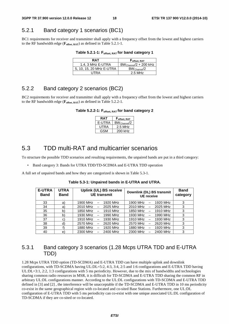
5.3.1 Band category 3 scenarios (1.28 Mcps UTRA TDD and E-UTRA TDD)
1.28 Mcps UTRA TDD option (TD-SCDMA) and E-UTRA TDD can have multiple uplink and downlink configurations, with TD-SCDMA having UL:DL=5:2, 4:3, 3:4, 2:5 and 1:6 configurations and E-UTRA TDD having UL:DL=3:1, 2:2, 1:3 configurations with 5 ms periodicity. However, due to the mix of bandwidths and technologies sharing common radio resources in MSR, it is difficult for TD-SCDMA and E-UTRA TDD sharing the common RF in arbitrary UL:DL configurations manner. According to the UL:DL configurations with TD-SCDMA and E-UTRA TDD defined in [3] and [2] , the interference will be unacceptable if the TD-SCDMA and E-UTRA TDD in 10 ms periodicity co-exist in the same geographical region with co-located and co-sited Base Stations. Furthermore, one UL:DL configuration of E-UTRA TDD with 5 ms periodicity can co-exist with one unique associated UL:DL configuration of TD-SCDMA if they are co-sited or co-located.
ETSI
ETSI TR 137 900 V12.0.0 (2014-10)193GPP TR 37.900 version 12.0.0 Release 12
TS1TS0 TS4 TS5 TS6 TS7 TS8 TS9
TS6 TS0 TS1 TS2 TS3 TS4 TS5TD-SCDMA
TD-LTE
UL/DL=3:1
TS1TS0 TS4 TS5 TS6 TS7 TS8 TS9
TS1TS0 TS4 TS5 TS6 TS7 TS8 TS9
UpPTSGPDwPTS
TS1TS0 TS4 TS5 TS6 TS7 TS8 TS9
TS1TS0 TS4 TS5 TS6 TS7 TS8 TS9
TS1TS0 TS4 TS5 TS6 TS7 TS8 TS9
TS6
SF 3:9:2
SF 6:6:2
SF 11:1:2
SF 6:6:2
SF 3:9:2
SF 6:6:2
TD-LTE
UL/DL=2:2
TD-LTE
UL/DL=1:3
Figure 5.3.1-1: Alignment of TD-SCDMA and E-UTRA TDD
Figure 5.3.1-1 shows that the UL:DL=5:2, 3:4 and 2:5 configurations of TD-SCDMA can coexist with UL:DL= 3:1, 2:2 and 1:3 configurations of E-UTRA TDD respectively. Consider minimizing the interference between the TD-SCDMA and E-UTRA TDD, UL and DL alignment of TD-SCDMA and E-UTRA TDD with 5ms periodicity will be assumed in the initial work stage of MSR; For E-UTRA TDD with 10 ms periodicity and TD-SCDMA deployment scenarios, it might be very difficult to define the RF requirements for the TD-SCDMA and E-UTRA TDD co-existence in MSR mode and this case is left aside at this stage.
For minimizing the interference between the TD-SCDMA and E-UTRA TDD the UL and DL alignment of TD-SCDMA and E-UTRA TDD with 5 ms periodicity shall be assumed. The operating band outlined in Table 5.3-1 shall be considered for the MSR combination of TD-SCDMA and E-UTRA TDD.
5.3.2 Foffset, RAT of band category 3
BC3 requirements for receiver and transmitter shall apply with a frequency offset from the lowest and highest carriers to the RF bandwidth edge (Foffset, RAT) as defined in Table 5.3.2-1.
Table 5.3.2-1: Foffset, RAT for band category 3
RAT Foffset, RAT 1.4, 3 MHz E-UTRA BWChannel /2 + 200 kHz
5, 10, 15, 20 MHz E-UTRA BWChannel /2 1.28Mcps UTRA TDD option 1 MHz
6 Transmitter characteristics
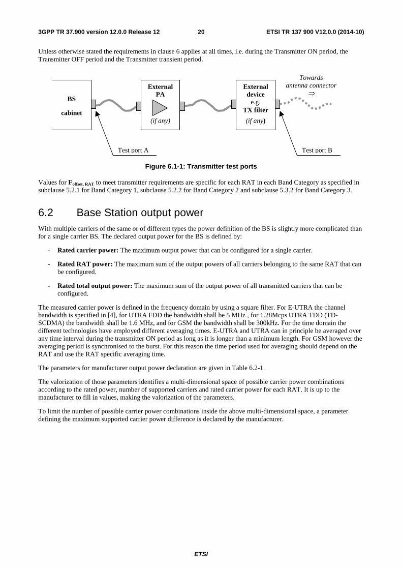
6.1 General Unless otherwise stated, the requirements in clause 6 are expressed for a single transmitter antenna connector. In case of transmit diversity, DB-DC-HSDPA or MIMO transmission, the requirements apply for each transmitter antenna connector.
Unless otherwise stated, the transmitter characteristics are specified at the BS antenna connector (test port A) with a full complement of transceivers for the configuration in normal operating conditions. If any external apparatus such as a TX amplifier, a filter or the combination of such devices is used, requirements apply at the far end antenna connector (test port B).
ETSI
ETSI TR 137 900 V12.0.0 (2014-10)203GPP TR 37.900 version 12.0.0 Release 12
Unless otherwise stated the requirements in clause 6 applies at all times, i.e. during the Transmitter ON period, the Transmitter OFF period and the Transmitter transient period.
BS
cabinet
Test port A Test port B
External device
e.g. TX filter
(if any)
External PA
(if any)
Towards antenna connector
⇒
Figure 6.1-1: Transmitter test ports
Values for Foffset, RAT to meet transmitter requirements are specific for each RAT in each Band Category as specified in subclause 5.2.1 for Band Category 1, subclause 5.2.2 for Band Category 2 and subclause 5.3.2 for Band Category 3.
6.2 Base Station output power With multiple carriers of the same or of different types the power definition of the BS is slightly more complicated than for a single carrier BS. The declared output power for the BS is defined by:
- Rated carrier power: The maximum output power that can be configured for a single carrier.
- Rated RAT power: The maximum sum of the output powers of all carriers belonging to the same RAT that can be configured.
- Rated total output power: The maximum sum of the output power of all transmitted carriers that can be configured.
The measured carrier power is defined in the frequency domain by using a square filter. For E-UTRA the channel bandwidth is specified in [4], for UTRA FDD the bandwidth shall be 5 MHz , for 1.28Mcps UTRA TDD (TD-SCDMA) the bandwidth shall be 1.6 MHz, and for GSM the bandwidth shall be 300kHz. For the time domain the different technologies have employed different averaging times. E-UTRA and UTRA can in principle be averaged over any time interval during the transmitter ON period as long as it is longer than a minimum length. For GSM however the averaging period is synchronised to the burst. For this reason the time period used for averaging should depend on the RAT and use the RAT specific averaging time.
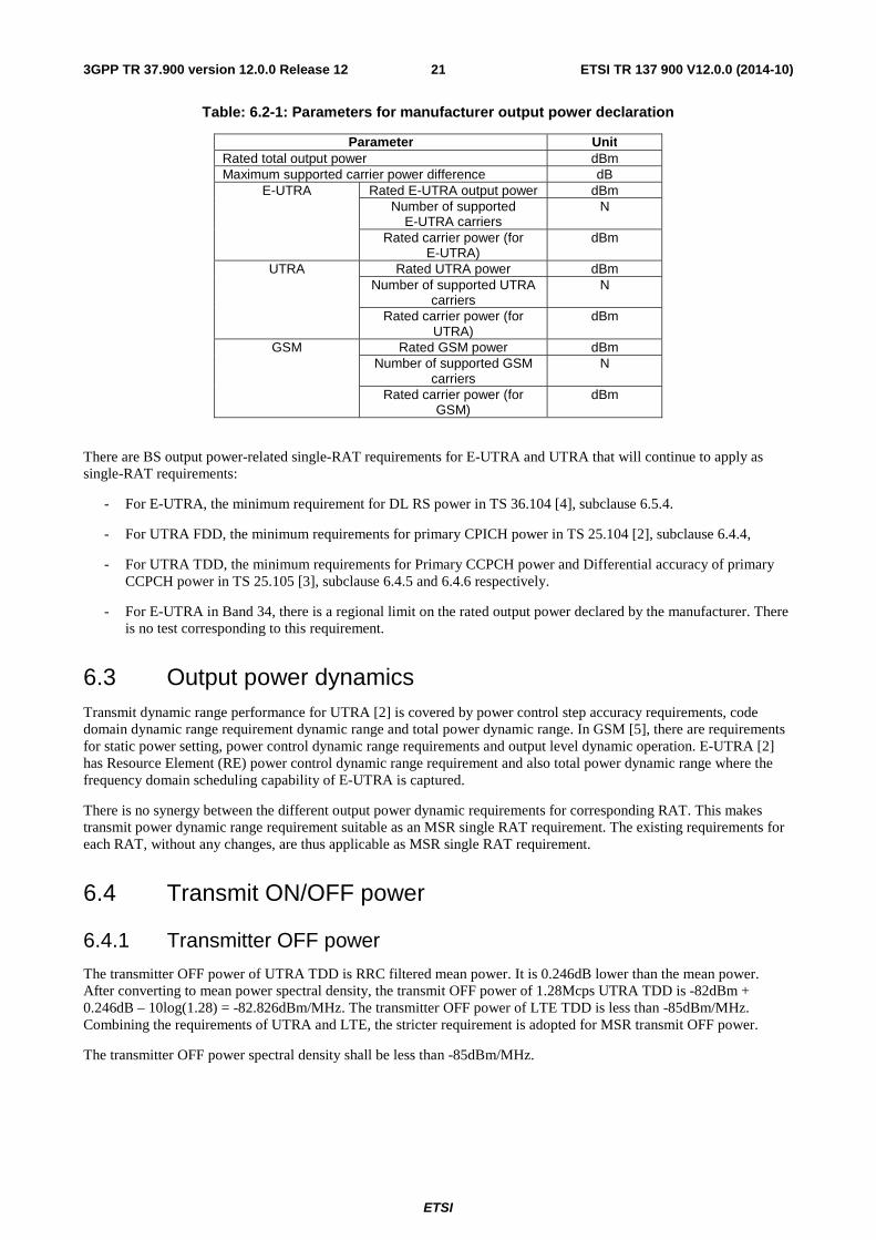
The parameters for manufacturer output power declaration are given in Table 6.2-1.
The valorization of those parameters identifies a multi-dimensional space of possible carrier power combinations according to the rated power, number of supported carriers and rated carrier power for each RAT. It is up to the manufacturer to fill in values, making the valorization of the parameters.
To limit the number of possible carrier power combinations inside the above multi-dimensional space, a parameter defining the maximum supported carrier power difference is declared by the manufacturer.
ETSI
ETSI TR 137 900 V12.0.0 (2014-10)213GPP TR 37.900 version 12.0.0 Release 12
Table: 6.2-1: Parameters for manufacturer output power declaration
Parameter Unit Rated total output power dBm Maximum supported carrier power difference dB
E-UTRA Rated E-UTRA output power dBm Number of supported
E-UTRA carriers N
Rated carrier power (for E-UTRA)
dBm
UTRA Rated UTRA power dBm Number of supported UTRA
carriers N
Rated carrier power (for UTRA)
dBm
GSM Rated GSM power dBm Number of supported GSM
carriers N
Rated carrier power (for GSM)
dBm
There are BS output power-related single-RAT requirements for E-UTRA and UTRA that will continue to apply as single-RAT requirements:
- For E-UTRA, the minimum requirement for DL RS power in TS 36.104 [4], subclause 6.5.4.
- For UTRA FDD, the minimum requirements for primary CPICH power in TS 25.104 [2], subclause 6.4.4,
- For UTRA TDD, the minimum requirements for Primary CCPCH power and Differential accuracy of primary CCPCH power in TS 25.105 [3], subclause 6.4.5 and 6.4.6 respectively.
- For E-UTRA in Band 34, there is a regional limit on the rated output power declared by the manufacturer. There is no test corresponding to this requirement.
6.3 Output power dynamics Transmit dynamic range performance for UTRA [2] is covered by power control step accuracy requirements, code domain dynamic range requirement dynamic range and total power dynamic range. In GSM [5], there are requirements for static power setting, power control dynamic range requirements and output level dynamic operation. E-UTRA [2] has Resource Element (RE) power control dynamic range requirement and also total power dynamic range where the frequency domain scheduling capability of E-UTRA is captured.
There is no synergy between the different output power dynamic requirements for corresponding RAT. This makes transmit power dynamic range requirement suitable as an MSR single RAT requirement. The existing requirements for each RAT, without any changes, are thus applicable as MSR single RAT requirement.
6.4 Transmit ON/OFF power
6.4.1 Transmitter OFF power
The transmitter OFF power of UTRA TDD is RRC filtered mean power. It is 0.246dB lower than the mean power. After converting to mean power spectral density, the transmit OFF power of 1.28Mcps UTRA TDD is -82dBm + 0.246dB – 10log(1.28) = -82.826dBm/MHz. The transmitter OFF power of LTE TDD is less than -85dBm/MHz. Combining the requirements of UTRA and LTE, the stricter requirement is adopted for MSR transmit OFF power.
The transmitter OFF power spectral density shall be less than -85dBm/MHz.
ETSI
ETSI TR 137 900 V12.0.0 (2014-10)223GPP TR 37.900 version 12.0.0 Release 12
6.4.2 Transmitter transient period
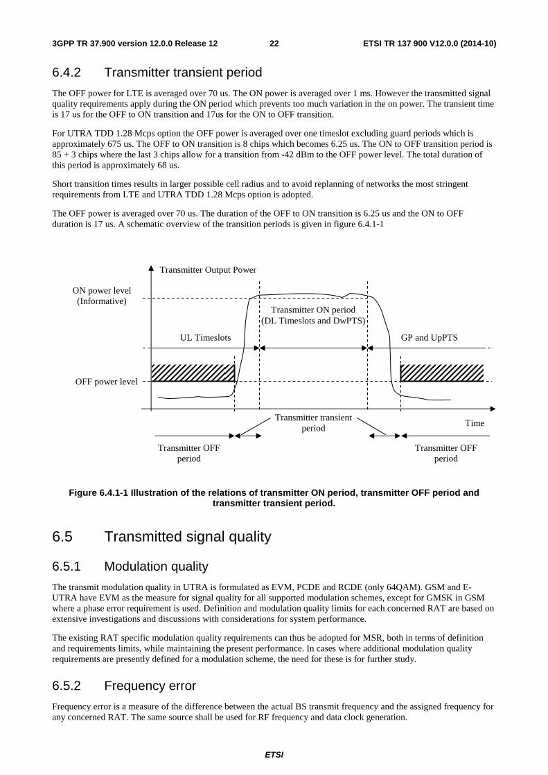
The OFF power for LTE is averaged over 70 us. The ON power is averaged over 1 ms. However the transmitted signal quality requirements apply during the ON period which prevents too much variation in the on power. The transient time is 17 us for the OFF to ON transition and 17us for the ON to OFF transition.
For UTRA TDD 1.28 Mcps option the OFF power is averaged over one timeslot excluding guard periods which is approximately 675 us. The OFF to ON transition is 8 chips which becomes 6.25 us. The ON to OFF transition period is 85 + 3 chips where the last 3 chips allow for a transition from -42 dBm to the OFF power level. The total duration of this period is approximately 68 us.
Short transition times results in larger possible cell radius and to avoid replanning of networks the most stringent requirements from LTE and UTRA TDD 1.28 Mcps option is adopted.
The OFF power is averaged over 70 us. The duration of the OFF to ON transition is 6.25 us and the ON to OFF duration is 17 us. A schematic overview of the transition periods is given in figure 6.4.1-1
Figure 6.4.1-1 Illustration of the relations of transmitter ON period, transmitter OFF period and transmitter transient period.
6.5 Transmitted signal quality
6.5.1 Modulation quality
The transmit modulation quality in UTRA is formulated as EVM, PCDE and RCDE (only 64QAM). GSM and E-UTRA have EVM as the measure for signal quality for all supported modulation schemes, except for GMSK in GSM where a phase error requirement is used. Definition and modulation quality limits for each concerned RAT are based on extensive investigations and discussions with considerations for system performance.
The existing RAT specific modulation quality requirements can thus be adopted for MSR, both in terms of definition and requirements limits, while maintaining the present performance. In cases where additional modulation quality requirements are presently defined for a modulation scheme, the need for these is for further study.
6.5.2 Frequency error
Frequency error is a measure of the difference between the actual BS transmit frequency and the assigned frequency for any concerned RAT. The same source shall be used for RF frequency and data clock generation.
Transmitter Output Power
Time
Transmitter ON period (DL Timeslots and DwPTS)
Transmitter OFF period
Transmitter OFF period
Transmitter transient period
OFF power level
ON power level (Informative)
UL Timeslots
GP and UpPTS
ETSI
ETSI TR 137 900 V12.0.0 (2014-10)233GPP TR 37.900 version 12.0.0 Release 12
Due to the very large similarity between E-UTRA, UTRA and GSM frequency error requirements, a common generic requirement can be adopted for MSR BS.
6.5.2.1 Minimum requirement
The modulated carrier frequency of any RAT supported by the BS shall be accurate to within ±0.05 ppm observed over a period of one sub-frame for E-UTRA, one time slot for UTRA and across the burst for GSM.
The requirement shall apply for both single RAT and multi-RAT operation.
6.6 Unwanted emissions Unwanted emissions consist of out-of-band emissions and spurious emissions [6]. Out of band emissions are unwanted emissions immediately outside the channel bandwidth resulting from the modulation process and non-linearity in the transmitter but excluding spurious emissions. Spurious emissions are emissions which are caused by unwanted transmitter effects such as harmonics emission, parasitic emission, intermodulation products and frequency conversion products, but exclude out of band emissions.
Spurious emissions limits for MSR BS are treated in subclause 6.6.2. Out-of-band emissions requirement for an MSR BS transmitter is specified in terms of an Operating band unwanted emissions requirement (6.6.1), occupied bandwidth (6.6.3) and ACLR (6.6.4).
6.6.1 Operating band unwanted emissions
6.6.1.1 Existing regulatory requirements
Generic 'masks' as regulatory requirements exist both in the US (FCC) and in Europe (WAPECS) as block edge mask requirements. The concept with limits related to the RF bandwidth edge that is introduced for the MSR scenarios in subclause 5.1.2 will be compatible with such Block edge masks (BEM), since it applies a frequency block (the RF bandwidth) as a reference for limits, rather then single carriers.
6.6.1.1.1 FCC requirements
The US (FCC) requirements for the relevant BC1 and BC2 bands are in Part 22, 24 and 27 of FCC Title 47 [11]. The requirements in [11] are for UTRA and E-UTRA interpreted as a -13 dBm limit, measured in a 100 kHz measurement bandwidth for the bands below 1GHz (band 5) and in 1 MHz for the bands above 1 GHz (bands 2, 4 and 10). For the 1 MHz frequency range immediately outside the license block, the measurement bandwidth can alternatively be taken as 1% of the emission bandwidth of the fundamental emission of the transmitter (the '-26 dB modulation bandwidth').
A generic limit based on FCC Title 47 [7], applying to UTRA as well as all channel bandwidths of E-UTRA, would have to be based on of the highest channel bandwidth of the deployment case at hand. Basing it in a worst case manner on the 20MHz channel bandwidth would be unnecessarily restrictive for all bandwidths below 20 MHz. The FCC Title 47 requirements will be referenced in the MSR specification as regional 'additional requirements', as explained in subclause 6.6.1.7.
6.6.1.1.2 WAPECS requirements for Europe
There are BEM limits defined in the EC 'WAPECS' decision [13] for Band 7. These limits are expressed as EIRP, but are based on the shape of the UTRA spectrum mask taken from TS 25.104 [2]. It is expected that similar limits may be defined for other European bands. In studies performed by ETSI, it was concluded that such BEM limits are licensing conditions that are difficult to include in technical specifications or in � hanneliza standards [14].
The WAPECS requirements are therefore not explicitly included in the MSR specifications, but the UEM limits can be chosen with the WAPECS requirements in mind.
For Band 20, there are also special out-of-band emissions requirements for UTRA FDD and E-UTRA that apply in Europe for the protection of Digital Terrestrial television (DTT). These should be included as additional operating band unwanted emission limits in the same way as in the single-RAT specifications TS 25.104 [2] and TS 36.104 [4].
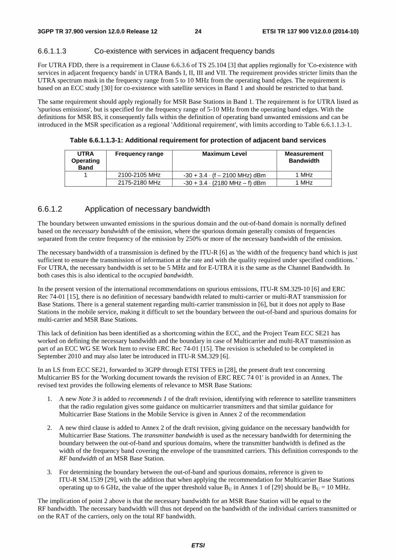
ETSI
ETSI TR 137 900 V12.0.0 (2014-10)243GPP TR 37.900 version 12.0.0 Release 12
6.6.1.1.3 Co-existence with services in adjacent frequency bands
For UTRA FDD, there is a requirement in Clause 6.6.3.6 of TS 25.104 [3] that applies regionally for 'Co-existence with services in adjacent frequency bands' in UTRA Bands I, II, III and VII. The requirement provides stricter limits than the UTRA spectrum mask in the frequency range from 5 to 10 MHz from the operating band edges. The requirement is based on an ECC study [30] for co-existence with satellite services in Band 1 and should be restricted to that band.
The same requirement should apply regionally for MSR Base Stations in Band 1. The requirement is for UTRA listed as 'spurious emissions', but is specified for the frequency range of 5-10 MHz from the operating band edges. With the definitions for MSR BS, it consequently falls within the definition of operating band unwanted emissions and can be introduced in the MSR specification as a regional 'Additional requirement', with limits according to Table 6.6.1.1.3-1.
Table 6.6.1.1.3-1: Additional requirement for protection of adjacent band services
UTRA Operating
Band
Frequency range Maximum Level Measurement Bandwidth
1 2100-2105 MHz -30 + 3.4 ⋅ (f – 2100 MHz) dBm 1 MHz 2175-2180 MHz -30 + 3.4 ⋅ (2180 MHz – f) dBm 1 MHz
6.6.1.2 Application of necessary bandwidth
The boundary between unwanted emissions in the spurious domain and the out-of-band domain is normally defined based on the necessary bandwidth of the emission, where the spurious domain generally consists of frequencies separated from the centre frequency of the emission by 250% or more of the necessary bandwidth of the emission.
The necessary bandwidth of a transmission is defined by the ITU-R [6] as 'the width of the frequency band which is just sufficient to ensure the transmission of information at the rate and with the quality required under specified conditions. ' For UTRA, the necessary bandwidth is set to be 5 MHz and for E-UTRA it is the same as the Channel Bandwidth. In both cases this is also identical to the occupied bandwidth.
In the present version of the international recommendations on spurious emissions, ITU-R SM.329-10 [6] and ERC Rec 74-01 [15], there is no definition of necessary bandwidth related to multi-carrier or multi-RAT transmission for Base Stations. There is a general statement regarding multi-carrier transmission in [6], but it does not apply to Base Stations in the mobile service, making it difficult to set the boundary between the out-of-band and spurious domains for multi-carrier and MSR Base Stations.
This lack of definition has been identified as a shortcoming within the ECC, and the Project Team ECC SE21 has worked on defining the necessary bandwidth and the boundary in case of Multicarrier and multi-RAT transmission as part of an ECC WG SE Work Item to revise ERC Rec 74-01 [15]. The revision is scheduled to be completed in September 2010 and may also later be introduced in ITU-R SM.329 [6].
In an LS from ECC SE21, forwarded to 3GPP through ETSI TFES in [28], the present draft text concerning Multicarrier BS for the 'Working document towards the revision of ERC REC 74 01' is provided in an Annex. The revised text provides the following elements of relevance to MSR Base Stations:
1. A new Note 3 is added to recommends 1 of the draft revision, identifying with reference to satellite transmitters that the radio regulation gives some guidance on multicarrier transmitters and that similar guidance for Multicarrier Base Stations in the Mobile Service is given in Annex 2 of the recommendation
2. A new third clause is added to Annex 2 of the draft revision, giving guidance on the necessary bandwidth for Multicarrier Base Stations. The transmitter bandwidth is used as the necessary bandwidth for determining the boundary between the out-of-band and spurious domains, where the transmitter bandwidth is defined as the width of the frequency band covering the envelope of the transmitted carriers. This definition corresponds to the RF bandwidth of an MSR Base Station.
3. For determining the boundary between the out-of-band and spurious domains, reference is given to ITU-R SM.1539 [29], with the addition that when applying the recommendation for Multicarrier Base Stations operating up to 6 GHz, the value of the upper threshold value BU in Annex 1 of [29] should be BU = 10 MHz.
The implication of point 2 above is that the necessary bandwidth for an MSR Base Station will be equal to the RF bandwidth. The necessary bandwidth will thus not depend on the bandwidth of the individual carriers transmitted or on the RAT of the carriers, only on the total RF bandwidth.
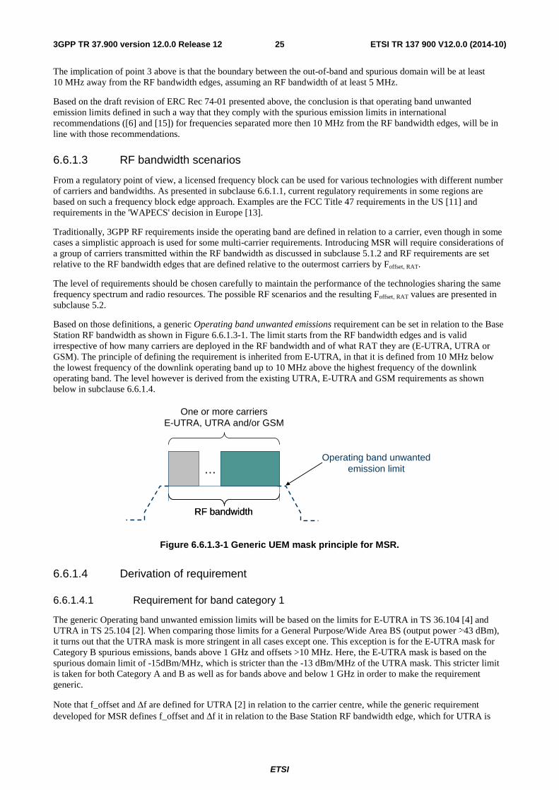
ETSI
ETSI TR 137 900 V12.0.0 (2014-10)253GPP TR 37.900 version 12.0.0 Release 12
The implication of point 3 above is that the boundary between the out-of-band and spurious domain will be at least 10 MHz away from the RF bandwidth edges, assuming an RF bandwidth of at least 5 MHz.
Based on the draft revision of ERC Rec 74-01 presented above, the conclusion is that operating band unwanted emission limits defined in such a way that they comply with the spurious emission limits in international recommendations ([6] and [15]) for frequencies separated more then 10 MHz from the RF bandwidth edges, will be in line with those recommendations.
6.6.1.3 RF bandwidth scenarios
From a regulatory point of view, a licensed frequency block can be used for various technologies with different number of carriers and bandwidths. As presented in subclause 6.6.1.1, current regulatory requirements in some regions are based on such a frequency block edge approach. Examples are the FCC Title 47 requirements in the US [11] and requirements in the 'WAPECS' decision in Europe [13].
Traditionally, 3GPP RF requirements inside the operating band are defined in relation to a carrier, even though in some cases a simplistic approach is used for some multi-carrier requirements. Introducing MSR will require considerations of a group of carriers transmitted within the RF bandwidth as discussed in subclause 5.1.2 and RF requirements are set relative to the RF bandwidth edges that are defined relative to the outermost carriers by Foffset, RAT.
The level of requirements should be chosen carefully to maintain the performance of the technologies sharing the same frequency spectrum and radio resources. The possible RF scenarios and the resulting Foffset, RAT values are presented in subclause 5.2.
Based on those definitions, a generic Operating band unwanted emissions requirement can be set in relation to the Base Station RF bandwidth as shown in Figure 6.6.1.3-1. The limit starts from the RF bandwidth edges and is valid irrespective of how many carriers are deployed in the RF bandwidth and of what RAT they are (E-UTRA, UTRA or GSM). The principle of defining the requirement is inherited from E-UTRA, in that it is defined from 10 MHz below the lowest frequency of the downlink operating band up to 10 MHz above the highest frequency of the downlink operating band. The level however is derived from the existing UTRA, E-UTRA and GSM requirements as shown below in subclause 6.6.1.4.
RF bandwidthRF bandwidth
Operating band unwantedemission limit…
One or more carriersE-UTRA, UTRA and/or GSM
Figure 6.6.1.3-1 Generic UEM mask principle for MSR.
6.6.1.4 Derivation of requirement
6.6.1.4.1 Requirement for band category 1
The generic Operating band unwanted emission limits will be based on the limits for E-UTRA in TS 36.104 [4] and UTRA in TS 25.104 [2]. When comparing those limits for a General Purpose/Wide Area BS (output power ≥43 dBm), it turns out that the UTRA mask is more stringent in all cases except one. This exception is for the E-UTRA mask for Category B spurious emissions, bands above 1 GHz and offsets >10 MHz. Here, the E-UTRA mask is based on the spurious domain limit of -15dBm/MHz, which is stricter than the -13 dBm/MHz of the UTRA mask. This stricter limit is taken for both Category A and B as well as for bands above and below 1 GHz in order to make the requirement generic.
Note that f_offset and Δf are defined for UTRA [2] in relation to the carrier centre, while the generic requirement developed for MSR defines f_offset and Δf it in relation to the Base Station RF bandwidth edge, which for UTRA is
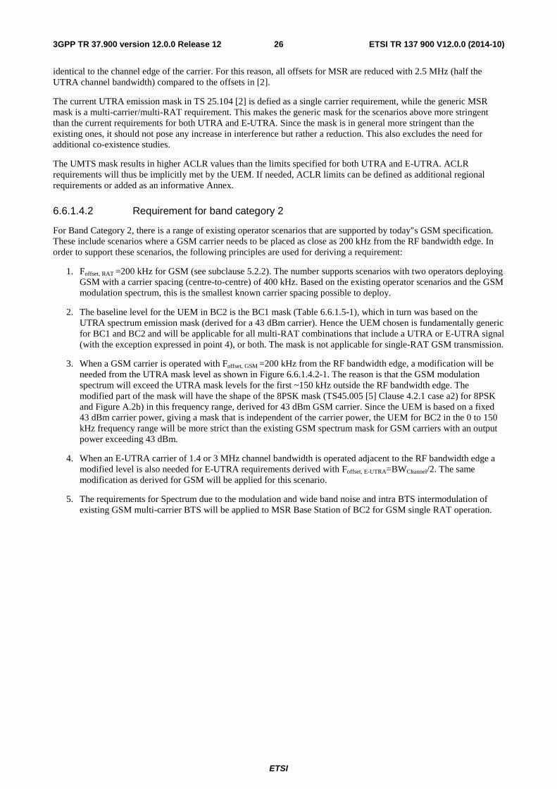
ETSI
ETSI TR 137 900 V12.0.0 (2014-10)263GPP TR 37.900 version 12.0.0 Release 12
identical to the channel edge of the carrier. For this reason, all offsets for MSR are reduced with 2.5 MHz (half the UTRA channel bandwidth) compared to the offsets in [2].
The current UTRA emission mask in TS 25.104 [2] is defied as a single carrier requirement, while the generic MSR mask is a multi-carrier/multi-RAT requirement. This makes the generic mask for the scenarios above more stringent than the current requirements for both UTRA and E-UTRA. Since the mask is in general more stringent than the existing ones, it should not pose any increase in interference but rather a reduction. This also excludes the need for additional co-existence studies.
The UMTS mask results in higher ACLR values than the limits specified for both UTRA and E-UTRA. ACLR requirements will thus be implicitly met by the UEM. If needed, ACLR limits can be defined as additional regional requirements or added as an informative Annex.
6.6.1.4.2 Requirement for band category 2
For Band Category 2, there is a range of existing operator scenarios that are supported by today"s GSM specification. These include scenarios where a GSM carrier needs to be placed as close as 200 kHz from the RF bandwidth edge. In order to support these scenarios, the following principles are used for deriving a requirement:
1. Foffset, RAT =200 kHz for GSM (see subclause 5.2.2). The number supports scenarios with two operators deploying GSM with a carrier spacing (centre-to-centre) of 400 kHz. Based on the existing operator scenarios and the GSM modulation spectrum, this is the smallest known carrier spacing possible to deploy.
2. The baseline level for the UEM in BC2 is the BC1 mask (Table 6.6.1.5-1), which in turn was based on the UTRA spectrum emission mask (derived for a 43 dBm carrier). Hence the UEM chosen is fundamentally generic for BC1 and BC2 and will be applicable for all multi-RAT combinations that include a UTRA or E-UTRA signal (with the exception expressed in point 4), or both. The mask is not applicable for single-RAT GSM transmission.
3. When a GSM carrier is operated with Foffset, GSM =200 kHz from the RF bandwidth edge, a modification will be needed from the UTRA mask level as shown in Figure 6.6.1.4.2-1. The reason is that the GSM modulation spectrum will exceed the UTRA mask levels for the first ~150 kHz outside the RF bandwidth edge. The modified part of the mask will have the shape of the 8PSK mask (TS45.005 [5] Clause 4.2.1 case a2) for 8PSK and Figure A.2b) in this frequency range, derived for 43 dBm GSM carrier. Since the UEM is based on a fixed 43 dBm carrier power, giving a mask that is independent of the carrier power, the UEM for BC2 in the 0 to 150 kHz frequency range will be more strict than the existing GSM spectrum mask for GSM carriers with an output power exceeding 43 dBm.
4. When an E-UTRA carrier of 1.4 or 3 MHz channel bandwidth is operated adjacent to the RF bandwidth edge a modified level is also needed for E-UTRA requirements derived with Foffset, E-UTRA=BWChannel/2. The same modification as derived for GSM will be applied for this scenario.
5. The requirements for Spectrum due to the modulation and wide band noise and intra BTS intermodulation of existing GSM multi-carrier BTS will be applied to MSR Base Station of BC2 for GSM single RAT operation.
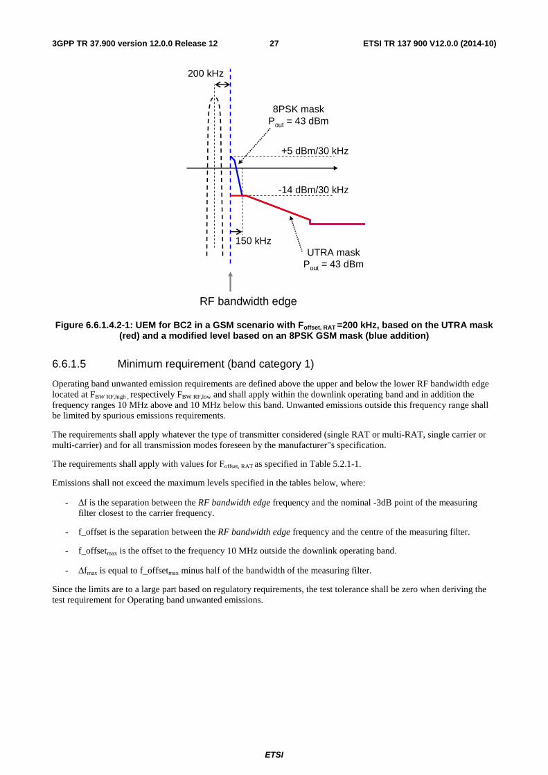
ETSI
ETSI TR 137 900 V12.0.0 (2014-10)273GPP TR 37.900 version 12.0.0 Release 12
+5 dBm/30 kHz
-14 dBm/30 kHz
150 kHz
RF bandwidth edge
200 kHz
UTRA maskPout = 43 dBm
8PSK maskPout = 43 dBm
Figure 6.6.1.4.2-1: UEM for BC2 in a GSM scenario with Foffset, RAT =200 kHz, based on the UTRA mask (red) and a modified level based on an 8PSK GSM mask (blue addition)
6.6.1.5 Minimum requirement (band category 1)
Operating band unwanted emission requirements are defined above the upper and below the lower RF bandwidth edge located at FBW RF,high , respectively FBW RF,low and shall apply within the downlink operating band and in addition the frequency ranges 10 MHz above and 10 MHz below this band. Unwanted emissions outside this frequency range shall be limited by spurious emissions requirements.
The requirements shall apply whatever the type of transmitter considered (single RAT or multi-RAT, single carrier or multi-carrier) and for all transmission modes foreseen by the manufacturer"s specification.
The requirements shall apply with values for Foffset, RAT as specified in Table 5.2.1-1.
Emissions shall not exceed the maximum levels specified in the tables below, where:
- Δf is the separation between the RF bandwidth edge frequency and the nominal -3dB point of the measuring filter closest to the carrier frequency.
- f_offset is the separation between the RF bandwidth edge frequency and the centre of the measuring filter.
- f_offsetmax is the offset to the frequency 10 MHz outside the downlink operating band.
- Δfmax is equal to f_offsetmax minus half of the bandwidth of the measuring filter.
Since the limits are to a large part based on regulatory requirements, the test tolerance shall be zero when deriving the test requirement for Operating band unwanted emissions.
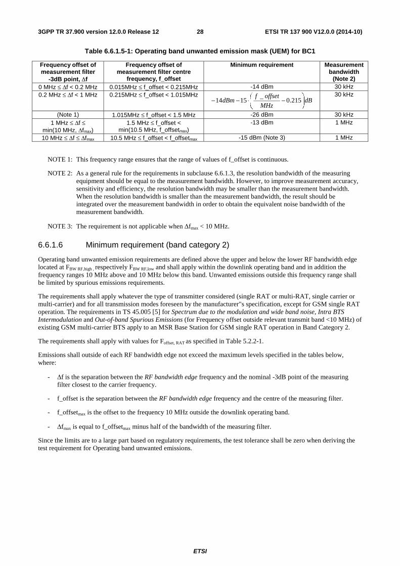
ETSI
ETSI TR 137 900 V12.0.0 (2014-10)283GPP TR 37.900 version 12.0.0 Release 12
Table 6.6.1.5-1: Operating band unwanted emission mask (UEM) for BC1
Frequency offset of measurement filter
-3dB point, Δf
Frequency offset of measurement filter centre
frequency, f_offset
Minimum requirement Measurement bandwidth
(Note 2) 0 MHz ≤ Δf < 0.2 MHz 0.015MHz ≤ f_offset < 0.215MHz -14 dBm 30 kHz 0.2 MHz ≤ Δf < 1 MHz 0.215MHz ≤ f_offset < 1.015MHz
dBMHz
offsetfdBm ⎟
⎠
⎞⎜⎝
⎛ −⋅−− 215.0_
1514 30 kHz
(Note 1) 1.015MHz ≤ f_offset < 1.5 MHz -26 dBm 30 kHz 1 MHz ≤ Δf ≤
min(10 MHz, Δfmax) 1.5 MHz ≤ f_offset <
min(10.5 MHz, f_offsetmax) -13 dBm 1 MHz
10 MHz ≤ Δf ≤ Δfmax 10.5 MHz ≤ f_offset < f_offsetmax -15 dBm (Note 3) 1 MHz
NOTE 1: This frequency range ensures that the range of values of f_offset is continuous.
NOTE 2: As a general rule for the requirements in subclause 6.6.1.3, the resolution bandwidth of the measuring equipment should be equal to the measurement bandwidth. However, to improve measurement accuracy, sensitivity and efficiency, the resolution bandwidth may be smaller than the measurement bandwidth. When the resolution bandwidth is smaller than the measurement bandwidth, the result should be integrated over the measurement bandwidth in order to obtain the equivalent noise bandwidth of the measurement bandwidth.
NOTE 3: The requirement is not applicable when Δfmax < 10 MHz.
6.6.1.6 Minimum requirement (band category 2)
Operating band unwanted emission requirements are defined above the upper and below the lower RF bandwidth edge located at FBW RF,high , respectively FBW RF,low and shall apply within the downlink operating band and in addition the frequency ranges 10 MHz above and 10 MHz below this band. Unwanted emissions outside this frequency range shall be limited by spurious emissions requirements.
The requirements shall apply whatever the type of transmitter considered (single RAT or multi-RAT, single carrier or multi-carrier) and for all transmission modes foreseen by the manufacturer"s specification, except for GSM single RAT operation. The requirements in TS 45.005 [5] for Spectrum due to the modulation and wide band noise, Intra BTS Intermodulation and Out-of-band Spurious Emissions (for Frequency offset outside relevant transmit band <10 MHz) of existing GSM multi-carrier BTS apply to an MSR Base Station for GSM single RAT operation in Band Category 2.
The requirements shall apply with values for Foffset, RAT as specified in Table 5.2.2-1.
Emissions shall outside of each RF bandwidth edge not exceed the maximum levels specified in the tables below, where:
- Δf is the separation between the RF bandwidth edge frequency and the nominal -3dB point of the measuring filter closest to the carrier frequency.
- f_offset is the separation between the RF bandwidth edge frequency and the centre of the measuring filter.
- f_offsetmax is the offset to the frequency 10 MHz outside the downlink operating band.
- Δfmax is equal to f_offsetmax minus half of the bandwidth of the measuring filter.
Since the limits are to a large part based on regulatory requirements, the test tolerance shall be zero when deriving the test requirement for Operating band unwanted emissions.
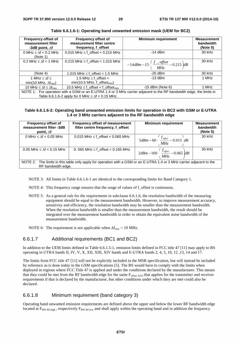
ETSI
ETSI TR 137 900 V12.0.0 (2014-10)293GPP TR 37.900 version 12.0.0 Release 12
Table 6.6.1.6-1: Operating band unwanted emission mask (UEM for BC2)
Frequency offset of measurement filter
-3dB point, Δf
Frequency offset of measurement filter centre
frequency, f_offset
Minimum requirement Measurement bandwidth
(Note 5) 0 MHz ≤ Δf < 0.2 MHz
(Note 1) 0.015 MHz ≤ f_offset < 0.215 MHz -14 dBm 30 kHz
0.2 MHz ≤ Δf < 1 MHz 0.215 MHz ≤ f_offset < 1.015 MHz dB
MHz
offsetfdBm ⎟
⎠
⎞⎜⎝
⎛ −⋅−− 215.0_
1514 30 kHz
(Note 4) 1.015 MHz ≤ f_offset < 1.5 MHz -26 dBm 30 kHz 1 MHz ≤ Δf ≤
min(10 MHz, Δfmax) 1.5 MHz ≤ f_offset <
min(10.5 MHz, f_offsetmax) -13 dBm 1 MHz
10 MHz ≤ Δf ≤ Δfmax 10.5 MHz ≤ f_offset < f_offsetmax -15 dBm (Note 6) 1 MHz NOTE 1: For operation with a GSM or an E-UTRA 1.4 or 3 MHz carrier adjacent to the RF bandwidth edge, the limits in
Table 6.6.1.6-2 apply for 0 MHz ≤ Δf < 0.15 MHz.
Table 6.6.1.6-2: Operating band unwanted emission limits for operation in BC2 with GSM or E-UTRA 1.4 or 3 MHz carriers adjacent to the RF bandwidth edge
Frequency offset of measurement filter -3dB
point, Δf
Frequency offset of measurement filter centre frequency, f_offset
Minimum requirement Measurement bandwidth
(Note 5) 0 MHz ≤ Δf < 0.05 MHz 0.015 MHz ≤ f_offset < 0.065 MHz
dBMHz
fdBm
offset
⎟⎟⎠
⎞⎜⎜⎝
⎛−⋅− 015.0605
30 kHz
0.05 MHz ≤ Δf < 0.15 MHz 0. 065 MHz ≤ f_offset < 0.165 MHz dB
MHz
fdBm
offset
⎟⎟⎠
⎞⎜⎜⎝
⎛−⋅− 065.01602
30 kHz
NOTE 2: The limits in this table only apply for operation with a GSM or an E-UTRA 1.4 or 3 MHz carrier adjacent to the RF bandwidth edge.
NOTE 3: All limits in Table 6.6.1.6-1 are identical to the corresponding limits for Band Category 1.
NOTE 4: This frequency range ensures that the range of values of f_offset is continuous.
NOTE 5: As a general rule for the requirements in subclause 6.6.1.6, the resolution bandwidth of the measuring equipment should be equal to the measurement bandwidth. However, to improve measurement accuracy, sensitivity and efficiency, the resolution bandwidth may be smaller than the measurement bandwidth. When the resolution bandwidth is smaller than the measurement bandwidth, the result should be integrated over the measurement bandwidth in order to obtain the equivalent noise bandwidth of the measurement bandwidth.
NOTE 6: The requirement is not applicable when Δfmax < 10 MHz.
6.6.1.7 Additional requirements (BC1 and BC2)
In addition to the UEM limits defined in Table 6.6.1.5-1, emission limits defined in FCC title 47 [11] may apply to BS operating in UTRA bands II, IV, V, X, XII, XIII, XIV bands and E-UTRA bands 2, 4, 5, 10, 12 ,13, 14 and 17.
The limits from FCC title 47 [11] will not be explicitly included in the MSR specification, but will instead be included by reference as is done today in the GSM specifications [5]. The BS would have to comply with the limits when deployed in regions where FCC Title 47 is applied and under the conditions declared by the manufacturer. This means that they could be met from the RF bandwidth edge for the same Foffset, RAT that applies for the transmitter and receiver requirements if that is declared by the manufacturer, but other conditions under which they are met could also be declared.
6.6.1.8 Minimum requirement (band category 3)
Operating band unwanted emission requirements are defined above the upper and below the lower RF bandwidth edge located at FBW RF,high , respectively FBW RF,low and shall apply within the operating band and in addition the frequency
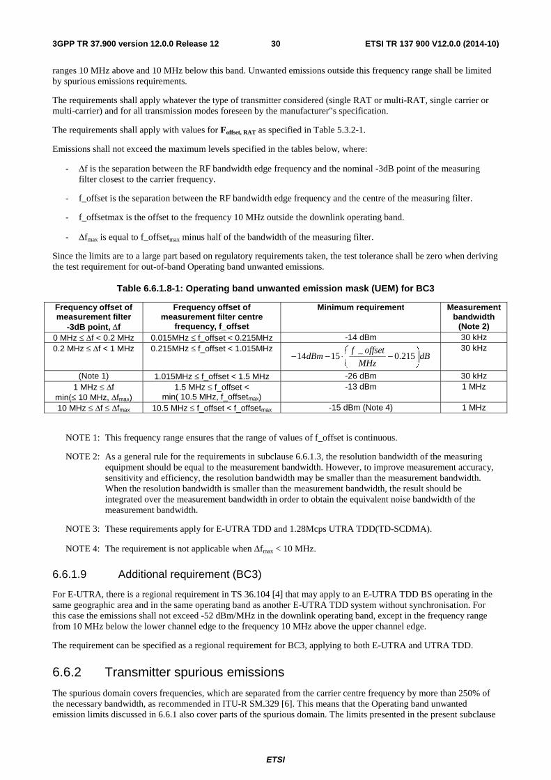
ETSI
ETSI TR 137 900 V12.0.0 (2014-10)303GPP TR 37.900 version 12.0.0 Release 12
ranges 10 MHz above and 10 MHz below this band. Unwanted emissions outside this frequency range shall be limited by spurious emissions requirements.
The requirements shall apply whatever the type of transmitter considered (single RAT or multi-RAT, single carrier or multi-carrier) and for all transmission modes foreseen by the manufacturer"s specification.
The requirements shall apply with values for Foffset, RAT as specified in Table 5.3.2-1.
Emissions shall not exceed the maximum levels specified in the tables below, where:
- Δf is the separation between the RF bandwidth edge frequency and the nominal -3dB point of the measuring filter closest to the carrier frequency.
- f_offset is the separation between the RF bandwidth edge frequency and the centre of the measuring filter.
- f_offsetmax is the offset to the frequency 10 MHz outside the downlink operating band.
- Δfmax is equal to f_offsetmax minus half of the bandwidth of the measuring filter.
Since the limits are to a large part based on regulatory requirements taken, the test tolerance shall be zero when deriving the test requirement for out-of-band Operating band unwanted emissions.
Table 6.6.1.8-1: Operating band unwanted emission mask (UEM) for BC3
Frequency offset of measurement filter
-3dB point, Δf
Frequency offset of measurement filter centre
frequency, f_offset
Minimum requirement Measurement bandwidth
(Note 2) 0 MHz ≤ Δf < 0.2 MHz 0.015MHz ≤ f_offset < 0.215MHz -14 dBm 30 kHz 0.2 MHz ≤ Δf < 1 MHz 0.215MHz ≤ f_offset < 1.015MHz
dBMHz
offsetfdBm ⎟
⎠
⎞⎜⎝
⎛ −⋅−− 215.0_
1514 30 kHz
(Note 1) 1.015MHz ≤ f_offset < 1.5 MHz -26 dBm 30 kHz 1 MHz ≤ Δf
min(≤ 10 MHz, Δfmax) 1.5 MHz ≤ f_offset <
min( 10.5 MHz, f_offsetmax) -13 dBm 1 MHz
10 MHz ≤ Δf ≤ Δfmax 10.5 MHz ≤ f_offset < f_offsetmax -15 dBm (Note 4) 1 MHz
NOTE 1: This frequency range ensures that the range of values of f_offset is continuous.
NOTE 2: As a general rule for the requirements in subclause 6.6.1.3, the resolution bandwidth of the measuring equipment should be equal to the measurement bandwidth. However, to improve measurement accuracy, sensitivity and efficiency, the resolution bandwidth may be smaller than the measurement bandwidth. When the resolution bandwidth is smaller than the measurement bandwidth, the result should be integrated over the measurement bandwidth in order to obtain the equivalent noise bandwidth of the measurement bandwidth.
NOTE 3: These requirements apply for E-UTRA TDD and 1.28Mcps UTRA TDD(TD-SCDMA).
NOTE 4: The requirement is not applicable when Δfmax < 10 MHz.
6.6.1.9 Additional requirement (BC3)
For E-UTRA, there is a regional requirement in TS 36.104 [4] that may apply to an E-UTRA TDD BS operating in the same geographic area and in the same operating band as another E-UTRA TDD system without synchronisation. For this case the emissions shall not exceed -52 dBm/MHz in the downlink operating band, except in the frequency range from 10 MHz below the lower channel edge to the frequency 10 MHz above the upper channel edge.
The requirement can be specified as a regional requirement for BC3, applying to both E-UTRA and UTRA TDD.
6.6.2 Transmitter spurious emissions
The spurious domain covers frequencies, which are separated from the carrier centre frequency by more than 250% of the necessary bandwidth, as recommended in ITU-R SM.329 [6]. This means that the Operating band unwanted emission limits discussed in 6.6.1 also cover parts of the spurious domain. The limits presented in the present subclause
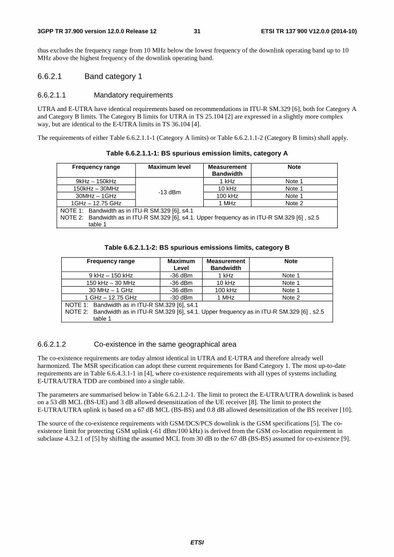
ETSI
ETSI TR 137 900 V12.0.0 (2014-10)313GPP TR 37.900 version 12.0.0 Release 12
thus excludes the frequency range from 10 MHz below the lowest frequency of the downlink operating band up to 10 MHz above the highest frequency of the downlink operating band.
6.6.2.1 Band category 1
6.6.2.1.1 Mandatory requirements
UTRA and E-UTRA have identical requirements based on recommendations in ITU-R SM.329 [6], both for Category A and Category B limits. The Category B limits for UTRA in TS 25.104 [2] are expressed in a slightly more complex way, but are identical to the E-UTRA limits in TS 36.104 [4].
The requirements of either Table 6.6.2.1.1-1 (Category A limits) or Table 6.6.2.1.1-2 (Category B limits) shall apply.
Table 6.6.2.1.1-1: BS spurious emission limits, category A
Frequency range Maximum level Measurement Bandwidth
Note
9kHz – 150kHz
-13 dBm
1 kHz Note 1 150kHz – 30MHz 10 kHz Note 1 30MHz – 1GHz 100 kHz Note 1
1GHz – 12.75 GHz 1 MHz Note 2 NOTE 1: Bandwidth as in ITU-R SM.329 [6], s4.1 NOTE 2: Bandwidth as in ITU-R SM.329 [6], s4.1. Upper frequency as in ITU-R SM.329 [6] , s2.5
table 1
Table 6.6.2.1.1-2: BS spurious emissions limits, category B
Frequency range Maximum Level
Measurement Bandwidth
Note
9 kHz – 150 kHz -36 dBm 1 kHz Note 1 150 kHz – 30 MHz -36 dBm 10 kHz Note 1 30 MHz – 1 GHz -36 dBm 100 kHz Note 1
1 GHz – 12.75 GHz -30 dBm 1 MHz Note 2 NOTE 1: Bandwidth as in ITU-R SM.329 [6], s4.1 NOTE 2: Bandwidth as in ITU-R SM.329 [6], s4.1. Upper frequency as in ITU-R SM.329 [6] , s2.5
table 1
6.6.2.1.2 Co-existence in the same geographical area
The co-existence requirements are today almost identical in UTRA and E-UTRA and therefore already well harmonized. The MSR specification can adopt these current requirements for Band Category 1. The most up-to-date requirements are in Table 6.6.4.3.1-1 in [4], where co-existence requirements with all types of systems including E-UTRA/UTRA TDD are combined into a single table.
The parameters are summarised below in Table 6.6.2.1.2-1. The limit to protect the E-UTRA/UTRA downlink is based on a 53 dB MCL (BS-UE) and 3 dB allowed desensitization of the UE receiver [8]. The limit to protect the E-UTRA/UTRA uplink is based on a 67 dB MCL (BS-BS) and 0.8 dB allowed desensitization of the BS receiver [10].
The source of the co-existence requirements with GSM/DCS/PCS downlink is the GSM specifications [5]. The co-existence limit for protecting GSM uplink (-61 dBm/100 kHz) is derived from the GSM co-location requirement in subclause 4.3.2.1 of [5] by shifting the assumed MCL from 30 dB to the 67 dB (BS-BS) assumed for co-existence [9].
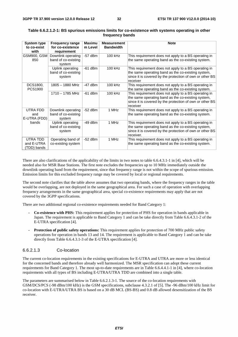
ETSI
ETSI TR 137 900 V12.0.0 (2014-10)323GPP TR 37.900 version 12.0.0 Release 12
Table 6.6.2.1.2-1: BS spurious emissions limits for co-existence with systems operating in other frequency bands
System type to co-exist
with
Frequency range for co-existence
requirement
Maximum Level
Measurement Bandwidth
Note
GSM900, GSM 850
Downlink operating band of co-existing
system
-57 dBm 100 kHz This requirement does not apply to a BS operating in the same operating band as the co-existing system.
Uplink operating band of co-existing
system
-61 dBm 100 kHz This requirement does not apply to a BS operating in the same operating band as the co-existing system, since it is covered by the protection of own or other BS receiver
DCS1800, PCS1900
1805 – 1880 MHz -47 dBm 100 kHz This requirement does not apply to a BS operating in the same operating band as the co-existing system.
1710 – 1785 MHz -61 dBm 100 kHz This requirement does not apply to a BS operating in the same operating band as the co-existing system, since it is covered by the protection of own or other BS receiver
UTRA FDD and
E-UTRA (FDD) bands
Downlink operating band of co-existing
system
-52 dBm 1 MHz This requirement does not apply to a BS operating in the same operating band as the co-existing system.
Uplink operating band of co-existing
system
-49 dBm 1 MHz This requirement does not apply to a BS operating in the same operating band as the co-existing system, since it is covered by the protection of own or other BS receiver.
UTRA TDD and E-UTRA (TDD) bands
Operating band of co-existing system
-52 dBm 1 MHz This requirement does not apply to a BS operating in the same operating band as the co-existing system.
There are also clarifications of the applicability of the limits in two notes to table 6.6.4.3.1-1 in [4], which will be needed also for MSR Base Stations. The first note excludes the frequencies up to 10 MHz immediately outside the downlink operating band from the requirement, since that frequency range is not within the scope of spurious emission. Emission limits for this excluded frequency range may be covered by local or regional requirements.
The second note clarifies that the table above assumes that two operating bands, where the frequency ranges in the table would be overlapping, are not deployed in the same geographical area. For such a case of operation with overlapping frequency arrangements in the same geographical area, special co-existence requirements may apply that are not covered by the 3GPP specifications.
There are two additional regional co-existence requirements needed for Band Category 1:
- Co-existence with PHS: This requirement applies for protection of PHS for operation in bands applicable in Japan. The requirement is applicable to Band Category 1 and can be take directly from Table 6.6.4.3.1-2 of the E-UTRA specification [4].
- Protection of public safety operations: This requirement applies for protection of 700 MHz public safety operations for operation in bands 13 and 14. The requirement is applicable to Band Category 1 and can be take directly from Table 6.6.4.3.1-3 of the E-UTRA specification [4].
6.6.2.1.3 Co-location
The current co-location requirements in the existing specifications for E-UTRA and UTRA are more or less identical for the concerned bands and therefore already well harmonized. The MSR specification can adopt these current requirements for Band Category 1. The most up-to-date requirements are in Table 6.6.4.4.1-1 in [4], where co-location requirements with all types of BS including E-UTRA/UTRA TDD are combined into a single table.
The parameters are summarised below in Table 6.6.2.1.3-1. The source of the co-location requirements with GSM/DCS/PCS (-98 dBm/100 kHz) is the GSM specifications, subclause 4.3.2.1 of [5]. The -96 dBm/100 kHz limit for co-location with E-UTRA/UTRA BS is based on a 30 dB MCL (BS-BS) and 0.8 dB allowed desensitization of the BS receiver.
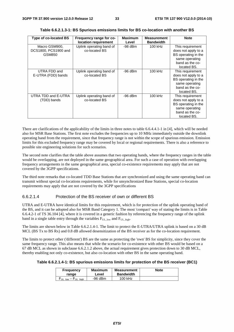
ETSI
ETSI TR 137 900 V12.0.0 (2014-10)333GPP TR 37.900 version 12.0.0 Release 12
Table 6.6.2.1.3-1: BS Spurious emissions limits for BS co-location with another BS
Type of co-located BS Frequency range for co-location requirement
Maximum Level
Measurement Bandwidth
Note
Macro GSM900, DCS1800, PCS1900 and
GSM850
Uplink operating band of co-located BS
-98 dBm 100 kHz This requirement does not apply to a BS operating in the
same operating band as the co-
located BS. UTRA FDD and
E-UTRA (FDD) bands Uplink operating band of
co-located BS -96 dBm 100 kHz This requirement
does not apply to a BS operating in the
same operating band as the co-
located BS. UTRA TDD and E-UTRA
(TDD) bands Uplink operating band of
co-located BS -96 dBm 100 kHz This requirement
does not apply to a BS operating in the
same operating band as the co-
located BS.
There are clarifications of the applicability of the limits in three notes to table 6.6.4.4.1-1 in [4], which will be needed also for MSR Base Stations. The first note excludes the frequencies up to 10 MHz immediately outside the downlink operating band from the requirement, since that frequency range is not within the scope of spurious emission. Emission limits for this excluded frequency range may be covered by local or regional requirements. There is also a reference to possible site engineering solutions for such scenarios.
The second note clarifies that the table above assumes that two operating bands, where the frequency ranges in the table would be overlapping, are not deployed in the same geographical area. For such a case of operation with overlapping frequency arrangements in the same geographical area, special co-existence requirements may apply that are not covered by the 3GPP specifications.
The third note remarks that co-located TDD Base Stations that are synchronized and using the same operating band can transmit without special co-locations requirements, while for unsynchronized Base Stations, special co-location requirements may apply that are not covered by the 3GPP specifications
6.6.2.1.4 Protection of the BS receiver of own or different BS
UTRA and E-UTRA have identical limits for this requirement, which is for protection of the uplink operating band of the BS, and it can be adopted also for MSR Band Category 1. The most 'compact' way of stating the limits is in Table 6.6.4.2-1 of TS 36.104 [4], where it is covered in a generic fashion by referencing the frequency range of the uplink band in a single table entry through the variables FUL_low and FUL_high.
The limits are shown below in Table 6.6.2.1.4-1. The limit to protect the E-UTRA/UTRA uplink is based on a 30 dB MCL (BS Tx to BS Rx) and 0.8 dB allowed desensitization of the BS receiver as for the co-location requirement.
The limits to protect other ('different') BS are the same as protecting the 'own' BS for simplicity, since they cover the same frequency range. This also means that while the scenario for co-existence with other BS would be based on a 67 dB MCL as shown in subclause 6.6.2.1.2 above, the actual requirement gives protection down to 30 dB MCL, thereby enabling not only co-existence, but also co-location with other BS in the same operating band.
Table 6.6.2.1.4-1: BS spurious emissions limits for protection of the BS receiver (BC1)
Frequency range
Maximum Level
Measurement Bandwidth
Note
FUL_low – FUL_high -96 dBm 100 kHz
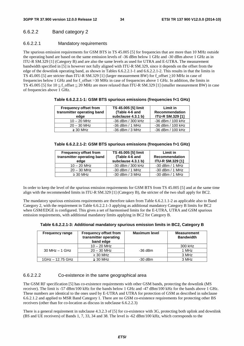
ETSI
ETSI TR 137 900 V12.0.0 (2014-10)343GPP TR 37.900 version 12.0.0 Release 12
6.6.2.2 Band category 2
6.6.2.2.1 Mandatory requirements
The spurious emission requirements for GSM BTS in TS 45.005 [5] for frequencies that are more than 10 MHz outside the operating band are based on the same emission levels of -36 dBm below 1 GHz and -30 dBm above 1 GHz as in ITU-R SM.329 [1] (Category B) and are also the same levels as used for UTRA and E-UTRA. The measurement bandwidth specified in [5] is however not fully aligned with ITU-R SM.329, since it depends on the offset from the edge of the downlink operating band, as shown in Tables 6.6.2.2.1-1 and 6.6.2.2.1-2. This results in that the limits in TS 45.005 [5] are stricter than ITU-R SM.329 [1] (larger measurement BW) for f_offset ≥10 MHz in case of frequencies below 1 GHz and for f_offset ≥30 MHz in case of frequencies above 1 GHz. In addition, the limits in TS 45.005 [5] for 10 ≤ f_offset ≤ 20 MHz are more relaxed than ITU-R SM.329 [1] (smaller measurement BW) in case of frequencies above 1 GHz.
Table 6.6.2.2.1-1: GSM BTS spurious emissions (frequencies f<1 GHz)
Frequency offset from transmitter operating band
edge
TS 45.005 [5] limit (Table 4-6 and
subclause 4.3.1 b)
Limit in Recommendation ITU-R SM.329 [1]
10 – 20 MHz -36 dBm / 300 kHz -36 dBm / 100 kHz 20 – 30 MHz -36 dBm / 1 MHz -36 dBm / 100 kHz ≥ 30 MHz -36 dBm / 3 MHz -36 dBm / 100 kHz
Table 6.6.2.2.1-2: GSM BTS spurious emissions (frequencies f>1 GHz)
Frequency offset from transmitter operating band
edge
TS 45.005 [5] limit (Table 4-6 and
subclause 4.3.1 b)
Limit in Recommendation ITU-R SM.329 [1]
10 – 20 MHz -30 dBm / 300 kHz -30 dBm / 1 MHz 20 – 30 MHz -30 dBm / 1 MHz -30 dBm / 1 MHz ≥ 30 MHz -30 dBm / 3 MHz -30 dBm / 1 MHz
In order to keep the level of the spurious emission requirements for GSM BTS from TS 45.005 [5] and at the same time align with the recommended limits in ITU-R SM.329 [1] (Category B), the stricter of the two shall apply for BC2.
The mandatory spurious emissions requirements are therefore taken from Table 6.6.2.1.1-2 as applicable also to Band Category 2, with the requirement in Table 6.6.2.2.1-3 applying as additional mandatory Category B limits for BC2 when GSM/EDGE is configured. This gives a set of harmonised limits for the E-UTRA, UTRA and GSM spurious emission requirements, with additional mandatory limits applying in BC2 for Category B.
Table 6.6.2.2.1-3: Additional mandatory spurious emission limits in BC2, Category B
Frequency range Frequency offset from transmitter operating
band edge
Maximum level Measurement Bandwidth
30 MHz – 1 GHz 10 – 20 MHz
-36 dBm 300 kHz
20 – 30 MHz 1 MHz ≥ 30 MHz 3 MHz
1GHz – 12.75 GHz ≥ 30 MHz -30 dBm 3 MHz
6.6.2.2.2 Co-existence in the same geographical area
The GSM RF specification [5] has co-existence requirements with other GSM bands, protecting the downlink (MS receiver). The limit is -57 dBm/100 kHz for the bands below 1 GHz and -47 dBm/100 kHz for the bands above 1 GHz. These numbers are identical to the ones used by E-UTRA and UTRA for protection of GSM as described in subclause 6.6.2.1.2 and applied to MSR Band Category 1. There are no GSM co-existence requirements for protecting other BS receivers (other than for co-location as discuss in subclause 6.6.2.2.3)
There is a general requirement in subclause 4.3.2.3 of [5] for co-existence with 3G, protecting both uplink and downlink (BS and UE receivers) of Bands 1, 7, 33, 34 and 38. The level is -62 dBm/100 kHz, which corresponds to the
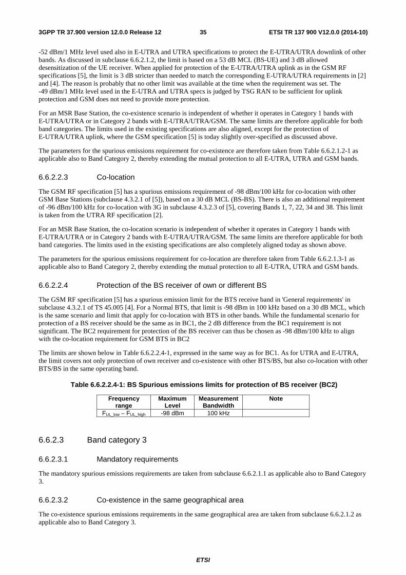
ETSI
ETSI TR 137 900 V12.0.0 (2014-10)353GPP TR 37.900 version 12.0.0 Release 12
-52 dBm/1 MHz level used also in E-UTRA and UTRA specifications to protect the E-UTRA/UTRA downlink of other bands. As discussed in subclause 6.6.2.1.2, the limit is based on a 53 dB MCL (BS-UE) and 3 dB allowed desensitization of the UE receiver. When applied for protection of the E-UTRA/UTRA uplink as in the GSM RF specifications [5], the limit is 3 dB stricter than needed to match the corresponding E-UTRA/UTRA requirements in [2] and [4]. The reason is probably that no other limit was available at the time when the requirement was set. The -49 dBm/1 MHz level used in the E-UTRA and UTRA specs is judged by TSG RAN to be sufficient for uplink protection and GSM does not need to provide more protection.
For an MSR Base Station, the co-existence scenario is independent of whether it operates in Category 1 bands with E-UTRA/UTRA or in Category 2 bands with E-UTRA/UTRA/GSM. The same limits are therefore applicable for both band categories. The limits used in the existing specifications are also aligned, except for the protection of E-UTRA/UTRA uplink, where the GSM specification [5] is today slightly over-specified as discussed above.
The parameters for the spurious emissions requirement for co-existence are therefore taken from Table 6.6.2.1.2-1 as applicable also to Band Category 2, thereby extending the mutual protection to all E-UTRA, UTRA and GSM bands.
6.6.2.2.3 Co-location
The GSM RF specification [5] has a spurious emissions requirement of -98 dBm/100 kHz for co-location with other GSM Base Stations (subclause 4.3.2.1 of [5]), based on a 30 dB MCL (BS-BS). There is also an additional requirement of -96 dBm/100 kHz for co-location with 3G in subclause 4.3.2.3 of [5], covering Bands 1, 7, 22, 34 and 38. This limit is taken from the UTRA RF specification [2].
For an MSR Base Station, the co-location scenario is independent of whether it operates in Category 1 bands with E-UTRA/UTRA or in Category 2 bands with E-UTRA/UTRA/GSM. The same limits are therefore applicable for both band categories. The limits used in the existing specifications are also completely aligned today as shown above.
The parameters for the spurious emissions requirement for co-location are therefore taken from Table 6.6.2.1.3-1 as applicable also to Band Category 2, thereby extending the mutual protection to all E-UTRA, UTRA and GSM bands.
6.6.2.2.4 Protection of the BS receiver of own or different BS
The GSM RF specification [5] has a spurious emission limit for the BTS receive band in 'General requirements' in subclause 4.3.2.1 of TS 45.005 [4]. For a Normal BTS, that limit is -98 dBm in 100 kHz based on a 30 dB MCL, which is the same scenario and limit that apply for co-location with BTS in other bands. While the fundamental scenario for protection of a BS receiver should be the same as in BC1, the 2 dB difference from the BC1 requirement is not significant. The BC2 requirement for protection of the BS receiver can thus be chosen as -98 dBm/100 kHz to align with the co-location requirement for GSM BTS in BC2
The limits are shown below in Table 6.6.2.2.4-1, expressed in the same way as for BC1. As for UTRA and E-UTRA, the limit covers not only protection of own receiver and co-existence with other BTS/BS, but also co-location with other BTS/BS in the same operating band.
Table 6.6.2.2.4-1: BS Spurious emissions limits for protection of BS receiver (BC2)
Frequency range
Maximum Level
Measurement Bandwidth
Note
FUL_low – FUL_high -98 dBm 100 kHz
6.6.2.3 Band category 3
6.6.2.3.1 Mandatory requirements
The mandatory spurious emissions requirements are taken from subclause 6.6.2.1.1 as applicable also to Band Category 3.
6.6.2.3.2 Co-existence in the same geographical area
The co-existence spurious emissions requirements in the same geographical area are taken from subclause 6.6.2.1.2 as applicable also to Band Category 3.
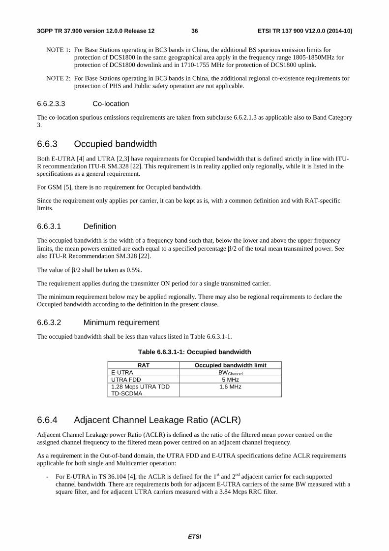
ETSI
ETSI TR 137 900 V12.0.0 (2014-10)363GPP TR 37.900 version 12.0.0 Release 12
NOTE 1: For Base Stations operating in BC3 bands in China, the additional BS spurious emission limits for protection of DCS1800 in the same geographical area apply in the frequency range 1805-1850MHz for protection of DCS1800 downlink and in 1710-1755 MHz for protection of DCS1800 uplink.
NOTE 2: For Base Stations operating in BC3 bands in China, the additional regional co-existence requirements for protection of PHS and Public safety operation are not applicable.
6.6.2.3.3 Co-location
The co-location spurious emissions requirements are taken from subclause 6.6.2.1.3 as applicable also to Band Category 3.
6.6.3 Occupied bandwidth
Both E-UTRA [4] and UTRA [2,3] have requirements for Occupied bandwidth that is defined strictly in line with ITU-R recommendation ITU-R SM.328 [22]. This requirement is in reality applied only regionally, while it is listed in the specifications as a general requirement.
For GSM [5], there is no requirement for Occupied bandwidth.
Since the requirement only applies per carrier, it can be kept as is, with a common definition and with RAT-specific limits.
6.6.3.1 Definition
The occupied bandwidth is the width of a frequency band such that, below the lower and above the upper frequency limits, the mean powers emitted are each equal to a specified percentage β/2 of the total mean transmitted power. See also ITU-R Recommendation SM.328 [22].
The value of β/2 shall be taken as 0.5%.
The requirement applies during the transmitter ON period for a single transmitted carrier.
The minimum requirement below may be applied regionally. There may also be regional requirements to declare the Occupied bandwidth according to the definition in the present clause.
6.6.3.2 Minimum requirement
The occupied bandwidth shall be less than values listed in Table 6.6.3.1-1.
Table 6.6.3.1-1: Occupied bandwidth
RAT Occupied bandwidth limit E-UTRA BWChannel UTRA FDD 5 MHz 1.28 Mcps UTRA TDD TD-SCDMA
1.6 MHz
6.6.4 Adjacent Channel Leakage Ratio (ACLR)
Adjacent Channel Leakage power Ratio (ACLR) is defined as the ratio of the filtered mean power centred on the assigned channel frequency to the filtered mean power centred on an adjacent channel frequency.
As a requirement in the Out-of-band domain, the UTRA FDD and E-UTRA specifications define ACLR requirements applicable for both single and Multicarrier operation:
- For E-UTRA in TS 36.104 [4], the ACLR is defined for the 1st and 2nd adjacent carrier for each supported channel bandwidth. There are requirements both for adjacent E-UTRA carriers of the same BW measured with a square filter, and for adjacent UTRA carriers measured with a 3.84 Mcps RRC filter.
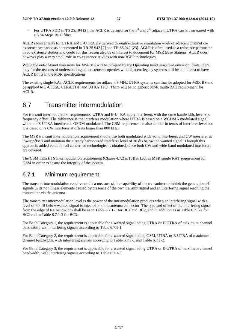
ETSI
ETSI TR 137 900 V12.0.0 (2014-10)373GPP TR 37.900 version 12.0.0 Release 12
- For UTRA FDD in TS 25.104 [2], the ACLR is defined for the 1st and 2nd adjacent UTRA carrier, measured with a 3.84 Mcps RRC filter.
ACLR requirements for UTRA and E-UTRA are derived through extensive simulation work of adjacent channel co-existence scenarios as documented in TR 25.942 [7] and TR 36.942 [23]. ACLR is often used as a reference parameter in co-existence studies and could for this reason also be of interest to document for MSR Base Stations. ACLR does however play a very small role in co-existence studies with non-3GPP technologies.
While the out-of-band emissions for MSR BS will be covered by the Operating band unwanted emission limits, there may for the reasons of understanding co-existence properties with adjacent legacy systems still be an interest to have ACLR limits in the MSR specifications.
The existing single-RAT ACLR requirements for adjacent 5 MHz UTRA systems can thus be adopted for MSR BS and be applied to E-UTRA, UTRA FDD and UTRA TDD. There will be no generic MSR multi-RAT requirement for ACLR.
6.7 Transmitter intermodulation For transmit intermodulation requirements, UTRA and E-UTRA apply interferers with the same bandwidth, level and frequency offset. The difference is the interferer modulation where UTRA is based on a WCDMA modulated signal while the E-UTRA interferer is OFDM modulated. The GSM requirement is also similar in terms of interferer level but it is based on a CW interferer at offsets larger than 800 kHz.
The MSR transmit intermodulation requirement should use both modulated wide-band interferers and CW interferer at lower offsets and maintain the already harmonized interferer level of 30 dB below the wanted signal. Through this approach, added value for all concerned technologies is obtained, since both CW and wide-band modulated interferers are covered.
The GSM Intra BTS intermodulation requirement (Clause 4.7.2 in [5]) is kept as MSR single RAT requirement for GSM in order to ensure the integrity of the system.
6.7.1 Minimum requirement
The transmit intermodulation requirement is a measure of the capability of the transmitter to inhibit the generation of signals in its non linear elements caused by presence of the own transmit signal and an interfering signal reaching the transmitter via the antenna.
The transmitter intermodulation level is the power of the intermodulation products when an interfering signal with a level of 30 dB below wanted signal is injected into the antenna connector. The type and offset of the interfering signal from the edge of RF bandwidth shall be as in Table 6.7.1-1 for BC1 and BC2, and in addition as in Table 6.7.1-2 for BC2 and in Table 6.7.1-3 for BC3.
For Band Category 1, the requirement is applicable for a wanted signal being UTRA or E-UTRA of maximum channel bandwidth, with interfering signals according to Table 6.7.1-1.
For Band Category 2, the requirement is applicable for a wanted signal being GSM, UTRA or E-UTRA of maximum channel bandwidth, with interfering signals according to Table 6.7.1-1 and Table 6.7.1-2.
For Band Category 3, the requirement is applicable for a wanted signal being UTRA or E-UTRA of maximum channel bandwidth, with interfering signals according to Table 6.7.1-3.
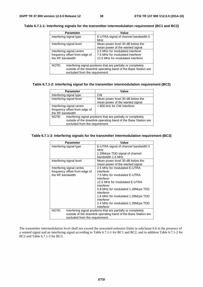
ETSI
ETSI TR 137 900 V12.0.0 (2014-10)383GPP TR 37.900 version 12.0.0 Release 12
Table 6.7.1-1: Interfering signals for the transmitter intermodulation requirement (BC1 and BC2)
Parameter Value Interfering signal type E-UTRA signal of channel bandwidth 5
MHz Interfering signal level Mean power level 30 dB below the
mean power of the wanted signal Interfering signal centre frequency offset from edge of the RF bandwidth
2.5 MHz for modulated interferer 7.5 MHz for modulated interferer 12.5 MHz for modulated interferer
NOTE: Interfering signal positions that are partially or completely outside of the downlink operating band of the Base Station are excluded from the requirement.
Table 6.7.1-2: Interfering signal for the transmitter intermodulation requirement (BC2)
Parameter Value Interfering signal type CW Interfering signal level Mean power level 30 dB below the
mean power of the wanted signal Interfering signal centre frequency offset from edge of the RF bandwidth
> 800 kHz for CW interferer
NOTE: Interfering signal positions that are partially or completely outside of the downlink operating band of the Base Station are excluded from the requirement.
Table 6.7.1-3: Interfering signals for the transmitter intermodulation requirement (BC3)
Parameter Value Interfering signal type E-UTRA signal of channel bandwidth 5
MHz 1.28Mcps TDD signal of channel bandwidth 1.6 MHz
Interfering signal level Mean power level 30 dB below the mean power of the wanted signal
Interfering signal centre frequency offset from edge of the RF bandwidth
2.5 MHz for modulated E-UTRA interferer 7.5 MHz for modulated E-UTRA interferer 12.5 MHz for modulated E-UTRA interferer 0.8 MHz for modulated 1.28Mcps TDD interferer 1.6 MHz for modulated 1.28Mcps TDD interferer 2.4 MHz for modulated 1.28Mcps TDD interferer
NOTE: Interfering signal positions that are partially or completely outside of the downlink operating band of the Base Station are excluded from the requirement.
The transmitter intermodulation level shall not exceed the unwanted emission limits in subclause 6.6 in the presence of a wanted signal and an interfering signal according to Table 6.7.1-1 for BC1 and BC2, and in addition Table 6.7.1-2 for BC2 and Table 6.7.1-3 for BC3.
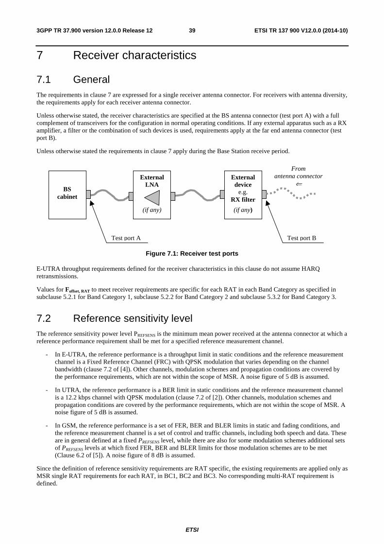
ETSI
ETSI TR 137 900 V12.0.0 (2014-10)393GPP TR 37.900 version 12.0.0 Release 12
7 Receiver characteristics
7.1 General The requirements in clause 7 are expressed for a single receiver antenna connector. For receivers with antenna diversity, the requirements apply for each receiver antenna connector.
Unless otherwise stated, the receiver characteristics are specified at the BS antenna connector (test port A) with a full complement of transceivers for the configuration in normal operating conditions. If any external apparatus such as a RX amplifier, a filter or the combination of such devices is used, requirements apply at the far end antenna connector (test port B).
Unless otherwise stated the requirements in clause 7 apply during the Base Station receive period.
BS
cabinet
Test port A Test port B
External device
e.g. RX filter
(if any)
External LNA
(if any)
From antenna connector
⇐
Figure 7.1: Receiver test ports
E-UTRA throughput requirements defined for the receiver characteristics in this clause do not assume HARQ retransmissions.
Values for Foffset, RAT to meet receiver requirements are specific for each RAT in each Band Category as specified in subclause 5.2.1 for Band Category 1, subclause 5.2.2 for Band Category 2 and subclause 5.3.2 for Band Category 3.
7.2 Reference sensitivity level The reference sensitivity power level PREFSENS is the minimum mean power received at the antenna connector at which a reference performance requirement shall be met for a specified reference measurement channel.
- In E-UTRA, the reference performance is a throughput limit in static conditions and the reference measurement channel is a Fixed Reference Channel (FRC) with QPSK modulation that varies depending on the channel bandwidth (clause 7.2 of [4]). Other channels, modulation schemes and propagation conditions are covered by the performance requirements, which are not within the scope of MSR. A noise figure of 5 dB is assumed.
- In UTRA, the reference performance is a BER limit in static conditions and the reference measurement channel is a 12.2 kbps channel with QPSK modulation (clause 7.2 of [2]). Other channels, modulation schemes and propagation conditions are covered by the performance requirements, which are not within the scope of MSR. A noise figure of 5 dB is assumed.
- In GSM, the reference performance is a set of FER, BER and BLER limits in static and fading conditions, and the reference measurement channel is a set of control and traffic channels, including both speech and data. These are in general defined at a fixed PREFSENS level, while there are also for some modulation schemes additional sets of PREFSENS levels at which fixed FER, BER and BLER limits for those modulation schemes are to be met (Clause 6.2 of [5]). A noise figure of 8 dB is assumed.
Since the definition of reference sensitivity requirements are RAT specific, the existing requirements are applied only as MSR single RAT requirements for each RAT, in BC1, BC2 and BC3. No corresponding multi-RAT requirement is defined.
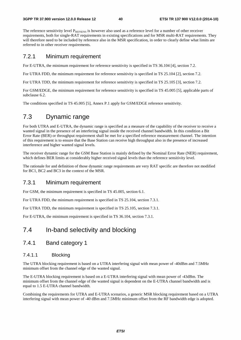
ETSI
ETSI TR 137 900 V12.0.0 (2014-10)403GPP TR 37.900 version 12.0.0 Release 12
The reference sensitivity level PREFSENS is however also used as a reference level for a number of other receiver requirements, both for single-RAT requirements in existing specifications and for MSR multi-RAT requirements. They will therefore need to be included by reference also in the MSR specification, in order to clearly define what limits are referred to in other receiver requirements.
7.2.1 Minimum requirement
For E-UTRA, the minimum requirement for reference sensitivity is specified in TS 36.104 [4], section 7.2.
For UTRA FDD, the minimum requirement for reference sensitivity is specified in TS 25.104 [2], section 7.2.
For UTRA TDD, the minimum requirement for reference sensitivity is specified in TS 25.105 [3], section 7.2.
For GSM/EDGE, the minimum requirement for reference sensitivity is specified in TS 45.005 [5], applicable parts of subclause 6.2.
The conditions specified in TS 45.005 [5], Annex P.1 apply for GSM/EDGE reference sensitivity.
7.3 Dynamic range For both UTRA and E-UTRA, the dynamic range is specified as a measure of the capability of the receiver to receive a wanted signal in the presence of an interfering signal inside the received channel bandwidth. In this condition a Bit Error Rate (BER) or throughput requirement shall be met for a specified reference measurement channel. The intention of this requirement is to ensure that the Base Station can receive high throughput also in the presence of increased interference and higher wanted signal levels.
The receiver dynamic range for the GSM Base Station is mainly defined by the Nominal Error Rate (NER) requirement, which defines BER limits at considerably higher received signal levels than the reference sensitivity level.
The rationale for and definition of those dynamic range requirements are very RAT specific are therefore not modified for BC1, BC2 and BC3 in the context of the MSR.
7.3.1 Minimum requirement
For GSM, the minimum requirement is specified in TS 45.005, section 6.1.
For UTRA FDD, the minimum requirement is specified in TS 25.104, section 7.3.1.
For UTRA TDD, the minimum requirement is specified in TS 25.105, section 7.3.1.
For E-UTRA, the minimum requirement is specified in TS 36.104, section 7.3.1.
7.4 In-band selectivity and blocking
7.4.1 Band category 1
7.4.1.1 Blocking
The UTRA blocking requirement is based on a UTRA interfering signal with mean power of -40dBm and 7.5MHz minimum offset from the channel edge of the wanted signal.
The E-UTRA blocking requirement is based on a E-UTRA interfering signal with mean power of -43dBm. The minimum offset from the channel edge of the wanted signal is dependent on the E-UTRA channel bandwidth and is equal to 1.5 E-UTRA channel bandwidth.
Combining the requirements for UTRA and E-UTRA scenarios, a generic MSR blocking requirement based on a UTRA interfering signal with mean power of -40 dBm and 7.5MHz minimum offset from the RF bandwidth edge is adopted.
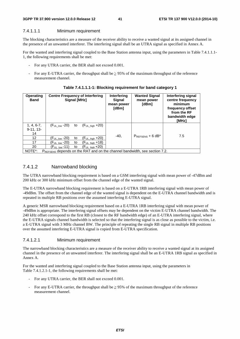
ETSI
ETSI TR 137 900 V12.0.0 (2014-10)413GPP TR 37.900 version 12.0.0 Release 12
7.4.1.1.1 Minimum requirement
The blocking characteristics are a measure of the receiver ability to receive a wanted signal at its assigned channel in the presence of an unwanted interferer. The interfering signal shall be an UTRA signal as specified in Annex A.
For the wanted and interfering signal coupled to the Base Station antenna input, using the parameters in Table 7.4.1.1.1-1, the following requirements shall be met:
- For any UTRA carrier, the BER shall not exceed 0.001.
- For any E-UTRA carrier, the throughput shall be ≥ 95% of the maximum throughput of the reference measurement channel.
Table 7.4.1.1.1-1: Blocking requirement for band category 1
Operating Band
Centre Frequency of Interfering Signal [MHz]
Interfering Signal
mean power [dBm]
Wanted Signal mean power
[dBm]
Interfering signal centre frequency
minimum frequency offset
from the RF bandwidth edge
[MHz] 1, 4, 6-7, 9-11, 13-
14
(FUL_low -20) to (FUL_high +20)
-40, PREFSENS + 6 dB* 7.5 12 (FUL_low -20) to (FUL_high +20) 17 (FUL_low -20) to (FUL_high +18) 20 (FUL_low -11) to (FUL_high +20)
NOTE*: PREFSENS depends on the RAT and on the channel bandwidth, see section 7.2.
7.4.1.2 Narrowband blocking
The UTRA narrowband blocking requirement is based on a GSM interfering signal with mean power of -47dBm and 200 kHz or 300 kHz minimum offset from the channel edge of the wanted signal.
The E-UTRA narrowband blocking requirement is based on a E-UTRA 1RB interfering signal with mean power of -49dBm. The offset from the channel edge of the wanted signal is dependent on the E-UTRA channel bandwidth and is repeated in multiple RB positions over the assumed interfering E-UTRA signal.
A generic MSR narrowband blocking requirement based on a E-UTRA 1RB interfering signal with mean power of -49dBm is appropriate. The interfering signal offsets may be dependent on the victim E-UTRA channel bandwidth. The 240 kHz offset correspond to the first RB (closest to the RF bandwidth edge) of an E-UTRA interfering signal, where the E-UTRA signals channel bandwidth is selected so that the interfering signal is as close as possible to the victim, i.e. a E-UTRA signal with 3 MHz channel BW. The principle of repeating the single RB signal in multiple RB positions over the assumed interfering E-UTRA signal is copied from E-UTRA specification.
7.4.1.2.1 Minimum requirement
The narrowband blocking characteristics are a measure of the receiver ability to receive a wanted signal at its assigned channel in the presence of an unwanted interferer. The interfering signal shall be an E-UTRA 1RB signal as specified in Annex A.
For the wanted and interfering signal coupled to the Base Station antenna input, using the parameters in Table 7.4.1.2.1-1, the following requirements shall be met:
- For any UTRA carrier, the BER shall not exceed 0.001.
- For any E-UTRA carrier, the throughput shall be ≥ 95% of the maximum throughput of the reference measurement channel.
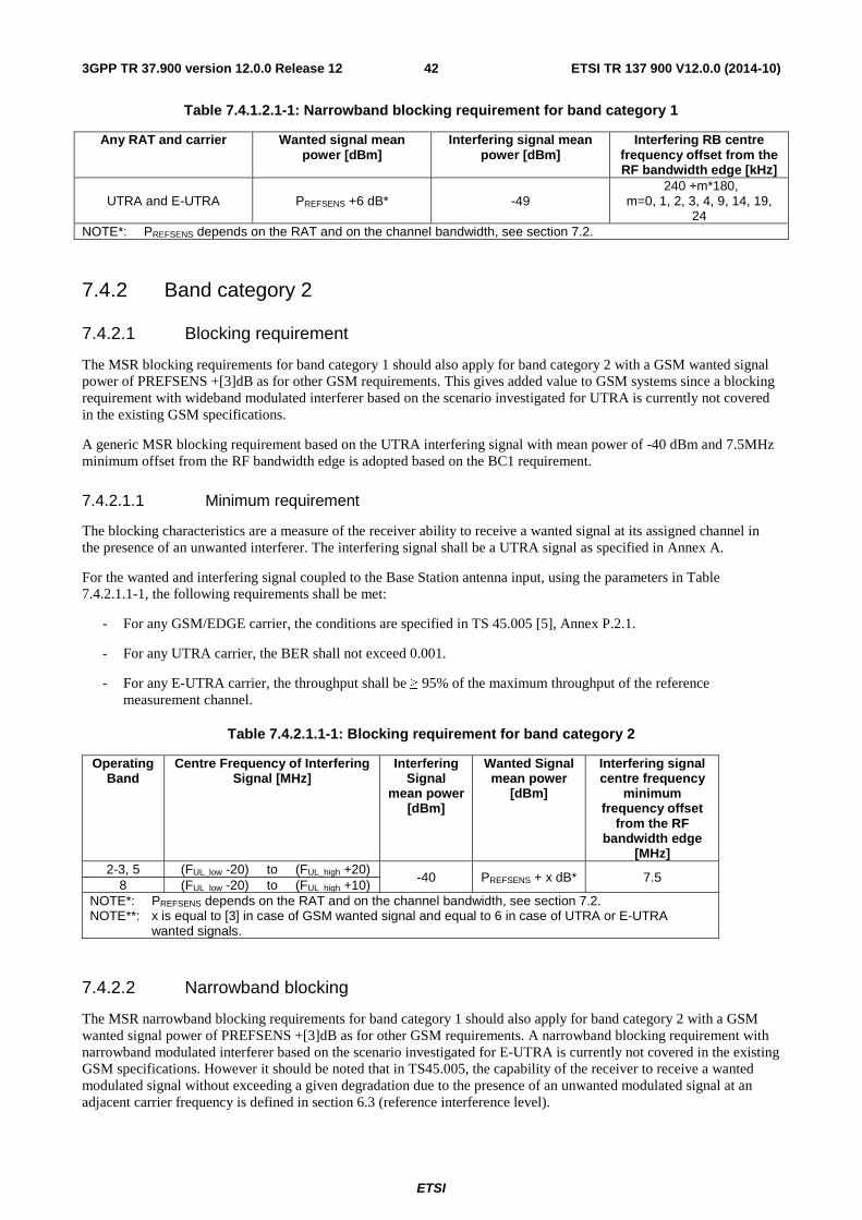
ETSI
ETSI TR 137 900 V12.0.0 (2014-10)423GPP TR 37.900 version 12.0.0 Release 12
Table 7.4.1.2.1-1: Narrowband blocking requirement for band category 1
Any RAT and carrier Wanted signal mean power [dBm]
Interfering signal mean power [dBm]
Interfering RB centre frequency offset from the RF bandwidth edge [kHz]
UTRA and E-UTRA PREFSENS +6 dB* -49 240 +m*180,
m=0, 1, 2, 3, 4, 9, 14, 19, 24
NOTE*: PREFSENS depends on the RAT and on the channel bandwidth, see section 7.2.
7.4.2 Band category 2
7.4.2.1 Blocking requirement
The MSR blocking requirements for band category 1 should also apply for band category 2 with a GSM wanted signal power of PREFSENS +[3]dB as for other GSM requirements. This gives added value to GSM systems since a blocking requirement with wideband modulated interferer based on the scenario investigated for UTRA is currently not covered in the existing GSM specifications.
A generic MSR blocking requirement based on the UTRA interfering signal with mean power of -40 dBm and 7.5MHz minimum offset from the RF bandwidth edge is adopted based on the BC1 requirement.
7.4.2.1.1 Minimum requirement
The blocking characteristics are a measure of the receiver ability to receive a wanted signal at its assigned channel in the presence of an unwanted interferer. The interfering signal shall be a UTRA signal as specified in Annex A.
For the wanted and interfering signal coupled to the Base Station antenna input, using the parameters in Table 7.4.2.1.1-1, the following requirements shall be met:
- For any GSM/EDGE carrier, the conditions are specified in TS 45.005 [5], Annex P.2.1.
- For any UTRA carrier, the BER shall not exceed 0.001.
- For any E-UTRA carrier, the throughput shall be ≥ 95% of the maximum throughput of the reference measurement channel.
Table 7.4.2.1.1-1: Blocking requirement for band category 2
Operating Band
Centre Frequency of Interfering Signal [MHz]
Interfering Signal
mean power [dBm]
Wanted Signal mean power
[dBm]
Interfering signal centre frequency
minimum frequency offset
from the RF bandwidth edge
[MHz] 2-3, 5 (FUL_low -20) to (FUL_high +20)
-40 PREFSENS + x dB* 7.5 8 (FUL_low -20) to (FUL_high +10)
NOTE*: PREFSENS depends on the RAT and on the channel bandwidth, see section 7.2. NOTE**: x is equal to [3] in case of GSM wanted signal and equal to 6 in case of UTRA or E-UTRA
wanted signals.
7.4.2.2 Narrowband blocking
The MSR narrowband blocking requirements for band category 1 should also apply for band category 2 with a GSM wanted signal power of PREFSENS +[3]dB as for other GSM requirements. A narrowband blocking requirement with narrowband modulated interferer based on the scenario investigated for E-UTRA is currently not covered in the existing GSM specifications. However it should be noted that in TS45.005, the capability of the receiver to receive a wanted modulated signal without exceeding a given degradation due to the presence of an unwanted modulated signal at an adjacent carrier frequency is defined in section 6.3 (reference interference level).
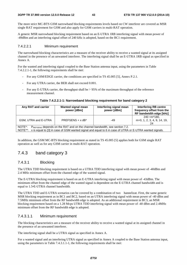
ETSI
ETSI TR 137 900 V12.0.0 (2014-10)433GPP TR 37.900 version 12.0.0 Release 12
The more strict MC-BTS GSM narrowband blocking requirements levels based on CW interferer are covered as MSR single RAT requirement for GSM and also apply for GSM carriers in multi-RAT operation.
A generic MSR narrowband blocking requirement based on an E-UTRA 1RB interfering signal with mean power of -49dBm and an interfering signal offset of 240 kHz is adopted, based on the BC1 requirement.
7.4.2.2.1 Minimum requirement
The narrowband blocking characteristics are a measure of the receiver ability to receive a wanted signal at its assigned channel in the presence of an unwanted interferer. The interfering signal shall be an E-UTRA 1RB signal as specified in Annex A.
For the wanted and interfering signal coupled to the Base Station antenna input, using the parameters in Table 7.4.2.2.1-1, the following requirements shall be met:
- For any GSM/EDGE carrier, the conditions are specified in TS 45.005 [5], Annex P.2.1.
- For any UTRA carrier, the BER shall not exceed 0.001.
- For any E-UTRA carrier, the throughput shall be ≥ 95% of the maximum throughput of the reference measurement channel.
Table 7.4.2.2.1-1: Narrowband blocking requirement for band category 2
Any RAT and carrier Wanted signal mean power [dBm]
Interfering signal mean power [dBm]
Interfering RB centre frequency offset from the RF bandwidth edge [kHz]
GSM, UTRA and E-UTRA PREFSENS + x dB* -49 240 +m*180,
m=0, 1, 2, 3, 4, 9, 14, 19, 24
NOTE*: PREFSENS depends on the RAT and on the channel bandwidth, see section 7.2. NOTE**: x is equal to [3] in case of GSM wanted signal and equal to 6 in case of UTRA or E-UTRA wanted signals.
In addition, the GSM MC-BTS blocking requirement as stated in TS 45.005 [5] applies both for GSM single RAT operation as well as for any GSM carrier in multi-RAT operation.
7.4.3 band category 3
7.4.3.1 Blocking
The UTRA TDD blocking requirement is based on a UTRA TDD interfering signal with mean power of -40dBm and 2.4 MHz minimum offset from the channel edge of the wanted signal.
The E-UTRA blocking requirement is based on an E-UTRA interfering signal with mean power of -43dBm. The minimum offset from the channel edge of the wanted signal is dependent on the E-UTRA channel bandwidth and is equal to 1.5•E-UTRA channel bandwidth.
The UTRA TDD and E-UTRA scenarios can be covered by a combination of two � hannelizat. First, the same generic MSR blocking requirement as in BC1 and BC2, based on an UTRA interfering signal with mean power of -40 dBm and 7.5MHz minimum offset from the RF bandwidth edge is adopted. As an additional requirement in BC3, an MSR blocking requirement based on a 1.28 Mcps UTRA TDD interfering signal with mean power of -40 dBm and 2.4MHz minimum offset from the RF bandwidth edge is adopted.
7.4.3.1.1 Minimum requirement
The blocking characteristics are a measure of the receiver ability to receive a wanted signal at its assigned channel in the presence of an unwanted interferer.
The interfering signal shall be a UTRA signal as specified in Annex A.
For a wanted signal and an interfering UTRA signal as specified in Annex A coupled to the Base Station antenna input, using the parameters in Table 7.4.3.1.1-1, the following requirements shall be met:
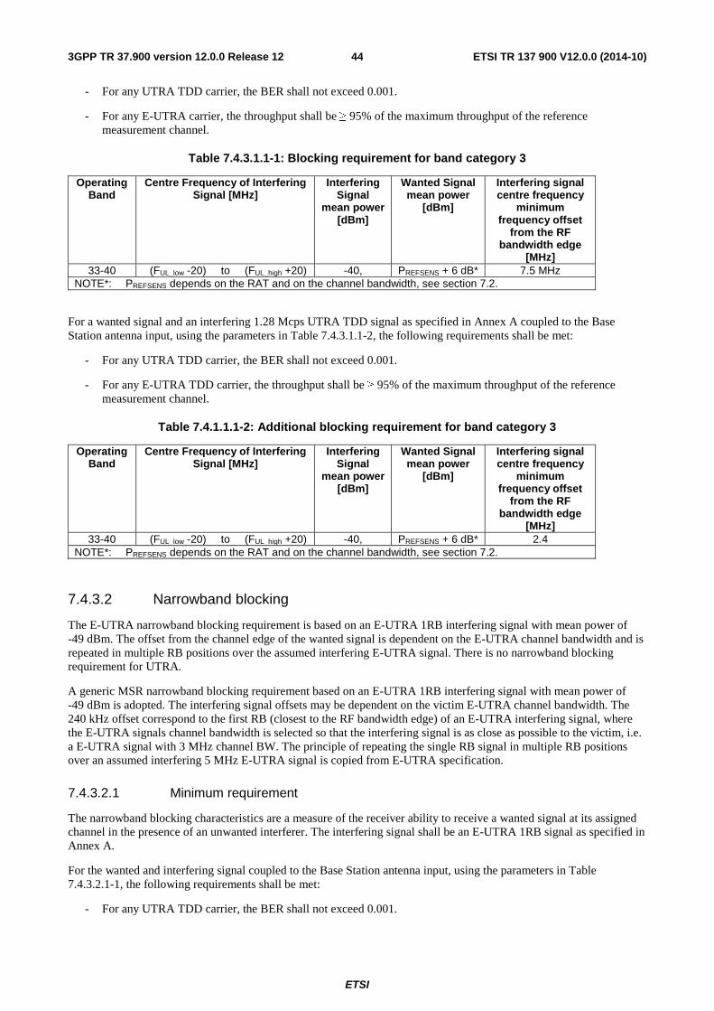
ETSI
ETSI TR 137 900 V12.0.0 (2014-10)443GPP TR 37.900 version 12.0.0 Release 12
- For any UTRA TDD carrier, the BER shall not exceed 0.001.
- For any E-UTRA carrier, the throughput shall be ≥ 95% of the maximum throughput of the reference measurement channel.
Table 7.4.3.1.1-1: Blocking requirement for band category 3
Operating Band
Centre Frequency of Interfering Signal [MHz]
Interfering Signal
mean power [dBm]
Wanted Signal mean power
[dBm]
Interfering signal centre frequency
minimum frequency offset
from the RF bandwidth edge
[MHz] 33-40 (FUL_low -20) to (FUL_high +20) -40, PREFSENS + 6 dB* 7.5 MHz
NOTE*: PREFSENS depends on the RAT and on the channel bandwidth, see section 7.2.
For a wanted signal and an interfering 1.28 Mcps UTRA TDD signal as specified in Annex A coupled to the Base Station antenna input, using the parameters in Table 7.4.3.1.1-2, the following requirements shall be met:
- For any UTRA TDD carrier, the BER shall not exceed 0.001.
- For any E-UTRA TDD carrier, the throughput shall be ≥ 95% of the maximum throughput of the reference measurement channel.
Table 7.4.1.1.1-2: Additional blocking requirement for band category 3
Operating Band
Centre Frequency of Interfering Signal [MHz]
Interfering Signal
mean power [dBm]
Wanted Signal mean power
[dBm]
Interfering signal centre frequency
minimum frequency offset
from the RF bandwidth edge
[MHz] 33-40 (FUL_low -20) to (FUL_high +20) -40, PREFSENS + 6 dB* 2.4
NOTE*: PREFSENS depends on the RAT and on the channel bandwidth, see section 7.2.
7.4.3.2 Narrowband blocking
The E-UTRA narrowband blocking requirement is based on an E-UTRA 1RB interfering signal with mean power of -49 dBm. The offset from the channel edge of the wanted signal is dependent on the E-UTRA channel bandwidth and is repeated in multiple RB positions over the assumed interfering E-UTRA signal. There is no narrowband blocking requirement for UTRA.
A generic MSR narrowband blocking requirement based on an E-UTRA 1RB interfering signal with mean power of -49 dBm is adopted. The interfering signal offsets may be dependent on the victim E-UTRA channel bandwidth. The 240 kHz offset correspond to the first RB (closest to the RF bandwidth edge) of an E-UTRA interfering signal, where the E-UTRA signals channel bandwidth is selected so that the interfering signal is as close as possible to the victim, i.e. a E-UTRA signal with 3 MHz channel BW. The principle of repeating the single RB signal in multiple RB positions over an assumed interfering 5 MHz E-UTRA signal is copied from E-UTRA specification.
7.4.3.2.1 Minimum requirement
The narrowband blocking characteristics are a measure of the receiver ability to receive a wanted signal at its assigned channel in the presence of an unwanted interferer. The interfering signal shall be an E-UTRA 1RB signal as specified in Annex A.
For the wanted and interfering signal coupled to the Base Station antenna input, using the parameters in Table 7.4.3.2.1-1, the following requirements shall be met:
- For any UTRA TDD carrier, the BER shall not exceed 0.001.
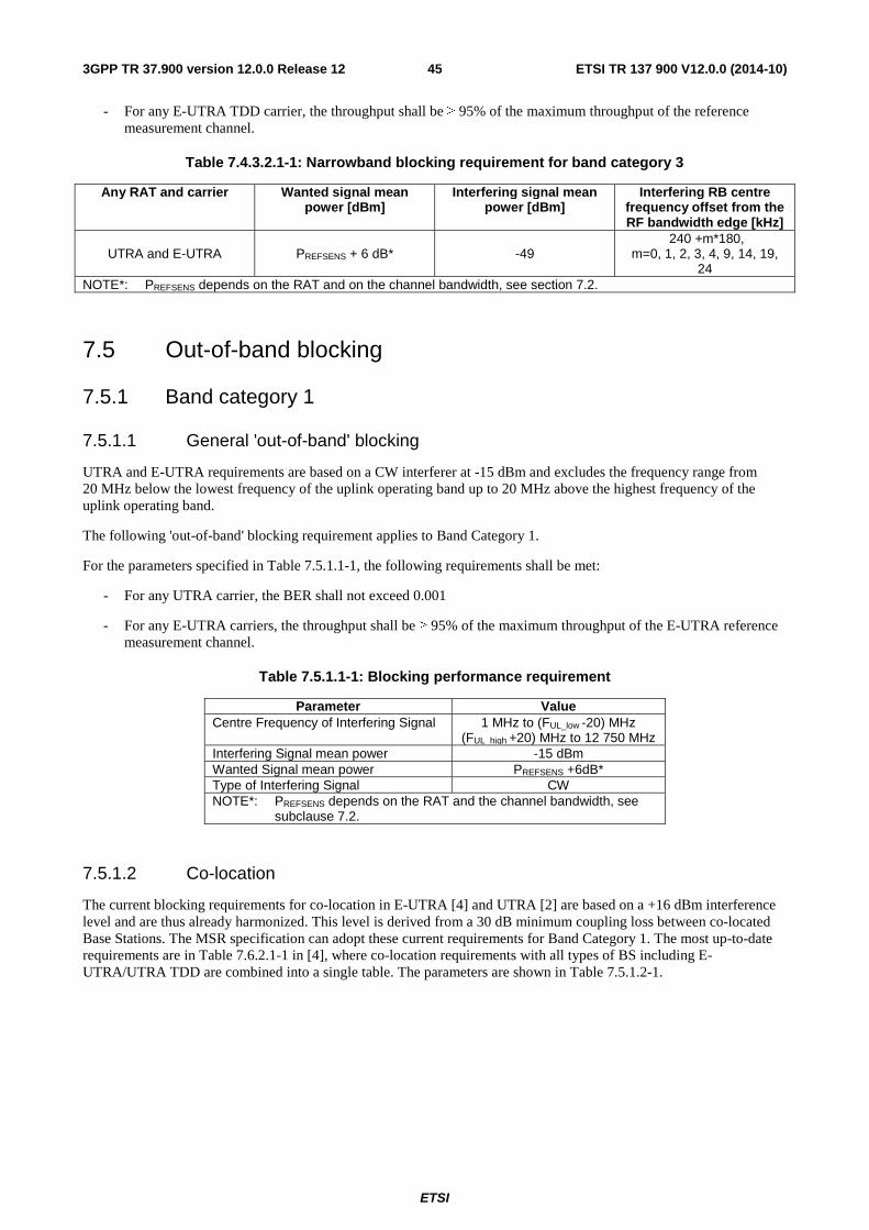
ETSI
ETSI TR 137 900 V12.0.0 (2014-10)453GPP TR 37.900 version 12.0.0 Release 12
- For any E-UTRA TDD carrier, the throughput shall be ≥ 95% of the maximum throughput of the reference measurement channel.
Table 7.4.3.2.1-1: Narrowband blocking requirement for band category 3
Any RAT and carrier Wanted signal mean power [dBm]
Interfering signal mean power [dBm]
Interfering RB centre frequency offset from the RF bandwidth edge [kHz]
UTRA and E-UTRA PREFSENS + 6 dB* -49 240 +m*180,
m=0, 1, 2, 3, 4, 9, 14, 19, 24
NOTE*: PREFSENS depends on the RAT and on the channel bandwidth, see section 7.2.
7.5 Out-of-band blocking
7.5.1 Band category 1
7.5.1.1 General 'out-of-band' blocking
UTRA and E-UTRA requirements are based on a CW interferer at -15 dBm and excludes the frequency range from 20 MHz below the lowest frequency of the uplink operating band up to 20 MHz above the highest frequency of the uplink operating band.
The following 'out-of-band' blocking requirement applies to Band Category 1.
For the parameters specified in Table 7.5.1.1-1, the following requirements shall be met:
- For any UTRA carrier, the BER shall not exceed 0.001
- For any E-UTRA carriers, the throughput shall be ≥ 95% of the maximum throughput of the E-UTRA reference measurement channel.
Table 7.5.1.1-1: Blocking performance requirement
Parameter Value Centre Frequency of Interfering Signal 1 MHz to (FUL_low -20) MHz
(FUL_high +20) MHz to 12 750 MHz Interfering Signal mean power -15 dBm Wanted Signal mean power PREFSENS +6dB* Type of Interfering Signal CW NOTE*: PREFSENS depends on the RAT and the channel bandwidth, see
subclause 7.2.
7.5.1.2 Co-location
The current blocking requirements for co-location in E-UTRA [4] and UTRA [2] are based on a +16 dBm interference level and are thus already harmonized. This level is derived from a 30 dB minimum coupling loss between co-located Base Stations. The MSR specification can adopt these current requirements for Band Category 1. The most up-to-date requirements are in Table 7.6.2.1-1 in [4], where co-location requirements with all types of BS including E-UTRA/UTRA TDD are combined into a single table. The parameters are shown in Table 7.5.1.2-1.
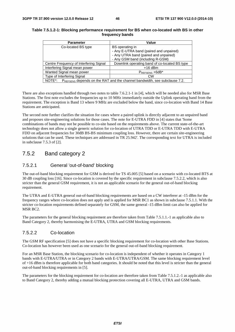
ETSI
ETSI TR 137 900 V12.0.0 (2014-10)463GPP TR 37.900 version 12.0.0 Release 12
Table 7.5.1.2-1: Blocking performance requirement for BS when co-located with BS in other frequency bands
Parameter Value Co-located BS type BS operating in
- Any E-UTRA band (paired and unpaired) - Any UTRA band (paired and unpaired) - Any GSM band (including R-GSM)
Centre Frequency of Interfering Signal Downlink operating band of co-located BS type Interfering Signal mean power +16 dBm Wanted Signal mean power PREFSENS +6dB* Type of Interfering Signal CW NOTE*: PREFSENS depends on the RAT and the channel bandwidth, see subclause 7.2.
There are also exceptions handled through two notes to table 7.6.2.1-1 in [4], which will be needed also for MSR Base Stations. The first note excludes the frequencies up to 10 MHz immediately outside the Uplink operating band from the requirement. The exception is Band 13 where 9 MHz are excluded below the band, since co-location with Band 14 Base Stations are anticipated.
The second note further clarifies the situation for cases where a paired uplink is directly adjacent to an unpaired band and proposes site-engineering solutions for those cases. The note for E-UTRA FDD in [4] states that 'Some combinations of bands may not be possible to co-site based on the requirements above. The current state-of-the-art technology does not allow a single generic solution for co-location of UTRA TDD or E-UTRA TDD with E-UTRA FDD on adjacent frequencies for 30dB BS-BS minimum coupling loss. However, there are certain site-engineering solutions that can be used. These techniques are addressed in TR 25.942'. The corresponding text for UTRA is included in subclause 7.5.3 of [2].
7.5.2 Band category 2
7.5.2.1 General 'out-of-band' blocking
The out-of-band blocking requirement for GSM is derived for TS 45.005 [5] based on a scenario with co-located BTS at 30 dB coupling loss [16]. Since co-location is covered by the specific requirement in subclause 7.5.2.2, which is also stricter than the general GSM requirement, it is not an applicable scenario for the general out-of-band blocking requirement.
The UTRA and E-UTRA general out-of-band blocking requirements are based on a CW interferer at -15 dBm for the frequency ranges where co-location does not apply and is applied for MSR BC1 as shown in subclause 7.5.1.1. With the stricter co-location requirements defined separately for GSM, the same general -15 dBm limit can also be applied for MSR BC2.
The parameters for the general blocking requirement are therefore taken from Table 7.5.1.1.-1 as applicable also to Band Category 2, thereby harmonising the E-UTRA, UTRA and GSM blocking requirements.
7.5.2.2 Co-location
The GSM RF specification [5] does not have a specific blocking requirement for co-location with other Base Stations. Co-location has however been used as one scenario for the general out-of-band blocking requirement.
For an MSR Base Station, the blocking scenario for co-location is independent of whether it operates in Category 1 bands with E-UTRA/UTRA or in Category 2 bands with E-UTRA/UTRA/GSM. The same blocking requirement level of +16 dBm is therefore applicable for both band categories. It should be noted that this level is stricter than the general out-of-band blocking requirements in [5].
The parameters for the blocking requirement for co-location are therefore taken from Table 7.5.1.2.-1 as applicable also to Band Category 2, thereby adding a mutual blocking protection covering all E-UTRA, UTRA and GSM bands.
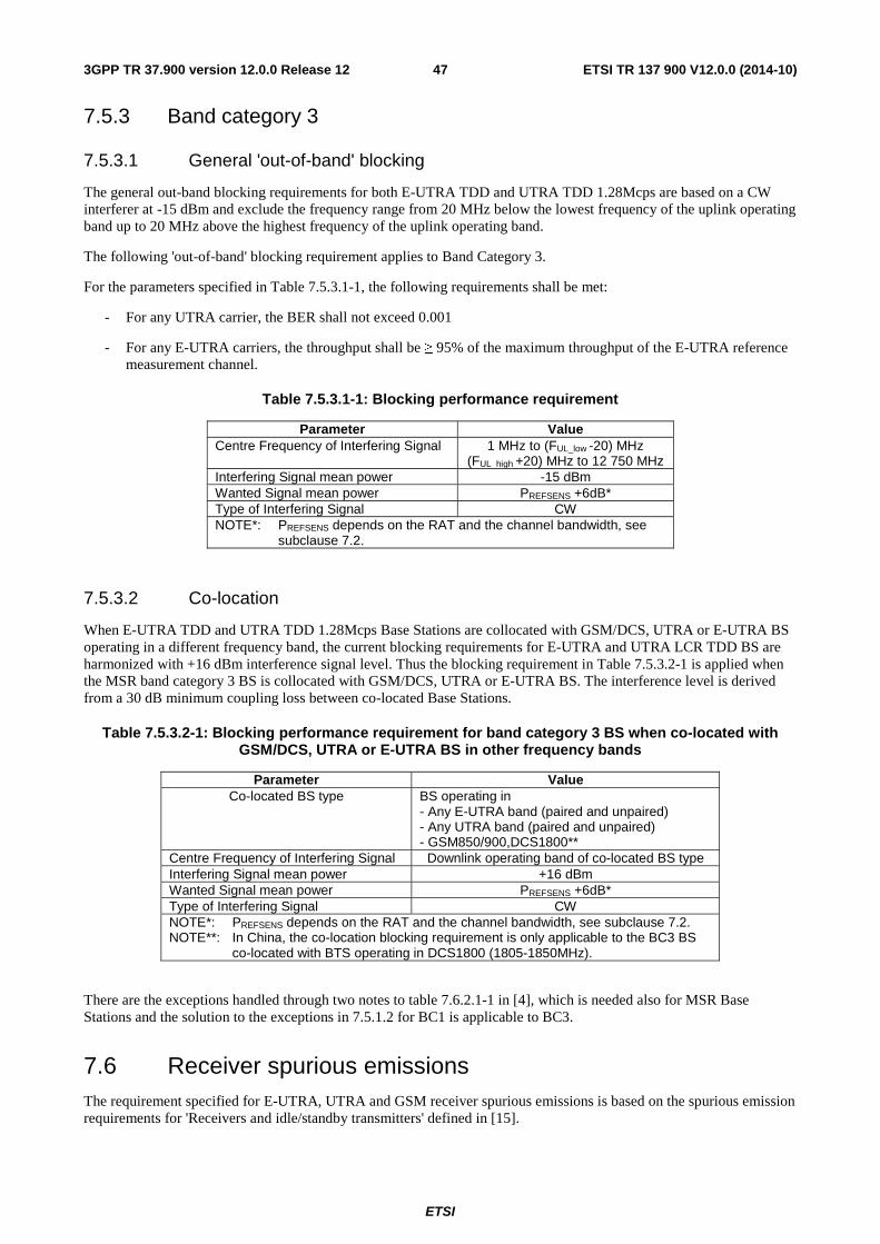
ETSI
ETSI TR 137 900 V12.0.0 (2014-10)473GPP TR 37.900 version 12.0.0 Release 12
7.5.3 Band category 3
7.5.3.1 General 'out-of-band' blocking
The general out-band blocking requirements for both E-UTRA TDD and UTRA TDD 1.28Mcps are based on a CW interferer at -15 dBm and exclude the frequency range from 20 MHz below the lowest frequency of the uplink operating band up to 20 MHz above the highest frequency of the uplink operating band.
The following 'out-of-band' blocking requirement applies to Band Category 3.
For the parameters specified in Table 7.5.3.1-1, the following requirements shall be met:
- For any UTRA carrier, the BER shall not exceed 0.001
- For any E-UTRA carriers, the throughput shall be ≥ 95% of the maximum throughput of the E-UTRA reference measurement channel.
Table 7.5.3.1-1: Blocking performance requirement
Parameter Value Centre Frequency of Interfering Signal 1 MHz to (FUL_low -20) MHz
(FUL_high +20) MHz to 12 750 MHz Interfering Signal mean power -15 dBm Wanted Signal mean power PREFSENS +6dB* Type of Interfering Signal CW NOTE*: PREFSENS depends on the RAT and the channel bandwidth, see
subclause 7.2.
7.5.3.2 Co-location
When E-UTRA TDD and UTRA TDD 1.28Mcps Base Stations are collocated with GSM/DCS, UTRA or E-UTRA BS operating in a different frequency band, the current blocking requirements for E-UTRA and UTRA LCR TDD BS are harmonized with +16 dBm interference signal level. Thus the blocking requirement in Table 7.5.3.2-1 is applied when the MSR band category 3 BS is collocated with GSM/DCS, UTRA or E-UTRA BS. The interference level is derived from a 30 dB minimum coupling loss between co-located Base Stations.
Table 7.5.3.2-1: Blocking performance requirement for band category 3 BS when co-located with GSM/DCS, UTRA or E-UTRA BS in other frequency bands
Parameter Value Co-located BS type BS operating in
- Any E-UTRA band (paired and unpaired) - Any UTRA band (paired and unpaired) - GSM850/900,DCS1800**
Centre Frequency of Interfering Signal Downlink operating band of co-located BS type Interfering Signal mean power +16 dBm Wanted Signal mean power PREFSENS +6dB* Type of Interfering Signal CW NOTE*: PREFSENS depends on the RAT and the channel bandwidth, see subclause 7.2. NOTE**: In China, the co-location blocking requirement is only applicable to the BC3 BS
co-located with BTS operating in DCS1800 (1805-1850MHz).
There are the exceptions handled through two notes to table 7.6.2.1-1 in [4], which is needed also for MSR Base Stations and the solution to the exceptions in 7.5.1.2 for BC1 is applicable to BC3.
7.6 Receiver spurious emissions The requirement specified for E-UTRA, UTRA and GSM receiver spurious emissions is based on the spurious emission requirements for 'Receivers and idle/standby transmitters' defined in [15].
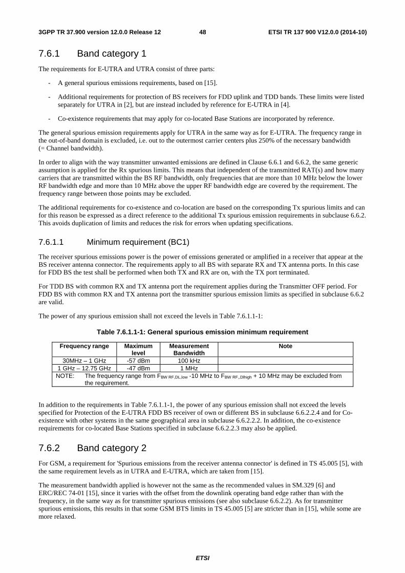
ETSI
ETSI TR 137 900 V12.0.0 (2014-10)483GPP TR 37.900 version 12.0.0 Release 12
7.6.1 Band category 1
The requirements for E-UTRA and UTRA consist of three parts:
- A general spurious emissions requirements, based on [15].
- Additional requirements for protection of BS receivers for FDD uplink and TDD bands. These limits were listed separately for UTRA in [2], but are instead included by reference for E-UTRA in [4].
- Co-existence requirements that may apply for co-located Base Stations are incorporated by reference.
The general spurious emission requirements apply for UTRA in the same way as for E-UTRA. The frequency range in the out-of-band domain is excluded, i.e. out to the outermost carrier centers plus 250% of the necessary bandwidth (= Channel bandwidth).
In order to align with the way transmitter unwanted emissions are defined in Clause 6.6.1 and 6.6.2, the same generic assumption is applied for the Rx spurious limits. This means that independent of the transmitted RAT(s) and how many carriers that are transmitted within the BS RF bandwidth, only frequencies that are more than 10 MHz below the lower RF bandwidth edge and more than 10 MHz above the upper RF bandwidth edge are covered by the requirement. The frequency range between those points may be excluded.
The additional requirements for co-existence and co-location are based on the corresponding Tx spurious limits and can for this reason be expressed as a direct reference to the additional Tx spurious emission requirements in subclause 6.6.2. This avoids duplication of limits and reduces the risk for errors when updating specifications.
7.6.1.1 Minimum requirement (BC1)
The receiver spurious emissions power is the power of emissions generated or amplified in a receiver that appear at the BS receiver antenna connector. The requirements apply to all BS with separate RX and TX antenna ports. In this case for FDD BS the test shall be performed when both TX and RX are on, with the TX port terminated.
For TDD BS with common RX and TX antenna port the requirement applies during the Transmitter OFF period. For FDD BS with common RX and TX antenna port the transmitter spurious emission limits as specified in subclause 6.6.2 are valid.
The power of any spurious emission shall not exceed the levels in Table 7.6.1.1-1:
Table 7.6.1.1-1: General spurious emission minimum requirement
Frequency range Maximum level
Measurement Bandwidth
Note
30MHz – 1 GHz -57 dBm 100 kHz 1 GHz – 12.75 GHz -47 dBm 1 MHz
NOTE: The frequency range from FBW RF,DL,low -10 MHz to FBW RF,,Dlhigh + 10 MHz may be excluded from the requirement.
In addition to the requirements in Table 7.6.1.1-1, the power of any spurious emission shall not exceed the levels specified for Protection of the E-UTRA FDD BS receiver of own or different BS in subclause 6.6.2.2.4 and for Co-existence with other systems in the same geographical area in subclause 6.6.2.2.2. In addition, the co-existence requirements for co-located Base Stations specified in subclause 6.6.2.2.3 may also be applied.
7.6.2 Band category 2
For GSM, a requirement for 'Spurious emissions from the receiver antenna connector' is defined in TS 45.005 [5], with the same requirement levels as in UTRA and E-UTRA, which are taken from [15].
The measurement bandwidth applied is however not the same as the recommended values in SM.329 [6] and ERC/REC 74-01 [15], since it varies with the offset from the downlink operating band edge rather than with the frequency, in the same way as for transmitter spurious emissions (see also subclause 6.6.2.2). As for transmitter spurious emissions, this results in that some GSM BTS limits in TS 45.005 [5] are stricter than in [15], while some are more relaxed.
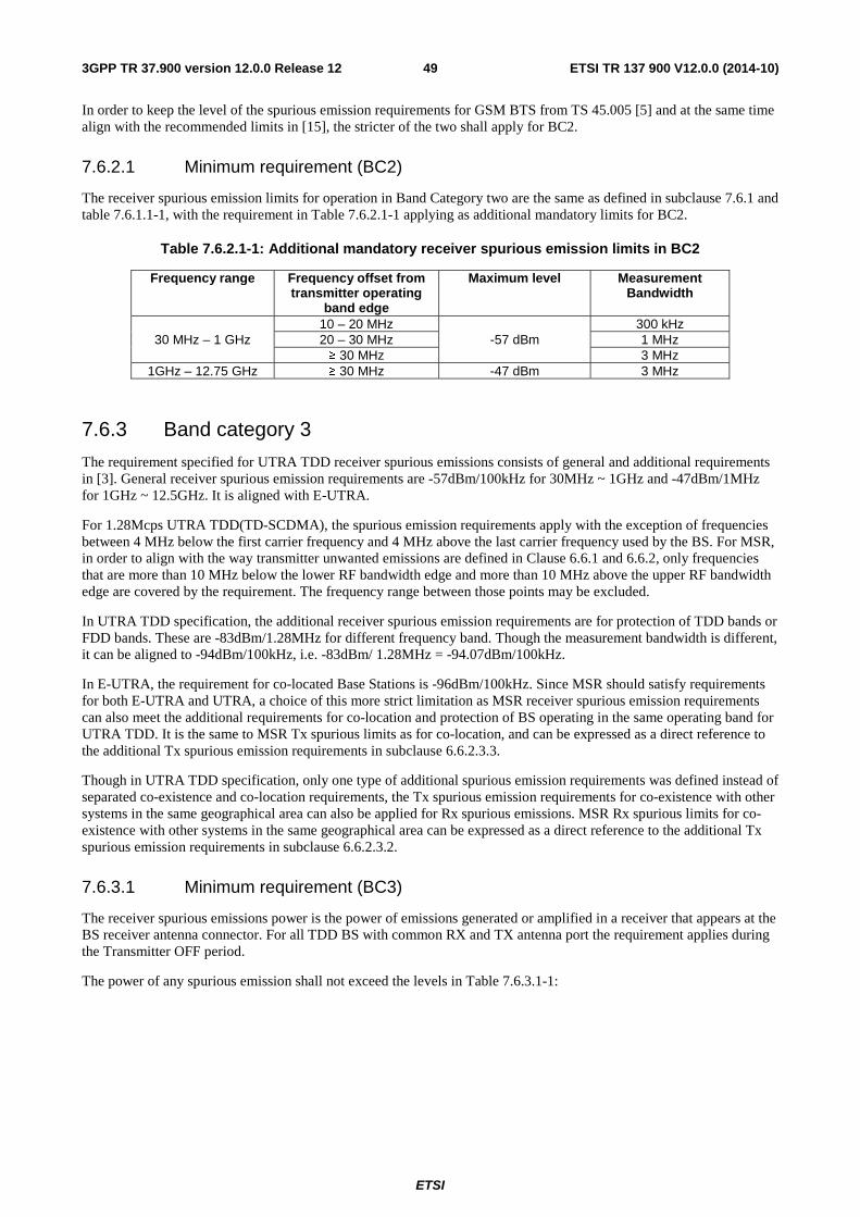
ETSI
ETSI TR 137 900 V12.0.0 (2014-10)493GPP TR 37.900 version 12.0.0 Release 12
In order to keep the level of the spurious emission requirements for GSM BTS from TS 45.005 [5] and at the same time align with the recommended limits in [15], the stricter of the two shall apply for BC2.
7.6.2.1 Minimum requirement (BC2)
The receiver spurious emission limits for operation in Band Category two are the same as defined in subclause 7.6.1 and table 7.6.1.1-1, with the requirement in Table 7.6.2.1-1 applying as additional mandatory limits for BC2.
Table 7.6.2.1-1: Additional mandatory receiver spurious emission limits in BC2
Frequency range Frequency offset from transmitter operating
band edge
Maximum level Measurement Bandwidth
30 MHz – 1 GHz 10 – 20 MHz
-57 dBm 300 kHz
20 – 30 MHz 1 MHz ≥ 30 MHz 3 MHz
1GHz – 12.75 GHz ≥ 30 MHz -47 dBm 3 MHz
7.6.3 Band category 3
The requirement specified for UTRA TDD receiver spurious emissions consists of general and additional requirements in [3]. General receiver spurious emission requirements are -57dBm/100kHz for 30MHz ~ 1GHz and -47dBm/1MHz for 1GHz ~ 12.5GHz. It is aligned with E-UTRA.
For 1.28Mcps UTRA TDD(TD-SCDMA), the spurious emission requirements apply with the exception of frequencies between 4 MHz below the first carrier frequency and 4 MHz above the last carrier frequency used by the BS. For MSR, in order to align with the way transmitter unwanted emissions are defined in Clause 6.6.1 and 6.6.2, only frequencies that are more than 10 MHz below the lower RF bandwidth edge and more than 10 MHz above the upper RF bandwidth edge are covered by the requirement. The frequency range between those points may be excluded.
In UTRA TDD specification, the additional receiver spurious emission requirements are for protection of TDD bands or FDD bands. These are -83dBm/1.28MHz for different frequency band. Though the measurement bandwidth is different, it can be aligned to -94dBm/100kHz, i.e. -83dBm/ 1.28MHz = -94.07dBm/100kHz.
In E-UTRA, the requirement for co-located Base Stations is -96dBm/100kHz. Since MSR should satisfy requirements for both E-UTRA and UTRA, a choice of this more strict limitation as MSR receiver spurious emission requirements can also meet the additional requirements for co-location and protection of BS operating in the same operating band for UTRA TDD. It is the same to MSR Tx spurious limits as for co-location, and can be expressed as a direct reference to the additional Tx spurious emission requirements in subclause 6.6.2.3.3.
Though in UTRA TDD specification, only one type of additional spurious emission requirements was defined instead of separated co-existence and co-location requirements, the Tx spurious emission requirements for co-existence with other systems in the same geographical area can also be applied for Rx spurious emissions. MSR Rx spurious limits for co-existence with other systems in the same geographical area can be expressed as a direct reference to the additional Tx spurious emission requirements in subclause 6.6.2.3.2.
7.6.3.1 Minimum requirement (BC3)
The receiver spurious emissions power is the power of emissions generated or amplified in a receiver that appears at the BS receiver antenna connector. For all TDD BS with common RX and TX antenna port the requirement applies during the Transmitter OFF period.
The power of any spurious emission shall not exceed the levels in Table 7.6.3.1-1:
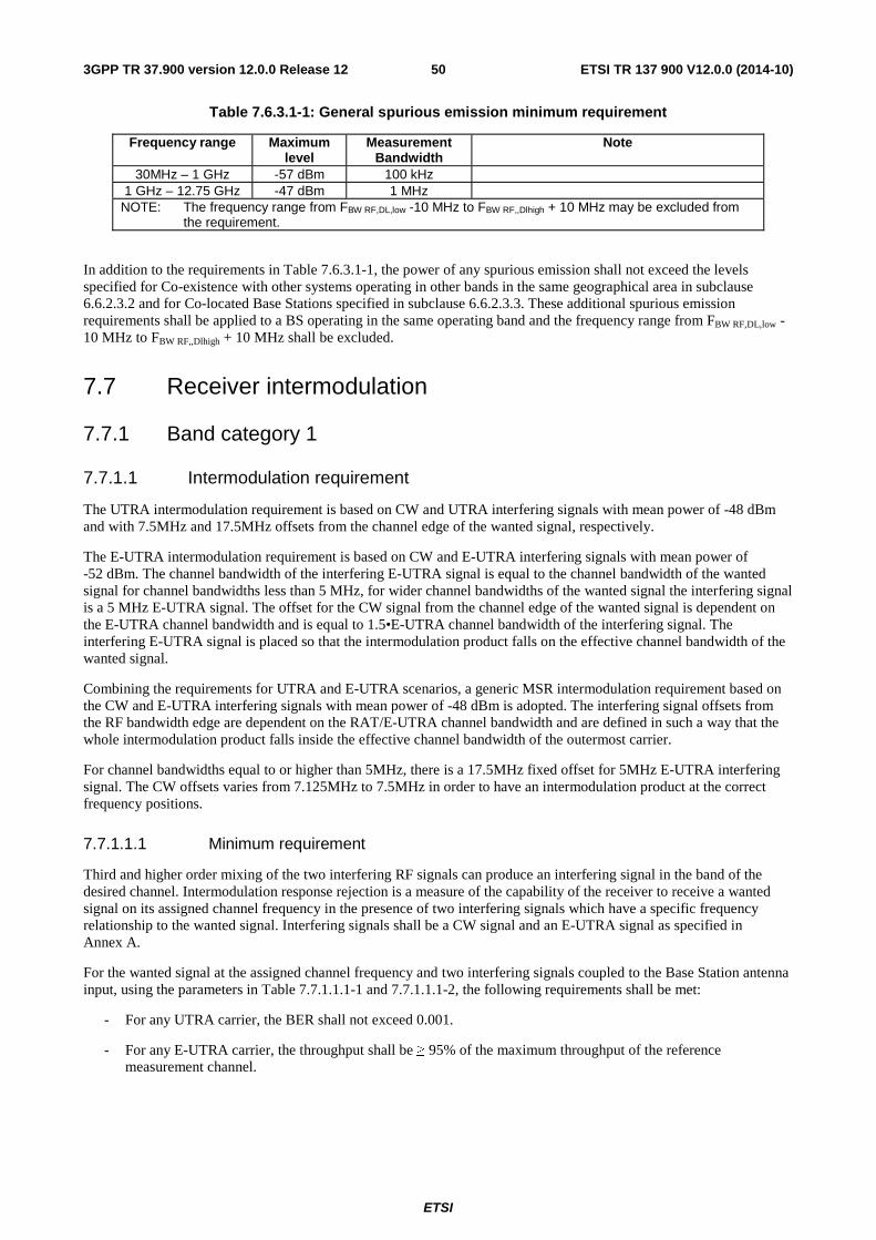
ETSI
ETSI TR 137 900 V12.0.0 (2014-10)503GPP TR 37.900 version 12.0.0 Release 12
Table 7.6.3.1-1: General spurious emission minimum requirement
Frequency range Maximum level
Measurement Bandwidth
Note
30MHz – 1 GHz -57 dBm 100 kHz 1 GHz – 12.75 GHz -47 dBm 1 MHz
NOTE: The frequency range from FBW RF,DL,low -10 MHz to FBW RF,,Dlhigh + 10 MHz may be excluded from the requirement.
In addition to the requirements in Table 7.6.3.1-1, the power of any spurious emission shall not exceed the levels specified for Co-existence with other systems operating in other bands in the same geographical area in subclause 6.6.2.3.2 and for Co-located Base Stations specified in subclause 6.6.2.3.3. These additional spurious emission requirements shall be applied to a BS operating in the same operating band and the frequency range from FBW RF,DL,low -10 MHz to FBW RF,,Dlhigh + 10 MHz shall be excluded.
7.7 Receiver intermodulation
7.7.1 Band category 1
7.7.1.1 Intermodulation requirement
The UTRA intermodulation requirement is based on CW and UTRA interfering signals with mean power of -48 dBm and with 7.5MHz and 17.5MHz offsets from the channel edge of the wanted signal, respectively.
The E-UTRA intermodulation requirement is based on CW and E-UTRA interfering signals with mean power of -52 dBm. The channel bandwidth of the interfering E-UTRA signal is equal to the channel bandwidth of the wanted signal for channel bandwidths less than 5 MHz, for wider channel bandwidths of the wanted signal the interfering signal is a 5 MHz E-UTRA signal. The offset for the CW signal from the channel edge of the wanted signal is dependent on the E-UTRA channel bandwidth and is equal to 1.5•E-UTRA channel bandwidth of the interfering signal. The interfering E-UTRA signal is placed so that the intermodulation product falls on the effective channel bandwidth of the wanted signal.
Combining the requirements for UTRA and E-UTRA scenarios, a generic MSR intermodulation requirement based on the CW and E-UTRA interfering signals with mean power of -48 dBm is adopted. The interfering signal offsets from the RF bandwidth edge are dependent on the RAT/E-UTRA channel bandwidth and are defined in such a way that the whole intermodulation product falls inside the effective channel bandwidth of the outermost carrier.
For channel bandwidths equal to or higher than 5MHz, there is a 17.5MHz fixed offset for 5MHz E-UTRA interfering signal. The CW offsets varies from 7.125MHz to 7.5MHz in order to have an intermodulation product at the correct frequency positions.
7.7.1.1.1 Minimum requirement
Third and higher order mixing of the two interfering RF signals can produce an interfering signal in the band of the desired channel. Intermodulation response rejection is a measure of the capability of the receiver to receive a wanted signal on its assigned channel frequency in the presence of two interfering signals which have a specific frequency relationship to the wanted signal. Interfering signals shall be a CW signal and an E-UTRA signal as specified in Annex A.
For the wanted signal at the assigned channel frequency and two interfering signals coupled to the Base Station antenna input, using the parameters in Table 7.7.1.1.1-1 and 7.7.1.1.1-2, the following requirements shall be met:
- For any UTRA carrier, the BER shall not exceed 0.001.
- For any E-UTRA carrier, the throughput shall be ≥ 95% of the maximum throughput of the reference measurement channel.
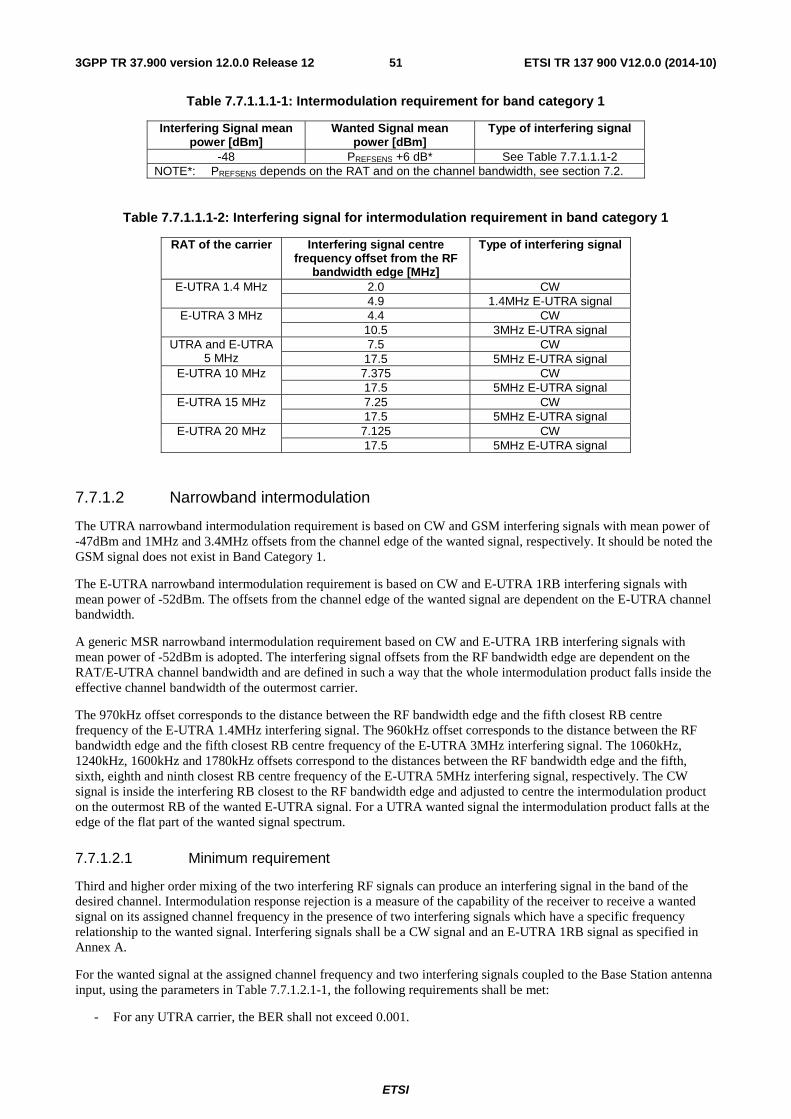
ETSI
ETSI TR 137 900 V12.0.0 (2014-10)513GPP TR 37.900 version 12.0.0 Release 12
Table 7.7.1.1.1-1: Intermodulation requirement for band category 1
Interfering Signal mean power [dBm]
Wanted Signal mean power [dBm]
Type of interfering signal
-48 PREFSENS +6 dB* See Table 7.7.1.1.1-2 NOTE*: PREFSENS depends on the RAT and on the channel bandwidth, see section 7.2.
Table 7.7.1.1.1-2: Interfering signal for intermodulation requirement in band category 1
RAT of the carrier Interfering signal centre frequency offset from the RF
bandwidth edge [MHz]
Type of interfering signal
E-UTRA 1.4 MHz
2.0 CW 4.9 1.4MHz E-UTRA signal
E-UTRA 3 MHz
4.4 CW 10.5 3MHz E-UTRA signal
UTRA and E-UTRA 5 MHz
7.5 CW 17.5 5MHz E-UTRA signal
E-UTRA 10 MHz
7.375 CW 17.5 5MHz E-UTRA signal
E-UTRA 15 MHz
7.25 CW 17.5 5MHz E-UTRA signal
E-UTRA 20 MHz 7.125 CW 17.5 5MHz E-UTRA signal
7.7.1.2 Narrowband intermodulation
The UTRA narrowband intermodulation requirement is based on CW and GSM interfering signals with mean power of -47dBm and 1MHz and 3.4MHz offsets from the channel edge of the wanted signal, respectively. It should be noted the GSM signal does not exist in Band Category 1.
The E-UTRA narrowband intermodulation requirement is based on CW and E-UTRA 1RB interfering signals with mean power of -52dBm. The offsets from the channel edge of the wanted signal are dependent on the E-UTRA channel bandwidth.
A generic MSR narrowband intermodulation requirement based on CW and E-UTRA 1RB interfering signals with mean power of -52dBm is adopted. The interfering signal offsets from the RF bandwidth edge are dependent on the RAT/E-UTRA channel bandwidth and are defined in such a way that the whole intermodulation product falls inside the effective channel bandwidth of the outermost carrier.
The 970kHz offset corresponds to the distance between the RF bandwidth edge and the fifth closest RB centre frequency of the E-UTRA 1.4MHz interfering signal. The 960kHz offset corresponds to the distance between the RF bandwidth edge and the fifth closest RB centre frequency of the E-UTRA 3MHz interfering signal. The 1060kHz, 1240kHz, 1600kHz and 1780kHz offsets correspond to the distances between the RF bandwidth edge and the fifth, sixth, eighth and ninth closest RB centre frequency of the E-UTRA 5MHz interfering signal, respectively. The CW signal is inside the interfering RB closest to the RF bandwidth edge and adjusted to centre the intermodulation product on the outermost RB of the wanted E-UTRA signal. For a UTRA wanted signal the intermodulation product falls at the edge of the flat part of the wanted signal spectrum.
7.7.1.2.1 Minimum requirement
Third and higher order mixing of the two interfering RF signals can produce an interfering signal in the band of the desired channel. Intermodulation response rejection is a measure of the capability of the receiver to receive a wanted signal on its assigned channel frequency in the presence of two interfering signals which have a specific frequency relationship to the wanted signal. Interfering signals shall be a CW signal and an E-UTRA 1RB signal as specified in Annex A.
For the wanted signal at the assigned channel frequency and two interfering signals coupled to the Base Station antenna input, using the parameters in Table 7.7.1.2.1-1, the following requirements shall be met:
- For any UTRA carrier, the BER shall not exceed 0.001.
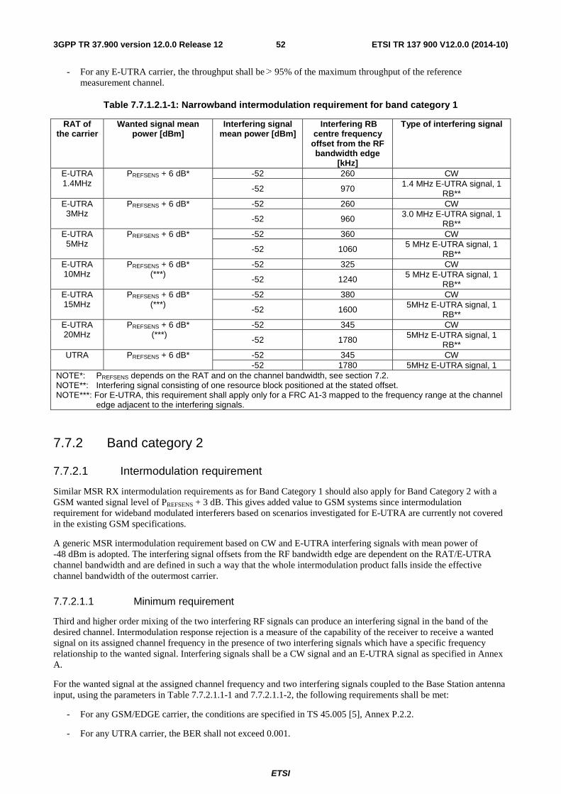
ETSI
ETSI TR 137 900 V12.0.0 (2014-10)523GPP TR 37.900 version 12.0.0 Release 12
- For any E-UTRA carrier, the throughput shall be ≥ 95% of the maximum throughput of the reference measurement channel.
Table 7.7.1.2.1-1: Narrowband intermodulation requirement for band category 1
RAT of the carrier
Wanted signal mean power [dBm]
Interfering signal mean power [dBm]
Interfering RB centre frequency
offset from the RF bandwidth edge
[kHz]
Type of interfering signal
E-UTRA 1.4MHz
PREFSENS + 6 dB*
-52 260 CW
-52 970 1.4 MHz E-UTRA signal, 1 RB**
E-UTRA 3MHz
PREFSENS + 6 dB*
-52 260 CW
-52 960 3.0 MHz E-UTRA signal, 1 RB**
E-UTRA 5MHz
PREFSENS + 6 dB*
-52 360 CW
-52 1060 5 MHz E-UTRA signal, 1 RB**
E-UTRA 10MHz
PREFSENS + 6 dB* (***)
-52 325 CW
-52 1240 5 MHz E-UTRA signal, 1 RB**
E-UTRA 15MHz
PREFSENS + 6 dB* (***)
-52 380 CW
-52 1600 5MHz E-UTRA signal, 1 RB**
E-UTRA 20MHz
PREFSENS + 6 dB* (***)
-52 345 CW
-52 1780 5MHz E-UTRA signal, 1 RB**
UTRA PREFSENS + 6 dB* -52 345 CW -52 1780 5MHz E-UTRA signal, 1
NOTE*: PREFSENS depends on the RAT and on the channel bandwidth, see section 7.2. NOTE**: Interfering signal consisting of one resource block positioned at the stated offset. NOTE***: For E-UTRA, this requirement shall apply only for a FRC A1-3 mapped to the frequency range at the channel
edge adjacent to the interfering signals.
7.7.2 Band category 2
7.7.2.1 Intermodulation requirement
Similar MSR RX intermodulation requirements as for Band Category 1 should also apply for Band Category 2 with a GSM wanted signal level of PREFSENS + 3 dB. This gives added value to GSM systems since intermodulation requirement for wideband modulated interferers based on scenarios investigated for E-UTRA are currently not covered in the existing GSM specifications.
A generic MSR intermodulation requirement based on CW and E-UTRA interfering signals with mean power of -48 dBm is adopted. The interfering signal offsets from the RF bandwidth edge are dependent on the RAT/E-UTRA channel bandwidth and are defined in such a way that the whole intermodulation product falls inside the effective channel bandwidth of the outermost carrier.
7.7.2.1.1 Minimum requirement
Third and higher order mixing of the two interfering RF signals can produce an interfering signal in the band of the desired channel. Intermodulation response rejection is a measure of the capability of the receiver to receive a wanted signal on its assigned channel frequency in the presence of two interfering signals which have a specific frequency relationship to the wanted signal. Interfering signals shall be a CW signal and an E-UTRA signal as specified in Annex A.
For the wanted signal at the assigned channel frequency and two interfering signals coupled to the Base Station antenna input, using the parameters in Table 7.7.2.1.1-1 and 7.7.2.1.1-2, the following requirements shall be met:
- For any GSM/EDGE carrier, the conditions are specified in TS 45.005 [5], Annex P.2.2.
- For any UTRA carrier, the BER shall not exceed 0.001.
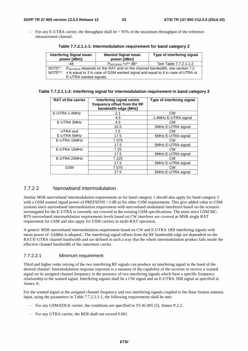
ETSI
ETSI TR 137 900 V12.0.0 (2014-10)533GPP TR 37.900 version 12.0.0 Release 12
- For any E-UTRA carrier, the throughput shall be ≥ 95% of the maximum throughput of the reference measurement channel.
Table 7.7.2.1.1-1: Intermodulation requirement for band category 2
Interfering Signal mean power [dBm]
Wanted Signal mean power [dBm]
Type of interfering signal
-48 PREFSENS +x** dB* See Table 7.7.2.1.1-2 NOTE*: PREFSENS depends on the RAT and on the channel bandwidth, see section 7.2. NOTE**: x is equal to 3 in case of GSM wanted signal and equal to 6 in case of UTRA or
E-UTRA wanted signals.
Table 7.7.2.1.1-2: Interfering signal for intermodulation requirement in band category 2
RAT of the carrier Interfering signal centre frequency offset from the RF
bandwidth edge [MHz]
Type of interfering signal
E-UTRA 1.4MHz
2.1 CW 4.9 1.4MHz E-UTRA signal
E-UTRA 3MHz
4.5 CW 10.5 3MHz E-UTRA signal
UTRA and E-UTRA 5MHz
7.5 CW 17.5 5MHz E-UTRA signal
E-UTRA 10MHz
7.375 CW 17.5 5MHz E-UTRA signal
E-UTRA 15MHz
7.25 CW 17.5 5MHz E-UTRA signal
E-UTRA 20MHz
7.125 CW 17.5 5MHz E-UTRA signal
GSM 7.575 CW 17.5 5MHz E-UTRA signal
7.7.2.2 Narrowband intermodulation
Similar MSR narrowband intermodulation requirements as for band category 1 should also apply for band category 2 with a GSM wanted signal power of PREFSENS +3 dB as for other GSM requirements. This give added value to GSM systems since narrowband intermodulation requirement with narrowband modulated interferers based on the scenario investigated for the E-UTRA is currently not covered in the existing GSM specifications. The more strict GSM MC-BTS narrowband intermodulation requirements levels based on CW interferer are covered as MSR single RAT requirement for GSM and also apply for GSM carriers in multi-RAT operation.
A generic MSR narrowband intermodulation requirement based on CW and E-UTRA 1RB interfering signals with mean power of -52dBm is adopted.. The interfering signal offsets from the RF bandwidth edge are dependent on the RAT/E-UTRA channel bandwidth and are defined in such a way that the whole intermodulation product falls inside the effective channel bandwidth of the outermost carrier.
7.7.2.2.1 Minimum requirement
Third and higher order mixing of the two interfering RF signals can produce an interfering signal in the band of the desired channel. Intermodulation response rejection is a measure of the capability of the receiver to receive a wanted signal on its assigned channel frequency in the presence of two interfering signals which have a specific frequency relationship to the wanted signal. Interfering signals shall be a CW signal and an E-UTRA 1RB signal as specified in Annex A.
For the wanted signal at the assigned channel frequency and two interfering signals coupled to the Base Station antenna input, using the parameters in Table 7.7.2.2.1-1, the following requirements shall be met:
- For any GSM/EDGE carrier, the conditions are specified in TS 45.005 [5], Annex P.2.2.
- For any UTRA carrier, the BER shall not exceed 0.001.

ETSI
ETSI TR 137 900 V12.0.0 (2014-10)543GPP TR 37.900 version 12.0.0 Release 12
- For any E-UTRA carrier, the throughput shall be ≥ 95% of the maximum throughput of the reference measurement channel.
Table 7.7.2.2.1-1: Narrowband intermodulation requirement for band category 2
RAT of the carrier
Wanted signal mean power [dBm]
Interfering signal mean power [dBm]
Interfering RB centre frequency
offset from the RF bandwidth edge
[kHz]
Type of interfering signal
E-UTRA 1.4MHz
PREFSENS + 6 dB*
-52 270 CW
-52 790 1.4 MHz E-UTRA signal, 1 RB**
E-UTRA 3MHz
PREFSENS + 6 dB*
-52 270 CW
-52 780 3.0 MHz E-UTRA signal, 1 RB**
E-UTRA 5MHz
PREFSENS + 6 dB*
-52 360 CW
-52 1060 5 MHz E-UTRA signal, 1 RB**
E-UTRA 10MHz
PREFSENS + 6 dB* (***)
-52 325 CW
-52 1240 5 MHz E-UTRA signal, 1 RB**
E-UTRA 15MHz
PREFSENS + 6 dB* (***)
-52 380 CW
-52 1600 5MHz E-UTRA signal, 1 RB**
E-UTRA 20MHz
PREFSENS + 6 dB* (***)
-52 345 CW
-52 1780 5MHz E-UTRA signal, 1 RB**
UTRA PREFSENS + 6 dB* -52 345 CW
-52 1780 5MHz E-UTRA signal, 1 RB**
GSM PREFSENS + 3 dB* -52 340 CW
-52 880 5MHz E-UTRA signal, 1 RB**
NOTE*: PREFSENS depends on the RAT and on the channel bandwidth, see section 7.2. NOTE**: Interfering signal consisting of one resource block positioned at the stated offset. NOTE***: For E-UTRA, this requirement shall apply only for a FRC A1-3 mapped to the frequency range at the channel
edge adjacent to the interfering signals.
In addition, GSM MC-BTS receiver inter-modulation requirements as stated in TS 45.005 [5] apply both for GSM single RAT cases as well as for any GSM carrier in multi-RAT operation.
7.7.3 Band category 3
7.7.3.1 Intermodulation requirement
The UTRA TDD intermodulation requirement is based on CW and UTRA interfering signals with mean power of -48 dBm and with 2.4MHz and 5.6MHz offsets for 1.28Mcps TDD option from the channel edge of the wanted signal, respectively.
The E-UTRA intermodulation requirement is based on CW and E-UTRA interfering signals with mean power of -52 dBm. The channel bandwidth of the interfering E-UTRA signal is equal to the channel bandwidth of the wanted signal for channel bandwidths less than 5 MHz, for wider channel bandwidths of the wanted signal the interfering signal is a 5 MHz E-UTRA signal. The offset for the CW signal from the channel edge of the wanted signal is dependent on the E-UTRA channel bandwidth and is equal to 1.5•E-UTRA channel bandwidth of the interfering signal. The interfering E-UTRA signal is placed so that the intermodulation product falls on the effective channel bandwidth of the wanted signal.
Combining the requirements for UTRA and E-UTRA scenarios, a generic MSR intermodulation requirement based on the CW and E-UTRA (or 1.28Mcps UTRA TDD) interfering signals with mean power of -48dBm is adopted. The interfering signal offsets from the RF bandwidth edge are dependent on the RAT/E-UTRA channel bandwidth and are defined in such a way that the whole intermodulation product falls inside the effective channel bandwidth of the outermost carrier.
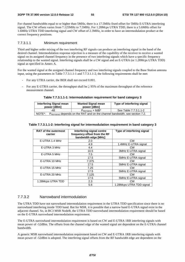
ETSI
ETSI TR 137 900 V12.0.0 (2014-10)553GPP TR 37.900 version 12.0.0 Release 12
For channel bandwidths equal to or higher than 5MHz, there is a 17.5MHz fixed offset for 5MHz E-UTRA interfering signal. The CW offsets varies from 7.125MHz to 7.5MHz. For 1.28Mcps UTRA TDD, there is a 5.6MHz offset for 1.6MHz UTRA TDD interfering signal and CW offset of 2.3MHz, in order to have an intermodulation product at the correct frequency positions.
7.7.3.1.1 Minimum requirement
Third and higher order mixing of the two interfering RF signals can produce an interfering signal in the band of the desired channel. Intermodulation response rejection is a measure of the capability of the receiver to receive a wanted signal on its assigned channel frequency in the presence of two interfering signals which have a specific frequency relationship to the wanted signal. Interfering signals shall be a CW signal and an E-UTRA (or 1.28Mcps UTRA TDD) signal as specified in Annex A.
For the wanted signal at the assigned channel frequency and two interfering signals coupled to the Base Station antenna input, using the parameters in Table 7.7.3.1.1-1 and 7.7.3.1.1-2, the following requirements shall be met:
- For any UTRA carrier, the BER shall not exceed 0.001.
- For any E-UTRA carrier, the throughput shall be ≥ 95% of the maximum throughput of the reference measurement channel.
Table 7.7.3.1.1-1: Intermodulation requirement for band category 3
Interfering Signal mean power [dBm]
Wanted Signal mean power [dBm]
Type of interfering signal
-48 PREFSENS + 6dB* See Table 7.7.3.1.1-2 NOTE*: PREFSENS depends on the RAT and on the channel bandwidth, see section 7.2.
Table 7.7.3.1.1-2: Interfering signal for intermodulation requirement in band category 3
RAT of the outermost carrier
Interfering signal centre frequency offset from the RF
bandwidth edge [MHz]
Type of interfering signal
E-UTRA 1.4 MHz
2.0 CW 4.9 1.4MHz E-UTRA signal
E-UTRA 3 MHz
4.4 CW 10.5 3MHz E-UTRA signal
E-UTRA 5 MHz 7.5 CW 17.5 5MHz E-UTRA signal
E-UTRA 10 MHz 7.375 CW 17.5 5MHz E-UTRA signal
E-UTRA 15 MHz
7.25 CW 17.5 5MHz E-UTRA signal
E-UTRA 20 MHz 7.125 CW 17.5 5MHz E-UTRA signal
1.28Mcps UTRA TDD 2.3 CW 5.6 1.28Mcps UTRA TDD signal
7.7.3.2 Narrowband intermodulation
The UTRA TDD have not narrowband intermodulation requirement in the UTRA TDD specification since there is no narrowband interfering inside TDD band. But for MSR, it is possible that a narrow band E-UTRA signal exist in the adjacent channel. So, in BC3 MSR NodeB, the UTRA TDD narrowband intermodulation requirement should be based on the E-UTRA narrowband intermodulation requirement.
The E-UTRA narrowband intermodulation requirement is based on CW and E-UTRA 1RB interfering signals with mean power of -52dBm. The offsets from the channel edge of the wanted signal are dependent on the E-UTRA channel bandwidth.
A generic MSR narrowband intermodulation requirement based on CW and E-UTRA 1RB interfering signals with mean power of -52dBm is adopted. The interfering signal offsets from the RF bandwidth edge are dependent on the
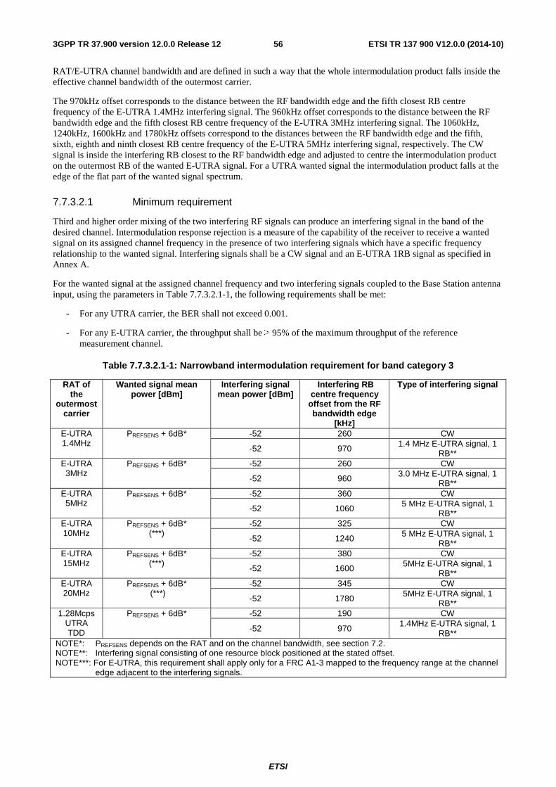
ETSI
ETSI TR 137 900 V12.0.0 (2014-10)563GPP TR 37.900 version 12.0.0 Release 12
RAT/E-UTRA channel bandwidth and are defined in such a way that the whole intermodulation product falls inside the effective channel bandwidth of the outermost carrier.
The 970kHz offset corresponds to the distance between the RF bandwidth edge and the fifth closest RB centre frequency of the E-UTRA 1.4MHz interfering signal. The 960kHz offset corresponds to the distance between the RF bandwidth edge and the fifth closest RB centre frequency of the E-UTRA 3MHz interfering signal. The 1060kHz, 1240kHz, 1600kHz and 1780kHz offsets correspond to the distances between the RF bandwidth edge and the fifth, sixth, eighth and ninth closest RB centre frequency of the E-UTRA 5MHz interfering signal, respectively. The CW signal is inside the interfering RB closest to the RF bandwidth edge and adjusted to centre the intermodulation product on the outermost RB of the wanted E-UTRA signal. For a UTRA wanted signal the intermodulation product falls at the edge of the flat part of the wanted signal spectrum.
7.7.3.2.1 Minimum requirement
Third and higher order mixing of the two interfering RF signals can produce an interfering signal in the band of the desired channel. Intermodulation response rejection is a measure of the capability of the receiver to receive a wanted signal on its assigned channel frequency in the presence of two interfering signals which have a specific frequency relationship to the wanted signal. Interfering signals shall be a CW signal and an E-UTRA 1RB signal as specified in Annex A.
For the wanted signal at the assigned channel frequency and two interfering signals coupled to the Base Station antenna input, using the parameters in Table 7.7.3.2.1-1, the following requirements shall be met:
- For any UTRA carrier, the BER shall not exceed 0.001.
- For any E-UTRA carrier, the throughput shall be ≥ 95% of the maximum throughput of the reference measurement channel.
Table 7.7.3.2.1-1: Narrowband intermodulation requirement for band category 3
RAT of the
outermost carrier
Wanted signal mean power [dBm]
Interfering signal mean power [dBm]
Interfering RB centre frequency
offset from the RF bandwidth edge
[kHz]
Type of interfering signal
E-UTRA 1.4MHz
PREFSENS + 6dB*
-52 260 CW
-52 970 1.4 MHz E-UTRA signal, 1 RB**
E-UTRA 3MHz
PREFSENS + 6dB*
-52 260 CW
-52 960 3.0 MHz E-UTRA signal, 1 RB**
E-UTRA 5MHz
PREFSENS + 6dB*
-52 360 CW
-52 1060 5 MHz E-UTRA signal, 1 RB**
E-UTRA 10MHz
PREFSENS + 6dB* (***)
-52 325 CW
-52 1240 5 MHz E-UTRA signal, 1 RB**
E-UTRA 15MHz
PREFSENS + 6dB* (***)
-52 380 CW
-52 1600 5MHz E-UTRA signal, 1 RB**
E-UTRA 20MHz
PREFSENS + 6dB* (***)
-52 345 CW
-52 1780 5MHz E-UTRA signal, 1
RB** 1.28Mcps
UTRA TDD
PREFSENS + 6dB* -52 190 CW
-52 970 1.4MHz E-UTRA signal, 1
RB** NOTE*: PREFSENS depends on the RAT and on the channel bandwidth, see section 7.2. NOTE**: Interfering signal consisting of one resource block positioned at the stated offset. NOTE***: For E-UTRA, this requirement shall apply only for a FRC A1-3 mapped to the frequency range at the channel
edge adjacent to the interfering signals.
ETSI
ETSI TR 137 900 V12.0.0 (2014-10)573GPP TR 37.900 version 12.0.0 Release 12
7.8 In-channel selectivity The in-channel selectivity is a measure of the receiver ability to receive a wanted signal at its assigned resource block locations in the presence of an interfering signal received at a larger power spectral density. In this condition a throughput requirement shall be met for a specified reference measurement channel. The interfering signal shall be an E-UTRA signal as specified in TS 36.104 [4], Annex C.
The in-channel selectivity requirement is applicable only in case of E-UTRA within the context of Multi Standard Radio (MSR).
7.8.1 Minimum requirement
For E-UTRA, the minimum requirement is specified in TS 36.104 [4], section 7.4.1.
8 Other requirements
8.1 EMC EMC requirements are today covered in the following specifications:
- UTRA EMC requirements are covered by TS 25.113 [24].
- E-UTRA EMC requirements are covered by TS 36.113 [25].
- There is no 3GPP specification for GSM/EDGE EMC requirements. These are covered by the ETSI standard EN 301 489-8 [26].
The EMC requirements are to a large part universal and based on international recommendations. It is therefore possible to draft a common EMC specification for an MSR Base Station that in principle covers both multi-RAT and single-RAT operation. It can be noted that the European series of EMC-standards is presently updated with a new version of EN 301 489-23 [27], which will include both UTRA and E-UTRA, thereby already covering multiple RATs.
The following parts of an EMC specification are by definition generic to multiple RATs:
- General test conditions
- Exclusion bands
- General performance assessment
- Applicability of emissions and immunity
- Emission requirements
- Immunity requirements
The following parts of an EMC specification will have to remain RAT specific:
- Test conditions (test models)
- Performance assessment in uplink and downlink
- Performance criteria for BS
The resulting specification TS 37.113 will therefore for most parts be generic to all RATs (E-UTRA, UTRA and GSM/EDGE).
8.2 Performance requirements Performance requirements specify the ability of the BS to correctly demodulate signals in various conditions and configurations. For UTRA and E-UTRA the requirements specify a minimum throughput, BLER or BER that shall be
ETSI
ETSI TR 137 900 V12.0.0 (2014-10)583GPP TR 37.900 version 12.0.0 Release 12
achieved at a specific SNR. For GSM/EDGE the requirements specify a maximum FER, BLER or BER that shall be achieved at specific sensitivity levels I and specific carrier-to-interference ratios (C/I).
For E-UTRA carriers the minimum requirement is defined in TS 36.104 [4], section 8.
For UTRA FDD carriers the minimum requirement is defined in TS 25.104 [2], section 8.
For UTRA TDD carriers the minimum requirement is defined in TS 25.105 [3], section 8.
For GSM/EDGE, the minimum requirements for reference sensitivity level and reference interference level are defined in TS 45.005 [5], applicable parts of subclauses 6.2, 6.3, 6.4, 6.5 and 6.6. The conditions specified in TS 45.005 [5], Annex P.1 are valid for GSM sensitivity and interference performance.
In the WI objective in subclause 4.1 it is clearly stated that performance requirements should not be a part of the MSR specifications. Thus these requirements apply together with the RF requirements in the MSR specification, but should not be a part of the MSR specifications.
9 Test specification
9.1 BS test configurations The test configurations are described in three steps. First there is a definition of Capability Sets (CS), which defines the RAT combinations that can be declared. Then the concept of Test Configurations (TC) is explained and finally, the full Mapping of RF requirements and Capability Sets to applicable Test Configurations is presented in two tables.
9.1.1 Definition of Capability Sets (CS)
Subclause 4.7 of the test specification TS 37.141 (Manufacturer"s declarations of supported RF configurations) will contain defined Capability Sets (CS), the support of which is subject to manufacturers declaration.
Table 9.1.1-1 shows the six capability sets CS1 to CS6, based on the possible RAT combinations that can be declared. The following abbreviations are used below:
CS Capability Set
MC multi-carrier (in single RAT)
SC single carrier
MR multi-RAT
SR single-RAT
TC Test Configuration,
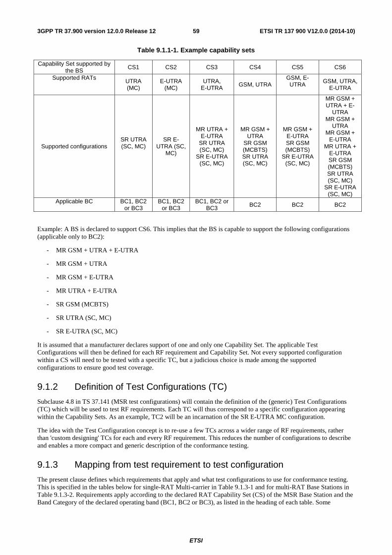
ETSI
ETSI TR 137 900 V12.0.0 (2014-10)593GPP TR 37.900 version 12.0.0 Release 12
Table 9.1.1-1. Example capability sets
Capability Set supported by the BS CS1 CS2 CS3 CS4 CS5 CS6
Supported RATs UTRA (MC)
E-UTRA (MC)
UTRA, E-UTRA GSM, UTRA
GSM, E-UTRA
GSM, UTRA, E-UTRA
Supported configurations SR UTRA (SC, MC)
SR E-UTRA (SC,
MC)
MR UTRA + E-UTRA
SR UTRA (SC, MC)
SR E-UTRA (SC, MC)
MR GSM + UTRA
SR GSM (MCBTS) SR UTRA (SC, MC)
MR GSM + E-UTRA SR GSM (MCBTS)
SR E-UTRA (SC, MC)
MR GSM + UTRA + E-
UTRA MR GSM +
UTRA MR GSM +
E-UTRA MR UTRA +
E-UTRA SR GSM (MCBTS) SR UTRA (SC, MC)
SR E-UTRA (SC, MC)
Applicable BC BC1, BC2 or BC3
BC1, BC2 or BC3
BC1, BC2 or BC3 BC2 BC2 BC2
Example: A BS is declared to support CS6. This implies that the BS is capable to support the following configurations (applicable only to BC2):
- MR GSM + UTRA + E-UTRA
- MR GSM + UTRA
- MR GSM + E-UTRA
- MR UTRA + E-UTRA
- SR GSM (MCBTS)
- SR UTRA (SC, MC)
- SR E-UTRA (SC, MC)
It is assumed that a manufacturer declares support of one and only one Capability Set. The applicable Test Configurations will then be defined for each RF requirement and Capability Set. Not every supported configuration within a CS will need to be tested with a specific TC, but a judicious choice is made among the supported configurations to ensure good test coverage.
9.1.2 Definition of Test Configurations (TC)
Subclause 4.8 in TS 37.141 (MSR test configurations) will contain the definition of the (generic) Test Configurations (TC) which will be used to test RF requirements. Each TC will thus correspond to a specific configuration appearing within the Capability Sets. As an example, TC2 will be an incarnation of the SR E-UTRA MC configuration.
The idea with the Test Configuration concept is to re-use a few TCs across a wider range of RF requirements, rather than 'custom designing' TCs for each and every RF requirement. This reduces the number of configurations to describe and enables a more compact and generic description of the conformance testing.
9.1.3 Mapping from test requirement to test configuration
The present clause defines which requirements that apply and what test configurations to use for conformance testing. This is specified in the tables below for single-RAT Multi-carrier in Table 9.1.3-1 and for multi-RAT Base Stations in Table 9.1.3-2. Requirements apply according to the declared RAT Capability Set (CS) of the MSR Base Station and the Band Category of the declared operating band (BC1, BC2 or BC3), as listed in the heading of each table. Some
ETSI
ETSI TR 137 900 V12.0.0 (2014-10)603GPP TR 37.900 version 12.0.0 Release 12
requirements listed in the tables may not be mandatory or they may apply only regionally. This is further specified for each requirement in clause 6 and 7, and in Table 4.5-1.
For a declared RAT Capability Set (CS), only the requirements listed in the column for that CS apply. Requirements listed under other CS than the declared CS need not be tested.
The clause references to BS test cases below are based on the clause numbering in TS 37.104 and may have to be updated for inclusion in TS 37.141.
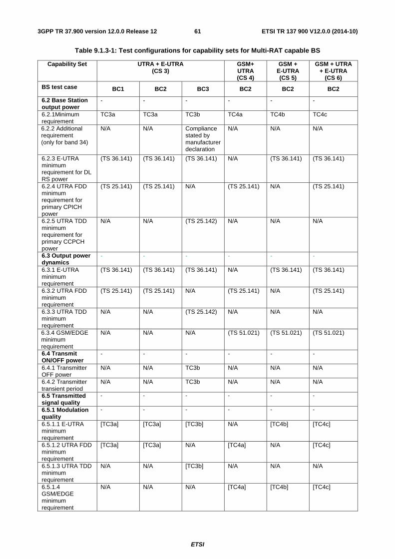
ETSI
ETSI TR 137 900 V12.0.0 (2014-10)613GPP TR 37.900 version 12.0.0 Release 12
Table 9.1.3-1: Test configurations for capability sets for Multi-RAT capable BS
Capability Set UTRA + E-UTRA (CS 3)
GSM+ UTRA (CS 4)
GSM + E-UTRA (CS 5)
GSM + UTRA + E-UTRA
(CS 6)
BS test case BC1 BC2 BC3 BC2 BC2 BC2
6.2 Base Station output power
- - - - - -
6.2.1Minimum requirement
TC3a TC3a TC3b TC4a TC4b TC4c
6.2.2 Additional requirement (only for band 34)
N/A N/A Compliance stated by manufacturer declaration
N/A N/A N/A
6.2.3 E-UTRA minimum requirement for DL RS power
(TS 36.141) (TS 36.141) (TS 36.141) N/A (TS 36.141) (TS 36.141)
6.2.4 UTRA FDD minimum requirement for primary CPICH power
(TS 25.141) (TS 25.141) N/A (TS 25.141) N/A (TS 25.141)
6.2.5 UTRA TDD minimum requirement for primary CCPCH power
N/A N/A (TS 25.142) N/A N/A N/A
6.3 Output power dynamics
- - - - - -
6.3.1 E-UTRA minimum requirement
(TS 36.141) (TS 36.141) (TS 36.141) N/A (TS 36.141) (TS 36.141)
6.3.2 UTRA FDD minimum requirement
(TS 25.141) (TS 25.141) N/A (TS 25.141) N/A (TS 25.141)
6.3.3 UTRA TDD minimum requirement
N/A N/A (TS 25.142) N/A N/A N/A
6.3.4 GSM/EDGE minimum requirement
N/A N/A N/A (TS 51.021) (TS 51.021) (TS 51.021)
6.4 Transmit ON/OFF power
- - - - - -
6.4.1 Transmitter OFF power
N/A N/A TC3b N/A N/A N/A
6.4.2 Transmitter transient period
N/A N/A TC3b N/A N/A N/A
6.5 Transmitted signal quality
- - - - - -
6.5.1 Modulation quality
- - - - - -
6.5.1.1 E-UTRA minimum requirement
[TC3a] [TC3a] [TC3b] N/A [TC4b] [TC4c]
6.5.1.2 UTRA FDD minimum requirement
[TC3a] [TC3a] N/A [TC4a] N/A [TC4c]
6.5.1.3 UTRA TDD minimum requirement
N/A N/A [TC3b] N/A N/A N/A
6.5.1.4 GSM/EDGE minimum requirement
N/A N/A N/A [TC4a] [TC4b] [TC4c]
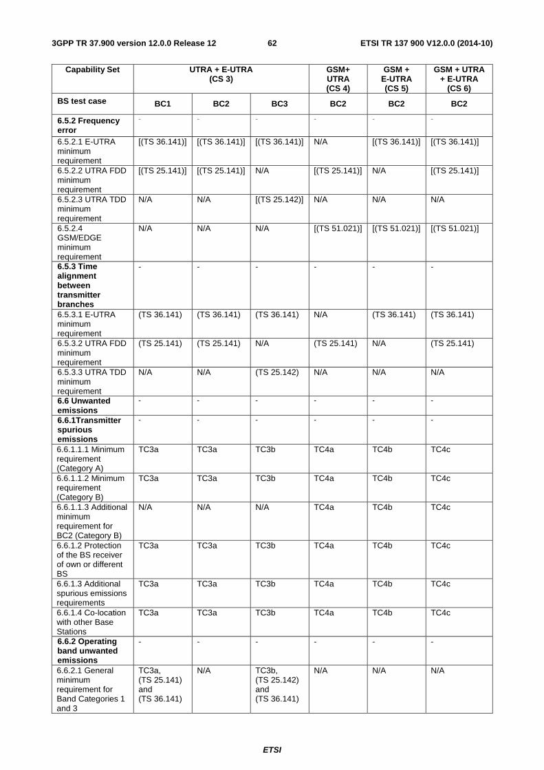
ETSI
ETSI TR 137 900 V12.0.0 (2014-10)623GPP TR 37.900 version 12.0.0 Release 12
Capability Set UTRA + E-UTRA (CS 3)
GSM+ UTRA (CS 4)
GSM + E-UTRA (CS 5)
GSM + UTRA + E-UTRA
(CS 6)
BS test case BC1 BC2 BC3 BC2 BC2 BC2
6.5.2 Frequency error
- - - - - -
6.5.2.1 E-UTRA minimum requirement
[(TS 36.141)] [(TS 36.141)] [(TS 36.141)] N/A [(TS 36.141)] [(TS 36.141)]
6.5.2.2 UTRA FDD minimum requirement
[(TS 25.141)] [(TS 25.141)] N/A [(TS 25.141)] N/A [(TS 25.141)]
6.5.2.3 UTRA TDD minimum requirement
N/A N/A [(TS 25.142)] N/A N/A N/A
6.5.2.4 GSM/EDGE minimum requirement
N/A N/A N/A [(TS 51.021)] [(TS 51.021)] [(TS 51.021)]
6.5.3 Time alignment between transmitter branches
- - - - - -
6.5.3.1 E-UTRA minimum requirement
(TS 36.141) (TS 36.141) (TS 36.141) N/A (TS 36.141) (TS 36.141)
6.5.3.2 UTRA FDD minimum requirement
(TS 25.141) (TS 25.141) N/A (TS 25.141) N/A (TS 25.141)
6.5.3.3 UTRA TDD minimum requirement
N/A N/A (TS 25.142) N/A N/A N/A
6.6 Unwanted emissions
- - - - - -
6.6.1Transmitter spurious emissions
- - - - - -
6.6.1.1.1 Minimum requirement (Category A)
TC3a TC3a TC3b TC4a TC4b TC4c
6.6.1.1.2 Minimum requirement (Category B)
TC3a TC3a TC3b TC4a TC4b TC4c
6.6.1.1.3 Additional minimum requirement for BC2 (Category B)
N/A N/A N/A TC4a TC4b TC4c
6.6.1.2 Protection of the BS receiver of own or different BS
TC3a TC3a TC3b TC4a TC4b TC4c
6.6.1.3 Additional spurious emissions requirements
TC3a TC3a TC3b TC4a TC4b TC4c
6.6.1.4 Co-location with other Base Stations
TC3a TC3a TC3b TC4a TC4b TC4c
6.6.2 Operating band unwanted emissions
- - - - - -
6.6.2.1 General minimum requirement for Band Categories 1 and 3
TC3a, (TS 25.141) and (TS 36.141)
N/A TC3b, (TS 25.142) and (TS 36.141)
N/A N/A N/A
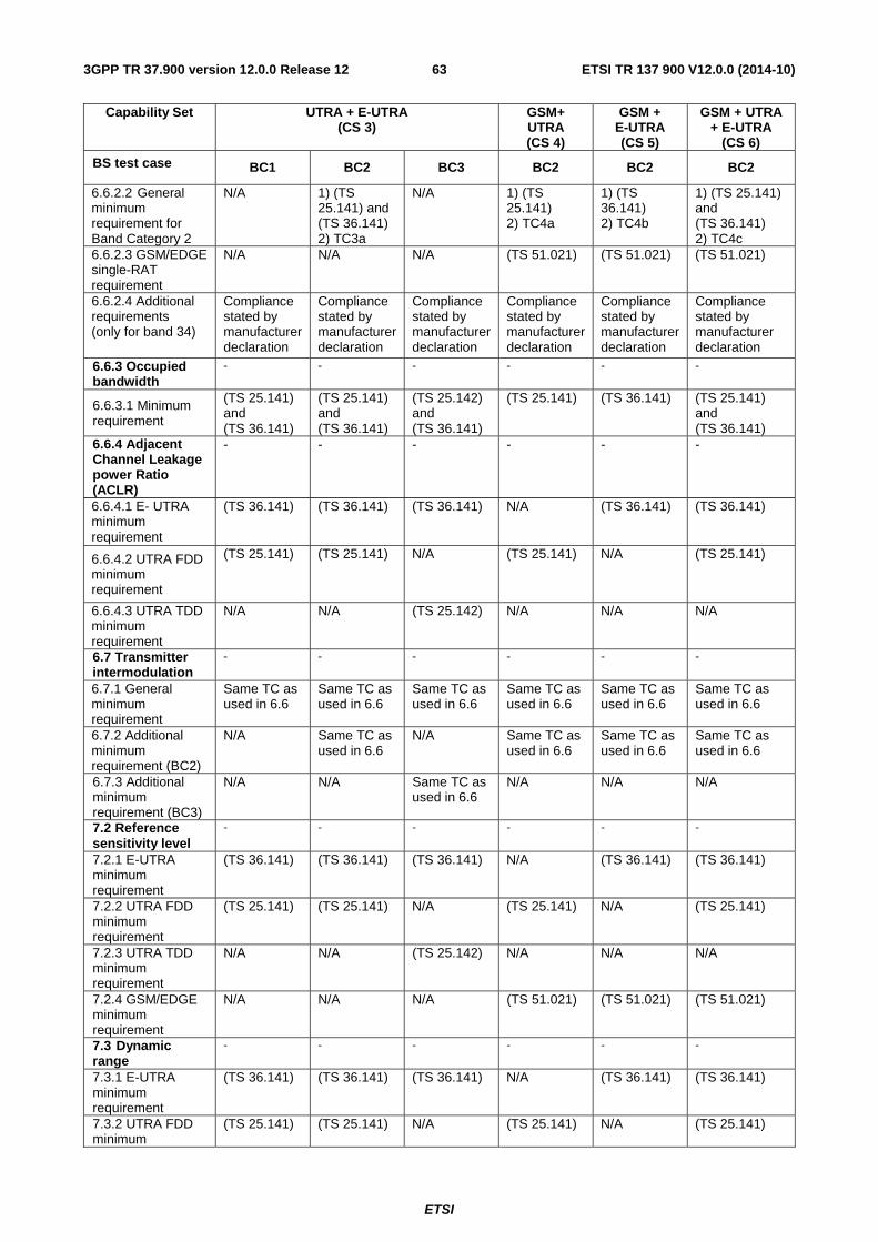
ETSI
ETSI TR 137 900 V12.0.0 (2014-10)633GPP TR 37.900 version 12.0.0 Release 12
Capability Set UTRA + E-UTRA (CS 3)
GSM+ UTRA (CS 4)
GSM + E-UTRA (CS 5)
GSM + UTRA + E-UTRA
(CS 6)
BS test case BC1 BC2 BC3 BC2 BC2 BC2
6.6.2.2 General minimum requirement for Band Category 2
N/A 1) (TS 25.141) and (TS 36.141) 2) TC3a
N/A 1) (TS 25.141) 2) TC4a
1) (TS 36.141) 2) TC4b
1) (TS 25.141) and (TS 36.141) 2) TC4c
6.6.2.3 GSM/EDGE single-RAT requirement
N/A N/A N/A (TS 51.021) (TS 51.021) (TS 51.021)
6.6.2.4 Additional requirements (only for band 34)
Compliance stated by manufacturer declaration
Compliance stated by manufacturer declaration
Compliance stated by manufacturer declaration
Compliance stated by manufacturer declaration
Compliance stated by manufacturer declaration
Compliance stated by manufacturer declaration
6.6.3 Occupied bandwidth
- - - - - -
6.6.3.1 Minimum requirement
(TS 25.141) and (TS 36.141)
(TS 25.141) and (TS 36.141)
(TS 25.142) and (TS 36.141)
(TS 25.141) (TS 36.141) (TS 25.141) and (TS 36.141)
6.6.4 Adjacent Channel Leakage power Ratio (ACLR)
- - - - - -
6.6.4.1 E- UTRA minimum requirement
(TS 36.141) (TS 36.141) (TS 36.141) N/A (TS 36.141) (TS 36.141)
6.6.4.2 UTRA FDD minimum requirement
(TS 25.141) (TS 25.141) N/A (TS 25.141) N/A (TS 25.141)
6.6.4.3 UTRA TDD minimum requirement
N/A N/A (TS 25.142) N/A N/A N/A
6.7 Transmitter intermodulation
- - - - - -
6.7.1 General minimum requirement
Same TC as used in 6.6
Same TC as used in 6.6
Same TC as used in 6.6
Same TC as used in 6.6
Same TC as used in 6.6
Same TC as used in 6.6
6.7.2 Additional minimum requirement (BC2)
N/A Same TC as used in 6.6
N/A Same TC as used in 6.6
Same TC as used in 6.6
Same TC as used in 6.6
6.7.3 Additional minimum requirement (BC3)
N/A N/A Same TC as used in 6.6
N/A N/A N/A
7.2 Reference sensitivity level
- - - - - -
7.2.1 E-UTRA minimum requirement
(TS 36.141) (TS 36.141) (TS 36.141) N/A (TS 36.141) (TS 36.141)
7.2.2 UTRA FDD minimum requirement
(TS 25.141) (TS 25.141) N/A (TS 25.141) N/A (TS 25.141)
7.2.3 UTRA TDD minimum requirement
N/A N/A (TS 25.142) N/A N/A N/A
7.2.4 GSM/EDGE minimum requirement
N/A N/A N/A (TS 51.021) (TS 51.021) (TS 51.021)
7.3 Dynamic range
- - - - - -
7.3.1 E-UTRA minimum requirement
(TS 36.141) (TS 36.141) (TS 36.141) N/A (TS 36.141) (TS 36.141)
7.3.2 UTRA FDD minimum
(TS 25.141) (TS 25.141) N/A (TS 25.141) N/A (TS 25.141)
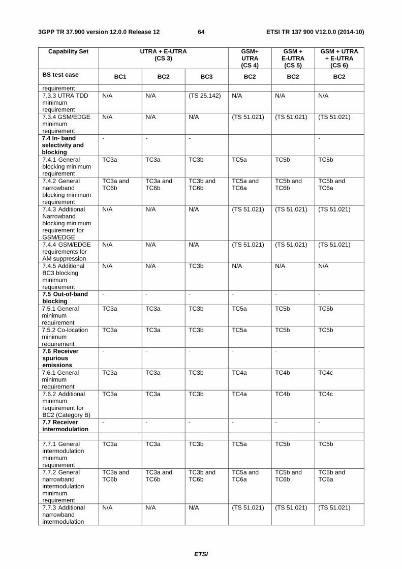
ETSI
ETSI TR 137 900 V12.0.0 (2014-10)643GPP TR 37.900 version 12.0.0 Release 12
Capability Set UTRA + E-UTRA (CS 3)
GSM+ UTRA (CS 4)
GSM + E-UTRA (CS 5)
GSM + UTRA + E-UTRA
(CS 6)
BS test case BC1 BC2 BC3 BC2 BC2 BC2
requirement 7.3.3 UTRA TDD minimum requirement
N/A N/A (TS 25.142) N/A N/A N/A
7.3.4 GSM/EDGE minimum requirement
N/A N/A N/A (TS 51.021) (TS 51.021) (TS 51.021)
7.4 In- band selectivity and blocking
- - - -
7.4.1 General blocking minimum requirement
TC3a TC3a TC3b TC5a TC5b TC5b
7.4.2 General narrowband blocking minimum requirement
TC3a and TC6b
TC3a and TC6b
TC3b and TC6b
TC5a and TC6a
TC5b and TC6b
TC5b and TC6a
7.4.3 Additional Narrowband blocking minimum requirement for GSM/EDGE
N/A N/A N/A (TS 51.021) (TS 51.021) (TS 51.021)
7.4.4 GSM/EDGE requirements for AM suppression
N/A N/A N/A (TS 51.021) (TS 51.021) (TS 51.021)
7.4.5 Additional BC3 blocking minimum requirement
N/A N/A TC3b N/A N/A N/A
7.5 Out-of-band blocking
- - - - - -
7.5.1 General minimum requirement
TC3a TC3a TC3b TC5a TC5b TC5b
7.5.2 Co-location minimum requirement
TC3a TC3a TC3b TC5a TC5b TC5b
7.6 Receiver spurious emissions
- - - - - -
7.6.1 General minimum requirement
TC3a TC3a TC3b TC4a TC4b TC4c
7.6.2 Additional minimum requirement for BC2 (Category B)
TC3a TC3a TC3b TC4a TC4b TC4c
7.7 Receiver intermodulation
- - - - - -
7.7.1 General intermodulation minimum requirement
TC3a TC3a TC3b TC5a TC5b TC5b
7.7.2 General narrowband intermodulation minimum requirement
TC3a and TC6b
TC3a and TC6b
TC3b and TC6b
TC5a and TC6a
TC5b and TC6b
TC5b and TC6a
7.7.3 Additional narrowband intermodulation
N/A N/A N/A (TS 51.021) (TS 51.021) (TS 51.021)
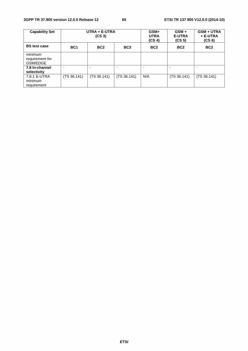
ETSI
ETSI TR 137 900 V12.0.0 (2014-10)653GPP TR 37.900 version 12.0.0 Release 12
Capability Set UTRA + E-UTRA (CS 3)
GSM+ UTRA (CS 4)
GSM + E-UTRA (CS 5)
GSM + UTRA + E-UTRA
(CS 6)
BS test case BC1 BC2 BC3 BC2 BC2 BC2
minimum requirement for GSM/EDGE 7.8 In-channel selectivity
- - - - - -
7.8.1 E-UTRA minimum requirement
(TS 36.141) (TS 36.141) (TS 36.141) N/A (TS 36.141) (TS 36.141)
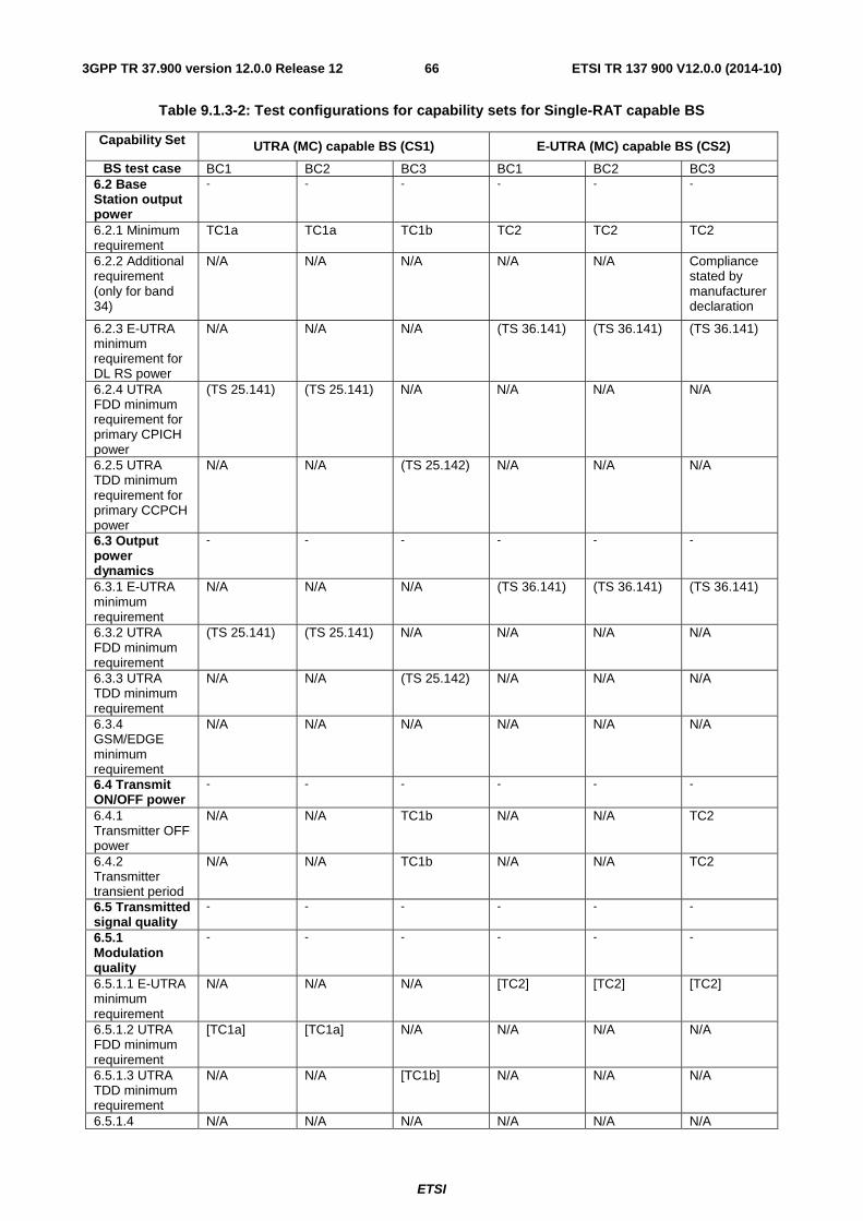
ETSI
ETSI TR 137 900 V12.0.0 (2014-10)663GPP TR 37.900 version 12.0.0 Release 12
Table 9.1.3-2: Test configurations for capability sets for Single-RAT capable BS
Capability Set UTRA (MC) capable BS (CS1) E-UTRA (MC) capable BS (CS2)
BS test case BC1 BC2 BC3 BC1 BC2 BC3 6.2 Base Station output power
- - - - - -
6.2.1 Minimum requirement
TC1a TC1a TC1b TC2 TC2 TC2
6.2.2 Additional requirement (only for band 34)
N/A N/A N/A N/A N/A Compliance stated by manufacturer declaration
6.2.3 E-UTRA minimum requirement for DL RS power
N/A N/A N/A (TS 36.141) (TS 36.141) (TS 36.141)
6.2.4 UTRA FDD minimum requirement for primary CPICH power
(TS 25.141) (TS 25.141) N/A N/A N/A N/A
6.2.5 UTRA TDD minimum requirement for primary CCPCH power
N/A N/A (TS 25.142) N/A N/A N/A
6.3 Output power dynamics
- - - - - -
6.3.1 E-UTRA minimum requirement
N/A N/A N/A (TS 36.141) (TS 36.141) (TS 36.141)
6.3.2 UTRA FDD minimum requirement
(TS 25.141) (TS 25.141) N/A N/A N/A N/A
6.3.3 UTRA TDD minimum requirement
N/A N/A (TS 25.142) N/A N/A N/A
6.3.4 GSM/EDGE minimum requirement
N/A N/A N/A N/A N/A N/A
6.4 Transmit ON/OFF power
- - - - - -
6.4.1 Transmitter OFF power
N/A N/A TC1b N/A N/A TC2
6.4.2 Transmitter transient period
N/A N/A TC1b N/A N/A TC2
6.5 Transmitted signal quality
- - - - - -
6.5.1 Modulation quality
- - - - - -
6.5.1.1 E-UTRA minimum requirement
N/A N/A N/A [TC2] [TC2] [TC2]
6.5.1.2 UTRA FDD minimum requirement
[TC1a] [TC1a] N/A N/A N/A N/A
6.5.1.3 UTRA TDD minimum requirement
N/A N/A [TC1b] N/A N/A N/A
6.5.1.4 N/A N/A N/A N/A N/A N/A
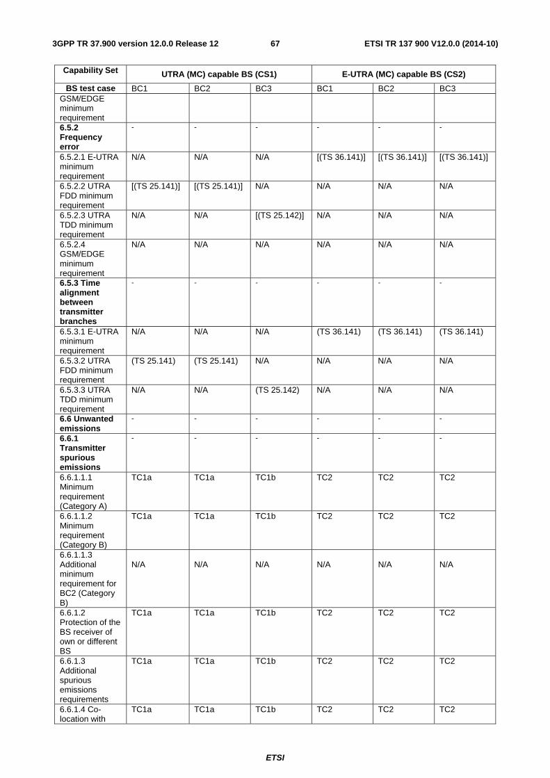
ETSI
ETSI TR 137 900 V12.0.0 (2014-10)673GPP TR 37.900 version 12.0.0 Release 12
Capability Set UTRA (MC) capable BS (CS1) E-UTRA (MC) capable BS (CS2)
BS test case BC1 BC2 BC3 BC1 BC2 BC3 GSM/EDGE minimum requirement 6.5.2 Frequency error
- - - - - -
6.5.2.1 E-UTRA minimum requirement
N/A N/A N/A [(TS 36.141)] [(TS 36.141)] [(TS 36.141)]
6.5.2.2 UTRA FDD minimum requirement
[(TS 25.141)] [(TS 25.141)] N/A N/A N/A N/A
6.5.2.3 UTRA TDD minimum requirement
N/A N/A [(TS 25.142)] N/A N/A N/A
6.5.2.4 GSM/EDGE minimum requirement
N/A N/A N/A N/A N/A N/A
6.5.3 Time alignment between transmitter branches
- - - - - -
6.5.3.1 E-UTRA minimum requirement
N/A N/A N/A (TS 36.141) (TS 36.141) (TS 36.141)
6.5.3.2 UTRA FDD minimum requirement
(TS 25.141) (TS 25.141) N/A N/A N/A N/A
6.5.3.3 UTRA TDD minimum requirement
N/A N/A (TS 25.142) N/A N/A N/A
6.6 Unwanted emissions
- - - - - -
6.6.1 Transmitter spurious emissions
- - - - - -
6.6.1.1.1 Minimum requirement (Category A)
TC1a TC1a TC1b TC2 TC2 TC2
6.6.1.1.2 Minimum requirement (Category B)
TC1a TC1a TC1b TC2 TC2 TC2
6.6.1.1.3 Additional minimum requirement for BC2 (Category B)
N/A
N/A
N/A
N/A
N/A
N/A
6.6.1.2 Protection of the BS receiver of own or different BS
TC1a TC1a TC1b TC2 TC2 TC2
6.6.1.3 Additional spurious emissions requirements
TC1a TC1a TC1b TC2 TC2 TC2
6.6.1.4 Co-location with
TC1a TC1a TC1b TC2 TC2 TC2
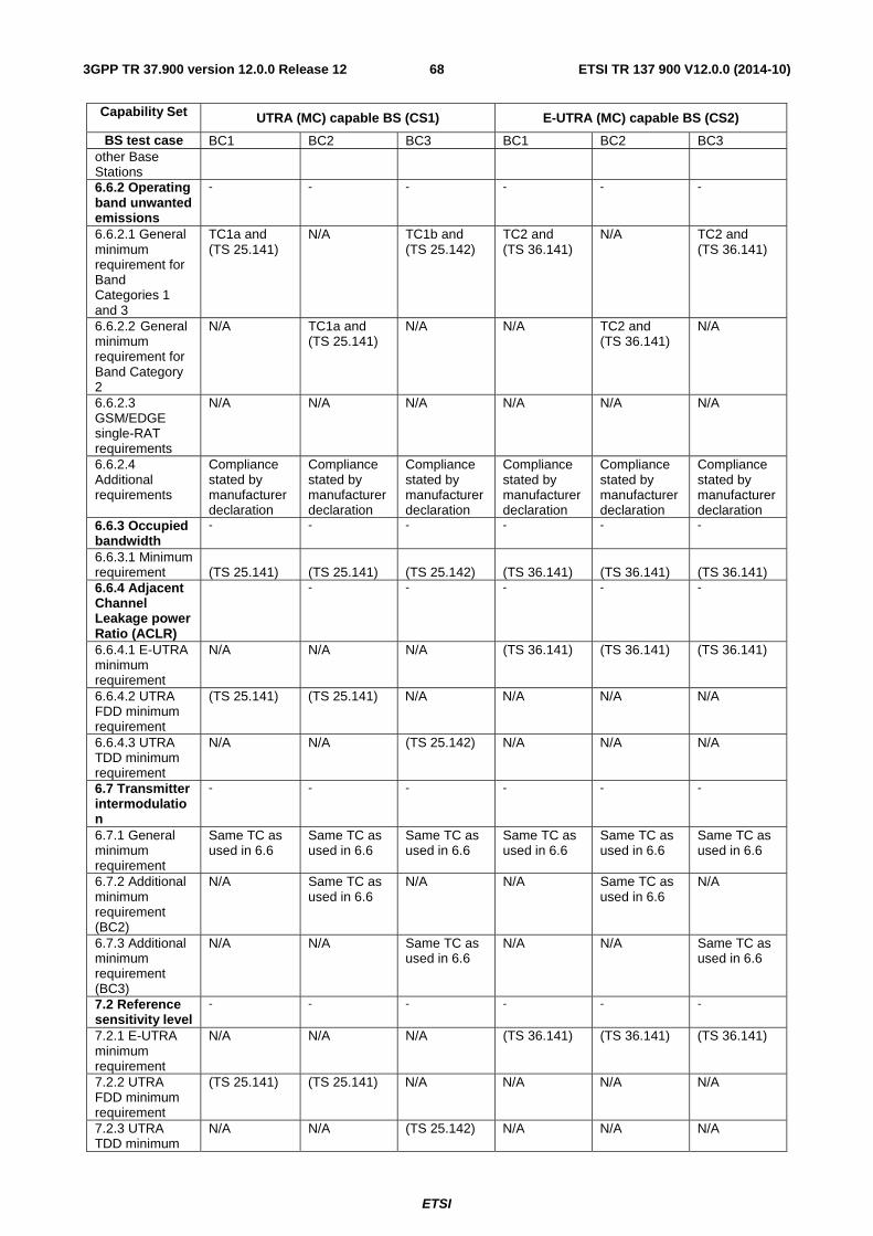
ETSI
ETSI TR 137 900 V12.0.0 (2014-10)683GPP TR 37.900 version 12.0.0 Release 12
Capability Set UTRA (MC) capable BS (CS1) E-UTRA (MC) capable BS (CS2)
BS test case BC1 BC2 BC3 BC1 BC2 BC3 other Base Stations 6.6.2 Operating band unwanted emissions
- - - - - -
6.6.2.1 General minimum requirement for Band Categories 1 and 3
TC1a and (TS 25.141)
N/A TC1b and (TS 25.142)
TC2 and (TS 36.141)
N/A TC2 and (TS 36.141)
6.6.2.2 General minimum requirement for Band Category 2
N/A TC1a and (TS 25.141)
N/A N/A TC2 and (TS 36.141)
N/A
6.6.2.3 GSM/EDGE single-RAT requirements
N/A N/A N/A N/A N/A N/A
6.6.2.4 Additional requirements
Compliance stated by manufacturer declaration
Compliance stated by manufacturer declaration
Compliance stated by manufacturer declaration
Compliance stated by manufacturer declaration
Compliance stated by manufacturer declaration
Compliance stated by manufacturer declaration
6.6.3 Occupied bandwidth
- - - - - -
6.6.3.1 Minimum requirement
(TS 25.141)
(TS 25.141)
(TS 25.142)
(TS 36.141)
(TS 36.141)
(TS 36.141)
6.6.4 Adjacent Channel Leakage power Ratio (ACLR)
- - - - -
6.6.4.1 E-UTRA minimum requirement
N/A N/A N/A (TS 36.141) (TS 36.141) (TS 36.141)
6.6.4.2 UTRA FDD minimum requirement
(TS 25.141) (TS 25.141) N/A N/A N/A N/A
6.6.4.3 UTRA TDD minimum requirement
N/A N/A (TS 25.142) N/A N/A N/A
6.7 Transmitter intermodulation
- - - - - -
6.7.1 General minimum requirement
Same TC as used in 6.6
Same TC as used in 6.6
Same TC as used in 6.6
Same TC as used in 6.6
Same TC as used in 6.6
Same TC as used in 6.6
6.7.2 Additional minimum requirement (BC2)
N/A Same TC as used in 6.6
N/A N/A Same TC as used in 6.6
N/A
6.7.3 Additional minimum requirement (BC3)
N/A N/A Same TC as used in 6.6
N/A N/A Same TC as used in 6.6
7.2 Reference sensitivity level
- - - - - -
7.2.1 E-UTRA minimum requirement
N/A N/A N/A (TS 36.141) (TS 36.141) (TS 36.141)
7.2.2 UTRA FDD minimum requirement
(TS 25.141) (TS 25.141) N/A N/A N/A N/A
7.2.3 UTRA TDD minimum
N/A N/A (TS 25.142) N/A N/A N/A
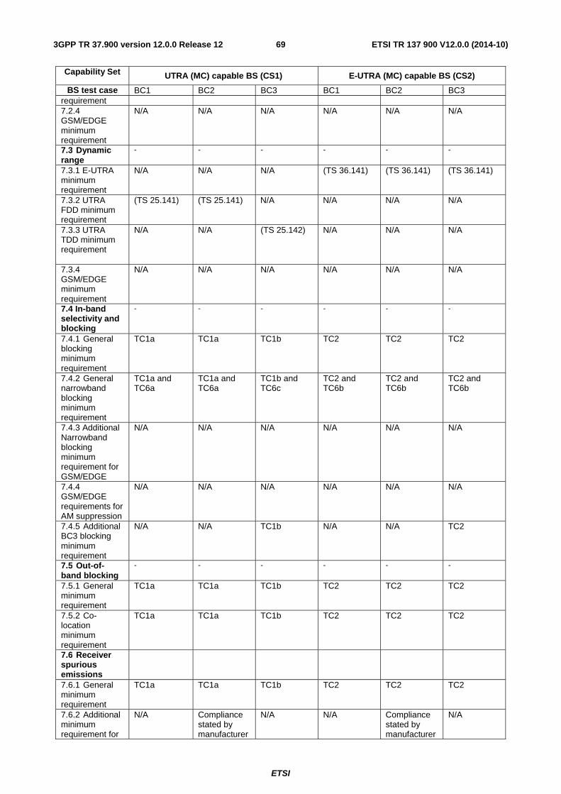
ETSI
ETSI TR 137 900 V12.0.0 (2014-10)693GPP TR 37.900 version 12.0.0 Release 12
Capability Set UTRA (MC) capable BS (CS1) E-UTRA (MC) capable BS (CS2)
BS test case BC1 BC2 BC3 BC1 BC2 BC3 requirement 7.2.4 GSM/EDGE minimum requirement
N/A N/A N/A N/A N/A N/A
7.3 Dynamic range
- - - - - -
7.3.1 E-UTRA minimum requirement
N/A N/A N/A (TS 36.141) (TS 36.141) (TS 36.141)
7.3.2 UTRA FDD minimum requirement
(TS 25.141) (TS 25.141) N/A N/A N/A N/A
7.3.3 UTRA TDD minimum requirement
N/A N/A (TS 25.142) N/A N/A N/A
7.3.4 GSM/EDGE minimum requirement
N/A N/A N/A N/A N/A N/A
7.4 In-band selectivity and blocking
- - - - - -
7.4.1 General blocking minimum requirement
TC1a TC1a TC1b TC2 TC2 TC2
7.4.2 General narrowband blocking minimum requirement
TC1a and TC6a
TC1a and TC6a
TC1b and TC6c
TC2 and TC6b
TC2 and TC6b
TC2 and TC6b
7.4.3 Additional Narrowband blocking minimum requirement for GSM/EDGE
N/A N/A N/A N/A N/A N/A
7.4.4 GSM/EDGE requirements for AM suppression
N/A N/A N/A N/A N/A N/A
7.4.5 Additional BC3 blocking minimum requirement
N/A N/A TC1b N/A N/A TC2
7.5 Out-of-band blocking
- - - - - -
7.5.1 General minimum requirement
TC1a TC1a TC1b TC2 TC2 TC2
7.5.2 Co-location minimum requirement
TC1a TC1a TC1b TC2 TC2 TC2
7.6 Receiver spurious emissions
7.6.1 General minimum requirement
TC1a TC1a TC1b TC2 TC2 TC2
7.6.2 Additional minimum requirement for
N/A Compliance stated by manufacturer
N/A N/A Compliance stated by manufacturer
N/A
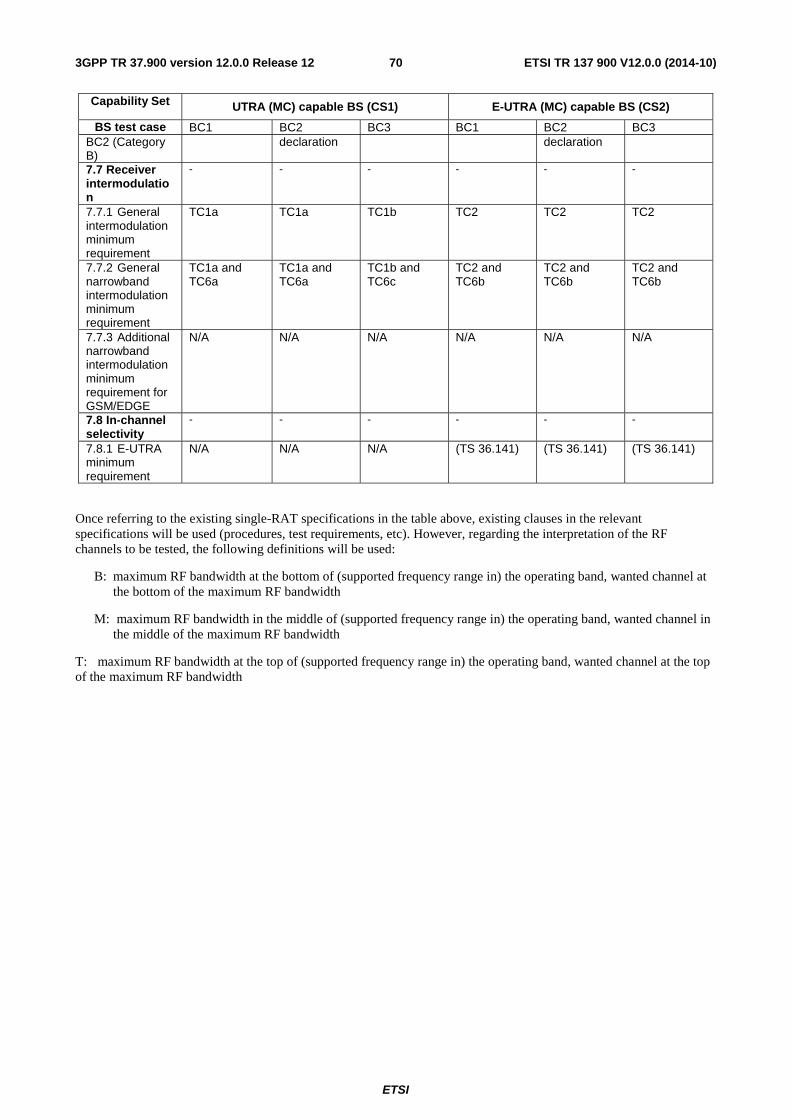
ETSI
ETSI TR 137 900 V12.0.0 (2014-10)703GPP TR 37.900 version 12.0.0 Release 12
Capability Set UTRA (MC) capable BS (CS1) E-UTRA (MC) capable BS (CS2)
BS test case BC1 BC2 BC3 BC1 BC2 BC3 BC2 (Category B)
declaration declaration
7.7 Receiver intermodulation
- - - - - -
7.7.1 General intermodulation minimum requirement
TC1a TC1a TC1b TC2 TC2 TC2
7.7.2 General narrowband intermodulation minimum requirement
TC1a and TC6a
TC1a and TC6a
TC1b and TC6c
TC2 and TC6b
TC2 and TC6b
TC2 and TC6b
7.7.3 Additional narrowband intermodulation minimum requirement for GSM/EDGE
N/A N/A N/A N/A N/A N/A
7.8 In-channel selectivity
- - - - - -
7.8.1 E-UTRA minimum requirement
N/A N/A N/A (TS 36.141) (TS 36.141) (TS 36.141)
Once referring to the existing single-RAT specifications in the table above, existing clauses in the relevant specifications will be used (procedures, test requirements, etc). However, regarding the interpretation of the RF channels to be tested, the following definitions will be used:
B: maximum RF bandwidth at the bottom of (supported frequency range in) the operating band, wanted channel at the bottom of the maximum RF bandwidth
M: maximum RF bandwidth in the middle of (supported frequency range in) the operating band, wanted channel in the middle of the maximum RF bandwidth
T: maximum RF bandwidth at the top of (supported frequency range in) the operating band, wanted channel at the top of the maximum RF bandwidth
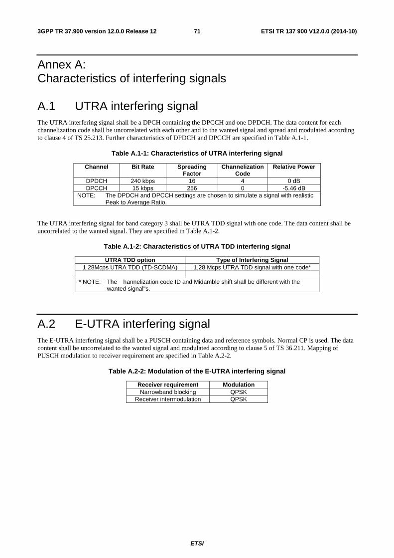
ETSI
ETSI TR 137 900 V12.0.0 (2014-10)713GPP TR 37.900 version 12.0.0 Release 12
Annex A: Characteristics of interfering signals
A.1 UTRA interfering signal The UTRA interfering signal shall be a DPCH containing the DPCCH and one DPDCH. The data content for each channelization code shall be uncorrelated with each other and to the wanted signal and spread and modulated according to clause 4 of TS 25.213. Further characteristics of DPDCH and DPCCH are specified in Table A.1-1.
Table A.1-1: Characteristics of UTRA interfering signal
Channel Bit Rate Spreading Factor
Channelization Code
Relative Power
DPDCH 240 kbps 16 4 0 dB DPCCH 15 kbps 256 0 -5.46 dB
NOTE: The DPDCH and DPCCH settings are chosen to simulate a signal with realistic Peak to Average Ratio.
The UTRA interfering signal for band category 3 shall be UTRA TDD signal with one code. The data content shall be uncorrelated to the wanted signal. They are specified in Table A.1-2.
Table A.1-2: Characteristics of UTRA TDD interfering signal
UTRA TDD option Type of Interfering Signal 1.28Mcps UTRA TDD (TD-SCDMA) 1,28 Mcps UTRA TDD signal with one code*
* NOTE: The � hannelization code ID and Midamble shift shall be different with the
wanted signal"s.
A.2 E-UTRA interfering signal The E-UTRA interfering signal shall be a PUSCH containing data and reference symbols. Normal CP is used. The data content shall be uncorrelated to the wanted signal and modulated according to clause 5 of TS 36.211. Mapping of PUSCH modulation to receiver requirement are specified in Table A.2-2.
Table A.2-2: Modulation of the E-UTRA interfering signal
Receiver requirement Modulation Narrowband blocking QPSK
Receiver intermodulation QPSK
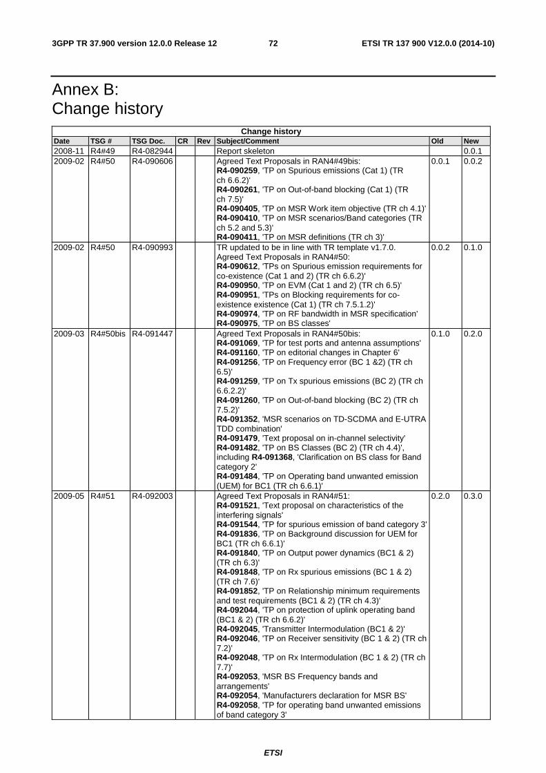
ETSI
ETSI TR 137 900 V12.0.0 (2014-10)723GPP TR 37.900 version 12.0.0 Release 12
Annex B: Change history
Change history Date TSG # TSG Doc. CR Rev Subject/Comment Old New 2008-11 R4#49 R4-082944 Report skeleton 0.0.1 2009-02 R4#50 R4-090606 Agreed Text Proposals in RAN4#49bis:
R4-090259, 'TP on Spurious emissions (Cat 1) (TR ch 6.6.2)' R4-090261, 'TP on Out-of-band blocking (Cat 1) (TR ch 7.5)' R4-090405, 'TP on MSR Work item objective (TR ch 4.1)' R4-090410, 'TP on MSR scenarios/Band categories (TR ch 5.2 and 5.3)' R4-090411, 'TP on MSR definitions (TR ch 3)'
0.0.1 0.0.2
2009-02 R4#50 R4-090993 TR updated to be in line with TR template v1.7.0. Agreed Text Proposals in RAN4#50: R4-090612, 'TPs on Spurious emission requirements for co-existence (Cat 1 and 2) (TR ch 6.6.2)' R4-090950, 'TP on EVM (Cat 1 and 2) (TR ch 6.5)' R4-090951, 'TPs on Blocking requirements for co-existence existence (Cat 1) (TR ch 7.5.1.2)' R4-090974, 'TP on RF bandwidth in MSR specification' R4-090975, 'TP on BS classes'
0.0.2 0.1.0
2009-03 R4#50bis R4-091447 Agreed Text Proposals in RAN4#50bis: R4-091069, 'TP for test ports and antenna assumptions' R4-091160, 'TP on editorial changes in Chapter 6' R4-091256, 'TP on Frequency error (BC 1 &2) (TR ch 6.5)' R4-091259, 'TP on Tx spurious emissions (BC 2) (TR ch 6.6.2.2)' R4-091260, 'TP on Out-of-band blocking (BC 2) (TR ch 7.5.2)' R4-091352, 'MSR scenarios on TD-SCDMA and E-UTRA TDD combination' R4-091479, 'Text proposal on in-channel selectivity' R4-091482, 'TP on BS Classes (BC 2) (TR ch 4.4)', including R4-091368, 'Clarification on BS class for Band category 2' R4-091484, 'TP on Operating band unwanted emission (UEM) for BC1 (TR ch 6.6.1)'
0.1.0 0.2.0
2009-05 R4#51 R4-092003 Agreed Text Proposals in RAN4#51: R4-091521, 'Text proposal on characteristics of the interfering signals' R4-091544, 'TP for spurious emission of band category 3' R4-091836, 'TP on Background discussion for UEM for BC1 (TR ch 6.6.1)' R4-091840, 'TP on Output power dynamics (BC1 & 2) (TR ch 6.3)' R4-091848, 'TP on Rx spurious emissions (BC 1 & 2) (TR ch 7.6)' R4-091852, 'TP on Relationship minimum requirements and test requirements (BC1 & 2) (TR ch 4.3)' R4-092044, 'TP on protection of uplink operating band (BC1 & 2) (TR ch 6.6.2)' R4-092045, 'Transmitter Intermodulation (BC1 & 2)' R4-092046, 'TP on Receiver sensitivity (BC 1 & 2) (TR ch 7.2)' R4-092048, 'TP on Rx Intermodulation (BC 1 & 2) (TR ch 7.7)' R4-092053, 'MSR BS Frequency bands and arrangements' R4-092054, 'Manufacturers declaration for MSR BS' R4-092058, 'TP for operating band unwanted emissions of band category 3'
0.2.0 0.3.0
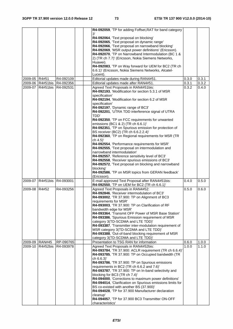
ETSI
ETSI TR 137 900 V12.0.0 (2014-10)733GPP TR 37.900 version 12.0.0 Release 12
R4-092059, 'TP for adding Foffset,RAT for band category 3' R4-092064, 'Text proposal on blocking' R4-092065, 'Text proposal on dynamic range' R4-092066, 'Text proposal on narrowband blocking' R4-092069, 'MSR output power definitions' (Ericsson). R4-092070, 'TP on Narrowband Intermodulation (BC 1 & 2) (TR ch 7.7)' (Ericsson, Nokia Siemens Networks, Huawei). R4-092083, 'TP on Way forward for UEM for BC2 (TR ch 6.6.1)' (Ericsson, Nokia Siemens Networks, Alcatel-Lucent).
2009-05 R4#51 R4-092109 Editorial updates made during RAN4#51. 0.3.0 0.3.1 2009-06 R4#51bis R4-092356 Editorial updates made after RAN4#51. 0.3.1 0.3.2 2009-07 R4#51bis R4-092531 Agreed Text Proposals in RAN4#51bis:
R4-092193, 'Modification for section 5.3.1 of MSR specification' R4-092194, 'Modification for section 6.2 of MSR specification' R4-092197, 'Dynamic range of BC3' R4-092201, 'UTRA TDD interference signal of UTRA TDD' R4-092350, 'TP on FCC requirements for unwanted emissions (BC1 & 2) (TR ch 6.6.1)' R4-092351, 'TP on Spurious emission for protection of BS receiver (BC2) (TR ch 6.6.2.2.4)' R4-092360, 'TP on Regional requirements for MSR (TR ch 4.5)' R4-092554, 'Performance requirements for MSR' R4-092555, 'Text proposal on intermodulation and narrowband intermodulation' R4-092557, 'Reference sensitivity level of BC3' R4-092558, 'Receiver spurious emissions of BC3' R4-092572, 'Text proposal on blocking and narrowband blocking' R4-092586, 'TP on MSR topics from GERAN feedback' (Ericsson).
0.3.2 0.4.0
2009-07 R4#51bis R4-093001 E-mail approved Text Proposal after RAN4#51bis: R4-092550, 'TP on UEM for BC2 (TR ch 6.6.1)'
0.4.0 0.5.0
2009-08 R4#52 R4-093256 Agreed Text Proposals in RAN4#52: R4-092846, 'Receiver intermodulation of BC3' R4-093002, 'TR 37.900: TP on Alignment of BC3 requirements for MSR' R4-093003, 'TR 37.900: TP on Clarification of RF bandwidth edge for MSR' R4-093364, 'Transmit OFF Power of MSR Base Station' R4-093386, 'Spurious Emission requirement of MSR category 3(TD-SCDMA and LTE TDD)' R4-093387, 'Transmitter inter-modulation requirement of MSR category 3(TD-SCDMA and LTE TDD)' R4-093388, 'Out-of-band blocking requirement of MSR category 3(TD-SCDMA and LTE TDD)'
0.5.0 0.6.0
2009-09 RAN#45 RP-090765 Presentation to TSG RAN for information 0.6.0 1.0.0 2009-10 R4#52bis R4-093978 Agreed Text Proposals in RAN4#52bis:
R4-093784, 'TR 37.900: ACLR requirement (TR ch 6.6.4)' R4-093785, 'TR 37.900: TP on Occupied bandwidth (TR ch 6.6.3)' R4-093786, 'TR 37.900: TP on Spurious emissions requirements in BC2 (TR ch 6.6.2 and 7.6)' R4-093787, 'TR 37.900: TP on In-band selectivity and blocking for BC3 (TR ch 7.4)' R4-094000, 'Corrections to maximum power definitions' R4-094014, 'Clarification on Spurious emissions limits for BS co-existed with another BS (37.900)' R4-094028, 'TP for 37.900 Manufacturer declaration cleanup' R4-094057, 'TP for 37.900 BC3 Transmitter ON-OFF characteristics'
1.0.0 1.1.0
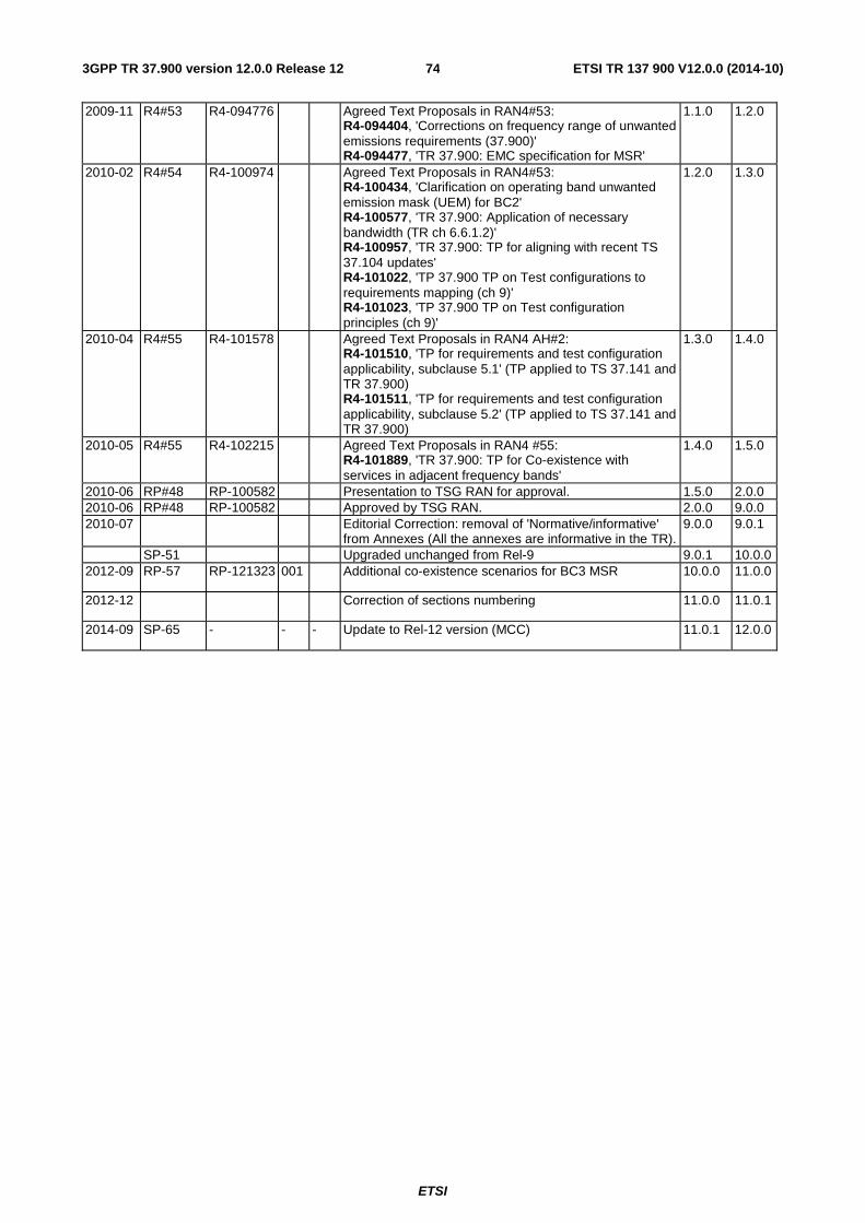
ETSI
ETSI TR 137 900 V12.0.0 (2014-10)743GPP TR 37.900 version 12.0.0 Release 12
2009-11 R4#53 R4-094776 Agreed Text Proposals in RAN4#53: R4-094404, 'Corrections on frequency range of unwanted emissions requirements (37.900)' R4-094477, 'TR 37.900: EMC specification for MSR'
1.1.0 1.2.0
2010-02 R4#54 R4-100974 Agreed Text Proposals in RAN4#53: R4-100434, 'Clarification on operating band unwanted emission mask (UEM) for BC2' R4-100577, 'TR 37.900: Application of necessary bandwidth (TR ch 6.6.1.2)' R4-100957, 'TR 37.900: TP for aligning with recent TS 37.104 updates' R4-101022, 'TP 37.900 TP on Test configurations to requirements mapping (ch 9)' R4-101023, 'TP 37.900 TP on Test configuration principles (ch 9)'
1.2.0 1.3.0
2010-04 R4#55 R4-101578 Agreed Text Proposals in RAN4 AH#2: R4-101510, 'TP for requirements and test configuration applicability, subclause 5.1' (TP applied to TS 37.141 and TR 37.900) R4-101511, 'TP for requirements and test configuration applicability, subclause 5.2' (TP applied to TS 37.141 and TR 37.900)
1.3.0 1.4.0
2010-05 R4#55 R4-102215 Agreed Text Proposals in RAN4 #55: R4-101889, 'TR 37.900: TP for Co-existence with services in adjacent frequency bands'
1.4.0 1.5.0
2010-06 RP#48 RP-100582 Presentation to TSG RAN for approval. 1.5.0 2.0.0 2010-06 RP#48 RP-100582 Approved by TSG RAN. 2.0.0 9.0.0 2010-07 Editorial Correction: removal of 'Normative/informative'
from Annexes (All the annexes are informative in the TR). 9.0.0 9.0.1
SP-51 Upgraded unchanged from Rel-9 9.0.1 10.0.0 2012-09 RP-57 RP-121323 001 Additional co-existence scenarios for BC3 MSR 10.0.0 11.0.0
2012-12 Correction of sections numbering 11.0.0 11.0.1
2014-09 SP-65 - - - Update to Rel-12 version (MCC) 11.0.1 12.0.0
ETSI
ETSI TR 137 900 V12.0.0 (2014-10)753GPP TR 37.900 version 12.0.0 Release 12
History
Document history
V12.0.0 October 2014 Publication
Related Documents