Torchmate Driver Software Version 4 Setup Guide Revised May 2011 Full information about each option and configuration setting can be found in the Torchmate 4 User’s Guide. This guide can be accessed by going to Help u User’s Guide.

Welcome message from author
This document is posted to help you gain knowledge. Please leave a comment to let me know what you think about it! Share it to your friends and learn new things together.
Transcript
Torchmate Driver Software Version 4 Setup Guide
Revised May 2011
Full information about each option and configuration setting can be found in the Torchmate 4 User’s Guide. This guide can be accessed by going to Help u User’s Guide.
2 TORCHMATE 4 SETUP GUIDE
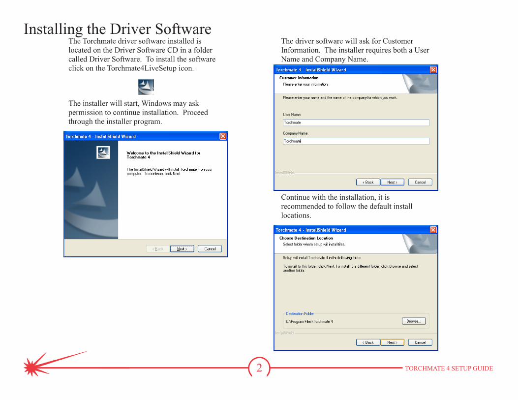
Installing the Driver SoftwareThe Torchmate driver software installed is located on the Driver Software CD in a folder called Driver Software. To install the software click on the Torchmate4LiveSetup icon.
The installer will start, Windows may ask permission to continue installation. Proceed through the installer program.
The driver software will ask for Customer Information. The installer requires both a User Name and Company Name.
Continue with the installation, it is recommended to follow the default install locations.
3 TORCHMATE 4 SETUP GUIDE
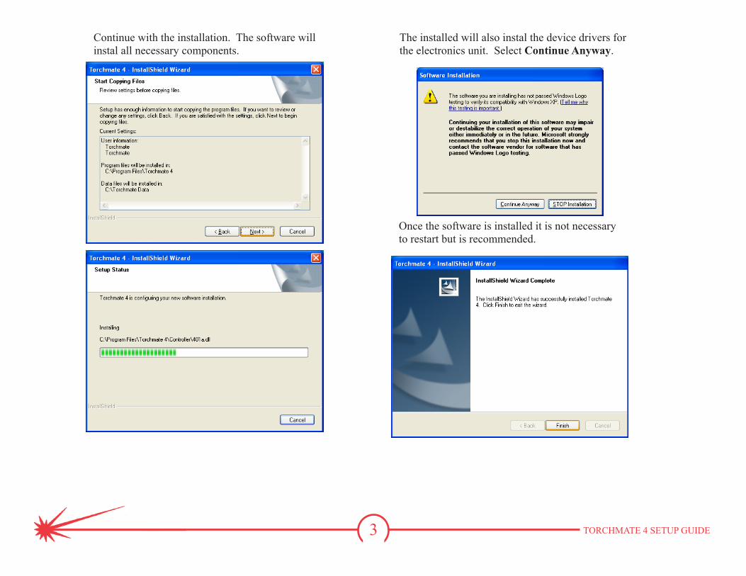
Continue with the installation. The software will instal all necessary components.
Once the software is installed it is not necessary to restart but is recommended.
The installed will also instal the device drivers for the electronics unit. Select Continue Anyway.
4 TORCHMATE 4 SETUP GUIDE
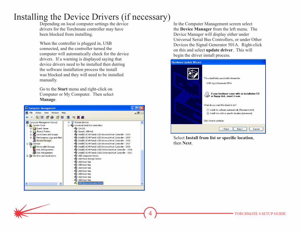
Installing the Device Drivers (if necessary)Depending on local computer settings the device drivers for the Torchmate controller may have been blocked from installing.
When the controller is plugged in, USB connected, and the controller turned the computer will automatically check for the device drivers. If a warning is displayed saying that device drivers need to be installed then dutring the software installation process the install was blocked and they will need to be installed manually.
Go to the Start menu and right-click on Computer or My Computer. Then select Manage.
In the Computer Management screen select the Device Manager from the left menu. The Device Manager will display either under Universal Serial Bus Controllers, or under Other Devices the Signal Generator 501A. Right-click on this and select update driver. This will begin the driver install process.
Select Install from list or specific location, then Next.
5 TORCHMATE 4 SETUP GUIDE
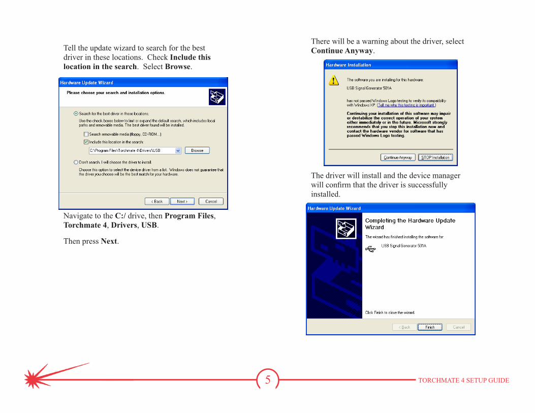
Tell the update wizard to search for the best driver in these locations. Check Include this location in the search. Select Browse.
Navigate to the C:/ drive, then Program Files, Torchmate 4, Drivers, USB.
Then press Next.
There will be a warning about the driver, select Continue Anyway.
The driver will install and the device manager will confirm that the driver is successfully installed.
6 TORCHMATE 4 SETUP GUIDE
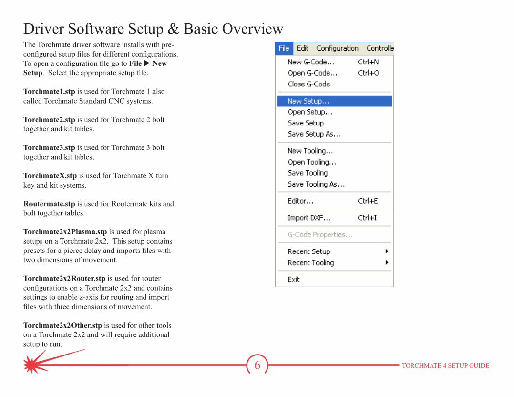
Driver Software Setup & Basic OverviewThe Torchmate driver software installs with pre-configured setup files for different configurations. To open a configuration file go to File u New Setup. Select the appropriate setup file.
Torchmate1.stp is used for Torchmate 1 also called Torchmate Standard CNC systems.
Torchmate2.stp is used for Torchmate 2 bolt together and kit tables.
Torchmate3.stp is used for Torchmate 3 bolt together and kit tables.
TorchmateX.stp is used for Torchmate X turn key and kit systems.
Routermate.stp is used for Routermate kits and bolt together tables.
Torchmate2x2Plasma.stp is used for plasma setups on a Torchmate 2x2. This setup contains presets for a pierce delay and imports files with two dimensions of movement.
Torchmate2x2Router.stp is used for router configurations on a Torchmate 2x2 and contains settings to enable z-axis for routing and import files with three dimensions of movement.
Torchmate2x2Other.stp is used for other tools on a Torchmate 2x2 and will require additional setup to run.
7 TORCHMATE 4 SETUP GUIDE
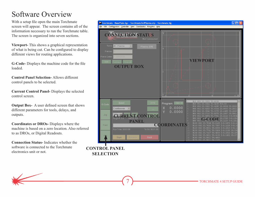
With a setup file open the main Torchmate screen will appear. The screen contains all of the information necessary to run the Torchmate table.The screen is organized into seven sections.
Viewport- This shows a graphical representation of what is being cut. Can be configured to display different views for routing applications.
G-Code- Displays the machine code for the file loaded.
Control Panel Selection- Allows different control panels to be selected.
Current Control Panel- Displays the selected control screen.
Output Box- A user defined screen that shows different parameters for tools, delays, and outputs.
Coordinates or DROs- Displays where the machine is based on a zero location. Also referred to as DROs, or Digital Readouts.
Connection Status- Indicates whether the software is connected to the Torchmate electronics unit or not.
Software Overview
VIEWPORTOUTPUT BOX
CONNECTION STATUS
G-CODECOORDINATES
CURRENT CONTROLPANEL
CONTROL PANELSELECTION
8 TORCHMATE 4 SETUP GUIDE
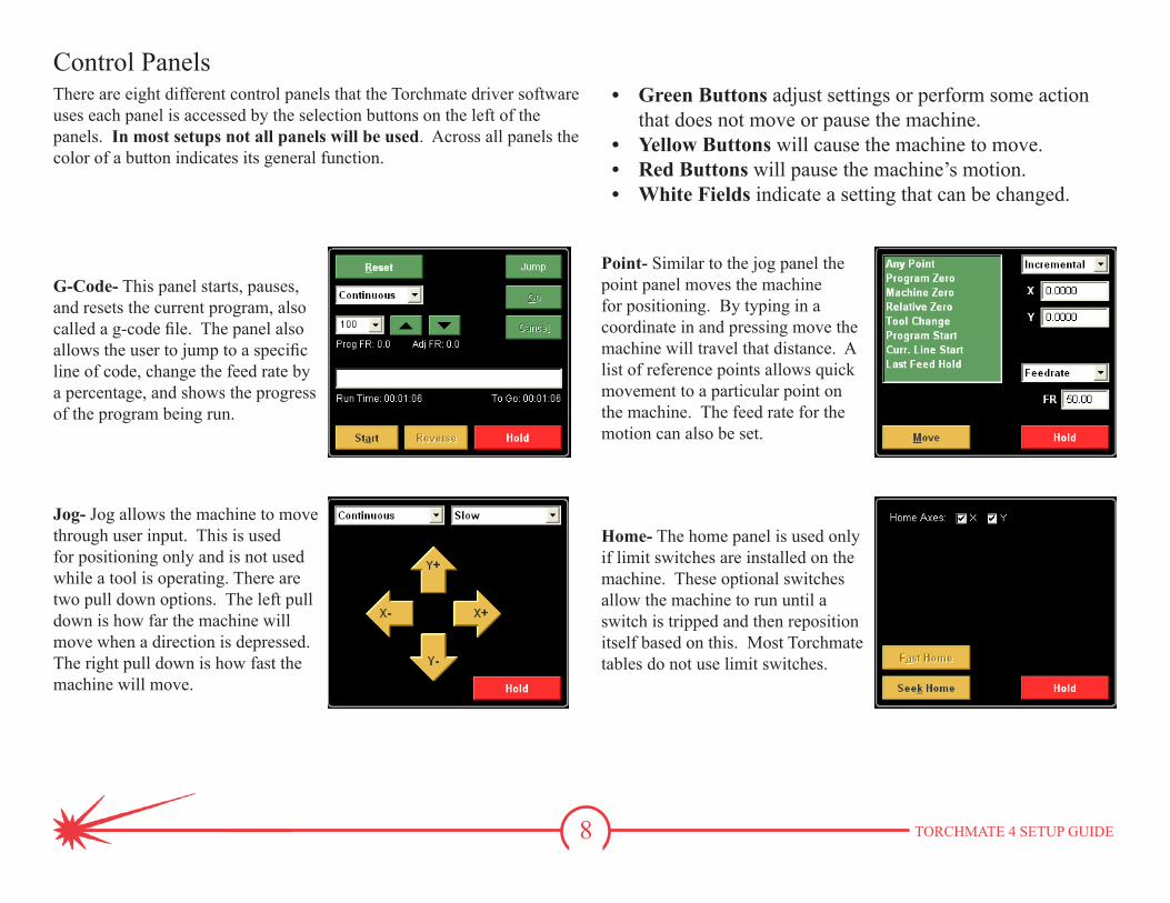
Control PanelsThere are eight different control panels that the Torchmate driver software uses each panel is accessed by the selection buttons on the left of the panels. In most setups not all panels will be used. Across all panels the color of a button indicates its general function.
G-Code- This panel starts, pauses, and resets the current program, also called a g-code file. The panel also allows the user to jump to a specific line of code, change the feed rate by a percentage, and shows the progress of the program being run.
Jog- Jog allows the machine to move through user input. This is used for positioning only and is not used while a tool is operating. There are two pull down options. The left pull down is how far the machine will move when a direction is depressed. The right pull down is how fast the machine will move.
Point- Similar to the jog panel the point panel moves the machine for positioning. By typing in a coordinate in and pressing move the machine will travel that distance. A list of reference points allows quick movement to a particular point on the machine. The feed rate for the motion can also be set.
Home- The home panel is used only if limit switches are installed on the machine. These optional switches allow the machine to run until a switch is tripped and then reposition itself based on this. Most Torchmate tables do not use limit switches.
• Green Buttons adjust settings or perform some action that does not move or pause the machine.
• Yellow Buttons will cause the machine to move.• Red Buttons will pause the machine’s motion.• White Fields indicate a setting that can be changed.
9 TORCHMATE 4 SETUP GUIDE
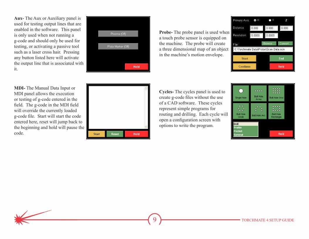
Aux- The Aux or Auxiliary panel is used for testing output lines that are enabled in the software. This panel is only used when not running a g-code and should only be used for testing, or activating a passive tool such as a laser cross hair. Pressing any button listed here will activate the output line that is associated with it.
MDI- The Manual Data Input or MDI panel allows the execution or testing of g-code entered in the field. The g-code in the MDI field will override the currently loaded g-code file. Start will start the code entered here, reset will jump back to the beginning and hold will pause the code.
Probe- The probe panel is used when a touch probe sensor is equipped on the machine. The probe will create a three dimensional map of an object in the machine’s motion envelope.
Cycles- The cycles panel is used to create g-code files without the use of a CAD software. These cycles represent simple programs for routing and drilling. Each cycle will open a configuration screen with options to write the program.
10 TORCHMATE 4 SETUP GUIDE
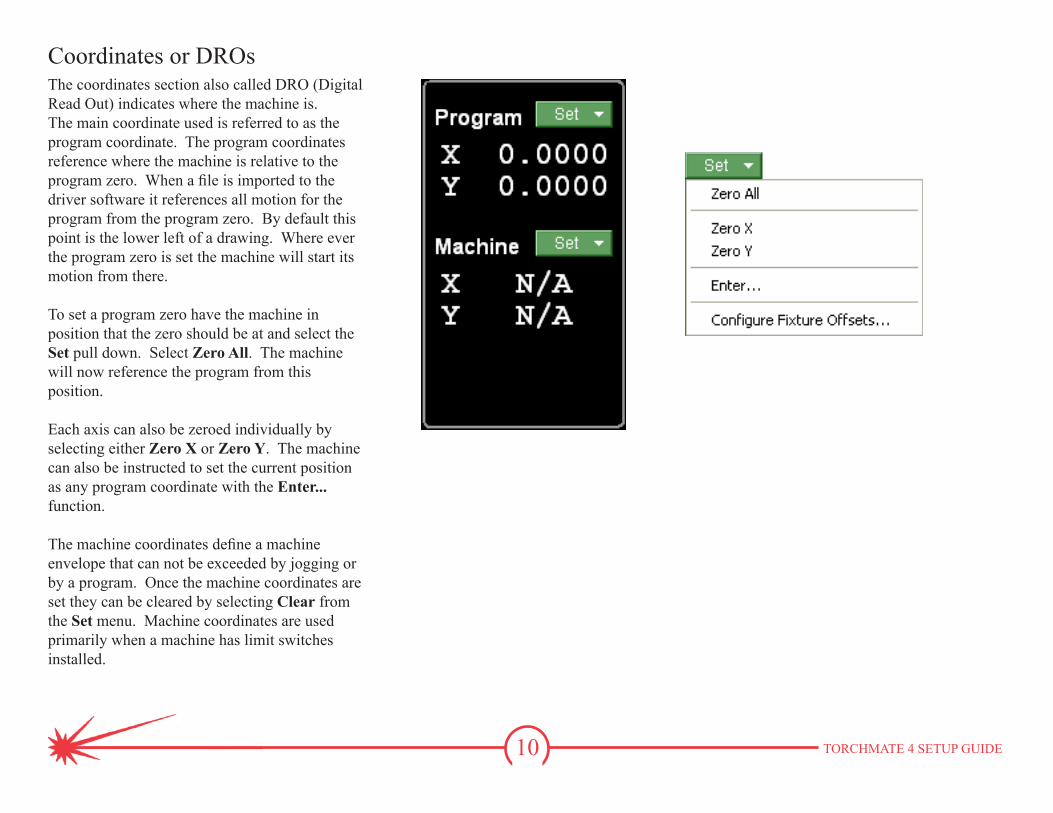
Coordinates or DROsThe coordinates section also called DRO (Digital Read Out) indicates where the machine is. The main coordinate used is referred to as the program coordinate. The program coordinates reference where the machine is relative to the program zero. When a file is imported to the driver software it references all motion for the program from the program zero. By default this point is the lower left of a drawing. Where ever the program zero is set the machine will start its motion from there.
To set a program zero have the machine in position that the zero should be at and select the Set pull down. Select Zero All. The machine will now reference the program from this position.
Each axis can also be zeroed individually by selecting either Zero X or Zero Y. The machine can also be instructed to set the current position as any program coordinate with the Enter... function.
The machine coordinates define a machine envelope that can not be exceeded by jogging or by a program. Once the machine coordinates are set they can be cleared by selecting Clear from the Set menu. Machine coordinates are used primarily when a machine has limit switches installed.
11 TORCHMATE 4 SETUP GUIDE
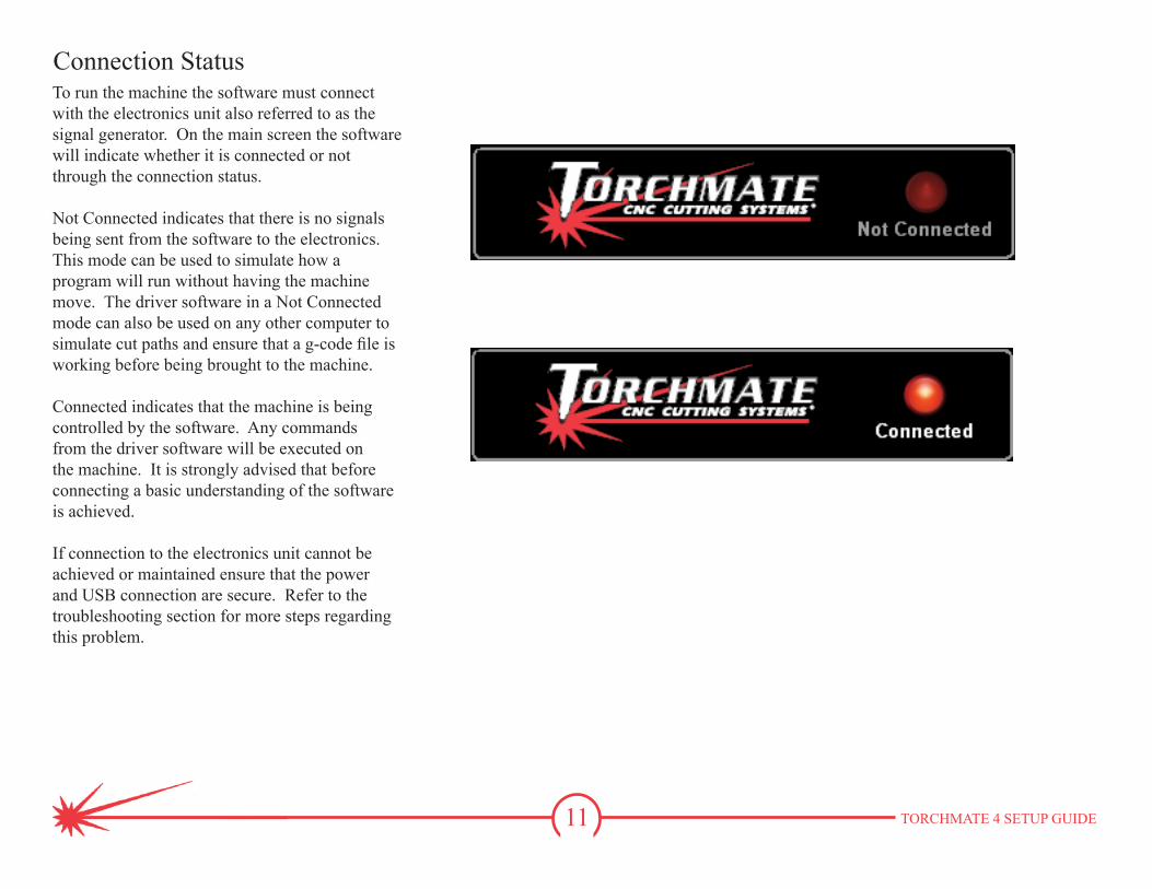
Connection StatusTo run the machine the software must connect with the electronics unit also referred to as the signal generator. On the main screen the software will indicate whether it is connected or not through the connection status.
Not Connected indicates that there is no signals being sent from the software to the electronics. This mode can be used to simulate how a program will run without having the machine move. The driver software in a Not Connected mode can also be used on any other computer to simulate cut paths and ensure that a g-code file is working before being brought to the machine.
Connected indicates that the machine is being controlled by the software. Any commands from the driver software will be executed on the machine. It is strongly advised that before connecting a basic understanding of the software is achieved.
If connection to the electronics unit cannot be achieved or maintained ensure that the power and USB connection are secure. Refer to the troubleshooting section for more steps regarding this problem.
12 TORCHMATE 4 SETUP GUIDE
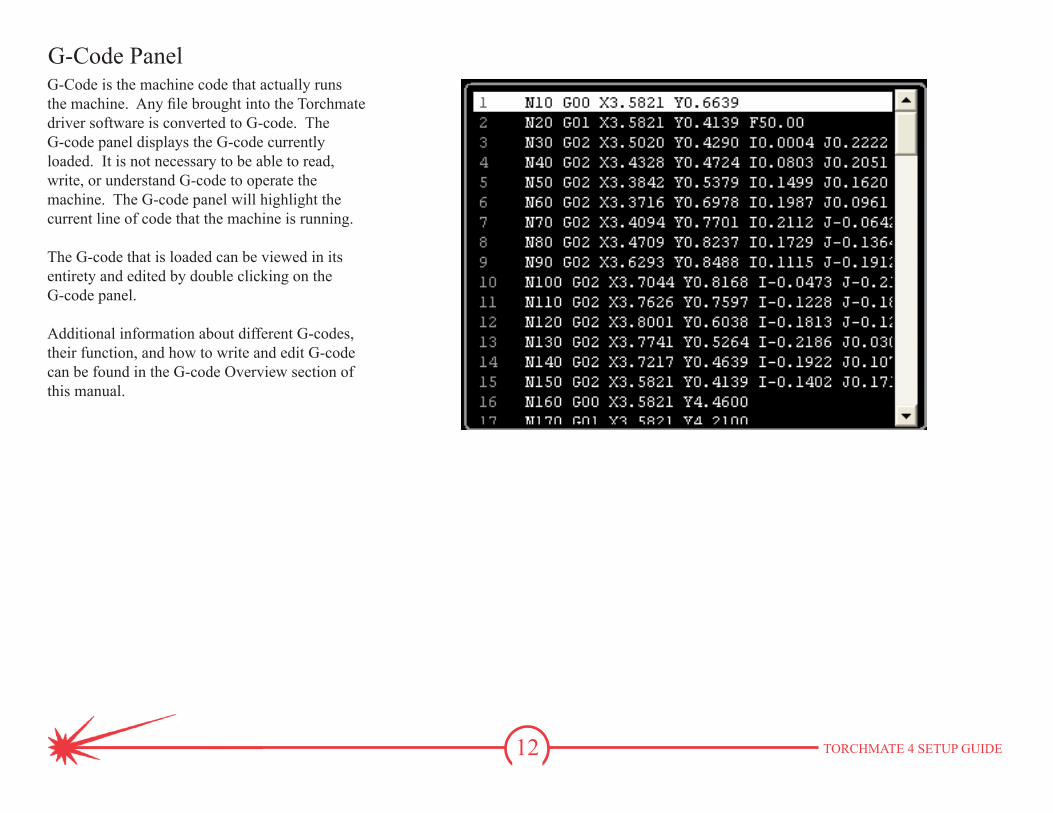
G-Code PanelG-Code is the machine code that actually runs the machine. Any file brought into the Torchmate driver software is converted to G-code. The G-code panel displays the G-code currently loaded. It is not necessary to be able to read, write, or understand G-code to operate the machine. The G-code panel will highlight the current line of code that the machine is running.
The G-code that is loaded can be viewed in its entirety and edited by double clicking on the G-code panel.
Additional information about different G-codes, their function, and how to write and edit G-code can be found in the G-code Overview section of this manual.
13 TORCHMATE 4 SETUP GUIDE
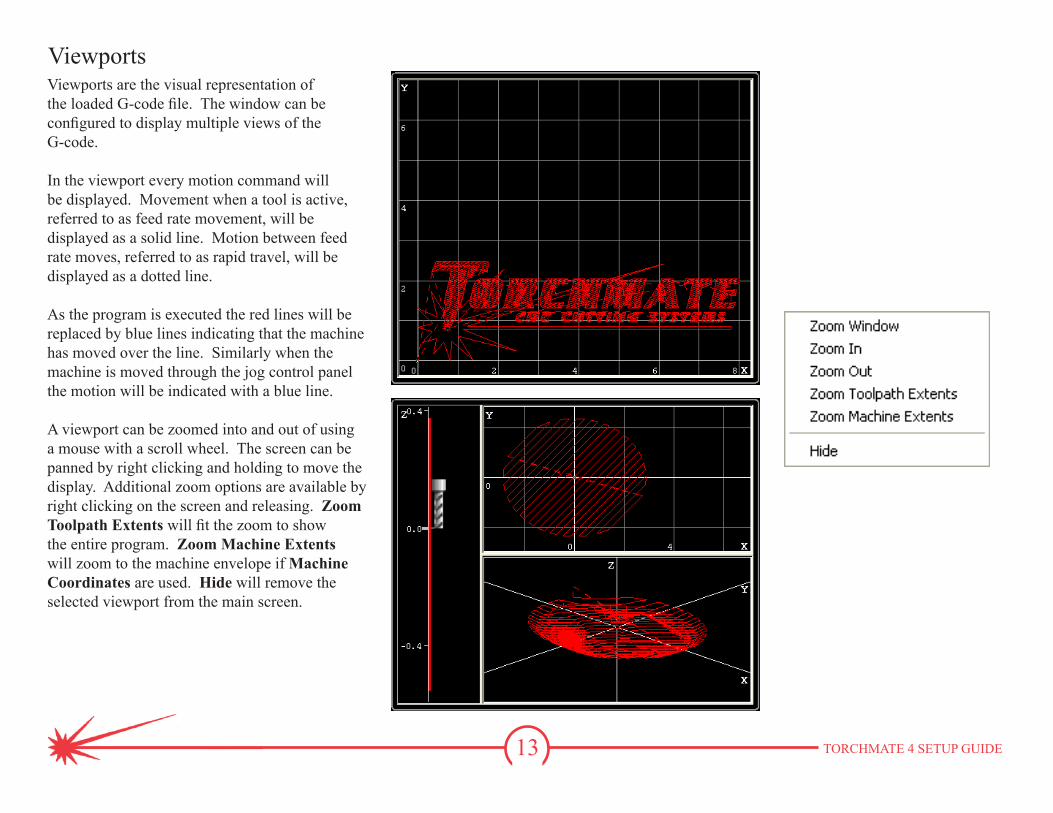
ViewportsViewports are the visual representation of the loaded G-code file. The window can be configured to display multiple views of the G-code.
In the viewport every motion command will be displayed. Movement when a tool is active, referred to as feed rate movement, will be displayed as a solid line. Motion between feed rate moves, referred to as rapid travel, will be displayed as a dotted line.
As the program is executed the red lines will be replaced by blue lines indicating that the machine has moved over the line. Similarly when the machine is moved through the jog control panel the motion will be indicated with a blue line.
A viewport can be zoomed into and out of using a mouse with a scroll wheel. The screen can be panned by right clicking and holding to move the display. Additional zoom options are available by right clicking on the screen and releasing. Zoom Toolpath Extents will fit the zoom to show the entire program. Zoom Machine Extents will zoom to the machine envelope if Machine Coordinates are used. Hide will remove the selected viewport from the main screen.
14 TORCHMATE 4 SETUP GUIDE
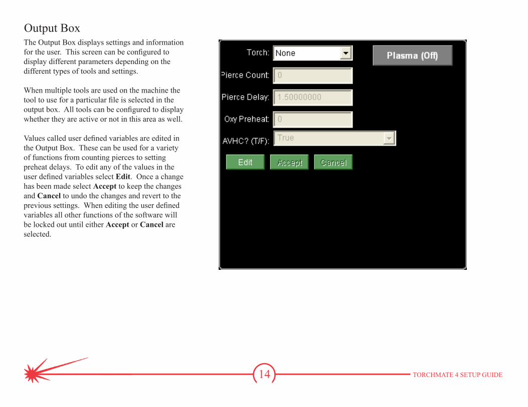
Output BoxThe Output Box displays settings and information for the user. This screen can be configured to display different parameters depending on the different types of tools and settings.
When multiple tools are used on the machine the tool to use for a particular file is selected in the output box. All tools can be configured to display whether they are active or not in this area as well.
Values called user defined variables are edited in the Output Box. These can be used for a variety of functions from counting pierces to setting preheat delays. To edit any of the values in the user defined variables select Edit. Once a change has been made select Accept to keep the changes and Cancel to undo the changes and revert to the previous settings. When editing the user defined variables all other functions of the software will be locked out until either Accept or Cancel are selected.
15 TORCHMATE 4 SETUP GUIDE
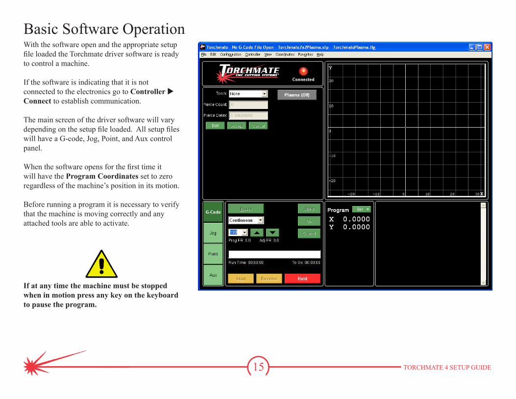
Basic Software OperationWith the software open and the appropriate setup file loaded the Torchmate driver software is ready to control a machine.
If the software is indicating that it is not connected to the electronics go to Controller u Connect to establish communication.
The main screen of the driver software will vary depending on the setup file loaded. All setup files will have a G-code, Jog, Point, and Aux control panel.
When the software opens for the first time it will have the Program Coordinates set to zero regardless of the machine’s position in its motion.
Before running a program it is necessary to verify that the machine is moving correctly and any attached tools are able to activate.
If at any time the machine must be stopped when in motion press any key on the keyboard to pause the program.
16 TORCHMATE 4 SETUP GUIDE
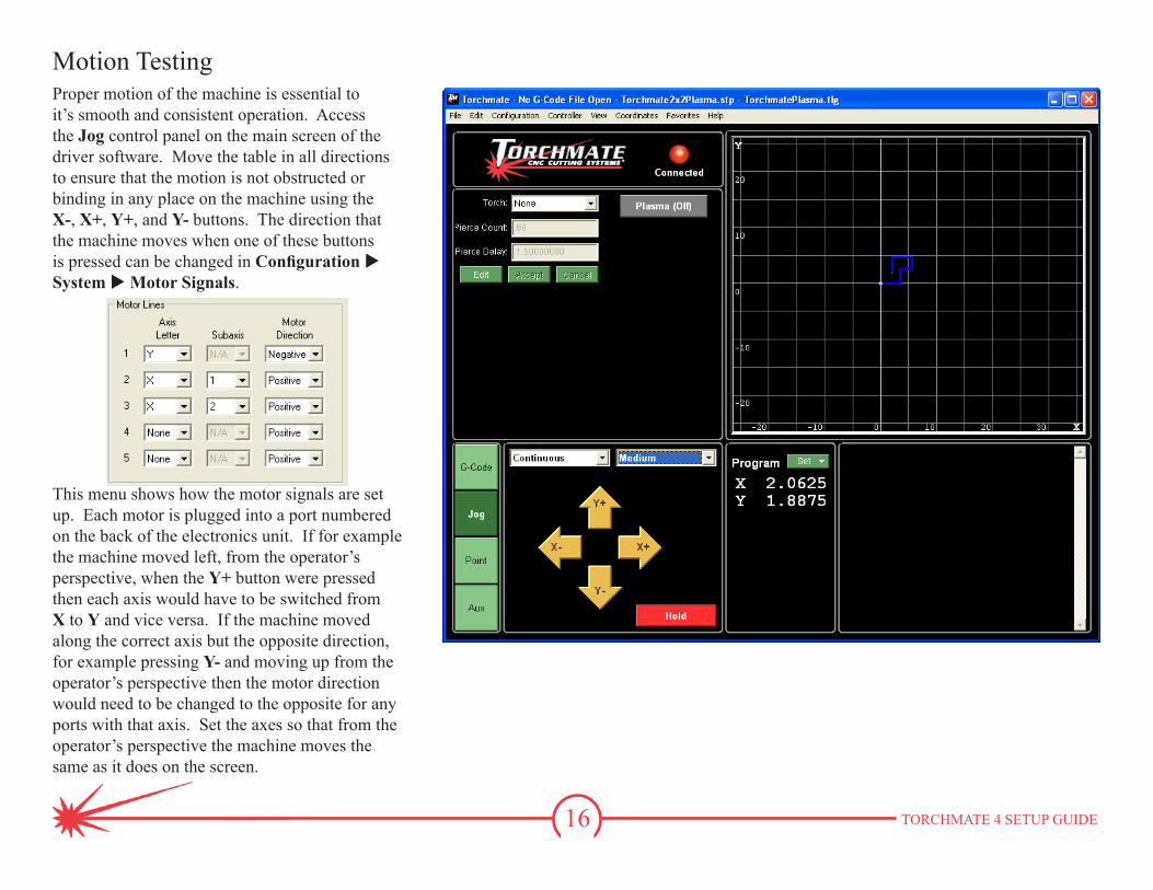
Motion TestingProper motion of the machine is essential to it’s smooth and consistent operation. Access the Jog control panel on the main screen of the driver software. Move the table in all directions to ensure that the motion is not obstructed or binding in any place on the machine using the X-, X+, Y+, and Y- buttons. The direction that the machine moves when one of these buttons is pressed can be changed in Configuration u System u Motor Signals.
This menu shows how the motor signals are set up. Each motor is plugged into a port numbered on the back of the electronics unit. If for example the machine moved left, from the operator’s perspective, when the Y+ button were pressed then each axis would have to be switched from X to Y and vice versa. If the machine moved along the correct axis but the opposite direction, for example pressing Y- and moving up from the operator’s perspective then the motor direction would need to be changed to the opposite for any ports with that axis. Set the axes so that from the operator’s perspective the machine moves the same as it does on the screen.
17 TORCHMATE 4 SETUP GUIDE
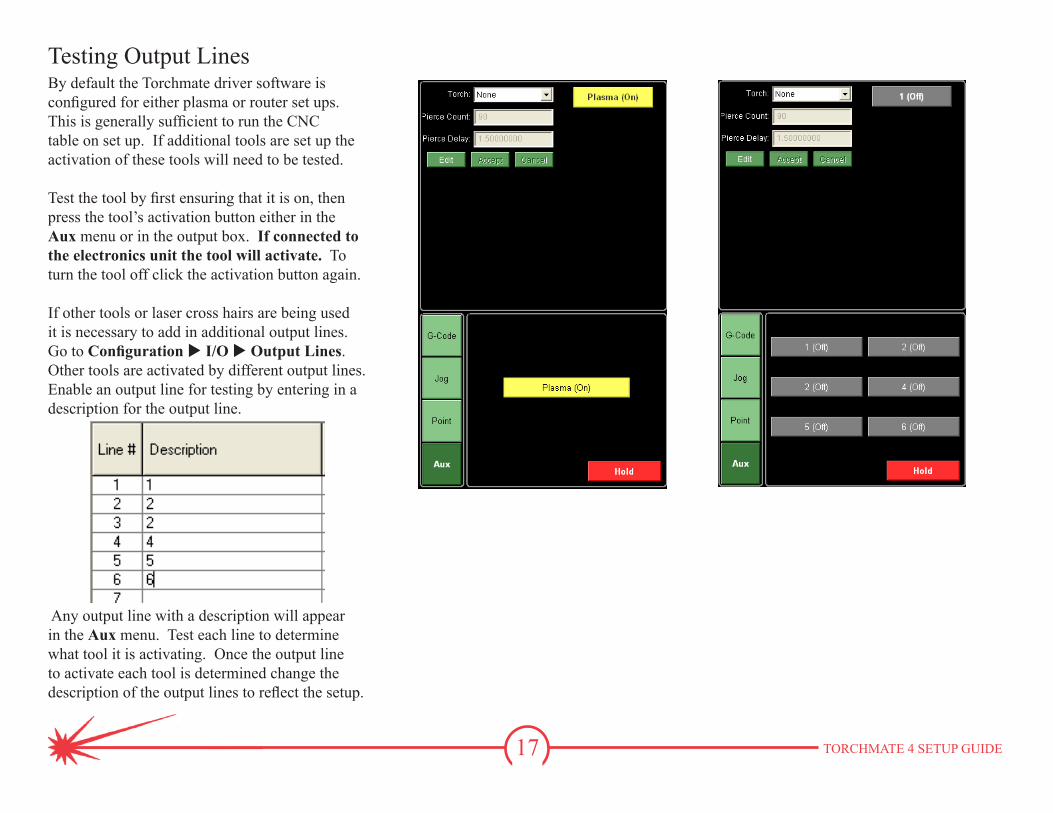
Testing Output LinesBy default the Torchmate driver software is configured for either plasma or router set ups. This is generally sufficient to run the CNC table on set up. If additional tools are set up the activation of these tools will need to be tested.
Test the tool by first ensuring that it is on, then press the tool’s activation button either in the Aux menu or in the output box. If connected to the electronics unit the tool will activate. To turn the tool off click the activation button again.
If other tools or laser cross hairs are being used it is necessary to add in additional output lines. Go to Configuration u I/O u Output Lines. Other tools are activated by different output lines. Enable an output line for testing by entering in a description for the output line.
Any output line with a description will appear in the Aux menu. Test each line to determine what tool it is activating. Once the output line to activate each tool is determined change the description of the output lines to reflect the setup.
18 TORCHMATE 4 SETUP GUIDE
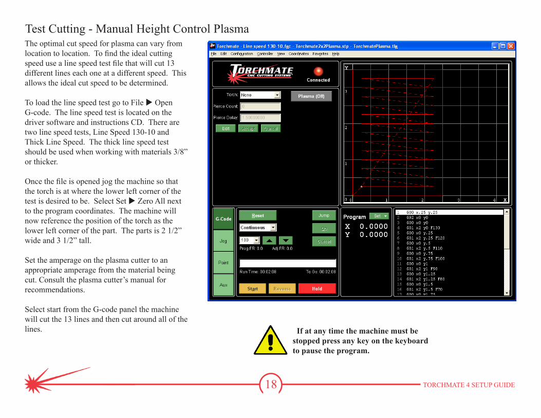
Test Cutting - Manual Height Control PlasmaThe optimal cut speed for plasma can vary from location to location. To find the ideal cutting speed use a line speed test file that will cut 13 different lines each one at a different speed. This allows the ideal cut speed to be determined.
To load the line speed test go to File u Open G-code. The line speed test is located on the driver software and instructions CD. There are two line speed tests, Line Speed 130-10 and Thick Line Speed. The thick line speed test should be used when working with materials 3/8” or thicker.
Once the file is opened jog the machine so that the torch is at where the lower left corner of the test is desired to be. Select Set u Zero All next to the program coordinates. The machine will now reference the position of the torch as the lower left corner of the part. The parts is 2 1/2” wide and 3 1/2” tall.
Set the amperage on the plasma cutter to an appropriate amperage from the material being cut. Consult the plasma cutter’s manual for recommendations.
Select start from the G-code panel the machine will cut the 13 lines and then cut around all of the lines. If at any time the machine must be
stopped press any key on the keyboard to pause the program.
19 TORCHMATE 4 SETUP GUIDE
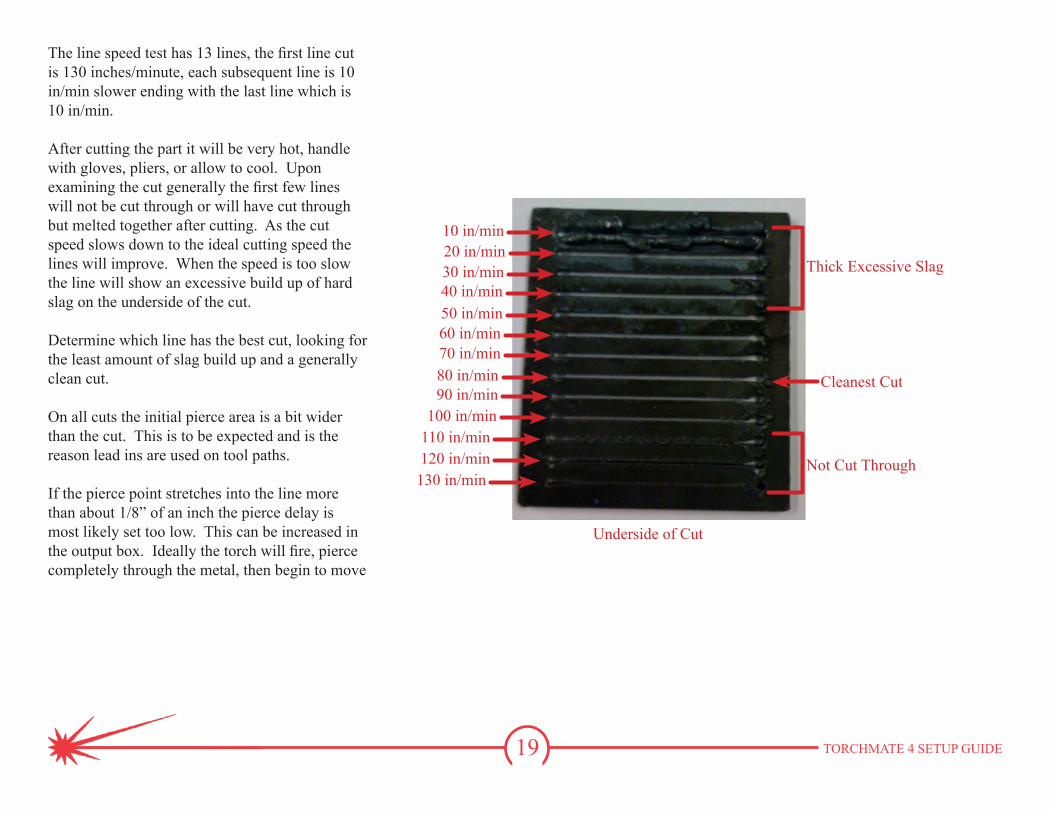
The line speed test has 13 lines, the first line cut is 130 inches/minute, each subsequent line is 10 in/min slower ending with the last line which is 10 in/min.
After cutting the part it will be very hot, handle with gloves, pliers, or allow to cool. Upon examining the cut generally the first few lines will not be cut through or will have cut through but melted together after cutting. As the cut speed slows down to the ideal cutting speed the lines will improve. When the speed is too slow the line will show an excessive build up of hard slag on the underside of the cut.
Determine which line has the best cut, looking for the least amount of slag build up and a generally clean cut.
On all cuts the initial pierce area is a bit wider than the cut. This is to be expected and is the reason lead ins are used on tool paths.
If the pierce point stretches into the line more than about 1/8” of an inch the pierce delay is most likely set too low. This can be increased in the output box. Ideally the torch will fire, pierce completely through the metal, then begin to move
130 in/min120 in/min110 in/min100 in/min
90 in/min80 in/min70 in/min60 in/min50 in/min40 in/min30 in/min20 in/min10 in/min
Thick Excessive Slag
Not Cut Through
Cleanest Cut
Underside of Cut
20 TORCHMATE 4 SETUP GUIDE
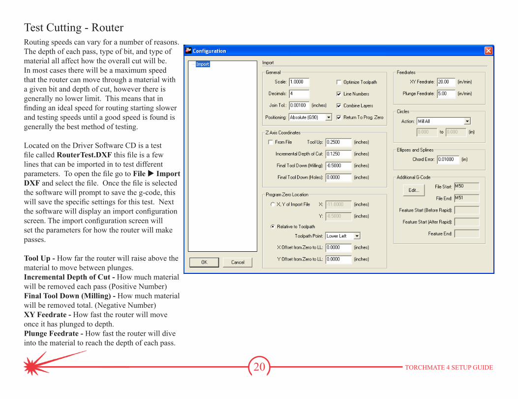
Test Cutting - RouterRouting speeds can vary for a number of reasons. The depth of each pass, type of bit, and type of material all affect how the overall cut will be. In most cases there will be a maximum speed that the router can move through a material with a given bit and depth of cut, however there is generally no lower limit. This means that in finding an ideal speed for routing starting slower and testing speeds until a good speed is found is generally the best method of testing.
Located on the Driver Software CD is a test file called RouterTest.DXF this file is a few lines that can be imported in to test different parameters. To open the file go to File u Import DXF and select the file. Once the file is selected the software will prompt to save the g-code, this will save the specific settings for this test. Next the software will display an import configuration screen. The import configuration screen will set the parameters for how the router will make passes.
Tool Up - How far the router will raise above the material to move between plunges.Incremental Depth of Cut - How much material will be removed each pass (Positive Number)Final Tool Down (Milling) - How much material will be removed total. (Negative Number)XY Feedrate - How fast the router will move once it has plunged to depth.Plunge Feedrate - How fast the router will dive into the material to reach the depth of each pass.
21 TORCHMATE 4 SETUP GUIDE
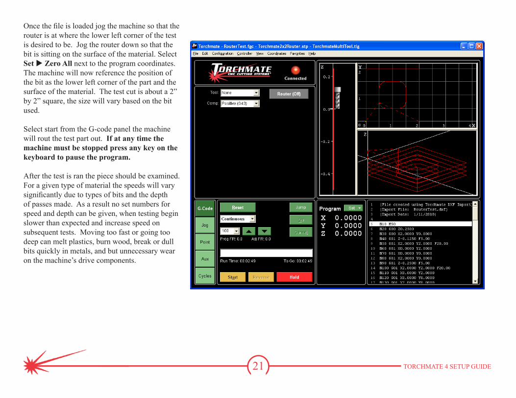
Once the file is loaded jog the machine so that the router is at where the lower left corner of the test is desired to be. Jog the router down so that the bit is sitting on the surface of the material. Select Set u Zero All next to the program coordinates. The machine will now reference the position of the bit as the lower left corner of the part and the surface of the material. The test cut is about a 2” by 2” square, the size will vary based on the bit used.
Select start from the G-code panel the machine will rout the test part out. If at any time the machine must be stopped press any key on the keyboard to pause the program.
After the test is ran the piece should be examined. For a given type of material the speeds will vary significantly due to types of bits and the depth of passes made. As a result no set numbers for speed and depth can be given, when testing begin slower than expected and increase speed on subsequent tests. Moving too fast or going too deep can melt plastics, burn wood, break or dull bits quickly in metals, and but unnecessary wear on the machine’s drive components.
22 TORCHMATE 4 SETUP GUIDE
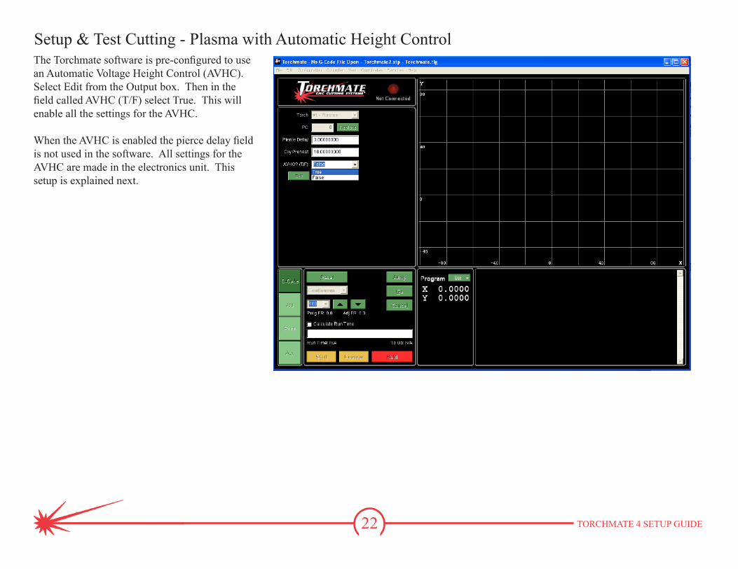
The Torchmate software is pre-configured to use an Automatic Voltage Height Control (AVHC). Select Edit from the Output box. Then in the field called AVHC (T/F) select True. This will enable all the settings for the AVHC.
When the AVHC is enabled the pierce delay field is not used in the software. All settings for the AVHC are made in the electronics unit. This setup is explained next.
Setup & Test Cutting - Plasma with Automatic Height Control
23 TORCHMATE 4 SETUP GUIDE
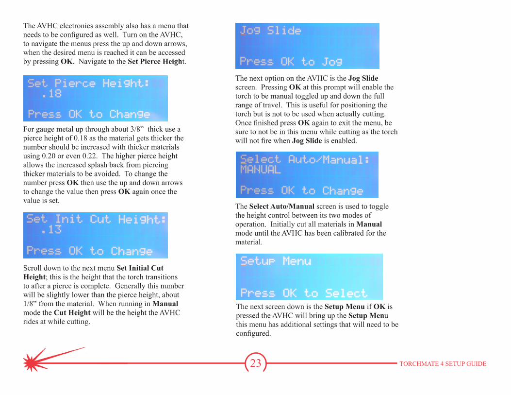
The AVHC electronics assembly also has a menu that needs to be configured as well. Turn on the AVHC, to navigate the menus press the up and down arrows, when the desired menu is reached it can be accessed by pressing OK. Navigate to the Set Pierce Height.
For gauge metal up through about 3/8” thick use a pierce height of 0.18 as the material gets thicker the number should be increased with thicker materials using 0.20 or even 0.22. The higher pierce height allows the increased splash back from piercing thicker materials to be avoided. To change the number press OK then use the up and down arrows to change the value then press OK again once the value is set.
Scroll down to the next menu Set Initial Cut Height; this is the height that the torch transitions to after a pierce is complete. Generally this number will be slightly lower than the pierce height, about 1/8” from the material. When running in Manual mode the Cut Height will be the height the AVHC rides at while cutting.
The next option on the AVHC is the Jog Slide screen. Pressing OK at this prompt will enable the torch to be manual toggled up and down the full range of travel. This is useful for positioning the torch but is not to be used when actually cutting. Once finished press OK again to exit the menu, be sure to not be in this menu while cutting as the torch will not fire when Jog Slide is enabled.
The Select Auto/Manual screen is used to toggle the height control between its two modes of operation. Initially cut all materials in Manual mode until the AVHC has been calibrated for the material.
The next screen down is the Setup Menu if OK is pressed the AVHC will bring up the Setup Menu this menu has additional settings that will need to be configured.
24 TORCHMATE 4 SETUP GUIDE
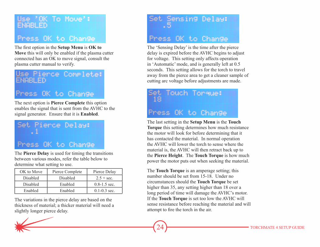
The first option in the Setup Menu is OK to Move this will only be enabled if the plasma cutter connected has an OK to move signal, consult the plasma cutter manual to verify.
The next option is Pierce Complete this option enables the signal that is sent from the AVHC to the signal generator. Ensure that it is Enabled.
The Pierce Delay is used for timing the transitions between various modes, refer the table below to determine what setting to use.
OK to Move Pierce Complete Pierce DelayDisabled Disabled 2.5 + sec.Disabled Enabled 0.8-1.5 sec.Enabled Enabled 0.1-0.3 sec.
The variations in the pierce delay are based on the thickness of material; a thicker material will need a slightly longer pierce delay.
The ‘Sensing Delay’ is the time after the pierce delay is expired before the AVHC begins to adjust for voltage. This setting only affects operation in ‘Automatic’ mode, and is generally left at 0.5 seconds. This setting allows for the torch to travel away from the pierce area to get a cleaner sample of cutting arc voltage before adjustments are made.
The last setting in the Setup Menu is the Touch Torque this setting determines how much resistance the motor will look for before determining that it has contacted the material. In normal operation the AVHC will lower the torch to sense where the material is, the AVHC will then retract back up to the Pierce Height. The Touch Torque is how much power the motor puts out when seeking the material.
The Touch Torque is an amperage setting; this number should be set from 15-18. Under no circumstances should the Touch Torque be set higher than 35, any setting higher than 18 over a long period of time will damage the AVHC’s motor. If the Touch Torque is set too low the AVHC will sense resistance before reaching the material and will attempt to fire the torch in the air.
25 TORCHMATE 4 SETUP GUIDE
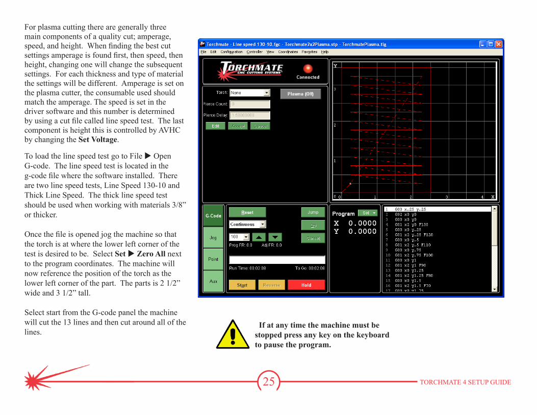
For plasma cutting there are generally three main components of a quality cut; amperage, speed, and height. When finding the best cut settings amperage is found first, then speed, then height, changing one will change the subsequent settings. For each thickness and type of material the settings will be different. Amperage is set on the plasma cutter, the consumable used should match the amperage. The speed is set in the driver software and this number is determined by using a cut file called line speed test. The last component is height this is controlled by AVHC by changing the Set Voltage.
To load the line speed test go to File u Open G-code. The line speed test is located in the g-code file where the software installed. There are two line speed tests, Line Speed 130-10 and Thick Line Speed. The thick line speed test should be used when working with materials 3/8” or thicker.
Once the file is opened jog the machine so that the torch is at where the lower left corner of the test is desired to be. Select Set u Zero All next to the program coordinates. The machine will now reference the position of the torch as the lower left corner of the part. The parts is 2 1/2” wide and 3 1/2” tall.
Select start from the G-code panel the machine will cut the 13 lines and then cut around all of the lines.
If at any time the machine must be stopped press any key on the keyboard to pause the program.

26 TORCHMATE 4 SETUP GUIDE
Once the best speed is found the last step is to determine the height. There is another file located on the Driver and Assembly Instructions CD, this file is called VoltageTest.DXF. Import this file by going to File u Import DXF.
Once the file is selected the software will prompt to save the g-code, this will save the specific settings for this test. Next the software will display an import configuration screen. In the import configuration screen enter the best speed found from the line speed test in the XY Feedrate section. No other setting need to be changed.
27 TORCHMATE 4 SETUP GUIDE
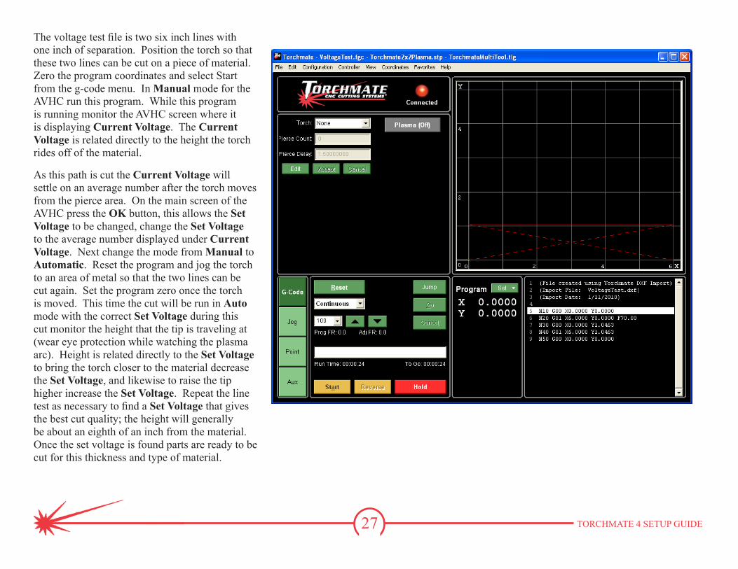
The voltage test file is two six inch lines with one inch of separation. Position the torch so that these two lines can be cut on a piece of material. Zero the program coordinates and select Start from the g-code menu. In Manual mode for the AVHC run this program. While this program is running monitor the AVHC screen where it is displaying Current Voltage. The Current Voltage is related directly to the height the torch rides off of the material.
As this path is cut the Current Voltage will settle on an average number after the torch moves from the pierce area. On the main screen of the AVHC press the OK button, this allows the Set Voltage to be changed, change the Set Voltage to the average number displayed under Current Voltage. Next change the mode from Manual to Automatic. Reset the program and jog the torch to an area of metal so that the two lines can be cut again. Set the program zero once the torch is moved. This time the cut will be run in Auto mode with the correct Set Voltage during this cut monitor the height that the tip is traveling at (wear eye protection while watching the plasma arc). Height is related directly to the Set Voltage to bring the torch closer to the material decrease the Set Voltage, and likewise to raise the tip higher increase the Set Voltage. Repeat the line test as necessary to find a Set Voltage that gives the best cut quality; the height will generally be about an eighth of an inch from the material. Once the set voltage is found parts are ready to be cut for this thickness and type of material.
28 TORCHMATE 4 SETUP GUIDE
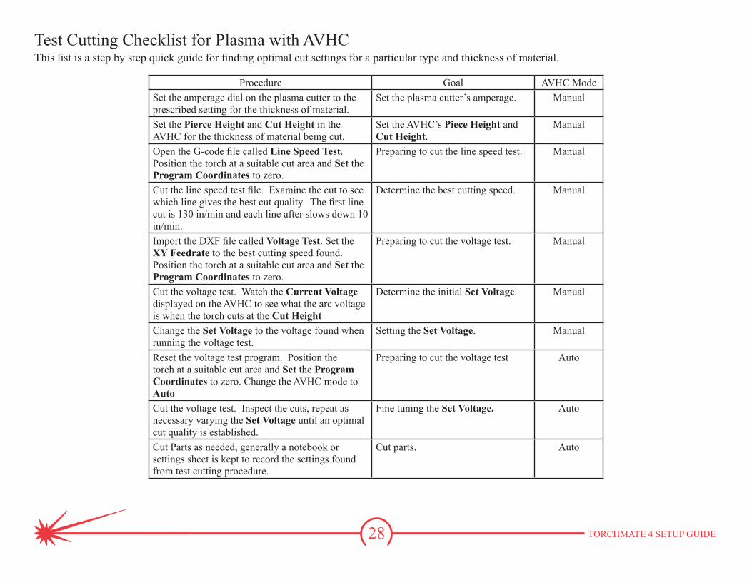
This list is a step by step quick guide for finding optimal cut settings for a particular type and thickness of material.
Procedure Goal AVHC ModeSet the amperage dial on the plasma cutter to the prescribed setting for the thickness of material.
Set the plasma cutter’s amperage. Manual
Set the Pierce Height and Cut Height in the AVHC for the thickness of material being cut.
Set the AVHC’s Piece Height and Cut Height.
Manual
Open the G-code file called Line Speed Test. Position the torch at a suitable cut area and Set the Program Coordinates to zero.
Preparing to cut the line speed test. Manual
Cut the line speed test file. Examine the cut to see which line gives the best cut quality. The first line cut is 130 in/min and each line after slows down 10 in/min.
Determine the best cutting speed. Manual
Import the DXF file called Voltage Test. Set the XY Feedrate to the best cutting speed found. Position the torch at a suitable cut area and Set the Program Coordinates to zero.
Preparing to cut the voltage test. Manual
Cut the voltage test. Watch the Current Voltage displayed on the AVHC to see what the arc voltage is when the torch cuts at the Cut Height
Determine the initial Set Voltage. Manual
Change the Set Voltage to the voltage found when running the voltage test.
Setting the Set Voltage. Manual
Reset the voltage test program. Position the torch at a suitable cut area and Set the Program Coordinates to zero. Change the AVHC mode to Auto
Preparing to cut the voltage test Auto
Cut the voltage test. Inspect the cuts, repeat as necessary varying the Set Voltage until an optimal cut quality is established.
Fine tuning the Set Voltage. Auto
Cut Parts as needed, generally a notebook or settings sheet is kept to record the settings found from test cutting procedure.
Cut parts. Auto
Test Cutting Checklist for Plasma with AVHC
29 TORCHMATE 4 SETUP GUIDE
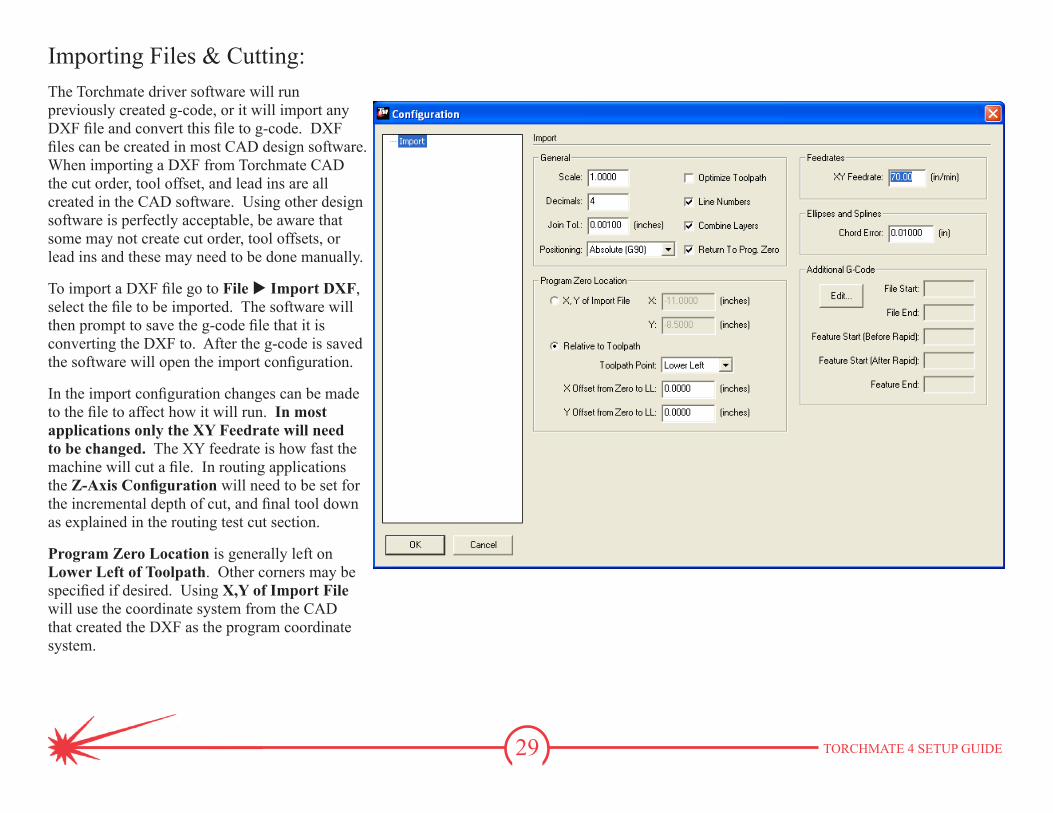
Importing Files & Cutting:The Torchmate driver software will run previously created g-code, or it will import any DXF file and convert this file to g-code. DXF files can be created in most CAD design software. When importing a DXF from Torchmate CAD the cut order, tool offset, and lead ins are all created in the CAD software. Using other design software is perfectly acceptable, be aware that some may not create cut order, tool offsets, or lead ins and these may need to be done manually.
To import a DXF file go to File u Import DXF, select the file to be imported. The software will then prompt to save the g-code file that it is converting the DXF to. After the g-code is saved the software will open the import configuration.
In the import configuration changes can be made to the file to affect how it will run. In most applications only the XY Feedrate will need to be changed. The XY feedrate is how fast the machine will cut a file. In routing applications the Z-Axis Configuration will need to be set for the incremental depth of cut, and final tool down as explained in the routing test cut section.
Program Zero Location is generally left on Lower Left of Toolpath. Other corners may be specified if desired. Using X,Y of Import File will use the coordinate system from the CAD that created the DXF as the program coordinate system.
30 TORCHMATE 4 SETUP GUIDE
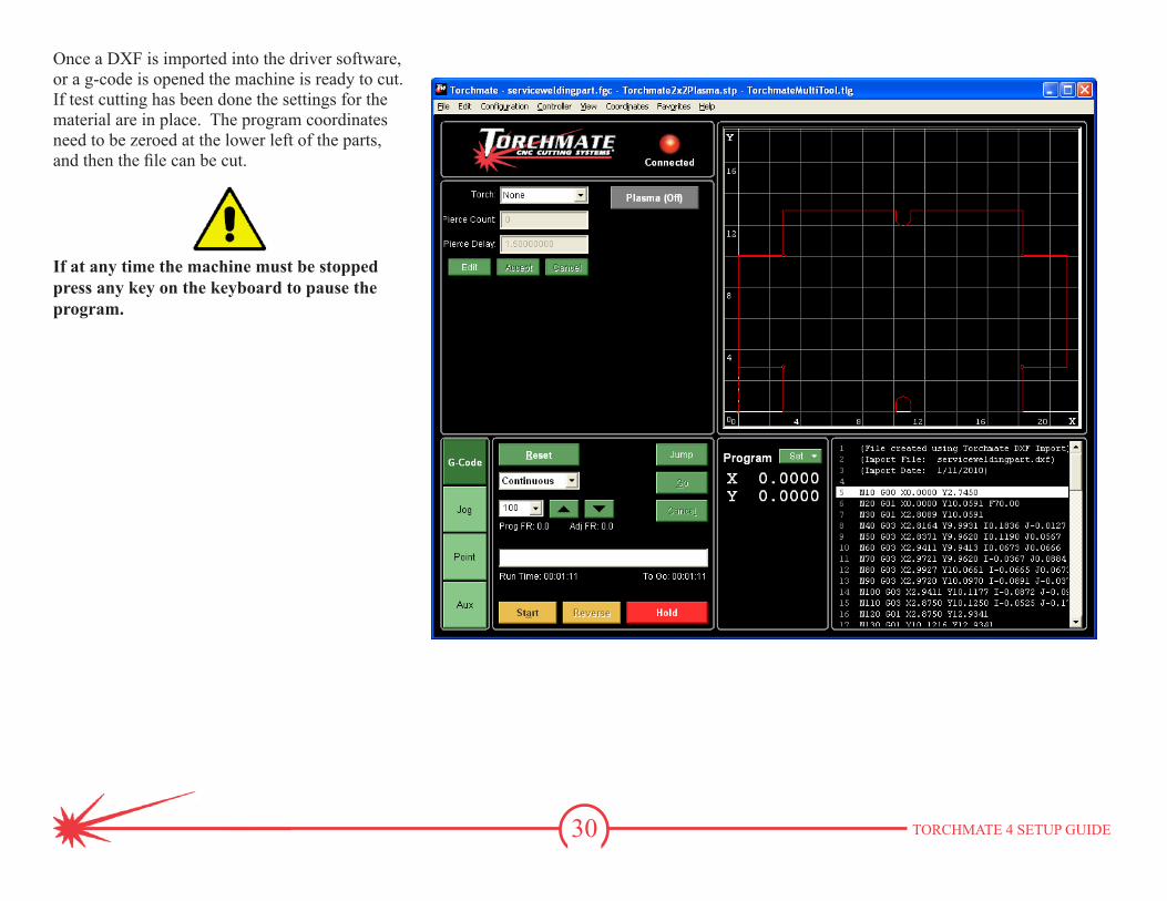
Once a DXF is imported into the driver software, or a g-code is opened the machine is ready to cut. If test cutting has been done the settings for the material are in place. The program coordinates need to be zeroed at the lower left of the parts, and then the file can be cut.
If at any time the machine must be stopped press any key on the keyboard to pause the program.
31 TORCHMATE 4 SETUP GUIDE
Toll Free: 1-866-571-1066 x3International: 775-673-2200 x3Fax: 775-673-2206Email: [email protected]
More information about each option and configuration setting can be found in the Torchmate 4 User’s Guide. This guide can be accessed by going to Help u User’s Guide. This file contains technical explanations of each option, and the different types of g-codes accepted.
Any questions about operation of the driver software, cut quality questions, or any problems please contact Torchmate Technical Support.
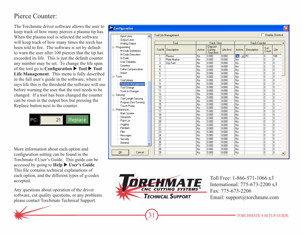
Pierce Counter:The Torchmate driver software allows the user to keep track of how many pierces a plasma tip has. When the plasma tool is selected the software will keep track of how many times the torch has been told to fire. The software is set by default to warn the user after 100 pierces that the tip has exceeded its life. This is just the default counter any number may be set. To change the life span of the tool go to Configuration u Tool u Tool Life Management. This menu is fully described in the full user’s guide in the software, where it says life this is the threshold the software will use before warning the user that the tool needs to be changed. If a tool has been changed the counter can be reset in the output box but pressing the Replace button next to the counter.
Related Documents