1 Codification through the 2016 legislative session. Subchapters 1, 3, 5, 7, 9, 13 and 19; Appendix E Board adoption - February 19, 2016 Approved by Governor's declaration on June 9, 2016 Effective date - September 15, 2016 TITLE 252. DEPARTMENT OF ENVIRONMENTAL QUALITY CHAPTER 626. PUBLIC WATER SUPPLY CONSTRUCTION STANDARDS Subchapter..............................................................................................................................Section 1 Introduction ................................................................................................................. 252:626-1 3. Permit procedures ....................................................................................................... 252:626-3 5. General Design............................................................................................................ 252:626-5 7. Source Development ................................................................................................... 252:626-7 9. Treatment .................................................................................................................... 252:626-9 11. Chemical Application ............................................................................................... 252:626-11 13. Residuals Management ............................................................................................. 252:626-13 15. Pumping Facilities .................................................................................................... 252:626-15 17. Finished Water Storage ............................................................................................. 252:626-17 19. Distribution System .................................................................................................. 252:626-19 21. Design Standards for Minor Systems [REVOKED] ................................................. 252:626-21 Appendix A. Piping Color Code Appendix B. Filtration Galleries Appendix C. Steel Pipe Appendix D. Gravel Support for Slow Sand Filters Appendix E. Gravel Support for Rapid Rate Sand Filter Appendix F. Quantity of Water Plant Residuals Generated Appendix G. Minor Water Systems [REVOKED]

Welcome message from author
This document is posted to help you gain knowledge. Please leave a comment to let me know what you think about it! Share it to your friends and learn new things together.
Transcript
1
Codification through the 2016 legislative session.
Subchapters 1, 3, 5, 7, 9, 13 and 19; Appendix E
Board adoption - February 19, 2016
Approved by Governor's declaration on June 9, 2016
Effective date - September 15, 2016
TITLE 252. DEPARTMENT OF ENVIRONMENTAL QUALITY
CHAPTER 626. PUBLIC WATER SUPPLY CONSTRUCTION STANDARDS
Subchapter..............................................................................................................................Section
1 Introduction ................................................................................................................. 252:626-1
3. Permit procedures ....................................................................................................... 252:626-3
5. General Design............................................................................................................ 252:626-5
7. Source Development ................................................................................................... 252:626-7
9. Treatment .................................................................................................................... 252:626-9
11. Chemical Application ............................................................................................... 252:626-11
13. Residuals Management ............................................................................................. 252:626-13
15. Pumping Facilities .................................................................................................... 252:626-15
17. Finished Water Storage ............................................................................................. 252:626-17
19. Distribution System .................................................................................................. 252:626-19
21. Design Standards for Minor Systems [REVOKED] ................................................. 252:626-21
Appendix A. Piping Color Code
Appendix B. Filtration Galleries
Appendix C. Steel Pipe
Appendix D. Gravel Support for Slow Sand Filters
Appendix E. Gravel Support for Rapid Rate Sand Filter
Appendix F. Quantity of Water Plant Residuals Generated
Appendix G. Minor Water Systems [REVOKED]
2
SUBCHAPTER 1. INTRODUCTION
Section
252:626-1-1. Purpose
252:626-1-2. Definitions
252:626-1-1. Purpose (a) Implement and enforce the "Oklahoma Water Supply Systems Act", 27A O.S. § 2-6-301 et
seq.
(b) This chapter applies to any person or entity that constructs or modifies a public water supply
distribution system or water supply system and sets the permit and construction standards for all
public water supply systems. This chapter does not apply to individual water systems, except the
fees for individual well inspections are included in OAC 252:626-3-10. The design criteria in this
chapter are set at a minimum and will be considered as such by the DEQ. These standards do not
prevent the consulting engineer from recommending or the DEQ from approving more effective
treatment where local conditions dictate. Other rules govern public water supply systems,
including OAC 252:606, 624, 631, 633, 641, 710, and other appropriate local, state and federal
regulations.
252:626-1-2. Definitions Terms have the meaning assigned in the Environmental Quality Code. The following words or
terms, when used in this Chapter, have the following meaning unless the context clearly indicates
otherwise:
"25-year flood" means a flood event that has a 4 percent chance of being equaled or exceeded
in magnitude in any given year.
"100-year flood" means a flood event that has a 1 percent chance of being equaled or
exceeded in magnitude in any given year.
"ANSI" means the American National Standards institute.
"APHA" means the American Public Health Association.
"API" means the American Petroleum Institute.
"Approvable", "Approve", "Approved" mean a submission to the DEQ that shall be
considered a final submission, all preliminary discussions between the DEQ and the permittee
regarding the requirements of a submission shall be concluded prior to the submission, so that the
submission shall be deemed complete as submitted.
"ASTM" means the American Society for Testing Materials.
"AWWA" means the American Water Works Association.
"Board" means the Environmental Quality Board.
"Calculated dose" means the RED calculated using the dose-monitoring equation that was
developed through validation testing.
"Cartridge filter" means a filter that is manufactured by placing a flat sheet membrane media
between a feed and filtrate support layer and plating the assembly to increase the membrane
surface area within the cartridge. The pleat pack assembly is then placed around a center core
with a corresponding outer case and subsequently sealed, via adhesive or thermal means, into its
cartridge configuration.
"Certified waterworks operator" means an operator licensed by the State of Oklahoma,
3
pursuant to OAC 252:710.
"CFR" means Code of Federal Regulation.
"Challenge test" means a study conducted to determine the removal efficiency (i.e. log
removal value [LRV]) of a membrane material for a particular organism, particulate or surrogate.
"Clean-in place (CIP)" means the periodic application of a chemical solution or series of
solutions to a membrane unit for the intended purpose of removing accumulated foulants and
restoring permeability and resistance to baseline levels, commonly used for in-situ chemical
cleaning.
"Combined distribution system" means the interconnected distribution system consisting of
the distribution systems of wholesale systems and of the consecutive systems that receive finished
water.
"Consecutive system" means a public water supply system that receives some or all of its
finished water from one or more wholesale systems. Delivery may be through a direct connection
or through the distribution system of one or more consecutive systems.
"Council" means the Water Quality Management Advisory Council.
"CT" means the product of "residual disinfectant concentration" (C) in mg/l, and the
corresponding "disinfectant contact time" (T) in minutes, i.e., "C" x "T". CT requirements for a
variety of disinfectants and conditions appear in the EPA Guidance Manual to the Surface Water
Treatment Rule.
"CT Value" means the product of disinfectant residual and disinfectant CT. The required
amount of CT needed is contained in the EPA Guidance Manual to the Surface Water Treatment
Rule.
"DEQ" means the Oklahoma Department of Environmental Quality.
"Differential pressure" means a pressure drop across a membrane module or unit from the
feed inlet to concentrate outlet, as distinguished from transmembrane pressure (TMP), which
represents the pressure from across the membrane barrier.
"Direct integrity testing" means a physical test applied to a membrane unit in order to
identify and/or isolate an integrity breach.
"Director" or "Executive Director" means the Executive Director of the Oklahoma
Department of Environmental Quality.
"Effective size" means from a particle-size distribution curve, it is the diameter where 10% of
the material is finer.
"Element" means a term used to describe an encased spiral-wound membrane module and is
synonymous with the terms module and cartridge.
"Engineer" means a professional engineer licensed to practice engineering in Oklahoma.
"ETV" means the EPA's Environmental Technical Verification Program.
"EPA" means the United States Environmental Protection Agency.
"FDA" means the United States Food and Drug Administration.
"Flood Plain" means the flood way and a zone of floodwater storage where water moves
slowly or is ponded, thus attenuating the flood peak as the flood waters move downstream.
"Flood way" means the part of the flood plain considered to be the zone of highest hazard and
the zone to be reserved for the passage of larger floods.
"Flux" means the throughput of a pressure-driven membrane filtration system expressed in
terms of flow per unit of membrane area.
"GWUDI" means groundwater under the direct influence of surface water.
4
"Hydraulic analysis" means the study of the water system network, evaluating water flows
within the distribution system under prescribed conditions, such as peak hourly flow plus fire flow
when required. Hydraulic analysis includes consideration of all factors affecting system energy
losses.
"Indirect integrity monitoring" means the monitoring of an aspect of filtered water quality,
such as turbidity, that is indicative of the removal of particulate matter at a frequency of no less
than once every fifteen (15) minutes.
"Individual water system" means a water system serving only one single-family residence.
"Iron and manganese control" means the treatment process designed specifically for the
treatment or removal of iron and manganese.
"Membrane unit" means a group of membrane modules that share common valving which
allows the unit to be isolated from the rest of the system for the purpose of integrity testing or other
maintenance, synonymous with the terms rack, skid and train.
"Minor public water supply system" means a water system not included in the public water
supply system definition. Minor public water supply systems are regulated by OAC 252:624.
"Multi-family dwelling" means a single structure designed and suitable for use of several or
many families.
"Municipal system" means public water supply distribution systems constructed, operated,
and maintained by a municipality or trust for the benefit of such municipality.
"mm" means millimeter
"nm" means nanometer.
"NSF" means the National Sanitation Foundation.
"OAC" means the Oklahoma Administrative Code.
"O.S." means the Oklahoma Statutes.
"OWRB" means the Oklahoma Water Resources Board.
"Package treatment plant" means plants that are pre-manufactured used to treat water that
do not meet conventional standards for flocculation and sedimentation.
"Plan documents" means reports, proposals, preliminary plans, survey and basis of design
data, general and detail construction plans, profiles, specifications, and all other information
pertaining to water supply planning.
"Pitless unit" means an assembly which extends the upper end of the well casing to above
grade to prevent the entrance of contaminants into the well or potable water supply, to conduct
water from the well, to protect the water from freezing or extremes of temperature and to provide
fill access to the well and to parts within the well.
"psi" means pounds per square inch.
"Public water supply (PWS) system" means any system providing water for human
consumption through pipes or other constructed conveyances, if such system has at least 15 service
connections or regularly serves an average of at least 25 individuals at least 60 days per year,
whether receiving payment or not. Multi-family dwellings, which are constructed, inspected, and
maintained under a State or locally approved plumbing code and purchase water from a permitted
water system, are not classified as a Public Water Supply system. The following are the
categories of Public Water Supply systems:
(A) "Community water system" means any PWS system, which serves at least 15 service
connections, used by year-round residents or regularly serves at least 25 year-round
residents.
5
(B) "Non-community water system" means any PWS system, which serves an average
of at least 25 individuals at least 60 days per year but is neither a community water system
nor a non-transient non-community water system.
(C) "Non-transient non-community (NTNC) water system" means any PWS system
that is not a community water system and that regularly serves at least 25 of the same
persons over 6 months per year.
"Purchase water system" means any system, which purchases all of its water through a
master meter and provides that water to the public.
"Reduced pressure zone, backflow preventer" means a device designed to prevent
backflow consisting of two spring loaded check valves with an intermediate reduced pressure zone
that drains to the atmosphere by a relief valve, with a reduced pressure maintained in the
intermediate zone by means of a pressure differential valve.
"Reduction Equivalent Dose (RED)" means the UV dose derived by entering the log
inactivation measured during full-scale reactor testing into the UV dose-response curve that was
derived through collimated beam testing. RED values are always specific to the challenge
microorganism used during experimental testing and the validation test conditions for full-scale
reactor testing.
"Required Dose" means the UV dose in units of mJ/cm2 needed to achieve the target log
inactivation for the target pathogen.
"Residuals" means the sludge generated by a drinking water treatment facility.
"Rip rap" means a permanent, erosion resistant ground cover that consists of hard, sound
durable stones, which average in weight between thirty pounds (30 lbs.) to fifty pounds (50 lbs.),
with no more than twenty percent (20%) weighing less than twenty pounds (20 lbs).
"Rural water system" means a water system designed to provide domestic water service to
an area having its major part outside of an incorporated community. This system may be
organized as a trust authority, a rural water district, or non-profit water corporation.
"Silt density index (SDI)" means the ASTM, standard D 4189-95, Standard Test Method for
Silt Density Index of Water. Measurements are taken by filtering a water sample through a
0.45mm flat sheet filter with a 47mm diameter at a pressure of 30 psi. The time required to collect
two samples at 500 ml each is measured and the resulting data is imputed into a formula.
"Solids contact unit" means a combination rapid mix, floc-aggregation, and upflow
sedimentation basin constructed in either a round or square configuration.
"Standard methods for the examination of water and wastewater" means the approval
methods developed by the APHA, the AWWA and the Water Environmental Federation. The
current standard methods are contained in the 20th
Edition, published by the AWWA.
"Sufficiency certification" means to provide assurance that the integrity and capacity of an
existing system will not or have not been compromised.
"Transmembrane pressure (TMP)" means the pressure drop across the membrane barrier.
"UL" means the Underwriters Laboratory.
"Uniformity coefficient" means from a particle-size distribution curve it is, the ratio of the 60
percent grain size to the 10 percent grain size.
"U.S.C." means United States Code.
"UV" means ultra violet.
"UV absorbance" means a measure of the amount of UV light that is absorbed by a substance
at a specific wavelength, across a specified pathlength of substance. This measurement accounts
6
for absorption and scattering in the medium. Standard Method 5910B details this measurement
method, however, for drinking water applications, samples need not be filtered or adjusted for pH
or longer pathlength cuvettes, 4 cm to 5 cm should be used instead of 1 cm cuvette.
"UV dose" means the UV energy per unit area incident on a surface, typically reported in units
of mJ/cm2 or J/m
2. The UV dose received by a waterborne microorganism in a reactor vessel
accounts for the effects on UV intensity of the absorbance of the water, absorbance of the quartz
sleeves, reflection and refraction of light from the water surface and reactor walls, and the
germicidal effectiveness of the UV wavelengths transmitted.
"UV dose distribution" means the probability distribution of UV doses that microorganisms
receive in a flow-through UV reactor, typically shown in a histogram.
"UV inactivation" means a process by which a microorganism is rendered unable to
reproduce, thereby unable to infect a host.
"UV intensity" means the power passing through a unit area perpendicular to the direction of
propagation. UV intensity is used in the UV Disinfection Guidance Manual (UVDGM) to
describe the magnitude of UV light measured by UV sensors in a reactor and with a radiometer in
bench-scale UV experiments.
"UV lamp sleeve" means the quartz tube that houses the UV lamp. The exterior of the lamp
sleeve is in direct contact with the water being treated. There is typically an air gap (approx. 1
cm) between the lamp envelope and quartz sleeve.
"UV low-pressure lamp" means a mercury-vapor lamp that operated at an internal pressure
of 0.13 to 1.3 Pa (2X10 to 2X10⁻⁴
psi) and electrical input 0.5 watts per centimeter (W/cm). This
results in essentially monochromatic light output at 254 nm.
"UV low-pressure high-output lamp" means a low-pressure mercury-vapor lamp that
operates under increased electrical input (1.5 to 10 W/cm), resulting in a higher UV intensity than
low-pressure lamps. This results in essentially monochromatic light output at 254 nm.
"UV medium-pressure lamp" means a mercury-vapor lamp that operates at an internal
pressure of 1.3 to 13,000 Pa (2 to 200 psi) and electrical input of 50 to 150 W/cm. This results in
a polychromatic (or broad spectrum) output of UV and visible light at multiple wavelengths,
including wavelengths in the germicidal range.
"UV off-line chemical clean" means a process to clean lamp sleeves where the UV reactor is
taken off-line and a cleaning solution (typically weak acid) is sprayed into the reactor through a
service port.
"UV off specification" means a UV facility that is operating outside of the validated
operating conditions (e.g. at a flow rate higher than the validated range or UVT below the
validated range).
"UV on-line mechanical clean" means a process to clean lamp sleeves where an automatic
mechanical wiper (e.g. o-ring) wipes the surface of the lamp sleeve at a prescribed frequency.
"UV on-line mechanical-chemical clean" means a process to clean lamp sleeves where an
automatic mechanical wiper (e.g. o-ring) with a chemical solution located within the cleaning
mechanism wipes the surface of the lamp sleeve at a prescribed frequency.
"UV sensor" means a photosensitive detector used to measure the UV intensity at a point
within the UV reactor that converts the signal to units of milliamps (mA).
"UV transmittance (UVT)" means a measure of the fraction of incident light transmitted
through a material. The UV transmittance is usually reported for a wavelength of 254 nm and a
pathlength of 1 cm. If an alternate pathlength is used, it shall be specified or converted to units of
7
cm-1
. UV transmittance is often represented as a percentage and is related to the UV absorbance
(A254) by the following equation (for a 1 cm path length): % UV transmittance=100X10-A
where
A is UV absorbance.
"Validated dose" means means the UV dose in units of mJ/cm2 delivered by the UV reactor
is determined through validation testing. The validated dose is compared to the required dose to
determine log inactivation credit.
"Water line extension" means an extension of an existing permitted water distribution line.
"WEF" means the Water Environmental Federation, formerly known as the WPCF.
"Wholesale system" means a public water supply system that treats source water as necessary
to produce finished water and then delivers finished water to another public water supply system.
Delivery may be through a direct connection or through the distribution system of one or more
consecutive systems.
"WQA" means the Water Quality Association.
"WTP" means Water Treatment Plant.
SUBCHAPTER 3. PERMIT PROCEDURES
Section
252:626-3-1. General
252:626-3-2. Applications
252:626-3-3. Financial assurance
252:626-3-4. Municipal permitting alternative
252:626-3-5. Individual waterline construction permit exceptions
252:626-3-6. Engineering report
252:626-3-7. Plans and specifications
252:626-3-8. Variances from construction standards
252:626-3-9. Construct according to plans and specifications
252:626-3-10. Permit fees
252:626-3-1. General (a) This subchapter implements the Uniform Permitting Act, Title 27A O.S. § 2-14-101 et seq. and
rules promulgated thereunder. A permit is required for construction or modification of a PWS
system or an extension of the distribution system, except:
(1) when the municipal permitting alternative is utilized under OAC 252:626-3-4;
(2) a construction permit exception is issued by the DEQ under OAC 252:626-3-5; or
(3) minor water systems constructed according to OAC 252:624 and approved by the
Environmental Complaints and Local Services (ECLS) office of the DEQ are exempt from the
permitting process, contained in this chapter.
(b) Unless an extension is granted, a construction permit expires if construction does not begin
within 1 year.
(c) No permit will be issued to any municipality which is the subject of an application for
dissolution or which has ceased to function to the extent that it may be subject to involuntary
dissolution under the laws of the State of Oklahoma.
(d) The construction permit for a PWS treatment facility will indicate its design capacity. When

8
additional users are considered which will cause the design capacity to be exceeded, notify the
DEQ and provide plans demonstrating how those additional customers will be supplied.
(e) The public water supply system shall inform the DEQ in writing at least 10 days before
completion of the project.
(f) Projects funded in part or in whole under the Drinking Water State Revolving Fund are also
subject to OAC 252:633.
252:626-3-2. Applications (a) Submit legible applications on forms provided by the DEQ and include:
(1) the type of entity that is applying
(2) the legal description,
(3) a minimum of 2 sets of plans and specifications, with at least one set of construction plans
printed on 11" x 17" paper and one set of specifications loosely bound that is suitable for
scanning,
(4) a final design analysis,
(5) all appropriate fees, and
(6) engineering report approved by the DEQ for major waterworks projects, or smaller
projects utilizing non-conventional processes.
(b) Public entities other than municipalities must provide certified copies of the results of the last
election or appointment of the members of the governing body. Public entities must provide a
citation of legal authority to own and operate the proposed facility.
(c) Applicants other than public entities must provide copies of documents that created them and
provide a citation to their statutory authority.
252:626-3-3. Financial assurance (a) All applicants must demonstrate they have adequate financial, technical, and managerial
capacity to comply with national primary drinking water regulations and continuously maintain
the facility.
(1) If the applicant is not a city, town or other public entity, the applicant must submit the
following to the DEQ:
(A) expected costs for operation and maintenance, replacement and closure,
(B) continued existence and financial accountability, and
(C) assurance that provisions have been made for continued existence of the operating
entity for the expected life of the facility.
(2) Continued existence may be demonstrated in one of the following fashions:
(A) the applicant may be a property owners' association or a nonprofit corporation
established under the laws of the State of Oklahoma. The association must have the legal
authority to own and manage the PWS system including the authority to set and collect fees
from users for operation and maintenance of the system. The bylaws of the entity must
contain a provision that dissolution cannot occur until the system is either closed in
accordance with applicable DEQ rules or transferred to another viable operating entity.
The instrument creating the association must be filed in the office of the county clerk where
the property is located, or
(B) the applicant must provide proof of a sufficient amount on deposit to the credit of a
trust, the powers of which are to operate and maintain the PWS system for the expected life
9
of the facility, or
(C) other proof of financial viability, such as the issuance of a bond or insurance contract
covering the operation and maintenance of the PWS system for the life of the system may
be submitted to DEQ for approval;
(3) Costs for closure of the PWS system as required by law must be included in any funding
plan.
(4) If the information fails to demonstrate the on-going viability of the operation, the
application will be denied.
(b) Applications and un-expired permits may be transferred upon showing the transferee has legal
authority and financial accountability, and that both parties agree to the transfer.
252:626-3-4. Municipal permitting alternative (a) Municipalities may utilize an alternate process for the construction of a PWS distribution
system extension if they:
(1) adopt and enforce an ordinance requiring all PWS systems within their corporate limits to
comply with applicable DEQ rules,
(2) retain an adequate number of competent full-time staff, including at least one Engineer to
review, approve, sign and seal plans and specifications for PWS distribution systems
extensions,
(3) have adequate inspection and enforcement staff and procedures to assure construction does
not proceed before approval of or deviate from approved plans and specifications,
(4) agree to supply DEQ with a copy of all approved plans and specifications and a list of all
approved projects monthly, no later than the 15th day of the month following approval. The
list of projects must include the name and location of each project and the date of approval by
the municipality, and
(5) received approval for the permitting alternative from the DEQ.
(b) To utilize the municipal permitting alternative, municipalities must apply on DEQ forms.
(c) This alternative may not be utilized for construction of water distribution lines larger than 12
inches in diameter or for construction funded by the State Revolving Fund.
252:626-3-5. Individual waterline construction permit exceptions (a) General. A construction permit exception is allowed under 27A O.S. § 2-6-304. The PWS
must:
(1) adopt and enforce an ordinance or rule requiring all water line extensions be constructed in
accordance with this Chapter,
(2) be in compliance with OAC 252:631 and 626 during the 12 months prior to the request for
permit exception or document that all instances of non-compliance have been corrected,
(3) submit a separate application for each proposed exception from the permit requirement,
(4) submit an application, on DEQ forms, and the following information:
(A) a general layout sheet as described in OAC 252:626-3-7,
(B) the location of proposed extension,
(C) the diameter of proposed extension,
(D) the length of proposed extension,
(E) the maximum number of service connections allowable without adversely affecting
system performance,
10
(F) the location of proposed fire hydrants, and
(G) a certification that the proposed design and construction meets or exceeds DEQ
standards, and
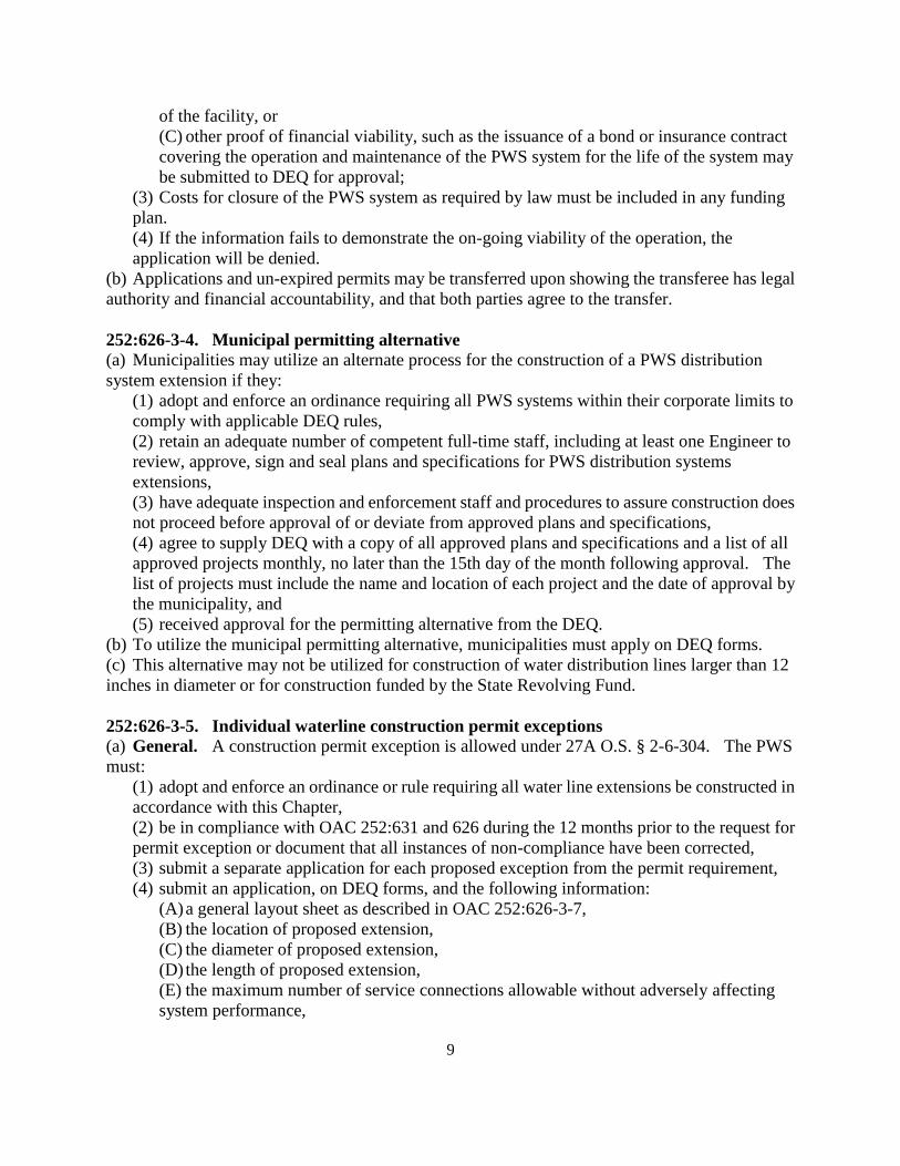
(5) after construction completion, submit a sufficiency certification, on forms provided or
approved by the DEQ, to the DEQ, executed by an Engineer, except in the case of a single
connection rural waterline extension certification, which may be executed by a Certified
waterworks operator, prior to commencement of service. Such certificate must provide
assurances that the integrity and capacity of the existing system will not or have not been
compromised.
(b) Municipal PWS systems. Municipal PWS systems may receive an exception from the
requirement to obtain a construction permit. The proposed extension must not be:
(1) larger than 6 inches in diameter,
(2) longer than 1,000 feet, and
(3) for an extension to a line, which previously has been granted a permit exception.
(c) Rural water districts. Rural water districts may receive an exception from the requirement
to obtain a construction permit under the following conditions. The proposed extensions must not
be:
(1) less than 2 inches in diameter and not greater than existing line,
(2) longer than 1 mile,
(3) added to a line, which was previously granted exception, or
(4) extended through, over or under any stream, lake, pond, marsh or any existing wastewater
collection lines.
(d) Non-community systems. Non-community systems may receive an exception from the
requirement to obtain a construction permit under the following conditions:
(1) utilize only a groundwater source, require no treatment systems, and serves a single public
or commercial establishment, and
(2) the proposed extension must not:
(A) be less than 2 inches in diameter and not greater than 4 inches in diameter,
(B) be longer than 1,000 feet,
(C) be added to a line, which was previously granted exception,
(D) add more than 1 connection, or
(E) be extended through, over or under any stream, lake, pond or marsh or any existing
sewage or wastewater collection lines.
(e) Cancellations of exceptions.
(1) The DEQ may cancel an exception if the system does not comply with DEQ rules, or does
not assure protection of public health and the environment.
(2) Failure to meet the terms of a granted exception may result in:
(A) cancellation or denial of future exceptions,
(B) a requirement that all future modification be subject to permit(s), or
(C) formal enforcement action(s).
(3) No exception will be terminated until the DEQ has advised the owner or operator of a
proposed cancellation and the owner or operator has been given an opportunity to show
compliance with exception requirements.
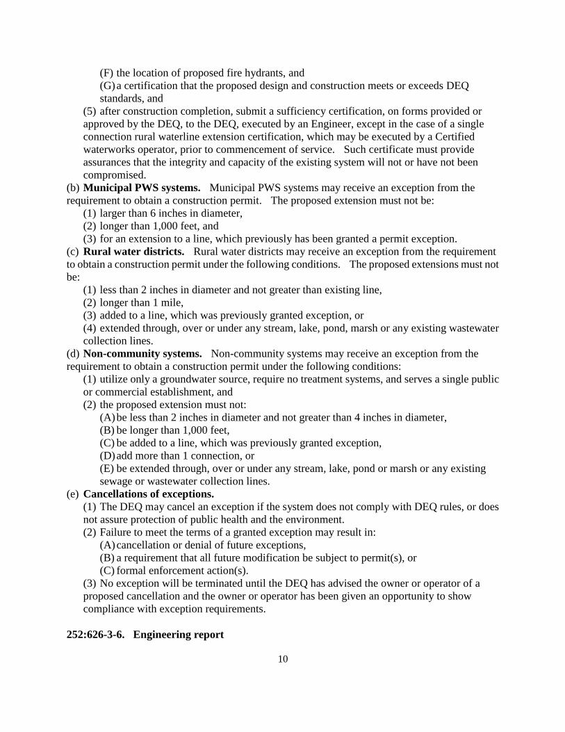
252:626-3-6. Engineering report
11
(a) Copies and timing. Submit 3 copies of an approvable engineering report as required in OAC
252:626-3-2 for proposed new construction or modifications to PWS systems, at least 30 days
prior to the submission of the application for a permit to construct.
(b) Purpose. The purpose of the report is to present the Engineer's findings with enough
attention given to detail(s) to allow adequate review of the project by the owner and applicable
regulatory agencies.
(c) Requirements. The report must include all information necessary for a comprehensive
evaluation of the proposed construction. The report must present, at a minimum, the following:
(1) General information. Include the following:
(A) a description of existing water works and wastewater facilities,
(B) identification of the municipality or area served,
(C) name and mailing addresses of the owner and official custodian,
(D) a statement as to whether the project will be constructed in phases. If the project is to
be constructed in phases, the statement will include the number of phases necessary to
complete the project and which portions of the project will be completed in each phase,
(E) a demonstration that adequate capacity, treatment and compliance with the primary
drinking water standards are maintained during construction,
(F) a letter from the permittee approving the contents contained in the engineering report as
submitted,
(G) a map showing legal and natural boundaries of entire service area, and
(H) a map showing new service areas or annexed areas.
(2) Extent of water works system. Include the following:
(A) a description of the area to be served,
(B) provisions for extending the waterworks system,
(C) establish the anticipated design average and peak flows for existing and potential
industrial, commercial, institutional and other water supply needs for both the current
service area and potential future service areas,
(D) a hydraulic analysis that demonstrates that a minimum of 25 psi shall be met at all times
throughout the distribution system, and
(E) a site plan and schematic layout of treatment facilities.
(3) Alternate plan. Where feasible and practical, provide a minimum of 3 alternative
solutions and discuss the alternatives, including cost estimates and reasons for selecting the
one recommended.
(4) Soil, ground water conditions, and foundation problems. The report must include a
description of the following:
(A) the character of the soil where water mains are to be laid,
(B) soil conditions, which might affect foundations of proposed structures, and
(C) the approximate elevation of ground water in relation to subsurface structures.
(5) Water use data. Provide the following water use data:
(A) a description of the population trends as indicated by available records, and the
estimated population which will be served by the proposed water supply system or
expanded system,
(B) present water consumption of existing systems and the projected average and
maximum daily demands that were used as the basis of the design, and
(C) present or estimated yield of supply source(s) along with a copy of the water rights
12
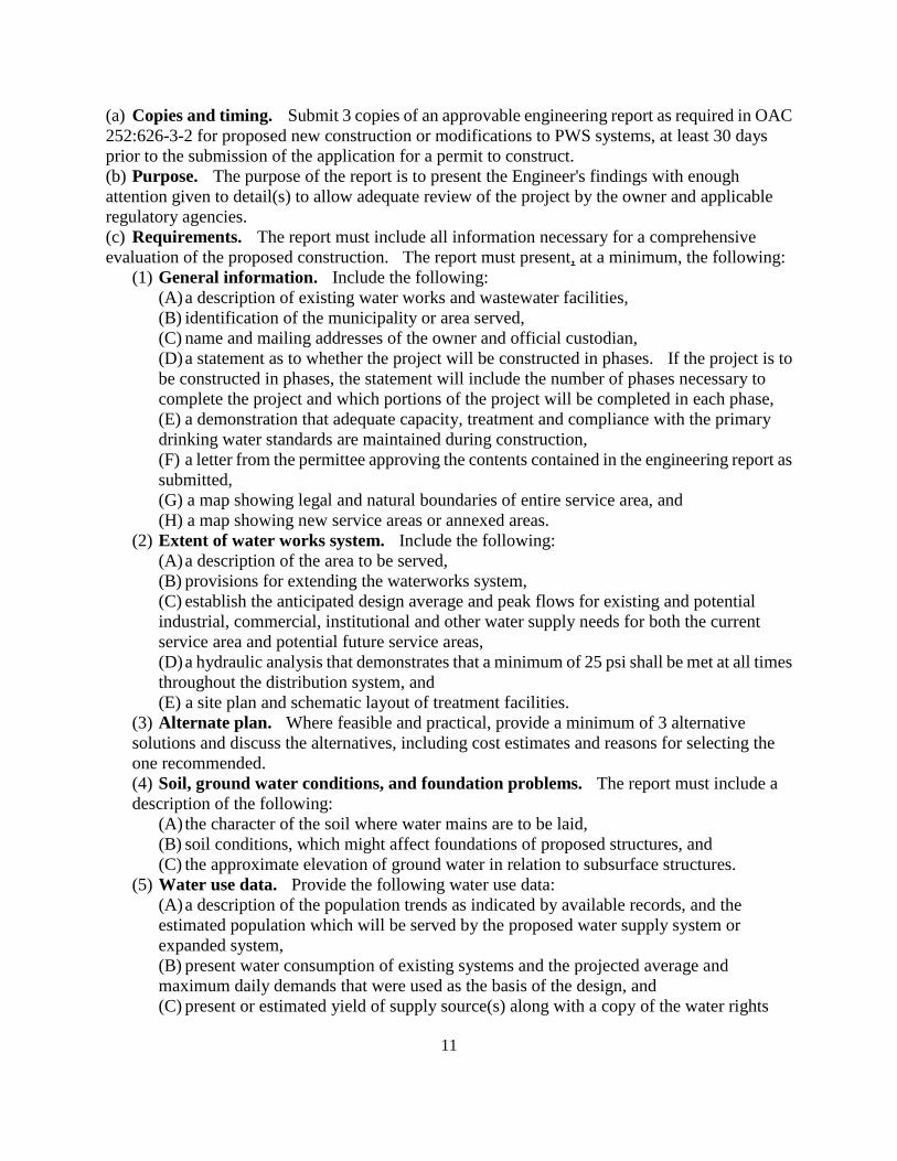
verification form and/or the purchase water contract.
(6) Fire flow requirements. Demonstrate that the plans meet the requirements regarding fire
flows pursuant to the International Fire Code, published by the International Code Council,
Inc., 2003 Edition, Distribution System Requirements for Fire Protection, M 31, published by
the AWWA, 3rd
Edition or other recommendations of similar organizations for the fire service
area.
(7) Sewer system available. Describe the methods of disposal for sanitary and all other
wastewater from the treatment plant.
(8) Sources of water supply. For the alternative chosen, the report must describe the
proposed source or sources of water supply to be developed, the reasons for their selection, and
provide information required by OAC 252:626-7 and the following:
(A) surface water sources, including:
(i) hydrological data, stream flow and weather records,
(ii) safe yield, including all factors that may affect it,
(iii)maximum flood or pool elevation,
(iv) description of watershed, noting any existing or potential sources of
contamination which may affect water quality, and
(v) quality of the raw water with special reference to fluctuations.
(B) ground water sources, including:
(i) sites considered,
(ii) advantages of the site selected,
(iii)elevations with respect to surroundings,
(iv) character of formations through which the source is to be developed,
(v) geologic conditions affecting the site,
(vi) summary of exploration; test well depth and method of construction; placement of
liners or screen; test pumping rates and duration; water levels and specific capacity;
chemical and radiological quality of the water,
(vii) sources of possible contamination including but not limited to wastewater
collection and treatment facilities, landfills, outcroppings of consolidated
water-bearing formations, waste disposal wells, slush pits, irrigation wells and
abandoned wells, and
(viii) industrial and other private water supply. Where pertinent, use significant ground
water developments within a 1 mile radius of the proposed ground water source, giving
depths, size, protective casing depth, capacity, location, type and any available
information pertaining thereto.
(9) Proposed treatment processes. Summarize and determine the adequacy of proposed
processes and unit parameters for the treatment of the water under consideration. Pilot studies
may be required for innovative design. Post treatment for membrane systems shall be in
accordance with OAC 252:626-9-9 (f)(6).
(10) Residuals management. Submit a Residuals Management Plan that discusses the
wastes and volume generated by existing and proposed water treatment processes, their
volume, proposed treatment of waste products, points of discharge or method of disposal or
land application.
(11) Project sites. Address the following in the report:
(A) discussion of various sites considered and advantages of those recommended,
13
(B) the proximity of residences, industries, and other establishments, and
(C) any potential sources of pollution that may influence the quality of the supply or
interfere with effective operation of the water works system, including but not limited to,
absorption systems, septic tanks, privies, sink holes, sanitary landfills, refuse and garbage
dumps.
(12) Cost estimates. Address the following in the report:
(A) estimated cost of integral parts of the system,
(B) detailed estimated annual cost of operation, and
(C) proposed methods to finance both capital charges and operating expenses.
(13) Future extensions. Summarize future needs and services.
252:626-3-7. Plans and specifications (a) Plans and specifications must address the entire project pursuant to the approved engineering
report as required in OAC 252:626-3-2. If the applicant plans to phase construction, the approved
engineering report shall contain a description of each phase of the project and the sequence of
construction to ensure continuity of the system and that adequate capacity will be available for
each phase.
(b) All detailed plans must be legible and drawn to a suitable scale. Plans for modifications or
extensions to existing systems or plants must indicate clearly the connections or relation. Include
the following:
(1) A general layout sheet that includes:
(A) title and date,
(B) name of municipality, rural water district, or other entity or person who owns the
system,
(C) area or institution to be served,
(D) scale, in feet,
(E) north point,
(F) data used,
(G) boundaries of the municipality, rural water district, or area to be served,
(H) name, telephone number, and address of the designing engineer,
(I) the Engineer's seal and signature,
(J) location and size of existing water mains, and
(K) location and nature of existing water works structures and appurtenances affecting the
proposed improvements.
(2) Detailed sheets that include:
(A) stream crossings with profiles of the stream bed showing the normal, high and low
water levels,
(B) profile sheets with a horizontal scale of not more than 100 feet to the inch and a
vertical scale of not more than 10 feet to the inch. Both scales must be clearly indicated.
A smaller horizontal scale may be used for rural water distribution systems, but in no case
smaller than 500 feet to the inch. Plans with contour intervals of 10 feet or less may be
provided in lieu of profiles,
(C) dimensional boundaries of property intended for ground water development. Show
location with respect to known references such as street intersections or section lines,
(D) topography and arrangement of existing and proposed wells or structures, with contour
14
intervals not greater than 2 feet. Contour intervals of greater than 2 feet can be used for
water line plans. Contour intervals cannot be greater than 10 feet,
(E) elevations of the highest known flood level, floor of the structure, upper terminal of
protective casings and outside surrounding grade, using Federal Emergency Management
Agency (FEMA) or equivalent elevations as reference,
(F) drawings of well construction, showing diameter and depth of drill holes, casing and
liner diameters and depths, grouting depths, elevations and designation of geological
formations, water levels and other details to describe the proposed well completely,
(G) location of all existing and potential sources of pollution within 300 feet of the raw
water source and within 100 feet of underground treated water storage facilities,
(H) size, length, and identity of sewers, drains, and water mains near the proposed water
works,
(I) schematic flow diagrams and hydraulic profiles showing the flow through plant units,
(J) piping in sufficient detail to show flow through the plant, including waste lines, and
locations of all sampling taps,
(K) locations of all chemical feeding equipment and points of chemical application,
sanitary and other facilities, including but not limited to lavatories, showers, toilets, and
lockers,
(L) all appurtenances, specific structures, equipment, water treatment plant waste disposal
units and points of discharge,
(M) locations, dimensions and elevations of all proposed and existing plant units,
(N) adequate description of any features not otherwise covered by the specifications,
(O) location of all valves, and
(P) location of all storage tanks, including the capacity of the tanks and top and bottom
elevations.
(c) Specifications must:
(1) supply complete, detailed, technical specifications for all parts of the proposed project,
including a program for keeping existing water works facilities in operation during
construction of additional facilities,
(2) cover in detail materials to be used, methods of making or drilling well(s), dimensions,
depth, straightness of the hole, required logs, tests, records, locations of water formations,
grouting or cementing, shooting and final testing of the well(s), for ground water systems,
(3) provide supporting data regarding reliability of operation, maintenance and operator
training, if automatic equipment is proposed. Provide manual override for any automatic
controls;
(4) be written so that a representative of the manufacturer will check the installation and
supervise initial operation of the major items of mechanical equipment and pumps,
(5) provide complete sets of all special tools and accessories required for operation and
maintenance, together with parts lists, and operation and maintenance manuals for each piece
of mechanical equipment, and
(6) provide for an Operation and Maintenance (O & M) Manual for the operation and
maintenance of the public water supply system. The O & M Manual shall include at a
minimum:
(A) System Treatment Requirements;
(B) Description, Operation and Control of the Water Treatment Plant;
15
(C) Control of Unit Processes;
(D) Laboratory Testing;
(E) Common Operating Problems;
(F) Start-Up Testing and Procedures;
(G) Standard Operating Procedures;
(H) Alternative and Emergency Operations;
(I) Emergency Shutdown Operations and Emergency Response;
(J) Records Control and Retention;
(K) Safety;
(L) Public Water Supply System Maintenance Records;
(M) Stormroom and Inventory System; and
(N) Utilities.
(d) File as-built plans (plans of record) which identify any changes to the DEQ approved plans and
specifications and an Engineer's certification that the construction was completed according to the
requirements of this Chapter within 6 months after the project is completed.
252:626-3-8. Variances from construction standards (a) The policy of DEQ is to encourage better water treatment methods and equipment, including
the use of new technology. DEQ may approve processes or equipment not specifically covered
by the standards in this Chapter provided the permittee requests a variance. A variance from the
standards in this Chapter may be allowed, upon the request of the applicant, if the DEQ finds the
variance will not increase the likelihood of a system failure. No variance will be allowed unless it
is noted on the construction permit.
(b) The consulting engineer shall justify the requested variance by submitting data showing the
proposed processes or equipment will equal or exceed the performance of processes or equipment
known to perform the same function according to the standards contained in this Chapter. Variance
requests shall include the following:
(1) monitoring observations including:
(A) test results and engineering evaluations, and
(B) data from existing installations that demonstrate the efficiency of the proposed
processes or equipment;
(2) a detailed description of the test methods;
(3) other information as requested by DEQ. The DEQ may require that pilot studies and
appropriate testing be conducted and evaluations be made under the supervision of a
competent process engineer other than one employed by the manufacturer or developer;
(4) if required under (c) of this Section, a copy of the supplier's bond or warranty/guarantee;
and
(5) if required under (d) of this Section, a copy of the bond or contract provided by the
engineer.
(c) Suppliers' bonds and warranties/guarantees. Suppliers of processes or equipment not
covered by the standards in this Chapter shall be required to post a performance bond or provide a
warranty or guarantee in the event that the processes or equipment fail.
(1) Performance bonds. Performance bonds shall:
(A) be made payable to the permittee in an amount equal to the contract price for the
installed processes or equipment plus ten percent (10%);and
16
(B) remain in effect for at least one (1) year after the processes or equipment are placed into
operation.
(2) Warranties/guarantees. Warranties and guarantees shall:
(A) be made payable to the permittee in an amount equal to the contract price for the
installed processes or equipment plus ten percent (10%); and
(B) remain in effect for at least one (1) year after the processes or equipment are placed into
operation.
(d) Engineers' bond or contractual agreement. Engineers proposing processes or equipment
not covered by the standards in this Chapter will be required to either:
(1) post a performance bond made payable to the permittee in an amount sufficient to cover the
cost of any engineering services necessary to replace the installed processes or equipment with
processes or equipment that conform with the requirements of this Chapter; or
(2) enter into a contractual agreement with the permittee wherein the engineer agrees to
provide engineering services necessary to replace any failed processes or equipment with
processes or equipment that conform with the requirements of this Chapter.
252:626-3-9. Construct according to plans and specifications Applicants must construct facilities according to the plans and specifications that are approved.
Applicants must comply with the terms of the permits that are issued. Permits may contain
provisions more stringent than these rules in order to meet drinking water standards contained in
OAC 252:631. Any changes to the approved plans and specifications must be submitted and
approved in writing by the DEQ. The permittee and the Engineer must sign the documentation.
252:626-3-10. Permit fees (a) Permits will not be issued until all fees are paid. Applicants may enter into a monthly billing
agreement with the DEQ.
(b) Fees for water treatment facility construction permit applications are as follows:
(1) New facilities and major modifications that alter the original design or the design capacity:
(A) Non-community systems (new) - $722.00
(B) Community systems (new)
(i) less than 10 MGD - $2,910.00
(ii) 10 MGD or greater design flow - $5,825.00
(2) Modifications of existing water treatment systems:
(A) Chemical feed system (not including disinfection) - $440.00
(B) Minor modifications that will not alter the design capacity of the facility such as flow
measurement, chlorine contact basins, disinfection and back-up power - $1,455.00
(C) Major modifications that alter the original design or the design capacity of the
treatment plant - $2,910.00
(3) Supply facilities:
(A) Well(s) - $580.00 each (maximum $2.910.00)
(B) Storage Tanks - $440.00 each
(C) Raw water transmission lines - $440.00
(D) Chlorination (ground water system) - $440.00
(4) Distribution system improvements:
(A) Line extensions (rounded to the nearest one hundred feet (100') - $150.00 for the initial
17
one to five hundred feet (1-500') plus $28.50 for each additional one hundred feet (100')
with a maximum total line extension fee of $5,825.00.
(B) Booster station(s) - $440.00 each
(C) Municipalities that utilize the alternative permitting process described in 252:626-3-4
shall submit payment to DEQ for twenty percent (20%) of the total fee calculated in (A)
and (B) of this paragraph. This fee may be paid upon submission of plans, or on a monthly
or quarterly basis.
(5) Permit Exemption - $100.00
(c) REAP (Rural Economic Assistance Program) and emergency grant projects (PWS systems
funded in whole by grant monies made available through the Oklahoma Water Resources Board as
authorized by 82 O.S. § 1085.39) are exempt from permit fees. Projects partially funded by
REAP and emergency grant projects may be exempt from a portion of the permit fees by the
percentage said funding is providing for the total cost of the project.
(d) Individual household well inspection - $200.00 each.
(e) To assist in meeting rising costs to the Department for implementing the Public Water Supply
Construction Standards program, the fees set out in (b) and (d) of this Section shall be
automatically adjusted on July 1st every year to correspond to the percentage, if any, by which the
Consumer Price Index (CPI) for the most recent calendar year exceeds the CPI for the previous
calendar year. The Department may round the adjusted fees up to the nearest dollar. The
Department may waive collection of an automatic increase in a given year if it determines other
revenues, including appropriated state general revenue funds, have increased sufficiently to make
the funds generated by the automatic adjustment unnecessary in that year. A waiver does not
affect future automatic adjustments.
(1) Any automatic fee adjustment under this subsection may be averted or eliminated, or the
adjustment percentage may be modified, by rule promulgated pursuant to the Oklahoma
Administrative Procedures Act. The rulemaking process may be initiated in any manner
provided by law, including a petition for rulemaking pursuant to 75 O.S. § 305 and 252:4-5-3
by any person affected by the automatic fee adjustment.
(2) If the United States Department of Labor ceases to publish the CPI or revises the
methodology or base years, no further automatic fee adjustments shall occur until a new
automatic fee adjustment rule is promulgated pursuant to the Oklahoma Administrative
Procedures Act.
(3) For purposes of this subsection, "Consumer Price Index" or "CPI" means the Consumer
Price Index - All Urban Consumers (U.S. All Items, Current Series, 1982-1984=100,
CUUR0000SA0) published by the United States Department of Labor. The CPI for a calendar
year is the figure denoted by the Department of Labor as the "Annual" index figure for that
calendar year.
SUBCHAPTER 5. GENERAL DESIGN
Section
252:626-5-1. Plant layout
252:626-5-2. Building layout
252:626-5-3. Flood protection
18
252:626-5-4. Security protection
252:626-5-5. Standby power and elevated storage
252:626-5-6. Laboratory facilities
252:626-5-7. Monitoring equipment
252:626-5-8. Sample taps
252:626-5-9. Facility water supply
252:626-5-10. Sanitary facilities
252:626-5-11. Piping and conduits
252:626-5-12. Piping color code
252:626-5-13. Disinfection
252:626-5-14. Treatment unit and piping configuration
252:626-5-15. Cross connections and interconnections
252:626-5-1. Plant layout Include the following in the approvable plans:
(1) functional aspects,
(2) provisions for expansion where applicable,
(3) provisions for WTP residuals treatment and disposal,
(4) site grading and drainage,
(A) prevent surface water from standing within 50 feet of any facility,
(B) disposal of surface water without danger of flooding any facility,
(5) provisions for access roads, walks, driveways and chemical delivery and handling,
(6) provisions for containment and disposal of overflow from tanks and other facilities,
(7) provisions for cleaning of facilities and disposal of cleaning waste, and
(8) provisions for disposal of sanitary waste.
252:626-5-2. Building layout Include the following in the approvable plans:
(1) adequate ventilation, lighting, heating, drainage and dehumidification,
(2) accessibility of equipment for operation, servicing, and removal,
(3) flexibility and convenience of operation and operator safety,
(4) chemical storage and feed equipment in separate rooms, and
(5) adequate facilities for shop space, laboratory space, and storage.
252:626-5-3. Flood protection Locate all structures and mechanical and electrical equipment above the 100-year flood plain
unless other protective measures are provided. Do not locate any structure in a flood way.
252:626-5-4. Security protection Public water supply systems shall provide the following security measures to protect water
treatment plants, finished water storage facilities (which include laboratories, chemical buildings,
administration buildings and storage buildings):
(1) Fencing at least six (6) feet high of galvanized steel chain link, number nine gauge with
two inch or smaller diameter mesh, and posts not more than ten feet (10') separation
center-to-center in post-holes at least thirty inches (30") deep, back-filled with concrete that
19
extends two inches (2") above grade and crowned to shed water;
(2) Three-strand barbed wire shall be installed atop the fence along its entire length;
(3) Gates shall be constructed of similar material as the fence or stronger;
(4) "No Trespassing" signs shall be installed at least at fifty foot (50') intervals along the entire
length of the fence and at the location of all intake structures. The signs shall contain the
following information:
(A) "Tampering with a Public Water Supply is a federal crime", and
(B) "If you see a problem contact the following:
(i) Contact name,
(ii) Contact address,
(iii) Contact phone number"; and
(5) Locks shall be installed on all gates, entry doors, manholes, other access points, water
wells and pumping stations. Electric gates shall be considered equivalent to locked gates.
252:626-5-5. Standby power and elevated storage If 24 hours of elevated distribution storage based on average daily demand is not available,
provide all plants with portable or in-place internal combustion engine equipment which will
generate electric power to allow continued operations, at peak hourly demand, during a power
failure.
252:626-5-6. Laboratory facilities Each public water supply must have its own equipment and facilities for routine laboratory
testing necessary to ensure proper operation. Provide methods for verifying adequate quality
assurances and for routine calibration of the equipment.
(1) Testing equipment. Laboratory equipment and facilities must be compatible with the
raw water source, intended use of the treatment plant and the complexity of the treatment
process involved. The laboratory must have enough equipment to perform operating control
tests set forth in OAC 252:631 and provide the following laboratory equipment:
(A) a pH meter, jar testing equipment, a nephelometric turbidimeter, and titration
equipment for both hardness and alkalinity for surface water treatment plants utilizing
flocculation and sedimentation, including those that soften the water with lime,
(B) a pH meter and titration equipment for both hardness and alkalinity for ion exchange
softening plant and lime softening plant treating only ground water,
(C) for iron and manganese removal plants, test equipment capable of accurately
measuring:
(i) iron to a minimum of 0.1 mg/l, and/or
(ii) manganese to a minimum of 0.05 mg/l,
(D) test equipment for determining both free and total chlorine residuals for PWS systems
that chlorinate,
(E) test equipment for determining fluoride concentration for PWS systems that fluoridate
or that treat or use blending for the reduction of naturally occurring fluoride, and
(F) test equipment capable of accurately measuring phosphates from 0.1 to 20 mg/l for
PWS systems that feed polyphosphate or orthophosphate.
(2) Physical facilities. Provide sufficient bench space, adequate ventilation, lighting, storage
space, laboratory sinks, and auxiliary facilities.
20
252:626-5-7. Monitoring equipment (a) Provide accurate and dependable flow measuring devices, equipped with totalizers, for
measuring the raw and finished water flow. Make provisions for manual verification of
measuring devices.
(b) For plants treating surface water, groundwater under the direct influence of surface water or
using lime for softening, provide equipment to monitor and record turbidity, free chlorine residual,
water temperature and pH at locations necessary to evaluate CT disinfection.
(c) for plants treating ground water using iron removal or ion exchange softeners, provide
monitoring and recording equipment for free chlorine residual.
(d) For plants treating or blending water for the reduction in the concentration of nitrates, provide
a test kit, used at least daily prior to the regeneration of the unit, to determine the finished water
nitrate/nitrite levels.
252:626-5-8. Sample taps Provide for sample taps in the approvable plans:
(1) for each raw water source,
(2) from each treatment unit, including on each filter, located to obtain representative samples
of unit contents,
(3) from finished water storage, and
(4) that are the smooth-nosed type without interior or exterior threads, and do not have a
screen, aerator, or other such equipment.
252:626-5-9. Facility water supply Provide potable water to the facility in the approvable plans.
252:626-5-10. Sanitary facilities Provide a toilet and lavatory equipped with hot water in the approved plans. Connect or
construct the wastewater system to a system either permitted or authorized pursuant to OAC
252:641 or OAC 252:656.
252:626-5-11. Piping and conduits (a) Design all piping and channels to carry the maximum design capacity of the treatment facility.
Clearly, show the design flow characteristics on the hydraulic profile sheet of the plans.
(b) Do not place treated water lines in a trench with sewers, plant wastewater lines, lines carrying
raw or partially treated water, or other utility lines. Do not locate lines carrying partially treated
water in a common trench or in close proximity to sewer or drain lines.
(c) No common wall is allowed between any channel, basin or reservoir containing raw or
partially treated water and another containing filtered water.
252:626-5-12. Piping color code (a) To facilitate identification of piping in plants and pumping stations use the color scheme
provided in Appendix A or otherwise clearly identify all piping.
(b) In situations where 2 colors do not have sufficient contrast to easily differentiate between
them, paint a 6-inch band, of contrasting color on one of the pipes at approximately 30-inch
21
intervals, and name of the chemical on the pipe.
252:626-5-13. Disinfection Disinfect all wells, pipes, tanks, and equipment that can convey or store potable water in
accordance with AWWA standard specifications prior to being placed into service. Plans or
specifications must outline the procedure and include the disinfectant dosage, contact time,
residual and method of testing.
252:626-5-14. Treatment unit and piping configuration (a) Where multiple treatment units are provided, the piping configuration must allow each
treatment unit to be taken out of operation without disturbing the treatment process.
(b) Do not allow a bypass between raw or partially treated water lines and lines or basins
containing filtered water.
252:626-5-15. Cross connections and interconnections (a) Cross connections. Avoid cross connections in the system.
(1) Do not allow a physical connection between a line carrying a public drinking water supply
and a line carrying water of unknown or questionable quality.
(2) Do not allow connections from any PWS system to any device or system that poses a health
threat unless it is equipped with an air gap of at least 6 inches or two pipe diameters, whichever
is larger, above the overflow or drain pipe. The installation of a reduced pressure zone
backflow prevention device will be considered in lieu of an air gap. To allow maintenance on
the backflow prevention device, the design shall include a diversion line with equal backflow
prevention. Do not locate backflow prevention devices in a pit or vault where they can
become submerged. A fire suppression system is not considered a hazardous water supply.
(3) Do not allow a cross-connection between a public water system and any private water
system.
(4) Provide an air gap at all points where finished water is discharged to a drain.
(b) Cooling water. Designs proposing the return of steam condensate, cooling water from
engine jackets or other heat exchange devices are not allowed by the DEQ.
(c) Interconnections. Obtain approval from the DEQ for interconnections between potable
water supplies.
(d) Water loading stations. To prevent contamination of the PWS, provide the following:
(1) a device on the fill line to provide an air break and prevent submerging the line,
(2) construct the fill line and cross connection control device so that when hanging freely it
will terminate at least 2 feet above the ground surface, and
(3) the discharge end of the fill line must be unthreaded or constructed to prevent the
attachment of additional line, piping or other appurtenances.
(e) Chemical feed equipment. Provide cross-connection control to assure that:
(1) service water lines discharging to solution tanks or pots are protected from backflow.
Provide a minimum 6-inch air gap between the end of the service water line and the spill line of
the solution tank. An air gap of less than 6 inches in conjunction with an approved backflow
preventer is acceptable,
(2) no direct connection will occur between any sewer and a drain or overflow from the feeder,
solution chamber or tank by terminating all drains at least 6 inches or 2 pipe diameters,
22
whichever is greater, above the overflow rim of a receiving sump, conduit or waste receptacle,
and
(3) discharge all drain and overflows from feeder(s), solution chamber(s), and tank(s) that
discharge to sanitary sewers through a sump. Terminate drain and overflow lines a minimum
of 6 inches or 2 pipe diameters whichever is greater above the overflow rim of the sump.
(f) Piping. Design and install all piping to eliminate possible back-siphonage in conformity with
the latest American Standards Association, Recommended Practice for Backflow Prevention and
Cross-Connection Control, Manual of Water Supply Practices, —14, 3rd
Edition, 2004. Provide
an air gap for all filter-to-waste connections. Filter pipe gallery floors and pump rooms must be
protected from flooding by backflow from filter waste lines, sewers or drains.
SUBCHAPTER 7. SOURCE DEVELOPMENT
Section
252:626-7-1. Source development
252:626-7-2. Surface water
252:626-7-3. Springs and dug wells
252:626-7-4. Ground water
252:626-7-5. Purchase water
252:626-7-6. Raw water supply conduit
252:626-7-1. Source development (a) General. The Engineer must submit documentation to DEQ demonstrating that an adequate
quantity of water will be available, and that water to be delivered to consumers will meet or exceed
current drinking water standards. The applicant must obtain necessary water rights and
withdrawal permits from the Oklahoma Water Resources Board.
(b) Demand. Investigate and document the requirements for each system and include past water
use records revised to conform to anticipated growth and conditions.
(c) Continued protection. Provide continued protection of the source from potential sources of
contamination through ownership, zoning, easements, leasing, or other means.
(d) Source water assessment. Perform a source water assessment of the factors, both natural
and manmade, which will potentially affect quality, including but not limited to:
(1) determining possible future uses of impoundments or reservoirs,
(2) determining degree of control of watershed by owner, including necessity of ordinance to
protect watershed from contamination,
(3) assessing degree of hazard to the supply by accidental spillage or other deposition of
materials that may be toxic, harmful or detrimental to treatment processes,
(4) obtaining samples over a sufficient period to assess the microbiological, physical, chemical
and radiological characteristics of the water,
(5) assessing the capability of the proposed treatment process to reduce contaminants to
applicable drinking water standards, and
(6) status of compliance with state and local reservoir sanitation law.
252:626-7-2. Surface water
23
A surface water source includes all streams, natural lakes, springs, and artificial reservoirs or
impoundments within the drainage basin above the point of intake.
(1) Quantity.
(A) The quantity of water must be adequate to:
(i) meet the projected water demand, including anticipated growth of the service area
as shown by calculations based on the extreme recorded drought, and
(ii) compensate for losses such as silting, evaporation, seepage, etc.
(B) Criteria for evaluating adequacy are outlined below:
(i) where water is drawn from a flowing stream, the minimum recorded stream flow,
less water demand of other users, plus off-stream storage must exceed the estimated
future water demand, and
(ii) where water is drawn from a reservoir or lake, the average inflow for a period
including the driest recorded period plus the effective storage capacity must exceed the
estimated future demand for the maximum recorded drought period.
(2) Quality.
(A) Bacterial quality.
(i) Waters containing coliform bacteria counts averaging less than 5,000 per 100 ml in
any 1 month and not exceeding this number in more than 20 percent of samples
examined in the same month require flocculation, sedimentation, filtration, and
disinfection.
(ii) Waters that contain coliform bacteria counts exceeding 5,000 per 100 ml in over 20
percent of samples examined during any 1 month, but less than 20,000 per 100 ml in
over 5% of the samples examined in the same month, require pre-sedimentation,
flocculation, sedimentation, filtration, disinfection, or at least 30 days of off-stream
storage.
(iii)Waters that contain coliform bacteria counts in excess of 20,000 per 100 ml in more
that 5% of the samples examined in any 1 month are considered unsuitable for use as a
source water supply unless they can be brought into conformance by prolonged
preliminary storage or other reliable means.
(B) Physical quality. Surface water containing an excessive amount of suspended
material requires pre-sedimentation and possibly other preliminary treatment prior to
conventional treatment.
(3) Hydrologic studies.
(A) Use stream flow and weather records for contributing or adjacent watersheds for
estimating the safe yield of a source. Empirical formulas and ratios in published literature
are not satisfactory criteria for judging the adequacy of a source unless supported by
hydrologic data obtained from the specific watershed.
(B) Perform a study of all hydrologic factors that affect and determine the safe yield of a
proposed surface water supply. Use data from the U.S. Weather Bureau, the U.S.
Geological Survey or Climatological Survey to estimate watershed run-off.
(4) Safe yield. When the demand for water is greater than the minimum rate of flow in the
stream from which the water is to be taken, an impounding reservoir is required. Evaluate the
factors disclosed by the hydrologic data by the use of a mass diagram or other equivalent
method and include in the design report.
(5) Reservoir and lake sanitation. Protection of the watershed is required for municipal
24
water supply reservoirs. Control the marginal shoreline land by purchase or ordinance. The
ordinance must describe the water district boundaries and enforcement rules for the protection
of the water supply and include but not be limited to:
(A) regulating the public health aspects of water supply, waste and sewage disposal, and
recreational activities,
(B) regulating the building of structures within the controlled area,
(C) regulating aquatic activities involving body contact with the water, and
(D) clearing of timber, brush and debris.
(6) Off-stream reservoirs.
(A) Provide for site preparation where applicable:
(i) removal of brush and trees to high water elevation,
(ii) protection from floods during construction, and
(iii)plugging of all wells which will be inundated, in accordance with OWRB
requirements.
(B) Restrict body contact recreational activities wherever water quality or public health
may be adversely affected.
(7) Intake structures.
(A) General. Intake structure design must provide for:
(i) location of the structure an adequate distance from existing or potential source(s) of
pollution to protect the water quality,
(ii) location of the structure to obtain the best quality of raw water,
(iii) the intake to meet the ultimate capacity of the water treatment plant,
(iv) release of undesirable water to prevent it from entering the treatment plant,
(v) temporary barriers to allow dewatering for inspections and maintenance,
(vi) protection against damage to the structure caused by dragging anchors, etc.,
(vii) ports located above the bottom of the stream, lake or impoundment, but at
sufficient depth to be kept submerged at low water level,
(viii) where shore wells are not provided, a diversion device capable of keeping fish or
debris from entering intake structure,
(ix) the operating floor must be above the 100-year flood level and be accessible at all
times, and
(x) in the case of Zebra mussel presence, an infiltration gallery may be used. See
Appendix B for design guidelines.
(B) River intakes.
(i) Site. Locate intakes so that a continuous supply of water is ensured.
(ii) Headworks structure. Design the intake to protect pumps from sand and to
minimize silting or obstruction by deposits of bed load. If the headworks are
constructed on permeable material, the design must take into account the anticipated
effect of underflow and hydrostatic uplift pressure.
(C) Reservoir or lake intakes. Locate inlets or gates in the intake structure so they are
accessible for inspection and maintenance.
(i) Fixed inlet structures. Design intake structure for water withdrawal from at least
three (3) separate levels of the lake or reservoir. Install the top inlet below the water
surface at normal pool elevation.
(ii) Floating structures. Design for water withdrawal at selected depths. Multiple
25
length suction pipes, provisions for addition or removal of extension pipe to the pump
suction are acceptable design. Other designs will be considered on a case-by-case
basis.
(8) Trash racks and screens. Provide a trash rack or screen at the inlets to any intake
structure. The port area design must limit the net velocity through the racks to not more than
2 ft/s during normal operation for bar racks having 1-1/2 inch spacing and larger, and must not
exceed 0.5 ft/s for fine screens of ½-inch. Precede fine screens with coarse screens or bar
racks. Use mechanical rakes or other devices to clean the bars. On small intakes, hand rakes
can be used.
(9) Shore wells. Shore wells must:
(A) have electrical controls protected from flooding,
(B) be accessible during a 100-year flood,
(C) be designed to resist flotation,
(D) be equipped with removable or traveling screens before the pump suction well,
(E) provide for chemical introduction into the raw water transmission main,
(F) be equipped with intake valves and provisions for backflushing or cleaning, and
(G) have provisions for withstanding surges.
(10)Infiltration lines as a raw water source.
(A) Infiltration lines may be used where geological conditions preclude the possibility of
developing an acceptable drilled well.
(B) The water supplier must control the area around infiltration lines for a minimum
distance of 600 feet from the lines.
(C) Flow in the lines must be by gravity to the collecting well.
(D) Water from infiltration lines is considered surface water and treatment equivalent to
surface water supplies is required.
(11) Off stream reservoirs. When constructing an off stream reservoir, assure that:
(A) water quality is protected by controlling runoff into the reservoir,
(B) dikes are structurally sound and protected against erosion,
(C) intake structures and devices meet requirements of this chapter, and
(D) point of influent must be separated from the point of withdrawal.
252:626-7-3. Springs and dug wells (a) General. Springs and dug wells are considered under the influence of surface water and
require treatment equivalent to surface water supplies.
(b) Site protection. Protect the spring or dug well at the point of intake from run-off water,
sewage disposal and other sources of contamination. Provide the following:
(1) suitable grading and drainage to drain water from the site, and
(2) industrial-type wire fence with locked gate surrounding the site.
(c) Intake structure or receiving tank for springs only.
(1) Provide an intake structure or receiving tank to store and regulate water flow prior to
treatment and distribution. Provisions of OAC 252:626-17 are applicable in the construction
of the receiving tank.
(2) Provide an overflow pipe with enough capacity to discharge excess water equal to the
spring flow.
(3) Provide a gravel pack to keep sand and deposits in the spring water from entering the tank.
26
252:626-7-4. Ground water (a) A ground water source includes all water obtained from drilled, bored or driven wells. A test
well is required where sufficient information is not available to assure adequate quality and
quantity of water.
(1) Quantity.
(A) Provide a minimum of 2 wells for community water systems unless a standby source
with adequate capacity is available.
(B) Where ground water is the sole supply source for a community water system, the total
developed ground water capacity must equal or exceed:
(i) the design maximum day demand, and
(ii) the design average day demand, with the largest producing well out of service.
(2) Quality.
(A) Bacteriological quality.
(i) Underground waters subject to a low degree of contamination shall require
chlorination if:
(I) the coliform count averages not more than 50 per 100 ml in any 1 month, and
(II) the turbidity does not exceed 5 NTU.
(ii) Disinfect every new, modified or reconditioned ground water source according to
AWWA standard specifications after the completion of work and placement of
permanent pumping equipment.
(iii) Upon completion of the well, collect at least 2 bacteriologically safe samples on
consecutive days. Collect samples after chlorine used in disinfecting the well has
been completely dissipated. Submit the records to the DEQ.
(iv) If any samples show the presence of coliform bacteria, take additional samples to
determine the degree of contamination and treatment required.
(B) Physical, chemical, and radiological quality.
(i) Test every new, modified, or reconditioned ground water source for applicable
physical, chemical, and radiological characteristics contained at OAC 252:631-3-1 by
submitting a representative sample to a certified laboratory or the State Environmental
Laboratory and report results to the DEQ.
(ii) Collect samples at the conclusion of test pumping.
(iii) Additional field determinations or special sampling procedures may be required by
the DEQ.
(C) Test results. The results of the required testing shall be used to determine the extent
of water treatment required. If all parameters are in compliance with the standards set
forth in the Safe Drinking Water Act and OAC 252:631, no treatment will be required.
(3) Location. In the selection of a site:
(A) evaluate the following:
(i) type of well construction to be utilized,
(ii) depth to water bearing zones,
(iii) type of formations to be penetrated, and
(iv) proximity of existing or possible future sources of pollution such as sewers,
seepage pits, soil absorption fields, privies, sink holes, dumping areas, caves, test holes,
abandoned wells, borings, industrial lagoons, private water supply developments, fuel

27
storage tanks, and other underground construction,
(B) locate wells at the highest point of the premises consistent with other facilities and
surroundings but always protected against surface drainage,
(C) do not locate wells:
(i) in a ravine where the well site may be flooded or within 300 feet horizontally from
any existing or potential source of pollution including water bodies. If a wellhead
delineation model has been performed for the site, the separation distance must
conform to the model prediction for potential contamination,
(ii) within three hundred feet (300') of a proposed or existing sewer line,
(iii) within one hundred feet (100') of a private property line, or
(iv) within fifty feet of a publicly owned property line, and
(D) locate pump room floor at least 2 feet above the 100-year flood plain
(b) Testing and records. The permittee shall:
(1) provide yield and drawdown testing procedures for the well(s) in the plans and
specifications, approved by the DEQ, and make the results for completed wells available for
final inspection. Yield and drawdown tests must:
(A) be performed on every production well after construction or improvements, which
affect the well capacity, and prior to placement of the permanent pump,
(B) have test methods clearly indicated in specifications,
(C) determine well capacity with the pumping rate at maximum anticipated drawdown,
pumping rate must be at least 1.5 times the quantity anticipated,
(D) test pump the well at 1.5 times the design pumping rate for at least 24 hours or until the
drawdown has stabilized for a minimum of 6 hours, and
(E) provide the following test data to the DEQ prior to completion of the well:
(i) test pump capacity-head characteristics, and overall efficiency,
(ii) static water level and water level at design pumping rate,
(iii) depth of test pump setting,
(iv) time of starting and ending each test cycle, and
(v) zone of influence for the well(s).
(2) test the well for plumb and alignment in accordance with AWWA standard specifications.
The specifications must cite the AWWA standard and describe the method to be used.
(3) submit well logs that shall contain:
(A) samples collected at maximum 20-foot intervals and at each pronounced change in
formation,
(B) a record of drill hole diameters and depths, assembled order of size and length of
casings and liners, length of the perforated section and type of perforations, or type and
length of screen used, grouting depths, formations penetrated, water levels, and location of
any blast charges. Where multiple water bearing formations are developed, give the
elevation and length of each perforated or screened section.
(c) General well construction.
(1) Minimum depths of wells. Construct wells to a depth sufficient to ensure that safe water
can be obtained. Water taken from depths of 20 feet or less shall require additional testing to
determine the necessary level of treatment.
(2) Minimum protected depths. Protect wells by watertight construction to a depth
necessary to:
28
(A) exclude surface contamination, and
(B) seal off formations that are contaminated or yield undesirable water.
(3) Well surface casing. Every well shall have a watertight surface casing extending at least
20 feet below the surface. A greater depth will be required in unconsolidated soils, karst
formations or when necessary to eliminate contamination from the surface or upper
formations.
(A) Surface casing material. Surface casing shall only be made from ferrous material
and must:
(i) be new pipe meeting ASTM, AWWA, NSF or API specifications for water well
construction,
(ii) have minimum weights and thickness indicated in Appendix C,
(iii) be capable of withstanding forces to which it is subjected,
(iv) be equipped with a drive shoe when driven, and
(v) have full circumferential welds or threaded coupling joints.
(B) Internal casing materials. Internal casing material shall:
(i) meet AWWA standards,
(ii) meet NSF standards for contact with potable water,
(iii) be resistant to the corrosiveness of the water,
(iv) be able to withstand the stresses to which the well will be subjected during
installation, grouting and operation, and
(v) be equipped with a drive shoe when driven.
(4) Packers. Packers must be made from an NSF approved material
(5) Screens. Screens must:
(A) be constructed of materials resistant to damage by chemical action of ground water or
cleaning operations,
(B) have sizes of openings based on sieve analysis of formation and gravel pack materials
to permit maximum transmitting ability without clogging or jamming,
(C) have sufficient diameter to provide adequate specific capacity and low aperture
entrance velocity. The entrance velocity must not exceed 0.1 ft/s,
(D) be installed so that the pumping water level remains above the screen under all
operating conditions, unless measures are provided to protect the screen from being
corroded, and
(E) be provided with a bottom plate or washdown bottom fitting of the same material as the
screen, where applicable.
(6) Grouting requirements. Surround surface casing with a minimum of 1-½ inches of
grout to the depth of the surface casing.
(A) Cement grout.
(i) Cement conforming to ASTM Standard C150, with not more than 6 gallons of
water per 94 pound sack of cement, must be used for 1-½ inch annular openings.
(ii) Additives used to increase fluidity are subject to approval by the DEQ.
(B) Concrete grout.
(i) Equal parts of cement conforming to ASTM Standard C150, and sand, with not
more than 6 gallons of water per 90-lb. sack of cement may be used for annular
openings larger than 1-½ inches.
(ii) Where an annular opening larger than 4 inches is available, gravel not larger than ½
29
inch in size may be added.
(C) Application.
(i) Provide sufficient annular opening to permit a minimum of 1-½ inches of grout
around permanent casings, including couplings.
(ii) When completing a gun perforated well with an annular opening less than 4 inches,
install grout under pressure by means of a grout pump from the bottom of the annular
opening upward in one continuous operation until the annular opening is filled.
(iii) Concrete grout used in an annular opening of 4 or more inches and less than 100
feet in depth, may be placed by gravity through a pipe installed to the bottom of the
opening in one continuous operation until filled.
(iv) Clay seals with at least ten percent (10%) swelling bentonite may be placed by
gravity when the annular opening exceeds 6 inches and the depth is less than 100 feet.
(v) Provide the casing with sufficient guides welded to the casing to permit
unobstructed flow and uniform thickness of grout.
(7) Well floor.
(A) Construct the well floor with reinforced, watertight concrete not less than 6 inches
thick with a footing of at least 12 inches.
(B) Provide a watertight joint between the concrete motor base and floor.
(C) Extend the floor or concrete apron at least 2 feet from the well excavation line in all
directions. Where necessary, extend it an additional distance to support the pump or
casing.
(D) Construct the top of the floor slab or apron at least 6 inches above the surrounding
ground.
(E) Thoroughly compact the area below the floor or apron prior to pouring the concrete.
(F) Slope the floor or apron at least 1/8 inch per foot away from the well casing and allow
for drainage.
(8) Upper terminal well construction.
(A) Extend the casing at least 12 inches above a well house floor or concrete apron.
(B) Terminate the top of the well casing at least 5 feet above the 100-year flood plain, or the
highest known flood elevation, whichever is greater.
(C) Seal the top of the casings with a sanitary well seal to properly protect against entrance
of contamination into the well.
(D) The discharge piping must:
(i) have control valves and appurtenances located above the well floor,
(ii) be equipped with a check valve, a shutoff valve, a pressure gauge, a flow meter, and
a smooth nosed sampling tap located upstream of the shutoff valve and at a point where
positive pressure is maintained,
(iii) be equipped with an air relief valve located upstream from the check valve. The
exhaust/relief piping must terminate in a down-turned position at least 18 inches above
the floor and covered with a 24 mesh corrosion resistant screen,
(iv) be valved to permit test pumping, pumping to waste and control of each well,
(v) enclose all exposed piping, valves and appurtenances in the well house to protect
against physical damage, tampering and freezing. The well house design shall be
sufficient to accommodate the disinfection equipment,
(vi) be properly anchored to prevent movement,
30
(vii) be protected against surge or water hammer,
(viii) must not be directly connected to a sewer, and
(ix) provide a concrete splash pad outside the wellhouse where the blow-off valve
discharges to protect the well house foundation from erosion.
(E) Access to disinfect the well is required.
(F) Design the well vent to:
(i) vent the casing to atmosphere, unless the design is for vacuum operation,
(ii) construct the vent of 1 ½ inch minimum diameter metal pipe and be fitted into the
well cap or pump base so as to form a water-tight connection,
(iii) terminate the vent in a full 180-degree bend not less than 24 inches above the well
floor slab or apron, and
(iv) screen the opening in the vent with a corrosion resistant screen. The openings in
the screen must not be larger than 24-mesh.
(G) Provisions for measurement of water levels in the completed well are required to:
(i) Provide an accurate draw-down gauge, air pipe, direct measurement tube, or other
access for measuring the water level in the well.
(ii) Make the connection between the air tube and the pump base watertight when an air
pipe passes through the pump base.
(iii) Extend tubes for direct measurement of water levels 24 inches above the well floor
slab, and tightly cap with a bolted flange or a screwed cap.
(iv) Provide corrosion resistant water level measurement equipment.
(9) Pumps.
(A) Line shaft pumps. Wells equipped with line shaft pumps must:
(i) have the casing firmly connected to the pump structure or have the casing inserted
into a recess extending at least 1 inch into the pump base,
(ii) have the pump foundation and base designed to prevent water from coming into
contact with the joint, and
(iii) have a heavy gasket installed between the pump base and the pump pedestal.
(B) Submersible pumps. Where a submersible pump is used:
(i) effectively seal the top of the casing against the entrance of water under all
conditions of vibration or movement of conductors or cables,
(ii) firmly attach the electrical cable to the riser pipe at 20 foot intervals or less, and
(iii) pumps with mercury seal are not permitted.
(10) Aquifer types and construction methods - special conditions.
(A) Gravel pack wells.
(i) Use gravel pack that is well rounded, 95% siliceous material, smooth and uniform,
free of foreign material, properly sized, washed and disinfected immediately prior to or
during placement.
(ii) Install gravel pack in one uniform continuous operation throughout each screened
interval.
(iii) Use Schedule 40 pipe, steel pipe or equivalent incorporated within the pump
foundation and terminated with screwed caps at least 12 inches above the pump house
floor or concrete apron when using gravel refill pipes.
(iv) Surround gravel refill pipes located in the grouted annular opening by a minimum
of 1-½ inches of grout.
31
(v) Provide protection from leakage of grout into the gravel pack or screen.
(B) Radial water collector as a raw water source.
(i) Indicate the locations of all caisson construction joints and porthole assemblies,
(ii) Reinforced the caisson wall to withstand the forces to which it will be subjected,
(iii) Locate radial collectors in areas and at depths approved by the DEQ,
(iv) Assure that radial collectors are essentially horizontal,
(v) Cover the top of the caisson with a watertight floor,
(vi) Protect all openings in the floor from the entrance of foreign material, and
(vii) Do not place the pump discharge piping through the caisson walls.
(C) Limestone wells. Where wells are in limestone areas, the DEQ will determine
surface casing and grouting requirements. The surface casing must extend at least 20 feet
into the formation.
(D) Naturally flowing wells.
(i) Provide provisions to control flow.
(ii) DEQ may require special protective construction, if erosion of the confining bed
appears likely.
(11) Pitless well units.
(A) Pitless well adapters are not allowed.
(B) Pitless units shall meet the standards of PAS-97-CC (04) as developed by the Water
Systems Council, as listed in the PAS-97, Appendix C, and shall:
(i) be shop-fabricated from the point of connection with the well casing to the unit cap
or cover,
(ii) be threaded or welded to the well casing,
(iii) be of watertight construction throughout,
(iv) be of materials and weight equivalent and compatible to the casing,
(v) have field connection to the lateral discharge from the pitless unit of threaded,
flanged or mechanical joint connection,
(vi) terminate at least 12 inches (30 centimeters) above the well slab, and
(vii) terminate 5 feet (1.5 meters) above the 100-year flood plain or the highest known
flood elevation whichever is higher.
(C) Design the pitless unit to provide:
(i) access to disinfect the well,
(ii) a properly constructed casing vent meeting the requirements of OAC
252:626-7-4(c)(8)(F),
(iii) a cover at the upper terminal of the well that will prevent the entrance of
contamination,
(iv) a contamination-proof entrance connection for electrical cable,
(v) an inside diameter as great as that of the well casing, up to and including casing
diameters of 12 inches, to facilitate work and repair on the well, pump, or well screen,
and
(vi) a well floor constructed in accordance with OAC 252:626-7-4(c)(7).
(D) If the connection to the casing is by field weld, the shop-assembled unit must be
designed specifically for field welding to the casing. The only field welding permitted will
be to connect a pitless unit to the casing.
(d) Disinfection of wells. Disinfect all wells and gravel for gravel-pack wells according to
32
current AWWA standard specifications.
(e) Disinfection of ground water. Provide chlorination facilities for all ground water systems.
If bacteriological tests indicate the water is safe, the facilities may be maintained as standby;
otherwise, full time chlorination will be required.
(1) Provide a welded metal plate or a threaded cap for capping a well.
(2) The contractor must provide protection to prevent tampering with the well or entrance of
foreign materials while work is in progress.
(f) Well abandonment. Seal test wells, abandoned wells and other existing wells not protected
and maintained for future use, by methods necessary to restore the controlling geological
conditions which existed prior to construction as directed by the OWRB.
(g) Test and observation wells.
(1) Test and observation wells must be:
(A) constructed in accordance with the requirements for permanent wells, including
surface casing, if they are to remain in service after completion as a water supply well, and
(B) sealed, if not in use, according to OAC 252:626-7-4(f).
(2) A construction permit is required before a test or observation well is converted into a
permanent well.
(h) Capping requirements.
(1) Provide a welded metal plate or a threaded cap for the capping of a well.
(2) The contractor shall provide protection to prevent the tampering with the well or entrance
of foreign materials while work is in progress.
252:626-7-5. Purchase water (a) Quantity. The quantity of water at the source must:
(1) be adequate to meet the projected water demand of the service area as shown by
calculations based on the extreme recorded drought, and
(2) provide a reasonable surplus for anticipated growth.
(b) Source. The seller must be a permitted PWS system and obtain a permit to supply water to
the purchasing system.
252:626-7-6. Raw water supply conduit (a) Pipe and accessories used for conduits must be new and conform to AWWA standard
specifications.
(b) Design supply conduits for the following:
(1) carrying capacity must meet the ultimate design capacity of the treatment facilities or
ultimate maximum daily demand of the community,
(2) maximum present and future pressures and water hammer,
(3) hydraulic grade, traffic loads, and laying conditions,
(4) expansion and contraction, anchorage at bends, and joints,
(5) blow-off valves and line valves to isolate line sections, and
(6) air inlet and release valves or towers to release air on filling or draining.
(c) Flush raw water lines to remove debris before being placed into service.
(d) Construct lines conducting water from impoundments or streams of watertight material sized
to provide a velocity of 3 – 4 ft/s. The conduit must be capable of drawing water from the source
when it is at its lowest elevation at a rate equal to the maximum demand of the pumps.
33
SUBCHAPTER 9. TREATMENT
Section
252:626-9-1. General treatment requirements
252:626-9-2. Pretreatment
252:626-9-3. Aeration
252:626-9-4. Ozonation
252:626-9-5. Granular activated carbon (GAC)
252:626-9-6. Taste and odor control
252:626-9-7. Iron and manganese control
252:626-9-8. Clarification
252:626-9-9. Filtration
252:626-9-10. Softening
252:626-9-11. Disinfection
252:626-9-12. Fluoridation
252:626-9-13. Stabilization and corrosion control
252:626-9-1. General treatment requirements (a) Provide treatment (flocculation, sedimentation, and filtration or other approved process) for all
surface water supplies, spring water supplies, and ground water supplies, which are of
questionable chemical or sanitary quality. Required treatment will be based on bacteriological,
chemical, physical, and microscopic examinations, taking into consideration variations in the
quality of the water. Include equipment for taste and odor control where objectionable odor or
taste problems have been experienced with the supply. Provide provisions for TOC removal.
(b) Design the plant capacity of the treatment facility so that it will not be overloaded, including
water required to wash the filters, on the day of maximum demand at the end of the design period.
Balance the plant capacity with finished water storage.
(c) Provide a minimum of 2 units for all treatment processes. Other than clarification, design
each of the unit processes to meet the designed peak maximum flow per day, with the largest unit
out of service.
(d) Construct each treatment process unit with a bypass so that units can be taken out of service
without disrupting operation, and with drains or pumps sized to allow dewatering in a reasonable
period of time.
(e) Package plants are approvable under the variance provision. A minimum of 2 units, each that
meet the design criteria, are required.
(f) Non-conventional treatment processes require a pilot study or an EPA/NSF Environmental
Technology Verification Report, which demonstrates removal of all contaminants.
(g) Disinfect all new and refurbished equipment according to AWWA standard specifications,
before placing into service.
(h) Safety requirements for PWS systems must meet applicable OSHA standards.
252:626-9-2. Pretreatment (a) Provide pre-sedimentation basins for package and slow sand filter water treatment plants if the
34
raw water turbidity is variable and exceeds 30 NTU at any time during the year. Surface water
containing an excessive amount of suspended material or high organic content which cannot be
readily removed by a package treatment plant or slow sand filtration requires pre-sedimentation
and may require additional treatment prior to conventional treatment.
(b) Pre-sedimentation basins shall be designed in accordance with OAC 252:626-9-8.
(c) Provide pre-sedimentation for microfiltration and ultrafiltration (MF/UF) for removal of total
organic carbon or other soluble compounds, including, but not limited to iron and manganese. If
the engineering report demonstrates that total organic carbon will not cause disinfection
by-products violations then pre-sedimentation is not necessary. Other pretreatment methods,
other than pre-sedimentation, shall be based on the results of a three (3) month pilot study. The
study shall also determine the need for additional treatment if the water is high in turbidity or
includes undesirable soluble constituents such as iron and manganese.
(d) Pretreatment for nanofiltration and reverse osmosis (NF/RO) depends on the quality of the raw
water. If the feed water has a turbidity of less than 1 NTU or an SDI of less than 5, then cartridge
filters with a pore size range of less than 20 µm are required prior to the NF/RO treatment. If the
feed water turbidity is 1 NTU or greater or the SDI is 5 or greater, then a more rigorous method of
particulate removal, such as conventional treatment (including media filtration) or MF/UF
membranes for particle removal is required. The use of MF/UF for pretreatment is more
commonly known as an integrated membrane system (IMS). The IMS is one method allowed for
the removal of particulate matter and microorganisms as well as some dissolved contaminants
such as hardness, iron and manganese or disinfection by-product (DBP) precursors.
252:626-9-3. Aeration (a) Natural draft aeration. Provide the following:
(1) perforations in the distribution pan 3/16 to 1/2 inches in diameter, spaced 1 to 3 inches on
centers to maintain a 6 inch water depth,
(2) distribution of water uniformly over the top tray,
(3) discharge through a series of 3 or more trays with separation of trays not less than 12
inches,
(4) loading at a rate of 1 to 5 gal/min/ft2
of total tray area,
(5) trays with slotted, heavy wire (½ inch openings) mesh or perforated bottoms,
(6) construction of durable material resistant to aggressiveness of the water and dissolved
gases,
(7) an enclosure with louvers sloped to the inside at an angle of approximately 45 degrees, and
(8) 24 mesh screen for protection from insects.
(b) Forced or induced draft aeration. Design devices to:
(1) include a blower with a weatherproof motor in a screened enclosure,
(2) ensure adequate counter current of air through the enclosed aerator column,
(3) exhaust air directly to the outside atmosphere,
(4) include a down-turned and 24-mesh screened air outlet and inlet,
(5) ensure air introduced in the column is as free from obnoxious fumes, dust and dirt as
possible,
(6) ensure that sections of the aerator can be easily reached or removed for maintenance of the
interior or installed in a separate aerator room,
(7) provide loading at a rate of 1 to 5 gal/min for each square foot of total tray area,
35
(8) insure that the water outlet is adequately sealed to prevent unwarranted loss of air,
(9) discharge through a series of 5 or more trays with separation of trays not less than 6 inches,
(10) provide distribution of water uniformly over the top tray, and
(11) be of durable material resistant to the aggressiveness of the water and dissolved gases.
(c) Other methods of aeration. Other methods of aeration may be used including but not
restricted to spraying, diffused air, cascades, packed tower, and mechanical aeration. Treatment
processes designs are subject to the approval of the DEQ.
(d) Protection of aerators. Locate air inlets for mechanical aerators in an area free from
obnoxious fumes, dust, dirt, or other contaminants.
(e) Disinfection. Provide chlorination, as the minimum additional treatment, for ground water
supplies exposed to the atmosphere by aeration.
252:626-9-4. Ozonation Ozonation systems may be used in potable water systems for disinfection, oxidation, and
microflocculation. Although the installation may be for a specific purpose, such as disinfection,
the overall plant design must have the capability to handle ozone by-products created by oxidation
and microflocculation. Positive or negative type ozonation systems are allowed. If ozonation is
used, it must meet the following:
(1) Capacity. The production rating of the ozone generators shall be stated in pounds per day
and kW-hr per pound at a maximum cooling water temperature and maximum ozone
concentration. The design shall ensure that the minimum concentration of ozone in the exit
gas shall not be less than one percent (1%) by weight. Ozonation systems shall be sized to
have sufficient reserve capacity so that the system does not operate at peak capacity for
extended periods of time. The ozone production rate decreases as the temperature of the
coolant increases. The design shall ensure that ozone can be produced at the maximum
coolant temperature. Backup ozone generating equipment shall be provided.
(2) Cooling. Adequate cooling shall be provided. The cooling water must be properly
treated to minimize corrosion, scaling and microbiological fouling of the water side of the
tubes. Where cooling water is treated, cross connection control shall be provided to prevent
contamination of the potable water supply.
(3) Materials. To prevent corrosion, ozone shell and tubes shall be constructed of Type
316L stainless steel.
(4) Diffusers. A minimum of two contact chambers each equipped with baffles to prevent
short circuiting and induce countercurrent flow shall be provided. The diffusion system shall
operate so that the ozone is fed at the bottom of the vessel and water is fed at the top of the
vessel. Ozone shall be applied using porous-tube or dome diffusers. The minimum contact
time shall be ten (10) minutes. A shorter time may occur, only with the approval of the DEQ,
if justified by appropriate design and CT Value considerations. Porous diffusers shall not be
used when precipitates are formed during ozone applications. The diffuser shall be fully
serviceable by either cleaning or replacement.
(5) Contactors. Contactors shall be separate closed vessels that have no common walls with
adjacent rooms. The contactor shall be kept under negative pressure and with sufficient
monitors to protect worker safety. The contactor shall be placed where the entire roof is
exposed to the open atmosphere. All openings into the contactor for pipe connections,
hatchways and/or other openings shall be properly sealed using welds or ozone resistant
36
gaskets. Multiple sampling ports shall be provided to enable sampling of each compartment's
effluent water and to confirm CT Value calculations. A pressure or vacuum relief valve shall
be provided in the contactor and piped to a location where there will be no damage to the unit.
The depth of water in the contactor shall be a minimum of eighteen feet (18') and have a
minimum of three feet (3') of freeboard. All contactors shall be equipped so that the contactor
can be cleaned, maintained and drained. Each contactor compartment shall be equipped with
an access hatchway.
(6) Ozone destruction unit. A system for treating the final gas-off from each unit shall be
provided by either thermal destruction or thermal/catalytic destruction. The maximum ozone
concentration in the release is 0.1 ppm by volume. At least two units shall be provided which
are each capable of handling the entire gas flow. Exhaust blowers shall be provided in order
to draw off-gas to the destruction unit. Catalysts shall be protected from froth, moisture and
other impurities. The catalyst and heating elements shall be located to allow for maintenance.
(7) Piping materials. Only low carbon 304L and 316L stainless steel shall be used for ozone
service.
(8) Joints and connections. Connections on piping used for ozone service shall be welded.
Connections with meters, valves or other equipment shall be made with flanged joints with
ozone resistant gaskets. A positive closing plug or butterfly valve plus a leak-proof check
valve shall be provided in the piping between the generator and the contactor to prevent
moisture reaching the generator.
(9) Instrumentation. Pressure gauges shall be provided at the discharge from the air
compressor, at the inlet to the refrigeration dryers, at the inlet and outlet of the desiccant dryers,
at the inlet to the ozone generators and contactors and at the inlet to the ozone destruction unit.
Electrical power meters shall be provided for measuring electrical power supplied to the ozone
generators. Each generator shall have a automatic shut down when wattage exceeds a preset
level. Dew point monitors shall be provided for measuring the moisture of the feed gas from
the desiccant dryers. Where there is a potential for moisture to enter the ozone generator from
downstream from the unit or where moisture accumulation can occur in the generator during
shutdown, post-generator dew point monitors shall be used. Air flow meters shall be
provided for measuring air flow from the desiccant dryers to each of the ozone generator and
air flow to each contactor, and purge air flow to the desiccant dryers. Temperature gauges
shall be provided for the inlet and outlet of the ozone cooling water and the inlet and outlet of
the ozone generators feed gas, and when necessary for the inlet and outlet of the ozone power
supply cooling water. Water flow meters shall be installed to monitor the flow of cooling
water to the ozone generators and when necessary to the ozone power supply. Ozone
monitors shall be installed to measure ozone concentration in both feed-gas and off-gas from
the contactor and in the off gas from the destruction unit. For disinfection systems, monitors
shall also be provided for monitoring ozone residuals in the water. A minimum of one
ambient ozone monitor shall be installed in the vicinity of the contactor and a minimum of one
shall be installed in the vicinity of the generator. Ozone monitors shall be installed in any area
where ozone gas may accumulate.
(10) Alarms and shut-down systems. Installation of alarms and /or shut-down systems are
required. The following alarms and/or shutdown systems shall be installed:
(A) A dew-point shut-down alarm system, when the generator exceeds 60 degrees Celsius,
(B) Ozone generator cooling water flow shut-down alarm system for the generator to
37
prevent potential harm,
(C) Ozone power supply cooling water flow shut-down alarm system, to prevent potential
harm to the power supply in the event that cooling water flow decreases to the point that
damage to the power supply could occur,
(D) Ozone generator cooling water temperature shut-down alarm system for the generator
when either the inlet or outlet cooling water exceeds a preset temperature,
(E) Ozone power supply cooling water temperature shut-down alarm system to shut down
the power supply if the inlet or outlet cooling water exceeds a certain preset temperature,
(F) Ozone generator inlet feed-gas temperature shut-down alarm system to the generator if
the feed gas temperature is above a preset value,
(G) Ambient ozone concentration shut-down alarm system shall sound an alarm when the
ozone levels in the ambient air exceed 0.1 ppm of ozone and shut down the system when
the levels exceed 0.3 ppm of ozone, and
(H) Ozone destruction temperature alarm system sounding an alarm when the temperature
exceeds a preset value.
(11) Safety. The maximum allowable ozone concentration in the air to which workers may
be exposed shall not exceed 0.1 ppm by volume. Emergency exhaust fans shall be installed in
rooms containing ozone generators to remove ozone gas. A sign shall be posted stating "No
Smoking, Oxygen in Use" at all entrances to the treatment plant. No flammable or
combustible materials shall be stored in the oxygen generator areas. The contactor shall be
tested for leakage after sealing the exterior.
(12) Instrumentation. For system used for disinfection CT compliance, provide monitors
for ozone residuals in the water with the number and locations of the ozone monitors such that
the amount of time that the water is in contact with the ozone residual can be determined.
(13) Disinfectant residual. The use of ozone as a disinfectant requires the application of a
disinfectant capable of maintaining a measurable residual to ensure that bacteriologically safe
water is carried throughout the distribution system.
252:626-9-5. Granular activated carbon (GAC) (a) GAC filter-adsorber. GAC filter-adsorbers utilized by replacing media in an existing filter,
capping an existing filter, or by the installation of a new filter-adsorber are allowed. Some of the
sand can be replaced in a single media filter or the coal in dual or mixed media filters with GAC.
(1) When adding GAC to existing filter media, provide a minimum of 15 inches of GAC.
(2) When using GAC as a single media, provide a total depth of 30 to 36 inches.
(3) Filter media must be 12 x 40 mesh (effective size of 1.68 to 0.42 mm) or 8 x 30 mesh
(effective size of 2.38 to 0.60 mm) with uniformity coefficient of 1.3 – 1.9.
(b) Adsorption with GAC.
(1) A pilot study is required to determine the following design information:
(A) adsorption isotherm of the contaminants to be removed,
(B) type, size, and adsorptive characteristics of the GAC to be utilized in the adsorber,
(C) type, dimensions and configuration of adsorbers, i.e. the number, sequence, and
arrangement of the separate GAC contactors,
(D) location of the adsorber(s) in the water treatment process,
(E) superficial (approach) velocity,
(F) minimum empty bed contact time for removal of contaminants to meet regulatory
38
limits,
(G) bed depth of GAC in adsorber(s), and
(H) service time of adsorber(s).
(2) Contactor type and number. Downflow contactors are the only acceptable type for
water treatment applications. Where only 2 units are provided, each must be capable of
meeting the maximum daily demand. Where more than 2 units are provided, the contactors
must be capable of meeting the design capacity with 1 or more units removed from service.
(3) Media. The carbon media must meet current AWWA Standards for GAC. The particle
size must be 12 x 40 US Standard mesh (1.68 x 0.42 mm) with uniformity coefficient of 1.9.
(4) Backwashing. Provide provisions for backwashing unless the adsorber does not function
as a filter and is designed as a replaceable unit. If the source of water for backwashing is the
public water supply, proper cross-connection protection must be provided. Disposal of
backwash water must be in a manner approved by DEQ.
252:626-9-6. Taste and odor control (a) Make provisions for controlling taste and odor at all surface water treatment plants through the
use of chlorination, chlorine dioxide, powdered activated carbon, granular activated carbon
absorption units, potassium permanganate, aeration, hydrogen peroxide, ozonation or other
approved method.
(b) If chemicals are to be used, add them at a point ahead of other treatment processes to assure
adequate contact time.
(c) Make a complete study of the cause before selecting a treatment method(s) for taste and odor
control.
252:626-9-7. Iron and manganese control (a) General. DEQ must approve treatment processes. When selecting treatment processes,
local conditions must be evaluated using engineering investigations, including chemical analyses
of representative samples of water to be treated. Include provisions for pH adjustment of the
water to optimize the chemical reaction and to produce a non-corrosive finished water, containing
not more than 0.3 ppm of iron and 0.05 ppm of manganese.
(1) Removal by oxidation, detention, and filtration.
(A) Oxidation. Provide oxidation through the use of chlorination, chlorine dioxide,
potassium permanganate, aeration, ozonation or other approved method.
(B) Detention.
(i) Reaction. Provide a minimum detention time of 30 minutes following oxidation
in order to insure that the oxidation reactions are as complete as possible. Design the
detention basin as a holding tank with sufficient baffling to prevent short circuits.
Provide drains for the basin.
(ii) Sedimentation. Provide sedimentation basins when treating water with high iron
or manganese content, or where chemical coagulation is used to reduce the load on the
filters.
(C) Filtration. Provide filtration.
(2) Removal by the lime-soda softening process. See 252:626-9-10.
(3) Removal by manganese green sand filtration.
(A) Make provisions to apply the permanganate as far ahead of the filter as practical.
39
(B) Provide an anthracite media cap of at least 6 inches over the manganese green sand.
(C) Three gal/min/ft2 is the maximum filtration rate.
(D) Normal wash rate is 8 to 10 gal/min/ft2 of filter area.
(E) Provide air washing.
(F) Provide sample taps:
(i) prior to application of permanganate,
(ii) immediately ahead of filtration,
(iii)at a point between the anthracite media and the manganese green sand,
(iv) halfway down the manganese green sand, and
(v) at the filter effluent.
(4) Sequestration by polyphosphates. Do not use sequestration by polyphosphates where
the concentration of iron, manganese, or the combination of the two exceeds 1.0 mg/l. Do not
exceed 10 mg/l of total phosphate as PO4. Where phosphate treatment is used, provide
chlorination and maintain chlorine levels throughout the distribution system as required by
OAC 252:631.
(A) Feeding equipment must meet the requirements of 252:626-11.
(B) Do not apply polyphosphates ahead of iron and manganese removal treatment.
(b) Sampling and testing equipment.
(1) Provide smooth-nosed sampling taps for control purposes. Locate taps on each raw water
source, treatment unit influent and effluent.
(2) Provide testing equipment with the capacity to accurately measure the iron content to a
minimum of 0.1 mg/l and the manganese content to a minimum of 0.05 mg/l.
(3) Public water supply systems that feed polyphosphate or orthophosphate shall have test
equipment capable of accurately measuring phosphates from 0.1 to 20 mg/l.
252:626-9-8. Clarification (a) Standard design.
(1) Rapid mix. Rapid mix means the rapid dispersion of chemicals throughout the water to
be treated. Provide for the following:
(A) equip mixing basins with mechanical mixing devices capable of adjustment to
compensate for variations in raw water quality and flow. Commercial in-line static
mixers capable of producing results equal to basins containing mechanical mixers at all
anticipated flows will be acceptable,
(B) the maximum detention time of the rapid mix basin, at design flow is 30 seconds, and
(C) locate the rapid mix and flocculation basins as close together as possible.
(2) Flocculation. Flocculation means the agitation of water at low velocities through gentle
stirring by hydraulic or mechanical means. Arrange piping to allow either unit to be removed
from service without disrupting operation of the treatment plant.
(A) Flow-through velocity must be 0.5 to 1.5 ft/min, with a detention time for floc
formation of at least 30 minutes.
(B) Provide variable speed drives to control the speed of agitators to a peripheral paddle
speed of 0.5 to 3.0 ft/s.
(C) Locate flocculation and sedimentation basins as close together as possible. The
velocity of flocculated water through pipes or conduits to settling basins must be 0.5 to 1.5
ft/s. Design to minimize turbulence at bends and changes in direction.
40
(D) Provide a basin drain line of at least four inches (4") in diameter.
(E) Baffling may be used to provide for flocculation. The design shall be such that the
velocities and flows in this paragraph will be maintained.
(3) Sedimentation. Conventional horizontal flow sedimentation basins shall conform to the
following.
(A) Sedimentation must follow flocculation. Arrange piping to allow either unit to be
removed from service without disrupting operation of the treatment plant.
(B) The following criteria apply to conventional sedimentation units:
(i) a minimum detention time of 4 hours is required except when used for lime-soda
softening of ground water, the settling time is reduced to a minimum of 2 hours,
(ii) design basins to prevent short-circuiting. Design inlets to distribute water equally
and at uniform velocities. Open ports, submerged ports, or similar entrance
arrangements are required. Design port to provide uniform flows across the basin and
control headloss to prevent floc breakage,
(iii)provide outlet weirs and maintain velocities suitable for settling in the basin,
(iv) limit flow rate over the weir to 20,000 gal/day/ft of weir length,
(v) limit the velocity through the basin to 0.5 ft/min,
(vi) design basins with mechanical residuals removal and slope the floor to conform to
manufacturer's recommendations. Provide a basin drain line of at least 4 inches in
diameter,
(vii) rectangular basins must have a minimum length-to-width ratio of 2:1, and
(viii) make provisions for the operator to observe or sample residuals being withdrawn
from the unit.
(C) Tube settlers.
(i) Set tubes at a 60-degree angle to the flow.
(ii) A minimum detention time of three (3) hours is required for surface water treatment
and two (2) hours for groundwater treatment.
(iii)Design tube settlers to maintain velocities suitable for settling in the basin and to
minimize short-circuiting.
(iv) Size drain piping to facilitate a quick flush of the settler units and to prevent
flooding other portions of the plant.
(v) Provide sufficient freeboard above the top of settlers to prevent freezing in the units
in outdoor installations
(vi) The maximum application rate is 2 gpm per square foot of cross-sectional area.
(vii) Provide flushing lines, equipped with backflow prevention, to facilitate
maintenance and cleaning.
(b) Solids contact unit.
(1) Installation of equipment. Supervision of all mechanical equipment installation by a
representative of the manufacturer at the time of installation and initial operation is required.
(2) Sampling taps. Adequate piping with sampling taps located to permit the collection of
samples from critical portions of the units are required.
(3) Chemical feed. Apply chemicals at points and means necessary to ensure satisfactory
mixing with the water.
(4) Mixing. Rapid mix units ahead of the solids contact units, must comply with OAC
252:626-9-8 (a)(1). Construct solids contact mixing devices to provide good mixing of raw
41
water with previously formed residuals particles, and prevent deposition of solids in the
mixing zone.
(5) Flocculation. Flocculation equipment must:
(A) be adjustable (speed or paddle pitch),
(B) provide for coagulation in a separate chamber or baffled zone within the unit, and
(C) provide a combined flocculation and mixing period of not less than 30 minutes.
(6) Residuals concentrators. Provide either internal or external concentrators to obtain
concentrated residuals with a minimum of wastewater.
(7) Residuals removal. Provide units with suitable controls for residuals withdrawal and the
following:
(A) residuals pipes not less than 4 inches in diameter and equipped with appropriate
cleanouts to facilitate cleaning,
(B) entrance to residuals withdrawal piping that will prevent clogging,
(C) valves located outside the tank for accessibility, and
(D) the ability for the operator to observe and sample residuals being withdrawn from the
unit.
(8) Settling zone detention period. Minimum detention times for the settling zone
(excluding the zones for mixing, flocculation, and sludge collection) are:
(A) three hours for suspended solids contact clarifiers and for softeners treating surface
water, and
(B) one and one-half hours for suspended solids contact softeners treating only
groundwater.
(9) Suspended slurry concentrate. Design softening units so that continuous slurry
concentrates of 1% or more, by weight, can be maintained.
(10) Weirs or orifices. Design overflow weirs so that water at the surface of the unit does not
travel more than 10 feet horizontally to the collection trough.
(A) Weirs must be adjustable, and at least equivalent in length to the perimeter of the tank.
(B) Do not exceed weir loading rates of:
(i) 14,400 gal/day/ft of weir length for units used as clarifiers, and
(ii) 28,800 gal/day/ft of weir length for units used as softeners treating only
groundwater.
(C) Weirs must provide uniform rise rates over the entire area of the tank.
(D) Where orifices are used, the loading rates per foot of launder rates shall be equivalent to
the weir loading rates.
(11) Upflow rates. Do not exceed upflow rates of:
(A) 1.0 gal/min/ft2 of area at the residuals separation line for units used as clarifiers, and
(B) 1.75 gal/min/ft2 of area at the slurry separation line, for units used as softeners treating
only groundwater.
252:626-9-9. Filtration (a) Filtration processes. When filtration is required, utilize one of the following:
(1) Gravity sand filtration
(A) Slow sand filtration
(B) Rapid sand filtration
(2) Pressure sand filtration
42
(3) Membrane processes
(b) Appurtenances.
(1) Design filters with filter rate controllers that ensure the rated capacity of the filter will not
be exceeded.
(2) Head loss through the filter media is monitored by differential pressure-cell devices that
measure the water pressure above and below the filter media. The head loss sensor
connection to the filter box should be located approximately four inches (4") above the top of
the washwater collection trough to prevent the wash water from entering the sensor. A
sediment trap with a drain shall be installed on the sensor line to capture any sediment that may
enter the line. The end of the sensor shall be turned up, keeping a full column of water in the
line at all times to minimize air entrainment. A fine mesh stainless steel screen shall be
installed on the end of the sensor to prevent clogging of the filter media.
(3) Include provisions for draining the filters to waste with appropriate measures for backflow
prevention.
(4) Provide a means to sample from the combined filter effluent line.
(5) Provide continuous online turbidimeters with a recording device on the effluent line of
each filter.
(c) Slow sand filter design.
(1) Slow sand filters are allowed for water supplies where raw water turbidity is less than 10
NTU or where this turbidity value can be obtained by pretreatment. Slow sand filters consist
of 24 to 48 inches of sand, which has an effective size of 0.15 to 0.30 mm and a uniformity
coefficient equal to or less than 2.5 supported by torpedo sand and graded gravel.
(2) A minimum of two filters shall be provided. Design capacity shall be achievable with the
largest filter out of service.
(3) Provide for piping for ripening of the filter media.
(4) Water depth above the filter sand surface must be 3 to 5 feet with 6 inches of freeboard.
(5) Provide an underdrain system consisting of a manifold and collector laterals. Construct
laterals of open joint, porous or perforated pipe or conduits with even spacing between laterals.
(6) Support media must conform to OAC 252:626-9-9(d)(6).
(7) Provide an orifice on the outlet line from each filter, limiting the flow of water through the
system to 50 gal/day/ft2 of surface area. Size orifices in accordance with Appendix E, Table
II. Locate the orifice at least 1 inch above the initial height of the filter sand surface.
Alternatively, the outlet line equipped with an orifice may terminate in a weir box with the
weir elevation at least 1 inch above the initial height of the filter sand surface.
(8) Equip each filter effluent line with a rate of flow indicator.
(9) Each filter shall be equipped with an indicating loss of head gauge or other means to
measure head loss.
(d) Rapid rate gravity filters.
(1) Pretreatment. Pretreat water to be processed in rapid rate gravity filters prior to filtration
by flocculation, coagulation and sedimentation.
(2) Rate of filtration.
(A) The maximum filtration rates:
(i) single media filter is 2 gal/min/ft2 surface area,
(ii) dual media filter is 3 gal/min/ft2 surface area, and
(iii)multi-media filter is 4 gal/min/ft2 surface area.
43
(B) Higher filtration rates will be considered only after pilot studies show that a higher rate
is suitable for the raw water source. Approval of higher rates will require continuous
monitoring of raw, settled and finished water for turbidity.
(3) Structural details and hydraulics.
(A) Define the hydraulic gradient across the rate-of-flow controller on the plans and
specifications. Provide for a positive head at the throat of the controller when operating at
the design flow rate. Show the entire hydraulic gradient from top of filter to clear well on
the plans.
(B) Provide for the following:
(i) vertical walls within the filter,
(ii) no protrusion of filter walls into filter media,
(iii)head room to permit normal inspection and operation,
(iv) minimum depth of filter box of 8.5 feet,
(v) minimum water depth of 3 feet above the surface of filter media,
(vi) trapped effluent to prevent backflow of air to the bottom of the filters,
(vii) a minimum curb height of 4 inches must surround the filters to prevent the
entrance of floor drainage,
(viii) overflow with discharge to backwash wastewater facilities,
(ix) maximum water velocity of 2 ft/s in pipes and conduits to filters,
(x) cleanouts and straight alignment for influent pipes or conduits where solids loading
is heavy, or following lime-soda softening,
(xi) washwater drain capacity sufficient to carry maximum flow and equipped with an
air gap a minimum of 2 times the diameter of the drain line,
(xii) walkways around filters to be a minimum of 24 inches wide,
(xiii) safety handrails or walls around filter areas adjacent to walkways,
(xiv) for each filter unit, a meter indicating the instantaneous rate of flow.
(4) Washwater troughs. Design washwater troughs as follows:
(A) bottom elevation above the maximum level of expanded media during washing,
(B) a 2-inch freeboard at the maximum rate of wash,
(C) the top edges to be level,
(D) spacing so that each trough serves an equal number of square feet of filter area, and
(E) do not exceed a 3 foot maximum horizontal travel of suspended particles to trough.
(5) Filter material. The media must be clean silica sand or other natural or synthetic material
meeting AWWA standard specifications.
(A) Silica sand (single media) must be a total depth of not less than 24 inches and generally
not more than 30 inches, an effective size of 0.45 - 0.55 mm and a uniformity coefficient
not greater than 1.65.
(B) Anthracite coal (single media) must be a total depth of 30 to 36 inches of clean crushed
anthracite coal, an effective size of 0.45 - 1.2 mm and a uniformity coefficient not greater
than 1.65.
(C) Silica sand and anthracite coal (dual media) must be a total depth of 24 to 30 inches
with at least 12 inches of sand.
(i) Sand must have an effective size of 0.45 - 0.55 mm and a uniformity coefficient not
greater than 1.65.
(ii) Anthracite must have an effective size of 0.45 - 1.2 mm and a uniformity
44
coefficient not greater than 1.85.
(D) Garnet, silica sand, and anthracite (multi-media) must have a total depth of media of at
least 30 inches with a minimum of 4.5 inches of garnet, 9 inches of silica sand, and 16.5
inches of anthracite.
(i) Garnet must have an effective size of 0.15 – 0.35 mm.
(ii) Silica sand must have an effective size of 0.45 - 0.55 mm and a uniformity
coefficient not greater than 1.65.
(iii)Anthracite must have an effective size of 0.45 - 1.2 mm and a uniformity
coefficient not greater than 1.85.
(E) Granular activated carbon as a single media may be considered for filtration only after
pilot or full scale testing and with prior approval of the DEQ. Granular activated carbon
use is covered in 252:626-9-5.
(6) Supporting media.
(A) Torpedo sand. Provide a 3-inch layer of torpedo sand, with an effective size of 0.8 -
2.0 mm, and a uniformity coefficient not greater than 1.7, as a supporting media for filter
sand.
(B) Gravel. Gravel, when used as supporting media, must consist of hard, rounded
particles and not include flat or elongated particles. The coarsest gravel must be 2-½
inches in size when the gravel rests directly on the strainer system, and extends above the
top of the perforated laterals.
(i) Provide at least 4 layers of gravel in accordance with Appendix E.
(ii) Reduction of gravel depths may be considered upon justification to the DEQ when
proprietary filter bottoms are specified.
(7) Underdrainage system.
(A) Design all filter piping based on a minimum flow rate of 5 gal/min/ft2 of surface area.
(B) Design underdrainage system to collect water with minimum uniform loss-of-head
over the filter bed during filtration and for uniform upward velocities throughout the entire
filter bed during the backwash process.
(C) Do not use porous types of underdrainage systems where the water has appreciable iron
or manganese content, or where softening by lime is considered.
(D) For underdrainage systems using strainers, the maximum ratio of area of strainer
openings to area of filter is 0.003.
(E) Direct laterals perforations without strainers downward.
(F) Total cross-sectional area of laterals on underdrain systems must be twice the
cross-sectional area of the final openings.
(G) Design the cross-sectional area of the manifold to be twice the cross-sectional area of
the laterals in order to minimize friction loss.
(H) Design the manifold so that air cannot accumulate as the result of slope or connection
to effluent piping.
(8) Rate of flow controllers. Equip each filter with a rate of flow controller to ensure that the
rated capacity of each filter is not exceeded during operation of other filters.
(9) Surface wash or subsurface wash. Surface or subsurface wash facilities are required
except for filters used exclusively for iron or manganese removal, and may be accomplished by
a system of fixed nozzles or a revolving-type apparatus.
(A) Install a reduced pressure zone (RPZ) back-flow preventer on surface wash units and
45
the potable water supply.
(B) Minimum water pressure is 45 psi on the high side of the pressure-reducing valve.
(C) Install a pressure regulator on the surface wash supply line.
(D) The minimum design flow rate is 2.0 gal/min/ft2 of filter area for fixed nozzle designs
and 0.5 gal/min/ft2 for revolving arm designs.
(E) Air-operated surface wash systems are allowed.
(10) Air scouring.
(A) Design underdrain to accommodate air scour piping, when piping is installed in the
underdrain.
(B) Air flow for scouring the filter must be 3-5 standard ft3/min/ft
2 of filter area when
introduced in the underdrain.
(C) Make provisions to avoid excessive loss of filter media during backwashing.
(D) Air must be free from contamination.
(E) Place the air scour distribution systems below the filter media and supporting bed
interface.
(F) Do not use flexible hose piping that is capable of collapsing when not under pressure,
or of materials easily eroded at the orifice by high velocity air.
(G) To prevent short-circuiting, do not place air delivery piping in the filter media.
(H) Design for ease of maintenance and replacement of air delivery piping.
(I) Design the backwash water delivery system for 15 gal/min/ft2 of filter surface area.
Where design includes air scour, backwash water rate must be variable with a normal
operating range up to 8 gal/min/ft2 unless experience shows that a higher rate is necessary
to remove scoured particles from filter media surfaces.
(11) Backwash. Make provisions for backwashing filters as follows:
(A) a minimum backwash rate of 15 gal/min/ft2, or at a rate necessary for 50 percent
expansion of the filter bed. A reduced rate of 10 gal/min/ft2 may be acceptable for full
depth anthracite or granular activated carbon filter,
(B) filtered water must come from washwater tanks, washwater pump(s), high service
main, or a combination of these,
(C) duplicate washwater pumps unless an alternate means of obtaining washwater is
available,
(D) sufficient water to backwash 1 filter for at least 15 minutes at design backwash rate,
(E) regulator or control valve for each filter to obtain desired rate of filter wash,
(F) rate-of-flow indicator on main washwater line, located so that it can be easily read by
the operator during the back-washing process, and
(G) design to prevent rapid changes in backwash water flow.
(e) Rapid rate pressure filters.
(1) General. Rapid rate pressure filters are only allowed for iron and manganese removal for
ground water systems.
(2) Details of design. Provide the following:
(A) pressure gauges on inlet and outlet pipes of each filter,
(B) filtration and backwashing of each filter individually,
(C) minimum side wall shell height of 5 feet. A corresponding reduction in side wall
height is acceptable where proprietary bottoms permit reduction of the gravel depth,
(D) top of washwater collectors to be at least 18 inches above surface of media,
46
(E) underdrain system to efficiently collect the filtered water and to uniformly distribute
the backwash water at a rate no less than 15 gal/min/ft2 of filter area,
(F) an air release valve on the highest point of each filter,
(G) an accessible manhole to facilitate inspections and repairs,
(H) means to observe wastewater during backwashing,
(I) construction to prevent cross-connection,
(J) rate of filtration must not exceed 3gal/ft2 of filter area, and
(K) sufficient information on the filter media to allow review and approval on a
case-by-case basis.
(f) Membrane filtration. There are four categories of membrane filtration: microfiltration
(MF), ultrafiltration (UF), nanofiltration (NF) and reverse osmosis (RO). For the purposes of this
design standard, membranes shall be defined strictly by pore size as follows: MF, 0.1 - 0.2 µm;
UF, 0.01 - 0.1 µm; NF, 0.001 - 0.01 µm; and RO 0.0001 - 0.001 µm. Using these membrane
sizes, MF and UF are used for particle and microbial removal, while NF and RO reject most
dissolved contaminants.
(1) Source water testing. Source water shall be tested for all parameters that may affect
membrane filtration and finished water quality. Historic information shall be reviewed to
determine water quality extremes that may be expected. Tabulated results of tests done,
summaries and conclusions shall be submitted as part of the engineering report proposing
membrane filtration.
(2) Pilot plant verification study. Prior to initiating the design of a membrane treatment
facility, the DEQ must be contacted to determine if a pilot plant study is required to determine
the best membrane to use, type of pretreatment, type of post treatment, the blending ratio
(blending is not allowed if the source water is surface water or GWUDI), the amount of reject
water produced, process efficiency, process control monitoring, cold and warm water flux,
fouling potential, operating and TMP, differential pressure and other design criteria. The
DEQ must be contacted prior to iniating any pilot study to establish a protocol. The use of
membrane processes for treatment of surface water shall require a pilot study for a minimum
duration of three (3) months during the time period identified as having the historically poorest
water quality for contaminants tested.
(3) Log inactivation. Challenge testing removal efficiency for Giardia and Cryptosporidium
shall be accepted by the DEQ if the system or modules meet the following:
(A) Challenge testing shall be conducted according to the criteria established by 40 CFR §
141.179 (b)(2) and show at a minimum 2.5 log removal of Giardia and 2.0 log removal for
Cryptosporidium.
(B) At least 0.5 log removal credit shall be from approved disinfection process using
chlorine, chlorine dioxide, ozone or UV.
(4) Membrane materials. Provide for compatibility of membrane material and the use of
oxidants in the engineering report.
(5) Pretreatment. Membrane processes treating surface water shall require pretreatment in
accordance with OAC 252:626-9-2. NF or RO processes treating surface water shall require
pre-sedimentation in accordance with OAC 252:626-9-2 (d).
(6) Post treatment. Post treatment shall be addressed in the engineering report, which shall
demonstrate the degasification of carbon dioxide, hydrogen sulfide removal, organic removal,
pH, hardness adjustment for corrosion control, and disinfection as a secondary pathogen
47
control for the distribution system.
(7) Cross-connections. Membrane systems piping for feed water, filtrate, backwash water,
waste and chemical cleaning shall be designed to prevent any cross connection with any
potable water supply, in accordance with OAC 252:626-5-15.
(8) Flow meters. Flow meters shall be provided on the source water influent piping, the plant
finish water piping and on membrane backwash piping.
(9) Pressure gauges. Pressure gauges shall be provided on the influent and effluent piping to
each membrane unit.
(10) Turbidity monitoring. Turbidity monitoring equipment shall be required on all
membrane processes treating surface water and GWUDI. Turbidity monitoring equipment
shall be installed on all influent and effluent piping of membrane units. Continuous turbidity
recording equipment shall be provided on the effluent piping and connected to an alarm system
to warn operators of an excessive turbidity breakthrough.
(11) Membrane cleaning. A schedule and procedure for proper membrane cleaning shall be
developed based on manufacturer's recommendations to prevent contamination of both raw
and finished water. The Clean-In-Place procedures shall be approved by the DEQ.
Chemicals shall meet AWWA, ANSI and/or NSF requirements, where applicable. Only
treatment devices approved by ANSI or NSF shall be used.
(12) Direct testing equipment. Equipment for direct testing shall be provided to monitor
membrane integrity and to detect and locate defects or breaches that could allow raw water to
be diverted around the membrane process.
(13) Indirect testing. The membrane system shall be designed to conduct and record indirect
integrity continuously on each membrane unit.
(14) Redundancy. Redundancy of control components, including, but not limited to, valves,
air supply and computers shall be required. Provide membrane units to meet the design
capacity with the largest unit out of service.
(15) Flux rates. The design engineer shall address the following factors in the engineering
report and/or pilot study:
(A) Fl
(B) Chemical cleaning strategy shall be determined to restore membrane permeability and
acceptable flux without damaging the membrane integrity.
(C) Backwash strategies shall be implemented for MF/UF membranes to enhance
membrane flux and to extend intervals between chemical cleanings.
(D) Flux rate shall be guaranteed by the manufacturer for a minimum of one (1) year.
(16) Backwashing. Provisions for backwashing shall be included in the design according to
the manufacturer's recommendations.
(17) Disinfection. The system shall be properly disinfected and water shall be run to waste
each time the membrane units are opened for maintenance. Certain disinfectants shall not be
used through the membranes, if prohibited by the manufacturer.
(18) Reject water and solids. Waste from membrane filtration shall be handled in
accordance with the requirements in OAC 252:626-13.
(19) Operation and maintenance requirements. Operation and maintenance manuals for
membrane filtration systems shall be in accordance with OAC 252:626-3-7 (c)(6).
48
252:626-9-10. Softening Select the softening process based on mineral qualities of raw water, desired finished water
quality, requirements for disposal of residuals or brine waste, cost of plant, cost of chemicals and
plant location.
(1) Lime or lime-soda process.
(A) Residuals removal. Provide mechanical residuals removal equipment in the
sedimentation basin.
(B) Rapid mix. In addition to the rapid mix requirements of OAC 252:626-9-8(a)(1), the
design of a softening plant must allow for the recycling of previously formed calcium
carbonate crystals (lime residuals) to the rapid mix basin.
(C) Filtration. In addition to the requirements for filter design as set forth in OAC
252:626-9-9, equip filters with a mechanical surface sweep to assist filter backwashing.
(D) Stabilization. Equipment for stabilization of water softened by the lime or lime-soda
process is required.
(2) Cation exchange process.
(A) Pre-treatment. Pre-treatment is required when the content of iron, manganese, or a
combination of the two, is 1 mg/l or more.
(B) Design. Automatic regeneration based on volume of water softened is required unless
manual regeneration can be justified and is approved by the DEQ. Provide a manual
override on all automatic controls.
(C) Exchange capacity. Do not exceed the resin manufacturer's recommended design
capacity for hardness removal and regeneration.
(D) Depth of resin. The depth of the exchange resin must be at least 3 feet.
(E) Flow rates. Do not exceed 7 gal/min/ft2 flow rate for softening of bed area. Provide
for backwash flow rate of 6 – 8 gal/min/ft2 of bed area.
(F) Freeboard. The freeboard will depend upon the specific gravity of the resin and the
direction of water flow. Washwater collector shall be twenty-four inches (24") above the
top of the resin on downflow units.
(G) Underdrains and supporting gravel. Design the bottoms, strainer systems and
support for the exchange resin to conform to criteria provided for rapid rate gravity filters.
(H) Brine distribution. Provide for even distribution of the brine over the entire surface
of both upflow and downflow units.
(I) Blending configuration. Provide piping around softening units to produce blended
water of desirable hardness. Provide an automatic proportioning or regulating device and
shut-off valve on each line. Install totalizing meters on the bypass line and on each
softener unit. Treatment of the water will be required when iron and/or manganese levels
in the blended water exceed the levels for secondary standards found in 40 CFR, Part 143.
(J) Additional limitations. Do not apply water with turbidity of 5 NTU or more directly
to the cation exchange softener. Do not use silica gel resins for waters having a pH above
8.4 or containing less than 6 mg/l of silica. When the applied water contains a chlorine
residual, the cation exchange resin must be a type that is not damaged by chlorine.
(K) Sampling taps. Provide smooth-nose sampling taps for the collection of
representative samples. Locate the taps to provide sampling of the softener influent,
effluent, and blended water. Install sampling taps for the blended water at least 20 feet
downstream from the point of blending.
49
(L) Brine and salt storage tanks. Cover brine measuring or salt dissolving tanks and wet
salt storage facilities and construct them of corrosion-resistant material. The make-up
water inlet must have a free fall discharge of two pipe diameters above the maximum liquid
level of the unit or obtain DEQ approval of other methods of protection from
back-siphonage. Support the salt on graduated layers of gravel with a suitable means of
collecting the brine. Equip wet salt storage basins with manhole or hatchway openings
having raised curbs and watertight covers with overhanging edges similar to those required
for finished water reservoirs. Overflow, where provided, must have a free fall discharge
and terminate at an approved brine waste disposal facility.
(M) Salt storage capacity. Design salt storage large enough to accommodate a 30-day
supply.
(N) Stabilization. Provide stabilization for corrosion control.
(O) Waste disposal. Provide a DEQ approved disposal plan for brine waste. If disposal
is to an impoundment, then the impoundment must be lined with a synthetic liner in
accordance with the requirements contained in OAC 252:656.
(P) Construction material. Pipes and contact materials must be resistant to the
aggressiveness of salt.
(Q) Housing. Enclose and separate salt storage from other operating areas.
(3) New technology. Other forms of softening not covered in this subchapter shall be
considered for approval under the conditions of OAC 252:626-3-8 until data from a sufficient
number of installations demonstrate their ability to perform satisfactorily.
(4) Water quality test equipment. Provide test equipment for pH, alkalinity and total
hardness to determine treatment effectiveness.
252:626-9-11. Disinfection (a) General.
(1) Surface and GWUDI. All surface and GWUDI supplies require disinfection.
(2) Groundwater. Full-time disinfection of a groundwater supply is required whenever the
record of bacteriological tests indicates the water is or was ever bacteriologically unsafe
pursuant to 252:626-7-4(a)(2).
(3) Modification to disinfection process. Do not make any changes to the disinfection
process unless approved by the DEQ.
(4) CT Standards. Design the system to meet the CT standards in accordance with 40 CFR §
141.72. CT shall provide 4.0 log inactivation for viruses.
(5) Accomplished log inactivation. Total log removal/inactivation required for Giardia,
Cryptosporidium and viruses shall be accomplished through filtration and disinfection as
described in the "Microbial and Disinfection Byproduct Rules Simultaneous Compliance
Guidance Manual," EPA 815-R-99-015.
(b) Chlorination.
(1) Chlorinators. Provide solution-feed-gas-type chlorinators positive displacement
hypochlorite feeders or tablet chlorinators. Only NSF approved tablet chlorinators are
allowed.
(2) Capacity. Design the capacity of chlorine feeders to produce a free chlorine residual of at
least 2 mg/l in the water after a contact time needed to meet the required CT Value. The
equipment must accurately operate over the desired feeding range.
50
(3) Stand-by equipment. Provide stand-by equipment to replace the largest unit during
shutdowns and adequate spare parts for chlorinators. Hypochlorinators of adequate capacity
may temporarily replace gas-type chlorinators in small plants.
(4) Proportioning. Provide automatic proportioning chlorinators where the rate of flow or
chlorine demand is not constant.
(5) Contact time and point of application.
(A) At plants treating surface water, make provisions for applying disinfectant to raw
water, water applied to filters, filtered water, and water entering the distribution system.
At plants treating ground water, make provisions for applying chlorine to the detention
basin inlet and water entering the distribution system.
(B) Design all basins used for disinfection to minimize short-circuiting and increase
contact time.
(C) If primary disinfection is accomplished using ozone, chlorine dioxide, or any other
chemical that does not provide a residual disinfectant, then chlorine or chloramines must
be added to provide a residual disinfectant.
(6) Testing equipment. Provide chlorine residual test equipment recognized in the latest
edition of "Standard Methods for the Examination of Water and Wastewater" published by
AWWA, APHA, and WEF. Public water supply systems that serve a population greater than
3,300 shall have equipment that continuously measures and records chlorine residuals at the
entry point to the distribution system.
(7) Chlorinator piping. Design the chlorinator water supply piping to prevent
contamination of the treated water supply by back-siphonage or cross connections with
non-potable water. At all facilities treating surface water, pre-chlorination and
post-chlorination systems must be independent to prevent possible siphoning of partially
treated water into the clear well.
(c) Chloramines. Disinfection with chloramines is not allowed for primary disinfection to meet
CT requirements.
(d) Chlorine dioxide. Perform an oxidant demand study before selecting chlorine dioxide as a
primary disinfectant.
(e) Chlorine dioxide testing equipment. When treatment with chlorine dioxide is used, provide
equipment for testing concentrations of chlorine dioxide and chlorites.
(f) Ultraviolet disinfection. UV drinking water disinfection applications shall be closed channel
reactors. Full-scale drinking water applications generally use UV low-pressure, UV low-pressure
high-output, or UV medium pressure mercury vapor lamps. There are several factors to
determine which lamp to use, including the number of lamps needed, lamp life, power usage,
start-up time and germicidal efficiency.
(1) Reactor dose monitoring approaches. One of the following UV reactor
dose-monitoring approaches shall be used:
(A) UV intensity setpoint approach. This approach relies on one or more "setpoints" for
UV intensity that are established during validation testing, pursuant to the requirements
contained in 252:626-9-11(e)(2)(C), to determine UV dose. During operations, the UV
intensity as measured by the UV sensors must meet or exceed the setpoint(s) to ensure
delivery of the required dose. In the UV intensity setpoint approach, UV transmittance
does not need to be monitored separately. Instead, the intensity readings by the sensor
account for changes in UV transmittance. The operating strategy can be with either a
51
single setpoint (one UV intensity setpoint is used for all validation flow rates) or a variable
setpoint (the UV intensity setpoint is determined using a lookup table or equation for a
range of flow rates).
(B) Calculated dose approach. This approach uses a dose monitoring equation to
estimate the UV dose based on the measured flow rate, UV intensity, and UV
transmittance. The dose monitoring equation shall be developed through validation
testing, pursuant to the requirements contained in 252:626-9-11(e)(2)(C). During reactor
operations, the UV reactor control system inputs the measured parameters into the dose
monitoring equation to produce a calculated dose. The water system operator divides the
calculated dose by the validation factor and compares the resulting value to the required
dose for the target pathogen and log inactivation level.
(2) Design. The following criteria shall be included in the design of the UV system:
(A) Flow rate. Maximum instantaneous flow rates shall be stated in the validation report
pursuant to the requirements contained in 252:626-9-11(e)(2)(C).
(B) Target pathogen(s) and log inactivation. The log inactivation for the target
pathogen(s) must be determined before sizing the UV reactor. The target
microorganism(s) and their log-inactivation level shall be stated in the engineering report.
The required UV doses for Cryptosporidium and Giardia inactivation are lower than those
needed for the inactivation of viruses. Most viruses can be easily inactivated with
chlorine.
(C) Validation. To ensure the validation testing and data analysis is conducted in a
technically sound manner and without bias, a person independent of the UV reactor
manufacturer shall oversee the validation testing. Individuals qualified for such oversight
shall include engineers experienced in testing and evaluating UV reactors and scientists
experienced in the microbial aspects of biodosimetry. Appropriate individuals should
have no real or apparent conflicts of interest regarding the ultimate use of the UV reactor
being tested. The range of validated operating conditions must be included in the
validation testing and submittal of a validation report shall be required. The validation
testing shall be completed in accordance with procedures outlined in the publication,
"Ultraviolet Disinfection Guidance Manual for the Final Long Term 2 Enhanced Surface
Water Treatment Rule," EPA 815-R-06-007, (2006).
(D) Sizing. A fouling aging factor of 0.70 shall be used to size the UV reactor.
(E) Required UV dose. The validation process shall determine the dose monitoring for
the required dose over the range of flow, UVT, lamp aging and fouling that will occur at
the water treatment plant.
(F) Water quality. The following water quality parameters shall be included in the
design of the system:
(i) Fouling factors, which include, temperature, pH, turbidity, iron, calcium,
manganese, alkalinity and total hardness;
(ii) UV transmittance at 254 mn; and
(iii)UV transmittance from 200-300 mn for MP reactors only.
(G) Operating pressure. Provide the expected operating pressures for the UV system.
The maximum operating pressure to be withstood by the lamp sleeves and UV reactor
housing.
(H) UV sensors. A germicidal spectral response shall be specified. A minimum of one
52
UV sensor shall be specified per UV reactor. The actual number shall be the same as used
during the validation process pursuant to the requirements contained in
252:626-9-11(e)(2)(C). The following shall also be required:
(i) UV sensors used during validation shall read within 10% of the average of 3 or
more reference sensor measurements.
(ii) UV sensors during operation shall be calibrated with 3 or more reference UV
sensor measurements. Reference UV sensors are off-line UV sensors that shall be at
least as accurate as the duty UV sensors and shall be constructed identically, unless
changes are made to the reference sensor to make said sensor more accurate.
(iii)Reference UV sensors shall have calibration traceable to one of the following
national standards:
(I) The National Physical Laboratory;
(II) The National Institute of Standards and Technology;
(III) Deutsche Vereinigung des Gas- und Wasserfaches (GVDW); and
(IV) Osterreichisches Normungsinstitut (ORNORM).
(I) Hydraulics. The following hydraulic information shall be provided:
(i) The maximum system pressure at the UV reactor;
(ii) The maximum allowable head loss through the UV reactor;
(iii)Special surge conditions that may be experienced; and
(iv) The hydraulic constraints based on the site-specific and validated conditions.
(J) Location constraints. Do not install UV disinfection upstream of filtration for
surface and GWUDI water treatment plants due to the potential of particles interfering with
UV disinfection.
(K) Lamp Sleeves. The following shall be applicable to all lamp sleeves installed:
(i) Lamp sleeves shall be annealed to minimize internal stress;
(ii) Lamp sleeve specifications shall describe the type of lamp sleeve cleaning system
to be used, whether an off-line chemical clean, an off-line mechanical clean, or an
on-line mechanical and/or chemical clean method is used. Indicate how the capacity
of the system will be affected by the chosen cleaning system; and
(iii)Provide piping and valves necessary to properly dispose of chemicals used during
the cleaning of the lamp sleeves.
(L) Alarms. At a minimum, the following UV reactor alarms shall be specified:
(i) Lamp or ballast failure;
(ii) Low UV intensity or low validated UV dose;
(iii)High temperature;
(iv) Operating conditions outside of validated range; and
(v) Wiper failure.
(M) Instrumentation. At a minimum, the following signals and indicators shall be
specified:
(i) UV lamp status;
(ii) UV reactor status;
(iii)All signals used in the dose monitoring algorithm (e.g. at a minimum lamp output,
UV intensity, flow, and UVT);
(iv) Lamp cleaning cycle and history;
(v) Accumulated run time for individual lamps or banks of lamps and reactors; and
53
(vi) Influent flow rate.
(N) Controls. At a minimum, the following UV reactor controls shall be specified:
(i) UV dose setpoints, UV intensity set points or UV transmittance setpoints as
appropriate;
(ii) UV lamps, on and off control;
(iii)UV reactor, on and off control;
(iv) UV reactor manual and automatic control;
(v) UV reactor local and remote control;
(vi) Manual lamp power level control;
(vii) Manual lamp cleaning cycle control; and
(viii) Automatic lamp cleaning cycle setpoint control.
(O) Startup Criteria. The equipment installed shall meet the performance requirements
contained in the specifications. The following specific performance criteria shall be
included in the specifications:
(i) Allowable head loss at each design flow rate;
(ii) Estimated power consumption under the design operating conditions;
(iii)Disinfection capacity of each reactor under the design water quality conditions;
(iv) Sensitivity of equipment to variations in voltage or current; and
(v) Reference UV sensor, duty UV sensor, and UV transmittance analyzer
performance.
(P) Warranties. A physical equipment warranty for a minimum of one year is required.
Lamps shall be warranted to provide the lamp intensity under design conditions and
warranted for a minimum number of operating hours taking into consideration the fouling
and aging of the lamp.
(Q) UV transmittance analyzer. When a UV transmittance analyzer is provided, a
calibrated spectrophotometer is required, capable to measure UV absorbance and/or UVT
at 254 nm, across a 4 cm or 5 cm pathlength.
(R) Back-up power supply. Power surges and the appropriate power conditioning
equipment must be addressed in the specifications.
252:626-9-12. Fluoridation [REVOKED]
252:626-9-13. Stabilization and corrosion control (a) Stabilization and corrosion control. Make provisions for corrective treatment of waters
that are corrosive to distribution systems and plumbing. The use of lined and coated mains in
accordance with the AWWA standard specifications will minimize corrosion of the distribution
system but will not protect plumbing systems on private property.
(b) Equipment. Equipment for feeding of an acid, alkali or polyphosphate compound must
comply with OAC 252:626-11.
(c) Control procedures. Include specifications for stability control equipment and laboratory
equipment for determining the alkalinity and pH of the water.
(d) Stabilization of alkaline (high pH) water. Stabilization with carbon dioxide or acid must
conform to one or more of the following:
(1) Carbon dioxide addition.
(A) Design recarbonation basin to provide:
54
(i) a total detention time of twenty minutes, and
(ii) two compartments, each with a depth of 8 feet, as follows:
(I) a mixing compartment having a detention time of at least 3 minutes,
(II) a reaction compartment.
(B) Take adequate precautions to prevent the possibility of carbon monoxide entering the
plant from the recarbonation compartments.
(C) Make provisions for draining the recarbonation basin and removing residuals.
(2) Acid addition. Take adequate precautions for safety, such as not adding water to the
concentrated acid.
(e) Polyphosphate addition. Polyphosphate addition for sequestering calcium in lime-softened
water, and in conjunction with alkali feed following ion exchange softening must comply with the
following:
(1) phosphate chemicals must be listed by NSF or the FDA as food grade,
(2) do not exceed 10 mg/l total phosphate applied as PO4,
(3) keep stock phosphate solution covered and disinfected by carrying approximately 10
mg/l free chlorine residual, and
(4) maintain satisfactory chlorine residuals in the distribution system when phosphates are
used,
(f) Carbon Dioxide Reduction. Carbon dioxide content of an aggressive water may be reduced
by aeration. Aeration devices shall conform with OAC 252:626-9-3.
(g) Other treatment. Other treatment for controlling corrosive waters by the use of sodium
silicate may be used where necessary. Any compound must be approved by the DEQ before use.
252:626-9-14. Anion exchange
(a) Pilot study. A pilot study protocol shall be approved prior to conducting the pilot study. A
pilot study is required prior to submission of an engineering report and must be conducted for a
minimum duration of time sufficient to process water through at least one full bed volume and
resin regeneration cycle, or 3 days, whichever is longer. The results of the pilot study shall be
included in the engineering report.
(b) Pretreatment. Pretreatment shall be required if the total concentration of iron, manganese,
and heavy metals exceeds 0.1 mg/L.
(c) Process Design.
(1) Redundancy. Redundancy of control components, including, but not limited to, valves,
air supply and computers, shall be provided. Anion exchange units shall be provided that
meet the design capacity at a level below the nitrate/nitrite MCL with the largest unit out of
service.
(2) Automatic controls. Automatic regeneration based on volume of water treated shall be
provided unless manual regeneration can be justified and is approved by DEQ. A manual
override shall be provided for all automatic controls.
(3) Exchange capacity. The design capacity of the anion exchange system shall not exceed
the manufacturer's recommended design capacity of the resin and regeneration.
(4) Flow rates. The design shall not exceed 7 gallons/min/ft2 of bed area for the treatment
flow rate. The backwash flow rate should be 2-3 gallons/min/ft2 of bed area with a fast rinse
approximately equal to the service flow rate.
(5) Flow meters. Flow meters shall be provided on the source water influent piping and the
55
plant finished water piping.
(6) Blending. If a portion of the water is bypassed around the treatment unit and blended
with the treated water, the maximum blend ratio allowable must be determined based on the
highest anticipated raw water nitrate level. If a bypass line is provided, a totalizing meter and
a proportioning or regulating device or flow regulating valves must be provided on the bypass
line.
(7) Stabilization. Stabilization for corrosion control shall be provided.
(8) Appurtenances. An adequate underdrain and supporting gravel system, brine
distribution equipment, and cross connection control shall be provided.
(9) Construction material. Pipes and contact materials must be resistant to the
aggressiveness of salt.
(10) Cross connections. Anion exchange system piping shall be designed to prevent any
cross connection with any potable water supply, in accordance with OAC 252:626-5-15.
(d) Sampling and monitoring.
(1) Sampling taps. Smooth-nose sampling taps for the collection of representative samples
shall be provided. The taps shall be located to provide sampling of the anion exchange unit
influent, effluent, and blended water. Sampling taps for the blended water shall be located at
least 20 feet downstream from the point of blending.
(2) Water quality test equipment. Test equipment for pH, alkalinity, stability, total
hardness, and nitrate shall be provided to determine treatment effectiveness.
(3) Monitoring. The treated water nitrate/nitrite level shall be monitored using continuous
monitoring and recording equipment with a high nitrate level alarm. In addition to continuous
monitoring and recording equipment, the finished water nitrate/nitrite levels shall be
determined (using a test kit) no less than once per day, preferably just prior to regeneration of
the unit.
(e) Brine System.
(1) Brine and salt storage tanks. Cover brine measuring or salt dissolving tanks and wet
salt storage facilities and construct them of corrosion-resistant material. The make-up water
inlet shall have a free fall discharge of two pipe diameters above the maximum liquid level of
the unit or obtain DEQ approval of other methods of protection from back-siphonage.
Support the salt on graduated layers of gravel with a suitable means of collecting the brine.
Equip wet salt storage basins with manhole or hatchway openings having raised curbs and
watertight covers with overhanging edges similar to those required for finished water storage.
Overflow, where provided, must have a free fall discharge and terminate at an approved brine
waste disposal facility.
(2) Salt storage capacity. Design salt storage large enough to accommodate a 30-day
supply.
(3) Housing. Enclose and separate salt storage from other operating areas.
(f) Waste disposal. A DEQ approved disposal plan is required for brine waste. If brine waste is
disposed of in a lagoon, then the lagoon must be permitted and constructed in accordance with
OAC 252:656 and lined with a synthetic liner in accordance with the requirement contained in
OAC:626-13-4.
SUBCHAPTER 11. CHEMICAL APPLICATION
56
Section
252:626-11-1. Chemical application
252:626-11-2. Operator safety
252:626-11-3. Facility design
252:626-11-4. Additional requirements for specific chemicals
252:626-11-1. Chemical application Chemicals must be listed by NSF or UL as meeting ANSI/NSF Standards 60 and 61. All
containers shall be labeled with the following information: chemical name, chemical purity,
chemical concentration, supplier name and supplier address. Do not apply any chemical to
drinking water unless specifically permitted by the DEQ.
(1) Plans and specifications. Include the following:
(A) description of equipment, including maximum and minimum feed ranges,
(B) location, piping layout and points of application,
(C) storage and handling facilities,
(D) specifications for chemicals to be used,
(E) operating and control procedures, including proposed applications rates, and
(F) descriptions of testing equipment and procedures.
(2) Chemical application. Include points of application to meet the following:
(A) assure maximum efficiency of treatment,
(B) assure maximum safety to consumer,
(C) provide maximum safety to operators,
(D) assure satisfactory mixing of the chemicals with the water,
(E) provide maximum flexibility of operation through multiple application points,
(F) prevent backflow or back-siphonage between common manifolds, and
(G) chemical's physical characteristics (viscosity, density, etc.) in determining the type and
location of feed equipment.
(3) General equipment design. General equipment design must:
(A) ensure that feeders will be able to supply the necessary amounts of chemicals at an
accurate feed rate throughout the plant operating range,
(B) specify chemical resistant material any place where operating procedures will require
transport or contact with chemicals,
(C) ensure that corrosive chemicals are introduced in such a manner to minimize potential
for corrosion, and
(D) ensure that incompatible chemicals are not fed, stored, handled, or disposed of
together.
252:626-11-2. Operator safety Conveniently locate an eye-washing device and deluge shower in the chemical storage and
handling area. Install a water holding tank that will allow the water feeding the shower and
eye-washing device to come to room temperature. Other methods of water tempering will be
considered on a case-by-case basis.
252:626-11-3. Facility design
57
(a) Number of feeders.
(1) Where chemical feed is necessary for the public health protection, such as chlorination,
coagulation or other essential processes:
(A) provide a minimum of 2 feeders for each chemical applied,
(B) design the feed system to meet the maximum chemical demand with the largest unit out
of service, and
(C) where a booster pump is required for feeder operation, provide duplicate pumps.
(2) Provide adequate spare parts for feed equipment.
(b) Control.
(1) Feeders may be manually or automatically controlled. Automatic controls must include a
manual override.
(2) Provide control equipment to keep feed rates proportional to the plant flow rate.
(3) Provide flow measurement to determine chemical feed rates.
(4) Make provisions for measuring quantities of chemicals applied.
(5) Equip feeders with alarm devices to warn operators of failures.
(c) Dry chemical feeders.
(1) Provide for measurement of chemicals either volumetrically or gravimetrically.
(2) Feeders must be accurate to within 5% of any desired feed rate.
(3) Provide adequate solution water and agitation in the solution pot.
(4) Provide gravity feed from solution pots.
(5) Completely enclose chemicals to prevent emission of dust to the operating room.
(6) Do not use positive displacement solution feed pumps to feed chemical slurries.
(d) Dust control.
(1) Make provisions for the proper transfer of dry chemicals from shipping containers to
storage bins or hoppers in order to minimize dust by using:
(A) vacuum pneumatic equipment (dust collectors),
(B) facilities designated for disposal of used shipping bags, or
(C) closed conveyor systems.
(2) Make provisions for wet mopping and for wiping of equipment, to remove any fluoride
dusts, which might accumulate, unless a suitable type of vacuum cleaner is available for
keeping the floor and equipment free from dust.
(3) Provide a floor drain.
(4) Equip all dry feeders with an enclosed hopper or cover to minimize dust problems.
(5) Use crystalline or granular forms of fluoride compounds in dry feeders when applicable.
(e) Liquid chemical feeders.
(1) Provide positive displacement solution feed pumps to feed liquid chemicals.
(2) Feeders must be accurate to within 5% of any desired feed rate.
(3) Design and install liquid chemical feeders to prevent the siphonage of chemical solution
into the public water supply.
(f) Chemical feed equipment location. Chemical feed equipment must:
(1) be located in a separate room to reduce hazards and dust problems,
(2) be conveniently located near points of application to minimize length of feed lines, and
(3) be readily accessible for servicing, repair, and observation of operation.
(g) Storage of chemicals.
(1) Provide space for dry storage of at least a 30-day supply of chemicals.
58
(2) Separate the chemical storage rooms from the feed machine room. Liquid chemicals may
be stored in the feed machine rooms where containment for spills is provided.
(3) Use storage tanks and pipelines for liquid chemicals specific to the intended chemicals.
(4) Provide liquid chemical storage tanks with:
(A) a device to measure the liquid level in the tank, and
(B) an overflow and a receiving basin or drain capable of receiving accidental spills or
overflows.
(h) Solution tanks.
(1) Provide a measuring device to measure chemical addition and dilution water to maintain a
uniform strength of solution.
(2) Provide continuous agitation to maintain slurries in suspension.
(3) Design solution tanks of adequate volume to assure continuity of supply in servicing a
solution tank.
(4) Provide a device to measure the solution level in the tank.
(5) Keep chemical solution tanks covered.
(6) Design large tanks with access openings that are curbed and fitted with tight overhanging
covers.
(7) Subsurface locations for solution tanks must:
(A) be free from sources of possible contamination, and
(B) assure positive drainage for ground waters, accumulated water, chemical spills and
overflows.
(8) Overflow pipes must:
(A) be turned downward, with the end screened,
(B) have freefall discharge, and
(C) discharge through an air gap at least 6 inches or two pipe diameters whichever is
greater above to an approved drain or containment area
(9) Vent acid storage tanks to the outside atmosphere, but not through vents in common with
day tanks.
(10) Provide each tank with a valved drain, protected against backflow and cross-connection.
(11) Have an overflow and a receiving basin capable of receiving accidential spills or
overflows without uncontrolled discharge; a common receiving basin may be provided for
each group of compatible chemicals, that provides sufficient containment volume to prevent
accidental discharge in the event of failure of the largest tank.
(12) Properly label tanks with the name of chemicals contained.
(i) Day tanks.
(1) Provide day tanks where design includes bulk storage of liquid chemical.
(2) Design day tanks to meet all the requirements of Section 252:626-11-3(h).
(3) Design day tanks to hold no more than a 30-hour supply.
(4) Day tanks must be scale-mounted, or have a calibrated gauge painted or mounted on the
side if liquid level can be observed in a gauge tube or through translucent side walls of the tank.
In opaque tanks, a gauge rod extending above a reference point at the top of the tank, attached
to a float is allowed. The ratio of the area of the tank to its height must be such that unit
readings are meaningful in relation to the total amount of chemical fed during a day.
(5) Provide hand pumps for liquid chemical transfer from a carboy or drum.
(6) Where motor-driven transfer pumps are provided, provide a liquid level limit switch and an
59
overflow from the day tank, which will drain by gravity back into the bulk storage tank.
(7) Tank refilling line entry points shall be clearly labeled with the name of the chemicals
contained.
(j) Feed lines. Design feed lines to:
(1) be as short as possible,
(2) be of durable, corrosion resistant material,
(3) be easily accessible throughout the entire length. Provide access to lines in floors or
walks,
(4) be protected against freezing,
(5) be readily cleanable, open flumes are required for carrying suspensions of lime,
(6) have adequate flow velocity in the lines to keep the chemical in suspension,
(7) slope upward from the chemical source to the feeder when conveying gases,
(8) be designed consistent with scale-forming or solids depositing properties of the water,
chemical, solution or mixture conveyed,
(9) be color-coded, per Appendix A, and
(10) keep chemicals from being located overhead.
(k) Handling.
(1) Provide carts, elevators or other appropriate means for lifting chemical containers.
(2) Make provisions for disposing of empty bags, drums or barrels by an approved procedure,
which will minimize exposure to dusts.
(3) Make provisions for the proper transfer of dry chemicals from shipping containers to
storage bins or hoppers to minimize dust. Provide control by using one of the following:
(A) vacuum pneumatic equipment or closed conveyor systems,
(B) facilities for emptying shipping containers in special enclosures, or
(C) exhaust fans and dust filters that can put the hoppers or bins under negative pressure.
(l) Housing.
(1) Construct floor surfaces to be smooth, impervious, slip-proof and with a minimum slope of
2.5 percent to an approved drain or containment area.
(2) Discharge vents from feeders, storage facilities and equipment exhaust to the outside
atmosphere above grade and remote from air intakes.
252:626-11-4. Additional requirements for specific chemicals (a) Chlorine gas.
(1) Housing. Enclose chlorine gas feed and storage and separate them from other operating
areas. The chlorine room must:
(A) have a shatter resistant, clear glass inspection window installed in an exterior door or
interior wall to permit the chlorinator to be viewed without entering the room,
(B) be constructed so that all openings between the chlorine room and the remainder of the
plant are sealed,
(C) be provided with doors equipped with panic hardware and opening only to the building
exterior,
(D) be on ground floor with easy access for handling cylinders from a ramp or dock at floor
level, and
(E) provide a gas-tight room to separate gas chlorination equipment, chlorine cylinders and
ozone generation equipment from other parts of the building, if the building is used for
60
other purposes. Do not connect floor drains from the chlorine room to floor drains from
other rooms. Doors to this room shall only open to the outside of the building, with panic
hardware, at ground level and allow easy access to all equipment. One-ton chlorine
cylinders shall have separate storage and feed areas. All doors and emergency equipment
shall be compatible with chlorine.
(2) Ventilation.
(A) Provide each room with a ventilating fan with the capacity to provide one complete air
change per minute.
(B) Locate air inlets near the ceiling and the point of discharge near the floor. Locate the
point of discharge to avoid contaminating air inlets to any rooms or structures.
(C) Locate switches for fans and lights outside of the room, at the entrance. Provide a
labeled signal light indicating fan operation at each entrance where the fan can be
controlled from more than one point.
(3) Heat.
Keep cylinders at room temperature.
(4) Storage of chlorine cylinders. Full and empty cylinders of chlorine gas must be:
(A) isolated from operating areas,
(B) restrained in position to prevent upset,
(C) stored in rooms separate from ammonia storage,
(D) stored in areas not in direct sunlight or exposed to excessive heat, and
(E) a minimum of a one-ton chlorine container, if more than 150 pounds of chlorine per
day is needed.
(5) Scales. Provide corrosion-resistant accurate scales for weighing chlorine cylinders.
Provide at least a platform scale. Indicating and recording scales are required.
(6) Chlorine gas line. Do not allow chlorinator feed lines to carry chlorine gas beyond the
chlorinator room, unless gas is fed under vacuum. Lines must be extra heavy weight pipes,
resistant to corrosion and slope upward from the cylinder to the chlorinator.
(7) Water supply. Provide an ample supply of water to operate the chlorinator. Back-up
any booster pumps, according to the back-up power requirements.
(8) Handling Equipment. For cylinders up to 150 pounds, provide securing restraints and a
hand-truck designed for the cylinders. For one-ton cylinders, provide:
(A) a 4,000-pound capacity hoist,
(B) a cylinder lifting bar,
(C) a monorail or hoist with sufficient lifting height to pass one cylinder over another, and
(D) cylinder trunnions to allow exchanging the cylinders for proper connection.
(9) Manifolds. Gaseous chlorine cylinders may be connected to a manifold, if all cylinders
are maintained at the same temperature or the system is designed for gas transfer from a warm
container to a cool container. Do not connect liquid chlorine cylinders to a manifold.
(10) Leak detection. Provide an emergency response plan for chlorine leaks. Provide a
bottle of 56% ammonium hydroxide solution for detecting chlorine leaks. Where one-ton
containers are used, provide a leak repair kit approved by the Chlorine Institute and include
caustic soda solution reaction tanks to absorb leaks. At large chlorination installations,
provide automatic gas detection and related alarm equipment. Air pollution control
regulations may require additional air scrubbing equipment be installed.
(11) Evaporators. The specifications shall demonstrate that a sufficient volume of chlorine
61
can be supplied.
(12) Respiratory protection. Where chlorine gas is handled, provide respiratory air-pac
protection equipment that meets the National Occupational Safety and Health (NIOSH)
standards. Store the equipment and operating instructions at a convenient location outside the
room where chlorine is used or stored. The units must use compressed air, with at least a
30-minute capacity. In the emergency response plan, describe how to maintain the air-pac
protection equipment.
(b) Acids and caustics.
(1) Keep acids and caustics in closed acid-resistant or caustic resistant shipping containers or
storage units.
(2) Design bulk acid and caustic storage systems with a liquid level indicator, overflow pipe,
and receiving basin or drain capable of receiving accidental spills or overflows.
(3) Do not handle acids or caustics in open vessels. Pump acid or caustics in undiluted form
from original containers through a suitable line to the point of treatment or to a covered day
tank.
(4) Due to their potential explosive nature, do not store acids and bases together or allow
discharge to a common drain.
(c) Fluoride. Documentation of approval from the Oklahoma State Department of Health for the
use of fluoride for a PWS system shall be submitted to DEQ with the engineering report.
(1) Approved fluoride compounds. The following compounds may be used for the
fluoridation of PWS systems when approved by NSF:
(A) sodium fluoride,
(B) sodium silicofluoride, and
(C) hydrofluosilicic acid.
(2) Storage.
(A) Store fluoride chemicals so that substitution for other chemicals used in water
treatment can be avoided.
(B) Provide storage facilities so fluoride dry chemicals can be stored a minimum of 6
inches from floor surface to prevent moisture build up within chemical (dry chemicals
only).
(C) Store fluoride compounds in covered or unopened shipping containers inside an
enclosure.
(D) Do not reuse empty fluoride shipping containers (bags, drums, or barrels).
(3) Chemical feed equipment and methods.
(A) Scales. Provide accurate scales and loss-of-weight recorders for hydrofluosilicic acid
solution feeders.
(B) Solution feeders. Provide a positive displacement pump having a stroke rate of not
less than 20 strokes per minute for the application of fluoride solution. Do not introduce
fluoride solution directly into the suction pipe of a pump or any other pipe or conduit that
normally operates under atmospheric or negative pressure.
(C) Feed lines. Provide easily accessible feed lines made of corrosion resistant material.
Protect feed lines from freezing. If using a horizontal pipe, apply the hydrofluosilicic acid
into the lower half of the pipe. Provide anti-siphon devices for all fluoride feed lines. Do
not add fluoride compounds before lime-soda softening or ion exchange softening.
(D) Dry-chemical feeders. Provide a minimum of 12 gallons of solution water per pound
62
of sodium fluoride or silicofluoride applied. Provide agitation of the chemical and gravity
feed from the solution pots. Provide a minimum retention period of 5 minutes for sodium
fluoride or 15 minutes for sodium silicofluoride in the solution pot or basin.
(4) Protective equipment. Place a sign in fluoride feeding areas, stating that hands and other
exposed areas must be washed with liberal quantities of water after handling fluoride
materials.
(A) Provide the following protective equipment when sodium fluoride and sodium
silicofluoride is utilized:
(i) gauntlet-type gloves made of neoprene, plasticized polyvinyl chloride, or other
equally resistant material,
(ii) dust respirator of a type certified by the National Institute of Occupational Safety
and Health (NIOSH) for toxic dusts,
(iii)an apron or other protective clothing, and
(B) Provide the following protective equipment when hydrofluosilicic acid is used:
(i) gauntlet-type gloves made of neoprene, plasticized polyvinyl chloride, or other
equally resistant material,
(ii) chemical safety goggles or shield,
(iii)an acid resistant apron made of neoprene or other equally resistant material, and
(iv) an operational safety shower and eyewash device in case of emergency.
(d) Powdered activated carbon. Powdered activated carbon storage and handling must meet
the following requirements:
(1) store activated carbon in a fireproof compartment or building. Do not store any other
material in the same compartment or building with carbon. Provide explosion-proof lights,
switches, and motors,
(2) install an exhaust fan with a dust collector for each room where carbon is stored or handled,
(3) provide wet carbon storage tank dust collectors at the charging point and an agitation
device to keep the slurry in suspension,
(4) provide pumps for transfer of the slurry to the feeders,
(5) construct all tanks, pipes, valves, pumps, agitators, etc., which will come in contact with
the carbon slurry, of materials that will withstand the corrosive action of the slurry, and
(6) the maximum slurry concentration is 1 pound of activated carbon per gallon of water.
(e) Chlorine dioxide.
(1) Feed system.
(A) Provide fiberglass reinforced vinyl ester plastic (FRP) or high density linear
polyethylene (HDLPE) tanks with no internal insulation or heat probes for bulk storage of
25-38% solution sodium chlorite.
(B) If centrifugal pumps are used, provide Teflon packing material. Pump motors must be:
(i) totally enclosed,
(ii) fan-cooled,
(iii)equipped with permanently sealed bearings, and
(iv) equipped with double mechanical seals or other means to prevent leakage.
(C) Provide chlorinated PVC, vinyl ester or Teflon piping material. Do not use carbon
steel or stainless steel piping systems.
(D) Provide glass view ports for the reactor if it is not made of transparent material.
(E) Provide flow monitoring on all chemical feed lines, dilution water lines, and chlorine
63
dioxide solution lines.
(F) Do not use excessively hard dilution water in order to avoid calcium deposits.
Dilution water must be near neutral pH.
(G) Control air contact with chlorine dioxide solution to limit potential for explosive
concentrations building up within the generator.
(H) The maximum chlorine dioxide concentration in the air is 10% by volume.
(2) Storage.
(A) Designate space for storage and feeding.
(B) Do not store and handle combustible or reactive materials, such as acids or organic
materials, in the sodium chlorite area.
(C) Provide non-combustible material for construction, such as concrete.
(D) Store chemicals in clean, closed, non-translucent containers.
(E) Avoid exposure to sunlight, UV light, or excessive heat.
(F) Provide a water supply near the storage and handling area for cleanup.
(G) Design the parts of the chlorine dioxide system in contact with the strong oxidizing or
acid solutions of inert material.
(H) Provide adequate ventilation and air monitoring equipment.
(I) Provide gas masks and first aid kits outside the chemical areas.
(f) Sodium chlorite. The storage and use of sodium chlorite must be approved by the DEQ in
the engineering report prior to the preparation of final plans and specifications. Provisions shall
be made for proper storage and handling of sodium chlorite to eliminate any danger of fire or
explosion associated with its oxidizing nature.
(1) Storage. Sodium chlorite shall be stored as follows:
(A) Sodium chlorite shall be stored alone in a separate room and in an outside building
detached from the water treatment facility. The sodium chlorite shall be stored away from
organic materials;
(B) Storage structures shall be constructed of noncombustible materials; and
(C) The storage structure shall be located in an area where water is provided for fire
protection and the structure shall be in an area sufficiently cool to prevent heat induced
explosive decomposition of the chlorite.
(2) Handling. Sodium chlorite shall be handled as follows:
(A) Sodium chlorite shall be handled to prevent spillage;
(B) An emergency operation plan shall be developed for the clean up of any spillage; and
(C) Storage drums shall be thoroughly flushed prior to recycling and/or disposal.
(3) Feeding. Sodium chlorite shall be fed as follows:
(A) Positive displacement feeders shall be provided;
(B) Tubing for conveying sodium chlorite or chlorine dioxide solutions shall be Type I
PVC, polyethylene or materials recommended by the manufacturer;
(C) Chemical feeders installed in chlorine rooms shall provide sufficient space or facilities
as approved in the specifications;
(D) Feed lines shall be installed in a manner to prevent formation of gas pockets and shall
terminate at a point of positive pressure; and
(E) Check valves shall be provided to prevent backflow of chlorine into the sodium chlorite
line.
(g) Sodium hypochlorite. Sodium hypochlorite storage and handling procedures shall be
64
arranged to minimize the slow natural decomposition process either by contamination or by
exposure. In addition, feed rates shall be regularly adjusted to compensate this progressive loss in
chlorine content.
(1) Storage. Sodium hypochlorite shall be stored as follows:
(A) In the original shipping containers or in a sodium hypochlorite compatible container;
and
(B) Storage containers or tanks shall be located in a cool area, away from any sunlight, and
vented to the outside of the building.
(2) Feeding. Sodium hypochlorite shall be fed as follows:
(A) Positive displacement pumps shall be used;
(B) To avoid air locking, for or systems using self-priming pumps, the use of a foot valve is
required;
(C) Where flooded suction is used, arrange pipe work to ease the escape of gas bubbles;
(D) Plants utilizing bulk storage of greater than 100 gallons shall be required to use
calibration tubes or mass flow monitors which allow for direct physical checking of actual
feed rates; and
(E) Injectors shall be removable to allow for regular cleaning.
(h) Ammonia. Ammonia for chloramine formation shall be added to water either as a water
solution of ammonium sulfate, or as aqua ammonia (ammonia gas in water solution), or as
anhydrous ammonia (purified 100% ammonia in liquid or gaseous form). Special provisions are
required for each form of ammonia as follows:
(1) Ammonium sulfate. A water solution is made by addition of ammonium sulfate solid to
water with agitation. The tank and dosing equipment contact surfaces shall be made of
corrosion resistant non-metallic materials. The point of delivery to the main water stream
shall be placed in a region of rapid and turbulent water flow.
(2) Aqua ammonia. Aqua ammonia (also known as ammonium hydroxide) feed pumps and
storage shall be enclosed and separated from other operating areas. The aqua ammonia room
shall be equipped as follows:
(A) A corrosion resistant, closed, unpressurized tank shall be used for bulk storage, vented
through an inert liquid trap to a high point outside and an incompatible connector or
lockout provisions shall be made to prevent the accidental addition of other chemicals to
the storage tank.
(B) The storage tank shall be fitted with either a cooling/refrigeration and/or with a
provision without opening the system to dilute and mix the contents with water to avoid
conditions where temperature increases cause the ammonia vapor pressure over the aqua
ammonia to exceed atmospheric pressure.
(C) An exhaust fan shall be installed to withdraw air from high points in the room and
makeup air shall be allowed to enter at a low point.
(D) The aqua ammonia feed pump, regulators, and lines shall be fitted with pressure relief
vents discharging outside the building away from any air intake and with water purge lines
leading back to the headspace of the bulk storage tank.
(E) The aqua ammonia shall be conveyed direct from storage to the treated water stream
injector without the use of a carrier water stream unless the carrier stream is softened.
(F) The point of delivery to the main water stream shall be placed in a region of rapid and
turbulent water flow.
65
(G) Provisions shall be made for easy access for removal of calcium scale deposits from the
injector.
(3) Anhydrous ammonia. Anhydr
-
atmospheric pressure. Anhydrous ammonia shall be handled as follows:
(A) Anhydrous ammonia and storage feed systems (including heaters where required) shall
be enclosed and separated from work areas and constructed of corrosion resistant
materials.
(B) Pressured ammonia feed lines shall be restricted to the ammonia room.
(C) An emergency air exhaust system, with an elevated intake, shall be provided in the
ammonia storage room.
(D) Leak detection systems shall be fitted in all areas where the ammonia is piped.
(E) Special vacuum breaker/regulator provisions shall be made to avoid potentially violent
results of backflow of water into cylinders or storage tanks.
(F) The ammonia injector shall either use a vacuum eductor or a perforated tube fitted with
a closely fitting flexible rubber tubing seal punctured with a number of small slits to delay
the fouling by lime deposits.
(G) A provision shall be made for the periodic removal of scale/lime deposits from
injectors and carrier piping.
(H) Meet OSHA requirements for the installation of an emergency gas scrubber capable of
absorbing the entire contents of the largest ammonia storage unit whenever there is a risk to
the public as a result of potential ammonia leaks.
SUBCHAPTER 13. RESIDUALS AND DECANT WATER MANAGEMENT
Section
252:626-13-1. General
252:626-13-2. Residuals Management Plan
252:626-13-3. Drying beds
252:626-13-4. Lagoons
252:626-13-5. Land application of wastewater
252:626-13-1. General (a) Provide for proper disposal of WTP waste such as sanitary, laboratory, clarification residuals,
softening residuals, iron residuals, filter backwash water, and brines.
(b) Do not discharge wastewater to waters of the state without first obtaining an OPDES permit
from the DEQ.
(c) Discharge sanitary waste from water treatment plants, pumping stations, etc., directly to a
sanitary sewer system or to an on-site waste treatment facility constructed and approved in
accordance with OAC 252:641 or OAC 252:656.
252:626-13-2. Residuals management plan (a) An approved Residuals Management Plan is required for storage, disposal or reuse of WTP
residuals, including residuals from iron and manganese removal plants. When a permit is required,
66
a residuals management plan shall be filed with the DEQ and shall include the following:
(1) estimate the volume of residuals produced using Appendix F,
(2) method of residuals management and storage,
(3) method for drying residuals,
(4) characterization of residuals, and
(5) method of ultimate disposal or reuse.
(b) WTP residuals may be discharged to a sanitary sewer, provided the discharge will not cause
pass-through or interference to the publicly-owned treatment works and the owner of the
treatment works agrees to accept the discharge. A pre-treatment permit may be required if the
discharge to the publicly-owned treatment works meets the requirements of 40 CFR, Part 403.
When discharging to a sanitary sewer, a flow-equalization system may be required to prevent the
overloading of the sewer and interference with the waste treatment processes.
(c) Mechanical dewatering of residuals is acceptable and shall be constructed in accordance with
OAC 252:656-19-5(3),(4) and (5). Mechanical dewatering equipment will be approved on a
case-by-case basis.
(d) Storage facilities shall be provided for concentrated residuals.
(e) An approved sludge management plan is required for the land application of WTP residuals.
If the residuals are being applied as a fertilizer or soil-amendment, the Oklahoma Department of
Agriculture, Food and Forestry regulations apply.
(f) The requirements of OAC 252:515 apply to WTP residuals disposal in landfills.
252:626-13-3. Drying beds Drying beds shall be designed based on the amount of residuals produced and other site
specific criteria including climatic conditions, quantity of residuals products, the method and
frequency of solids removal, and land requirements. The design shall include the following:
(1) a minimum total filter area, regardless of the volume of water to be handled, of 100 ft2,
(2) protection from flooding by surface runoff or floodwaters, in accordance with OAC
252:626-5-3,
(3) drying beds to facilitate maintenance, mechanical cleaning, and removal of surface sand
and residuals,
(4) drying bed media consisting of a minimum of 12 inches of sand, 3 inches of supporting
gravel or torpedo sand, and 9 inches of gravel in graded layers. Wash all sand and gravel to
remove fines,
(5) drying bed sand with an effective size of 0.8 to 1.2 mm and a uniformity coefficient not to
exceed 1.7. Alternate bed material will be considered on a case-by-case basis,
(6) an adequate under-drainage collection system to permit satisfactory discharge of the
filtrate to the backwash lagoons, and
(7) surface area designed so that during any one filtration cycle, no more than 2 feet of
wastewater will accumulate over the sand surface.
252:626-13-4. Lagoons (a) General. Lagoons used for the treatment of WTP waste shall be designed, permitted and
constructed in accordance with OAC 252:656-11. In addition, lagoon designs shall include the
following:
(1) two or more lagoon cells that provide for a minimum residual storage time of six (6)
67
months per lagoon cell,
(2) design lagoons for the periodic removal of residuals as required in OAC 252:631-3-19,
(3) a minimum of 3 feet of freeboard,
(4) adjustable decanting device,
(5) effluent sampling point (if lagoon is permitted to discharge),
(6) a pond gauge, to measure the level of residuals in the lagoon.
(b) Surface evaporation lagoons (total retention).
(1) Size lagoons to store both the expected wastewater and residuals produced.
(2) Provide sufficient surface area to evaporate the wastewater generated.
(3) Base evaporation rates on the annual average pan evaporation minus the 90th percentile
annual rainfall.
(c) Surface water treatment wastewater handling.
Design for:
(1) at least 4-hours settling time prior to recycling,
(2) wastewater to be returned to a point prior to the point of primary coagulant addition, and
(3) wastewater to be returned at an instantaneous rate of 10 percent or less of the raw water
entering the plant. Total flow shall not exceed the WTP maximum design flow rate, and
(4) when wastewater is to be discharged, a plant outfall must be provided that is designed and
constructed in accordance with OAC 252:656-9-3.
(d) Sealing of lagoons. Water treatment plants utilizing conventional, microfiltration or softening
treatment may seal the lagoons with any approvable material listed in OAC 252:656. For all other
types of treatment, the lagoons shall have a synthetic liner that meets the requirements of OAC
252:656.
(e) Evaporation ponds. The waste from ion exchange plants, demineralization plants, etc., that
cannot flow to a sanitary sewer or meet discharge permit requirements without cost prohibitive
treatment may flow to evaporation ponds meeting the requirements of OAC 252:619, 252:621 and
252:656.
252:626-13-5. Land application of decant water or residuals A permit is required if WTP decant water or WTP residuals are to be land applied from a water
treatment plant. Refer to OAC 252:621, 252:627 and 252:656 for permit and operations criteria.
SUBCHAPTER 15. PUMPING FACILITIES
Sections
252:626-15-1. General
252:626-15-2. Pumping station building
252:626-15-3. Pumps
252:626-15-4. Automatic and remote controlled stations
252:626-15-5. Appurtenances
252:626-15-1. General (a) Pumping facilities.
(1) Pumping facilities must deliver the required pressure and volume of water without
impairment of its sanitary quality.
68
(2) Design pumping stations to provide the required pressure and volume of water under
expected suction and discharge head based on a hydraulic analysis of the affected area.
(b) Location. The facility must be accessible at all times. Elevate the pump station at least three
feet (3') above the 100-year flood plain. Provide grading to divert surface drainage away from the
station site.
252:626-15-2. Pumping station building (a) General construction of building.
(1) Locate pump station buildings on a concrete floor at least 6 inches above the surrounding
surface and graded to prevent the entrance of water.
(2) Slope the floor at least 2.5% to a suitable drain.
(3) Construction materials shall be fire and weather resistant.
(4) Provide openings in the floors, roofs or other locations as needed for removal of large,
heavy and/or bulky equipment.
(5) Doors must open outward.
(6) Size the building to house all pumping equipment and accessories including future units for
expected growth with ample space around all moving mechanical parts and electrical
equipment to ensure safety of personnel and permit ready removal or servicing of equipment.
(7) Construct all portions of the structure below the ground surface of waterproofed concrete
or other impervious material.
(8) Design all floors, dry wells, meter pits, or other compartments not intended to contain
water to be self-draining to a point where all drippage, condensation, cleanup water or spillage
will flow away by gravity without possibility of backflow under maximum ground water levels
or other adverse conditions or provide a suitable sump and sump pump to remove water
without impairing the quality of the water handled by the station.
(9) All construction must be in accordance with state and local safety, building, electrical,
plumbing, and sanitary codes.
(b) Equipment servicing.
(1) Arrange piping for ease of service and removal of pumps, valves or other parts requiring
service and for removal with minimum disturbance to the system.
(2) Provide crane ways and hoists or other equipment to facilitate handling of heavy or bulky
quipment when making repairs.
(c) Wet wells or suction wells. All wet wells and other water-containing compartments must:
(1) be constructed of waterproofed masonry or other impervious material,
(2) have floors with sufficient slope to permit the complete removal of the water and any
entrained solids, and
(3) be covered or otherwise protected to prevent impairment of the quality of the water
contained therein.
(d) Stairways and ladders. Provide stairways or ladders between all floors and in pits or
compartments. Provide handrails on both sides and non-slip treads. The maximum height of
risers is 9 inches with treads wide enough for safety.
(e) Heating. Provide sufficient heating for safe, efficient operation and to prevent freezing of
equipment.
(f) Ventilation. Provide adequate ventilation for all pumping stations. Provide forced
ventilation of at least 6 air changes per hour for:
69
(1) all rooms, compartments, pits and other enclosures below ground floor, and
(2) any area where unsafe atmosphere may develop or where excessive heat may build up.
(g) Dehumidification. Provide dehumidification in areas where excess moisture could cause
safety hazards or equipment damage.
(h) Lighting. Adequately light pump stations and design all electrical work to conform to the
requirements of relevant state or local codes.
(i) Sanitary and other conveniences. Install plumbing in stations with lavatory and toilet
facilities to prevent contamination of the PWS. Discharge sanitary wastes to an approved
sanitary sewer system or an approved on-site waste treatment facility.
252:626-15-3. Pumps (a) General requirements.
(1) All pumping stations shall have a minimum of two (2) pumping units. With any pump out
of service, the remaining pump(s) shall be capable of providing the maximum pumping
demand of the system.
(2) All pumping stations shall have ample capacity to supply the peak demand against the
required distribution system pressure without dangerous overloading.
(3) All pumping stations shall be driven by prime movers able to meet the maximum
horsepower condition of the pumps.
(4) All pumping stations shall be provided with readily available spare parts and tools.
(5) All pumping stations shall be served by control equipment that has proper heater and
overload protection for air temperature encountered.
(6) All pumping stations shall provide standby power to ensure the continuous service when
the primary power has been interrupted. Such a standby power supply shall be provided from
at least two (2) independent sources or a standby or an auxiliary source shall be provided.
(b) Lubrication. Oil lubrication of water column vertical shaft bearings or other bearings
coming in contact with potable water is not allowed.
(c) Pump suction, priming and water seal.
(1) Provide pump installations with a positive suction head where possible. Do not exceed a
suction head of 15 feet, where installation precludes the use of a positive suction head. The
pumps must be self-priming or equipped with suitable foot valves with a net valve area at least
2½ times that of the suction piping. Pumps that are not self-priming must have adequate and
positive means of priming by vacuum or with water equal in sanitary quality to that delivered
by the pump.
(2) Supply water seals with water equal in sanitary quality to the water the pump is handling.
Where potable water is supplied to seals for pumps handling non-potable water, supply the
water from a tank fed by a water line terminating at a point at least 6 inches above the spill line
of the tank, or from a water line equipped with a RPZ backflow preventer.
(3) Equip each pump with an individual suction line from the supply, unless the suction lines
are manifolded to provide hydraulic conditions that will ensure that each pump will operate in
accordance with its design.
(4) Where multiple suctions are installed in a wet well, space the suctions so that hydraulic
interference and deposition of solids between the suction inlets will not occur.
(d) Booster pumps. Locate and control booster pumps used to increase water pressure in the
distribution system so that in normal operation they will not reduce pressure below 25 psi within
70
the distribution system or below 20 psi at any pump suction. Provide automatic cutoff of the
pump when the pressure drops below 20 psi. Equip pumps with controls to prevent excessive
cycling. Capacity shall meet instantaneous peak demands with the largest pump out of service.
Provide a diversion line and valves to permit removal of the pump without disrupting water
service. Private booster pumps shall not be allowed for any individual residential service from
the public water supply.
252:626-15-4. Automatic and remote controlled stations Electrically operate and control all remote controlled stations and install a signaling apparatus.
Installation of electrical equipment must meet the applicable state and local electrical codes.
252:626-15-5. Appurtenances (a) Valves.
(1) All pumps must have a non-slam type check valve located at each pump casing and a
positive closing valve installed on the discharge line after the check valve. The check valve
must work in conjunction with a surge suppressor, wherever conditions warrant.
(2) Provide shut-off valves on suction lines to all pumps except vertical turbine pumps.
Design and locate valves so that disturbance is minimized.
(b) Piping. Piping must:
(1) be designed so that the friction losses will be minimized,
(2) not be subject to contamination,
(3) have watertight joints,
(4) be protected against surge or water hammer, and
(5) be protected against freezing.
(c) Controls. Positively and accurately control the pumps, their prime movers, and accessories
for speed, pressures, quantities of discharge, operating temperatures, lubrication, voltages, and all
other factors essential to proper operation. Provide for the following:
(1) controls for alternation of pumps,
(2) prevention of energizing the motor in the event of a backspin cycle, and
(3) location of electrical controls above grade.
(d) Gauges, meters and sampling cocks.
(1) Equip each pump with the following:
(A) standard pressure gauge on its discharge line,
(B) compound gauge on its suction line,
(C) smooth nosed sampling cocks on suction line and discharge line of booster pumps,
(D) recording gauges in the larger stations, and
(E) discharge measuring device.
(2) Equip pump stations carrying water from well fields or treatment facilities with flow
indicating, totalizing and recording devices.
(e) Water pre-lubrication. When automatic pre-lubrication of pump bearings is necessary and
an auxiliary power supply is provided, provide the pre-lubrication line with a valved bypass
around the automatic control.
SUBCHAPTER 17. FINISHED WATER STORAGE
71
Section
252:626-17-1. General
252:626-17-2. Plant storage
252:626-17-3. Pressure tanks
252:626-17-4. Distribution storage
252:626-17-1. General (a) Construct tanks of reinforced concrete or steel in accordance with AWWA standard
specifications. Adequately protect steel tanks against corrosion.
(b) Provide all tanks with a bypass.
(c) Provide safety equipment in accordance with OSHA standards.
(d) Maintain sufficient storage capacity to meet domestic demands and fire flow demands, where
fire protection is provided.
(1) Satisfy fire flow requirements pursuant to the International Fire Code, published by the
International Code Council, Inc., 2003 Edition, Distribution System Requirements for Fire
Protection, M 31, published by the AWWA, 3rd
Edition where fire protection is provided.
(2) Systems not providing fire protection are required to maintain a minimum storage capacity
of 24 hours capable of delivering 25 psi throughout the distribution system.
(e) Location of standpipes and finished water storage.
(1) Place the bottom of standpipes on a suitable foundation at the normal ground surface and
above the 100-year flood plain.
(2) When the bottom of a finished water storage structure must be below normal ground
surface, place it above the ground water table. Sewers, drains, standing water, and similar
sources of possible contamination must be kept at least 50 feet from the finished water storage
structure. Do not locate below ground finished water storage structures within 20 feet of a
sanitary sewer or 50 feet from pressure sewer lines.
(3) The top of a reservoir must be at least two feet above the normal ground surface.
Clearwells constructed under filters may be exempted from this requirement when the total
design gives the same protection.
(f) Protection.
(1) Cover of finished water storage. Storage of treated water must have a watertight roof or
cover, which will exclude birds, animals, insects and excessive dust. Locate the top of all
finished water storage structures above possible flood elevations.
(2) Protection from trespasses. Provide fencing, locks on access manholes, and other
necessary precautions to prevent vandalism, pilfering, trespassing, or sabotaging.
(3) Cathodic protection shall be provided for all steel tanks to prevent under bottom corrosion.
(g) Drains. Connection through a 6 inch air gap or two pipe diameters of the drain whichever is
greater is allowed.
(h) Overflow. Provide all water storage structures with an overflow that terminates at an
elevation between 12 and 24 inches above the ground surface, and release water over a drainage
inlet structure or splash plate.
(1) Do not connect the water storage structure overflow line to a sewer or storm drain.
(2) Locate all overflow pipes so that any release of water is visible.
(3) Equip the ends of the pipes with flex gates.
72
(4) Design the overflow pipe with sufficient diameter to permit wasting of water in excess of
the filling rate.
(i) Access. Design finished water storage structures with convenient access to the interior for
cleaning and maintenance. Manholes located on top of storage structures must:
(1) be surrounded with a frame at least 4 inches in height above the surface of the roof at the
opening,
(2) be elevated 24 to 36 inches above the top of sod covering ground level structures,
(3) be fitted with a solid watertight cover, which overlaps the framed opening and extends
down around the frame at least 2 inches,
(4) be hinged at one side, and
(5) have a locking device.
(j) Vents. Vent all finished water storage structures. Overflows are not considered vents.
Open construction between the side wall and roof is not allowed. Design of vents must:
(1) prevent the entrance of surface water, rainwater, birds, insects and animals,
(2) limit the introduction of dust,
(3) terminate in an inverted U with the opening 24 to 36 inches above the roof or sod covering
on ground-level structures, and
(4) be covered with a 24 mesh corrosion resistant screen installed at a location least susceptible
to vandalism.
(k) Roof and side wall. Make the roof and side walls of all structures watertight with no
openings except properly constructed vents, manholes, overflows, risers, drains, pump mountings,
control ports, and piping for inflow and outflow.
(1) Any pipes running through the roof or side wall of a metal finished water storage structure
must be welded, or properly gasketed. In concrete storage structures, connect pipes to
standard wall castings poured in place during the forming of the concrete. The wall castings
must have seepage rings imbedded in the concrete.
(2) Curb and properly sleeve all openings in the storage structure roof or top to prevent
entrance of surface water or floor drainage into the structure.
(3) Locate valves and controls outside the storage structure so that valve stems and similar
projections will not pass through the roof or top of the structure.
(l) Drainage of roof. The roof of the storage structure must be well drained and designed not to
hold water or snow. Do not allow downspout pipes to enter or pass through the reservoir.
(m) Freezing. Design finished water storage structures and their appurtenances to prevent
freezing.
(n) Internal catwalk. Every catwalk over finished water in a storage structure must have a solid
floor with raised edges so shoe scrapings and dirt will not fall into the water.
(o) Outlet piping. Locate the outlet pipes from all storage structures in a manner that will
prevent the flow of sediment into the distribution system.
(p) Grading. Grade the area surrounding a ground level structure to prevent surface water from
standing within 50 feet of the structure.
(q) Painting and cathodic protection. Provide proper protection to metal surfaces by paints or
other protective coatings. Paint systems must be listed by NSF or UL as meeting the ANSI/NSF
Standards for contact with potable water. Cathodic protective devices are required where soil
conditions warrant.
(r) Disinfection. Disinfect finished water storage structures in accordance with AWWA
73
standard specifications.
252:626-17-2. Plant storage (a) Backwash water. Provide adequate backwash water storage tanks, pump units, or finished
water storage, to adequately backwash filters.
(b) Clearwell. In addition to the requirements of OAC 252:626-17-1 (a) - (c) and (f) - (r), the
following requirements shall apply to clearwells:
(1) Construct the top of the clearwell at least 5 feet above the 100-year flood plain.
(2) Size clear wells to provide adequate reserves of treated water for filter washing, pumping
to distribution, and for emergencies.
(3) Do not locate the clear well under any part of a building where contamination is probable.
(4) Do not allow a common wall with any basin holding untreated water.
(5) Construct clearwells to prevent external leakage or seepage.
(c) Basins and wet-wells. Design receiving basins and pump wet-wells for finished water as
finished water storage structures.
252:626-17-3. Pressure tanks Hydropneumatic (pressure) tanks, provided as the only storage facility, are acceptable only in
small water systems serving not more than 30 homes. Pressure tank storage is not adequate for
fire protection purposes. Pressure tanks must meet American Society of Mechanical Engineers
Code requirements or an equivalent requirement of state and local laws and regulations for the
construction and installation of unfired pressure vessels.
(1) Provide at least 2 pressure tanks.
(2) Locate the tanks above normal ground surface.
(3) Pressure tanks must be completely housed.
(4) Design the capacity of the wells and pumps in a hydropneumatic system to be at least 10
times the average daily consumption rate. The gross volume of the hydropneumatic tank, in
gallons, must be at least 10 times the capacity of the largest pump, rated in gal/min.
(5) Provide diversion piping for each tank to permit operating the system while it is being
repaired or serviced.
(6) Provide each tank with:
(A) an access manhole,
(B) a drain, and
(C) control equipment including:
(i) pressure gauge,
(ii) manual air blow-off,
(iii) addition of air, and
(iv) pressure operated start-stop controls for the pumps.
252:626-17-4. Distribution storage The maximum design variation between high and low levels in storage structures providing
pressure to distribution system is 30 feet.
(1) Drainage. Design storage structures that provide pressure directly to the distribution
system so they can be isolated from the distribution system and drained for cleaning or
maintenance without losing pressure in the distribution system. Pipe the drain to the ground
74
surface with no direct connection to a sewer or storm drain.
(2) Level controls. Provide adequate controls to maintain levels in distribution system
storage structures.
(A) Control pumps by sensing tank water levels and transmitting the signal by telemetering
equipment when any appreciable head loss occurs in the distribution system between the
pump and the storage structure.
(B) Provide altitude valves or equivalent controls for a second and subsequent structures on
the system based on the hydraulic profile.
(C) Provide overflow and low-level warnings or alarms.
(3) Inlet and outlet lines. Provide separate inlet and outlet lines for positive circulation of
water in the tank. Terminate the inlet line at a minimum elevation of 30% or greater tank
height to ensure adequate circulation in the tank. Locate the outlet line at least 18 inches
above bottom of tank to prevent withdrawal of sediment.
SUBCHAPTER 19. DISTRIBUTION SYSTEM
Section
252:626-19-1. General
252:626-19-2. Installation of mains
252:626-19-3. Water main design for all systems providing fire protection
252:626-19-4. Water main design for systems providing domestic water only
252:626-19-1. General (a) Pressure Requirements. Design the distribution system to provide a minimum of 25 psi
throughout the distribution system under normal operating conditions including peak demand and
fire flows where fire protection is provided.
(b) Hydraulic analysis. Submit a hydraulic analysis of the system that demonstrates:
(1) a minimum of 25 psi shall be maintained throughout the distribution system during peak
demand, and
(2) that flows are calculated at not less than one (1) gallon per minute per service connection.
(c) Standards. All materials, including piping, fittings, valves, fire hydrants, gaskets, packing
and other joint materials shall meet the latest specifications issued by the AWWA, ASTM, ANSI,
NSF, or the federal government.
(d) Dead ends. Minimize dead ends by looping of all mains whenever practical. Where dead
end mains occur, provide an approved flushing hydrant or blow-off for flushing purposes. Do not
connect flushing devices directly to any sewer. A fire hydrant is an approved flushing device.
(e) Air relief and blow-off valves. Locate air relief valves at high points in lines where air can
accumulate. Do not use automatic air-relief valves where flooding of the valve exhaust may
occur. Locate sufficiently sized blow-offs at low points of large mains to effectively remove
accumulated sediments. Extend the open end of the exhaust line from automatic valves to at least
1 foot above grade and terminate with a screened, downward-facing elbow. Do not connect air
reliefs or blow-offs directly to any sewer.
(f) Enclosure drainage. Do not connect chambers, pits or manholes containing valves,
blow-offs, meters or other appurtenances to a distribution system directly to any storm drain or
75
sanitary sewer. Drain chambers or pits to the surface of the ground where they are not subject to
flooding by surface water, or to underground absorption pits.
252:626-19-2. Installation of piping (a) Standards. The standards in this Section apply to the installation of piping in public water
supply distribution systems. Specifications must incorporate the provisions of the AWWA
standards.
(b) Bedding. Provide continuous and uniform bedding in the trench for all buried pipe. Tamp
backfill material in layers around the pipe and to a sufficient height above the pipe to adequately
support and protect the pipe. Remove all stones found in the trench to a depth of at least 6 inches
below the bottom of the pipe.
(c) Cover. Provide all water mains with at least 30 inches of cover or with sufficient insulation to
prevent freezing.
(d) Blocking. Provide reaction blocking, tie rods, or joints designed to prevent movement at all
tees, bends, plugs and hydrants to prevent movement of the pipe.
(e) Pressure and leakage testing. Test the installed pipe for leakage in accordance with
AWWA standard specifications. Leakage must not exceed 10 gal/inch diameter per mile of pipe
per 24 hours at 150 psi testing pressure.
(f) Disinfection and testing. Disinfect all waterlines according to AWWA standard
specifications. Obtain safe bacteriological samples on two consecutive days before placing the
waterline into service.
(g) Permeation of system by organic compounds. Where distribution lines are installed in
areas of soil or groundwater contamination by organic compounds use:
(1) pipe and joint materials that are not subject to permeation by organic compounds.
(2) non-permeable materials for all portions of the system including water mains, service
connections, and hydrant leads.
(h) Separation of water mains and sewers from contamination sources.
(1) Horizontal separation.
(A) Measure the separation distance edge to edge.
(B) Locate water mains at least 10 feet horizontally from any existing or proposed sewer
lines.
(C) Locate water mains at least 5 feet horizontally from any existing or proposed storm
sewers, raw water lines, petroleum product lines, natural gas lines, and other buried utility
lines.
(D) Locate cast iron waterlines at least 10 feet from any gasoline storage tank and lines and
PVC water lines at least 50 feet horizontally from any gasoline storage tank and lines.
(E) Locate waterlines at least 15 feet from all parts of septic tanks and absorption fields, or
other sewage treatment and disposal systems.
(2) Vertical Separation.
(A) Measure the separation distance from edge to edge.
(B) Lay waterlines crossing sewer lines to provide a minimum vertical distance of 24
inches between the water main and the sewer line. Arrange the piping so that joints in a
20-foot length of PVC or 18-foot length of cast iron sewer pipe will be equidistant from the
water main. Where a water main crosses under a sewer, provide adequate structural
support for the sewer to prevent damage to the water main.
76
(C) Maintain a 2-foot vertical separation between waterlines and any existing or proposed
storm sewers, raw water lines, petroleum product lines, natural gas lines, and other buried
utility lines.
(3) Special conditions. When it is impossible to obtain proper horizontal and vertical
separation as stipulated in (1) and (2) of this subsection, design and construct the other line
equal to water pipe, and pressure test it to assure water tightness of joints adjacent to the water
line prior to backfilling.
(i) Surface water crossings.
(1) Above-water crossings. Adequately support and anchor the pipe. Provide protection
from damage and freezing. Make waterline accessible for repair or replacement.
(2) Underwater crossings. Provide a minimum cover of 2 feet over the pipe. For
waterlines crossing a well defined channel bottom greater than 15 feet in width, construct the
waterline as follows:
(A) design the pipe for river crossings and have flexible, restrained or welded watertight
joints,
(B) provide valves at both ends of water crossings so that the section can be isolated for
testing or repair. The valves must be easily accessible and not subject to flooding. The
valve closest to the supply source must be in a manhole, and
(C) make permanent taps on each side of the valve within the manhole to allow insertion of
a small meter for testing to determine leakage and for sampling purposes.
(j) Tracer wire. Install metal tracer wire on all non-ferrous piping used for public water supply
mains.
252:626-19-3. Water main design for all systems providing fire protection (a) Sizing of mains. Size all lines after a hydraulic analysis pursuant to the International Fire
Code, published by the International Code Council, Inc., 2003 Edition, Distribution System
Requirements for Fire Protection, M 31, published by the AWWA, 3rd
Edition or other
recommendations of similar organizations for the fire service area. The minimum main size is 6
inches in diameter.
(b) Hydrants.
(1) Fire hydrants must have a 4-1/2 inch pumper outlet and at least two 2-1/2 inch hose outlets.
(2) Fire hydrants shall only be connected to water systems and mains designed to carry
fire-flows.
(3) Locate and space hydrants pursuant to the International Fire Code, published by the
International Code Council, Inc., 2003 Edition, Distribution System Requirements for Fire
Protection, M 31, published by the AWWA, 3rd
Edition or other recommendations of similar
organizations for the fire service area.
(4) The minimum hydrant lead size is 6 inches in diameter.
(5) Provide a shut-off valve to allow hydrant maintenance or replacement.
(6) The lowest outlet shall be installed no less than 18 inches above the surrounding grade and
the operating nut higher than 4 feet above grade.
(7) Drains from fire hydrant barrels shall not be connected to sanitary sewers or storm drains.
(c) Valves. Install valves on all small distribution lines branching from larger mains. Locate
positive closing valves for isolating a line so that a single break will:
(1) require no more than 500 feet of pipe be removed from service in high-service areas,
77
(2) require no more than 1,320 feet in other sections, and
(3) not require shutting down an artery.
252:626-19-4. Water main design for systems providing domestic water only This section applies only to water systems without full fire protection capabilities.
(1) Sizing of mains. Size all water mains after a hydraulic analysis based on flow demand of
not less than 1 gal/min per service connection. The minimum size of water mains is 2 inches
in diameter.
(2) Hydrants. Fire hydrants with pumper outlets shall not be connected to water systems or
mains unless the system is designed to carry fire-flows.
(3) Valves. Locate valves at not more than 1 mile intervals and at all branch lines from the
main line.
SUBCHAPTER 21. DESIGN STANDARDS FOR MINOR SYSTEMS [REVOKED]
Section
252:626-21-1. General requirements for permittees [REVOKED]
252:626-21-2. Water wells [REVOKED]
252:626-21-3. Slow sand filter systems [REVOKED]
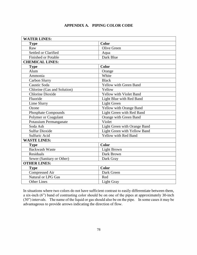
78
APPENDIX A. PIPING COLOR CODE
WATER LINES:
Type Color
Raw Olive Green
Settled or Clarified Aqua
Finished or Potable Dark Blue
CHEMICAL LINES:
Type Color
Alum Orange
Ammonia White
Carbon Slurry Black
Caustic Soda Yellow with Green Band
Chlorine (Gas and Solution) Yellow
Chlorine Dioxide Yellow with Violet Band
Fluoride Light Blue with Red Band
Lime Slurry Light Green
Ozone Yellow with Orange Band
Phosphate Compounds Light Green with Red Band
Polymer or Coagulant Orange with Green Band
Potassium Permanganate Violet
Soda Ash Light Green with Orange Band
Sulfur Dioxide Light Green with Yellow Band
Sulfuric Acid Yellow with Red Band
WASTE LINES:
Type Color
Backwash Waste Light Brown
Residuals Dark Brown
Sewer (Sanitary or Other) Dark Gray
OTHER LINES:
Type Color
Compressed Air Dark Green
Natural or LPG Gas Red
Other Lines Light Gray
In situations where two colors do not have sufficient contrast to easily differentiate between them,
a six- ” oximately 30-inch
3 ” T I
advantageous to provide arrows indicating the direction of flow.
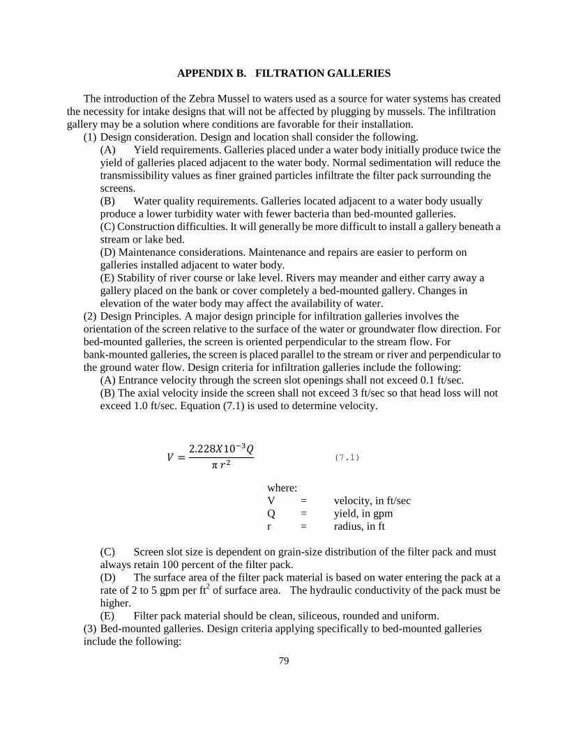
79
APPENDIX B. FILTRATION GALLERIES
The introduction of the Zebra Mussel to waters used as a source for water systems has created
the necessity for intake designs that will not be affected by plugging by mussels. The infiltration
gallery may be a solution where conditions are favorable for their installation.
(1) Design consideration. Design and location shall consider the following.
(A) Yield requirements. Galleries placed under a water body initially produce twice the
yield of galleries placed adjacent to the water body. Normal sedimentation will reduce the
transmissibility values as finer grained particles infiltrate the filter pack surrounding the
screens.
(B) Water quality requirements. Galleries located adjacent to a water body usually
produce a lower turbidity water with fewer bacteria than bed-mounted galleries.
(C) Construction difficulties. It will generally be more difficult to install a gallery beneath a
stream or lake bed.
(D) Maintenance considerations. Maintenance and repairs are easier to perform on
galleries installed adjacent to water body.
(E) Stability of river course or lake level. Rivers may meander and either carry away a
gallery placed on the bank or cover completely a bed-mounted gallery. Changes in
elevation of the water body may affect the availability of water.
(2) Design Principles. A major design principle for infiltration galleries involves the
orientation of the screen relative to the surface of the water or groundwater flow direction. For
bed-mounted galleries, the screen is oriented perpendicular to the stream flow. For
bank-mounted galleries, the screen is placed parallel to the stream or river and perpendicular to
the ground water flow. Design criteria for infiltration galleries include the following:
(A) Entrance velocity through the screen slot openings shall not exceed 0.1 ft/sec.
(B) The axial velocity inside the screen shall not exceed 3 ft/sec so that head loss will not
exceed 1.0 ft/sec. Equation (7.1) is used to determine velocity.
where:
V = velocity, in ft/sec
Q = yield, in gpm
r = radius, in ft
(C) Screen slot size is dependent on grain-size distribution of the filter pack and must
always retain 100 percent of the filter pack.
(D) The surface area of the filter pack material is based on water entering the pack at a
rate of 2 to 5 gpm per ft2 of surface area. The hydraulic conductivity of the pack must be
higher.
(E) Filter pack material should be clean, siliceous, rounded and uniform.
(3) Bed-mounted galleries. Design criteria applying specifically to bed-mounted galleries
include the following:
(7.1)
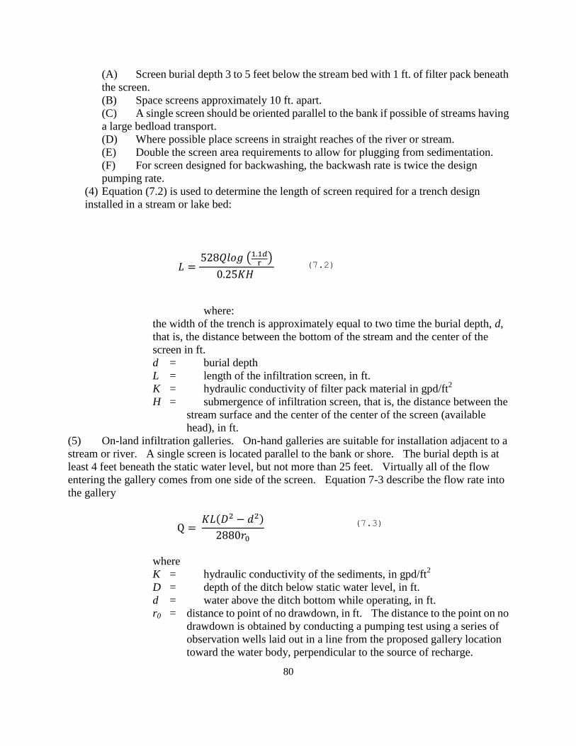
80
(7.3)
(A) Screen burial depth 3 to 5 feet below the stream bed with 1 ft. of filter pack beneath
the screen.
(B) Space screens approximately 10 ft. apart.
(C) A single screen should be oriented parallel to the bank if possible of streams having
a large bedload transport.
(D) Where possible place screens in straight reaches of the river or stream.
(E) Double the screen area requirements to allow for plugging from sedimentation.
(F) For screen designed for backwashing, the backwash rate is twice the design
pumping rate.
(4) Equation (7.2) is used to determine the length of screen required for a trench design
installed in a stream or lake bed:
(
)
where:
the width of the trench is approximately equal to two time the burial depth, d,
that is, the distance between the bottom of the stream and the center of the
screen in ft.
d = burial depth
L = length of the infiltration screen, in ft.
K = hydraulic conductivity of filter pack material in gpd/ft2
H = submergence of infiltration screen, that is, the distance between the
stream surface and the center of the center of the screen (available
head), in ft.
(5) On-land infiltration galleries. On-hand galleries are suitable for installation adjacent to a
stream or river. A single screen is located parallel to the bank or shore. The burial depth is at
least 4 feet beneath the static water level, but not more than 25 feet. Virtually all of the flow
entering the gallery comes from one side of the screen. Equation 7-3 describe the flow rate into
the gallery
( )
where
K = hydraulic conductivity of the sediments, in gpd/ft2
D = depth of the ditch below static water level, in ft.
d = water above the ditch bottom while operating, in ft.
r0 = distance to point of no drawdown, in ft. The distance to the point on no
drawdown is obtained by conducting a pumping test using a series of
observation wells laid out in a line from the proposed gallery location
toward the water body, perpendicular to the source of recharge.
(7.2)
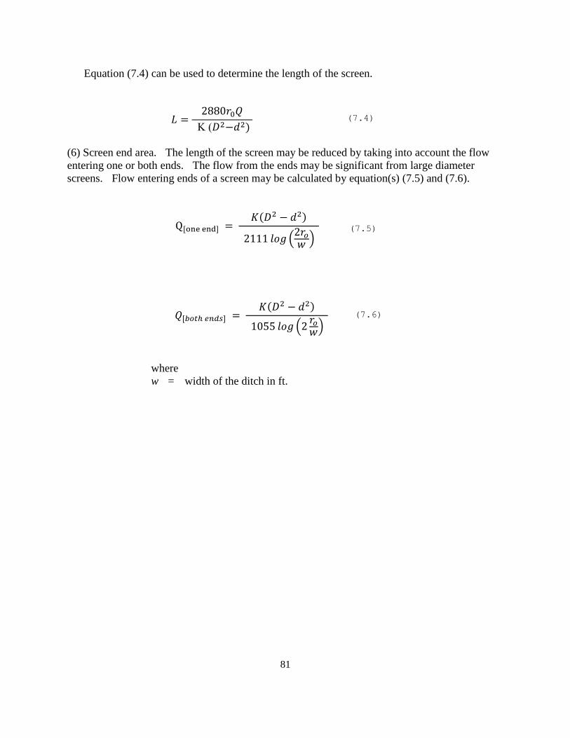
81
(7.4)
(7.5)
(7.6)
Equation (7.4) can be used to determine the length of the screen.
)
(6) Screen end area. The length of the screen may be reduced by taking into account the flow
entering one or both ends. The flow from the ends may be significant from large diameter
screens. Flow entering ends of a screen may be calculated by equation(s) (7.5) and (7.6).
( )
( )
( )
( )
where
w = width of the ditch in ft.
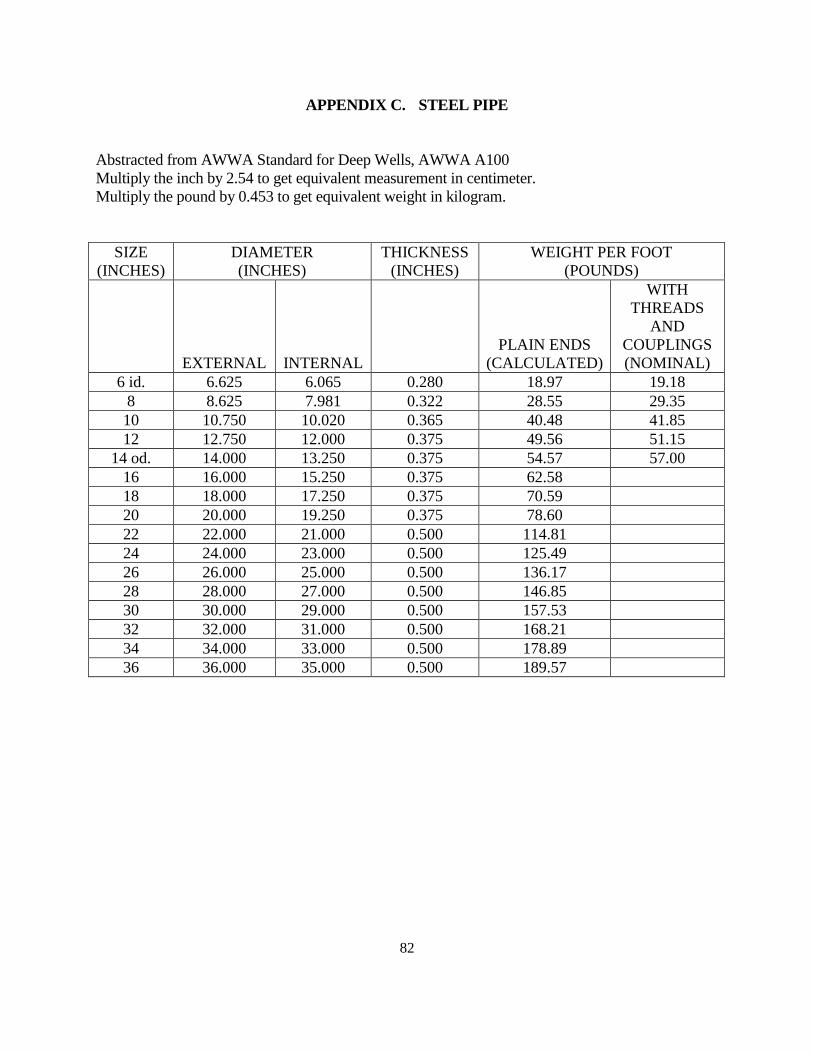
82
APPENDIX C. STEEL PIPE
Abstracted from AWWA Standard for Deep Wells, AWWA A100
Multiply the inch by 2.54 to get equivalent measurement in centimeter.
Multiply the pound by 0.453 to get equivalent weight in kilogram.
SIZE
(INCHES)
DIAMETER
(INCHES)
THICKNESS
(INCHES)
WEIGHT PER FOOT
(POUNDS)
EXTERNAL INTERNAL
PLAIN ENDS
(CALCULATED)
WITH
THREADS
AND
COUPLINGS
(NOMINAL)
6 id. 6.625 6.065 0.280 18.97 19.18
8 8.625 7.981 0.322 28.55 29.35
10 10.750 10.020 0.365 40.48 41.85
12 12.750 12.000 0.375 49.56 51.15
14 od. 14.000 13.250 0.375 54.57 57.00
16 16.000 15.250 0.375 62.58
18 18.000 17.250 0.375 70.59
20 20.000 19.250 0.375 78.60
22 22.000 21.000 0.500 114.81
24 24.000 23.000 0.500 125.49
26 26.000 25.000 0.500 136.17
28 28.000 27.000 0.500 146.85
30 30.000 29.000 0.500 157.53
32 32.000 31.000 0.500 168.21
34 34.000 33.000 0.500 178.89
36 36.000 35.000 0.500 189.57

83
APPENDIX D. GRAVEL SUPPORT FOR SLOW SAND FILTERS
Depth Size
Bottom layer four inches 1¼ - 1½ inches (30 – 40 mm)
Third layer four inches ¾ - ⅛ – 30 mm)
Second layer four inches ⅜ ¾ – 20 mm)
Top layer four inches 3/16 - ⅜ – 10 mm)
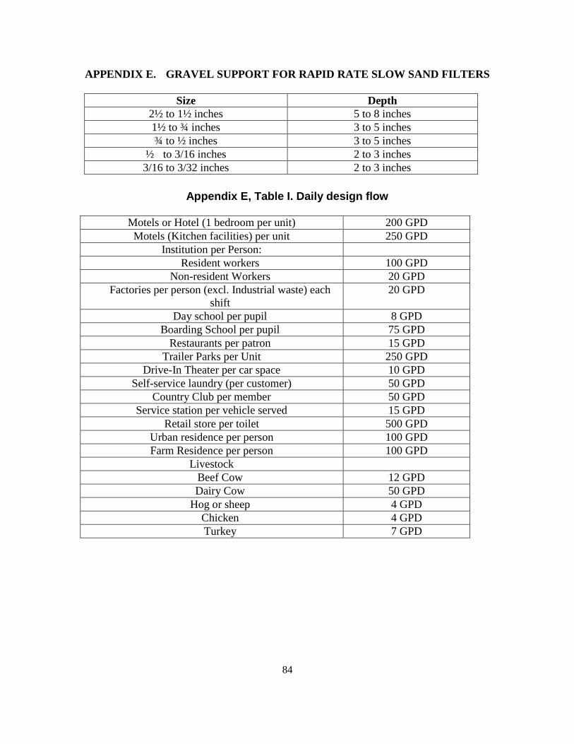
84
APPENDIX E. GRAVEL SUPPORT FOR RAPID RATE SLOW SAND FILTERS
Size Depth
2½ to 1½ inches 5 to 8 inches
1½ to ¾ inches 3 to 5 inches
¾ to ½ inches 3 to 5 inches
½ to 3/16 inches 2 to 3 inches
3/16 to 3/32 inches 2 to 3 inches
Appendix E, Table I. Daily design flow
Motels or Hotel (1 bedroom per unit) 200 GPD
Motels (Kitchen facilities) per unit 250 GPD
Institution per Person:
Resident workers 100 GPD
Non-resident Workers 20 GPD
Factories per person (excl. Industrial waste) each
shift
20 GPD
Day school per pupil 8 GPD
Boarding School per pupil 75 GPD
Restaurants per patron 15 GPD
Trailer Parks per Unit 250 GPD
Drive-In Theater per car space 10 GPD
Self-service laundry (per customer) 50 GPD
Country Club per member 50 GPD
Service station per vehicle served 15 GPD
Retail store per toilet 500 GPD
Urban residence per person 100 GPD
Farm Residence per person 100 GPD
Livestock
Beef Cow 12 GPD
Dairy Cow 50 GPD
Hog or sheep 4 GPD
Chicken 4 GPD
Turkey 7 GPD
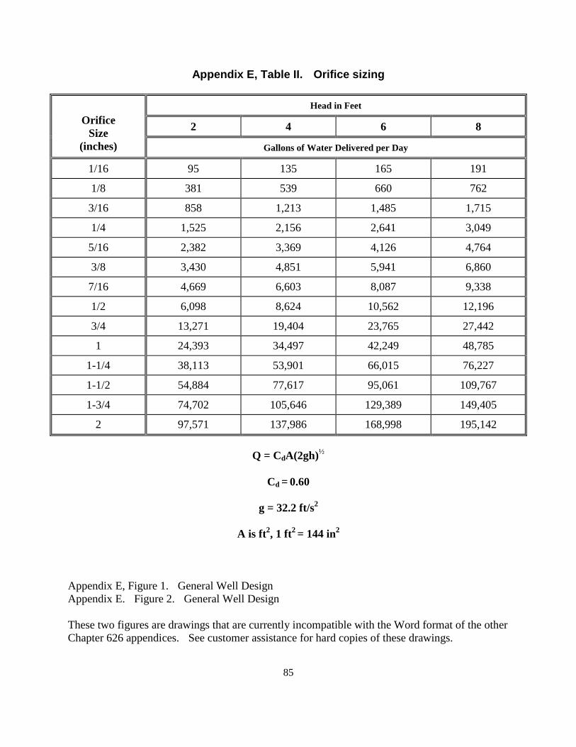
85
Appendix E, Table II. Orifice sizing
Orifice
Size
(inches)
Head in Feet
2 4 6 8
Gallons of Water Delivered per Day
1/16 95 135 165 191
1/8 381 539 660 762
3/16 858 1,213 1,485 1,715
1/4 1,525 2,156 2,641 3,049
5/16 2,382 3,369 4,126 4,764
3/8 3,430 4,851 5,941 6,860
7/16 4,669 6,603 8,087 9,338
1/2 6,098 8,624 10,562 12,196
3/4 13,271 19,404 23,765 27,442
1 24,393 34,497 42,249 48,785
1-1/4 38,113 53,901 66,015 76,227
1-1/2 54,884 77,617 95,061 109,767
1-3/4 74,702 105,646 129,389 149,405
2 97,571 137,986 168,998 195,142
Q = CdA(2gh)½
Cd = 0.60
g = 32.2 ft/s2
A is ft2, 1 ft
2 = 144 in
2
Appendix E, Figure 1. General Well Design
Appendix E. Figure 2. General Well Design
These two figures are drawings that are currently incompatible with the Word format of the other
Chapter 626 appendices. See customer assistance for hard copies of these drawings.
86
Appendix F. Quantity of Water Plant Residuals Generated
Most conventional coagulation plants product two major residuals – residuals from
sedimentation basin (commonly referred to as sludge) and residuals from back-washing A filter
(referred to as filter backwash water).
The quantity of these residuals generated from water treatment plants depends upon the raw
water quality, dosage of chemicals used, performance of the treatment process, method of sludge
removal, efficiency of sedimentation, and backwash frequency.
Alum and Iron residuals.
The amount of alum (or iron) residuals can be calculated fairly closely by considering the
reactions of alum or iron in the coagulation process. Using an empirical to account for the residual
contribution from turbidity will improve the estimate, and the contribution from other sources can
be added as required.
When alum is added to water as aluminum sulfate, the reaction with respect to residual production
is typically by the following simplified equation:
A12(SO4)3. 14 H2O + 6HCO3 = 2Al(OH)3. 3H2O + 6CO2 + 11H2O + 3SO4-2
If inadequate alkalinity is present, lime or sodium hydroxide is normally added to maintain
proper pH.
Commercial alum has a molecular weight of 594 and contains two moles of aluminum. Therefore,
alum is about 9.1 percent aluminum. The resulting aluminum hydroxide species has a molecular
weight of 132, and therefore, 1 mg/1 of aluminum will produce 4.89 mg/1solids, or 1 mg/1 alum
added to water will produce approximately 0.44 mg/1 of inorganic aluminum solids. Suspended
solids present in the raw water produce an equivalent weight of sludge solids because they are
non-reactive.
The amount of residual produced in an alum coagulation plant for removal of suspended solids is
then:
S=8.34 Q (0.44 Al + SS + A)
Where:
S = residual produced (lb/day)
Q = plant flow (mdg)
A1 = dry alum dose (mg/1) (as 17.1 percent Al2O3)
SS = raw water suspended solids (mg/l)
A = additional chemicals added, such as polymer, clay, powdered activated
carbon (mg/l)
If iron is used as the coagulant, then the solids production equation becomes:
S = 8.34 Q (2.9 Fe + SS + A)
87
where the iron dose is expressed as mg/l of Fe3+
added or produced via Fe2+
oxidation (note that
significant Fe2+
in the raw water will produce sludge at a factor of 2.9 if it is oxidized).
The above equations can be used to track yearly or even daily variation changes in residuals
dry weight produced. One difficulty in applying the relationship is that most plants do not
routinely analyze raw water suspended solids concentrations. The logical correlation is to equate a
turbidity unit to a suspended solids unit. Unfortunately, the relationship is generally not 1 to 1.
SS (mg/l) = b.TU
The value of b for low-color, predominantly turbidity removal plants can vary from 0.7 to 2.2.
It may vary seasonally for the same raw water supply. A utility can therefore either continually
measure suspended solids, or it may be possible to develop a correlation between turbidity and
suspended solids.
Lime Softening Residuals
Through similar theoretical considerations, a general equation has been developed for plants
that use a lime softening process for carbonate hardness removal with or without the use of alum,
iron or polymer. The equation is:
S = 8.34 Q [2.0 Ca + 2.6 Mg + 0.44 Al + 2.9 Fe + SS + A]
Where
S = residuals production (lb/day)
Ca = calcium hardness removed as CaCO3 (mg/l)
Mg = magnesium hardness removed as Mg(OH)2 (mg/l)
Fe = iron dose as Fe (mg/l)
Al = dry alum dose (mg/1) (as 17.1 percent Al2O3)
Q = plant flow (mgd)
A = other additives (mg/l)

88
APPENDIX G. Minor Water Systems [REVOKED]
Related Documents