Titan Explorer: The Next Step in the Exploration of a Mysterious World Principal Investigator: Dr. Joel S. Levine, NASA Langley Research Center Study Manager: Mr. Henry S. Wright, NASA Langley Research Center https://ntrs.nasa.gov/search.jsp?R=20050212185 2018-07-04T18:13:32+00:00Z

Welcome message from author
This document is posted to help you gain knowledge. Please leave a comment to let me know what you think about it! Share it to your friends and learn new things together.
Transcript
Titan Explorer:The Next Step in the Exploration of a Mysterious World
Principal Investigator: Dr. Joel S. Levine, NASA Langley Research CenterStudy Manager: Mr. Henry S. Wright, NASA Langley Research Center
https://ntrs.nasa.gov/search.jsp?R=20050212185 2018-07-04T18:13:32+00:00Z
Inset Image 2:Image Credit: NASA/JPL/ESA/University of ArizonaImage Caption: This image was returned yesterday, January 14, 2005, by the European Space Agency's Huygens probe during its successful descent to land on Titan. This is the colored view, following processing to add reflection spectra data, and gives a better indication of the actual color of the surface.
Inset Image 1:Image Credit: NASA/JPL/University of ArizonaImage Caption: The visual and infrared mapping spectrometer instrument onboard Cassini has found an unusual bright, red spot on Titan. This dramatic color (but not true color) image was taken during the April 16, 2005, encounter with Titan. North is to the right. In the center it shows the dark lanes of the "H"-shaped feature discovered from Earth and first seen by Cassini July 2004 shortly after it arrived in the Saturn system
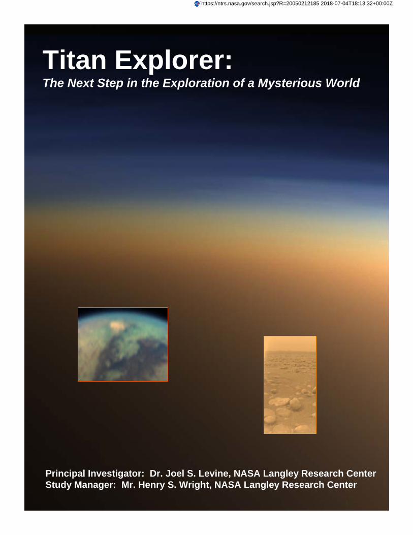
Cover Image:Image Credit: NASA/JPL/Space Science InstituteImage Caption: This natural color image shows Titan's upper atmosphere -- an active place where methane molecules are being broken apart by solar ultraviolet light and the byproducts combine to form compounds like ethane and acetylene. The haze preferentially scatters blue and ultraviolet wavelengths of light, making its complex layered structure more easily visible at the shorter wavelengths used in this image.
TITAN EXPLORER
- 1 -
Titan Explorer: The Next Step in the Exploration of a Mysterious World
Final Report for NASA Vision Mission Study per NRA-03-OSS-01 Submitted by: Principal Investigator: Dr. Joel S. Levine, NASA Langley Research Center Study Lead: Henry S. Wright, NASA Langley Research Center Date Submitted: June 10, 2005

TITAN EXPLORER
- 2 -
This page intentionally left blank
TITAN EXPLORER
- 3 -
0. Front Matter
0.1 Executive Summary Our knowledge and understanding of Titan, Saturn’s largest moon, have increased significantly as a result of measurements obtained from the Cassini spacecraft following its orbital insertion around Saturn on June 30, 2004 and even more recently with the measurements obtained during the descent of the Huygens probe through the atmosphere and onto the surface of Titan on January 14, 2005. The Titan Explorer Mission discussed in this report is the next step in the exploration of this mysterious world. The Titan Explorer Mission consists of a Titan Orbiter and a Titan Airship that traverses the atmosphere of Titan and can land on its surface. One of the fundamental questions in all of science concerns the origin and evolution of life and the occurrence of life beyond Earth. In the search for life in the Solar System, Titan holds a very unique position. Titan (radius: 2575 km) is slightly larger than Mercury (radius: 2439 km) and smaller than Mars (radius: 3393 km). Like the terrestrial planets, Titan has a solid surface and a density that suggests it is composed of a mixture of rock and ice in almost equal amounts. Titan may provide the details to explain how life formed on Earth very early in its history, shortly after the Earth formed 4.6 billion years ago. The evolution of the Earth’s atmosphere and plate tectonics have erased any early record of the primitive pre-biological Earth (the Earth’s geological record begins with the oldest rocks on our planet, dated to be about 3.5 billion years old, about a billion years after the Earth formed). The appearance on Earth of the first biological or living system and the subsequent evolution of biological systems, were preceded by the process of prebiotic chemistry or “chemical evolution.” Chemical evolution is the formation of the complex organic compounds, the precursors of living system. It is generally believed, that on Earth, chemical evolution occurred very soon after the Earth and its atmosphere formed. It is further believed that the gases in the early atmosphere, including nitrogen, methane, water vapor, molecular hydrogen, etc. were the “raw” materials that chemically formed the complex organic molecules, the precursors for the first living system. The successful entry and descent of the Titan Huygens probe through the atmosphere and landing on the surface of Titan on January 14, 2005, provided new information about the composition and structure of the atmosphere and the nature and characteristics of the surface of Titan. Titan’s atmosphere may hold answers to chemical evolution on the early Earth (references 1, 2, and 3). Titan is surrounded by a thick, opaque orange-colored atmosphere with a surface pressure of 1.5 bars-about 50% greater than the Earth’s atmosphere. The stability of methane in Titan’s atmosphere is puzzling, since the atmospheric lifetime of methane is controlled by its destruction by solar ultraviolet radiation, which is short on cosmic timescales (about 107 years). Hence, atmospheric methane on Titan appears to be buffered or re-supplied by a possible surface reservoir. The cloud and haze are sufficiently thick that ultraviolet radiation cannot penetrate to the troposphere. Photochemical and chemical reactions initiated by methane (and nitrogen) leads to the production of numerous hydrocarbons of increasing molecular complexity, beginning with ethane, hydrogen cyanide, etc., and leading to complex organic compounds such as purines, pyrimidines, and aldehydes, believed to be the chemical precursors of the first living systems on Earth (references 1, 2, and 3). The Titan Explorer mission focuses on the following scientific questions and required instrumentation to answer these questions:
1. What is the chemical composition of the atmosphere, including the trace gases? 2. What is the isotopic ratio of the gases in the atmosphere? 3. What pre-biological chemistry is occurring in the atmosphere/surface of Titan today and
what is its relevance to the origin of life on Earth? 4. What is the nature, origin, and composition of the clouds and haze layers?
TITAN EXPLORER
- 4 -
5. What is the nature and composition of the surface? 6. Are there oceans of liquid hydrocarbons on the surface of Titan? 7. What is the nature of the meteorology and dynamics of the atmosphere? 8. What processes control the meteorology and circulation of the atmosphere? 9. What is the nature of the hydrocarbon “hydrological cycle” on Titan? 10. What are the rates of escape of atomic and molecular hydrogen from the upper
atmosphere of Titan and what impact does this escape have on atmospheric chemistry? 11. How does the atmosphere of Titan interact with the solar wind and Saturn itself? 12. How have the atmosphere and surface of Titan evolved over its history?
To answer these questions, instruments on the Titan Orbiter include: 1. Solar occultation spectrometer to measure atmospheriuc composition and isotopic ratios. 2. Radar mapper to measure the nature of the surface. 3. Magnetometer to search both a planetary dipole field and surface magnetism. 4. Ultraviolet spectrometer to measure the escape of gases from Titan’s upper atmosphere. 5. Visual and infrared mapping spectrometer to measure cloud and haze layers and the
nature of the surface. Instruments on the Titan Airship include:
1. Imager to measure cloud and haze layers and the nature of the surface. 2. Mass spectrometer to measure atmospheric composition and isotopic ratios. 3. Haze and cloud particle detector to measure aerosol abundance and characterization. 4. Spectrometer to determine the nature and composition of the surface. 5. Sun-seeking spectrometer to measure the opacity of the atmosphere.
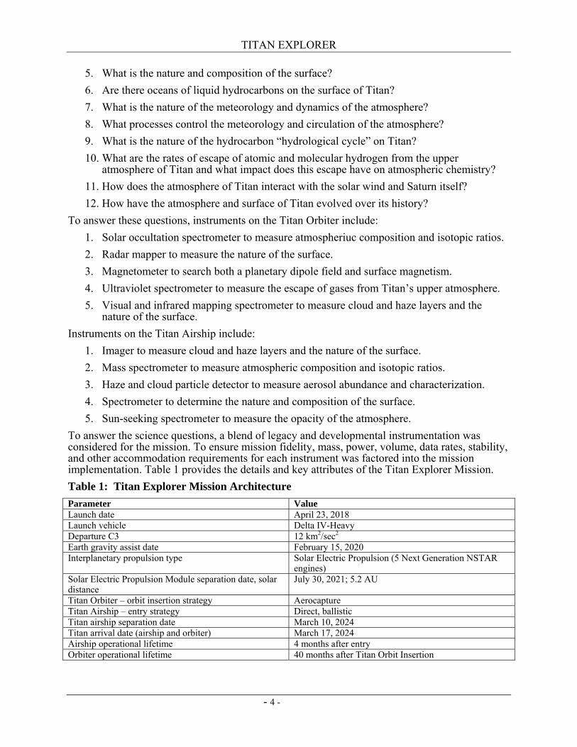
To answer the science questions, a blend of legacy and developmental instrumentation was considered for the mission. To ensure mission fidelity, mass, power, volume, data rates, stability, and other accommodation requirements for each instrument was factored into the mission implementation. Table 1 provides the details and key attributes of the Titan Explorer Mission. Table 1: Titan Explorer Mission Architecture Parameter Value Launch date April 23, 2018 Launch vehicle Delta IV-Heavy Departure C3 12 km2/sec2 Earth gravity assist date February 15, 2020 Interplanetary propulsion type Solar Electric Propulsion (5 Next Generation NSTAR
engines) Solar Electric Propulsion Module separation date, solar distance
July 30, 2021; 5.2 AU
Titan Orbiter – orbit insertion strategy Aerocapture Titan Airship – entry strategy Direct, ballistic Titan airship separation date March 10, 2024 Titan arrival date (airship and orbiter) March 17, 2024 Airship operational lifetime 4 months after entry Orbiter operational lifetime 40 months after Titan Orbit Insertion
TITAN EXPLORER
- 5 -
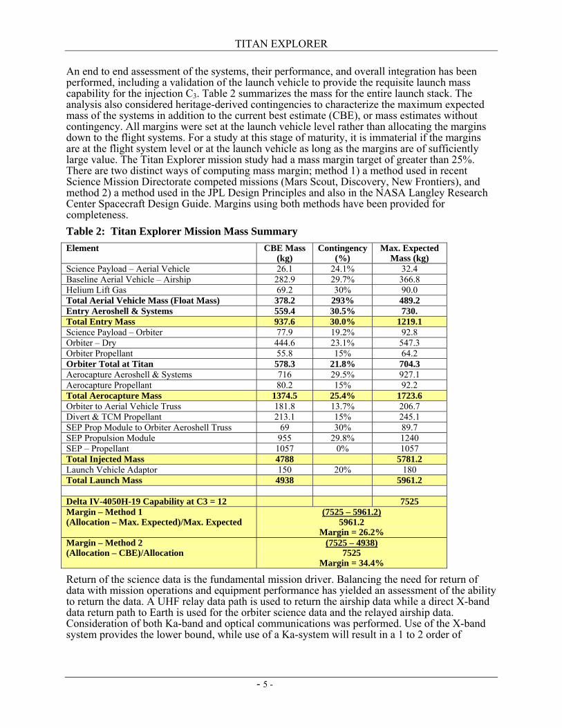
An end to end assessment of the systems, their performance, and overall integration has been performed, including a validation of the launch vehicle to provide the requisite launch mass capability for the injection C3. Table 2 summarizes the mass for the entire launch stack. The analysis also considered heritage-derived contingencies to characterize the maximum expected mass of the systems in addition to the current best estimate (CBE), or mass estimates without contingency. All margins were set at the launch vehicle level rather than allocating the margins down to the flight systems. For a study at this stage of maturity, it is immaterial if the margins are at the flight system level or at the launch vehicle as long as the margins are of sufficiently large value. The Titan Explorer mission study had a mass margin target of greater than 25%. There are two distinct ways of computing mass margin; method 1) a method used in recent Science Mission Directorate competed missions (Mars Scout, Discovery, New Frontiers), and method 2) a method used in the JPL Design Principles and also in the NASA Langley Research Center Spacecraft Design Guide. Margins using both methods have been provided for completeness. Table 2: Titan Explorer Mission Mass Summary Element CBE Mass
(kg) Contingency
(%) Max. Expected
Mass (kg) Science Payload – Aerial Vehicle 26.1 24.1% 32.4 Baseline Aerial Vehicle – Airship 282.9 29.7% 366.8 Helium Lift Gas 69.2 30% 90.0 Total Aerial Vehicle Mass (Float Mass) 378.2 293% 489.2 Entry Aeroshell & Systems 559.4 30.5% 730. Total Entry Mass 937.6 30.0% 1219.1 Science Payload – Orbiter 77.9 19.2% 92.8 Orbiter – Dry 444.6 23.1% 547.3 Orbiter Propellant 55.8 15% 64.2 Orbiter Total at Titan 578.3 21.8% 704.3 Aerocapture Aeroshell & Systems 716 29.5% 927.1 Aerocapture Propellant 80.2 15% 92.2 Total Aerocapture Mass 1374.5 25.4% 1723.6 Orbiter to Aerial Vehicle Truss 181.8 13.7% 206.7 Divert & TCM Propellant 213.1 15% 245.1 SEP Prop Module to Orbiter Aeroshell Truss 69 30% 89.7 SEP Propulsion Module 955 29.8% 1240 SEP – Propellant 1057 0% 1057 Total Injected Mass 4788 5781.2 Launch Vehicle Adaptor 150 20% 180 Total Launch Mass 4938 5961.2 Delta IV-4050H-19 Capability at C3 = 12 7525 Margin – Method 1 (Allocation – Max. Expected)/Max. Expected
(7525 – 5961.2) 5961.2
Margin = 26.2% Margin – Method 2 (Allocation – CBE)/Allocation
(7525 – 4938) 7525
Margin = 34.4%
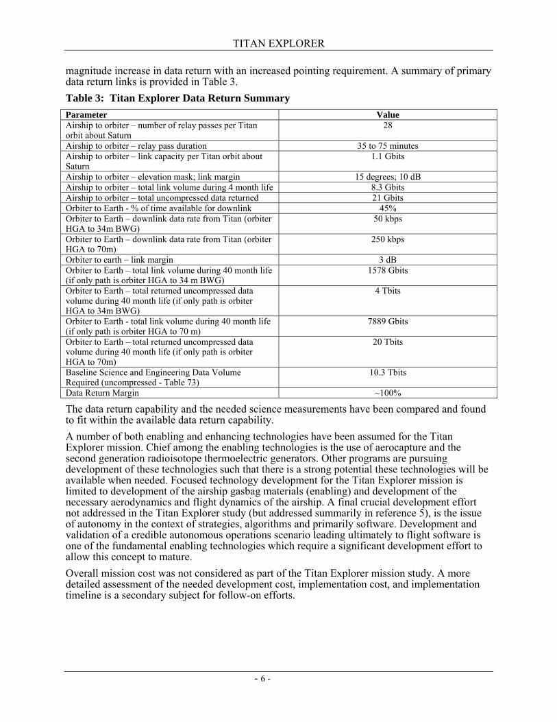
Return of the science data is the fundamental mission driver. Balancing the need for return of data with mission operations and equipment performance has yielded an assessment of the ability to return the data. A UHF relay data path is used to return the airship data while a direct X-band data return path to Earth is used for the orbiter science data and the relayed airship data. Consideration of both Ka-band and optical communications was performed. Use of the X-band system provides the lower bound, while use of a Ka-system will result in a 1 to 2 order of
TITAN EXPLORER
- 6 -
magnitude increase in data return with an increased pointing requirement. A summary of primary data return links is provided in Table 3. Table 3: Titan Explorer Data Return Summary Parameter Value Airship to orbiter – number of relay passes per Titan orbit about Saturn
28
Airship to orbiter – relay pass duration 35 to 75 minutes Airship to orbiter – link capacity per Titan orbit about Saturn
1.1 Gbits
Airship to orbiter – elevation mask; link margin 15 degrees; 10 dB Airship to orbiter – total link volume during 4 month life 8.3 Gbits Airship to orbiter – total uncompressed data returned 21 Gbits Orbiter to Earth - % of time available for downlink 45% Orbiter to Earth – downlink data rate from Titan (orbiter HGA to 34m BWG)
50 kbps
Orbiter to Earth – downlink data rate from Titan (orbiter HGA to 70m)
250 kbps
Orbiter to earth – link margin 3 dB Orbiter to Earth – total link volume during 40 month life (if only path is orbiter HGA to 34 m BWG)
1578 Gbits
Orbiter to Earth – total returned uncompressed data volume during 40 month life (if only path is orbiter HGA to 34m BWG)
4 Tbits
Orbiter to Earth - total link volume during 40 month life (if only path is orbiter HGA to 70 m)
7889 Gbits
Orbiter to Earth – total returned uncompressed data volume during 40 month life (if only path is orbiter HGA to 70m)
20 Tbits
Baseline Science and Engineering Data Volume Required (uncompressed - Table 73)
10.3 Tbits
Data Return Margin ~100%
The data return capability and the needed science measurements have been compared and found to fit within the available data return capability. A number of both enabling and enhancing technologies have been assumed for the Titan Explorer mission. Chief among the enabling technologies is the use of aerocapture and the second generation radioisotope thermoelectric generators. Other programs are pursuing development of these technologies such that there is a strong potential these technologies will be available when needed. Focused technology development for the Titan Explorer mission is limited to development of the airship gasbag materials (enabling) and development of the necessary aerodynamics and flight dynamics of the airship. A final crucial development effort not addressed in the Titan Explorer study (but addressed summarily in reference 5), is the issue of autonomy in the context of strategies, algorithms and primarily software. Development and validation of a credible autonomous operations scenario leading ultimately to flight software is one of the fundamental enabling technologies which require a significant development effort to allow this concept to mature. Overall mission cost was not considered as part of the Titan Explorer mission study. A more detailed assessment of the needed development cost, implementation cost, and implementation timeline is a secondary subject for follow-on efforts.
TITAN EXPLORER
- 7 -
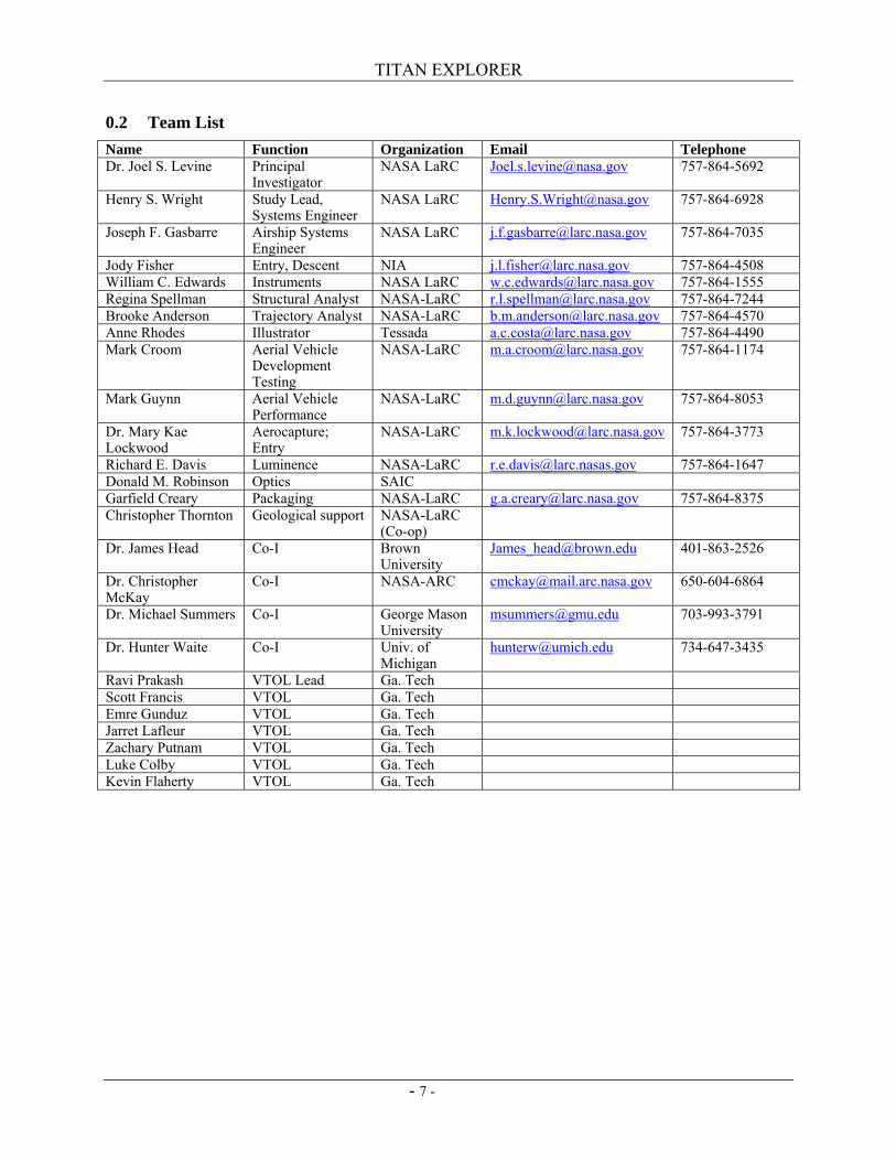
0.2 Team List Name Function Organization Email Telephone Dr. Joel S. Levine Principal
Investigator NASA LaRC [email protected] 757-864-5692
Henry S. Wright Study Lead, Systems Engineer
NASA LaRC [email protected] 757-864-6928
Joseph F. Gasbarre Airship Systems Engineer
NASA LaRC [email protected] 757-864-7035
Jody Fisher Entry, Descent NIA [email protected] 757-864-4508 William C. Edwards Instruments NASA LaRC [email protected] 757-864-1555 Regina Spellman Structural Analyst NASA-LaRC [email protected] 757-864-7244 Brooke Anderson Trajectory Analyst NASA-LaRC [email protected] 757-864-4570 Anne Rhodes Illustrator Tessada [email protected] 757-864-4490 Mark Croom Aerial Vehicle
Development Testing
NASA-LaRC [email protected] 757-864-1174
Mark Guynn Aerial Vehicle Performance
NASA-LaRC [email protected] 757-864-8053
Dr. Mary Kae Lockwood
Aerocapture; Entry
NASA-LaRC [email protected] 757-864-3773
Richard E. Davis Luminence NASA-LaRC [email protected] 757-864-1647 Donald M. Robinson Optics SAIC Garfield Creary Packaging NASA-LaRC [email protected] 757-864-8375 Christopher Thornton Geological support NASA-LaRC
(Co-op)
Dr. James Head Co-I Brown University
[email protected] 401-863-2526
Dr. Christopher McKay
Co-I NASA-ARC [email protected] 650-604-6864
Dr. Michael Summers Co-I George Mason University
[email protected] 703-993-3791
Dr. Hunter Waite Co-I Univ. of Michigan
[email protected] 734-647-3435
Ravi Prakash VTOL Lead Ga. Tech Scott Francis VTOL Ga. Tech Emre Gunduz VTOL Ga. Tech Jarret Lafleur VTOL Ga. Tech Zachary Putnam VTOL Ga. Tech Luke Colby VTOL Ga. Tech Kevin Flaherty VTOL Ga. Tech

TITAN EXPLORER
- 8 -
This page intentionally left blank
TITAN EXPLORER
- 9 -
0.3 Table of Contents 0. Front Matter ...........................................................................................................................3
0.1 Executive Summary .....................................................................................................3 0.2 Team List .....................................................................................................................7 0.3 Table of Contents.........................................................................................................9 0.4 Introduction................................................................................................................13
1. Science Rationale.................................................................................................................15 1.1 Elements of the Scientific Investigation ....................................................................15 1.1.1 The Atmosphere of Titan ...........................................................................................15 1.1.2 Meteorology and Circulation .....................................................................................17 1.1.3 The Surface ................................................................................................................17 1.1.4 Key Questions to be Addressed by the Titan Explorer..............................................17
1.2 Measurements ............................................................................................................17 1.3 Science Instrument Description .................................................................................19 1.3.1 Orbiter Instruments ....................................................................................................19 1.3.2 Airship Instruments....................................................................................................22 1.3.3 Instrument Summary..................................................................................................26
2. Architecture and Implementation Approach........................................................................27 2.1 Summary Description ................................................................................................27 2.1.1 Mission Overview......................................................................................................27 2.1.2 Flight Systems Summary ...........................................................................................28 2.1.3 Environmental Comparison .......................................................................................29 2.1.4 Mission Assumptions.................................................................................................29
2.2 Launch Segment.........................................................................................................30 2.2.1 Launch Vehicle ..........................................................................................................30 2.2.2 Launch Stack Configuration ......................................................................................32
2.3 Cruise Segment ..........................................................................................................35 2.3.1 Solar Electric Propulsion Module..............................................................................35 2.3.2 Truss Mounted Systems and Components.................................................................40
2.4 Aerocapture Segment.................................................................................................44 2.4.1 Aerocapture Aeroshell Subsystem.............................................................................44 2.4.2 Aerocapture Thermal Subsystem...............................................................................47 2.4.3 Aerocapture ACS Subsystem.....................................................................................48 2.4.4 Aeroshell Propulsion – Divert Maneuver ..................................................................48
2.5 Orbital Segment .........................................................................................................48 2.5.1 Orbiter Overview .......................................................................................................48 2.5.2 Orbiter Subsystems ....................................................................................................49
2.6 Entry Segment............................................................................................................59 2.6.1 Entry Aeroshell ..........................................................................................................59 2.6.2 Entry Thermal System (PCM’s) ................................................................................61 2.6.3 Entry Descent System (Parachute).............................................................................61 2.6.4 Airship Inflation System............................................................................................62
2.7 Aerial Flight Segment – Baseline - Airship...............................................................63 2.7.1 Airship........................................................................................................................63 2.7.2 Airship Subsystems....................................................................................................71
2.8 Optional Aerial Flight Segment –Vertical Take-off and Landing (VTOL)...............78 2.8.1 VTOL Overview ........................................................................................................78 2.8.2 VTOL Overall Performance - Propulsion..................................................................80 2.8.3 VTOL Subsystems .....................................................................................................82
2.9 Science Payload .........................................................................................................87 2.9.1 Aerial Vehicle Instruments ........................................................................................88
3. Technology ..........................................................................................................................91 3.1 Unique Requirements and System Sensitivity...........................................................91
TITAN EXPLORER
- 10 -
3.1.1 Science Instruments ...................................................................................................91 3.1.2 Aerocapture - Enabling ..............................................................................................92 3.1.3 Airship – Envelope Materials - Enabling...................................................................92 3.1.4 Orbiter and Airship Power – Use of Second Generation RTG’s - Enabling .............92 3.1.5 Spacecraft Propulsion – Next Generation Ion Engines - Enabling............................93 3.1.6 Aerial Vehicle (Airship & VTOL) – Autonomy and Navigation - Enabling ............93 3.1.7 Orbiter Data Relay –Communications Options – Ka or Optical - Enhancing...........94 3.1.8 Aeroshell – Heatshield Radiator Concept - Enhancing .............................................94 3.1.9 Optional Aerial Vehicle - VTOL – Turbo-Expander - Enhancing ............................95
3.2 Key Technology Risks and Uncertainties..................................................................98 3.3 Development Strategy (Roadmap).............................................................................99 3.4 Validation and Demonstration Approach ..................................................................99 3.4.1 Airship Flight Testing ................................................................................................99 3.4.2 VTOL Flight Testing .................................................................................................99 3.4.3 EDI Flight Testing .....................................................................................................99
4. Deployment (Mission Design)...........................................................................................101 4.1 Mission Design Overview........................................................................................101 4.2 Cruise .......................................................................................................................101 4.2.1 Navigation Systems .................................................................................................102
4.3 Orbiter – Aerocapture ..............................................................................................103 4.3.1 Aerocapture Sequence Overview.............................................................................103 4.3.2 Aerocapture Aerodynamics .....................................................................................104 4.3.3 Guidance ..................................................................................................................104 4.3.4 Previous Titan Aerocapture Simulations .................................................................105
4.4 Baseline – Airship - Entry, Descent, Inflation.........................................................106 4.4.1 3DOF Trajectory Simulation in POST2 ..................................................................106 4.4.2 Airship Inflation Initiation and Deployment............................................................111 4.4.3 Titan-GRAM Atmospheric Model...........................................................................113 4.4.4 Extreme Case Entry Trajectory Simulations............................................................113
4.5 Option – VTOL - Entry, Descent, Transition ..........................................................116 5. Operations ..........................................................................................................................119
5.1 Launch Operations ...................................................................................................119 5.2 Cruise Phase.............................................................................................................119 5.3 Approach Operations ...............................................................................................121 5.3.1 Approach Navigation ...............................................................................................121 5.3.2 Orbiter Coasting.......................................................................................................122
5.4 Entry Operations ......................................................................................................122 5.4.1 Airship Entry System – Direct Entry .......................................................................122 5.4.2 Orbiter Entry System – Aerocapture........................................................................124 5.4.3 Exit Phase.................................................................................................................125
5.5 Orbital Operations....................................................................................................125 5.5.1 Initial Checkout........................................................................................................125 5.5.2 Orbiter Operations – Airship Active........................................................................126 5.5.3 Orbiter Operations – Post Airship............................................................................130
5.6 Baseline – Airship Operations .................................................................................131 5.6.1 Science Instrument Operations ................................................................................133 5.6.2 Airship Navigation...................................................................................................135 5.6.3 Surface Science Package..........................................................................................135
5.7 Option – VTOL Operations .....................................................................................136 5.8 Data Return ..............................................................................................................136 5.8.1 Relay Links – To/From Orbiter ...............................................................................136 5.8.2 Deep Space Links – To/From Earth.........................................................................141
5.9 Ground Operations...................................................................................................144 5.9.1 Ground Operations – Airship Phase ........................................................................144
TITAN EXPLORER
- 11 -
5.9.2 Ground Operations – Orbiter Only ..........................................................................144 6. Operations Assurance ........................................................................................................145
6.1 System Resilience (Redundancy or Adaptability) ...................................................145 6.2 Maintenance or Servicing ........................................................................................145
7. Safety .................................................................................................................................147 7.1 Launch and Earth Gravity Assist .............................................................................147 7.1.1 Use of Nuclear Materials .........................................................................................147 7.1.2 Supercritical Xenon .................................................................................................147
7.2 Titan Planetary Protection........................................................................................148 8. References..........................................................................................................................149

TITAN EXPLORER
- 12 -
This page intentionally left blank
TITAN EXPLORER
- 13 -
0.4 Introduction An integrated assessment of a science mission to study Titan has been performed. Starting with a set of needed scientific goals and objectives, a set of observations has been defined. Further decomposition to a suite of science instruments followed by the details of each platform as well as the essential mission architecture has been defined. High level mission requirements as characterized in the original NASA Research Announcement (NRA) were to focus on missions whose launch dates were after 2015 and were considered “Flagship” class missions (total mission cost in excess of $700 million FY2005). A blend of both existing (or near term) technologies and longer term developmental technologies has been assumed to provide a reasonable performance bound. Legacy systems provide the ability to define upper bounds on mass, power, volume, and performance which illustrate there are opportunities for significant improvement. A key assumption in this study was to only consider existing expendable launch vehicles (in terms of available launch energy and the physical integration constraints). Various levels of maturity of the design exist within this study. Some new work was performed (primarily with the airship and the optional vertical take-off and landing vehicles) while leveraging various other studies previously performed (ref. 4)(orbiter and solar electric propulsion module). A reasonable mission performance can be attained with this architecture. There are numerous opportunities for either reducing the system mass and power or increasing the overall system performance through a more aggressive infusion of newer technologies. The mission employs solar electric propulsion with a single Earth gravity assist to transit between Earth and Titan. Two platforms are used in the mission; an airship for local, in-situ observations of Titan, and an orbiter for extended observations and to serve as the data relay platform for the airship. The airship is separated from the cruise stack near Titan and then performs a direct entry with an inflation prior to surface contact. The orbiter performs an aerocapture maneuver to achieve the Titan orbit. It is assumed the airship will have an operational life of about 4 months, after which the helium reserve is expended and the airship can no longer maintain positive buoyancy. The life of the orbiter is intended to be about 3.3 years after achieving orbit about Titan. An assessment of an alternative aerial vehicle (a vertical take-off and landing vehicle – helicopter) is included to assess how to increase surface interaction. The basic conclusion is that this vehicle is also a feasible alternative. After completing the study, it has been concluded that the baseline airship/orbiter mission or the optional helicopter/orbiter mission can be performed within the constraints imposed by the launch vehicle, the cruise propulsion, and the entry/aerocapture limitations. A follow-on effort is recommended to explore each of the vehicles in greater detail as well as to assess how the recent discoveries at Titan from Cassini and Huygens should refine or change the basic science observations. Included with this follow-on effort should be a more detailed development schedule and funding assessment.

TITAN EXPLORER
- 14 -
This page intentionally left blank
TITAN EXPLORER
- 15 -
1. Science Rationale One of the fundamental questions in all of science concerns the origin and evolution of life and the occurrence of life in the Solar System. In the search for life outside the Earth, Titan, the largest moon of Saturn, holds a very unique position. Titan (radius: 2575 km) is slightly larger than Mercury (radius: 2439 km) and smaller than Mars (radius: 3393 km). Like the terrestrial planets, Titan has a solid surface and a density that suggests it is composed of a mixture of rock and ice in almost equal amounts. Titan may provide the details to explain how life formed on Earth very early in its history, shortly after the Earth formed 4.6 billion years ago. The evolution of the Earth’s atmosphere and plate tectonics have erased any early record of the primitive pre-biological Earth (the Earth’s geological record begins with the oldest rocks on our planet, dated to be about 3.5 billion years old, about a billion years after the Earth formed). The appearance on Earth of the first biological or living system and the subsequent evolution of biological systems, were preceded by the process of prebiotic chemistry or “chemical evolution.” Chemical evolution is the formation of the complex organic compounds, the precursors of living system. It is generally believed, that on Earth, chemical evolution occurred very soon after the Earth and its atmosphere formed. It is further believed that the gases in the early atmosphere, including nitrogen, methane, water vapor, molecular hydrogen, etc. were the “raw” materials that chemically formed the complex organic molecules, the precursors for the first living system. The successful entry and descent of the Huygens probe, through the atmosphere and landing on the surface of Titan on January 14, 2005, provide new information about the composition and structure of the atmosphere and the nature and characteristics of the surface of Titan. The combination of the Huygens in-situ measurements and Cassini’s global observations (flyby) are changing our entire perspective of Titan.
1.1 Elements of the Scientific Investigation 1.1.1 The Atmosphere of Titan Titan’s atmosphere may hold answers to chemical evolution on the early Earth (references 1, 2, and 3). Titan is surrounded by a thick, opaque orange-colored atmosphere with a surface pressure of 1.5 bars-about 50% greater than the Earth’s atmosphere. Similar to the Earth, molecular nitrogen (N2) is the overwhelming constituent of the Titan atmosphere (about 95% by volume), with smaller amounts of methane (CH4) and molecular hydrogen (H2) (ref. 6). The stability of methane in Titan’s atmosphere is puzzling, since the atmospheric lifetime of methane is controlled by its destruction by solar ultraviolet radiation, which is short on cosmic timescales (107 years). Hence, atmospheric methane on Titan appears to be buffered or re-supplied by a possible surface reservoir. The cloud and haze are sufficiently thick that ultraviolet radiation cannot penetrate to the troposphere. Photochemical and chemical reactions initiated by methane (and nitrogen) leads to the production of numerous hydrocarbons of increasing molecular complexity, beginning with ethane, hydrogen cyanide, etc., and leading to complex organic compounds such as purines, pyrimidines, and aldehydes, believed to be the chemical precursors of the first living systems on Earth (references 1, 2, and 3) (see Figure 1). The constituents of Titan’s atmosphere are given in Table 4 (ref. 6). The dominance of nitrogen on Titan, gives rise to the rich coupled chemistry between nitrogen and carbon. The variety of nitrile species on Titan appears to be unique in the Solar System. As already noted, it is generally believed that the atmosphere of Titan is very similar to the Earth’s primordial, pre-biological atmosphere, the atmosphere that produced the complex organic molecules that led to the formation of living systems on Earth in its early history.
TITAN EXPLORER
- 16 -
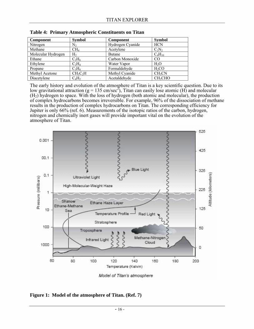
Table 4: Primary Atmospheric Constituents on Titan Component Symbol Component Symbol Nitrogen N2 Hydrogen Cyanide HCN Methane CH4 Acetylene C2N2 Molecular Hydrogen H2 Butane C4H10 Ethane C2H6 Carbon Monoxide CO Ethylene C2H4 Water Vapor H2O Propane C3H8 Formaldehyde H2CO Methyl Acetone CH3C2H Methyl Cyanide CH3CN Diacetylene C4H2 Acetaldehyde CH3CHO
The early history and evolution of the atmosphere of Titan is a key scientific question. Due to its low gravitational attraction (g = 135 cm/sec2), Titan can easily lose atomic (H) and molecular (H2) hydrogen to space. With the loss of hydrogen (both atomic and molecular), the production of complex hydrocarbons becomes irreversible. For example, 96% of the dissociation of methane results in the production of complex hydrocarbons on Titan. The corresponding efficiency for Jupiter is only 66% (ref. 6). Measurements of the isotopic ratios of the carbon, hydrogen, nitrogen and chemically inert gases will provide important vital on the evolution of the atmosphere of Titan.
Figure 1: Model of the atmosphere of Titan. (Ref. 7)
TITAN EXPLORER
- 17 -
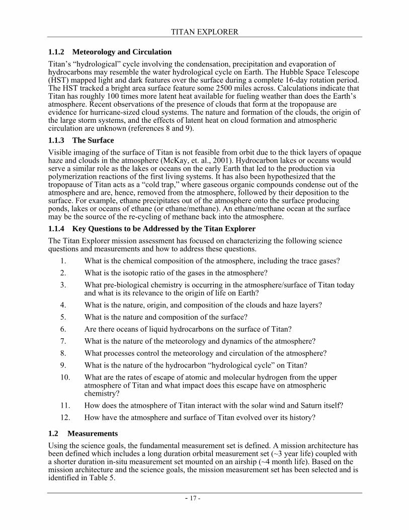
1.1.2 Meteorology and Circulation Titan’s “hydrological” cycle involving the condensation, precipitation and evaporation of hydrocarbons may resemble the water hydrological cycle on Earth. The Hubble Space Telescope (HST) mapped light and dark features over the surface during a complete 16-day rotation period. The HST tracked a bright area surface feature some 2500 miles across. Calculations indicate that Titan has roughly 100 times more latent heat available for fueling weather than does the Earth’s atmosphere. Recent observations of the presence of clouds that form at the tropopause are evidence for hurricane-sized cloud systems. The nature and formation of the clouds, the origin of the large storm systems, and the effects of latent heat on cloud formation and atmospheric circulation are unknown (references 8 and 9). 1.1.3 The Surface Visible imaging of the surface of Titan is not feasible from orbit due to the thick layers of opaque haze and clouds in the atmosphere (McKay, et. al., 2001). Hydrocarbon lakes or oceans would serve a similar role as the lakes or oceans on the early Earth that led to the production via polymerization reactions of the first living systems. It has also been hypothesized that the tropopause of Titan acts as a “cold trap,” where gaseous organic compounds condense out of the atmosphere and are, hence, removed from the atmosphere, followed by their deposition to the surface. For example, ethane precipitates out of the atmosphere onto the surface producing ponds, lakes or oceans of ethane (or ethane/methane). An ethane/methane ocean at the surface may be the source of the re-cycling of methane back into the atmosphere. 1.1.4 Key Questions to be Addressed by the Titan Explorer The Titan Explorer mission assessment has focused on characterizing the following science questions and measurements and how to address these questions.
1. What is the chemical composition of the atmosphere, including the trace gases? 2. What is the isotopic ratio of the gases in the atmosphere? 3. What pre-biological chemistry is occurring in the atmosphere/surface of Titan today
and what is its relevance to the origin of life on Earth? 4. What is the nature, origin, and composition of the clouds and haze layers? 5. What is the nature and composition of the surface? 6. Are there oceans of liquid hydrocarbons on the surface of Titan? 7. What is the nature of the meteorology and dynamics of the atmosphere? 8. What processes control the meteorology and circulation of the atmosphere? 9. What is the nature of the hydrocarbon “hydrological cycle” on Titan? 10. What are the rates of escape of atomic and molecular hydrogen from the upper
atmosphere of Titan and what impact does this escape have on atmospheric chemistry?
11. How does the atmosphere of Titan interact with the solar wind and Saturn itself? 12. How have the atmosphere and surface of Titan evolved over its history?
1.2 Measurements Using the science goals, the fundamental measurement set is defined. A mission architecture has been defined which includes a long duration orbital measurement set (~3 year life) coupled with a shorter duration in-situ measurement set mounted on an airship (~4 month life). Based on the mission architecture and the science goals, the mission measurement set has been selected and is identified in Table 5.
TITAN EXPLORER
- 18 -
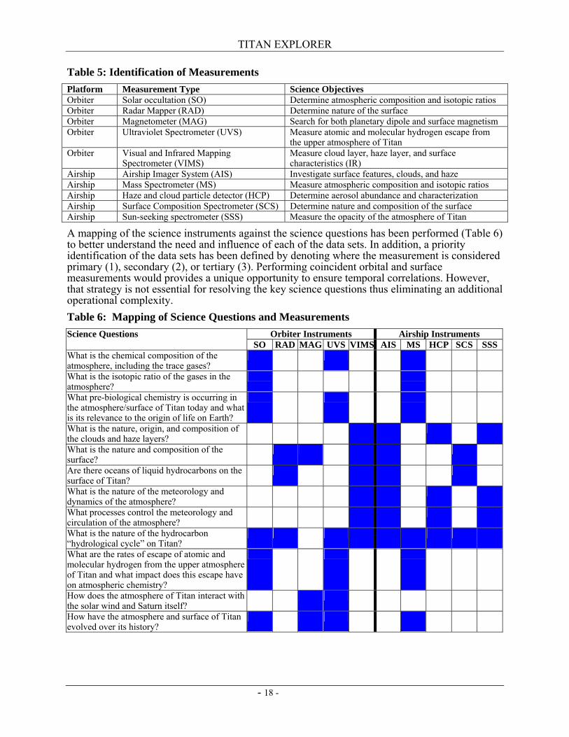
Table 5: Identification of Measurements Platform Measurement Type Science Objectives Orbiter Solar occultation (SO) Determine atmospheric composition and isotopic ratios Orbiter Radar Mapper (RAD) Determine nature of the surface Orbiter Magnetometer (MAG) Search for both planetary dipole and surface magnetism Orbiter Ultraviolet Spectrometer (UVS) Measure atomic and molecular hydrogen escape from
the upper atmosphere of Titan Orbiter Visual and Infrared Mapping
Spectrometer (VIMS) Measure cloud layer, haze layer, and surface characteristics (IR)
Airship Airship Imager System (AIS) Investigate surface features, clouds, and haze Airship Mass Spectrometer (MS) Measure atmospheric composition and isotopic ratios Airship Haze and cloud particle detector (HCP) Determine aerosol abundance and characterization Airship Surface Composition Spectrometer (SCS) Determine nature and composition of the surface Airship Sun-seeking spectrometer (SSS) Measure the opacity of the atmosphere of Titan
A mapping of the science instruments against the science questions has been performed (Table 6) to better understand the need and influence of each of the data sets. In addition, a priority identification of the data sets has been defined by denoting where the measurement is considered primary (1), secondary (2), or tertiary (3). Performing coincident orbital and surface measurements would provides a unique opportunity to ensure temporal correlations. However, that strategy is not essential for resolving the key science questions thus eliminating an additional operational complexity. Table 6: Mapping of Science Questions and Measurements
Orbiter Instruments Airship Instruments Science Questions SO RAD MAG UVS VIMS AIS MS HCP SCS SSS
What is the chemical composition of the atmosphere, including the trace gases?
What is the isotopic ratio of the gases in the atmosphere?
What pre-biological chemistry is occurring in the atmosphere/surface of Titan today and what is its relevance to the origin of life on Earth?
What is the nature, origin, and composition of the clouds and haze layers?
What is the nature and composition of the surface?
Are there oceans of liquid hydrocarbons on the surface of Titan?
What is the nature of the meteorology and dynamics of the atmosphere?
What processes control the meteorology and circulation of the atmosphere?
What is the nature of the hydrocarbon “hydrological cycle” on Titan?
What are the rates of escape of atomic and molecular hydrogen from the upper atmosphere of Titan and what impact does this escape have on atmospheric chemistry?
How does the atmosphere of Titan interact with the solar wind and Saturn itself?
How have the atmosphere and surface of Titan evolved over its history?
TITAN EXPLORER
- 19 -
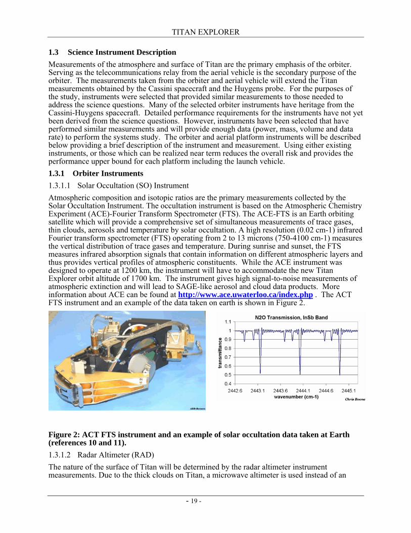
1.3 Science Instrument Description Measurements of the atmosphere and surface of Titan are the primary emphasis of the orbiter. Serving as the telecommunications relay from the aerial vehicle is the secondary purpose of the orbiter. The measurements taken from the orbiter and aerial vehicle will extend the Titan measurements obtained by the Cassini spacecraft and the Huygens probe. For the purposes of the study, instruments were selected that provided similar measurements to those needed to address the science questions. Many of the selected orbiter instruments have heritage from the Cassini-Huygens spacecraft. Detailed performance requirements for the instruments have not yet been derived from the science questions. However, instruments have been selected that have performed similar measurements and will provide enough data (power, mass, volume and data rate) to perform the systems study. The orbiter and aerial platform instruments will be described below providing a brief description of the instrument and measurement. Using either existing instruments, or those which can be realized near term reduces the overall risk and provides the performance upper bound for each platform including the launch vehicle. 1.3.1 Orbiter Instruments 1.3.1.1 Solar Occultation (SO) Instrument Atmospheric composition and isotopic ratios are the primary measurements collected by the Solar Occultation Instrument. The occultation instrument is based on the Atmospheric Chemistry Experiment (ACE)-Fourier Transform Spectrometer (FTS). The ACE-FTS is an Earth orbiting satellite which will provide a comprehensive set of simultaneous measurements of trace gases, thin clouds, aerosols and temperature by solar occultation. A high resolution (0.02 cm-1) infrared Fourier transform spectrometer (FTS) operating from 2 to 13 microns (750-4100 cm-1) measures the vertical distribution of trace gases and temperature. During sunrise and sunset, the FTS measures infrared absorption signals that contain information on different atmospheric layers and thus provides vertical profiles of atmospheric constituents. While the ACE instrument was designed to operate at 1200 km, the instrument will have to accommodate the new Titan Explorer orbit altitude of 1700 km. The instrument gives high signal-to-noise measurements of atmospheric extinction and will lead to SAGE-like aerosol and cloud data products. More information about ACE can be found at http://www.ace.uwaterloo.ca/index.php . The ACT FTS instrument and an example of the data taken on earth is shown in Figure 2.
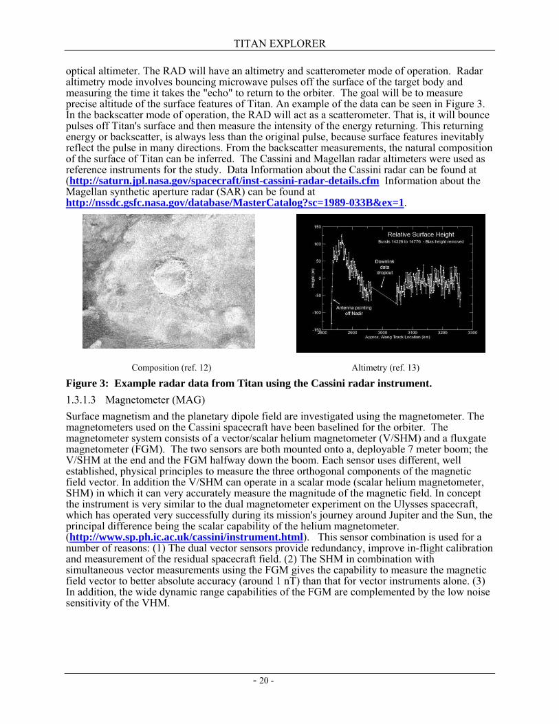
Figure 2: ACT FTS instrument and an example of solar occultation data taken at Earth (references 10 and 11). 1.3.1.2 Radar Altimeter (RAD) The nature of the surface of Titan will be determined by the radar altimeter instrument measurements. Due to the thick clouds on Titan, a microwave altimeter is used instead of an
TITAN EXPLORER
- 20 -
optical altimeter. The RAD will have an altimetry and scatterometer mode of operation. Radar altimetry mode involves bouncing microwave pulses off the surface of the target body and measuring the time it takes the "echo" to return to the orbiter. The goal will be to measure precise altitude of the surface features of Titan. An example of the data can be seen in Figure 3. In the backscatter mode of operation, the RAD will act as a scatterometer. That is, it will bounce pulses off Titan's surface and then measure the intensity of the energy returning. This returning energy or backscatter, is always less than the original pulse, because surface features inevitably reflect the pulse in many directions. From the backscatter measurements, the natural composition of the surface of Titan can be inferred. The Cassini and Magellan radar altimeters were used as reference instruments for the study. Data Information about the Cassini radar can be found at (http://saturn.jpl.nasa.gov/spacecraft/inst-cassini-radar-details.cfm Information about the Magellan synthetic aperture radar (SAR) can be found at http://nssdc.gsfc.nasa.gov/database/MasterCatalog?sc=1989-033B&ex=1.
Composition (ref. 12) Altimetry (ref. 13)
Figure 3: Example radar data from Titan using the Cassini radar instrument. 1.3.1.3 Magnetometer (MAG) Surface magnetism and the planetary dipole field are investigated using the magnetometer. The magnetometers used on the Cassini spacecraft have been baselined for the orbiter. The magnetometer system consists of a vector/scalar helium magnetometer (V/SHM) and a fluxgate magnetometer (FGM). The two sensors are both mounted onto a, deployable 7 meter boom; the V/SHM at the end and the FGM halfway down the boom. Each sensor uses different, well established, physical principles to measure the three orthogonal components of the magnetic field vector. In addition the V/SHM can operate in a scalar mode (scalar helium magnetometer, SHM) in which it can very accurately measure the magnitude of the magnetic field. In concept the instrument is very similar to the dual magnetometer experiment on the Ulysses spacecraft, which has operated very successfully during its mission's journey around Jupiter and the Sun, the principal difference being the scalar capability of the helium magnetometer. (http://www.sp.ph.ic.ac.uk/cassini/instrument.html). This sensor combination is used for a number of reasons: (1) The dual vector sensors provide redundancy, improve in-flight calibration and measurement of the residual spacecraft field. (2) The SHM in combination with simultaneous vector measurements using the FGM gives the capability to measure the magnetic field vector to better absolute accuracy (around 1 nT) than that for vector instruments alone. (3) In addition, the wide dynamic range capabilities of the FGM are complemented by the low noise sensitivity of the VHM.
TITAN EXPLORER
- 21 -
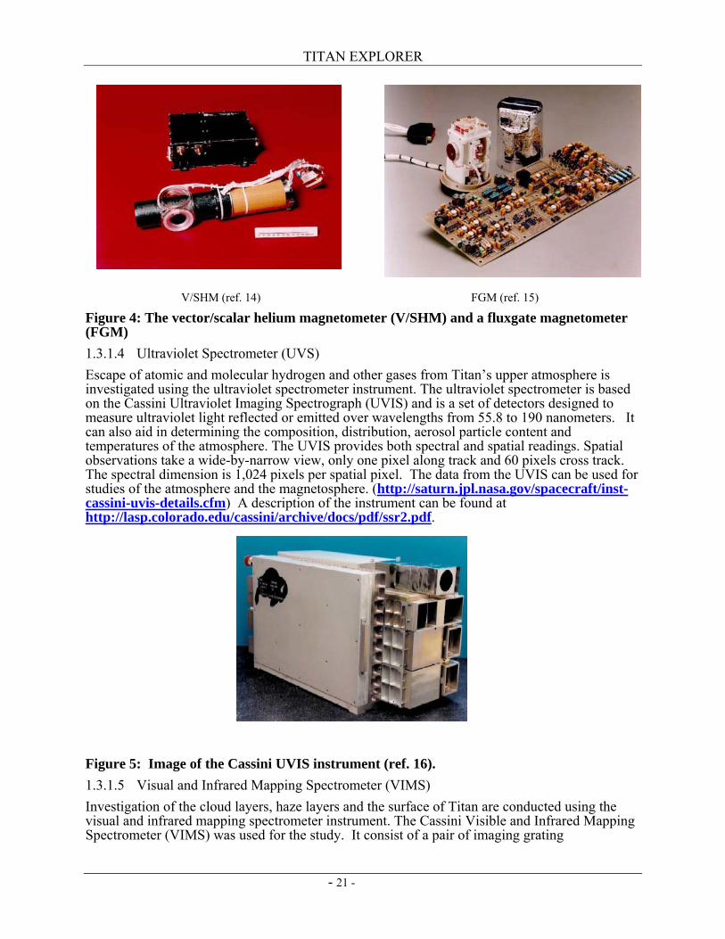
Figure 4: The vector/scalar helium magnetometer (V/SHM) and a fluxgate magnetometer (FGM) 1.3.1.4 Ultraviolet Spectrometer (UVS) Escape of atomic and molecular hydrogen and other gases from Titan’s upper atmosphere is investigated using the ultraviolet spectrometer instrument. The ultraviolet spectrometer is based on the Cassini Ultraviolet Imaging Spectrograph (UVIS) and is a set of detectors designed to measure ultraviolet light reflected or emitted over wavelengths from 55.8 to 190 nanometers. It can also aid in determining the composition, distribution, aerosol particle content and temperatures of the atmosphere. The UVIS provides both spectral and spatial readings. Spatial observations take a wide-by-narrow view, only one pixel along track and 60 pixels cross track. The spectral dimension is 1,024 pixels per spatial pixel. The data from the UVIS can be used for studies of the atmosphere and the magnetosphere. (http://saturn.jpl.nasa.gov/spacecraft/inst-cassini-uvis-details.cfm) A description of the instrument can be found at http://lasp.colorado.edu/cassini/archive/docs/pdf/ssr2.pdf.
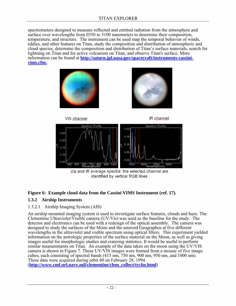
Figure 5: Image of the Cassini UVIS instrument (ref. 16). 1.3.1.5 Visual and Infrared Mapping Spectrometer (VIMS) Investigation of the cloud layers, haze layers and the surface of Titan are conducted using the visual and infrared mapping spectrometer instrument. The Cassini Visible and Infrared Mapping Spectrometer (VIMS) was used for the study. It consist of a pair of imaging grating
V/SHM (ref. 14) FGM (ref. 15)
TITAN EXPLORER
- 22 -
spectrometers designed to measure reflected and emitted radiation from the atmosphere and surface over wavelengths from 0350 to 5100 nanometers to determine their composition, temperature, and structure. The instrument can be used map the temporal behavior of winds, eddies, and other features on Titan, study the composition and distribution of atmospheric and cloud species, determine the composition and distribution of Titan’s surface materials, search for lightning on Titan and for active volcanism on Titan, and observe Titan's surface. More information can be found at http://saturn.jpl.nasa.gov/spacecraft/instruments-cassini-vims.cfm.
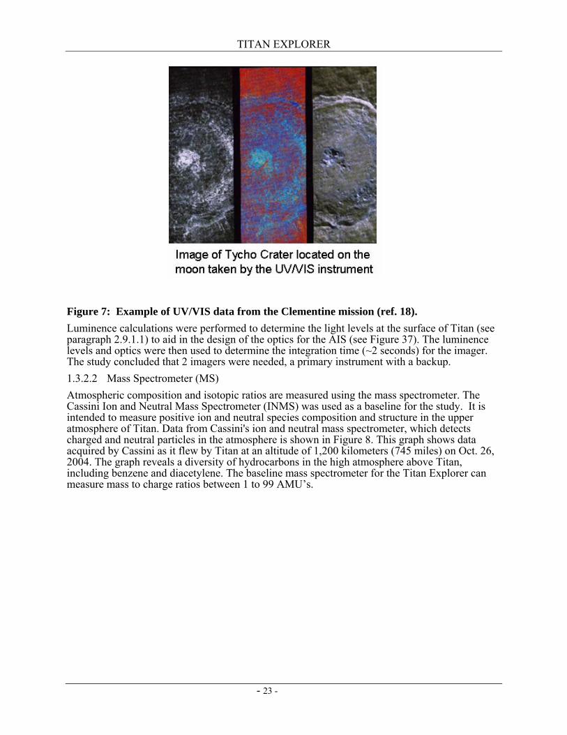
Figure 6: Example cloud data from the Cassini VIMS Instrument (ref. 17). 1.3.2 Airship Instruments 1.3.2.1 Airship Imaging System (AIS) An airship mounted imaging system is used to investigate surface features, clouds and haze. The Clementine Ultraviolet/Visible camera (UV/Vis) was used as the baseline for the study. The detector and electronics can be used with a redesign of the optical assembly. The camera was designed to study the surfaces of the Moon and the asteroid Geographos at five different wavelengths in the ultraviolet and visible spectrum using optical filters. This experiment yielded information on the petrologic properties of the surface material on the Moon, as well as giving images useful for morphologic studies and cratering statistics. It would be useful to perform similar measurements on Titan. An example of the data taken on the moon using the UV/VIS camera is shown in Figure 7. These UV/VIS images were formed from a mosaic of five image cubes, each consisting of spectral bands (415 nm, 750 nm, 900 nm, 950 nm, and 1000 nm). These data were acquired during orbit 40 on February 28, 1994. (http://www.cmf.nrl.navy.mil/clementine/clem_collect/tycho.html)
TITAN EXPLORER
- 23 -
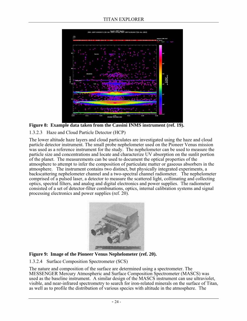
Figure 7: Example of UV/VIS data from the Clementine mission (ref. 18). Luminence calculations were performed to determine the light levels at the surface of Titan (see paragraph 2.9.1.1) to aid in the design of the optics for the AIS (see Figure 37). The luminence levels and optics were then used to determine the integration time (~2 seconds) for the imager. The study concluded that 2 imagers were needed, a primary instrument with a backup. 1.3.2.2 Mass Spectrometer (MS) Atmospheric composition and isotopic ratios are measured using the mass spectrometer. The Cassini Ion and Neutral Mass Spectrometer (INMS) was used as a baseline for the study. It is intended to measure positive ion and neutral species composition and structure in the upper atmosphere of Titan. Data from Cassini's ion and neutral mass spectrometer, which detects charged and neutral particles in the atmosphere is shown in Figure 8. This graph shows data acquired by Cassini as it flew by Titan at an altitude of 1,200 kilometers (745 miles) on Oct. 26, 2004. The graph reveals a diversity of hydrocarbons in the high atmosphere above Titan, including benzene and diacetylene. The baseline mass spectrometer for the Titan Explorer can measure mass to charge ratios between 1 to 99 AMU’s.
TITAN EXPLORER
- 24 -
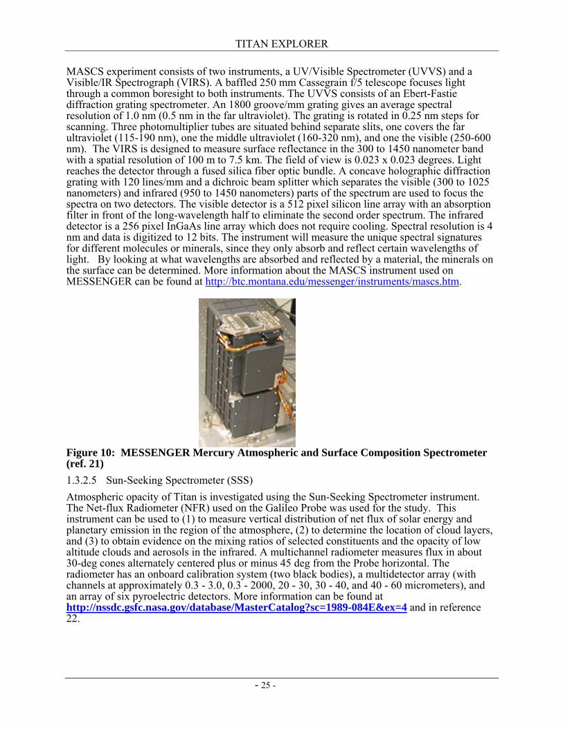
Figure 8: Example data taken from the Cassini INMS instrument (ref. 19). 1.3.2.3 Haze and Cloud Particle Detector (HCP) The lower altitude haze layers and cloud particulates are investigated using the haze and cloud particle detector instrument. The small probe nephelometer used on the Pioneer Venus mission was used as a reference instrument for the study. The nephelometer can be used to measure the particle size and concentrations and locate and characterize UV absorption on the sunlit portion of the planet. The measurements can be used to document the optical properties of the atmosphere to attempt to infer the composition of particulate matter or gaseous absorbers in the atmosphere. The instrument contains two distinct, but physically integrated experiments, a backscattering nephelometer channel and a two-spectral channel radiometer. The nephelometer comprised of a pulsed laser, a detector to measure the scattered light, collimating and collecting optics, spectral filters, and analog and digital electronics and power supplies. The radiometer consisted of a set of detector-filter combinations, optics, internal calibration systems and signal processing electronics and power supplies (ref. 20).
Figure 9: Image of the Pioneer Venus Nephelometer (ref. 20). 1.3.2.4 Surface Composition Spectrometer (SCS) The nature and composition of the surface are determined using a spectrometer. The MESSENGER Mercury Atmospheric and Surface Composition Spectrometer (MASCS) was used as the baseline instrument. A similar design of the MASCS instrument can use ultraviolet, visible, and near-infrared spectrometry to search for iron-related minerals on the surface of Titan, as well as to profile the distribution of various species with altitude in the atmosphere. The
TITAN EXPLORER
- 25 -
MASCS experiment consists of two instruments, a UV/Visible Spectrometer (UVVS) and a Visible/IR Spectrograph (VIRS). A baffled 250 mm Cassegrain f/5 telescope focuses light through a common boresight to both instruments. The UVVS consists of an Ebert-Fastie diffraction grating spectrometer. An 1800 groove/mm grating gives an average spectral resolution of 1.0 nm (0.5 nm in the far ultraviolet). The grating is rotated in 0.25 nm steps for scanning. Three photomultiplier tubes are situated behind separate slits, one covers the far ultraviolet (115-190 nm), one the middle ultraviolet (160-320 nm), and one the visible (250-600 nm). The VIRS is designed to measure surface reflectance in the 300 to 1450 nanometer band with a spatial resolution of 100 m to 7.5 km. The field of view is 0.023 x 0.023 degrees. Light reaches the detector through a fused silica fiber optic bundle. A concave holographic diffraction grating with 120 lines/mm and a dichroic beam splitter which separates the visible (300 to 1025 nanometers) and infrared (950 to 1450 nanometers) parts of the spectrum are used to focus the spectra on two detectors. The visible detector is a 512 pixel silicon line array with an absorption filter in front of the long-wavelength half to eliminate the second order spectrum. The infrared detector is a 256 pixel InGaAs line array which does not require cooling. Spectral resolution is 4 nm and data is digitized to 12 bits. The instrument will measure the unique spectral signatures for different molecules or minerals, since they only absorb and reflect certain wavelengths of light. By looking at what wavelengths are absorbed and reflected by a material, the minerals on the surface can be determined. More information about the MASCS instrument used on MESSENGER can be found at http://btc.montana.edu/messenger/instruments/mascs.htm.
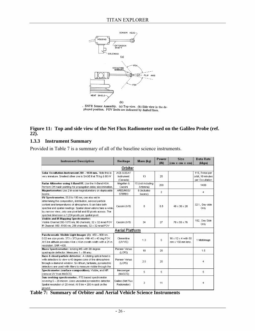
Figure 10: MESSENGER Mercury Atmospheric and Surface Composition Spectrometer (ref. 21) 1.3.2.5 Sun-Seeking Spectrometer (SSS) Atmospheric opacity of Titan is investigated using the Sun-Seeking Spectrometer instrument. The Net-flux Radiometer (NFR) used on the Galileo Probe was used for the study. This instrument can be used to (1) to measure vertical distribution of net flux of solar energy and planetary emission in the region of the atmosphere, (2) to determine the location of cloud layers, and (3) to obtain evidence on the mixing ratios of selected constituents and the opacity of low altitude clouds and aerosols in the infrared. A multichannel radiometer measures flux in about 30-deg cones alternately centered plus or minus 45 deg from the Probe horizontal. The radiometer has an onboard calibration system (two black bodies), a multidetector array (with channels at approximately 0.3 - 3.0, 0.3 - 2000, 20 - 30, 30 - 40, and 40 - 60 micrometers), and an array of six pyroelectric detectors. More information can be found at http://nssdc.gsfc.nasa.gov/database/MasterCatalog?sc=1989-084E&ex=4 and in reference 22.
TITAN EXPLORER
- 26 -
Figure 11: Top and side view of the Net Flux Radiometer used on the Galileo Probe (ref. 22). 1.3.3 Instrument Summary Provided in Table 7 is a summary of all of the baseline science instruments.
Table 7: Summary of Orbiter and Aerial Vehicle Science Instruments
TITAN EXPLORER
- 27 -
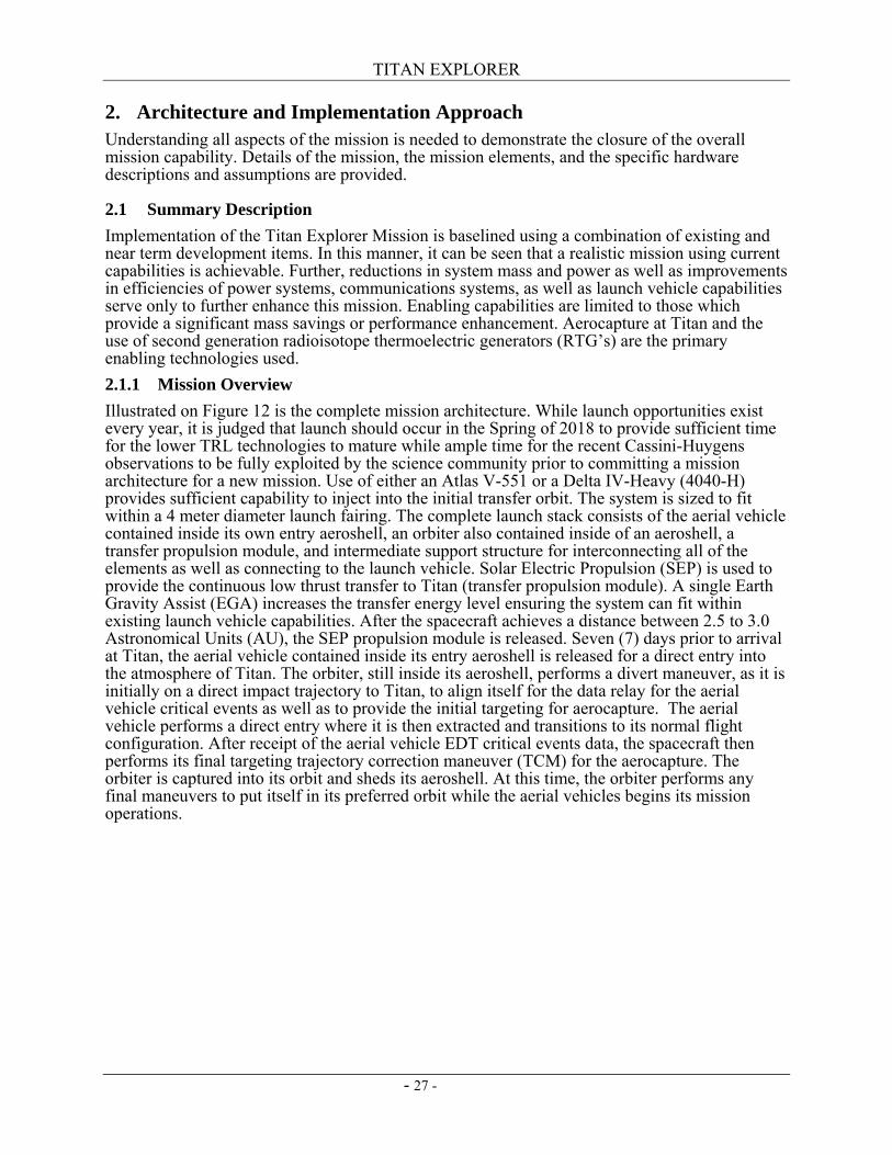
2. Architecture and Implementation Approach Understanding all aspects of the mission is needed to demonstrate the closure of the overall mission capability. Details of the mission, the mission elements, and the specific hardware descriptions and assumptions are provided.
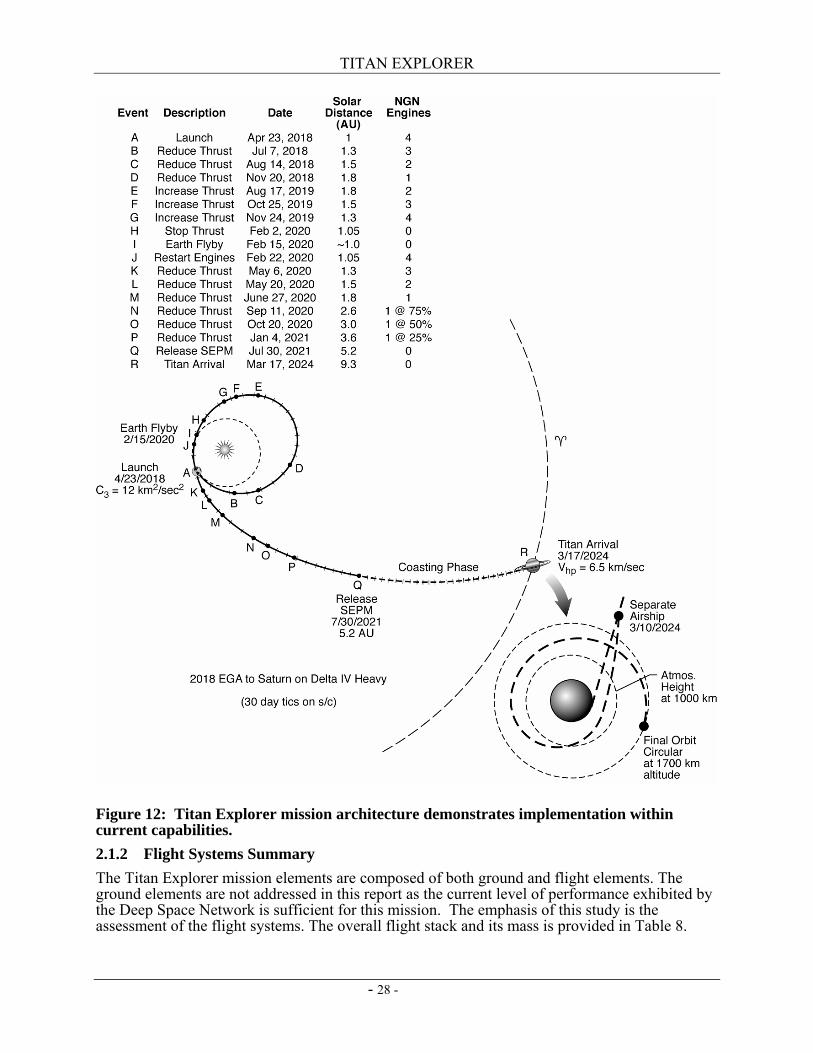
2.1 Summary Description Implementation of the Titan Explorer Mission is baselined using a combination of existing and near term development items. In this manner, it can be seen that a realistic mission using current capabilities is achievable. Further, reductions in system mass and power as well as improvements in efficiencies of power systems, communications systems, as well as launch vehicle capabilities serve only to further enhance this mission. Enabling capabilities are limited to those which provide a significant mass savings or performance enhancement. Aerocapture at Titan and the use of second generation radioisotope thermoelectric generators (RTG’s) are the primary enabling technologies used. 2.1.1 Mission Overview Illustrated on Figure 12 is the complete mission architecture. While launch opportunities exist every year, it is judged that launch should occur in the Spring of 2018 to provide sufficient time for the lower TRL technologies to mature while ample time for the recent Cassini-Huygens observations to be fully exploited by the science community prior to committing a mission architecture for a new mission. Use of either an Atlas V-551 or a Delta IV-Heavy (4040-H) provides sufficient capability to inject into the initial transfer orbit. The system is sized to fit within a 4 meter diameter launch fairing. The complete launch stack consists of the aerial vehicle contained inside its own entry aeroshell, an orbiter also contained inside of an aeroshell, a transfer propulsion module, and intermediate support structure for interconnecting all of the elements as well as connecting to the launch vehicle. Solar Electric Propulsion (SEP) is used to provide the continuous low thrust transfer to Titan (transfer propulsion module). A single Earth Gravity Assist (EGA) increases the transfer energy level ensuring the system can fit within existing launch vehicle capabilities. After the spacecraft achieves a distance between 2.5 to 3.0 Astronomical Units (AU), the SEP propulsion module is released. Seven (7) days prior to arrival at Titan, the aerial vehicle contained inside its entry aeroshell is released for a direct entry into the atmosphere of Titan. The orbiter, still inside its aeroshell, performs a divert maneuver, as it is initially on a direct impact trajectory to Titan, to align itself for the data relay for the aerial vehicle critical events as well as to provide the initial targeting for aerocapture. The aerial vehicle performs a direct entry where it is then extracted and transitions to its normal flight configuration. After receipt of the aerial vehicle EDT critical events data, the spacecraft then performs its final targeting trajectory correction maneuver (TCM) for the aerocapture. The orbiter is captured into its orbit and sheds its aeroshell. At this time, the orbiter performs any final maneuvers to put itself in its preferred orbit while the aerial vehicles begins its mission operations.
TITAN EXPLORER
- 28 -
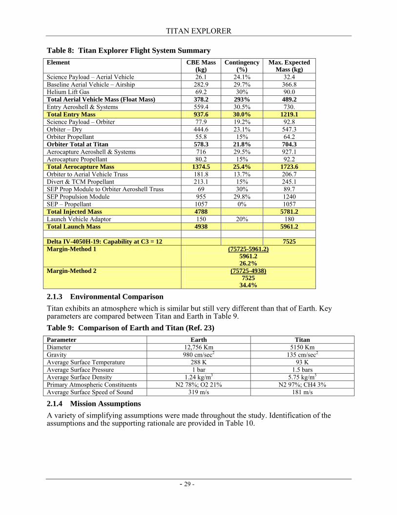
Figure 12: Titan Explorer mission architecture demonstrates implementation within current capabilities. 2.1.2 Flight Systems Summary The Titan Explorer mission elements are composed of both ground and flight elements. The ground elements are not addressed in this report as the current level of performance exhibited by the Deep Space Network is sufficient for this mission. The emphasis of this study is the assessment of the flight systems. The overall flight stack and its mass is provided in Table 8.
TITAN EXPLORER
- 29 -
Table 8: Titan Explorer Flight System Summary Element CBE Mass
(kg) Contingency
(%) Max. Expected
Mass (kg) Science Payload – Aerial Vehicle 26.1 24.1% 32.4 Baseline Aerial Vehicle – Airship 282.9 29.7% 366.8 Helium Lift Gas 69.2 30% 90.0 Total Aerial Vehicle Mass (Float Mass) 378.2 293% 489.2 Entry Aeroshell & Systems 559.4 30.5% 730. Total Entry Mass 937.6 30.0% 1219.1 Science Payload – Orbiter 77.9 19.2% 92.8 Orbiter – Dry 444.6 23.1% 547.3 Orbiter Propellant 55.8 15% 64.2 Orbiter Total at Titan 578.3 21.8% 704.3 Aerocapture Aeroshell & Systems 716 29.5% 927.1 Aerocapture Propellant 80.2 15% 92.2 Total Aerocapture Mass 1374.5 25.4% 1723.6 Orbiter to Aerial Vehicle Truss 181.8 13.7% 206.7 Divert & TCM Propellant 213.1 15% 245.1 SEP Prop Module to Orbiter Aeroshell Truss 69 30% 89.7 SEP Propulsion Module 955 29.8% 1240 SEP – Propellant 1057 0% 1057 Total Injected Mass 4788 5781.2 Launch Vehicle Adaptor 150 20% 180 Total Launch Mass 4938 5961.2 Delta IV-4050H-19: Capability at C3 = 12 7525 Margin-Method 1 (75725-5961.2)
5961.2 26.2%
Margin-Method 2 (75725-4938) 7525
34.4%
2.1.3 Environmental Comparison Titan exhibits an atmosphere which is similar but still very different than that of Earth. Key parameters are compared between Titan and Earth in Table 9. Table 9: Comparison of Earth and Titan (Ref. 23) Parameter Earth Titan Diameter 12,756 Km 5150 Km Gravity 980 cm/sec2 135 cm/sec2 Average Surface Temperature 288 K 93 K Average Surface Pressure 1 bar 1.5 bars Average Surface Density 1.24 kg/m3 5.75 kg/m3 Primary Atmospheric Constituents N2 78%; O2 21% N2 97%; CH4 3% Average Surface Speed of Sound 319 m/s 181 m/s
2.1.4 Mission Assumptions A variety of simplifying assumptions were made throughout the study. Identification of the assumptions and the supporting rationale are provided in Table 10.
TITAN EXPLORER
- 30 -
Table 10: Mission Assumptions No. Assumption Rationale 1 Launch in 2018 Allows newer technologies to be developed. Allows full
evaluation of Cassini-Huygens data. 2 Technology cutoff (TRL-6) in 2014 Typical assumption – launch minus 4 years 3 No special planetary protection provisions Consistent with current NASA policy. 4 Titan orbit insertion performed via aerocapture. Reduces total launch mass 5 Low thrust solar electric propulsion to Titan Reduces total launch mass. Eliminates need for large
launch vehicle. Eliminates need for nuclear propulsion. 6 Single Earth Gravity Assist Reduces total launch mass. Earth provides larger ∆V
increment than Venus. 7 X-band as primary data return to Earth Heritage. Provides lower performance bound. Ka-band
or optical are enhancing. 8 Total radiation dose of 25 krads behind 100 mils
of aluminum with an RDM of 2. From Team-X
9 Use TitanGRAM as the engineering model of the atmosphere.
See Reference 24.
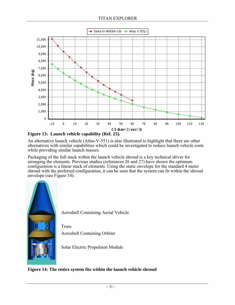
2.2 Launch Segment 2.2.1 Launch Vehicle Launch of the Titan Explorer mission is performed using existing expendable, heavy lift launch vehicles. It has been assumed (and verified via analysis) that the Delta IV – Heavy (4050H) has sufficient lift capability to meet the mission needs. From Table 8, the maximum launch mass needed is 5961 kg. With a mission design strategy using a combination of solar electric propulsion, and aerocapture at Titan, a launch energy (C3) of only 12 km2/sec2 is needed. As illustrated in Figure 13, there is sufficient margin available within the capability of this launch vehicle to accommodate changes within the system. With reductions in systems mass and power on the horizon, the overall launch mass can be reduced thus enabling use of a higher launch energy with the commensurate reduction in needed capability of the Solar Electric Propulsion system. The standard 4 meter diameter fairing for the Delta IV-H launch vehicle was assumed, as well as the standard launch vehicle adaptor.
TITAN EXPLORER
- 31 -
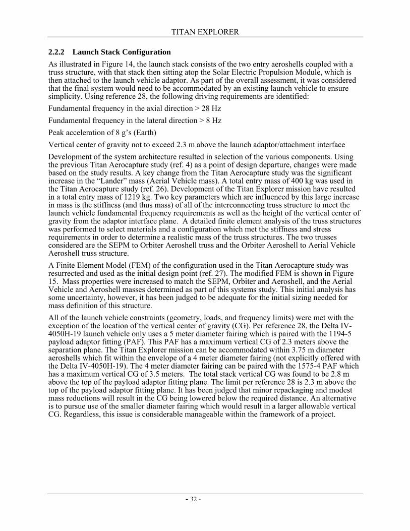
Figure 13: Launch vehicle capability (Ref. 25). An alternative launch vehicle (Atlas-V-551) is also illustrated to highlight that there are other alternatives with similar capabilities which could be investigated to reduce launch vehicle costs while providing similar launch masses. Packaging of the full stack within the launch vehicle shroud is a key technical driver for arranging the elements. Previous studies (references 26 and 27) have shown the optimum configuration is a linear stack of elements. Using the static envelope for the standard 4 meter shroud with the preferred configuration, it can be seen that the system can fit within the shroud envelope (see Figure 14).
Aeroshell Containing Aerial Vehicle Truss Aeroshell Containing Orbiter Solar Electric Propulsion Module
Figure 14: The entire system fits within the launch vehicle shroud
TITAN EXPLORER
- 32 -
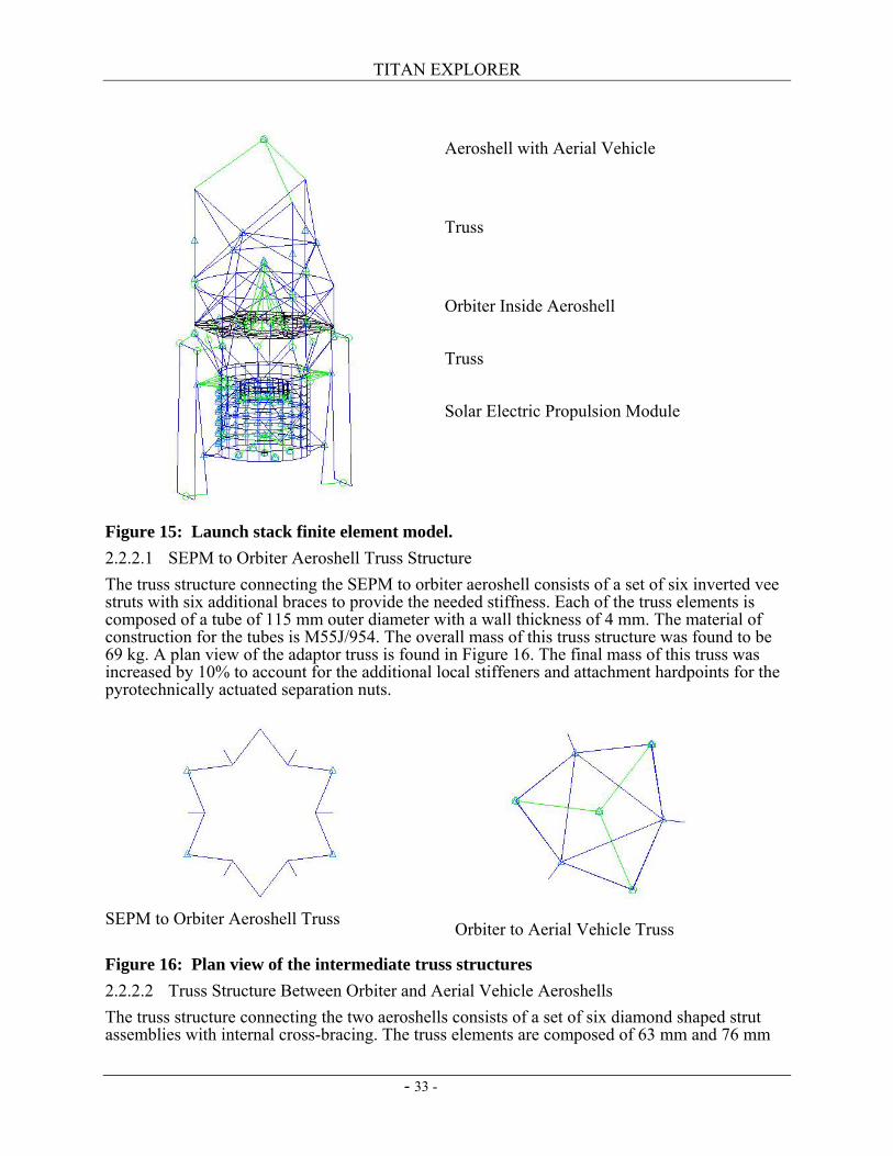
2.2.2 Launch Stack Configuration As illustrated in Figure 14, the launch stack consists of the two entry aeroshells coupled with a truss structure, with that stack then sitting atop the Solar Electric Propulsion Module, which is then attached to the launch vehicle adaptor. As part of the overall assessment, it was considered that the final system would need to be accommodated by an existing launch vehicle to ensure simplicity. Using reference 28, the following driving requirements are identified: Fundamental frequency in the axial direction > 28 Hz Fundamental frequency in the lateral direction > 8 Hz Peak acceleration of 8 g’s (Earth) Vertical center of gravity not to exceed 2.3 m above the launch adaptor/attachment interface Development of the system architecture resulted in selection of the various components. Using the previous Titan Aerocapture study (ref. 4) as a point of design departure, changes were made based on the study results. A key change from the Titan Aerocapture study was the significant increase in the “Lander” mass (Aerial Vehicle mass). A total entry mass of 400 kg was used in the Titan Aerocapture study (ref. 26). Development of the Titan Explorer mission have resulted in a total entry mass of 1219 kg. Two key parameters which are influenced by this large increase in mass is the stiffness (and thus mass) of all of the interconnecting truss structure to meet the launch vehicle fundamental frequency requirements as well as the height of the vertical center of gravity from the adaptor interface plane. A detailed finite element analysis of the truss structures was performed to select materials and a configuration which met the stiffness and stress requirements in order to determine a realistic mass of the truss structures. The two trusses considered are the SEPM to Orbiter Aeroshell truss and the Orbiter Aeroshell to Aerial Vehicle Aeroshell truss structure. A Finite Element Model (FEM) of the configuration used in the Titan Aerocapture study was resurrected and used as the initial design point (ref. 27). The modified FEM is shown in Figure 15. Mass properties were increased to match the SEPM, Orbiter and Aeroshell, and the Aerial Vehicle and Aeroshell masses determined as part of this systems study. This initial analysis has some uncertainty, however, it has been judged to be adequate for the initial sizing needed for mass definition of this structure. All of the launch vehicle constraints (geometry, loads, and frequency limits) were met with the exception of the location of the vertical center of gravity (CG). Per reference 28, the Delta IV-4050H-19 launch vehicle only uses a 5 meter diameter fairing which is paired with the 1194-5 payload adaptor fitting (PAF). This PAF has a maximum vertical CG of 2.3 meters above the separation plane. The Titan Explorer mission can be accommodated within 3.75 m diameter aeroshells which fit within the envelope of a 4 meter diameter fairing (not explicitly offered with the Delta IV-4050H-19). The 4 meter diameter fairing can be paired with the 1575-4 PAF which has a maximum vertical CG of 3.5 meters. The total stack vertical CG was found to be 2.8 m above the top of the payload adaptor fitting plane. The limit per reference 28 is 2.3 m above the top of the payload adaptor fitting plane. It has been judged that minor repackaging and modest mass reductions will result in the CG being lowered below the required distance. An alternative is to pursue use of the smaller diameter fairing which would result in a larger allowable vertical CG. Regardless, this issue is considerable manageable within the framework of a project.
TITAN EXPLORER
- 33 -
Aeroshell with Aerial Vehicle Truss Orbiter Inside Aeroshell Truss Solar Electric Propulsion Module
Figure 15: Launch stack finite element model. 2.2.2.1 SEPM to Orbiter Aeroshell Truss Structure The truss structure connecting the SEPM to orbiter aeroshell consists of a set of six inverted vee struts with six additional braces to provide the needed stiffness. Each of the truss elements is composed of a tube of 115 mm outer diameter with a wall thickness of 4 mm. The material of construction for the tubes is M55J/954. The overall mass of this truss structure was found to be 69 kg. A plan view of the adaptor truss is found in Figure 16. The final mass of this truss was increased by 10% to account for the additional local stiffeners and attachment hardpoints for the pyrotechnically actuated separation nuts.
SEPM to Orbiter Aeroshell Truss Orbiter to Aerial Vehicle Truss
Figure 16: Plan view of the intermediate truss structures 2.2.2.2 Truss Structure Between Orbiter and Aerial Vehicle Aeroshells The truss structure connecting the two aeroshells consists of a set of six diamond shaped strut assemblies with internal cross-bracing. The truss elements are composed of 63 mm and 76 mm
TITAN EXPLORER
- 34 -
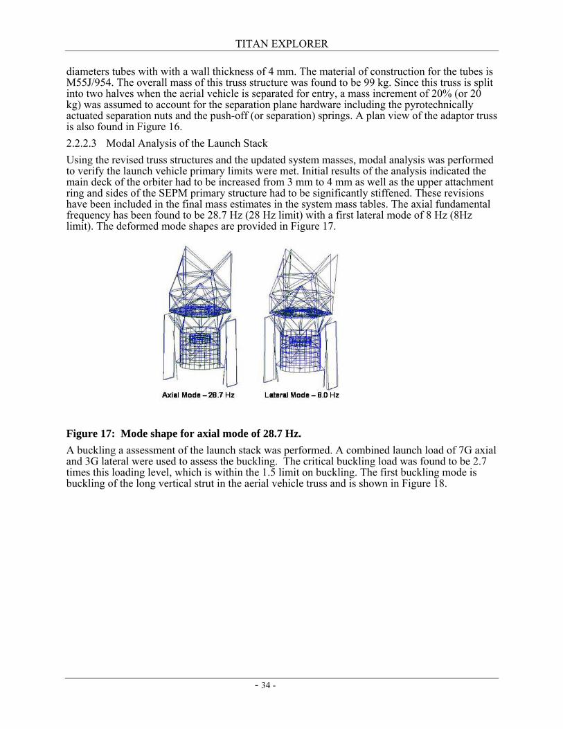
diameters tubes with with a wall thickness of 4 mm. The material of construction for the tubes is M55J/954. The overall mass of this truss structure was found to be 99 kg. Since this truss is split into two halves when the aerial vehicle is separated for entry, a mass increment of 20% (or 20 kg) was assumed to account for the separation plane hardware including the pyrotechnically actuated separation nuts and the push-off (or separation) springs. A plan view of the adaptor truss is also found in Figure 16. 2.2.2.3 Modal Analysis of the Launch Stack Using the revised truss structures and the updated system masses, modal analysis was performed to verify the launch vehicle primary limits were met. Initial results of the analysis indicated the main deck of the orbiter had to be increased from 3 mm to 4 mm as well as the upper attachment ring and sides of the SEPM primary structure had to be significantly stiffened. These revisions have been included in the final mass estimates in the system mass tables. The axial fundamental frequency has been found to be 28.7 Hz (28 Hz limit) with a first lateral mode of 8 Hz (8Hz limit). The deformed mode shapes are provided in Figure 17.
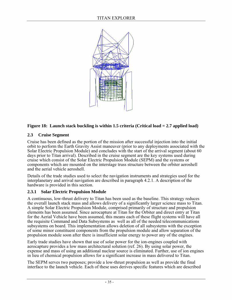
Figure 17: Mode shape for axial mode of 28.7 Hz. A buckling a assessment of the launch stack was performed. A combined launch load of 7G axial and 3G lateral were used to assess the buckling. The critical buckling load was found to be 2.7 times this loading level, which is within the 1.5 limit on buckling. The first buckling mode is buckling of the long vertical strut in the aerial vehicle truss and is shown in Figure 18.
TITAN EXPLORER
- 35 -
Figure 18: Launch stack buckling is within 1.5 criteria (Critical load = 2.7 applied load)
2.3 Cruise Segment Cruise has been defined as the portion of the mission after successful injection into the initial orbit to perform the Earth Gravity Assist maneuver (prior to any deployments associated with the Solar Electric Propulsion Module) and concludes with the start of the arrival segment (about 60 days prior to Titan arrival). Described in the cruise segment are the key systems used during cruise which consist of the Solar Electric Propulsion Module (SEPM) and the systems or components which are mounted on the interstage truss structure between the orbiter aeroshell and the aerial vehicle aeroshell. Details of the trade studies used to select the navigation instruments and strategies used for the interplanetary and arrival navigation are described in paragraph 4.2.1. A description of the hardware is provided in this section. 2.3.1 Solar Electric Propulsion Module A continuous, low-thrust delivery to Titan has been used as the baseline. This strategy reduces the overall launch stack mass and allows delivery of a significantly larger science mass to Titan. A simple Solar Electric Propulsion Module, comprised primarily of structure and propulsion elements has been assumed. Since aerocapture at Titan for the Orbiter and direct entry at Titan for the Aerial Vehicle have been assumed, this means each of these flight systems will have all the requisite Command and Data Subsystems as well as all of the needed telecommunications subsystems on board. This implementation allows deletion of all subsystems with the exception of some minor constituent components from the propulsion module and allow separation of the propulsion module soon after there is insufficient solar energy to power any of the engines. Early trade studies have shown that use of solar power for the ion-engines coupled with aerocapture provides a low mass architectural solution (ref. 26). By using solar power, the expense and mass of using an additional nuclear source is eliminated. Further, use of ion engines in lieu of chemical propulsion allows for a significant increase in mass delivered to Titan. The SEPM serves two purposes; provide a low-thrust propulsion as well as provide the final interface to the launch vehicle. Each of these uses derives specific features which are described
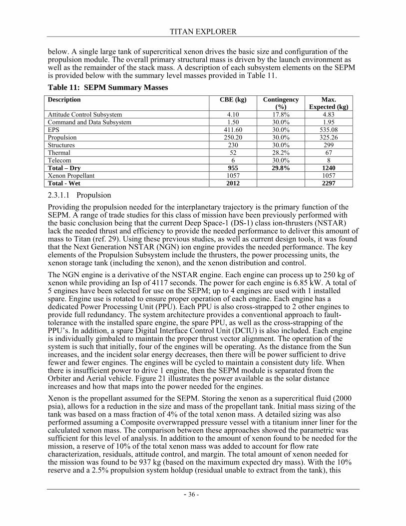
TITAN EXPLORER
- 36 -
below. A single large tank of supercritical xenon drives the basic size and configuration of the propulsion module. The overall primary structural mass is driven by the launch environment as well as the remainder of the stack mass. A description of each subsystem elements on the SEPM is provided below with the summary level masses provided in Table 11. Table 11: SEPM Summary Masses Description CBE (kg) Contingency
(%) Max.
Expected (kg) Attitude Control Subsystem 4.10 17.8% 4.83 Command and Data Subsystem 1.50 30.0% 1.95 EPS 411.60 30.0% 535.08 Propulsion 250.20 30.0% 325.26 Structures 230 30.0% 299 Thermal 52 28.2% 67 Telecom 6 30.0% 8 Total – Dry 955 29.8% 1240 Xenon Propellant 1057 1057 Total - Wet 2012 2297
2.3.1.1 Propulsion Providing the propulsion needed for the interplanetary trajectory is the primary function of the SEPM. A range of trade studies for this class of mission have been previously performed with the basic conclusion being that the current Deep Space-1 (DS-1) class ion-thrusters (NSTAR) lack the needed thrust and efficiency to provide the needed performance to deliver this amount of mass to Titan (ref. 29). Using these previous studies, as well as current design tools, it was found that the Next Generation NSTAR (NGN) ion engine provides the needed performance. The key elements of the Propulsion Subsystem include the thrusters, the power processing units, the xenon storage tank (including the xenon), and the xenon distribution and control. The NGN engine is a derivative of the NSTAR engine. Each engine can process up to 250 kg of xenon while providing an Isp of 4117 seconds. The power for each engine is 6.85 kW. A total of 5 engines have been selected for use on the SEPM; up to 4 engines are used with 1 installed spare. Engine use is rotated to ensure proper operation of each engine. Each engine has a dedicated Power Processing Unit (PPU). Each PPU is also cross-strapped to 2 other engines to provide full redundancy. The system architecture provides a conventional approach to fault-tolerance with the installed spare engine, the spare PPU, as well as the cross-strapping of the PPU’s. In addition, a spare Digital Interface Control Unit (DCIU) is also included. Each engine is individually gimbaled to maintain the proper thrust vector alignment. The operation of the system is such that initially, four of the engines will be operating. As the distance from the Sun increases, and the incident solar energy decreases, then there will be power sufficient to drive fewer and fewer engines. The engines will be cycled to maintain a consistent duty life. When there is insufficient power to drive 1 engine, then the SEPM module is separated from the Orbiter and Aerial vehicle. Figure 21 illustrates the power available as the solar distance increases and how that maps into the power needed for the engines. Xenon is the propellant assumed for the SEPM. Storing the xenon as a supercritical fluid (2000 psia), allows for a reduction in the size and mass of the propellant tank. Initial mass sizing of the tank was based on a mass fraction of 4% of the total xenon mass. A detailed sizing was also performed assuming a Composite overwrapped pressure vessel with a titanium inner liner for the calculated xenon mass. The comparison between these approaches showed the parametric was sufficient for this level of analysis. In addition to the amount of xenon found to be needed for the mission, a reserve of 10% of the total xenon mass was added to account for flow rate characterization, residuals, attitude control, and margin. The total amount of xenon needed for the mission was found to be 937 kg (based on the maximum expected dry mass). With the 10% reserve and a 2.5% propulsion system holdup (residual unable to extract from the tank), this
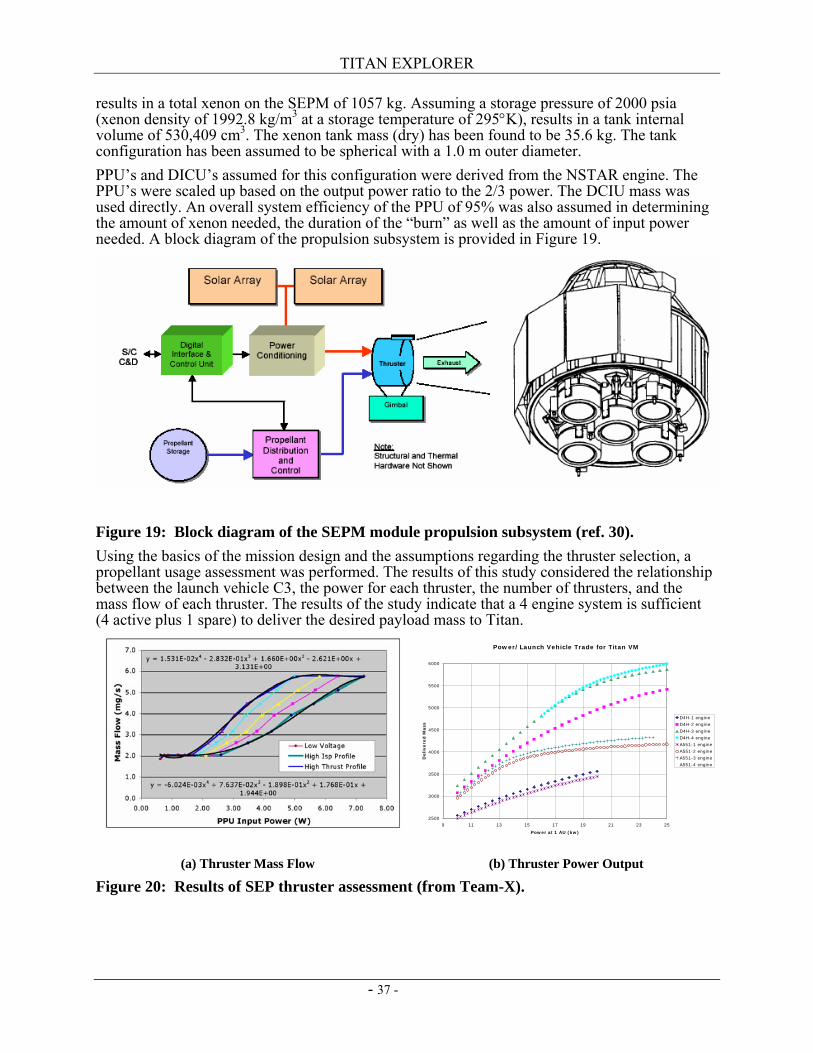
TITAN EXPLORER
- 37 -
results in a total xenon on the SEPM of 1057 kg. Assuming a storage pressure of 2000 psia (xenon density of 1992.8 kg/m3 at a storage temperature of 295°K), results in a tank internal volume of 530,409 cm3. The xenon tank mass (dry) has been found to be 35.6 kg. The tank configuration has been assumed to be spherical with a 1.0 m outer diameter. PPU’s and DICU’s assumed for this configuration were derived from the NSTAR engine. The PPU’s were scaled up based on the output power ratio to the 2/3 power. The DCIU mass was used directly. An overall system efficiency of the PPU of 95% was also assumed in determining the amount of xenon needed, the duration of the “burn” as well as the amount of input power needed. A block diagram of the propulsion subsystem is provided in Figure 19.
Figure 19: Block diagram of the SEPM module propulsion subsystem (ref. 30). Using the basics of the mission design and the assumptions regarding the thruster selection, a propellant usage assessment was performed. The results of this study considered the relationship between the launch vehicle C3, the power for each thruster, the number of thrusters, and the mass flow of each thruster. The results of the study indicate that a 4 engine system is sufficient (4 active plus 1 spare) to deliver the desired payload mass to Titan.
(a) Thruster Mass Flow (b) Thruster Power Output
Figure 20: Results of SEP thruster assessment (from Team-X).
Power/Launch Vehicle Trade for Titan VM
2500
3000
3500
4000
4500
5000
5500
6000
9 11 13 15 17 19 21 23 25
Power at 1 AU (kw)
Delivere
d M
ass
D4H-1 engine
D4H-2 engine
D4H-3 engine
D4H-4 engine
A551-1 engine
A551-2 engine
A551-3 engine
A551-4 engine
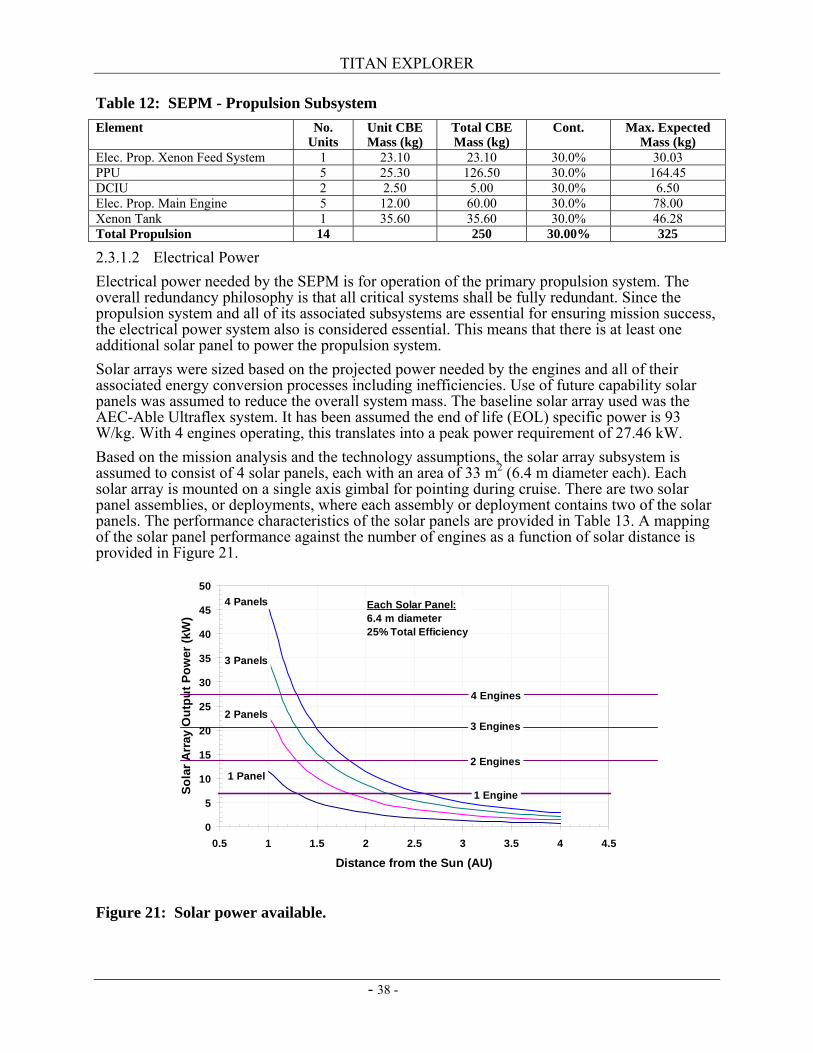
TITAN EXPLORER
- 38 -
Table 12: SEPM - Propulsion Subsystem Element No.
Units Unit CBE Mass (kg)
Total CBE Mass (kg)
Cont. Max. Expected Mass (kg)
Elec. Prop. Xenon Feed System 1 23.10 23.10 30.0% 30.03 PPU 5 25.30 126.50 30.0% 164.45 DCIU 2 2.50 5.00 30.0% 6.50 Elec. Prop. Main Engine 5 12.00 60.00 30.0% 78.00 Xenon Tank 1 35.60 35.60 30.0% 46.28 Total Propulsion 14 250 30.00% 325
2.3.1.2 Electrical Power Electrical power needed by the SEPM is for operation of the primary propulsion system. The overall redundancy philosophy is that all critical systems shall be fully redundant. Since the propulsion system and all of its associated subsystems are essential for ensuring mission success, the electrical power system also is considered essential. This means that there is at least one additional solar panel to power the propulsion system. Solar arrays were sized based on the projected power needed by the engines and all of their associated energy conversion processes including inefficiencies. Use of future capability solar panels was assumed to reduce the overall system mass. The baseline solar array used was the AEC-Able Ultraflex system. It has been assumed the end of life (EOL) specific power is 93 W/kg. With 4 engines operating, this translates into a peak power requirement of 27.46 kW. Based on the mission analysis and the technology assumptions, the solar array subsystem is assumed to consist of 4 solar panels, each with an area of 33 m2 (6.4 m diameter each). Each solar array is mounted on a single axis gimbal for pointing during cruise. There are two solar panel assemblies, or deployments, where each assembly or deployment contains two of the solar panels. The performance characteristics of the solar panels are provided in Table 13. A mapping of the solar panel performance against the number of engines as a function of solar distance is provided in Figure 21.
Figure 21: Solar power available.
0
5
10
15
20
25
30
35
40
45
50
0.5 1 1.5 2 2.5 3 3.5 4 4.5
Distance from the Sun (AU)
Sola
r Arr
ay O
utpu
t Pow
er (k
W)
4 Engines
1 Engine
2 Engines
3 Engines
Each Solar Panel:6.4 m diameter25% Total Efficiency
1 Panel
2 Panels
3 Panels
4 Panels
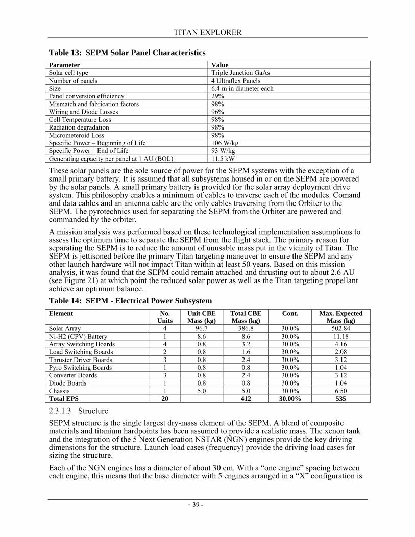
TITAN EXPLORER
- 39 -
Table 13: SEPM Solar Panel Characteristics Parameter Value Solar cell type Triple Junction GaAs Number of panels 4 Ultraflex Panels Size 6.4 m in diameter each Panel conversion efficiency 29% Mismatch and fabrication factors 98% Wiring and Diode Losses 96% Cell Temperature Loss 98% Radiation degradation 98% Micrometeroid Loss 98% Specific Power – Beginning of Life 106 W/kg Specific Power – End of Life 93 W/kg Generating capacity per panel at 1 AU (BOL) 11.5 kW
These solar panels are the sole source of power for the SEPM systems with the exception of a small primary battery. It is assumed that all subsystems housed in or on the SEPM are powered by the solar panels. A small primary battery is provided for the solar array deployment drive system. This philosophy enables a minimum of cables to traverse each of the modules. Comand and data cables and an antenna cable are the only cables traversing from the Orbiter to the SEPM. The pyrotechnics used for separating the SEPM from the Orbiter are powered and commanded by the orbiter. A mission analysis was performed based on these technological implementation assumptions to assess the optimum time to separate the SEPM from the flight stack. The primary reason for separating the SEPM is to reduce the amount of unusable mass put in the vicinity of Titan. The SEPM is jettisoned before the primary Titan targeting maneuver to ensure the SEPM and any other launch hardware will not impact Titan within at least 50 years. Based on this mission analysis, it was found that the SEPM could remain attached and thrusting out to about 2.6 AU (see Figure 21) at which point the reduced solar power as well as the Titan targeting propellant achieve an optimum balance. Table 14: SEPM - Electrical Power Subsystem Element No.
Units Unit CBE Mass (kg)
Total CBE Mass (kg)
Cont. Max. Expected Mass (kg)
Solar Array 4 96.7 386.8 30.0% 502.84 Ni-H2 (CPV) Battery 1 8.6 8.6 30.0% 11.18 Array Switching Boards 4 0.8 3.2 30.0% 4.16 Load Switching Boards 2 0.8 1.6 30.0% 2.08 Thruster Driver Boards 3 0.8 2.4 30.0% 3.12 Pyro Switching Boards 1 0.8 0.8 30.0% 1.04 Converter Boards 3 0.8 2.4 30.0% 3.12 Diode Boards 1 0.8 0.8 30.0% 1.04 Chassis 1 5.0 5.0 30.0% 6.50 Total EPS 20 412 30.00% 535
2.3.1.3 Structure SEPM structure is the single largest dry-mass element of the SEPM. A blend of composite materials and titanium hardpoints has been assumed to provide a realistic mass. The xenon tank and the integration of the 5 Next Generation NSTAR (NGN) engines provide the key driving dimensions for the structure. Launch load cases (frequency) provide the driving load cases for sizing the structure. Each of the NGN engines has a diameter of about 30 cm. With a “one engine” spacing between each engine, this means that the base diameter with 5 engines arranged in a “X” configuration is
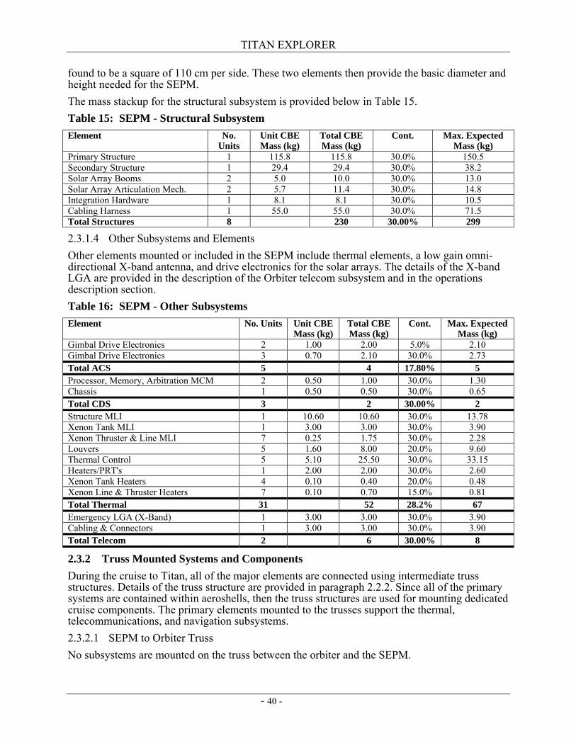
TITAN EXPLORER
- 40 -
found to be a square of 110 cm per side. These two elements then provide the basic diameter and height needed for the SEPM. The mass stackup for the structural subsystem is provided below in Table 15. Table 15: SEPM - Structural Subsystem Element No.
Units Unit CBE Mass (kg)
Total CBE Mass (kg)
Cont. Max. Expected Mass (kg)
Primary Structure 1 115.8 115.8 30.0% 150.5 Secondary Structure 1 29.4 29.4 30.0% 38.2 Solar Array Booms 2 5.0 10.0 30.0% 13.0 Solar Array Articulation Mech. 2 5.7 11.4 30.0% 14.8 Integration Hardware 1 8.1 8.1 30.0% 10.5 Cabling Harness 1 55.0 55.0 30.0% 71.5 Total Structures 8 230 30.00% 299
2.3.1.4 Other Subsystems and Elements Other elements mounted or included in the SEPM include thermal elements, a low gain omni-directional X-band antenna, and drive electronics for the solar arrays. The details of the X-band LGA are provided in the description of the Orbiter telecom subsystem and in the operations description section. Table 16: SEPM - Other Subsystems Element No. Units Unit CBE
Mass (kg) Total CBE Mass (kg)
Cont. Max. Expected Mass (kg)
Gimbal Drive Electronics 2 1.00 2.00 5.0% 2.10 Gimbal Drive Electronics 3 0.70 2.10 30.0% 2.73 Total ACS 5 4 17.80% 5 Processor, Memory, Arbitration MCM 2 0.50 1.00 30.0% 1.30 Chassis 1 0.50 0.50 30.0% 0.65 Total CDS 3 2 30.00% 2 Structure MLI 1 10.60 10.60 30.0% 13.78 Xenon Tank MLI 1 3.00 3.00 30.0% 3.90 Xenon Thruster & Line MLI 7 0.25 1.75 30.0% 2.28 Louvers 5 1.60 8.00 20.0% 9.60 Thermal Control 5 5.10 25.50 30.0% 33.15 Heaters/PRT's 1 2.00 2.00 30.0% 2.60 Xenon Tank Heaters 4 0.10 0.40 20.0% 0.48 Xenon Line & Thruster Heaters 7 0.10 0.70 15.0% 0.81 Total Thermal 31 52 28.2% 67 Emergency LGA (X-Band) 1 3.00 3.00 30.0% 3.90 Cabling & Connectors 1 3.00 3.00 30.0% 3.90 Total Telecom 2 6 30.00% 8
2.3.2 Truss Mounted Systems and Components During the cruise to Titan, all of the major elements are connected using intermediate truss structures. Details of the truss structure are provided in paragraph 2.2.2. Since all of the primary systems are contained within aeroshells, then the truss structures are used for mounting dedicated cruise components. The primary elements mounted to the trusses support the thermal, telecommunications, and navigation subsystems. 2.3.2.1 SEPM to Orbiter Truss No subsystems are mounted on the truss between the orbiter and the SEPM.
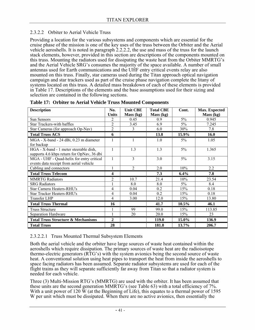
TITAN EXPLORER
- 41 -
2.3.2.2 Orbiter to Aerial Vehicle Truss Providing a location for the various subsystems and components which are essential for the cruise phase of the mission is one of the key uses of the truss between the Orbiter and the Aerial vehicle aeroshells. It is noted in paragraph 2.2.2.2, the use and mass of the truss for the launch stack elements, however, provided in this section are descriptions of the components mounted on this truss. Mounting the radiators used for dissipating the waste heat from the Orbiter MMRTG’s and the Aerial Vehicle SRG’s consumes the majority of the space available. A number of small antennas used for Earth communications and the UHF entry critical events relay are also mounted on this truss. Finally, star cameras used during the Titan approach optical navigation campaign and star trackers used as part of the cruise phase navigation complete the litany of systems located on this truss. A detailed mass breakdown of each of these elements is provided in Table 17. Descriptions of the elements and the base assumptions used for their sizing and selection are contained in the following sections. Table 17: Orbiter to Aerial Vehicle Truss Mounted Components Description No.
Units Unit CBE Mass (kg)
Total CBE Mass (kg)
Cont. Max. Expected Mass (kg)
Sun Sensors 2 0.45 0.9 5% 0.945 Star Trackers-with baffles 2 3.45 6.9 5% 7.245 Star Cameras (for approach Op-Nav) 2 3 6.0 30% 7.8 Total Truss ACS 6 13.8 15.9% 16.0 MGA - X-band - 24 dBi, 0.23 m diameter for backup
1 1 1.0 5% 1.05
HGA - X-band - 1 meter steerable dish, supports 4.6 kbps return for OpNav, 36 dbi
1 1.3 1.3 5% 1.365
MGA - UHF - Quad-helix for entry critical events data receipt from aerial vehicle
1 3 3.0 5% 3.15
Cabling and connectors 1 2 2.0 10% 2.2 Total Truss Telecom 4 7.3 6.4% 7.8 MMRTG Radiators 2 10.7 21.4 10% 23.54 SRG Radiators 1 8.0 8.0 5% 8.4 Star Camera Heaters-RHU's 4 0.04 0.2 15% 0.18 Star Tracker Heaters-RHU's 4 0.04 0.2 15% 0.18 Transfer LHP 4 3.00 12.0 15% 13.80 Total Truss Thermal 16 41.7 10.5% 46.1 Truss Structure 1 99 99.0 15% 113.85 Separation Hardware 1 20 20.0 15% 23 Total Truss Structure & Mechanisms 2 119.0 15.0% 136.9 Total Truss 28 181.8 13.7% 206.7
2.3.2.2.1 Truss Mounted Thermal Subsystem Elements Both the aerial vehicle and the orbiter have large sources of waste heat contained within the aeroshells which require dissipation. The primary sources of waste heat are the radioisotope thermo-electric generators (RTG’s) with the system avionics being the second source of waste heat. A conventional solution using heat pipes to transport the heat from inside the aeroshells to space facing radiators has been assumed. Separate radiator subsystems are used for each of the flight trains as they will separate sufficiently far away from Titan so that a radiator system is needed for each vehicle. Three (3) Multi-Mission RTG’s (MMRTG) are used with the orbiter. It has been assumed that these units are the second generation MMRTG’s (see Table 63) with a total efficiency of 7%. With a unit power of 120 W (at the Beginning of Life), this equates to a thermal power of 1595 W per unit which must be dissipated. When there are no active avionics, then essentially the
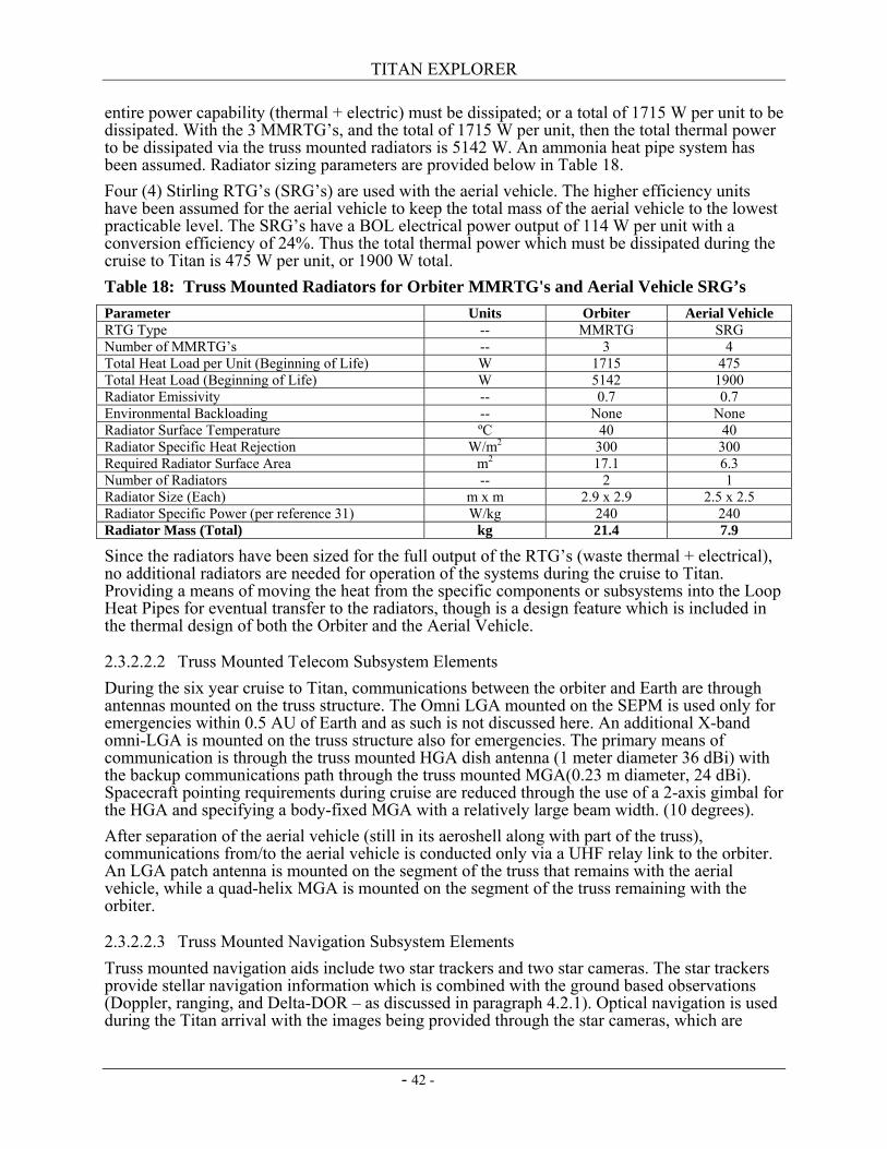
TITAN EXPLORER
- 42 -
entire power capability (thermal + electric) must be dissipated; or a total of 1715 W per unit to be dissipated. With the 3 MMRTG’s, and the total of 1715 W per unit, then the total thermal power to be dissipated via the truss mounted radiators is 5142 W. An ammonia heat pipe system has been assumed. Radiator sizing parameters are provided below in Table 18. Four (4) Stirling RTG’s (SRG’s) are used with the aerial vehicle. The higher efficiency units have been assumed for the aerial vehicle to keep the total mass of the aerial vehicle to the lowest practicable level. The SRG’s have a BOL electrical power output of 114 W per unit with a conversion efficiency of 24%. Thus the total thermal power which must be dissipated during the cruise to Titan is 475 W per unit, or 1900 W total. Table 18: Truss Mounted Radiators for Orbiter MMRTG's and Aerial Vehicle SRG’s Parameter Units Orbiter Aerial Vehicle RTG Type -- MMRTG SRG Number of MMRTG’s -- 3 4 Total Heat Load per Unit (Beginning of Life) W 1715 475 Total Heat Load (Beginning of Life) W 5142 1900 Radiator Emissivity -- 0.7 0.7 Environmental Backloading -- None None Radiator Surface Temperature ºC 40 40 Radiator Specific Heat Rejection W/m2 300 300 Required Radiator Surface Area m2 17.1 6.3 Number of Radiators -- 2 1 Radiator Size (Each) m x m 2.9 x 2.9 2.5 x 2.5 Radiator Specific Power (per reference 31) W/kg 240 240 Radiator Mass (Total) kg 21.4 7.9
Since the radiators have been sized for the full output of the RTG’s (waste thermal + electrical), no additional radiators are needed for operation of the systems during the cruise to Titan. Providing a means of moving the heat from the specific components or subsystems into the Loop Heat Pipes for eventual transfer to the radiators, though is a design feature which is included in the thermal design of both the Orbiter and the Aerial Vehicle.
2.3.2.2.2 Truss Mounted Telecom Subsystem Elements During the six year cruise to Titan, communications between the orbiter and Earth are through antennas mounted on the truss structure. The Omni LGA mounted on the SEPM is used only for emergencies within 0.5 AU of Earth and as such is not discussed here. An additional X-band omni-LGA is mounted on the truss structure also for emergencies. The primary means of communication is through the truss mounted HGA dish antenna (1 meter diameter 36 dBi) with the backup communications path through the truss mounted MGA(0.23 m diameter, 24 dBi). Spacecraft pointing requirements during cruise are reduced through the use of a 2-axis gimbal for the HGA and specifying a body-fixed MGA with a relatively large beam width. (10 degrees). After separation of the aerial vehicle (still in its aeroshell along with part of the truss), communications from/to the aerial vehicle is conducted only via a UHF relay link to the orbiter. An LGA patch antenna is mounted on the segment of the truss that remains with the aerial vehicle, while a quad-helix MGA is mounted on the segment of the truss remaining with the orbiter.
2.3.2.2.3 Truss Mounted Navigation Subsystem Elements Truss mounted navigation aids include two star trackers and two star cameras. The star trackers provide stellar navigation information which is combined with the ground based observations (Doppler, ranging, and Delta-DOR – as discussed in paragraph 4.2.1). Optical navigation is used during the Titan arrival with the images being provided through the star cameras, which are
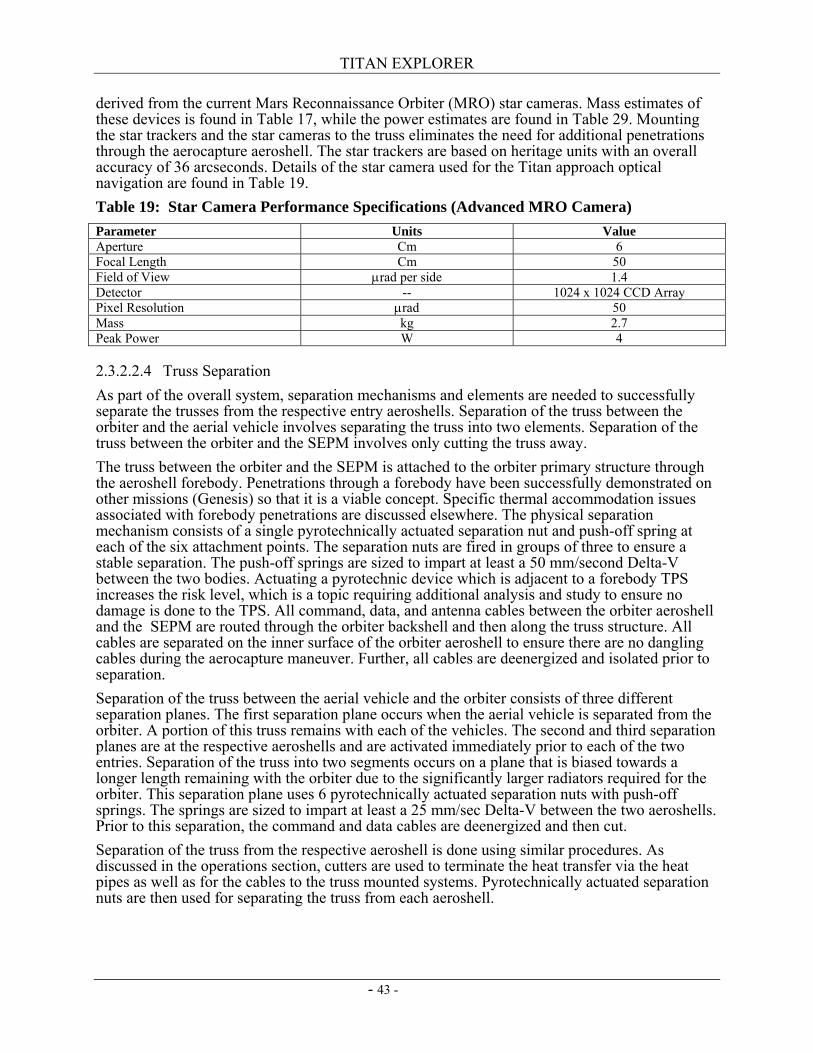
TITAN EXPLORER
- 43 -
derived from the current Mars Reconnaissance Orbiter (MRO) star cameras. Mass estimates of these devices is found in Table 17, while the power estimates are found in Table 29. Mounting the star trackers and the star cameras to the truss eliminates the need for additional penetrations through the aerocapture aeroshell. The star trackers are based on heritage units with an overall accuracy of 36 arcseconds. Details of the star camera used for the Titan approach optical navigation are found in Table 19. Table 19: Star Camera Performance Specifications (Advanced MRO Camera) Parameter Units Value Aperture Cm 6 Focal Length Cm 50 Field of View µrad per side 1.4 Detector -- 1024 x 1024 CCD Array Pixel Resolution µrad 50 Mass kg 2.7 Peak Power W 4
2.3.2.2.4 Truss Separation As part of the overall system, separation mechanisms and elements are needed to successfully separate the trusses from the respective entry aeroshells. Separation of the truss between the orbiter and the aerial vehicle involves separating the truss into two elements. Separation of the truss between the orbiter and the SEPM involves only cutting the truss away. The truss between the orbiter and the SEPM is attached to the orbiter primary structure through the aeroshell forebody. Penetrations through a forebody have been successfully demonstrated on other missions (Genesis) so that it is a viable concept. Specific thermal accommodation issues associated with forebody penetrations are discussed elsewhere. The physical separation mechanism consists of a single pyrotechnically actuated separation nut and push-off spring at each of the six attachment points. The separation nuts are fired in groups of three to ensure a stable separation. The push-off springs are sized to impart at least a 50 mm/second Delta-V between the two bodies. Actuating a pyrotechnic device which is adjacent to a forebody TPS increases the risk level, which is a topic requiring additional analysis and study to ensure no damage is done to the TPS. All command, data, and antenna cables between the orbiter aeroshell and the SEPM are routed through the orbiter backshell and then along the truss structure. All cables are separated on the inner surface of the orbiter aeroshell to ensure there are no dangling cables during the aerocapture maneuver. Further, all cables are deenergized and isolated prior to separation. Separation of the truss between the aerial vehicle and the orbiter consists of three different separation planes. The first separation plane occurs when the aerial vehicle is separated from the orbiter. A portion of this truss remains with each of the vehicles. The second and third separation planes are at the respective aeroshells and are activated immediately prior to each of the two entries. Separation of the truss into two segments occurs on a plane that is biased towards a longer length remaining with the orbiter due to the significantly larger radiators required for the orbiter. This separation plane uses 6 pyrotechnically actuated separation nuts with push-off springs. The springs are sized to impart at least a 25 mm/sec Delta-V between the two aeroshells. Prior to this separation, the command and data cables are deenergized and then cut. Separation of the truss from the respective aeroshell is done using similar procedures. As discussed in the operations section, cutters are used to terminate the heat transfer via the heat pipes as well as for the cables to the truss mounted systems. Pyrotechnically actuated separation nuts are then used for separating the truss from each aeroshell.
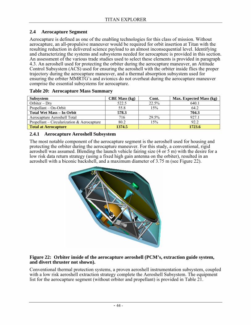
TITAN EXPLORER
- 44 -
2.4 Aerocapture Segment Aerocapture is defined as one of the enabling technologies for this class of mission. Without aerocapture, an all-propulsive maneuver would be required for orbit insertion at Titan with the resulting reduction in delivered science payload to an almost inconsequential level. Identifying and characterizing the systems and subsystems needed for aerocapture is provided in this section. An assessment of the various trade studies used to select these elements is provided in paragraph 4.3. An aeroshell used for protecting the orbiter during the aerocapture maneuver, an Attitude Control Subsystem (ACS) used for ensuring the aeroshell with the orbiter inside flies the proper trajectory during the aerocapture maneuver, and a thermal absorption subsystem used for ensuring the orbiter MMRTG’s and avionics do not overheat during the aerocapture maneuver comprise the essential subsystems for aerocapture. Table 20: Aerocapture Mass Summary Subsystem CBE Mass (kg) Cont. Max. Expected Mass (kg) Orbiter – Dry 522.5 22.5% 640.1 Propellant – On-Orbit 55.8 15% 64.2 Total Wet Mass – In Orbit 578.3 704.3 Aerocapture Aeroshell Total 716 29.5% 927.1 Propellant – Circularization & Aerocapture 80.2 15% 92.2 Total at Aerocapture 1374.5 1723.6
2.4.1 Aerocapture Aeroshell Subsystem The most notable component of the aerocapture segment is the aeroshell used for housing and protecting the orbiter during the aerocapture maneuver. For this study, a conventional, rigid aeroshell was assumed. Blending the launch vehicle fairing size (4 or 5 m) with the desire for a low risk data return strategy (using a fixed high gain antenna on the orbiter), resulted in an aeroshell with a biconic backshell, and a maximum diameter of 3.75 m (see Figure 22).
Figure 22: Orbiter inside of the aerocapture aeroshell (PCM’s, extraction guide system, and divert thruster not shown). Conventional thermal protection systems, a proven aeroshell instrumentation subsystem, coupled with a low risk aeroshell extraction strategy complete the Aeroshell Subsystem. The equipment list for the aerocapture segment (without orbiter and propellant) is provided in Table 21.
TITAN EXPLORER
- 45 -
Table 21: Aerocapture Aeroshell Structures, Mechanisms, and Subsystems Mass Element No. of
Units CBE Mass
(kg) Cont. Max. Expected
Mass (kg) Heritage
Backshell structure 1 43.3 30.0% 56.29 Forebody structure 1 41.6 30.0% 54.08 Forebody Separation Mechanism 6 18.6 30.0% 24.18 Orbiter Extraction Guide System 1 6.5 30.0% 8.45 Payload Pallet Ring 1 55 30.0% 71.5 Secondary Support Structure 1 10 30.0% 13 PCM Blocks 3 154 30.0% 200.2 Forebody Penetration Molybdenum Heat Sink blocks
6 48 30.0% 62.4
Forebody TPS - TUFROC 1 277 30.0% 360.1 Backshell TPS - SLA-561 1 35 30.0% 45.5 Aeroshell mounted Monoprop Engine (450N)
1 5 15.0% 5.75
Aeroshell Instrumentation 1 7 30.0% 9.1 Ballast 1 15 10.0% 16.5 Aerocapture Aeroshell Total 25 716 29.5% 927.05
2.4.1.1 Aeroshell Structures and Mechanisms Structure for the aeroshell is divided into three primary elements; the backshell, the forebody, and the pallet support ring. Detailed design and analysis of these elements was addressed previously (reference 27). The backshell is a biconic shape fabricated using Hexcell 5052 alloy hexagonal aluminum honeycomb core, 12.7 mm (0.5 inch) thick. Graphite polyimide face sheets are used for the skins. Penetrations through the backshell are accommodated with local reinforcements. Attachment of the forebody to the backshell is accomplished using MER derived heat shield attachment and release mechanisms. These elements are scaled up for the increased size and mass of the forebody including the different environment which exists during the forebody separation event. Since the backshell is essentially an aerodynamic shroud and does not carry any of the increased loads, the mass and structural arrangement defined during the previous studies is still valid. The forebody is a 70 degree sphere cone with a one (1) m nose radius. Fabrication of the forebody is similar to that of the backshell, except the honeycomb core is 25.4 mm (1 inch) in thickness. Penetrations through the forebody are used to pass the load of the aerial vehicle and its aeroshell as well as the orbiter and aerocapture aeroshell loads to the propulsion module. These 6 penetrations are similar in design to the forebody penetrations used on the recent Genesis mission. Molybdenum thermal heat sink blocks are used at each penetration to prevent the thermal load from the aerocapture maneuver from being conducted back into the orbiter structure. Separation of the orbiter from the aeroshell is accomplished with a simple guide-rail system and separation springs. Three guide-rails are attached to the backshell with small separation springs to impart a small differential Delta-V between the backshell and the orbiter when the orbiter is separated after the atmospheric drag pass is complete. The guide-rails are not there to provide any lateral restraint during launch or during the atmospheric drag pass, but are there strictly to ensure the orbiter and the backshell maintain a reasonable concentric alignment during the orbiter extraction. Three retaining pins with compressed springs are used to inhibit and then impart motion. A payload pallet ring is used to transfer the loads coming from the aerial vehicle as well as the payload deck to six hard points on the Orbiter’s heatshield. The six hard points are equally spaced around the perimeter of the payload ring and represent penetrations through the forebody. An aluminum tubular truss structure is used as the pallet structure. This structure allows the load
TITAN EXPLORER
- 46 -
from the aerial vehicle and the orbiter to be carried directly through the forebody without the aeroshell (backshell or forebody) carrying the load. 2.4.1.2 Aeroshell Thermal Protection System (TPS) Aerocapture provides a thermal environment which does not provide as large a heat pulse as entry, however, the duration of the maneuver results in a significantly larger integrated heat load. Further, the large entry velocities into a nitrogen rich environment result in a significant radiative heat load contribution. The TPS for both the forebody and the backshell have been extensively studied (ref. 32). The size (area) and predicted drag coefficient for the aerocapture maneuver are assumed to be essentially the same as in previous studies. The aerocapture mass, however, is greater than was used in previous studies resulting in a larger ballistic coefficient. Increased mass is due to the inclusion of the Phase Change Materials needed to prevent MMRTG overheating after separation of the radiators as well as the addition of a number of science instruments. From previous studies, the ballistic coefficient was found to be 90 kg/m2. With the additional science instruments, additional MMRTG’s, and the PCM, the overall aerocapture ballistic coefficient has increased to about 125 kg/m2. An extensive analysis of forebody TPS materials has identified a number of viable candidates for use at Titan for aerocapture (ref. 32). The use of TUFROC, a TPS material currently in development, was judged to be a viable solution as it provided an optimal performance balance between overall mass, absorption of UV, thermal conductivity, and heat rate. A description of the forebody TPS (TUFROC) and the backshell TPS (SLA-561) is provided in Table 22. Table 22: Aerocapture TPS Description (reference 32) Parameter Forebody – TUFROC Backshell – SLA-561 Description Multi-layer composite; Carbon fiberform
/ AETB tile; non-ablative; high -temperature, high-emissivity, low catalytic efficiency surface treatment
Performance Non-ablative – good to 300 W/cm2 (Note since this application is 8% above this limit, it is judged sufficient for sizing and performance estimations)
Solar Absorptance 0.9 Total Hemispherical Emittance
0.8
UV Radiation Absorbs UV Density ~0.23 grams/cm3
The heating (peak heat rate and integrated heat load) varies with the square root of the ballistic coefficient ratio. A comparison of the previous and current studies is provided in Table 23. Table 23: Comparison of Aerocapture Parameters Parameter Aerocapture Study Titan Explorer Velocity at Entry of Aerocapture Corridor (m/s) 6500 6500 Ballistic Coefficient (kg/m2) 90 128 Peak Convective Heat Rate (W/cm2) 50 60 Peak Radiative Heat Rate (W/cm2) 225 268 Peak Total Heat Rate (W/cm2) 275 328 Forebody TPS Material (0.23 grams/cm3) TUFROC TUFROC Integrated Heat Load (J/cm2 – convective – 1/3; radiative – 2/3) 19,600 23,400 Forebody TPS thickness (cm) 5.13 10 Forebody TPS Mass (kg) 149 277 Backshell TPS Material SLA-561 SLA-561 Backshell TPS Mass (kg) 29 35
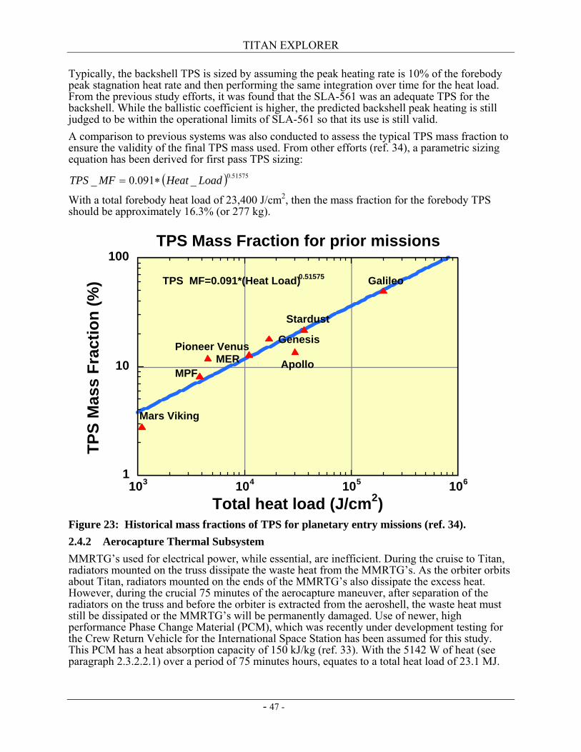
TITAN EXPLORER
- 47 -
Typically, the backshell TPS is sized by assuming the peak heating rate is 10% of the forebody peak stagnation heat rate and then performing the same integration over time for the heat load. From the previous study efforts, it was found that the SLA-561 was an adequate TPS for the backshell. While the ballistic coefficient is higher, the predicted backshell peak heating is still judged to be within the operational limits of SLA-561 so that its use is still valid. A comparison to previous systems was also conducted to assess the typical TPS mass fraction to ensure the validity of the final TPS mass used. From other efforts (ref. 34), a parametric sizing equation has been derived for first pass TPS sizing:
( ) 51575.0_091.0_ LoadHeatMFTPS ∗=
With a total forebody heat load of 23,400 J/cm2, then the mass fraction for the forebody TPS should be approximately 16.3% (or 277 kg).
Figure 23: Historical mass fractions of TPS for planetary entry missions (ref. 34). 2.4.2 Aerocapture Thermal Subsystem MMRTG’s used for electrical power, while essential, are inefficient. During the cruise to Titan, radiators mounted on the truss dissipate the waste heat from the MMRTG’s. As the orbiter orbits about Titan, radiators mounted on the ends of the MMRTG’s also dissipate the excess heat. However, during the crucial 75 minutes of the aerocapture maneuver, after separation of the radiators on the truss and before the orbiter is extracted from the aeroshell, the waste heat must still be dissipated or the MMRTG’s will be permanently damaged. Use of newer, high performance Phase Change Material (PCM), which was recently under development testing for the Crew Return Vehicle for the International Space Station has been assumed for this study. This PCM has a heat absorption capacity of 150 kJ/kg (ref. 33). With the 5142 W of heat (see paragraph 2.3.2.2.1) over a period of 75 minutes hours, equates to a total heat load of 23.1 MJ.
1
10
100
103 104 105 106
TPS Mass Fraction for prior missions
TPS
Mas
s Fr
actio
n (%
)
Total heat load (J/cm2)
Mars Viking
MPF
Pioneer VenusApollo
Stardust
GalileoTPS MF=0.091*(Heat Load)0.51575
MER
Genesis
TITAN EXPLORER
- 48 -
Using the assumed PCM, the mass of the PCM is found to be 154.3 kg. A detailed packaging study of the PCM’s and the routing of the heat pipes was not performed. 2.4.3 Aerocapture ACS Subsystem The aerocapture maneuver uses a well studied, simple guidance algorithm called HYPAS. This algorithm has its origins in the Apollo program, however, it has been extensively modified for use in a robotic aerocapture maneuver. The main navigation input (besides the initial state vector at atmospheric interface) is input from an Inertial Measuring Unit (IMU). The IMU is the only navigation sensor needed for flying the Aerocapture maneuver. The control is provided through 0.7 N Miniature Impulse Thrusters (MITs) which penetrate through the backshell near the biconic line. These thrusters provide small amounts of thrust to modulate the bank angle and have either the lift vector up or down depending on the state of the vehicle flight path angle with respect to the desired flight path. Since the thrusters used here are part of the Orbiter propulsion subsystem, they are described in paragraph 2.5.2.4. The essential components of the aerocapture guidance and navigation system is the HYPAS algorithm and the orbiter mounted Inertial Measuring Unit (IMU) as shown in Table 29. Use of an existing IMU (the Honeywell Miniature IMU (MIMU)) was assumed along with a redundant MIMU. The MIMU provides sufficient accuracy to navigate through the dynamics of the aerocapture maneuver. 2.4.4 Aeroshell Propulsion – Divert Maneuver After release of the aerial vehicle, the orbiter must perform a divert and delay maneuver to modify its trajectory away from an entry to an aerocapture trajectory. A single 450 N thruster has been assumed to be mounted at the apex of the aerocapture aeroshell such that its line of action is through the centerline of the truss. This thruster is used only for this single maneuver and is then no longer used. Included with the thruster are propellant lines and electrical power cables for operating the thruster.
2.5 Orbital Segment During the orbital segment, the orbiter is either collecting its own science measurements, collecting data from the aerial vehicle, relaying commands to the aerial vehicle, relaying data to Earth, receiving commands from Earth, or performing housekeeping maneuvers such as battery recharging. Description of the orbiter and all of the associated subsystems are provided in this section. Additional details on the orbiter science instruments are contained in paragraph 1.3.1. Details of the systems used during the aerocapture segment are provided in paragraph 2.4. Description of the operational modes of the orbiter are found in section 5.5. 2.5.1 Orbiter Overview A block redundant spacecraft, powered with a combination of rechargeable batteries and next generation Multi-Mission Radioisotope Thermoelectric Generators (MMRTG) provides both an observation platform for orbital science and a relay pathway for the aerial vehicle. A traditional X-band communications system is assumed as part of the baseline which includes a fixed 2.4 m HGA. The X-band HGA also doubles as the transmit/receive antenna for the Radar science measurements. The Team-X assessment assumed use of Ka-band for the data downlink and X-band for command uplink and backup data downlink. Optical communications was considered early during the study period, however, due to time constraints, the systems analysis and systems impacts were not addressed. Attitude control is provided through a combination of reaction wheels and Miniature Inertial Thrusters (MIT). Standard monopropellant using a blowdown hydrazine system provides a low cost, simple propulsion solution. A breakdown of the orbiter subsystems is provided in Table 24.
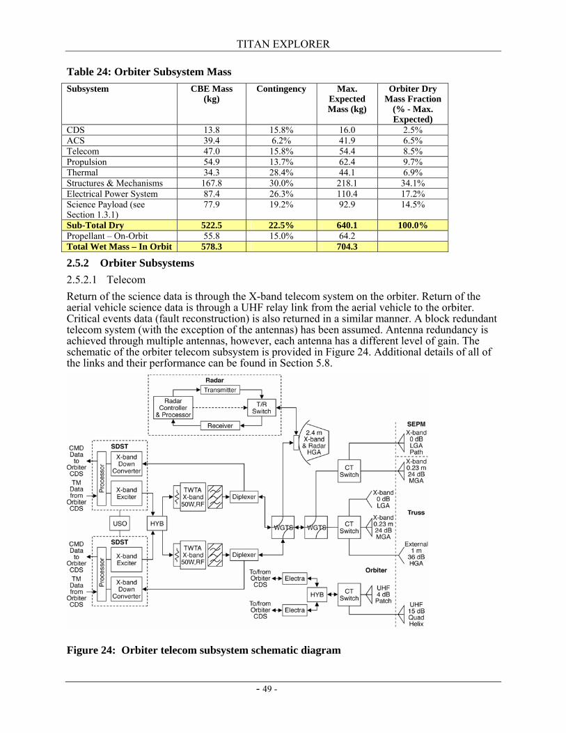
TITAN EXPLORER
- 49 -
Table 24: Orbiter Subsystem Mass Subsystem CBE Mass
(kg) Contingency Max.
Expected Mass (kg)
Orbiter Dry Mass Fraction
(% - Max. Expected)
CDS 13.8 15.8% 16.0 2.5% ACS 39.4 6.2% 41.9 6.5% Telecom 47.0 15.8% 54.4 8.5% Propulsion 54.9 13.7% 62.4 9.7% Thermal 34.3 28.4% 44.1 6.9% Structures & Mechanisms 167.8 30.0% 218.1 34.1% Electrical Power System 87.4 26.3% 110.4 17.2% Science Payload (see Section 1.3.1)
77.9 19.2% 92.9 14.5%
Sub-Total Dry 522.5 22.5% 640.1 100.0% Propellant – On-Orbit 55.8 15.0% 64.2 Total Wet Mass – In Orbit 578.3 704.3
2.5.2 Orbiter Subsystems 2.5.2.1 Telecom Return of the science data is through the X-band telecom system on the orbiter. Return of the aerial vehicle science data is through a UHF relay link from the aerial vehicle to the orbiter. Critical events data (fault reconstruction) is also returned in a similar manner. A block redundant telecom system (with the exception of the antennas) has been assumed. Antenna redundancy is achieved through multiple antennas, however, each antenna has a different level of gain. The schematic of the orbiter telecom subsystem is provided in Figure 24. Additional details of all of the links and their performance can be found in Section 5.8.
Figure 24: Orbiter telecom subsystem schematic diagram
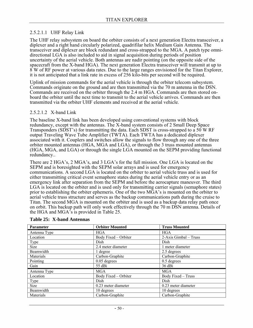
TITAN EXPLORER
- 50 -
2.5.2.1.1 UHF Relay Link The UHF relay subsystem on board the orbiter consists of a next generation Electra transceiver, a diplexer and a right hand circularly polarized, quadrifilar helix Medium Gain Antenna. The transceiver and diplexer are block redundant and cross-strapped to the MGA. A patch type omni-directional LGA is also included to aid in signal acquisition during periods of position uncertainty of the aerial vehicle. Both antennas are nadir pointing (on the opposite side of the spacecraft from the X-band HGA). The next generation Electra transceiver will transmit at up to 8 W of RF power at various data rates. Due to the large ranges envisioned for the Titan Explorer, it is not anticipated that a link rate in excess of 256 kilo-bits per second will be required. Uplink of mission commands for the aerial vehicle is through the orbiter telecom subsystem. Commands originate on the ground and are then transmitted via the 70 m antenna in the DSN. Commands are received on the orbiter through the 2.4 m HGA. Commands are then stored on-board the orbiter until the next time to transmit to the aerial vehicle arrives. Commands are then transmitted via the orbiter UHF elements and received at the aerial vehicle.
2.5.2.1.2 X-band Link The baseline X-band link has been developed using conventional systems with block redundancy, except with the antennas. The X-band system consists of 2 Small Deep Space Transponders (SDST’s) for transmitting the data. Each SDST is cross-strapped to a 50 W RF output Traveling Wave Tube Amplifier (TWTA). Each TWTA has a dedicated diplexer associated with it. Couplers and switches allow the signals to flow through any one of the three orbiter mounted antennas (HGA, MGA and LGA), or through the 3 truss mounted antennas (HGA, MGA, and LGA) or through the single LGA mounted on the SEPM providing functional redundancy.. There are 2 HGA’s, 2 MGA’s, and 3 LGA’s for the full mission. One LGA is located on the SEPM and is boresighted with the SEPM solar arrays and is used for emergency communications. A second LGA is located on the orbiter to aerial vehicle truss and is used for either transmitting critical event semaphore states during the aerial vehicle entry or as an emergency link after separation from the SEPM and before the aerocapture maneuver. The third LGA is located on the orbiter and is used only for transmitting carrier signals (semaphore states) prior to establishing the orbiter ephemeris. One of the two MGA’s is mounted on the orbiter to aerial vehicle truss structure and serves as the backup communications path during the cruise to Titan. The second MGA is mounted on the orbiter and is used as a backup data relay path once on orbit. This backup path will only work effectively through the 70 m DSN antenna. Details of the HGA and MGA’s is provided in Table 25. Table 25: X-band Antennas Parameter Orbiter Mounted Truss Mounted Antenna Type HGA HGA Location Body Fixed – Orbiter 2-Axis Gimbal – Truss Type Dish Dish Size 2.4 meter diameter 1 meter diameter Beamwidth 1 degree 2.5 degrees Materials Carbon-Graphite Carbon-Graphite Pointing 0.05 degrees 0.5 degrees Gain 55 dBi 36 dBi Antenna Type MGA MGA Location Body Fixed – Orbiter Body Fixed – Truss Type Dish Dish Size 0.23 meter diameter 0.23 meter diameter Beamwidth 10 degrees 10 degrees Materials Carbon-Graphite Carbon-Graphite
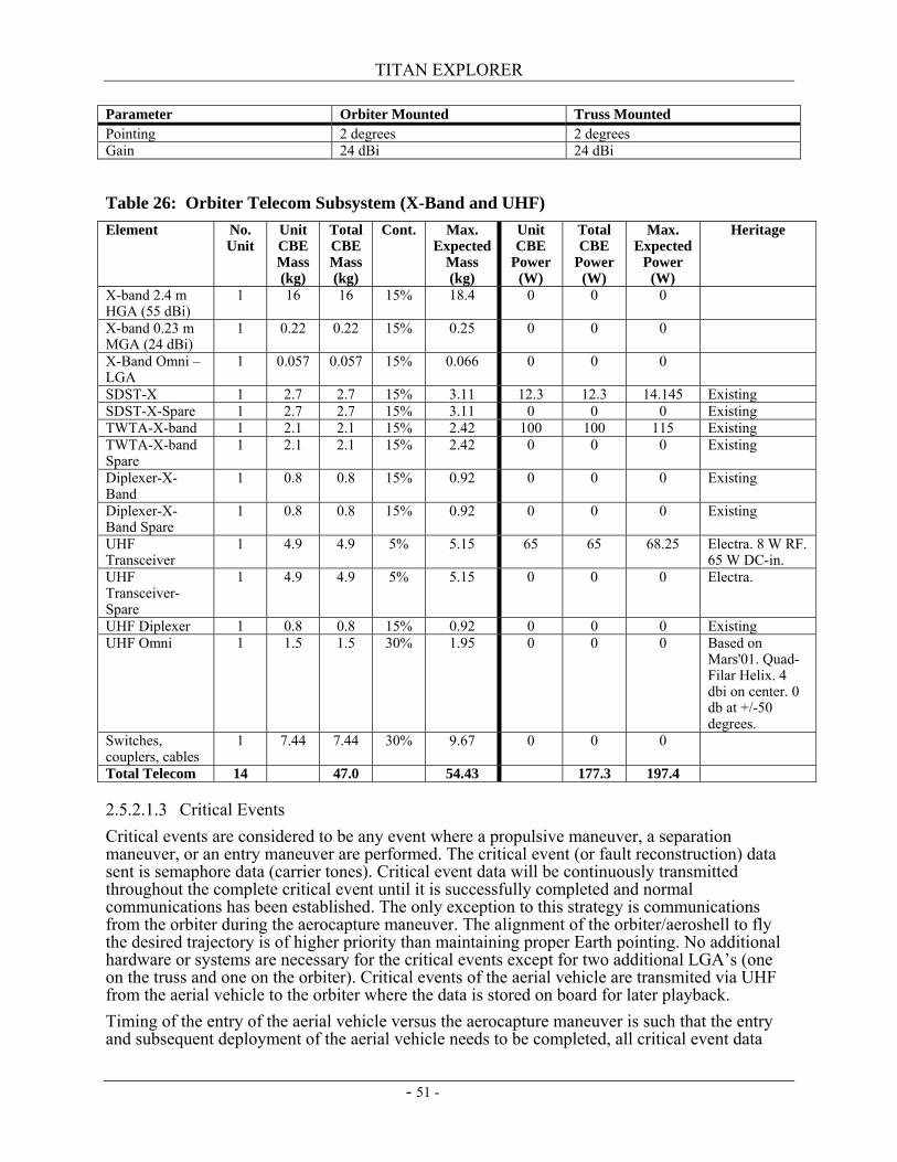
TITAN EXPLORER
- 51 -
Parameter Orbiter Mounted Truss Mounted Pointing 2 degrees 2 degrees Gain 24 dBi 24 dBi
Table 26: Orbiter Telecom Subsystem (X-Band and UHF) Element No.
Unit Unit CBE Mass (kg)
Total CBE Mass (kg)
Cont. Max. Expected
Mass (kg)
Unit CBE
Power (W)
Total CBE
Power (W)
Max. Expected
Power (W)
Heritage
X-band 2.4 m HGA (55 dBi)
1 16 16 15% 18.4 0 0 0
X-band 0.23 m MGA (24 dBi)
1 0.22 0.22 15% 0.25 0 0 0
X-Band Omni – LGA
1 0.057 0.057 15% 0.066 0 0 0
SDST-X 1 2.7 2.7 15% 3.11 12.3 12.3 14.145 Existing SDST-X-Spare 1 2.7 2.7 15% 3.11 0 0 0 Existing TWTA-X-band 1 2.1 2.1 15% 2.42 100 100 115 Existing TWTA-X-band Spare
1 2.1 2.1 15% 2.42 0 0 0 Existing
Diplexer-X-Band
1 0.8 0.8 15% 0.92 0 0 0 Existing
Diplexer-X-Band Spare
1 0.8 0.8 15% 0.92 0 0 0 Existing
UHF Transceiver
1 4.9 4.9 5% 5.15 65 65 68.25 Electra. 8 W RF. 65 W DC-in.
UHF Transceiver-Spare
1 4.9 4.9 5% 5.15 0 0 0 Electra.
UHF Diplexer 1 0.8 0.8 15% 0.92 0 0 0 Existing UHF Omni 1 1.5 1.5 30% 1.95 0 0 0 Based on
Mars'01. Quad-Filar Helix. 4 dbi on center. 0 db at +/-50 degrees.
Switches, couplers, cables
1 7.44 7.44 30% 9.67 0 0 0
Total Telecom 14 47.0 54.43 177.3 197.4
2.5.2.1.3 Critical Events Critical events are considered to be any event where a propulsive maneuver, a separation maneuver, or an entry maneuver are performed. The critical event (or fault reconstruction) data sent is semaphore data (carrier tones). Critical event data will be continuously transmitted throughout the complete critical event until it is successfully completed and normal communications has been established. The only exception to this strategy is communications from the orbiter during the aerocapture maneuver. The alignment of the orbiter/aeroshell to fly the desired trajectory is of higher priority than maintaining proper Earth pointing. No additional hardware or systems are necessary for the critical events except for two additional LGA’s (one on the truss and one on the orbiter). Critical events of the aerial vehicle are transmited via UHF from the aerial vehicle to the orbiter where the data is stored on board for later playback. Timing of the entry of the aerial vehicle versus the aerocapture maneuver is such that the entry and subsequent deployment of the aerial vehicle needs to be completed, all critical event data
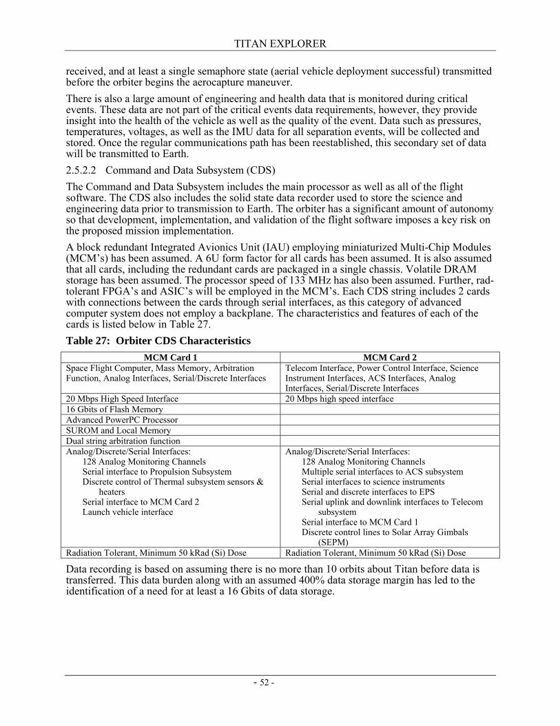
TITAN EXPLORER
- 52 -
received, and at least a single semaphore state (aerial vehicle deployment successful) transmitted before the orbiter begins the aerocapture maneuver. There is also a large amount of engineering and health data that is monitored during critical events. These data are not part of the critical events data requirements, however, they provide insight into the health of the vehicle as well as the quality of the event. Data such as pressures, temperatures, voltages, as well as the IMU data for all separation events, will be collected and stored. Once the regular communications path has been reestablished, this secondary set of data will be transmitted to Earth. 2.5.2.2 Command and Data Subsystem (CDS) The Command and Data Subsystem includes the main processor as well as all of the flight software. The CDS also includes the solid state data recorder used to store the science and engineering data prior to transmission to Earth. The orbiter has a significant amount of autonomy so that development, implementation, and validation of the flight software imposes a key risk on the proposed mission implementation. A block redundant Integrated Avionics Unit (IAU) employing miniaturized Multi-Chip Modules (MCM’s) has been assumed. A 6U form factor for all cards has been assumed. It is also assumed that all cards, including the redundant cards are packaged in a single chassis. Volatile DRAM storage has been assumed. The processor speed of 133 MHz has also been assumed. Further, rad-tolerant FPGA’s and ASIC’s will be employed in the MCM’s. Each CDS string includes 2 cards with connections between the cards through serial interfaces, as this category of advanced computer system does not employ a backplane. The characteristics and features of each of the cards is listed below in Table 27. Table 27: Orbiter CDS Characteristics
MCM Card 1 MCM Card 2 Space Flight Computer, Mass Memory, Arbitration Function, Analog Interfaces, Serial/Discrete Interfaces
Telecom Interface, Power Control Interface, Science Instrument Interfaces, ACS Interfaces, Analog Interfaces, Serial/Discrete Interfaces
20 Mbps High Speed Interface 20 Mbps high speed interface 16 Gbits of Flash Memory Advanced PowerPC Processor SUROM and Local Memory Dual string arbitration function Analog/Discrete/Serial Interfaces: 128 Analog Monitoring Channels Serial interface to Propulsion Subsystem Discrete control of Thermal subsystem sensors &
heaters Serial interface to MCM Card 2 Launch vehicle interface
Analog/Discrete/Serial Interfaces: 128 Analog Monitoring Channels Multiple serial interfaces to ACS subsystem Serial interfaces to science instruments Serial and discrete interfaces to EPS Serial uplink and downlink interfaces to Telecom
subsystem Serial interface to MCM Card 1 Discrete control lines to Solar Array Gimbals
(SEPM) Radiation Tolerant, Minimum 50 kRad (Si) Dose Radiation Tolerant, Minimum 50 kRad (Si) Dose
Data recording is based on assuming there is no more than 10 orbits about Titan before data is transferred. This data burden along with an assumed 400% data storage margin has led to the identification of a need for at least a 16 Gbits of data storage.
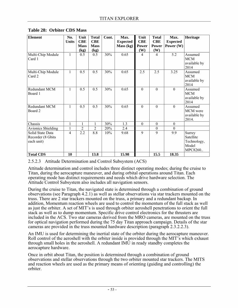
TITAN EXPLORER
- 53 -
Table 28: Orbiter CDS Mass Element No.
Units Unit CBE Mass (kg)
Total CBE Mass (kg)
Cont. Max. Expected Mass (kg)
Unit CBE
Power (W)
Total CBE
Power (W)
Max. Expected
Power (W)
Heritage
Multi-Chip Module Card 1
1 0.5 0.5 30% 0.65 4 4 5.2 Assumed MCM available by 2014
Multi-Chip Module Card 2
1 0.5 0.5 30% 0.65 2.5 2.5 3.25 Assumed MCM available by 2014
Redundant MCM Board 1
1 0.5 0.5 30% 0.65 0 0 0 Assumed MCM available by 2014
Redundant MCM Board 2
1 0.5 0.5 30% 0.65 0 0 0 Assumed MCM were available by 2014.
Chassis 1 1 1 30% 1.3 0 0 0 Avionics Shielding 1 2 2 20% 2.4 0 0 Solid State Data Recorder (8 Gbits each unit)
4 2.2 8.8 10% 9.68 9 9 9.9 Surrey Satellite Technology, Model MPC8260..
Total CDS 10 13.8 15.98 15.5 18.35
2.5.2.3 Attitude Determination and Control Subsystem (ACS) Attitude determination and control includes three distinct operating modes; during the cruise to Titan, during the aerocapture maneuver, and during orbital operations around Titan. Each operating mode has distinct requirements and needs which drive hardware selection. The Attitude Control Subsystem also includes all navigation sensors. During the cruise to Titan, the navigated state is determined through a combination of ground observations (see Paragraph 4.2.1) as well as stellar observations via star trackers mounted on the truss. There are 2 star trackers mounted on the truss, a primary and a redundant backup. In addition, Momentum reaction wheels are used to control the momentum of the full stack as well as just the orbiter. A set of MIT’s is used through orbiter aeroshell penetrations to orient the full stack as well as to dump momentum. Specific drive control electronics for the thrusters are included in the ACS. Two star cameras derived from the MRO cameras, are mounted on the truss for optical navigation performed during the 75 day Titan approach campaign. Details of the star cameras are provided in the truss mounted hardware description (paragraph 2.3.2.2.3). An IMU is used for determining the inertial state of the orbiter during the aerocapture maneuver. Roll control of the aeroshell with the orbiter inside is provided through the MIT’s which exhaust through small holes in the aeroshell. A redundant IMU in ready standby completes the aerocapture hardware. Once in orbit about Titan, the position is determined through a combination of ground observations and stellar observations through the two orbiter mounted star trackers. The MITS and reaction wheels are used as the primary means of orienting (guiding and controlling) the orbiter.
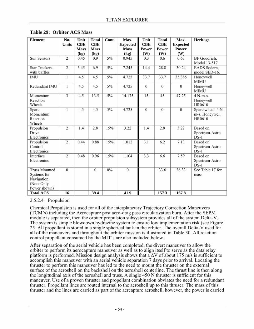
TITAN EXPLORER
- 54 -
Table 29: Orbiter ACS Mass Element No.
Units Unit CBE Mass (kg)
Total CBE Mass (kg)
Cont. Max. Expected
Mass (kg)
Unit CBE
Power (W)
Total CBE
Power (W)
Max. Expected
Power (W)
Heritage
Sun Sensors 2 0.45 0.9 5% 0.945 0.3 0.6 0.63 BF Goodrich, Model 13-517
Star Trackers-with baffles
2 3.45 6.9 5% 7.245 14.4 28.8 30.24 EADS Sodern, model SED-16.
IMU 1 4.5 4.5 5% 4.725 33.7 33.7 35.385 Honeywell MIMU
Redundant IMU 1 4.5 4.5 5% 4.725 0 0 0 Honeywell MIMU
Momentum Reaction Wheels
3 4.5 13.5 5% 14.175 15 45 47.25 4 N-m-s. Honeywell HR0610
Spare Momentum Reaction Wheels
1 4.5 4.5 5% 4.725 0 0 0 Spare wheel. 4 N-m-s. Honeywell HR0610
Propulsion Drive Electronics
2 1.4 2.8 15% 3.22 1.4 2.8 3.22 Based on Spectrum-Astro DS-1
Propulsion Control Electronics
2 0.44 0.88 15% 1.012 3.1 6.2 7.13 Based on Spectrum-Astro DS-1
Interface Electronics
2 0.48 0.96 15% 1.104 3.3 6.6 7.59 Based on Spectrum-Astro DS-1
Truss Mounted Systems for Navigation (Note Only Power shown)
0 0 0% 0 33.6 36.33 See Table 17 for mass
Total ACS 16 39.4 41.9 157.3 167.8
2.5.2.4 Propulsion Chemical Propulsion is used for all of the interplanetary Trajectory Correction Maneuvers (TCM’s) including the Aerocapture post aero-drag pass circularization burn. After the SEPM module is separated, then the orbiter propulsion subsystem provides all of the system Delta-V. The system is simple blowdown hydrazine system to ensure low implementation risk (see Figure 25. All propellant is stored in a single spherical tank in the orbiter. The overall Delta-V used for all of the maneuvers and throughout the orbiter mission is illustrated in Table 30. All reaction control propellant consumed by the MIT’s are also included below. After separation of the aerial vehicle has been completed, the divert maneuver to allow the orbiter to perform its aerocapture maneuver as well as to align itself to serve as the data relay platform is performed. Mission design analysis shows that a ∆V of about 175 m/s is sufficient to accomplish this maneuver with an aerial vehicle separation 7 days prior to arrival. Locating the thruster to perform this maneuver has led to the need to mount the thruster on the external surface of the aeroshell on the backshell on the aeroshell centerline. The thrust line is then along the longitudinal axis of the aeroshell and truss. A single 450 N thruster is sufficient for this maneuver. Use of a proven thruster and propellant combination obviates the need for a redundant thruster. Propellant lines are routed internal to the aeroshell up to this thruser. The mass of this thruster and the lines are carried as part of the aercapture aeroshell, however, the power is carried
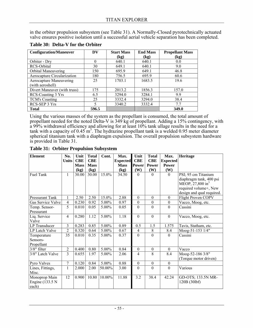
TITAN EXPLORER
- 55 -
in the orbiter propulsion subsystem (see Table 31). A Normally-Closed pyrotechnically actuated valve ensures positive isolation until a successful aerial vehicle separation has been completed. Table 30: Delta-V for the Orbiter Configuration/Maneuver DV Start Mass
(kg) End Mass
(kg) Propellant Mass
(kg) Orbiter - Dry 0 640.1 640.1 0.0 RCS-Orbital 30 649.1 640.1 9.0 Orbital Maneuvering 150 695.9 649.1 46.8 Aerocapture Circularization 180 756.5 695.9 60.6 Aerocapture Maneuvering (with aeroshell)
25 1703.1 1683.5 19.6
Divert Maneuver (with truss) 175 2013.2 1856.3 157.0 RCS-Coasting 3 Yrs 6.5 3294.0 3284.1 9.9 TCM's Coasting 25 3332.4 3294.0 38.4 RCS-SEP 3 Yrs 5 3340.2 3332.4 7.7 Total 596.5 349.0
Using the various masses of the system as the propellant is consumed, the total amount of propellant needed for the noted Delta-V is 349 kg of propellant. Adding a 15% contingency, with a 99% withdrawal efficiency and allowing for at least 10% tank ullage results in the need for a tank with a capacity of 0.45 m3. The hydrazine propellant tank is a welded 0.95 meter diameter spherical titanium tank with a diaphragm expulsion. The overall propulsion subsystem hardware is provided in Table 31. Table 31: Orbiter Propulsion Subsystem Element No.
Units Unit CBE Mass (kg)
Total CBE Mass (kg)
Cont. Max. Expected
Mass (kg)
Unit CBE
Power (W)
Total CBE
Power (W)
Max. Expected
Power (W)
Heritage
Fuel Tank 1 30.00 30.00 15.0% 34.50 0 0 0 PSI; 95 cm Titanium diaphragm tank, 400 psi MEOP, 27,800 in3 required volume+, New design and qual required.
Pressurant Tank 1 2.50 2.50 15.0% 2.88 0 0 0 Flight Proven COPV Gas Service Valve 4 0.230 0.92 5.00% 0.97 0 0 0 Vacco, Moog, etc. Temp. Sensor-Pressurant
5 0.010 0.05 5.00% 0.05 0 0 0 Cassini
Liq. Service Valve
4 0.280 1.12 5.00% 1.18 0 0 0 Vacco, Moog, etc.
LP Transducer 3 0.283 0.85 5.00% 0.89 0.5 1.5 1.575 Tavis, Statham, etc. LP Latch Valve 2 0.320 0.64 5.00% 0.67 4 8 8.4 Moog-51-153 1/4" Temperature Sensors-Propellant
35 0.010 0.35 5.00% 0.37 0 0 0 Cassini
3/8" filter 2 0.400 0.80 5.00% 0.84 0 0 0 Vacco 3/8" Latch Valve 3 0.655 1.97 5.00% 2.06 4 8 8.4 Moog-52-186 3/8"
(Torque motor driven) Pyro Valves 7 0.120 0.84 5.00% 0.88 0 0 0 Lines, Fittings, Misc.
1 2.000 2.00 50.00% 3.00 0 0 0 Various
Monoprop Main Engine (133.5 N each)
12 0.900 10.80 10.00% 11.88 3.2 38.4 42.24 GD-OTS; 133.5N MR-120B (30lbf)
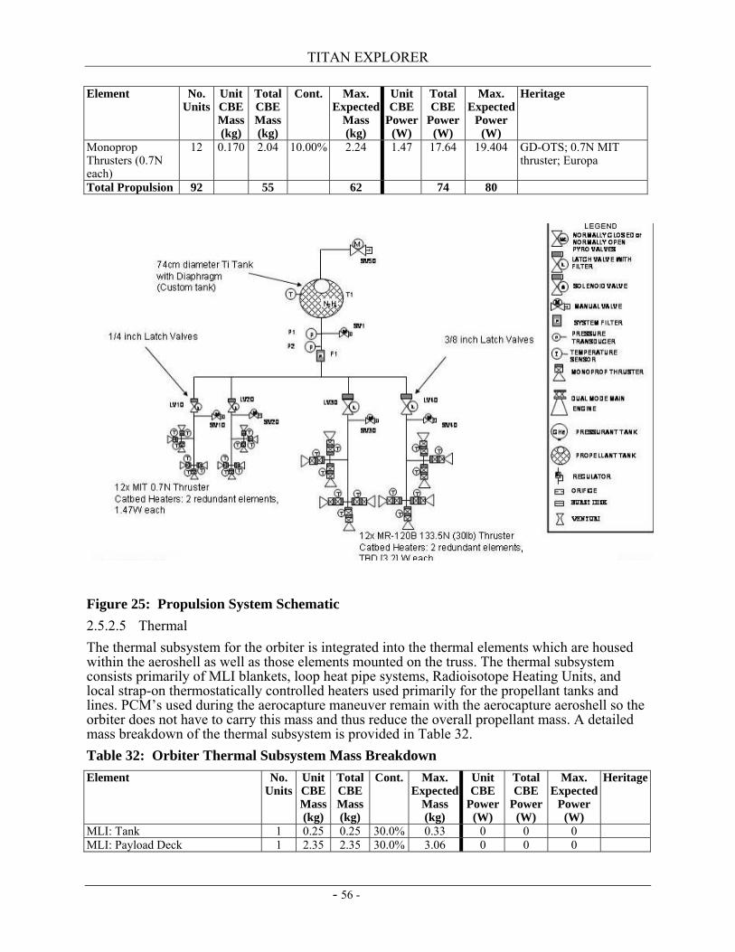
TITAN EXPLORER
- 56 -
Element No. Units
Unit CBE Mass (kg)
Total CBE Mass (kg)
Cont. Max. Expected
Mass (kg)
Unit CBE
Power (W)
Total CBE
Power (W)
Max. Expected
Power (W)
Heritage
Monoprop Thrusters (0.7N each)
12 0.170 2.04 10.00% 2.24 1.47 17.64 19.404 GD-OTS; 0.7N MIT thruster; Europa
Total Propulsion 92 55 62 74 80
Figure 25: Propulsion System Schematic 2.5.2.5 Thermal The thermal subsystem for the orbiter is integrated into the thermal elements which are housed within the aeroshell as well as those elements mounted on the truss. The thermal subsystem consists primarily of MLI blankets, loop heat pipe systems, Radioisotope Heating Units, and local strap-on thermostatically controlled heaters used primarily for the propellant tanks and lines. PCM’s used during the aerocapture maneuver remain with the aerocapture aeroshell so the orbiter does not have to carry this mass and thus reduce the overall propellant mass. A detailed mass breakdown of the thermal subsystem is provided in Table 32. Table 32: Orbiter Thermal Subsystem Mass Breakdown Element No.
Units Unit CBE Mass (kg)
Total CBE Mass (kg)
Cont. Max. Expected
Mass (kg)
Unit CBE
Power (W)
Total CBE
Power (W)
Max. Expected
Power (W)
Heritage
MLI: Tank 1 0.25 0.25 30.0% 0.33 0 0 0 MLI: Payload Deck 1 2.35 2.35 30.0% 3.06 0 0 0
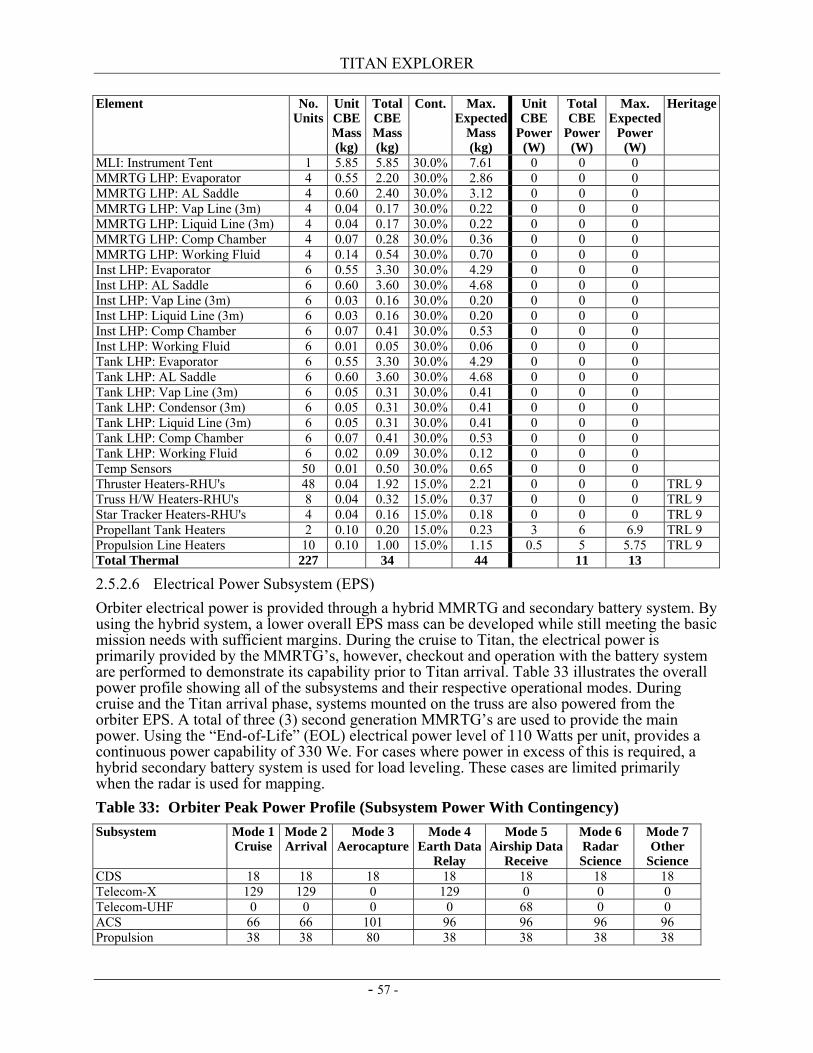
TITAN EXPLORER
- 57 -
Element No. Units
Unit CBE Mass (kg)
Total CBE Mass (kg)
Cont. Max. Expected
Mass (kg)
Unit CBE
Power (W)
Total CBE
Power (W)
Max. Expected
Power (W)
Heritage
MLI: Instrument Tent 1 5.85 5.85 30.0% 7.61 0 0 0 MMRTG LHP: Evaporator 4 0.55 2.20 30.0% 2.86 0 0 0 MMRTG LHP: AL Saddle 4 0.60 2.40 30.0% 3.12 0 0 0 MMRTG LHP: Vap Line (3m) 4 0.04 0.17 30.0% 0.22 0 0 0 MMRTG LHP: Liquid Line (3m) 4 0.04 0.17 30.0% 0.22 0 0 0 MMRTG LHP: Comp Chamber 4 0.07 0.28 30.0% 0.36 0 0 0 MMRTG LHP: Working Fluid 4 0.14 0.54 30.0% 0.70 0 0 0 Inst LHP: Evaporator 6 0.55 3.30 30.0% 4.29 0 0 0 Inst LHP: AL Saddle 6 0.60 3.60 30.0% 4.68 0 0 0 Inst LHP: Vap Line (3m) 6 0.03 0.16 30.0% 0.20 0 0 0 Inst LHP: Liquid Line (3m) 6 0.03 0.16 30.0% 0.20 0 0 0 Inst LHP: Comp Chamber 6 0.07 0.41 30.0% 0.53 0 0 0 Inst LHP: Working Fluid 6 0.01 0.05 30.0% 0.06 0 0 0 Tank LHP: Evaporator 6 0.55 3.30 30.0% 4.29 0 0 0 Tank LHP: AL Saddle 6 0.60 3.60 30.0% 4.68 0 0 0 Tank LHP: Vap Line (3m) 6 0.05 0.31 30.0% 0.41 0 0 0 Tank LHP: Condensor (3m) 6 0.05 0.31 30.0% 0.41 0 0 0 Tank LHP: Liquid Line (3m) 6 0.05 0.31 30.0% 0.41 0 0 0 Tank LHP: Comp Chamber 6 0.07 0.41 30.0% 0.53 0 0 0 Tank LHP: Working Fluid 6 0.02 0.09 30.0% 0.12 0 0 0 Temp Sensors 50 0.01 0.50 30.0% 0.65 0 0 0 Thruster Heaters-RHU's 48 0.04 1.92 15.0% 2.21 0 0 0 TRL 9 Truss H/W Heaters-RHU's 8 0.04 0.32 15.0% 0.37 0 0 0 TRL 9 Star Tracker Heaters-RHU's 4 0.04 0.16 15.0% 0.18 0 0 0 TRL 9 Propellant Tank Heaters 2 0.10 0.20 15.0% 0.23 3 6 6.9 TRL 9 Propulsion Line Heaters 10 0.10 1.00 15.0% 1.15 0.5 5 5.75 TRL 9 Total Thermal 227 34 44 11 13
2.5.2.6 Electrical Power Subsystem (EPS) Orbiter electrical power is provided through a hybrid MMRTG and secondary battery system. By using the hybrid system, a lower overall EPS mass can be developed while still meeting the basic mission needs with sufficient margins. During the cruise to Titan, the electrical power is primarily provided by the MMRTG’s, however, checkout and operation with the battery system are performed to demonstrate its capability prior to Titan arrival. Table 33 illustrates the overall power profile showing all of the subsystems and their respective operational modes. During cruise and the Titan arrival phase, systems mounted on the truss are also powered from the orbiter EPS. A total of three (3) second generation MMRTG’s are used to provide the main power. Using the “End-of-Life” (EOL) electrical power level of 110 Watts per unit, provides a continuous power capability of 330 We. For cases where power in excess of this is required, a hybrid secondary battery system is used for load leveling. These cases are limited primarily when the radar is used for mapping. Table 33: Orbiter Peak Power Profile (Subsystem Power With Contingency) Subsystem Mode 1
Cruise Mode 2 Arrival
Mode 3 Aerocapture
Mode 4 Earth Data
Relay
Mode 5 Airship Data
Receive
Mode 6 Radar Science
Mode 7 Other
Science CDS 18 18 18 18 18 18 18 Telecom-X 129 129 0 129 0 0 0 Telecom-UHF 0 0 0 0 68 0 0 ACS 66 66 101 96 96 96 96 Propulsion 38 38 80 38 38 38 38
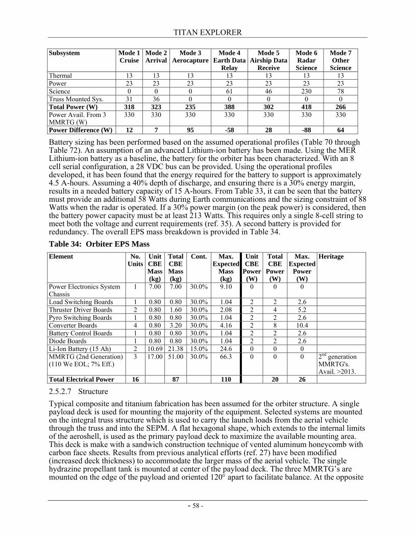
TITAN EXPLORER
- 58 -
Subsystem Mode 1 Cruise
Mode 2 Arrival
Mode 3 Aerocapture
Mode 4 Earth Data
Relay
Mode 5 Airship Data
Receive
Mode 6 Radar Science
Mode 7 Other
Science Thermal 13 13 13 13 13 13 13 Power 23 23 23 23 23 23 23 Science 0 0 0 61 46 230 78 Truss Mounted Sys. 31 36 0 0 0 0 0 Total Power (W) 318 323 235 388 302 418 266 Power Avail. From 3 MMRTG (W)
330 330 330 330 330 330 330
Power Difference (W) 12 7 95 -58 28 -88 64
Battery sizing has been performed based on the assumed operational profiles (Table 70 through Table 72). An assumption of an advanced Lithium-ion battery has been made. Using the MER Lithium-ion battery as a baseline, the battery for the orbiter has been characterized. With an 8 cell serial configuration, a 28 VDC bus can be provided. Using the operational profiles developed, it has been found that the energy required for the battery to support is approximately 4.5 A-hours. Assuming a 40% depth of discharge, and ensuring there is a 30% energy margin, results in a needed battery capacity of 15 A-hours. From Table 33, it can be seen that the battery must provide an additional 58 Watts during Earth communications and the sizing constraint of 88 Watts when the radar is operated. If a 30% power margin (on the peak power) is considered, then the battery power capacity must be at least 213 Watts. This requires only a single 8-cell string to meet both the voltage and current requirements (ref. 35). A second battery is provided for redundancy. The overall EPS mass breakdown is provided in Table 34. Table 34: Orbiter EPS Mass Element No.
Units Unit CBE Mass (kg)
Total CBE Mass (kg)
Cont. Max. Expected
Mass (kg)
Unit CBE
Power (W)
Total CBE
Power (W)
Max. Expected
Power (W)
Heritage
Power Electronics System Chassis
1 7.00 7.00 30.0% 9.10 0 0 0
Load Switching Boards 1 0.80 0.80 30.0% 1.04 2 2 2.6 Thruster Driver Boards 2 0.80 1.60 30.0% 2.08 2 4 5.2 Pyro Switching Boards 1 0.80 0.80 30.0% 1.04 2 2 2.6 Converter Boards 4 0.80 3.20 30.0% 4.16 2 8 10.4 Battery Control Boards 1 0.80 0.80 30.0% 1.04 2 2 2.6 Diode Boards 1 0.80 0.80 30.0% 1.04 2 2 2.6 Li-Ion Battery (15 Ah) 2 10.69 21.38 15.0% 24.6 0 0 0 MMRTG (2nd Generation) (110 We EOL; 7% Eff.)
3 17.00 51.00 30.0% 66.3 0 0 0 2nd generation MMRTG's. Avail. >2013.
Total Electrical Power 16 87 110 20 26
2.5.2.7 Structure Typical composite and titanium fabrication has been assumed for the orbiter structure. A single payload deck is used for mounting the majority of the equipment. Selected systems are mounted on the integral truss structure which is used to carry the launch loads from the aerial vehicle through the truss and into the SEPM. A flat hexagonal shape, which extends to the internal limits of the aeroshell, is used as the primary payload deck to maximize the available mounting area. This deck is make with a sandwich construction technique of vented aluminum honeycomb with carbon face sheets. Results from previous analytical efforts (ref. 27) have been modified (increased deck thickness) to accommodate the larger mass of the aerial vehicle. The single hydrazine propellant tank is mounted at center of the payload deck. The three MMRTG’s are mounted on the edge of the payload and oriented 120° apart to facilitate balance. At the opposite
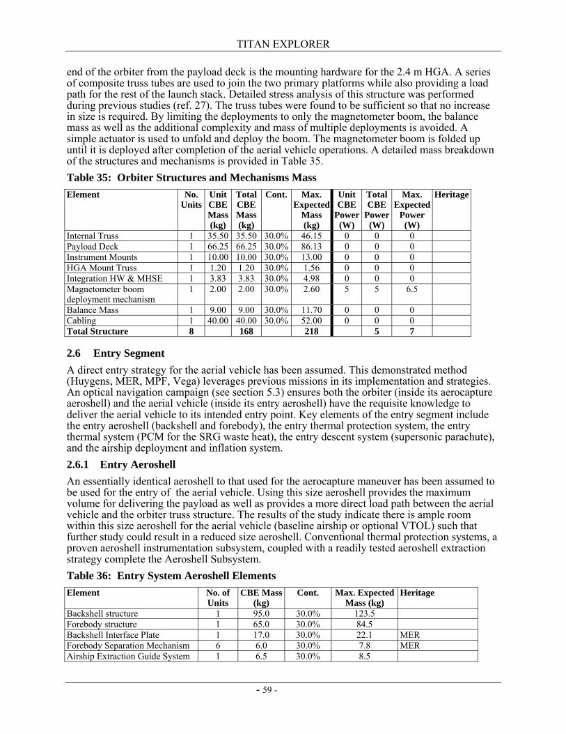
TITAN EXPLORER
- 59 -
end of the orbiter from the payload deck is the mounting hardware for the 2.4 m HGA. A series of composite truss tubes are used to join the two primary platforms while also providing a load path for the rest of the launch stack. Detailed stress analysis of this structure was performed during previous studies (ref. 27). The truss tubes were found to be sufficient so that no increase in size is required. By limiting the deployments to only the magnetometer boom, the balance mass as well as the additional complexity and mass of multiple deployments is avoided. A simple actuator is used to unfold and deploy the boom. The magnetometer boom is folded up until it is deployed after completion of the aerial vehicle operations. A detailed mass breakdown of the structures and mechanisms is provided in Table 35. Table 35: Orbiter Structures and Mechanisms Mass Element No.
Units Unit CBE Mass (kg)
Total CBE Mass (kg)
Cont. Max. Expected
Mass (kg)
Unit CBE
Power (W)
Total CBE
Power (W)
Max. Expected
Power (W)
Heritage
Internal Truss 1 35.50 35.50 30.0% 46.15 0 0 0 Payload Deck 1 66.25 66.25 30.0% 86.13 0 0 0 Instrument Mounts 1 10.00 10.00 30.0% 13.00 0 0 0 HGA Mount Truss 1 1.20 1.20 30.0% 1.56 0 0 0 Integration HW & MHSE 1 3.83 3.83 30.0% 4.98 0 0 0 Magnetometer boom deployment mechanism
1 2.00 2.00 30.0% 2.60 5 5 6.5
Balance Mass 1 9.00 9.00 30.0% 11.70 0 0 0 Cabling 1 40.00 40.00 30.0% 52.00 0 0 0 Total Structure 8 168 218 5 7
2.6 Entry Segment A direct entry strategy for the aerial vehicle has been assumed. This demonstrated method (Huygens, MER, MPF, Vega) leverages previous missions in its implementation and strategies. An optical navigation campaign (see section 5.3) ensures both the orbiter (inside its aerocapture aeroshell) and the aerial vehicle (inside its entry aeroshell) have the requisite knowledge to deliver the aerial vehicle to its intended entry point. Key elements of the entry segment include the entry aeroshell (backshell and forebody), the entry thermal protection system, the entry thermal system (PCM for the SRG waste heat), the entry descent system (supersonic parachute), and the airship deployment and inflation system. 2.6.1 Entry Aeroshell An essentially identical aeroshell to that used for the aerocapture maneuver has been assumed to be used for the entry of the aerial vehicle. Using this size aeroshell provides the maximum volume for delivering the payload as well as provides a more direct load path between the aerial vehicle and the orbiter truss structure. The results of the study indicate there is ample room within this size aeroshell for the aerial vehicle (baseline airship or optional VTOL) such that further study could result in a reduced size aeroshell. Conventional thermal protection systems, a proven aeroshell instrumentation subsystem, coupled with a readily tested aeroshell extraction strategy complete the Aeroshell Subsystem. Table 36: Entry System Aeroshell Elements Element No. of
Units CBE Mass
(kg) Cont. Max. Expected
Mass (kg) Heritage
Backshell structure 1 95.0 30.0% 123.5 Forebody structure 1 65.0 30.0% 84.5 Backshell Interface Plate 1 17.0 30.0% 22.1 MER Forebody Separation Mechanism 6 6.0 30.0% 7.8 MER Airship Extraction Guide System 1 6.5 30.0% 8.5
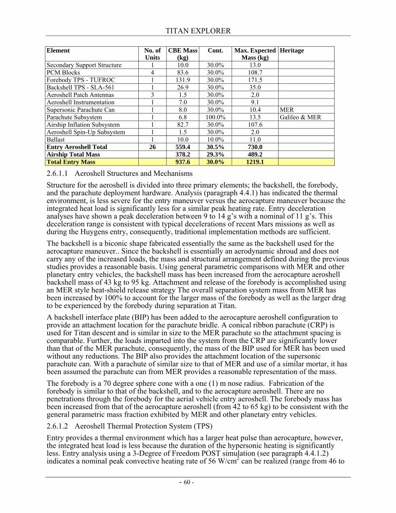
TITAN EXPLORER
- 60 -
Element No. of Units
CBE Mass (kg)
Cont. Max. Expected Mass (kg)
Heritage
Secondary Support Structure 1 10.0 30.0% 13.0 PCM Blocks 4 83.6 30.0% 108.7 Forebody TPS - TUFROC 1 131.9 30.0% 171.5 Backshell TPS - SLA-561 1 26.9 30.0% 35.0 Aeroshell Patch Antennas 3 1.5 30.0% 2.0 Aeroshell Instrumentation 1 7.0 30.0% 9.1 Supersonic Parachute Can 1 8.0 30.0% 10.4 MER Parachute Subsystem 1 6.8 100.0% 13.5 Galileo & MER Airship Inflation Subsystem 1 82.7 30.0% 107.6 Aeroshell Spin-Up Subsystem 1 1.5 30.0% 2.0 Ballast 1 10.0 10.0% 11.0 Entry Aeroshell Total 26 559.4 30.5% 730.0 Airship Total Mass 378.2 29.3% 489.2 Total Entry Mass 937.6 30.0% 1219.1
2.6.1.1 Aeroshell Structures and Mechanisms Structure for the aeroshell is divided into three primary elements; the backshell, the forebody, and the parachute deployment hardware. Analysis (paragraph 4.4.1) has indicated the thermal environment, is less severe for the entry maneuver versus the aerocapture maneuver because the integrated heat load is significantly less for a similar peak heating rate. Entry deceleration analyses have shown a peak deceleration between 9 to 14 g’s with a nominal of 11 g’s. This deceleration range is consistent with typical decelerations of recent Mars missions as well as during the Huygens entry, consequently, traditional implementation methods are sufficient. The backshell is a biconic shape fabricated essentially the same as the backshell used for the aerocapture maneuver.. Since the backshell is essentially an aerodynamic shroud and does not carry any of the increased loads, the mass and structural arrangement defined during the previous studies provides a reasonable basis. Using general parametric comparisons with MER and other planetary entry vehicles, the backshell mass has been increased from the aerocapture aeroshell backshell mass of 43 kg to 95 kg. Attachment and release of the forebody is accomplished using an MER style heat-shield release strategy The overall separation system mass from MER has been increased by 100% to account for the larger mass of the forebody as well as the larger drag to be experienced by the forebody during separation at Titan. A backshell interface plate (BIP) has been added to the aerocapture aeroshell configuration to provide an attachment location for the parachute bridle. A conical ribbon parachute (CRP) is used for Titan descent and is similar in size to the MER parachute so the attachment spacing is comparable. Further, the loads imparted into the system from the CRP are significantly lower than that of the MER parachute, consequently, the mass of the BIP used for MER has been used without any reductions. The BIP also provides the attachment location of the supersonic parachute can. With a parachute of similar size to that of MER and use of a similar mortar, it has been assumed the parachute can from MER provides a reasonable representation of the mass. The forebody is a 70 degree sphere cone with a one (1) m nose radius. Fabrication of the forebody is similar to that of the backshell, and to the aerocapture aeroshell. There are no penetrations through the forebody for the aerial vehicle entry aeroshell. The forebody mass has been increased from that of the aerocapture aeroshell (from 42 to 65 kg) to be consistent with the general parametric mass fraction exhibited by MER and other planetary entry vehicles. 2.6.1.2 Aeroshell Thermal Protection System (TPS) Entry provides a thermal environment which has a larger heat pulse than aerocapture, however, the integrated heat load is less because the duration of the hypersonic heating is significantly less. Entry analysis using a 3-Degree of Freedom POST simulation (see paragraph 4.4.1.2) indicates a nominal peak convective heating rate of 56 W/cm2 can be realized (range from 46 to
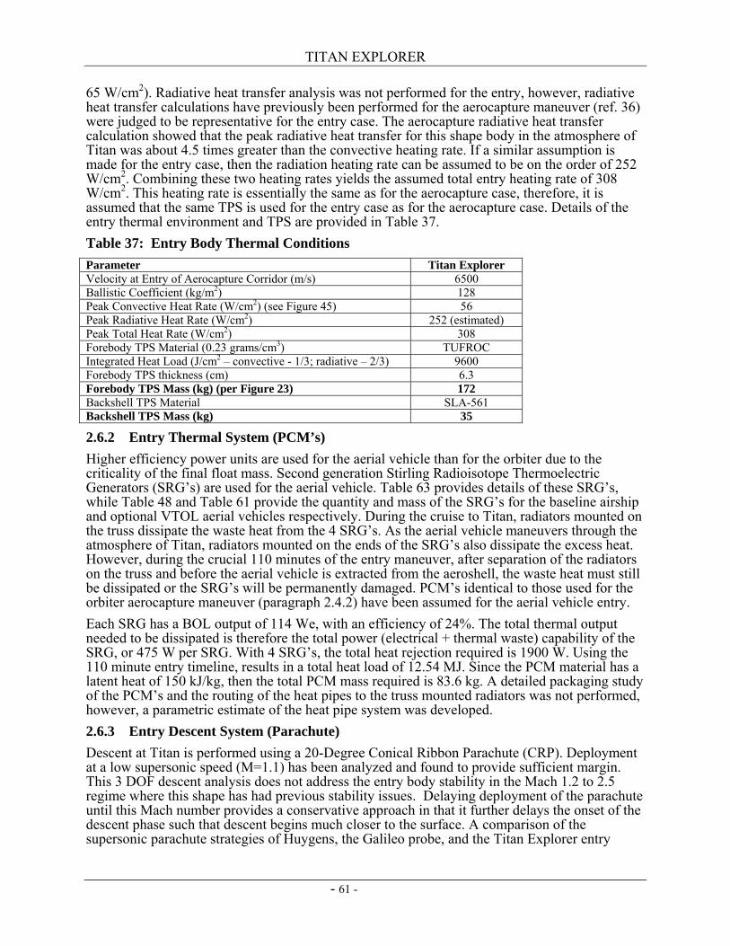
TITAN EXPLORER
- 61 -
65 W/cm2). Radiative heat transfer analysis was not performed for the entry, however, radiative heat transfer calculations have previously been performed for the aerocapture maneuver (ref. 36) were judged to be representative for the entry case. The aerocapture radiative heat transfer calculation showed that the peak radiative heat transfer for this shape body in the atmosphere of Titan was about 4.5 times greater than the convective heating rate. If a similar assumption is made for the entry case, then the radiation heating rate can be assumed to be on the order of 252 W/cm2. Combining these two heating rates yields the assumed total entry heating rate of 308 W/cm2. This heating rate is essentially the same as for the aerocapture case, therefore, it is assumed that the same TPS is used for the entry case as for the aerocapture case. Details of the entry thermal environment and TPS are provided in Table 37. Table 37: Entry Body Thermal Conditions Parameter Titan Explorer Velocity at Entry of Aerocapture Corridor (m/s) 6500 Ballistic Coefficient (kg/m2) 128 Peak Convective Heat Rate (W/cm2) (see Figure 45) 56 Peak Radiative Heat Rate (W/cm2) 252 (estimated) Peak Total Heat Rate (W/cm2) 308 Forebody TPS Material (0.23 grams/cm3) TUFROC Integrated Heat Load (J/cm2 – convective - 1/3; radiative – 2/3) 9600 Forebody TPS thickness (cm) 6.3 Forebody TPS Mass (kg) (per Figure 23) 172 Backshell TPS Material SLA-561 Backshell TPS Mass (kg) 35
2.6.2 Entry Thermal System (PCM’s) Higher efficiency power units are used for the aerial vehicle than for the orbiter due to the criticality of the final float mass. Second generation Stirling Radioisotope Thermoelectric Generators (SRG’s) are used for the aerial vehicle. Table 63 provides details of these SRG’s, while Table 48 and Table 61 provide the quantity and mass of the SRG’s for the baseline airship and optional VTOL aerial vehicles respectively. During the cruise to Titan, radiators mounted on the truss dissipate the waste heat from the 4 SRG’s. As the aerial vehicle maneuvers through the atmosphere of Titan, radiators mounted on the ends of the SRG’s also dissipate the excess heat. However, during the crucial 110 minutes of the entry maneuver, after separation of the radiators on the truss and before the aerial vehicle is extracted from the aeroshell, the waste heat must still be dissipated or the SRG’s will be permanently damaged. PCM’s identical to those used for the orbiter aerocapture maneuver (paragraph 2.4.2) have been assumed for the aerial vehicle entry. Each SRG has a BOL output of 114 We, with an efficiency of 24%. The total thermal output needed to be dissipated is therefore the total power (electrical + thermal waste) capability of the SRG, or 475 W per SRG. With 4 SRG’s, the total heat rejection required is 1900 W. Using the 110 minute entry timeline, results in a total heat load of 12.54 MJ. Since the PCM material has a latent heat of 150 kJ/kg, then the total PCM mass required is 83.6 kg. A detailed packaging study of the PCM’s and the routing of the heat pipes to the truss mounted radiators was not performed, however, a parametric estimate of the heat pipe system was developed. 2.6.3 Entry Descent System (Parachute) Descent at Titan is performed using a 20-Degree Conical Ribbon Parachute (CRP). Deployment at a low supersonic speed (M=1.1) has been analyzed and found to provide sufficient margin. This 3 DOF descent analysis does not address the entry body stability in the Mach 1.2 to 2.5 regime where this shape has had previous stability issues. Delaying deployment of the parachute until this Mach number provides a conservative approach in that it further delays the onset of the descent phase such that descent begins much closer to the surface. A comparison of the supersonic parachute strategies of Huygens, the Galileo probe, and the Titan Explorer entry
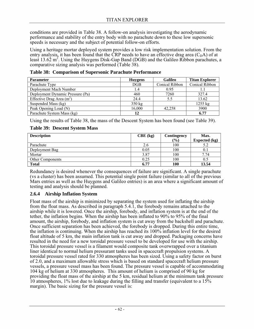
TITAN EXPLORER
- 62 -
conditions are provided in Table 38. A follow-on analysis investigating the aerodynamic performance and stability of the entry body with no parachute down to these low supersonic speeds is necessary and the subject of potential follow-on efforts. Using a heritage mortar deployed system provides a low risk implementation solution. From the entry analysis, it has been found that the CRP needs to have an effective drag area (CDA) of at least 13.62 m2. Using the Huygens Disk-Gap Band (DGB) and the Galileo Ribbon parachutes, a comparative sizing analysis was performed (Table 38). Table 38: Comparison of Supersonic Parachute Performance Parameter Huygens Galileo Titan Explorer Parachute Type DGB Conical Ribbon Conical Ribbon Deployment Mach Number 1.4 0.95 1.1 Deployment Dynamic Pressure (Pa) 460 7260 327.4 Effective Drag Area (m2) 24.4 5.5 13.62 Suspended Mass (kg) 350 kg 1255 kg Peak Opening Load (N) 16,000 42,258 3900 Parachute System Mass (kg) 12 6.77
Using the results of Table 38, the mass of the Descent System has been found (see Table 39). Table 39: Descent System Mass Description CBE (kg) Contingency
(%) Max.
Expected (kg) Parachute 2.6 100 5.2 Deployment Bag 0.05 100 0.1 Mortar 3.87 100 7.74 Other Components 0.25 100 0.5 Total 6.77 100 13.54
Redundancy is desired whenever the consequences of failure are significant. A single parachute (vs a cluster) has been assumed. This potential single point failure (similar to all of the previous Mars entries as well as the Huygens and Galileo entries) is an area where a significant amount of testing and analysis should be planned. 2.6.4 Airship Inflation System Float mass of the airship is minimized by separating the system used for inflating the airship from the float mass. As described in paragraph 5.4.1, the forebody remains attached to the airship while it is lowered. Once the airship, forebody, and inflation system is at the end of the tether, the inflation begins. When the airship has been inflated to 90% to 95% of the final amount, the airship, forebody, and inflation system is cut away from the backshell and parachute. Once sufficient separation has been achieved, the forebody is dropped. During this entire time, the inflation is continuing. When the airship has reached its 100% inflation level for the desired float altitude of 5 km, the main inflation tank is cut away and dropped. Packaging concerns have resulted in the need for a new toroidal pressure vessel to be developed for use with the airship. This toroidal pressure vessel is a filament would composite tank overwrapped over a titanium liner identical to normal helium pressurant tanks used in spacecraft propulsion systems. A toroidal pressure vessel rated for 330 atmospheres has been sized. Using a safety factor on burst of 2.0, and a maximum allowable stress which is based on standard spacecraft helium pressure vessels, a pressure vessel mass has been found. The pressure vessel is capable of accommodating 104 kg of helium at 330 atmospheres. This amount of helium is comprised of 90 kg for providing the float mass of the airship at the 5 km, residual helium at the minimum tank pressure 10 atmospheres, 1% lost due to leakage during the filling and transfer (equivalent to a 15% margin). The basic sizing for the pressure vessel is:
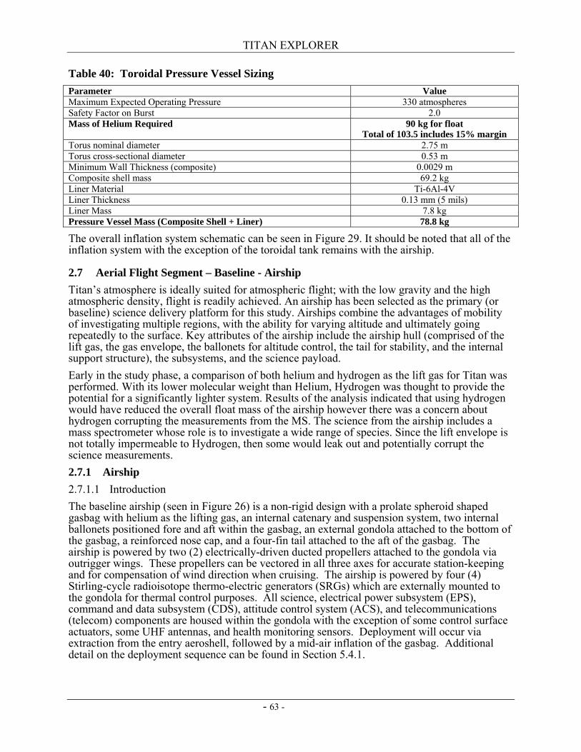
TITAN EXPLORER
- 63 -
Table 40: Toroidal Pressure Vessel Sizing Parameter Value Maximum Expected Operating Pressure 330 atmospheres Safety Factor on Burst 2.0 Mass of Helium Required 90 kg for float
Total of 103.5 includes 15% margin Torus nominal diameter 2.75 m Torus cross-sectional diameter 0.53 m Minimum Wall Thickness (composite) 0.0029 m Composite shell mass 69.2 kg Liner Material Ti-6Al-4V Liner Thickness 0.13 mm (5 mils) Liner Mass 7.8 kg Pressure Vessel Mass (Composite Shell + Liner) 78.8 kg
The overall inflation system schematic can be seen in Figure 29. It should be noted that all of the inflation system with the exception of the toroidal tank remains with the airship.
2.7 Aerial Flight Segment – Baseline - Airship Titan’s atmosphere is ideally suited for atmospheric flight; with the low gravity and the high atmospheric density, flight is readily achieved. An airship has been selected as the primary (or baseline) science delivery platform for this study. Airships combine the advantages of mobility of investigating multiple regions, with the ability for varying altitude and ultimately going repeatedly to the surface. Key attributes of the airship include the airship hull (comprised of the lift gas, the gas envelope, the ballonets for altitude control, the tail for stability, and the internal support structure), the subsystems, and the science payload. Early in the study phase, a comparison of both helium and hydrogen as the lift gas for Titan was performed. With its lower molecular weight than Helium, Hydrogen was thought to provide the potential for a significantly lighter system. Results of the analysis indicated that using hydrogen would have reduced the overall float mass of the airship however there was a concern about hydrogen corrupting the measurements from the MS. The science from the airship includes a mass spectrometer whose role is to investigate a wide range of species. Since the lift envelope is not totally impermeable to Hydrogen, then some would leak out and potentially corrupt the science measurements. 2.7.1 Airship 2.7.1.1 Introduction The baseline airship (seen in Figure 26) is a non-rigid design with a prolate spheroid shaped gasbag with helium as the lifting gas, an internal catenary and suspension system, two internal ballonets positioned fore and aft within the gasbag, an external gondola attached to the bottom of the gasbag, a reinforced nose cap, and a four-fin tail attached to the aft of the gasbag. The airship is powered by two (2) electrically-driven ducted propellers attached to the gondola via outrigger wings. These propellers can be vectored in all three axes for accurate station-keeping and for compensation of wind direction when cruising. The airship is powered by four (4) Stirling-cycle radioisotope thermo-electric generators (SRGs) which are externally mounted to the gondola for thermal control purposes. All science, electrical power subsystem (EPS), command and data subsystem (CDS), attitude control system (ACS), and telecommunications (telecom) components are housed within the gondola with the exception of some control surface actuators, some UHF antennas, and health monitoring sensors. Deployment will occur via extraction from the entry aeroshell, followed by a mid-air inflation of the gasbag. Additional detail on the deployment sequence can be found in Section 5.4.1.
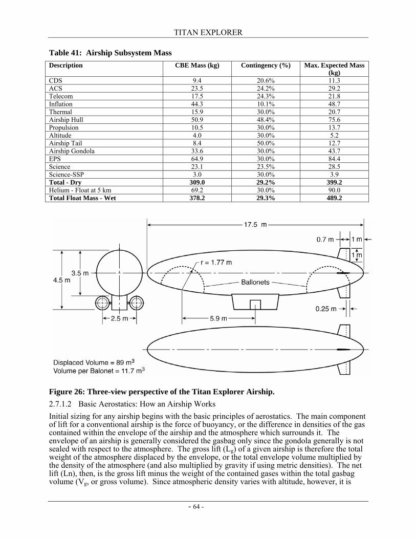
TITAN EXPLORER
- 64 -
Table 41: Airship Subsystem Mass Description CBE Mass (kg) Contingency (%) Max. Expected Mass
(kg) CDS 9.4 20.6% 11.3 ACS 23.5 24.2% 29.2 Telecom 17.5 24.3% 21.8 Inflation 44.3 10.1% 48.7 Thermal 15.9 30.0% 20.7 Airship Hull 50.9 48.4% 75.6 Propulsion 10.5 30.0% 13.7 Altitude 4.0 30.0% 5.2 Airship Tail 8.4 50.0% 12.7 Airship Gondola 33.6 30.0% 43.7 EPS 64.9 30.0% 84.4 Science 23.1 23.5% 28.5 Science-SSP 3.0 30.0% 3.9 Total - Dry 309.0 29.2% 399.2 Helium - Float at 5 km 69.2 30.0% 90.0 Total Float Mass - Wet 378.2 29.3% 489.2
Figure 26: Three-view perspective of the Titan Explorer Airship. 2.7.1.2 Basic Aerostatics: How an Airship Works Initial sizing for any airship begins with the basic principles of aerostatics. The main component of lift for a conventional airship is the force of buoyancy, or the difference in densities of the gas contained within the envelope of the airship and the atmosphere which surrounds it. The envelope of an airship is generally considered the gasbag only since the gondola generally is not sealed with respect to the atmosphere. The gross lift (Lg) of a given airship is therefore the total weight of the atmosphere displaced by the envelope, or the total envelope volume multiplied by the density of the atmosphere (and also multiplied by gravity if using metric densities). The net lift (Ln), then, is the gross lift minus the weight of the contained gases within the total gasbag volume (Vg, or gross volume). Since atmospheric density varies with altitude, however, it is
TITAN EXPLORER
- 65 -
necessary to incorporate a method of altitude control. The most common method for accomplishing this is with ballonets. Ballonets are separate envelopes housed within the main envelope which inflate and deflate to allow the airship to descend or ascend. Airship designs can incorporate a single ballonet or multiple ballonets. The use of multiple ballonets allows trimming of the airship with respect to the center of gravity (CG) and for small airships (<50,000 m3 enclosed envelope volume) two ballonets are common, usually placed in fore and aft positions. The ballonets are inflated with the external atmosphere to cause the airship to descend to a point at which the enclosed lift gas weight (Vn, net volume) is again equal to the displaced volume of atmosphere (Vg from above) minus the inflated volume of the ballonets (Va, or atmospheric volume now within the gasbag). The pressure height of a given airship envelope, then, is considered the point at which the ballonets are completely deflated and Vn = Vg. This is the maximum density altitude at which the airship can fly. 2.7.1.3 Detailed Design Methodology The detailed design methodology of each component is divided into common subgroups associated with an airship. The Hull Group includes the gasbag sizing, the ballonets, and all associated items (such as the suspension system for the gondola, the nose reinforcement, etc.). The Propulsion Group includes the propeller system and all related components. This section will also contain a short description of the simple propeller analysis and the drag characteristics of the airship. The Tail Group and Gondola Group are briefly described and thus are combined in one section. The internal component subsystems and the science payload are described in Sections 2.7.2 and 1.3.2 respectively.
2.7.1.3.1 Hull Group For the Titan Explorer Mission, the gross lift mass, Lg, was considered an input. Mass is used in place of weight or force when discussing the airship sizing from here on. The gravity component, while important when equating forces for comparison with terrestrial vehicles, can be divided out in all airship sizing equations if, for example, “lift” is considered a lifted mass instead of an actual weight or force. This provides a closer link between the airship sizing and the sizing of other mission systems, such as the orbiter, for which numbers are always quoted in terms of mass. Using Lg, Vg was calculated based on a maximum flight altitude on Titan of 5 km, which equates to an atmospheric density of 4.37 kg/m3 (see Appendix 2). Different lifting gases were considered, but only two reasonable options were available based on terrestrial use and performance: hydrogen and helium. While hydrogen has a slightly lower density than helium, and therefore has slightly better performance, its use was eliminated early in the design process due to operational liabilities associated with contamination of the science instruments’ measurements. Therefore, moving forward with helium as the lifting gas, a net lift (Ln) could be calculated based on helium’s density. In calculating helium’s density, it was assumed that the helium could be held above the atmospheric pressure at the surface throughout all operating altitudes, but the temperature was equated with the atmospheric temperature at 5km (~85.8 K, see Appendix 2). A mass of the lifting gas was calculated using Vg multiplied by the aforementioned density of helium. One essential parameter that should be mentioned about the gasbag is the differential pressure between the lifting gas within the gasbag and the Titan atmosphere. Suggested values for most modern non-rigid terrestrial airships (ref. 37) show that a pressure difference of 125 Pa is sufficient, with a factor added to account for the maximum impinging velocity expected during flight (including wind gusts). Including this factor assuming maximum wind gusts of 30 m/s gives a minimum pressure differential of 155 Pa. Due to the cryogenic temperatures on Titan, as well as the higher atmospheric density, the materials chosen for the gasbag laminate (discussed in paragraph 3.1.3) will be able to withstand differential pressures in excess of 300 Pa. More
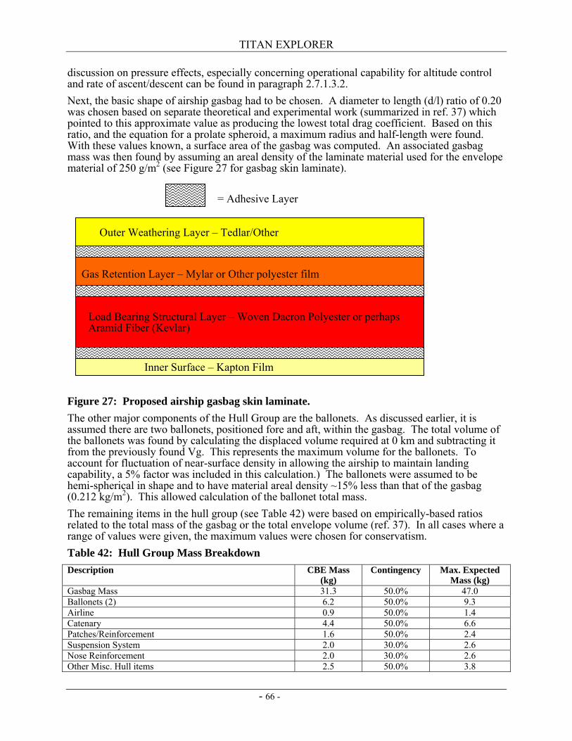
TITAN EXPLORER
- 66 -
= Adhesive Layer
Outer Weathering Layer – Tedlar/Other
Gas Retention Layer – Mylar or Other polyester film
Load Bearing Structural Layer – Woven Dacron Polyester or perhaps Aramid Fiber (Kevlar)
Inner Surface – Kapton Film
discussion on pressure effects, especially concerning operational capability for altitude control and rate of ascent/descent can be found in paragraph 2.7.1.3.2. Next, the basic shape of airship gasbag had to be chosen. A diameter to length (d/l) ratio of 0.20 was chosen based on separate theoretical and experimental work (summarized in ref. 37) which pointed to this approximate value as producing the lowest total drag coefficient. Based on this ratio, and the equation for a prolate spheroid, a maximum radius and half-length were found. With these values known, a surface area of the gasbag was computed. An associated gasbag mass was then found by assuming an areal density of the laminate material used for the envelope material of 250 g/m2 (see Figure 27 for gasbag skin laminate).
Figure 27: Proposed airship gasbag skin laminate. The other major components of the Hull Group are the ballonets. As discussed earlier, it is assumed there are two ballonets, positioned fore and aft, within the gasbag. The total volume of the ballonets was found by calculating the displaced volume required at 0 km and subtracting it from the previously found Vg. This represents the maximum volume for the ballonets. To account for fluctuation of near-surface density in allowing the airship to maintain landing capability, a 5% factor was included in this calculation.) The ballonets were assumed to be hemi-spherical in shape and to have material areal density ~15% less than that of the gasbag (0.212 kg/m2). This allowed calculation of the ballonet total mass. The remaining items in the hull group (see Table 42) were based on empirically-based ratios related to the total mass of the gasbag or the total envelope volume (ref. 37). In all cases where a range of values were given, the maximum values were chosen for conservatism. Table 42: Hull Group Mass Breakdown Description CBE Mass
(kg) Contingency Max. Expected
Mass (kg) Gasbag Mass 31.3 50.0% 47.0 Ballonets (2) 6.2 50.0% 9.3 Airline 0.9 50.0% 1.4 Catenary 4.4 50.0% 6.6 Patches/Reinforcement 1.6 50.0% 2.4 Suspension System 2.0 30.0% 2.6 Nose Reinforcement 2.0 30.0% 2.6 Other Misc. Hull items 2.5 50.0% 3.8
TITAN EXPLORER
- 67 -
Description CBE Mass (kg)
Contingency Max. Expected Mass (kg)
Total Hull Mass - Dry 50.9 48.4% 75.6 Lifting Gas - Helium 69.2 30.0% 90.0 Total Hull Mass - Wet 120.1 37.8% 165.5
2.7.1.3.2 Propulsion Group The main component of the propulsion group is the propellers. The sizing of the propellers was based on basic propeller analysis momentum theory with an airship drag buildup. The propeller analysis was performed over a range of blade diameters (meaning the tip to tip length of the propeller, assuming a 2-bladed propeller), available powers, and densities (employing the density variations over the operating range) for a given maximum flight speed. For each combination, it is possible to compute a maximum static thrust, a static induced velocity, a thrust available, the associated thrust coefficient, and finally, an ideal efficiency based on momentum theory. The total efficiency can then be computed by combining this result with reasonable values for the motor, gearbox, and control electronics efficiencies (ref. 38). Before an ideal efficiency can be found, the thrust available must be made equal to or greater than the thrust required to overcome drag on the airship at the desired flight velocity. To find the total vehicle drag, a simple drag buildup on the airship was necessary. Aerodynamic relations for airships are dealt with in much the same way as for airplanes, but generally, drag coefficients are based on wetted volumes or surface areas rather than planform areas (such as for wings). Since the design speed for the Titan Explorer airship is < 5 m/s, it is assumed that the vast majority of its drag comes from skin friction drag over the considerable exposed wetted area. The volumetric coefficient of drag for the hull (Cdv,hull) was computed for various densities found throughout the operating altitude range for a maximum flight velocity of 4 m/s. The formula for the hull drag is based on a combination of theoretical and experimental work, again by Young and Hoerner (ref. 37) is:
In this expression, d/l is the same ratio described in Section 0 and Re is the Reynold’s Number. Using the this value, a hull drag value was found using the formula for drag based on volume, with ρ being density and V being flight velocity:
Although the major component of drag on the airship is skin friction with the gasbag, other components must be accounted for. Tail drag is a very complex phenomenon, but must be accounted for in this design. To account for tail drag, it is first necessary to find the ratio of tail wetted area to gasbag wetted area. An average of values taken from various terrestrial airships (Table 3.4 in ref. 37) shows this ratio to be ~0.078. However, since the main effect of the tail is to provide an opposing force in order to provide directional control, and this average value is from airships flying in Earth’s atmosphere, it is necessary to scale the ratio with respect to the ratio of Earth’s atmospheric density to that of Titan’s (at 5 km, approximately 1.22/4.37 or .279). This results in a ratio of Atail/Ahull of approximately 0.0218 for Titan. Using this value, it is possible to produce a tail drag for the airship based on a curve fit to the same data which produced the average value (see Eq. 3.8 in ref. 37):
6/17.22.13/1
, Re/032.1252.0172.0⎪⎭
⎪⎬⎫
⎪⎩
⎪⎨⎧
⎟⎠⎞
⎜⎝⎛+⎟
⎠⎞
⎜⎝⎛+⎟
⎠⎞
⎜⎝⎛=
ld
ld
dlC hullDV
( ) hullDVhull CVolVD ,3/22
21 ρ=
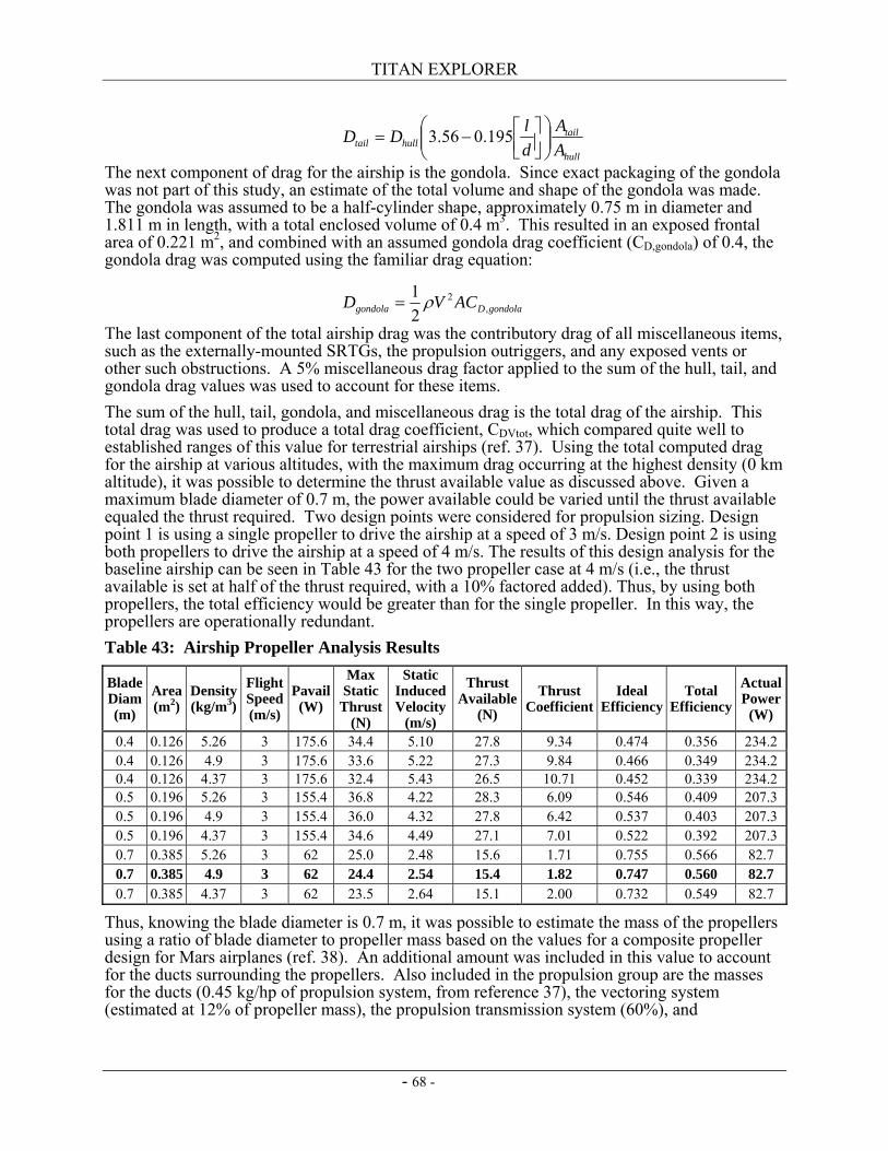
TITAN EXPLORER
- 68 -
The next component of drag for the airship is the gondola. Since exact packaging of the gondola was not part of this study, an estimate of the total volume and shape of the gondola was made. The gondola was assumed to be a half-cylinder shape, approximately 0.75 m in diameter and 1.811 m in length, with a total enclosed volume of 0.4 m3. This resulted in an exposed frontal area of 0.221 m2, and combined with an assumed gondola drag coefficient (CD,gondola) of 0.4, the gondola drag was computed using the familiar drag equation:
The last component of the total airship drag was the contributory drag of all miscellaneous items, such as the externally-mounted SRTGs, the propulsion outriggers, and any exposed vents or other such obstructions. A 5% miscellaneous drag factor applied to the sum of the hull, tail, and gondola drag values was used to account for these items. The sum of the hull, tail, gondola, and miscellaneous drag is the total drag of the airship. This total drag was used to produce a total drag coefficient, CDVtot, which compared quite well to established ranges of this value for terrestrial airships (ref. 37). Using the total computed drag for the airship at various altitudes, with the maximum drag occurring at the highest density (0 km altitude), it was possible to determine the thrust available value as discussed above. Given a maximum blade diameter of 0.7 m, the power available could be varied until the thrust available equaled the thrust required. Two design points were considered for propulsion sizing. Design point 1 is using a single propeller to drive the airship at a speed of 3 m/s. Design point 2 is using both propellers to drive the airship at a speed of 4 m/s. The results of this design analysis for the baseline airship can be seen in Table 43 for the two propeller case at 4 m/s (i.e., the thrust available is set at half of the thrust required, with a 10% factored added). Thus, by using both propellers, the total efficiency would be greater than for the single propeller. In this way, the propellers are operationally redundant. Table 43: Airship Propeller Analysis Results
Blade Diam (m)
Area (m2)
Density (kg/m3)
Flight Speed (m/s)
Pavail (W)
Max Static
Thrust (N)
Static Induced Velocity
(m/s)
Thrust Available
(N)
Thrust Coefficient
Ideal Efficiency
Total Efficiency
Actual Power
(W)
0.4 0.126 5.26 3 175.6 34.4 5.10 27.8 9.34 0.474 0.356 234.2 0.4 0.126 4.9 3 175.6 33.6 5.22 27.3 9.84 0.466 0.349 234.2 0.4 0.126 4.37 3 175.6 32.4 5.43 26.5 10.71 0.452 0.339 234.2 0.5 0.196 5.26 3 155.4 36.8 4.22 28.3 6.09 0.546 0.409 207.3 0.5 0.196 4.9 3 155.4 36.0 4.32 27.8 6.42 0.537 0.403 207.3 0.5 0.196 4.37 3 155.4 34.6 4.49 27.1 7.01 0.522 0.392 207.3 0.7 0.385 5.26 3 62 25.0 2.48 15.6 1.71 0.755 0.566 82.7 0.7 0.385 4.9 3 62 24.4 2.54 15.4 1.82 0.747 0.560 82.7 0.7 0.385 4.37 3 62 23.5 2.64 15.1 2.00 0.732 0.549 82.7
Thus, knowing the blade diameter is 0.7 m, it was possible to estimate the mass of the propellers using a ratio of blade diameter to propeller mass based on the values for a composite propeller design for Mars airplanes (ref. 38). An additional amount was included in this value to account for the ducts surrounding the propellers. Also included in the propulsion group are the masses for the ducts (0.45 kg/hp of propulsion system, from reference 37), the vectoring system (estimated at 12% of propeller mass), the propulsion transmission system (60%), and
hull
tailhulltail A
AdlDD ⎟⎟
⎠
⎞⎜⎜⎝
⎛⎥⎦⎤
⎢⎣⎡−= 195.056.3
gondolaDgondola ACVD ,2
21 ρ=
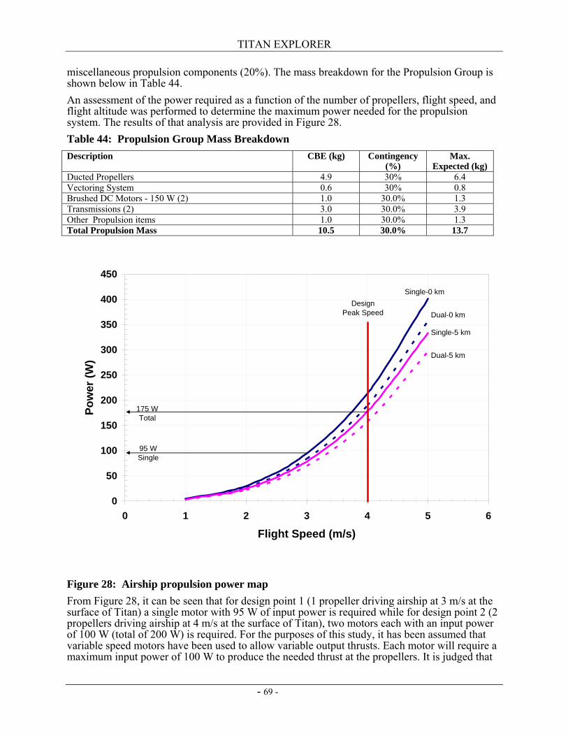
TITAN EXPLORER
- 69 -
miscellaneous propulsion components (20%). The mass breakdown for the Propulsion Group is shown below in Table 44. An assessment of the power required as a function of the number of propellers, flight speed, and flight altitude was performed to determine the maximum power needed for the propulsion system. The results of that analysis are provided in Figure 28. Table 44: Propulsion Group Mass Breakdown Description CBE (kg) Contingency
(%) Max.
Expected (kg) Ducted Propellers 4.9 30% 6.4 Vectoring System 0.6 30% 0.8 Brushed DC Motors - 150 W (2) 1.0 30.0% 1.3 Transmissions (2) 3.0 30.0% 3.9 Other Propulsion items 1.0 30.0% 1.3 Total Propulsion Mass 10.5 30.0% 13.7
Figure 28: Airship propulsion power map From Figure 28, it can be seen that for design point 1 (1 propeller driving airship at 3 m/s at the surface of Titan) a single motor with 95 W of input power is required while for design point 2 (2 propellers driving airship at 4 m/s at the surface of Titan), two motors each with an input power of 100 W (total of 200 W) is required. For the purposes of this study, it has been assumed that variable speed motors have been used to allow variable output thrusts. Each motor will require a maximum input power of 100 W to produce the needed thrust at the propellers. It is judged that
0
50
100
150
200
250
300
350
400
450
0 1 2 3 4 5 6
Flight Speed (m/s)
Pow
er (W
)
Single-0 km
Single-5 km
Dual-5 km
Dual-0 kmDesign
Peak Speed
175 WTotal
95 WSingle
TITAN EXPLORER
- 70 -
varying the motor power, and thus the propeller speed is a simpler accommodation for station-keeping than by using either variable pitch propeller blades or by vectoring the propulsion units.
2.7.1.3.3 Vertical Propulsion Interacting with the surface, either by performing measurements within close proximity to the surface (a few hundred meters) or by depositing a surface science package (SSP), is a desirable feature of the airship. It has been judged that landing or coming in close proximity to the surface is a critical event with the operational constraint of only performing these maneuvers when in contact with the orbiter. Operating anywhere between 1 to 5 km altitude is considered normal operations which can occur any time in the mission. Descent below 1 km is considered a critical event (descent but not operations at that altitude).Typical orbiter overhead durations range between 30 to 75 minutes. If it is assumed that the descent time should be about half of the maximum overhead time (38 minutes), then a maximum descent rate of 25 meters per minute is found. A fan system is used to inject atmosphere into the ballonets. With the low gravity of Titan coupled with the thick atmosphere means vertical changes in altitude are time consuming. Accounting for the drag on the hull (similar to forward propulsion) and the apparent mass, then it is needed to inflate the ballonets in half the time for descent, or within 20 minutes. Using the atmospheric properties of Titan then to reduce the altitude from 1 km to 0 km equates to a 5 m3 change in the ballonet volume. In addition, it is assumed the fan adds 300 Pa pressure differential previously noted plus an additional 100 Pa attributed to line losses. A theoretical power of 30 W is found (5 m3 in 20 minutes = 0.25 CFM * (300+100 Pa) = 30 W). Two fans (1 fan per ballonet) has been assumed. Ducting and dampers are used to allow either fan to fill either ballonet (or both) thus providing full redundancy. The fans are operated at a constant speed, to reduce complexity, and are duty cycled to meet specific operating needs. Details of fan system are found in Table 45. Table 45: Ballonet Fan Details Description CBE (kg) Contingency
(%) Max.
Expected (kg) Fans in Shrouds (2) 2.0 30.0% 2.6 Brushed DC Motors -25 W (2) 0.5 30.0% 0.7 Dampers with actuators (2) 0.5 30.0% 0.7 Local Ducts 0.7 30.0% 0.9 Mounting 0.3 30.0% 0.4 Total Altitude Mass 4.0 30.0% 5.2
2.7.1.3.4 Tail and Gondola Group The Tail Group includes the tail surfaces and structure, as well as any rigging and support material. For the tail sizing, the wetted area of the tail was taken to be a function of the total surface area of the hull/gasbag. This relationship is based on the area relationship of the tail to the hull as discussed above (assumed to be 0.0218 for Titan). The hull surface area is then multiplied by this ratio to obtain an estimate of the wetted tail area. The planform area of the tail is then half of the wetted area, assuming the tail has flow on both sides. This planform area is then multiplied by a historically-based value of areal density for the tail of 5.9 kg/m2 (ref. 37). This referenced areal density is at the high end of the historically-based range, generally representing smaller, high performance airships. The Gondola Group represents the actual gondola structure only. The attachment scheme to the hull is considered as part of the Hull Group and the internal components housed within the gondola are considered among the science instrument group and the internal subsystem components. For this study, the gondola design was not explored in detail. However, an assumption was made for the gondola of a half-cylinder shape, approximately 0.75 m in diameter and 1.8 m in length (as described above). This produced a total enclosed volume for the gondola
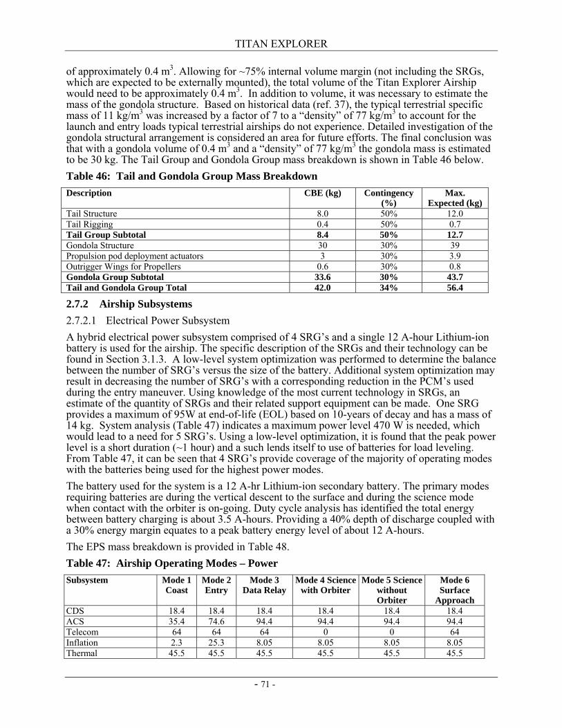
TITAN EXPLORER
- 71 -
of approximately 0.4 m3. Allowing for ~75% internal volume margin (not including the SRGs, which are expected to be externally mounted), the total volume of the Titan Explorer Airship would need to be approximately 0.4 m3. In addition to volume, it was necessary to estimate the mass of the gondola structure. Based on historical data (ref. 37), the typical terrestrial specific mass of 11 kg/m3 was increased by a factor of 7 to a “density” of 77 kg/m3 to account for the launch and entry loads typical terrestrial airships do not experience. Detailed investigation of the gondola structural arrangement is considered an area for future efforts. The final conclusion was that with a gondola volume of 0.4 m3 and a “density” of 77 kg/m3 the gondola mass is estimated to be 30 kg. The Tail Group and Gondola Group mass breakdown is shown in Table 46 below. Table 46: Tail and Gondola Group Mass Breakdown Description CBE (kg) Contingency
(%) Max.
Expected (kg) Tail Structure 8.0 50% 12.0 Tail Rigging 0.4 50% 0.7 Tail Group Subtotal 8.4 50% 12.7 Gondola Structure 30 30% 39 Propulsion pod deployment actuators 3 30% 3.9 Outrigger Wings for Propellers 0.6 30% 0.8 Gondola Group Subtotal 33.6 30% 43.7 Tail and Gondola Group Total 42.0 34% 56.4
2.7.2 Airship Subsystems 2.7.2.1 Electrical Power Subsystem A hybrid electrical power subsystem comprised of 4 SRG’s and a single 12 A-hour Lithium-ion battery is used for the airship. The specific description of the SRGs and their technology can be found in Section 3.1.3. A low-level system optimization was performed to determine the balance between the number of SRG’s versus the size of the battery. Additional system optimization may result in decreasing the number of SRG’s with a corresponding reduction in the PCM’s used during the entry maneuver. Using knowledge of the most current technology in SRGs, an estimate of the quantity of SRGs and their related support equipment can be made. One SRG provides a maximum of 95W at end-of-life (EOL) based on 10-years of decay and has a mass of 14 kg. System analysis (Table 47) indicates a maximum power level 470 W is needed, which would lead to a need for 5 SRG’s. Using a low-level optimization, it is found that the peak power level is a short duration (~1 hour) and a such lends itself to use of batteries for load leveling. From Table 47, it can be seen that 4 SRG’s provide coverage of the majority of operating modes with the batteries being used for the highest power modes. The battery used for the system is a 12 A-hr Lithium-ion secondary battery. The primary modes requiring batteries are during the vertical descent to the surface and during the science mode when contact with the orbiter is on-going. Duty cycle analysis has identified the total energy between battery charging is about 3.5 A-hours. Providing a 40% depth of discharge coupled with a 30% energy margin equates to a peak battery energy level of about 12 A-hours. The EPS mass breakdown is provided in Table 48. Table 47: Airship Operating Modes – Power Subsystem Mode 1
Coast Mode 2 Entry
Mode 3 Data Relay
Mode 4 Science with Orbiter
Mode 5 Science without Orbiter
Mode 6 Surface
Approach CDS 18.4 18.4 18.4 18.4 18.4 18.4 ACS 35.4 74.6 94.4 94.4 94.4 94.4 Telecom 64 64 64 0 0 64 Inflation 2.3 25.3 8.05 8.05 8.05 8.05 Thermal 45.5 45.5 45.5 45.5 45.5 45.5
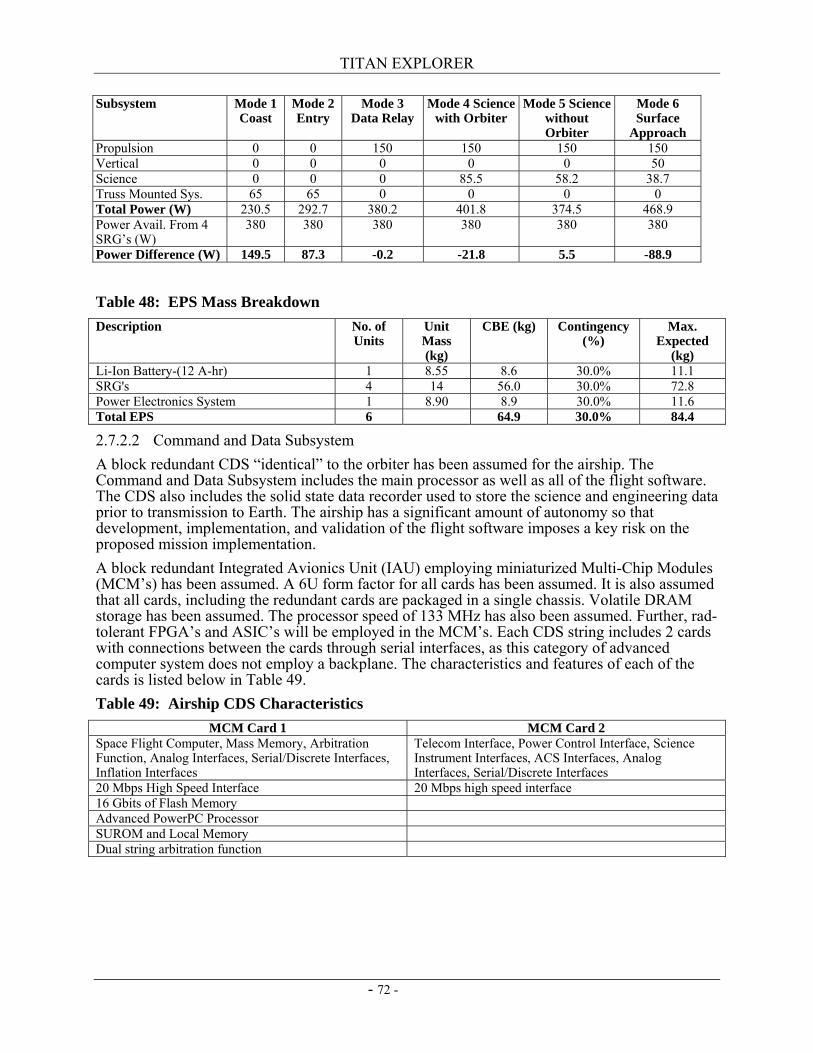
TITAN EXPLORER
- 72 -
Subsystem Mode 1 Coast
Mode 2 Entry
Mode 3 Data Relay
Mode 4 Science with Orbiter
Mode 5 Science without Orbiter
Mode 6 Surface
Approach Propulsion 0 0 150 150 150 150 Vertical 0 0 0 0 0 50 Science 0 0 0 85.5 58.2 38.7 Truss Mounted Sys. 65 65 0 0 0 0 Total Power (W) 230.5 292.7 380.2 401.8 374.5 468.9 Power Avail. From 4 SRG’s (W)
380 380 380 380 380 380
Power Difference (W) 149.5 87.3 -0.2 -21.8 5.5 -88.9
Table 48: EPS Mass Breakdown Description No. of
Units Unit Mass (kg)
CBE (kg) Contingency (%)
Max. Expected
(kg) Li-Ion Battery-(12 A-hr) 1 8.55 8.6 30.0% 11.1 SRG's 4 14 56.0 30.0% 72.8 Power Electronics System 1 8.90 8.9 30.0% 11.6 Total EPS 6 64.9 30.0% 84.4
2.7.2.2 Command and Data Subsystem A block redundant CDS “identical” to the orbiter has been assumed for the airship. The Command and Data Subsystem includes the main processor as well as all of the flight software. The CDS also includes the solid state data recorder used to store the science and engineering data prior to transmission to Earth. The airship has a significant amount of autonomy so that development, implementation, and validation of the flight software imposes a key risk on the proposed mission implementation. A block redundant Integrated Avionics Unit (IAU) employing miniaturized Multi-Chip Modules (MCM’s) has been assumed. A 6U form factor for all cards has been assumed. It is also assumed that all cards, including the redundant cards are packaged in a single chassis. Volatile DRAM storage has been assumed. The processor speed of 133 MHz has also been assumed. Further, rad-tolerant FPGA’s and ASIC’s will be employed in the MCM’s. Each CDS string includes 2 cards with connections between the cards through serial interfaces, as this category of advanced computer system does not employ a backplane. The characteristics and features of each of the cards is listed below in Table 49. Table 49: Airship CDS Characteristics
MCM Card 1 MCM Card 2 Space Flight Computer, Mass Memory, Arbitration Function, Analog Interfaces, Serial/Discrete Interfaces, Inflation Interfaces
Telecom Interface, Power Control Interface, Science Instrument Interfaces, ACS Interfaces, Analog Interfaces, Serial/Discrete Interfaces
20 Mbps High Speed Interface 20 Mbps high speed interface 16 Gbits of Flash Memory Advanced PowerPC Processor SUROM and Local Memory Dual string arbitration function
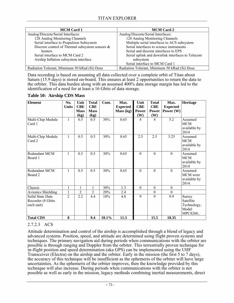
TITAN EXPLORER
- 73 -
MCM Card 1 MCM Card 2 Analog/Discrete/Serial Interfaces: 128 Analog Monitoring Channels Serial interface to Propulsion Subsystem Discrete control of Thermal subsystem sensors &
heaters Serial interface to MCM Card 2 Airship Inflation subsystem interface
Analog/Discrete/Serial Interfaces: 128 Analog Monitoring Channels Multiple serial interfaces to ACS subsystem Serial interfaces to science instruments Serial and discrete interfaces to EPS Serial uplink and downlink interfaces to Telecom
subsystem Serial interface to MCM Card 1
Radiation Tolerant, Minimum 50 kRad (Si) Dose Radiation Tolerant, Minimum 50 kRad (Si) Dose
Data recording is based on assuming all data collected over a complete orbit of Titan about Saturn (15.9 days) is stored on-board. This ensures at least 2 opportunities to return the data to the orbiter. This data burden along with an assumed 400% data storage margin has led to the identification of a need for at least a 16 Gbits of data storage. Table 50: Airship CDS Mass Element No.
Units Unit CBE Mass (kg)
Total CBE Mass (kg)
Cont. Max. Expected Mass (kg)
Unit CBE
Power (W)
Total CBE
Power (W)
Max. Expected
Power (W)
Heritage
Multi-Chip Module Card 1
1 0.5 0.5 30% 0.65 4 4 5.2 Assumed MCM available by 2014
Multi-Chip Module Card 2
1 0.5 0.5 30% 0.65 2.5 2.5 3.25 Assumed MCM available by 2014
Redundant MCM Board 1
1 0.5 0.5 30% 0.65 0 0 0 Assumed MCM available by 2014
Redundant MCM Board 2
1 0.5 0.5 30% 0.65 0 0 0 Assumed MCM were available by 2014.
Chassis 1 1 1 30% 1.3 0 0 0 Avionics Shielding 1 2 2 20% 2.4 0 0 Solid State Data Recorder (8 Gbits each unit)
2 2.2 4.4 10% 4.8 9 9 9.9 Surrey Satellite Technology, Model MPC8260..
Total CDS 8 9.4 18.1% 11.3 15.5 18.35
2.7.2.3 ACS Attitude determination and control of the airship is accomplished through a blend of legacy and advanced systems. Position, speed, and attitude are determined using flight proven systems and techniques. The primary navigation aid during periods when communications with the orbiter are possible is through ranging and Doppler from the orbiter. This terrestrially proven technique for in-flight position and speed determination (aka GPS) can be implemented using the UHF Transceiver (Electra) on the airship and the orbiter. Early in the mission (the first 5 to 7 days), the accuracy of this technique will be insufficient as the ephemeris of the orbiter will have large uncertainties. As the ephemeris of the orbiter improves, then the knowledge provided by this technique will also increase. During periods when communications with the orbiter is not possible as well as early in the mission, legacy methods combining inertial measurements, direct
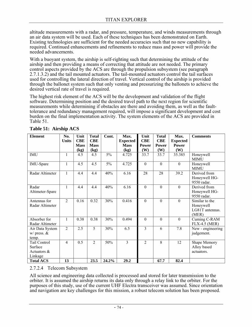
TITAN EXPLORER
- 74 -
altitude measurements with a radar, and pressure, temperature, and winds measurements through an air data system will be used. Each of these techniques has been demonstrated on Earth. Existing technologies are sufficient for the needed accuracies such that no new capability is required. Continued enhancements and refinements to reduce mass and power will provide the needed advancements. With a buoyant system, the airship is self-righting such that determining the attitude of the airship and then providing a means of correcting that attitude are not needed. The primary control aspects provided by the ACS are through the propulsion subsystem (see paragraph 2.7.1.3.2) and the tail mounted actuators. The tail-mounted actuators control the tail surfaces used for controlling the lateral direction of travel. Vertical control of the airship is provided through the ballonet system such that only venting and pressurizing the ballonets to achieve the desired vertical rate of travel is required. The highest risk element of the ACS will be the development and validation of the flight software. Determining position and the desired travel path to the next region for scientific measurements while determining if obstacles are there and avoiding them, as well as the fault-tolerance and redundancy management required, will impose a significant development and cost burden on the final implementation activity. The system elements of the ACS are provided in Table 51. Table 51: Airship ACS Element No.
Units Unit CBE Mass (kg)
Total CBE Mass (kg)
Cont. Max. Expected
Mass (kg)
Unit CBE
Power (W)
Total CBE
Power (W)
Max. Expected
Power (W)
Comments
IMU 1 4.5 4.5 5% 4.725 33.7 33.7 35.385 Honeywell MIMU
IMU-Spare 1 4.5 4.5 5% 4.725 0 0 0 Honeywell MIMU
Radar Altimeter 1 4.4 4.4 40% 6.16 28 28 39.2 Derived from Honeywell HG-9550 radar.
Radar Altimeter-Spare
1 4.4 4.4 40% 6.16 0 0 0 Derived from Honeywell HG-9550 radar.
Antennas for Radar Altimeter
2 0.16 0.32 30% 0.416 0 0 0 Similar to the Honeywell LG81T antennas. (MER)
Absorber for Radar Altimeter
1 0.38 0.38 30% 0.494 0 0 0 Cuming C-RAM FLX-4.5 (MER)
Air Data System w/ press. & temp.
2 2.5 5 30% 6.5 3 6 7.8 New - engineering judgement.
Tail Control Surface Actuators & Linkage
4 0.5 2 50% 3 2 8 12 Shape Memory Alloy based actuators.
Total ACS 13 23.5 24.2% 29.2 67.7 82.4
2.7.2.4 Telecom Subsystem All science and engineering data collected is processed and stored for later transmission to the orbiter. It is assumed the airship returns its data only through a relay link to the orbiter. For the purposes of this study, use of the current UHF Electra transceiver was assumed. Since orientation and navigation are key challenges for this mission, a robust telecom solution has been proposed.
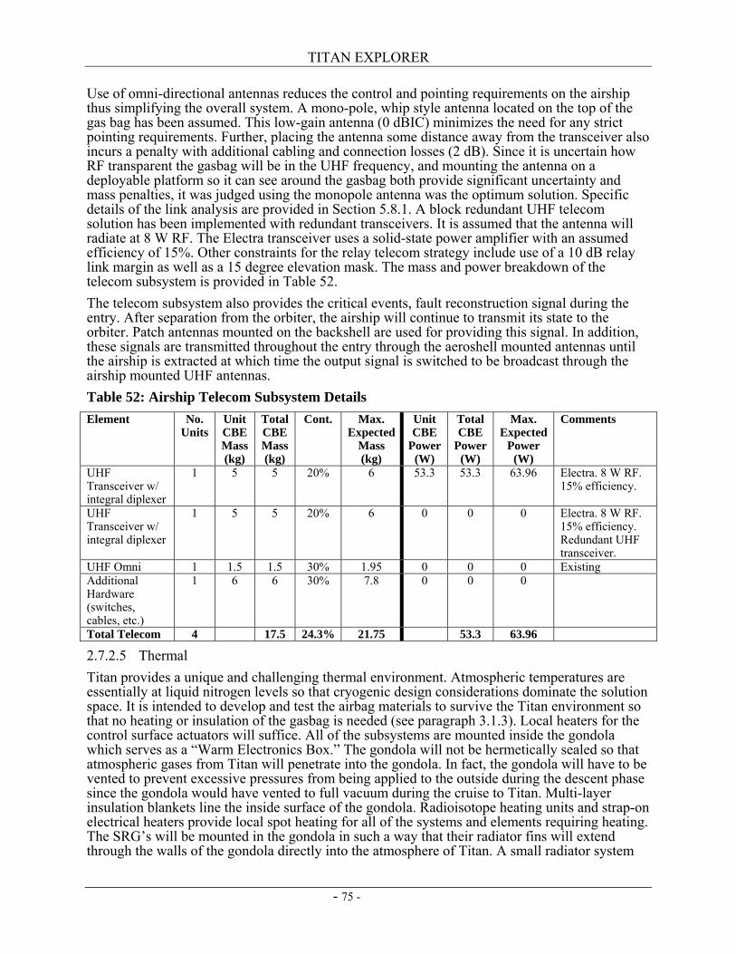
TITAN EXPLORER
- 75 -
Use of omni-directional antennas reduces the control and pointing requirements on the airship thus simplifying the overall system. A mono-pole, whip style antenna located on the top of the gas bag has been assumed. This low-gain antenna (0 dBIC) minimizes the need for any strict pointing requirements. Further, placing the antenna some distance away from the transceiver also incurs a penalty with additional cabling and connection losses (2 dB). Since it is uncertain how RF transparent the gasbag will be in the UHF frequency, and mounting the antenna on a deployable platform so it can see around the gasbag both provide significant uncertainty and mass penalties, it was judged using the monopole antenna was the optimum solution. Specific details of the link analysis are provided in Section 5.8.1. A block redundant UHF telecom solution has been implemented with redundant transceivers. It is assumed that the antenna will radiate at 8 W RF. The Electra transceiver uses a solid-state power amplifier with an assumed efficiency of 15%. Other constraints for the relay telecom strategy include use of a 10 dB relay link margin as well as a 15 degree elevation mask. The mass and power breakdown of the telecom subsystem is provided in Table 52. The telecom subsystem also provides the critical events, fault reconstruction signal during the entry. After separation from the orbiter, the airship will continue to transmit its state to the orbiter. Patch antennas mounted on the backshell are used for providing this signal. In addition, these signals are transmitted throughout the entry through the aeroshell mounted antennas until the airship is extracted at which time the output signal is switched to be broadcast through the airship mounted UHF antennas. Table 52: Airship Telecom Subsystem Details Element No.
Units Unit CBE Mass (kg)
Total CBE Mass (kg)
Cont. Max. Expected
Mass (kg)
Unit CBE
Power (W)
Total CBE
Power (W)
Max. Expected
Power (W)
Comments
UHF Transceiver w/ integral diplexer
1 5 5 20% 6 53.3 53.3 63.96 Electra. 8 W RF. 15% efficiency.
UHF Transceiver w/ integral diplexer
1 5 5 20% 6 0 0 0 Electra. 8 W RF. 15% efficiency. Redundant UHF transceiver.
UHF Omni 1 1.5 1.5 30% 1.95 0 0 0 Existing Additional Hardware (switches, cables, etc.)
1 6 6 30% 7.8 0 0 0
Total Telecom 4 17.5 24.3% 21.75 53.3 63.96
2.7.2.5 Thermal Titan provides a unique and challenging thermal environment. Atmospheric temperatures are essentially at liquid nitrogen levels so that cryogenic design considerations dominate the solution space. It is intended to develop and test the airbag materials to survive the Titan environment so that no heating or insulation of the gasbag is needed (see paragraph 3.1.3). Local heaters for the control surface actuators will suffice. All of the subsystems are mounted inside the gondola which serves as a “Warm Electronics Box.” The gondola will not be hermetically sealed so that atmospheric gases from Titan will penetrate into the gondola. In fact, the gondola will have to be vented to prevent excessive pressures from being applied to the outside during the descent phase since the gondola would have vented to full vacuum during the cruise to Titan. Multi-layer insulation blankets line the inside surface of the gondola. Radioisotope heating units and strap-on electrical heaters provide local spot heating for all of the systems and elements requiring heating. The SRG’s will be mounted in the gondola in such a way that their radiator fins will extend through the walls of the gondola directly into the atmosphere of Titan. A small radiator system
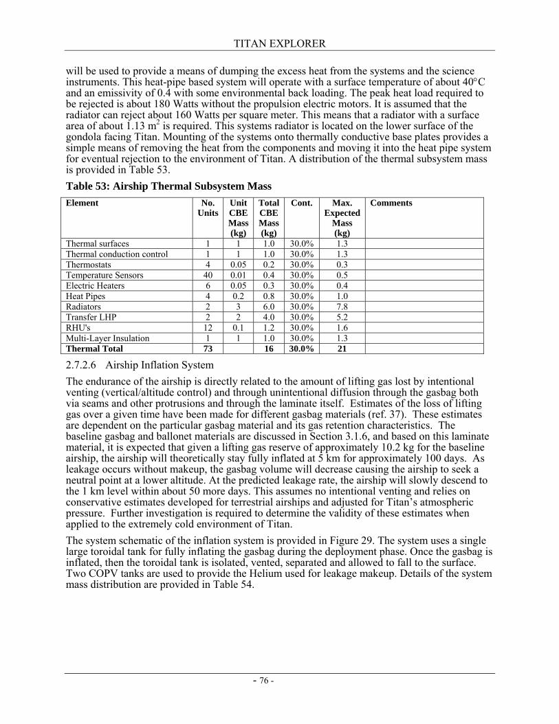
TITAN EXPLORER
- 76 -
will be used to provide a means of dumping the excess heat from the systems and the science instruments. This heat-pipe based system will operate with a surface temperature of about 40°C and an emissivity of 0.4 with some environmental back loading. The peak heat load required to be rejected is about 180 Watts without the propulsion electric motors. It is assumed that the radiator can reject about 160 Watts per square meter. This means that a radiator with a surface area of about 1.13 m2 is required. This systems radiator is located on the lower surface of the gondola facing Titan. Mounting of the systems onto thermally conductive base plates provides a simple means of removing the heat from the components and moving it into the heat pipe system for eventual rejection to the environment of Titan. A distribution of the thermal subsystem mass is provided in Table 53. Table 53: Airship Thermal Subsystem Mass Element No.
Units Unit CBE Mass (kg)
Total CBE Mass (kg)
Cont. Max. Expected
Mass (kg)
Comments
Thermal surfaces 1 1 1.0 30.0% 1.3 Thermal conduction control 1 1 1.0 30.0% 1.3 Thermostats 4 0.05 0.2 30.0% 0.3 Temperature Sensors 40 0.01 0.4 30.0% 0.5 Electric Heaters 6 0.05 0.3 30.0% 0.4 Heat Pipes 4 0.2 0.8 30.0% 1.0 Radiators 2 3 6.0 30.0% 7.8 Transfer LHP 2 2 4.0 30.0% 5.2 RHU's 12 0.1 1.2 30.0% 1.6 Multi-Layer Insulation 1 1 1.0 30.0% 1.3 Thermal Total 73 16 30.0% 21
2.7.2.6 Airship Inflation System The endurance of the airship is directly related to the amount of lifting gas lost by intentional venting (vertical/altitude control) and through unintentional diffusion through the gasbag both via seams and other protrusions and through the laminate itself. Estimates of the loss of lifting gas over a given time have been made for different gasbag materials (ref. 37). These estimates are dependent on the particular gasbag material and its gas retention characteristics. The baseline gasbag and ballonet materials are discussed in Section 3.1.6, and based on this laminate material, it is expected that given a lifting gas reserve of approximately 10.2 kg for the baseline airship, the airship will theoretically stay fully inflated at 5 km for approximately 100 days. As leakage occurs without makeup, the gasbag volume will decrease causing the airship to seek a neutral point at a lower altitude. At the predicted leakage rate, the airship will slowly descend to the 1 km level within about 50 more days. This assumes no intentional venting and relies on conservative estimates developed for terrestrial airships and adjusted for Titan’s atmospheric pressure. Further investigation is required to determine the validity of these estimates when applied to the extremely cold environment of Titan. The system schematic of the inflation system is provided in Figure 29. The system uses a single large toroidal tank for fully inflating the gasbag during the deployment phase. Once the gasbag is inflated, then the toroidal tank is isolated, vented, separated and allowed to fall to the surface. Two COPV tanks are used to provide the Helium used for leakage makeup. Details of the system mass distribution are provided in Table 54.
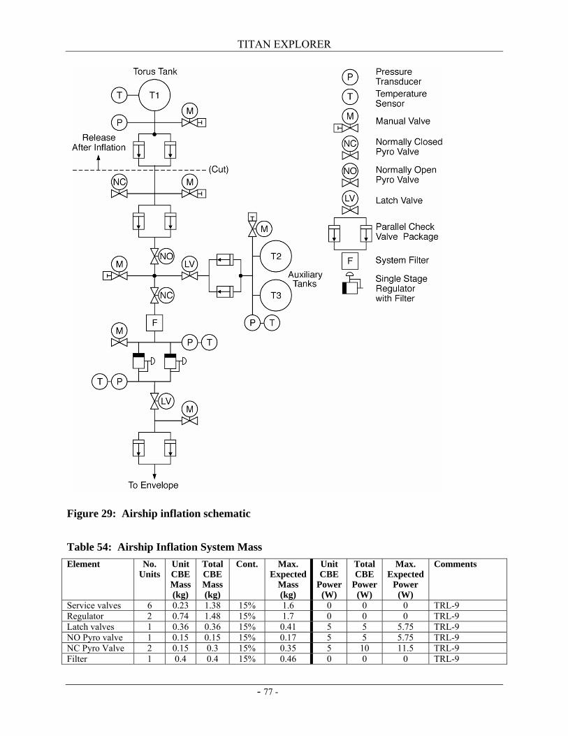
TITAN EXPLORER
- 77 -
Figure 29: Airship inflation schematic Table 54: Airship Inflation System Mass Element No.
Units Unit CBE Mass (kg)
Total CBE Mass (kg)
Cont. Max. Expected
Mass (kg)
Unit CBE
Power (W)
Total CBE
Power (W)
Max. Expected
Power (W)
Comments
Service valves 6 0.23 1.38 15% 1.6 0 0 0 TRL-9 Regulator 2 0.74 1.48 15% 1.7 0 0 0 TRL-9 Latch valves 1 0.36 0.36 15% 0.41 5 5 5.75 TRL-9 NO Pyro valve 1 0.15 0.15 15% 0.17 5 5 5.75 TRL-9 NC Pyro Valve 2 0.15 0.3 15% 0.35 5 10 11.5 TRL-9 Filter 1 0.4 0.4 15% 0.46 0 0 0 TRL-9
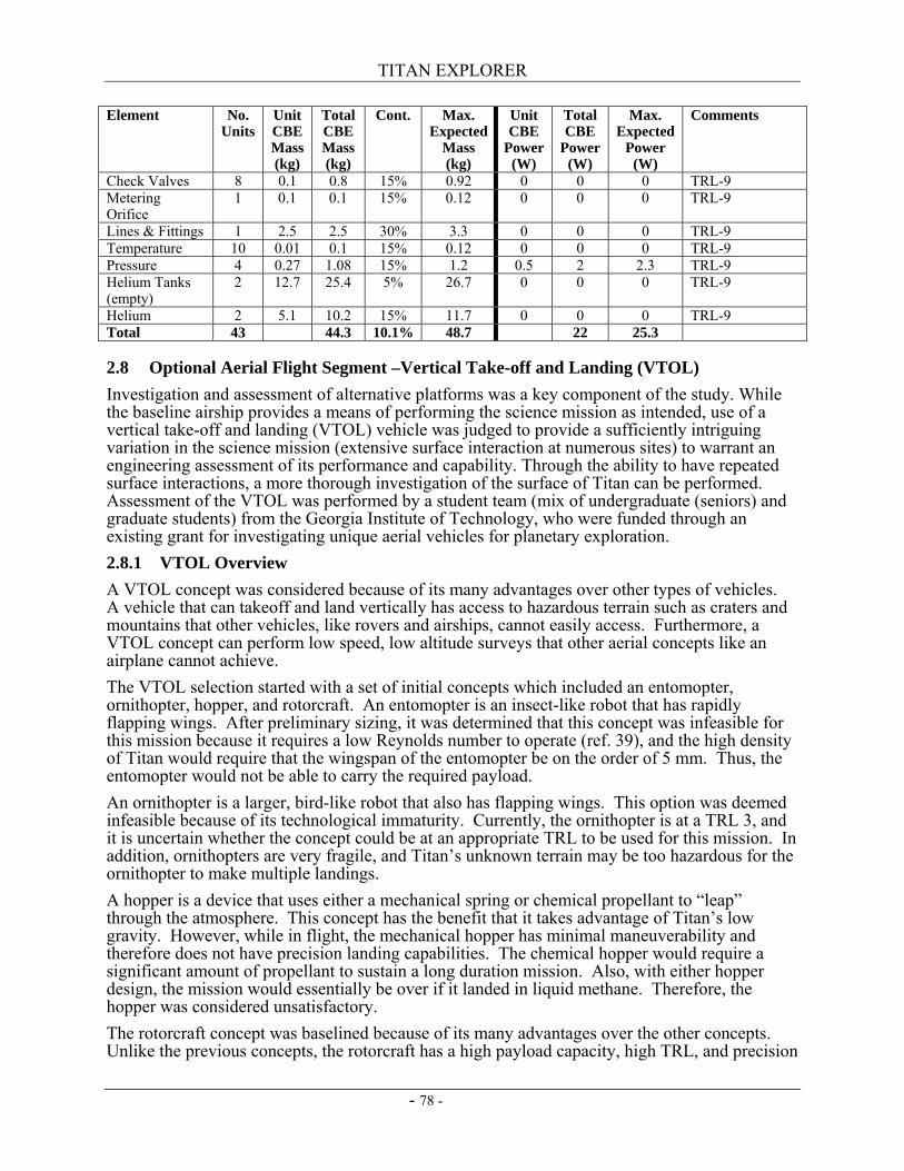
TITAN EXPLORER
- 78 -
Element No. Units
Unit CBE Mass (kg)
Total CBE Mass (kg)
Cont. Max. Expected
Mass (kg)
Unit CBE
Power (W)
Total CBE
Power (W)
Max. Expected
Power (W)
Comments
Check Valves 8 0.1 0.8 15% 0.92 0 0 0 TRL-9 Metering Orifice
1 0.1 0.1 15% 0.12 0 0 0 TRL-9
Lines & Fittings 1 2.5 2.5 30% 3.3 0 0 0 TRL-9 Temperature 10 0.01 0.1 15% 0.12 0 0 0 TRL-9 Pressure 4 0.27 1.08 15% 1.2 0.5 2 2.3 TRL-9 Helium Tanks (empty)
2 12.7 25.4 5% 26.7 0 0 0 TRL-9
Helium 2 5.1 10.2 15% 11.7 0 0 0 TRL-9 Total 43 44.3 10.1% 48.7 22 25.3
2.8 Optional Aerial Flight Segment –Vertical Take-off and Landing (VTOL) Investigation and assessment of alternative platforms was a key component of the study. While the baseline airship provides a means of performing the science mission as intended, use of a vertical take-off and landing (VTOL) vehicle was judged to provide a sufficiently intriguing variation in the science mission (extensive surface interaction at numerous sites) to warrant an engineering assessment of its performance and capability. Through the ability to have repeated surface interactions, a more thorough investigation of the surface of Titan can be performed. Assessment of the VTOL was performed by a student team (mix of undergraduate (seniors) and graduate students) from the Georgia Institute of Technology, who were funded through an existing grant for investigating unique aerial vehicles for planetary exploration. 2.8.1 VTOL Overview A VTOL concept was considered because of its many advantages over other types of vehicles. A vehicle that can takeoff and land vertically has access to hazardous terrain such as craters and mountains that other vehicles, like rovers and airships, cannot easily access. Furthermore, a VTOL concept can perform low speed, low altitude surveys that other aerial concepts like an airplane cannot achieve. The VTOL selection started with a set of initial concepts which included an entomopter, ornithopter, hopper, and rotorcraft. An entomopter is an insect-like robot that has rapidly flapping wings. After preliminary sizing, it was determined that this concept was infeasible for this mission because it requires a low Reynolds number to operate (ref. 39), and the high density of Titan would require that the wingspan of the entomopter be on the order of 5 mm. Thus, the entomopter would not be able to carry the required payload. An ornithopter is a larger, bird-like robot that also has flapping wings. This option was deemed infeasible because of its technological immaturity. Currently, the ornithopter is at a TRL 3, and it is uncertain whether the concept could be at an appropriate TRL to be used for this mission. In addition, ornithopters are very fragile, and Titan’s unknown terrain may be too hazardous for the ornithopter to make multiple landings. A hopper is a device that uses either a mechanical spring or chemical propellant to “leap” through the atmosphere. This concept has the benefit that it takes advantage of Titan’s low gravity. However, while in flight, the mechanical hopper has minimal maneuverability and therefore does not have precision landing capabilities. The chemical hopper would require a significant amount of propellant to sustain a long duration mission. Also, with either hopper design, the mission would essentially be over if it landed in liquid methane. Therefore, the hopper was considered unsatisfactory. The rotorcraft concept was baselined because of its many advantages over the other concepts. Unlike the previous concepts, the rotorcraft has a high payload capacity, high TRL, and precision
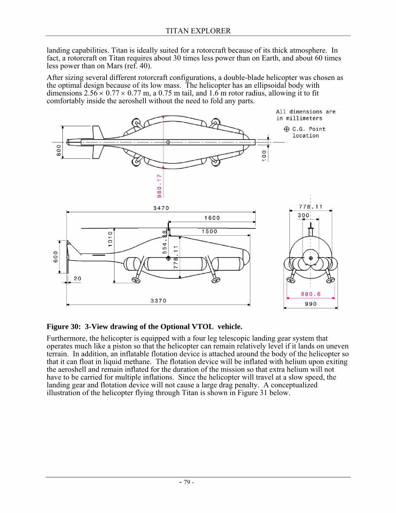
TITAN EXPLORER
- 79 -
landing capabilities. Titan is ideally suited for a rotorcraft because of its thick atmosphere. In fact, a rotorcraft on Titan requires about 30 times less power than on Earth, and about 60 times less power than on Mars (ref. 40). After sizing several different rotorcraft configurations, a double-blade helicopter was chosen as the optimal design because of its low mass. The helicopter has an ellipsoidal body with dimensions 2.56 × 0.77 × 0.77 m, a 0.75 m tail, and 1.6 m rotor radius, allowing it to fit comfortably inside the aeroshell without the need to fold any parts.
Figure 30: 3-View drawing of the Optional VTOL vehicle. Furthermore, the helicopter is equipped with a four leg telescopic landing gear system that operates much like a piston so that the helicopter can remain relatively level if it lands on uneven terrain. In addition, an inflatable flotation device is attached around the body of the helicopter so that it can float in liquid methane. The flotation device will be inflated with helium upon exiting the aeroshell and remain inflated for the duration of the mission so that extra helium will not have to be carried for multiple inflations. Since the helicopter will travel at a slow speed, the landing gear and flotation device will not cause a large drag penalty. A conceptualized illustration of the helicopter flying through Titan is shown in Figure 31 below.
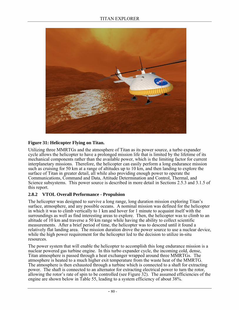
TITAN EXPLORER
- 80 -
Figure 31: Helicopter Flying on Titan. Utilizing three MMRTGs and the atmosphere of Titan as its power source, a turbo expander cycle allows the helicopter to have a prolonged mission life that is limited by the lifetime of its mechanical components rather than the available power, which is the limiting factor for current interplanetary missions. Therefore, the helicopter can easily perform a long endurance mission such as cruising for 50 km at a range of altitudes up to 10 km, and then landing to explore the surface of Titan in greater detail, all while also providing enough power to operate the Communications, Command and Data, Attitude Determination and Control, Thermal, and Science subsystems. This power source is described in more detail in Sections 2.5.3 and 3.1.5 of this report. 2.8.2 VTOL Overall Performance - Propulsion The helicopter was designed to survive a long range, long duration mission exploring Titan’s surface, atmosphere, and any possible oceans. A nominal mission was defined for the helicopter in which it was to climb vertically to 1 km and hover for 1 minute to acquaint itself with the surroundings as well as find interesting areas to explore. Then, the helicopter was to climb to an altitude of 10 km and traverse a 50 km range while having the ability to collect scientific measurements. After a brief period of time, the helicopter was to descend until it found a relatively flat landing area. The mission duration drove the power source to use a nuclear device, while the high power requirement for the helicopter led to the decision to utilize in-situ resources. The power system that will enable the helicopter to accomplish this long endurance mission is a nuclear powered gas turbine engine. In this turbo expander cycle, the incoming cold, dense, Titan atmosphere is passed through a heat exchanger wrapped around three MMRTGs. The atmosphere is heated to a much higher exit temperature from the waste heat of the MMRTG. The atmosphere is then exhausted through a turbine which is connected to a shaft for extracting power. The shaft is connected to an alternator for extracting electrical power to turn the rotor, allowing the rotor’s rate of spin to be controlled (see Figure 32). The assumed efficiencies of the engine are shown below in Table 55, leading to a system efficiency of about 38%.
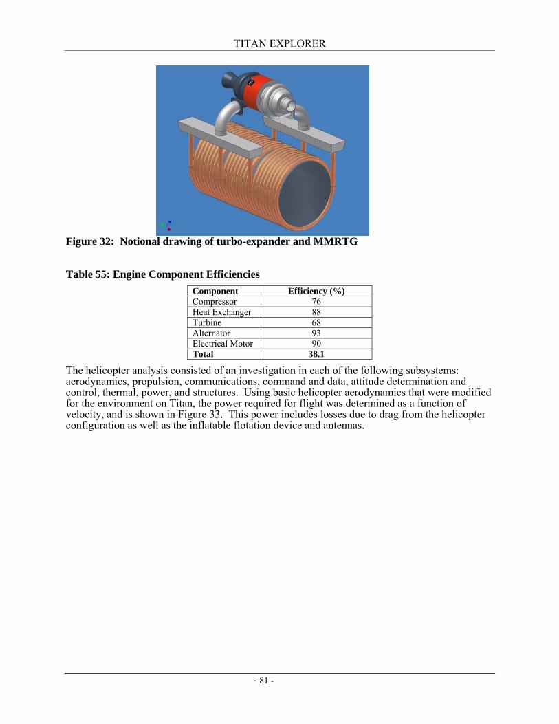
TITAN EXPLORER
- 81 -
Figure 32: Notional drawing of turbo-expander and MMRTG Table 55: Engine Component Efficiencies
Component Efficiency (%) Compressor 76 Heat Exchanger 88 Turbine 68 Alternator 93 Electrical Motor 90 Total 38.1
The helicopter analysis consisted of an investigation in each of the following subsystems: aerodynamics, propulsion, communications, command and data, attitude determination and control, thermal, power, and structures. Using basic helicopter aerodynamics that were modified for the environment on Titan, the power required for flight was determined as a function of velocity, and is shown in Figure 33. This power includes losses due to drag from the helicopter configuration as well as the inflatable flotation device and antennas.
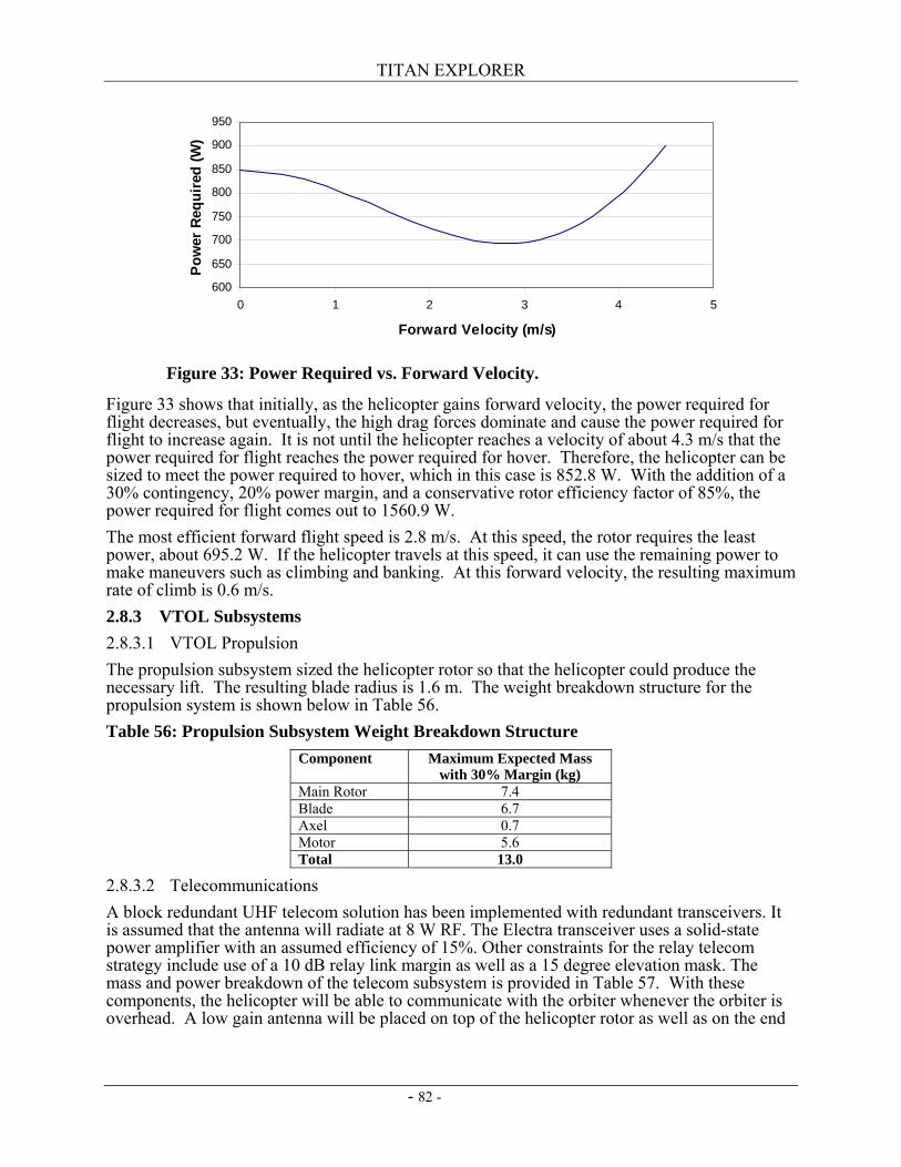
TITAN EXPLORER
- 82 -
Figure 33 shows that initially, as the helicopter gains forward velocity, the power required for flight decreases, but eventually, the high drag forces dominate and cause the power required for flight to increase again. It is not until the helicopter reaches a velocity of about 4.3 m/s that the power required for flight reaches the power required for hover. Therefore, the helicopter can be sized to meet the power required to hover, which in this case is 852.8 W. With the addition of a 30% contingency, 20% power margin, and a conservative rotor efficiency factor of 85%, the power required for flight comes out to 1560.9 W. The most efficient forward flight speed is 2.8 m/s. At this speed, the rotor requires the least power, about 695.2 W. If the helicopter travels at this speed, it can use the remaining power to make maneuvers such as climbing and banking. At this forward velocity, the resulting maximum rate of climb is 0.6 m/s. 2.8.3 VTOL Subsystems 2.8.3.1 VTOL Propulsion The propulsion subsystem sized the helicopter rotor so that the helicopter could produce the necessary lift. The resulting blade radius is 1.6 m. The weight breakdown structure for the propulsion system is shown below in Table 56. Table 56: Propulsion Subsystem Weight Breakdown Structure
Component Maximum Expected Mass with 30% Margin (kg)
Main Rotor 7.4 Blade 6.7 Axel 0.7 Motor 5.6 Total 13.0
2.8.3.2 Telecommunications A block redundant UHF telecom solution has been implemented with redundant transceivers. It is assumed that the antenna will radiate at 8 W RF. The Electra transceiver uses a solid-state power amplifier with an assumed efficiency of 15%. Other constraints for the relay telecom strategy include use of a 10 dB relay link margin as well as a 15 degree elevation mask. The mass and power breakdown of the telecom subsystem is provided in Table 57. With these components, the helicopter will be able to communicate with the orbiter whenever the orbiter is overhead. A low gain antenna will be placed on top of the helicopter rotor as well as on the end
Figure 33: Power Required vs. Forward Velocity.
600
650
700
750
800
850
900
950
0 1 2 3 4 5
Forward Velocity (m/s)
Pow
er R
equi
red
(W)
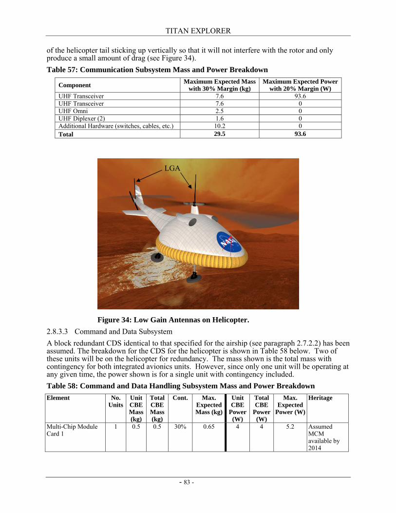
TITAN EXPLORER
- 83 -
of the helicopter tail sticking up vertically so that it will not interfere with the rotor and only produce a small amount of drag (see Figure 34). Table 57: Communication Subsystem Mass and Power Breakdown
Component Maximum Expected Mass with 30% Margin (kg)
Maximum Expected Power with 20% Margin (W)
UHF Transceiver 7.6 93.6 UHF Transceiver 7.6 0 UHF Omni 2.5 0 UHF Diplexer (2) 1.6 0 Additional Hardware (switches, cables, etc.) 10.2 0 Total 29.5 93.6
2.8.3.3 Command and Data Subsystem A block redundant CDS identical to that specified for the airship (see paragraph 2.7.2.2) has been assumed. The breakdown for the CDS for the helicopter is shown in Table 58 below. Two of these units will be on the helicopter for redundancy. The mass shown is the total mass with contingency for both integrated avionics units. However, since only one unit will be operating at any given time, the power shown is for a single unit with contingency included. Table 58: Command and Data Handling Subsystem Mass and Power Breakdown Element No.
Units Unit CBE Mass (kg)
Total CBE Mass (kg)
Cont. Max. Expected Mass (kg)
Unit CBE
Power (W)
Total CBE
Power (W)
Max. Expected
Power (W)
Heritage
Multi-Chip Module Card 1
1 0.5 0.5 30% 0.65 4 4 5.2 Assumed MCM available by 2014
LGA
Figure 34: Low Gain Antennas on Helicopter.
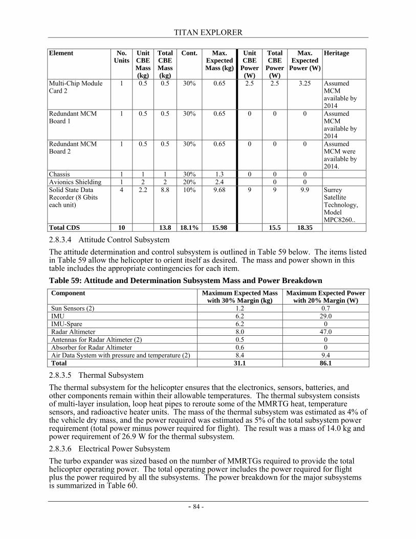
TITAN EXPLORER
- 84 -
Element No. Units
Unit CBE Mass (kg)
Total CBE Mass (kg)
Cont. Max. Expected Mass (kg)
Unit CBE
Power (W)
Total CBE
Power (W)
Max. Expected
Power (W)
Heritage
Multi-Chip Module Card 2
1 0.5 0.5 30% 0.65 2.5 2.5 3.25 Assumed MCM available by 2014
Redundant MCM Board 1
1 0.5 0.5 30% 0.65 0 0 0 Assumed MCM available by 2014
Redundant MCM Board 2
1 0.5 0.5 30% 0.65 0 0 0 Assumed MCM were available by 2014.
Chassis 1 1 1 30% 1.3 0 0 0 Avionics Shielding 1 2 2 20% 2.4 0 0 Solid State Data Recorder (8 Gbits each unit)
4 2.2 8.8 10% 9.68 9 9 9.9 Surrey Satellite Technology, Model MPC8260..
Total CDS 10 13.8 18.1% 15.98 15.5 18.35
2.8.3.4 Attitude Control Subsystem The attitude determination and control subsystem is outlined in Table 59 below. The items listed in Table 59 allow the helicopter to orient itself as desired. The mass and power shown in this table includes the appropriate contingencies for each item. Table 59: Attitude and Determination Subsystem Mass and Power Breakdown Component Maximum Expected Mass
with 30% Margin (kg) Maximum Expected Power
with 20% Margin (W) Sun Sensors (2) 1.2 0.7 IMU 6.2 29.0 IMU-Spare 6.2 0 Radar Altimeter 8.0 47.0 Antennas for Radar Altimeter (2) 0.5 0 Absorber for Radar Altimeter 0.6 0 Air Data System with pressure and temperature (2) 8.4 9.4 Total 31.1 86.1
2.8.3.5 Thermal Subsystem The thermal subsystem for the helicopter ensures that the electronics, sensors, batteries, and other components remain within their allowable temperatures. The thermal subsystem consists of multi-layer insulation, loop heat pipes to reroute some of the MMRTG heat, temperature sensors, and radioactive heater units. The mass of the thermal subsystem was estimated as 4% of the vehicle dry mass, and the power required was estimated as 5% of the total subsystem power requirement (total power minus power required for flight). The result was a mass of 14.0 kg and power requirement of 26.9 W for the thermal subsystem. 2.8.3.6 Electrical Power Subsystem The turbo expander was sized based on the number of MMRTGs required to provide the total helicopter operating power. The total operating power includes the power required for flight plus the power required by all the subsystems. The power breakdown for the major subsystems is summarized in Table 60.
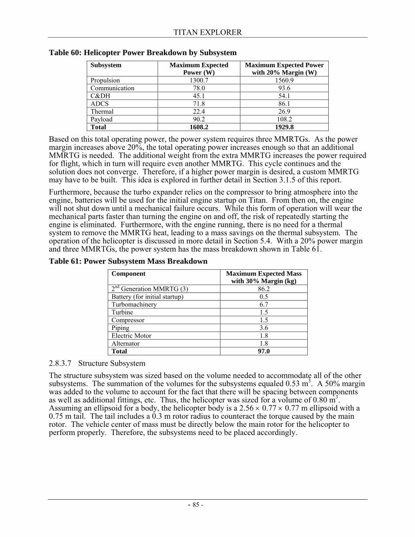
TITAN EXPLORER
- 85 -
Table 60: Helicopter Power Breakdown by Subsystem Subsystem Maximum Expected
Power (W) Maximum Expected Power
with 20% Margin (W) Propulsion 1300.7 1560.9 Communication 78.0 93.6 C&DH 45.1 54.1 ADCS 71.8 86.1 Thermal 22.4 26.9 Payload 90.2 108.2 Total 1608.2 1929.8
Based on this total operating power, the power system requires three MMRTGs. As the power margin increases above 20%, the total operating power increases enough so that an additional MMRTG is needed. The additional weight from the extra MMRTG increases the power required for flight, which in turn will require even another MMRTG. This cycle continues and the solution does not converge. Therefore, if a higher power margin is desired, a custom MMRTG may have to be built. This idea is explored in further detail in Section 3.1.5 of this report. Furthermore, because the turbo expander relies on the compressor to bring atmosphere into the engine, batteries will be used for the initial engine startup on Titan. From then on, the engine will not shut down until a mechanical failure occurs. While this form of operation will wear the mechanical parts faster than turning the engine on and off, the risk of repeatedly starting the engine is eliminated. Furthermore, with the engine running, there is no need for a thermal system to remove the MMRTG heat, leading to a mass savings on the thermal subsystem. The operation of the helicopter is discussed in more detail in Section 5.4. With a 20% power margin and three MMRTGs, the power system has the mass breakdown shown in Table 61. Table 61: Power Subsystem Mass Breakdown
Component Maximum Expected Mass with 30% Margin (kg)
2nd Generation MMRTG (3) 86.2 Battery (for initial startup) 0.5 Turbomachinery 6.7 Turbine 1.5 Compressor 1.5 Piping 3.6 Electric Motor 1.8 Alternator 1.8 Total 97.0
2.8.3.7 Structure Subsystem The structure subsystem was sized based on the volume needed to accommodate all of the other subsystems. The summation of the volumes for the subsystems equaled 0.53 m3. A 50% margin was added to the volume to account for the fact that there will be spacing between components as well as additional fittings, etc. Thus, the helicopter was sized for a volume of 0.80 m3. Assuming an ellipsoid for a body, the helicopter body is a 2.56 × 0.77 × 0.77 m ellipsoid with a 0.75 m tail. The tail includes a 0.3 m rotor radius to counteract the torque caused by the main rotor. The vehicle center of mass must be directly below the main rotor for the helicopter to perform properly. Therefore, the subsystems need to be placed accordingly.
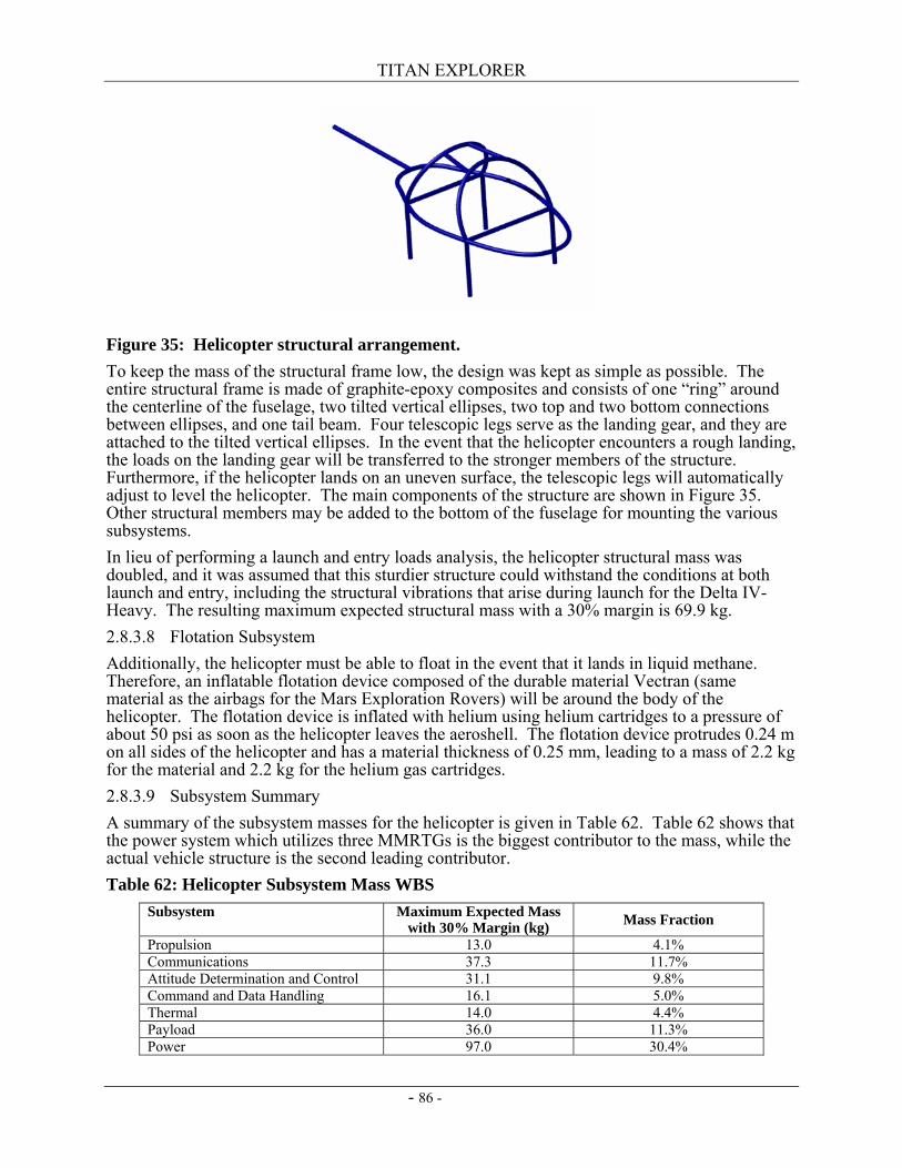
TITAN EXPLORER
- 86 -
Figure 35: Helicopter structural arrangement. To keep the mass of the structural frame low, the design was kept as simple as possible. The entire structural frame is made of graphite-epoxy composites and consists of one “ring” around the centerline of the fuselage, two tilted vertical ellipses, two top and two bottom connections between ellipses, and one tail beam. Four telescopic legs serve as the landing gear, and they are attached to the tilted vertical ellipses. In the event that the helicopter encounters a rough landing, the loads on the landing gear will be transferred to the stronger members of the structure. Furthermore, if the helicopter lands on an uneven surface, the telescopic legs will automatically adjust to level the helicopter. The main components of the structure are shown in Figure 35. Other structural members may be added to the bottom of the fuselage for mounting the various subsystems. In lieu of performing a launch and entry loads analysis, the helicopter structural mass was doubled, and it was assumed that this sturdier structure could withstand the conditions at both launch and entry, including the structural vibrations that arise during launch for the Delta IV-Heavy. The resulting maximum expected structural mass with a 30% margin is 69.9 kg. 2.8.3.8 Flotation Subsystem Additionally, the helicopter must be able to float in the event that it lands in liquid methane. Therefore, an inflatable flotation device composed of the durable material Vectran (same material as the airbags for the Mars Exploration Rovers) will be around the body of the helicopter. The flotation device is inflated with helium using helium cartridges to a pressure of about 50 psi as soon as the helicopter leaves the aeroshell. The flotation device protrudes 0.24 m on all sides of the helicopter and has a material thickness of 0.25 mm, leading to a mass of 2.2 kg for the material and 2.2 kg for the helium gas cartridges. 2.8.3.9 Subsystem Summary A summary of the subsystem masses for the helicopter is given in Table 62. Table 62 shows that the power system which utilizes three MMRTGs is the biggest contributor to the mass, while the actual vehicle structure is the second leading contributor. Table 62: Helicopter Subsystem Mass WBS
Subsystem Maximum Expected Mass with 30% Margin (kg) Mass Fraction
Propulsion 13.0 4.1% Communications 37.3 11.7% Attitude Determination and Control 31.1 9.8% Command and Data Handling 16.1 5.0% Thermal 14.0 4.4% Payload 36.0 11.3% Power 97.0 30.4%
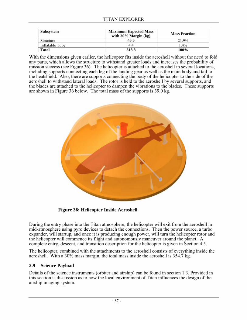
TITAN EXPLORER
- 87 -
Subsystem Maximum Expected Mass with 30% Margin (kg) Mass Fraction
Structure 69.9 21.9% Inflatable Tube 4.4 1.4% Total 318.8 100%
With the dimensions given earlier, the helicopter fits inside the aeroshell without the need to fold any parts, which allows the structure to withstand greater loads and increases the probability of mission success (see Figure 36). The helicopter is attached to the aeroshell in several locations, including supports connecting each leg of the landing gear as well as the main body and tail to the heatshield. Also, there are supports connecting the body of the helicopter to the side of the aeroshell to withstand lateral loads. The rotor is held to the aeroshell by several supports, and the blades are attached to the helicopter to dampen the vibrations to the blades. These supports are shown in Figure 36 below. The total mass of the supports is 39.0 kg.
During the entry phase into the Titan atmosphere, the helicopter will exit from the aeroshell in mid-atmosphere using pyro devices to detach the connections. Then the power source, a turbo expander, will startup, and once it is producing enough power, will turn the helicopter rotor and the helicopter will commence its flight and autonomously maneuver around the planet. A complete entry, descent, and transition description for the helicopter is given in Section 4.5. The helicopter, combined with the attachments to the aeroshell consists of everything inside the aeroshell. With a 30% mass margin, the total mass inside the aeroshell is 354.7 kg.
2.9 Science Payload Details of the science instruments (orbiter and airship) can be found in section 1.3. Provided in this section is discussion as to how the local environment of Titan influences the design of the airship imaging system.
Figure 36: Helicopter Inside Aeroshell.
TITAN EXPLORER
- 88 -
2.9.1 Aerial Vehicle Instruments 2.9.1.1 Environmental Assumptions Assessing and selecting baseline science instruments is accomplished after the science range and operational environments have been defined. As with all instruments at Titan, the cryogenic conditions and moderate pressures influence the instrument performance. One of the key drivers for any of the imaging instruments, is the luminence levels (or amount of light near the surface). Light levels drive two fundamental parameters: the aperture required for the optics for the imaging devices and the integration time for collecting sufficient photons for the measurement. Integration time also becomes a platform accommodation requirement as it can be transformed into a platform stability requirement. For the imaging instrument, the amount of solar power in the spectrum of visible light is of primary concern. The amount of solar power at or near the surface is a function of the solar power available at the orbit of Titan (exoatmospheric solar flux) coupled with the amount of attenuation provided by the atmosphere. It is generally accepted, that Titan’s atmosphere attenuates about 90% of the solar flux so that only 10% of the solar flux reaches the surface (ref. 41). Titan is at a mean distance from the sun of about 9.54 AU, which correlates to an exatmospheric solar flux of about 15.1 W/m2. Based on a 90% attenuation (ref. 41), an optical depth of 2.3026 for the atmosphere of Titan can be estimated. The solar power available at the surface of Titan may be estimated by use of the following formula:
⎟⎠⎞⎜
⎝⎛ −
∗= )cos(3026.2
08.15 SZAeP where: 15. 08 is the exoatmospheric solar flux (W m-2) at Titan 2.3026 is the Titan atmosphere optical depth SZA is the solar zenith angle, in degrees At noon time on Titan, (SZA = 0 degrees), the solar power available at the surface is 1.508 W/m2. At 9 am or 3 pm, the SZA = 45 degrees at the equator, and the solar power available is 0.58 W/m2. The optics on the visible light context imaging devices, have been based on the above incident solar powers with an assumption of the surface reflectance as Lambertian, at 0.1 across the spectrum.
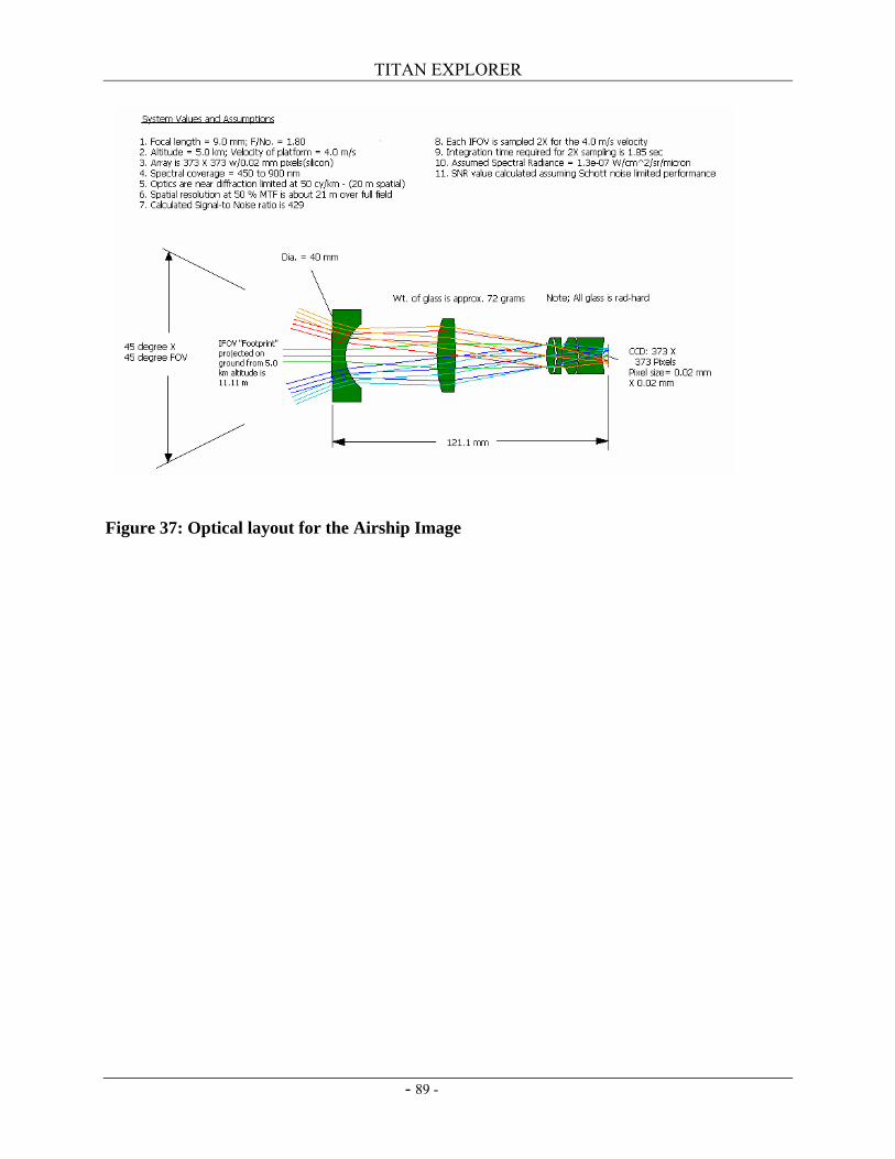
TITAN EXPLORER
- 89 -
Figure 37: Optical layout for the Airship Image

TITAN EXPLORER
- 90 -
This page intentionally left blank
TITAN EXPLORER
- 91 -
3. Technology Successfully delivering the science payloads on the airship and the orbiter to Titan can be accomplished using systems and launch vehicles comprised of essentially existing and near term technologies with the exception of specific elements. With the estimated launch date of 2018 and the resulting technology cutoff date of 2014, a viable development and implementation approach can be planned. No new launch technology is required to accomplish the mission as the existing Delta IV-H can delivery the requisite payload to Titan with sufficient margin. An Atlas V-551, can also deliver the requisite payload, however, the margins are significantly lower resulting in either the need for a more aggressive infusion of new technologies or a rigorous mission implementation strategy with a low mass focus. The key technologies which either ENABLE or ENHANCE the mission can be categorized as either delivery (Aerocapture), systems (power, solar arrays, computational methods), or implementation (Airship or VTOL). Each of these system elements has been investigated as part of the trade studies, each of varying degree and complexity, to arrive at the final configuration described elsewhere. Attributes and risks associated with these developments are described below.
3.1 Unique Requirements and System Sensitivity Described below are the driving requirements, features, or attributes which result in the need for development. Where feasible, an assessment of the sensitivity of the final conclusions to these technologies is provided. 3.1.1 Science Instruments In the following section, the need for technology development for the instruments will be highlighted. For the purpose of the study, instruments were selected that perform similar measurements to the ones needed to address the science questions. Since detailed performance requirements have not been derived from the science questions, the instrument selections may need to be modified once the performance requirements have been determined. We can, however, note selected technology development areas that will need focused attention. Ultimately, the required technology development for the instruments will be based on the performance and accommodation requirements. 3.1.1.1 Orbiter Instruments – Enabling Solar occultation has been used in Earth orbit for many years and the technology is well understood. The concept that works in low Earth orbit would have to be adapted to operate in the orbit of Titan. An instrument concept for solar occultation will need to be developed. While the ACE-FTS instrument was used as the baseline, it is the only instrument found that is in its size category. All other Earth orbiting solar occultation instruments are of the SAGE III class and larger with masses in excess of 70 kg. The enabling technology will be to develop an instrument with sufficiently low mass, with high performance optics sized to operate with the significantly reduced signal to noise ratio typical of the Earth orbiting instruments. 3.1.1.2 Orbiter Instruments – Enhancing The radar mapper and the magnetometer are well understood instruments with minimal development necessary. Resolution again will drive the development of these instruments. The technology of the spectrometers is well understood but depending on the required resolution, instrument concepts may need to be developed. The spectrometers on the orbiter will need to be modified depending on the resolutions required. 3.1.1.3 Airship Instruments – Enabling Specification of the haze and cloud particle detector as well as the sun seeking spectrometer used derivations of legacy instruments. Proper operation in the environment of Titan specifically to
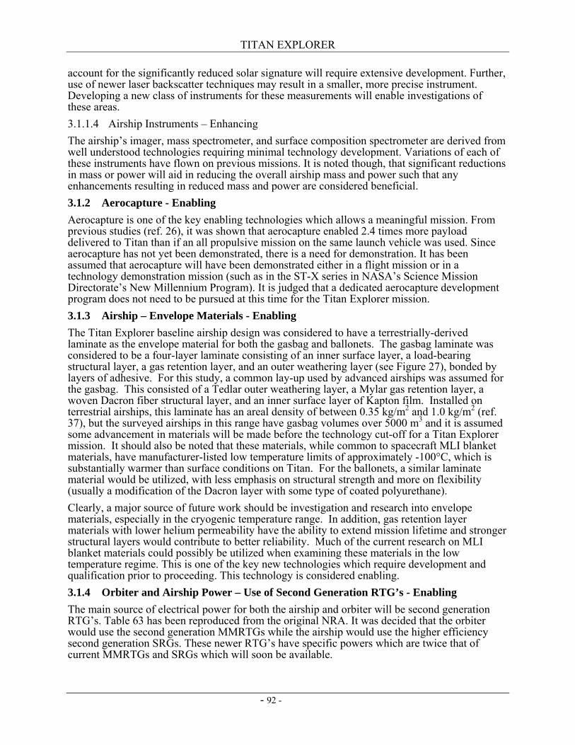
TITAN EXPLORER
- 92 -
account for the significantly reduced solar signature will require extensive development. Further, use of newer laser backscatter techniques may result in a smaller, more precise instrument. Developing a new class of instruments for these measurements will enable investigations of these areas. 3.1.1.4 Airship Instruments – Enhancing The airship’s imager, mass spectrometer, and surface composition spectrometer are derived from well understood technologies requiring minimal technology development. Variations of each of these instruments have flown on previous missions. It is noted though, that significant reductions in mass or power will aid in reducing the overall airship mass and power such that any enhancements resulting in reduced mass and power are considered beneficial. 3.1.2 Aerocapture - Enabling Aerocapture is one of the key enabling technologies which allows a meaningful mission. From previous studies (ref. 26), it was shown that aerocapture enabled 2.4 times more payload delivered to Titan than if an all propulsive mission on the same launch vehicle was used. Since aerocapture has not yet been demonstrated, there is a need for demonstration. It has been assumed that aerocapture will have been demonstrated either in a flight mission or in a technology demonstration mission (such as in the ST-X series in NASA’s Science Mission Directorate’s New Millennium Program). It is judged that a dedicated aerocapture development program does not need to be pursued at this time for the Titan Explorer mission. 3.1.3 Airship – Envelope Materials - Enabling The Titan Explorer baseline airship design was considered to have a terrestrially-derived laminate as the envelope material for both the gasbag and ballonets. The gasbag laminate was considered to be a four-layer laminate consisting of an inner surface layer, a load-bearing structural layer, a gas retention layer, and an outer weathering layer (see Figure 27), bonded by layers of adhesive. For this study, a common lay-up used by advanced airships was assumed for the gasbag. This consisted of a Tedlar outer weathering layer, a Mylar gas retention layer, a woven Dacron fiber structural layer, and an inner surface layer of Kapton film. Installed on terrestrial airships, this laminate has an areal density of between 0.35 kg/m2 and 1.0 kg/m2 (ref. 37), but the surveyed airships in this range have gasbag volumes over 5000 m3 and it is assumed some advancement in materials will be made before the technology cut-off for a Titan Explorer mission. It should also be noted that these materials, while common to spacecraft MLI blanket materials, have manufacturer-listed low temperature limits of approximately -100°C, which is substantially warmer than surface conditions on Titan. For the ballonets, a similar laminate material would be utilized, with less emphasis on structural strength and more on flexibility (usually a modification of the Dacron layer with some type of coated polyurethane). Clearly, a major source of future work should be investigation and research into envelope materials, especially in the cryogenic temperature range. In addition, gas retention layer materials with lower helium permeability have the ability to extend mission lifetime and stronger structural layers would contribute to better reliability. Much of the current research on MLI blanket materials could possibly be utilized when examining these materials in the low temperature regime. This is one of the key new technologies which require development and qualification prior to proceeding. This technology is considered enabling. 3.1.4 Orbiter and Airship Power – Use of Second Generation RTG’s - Enabling The main source of electrical power for both the airship and orbiter will be second generation RTG’s. Table 63 has been reproduced from the original NRA. It was decided that the orbiter would use the second generation MMRTGs while the airship would use the higher efficiency second generation SRGs. These newer RTG’s have specific powers which are twice that of current MMRTGs and SRGs which will soon be available.
TITAN EXPLORER
- 93 -
If the MMRTGs available in 2009 are used in lieu of the ones available in 2013, then the mass of the RTG’s carried by the orbiter would increase by 51 kg. This increase in the EPS would result in increased structure mass, increased propellant mass, increased propellant tank, increased aerocapture TPS mass, as well as increases in the SEPM xenon propellant. While this may be able to be accommodated, the net effect is a total launch mass increase of at least 150 kg. If the SRGs available in 2009 are used in lieu of the ones available in 2013, then the mass of the RTG’s carried by the airship would increase by 52 kg. This increase in the EPS would result in increased structure mass, increased gasbag and lift helium mass, increased mass of the toroidal tank, increased entry aeroshell TPS mass, as well as increases in the SEPM xenon propellant. It is judged that the airship float mass would increase by at least 100 kg, essentially making the implementation of the airship system questionable. Further, if the airship SRGs were replaced with MMRTGs, then the total EPS mass would increase by about 12 kg, however, due to the significantly reduced efficiency of the MMRTG’s, the mass of the PCMs used during the airship entry would increase by a factor of 3. The final conclusions are: 1) the use of RTGs is essential for the Titan Explorer mission (enabling), 2) use of the second generation RTGs is also essential for the Titan Explorer mission (enabling), 3) the use of the second generation SRGs for the airship provides a significant benefit, however if needed, the second generation MMRTGs could be used (enhancing), and 4) a specific development program is not needed as there are numerous uses for these units such that the current general development program(s) are sufficient. Table 63: Choices of RTG's
Parameter MMRTG SRG 2nd Gen. MMRTG
2nd Gen. SRG Multiwatt RPS
Power (W-electric) 120 (BOL) 110 (EOL)
114 (BOL) 95 (EOL)
120 (BOL) 110 (EOL)
114 (BOL) 95 (EOL)
1 – 20
Specific Power (We/kg) 4.12 4.22 8-10 8-10 2 Mass (kg) 34 27 17 14 0.5 – 10 Envelope 58 cm long x
84 cm wide 89 cm long x 27 cm wide
58 cm long x 84 cm wide
89 cm long x 27 cm wide
TBD
Voltage (Vdc) 28 ± 0.2 28 ± 0.2 28 ± 0.2 28 ± 0.2 TBD Lifetime (yrs) 10-14 (space)
3 (Mars) 10-14 (space)
3 (Mars) 10-14 (space)
3 (Mars) 10-14 (space)
3 (Mars) 10
Availability 2009 2009 2013 2013 2011 Pu-238 Content (kg) 4 1 4 1 ~0.1 Thermal Efficiency (% - W-e/W-th)
7% 24% 7% 24% 7%
3.1.5 Spacecraft Propulsion – Next Generation Ion Engines - Enabling Combining aerocapture with solar electric propulsion provides a highly desirable system opportunity. While aerocapture is not directly linked to a propulsive option, having the ability to eliminate a large amount of mass prior to performing the aerocapture maneuver reduces the burden on the overall aerocapture system. Thus use of solar electric propulsion in a propulsion module format which can be separated prior to aerocapture is extremely beneficial. The original NSTAR engines demonstrated by DS-1 were extremely successful. Since then, the next generation engines have been under development and are now being implemented in the DAWN mission. These engines enable the mission, however, no new technology development is needed since the current programs are sufficient. 3.1.6 Aerial Vehicle (Airship & VTOL) – Autonomy and Navigation - Enabling Position and attitude determination is essential for flight as well as for correlating the collected science data. The Titan Explorer study did not focus on the software and algorithm development needed, however, the level of autonomy in the mission software as well as the Guidance,
TITAN EXPLORER
- 94 -
Navigation, and Control software will be extreme. Further, developing means and strategies for testing and validating the software will also require a concerted effort. Position determination will be a fundamental mission driver in terms of mission design, communications architectures, and on-board systems. High resolution surface imagery will not be collected prior to the Titan Explorer mission so that feature recognition will not be a viable navigation technique. Use of inertial systems with RF ranging and Doppler updates from the orbiter will provide a reasonable level of position precision. Validation of the autonomous operations modes including the system architectures for GN&C are judged to be enabling and require specific Titan focused development efforts. 3.1.7 Orbiter Data Relay –Communications Options – Ka or Optical - Enhancing A baseline X-band system has been assumed. The Team-X study considered Ka-band for the data downlink and showed at least 1.5 orders of magnitude increase in returned data. This technology would certainly enhance the mission. Since MRO and MTO will be demonstrating the Ka and Optical data return techniques respectively, either or both of these technologies should be available by the time of the technology cutoff of 2014. No new technology development program is needed. 3.1.8 Aeroshell – Heatshield Radiator Concept - Enhancing During cruise from Earth, the entry aeroshell (as well as the orbiter aeroshell) will need to overcome a significant thermal problem. With the use of multiple RTGs for both the orbiter and aerial platform, it will be necessary to account for the large amount of waste heat generated by these devices. While conventional methods such as use of heat pipes to route the heat to large radiators external to the aeroshells during cruise are useful, they present two problems. One issue is these external radiators contribute an appreciable percentage of the overall mission mass (depending on their design) and consideration for their size and location complicates the structure of the spacecraft by requiring a larger and more intricate truss structure to support them. A second, less obvious issue is the dissipation of waste heat from the RTGs after separation of the two aeroshells from the combined spacecraft truss structure. During the coast to entry (for the aerial platform aeroshell) or aerocapture (for the orbiter’s aeroshell), there is a time period where the nominal external dissipation path is not available. Thus, internal heat generation quickly elevates internal aeroshell temperatures causing an extreme thermal environment. The solution selected for use in the Titan Explorer study is to use PCMs. Use of PCMs adds a significant amount of mass to the aeroshell systems. Current estimates for the Titan Explorer study indicate 201 kg are needed for the aerocapture system and 108 kg are needed for the entry system. JPL’s Team-X estimated these PCM masses as 191 and 73 kg respectively. An alternative concept that has the potential capability to alleviate some amount of this mass burden, both for the cruise from Earth by allowing the use of smaller radiators and for the coast after separation by reducing or eliminating the use of the PCMs within the aeroshell. This concept relies on the large exposed area of the heatshield and the possible high in-plane thermal conductivity of certain heatshield TPS materials, such as carbon-carbon. A high emissivity coating can be placed on the outer TPS material to aid in radiant dissipation to deep space during the cruise and coast periods. Additionally, with the RTGs mechanically attached to the inner surface of the heatshield, heat pipes or other heat spreading devices could be used to disperse the heat along the forebody surface. Assuming the outer surface emissivity to be 0.6 and the radiative surface temperature to be 0°C, the aeroshell forebody is capable of dissipating the 3 kW of excess waste heat from the RTGs in either aeroshell and still provide an inner surface temperature of <165°C (250°C is material limit of the forebody laminate structure using graphite epoxy face sheets and aluminum honeycomb core). The internal pallet of the aeroshell would then require insulation or other means of thermal isolation from the inner surface of the forebody. This calculation is an approximation, but does provide some insight into the advantage this system might provide. Future research in the areas of combined thermal and structural design and analysis of this concept would be beneficial to any future aeroshell-based
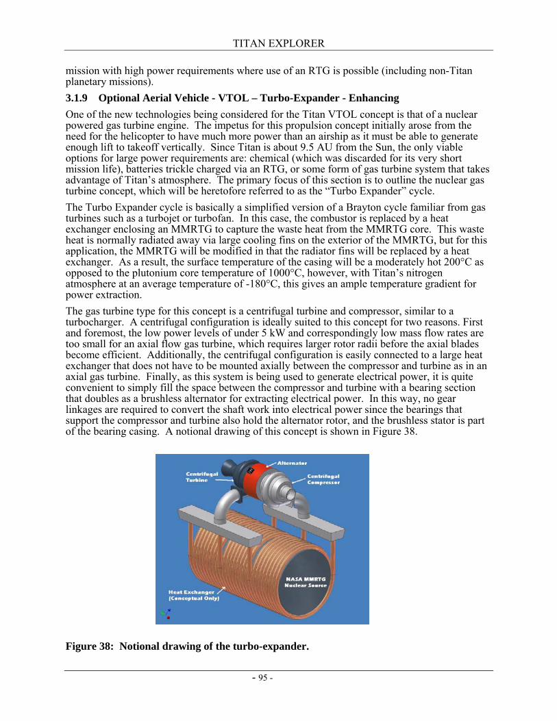
TITAN EXPLORER
- 95 -
mission with high power requirements where use of an RTG is possible (including non-Titan planetary missions). 3.1.9 Optional Aerial Vehicle - VTOL – Turbo-Expander - Enhancing One of the new technologies being considered for the Titan VTOL concept is that of a nuclear powered gas turbine engine. The impetus for this propulsion concept initially arose from the need for the helicopter to have much more power than an airship as it must be able to generate enough lift to takeoff vertically. Since Titan is about 9.5 AU from the Sun, the only viable options for large power requirements are: chemical (which was discarded for its very short mission life), batteries trickle charged via an RTG, or some form of gas turbine system that takes advantage of Titan’s atmosphere. The primary focus of this section is to outline the nuclear gas turbine concept, which will be heretofore referred to as the “Turbo Expander” cycle. The Turbo Expander cycle is basically a simplified version of a Brayton cycle familiar from gas turbines such as a turbojet or turbofan. In this case, the combustor is replaced by a heat exchanger enclosing an MMRTG to capture the waste heat from the MMRTG core. This waste heat is normally radiated away via large cooling fins on the exterior of the MMRTG, but for this application, the MMRTG will be modified in that the radiator fins will be replaced by a heat exchanger. As a result, the surface temperature of the casing will be a moderately hot 200°C as opposed to the plutonium core temperature of 1000°C, however, with Titan’s nitrogen atmosphere at an average temperature of -180°C, this gives an ample temperature gradient for power extraction. The gas turbine type for this concept is a centrifugal turbine and compressor, similar to a turbocharger. A centrifugal configuration is ideally suited to this concept for two reasons. First and foremost, the low power levels of under 5 kW and correspondingly low mass flow rates are too small for an axial flow gas turbine, which requires larger rotor radii before the axial blades become efficient. Additionally, the centrifugal configuration is easily connected to a large heat exchanger that does not have to be mounted axially between the compressor and turbine as in an axial gas turbine. Finally, as this system is being used to generate electrical power, it is quite convenient to simply fill the space between the compressor and turbine with a bearing section that doubles as a brushless alternator for extracting electrical power. In this way, no gear linkages are required to convert the shaft work into electrical power since the bearings that support the compressor and turbine also hold the alternator rotor, and the brushless stator is part of the bearing casing. A notional drawing of this concept is shown in Figure 38.
Figure 38: Notional drawing of the turbo-expander.
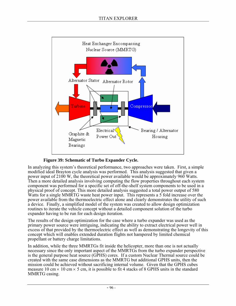
TITAN EXPLORER
- 96 -
In analyzing this system’s theoretical performance, two approaches were taken. First, a simple modified ideal Brayton cycle analysis was performed. This analysis suggested that given a power input of 2100 W, the theoretical power available would be approximately 960 Watts. Then a more detailed analysis involving computing the flow properties throughout each system component was performed for a specific set of off-the-shelf system components to be used in a physical proof of concept. This more detailed analysis suggested a total power output of 580 Watts for a single MMRTG waste heat power input. This represents a 5 fold increase over the power available from the thermoelectric effect alone and clearly demonstrates the utility of such a device. Finally, a simplified model of the system was created to allow design optimization routines to iterate the vehicle concept without a detailed component solution of the turbo expander having to be run for each design iteration. The results of the design optimization for the case where a turbo expander was used as the primary power source were intriguing, indicating the ability to extract electrical power well in excess of that provided by the thermoelectric effect as well as demonstrating the longevity of this concept which will enables extended duration flights not hampered by limited chemical propellant or battery charge limitations. In addition, while the three MMRTGs fit inside the helicopter, more than one is not actually necessary since the only important aspect of the MMRTGs from the turbo expander perspective is the general purpose heat source (GPHS) cores. If a custom Nuclear Thermal source could be created with the same case dimensions as the MMRTG but additional GPHS units, then the mission could be achieved without sacrificing internal volume. Given that the GPHS cubes measure 10 cm × 10 cm × 5 cm, it is possible to fit 4 stacks of 8 GPHS units in the standard MMRTG casing.
Figure 39: Schematic of Turbo Expander Cycle.

TITAN EXPLORER
- 97 -
Finally, as the turbo expander only requires cold dense gas to function, it is quite reasonable to assume that once such a system has been developed for a Titan mission, it can be adapted and expanded to a broader role of providing power to aerial vehicles that might fly through any of the atmospheres of the outer planets. The advantages of this propulsion concept are numerous and readily understandable, but one of the most important issues concerning this idea is the technology development path that NASA would have to take to implement such a concept. Therefore, the remainder of this section touches upon some of the key technologies that need to be worked on to bring this idea to fruition. The first and perhaps most important technology component that would have to be implemented is the currently planned second generation MMRTG. Indeed the concept of the turbo expander would be far less practical if applied to a vehicle using one of the current RTGs as they are almost 2 meters long and far too bulky for a small aerial platform. The second critical technology that would need to be looked into would be the bearings for such a gas turbine system. As any probe sent to the outer planets will have to endure a long trip in space (up to seven years for Titan), the bearings must be quite robust and maintenance free. Further, they must be able to survive launch loads and then long term (several months) operation on Titan in an extremely cold environment spinning at speeds most likely above 50,000 RPMs due to the small rotor radii of the centrifugal configuration. Ordinarily, bearings in such circumstances are dealt with by using a recirculating liquid or (oil) lubricant. However, to reduce system components and complexity, a liquid lubricant system would be impractical as it would require constant monitoring, temperature control, and periodic cycling to keep the lubricants viable after such a trip. Instead, a liquid lubricant-free bearing capable of handling the high RPMs and harsh environment are desirable. After some initial research, it was concluded that some form of bearing involving magnetic bearings backed up with self lubricating graphite metal alloy bushings would be a possible practical solution to the problem. However, as with all rotating machinery, this and all the other moving parts of the turbo expander would have to be thoroughly tested. Other key technologies for this concept include the development of highly efficient heat exchangers to encompass an MMRTG, as well as maintenance free brushless alternators capable of high speed rotation. However, it is felt that all of the above technology developments would be relatively straight forward continuations of the current state-of-the-art technology. Finally, it should be noted that a simple proof of concept of this system utilizing low cost off the shelf components is currently being tested in the Georgia Institute of Technology Combustion Lab (development and testing funding from sources other than the Titan Vision Mission NRA) to verify the assumptions made in the formulation of this concept (see Figure 40). Data from these experiments will be forthcoming in the future. Laboratory testing using liquid nitrogen as the source of “Titan atmosphere” has demonstrated the ability to generate a significant amount of electrical power with this setup thus validating the proof of concept.
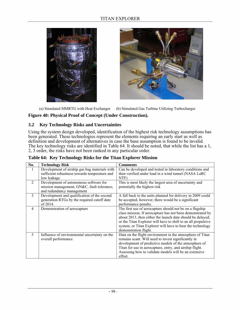
TITAN EXPLORER
- 98 -
(a) Simulated MMRTG with Heat Exchanger (b) Simulated Gas Turbine Utilizing Turbocharger
Figure 40: Physical Proof of Concept (Under Construction).
3.2 Key Technology Risks and Uncertainties Using the system design developed, identification of the highest risk technology assumptions has been generated. These technologies represent the elements requiring an early start as well as definition and development of alternatives in case the base assumption is found to be invalid. The key technology risks are identified in Table 64. It should be noted, that while the list has a 1, 2, 3 order, the risks have not been ranked in any particular order. Table 64: Key Technology Risks for the Titan Explorer Mission No. Technology Risk Comments
1 Development of airship gas bag materials with sufficient robustness towards temperature and low leakage
Can be developed and tested in laboratory conditions and then verified under load in a wind tunnel (NASA LaRC NTF)
2 Development of autonomous software for mission management, GN&C, fault tolerance, and redundancy management
This is most likely the largest area of uncertainty and potentially the highest risk
3 Development and qualification of the second generation RTGs by the required cutoff date of 2014.
A fall back to the units planned for delivery in 2009 could be accepted, however, there would be a significant performance penalty.
4 Demonstration of aerocapture The first use of aerocapture should not be on a flagship class mission. If aerocapture has not been demonstrated by about 2013, then either the launch date should be delayed, or the Titan Explorer will have to shift to an all propulsive system, or Titan Explorer will have to bear the technology demonstration flight.
5 Influence of environmental uncertainty on the overall performance
Data on the flight environment in the atmosphere of Titan remains scant. Will need to invest significantly in development of predictive models of the atmosphere of Titan for use in aerocapture, entry, and airship flight. Assessing how to validate models will be an extensive effort.
TITAN EXPLORER
- 99 -
3.3 Development Strategy (Roadmap)
3.4 Validation and Demonstration Approach A time-honored strategy to develop any new vehicle involves a progressive maturation using computational and experimental methods, and ultimately involves flight testing in a relevant environment. Though vastly different than Earth from an environmental perspective, the pertinent flight parameters for Titan vehicles are achievable using existing facilities and methods. 3.4.1 Airship Flight Testing Credible predictions of the airship performance and flight dynamics are readily obtainable using the current state of the art methods for design, analysis, and testing. The key aerodynamic scaling parameter (Reynolds number) for the airship is of the same order as current and previously flown airships. The Titan Explorer has a Reynolds number (based on the cube root of the gas bag volume) of the order of 13 to 16 billion. The latest in the GoodyearTM blimp series (the Spirit of America) has a Reynolds number of about 16 billion at cruise. Although the low temperature on Titan produce low sonic speeds, the slow airship cruise speed results in low Mach numbers (typically about 0.015). Hence compressible effects can be ignored considerably simplifying analysis and wind tunnel testing. As long as the proper aerodynamic scaling is performed, the wind tunnel and flight testing will be relevant. By equating the Earth based Reynolds number to the Titan Reynolds number, then the proper scale factor can be found. Since the Titan atmospheric density is about 4.6 times greater than Earth at sea level and the Titan viscosity is about 3.5 times less than on Earth at sea level, then the scale of an airship model for Earth based testing is dependent upon the test speed. If the Earth to Titan airspeed ratio is about 15 to 25, then the scale of the model would range from full-scale to ¾-scale respectively. The fundamental challenge with flight testing lies in the difference in gravity. One of the driving performance issues for any flight vehicle is its Thrust to Weight ratio. Since Titan has only 1/7th of the gravity of Earth, a full-size propulsion system would have insufficient thrust to propel the airship at the correct speed to match the Reynolds number on Earth. Dynamically scaled flight tests have been performed over a wide range of terrestrial airplanes. Most airplanes begin their first flight as a sub-scale dynamically scaled flight vehicle. Development of the Titan airship is no different. A wide range of airships would need to be developed and tested, each with a different focus. 3.4.2 VTOL Flight Testing Development of the VTOL vehicle will provide some developmental and scaling challenges. Performing the integrated flight testing with a flight-like MMRTG will necessitate a very expensive range test. 3.4.3 EDI Flight Testing Inflation of the airship occurs as the system is descending. Analysis has indicated the inflation will occur under a dynamic pressure load of about 10 Pa (or the same as a speed of 4.1 m/s. This low load means the inflation could occur in essentially stagnant air while being suspended from a crane. Performing the drop testing and inflating it while taking the planned 20 minutes for inflation under a parachute may not be needed.

TITAN EXPLORER
- 100 -
This page intentionally left blank
TITAN EXPLORER
- 101 -
4. Deployment (Mission Design) Developing a credible mission concept includes balancing the science measurement needs with a realistic strategy for putting the science instruments at the needed locale for collecting their data. While the science needs and measurement types provide the foundation for a mission, the implementation of the mission has to recognize the limitations of the systems needed. A mission design strategy which can be developed and remains within the constraints of either system capabilities or realistic cost estimates is performed as part of the overall mission design and development activity. A description of the integrated sequence of operations is provided in Section 5. Provided here is a description of the assessments performed for the various elements of the overall mission design. Each phase requires specific types of analysis and hardware solutions to ensure the system meets all of the needed performance requirements. Phases assessed during this study include the Cruise Phase (which starts after launch and includes the Earth Gravity Assist), the Orbiter Aerocapture phase, and the Entry phase of the baseline Airship as well as the optional VTOL.
4.1 Mission Design Overview Previous studies have validated a reasonable mission architecture for this class of mission to rely primarily on a direct entry for the airship and aerocapture for the orbiter (ref. 26). Use of solar electric propulsion during the cruise phase has also been compared to other techniques, such as Cassini’s multiple planetary flybys and chemical propulsion, as well as purely all chemical propulsion, and nuclear electric propulsion (ref. 29). For the purposes of this study, it was judged the downselect analysis for a mission design architecture was not required as a preferred architecture would be selected, thus leveraging previous efforts. Provided in this section are the attributes of the key mission phases. General overview of previous mission design assessments of the Titan arrival navigation strategies and the orbiter aerocapture strategies are provided. Detailed analysis (3-DoF) of the entry is also explained in detail to identify the driving design data including definition of the Entry, Descent, Inflation time line.
4.2 Cruise Interplanetary trajectory propagation analysis is the primary design analysis performed for the cruise phase, to be able to define the mission dates as well as the timing and sequencing of the critical activities. A secondary output of the trajectory analysis is the balance between launch vehicle C3 and the amount of xenon propellant needed for the mission. The preferred trajectory includes a defined launch and arrival date, a single EGA, as well as the definition of the NGN engine operational sequences. JPL’s Team-X performed a high level systems assessment as part of the study. The results from the Team-X study were that a launch vehicle C3 of 25.5 km2/sec2 coupled with using 3 NGN engines and 807 kg of xenon propellant were sufficient for the mission. The assessment performed as part of the Titan Explorer assessment considered a launch vehicle C3 of 12 km2/sec2 to provide a much larger launch mass margin. The difference in C3’s results in the need for an additional ∆V for the Titan Explorer study case of 1586 m/s. Addition of a fourth NGN engine along with a 45 day burn of that engine is sufficient to provide the additional ∆V such that at the time of the EGA, the two mission trajectories are essentially identical. The 1057 kg of xenon needed for the Titan Explorer mission accounts for the additional ∆V due to the difference in C3’s as well as the additional propellant needed because the overall dry mass increased. All other assumptions concerning propellant margin and propellant holdup are consistent between the two studies.
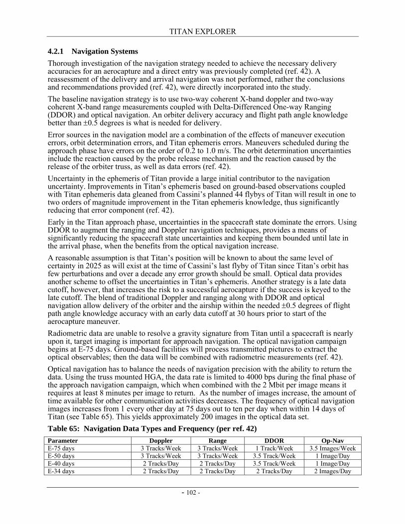
TITAN EXPLORER
- 102 -
4.2.1 Navigation Systems Thorough investigation of the navigation strategy needed to achieve the necessary delivery accuracies for an aerocapture and a direct entry was previously completed (ref. 42). A reassessment of the delivery and arrival navigation was not performed, rather the conclusions and recommendations provided (ref. 42), were directly incorporated into the study. The baseline navigation strategy is to use two-way coherent X-band doppler and two-way coherent X-band range measurements coupled with Delta-Differenced One-way Ranging (DDOR) and optical navigation. An orbiter delivery accuracy and flight path angle knowledge better than ±0.5 degrees is what is needed for delivery. Error sources in the navigation model are a combination of the effects of maneuver execution errors, orbit determination errors, and Titan ephemeris errors. Maneuvers scheduled during the approach phase have errors on the order of 0.2 to 1.0 m/s. The orbit determination uncertainties include the reaction caused by the probe release mechanism and the reaction caused by the release of the orbiter truss, as well as data errors (ref. 42). Uncertainty in the ephemeris of Titan provide a large initial contributor to the navigation uncertainty. Improvements in Titan’s ephemeris based on ground-based observations coupled with Titan ephemeris data gleaned from Cassini’s planned 44 flybys of Titan will result in one to two orders of magnitude improvement in the Titan ephemeris knowledge, thus significantly reducing that error component (ref. 42). Early in the Titan approach phase, uncertainties in the spacecraft state dominate the errors. Using DDOR to augment the ranging and Doppler navigation techniques, provides a means of significantly reducing the spacecraft state uncertainties and keeping them bounded until late in the arrival phase, when the benefits from the optical navigation increase. A reasonable assumption is that Titan’s position will be known to about the same level of certainty in 2025 as will exist at the time of Cassini’s last flyby of Titan since Titan’s orbit has few perturbations and over a decade any error growth should be small. Optical data provides another scheme to offset the uncertainties in Titan’s ephemeris. Another strategy is a late data cutoff, however, that increases the risk to a successful aerocapture if the success is keyed to the late cutoff. The blend of traditional Doppler and ranging along with DDOR and optical navigation allow delivery of the orbiter and the airship within the needed ±0.5 degrees of flight path angle knowledge accuracy with an early data cutoff at 30 hours prior to start of the aerocapture maneuver. Radiometric data are unable to resolve a gravity signature from Titan until a spacecraft is nearly upon it, target imaging is important for approach navigation. The optical navigation campaign begins at E-75 days. Ground-based facilities will process transmitted pictures to extract the optical observables; then the data will be combined with radiometric measurements (ref. 42). Optical navigation has to balance the needs of navigation precision with the ability to return the data. Using the truss mounted HGA, the data rate is limited to 4000 bps during the final phase of the approach navigation campaign, which when combined with the 2 Mbit per image means it requires at least 8 minutes per image to return. As the number of images increase, the amount of time available for other communication activities decreases. The frequency of optical navigation images increases from 1 every other day at 75 days out to ten per day when within 14 days of Titan (see Table 65). This yields approximately 200 images in the optical data set. Table 65: Navigation Data Types and Frequency (per ref. 42) Parameter Doppler Range DDOR Op-Nav E-75 days 3 Tracks/Week 3 Tracks/Week 1 Track/Week 3.5 Images/Week E-50 days 3 Tracks/Week 3 Tracks/Week 3.5 Track/Week 1 Image/Day E-40 days 2 Tracks/Day 2 Tracks/Day 3.5 Track/Week 1 Image/Day E-34 days 2 Tracks/Day 2 Tracks/Day 2 Tracks/Day 2 Images/Day
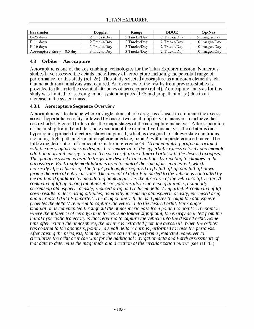
TITAN EXPLORER
- 103 -
Parameter Doppler Range DDOR Op-Nav E-25 days 2 Tracks/Day 2 Tracks/Day 2 Tracks/Day 5 Images/Day E-14 days 2 Tracks/Day 2 Tracks/Day 2 Tracks/Day 10 Images/Day E-10 days 3 Tracks/Day 3 Tracks/Day 2 Tracks/Day 10 Images/Day Aerocapture Entry—0.5 day 3 Tracks/Day 3 Tracks/Day 2 Tracks/Day 10 Images/Day
4.3 Orbiter – Aerocapture Aerocapture is one of the key enabling technologies for the Titan Explorer mission. Numerous studies have assessed the details and efficacy of aerocapture including the potential range of performance for this study (ref. 26). This study selected aerocapture as a mission element such that no additional analysis was required. An overview of the results from previous studies is provided to illustrate the essential attributes of aerocapture (ref. 4). Aerocapture analysis for this study was limited to assessing minor system impacts (TPS and propellant mass) due to an increase in the system mass. 4.3.1 Aerocapture Sequence Overview Aerocapture is a technique where a single atmospheric drag pass is used to eliminate the excess arrival hyperbolic velocity followed by one or two small impulsive maneuvers to achieve the desired orbit. Figure 41 illustrates the major stages of the aerocapture maneuver. After separation of the airship from the orbiter and execution of the orbiter divert maneuver, the orbiter is on a hyperbolic approach trajectory, shown at point 1, which is designed to achieve state conditions including flight path angle at atmospheric interface, point 2, within a predetermined range. The following description of aerocapture is from reference 43. “A nominal drag profile associated with the aerocapture pass is designed to remove all of the hyperbolic excess velocity and enough additional orbital energy to place the spacecraft in an elliptical orbit with the desired apoapsis. The guidance system is used to target the desired exit conditions by reacting to changes in the atmosphere. Bank angle modulation is used to control the rate of ascent/descent, which indirectly affects the drag. The flight path angles required to fly full lift-up and full lift-down form a theoretical entry corridor. The amount of delta V imparted to the vehicle is controlled by the on-board guidance by modulating bank angle, i.e. the direction of the vehicle’s lift vector. A command of lift up during an atmospheric pass results in increasing altitudes, nominally decreasing atmospheric density, reduced drag and reduced delta V imparted. A command of lift down results in decreasing altitudes, nominally increasing atmospheric density, increased drag and increased delta V imparted. The drag on the vehicle as it passes through the atmosphere provides the delta V required to capture the vehicle into the desired orbit. Bank angle modulation is commanded throughout the atmospheric pass from point 3 to point 5. By point 5, where the influence of aerodynamic forces is no longer significant, the energy depleted from the initial hyperbolic trajectory is that required to capture the vehicle into the desired orbit. Some time after exiting the atmosphere, the orbiter is extracted from the aeroshell. When the orbiter has coasted to the apoapsis, point 7, a small delta V burn is performed to raise the periapsis. After raising the periapsis, then the orbiter can either perform a predicted maneuver to circularize the orbit or it can wait for the additional navigation data and Earth assessments of that data to determine the magnitude and direction of the circularization burn.” (see ref. 43).
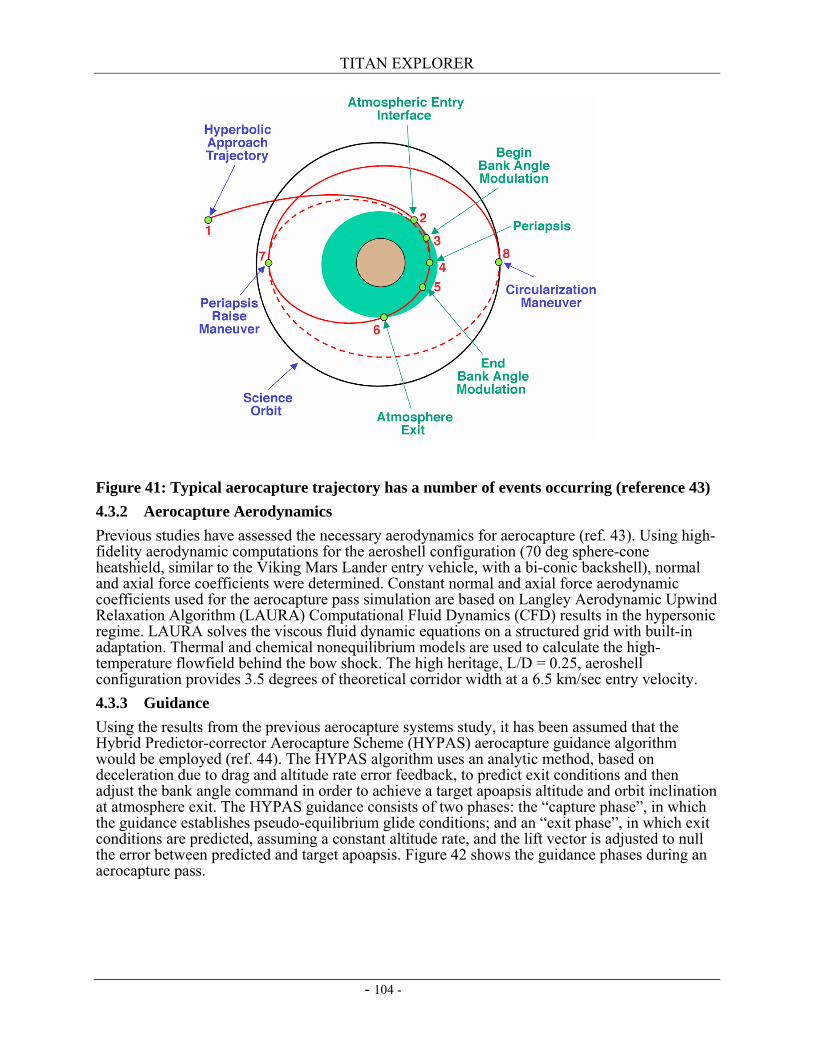
TITAN EXPLORER
- 104 -
Figure 41: Typical aerocapture trajectory has a number of events occurring (reference 43) 4.3.2 Aerocapture Aerodynamics Previous studies have assessed the necessary aerodynamics for aerocapture (ref. 43). Using high-fidelity aerodynamic computations for the aeroshell configuration (70 deg sphere-cone heatshield, similar to the Viking Mars Lander entry vehicle, with a bi-conic backshell), normal and axial force coefficients were determined. Constant normal and axial force aerodynamic coefficients used for the aerocapture pass simulation are based on Langley Aerodynamic Upwind Relaxation Algorithm (LAURA) Computational Fluid Dynamics (CFD) results in the hypersonic regime. LAURA solves the viscous fluid dynamic equations on a structured grid with built-in adaptation. Thermal and chemical nonequilibrium models are used to calculate the high-temperature flowfield behind the bow shock. The high heritage, L/D = 0.25, aeroshell configuration provides 3.5 degrees of theoretical corridor width at a 6.5 km/sec entry velocity. 4.3.3 Guidance Using the results from the previous aerocapture systems study, it has been assumed that the Hybrid Predictor-corrector Aerocapture Scheme (HYPAS) aerocapture guidance algorithm would be employed (ref. 44). The HYPAS algorithm uses an analytic method, based on deceleration due to drag and altitude rate error feedback, to predict exit conditions and then adjust the bank angle command in order to achieve a target apoapsis altitude and orbit inclination at atmosphere exit. The HYPAS guidance consists of two phases: the “capture phase”, in which the guidance establishes pseudo-equilibrium glide conditions; and an “exit phase”, in which exit conditions are predicted, assuming a constant altitude rate, and the lift vector is adjusted to null the error between predicted and target apoapsis. Figure 42 shows the guidance phases during an aerocapture pass.
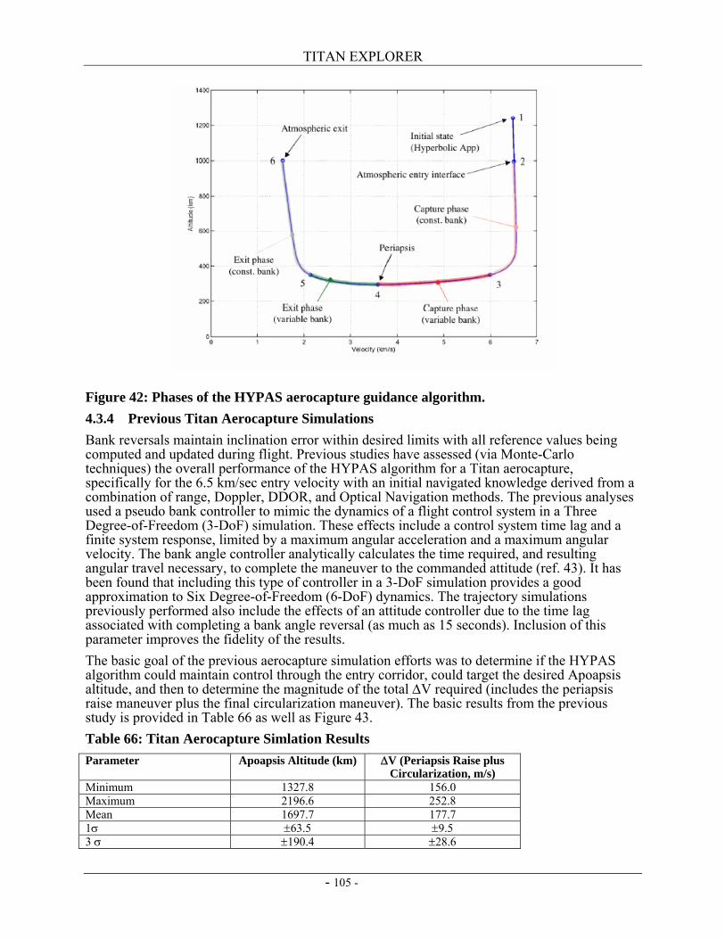
TITAN EXPLORER
- 105 -
Figure 42: Phases of the HYPAS aerocapture guidance algorithm. 4.3.4 Previous Titan Aerocapture Simulations Bank reversals maintain inclination error within desired limits with all reference values being computed and updated during flight. Previous studies have assessed (via Monte-Carlo techniques) the overall performance of the HYPAS algorithm for a Titan aerocapture, specifically for the 6.5 km/sec entry velocity with an initial navigated knowledge derived from a combination of range, Doppler, DDOR, and Optical Navigation methods. The previous analyses used a pseudo bank controller to mimic the dynamics of a flight control system in a Three Degree-of-Freedom (3-DoF) simulation. These effects include a control system time lag and a finite system response, limited by a maximum angular acceleration and a maximum angular velocity. The bank angle controller analytically calculates the time required, and resulting angular travel necessary, to complete the maneuver to the commanded attitude (ref. 43). It has been found that including this type of controller in a 3-DoF simulation provides a good approximation to Six Degree-of-Freedom (6-DoF) dynamics. The trajectory simulations previously performed also include the effects of an attitude controller due to the time lag associated with completing a bank angle reversal (as much as 15 seconds). Inclusion of this parameter improves the fidelity of the results. The basic goal of the previous aerocapture simulation efforts was to determine if the HYPAS algorithm could maintain control through the entry corridor, could target the desired Apoapsis altitude, and then to determine the magnitude of the total ∆V required (includes the periapsis raise maneuver plus the final circularization maneuver). The basic results from the previous study is provided in Table 66 as well as Figure 43. Table 66: Titan Aerocapture Simlation Results Parameter Apoapsis Altitude (km) ∆V (Periapsis Raise plus
Circularization, m/s) Minimum 1327.8 156.0 Maximum 2196.6 252.8 Mean 1697.7 177.7 1σ ±63.5 ±9.5 3 σ ±190.4 ±28.6
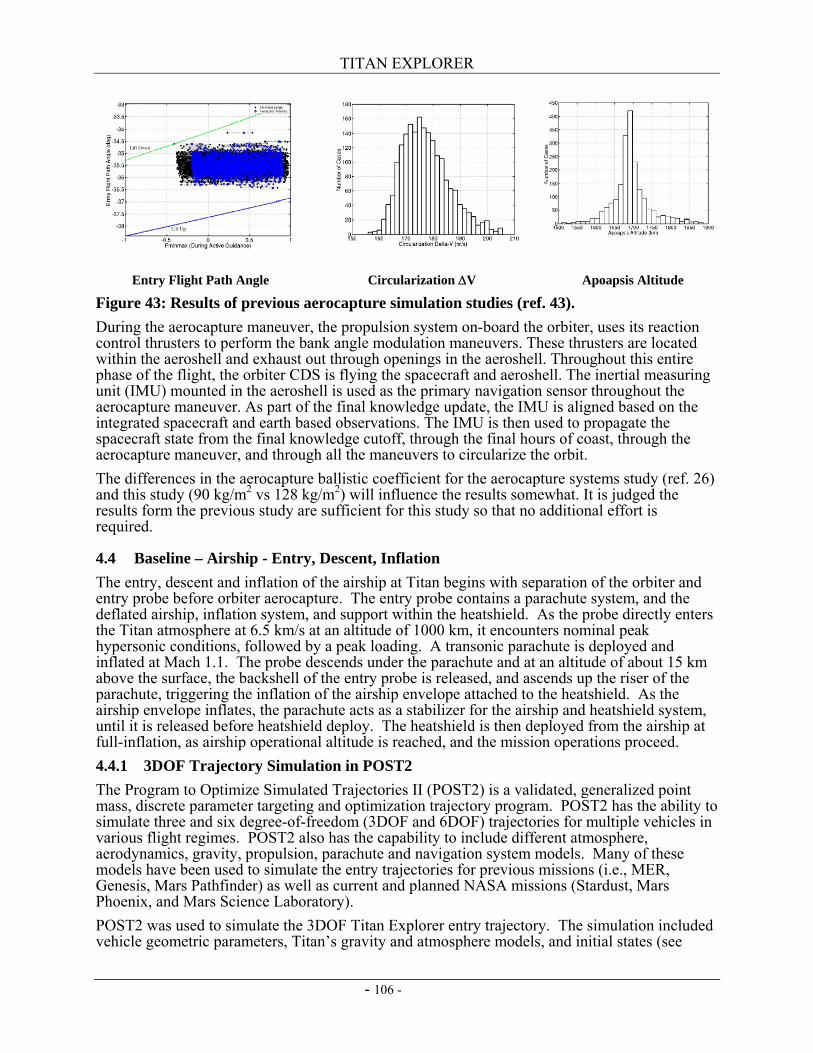
TITAN EXPLORER
- 106 -
Entry Flight Path Angle Circularization ∆V Apoapsis Altitude
Figure 43: Results of previous aerocapture simulation studies (ref. 43). During the aerocapture maneuver, the propulsion system on-board the orbiter, uses its reaction control thrusters to perform the bank angle modulation maneuvers. These thrusters are located within the aeroshell and exhaust out through openings in the aeroshell. Throughout this entire phase of the flight, the orbiter CDS is flying the spacecraft and aeroshell. The inertial measuring unit (IMU) mounted in the aeroshell is used as the primary navigation sensor throughout the aerocapture maneuver. As part of the final knowledge update, the IMU is aligned based on the integrated spacecraft and earth based observations. The IMU is then used to propagate the spacecraft state from the final knowledge cutoff, through the final hours of coast, through the aerocapture maneuver, and through all the maneuvers to circularize the orbit. The differences in the aerocapture ballistic coefficient for the aerocapture systems study (ref. 26) and this study (90 kg/m2 vs 128 kg/m2) will influence the results somewhat. It is judged the results form the previous study are sufficient for this study so that no additional effort is required.
4.4 Baseline – Airship - Entry, Descent, Inflation The entry, descent and inflation of the airship at Titan begins with separation of the orbiter and entry probe before orbiter aerocapture. The entry probe contains a parachute system, and the deflated airship, inflation system, and support within the heatshield. As the probe directly enters the Titan atmosphere at 6.5 km/s at an altitude of 1000 km, it encounters nominal peak hypersonic conditions, followed by a peak loading. A transonic parachute is deployed and inflated at Mach 1.1. The probe descends under the parachute and at an altitude of about 15 km above the surface, the backshell of the entry probe is released, and ascends up the riser of the parachute, triggering the inflation of the airship envelope attached to the heatshield. As the airship envelope inflates, the parachute acts as a stabilizer for the airship and heatshield system, until it is released before heatshield deploy. The heatshield is then deployed from the airship at full-inflation, as airship operational altitude is reached, and the mission operations proceed. 4.4.1 3DOF Trajectory Simulation in POST2 The Program to Optimize Simulated Trajectories II (POST2) is a validated, generalized point mass, discrete parameter targeting and optimization trajectory program. POST2 has the ability to simulate three and six degree-of-freedom (3DOF and 6DOF) trajectories for multiple vehicles in various flight regimes. POST2 also has the capability to include different atmosphere, aerodynamics, gravity, propulsion, parachute and navigation system models. Many of these models have been used to simulate the entry trajectories for previous missions (i.e., MER, Genesis, Mars Pathfinder) as well as current and planned NASA missions (Stardust, Mars Phoenix, and Mars Science Laboratory). POST2 was used to simulate the 3DOF Titan Explorer entry trajectory. The simulation included vehicle geometric parameters, Titan’s gravity and atmosphere models, and initial states (see
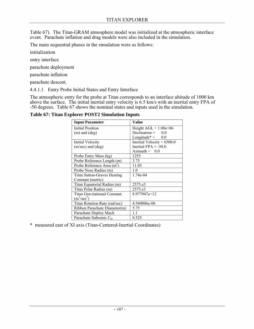
TITAN EXPLORER
- 107 -
Table 67). The Titan-GRAM atmosphere model was initialized at the atmospheric interface event. Parachute inflation and drag models were also included in the simulation. The main sequential phases in the simulation were as follows: initialization entry interface parachute deployment parachute inflation parachute descent. 4.4.1.1 Entry Probe Initial States and Entry Interface The atmospheric entry for the probe at Titan corresponds to an interface altitude of 1000 km above the surface. The initial inertial entry velocity is 6.5 km/s with an inertial entry FPA of -50 degrees. Table 67 shows the nominal states and inputs used in the simulation. Table 67: Titan Explorer POST2 Simulation Inputs
Input Parameter Value Initial Position (m) and (deg)
Height AGL = 1.00e+06 Declination = 0.0 Longitude* = 0.0
Initial Velocity (m/sec) and (deg)
Inertial Velocity = 6500.0 Inertial FPA = -50.0 Azimuth = 0.0
Probe Entry Mass (kg) 1255 Probe Reference Length (m) 3.75 Probe Reference Area (m2) 11.05 Probe Nose Radius (m) 1.0 Titan Sutton-Graves Heating Constant (metric)
1.74e-04
Titan Equatorial Radius (m) 2575.e3 Titan Polar Radius (m) 2575.e3 Titan Gravitational Constant (m3/sec2)
8.977947e+12
Titan Rotation Rate (rad/sec) 4.560806e-06 Ribbon Parachute Diameter(m) 5.75 Parachute Deploy Mach 1.1 Parachute Subsonic CD 0.525
* measured east of XI axis (Titan-Centered-Inertial Coordinates)
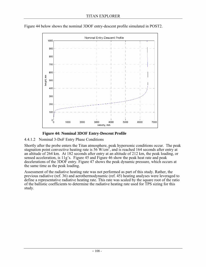
TITAN EXPLORER
- 108 -
Figure 44 below shows the nominal 3DOF entry-descent profile simulated in POST2.
4.4.1.2 Nominal 3-DoF Entry Phase Conditions Shortly after the probe enters the Titan atmosphere, peak hypersonic conditions occur. The peak stagnation point convective heating rate is 56 W/cm2, and is reached 164 seconds after entry at an altitude of 264 km. At 182 seconds after entry at an altitude of 212 km, the peak loading, or sensed acceleration, is 11g’s. Figure 45 and Figure 46 show the peak heat rate and peak decelerations of the 3DOF entry. Figure 47 shows the peak dynamic pressure, which occurs at the same time as the peak loading. Assessment of the radiative heating rate was not performed as part of this study. Rather, the previous radiative (ref. 36) and aerothermodynamic (ref. 45) heating analyses were leveraged to define a representative radiative heating rate. This rate was scaled by the square root of the ratio of the ballistic coefficients to determine the radiative heating rate used for TPS sizing for this study.
Figure 44: Nominal 3DOF Entry-Descent Profile
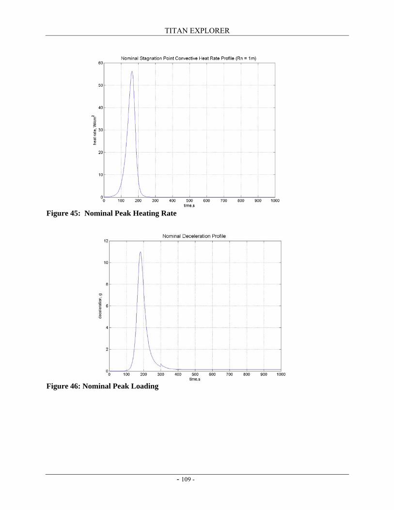
TITAN EXPLORER
- 109 -
Figure 45: Nominal Peak Heating Rate
Figure 46: Nominal Peak Loading
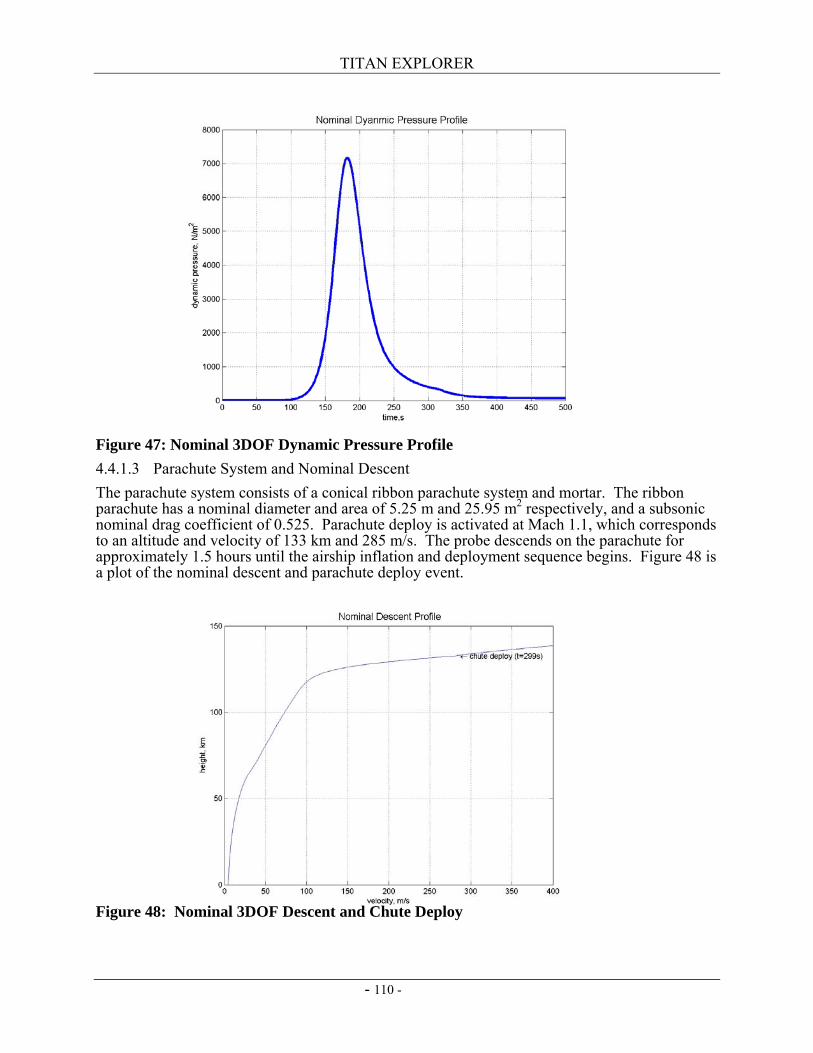
TITAN EXPLORER
- 110 -
Figure 47: Nominal 3DOF Dynamic Pressure Profile 4.4.1.3 Parachute System and Nominal Descent The parachute system consists of a conical ribbon parachute system and mortar. The ribbon parachute has a nominal diameter and area of 5.25 m and 25.95 m2 respectively, and a subsonic nominal drag coefficient of 0.525. Parachute deploy is activated at Mach 1.1, which corresponds to an altitude and velocity of 133 km and 285 m/s. The probe descends on the parachute for approximately 1.5 hours until the airship inflation and deployment sequence begins. Figure 48 is a plot of the nominal descent and parachute deploy event.
Figure 48: Nominal 3DOF Descent and Chute Deploy
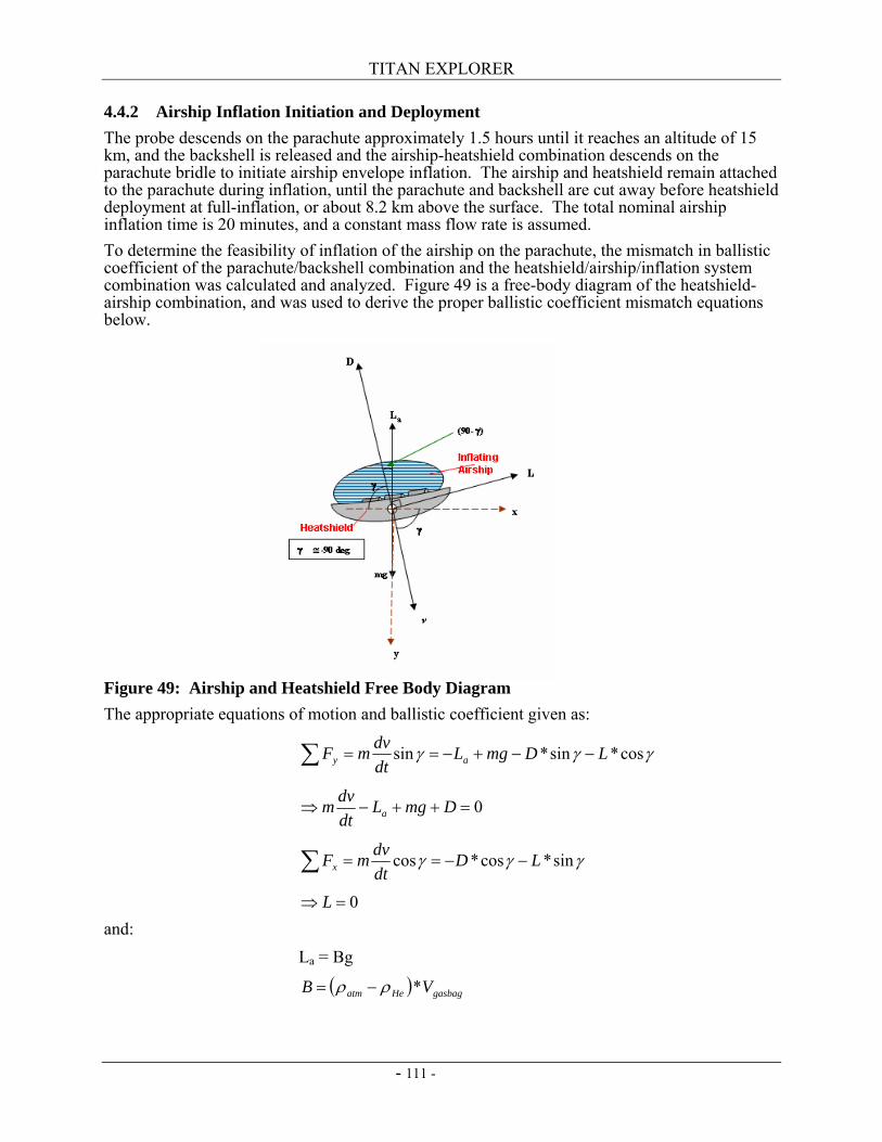
TITAN EXPLORER
- 111 -
4.4.2 Airship Inflation Initiation and Deployment The probe descends on the parachute approximately 1.5 hours until it reaches an altitude of 15 km, and the backshell is released and the airship-heatshield combination descends on the parachute bridle to initiate airship envelope inflation. The airship and heatshield remain attached to the parachute during inflation, until the parachute and backshell are cut away before heatshield deployment at full-inflation, or about 8.2 km above the surface. The total nominal airship inflation time is 20 minutes, and a constant mass flow rate is assumed. To determine the feasibility of inflation of the airship on the parachute, the mismatch in ballistic coefficient of the parachute/backshell combination and the heatshield/airship/inflation system combination was calculated and analyzed. Figure 49 is a free-body diagram of the heatshield-airship combination, and was used to derive the proper ballistic coefficient mismatch equations below.
Figure 49: Airship and Heatshield Free Body Diagram The appropriate equations of motion and ballistic coefficient given as:
∑ −−+−== γγγ cos*sin*sin LDmgLdtdvmF ay
0=++−⇒ DmgLdtdvm a
∑ −−== γγγ sin*cos*cos LDdtdvmFx
0=⇒ L and: La = Bg
( ) gasbagHeatm VB *ρρ −=
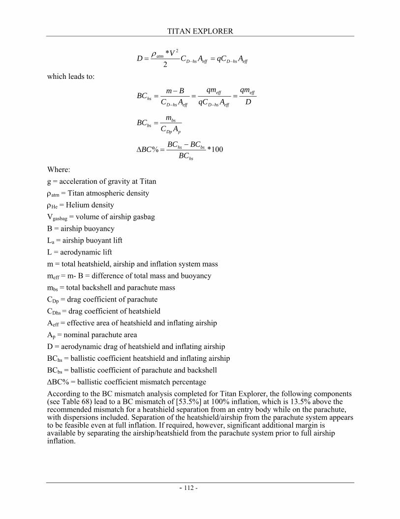
TITAN EXPLORER
- 112 -
effhsDeffhsDatm AqCACVD −− ==
2* 2ρ
which leads to:
D
qmAqC
qmACBmBC eff
effhsD
eff
effhsDhs ==
−=
−−
pDp
bsbs AC
mBC =
100*%hs
bshs
BCBCBCBC −
=∆
Where: g = acceleration of gravity at Titan ρatm = Titan atmospheric density
ρHe = Helium density Vgasbag = volume of airship gasbag B = airship buoyancy La = airship buoyant lift L = aerodynamic lift m = total heatshield, airship and inflation system mass meff = m- B = difference of total mass and buoyancy mbs = total backshell and parachute mass CDp = drag coefficient of parachute CDhs = drag coefficient of heatshield Aeff = effective area of heatshield and inflating airship Ap = nominal parachute area D = aerodynamic drag of heatshield and inflating airship BChs = ballistic coefficient heatshield and inflating airship BCbs = ballistic coefficient of parachute and backshell ∆BC% = ballistic coefficient mismatch percentage According to the BC mismatch analysis completed for Titan Explorer, the following components (see Table 68) lead to a BC mismatch of [53.5%] at 100% inflation, which is 13.5% above the recommended mismatch for a heatshield separation from an entry body while on the parachute, with dispersions included. Separation of the heatshield/airship from the parachute system appears to be feasible even at full inflation. If required, however, significant additional margin is available by separating the airship/heatshield from the parachute system prior to full airship inflation.
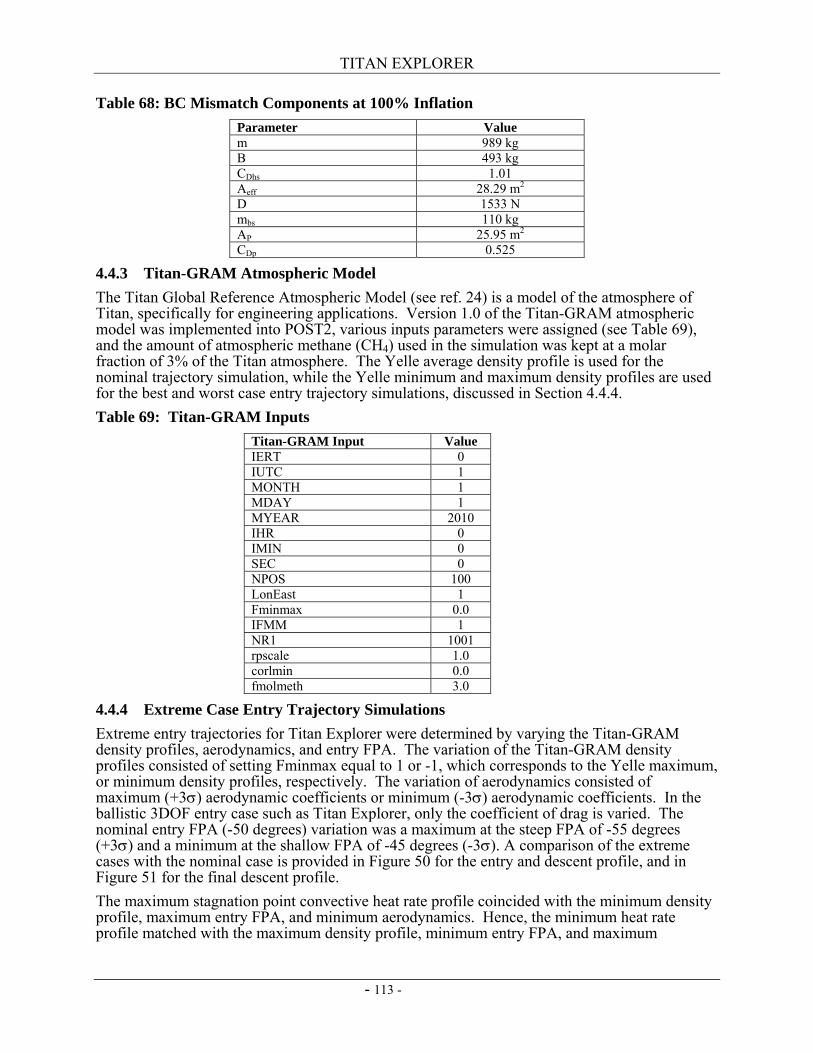
TITAN EXPLORER
- 113 -
Table 68: BC Mismatch Components at 100% Inflation Parameter Value m 989 kg B 493 kg CDhs 1.01 Aeff 28.29 m2 D 1533 N mbs 110 kg AP 25.95 m2
CDp 0.525
4.4.3 Titan-GRAM Atmospheric Model The Titan Global Reference Atmospheric Model (see ref. 24) is a model of the atmosphere of Titan, specifically for engineering applications. Version 1.0 of the Titan-GRAM atmospheric model was implemented into POST2, various inputs parameters were assigned (see Table 69), and the amount of atmospheric methane (CH4) used in the simulation was kept at a molar fraction of 3% of the Titan atmosphere. The Yelle average density profile is used for the nominal trajectory simulation, while the Yelle minimum and maximum density profiles are used for the best and worst case entry trajectory simulations, discussed in Section 4.4.4. Table 69: Titan-GRAM Inputs
Titan-GRAM Input Value IERT 0 IUTC 1 MONTH 1 MDAY 1 MYEAR 2010 IHR 0 IMIN 0 SEC 0 NPOS 100 LonEast 1 Fminmax 0.0 IFMM 1 NR1 1001 rpscale 1.0 corlmin 0.0 fmolmeth 3.0
4.4.4 Extreme Case Entry Trajectory Simulations Extreme entry trajectories for Titan Explorer were determined by varying the Titan-GRAM density profiles, aerodynamics, and entry FPA. The variation of the Titan-GRAM density profiles consisted of setting Fminmax equal to 1 or -1, which corresponds to the Yelle maximum, or minimum density profiles, respectively. The variation of aerodynamics consisted of maximum (+3σ) aerodynamic coefficients or minimum (-3σ) aerodynamic coefficients. In the ballistic 3DOF entry case such as Titan Explorer, only the coefficient of drag is varied. The nominal entry FPA (-50 degrees) variation was a maximum at the steep FPA of -55 degrees (+3σ) and a minimum at the shallow FPA of -45 degrees (-3σ). A comparison of the extreme cases with the nominal case is provided in Figure 50 for the entry and descent profile, and in Figure 51 for the final descent profile. The maximum stagnation point convective heat rate profile coincided with the minimum density profile, maximum entry FPA, and minimum aerodynamics. Hence, the minimum heat rate profile matched with the maximum density profile, minimum entry FPA, and maximum
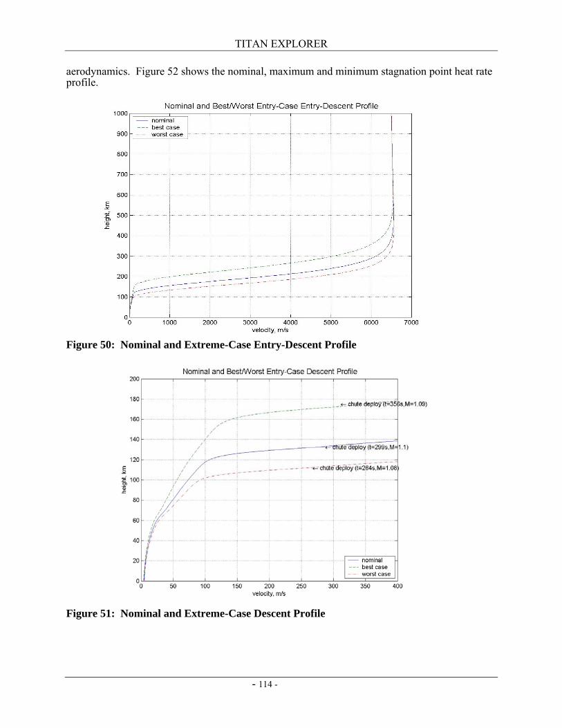
TITAN EXPLORER
- 114 -
aerodynamics. Figure 52 shows the nominal, maximum and minimum stagnation point heat rate profile.
Figure 50: Nominal and Extreme-Case Entry-Descent Profile
Figure 51: Nominal and Extreme-Case Descent Profile
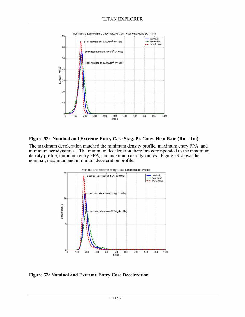
TITAN EXPLORER
- 115 -
Figure 52: Nominal and Extreme-Entry Case Stag. Pt. Conv. Heat Rate (Rn = 1m) The maximum deceleration matched the minimum density profile, maximum entry FPA, and minimum aerodynamics. The minimum deceleration therefore corresponded to the maximum density profile, minimum entry FPA, and maximum aerodynamics. Figure 53 shows the nominal, maximum and minimum deceleration profile.
Figure 53: Nominal and Extreme-Entry Case Deceleration
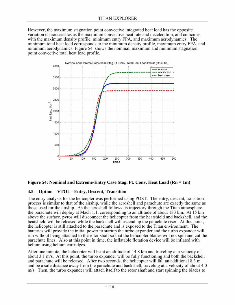
TITAN EXPLORER
- 116 -
However, the maximum stagnation point convective integrated heat load has the opposite variation characteristics as the maximum convective heat rate and deceleration, and coincides with the maximum density profile, minimum entry FPA, and maximum aerodynamics. The minimum total heat load corresponds to the minimum density profile, maximum entry FPA, and minimum aerodynamics. Figure 54 shows the nominal, maximum and minimum stagnation point convective total heat load profile.
Figure 54: Nominal and Extreme-Entry Case Stag. Pt. Conv. Heat Load (Rn = 1m)
4.5 Option – VTOL - Entry, Descent, Transition The entry analysis for the helicopter was performed using POST. The entry, descent, transition process is similar to that of the airship, while the aeroshell and parachute are exactly the same as those used for the airship. As the aeroshell follows its trajectory through the Titan atmosphere, the parachute will deploy at Mach 1.1, corresponding to an altitude of about 133 km. At 15 km above the surface, pyros will disconnect the helicopter from the heatshield and backshell, and the heatshield will be released while the backshell will ascend up the parachute riser. At this point, the helicopter is still attached to the parachute and is exposed to the Titan environment. The batteries will provide the initial power to startup the turbo expander and the turbo expander will run without being attached to the rotor shaft so that the helicopter blades will not spin and cut the parachute lines. Also at this point in time, the inflatable flotation device will be inflated with helium using helium cartridges. After one minute, the helicopter will be at an altitude of 14.8 km and traveling at a velocity of about 3.1 m/s. At this point, the turbo expander will be fully functioning and both the backshell and parachute will be released. After two seconds, the helicopter will fall an additional 8.3 m and be a safe distance away from the parachute and backshell, traveling at a velocity of about 4.0 m/s. Then, the turbo expander will attach itself to the rotor shaft and start spinning the blades to
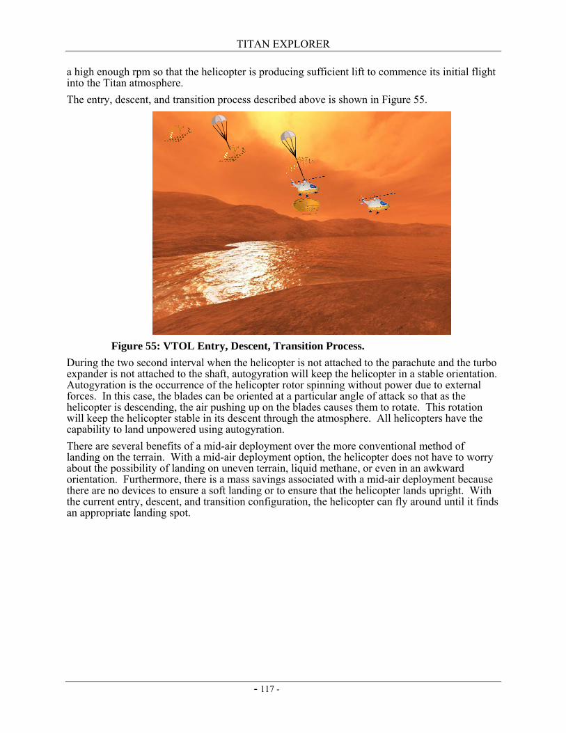
TITAN EXPLORER
- 117 -
a high enough rpm so that the helicopter is producing sufficient lift to commence its initial flight into the Titan atmosphere. The entry, descent, and transition process described above is shown in Figure 55.
During the two second interval when the helicopter is not attached to the parachute and the turbo expander is not attached to the shaft, autogyration will keep the helicopter in a stable orientation. Autogyration is the occurrence of the helicopter rotor spinning without power due to external forces. In this case, the blades can be oriented at a particular angle of attack so that as the helicopter is descending, the air pushing up on the blades causes them to rotate. This rotation will keep the helicopter stable in its descent through the atmosphere. All helicopters have the capability to land unpowered using autogyration. There are several benefits of a mid-air deployment over the more conventional method of landing on the terrain. With a mid-air deployment option, the helicopter does not have to worry about the possibility of landing on uneven terrain, liquid methane, or even in an awkward orientation. Furthermore, there is a mass savings associated with a mid-air deployment because there are no devices to ensure a soft landing or to ensure that the helicopter lands upright. With the current entry, descent, and transition configuration, the helicopter can fly around until it finds an appropriate landing spot.
Figure 55: VTOL Entry, Descent, Transition Process.

TITAN EXPLORER
- 118 -
This page intentionally left blank
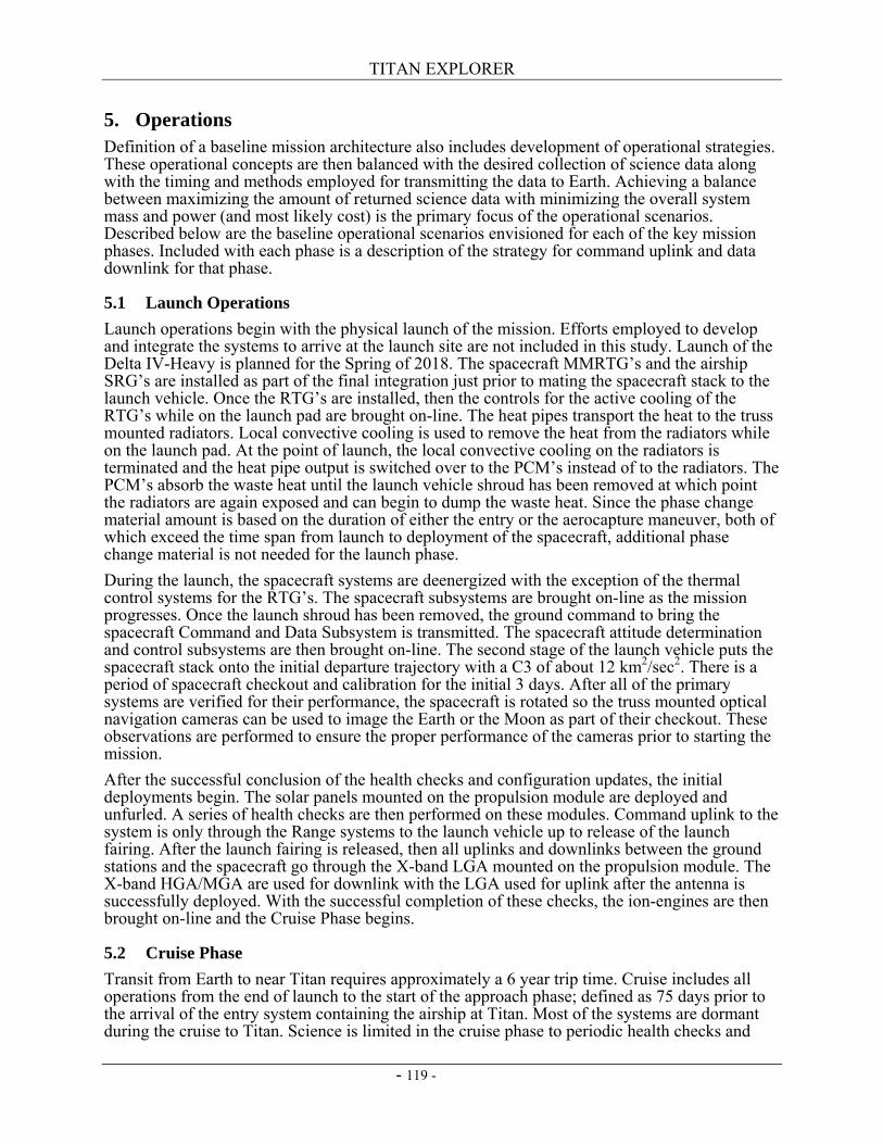
TITAN EXPLORER
- 119 -
5. Operations Definition of a baseline mission architecture also includes development of operational strategies. These operational concepts are then balanced with the desired collection of science data along with the timing and methods employed for transmitting the data to Earth. Achieving a balance between maximizing the amount of returned science data with minimizing the overall system mass and power (and most likely cost) is the primary focus of the operational scenarios. Described below are the baseline operational scenarios envisioned for each of the key mission phases. Included with each phase is a description of the strategy for command uplink and data downlink for that phase.
5.1 Launch Operations Launch operations begin with the physical launch of the mission. Efforts employed to develop and integrate the systems to arrive at the launch site are not included in this study. Launch of the Delta IV-Heavy is planned for the Spring of 2018. The spacecraft MMRTG’s and the airship SRG’s are installed as part of the final integration just prior to mating the spacecraft stack to the launch vehicle. Once the RTG’s are installed, then the controls for the active cooling of the RTG’s while on the launch pad are brought on-line. The heat pipes transport the heat to the truss mounted radiators. Local convective cooling is used to remove the heat from the radiators while on the launch pad. At the point of launch, the local convective cooling on the radiators is terminated and the heat pipe output is switched over to the PCM’s instead of to the radiators. The PCM’s absorb the waste heat until the launch vehicle shroud has been removed at which point the radiators are again exposed and can begin to dump the waste heat. Since the phase change material amount is based on the duration of either the entry or the aerocapture maneuver, both of which exceed the time span from launch to deployment of the spacecraft, additional phase change material is not needed for the launch phase. During the launch, the spacecraft systems are deenergized with the exception of the thermal control systems for the RTG’s. The spacecraft subsystems are brought on-line as the mission progresses. Once the launch shroud has been removed, the ground command to bring the spacecraft Command and Data Subsystem is transmitted. The spacecraft attitude determination and control subsystems are then brought on-line. The second stage of the launch vehicle puts the spacecraft stack onto the initial departure trajectory with a C3 of about 12 km2/sec2. There is a period of spacecraft checkout and calibration for the initial 3 days. After all of the primary systems are verified for their performance, the spacecraft is rotated so the truss mounted optical navigation cameras can be used to image the Earth or the Moon as part of their checkout. These observations are performed to ensure the proper performance of the cameras prior to starting the mission. After the successful conclusion of the health checks and configuration updates, the initial deployments begin. The solar panels mounted on the propulsion module are deployed and unfurled. A series of health checks are then performed on these modules. Command uplink to the system is only through the Range systems to the launch vehicle up to release of the launch fairing. After the launch fairing is released, then all uplinks and downlinks between the ground stations and the spacecraft go through the X-band LGA mounted on the propulsion module. The X-band HGA/MGA are used for downlink with the LGA used for uplink after the antenna is successfully deployed. With the successful completion of these checks, the ion-engines are then brought on-line and the Cruise Phase begins.
5.2 Cruise Phase Transit from Earth to near Titan requires approximately a 6 year trip time. Cruise includes all operations from the end of launch to the start of the approach phase; defined as 75 days prior to the arrival of the entry system containing the airship at Titan. Most of the systems are dormant during the cruise to Titan. Science is limited in the cruise phase to periodic health checks and
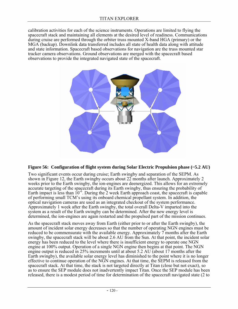
TITAN EXPLORER
- 120 -
calibration activities for each of the science instruments. Operations are limited to flying the spacecraft stack and maintaining all elements at the desired level of readiness. Communications during cruise are performed through the orbiter truss mounted X-band HGA (primary) or the MGA (backup). Downlink data transferred includes all state of health data along with attitude and state information. Spacecraft based observations for navigation are the truss mounted star tracker camera observations. Ground observations are merged with the spacecraft based observations to provide the integrated navigated state of the spacecraft.
Figure 56: Configuration of flight system during Solar Electric Propulsion phase (~5.2 AU) Two significant events occur during cruise; Earth swingby and separation of the SEPM. As shown in Figure 12, the Earth swingby occurs about 22 months after launch. Approximately 2 weeks prior to the Earth swingby, the ion-engines are deenergized. This allows for an extremely accurate targeting of the spacecraft during its Earth swingby, thus ensuring the probability of Earth impact is less than 10-6. During the 2 week Earth approach coast, the spacecraft is capable of performing small TCM’s using its onboard chemical propellant system. In addition, the optical navigation cameras are used as an integrated checkout of the system performance. Approximately 1 week after the Earth swingby, the total overall Delta-V imparted into the system as a result of the Earth swingby can be determined. After the new energy level is determined, the ion-engines are again restarted and the propulsed part of the mission continues. As the spacecraft stack moves away from Earth (either prior to or after the Earth swingby), the amount of incident solar energy decreases so that the number of operating NGN engines must be reduced to be commensurate with the available energy. Approximately 7 months after the Earth swingby, the spacecraft stack will be about 2.6 AU from the Sun. At that point, the incident solar energy has been reduced to the level where there is insufficient energy to operate one NGN engine at 100% output. Operation of a single NGN engine then begins at that point. The NGN engine output is reduced in 25% increments until at about 5.2 AU (about 17 months after the Earth swingby), the available solar energy level has diminished to the point where it is no longer effective to continue operation of the NGN engines. At that time, the SEPM is released from the spacecraft stack. At that time, the stack is not targeted directly at Titan (close but not exact), so as to ensure the SEP module does not inadvertently impact Titan. Once the SEP module has been released, there is a modest period of time for determination of the spacecraft navigated state (2 to
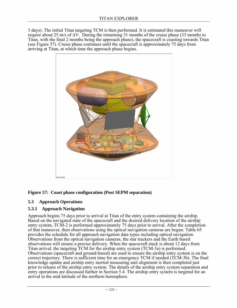
TITAN EXPLORER
- 121 -
3 days). The initial Titan targeting TCM is then performed. It is estimated this maneuver will require about 25 m/s of ∆V. During the remaining 31 months of the cruise phase (33 months to Titan, with the final 2 months being the approach phase), the spacecraft is coasting towards Titan (see Figure 57). Cruise phase continues until the spacecraft is approximately 75 days from arriving at Titan, at which time the approach phase begins.
Figure 57: Coast phase configuration (Post SEPM separation)
5.3 Approach Operations 5.3.1 Approach Navigation Approach begins 75 days prior to arrival at Titan of the entry system containing the airship. Based on the navigated state of the spacecraft and the desired delivery location of the airship entry system, TCM-2 is performed approximately 75 days prior to arrival. After the completion of that maneuver, then observations using the optical navigation cameras are begun. Table 65 provides the schedule for all approach navigation data types including optical navigation. Observations from the optical navigation cameras, the star trackers and the Earth based observations will ensure a precise delivery. When the spacecraft stack is about 12 days from Titan arrival, the targeting TCM for the airship entry system (TCM-3a) is performed. Observations (spacecraft and ground-based) are used to ensure the airship entry system is on the correct trajectory. There is sufficient time for an emergency TCM if needed (TCM-3b). The final knowledge update and airship entry inertial measuring unit alignment is then completed just prior to release of the airship entry system. The details of the airship entry system separation and entry operations are discussed further in Section 5.4. The airship entry system is targeted for an arrival in the mid-latitude of the northern hemisphere.
TITAN EXPLORER
- 122 -
5.3.2 Orbiter Coasting After successful separation of the airship entry system, the orbiter system performs a preplanned maneuver, TCM-4, to revise its trajectory to no longer be on a direct entry trajectory. This preplanned maneuver also serves to delay the arrival of the orbiter so it can serve as the critical events relay platform for the airship entry system. Optical navigation measurements are continued to be made and sent to Earth to aid in precise orbiter navigation. Approximately 3 days prior to the orbiter arriving at its aerocapture entry point, a final targeting maneuver, TCM-5, is performed. This maneuver serves as the final aerocapture targeting maneuver. Time is available for a final emergency TCM about 1 day prior to aerocapture arrival. At about 5 hours prior to the start of the aerocapture maneuver, the airship entry system begins its entry into the atmosphere of Titan. This 5 hour separation corresponds to a separation distance between the airship entry system and the orbiter of 110,000 km. The UHF antenna mounted on the orbiter truss is used to receive the airship entry system critical events data. This data is collected and stored on-board the orbiter for eventual relay to Earth. After receiving the indication of a successful airship deployment and mission start, the HGA mounted on the orbiter truss is turned towards Earth so that the carrier tone signal indicating successful airship deployment can be transmitted. After transmitting that signal for 10 minutes continuously, the orbiter is rotated into its final inertial position for performing the aerocapture maneuver. The arrival at Titan is a direct Titan Orbit Insertion (TOI) (there is no Saturn orbit insertion occurring prior to TOI). Titan’s north pole is targeted in order to place the spacecraft into a polar orbit.
5.4 Entry Operations 5.4.1 Airship Entry System – Direct Entry The airship entry system performs a direct, ballistic entry, into the atmosphere of Titan. A heritage approach blending the extensive Mars entry experience with the Huygens entry experience and the Cassini observational data provides a simple strategy for a robust entry solution. The entry phase for the airship begins about 1 hour prior to separation from the orbiter spacecraft and concludes with the successful inflation of the airship envelope so as to achieve neutral buoyancy and a clean separation from the rest of the entry system elements. TCM-3a is performed about 12 days prior to arrival at Titan in order to put the airship entry system on its proper entry trajectory. Airship systems are energized 4 hours prior to separation to allow sufficient time for all devices to become operational and perform all built-in testing and transfer their final state to the orbiter for eventual relay to Earth. The final knowledge state and airship IMU alignment is completed 1 hour prior to release. The orbiter then realigns the spacecraft stack so the airship entry system is at the proper inertial attitude for entry into the atmosphere of Titan. At 5 minutes prior to separation all final power and data cables between the airship and the orbiter CDS’ are severed. The orbiter CDS commands the release pyros to fire at the proper time. Springs mounted on the truss impart a small delta-V (50 mm/sec) differential speed into the system to ensure separation of the two truss structures. The airship entry system with its own truss is separated from the orbiter and its own truss. At 15 minutes after separation, a cold-gas system mounted in the airship aeroshell with small penetrations is used to spin-up the aeroshell to the proper entry rotational rate of 2 RPM. This system requires about 0.2 kg of gaseous nitrogen to be expended to achieve the desired spin rate. The airship entry system then puts all operating systems into a stand-by mode for the coast to Titan. When the airship entry system is 6 hours from reaching Titan, all systems are brought on-line and a status and health check is performed. The results of this check are relayed to the trailing orbiter via the aeroshell mounted UHF patch antenna. At 15 minutes prior to atmospheric interface, the airship thermal control system shifts thermal management of the SRG’s heat pipes from the truss mounted radiators to the aeroshell internally mounted PCM’s. Once that switch is completed, the heat pipes going to the truss heat pipes are isolated and severed. All cables to the truss mounted devices are also cut. Pyrotechnically actuated separation nuts are used to cut away
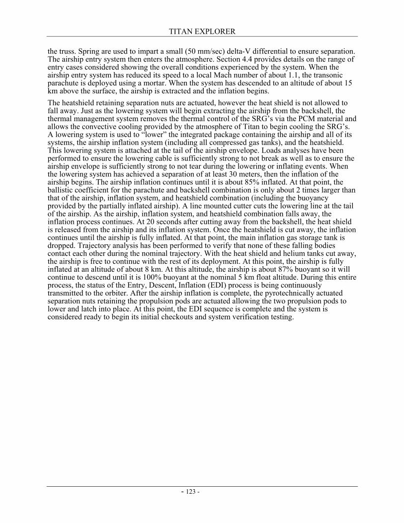
TITAN EXPLORER
- 123 -
the truss. Spring are used to impart a small (50 mm/sec) delta-V differential to ensure separation. The airship entry system then enters the atmosphere. Section 4.4 provides details on the range of entry cases considered showing the overall conditions experienced by the system. When the airship entry system has reduced its speed to a local Mach number of about 1.1, the transonic parachute is deployed using a mortar. When the system has descended to an altitude of about 15 km above the surface, the airship is extracted and the inflation begins. The heatshield retaining separation nuts are actuated, however the heat shield is not allowed to fall away. Just as the lowering system will begin extracting the airship from the backshell, the thermal management system removes the thermal control of the SRG’s via the PCM material and allows the convective cooling provided by the atmosphere of Titan to begin cooling the SRG’s. A lowering system is used to “lower” the integrated package containing the airship and all of its systems, the airship inflation system (including all compressed gas tanks), and the heatshield. This lowering system is attached at the tail of the airship envelope. Loads analyses have been performed to ensure the lowering cable is sufficiently strong to not break as well as to ensure the airship envelope is sufficiently strong to not tear during the lowering or inflating events. When the lowering system has achieved a separation of at least 30 meters, then the inflation of the airship begins. The airship inflation continues until it is about 85% inflated. At that point, the ballistic coefficient for the parachute and backshell combination is only about 2 times larger than that of the airship, inflation system, and heatshield combination (including the buoyancy provided by the partially inflated airship). A line mounted cutter cuts the lowering line at the tail of the airship. As the airship, inflation system, and heatshield combination falls away, the inflation process continues. At 20 seconds after cutting away from the backshell, the heat shield is released from the airship and its inflation system. Once the heatshield is cut away, the inflation continues until the airship is fully inflated. At that point, the main inflation gas storage tank is dropped. Trajectory analysis has been performed to verify that none of these falling bodies contact each other during the nominal trajectory. With the heat shield and helium tanks cut away, the airship is free to continue with the rest of its deployment. At this point, the airship is fully inflated at an altitude of about 8 km. At this altitude, the airship is about 87% buoyant so it will continue to descend until it is 100% buoyant at the nominal 5 km float altitude. During this entire process, the status of the Entry, Descent, Inflation (EDI) process is being continuously transmitted to the orbiter. After the airship inflation is complete, the pyrotechnically actuated separation nuts retaining the propulsion pods are actuated allowing the two propulsion pods to lower and latch into place. At this point, the EDI sequence is complete and the system is considered ready to begin its initial checkouts and system verification testing.
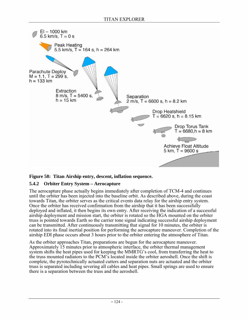
TITAN EXPLORER
- 124 -
Figure 58: Titan Airship entry, descent, inflation sequence. 5.4.2 Orbiter Entry System – Aerocapture The aerocapture phase actually begins immediately after completion of TCM-4 and continues until the orbiter has been injected into the baseline orbit. As described above, during the coast towards Titan, the orbiter serves as the critical events data relay for the airship entry system. Once the orbiter has received confirmation from the airship that it has been successfully deployed and inflated, it then begins its own entry. After receiving the indication of a successful airship deployment and mission start, the orbiter is rotated so the HGA mounted on the orbiter truss is pointed towards Earth so the carrier tone signal indicating successful airship deployment can be transmitted. After continuously transmitting that signal for 10 minutes, the orbiter is rotated into its final inertial position for performing the aerocapture maneuver. Completion of the airship EDI phase occurs about 3 hours prior to the orbiter entering the atmosphere of Titan. As the orbiter approaches Titan, preparations are begun for the aerocapture maneuver. Approximately 15 minutes prior to atmospheric interface, the orbiter thermal management system shifts the heat pipes used for keeping the MMRTG’s cool, from transferring the heat to the truss mounted radiators to the PCM’s located inside the orbiter aeroshell. Once the shift is complete, the pyrotechnically actuated cutters and separation nuts are actuated and the orbiter truss is separated including severing all cables and heat pipes. Small springs are used to ensure there is a separation between the truss and the aeroshell.
TITAN EXPLORER
- 125 -
5.4.3 Exit Phase Previous studies have provided extensive results regarding the ability of the aerocapture strategy to successfully capture the orbiter into an orbit around Titan (ref. 43). The HYPAS algorithm coupled with the propagated state information from the IMU provide a means to predict when the atmospheric exit occurs. When the orbiter inside the aeroshell has determined it has exited the atmosphere, then a timer is started. From the time the orbiter predicts it is at the atmospheric exit point, it will initiate transmission of the tone signal to Earth of its successful drag pass through an aeroshell mounted LGA. This tone will continue up to the point where the aeroshell extraction begins. At the time of Exit +10 minutes, the orbiter heat shield is released. Springs contained within the heat shield release mechanism are used to impart a 100 mm/s Delta-V into the heat shield to ensure positive separation. After a period of 2 minutes, the heat shield will have moved about 12 meters away from the backshell. The pyrotechnically actuated separation nuts used to retain the orbiter within the aeroshell are then activated so the orbiter is released from the backshell. There are 6 attachment points between the orbiter and the backshell. These are released in clusters of 3 and 3. When the final set of separation nuts are actuated, then springs are again used to impart a differential Delta-V of 50 mm/s between the orbiter and the backshell. Given the significantly larger masses and smaller clearances of the orbiter and backshell, a lower separation speed is desirable. It will require at least 13 seconds for the orbiter to be extracted from the backshell. After successful extraction from the backshell, the components remain in their quasi-steady state for a period of 15 minutes. During this time, the orbiter is under 3-axis control and if it determines minor stability maneuvers are required, they are performed. Once the extraction is complete, the orbiter will switch to one of its antennas to continue transmitting the critical event tones. Once the orbiter has been extracted from the backshell, the MMRTG cooling is then performed via the orbiter mounted radiators instead of through the PCM in the backshell. At the conclusion of the 15 minute waiting period, the heatshield separation distance is about 100 meters while the clearance between the backshell and the orbiter is about 50 meters. At this time, the orbiter performs a small 1 m/s maneuver to increase the separation rate. The elements then continue coasting. When the orbiter reaches the apoapsis of the aerocapture drag pass, the orbiter performs the periapsis raise maneuver. It has been found via the simulation analysis, that this maneuver has a magnitude of about 100 m/s. This crucial maneuver ensures the orbiter will not reenter the atmosphere of Titan. Approximately 2.5 hours later, the orbiter will be near the final orbital altitude. At that time, the circularization maneuver is performed to put the orbiter into its final 1700 km altitude circular orbit. This maneuver requires about 80 m/s of delta-V. At this point, the orbiter will turn its X-Band HGA towards Earth and transmit the initial navigation data set. The spacecraft navigated state will be transmitted back to the spacecraft so it can then switch from IMU only navigation to its baseline stellar observation navigation strategy. At the conclusion of this change in navigation strategy, the orbiter will initiate the playback of the entire Aerocapture maneuver including all of the critical events data from the airship entry.
5.5 Orbital Operations The orbiter operations are divided into three categories; initial checkout (of both the orbiter and the airship), operations during the airship mission, and operations after the airship has completed its mission. The initial checkout period is anticipated to require at least one week. The baseline airship mission is anticipated to be 4 months in duration. The orbiter is operated for about 3 years after completion of the airship mission phase (3.3 years after the aerocapture maneuver). Details of each category are described below. 5.5.1 Initial Checkout Immediately after performing the circularization maneuver, the checkout period begins. This phase consists of energizing each of the main subsystems and science instruments and verifying their proper operation. Two science instruments (magnetometer and solar occultation) can be
TITAN EXPLORER
- 126 -
only partially verified until they are in the final operational configuration. In addition, during this period, the various navigation observations are provided and evaluated to improve the accuracy of the orbiter ephemeris. The predicted positions of the orbiter and the airship based on the pre arrival states coupled with the use of the airship UHF omni-directional antenna and the orbiter UHF MGA provide sufficient margin to allow for early communication between both vehicles. The arrival timing is established so that the orbiter can see the airship for at least 3 passes prior to the periods of non-communication to allow for: 1) a playback of the airship engineering data collected during entry, 2) return of the initial checkout and vehicle health status, 3) return of the initial science data, and 4) to provide a navigation state update to the airship. The checkout period continues until the orbiter finds the airship on the other side of Titan. At this point, the orbiter’s ephemeris will have significantly improved. Also during this phase, any orbital cleanup maneuvers needed to achieve the desired science orbit are also performed. Once the orbiter has completed the second set of communication passes with the airship, then normal orbital operations commences. 5.5.2 Orbiter Operations – Airship Active Orbiter operations focus during the life of the airship are split between collecting and returning the data from the airship and performing orbiter science. The intended orbit about Titan is illustrated in Figure 59. Early operation of the orbiter’s radar is limited to performance operation checkout and to provide the initial data set used for calibration and validation of the science models. After receipt of this early data, the radar use will be curtailed until after the airship operations phase is complete. Deployment of the magnetometer boom will not occur until after completion of the airship operational period. This strategy is needed to prevent any inadvertent issues with the boom deployment interfering with return of the data from the airship.
Figure 59: Rendering of the orbit about Titan (100 degree inclination circular 1700 km altitude). Airship operational baseline is a 4 month flight period, which corresponds to eight orbits of Titan about Saturn. With a 5.2 hour period for the orbiter, then the airship operational period equates to about 620 orbits of the orbiter about Titan. The orbiter can communicate with the airship for 14 consecutive orbits before Titan precesses beneath the orbiter. Anywhere from 3.5 to 6.2 days later, the orbiter again can communicate with the airship (see Figure 60). During each communication opportunity (14 consecutive orbits), the first 5 orbits are used for mission status updates from the Airship and navigated state updates from the Orbiter. The middle 4 orbits are
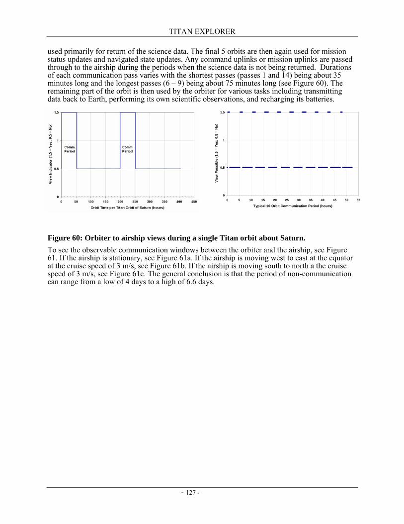
TITAN EXPLORER
- 127 -
0
0.5
1
1.5
0 5 10 15 20 25 30 35 40 45 50 55
Typical 10 Orbit Communication Period (hours)
View
Pos
sibl
e (1
.5 =
Yes
; 0.5
= N
o)
used primarily for return of the science data. The final 5 orbits are then again used for mission status updates and navigated state updates. Any command uplinks or mission uplinks are passed through to the airship during the periods when the science data is not being returned. Durations of each communication pass varies with the shortest passes (passes 1 and 14) being about 35 minutes long and the longest passes (6 – 9) being about 75 minutes long (see Figure 60). The remaining part of the orbit is then used by the orbiter for various tasks including transmitting data back to Earth, performing its own scientific observations, and recharging its batteries.
Figure 60: Orbiter to airship views during a single Titan orbit about Saturn. To see the observable communication windows between the orbiter and the airship, see Figure 61. If the airship is stationary, see Figure 61a. If the airship is moving west to east at the equator at the cruise speed of 3 m/s, see Figure 61b. If the airship is moving south to north a the cruise speed of 3 m/s, see Figure 61c. The general conclusion is that the period of non-communication can range from a low of 4 days to a high of 6.6 days.
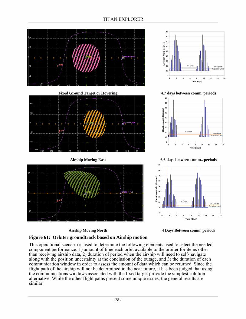
TITAN EXPLORER
- 128 -
Fixed Ground Target or Hovering 4.7 days between comm. periods
Airship Moving East 6.6 days between comm.. periods
Airship Moving North 4 Days Between comm. periods
Figure 61: Orbiter groundtrack based on Airship motion This operational scenario is used to determine the following elements used to select the needed component performance: 1) amount of time each orbit available to the orbiter for items other than receiving airship data, 2) duration of period when the airship will need to self-navigate along with the position uncertainty at the conclusion of the outage, and 3) the duration of each communication window in order to assess the amount of data which can be returned. Since the flight path of the airship will not be determined in the near future, it has been judged that using the communications windows associated with the fixed target provide the simplest solution alternative. While the other flight paths present some unique issues, the general results are similar.
0
10
20
30
40
50
60
70
80
90
0 2 4 6 8 10 12 14 16
Time (days)
Elev
atio
n A
ngle
(deg
rees
)
15 degree Elevation Limit
4.7 Days
0
10
20
30
40
50
60
70
80
90
0 2 4 6 8 10 12 14 16
Time (days)
Elev
atio
n A
ngle
(deg
rees
)
15 DegreeElevation Limit
6.6 Days
0
10
20
30
40
50
60
70
80
90
0 2 4 6 8 10 12 14 16
Time (days)
Elev
atio
n A
ngle
(deg
rees
)
15 DegreeElevation Limit
4 Days
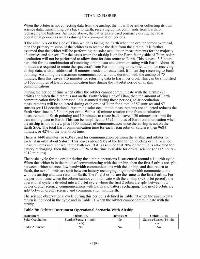
TITAN EXPLORER
- 129 -
When the orbiter is not collecting data from the airship, then it will be either collecting its own science data, transmitting data back to Earth, receiving uplink commands from Earth, or recharging the batteries. As noted above, the batteries are used primarily during the radar operational periods as well as during the communication periods. If the airship is on the side of Titan which is facing the Earth when the orbiter comes overhead, then the primary mission of the orbiter is to receive the data from the airship. It is further assumed that the orbiter will be performing the solar occultation measurements for the majority of sunrises and sunsets. For the cases when the airship is on the Earth facing side of Titan, solar occultation will not be performed to allow time for data return to Earth. This leaves ~3.5 hours per orbit for the combination of receiving airship data and communicating with Earth. About 10 minutes are required to rotate the spacecraft from Earth pointing to the orientation for receiving airship data, with an additional 10 minutes needed to rotate back from airship receiving to Earth pointing. Assuming the maximum communication window duration with the airship of 75 minutes, then this leaves 115 minutes for returning data to Earth per orbit. This can be simplified to 1600 minutes of Earth communication time during the 14 orbit period of airship communications. During the period of time when either the orbiter cannot communicate with the airship (28 orbits) and when the airship is not on the Earth facing side of Titan, then the amount of Earth communication time is increased. It is assumed during those periods, solar occultation measurements will be collected during each orbit of Titan for a total of 57 sunrises and 57 sunsets (or 114 occultations). Assuming solar occultation measurements are collected reduces the Earth view time to 2.5 hours per orbit. With a 10 minute rotation time from occultation measurement to Earth pointing and 10 minutes to rotate back, leaves 130 minutes per orbit for transmitting data to Earth. This can be simplified to 3692 minutes of Earth communication when the airship is not in view plus 1300 minutes of communication since the airship is not on the Earth Side. The total Earth communication time for each Titan orbit of Saturn is then 9684 minutes, or 42% of the total orbit time. There is 1440 minutes (or 6.3%) used for communication between the airship and orbiter for each Titan orbit about Saturn. This leaves about 50% of the life for conducting orbital science measurements and recharging the batteries. If it is assumed that 20% of the time is allocated for battery recharging, then this leaves ~30% of the time available for orbital science (or 115 hours – 6912 minutes). The basic cycle for the orbiter during the airship operations is structured around a 14 orbit cycle. When the orbiter is in the mode of communicating with the airship, then the first 5 orbits are split between orbiter science, low bandwidth communications with the airship, and data return to Earth, the next 4 orbits are split between battery recharging, high bandwidth communications with the airship and data return to Earth. The final 5 orbits are the same as the first 5 orbits. For the period of time when the orbiter cannot communicate with the airship (~28 orbit period), the operational cycle is divided into a 7 orbit cycle where the first 2 orbits are split between low power orbiter science, communications with Earth and battery recharging. The next 5 orbits are split between orbiter science and communication with Earth. The science observational cycle during this period is defined in Table 70 when the airship data return is included in the cycle and in Table 71 when the orbiter cannot communicate with the airship. Table 70: Orbiter Instrument Operational Scenario-With Airship Instrument Orbits 1-5 Orbits 6-9 Orbits 10-14 Solar Occultation Sunrise/Sunset (14 min.
each) No Sunrise/Sunset (14 min.
each) Radar Altimeter No No No
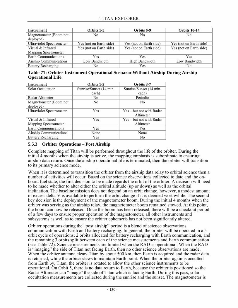
TITAN EXPLORER
- 130 -
Instrument Orbits 1-5 Orbits 6-9 Orbits 10-14 Magnetometer (Boom not deployed)
No No No
Ultraviolet Spectrometer Yes (not on Earth side) Yes (not on Earth side) Yes (not on Earth side) Visual & Infrared Mapping Spectrometer
Yes (not on Earth side) Yes (not on Earth side) Yes (not on Earth side)
Earth Communications Yes Yes Yes Airship Communications Low Bandwidth High Bandwidth Low Bandwidth Battery Recharging No Yes No
Table 71: Orbiter Instrument Operational Scenario-Without Airship During Airship Operational Life Instrument Orbits 1-2 Orbits 3-7 Solar Occultation Sunrise/Sunset (14 min.
each) Sunrise/Sunset (14 min.
each) Radar Altimeter No Periodic Magnetometer (Boom not deployed)
No No
Ultraviolet Spectrometer Yes Yes – but not with Radar Altimeter
Visual & Infrared Mapping Spectrometer
Yes Yes – but not with Radar Altimeter
Earth Communications Yes Yes Airship Communications None None Battery Recharging Yes No
5.5.3 Orbiter Operations – Post Airship Complete mapping of Titan will be performed throughout the life of the orbiter. During the initial 4 months when the airship is active, the mapping emphasis is subordinate to ensuring airship data return. Once the airship operational life is terminated, then the orbiter will transition to its primary science mode. When it is determined to transition the orbiter from the airship data relay to orbital science then a number of activities will occur. Based on the science observations collected to date and the on-board fuel state, the first decision to be made regards the orbit of the orbiter. A decision will need to be made whether to alter either the orbital altitude (up or down) as well as the orbital inclination. The baseline mission does not depend on an orbit change, however, a modest amount of excess delta-V is available to perform the orbit change if it is deemed worthwhile. The second key decision is the deployment of the magnetometer boom. During the initial 4 months when the orbiter was serving as the airship relay, the magnetometer boom remained stowed. At this point, the boom can now be released. Once the boom has been released, there will be a checkout period of a few days to ensure proper operation of the magnetometer, all other instruments and subsystems as well as to ensure the orbiter ephemeris has not been significantly altered. Orbiter operations during the “post airship” period is a blend of science observations, communication with Earth and battery recharging. In general, the orbiter will be operated in a 5 orbit cycle of operations; 2 orbits allocated for battery recharging with Earth communication, and the remaining 3 orbits split between each of the science measurements and Earth communication (see Table 72). Science measurements are limited when the RAD is operational. When the RAD is “imaging” the side of Titan not facing Earth, then no other science observations are made. When the orbiter antenna clears Titan by about 500 km, then Earth is acquired and the radar data is returned, while the orbiter slews to maintain Earth point. When the orbiter again is occulted from Earth by, Titan, the orbiter is rotated to allow the other science instruments to be operational. On Orbit 5, there is no data return to Earth, because the orbiter is positioned so the Radar Altimeter can “image” the side of Titan which is facing Earth. During this pass, solar occultation measurements are collected during the sunrise and the sunset. The magnetometer is
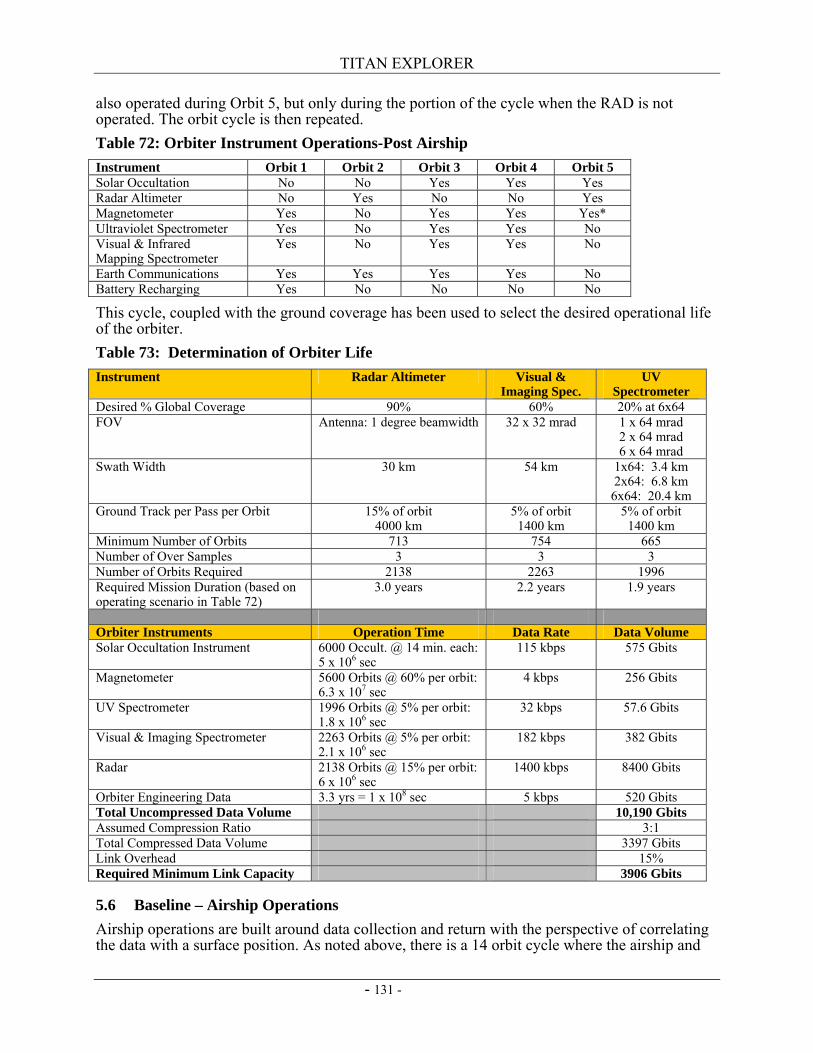
TITAN EXPLORER
- 131 -
also operated during Orbit 5, but only during the portion of the cycle when the RAD is not operated. The orbit cycle is then repeated. Table 72: Orbiter Instrument Operations-Post Airship Instrument Orbit 1 Orbit 2 Orbit 3 Orbit 4 Orbit 5 Solar Occultation No No Yes Yes Yes Radar Altimeter No Yes No No Yes Magnetometer Yes No Yes Yes Yes* Ultraviolet Spectrometer Yes No Yes Yes No Visual & Infrared Mapping Spectrometer
Yes No Yes Yes No
Earth Communications Yes Yes Yes Yes No Battery Recharging Yes No No No No
This cycle, coupled with the ground coverage has been used to select the desired operational life of the orbiter. Table 73: Determination of Orbiter Life Instrument Radar Altimeter Visual &
Imaging Spec. UV
Spectrometer Desired % Global Coverage 90% 60% 20% at 6x64 FOV Antenna: 1 degree beamwidth 32 x 32 mrad 1 x 64 mrad
2 x 64 mrad 6 x 64 mrad
Swath Width 30 km 54 km 1x64: 3.4 km 2x64: 6.8 km
6x64: 20.4 km Ground Track per Pass per Orbit 15% of orbit
4000 km 5% of orbit
1400 km 5% of orbit
1400 km Minimum Number of Orbits 713 754 665 Number of Over Samples 3 3 3 Number of Orbits Required 2138 2263 1996 Required Mission Duration (based on operating scenario in Table 72)
3.0 years 2.2 years 1.9 years
Orbiter Instruments Operation Time Data Rate Data Volume Solar Occultation Instrument 6000 Occult. @ 14 min. each:
5 x 10⁶ sec 115 kbps 575 Gbits
Magnetometer 5600 Orbits @ 60% per orbit: 6.3 x 10⁷ sec
4 kbps 256 Gbits
UV Spectrometer 1996 Orbits @ 5% per orbit: 1.8 x 10⁶ sec
32 kbps 57.6 Gbits
Visual & Imaging Spectrometer 2263 Orbits @ 5% per orbit: 2.1 x 10⁶ sec
182 kbps 382 Gbits
Radar 2138 Orbits @ 15% per orbit: 6 x 10⁶ sec
1400 kbps 8400 Gbits
Orbiter Engineering Data 3.3 yrs = 1 x 10⁸ sec 5 kbps 520 Gbits Total Uncompressed Data Volume 10,190 Gbits Assumed Compression Ratio 3:1 Total Compressed Data Volume 3397 Gbits Link Overhead 15% Required Minimum Link Capacity 3906 Gbits
5.6 Baseline – Airship Operations Airship operations are built around data collection and return with the perspective of correlating the data with a surface position. As noted above, there is a 14 orbit cycle where the airship and
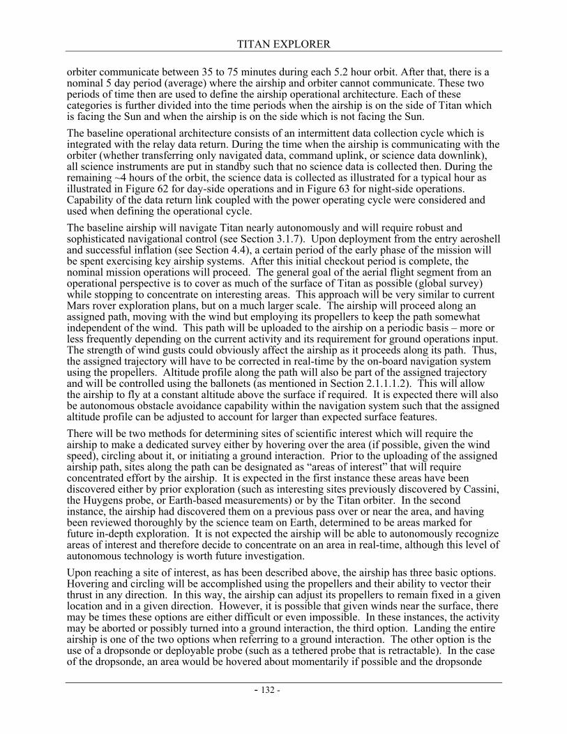
TITAN EXPLORER
- 132 -
orbiter communicate between 35 to 75 minutes during each 5.2 hour orbit. After that, there is a nominal 5 day period (average) where the airship and orbiter cannot communicate. These two periods of time then are used to define the airship operational architecture. Each of these categories is further divided into the time periods when the airship is on the side of Titan which is facing the Sun and when the airship is on the side which is not facing the Sun. The baseline operational architecture consists of an intermittent data collection cycle which is integrated with the relay data return. During the time when the airship is communicating with the orbiter (whether transferring only navigated data, command uplink, or science data downlink), all science instruments are put in standby such that no science data is collected then. During the remaining ~4 hours of the orbit, the science data is collected as illustrated for a typical hour as illustrated in Figure 62 for day-side operations and in Figure 63 for night-side operations. Capability of the data return link coupled with the power operating cycle were considered and used when defining the operational cycle. The baseline airship will navigate Titan nearly autonomously and will require robust and sophisticated navigational control (see Section 3.1.7). Upon deployment from the entry aeroshell and successful inflation (see Section 4.4), a certain period of the early phase of the mission will be spent exercising key airship systems. After this initial checkout period is complete, the nominal mission operations will proceed. The general goal of the aerial flight segment from an operational perspective is to cover as much of the surface of Titan as possible (global survey) while stopping to concentrate on interesting areas. This approach will be very similar to current Mars rover exploration plans, but on a much larger scale. The airship will proceed along an assigned path, moving with the wind but employing its propellers to keep the path somewhat independent of the wind. This path will be uploaded to the airship on a periodic basis – more or less frequently depending on the current activity and its requirement for ground operations input. The strength of wind gusts could obviously affect the airship as it proceeds along its path. Thus, the assigned trajectory will have to be corrected in real-time by the on-board navigation system using the propellers. Altitude profile along the path will also be part of the assigned trajectory and will be controlled using the ballonets (as mentioned in Section 2.1.1.1.2). This will allow the airship to fly at a constant altitude above the surface if required. It is expected there will also be autonomous obstacle avoidance capability within the navigation system such that the assigned altitude profile can be adjusted to account for larger than expected surface features. There will be two methods for determining sites of scientific interest which will require the airship to make a dedicated survey either by hovering over the area (if possible, given the wind speed), circling about it, or initiating a ground interaction. Prior to the uploading of the assigned airship path, sites along the path can be designated as “areas of interest” that will require concentrated effort by the airship. It is expected in the first instance these areas have been discovered either by prior exploration (such as interesting sites previously discovered by Cassini, the Huygens probe, or Earth-based measurements) or by the Titan orbiter. In the second instance, the airship had discovered them on a previous pass over or near the area, and having been reviewed thoroughly by the science team on Earth, determined to be areas marked for future in-depth exploration. It is not expected the airship will be able to autonomously recognize areas of interest and therefore decide to concentrate on an area in real-time, although this level of autonomous technology is worth future investigation. Upon reaching a site of interest, as has been described above, the airship has three basic options. Hovering and circling will be accomplished using the propellers and their ability to vector their thrust in any direction. In this way, the airship can adjust its propellers to remain fixed in a given location and in a given direction. However, it is possible that given winds near the surface, there may be times these options are either difficult or even impossible. In these instances, the activity may be aborted or possibly turned into a ground interaction, the third option. Landing the entire airship is one of the two options when referring to a ground interaction. The other option is the use of a dropsonde or deployable probe (such as a tethered probe that is retractable). In the case of the dropsonde, an area would be hovered about momentarily if possible and the dropsonde
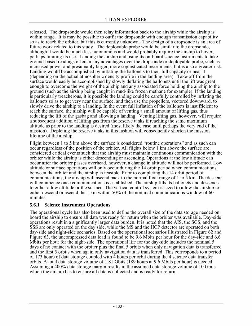
TITAN EXPLORER
- 133 -
released. The dropsonde would then relay information back to the airship while the airship is within range. It is may be possible to outfit the dropsonde with enough transmission capability so as to reach the orbiter, but this is currently unknown. The design of a dropsonde is an area of future work related to this study. The deployable probe would be similar to the dropsonde, although it would be much less autonomous and would probably require the airship to hover, perhaps limiting its use. Landing the airship and using its on-board science instruments to take ground-based readings offers many advantages over the dropsonde or deployable probe, such as increased power and presumably larger, more sophisticated instruments, but is also a greater risk. Landing would be accomplished by inflating the ballonets to their full capacity or near it (depending on the actual atmospheric density profile in the landing area). Take-off from the surface would easily be accomplished by slowly deflating the ballonets until the lift was great enough to overcome the weight of the airship and any associated force holding the airship to the ground (such as the airship being caught in mud-like frozen methane for example). If the landing is particularly treacherous, it is possible the landing could be carefully controlled by inflating the ballonets so as to get very near the surface, and then use the propellers, vectored downward, to slowly drive the airship to a landing. In the event full inflation of the ballonets is insufficient to reach the surface, the airship will be capable of venting a small amount of lifting gas, thus reducing the lift of the gasbag and allowing a landing. Venting lifting gas, however, will require a subsequent addition of lifting gas from the reserve tanks if reaching the same maximum altitude as prior to the landing is desired (most likely the case until perhaps the very end of the mission). Depleting the reserve tanks in this fashion will consequently shorten the mission lifetime of the airship. Flight between 1 to 5 km above the surface is considered “routine operations” and as such can occur regardless of the position of the orbiter. All flights below 1 km above the surface are considered critical events such that the airship must maintain continuous communication with the orbiter while the airship is either descending or ascending. Operations at the low altitude can occur after the orbiter passes overhead, however, a change in altitude will not be performed. Low altitude or surface operations will only occur during the 14 orbit period when communications between the orbiter and the airship is feasible. Prior to completing the 14 orbit period of communications, the airship will ascend back to the normal float range of 1 to 5 km. The descent will commence once communications is established. The airship fills its ballonets and descends to either a low altitude or the surface. The vertical control system is sized to allow the airship to either descend or ascend the 1 km within 50% of the nominal communications window of 60 minutes. 5.6.1 Science Instrument Operations The operational cycle has also been used to define the overall size of the data storage needed on board the airship to ensure all data was ready for return when the orbiter was available. Day-side operations result in a significantly larger data burden. It is noted that the AIS, the SCS, and the SSS are only operated on the day side, while the MS and the HCP detector are operated on both day-side and night-side scenarios. Based on the operational scenarios illustrated in Figure 62 and Figure 63, the uncompressed data load is found to be 9.6 Mbits per hour for the day-side and 6.6 Mbits per hour for the night-side. The operational life for the day-side includes the nominal 5 days of no contact with the orbiter plus the final 5 orbits when only navigation data is transferred and the first 5 orbits when again only navigation data is transferred. This corresponds to a period of 173 hours of data storage coupled with 4 hours per orbit during the 4 science data transfer orbits. A total data storage volume of 1.81 Gbits (189 hours at 9.6 Mbits per hour) is needed. Assuming a 400% data storage margin results in the assumed data storage volume of 10 Gbits which the airship has to ensure all data is collected and is ready for return.
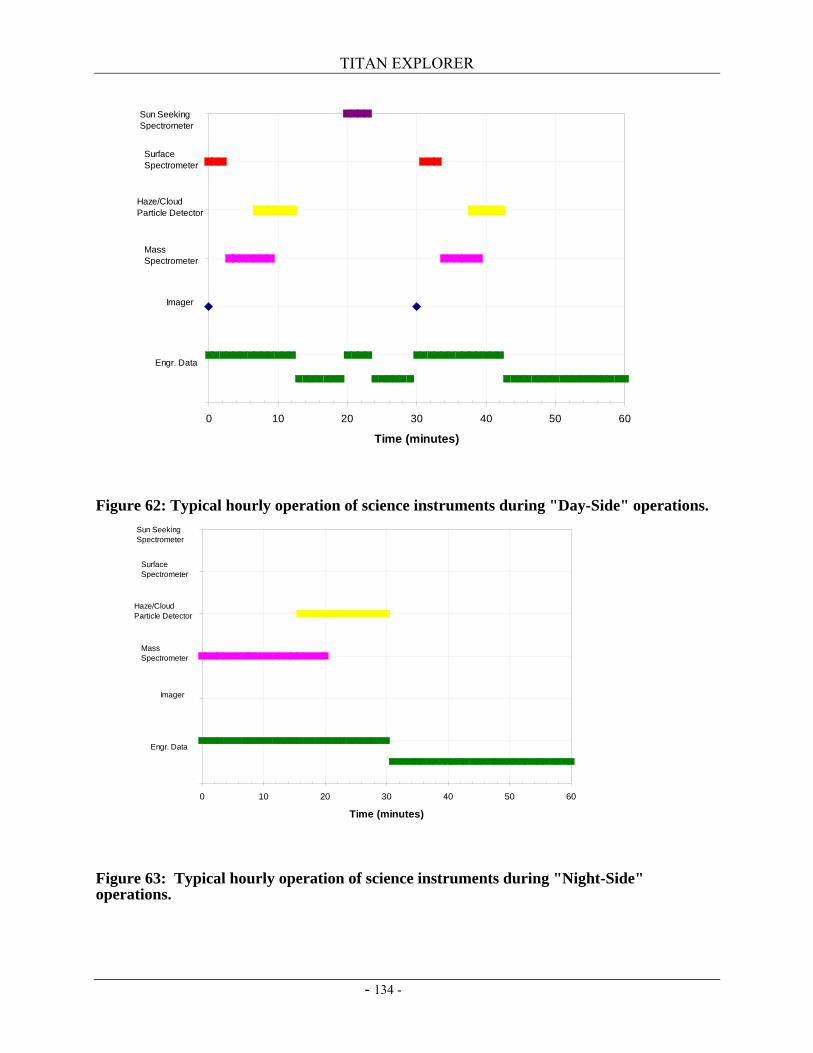
TITAN EXPLORER
- 134 -
Figure 62: Typical hourly operation of science instruments during "Day-Side" operations.
Figure 63: Typical hourly operation of science instruments during "Night-Side" operations.
0 10 20 30 40 50 60
Time (minutes)
Engr. Data
Imager
Mass Spectrometer
Haze/CloudParticle Detector
SurfaceSpectrometer
Sun SeekingSpectrometer
0 10 20 30 40 50 60
Time (minutes)
Engr. Data
Imager
Mass Spectrometer
Haze/CloudParticle Detector
SurfaceSpectrometer
Sun SeekingSpectrometer
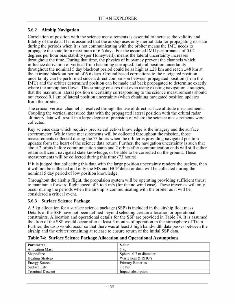
TITAN EXPLORER
- 135 -
5.6.2 Airship Navigation Correlation of position with the science measurements is essential to increase the validity and fidelity of the data. If it is assumed that the airship uses only inertial data for propagating its state during the periods when it is not communicating with the orbiter means the IMU needs to propagate the state for a maximum of 6.6 days. For the assumed IMU performance of 0.02 degrees per hour bias stability (per Honeywell), means the lateral uncertainty increases throughout the time. During that time, the physics of buoyancy prevent the channels which influence derivation of vertical from becoming corrupted. Lateral position uncertainty throughout the nominal 5 day blackout period could be as high as ±28 km and reach ±48 km at the extreme blackout period of 6.6 days. Ground based corrections to the navigated position uncertainty can be performed since a direct comparison between propagated position (from the IMU) and the orbiter determined position can be made and back propagated to determine exactly where the airship has flown. This strategy ensures that even using existing navigation strategies, that the maximum lateral position uncertainty corresponding to the science measurements should not exceed 0.1 km of lateral position uncertainty (when obtaining navigated position updates from the orbiter. The crucial vertical channel is resolved through the use of direct surface altitude measurements. Coupling the vertical measured data with the propagated lateral position with the orbital radar altimetry data will result in a large degree of precision of where the science measurements were collected. Key science data which requires precise collection knowledge is the imagery and the surface spectrometer. While these measurements will be collected throughout the mission, those measurements collected during the 73 hours when the orbiter is providing navigated position updates form the heart of the science data return. Further, the navigation uncertainty is such that about 2 orbits before communication starts and 2 orbits after communication ends will still either retain sufficient navigated state knowledge, or be able to be corrected on the ground. These measurements will be collected during this time (73 hours). If it is judged that collecting this data with the large position uncertainty renders the useless, then it will not be collected and only the MS and HCP detector data will be collected during the nominal 5 day period of low position knowledge. Throughout the airship flight, the propulsion system will be operating providing sufficient thrust to maintain a forward flight speed of 3 to 4 m/s (for the no wind case). These traverses will only occur during the periods when the airship is communicating with the orbiter as it will be considered a critical event. 5.6.3 Surface Science Package A 5 kg allocation for a surface science package (SSP) is included in the airship float mass. Details of the SSP have not been defined beyond selecting certain allocation or operational constraints. Allocation and operational details for the SSP are provided in Table 74. It is assumed the drop of the SSP would occur after at least 3 months of operation in the atmosphere of Titan. Further, the drop would occur so that there was at least 3 high bandwidth data passes between the airship and the orbiter remaining at release to ensure return of the initial SSP data. Table 74: Surface Science Package Allocation and Operational Assumptions Parameter Value Allocation Mass 5 kg Shape/Size Sphere, 0.7 m diameter Heating Strategy Waste heat & RHU’s Energy Source Primary Batteries Surface Life 7 days Terminal Descent Impact absorption
TITAN EXPLORER
- 136 -
Parameter Value Data Transfer UHF Uncompressed data volume 1 Gbit Maximum Communications Range 100 km
5.7 Option – VTOL Operations From the moment the helicopter leaves the aeroshell, the turbo expander cycle will be operating at full capacity. Even though constantly running the moving parts will increase the rate of mechanical wear, having the turbo expander operate continuously will prevent mishaps from occurring from repeated starts. Also, as long the turbo expander is operating, the heat from the MMRTGs is carried away into the atmosphere, so there does not have to be a massive heat removal system. When the helicopter is on the surface, the alternator does not supply power to the electric motor, but still supplies power to the other subsystems including the scientific payload. When the helicopter wants to go explore Titan, a solid state relay will complete the circuit and supply power from the alternator to the electric motor which will turn the helicopter rotor. While the rotor is spinning, there is still enough power for all the other subsystems to operate simultaneously, and the helicopter can always take science measurements.
5.8 Data Return A description of the data return architecture is provided in this section. The baseline scenario is to use RF methods for the return of all of the data. A brief comparison of the influence or benefits derived from using optical communications was also considered to assess how this technique influences the return of the data. Each of the individual links (airship to orbiter and orbiter to Earth) is described. In paragraph 5.8.2, the links used during post launch checkout and interplanetary cruise are also described. The baseline system uses a next generation Electra based UHF system for the link between the airship and the orbiter. This system uses omni-directional patch antennas mounted on the airship. The orbiter to Earth link is based on an X-band system using current state of the art small deep-space transponders (SDST) with a 2.4 meter diameter, fixed, HGA. In addition to the HGA, there is one LGA and one MGA mounted on the orbiter and one HGA, one MGA, and one LGA mounted on the orbiter to airship intermediate truss structure for use during Post Launch Checkout and Interplanetary Cruise. There is also a UHF MGA mounted on the truss for the orbiter to use when receiving the airship EDI critical events semaphore signals. 5.8.1 Relay Links – To/From Orbiter Determining a credible data return architecture is a key element of this study. The basis of the architecture is to use existing or near term solutions for use in this critical relay link. Determination of the link volume capability provides the first step towards assessing the overall architecture. Balancing the link capability with the science data collection needs along with the system impact on the airship (power, thermal and float mass) ensures there is a credible integrated solution. From the previous orbital analysis, it has been determined that the orbiter will be in a circular, near-polar orbit. Orbital inclination: 100 degrees Orbital altitude: 1700 km Orbital period: 5.149 hours Initial assessments of the relay link have assumed the airship is stationary at the equator of Titan to reduce the analytical complexity, while providing a reasonable bound on the data return. The basic link equation used including the system hardware performance assumptions are provided below in the equations listed as well as in Table 75.

TITAN EXPLORER
- 137 -
Theoretical Data Rate:
100010 10
Re__.⎟⎠⎞
⎜⎝⎛
=
qdBWMin
D kilo-bits per second
Minimum Bandwidth Required: LmnGrBBERLrLaGscLsLtEIRPqdBWMin −−−−−−+++= _Re__
Table 75: Relay Link Equations & Parameters Term Description Value EIRP Effective Isotropic Radiated Power: Lp + Glander Lp Power: ( )PLp log10= P Radiated Power (at Diplexer Output) – Watts 8 W (Electra) Glander Airship Transmission Antenna Gain See Figure 64 Lt Transmission Losses: cktLpolarLLt __ += L_polar Polarization Losses -0.5 dB L_ckt Transmitter Circuit Losses -1 dB Ls Space Loss: ( ) ( )( )freqRLs log20log2045.32 ++−= R Range (km) See Slant Range Figure freq Transmission Frequency (MHz) UHF – 405 MHz Gsc Spacecraft Receive Antenna Gain MGA: 11 dB La Atmospheric Loss (attenuation) 1 dB Lr Receiver Losses: LlineLagcLdeLLr +++= modmod Lmod Modulation Losses 1.25 dB Ldemod Demodulation losses 1 dB Lagc AGC Losses 1.2 dB Lline Receiver Line Losses 4.5 dB BER Signal to Noise Ratio needed for the desired Bit Error Rate. A
function of the coding used. 3.6 dB
B Boltzmann’s Constant: -228.6 dBW/Hz/K Gr_n Receiver System Noise Temperature Gain: ( )TnGr log10_ = T Receiver System Noise Temperature – degrees K 466 K Lm Link Margin 10 dB
Additional assumptions used in the link analysis are provided in Table 76. Table 76: Additional Relay Link Assumptions Parameter Assumption/Value Airship Minimum Elevation Angle 15 degrees Orbiter MGA beam width (3 dB point) 30 degrees Orbiter slewing Orbiter slews to maintain Nadir for along track but not cross track Orbiter MGA Gain at Off-Axis When angle exceeds 15 degrees, then assume gain is same as Airship
LGA at the same angle.
The assumed omni-directional antenna pattern (Low Gain Antenna) for the airship is illustrated in Figure 64.
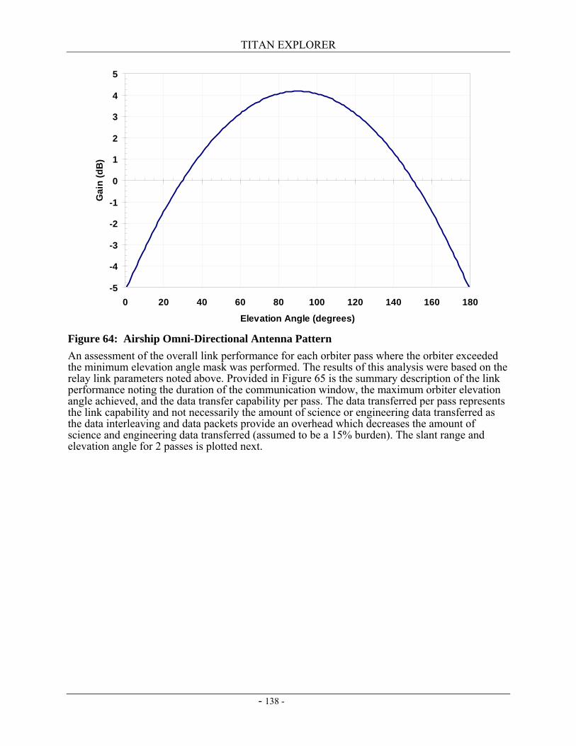
TITAN EXPLORER
- 138 -
Figure 64: Airship Omni-Directional Antenna Pattern An assessment of the overall link performance for each orbiter pass where the orbiter exceeded the minimum elevation angle mask was performed. The results of this analysis were based on the relay link parameters noted above. Provided in Figure 65 is the summary description of the link performance noting the duration of the communication window, the maximum orbiter elevation angle achieved, and the data transfer capability per pass. The data transferred per pass represents the link capability and not necessarily the amount of science or engineering data transferred as the data interleaving and data packets provide an overhead which decreases the amount of science and engineering data transferred (assumed to be a 15% burden). The slant range and elevation angle for 2 passes is plotted next.
-5
-4
-3
-2
-1
0
1
2
3
4
5
0 20 40 60 80 100 120 140 160 180
Elevation Angle (degrees)
Gai
n (d
B)
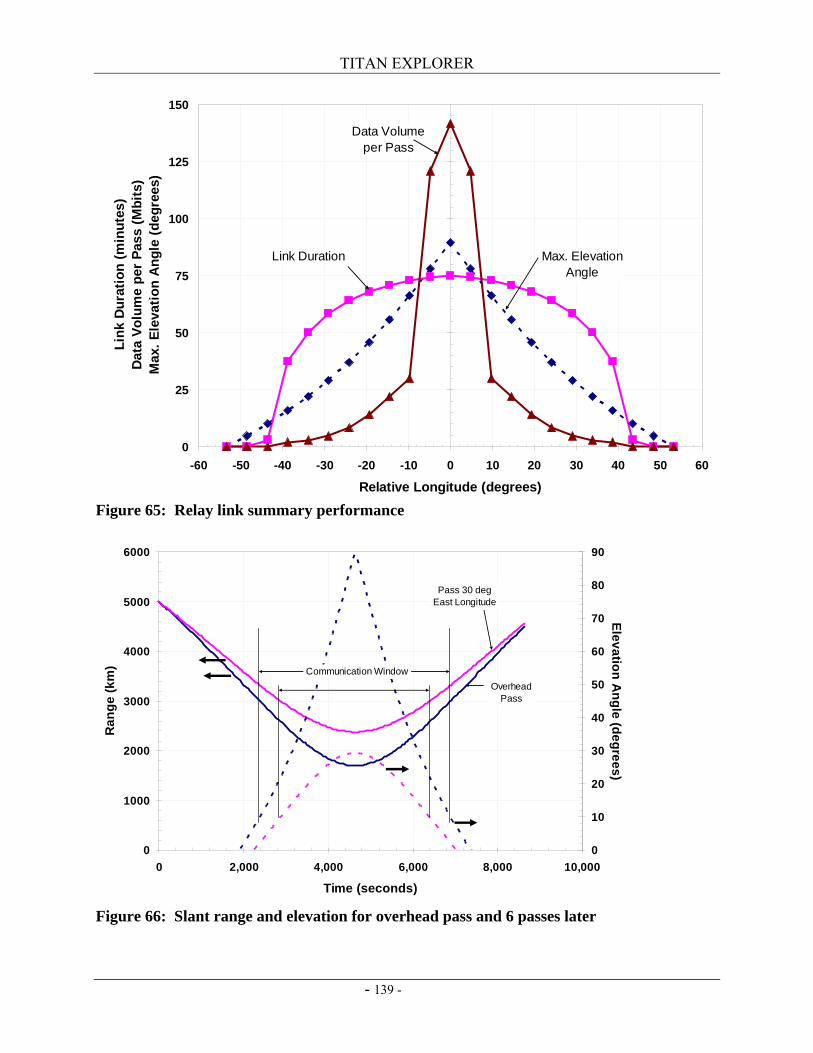
TITAN EXPLORER
- 139 -
Figure 65: Relay link summary performance
Figure 66: Slant range and elevation for overhead pass and 6 passes later
0
25
50
75
100
125
150
-60 -50 -40 -30 -20 -10 0 10 20 30 40 50 60
Relative Longitude (degrees)
Link
Dur
atio
n (m
inut
es)
Dat
a Vo
lum
e pe
r Pa
ss (M
bits
) M
ax. E
leva
tion
Ang
le (d
egre
es)
Data Volume per Pass
Link Duration Max. ElevationAngle
0
1000
2000
3000
4000
5000
6000
0 2,000 4,000 6,000 8,000 10,000
Time (seconds)
Ran
ge (k
m)
0
10
20
30
40
50
60
70
80
90
Elevation Angle (degrees)
Communication WindowOverhead
Pass
Pass 30 degEast Longitude
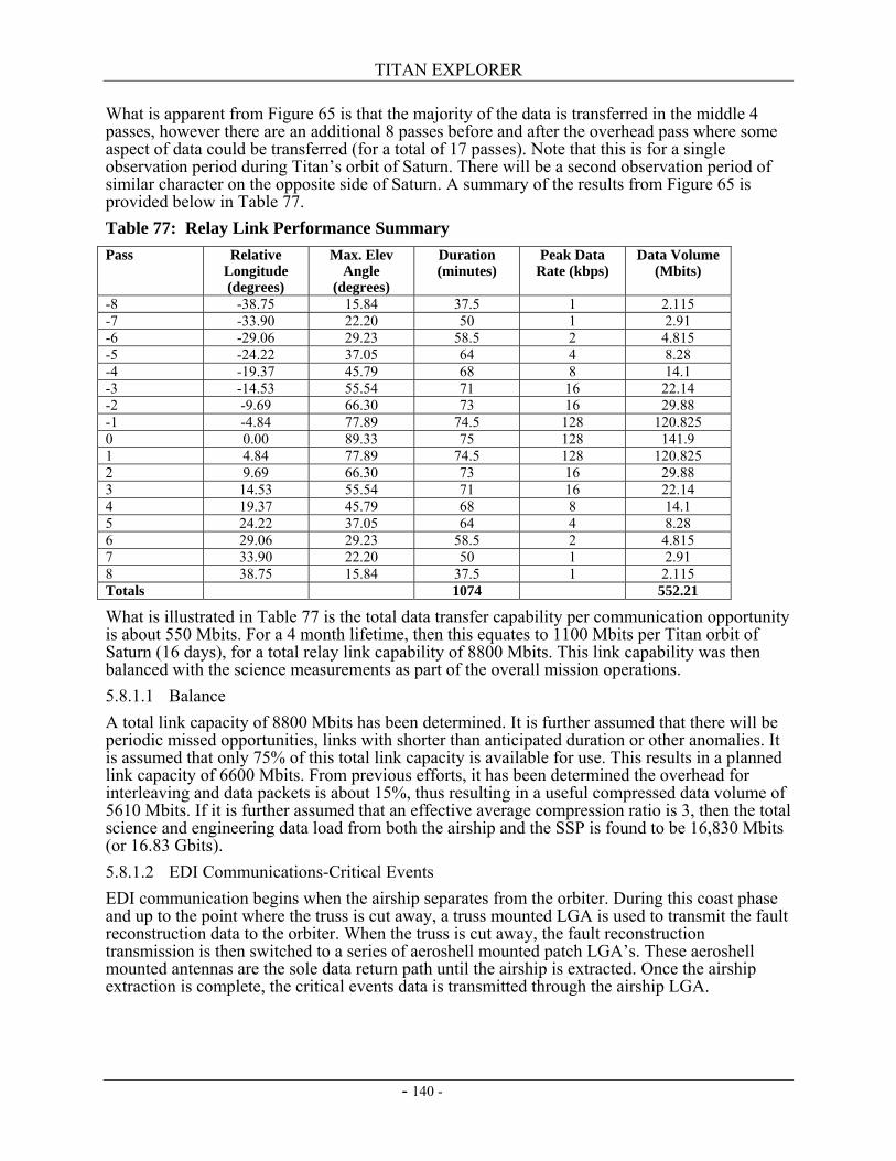
TITAN EXPLORER
- 140 -
What is apparent from Figure 65 is that the majority of the data is transferred in the middle 4 passes, however there are an additional 8 passes before and after the overhead pass where some aspect of data could be transferred (for a total of 17 passes). Note that this is for a single observation period during Titan’s orbit of Saturn. There will be a second observation period of similar character on the opposite side of Saturn. A summary of the results from Figure 65 is provided below in Table 77. Table 77: Relay Link Performance Summary Pass Relative
Longitude (degrees)
Max. Elev Angle
(degrees)
Duration (minutes)
Peak Data Rate (kbps)
Data Volume (Mbits)
-8 -38.75 15.84 37.5 1 2.115 -7 -33.90 22.20 50 1 2.91 -6 -29.06 29.23 58.5 2 4.815 -5 -24.22 37.05 64 4 8.28 -4 -19.37 45.79 68 8 14.1 -3 -14.53 55.54 71 16 22.14 -2 -9.69 66.30 73 16 29.88 -1 -4.84 77.89 74.5 128 120.825 0 0.00 89.33 75 128 141.9 1 4.84 77.89 74.5 128 120.825 2 9.69 66.30 73 16 29.88 3 14.53 55.54 71 16 22.14 4 19.37 45.79 68 8 14.1 5 24.22 37.05 64 4 8.28 6 29.06 29.23 58.5 2 4.815 7 33.90 22.20 50 1 2.91 8 38.75 15.84 37.5 1 2.115 Totals 1074 552.21
What is illustrated in Table 77 is the total data transfer capability per communication opportunity is about 550 Mbits. For a 4 month lifetime, then this equates to 1100 Mbits per Titan orbit of Saturn (16 days), for a total relay link capability of 8800 Mbits. This link capability was then balanced with the science measurements as part of the overall mission operations. 5.8.1.1 Balance A total link capacity of 8800 Mbits has been determined. It is further assumed that there will be periodic missed opportunities, links with shorter than anticipated duration or other anomalies. It is assumed that only 75% of this total link capacity is available for use. This results in a planned link capacity of 6600 Mbits. From previous efforts, it has been determined the overhead for interleaving and data packets is about 15%, thus resulting in a useful compressed data volume of 5610 Mbits. If it is further assumed that an effective average compression ratio is 3, then the total science and engineering data load from both the airship and the SSP is found to be 16,830 Mbits (or 16.83 Gbits). 5.8.1.2 EDI Communications-Critical Events EDI communication begins when the airship separates from the orbiter. During this coast phase and up to the point where the truss is cut away, a truss mounted LGA is used to transmit the fault reconstruction data to the orbiter. When the truss is cut away, the fault reconstruction transmission is then switched to a series of aeroshell mounted patch LGA’s. These aeroshell mounted antennas are the sole data return path until the airship is extracted. Once the airship extraction is complete, the critical events data is transmitted through the airship LGA.
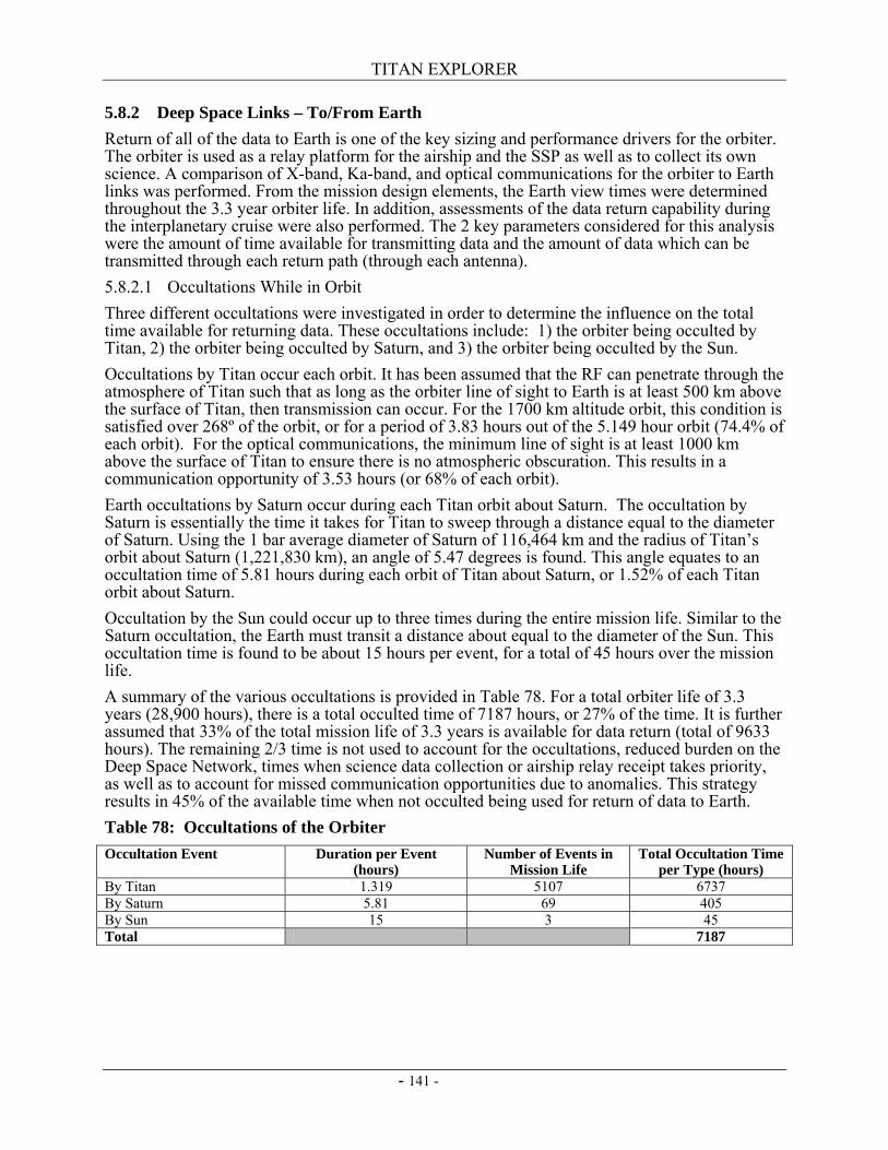
TITAN EXPLORER
- 141 -
5.8.2 Deep Space Links – To/From Earth Return of all of the data to Earth is one of the key sizing and performance drivers for the orbiter. The orbiter is used as a relay platform for the airship and the SSP as well as to collect its own science. A comparison of X-band, Ka-band, and optical communications for the orbiter to Earth links was performed. From the mission design elements, the Earth view times were determined throughout the 3.3 year orbiter life. In addition, assessments of the data return capability during the interplanetary cruise were also performed. The 2 key parameters considered for this analysis were the amount of time available for transmitting data and the amount of data which can be transmitted through each return path (through each antenna). 5.8.2.1 Occultations While in Orbit Three different occultations were investigated in order to determine the influence on the total time available for returning data. These occultations include: 1) the orbiter being occulted by Titan, 2) the orbiter being occulted by Saturn, and 3) the orbiter being occulted by the Sun. Occultations by Titan occur each orbit. It has been assumed that the RF can penetrate through the atmosphere of Titan such that as long as the orbiter line of sight to Earth is at least 500 km above the surface of Titan, then transmission can occur. For the 1700 km altitude orbit, this condition is satisfied over 268º of the orbit, or for a period of 3.83 hours out of the 5.149 hour orbit (74.4% of each orbit). For the optical communications, the minimum line of sight is at least 1000 km above the surface of Titan to ensure there is no atmospheric obscuration. This results in a communication opportunity of 3.53 hours (or 68% of each orbit). Earth occultations by Saturn occur during each Titan orbit about Saturn. The occultation by Saturn is essentially the time it takes for Titan to sweep through a distance equal to the diameter of Saturn. Using the 1 bar average diameter of Saturn of 116,464 km and the radius of Titan’s orbit about Saturn (1,221,830 km), an angle of 5.47 degrees is found. This angle equates to an occultation time of 5.81 hours during each orbit of Titan about Saturn, or 1.52% of each Titan orbit about Saturn. Occultation by the Sun could occur up to three times during the entire mission life. Similar to the Saturn occultation, the Earth must transit a distance about equal to the diameter of the Sun. This occultation time is found to be about 15 hours per event, for a total of 45 hours over the mission life. A summary of the various occultations is provided in Table 78. For a total orbiter life of 3.3 years (28,900 hours), there is a total occulted time of 7187 hours, or 27% of the time. It is further assumed that 33% of the total mission life of 3.3 years is available for data return (total of 9633 hours). The remaining 2/3 time is not used to account for the occultations, reduced burden on the Deep Space Network, times when science data collection or airship relay receipt takes priority, as well as to account for missed communication opportunities due to anomalies. This strategy results in 45% of the available time when not occulted being used for return of data to Earth. Table 78: Occultations of the Orbiter Occultation Event Duration per Event
(hours) Number of Events in
Mission Life Total Occultation Time
per Type (hours) By Titan 1.319 5107 6737 By Saturn 5.81 69 405 By Sun 15 3 45 Total 7187
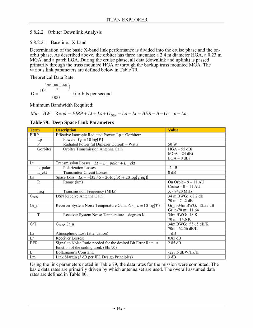
TITAN EXPLORER
- 142 -
5.8.2.2 Orbiter Downlink Analysis
5.8.2.2.1 Baseline: X-band Determination of the basic X-band link performance is divided into the cruise phase and the on-orbit phase. As described above, the orbiter has three antennas; a 2.4 m diameter HGA, a 0.23 m MGA, and a patch LGA. During the cruise phase, all data (downlink and uplink) is passed primarily through the truss mounted HGA or through the backup truss mounted MGA. The various link parameters are defined below in Table 79. Theoretical Data Rate:
100010 10
Re__.⎟⎠⎞
⎜⎝⎛
=
qdBWMin
D kilo-bits per second
Minimum Bandwidth Required:
LmnGrBBERLrLaGLsLtEIRPqdBWMin DSN −−−−−−+++= _Re__
Table 79: Deep Space Link Parameters Term Description Value EIRP Effective Isotropic Radiated Power: Lp + Gorbiterr Lp Power: ( )PLp log10= P Radiated Power (at Diplexer Output) – Watts 50 W Gorbiter Orbiter Transmission Antenna Gain HGA – 55 dBi
MGA – 24 dBi LGA – 0 dBi
Lt Transmission Losses: cktLpolarLLt __ += L_polar Polarization Losses -2 dB L_ckt Transmitter Circuit Losses 0 dB Ls Space Loss: ( ) ( )( )freqRLs log20log2045.32 ++−= R Range (km) On Orbit – 9 – 11 AU
Cruise – 0 – 11 AU freq Transmission Frequency (MHz) X - 8420 MHz GDSN DSN Receive Antenna Gain 34 m BWG: 68.2 dB
70 m: 74.2 dB Gr_n Receiver System Noise Temperature Gain: ( )TnGr log10_ = Gr_n-34m BWG: 12.55 dB
Gr_n-70 m: 11.64 T Receiver System Noise Temperature – degrees K 34m BWG: 18 K
70 m: 14.6 K G/T GDSN-Gr_n 34m BWG: 55.65 dB/K
70m: 62.56 dB/K La Atmospheric Loss (attenuation) 1 dB Lr Receiver Losses: 0.85 dB BER Signal to Noise Ratio needed for the desired Bit Error Rate. A
function of the coding used. (Eb/N0) 2.85 dB
B Boltzmann’s Constant: -228.6 dBW/Hz/K Lm Link Margin (3 dB per JPL Design Principles) 3 dB
Using the link parameters noted in Table 79, the data rates for the mission were computed. The basic data rates are primarily driven by which antenna set are used. The overall assumed data rates are defined in Table 80.
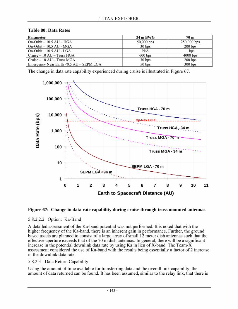
TITAN EXPLORER
- 143 -
Table 80: Data Rates Parameter 34 m BWG 70 m On-Orbit – 10.5 AU – HGA 50,000 bps 250,000 bps On-Orbit – 10.5 AU - MGA 30 bps 200 bps On-Orbit – 10.5 AU - LGA N/A 1 bps Cruise – 10 AU – Truss HGA 600 bps 4000 bps Cruise – 10 AU – Truss MGA 30 bps 200 bps Emergency Near Earth <0.5 AU – SEPM LGA 50 bps 300 bps
The change in data rate capability experienced during cruise is illustrated in Figure 67.
Figure 67: Change in data rate capability during cruise through truss mounted antennas
5.8.2.2.2 Option: Ka-Band A detailed assessment of the Ka-band potential was not performed. It is noted that with the higher frequency of the Ka-band, there is an inherent gain in performance. Further, the ground based assets are planned to consist of a large array of small 12 meter dish antennas such that the effective aperture exceeds that of the 70 m dish antennas. In general, there will be a significant increase in the potential downlink data rate by using Ka in lieu of X-band. The Team-X assessment considered the use of Ka-band with the results being essentially a factor of 2 increase in the downlink data rate. 5.8.2.3 Data Return Capability Using the amount of time available for transferring data and the overall link capability, the amount of data returned can be found. It has been assumed, similar to the relay link, that there is
1
10
100
1,000
10,000
100,000
1,000,000
0 1 2 3 4 5 6 7 8 9 10 11
Earth to Spacecraft Distance (AU)
Dat
a R
ate
(bps
)
Truss HGA - 70 m
Truss HGA - 34 m
Truss MGA - 70 m
Truss MGA - 34 m
SEPM LGA - 70 mSEPM LGA - 34 m
Op-Nav Limit
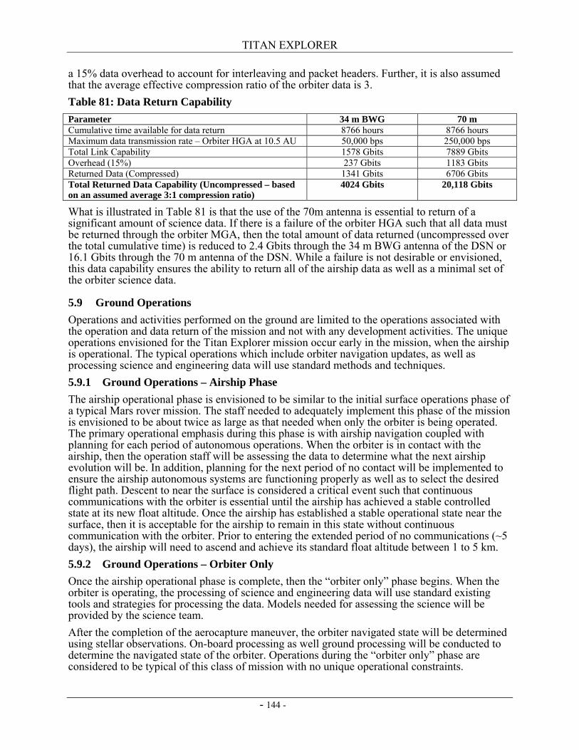
TITAN EXPLORER
- 144 -
a 15% data overhead to account for interleaving and packet headers. Further, it is also assumed that the average effective compression ratio of the orbiter data is 3. Table 81: Data Return Capability Parameter 34 m BWG 70 m Cumulative time available for data return 8766 hours 8766 hours Maximum data transmission rate – Orbiter HGA at 10.5 AU 50,000 bps 250,000 bps Total Link Capability 1578 Gbits 7889 Gbits Overhead (15%) 237 Gbits 1183 Gbits Returned Data (Compressed) 1341 Gbits 6706 Gbits Total Returned Data Capability (Uncompressed – based on an assumed average 3:1 compression ratio)
4024 Gbits 20,118 Gbits
What is illustrated in Table 81 is that the use of the 70m antenna is essential to return of a significant amount of science data. If there is a failure of the orbiter HGA such that all data must be returned through the orbiter MGA, then the total amount of data returned (uncompressed over the total cumulative time) is reduced to 2.4 Gbits through the 34 m BWG antenna of the DSN or 16.1 Gbits through the 70 m antenna of the DSN. While a failure is not desirable or envisioned, this data capability ensures the ability to return all of the airship data as well as a minimal set of the orbiter science data.
5.9 Ground Operations Operations and activities performed on the ground are limited to the operations associated with the operation and data return of the mission and not with any development activities. The unique operations envisioned for the Titan Explorer mission occur early in the mission, when the airship is operational. The typical operations which include orbiter navigation updates, as well as processing science and engineering data will use standard methods and techniques. 5.9.1 Ground Operations – Airship Phase The airship operational phase is envisioned to be similar to the initial surface operations phase of a typical Mars rover mission. The staff needed to adequately implement this phase of the mission is envisioned to be about twice as large as that needed when only the orbiter is being operated. The primary operational emphasis during this phase is with airship navigation coupled with planning for each period of autonomous operations. When the orbiter is in contact with the airship, then the operation staff will be assessing the data to determine what the next airship evolution will be. In addition, planning for the next period of no contact will be implemented to ensure the airship autonomous systems are functioning properly as well as to select the desired flight path. Descent to near the surface is considered a critical event such that continuous communications with the orbiter is essential until the airship has achieved a stable controlled state at its new float altitude. Once the airship has established a stable operational state near the surface, then it is acceptable for the airship to remain in this state without continuous communication with the orbiter. Prior to entering the extended period of no communications (~5 days), the airship will need to ascend and achieve its standard float altitude between 1 to 5 km. 5.9.2 Ground Operations – Orbiter Only Once the airship operational phase is complete, then the “orbiter only” phase begins. When the orbiter is operating, the processing of science and engineering data will use standard existing tools and strategies for processing the data. Models needed for assessing the science will be provided by the science team. After the completion of the aerocapture maneuver, the orbiter navigated state will be determined using stellar observations. On-board processing as well ground processing will be conducted to determine the navigated state of the orbiter. Operations during the “orbiter only” phase are considered to be typical of this class of mission with no unique operational constraints.
TITAN EXPLORER
- 145 -
6. Operations Assurance A definition of operations assurance used for the Titan Explorer study is the fault tolerance (or redundancy) as well as the maintainability of the system. The traditional mission assurance elements (risk definitions and classification) is not considered part of this category to be consistent with the original Vision Mission NRA.
6.1 System Resilience (Redundancy or Adaptability) Providing means or strategies for accommodating uncertainties and off-nominal conditions is essential for missions of this duration. With a 6 year cruise to Titan as well as up to a 3.3 year orbital life, this means, the system (orbiter) needs to be capable of at least a 10 year life. The basic design premise for all systems on board the orbiter, the airship, and the SEPM is full redundancy. There are some areas where redundancy is not provided, specifically items such as the primary structure. Most of the propulsion systems use more than one means of propulsion. Extra energy sources (RTGs or batteries) are provided. A complete spare flight control computer as well as navigation sensors are provided for both the orbiter and the airship. With missions of this type at the time period where this mission is envisioned, software will be a significant component of the overall mission implementation. Since the study did not focus on software or software development, that is an area which warrants a significant amount of attention in future efforts. As such, no claims or considerations as to the fault tolerance or robustness of the flight software is provided at this time.
6.2 Maintenance or Servicing After launch of the system, all maintenance and servicing will be performed through periodic uploads of new or revised software. Ground commands as well as automated responses on board either the orbiter or the airship will allow switching between the A-side and B-side avionics.

TITAN EXPLORER
- 146 -
This page intentionally left blank
TITAN EXPLORER
- 147 -
7. Safety Safety of the Titan Explorer mission has three primary elements which require specific attention. Standard safety issues associated with any spacecraft including landers still exist. These elements include the use of pyrotechnic devices for releasing or deploying activities, high voltages for selected hardware, as well as other items. The key safety issues for the Titan Explorer mission include the use of nuclear materials, the presence of a large volume of supercritical xenon, and the planetary protection concerns related to Titan.
7.1 Launch and Earth Gravity Assist Two of the three safety concerns exist during the ground servicing and launch activities as well as during the single Earth Gravity Assist. These issues include the presence of a large amount of supercritical xenon in a “pressure vessel” located in the SEPM as well as the presence of nuclear materials in the SRG’s, MMRTG’s, and the RHU’s. 7.1.1 Use of Nuclear Materials From the operations and systems definition analysis, it has been determined there is 16 kg of fuel for the SRG’s and MMRTG’s (Plutonium-238; Pu-238) is needed for the operational profile. Since the amount of fuel needed for the Titan Explorer is less than that of at least one previously launched mission, then the protocols and procedures developed and implemented by that mission (Cassini) provide a basis of what is needed for this mission. It is not envisioned that any new methods or systems are needed to be developed. The use of nuclear materials for the Titan Explorer mission does not impose a technical challenge on the mission, however, it does impose an additional cost and schedule requirement. Specific areas where either the launch or EGA impose an operational constraint on the mission include assessing a launch and ascent failure to ensure the nuclear material can be contained and protected during the reentry after an ascent failure. Potential solutions include extensive analysis and testing (leveraging any Exploration System Mission Directorate’s development activities related to manned exploration where nuclear materials have also been protected from an ascent failure) to determine if the aeroshells around each of the vehicles are sufficient to protect the SRG’s and MMRTG’s from catastrophic failure. Other potential solutions include using the Cassini solution where each of the RTG modules was encased in a Carbon-Carbon TPS system to allow them to survive a failure during ascent. Further, there will be extensive efforts needed for the NEPA and other law and policy issues needed to provide public comment and input on these nuclear materials. The EGA maneuver will have a minimum approach distance as well as requirements on navigated state knowledge and capability uncertainty. The goal will be able to show that there is less than a 10-6 chance of the vehicle inadvertently reentering Earth’s atmosphere. Since the closer the vehicle flies to the body providing the gravity assist, the larger velocity increment added to the vehicle, the minimum approach distance will need to be determined early enough in the design process to allow the mission design team to address the proper balance between gravity assist energy added as well as amount of thrust and duration of thrust of the Solar Electric Propulsion Module. Cassini performed a similar maneuver so an established protocol and procedure has been developed, then these methods can be explored for application to the Titan Explorer mission. 7.1.2 Supercritical Xenon Approximately 1057 kg of supercritical xenon is used as the SEPM propellant. Storing the xenon as a supercritical fluid (higher density than a gas phase) resulting in a significantly smaller pressure vessel. Many propellant storage tanks for supercritical xenon have been designed, built, tested and used. This is a proven and existing technology where a successful design has been developed. The key safety issue revolves around ground handling when personnel are in the vicinity. Maintaining the proper environment to ensure the xenon remains in a supercritical state requires selected ground systems (cooling) to be functioning. Consequently, there will be an
TITAN EXPLORER
- 148 -
additional reliability and redundancy constraint imposed on the ground support systems for the xenon tank. Operations in space during cruise pose no additional risk
7.2 Titan Planetary Protection NASA’s policy documents (ref. 46) establish the basic mission classification rules and policies. In accordance with Appendix A of reference 46, both the orbiter and the airship are classified as Category II missions. With this classification level, typical spacecraft contamination control protocols along with modest cleaning and development and implementation of the appropriate plans are sufficient. Classification as a Category II mission means long term orbit propagation is not needed to determine if the orbit of the orbiter will eventually decay sufficient for it to enter the atmosphere or if the SEPM will eventually cross the orbit of Titan and enter the atmosphere. Once a mission trajectory is defined more precisely, then the long term propagation for only the elements in the heliocentric orbit will be needed since those elements cross the orbits of both Mars and Jupiter (Europa). Assessment of the long term heliocentric orbit propagation was not conducted as part of the study.
TITAN EXPLORER
- 149 -
8. References 1. Levine, J. S.: The Photochemistry of the Paleoatmosphere. Journal of Molecular
Evolution, 18, 1982a, 161-172. 2. Levine, J. S. ;Augustsson, T. R.; and Natarajan, M.: The Prebiological
Paleoatmosphere: Stability and Composition. Origins of Life, 12, 1982b, 245-259. 3. Levine, J. S.: The Photochemistry of the Early Atmsophere. The Photochemistry of
Atmospheres: Earth, The Other Planets, and Comets (J. S. Levine, Editor), Academic Press, Inc., San Diego, CA, 1985, pp. 3-38.
4. Lockwood, M. K. Titan Aerocapture Systems Analysis. AIAA 2003-4799. 5. Elfes, A., Hall, J. L., Montgomery, J. F., Bergh, C. F., Dudik, B. A. Towards a
Substantially Autonomous Aerobot for Titan Exploration. AIAA 2003-6714. 6. Yung, Y. L. and Demore, W. B., 1999: Photochemistry of Planetary Atmospheres.
Oxford University Press, New York. 7. Cassini-Huygens Arrival Press Kit. June 2004. 8. McKay, C. P.; Lorenz, R. L.; Lunine, J. I.; 1999. Analytic Solutions for the
Antigreenhouse Effect: Titan and the early Earth. Icarus, 137, 56-61. 9. McKay, C. P., et. al., 2001 Physical Properties of Organic Aerosols and Clouds on
Titan. Planetary and Space Science, 49, 79-99. 10. Solar Occultation Instrument Image:
http://www.ace.uwaterloo.ca/Websites_Links/Links_Gallery.php?header=inter 11. Solar Occultation Spectra Image:
http://www.ace.uwaterloo.ca/Websites_ACE_Public/ACE_Spectra.php?header=inter 12. Radar data imagery – Impact Crater with Ejecta Blanket:
http://saturn.jpl.nasa.gov/multimedia/images/images.cfm?startimage=33&category|D=4&subCatgegory|D=10
13. Radar data imager – Topography on Titan: http://saturn.jpl.nasa.gov/multimedia/images/images.cfm?startimage=81&category|D=4&subCatgegory|D=10
14. V/SHM Image: http://www.sp.ph.ic.ac.uk/cassini/vshm.html 15. FGM Image: http://www.sp.ph.ic.ac.uk/cassini/fgm.html 16. UVIS Image: http://lasp.colorado.edu/cassini/inst_desc 17. Mosaic of VIMS Images: http://vims.artov.rm.cnr.it/data/res-tit.html 18. Mosaic of UV/VIS images from the Clementine mission:
http://www.cmf.nrl.navy.mil/clementine/clem_collect/tycho.html 19. Cassini INMS Data Image:
http://saturn.jpl.nasa.gov/multimedia/images/images.cfm?startimage=81&category|D=4&subCategory|D=10
20. Knollenberg, R. G.; Gilland, J. R. "Pioneer Venus Sounder Probe Particle Size Spectrometer," IEEE Trans. Geosci. Remote Sensing GE-18, 100-104 (1980).)
21. MESSENGER Magnetometer Image: http://btc.montana.edu/messenger/instruments/mascs.htm
TITAN EXPLORER
- 150 -
22. Stomovsky, L. A.; Revercomb, H. E.; Suomi, V. E. "Pioneer Venus Small Probes Net Flux Radiometer Experiment," IEEE Trans. Geosci. Remote Sensing GE-18, 117-122 (1980).
23. Levine, J. S. Planetary Atmospheres. Encyclopedia of Physical Science and Technology, third edition, volume 12. Academic Press, Inc., San Diego, CA. 2002, 245-273.
24. Justus, C. G., Duvall, A. Engineering-Level Model Atmospheres for Titan and Neptune. AIAA 2003-4803
25. NASA KSC Expendable Launch Vehicle performance website. http://elvperf.ksc.nasa.gov/elvMap/staticPages/nls1.htm
26. Lockwood, M. K. Titan Aerocapture Systems Analysis. AIAA 2003-4799. 27. Hrinda, G. A. Structural Design of the Titan Aerocapture Mission. AIAA 2003-4955. 28. Delta IV Payload Planners Guide. MDC00H0043. The Boeing Company, Huntington
Beach, CA, April 2002. 29. Noca, M., Bailey, R. W. Titan Explorer Mission Trades From the Perspective of
Aerocapture. AIAA 2003-4801. 30. Bailey, R. W., Hall, J. L., Spilker, T. R. Titan Aerocapture Mission and Spacecraft
Design Overview. AIAA 2003-4800 31. Anderson, W. G., Bienert, W. Loop Heat-Pipe Radiator Trade Study for the 300 –
550 K Temperature Range. Proceedings of Space Technology and Applications International Forum (STAIF-05), edited by M. S. El-Genk, American Institute of Physics, Melville, NY, 2005.
32. Laub, B. Thermal Protection Concepts and Issues For Aerocapture at Titan. AIAA 2003-4954.
33. Ashford, V.: X-38 Battery Heatsink Thermal Test Report. Energy Science Laboratories, Inc., 25 Jan 2002.
34. Laub, B. TPS presentation at the Robotic Access to Planetary Surface Capability Roadmap Team Workshop, February 2005. NASA Ames Research Center, Mountain View, CA.
35. Smart, M. C.; Ratnakumar, B. V.; Ewell, R. C.; Whitcanack, L. D.; Chin, K. B.; Surampudi, S. Validation of Lithium-Ion Cell Technology for JPL’s 2003 Mars Exploration Rover Mission. AIAA 2004-5764.
36. Olejniczak, J., Wright, M. J., Prabhu, D., Takashima, N., Hollis, B. R., Zoby, V., Sutton, K. An Analysis of the Radiative Heating Environment for Aerocapture at Titan. AIAA 2003-4953.
37. Khoury, G. A.; Gillett, J. D. Airship Technology. Cambridge University Press, August, 2004.
38. Colozza, A. J. Comparison of Mars Aircraft Propulsion Systems. NASA/CR-2003-212350. 2003
39. Colozza, A. J., “Planetary Exploration Using Biomimetrics,” NASA Institute for Advanced Concepts, November 2000.
40. Lafleur, J.M., “Derivation and Application of a Methodology to Estimate Planetary Aerial Vehicle Power Requirements,” AIAA Region II Student Conference, Gainesville, 4-5 April 2005.
TITAN EXPLORER
- 151 -
41. McKay, C.P.; Pollack, J.B.; Courtin, R.; and Lunine, J.I.: “The Atmospheric Temperature Structure of Titan”, in Proceedings of the Symposium on Titan, Toulouse France 9-12 September 1991, pp 77-80.
42. Haw, R. J. Approach Navigation for a Titan Aerocapture Orbiter. AIAA 2003-4802. 43. Way, D. W., Powell, R. W., Equist, K. T., Masciarelli, J. P., Starr, B. R. Aerocapture
Simulation and Performance for the Titan Explorer Mission. AIAA 2003-4951. 44. Masciarelli, J. P., Queen, E. M. Guidance Algorithms for Aerocapture at Titan. AIAA
2003-4804. 45. Takashima, N., Hollis, B. R., Zoby, V., Sutton, K., Olejniczak, J., Wright, M. J.,
Prabhu, D. Preliminary Aerothermodynamics of Titan Aerocapture Aeroshell. AIAA 2003-4952.
46. NASA Procedural Requirement – NPR 8020.12C. Planetary Protection Provisions for Robotic Extraterrestrial Missions. April 27, 2005.

TITAN EXPLORER
- 152 -
This page intentionally left blank
TITAN EXPLORER
- 153 -
APPENDIX 1: ACRONYMS 3-DoF Three Degree-of-Freedom 6-DoF Six Degree-of-Freedom ACE Atmospheric Chemistry Experiment ACS Attitude Control Subsystem ACS Attitude Determination and Control Subsystem ARES Aerial Regional-scale Environmental Survey AU Astronomical Units BIP Backshell Interface Plate BOC Beginning of Cassini CDS Command and Data Subsystem CFD Computational Fluid Dynamics CRP Conical Ribbon Parachute DCIU Digital Interface Control Unit DGB Disk-Gap Band DS-1 Deep Space-1 EGA Earth Gravity Assist EOC End of Cassini EOL End-of-Life EPS Electrical Power Subsystem FEM Finite Element Model FGM Fluxgate Magnetometer FTS Fourier Transform Spectrometer GB Ground-Based GPHS General Purpose Heat Source GPS Global Positioning System HCP Haze and Cloud Particle Detector HGA High Gain Antenna HST Hubble Space Telescope HYPAS Hybrid Predictor-corrector Aerocapture Scheme IAU Integrated Avionics Unit IM Imager IMU Inertial Measuring Unit INMS Ion and Neutral Mass Spectrometer LAURA Langley Aerodynamic Upwind Relaxation Algorithm LGA Low Gain Antenna MAG Magnetometer MASCS Mercury Atmospheric and Surface Composition Spectrometer MCM Multi-Chip Module MER Mars Exploration Rover MGA Medium Gain Antenna MIT Miniature Inertial Thruster MMRTG Multi-Mission RTG MS Mass Spectrometer NFR Net-Flux Radiometer NGN Next Generation NSTAR NSTAR DS-1 class ion-thrusters PCM Phase Change Material POST Program to Optimize Simulated Trajectories POST2 Program to Optimize Simulated Trajectories II PPU Power Processing Unit RAD Radar Mapper RTG Radioisotope Thermo-Electric Generator SAR Synthetic Aperture Radar SCS Surface Composition Spectrometer SEP Solar Electric Propulsion SEPM Solar Electric Propulsion Module SHM Scalar Helium Magnetometer
TITAN EXPLORER
- 154 -
SO Solar Occultation SRG Stirling RTG SSP Surface Science Package SSS Sun-Seeking Spectrometer UVS Ultraviolet Spectrometer UVVS UV/Visible Spectrometer V/SHM Vector/Scalar Helium Magnetometer VIMS Visual and Infrared Mapping Spectrometer VIRS Visible/IR Spectrograph VTOL Vertical Take-off and Landing
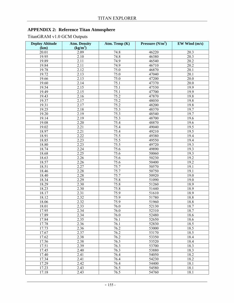
TITAN EXPLORER
- 155 -
APPENDIX 2: Reference Titan Atmosphere TitanGRAM v1.0 GCM Outputs
Deploy Altitude (km)
Atm. Density (kg/m3)
Atm. Temp (K) Pressure (N/m2) EW Wind (m/s)
20.01 2.09 74.8 46220 20.3 19.95 2.10 74.8 46380 20.3 19.89 2.11 74.9 46540 20.2 19.84 2.11 74.9 46710 20.2 19.78 2.12 75.0 46870 20.1 19.72 2.13 75.0 47040 20.1 19.66 2.13 75.0 47200 20.0 19.60 2.14 75.1 47370 20.0 19.54 2.15 75.1 47530 19.9 19.49 2.15 75.1 47700 19.9 19.43 2.16 75.2 47870 19.8 19.37 2.17 75.2 48030 19.8 19.31 2.17 75.2 48200 19.8 19.25 2.18 75.3 48370 19.7 19.20 2.19 75.3 48540 19.7 19.14 2.19 75.3 48700 19.6 19.08 2.20 75.4 48870 19.6 19.02 2.21 75.4 49040 19.5 18.97 2.21 75.4 49210 19.5 18.91 2.22 75.5 49380 19.4 18.85 2.23 75.5 49550 19.4 18.80 2.23 75.5 49720 19.3 18.74 2.24 75.6 49890 19.3 18.68 2.25 75.6 50060 19.3 18.63 2.26 75.6 50230 19.2 18.57 2.26 75.6 50400 19.2 18.51 2.27 75.7 50570 19.1 18.46 2.28 75.7 50750 19.1 18.40 2.28 75.7 50920 19.0 18.34 2.29 75.8 51090 19.0 18.29 2.30 75.8 51260 18.9 18.23 2.30 75.8 51440 18.9 18.17 2.31 75.9 51610 18.9 18.12 2.32 75.9 51780 18.8 18.06 2.32 75.9 51960 18.8 18.01 2.33 76.0 52130 18.7 17.95 2.34 76.0 52310 18.7 17.89 2.34 76.0 52480 18.6 17.84 2.35 76.1 52650 18.6 17.78 2.36 76.1 52830 18.5 17.73 2.36 76.2 53000 18.5 17.67 2.37 76.2 53170 18.5 17.62 2.38 76.2 53350 18.4 17.56 2.38 76.3 53520 18.4 17.51 2.39 76.3 53700 18.3 17.45 2.40 76.3 53880 18.3 17.40 2.41 76.4 54050 18.2 17.34 2.41 76.4 54230 18.2 17.29 2.42 76.4 54400 18.1 17.23 2.43 76.5 54580 18.1 17.18 2.43 76.5 54760 18.1
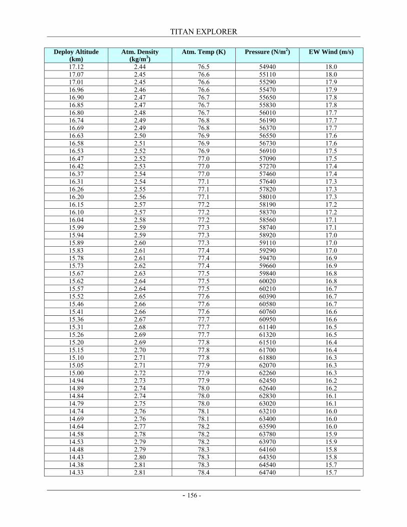
TITAN EXPLORER
- 156 -
Deploy Altitude (km)
Atm. Density (kg/m3)
Atm. Temp (K) Pressure (N/m2) EW Wind (m/s)
17.12 2.44 76.5 54940 18.0 17.07 2.45 76.6 55110 18.0 17.01 2.45 76.6 55290 17.9 16.96 2.46 76.6 55470 17.9 16.90 2.47 76.7 55650 17.8 16.85 2.47 76.7 55830 17.8 16.80 2.48 76.7 56010 17.7 16.74 2.49 76.8 56190 17.7 16.69 2.49 76.8 56370 17.7 16.63 2.50 76.9 56550 17.6 16.58 2.51 76.9 56730 17.6 16.53 2.52 76.9 56910 17.5 16.47 2.52 77.0 57090 17.5 16.42 2.53 77.0 57270 17.4 16.37 2.54 77.0 57460 17.4 16.31 2.54 77.1 57640 17.3 16.26 2.55 77.1 57820 17.3 16.20 2.56 77.1 58010 17.3 16.15 2.57 77.2 58190 17.2 16.10 2.57 77.2 58370 17.2 16.04 2.58 77.2 58560 17.1 15.99 2.59 77.3 58740 17.1 15.94 2.59 77.3 58920 17.0 15.89 2.60 77.3 59110 17.0 15.83 2.61 77.4 59290 17.0 15.78 2.61 77.4 59470 16.9 15.73 2.62 77.4 59660 16.9 15.67 2.63 77.5 59840 16.8 15.62 2.64 77.5 60020 16.8 15.57 2.64 77.5 60210 16.7 15.52 2.65 77.6 60390 16.7 15.46 2.66 77.6 60580 16.7 15.41 2.66 77.6 60760 16.6 15.36 2.67 77.7 60950 16.6 15.31 2.68 77.7 61140 16.5 15.26 2.69 77.7 61320 16.5 15.20 2.69 77.8 61510 16.4 15.15 2.70 77.8 61700 16.4 15.10 2.71 77.8 61880 16.3 15.05 2.71 77.9 62070 16.3 15.00 2.72 77.9 62260 16.3 14.94 2.73 77.9 62450 16.2 14.89 2.74 78.0 62640 16.2 14.84 2.74 78.0 62830 16.1 14.79 2.75 78.0 63020 16.1 14.74 2.76 78.1 63210 16.0 14.69 2.76 78.1 63400 16.0 14.64 2.77 78.2 63590 16.0 14.58 2.78 78.2 63780 15.9 14.53 2.79 78.2 63970 15.9 14.48 2.79 78.3 64160 15.8 14.43 2.80 78.3 64350 15.8 14.38 2.81 78.3 64540 15.7 14.33 2.81 78.4 64740 15.7
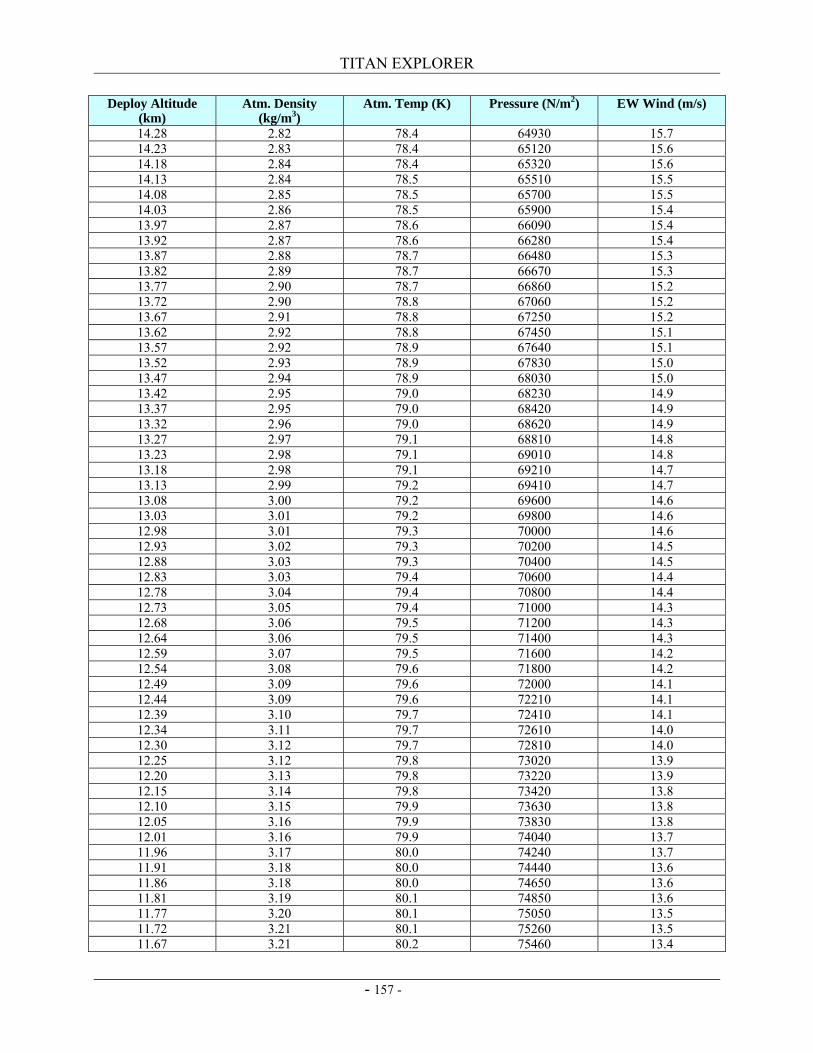
TITAN EXPLORER
- 157 -
Deploy Altitude (km)
Atm. Density (kg/m3)
Atm. Temp (K) Pressure (N/m2) EW Wind (m/s)
14.28 2.82 78.4 64930 15.7 14.23 2.83 78.4 65120 15.6 14.18 2.84 78.4 65320 15.6 14.13 2.84 78.5 65510 15.5 14.08 2.85 78.5 65700 15.5 14.03 2.86 78.5 65900 15.4 13.97 2.87 78.6 66090 15.4 13.92 2.87 78.6 66280 15.4 13.87 2.88 78.7 66480 15.3 13.82 2.89 78.7 66670 15.3 13.77 2.90 78.7 66860 15.2 13.72 2.90 78.8 67060 15.2 13.67 2.91 78.8 67250 15.2 13.62 2.92 78.8 67450 15.1 13.57 2.92 78.9 67640 15.1 13.52 2.93 78.9 67830 15.0 13.47 2.94 78.9 68030 15.0 13.42 2.95 79.0 68230 14.9 13.37 2.95 79.0 68420 14.9 13.32 2.96 79.0 68620 14.9 13.27 2.97 79.1 68810 14.8 13.23 2.98 79.1 69010 14.8 13.18 2.98 79.1 69210 14.7 13.13 2.99 79.2 69410 14.7 13.08 3.00 79.2 69600 14.6 13.03 3.01 79.2 69800 14.6 12.98 3.01 79.3 70000 14.6 12.93 3.02 79.3 70200 14.5 12.88 3.03 79.3 70400 14.5 12.83 3.03 79.4 70600 14.4 12.78 3.04 79.4 70800 14.4 12.73 3.05 79.4 71000 14.3 12.68 3.06 79.5 71200 14.3 12.64 3.06 79.5 71400 14.3 12.59 3.07 79.5 71600 14.2 12.54 3.08 79.6 71800 14.2 12.49 3.09 79.6 72000 14.1 12.44 3.09 79.6 72210 14.1 12.39 3.10 79.7 72410 14.1 12.34 3.11 79.7 72610 14.0 12.30 3.12 79.7 72810 14.0 12.25 3.12 79.8 73020 13.9 12.20 3.13 79.8 73220 13.9 12.15 3.14 79.8 73420 13.8 12.10 3.15 79.9 73630 13.8 12.05 3.16 79.9 73830 13.8 12.01 3.16 79.9 74040 13.7 11.96 3.17 80.0 74240 13.7 11.91 3.18 80.0 74440 13.6 11.86 3.18 80.0 74650 13.6 11.81 3.19 80.1 74850 13.6 11.77 3.20 80.1 75050 13.5 11.72 3.21 80.1 75260 13.5 11.67 3.21 80.2 75460 13.4
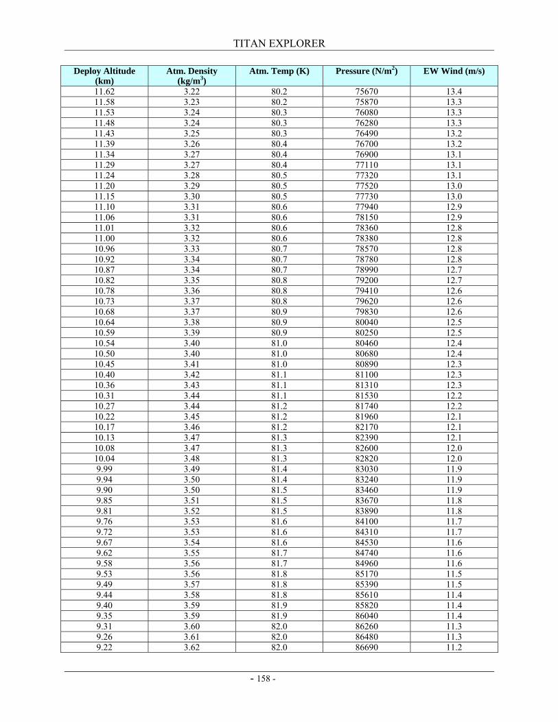
TITAN EXPLORER
- 158 -
Deploy Altitude (km)
Atm. Density (kg/m3)
Atm. Temp (K) Pressure (N/m2) EW Wind (m/s)
11.62 3.22 80.2 75670 13.4 11.58 3.23 80.2 75870 13.3 11.53 3.24 80.3 76080 13.3 11.48 3.24 80.3 76280 13.3 11.43 3.25 80.3 76490 13.2 11.39 3.26 80.4 76700 13.2 11.34 3.27 80.4 76900 13.1 11.29 3.27 80.4 77110 13.1 11.24 3.28 80.5 77320 13.1 11.20 3.29 80.5 77520 13.0 11.15 3.30 80.5 77730 13.0 11.10 3.31 80.6 77940 12.9 11.06 3.31 80.6 78150 12.9 11.01 3.32 80.6 78360 12.8 11.00 3.32 80.6 78380 12.8 10.96 3.33 80.7 78570 12.8 10.92 3.34 80.7 78780 12.8 10.87 3.34 80.7 78990 12.7 10.82 3.35 80.8 79200 12.7 10.78 3.36 80.8 79410 12.6 10.73 3.37 80.8 79620 12.6 10.68 3.37 80.9 79830 12.6 10.64 3.38 80.9 80040 12.5 10.59 3.39 80.9 80250 12.5 10.54 3.40 81.0 80460 12.4 10.50 3.40 81.0 80680 12.4 10.45 3.41 81.0 80890 12.3 10.40 3.42 81.1 81100 12.3 10.36 3.43 81.1 81310 12.3 10.31 3.44 81.1 81530 12.2 10.27 3.44 81.2 81740 12.2 10.22 3.45 81.2 81960 12.1 10.17 3.46 81.2 82170 12.1 10.13 3.47 81.3 82390 12.1 10.08 3.47 81.3 82600 12.0 10.04 3.48 81.3 82820 12.0 9.99 3.49 81.4 83030 11.9 9.94 3.50 81.4 83240 11.9 9.90 3.50 81.5 83460 11.9 9.85 3.51 81.5 83670 11.8 9.81 3.52 81.5 83890 11.8 9.76 3.53 81.6 84100 11.7 9.72 3.53 81.6 84310 11.7 9.67 3.54 81.6 84530 11.6 9.62 3.55 81.7 84740 11.6 9.58 3.56 81.7 84960 11.6 9.53 3.56 81.8 85170 11.5 9.49 3.57 81.8 85390 11.5 9.44 3.58 81.8 85610 11.4 9.40 3.59 81.9 85820 11.4 9.35 3.59 81.9 86040 11.4 9.31 3.60 82.0 86260 11.3 9.26 3.61 82.0 86480 11.3 9.22 3.62 82.0 86690 11.2
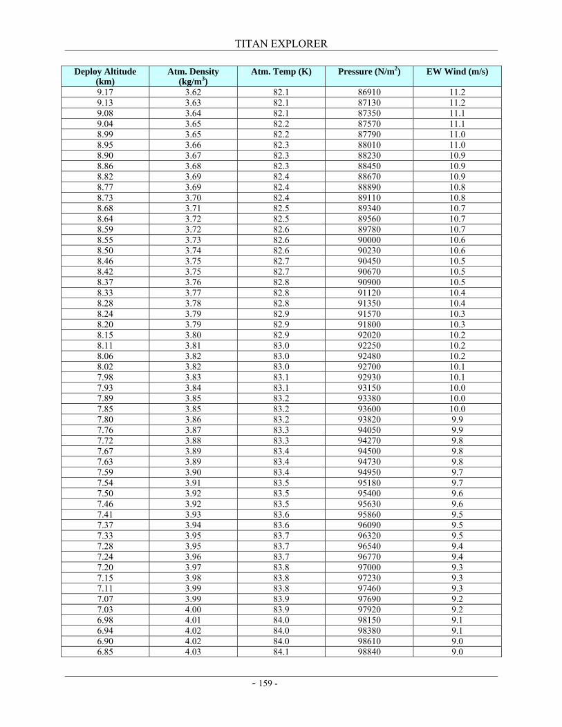
TITAN EXPLORER
- 159 -
Deploy Altitude (km)
Atm. Density (kg/m3)
Atm. Temp (K) Pressure (N/m2) EW Wind (m/s)
9.17 3.62 82.1 86910 11.2 9.13 3.63 82.1 87130 11.2 9.08 3.64 82.1 87350 11.1 9.04 3.65 82.2 87570 11.1 8.99 3.65 82.2 87790 11.0 8.95 3.66 82.3 88010 11.0 8.90 3.67 82.3 88230 10.9 8.86 3.68 82.3 88450 10.9 8.82 3.69 82.4 88670 10.9 8.77 3.69 82.4 88890 10.8 8.73 3.70 82.4 89110 10.8 8.68 3.71 82.5 89340 10.7 8.64 3.72 82.5 89560 10.7 8.59 3.72 82.6 89780 10.7 8.55 3.73 82.6 90000 10.6 8.50 3.74 82.6 90230 10.6 8.46 3.75 82.7 90450 10.5 8.42 3.75 82.7 90670 10.5 8.37 3.76 82.8 90900 10.5 8.33 3.77 82.8 91120 10.4 8.28 3.78 82.8 91350 10.4 8.24 3.79 82.9 91570 10.3 8.20 3.79 82.9 91800 10.3 8.15 3.80 82.9 92020 10.2 8.11 3.81 83.0 92250 10.2 8.06 3.82 83.0 92480 10.2 8.02 3.82 83.0 92700 10.1 7.98 3.83 83.1 92930 10.1 7.93 3.84 83.1 93150 10.0 7.89 3.85 83.2 93380 10.0 7.85 3.85 83.2 93600 10.0 7.80 3.86 83.2 93820 9.9 7.76 3.87 83.3 94050 9.9 7.72 3.88 83.3 94270 9.8 7.67 3.89 83.4 94500 9.8 7.63 3.89 83.4 94730 9.8 7.59 3.90 83.4 94950 9.7 7.54 3.91 83.5 95180 9.7 7.50 3.92 83.5 95400 9.6 7.46 3.92 83.5 95630 9.6 7.41 3.93 83.6 95860 9.5 7.37 3.94 83.6 96090 9.5 7.33 3.95 83.7 96320 9.5 7.28 3.95 83.7 96540 9.4 7.24 3.96 83.7 96770 9.4 7.20 3.97 83.8 97000 9.3 7.15 3.98 83.8 97230 9.3 7.11 3.99 83.8 97460 9.3 7.07 3.99 83.9 97690 9.2 7.03 4.00 83.9 97920 9.2 6.98 4.01 84.0 98150 9.1 6.94 4.02 84.0 98380 9.1 6.90 4.02 84.0 98610 9.0 6.85 4.03 84.1 98840 9.0
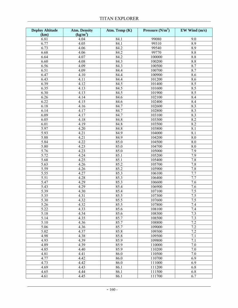
TITAN EXPLORER
- 160 -
Deploy Altitude (km)
Atm. Density (kg/m3)
Atm. Temp (K) Pressure (N/m2) EW Wind (m/s)
6.81 4.04 84.1 99080 9.0 6.77 4.05 84.1 99310 8.9 6.73 4.06 84.2 99540 8.9 6.68 4.06 84.2 99770 8.8 6.64 4.07 84.2 100000 8.8 6.60 4.08 84.3 100200 8.8 6.56 4.09 84.3 100500 8.7 6.51 4.09 84.4 100700 8.7 6.47 4.10 84.4 100900 8.6 6.43 4.11 84.4 101200 8.6 6.39 4.12 84.5 101400 8.5 6.35 4.13 84.5 101600 8.5 6.30 4.13 84.5 101900 8.5 6.26 4.14 84.6 102100 8.4 6.22 4.15 84.6 102400 8.4 6.18 4.16 84.7 102600 8.3 6.14 4.17 84.7 102800 8.3 6.09 4.17 84.7 103100 8.3 6.05 4.18 84.8 103300 8.2 6.01 4.19 84.8 103500 8.2 5.97 4.20 84.8 103800 8.1 5.93 4.21 84.9 104000 8.1 5.88 4.21 84.9 104200 8.0 5.84 4.22 85.0 104500 8.0 5.80 4.23 85.0 104700 8.0 5.76 4.23 85.0 105000 7.9 5.72 4.24 85.1 105200 7.9 5.68 4.25 85.1 105400 7.8 5.63 4.26 85.2 105700 7.8 5.59 4.26 85.2 105900 7.8 5.55 4.27 85.3 106100 7.7 5.51 4.28 85.3 106400 7.7 5.47 4.29 85.3 106600 7.6 5.43 4.29 85.4 106900 7.6 5.39 4.30 85.4 107100 7.5 5.35 4.31 85.5 107300 7.5 5.30 4.32 85.5 107600 7.5 5.26 4.32 85.5 107800 7.4 5.22 4.33 85.6 108100 7.4 5.18 4.34 85.6 108300 7.3 5.14 4.35 85.7 108500 7.3 5.10 4.36 85.7 108800 7.2 5.06 4.36 85.7 109000 7.2 5.02 4.37 85.8 109300 7.2 4.98 4.38 85.8 109500 7.1 4.93 4.39 85.9 109800 7.1 4.89 4.39 85.9 110000 7.0 4.85 4.40 85.9 110200 7.0 4.81 4.41 86.0 110500 7.0 4.77 4.42 86.0 110700 6.9 4.73 4.42 86.0 111000 6.9 4.69 4.43 86.1 111200 6.8 4.65 4.44 86.1 111500 6.8 4.61 4.45 86.1 111700 6.7
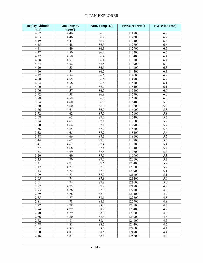
TITAN EXPLORER
- 161 -
Deploy Altitude (km)
Atm. Density (kg/m3)
Atm. Temp (K) Pressure (N/m2) EW Wind (m/s)
4.57 4.46 86.2 111900 6.7 4.53 4.46 86.2 112200 6.7 4.49 4.47 86.2 112400 6.6 4.45 4.48 86.3 112700 6.6 4.41 4.49 86.3 112900 6.5 4.37 4.50 86.4 113200 6.5 4.32 4.50 86.4 113400 6.4 4.28 4.51 86.4 113700 6.4 4.24 4.52 86.5 113900 6.4 4.20 4.53 86.5 114100 6.3 4.16 4.54 86.5 114400 6.3 4.12 4.54 86.6 114600 6.2 4.08 4.55 86.6 114900 6.2 4.04 4.56 86.6 115100 6.1 4.00 4.57 86.7 115400 6.1 3.96 4.57 86.7 115600 6.0 3.92 4.58 86.8 115900 6.0 3.88 4.59 86.8 116100 6.0 3.84 4.60 86.9 116400 5.9 3.80 4.60 86.9 116600 5.9 3.76 4.61 86.9 116900 5.8 3.72 4.62 87.0 117100 5.8 3.68 4.62 87.0 117400 5.7 3.64 4.63 87.1 117600 5.7 3.60 4.64 87.1 117900 5.7 3.56 4.65 87.2 118100 5.6 3.52 4.65 87.2 118400 5.6 3.48 4.66 87.3 118600 5.5 3.44 4.67 87.3 118900 5.5 3.41 4.67 87.4 119100 5.4 3.37 4.68 87.4 119400 5.4 3.33 4.69 87.5 119600 5.3 3.29 4.69 87.5 119900 5.3 3.25 4.70 87.6 120100 5.3 3.21 4.71 87.6 120400 5.2 3.17 4.72 87.7 120600 5.2 3.13 4.72 87.7 120900 5.1 3.09 4.73 87.7 121100 5.1 3.05 4.74 87.8 121400 5.0 3.01 4.74 87.8 121600 5.0 2.97 4.75 87.9 121900 4.9 2.93 4.76 87.9 122100 4.9 2.89 4.76 88.0 122400 4.9 2.85 4.77 88.1 122600 4.8 2.81 4.78 88.1 122900 4.8 2.77 4.78 88.2 123100 4.7 2.74 4.79 88.2 123400 4.7 2.70 4.79 88.3 123600 4.6 2.66 4.80 88.4 123900 4.6 2.62 4.81 88.4 124100 4.5 2.58 4.81 88.5 124400 4.5 2.54 4.82 88.5 124600 4.4 2.50 4.83 88.6 124900 4.4 2.46 4.83 88.6 125200 4.3
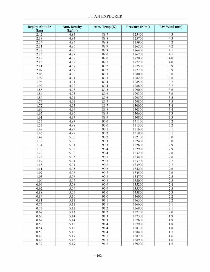
TITAN EXPLORER
- 162 -
Deploy Altitude (km)
Atm. Density (kg/m3)
Atm. Temp (K) Pressure (N/m2) EW Wind (m/s)
2.42 4.84 88.7 125400 4.3 2.38 4.84 88.8 125700 4.3 2.34 4.85 88.8 125900 4.2 2.31 4.86 88.9 126200 4.2 2.27 4.86 88.9 126400 4.1 2.23 4.87 89.0 126700 4.1 2.19 4.88 89.0 127000 4.0 2.15 4.88 89.1 127200 4.0 2.11 4.89 89.2 127500 3.9 2.07 4.89 89.2 127700 3.9 2.03 4.90 89.3 128000 3.8 1.99 4.91 89.3 128200 3.8 1.96 4.91 89.4 128500 3.7 1.92 4.92 89.4 128800 3.7 1.88 4.93 89.5 129000 3.6 1.84 4.93 89.6 129300 3.6 1.80 4.94 89.6 129500 3.5 1.76 4.94 89.7 129800 3.5 1.72 4.95 89.7 130000 3.4 1.69 4.96 89.8 130300 3.4 1.65 4.96 89.9 130600 3.3 1.61 4.97 89.9 130800 3.3 1.57 4.97 90.0 131100 3.2 1.53 4.98 90.0 131300 3.2 1.49 4.99 90.1 131600 3.1 1.46 4.99 90.2 131900 3.1 1.42 5.00 90.2 132100 3.0 1.38 5.00 90.3 132400 3.0 1.34 5.01 90.3 132600 2.9 1.30 5.02 90.4 132900 2.9 1.26 5.02 90.4 133200 2.8 1.23 5.03 90.5 133400 2.8 1.19 5.04 90.5 133700 2.7 1.15 5.04 90.6 133900 2.7 1.11 5.05 90.6 134200 2.6 1.07 5.06 90.7 134500 2.6 1.03 5.06 90.8 134700 2.5 1.00 5.07 90.8 135000 2.5 0.96 5.08 90.9 135200 2.4 0.92 5.09 90.9 135500 2.3 0.88 5.09 91.0 135800 2.3 0.84 5.10 91.0 136000 2.2 0.81 5.11 91.1 136300 2.2 0.77 5.11 91.1 136600 2.1 0.73 5.12 91.2 136800 2.1 0.69 5.13 91.2 137100 2.0 0.65 5.14 91.3 137300 1.9 0.62 5.14 91.3 137600 1.9 0.58 5.15 91.4 137900 1.8 0.54 5.16 91.4 138100 1.8 0.50 5.16 91.4 138400 1.7 0.46 5.17 91.5 138700 1.6 0.43 5.18 91.5 138900 1.6 0.39 5.19 91.6 139200 1.5
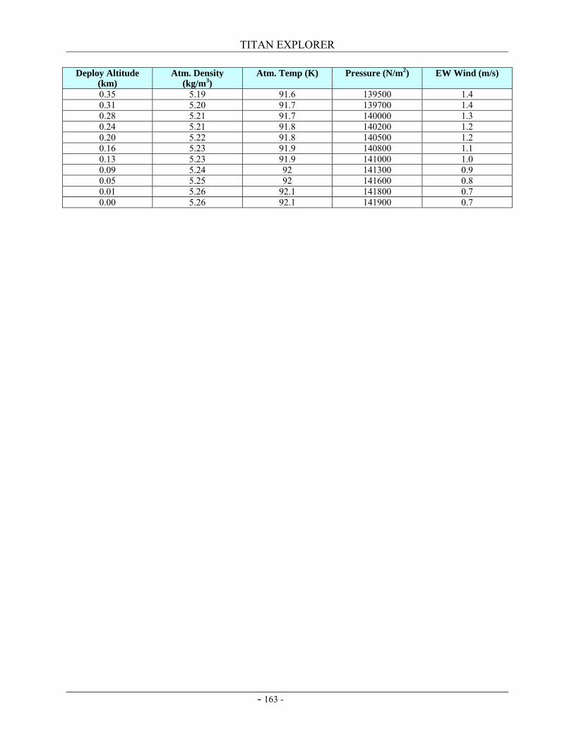
TITAN EXPLORER
- 163 -
Deploy Altitude (km)
Atm. Density (kg/m3)
Atm. Temp (K) Pressure (N/m2) EW Wind (m/s)
0.35 5.19 91.6 139500 1.4 0.31 5.20 91.7 139700 1.4 0.28 5.21 91.7 140000 1.3 0.24 5.21 91.8 140200 1.2 0.20 5.22 91.8 140500 1.2 0.16 5.23 91.9 140800 1.1 0.13 5.23 91.9 141000 1.0 0.09 5.24 92 141300 0.9 0.05 5.25 92 141600 0.8 0.01 5.26 92.1 141800 0.7 0.00 5.26 92.1 141900 0.7
Related Documents