8 Three Dimensional Measurement Using Fisheye Stereo Vision Jun’ichi Yamaguchi Kagawa University Japan 1. Introduction Studies on omni-directional vision sensor with a large field of view have shown a superiority in sensing of surrounding and scene analysis. For omni-directional view, mainly a hyperboloid mirror or a conic mirror is installed in front of the camera lens, and application equipments are used in robot, car, etc. (Yamazawa et al., 1997; Torii & Imiya, 2004; Kawanishi et al., 2008; Kawanishi et al., 2009). Recently, in accordance with an experience in such applications, the study on omni-directional three dimensional (3D) recognition is increasing (Kubo & Yamaguchi, 2007; Nishimoto & Yamaguchi, 2008). This chapter describes 3D measurement using fish-eye lens as omni-directional optical device. Fish-eye lens provides a remarkable large field of view compared with a standard lens. Field of view (FOV) is nearly 180°. Concerning FOV, there are some FOVs (170°, 180°, 185°, etc.) by lens. Fish-eye camera is simple and compact compared with mirror mounting camera above. Difference from mirror mounting camera is as follows: no optical device in front of camera, and no blind spot in center of the image (mirror system captures the camera). 3D measurement by fish-eye stereo vision is one of evolution for wide range measuring. Fish- eye image has a peculiar distortion. But, handling of it is not hard, by using an established process to the distortion. Methods of 3D measurement using fish-eye camera have been proposed until now (Shah & Aggarwal, 1997; Oizumi et al., 2003; Hrabar et al., 2004; Gehrig et al., 2008). Necessary images for making a range data are acquired by binocular stereo or motion stereo. Range data is obtained by 3D equation which is decided by optical system, using a parallax quantity which is given by detection of a correspondence between two image pixels. Therefore, correctness of the correspondence is important. In correspondence process, an undistorted image, which is obtained by correcting an inherent distortion of the fish-eye image, is generally used. Correction of the distortion is performed by calibration methods as follows: method using the radial and tangential offset components by Nth-order polynomial, method of non-linear least mean squares fit, Bundle adjustment method, method by inverse model of fish-eye projection, etc. Using the undistorted image, the correspondence between two image pixels is decided by image matching (for example template matching). As such, the corrected image has an important role and is generally used for obtaining the range data. On the other hand, the method without the corrected image has been proposed. In such method, corresponding pixel is searched following an epipolar line at every coordinate. The epipolar line draws a complicated locus and the shape www.intechopen.com

Welcome message from author
This document is posted to help you gain knowledge. Please leave a comment to let me know what you think about it! Share it to your friends and learn new things together.
Transcript
8
Three Dimensional Measurement Using Fisheye Stereo Vision
Jun’ichi Yamaguchi Kagawa University
Japan
1. Introduction
Studies on omni-directional vision sensor with a large field of view have shown a superiority in sensing of surrounding and scene analysis. For omni-directional view, mainly a hyperboloid mirror or a conic mirror is installed in front of the camera lens, and application equipments are used in robot, car, etc. (Yamazawa et al., 1997; Torii & Imiya, 2004; Kawanishi et al., 2008; Kawanishi et al., 2009). Recently, in accordance with an experience in such applications, the study on omni-directional three dimensional (3D) recognition is increasing (Kubo & Yamaguchi, 2007; Nishimoto & Yamaguchi, 2008). This chapter describes 3D measurement using fish-eye lens as omni-directional optical device. Fish-eye lens provides a remarkable large field of view compared with a standard lens. Field of view (FOV) is nearly 180°. Concerning FOV, there are some FOVs (170°, 180°, 185°, etc.) by lens. Fish-eye camera is simple and compact compared with mirror mounting camera above. Difference from mirror mounting camera is as follows: no optical device in front of camera, and no blind spot in center of the image (mirror system captures the camera). 3D measurement by fish-eye stereo vision is one of evolution for wide range measuring. Fish-eye image has a peculiar distortion. But, handling of it is not hard, by using an established process to the distortion. Methods of 3D measurement using fish-eye camera have been proposed until now (Shah & Aggarwal, 1997; Oizumi et al., 2003; Hrabar et al., 2004; Gehrig et al., 2008). Necessary images for making a range data are acquired by binocular stereo or motion stereo. Range data is obtained by 3D equation which is decided by optical system, using a parallax quantity which is given by detection of a correspondence between two image pixels. Therefore, correctness of the correspondence is important. In correspondence process, an undistorted image, which is obtained by correcting an inherent distortion of the fish-eye image, is generally used. Correction of the distortion is performed by calibration methods as follows: method using the radial and tangential offset components by Nth-order polynomial, method of non-linear least mean squares fit, Bundle adjustment method, method by inverse model of fish-eye projection, etc. Using the undistorted image, the correspondence between two image pixels is decided by image matching (for example template matching). As such, the corrected image has an important role and is generally used for obtaining the range data. On the other hand, the method without the corrected image has been proposed. In such method, corresponding pixel is searched following an epipolar line at every coordinate. The epipolar line draws a complicated locus and the shape
www.intechopen.com
Advances in Theory and Applications of Stereo Vision
152
of the locus is different every coordinate due to inherent distortion of fish-eye image. Therefore, it is generally hard to apply the epipolar geometry to fish-eye image. But, that method shows the applicability of the epipolar geometry using an invariance feature on translation, rotation and scale change in the image. Consequently, such method has the advantage that correspondence can be decided directly from the fish-eye image, though the measuring object is restricted because of a fixed shooting condition. For defining the region which is composed of homogeneous pixels, segmentation is
performed using the result of the correspondence process. Namely, segmentation process is
needed for region classification and region extraction. For example, it can be used for
recognizing the objects individually in moving objects measurement. Thus, this process has
important role for scene analysis. In case of using corrected image, the conventional
segmentation method which is used to the image from normal lens camera can be applied.
Segmentation based on feature extraction is one of well known methods. If a specified shape
(for example, pillar, door, …) is stably shot, scene can be analyzed by depth information of
vertical lines and/or horizontal lines. But, in case of a general scene and overlapping objects,
it is considered that the method based on feature extraction is not enough accuracy. In such
case, clustering based on 3D position data is useful. Namely, the pixels which close each
other within a threshold of 3D distance are clustered. According to it, the region can be
decided regardless shape and feature of the object. On the other hand, a direct segmentation
to fish-eye image is proposed. Such method is based on homogeneity of pixels on concentric
circumference. It has the advantage that the pixels are classified directly in the fish-eye
image. However, application of the method is restricted because objects must be always shot
from a particular angle. In 3D measurement using fish-eye images, correspondence process
and 3D segmentation process have important role. Therefore, the process should be
designed appropriately to a purpose of application.
In this chapter, section 2 describes fish-eye lens and construction of fish-eye vision, section 3
describes correspondence process and section 4 describes 3D segmentation. Section 5
explains an example of the experimental result in study of 3D measurement using fish-eye
stereo vision. Result shows the measurement accuracy on 3D structure of scene and moving
objects. Finally, section 6 concludes the chapter.
2. Fish-eye stereo vision
2.1 Fish-eye camera Fish-eye lens provides a remarkable large FOV (nearly 180°) compared with a standard lens.
Lineup of FOV which depends upon lens are 170°, 180°, 185°, etc. Using the fish-eye lens
mounting camera (fish-eye camera), all-direction space in front of the lens is projected onto
an image plane. Namely, by the projection image (fish-eye image), it is possible to handle a
semispherical space in front of the fish-eye camera. As such, an extreme wide measurable
space is an advantage of the fish-eye camera. So it is expected that the fish-eye camera
produces a novel and creative possibilities of image application. As fish-eye transform, some
methods (logarithmic mapping, log-polar mapping, polynomial transform, etc.) had been
proposed. Recently, the equidistance projection model, the orthogonal projection model, etc.
are used well. It is considered that these models are easily accepted because of popular first-
order approximation and enough accuracy. Fig.1 shows the projection model of fish-eye
lens. Fish-eye mapping is expressed by some of following (1)-(4):
www.intechopen.com

Three Dimensional Measurement Using Fisheye Stereo Vision
153
Fish-eye imageregion
Image plane
Fish-eye lens
Nodal pointon the lens
Fig. 1. Fish-eye mapping model
fθ=r (equidistance projection), (1)
fsinθ=r (orthogonal projection), (2)
( )2 / 2ftan θ=r (stereographic projection), (3)
( )2 / 2fsin θ=r (equisolid angle projection). (4)
Where, r is the distance of the point from the fish-eye image center, f is the focal length of
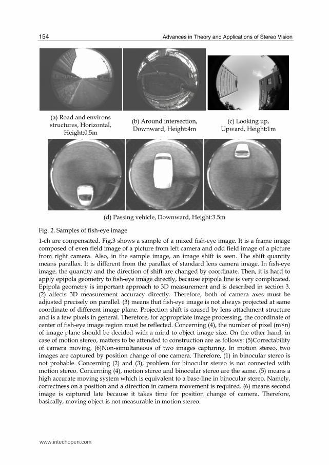
the fish-eye lens and θ is the zenith angle. Mechanism of the mapping is that a 3D ray from the nodal point on the lens is projected onto an image position which is specified by r using θ and α. According to the mapping, as θ is larger, the extension rate of r is reduced. Namely, space resolution towards periphery of image is decreased. Fig.2 shows sample of fish-eye images. Caption of each figure mean as follows: Object, Direction of camera, Height above the ground. Inside of circle area is the fish-eye image region. According to it, decrease of space resolution towards periphery and large observable area can be confirmed. Decrease of resolution causes an image distortion. As seen in the sample, object bends in an arc by coordinate. That is there are different degrees of the distortion on different coordinates. Therefore, it is generally hard to apply the epipolar analysis to fish-eye image because of complicated epipolar lines. The sample also expresses a possibility of various shooting and measurement. For example, as seen in fig.2(c) and (d), omni-directional 3D recognition by looking up and overall observation of a passing object are interesting subjects. As such, though we need to note fish-eye image in handling, it is considered that the fish-eye camera has the potential on novel and creative image application.
2.2 Stereo vision As a fish-eye vision system for 3D measurement, a binocular stereo or a motion stereo is generally used. In case of binocular stereo, matters to be attended to construct a stereo vision system are as follows: (1)Simultaneous capturing of two images, (2)Parallel two camera axes, (3)Center of each fish-eye image region, (4)Space resolution, etc. (1) is especially important in case of capturing moving object. Capturing equipments of two channels are used in many case. In case of using 1-ch capturing equipment, two images mixing device is useful. The device can be easily made by low cost relatively. It has an advantage that simultaneous capturing of two images and stereo image transmission by
www.intechopen.com
Advances in Theory and Applications of Stereo Vision
154
(a) Road and environs structures, Horizontal,
Height:0.5m
(b) Around intersection, Downward, Height:4m
(c) Looking up, Upward, Height:1m
(d) Passing vehicle, Downward, Height:3.5m
Fig. 2. Samples of fish-eye image
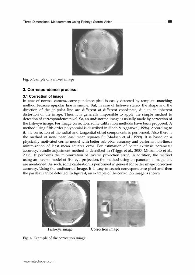
1-ch are compensated. Fig.3 shows a sample of a mixed fish-eye image. It is a frame image composed of even field image of a picture from left camera and odd field image of a picture from right camera. Also, in the sample image, an image shift is seen. The shift quantity means parallax. It is different from the parallax of standard lens camera image. In fish-eye image, the quantity and the direction of shift are changed by coordinate. Then, it is hard to apply epipola geometry to fish-eye image directly, because epipola line is very complicated. Epipola geometry is important approach to 3D measurement and is described in section 3. (2) affects 3D measurement accuracy directly. Therefore, both of camera axes must be adjusted precisely on parallel. (3) means that fish-eye image is not always projected at same coordinate of different image plane. Projection shift is caused by lens attachment structure and is a few pixels in general. Therefore, for appropriate image processing, the coordinate of center of fish-eye image region must be reflected. Concerning (4), the number of pixel (m×n) of image plane should be decided with a mind to object image size. On the other hand, in case of motion stereo, matters to be attended to construction are as follows: (5)Correctability of camera moving, (6)Non-simultaneous of two images capturing. In motion stereo, two images are captured by position change of one camera. Therefore, (1) in binocular stereo is not probable. Concerning (2) and (3), problem for binocular stereo is not connected with motion stereo. Concerning (4), motion stereo and binocular stereo are the same. (5) means a high accurate moving system which is equivalent to a base-line in binocular stereo. Namely, correctness on a position and a direction in camera movement is required. (6) means second image is captured late because it takes time for position change of camera. Therefore, basically, moving object is not measurable in motion stereo.
www.intechopen.com
Three Dimensional Measurement Using Fisheye Stereo Vision
155
Fig. 3. Sample of a mixed image
3. Correspondence process
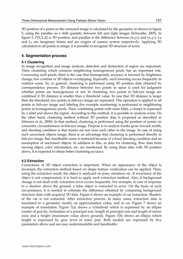
3.1 Correction of image In case of normal camera, correspondence pixel is easily detected by template matching method because epipolar line is simple. But, in case of fish-eye stereo, the shape and the direction of the epipolar line are different at different coordinate, due to an inherent distortion of the image. Then, it is generally impossible to apply the simple method to detection of correspondence pixel. So, an undistorted image is usually made by correction of the fish-eye image. For image correction, some calibration methods have been proposed. A method using fifth-order polynomial is described in (Shah & Aggarwal, 1996). According to it, the correction of the radial and tangential offset components is performed. Also there is the method of non-linear least mean squares fit (Madsen et al., 1999). It is based on a physically motivated corner model with better sub-pixel accuracy and performs non-linear minimization of least mean squares error. For estimation of better extrinsic parameter accuracy, Bundle adjustment method is described in (Triggs et al., 2000; Mitsumoto et al., 2008). It performs the minimization of inverse projection error. In addition, the method using an inverse model of fish-eye projection, the method using an panoramic image, etc. are mentioned. As such, some calibration is performed in general for better image correction accuracy. Using the undistorted image, it is easy to search correspondence pixel and then the parallax can be detected. In figure 4, an example of the correction image is shown.
Fig. 4. Example of the correction image
Fish-eye image Correction image
www.intechopen.com

Advances in Theory and Applications of Stereo Vision
156
On the other hand, there is the case that correspondence can be decided directly from the
fish-eye image. Such correspondence is possible in case of a scene which is composed of an
invariance feature on translation, rotation and scale change. For example, as seen in (Herrera
et al., 2009), objects which grow straightly toward zenith is mentioned. In the case,
correspondent point is searched in limited region in fish-eye image. As such, there is an
advantage that correspondent point can be decided directly without image correction,
though application is restricted because of a fixed shooting condition.
In order to apply fish-eye stereo to 3D measurement of various scene, correction of image is
useful and then calibration has an important role for better correction accuracy. Using the
correction image, it is easy to detect the parallax in various applications.
3.2 Stereo matching The analysis of stereo images is a well-established method for 3D structure extracting from
2D projection images. For 3D structure expression, 3D position data is needed. And parallax
data obtained by image matching is needed for 3D position detection. In case of using the
undistorted image obtained by correction, template matching which is well known in
pattern matching can be applied to parallax detection. Actually template matching is well
used in normal FOV stereo. But it is needed to notice to uniform region and only horizontal
line region, because right correlation result is not obtained in such region. When
characteristic texture is detected stably in the images, a feature-based method can be
applied. For example, parallax detection on vertical line is well known as described in (Shah
& Aggarwal, 1997). If object is rigid body and its shape is unique, image matching is easier.
Fig. 5. Stereo system
IR(x1,y1)
Corrected image
P(X,Y,Z)
LR LL
x x
y
IL(x2,y1)
y
z z
Base line length
www.intechopen.com
Three Dimensional Measurement Using Fisheye Stereo Vision
157
3D position of a point on the corrected image is calculated by the geometry as shown in figure 5, using the parallax as a shift quantity between left and right images (Schwalbe, 2005). In figure 5, P(X,Y,Z) is 3D position, and parallax is the difference between (x2,y1) and (x1,y1). LR and LL are imaginary lenses and are origins of camera system respectively. Applying 3D calculation to all points in image, it is possible to recognize 3D structure of scene.
4. Segmentation process
4.1 Clustering In image recognition and image analysis, detection and distinction of region are important. Then, clustering which connects neighboring homogeneous pixels has an important role. Concerning such pixels, there is the case that homogeneity accuracy is lowered by brightness change, low contrast or 3D objects overlapping. Especially, such lowering occurs frequently in outdoor scene. So, in general, clustering is performed using 3D position data obtained by correspondence process. 3D distance between two points in space is used for judgment whether points are homogeneous or not. In clustering, two points in fish-eye image are combined if 3D distance is smaller than a threshold value. In case that 3D distance is larger than the threshold, two points in fish-eye image are separated. This operation is applied to all points in fish-eye image and labeling (for example numbering) is performed to neighboring points as homogeneous pixels. Then, combining points with same label, a cluster is expressed by a label and shows the region. According to this method, it is possible to analysis scene. On the other hand, clustering method without 3D position data is proposed as described in (Herrera et al., 2009). In that method, clustering is performed using the position of points on concentric circumferences in fish-eye image. Purpose is to analyze trunks grow toward zenith, and shooting condition is that trunks are not cross each other in the image. In case of using such uncrossed objects image, there is an advantage that clustering is performed directly in fish-eye image. But, handleable scene is restricted because of a fixed shooting condition and an assumption of uncrossed objects. In addition to this, as data for clustering, flow data from moving object, color information, etc. are mentioned. By using these data with 3D position above, it is expected to obtain better clustering accuracy.
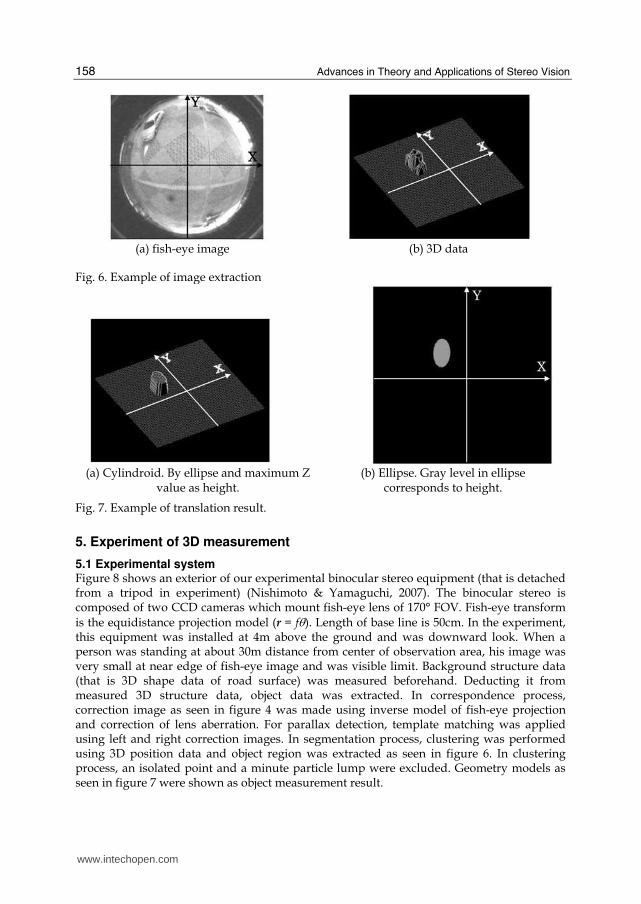
4.2 Extraction Correctness of 3D object extraction is important. When an appearance of the object is invariant, the extraction method based on shape feature verification can be applied. Then, using the extraction result, the object is analyzed on pose, situation, etc. If invariance of the object is not compensated, it is hard to apply such extraction method. Also, if background change is not dealt with, extraction error occurs frequently. For example, in case of response to a shadow above the ground, a false object is extracted in error. On the basis of such circumstance, it is needed to estimate the difference obtained by comparing background structure data with acquired 3D data. Figure 6 shows an example of car extraction. Shadow of the car is not extracted. After extraction process, in many cases, extraction data is translated to a geometry model, an approximation value, and so on. Figure 7 shows an example of translation. Figure 7(a) shows a cylindroid which is expressed by an ellipse (center of gravity, inclination of a principal axis, length of principal axis and length of minor axis) and a height (maximum value above ground). Figure 7(b) shows an ellipse which height is expressed by gray level of inner part. Both models are expressed by five parameters above and are easy understandable and handleable.
www.intechopen.com
Advances in Theory and Applications of Stereo Vision
158
(a) fish-eye image (b) 3D data Fig. 6. Example of image extraction
(a) Cylindroid. By ellipse and maximum Z
value as height. (b) Ellipse. Gray level in ellipse
corresponds to height.
Fig. 7. Example of translation result.
5. Experiment of 3D measurement
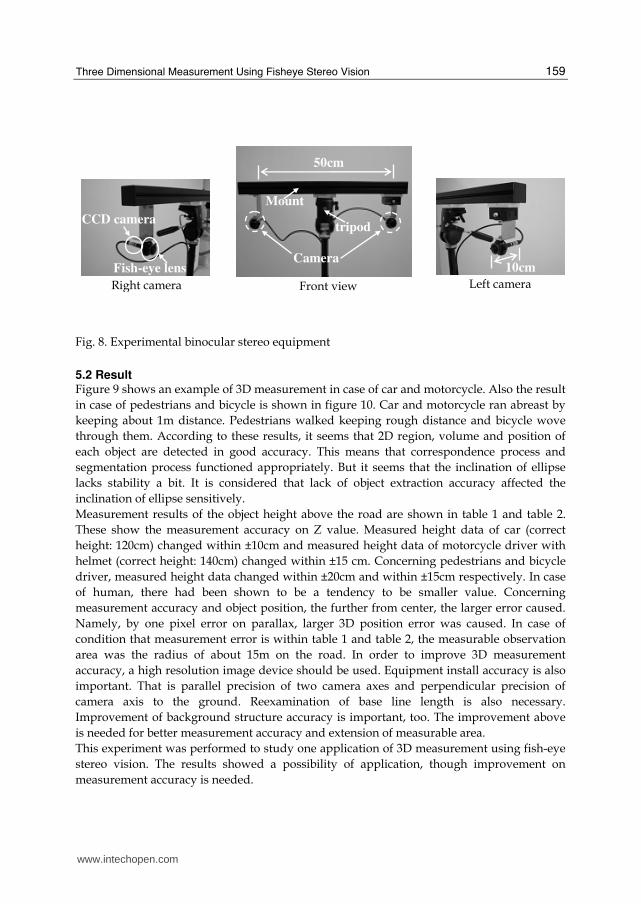
5.1 Experimental system Figure 8 shows an exterior of our experimental binocular stereo equipment (that is detached from a tripod in experiment) (Nishimoto & Yamaguchi, 2007). The binocular stereo is composed of two CCD cameras which mount fish-eye lens of 170° FOV. Fish-eye transform is the equidistance projection model (r = fθ). Length of base line is 50cm. In the experiment, this equipment was installed at 4m above the ground and was downward look. When a person was standing at about 30m distance from center of observation area, his image was very small at near edge of fish-eye image and was visible limit. Background structure data (that is 3D shape data of road surface) was measured beforehand. Deducting it from measured 3D structure data, object data was extracted. In correspondence process, correction image as seen in figure 4 was made using inverse model of fish-eye projection and correction of lens aberration. For parallax detection, template matching was applied using left and right correction images. In segmentation process, clustering was performed using 3D position data and object region was extracted as seen in figure 6. In clustering process, an isolated point and a minute particle lump were excluded. Geometry models as seen in figure 7 were shown as object measurement result.
www.intechopen.com
Three Dimensional Measurement Using Fisheye Stereo Vision
159
Fig. 8. Experimental binocular stereo equipment
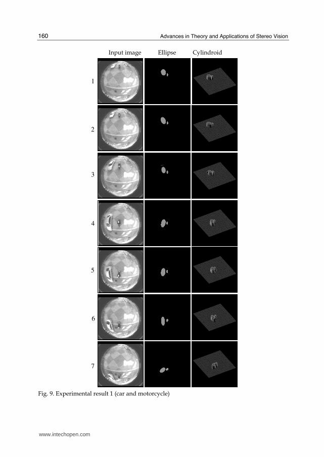
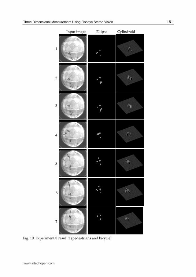
5.2 Result Figure 9 shows an example of 3D measurement in case of car and motorcycle. Also the result
in case of pedestrians and bicycle is shown in figure 10. Car and motorcycle ran abreast by
keeping about 1m distance. Pedestrians walked keeping rough distance and bicycle wove
through them. According to these results, it seems that 2D region, volume and position of
each object are detected in good accuracy. This means that correspondence process and
segmentation process functioned appropriately. But it seems that the inclination of ellipse
lacks stability a bit. It is considered that lack of object extraction accuracy affected the
inclination of ellipse sensitively.
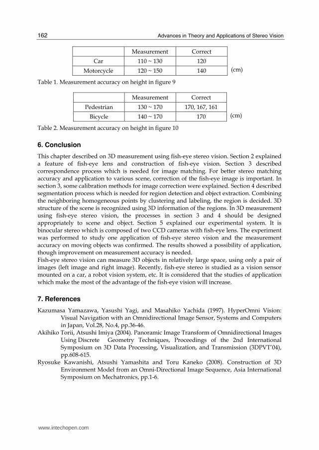
Measurement results of the object height above the road are shown in table 1 and table 2.
These show the measurement accuracy on Z value. Measured height data of car (correct
height: 120cm) changed within ±10cm and measured height data of motorcycle driver with
helmet (correct height: 140cm) changed within ±15 cm. Concerning pedestrians and bicycle
driver, measured height data changed within ±20cm and within ±15cm respectively. In case
of human, there had been shown to be a tendency to be smaller value. Concerning
measurement accuracy and object position, the further from center, the larger error caused.
Namely, by one pixel error on parallax, larger 3D position error was caused. In case of
condition that measurement error is within table 1 and table 2, the measurable observation
area was the radius of about 15m on the road. In order to improve 3D measurement
accuracy, a high resolution image device should be used. Equipment install accuracy is also
important. That is parallel precision of two camera axes and perpendicular precision of
camera axis to the ground. Reexamination of base line length is also necessary.
Improvement of background structure accuracy is important, too. The improvement above
is needed for better measurement accuracy and extension of measurable area.
This experiment was performed to study one application of 3D measurement using fish-eye
stereo vision. The results showed a possibility of application, though improvement on
measurement accuracy is needed.
10cm Fish-eye lens
CCD camera
Front view Left camera Right camera
tripod
Camera
50cm
Mount
www.intechopen.com
Advances in Theory and Applications of Stereo Vision
160
Fig. 9. Experimental result 1 (car and motorcycle)
Input image Ellipse Cylindroid
1
2
3
7
5
6
4
www.intechopen.com
Three Dimensional Measurement Using Fisheye Stereo Vision
161
Fig. 10. Experimental result 2 (pedestrians and bicycle)
Input image Ellipse Cylindroid
1
2
3
7
5
6
4
www.intechopen.com
Advances in Theory and Applications of Stereo Vision
162
Measurement Correct
Car 110 ~ 130 120
Motorcycle 120 ~ 150 140 (cm)
Table 1. Measurement accuracy on height in figure 9
Measurement Correct
Pedestrian 130 ~ 170 170, 167, 161
Bicycle 140 ~ 170 170 (cm)
Table 2. Measurement accuracy on height in figure 10
6. Conclusion
This chapter described on 3D measurement using fish-eye stereo vision. Section 2 explained a feature of fish-eye lens and construction of fish-eye vision. Section 3 described correspondence process which is needed for image matching. For better stereo matching accuracy and application to various scene, correction of the fish-eye image is important. In section 3, some calibration methods for image correction were explained. Section 4 described segmentation process which is needed for region detection and object extraction. Combining the neighboring homogeneous points by clustering and labeling, the region is decided. 3D structure of the scene is recognized using 3D information of the regions. In 3D measurement using fish-eye stereo vision, the processes in section 3 and 4 should be designed appropriately to scene and object. Section 5 explained our experimental system. It is binocular stereo which is composed of two CCD cameras with fish-eye lens. The experiment was performed to study one application of fish-eye stereo vision and the measurement accuracy on moving objects was confirmed. The results showed a possibility of application, though improvement on measurement accuracy is needed. Fish-eye stereo vision can measure 3D objects in relatively large space, using only a pair of images (left image and right image). Recently, fish-eye stereo is studied as a vision sensor mounted on a car, a robot vision system, etc. It is considered that the studies of application which make the most of the advantage of the fish-eye vision will increase.
7. References
Kazumasa Yamazawa, Yasushi Yagi, and Masahiko Yachida (1997). HyperOmni Vision: Visual Navigation with an Omnidirectional Image Sensor, Systems and Computers in Japan, Vol.28, No.4, pp.36-46.
Akihiko Torii, Atsushi Imiya (2004). Panoramic Image Transform of Omnidirectional Images Using Discrete Geometry Techniques, Proceedings of the 2nd International Symposium on 3D Data Processing, Visualization, and Transmission (3DPVT’04), pp.608-615.
Ryosuke Kawanishi, Atsushi Yamashita and Toru Kaneko (2008). Construction of 3D Environment Model from an Omni-Directional Image Sequence, Asia International Symposium on Mechatronics, pp.1-6.
www.intechopen.com
Three Dimensional Measurement Using Fisheye Stereo Vision
163
Ryosuke Kawanishi, Atsushi Yamashita, and Toru Kaneko (2009). Three-Dimensional Environment Model Construction from an Omnidirectional Image Sequence, Journal of Robotics and Mechatronics, Vol.21, No.5, pp.574-579,
Yohei Kubo and Jun’ichi Yamaguchi (2007). Human Tracking Using Fisheye Images, Proceedings of SICE Annual Conference 2007, pp.2013-2017.
Takeshi Nishimoto and Jun’ichi Yamaguchi (2008). A Vehicle Identification Using Fisheye Camera, Proceedings of Asia International Symposium on Mechatronics (AISM2008), TA1-1(1), pp.5-8.
Shishir Shah, J. K. Aggarwal (1997). Mobile robot navigation and scene modeling using stereo fish-eye lens system, Machine Vision and Applications (ISSN:0932-8092), Vol.10, No.4, pp.159-173.
Oizumi Ken, Yamamoto Yasuhide, Sakata Masao, Inoue Masato (2003). Development of "All-Around View" system, Nissan Technical Review, Vol.53, pp.52-56.
Stefan Hrabar, Gaurav S. Sukhatme, Peter Corke, Kane Usher and Jonathan Roberts (2004). Combined Optic-Flow and Stereo-Based Navigation of Urban Canyons for a UAV, proceedings of IEEE International Conference on Intelligent Robots and Systems, pp.3609-3615.
Stefan Gehrig, Clemens Rabe, Lars Krüger (2008). 6D Vision Goes Fisheye for Intersection Assistance, Proceeding of Canadian Conference on Computer and Robot Vision, pp.34-41.
Shah S, Aggarwal J. K. (1996). Intrinsic parameter calibration procedure for (high-distortion) fish-eye lens Camera with distortion model and accuracy estimation, Pattern Recognition, 29(11), pp.1775-1788.
K. Madsen, H. B. Nielsen, and O. Tingleff (1999). Methods for non-linear least squares problems, IMM, pp.1-29.
Bill Triggs, Philip F. McLauchlan, Richard I. Hartley, and Andrew W. Fitzgibbon (2000). Bundle Adjustment —A Modern Synthesis, Vision Algorithms’99, LNCS 1883, pp. 298-372.
Hisanori Mitsumoto, Yohei Aragaki, Noriko Shimomura, Kenji Terabayashi and Kazunori Umeda (2008). Basic Examination on Motion Stereo Vision Using a Fish-Eye Camera, Proceeding of the 26th Annual Conference of the Robotics Society of Japan, Vol.26, pp.1L1-07.
P. Javier Herrera, Gonzalo Pajares, Maria Guijarro, Jose J. Ruz, and Jesus M. Cruz (2009). Choquet Fuzzy Integral Applied to Stereovision Matching for Fish-Eye Lenses in Forest Analysis, Advances in Soft Computing (ISSN:1615-3871), Vol.116, pp.179-187.
Pedro Javier Herrera, Gonzalo Pajares, Maria Guijarro, Jose J. Ruz, Jesus M. Cruz and Fernando Montes (2009). A Featured-Based Strategy for Stereovision Matching in Sensors with Fish-Eye Lenses for Forest Environments, Sensors (ISSN 1424-8220), 9, pp.9468-9492.
Schwalbe (2005). Geometric modeling and calibration of fisheye lens camera systems, Proceedings of the 2nd
Panoramic Photogrammetry Workshop, International Archives of Photogrammetry and Remote Sensing, Vol.36, Part5/W8.
Pedro Javier Herrera, Gonzalo Pajares, Maria Guijarro, Jose J. Ruz, and Jesus M. Cruz (2009). Combination
www.intechopen.com

Advances in Theory and Applications of Stereo Vision
164
of attributes in stereovision matching for fish-eye lenses in forest analysis, In ACIVS 2009, Springer-Verlag, LNCS 5807, pp.277-287.
Takeshi Nishimoto and Jun’ichi Yamaguchi (2007). Three-dimensional measurement using fisheye stereo vision, Proceedings of SICE Annual Conference 2007, pp.2008-2012.
www.intechopen.com

Advances in Theory and Applications of Stereo VisionEdited by Dr Asim Bhatti
ISBN 978-953-307-516-7Hard cover, 352 pagesPublisher InTechPublished online 08, January, 2011Published in print edition January, 2011
InTech EuropeUniversity Campus STeP Ri Slavka Krautzeka 83/A 51000 Rijeka, Croatia Phone: +385 (51) 770 447 Fax: +385 (51) 686 166www.intechopen.com
InTech ChinaUnit 405, Office Block, Hotel Equatorial Shanghai No.65, Yan An Road (West), Shanghai, 200040, China
Phone: +86-21-62489820 Fax: +86-21-62489821
The book presents a wide range of innovative research ideas and current trends in stereo vision. The topicscovered in this book encapsulate research trends from fundamental theoretical aspects of robust stereocorrespondence estimation to the establishment of novel and robust algorithms as well as applications in awide range of disciplines. Particularly interesting theoretical trends presented in this book involve theexploitation of the evolutionary approach, wavelets and multiwavelet theories, Markov random fields and fuzzysets in addressing the correspondence estimation problem. Novel algorithms utilizing inspiration frombiological systems (such as the silicon retina imager and fish eye) and nature (through the exploitation of therefractive index of liquids) make this book an interesting compilation of current research ideas.
How to referenceIn order to correctly reference this scholarly work, feel free to copy and paste the following:
Jun'ichi Yamaguchi (2011). Three Dimensional Measurement Using Fisheye Stereo Vision, Advances inTheory and Applications of Stereo Vision, Dr Asim Bhatti (Ed.), ISBN: 978-953-307-516-7, InTech, Availablefrom: http://www.intechopen.com/books/advances-in-theory-and-applications-of-stereo-vision/three-dimensional-measurement-using-fisheye-stereo-vision
Related Documents