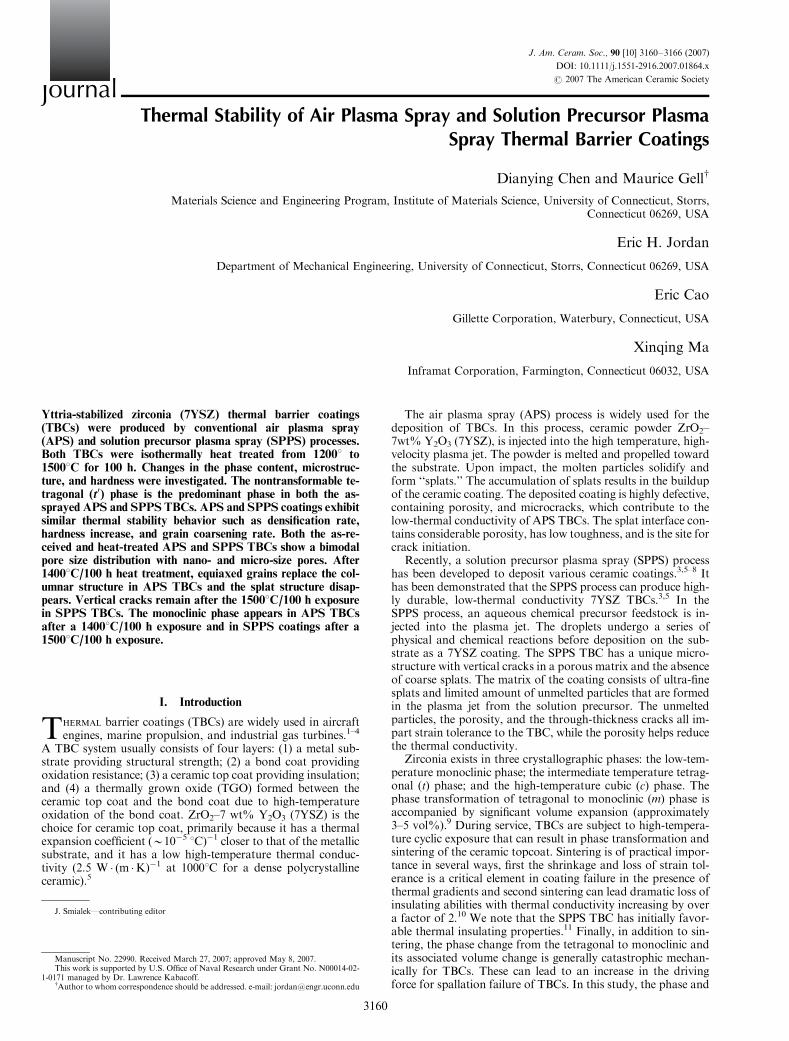
Thermal Stability of Air Plasma Spray and Solution Precursor Plasma Spray Thermal Barrier Coatings Dianying Chen and Maurice Gell w Materials Science and Engineering Program, Institute of Materials Science, University of Connecticut, Storrs, Connecticut 06269, USA Eric H. Jordan Department of Mechanical Engineering, University of Connecticut, Storrs, Connecticut 06269, USA Eric Cao Gillette Corporation, Waterbury, Connecticut, USA Xinqing Ma Inframat Corporation, Farmington, Connecticut 06032, USA Yttria-stabilized zirconia (7YSZ) thermal barrier coatings (TBCs) were produced by conventional air plasma spray (APS) and solution precursor plasma spray (SPPS) processes. Both TBCs were isothermally heat treated from 12001 to 15001C for 100 h. Changes in the phase content, microstruc- ture, and hardness were investigated. The nontransformable te- tragonal (t 0 ) phase is the predominant phase in both the as- sprayed APS and SPPS TBCs. APS and SPPS coatings exhibit similar thermal stability behavior such as densification rate, hardness increase, and grain coarsening rate. Both the as-re- ceived and heat-treated APS and SPPS TBCs show a bimodal pore size distribution with nano- and micro-size pores. After 14001C/100 h heat treatment, equiaxed grains replace the col- umnar structure in APS TBCs and the splat structure disap- pears. Vertical cracks remain after the 15001C/100 h exposure in SPPS TBCs. The monoclinic phase appears in APS TBCs after a 14001C/100 h exposure and in SPPS coatings after a 15001C/100 h exposure. I. Introduction T HERMAL barrier coatings (TBCs) are widely used in aircraft engines, marine propulsion, and industrial gas turbines. 1–4 A TBC system usually consists of four layers: (1) a metal sub- strate providing structural strength; (2) a bond coat providing oxidation resistance; (3) a ceramic top coat providing insulation; and (4) a thermally grown oxide (TGO) formed between the ceramic top coat and the bond coat due to high-temperature oxidation of the bond coat. ZrO 2 –7 wt% Y 2 O 3 (7YSZ) is the choice for ceramic top coat, primarily because it has a thermal expansion coefficient (B10 5 1C) 1 closer to that of the metallic substrate, and it has a low high-temperature thermal conduc- tivity (2.5 W (m K) 1 at 10001C for a dense polycrystalline ceramic). 5 The air plasma spray (APS) process is widely used for the deposition of TBCs. In this process, ceramic powder ZrO 2 – 7wt% Y 2 O 3 (7YSZ), is injected into the high temperature, high- velocity plasma jet. The powder is melted and propelled toward the substrate. Upon impact, the molten particles solidify and form ‘‘splats.’’ The accumulation of splats results in the buildup of the ceramic coating. The deposited coating is highly defective, containing porosity, and microcracks, which contribute to the low-thermal conductivity of APS TBCs. The splat interface con- tains considerable porosity, has low toughness, and is the site for crack initiation. Recently, a solution precursor plasma spray (SPPS) process has been developed to deposit various ceramic coatings. 3,5–8 It has been demonstrated that the SPPS process can produce high- ly durable, low-thermal conductivity 7YSZ TBCs. 3,5 In the SPPS process, an aqueous chemical precursor feedstock is in- jected into the plasma jet. The droplets undergo a series of physical and chemical reactions before deposition on the sub- strate as a 7YSZ coating. The SPPS TBC has a unique micro- structure with vertical cracks in a porous matrix and the absence of coarse splats. The matrix of the coating consists of ultra-fine splats and limited amount of unmelted particles that are formed in the plasma jet from the solution precursor. The unmelted particles, the porosity, and the through-thickness cracks all im- part strain tolerance to the TBC, while the porosity helps reduce the thermal conductivity. Zirconia exists in three crystallographic phases: the low-tem- perature monoclinic phase; the intermediate temperature tetrag- onal (t) phase; and the high-temperature cubic (c) phase. The phase transformation of tetragonal to monoclinic (m) phase is accompanied by significant volume expansion (approximately 3–5 vol%). 9 During service, TBCs are subject to high-tempera- ture cyclic exposure that can result in phase transformation and sintering of the ceramic topcoat. Sintering is of practical impor- tance in several ways, first the shrinkage and loss of strain tol- erance is a critical element in coating failure in the presence of thermal gradients and second sintering can lead dramatic loss of insulating abilities with thermal conductivity increasing by over a factor of 2. 10 We note that the SPPS TBC has initially favor- able thermal insulating properties. 11 Finally, in addition to sin- tering, the phase change from the tetragonal to monoclinic and its associated volume change is generally catastrophic mechan- ically for TBCs. These can lead to an increase in the driving force for spallation failure of TBCs. In this study, the phase and J. Smialek—contributing editor This work is supported by U.S. Office of Naval Research under Grant No. N00014-02- 1-0171 managed by Dr. Lawrence Kabacoff. w Author to whom correspondence should be addressed. e-mail: [email protected] Manuscript No. 22990. Received March 27, 2007; approved May 8, 2007. J ournal J. Am. Ceram. Soc., 90 [10] 3160–3166 (2007) DOI: 10.1111/j.1551-2916.2007.01864.x r 2007 The American Ceramic Society 3160

Welcome message from author
This document is posted to help you gain knowledge. Please leave a comment to let me know what you think about it! Share it to your friends and learn new things together.
Transcript
Thermal Stability of Air Plasma Spray and Solution Precursor PlasmaSpray Thermal Barrier Coatings
Dianying Chen and Maurice Gellw
Materials Science and Engineering Program, Institute of Materials Science, University of Connecticut, Storrs,Connecticut 06269, USA
Eric H. Jordan
Department of Mechanical Engineering, University of Connecticut, Storrs, Connecticut 06269, USA
Eric Cao
Gillette Corporation, Waterbury, Connecticut, USA
Xinqing Ma
Inframat Corporation, Farmington, Connecticut 06032, USA
Yttria-stabilized zirconia (7YSZ) thermal barrier coatings(TBCs) were produced by conventional air plasma spray(APS) and solution precursor plasma spray (SPPS) processes.Both TBCs were isothermally heat treated from 12001 to15001C for 100 h. Changes in the phase content, microstruc-ture, and hardness were investigated. The nontransformable te-tragonal (t0) phase is the predominant phase in both the as-sprayed APS and SPPS TBCs. APS and SPPS coatings exhibitsimilar thermal stability behavior such as densification rate,hardness increase, and grain coarsening rate. Both the as-re-ceived and heat-treated APS and SPPS TBCs show a bimodalpore size distribution with nano- and micro-size pores. After14001C/100 h heat treatment, equiaxed grains replace the col-umnar structure in APS TBCs and the splat structure disap-pears. Vertical cracks remain after the 15001C/100 h exposurein SPPS TBCs. The monoclinic phase appears in APS TBCsafter a 14001C/100 h exposure and in SPPS coatings after a15001C/100 h exposure.
I. Introduction
THERMAL barrier coatings (TBCs) are widely used in aircraftengines, marine propulsion, and industrial gas turbines.1–4
A TBC system usually consists of four layers: (1) a metal sub-strate providing structural strength; (2) a bond coat providingoxidation resistance; (3) a ceramic top coat providing insulation;and (4) a thermally grown oxide (TGO) formed between theceramic top coat and the bond coat due to high-temperatureoxidation of the bond coat. ZrO2–7 wt% Y2O3 (7YSZ) is thechoice for ceramic top coat, primarily because it has a thermalexpansion coefficient (B10�5 1C)�1 closer to that of the metallicsubstrate, and it has a low high-temperature thermal conduc-tivity (2.5 W � (m �K)�1 at 10001C for a dense polycrystallineceramic).5
The air plasma spray (APS) process is widely used for thedeposition of TBCs. In this process, ceramic powder ZrO2–7wt% Y2O3 (7YSZ), is injected into the high temperature, high-velocity plasma jet. The powder is melted and propelled towardthe substrate. Upon impact, the molten particles solidify andform ‘‘splats.’’ The accumulation of splats results in the buildupof the ceramic coating. The deposited coating is highly defective,containing porosity, and microcracks, which contribute to thelow-thermal conductivity of APS TBCs. The splat interface con-tains considerable porosity, has low toughness, and is the site forcrack initiation.
Recently, a solution precursor plasma spray (SPPS) processhas been developed to deposit various ceramic coatings.3,5–8 Ithas been demonstrated that the SPPS process can produce high-ly durable, low-thermal conductivity 7YSZ TBCs.3,5 In theSPPS process, an aqueous chemical precursor feedstock is in-jected into the plasma jet. The droplets undergo a series ofphysical and chemical reactions before deposition on the sub-strate as a 7YSZ coating. The SPPS TBC has a unique micro-structure with vertical cracks in a porous matrix and the absenceof coarse splats. The matrix of the coating consists of ultra-finesplats and limited amount of unmelted particles that are formedin the plasma jet from the solution precursor. The unmeltedparticles, the porosity, and the through-thickness cracks all im-part strain tolerance to the TBC, while the porosity helps reducethe thermal conductivity.
Zirconia exists in three crystallographic phases: the low-tem-perature monoclinic phase; the intermediate temperature tetrag-onal (t) phase; and the high-temperature cubic (c) phase. Thephase transformation of tetragonal to monoclinic (m) phase isaccompanied by significant volume expansion (approximately3–5 vol%).9 During service, TBCs are subject to high-tempera-ture cyclic exposure that can result in phase transformation andsintering of the ceramic topcoat. Sintering is of practical impor-tance in several ways, first the shrinkage and loss of strain tol-erance is a critical element in coating failure in the presence ofthermal gradients and second sintering can lead dramatic loss ofinsulating abilities with thermal conductivity increasing by overa factor of 2.10 We note that the SPPS TBC has initially favor-able thermal insulating properties.11 Finally, in addition to sin-tering, the phase change from the tetragonal to monoclinic andits associated volume change is generally catastrophic mechan-ically for TBCs. These can lead to an increase in the drivingforce for spallation failure of TBCs. In this study, the phase and
J. Smialek—contributing editor
This work is supported by U.S. Office of Naval Research under Grant No. N00014-02-1-0171 managed by Dr. Lawrence Kabacoff.
wAuthor to whom correspondence should be addressed. e-mail: [email protected]
Manuscript No. 22990. Received March 27, 2007; approved May 8, 2007.
Journal
J. Am. Ceram. Soc., 90 [10] 3160–3166 (2007)
DOI: 10.1111/j.1551-2916.2007.01864.x
r 2007 The American Ceramic Society
3160
microstructural stability of APS and SPPS 7YSZ TBCs areevaluated.
II. Experimental Procedures
(1) APS Coating Preparation
Commercial, reconstituted ZrO2–7.0 wt% Y2O3 (7YSZ) powderwith average grain size of B200 nm (Metco 204NS, SulzerMetco, Westbury, NY) is used as a feedstock to deposit YSZTBCs with a Metco 9MB plasma torch (Sulzer Metco, West-bury, NY), and a six-axis robotic arm. Argon and hydrogen areused as the primary and the secondary plasma gases, respec-tively. The coatings were deposited on type 304 stainless steelsubstrates (disks 25 mm diameter, 3 mm thickness).
(2) SPPS Coating Preparation
The deposition of 7YSZ coatings by the SPPS process is similarto APS process, except that the powder feedstock is replaced bydroplets of an aqueous solution containing zirconium and yttri-um salts to produce a solid solution of 93 wt% ZrO2 and 7 wt%Y2O3 (7YSZ). The detailed processing conditions can be foundin previous publications.3,5,7,12–18
(3) Heat Treatment of Stand-Alone Ceramics
All the as-sprayed APS and SPPS coatings were detached byimmersion of the specimen in a bath of hydrochloric acid. Theacid attacked the substrate/top coat interface and the coatingbecome detached after 1 week. The detached samples weresoaked in water for 24 h and rinsed a second time to removeacid residue before heat treatment. The specimens were thenheat treated in air at temperatures in the range 12001–15001C for100 h with heating rate of 151C/min.
(4) Coating Characterization
The crystalline phase composition of as-sprayed and heat-treat-ed samples was determined using X-ray diffraction (XRD,CuKa radiation; D5005, Bruker AXS, Karlsruhe, Germany).The XRD patterns were collected in a 2y range from 201 to 801with a scanning rate of 21/min and a slow scan rate of 0.11/minin the 2y range from 721 to 761. The average crystallite size wasestimated based on XRD peak broadening using the Scherrerformula. The grain size of heat-treated APS and SPPS TBCswas determined from SEM images using a rectangular interceptprocedure.19 The average grain size, D, is then given by
D ¼ffiffiffiffiffiffiffiffiffiffiffiffiffiffiffiffiffiffiffiffiffiffiffiffiffi
4A
pðni þ n0=2Þ
s
where A is the area of rectangular, ni and n0 are the grain num-bers in the rectangular and on the rectangular boundary, re-spectively.
All as-sprayed and heat-treated APS and SPPS TBCs werecut to prepare the cross sections. These cross sections were thenpolished to a 1 mm finish using routine metallographic methods.The polished cross sections of the APS and SPPS TBCs werecharacterized using a scanning electron microscope (SEM)(ESEM 2020, Philips Electron Optics, Eindhoven, the Nether-lands). A JEOL (Japan) JSM-6335F field emission scanningelectron microscope (FESEM) was used to characterize thecoating surface and fracture surface microstructure. Hardnessmeasurements (Vickers indenter, Leco Corporation, St. Joseph,MI, 100 g load) were performed at random locations on thepolished cross section of the TBCs. The reported hardness valuefor each specimen is an average of 10 measurements. Coatingporosity was measured on the polished cross section (� 1000magnification) by image analysis. Coating pore size distributionwas measured by a mercury intrusion porosimetry method. Thepore volume distribution was obtained from the derivative curveof the cumulative intruded pore volume as a function of pore
diameter. This latter parameter is related to the measured pres-sure according to the Washburn equation.20
III. Experimental Results and Discussion
(1) Microstructure and Phase Composition of As-SprayedCoatings
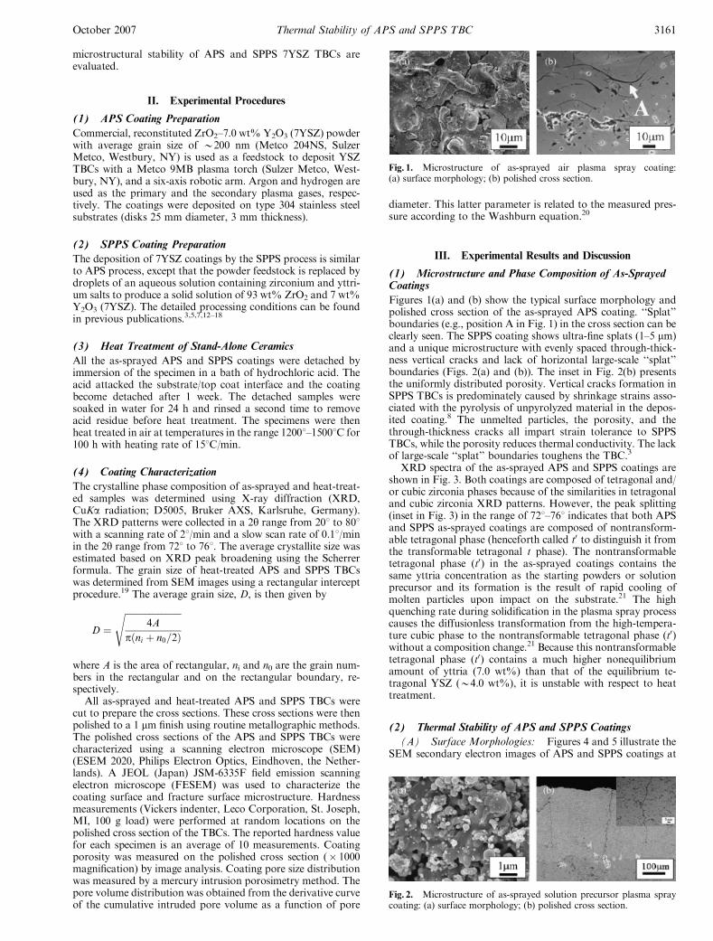
Figures 1(a) and (b) show the typical surface morphology andpolished cross section of the as-sprayed APS coating. ‘‘Splat’’boundaries (e.g., position A in Fig. 1) in the cross section can beclearly seen. The SPPS coating shows ultra-fine splats (1–5 mm)and a unique microstructure with evenly spaced through-thick-ness vertical cracks and lack of horizontal large-scale ‘‘splat’’boundaries (Figs. 2(a) and (b)). The inset in Fig. 2(b) presentsthe uniformly distributed porosity. Vertical cracks formation inSPPS TBCs is predominately caused by shrinkage strains asso-ciated with the pyrolysis of unpyrolyzed material in the depos-ited coating.8 The unmelted particles, the porosity, and thethrough-thickness cracks all impart strain tolerance to SPPSTBCs, while the porosity reduces thermal conductivity. The lackof large-scale ‘‘splat’’ boundaries toughens the TBC.3
XRD spectra of the as-sprayed APS and SPPS coatings areshown in Fig. 3. Both coatings are composed of tetragonal and/or cubic zirconia phases because of the similarities in tetragonaland cubic zirconia XRD patterns. However, the peak splitting(inset in Fig. 3) in the range of 721–761 indicates that both APSand SPPS as-sprayed coatings are composed of nontransform-able tetragonal phase (henceforth called t0 to distinguish it fromthe transformable tetragonal t phase). The nontransformabletetragonal phase (t0) in the as-sprayed coatings contains thesame yttria concentration as the starting powders or solutionprecursor and its formation is the result of rapid cooling ofmolten particles upon impact on the substrate.21 The highquenching rate during solidification in the plasma spray processcauses the diffusionless transformation from the high-tempera-ture cubic phase to the nontransformable tetragonal phase (t0)without a composition change.21 Because this nontransformabletetragonal phase (t0) contains a much higher nonequilibriumamount of yttria (7.0 wt%) than that of the equilibrium te-tragonal YSZ (B4.0 wt%), it is unstable with respect to heattreatment.
(2) Thermal Stability of APS and SPPS Coatings
(A) Surface Morphologies: Figures 4 and 5 illustrate theSEM secondary electron images of APS and SPPS coatings at
Fig. 1. Microstructure of as-sprayed air plasma spray coating:(a) surface morphology; (b) polished cross section.
Fig. 2. Microstructure of as-sprayed solution precursor plasma spraycoating: (a) surface morphology; (b) polished cross section.
October 2007 Thermal Stability of APS and SPPS TBC 3161
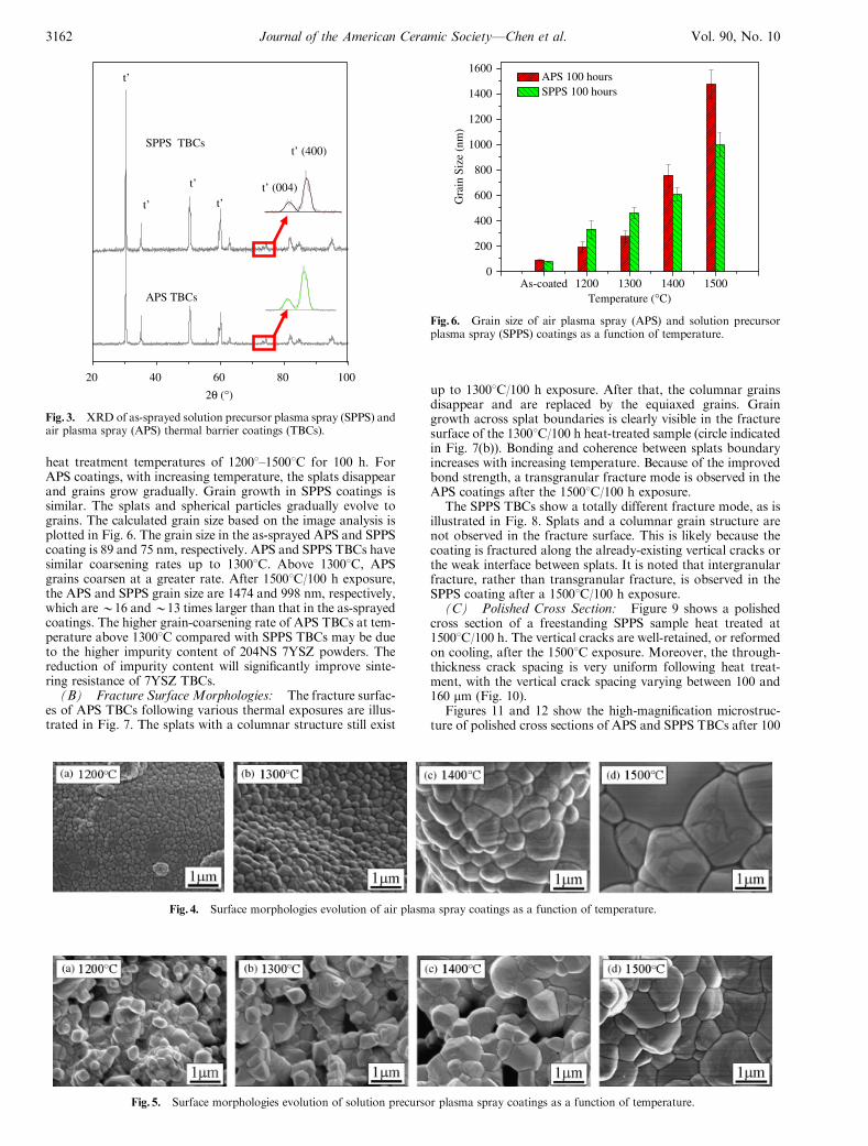
heat treatment temperatures of 12001–15001C for 100 h. ForAPS coatings, with increasing temperature, the splats disappearand grains grow gradually. Grain growth in SPPS coatings issimilar. The splats and spherical particles gradually evolve tograins. The calculated grain size based on the image analysis isplotted in Fig. 6. The grain size in the as-sprayed APS and SPPScoating is 89 and 75 nm, respectively. APS and SPPS TBCs havesimilar coarsening rates up to 13001C. Above 13001C, APSgrains coarsen at a greater rate. After 15001C/100 h exposure,the APS and SPPS grain size are 1474 and 998 nm, respectively,which areB16 andB13 times larger than that in the as-sprayedcoatings. The higher grain-coarsening rate of APS TBCs at tem-perature above 13001C compared with SPPS TBCs may be dueto the higher impurity content of 204NS 7YSZ powders. Thereduction of impurity content will significantly improve sinte-ring resistance of 7YSZ TBCs.
(B) Fracture Surface Morphologies: The fracture surfac-es of APS TBCs following various thermal exposures are illus-trated in Fig. 7. The splats with a columnar structure still exist
up to 13001C/100 h exposure. After that, the columnar grainsdisappear and are replaced by the equiaxed grains. Graingrowth across splat boundaries is clearly visible in the fracturesurface of the 13001C/100 h heat-treated sample (circle indicatedin Fig. 7(b)). Bonding and coherence between splats boundaryincreases with increasing temperature. Because of the improvedbond strength, a transgranular fracture mode is observed in theAPS coatings after the 15001C/100 h exposure.
The SPPS TBCs show a totally different fracture mode, as isillustrated in Fig. 8. Splats and a columnar grain structure arenot observed in the fracture surface. This is likely because thecoating is fractured along the already-existing vertical cracks orthe weak interface between splats. It is noted that intergranularfracture, rather than transgranular fracture, is observed in theSPPS coating after a 15001C/100 h exposure.
(C) Polished Cross Section: Figure 9 shows a polishedcross section of a freestanding SPPS sample heat treated at15001C/100 h. The vertical cracks are well-retained, or reformedon cooling, after the 15001C exposure. Moreover, the through-thickness crack spacing is very uniform following heat treat-ment, with the vertical crack spacing varying between 100 and160 mm (Fig. 10).
Figures 11 and 12 show the high-magnification microstruc-ture of polished cross sections of APS and SPPS TBCs after 100
80604020 100
2θ (°)
t’ (004)
t’ (400)
t’
t’
t’
t’
APS TBCs
SPPS TBCs
Fig. 3. XRD of as-sprayed solution precursor plasma spray (SPPS) andair plasma spray (APS) thermal barrier coatings (TBCs).
Fig. 4. Surface morphologies evolution of air plasma spray coatings as a function of temperature.
Fig. 5. Surface morphologies evolution of solution precursor plasma spray coatings as a function of temperature.
0
800
600
400
200
1600
1400
1200
1000
As-coated 1200 1300 1400 1500
APS 100 hoursSPPS 100 hours
Gra
in S
ize
(nm
)
Temperature (°C)
Fig. 6. Grain size of air plasma spray (APS) and solution precursorplasma spray (SPPS) coatings as a function of temperature.
3162 Journal of the American Ceramic Society—Chen et al. Vol. 90, No. 10
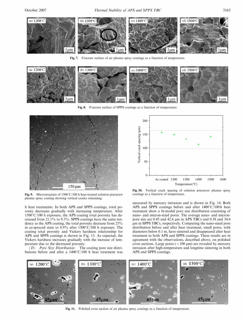
h heat treatments. In both APS and SPPS coatings, total po-rosity decreases gradually with increasing temperature. After15001C/100 h exposure, the APS coating total porosity has de-creased from 21.1% to 9.3%. SPPS coatings have the same ten-dency as the APS coating, the total porosity decrease from 25%in as-sprayed state to 8.9% after 15001C/100 h exposure. Thecoating total porosity and Vickers hardness relationship forAPS and SPPS coatings is shown in Fig. 13. As expected, theVickers hardness increases gradually with the increase of tem-perature due to the decreased porosity.
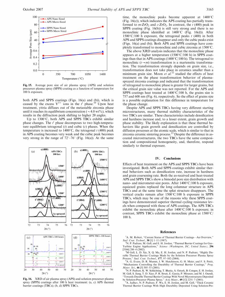
(D) Pore Size Distribution: The coating pore size distri-butions before and after a 14001C/100 h heat treatment was
measured by mercury intrusion and is shown in Fig. 14. BothAPS and SPPS coatings before and after 14001C/100h heattreatment show a bi-modal pore size distribution consisting ofnano- and micron-sized pores. The average nano- and micron-pore size are 0.45 and 42.6 mm in APS TBCs and 0.38 and 34.6mm in SPPS TBCs, respectively. Comparing the nano-sized poredistribution before and after heat treatment, small pores, withdiameters below 0.1 m, have sintered and disappeared after heattreatment in both APS and SPPS coatings. These results are inagreement with the observations, described above, on polishedcross sections. Large pores (B100 mm) are revealed by mercuryintrusion after high-temperature and longtime sintering in bothAPS and SPPS coatings.
Fig. 7. Fracture surface of air plasma spray coatings as a function of temperature.
Fig. 8. Fracture surface of SPPS coatings as a function of temperature.
Fig. 9. Microstructure of 15001C/100 h heat-treated solution precursorplasma spray coating showing vertical cracks remaining.
0
50
100
150
200
Ver
tical
cra
ck s
paci
ng (
µm)
Temperature(°C)
As coated 1200 1300 1400 1500 1600
Fig. 10. Vertical crack spacing of solution precursor plasma spraycoatings as a function of temperature.
Fig. 11. Polished cross section of air plasma spray coatings as a function of temperature.
October 2007 Thermal Stability of APS and SPPS TBC 3163
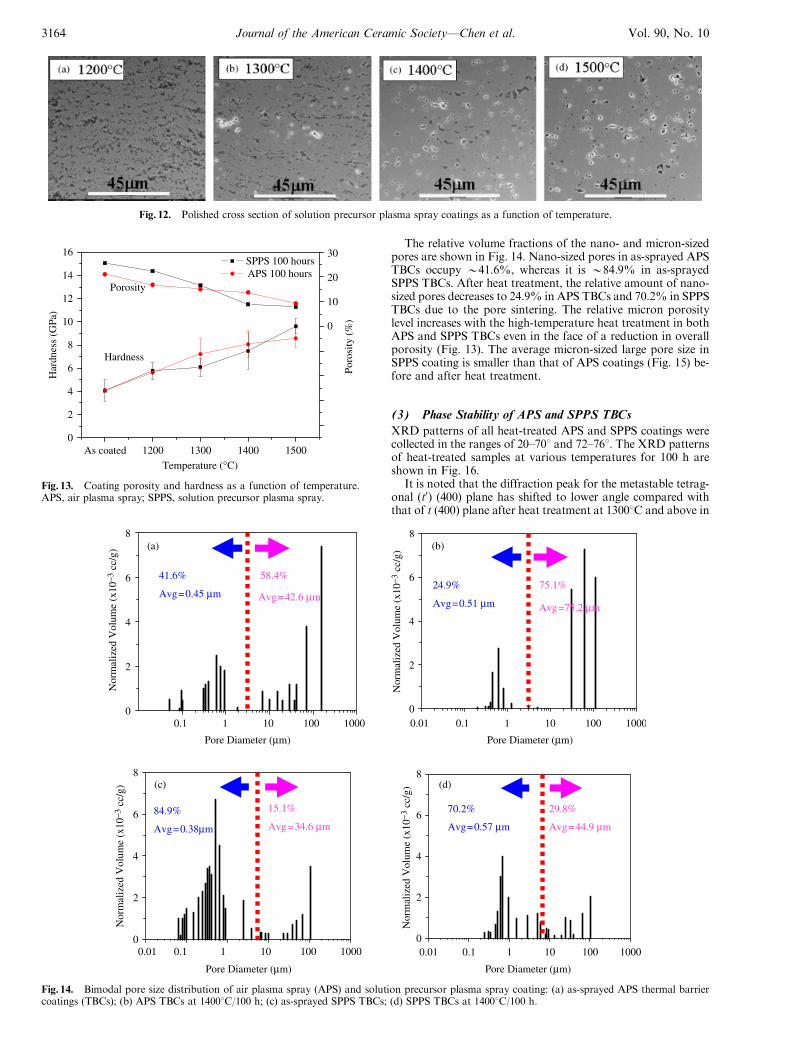
The relative volume fractions of the nano- and micron-sizedpores are shown in Fig. 14. Nano-sized pores in as-sprayed APSTBCs occupy B41.6%, whereas it is B84.9% in as-sprayedSPPS TBCs. After heat treatment, the relative amount of nano-sized pores decreases to 24.9% in APS TBCs and 70.2% in SPPSTBCs due to the pore sintering. The relative micron porositylevel increases with the high-temperature heat treatment in bothAPS and SPPS TBCs even in the face of a reduction in overallporosity (Fig. 13). The average micron-sized large pore size inSPPS coating is smaller than that of APS coatings (Fig. 15) be-fore and after heat treatment.
(3) Phase Stability of APS and SPPS TBCs
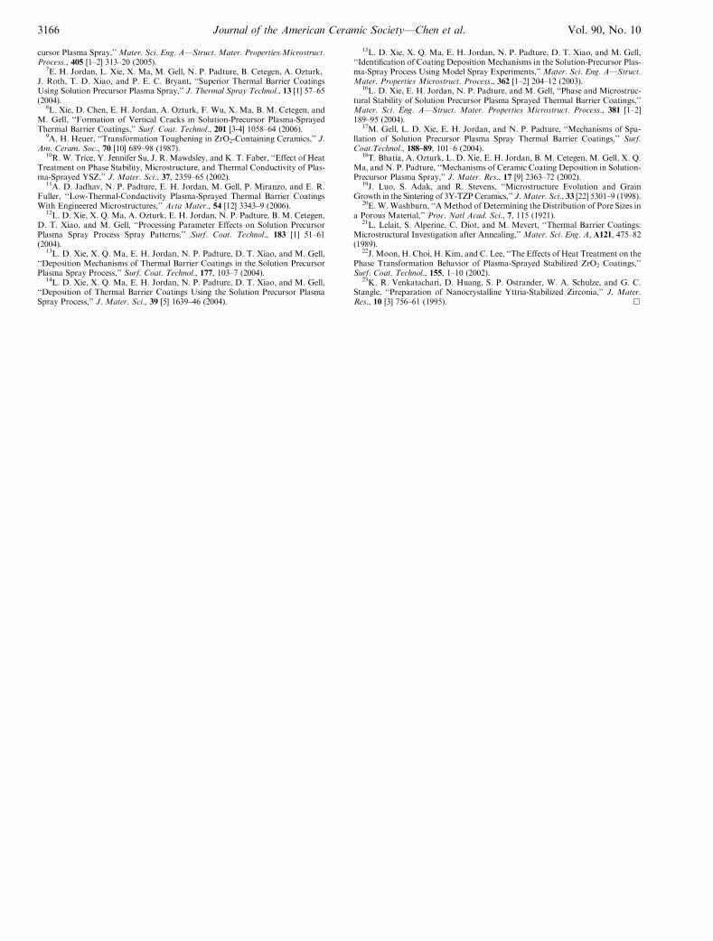
XRD patterns of all heat-treated APS and SPPS coatings werecollected in the ranges of 20–701 and 72–761. The XRD patternsof heat-treated samples at various temperatures for 100 h areshown in Fig. 16.
It is noted that the diffraction peak for the metastable tetrag-onal (t0) (400) plane has shifted to lower angle compared withthat of t (400) plane after heat treatment at 13001C and above in
Fig. 12. Polished cross section of solution precursor plasma spray coatings as a function of temperature.
0
2
4
6
8
10
12
14
16 30
20
10
0
Porosity
HardnessPo
rosi
ty (
%)
As coated 1200 1300 1400 1500
SPPS 100 hoursAPS 100 hours
Temperature (°C)
Har
dnes
s (G
Pa)
Fig. 13. Coating porosity and hardness as a function of temperature.APS, air plasma spray; SPPS, solution precursor plasma spray.
0.1 1 10 100 1000 0.1 1 10 100 10000
2
4
6
8
41.6%
Avg=0.45 µm
58.4%
0.01
0.01 0.1 1 10 100 1000 0.1 1 10 100 10000.01
0
2
4
6
8
Pore Diameter (µm)Pore Diameter (µm)
Pore Diameter (µm)Pore Diameter (µm)
75.1%24.9%
Avg=0.51 µm
0
2
4
6
8
Nor
mal
ized
Vol
ume
(x10
−3 c
c/g)
Nor
mal
ized
Vol
ume
(x10
−3 c
c/g)
Nor
mal
ized
Vol
ume
(x10
−3 c
c/g)
Nor
mal
ized
Vol
ume
(x10
−3 c
c/g)
84.9%
Avg=0.38µm
15.1%
Avg=34.6 µm
0
2
4
6
8
70.2%
Avg=0.57 µm
29.8%
Avg=44.9 µm
Avg=75.2 µmAvg=42.6 µm
(a) (b)
(c) (d)
Fig. 14. Bimodal pore size distribution of air plasma spray (APS) and solution precursor plasma spray coating: (a) as-sprayed APS thermal barriercoatings (TBCs); (b) APS TBCs at 14001C/100 h; (c) as-sprayed SPPS TBCs; (d) SPPS TBCs at 14001C/100 h.
3164 Journal of the American Ceramic Society—Chen et al. Vol. 90, No. 10
both APS and SPPS coatings (Figs. 16(a) and (b)), which iscaused by the excess Y31 ions in the t0 phase.10 Upon heattreatment, yttria diffuses out of the metastable zirconia phaseuntil it reaches its equilibrium concentration (B4.0 wt%), whichresults in the diffraction peak shifting to higher 2y angles.
Up to 13001C, both APS and SPPS TBCs exhibit similarphase changes. The t0 phase decomposes to two high-tempera-ture equilibrium tetragonal (t) and cubic (c) phases. When thetemperature is increased to 14001C, the tetragonal t (400) peakin APS coating becomes very weak and the cubic peak becomesvery strong in the range of 721–761 (Fig. 16(a)). At the same
time, the monoclinic peaks become apparent at 14001C(Fig. 16(c)), which indicates the APS coating has partially trans-formed to m-ZrO2 and c-ZrO2. In contrast, the t (400) peak inSPPS coating (Fig. 16(b)) is still very strong and there is nomonoclinic phase identified at 14001C (Fig. 16(d)). After15001C/100 h exposure, the tetragonal peaks t (400) in bothAPS and SPPS coatings disappear and only the cubic peaks exist(Figs. 16(a) and (b)). Both APS and SPPS coatings have com-pletely transformed to monoclinic and cubic zirconia at 15001C.
The above XRD analysis indicates that the monoclinic phaseappears at a higher temperature (15001C/100 h) in SPPS coat-ings than that in APS coatings (14001C/100 h). The tetragonal tomonoclinic (t-m) transformation is a martensitic transforma-tion. The transformation strongly depends on grain size, i.e.,transformation does not take place in ceramics smaller than aminimum grain size. Moon et al.22 studied the effects of heattreatment on the phase transformation behavior of plasma-sprayed zirconia coatings and indicated that the transformationof tetragonal to monoclinic phase is greater for larger grains, butthe critical grain size value was not reported. For the APS andSPPS coatings heat treated at 14001C/100 h, the grains size is757 and 608 nm (Fig. 6), respectively. So the effect of grains sizeis a possible explanation for this difference in temperature forthe phase change.
Despite APS and SPPS TBCs having very different startingmicrostructures, many thermal stability characteristics of thetwo TBCs are similar. These characteristics include densificationand hardness increase and, to a lesser extent, grain growth andphase stability. The likely explanation is that these thermal be-haviors like grain growth and densification are controlled bydiffusion processes at the atomic scale, which is similar to that inzirconia ceramic sintering process.23 Despite the difference in as-coated microstructures, the two TBCs have the same composi-tion and compositional homogeneity, and, therefore, respondsimilarly to thermal exposure.
IV. Conclusions
Effects of heat treatment on the APS and SPPS TBCs have beeninvestigated. Both APS and SPPS coatings exhibit similar ther-mal behaviors such as densification rate, increase in hardnessand grain coarsening rate. Both the as-received and heat-treatedAPS and SPPS TBCs show a bimodal pore size distribution withnano- and micrometer-size pores. After 14001C/100 h exposure,equiaxed grains replaced the long columnar structure in APSTBCs and at the same time the splat structure disappears. Thevertical cracks remain after 15001C/100 h exposure in SPPSTBCs, which may be one of the reasons why these SPPS coat-ings have demonstrated superior thermal cycling resistance lev-els when compared with those of APS coatings. The APS TBCsexhibit the monoclinic phase after 14001C/100 h exposure; incontrast, SPPS TBCs exhibit the monoclinic phase at 15001C/100 h.
References
1A. M. Robert, ‘‘Current Status of Thermal Barrier Coatings—An Overview,’’Surf. Coat. Technol., 30 [1] 1–11 (1987).
2N. P. Padture, M. Gell, and E. H. Jordan, ‘‘Thermal Barrier Coatings for Gas–Turbine Engine Applications,’’ Science (Washington, DC, United States), 296[5566] 280–4 (2002).
3M Gell, L. D. Xie, X. Q. Ma, E. H. Jordan, and N. P. Padture, ‘‘Highly Du-rable Thermal Barrier Coatings Made by the Solution Precursor Plasma SprayProcess,’’ Surf. Coat. Technol., 177, 97–102 (2004).
4A. G. Evans, D. R. Mumm, J. W. Hutchinson, G. H. Meier, and F. S. Pettit,‘‘Mechanisms Controlling the Durability of Thermal Barrier Coatings,’’ Prog.Mater. Sci., 46 [5] 505–53 (2001).
5N. P. Padture, K.W. Schlichting, T. Bhatia, A. Ozturk, B. Cetegen, E. H. Jordan,M. Gell, S. Jiang, T. D. Xiao, P. R. Strutt, E. Garcia, P. Miranzo, and M. I. Osendi,‘‘Towards Durable Thermal Barrier CoatingsWith NovelMicrostructures Depositedby Solution-Precursor Plasma Spray,’’ Acta Mater., 49 [12] 2251–7 (2001).
6A. Jadhav, N. P. Padture, F. Wu, E. H. Jordan, and M. Gell, ‘‘Thick CeramicThermal Barrier Coatings With High Durability Deposited Using Solution-Pre-
0 350 700 1050 14000.0
0.2
0.4
0.6
40
60
80
100APS Nano SizedAPS Micro-Sized
SPPS Nano SizedSPPS Micro Sized
Temperature (°C)
Ave
rage
Por
e Si
ze (
µm)
Fig. 15. Average pore size of air plasma spray (APS) and solutionprecursor plasma spray (SPPS) coating as a function of temperature for100 h exposure.
706050403020 706050403020
m m
APS TBCs 100 hours
mm
mm
m
mm
m
SPPS TBCs 100 hours
2θ (°)2θ (°)
2θ (°)2θ (°)
mm
m
m
As sprayed
1200°
1300°
1400°
1500°
APS TBCs 100 hrs
c(400)
t(004)t(400)
t’(004) t’(400)
7675747372 7675747372
As sprayed
1200°C
1300°C
1400°C
1500°C
SPPS TBCs 100 hrs
c(400)
c(400)
t(004)t(400)
t’(004) t’(400)
(a) (b)
(d)(c)
Fig. 16. XRD of air plasma spray (APS) and solution precursor plasmaspray (SPPS) coatings after 100 h heat treatment: (a, c) APS thermalbarrier coatings (TBCs); (b, d) SPPS TBCs.
October 2007 Thermal Stability of APS and SPPS TBC 3165
cursor Plasma Spray,’’Mater. Sci. Eng. A—Struct. Mater. Properties Microstruct.Process., 405 [1–2] 313–20 (2005).
7E. H. Jordan, L. Xie, X. Ma, M. Gell, N. P. Padture, B. Cetegen, A. Ozturk,J. Roth, T. D. Xiao, and P. E. C. Bryant, ‘‘Superior Thermal Barrier CoatingsUsing Solution Precursor Plasma Spray,’’ J. Thermal Spray Technol., 13 [1] 57–65(2004).
8L. Xie, D. Chen, E. H. Jordan, A. Ozturk, F. Wu, X. Ma, B. M. Cetegen, andM. Gell, ‘‘Formation of Vertical Cracks in Solution-Precursor Plasma-SprayedThermal Barrier Coatings,’’ Surf. Coat. Technol., 201 [3-4] 1058–64 (2006).
9A. H. Heuer, ‘‘Transformation Toughening in ZrO2-Containing Ceramics,’’ J.Am. Ceram. Soc., 70 [10] 689–98 (1987).
10R. W. Trice, Y. Jennifer Su, J. R. Mawdsley, and K. T. Faber, ‘‘Effect of HeatTreatment on Phase Stability, Microstructure, and Thermal Conductivity of Plas-ma-Sprayed YSZ,’’ J. Mater. Sci., 37, 2359–65 (2002).
11A. D. Jadhav, N. P. Padture, E. H. Jordan, M. Gell, P. Miranzo, and E. R.Fuller, ‘‘Low-Thermal-Conductivity Plasma-Sprayed Thermal Barrier CoatingsWith Engineered Microstructures,’’ Acta Mater., 54 [12] 3343–9 (2006).
12L. D. Xie, X. Q. Ma, A. Ozturk, E. H. Jordan, N. P. Padture, B. M. Cetegen,D. T. Xiao, and M. Gell, ‘‘Processing Parameter Effects on Solution PrecursorPlasma Spray Process Spray Patterns,’’ Surf. Coat. Technol., 183 [1] 51–61(2004).
13L. D. Xie, X. Q. Ma, E. H. Jordan, N. P. Padture, D. T. Xiao, and M. Gell,‘‘Deposition Mechanisms of Thermal Barrier Coatings in the Solution PrecursorPlasma Spray Process,’’ Surf. Coat. Technol., 177, 103–7 (2004).
14L. D. Xie, X. Q. Ma, E. H. Jordan, N. P. Padture, D. T. Xiao, and M. Gell,‘‘Deposition of Thermal Barrier Coatings Using the Solution Precursor PlasmaSpray Process,’’ J. Mater. Sci., 39 [5] 1639–46 (2004).
15L. D. Xie, X. Q. Ma, E. H. Jordan, N. P. Padture, D. T. Xiao, and M. Gell,‘‘Identification of Coating Deposition Mechanisms in the Solution-Precursor Plas-ma-Spray Process Using Model Spray Experiments,’’ Mater. Sci. Eng. A—Struct.Mater. Properties Microstruct. Process., 362 [1–2] 204–12 (2003).
16L. D. Xie, E. H. Jordan, N. P. Padture, and M. Gell, ‘‘Phase and Microstruc-tural Stability of Solution Precursor Plasma Sprayed Thermal Barrier Coatings,’’Mater. Sci. Eng. A—Struct. Mater. Properties Microstruct. Process., 381 [1–2]189–95 (2004).
17M. Gell, L. D. Xie, E. H. Jordan, and N. P. Padture, ‘‘Mechanisms of Spa-llation of Solution Precursor Plasma Spray Thermal Barrier Coatings,’’ Surf.Coat.Technol., 188–89, 101–6 (2004).
18T. Bhatia, A. Ozturk, L. D. Xie, E. H. Jordan, B. M. Cetegen, M. Gell, X. Q.Ma, and N. P. Padture, ‘‘Mechanisms of Ceramic Coating Deposition in Solution-Precursor Plasma Spray,’’ J. Mater. Res., 17 [9] 2363–72 (2002).
19J. Luo, S. Adak, and R. Stevens, ‘‘Microstructure Evolution and GrainGrowth in the Sintering of 3Y-TZP Ceramics,’’ J.Mater. Sci., 33 [22] 5301–9 (1998).
20E. W. Washburn, ‘‘AMethod of Determining the Distribution of Pore Sizes ina Porous Material,’’ Proc. Natl Acad. Sci., 7, 115 (1921).
21L. Lelait, S. Alperine, C. Diot, and M. Mevert, ‘‘Thermal Barrier Coatings:Microstructural Investigation after Annealing,’’ Mater. Sci. Eng. A, A121, 475–82(1989).
22J. Moon, H. Choi, H. Kim, and C. Lee, ‘‘The Effects of Heat Treatment on thePhase Transformation Behavior of Plasma-Sprayed Stabilized ZrO2 Coatings,’’Surf. Coat. Technol., 155, 1–10 (2002).
23K. R. Venkatachari, D. Huang, S. P. Ostrander, W. A. Schulze, and G. C.Stangle, ‘‘Preparation of Nanocrystalline Yttria-Stabilized Zirconia,’’ J. Mater.Res., 10 [3] 756–61 (1995). &
3166 Journal of the American Ceramic Society—Chen et al. Vol. 90, No. 10
Related Documents