The Mechanical Analog Computers of Hannibal Ford and William Newell A. BEN CLYMER The history of mechanical analog computers is described from ear/y devel- opments to their peak in World War II and to their obsolescence in the 1950s. The chief importance of most of these computers was their contribution to the superb gunnery of the US Navy. The work of Hannibal Ford, William Newell, and the Ford Instrument Co. is the framework around which this account is based. F or over 40 years mechanical analog computers provided the US Navy with the world’s most advanced and capa- ble fire-control systems for aiming large naval guns and setting fuze times on the shells for destroying either surface or air targets. A large part of this preeminence can be attributed to the work of Hannibal Ford and William New- ell. However, the credit has usually been withheld. first because of security classifications and later by the resulting widespread ignorance of even the main facts of their stories. The history of the evolution of fire-control equipment can be divided into three crudely defined periods of prog- ress: early. middle. and late, being respectively the eigh- teenth, nineteenth, and twentieth centuries. In the early period, the eighteenth century. there was no perception of fire control as a hierarchical system. so there were no inven- tions on the sytetn level. Lack of concern for improvement caused continuation of the status quo. In the middle period, the nineteenth century. there began a trend toward automa- tion in many practical pursuits (e.g., the cotton gin. railroads. steamboats. and glass-forming machines) which extended to naval gunnery. Handwheels provided a mechanical advan- tage in training and elevating guns. The man-machine sys- tem was being made easier and better for the men by delegating more to machines. In the late period, the twentieth century. people have seen the system as a whole, and they have been conscious of missing subsystems. Inventions then took place on the top echelon, and system engineering began to deal with the entire hierarchical system. In the late period there was concern for errors of system performance. In the case of a fire-control system, the contributions of all causes to the ultimate miss data were studied to identify the most critical remaining sources of error. Early analog computing mechanisms To understand the types of mechanisms invented by Ford and Newell, it is necessary to briefly examine a few of the simple components from which they arose. The history of mechanical analog devices goes back at least to Vitruvius (SO BC), who described the use of a wheel for measuring arc length along a curve. the most simple integral in space. Many other elementary analog devices were described before the modern period: Differential gears (Figure 1). used for add- ing or subtracting two variables. arc usually ascribed to Leonardo da Vinci: and Leibniz is credited for the idea late in the seventeenth century of a similar-triangles device for equation solving or root solving.’ The first device to form the integral under a curve, or the area within a closed curve, was the integrator of B.H. Her- mann in 1814. Hermann’s integrator was essentially a wheel pressed against a disk. as shown in Figure 2. There was a second disk over the first. which squeezed the wheel be- tween them. The rate of rotation of the wheel is proportional to the product of the disk rotation rate and the radial location of the point of contact of the wheel on the disk. That is. the rate of change of angular position of the wheel z is given by dz dy d; = KL’ ~dt where ; is the time integral of y times a constant. x is the angular position of the disk, and K is a scale constant. Note that the variables in this device are angular and linear positions. An early application of such integrators was the integra- tion of force over distance to measure work. Another appli- cation was a planimeter to measure the area within a closed curve. In fact. the chief impetus behind the early integrator inventions of the nineteenth century was to get an improved planimeter. James Clerk Maxwell’ described a ball type of integrat- ing device while he was an undergraduate: it was incorpo- rated in a planimeter design. In about 1863. James Thom- son’ conceived an equivalent integrator in which a ball rotates between the disk and a cylinder (see Figure 3). The angular position of the cylinder is the output variable z. and the ball replaces the wheel of the Hermann integrator. The ball is held in a housing that is translated along the radius of the disk with displacement _Y. This integrator became the heart of numerous harmonic analyzers and time analyzers. IEEE Annrrls of’thr History of C‘ottzp~rritzg. Vol. 15. No. 2, 1993 l 19

Welcome message from author
This document is posted to help you gain knowledge. Please leave a comment to let me know what you think about it! Share it to your friends and learn new things together.
Transcript
The Mechanical Analog Computers ofHannibal Ford and William NewellA. BEN CLYMER
The history of mechanical analog computers is described from ear/y devel-opments to their peak in World War II and to their obsolescence in the 1950s.The chief importance of most of these computers was their contribution to thesuperb gunnery of the US Navy. The work of Hannibal Ford, William Newell,and the Ford Instrument Co. is the framework around which this account isbased.
For over 40 years mechanical analog computers providedthe US Navy with the world’s most advanced and capa-
ble fire-control systems for aiming large naval guns andsetting fuze times on the shells for destroying either surfaceor air targets. A large part of this preeminence can beattributed to the work of Hannibal Ford and William New-ell. However, the credit has usually been withheld. firstbecause of security classifications and later by the resultingwidespread ignorance of even the main facts of their stories.
The history of the evolution of fire-control equipmentcan be divided into three crudely defined periods of prog-ress: early. middle. and late, being respectively the eigh-teenth, nineteenth, and twentieth centuries. In the earlyperiod, the eighteenth century. there was no perception offire control as a hierarchical system. so there were no inven-tions on the sytetn level. Lack of concern for improvementcaused continuation of the status quo. In the middle period,the nineteenth century. there began a trend toward automa-tion in many practical pursuits (e.g., the cotton gin. railroads.steamboats. and glass-forming machines) which extended tonaval gunnery. Handwheels provided a mechanical advan-tage in training and elevating guns. The man-machine sys-tem was being made easier and better for the men bydelegating more to machines.
In the late period, the twentieth century. people haveseen the system as a whole, and they have been consciousof missing subsystems. Inventions then took place on the topechelon, and system engineering began to deal with theentire hierarchical system. In the late period there wasconcern for errors of system performance. In the case of afire-control system, the contributions of all causes to theultimate miss data were studied to identify the most criticalremaining sources of error.
Early analog computing mechanismsTo understand the types of mechanisms invented by
Ford and Newell, it is necessary to briefly examine a few ofthe simple components from which they arose. The historyof mechanical analog devices goes back at least to Vitruvius(SO BC), who described the use of a wheel for measuring arc
length along a curve. the most simple integral in space. Manyother elementary analog devices were described before themodern period: Differential gears (Figure 1). used for add-ing or subtracting two variables. arc usually ascribed toLeonardo da Vinci: and Leibniz is credited for the idea latein the seventeenth century of a similar-triangles device forequation solving or root solving.’
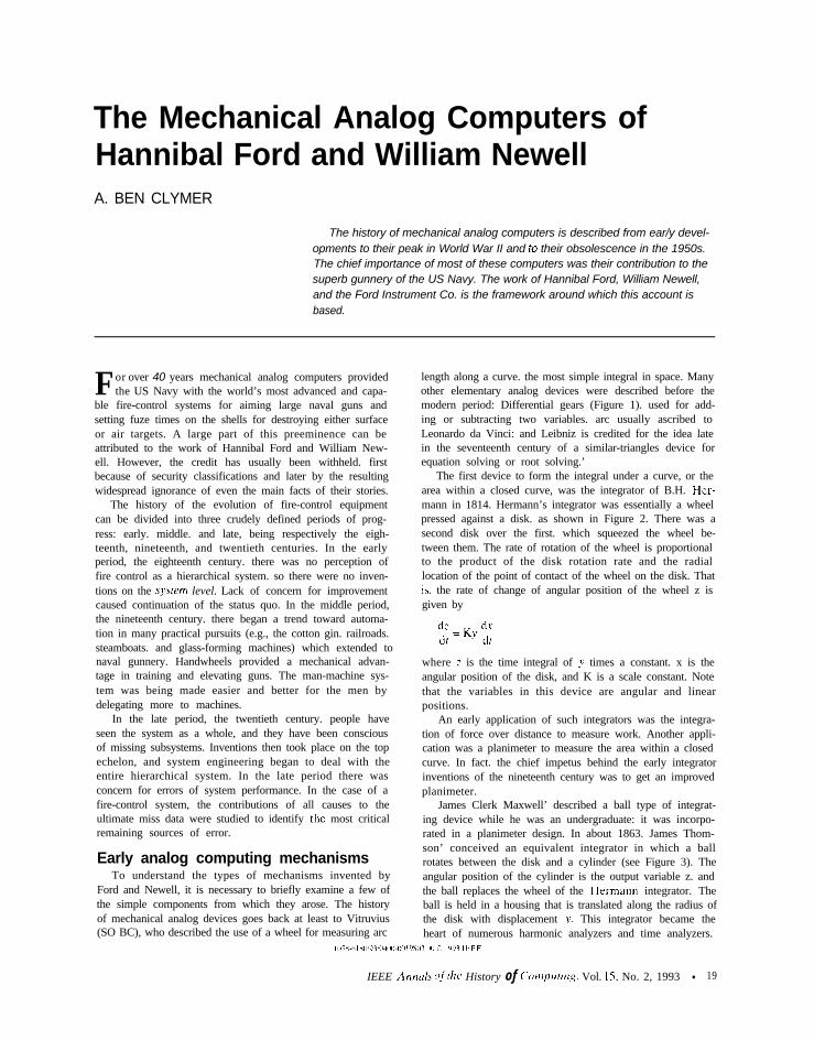
The first device to form the integral under a curve, or thearea within a closed curve, was the integrator of B.H. Her-mann in 1814. Hermann’s integrator was essentially a wheelpressed against a disk. as shown in Figure 2. There was asecond disk over the first. which squeezed the wheel be-tween them. The rate of rotation of the wheel is proportionalto the product of the disk rotation rate and the radiallocation of the point of contact of the wheel on the disk. Thatis. the rate of change of angular position of the wheel z isgiven by
dz dyd; = KL’ ~dt
where ; is the time integral of y times a constant. x is theangular position of the disk, and K is a scale constant. Notethat the variables in this device are angular and linearpositions.
An early application of such integrators was the integra-tion of force over distance to measure work. Another appli-cation was a planimeter to measure the area within a closedcurve. In fact. the chief impetus behind the early integratorinventions of the nineteenth century was to get an improvedplanimeter.
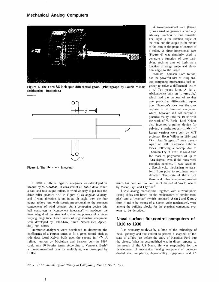
James Clerk Maxwell’ described a ball type of integrat-ing device while he was an undergraduate: it was incorpo-rated in a planimeter design. In about 1863. James Thom-son’ conceived an equivalent integrator in which a ballrotates between the disk and a cylinder (see Figure 3). Theangular position of the cylinder is the output variable z. andthe ball replaces the wheel of the Hermann integrator. Theball is held in a housing that is translated along the radius ofthe disk with displacement _Y. This integrator became theheart of numerous harmonic analyzers and time analyzers.
IEEE Annrrls of’thr History of C‘ottzp~rritzg. Vol. 15. No. 2, 1993 l 19
Mechanical Analog Computers
Figure 1. The Ford 3/S-inch spur differential gears. (Photograph by Laurie Minor,Smithsonian Institution.)
m11 Y+l
I I
Figure 2. The Hermann integrator.
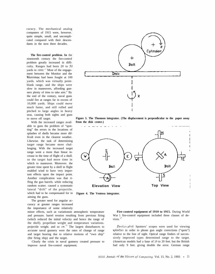
In 1881 a different type of integrator was developed inMadrid by V. Ventosa.’ It consisted of a tiltable drive roller.a ball, and four output rollers. If wind velocity is put into thedrive roller (marked “A” in Figure 4) as angular velocity.and if wind direction is put in as tilt angle. then the fouroutput rollers turn with speeds proportional to the compasscomponents of wind velocity. As a computing device thisball constitutes a “component integrator” -it produces thetime integral of the sine and cosine components of a givenvarying magnitude. Later forms of trigonometric integratorswere developed by Hele-Shaw, Smith. Newell (see Appen-dix), and others.
William Thomson. Lord Kelvin,had the powerful idea of using ana-log computing mechanisms tied to-gether to solve a differential equa-tion.h Ten years later, Abdank-Abakanowicz built an “integraph.”which had the purpose of solvingone particular differential equa-tion. Thomson’s idea was the con-ception of differential analyzers.which. however. did not become apractical reality until the 1930s withthe work of V. Bush.’ Lord Kelvinalso invented a pulley device forsolving simultaneous equations.xLarger versions were built by MITprofessor Bohn Wilbur in 1934 and1935. An “isograph” was devel-oped at Bell Telephone Labora-tories. following a concept due toThornton Fry in 1937. It could findthe roots of polynomials of up to10th degree, even if the roots werecomplex numbers. It was based ona Scotch yoke mechanism to trans-form from polar to rectilinear coor-dinates.’ The state of the art ofthese and other computing mecha-
nisms has been summarized as of the end of World War IIby Macon Fry” and Clymer.‘”
These analog mechanisms. together with a “multiplier”(using slides and based on the mathematics of similar trian-gles) and a “resolver” (which produced R sin 41 and R cos Qfrom R and $I by means of a Scotch yoke mechanism). wereamong the building blocks for the practical computing sys-tems to be described.
Harmonic analyzers were developed to determine thecoefficients of a Fourier series to fit a given record. such astide data. Lord Kelvin built two. the second in 1x7’). Arefined version by Michelson and Stratton built in 1897could sum 80 Fourier terms. According to Vannevar Bush”a three-dimensional cam for multiplying was developed byBollee.
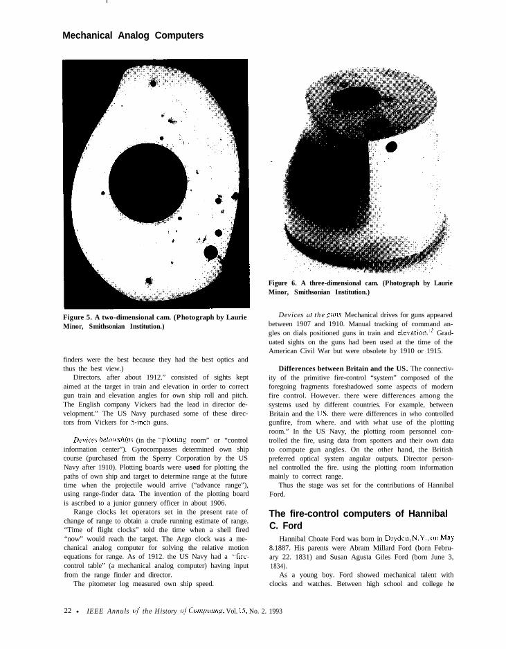
A two-dimensional cam (Figure5) was used to generate a virtuallyarbitrary function of one variable:The input is the rotation angle ofthe cam, and the output is the radiusof the cam at the point of contact ofa roller. A three-dimensional cam(Figure 6) was similarly used togenerate a function of two vari-ables. such as time of flight as afunction of range angle and eleva-tion angle to the target.
Naval surface fire-control computers of1910 to 1930
It is necessary to describe a little of the technology ofnaval gunnery and fire control to present a snapshot of thestate of affairs just before the entry of Hannibal Ford intothe picture. What he accomplished was in direct response tothe needs of the US Navy. He was responsible for thedevelopment of mechanical analog computers of unprece-dented size. complexity, dependability. ruggedness, and ac-
20 l IEEE Annals ofthe History of‘Cornpllting. Vol. 15. No. 2. 1003
curacy. The mechanical analogcomputers of 1915 were, however.quite simple, small, and uncompli-cated compared with their descen-dants in the next three decades.
The fire-control problem. In thenineteenth century the fire-controlproblem greatly increased in diffi-culty. Ranges had been 20 to 50yards in 1800.’ ’ Most of the engage-ment between the Monitor and theMerrimac had been fought at 100yards. which was virtually point-blank range, and the ships wereslow in maneuvers, affording gun-ners plenty of time to take aim.” Bythe end of the century, naval gunscould fire at ranges far in excess of10,000 yards. Ships could movemuch faster, and still rolled andpitched to large angles in heavyseas, causing both sights and gunsto move off target.
With the increased ranges avail-able to guns the problem of “spot-ting” the errors in the locations ofsplashes of shells became more dif-ficult even in the clearest weather.Likewise. the task of determiningtarget range became more chal-lenging. With the increased targetrange went a more than linear in-crease in the time of flight of a shell.so the target had more time inwhich to maneuver. Moreover. thegreater time spent by a shell in flightenabled wind to have very impor-tant effects upon the impact point.Another complication was that ri-fling the gun barrels. while reducingrandom scatter. caused a systematiclateral “drift” of the projectile.which had to be compensated for inaiming the guns.
The greater need for angular ac-curacy at greater ranges increasedthe importance of some relatively
Figure 3. The Thomson integrator. (The displacement is perpendicular to the paper awayfrom the disk center.)
Elevation View
Figure 4. The Ventosa integrator.
Top View
minor effects, such as variationsin atmospheric temperatureand pressure. barrel erosion resulting from previous firing(which reduced the initial velocity and hence the range ofthe shell). propellant weight and temperature variations.projectile weight. and so on.‘? The largest disturbances toaccurate naval gunnery were the rates of change of rangeand target bearing due to relative motions of “own ship”(the firing ship) and the target.
Clearly the crisis in naval gunnery created pressure toimprove naval fire-control equipment.
Fire-control equipment of 1910 to 1915. During WorldWar I fire-control equipment included three classes of de-vices. II
nc\Ycc.s ~lOfi. Spotters’ scopes were used for viewingsplashes in order to phone gun angle corrections (“spots”)relative to the line of sight. Optical range finders of succes-sively improved types determined range to the target.(American models had a base of 18 to 20 feet. but the Britishhad only 9 feet. giving double the error. German range
IEEE Ann& of thr Histy>, o,f Computing. Vol. 15. No. 2, 1993 l 21
Mechanical Analog Computers
Figure 6. A three-dimensional cam. (Photograph by LaurieMinor, Smithsonian Institution.)
Figure 5. A two-dimensional cam. (Photograph by LaurieMinor, Smithsonian Institution.)
finders were the best because they had the best optics andthus the best view.)
Directors. after about 1912.” consisted of sights keptaimed at the target in train and elevation in order to correctgun train and elevation angles for own ship roll and pitch.The English company Vickers had the lead in director de-velopment.” The US Navy purchased some of these direc-tors from Vickers for 5-inch guns.
Devicrs belowships (in the *&plotting room” or “controlinformation center”). Gyrocompasses determined own shipcourse (purchased from the Sperry Corporation by the USNavy after 1910). Plotting boards were used for plotting thepaths of own ship and target to determine range at the futuretime when the projectile would arrive (“advance range”),using range-finder data. The invention of the plotting boardis ascribed to a junior gunnery officer in about 1906.
Range clocks let operators set in the present rate ofchange of range to obtain a crude running estimate of range.“Time of flight clocks” told the time when a shell fired“now” would reach the target. The Argo clock was a me-chanical analog computer for solving the relative motionequations for range. As of 1912. the US Navy had a “fire-control table” (a mechanical analog computer) having inputfrom the range finder and director.
The pitometer log measured own ship speed.
Devices at the gum. Mechanical drives for guns appearedbetween 1907 and 1910. Manual tracking of command an-gles on dials positioned guns in train and elevation.12 Grad-uated sights on the guns had been used at the time of theAmerican Civil War but were obsolete by 1910 or 1915.
Differences between Britain and the US. The connectiv-ity of the primitive fire-control “system” composed of theforegoing fragments foreshadowed some aspects of modernfire control. However. there were differences among thesystems used by different countries. For example, betweenBritain and the IJS, there were differences in who controlledgunfire, from where. and with what use of the plottingroom.” In the US Navy, the plotting room personnel con-trolled the fire, using data from spotters and their own datato compute gun angles. On the other hand, the Britishpreferred optical system angular outputs. Director person-nel controlled the fire. using the plotting room informationmainly to correct range.
Thus the stage was set for the contributions of HannibalFord.
The fire-control computers of HannibalC. Ford
Hannibal Choate Ford was born in Dryden,N.Y., on May8.1887. His parents were Abram Millard Ford (born Febru-ary 22. 1831) and Susan Agusta Giles Ford (born June 3,1834).
As a young boy. Ford showed mechanical talent withclocks and watches. Between high school and college he
22 l IEEE Annuls of the History of Conzprdng, Vol. 15. No. 2. 1993
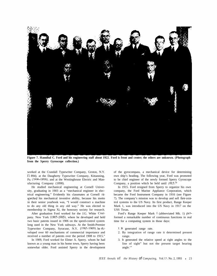
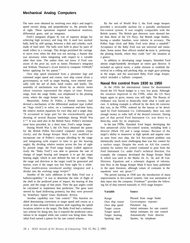
Figure 7. Hannibal C. Ford and his engineering staff about 1922. Ford is front and center; the others are unknown. (Photographfrom the Sperry Gyroscope collection.)
worked at the Crandall Typewriter Company, Groton, N.Y. of the gyrocompass, a mechanical device for determining(I 894). at the Daugherty Typewriter Company, Kittanning, own ship’s heading. The following year, Ford was promotedPa. (1896-1898), and at the Westinghouse Electric and Man- to be chief engineer of the newly formed Sperry Gyroscopeufacturing Company (1898). Company, a position which he held until 1915.15
He studied mechanical engineering at Cornell Univer-sity, graduating in 1903 as a “mechanical engineer in elec-trical engineering.” Evidently his classmates at Cornell re-spected his mechanical inventive ability, because his mottoin their senior yearbook was, “I would construct a machineto do any old thing in any old way.” He was elected tomembership in Sigma Xi, the honorary society for research.
After graduation Ford worked for the J.G. White Com-pany. New York (1903-1905) where he developed and heldtwo basic patents issued in 1906 on the speed-control systemlong used in the New York subways. At the Smith-PremierTypewriter Company, Syracuse, N.Y. (1905-1909). he de-veloped over 60 mechanisms of commercial importance andreceived a number of patents over the period 1908 to 1915.”
In 1909, Ford worked for Elmer A. Sperry. whom he hadknown as a young man in his home town, Sperry having beensomewhat older. Ford assisted Sperry in the development
In 1915. Ford resigned from Sperry to organize his owncompany, the Ford Marine Appliance Corporation, whichbecame the Ford Instrument Company in 1916 (see Figure7). The company’s mission was to develop and sell fire-con-trol systems to the US Navy. Its first product, Range KeeperMark 1, was introduced into the US Navy in 1917 on theUSS Texas.
Ford’s Range Keeper Mark 1 (abbreviated Mk. 1) per-formed a remarkable number of continuous functions in realtime for a computing system in those days:
1. It generated range rate.2. By integration of range rate it determined present
range.3. It generated the relative speed at right angles to the
line of sight” but not the present target bearingangle.‘”
IEEE Annals of the History of Computing, Vol. 15. No. 2, 1993 l 23
Mechanical Analog Computers
The rates were obtained by resolving own ship’s and target’sspeed vectors along, and perpendicular to, the present lineof sight. These operations required mechanical resolvers,differential gears, and an integrator.
Ford’s integrator (Figure 8) was of superior design forachieving high accuracy and long life. It used two stackedballs, held by stiff springs, between a disk and cylinder, eachmade of hard steel. The balls were held in place by pairs ofsmall rollers in a carriage. This design permitted the carriageto move even when the disk was not moving, a feature thatwas necessary when integrating with respect to a variableother than time. The author does not know if Ford wasaware of the prior art, such as James Thomson’s integratorand William Thomson’s (Lord Kelvin’s) computer concept,6before applying for his patent.‘”
Own ship speed (measured from a pitometer log) andestimated target speed and course, own ship course (from agyrocompass), as well as target bearing, were entered man-ually with the aid of dials, hand cranks. and knobs. Theassembly of mechanisms was driven by an electric motorwhose rotations represented the elapse of time. Presentrange, from the range finder, was telephoned to the plottingroom, where the range keeper was kept.
Meanwhile, Arthur H. Pollen, a British inventor, haddevised a mechanism of the differential analyzer type (calledan “Argo clock”) to solve, on a continuous real-time basis,the relative motion equations for own ship and a target ship:“It accounted in large part for the extraordinarily goodshooting of several Russian battleships during World WarI.“‘” It was used also in the British Navy. Pollen’s inventionmust have preceded, by a short time, Ford’s range keeper.
During World War I, the US Navy obtained the patentfor the British Pollen fire-control computer system (Argoclock), and the Range Keeper Mark 1 was modified toincorporate one of Pollen’s concepts (dividing by the rangeand integrating with respect to time to get the bearingangle). By dividing relative motion across the line of sightby present range, the Ford range keeper (called apprecia-tively the “Baby Ford”) was able to generate the rate ofchange of target bearing and integrate it to get the targetbearing angle, which in turn defined the line of sight. Thusthe range and direction to the target could be generated andknown, even if the target was lost from sight for a while.These modifications introduced another integrator and adivider into the evolving range keeper.13
Another of the early additions to the Baby Ford was aballisticcapability.” It was to determine the time of flight ofthe shell to the predicted point of impact, the bearing of thatpoint, and the range of that point. Then the gun angles couldbe calculated to implement that prediction. The guns weresteered by hand (following pointers), but they were poweredby Waterbury Speed Gears (hydraulic drives).
Another capability was “rate control.” This function en-abled determining corrections to target speed and course as aresult of data obtained from spotters aloft regarding the splashlocations relative to the target. The Baby Ford had a rudimen-tary scheme for doing this, but it required the prediction calcu-lations to be stopped while rate control was being done. Han-nibal Ford earned a patent for his rate control scheme.
By the end of World War I, the Ford range keepersprovided a serviceable nucleus for a partially mechanizedfire-control system. It was roughly comparable with theBritish system. The British gun directors were deemed bet-ter than those of the US Navy, but British range finders,having a smaller baseline, were inferior in accuracy. ThePollen Argo clock and Baby Ford were about a standoff.”Acceptance of the Baby Ford was not universal and imme-diate. Some senior fleet officers tended to resist it, preferringthe plotting boards, where they could “see” the situation ata glance.
In addition to developing range keepers, Hannibal Fordalmost single-handedly developed an entire gun director. Itincluded an optical turret, a stable element to establish thevertical on a rolling and pitching ship, an angle gyro pointingat the target, and the associated Baby Ford range keeper,which included a ballistic computer.
Naval fire control from 1930 to 1950In the 1920s the international clamor for disarmament
forced the US Naval budget to a very low point. Althoughthe situation improved in the 1930s when the US Navybegan again to grow, money was still tight. The Bureau ofOrdnance was forced to drastically limit what it could pro-cure. A striking example is offered by the deck tilt correctorthat was, in the 1930s ordered by the bureau to be devel-oped by Ford Instrument Co. Unfortunately, there was onlyenough money to order half of the desired corrector. Duringpart of that period Ford Instrument Co. was down to athree-day week for its employees.
In the late 1920s Hannibal Ford began developing thefirst antiaircraft (AA) fire-control system, including both adirector (Mark 19) and a range keeper. Because of thetarget’s ability to maneuver at high speeds and angular ratesas seen from own ship, the AA fire-control problem wasintrinsically much more challenging than was fire control fora surface target. Despite the work on AA fire control,systems for surface fire control continued to pour from theFord Instrument Co. under Ford’s technical direction. Forexample, the company developed the Range Keeper Mark8, which was used in the Marks 24, 31, 34, and 38 GunDirectors. Equations and a schematic diagram of informa-tion flow in the Range Keeper Mark 8 have been publishedin the open literature, although values of constants in theequations were not given.“.”
The period starting in 1930 saw the introduction of manyimprovements in fire-control systems. One was automation ofdata input into the computer. Friedman’” provides the follow-ing list of data entered manually in 1933 range keepers:
Variable
RangeOwn ship courseOwn ship speedTarget courseTarget speedTarget bearingSpotting data
Source
Phoned from range finderGyrocompass repeaterPitometer logInitial estimates for rate controlInitial estimates for rate controlAutomatically from directorSpotter, by telephone
24 l IEEE Annals of thr History of Computing. Vol. 15, No. 2, 1993
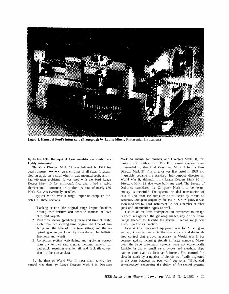
Figure 8. Hannibal Ford’s integrator. (Photograph by
By the late 1930s the input of these variables was much morehighly automated.
The Gun Director Mark 33 was initiated in 1932 fordual-purpose 5-inch138 guns on ships of all sizes. It resem-bled an apple on a stick when it was mounted aloft, and ithad vibration problems. It was used with the Ford RangeKeeper Mark 10 for antiaircraft fire, and it had a stableelement and a computer below deck. A total of nearly 850Mark 33s was eventually installed.
A typical World War II range keeper or computer con-sisted of three sections:
I. Tracking section (the original range keeper functionsdealing with relative and absolute motions of ownship and target).
2. Prediction section (predicting range and time of flight,each from two moving time origins: the time of gunfiring and the time of fuze time setting; and the re-quired gun angles found by considering the ballisticfunctions and wind).
3. Correction section (calculating and applying correc-tions due to own ship angular motions. namely. rolland pitch. requiring trunnion tilt and deck tilt correc-tions to the gun angles).
By the time of World War II most main battery firecontrol was done by Range Keepers Mark 8 in Directors
~--;--____-_-~-“-”Laurie Minor, Smithsonian Institution.)
Mark 34, mainly for cruisers, and Directors Mark 38, forcruisers and battleships. ” The Ford range keepers weresuperseded by the Ford Computer Mark 1 in the GunDirector Mark 37. This director was first tested in 1939 andit quickly became the standard dual-purpose director inWorld War II, although many Range Keepers Mark 10 inDirectors Mark 33 also were built and used. The Bureau ofOrdnance considered the Computer Mark 1 to be “enor-mously successful.“” The system included transmission ofdata to and from the computer below decks by means ofsynchros. Designed originally for the 5-inch/38 guns, it wassoon modified by Ford Instrument Co. for a number of otherguns and ammunition types as well.
Choice of the term “computer” in preference to “rangekeeper” recognized the growing inadequacy of the term“range keeper” to describe the system. Keeping range wasa small part of its function.
Fine as this fire-control equipment was for 5-inch gunsand up, it was not suited to the smaller guns and decentral-ized control that proved necessary in World War II fordefense against incoming aircraft in large numbers. More-over, the large fire-control systems were not economicallyfeasible for use on small naval vessels and merchant shipshaving guns even as large as 3 inches. Fire control forclose-in attack by a number of aircraft was “sadly neglectedin the years between the two wars” due to an “ill-foundedcomplacency” concerning the ability of fire-control systems
IEEE Annals oj’the History of Computing, Vol. 15, No. 2, 1993 l 25
Mechanical Analog Computers
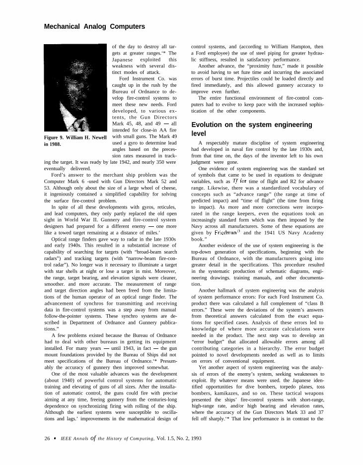
Figure 9. William H. Newellin 1988.
of the day to destroy all tar-gets at greater ranges.‘* TheJapanese exploited thisweakness with several dis-tinct modes of attack.
Ford Instrument Co. wascaught up in the rush by theBureau of Ordnance to de-velop fire-control systems tomeet these new needs. Forddeveloped, to various ex-tents, the Gun DirectorsMark 45, 48, and 49 - allintended for close-in AA firewith small guns. The Mark 49used a gyro to determine leadangles based on the preces-sion rates measured in track-
ing the target. It was ready by late 1942, and nearly 350 wereeventually delivered.
Ford’s answer to the merchant ship problem was theComputer Mark 6 -used with Gun Directors Mark 52 and53. Although only about the size of a large wheel of cheese,it ingeniously contained a simplified capability for solvingthe surface fire-control problem.
In spite of all these developments with gyros, reticules,and lead computers, they only partly replaced the old opensight in World War II. Gunnery and fire-control systemdesigners had prepared for a different enemy - one morelike a towed target remaining at a distance of miles.’
Optical range finders gave way to radar in the late 1930sand early 1940s. This resulted in a substantial increase ofcapability of searching for targets (with “broad-beam searchradars”) and tracking targets (with “narrow-beam fire-con-trol radar”). No longer was it necessary to illuminate a targetwith star shells at night or lose a target in mist. Moreover,the range, target bearing, and elevation signals were cleaner,smoother. and more accurate. The measurement of rangeand target direction angles had been freed from the limita-tions of the human operator of an optical range finder. Theadvancement of synchros for transmitting and receivingdata in fire-control systems was a step away from manualfollow-the-pointer systems. These synchro systems are de-scribed in Department of Ordnance and Gunnery publica-tions.”
A few problems existed because the Bureau of Ordnancehad to deal with other bureaus in getting its equipmentinstalled. For many years - until 1943, in fact - the gunmount foundations provided by the Bureau of Ships did notmeet specifications of the Bureau of Ordnance.‘* Presum-ably the accuracy of gunnery then improved somewhat.
One of the most valuable advances was the development(about 1940) of powerful control systems for automatictraining and elevating of guns of all sizes. After the installa-tion of automatic control, the guns could fire with preciseaiming at any time, freeing gunnery from the centuries-longdependence on synchronizing firing with rolling of the ship.Although the earliest systems were susceptible to oscilla-tions and lags.’ improvements in the mathematical design of
control systems, and (according to William Hampton, thena Ford employee) the use of steel piping for greater hydrau-lic stiffness, resulted in satisfactory performance.
Another advance, the “proximity fuze,” made it possibleto avoid having to set fuze time and incurring the associatederrors of burst time. Projectiles could be loaded directly andfired immediately, and this allowed gunnery accuracy toimprove even further.
The entire functional environment of fire-control com-puters had to evolve to keep pace with the increased sophis-tication of the other components.
Evolution on the system engineeringlevel
A respectably mature discipline of system engineeringhad developed in naval fire control by the late 1930s and,from that time on, the days of the inventor left to his ownjudgment were gone.
One evidence of system engineering was the standard setof symbols that came to be used in equations to designatevariables, such as Tf for time of flight and R2 for advancerange. Likewise, there was a standardized vocabulary ofconcepts such as “advance range” (the range at time ofpredicted impact) and “time of flight” (the time from firingto impact). As more and more corrections were incorpo-rated in the range keepers, even the equations took anincreasingly standard form which was then imposed by theNavy across all manufacturers. Some of these equations aregiven by FriedmanI and the 1941 US Navy Academybook.”
Another evidence of the use of system engineering is thetop-down generation of specifications, beginning with theBureau of Ordnance, with the manufacturers going intogreater detail in the specifications. This procedure resultedin the systematic production of schematic diagrams, engi-neering drawings. training manuals, and other documenta-tion.
Another hallmark of system engineering was the analysisof system performance errors: For each Ford Instrument Co.product there was calculated a full complement of “class Berrors.” These were the deviations of the system’s answersfrom theoretical answers calculated from the exact equa-tions for specified cases. Analysis of these errors led toknowledge of where more accurate calculations wereneeded in the product. The next step was to develop an“error budget” that allocated allowable errors among allcontributing categories in a hierarchy. The error budgetpointed to novel developments needed as well as to limitson errors of conventional equipment.
Yet another aspect of system engineering was the analy-sis of errors of the enemy’s system, seeking weaknesses toexploit. By whatever means were used. the Japanese iden-tified opportunities for dive bombers, torpedo planes, tossbombers, kamikazes, and so on. These tactical weaponspresented the ships’ fire-control systems with short-range,high-range rate, and/or high bearing and elevation rates,where the accuracy of the Gun Directors Mark 33 and 37fell off sharply.‘* That low performance is in contrast to the
26 9 IEEE Annals of the History of Computing, Vol. 1.5, No. 2, 1993
reported high accuracy with slowtargets, even at great ranges. (Forexample, the battleship Washing-ton is said to have achieved ninehits on the Japanese battleshipKirishima, out of 75 rounds of 16.inch shells at 19,000 yards range inthe night battle of Guadalcanal in1942, where radar was used.)
The contributions ofWilliam H. Newell
In 1926 the Ford InstrumentCo., which was then working on itsfirst antiaircraft director, got a new
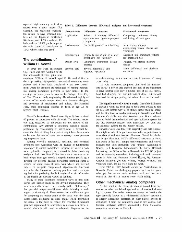
Table 1. Differences between differential analyzers and fire-control computers.
Characteristic Differential analyzers Fire-control computers
Application Solution of arbitrary differential Computing continuous aimingequations sets (general-purpose and fuzing of naval gunscomputer)
Environment On “solid ground” in a building In a moving warshipexperiencing severe shocks andvibrations
Construction Originally spread out on a large Designed into minimum volumebreadboard for flexibility for shipboard use
Design style Laboratory instrument design Rugged, yet precise machinepractice design
Problem size Several differential and Many differential and algebraicalgebraic eouations eauations
employee: William H. Newell, aged 16. He worked first inthe shop making high-precision mechanical computing com-ponents and, a year later, transferred to the Test Depart-ment where he acquired the techniques of making mechan-ical analog computers perform to their limits. In theevenings for seven years he went to the College of the Cityof New York to study engineering. He advanced rapidly asa result of his nearly unique talents as an inventor, designer,and developer of mechanisms and indeed, like HannibalFord, entire computing systems. In 1943. at age 32, hebecame chief engineer.
Newell’s inventions. Newell (see Figure 9) has received80 patents in connection with his work. The subject matterwas long classified, so the public has not known of hiscontributions. Any attempt to determine Newell’s accom-plishments by concentrating on patent dates is difficult be-cause the date of filing for a patent might have been muchearlier than the date of issue due to secrecy orders prevent-ing responsive issue.
Among Newell’s mechanical. hydraulic. and electricalinventions (see Appendix) were 31 devices of fundamentalimportance to analog technology. Included are devices suchas a hydraulic computer: an irreversible drive involvingwedges to lock two disks if direction starts to reverse, as inback torque from gun recoil: a torpedo director (Mark 2); adirector for defense against horizontal bombing runs; ascheme for using trains of balls, with wheels and steeringrollers, to integrate complicated trigonometric functionsand solve the fire-control tracking problem; and a comput-ing device for predicting the deck angles of an aircraft carrierat the instant an airplane would be landing.
Many of these inventions concerned ways to deal withinertia and friction loads on the driving mechanisms. Theywere essentially servos, then usually called “follow-ups.”that provided torque amplification while following a shaftangular position signal. These servos had a differential gearfor comparing the output angle of the servo with the inputsignal angle, producing an error angle, which determinedthe signal to the drive to reduce the error-that differentialgear was represented on schematics by a cross in a circle. asymbol which is still used on schematic diagrams for the
1 I
error-determining subtraction in control systems of manytypes today.
The Ford Instrument equipment often used an “intermit-tent drive,” a device that enabled one part of the equipmentto drive another over only a limited part of its total travel.Ford had designed the first intermittent drive, but Newellimproved the design, putting the whole drive on one shaft.
The significance of Newell’s work. One of the hallmarksof Newell’s work has been that he took extra trouble to findthe neat and simple way to do things, rather than go aheadwith his first idea. A notable testimony to Newell’s and FordInstrument’s skills was that Wernher von Braun selectedthem to build the mechanical and gyro guidance system forthe first Redstone missile. Ford Instrument Co. built alsothe guidance system for the Jupiter missile.
Newell’s work was done with originality and self-reliance.One might wonder if he got ideas from other organizations inthose days of technical ferment. However, Newell has deniedthat he got ideas from MIT’s differential analyzers or ServoLab work: In fact. MIT bought Ford components, and Newellbelieved that Ford Instrument was “ahead.” According toNewell. Bell Telephone Laboratories, the Naval ResearchLaboratory, the Office of Naval Research, the ENIAC project,and the university researchers, including such avid communi-cators as John von Neumann, Harold Hazen, Jay Forrester,Claude Shannon, Norbert Wiener, Warren Weaver, andVannevar Bush, had no effect upon his work.
From 1965 to 1977, Newell worked for Perkin-Elmer, inNorwalk, Conn.. on challenging projects such as the spacetelescope, first on the senior technical staff and then as aconsultant. But that is another story worth telling.
Other mechanical analog computersAt this point in the story, attention is turned from fire
control to other specialized applications of mechanical ana-log computers. The author makes no attempt to describe thetype generally known as a “differential analyzer” because itis already adequately described in other places -except todistinguish it from the computers used in fire control. Dif-ferential analyzers differed dramatically from fire-controlcomputers. as shown in Table 1.
IEEE Annals of the History of Computing, Vol. 15, No. 2, 1993 l 27
Mechanical Analog Computers
These were the two distinct species that represented thehigh point of mechanical analog computer development,each in its own way. Williams’ felt that *‘the analog traditionreached its height in the differential analyzers.” This authordisagrees that either species was superior.
Torpedo mechanical computers. Torpedo data comput-ers for use by submarines were developed by the ArmaCorporation in 1935. Arma had been building stable ele-ments and other gyroscope instrumentation for weaponssince its founding in about 1920. The torpedo data computerautomated much of the process of inserting data into atorpedo to establish its course, speed, and depth. It wasprimarily a mechanical computer with some electrical com-ponents. By World War II most submarines in the US Navyhad a TDC Mark 3.12 A simpler and more compact versionof the torpedo data computer, the Mark 2, was developedby William Newell (see item 5 in the Appendix).
Destroyers of that period carried Torpedo DirectorMark 27, which contained a mechanical computer. A num-ber of approximations could be made, because the resultingerrors could be ignored when torpedoes were fired in aspread. As a result, the equations were much less complexthan those of the antiaircraft fire-controlproblem.‘2 As earlyas 1942, the Bureau of Ordnance conceived of a need for asystem for computing and displaying the data of concern inantisubmarine warfare. The resulting product was the At-tack Director Mark 2, which contained a mechanical com-puter. Fifteen were delivered.”
In the early 1950s Arma built a mechanical analog com-puter (“coordinate conversion computer”) containing agimbal system. Designed at MIT, it was one unit of a fire-control system for use by the Navy in the Korean War. Thetorpedo itself contained several small mechanical analogcomputers. They were extremely delicate and complex, withthe result that their effectiveness was reduced. These com-puters included the following mechanical devices:
1. The course control system that activated a rudder.2. A computer to determine the course angle for colli-
sion with the target.3. A depth-control system, relying on a diaphragm to
measure depth (water pressure) and a pendulum tomeasure rate of change of depth. The pendulum waslater replaced by a gyroscope to avoid the error dueto longitudinal acceleration. The change was Newell’sidea.” (See item 25 in the Appendix.)
Bombsight mechanical analog computers. Anotherhighly specialized type of mechanical analog computer wasdeveloped for use in bombers. Bombsights were remarkablefor their extremely small size and high precision. TheNorden bombsights contained over 2.000 parts. Develop-ment began at the end of World War I and progress wasrapid: The Bombsight Mark 3 was contracted for in 1922.the Mark 11 was accepted in 1931, and the Mark 15 wasbeing tested in 1931.” Bombsights were also made bySperry.
One of the refinements to bombsights was the inventionby Newell and Lawrence Brown that enabled a bomber tonavigate by some identified visible point, when the targetitself was obscured, and yet still bomb the target.
Sights and directors for small guns. Major naval vesselshad no small guns until after Pearl Harbor, when the largenumbers of incoming aircraft had overwhelmed the fire-con-trol systems for large guns. As a result, a rapid evolution hadto take place to provide something better than the open sightmounted on the gun barrel, which had been standard arma-ment against aircraft in World War I.
A significant advance was made by the lead-computingsight developed in the 1930s by Charles S. Draper of MIT.Draper’s sight evolved from his earlier products of an air-craft instrument to display rates of turn and his tank gunsight. These devices used precessing-rate gyros mounted onthe line of sight to the target, Each rate was multiplied by asuitable factor to produce a proportional lead angle, whichwas applied to the gun direction.” The overall precision wason the order of 2 percent. The Navy learned of the Drapersight belatedly: One was tested in July 1941, and the sightsentered service in the fall of 1942 - built by Sperry and byCrosley. Eventually 85,000 of the Gun Sights Mark 14 werebought for naval vessels.
The US Navy’s response to the need also included thedevelopment of some heavy machine-gun directors. Con-tracts for development were awarded to Ford Instrumentfor the Gun Director Mark 45, to General Electric for theMark 46, and to Arma for the Mark 47 (the Mark 46 and47 never reached production). The Mark 45 was com-pleted as early as 1942: however, it was too complicatedand heavy as a computer, and it was too crowded as aworkplace, so production of it was stopped. It was re-placed by the Gun Director Mark 49, which also wasbeing developed by Ford Instrument. The Mark 49 con-tained a gyro torqued hydraulically to precess it, and ithad hydraulic pick-offs. The Mark 49 was replaced by theMark 5 1 .I2 Located on a pedestal remote from the guns,it used a Draper sight to transmit train and elevationangle orders to heavy machine guns. It was manufacturedby Sperry Gyroscope Co., beginning in January 1942.” Itsperformance was poorest for surface targets, which hadsmall angular rates as seen by the sight.
Gun Director Mark 56 was designed at MIT. It utilizedan unusual mechanical analog computer technology: four-bar linkages. By properly proportioning the bar lengths, onecould design linkages to generate a surprising variety offunctions. Some of the linkage computers were made byFord Instrument Co. Vannevar Bush, in his role as one ofthe organizers of the National Defense Research Commit-tee. was able to do much for small gunfire-control develop-ments. and he had a hand in its production.
In addition to the naval gun sights and directors men-tioned here for heavy machine guns. comparable or smallersystems were developed for use in aircraft, such as thelargest bombers (B-29). There was. for example, a Mark 18Turret Gun Sight. which had a computing mechanism. It wasfollowed by the Mark 23 in 1945.”
28 . IEEE Annals o,f the History of Computing, Vol. 15. No. 2, 1993
Other analog mechanical computers. Flight simulatorsfor pilot training have been in existence since the “PilotMaker,” alias “Blue Box,” of Ed Link, developed in 1929,‘sLink’s flight simulator contained a pneumatic analog com-puter that used principles he had learned in his father’sorgan factory. A mechanical analog flight simulator wasdesigned and built by Ford Instrument Co. in 1945. Laterflight simulators were based on electric and electronic ana-log and then digital technology. Mechanical analogcomput-ers were used also in early guidance systems for missiles:Arma did the inertial guidance for the Atlas missile. WilliamNewell also invented a guidance system that worked withoutgimbals, integrating components of acceleration and veloc-ity to determine present position (see item 27 in the Appen-dix).
The range of the German V2 rocket was determined bya mechanical analog computing device. It integrated accel-eration twice to get distance traveled; it also contained somelinkages and differential gears to relate the twice-integratedacceleration to horizontal distance.” As the technology wasrefined, new applications were undertaken. Most of theseand other mechanical analog computers were eventuallysuperseded by electrical analog computers.
The descendants of mechanical analogcomputers
Mechanical analog computing evolved in two directions,branching into developments in AC analog computers andDC analog computers.
AC analog developments. In about 1940 the market fortools for performing mathematical operations was quitesmall. Mechanical desk calculators served acceptably for allbut the largest problems, such as fire control and exteriorballistics. When Thornton C. Fry wrote a survey article’”about the extent of the use of mathematics in industry, hehad little to report outside the telephone and aircraft indus-tries. One could not then imagine the explosion of electricaland electronic technologies that would result in a flood ofcomputers available at modest cost.
The principles of AC (alternating current) electrical an-alog circuits had been known since Steinmetz in the 1880s.Currents entering a node were known to add. The chargeon a capacitor was known to be the time integral of thecurrent that had flowed through it. It was known that aservo-driven potentiometer could be “tapped” to yield afunction or a product of two variables. This technology wasnot developed, however, until Bell Telephone Laboratoriesfound application for it in a developmental gun directorearly in World War II.
The BTL project was to develop an AC analog gundirector, the T-15. It was funded in November 1941, and themodel was completed a year later and tested in December1942.” The T-15 was never put into production: it was,however. used for research with targets flying trajectoriesthat were not straight lines.
The T-15 led to a proposal to the Navy, in February 1942,to construct an AC analog version of the Ford Instrument
Company’s Computer Mark 1. A contract was awarded inSeptember 1942 for development of this “Mark 8 Com-puter.” Although it proved to be faster than the ComputerMark 1 in completing the initial transient of acquiring andlocking onto a target, the Mark 8 Computer was neverproduced. It had one other feature worth noting: a special
A refinement to bombsights inventedby Newell and Lawrence Brown
enabled a bomber to navigate by avisible point, when the target itself wasobscured, and yet still bomb the target.
electrical integrator that was developed for it.Ford Instrument Co., under the direction of Harry Mc-
Kenny and William Newell, developed an AC analog com-puter, the Mark 47, which replaced the mechanical analogComputer Mark 1.
From 1945 to 1950 the Dynamic Analysis and ControlLaboratory at MIT developed an AC analog computer,using 400-cycle AC components in a guided missile flightsimulator. This was an activity within Project Meteor. Theflight table was mounted on four concentric gimbals sodriven as to avoid gimbal lock under all conditions.
DC analog developments. DC (direct current) amplifiershad been used since the post-World War I days of radio.They were highly developed in the 1930s by BTL, whichused them for signal amplification in telephony. They wereused also by George Philbrick at Foxboro, as early as 1937or 1938, for simulation of linear processes and control sys-tems.” Developments of amplifiers for use in simulationwere made also by John Ragazzini et al. at Columbia Uni-versity in about 1940. Bell Telephone Laboratories devoteditself to the development of DC vacuum tube amplifiers foruse in analog computers for fire control after about June1940. A patent. applied for in May 1941, was issued in June1946 as US patent 2404387 to C.A. Lovell, D.B. Parkinson,and B.T. Weber. Their contemplated systems used summingnetworks, potentiometer cards for functions, and an integra-tor using an amplifier and a capacitor.2’
In November 1940 Western Electric received a contractto develop a model of a DC analog gun director, the T-10.It was to use the BTL-developed DC analog technology.The model was tested successfully in December 1941.2’
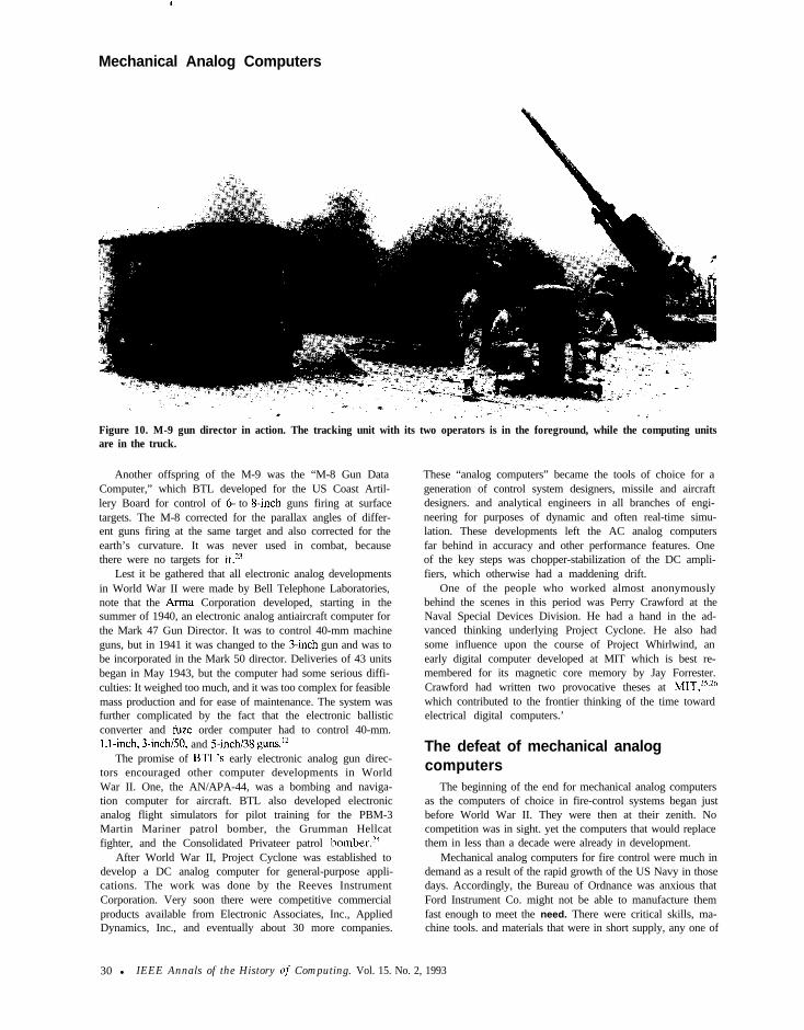
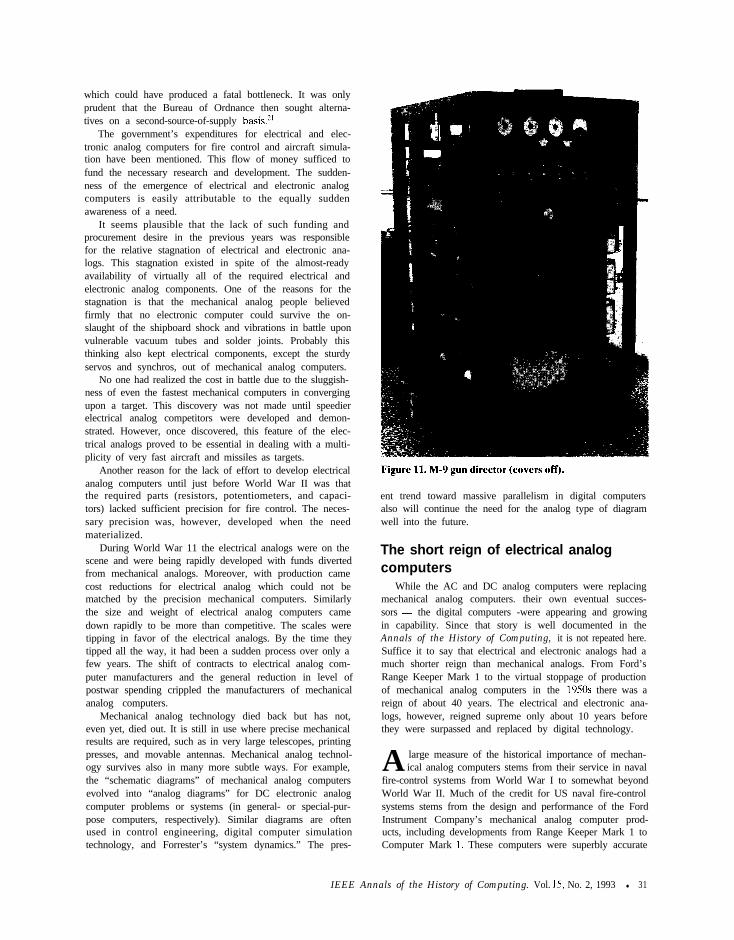
The success of the T-10 led to a contract to build theproduction version, the M-9 Gun Director. It was deliveredin December 1942, and it was placed in service in early 1943.It was used during the Vl “buzz bomb” attack on Londonto control the fire of 90-mm guns located along the Englishcoast. During the month of August it shot down 90 percentof the buzz bombs that arrived, and in its best week it shotdown 89 of the 91 that arrived. The M-9 (see Figures 10 and11) was aided by radar and proximity fuzes.” A Britishversion of the M-9 (the T-24. directing 4.5inch AA guns)had its prototype completed by May I 942.2’
IEEE Annals ofthe History of Computing. Vol. 15, No. 2, 1993 l 29
Mechanical Analog Computers
Figure 10. M-9 gun director in action. The tracking unit with its two operators is in the foreground, while the computing unitsare in the truck.
Another offspring of the M-9 was the “M-8 Gun DataComputer,” which BTL developed for the US Coast Artil-lery Board for control of 6- to &inch guns firing at surfacetargets. The M-8 corrected for the parallax angles of differ-ent guns firing at the same target and also corrected for theearth’s curvature. It was never used in combat, becausethere were no targets for it.*”
Lest it be gathered that all electronic analog developmentsin World War II were made by Bell Telephone Laboratories,note that the Arma Corporation developed, starting in thesummer of 1940, an electronic analog antiaircraft computer forthe Mark 47 Gun Director. It was to control 40-mm machineguns, but in 1941 it was changed to the 3-inch gun and was tobe incorporated in the Mark 50 director. Deliveries of 43 unitsbegan in May 1943, but the computer had some serious diffi-culties: It weighed too much, and it was too complex for feasiblemass production and for ease of maintenance. The system wasfurther complicated by the fact that the electronic ballisticconverter and fuze order computer had to control 40-mm.1.1~inch, 3-i&/50, and ?&inch/38 gunsI
The promise of BTL’s early electronic analog gun direc-tors encouraged other computer developments in WorldWar II. One, the AN/APA-44, was a bombing and naviga-tion computer for aircraft. BTL also developed electronicanalog flight simulators for pilot training for the PBM-3Martin Mariner patrol bomber, the Grumman Hellcatfighter, and the Consolidated Privateer patrol bomber.‘4
After World War II, Project Cyclone was established todevelop a DC analog computer for general-purpose appli-cations. The work was done by the Reeves InstrumentCorporation. Very soon there were competitive commercialproducts available from Electronic Associates, Inc., AppliedDynamics, Inc., and eventually about 30 more companies.
These “analog computers” became the tools of choice for ageneration of control system designers, missile and aircraftdesigners. and analytical engineers in all branches of engi-neering for purposes of dynamic and often real-time simu-lation. These developments left the AC analog computersfar behind in accuracy and other performance features. Oneof the key steps was chopper-stabilization of the DC ampli-fiers, which otherwise had a maddening drift.
One of the people who worked almost anonymouslybehind the scenes in this period was Perry Crawford at theNaval Special Devices Division. He had a hand in the ad-vanced thinking underlying Project Cyclone. He also hadsome influence upon the course of Project Whirlwind, anearly digital computer developed at MIT which is best re-membered for its magnetic core memory by Jay Forrester.Crawford had written two provocative theses at MIT,“.2hwhich contributed to the frontier thinking of the time towardelectrical digital computers.’
The defeat of mechanical analogcomputers
The beginning of the end for mechanical analog computersas the computers of choice in fire-control systems began justbefore World War II. They were then at their zenith. Nocompetition was in sight. yet the computers that would replacethem in less than a decade were already in development.
Mechanical analog computers for fire control were much indemand as a result of the rapid growth of the US Navy in thosedays. Accordingly, the Bureau of Ordnance was anxious thatFord Instrument Co. might not be able to manufacture themfast enough to meet the need. There were critical skills, ma-chine tools. and materials that were in short supply, any one of
30 l IEEE Annals of the History o,f Computing. Vol. 15. No. 2, 1993
which could have produced a fatal bottleneck. It was onlyprudent that the Bureau of Ordnance then sought alterna-tives on a second-source-of-supply basis.”
The government’s expenditures for electrical and elec-tronic analog computers for fire control and aircraft simula-tion have been mentioned. This flow of money sufficed tofund the necessary research and development. The sudden-ness of the emergence of electrical and electronic analogcomputers is easily attributable to the equally suddenawareness of a need.
It seems plausible that the lack of such funding andprocurement desire in the previous years was responsiblefor the relative stagnation of electrical and electronic ana-logs. This stagnation existed in spite of the almost-readyavailability of virtually all of the required electrical andelectronic analog components. One of the reasons for thestagnation is that the mechanical analog people believedfirmly that no electronic computer could survive the on-slaught of the shipboard shock and vibrations in battle uponvulnerable vacuum tubes and solder joints. Probably thisthinking also kept electrical components, except the sturdyservos and synchros, out of mechanical analog computers.
No one had realized the cost in battle due to the sluggish-ness of even the fastest mechanical computers in convergingupon a target. This discovery was not made until speedierelectrical analog competitors were developed and demon-strated. However, once discovered, this feature of the elec-trical analogs proved to be essential in dealing with a multi-plicity of very fast aircraft and missiles as targets.
Another reason for the lack of effort to develop electricalanalog computers until just before World War II was thatthe required parts (resistors, potentiometers, and capaci-tors) lacked sufficient precision for fire control. The neces-sary precision was, however, developed when the needmaterialized.
During World War 11 the electrical analogs were on thescene and were being rapidly developed with funds divertedfrom mechanical analogs. Moreover, with production camecost reductions for electrical analog which could not bematched by the precision mechanical computers. Similarlythe size and weight of electrical analog computers camedown rapidly to be more than competitive. The scales weretipping in favor of the electrical analogs. By the time theytipped all the way, it had been a sudden process over only afew years. The shift of contracts to electrical analog com-puter manufacturers and the general reduction in level ofpostwar spending crippled the manufacturers of mechanicalanalog computers.
Mechanical analog technology died back but has not,even yet, died out. It is still in use where precise mechanicalresults are required, such as in very large telescopes, printingpresses, and movable antennas. Mechanical analog technol-ogy survives also in many more subtle ways. For example,the “schematic diagrams” of mechanical analog computersevolved into “analog diagrams” for DC electronic analogcomputer problems or systems (in general- or special-pur-pose computers, respectively). Similar diagrams are oftenused in control engineering, digital computer simulationtechnology, and Forrester’s “system dynamics.” The pres-
ent trend toward massive parallelism in digital computersalso will continue the need for the analog type of diagramwell into the future.
The short reign of electrical analogcomputers
While the AC and DC analog computers were replacingmechanical analog computers. their own eventual succes-sors - the digital computers -were appearing and growingin capability. Since that story is well documented in theAnnals of the History of Computing, it is not repeated here.Suffice it to say that electrical and electronic analogs had amuch shorter reign than mechanical analogs. From Ford’sRange Keeper Mark 1 to the virtual stoppage of productionof mechanical analog computers in the 1950s there was areign of about 40 years. The electrical and electronic ana-logs, however, reigned supreme only about 10 years beforethey were surpassed and replaced by digital technology.
A large measure of the historical importance of mechan-ical analog computers stems from their service in naval
fire-control systems from World War I to somewhat beyondWorld War II. Much of the credit for US naval fire-controlsystems stems from the design and performance of the FordInstrument Company’s mechanical analog computer prod-ucts, including developments from Range Keeper Mark 1 toComputer Mark 1. These computers were superbly accurate
IEEE Annals of the History of Computing. Vol. 1.5, No. 2, 1993 l 31
Mechanical Analog Computers
despite their need to be rugged under the abuse of shocksand vibration in battle.
The outstanding inventors and developers of the FordInstrument computers were Hannibal C. Ford and WilliamNewell. Their technical leadership, which spanned four de-cades, provided a unique corporate capability.
Ford and Newell deserve to be recognized as mechanicalgeniuses at least on a par with Vannevar Bush. Bush hasbecome the better known by far, because of his differentialanalyzers, because of his writings, and because of his visibil-ity as an administrator on the national level. In contrast,Ford and Newell worked exclusively on classified projectsunknown to the public, modestly wrote nothing, and wereadministrators only within the company. They let their in-ventions and developments speak for them.
It is unfortunate that the story of Ford and Newell hasnot been known and appreciated among engineers and thegeneral public. The US Navy has had the facts all along, butit could not speak for many years because of the need forsecrecy. The material could not be declassified until it nolonger had current military importance. As a result, onlythose who were involved in the work have been privy to
much of the story.
Likewise, in the author’s opinion. mechanical analogcomputers for naval fire control deserve a featured place inthe history of computing, as differential analyzers haveenjoyed.
The outlook for future mechanical analog technology isconfined to some highly specialized opportunities where itsadvantages outweigh its disadvantages. These opportunitiesare most likely to arise for one or two components ratherthan complete computers. The glory lies in the past.
Thus, the story of mechanical analog computers deservesa place in the history of computers. It is truly important inits own right and, in addition, the technology served as anearly stepping stone toward today’s digital computers. n
AcknowledgmentsThe author has endeavored to portray the mechanical
analog aspects of the history of computing from the perspec-tive of a mathematical engineer. The author has been guidedby correspondence with Hunter Dupree, a professional his-torian of science and technology. Michael Williams gets thecredit for converting a long and disorganized paper into theform published here and then shepherding it through theeditorial process. The author could not have structured,condensed, and enlivened it so well unaided.
This article was submitted in 1985.
References
1. B.O. Williams, Cornpufing with Electricity, 1035-1945. doctoraldissertation, Univ. of Kansas, Lawrence. 1984.
2. J.C. Maxwell. “Description of a New Form of Planimeter. anInstrument for Measuring the Areas of Plain Figures Drawn onPaper,” Trans. Royal Scottish Society of Arts. Vol. 4. 1855.
3_
4.
1. Thomson. “On an Integrating Machine Having a New Kine-matic Principle.” Proc. Royal Socier_v. Vol. 28. 1876, p. 262.
V. Ventosa. “Integrating Anemometer.” letter to the editor.Nuture. Nov. 24. 1881.
5. V. Bush. “12th Josiah Willard Gibbs Lecture.” Oct. 1936.
6. W. Thomson. “Mechanical Integration of the Linear Differen-tial Equations of the Second Order with Variable Coeffi-cicnts.” Proc. Royal Society. Vol. 24. 1876, p. 269.
I. V. Bush. “Differential Analyzer.” J. Franklin Inst.. Vol. 212.No. 3. 193 I. pp. 447-488.
8 W. Thomson. “Machine for the Solution of Simultaneous Lin-car Equations.” Proc. Royal Soc~ir~y. Vol. 28, 1878.
Y M. Fry, “Designing Computing Mechanisms.” Machine Design.Aug.-Dec. 1945 and Jan. 1946.
10 A.B. Clymer. Mechanrcal Intqyratorc. master’s thesis, OhioState Univ.. Columbus. Ohio. lY46.
11 Dept. of Ordnance and Gunnery. US Bureau of Naval Person-nel, US Naval Academy. in three volumes. NAVPERS 10798.A. US Government Printing Office. Washington, D.C.. 1955,19.57.lYS9.
12 B. Rowland and W.B. Bovd. US Navy Burealc of Ordnance inWorld War II. Bureau of Ordnance, Dept. of the Navy. USGovernment Printing Office. Washington D.C., 1953.
13 N. Friedman. L/S Naval Weapot~s. Naval Inst. Press, Annapolis,Md.. 1982.
14 Anon.. -‘Hannibal C. Ford is Honored by Cornell,” The GreatNeck (N. Y.) New\. July 24. 1953.
IS 4non.. Obituary of H.C. Ford. Nrn York Times. Mar. 14. 1955.
16 H.C. Ford. US Patent 1317915 (granted 1919) and US Patent1317916(grantcd 1919).
17 US Naval Academy. ,~diore.s o,r Fire Control, 1933, 1941.
18. E.A. Link. Jr.. US Patent 1825462. Sept. 29, 1931.
19.
20.
21
22.
W. dc Beauclair. “Alwin Walthcr. IPM. and the Developmentof Calculator/Computer Technology in Germany, 1930-1945.”Annals of the Hisrory of Con~p~tring. Vol. 8, No. 4, 1986. pp.334-350.
r.C. Fry. “Industrial Mathematics.” Research - A Narimal Re-solrrceII.Section6.Part4. lY4l.pp.268288. ReprintedinAmericanMathematical Monthly. Vol. 4X. Supplement 11, pp. l-38.
W.H.C. Higgins. B.D. Holbrook. and J.W. Emling. “DefenseResearch at Bell Laboratories: Electrical Computers for FireControl.” Annals of the History of Computing. Vol. 4, No. 3,July 1982. pp. 218236.
P. Hoist. “George A. Philbrick and Polythemus - The FirstElectronic Training Simulator.” Annals c!fthe History of Com-paring. Vol. 4. No. 2. Apr. 1982. pp. 143-146.
32 l IEEE Annals of the History of Computing, Vol. 15, No. 2. 1993
23.
24
25
26
H.G. Och. “Computer for Coastal Guns.” Bell Lahoratorivs
Record. Vol. 24. May 1946. pp. 177-182.
R.D. Rippere. “An Analog Computer for Flight Training.” BellLaboratories Record. Vol. 25. Feb. 1947. pp. 7X-81.
P. Crawford, Instrumental Atmlysis /PI Matrix Analysk.bachelor’s thesis, MIT. Cambridge, Mass.. 1939.
P. Crawford. Automatic Control by Arithrnrtictrl Operatiotu.master’s thesis, MIT. Cambridge. Mass.. 1942.
Related readingAnon., “Mathematical Instruments.” Enc\cloprdia Britanrrrca.
14th ed.. Vol. 15, 1911.
Anon., “Noteworthy Patents.” Machine &sign. May 23. 1963.
J. Berry. “Clifford Edward Berry. 191%1963.“Annals of’the Histor)
of Comparing, Vol. 8, No. 4. 1986, pp. 361-369.
J.R. Fox, ed.. Shipboard Weapon System. US Naval Academy.Annapolis, Md.. undated (1976‘~).
J. Rothwell. US Patent 2002585. 1935.
W. Tamlyn et al.. “Instruction Books” for all products. Ford Instru-ment Co., published for the LJS Navy et al.. various years.
US Bureau of Naval Personnel. Principles of.Vavrrl Ordmrme and
Gunnery, NAVPERS 10783-A. 1965.
W.H.S. “H.C. Ford. Working at Home. Follows Company’s Prog-ress.“Productionfor Victory(house organ of Ford Instrument Co.).Oct. 20, 1943. pp. 6-8.
K.L. Wildes and N.A. Lindgren. A Centmy of Elecrrical Engineer-
ing and Computer Science at MIT, 18X2-1982. MIT Press. Cam-bridge, Mass.. 1985.
A. Ben Clymer is a retired consultingengineer who had been in a private prac-tice specializing in simulation and simu-lators. His interest in mechanical analogcomputers stems from his employment atFord Instrument Co. from 1942 to 1945.As a junior design engineer. he designedmechanical analog computers used in
naval fire-control systems for S-inch guns and up and anaircraft flight simulator.
Clymer can be reached at 32 Willow Drive. Apt. 1B.Ocean, NJ 07712.
AppendixAmong Newell’s mechanical. hydraulic. and electrical
inventions were the following:
1. A hydraulic computer. plus some hydraulic compo-nents, such as a device to generate a hydraulic pres-sure proportional to a displacement, and a hydraulic
4.
5.
6.
7.
8.
9.
IO.
11.
torquer and pick-off for a gyro in a gun director.Patents 2317293. Apr. 20, 1943: 2405052, July 30,1946: 2483980, Oct. 4. 1949: 25 13888, July 4, 1950:2533306. Dec. 12. 1950: 2550712, May 1, 1951;2569571. Oct. 2. 1951: 2766587, Oct. 16, 1956.Various rotary damping and/or inertia devices to beattached to a servo shaft to smooth the mechanicaloutput with a low-pass filter. One of these, called a‘*k-motor,” acted only when the signal got rough,Patent 2400775.Poitras and Tear of Ford Instrument developed anarrangement making a follow-up motor’s speed pro-portional to error. thereby obtaining an exponentialcharacteristic. making it a ‘velocity-lag servo.” Thisused a drag cup and gave an error proportional tovelocity. To eliminate this error there was intro-duced a differential gear between the motor anddrag cup with an inertia on the other differentialinput. which gave a smaller error proportional toacceleration. but no error proportional to velocity.Newell. in one application. used an air dashpot toobtain the velocity-lag servo effect.An irreversible drive involving wedges to lock twodisks if direction starts to reverse. as in back torquefrom gun recoil. This device prevents stick-slip oscil-lation when driving an inertia. whereas an “irrevers-ible” worm drive does not stop stick-slip. Patents2266237, Dec. 16.194 I : 2402073. June 11,1946.A torpedo director (Mark 2). Newell simplified themathematical basis. which enabled the size of thecomputer to be cut in half. Six of these systems sawservice in World War II. Patent 2403542. July 9,1046.A director for defense against horizontal bombingruns. By restricting its applicability. Newell was ableto do it with a much simpler computer than was inuse. Patents 2403543. July 9, 1946; 2403544. July 9,1946.A combination of a coarse and fine synchro, using acam-driven link to switch between coarse and fine.The patent application was filed in 1934, but thework had been done before that. Patent 2405045,July 30. 1946.A single-ball integrator with a rack to eliminatetangent function effect. Patent 2412468. Dec. 10.1046.A scheme to prevent large inertial load on a hydrau-lic servo from overshooting. which involved intro-ducing a spurious signal to start slowing it downbefore it reached the intended position. This wasparticularly important in synchronizing S-inch gunsand in bringing heavier guns to a loading position.Patents 2427154. Sept. 9.1947: 2840992, July 1,1958.A triangle mechanism to generate the square root ofthe sum of the squares of two input position vari-ables. Patent 243X818. Mar. 30. 1948.A scheme for using trains of balls, with wheels andsteering rollers. to integrate complicated trigono-metric functions and solve the fire-control tracking
IEEE Annals c!fthe History of’Cornpctting. Vol. 15. No. 2. 1993 l 33
Mechanical Analog Computers
12.
13.
14.
15.
16.
17.
18.
19.
20.
21.
22.
23.
24.
25.
34 l
problem (related to the earlier fundamental work ofMaxwell, Ventosa. Hele-Shaw. and Smith).“’ Patent2528284. Oct. 3 1, 1950.An electrical servo (with Henry F. McKenny). Pa-tents2448387,Aug.31,1948:254627l.Mar.21.19Sl.A printing press registration scheme using a photo-cell (with McKenny). Patent 2576529. Nov. 27, 195 1.An electronic analog resolver - given a magnitudeR and an angle A. it computes the components R sinA and R cm A continuously while compensating forthe magnetic distortion of the R input. Patent2646218, July 21. 1953.A “rate control” system whereby splash- or burst-point error data generated by a spotter topsidewould cause automatic continuous computation ofcorrections to target course and speed (patented inthe name of Ford et al.). Ford had developed a ratecontrol system that reversed the computation andfound target course and speed, but in doing so inter-rupted the generation of the prediction problem.Newell used component integrators to generate cor-rections to the target course and speed from thespotting corrections without interrupting the conti-nuity of the fire-control solution. Friedman gives theequations.” Patent 2702667, Feb. 22. 1955.A rhumb-line mechanical (later electrical) computerfor Air Force navigation along a great circle fromone given longitude/latitude to another. Thousandsof them were built. Patent 2783942. Mar. 5. 1057.An offset bombing director to allow homing on an-other point when the target cannot be seen (withLawrence Brown). Patent 2X15170, Dec. 3. 1957.A mechanical integrator with reduced friction sur-face area. Patent 2693709, Nov. 9, lYS4.An “error reducer” unit for reducing greatly thepointing errors of main battery guns (developed inabou t 1950). Patents 2763YX8. Sept. 25. 1 9 5 6 :2800769. July 30. 1957.An electrical device containing tapped potentiome-ters for generating a class of functions of three vari-ables. Patent 2817478. Dec. 24. 1957.A computing device for predicting the deck anglesof an aircraft carrier at the instant an airplane wouldbe landing. Patents 2817479, Dec. 24.1957: 2888195.May 26,1959: 2888203, May 26.1959: 2978177. Apr.1. 1961: 2996706. Aug. 15. 1961: 3174030. Mar. 16.1965.A parachute-release device. with Howard Brevoort.Patent 2834083, May 13. 1958.A device for squaring using a cone and cylinders(with S. Rappaport). Patent 2854854. Oct. 7. 19%.A computing module for correcting for the tilt of guntrunnions. Patents 2902212. Sept. I. lY5Y: 2920817.Jan. 12, 1960; 1967663. Jan. IO. 1961.A depth control for torpedoes using a gyro to senseattitude. It avoided the error in the previous Uhlangear design, which had been due to use of a pendu-lum for attitude sensing. During initial accelerationthis gave a spurious attitude signal which caused a
IEEE Annals of the History of' Computing. Vol. 15. No. 2. 1993
26.
27.
28.
29.
30.
3 1
deep and many times disastrous dive. Patent2920596. Jan. 12, 1960.
A torpedo motion simulator for engineering pur-poses based on the torpedo equations of motion,including the water mass and inertia associated withthe torpedo. Such a simulator was built for develop-ment purposes at Ford Instrument Co., possibly thefirst torpedo simulator.
A “strapped-down” navigation system not using anygimbals (developed on a contract in 1958). In apersonal communication, Newell said he considersthis to be one of his potentially most importantinventions. Patents 3049294, Aug. 14,1962; 2087333,Apr. 30. 1 Y63.
A scheme for developing an electric current from ahot rod and a magnetic field. This is the other inven-tion that Newell considers to be potentially mostimportant. Patents 3075096, Jan. 22. 1963; 3084267,Apr. 2. 1963.
Newell and Willard B. Constantinides developed adeck-tilt corrector which corrected gun angles ap-proximately for the level and cross level angles of thedeck.
The mechanical analog technology was extended in1945 for the development of a bomber navigationtrainer, mainly by Willard B. Constantinidesof FordInstrument Co. It solved the equations of motion ofan airplane with far greater generality, realism, andprecision than the contemporaneous pneumaticcomputers in the famous Link trainers, which dealtonly with small linear perturbations about steadyflight. To record the trajectory of the airplane asprojected on the horizontal plane, the Ford simula-tor drove electrically and remotely a mechanical“crab” that drew a curve on a large sheet of paperon the floor.
A scheme for using resistors (standard but trimmedto precise values of a 1 OOO- 1 range) to obtain ampli-fier input gains, which was patented.
In the foregoing list. the items that were mainly electrical,as distinguished from mechanical or hydraulic. were nos. 12,13. 14. 16.20.29. and 31.
Many more people than have been mentioned playednotable roles under Ford and Newell. Certainly the follow-ing at least also deserve to be named here: Ray Jahn, GeorgeCrowther. George Hamilton. Charles Buckley, Walter Con-able (the nephew of H.C. Ford), John Kallenberg, HowardBrevoort. and Elmer Garrett. During World War II theywere assisted by Charles Henrich. Charles Pond, KennethCrawford (brother of Perry). Rasmus Figenschou (of Nor-way). John Hauser. George Licske. Mrs. George Elder (neeAthena Rosarkv). Alois Mertz. and the author and other,then junior, design engineers.
Related Documents