1 The Mars Airplane: A Credible Science Platform 1, 2 Robert D. Braun Georgia Institute of Technology Atlanta, GA 30332-0150 (404) 385-6171 Henry S. Wright Mark A. Croom Joel S. Levine NASA Langley Research Center David A. Spencer Jet Propulsion Laboratory Pasadena, CA 91109 (818) 393-7886 [email protected] Hampton, VA 23681 [email protected] Abstract— Significant technology advances have enabled planetary aircraft to be considered as viable science platforms. Such systems fill a unique planetary science measurement gap, that of regional-scale, near-surface observation, while providing a fresh perspective for potential discovery. Recent efforts have produced mature mission and flight system concepts, ready for flight project implementation. This paper summarizes the development of a Mars airplane mission architecture that balances science, implementation risk and cost. Airplane mission performance, flight system design and technology readiness are described. TABLE OF CONTENTS 1. INTRODUCTION 1 2. MISSION ARCHITECTURE 1 3. DRIVING REQUIREMENTS 3 4. MISSION SYSTEM 3 5. FLIGHT SYSTEM 6 6. SYSTEM PERFORMANCE 8 7. TECHNOLOGY MATURATION 10 8. CONCLUDING REMARKS 12 REFERENCES 12 1. INTRODUCTION One hundred years ago, the Wright brothers successfully completed the first powered airplane flight above the sand dunes of North Carolina’s Outer Banks. A century later, technology advances in unmanned aerial vehicles and space flight systems have enabled a viable mission concept for the first flight of a powered airplane above the unexplored landscape of another planet. From its unique vantage point, a few kilometers above the Mars surface, an autonomous airplane can return unique science measurements over regional-scale distances for immediate scientific review and public dissemination. Such a flight would: (1) return fundamental scientific knowledge about the planet’s atmosphere, surface, and interior, (2) inspire the next generation of explorers, and (3) demonstrate the synergies possible through integration of our nation’s aeronautics and space enterprises. Planetary airplanes with potential application to Mars, Venus or Titan have been studied for numerous years [1-5] as a means to bridge the scale and resolution measurement gaps between orbiters (global-scale, limited spatial resolution) and landers (local-scale, high spatial resolution). By traversing regional-scale distances at near-surface altitude, planetary airplane observations complement and extend orbital and landed measurements while providing a fresh perspective for scientific discovery. Planetary aircraft can also survey scientifically interesting terrain that is inaccessible or hazardous to landed missions. While unpowered concepts [6-7] have been studied, powered airplanes offer a means to perform a controlled, near-surface scientific survey spanning hundreds of kilometers. Two recent, large efforts have significantly advanced Mars airplane technology readiness. The Mars Micromission Airplane [8-9] efforts of 1998-1999 brought out many of the design challenges associated with powered airplane flight on another planet. Challenges identified included the importance of airplane size as a means to reduce implementation risk and the need to mature the critical technologies of airplane wing/tail deployment and latching. With these lessons learned, the Aerial Regional-scale Environmental Survey (ARES) Mars Scout airplane [10-11] efforts of 2001-2003 demonstrated a compelling science rationale and a mature mission and flight system concept. This paper summarizes the development of a Mars airplane mission architecture that balances science, implementation risk and cost. The airplane mission performance and flight system design is described. Recent design, analysis and test experience has demonstrated the maturity of this science platform for use in a Mars flight project. 2. MISSION ARCHITECTURE ARES science objectives required completion of a 500-km pre-planned science survey from a vantage point 1-2 km above the surface terrain [10]. During this traverse, unique measurements of the Mars atmosphere, surface and the interior would be obtained using magnetometers, a mass spectrometer, a point spectrometer, and imaging cameras. These measurement objectives impose additional mission architecture constraints on local solar time and arrival season. In addition, traverse latitude and longitude requirements are science derived. __________________________________ 1 0-7803-8155-6/04/$17.00© 2004 IEEE 2 IEEEAC paper #1260, Final, Updated December 1, 2003

Welcome message from author
This document is posted to help you gain knowledge. Please leave a comment to let me know what you think about it! Share it to your friends and learn new things together.
Transcript
1
The Mars Airplane: A Credible Science Platform1, 2
Robert D. Braun
Georgia Institute of Technology Atlanta, GA 30332-0150
(404) 385-6171
Henry S. Wright Mark A. Croom Joel S. Levine
NASA Langley Research Center
David A. Spencer Jet Propulsion Laboratory
Pasadena, CA 91109 (818) 393-7886
[email protected] Hampton, VA 23681 [email protected]
Abstract— Significant technology advances have enabled planetary aircraft to be considered as viable science platforms. Such systems fill a unique planetary science measurement gap, that of regional-scale, near-surface observation, while providing a fresh perspective for potential discovery. Recent efforts have produced mature mission and flight system concepts, ready for flight project implementation. This paper summarizes the development of a Mars airplane mission architecture that balances science, implementation risk and cost. Airplane mission performance, flight system design and technology readiness are described.
TABLE OF CONTENTS
1. INTRODUCTION 1 2. MISSION ARCHITECTURE 1 3. DRIVING REQUIREMENTS 3 4. MISSION SYSTEM 3 5. FLIGHT SYSTEM 6 6. SYSTEM PERFORMANCE 8 7. TECHNOLOGY MATURATION 10 8. CONCLUDING REMARKS 12 REFERENCES 12
1. INTRODUCTION One hundred years ago, the Wright brothers successfully completed the first powered airplane flight above the sand dunes of North Carolina’s Outer Banks. A century later, technology advances in unmanned aerial vehicles and space flight systems have enabled a viable mission concept for the first flight of a powered airplane above the unexplored landscape of another planet. From its unique vantage point, a few kilometers above the Mars surface, an autonomous airplane can return unique science measurements over regional-scale distances for immediate scientific review and public dissemination. Such a flight would: (1) return fundamental scientific knowledge about the planet’s atmosphere, surface, and interior, (2) inspire the next generation of explorers, and (3) demonstrate the synergies possible through integration of our nation’s aeronautics and space enterprises.
Planetary airplanes with potential application to Mars, Venus or Titan have been studied for numerous years [1-5] as a means to bridge the scale and resolution measurement gaps between orbiters (global-scale, limited spatial resolution) and landers (local-scale, high spatial resolution). By traversing regional-scale distances at near-surface altitude, planetary airplane observations complement and extend orbital and landed measurements while providing a fresh perspective for scientific discovery. Planetary aircraft can also survey scientifically interesting terrain that is inaccessible or hazardous to landed missions. While unpowered concepts [6-7] have been studied, powered airplanes offer a means to perform a controlled, near-surface scientific survey spanning hundreds of kilometers. Two recent, large efforts have significantly advanced Mars airplane technology readiness. The Mars Micromission Airplane [8-9] efforts of 1998-1999 brought out many of the design challenges associated with powered airplane flight on another planet. Challenges identified included the importance of airplane size as a means to reduce implementation risk and the need to mature the critical technologies of airplane wing/tail deployment and latching. With these lessons learned, the Aerial Regional-scale Environmental Survey (ARES) Mars Scout airplane [10-11] efforts of 2001-2003 demonstrated a compelling science rationale and a mature mission and flight system concept. This paper summarizes the development of a Mars airplane mission architecture that balances science, implementation risk and cost. The airplane mission performance and flight system design is described. Recent design, analysis and test experience has demonstrated the maturity of this science platform for use in a Mars flight project.
2. MISSION ARCHITECTURE ARES science objectives required completion of a 500-km pre-planned science survey from a vantage point 1-2 km above the surface terrain [10]. During this traverse, unique measurements of the Mars atmosphere, surface and the interior would be obtained using magnetometers, a mass spectrometer, a point spectrometer, and imaging cameras. These measurement objectives impose additional mission architecture constraints on local solar time and arrival season. In addition, traverse latitude and longitude requirements are science derived.
__________________________________ 1 0-7803-8155-6/04/$17.00© 2004 IEEE 2 IEEEAC paper #1260, Final, Updated December 1, 2003
2
Extensive trade studies and numerous design cycles enabled the development of low-risk mission architecture. Key mission architecture trades are highlighted in Table 1. Mission design aspects including launch/arrival options, entry, descent and deployment trades and telecom options are presented. Science platform trades including the number and type of aerial platform, and its propulsion and navigation options were studied. The resulting mission architecture enabled satisfaction of ARES science objectives through a simple, low-risk flight system design. The most critical mission architecture trades were as follows: Launch Vehicle Selection
The Delta II series of launch vehicles were considered. The 2425 vehicle did not provide sufficient launch mass capability. The 2925 vehicle was selected to balance mass and cost margins. The 2925H vehicle provides an additional 155 kg of launch performance, for a cost increase of $10M. Launch/Arrival Strategy
Multiple interplanetary trajectory options were considered. A Type II transfer was selected to balance launch mass and cruise duration considerations. Three distinct Type II launch/arrival designs were developed, each of which satisfied our arrival season (Ls, solar longitude) and local solar time (LTST) science constraints. The baseline mission was designed to launch in Sept. 2007 and arrive in Sept. 2008 (Ls = 121°) with a reference traverse centered on 32°S. The LTST at arrival was 2:30 PM, allowing the use of the Mars Reconnaissance Orbiter as a backup communications relay asset during the airplane flight. Alternate Type II transfers were identified to target more southerly latitudes. As the traverse target moved south, these trajectory options required arriving later in the Mars season and earlier in local time; however, each of these options met the science constraints while avoiding solar conjunction (Ls = 169°) and the start of the dust storm season (Ls = 180°).
Direct Entry/Flyby versus Orbital Capture
Orbital capture was extensively considered. The propellant mass associated with orbital capture resulted in the need for a Delta II 2925H launch vehicle. The direct entry technique coupled with a flyby of the carrier vehicle allowed ARES to be launched on a 2925 vehicle, with an associated $15-20M in launch vehicle and spacecraft savings. In addition, the flyby geometry to the carrier spacecraft allowed a communications link duration and data return volume exceeding that possible for a single orbiter overflight. A direct entry/flyby mission architecture was selected for these two reasons. A direct-entry cruise stage option (as employed by Mars Pathfinder and MER) was also considered, but determined to be high risk due to the reliance on existing assets as the only means of data return. Science Platform
A powered airplane was selected because it is the only platform that satisfies all ARES science measurement requirements [11]. Selection of this science platform was made after considering orbiter, lander, glider, balloon, airship, and powered airplane mission concepts. In addition to platform class, these trades considered platform quantity and propulsion system options. A single, powered airplane comprised of flight-proven subsystems provides robust performance, meets the science objectives, and provides a platform that can be tested using conventional techniques, thus minimizing risk. Propeller and rocket propulsion systems were investigated. A rocket system was selected because it is the lowest risk means of achieving the ARES science objectives. Propeller system risks included designing a propeller of sufficient efficiency and size to power the Mars airplane and packaging concerns associated with folding and deploying the propeller blades. These risks are exacerbated on Mars, where the lower atmospheric density (relative to the Earth) requires larger propellers to generate a given thrust.
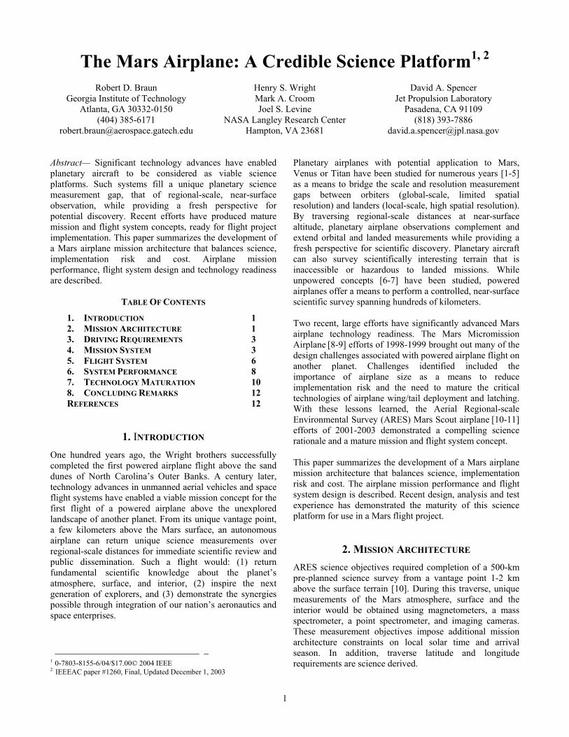
Table 1: Key Mars Airplane Mission Architecture Trades.
3
A thorough investigation of various propellant combinations (energy content, freezing temperature and availability of existing thrusters) was conducted [12]. This study focused on Hydrazine (mono-propellant) versus Mono-Methyl Hydrazine (MMH) and Nitrogen Tetroxide with a 3% Mixed Oxides of Nitrogen additive (MON-3) bi-propellant. In contrast to the mono-propellant, the MMH/MON-3 bi-propellant combination was shown to: 1) reduce propellant mass, 2) reduce propellant tank size thus reducing the tank-driven depth of the airplane fuselage cross-section and 3) maximize dry mass margin. For these reasons, the MMH/MON-3 bi-propellant combination was selected. An inertial-aided aircraft navigation system consisting of a high-accuracy IMU, air data system and radar altimeter was shown to be the minimum risk navigation strategy that met all science requirements [13].
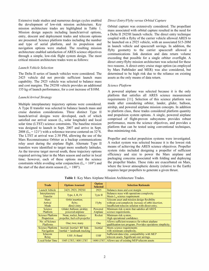
3. DRIVING REQUIREMENTS The baseline science scenario requires completion of a controlled aerial survey, spanning a flight range of 500 km at an altitude below 2 km. As described in Table 2, these requirements drive selection of a powered airplane as well as the airplane propulsion and navigation systems and aerodynamic configuration. Airplane structural mass is driven by launch vehicle vibration frequency requirements. Science payload pixel smear requirements limit apparent ground speed. Instrument data volume and the requirement for continuous telecom contact drive UHF power and performance. Airplane
Table 2: Influence of Driving Requirements on Airplane Mission and Flight System Implementation
wingspan and tail size are constrained by the diameter of the aeroshell, which in turn is driven by the launch shroud diameter. Airplane wet mass allocation and aerodynamic lift requirements are determined by the pullout maneuver, terrain altitude and atmospheric density.
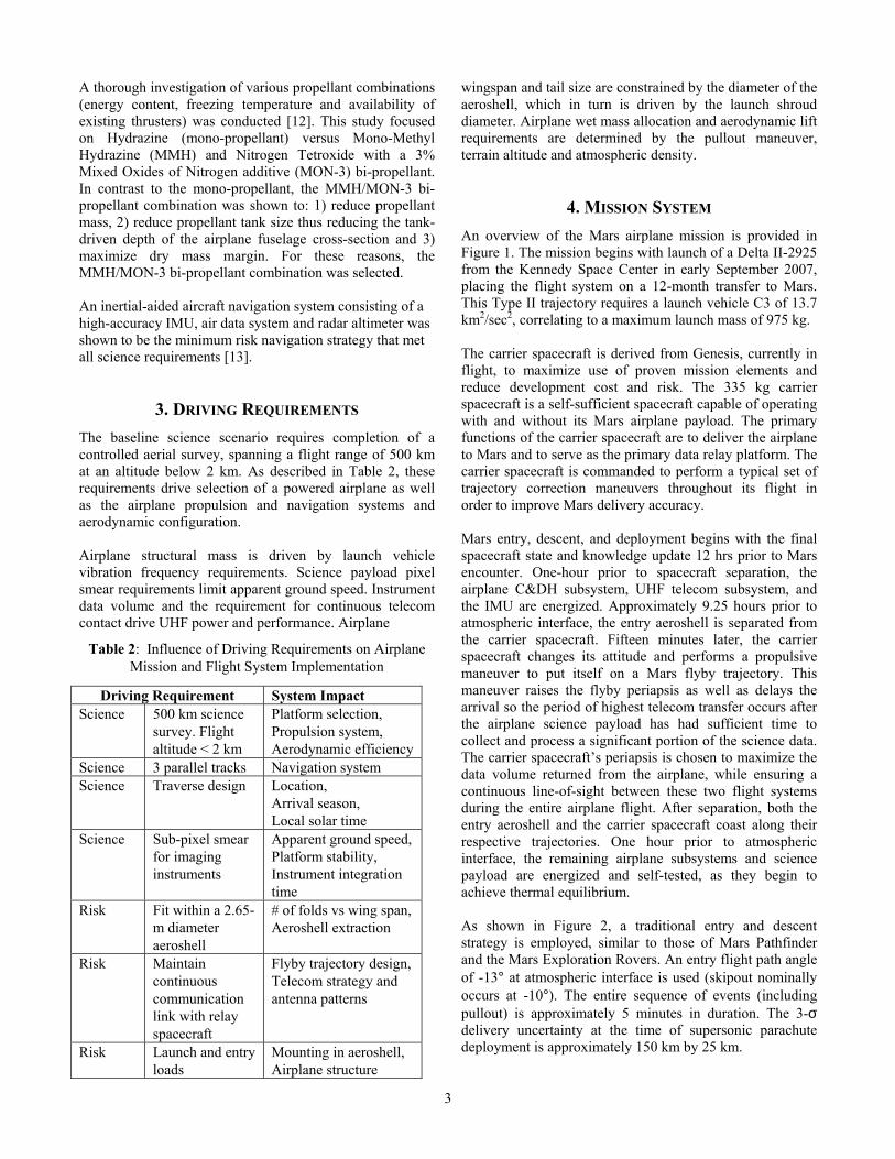
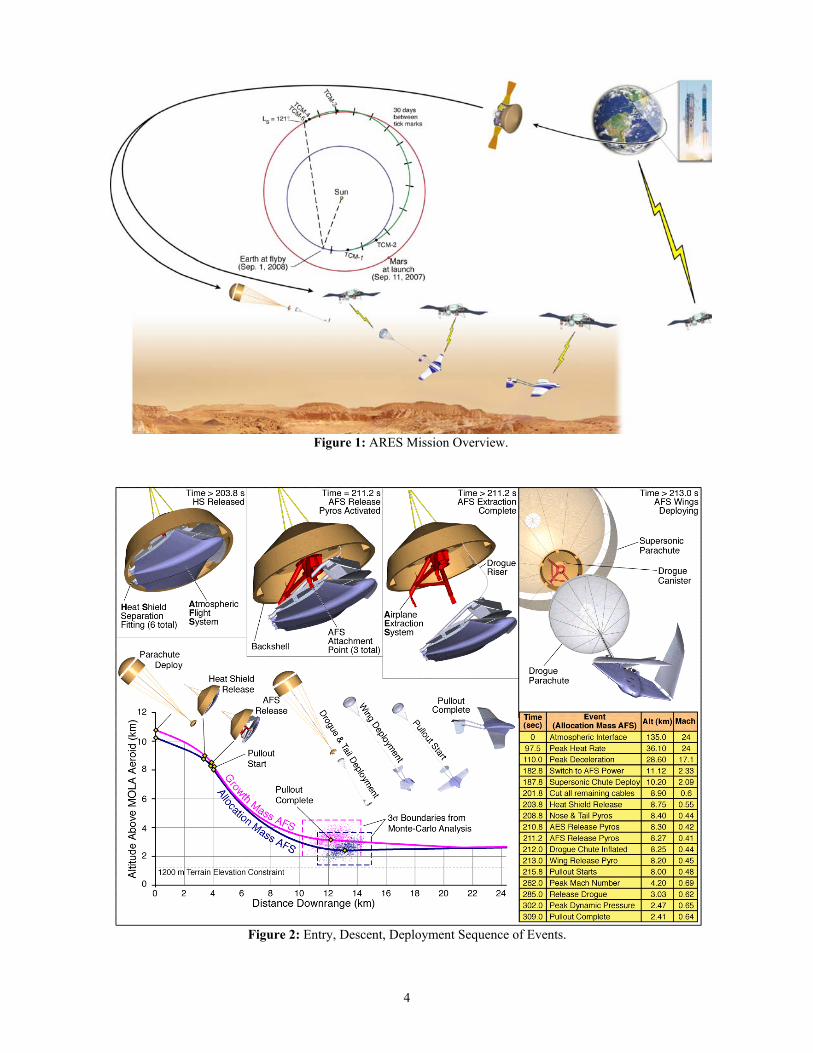
4. MISSION SYSTEM An overview of the Mars airplane mission is provided in Figure 1. The mission begins with launch of a Delta II-2925 from the Kennedy Space Center in early September 2007, placing the flight system on a 12-month transfer to Mars. This Type II trajectory requires a launch vehicle C3 of 13.7 km2/sec2, correlating to a maximum launch mass of 975 kg. The carrier spacecraft is derived from Genesis, currently in flight, to maximize use of proven mission elements and reduce development cost and risk. The 335 kg carrier spacecraft is a self-sufficient spacecraft capable of operating with and without its Mars airplane payload. The primary functions of the carrier spacecraft are to deliver the airplane to Mars and to serve as the primary data relay platform. The carrier spacecraft is commanded to perform a typical set of trajectory correction maneuvers throughout its flight in order to improve Mars delivery accuracy. Mars entry, descent, and deployment begins with the final spacecraft state and knowledge update 12 hrs prior to Mars encounter. One-hour prior to spacecraft separation, the airplane C&DH subsystem, UHF telecom subsystem, and the IMU are energized. Approximately 9.25 hours prior to atmospheric interface, the entry aeroshell is separated from the carrier spacecraft. Fifteen minutes later, the carrier spacecraft changes its attitude and performs a propulsive maneuver to put itself on a Mars flyby trajectory. This maneuver raises the flyby periapsis as well as delays the arrival so the period of highest telecom transfer occurs after the airplane science payload has had sufficient time to collect and process a significant portion of the science data. The carrier spacecraft’s periapsis is chosen to maximize the data volume returned from the airplane, while ensuring a continuous line-of-sight between these two flight systems during the entire airplane flight. After separation, both the entry aeroshell and the carrier spacecraft coast along their respective trajectories. One hour prior to atmospheric interface, the remaining airplane subsystems and science payload are energized and self-tested, as they begin to achieve thermal equilibrium. As shown in Figure 2, a traditional entry and descent strategy is employed, similar to those of Mars Pathfinder and the Mars Exploration Rovers. An entry flight path angle of -13° at atmospheric interface is used (skipout nominally occurs at -10°). The entire sequence of events (including pullout) is approximately 5 minutes in duration. The 3-σ delivery uncertainty at the time of supersonic parachute deployment is approximately 150 km by 25 km.
Driving Requirement System Impact Science 500 km science
survey. Flight altitude < 2 km
Platform selection, Propulsion system, Aerodynamic efficiency
Science 3 parallel tracks Navigation system Science Traverse design Location,
Arrival season, Local solar time
Science Sub-pixel smear for imaging instruments
Apparent ground speed, Platform stability, Instrument integration time
Risk Fit within a 2.65-m diameter aeroshell
# of folds vs wing span,Aeroshell extraction
Risk Maintain continuous communication link with relay spacecraft
Flyby trajectory design, Telecom strategy and antenna patterns
Risk Launch and entry loads
Mounting in aeroshell, Airplane structure
4
Figure 2: Entry, Descent, Deployment Sequence of Events.
Figure 1: ARES Mission Overview.
5
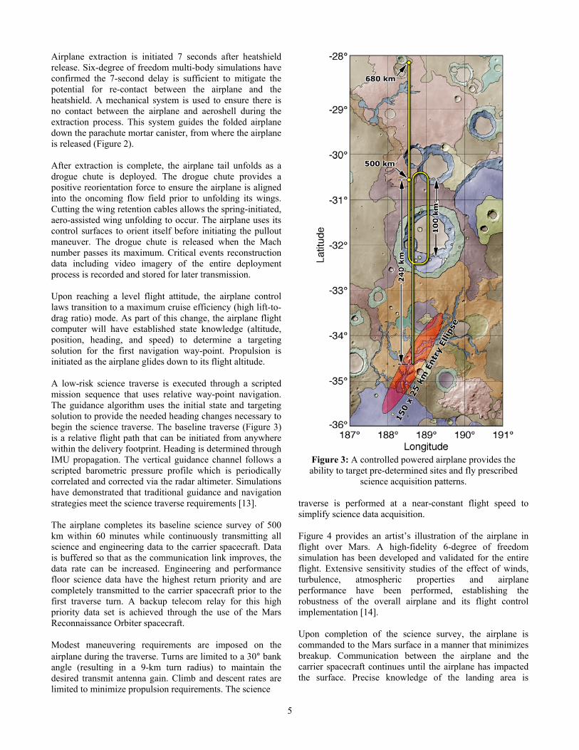
Airplane extraction is initiated 7 seconds after heatshield release. Six-degree of freedom multi-body simulations have confirmed the 7-second delay is sufficient to mitigate the potential for re-contact between the airplane and the heatshield. A mechanical system is used to ensure there is no contact between the airplane and aeroshell during the extraction process. This system guides the folded airplane down the parachute mortar canister, from where the airplane is released (Figure 2). After extraction is complete, the airplane tail unfolds as a drogue chute is deployed. The drogue chute provides a positive reorientation force to ensure the airplane is aligned into the oncoming flow field prior to unfolding its wings. Cutting the wing retention cables allows the spring-initiated, aero-assisted wing unfolding to occur. The airplane uses its control surfaces to orient itself before initiating the pullout maneuver. The drogue chute is released when the Mach number passes its maximum. Critical events reconstruction data including video imagery of the entire deployment process is recorded and stored for later transmission. Upon reaching a level flight attitude, the airplane control laws transition to a maximum cruise efficiency (high lift-to-drag ratio) mode. As part of this change, the airplane flight computer will have established state knowledge (altitude, position, heading, and speed) to determine a targeting solution for the first navigation way-point. Propulsion is initiated as the airplane glides down to its flight altitude. A low-risk science traverse is executed through a scripted mission sequence that uses relative way-point navigation. The guidance algorithm uses the initial state and targeting solution to provide the needed heading changes necessary to begin the science traverse. The baseline traverse (Figure 3) is a relative flight path that can be initiated from anywhere within the delivery footprint. Heading is determined through IMU propagation. The vertical guidance channel follows a scripted barometric pressure profile which is periodically correlated and corrected via the radar altimeter. Simulations have demonstrated that traditional guidance and navigation strategies meet the science traverse requirements [13]. The airplane completes its baseline science survey of 500 km within 60 minutes while continuously transmitting all science and engineering data to the carrier spacecraft. Data is buffered so that as the communication link improves, the data rate can be increased. Engineering and performance floor science data have the highest return priority and are completely transmitted to the carrier spacecraft prior to the first traverse turn. A backup telecom relay for this high priority data set is achieved through the use of the Mars Reconnaissance Orbiter spacecraft. Modest maneuvering requirements are imposed on the airplane during the traverse. Turns are limited to a 30° bank angle (resulting in a 9-km turn radius) to maintain the desired transmit antenna gain. Climb and descent rates are limited to minimize propulsion requirements. The science
Figure 3: A controlled powered airplane provides the ability to target pre-determined sites and fly prescribed
science acquisition patterns.
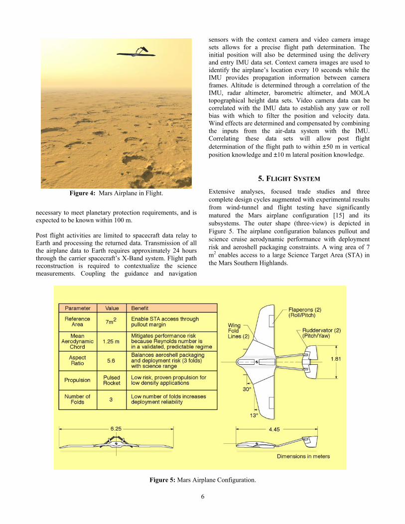
traverse is performed at a near-constant flight speed to simplify science data acquisition. Figure 4 provides an artist’s illustration of the airplane in flight over Mars. A high-fidelity 6-degree of freedom simulation has been developed and validated for the entire flight. Extensive sensitivity studies of the effect of winds, turbulence, atmospheric properties and airplane performance have been performed, establishing the robustness of the overall airplane and its flight control implementation [14]. Upon completion of the science survey, the airplane is commanded to the Mars surface in a manner that minimizes breakup. Communication between the airplane and the carrier spacecraft continues until the airplane has impacted the surface. Precise knowledge of the landing area is
6
necessary to meet planetary protection requirements, and is expected to be known within 100 m. Post flight activities are limited to spacecraft data relay to Earth and processing the returned data. Transmission of all the airplane data to Earth requires approximately 24 hours through the carrier spacecraft’s X-Band system. Flight path reconstruction is required to contextualize the science measurements. Coupling the guidance and navigation
sensors with the context camera and video camera image sets allows for a precise flight path determination. The initial position will also be determined using the delivery and entry IMU data set. Context camera images are used to identify the airplane’s location every 10 seconds while the IMU provides propagation information between camera frames. Altitude is determined through a correlation of the IMU, radar altimeter, barometric altimeter, and MOLA topographical height data sets. Video camera data can be correlated with the IMU data to establish any yaw or roll bias with which to filter the position and velocity data. Wind effects are determined and compensated by combining the inputs from the air-data system with the IMU. Correlating these data sets will allow post flight determination of the flight path to within ±50 m in vertical position knowledge and ±10 m lateral position knowledge.
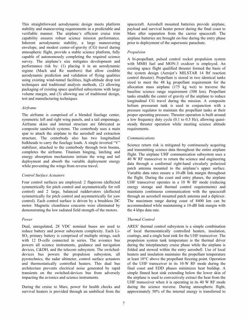
5. FLIGHT SYSTEM Extensive analyses, focused trade studies and three complete design cycles augmented with experimental results from wind-tunnel and flight testing have significantly matured the Mars airplane configuration [15] and its subsystems. The outer shape (three-view) is depicted in Figure 5. The airplane configuration balances pullout and science cruise aerodynamic performance with deployment risk and aeroshell packaging constraints. A wing area of 7 m2 enables access to a large Science Target Area (STA) in the Mars Southern Highlands.
Figure 5: Mars Airplane Configuration.
Figure 4: Mars Airplane in Flight.
7
This straightforward aerodynamic design meets platform stability and maneuvering requirements in a predictable and verifiable manner. The airplane’s efficient cruise trim capability ensures robust science mission performance. Inherent aerodynamic stability, a large maneuvering envelope, and modest center-of-gravity (CG) travel during atmospheric flight, provide a stable science platform, fully capable of autonomously completing the required science survey. The airplane’s size mitigates development and performance risk by: (1) placing it in an aerodynamic regime (Mach and Re numbers) that allow credible aerodynamic prediction and validation of flying qualities using existing wind-tunnel facilities, high-altitude drop test techniques and traditional analysis methods, (2) allowing packaging of existing space qualified subsystems with large volume margin, and (3) allowing use of traditional design, test and manufacturing techniques. Airframe
The airframe is comprised of a blended fuselage center, symmetric left and right wing panels, and a tail empennage. Airframe skins and internal structure are fabricated as composite sandwich systems. The centerbody uses a main spar to attach the airplane to the aeroshell and extraction structure. The centerbody also has two longitudinal bulkheads to carry the fuselage loads. A single inverted “V” stabilizer, attached to the centerbody through twin booms, completes the airframe. Titanium hinging, latching and energy absorption mechanisms initiate the wing and tail deployment and absorb the variable deployment energy while preventing the wings from reverse travel. Control Surface Actuators
Four control surfaces are employed: 2 flaperons (deflected symmetrically for pitch control and asymmetrically for roll control) and 2 large, balanced ruddervators (deflected symmetrically for pitch control and asymmetrically for yaw control). Each control surface is driven by a brushless DC motor. Magnetic cleanliness concerns were eliminated by demonstrating the low radiated field strength of the motors. Power
Dual, unregulated, 28 VDC nominal buses are used to reduce battery and power subsystem complexity. Each Li-SO2 primary battery is comprised of multiple strings, each with 12 D-cells connected in series. The avionics bus powers all science instruments, guidance and navigation devices, C&DH, and the telecom subsystem. The switched-devices bus powers the propulsion subsystem, all pyrotechnics, the radar altimeter, control surface actuators and thermostatically controlled heaters. This dual bus architecture prevents electrical noise generated by rapid transients on the switched-devices bus from adversely impacting the avionics and science instruments. During the cruise to Mars, power for health checks and survival heaters is provided through an umbilical from the
spacecraft. Aeroshell mounted batteries provide airplane, payload and survival heater power during the final coast to Mars after separation from the carrier spacecraft. The airplane batteries are brought on-line during the entry phase prior to deployment of the supersonic parachute. Propulsion
A bi-propellant, pulsed control rocket propulsion system with MMH fuel and MON-3 oxidizer is employed. An existing space flight qualified thruster formed the basis of the system design (Aerojet’s MILSTAR 14 lbf reaction control thruster). Propellant is stored in two identical tanks sized to meet the 48 kg propellant requirement for the allocation mass airplane (175 kg wet) to traverse the baseline science range requirement (500 km). Propellant tanks straddle the center of gravity of the airplane to reduce longitudinal CG travel during the mission. A composite helium pressurant tank is used in conjunction with a pressure regulator to maintain the propellant tanks at their proper operating pressure. Thruster operation is built around a low frequency duty cycle (0.1 to 0.5 Hz), allowing quasi-steady thruster operation while meeting science altitude requirements. Communications
Science return risk is mitigated by continuously acquiring and transmitting science data throughout the entire airplane flight. The airplane UHF communication subsystem uses a 40 W RF transceiver to return the science and engineering data through a conformal right-hand circularly polarized patch antenna mounted to the airplane’s upper surface. Variable data rates ensure a 10-dB link margin throughout the flight. During the coast and entry phases, the airplane UHF transceiver operates in a 10 W RF mode (reducing energy storage and thermal control requirements) and maintains continuous communication with the spacecraft through an aeroshell mounted patch antenna and a diplexer. The maximum range during coast of 8400 km can be accommodated while maintaining a 10-dB link margin with the 4 kbps data rate. Thermal Control
ARES’ thermal control subsystem is a simple combination of local thermostatically controlled heaters, insulation, coatings, and a single heat sink for the UHF transceiver. The propulsion system tank temperature is the thermal driver during the interplanetary cruise phase while the airplane is folded and stowed within the entry aeroshell. Use of local heaters and insulation maintains the propellant temperature at least 10°C above the propellant freezing point. Operation of the UHF transceiver in its 10-W RF mode during the final coast and EDD phases minimizes heat buildup. A simple finned heat sink extending below the lower skin of the airplane is used to convectively extract the heat from the UHF transceiver when it is operating in its 40 W RF mode during the science traverse. During atmospheric flight, approximately 50% of the internal energy is transferred to
8
the environment through convection, 40% is transferred out of the system via radiation, and the remaining 10% is absorbed in components and structure. Analyses indicate convective cooling of the subsystems provides a simple low-mass cooling strategy. Both laminar and turbulent convective heat transfer modes were found to keep all components within their thermal operating limits [16]. Navigation and Guidance
Airplane navigation uses inputs from the inertial measurement unit (IMU), air data system (airspeed, angle-of-attack, and angle-of-sideslip), barometer (pressure altitude), and radar altimeter (terrain-relative altitude). The carrier spacecraft computer initializes the airplane navigation system prior to entry system separation. After separation, the IMU maintains its attitude knowledge using inputs from an aeroshell mounted sun sensor and the inertially stabilized aeroshell angular momentum vector. During atmospheric entry, the navigation relies on sensed deceleration forces. After pullout, navigation algorithms blend measurements from the guidance and navigation sensor suite. Navigation performance during the science survey is driven by the requirement of three nearly parallel tracks with a specified separation distance. Linear covariance analyses have shown the combination of this sensor suite and the navigation and guidance algorithms provide the necessary relative navigation knowledge throughout the science survey [13]. Command and Data Handling
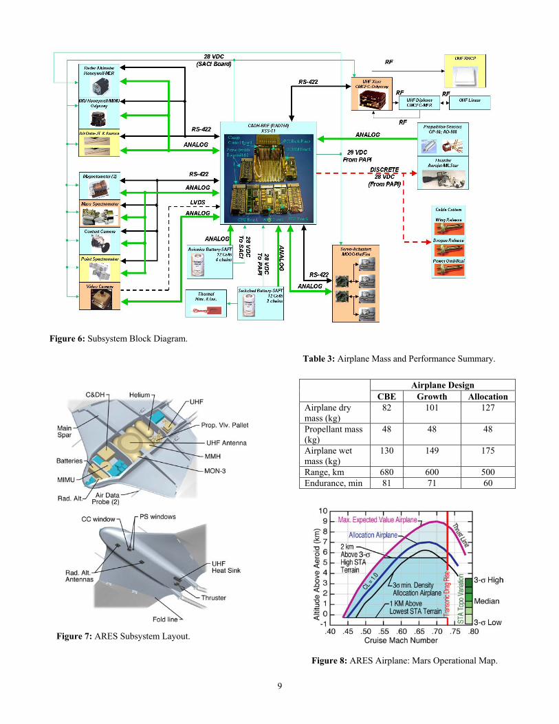
The airplane command and data handling (C&DH) subsystem performs science data collection in addition to the classical flight control computer functions. The key component is the space-flight qualified Broad Reach Engineering C&DH subsystem developed for the joint AFRL/NASA Experimental Satellite System (XSS-11). This design uses the BAE Systems RAD750 PowerPC processor housed in a 3u Compact PCI. The RAD750 uses a compact PCI backplane to interface with the C&DH internal I/O circuit boards allowing simultaneous management of science data and real-time flight control. Complementing the high speed RAD750 processor are 3 integrated I/O boards that interface the processor to the flight control sensors and actuators, the science instruments, the UHF transceiver, the airplane subsystems including propulsion control, and the carrier spacecraft and aeroshell. The C&DH also includes I/O boards to control electric power distribution, and circuits to initiate redundant pyrotechnic devices. FPGA logic is used to offload data compression from the RAD750 processor. The C&DH I/O cards interface to other electronics using conventional RS-422 and LVDS data buses. RS-422 buses are also used to provide a data umbilical to the carrier spacecraft and to command the aeroshell pyrotechnic initiation unit. The overall system block diagram is shown in Figure 6.
Science Payload
Five complementary instruments return a compelling set of integrated science measurements. The science payload consists of 2 wing-tip mounted magnetometers; a nose mounted mass spectrometer; a nadir pointing context camera, a nadir-oriented point spectrometer; and a tail mounted video camera. The integrated suite of instruments require 10.1 kg and 30 W. Airplane stability requirements are derived from pixel smear limitations associated with the context camera and point spectrometer. Pointing stability is a function of airplane dynamics, atmospheric turbulence and instrument integration time. Pointing reconstruction knowledge is also impacted by the asynchronous data rates of the science instruments and IMU (50 Hz). Analysis and flight test results in the Earth’s atmosphere indicate substantial margin in science payload stability and pointing performance. Field characterization tests have demonstrated sufficient isolation of magnetometer sensors.
6. SYSTEM PERFORMANCE Airplane packaging is illustrated in Figure 7. Thermal, electro-magnetic and mass balance issues drive subsystem packaging. Placement of the inertial measuring unit slightly forward of the airplane center of gravity and near the instantaneous center of rotation improves flight controls performance. The current best estimate (CBE) mass is defined without any uncertainty or contingency. A maturity-based contingency is then applied to each component to derive the growth (or maximum expected) mass. Allocation mass is defined as the mass constrained by the laws of physics, where margin is defined as the difference between the growth and allocation values. The Mars airplane’s mass posture is summarized in Table 3. Range and endurance values for the CBE, Growth, and Allocation airplanes are also provided in this table. The airplane has been designed to successfully complete the pullout maneuver up to the allocation mass of 175 kg while meeting the baseline science range requirement of 500 km. The performance capability of the Mars airplane is illustrated in Figure 8. At its allocation mass and a Mach number of 0.68, this system has the ability to fly 3.5-km above the 3-σ high terrain within the Southern Highlands science target area. The allocation mass airplane can maintain a flight altitude 2-km above the 3-σ terrain even in the presence of 3-σ minimum density (at a Mach number between 0.62 and 0.71). This operational performance provides significant mission design and science acquisition flexibility. The airplane’s minimum flight speed is limited by a maximum cruise lift coefficient of 1.0; while its upper speed is limited by the onset of the transonic drag rise at Mach 0.73, similar to most terrestrial airplanes.
9
Figure 6: Subsystem Block Diagram.
Table 3: Airplane Mass and Performance Summary.
Airplane Design CBE Growth Allocation
Airplane dry mass (kg)
82 101 127
Propellant mass (kg)
48 48 48
Airplane wet mass (kg)
130 149 175
Range, km 680 600 500 Endurance, min 81 71 60
Figure 7: ARES Subsystem Layout. Figure 8: ARES Airplane: Mars Operational Map.
10
A system level mass breakdown is provided in Table 4. A 26% airplane dry mass margin and 29% launch mass margin further mitigate development risk. Allocation mass constraints are prescribed by launch vehicle capability (975 kg) and airplane pullout mass (175 kg).
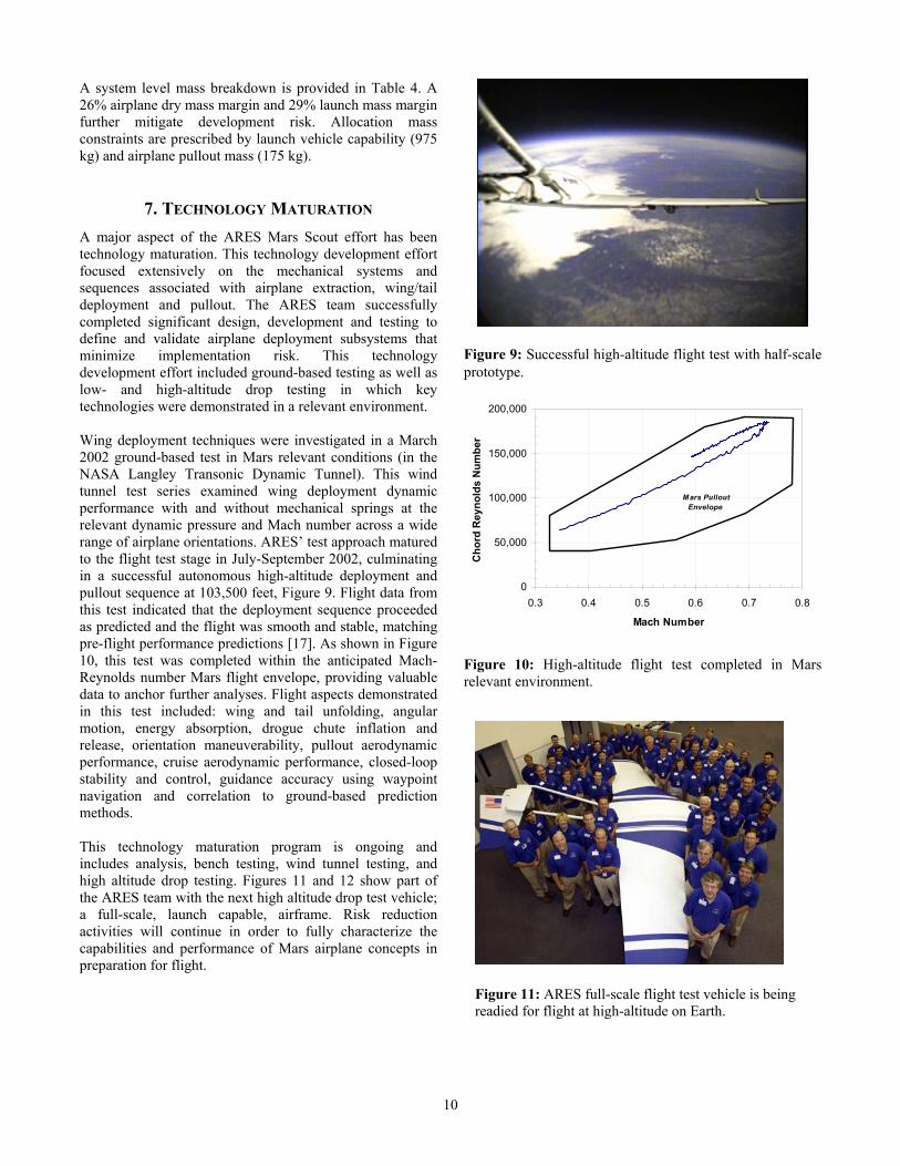
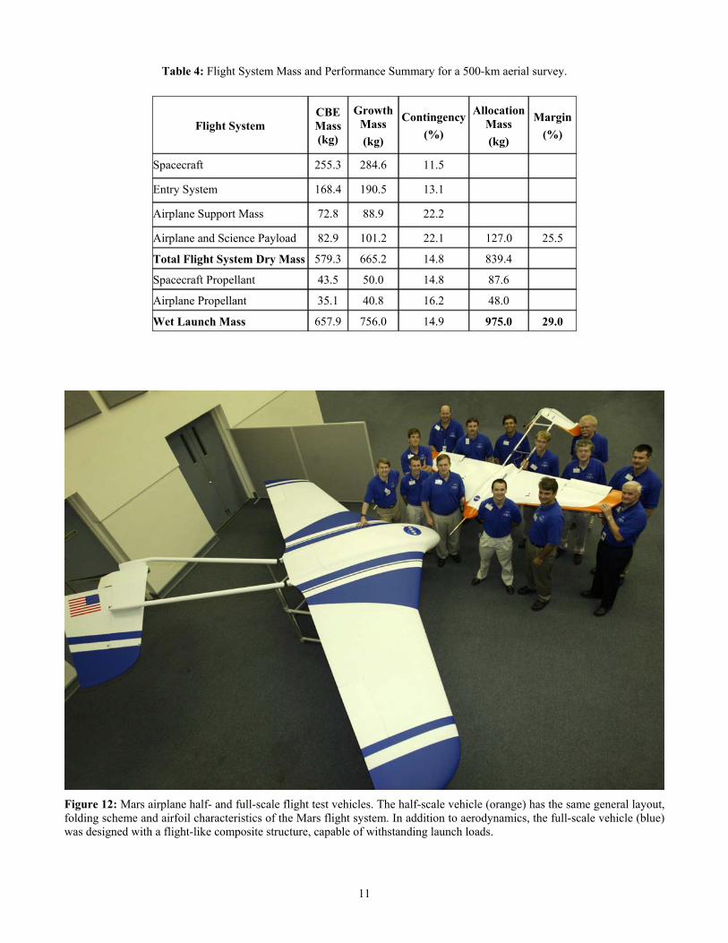
7. TECHNOLOGY MATURATION A major aspect of the ARES Mars Scout effort has been technology maturation. This technology development effort focused extensively on the mechanical systems and sequences associated with airplane extraction, wing/tail deployment and pullout. The ARES team successfully completed significant design, development and testing to define and validate airplane deployment subsystems that minimize implementation risk. This technology development effort included ground-based testing as well as low- and high-altitude drop testing in which key technologies were demonstrated in a relevant environment. Wing deployment techniques were investigated in a March 2002 ground-based test in Mars relevant conditions (in the NASA Langley Transonic Dynamic Tunnel). This wind tunnel test series examined wing deployment dynamic performance with and without mechanical springs at the relevant dynamic pressure and Mach number across a wide range of airplane orientations. ARES’ test approach matured to the flight test stage in July-September 2002, culminating in a successful autonomous high-altitude deployment and pullout sequence at 103,500 feet, Figure 9. Flight data from this test indicated that the deployment sequence proceeded as predicted and the flight was smooth and stable, matching pre-flight performance predictions [17]. As shown in Figure 10, this test was completed within the anticipated Mach-Reynolds number Mars flight envelope, providing valuable data to anchor further analyses. Flight aspects demonstrated in this test included: wing and tail unfolding, angular motion, energy absorption, drogue chute inflation and release, orientation maneuverability, pullout aerodynamic performance, cruise aerodynamic performance, closed-loop stability and control, guidance accuracy using waypoint navigation and correlation to ground-based prediction methods. This technology maturation program is ongoing and includes analysis, bench testing, wind tunnel testing, and high altitude drop testing. Figures 11 and 12 show part of the ARES team with the next high altitude drop test vehicle; a full-scale, launch capable, airframe. Risk reduction activities will continue in order to fully characterize the capabilities and performance of Mars airplane concepts in preparation for flight.
Figure 9: Successful high-altitude flight test with half-scale prototype.
Figure 10: High-altitude flight test completed in Mars relevant environment.
Figure 11: ARES full-scale flight test vehicle is being readied for flight at high-altitude on Earth.
0
50,000
100,000
150,000
200,000
0.3 0.4 0.5 0.6 0.7 0.8
Mach Number
Cho
rd R
eyno
lds
Num
ber
Mars Pullout Envelope
11
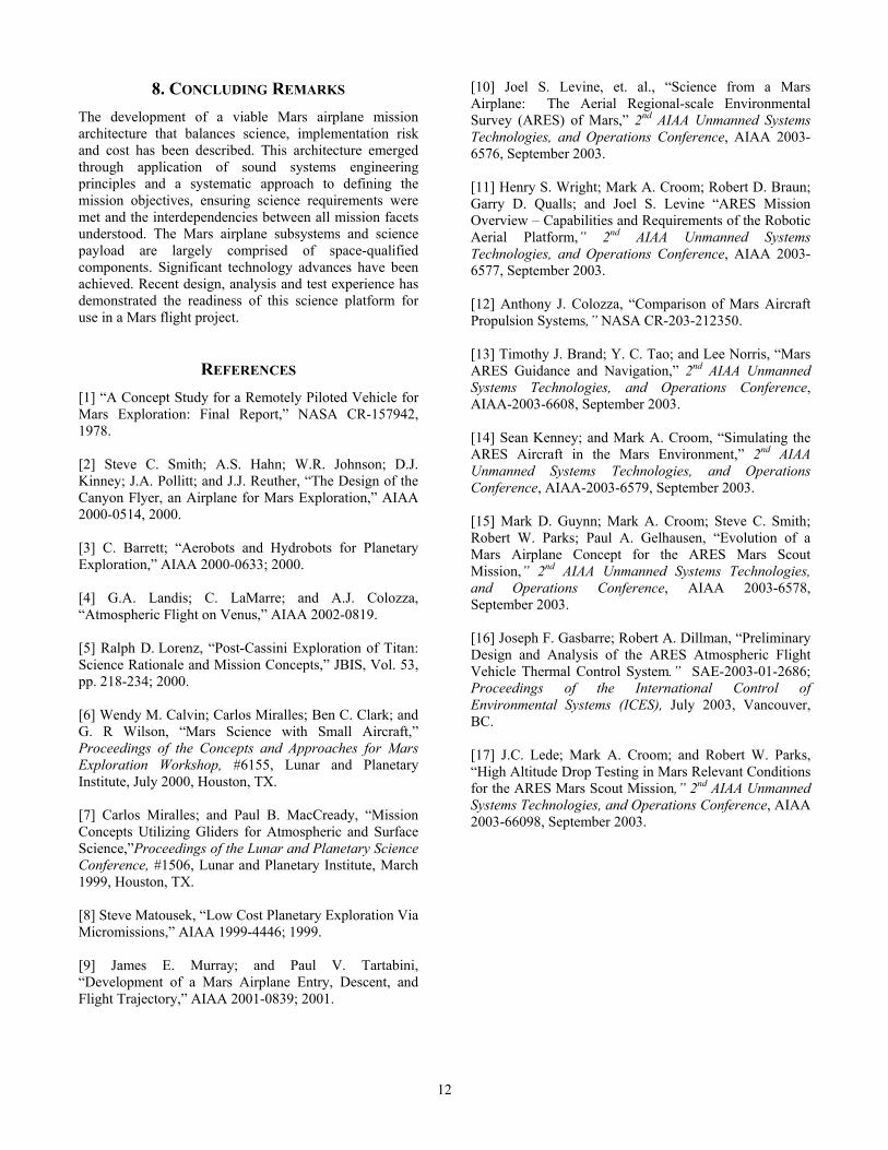
Table 4: Flight System Mass and Performance Summary for a 500-km aerial survey.
Figure 12: Mars airplane half- and full-scale flight test vehicles. The half-scale vehicle (orange) has the same general layout, folding scheme and airfoil characteristics of the Mars flight system. In addition to aerodynamics, the full-scale vehicle (blue) was designed with a flight-like composite structure, capable of withstanding launch loads.
Flight System CBE Mass (kg)
Growth Mass (kg)
Contingency(%)
Allocation Mass (kg)
Margin (%)
Spacecraft 255.3 284.6 11.5
Entry System 168.4 190.5 13.1
Airplane Support Mass 72.8 88.9 22.2
Airplane and Science Payload 82.9 101.2 22.1 127.0 25.5
Total Flight System Dry Mass 579.3 665.2 14.8 839.4
Spacecraft Propellant 43.5 50.0 14.8 87.6
Airplane Propellant 35.1 40.8 16.2 48.0
Wet Launch Mass 657.9 756.0 14.9 975.0 29.0
12
8. CONCLUDING REMARKS The development of a viable Mars airplane mission architecture that balances science, implementation risk and cost has been described. This architecture emerged through application of sound systems engineering principles and a systematic approach to defining the mission objectives, ensuring science requirements were met and the interdependencies between all mission facets understood. The Mars airplane subsystems and science payload are largely comprised of space-qualified components. Significant technology advances have been achieved. Recent design, analysis and test experience has demonstrated the readiness of this science platform for use in a Mars flight project.
REFERENCES [1] “A Concept Study for a Remotely Piloted Vehicle for Mars Exploration: Final Report,” NASA CR-157942, 1978. [2] Steve C. Smith; A.S. Hahn; W.R. Johnson; D.J. Kinney; J.A. Pollitt; and J.J. Reuther, “The Design of the Canyon Flyer, an Airplane for Mars Exploration,” AIAA 2000-0514, 2000. [3] C. Barrett; “Aerobots and Hydrobots for Planetary Exploration,” AIAA 2000-0633; 2000. [4] G.A. Landis; C. LaMarre; and A.J. Colozza, “Atmospheric Flight on Venus,” AIAA 2002-0819. [5] Ralph D. Lorenz, “Post-Cassini Exploration of Titan: Science Rationale and Mission Concepts,” JBIS, Vol. 53, pp. 218-234; 2000. [6] Wendy M. Calvin; Carlos Miralles; Ben C. Clark; and G. R Wilson, “Mars Science with Small Aircraft,” Proceedings of the Concepts and Approaches for Mars Exploration Workshop, #6155, Lunar and Planetary Institute, July 2000, Houston, TX. [7] Carlos Miralles; and Paul B. MacCready, “Mission Concepts Utilizing Gliders for Atmospheric and Surface Science,”Proceedings of the Lunar and Planetary Science Conference, #1506, Lunar and Planetary Institute, March 1999, Houston, TX. [8] Steve Matousek, “Low Cost Planetary Exploration Via Micromissions,” AIAA 1999-4446; 1999. [9] James E. Murray; and Paul V. Tartabini, “Development of a Mars Airplane Entry, Descent, and Flight Trajectory,” AIAA 2001-0839; 2001.
[10] Joel S. Levine, et. al., “Science from a Mars Airplane: The Aerial Regional-scale Environmental Survey (ARES) of Mars,” 2nd AIAA Unmanned Systems Technologies, and Operations Conference, AIAA 2003-6576, September 2003. [11] Henry S. Wright; Mark A. Croom; Robert D. Braun; Garry D. Qualls; and Joel S. Levine “ARES Mission Overview – Capabilities and Requirements of the Robotic Aerial Platform,” 2nd AIAA Unmanned Systems Technologies, and Operations Conference, AIAA 2003-6577, September 2003. [12] Anthony J. Colozza, “Comparison of Mars Aircraft Propulsion Systems,” NASA CR-203-212350. [13] Timothy J. Brand; Y. C. Tao; and Lee Norris, “Mars ARES Guidance and Navigation,” 2nd AIAA Unmanned Systems Technologies, and Operations Conference, AIAA-2003-6608, September 2003. [14] Sean Kenney; and Mark A. Croom, “Simulating the ARES Aircraft in the Mars Environment,” 2nd AIAA Unmanned Systems Technologies, and Operations Conference, AIAA-2003-6579, September 2003. [15] Mark D. Guynn; Mark A. Croom; Steve C. Smith; Robert W. Parks; Paul A. Gelhausen, “Evolution of a Mars Airplane Concept for the ARES Mars Scout Mission,” 2nd AIAA Unmanned Systems Technologies, and Operations Conference, AIAA 2003-6578, September 2003. [16] Joseph F. Gasbarre; Robert A. Dillman, “Preliminary Design and Analysis of the ARES Atmospheric Flight Vehicle Thermal Control System.” SAE-2003-01-2686; Proceedings of the International Control of Environmental Systems (ICES), July 2003, Vancouver, BC. [17] J.C. Lede; Mark A. Croom; and Robert W. Parks, “High Altitude Drop Testing in Mars Relevant Conditions for the ARES Mars Scout Mission,” 2nd AIAA Unmanned Systems Technologies, and Operations Conference, AIAA 2003-66098, September 2003.
13
BIOGRAPHY Robert Braun is the David and Andrew Lewis Associate Professor of Space Technology in the School of Aerospace Engineering at the Georgia Institute of Technology. Prior to this, he served on the technical staff of the NASA Langley Research Center. He has worked extensively in the areas of entry system
design, planetary atmospheric flight, and mission architecture development. Dr. Braun has participated as a team member or independent reviewer in the Mars Pathfinder, Mars Microprobe, Mars Polar Lander, Mars Odyssey, and Mars Exploration Rover projects. He led the development of prototype flight systems for a Mars Sample Return Earth Entry Vehicle and Mars Airplane mission. He has a B.S. in Aerospace Engineering from Penn State University, a M.S. in Astronautics from George Washington University and a Ph.D. in Aeronautics and Astronautics from Stanford University.
Henry Wright is a Senior Engineer in the Systems Engineering Competency at the NASA Langley Research Center. He has led the engineering development of numerous aerospace projects during his 15 years with NASA. For the last two
years, he was the Chief Systems Engineer for a Mars Airplane project, responsible for all engineering aspects of the airplane and science payload design, development and implementation. He has had key engineering roles in the 1999 Mars Micromission Airplane project, the Smart Vehicle project as well as the 15% scale free-flight Blended-Wing Body Airplane project. Mr. Wright has either led or had a significant engineering role in the development and implementation of many aerospace research facilities including wind tunnels and cryogenic structures test stands. Prior to his tenure at NASA, Mr. Wright spent 6 years at the Bettis Atomic Power Lab working on safety systems for Navy nuclear power plants. He has a B. S. in Mechanical Engineering from Virginia Polytechnic Institute and State University and a M. S. in Astronautics from the George Washington University.
Mark Croom is a Senior Engineer in the Airborne Systems Competency at the NASA Langley Research Center. He has performed research in aerodynamics, flight performance, controls systems and handling qualities for both piloted and unmanned aircraft with both civil and
military applications. He served as NASA Principal Investigator for the Navy F/A-18E/F high fidelity drop model program, providing critical information on the spin performance of this vehicle to improve Fleet operations and safety. In the last few years, he has focused on
aerodynamic design and flight performance of a Mars airplane concept and had an extensive role in development and implementation of the successful ground-based and flight test program. He has a B.S. and M.S. in Aerospace Engineering from Virginia Polytechnic Institute and State University.
Joel Levine is a Senior Research Scientist in the Atmospheric Sciences Competency at NASA Langley Research Center. Dr. Levine has worked extensively in the areas of the origin and evolution of the atmospheres of Earth and Mars, atmospheric photochemistry, the production of trace atmospheric
gases by biogenic processes and atmospheric lightning, and biomass burning and global change. Dr. Levine has been involved in the science-measurement definition and design/development of prototype flight systems for several Mars Airplane missions. At the request of the National Archives, he formed and directed a NASA team to investigate the chemical composition of the hermetically-sealed atmosphere in the encasements containing the Declaration of Independence, the Constitution and the Bill of Rights. Dr. Levine has a BS in Physics from Brooklyn College, City University of New York, a MS in Meteorology from New York University, and a MS in Aeronomy and Planetary Atmospheres and a PhD in Atmospheric Sciences, both from the University of Michigan.
David Spencer is the deputy manager of the Flight Systems Section at the Jet Propulsion Laboratory. Prior to this, he was the Mission Manager for the Mars Odyssey project, responsible for leading the mission design, navigation, and flight operations from project formulation through the initial science
campaign. Mr. Spencer was the lead mission designer for the Mars Pathfinder mission, responsible for trajectory design, maneuver design, and atmospheric entry analysis. He also performed navigation and system analysis for the TOPEX/POSEIDON mission. Mr. Spencer began working at the Jet Propulsion Laboratory in 1991, after receiving B.S. and M.S. degrees in Aeronautics and Astronautics from Purdue University. He was born and raised in Indianapolis, Indiana, and now resides with his wife and two sons in La Canada Flintridge, California.
Related Documents