The behaviour of spudcan footings on clay subjected to combined cyclic loading by G. Vlahos, M.J. Cassidy and B.W. Byrne Report No. OUEL 2286/05 University of Oxford Department of Engineering Science Parks Road, Oxford, OX1 3PJ, U.K. Tel. 01865 273162/283300 Fax. 01865 283301 Email [email protected] http://www-civil.eng.ox.ac.uk/

Welcome message from author
This document is posted to help you gain knowledge. Please leave a comment to let me know what you think about it! Share it to your friends and learn new things together.
Transcript
The behaviour of spudcan footings on clay subjected to
combined cyclic loading
by
G. Vlahos, M.J. Cassidy and B.W. Byrne
Report No. OUEL 2286/05
University of Oxford Department of Engineering Science Parks Road, Oxford, OX1 3PJ, U.K.
Tel. 01865 273162/283300
Fax. 01865 283301 Email [email protected]
http://www-civil.eng.ox.ac.uk/
1
The behaviour of spudcan footings on clay subjected to combined cyclic loading
G. Vlahos1, M.J. Cassidy1 and B.W. Byrne2
Abstract This paper presents an improved numerical ‘force resultant model’ for spudcan foundations that can be used within a structural analysis of a mobile drilling unit. The model incorporates hysteretic behaviour for pre-yield ‘elastic’ movements by using a hyperplasticity formulation (Houlsby and Puzrin, 2002) for the moment-rotation response in the ‘elastic’ stiffness matrix. The formulation is embedded within an existing single surface plasticity model (Martin and Houlsby, 2001) that would typically use linear elastic stiffness coefficients. The hyperplastic model has been calibrated against single footing tests carried out using a sophisticated three degree-of-freedom loading device at Oxford University. These loading tests were specific to the load paths experienced by spudcan foundations of large jack-ups in deep water. Further experimental work at the University of Western Australia involved applying monotonic and cyclic loading to a model three-legged jack-up (Vlahos, 2004). The experimental results from jack-up tests were compared to numerical simulations using a finite element model with the single surface plasticity foundation model incorporating (i) linear springs, and, (ii) non-linear hyperplastic springs. The latter formulation showed an improved correlation with the experimental results. Introduction During storm conditions mobile drilling “jack-up” units are subjected to repetitive wave loads. This loading condition causes combined vertical (V), moment (M) and horizontal (H) loading on their foundations. Typically these foundations consist of large inverted cones called “spudcans” though other foundations have been considered (Cassidy et al., 2004). One of the critical calculations for assessing a jack-up at any given site is the contribution of the stiffness of the foundation-soil connection to the overall structural response. In particular the rotational stiffness of the foundation can contribute significantly to the moment distribution along a jack-up leg and therefore to the structural stresses at critical locations, such as the hull-leg connection. These calculations are particularly critical when assessing the dynamic characteristics of the jack-up during the extreme wave loading conditions. Current recommendations (SNAME, 2002) require an assessment of the suitability of a jack-up at each new site it will operate at. Typical calculations involve, initially, a pushover analysis with more detailed calculations requiring a full dynamic assessment. In these calculations it is usual to assume that the foundation is a pinned connection with the sea-bed such that there is infinite vertical and horizontal stiffness but no rotational stiffness, or, at best a set of linear springs for the three components. Clearly, these approaches are a simplification of the actual physical response of the jack-up foundations interacting with the seabed soils. Consequently, as jack-up operators strive to use their units in harsher environments the analysis assumptions have proved rather unsatisfactory at predicting actual response (for instance see Cassidy et al., 2002 or Cassidy et al., 2004). So as to improve calculation procedures there has been much emphasis over the past fifteen years on developing better models for the foundation response. One such approach, using the theory of strain hardening plasticity, provides a satisfactory description of foundation response (Cassidy et al., 2004). In particular, the theory has been applied to the modelling of spudcans on clay (Martin, 1994; Martin and Houlsby, 2000; Martin and Houlsby, 2001) as well as spudcans on sand (Cassidy, 1999; Houlsby and Cassidy, 2002). These models, comprising single surface hardening plasticity 1 Centre for Offshore Foundations Systems, University of Western Australia, Perth, Western Australia. 2 Department of Engineering Science, The University of Oxford, Parks Rd, Oxford.
2
models, are called “Model B” and “Model C” respectively. The models are defined in a way that they can be easily implemented within standard structural analysis programs as ‘macro-elements’ such as described in Martin (1994), Thomson (1996), Cassidy (1999) and Vlahos (2004). To develop these models the following components must be defined;
(i) a yield surface to define the allowable combinations of load; (ii) a flow rule to determine the ratios of plastic displacements at yield; (iii) a hardening law to determine the expansion and contraction of the yield surface; and (iv) elastic response for increments of load-displacements within the yield surface.
Extensive experimental work has been carried out to examine the shape of the yield surface, the nature of the flow rule and the definition of the hardening law. For example, the testing includes “swipe” tests to track the shape of the combined loading yield surface and “constant V” combined with “radial displacement” tests to calibrate the flow rule (Martin and Houlsby, 2000; Gottardi et al., 1999; Byrne and Houlsby, 2001). There has, however, been considerably less effort devoted to the behaviour “within” the yield surface (i.e. part (iv)) which is usually assumed to be linear elastic. The response in this area is typically defined by an elastic stiffness matrix determined by finite element analyses (Bell, 1991; Ngo Tran, 1996; Doherty and Deeks, 2003; Doherty, 2004) and calibrated against monitored field data (Cassidy et al., 2002). Using such a model provides a satisfactory response for monotonic analyses, however, they do not adequately model cyclic loading, which is clearly a relevant loading condition within the ocean environment. Much recent experimental work shows evidence of non-linear behaviour with-in the yield surface. For instance, on discussing their test results of combined loading of strip footings on sand Nova and Montrasio (1991) conclude that plasticity is dominant well inside a “theoretical” yield surface. Temperton (1996), while exploring the cyclic behaviour of spudcans on sand within an established yield surface, showed the degradation of soil stiffness that resulted in accumulated displacements for all degrees of freedom. More recently, although for skirted foundations, Byrne and Houlsby (2004) show that significant non-linearity is evident within an established yield surface. This non-linearity within the yield surface, whilst recognised by researchers previously, has been ignored, as the larger problem of capturing the overall non-linear behaviour of the foundation has been more pressing. With single surface models, as described above, now sufficiently developed to be used under the SNAME (2002) guidelines, it is now relevant to concentrate on the finer details of the model. Non-linearity within the yield surface can be incorporated into the models, such as Model B, by increasing the number of yield surfaces so that the model becomes multi-surface. However, calibration of such a model against experimental data is a non-trivial exercise. An easier approach might be to develop a non-linear spring that might be substituted into the elastic stiffness matrix. Recently Byrne et al. (2002) used a framework known as hyperplasticity (Puzrin and Houlsby, 2001) to reproduce the results of a single degree-of-freedom system. More specifically they were able to replicate the moment-rotation response of suction caissons embedded in sand subjected to cyclic combined loading. This paper presents the development of a non-linear spring, based on single footing spudcan tests and hyperplasticity that can be incorporated into the single surface plasticity framework. To calibrate the proposed hybrid model a series of experiments of a single spudcan footing subjected to combined cyclic loading were conducted. The combined load paths followed were indicative of a large three-legged jack-up system (Vlahos, 2004) and were of a magnitude that did not exceed the limits of the theoretical combined loading yield surface established through preloading. This allowed a thorough investigation of the region previously defined as purely elastic. Following model calibration, cyclic loading of a 250:1 scale model jack-up provided the
3
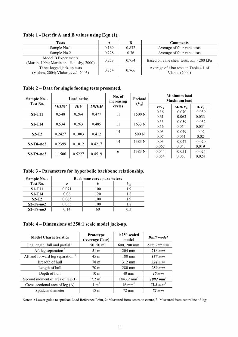
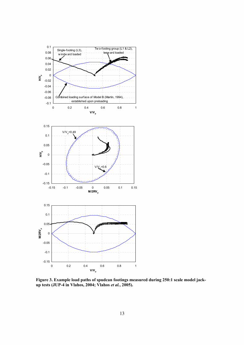
experimental data required to evaluate the hybrid model’s ability to numerically simulate a full jack-up structural-soil system. Both experimental and numerical results are detailed in this paper. Relevant load paths for spudcan foundations Once on-site the foundations of a jack-up will be pre-loaded by increasing the hull weight to a level of (roughly) twice the operating vertical self-weight. This is achieved by pumping seawater into the hull. After the preloading operation has been completed the water is released from the hull so that the jack-up is ready to commence operation. Figure 1 shows diagrammatically the effect of applying the preload to individual foundations and therefore the available horizontal or moment capacity for each foundation. The maximum vertical load applied to the foundations is denoted as Vp and the initial starting conditions for each spudcan prior to operations commencing will be Vself-
weight / Vp = 0.5. Under wind, wave and current loading each spudcan will encounter different load paths, with the windward leg(s) shedding vertical load to the leeward leg(s) as shown on Figure 1. The proportions of vertical to moment and vertical to horizontal loads vary due to (i) geometry of the jack-up system (leg length, stiffness and spacing), (ii) geometry of spudcan footing, and the (iii) rotational stiffness provided by the seabed soil. The aim of the experiments reported here is to investigate the effect of cyclic loading along these specific load paths. The initial load paths were derived from a set of experimental pushover tests conducted on a scaled three-legged jack-up model (Figure 2, Vlahos, 2004; Vlahos et al., 2005). The example load paths are given in Figure 3 compared to the theoretical yield surface of Martin (1994) and Martin and Houlsby (2000, 2001). The slope for the load paths was taken from the initial “linear” segment of the experimental results shown. A consistent clay soil profile and spudcan shape was maintained between these three-legged model jack-up tests and the work described in this paper so that these load paths are relevant. It is important to note that from Figure 3, assuming an associated flow rule in the H:M plane (Martin and Houlsby, 2001; Houlsby and Cassidy, 2002), that the main displacement acting on the foundation would be rotational. This is determined by extrapolating the load path to the yield surface and examining the normal to the yield surface at that point. In fact, at this section of the yield surface, the displacement ratios are relatively insensitive to the load paths. A conclusion from this is that whilst it is important to accurately model the vertical and horizontal response the rotational response will be most critical to determining jack-up behaviour. Cyclic loading tests on single spudcan footings Experimental apparatus The single footing tests were carried out using a sophisticated three degree-of-freedom loading rig capable of applying load-controlled paths to model foundations (further details can be found in Martin, 1994; Byrne, 2000). The foundation used in the tests is 125 mm in diameter with all dimensions shown in Figure 4. It is consistent with previous work at Oxford (Martin, 1994) as well as work at The University of Western Australia on model jack-up units (Vlahos, 2004a). The forces (V, M/2R, H) applied to the foundation and the corresponding displacements (w, 2Rθ, u) are relative to the load reference point (LRP) and are defined according to the sign conventions shown on Figure 4 (recommended by Butterfield et al., 1997). The moments and rotations are divided by the footing radius, R, to ensure consistency of dimensions. A system of small displacement transducers is used to determine the displacements and allow resolution of measurements to 2 microns. These tests were carried-out on two samples of overconsolidated kaolin clay produced from a reconstituted Speswhite powder (described by Fannin, 1986) following the specifications and procedure outlined in Martin (1994). The shear strength of the clay samples was deduced by conducting a number of shear vane tests in the sample after the completion of the tests and are shown in Figure 5. A best fit average profile using the following semi-empirical expression (Ladd et al., 1977; Wroth, 1984) is also shown:
4
su = σ′v A( )OCR B. Eqn (1)
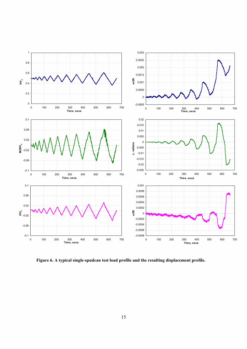
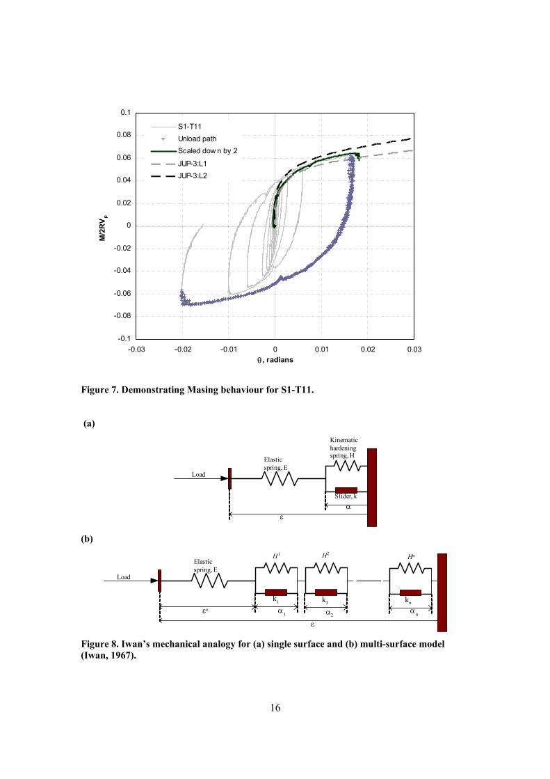
The parameters A and B are curve-fit parameters to the data and are summarised in Table 1 and compared to other similar studies. Testing procedure and experiments performed The single footing tests proceeded by first pre-loading the foundation prior to the ‘loading’ event so that the load-state on the foundation was equal to V/Vp = 0.5, as would be usual in the offshore situation (and shown in Figure 1). After preloading the main loading event was carried out which consisted of either a combined cyclic loading (V, M/2R, H) along specified load paths or simple vertical cyclic loading. A total of 33 loading events were completed comprising 13 combined loading tests and 20 vertical loading tests (monotonic and cyclic loading). Within the combined load tests seven simulated the load path of the leeward foundations while five tests simulated the windward foundation. A further test was completed using a higher moment component. The majority of the combined load tests were conducted at penetration depths between 56mm and 98mm which brackets the pre-load penetration of the three-legged model jack-up tests (Vlahos, 2004). One test was conducted at a shallow penetration for comparison. Details of relevant tests for this paper are presented in Table 2 though further details may be obtained from Vlahos (2004a). Figure 6 shows the load-time and displacement-time histories for a typical combined loading of the single spudcan. In this test the ratios of V:M/2R:H were chosen to simulate the leeward foundations of the model jack-up. The magnitude of the cycles was chosen so that the tests were probing the very inner part of the yield surface without the possibility of hitting the yield surface (and therefore experiencing significant amounts of plasticity). The exact type of loading path was chosen with reference to developing cyclic loading models (Byrne et al., 2002). In particular, the loads increase in magnitude at each single cycle so that the load-time history resembles a saw-tooth wave. The amplitude of the cycles varied between tests, but with the mean load levels kept constant at V/Vp = 0.5, M/2RVp = 0 and H/Vp =0. Load displacement behaviour Figure 7 shows the moment-rotation (M-θ) relationship for test S1-T11 showing significant hysteresis associated with each cycle. The response is symmetrical, as a result of the applied loading being symmetrical about M = 0. The main features of the load-displacement relation shown are (i) a smooth continuous line, (ii) degradation of the secant stiffness with increasing cycle amplitude, and (iii) the peak from each cycle follows on from the last loop along a common boundary. Similar responses were found by Byrne and Houlsby (2004) for caissons on dense sand. Shown on Figure 7 is the unload curve rescaled (divided by 2) and plotted from the origin which follows the backbone curve of the cyclic loading test. These characteristics can be described by a set of “Masing” rules (Masing, 1926; Pyke 1979). This result was typical of the spudcan tests and no degradation of the backbone curve was observed, similar to tests on sand (Byrne and Houlsby, 2004). Overlain on the test results are monotonic load-displacement curves from the three legged jack-up test JUP-4 (shown previously in Figure 3) Numerical simulation using a hyperplasticity theory The hysteretic behaviour shown in Figure 7 can be simulated using a simple mechanical model, such as the spring-slider system of Iwan (1967) as described by Byrne et al. (2002). This simple mechanical analogue can be modelled theoretically using the hyperplasticity theory of Puzrin and Houlsby (2001). Importantly the hyperplasticity framework, as described by Puzrin and Houlsby (2001), is closely linked to conventional plasticity as well as ensuring that any resulting model follows thermodynamic principles. The theory allows the entire constitutive behaviour of a
5
dissipative material to be completely defined by two scalar potential functions, an energy potential function (such as Helmholtz or its conjugate Gibbs free energy), and a dissipation function. A one-dimensional kinematic hardening plasticity model The mechanical analogue for kinematic hardening as described by Iwan (1967) is shown in Figure 8. Two systems are shown, Figure 8a shows an elastic-linear hardening model whilst Figure 8b shows the extension to a kinematic hardening model. The system in Figure 8a is comprised of an initial spring of stiffness E in series with a combined spring (stiffness H) slider (of strength k) elements. On loading the first spring is loaded and the slider prevents the second spring from activating until the threshold (k) has been reached. The second spring acts as the hardening component of the system with a lower linear modulus (H). Upon application of load, the first spring compresses providing an elastic response. Once the load exceeds the slider threshold, the second spring contributes to the response. The displacement that results from the second spring is irrecoverable, since upon reversal of the load the slider “locks” and the kinematic hardening spring is de-activated. Once the load reaches the negative equivalent of the slider capacity (k), the kinematic hardening spring is again activated until load reversal and so on. Therefore, in-terms of conventional plasticity the slider can be related to a yield surface. The system is generalised to a multi-surface plasticity model by increasing the number of spring slider elements as shown in Figure 8b. These systems have been described within thermo-mechanical terms by Martin & Nappi (1990) and Puzrin & Houlsby (2001). The approach of Martin and Nappi (1990), which favours the Helmholtz free energy potential function, is preferred as it is displacement-driven thereby allowing easier implementation into the finite element program ABAQUS. The first component of the model is the Helmholtz free energy potential which for the multi-surface model is:
∑+
∑−=N
nnN
nn HE),(f1
22
11 2
12
ααεααε K Eqn (2)
where ε is the total displacement and α1 … αN are internal variables describing the state of the material (in this case, they are equivalent to the plastic component of each of the N spring-slider elements). The second main component is the dissipation function:
( ) 01
1 ≥∑ ∆=∆∆N
nnN kd ααα K , Eqn (3)
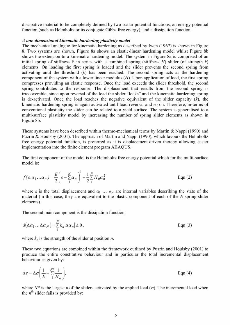
where kn is the strength of the slider at position n. These two equations are combined within the framework outlined by Puzrin and Houlsby (2001) to produce the entire constitutive behaviour and in particular the total incremental displacement behaviour as given by:
∑+∆=∆
*N
nHE 1
11σε , Eqn (4)
where N* is the largest n of the sliders activated by the applied load (σ). The incremental load when the nth slider fails is provided by:
6
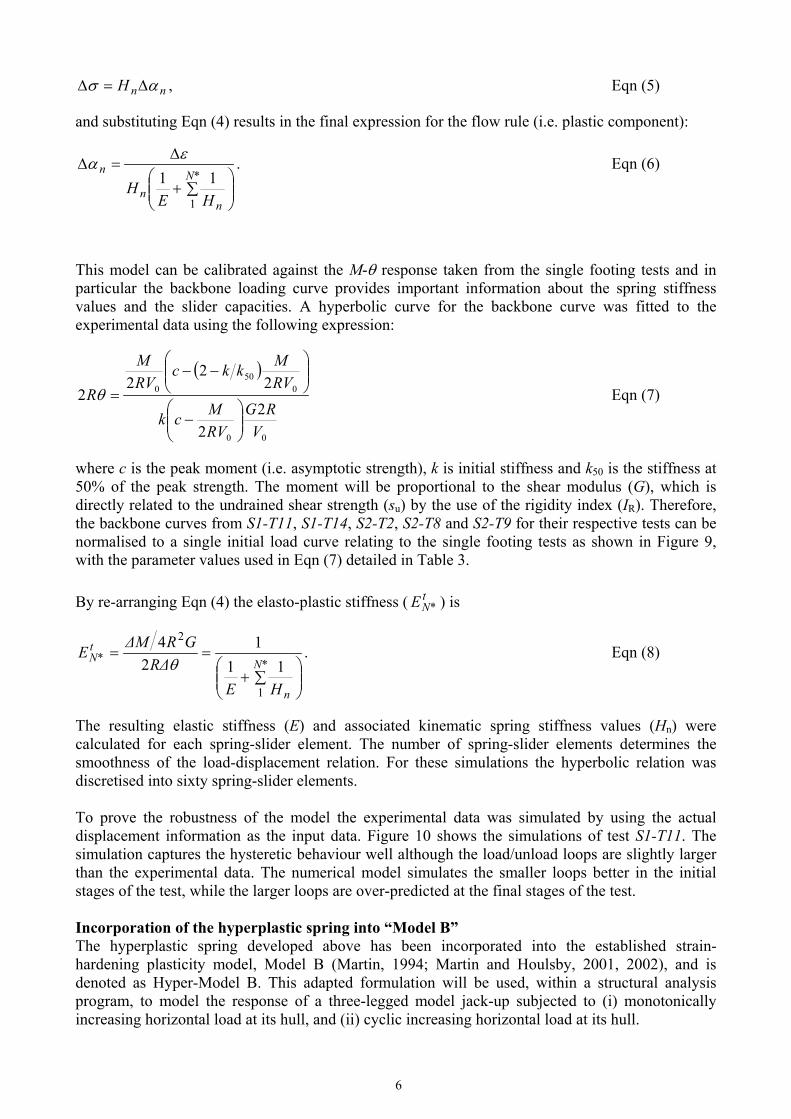
nnH ασ ∆=∆ , Eqn (5)
and substituting Eqn (4) results in the final expression for the flow rule (i.e. plastic component):
∑+
∆=∆
*N
nn
n
HEH
1
11εα . Eqn (6)
This model can be calibrated against the M-θ response taken from the single footing tests and in particular the backbone loading curve provides important information about the spring stiffness values and the slider capacities. A hyperbolic curve for the backbone curve was fitted to the experimental data using the following expression:
( )
00
050
0
22
22
22
VRG
RVMck
RVMkkc
RVM
R
−
−−
=θ Eqn (7)
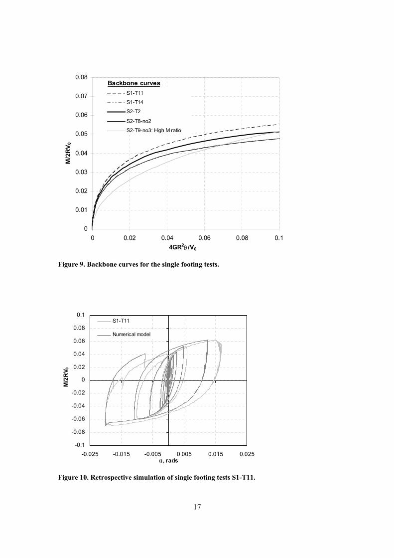
where c is the peak moment (i.e. asymptotic strength), k is initial stiffness and k50 is the stiffness at 50% of the peak strength. The moment will be proportional to the shear modulus (G), which is directly related to the undrained shear strength (su) by the use of the rigidity index (IR). Therefore, the backbone curves from S1-T11, S1-T14, S2-T2, S2-T8 and S2-T9 for their respective tests can be normalised to a single initial load curve relating to the single footing tests as shown in Figure 9, with the parameter values used in Eqn (7) detailed in Table 3. By re-arranging Eqn (4) the elasto-plastic stiffness ( t
*NE ) is
∑+
==*N
n
t*N
HER∆
GR∆ME
1
2
111
24θ
. Eqn (8)
The resulting elastic stiffness (E) and associated kinematic spring stiffness values (Hn) were calculated for each spring-slider element. The number of spring-slider elements determines the smoothness of the load-displacement relation. For these simulations the hyperbolic relation was discretised into sixty spring-slider elements. To prove the robustness of the model the experimental data was simulated by using the actual displacement information as the input data. Figure 10 shows the simulations of test S1-T11. The simulation captures the hysteretic behaviour well although the load/unload loops are slightly larger than the experimental data. The numerical model simulates the smaller loops better in the initial stages of the test, while the larger loops are over-predicted at the final stages of the test. Incorporation of the hyperplastic spring into “Model B” The hyperplastic spring developed above has been incorporated into the established strain-hardening plasticity model, Model B (Martin, 1994; Martin and Houlsby, 2001, 2002), and is denoted as Hyper-Model B. This adapted formulation will be used, within a structural analysis program, to model the response of a three-legged model jack-up subjected to (i) monotonically increasing horizontal load at its hull, and (ii) cyclic increasing horizontal load at its hull.
7
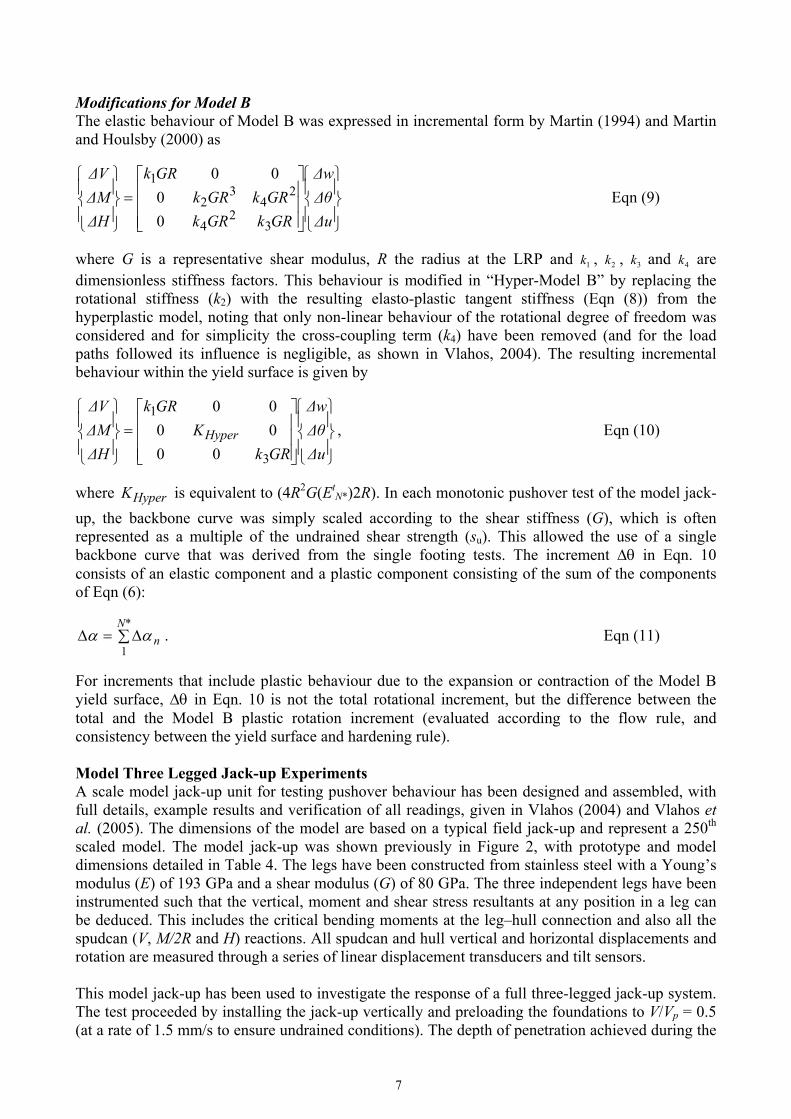
Modifications for Model B The elastic behaviour of Model B was expressed in incremental form by Martin (1994) and Martin and Houlsby (2000) as
=
∆u∆θ∆w
GRkGRkGRkGRk
GRk
∆H∆M∆V
32
4
24
32
1
00
00 Eqn (9)
where G is a representative shear modulus, R the radius at the LRP and 1k , 2k , 3k and 4k are dimensionless stiffness factors. This behaviour is modified in “Hyper-Model B” by replacing the rotational stiffness (k2) with the resulting elasto-plastic tangent stiffness (Eqn (8)) from the hyperplastic model, noting that only non-linear behaviour of the rotational degree of freedom was considered and for simplicity the cross-coupling term (k4) have been removed (and for the load paths followed its influence is negligible, as shown in Vlahos, 2004). The resulting incremental behaviour within the yield surface is given by
=
∆u∆θ∆w
GRkK
GRk
∆H∆M∆V
Hyper
3
1
000000
, Eqn (10)
where HyperK is equivalent to (4R2G(EtN*)2R). In each monotonic pushover test of the model jack-
up, the backbone curve was simply scaled according to the shear stiffness (G), which is often represented as a multiple of the undrained shear strength (su). This allowed the use of a single backbone curve that was derived from the single footing tests. The increment θ∆ in Eqn. 10 consists of an elastic component and a plastic component consisting of the sum of the components of Eqn (6):
∑∆=∆*N
n1
αα . Eqn (11)
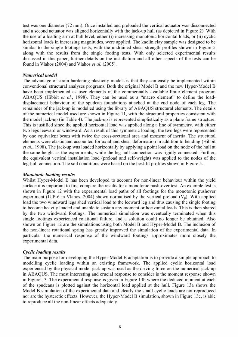
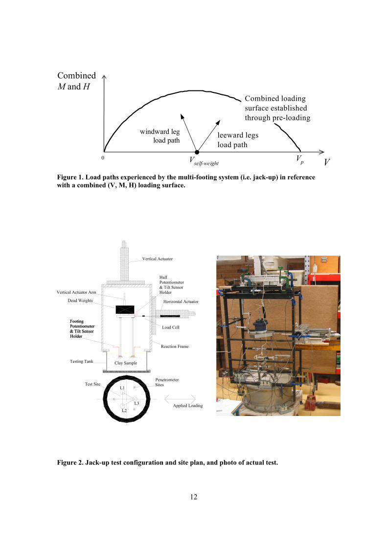
For increments that include plastic behaviour due to the expansion or contraction of the Model B yield surface, θ∆ in Eqn. 10 is not the total rotational increment, but the difference between the total and the Model B plastic rotation increment (evaluated according to the flow rule, and consistency between the yield surface and hardening rule). Model Three Legged Jack-up Experiments A scale model jack-up unit for testing pushover behaviour has been designed and assembled, with full details, example results and verification of all readings, given in Vlahos (2004) and Vlahos et al. (2005). The dimensions of the model are based on a typical field jack-up and represent a 250th scaled model. The model jack-up was shown previously in Figure 2, with prototype and model dimensions detailed in Table 4. The legs have been constructed from stainless steel with a Young’s modulus (E) of 193 GPa and a shear modulus (G) of 80 GPa. The three independent legs have been instrumented such that the vertical, moment and shear stress resultants at any position in a leg can be deduced. This includes the critical bending moments at the leg–hull connection and also all the spudcan (V, M/2R and H) reactions. All spudcan and hull vertical and horizontal displacements and rotation are measured through a series of linear displacement transducers and tilt sensors. This model jack-up has been used to investigate the response of a full three-legged jack-up system. The test proceeded by installing the jack-up vertically and preloading the foundations to V/Vp = 0.5 (at a rate of 1.5 mm/s to ensure undrained conditions). The depth of penetration achieved during the
8
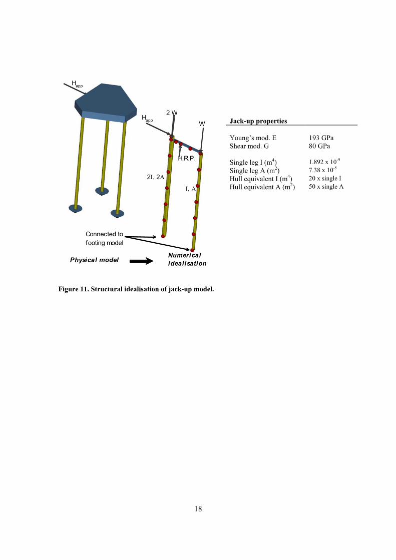
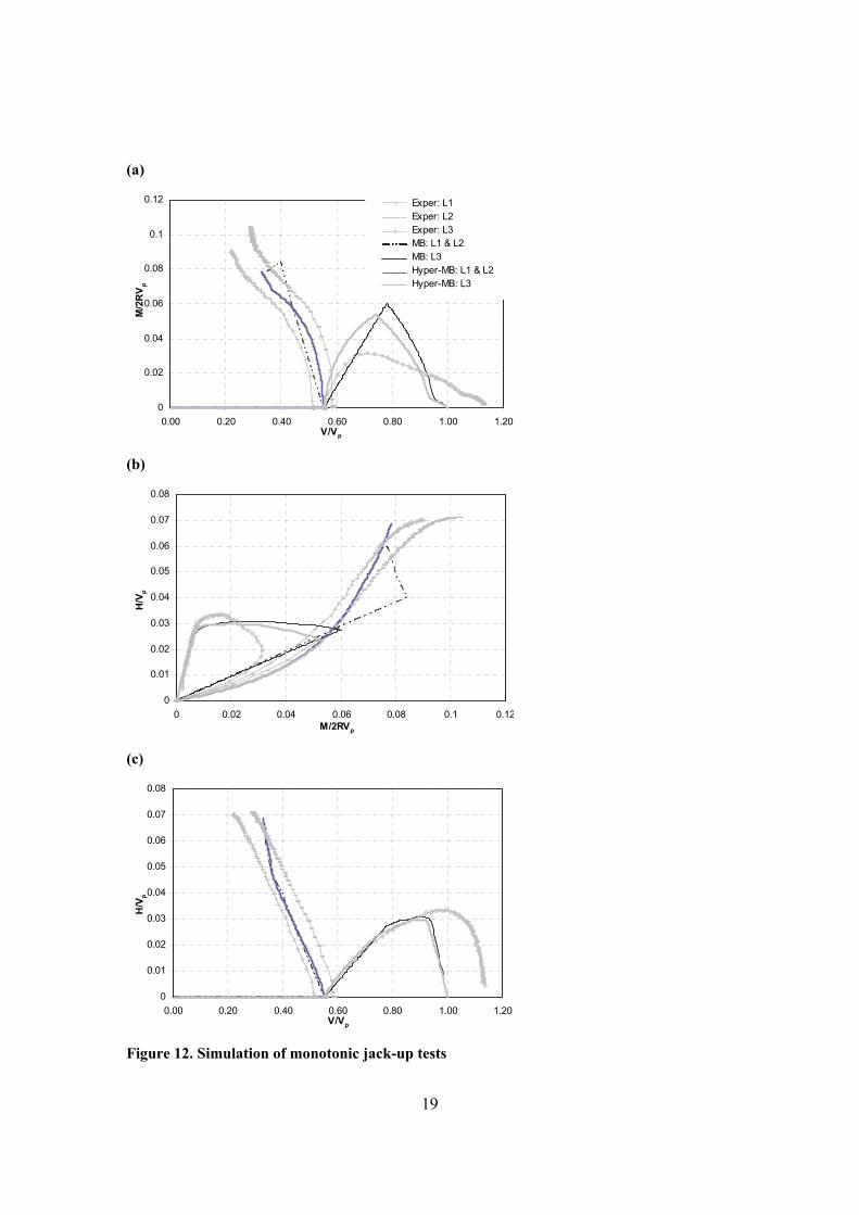
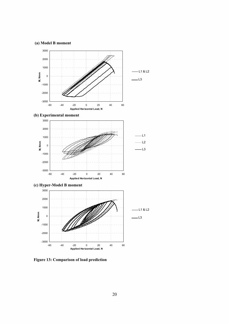
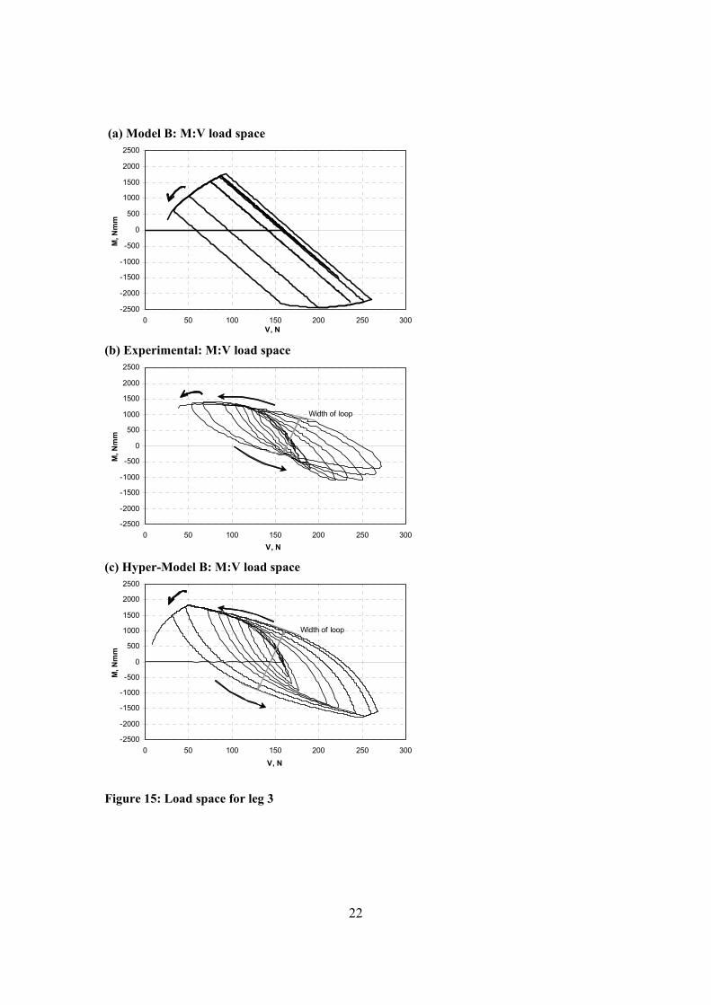
test was one diameter (72 mm). Once installed and preloaded the vertical actuator was disconnected and a second actuator was aligned horizontally with the jack-up hull (as depicted in Figure 2). With the use of a loading arm at hull level, either (i) increasing monotonic horizontal loads, or (ii) cyclic horizontal loads in increasing magnitudes, were applied. The kaolin clay sample was designed to be similar to the single footings tests, with the undrained shear strength profiles shown in Figure 5 along with the results from the single footing tests. With only selected experimental results discussed in this paper, further details on the installation and all other aspects of the tests can be found in Vlahos (2004) and Vlahos et al. (2005). Numerical model The advantage of strain-hardening plasticity models is that they can easily be implemented within conventional structural analyses programs. Both the original Model B and the new Hyper-Model B have been implemented as user elements in the commercially available finite element program ABAQUS (Hibbit et al., 1998). They can be used as a “macro element” to define the load-displacement behaviour of the spudcan foundations attached at the end node of each leg. The remainder of the jack-up is modelled using the library of ABAQUS structural elements. The details of the numerical model used are shown in Figure 11, with the structural properties consistent with the model jack-up (in Table 4). The jack-up is represented simplistically as a plane frame structure. This is justified since the applied horizontal load was applied along a line of symmetry, with either two legs leeward or windward. As a result of this symmetric loading, the two legs were represented by one equivalent beam with twice the cross-sectional area and moment of inertia. The structural elements were elastic and accounted for axial and shear deformation in addition to bending (Hibbit et al., 1998). The jack-up was loaded horizontally by applying a point load on the node of the hull at the same height as the experiments, while the leg-hull connection was rigidly connected. Further, the equivalent vertical installation load (preload and self-weight) was applied to the nodes of the leg-hull connection. The soil conditions were based on the best-fit profiles shown in Figure 5. Monotonic loading results Whilst Hyper-Model B has been developed to account for non-linear behaviour within the yield surface it is important to first compare the results for a monotonic push-over test. An example test is shown in Figure 12 with the experimental load paths of all footings for the monotonic pushover experiment (JUP-6 in Vlahos, 2004) shown normalised by the vertical preload (Vp). With applied load the two windward legs shed vertical load to the leeward leg and thus causing the single footing to become heavily loaded and unable to sustain any moment or horizontal loads. This is then shared by the two windward footings. The numerical simulation was eventually terminated when this single footings experienced rotational failure, and a solution could no longer be obtained. Also shown on Figure 12 are the simulations using both Model B and Hyper-Model B. The inclusion of the non-linear rotational spring has greatly improved the simulation of the experimental data. In particular the numerical response of the windward footings approximates more closely the experimental data. Cyclic loading results The main purpose for developing the Hyper-Model B adaptation is to provide a simple approach to modelling cyclic loading within an existing framework. The applied cyclic horizontal load experienced by the physical model jack-up was used as the driving force on the numerical jack-up in ABAQUS. The most interesting and crucial response to consider is the moment response shown in Figure 13. The experimental response is given in Figure 13b where the deduced moment at each of the spudcans is plotted against the horizontal load applied at the hull. Figure 13a shows the Model B simulation of the experimental data and clearly the small cyclic loads are not reproduced nor are the hysteretic effects. However, the Hyper-Model B simulation, shown in Figure 13c, is able to reproduce all the non-linear effects adequately.
9
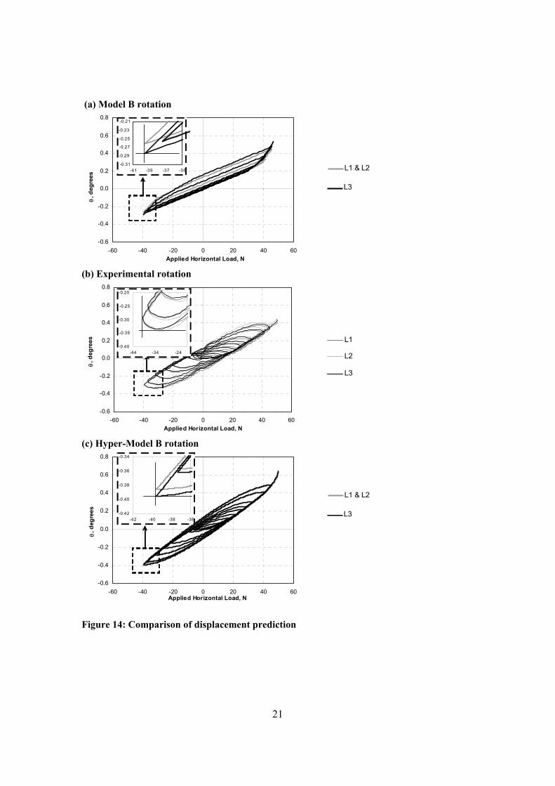
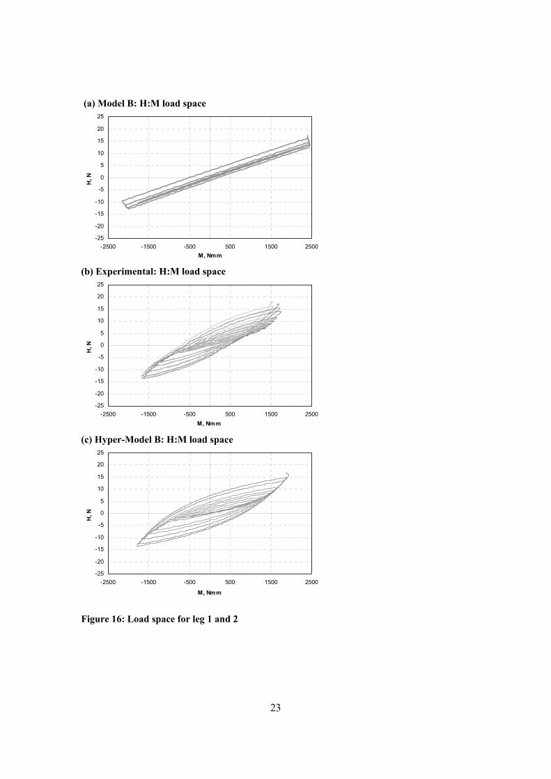
This is also evident in Figure 14 which shows the deduced footing rotations plotted against the horizontal load applied to the hull. Clearly the Hyper-Model B modification provides a closer approximation to the experimental data than the Model B simulation, in both magnitude and shape. A minor discrepancy is observed, however, in that the Hyper-Model B and the experimental results show different positions for the peak rotation of the footing. The peak rotation does not occur at the peak applied horizontal load. Further evidence of an improved modelling of the experimental data by Hyper-Model B is shown in Figure 15 for the leeward footing response in M:V space. Considerable disparity is seen between Model B and the modified Hyper-Model B formulation as well as the experimental data. Figure 16 shows the windward footing response in M:H space where similar observations are evident. Conclusions Numerical modelling of the foundations for mobile jack-up units does not usually account for non-linear cyclic loading behaviour. Currently available strain hardening models are based on single surface hardening plasticity. The models assume that any behaviour within the yield surface is assumed to be elastic and therefore the models are not able to reproduce cyclic loading adequately. This is clearly a simplification of actual behaviour. To develop a cyclic loading capability a series of cyclic loading tests were carried out on model spudcan foundations embedded in a clay soil. The tests followed specific load paths representative of those that would be experienced by a three-legged jack-up in the field. The data resulting from the tests showed hysteretic cycles characteristic of a material obeying to Masing’s rules (Masing, 1926; Pyke, 1979). Though this was observed in all degrees of freedom, it was shown that, for load paths relevant to jack-up rigs, the moment rotation response was most important. This data was modelled using a single degree-of-freedom multi-surface plasticity model based on hyperplasticity. To carry out numerical modelling of a model jack-up unit a modification was proposed to an existing strain hardening plasticity theory (Model B). The modification consisted of using the hyperplastic spring within the elastic stiffness matrix for the rotational degree-of-freedom, as this was considered most critical. Simulations were undertaken using this modified foundation model within an ABAQUS model of a jack-up unit. The simulations were compared to small-scale jack-up tests carried out in the laboratory. The new model provided an improved description of the response of the jack-up to both monotonic pushover analyses as well as cyclic loading tests. Further modifications could include using non-linear hyperplastic springs for the other degrees-of-freedom. Acknowledgments This research was supported by the Australian Research Council’s Special Research Centre, Discovery (DP0345424) and Linkage International (LX0560459) programs, and this is gratefully acknowledged. The first author extends thanks to the friendly atmosphere at the Department of Engineering Science at the University of Oxford and to Prof. G.T. Houlsby for his time and sound advice during his visit and since. References Bell, R.W. (1991). The Analysis of Offshore Foundations Subjected to Combined Loading. M.Sc. Thesis, University of
Oxford, United Kingdom. Butterfield, R., Houlsby, G.T. & Gottardi, G. (1997). Standardized sign conventions and notation for generally loaded
foundations. Géotechnique, Vol. 47, No. 5, pp. 1051-1054. Byrne, B.W. (2000). Investigations of suction caissons in dense sand. D.Phil. Thesis, University of Oxford, United
Kingdom. Byrne, B.W. and Houlsby, G.T. (2001). Observations of Footing Behaviour on Loose Carbonate Sands. Géotechnique,
Vol. 51, No. 5, pp 463-466.
10
Byrne, B.W. and Houlsby, G.T. (2004). Experimental investigations of the response of suction caissons to transient combined loading. Proc. ACSE, Journal of Geotechnical and Geoenvironmental Engineering 130, No 3, Mar., pp240-253.
Byrne, B.W., Houlsby, G.T. and Martin, C.M. (2002). Cyclic Loading of Shallow Foundations on Sand. Proc. Int. Conf. on Physical Modelling in Geotechnics (ICPMG), St John’s, Newfoundland, Canada.
Cassidy, M.J. (1999). Non-Linear Analysis of Jack-up Structures Subjected to Random Waves. D.Phil. Thesis, University of Oxford, United Kingdom.
Cassidy, M.J., Houlsby, G.T., Hoyle, M., Marcom, M. (2002). Determining appropriate stiffness levels for spudcan foundations using jack-up case records. Proc. 21th Int. Conf. on Offshore Mechanics and Arctic Engineering (OMAE)., Oslo, Norway, OMAE2002-28085.
Cassidy, M.J., Martin, C.M., Houlsby, G.T. (2004). Development and application of force resultant models describing jack-up foundation behaviour. Marine Structures, Vol. 17 No. 3-4, pp. 165-193.
Doherty, J.P. (2004). Development of the scaled boundary finite element method for applications in geomechanics. PhD Thesis, University of Western Australia, Australia.
Doherty, J.P. and Deeks, A.J. (2003). Elastic response of circular footings embedded in a non-homogeneous half-space, Géotechnique 53(8), pp. 703-714.
Fannin, R.J. (1986). Geogrid reinforcement of granular layers on soft clay – a study at model and full scale. D.Phil. Thesis, University of Oxford, United Kingdom.
Gottardi, G., Houlsby, G.T. & Butterfield, R. (1999). The plastic response of circular footings on sand under general planar loading. Géotechnique, Vol. 49, No. 4, pp. 453-470.
Hibbit, Karlsson and Sorenson Inc. (1998). ABAQUS Users’ Manual, Version 5.8. Houlsby, G.T. & Cassidy, M.J. (2002). A plasticity model for the behaviour of footings on sand under combined
loading. Géotechnique, Vol. 52, No. 2, pp. 117-129. Houlsby, G.T. & Puzrin, A.M. (2002) Rate-Dependent Plasticity Models Derived from Potential Functions. Journal of
Rheology, Vol. 46, No. 1, January/February, pp 113-126 Iwan, W.D. (1967). On a class of models for the yielding behaviour of continuous and composite systems. Journal of
Applied Mechanics, Vol. 34, pp. 612-617. Ladd, C.C., Foott, R., Ishihara, K., Schlosser, F., and Poulos, H.G. (1977). Stress deformation and strength
characteristics. Proc. 9th Int. Conf. on Soil Mechanics and Foundation Eng., Tokyo, Japan, Vol. 2, pp. 421-494.
Martin, C.M. & Houlsby, G.T. (2000). Combined loading of spudcan foundations on clay: laboratory tests. Géotechnique, Vol. 50, No. 4, pp. 325-338.
Martin, C.M. & Houlsby, G.T. (2001). Combined loading of spudcan foundations on clay: numerical modelling. Géotechnique, Vol. 51, No. 8, pp. 687-699.
Martin, C.M. (1994). Physical and numerical modelling of offshore foundations under combined loads. D.Phil. Thesis, University of Oxford, United Kingdom.
Martin, J.B. & Nappi, A. (1990). An internal variable formulation for perfectly plastic and linear hardening relations in plasticity. European Journal of Mechanics. A/Solids, Vol. 9, No. 2, pp. 107-131.
Masing, G. (1926). Eiganspannungen und verfestigung beim messing. Proc. 2nd Int. Congress of App. Mech., pp 332-335.
Ngo Tran, C.L. (1996). The Analysis of Offshore Foundations Subjected to Combined Loading. D.Phil. Thesis, University of Oxford, United Kingdom.
Nova, R. & Montrasio, L. (1991). Settlements of shallow foundations on sand. Geotechnique, vol. 41, no.2, pp. 243-256.
Puzrin, A.M. & Houlsby G.T. (2001). Fundamentals of kinematic hardening hyperplasticity. International Journal of Solids and Structures, Vol. 38, No. 21, May, pp 3771-3794.
Pyke, R. (1979). Non-linear soil models for irregular cyclic loading. ASCE Journal of the Geotechnical Division, Vol. 105, GT6, pp. 715-726.
SNAME T & R 5-5A. (2002). “Site specific assessment of mobile jack-up units, SNAME Technical and Research Bulletin 5-5A” 1st Edition – 2nd Revision, Society of Naval Architects and Marine Engineers, New Jersey.
Temperton, I. (1996). Jack-up spudcan fixity, Masters Thesis, University of Cambridge, United Kingdom. Thompson, R.S.G. (1996). Development of Non-Linear Numerical Models Appropriate for the Analysis of Jack-up
Units. D.Phil. Thesis, University of Oxford, United Kingdom. Vlahos, G. (2004). Physical and numerical modelling of a three-legged jack-up structure on clay soil. Ph.D. Thesis,
University of Western Australia, Australia. Vlahos, G. (2004a). Combined (V, M/2R, H) loading of spudcan footings on clay. Internal report GR:03293, University
of Western Australia, Perth, Australia. Vlahos, G., Martin, C.M., Prior, M.S., Cassidy, M.J. (2005). Development of a model jack-up unit for the study of soil-
structure interaction on clay. Inter. Journal of Physical Modelling in Geomechanics, Vol. 5, No. 2, pp. 31-48. Wroth, C.P. (1984). The interpretation of in situ soil tests. Geotechnique, Vol. 34, No. 4, pp. 449-489.
11
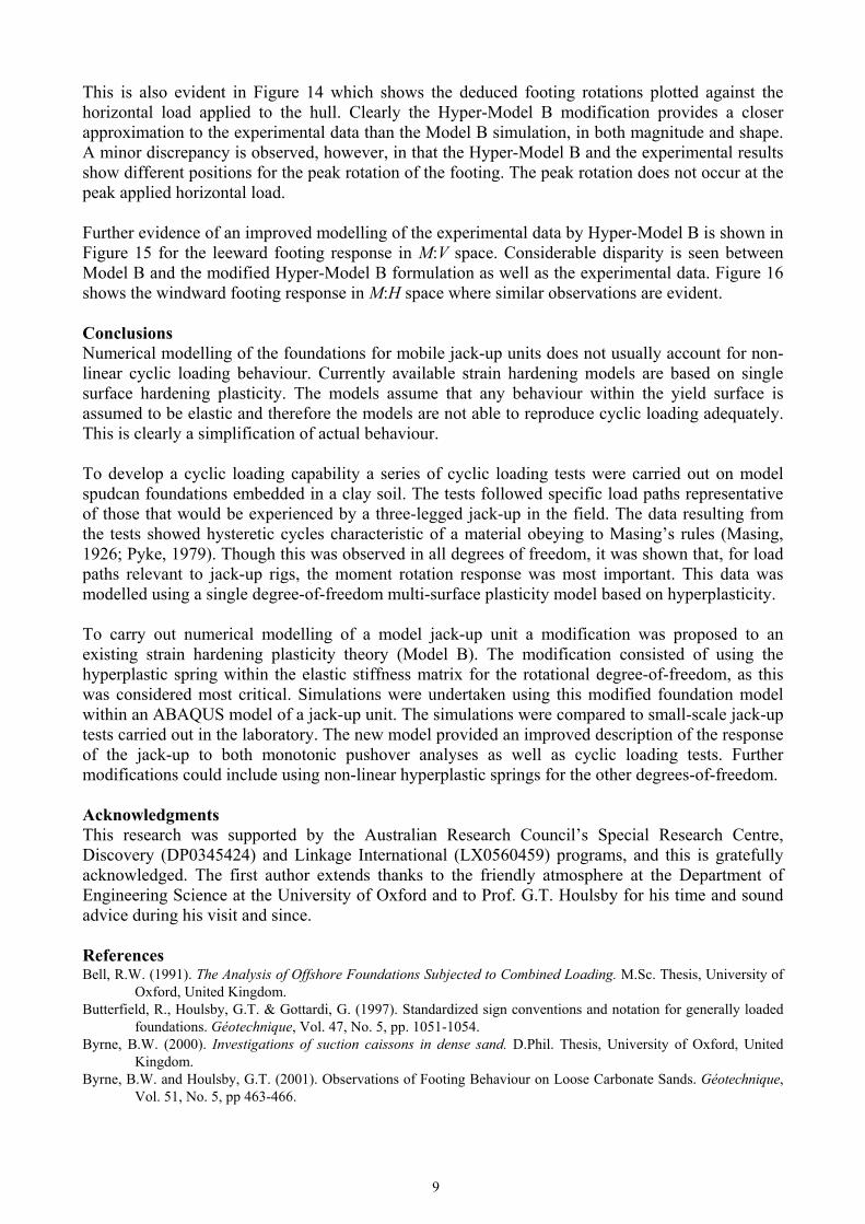
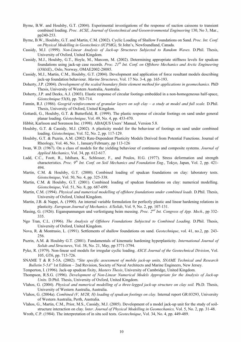
Table 1 - Best fit A and B values using Eqn (1). Tests A B Comments
Sample No.1 0.169 0.832 Average of four vane tests Sample No.2 0.228 0.76 Average of four vane tests
Model B Experiments (Martin, 1994; Martin and Houlsby, 2000) 0.253 0.754 Based on vane shear tests, σmax≈200 kPa
Three-legged jack-up tests (Vlahos, 2004; Vlahos et al., 2005) 0.354 0.766 Average of t-bar tests in Table 4.1 of
Vlahos (2004)
Table 2 – Data for single footing tests presented.
Load ratios Minimum load Maximum load Sample No. -
Test No. M/2RV H/V 2RH/M
No. of increasing
cycles
Preload (Vp)
V/Vp M/2RVp H/Vp
S1-T11 0.548 0.264 0.477 11 1500 N 0.36 0.61
-0.070 0.063
-0.039 0.033
S1-T14 0.534 0.263 0.485 11 1633 N 0.33 0.56
-0.059 0.054
-0.032 0.031
S2-T2 0.2427 0.1003 0.412 14 500 N 0.03 0.07
-0.049 0.051
-0.02 0.02
S2-T8–no2 0.2399 0.1012 0.4217 14 1383 N 0.03 0.067
-0.047 0.043
-0.020 0.019
S2-T9–no3 1.1506 0.5227 0.4519 6 1383 N 0.044 0.054
-0.051 0.053
-0.024 0.024
Table 3 - Parameters for hyperbolic backbone relationship. Backbone curve parameters Sample No. -
Test No. c k k50 S1-T11 0.071 100 1.9 S1-T14 0.06 120 1.8 S2-T2 0.065 100 1.9
S2-T8-no2 0.055 100 1.8 S2-T9-no3 0.14 60 0.3
Table 4 – Dimensions of 250:1 scale model jack-up.
Notes:1: Lower guide to spudcan Load Reference Point, 2: Measured from centre to centre, 3: Measured from centreline of legs
Model Characteristics Prototype (Average Case)
1:250 scaled model Built model
Leg length: full and partial 1 150, 50 m 600, 200 mm 600, 200 mm Aft leg separation 2 51 m 204 mm 216 mm
Aft and forward leg separation 3 45 m 180 mm 187 mm Breadth of hull 78 m 312 mm 324 mm Length of hull 70 m 280 mm 280 mm Depth of hull 10 m 40 mm 40 mm
Second moment of area of leg (I) 7.2 m4 1843.2 mm4 1892 mm4 Cross-sectional area of leg (A) 1 m2 16 mm2 73.8 mm2
Spudcan diameter 18 m 72 mm 72 mm
12
V
CombinedM and H
VpVself-weight
leeward legsload path
windward legload path
0
Combined loadingsurface establishedthrough pre-loading
Figure 1. Load paths experienced by the multi-footing system (i.e. jack-up) in reference with a combined (V, M, H) loading surface.
Figure 2. Jack-up test configuration and site plan, and photo of actual test.
Horizontal Actuator
Load Cell
Dead Weights
Clay Sample
Vertical Actuator Arm
Testing Tank
Reaction Frame
Footing Potentiometer & Tilt Sensor Holder
Test SitePenetrometer Sites
Vertical Actuator
Applied Loading
Footing Potentiometer & Tilt Sensor Holder
Hull Potentiometer & Tilt Sensor Holder
L1
L2L3
13
-0.1
-0.08
-0.06
-0.04
-0.02
0
0.02
0.04
0.06
0.08
0.1
0 0.2 0.4 0.6 0.8 1V/Vp
H/V
p
Combined loading surface of Model B (Martin, 1994), established upon preloading
Single-footing (L3), w indw ard loaded
Tw o-footing group (L1 & L2), leew ard loaded
-0.15
-0.1
-0.05
0
0.05
0.1
0.15
-0.15 -0.1 -0.05 0 0.05 0.1 0.15M/2RVp
H/V
p
V/Vp=0.49
V/Vp=0.6
-0.15
-0.1
-0.05
0
0.05
0.1
0.15
0 0.2 0.4 0.6 0.8 1V/Vp
M/2
RV
p
Figure 3. Example load paths of spudcan footings measured during 250:1 scale model jack-up tests (JUP-4 in Vlahos, 2004; Vlahos et al., 2005).

14
ReferencePosition
76°130°
13°
M
u
Displaced Position
V
Hθ
Soil Surface
Load Reference Point L.R.P.
wØ125mm
Figure 4. Sign convention for spudcan loads (V, M, H) and displacements (w, θ, u) (as recommended by Butterfield et al., 1997).
0
50
100
150
200
250
300
350
0 2.5 5 7.5 10 12.5 15 17.5 20
Shear Strength, kPa
Dep
th, m
m
Vane tests S1
Best f it S1: A=0.17, B=0.83
Vane tests S2
Best f it S2: A=0.23, B=0.76
Average of model jack-up tests
Model B Tests, Martin (1994)
Figure 5. Undrained shear strength profile obtained with hand-held vane tests for the single-footing tests.
15
0
0.2
0.4
0.6
0.8
1
0 100 200 300 400 500 600 700Time, secs
V/V
p
-0.0005
0
0.0005
0.001
0.0015
0.002
0.0025
0.003
0 100 200 300 400 500 600 700Time, secs
w/2
R
-0.1
-0.06
-0.02
0.02
0.06
0.1
0 100 200 300 400 500 600 700Time, secs
M/2
RV
p
-0.025
-0.02
-0.015
-0.01
-0.005
0
0.005
0.01
0.015
0.02
0 100 200 300 400 500 600 700Time, secs
θ, r
adia
ns
-0.1
-0.06
-0.02
0.02
0.06
0.1
0 100 200 300 400 500 600 700Time, secs
H/V
p
-0.0008
-0.0006
-0.0004
-0.0002
0
0.0002
0.0004
0.0006
0.0008
0.001
0 100 200 300 400 500 600 700Time, secs
u/2R
Figure 6. A typical single-spudcan test load profile and the resulting displacement profile.
16
-0.1
-0.08
-0.06
-0.04
-0.02
0
0.02
0.04
0.06
0.08
0.1
-0.03 -0.02 -0.01 0 0.01 0.02 0.03θ, radians
M/2
RV
p
S1-T11Unload pathScaled dow n by 2
JUP-3:L1JUP-3:L2
Figure 7. Demonstrating Masing behaviour for S1-T11.
(a)
εα
Elasticspring, E
Load
Kinematichardeningspring, H
Slider, k
(b)
ε
Elasticspring, E
Load
Hn
α1 αnα2
k1 k2 kn
εe
H2H1
Figure 8. Iwan’s mechanical analogy for (a) single surface and (b) multi-surface model (Iwan, 1967).
17
0
0.01
0.02
0.03
0.04
0.05
0.06
0.07
0.08
0 0.02 0.04 0.06 0.08 0.14GR2θ /V0
M/2
RV 0
S1-T11
S1-T14
S2-T2
S2-T8-no2
S2-T9-no3: High M ratio
Backbone curves
Figure 9. Backbone curves for the single footing tests.
-0.1
-0.08
-0.06
-0.04
-0.02
0
0.02
0.04
0.06
0.08
0.1
-0.025 -0.015 -0.005 0.005 0.015 0.025θ, rads
M/2
RV 0
S1-T11
Numerical model
Figure 10. Retrospective simulation of single footing tests S1-T11.
18
Physical modelNumerical idealisation
2 W
W
Connected to footing model
2I, 2A
I, A
Happ
Happ
H.R.P.
Figure 11. Structural idealisation of jack-up model.
Jack-up properties
Young’s mod. E 193 GPa Shear mod. G 80 GPa Single leg I (m4) 1.892 x 10⁻⁹ Single leg A (m2) 7.38 x 10⁻⁵ Hull equivalent I (m4) 20 x single I Hull equivalent A (m2) 50 x single A
19
(a)
0
0.02
0.04
0.06
0.08
0.1
0.12
0.00 0.20 0.40 0.60 0.80 1.00 1.20V/Vp
M/2
RV
p
Exper: L1Exper: L2Exper: L3MB: L1 & L2MB: L3Hyper-MB: L1 & L2Hyper-MB: L3
(b)
0
0.01
0.02
0.03
0.04
0.05
0.06
0.07
0.08
0 0.02 0.04 0.06 0.08 0.1 0.12M/2RVp
H/V
p
(c)
0
0.01
0.02
0.03
0.04
0.05
0.06
0.07
0.08
0.00 0.20 0.40 0.60 0.80 1.00 1.20V/Vp
H/V
p
Figure 12. Simulation of monotonic jack-up tests
20
(a) Model B moment
-3000
-2000
-1000
0
1000
2000
3000
-60 -40 -20 0 20 40 60Applied Horizontal Load, N
M, N
mm
(b) Experimental moment
-3000
-2000
-1000
0
1000
2000
3000
-60 -40 -20 0 20 40 60
Applied Horizontal Load, N
M, N
mm
(c) Hyper-Model B moment
-3000
-2000
-1000
0
1000
2000
3000
-60 -40 -20 0 20 40 60Applied Horizontal Load, N
M, N
mm
Figure 13: Comparison of load prediction
L1 & L2
L3
L1
L2
L3
L1 & L2
L3
21
(a) Model B rotation
-0.6
-0.4
-0.2
0.0
0.2
0.4
0.6
0.8
-60 -40 -20 0 20 40 60Applied Horizontal Load, N
θ, d
egre
es
(b) Experimental rotation
-0.6
-0.4
-0.2
0.0
0.2
0.4
0.6
0.8
-60 -40 -20 0 20 40 60Applied Horizontal Load, N
θ, d
egre
es
(c) Hyper-Model B rotation
-0.6
-0.4
-0.2
0.0
0.2
0.4
0.6
0.8
-60 -40 -20 0 20 40 60Applied Horizontal Load, N
θ, d
egre
es
Figure 14: Comparison of displacement prediction
L1 & L2
L3
L1
L2
L3
L1 & L2
L3
-0.31
-0.29
-0.27
-0.25
-0.23
-0.21
-41 -39 -37 -35
-0.40
-0.35
-0.30
-0.25
-0.20
-44 -34 -24
-0.42
-0.40
-0.38
-0.36
-0.34
-42 -40 -38 -36
22
(a) Model B: M:V load space
-2500
-2000
-1500
-1000
-500
0
500
1000
1500
2000
2500
0 50 100 150 200 250 300V, N
M, N
mm
(b) Experimental: M:V load space
-2500
-2000
-1500
-1000
-500
0
500
1000
1500
2000
2500
0 50 100 150 200 250 300V, N
M, N
mm
Width of loop
(c) Hyper-Model B: M:V load space
-2500
-2000
-1500
-1000
-500
0
500
1000
1500
2000
2500
0 50 100 150 200 250 300
V, N
M, N
mm
Width of loop
Figure 15: Load space for leg 3
23
(a) Model B: H:M load space
-25
-20
-15
-10
-5
0
5
10
15
20
25
-2500 -1500 -500 500 1500 2500M, Nmm
H, N
(b) Experimental: H:M load space
-25
-20
-15
-10
-5
0
5
10
15
20
25
-2500 -1500 -500 500 1500 2500M, Nmm
H, N
(c) Hyper-Model B: H:M load space
-25
-20
-15
-10
-5
0
5
10
15
20
25
-2500 -1500 -500 500 1500 2500
M, Nmm
H, N
Figure 16: Load space for leg 1 and 2
Related Documents