THE BALL VALVES

Welcome message from author
This document is posted to help you gain knowledge. Please leave a comment to let me know what you think about it! Share it to your friends and learn new things together.
Transcript

THE BALL VALVES
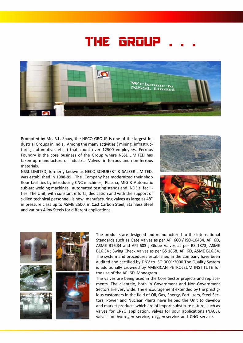
Promoted by Mr. B.L. Shaw, the NECO GROUP is one of the largest In-dustrial Groups in India. Among the many activities ( mining, infrastruc-tures, automotive, etc. ) that count over 12500 employees, Ferrous Foundry is the core business of the Group where NSSL LIMITED has taken up manufacture of Industrial Valves in ferrous and non-ferrous materials. NSSL LIMITED, formerly known as NECO SCHUBERT & SALZER LIMITED, was established in 1988-89. The Company has modernized their shop floor facilities by introducing CNC machines, Plasma, MIG & Automatic sub-arc welding machines, automated testing stands and NDE.s facili-ties. The Unit, with constant efforts, dedication and with the support of skilled technical personnel, is now manufacturing valves as large as 48” in pressure class up to ASME 2500, in Cast Carbon Steel, Stainless Steel and various Alloy Steels for different applications.
The products are designed and manufactured to the International Standards such as Gate Valves as per API 600 / ISO-10434, API 6D, ASME B16.34 and API 603 ; Globe Valves as per BS 1873, ASME B16.34 ; Swing Check Valves as per BS 1868, API 6D, ASME B16.34. The system and procedures established in the company have been audited and certified by DNV to ISO 9001:2000.The Quality System is additionally crowned by AMERICAN PETROLEUM INSTITUTE for the use of the API 6D Monogram. The valves are being used in the Core Sector projects and replace-ments. The clientele, both in Government and Non-Government Sectors are very wide. The encouragement extended by the prestig-ious customers in the field of Oil, Gas, Energy, Fertilizers, Steel Sec-tors, Power and Nuclear Plants have helped the Unit to develop and market products which are of import substitute nature, such as valves for CRYO application, valves for sour applications (NACE), valves for hydrogen service, oxygen service and CNG service.
THE GROUP . . .
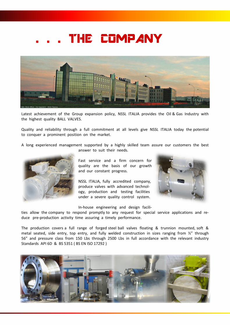
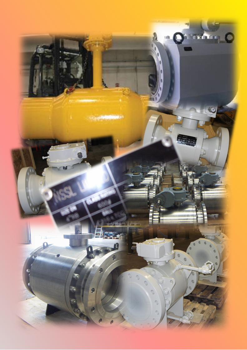
Latest achievement of the Group expansion policy, NSSL ITALIA provides the Oil & Gas Industry with the highest quality BALL VALVES. Quality and reliability through a full commitment at all levels give NSSL ITALIA today the potential to conquer a prominent position on the market. A long experienced management supported by a highly skilled team assure our customers the best
answer to suit their needs. Fast service and a firm concern for quality are the basis of our growth and our constant progress. NSSL ITALIA, fully accredited company, produce valves with advanced technol-ogy, production and testing facilities under a severe quality control system. In-house engineering and design facili-
ties allow the company to respond promptly to any request for special service applications and re-duce pre-production activity time assuring a timely performance. The production covers a full range of forged steel ball valves floating & trunnion mounted, soft & metal seated, side entry, top entry, and fully welded construction in sizes ranging from ½” through 56” and pressure class from 150 Lbs through 2500 Lbs in full accordance with the relevant industry Standards API 6D & BS 5351 ( BS EN ISO 17292 )
NSSL ITALIA Offices : Via Coppalati 6 - 29122 Piacenza
. . . THE COMPANY
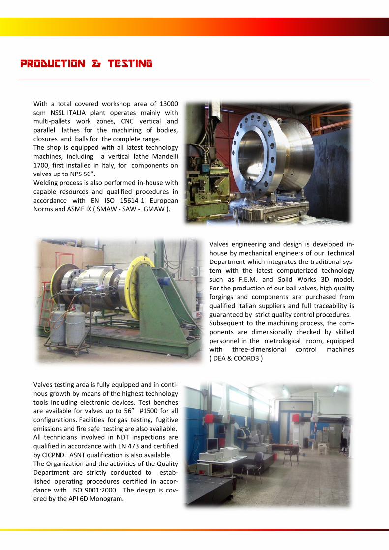
With a total covered workshop area of 13000 sqm NSSL ITALIA plant operates mainly with multi-pallets work zones, CNC vertical and parallel lathes for the machining of bodies, closures and balls for the complete range. The shop is equipped with all latest technology machines, including a vertical lathe Mandelli 1700, first installed in Italy, for components on valves up to NPS 56”. Welding process is also performed in-house with capable resources and qualified procedures in accordance with EN ISO 15614-1 European Norms and ASME IX ( SMAW - SAW - GMAW ).
Valves engineering and design is developed in-house by mechanical engineers of our Technical Department which integrates the traditional sys-tem with the latest computerized technology such as F.E.M. and Solid Works 3D model. For the production of our ball valves, high quality forgings and components are purchased from qualified Italian suppliers and full traceability is guaranteed by strict quality control procedures. Subsequent to the machining process, the com-ponents are dimensionally checked by skilled personnel in the metrological room, equipped with three-dimensional control machines ( DEA & COORD3 )
Valves testing area is fully equipped and in conti-nous growth by means of the highest technology tools including electronic devices. Test benches are available for valves up to 56” #1500 for all configurations. Facilities for gas testing, fugitive emissions and fire safe testing are also available. All technicians involved in NDT inspections are qualified in accordance with EN 473 and certified by CICPND. ASNT qualification is also available. The Organization and the activities of the Quality Department are strictly conducted to estab-lished operating procedures certified in accor-dance with ISO 9001:2000. The design is cov-ered by the API 6D Monogram.
PRODUCTION & TESTING

NSSL ITALIA S.r.l. manufacture ball valves in accordance with API, ASME and BS standard requirements. The list reported below contains the most important applicable standards for ball valves. On request NSSL ITALIA S.r.l. may design manufacture and test in accordance with other international standard or Customer specifications.
REFERENCE STANDARDS
ISO - International organization for standardiza-tion
API - American Petroleum Institute
ISO 9001 : Quality system. Model for quality assur-ance in design, development, production, installa-tion and servicing.
Spec. 6A : Specification for wellhead and Christmas tree equipment
ISO 5208 : Industrial valve pressure testing Spec. 6D : Specification for pipeline valves
ANSI - American National Standard Institute ASME - American Society of Mechanical Engineers
Spec. RP6F : Recommended practice for fire testing of valves
B16.11 : Forged steel fitting socket-welding and threaded
Spec. 6FA : Specification for fire testing of valves
B16.5 : Steel pipe flanges and flanged fittings Std. 598 : Valve inspection and test
B16.10 : Face to face and end to end dimension of ferrous valves
Std. 605 : Large diameter carbon steel flanges
B16.25 : Butt welding ends Std. 607 : Fire safe for soft seated quarter-turn valves
B16.34 : Steel valves - Flanged and butt welding ends.
B31.3 : Chemical plant and petroleum MSS - Manufactures Standardization Society
B31.4 : Liquid petroleum transportation piping sys-tem
SP 6 : Standard finished for contact faces of pipes flanges
B31.8 : Gas transmission and distribution piping system
SP 25 : standard marking system for valves fittings, flanges and unions.
SP 44 : Steel pipeline flanges
British Standard SP 45 : by pass and drain connection standard
BS 1560 : steel pipe flanges and flanged fittings. SP 55 : Quality standard of steel casting visual method
BS 2090 : face to face, center to face, end to end and center to end dimension of flanged and butt welding and steel valves for the petroleum, petro-chemical and allied industries
SP 61 : Hydrostatic testing of steel valves
BS 4505 : Flanges and bolting for pipes valves and fittings
SP 72 : Ball valves and flanges of butt welded ends for general service.
BS 5146 : Inspection and test of steel valves for petroleum, petrochemical and allied industries
BS 5351 : Steel ball valves for the petroleum, petro-chemical and allied industries.
NACE - National association of corrosion Engineers
BS 6755 : Testing of Valves.
MR01.75 & ISO 151 : Sulphide Stress Cracking Resis-tant Materials for offshore applications
SIDE ENTRY BALL VALVES
ASME #150 F. B. SPLIT BODY - SIDE ENTRY
Size inch/mm
I-d O-d L - Rf L - Bw W H K Weight
lb/kg
2 1.93 1.93 7.01 8.50 6.10 4.13 4.13 62
50 49 49 178 216 155 105 105 28
3 2.91 2.91 7.99 11.14 7.68 6.10 4.92 121
80 74 74 203 283 195 155 125 55
4 3.94 3.94 9.02 12.01 9.25 7.68 6.50 194
100 100 100 229 305 235 195 165 88
6 5.91 5.91 15.51 17.99 12.01 9.65 7.28 357
150 150 150 394 457 305 245 185 162
8 7.91 7.91 17.99 20.51 15.55 11.02 8.86 562
200 201 201 457 521 395 280 225 255
10 9.92 9.92 20.98 22.01 18.31 12.60 10.83 849
250 252 252 533 559 465 320 275 385
12 11.93 11.93 24.02 25.00 21.46 13.19 12.01 1232
300 303 303 610 635 545 335 305 559
14 13.15 13.15 27.01 30.00 23.82 14.76 13.19 1687
350 334 334 686 762 605 375 335 765
16 15.16 15.16 30.00 32.99 26.57 15.94 13.98 2260
400 385 385 762 838 675 405 355 1025
18 17.17 17.17 34.02 35.98 25.00 17.32 15.55 2690
450 436 436 864 914 635 440 395 1220
20 19.17 19.17 35.98 39.02 33.46 19.49 17.13 3957
500 487 487 914 991 850 495 435 1795
22 21.18 21.18 39.02 42.99 36.81 20.67 18.70 5203
550 538 538 991 1092 935 525 475 2360
24 23.19 23.19 42.01 45.00 39.76 23.03 20.67 6845
600 589 589 1067 1143 1010 585 525 3105
26 24.92 24.92 45.00 49.02 41.93 24.61 22.24 8146
650 633 633 1143 1245 1065 625 565 3695
28 26.93 26.93 48.98 53.03 44.69 25.59 26.18 9910
700 684 684 1244 1347 1135 650 665 4495
30 28.94 28.94 50.98 55.00 38.98 27.36 27.76 11508
750 735 735 1295 1397 990 695 705 5220
32 30.67 30.67 53.98 60.00 51.38 29.33 29.53 14980
800 779 779 1371 1524 1305 745 750 6795
34 32.68 32.68 57.99 64.02 54.13 29.92 30.51 17626
850 830 830 1473 1626 1375 760 775 7995
36 34.41 34.41 60.00 68.03 56.50 31.89 31.89 19389
900 874 874 1524 1728 1435 810 810 8795
40 38.43 38.43 69.02 77.01 62.80 35.63 35.63 27668
1000 976 976 1753 1956 1595 905 905 12550
42 40.16 40.16 73.03 82.01 65.35 37.01 36.61 31459
1050 1020 1020 1855 2083 1660 940 930 14270
48 45.91 45.91 84.02 94.02 75.79 43.11 41.93 48258
1200 1166 1166 2134 2388 1925 1095 1065 21890
56 53.54 53.54 97.99 97.99 89.17 51.38 49.41 75154
1400 1360 1360 2489 2489 2265 1305 1255 34090
ASME #150 R. B. SPLIT BODY - SIDE ENTRY
Size inch/mm
I-d O-d L - Rf L - Bw W H K Weight
lb/kg
2 x 1 1/2 1.93 1.50 7.01 8.50 6.10 3.74 3.94 60
50 x 40 49 38 178 216 155 95 100 27
3 x 2 2.91 2.91 7.99 11.14 7.68 4.13 4.13 71
80 x 50 74 49 203 283 195 105 105 32
4 x 3 3.94 3.94 9.02 12.01 9.06 6.10 5.12 137
100 x 80 100 74 229 305 230 155 130 62
6 x 4 5.91 5.91 15.51 17.99 11.02 7.87 6.50 223
150 x 100 150 100 394 457 280 200 165 101
8 x 6 7.91 7.91 17.99 20.51 13.58 10.04 7.28 410
200 x 150 201 150 457 521 345 255 185 186
10 x 8 9.92 9.92 20.98 22.01 15.94 11.22 8.86 646
250 x 200 252 201 533 559 405 285 225 293
12 x 10 11.93 11.93 24.02 25.00 19.09 12.80 11.22 1025
300 x 250 303 252 610 635 485 325 285 465
14 x 12 13.15 13.15 27.01 30.00 21.06 13.58 11.81 1356
350 x 300 334 303 686 762 535 345 300 615
16 x 12 15.16 15.16 30.00 32.99 23.62 13.58 12.01 1541
400 x 300 385 303 762 838 600 345 305 699
18 x 16 17.17 17.17 34.02 35.98 25.00 16.54 13.78 2343
450 x 400 436 385 864 914 635 420 350 1063
20 x 16 19.17 19.17 35.98 39.02 27.76 16.34 13.98 2449
500 x 400 487 385 914 991 705 415 355 1111
24 x 20 23.19 23.19 42.01 45.00 32.09 19.49 17.13 4347
600 x 500 589 487 1067 1143 815 495 435 1972
30 x 24 28.94 28.94 50.98 55.00 38.78 23.03 20.28 7163
750 x 600 735 589 1295 1397 985 585 515 3249
36 x 30 34.41 34.41 60.00 68.03 46.26 27.36 27.76 13922
900 x 750 874 735 1524 1728 1175 695 705 6315
6
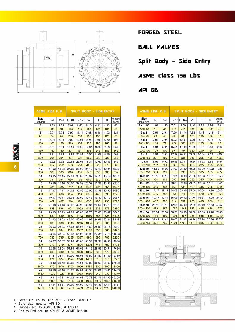
FORGED STEEL BALL VALVES Split Body - Side Entry ASME Class 150 Lbs API 6D
> Lever Op. up to 6” / 8 x 6” - Over Gear Op. > Bore size acc. to API 6D > Flanges acc. to ASME B16.5 & B16.47 > End to End acc. to API 6D & ASME B16.10
ASME #300 F. B. SPLIT BODY - SIDE ENTRY
Size inch/mm
I-d O-d L - Rf L - Bw W H K Weight
lb/kg
2 1.93 1.93 8.50 8.50 6.50 4.33 3.74 62
50 49 49 216 216 165 110 95 28
3 2.91 2.91 11.14 11.14 8.07 6.10 4.92 121
80 74 74 283 283 205 155 125 55
4 3.94 3.94 12.01 12.01 10.04 8.07 6.50 205
100 100 100 305 305 255 205 165 93
6 5.91 5.91 15.87 17.99 12.60 9.65 8.07 403
150 150 150 403 457 320 245 205 183
8 7.91 7.91 19.76 20.51 15.16 11.02 8.86 617
200 201 201 502 521 385 280 225 280
10 9.92 9.92 22.36 22.01 18.31 12.60 11.61 1107
250 252 252 568 559 465 320 295 502
12 11.93 11.93 25.51 25.00 21.46 14.17 13.19 1620
300 303 303 648 635 545 360 335 735
14 13.15 13.15 30.00 30.00 25.00 15.55 13.58 2271
350 334 334 762 762 635 395 345 1030
16 15.16 15.16 32.99 32.99 27.36 17.13 15.55 3128
400 385 385 838 838 695 435 395 1419
18 17.17 17.17 35.98 35.98 30.51 18.11 16.34 3514
450 436 436 914 914 775 460 415 1594
20 19.17 19.17 39.02 39.02 33.66 19.88 18.50 4846
500 487 487 991 991 855 505 470 2198
22 21.18 21.18 42.99 42.99 37.20 20.87 19.09 6153
550 538 538 1092 1092 945 530 485 2791
24 23.19 23.19 45.00 45.00 40.35 23.43 21.65 7632
600 589 589 1143 1143 1025 595 550 3462
26 24.92 24.92 49.02 49.02 42.72 25.00 23.03 10293
650 633 633 1245 1245 1085 635 585 4669
28 26.93 26.93 52.99 52.99 45.47 25.39 25.98 12716
700 684 684 1346 1346 1155 645 660 5768
30 28.94 28.94 55.00 55.00 48.82 27.76 29.13 14539
750 735 735 1397 1397 1240 705 740 6595
32 30.67 30.67 60.00 60.00 52.17 29.72 30.31 17502
800 779 779 1524 1524 1325 755 770 7939
34 32.68 32.68 64.02 64.02 54.92 30.12 31.69 19940
850 830 830 1626 1626 1395 765 805 9045
36 34.41 34.41 67.99 67.99 57.09 31.89 32.68 22260
900 874 874 1727 1727 1450 810 830 10097
40 38.43 38.43 77.01 77.01 63.98 35.63 36.42 30373
1000 976 976 1956 1956 1625 905 925 13777
42 40.16 40.16 82.01 82.01 66.54 37.99 37.60 35514
1050 1020 1020 2083 2083 1690 965 955 16109
48 45.91 45.91 85.43 85.43 57.68 43.50 43.50 53031
1200 1166 1166 2170 2170 1465 1105 1105 24055
56 53.54 53.54 107.99 107.99 89.96 50.98 50.20 84116
1400 1360 1360 2743 2743 2285 1295 1275 38155
ASME #300 R. B. SPLIT BODY - SIDE ENTRY
Size inch/mm
I-d O-d L - Rf L - Bw W H K Weight
lb/kg
2 x 1 1/2 1.93 1.50 8.50 8.50 6.50 3.74 3.94 60
50 x 40 49 38 216 216 165 95 100 27
3 x 2 2.91 2.91 11.14 11.14 8.07 4.13 3.74 73
80 x 50 74 49 283 283 205 105 95 33
4 x 3 3.94 3.94 12.01 12.01 10.04 6.10 4.92 139
100 x 80 100 74 305 305 255 155 125 63
6 x 4 5.91 5.91 17.99 17.99 12.40 8.07 6.50 251
150 x 100 150 100 457 457 315 205 165 114
8 x 6 7.91 7.91 20.51 20.51 14.96 9.45 8.07 481
200 x 150 201 150 521 521 380 240 205 218
10 x 8 9.92 9.92 22.01 22.01 17.72 11.02 9.25 646
250 x 200 252 201 559 559 450 280 235 293
12 x 10 11.93 11.93 25.51 25.00 20.67 12.80 11.61 1312
300 x 250 303 252 648 635 525 325 295 595
14 x 12 13.15 13.15 30.00 30.00 23.23 14.17 13.19 1797
350 x 300 334 303 762 762 590 360 335 815
16 x 12 15.16 15.16 32.99 32.99 25.79 14.17 13.19 2132
400 x 300 385 303 838 838 655 360 335 967
18 x 16 17.17 17.17 35.98 35.98 28.15 16.73 15.55 3507
450 x 400 436 385 914 914 715 425 395 1591
20 x 16 19.17 19.17 39.02 39.02 30.31 16.73 15.55 3662
500 x 400 487 385 991 991 770 425 395 1661
24 x 20 23.19 23.19 45.00 45.00 36.22 19.88 18.50 5877
600 x 500 589 487 1143 1143 920 505 470 2666
30 x 24 28.94 28.94 55.00 55.00 43.11 23.43 21.65 9879
750 x 600 735 589 1397 1397 1095 595 550 4481
36 x 30 34.41 34.41 67.99 67.99 50.20 27.76 28.94 18036
900 x 750 874 735 1727 1727 1275 705 735 8181
7
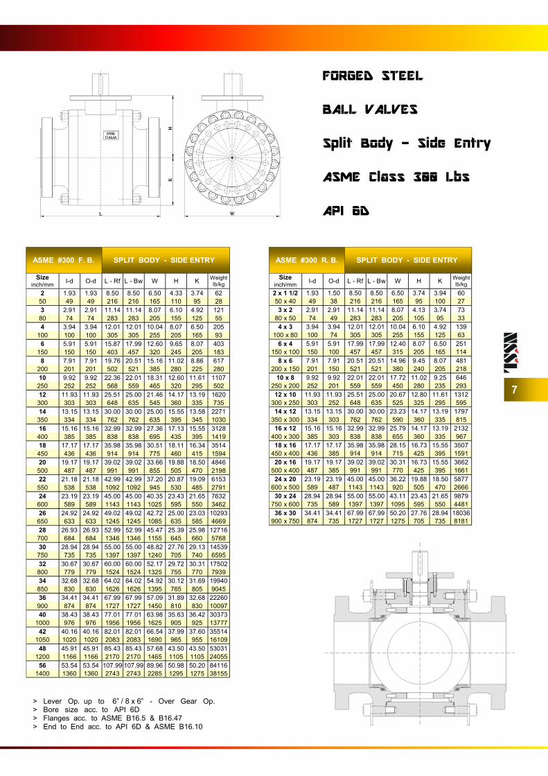
FORGED STEEL BALL VALVES Split Body - Side Entry ASME Class 300 Lbs API 6D
> Lever Op. up to 6” / 8 x 6” - Over Gear Op. > Bore size acc. to API 6D > Flanges acc. to ASME B16.5 & B16.47 > End to End acc. to API 6D & ASME B16.10
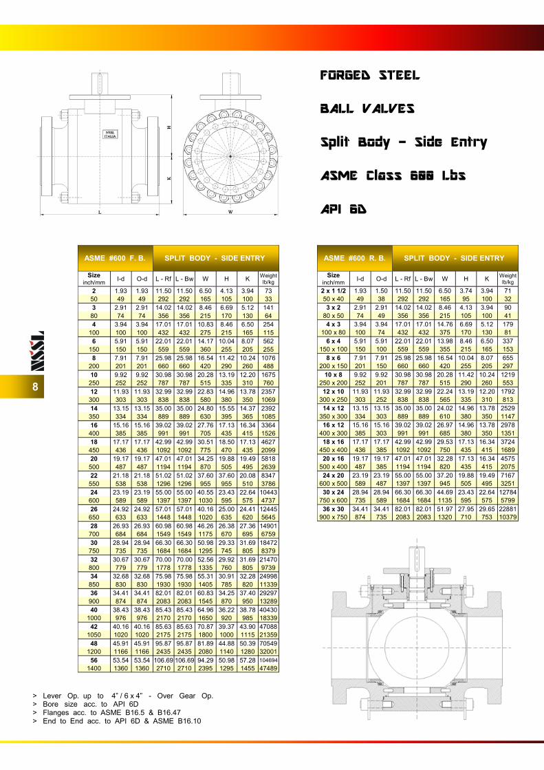
ASME #600 F. B. SPLIT BODY - SIDE ENTRY
Size inch/mm
I-d O-d L - Rf L - Bw W H K Weight
lb/kg
2 1.93 1.93 11.50 11.50 6.50 4.13 3.94 73
50 49 49 292 292 165 105 100 33
3 2.91 2.91 14.02 14.02 8.46 6.69 5.12 141
80 74 74 356 356 215 170 130 64
4 3.94 3.94 17.01 17.01 10.83 8.46 6.50 254
100 100 100 432 432 275 215 165 115
6 5.91 5.91 22.01 22.01 14.17 10.04 8.07 562
150 150 150 559 559 360 255 205 255
8 7.91 7.91 25.98 25.98 16.54 11.42 10.24 1076
200 201 201 660 660 420 290 260 488
10 9.92 9.92 30.98 30.98 20.28 13.19 12.20 1675
250 252 252 787 787 515 335 310 760
12 11.93 11.93 32.99 32.99 22.83 14.96 13.78 2357
300 303 303 838 838 580 380 350 1069
14 13.15 13.15 35.00 35.00 24.80 15.55 14.37 2392
350 334 334 889 889 630 395 365 1085
16 15.16 15.16 39.02 39.02 27.76 17.13 16.34 3364
400 385 385 991 991 705 435 415 1526
18 17.17 17.17 42.99 42.99 30.51 18.50 17.13 4627
450 436 436 1092 1092 775 470 435 2099
20 19.17 19.17 47.01 47.01 34.25 19.88 19.49 5818
500 487 487 1194 1194 870 505 495 2639
22 21.18 21.18 51.02 51.02 37.60 37.60 20.08 8347
550 538 538 1296 1296 955 955 510 3786
24 23.19 23.19 55.00 55.00 40.55 23.43 22.64 10443
600 589 589 1397 1397 1030 595 575 4737
26 24.92 24.92 57.01 57.01 40.16 25.00 24.41 12445
650 633 633 1448 1448 1020 635 620 5645
28 26.93 26.93 60.98 60.98 46.26 26.38 27.36 14901
700 684 684 1549 1549 1175 670 695 6759
30 28.94 28.94 66.30 66.30 50.98 29.33 31.69 18472
750 735 735 1684 1684 1295 745 805 8379
32 30.67 30.67 70.00 70.00 52.56 29.92 31.69 21470
800 779 779 1778 1778 1335 760 805 9739
34 32.68 32.68 75.98 75.98 55.31 30.91 32.28 24998
850 830 830 1930 1930 1405 785 820 11339
36 34.41 34.41 82.01 82.01 60.83 34.25 37.40 29297
900 874 874 2083 2083 1545 870 950 13289
40 38.43 38.43 85.43 85.43 64.96 36.22 38.78 40430
1000 976 976 2170 2170 1650 920 985 18339
42 40.16 40.16 85.63 85.63 70.87 39.37 43.90 47088
1050 1020 1020 2175 2175 1800 1000 1115 21359
48 45.91 45.91 95.87 95.87 81.89 44.88 50.39 70549
1200 1166 1166 2435 2435 2080 1140 1280 32001
56 53.54 53.54 106.69 106.69 94.29 50.98 57.28 104694
1400 1360 1360 2710 2710 2395 1295 1455 47489
ASME #600 R. B. SPLIT BODY - SIDE ENTRY
Size inch/mm
I-d O-d L - Rf L - Bw W H K Weight
lb/kg
2 x 1 1/2 1.93 1.50 11.50 11.50 6.50 3.74 3.94 71
50 x 40 49 38 292 292 165 95 100 32
3 x 2 2.91 2.91 14.02 14.02 8.46 4.13 3.94 90
80 x 50 74 49 356 356 215 105 100 41
4 x 3 3.94 3.94 17.01 17.01 14.76 6.69 5.12 179
100 x 80 100 74 432 432 375 170 130 81
6 x 4 5.91 5.91 22.01 22.01 13.98 8.46 6.50 337
150 x 100 150 100 559 559 355 215 165 153
8 x 6 7.91 7.91 25.98 25.98 16.54 10.04 8.07 655
200 x 150 201 150 660 660 420 255 205 297
10 x 8 9.92 9.92 30.98 30.98 20.28 11.42 10.24 1219
250 x 200 252 201 787 787 515 290 260 553
12 x 10 11.93 11.93 32.99 32.99 22.24 13.19 12.20 1792
300 x 250 303 252 838 838 565 335 310 813
14 x 12 13.15 13.15 35.00 35.00 24.02 14.96 13.78 2529
350 x 300 334 303 889 889 610 380 350 1147
16 x 12 15.16 15.16 39.02 39.02 26.97 14.96 13.78 2978
400 x 300 385 303 991 991 685 380 350 1351
18 x 16 17.17 17.17 42.99 42.99 29.53 17.13 16.34 3724
450 x 400 436 385 1092 1092 750 435 415 1689
20 x 16 19.17 19.17 47.01 47.01 32.28 17.13 16.34 4575
500 x 400 487 385 1194 1194 820 435 415 2075
24 x 20 23.19 23.19 55.00 55.00 37.20 19.88 19.49 7167
600 x 500 589 487 1397 1397 945 505 495 3251
30 x 24 28.94 28.94 66.30 66.30 44.69 23.43 22.64 12784
750 x 600 735 589 1684 1684 1135 595 575 5799
36 x 30 34.41 34.41 82.01 82.01 51.97 27.95 29.65 22881
900 x 750 874 735 2083 2083 1320 710 753 10379
8
FORGED STEEL BALL VALVES Split Body - Side Entry ASME Class 600 Lbs API 6D
> Lever Op. up to 4” / 6 x 4” - Over Gear Op. > Bore size acc. to API 6D > Flanges acc. to ASME B16.5 & B16.47 > End to End acc. to API 6D & ASME B16.10
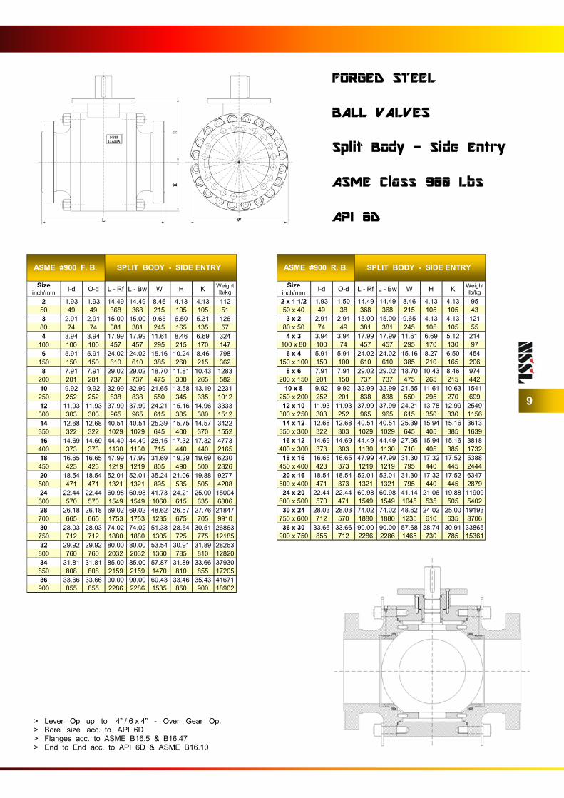
ASME #900 F. B. SPLIT BODY - SIDE ENTRY
Size inch/mm
I-d O-d L - Rf L - Bw W H K Weight
lb/kg
2 1.93 1.93 14.49 14.49 8.46 4.13 4.13 112
50 49 49 368 368 215 105 105 51
3 2.91 2.91 15.00 15.00 9.65 6.50 5.31 126
80 74 74 381 381 245 165 135 57
4 3.94 3.94 17.99 17.99 11.61 8.46 6.69 324
100 100 100 457 457 295 215 170 147
6 5.91 5.91 24.02 24.02 15.16 10.24 8.46 798
150 150 150 610 610 385 260 215 362
8 7.91 7.91 29.02 29.02 18.70 11.81 10.43 1283
200 201 201 737 737 475 300 265 582
10 9.92 9.92 32.99 32.99 21.65 13.58 13.19 2231
250 252 252 838 838 550 345 335 1012
12 11.93 11.93 37.99 37.99 24.21 15.16 14.96 3333
300 303 303 965 965 615 385 380 1512
14 12.68 12.68 40.51 40.51 25.39 15.75 14.57 3422
350 322 322 1029 1029 645 400 370 1552
16 14.69 14.69 44.49 44.49 28.15 17.32 17.32 4773
400 373 373 1130 1130 715 440 440 2165
18 16.65 16.65 47.99 47.99 31.69 19.29 19.69 6230
450 423 423 1219 1219 805 490 500 2826
20 18.54 18.54 52.01 52.01 35.24 21.06 19.88 9277
500 471 471 1321 1321 895 535 505 4208
24 22.44 22.44 60.98 60.98 41.73 24.21 25.00 15004
600 570 570 1549 1549 1060 615 635 6806
28 26.18 26.18 69.02 69.02 48.62 26.57 27.76 21847
700 665 665 1753 1753 1235 675 705 9910
30 28.03 28.03 74.02 74.02 51.38 28.54 30.51 26863
750 712 712 1880 1880 1305 725 775 12185
32 29.92 29.92 80.00 80.00 53.54 30.91 31.89 28263
800 760 760 2032 2032 1360 785 810 12820
34 31.81 31.81 85.00 85.00 57.87 31.89 33.66 37930
850 808 808 2159 2159 1470 810 855 17205
36 33.66 33.66 90.00 90.00 60.43 33.46 35.43 41671
900 855 855 2286 2286 1535 850 900 18902
ASME #900 R. B. SPLIT BODY - SIDE ENTRY
Size inch/mm
I-d O-d L - Rf L - Bw W H K Weight
lb/kg
2 x 1 1/2 1.93 1.50 14.49 14.49 8.46 4.13 4.13 95
50 x 40 49 38 368 368 215 105 105 43
3 x 2 2.91 2.91 15.00 15.00 9.65 4.13 4.13 121
80 x 50 74 49 381 381 245 105 105 55
4 x 3 3.94 3.94 17.99 17.99 11.61 6.69 5.12 214
100 x 80 100 74 457 457 295 170 130 97
6 x 4 5.91 5.91 24.02 24.02 15.16 8.27 6.50 454
150 x 100 150 100 610 610 385 210 165 206
8 x 6 7.91 7.91 29.02 29.02 18.70 10.43 8.46 974
200 x 150 201 150 737 737 475 265 215 442
10 x 8 9.92 9.92 32.99 32.99 21.65 11.61 10.63 1541
250 x 200 252 201 838 838 550 295 270 699
12 x 10 11.93 11.93 37.99 37.99 24.21 13.78 12.99 2549
300 x 250 303 252 965 965 615 350 330 1156
14 x 12 12.68 12.68 40.51 40.51 25.39 15.94 15.16 3613
350 x 300 322 303 1029 1029 645 405 385 1639
16 x 12 14.69 14.69 44.49 44.49 27.95 15.94 15.16 3818
400 x 300 373 303 1130 1130 710 405 385 1732
18 x 16 16.65 16.65 47.99 47.99 31.30 17.32 17.52 5388
450 x 400 423 373 1219 1219 795 440 445 2444
20 x 16 18.54 18.54 52.01 52.01 31.30 17.32 17.52 6347
500 x 400 471 373 1321 1321 795 440 445 2879
24 x 20 22.44 22.44 60.98 60.98 41.14 21.06 19.88 11909
600 x 500 570 471 1549 1549 1045 535 505 5402
30 x 24 28.03 28.03 74.02 74.02 48.62 24.02 25.00 19193
750 x 600 712 570 1880 1880 1235 610 635 8706
36 x 30 33.66 33.66 90.00 90.00 57.68 28.74 30.91 33865
900 x 750 855 712 2286 2286 1465 730 785 15361
9
FORGED STEEL BALL VALVES Split Body - Side Entry ASME Class 900 Lbs API 6D
> Lever Op. up to 4” / 6 x 4” - Over Gear Op. > Bore size acc. to API 6D > Flanges acc. to ASME B16.5 & B16.47 > End to End acc. to API 6D & ASME B16.10
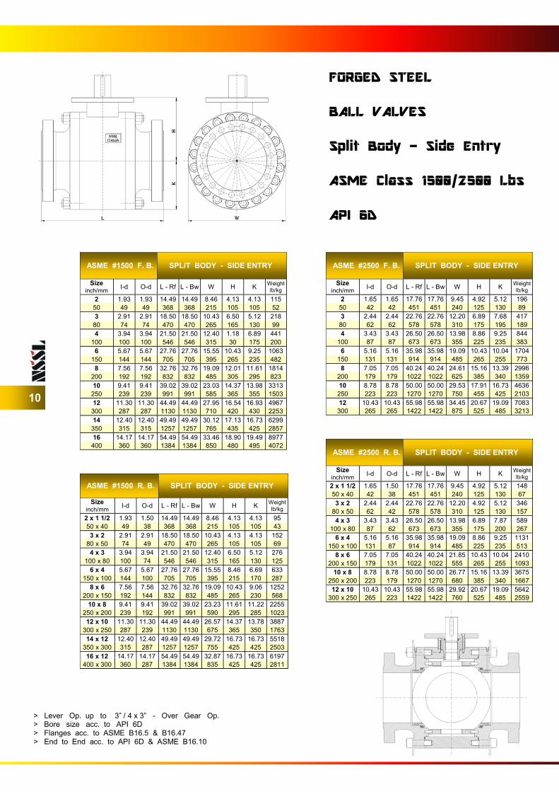
ASME #1500 F. B. SPLIT BODY - SIDE ENTRY
Size inch/mm
I-d O-d L - Rf L - Bw W H K Weight
lb/kg
2 1.93 1.93 14.49 14.49 8.46 4.13 4.13 115
50 49 49 368 368 215 105 105 52
3 2.91 2.91 18.50 18.50 10.43 6.50 5.12 218
80 74 74 470 470 265 165 130 99
4 3.94 3.94 21.50 21.50 12.40 1.18 6.89 441
100 100 100 546 546 315 30 175 200
6 5.67 5.67 27.76 27.76 15.55 10.43 9.25 1063
150 144 144 705 705 395 265 235 482
8 7.56 7.56 32.76 32.76 19.09 12.01 11.61 1814
200 192 192 832 832 485 305 295 823
10 9.41 9.41 39.02 39.02 23.03 14.37 13.98 3313
250 239 239 991 991 585 365 355 1503
12 11.30 11.30 44.49 44.49 27.95 16.54 16.93 4967
300 287 287 1130 1130 710 420 430 2253
14 12.40 12.40 49.49 49.49 30.12 17.13 16.73 6299
350 315 315 1257 1257 765 435 425 2857
16 14.17 14.17 54.49 54.49 33.46 18.90 19.49 8977
400 360 360 1384 1384 850 480 495 4072
ASME #2500 F. B. SPLIT BODY - SIDE ENTRY
Size inch/mm
I-d O-d L - Rf L - Bw W H K Weight
lb/kg
2 1.65 1.65 17.76 17.76 9.45 4.92 5.12 196
50 42 42 451 451 240 125 130 89
3 2.44 2.44 22.76 22.76 12.20 6.89 7.68 417
80 62 62 578 578 310 175 195 189
4 3.43 3.43 26.50 26.50 13.98 8.86 9.25 844
100 87 87 673 673 355 225 235 383
6 5.16 5.16 35.98 35.98 19.09 10.43 10.04 1704
150 131 131 914 914 485 265 255 773
8 7.05 7.05 40.24 40.24 24.61 15.16 13.39 2996
200 179 179 1022 1022 625 385 340 1359
10 8.78 8.78 50.00 50.00 29.53 17.91 16.73 4636
250 223 223 1270 1270 750 455 425 2103
12 10.43 10.43 55.98 55.98 34.45 20.67 19.09 7083
300 265 265 1422 1422 875 525 485 3213
10
FORGED STEEL BALL VALVES Split Body - Side Entry ASME Class 1500/2500 Lbs API 6D
> Lever Op. up to 3” / 4 x 3” - Over Gear Op. > Bore size acc. to API 6D > Flanges acc. to ASME B16.5 & B16.47 > End to End acc. to API 6D & ASME B16.10
ASME #1500 R. B. SPLIT BODY - SIDE ENTRY
Size inch/mm
I-d O-d L - Rf L - Bw W H K Weight
lb/kg
2 x 1 1/2 1.93 1.50 14.49 14.49 8.46 4.13 4.13 95
50 x 40 49 38 368 368 215 105 105 43
3 x 2 2.91 2.91 18.50 18.50 10.43 4.13 4.13 152
80 x 50 74 49 470 470 265 105 105 69
4 x 3 3.94 3.94 21.50 21.50 12.40 6.50 5.12 276
100 x 80 100 74 546 546 315 165 130 125
6 x 4 5.67 5.67 27.76 27.76 15.55 8.46 6.69 633
150 x 100 144 100 705 705 395 215 170 287
8 x 6 7.56 7.56 32.76 32.76 19.09 10.43 9.06 1252
200 x 150 192 144 832 832 485 265 230 568
10 x 8 9.41 9.41 39.02 39.02 23.23 11.61 11.22 2255
250 x 200 239 192 991 991 590 295 285 1023
12 x 10 11.30 11.30 44.49 44.49 26.57 14.37 13.78 3887
300 x 250 287 239 1130 1130 675 365 350 1763
14 x 12 12.40 12.40 49.49 49.49 29.72 16.73 16.73 5518
350 x 300 315 287 1257 1257 755 425 425 2503
16 x 12 14.17 14.17 54.49 54.49 32.87 16.73 16.73 6197
400 x 300 360 287 1384 1384 835 425 425 2811
ASME #2500 R. B. SPLIT BODY - SIDE ENTRY
Size inch/mm
I-d O-d L - Rf L - Bw W H K Weight
lb/kg
2 x 1 1/2 1.65 1.50 17.76 17.76 9.45 4.92 5.12 148
50 x 40 42 38 451 451 240 125 130 67
3 x 2 2.44 2.44 22.76 22.76 12.20 4.92 5.12 346
80 x 50 62 42 578 578 310 125 130 157
4 x 3 3.43 3.43 26.50 26.50 13.98 6.89 7.87 589
100 x 80 87 62 673 673 355 175 200 267
6 x 4 5.16 5.16 35.98 35.98 19.09 8.86 9.25 1131
150 x 100 131 87 914 914 485 225 235 513
8 x 6 7.05 7.05 40.24 40.24 21.85 10.43 10.04 2410
200 x 150 179 131 1022 1022 555 265 255 1093
10 x 8 8.78 8.78 50.00 50.00 26.77 15.16 13.39 3675
250 x 200 223 179 1270 1270 680 385 340 1667
12 x 10 10.43 10.43 55.98 55.98 29.92 20.67 19.09 5642
300 x 250 265 223 1422 1422 760 525 485 2559
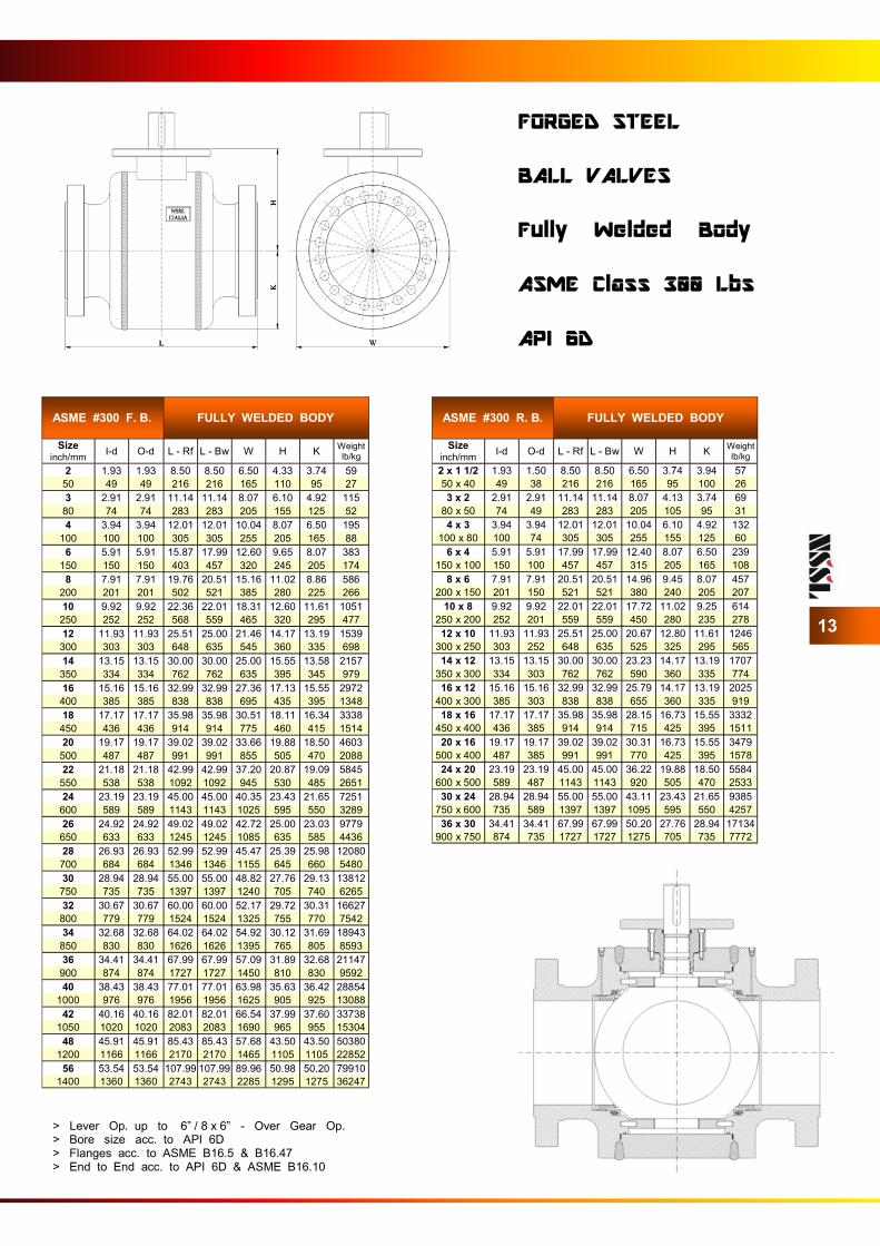
FULLY WELDED BALL VALVES

ASME #150 F. B. FULLY WELDED BODY
Size inch/mm
I-d O-d L - Rf L - Bw W H K Weight
lb/kg
2 1.93 1.93 7.01 8.50 6.10 4.13 4.13 59
50 49 49 178 216 155 105 105 27
3 2.91 2.91 7.99 11.14 7.68 6.10 4.92 115
80 74 74 203 283 195 155 125 52
4 3.94 3.94 9.02 12.01 9.25 7.68 6.50 184
100 100 100 229 305 235 195 165 84
6 5.91 5.91 15.51 17.99 12.01 9.65 7.28 339
150 150 150 394 457 305 245 185 154
8 7.91 7.91 17.99 20.51 15.55 11.02 8.86 534
200 201 201 457 521 395 280 225 242
10 9.92 9.92 20.98 22.01 18.31 12.60 10.83 806
250 252 252 533 559 465 320 275 366
12 11.93 11.93 24.02 25.00 21.46 13.19 12.01 1171
300 303 303 610 635 545 335 305 531
14 13.15 13.15 27.01 30.00 23.82 14.76 13.19 1602
350 334 334 686 762 605 375 335 727
16 15.16 15.16 30.00 32.99 26.57 15.94 13.98 2147
400 385 385 762 838 675 405 355 974
18 17.17 17.17 34.02 35.98 25.00 17.32 15.55 2555
450 436 436 864 914 635 440 395 1159
20 19.17 19.17 35.98 39.02 33.46 19.49 17.13 3759
500 487 487 914 991 850 495 435 1705
22 21.18 21.18 39.02 42.99 36.81 20.67 18.70 4943
550 538 538 991 1092 935 525 475 2242
24 23.19 23.19 42.01 45.00 39.76 23.03 20.67 6503
600 589 589 1067 1143 1010 585 525 2950
26 24.92 24.92 45.00 49.02 41.93 24.61 22.24 7739
650 633 633 1143 1245 1065 625 565 3510
28 26.93 26.93 48.98 53.03 44.69 25.59 26.18 9414
700 684 684 1244 1347 1135 650 665 4270
30 28.94 28.94 50.98 55.00 38.98 27.36 27.76 10933
750 735 735 1295 1397 990 695 705 4959
32 30.67 30.67 53.98 60.00 51.38 29.33 29.53 14231
800 779 779 1371 1524 1305 745 750 6455
34 32.68 32.68 57.99 64.02 54.13 29.92 30.51 16744
850 830 830 1473 1626 1375 760 775 7595
36 34.41 34.41 60.00 68.03 56.50 31.89 31.89 18420
900 874 874 1524 1728 1435 810 810 8355
40 38.43 38.43 69.02 77.01 62.80 35.63 35.63 26284
1000 976 976 1753 1956 1595 905 905 11923
42 40.16 40.16 73.03 82.01 65.35 37.01 36.61 29886
1050 1020 1020 1855 2083 1660 940 930 13557
48 45.91 45.91 84.02 94.02 75.79 43.11 41.93 45845
1200 1166 1166 2134 2388 1925 1095 1065 20796
56 53.54 53.54 97.99 97.99 89.17 51.38 49.41 71397
1400 1360 1360 2489 2489 2265 1305 1255 32386
ASME #150 R. B. FULLY WELDED BODY
Size inch/mm
I-d O-d L - Rf L - Bw W H K Weight
lb/kg
2 x 1 1/2 1.93 1.50 7.01 8.50 6.10 3.74 3.94 57
50 x 40 49 38 178 216 155 95 100 26
3 x 2 2.91 2.91 7.99 11.14 7.68 4.13 4.13 67
80 x 50 74 49 203 283 195 105 105 30
4 x 3 3.94 3.94 9.02 12.01 9.06 6.10 5.12 130
100 x 80 100 74 229 305 230 155 130 59
6 x 4 5.91 5.91 15.51 17.99 11.02 7.87 6.50 212
150 x 100 150 100 394 457 280 200 165 96
8 x 6 7.91 7.91 17.99 20.51 13.58 10.04 7.28 390
200 x 150 201 150 457 521 345 255 185 177
10 x 8 9.92 9.92 20.98 22.01 15.94 11.22 8.86 614
250 x 200 252 201 533 559 405 285 225 278
12 x 10 11.93 11.93 24.02 25.00 19.09 12.80 11.22 974
300 x 250 303 252 610 635 485 325 285 442
14 x 12 13.15 13.15 27.01 30.00 21.06 13.58 11.81 1288
350 x 300 334 303 686 762 535 345 300 584
16 x 12 15.16 15.16 30.00 32.99 23.62 13.58 12.01 1464
400 x 300 385 303 762 838 600 345 305 664
18 x 16 17.17 17.17 34.02 35.98 25.00 16.54 13.78 2226
450 x 400 436 385 864 914 635 420 350 1010
20 x 16 19.17 19.17 35.98 39.02 27.76 16.34 13.98 2327
500 x 400 487 385 914 991 705 415 355 1055
24 x 20 23.19 23.19 42.01 45.00 32.09 19.49 17.13 4130
600 x 500 589 487 1067 1143 815 495 435 1873
30 x 24 28.94 28.94 50.98 55.00 38.78 23.03 20.28 6805
750 x 600 735 589 1295 1397 985 585 515 3087
36 x 30 34.41 34.41 60.00 68.03 46.26 27.36 27.76 13226
900 x 750 874 735 1524 1728 1175 695 705 5999
12
FORGED STEEL BALL VALVES Fully Welded Body ASME Class 150 Lbs API 6D
> Lever Op. up to 6” / 8 x 6” - Over Gear Op. > Bore size acc. to API 6D > Flanges acc. to ASME B16.5 & B16.47 > End to End acc. to API 6D & ASME B16.10
ASME #300 F. B. FULLY WELDED BODY
Size inch/mm
I-d O-d L - Rf L - Bw W H K Weight
lb/kg
2 1.93 1.93 8.50 8.50 6.50 4.33 3.74 59
50 49 49 216 216 165 110 95 27
3 2.91 2.91 11.14 11.14 8.07 6.10 4.92 115
80 74 74 283 283 205 155 125 52
4 3.94 3.94 12.01 12.01 10.04 8.07 6.50 195
100 100 100 305 305 255 205 165 88
6 5.91 5.91 15.87 17.99 12.60 9.65 8.07 383
150 150 150 403 457 320 245 205 174
8 7.91 7.91 19.76 20.51 15.16 11.02 8.86 586
200 201 201 502 521 385 280 225 266
10 9.92 9.92 22.36 22.01 18.31 12.60 11.61 1051
250 252 252 568 559 465 320 295 477
12 11.93 11.93 25.51 25.00 21.46 14.17 13.19 1539
300 303 303 648 635 545 360 335 698
14 13.15 13.15 30.00 30.00 25.00 15.55 13.58 2157
350 334 334 762 762 635 395 345 979
16 15.16 15.16 32.99 32.99 27.36 17.13 15.55 2972
400 385 385 838 838 695 435 395 1348
18 17.17 17.17 35.98 35.98 30.51 18.11 16.34 3338
450 436 436 914 914 775 460 415 1514
20 19.17 19.17 39.02 39.02 33.66 19.88 18.50 4603
500 487 487 991 991 855 505 470 2088
22 21.18 21.18 42.99 42.99 37.20 20.87 19.09 5845
550 538 538 1092 1092 945 530 485 2651
24 23.19 23.19 45.00 45.00 40.35 23.43 21.65 7251
600 589 589 1143 1143 1025 595 550 3289
26 24.92 24.92 49.02 49.02 42.72 25.00 23.03 9779
650 633 633 1245 1245 1085 635 585 4436
28 26.93 26.93 52.99 52.99 45.47 25.39 25.98 12080
700 684 684 1346 1346 1155 645 660 5480
30 28.94 28.94 55.00 55.00 48.82 27.76 29.13 13812
750 735 735 1397 1397 1240 705 740 6265
32 30.67 30.67 60.00 60.00 52.17 29.72 30.31 16627
800 779 779 1524 1524 1325 755 770 7542
34 32.68 32.68 64.02 64.02 54.92 30.12 31.69 18943
850 830 830 1626 1626 1395 765 805 8593
36 34.41 34.41 67.99 67.99 57.09 31.89 32.68 21147
900 874 874 1727 1727 1450 810 830 9592
40 38.43 38.43 77.01 77.01 63.98 35.63 36.42 28854
1000 976 976 1956 1956 1625 905 925 13088
42 40.16 40.16 82.01 82.01 66.54 37.99 37.60 33738
1050 1020 1020 2083 2083 1690 965 955 15304
48 45.91 45.91 85.43 85.43 57.68 43.50 43.50 50380
1200 1166 1166 2170 2170 1465 1105 1105 22852
56 53.54 53.54 107.99 107.99 89.96 50.98 50.20 79910
1400 1360 1360 2743 2743 2285 1295 1275 36247
ASME #300 R. B. FULLY WELDED BODY
Size inch/mm
I-d O-d L - Rf L - Bw W H K Weight
lb/kg
2 x 1 1/2 1.93 1.50 8.50 8.50 6.50 3.74 3.94 57
50 x 40 49 38 216 216 165 95 100 26
3 x 2 2.91 2.91 11.14 11.14 8.07 4.13 3.74 69
80 x 50 74 49 283 283 205 105 95 31
4 x 3 3.94 3.94 12.01 12.01 10.04 6.10 4.92 132
100 x 80 100 74 305 305 255 155 125 60
6 x 4 5.91 5.91 17.99 17.99 12.40 8.07 6.50 239
150 x 100 150 100 457 457 315 205 165 108
8 x 6 7.91 7.91 20.51 20.51 14.96 9.45 8.07 457
200 x 150 201 150 521 521 380 240 205 207
10 x 8 9.92 9.92 22.01 22.01 17.72 11.02 9.25 614
250 x 200 252 201 559 559 450 280 235 278
12 x 10 11.93 11.93 25.51 25.00 20.67 12.80 11.61 1246
300 x 250 303 252 648 635 525 325 295 565
14 x 12 13.15 13.15 30.00 30.00 23.23 14.17 13.19 1707
350 x 300 334 303 762 762 590 360 335 774
16 x 12 15.16 15.16 32.99 32.99 25.79 14.17 13.19 2025
400 x 300 385 303 838 838 655 360 335 919
18 x 16 17.17 17.17 35.98 35.98 28.15 16.73 15.55 3332
450 x 400 436 385 914 914 715 425 395 1511
20 x 16 19.17 19.17 39.02 39.02 30.31 16.73 15.55 3479
500 x 400 487 385 991 991 770 425 395 1578
24 x 20 23.19 23.19 45.00 45.00 36.22 19.88 18.50 5584
600 x 500 589 487 1143 1143 920 505 470 2533
30 x 24 28.94 28.94 55.00 55.00 43.11 23.43 21.65 9385
750 x 600 735 589 1397 1397 1095 595 550 4257
36 x 30 34.41 34.41 67.99 67.99 50.20 27.76 28.94 17134
900 x 750 874 735 1727 1727 1275 705 735 7772
13
FORGED STEEL BALL VALVES Fully Welded Body ASME Class 300 Lbs API 6D
> Lever Op. up to 6” / 8 x 6” - Over Gear Op. > Bore size acc. to API 6D > Flanges acc. to ASME B16.5 & B16.47 > End to End acc. to API 6D & ASME B16.10
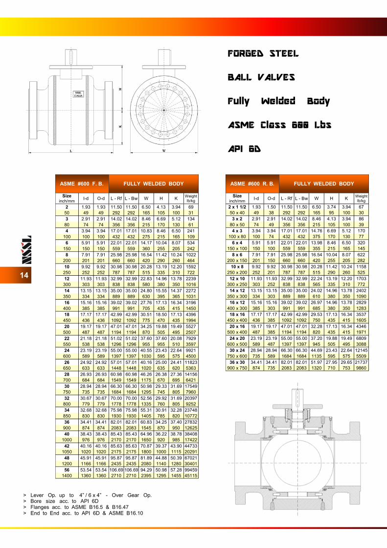
ASME #600 F. B. FULLY WELDED BODY
Size inch/mm
I-d O-d L - Rf L - Bw W H K Weight
lb/kg
2 1.93 1.93 11.50 11.50 6.50 4.13 3.94 69
50 49 49 292 292 165 105 100 31
3 2.91 2.91 14.02 14.02 8.46 6.69 5.12 134
80 74 74 356 356 215 170 130 61
4 3.94 3.94 17.01 17.01 10.83 8.46 6.50 241
100 100 100 432 432 275 215 165 109
6 5.91 5.91 22.01 22.01 14.17 10.04 8.07 534
150 150 150 559 559 360 255 205 242
8 7.91 7.91 25.98 25.98 16.54 11.42 10.24 1022
200 201 201 660 660 420 290 260 464
10 9.92 9.92 30.98 30.98 20.28 13.19 12.20 1592
250 252 252 787 787 515 335 310 722
12 11.93 11.93 32.99 32.99 22.83 14.96 13.78 2239
300 303 303 838 838 580 380 350 1016
14 13.15 13.15 35.00 35.00 24.80 15.55 14.37 2272
350 334 334 889 889 630 395 365 1031
16 15.16 15.16 39.02 39.02 27.76 17.13 16.34 3196
400 385 385 991 991 705 435 415 1450
18 17.17 17.17 42.99 42.99 30.51 18.50 17.13 4396
450 436 436 1092 1092 775 470 435 1994
20 19.17 19.17 47.01 47.01 34.25 19.88 19.49 5527
500 487 487 1194 1194 870 505 495 2507
22 21.18 21.18 51.02 51.02 37.60 37.60 20.08 7929
550 538 538 1296 1296 955 955 510 3597
24 23.19 23.19 55.00 55.00 40.55 23.43 22.64 9921
600 589 589 1397 1397 1030 595 575 4500
26 24.92 24.92 57.01 57.01 40.16 25.00 24.41 11823
650 633 633 1448 1448 1020 635 620 5363
28 26.93 26.93 60.98 60.98 46.26 26.38 27.36 14156
700 684 684 1549 1549 1175 670 695 6421
30 28.94 28.94 66.30 66.30 50.98 29.33 31.69 17549
750 735 735 1684 1684 1295 745 805 7960
32 30.67 30.67 70.00 70.00 52.56 29.92 31.69 20397
800 779 779 1778 1778 1335 760 805 9252
34 32.68 32.68 75.98 75.98 55.31 30.91 32.28 23748
850 830 830 1930 1930 1405 785 820 10772
36 34.41 34.41 82.01 82.01 60.83 34.25 37.40 27832
900 874 874 2083 2083 1545 870 950 12625
40 38.43 38.43 85.43 85.43 64.96 36.22 38.78 38408
1000 976 976 2170 2170 1650 920 985 17422
42 40.16 40.16 85.63 85.63 70.87 39.37 43.90 44733
1050 1020 1020 2175 2175 1800 1000 1115 20291
48 45.91 45.91 95.87 95.87 81.89 44.88 50.39 67021
1200 1166 1166 2435 2435 2080 1140 1280 30401
56 53.54 53.54 106.69 106.69 94.29 50.98 57.28 99459
1400 1360 1360 2710 2710 2395 1295 1455 45115
ASME #600 R. B. FULLY WELDED BODY
Size inch/mm
I-d O-d L - Rf L - Bw W H K Weight
lb/kg
2 x 1 1/2 1.93 1.50 11.50 11.50 6.50 3.74 3.94 67
50 x 40 49 38 292 292 165 95 100 30
3 x 2 2.91 2.91 14.02 14.02 8.46 4.13 3.94 86
80 x 50 74 49 356 356 215 105 100 39
4 x 3 3.94 3.94 17.01 17.01 14.76 6.69 5.12 170
100 x 80 100 74 432 432 375 170 130 77
6 x 4 5.91 5.91 22.01 22.01 13.98 8.46 6.50 320
150 x 100 150 100 559 559 355 215 165 145
8 x 6 7.91 7.91 25.98 25.98 16.54 10.04 8.07 622
200 x 150 201 150 660 660 420 255 205 282
10 x 8 9.92 9.92 30.98 30.98 20.28 11.42 10.24 1158
250 x 200 252 201 787 787 515 290 260 525
12 x 10 11.93 11.93 32.99 32.99 22.24 13.19 12.20 1703
300 x 250 303 252 838 838 565 335 310 772
14 x 12 13.15 13.15 35.00 35.00 24.02 14.96 13.78 2402
350 x 300 334 303 889 889 610 380 350 1090
16 x 12 15.16 15.16 39.02 39.02 26.97 14.96 13.78 2829
400 x 300 385 303 991 991 685 380 350 1283
18 x 16 17.17 17.17 42.99 42.99 29.53 17.13 16.34 3537
450 x 400 436 385 1092 1092 750 435 415 1605
20 x 16 19.17 19.17 47.01 47.01 32.28 17.13 16.34 4346
500 x 400 487 385 1194 1194 820 435 415 1971
24 x 20 23.19 23.19 55.00 55.00 37.20 19.88 19.49 6809
600 x 500 589 487 1397 1397 945 505 495 3088
30 x 24 28.94 28.94 66.30 66.30 44.69 23.43 22.64 12145
750 x 600 735 589 1684 1684 1135 595 575 5509
36 x 30 34.41 34.41 82.01 82.01 51.97 27.95 29.65 21737
900 x 750 874 735 2083 2083 1320 710 753 9860
14
FORGED STEEL BALL VALVES Fully Welded Body ASME Class 600 Lbs API 6D
> Lever Op. up to 4” / 6 x 4” - Over Gear Op. > Bore size acc. to API 6D > Flanges acc. to ASME B16.5 & B16.47 > End to End acc. to API 6D & ASME B16.10
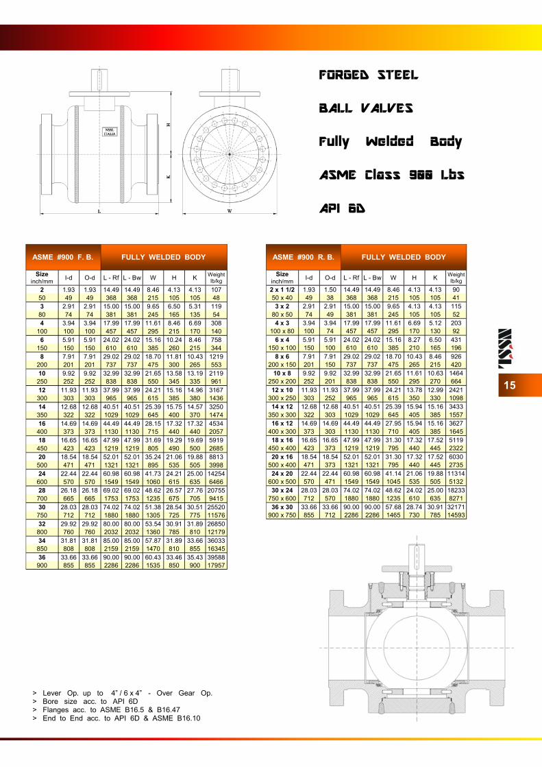
ASME #900 F. B. FULLY WELDED BODY
Size inch/mm
I-d O-d L - Rf L - Bw W H K Weight
lb/kg
2 1.93 1.93 14.49 14.49 8.46 4.13 4.13 107
50 49 49 368 368 215 105 105 48
3 2.91 2.91 15.00 15.00 9.65 6.50 5.31 119
80 74 74 381 381 245 165 135 54
4 3.94 3.94 17.99 17.99 11.61 8.46 6.69 308
100 100 100 457 457 295 215 170 140
6 5.91 5.91 24.02 24.02 15.16 10.24 8.46 758
150 150 150 610 610 385 260 215 344
8 7.91 7.91 29.02 29.02 18.70 11.81 10.43 1219
200 201 201 737 737 475 300 265 553
10 9.92 9.92 32.99 32.99 21.65 13.58 13.19 2119
250 252 252 838 838 550 345 335 961
12 11.93 11.93 37.99 37.99 24.21 15.16 14.96 3167
300 303 303 965 965 615 385 380 1436
14 12.68 12.68 40.51 40.51 25.39 15.75 14.57 3250
350 322 322 1029 1029 645 400 370 1474
16 14.69 14.69 44.49 44.49 28.15 17.32 17.32 4534
400 373 373 1130 1130 715 440 440 2057
18 16.65 16.65 47.99 47.99 31.69 19.29 19.69 5919
450 423 423 1219 1219 805 490 500 2685
20 18.54 18.54 52.01 52.01 35.24 21.06 19.88 8813
500 471 471 1321 1321 895 535 505 3998
24 22.44 22.44 60.98 60.98 41.73 24.21 25.00 14254
600 570 570 1549 1549 1060 615 635 6466
28 26.18 26.18 69.02 69.02 48.62 26.57 27.76 20755
700 665 665 1753 1753 1235 675 705 9415
30 28.03 28.03 74.02 74.02 51.38 28.54 30.51 25520
750 712 712 1880 1880 1305 725 775 11576
32 29.92 29.92 80.00 80.00 53.54 30.91 31.89 26850
800 760 760 2032 2032 1360 785 810 12179
34 31.81 31.81 85.00 85.00 57.87 31.89 33.66 36033
850 808 808 2159 2159 1470 810 855 16345
36 33.66 33.66 90.00 90.00 60.43 33.46 35.43 39588
900 855 855 2286 2286 1535 850 900 17957
ASME #900 R. B. FULLY WELDED BODY
Size inch/mm
I-d O-d L - Rf L - Bw W H K Weight
lb/kg
2 x 1 1/2 1.93 1.50 14.49 14.49 8.46 4.13 4.13 90
50 x 40 49 38 368 368 215 105 105 41
3 x 2 2.91 2.91 15.00 15.00 9.65 4.13 4.13 115
80 x 50 74 49 381 381 245 105 105 52
4 x 3 3.94 3.94 17.99 17.99 11.61 6.69 5.12 203
100 x 80 100 74 457 457 295 170 130 92
6 x 4 5.91 5.91 24.02 24.02 15.16 8.27 6.50 431
150 x 100 150 100 610 610 385 210 165 196
8 x 6 7.91 7.91 29.02 29.02 18.70 10.43 8.46 926
200 x 150 201 150 737 737 475 265 215 420
10 x 8 9.92 9.92 32.99 32.99 21.65 11.61 10.63 1464
250 x 200 252 201 838 838 550 295 270 664
12 x 10 11.93 11.93 37.99 37.99 24.21 13.78 12.99 2421
300 x 250 303 252 965 965 615 350 330 1098
14 x 12 12.68 12.68 40.51 40.51 25.39 15.94 15.16 3433
350 x 300 322 303 1029 1029 645 405 385 1557
16 x 12 14.69 14.69 44.49 44.49 27.95 15.94 15.16 3627
400 x 300 373 303 1130 1130 710 405 385 1645
18 x 16 16.65 16.65 47.99 47.99 31.30 17.32 17.52 5119
450 x 400 423 373 1219 1219 795 440 445 2322
20 x 16 18.54 18.54 52.01 52.01 31.30 17.32 17.52 6030
500 x 400 471 373 1321 1321 795 440 445 2735
24 x 20 22.44 22.44 60.98 60.98 41.14 21.06 19.88 11314
600 x 500 570 471 1549 1549 1045 535 505 5132
30 x 24 28.03 28.03 74.02 74.02 48.62 24.02 25.00 18233
750 x 600 712 570 1880 1880 1235 610 635 8271
36 x 30 33.66 33.66 90.00 90.00 57.68 28.74 30.91 32171
900 x 750 855 712 2286 2286 1465 730 785 14593
15
FORGED STEEL BALL VALVES Fully Welded Body ASME Class 900 Lbs API 6D
> Lever Op. up to 4” / 6 x 4” - Over Gear Op. > Bore size acc. to API 6D > Flanges acc. to ASME B16.5 & B16.47 > End to End acc. to API 6D & ASME B16.10
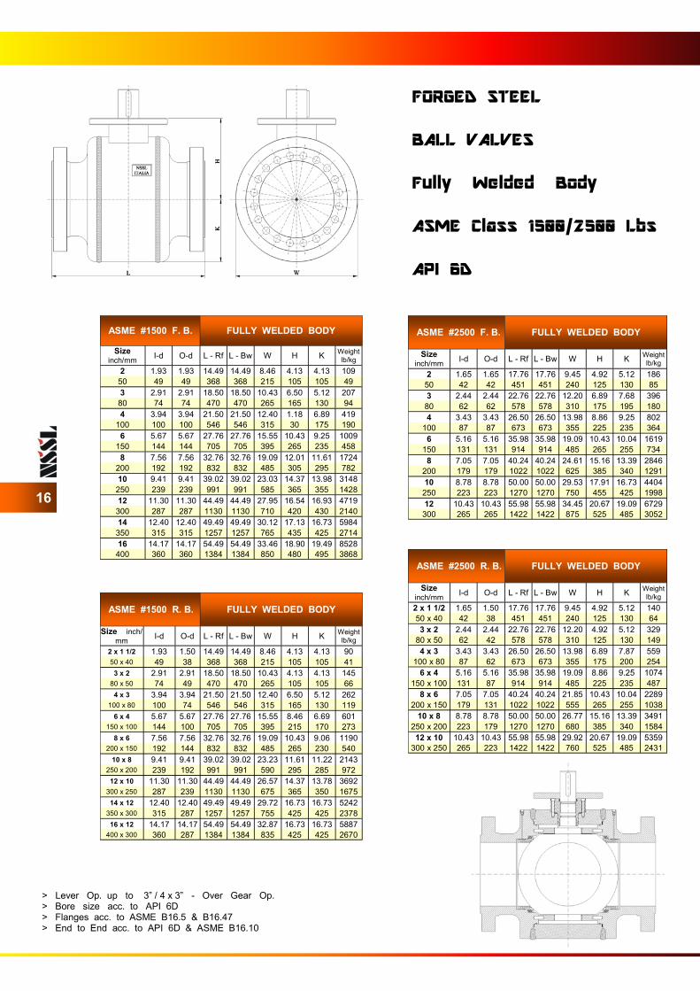
ASME #1500 F. B. FULLY WELDED BODY
Size inch/mm
I-d O-d L - Rf L - Bw W H K Weight
lb/kg
2 1.93 1.93 14.49 14.49 8.46 4.13 4.13 109
50 49 49 368 368 215 105 105 49
3 2.91 2.91 18.50 18.50 10.43 6.50 5.12 207
80 74 74 470 470 265 165 130 94
4 3.94 3.94 21.50 21.50 12.40 1.18 6.89 419
100 100 100 546 546 315 30 175 190
6 5.67 5.67 27.76 27.76 15.55 10.43 9.25 1009
150 144 144 705 705 395 265 235 458
8 7.56 7.56 32.76 32.76 19.09 12.01 11.61 1724
200 192 192 832 832 485 305 295 782
10 9.41 9.41 39.02 39.02 23.03 14.37 13.98 3148
250 239 239 991 991 585 365 355 1428
12 11.30 11.30 44.49 44.49 27.95 16.54 16.93 4719
300 287 287 1130 1130 710 420 430 2140
14 12.40 12.40 49.49 49.49 30.12 17.13 16.73 5984
350 315 315 1257 1257 765 435 425 2714
16 14.17 14.17 54.49 54.49 33.46 18.90 19.49 8528
400 360 360 1384 1384 850 480 495 3868
ASME #2500 F. B. FULLY WELDED BODY
Size inch/mm
I-d O-d L - Rf L - Bw W H K Weight
lb/kg
2 1.65 1.65 17.76 17.76 9.45 4.92 5.12 186
50 42 42 451 451 240 125 130 85
3 2.44 2.44 22.76 22.76 12.20 6.89 7.68 396
80 62 62 578 578 310 175 195 180
4 3.43 3.43 26.50 26.50 13.98 8.86 9.25 802
100 87 87 673 673 355 225 235 364
6 5.16 5.16 35.98 35.98 19.09 10.43 10.04 1619
150 131 131 914 914 485 265 255 734
8 7.05 7.05 40.24 40.24 24.61 15.16 13.39 2846
200 179 179 1022 1022 625 385 340 1291
10 8.78 8.78 50.00 50.00 29.53 17.91 16.73 4404
250 223 223 1270 1270 750 455 425 1998
12 10.43 10.43 55.98 55.98 34.45 20.67 19.09 6729
300 265 265 1422 1422 875 525 485 3052
16
FORGED STEEL BALL VALVES Fully Welded Body ASME Class 1500/2500 Lbs API 6D
> Lever Op. up to 3” / 4 x 3” - Over Gear Op. > Bore size acc. to API 6D > Flanges acc. to ASME B16.5 & B16.47 > End to End acc. to API 6D & ASME B16.10
ASME #1500 R. B. FULLY WELDED BODY
Size inch/
mm I-d O-d L - Rf L - Bw W H K
Weight
lb/kg
2 x 1 1/2 1.93 1.50 14.49 14.49 8.46 4.13 4.13 90
50 x 40 49 38 368 368 215 105 105 41
3 x 2 2.91 2.91 18.50 18.50 10.43 4.13 4.13 145
80 x 50 74 49 470 470 265 105 105 66
4 x 3 3.94 3.94 21.50 21.50 12.40 6.50 5.12 262
100 x 80 100 74 546 546 315 165 130 119
6 x 4 5.67 5.67 27.76 27.76 15.55 8.46 6.69 601
150 x 100 144 100 705 705 395 215 170 273
8 x 6 7.56 7.56 32.76 32.76 19.09 10.43 9.06 1190
200 x 150 192 144 832 832 485 265 230 540
10 x 8 9.41 9.41 39.02 39.02 23.23 11.61 11.22 2143
250 x 200 239 192 991 991 590 295 285 972
12 x 10 11.30 11.30 44.49 44.49 26.57 14.37 13.78 3692
300 x 250 287 239 1130 1130 675 365 350 1675
14 x 12 12.40 12.40 49.49 49.49 29.72 16.73 16.73 5242
350 x 300 315 287 1257 1257 755 425 425 2378
16 x 12 14.17 14.17 54.49 54.49 32.87 16.73 16.73 5887
400 x 300 360 287 1384 1384 835 425 425 2670
ASME #2500 R. B. FULLY WELDED BODY
Size inch/mm
I-d O-d L - Rf L - Bw W H K Weight
lb/kg
2 x 1 1/2 1.65 1.50 17.76 17.76 9.45 4.92 5.12 140
50 x 40 42 38 451 451 240 125 130 64
3 x 2 2.44 2.44 22.76 22.76 12.20 4.92 5.12 329
80 x 50 62 42 578 578 310 125 130 149
4 x 3 3.43 3.43 26.50 26.50 13.98 6.89 7.87 559
100 x 80 87 62 673 673 355 175 200 254
6 x 4 5.16 5.16 35.98 35.98 19.09 8.86 9.25 1074
150 x 100 131 87 914 914 485 225 235 487
8 x 6 7.05 7.05 40.24 40.24 21.85 10.43 10.04 2289
200 x 150 179 131 1022 1022 555 265 255 1038
10 x 8 8.78 8.78 50.00 50.00 26.77 15.16 13.39 3491
250 x 200 223 179 1270 1270 680 385 340 1584
12 x 10 10.43 10.43 55.98 55.98 29.92 20.67 19.09 5359
300 x 250 265 223 1422 1422 760 525 485 2431
TOP ENTRY BALL VALVES
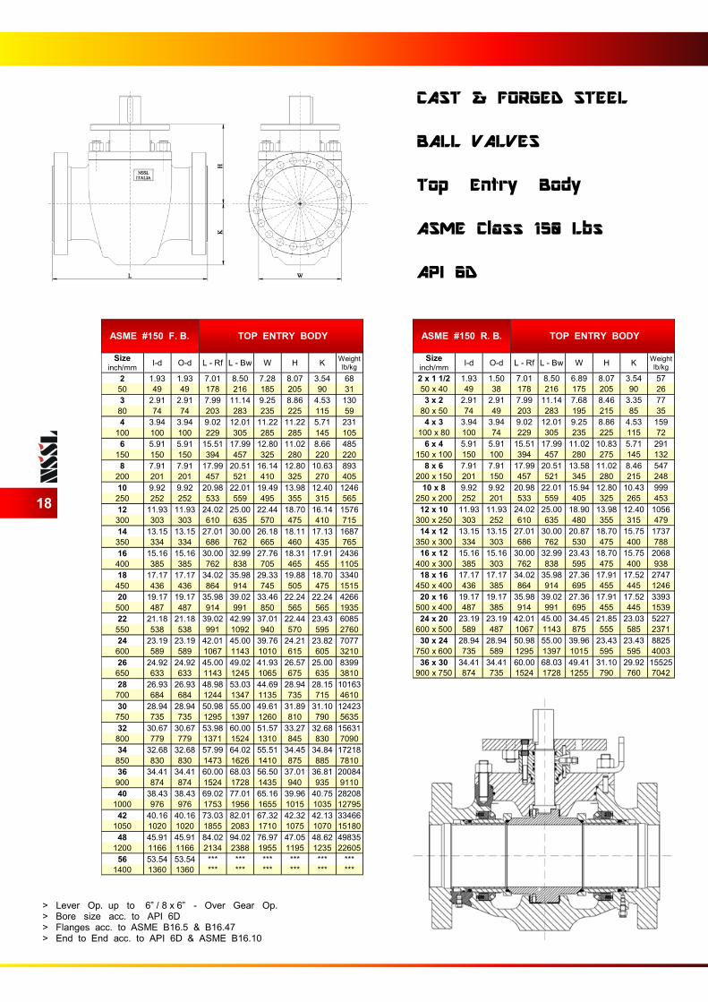
ASME #150 F. B. TOP ENTRY BODY
Size inch/mm
I-d O-d L - Rf L - Bw W H K Weight
lb/kg
2 1.93 1.93 7.01 8.50 7.28 8.07 3.54 68
50 49 49 178 216 185 205 90 31
3 2.91 2.91 7.99 11.14 9.25 8.86 4.53 130
80 74 74 203 283 235 225 115 59
4 3.94 3.94 9.02 12.01 11.22 11.22 5.71 231
100 100 100 229 305 285 285 145 105
6 5.91 5.91 15.51 17.99 12.80 11.02 8.66 485
150 150 150 394 457 325 280 220 220
8 7.91 7.91 17.99 20.51 16.14 12.80 10.63 893
200 201 201 457 521 410 325 270 405
10 9.92 9.92 20.98 22.01 19.49 13.98 12.40 1246
250 252 252 533 559 495 355 315 565
12 11.93 11.93 24.02 25.00 22.44 18.70 16.14 1576
300 303 303 610 635 570 475 410 715
14 13.15 13.15 27.01 30.00 26.18 18.11 17.13 1687
350 334 334 686 762 665 460 435 765
16 15.16 15.16 30.00 32.99 27.76 18.31 17.91 2436
400 385 385 762 838 705 465 455 1105
18 17.17 17.17 34.02 35.98 29.33 19.88 18.70 3340
450 436 436 864 914 745 505 475 1515
20 19.17 19.17 35.98 39.02 33.46 22.24 22.24 4266
500 487 487 914 991 850 565 565 1935
22 21.18 21.18 39.02 42.99 37.01 22.44 23.43 6085
550 538 538 991 1092 940 570 595 2760
24 23.19 23.19 42.01 45.00 39.76 24.21 23.82 7077
600 589 589 1067 1143 1010 615 605 3210
26 24.92 24.92 45.00 49.02 41.93 26.57 25.00 8399
650 633 633 1143 1245 1065 675 635 3810
28 26.93 26.93 48.98 53.03 44.69 28.94 28.15 10163
700 684 684 1244 1347 1135 735 715 4610
30 28.94 28.94 50.98 55.00 49.61 31.89 31.10 12423
750 735 735 1295 1397 1260 810 790 5635
32 30.67 30.67 53.98 60.00 51.57 33.27 32.68 15631
800 779 779 1371 1524 1310 845 830 7090
34 32.68 32.68 57.99 64.02 55.51 34.45 34.84 17218
850 830 830 1473 1626 1410 875 885 7810
36 34.41 34.41 60.00 68.03 56.50 37.01 36.81 20084
900 874 874 1524 1728 1435 940 935 9110
40 38.43 38.43 69.02 77.01 65.16 39.96 40.75 28208
1000 976 976 1753 1956 1655 1015 1035 12795
42 40.16 40.16 73.03 82.01 67.32 42.32 42.13 33466
1050 1020 1020 1855 2083 1710 1075 1070 15180
48 45.91 45.91 84.02 94.02 76.97 47.05 48.62 49835
1200 1166 1166 2134 2388 1955 1195 1235 22605
56 53.54 53.54 *** *** *** *** *** ***
1400 1360 1360 *** *** *** *** *** ***
ASME #150 R. B. TOP ENTRY BODY
Size inch/mm
I-d O-d L - Rf L - Bw W H K Weight
lb/kg
2 x 1 1/2 1.93 1.50 7.01 8.50 6.89 8.07 3.54 57
50 x 40 49 38 178 216 175 205 90 26
3 x 2 2.91 2.91 7.99 11.14 7.68 8.46 3.35 77
80 x 50 74 49 203 283 195 215 85 35
4 x 3 3.94 3.94 9.02 12.01 9.25 8.86 4.53 159
100 x 80 100 74 229 305 235 225 115 72
6 x 4 5.91 5.91 15.51 17.99 11.02 10.83 5.71 291
150 x 100 150 100 394 457 280 275 145 132
8 x 6 7.91 7.91 17.99 20.51 13.58 11.02 8.46 547
200 x 150 201 150 457 521 345 280 215 248
10 x 8 9.92 9.92 20.98 22.01 15.94 12.80 10.43 999
250 x 200 252 201 533 559 405 325 265 453
12 x 10 11.93 11.93 24.02 25.00 18.90 13.98 12.40 1056
300 x 250 303 252 610 635 480 355 315 479
14 x 12 13.15 13.15 27.01 30.00 20.87 18.70 15.75 1737
350 x 300 334 303 686 762 530 475 400 788
16 x 12 15.16 15.16 30.00 32.99 23.43 18.70 15.75 2068
400 x 300 385 303 762 838 595 475 400 938
18 x 16 17.17 17.17 34.02 35.98 27.36 17.91 17.52 2747
450 x 400 436 385 864 914 695 455 445 1246
20 x 16 19.17 19.17 35.98 39.02 27.36 17.91 17.52 3393
500 x 400 487 385 914 991 695 455 445 1539
24 x 20 23.19 23.19 42.01 45.00 34.45 21.85 23.03 5227
600 x 500 589 487 1067 1143 875 555 585 2371
30 x 24 28.94 28.94 50.98 55.00 39.96 23.43 23.43 8825
750 x 600 735 589 1295 1397 1015 595 595 4003
36 x 30 34.41 34.41 60.00 68.03 49.41 31.10 29.92 15525
900 x 750 874 735 1524 1728 1255 790 760 7042
18
CAST & FORGED STEEL BALL VALVES Top Entry Body ASME Class 150 Lbs API 6D
> Lever Op. up to 6” / 8 x 6” - Over Gear Op. > Bore size acc. to API 6D > Flanges acc. to ASME B16.5 & B16.47 > End to End acc. to API 6D & ASME B16.10
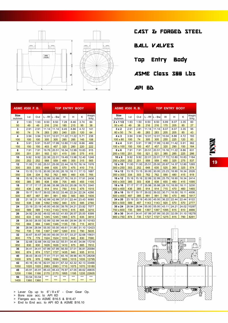
ASME #300 F. B. TOP ENTRY BODY
Size inch/mm
I-d O-d L - Rf L - Bw W H K Weight
lb/kg
2 1.93 1.93 8.50 8.50 7.28 8.46 3.74 84
50 49 49 216 216 185 215 95 38
3 2.91 2.91 11.14 11.14 9.45 8.86 4.72 141
80 74 74 283 283 240 225 120 64
4 3.94 3.94 12.01 12.01 11.22 11.22 5.71 238
100 100 100 305 305 285 285 145 108
6 5.91 5.91 15.87 17.99 12.80 11.02 8.66 489
150 150 150 403 457 325 280 220 222
8 7.91 7.91 19.76 20.51 16.34 12.99 10.83 915
200 201 201 502 521 415 330 275 415
10 9.92 9.92 22.36 22.01 19.49 13.98 12.40 1246
250 252 252 568 559 495 355 315 565
12 11.93 11.93 25.51 25.00 22.44 18.70 16.14 1576
300 303 303 648 635 570 475 410 715
14 13.15 13.15 30.00 30.00 26.18 18.11 17.13 1687
350 334 334 762 762 665 460 435 765
16 15.16 15.16 32.99 32.99 27.76 18.31 17.91 2436
400 385 385 838 838 705 465 455 1105
18 17.17 17.17 35.98 35.98 29.53 20.08 18.70 3340
450 436 436 914 914 750 510 475 1515
20 19.17 19.17 39.02 39.02 33.46 22.24 22.24 4266
500 487 487 991 991 850 565 565 1935
22 21.18 21.18 42.99 42.99 37.01 22.44 23.43 6085
550 538 538 1092 1092 940 570 595 2760
24 23.19 23.19 45.00 45.00 39.76 24.21 23.82 7077
600 589 589 1143 1143 1010 615 605 3210
26 24.92 24.92 49.02 49.02 41.93 26.57 25.00 8399
650 633 633 1245 1245 1065 675 635 3810
28 26.93 26.93 52.99 52.99 44.69 28.94 28.15 10163
700 684 684 1346 1346 1135 735 715 4610
30 28.94 28.94 55.00 55.00 49.61 31.89 31.10 12423
750 735 735 1397 1397 1260 810 790 5635
32 30.67 30.67 60.00 60.00 51.57 33.27 32.68 15631
800 779 779 1524 1524 1310 845 830 7090
34 32.68 32.68 64.02 64.02 55.51 34.45 34.84 17218
850 830 830 1626 1626 1410 875 885 7810
36 34.41 34.41 67.99 67.99 56.50 37.01 36.81 20084
900 874 874 1727 1727 1435 940 935 9110
40 38.43 38.43 77.01 77.01 65.16 39.96 40.75 28208
1000 976 976 1956 1956 1655 1015 1035 12795
42 40.16 40.16 82.01 82.01 67.32 42.32 42.13 33466
1050 1020 1020 2083 2083 1710 1075 1070 15180
48 45.91 45.91 85.43 85.43 76.97 47.05 48.62 49835
1200 1166 1166 2170 2170 1955 1195 1235 22605
56 53.54 53.54 *** *** *** *** *** ***
1400 1360 1360 *** *** *** *** *** ***
ASME #300 R. B. TOP ENTRY BODY
Size inch/mm
I-d O-d L - Rf L - Bw W H K Weight
lb/kg
2 x 1 1/2 1.93 1.50 8.50 8.50 6.89 8.07 3.35 60
50 x 40 49 38 216 216 175 205 85 27
3 x 2 2.91 2.91 11.14 11.14 8.07 8.07 3.35 95
80 x 50 74 49 283 283 205 205 85 43
4 x 3 3.94 3.94 12.01 12.01 10.04 8.86 4.72 183
100 x 80 100 74 305 305 255 225 120 83
6 x 4 5.91 5.91 17.99 17.99 12.60 11.42 5.91 362
150 x 100 150 100 457 457 320 290 150 164
8 x 6 7.91 7.91 20.51 20.51 15.16 11.22 8.86 631
200 x 150 201 150 521 521 385 285 225 286
10 x 8 9.92 9.92 22.01 22.01 17.72 12.80 10.83 1184
250 x 200 252 201 559 559 450 325 275 537
12 x 10 11.93 11.93 25.51 25.00 20.67 14.37 12.80 1265
300 x 250 303 252 648 635 525 365 325 574
14 x 12 13.15 13.15 30.00 30.00 23.23 18.90 16.34 2026
350 x 300 334 303 762 762 590 480 415 919
16 x 12 15.16 15.16 32.99 32.99 25.79 18.90 16.34 2414
400 x 300 385 303 838 838 655 480 415 1095
18 x 16 17.17 17.17 35.98 35.98 28.15 18.50 18.11 3230
450 x 400 436 385 914 914 715 470 460 1465
20 x 16 19.17 19.17 39.02 39.02 30.71 18.50 18.11 4006
500 x 400 487 385 991 991 780 470 460 1817
24 x 20 23.19 23.19 45.00 45.00 36.22 22.44 22.44 6122
600 x 500 589 487 1143 1143 920 570 570 2777
30 x 24 28.94 28.94 55.00 55.00 43.11 24.21 24.02 10287
750 x 600 735 589 1397 1397 1095 615 610 4666
36 x 30 34.41 34.41 67.99 67.99 50.20 32.09 31.10 18278
900 x 750 874 735 1727 1727 1275 815 790 8291
19
CAST & FORGED STEEL BALL VALVES Top Entry Body ASME Class 300 Lbs API 6D
> Lever Op. up to 6” / 8 x 6” - Over Gear Op. > Bore size acc. to API 6D > Flanges acc. to ASME B16.5 & B16.47 > End to End acc. to API 6D & ASME B16.10

ASME #600 F. B. TOP ENTRY BODY
Size inch/mm
I-d O-d L - Rf L - Bw W H K Weight
lb/kg
2 1.93 1.93 11.50 11.50 7.68 8.66 3.94 95
50 49 49 292 292 195 220 100 43
3 2.91 2.91 14.02 14.02 9.65 9.25 4.92 152
80 74 74 356 356 245 235 125 69
4 3.94 3.94 17.01 17.01 11.61 11.61 6.10 247
100 100 100 432 432 295 295 155 112
6 5.91 5.91 22.01 22.01 13.39 11.42 5.12 503
150 150 150 559 559 340 290 130 228
8 7.91 7.91 25.98 25.98 16.54 12.80 11.02 924
200 201 201 660 660 420 325 280 419
10 9.92 9.92 30.98 30.98 20.08 14.57 12.99 1261
250 252 252 787 787 510 370 330 572
12 11.93 11.93 32.99 32.99 22.83 19.09 16.54 1594
300 303 303 838 838 580 485 420 723
14 13.15 13.15 35.00 35.00 26.57 18.39 17.48 1713
350 334 334 889 889 675 467 444 777
16 15.16 15.16 39.02 39.02 28.15 18.70 18.31 2449
400 385 385 991 991 715 475 465 1111
18 17.17 17.17 42.99 42.99 29.92 20.28 19.09 3362
450 436 436 1092 1092 760 515 485 1525
20 19.17 19.17 47.01 47.01 34.06 22.64 22.64 4295
500 487 487 1194 1194 865 575 575 1948
22 21.18 21.18 51.02 51.02 37.40 22.05 24.02 6091
550 538 538 1296 1296 950 560 610 2763
24 23.19 23.19 55.00 55.00 40.16 24.61 24.21 7092
600 589 589 1397 1397 1020 625 615 3217
26 24.92 24.92 57.01 57.01 42.52 26.97 25.39 8410
650 633 633 1448 1448 1080 685 645 3815
28 26.93 26.93 60.98 60.98 45.28 29.33 28.54 10174
700 684 684 1549 1549 1150 745 725 4615
30 28.94 28.94 66.30 66.30 50.20 32.28 31.69 12440
750 735 735 1684 1684 1275 820 805 5643
32 30.67 30.67 70.00 70.00 51.97 33.86 33.27 15668
800 779 779 1778 1778 1320 860 845 7107
34 32.68 32.68 75.98 75.98 56.10 35.24 35.24 17249
850 830 830 1930 1930 1425 895 895 7824
36 34.41 34.41 82.01 82.01 57.28 37.40 37.20 20108
900 874 874 2083 2083 1455 950 945 9121
40 38.43 38.43 85.43 85.43 65.75 40.55 41.14 28234
1000 976 976 2170 2170 1670 1030 1045 12807
42 40.16 40.16 85.63 85.63 67.91 42.72 42.13 33333
1050 1020 1020 2175 2175 1725 1085 1070 15120
48 45.91 45.91 95.87 95.87 77.76 59.25 49.02 49883
1200 1166 1166 2435 2435 1975 1505 1245 22627
56 53.54 53.54 *** *** *** *** *** ***
1400 1360 1360 *** *** *** *** *** ***
ASME #600 R. B. TOP ENTRY BODY
Size inch/mm
I-d O-d L - Rf L - Bw W H K Weight
lb/kg
2 x 1 1/2 1.93 1.50 11.50 11.50 7.09 8.46 3.54 77
50 x 40 49 38 292 292 180 215 90 35
3 x 2 2.91 2.91 14.02 14.02 8.46 8.66 3.94 106
80 x 50 74 49 356 356 215 220 100 48
4 x 3 3.94 3.94 17.01 17.01 10.83 9.25 4.92 209
100 x 80 100 74 432 432 275 235 125 95
6 x 4 5.91 5.91 22.01 22.01 13.98 11.61 6.10 408
150 x 100 150 100 559 559 355 295 155 185
8 x 6 7.91 7.91 25.98 25.98 16.54 11.22 5.12 708
200 x 150 201 150 660 660 420 285 130 321
10 x 8 9.92 9.92 30.98 30.98 20.28 12.80 11.02 1329
250 x 200 252 201 787 787 515 325 280 603
12 x 10 11.93 11.93 32.99 32.99 22.24 14.57 12.99 1594
300 x 250 303 252 838 838 565 370 330 723
14 x 12 13.15 13.15 35.00 35.00 24.02 19.09 16.54 2630
350 x 300 334 303 889 889 610 485 420 1193
16 x 12 15.16 15.16 39.02 39.02 27.17 19.09 16.54 3117
400 x 300 385 303 991 991 690 485 420 1414
18 x 16 17.17 17.17 42.99 42.99 29.53 18.70 18.31 4098
450 x 400 436 385 1092 1092 750 475 465 1859
20 x 16 19.17 19.17 47.01 47.01 32.28 18.70 18.31 6391
500 x 400 487 385 1194 1194 820 475 465 2899
24 x 20 23.19 23.19 55.00 55.00 37.20 22.64 22.64 7762
600 x 500 589 487 1397 1397 945 575 575 3521
30 x 24 28.94 28.94 66.30 66.30 44.69 24.61 24.21 13166
750 x 600 735 589 1684 1684 1135 625 615 5972
36 x 30 34.41 34.41 82.01 82.01 51.97 32.28 31.89 23313
900 x 750 874 735 2083 2083 1320 820 810 10575
20
CAST & FORGED STEEL BALL VALVES Top Entry Body ASME Class 600 Lbs API 6D
> Lever Op. up to 4” / 6 x 4” - Over Gear Op. > Bore size acc. to API 6D > Flanges acc. to ASME B16.5 & B16.47 > End to End acc. to API 6D & ASME B16.10
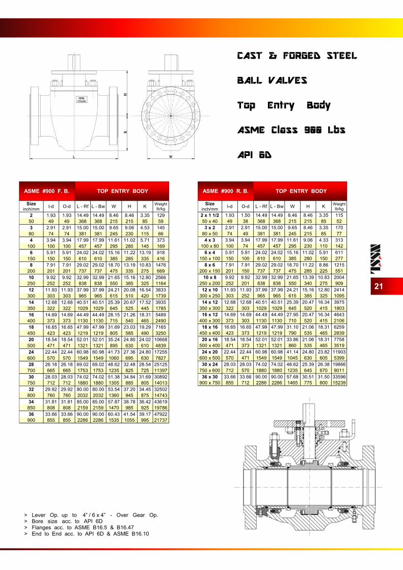
ASME #900 F. B. TOP ENTRY BODY
Size inch/mm
I-d O-d L - Rf L - Bw W H K Weight
lb/kg
2 1.93 1.93 14.49 14.49 8.46 8.46 3.35 129
50 49 49 368 368 215 215 85 59
3 2.91 2.91 15.00 15.00 9.65 9.06 4.53 145
80 74 74 381 381 245 230 115 66
4 3.94 3.94 17.99 17.99 11.61 11.02 5.71 373
100 100 100 457 457 295 280 145 169
6 5.91 5.91 24.02 24.02 15.16 11.22 13.19 918
150 150 150 610 610 385 285 335 416
8 7.91 7.91 29.02 29.02 18.70 13.19 10.83 1476
200 201 201 737 737 475 335 275 669
10 9.92 9.92 32.99 32.99 21.65 15.16 12.80 2566
250 252 252 838 838 550 385 325 1164
12 11.93 11.93 37.99 37.99 24.21 20.08 16.54 3833
300 303 303 965 965 615 510 420 1739
14 12.68 12.68 40.51 40.51 25.39 20.67 17.52 3935
350 322 322 1029 1029 645 525 445 1785
16 14.69 14.69 44.49 44.49 28.15 21.26 18.31 5489
400 373 373 1130 1130 715 540 465 2490
18 16.65 16.65 47.99 47.99 31.69 23.03 19.29 7165
450 423 423 1219 1219 805 585 490 3250
20 18.54 18.54 52.01 52.01 35.24 24.80 24.02 10668
500 471 471 1321 1321 895 630 610 4839
24 22.44 22.44 60.98 60.98 41.73 27.36 24.80 17255
600 570 570 1549 1549 1060 695 630 7827
28 26.18 26.18 69.02 69.02 48.62 32.48 28.54 25125
700 665 665 1753 1753 1235 825 725 11397
30 28.03 28.03 74.02 74.02 51.38 34.84 31.69 30892
750 712 712 1880 1880 1305 885 805 14013
32 29.92 29.92 80.00 80.00 53.54 37.20 34.45 32502
800 760 760 2032 2032 1360 945 875 14743
34 31.81 31.81 85.00 85.00 57.87 38.78 36.42 43619
850 808 808 2159 2159 1470 985 925 19786
36 33.66 33.66 90.00 90.00 60.43 41.54 39.17 47922
900 855 855 2286 2286 1535 1055 995 21737
ASME #900 R. B. TOP ENTRY BODY
Size inch/mm
I-d O-d L - Rf L - Bw W H K Weight
lb/kg
2 x 1 1/2 1.93 1.50 14.49 14.49 8.46 8.46 3.35 115
50 x 40 49 38 368 368 215 215 85 52
3 x 2 2.91 2.91 15.00 15.00 9.65 8.46 3.35 170
80 x 50 74 49 381 381 245 215 85 77
4 x 3 3.94 3.94 17.99 17.99 11.61 9.06 4.33 313
100 x 80 100 74 457 457 295 230 110 142
6 x 4 5.91 5.91 24.02 24.02 15.16 11.02 5.91 611
150 x 100 150 100 610 610 385 280 150 277
8 x 6 7.91 7.91 29.02 29.02 18.70 11.22 8.86 1215
200 x 150 201 150 737 737 475 285 225 551
10 x 8 9.92 9.92 32.99 32.99 21.65 13.39 10.83 2004
250 x 200 252 201 838 838 550 340 275 909
12 x 10 11.93 11.93 37.99 37.99 24.21 15.16 12.80 2414
300 x 250 303 252 965 965 615 385 325 1095
14 x 12 12.68 12.68 40.51 40.51 25.39 20.47 16.34 3975
350 x 300 322 303 1029 1029 645 520 415 1803
16 x 12 14.69 14.69 44.49 44.49 27.95 20.47 16.34 4643
400 x 300 373 303 1130 1130 710 520 415 2106
18 x 16 16.65 16.65 47.99 47.99 31.10 21.06 18.31 6259
450 x 400 423 373 1219 1219 790 535 465 2839
20 x 16 18.54 18.54 52.01 52.01 33.86 21.06 18.31 7758
500 x 400 471 373 1321 1321 860 535 465 3519
24 x 20 22.44 22.44 60.98 60.98 41.14 24.80 23.82 11903
600 x 500 570 471 1549 1549 1045 630 605 5399
30 x 24 28.03 28.03 74.02 74.02 48.62 25.39 26.38 19866
750 x 600 712 570 1880 1880 1235 645 670 9011
36 x 30 33.66 33.66 90.00 90.00 57.68 30.51 31.50 33596
900 x 750 855 712 2286 2286 1465 775 800 15239
21
CAST & FORGED STEEL BALL VALVES Top Entry Body ASME Class 900 Lbs API 6D
> Lever Op. up to 4” / 6 x 4” - Over Gear Op. > Bore size acc. to API 6D > Flanges acc. to ASME B16.5 & B16.47 > End to End acc. to API 6D & ASME B16.10
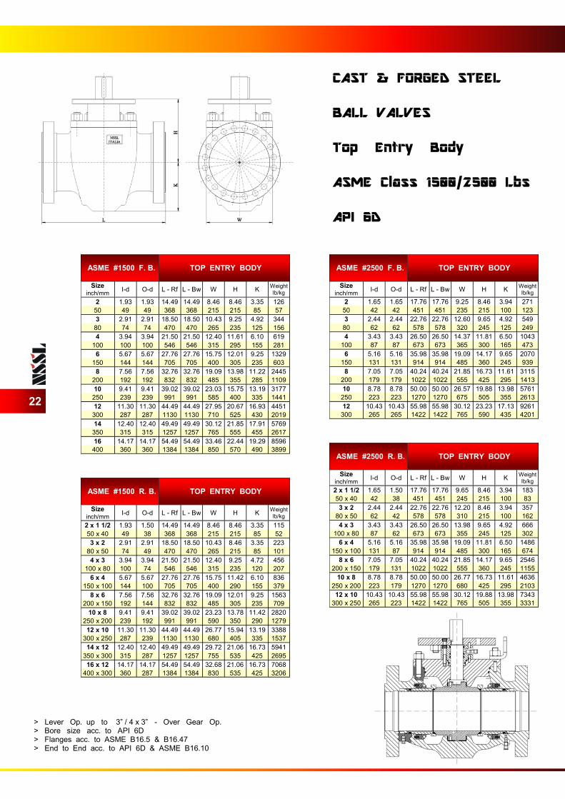
ASME #1500 F. B. TOP ENTRY BODY
Size inch/mm
I-d O-d L - Rf L - Bw W H K Weight
lb/kg
2 1.93 1.93 14.49 14.49 8.46 8.46 3.35 126
50 49 49 368 368 215 215 85 57
3 2.91 2.91 18.50 18.50 10.43 9.25 4.92 344
80 74 74 470 470 265 235 125 156
4 3.94 3.94 21.50 21.50 12.40 11.61 6.10 619
100 100 100 546 546 315 295 155 281
6 5.67 5.67 27.76 27.76 15.75 12.01 9.25 1329
150 144 144 705 705 400 305 235 603
8 7.56 7.56 32.76 32.76 19.09 13.98 11.22 2445
200 192 192 832 832 485 355 285 1109
10 9.41 9.41 39.02 39.02 23.03 15.75 13.19 3177
250 239 239 991 991 585 400 335 1441
12 11.30 11.30 44.49 44.49 27.95 20.67 16.93 4451
300 287 287 1130 1130 710 525 430 2019
14 12.40 12.40 49.49 49.49 30.12 21.85 17.91 5769
350 315 315 1257 1257 765 555 455 2617
16 14.17 14.17 54.49 54.49 33.46 22.44 19.29 8596
400 360 360 1384 1384 850 570 490 3899
ASME #2500 F. B. TOP ENTRY BODY
Size inch/mm
I-d O-d L - Rf L - Bw W H K Weight
lb/kg
2 1.65 1.65 17.76 17.76 9.25 8.46 3.94 271
50 42 42 451 451 235 215 100 123
3 2.44 2.44 22.76 22.76 12.60 9.65 4.92 549
80 62 62 578 578 320 245 125 249
4 3.43 3.43 26.50 26.50 14.37 11.81 6.50 1043
100 87 87 673 673 365 300 165 473
6 5.16 5.16 35.98 35.98 19.09 14.17 9.65 2070
150 131 131 914 914 485 360 245 939
8 7.05 7.05 40.24 40.24 21.85 16.73 11.61 3115
200 179 179 1022 1022 555 425 295 1413
10 8.78 8.78 50.00 50.00 26.57 19.88 13.98 5761
250 223 223 1270 1270 675 505 355 2613
12 10.43 10.43 55.98 55.98 30.12 23.23 17.13 9261
300 265 265 1422 1422 765 590 435 4201
22
CAST & FORGED STEEL BALL VALVES Top Entry Body ASME Class 1500/2500 Lbs API 6D
> Lever Op. up to 3” / 4 x 3” - Over Gear Op. > Bore size acc. to API 6D > Flanges acc. to ASME B16.5 & B16.47 > End to End acc. to API 6D & ASME B16.10
ASME #1500 R. B. TOP ENTRY BODY
Size inch/mm
I-d O-d L - Rf L - Bw W H K Weight
lb/kg
2 x 1 1/2 1.93 1.50 14.49 14.49 8.46 8.46 3.35 115
50 x 40 49 38 368 368 215 215 85 52
3 x 2 2.91 2.91 18.50 18.50 10.43 8.46 3.35 223
80 x 50 74 49 470 470 265 215 85 101
4 x 3 3.94 3.94 21.50 21.50 12.40 9.25 4.72 456
100 x 80 100 74 546 546 315 235 120 207
6 x 4 5.67 5.67 27.76 27.76 15.75 11.42 6.10 836
150 x 100 144 100 705 705 400 290 155 379
8 x 6 7.56 7.56 32.76 32.76 19.09 12.01 9.25 1563
200 x 150 192 144 832 832 485 305 235 709
10 x 8 9.41 9.41 39.02 39.02 23.23 13.78 11.42 2820
250 x 200 239 192 991 991 590 350 290 1279
12 x 10 11.30 11.30 44.49 44.49 26.77 15.94 13.19 3388
300 x 250 287 239 1130 1130 680 405 335 1537
14 x 12 12.40 12.40 49.49 49.49 29.72 21.06 16.73 5941
350 x 300 315 287 1257 1257 755 535 425 2695
16 x 12 14.17 14.17 54.49 54.49 32.68 21.06 16.73 7068
400 x 300 360 287 1384 1384 830 535 425 3206
ASME #2500 R. B. TOP ENTRY BODY
Size inch/mm
I-d O-d L - Rf L - Bw W H K Weight
lb/kg
2 x 1 1/2 1.65 1.50 17.76 17.76 9.65 8.46 3.94 183
50 x 40 42 38 451 451 245 215 100 83
3 x 2 2.44 2.44 22.76 22.76 12.20 8.46 3.94 357
80 x 50 62 42 578 578 310 215 100 162
4 x 3 3.43 3.43 26.50 26.50 13.98 9.65 4.92 666
100 x 80 87 62 673 673 355 245 125 302
6 x 4 5.16 5.16 35.98 35.98 19.09 11.81 6.50 1486
150 x 100 131 87 914 914 485 300 165 674
8 x 6 7.05 7.05 40.24 40.24 21.85 14.17 9.65 2546
200 x 150 179 131 1022 1022 555 360 245 1155
10 x 8 8.78 8.78 50.00 50.00 26.77 16.73 11.61 4636
250 x 200 223 179 1270 1270 680 425 295 2103
12 x 10 10.43 10.43 55.98 55.98 30.12 19.88 13.98 7343
300 x 250 265 223 1422 1422 765 505 355 3331
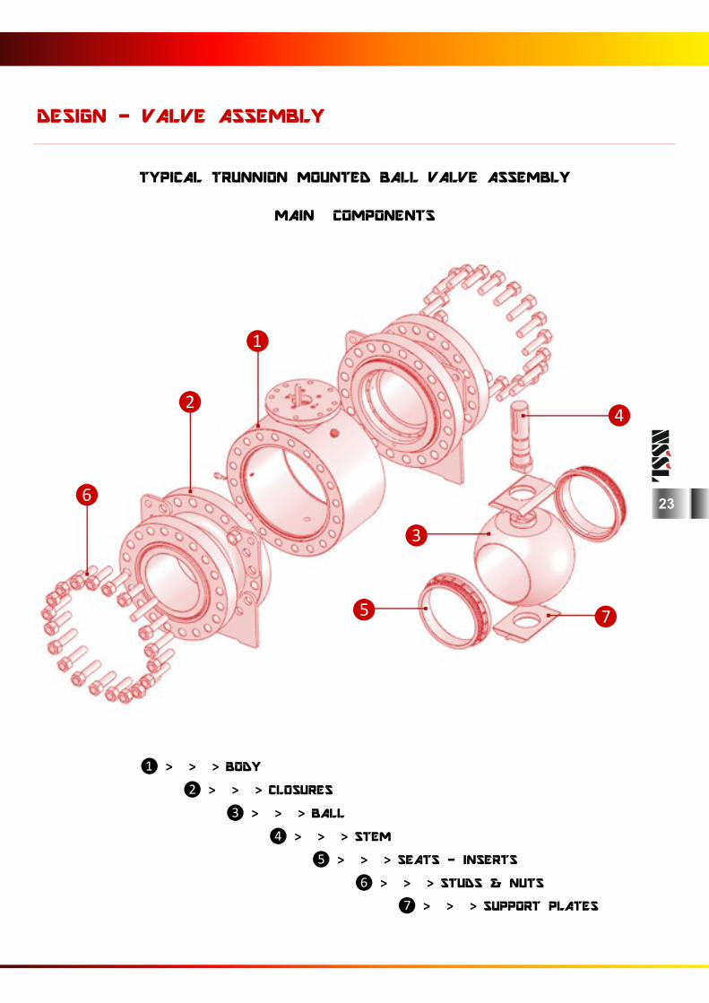
TYPICAL TRUNNION MOUNTED BALL VALVE ASSEMBLY
MAIN COMPONENTS
❶ > > > BODY
❷ > > > CLOSURES
❸ > > > BALL
❹ > > > STEM
❺ > > > SEATS - INSERTS
❻ > > > STUDS & NUTS
❼ > > > SUPPORT PLATES
DESIGN - VALVE ASSEMBLY
❶
❷ ❹
❻
❸
❺ ❼
23
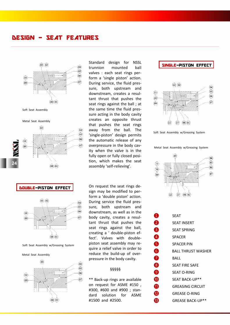
❶ SEAT
❷ SEAT INSERT
❸ SEAT SPRING
❹ SPACER
❺ SPACER PIN
❻ BALL THRUST WASHER
❼ BALL
❽ SEAT FIRE SAFE
❾ SEAT O-RING
❿ SEAT BACK-UP**
⓫ GREASING CIRCUIT
⓬ GREASE O-RING
⓭ GREASE BACK-UP**
On request the seat rings de-sign may be modified to per-form a ‘double piston’ action. During service the fluid pres-sure, both upstream and downstream, as well as in the body cavity, creates a resul-tant thrust that pushes the seat rings against the ball, creating a ‘ double-piston ef-fect’. Valves with double-piston seat assembly may re-quire a relief valve in order to reduce the build-up of over-pressure in the body cavity. §§§§§ ** Back-up rings are available on request for ASME #150 , #300, #600 and #900 ; stan-dard solution for ASME #1500 and #2500.
Standard design for NSSL trunnion mounted ball valves : each seat rings per-form a ‘single piston’ action. During service, the fluid pres-sure, both upstream and downstream, creates a resul-tant thrust that pushes the seat rings against the ball ; at the same time the fluid pres-sure acting in the body cavity creates an opposite thrust that pushes the seat rings away from the ball. The ‘single-piston’ design permits the automatic release of any overpressure in the body cav-ity when the valve is in the fully open or fully closed posi-tion, which makes the seat assembly ‘self-relieving’.
Soft Seat Assembly Metal Seat Assembly
Soft Seat Assembly w/Greasing System Metal Seat Assembly w/Greasing System
Soft Seat Assembly w/Greasing System
Metal Seat Assembly
DESIGN - SEAT FEATURES
SINGLE-PISTON EFFECT
DOUBLE-PISTON EFFECT
24
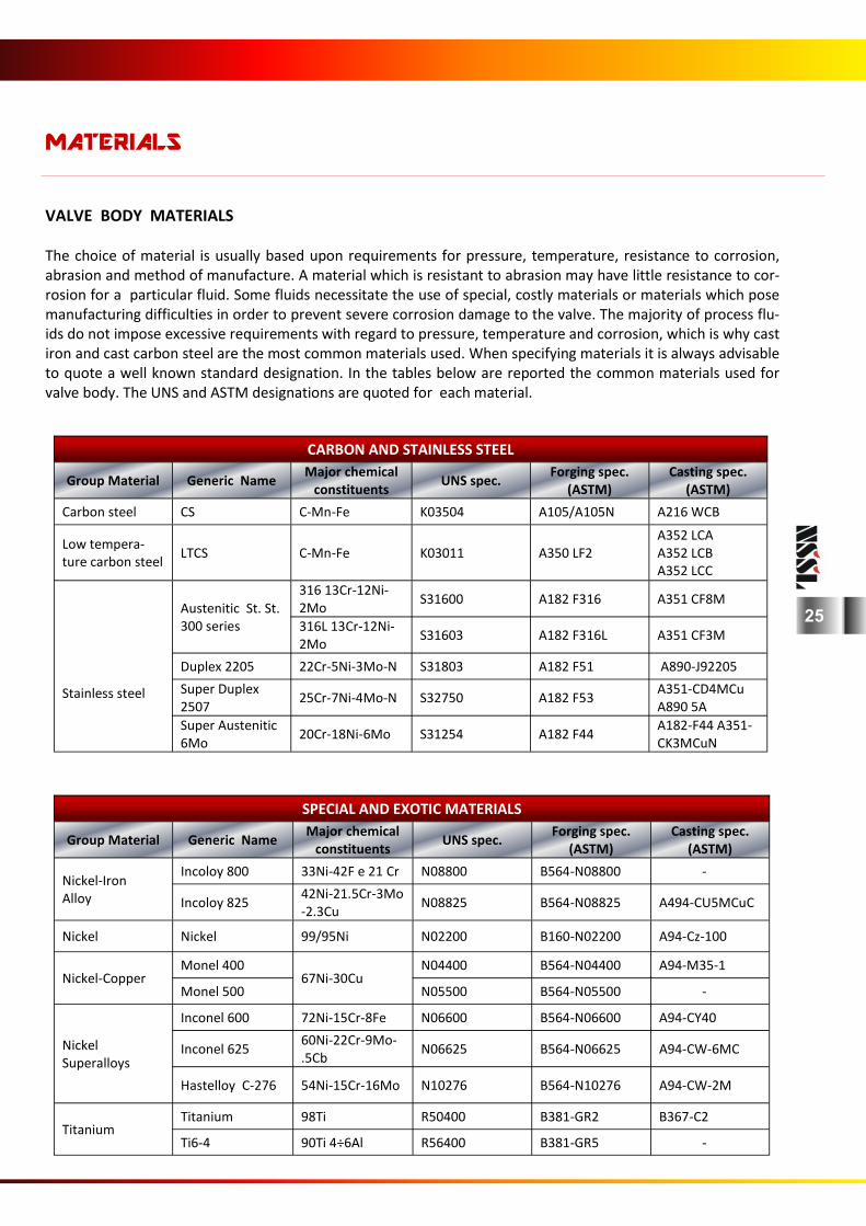
VALVE BODY MATERIALS The choice of material is usually based upon requirements for pressure, temperature, resistance to corrosion, abrasion and method of manufacture. A material which is resistant to abrasion may have little resistance to cor-rosion for a particular fluid. Some fluids necessitate the use of special, costly materials or materials which pose manufacturing difficulties in order to prevent severe corrosion damage to the valve. The majority of process flu-ids do not impose excessive requirements with regard to pressure, temperature and corrosion, which is why cast iron and cast carbon steel are the most common materials used. When specifying materials it is always advisable to quote a well known standard designation. In the tables below are reported the common materials used for valve body. The UNS and ASTM designations are quoted for each material.
MATERIALS
CARBON AND STAINLESS STEEL
Group Material Generic Name Major chemical
constituents UNS spec.
Forging spec. (ASTM)
Casting spec. (ASTM)
Carbon steel CS C-Mn-Fe K03504 A105/A105N A216 WCB
Low tempera-ture carbon steel
LTCS C-Mn-Fe K03011 A350 LF2 A352 LCA A352 LCB A352 LCC
Stainless steel
Austenitic St. St. 300 series
316 13Cr-12Ni-2Mo
S31600 A182 F316 A351 CF8M
316L 13Cr-12Ni-2Mo
S31603 A182 F316L A351 CF3M
Duplex 2205 22Cr-5Ni-3Mo-N S31803 A182 F51 A890-J92205
Super Duplex 2507
25Cr-7Ni-4Mo-N S32750 A182 F53 A351-CD4MCu A890 5A
Super Austenitic 6Mo
20Cr-18Ni-6Mo S31254 A182 F44 A182-F44 A351-CK3MCuN
SPECIAL AND EXOTIC MATERIALS
Group Material Generic Name Major chemical
constituents UNS spec.
Forging spec. (ASTM)
Casting spec. (ASTM)
Nickel-Iron Alloy
Incoloy 800 33Ni-42F e 21 Cr N08800 B564-N08800 -
Incoloy 825 42Ni-21.5Cr-3Mo-2.3Cu
N08825 B564-N08825 A494-CU5MCuC
Nickel Nickel 99/95Ni N02200 B160-N02200 A94-Cz-100
Nickel-Copper Monel 400 N04400 B564-N04400 A94-M35-1
67Ni-30Cu Monel 500 N05500 B564-N05500 -
Nickel Superalloys
Inconel 600 72Ni-15Cr-8Fe N06600 B564-N06600 A94-CY40
Inconel 625 60Ni-22Cr-9Mo-.5Cb
N06625 B564-N06625 A94-CW-6MC
Hastelloy C-276 54Ni-15Cr-16Mo N10276 B564-N10276 A94-CW-2M
Titanium Titanium 98Ti R50400 B381-GR2 B367-C2
Ti6-4 90Ti 4÷6Al R56400 B381-GR5 -
25
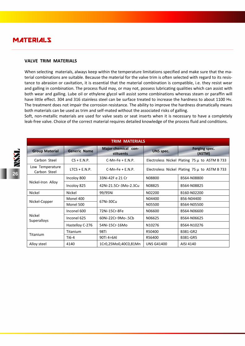
VALVE TRIM MATERIALS When selecting materials, always keep within the temperature limitations specified and make sure that the ma-terial combinations are suitable. Because the material for the valve trim is often selected with regard to its resis-tance to abrasion or cavitation, it is essential that the material combination is compatible, i.e. they resist wear and galling in combination. The process fluid may, or may not, possess lubricating qualities which can assist with both wear and galling. Lube oil or ethylene glycol will assist some combinations whereas steam or paraffin will have little effect. 304 and 316 stainless steel can be surface treated to increase the hardness to about 1100 Hv. The treatment does not impair the corrosion resistance. The ability to improve the hardness dramatically means both materials can be used as trim and self-mated without the associated risks of galling. Soft, non-metallic materials are used for valve seats or seat inserts when it is necessary to have a completely leak-free valve. Choice of the correct material requires detailed knowledge of the process fluid and conditions.
MATERIALS
TRIM MATERIALS
Group Material Generic Name Major chemical con-
stituents UNS spec.
Forging spec. (ASTM)
Carbon Steel CS + E.N.P. C-Mn-Fe + E.N.P. Electroless Nickel Plating 75 µ to ASTM B 733
Low Temperature Carbon Steel
LTCS + E.N.P. C-Mn-Fe + E.N.P. Electroless Nickel Plating 75 µ to ASTM B 733
Nickel-Iron Alloy
Incoloy 800 33Ni-42F e 21 Cr N08800 B564-N08800
Incoloy 825 42Ni-21.5Cr-3Mo-2.3Cu N08825 B564-N08825
Nickel Nickel 99/95Ni N02200 B160-N02200
Nickel-Copper Monel 400
67Ni-30Cu N04400 B56-N04400
Monel 500 N05500 B564-N05500
Nickel Superalloys
Inconel 600 72Ni-15Cr-8Fe N06600 B564-N06600
Inconel 625 60Ni-22Cr-9Mo-.5Cb N06625 B564-N06625
Hastelloy C-276 54Ni-15Cr-16Mo N10276 B564-N10276
Titanium 98Ti R50400 B381-GR2 Titanium
Ti6-4 90Ti 4÷6Al R56400 B381-GR5
Alloy steel 4140 1Cr0,25Mo0,40C0,81Mn UNS G41400 AISI 4140
26
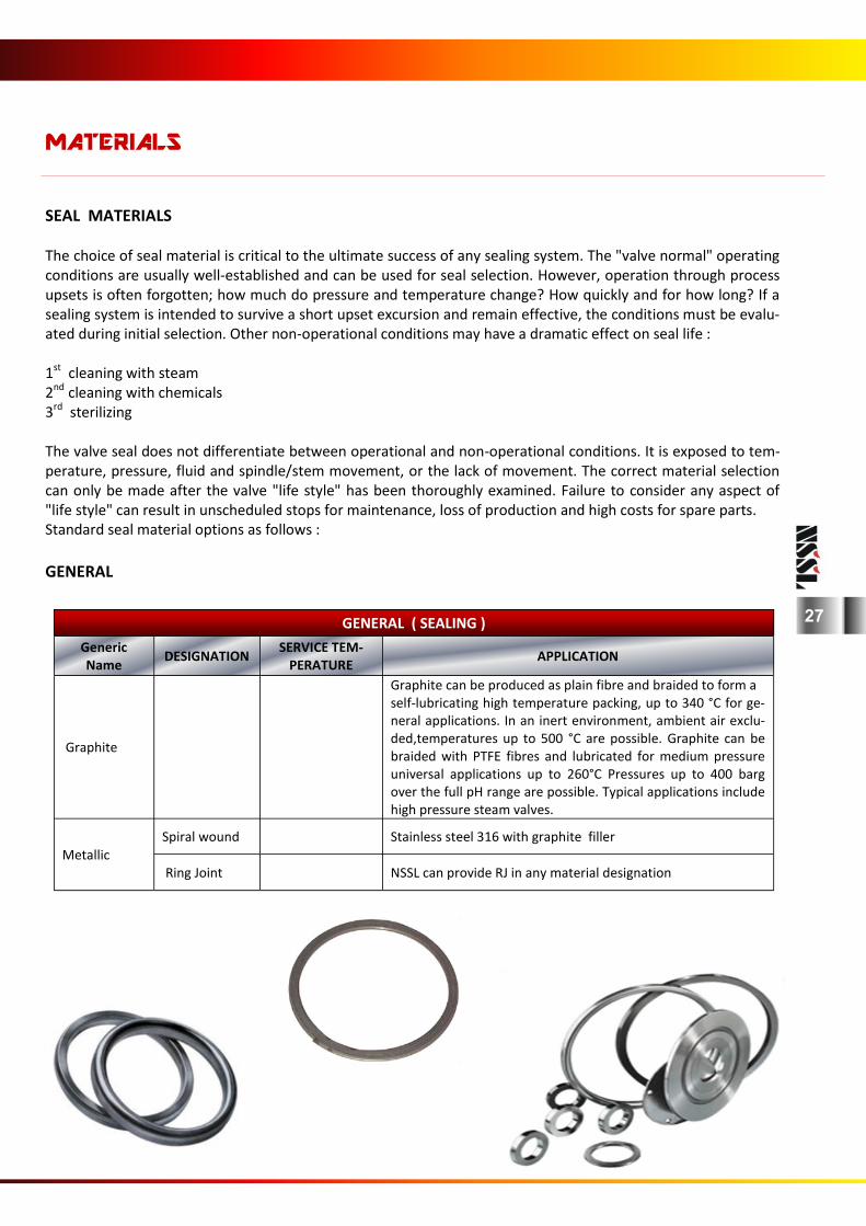
SEAL MATERIALS The choice of seal material is critical to the ultimate success of any sealing system. The "valve normal" operating conditions are usually well-established and can be used for seal selection. However, operation through process upsets is often forgotten; how much do pressure and temperature change? How quickly and for how long? If a sealing system is intended to survive a short upset excursion and remain effective, the conditions must be evalu-ated during initial selection. Other non-operational conditions may have a dramatic effect on seal life : 1st cleaning with steam 2nd cleaning with chemicals 3rd sterilizing The valve seal does not differentiate between operational and non-operational conditions. It is exposed to tem-perature, pressure, fluid and spindle/stem movement, or the lack of movement. The correct material selection can only be made after the valve "life style" has been thoroughly examined. Failure to consider any aspect of "life style" can result in unscheduled stops for maintenance, loss of production and high costs for spare parts. Standard seal material options as follows :
GENERAL
MATERIALS
GENERAL ( SEALING )
Generic Name
DESIGNATION SERVICE TEM-
PERATURE APPLICATION
Graphite
Graphite can be produced as plain fibre and braided to form a self-lubricating high temperature packing, up to 340 °C for ge-neral applications. In an inert environment, ambient air exclu-ded,temperatures up to 500 °C are possible. Graphite can be braided with PTFE fibres and lubricated for medium pressure universal applications up to 260°C Pressures up to 400 barg over the full pH range are possible. Typical applications include high pressure steam valves.
Metallic
Spiral wound Stainless steel 316 with graphite filler
Ring Joint
NSSL can provide RJ in any material designation
27
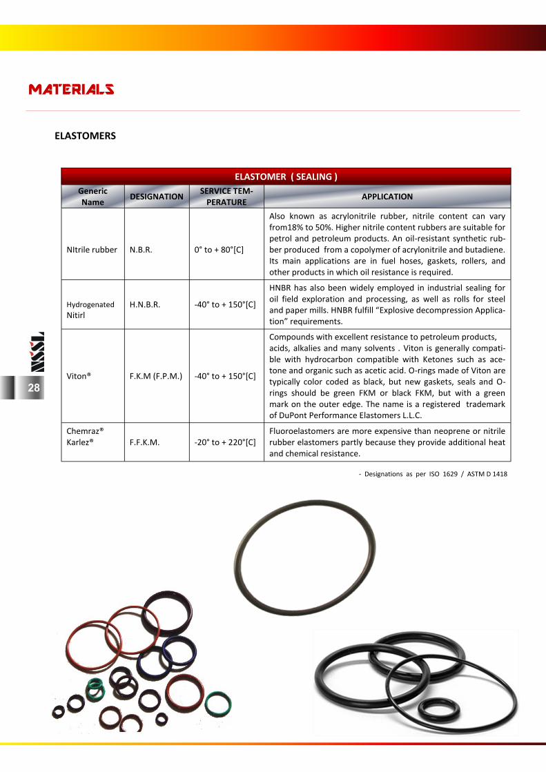
ELASTOMERS
- Designations as per ISO 1629 / ASTM D 1418
MATERIALS
ELASTOMER ( SEALING )
Generic Name
DESIGNATION SERVICE TEM-
PERATURE APPLICATION
NItrile rubber
N.B.R.
0° to + 80°[C]
Also known as acrylonitrile rubber, nitrile content can vary from18% to 50%. Higher nitrile content rubbers are suitable for petrol and petroleum products. An oil-resistant synthetic rub-ber produced from a copolymer of acrylonitrile and butadiene. Its main applications are in fuel hoses, gaskets, rollers, and other products in which oil resistance is required.
Hydrogenated
Nitirl H.N.B.R. -40° to + 150°[C]
HNBR has also been widely employed in industrial sealing for oil field exploration and processing, as well as rolls for steel and paper mills. HNBR fulfill “Explosive decompression Applica-tion” requirements.
Viton® F.K.M (F.P.M.) -40° to + 150°[C]
Compounds with excellent resistance to petroleum products, acids, alkalies and many solvents . Viton is generally compati-ble with hydrocarbon compatible with Ketones such as ace-tone and organic such as acetic acid. O-rings made of Viton are typically color coded as black, but new gaskets, seals and O-rings should be green FKM or black FKM, but with a green mark on the outer edge. The name is a registered trademark of DuPont Performance Elastomers L.L.C.
Chemraz® Karlez®
F.F.K.M. -20° to + 220°[C] Fluoroelastomers are more expensive than neoprene or nitrile rubber elastomers partly because they provide additional heat and chemical resistance.
28
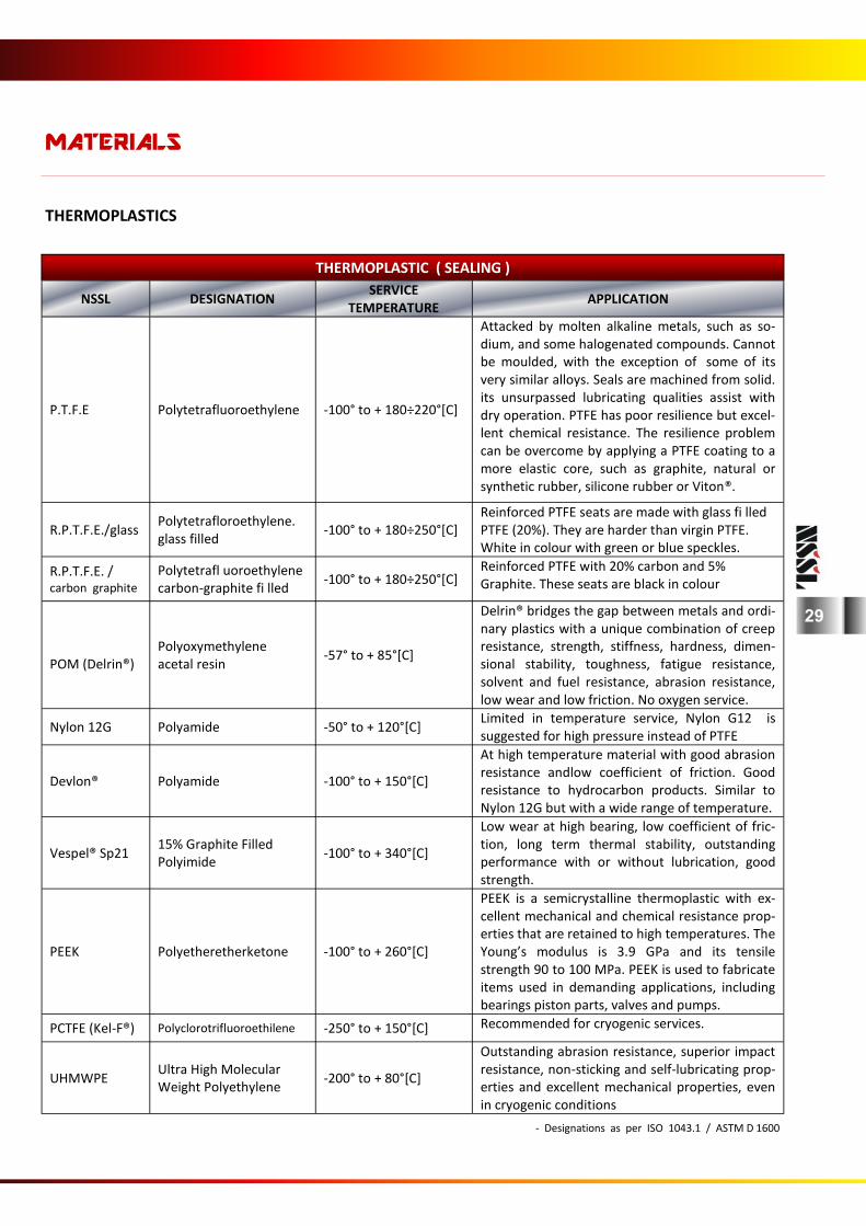
THERMOPLASTICS
- Designations as per ISO 1043.1 / ASTM D 1600
MATERIALS
THERMOPLASTIC ( SEALING )
NSSL DESIGNATION SERVICE
TEMPERATURE APPLICATION
P.T.F.E Polytetrafluoroethylene -100° to + 180÷220°[C]
Attacked by molten alkaline metals, such as so-dium, and some halogenated compounds. Cannot be moulded, with the exception of some of its very similar alloys. Seals are machined from solid. its unsurpassed lubricating qualities assist with dry operation. PTFE has poor resilience but excel-lent chemical resistance. The resilience problem can be overcome by applying a PTFE coating to a more elastic core, such as graphite, natural or synthetic rubber, silicone rubber or Viton®.
R.P.T.F.E./glass Polytetrafloroethylene. glass filled
-100° to + 180÷250°[C] Reinforced PTFE seats are made with glass fi lled PTFE (20%). They are harder than virgin PTFE. White in colour with green or blue speckles.
R.P.T.F.E. /carbon graphite
Polytetrafl uoroethylene carbon-graphite fi lled
-100° to + 180÷250°[C] Reinforced PTFE with 20% carbon and 5% Graphite. These seats are black in colour
POM (Delrin®)
Polyoxymethylene acetal resin
-57° to + 85°[C]
Delrin® bridges the gap between metals and ordi-nary plastics with a unique combination of creep resistance, strength, stiffness, hardness, dimen-sional stability, toughness, fatigue resistance, solvent and fuel resistance, abrasion resistance, low wear and low friction. No oxygen service.
Nylon 12G Polyamide -50° to + 120°[C] Limited in temperature service, Nylon G12 is suggested for high pressure instead of PTFE
Devlon® Polyamide -100° to + 150°[C]
At high temperature material with good abrasion resistance andlow coefficient of friction. Good resistance to hydrocarbon products. Similar to Nylon 12G but with a wide range of temperature.
Vespel® Sp21 15% Graphite Filled Polyimide
-100° to + 340°[C]
Low wear at high bearing, low coefficient of fric-tion, long term thermal stability, outstanding performance with or without lubrication, good strength.
PEEK Polyetheretherketone -100° to + 260°[C]
PEEK is a semicrystalline thermoplastic with ex-cellent mechanical and chemical resistance prop-erties that are retained to high temperatures. The Young’s modulus is 3.9 GPa and its tensile strength 90 to 100 MPa. PEEK is used to fabricate items used in demanding applications, including bearings piston parts, valves and pumps.
PCTFE (Kel-F®) Polyclorotrifluoroethilene -250° to + 150°[C] Recommended for cryogenic services.
UHMWPE Ultra High Molecular Weight Polyethylene
-200° to + 80°[C]
Outstanding abrasion resistance, superior impact resistance, non-sticking and self-lubricating prop-erties and excellent mechanical properties, even in cryogenic conditions
29
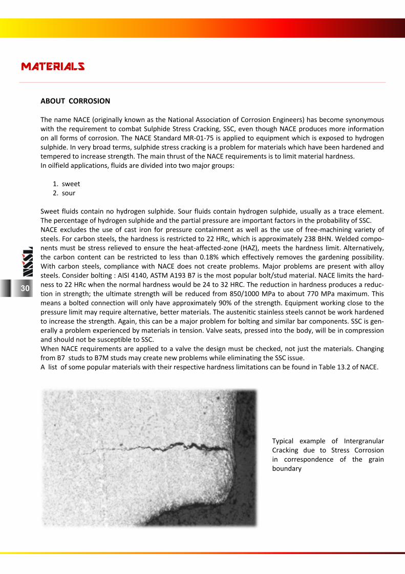
ABOUT CORROSION The name NACE (originally known as the National Association of Corrosion Engineers) has become synonymous with the requirement to combat Sulphide Stress Cracking, SSC, even though NACE produces more information on all forms of corrosion. The NACE Standard MR-01-75 is applied to equipment which is exposed to hydrogen sulphide. In very broad terms, sulphide stress cracking is a problem for materials which have been hardened and tempered to increase strength. The main thrust of the NACE requirements is to limit material hardness. In oilfield applications, fluids are divided into two major groups:
1. sweet 2. sour
Sweet fluids contain no hydrogen sulphide. Sour fluids contain hydrogen sulphide, usually as a trace element. The percentage of hydrogen sulphide and the partial pressure are important factors in the probability of SSC. NACE excludes the use of cast iron for pressure containment as well as the use of free-machining variety of steels. For carbon steels, the hardness is restricted to 22 HRc, which is approximately 238 BHN. Welded compo-nents must be stress relieved to ensure the heat-affected-zone (HAZ), meets the hardness limit. Alternatively, the carbon content can be restricted to less than 0.18% which effectively removes the gardening possibility. With carbon steels, compliance with NACE does not create problems. Major problems are present with alloy steels. Consider bolting : AISI 4140, ASTM A193 B7 is the most popular bolt/stud material. NACE limits the hard-ness to 22 HRc when the normal hardness would be 24 to 32 HRC. The reduction in hardness produces a reduc-tion in strength; the ultimate strength will be reduced from 850/1000 MPa to about 770 MPa maximum. This means a bolted connection will only have approximately 90% of the strength. Equipment working close to the pressure limit may require alternative, better materials. The austenitic stainless steels cannot be work hardened to increase the strength. Again, this can be a major problem for bolting and similar bar components. SSC is gen-erally a problem experienced by materials in tension. Valve seats, pressed into the body, will be in compression and should not be susceptible to SSC. When NACE requirements are applied to a valve the design must be checked, not just the materials. Changing from B7 studs to B7M studs may create new problems while eliminating the SSC issue. A list of some popular materials with their respective hardness limitations can be found in Table 13.2 of NACE.
MATERIALS
Typical example of Intergranular Cracking due to Stress Corrosion in correspondence of the grain boundary
30
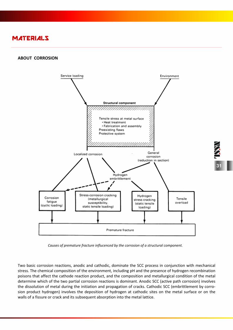
ABOUT CORROSION
Causes of premature fracture influcenced by the corrosion of a structural component.
Two basic corrosion reactions, anodic and cathodic, dominate the SCC process in conjunction with mechanical stress. The chemical composition of the environment, including pH and the presence of hydrogen recombination poisons that affect the cathode reaction product, and the composition and metallurgical condition of the metal determine which of the two partial corrosion reactions is dominant. Anodic SCC (active path corrosion) involves the dissolution of metal during the initiation and propagation of cracks. Cathodic SCC (embrittlement by corro-sion product hydrogen) involves the deposition of hydrogen at cathodic sites on the metal surface or on the walls of a fissure or crack and its subsequent absorption into the metal lattice.
MATERIALS
31
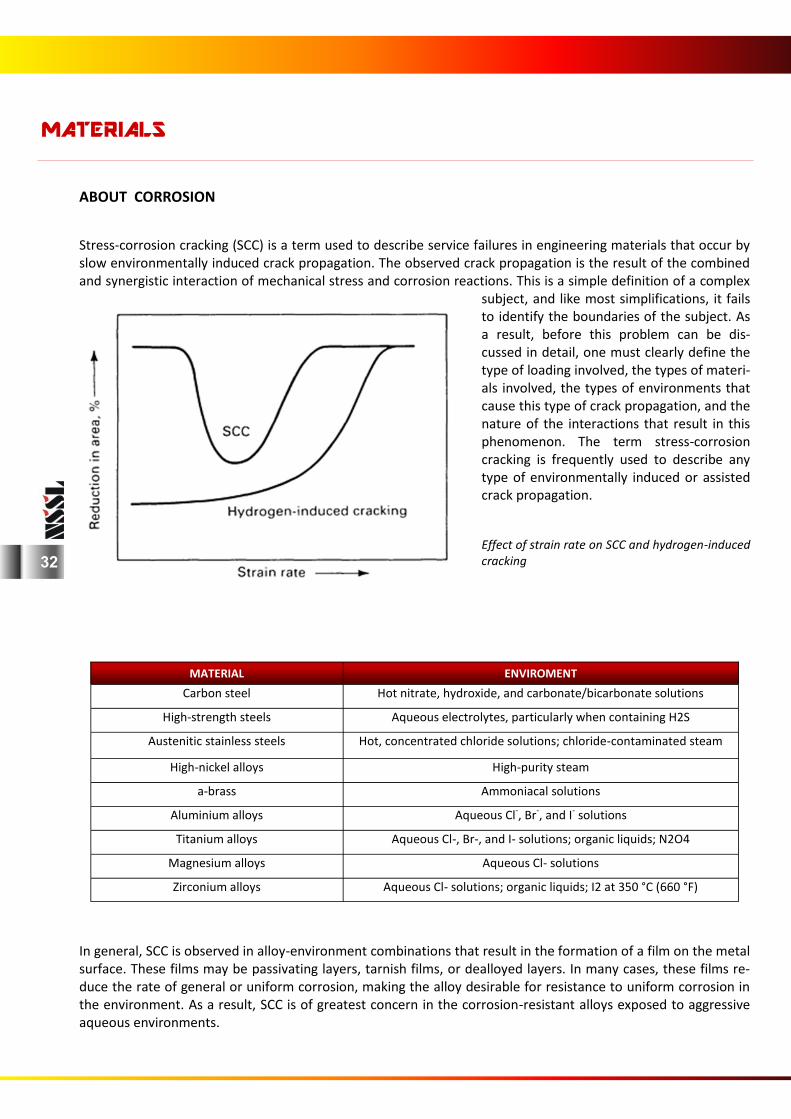
ABOUT CORROSION
In general, SCC is observed in alloy-environment combinations that result in the formation of a film on the metal surface. These films may be passivating layers, tarnish films, or dealloyed layers. In many cases, these films re-duce the rate of general or uniform corrosion, making the alloy desirable for resistance to uniform corrosion in the environment. As a result, SCC is of greatest concern in the corrosion-resistant alloys exposed to aggressive aqueous environments.
MATERIALS
MATERIAL ENVIROMENT
Carbon steel Hot nitrate, hydroxide, and carbonate/bicarbonate solutions
High-strength steels Aqueous electrolytes, particularly when containing H2S
Austenitic stainless steels Hot, concentrated chloride solutions; chloride-contaminated steam
High-nickel alloys High-purity steam
a-brass Ammoniacal solutions
Aluminium alloys Aqueous Cl-, Br-, and I- solutions
Titanium alloys Aqueous Cl-, Br-, and I- solutions; organic liquids; N2O4
Magnesium alloys Aqueous Cl- solutions
Zirconium alloys Aqueous Cl- solutions; organic liquids; I2 at 350 °C (660 °F)
Stress-corrosion cracking (SCC) is a term used to describe service failures in engineering materials that occur by slow environmentally induced crack propagation. The observed crack propagation is the result of the combined and synergistic interaction of mechanical stress and corrosion reactions. This is a simple definition of a complex
subject, and like most simplifications, it fails to identify the boundaries of the subject. As a result, before this problem can be dis-cussed in detail, one must clearly define the type of loading involved, the types of materi-als involved, the types of environments that cause this type of crack propagation, and the nature of the interactions that result in this phenomenon. The term stress-corrosion cracking is frequently used to describe any type of environmentally induced or assisted crack propagation. Effect of strain rate on SCC and hydrogen-induced cracking 32
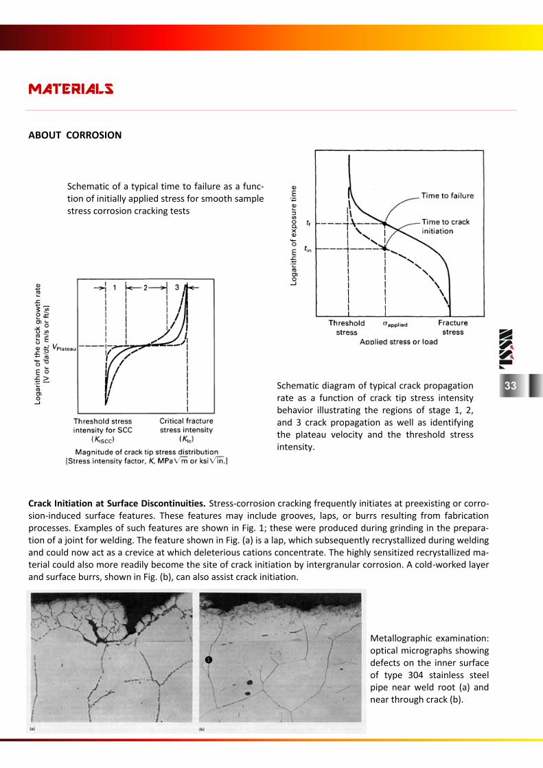
ABOUT CORROSION
Crack Initiation at Surface Discontinuities. Stress-corrosion cracking frequently initiates at preexisting or corro-sion-induced surface features. These features may include grooves, laps, or burrs resulting from fabrication processes. Examples of such features are shown in Fig. 1; these were produced during grinding in the prepara-tion of a joint for welding. The feature shown in Fig. (a) is a lap, which subsequently recrystallized during welding and could now act as a crevice at which deleterious cations concentrate. The highly sensitized recrystallized ma-terial could also more readily become the site of crack initiation by intergranular corrosion. A cold-worked layer and surface burrs, shown in Fig. (b), can also assist crack initiation.
Metallographic examination: optical micrographs showing defects on the inner surface of type 304 stainless steel pipe near weld root (a) and near through crack (b).
MATERIALS
Schematic of a typical time to failure as a func-tion of initially applied stress for smooth sample stress corrosion cracking tests
Schematic diagram of typical crack propagation rate as a function of crack tip stress intensity behavior illustrating the regions of stage 1, 2, and 3 crack propagation as well as identifying the plateau velocity and the threshold stress intensity.
❶
33
DEFINITIONS
34
Bonnet The component attached to the valve body through which the stem or spindle passes and has locations for mounting the actua-tor. The bonnet includes the packing box which is equivalent to the stuffing box on a pump or compressor. The bonnet can be threaded, flanged, union, clamped, breech-lock or welded to the body. Special valves can have the bonnet retained by shear rings. Braided packing Strands or filaments, all running in the same longitudinal direc-tion, that are twisted together to form square or rectangular sections. Various types of braiding are possible to produce harder, stiffer or softer, more pliable, packing. The braiding can be applied over a soft or hard central core. Reinforced corners can be incorporated. The strands can be coated with solid or fluid lubricant to extend operating conditions. Metallic strands can be included for reinforcement and to improve heat transfer. Braided packing can be extruded to compress the section and control the finished size. Braided packing is generally supplied as a continuous length, 5 to 20 m, depending upon the cross sec-tion. Sealing rings are produced by cutting the required length from the coil. Breakaway force The force required on a linear motion sealing element to open the valve against maximum differential pressure. Breakaway torque The torque required on a rotary motion sealing element to open the valve against maximum differential pressure. Bright drawing The process of drawing hot rolled steel through a die to impart close dimensional tolerances, a bright, scale free surface, and improved mechanical properties. The product is termed bright. Built-up back pressure The pressure experienced at the safety valve outlet when pass-ing 100% flow, due to friction losses in attached pipework and any static back pressure. Butt fusion weld A thermal welding technique used with some non-metallic pip-ing systems. Materials such as polypropylene can be welded by using electric heaters. Machines can join 1200 mm diameter pipe. Butt weld joint A welded joint between two components usually of the same diameter and with identical weld preparations; for example, a connection between two pipes or a pipe and a fitting. Welded pipe can be manufactured with a butt weld joint. A pipe or a fitting can be butt welded to a flat surface without a weld prepa-ration but this form is not acceptable to many purchasers. Butt weld pipe joints can be the highest integrity connection, if proved by suitable NDE, or NDT, such as 100% radiography. Butt fusion weld A thermal welding technique used with some non-metallic pip-ing systems. Materials such as polypropylene can be welded by using electric heaters. Machines can join 1200 mm diameter pipe. C The chemical symbol for the element carbon; alloyed with iron to produce cast iron and steel. Carbon increases the strength of iron and steel and can increase the hardness.
Annealing Heating steel to, and holding at a suitable temperature, followed by relatively slow cooling. The purpose of annealing may be to remove stresses, to soften the steel, to improve machining, to improve cold working properties, to obtain a desired structure. The annealing process usually involves allowing the steel to cool slowly in the furnace. Anti-static design A design which provides electrical continuity for the moving valve components and across the valve body to the connected piping. ANSI The American National Standards Institute, the National Stan-dards Authority of the USA. API The American Petroleum Institute ASME American Society of Mechanical Engineers ASTM American Society for Testing and Materials Atmospheric pressure Atmospheric pressure is standardised, technically, at 101.325 kPa (absolute), equivalent to 14.696 psi( a). Remember! This is the pressure at sea level. Equipment working at altitude will not experience the same atmospheric pressure. Also the local at-mospheric pressure changes with the weather. Local values are likely to vary from 94 to 108 kPa at sea level. Austempering Quenching from a temperature above the transformation range to a temperature above the upper limit of martensite formation, and holding at this temperature until the austenite is completely transformed to the desired intermediate structure, for the pur-pose of conferring certain mechanical properties. Austenite A face centred cubic crystal structure found in chrome-nickel stainless steels. Austenitic stainless steel Steels containing high percentages of certain alloying elements such as manganese and nickel which are austenitic at room tem-perature and cannot be hardened by normal heat-treatment but do work harden. They are also non-magnetic in the annealed condition and very corrosion resistant. Chromium content usu-ally falls between 16 and 26% and nickel content less than 35%. Typical examples of austenitic steels include the 18/8 stainless steels and 14 % manganese steel. Work gardening or welding may induce some magnetism. Back pressure The pressure at the safety valve outlet. This can be expressed as a percentage of the fluid inlet pressure or as a specific pressure. Back pressure is very important and has a significant effect on valve performance. Blowdown valve A valve which permits pressurised fluid to be released to the environment. Bolted gland A gland which is attached to the bonnet by two or more bolts or studs. Because of the difficulty of maintaining exact alignment on adjustable versions some form of spherical bearing on the packing follower is recommended.
DEFINITIONS
35
Carbo-nitriding A case-hardening process in which steel components are heated in an atmosphere containing both carbon and nitrogen. Carbon steel A steel whose properties are determined primarily by the amount of carbon present. Apart from iron and carbon, manga-nese up to 1.5% may be present as well as residual amounts of alloying elements such as nickel, chromium, molybdenum, etc. It is when one or more alloying elements are added in sufficient amount that it is classed as an alloy steel. Case-hardening The process of hardening the surface of steel whilst leaving the interior unchanged. Both carbon and alloy steels are suitable for case-hardening providing their carbon content is low, usually up to a maximum of 0.2%. Components subject to this process, particularly in the case of alloy steels, have a hard, wear-resistant surface with a tough core. Cast iron A definition can be applied that cast iron is an alloy of iron and carbon in which the carbon is in excess of the amount that can be retained in solid solution in austenite at the eutectic tem-perature. Carbon is usually present in the range of 1.8% to 4.5%. In addition, silicon, manganese, sulfur and phosphorus are con-tained in varying amounts. Various types of cast iron are covered by many of the National Standard authorities and include grey, malleable and white irons. Elements such as nickel, chromium, molybdenum, vanadium can be added to produce alloy cast irons. CE Carbon equivalent, an assessment made of carbon and carbon manganese steels used in a sour environment (H2S present), according to the percentages of the constituents: CE = C + Mn/6 + (Cr + Mo + V )/5 + (Ni + Cu)/15 Change-over valve A valve with three connections which allows one circuit to be connected to one of a possible two circuits. The circuit not con-nected is isolated. Valves of this type are frequently built into equipment such as duplex filters. The change-over valve allows one filter element to be used while the other is cleaned or re-placed. In the case of duplex filters, two change-over valves are ganged together. An inlet change-over valve is ganged with an outlet change-over valve so that two filters work with one inlet and outlet process connection. Very special change-over valves are available to be used with safety relief valves. One process connection may be connected to one of two safety relief valves (srvs). The valve ensures that at least one srv is in circuit at all times. Both srvs cannot be isolated simultaneously. Charpy test A test to measure the impact properties of steel. A prepared test piece, usually notched, is broken by a swinging pendulum. The energy consumed in breaking the test piece is measured in Joules. The more brittle the steel the lower the impact strength. CEN and ISO provide test methods. Chokes A manual valve used for continuous throttling applications; a heavy duty needle valve. An American term used mainly in con-nection with crude oil production.
Co Chemical symbol for Cobalt. It may be present in steels as an impurity added with nickel. It is added specifically to tool steels to improve hot strength. Cobalt becomes highly radioactive when irradiated; specifications for nuclear applications restrict the cobalt concentration to very low levels. Closed-loop control system A control system in which the measurement of process variables corrects, if necessary, the position of a control element. Con-sider a householder sitting in the living-room of a house with gas/water central heating. The living-room is fitted with a room thermostat for temperature control. The householder goes to the kitchen leaving the living-room door open. Cold air from the hall enters the living-room reducing the temperature. The ther-mostat detects the fall in temperature and sends a signal to the boiler to maintain the water temperature. If the radiator was fitted with a thermostatic control valve, the sensor would detect the fall in temperature. The thermostatic valve would open and allow more hot water to flow through the radiator. The hot wa-ter temperature would fall prompting the boiler to turn on or increase the fuel flow. Cold working Altering the shape or size of a metal by plastic deformation. Processes include rolling, drawing, pressing, spinning, extruding and heading. It is carried out below the re-crystallization point usually at room temperature. Hardness and tensile strength are increased with the degree of cold work whilst ductility and im-pact values are lowered. The cold rolling and cold drawing of steel significantly improves surface finish. Control valve A valve which opens and closes in response to an external signal and is powered by an external source. Similar to a regulator but requires an external supply of electricity, compressed air or pres-surized liquid. The control signal may be electric analogue, elec-tric digital or fluid analogue. Controlled atmosphere A gas or mixture of gases in which steel is heated to produce or maintain a specific surface condition. Controlled atmosphere furnaces are widely used in the heat treatment of steel as scaling and decarburization of components is minimized by this process. In the case of steel this refers to a component that has been case-hardened where the centre is softer than the hard surface layer or case. It can also be applied to the central part of a rolled rimming steel. Controlled bore pipe Pipe which is specially manufactured to close tolerances. Ordi-nary pipes may have a 12.5% tolerance on the wall thickness which leads to considerable variation in the bore size. Controlled bore pipes use strict manufacturing controls to ensure the bore size varies from 1.5% or 3.2 mm in the larger sizes. Cr The chemical symbol for the element chromium, sometimes abbreviated to "chrome". Chrome is added in small quantities to steel, less than 3%, to improve the effectiveness of heat treat-ment and hardening and to increase the strength. When the content is increased to between 10 and 30%, the steel acquires stain resistance or becomes stainless, i.e. less likely to oxidize.
DEFINITIONS
36
Fatigue The effect on materials of repeated cycles of stress. The danger-ous feature of fatigue failure is that there is not necessarily an obvious warning, a crack forms without appreciable deformation of structure making it difficult to detect the presence of growing cracks. Fractures usually start from small surface nicks or scratches or abrupt changes in shape which cause Iocalized stress concentrations. Failure can be influenced by a number of factors including size, shape and design of the com-ponent, condition of the surface or the overall operating envi-ronment. Ferritic stainless steel A term usually applied to a group of stain resistant steels with a chromium content in the range of 12 to 30% and whose struc-ture consists largely of ferrite. Alloys with chromium content at the bottom of the range will not be "stainless" in the generally accepted sense of the term. Such steels possess good ductility and are easily worked but do not respond to any hardening or tempering processes and have poor high temperature proper-ties. Fire-safe A valve which is suitable for installations where the risk of being engulfed by fire cannot be ignored. Valves are tested to a specifi-cation and qualified, see Chapter 15. Most valves which qualify are ball and butterfly. Linear valves are often said to suffer from stem thermal problems but some wedge gate valves have quali-fied. Most wafer and lug valves are generally not suitable. Flanged connection A pipe joint which uses two discs held together by bolts. Many flange designs are available for high and low pressure. Flanged connections are usually the preferred method of joining pipes for 3" nb, DN 80 and larger. Flow coefficient Cv, Kv A factor, determined experimentally, which indicates the flow capacity of incompressible fluid during non-choked, non-flashing flow of a valve with a unit differential pressure. Two flow coeffi-cients are in common use; the American Cv and the metric Kv. Equations 1.1 and 1.2 relate to liquid flow. Liquid flow coeffi-cients are based on turbulent flow conditions for a water-like liquid. Equ 1.1 Cv= Q sqr sg/ where: Cv = US flow coefficient (USgpm/psi) Q = liquid flow (USgpm) sg= liquid specific gravity (non-dimensional) Ap= differential pressure (Ib/in 2) Flow-to-close, FTC The direction of flow which tends to close the valve. In single-seat valves, it is the direction in which fluid flows over the seal-ing element and then out through the seat. Flow-to-open, FTO A linear motion valve fitted in a system so that the fluid flows through the seat and passed the plug to the outlet. The hydraulic process forces tend to open the valve. Fluid The term fluid is a generalization. It describes a group of "states'' liquids, vapors, gases and plasmas. The term could be used to describe mixtures of these states and also mixtures with solids. Fluid is a vague term and should be used with great caution. It is not, as many people seem to think, synonymous with liquid.
Creep The gradual permanent change in dimensions of solid materials when exposed to long term tensile stress. Non-metallic materials tend to creep much faster than metallic materials. High tem-perature is not necessary but it will accelerate the effect. Cu The chemical symbol for the element copper, which is usually present in steels as a trace impurity. It is added to some chrome-nickel alloys to impart precipitation hardening properties. It is added to some stainless steels to improve the strength and cor-rosion resistance at the expense of elasticity, and possibly casta-bility. Damper A hydraulic device which can be fitted to power-actuated valves to eliminate spindle/stem vibration and/or control actuation speed. Dashpot A device which relies on fluid friction to produce a force which opposes the motion. This can be a piston in a cylinder or a disc in a close-fitting housing. The opposing force increases as velocity increases. Data sheet A formatted sheet or sheets which fully describes the operating conditions the valve will experience. Operating conditions are not limited to the internal process fluid. External environmental factors can play a decisive part in the valve selection and the design of auxiliary equipment Dead band The range through which the controlled variable can reverse and change in magnitude without initiating a regulator response. Duplex stainless steels A high strength, corrosion resistant group of stainless steels, iron-chrome-nickel alloys, where the crystal structure is a mixture of body-centred cubic ferrite and face-centred cubic austenite. The balance between the two crystal groups is usually about 50-50 but heat treatment can change the proportions. The ferrite con-tent is usually controlled to avoid cracking or lack of toughness or susceptibility to stress corrosion cracking but a minimum per-centage is required to ensure the strength. Ductility The property of materials which permits it to be reduced in cross-sectional area, while experiencing tensile stress, without fracture. In a tensile test, ductile metals show considerable elon-gation eventually failing by necking, with consequent rapid in-crease in local stresses. Dye penetrant inspection Colloquially known as "dye-pen", a method for detecting surface porosity or cracks in metal. The part to be inspected is thor-oughly cleaned and coated with a dye which penetrates any surface flaws that may be present. The surface is wiped clean and coated with a white powder. The powder absorbs the dye held in the defects indicating their location. Elongation A measure of the ductility of a material; how much a material can stretch before it fractures Ferrite A body-centred cubic crystal structure found in chromium alloys.
DEFINITIONS
37
Forging A process of working metal to a finished shape by hammering or pressing and is primarily a "hot" operation. It is applied to the production of shapes either impossible or too costly to make by other methods or needing properties not obtainable by casting, such as inherent integrity. Categories of forgings include ham-mer, press, drop or stamping. Full bore A valve which has the same flow area as the attached pipework. This concept is not as simple as it seems. Pipework is produced in discrete sizes and a valve will be matched to a particular wall thickness with a similar pressure/temperature rating. Always check actual sizes. Refer to Reduced-port for an indication of problems. Gas A state of matter, achieved by heating beyond the superheated vapour phase to a temperature higher than the critical tempera-ture, in which the molecules move randomly to fill the volume available. A gas cannot be converted to liquid by simply increas-ing the pressure. The volume of a gas changes easily to accom-modate changes in the confining volume. The pressure and tem-perature of an ideal or perfect gas can be calculated by using the characteristic equation and Boyle's and Charles' Laws. Ideal gas properties can be converted to real gas properties by including compressibility factors in the characteristic equation. Gases can exist in mixtures, air, and can be dissolved in liquids, like fresh water or seawater. Compressors are designed to handle gases. Special compressors, like refrigeration compressors, are de-signed to handle gases and vapours, sometimes with trace quan-tities of liquid. Gauge pressure A pressure measurement relative to the local atmospheric pres-sure. Normal pressure gauges indicate this relative pressure. Units are usually suffixed with "g", but this common practice is frowned upon by the Standards Authorities. Gland The flange or special nut which retains and/or compresses the packing in the packing box. GMAW Gas Metal-Arc Welding, another name for MIG welding, Metal Inert-Gas welding. GOST-R Federal Agency on Technical Regulating and Metrology, the Na-tional Standards Authority of Russia. Grey iron Grey cast iron, also known as "flake iron", is the normal cast iron used for many applications and is available in many grades (strengths). GTAW Gas Tungsten-Arc Welding, another name for TIG welding, Tung-sten Inert-Gas welding. Guide bushing A replaceable bushing, considered as a stationary trim compo-nent, within a valve to align the moving element with the seat. Hard facing A method of increasing the wear resistance of a metal by the deposition of a hard protective coating. Alloys such as Stellite or Colmonoy, or a metallic carbide or a ceramic oxide are most often used for the coating. Increased corrosion resistance is an additional benefit.
HAZ Heat affected zone; the parent material immediately next to a weld; the material which could have been "heat-treated" by the welding process. Welding can change the local hardness and/or modify the grain structure of the parent material. Hazardous fluids These are fluids, which by nature of their chemical properties, create a potential for human injury, damage to property, to the environment or a combination of these. There is no European or International agreement on which fluids should be classed as hazardous. The UK Health and Safety Executive has a document, EH40, regarding the safety of personnel. In America there is a useful document produced by the National Fire Protection Agency, NFPA 325M. Another good source of information is the requirements for the transportation by road of dangerous goods, commonly known as ADR. A similar agreement applies to rail transportation, RID. These documents are published in the local language, not just English, French and German, and cover over 20 countries. For flammable fluids useful data can be found in IEC 79-12 which identifies gases and vapours for potentially explosive atmospheres for electrical equipment. Dust clouds can create a potential hazard and these should be checked rather than assuming dust to be safe. High pressure change-over valve A type of regulator which automatically selects between two feed systems depending upon the downstream pressure. For rapidly filling vessels a low pressure high flow supply, from a centrifugal pump, can be used. As the vessel pressure ap-proaches the pump closed valve head, the change-over valve changes supplies to a low flow high pressure source, possibly from a positive displacement pump. HRc Rockwell hardness on Scale "C" H2S trim A valve with all contact materials in compliance with NACE MR-01-75, latest edition. Hydraulic lock A situation usually encountered in gas systems when liquid has become trapped in a confined volume which should only contain gas, and prevents the movement of components. Inclusions Usually non-metallic particles contained in metal. In steel they may consist of simple or complex oxides, sulphides, silicates and sometimes nitrides of iron, manganese, silicon, aluminium and other elements. In general they are detrimental to the mechani-cal properties but much depends on the number, their size, shape and distribution. Intercrystalline corrosion Chromium-nickel austenitic stainless steels are prone to this form of corrosion when they are welded and subsequently in contact with certain types of corrosive media. When the metal is heated to within a temperature range of 450 to 800~ precipita-tion of the chromium carbides takes place at the grain bounda-ries in the area of the weld and these areas no longer have the protection of the chromium on the peripheries of the grains. This type of corrosion is also known as Weld Decay and Inter-granular Corrosion. The most common way to avoid the problem is to select a grade of steel that is very low in carbon i.e. 0.03% or less, or one that is stabilised with niobium or titanium.
DEFINITIONS
38
MIG welding Metal arc Inert-Gas welding is an electric arc welding process where the arc is struck with the filler metal. The weld site is pro-tected from atmospheric contamination by an inert gas shield, argon, helium or carbon dioxide being the most popular. Mo Molybdenum is alloyed with high strength steel to improve the high temperature physical properties. It is added to stainless steels to increase resistance to pitting corrosion. "Moly" has a favourable influence on the welding qualities. NACE National Association of Corrosion Engineers (of America). Al-though the NACE organisation provides guidance on all types of corrosion its name has become synonymous with sour service applications where hydrogen sulphide may be a problem. Nb The element niobium (used to be known as Columbium) is added to some steels to stabilise carbon, in a similar way to titanium, but has the added benefit of improving elevated temperature strength. nb Nominal bore, the nominal size of a valve or pipe in inches. Nominal bore pipework has a fixed outside diameter and vari-able wall thickness to accommodate different pressure ratings, up to 12". Pipe sizes over 12" are designated by the outside di-ameter. In low pressure pipe the bore size may be larger than the nominal bore. In high pressure pipe the bore size can be considerably smaller than the nominal bore and the actual diameter must be checked when calculating flow velocities. The wall thickness of pipe is subject to manufacturing tolerances and +12.5% is fairly typical. The pipe bore is therefore variable to some extent. The pipe wall thickness available for stressing and corrosion is also variable. DN is the metric equivalent of nb. NDE Non-destructive examination NDT - Non-destructive testing All those forms of testing that do not result in permanent dam-age or deformation to the part being tested. Typical examples include magnetic crack detection, ultrasonic inspection, X-ray inspection and gamma radiography. Some types of hardness testing do not leave any damaging impressions. Nipple A short length of pipe, usually of small diameter, 2" nb, DN50, or smaller. Non-rising stem Used on linear motion valves with inside screws. The nut is built into the sealing element which moves due to rotation only of the stem. Non-rotating tip The disc, plug or needle of a linear valve is attached to the stem but does not necessarily rotate. It is a good way to reduce wear when tightening the tip against the seat. Normalising A heat treatment process that has the object of relieving internal stresses, refining the grain size and improving the mechanical properties. The steel is heated to 800 to 900~ according to analysis, held at temperature to allow a full soak and cooled in still air.
Isolating valve A valve which is intended to be wide open or closed, with no flow regulation functions. Izod Impact test A test specimen, usually of square cross-section is notched and held between a pair of jaws, to be broken by a swinging or falling weight. When the pendulum of the Izod testing machine is re-leased it swings with a downward movement and when it reaches the vertical the hammer makes contact with the speci-men which is broken by the force of the blow. The hammer con-tinues its upward motion but the energy absorbed in breaking the test piece reduces its momentum. A graduated scale enables a reading to be taken of the energy used to fracture the test piece. To obtain a representative result the average of three tests is used and to ensure that the results conform to those of the steel specification the test specimens should be machined and polished accurately. Charpy testing is now more popular. Knoop hardness test A micro hardness test in which a pyramid shaped diamond is pressed into the surface. Lamination A problem which can occur with rolled raw materials, like steel plate. The bulk material is not homogeneous and can separate into layers. Lantern ring A spacer/bush used in packing boxes to allow the injection of lubricant, the collection of leakage and the application of a wa-ter seal, to the spindle/stem. Lantern rings are usually metallic but plastic or ceramic can be used. A short spacer with material removed from the central portion to provide storage or collec-tion volumes in the bore and around the od. Internal and exter-nal volumes are connected by a series of holes or slots. Leakage rates For substances hazardous to the environment the allowable leakage rates are controlled by local, national or country group-ing legislation. There is no complete list of hazardous substances but a list entitled Red List Chemicals or NFPA 325, is available for guidance. Local inspectors evaluate the site and issue an operat-ing licence which specifies maximum emissions. More than one licence may be necessary for a site. For substances hazardous to personnel, but not to the environ-ment, the allowable leakage rate is dependent upon local condi-tions; it is the concentration in the air which is important. Totally enclosed processes, with little or no air movement, will achieve high concentrations with low seal leakage. Open processes, with very large air volumes and continuous air movement, will be able to tolerate larger leakage rates without creating dangerous concentrations. Leakage will generally be dispersed downwind. Lubricator A connection on the packing box to facilitate packing lubrication. Martensitic stainless steel An alloy of iron, carbon and chromium which can be hardened by heat treatment, are magnetic but are not as corrosion resis-tant as other grades of stainless steel. The chrome content is usually between 10 and 18% with a carbon content over 1%. Carbon allows the material to be very hard and provides a degree
DEFINITIONS
39
Normally closed An isolating or control valve which requires control pressures above atmospheric to open. If the actuating system fails and the control pressure is reduced to atmospheric, the valve will close. A control valve can also be called direct-acting. Normally open An isolating or control valve which requires control pressures above atmospheric to close. If the actuating system fails and the control pressure is reduced to atmospheric, the valve will open wide. A control valve may also be called reverse-acting. NPS Nominal pipe size (see nb) NPT National Pipe Thread (of America), is a tapered pipe thread which seals the fluid. Thread tape or sealant is applied to the thread during assembly. The basic 60° thread form is cut on a taper of 0.75" per foot on diameter. The standard provides sizes up to 24" nb, but in practice 6" is about the largest used in proc-ess applications, Many users will not accept threaded fittings over 3". Obturator The moving sealing element in a valve. Oxidation The most common form of chemical reaction which is the com-bining of oxygen with various elements and compounds. The corrosion of metals is a form of oxidation, rust on iron and steel for example is iron oxide. Refined metals can be considered as unstable compounds; the natural stable state is their original mineral ores. Packing box The part of the bonnet which contains the seal or packing to reduce leakage along the valve stem. Packing lubricator An optional fitting on the bonnet to allow the packing to be lu-bricated while working. Packing tape Packing boxes can be sealed using thin tape which is rolled to fill the box. Usually only PTFE and graphite is available in this form. Panel mounting A facility supplied on smaller valves which enables the valve to be mounted with the connections behind the panel. Usually applied to valves with screwed glands, extra nuts are provided to clamp the panel. Pipe A conduit for carrying fluid which is designated by its nominal bore, nb, or its nominal diameter, DN. Pipes below 14" nb have unusual outside diameters i.e. 6.625", 10.75", etc. Pipes 14" and above use the od as the size. Pipe with an appropriate wall thick-ness can be threaded with standard pipe threads. PN Pressure nominal, a European designation, in bar-g, of the maxi-mum working pressure at ambient temperature. Pressure- tem-perature rating tables or graphs must be reviewed for the actual material at specific operating temperatures. Metallic materials are usually suitable up to 65° without de-rating. Some non-metallic materials may need de-rating over 20°C.
Positioner A control valve actuator used for accurate control applications. The positioner supplies air to the diaphragm or piston actuator to adjust the valve in response to control signals. The positioner is coupled to the valve/actuator stem and monitors the valve position to ensure the valve does adjust in response to the con-trol requirement. The feedback of valve stem position allows very precise valve control. Positive Material Identification, PMI Certain critical components may have the material of construc-tion identified beyond any doubt. A piece of the component can be removed and given to a witnessing inspector who carries the sample to a laboratory and watches the analysis. Alternatively, the component is analysed by a portable instrument which con-firms the chemical composition. PRE Pitting resistance equivalent, calculated from a formula, depend-ing on the material considered : PREN= Cr + 1.5 x (Mo + W + Nb) for stainless steel PREN= 3.3 x Mo + 16 x N2 for duplex and super duplex steel PREN= Cr -0.8 x Cu + 1.5 (Mo+ W) for nickel alloy weld wire Precipitation-hardening steels There are relatively few precipitation-hardening steels compared to other alloy categories. A group of iron-chrome-nickel alloys with relatively small nickel proportions. In the annual condition, alloys can be austenitic or martensitic. Heat treatment hardens the martensitic crystal structure. Pressure containing part A valve part which is in physical contact with the process fluid or any actuating fluid. These parts may be subject to corrosion or erosion by the fluid. Parts include: valve body, bonnet, stem and spindle. Pressure retaining part A valve part which is stressed by internal fluid pressure due to its function of holding one or more pressure containing parts in position. Pressure retaining parts are not in direct physical con-tact with the process or actuating fluids and are not subject to corrosion or erosion by them. Pressure retaining parts may be subject to corrosion or erosion by atmospheric pollution. Parts include: bonnet fasteners, glands, gland fasteners, stems, spin-dles and stem nuts. Pressure-temperature ratings Metallic and non-metallic materials used for valve manufacture usually weaken and become more elastic as temperature in-creases. Some materials become brittle as temperature de-creases. These factors are well known and have been studied extensively by classification societies and standards authorities. Allowable stress values have been correlated with working temperature by pressure vessel standards and codes. The most popular Standards are EN 13445, ASME VIII and ANSI B 16.34. BS 5500 has been replaced by PD 5500 and is popular outside Europe. These Standards use different formulae to calcu-late the stresses arising from fluid pressure; the allowable stress values are not interchangeable. Pressure-temperature ratings are usually qualified as non-shock, may be time limited or have specified full-cycle pressure limitations.
DEFINITIONS
40
Se The element Selenium, added to some steels to improve Machining. Seal weld A threaded pipe connection, usually a taper thread but could be applied to a parallel thread, which is made dry without sealants. A fillet weld is added at the external joint face to prevent any leakage. This type of construction is only acceptable when the process fluid is not corrosive. The pipe threads, which provide the strength for the joint, are not protected and are susceptible to crevice corrosion or galvanic corrosion if the metals are sig-nificantly different. Seamless Pipe or tube which does not have a welded seam. Some rolled plate and strip products have no seam because the edges are joined by pressure welding when the metal is hot. Seat The pressure-retaining contact seal between the stationary and moving parts of the valve. A valve may have more than one seat. Seat leakage The leakage through the seat when the valve is closed. Leakage is standardised in many cases please refer to applicable specifi-cations. Self-energised packing Packing which uses the fluid pressure to create the sealing forces to prevent leakage. Higher pressures result in higher sealing forces. Shutdown valve, SDV An isolating valve, part of the ESD system, which closes to isolate equipment or a process during the shutdown sequence. Smooth finish A flange facing finish which is smooth but not polished. The fin-ish would normally lie between 1.6 and 3.2 µm. No visible tool marks should be discernible. Socket fusion weld A thermal welding technique used with some non-metallic pip-ing systems. Materials such as polypropylene can be welded by using electric heaters. Socket weld fittings Fittings for connecting pipes, which use a single fillet weld around the od of the pipe/tube for mechanical attachment and sealing. The pipe/tube is inserted into the fitting, then welded. It should only be used with safe fluids. The weld cannot be X-rayed to verify integrity. Soft-seat A soft insert of plastic, elastomer or other readily deformable material, in the valve body or the moving element which de-forms on contact with the other sealing surface to provide low or zero seat leakage. Solution annealing A heat treatment to allow precipitated constituents to return in to the solution. Quenching "freezes" all the constituents in the required state. Sour A description of the environment or the process fluid; hydrogen sulphide, H2S, is present.
RAL The German organisation, Reichsausschuss Lieferbedingungen, was instigated to standardise precise technical terms to allow rationalisation of purchasing (long before the EU Single Market Project). Now the RAL prefix is used for colour shades in accor-dance with international standards such as BS 381C. Reduced-port Always described as reduced-bore, a valve in which the seat area or the ports leading to the seat are smaller than the nominal pipe area in which it is fitted. In globe valves the ports may be smaller and the seat may be larger than the nominal pipe area. Gate valves may have 50% flow area, globe valves even less. The increased velocity in the port or seat can result in increate ero-sion, corrosion and noise. Accelerated material loss is not limited to solids handling. Increased liquid velocities can damage the protective oxide layer resulting in unexpected corrosion. Some valves do not have circular ports. Sudden changes in area can create violent turbulence leading to greatly increased erosion and corrosion. Rising stem On linear motion valves the stem rises through the yoke when the valve is opened. RJT Ring Joint Type; a hygienic union pipe connector. Not to be con-fused with RTJ. Rockwell hardness testing A method for testing the hardness of metals by determining the depth of penetration of a steel ball or a diamond sphero-conical indentor. The value is read from a dial and is an arbitrary num-ber related to the depth of penetration. For testing hard steels, a sphero-conical diamond is used with a 150 kg load, the result is read from the black scale on the dial and is prefixed with the letter C. A hardened tool steel would typically give a reading of 62 HRc. For softer metals Scale B is used with a 1/16" diameter steel ball and a standard load of 100 kg. SAW Submerged Arc Welded, a type of electric welding process used on thick wall pipe and tube. The submerged arc process pro-duces a very high quality, clean weld. Powdered flux is poured into a dam which is clamped either side of the seam. The end of the welding electrode is covered by the flux and air is effectively excluded. The powdered flux melts to protect the molten filler metal. Both flux and filler metal solidify on cooling. Unused pow-dered flux is collected for re-use. When cold, the flux forms a solid slag which peels off the weld metal. Typical pipe sizes would be in the range of 400 mm diameter and larger with wall thickness of 6 to 32 mm. For corrosive applications the filler metal should be the same chemical composition as the parent metal or slightly more noble. For critical applications clarification will be worthwhile. SCC Standards Council of Canada, the National Standards Authority of Canada. Screwed bonnet A bonnet which is threaded and screwed directly into the valve body. Screwed gland A gland which screws into a female thread in the bonnet. It can be either adjustable or non-adjustable.
DEFINITIONS
41
Specification A document issued as part of a contractual agreement for equip-ment. Most specifications refer to standards and amend or ex-tend requirements to suit the particular application. Some speci-fications are "vague" in the sense that requirements are aspira-tions and cannot be verified. Before writing a specification, au-thors could be usefully guided by consulting Standard writing rules, like BS 0 (Standards, specifications for structure, drafting and presentation.). A specification which is vague or ambiguous will be interpreted to the suppliers" advantage. A specification which is capable of interpretation, is of little value to purchaser. SSC Sulphide stress cracking; a type of corrosion mechanism which attacks components made of high strength materials which de-rive their strength from heat treatment to relatively high hard-ness levels. Sulphide stress cracking is usually associated with hydrogen sulphide in connection with crude oil and natural gas production. Stainless steel An alloy of iron and chromium which is usually, at least, 50% iron and up to 30% chromium. Carbon is usually present from very low concentrations, 0.03% to 1.0% or more. Stainless steel can be divided into five groups: martensitic, ferritic, austenitic, du-plex and precipitation-hardening. Standard A specification, issued by a National Standards Authority, a gov-ernment sponsored organisation, which is characterised by strict editorial control and verifiable requirements. Standards should consist of clauses which mainly use "shall" to indicate a "requirement" which must be met. Compliance with standards must be verifiable, otherwise the effort is wasted. "Should" is used to describe recommendations; "may" indicates a course of action which is acceptable. Clauses which require an agreement should be kept to an absolute minimum. Steel An alloy of iron and carbon with small quantities of silicon, man-ganese, moly or nickel. Phosphorous and sulphur are usually present, in quite small quantities, less than 0.05%, as impurities which impair the physical and chemical properties. If the carbon content is between 0.4 and 1.2% approximately the steel can be hardened by heat treatment although steels with lower carbon contents can be heat treated, inadvertently, during welding. Stem The shaft which reciprocates in linear valves and actuators. Stem connector A clamp, usually in two halves, to connect the valve stem to the actuator stem. Stem leakage Leakage through the stern (or spindle) seal when the valve is open or closed. Some valve designs seal the packing box when open; others when closed. Rotary valves generally are unable to seal the packing box. Stock finish The standard surface finish applied to flange facings by the flange manufacturer. Stock finish is a shallow spiral groove ma-chined as one continuous cut across the face. The angled crests created apply a strong grip to the gasket to resist blow-outs. Flanges up to 12" have a 1/16" radius groove cut with a feed rate of 1/32" per revolution. Larger flanges use a 1/8" radius tool and 3/64" per revolution.
Stress relieving A heat treatment including heating and soaking at a suitable temperature e.g. 600 to 650°C followed by cooling at an appro-priate rate in order to reduce internal stresses without substan-tially modifying the steel's structure. This treatment may be used to relieve stresses induced by machining, quenching, welding or cold working. TIG welding Tungsten arc Inert-Gas welding is an electric arc welding process, where the arc is struck with a dedicated tungsten electrode across to the workpiece. A separate filler rod or wire is fed into the weld pool which is protected by an inert gas shield. Toughness The ability of a metal to rapidly distribute within itself both the stress and strain caused by a suddenly applied load, or more simply expressed, the ability of a material to withstand shock loading, It is the opposite of "brittleness" which carries the impli-cation of sudden failure. A brittle material has little resistance to failure once the elastic limit has been reached. Trim The internal components of a valve in contact with the process fluid. Ultrasonic Sound above the range of human hearing; typically frequencies greater than 20 kHz. These high frequency sounds can be de-tected by piezo-electric crystals. Vickers hardness test This test, more commonly known as the Vickers test, finds greater use in the laboratory than the workshop. It employs a pyramid shaped diamond with an included angle of 136 °which is impressed into the specimen using loads of 5 to 120 kg making a small square impression. This test is used for finished or polished components because the impression can be very small. The dia-mond pyramid hardness number is obtained from a calculation based on measuring the diagonals of the impressions in the material. Test results are usually quoted as VPN, Vickers Pyramid Number, or just HV. W The chemical symbol for tungsten, which used to be called Wolf-ram. Tungsten can greatly improve the hot properties of tool steels. It is added to some chrome-nickel alloys to aid carbide formation. Welded bonnet For applications requiring very high integrity the bonnet can be welded to the body. Care must be taken to ensure the weld can be inspected adequately to verify the soundness. Weldolet A specially-designed, mass-produced, forged fitting for making tees in pipe runs. It produces a better result, from stressing and fluid flow criteria, than butting a branch directly to the run pipe. The trade name has passed into common usage to represent fittings of this style produced by other manufacturers. Versions are available for connections on bends, branches at an angle and adding screwed connections. WPS Welding procedure specification WQC Welder qualification certificate
NSSL ITALIA S.r.l. - Via Coppalati 6 - 29122 Piacenza - Italy
Tel. +39 0523 648254 Fax +39 0523 609414 E-mail [email protected] Web www.nsslitalia.com
Ca
t-B
-Gen
-01
-10
Related Documents