18 APRIL 2008 TRIBOLOGY & LUBRICATION TECHNOLOGY 18 APRIL 2008 TRIBOLOGY & LUBRICATION TECHNOLOGY 18 APRIL 2008 TRIBOLOGY & LUBRICATION TECHNOLOGY ubricant selection is a pivotal starting point in the pursuit of precision lubrication practices. All the effort applied to clean delivery and handling, filtra- tion, dehydration, alignment, balancing, etc., is lost if the lubricant selected for the application cannot support the machine’s demands. Many criteria must be considered when selecting a lubricant for a set of machines or machine components. Lubricant chemistry has an influence on the final decision. The basestock (synthetic or mineral) and the additive systems in use (EP, AW, R&O) exert tremen- dous influence on the performance qualities of the lubricant. It is common to have multiple choices for a given grade and type of lubricant within a product line (i.e., ISO 220EP/SAE 90EP gear oil), with each example designed to perform effectively for a set of given conditions. The machines themselves have an influence on final lubricant selections. OEMs design and build machines for general types of service. A gear drive manufacturer could not possibly consider each and every type of application for a given make and model when it begins the design process. Designers can build BEST PRACTICES NOTEBOOK Lubricant selection: Bearings, gear drives and hydraulics Lubricant selection: Bearings, gear drives and hydraulics Make sure you’re using the right product by following a systemactic approach based on objective, repeatable and widely recognized engineering practices and principles. By Mike Johnson, CLS, CMRP Contributing Editor L Article highlights: ■ Guidelines for selecting lubricants for plain and ele- ment bearings, gears and hydraulic systems. ■ Analyzing the additive mix for each component. ■ Making technically accurate baseline lubricant selection decisions without exacting mathematical expressions.

Welcome message from author
This document is posted to help you gain knowledge. Please leave a comment to let me know what you think about it! Share it to your friends and learn new things together.
Transcript
18 A P R I L 2 0 0 8 T R I B O L O G Y & L U B R I C A T I O N T E C H N O L O G Y18 A P R I L 2 0 0 8 T R I B O L O G Y & L U B R I C A T I O N T E C H N O L O G Y18 A P R I L 2 0 0 8 T R I B O L O G Y & L U B R I C A T I O N T E C H N O L O G Y
ubricant selection is a pivotal starting point in thepursuit of precision lubrication practices. All theeffort applied to clean delivery and handling, filtra-
tion, dehydration, alignment, balancing, etc., is lost if thelubricant selected for the application cannot support themachine’s demands. Many criteria must be consideredwhen selecting a lubricant for a set of machines ormachine components.
Lubricant chemistry has an influence on the finaldecision. The basestock (synthetic or mineral) and theadditive systems in use (EP, AW, R&O) exert tremen-dous influence on the performance qualities of thelubricant. It is common to have multiple choices for agiven grade and type of lubricant within a productline (i.e., ISO 220EP/SAE 90EP gear oil), with eachexample designed to perform effectively for a set ofgiven conditions.
The machines themselves have an influence onfinal lubricant selections. OEMs design and buildmachines for general types of service. A gear drive
manufacturer could not possibly consider each andevery type of application for a given make and modelwhen it begins the design process. Designers can build
BEST PRACTICES NOTEBOOK
Lubricant selection:Bearings, gear drives
and hydraulics
Lubricant selection:Bearings, gear drives
and hydraulics
Make sure you’re using the right product by following asystemactic approach based on objective, repeatable and
widely recognized engineering practices and principles.
By Mike Johnson, CLS, CMRPContributing Editor
LArticle highlig
hts:
■ Guidelines for selecting
lubricants for plain and ele
-
ment bearings, gears and
hydraulic systems.
■ Analyzing the additive mix
for each component.
■ Making technically accurate
baseline lubricant selection
decisions without exacting
mathematical expressions.
sufficient durability into the basic design thatallows customers to use those products for similaruses within widely varying production environ-ments. The nature of the production environment(wet, dry, hot, cold, abrasive dirt, harsh chemicalexposure, steady state or intermittent operation,etc.) influences the degree of effectiveness for agiven lubricant type and grade.
Plant maintenance strategy has an influence onlubricant selection as well. Where management isparticularly forward thinking and willing to investin modifications that improve lubricant manage-ment effectiveness (filter connections, continuousfiltration, embedded sample ports, bearing isola-tors, etc.), the company is positioned to maximizethe superior value that can be achieved throughthe use of high-performance lubricants, both min-eral- and synthetic oil-based.
With the variety of factors that can impact lubri-cant film formation and effectiveness, it is to thepractitioner’s benefit to follow a lubricant selectionprocess that is objective, repeatable and based onwidely recognized engineering practices and princi-ples. This article addresses a formal lubricant selec-tion process that could be used to make technical-ly accurate baseline lubricant selection decisionswithout using exacting mathematical expressions.
Parsing the machineIn the January TLT I proposed cataloging all lubri-cated components within a machine for evaluationand specification of a lubricant. The purpose of theprocess is to consolidate the collection of machinecomponents into a concise set of types and catalogwhich components rotate, slide, pivot or haveother dynamically interacting surfaces. There arerelatively few unique types of components, butthere are many permutations of each of the fewunique options. Let’s address these componentsby general type that represent most industrialmachinery, including:
■ Plain bearings■ Element bearings■ Gears■ Hydraulic systems
Plain bearing lubricant selectionProbably the most common manifestation of aplain bearing is a round steel journal riding on aconforming one- or two-part brass or babbit bush-ing. There are plenty other machine componenttypes that could be categorized similarly, includingmachine tool gibbs (slideways), brass bushing,pivot pins, ball screws, worm gears, etc. Thesebushings are similar to plain bearings in composi-tion, form (shape), and film characteristics.
Regardless of shape and form, all plain bearingcomponents have a common requirement: a full-fluid hydrodynamic film to sustain component lifecycles. Two types of decisions must be made:
1. Viscosity grade according to the machine’soperating profile.
2. Lubricant chemistry/additive type (R&O, EP,AW, Compounded, Tackified).
The viscosity grade considerations for slidingsurface interaction are rooted in a common set ofphysical realities. Total available surface area, lin-ear surface speed, surface unit loading, lubricantviscosity grade and lubricant replacement rate allhave an influence on the formation of a hydrody-namic oil film.
STLE member Bob Scott, manager of Lube-Works, Ltd., in Calgary, offers a method of lubricantselection for plain bearing applications. Accordingto Scott, the minimum information required for thedetermination of the proper ISO grade for journalbearings includes:
1. Shaft RPM.
2. Temperature of the oil in the bearing.
3. Approximate unit loading pressure (PSI orNewtons /m2).
Scott adds that it would be best to also haveadditional information, including:
■ Bearing length, number of bearings androtor weight (to calculate the bearing pres-sure to verify the load).
■ Shaft diameter to calculate the shaft surfacespeed.
■ Driving horsepower.
■ Knowing whether shock loading is present.
■ Knowing if the unit is in a warm or cold envi-ronment.
■ Knowing if cooling water is being applied.
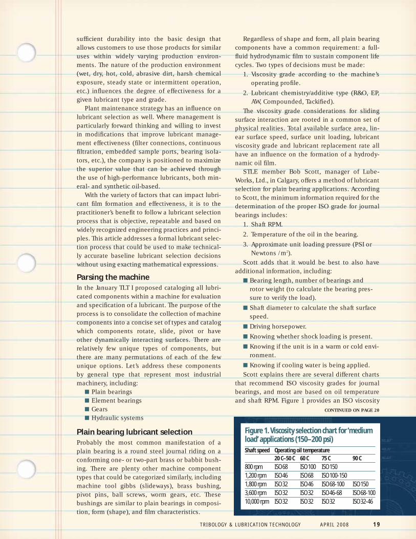
Scott explains there are several different chartsthat recommend ISO viscosity grades for journalbearings, and most are based on oil temperatureand shaft RPM. Figure 1 provides an ISO viscosity
CONTINUED ON PAGE 20
Figure 1. Viscosity selection chart for ‘mediumload’ applications (150–200 psi) Shaft speed Operating oil temperature
20 C–50 C 60 C 75 C 90 C 800 rpm ISO 68 ISO 100 ISO 1501,200 rpm ISO 46 ISO 68 ISO 100-1501,800 rpm ISO 32 ISO 46 ISO 68-100 ISO 1503,600 rpm ISO 32 ISO 32 ISO 46-68 ISO 68-100 10,000 rpm ISO 32 ISO 32 ISO 32 ISO 32-46
T R I B O L O G Y & L U B R I C A T I O N T E C H N O L O G Y A P R I L 2 0 0 8 1 9
grade selection based on oil temperature and RPMfor moderate shaft loads (150-200 psi). While this isa common representation, it is the shaft surfacespeed, not RPM, which should be used to deter-mine the correct viscosity grade.
For higher loads (~300 psi), raise the viscosityby 2 ISO grades. For lower loads (~100 psi), lowerthe viscosity by 1 or 2 ISO grades.
According to Scott, temperature estimation iscritical. Oil temperature at the bearing, shaft sur-face speed and load should be taken into account.It is the temperature of the oil in the bearing itselfthat must be considered. When provided with thetemperature of a piece of equipment be sure toknow, and account for, how and where the temper-ature was taken. It is the oil temperature in thebearing that is desired. The temperature of thebearing housing is likely 5 C-10 C below the oiltemperature and the actual bearing metal temper-ature may be 15 C higher than the oil temperature.Reservoir temperatures could be 20 C below the oiltemperature in the bearing.
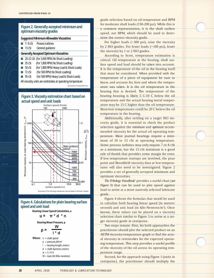
Additionally, after settling on a target ISO vis-cosity grade, it is essential to check the productselection against the minimum and optimum recom-mended viscosity for the actual oil operating tem-perature. Most journal bearings require a mini-mum of 10 to 13 cSt at operating temperature.Some process turbines may only require 7 or 8 cStas a minimum, but the 13 cSt minimum is a goodrule of thumb that provides some margin for error.If low temperature startups are involved, the pourpoint and Brookfield viscosity data at low tempera-tures will also need to be investigated. Figure 2provides a set of generally accepted minimum andoptimum viscosities.
The Tribology Handbook1 provides a useful chart (seeFigure 3) that can be used to plot speed againstload to arrive at a more narrowly selected lubricantgrade.
Figure 4 shows the formulas that would be usedto calculate both bearing linear speed (in meters/second) and unit load (in kilo-Newtons/m2). Onceknown, these values can be placed on a viscosityselection chart similar to Figure 3 to arrive at a tar-get viscosity grade in centipoise.
Two steps remain. First, for both approaches thepractitioner should plot the selected product on anASTM viscosity-temperature graph to find the actu-al viscosity in centistokes for the expected operat-ing temperature. This step provides a useful profileof the viscosity of the oil across its operating tem-perature range.
Second, for the approach using Figure 1 (units incentipoise), the practitioner should multiply the
CONTINUED FROM PAGE 19
Figure 4. Calculations for plain bearing surfacespeed and unit load
Suggested Minimum Allowable Viscosities■ 7- 8 cSt Process turbines■ 13 cSt General guidance Generally Accepted Optimum Viscosities ■ 20-22 cSt (for 3,600 RPM, No Shock Loading) ■ 35 cSt (for 1,800 RPM, No Shock Loading) ■ 50 cSt (for 1,800 RPM, Heavy Load & Shock Loads) ■ 72 cSt (for 500 RPM, No Shock Loading) ■ 95 cSt (for 500 RPM, Heavy Load & Shock Loads) All viscosity units are centistokes at operating temperature
Figure 2. Generally accepted minimum andoptimum viscosity grades
(Courtesy of Lubeworks, Inc.)
Figure 3. Viscosity estimation chart based onactual speed and unit loads
20 A P R I L 2 0 0 8 T R I B O L O G Y & L U B R I C A T I O N T E C H N O L O G Y
(Courtesy of The Tribology Handbook, Second Edition, Michael J. Neale)
T R I B O L O G Y & L U B R I C A T I O N T E C H N O L O G Y A P R I L 2 0 0 8 2 1
selected oil viscosity in centistokes (at operatingtemperature) by the typical specific gravity for theproduct to arrive at the expected viscosity in cen-tipoise.
Plain bearing additivesPlain bearings traditionally have been lubricatedby either compounded type products (fortified withfatty-acid compounds to improve lubricity) for low-speed and heavily loaded sliding surfaces, or rustand oxidation inhibited type products for high-speed sliding surfaces. A strong argument can bemade for sticking with these general product cate-gories, particularly in defense of avoiding EP typelubricants.
Given the thermal energy state required to acti-vate EP (sulfur and phosphorous) agents and thelow likelihood that the steel-on-soft metals interac-tion (bronze or babbit) can deliver the heat loadsufficient to cause these agents to perform theirlocalized function, there is likely more risk from theuse of EP products (accelerated lubricant degrada-tion and increase of acidic oil conditions) thanthere is a benefit from their use. If high load capa-bility is required, and there is concern that the vis-cosity cannot deliver the required results, then thereliability engineer should consider the use of solidfilm (molybdenum disulfide, graphite) fortifiedlubricant that can provide the added protection.
Element bearing lubricant selectionThere are many types of element bearings, includ-ing ball, roller, spherical roller, thrust roller, needleroller and single- and double-row types. Fortunate-ly the selection process for the various types issimilar. The following discussion pertains to thecommon ball, roller, spherical roller and thrustroller type element bearings.
Element bearings operate under a wide array oftemperature, speed, load and environmental con-ditions. The first step is to select an appropriateviscosity grade followed by selection of additivetype (R&O, AW, EP).
Bearing manufacturers provide fairly usefulcharts that assist us with this process. The fivesteps to this process are:
1. Determine the bearing physical size (width,outer diameter, inner diameter), element type(ball, cylindrical roller, spherical roller, thrustball or roller) and shaft speed. These detailsoften can be found in the shaft RPM machineconstruction diagrams and drawings. Exam-ple: A 6320 bearing has a bore dimension of100 mm, an outer diameter dimension of 215mm and a race width of 47 mm.
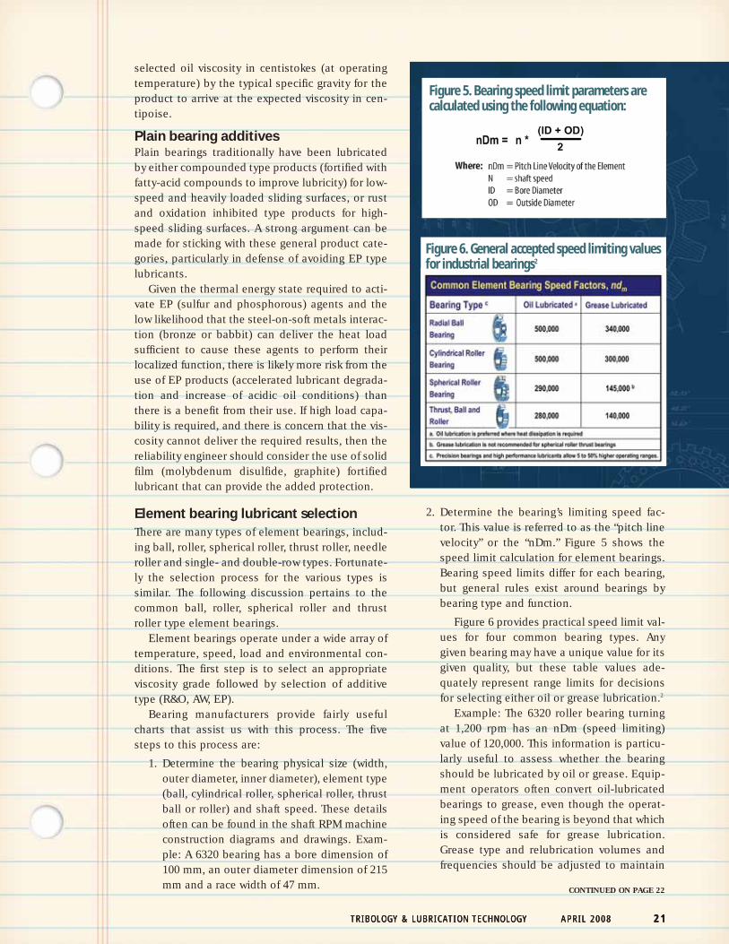
2. Determine the bearing’s limiting speed fac-tor. This value is referred to as the “pitch linevelocity” or the “nDm.” Figure 5 shows thespeed limit calculation for element bearings.Bearing speed limits differ for each bearing,but general rules exist around bearings bybearing type and function.
Figure 6 provides practical speed limit val-ues for four common bearing types. Anygiven bearing may have a unique value for itsgiven quality, but these table values ade-quately represent range limits for decisionsfor selecting either oil or grease lubrication.2
Example: The 6320 roller bearing turningat 1,200 rpm has an nDm (speed limiting)value of 120,000. This information is particu-larly useful to assess whether the bearingshould be lubricated by oil or grease. Equip-ment operators often convert oil-lubricatedbearings to grease, even though the operat-ing speed of the bearing is beyond that whichis considered safe for grease lubrication.Grease type and relubrication volumes andfrequencies should be adjusted to maintain
T R I B O L O G Y & L U B R I C A T I O N T E C H N O L O G Y A P R I L 2 0 0 8 2 1T R I B O L O G Y & L U B R I C A T I O N T E C H N O L O G Y A P R I L 2 0 0 8 2 1
CONTINUED ON PAGE 22
Figure 5. Bearing speed limit parameters arecalculated using the following equation:
Figure 6. General accepted speed limiting valuesfor industrial bearings2
bearing reliability under these circum-stances.
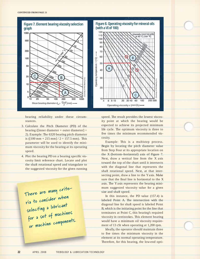
3. Calculate the Pitch Diameter (PD) of thebearing ([inner diameter + outer diameter] ÷2). Example: The 6320 bearing pitch diameteris ([100 mm + 215 mm] / 2 = 157.5 mm). Thisparameter will be used to identify the mini-mum viscosity for the bearing at its operatingspeed.
4. Plot the bearing PD on a bearing specific vis-cosity limit reference chart. Locate and plotthe shaft rotational speed and triangulate tothe suggested viscosity for the given running
speed. The result provides the lowest viscos-ity point at which the bearing would beexpected to achieve its projected minimumlife cycle. The optimum viscosity is three tofive times the minimum recommended vis-cosity.
Example: This is a multistep process.Begin by locating the pitch diameter valuefrom Step Four at its appropriate location onthe X (bottom–horizontal) axis of Figure 7.Next, draw a vertical line from the X axistoward the top of the chart until it intersectswith the diagonal line that represents theshaft rotational speed. Next, at that inter-secting point, draw a line to the Y axis. Makesure that the final line is horizontal to the Xaxis. The Y axis represents the bearing mini-mum suggested viscosity value for a givensize and shaft speed.
In this instance, the PD value (157.4) islabeled Point A. The intersection with thediagonal line for shaft speed is labeled PointB, which is the initiating point for the line thatterminates at Point C, this bearing’s requiredviscosity in centistokes. This element bearingwould have a minimum oil viscosity require-ment of 13 cSt when operating at 1,200 rpm.
Ideally, the operator should maintain threeto five times the minimum viscosity in theelement at its normal operating temperature.Therefore, for this bearing, the low-end opti-
22 A P R I L 2 0 0 8 T R I B O L O G Y & L U B R I C A T I O N T E C H N O L O G Y
CONTINUED FROM PAGE 21
There are many crite-
ria to consider when
selecting a lubricant
for a set of machines
or machine components.
Figure 7. Element bearing viscosity selectiongraph
Figure 8. Operating viscosity for mineral oils(with a VI of 100)
(Co
urt
esy
of F
AG
Bea
rin
g C
o.)
(Co
urt
esy
of F
AG
Bea
rin
g C
o.)
T R I B O L O G Y & L U B R I C A T I O N T E C H N O L O G Y A P R I L 2 0 0 8 2 3
mum is (13 cSt* 3 = 39 centistokes), and high-end optimum is (13 cSt* 5 = 65 centistokes).If viscosity error must be tolerated it would bebest to err on the side of increased oil thick-ness as long as the overage does not induceheat through fluid friction.
5. Plot the viscosity of the target lubricant on anASTM viscosity-temperature graph and deter-mine the actual viscosity at the expectedoperating temperature. Repeat the processuntil the correct lubricant has been selected.
Example: Figure 8 is a temperature viscos-ity chart provided by FAG Bearing Co. Thebearing operating temperature is located onthe Y axis, and is labeled Point A. Draw astraight line from the point that is horizontalto the X axis until it intersects with a red line,representing a standard viscosity grade (32,46, 68, 100, etc.). An ISO 68 should providethe desired viscosity at the normal operatingtemperature of the application (50 C). Theintersection point with this line for ISO 68 islabeled Point B. Lastly, from this intersectionpoint (B), draw a straight line to the X axis tolocate the actual operating viscosity, 38 cSt,which is labeled Point C.
It is evident from this exercise that thisbearing, operating at a running speed of1,200 rpm at 50 C temperature requires anISO 68 viscosity grade (with a VI of 100).
Element bearing additivesBearing manufacturers suggest that as long as theoperating viscosity is above the minimum it wouldbe best to lubricate without “doped” lubricants.Doped pertains to lubricants with AW or EP agentsthat form physi-chemical barrier films followingsurface contacts. AW and EP agents may over timeinfluence the microcrystalline structure of the bear-
ing metals in a negative way, even if the additiveagent is not fully engaged in surface protection.3
If shock loading is expected, then plan to useEP/AW-fortified lubricants to provide a margin oferror. If not, assuming that the operating viscosityis in an ideal range, use an R&O lubricant. If theoperating conditions include momentary high-temperature excursions that bring the operatingviscosity below the allowable minimum, thenEP/AW type lubricants are in order.
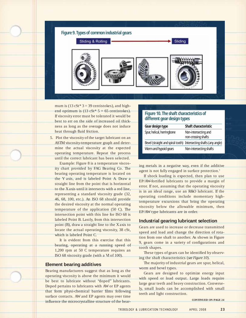
Industrial gearing lubricant selectionGears are used to increase or decrease transmittedspeed and load and change the direction of rota-tion from one shaft to another. As shown in Figure9, gears come in a variety of configurations andtooth shapes.
These types of gears can be identified by observ-ing the shaft characteristics (see Figure 10).
The majority of industrial gears are spur, helical,worm and bevel types.
Gears are designed to optimize energy inputwith speed or load output. Large loads requirelarge gear teeth and heavy construction. Converse-ly, small loads can be accomplished with smallteeth and light construction.
Figure 9. Types of common industrial gears
Figure 10. The shaft characteristics of different gear design typesGear design type Shaft characteristicSpur, helical, herringbone Non-intersecting and
non-crossing shaftsBevel (straight and spiral tooth) Intersecting shafts (any angle)Worm and hypoid gears Non-intersecting shafts
CONTINUED ON PAGE 24
24 A P R I L 2 0 0 8 T R I B O L O G Y & L U B R I C A T I O N T E C H N O L O G Y
Gear drives can be lubricated with either greaseor oil. Gear type, size and function are the leadingfactors in this decision. While the great majority ofindustrial gear applications operate in an oil bath,some gears operate without one. These gears,called ‘open’ gears, are lubricated with specializedgreases that are sprayed onto the gear set on anintermittent basis or applied manually (greasegun, brush, spray can). Open gear lubrication willbe addressed later in this series.
Once again, viscosity is the central feature ofthe lubricant that must be accurately identifiedand selected in order for components to achievetheir expected life cycles. As is the case with thepreviously evaluated components, the oil mustpossess viscometric properties that cover cold-flow requirements at low starting temperaturesand provide sufficient oil thickness at normal oper-ating temperatures to resist the squeezing effect ofthe meshing gears.
The low temperature flow requirement is depend-ent on a variety of application-specific factors,including weather, degree of shelter (indoor, out-doors), presence of thermal controls and likelihoodthat the unit will be started at extreme (cold) condi-tions. A safe pour-point limit for gear oils is 10 F/5.2C below the coldest likely starting temperature.4
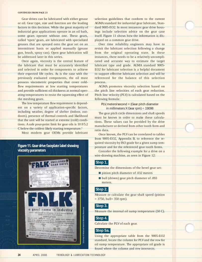
Most modern gear OEMs provide lubricant
selection guidelines that conform to the currentAGMA standard for industrial gear lubricant, Stan-dard 9005-EO2. In most instances gear drive hous-ings include selection advice on the gear caseitself. Figure 11 shows how the information is dis-played on a common gear drive.
Over time reliability engineers may have torevisit the lubricant selection following a changefrom the original operating state. In theseinstances, there needs to be a relatively uncompli-cated and accurate way to estimate the targetlubricant type and grade. AGMA standard 9005-EO2 for lubricant selection is a helpful documentto support effective lubricant selection and will bereferenced for the balance of this selectionprocess.
AGMA promotes viscosity selection based onthe pitch line velocities of each gear reduction.Pitch line velocity (PLV) is calculated based on thefollowing formula:
PLV, meters/second = (Gear pitch diameter in millimeters X Gear rpm) ÷ 19098
The gear pitch circle dimensions and shaft speedsmust be known in order to make these calcula-tions. These values can be provided by the drivemanufacturer or derived from other tooth form andratio data.
Once known, the PLV can be correlated to tablesfrom 9005-EO2, Appendix B, to reference the re-quired viscosity by ISO grade for a given sump tem-perature and for the referenced gear tooth forms.
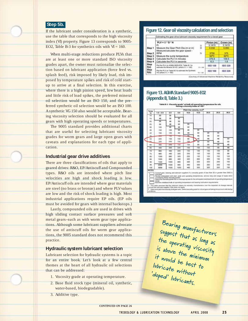
Consider the following example for a drive on awire-drawing machine, as seen in Figure 12:
Step 1..Determine the dimensions of the bevel gear set:
■ pinion pitch diameter of .032 meters
■ bull (driven) gear pitch diameter of .093meters.
Step 2..Measure or calculate the gear shaft speed (pinion= 3750, bull= 350 rpm).
Step 3..Measure the internal oil sump temperature (50 C).
Step 4..Calculate the PLV of each gear.
Step 5a..Using the appropriate table from the 9005-EO2standard, locate the column for PLV and the row foroil sump temperature. The appropriate oil grade isfound where the column and row intersects.
CONTINUED FROM PAGE 23
Figure 11. Gear drive faceplate label showingviscosity parameters
(Co
urt
esy
of A
dva
nce
d M
ach
ine
Relia
bili
ty R
eso
urc
es)
T R I B O L O G Y & L U B R I C A T I O N T E C H N O L O G Y A P R I L 2 0 0 8 2 5T R I B O L O G Y & L U B R I C A T I O N T E C H N O L O G Y A P R I L 2 0 0 8 2 5
Step 5b..If the lubricant under consideration is a synthetic,use the table that corresponds to the high viscosityindex (VI) property. Figure 13 corresponds to 9005-EO2, Table B-3 for synthetics oils with VI = 160.
When multi-stage reductions produce PLVs thatare at least one or more standard ISO viscositygrades apart, the owner must rationalize the selec-tion based on lubricant application (force feed vs.splash feed), risk imposed by likely load, risk im-posed by temperature spikes and risk of cold start-up to arrive at a final selection. In this exercise,where there is a high pinion speed, low heat loadsand little risk of load spikes, the preferred mineraloil selection would be an ISO 150, and the pre-ferred synthetic oil selection would be an ISO 100.A synthetic VG 150 also would be acceptable. Bear-ing viscosity selection should be evaluated for allgears with high operating speeds or temperatures.
The 9005 standard provides additional chartsthat are useful for selecting lubricant viscositygrades for worm gears and large open gears withcaveats and explanations for each type of appli-cation.
Industrial gear drive additivesThere are three classifications of oils that apply togeared drives: R&O, EP/Antiscuff and Compoundedtypes. R&O oils are intended where pitch linevelocities are high and shock loading is low.EP/Antiscuff oils are intended where gear materialsare steel (no brass or bronze) and where PLV valuesare low and the risk of shock loading is high. Mostindustrial applications require EP oils. (EP oilsmust be avoided for gears with internal backstops.)
Lastly, compounded oils are used in drives withhigh sliding contact surface pressures and softmetal gears–such as with worm gear type applica-tions. Although some lubricant suppliers advocatethe use of antiscuff oils for worm gear applica-tions, the 9005 standard does not recommend thispractice.
Hydraulic system lubricant selectionLubricant selection for hydraulic systems is a topicfor an entire book. Let’s look at a few centralthemes at the heart of all hydraulic oil selectionsthat can be addressed:
1. Viscosity grade at operating temperature.
2. Base fluid stock type (mineral oil, synthetic,water-based, biodegradable).
3. Additive type.
Figure 12. Gear oil viscosity calculation and selection
Figure 13. AGMA Standard 9005-EO2 (Appendix B, Table 3.)
CONTINUED ON PAGE 26
(Courtesy of Advanced Machine Reliability Resources)
Bearing manufacturerssuggest that as long asthe operating viscosityis above the minimumit would be best tolubricate without‘doped’ lubricants.
The hydraulic system, in a simplistic view, ac-complishes work by squeezing a small quantity ofoil into a pipe very rapidly and then directing thepressurized fluid through a set of valves to be re-leased where specific mechanical force is needed.
There are several common components in ahydraulic system, including:
■ Reservoir. Provides a supply of oil to thepump.
■ Pump. Adds flow/pressure to the oil.
■ Piping system. Contains the pressurized oil.
■ Valve/control system. Channels energy inthe form of pressurized oil.
■ Work components of some type. Performsthe required work.
■ Filters. Protects critical components fromcatastrophic damage, cleans the oil.
These various components represent a mixtureof frictional properties, including rolling friction(hydraulic motor and input motor bearings), slidingfriction (pump vanes and pistons, hydraulic rodsand cylinders) and a combination of the two (gearpump tooth contacts, hydraulic motors). All theseworking components are sensitive to the physical,chemical and cleanliness properties of the fluid.
Flow control systems tend to dictate fluid clean-liness requirements. Cleanliness will be addressedin a future article. Pump type (mechanical inter-face) and efficiency parameters typically dictatephysical viscosity parameters. Fluid type is dictat-ed by plant environmental factors: basestock typeand additive performance selection. It is notunusual for a given product selection to have con-flicting priorities.
Despite the many differences between systems,they are all intended to operate within an efficien-cy range. The allowable viscosity for a given system
is established by pump type and the specificpump’s efficiency parameters. If the fluid is toothick the pump may cavitate, overheat due to fluidfriction, increase mechanical stress on bearing ele-ments and consume excessive energy to fulfill itsfunction. If the fluid is too thin the pump contactsurfaces will wear and lose efficiency, and thepump may leak across internal and external sealsand clearances and overheat.
System manufacturers offer a window for appro-priate viscosity performance. The equipmentowner must fit the product into the viscometricwindow. The following seven steps represent a sys-tematic approach that may be used to arrive at thebest overall viscosity selection.
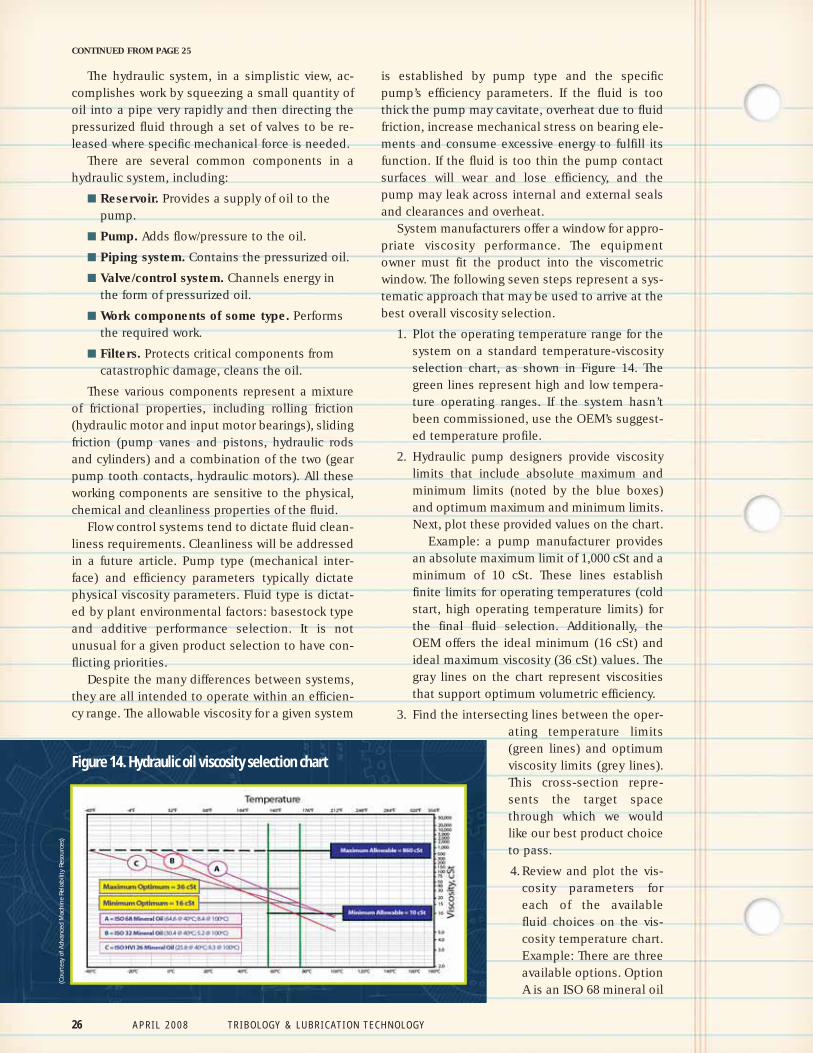
1. Plot the operating temperature range for thesystem on a standard temperature-viscosityselection chart, as shown in Figure 14. Thegreen lines represent high and low tempera-ture operating ranges. If the system hasn’tbeen commissioned, use the OEM’s suggest-ed temperature profile.
2. Hydraulic pump designers provide viscositylimits that include absolute maximum andminimum limits (noted by the blue boxes)and optimum maximum and minimum limits.Next, plot these provided values on the chart.
Example: a pump manufacturer providesan absolute maximum limit of 1,000 cSt and aminimum of 10 cSt. These lines establishfinite limits for operating temperatures (coldstart, high operating temperature limits) forthe final fluid selection. Additionally, theOEM offers the ideal minimum (16 cSt) andideal maximum viscosity (36 cSt) values. Thegray lines on the chart represent viscositiesthat support optimum volumetric efficiency.
3. Find the intersecting lines between the oper-ating temperature limits(green lines) and optimumviscosity limits (grey lines).This cross-section repre-sents the target spacethrough which we wouldlike our best product choiceto pass.
4. Review and plot the vis-cosity parameters foreach of the availablefluid choices on the vis-cosity temperature chart.Example: There are threeavailable options. OptionA is an ISO 68 mineral oil
CONTINUED FROM PAGE 25(C
ou
rtes
y o
f Ad
van
ced
Mac
hin
e Re
liab
ility
Res
ou
rces
)
Figure 14. Hydraulic oil viscosity selection chart
26 A P R I L 2 0 0 8 T R I B O L O G Y & L U B R I C A T I O N T E C H N O L O G Y
T R I B O L O G Y & L U B R I C A T I O N T E C H N O L O G Y A P R I L 2 0 0 8 2 7
with a VI of 100. Its default viscosity meas-urements are 64.6 cSt at 40 C, and 8.4 cSt at100 C. These points are plotted and a line isdrawn from the far left of the chart throughthese points to the far right of the chart. Theextreme ends of this line represent tempera-ture extremes that will be considered later.This process is repeated for the other avail-able products (options B and C are provided).
5. Evaluate the cold flow temperature limit foreach of the plotted lines and eliminate anythat do not meet the limits for cold weatheroperation.
Example: Identify the product that has thelongest line segment passing through theoptimum area (noted in Step 3). In this caseit appears to be option A. Observe the leftside of the chart where the ‘A’ line passesthrough the OEM’s absolute low viscositylimit. Line A crosses this (1,000 cSt) line atabout 0 C. This temperature is the lowestpossible temperature that the system can beallowed to run with this fluid. If it is likelythat the system will be expected to start attemperatures lower than 0 C, then anotheroption must be considered. Repeat the stepsfor each additional product option.
6. Make the final selection based on the best fitfor optimum viscosity within the operatingtemperature range and the least risk of coldstart failure.
Example: If the fluid is being selected for ahydraulic system that is bolted to the floor, itis unlikely that the cold start temperatureswill ever fall below 0 C. To control this risk,
the OEM might install a thermostatically-controlled heater to assure safe start condi-tions. If the system happens to be installed inoutdoor construction machinery, then it islikely that eventually this machine will haveto function below the cold start limit sug-gested for fluid A, making it undesirable forthe application.
7. Repeat this evaluation process for each prod-uct type until the best option is identified.
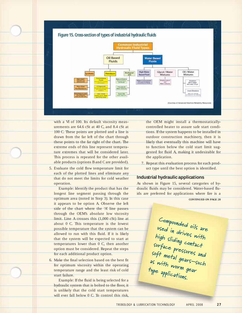
Industrial hydraulic applicationsAs shown in Figure 15, several categories of hy-draulic fluids may be considered. Water-based flu-ids are preferred for applications where fire is a
CONTINUED ON PAGE 28
Compounded oils areused in drives withhigh sliding contactsurface pressures andsoft metal gears–suchas with worm gear type applications.
Figure 15. Cross-section of types of industrial hydraulic fluids
(Courtesy of Advanced Machine Reliability Resources)

28 A P R I L 2 0 0 8 T R I B O L O G Y & L U B R I C A T I O N T E C H N O L O G Y
threat, and oil-based fluids are preferred for appli-cations where either there is no risk of fire or wherethere is both risk of fire and a high degree of com-ponent reliability is necessary for other reasons(i.e., safety factors such as fluids used in aircraft hy-draulics).
In each instance, regardless of the basestocktype, wear-resistance is critical. The primarymechanical component subject to wear is thepump. Pumps operate with significant but lowincremental-force mechanical interaction (bound-ary and mixed film state). AW fluids are appropri-ate for this type of service. These additives gener-ate a physi-chemical organo-metallic barrier layeron contacting surfaces that can be repeatedlywiped off and replaced many times during normaloperation. These chemi-physical films provide on-going wear resistance without excessive chemicalreactivity.
Lubricant manufacturers have many differentlubricant formulas that accomplish these results,with varying degrees of longevity, additive stabilityand overall system friendliness. Standardized wear-resistance performance testing should be includedin the final lubricant selection process.
Mike Johnson, CLS, CMRP, MLT, is the principal consult-ant for Advanced Machine Reliability Resources, headquar-tered in Franklin, Tenn. You can reach him at [email protected].
TLT
CONTINUED FROM PAGE 27
References1. Heale, M.J. (1985), The Tribology Hand-book, Second Edition, Elsevier.
2. Pirro, D.M. and Wessol, A.A. (2001),Lubrication Fundamentals, Second Edition,Marcel Dekker.
3. SKF Bearing Installation and Mainte-nance Guide, 140-710.
4. AGMA 9005-E02, American NationalStandard for Industrial Gear Lubrication.
Related Documents