Test Suite for the CAE Implementor Forum Round 3S June - December 2018 Release 1.1 October 5, 2018 Contacts Jochen Boy PROSTEP AG Dolivostraße 11 64293 Darmstadt / Germany [email protected] Jean-Marc Crepel AFNeT 30, Rue de Miromesnil 75008 Paris / France [email protected] Phil Rosché ACCR, LLC. 125 King Charles Circle Summerville, SC 29485 USA [email protected] © CAx Implementor Forum

Welcome message from author
This document is posted to help you gain knowledge. Please leave a comment to let me know what you think about it! Share it to your friends and learn new things together.
Transcript
Test Suite for the
CAE Implementor Forum
Round 3S
June - December 2018
Release 1.1
October 5, 2018
Contacts
Jochen Boy
PROSTEP AG
Dolivostraße 11
64293 Darmstadt / Germany
Jean-Marc Crepel
AFNeT
30, Rue de Miromesnil
75008 Paris / France
Phil Rosché
ACCR, LLC.
125 King Charles Circle
Summerville, SC 29485 USA
© CAx Implementor Forum
CAE Implementor Forum Round 3S Test Suite Version 1.1, October 5, 2018
© CAx Implementor Forum http://www.cax-if.de/ 2 http://www.cax-if.org/
Table of Contents
1 Introduction .......................................................................................................... 3
1.1 Functionality tested in this round ................................................................................. 3
1.2 General testing instructions for this round ................................................................... 4
1.3 Testing Schedule ........................................................................................................ 5
1.4 Copyrights on Test Cases ........................................................................................... 5
2 Synthetic Test Case Specifications ................................................................... 6
2.1 Test Case ATS1: beam FEA model using rod elements ............................................. 6
2.2 Test Case ATS2: beam FEA model using bar elements ............................................. 8
2.3 Test Case ATS3: beam FEA model using shell elements ......................................... 11
2.4 Test Case ATS4: beam FEA model using solid elements ......................................... 15
Annex A General Considerations about CAE ..................................................... 19
Annex B Information related to Statistics calculation ....................................... 20
List of Figures Figure 1: CAE-IF round trip process ......................................................................................... 3
Figure 2: CAE-IF Round3S Schedule ...................................................................................... 5
Figure 3: ATS1 model overview ............................................................................................... 7
Figure 4: ATS2 model overview ............................................................................................. 10
Figure 5: ATS3 model overview ............................................................................................. 13
Figure 6: ATS4 model overview ............................................................................................. 17
Document History
Release Date Change
0.1 September 21, 2018 First Draft Release
0.2 September 24, 2018 Add reference to FEA Handbook vol 2 Add load case selection for “FEA loadcase_id” statistics
1.0 September 29, 2018 First release for CAE-IF participants
1.1 October 5,2018 Assignement of validation properties limited to “model level val.prop. in R3S
CAE Implementor Forum Round 3S Test Suite Version 1.1, October 5, 2018
© CAx Implementor Forum http://www.cax-if.de/ 3 http://www.cax-if.org/
1 Introduction This document describes the suite of test cases to be used for the test round R3S of the CAE Implementor Forum (CAE-IF). The CAE-IF is a workgroup in the CAx Implementor Forum (CAx-IF), a joint testing forum, organized and facilitated by AFNeT, PDES, Inc., and the prostep ivip Association. The test rounds of the CAE-IF concentrate primarily on testing the interoper-ability and compliance of STEP processors based on AP209ed2.
The test rounds in general combine testing of synthetic and production models. Production models will in most cases be provided by the member companies of the organizations ANFeT, PDES, Inc., and prostep ivip Association. When production models are not available from the member companies, “production-like” models will be solicited from the various CAE-IF partici-pants.
This test suite includes synthetic models for testing the following capabilities: export /import Input FEA models for 3D Linear Static Structural Finite Element Analysis using simple models. More complex models, including production models and dynamic analysis, will be introduced later
1.1 Functionality tested in this round
The main objective of this test round is to check the robustness of a Finite Element Model (FEM) round trip, i.e. the ability to regenerate and re-run a FEM after an exchange using STEP AP209ed2 translators.
For this purpose the statistics to be checked in this test round will be focused on input data, which includes all information regarding discretized geometry (Nodes, Elements, …), physical and material properties, loads and boundary conditions (see Annex A) as well as execution control statements. The output data will be additionally considered for a visual check.
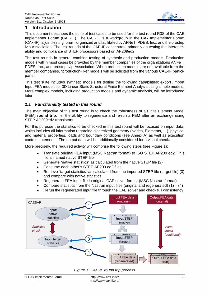
More precisely, the required activity will comprise the following steps (see Figure 1):
Translate original FEA input (MSC Nastran format) to ISO STEP AP209 ed2. This file is named native STEP file
Generate “native statistics” as calculated from the native STEP file (2) Consume each other’s STEP AP209 ed2 files Retrieve “target statistics” as calculated from the imported STEP file (target file) (3)
and compare with native statistics Regenerate FEA input file in original CAE solver format (MSC Nastran format) Compare statistics from the Nastran input files (original and regenerated) (1) – (4) Rerun the regenerated input file through the CAE solver and check full consistency.
Figure 1: CAE-IF round trip process
CAE Implementor Forum Round 3S Test Suite Version 1.1, October 5, 2018
© CAx Implementor Forum http://www.cax-if.de/ 4 http://www.cax-if.org/
1.2 General testing instructions for this round
The general procedures for communication of models and statistics are outlined in a separate document, named ‘General Testing Instructions’. The document can be retrieved from the CAx Implementor Forum web sites. The latest version is v1.12, dated July 5, 2016.
Therefore, the “native statistics” and “target statistics” (indicated (2) and (3) in Figure 1) will be submitted to the CAESAR system according to the regular process described in the ‘General Testing Instructions’, while statistics from original input data and regenerated input data (indi-cated (1) and (4) in Figure 1) will be submitted by the CAE-IF facilitator.
Key issues should be reported using the BRUTUS system (see ‘General Testing Instructions’).
Native FEA Model use NASTRAN card descriptions. Documentation of NASTRAN input syntax is available in the “NASTRAN quick reference guide”, which can be download from the MSC homepage at:
https://simcompanion.mscsoftware.com/infocenter/index?page=con-tent&id=DOC11146&cat=MSC_NASTRAN_DOCUMENTATION_2017&actp=LIST
Original FEA model of each test case is available in the xx.bdf file.
Note: CAE models are generally “unit consistent models”. This means there is no need for data conversion. Participants are requested to keep the original unit system unchanged and to deliver results and statistics using the same unit system as the native models. Nevertheless, the units’ definition shall be included in the STEP file, as stated in the recommended prac-tices.
The validation properties shall be assigned in the native STEP file as described in the “Rec-ommended Practices for Structural FEA validation properties” (v 0.4). For the test round 3S, the assignment of validation properties shall be limited to “model level validation properties” only. Specific statistics will be used to check if the validation property value included in the native STEP file is equal to the calculated value.
The rerun sequence will be executed by the LOTAR EAS WG and is not due by the partici-pants.
As described later, most of the statistics to be used in R3S are similar to theses used in R1S, but some new ones have been added:
FEA Bounding Box (see “Rec. Pract. For Struct. FEA validation properties” document)
3D elements centroid (see “Rec. Pract. For Struct. FEA validation properties” document)
2D elements centroid (see “Rec. Pract. For Struct. FEA validation properties” document)
1D elements centroid (see “Rec. Pract. For Struct. FEA validation properties” document)
FEA model title : text identifier of the FEA model (if any)
FEA loadcase identifier : text identifier of a selected load case
CAE Implementor Forum Round 3S Test Suite Version 1.1, October 5, 2018
© CAx Implementor Forum http://www.cax-if.de/ 5 http://www.cax-if.org/
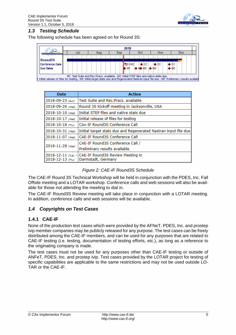
1.3 Testing Schedule The following schedule has been agreed on for Round 3S:
Figure 2: CAE-IF Round3S Schedule
The CAE-IF Round 3S Technical Workshop will be held in conjunction with the PDES, Inc. Fall Offsite meeting and a LOTAR workshop. Conference calls and web sessions will also be avail-able for those not attending the meeting to dial in.
The CAE-IF Round3S Review meeting will take place in conjunction with a LOTAR meeting. In addition, conference calls and web sessions will be available.
1.4 Copyrights on Test Cases
1.4.1 CAE-IF None of the production test cases which were provided by the AFNeT, PDES, Inc. and prostep ivip member companies may be publicly released for any purpose. The test cases can be freely distributed among the CAE-IF members, and can be used for any purposes that are related to CAE-IF testing (i.e. testing, documentation of testing efforts, etc.), as long as a reference to the originating company is made.
The test cases must not be used for any purposes other than CAE-IF testing or outside of ANFeT, PDES, Inc. and prostep ivip. Test cases provided by the LOTAR project for testing of specific capabilities are applicable to the same restrictions and may not be used outside LO-TAR or the CAE-IF.
CAE Implementor Forum Round 3S Test Suite Version 1.1, October 5, 2018
© CAx Implementor Forum http://www.cax-if.de/ 6 http://www.cax-if.org/
2 Synthetic Test Case Specifications
2.1 Test Case ATS1: beam FEA model using rod elements
All information about this test case can also be viewed in CAESAR on its Information page.
2.1.1 Motivation
This test case is part of the simple ATSx series models focusing on elementary CAE function-alities. The ATS1 test represents a cantilever beam using “rod” elements only, with one applied lumped force.
Within the CAE domain, the following functionalities are in scope of Round 3S:
Export/import input data of 3D FEA models with
o 1D elements (rod elements), linear order,
o Lumped force and fixed boundary conditions
o Execution control statements
Assignment of Structural FEA validation properties
Regeneration of the input data file in the original CAE solver format after STEP trans-lation
2.1.2 Approach
The approach to be used is described in the latest version of the following documents:
“Recommended Practices for AP 209 ed2” (at least version 2.0, dated March 30, 2016) “AP 209 ed2 Linear Static Structural FEA Handbook” vol.1 - (at least version v 2.2, dated
May 16, 2018) “AP 209 ed2 Linear Static Structural FEA Handbook” vol. 2 - (v 0.0.5). “Recommended Practices for Structural FEA validation properties (v 0.4)
For the test round 3S, the assignment of validation properties shall be limited to “model level validation properties” only.
These documents can be found either in the public area of the CAx-IF website under “Joint Testing Information” or in the member area of the CAx-IF website under “Information on round 3S of testing”.
The AP 209 schema to be used is a corrected version of the AP 209 ed2 schema, which can be found in the member area of the CAx-IF website, under “Information on Round 1S of Test-ing”.
2.1.3 Testing Instructions
The tests will be performed based on the ATS1m5 NASTRAN model described below. This model has been developed by the LOTAR EAS Working Group, and has been checked during previous pilot studies.
2.1.3.1 Test Model Overview
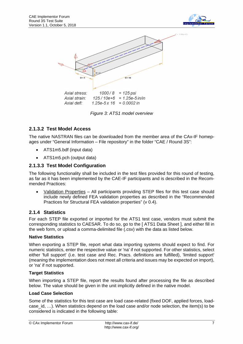
The ATS1m5 model represents a beam (rectangular prism) idealized using “rod” elements (axial stiffness element, no torsional stiffness), with the following characteristics:
Isotropic material property
1000 lbf axial load in compressive (-x) direction
Rectangular coordinate system at origin with model at [0, -2, 1]
CAE Implementor Forum Round 3S Test Suite Version 1.1, October 5, 2018
© CAx Implementor Forum http://www.cax-if.de/ 7 http://www.cax-if.org/
Figure 3: ATS1 model overview
2.1.3.2 Test Model Access
The native NASTRAN files can be downloaded from the member area of the CAx-IF homep-ages under “General Information – File repository” in the folder “CAE / Round 3S”:
ATS1m5.bdf (input data)
ATS1m5.pch (output data)
2.1.3.3 Test Model Configuration
The following functionality shall be included in the test files provided for this round of testing, as far as it has been implemented by the CAE-IF participants and is described in the Recom-mended Practices:
Validation Properties – All participants providing STEP files for this test case should include newly defined FEA validation properties as described in the “Recommended Practices for Structural FEA validation properties” (v 0.4).
2.1.4 Statistics For each STEP file exported or imported for the ATS1 test case, vendors must submit the corresponding statistics to CAESAR. To do so, go to the [ ATS1 Data Sheet ], and either fill in the web form, or upload a comma-delimited file (.csv) with the data as listed below.
Native Statistics
When exporting a STEP file, report what data importing systems should expect to find. For numeric statistics, enter the respective value or 'na' if not supported. For other statistics, select either 'full support' (i.e. test case and Rec. Pracs. definitions are fulfilled), 'limited support' (meaning the implementation does not meet all criteria and issues may be expected on import), or 'na' if not supported.
Target Statistics
When importing a STEP file, report the results found after processing the file as described below. The value should be given in the unit implicitly defined in the native model.
Load Case Selection
Some of the statistics for this test case are load case-related (fixed DOF, applied forces, load-case_id, …). When statistics depend on the load case and/or node selection, the item(s) to be considered is indicated in the following table:
CAE Implementor Forum Round 3S Test Suite Version 1.1, October 5, 2018
© CAx Implementor Forum http://www.cax-if.de/ 8 http://www.cax-if.org/
Statistic Case ‘A’ Fixed DOF nb Loadcase #1 Applied force Loadcase #1 Load case identifier Loadcase #1
Applicable Units and Coordinate system
The model is based on imperial units (in, lbf).
Components of any point (such as Center of Gravity) or vector (such as resultant of applied loads) should be calculated in the basic coordinate system.
Screenshots (optional)
Note that CASEAR allows the addition of multiple screenshots per dataset.
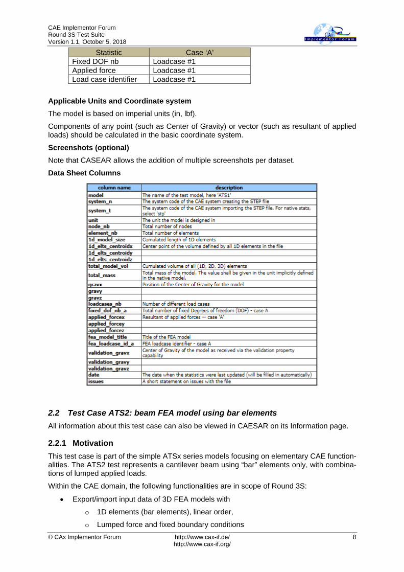
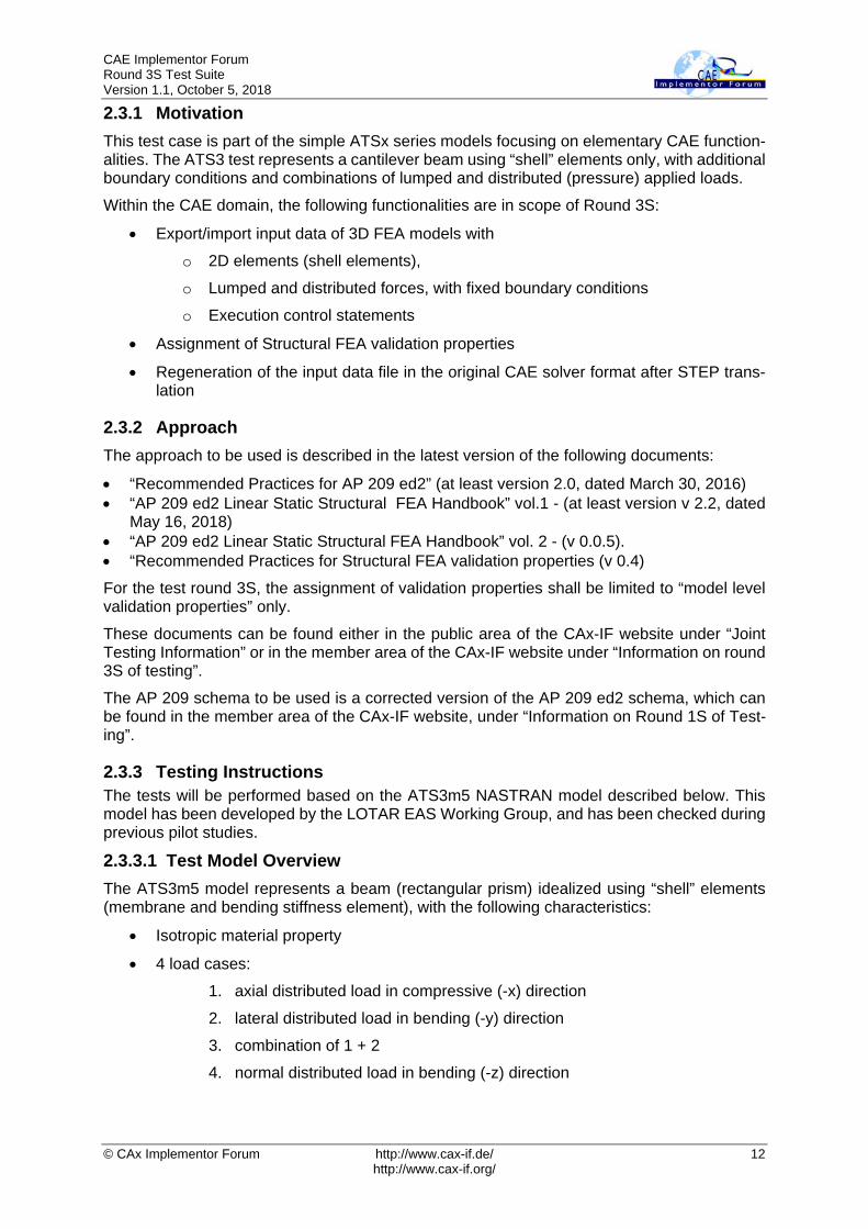
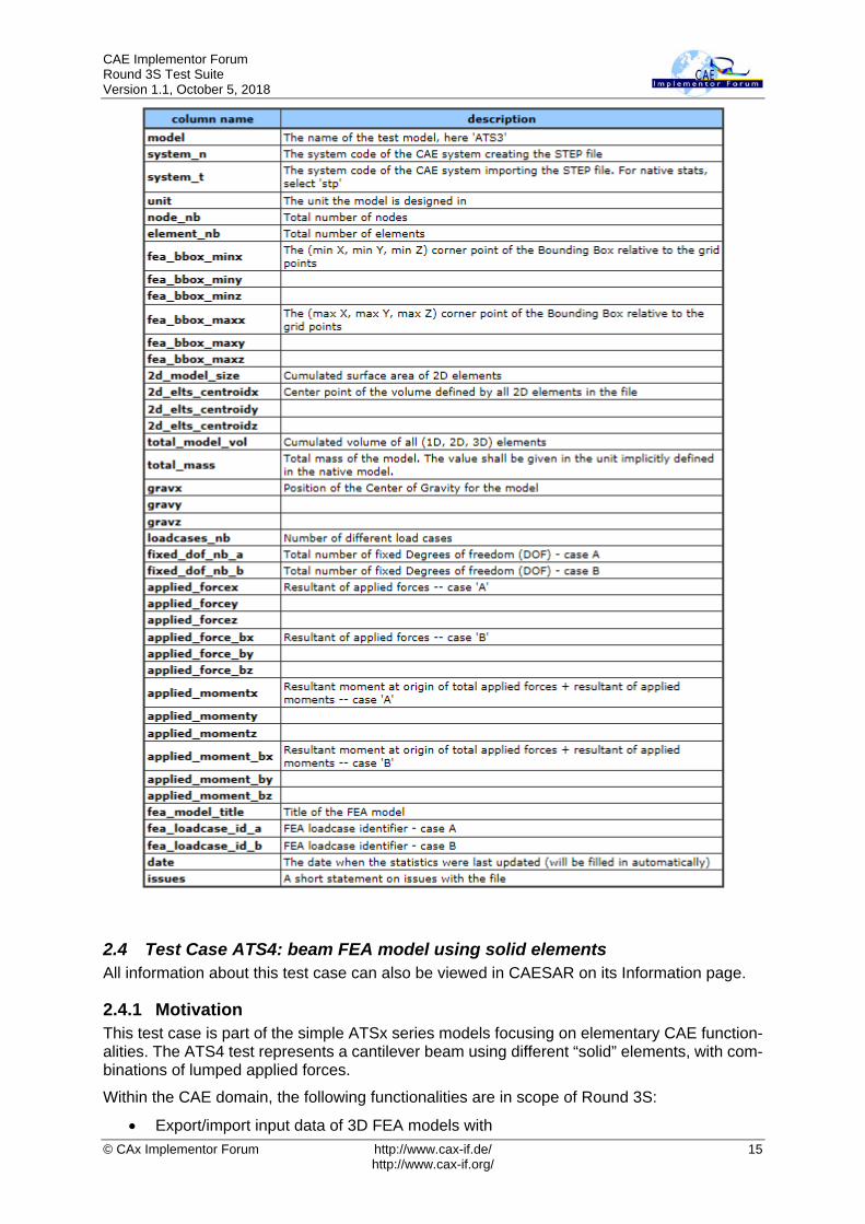
Data Sheet Columns
2.2 Test Case ATS2: beam FEA model using bar elements
All information about this test case can also be viewed in CAESAR on its Information page.
2.2.1 Motivation
This test case is part of the simple ATSx series models focusing on elementary CAE function-alities. The ATS2 test represents a cantilever beam using “bar” elements only, with combina-tions of lumped applied loads.
Within the CAE domain, the following functionalities are in scope of Round 3S:
Export/import input data of 3D FEA models with
o 1D elements (bar elements), linear order,
o Lumped force and fixed boundary conditions
CAE Implementor Forum Round 3S Test Suite Version 1.1, October 5, 2018
© CAx Implementor Forum http://www.cax-if.de/ 9 http://www.cax-if.org/
o Execution control statements
Assignment of Structural FEA validation properties
Regeneration of the input data file in the original CAE solver format after STEP trans-lation
2.2.2 Approach
The approach to be used is described in the latest version of the following documents:
“Recommended Practices for AP 209 ed2” (at least version 2.0, dated March 30, 2016) “AP 209 ed2 Linear Static Structural FEA Handbook” vol.1 - (at least version v 2.2, dated
May 16, 2018) “AP 209 ed2 Linear Static Structural FEA Handbook” vol. 2 - (v 0.0.5). “Recommended Practices for Structural FEA validation properties (v 0.4)
For the test round 3S, the assignment of validation properties shall be limited to “model level validation properties” only.
These documents can be found either in the public area of the CAx-IF website under “Joint Testing Information” or in the member area of the CAx-IF website under “Information on round 3S of testing”.
The AP 209 schema to be used is a corrected version of the AP 209 ed2 schema, which can be found in the member area of the CAx-IF website, under “Information on Round 1S of Test-ing”.
2.2.3 Testing Instructions The tests will be performed based on the ATS2m5 NASTRAN model described below. This model has been developed by the LOTAR EAS Working Group, and has been checked during previous pilot studies.
2.2.3.1 Test Model Overview
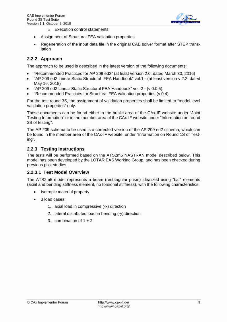
The ATS2m5 model represents a beam (rectangular prism) idealized using “bar” elements (axial and bending stiffness element, no torsional stiffness), with the following characteristics:
Isotropic material property
3 load cases:
1. axial load in compressive (-x) direction
2. lateral distributed load in bending (-y) direction
3. combination of 1 + 2
CAE Implementor Forum Round 3S Test Suite Version 1.1, October 5, 2018
© CAx Implementor Forum http://www.cax-if.de/ 10 http://www.cax-if.org/
Figure 4: ATS2 model overview
2.2.3.2 Test Model Access. The native NASTRAN files can be downloaded from the member area of the CAx-IF homep-ages under “General Information – File repository” in the folder “CAE / Round 3S”:
ATS2m5.bdf (input data)
ATS2m5.pch (output data)
2.2.3.3 Test Model Configuration See section 2.1.3.3 above.
2.2.4 Statistics For each STEP file exported or imported for the ATS2 test case, vendors must submit the corresponding statistics to CAESAR. To do so, go to the [ ATS2 Data Sheet ], and either fill in the web form, or upload a comma-delimited file (.csv) with the data as listed below.
Native Statistics
When exporting a STEP file, report what data importing systems should expect to find. For numeric statistics, enter the respective value or 'na' if not supported. For other statistics, select either 'full support' (i.e. test case and Rec. Pracs. definitions are fulfilled), 'limited support' (meaning the implementation does not meet all criteria and issues may be expected on import), or 'na' if not supported.
Target Statistics
When importing a STEP file, report the results found after processing the file as described in the table below. The value should be given in the unit implicitly defined in the native model.
Load Case Selection
Some of the statistics for this test case are load case-related (fixed DOF, applied forces, ap-plied moment, …). When statistics depend on the load case and/or node selection, the item(s) to be considered is indicated in the following table:
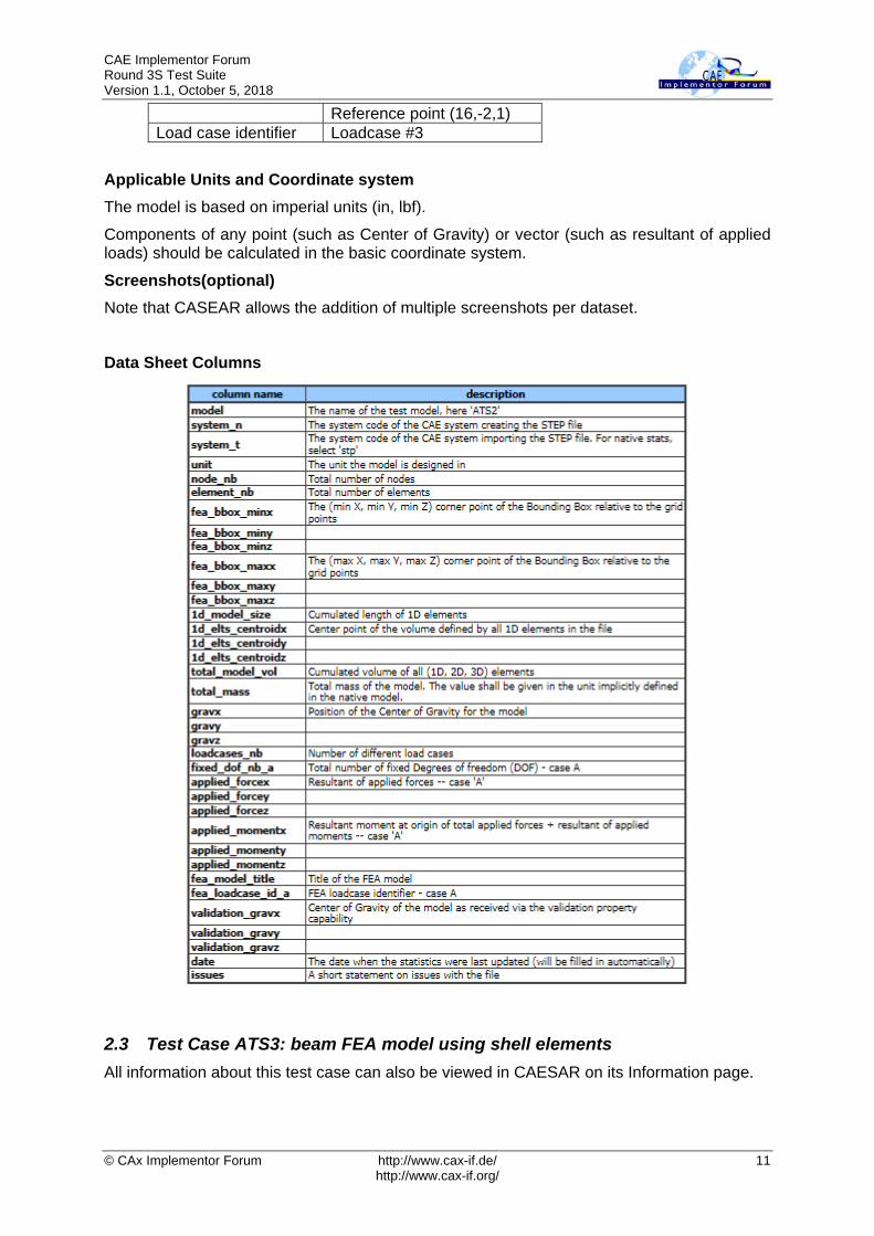
Statistic Case ‘A’ Fixed DOF nb Loadcase #3 Applied force Loadcase #3 Applied moment Loadcase #3
CAE Implementor Forum Round 3S Test Suite Version 1.1, October 5, 2018
© CAx Implementor Forum http://www.cax-if.de/ 11 http://www.cax-if.org/
Reference point (16,-2,1) Load case identifier Loadcase #3
Applicable Units and Coordinate system
The model is based on imperial units (in, lbf).
Components of any point (such as Center of Gravity) or vector (such as resultant of applied loads) should be calculated in the basic coordinate system.
Screenshots(optional)
Note that CASEAR allows the addition of multiple screenshots per dataset.
Data Sheet Columns
2.3 Test Case ATS3: beam FEA model using shell elements
All information about this test case can also be viewed in CAESAR on its Information page.
CAE Implementor Forum Round 3S Test Suite Version 1.1, October 5, 2018
© CAx Implementor Forum http://www.cax-if.de/ 12 http://www.cax-if.org/
2.3.1 Motivation
This test case is part of the simple ATSx series models focusing on elementary CAE function-alities. The ATS3 test represents a cantilever beam using “shell” elements only, with additional boundary conditions and combinations of lumped and distributed (pressure) applied loads.
Within the CAE domain, the following functionalities are in scope of Round 3S:
Export/import input data of 3D FEA models with
o 2D elements (shell elements),
o Lumped and distributed forces, with fixed boundary conditions
o Execution control statements
Assignment of Structural FEA validation properties
Regeneration of the input data file in the original CAE solver format after STEP trans-lation
2.3.2 Approach
The approach to be used is described in the latest version of the following documents:
“Recommended Practices for AP 209 ed2” (at least version 2.0, dated March 30, 2016) “AP 209 ed2 Linear Static Structural FEA Handbook” vol.1 - (at least version v 2.2, dated
May 16, 2018) “AP 209 ed2 Linear Static Structural FEA Handbook” vol. 2 - (v 0.0.5). “Recommended Practices for Structural FEA validation properties (v 0.4)
For the test round 3S, the assignment of validation properties shall be limited to “model level validation properties” only.
These documents can be found either in the public area of the CAx-IF website under “Joint Testing Information” or in the member area of the CAx-IF website under “Information on round 3S of testing”.
The AP 209 schema to be used is a corrected version of the AP 209 ed2 schema, which can be found in the member area of the CAx-IF website, under “Information on Round 1S of Test-ing”.
2.3.3 Testing Instructions The tests will be performed based on the ATS3m5 NASTRAN model described below. This model has been developed by the LOTAR EAS Working Group, and has been checked during previous pilot studies.
2.3.3.1 Test Model Overview
The ATS3m5 model represents a beam (rectangular prism) idealized using “shell” elements (membrane and bending stiffness element), with the following characteristics:
Isotropic material property
4 load cases:
1. axial distributed load in compressive (-x) direction
2. lateral distributed load in bending (-y) direction
3. combination of 1 + 2
4. normal distributed load in bending (-z) direction
CAE Implementor Forum Round 3S Test Suite Version 1.1, October 5, 2018
© CAx Implementor Forum http://www.cax-if.de/ 13 http://www.cax-if.org/
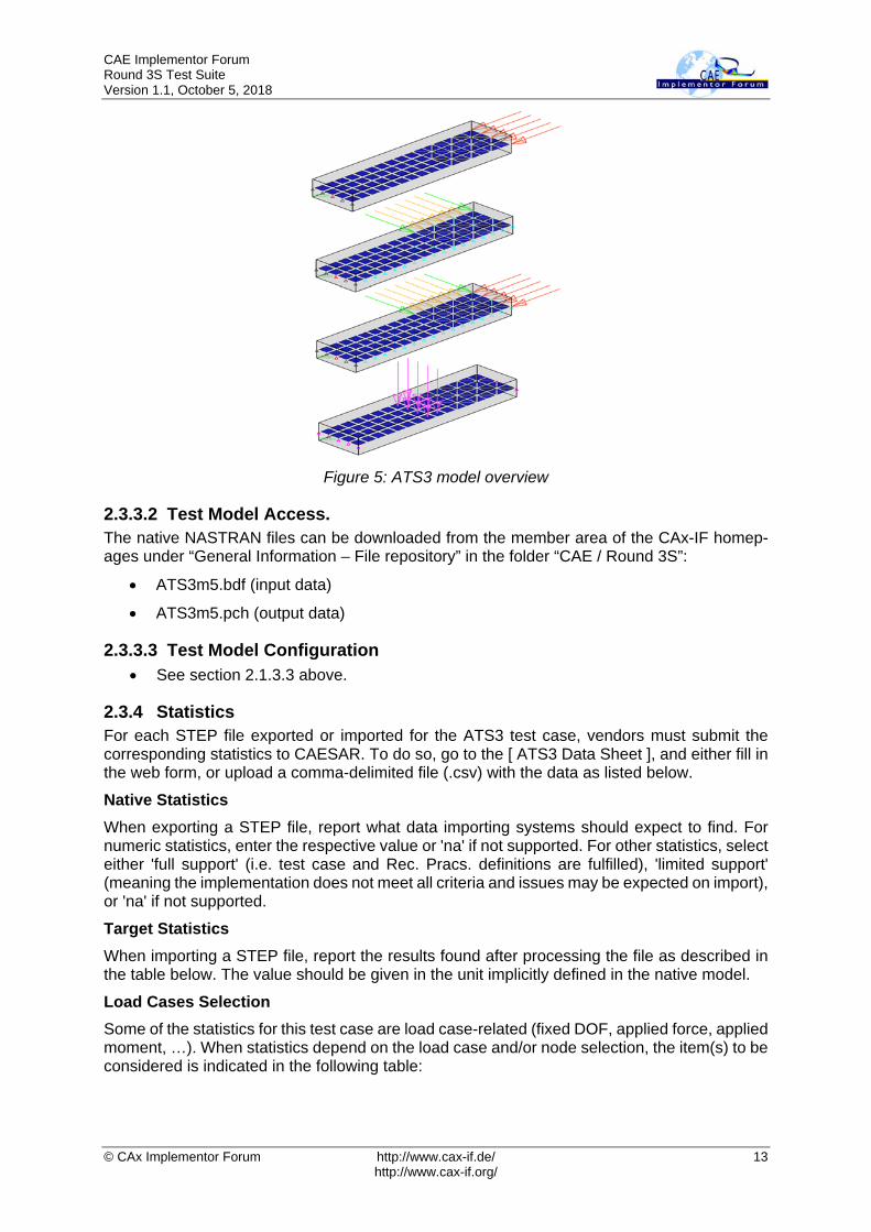
Figure 5: ATS3 model overview
2.3.3.2 Test Model Access. The native NASTRAN files can be downloaded from the member area of the CAx-IF homep-ages under “General Information – File repository” in the folder “CAE / Round 3S”:
ATS3m5.bdf (input data)
ATS3m5.pch (output data)
2.3.3.3 Test Model Configuration See section 2.1.3.3 above.
2.3.4 Statistics For each STEP file exported or imported for the ATS3 test case, vendors must submit the corresponding statistics to CAESAR. To do so, go to the [ ATS3 Data Sheet ], and either fill in the web form, or upload a comma-delimited file (.csv) with the data as listed below.
Native Statistics
When exporting a STEP file, report what data importing systems should expect to find. For numeric statistics, enter the respective value or 'na' if not supported. For other statistics, select either 'full support' (i.e. test case and Rec. Pracs. definitions are fulfilled), 'limited support' (meaning the implementation does not meet all criteria and issues may be expected on import), or 'na' if not supported.
Target Statistics
When importing a STEP file, report the results found after processing the file as described in the table below. The value should be given in the unit implicitly defined in the native model.
Load Cases Selection
Some of the statistics for this test case are load case-related (fixed DOF, applied force, applied moment, …). When statistics depend on the load case and/or node selection, the item(s) to be considered is indicated in the following table:
CAE Implementor Forum Round 3S Test Suite Version 1.1, October 5, 2018
© CAx Implementor Forum http://www.cax-if.de/ 14 http://www.cax-if.org/
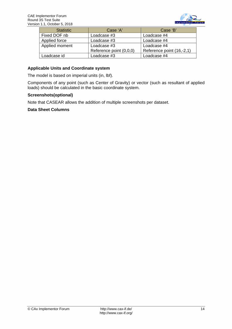
Statistic Case ‘A’ Case ‘B’ Fixed DOF nb Loadcase #3 Loadcase #4 Applied force Loadcase #3 Loadcase #4 Applied moment Loadcase #3
Reference point (0,0,0) Loadcase #4 Reference point (16,-2,1)
Loadcase id Loadcase #3 Loadcase #4
Applicable Units and Coordinate system
The model is based on imperial units (in, lbf).
Components of any point (such as Center of Gravity) or vector (such as resultant of applied loads) should be calculated in the basic coordinate system.
Screenshots(optional)
Note that CASEAR allows the addition of multiple screenshots per dataset.
Data Sheet Columns
CAE Implementor Forum Round 3S Test Suite Version 1.1, October 5, 2018
© CAx Implementor Forum http://www.cax-if.de/ 15 http://www.cax-if.org/
2.4 Test Case ATS4: beam FEA model using solid elements All information about this test case can also be viewed in CAESAR on its Information page.
2.4.1 Motivation This test case is part of the simple ATSx series models focusing on elementary CAE function-alities. The ATS4 test represents a cantilever beam using different “solid” elements, with com-binations of lumped applied forces.
Within the CAE domain, the following functionalities are in scope of Round 3S:
Export/import input data of 3D FEA models with
CAE Implementor Forum Round 3S Test Suite Version 1.1, October 5, 2018
© CAx Implementor Forum http://www.cax-if.de/ 16 http://www.cax-if.org/
o 3D elements (solid elements), linear order,
o Combination of lumped forces and fixed boundary conditions
o Execution control statements
Assignment of Structural FEA validation properties
Regeneration of the input data file in the original CAE solver format after STEP trans-lation
2.4.2 Approach The approach to be used is described in the latest version of the following documents:
“Recommended Practices for AP 209 ed2” (at least version 2.0, dated March 30, 2016) “AP 209 ed2 Linear Static Structural FEA Handbook” vol.1 - (at least version v 2.2, dated
May 16, 2018) “AP 209 ed2 Linear Static Structural FEA Handbook” vol. 2 - (v 0.0.5). “Recommended Practices for Structural FEA validation properties (v 0.4)
For the test round 3S, the assignment of validation properties shall be limited to “model level validation properties” only.
These documents can be found either in the public area of the CAx-IF website under “Joint Testing Information” or in the member area of the CAx-IF website under “Information on round 3S of testing”.
The AP 209 schema to be used is a corrected version of the AP 209 ed2 schema, which can be found in the member area of the CAx-IF website, under “Information on Round 1S of Test-ing”.
2.4.3 Testing Instructions The tests will be performed based on the ATS4m5 NASTRAN model described below. This model has been developed by the LOTAR EAS Working Group, and has been checked during previous pilot studies.
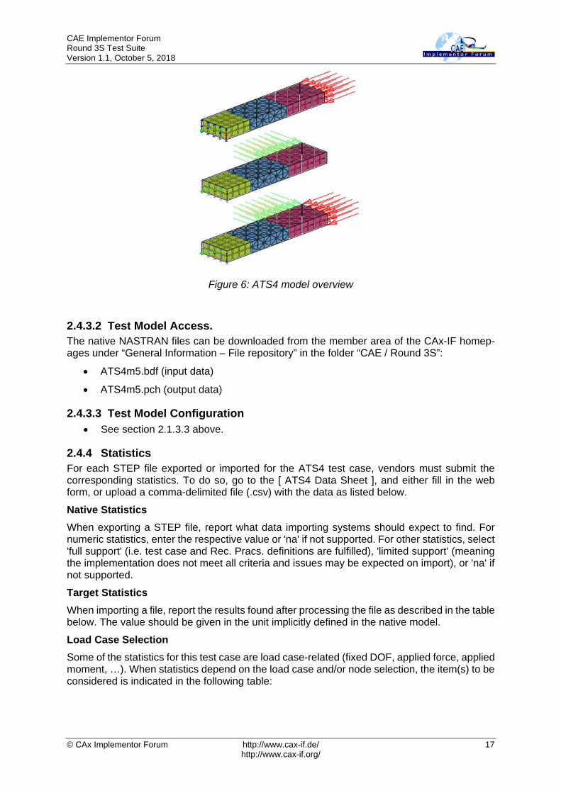
2.4.3.1 Test Model Overview
The ATS4m5 model represents a beam (rectangular prism) idealized using “solid” elements (mix of 4-noded tetrahedral, 6-noded pentahedral and 8-noded hexahedral elements), with the following characteristics:
Isotropic material property
3 load cases:
1. axial distributed load in compressive (-x) direction
2. lateral distributed load in bending (-y) direction
3. combination of 1 + 2
CAE Implementor Forum Round 3S Test Suite Version 1.1, October 5, 2018
© CAx Implementor Forum http://www.cax-if.de/ 17 http://www.cax-if.org/
Figure 6: ATS4 model overview
2.4.3.2 Test Model Access. The native NASTRAN files can be downloaded from the member area of the CAx-IF homep-ages under “General Information – File repository” in the folder “CAE / Round 3S”:
ATS4m5.bdf (input data)
ATS4m5.pch (output data)
2.4.3.3 Test Model Configuration See section 2.1.3.3 above.
2.4.4 Statistics For each STEP file exported or imported for the ATS4 test case, vendors must submit the corresponding statistics. To do so, go to the [ ATS4 Data Sheet ], and either fill in the web form, or upload a comma-delimited file (.csv) with the data as listed below.
Native Statistics
When exporting a STEP file, report what data importing systems should expect to find. For numeric statistics, enter the respective value or 'na' if not supported. For other statistics, select 'full support' (i.e. test case and Rec. Pracs. definitions are fulfilled), 'limited support' (meaning the implementation does not meet all criteria and issues may be expected on import), or 'na' if not supported.
Target Statistics
When importing a file, report the results found after processing the file as described in the table below. The value should be given in the unit implicitly defined in the native model.
Load Case Selection
Some of the statistics for this test case are load case-related (fixed DOF, applied force, applied moment, …). When statistics depend on the load case and/or node selection, the item(s) to be considered is indicated in the following table:
CAE Implementor Forum Round 3S Test Suite Version 1.1, October 5, 2018
© CAx Implementor Forum http://www.cax-if.de/ 18 http://www.cax-if.org/
Statistic Case ‘A’ Fixed DOF nb Loadcase #3 Applied force Loadcase #3 Applied moment Loadcase #3
Moment at point (16,-2,1) Load case identifier Loadcase #3
Applicable Units and Coordinate system
The model is based on imperial units (in, lbf).
Components of any point (such as Center of Gravity) or vector (such as resultant of applied loads) should be calculated in the basic coordinate system.
Screenshots(optional)
Note that CASEAR allows the addition of multiple screenshots per dataset.
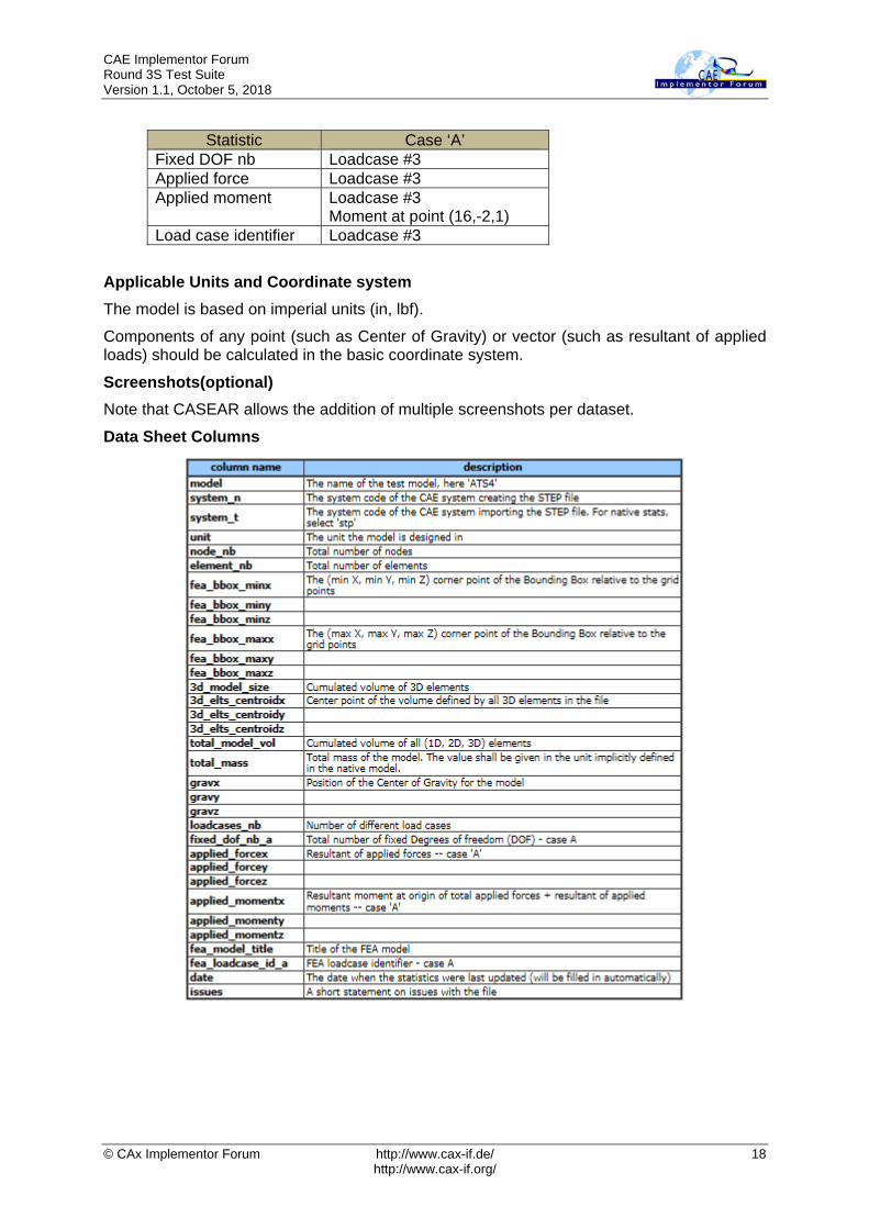
Data Sheet Columns
CAE Implementor Forum Round 3S Test Suite Version 1.1, October 5, 2018
© CAx Implementor Forum http://www.cax-if.de/ 19 http://www.cax-if.org/
Annex A General Considerations about CAE
CAE is dedicated to analyze/predict the physical behavior of parts or products. It is a way to calculate the displacement field and the related stress/strain field (mechanical/structural anal-ysis), temperature fields and heat flows (Thermal analysis), electric and magnetic fields (Elec-tromagnetic analysis) … Such problems can be addressed separately (mono-physics analysis) or simultaneously (coupled or multi-physics analysis), but the results is generally expressed as scalar fields, vector fields or tensor fields.
Basically, CAE models (whether it could be Finite Element models, Boundary element models or any other mathematical methods for discretization) deals with the following sets of data:
Input data
Discretized geometrical data, which represents the product to be studied. It uses nodes (points) and elements for connecting nodes. Some special elements may require additional properties such as section area, thickness, offset, …
Material properties, which are parameters used to describe the physical behavior. Most of the time, the physical behavior is hard coded in the CAE solver software, so that the meaning of each material parameter is defined in the user manual of the solver software. However, some standard physical behaviors are available in (almost) all CAE software with the same definition and same material parameters: mechanical elasticity, thermal expansion, heat transfer, Navier-stokes CFD, …
Boundary conditions. This is a set of locations where the solution is known/imposed, either for all components of the solution or one or more of the components if the solution is on the vector form. This will decrease the number of unknown values to be calculated (called the number of free Degrees Of Freedom –free DOF-) to fully define the solution, more formally to define the value of each component of the solution on each node without boundary condition.
Applied loads are external influences, depending of the physics to be studied. For structural analysis it could be forces and moments; heat flow for thermal analysis, … Such solicitations can be defined as :
o Nodal (or lumped) loads, ie, the component values are defined on specific nodes
o Distributed loads, ie, the component values are defined along a line (linear load), over a surface (surface load) or within a volume (volumic load)
Output data
As explained above, the results are expressed as scalar fields, vector fields or tensor fields, depending of the physics. Two set of output data can be considered:
Primary results which are directly calculated by the solver as the components of the solution at each node (i.e. each DOF). Could be nodal displacements for structural analysis, temperature for thermal analysis or flow speed for CFD…
Derivative results which are post-calculated from the primary results, and which could be located either on nodes location or anywhere else using discretization functions for interpolation. Basically, for structural analysis, it could be displacements out of node position, internal loads, strain or stresses (nodal value or out of node position), or any relevant combination for analysis (such as Von Mises scalar stress field for instance).
Similar derivative results can be defined for other physics.
CAE Implementor Forum Round 3S Test Suite Version 1.1, October 5, 2018
© CAx Implementor Forum http://www.cax-if.de/ 20 http://www.cax-if.org/
Annex B Information related to Statistics calculation
The value should be given in the unit implicitly defined in the native model. Components of any point (such as CDG) or vector (such as resultant of applied loads) should be calculated in the basic coordinate system.
Discretized geometrical values such as “Cumulated length of 1D elements” resp. “2D ele-ments”, “3D elements” (1D_Model_size, resp. 2D_Model_size, 3D_Model_size) should be cal-culated based on the Finite Element discretization, which can be slightly different from the original CAD definition.
Center of Gravity (CDG): should be calculated taking into account the density of all material in the model
Total_model_volume:
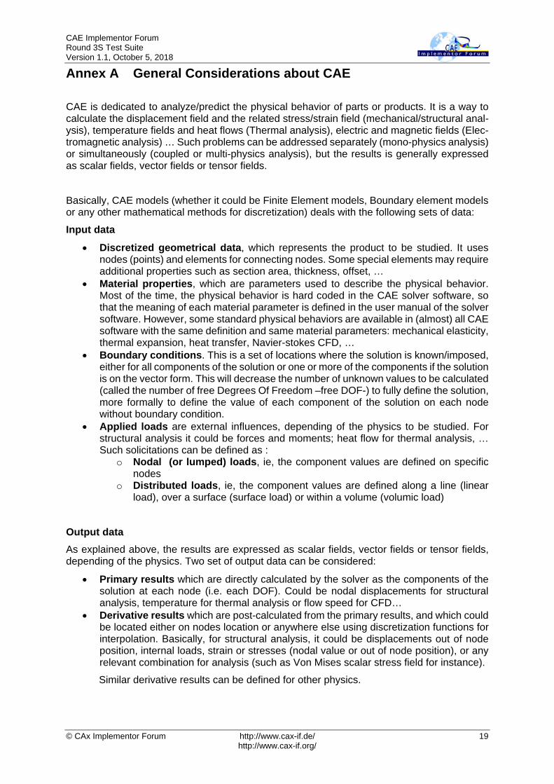
1D elements in Finite Element models are used to represent a beam or a bar along their middle-line (so called neutral axis). During the computation, the cross-section value of these elements is taken into account in order to evaluate the stiffness and more generally the mechanical behavior of the beam. Then, the “physical 1D volume” is given by the summation of (element_length * cross_section_area) over all 1D elements. Cross section area is given within the properties attached to each element.
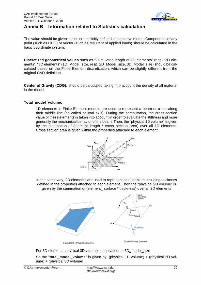
In the same way, 2D elements are used to represent shell or plate including thickness defined in the properties attached to each element. Then the “physical 2D volume” is
given by the summation of (element_ surface * thickness) over all 2D elements
For 3D elements, physical 3D volume is equivalent to 3D_model_size
So the “total_model_volume” is given by: (physical 1D volume) + (physical 2D vol-ume) + (physical 3D volume).
Related Documents