CA60Plus Installation manual WARNING This manual contains information on limitations regarding product use and function and information on the limitations as to liability of the manufacturer. The entire manual should be carefully read.

TeleTek CA60Plus
Aug 29, 2014
Welcome message from author
This document is posted to help you gain knowledge. Please leave a comment to let me know what you think about it! Share it to your friends and learn new things together.
Transcript

CA60Plus
Installation manual
WARNINGThis manual contains information on limitations regarding product use and function and information on thelimitations as to liability of the manufacturer. The entire manual should be carefully read.

ContentsPART I. Installation of the CA60Plus alarm control panel............................................................31. CA60Plus alarm control panel....................................................................................................42. LED60 and LED61 keyboards...................................................................................................53. CA60Plus control panel inputs and outputs...............................................................................64. Connecting LED60 and LED61 keyboards...............................................................................75. Using the PGM1, PGM2 and PGM3 programmable outputs...................................................86. Using SIREN programmable output..........................................................................................87. Connecting sensors to CA60Plus control panel........................................................................98. Connecting the CA60Plus built-in digital communicator..........................................................119. Powering the CA60Plus control panel......................................................................................1110. Installation of the voice dialer - VD60......................................................................................1211. Proximity cards reader - PR62 - connection....................................................................................13
PART II. Programming the software parameters for CA60Plus alarm controlpanel. . . . . . . . . . . . . . . . . . . . . . . . . . . . . . . . . . . . . . . . . . . . . . . . . . . . . . . . . . . . . . . . . . . . . . . . . . . . . . . . . . . . . . . . . . . . . . . . . . . . . . . . . .14
0. User codes in the CA60Plus control panel..............................................................................152. Zone programming...................................................................................................................163. Programming the PGM and SIREN programmable outputs...................................................204. Time periods............................................................................................................................225. Engineer parameters................................................................................................................246. Communicator parameters.......................................................................................................267. Programming Up/Down Load parameters................................................................................298. Programming the voice dialer - VD60..............................................................................319. CA60Plus test modes...............................................................................................................32
Supplement A LED61 keyboard for CA60Plus control panel......................................................35Supplement B Default programming table..................................................................................36Supplement C Additional information.........................................................................................39Supplement D General connection scheme.........................................................................................42Supplement E Example voice messages...................................................................................43

CA60Plus control panel Installation manual 3
PART I. Installation of the CA60Plus alarm control panel
The CA60Plus Alarm control panel was designed and tested in compliance with electromagneticcompatibility standards.
The following recommendations need to be observed for the proper performance of the alarm station:
1. Ensure the alarm system is properly earthed (grounded)
2. Insulate the high and low voltage cables and use different input openings on the box.
3. Avoid any loops of connecting wires within the very box and in their passage over or under theprinted-circuit boarding.
4. Additional relays must not be placed in the CA60Plus Alarm control panel box as these maygenerate electromagnetic interference when switched.
4.1. Use only relays with good insulation between contacts and the winding.
4.2. Relays, connected to outputs with an open commutator, must be designed to accom-modate a 12 V DC driving voltage and an impedance at the winding greater than400Ω.
5. The cable connecting the control panel and the keyboard is quadruple. It is strongly recom-mended not to:
5.1. use this cable to make other connections – connect to a telephone line, Flash-lampscontrol signals, sirens or relays.
6. Avoid channels or cable forms that contain high voltage cables when placing the connectingcables. This is very important in cases where such cables are being used to power electricmotors, fluorescent lamps or triple-phase voltage. Where the above is not possible, use onlyshielded cables, where the shield is grounded only in the alarm system box.

4 CA60Plus control panel Installation manual
CA60Plus alarm control panel metal box
1. CA60Plus alarm control panel
2
1
1 1
Unscrew (1)Remove cover (2)
Fig.1a CA60Plus control panel plastic box
1
6
3
5
1
4
Battery12V / 7 Ah
F - 0,63 A
Transformer230 Vac 50 / 60 Hzsec.: 17 V / 24 VA
1
Radio transmitter
2
RESET
F1 BATT
F3 AUX
F2 PGM
PROG
CommunicatorLED
2A
1A
1A
1 - Mounting openings2 - CA60Plus control panel3 - Mains supply terminal and fuse holder4 - Signal cables openings5 - Mains supply cable hole6 - Self-security TAMPER button
Fig.1 CA60Plus control panel
EXPAND
CA60Plus control panel Installation manual 5
2. LED60 and LED61 keyboards
Fig.2 CA60Plus LED keyboard
a) Cover
1 2 3
4 5 6
7 8 9
0
ON PROG CLEAR ENTER
ARM
MEM
CLR ENT0
1 2 3
4 5 6
7 8 9
PROG
DIS
ARM
?) Bottom
11
1
2
1 - Mounting holes2 - Cables hole
1
1
11
1
2
2
CA60Plus alarm control panel plastic box
Fig.1b CA60Plus control panel plastic box
7
86
66
6
6
6
5
4
3
22
2 2
Accu
mu
lato
r ca
ble
1 - Center support opening (behind PCB)2 - S3 - CA 864 control panel4 - Mains power supply terminal5 - Main cable opening
7 -
8 - Tamper button for box self-protection
upport opening
6 - Add. cable openingsMains power supply
opening
Mainstransformer50 / 60 Hz
15-25 V / 50VA
12V / 7 Ahbattery
Room for additional modules
Room for add. Modules
Use to fixmain power supply cable
F - 0,63 A
BA
TT
RESET
F1 BATT
F3 AUX
F2 PGM
PROG
CommunicatorLED
2A
1A
1A
1EXPAND
6 CA60Plus control panel Installation manual
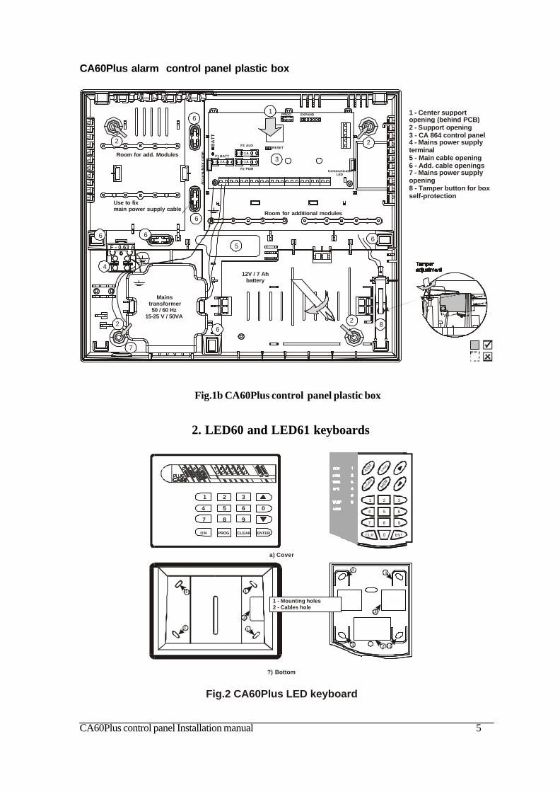
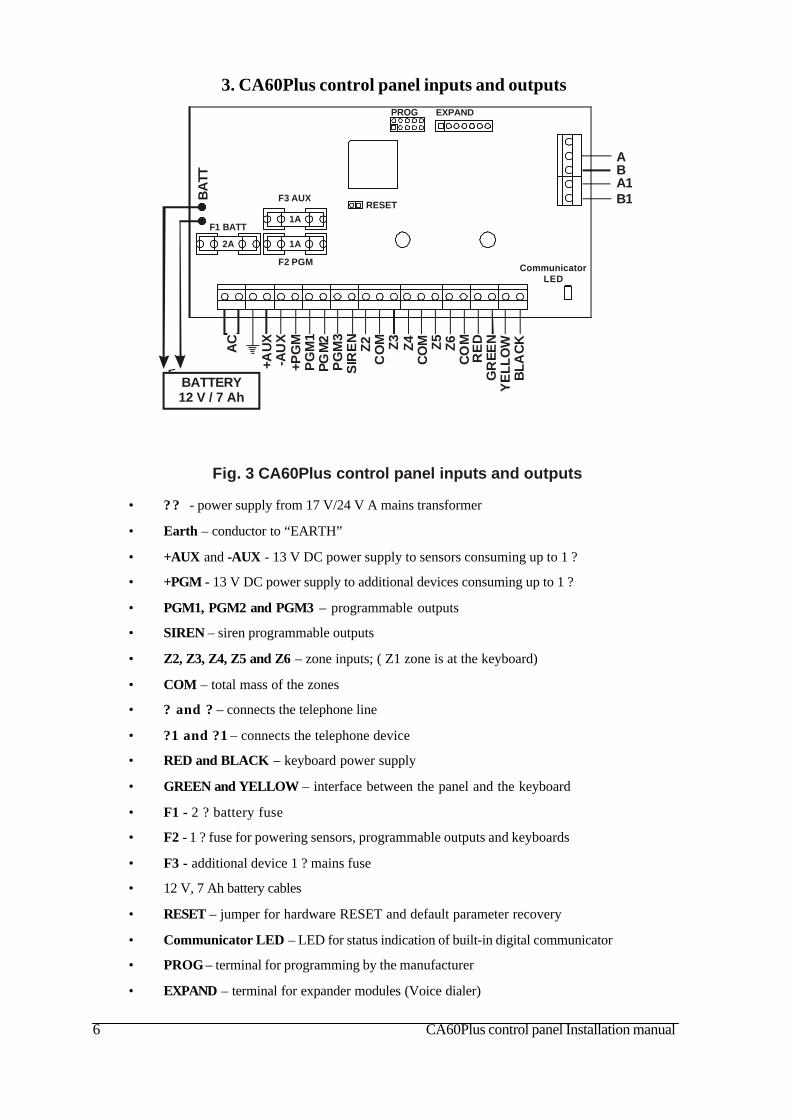
3. CA60Plus control panel inputs and outputs
• ? ? - power supply from 17 V/24 V A mains transformer
• Earth – conductor to “EARTH”
• +AUX and -AUX - 13 V DC power supply to sensors consuming up to 1 ?
• +PGM - 13 V DC power supply to additional devices consuming up to 1 ?
• PGM1, PGM2 and PGM3 – programmable outputs
• SIREN – siren programmable outputs
• Z2, Z3, Z4, Z5 and Z6 – zone inputs; ( Z1 zone is at the keyboard)
• COM – total mass of the zones
• ? and ? – connects the telephone line
• ?1 and ?1 – connects the telephone device
• RED and BLACK – keyboard power supply
• GREEN and YELLOW – interface between the panel and the keyboard
• F1 - 2 ? battery fuse
• F2 - 1 ? fuse for powering sensors, programmable outputs and keyboards
• F3 - additional device 1 ? mains fuse
• 12 V, 7 Ah battery cables
• RESET – jumper for hardware RESET and default parameter recovery
• Communicator LED – LED for status indication of built-in digital communicator
• PROG – terminal for programming by the manufacturer
• EXPAND – terminal for expander modules (Voice dialer)
Fig. 3 nputs and outputs CA60Plus control panel i
BATTERY12 V / 7 Ah
BA
TTB1A1BA
AC
+AU
X-A
UX
+PG
MP
GM
1PG
M2
PG
M3
SIR
EN
Z2C
OM Z3 Z4
CO
M Z5 Z6C
OM
RE
DG
REE
NY
ELL
OW
BLA
CK
RESET
F1 BATT
F3 AUX
F2 PGM
PROG
CommunicatorLED
2A
1A
1A
EXPAND
CA60Plus control panel Installation manual 7
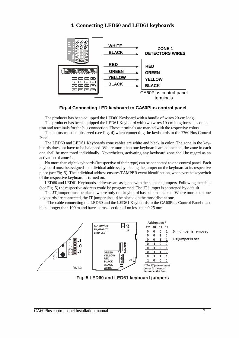
4. Connecting LED60 and LED61 keyboards
The producer has been equipped the LED60 Keyboard with a bundle of wires 20-cm long.The producer has been equipped the LED61 Keyboard with two wires 10-cm long for zone connec-
tion and terminals for the bus connection. These terminals are marked with the respective colors.The colors must be observed (see Fig. 4) when connecting the keyboards to the ??60Plus Control
Panel.The LED60 and LED61 Keyboards zone cables are white and black in color. The zone in the key-
boards does not have to be balanced. Where more than one keyboards are connected, the zone in eachone shall be monitored individually. Nevertheless, activating any keyboard zone shall be regard as anactivation of zone 1.
No more than eight keyboards (irrespective of their type) can be connected to one control panel. Eachkeyboard must be assigned an individual address, by placing the jumper on the keyboard at its respectiveplace (see Fig. 5). The individual address ensures TAMPER event identification, whenever the keyswitchof the respective keyboard is turned on.
LED60 and LED61 Keyboards addresses are assigned with the help of a jumpers. Following the table(see Fig. 5) the respective address could be programmed. The JT jumper is shortened by default.
The JT jumper must be placed where only one keyboard has been connected. Where more than onekeyboards are connected, the JT jumper should be placed on the most distant one.
The cable connecting the LED60 and the LED61 Keyboards to the CA60Plus Control Panel mustbe no longer than 100 m and have a cross-section of no less than 0.25 mm.
Fig. 4 Connecting LED keyboard to CA60Plus control panel
1 2 3
4 5 6
7 8 9
0
ON PROG CLEAR ENTER
YELLOW
WHITE
GREEN
RED
BLACK
BLACK
REDGREEN
YELLOWBLACK
CA60Plus control panel terminals
ZONE 1DETECTORS WIRES
ARM
ME M
CLR ENT0
1 2 3
4 5 6
7 8 9
P ROG
DISA
RM
Fig. 5 LED60 and LED61 keyboard jumpers
Addresses *
* The JT jumper mustbe set in the mostfar unit in the bus.
J0
1
000
0
111
J1
0
011
0
011
JT*
0
000
1
000
J2
0
101
0
101
0 = jumper is removed
1 = jumper is set
Rev1.3
JT
J0J1J2
TAM
PE
R
CA60PluskeyboardRev. 2.3
GREENYELLOWREDBLACKBLACKWHITE
8 CA60Plus control panel Installation manual
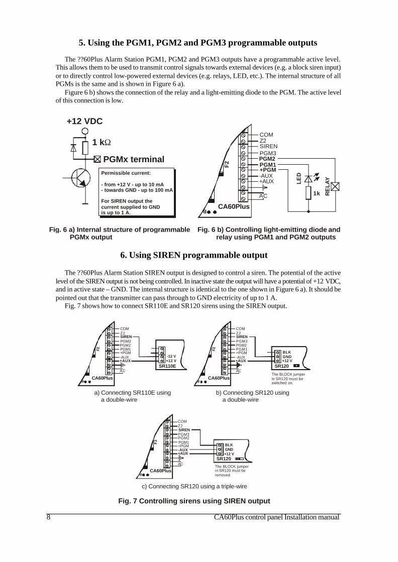
5. Using the PGM1, PGM2 and PGM3 programmable outputs
The ??60Plus Alarm Station PGM1, PGM2 and PGM3 outputs have a programmable active level.This allows them to be used to transmit control signals towards external devices (e.g. a block siren input)or to directly control low-powered external devices (e.g. relays, LED, etc.). The internal structure of allPGMs is the same and is shown in Figure 6 a).
Figure 6 b) shows the connection of the relay and a light-emitting diode to the PGM. The active levelof this connection is low.
Fig. 6 b) Controlling light-emitting diode relay using PGM1 and PGM2 outputs
andF
2
B
AC
+AUX-AUX+PGMPGM1PGM2PGM3SIRENZ2COM
CA60Plus
1k RE
LA
Y
LE
D
Fig. 6 a) Internal structure of programmable PGMx output
+12 VDC
1 kΩ
PGMx terminalPermissible current:
- from +12 V - up to 10 mA- towards GND - up to 100 mA
For SIREN output thecurrent supplied to GND is up to 1 A.
6. Using SIREN programmable output
The ??60Plus Alarm Station SIREN output is designed to control a siren. The potential of the activelevel of the SIREN output is not being controlled. In inactive state the output will have a potential of +12 VDC,and in active state – GND. The internal structure is identical to the one shown in Figure 6 a). It should bepointed out that the transmitter can pass through to GND electricity of up to 1 A.
Fig. 7 shows how to connect SR110E and SR120 sirens using the SIREN output.
Fig. 7 Controlling sirens using SIREN output
F2
B
AC
+AUX-AUX+PGMPGM1PGM2PGM3SIRENZ2COM
+12 V-12 V
CA60Plus
SR110E
a) Connecting SR110E using a double-wire
F2
B
AC
+AUX-AUX+PGMPGM1PGM2PGM3SIRENZ2COM
+12 VGND
CA60Plus
SR120
BLK
The BLOCK jumperin
.SR120 must be
switched on
b) Connecting SR120 using a double-wire
F2
B
AC
+AUX-AUX+PGMPGM1PGM2PGM3SIRENZ2COM
+12 VGND
CA60Plus
SR120
BLK
The BLOCK jumperin
. SR120 must be
removed
c) Connecting SR120 using a triple-wire

CA60Plus control panel Installation manual 9
7. Connecting sensors to CA60Plus control panel
The security system is mounted with sensors with relay contacts. Fire alarm sensors supplied withrelay outputs can also be used.
Use the supplied 1 kΩ resistors to balance the zones. The balancing resistors are installed on the lastsensor of the chain. The zones, which shall not be used, are terminated by way of the 1 kΩ resistor at theterminals of the CA60Plus Control Panel, irrespective of the chosen type of zone balancing.
After the initial power up of the station, the zone balance type has to be programmed. By default only1 balancing resistor is used.
Figure 8 shows the possible options for connecting the sensors and for balancing the zones.Figure 9 shows the connection between a keyswitch and a fire detector with a relay at the base.The hardware implementation of zone 4 of the panel permits performance in pulse count mode. This
mode counts short pulses – 2 to 4 ms for a period of 20 seconds. The first pulse starts a 20-secondcountdown during which pulses are expected to be received. Their number is assigned at Address 28 ofthe engineer program. An alarm signal is emitted when this number is reached within the time of 20seconds. Otherwise the pulse counter will be zeroed after the time of 20 seconds expires.
Activating the pulse count mode will automatically start when a number other than 0 is keyed in atAddress 28 of the engineer program.
b) Connecting Detectors with Two Balancing Resistors
1k
NC
RELAY 1
NC
RELAY 2
NC
RELAY n
NC
TAMPER 1
NC
TAMPER 2
NC
TAMPER n
1k
ZONE x
COM
Fig. 8 Options for connecting detectors to the CA60Plus control panel
?) Connecting Detectors with One Balancing Resistor
NC
RELAY 1
NC
RELAY 2
NC
RELAY n
NC
TAMPER 1
NC
TAMPER 2
NC
TAMPER n
1k
1k
ZONE x
TAMPERZONE
COM
COM
C) Connecting up to Four Detectors with Two Balancing Resistors
1k
NC
RELAY 1
NC
RELAY 2
NC
RELAY n
NC
TAMPER 1
NC
TAMPER 2
NC
TAMPER n
1k
ZONE x
COM
1k 1k

10 CA60Plus control panel Installation manual
Fig. 9 Connecting a key-switch and a fire detector with relay in the base to a CA60Plus control panel
Connecting keyswitch with two balancing resistors
1k
NC
NC1k
ZONE x
COM
Key-switchMust be normally closed.
Tamper switch of the key-switch.
NC
Key-switchMust be normally closed.
NC
Tamper switch of the key-switch.
1k
1k
ZONE x
TAMPERZONE
COM
COM
Connecting key-switch with one balancing resistor
Connecting a fire detector with a relay in the basein scheme with two balancing resistors
F2
B
AC
+AUX-AUX+PGMPGM1PGM2PGM3SIRENZ2COM
+12 VGNDNO
CA60Plus
Fire detector base
NCCOM
1k
1k
The programmable outputmust be programmed as Fire Reset and the activestatus must be +12 VDC.
Connecting a fire detector with a relay in the base in scheme with one balancing resistor
F2
B
AC
+AUX-AUX+PGMPGM1PGM2PGM3SIRENZ2COM
+12 VGNDNO
CA60Plus
Fire detector base
NCCOM
1k
The programmable outputmust be programmed as Fire Reset and the activestatus must be +12 VDC.

CA60Plus control panel Installation manual 11
9. Powering the CA60Plus control panel
The system should be powered-up only after it is installed and all necessary devices have been con-nected – control panel, keyboard, sensors, etc.
In order to set the station to the producer’s default parameters place the Reset jumper on the CA60PlusControl Panel.
Supply 220 V mains power. The keyboard emits a short sound signal and the light-emitting diodes onthe display blink.
Remove the Reset jumper.Use the red (+) and black (-) cables to connect the battery to the station.The normal status of the station (all sensors in the security system are inactive and there are no
violated anti-TAMPER chains) is indicated on the keypad by a continuously lit green READY light-emitting diode. The station has now been programmed the producer default parameters.
All light-emitting diodes will blink and a sound signal will be heard where the keyboard is open orincorrectly connected.
Where there is an open zone or an open TAMPER for any zone, the light-emitting diode for therespective zone together with the MEMORY or TAMPER light-emitting diodes on the display will lightup.
NB! An open anti-sabotage chain (TAMPER) in the security system will sound the siren. Tostop the siren key in code 0000. The respective zone light-emitting diode remains perma-nently lit whereas the TAMPER light-emitting diode will blink. Remove the failure – theTAMPER light-emitting diode remains permanently lit. Key in code 0000 again to clear thealarm event from the memory.
Any technical trouble in the panel will light up the Trouble indicator. To view these problems introducethe 0000 manager code and single-press ENTER. The display will indicate a list of current problems. Theindications and their meaning are shown in Figure 11.
Fig. 11 TROUBLE mode indication
LED Technical trouble1 No 220 V power supply2 Battery low3 Fuse burned4 No telephone line5 No communication available6 Active TAMPER within the system
8. Connecting the CA60Plus built-in digital communicator
The telephone line is connected to A and Bterminals on the CA60Plus Control Panel withno requirements to observe polarity (Fig. 10).
The telephone device is connected to A1 andB1 terminals on the CA60Plus Control Panelwith no requirements to observe polarity (Fig.10).
The parameters of the digital communica-tor are engineer programmed.
It is not necessary to install additional com-ponents if the built-in communicator is not to beused.
B1A1BA
Telephone line
Telephone device
Fig.10 Connecting the CA60Plus built-in communicator
12 CA60Plus control panel Installation manual
RESET
PROG EXPAND
SP MIC
REC
MSG
PLAY
MS
G ?
VD60
CA
60P
lus
BU
SY
1
2 2
B1A1BA
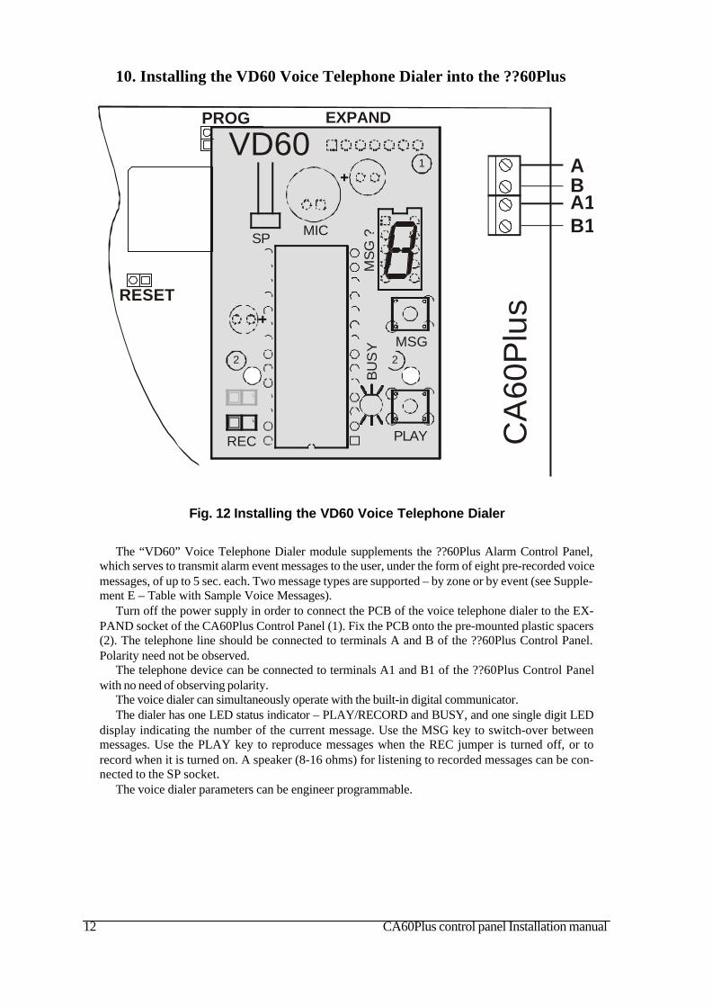
10. Installing the VD60 Voice Telephone Dialer into the ??60Plus
Fig. 12 Installing the VD60 Voice Telephone Dialer
The “VD60” Voice Telephone Dialer module supplements the ??60Plus Alarm Control Panel,which serves to transmit alarm event messages to the user, under the form of eight pre-recorded voicemessages, of up to 5 sec. each. Two message types are supported – by zone or by event (see Supple-ment E – Table with Sample Voice Messages).
Turn off the power supply in order to connect the PCB of the voice telephone dialer to the EX-PAND socket of the CA60Plus Control Panel (1). Fix the PCB onto the pre-mounted plastic spacers(2). The telephone line should be connected to terminals A and B of the ??60Plus Control Panel.Polarity need not be observed.
The telephone device can be connected to terminals A1 and B1 of the ??60Plus Control Panelwith no need of observing polarity.
The voice dialer can simultaneously operate with the built-in digital communicator.The dialer has one LED status indicator – PLAY/RECORD and BUSY, and one single digit LED
display indicating the number of the current message. Use the MSG key to switch-over betweenmessages. Use the PLAY key to reproduce messages when the REC jumper is turned off, or torecord when it is turned on. A speaker (8-16 ohms) for listening to recorded messages can be con-nected to the SP socket.
The voice dialer parameters can be engineer programmable.
CA60Plus control panel Installation manual 13
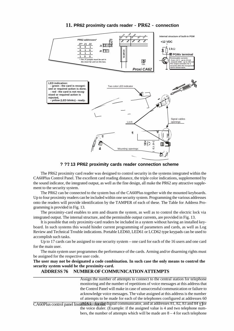
11. PR62 proximity cards reader - PR62 - connection
The PR62 proximity card reader was designed to control security in the systems integrated within theCA60Plus Control Panel. The excellent card reading distance, the triple color indications, supplemented bythe sound indicator, the integrated output, as well as the fine design, all make the PR62 any attractive supple-ment to the security system.
The PR62 can be connected to the system bus of the CA60Plus together with the mounted keyboards.Up to four proximity readers can be included within one security system. Programming the various addressesonto the readers will provide identification by the TAMPER of each of these. The Table for Address Pro-gramming is provided in Fig. 13.
The proximity-card enables to arm and disarm the system, as well as to control the electric lock viaintegrated output. The internal structure, and the permissible output currents, are provided in Fig. 13.
It is possible that only proximity-card readers be included in a system without having an installed key-board. In such systems this would hinder current programming of parameters and cards, as well as LogReview and Technical Trouble indications. Portable LED60, LED61 or LCD62 type keypads can be used toaccomplish such tasks.
Up to 17 cards can be assigned to one security system – one card for each of the 16 users and one cardfor the main user.
The main system user programmes the performance of the cards. Arming and/or disarming rights mustbe assigned for the respective user code.The user may not be designated a code combination. In such case the only means to control thesecurity system would be the proximity-card.
ADDRESS 76 NUMBER OF COMMUNICATION ATTEMPTS
Assign the number of attempts to connect to the central station for telephonemonitoring and the number of repetitions of voice messages at this address thatthe Control Panel will make in case of unsuccessful communication or failure toacknowledge voice messages. The value assigned at this address is the numberof attempts to be made for each of the telephones configured at addresses 60and 63 – for the digital communicator, and at addresses 81, 82, 83 and 84 – forthe voice dialer. (Example: if the assigned value is 4 and two telephone num-bers, the number of attempts which will be made are 8 – 4 for each telephone
? ??. 13 PR62 proximity cards reader connection scheme
Proxi CA62
TAM
PE
R
LED
YELL
OW
BLACK
GREEN
REDPGM
J1
J2
JT*PR62 addresses*
JT* J1 J2
1 0 0
0 100 1 0
1 10
* The JT jumper must be set in the most far unit on the bus.
Internal structure of built-in PGM
+12 VDC
1 kΩ
PGMx terminalPermissable currents:- from +12 V - up to 10 mA- towards GND - up to 100 mAThe output activates for 2seconds after the recognisedcard is drown back.
Two color LED indicator
Signal cablesopenings
Mounting openings
Lock
LED indication: - green - the card is recogni-sed or required action is done, - red - the card is not recog-nised or required action is rejected, - yellow (LED blinks) - ready.

14 CA60Plus control panel Installation manual
PART II. Programming the parameters for CA60Plus alarmcontrol panel
Carefully study this installation manual before programming the alarm station.
The respective parameters can be configured from a keyboard or remote control connected to thesystem – a personal computer via a telephone using the UDLManager program.
Keyboard programming:
The CA60Plus Alarm System engineer parameters programming mode can be only begin when thesystem is in disarmed mode.
Keying in the system engineer code will initiate the CA60Plus Alarm System programming mode forthe engineer parameters. After restoring the default parameters (RESET) the engineer code will remain7777.
The respective Alarm System parameters can be programmed after a double-digit address is intro-duced. Use the table with addresses in Supplement A and the detailed instructions about the addresses inthe remaining part of the manual.
The table with addresses provides the system RESET configuration.
A detailed description of the possible parameters, the keypad display indicators and the necessaryprogramming functions has been provided for each address.
Each address has been provided default configurations after a software or hardware RESET has beencarried out.
The information entered for each address can be confirmed by pressing the ENTER button.
When reviewing the programmed parameters it is recommended to exit any given address by singlepressing the CLEAR button. This function will leave the introduced parameters unchanged.
In case the programmer is disoriented in the engineer menu, it is recommended to exit the menu bydouble clicking the CLEAR button and to begin programming the station parameters from the start.
Remote programming using the UDLManager program
To access a UDLManager program system requires a system password and a station program pass-word. After restoring the default parameters these passwords will be the same and are 1234. In order toprovide access to the system from the central station enter the correct password of the central station atAddress 71.
A 24-hour period automatically begins after default parameters are restored during which the systemis in remote programming standby mode. Following this period, the “ring number” parameter is zeroed,whereby the system will be locked for remote programming. This 24-hour period can be canceled byintroducing a telephone number for connecting to the central station at Address 70.
Detailed working instructions for the UDLManager program are provided in the built-in Help files.
The details listed in this manual apply to all parameters for remote system programming.
CA60Plus control panel Installation manual 15
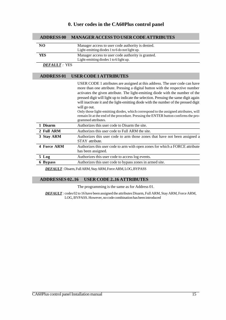
ADDRESSES 02..16 USER CODE 2..16 ATTRIBUTES
The programming is the same as for Address 01.
DEFAULT : codes 02 to 16 have been assigned the attributes Disarm, Full ARM, Stay ARM, Force ARM,LOG, BYPASS. However, no code combination has been introduced
0. User codes in the CA60Plus control panel
ADDRESS 00 MANAGER ACCESS TO USER CODE ATTRIBUTES
NO Manager access to user code authority is denied.Light-emitting diodes 1 to 6 do not light up.
YES Manager access to user code authority is granted.Light-emitting diodes 1 to 6 light up.
DEFAULT : YES
ADDRESS 01 USER CODE 1 ATTRIBUTES
USER CODE 1 attributes are assigned at this address. The user code can havemore than one attribute. Pressing a digital button with the respective numberactivates the given attribute. The light-emitting diode with the number of thepressed digit will light up to indicate the selection. Pressing the same digit againwill inactivate it and the light-emitting diode with the number of the pressed digitwill go out.Only those light-emitting diodes, which correspond to the assigned attributes, willremain lit at the end of the procedure. Pressing the ENTER button confirms the pro-grammed attributes.
1 Disarm Authorizes this user code to Disarm the site.2 Full ARM Authorizes this user code to Full ARM the site.3 Stay ARM Authorizes this user code to arm those zones that have not been assigned a
STAY attribute.4 Force ARM Authorizes this user code to arm with open zones for which a FORCE attribute
has been assigned.5 Log Authorizes this user code to access log events.6 Bypass Authorizes this user code to bypass zones in armed site.
DEFAULT : Disarm, Full ARM, Stay ARM, Force ARM, LOG, BYPASS
16 CA60Plus control panel Installation manual
2. Zone programming
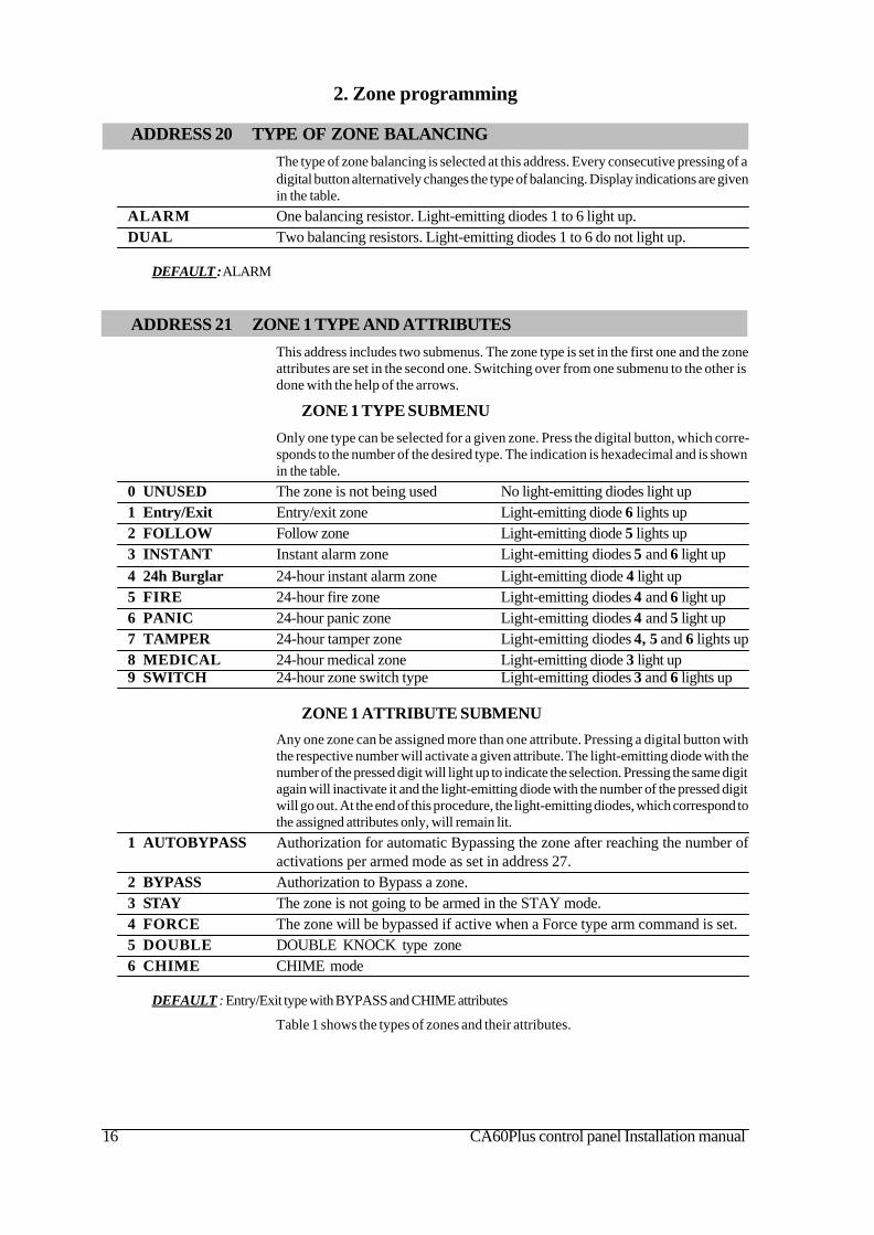
ADDRESS 21 ZONE 1 TYPE AND ATTRIBUTESThis address includes two submenus. The zone type is set in the first one and the zoneattributes are set in the second one. Switching over from one submenu to the other isdone with the help of the arrows.
ZONE 1 TYPE SUBMENU
Only one type can be selected for a given zone. Press the digital button, which corre-sponds to the number of the desired type. The indication is hexadecimal and is shownin the table.
0 UNUSED The zone is not being used No light-emitting diodes light up1 Entry/Exit Entry/exit zone Light-emitting diode 6 lights up2 FOLLOW Follow zone Light-emitting diode 5 lights up3 INSTANT Instant alarm zone Light-emitting diodes 5 and 6 light up4 24h Burglar 24-hour instant alarm zone Light-emitting diode 4 light up5 FIRE 24-hour fire zone Light-emitting diodes 4 and 6 light up6 PANIC 24-hour panic zone Light-emitting diodes 4 and 5 light up7 TAMPER 24-hour tamper zone Light-emitting diodes 4, 5 and 6 lights up8 MEDICAL 24-hour medical zone Light-emitting diode 3 light up9 SWITCH 24-hour zone switch type Light-emitting diodes 3 and 6 lights up
ZONE 1 ATTRIBUTE SUBMENU
Any one zone can be assigned more than one attribute. Pressing a digital button withthe respective number will activate a given attribute. The light-emitting diode with thenumber of the pressed digit will light up to indicate the selection. Pressing the same digitagain will inactivate it and the light-emitting diode with the number of the pressed digitwill go out. At the end of this procedure, the light-emitting diodes, which correspond tothe assigned attributes only, will remain lit.
1 AUTOBYPASS Authorization for automatic Bypassing the zone after reaching the number ofactivations per armed mode as set in address 27.
2 BYPASS Authorization to Bypass a zone.3 STAY The zone is not going to be armed in the STAY mode.4 FORCE The zone will be bypassed if active when a Force type arm command is set.5 DOUBLE DOUBLE KNOCK type zone6 CHIME CHIME mode
DEFAULT : Entry/Exit type with BYPASS and CHIME attributes
Table 1 shows the types of zones and their attributes.
ADDRESS 20 TYPE OF ZONE BALANCINGThe type of zone balancing is selected at this address. Every consecutive pressing of adigital button alternatively changes the type of balancing. Display indications are givenin the table.
ALARM One balancing resistor. Light-emitting diodes 1 to 6 light up.DUAL Two balancing resistors. Light-emitting diodes 1 to 6 do not light up.
DEFAULT : ALARM
CA60Plus control panel Installation manual 17
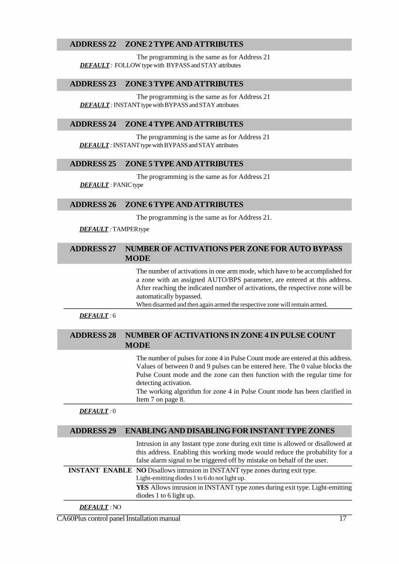
ADDRESS 22 ZONE 2 TYPE AND ATTRIBUTES
The programming is the same as for Address 21DEFAULT : FOLLOW type with BYPASS and STAY attributes
ADDRESS 23 ZONE 3 TYPE AND ATTRIBUTES
The programming is the same as for Address 21DEFAULT : INSTANT type with BYPASS and STAY attributes
ADDRESS 24 ZONE 4 TYPE AND ATTRIBUTES
The programming is the same as for Address 21DEFAULT : INSTANT type with BYPASS and STAY attributes
ADDRESS 25 ZONE 5 TYPE AND ATTRIBUTES
The programming is the same as for Address 21DEFAULT : PANIC type
ADDRESS 26 ZONE 6 TYPE AND ATTRIBUTES
The programming is the same as for Address 21.
DEFAULT : TAMPER type
ADDRESS 29 ENABLING AND DISABLING FOR INSTANT TYPE ZONES
Intrusion in any Instant type zone during exit time is allowed or disallowed atthis address. Enabling this working mode would reduce the probability for afalse alarm signal to be triggered off by mistake on behalf of the user.
INSTANT ENABLE NO Disallows intrusion in INSTANT type zones during exit type.Light-emitting diodes 1 to 6 do not light up.YES Allows intrusion in INSTANT type zones during exit type. Light-emittingdiodes 1 to 6 light up.
DEFAULT : NO
ADDRESS 27 NUMBER OF ACTIVATIONS PER ZONE FOR AUTO BYPASSMODE
The number of activations in one arm mode, which have to be accomplished fora zone with an assigned AUTO/BPS parameter, are entered at this address.After reaching the indicated number of activations, the respective zone will beautomatically bypassed.When disarmed and then again armed the respective zone will remain armed.
DEFAULT : 6
ADDRESS 28 NUMBER OF ACTIVATIONS IN ZONE 4 IN PULSE COUNTMODE
The number of pulses for zone 4 in Pulse Count mode are entered at this address.Values of between 0 and 9 pulses can be entered here. The 0 value blocks thePulse Count mode and the zone can then function with the regular time fordetecting activation.The working algorithm for zone 4 in Pulse Count mode has been clarified inItem 7 on page 8.
DEFAULT : 0

18 CA60Plus control panel Installation manual
INSTANT type An alarm zone which is active only when the site is armed. The zone operatesinstantaneously and activates the programmable ALARM type outputs, theSIREN output and the communicator.The MEMORY light-emitting diode and the light-emitting diode for the respectivezone will light up when activated in armed mode. After disarming, these light-emittingdiodes will continue to be lit until the user code is entered or until the next arming.Where the system is unarmed, the activation of the zone is indicated by theblinking of the respective light-emitting diode for the zone for the time that thezone remains open.Violation of INSTANT type zones during Exit Time can be authorized at Address 29.
FIRE type Allows connecting 12 V fire alert sensors to the system. These should avail ofa normally closed relay output in inactive status.Any activation of the zone will trigger off the SIREN output, the programmableFIRE type outputs and the station communicator.Activating this zone will cause the MEMORY light-emitting diode to blink andthe activated zone light-emitting diode to light up continuously, irrespective ofthe working mode of the station.The indication of the memory can be deleted by entering a legal user code,manager code or during the next arming.
PANIC type Silent Panic – only the programmable PANIC type outputs and the stationcommunicator can be activated. The respective light-emitting diode blinks whilethe zone is active. There is no memory indication. After a legal user code isentered, the MEMORY light-emitting diode and the activated zone light-emittingdiode both light up continuously.Sound Panic – the SIREN output, the programmable PANIC type outputs andthe station communicator are activated. The sirens are instantaneously activatedirrespective of the programmed time delay. Activating the zone will cause theMEMORY light-emitting diode and the activated zone light-emitting diode tolight up continuously.The indication of the memory can be deleted by entering a legal user code, amanager code or during the next arming.
24h Burglar type An alarm zone, which is active, irrespective of the arm mode. The zone operatesinstantaneously and activates the programmable ALARM type output, the SIRENoutput and the communicator.The MEMORY light-emitting diode and the light-emitting diode for the respec-tive zone will light up when activated. After entering a legal code these light-emitting diodes continue to be lit until the user code is entered a second time oruntil the next arming.
Table 1. Types of zones and their attributes
Entry/Exit type Provides time to arm and disarm the site. After arming, the sensor, which wastriggered off in this zone, will not sound an alarm until the programmed EXITTIME expires.No violation of the zone when in armed mode will sound an alarm before theprogrammed ENTRY TIME expires.A sound signal is activated from the keyboard buzzer during entry and exit time.
FOLLOW type An alarm zone which is active only when the site is armed. The zone operatesinstantaneously and activates the programmable ALARM type outputs, theSIREN output and the communicator.Activating the zone during entry or exit time does not cause an alarm event.The MEMORY light-emitting diode and the light-emitting diode for the respectivezone will light up when activated in armed mode. After disarming, these light-emittingdiodes will continue to be lit until the user code is entered or until the next arming.Where the system is unarmed, the activation of the zone is indicated by theblinking of the respective light-emitting diode for the zone for the time that thezone remains open.
CA60Plus control panel Installation manual 19
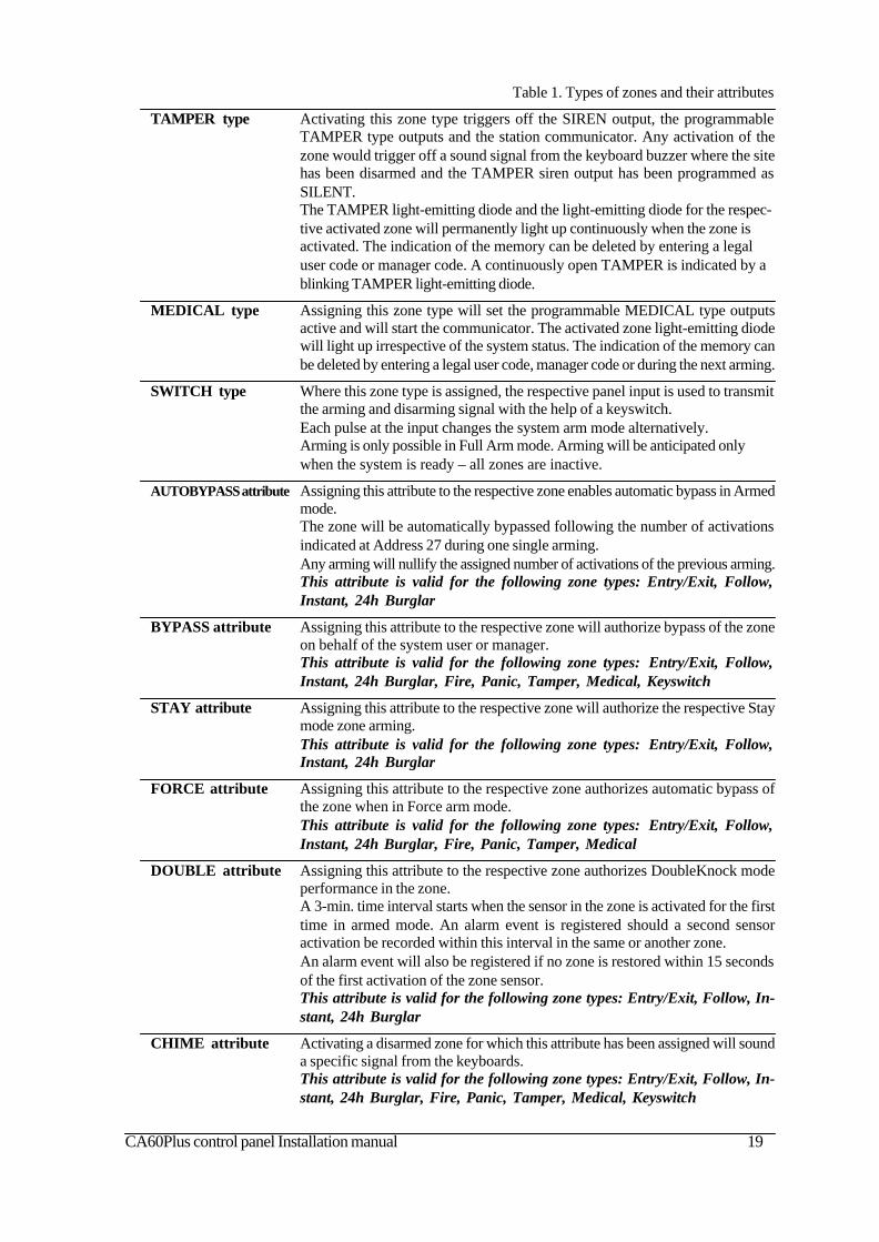
SWITCH type Where this zone type is assigned, the respective panel input is used to transmitthe arming and disarming signal with the help of a keyswitch.Each pulse at the input changes the system arm mode alternatively.Arming is only possible in Full Arm mode. Arming will be anticipated onlywhen the system is ready – all zones are inactive.
AUTOBYPASS attribute Assigning this attribute to the respective zone enables automatic bypass in Armedmode.The zone will be automatically bypassed following the number of activationsindicated at Address 27 during one single arming.Any arming will nullify the assigned number of activations of the previous arming.This attribute is valid for the following zone types: Entry/Exit, Follow,Instant, 24h Burglar
BYPASS attribute Assigning this attribute to the respective zone will authorize bypass of the zoneon behalf of the system user or manager.This attribute is valid for the following zone types: Entry/Exit, Follow,Instant, 24h Burglar, Fire, Panic, Tamper, Medical, Keyswitch
STAY attribute Assigning this attribute to the respective zone will authorize the respective Staymode zone arming.This attribute is valid for the following zone types: Entry/Exit, Follow,Instant, 24h Burglar
FORCE attribute Assigning this attribute to the respective zone authorizes automatic bypass ofthe zone when in Force arm mode.This attribute is valid for the following zone types: Entry/Exit, Follow,Instant, 24h Burglar, Fire, Panic, Tamper, Medical
DOUBLE attribute Assigning this attribute to the respective zone authorizes DoubleKnock modeperformance in the zone.A 3-min. time interval starts when the sensor in the zone is activated for the firsttime in armed mode. An alarm event is registered should a second sensoractivation be recorded within this interval in the same or another zone.An alarm event will also be registered if no zone is restored within 15 secondsof the first activation of the zone sensor.This attribute is valid for the following zone types: Entry/Exit, Follow, In-stant, 24h Burglar
CHIME attribute Activating a disarmed zone for which this attribute has been assigned will sounda specific signal from the keyboards.This attribute is valid for the following zone types: Entry/Exit, Follow, In-stant, 24h Burglar, Fire, Panic, Tamper, Medical, Keyswitch
Table 1. Types of zones and their attributes
MEDICAL type Assigning this zone type will set the programmable MEDICAL type outputsactive and will start the communicator. The activated zone light-emitting diodewill light up irrespective of the system status. The indication of the memory canbe deleted by entering a legal user code, manager code or during the next arming.
TAMPER type Activating this zone type triggers off the SIREN output, the programmableTAMPER type outputs and the station communicator. Any activation of thezone would trigger off a sound signal from the keyboard buzzer where the sitehas been disarmed and the TAMPER siren output has been programmed asSILENT.The TAMPER light-emitting diode and the light-emitting diode for the respec-tive activated zone will permanently light up continuously when the zone isactivated. The indication of the memory can be deleted by entering a legaluser code or manager code. A continuously open TAMPER is indicated by ablinking TAMPER light-emitting diode.

20 CA60Plus control panel Installation manual
3. Programming the PGM and SIREN programmable outputs
ADDRESS 31 PGM1 PROGRAMMABLE OUTPUT
The events, which activate the programmable output, are programmed at thisaddress.An arbitrary combination of events, which activate the programmable output, isallowed. The output is activated upon the occurrence of any of the programmedevents and is restored when all programmed events are discarded.Press a digital button, which corresponds, to a given parameter. The parameterwill have been selected when the light-emitting diode on the display with therespective number lights up.To switch from one parameter group over to another use the arrows.
FIRST GROUP PGM1 PARAMETERS
1 ALARM It is activated when Entry\Exit, Follow and Instant type zones are violated whilethe system is in armed mode, or when the 24h Burglar type zone, irrespective ofthe arm mode, is violated. Output is restored after a legal user code is enteredor following an interval of 1 min.
2 PANIC It is activated when the PANIC type zone is triggered or when PANIC is triggeredfrom the keyboard. Output is restored after a legal code is entered.
3 TAMPER It is activated when TAMPER is triggered off in any zone, when a TAMPERtype zone is triggered off or when TAMPER is triggered from the keyboard,irrespective of the arm mode. It is restored after activation is discarded.
4 FIRE It is activated when a FIRE type zone is triggered. It is restored after a legalcode is entered.
5 FIRE RST It is activated for 4 sec. after a legal code is entered.6 ? N/OFF It is activated by a command to arm. Output is restored after disarming.
SECOND GROUP PGM1 PARAMETERS
1 MEDICAL It is activated when a MEDICAL type zone is triggered. Output is restoredafter all MEDICAL type zones are restored.
2 PS/Bypass It is activated right after a zone has been designated to be bypassed or when thezone has been assigned a Stay and Instant type arming. Output is restored afterdisarming.
3 AC LOSS It is activated when there is a loss of the 220 V mains supply. ! If a delay forthe indication of the mains supply loss has been set (at Address 47), theoutput shall be activated 30 minutes after supply loss! Output is restoredafter the mains supply is restored.
4 BAT LOW It is activated when the battery voltage falls below 11 V, in case of damage tothe battery (BATT) fuse or if the battery is missing. It is restored after the levelof battery charge reaches a value greater than 12.5 V.
5 FUSE It is activated when a fault occurs in any of the AUX or PGM fuses. It passesinto inactive state when the fuse is restored.
6 POL +/- This attribute helps select the active level of the output. When “-“ is set (thelight-emitting diode is not lit) the active level is 0 V. At “+” the active level at theoutput is 12 V.
DEFAULT : ON/OFF, POL “+”

CA60Plus control panel Installation manual 21
ADDRESS 32 PGM2 PROGRAMMABLE OUTPUT
The programming is the same as for Address 31
DEFAULT : ALARM, TAMPER, POL “+”
ADDRESS 33 PGM3 PROGRAMMABLE OUTPUT
The programming is the same as for Address 31
DEFAULT : AC LOSS, BAT LOW, FUSE, POL “+”
ADDRESS 34 PROGRAMMABLE SIREN OUTPUT
The SIREN output can be activated by six events. The active level of thisoutput is low (0 V) and cannot be programmed.An arbitrary combination of events is allowed to activate this output. It is re-stored after bell time expires, which can be programmed at Address 42, ex-pires.
ALARM It is activated when Entry\Exit, Follow and Instant type zones are violated whilethe system is in armed mode, or when the 24h Burglar type zone, irrespective ofthe arm mode, is violated. The output becomes inactive when a legal user ormanager code is entered or after bell time expires.
TAMPER It is activated when TAMPER is triggered off in any zone or when a TAMPERtype zone is triggered, irrespective of whether the site is armed or not. In casethe event activating the siren output has not been selected, the keyboards shallemit a sound signal when TAMPER is triggered off. Output becomes inactivewhen a legal user or manager code are entered or after the bell time, assignedat Address 42, expires.
PANIC It is activated when the PANIC type zone is triggered or when PANIC is triggeredfrom the keyboard. Output becomes inactive when a legal user code is enteredor after the bell time, assigned at Address 42, expires.
FIRE/ALW A sequence of impulses is activated (1 second on, 1 second off) where theFIRE type zone is triggered. Output becomes inactive when a legal user code isentered. This event always activates the SIREN output and cannot becancelled.
ON SQUAWK It is singly activated for 1 second at the command to arm.OFF SQUAWK It is activated twice for 1 second in a 1 second interval upon a disarm command.
DEFAULT : ALARM, PANIC, TAMPER, FIRE/ALW

22 CA60Plus control panel Installation manual
ADDRESS 45 SETTING THE DATE
SET DATE The date and month are set (DD.MM). The indication is hexadecimal and thedigits are displayed one by one. To view the date, the digits can be browsed withthe help of the arrows.
DEFAULT : 01.01
ADDRESS 42 PROGRAMMING BELL TIME
BELL TIME Duration is set for the bell time of the sirens. A double-digit figure between 0and 99 minutes is entered. For a time interval of less than 10 seconds, the firstdigit must be 0.The indication is hexadecimal and the digits are displayed one by one. To viewthe introduced data, the digits can be browsed with the help of the arrows.
DEFAULT : 3 minutes
ADDRESS 41 PROGRAMMING ENTRY TIME
ENTRY TIME Entry time is assigned to Entry/Exit type zones. A double-digit figure between 1and 99 seconds is entered. For a time interval of less than 10 seconds, the firstdigit must be 0.The indication is hexadecimal and the digits are displayed one by one. To viewthe introduced data, the digits can be browsed with the help of the arrows.
DEFAULT : 15 seconds
4. Time periods
ADDRESS 40 PROGRAMMING EXIT TIME
EXIT TIME Exit time is assigned to Entry/Exit type zones. A double-digit figure between 1and 99 seconds is entered. For an interval of time, less than 10 seconds, the firstdigit must be 0.The indication is hexadecimal and the digits are displayed one by one. To viewthe introduced data, the digits can be browsed with the help of the arrows.
DEFAULT : 45 seconds
ADDRESS 44 SETTING THE BUILT-IN CLOCK
SET CLOCK The hours and minutes are set (HH:MM). The indication is hexadecimal andthe digits are displayed one by one. To view the clock, the digits can be browsedwith the help of the arrows.
DEFAULT : 00:00 hours
ADDRESS 43 PROGRAMMING BELL DELAY TIME
BELL DELAY Delay is set for initiating the bell time of the sirens. A double-digit figure between0 and 99 seconds is entered. For a time interval of less than 10 seconds, the firstdigit must be 0.The indication is hexadecimal and the digits are displayed one by one. To viewthe introduced data, the digits can be browsed with the help of the arrows.
DEFAULT : 0 seconds
CA60Plus control panel Installation manual 23
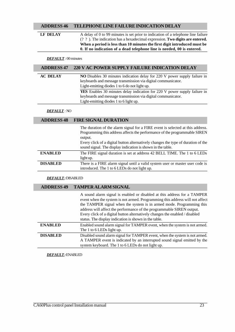
ADDRESS 47 220 V AC POWER SUPPLY FAILURE INDICATION DELAY
AC DELAY NO Disables 30 minutes indication delay for 220 V power supply failure inkeyboards and message transmission via digital communicator.Light-emitting diodes 1 to 6 do not light up.YES Enables 30 minutes delay indication for 220 V power supply failure inkeyboards and message transmission via digital communicator.Light-emitting diodes 1 to 6 light up.
DEFAULT : NO
ADDRESS 46 TELEPHONE LINE FAILURE INDICATION DELAY
LF DELAY A delay of 0 to 99 minutes is set prior to indication of a telephone line failure(? ? ). The indication has a hexadecimal expression. Two digits are entered.When a period is less than 10 minutes the first digit introduced must be0. If no indication of a dead telephone line is needed, 00 is entered.
DEFAULT : 00 minutes
ADDRESS 48 FIRE SIGNAL DURATION
The duration of the alarm signal for a FIRE event is selected at this address.Programming this address affects the performance of the programmable SIRENoutput.Every click of a digital button alternatively changes the type of duration of thesound signal. The display indication is shown in the table.
ENABLED The FIRE signal duration is set at address 42 BELL TIME. The 1 to 6 LEDslight up.
DISABLED There is a FIRE alarm signal until a valid system user or master user code isintroduced. The 1 to 6 LEDs do not light up.
DEFAULT : DISABLED
ADDRESS 49 TAMPER ALARM SIGNAL
A sound alarm signal is enabled or disabled at this address for a TAMPERevent when the system is not armed. Programming this address will not affectthe TAMPER signal when the system is in armed mode. Programming thisaddress will affect the performance of the programmable SIREN output.Every click of a digital button alternatively changes the enabled / disabledstatus. The display indication is shown in the table.
ENABLED Enabled sound alarm signal for TAMPER event, when the system is not armed.The 1 to 6 LEDs light up.
DISABLED Disabled sound alarm signal for TAMPER event, when the system is not armed.A TAMPER event is indicated by an interrupted sound signal emitted by thesystem keyboard. The 1 to 6 LEDs do not light up.
DEFAULT : ENABLED

24 CA60Plus control panel Installation manual
5. Engineer parameters
ADDRESS 53 RESTORING DEFAULT MANAGER CODE (PARTIALSOFTWARE RESET)
DEFAULT Restoration of the default manager code. Buttons 1, 2, 3, 4, 5, 6 are pressed inMANAGER succession and confirmed with the ENTER button.CODE The station restores the default 0000 manager user code.
ADDRESS 50 ENGINEER CODE CHANGE
ENGINEER CODE A new access code to the alarm station engineer parameters can be assigned atthis address. The light-emitting diodes 3, 4, 5 and 6 on the keypad display lightup. These go out one by one as the new code is entered. The new code has tobe entered a second time.
DEFAULT : 7777
ADDRESS 51 BLOCKING THE HARDWARE RESET
Disables or enables the hardware RESET of the alarm station. Specializedservice is required where the hardware RESET is disabled and the en-gineer code is obscure.
NO Hardware RESET is disabled.Light-emitting diodes 1 to 6 do not light up.
YES Hardware RESET is enabled.Light-emitting diodes 1 to 6 light up.
DEFAULT : YES
ADDRESS 52 RESTORING DEFAULT PARAMETERS (SOFTWARE RESET)
DEFAULT Restoration of default settings of the station. The buttons 1, 2, 3, 4, 5, 6 areSETTINGS pressed in succession and confirmed with the ENTER button.
ADDRESS 54 AUTHORITY TO ARM USING A ONE PUSH-BUTTON (QUICKARM)
QUICK NO Arming disabled without legal user code.ARM Light-emitting diodes 1 to 6 do not light up.ENABLE YES Arming enabled without legal user code.
Light-emitting diodes 1 to 6 light up.
DEFAULT : YES
ADDRESS 55 AUTHORITY CODE DURING AMBUSH (AMBUSH CODE)
ENABLE NO Disabled ambush code.AMBUSH Light-emitting diodes 1 to 6 do not light up.CODE YES Enabled ambush code. The code is made up by adding 1 to a legal user
code. There is no carrying over for codes ending in the figure 9. For example,the ambush code for 1234 is 1235, and for 9999 it is 9990.Light-emitting diodes 1 to 6 light up.
DEFAULT : YES

CA60Plus control panel Installation manual 25
ADDRESS 57 TECHNICAL TROUBLE INDICATION MASK
The mask for sound indication from the keyboard in Technical Trouble mode isassigned at this address.The mask for sound indication from the keyboard in Technical Trouble mode isassigned at this address.Only those light-emitting diodes whose numbers correspond to technical prob-lems for which sound indications are available will light up on the display at theend of the procedure.
1 AC LOST Loss of 220 V mains supply.2 BATT LOW Drop in battery charge, no battery or burnt out F1 battery fuse.3 FUSE BLOWN Burnt out PGM fuse.4 NO TEL LINE Loss of telephone line.5 COMM ERROR Central station communication failure.6 TAMPER Activated TAMPER within the system.
DEFAULT : AC LOST, BATT LOW, FUSE BLOWN, NO TEL LINE, COMM ERROR, TAMPER
ADDRESS 56 ENABLED KEYBOARD BLOCKING IN CASE OF ACCESSCODE ERROR
ENABLE NO Disables keyboard blocking in case of access code mistake.KBD Light-emitting diodes 1 to 6 do not light up.BLOCK YES Enables keyboard blocking for 30 sec. following the triple introduction in
sequence of a false code. Light-emitting diodes 1 to 6 light up.
DEFAULT : NO

26 CA60Plus control panel Installation manual
6. Communicator parameters
The parameters of the built-in digital communicator are programmed at thisgroup of addresses.Delete the queue of events to be sent to Address 93 by single pressing the 0button before configuring communicator parameters.
ADDRESS 62 ENTERING PROTOCOL 1 NUMBER FOR THECOMMUNICATOR
PROTOCOL 1 Enter central station No. 1 protocol number from the attached table. Valid arethe symbols from 0 to 2, where:[0] User protocol – dialer – transmits a melody sound signal upon occurrence ofan event listed on the bottom on page 26[1] ADEMCO CONTACT ID – see table with codes in Supplement B[2] SIA (Level 1) - see table with codes in Supplement B
DEFAULT : 1
ADDRESS 60 ENTERING TELEPHONE NUMBER 1 FOR THECOMMUNICATOR
Tel No 1 A telephone number is assigned for communicating with central station - No. 1.The indication is hexadecimal. The telephone number must not exceed 16characters, including the “pulse dialer” (ON and 0 buttons), “tone dialer” (ONand 1 buttons), “pause” (ON and 2 buttons), “wait DIAL tone” (ON and 3buttons) and “delete telephone number” (ON and 5 buttons) symbols.
Dialing has been assigned a default tone signalDEFAULT : there is no number entered
ADDRESS 61 ENTERING PANEL IDENTIFICATION NUMBER 1
PANEL ID 1 Identification number for central station No. 1. Four digits are entered. Validare symbols 0 to 9, A to F (SIA) and B to F (ADEMCO)
DEFAULT : 9999
ADDRESS 64 ENTERING PANEL IDENTIFICATION NUMBER 2
PANEL ID 2 Identification number for central station No. 2. Four digits are entered. Validare symbols 0 to 9, A to F (SIA) and B to F (ADEMCO)
DEFAULT : 9999
ADDRESS 63 ENTERING TELEPHONE NUMBER 2 FOR THECOMMUNICATOR
Tel No 2 A telephone number is assigned for communicating with central station No. 2.The indication is hexadecimal. The telephone number must not exceed 16characters, including the “pulse dialer” (ON and 0 buttons), “tone dialer” (ONand 1 buttons), “pause” (ON and 2 buttons), “wait DIAL tone” (ON and 3buttons) and “delete telephone number” (ON and 5 buttons) symbols.Dialing has been assigned a default tone signal.
DEFAULT : there is no number entered

CA60Plus control panel Installation manual 27
ADDRESS 66 WAIT DIAL TONE
WAIT DIAL TONE NO Disable DIAL signal test.Light-emitting diodes 1 to 6 do not light up.YES Enable DIAL signal testLight-emitting diodes 1 to 6 light up.
DEFAULT : YES
ADDRESS 68 TEST MESSAGE TRANSMITTING PERIOD
TEST PERIOD Duration of transmission of test message in days (DD) is entered. The indicationis hexadecimal. Two digits must be entered. When entering a periodshorter than 10 days the first digit must be 0.
DEFAULT : 01 day
ADDRESS 65 ENTERING PROTOCOL 2 NUMBER FOR THECOMMUNICATOR
PROTOCOL2 Enter central station No. 2 protocol number from the attached table. Valid arethe symbols from 0 to 2, where:[0] User protocol – dialer – transmits a melody sound signal upon occurrence ofan event listed on the bottom on page 2618020xxx[1] ADEMCO CONTACT ID – see table with codes in Supplement B[2] SIA (Level 1) - see table with codes in Supplement B
DEFAULT : 1
ADDRESS 67 SETTING TEST TIME FOR SENDING MESSAGE
TEST TIME Time of sending test message to central station is entered . Hours and minutesare entered (HH:MM). The indication is hexadecimal.
DEFAULT : 00:05 hours
ADDRESS 69 TYPES OF MESSAGE TRANSMITTED FROM THE DIGITALCOMMUNICATOR *
The messages from both telephone numbers to the telephone monitoring central station, as well as thereport algorithm, are programmed at this address. The following report options can be set:
1. Message report from at least one of the two telephone numbers – Alternative report.2. Independent message report to both telephone numbers –Split report.3. Message report from one telephone number, which is also duplicated at the second –Both report.The address consists of two identical submenus, structured as shown below. The first submenu is for
programming the streams of messages to the first telephone number, entered at address 60. The secondsubmenu is for programming the streams of messages to the second telephone number, entered respectivelyat address 63. Switching over between the two submenus can be done with the help of the arrows.
Where message streams are marked only for the first telephone number, the report algorithm to beused is Alternative report. There should be no marked message streams for the second telephone number.
Where the same message streams for both telephone numbers are marked, the report algorithm to beused is Both report.
Where different message streams for both telephone numbers are marked, the report algorithm to beused is Split report.
Both and Split reports can be jointly used.The digital buttons 1 to 6 are used for programming. Pressing them each time will alternatively
change the status of the respective message type – report (LED lights up) or no report (LED does not light

28 CA60Plus control panel Installation manual
* User protocol transmitted messages are ALARM, FIRE, PANIC, TAMPER, MEDICAL andmanually transmitted TEST signal. These messages are not programmable and are transmitted byone and the same sound signal in the telephone line.
up). At the end of the procedure only those LEDs, which correspond to the designated for report mes-sages, should remain lit up on the display.
1 ALARM ALARM and TAMPER type messages are transmitted.2 PANIC PANIC type messages or entered assault code are transmitted.3 FIRE FIRE and TAMPER type messages are transmitted.4 ON/OFF+BPS BYPASS, ON/OFF type messages and engineer programming input are
transmitted.5 MEDICAL MEDICAL type messages are transmitted.6 TROUBLE TROUBLE and TEST type messages are transmitted.
DEFAULT : 1, 2, 3, 4, 5, 6 for the first telephone number. There are no marked streams for the second telephonenumber.
CA60Plus control panel Installation manual 29
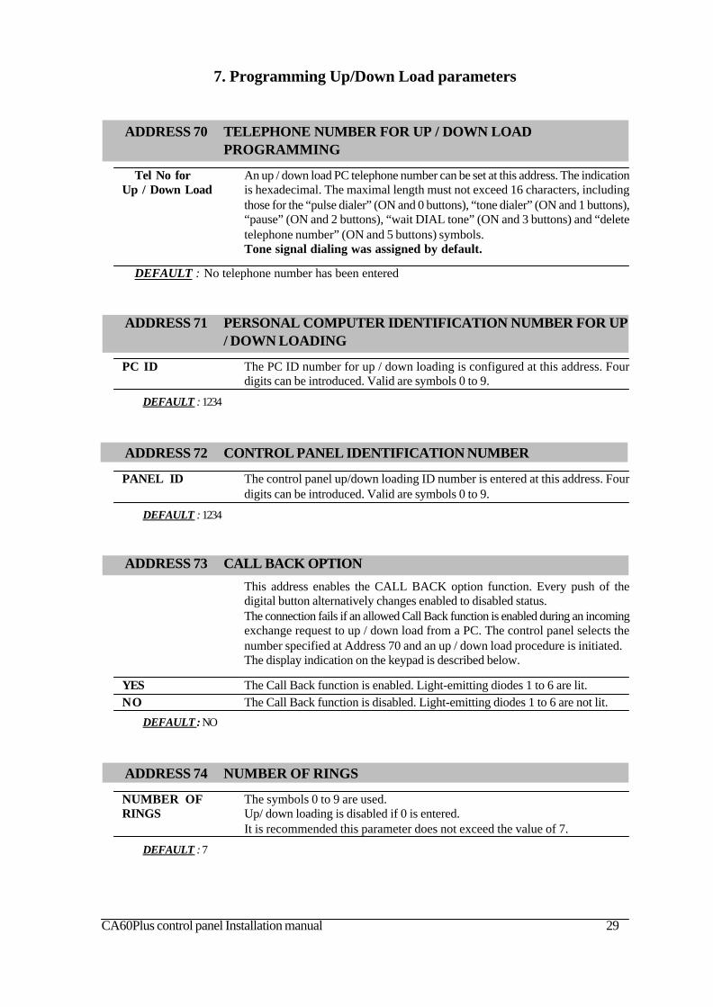
ADDRESS 74 NUMBER OF RINGS
NUMBER OF The symbols 0 to 9 are used.RINGS Up/ down loading is disabled if 0 is entered.
It is recommended this parameter does not exceed the value of 7.
DEFAULT : 7
7. Programming Up/Down Load parameters
ADDRESS 71 PERSONAL COMPUTER IDENTIFICATION NUMBER FOR UP/ DOWN LOADING
PC ID The PC ID number for up / down loading is configured at this address. Fourdigits can be introduced. Valid are symbols 0 to 9.
DEFAULT : 1234
ADDRESS 73 CALL BACK OPTION
This address enables the CALL BACK option function. Every push of thedigital button alternatively changes enabled to disabled status.The connection fails if an allowed Call Back function is enabled during an incomingexchange request to up / down load from a PC. The control panel selects thenumber specified at Address 70 and an up / down load procedure is initiated.The display indication on the keypad is described below.
YES The Call Back function is enabled. Light-emitting diodes 1 to 6 are lit.NO The Call Back function is disabled. Light-emitting diodes 1 to 6 are not lit.
DEFAULT : NO
ADDRESS 72 CONTROL PANEL IDENTIFICATION NUMBER
PANEL ID The control panel up/down loading ID number is entered at this address. Fourdigits can be introduced. Valid are symbols 0 to 9.
DEFAULT : 1234
ADDRESS 70 TELEPHONE NUMBER FOR UP / DOWN LOADPROGRAMMING
Tel No for An up / down load PC telephone number can be set at this address. The indicationUp / Down Load is hexadecimal. The maximal length must not exceed 16 characters, including
those for the “pulse dialer” (ON and 0 buttons), “tone dialer” (ON and 1 buttons),“pause” (ON and 2 buttons), “wait DIAL tone” (ON and 3 buttons) and “deletetelephone number” (ON and 5 buttons) symbols.Tone signal dialing was assigned by default.
DEFAULT : No telephone number has been entered
30 CA60Plus control panel Installation manual
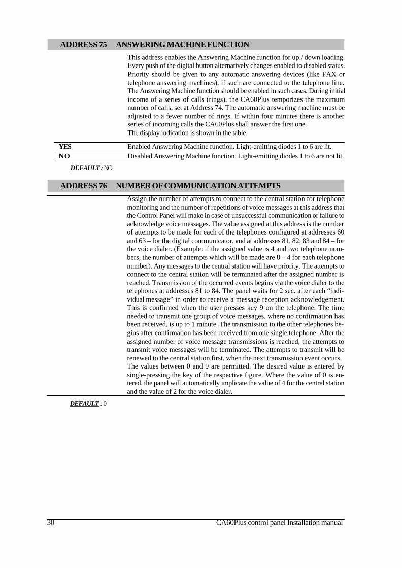
ADDRESS 75 ANSWERING MACHINE FUNCTION
This address enables the Answering Machine function for up / down loading.Every push of the digital button alternatively changes enabled to disabled status.Priority should be given to any automatic answering devices (like FAX ortelephone answering machines), if such are connected to the telephone line.The Answering Machine function should be enabled in such cases. During initialincome of a series of calls (rings), the CA60Plus temporizes the maximumnumber of calls, set at Address 74. The automatic answering machine must beadjusted to a fewer number of rings. If within four minutes there is anotherseries of incoming calls the CA60Plus shall answer the first one.The display indication is shown in the table.
YES Enabled Answering Machine function. Light-emitting diodes 1 to 6 are lit.NO Disabled Answering Machine function. Light-emitting diodes 1 to 6 are not lit.
DEFAULT : NO
ADDRESS 76 NUMBER OF COMMUNICATION ATTEMPTS
Assign the number of attempts to connect to the central station for telephonemonitoring and the number of repetitions of voice messages at this address thatthe Control Panel will make in case of unsuccessful communication or failure toacknowledge voice messages. The value assigned at this address is the numberof attempts to be made for each of the telephones configured at addresses 60and 63 – for the digital communicator, and at addresses 81, 82, 83 and 84 – forthe voice dialer. (Example: if the assigned value is 4 and two telephone num-bers, the number of attempts which will be made are 8 – 4 for each telephonenumber). Any messages to the central station will have priority. The attempts toconnect to the central station will be terminated after the assigned number isreached. Transmission of the occurred events begins via the voice dialer to thetelephones at addresses 81 to 84. The panel waits for 2 sec. after each “indi-vidual message” in order to receive a message reception acknowledgement.This is confirmed when the user presses key 9 on the telephone. The timeneeded to transmit one group of voice messages, where no confirmation hasbeen received, is up to 1 minute. The transmission to the other telephones be-gins after confirmation has been received from one single telephone. After theassigned number of voice message transmissions is reached, the attempts totransmit voice messages will be terminated. The attempts to transmit will berenewed to the central station first, when the next transmission event occurs.The values between 0 and 9 are permitted. The desired value is entered bysingle-pressing the key of the respective figure. Where the value of 0 is en-tered, the panel will automatically implicate the value of 4 for the central stationand the value of 2 for the voice dialer.
DEFAULT : 0

CA60Plus control panel Installation manual 31
8. VOICE DIALER PROGRAMMING PARAMETERS
ADDRESS 81 ENTERING TELEPHONE NUMBER 1 FOR THE DIALER
Tel No 1 A telephone number is assigned for communicating via voice dialer No. 1. The indicationis hexadecimal. The telephone number must not exceed 16 characters, including the “pulsedialer” (ON and 0 buttons), “tone dialer” (ON and 1 buttons), “pause” (ON and 2 buttons),“wait DIAL tone” (ON and 3 buttons) and “delete telephone number” (ON and 5 buttons)symbols.
Dialing has been assigned a default tone signal
DEFAULT : there are no configured numbers
ADDRESS 80 RECORDING AND LISTENING TO VOICE MESSAGES
One can record and listen to messages in the voice dialer at this address. To record amessage place the REC jumper, select the number of the message by pressing the MSG key,press and hold the PLAY key and dictate the message into the microphone immediatelywhen the LED lights up. Release the key. Remove the REC jumper when all messages havebeen recorded. To listen to the messages connect an 8-16 ohm speaker to the SP socket.Use the MSG key to select the number of the message, and press the PLAY key to listen therecording.
DEFAULT : test message ? 8
ADDRESS 85 GROUPS OF MESSAGES FOR VOICE DIALERTRANSMISSION
Programme the groups of message to be transmitted by the voice dialer at thisaddress. The possible options are 0 and 1. 0 transmits alarm messages by zones, and 1transmits messages by events (see Supplement E).
DEFAULT : 1
ADDRESS 82 ENTERING TELEPHONE NUMBER 2 FOR THE DIALER
Tel No 2 A telephone number is assigned for communicating via voice dialer No. 2. The indicationis hexadecimal. The telephone number must not exceed 16 characters, including the “pulsedialer” (ON and 0 buttons), “tone dialer” (ON and 1 buttons), “pause” (ON and 2 buttons),“wait DIAL tone” (ON and 3 buttons) and “delete telephone number” (ON and 5 buttons)symbols.
Dialing has been assigned a default tone signal
DEFAULT : there are no configured numbers
ADDRESS 83 ENTERING TELEPHONE NUMBER 3 FOR THE DIALER
Tel No 3 A telephone number is assigned for communicating via voice dialer No. 3. The indicationis hexadecimal. The telephone number must not exceed 16 characters, including the “pulsedialer” (ON and 0 buttons), “tone dialer” (ON and 1 buttons), “pause” (ON and 2 buttons),“wait DIAL tone” (ON and 3 buttons) and “delete telephone number” (ON and 5 buttons)symbols.
Dialing has been assigned a default tone signal
DEFAULT : there are no configured numbers
ADDRESS 84 ENTERING TELEPHONE NUMBER 4 FOR THE DIALER
Tel No 4 A telephone number is assigned for communicating via voice dialer No. 4. The indicationis hexadecimal. The telephone number must not exceed 16 characters, including the “pulsedialer” (ON and 0 buttons), “tone dialer” (ON and 1 buttons), “pause” (ON and 2 buttons),“wait DIAL tone” (ON and 3 buttons) and “delete telephone number” (ON and 5 buttons)symbols.
Dialing has been assigned a default tone signal
DEFAULT : there are no configured numbers
32 CA60Plus control panel Installation manual
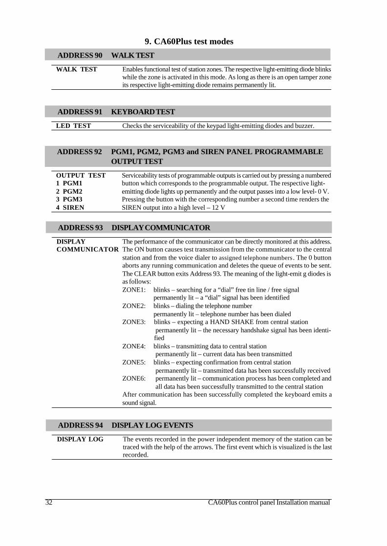
ADDRESS 92 PGM1, PGM2, PGM3 and SIREN PANEL PROGRAMMABLEOUTPUT TEST
OUTPUT TEST Serviceability tests of programmable outputs is carried out by pressing a numbered1 PGM1 button which corresponds to the programmable output. The respective light-2 PGM2 emitting diode lights up permanently and the output passes into a low level- 0 V.3 PGM3 Pressing the button with the corresponding number a second time renders the4 SIREN SIREN output into a high level – 12 V
ADDRESS 91 KEYBOARD TEST
LED TEST Checks the serviceability of the keypad light-emitting diodes and buzzer.
9. CA60Plus test modes
ADDRESS 94 DISPLAY LOG EVENTS
DISPLAY LOG The events recorded in the power independent memory of the station can betraced with the help of the arrows. The first event which is visualized is the lastrecorded.
ADDRESS 90 WALK TEST
WALK TEST Enables functional test of station zones. The respective light-emitting diode blinkswhile the zone is activated in this mode. As long as there is an open tamper zoneits respective light-emitting diode remains permanently lit.
ADDRESS 93 DISPLAY COMMUNICATOR
DISPLAY The performance of the communicator can be directly monitored at this address.COMMUNICATOR The ON button causes test transmission from the communicator to the central
station and from the voice dialer to assigned telephone numbers . The 0 buttonaborts any running communication and deletes the queue of events to be sent.The CLEAR button exits Address 93. The meaning of the light-emit g diodes isas follows:ZONE1: blinks – searching for a “dial” free tin line / free signal
permanently lit – a “dial” signal has been identifiedZONE2: blinks – dialing the telephone number
permanently lit – telephone number has been dialedZONE3: blinks – expecting a HAND SHAKE from central station
permanently lit – the necessary handshake signal has been identi-fied
ZONE4: blinks – transmitting data to central stationpermanently lit – current data has been transmitted
ZONE5: blinks – expecting confirmation from central stationpermanently lit – transmitted data has been successfully received
ZONE6: permanently lit – communication process has been completed andall data has been successfully transmitted to the central station
After communication has been successfully completed the keyboard emits asound signal.

CA60Plus control panel Installation manual 33
ADDRESS 95 DISPLAY UDL PROCESS
UDL/ The Up / Down Load process can be directly monitored at this address.Direct UDL A single click on the 0 button aborts current communication.
A single click on the ON button can start manual communication. This willignore the counter for incoming calls and will directly proceed on to step 2.Address 95 is exited with the help of the CLEAR button. The meaning of thelight-emitting diodes is as follows:ZONE1: blinks – each blink indicates one received call
permanently lit – the number of designated at Address 74 callshave been received
ZONE2: blinks - a CALL BACK processpermanently lit – CALL BACK completed
ZONE3: blinks – process of detecting a carrierpermanently lit – established connection to PC
ZONE4: blinks – receiving data from central stationpermanently lit – data pack received
ZONE5: blinks – transmitting data to central stationpermanently lit – data pack transmitted
ZONE6: permanently lit – up / down loading completed
ADDRESS 96 DIGITAL COMMUNICATOR HARDWARE TEST
MANUFACTURER A step by step test of the hardware of the digital communicator can be done atTEST this address. A light-emitting diode on the keypad lights up to visualize every
step. There is no time limitation for the steps.!During the test the digital communicator is blocked and disabled!
The first step of the digital communicator hardware test automatically beginsafter Address 96 is entered. Transition between the various steps can beaccomplished with the respective digital buttons 1 to 5 or with the help of thearrows. The light-emitting diodes on the keypad indicate the number of thecurrent step:ZONE1: The built-in relay is activated at this step. As a result the telephone
line, connected to terminals A and B, is discontinued from terminalsA1 and B1, where the local telephone device or some otherapparatus using the telephone line, should be connected. Duringthis step the telephone line voltage should be measured at terminalsA and B (to read usually between 40 and 60 V DC) and at terminalsA1 and B1 (to read 0 V DC).
ZONE2: The digital communicator has engaged the telephone line here. Thevoltage measured at terminals A and B should read between 7.5 VDC and 10.5 V DC. At the same time the built-in Dial Tone Detectoris also activated- a detector for the DIAL signal.
ZONE3: The digital communicator attributes low frequency to the telephoneline.
ZONE4: The digital communicator attributes high frequency to the telephoneline.
ZONE5: The digital communicator attributes a DTMF signal.

34 CA60Plus control panel Installation manual
ADDRESS 97 ADJUSTING THE BUILT-IN CLOCK
Any adjustments to the built-in clock can be done at this address. Digits between 00and 99 are permissible. Where no adjustment is required, the value of 50 must be entered.A respective value, which is greater than 50, is to be entered where the clock runs slow,and lesser than 50 where it runs quick.Each unit of value will adjust the clock by 5 seconds per month as speed or lag. This timeadjustment is evenly allocated within the month.Recommended methodology for calculating the necessary correction value:The days necessary for 1 minute’s time deflection of the built-in clock is set here. Thecorrection is calculated by the formula:
360/days,
where “days” are the days specified above. The whole of the result is taken underconsideration. The figure can be rounded up to the larger digit. The result obtained isadded to the current value at this address in case of a lag of the clock, or is subtractedfrom the current value at this address in case the built-in clock runs fast.Example of calculating the adjustment: Suppose the clock lags by 1 minute per 85days. The result after applying the quoted formula is 4.2. Where the current value atthis address is 50, the corrective factor of 54 needs to be introduced.
DEFAULT : 50
CA60Plus control panel Installation manual 35
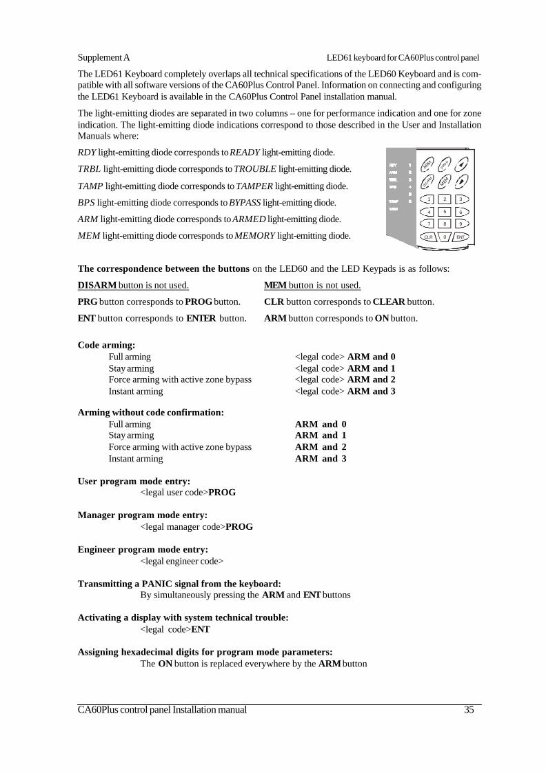
The LED61 Keyboard completely overlaps all technical specifications of the LED60 Keyboard and is com-patible with all software versions of the CA60Plus Control Panel. Information on connecting and configuringthe LED61 Keyboard is available in the CA60Plus Control Panel installation manual.
The light-emitting diodes are separated in two columns – one for performance indication and one for zoneindication. The light-emitting diode indications correspond to those described in the User and InstallationManuals where:
RDY light-emitting diode corresponds to READY light-emitting diode.
TRBL light-emitting diode corresponds to TROUBLE light-emitting diode.
TAMP light-emitting diode corresponds to TAMPER light-emitting diode.
BPS light-emitting diode corresponds to BYPASS light-emitting diode.
ARM light-emitting diode corresponds to ARMED light-emitting diode.
MEM light-emitting diode corresponds to MEMORY light-emitting diode.
The correspondence between the buttons on the LED60 and the LED Keypads is as follows:
DISARM button is not used. MEM button is not used.
PRG button corresponds to PROG button. CLR button corresponds to CLEAR button.
ENT button corresponds to ENTER button. ARM button corresponds to ON button.
Code arming:Full arming <legal code> ARM and 0Stay arming <legal code> ARM and 1Force arming with active zone bypass <legal code> ARM and 2Instant arming <legal code> ARM and 3
Arming without code confirmation:Full arming ARM and 0Stay arming ARM and 1Force arming with active zone bypass ARM and 2Instant arming ARM and 3
User program mode entry:<legal user code>PROG
Manager program mode entry:<legal manager code>PROG
Engineer program mode entry:<legal engineer code>
Transmitting a PANIC signal from the keyboard:By simultaneously pressing the ARM and ENT buttons
Activating a display with system technical trouble:<legal code>ENT
Assigning hexadecimal digits for program mode parameters:The ON button is replaced everywhere by the ARM button
ARM
MEM
CLR ENT0
1 2 3
4 5 6
7 8 9
PRO
G
DISARM
Supplement A LED61 keyboard for CA60Plus control panel

36 CA60Plus control panel Installation manual
Supplement B Default programming table
PROGRAM MENU ADDRESS LED 1 LED 2 LED 3 LED 4 LED 5 LED 6MANGER ACCESS 00 NO - LED1 to LED6 do not light YES - LED1 to LED6 light
USER CODE 1 01 DISARM FULL ARM STAY ARM FORCE ARM LOG BYPASS
USER CODE 2 02 DISARM FULL ARM STAY ARM FORCE ARM LOG BYPASS
USER CODE 3 03 DISARM FULL ARM STAY ARM FORCE ARM LOG BYPASS
USER CODE 4 04 DISARM FULL ARM STAY ARM FORCE ARM LOG BYPASS
USER CODE 5 05 DISARM FULL ARM STAY ARM FORCE ARM LOG BYPASS
USER CODE 6 06 DISARM FULL ARM STAY ARM FORCE ARM LOG BYPASS
USER CODE 7 07 DISARM FULL ARM STAY ARM FORCE ARM LOG BYPASS
USER CODE 8 08 DISARM FULL ARM STAY ARM FORCE ARM LOG BYPASS
USER CODE 9 09 DISARM FULL ARM STAY ARM FORCE ARM LOG BYPASS
USER CODE 10 10 DISARM FULL ARM STAY ARM FORCE ARM LOG BYPASS
USER CODE 11 11 DISARM FULL ARM STAY ARM FORCE ARM LOG BYPASS
USER CODE 12 12 DISARM FULL ARM STAY ARM FORCE ARM LOG BYPASS
USER CODE 13 13 DISARM FULL ARM STAY ARM FORCE ARM LOG BYPASS
USER CODE 14 14 DISARM FULL ARM STAY ARM FORCE ARM LOG BYPASS
USER CODE 15 15 DISARM FULL ARM STAY ARM FORCE ARM LOG BYPASS
USER CODE 16 16 DISARM FULL ARM STAY ARM FORCE ARM LOG BYPASS
LOOP TYPE 20 ALARM - LED1 to LED6 light
ZONE 1 TYPE 21 Ù
ATTRIBUTS ZONE 1 Ú AUTOBYPASS BYPASS STAY FORCE DOUBLE CHIME
ZONE 2 TYPE 22 Ù
ATTRIBUTS ZONE 2 Ú AUTOBYPASS BYPASS STAY FORCE DOUBLE CHIME
ZONE 3 TYPE 23 Ù
ATTRIBUTS ZONE 3 Ú AUTOBYPASS BYPASS STAY FORCE DOUBLE CHIME
ZONE 4 TYPE 24 Ù
ATTRIBUTS ZONE 4 Ú AUTOBYPASS BYPASS STAY FORCE DOUBLE CHIME
ZONE 5 TYPE 25 Ù
ATTRIBUTS ZONE 5 Ú AUTOBYPASS BYPASS STAY FORCE DOUBLE CHIME
ZONE 6 TYPE 26 Ù
ATTRIBUTS ZONE 6 Ú AUTOBYPASS BYPASS STAY FORCE DOUBLE CHIME
AUTOBYPASS COUNT 27
PULSE COUNT 28
ENABLE INSTANT 29 NO - LED1 to LED6 do not light YES - LED1 to LED6 light
PGM 1 31 Ù ALARM PANIC TAMPER FIRE FIRE/RST ON/OFF Ú MEDICAL PS/bypass AC LOSS BAT LOW FUSE Pol+ / -
PGM 2 32 Ù ALARM PANIC TAMPER FIRE FIRE/RST ON/OFF Ú MEDICAL PS/bypass AC LOSS BAT LOW FUSE Pol+ / -
PGM 3 33 Ù ALARM PANIC TAMPER FIRE FIRE/RST ON/OFF Ú MEDICAL PS/bypass AC LOSS BAT LOW FUSE Pol+ / -
SIREN OUTPUT 34 ALARM PANIC TAMPER FIRE/ALW ON SQUAWK OFF SQUAWK
EXIT TIME 40
ENTRY TIME 41
BELL TIME 42
BELL DELAY 43
SET CLOCK 44
SET DATE 45
LF DELAY 46
AC DELAY 30min 47 NO - LED1 to LED6 do not light YES - LED1 to LED6 light
FIRE DURATION 48 Until a valid user code is entered - LED1 to LED6 do not light
Bell time at address 42 - LED1 ot LED6 light
TAMPER ALARM 49Audible alarm signel TAMPER disabled in Disarm mode - LED1 to LED6 do not light
Audible alarm signel TAMPER enabled in Disarm mode - LED1 to LED6 light
ENGINEER CODE 50 DIGIT 1 DIGIT 2 DIGIT 3 DIGIT 4
RESET ENABLE 51 NO - LED1 to LED6 do not light YES - LED1 to LED6 light
DEFAULT SETTINGS 52
PART. RESET 53
Number of activations (0 to 9). Default -> 0.
DUAL - LED1 to LED6 do not light
UNUSED \ E-E \ FOLOW \ INSTANT \ 24h \ FIRE \ PANIC \ TAMPER \ MEDICAL \ SWITCH
UNUSED \ E-E \ FOLOW \ INSTANT \ 24h \ FIRE \ PANIC \ TAMPER \ MEDICAL \ SWITCH
UNUSED \ E-E \ FOLOW \ INSTANT \ 24h \ FIRE \ PANIC \ TAMPER \ MEDICAL \ SWITCH
UNUSED \ E-E \ FOLOW \ INSTANT \ 24h \ FIRE \ PANIC \ TAMPER \ MEDICAL \ SWITCH
UNUSED \ E-E \ FOLOW \ INSTANT \ 24h \ FIRE \ PANIC \ TAMPER \ MEDICAL \ SWITCH
UNUSED \ E-E \ FOLOW \ INSTANT \ 24h \ FIRE \ PANIC \ TAMPER \ MEDICAL \ SWITCH
Number of activations (0 to 9). Default -> 6.
0-99 SEC. Default -> 45.
0-99 SEC. Default -> 15.
0-99 MIN. Default -> 3.
0-99 SECDefault -> 0.
Press the keys from 1 to 6 consequently and confirm by ENTER
Clock setting ( HH:MM). Default -> 00:00.
Date setting ( dd:mm). Default -> 01.01.
Telephone line fault indication delay (0-99 MIN). Default -> 0.
Press the keys from 1 to 6 consequently and confirm by ENTER
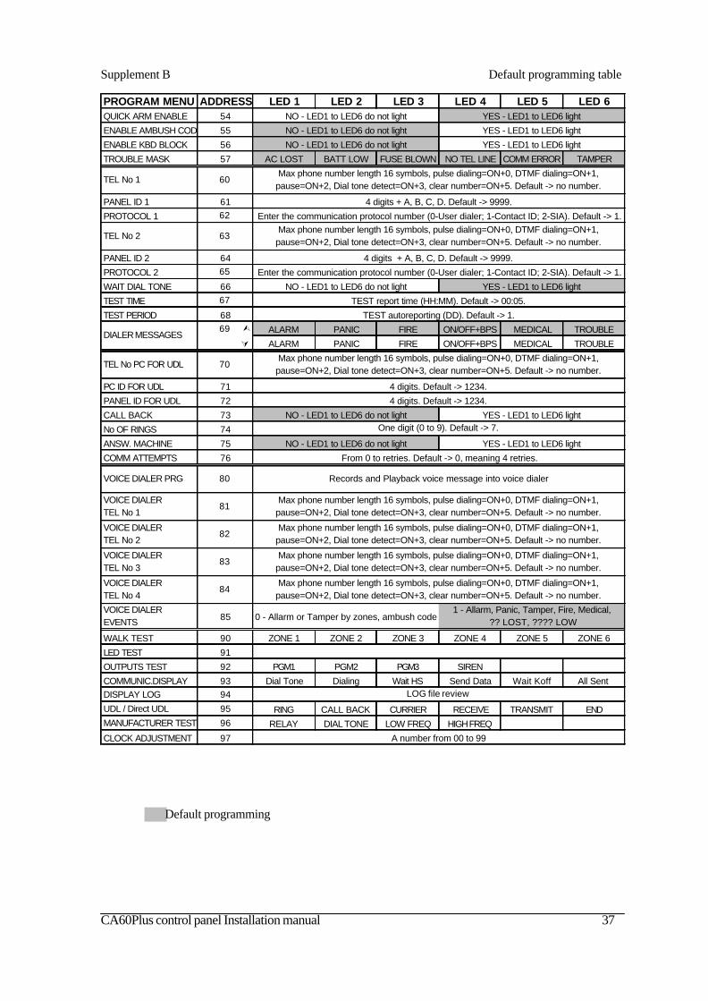
CA60Plus control panel Installation manual 37
Supplement B Default programming table
Default programming
PROGRAM MENU ADDRESS LED 1 LED 2 LED 3 LED 4 LED 5 LED 6QUICK ARM ENABLE 54 NO - LED1 to LED6 do not light YES - LED1 to LED6 light
ENABLE AMBUSH CODE 55
ENABLE KBD BLOCK 56 NO - LED1 to LED6 do not light YES - LED1 to LED6 light
TROUBLE MASK 57 AC LOST BATT LOW FUSE BLOWN NO TEL LINE COMM ERROR TAMPER
TEL No 1 60
PANEL ID 1 61
PROTOCOL 1 62
TEL No 2 63
PANEL ID 2 64
PROTOCOL 2 65
WAIT DIAL TONE 66 NO - LED1 to LED6 do not light YES - LED1 to LED6 light
TEST TIME 67
TEST PERIOD 6869 Ù ALARM PANIC FIRE ON/OFF+BPS MEDICAL TROUBLE
Ú ALARM PANIC FIRE ON/OFF+BPS MEDICAL TROUBLE
TEL No PC FOR UDL 70
PC ID FOR UDL 71
PANEL ID FOR UDL 72
CALL BACK 73 NO - LED1 to LED6 do not light YES - LED1 to LED6 light
No OF RINGS 74
ANSW. MACHINE 75 NO - LED1 to LED6 do not light YES - LED1 to LED6 light
COMM ATTEMPTS 76
VOICE DIALER PRG 80
VOICE DIALER TEL No 1
81
VOICE DIALER TEL No 2
82
VOICE DIALER TEL No 3
83
VOICE DIALER TEL No 4
84
VOICE DIALER EVENTS 85 0 - Allarm or Tamper by zones, ambush code
1 - Allarm, Panic, Tamper, Fire, Medical, ?? LOST, ???? LOW
WALK TEST 90 ZONE 1 ZONE 2 ZONE 3 ZONE 4 ZONE 5 ZONE 6
LED TEST 91
OUTPUTS TEST 92 PGM1 PGM2 PGM3 SIREN
COMMUNIC.DISPLAY 93 Dial Tone Dialing Wait HS Send Data Wait Koff All SentDISPLAY LOG 94
UDL / Direct UDL 95 RING CALL BACK CURRIER RECEIVE TRANSMIT ENDMANUFACTURER TEST 96 RELAY DIAL TONE LOW FREQ HIGH FREQ
CLOCK ADJUSTMENT 97
LOG file review
Max phone number length 16 symbols, pulse dialing=ON+0, DTMF dialing=ON+1, pause=ON+2, Dial tone detect=ON+3, clear number=ON+5. Default -> no number.
4 digits. Default -> 1234.
4 digits. Default -> 1234.
One digit (0 to 9). Default -> 7.
Records and Playback voice message into voice dialer
Max phone number length 16 symbols, pulse dialing=ON+0, DTMF dialing=ON+1, pause=ON+2, Dial tone detect=ON+3, clear number=ON+5. Default -> no number.
DIALER MESSAGES
A number from 00 to 99
From 0 to retries. Default -> 0, meaning 4 retries.
Max phone number length 16 symbols, pulse dialing=ON+0, DTMF dialing=ON+1, pause=ON+2, Dial tone detect=ON+3, clear number=ON+5. Default -> no number.
4 digits + A, B, C, D. Default -> 9999.
Enter the communication protocol number (0-User dialer; 1-Contact ID; 2-SIA). Default -> 1.Max phone number length 16 symbols, pulse dialing=ON+0, DTMF dialing=ON+1,
pause=ON+2, Dial tone detect=ON+3, clear number=ON+5. Default -> no number.
4 digits + A, B, C, D. Default -> 9999.
Enter the communication protocol number (0-User dialer; 1-Contact ID; 2-SIA). Default -> 1.
TEST report time (HH:MM). Default -> 00:05.
Max phone number length 16 symbols, pulse dialing=ON+0, DTMF dialing=ON+1, pause=ON+2, Dial tone detect=ON+3, clear number=ON+5. Default -> no number.
Max phone number length 16 symbols, pulse dialing=ON+0, DTMF dialing=ON+1, pause=ON+2, Dial tone detect=ON+3, clear number=ON+5. Default -> no number.
Max phone number length 16 symbols, pulse dialing=ON+0, DTMF dialing=ON+1, pause=ON+2, Dial tone detect=ON+3, clear number=ON+5. Default -> no number.
NO - LED1 to LED6 do not light YES - LED1 to LED6 light
TEST autoreporting (DD). Default -> 1.
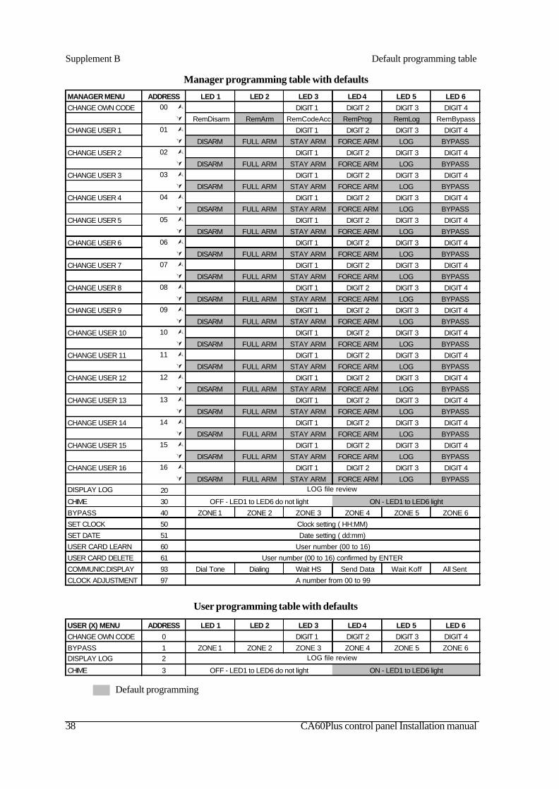
38 CA60Plus control panel Installation manual
Supplement B Default programming table
Default programming
User programming table with defaults
USER (X) MENU ADDRESS LED 1 LED 2 LED 3 LED 4 LED 5 LED 6
CHANGE OWN CODE 0 DIGIT 1 DIGIT 2 DIGIT 3 DIGIT 4
BYPASS 1 ZONE 1 ZONE 2 ZONE 3 ZONE 4 ZONE 5 ZONE 6DISPLAY LOG 2
CHIME 3 OFF - LED1 to LED6 do not light ON - LED1 to LED6 light
LOG file review
Manager programming table with defaults
MANAGER MENU ADDRESS LED 1 LED 2 LED 3 LED 4 LED 5 LED 6
CHANGE OWN CODE 00 Ù DIGIT 1 DIGIT 2 DIGIT 3 DIGIT 4 Ú RemDisarm RemArm RemCodeAcc RemProg RemLog RemBypass
CHANGE USER 1 01 Ù DIGIT 1 DIGIT 2 DIGIT 3 DIGIT 4 Ú DISARM FULL ARM STAY ARM FORCE ARM LOG BYPASS
CHANGE USER 2 02 Ù DIGIT 1 DIGIT 2 DIGIT 3 DIGIT 4 Ú DISARM FULL ARM STAY ARM FORCE ARM LOG BYPASS
CHANGE USER 3 03 Ù DIGIT 1 DIGIT 2 DIGIT 3 DIGIT 4 Ú DISARM FULL ARM STAY ARM FORCE ARM LOG BYPASS
CHANGE USER 4 04 Ù DIGIT 1 DIGIT 2 DIGIT 3 DIGIT 4 Ú DISARM FULL ARM STAY ARM FORCE ARM LOG BYPASS
CHANGE USER 5 05 Ù DIGIT 1 DIGIT 2 DIGIT 3 DIGIT 4 Ú DISARM FULL ARM STAY ARM FORCE ARM LOG BYPASS
CHANGE USER 6 06 Ù DIGIT 1 DIGIT 2 DIGIT 3 DIGIT 4 Ú DISARM FULL ARM STAY ARM FORCE ARM LOG BYPASS
CHANGE USER 7 07 Ù DIGIT 1 DIGIT 2 DIGIT 3 DIGIT 4 Ú DISARM FULL ARM STAY ARM FORCE ARM LOG BYPASS
CHANGE USER 8 08 Ù DIGIT 1 DIGIT 2 DIGIT 3 DIGIT 4 Ú DISARM FULL ARM STAY ARM FORCE ARM LOG BYPASS
CHANGE USER 9 09 Ù DIGIT 1 DIGIT 2 DIGIT 3 DIGIT 4 Ú DISARM FULL ARM STAY ARM FORCE ARM LOG BYPASS
CHANGE USER 10 10 Ù DIGIT 1 DIGIT 2 DIGIT 3 DIGIT 4 Ú DISARM FULL ARM STAY ARM FORCE ARM LOG BYPASS
CHANGE USER 11 11 Ù DIGIT 1 DIGIT 2 DIGIT 3 DIGIT 4 Ú DISARM FULL ARM STAY ARM FORCE ARM LOG BYPASS
CHANGE USER 12 12 Ù DIGIT 1 DIGIT 2 DIGIT 3 DIGIT 4 Ú DISARM FULL ARM STAY ARM FORCE ARM LOG BYPASS
CHANGE USER 13 13 Ù DIGIT 1 DIGIT 2 DIGIT 3 DIGIT 4 Ú DISARM FULL ARM STAY ARM FORCE ARM LOG BYPASS
CHANGE USER 14 14 Ù DIGIT 1 DIGIT 2 DIGIT 3 DIGIT 4 Ú DISARM FULL ARM STAY ARM FORCE ARM LOG BYPASS
CHANGE USER 15 15 Ù DIGIT 1 DIGIT 2 DIGIT 3 DIGIT 4 Ú DISARM FULL ARM STAY ARM FORCE ARM LOG BYPASS
CHANGE USER 16 16 Ù DIGIT 1 DIGIT 2 DIGIT 3 DIGIT 4 Ú DISARM FULL ARM STAY ARM FORCE ARM LOG BYPASS
DISPLAY LOG 20
CHIME 30 OFF - LED1 to LED6 do not light ON - LED1 to LED6 light
BYPASS 40 ZONE 1 ZONE 2 ZONE 3 ZONE 4 ZONE 5 ZONE 6
SET CLOCK 50
SET DATE 51
USER CARD LEARN 60
USER CARD DELETE 61
COMMUNIC.DISPLAY 93 Dial Tone Dialing Wait HS Send Data Wait Koff All Sent
CLOCK ADJUSTMENT 97 A number from 00 to 99
User number (00 to 16) confirmed by ENTER
LOG file review
Clock setting ( HH:MM)
Date setting ( dd:mm)
User number (00 to 16)
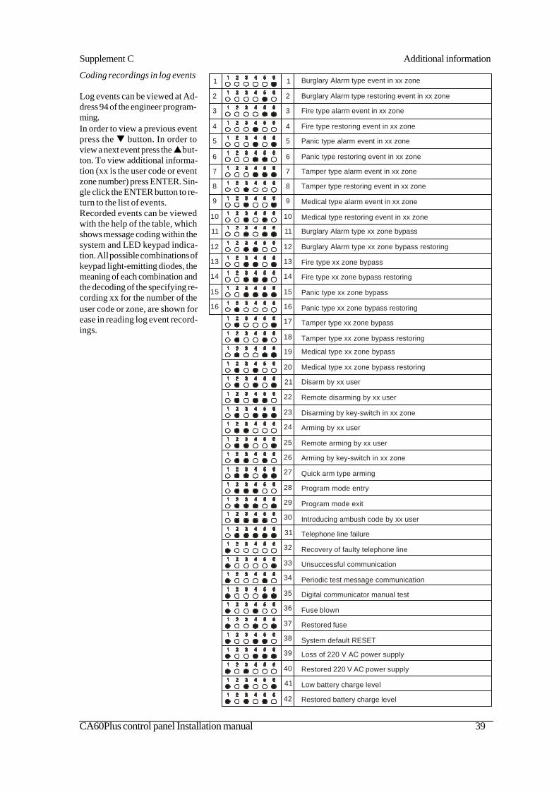
CA60Plus control panel Installation manual 39
Coding recordings in log events
Log events can be viewed at Ad-dress 94 of the engineer program-ming.In order to view a previous eventpress the q button. In order toview a next event press the p but-ton. To view additional informa-tion (xx is the user code or eventzone number) press ENTER. Sin-gle click the ENTER button to re-turn to the list of events.Recorded events can be viewedwith the help of the table, whichshows message coding within thesystem and LED keypad indica-tion. All possible combinations ofkeypad light-emitting diodes, themeaning of each combination andthe decoding of the specifying re-cording xx for the number of theuser code or zone, are shown forease in reading log event record-ings.
Supplement C Additional information
1
2
3
4
5
6
7
8
9
10
11
12
13
14
15
16
17
18
19
20
21
22
23
24
25
26
27
28
29
30
31
32
33
34
35
36
37
38
39
40
41
42
Burglary Alarm type event in xx zone
Burglary Alarm type restoring event in xx zone
Fire type alarm event in xx zone
Fire type restoring event in xx zone
Panic type alarm event in xx zone
Panic type restoring event in xx zone
Tamper type alarm event in xx zone
Tamper type restoring event in xx zone
Medical type alarm event in xx zone
Medical type restoring event in xx zone
Burglary Alarm type xx zone bypass
Burglary Alarm type xx zone bypass restoring
Fire type xx zone bypass
Fire type xx zone bypass restoring
Panic type xx zone bypass
Panic type xx zone bypass restoring
Tamper type xx zone bypass
Tamper type xx zone bypass restoring
Medical type xx zone bypass
Medical type xx zone bypass restoring
Disarm by xx user
Remote disarming by xx user
Disarming by key-switch in xx zone
Arming by xx user
Remote arming by xx user
Arming by key-switch in xx zone
Quick arm type arming
Program mode entry
Program mode exit
Introducing ambush code by xx user
Telephone line failure
Recovery of faulty telephone line
Unsuccessful communication
Periodic test message communication
Digital communicator manual test
Fuse blown
Restored fuse
System default RESET
Loss of 220 V AC power supply
Restored 220 V AC power supply
Low battery charge level
Restored battery charge level
1
2
3
4
5
6
7
8
9
10
11
12
13
14
15
16
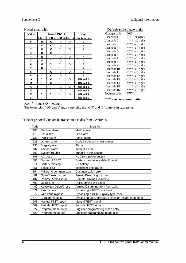
40 CA60Plus control panel Installation manual
Supplement C Additional information
Table of protocol Contact ID transmitted codes from CA60Plus
Code100 Medical alarm Medical alarm110 Fire alarm Fire alarm120 Panic alarm Panic alarm121 Duress code Code introduced under duress130 Burglary alarm Alarm137 Tamper alarm Tamper alarm300 System trouble Trouble in the system301 AC Loss No 220 V power supply305 System RESET System parameters default reset311 Battery missing No battery351 Teleco Fail Telephone line failure354 Failure to communicate Communication error401 Open/Close by user Arming/Disarming by user407 Remote Arm/Disarm Remote Arming/Disarming408 Quick arm Quick arming (no code)409 Keyswitch Open/Close Arming/Disarming from key-switch571 Fire bypass Bypassing a FIRE type zone572 24 h zone bypass Bypassing a 24 h Burglary type zone573 Burglary bypass Bypassing an Entry/Exit, Follow or Instant type zone601 Manual TEST report Manual TEST signal602 Periodic TEST report Periodic TEST signal627 Program mode entry Engineer programming mode entry628 Program mode exit Engineer programming mode exit
Meaning
Default code passwords:Manager code - 0000User code 1 - 1111 - all rightsUser code 2 - **** - all rightsUser code 3 - **** - all rightsUser code 4 - **** - all rightsUser code 5 - **** - all rightsUser code 6 - **** - all rightsUser code 7 - **** - all rightsUser code 8 - **** - all rightsUser code 9 - **** - all rightsUser code 10 - **** - all rightsUser code 11 - **** - all rightsUser code 12 - **** - all rightsUser code 13 - **** - all rightsUser code 14 - **** - all rightsUser code 15 - **** - all rightsUser code 16 - **** - all rightsEngineer code - 7777
**** - no code combination
Hexadecimal table
Key: ⊗ - lights O - not light.The expression “ON and 1” means pressing the “ON” and “1” buttons in succession.
Value Status LED3..6 KeysLED 3 LED 4 LED 5 LED 6 Combination
0 Ο Ο Ο Ο 01 Ο Ο Ο ⊗ 12 Ο Ο ⊗ Ο 23 Ο Ο ⊗ ⊗ 34 Ο ⊗ Ο Ο 45 Ο ⊗ Ο ⊗ 56 Ο ⊗ ⊗ Ο 67 Ο ⊗ ⊗ ⊗ 78 ⊗ Ο Ο Ο 89 ⊗ Ο Ο ⊗ 9A ⊗ Ο ⊗ Ο ON and 0B ⊗ Ο ⊗ ⊗ ON and 1C ⊗ ⊗ Ο Ο ON and 2D ⊗ ⊗ Ο ⊗ ON and 3E ⊗ ⊗ ⊗ Ο ON and 4F ⊗ ⊗ ⊗ ⊗ ON and 5

CA60Plus control panel Installation manual 41
Table of protocol SIA Level 1 transmitted codes from CA60Plus
CodeAR AC Restore Restore 220V power supplyAT AC Loss No 220 V power supplyBA Burglary alarm AlarmBB Burglary bypass Bypassing an Entry/Exit, Follow or Instant type zoneBH Burglary Restore Restore alarm
BU Burglary bypass RestoreRestore after Bypassing an Entry/Exit, Follow or Instant type zone
CL Quick arm Quick arming (no code)CL Arming by user Arming by userCQ Remote arming Remote armingCS Arming by keyswitch Arming from key-switchFA Fire alarm Fire alarmFB Fire bypass Bypassing a FIRE type zoneFH Fire Restore Restore after Fire alarmFU Fire bypass Restore Restore after bypassing a FIRE type zoneHA Duress code Code introduced under duressLB Program mode entry Engineer programming mode entryLX Program mode exit Engineer programming mode exitMA Medical alarm Medical alarmMB Medical bypass Bypassing a Medical type zoneMH Medical Restore Restore after Medical alarmMU Medical bypass Restore Restore after bypassing a Medical type zoneOP Disarm by user Disarming by userOQ Remote disarm Remote disarmingOS Disarm by keyswitch Disarming from key-switchPA Panic alarm Panic alarmPB Panic bypass Bypassing a Panic type zonePH Panic Restore Restore after Panic alarmPU Panic bypass Restore Restore after bypassing a Panic type zoneRP Periodic TEST report Periodic TEST signalRX Manual TEST report Manual TEST signalTA Tamper alarm Tamper alarmTB Tamper bypass Bypassing a Tamper type zoneTH Tamper Restore Restore after Tamper alarmTU Tamper bypass Restore Restore after bypassing a Tamper type zoneYC Failure to communicate Communication errorYK Telephone line Retsore Restored telephone lineYP Fuse blown Blown fuseYQ Fuse Restore Restored fuseYR Battery Restore Restored batteryYS Telephone line Fault Telephone line failureYT Battery missing No batteryYW System RESET System parameters default reset
Meaning
Supplement C Additional information
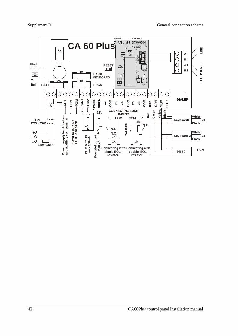
42 CA60Plus control panel Installation manual
Supplement D General connection scheme
CA 60 Plus
+ PGM
+ AUXKEYBOARD
AC
+AU
X
+PG
M
PG
M1
PGM
2
PG
M3
SIR
EN
Z2 CO
M
Z3 Z4 Z5 Z6CO
M
CO
M
RE
D
GR
N
YLW
BLC
K
RESET
BATT2A
1A
1A
DIALER
Keyboard1
Keyboard 2
PR 60
Pow
erfu
l ou
tput
max
2À
12V
Connecting with double EOL resistor
CONNECTING ZONE INPUTS
N.C.N.O.
ZCOM
1k
Connecting with single EOL resistor
1kTA
MP
ER
Z COM
1k
N.C.
Red
Gre
en
Yello
w
Bla
ck
PG
M o
utpu
ts m
ax 1
00m
A
12V
A
B
A1
B1
LIN
E
CO
M
Pow
er s
uppl
y fo
r de
tect
ors
and
auxi
llary
com
pone
nts
Pow
er s
upp
ly fo
r P
GM
an
d si
ren
220V/0,63A
N
L
Z1White
Black
Z1White
Black
PGM
TELE
PHO
NE
17V17W - 25W
PROG EXPAND
SP MIC
REC
MSG
PLAY
MS
G ?
VD60
BUS
Y
1
2 2

CA60Plus control panel Installation manual 43
Revision historyRevision 4.31
1. Added menu 48 - fire duration.2. Added menu 49 - enable/disable audible TAMPER.3. Changed menu 69 - second half - events for transmit by second phone.4. Added menu 76 - communications attempts.5. Added menu 93 - communicator test.6. Added menu 97 - internal clock adjustement.7. Possibility of FORCE arming for zone type KEYSWITCH.8. Added sound signal ALLARM to keyboards.9. Clear LOG files after hardware RESET.
Revision 4.331. In menu 61 and 64 - panel ID can be hexadecimal.
Revision 5.01. Added possibility to attach voice dialer.2. Added menu 80 - record and playback of voice messages.3. Added menu 81, 82, 83, 84 - four phone numbers for voice dialer.4. Added menu 85 - message type transission for voice dialer.
Message Event Example message 1 Alarm or tamper from Zone1 “ Alarm from Zone 1” or “Alarm in Entrance
zone” 2 Alarm or tamper from Zone2 “alarm from Zone 2” or “Alarm in the corridor” 3 Alarm or tamper from Zone3 “Alarm from Zone 3” or “Alarm in the children
room” 4 Alarm or tamper from Zone4 “Alarm from Zone 4” or “Alarm in the dinning
room” 5 Alarm or tamper from Zone5 “Alarm from Zone 5” or “Alarm in the bedroom” 6 Alarm or tamper from Zone
6 “Alarm from Zone 6” or “ Cable interrupting in the alarm system”
7 The control panel turn off with Ambush code
“Duress code have been entered”
8 Personal message “Message for Mr. John Smith”
Message Event Example message 1 Alarm in the system “ Burglary alarm” 2 Panic alarm in the system “ Panic or Duress code have been entered” 3 Tamper alarm in the system “ Cable interrupting in the alarm system” 4 Fire alarm in the system “Fire” 5 Medical alarm in the system “ Medical alarm ” 6 AC loss “AC power supply interrupting” 7 Battery low “ Battery too low ” 8 Common message “Message for Mr. John Smith”
Supplement E Example vioce message
Table 1: Message by zones (in 85 addres entered 0)
Table 2: Message by events (in 85 addres entered 1)
GuaranteeDuring the guarantee period the manufacturer shall, at its sole discretion, replace or repair anydefective product when it is returned to the factory. All parts replaced and/or repaired shall becovered for the remainder of the original guarantee, or for ninety (90) days, whichever period islonger. The original purchaser shall immediately send manufacturer a written notice of thedefective parts or workmanship, which written notice must in all cases be received prior toexpiry of the guarantee.International GuaranteeForeign customers shall enjoy the same guarantee rights as those enjoyed by any customer in Bulgaria,except that manufacturer shall not be liable for any related customs duties, taxes or VAT, which may bepayable.
Guarantee Procedure
This guarantee will be granted when the appliance in question is returned. The manufacturershall accept no product whatsoever, of which no prior notice has been received.
Conditions for waiving the guaranteeThis guarantee shall apply to defects in products resulting only from improper materials orworkmanship, related to its normal use. It shall not cover:
§ Damages resulting from transportation and handling;§ Damages caused by natural calamities, such as fire, floods, storms, earthquakes or
lightning;§ Damages caused by incorrect voltage, accidental breakage or water; beyond the control
of the manufacturer;§ Damages caused by unauthorized system incorporation, changes, modifications or
surrounding objects:§ Damages caused by peripheral appliances (unless such peripheral appliances have
been supplied by the manufacturer:§ Defects caused by inappropriate surrounding of installed products;§ Damages caused by failure to use the product for its normal purpose; Damages caused
by improper maintenance;§ Damages resulting from any other cause, bad maintenance or product misuse.
In the case of a reasonable number of unsuccessful attempts to repair the product, covered bythis guarantee, the manufacturer’s liability shall be limited to the replacement of the product asthe sole compensation for breach of the guarantee. Under no circumstances shall themanufacturer be liable for any special, accidental or consequential damages, on the grounds ofbreach of guarantee, breach of agreement, negligence, or any other legal notion.
WaiverThis Guarantee shall contain the entire guarantee and shall be prevailing over any and all otherguarantees, explicit or implicit (including any implicit guarantees on behalf of the dealer, oradaptability to specific purposes), and over any other responsibilities or liabilities on behalf ofthe manufacturer. The manufacturer does neither agree, nor empower, any person, acting onhis own behalf, to modify or alter this Guarantee, nor to replace it with another guarantee, oranother liability with regard to this product.
Unwarranted ServicesThe manufacturer shall repair or replace unwarranted products, which have been returned to itsfactory, at its sole discretion under the conditions below. The manufacturer shall accept noproducts for which no prior notice has been received.The products, which the manufacturer deems repairable, will be repaired and returned. Themanufacturer has prepared a price list and those products, which can be repaired, shall be paidfor every repaired appliance.The closest equivalent product, available at the time, shall replace the products manufacturerdeems unrepairable. The current market price shall be charged for every replaced product.
1802
0351
Rev
.5.0
01/2
005
Related Documents