Standards for Communications Infrastructure C&IT IT Customer Services & Telecommunications Wayne State University 5925 Woodward Detroit, Michigan 48202-3555 Revised: 31 October 2012 By: Pete Garabedian 1

Telecommunication Facilities Planning
Oct 22, 2015
Telecommunication_Facilities Planning
Welcome message from author
This document is posted to help you gain knowledge. Please leave a comment to let me know what you think about it! Share it to your friends and learn new things together.
Transcript
Standards for Communications Infrastructure
C&IT IT Customer Services & Telecommunications Wayne State University
5925 Woodward Detroit, Michigan 48202-3555
Revised: 31 October 2012 By: Pete Garabedian
1
This document is available online in Adobe Acrobat (.pdf) format
at
http://computing.wayne.edu/docs/wsu-communications-standards.pdf
Revision History
31 October 2012 Updated to add & clarify systems requirements, specifications, clarify wording, remove redundant specifications, numbers, bullets, etc. Update URL name location & update online copy of this document in pdf format.
31 October 2010 Updated to include additional manufacturers of approved structure
cabling systems, clarify wording, Add page numbers, fix table of contents page numbers, etc. Update URL for online copy of this document in .pdf format.
15 June 2009 Updated to include additional manufacturers of approved structure
cabling systems. Update URL for online copy of this document in .pdf format.
29 April 2005 Updated to include exact manufacturer product names for
approved Category 6e (cat6e) structured cabling system components. Add URL for online copy of this document in Adobe Acrobat (.pdf) format.
1 December 2004 First publication of completely revised document. All sections
rewritten.
2
Table of Contents Page WSU TELECOMMUNICATIONS DESIGN GUIDELINES.................................... 5 SECTION 17010 - TELECOMMUNICATIONS GENERAL
REQUIREMENTS............................................................. 12 SECTION 17110 - TELECOMMUNICATIONS INTERIOR
PATHWAYS...................................................................... 21 SECTION 17130 - COMMUNICATION EQUIPMENT SPACES
SUPPORT HARDWARE .................................................. 25 SECTION 17150 - TELECOMMUNICATIONS CABLING.................................... 33 SECTION 17170 - CABLE PLANT ADMINISTRATION AND
TESTING .......................................................................... 45 SECTION 17500 - C&IT CATV SPECIFICATIONS AND
STANDARDS.................................................................... 49
3
Acknowledgements C&IT IT Customer Services & Telecommunications expresses its appreciation to the following participants in their review of this document:
C&IT IT Customer Services & Telecommunications
(WSU) Jill Zeller, Senior Director, IT Customer Services Kathy Guarano, Associate. Director, Telecommunications Peter Garabedian, Project Manager, Telecommunications VACANT Position, Director, Network Engineering Tim Muir, Lead Electronics Technician, Telecommunications Chuck Zuber, Electronics Technician, Telecommunications David Fleig, Network Engineering C&IT IT Customer Services & Telecommunications 5925 Woodward Detroit, Michigan 48202-3555 Tel: 313-577-1977 Fax: 313-577-5577 http://networks.wayne.edu
WSU Facilities planning & Management (WSU)
Randy Paquette, Director III Facilities Planning & Management 5454 Cass Detroit, Michigan 48202 Tel: 313-577-4310 Fax: 313-577-1817 http://www.facilities.wayne.edu
Other Sources BICSI (Building Industry Consulting Service International) Roger Mahlmeister, RCDD - Western TelCom Rick Gillam, RCDD Learning Consultants, INC Tom - Hilla Hubble
4
WSU Telecommunications Design Requirements
Applicable Standards: Unless specifically indicated otherwise in this document, all telecommunications infrastructure shall be design in accordance with the following standards including all appropriate addendums and revisions:
ANSI/EIA/TIA-568-B Commercial Building Telecommunications Cabling Standard
ANSI/EIA/TIA-606-A Administration Standard for Commercial Telecommunications Infrastructure
ANSI J-STD-607-A Commercial Building Grounding (Earthing) and Bonding Requirements for Telecommunications
ANSI/EIA/TIA-758 Customer Owned Outside Plant telecommunications Cabling Standard
BICSI Telecommunications Distribution Methods Manual (TDMM)
BICSI Telecommunications Cabling Installation Manual (TCIM)
Design Deliverables:
Programming • With specific input from C&IT, generate outlet schedule based on functional use summary in the statement of needs/program statement.
• Provide preliminary area requirements for entrance facility and telecommunication rooms
• Identify extent of site work necessary to bring services to building
• Where wireless networks are to be the primary connection to the network, an independent consultant with demonstrated expertise in wireless systems shall be commissioned to provide access point layout, equipment selection and input on other construction methods that may affect wireless transmissions.
Schematic Design • Concept Sketches showing preliminary telecommunications rooms and sizes and zone plan showing areas served by rooms.
• Preliminary backbone riser diagrams showing interrelationships
• Concept sketch showing major pathways for backbone and horizontal cabling
5
Design Development • Preliminary drawings identifying device layouts for typical spaces.
• Preliminary drawing showing main cable tray layouts. • Preliminary drawing showing communication backbone
riser. • Preliminary drawing showing communication grounding
riser.
Construction Documents
• Identify all device locations on scaled plan drawings • Identify outlet configurations by unique symbol and/or
schedule • Identify all intended pathways and raceways for horizontal
and backbone cable. • Provide enlarged telecommunications room plans
indicating placement of racks, cable runway, wall mounted systems, ground bus locations.
• Provide rack elevations indicating all patch panels placement, cable management, structural supports, ground connections and space allocated for owner provided network electronics and any UPS/power conditioners. Provide backboard elevations indicating space allocate• d for wall fields, equipment, etc. Indicate location and provid• e details for all grounding apparatus. Provide CSI format specification• s for cable, connectors, cable management hardware, etc.
Construction Administration
• Review shop drawings for cable, connectors, and hardware
• construction visits to observe the installation
• including follow-up to verify
Systems and Performance:
for compliance with project specifications and WSU requirements. Make periodic for conformance to project specifications and proper installation practices. Perform final punchlistpunchlist items have been completed.
Data System • Designed to support 10 Gbps Ethernet to the desktop over
• upport 10Gbps Ethernet ve
Voice System • ordinated with WSU C&IT.
Video Distribution •
UTP copper cable (CAT 6E) . Inter-building backbone shall s
• Intra-building backbone shall support DWDM (Dense WaDivision Multiplexing)
Specific design to be co
Specific design to be coordinated with WSU C&IT.
Wireless Networks • Specific design to be coordinated with WSU C&IT.
6
Site and Service Conside iorat ns:
Incoming Services: • Provide minimum of (4) 4” conduits from nearest telecommunications manhole, tunnel, etc. into service
ne for
• el d.
Manholes, Handholes: nd holes to minimize bends.
• In Streets & Driveways, provide 5’x5’x5’ concrete
• hole with
• 6”l “Quazite”
• opper tracer wire in all
• ust
• it
• to this will be allowed.
Grounding:
entrance facility. (two for WSU, one for AT&T & oemergency maintenance spare). These conduits shall be HDPE if buried underground. Steconduit when cast in concrete. PVC conduit is not allowe
• Provide three 1 ¼” inner ducts in all of the service entrance conduits. In each Inner duct, a pull string must be installed.
• The inner ducts installed must extend 6 to 8 inches past the conduit at both ends.
• Coordinate with AT&T • Coordinate with C&IT for further definition of design
requirements. • Minimum of 1 240V dedicated circuit. • Minimum of 1 120V dedicated circuit.
• Provide additional manholes and/or hacable pulls to 400’, and two 90 degree
handhole with round steel rim and cover. In sidewalks, provide 5’x5’x5’ concrete handround steel rim and cover Only in Green Areas, provide 24”w x 42”d x 3hand holes. (locate hand holes in green space only) Provide a # 10 gauge solid cexterior conduits for future conduit locating usage. Upon completion, before final payment the following mbe provided: Provide a site plan of installed conduit showing condulocation, quantities & depth. No exception
• Provide ¼” x 2” x 4’ ground bus in the main telecommunications room.
• Provide ¼” x 2” x 2’ ground bus in each
Bonding Backbone nding backbone entrance facility
oms (IDF) with #6 jumper to
Ground Bus
telecommunications room.
• Provide a #4/0 AWG insulated copper bofrom the main ground bus in the service (MDF) to the intermediate roTGB’s.
• Do not route bonding backbone within 18” of electrical feeders.
7

Equipment • racks, cabinets, etc to ground bus in each d
r.
Telecommunications Rooms (MDF, IDF):
Bond alltelecommunications room with #6 AWG insulated grounconducto
Performance: • Minimum 2 ohms
pacing Criteria • Stack rooms wherever possible t exceed 250’. If this is the case,
additional closets will need to be built. • Provide one room for every 10 to 20,000 sft and less than
Security • oms will be fitted with the new
• ard ccess room via ID card swipe.
& WSU OneCard
Room sizes
• . ions for multi-story buildings with small floor plate.)
3 racks, and 10 x
Layout
•
t. to each
• m 2 racks per TR
Lighting f 7’-6” AFF.
S• Cable length shall no
250 ft. in length of cable. • Centrally locate rooms to minimize horizontal cable
lengths.
All new communication roWSU / Best lock key series # 88672.
All communication rooms will have WSU OneCard celectronics installed to a
• This design & layout must be coordinated with at least 1 person from WSU FP&M, WSU C&IT office.
• Provide minimum of one (10’ x 12’) MDF telecommunications room per building. Provide one IDF telecommunications room per floor, min(except
• Based on density served. • 8’ x 10’ for rooms serving (175) outlets or
12’ for rooms serving between (176) and (325) outlets, or 6racks.
gly for additional systems • Adjust room sizes accordin(video, security, access control, etc.)
Allow minimum of 24” deep for rack equipment, 36” clearance behind racks and 36” in front of racks.
• Allow for 12” deep equipment on wall fields when calculating clearances.
• Doors shall always swing out, provided it meets code requirements. Provide Fire Rated ¾” grade plywood. Do not pain•
• Provide 12” ladder rack around 3 sides of room & equipment rack.
• Ladder rack shall be secured to top of equipment racksProvide minimu
• Locate lighting in front of and behind racks. (not above) at minimum height o
8
• Provide 50fc minimum at floor level.
Power • oard for each MDF
ions room. ated circuit for each
or service
•
•
Environmental
Pathways:
Provide dedicated 12 circuit panel btelecommunications room. Preferred location for dedicated panel board is telecommunicat
• Provide a minimum of one 20A dedicequipment rack plus one additional 20A circuit foutlets, one on each wall. Provide 8 plug grounded power strip at the bottom of each equipment rack.
• Provide 8” space at the bottom of each rack for owner provided rack mounted UPS and/or power conditioner. Provide dedicated feeder/riser for all telecommunications room dedicated panel boards. No other loads should be served by this feeder.
• Provide cooling based on 75% of total electrical room wattage.
ed ese sleeves should be sized progressively
smaller or less of them as you move away from the serving closet. Size with 30% growth after cable is installed.
• Where rooms are not stacked, provide minimum (2) 4”
. •
Horizontal, accessible ceiling spaces:
• d below. s
ain runs.
• fluorescent
Backbone Cabling:
Backbone • Provide minimum (4) 4” sleeves through floors in stackrooms. Th
conduits continuous between rooms. • Connect TR’s on same floor with minimum of (1) 4”conduit
Conduit between rooms shall have no more than (2) 90 degree bends and/or over 150’ without pull box. Pull boxes shall be sized per the amount of conduits.
• Sleeves shall consist of GRS conduit with bushings andstub above the floor a minimum of 4”.
• Provide cable trays down corridors whenever possible. If cost prohibitive, J-hooks are acceptable. Provide J-Hooks for cable bundles of 24 an
• Route main cable runs through accessible corridor spaceand drop off into each room from the m
• When ever possible do not route main cable trays or cable bundles through classrooms or offices. Maintain 12” minimum between cable traylighting.
Inter Building (between • 96 strand single mode (glass fiber as Minimum
9
buildings hub) manufactured by corning) between hub buildings • Provide 30’ slack loop in manhole. • Provide 15’ slack loop in telecommunications room.
ngle mode hub and
•
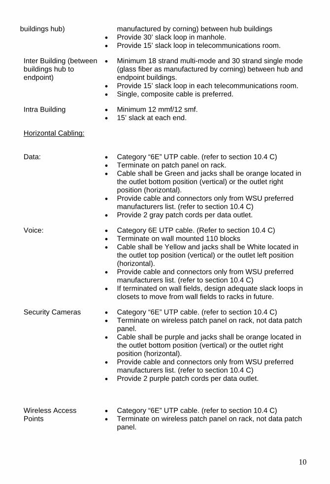
Horizontal Cabling:
Inter Building (between buildings hub to endpoint)
• Minimum 18 strand multi-mode and 30 strand si(glass fiber as manufactured by corning) between endpoint buildings.
• Provide 15’ slack loop in each telec ommunications room. • Single, composite cable is preferred.
Intra Building • Minimum 12 mmf/12 smf. 15’ slack at each end.
(refer to section 10.4 C) on rack.
• Cable shall be Green and jacks shall be orange located in the outlet bottom position (vertical) or the outlet right position (horizontal).
• Provide cable and connectors only from WSU preferred
outlet.
Voice: • • unted 110 blocks
left position
• Provide cable and connectors only from WSU preferred
ate slack loops in
Security Cameras • h
rred
Wireless Access Points h
Data: • Category “6E” UTP cable. • Terminate on patch panel
manufacturers list. (refer to section 10.4 C) • Provide 2 gray patch cords per data
Category 6E UTP cable. (Refer to section 10.4 C) Terminate on wall mo
• Cable shall be Yellow and jacks shall be White located inthe outlet top position (vertical) or the outlet (horizontal).
manufacturers list. (refer to section 10.4 C) • If terminated on wall fields, design adequ
closets to move from wall fields to racks in future.
Category “6E” UTP cable. (refer to section 10.4 C) • Terminate on wireless patch panel on rack, not data patc
panel. • Cable shall be purple and jacks shall be orange located in
the outlet bottom position (vertical) or the outlet right position (horizontal).
• Provide cable and connectors only from WSU prefemanufacturers list. (refer to section 10.4 C)
• Provide 2 purple patch cords per data outlet.
Category “6E” UTP ca• ble. (refer to section 10.4 C) • Terminate on wireless patch panel on rack, not data patc
panel.
10
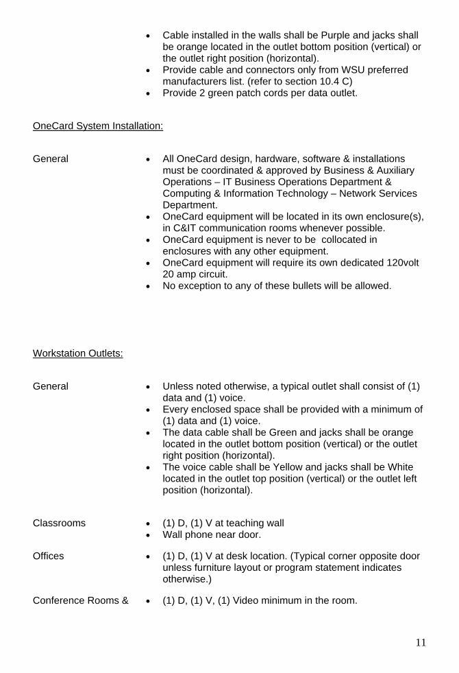
• Cable installed in the walls shall be Purple and jacks shall be orange located in the outlet bottom position (vertical) or the outlet right position (horizontal).
rred
• 2 green patch cords per data outlet.
OneCard System Installation:
• Provide cable and connectors only from WSU prefemanufacturers list. (refer to section 10.4 C) Provide
General tallations & Auxiliary
Operations – IT Business Operations Department & omputing & Information Technology – Network Services
• OneCard equipment will be located in its own enclosure(s),
•
•
Workstation Outlets:
• All OneCard design, hardware, software & insmust be coordinated & approved by Business
CDepartment.
in C&IT communication rooms whenever possible. OneCard equipment is never to be collocated in enclosures with any other equipment. OneCard equipment will require its own dedicated 120volt 20 amp circuit.
• No exception to any of these bullets will be allowed.
eneral • Unless noted otherwise, a typical outlet shall consist of (1) data and (1) voice.
• Every enclosed space shall be provided with a minimum of (1) data and (1) voice.
• The data cable shall be Green and jacks shall be orange located in the outlet bottom position (vertical) or the outlet
Classrooms • •
Offices • t or program statement indicates
otherwise.)
ooms & um in the room.
G
right position (horizontal). • The voice cable shall be Yellow and jacks shall be White
located in the outlet top position (vertical) or the outlet left position (horizontal).
(1) D, (1) V at teaching wall Wall phone near door.
(1) D, (1) V at desk location. (Typical corner opposite door unless furniture layou
Conference R • (1) D, (1) V, (1) Video minim
11
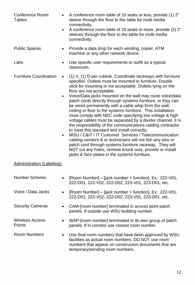
Conference Room Tables
e of 10 seats or less, provide (1) 2” sleeve through the floor to the table for multi media
• 2) 2” ugh the floor to the table for multi media
connectivity.
Labs
Furniture Coordination • r cubicle. Coordinate raceways with furniture ble the
e/data
h a cable whip from the wall,
h is
mmunications cabling contractor
•r
Administration (Labeling):
• A conference room tabl
connectivity. A conference room table of 10 seats or more, provide (sleeves thro
Public Spaces • Provide a data drop for each vending, copier, ATM machine or any other network device.
• Use specific user requirements or outfit as a typical classroom.
(1) V, (1) D pespecifier. Outlets must be mounted to furniture. Doustick for mounting is not acceptable. Outlets lying onfloor are not acceptable.
• Voice/Data jacks mounted on the wall may route voicpatch cords directly through systems furniture, or they can be wired permanently witceiling or floor to the systems furniture. This installation must comply with NEC code specifying low voltage & higvoltage cables must be separated by a divider channel. Itthe responsibility of the coto meet this standard and install correctly.
WSU / C&IT / IT Customer Services / Telecommunication cabling vendors & or technicians will not fish any wire opatch cord through systems furniture raceway. They will NOT cut any holes, remove knock outs, provide or install jacks & face plates in the systems furniture.
Number Scheme: •
Voice / Data Jacks • x: 222-V01, 222-D01, 222-V02, 222-D02, 223-V01, 223-D01, etc.
ecurity Cameras • CAM-[room number] terminated in access point patch
Wireless Access • tch
Room Numbers • SU
re
[Room Number] – [jack number + function]. Ex: 222-V01,222-D01, 222-V02, 222-D02, 223-V01, 223-D01, etc.
[Room Number] – [jack number + function]. E
Spanels. If outside use WSU building number.
WAP-[room number] terminated in its own group of paPoints panels. If in corridor use closest room number.
Use final room numbers that have been approved by Wfacilities as actual room numbers. DO NOT use room numbers that appear on construction documents that atemporary/pending room numbers.
12
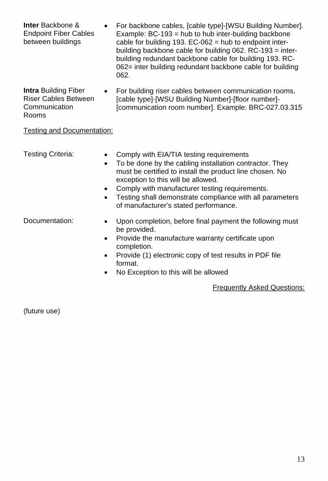
Inter Backbone & Endpoint Fiber Cables
s
• g Number]. Example: BC-193 = hub to hub inter-building backbone
er-
one cable for building
en Communication Rooms
•
Testing and Documentation:
between building
For backbone cables, [cable type]-[WSU Buildin
cable for building 193. EC-062 = hub to endpoint inter-building backbone cable for building 062. RC-193 = intbuilding redundant backbone cable for building 193. RC-062= inter building redundant backb062.
For building riser cables between communication rooms,[cable type]-[WSU Building Number]-[floor number]-[communication room number]. Example: BRC-027.03.315
Intra Building Fiber Riser Cables Betwe
• •
must be certified to install the product line chosen. No exception to this will be allowed. Comply with manufacturer testing requirements.
• Testing shall demonstrate compliance with all parameters
Documentation: st
• n
Testing Criteria: Comply with EIA/TIA testing requirements To be done by the cabling installation contractor. They
•
of manufacturer’s stated performance.
• Upon completion, before final payment the following mube provided. Provide the manufacture warranty certificate upocompletion.
• Provide (1) electronic copy of test results in PDF file format.
• No Exception to this will be allowed
Frequently Asked Questions:
(future use)
13
SECTION 17010 - TELECOMMUNICATIONS GENERAL REQUIREMENTS
PART 1 - GENERAL
1.1 RELATED DOCUMENTS
A. Drawings and general provisions of the contract, including general and supplementary conditions including division 1 specifications apply to work in this section.
1.2 SUMMARY
A. This Section includes telecommunications general administrative and procedural requirements. The following requirements are included in this Section to supplement the requirements specified in Division 1 Specification Sections.
1.3 DRAWINGS
A. The Drawings must show the location of equipment racks & elevations, Ladder rack on 3 walls, power outlet locations, general arrangement of equipment, electrical systems and related items. The installation will follow as closely as elements of the construction will permit.
B. The Drawings must show a conduit & cabling riser diagram from MDF & related IDFs. Copper pair & fiber strand counts will be detailed showing the distribution of riser cabling between the MDF & related IDFs.
C. Deviations from the Drawings, with the exception of minor changes in routing and other such incidental changes that do not affect the functioning or serviceability of the systems, shall not be made without the written approval of the Architect/Engineer and WSU C&IT.
D. The architectural and structural Drawings take precedence in all matters pertaining to the building structure, mechanical Drawings in all matters pertaining to mechanical trades and electrical Drawings in all matters pertaining to electrical trades. Where there are conflicts or differences between the Drawings for the various trades, report such conflicts or differences to the Architect and WSU C&IT for resolution.
1.4 INSPECTION OF SITE
A. Visit the site, examine and verify the conditions under which the work must be conducted before submitting proposal.
14

B. The submitting of a proposal implies that the Contractor has visited the site and understands the conditions under which the work must be conducted.
1.5 CONTRACT BREAKDOWN
A. WSU Facilities Department retains the installation and coordination for all projects initiated by that department.. WSU C&IT retains the design review, installation and coordination for all other voice, data & video projects not initiated by WSU Facilities.
B. Within two (2) weeks following award of contract, submit to the Architect/Engineer for approval a contract amount breakdown. Breakdown shall be submitted on a form similar to the form available at the Architect's/Engineer's office. All requests for payment shall be based on the approved breakdown.
1.6 TEMPORARY FACILITIES
A. Provide and remove upon completion of the project, in accordance with the general conditions, a complete temporary telephone service during construction, as required.
1.7 ALTERNATES
A. See Alternate Section and other applicable parts of the Specifications.
1.8 GUARANTEE
A. Contractor guarantees that the installation is free from defects and agrees to replace or repair, any part of this installation which becomes defective within a period of one year following final acceptance, provided that such failure is due to defects in the equipment, material or installation or to follow the Specifications and Drawings. File with the Owner any and all guarantees from the equipment manufacturers and warranty certificates.
1.9 CODES, PERMITS AND FEES
A. Unless otherwise indicated, all required permits, licenses, inspections, approvals and fees for telecommunications work shall be secured and paid for by the Contractor. All work shall conform to all applicable codes, rules and regulations.
B. Rules of local service providers shall be complied with. Check with the local exchange carrier supplying service to the installation and determine all raceways and devices required including, but not limited to, all terminal cabinets, backboards, space requirements, etc.
C. All work shall be executed in accordance with the rules and regulations set forth in local and state codes. Prepare any detailed Drawings or diagrams which may
15
be required by the governing authorities. Where the Drawings and/or Specifications indicate materials or construction in excess of code requirements, the Drawings and/or Specifications shall govern.
1.10 STANDARDS OF MATERIAL AND WORKMANSHIP
A. All materials shall be new, never used, reused, reconditioned, or refurbished componets. The electrical and physical properties of all materials, and the design, performance characteristics, and methods of construction of all items of equipment, shall be in accordance with the latest issue of the various, applicable Standard Specifications of the following recognized authorities:
A.N.S.I. American National Standards Institute A.S.T.M. American Society for Testing Materials BICSI Building Industry Consulting Services International I.C.E.A. Insulated Cable Engineer’s Association I.E.E.E. Institute of Electrical and Electronics Engineers N.E.C. National Electrical Code N.E.M.A. National Electrical Manufacturer's Association TIA/EIA Telecommunications Industry Association/Electronic Industries
Association U.L. Underwriters Laboratories, Inc. NFPA National Fire Protection Agency
B. Perform all work in a first class and workmanlike manner, in accordance with the latest accepted standards and practices for the Trades involved.
C. All equipment of the same or similar systems shall be by the same manufacturer.
1.11 RECORD DRAWINGS
A. Provide complete operating and maintenance instruction manuals covering all telecommunications equipment herein specified, together with parts lists. All literature shall be furnished in triplicate for Owner and shall be bound in book or ring binder form as directed by Architect/Engineer.
B. The operating and maintenance instructions shall include a brief, general description for all electrical systems including, but not limited to:
1. Routine maintenance procedures. 2. Trouble-shooting procedures. 3. Contractor's telephone numbers for warranty repair service. 4. Shop Drawings. 5. Recommended spare parts lists. 6. Names and telephone numbers of major material suppliers.
C. Provide revised telecommunications working Drawings indicating "as-built" conditions. Drawings shall indicate all changes that have occurred during construction. Properly and identify backbone and horizontal wiring pathways.
16
Locate all network and workstation devices. Identify all devices on plan with proper labeling. Identify outside plant backbone conduits, man holes & fiber cables installed on a site plan. "as-Built" Drawings shall be submitted on AutoCAD 2000 or newer electronic DWG file format. Provide (1) copy paper and (1) copy electronic DWG file.
D. Provide a site plan with elevations showing any man holes, hand holes or conduit installed outside.
1.12 MATERIAL AND EQUIPMENT MANUFACTURERS
A. All items of equipment shall be furnished complete with all accessories normally supplied with the catalog items listed and all other accessories necessary for a complete and satisfactory operating system. All equipment and materials shall be new and shall be standard products of manufacturers regularly engaged in the production of telecommunications equipment and shall be of the manufacturer's latest design.
B. No substitutions will be allowed without WSU C&IT approval.
1.13 SHOP DRAWINGS/SUBMITTALS
A. All shop drawings shall be submitted in groupings of similar and/or related items (cable and connectors, equipment cabinets and racks, etc.). Incomplete submittal groupings will be returned unchecked.
B. Provide detailed layout shop drawings (on transparent media) of backbone and horizontal cabling distribution, pathways, equipment room layouts, details and related information necessary of installation and maintenance. After review by the Engineer and WSU C&IT, a copy of Drawings will be stamped and returned to the Contractor.
C. Submit for approval eight (2) copies of shop drawings for all telecommunications systems or equipment but not limited to the items listed below. Where items are referred to by symbolic designation on the Drawings and Specifications, all submittals shall bear the same designation. Refer to other sections of the Specifications for additional requirements.
1. Structured cabling system components 2. Structured cable system raceways and supports 3. Outside plant cabling and components 4. Outside plant ducts manholes, hand holes & conduit systems on a
site plan with elevations. 5. Equipment racks and cabinets including management components 6. Labeling equipment 7. Telecommunications grounding components 8. Conduit, inner duct, junction and pullboxes 9. Surface raceway components 10. Manholes, hand holes and all accessories
17
11. Telephone system components 12. Data network system components 13. Audio/video system components 14. Access control system components 15. Security Camera system components
1.14 USE OF EQUIPMENT
A. The use of any equipment or any part thereof for purposes other than testing even with the Owner’s consent shall not be construed to be an acceptance of the work on the part of the Owner, nor be construed to obligate the Owner in any way to accept improper work or defective materials.
1.15 WORK SPECIFIED UNDER OTHER DIVISIONS
A. The following items are an integral part of the telecommunications system and will be provided by the Electrical Contractor & or Telecommunications Contractor.
1. Raceways 2. Boxes, cabinets and enclosures. 3. Grounding and Bonding 4. Underground Utilities
1.16 CONTRACTOR QUALIFICATIONS
A. The Installing Contractor for each communications system shall have a minimum of 5 years of experience with the types of systems specified. They must be certified to install, test & warranty the product specified prior to a bid submittal. No exception to this will be allowed.
B. The Installing Contractor shall submit a reference list consisting of a minimum of [3] [5] installations of equivalent size and complexity of this contract. The reference list shall contain the following information for each installation:
1. Name of project, square footage, location and brief description of systems.
2. Date of completed installation. 3. Contact name and phone number of facility representative. 4. Total bid amount of each system installed. 5. Final contract amount of each system installed, including all change
orders and bulletins.
C. The Installing Contractor shall submit with the bid the names and registration numbers of members of the firm that have a valid membership and are certified with BICSI as Registered Communications Distribution Designers (RCDD). This Contractor shall identify at least one RCDD assigned to this project in the bid.
18
D. The bidding, shop drawing submittal, procurement of materials, the installation as-builts and record documents shall be reviewed and overseen by the RCDD(s) assigned to the project.
E. The Contractor’s bid, shop drawing submittals, as-builts and record documents shall bear the valid seal of the RCDD(s) assigned to this project.
F. The Installing Contractor of the video system shall submit with the bid names and license numbers of all members of the firm that hold a valid commercial general class license with the FCC. The Contractor shall identify at least one FCC licensed technician/engineer assigned to this project with the bid.
G. All calculations, shop drawings, testing, certification and as-built documents shall be directly supervised by the licensed technician/engineer assigned to the project.
H. The contractor must provide a copy of the manufacturer’s certification that the contractor is currently certified to install, test & warranty the proposed system prior to a bid submittal. See Section 17110, 7.5A & section 17010, 1.16A. No exception to this will be allowed.
PART 2 - PRODUCTS
Not applicable.
PART 3 - EXECUTION
3.1 INSTALLATION OF EQUIPMENT
A. Install all equipment in strict accordance with all installation specifications set by the equipment manufacturer. Where such directions are in conflict with the Drawings and Specifications, report such conflicts to the Architect/Engineer and WSU C&IT for resolution.
3.2 WORK PERFORMED BY OTHERS
A. [Electrical Contractor shall install 4” sq. sheet steel wall boxes, minimum 1" trade size conduit (or as indicated on drawings) stubbed 12" above ceiling with 6" radius (or as required by TIA/EIA-569), with a 90 degree bend at top in the direction towards route destination, and plastic bushing for recessed locations.]
B. [Electrical Contractor shall install 4” sq. cast boxes. Minimum 1” trade size conduit (or as indicated on Drawings) stubbed up to 10’ AFF (or as indicated on Drawings), with 6” radius (or as required by TIA/EIA-569) for surface mounted locations.]
C. [The Owner will provide access point & network electronics equipment in all Communications Rooms as required.]
19
D. The Owner will provide all voice & data cross-connect jumpers.
3.3 DEMOLITION WORK
A. All demolition of existing telecommunications Cable, equipment and materials shall be specified by C&IT and done by this Contractor unless otherwise indicated. Include all items such as, but not limited to, cable, patch panels, devices, and wiring called out on the Drawings and as necessary whether such items are actually indicated on the Drawings or not in order to meet NFPA requirements.
B. In general, demolition of old low voltage communications cabling work is indicated on the drawings, however, the contractor shall visit the job site to determine the full extent and character of this work. All existing voice & data jacks demolished need to be documented. A room number, Jack number (if still there), approximate location in the room & the communication room where it terminated need to be identified. This information must be returned to C&IT IT Customer Services Telecommunications department.
C. None of the recovered material shall be reused in the new work.
D. Where equipment or fixtures are removed, outlets shall be properly blanked off, and conduits capped. After alterations are done, the entire installation shall present a "finished" look, as approved by the Architect/Engineer. The original function of the present systems to be modified shall not be changed unless required by the specific revisions to the system as specified or as indicated.
E. Reroute cable as required to maintain service. Where walls and ceilings are to be removed as shown on the Drawings, the conduit is to be cut off by the Electrical Trades so that the abandoned conduit in these walls and ceilings may be removed with the walls and ceilings by the Architectural Trades. All dead-end conduit runs shall be plugged at the remaining outlet boxes or at the panels.
F. Where new walls and/or floors are installed which interfere with existing telecommunications outlets, devices, etc., this Contractor shall adjust, extend and reconnect such items as required to maintain continuity of same.
G. All electrical work in altered and unaltered areas shall be run concealed wherever possible. Use of surface metal raceway or exposed conduits will be permitted only where approved by the Architect/Engineer and as specifically indicated on the Drawings.
3.4 WORK IN EXISTING BUILDINGS
A. The Owner will provide access to existing buildings via a Project Coordinator. However, this Contractor, once work is started in the existing building, shall complete same without interruption so as to return work areas as soon as possible to Owner.
20
B. Adequately protect and preserve all existing and newly installed work. Promptly repair any damage to same at this Contractor's expense.
C. Consult with the Owner's Project Coordinator and C&IT Project Coordinator as to the methods of carrying on the work so as not to interfere with the Owner's operation any more than absolutely necessary. Accordingly, all telecommunications services shall be kept in operation as long as possible and the services shall only be interrupted at such time as will be designated by the Owner's representative.
3.5 COORDINATION
A. Install work to avoid interference with work of other trades including, but not limited to, architectural, mechanical and electrical trades. Remove and relocate any work that causes interference at this Contractor's expense. Disputes regarding the cause of interference will be resolved by the Owner's representative or Architect/Engineer.
B. If there is a general contractor, The general contractor is responsible for the construction schedule. All work activities are to be coordinated with the general contractor.
3.6 CHASES AND RECESSES
A. Chases and recesses shall be provided by the Architectural Trades, but this Contractor shall be responsible for coordinating their accurate location and size.
3.7 SLEEVES
A. Provide and install Hilti Speed Sleeve model CP-630 or EZ path fire stop system wherever conduits or cabling pass through fire rated walls, floors or cables pass through openings in walls.
B. Sleeves are used in standard walls & floors with no fire rating. All sleeves through the floor are to extend 4 inches above floor, unless otherwise noted. Provide escutcheons at each sleeve in finished areas and adequate spacing between sleeves to accommodate escutcheons.
3.8 CUTTING, PATCHING AND DAMAGE TO OTHER WORK
A. Refer to General Conditions for requirements.
B. All cutting, patching and repair work shall be done by the Contractor.
21
3.9 EXCAVATION AND BACKFILLING
A. Provide all excavation, trenching, tunneling, dewatering and backfilling required for the telecommunications work. Coordinate the work with other excavating and backfilling in the same area.
B. Refer to electrical Drawings and the architectural Specifications for excavating and backfilling methods and materials.
3.10 ACCESS DOORS
A. Provide access doors for installation by architectural trades. In the walls, provide Milcor No. "DW" or "M" as required to make all controls, electrical boxes and other equipment installed by the Contractor accessible. Minimum size 12 inches x 12 inches. In the ceiling, provide Milcor No. 3210, 3105 or 3206 for accessibility as mentioned above, 24 inches x 24 inches minimum size. The plaster or acoustical tile insert shall be by the architectural trades. Areas with accessible ceilings (ceilings where tiles are not fastened in place and can be individually removed without removal of adjacent tiles) will not require access doors.
B. When access doors are in fire resistant wall or ceilings, they must bear the Underwriters Laboratories, Inc., Label, with time design rating equal to or exceeding that of the wall or ceiling unless they were a part of the tested assembly.
3.11 CLEANING
A. All debris shall be removed daily as required to maintain the work area in a neat, orderly condition.
B. Final cleanup shall include, but not be limited to, cleaning all telecommunications equipment spaces, devices, cover plates, and removing all scrap cable and debris from pathways.
3.12 PROTECTION AND HANDLING OF EQUIPMENT AND MATERIALS
A. Equipment and materials shall be protected from theft, injury or damage.
B. Protect conduit openings with temporary plugs or caps.
C. Provide adequate storage for all equipment and materials delivered to the job site. Location of the space will be designated by the Owner's Project Coordinator or Architect. Equipment set in place in unprotected areas must be provided with temporary protection.
22
3.13 EXTRA WORK
A. For any extra telecommunications work that may be proposed, this Contractor shall furnish to the General Contractor, an itemized breakdown of the estimated cost of the materials and labor required to complete this work. This Contractor shall proceed only after receiving a written order from the General Contractor establishing the agreed price and describing the work to be done.
3.14 DRAWINGS AND MEASUREMENTS
A. These Specifications and accompanying Drawings are intended to describe and provide for finished work. They are intended to be cooperative, and what is called for by either shall be as binding as if call for by both. The Contractor will understand that the work herein described shall be complete in every detail.
B. The Drawings are not intended to be scaled for rough-in measurements or to serve as shop drawings. Field measurements, necessary for ordering materials and fitting the installation to the building construction and arrangement, shall be taken by this contractor.
3.15 Automation System Program Code
A. All automation system uncompiled and compiled program
codes, source codes, custom modules, graphical user interface screen shots and any other automation system programming data and material (Program Code) shall be provided to the UNIVERSITY in hard copy and on CD Rom in an unencrypted format acceptable to the UNIVERSITY.
B. Copyright for the Program Code shall be assigned to the
UNIVERSITY for purposes of system maintenance. C. Provision of and Copyright assignment of the Program Code to
the UNIVERSITY by the Vendor shall be conditions of the Purchase Order and contract acceptance by the Vendor.
D. Provision of and Copyright assignment of the Program Code to
the UNIVERSITY by the Vendor shall be conditions of final System acceptance by the UNIVERSITY.
END OF SECTION 17010
23
SECTION 17110 - TELECOMMUNICATIONS INTERIOR PATHWAYS
PART 4 - GENERAL
4.1 RELATED DOCUMENTS
A. Related Sections include the following:
1. Division 17 Section “Telecommunications General Requirements.”
4.2 REFERENCES
A. ANSI/NFPA 70 - National Electrical Code.
B. NFPA-297 - Guide on Principles and Practices for Communication Systems.
C. ANSI/TIA/EIA 568-A - Commercial Building Telecommunications Cabling Standard.
D. ANSI/TIA/EIA 569-A - Commercial Building Standard for Telecommunications Pathways and Spaces.
E. ANSI/TIA/EIA 607 - Commercial Building Grounding and Bonding Requirements for Telecommunications.
F. ANSI/IEEE-110-1992 - Powering and Grounding Sensitive Electronic Equipment.
G. BICSI – Building Industry Consulting Services International.
4.3 SUBMITTALS
A. Submit all structured cabling system raceways and supports identified in this section under provisions of Section 17010.
B. Product Data: Provide for products specified and required.
C. Shop Drawings: Indicate project specific part numbers, dimensions, support points, fittings and finishes.
4.4 PROJECT RECORD DOCUMENTS
A. Submit all structured cabling system raceways and supports identified in this section under provisions of Section 17010.
24
B. Accurately record equipment layout and cable layouts in all telecommunication spaces.
4.5 DELIVERY, STORAGE, AND HANDLING
A. Deliver, store, protect, and handle products to site under provisions of Section 17010.
B. Protect products from corrosion and entrance of debris by storing above grade. Provide appropriate covering.
4.6 PROJECT CONDITIONS
A. Verify that field measurements are as shown on Drawings.
B. Verify routing and termination locations of conduits, and cable pathways prior to rough-in.
4.7 DESCRIPTION OF SYSTEMS
A. Communications cabling systems pathways shall be installed in accordance with ANSI/TIA/EIA 569-A.
B. Intra-building backbone cabling shall be installed in conduit, cable tray or J-hook support system.
C. Horizontal cabling (cabling from the telecommunications room to the work area outlet) pathways shall consist of [conduit] [cable tray] [J-hooks] [under floor duct system] [raised access flooring system] [accessible ceiling space] [cellular flooring system] as indicated on Drawings and as required.
D. Where the accessible ceiling systems [raised access flooring systems] are used as the primary pathway, cabling shall be installed [in main cable tray runs] as indicated on the Drawings, with individual work area cables routed exposed [in conduit] and supported as specified herein.
PART 5 - PRODUCTS
5.1 J-HOOKS
A. Manufacturers:
1. Erico-Caddy. 2. B-Line.
B. Horizontal cable routed exposed through ceiling space shall be supported from J-hooks.
25
C. J-hooks shall be a minimum of 5/8” wide and shall have a bearing surface that complies with required bend radii of the specified cables to be supported.
D. J-hooks shall have flared or folded edges to prevent damage when installing cables.
5.2 INNERDUCT
A. Manufacturers:
1. Carlon. 2. Endot.
B. Install inner duct through conduits and sleeves for optical fiber cabling installations.
C. Description: UL listed, non-metallic, corrugated flexible conduit for use in plenum or riser installations as applicable. Provide each inner duct with one 1/4” W pull tape with a tensile rating of 900 lbs.
PART 6 - EXECUTION
6.1 GENERAL
A. Where cables pass through fire rated walls, the Contractor shall provide and install Hilti Speed Sleeve model CP-630 or EZ path fire stop system. This penetration sleeve must match the fire rating of the wall. The penetration shall be sized per ANSI/TIA/EIA-569.
B. Any other wall or floor penetrations that aren’t fire rated, the Contractor shall fire-stop the penetrations, after final cable installation, using Engineer-approved materials. Fire-stopping materials shall be installed per manufacturer's recommendations and shall maintain partition rating and integrity. All fireproofing shall be applied in a neat manner with all excess material cleaned from all walls and surfaces. Contractor shall replace and re-install all fireproofing materials removed during cable installation.
C. Contractor shall patch and repair any holes or other damage to walls or partitions and paint to match original, as applicable.
D. The Communication Cabling Contractor shall provide plastic and/or grounding bushings, as applicable, on all conduit sleeves, stubs and conduit terminations that may have been missed by the Electrical Contractor.
E. All cutting, patching and restoration to the original condition of walls, ceilings, floors, etc., shall be the responsibility of the Contractor.
F. All ceiling removal and restoration required for the execution of this work shall be the responsibility of the Contractor.
26
G. Any additional existing voice & data jacks demolished need to be documented. A room number, Jack number (if still there), approximate location in the room & the communication room where it terminated need to be identified. This information must be returned to C&IT IT Customer Services Telecommunications department.
H. All cabling installed exposed in accessible ceiling systems shall be supported by cable tray or J-hooks.
I. All J-hooks shall be supported directly from the structure above or wall mounted, as applicable, independent of ceiling framing, electrical conduit, mechanical piping and ductwork. Provide all-thread rod with ¼” diameter or equivalent supporting means with suitable fasteners when attaching to structure or structural members. Increase size of support as required when multiple J-hooks (stacked or tree configuration) are attached to single support based on maximum loading capacity of J-hooks.
J. J-Hooks shall be spaced 48” Minimum or 60” maximum on center.
K. Telecommunications cabling shall be routed in continuous conduit above hard ceilings or between floors in any kind of offset condition.
L. Communications cable pathway routing shall be coordinated with above ceiling work of other Contractors to avoid conflicts and potential sources of EMI.
M. Do not route exposed communications pathway within 12” of lighting fixtures and electrical power feeders.
N. Route inner duct for all fiber optic backbone cabling, in cable tray, conduit, and sleeves. Coordinate routings and quantities with Drawings.
END OF SECTION 17110
Th
27
SECTION 17130 - COMMUNICATION EQUIPMENT SPACES SUPPORT HARDWARE
PART 7 - GENERAL
7.1 RELATED DOCUMENTS
A. Related Sections include the following:
1. Division 17010 Section “Telecommunications General Requirements.”
7.2 SECTION INCLUDES
A. Equipment racks.
B. Equipment cabinets.
C. Equipment shelves.
D. Cable management.
E. Backboards.
F. Telecommunications cable runway.
7.3 REFERENCES
A. ANSI/NFPA 70 - National Electrical Code.
B. NFPA-75 - Protection of Electronic Computer Data Processing Equipment.
C. NFPA-297 - Guide on Principles and Practices for communication Systems.
D. ANSI/TIA/EIA 568-B.1,2,3 - Commercial Building Telecommunications Cabling Standard.
E. ANSI/TIA/EIA 569-A - Commercial Building Standard for Telecommunications Pathways and Spaces.
F. ANSI/TIA/EIA 607-A - Commercial Building Grounding and Bonding Requirements for Telecommunications.
G. ANSI/IEEE-110-1992 - Powering and Grounding Sensitive Electronic Equipment.
H. BICSI – Building Industry Consulting Services International.
28
7.4 SUBMITTALS
A. Submit under provisions of Section 17010.
B. Product Data: Provide for racks and all cable management hardware
C. Shop Drawings: Indicate dimensions, support points, and finishes.
D. Submit layout Drawings to scale of all communication rooms indicating routing of all cable runway, elevations of equipment racks indicating all equipment to be installed, and all wall penetrations.
7.5 PROJECT RECORD DOCUMENTS
A. Submit under provisions of Section 17010.
B. Accurately record equipment layout and cable layouts in all telecommunication spaces.
7.6 DELIVERY, STORAGE, AND HANDLING
A. Deliver, store, protect, and handle products to site under provisions of Section 17010.
B. Protect products from corrosion and entrance of debris by storing above grade. Provide appropriate covering.
7.7 PROJECT CONDITIONS
A. Verify that field measurements are as shown on Drawings.
B. Verify routing and termination locations of conduits, and cable pathways prior to rough-in.
PART 8 - PRODUCTS
8.1 EQUIPMENT RACKS
A. Manufacturers:
1. Homaco. 2. Hubbell.
B. Description: Nominal 19" x 84"H equipment rack, with universal EIA hole spacing for mounting equipment and accessories.
C. Material: 6061-T6 heavy-duty aluminum or equivalent.
29
D. Provide all hardware for floor mounting and anchoring.
E. Provide one (1) equipment shelf and all mounting hardware.
F. Provide complete ground bar kit with all required hardware
G. Provide power plug strip mounted to equipment rack, with a minimum of 6 surge-protected outlets and 10-foot cord.
8.2 WALL MOUNTED EQUIPMENT RACKS
A. Manufacturers:
1. Homaco. 2. Hubbell. 3. Blackbox.
B. Description: Wall mounted rack, nominal 19" x 48"H, or 19" x 84"H, as indicated on Drawings.
C. Material: Equivalent construction as floor mounted rack, with steel hinge and mounting hardware.
D. Finish: Telco black powder coat.
E. Width: Nominal 22 inches.
F. Depth: Nominal 28 inches projection from wall.
G. Height: Nominal 48 inches.
H. Provide complete ground bar kit with all required hardware.
I. Provide power plug strip with a minimum of 6 surge-protected outlets in cabinet and 10 foot cord.
8.3 VERTICAL CABLE MANAGEMENT
A. Manufacturers:
1. Same as equipment rack.
B. Description
1. Duct style cable management panel for mounting on equipment racks with slotted construction to allow multiple cable exits, [double sided for front and rear management] and fluted to allow cables to pass from front to rear.
2. Removable solid cover. 3. Material: ASTM A569 steel or 5052-H32 aluminum.
30
4. Provide (2) 3”W cable management units between racks and one 6”W at ends. Cable management unit shall be [84”H] [96”H] by nominal 6”D
5. Finish: Electrostatic powder coat, post-fab painted in black.
C. Provide all hardware required for securely mounting panel to equipment rack.
8.4 HORIZONTAL CABLE MANAGEMENT
A. Manufacturers:
1. Same as equipment [rack] [cabinet]. 2. Same as UTP connector.
B. Description
C. Cable management bar with split D-rings [with pass-through holes] [removable cover] for mounting on 19” rails.
D. Material: [Steel] [High-strength plastic].
E. Dimensions: Provide one (1) rack unit and two (2) rack unit sizes to coordinate with size of corresponding patch panel. D-rings shall be nominally 5”D.
8.5 EQUIPMENT CABINETS
A. Manufacturers:
1. Hubbell. 2. Great Lakes Cabinets.
B. Standard equipment cabinet, floor mounted, will be nominal 24"W x 30"D x 84"H, fully welded steel construction, lockable front and rear doors (roof fans) cable management, 19" EIA mounting racks and adjustable, fixed shelves as required.
C. The cabinet frame shall be constructed of four cold rolled steel components – top, bottom, left and right welded to form a self supporting framework. The side members shall be fabricated from 16 gauge cold rolled steel. The top and bottom shall be fabricated from 14 gauge cold rolled steel. The vertical uprights shall have integral cable management channels with provisions for hook and loop or traditional cable ties. The frame shall be designed to be bolted side by side to other frames.
D. The side covers shall be constructed of 19 gauge cold rolled steel with double bent flanges along the entire perimeter. The side covers shall lift off easily via grip handles assembled to the covers. The side cover shall have clusters of rectangular perforation to accommodate ventilation for equipment providing greater than 100 sq. in. of ventilation.
E. The front door shall be a window door assembled to the frame via spring-loaded hinges at the top and bottom. The door shall be locking with a unique operator’s
31
key. The operator’s key shall operate the front door only. The latch shall be flush to the door. The window shall be a .125” acrylic panel secured to a reinforced steel frame.
F. The rear door shall be a steel door assembled to the frame via spring-loaded hinges at the top and bottom. The door shall be locking with a unique service personnel key. The service personnel key shall operate both the rear and front doors. The latch shall be push button operated. The rear door shall be reinforced and have a cluster of rectangular perforations for ventilation.
G. The top shall have a removable panel in the center, designed to be replaced with a cooling fan, and six 3” diameter cable entry knockouts; three along each side to route cables directly into vertical cable organizers minimizing the number of bends to the cables.
H. The bottom panel shall be similarly configured with 6 knockout locations. The cabinet bottom shall also be provided with holes for securing the cabinet to the floor.
I. The top cover shall accept the mounting of a 250 CFM cooling fan.
J. The cabinet shall be pre-configured for 19” mounting with universal hole spacing per the EIA 310 standard requirements.
K. The cabinet shall feature three sets of rails, front, center, and rear. The front set of rails shall be 20 rack positions high, from the bottom of the cabinet. The rear and center rails shall be the full internal height. The recess of all three sets of rails shall be adjustable forward and back. The rails shall be tapped for a #10-32 screw. The center rails shall be formed in a ‘C’ profile, 3” deep, tapped on both the front and rear flanges so as to provide the functionality of an open frame rack. The front and rear rails shall be of an L shape.
L. The entire enclosure shall be finished with a durable polyurethane powder coat – medium texture, and shall be black in color.
8.6 EXTRA LARGE EQUIPMENT CABINETS
A. Description: Extra large equipment cabinets, floor mounted, nominal 30"W x 36"D x 84"H, fully welded steel construction, lockable front and rear doors, roof fans, cable management, 19" or 23" EIA mounting racks as indicated and required, and adjustable, fixed shelves as required.
B.
8.7 WALL MOUNTED EQUIPMENT CABINETS
A. Manufacturers:
1. Hubbell.
32
2. Great Lakes Cabinets.
B. Equipment cabinet, wall mounted will be nominal 24"W x 48"H x 24"D, with equivalent construction as standard floor mounted cabinet except with double hinged center section.
C. The cabinet body shall consist of 16 gauge cold rolled steel formed and welded construction. The cabinet body sides shall have clusters of rectangular perforations to accommodate adequate ventilation for the enclosed equipment. The top and bottom of the cabinet body shall also have a circular cut with a removable cover plate for the mounting of an optional 250 cfm cooling fan. The cabinet shall be symmetrical in design to allow front and rear doors to open left or right.
D. The rear door shall consist of 16 gauge cold rolled steel formed and welded construction with a double bent flange along the door’s entire perimeter. There shall be two (2) pairs of wall mounting holes located at the upper and lower surface of the door, spaced 16” on center for mounting to studded wall construction. The top and bottom edge of the rear door shall each have three (3) through hole cut outs [3” in diameter] with removable plastic covers, along with two (2) double ring knock out holes for 1.12” or 0.88” through-hole openings. The rear door shall be symmetrical in design to allow for reverse mounting. The door shall be locking with a unique key to operate the rear door only.
E. The front door shall be made of 16 gauge cold rolled steel formed and welded construction, with a double bent flange along the entire perimeter. The door should be available in both solid and a framed window. The window version shall have .125” thick acrylic panel secured to a reinforced steel frame. The door shall be locking with a unique operator’s key, which operates the front door only.
F. The wall mount cabinet shall be pre-configured for 19” mounting with #12-24 tapped holes 5/8”, 5/8”, ½” EIA standard hole pattern. The 19” mounting rails shall be constructed of 11 gauge cold rolled steel. Mounting rails shall also be fully adjustable from front to back of the cabinet.
G. The entire cabinet shall be finished with a durable polyurethane powder coat, medium texture, and be available in black or office white.
H. The wall mount cabinet shall be designed so that access to all internal components can be from the front or rear of the cabinet body by way of a dual hinge design.
I. Weight: Load capacity of the cabinet shall be 150 lbs. Dedicated 120V cabinet installed in cabinet.
J. Provide dedicated 120V circuit installed in cabinet.
33
8.8 BACKBOARDS
A. Description: AC-grade fire rated or better plywood backboard in sheets measuring 4’W x 8’H x 3/4“D. Plywood sheets shall be free of all voids. Plywood shall have a minimum of two coats of fire-resistant, non-conducting paint applied to all sides of all sheets. Provide flush hardware and supports to mount plywood to wall. The provided hardware shall have sufficient strength to carry all anticipated loads including, but not limited to cabling, cable management, equipment and terminating hardware and electronics equipment.
8.9 TELECOMMUNICATIONS CABLE RUNWAY
A. Manufacturers:
1. Homaco. 2. Hubbell. 3. Cablofil.
B. Description: 16 gauge tubular steel stringer style, with rungs 9"-12” O.C.
C. Material: 3/8" x 1-1/2" tubular steel with 1/2" x 1" steel channel rungs, or equivalent.
D. Finish: Telco gray [black] powder coat.
E. Width: 18 inches, or as indicated on Drawings.
F. Provide manufacturer's standard hardware and accessories indicated and required to provide a complete system. Provide minimum 3/8" diameter threaded rod and mounting hardware for cable runway. Cable runway must be mounted from the sides. It is not permissible to support the cable runway from the center. No exception to this will be allowed.
G. Provide 6" H side mount vertical retaining posts on each side at minimum 48" intervals to maintain cabling on runway, or vertical members integrally attached to rungs. Provide same finish color as runway.
H. Provide cable drop-off, radius fittings as required for cable transitions from horizontal to vertical. Provide same finish color as runway.
PART 9 - EXECUTION
9.1 EQUIPMENT RACKS
A. Contractor shall furnish and install wall mounted and floor-mounted equipment racks per manufacturer’s recommendation.
B. Provide equipment racks of same type, style and finish color as existing, where applicable.
34
C. The racks shall be labeled according to the Drawings and in accordance with specification 17170 “Cable Plant Administration and Testing.”
D. Free standing equipment racks shall be bolted to the floor using anchors in concrete floor and toggle bolts through raised flooring.
E. All racks, cabinets and cable transport hardware shall be bonded to the communications system ground riser.
F. Mount the top of the equipment racks to the bottom of cable runway unless noted otherwise on Drawings for the cable runway to be higher.
G. Dedicated power circuits for each equipment rack will be located at the bottom or the top of the equipment racks as indicated on the drawings.
H. Each equipment rack will have separate ground wire to the ground buss bar.
9.2 EQUIPMENT CABINETS
A. Free Standing Cabinets
1. Cabinets shall be installed in a location that allows both the front and rear door to open a full 90 degrees.
2. Cabinets employing cooling fans shall be installed such that there is at least 6” of clear space above the top of the fan casing.
3. Each free standing equipment cabinet will have a separate ground wire to the ground buss bar.
B. Wall Mount Cabinets
1. Wall mount cabinets shall arrive on site fully assembled and ready to install.
2. When mounting the cabinets to studded wall construction, the cabinet must be secured to the wall studs to assure adequate support for the enclosure and its contents.
3. Cabinets shall be installed in such a way as to not interfere with the use of the front door or hinged body section.
4. Each wall mount cabinet will have a separate ground wire to the ground buss bar.
9.3 EQUIPMENT SHELVES
A. Install per manufacturer's recommendations using all hardware required.
9.4 CABLE MANAGEMENT
A. Install vertical and horizontal cable management panels per manufacturer’s recommendations.
35
B. Install vertical panels on each side of free-standing equipment racks.
C. Install horizontal patch panels of equivalent quantity as patch panels and of equivalent size, i.e. one rms of cable management panels for one rms of patch panels.
9.5 BACKBOARDS
A. A minimum of three walls (or as indicated on Drawings) shall be covered with plywood backboards to a minimum 8’-6” above finished floor in all Telecommunications spaces and as indicated on Drawings. Normally no plywood is needed on the wall where the door is.
B. Securely fasten backboard to wall using appropriate hardware and mount at all four corners, minimum. Securely fasten backboard to wall-framing members (studs).
C. Provide adequate backboard space to allow a clean and workable arrangement for telephone and data connections. Keep all non-voice data item to corners of shortest wall (doorwall).
9.6 TELECOMMUNICATIONS CABLE RUNWAY
A. Provide tubular steel cable runway in communications closets around 3 sides of the room for proper cable management. Provide all mounting hardware to securely mount to equipment racks, wall, ceiling or structure above, as required. Provide supports recommended by manufacturers and no more than 10 ft O.C.
B. As a minimum, mount runway at each end to wall using appropriate hardware. Where overall length is greater than 10 ft, provide supplemental support from structure above or from equipment racks and cabinets below. Provide additional supports as required to prevent runway from swaying.
C. Mount runway directly to top of racks unless noted otherwise on drawings for the cable runway to be higher.
D. Runway shall run around 3 sides of perimeter of room and an additional 4th section across the center of the room securing the top of the equipment racks to the cable runway. Normally no cable runway will be needed on the door side wall unless cable sleeves / cable tray entering the communication room are over the door header or noted otherwise on the drawings.
E. Each section of the cable runway section will be grounded and bonded together.
F. The cable runway will have a separate ground wire to the ground buss bar.
END OF SECTION 17130
36
SECTION 17150 - TELECOMMUNICATIONS CABLING
PART 10 - GENERAL
10.1 RELATED DOCUMENTS
A. Related Sections include the following:
1. Division 17010 Section “Telecommunications General Requirements.”
2. Telecommunications construction drawings.
10.2 REFERENCES
A. ANSI/TIA/EIA-568-B.1,2,3 - Commercial Building Telecommunications Cabling Standard.
B. ANSI/NFPA 70 - National Electrical Code.
C. FCC Part 68 - Connection of Terminal Equipment to the Telephone Network.
D. FCC Part 15 - Radiation Limits.
E. FCC Part 76 - Cable Television Service.
F. BICSI TDMM - Telecommunications Distribution Methods Manual, Latest Edition.
G. BICSI TCIM - Telecommunications Cabling Installation Manual, Latest Edition.
10.3 PROJECT CONDITIONS
A. Verify field measurements are as shown on Drawings.
B. Verify suitability of all pathways prior to cable installation.
10.4 CABLING SYSTEM PERFORMANCE
A. General:
1. Cabling system performance shall meet or exceed current industry standards and/or manufacturers’ specifications as specified herein.
2. The cable installed in the walls, connectors, jack, patch panels, & patch cords must be the same manufacture & model that forms the
37
complete cabling system channel. The total system shall meet the performance criteria described below.
3. The cable and connector devices shall be certified compatible by the manufacturer of each component to meet the performance criteria described below. Submit manufacturer’s certification with submittals.
4. The referenced standards describing the performance below shall include all revisions, clarifications and bulletins to the original standard referenced as well as any standards cross-referenced.
5. The referenced standards describing the performance below shall apply to backbone cable, horizontal cabling and connecting hardware performance requirements as well as installation standards and techniques and field testing and verification of performance.
B. A plenum category 5E (CAT5E) cabling in a 25 pair cable bundle is to be utilized for voice (telephone) building backbone riser only. Category 5E performance is defined by TIA/EIA 568-B for 100 ohm UTP cables and associated connecting hardware whose transmission characteristics are specified up to 16 MHz.
C. Category 6 enhanced (CAT6E) cabling shall be utilized for all voice, data, wireless access points & security camera horizontal wiring. For WSU projects, any one of the following five cat6e structured cabling system products are acceptable:
1. Hubbell NEXTSPEED Cat 6 enhanced 2. Superior-Essex/Leviton NextGain Cat6EX 3. BerkTek-Ortronics Lanmark-2000 4. Beldon DataTwist 600e 5. CommScope Uniprise 7504 Cat6E
Category 6e performance is defined by the manufacturers of the above cabling products,
D. Fiber optic cabling shall be utilized for all data building backbone riser. Fiber optic performance is defined as follows:
1. Multimode:
a. [62.5]/125µm core/cladding fiber optic cable. The cable shall be dual rated for 850nm and 1300nm and meet all performance requirements of TIA/EIA 568-B at each transmission wavelength.
b. Maximum attenuation: 3.5dB/km @ 850nm c. 1.0dB/km @ 1300nm d. Bandwidth: 160MHz*km @ 850nm e. 500 MHz*km @ 1300nm
2. Singlemode:
a. Provide nominal 9/125µm core/cladding, singlemode dispersion un-shifted fiber optic cable. The cable shall be rated for 1310nm and
38
1510nm and meet all performance requirements of TIA/EIA 568-B at each transmission wavelength.
b. Maximum Attenuation: 0.5dB/km @ 1310nm c. 0.5dB/km @ 1550nm d. Bandwidth: 2GHz*km @ 1310nm e. 2GH*/km @ 1550nm
10.5 CONTRACTOR QUALIFICATIONS
A. The installing Contractor shall be certified by the cabling and connector manufacturer of the structured cabling system product selected from 1.4.C (above). A letter of certification from the manufacturer shall be included in the bid submittal. No exception to this will be allowed.
10.6 SUBMITTALS
A. Product Data Sheets:
1. Submittals shall be complete and bound in 3-ring binders (or similar fashion) for Engineer's approval prior to ordering equipment.
2. The binders shall contain manufacturer's product data sheets for the specific items to be installed for this project.
3. Contractor shall highlight or otherwise identify each specific item to be installed, by catalog number, on each product data sheet. The Contractor shall indicate specific color, style, configuration, etc., and all accessories specified and required for a complete installation.
B. Samples (May Be Required)
1. Submit samples of all cabling to be provided in this section for Engineer's review prior to installation. Samples shall be 12" in length and shall be labeled.
2. Submit 2 sets of samples of all types of cable labels to be provided in this section. Attach one set to the cable samples, and submit together for Engineer's review.
3. Submit sample of labeling scheme proposed for the project. Include all labeling scenarios such as cables, outlets, patch panels, racks, etc. Submit proposed schemes for Engineer/Owner review prior to installation.
10.7 UNIT PRICING
A. Provide separate unit pricing included with bid for each of the following:
1. A complete workstation drop of each type of outlet indicated (e.g. A, B, C, etc.) of length 100 feet, including all cabling, connectors, faceplate, labeling, installation, termination and testing.
39
2. Complete schedule C of WSU’s purchasing bid package.
10.8 UTP CABLING SYSTEM WARRANTY
A. General
1. The UTP voice and data cabling system shall be warranted by the manufacturer(s) of the components for a period of not less than 20 years from the time the installation is deemed complete.
2. It shall be the sole responsibility of the low voltage cabling Contractor to register the project with the manufacturer(s) and meet all manufacturers' warranty requirements.
3. It shall be the sole responsibility of the low voltage cabling Contractor shall provide Owner with test results, all manufacturers' warranty certificates with Record Documents including a site plan elevation with outside plant man holes, hand holes & conduit.
B. Warranty Coverage
1. Product - all passive components of the cabling system shall be warranted to be free from defects in material and workmanship.
2. Performance - all passive components, as installed, shall meet or exceed all published performance data.
3. This will exceed TIA and ISO performance specifications for Permanent Link and Channel, as required, at all frequencies specified.
4. Applications - the installed Permanent Link and Channel shall be warranted to support all current applications, as well as those introduced in the future, that require the specified cabling system per TIA, ISO & cabling manufacture specifications.
C. Warranty Requirements
1. Provide a Permanent Link warranty for all voice drops. Provide a Channel warranty for all data drops.
2. Warranty shall cover repair or replacement of all defective components free of charge, including all labor performed by a manufacturer-certified installer. All new or replacement components shall be furnished new. Never used, reused, reconditioned, or refurbished components shall be allowed.
3. The installing Contractor shall be certified by the cabling and connector manufacturers as an approved and trained installer of their equipment. Submit letter of certification from the manufacturer to the engineer at time of submittal. No exception to this will be allowed.
40
PART 11 - PRODUCTS
11.1 INTER-BUILDING FIBER OPTIC BACKBONE
A. Singlemode fiber optic cabling
1. Manufacturers:
a. Systimax b. Corning c. BerkTek-Ortronics d. CommScope
2. Description: Nominal 9/125 µm, [6] [12] [18] [24] [36] [48] [96] strand or as indicated on Drawings, loose tube, all-dielectric cable, rated for outdoor use. Cable shall have water-blocking properties to prevent water penetration and fiber damage. Cable shall have maximum 12 stands per tube, and an overall Polyethylene jacket.
3. Description: Nominal 9/125 µm, [6] [12] [18] [24] [36] [48] [96] strand or as indicated on Drawings, loose tube, armored cable, rated for outdoor use. Cable shall have water-blocking properties to prevent water penetration and fiber damage. Cable shall have maximum 12 stands per tube, and an overall Polyethylene jacket.
4. Description: Nominal 9/125 µm, [6] [12] [18] [24] [36] [48] [96] strand or as indicated on Drawings, loose tube, OFNR rated for indoor/outdoor use. Cable shall have water-blocking properties to prevent water penetration and fiber damage. Cable shall have maximum 12 stands per tube, and an overall UV resistant, flame retardant jacket.
11.2 INTRA-BUILDING COPPER BACKBONE (VOICE ONLY)
A. Manufacturers:
1. Superior-Essex
2. BerkTek-Ortronics
3. Beldon
4. Hubbell
5. CommScope
B. Description:
1. Twisted pair copper conductors, 24 AWG, solid annealed copper. Provide [25] [50] [100] pair cable bundles, as indicated on Drawings.
41
2. Cable rated Category 5 voice backbone cable, UL Listed CMR, CMP as required.
3. 25 pair binder groups color coded per industry standards. 4. Flame-retardant PVC insulation for riser rated applications, low-
smoke PVC insulation for plenum applications, color-coded for each conductor per industry standards.
5. White, flame-retardant PVC outer jacket for riser rated applications, gray low-smoke PVC outer jacket for plenum applications.
11.3 INTRA-BUILDING FIBER OPTIC BACKBONE
A. Multimode fiber optic cabling
1. Manufacturers:
a. Systimax b. Corning c. BerkTek-Ortronics d. CommScope
2. Description: [62.5]/125 µm, [6] [12] [18] [24] [36] [48] strand or as indicated on Drawings, tight buffered, OFNP. Cable shall be comprised of individually jacketed, and uniquely identified fibers with an overall orange sheath.
3. Horizontal & Vertical fiber cable shall be furnished with performance requirements for the system served (voice, video or data) as indicated on the drawings riser diagram.
B. Singlemode fiber optic cabling
1. Manufacturers:
a. Systimax b. Corning c. BerkTek-Ortronics d. CommScope
2. Description: Nominal 9/125 µm, [6] [12] [18] [24] [36] [48] strand or as indicated on Drawings, tight buffered, OFNP. Cable shall be comprised of individually jacketed, and uniquely identified fibers with an overall yellow sheath.
3. Horizontal & Vertical fiber cable shall be furnished with performance requirements for the system served (voice, video or data) as indicated on the drawings riser diagram.
42
11.4 COPPER HORIZONTAL CABLING
A. Manufacturers:
1. CommScope 2. BerkTek-Ortronics 3. Superior-Essex 4. Hubbell 5. Beldon
B. Description:
1. Horizontal cable shall be furnished with performance requirements for the system served (voice, video or data) as indicated on the drawings riser diagram.
2. Category 6 enhanced: 23 AWG, 4-pair, 100 ohm, UTP, [CMR] [CMP], with green jacket for data & wireless access points, yellow jacket for voice cabling, purple jacket for security camera cabling. See exact products in section 10.4 C above.
3. Voice jacks will terminate on wall mount 110 type termination blocks. Workstation, server, printer etc. data jacks will terminate in their own group of patch panels installed in equipment racks. Wireless access point & security camera data jacks will terminate in their own separate group of patch panels installed in the equipment racks.
11.5 UTP JACKS AND CONNECTORS
A. Manufacturers:
1. CommScope UNJ600. 2. Ortronics 3. Leviton 4. Hubbell 5. Beldon
B. Modular jacks for UTP cables:
1. 8 position, 8 conductor, non-keyed, universal modular jack, snap-in type, terminated with a 110 style pc board connector, color coded for T568A &T568B wiring.
2. Designed to terminate 22-26 AWG solid on insulation-displacement 110-style connectors.
3. Contacts shall be minimum 50 micron gold-plated in the contact area. 4. Rated to match the performance of the cabling system they are
installed on. 5. Color coded for system served as indicated on the Drawings. 6. Furnish keystones (icons) for jack identification. Keystones for voice
jacks shall be [White] and keystones for data, wireless access points & security cameras jacks shall be [orange].
43
11.6 UTP PATCH PANELS
A. Manufacturers:
1. CommScope UMP610-24P or UMP610-48P. 2. Ortronics 3. Leviton 4. Hubbell 5. Beldon
B. UTP Patch Panel:
1. Patch panel shall serve as data jack, security camera and wireless access point system horizontal cross connect.
2. Wireless access point & security camera data jacks will be terminated on their own patch panel separate from the workstation data jack patch panels.
3. Patch panel shall be configured for standard 19” rack mounting. 4. High density type with 24 modular jack ports for every standard rack
mount unit (1.75" high). 5. Maximum 6 port groupings of replaceable modules. 6. Terminations for the “building side” cabling on 110-style insulation pc
board connectors color-coded for T568B terminations. 7. Horizontal and vertical cable management hardware front and rear. 8. Performance shall meet the performance of the cabling system they
are installed on. 9. Constructed of black anodized aluminum with adequate structural
integrity so that panel will not deflect when center of panel is pushed with the hand.
10. Provisions for icons and labeling to comply with the labeling requirements in specification 17170, "Cable Plant Administration and Testing".
11.7 CROSS-CONNECT BLOCKS
A. Manufacturers:
1. CommScope. 2. Ortronics 3. Leviton 4. Hubbell 5. Beldon
B. Cross-connect blocks
1. Cross connect blocks shall be used for voice connectivity [backbone to] horizontal cross connects:
44
2. Wall mount 110 type wiring blocks mounted in a modular frame design that includes the frame, blocks, vertical and horizontal wiring troughs, and designation strips.
3. Provide wire management frames between adjacent vertical sections to allow management of cross connect wiring.
4. The frames and horizontal wiring troughs shall be constructed of steel (painted white or ivory in color), the wiring blocks, connecting blocks and vertical frames shall be constructed of molded polycarbonate.
5. Blocks shall be marked black every fifth pair. 6. Locate backbone frames on the right and horizontal frames on the
left.
11.8 FACE PLATES
A. Manufacturers: Same as jacks and connectors, unless otherwise noted. In almost all cases in labs, stainless steel plates will be called out in lieu of plastic. Reference construction drawings.
B. Face plates for wall mounted workstation outlets shall allow a minimum 2 and maximum of 6 positions and accept snap-in jacks, as specified.
C. Face plates for recessed outlet boxes shall be high-strength nylon, [white] color, single-or double-gang as required and as applicable. Face plates shall be equipped with label slots, top and bottom, and clear polycarbonate covers for each label.
D. Provide duplex mounting frames, as required, to mate and match jacks to face plates.
E. Provide stainless steel faceplates with attachment hooks for hanging telephone device for outlets indicated as wall phone outlets.
11.9 UTP PATCH CORDS
A. Manufacturers:
1. Shall be the same manufacturer & type as the cable, jacks & patch panels installed in the building..
B. Description: 1. Provide two (2) patch cords, one of each length specified, for each
data port in patch panel outlet and one (1) patch cord for each data port for the workstation, length as specified above.
2. For the communication room side provide 24 AWG, 4-pair, 100 Ohm, solid, UTP patch cords of similar construction, impedance-matched, having compatible performance as copper UTP horizontal and fully warranted, as required.
45
3. For the workstation room side provide cords with stranded conductors and jacketing for greater flexibility, having compatible performance as copper UTP horizontal and fully warranted, as required.
4. Patch cords shall be [10’-15’] in length, gray color for the workstation, [3’-7’] in length, gray color for the communication room, [1’] in length, green color for the access point & [3’] in length, purple color for the security cameras. Coordinate possible different lengths with Owner.
11.10 FIBER OPTIC CONNECTORS FOR BOTH INTER – BUILDING & INTRA – BUILDING CABLES
A. Manufacturers:
1. Corning Cable Systems.
B. Multimode fiber optic connectors shall be:
1. Field installed [SC] type in 12/24 port panels for INTRA – BUILDING riser tie cabling between communication rooms. Provide [black] color connector.
2. Field installed [SC] type in 12/24 port panels for INTER – BUILDING tie cabling between buildings. Provide [blue] color connector.
C. Singlemode fiber optic connectors shall be:
1. Field installed [SC] type in 12/24 port panels for INTRA – BUILDING riser tie cabling between communication rooms. Provide [black] color connector.
2. Field installed [SC] type in 12/24 port panels for INTER – BUILDING tie cabling between buildings. Provide [black] color connector.
D. Singlemode fiber optic connectors for video shall be:
1. Field installed [SC/APC] type in 12/24 port panels for INTRA – BUILDING riser tie cabling between communication rooms. Provide [green] color connector.
2. Field installed [SC] type in 12/24 port panels for INTER – BUILDING tie cabling between buildings. Provide [green] color connector.
3. Connectors shall be epoxy polish [SC/APC] type with ceramic ferrule with tool kit.
4. Connectors shall be fusion type. Compression type connectors shall not be allowed.
5. All [SC/APC] connectors and ferrules shall be green in color. 6. Field Install A Minimum of 2 strands or Coordinated exact quantities
and requirements for [SC/APC] terminated fiber optic strands with C&IT-IT Customer Services- Telecommunications department prior to installation.
46
11.11 FIBER OPTIC PATCH PANELS
A. Manufacturers
1. CommScope. 2. Corning 3. BerkTek-Ortronics
B. Description:
1. Rack-mounted, minimum 24-port patch panel with modules or panels as indicated suitable for mounting connector types as specified and as required, complete with slide-out fiber management tray and management rings and clips to maintain minimum bend radius of fibers, and lockable front and rear doors, clear, tinted-polycarbonate front door (03U and 04U panels only).
2. Provisions for icons and labeling to comply with the labeling requirements in specification 17170, "Cable Plant Administration and Testing".
11.12 COPPER SPLICING PRODUCTS
A. Manufacturers:
1. 3M – Series 2-Type FR 510 Closure.
B. Description: Copper splice case, indoor, re-openable, sized for pair counts indicated on Drawings. Provide all hardware and accessories required to make the quantity and type of splices as indicated on the Drawings.
11.13 FIBER OPTIC SPLICE PANELS
A. Manufacturers:
1. CommScope. 2. Corning 3. BerkTek-Ortronics
B. Description: Rack-mounted splice enclosure with splice trays, cable strain relief hardware, sliding shelf, locking front and rear doors, grommeted entry points, and open-side design for easy fiber egress.
C. Splice trays shall be for heat-shrink fusion splices and compatible with splice panel.
47
PART 12 - EXECUTION
12.1 GENERAL
A. In addition to the notes contained on the Drawings, the following Contractor notes shall apply.
12.2 CABLE ROUTING
A. Route all cables and cable raceways parallel to or perpendicular to building structure.
B. All cables shall be installed as single continuous "home-run" pulls from connector block to connector block, or from patch panel in the telecommunications room to voice/data workstation outlet in the work area.
C. Cable that is run above a suspended ceiling should be supported per manufacturer's recommendations, whether in approved cable tray, in conduit, or by j-hooks.
D. All data/communication cables, not installed in conduits, shall be supported by j-hooks supported from the bar joists or trusses. No tie-raps or bundling allowed.
E. The number of voice/data cables per hanger shall not exceed manufacture rating.
F. The maximum spacing of cable hangers and supports shall be 60 inches or less. Level changes may require additional support. Contractor shall be responsible to replace all fire-proofing materials displaced during installation of hangers to maintain required fire rating of structure.
G. Communication cable and infrastructure shall be independently supported.
H. Do not support or tie-wrap any cables to ductwork, plumbing lines, fire suppression, electrical conduits, mechanical systems, or ceiling system.
I. Do not directly lay or route voice/data cables on ductwork, piping and plumbing systems or on top of the lay-in ceiling tile.
J. Minimum clearance distance requirements shall be observed:
1. 5" (125 mm) from power lines of 2 KVA or less. 2. 12" (305 mm) from high voltage lighting (including fluorescent). 3. 39" (1 m) from power lines of 5 KVA or greater. 4. 39" (1 m) from transformers and motors.
K. All cable must be free of tension at both ends as well as over the length of the run.
48
L. Only Velcro straps are permitted as cable bundle supports. Waterfalls from cable tray shall not pinch, bind, crimp or in anyway deform or cause physical damage to the cable jacket, or alter the electrical characteristics of the voice/data cables.
M. Contractor shall take care to assure that during and upon completion of the installation, all cables are free of kinks, sharp bends, twists, gouges, cuts or any other physical damage which may cause physical or electrical characteristic alterations to the cables. The cables must also be installed at the proper room temperature. Any of these conditions will constitute a replacement of the installed cable.
N. Contractor to observe all minimum bend radius and tension limitations, etc., as specified by the cable manufacturer when installing the cables.
O. Contractor shall supply neatly bundled slack loops of length 10 feet for all cabling in telecommunications spaces. Provide neatly bundled slack loop 1 foot above the ceiling at workstation end.
P. Provide Velcro cable ties periodically in all runs and within the telecommunications spaces provide slack loops per standards and to neatly bundle cables.
Q. Route all optical fiber cabling in inner duct. Support inner duct with j-hooks a maximum five feet on center when not routed in conduit or cable tray.
12.3 CABLE TERMINATIONS
A. The Contractor who installs the communications cabling shall terminate & test the finished link. It is not allowed to have a non certified electrical contractor install the communications cable & have another certified contractor terminate, test & warranty it. No exceptions to this will be allowed. Terminate all wiring at both ends using the T568B convention. All voice and data cables shall be terminated in accordance with ANSI/TIA/EIA 568-B installation guidelines.
B. Contractor to install all modular jack dust covers and 110 style module "stuffer" caps as per manufacturer's recommendations on all workstation outlets and patch panels.
C. All voice (phone) cables shall terminate in the designated telecommunications room to standard 110 type punch down blocks. The punch blocks shall be mounted to the plywood backboard.
D. All data cables shall be terminated on rack mounted, high density, patch panels.
E. Wireless access point & security camera data jacks will be terminated on their own patch panel separate from the workstation data jack patch panels.
F. All cable terminations shall be free of stress or tension when complete.
G. Provide sufficient slack and manage cabling accordingly.
49
12.4 OUTLETS
A. Contractor shall coordinate the location of all outlets with the architectural furniture layouts and the Engineer and WSU C&IT.
B. Contractor to furnish and install voice, data, and video jacks in face plates for flush and surface-mounted workstation outlets.
C. Mount surface outlets securely in place in consistent locations on systems furniture. Coordinate with furniture installer.
12.5 FACE PLATES
A. Contractor shall furnish and install faceplates on wall boxes and raceway as required and as indicated on the Drawings.
B. Contractor shall provide standard faceplate with blank inserts for all outlets indicated as "future".
12.6 PATCH PANELS
A. The Contractor shall provide patch panels and cable management panels in equipment racks, as required.
B. Mount patch panel according to equipment rack elevations.
12.7 VOICE CONNECTING BLOCKS
A. Contractor shall mount 110 style-connecting blocks on plywood backboard. Provide “D rings” & cable management between blocks.
END OF SECTION 17150
50
SECTION 17170 - CABLE PLANT ADMINISTRATION AND
TESTING
PART 13 - GENERAL
13.1 RELATED DOCUMENTS
A. Drawings and general provisions of the contract, including General and Supplementary Conditions and Division 1 specification sections, apply to work of this section.
B. Related Sections include the following:
1. Division 17010 Section “Telecommunications General Requirements.”
13.2 REFERENCES
A. ANSI/NFPA 70 - National Electrical Code.
B. NFPA-297 - Guide on Principles and Practices for Communication Systems.
C. ANSI/TIA/EIA 568-B-1,2,3 - Commercial Building Telecommunications Cabling Standard.
D. ANSI/TIA/EIA 569-A - Commercial Building Standard for Telecommunications Pathways and Spaces.
E. ANSI/EIA/TIA 607 - Commercial Building Grounding and Bonding Requirements for Telecommunications.
F. ANSI/IEEE-110-1992 - Powering and Grounding Sensitive Electronic Equipment.
G. BICSI – Building Industry Consulting Services International.
13.3 SUBMITTALS
A. Submit under provisions of Section 17010.
B. Product Data: Provide for all cable and device labeling apparatus.
C. Reports: Submit final, certified test reports in bound booklet and electronic media. Include signed and dated reports certifying the test results.
51
13.4 PROJECT RECORD DOCUMENTS
A. Submit under provisions of Section 17010.
B. Accurately record equipment layout and cable layouts in all telecommunication spaces.
13.5 DELIVERY, STORAGE, AND HANDLING
A. Deliver, store, protect, and handle Products to site under provisions of Section 16010.
B. Protect products from corrosion and entrance of debris by storing above grade. Provide appropriate covering.
13.6 PROJECT CONDITIONS
A. Verify that field measurements are as shown on Drawings.
B. Verify routing and termination locations of conduits, and cable pathways prior to rough-in.
PART 14 - PRODUCTS
14.1 LABELS
A. Manufacturers:
1. Brady. 2. Brother P-Touch. 3. Equivalent by Tester manufacturer. 4. Equivalent by UTP connectivity manufacturer.
B. Description
1. Machine-printed permanent glossy polyester labels for racks, cabinets, faceplates, and panels. (Brady B-422).
C. Machine-printed, self-laminating vinyl for cabling and patch cords. (Brady B-427)
PART 15 - EXECUTION
15.1 LABELING
A. Contractor to install all faceplate and equipment labels in accordance with manufacturer's recommendations and the specifications. All labels shall be
52
neatly installed and shall be level with the floor and properly aligned on the faceplate.
B. All pieces of voice and data equipment, including wires, cables, fibers and their respective terminations shall be labeled and identified in accordance with ANSI/TIA/EIA Standard 606.
C. Labels shall meet the requirements of UL 969 as outlined in the ANSI/TIA/EIA Standard 606.
D. All horizontal and backbone subsystem copper and fiber cables shall be labeled at each end. Labeling is required at intermediate points such as pullboxes and consolidation points (where appropriate).
E. Do not install labels closer than 3" to the termination point.
F. Patch panel labels shall be printed with the associated user data jack number. Contractor shall submit a sample of patch panel label strips to the Engineer for approval prior to installation.
G. Numbering schemes for fiber panels, copper patch panels & voice wall 110 punch blocks will go in ascending order.
H. Intra-building fiber riser cable labeling scheme is for building riser cables between communication rooms, [cable type]-[WSU Building Number]-[floor number]-[communication room number]. Example: BRC-027.03.315
I. Voice & data jack labeling scheme is [Room Number] – [jack number + function]. Ex: 222-V01, 222-D01, 222-V02, 222-D02, 223-V01, 223-D01, etc labeling shall be consistent at each end of cabling and at workstation outlet and patch panel or connecting block. Data jacks shall be orange located in the outlet bottom position (vertical) or the outlet right position (horizontal). Voice jacks shall be White located in the outlet top position (vertical) or the outlet left position (horizontal).
J. Wireless access point jacks labeling scheme is [WAP] - [Room Number]. If the access point is in a corridor, use the closest room number. Labeling shall be consistent at each end of cabling and at WAP outlet and patch panel or connecting block.
K. Security camera jacks labeling scheme is [CAM] - [Room Number]. If the security camera is in a corridor, use the closest room number. Labeling shall be consistent at each end of cabling and at WAP outlet and patch panel or connecting block.
L. All access point & security camera jacks will be terminated on their own patch panel separate from the workstation data patch panels.
M. All labels must be based on the final room numbers. Verify room numbering with Owner prior to installation of labels. Do not use room numbers that appear on construction drawings.
53
15.2 UTP SYSTEM TESTING
A. Upon completion of the cable installation, the Contractor shall perform complete copper cable certification tests, according to all manufacturer's requirements for warranty and all testing required by TIA/EIA, including, but not limited to:
1. Continuity checks on each cable, checking for opens and shorts. 2. Cable length (Channel and Permanent Link). 3. Correct pair polarity. 4. Correct cable labeling at both ends.
B. Tests shall be performed with connectors installed.
C. Any outlet, cable or component not satisfactorily passing tests or failing to meet quality installation standards as described in the specification, shall be repaired and/or replaced as directed by the Engineer at the Contractor's expense.
D. The Contractor shall prepare complete cable test reports for all installed cables for review and acceptance by the Engineer WSU C&IT prior to acceptance of the cabling system.
E. Category 6E UTP cable and patch cord installations shall be fully tested and verified in accordance with TIA/EIA-568-B specifications.
F. All cable testing shall be conducted by an experienced technician using a Microtest Omni Scanner, or Agilent Technologies (HP/Scope Communications) WireScope 350, or Engineer-approved equal for certification testing.
G. The cable tester shall be calibrated to the type of cable being tested prior to beginning the cable certifications. It should identify each cable or jack number on the test results.
H. Descriptions of the proposed calibration procedure shall be submitted to the Engineer for approval prior to beginning any testing.
I. The Category 6E Horizontal Cable Certification reports shall have complete testing of Permanent Link for voice drops and Channel for data drops, at frequency increments up to 250MHz as indicated in TIA/EIA-568-B and shall include the following:
1. Cable/Faceplate Number -- matching faceplate numbers on patch panels
2. Test Date 3. Cable Length 4. Wire-Map 5. Network Tests for 100BASE-TX and 1000BASE-T 6. Attenuation 7. Near End CrossTalk (NEXT) 8. Power-sum NEXT (PS-NEXT) 9. Attenuation to Cross Talk Ratio (ACR) 10. Power-sum Attenuation to Cross Talk Ratio (PS-ACR)
54
11. Equal Level Far End CrossTalk (ELFEXT) 12. Power-sum Equal Level Far End CrossTalk (PS-ELFEXT) 13. Return Loss 14. Propagation Delay 15. Delay Skew 16. Signal to Noise Ratio
J. Upon completion, before final payment the following must be provided: 1. Provide (1) electronic copy of test results in PDF file format. 2. Provide the manufacture warranty certificate upon completion. 3. Test date. 4. Tester make and model no. 5. No exception to this will be allowed.
K. After the horizontal cable tests have been performed, the Contractor shall install the faceplate labels and modular jack dust covers.
15.3 OPTICAL FIBER SYSTEM TESTING
A. Upon completion of the fiber cable installation, the Contractor shall perform complete fiber cable certification tests, according to all manufacturer's requirements for warranty and all testing required by TIA/EIA.
B. Test all fiber (100%) using a power meter, testing all cables in both directions.
C. Provide test report and include as a minimum the following information for all cables:
1. Fiber cable number 2. Fiber length. 3. Attenuation (loss in dB). 4. Test date 5. Tester make and model no. 6. Tester calibration date.
D. All cable testing shall be conducted by an experienced technician using a Microtest Simplifiber meter or equivalent tester.
END OF SECTION 17170
55
SECTION 17500 – C&IT CATV SPECIFICATIONS AND TESTING
PART 16 - GENERAL
16.1 CONDITIONS AND RELATED DOCUMENTS
A. All work shall conform to the most current revision of WSU Standards for Communications Infrastructure, which is available online at:
http://ucomm.wayne.edu/WSU-Communications-Standards.pdf
B. The System shall allow the building Owner the capability of providing and regulating the distribution of digital and analog Standard Definition Television (SDTV) and High Definition Television (HDTV) channels and media to each individual jack or outlet.
C. Prior to start of work, the Contractor’s design and plan shall be reviewed and approved in advance by WSU C&IT Computing & Network Services. The representatives from WSU C&IT Computing & Network Services shall be David Fleig, 313-577-0845 and Pete Garabedian 313-577-1955.
D. For requirements of work in existing buildings refer to Section 17010 and as otherwise noted herein. Coordinate all work with WSU C&IT Computing & Network Services and WSU FP&M for access to buildings and telecommunications spaces, and building occupancy schedules.
E. Provide all items, articles, materials, operations or methods listed, mentioned or scheduled on drawings and/or herein, including labor, materials, equipment and incidentals necessary and required for their completion.
F. All work shall be in compliance with the most current NEC, NFPA, state and local codes, ordinances and regulations of any other governing body having jurisdiction.
G. The Contractor shall provide references and shall show evidence of having successfully completed at least three similar projects. Site visits may be required at the discretion of WSU C&IT Computing & Network Services.
H. The Contractor shall provide a list of all its subcontractors. The Contractor shall provide references for each subcontractor showing evidence of their having successfully completed at least three similar projects. Site visits may be required at the discretion of WSU C&IT Computing & Network Services.
I. The Contractor shall show evidence upon request that he maintains a fully equipped service organization capable of furnishing adequate certification, testing, inspection and service to the System, including replacement parts. Site
56
visits may be required at the discretion of WSU C&IT Computing & Network Services.
J. After completion of the contract, the Contractor shall furnish two complete sets of operating instructions and other information necessary for proper installation and maintenance of System components.
K. As-built drawings and documentation of the System performance shall be provided in three ring binders and supplied in both CD and hardcopy formats.
L. AutoCad shall be used for all drawings supplied on CD. Microsoft Word or Adobe PDF shall be used for all word-processed files and related documentation supplied on CD.
M. All electronic equipment and cable shall be new and shall be products of a manufacturer of established reputation and experience. The manufacturer shall have supplied similar apparatus to comparable installations rendering satisfactory service for at least three years.
N. The Contractor shall furnish all necessary equipment, labor and installation materials whether specified or not to provide a complete turnkey, operating System.
O. All equipment and cables shall be installed according to accepted construction regulations and practices and shall comply with manufacturers’ recommendations.
P. Pull strings shall be installed in all pathways.
Q. All pathways and cores shall be firestopped as required per the attached Section 17110 document.
16.2 DRAWINGS
A. The drawings show the location and general arrangement of equipment, electrical systems and related items. They shall be followed as closely as possible as the construction will permit.
B. Examine the drawings of other trades and verify the conditions governing the work on the job site. Arrange work accordingly; provide such fittings, conduit, junction boxes and accessories as may be required to meet such conditions.
C. Deviations from the drawings, with the exception of routing and other such incidental changes that do not affect the serviceability of the System, shall not be made without the written approval of WSU C&IT Computing & Network Services.
D. The architectural and structural drawings take precedence in all matters pertaining to the building structure, mechanical drawings in all matters pertaining to mechanical trades and electrical drawings in all matters pertaining to electrical trades. Where there are conflicts or differences between the drawings for the
57
various trades, report such conflicts or differences to WSU C&IT Computing & Network Services for resolution. The Architect/Engineer does not have authority to approve any changes due to conflicts in documents. Approval must come from WSU C&IT Computing & Network Services Department. Primary contact is Pete Garabedian (313) 577-1955 backup contact is Dave Fleig (313) 577-0845.
16.3 STANDARDS, CODES AND REFERENCES
A. ANSI/TIA/EIA-568-B-1,2,3 Commercial Building Telecommunications Standard
B. ANSI/NFPA 70 National Electrical Code, Latest Edition
C. FCC Part 15 Radiation Limits
D. FCC Part 76 Cable Television Service
E. BICSI TDMM Telecommunications Distribution Methods Manual, Latest Edition
F. DOCSIS 3.0 or later Cable Television Standards
16.4 PROJECT CONDITIONS
A. Verify field measurements are as shown on Drawings.
B. Verify suitability of all pathways prior to cable installation.
16.5 SUBMITTALS
A. Product Data Sheets
1. Submittals shall be complete and bound in 3-ring binders or similar fashion for WSU C&IT Computing & Network Services approval prior to ordering equipment.
2. The binders shall contain manufacturer’s product data sheets for the specific items to be installed for this Project.
3. Contractor shall highlight or identify each specific item to be installed, by catalog number, on each product data sheet. The Contractor shall indicate specific color, style, configuration, etc., and all accessories specified for a complete, turnkey installation.
4. Contractor shall provide detailed line item pricing and a bill of materials for all aspects of the System.
5. Provide product data sheets for all specified and required products prior to purchase of any materials.
58
B. Layout Drawings
1. Submit layout drawings to scale for all cable television systems indicating all active and passive equipment, taps, splitters, jacks, and cable routing.
2. Submit summary of results based on calculations required to layout each trunk, branch, system or subsystem including dB loss budgets and bandwidth. Identify dB loss and bandwidth of every component.
3. Provide layout drawings prior to installation of any materials.
16.6 CATV BROADBAND SYSTEM DESCRIPTION
A. The System shall utilize trunk and branch topology.
B. The System shall utilize 0.500 inch diameter hard-line trunk with RG-6U branches. The System may utilize RG-11U Quad Shield, Double-braided coaxial trunk cable with RG-6U branches in special cases. Use of RG-11U trunk cable shall be determined and permitted solely by the representatives of WSU C&IT Computing & Network Services.
C. The System shall allow the building Owner the capability of providing and regulating the distribution of digital and analog Standard Definition Television (SDTV) and High Definition Television (HDTV) channels and media to each individual jack or outlet.
D. Branch circuits shall be tapped directly into the trunk and shall be home runs from the nearest trunk tap.
E. No taps, couplers, splitters, amplifiers or splices shall be allowed between the trunk taps and wall jacks/drops.
F. All in-line amplifiers shall be remote-powered from the first floor building communications MDF.
G. Each residence room shall be furnished with two wall jacks/drops and shall be located per System drawings and field conditions.
H. Designated common areas and offices shall be provided with one or more wall jacks/drops and shall be located per System drawings and field conditions.
I. System input shall be a single point within the building MDF at which signals from various sources shall be injected.
J. Accessibility for the addition of individual channel filter/traps shall be provided.
K. Each hard line trunk shall be served by its own amplifier.
L. System input shall be buffered with its own amplifier.
59
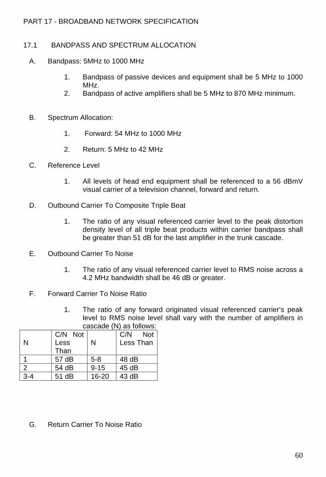
PART 17 - BROADBAND NETWORK SPECIFICATION
17.1 BANDPASS AND SPECTRUM ALLOCATION
A. Bandpass: 5MHz to 1000 MHz
1. Bandpass of passive devices and equipment shall be 5 MHz to 1000 MHz.
2. Bandpass of active amplifiers shall be 5 MHz to 870 MHz minimum.
B. Spectrum Allocation:
1. Forward: 54 MHz to 1000 MHz
2. Return: 5 MHz to 42 MHz
C. Reference Level
1. All levels of head end equipment shall be referenced to a 56 dBmV visual carrier of a television channel, forward and return.
D. Outbound Carrier To Composite Triple Beat
1. The ratio of any visual referenced carrier level to the peak distortion density level of all triple beat products within carrier bandpass shall be greater than 51 dB for the last amplifier in the trunk cascade.
E. Outbound Carrier To Noise
1. The ratio of any visual referenced carrier level to RMS noise across a 4.2 MHz bandwidth shall be 46 dB or greater.
F. Forward Carrier To Noise Ratio
1. The ratio of any forward originated visual referenced carrier’s peak level to RMS noise level shall vary with the number of amplifiers in cascade (N) as follows:
N
C/N Not Less Than
N
C/N Not Less Than
1 57 dB 5-8 48 dB 2 54 dB 9-15 45 dB 3-4 51 dB 16-20 43 dB
G. Return Carrier To Noise Ratio
60
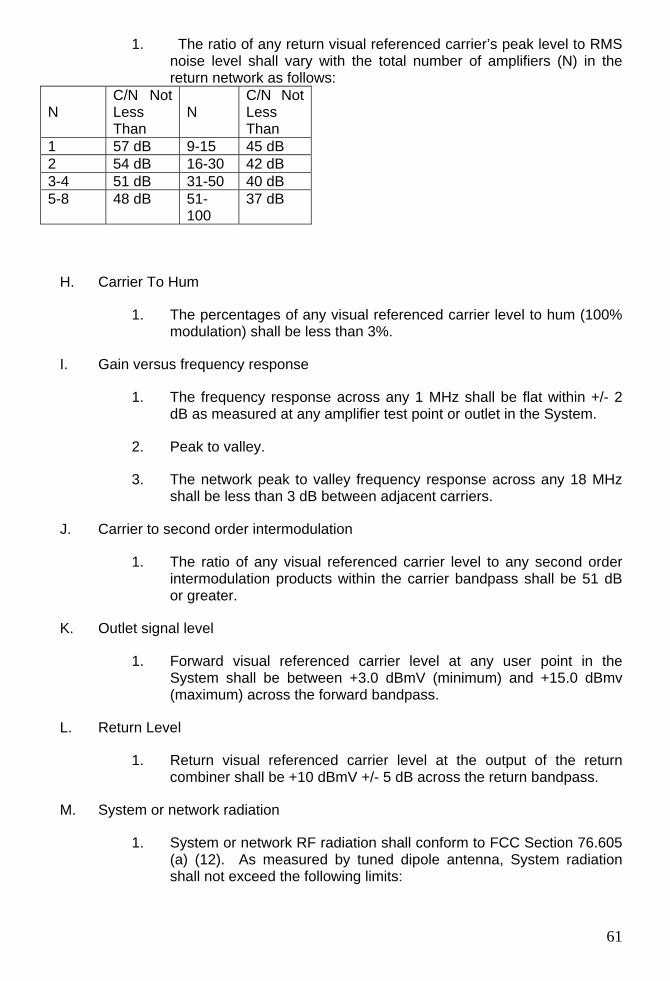
1. The ratio of any return visual referenced carrier’s peak level to RMS noise level shall vary with the total number of amplifiers (N) in the return network as follows:
N
C/N Not Less Than
N
C/N Not Less Than
1 57 dB 9-15 45 dB 2 54 dB 16-30 42 dB 3-4 51 dB 31-50 40 dB 5-8 48 dB 51-
100 37 dB
H. Carrier To Hum
1. The percentages of any visual referenced carrier level to hum (100% modulation) shall be less than 3%.
I. Gain versus frequency response
1. The frequency response across any 1 MHz shall be flat within +/- 2 dB as measured at any amplifier test point or outlet in the System.
2. Peak to valley.
3. The network peak to valley frequency response across any 18 MHz shall be less than 3 dB between adjacent carriers.
J. Carrier to second order intermodulation
1. The ratio of any visual referenced carrier level to any second order intermodulation products within the carrier bandpass shall be 51 dB or greater.
K. Outlet signal level
1. Forward visual referenced carrier level at any user point in the System shall be between +3.0 dBmV (minimum) and +15.0 dBmv (maximum) across the forward bandpass.
L. Return Level
1. Return visual referenced carrier level at the output of the return combiner shall be +10 dBmV +/- 5 dB across the return bandpass.
M. System or network radiation
1. System or network RF radiation shall conform to FCC Section 76.605 (a) (12). As measured by tuned dipole antenna, System radiation shall not exceed the following limits:
61
a. 54 MHz to 216 MHz 15 µV/meter at 30 meters
b. Greater than 216 MHz 20 µV/meter at 3 meters & 15 µV/meter at 30 meters
PART 18 - EXECUTION
18.1 GENERAL
A. All equipment shall be held firmly in place and supported by fastenings, brackets, etc. capable of supporting the load.
B. Boxes, equipment cabling, racks, etc. shall be installed and secured plumb and square with building lines.
C. In the installation of equipment and cable, consideration shall be given to operational efficiency, serviceability and overall aesthetics shall be determined by WSU C&IT Computing & Network Services.
D. All cable, regardless of length, shall be marked with machine-generated, wrap-around numbered or lettered markers at both ends, and sealed with clear heat-shrink covers. There shall be no unmarked cables in the System. Marking codes shall be keyed to the floor and room number and shall be shown on the drawings. Marking nomenclature shall be approved prior to cable installation by WSU C&IT Computing & Network Services. Submit proposed nomenclature scheme with shop drawings and product data for approval by engineer and owner. Refer to Section 17010 for requirements.
E. Terminal blocks, boards, strips or connectors shall be furnished for all cables that interface with racks, cabinets, consoles or equipment modules.
F. All cables associated with the cable television System shall be grouped according to signals being carried in order to reduce signal contamination or interference. Grouping of cables shall adhere to the WSU Standards for Communications Infrastructure. Separate groups shall be formed for the following:
1. Power cables.
2. Control cables
3. Cable television/RF cables.
G. All branch cables shall be cut to the length dictated by the run and shall include a minimum 3 foot service loop at the trunk end, for repair purposes or future uses.
62
H. All trunk cables shall be cut to the length dictated by the run and shall include a minimum 25 foot service loop at the head end/MDF end, for repair purposes or future uses.
I. For equipment mounted in drawers or slides, the interconnecting cables shall be provided with a service loop of appropriate length.
J. All cables run in plenum areas shall be installed in cable trays provided by the Electrical Contractor or securely and independently supported using J-Hooks from the building structure at a maximum 4 feet on center. Bridal rings shall not be allowed.
K. Cable shall not be laid on ceiling grid, light fixtures, plumbing, conduit, piping, ducts, etc. Cable shall not be attached to ceiling grid supports or tied to existing electrical conduit, conduit hangers, light fixtures, plumbing, plumbing hangers, piping, ducts, duct hangers, etc.
L. All cables in vertical riser shall be strain-relieved at each floor.
M. Cables installed in air return spaces or plenum spaces shall be plenum-rated per NFPA codes.
18.2 PRODUCTS
A. Trunk Cables
1. Cable shall be 0.500 inch diameter hard-line.
2. Cable shall be plenum-rated.
3. Cable shall be Commscope 2312K. Substitutions must be approved in advance by WSU C&IT Computing & Network Services.
4. In the special-use case of RG-11U coaxial trunk cable, all cable shall be Commscope 2287K plenum-rated. Use of RG-11U cable must be approved in advance by WSU C&IT Computing & Network Services.
5. Cable shall have a nominal impedance of 75 Ohms.
6. Cable shall be sweep-tested by its manufacturer, passed and certified as such by its manufacturer and shall be certified as its best grade over its entire rated bandwidth. A written copy of the certification shall be provided to WSU C&IT Computing & Network Services and shall be included with the Submittals and As-built documentation.
B. Coaxial branch/drop cable
1. Cable shall be RG-6U, 98% or higher RFI shield rating, quadshielded, doublebraided.
2. Cable shall be plenum-rated.
63
3. Cable shall be Commscope 2227V. Substitutions must be approved in advance by WSU C&IT Computing & Network Services.
4. Cable shall have a nominal impedance of 75 Ohms.
5. Cable shall be sweep-tested by its manufacturer, passed and certified as such by its manufacturer and shall be certified as its best grade over its entire rated bandwidth. A written copy of the certification shall be provided to WSU C&IT Computing & Network Services and shall be included with the Submittals and As-built documentation.
C. Trunk cable taps, Directional couplers, Splitters, Equalizers
1. Taps, couplers, splitters and equalizers shall be manufactured by C-Cor, Philips or equal. Substitutions must be approved in advance by WSU C&IT Computing & Network Services.
2. Taps, couplers, splitters and equalizers shall be trunk power-bypass and RF-bypass type.
3. Removal of a tap, coupler, splitter or equalizer cover shall not interrupt or disable the trunk power bypass or the RF bypass.
4. Taps shall not pass trunk power to the individual branch circuits, drops and wall jacks. Branch circuit taps shall be passive and shall not be powered by trunk power.
5. Taps, couplers, splitters and equalizers shall be of a type and size specifically designed for 0.500 inch diameter hard-line cable and connectors.
D. Trunk connectors
1. Connectors shall be Pyramid, LRC, Gilbert, Commscope or equal. Substitutions must be approved in advance by WSU C&IT Computing & Network Services.
2. Trunk connectors shall be of a two-piece design. Three piece connectors shall not be allowed.
3. Connectors shall be Cable Television Service, FCC Part 76 certified.
4. Connectors shall be of a type and size specifically designed for 0.500 inch diameter hard-line cable or RG-11U coaxial cable, as required.
5. If RG-11U coaxial cable is used, connectors shall be Thomas & Betts “Snap-n-Seal”.
6. Connectors shall have a nominal impedance of 75 Ohms.
E. Branch cable connectors
64
1. Connectors shall be Thomas & Betts “Snap-n-Seal”. Substitutions must be approved in advance by WSU C&IT Computing & Network Services.
2. Connectors shall be Cable Television Service, FCC Part 76 certified.
3. Connectors shall be of a size and type specifically designed for RG-6U Commscope 2227V plenum-rated cable, the trunk taps and the wall jacks. Computing & Network Services representatives shall approve these connectors in advance prior to the start of work.
4. Connectors shall be of a one-piece design. Two-piece connectors shall not be allowed.
5. Connectors shall have a nominal impedance of 75 Ohms.
F. Trunk amplifiers, line extenders
1. Amplifiers and extenders shall be C-Cor Flexnet NL Series or equal. Substitutions must be approved in advance by WSU C&IT Computing & Network Services.
2. Amplifiers and extenders shall be subsplit capable.
3. Amplifiers and extenders shall be designed to allow for remote trunk power and trunk power bypass.
4. Amplifiers and extenders shall be of a type and size specifically designed for 0.500 inch diameter hard-line cable and connectors.
5. Amplifiers shall be gain adjustable and equalizable.
6. Amplifiers and extenders shall be backboard mounted in the MDF.
7. Amplifiers shall have a minimum bandwidth of 862 MHz.
G. Line power inserters
1. Line power inserters shall be Philips 9-LPI or equal. Substitutions must be approved in advance by WSU C&IT Computing & Network Services.
2. Inserters shall be of a type and size specifically designed for 0.500 inch diameter hard-line cable and connectors.
H. Power supplies
1. Power supplies shall be Exide or Lectro “Broadband” series or equal and shall be compatible with the 0.500 hardline-equipped amplifier and line extender array.
2. Power supplies shall be fed from 120 volts AC.
65
3. Power supplies shall be hardwired to a dedicated, separate 120 VAC branch circuit. Coordinate installation with electrical trades as required.
4. Power supplies shall be backboard mounted in the MDF.
I. Coax jacks and wall plates, wall connectors
1. Wall jacks/connectors shall be “Grayfox Gold #7530.” NO SUBSTITUTIONS ALLOWED.
2. Wall jack connectors shall be type F.
3. Wall jacks shall be 75 Ohm, SELF-TERMINATING.
4. Wall jacks and connectors shall have a nominal impedance of 75 Ohms.
5. Wall plates shall be satin finish, stainless steel, square corner, sized to match junction boxes.
J. Jumper cables
1. Provide a sufficient number of twelve foot, black, 75 Ohm, type F coaxial jumper cables for use to connect television sets and VCR’s to CATV outlets.
2. Coaxial jumper cables are not required to be plenum-rated.
3. Coaxial jumper cables shall be press-on/friction fit type. Screw-on connectors shall not be allowed.
4. Coaxial jumper cables shall be compatible with the building CATV outlet connectors.
K. Security at trunk line taps (IF required)
1. All connectors shall be equipped and installed with security shields.
L. Unused taps
1. At any point in the system, all unused taps shall be terminated into precision, passive 75-Ohm terminators of appropriate size and wattage. Security provisions at trunk line taps shall apply.
18.3 SYSTEM PERFORMANCE AND TESTING
A. All aspects of Section 1.8 BROADBAND NETWORK SPECIFICATIONS shall be tested and documented.
66
B. Three sets of written test results shall be provided to WSU Computing & Network Services (C&IT) in 3-ring binders and on CD-ROM.
C. System testing shall be performed by an independent testing company not affiliated with the System Contractor.
D. System testing and methods shall be approved in advance by WSU Computing & Network Services (C&IT).
E. All system testing shall be supervised by WSU Computing & Network Services (C&IT)
F. System acceptance testing shall be subject to WSU Computing & Network Services (C&IT) inspection and approval of installation, workmanship, products, performance testing and documentation.
18.4 RELATED SYSTEMS AND FACILITIES (IF REQUIRED)
A. Inter/Intra building signal transport system
1. Provide a fiber optic CATV transport system to deliver all channels, whether active or not, across the specified bandwidth from the existing MDF. System shall be compatible and shall match the existing WSU transmit and receive systems. Substitutions shall not be allowed.
2. The transport system shall feed the existing CATV programming to the new CATV broadband system for distribution to all CATV outlets.
3. Signals shall be transported between buildings via the WSU single mode fiber optic backbone network.
4. Signals shall be interfaced to the WSU fiber optic backbone network via WSU fiber optic patch panels located in each building’s MDF.
5. The transmitting end of the system shall have a minimum six fiber optic outputs for use with the inter-building transport system, monitoring systems and for future expansion.
6. The system shall have an auxiliary input to allow delivery of programming from remote locations elsewhere on campus via the WSU single mode fiber optic backbone network.
7. Fiber optic patch panels and patch cords shall be provided to interface all system inputs and outputs to the WSU fiber optic patch panels.
8. Performance of the transport system shall meet or exceed the specifications of the CATV system specified within Section 17500 and
67
shall not impair, limit, change or reduce the quality or specifications of the existing CATV systems.
9. All fiber optic equipment shall be rack-mounted or backboard mounted. Mounting methods shall be approved in advance by WSU C&IT Network Services.
10. Fiber optic transmitter power levels shall be designed with sufficient headroom to compensate for practical and theoretical losses within the WSU fiber optic network and any passive optical splitters.
11. All singlemode fiber-optic connectors and ferrules shall be SC/APC. Color shall be green.
B. Local monitoring system
1. Provide a CATV monitoring television set within the MDF similar to the existing set in the WSU Headend.
2. The monitoring television set shall be rack mounted and shall be capable of viewing all CATV channels, whether active or not.
3. The CATV monitoring television shall be rack-mounted in the building MDF or its CATV distribution point.
END OF SECTION 17500
68

69
Related Documents