Technology Focus Electronics/Computers Software Materials Mechanics Machinery/Automation Manufacturing & Prototyping Bio-Medical Physical Sciences Information Sciences Books and Reports 12-06 December 2006 https://ntrs.nasa.gov/search.jsp?R=20110013617 2018-05-12T22:06:22+00:00Z

Welcome message from author
This document is posted to help you gain knowledge. Please leave a comment to let me know what you think about it! Share it to your friends and learn new things together.
Transcript

Technology Focus
Electronics/Computers
Software
Materials
Mechanics
Machinery/Automation
Manufacturing & Prototyping
Bio-Medical
Physical Sciences
Information Sciences
Books and Reports
12-06 December 2006
https://ntrs.nasa.gov/search.jsp?R=20110013617 2018-05-12T22:06:22+00:00Z


NASA Tech Briefs, December 2006 1
INTRODUCTIONTech Briefs are short announcements of innovations originating from research and develop-
ment activities of the National Aeronautics and Space Administration. They emphasizeinformation considered likely to be transferable across industrial, regional, or disciplinary linesand are issued to encourage commercial application.
Availability of NASA Tech Briefs and TSPsRequests for individual Tech Briefs or for Technical Support Packages (TSPs) announced herein shouldbe addressed to
National Technology Transfer CenterTelephone No. (800) 678-6882 or via World Wide Web at www2.nttc.edu/leads/
Please reference the control numbers appearing at the end of each Tech Brief. Information on NASA’s Innovative Partnerships Program (IPP), its documents, and services is also available at the same facility oron the World Wide Web at http://ipp.nasa.gov.
Innovative Partnerships Offices are located at NASA field centers to provide technology-transfer access toindustrial users. Inquiries can be made by contacting NASA field centers listed below.
Ames Research CenterLisa L. Lockyer(650) [email protected]
Dryden Flight Research CenterGregory Poteat(661) [email protected]
Goddard Space Flight CenterNona Cheeks(301) [email protected]
Jet Propulsion LaboratoryKen Wolfenbarger(818) [email protected]
Johnson Space CenterMichele Brekke(281) [email protected]
Kennedy Space CenterDavid R. Makufka(321) [email protected]
Langley Research CenterMartin Waszak(757) [email protected]
Glenn Research CenterRobert Lawrence(216) [email protected]
Marshall Space Flight CenterVernotto McMillan(256) [email protected]
Stennis Space CenterJohn Bailey(228) 688-1660 [email protected]
Carl Ray, Program ExecutiveSmall Business Innovation Research (SBIR) & Small Business Technology Transfer (STTR) Programs(202) [email protected]
Merle McKenzieInnovative Partnerships Program Office(202) [email protected]
NASA Field Centers and Program Offices


5 Technology Focus: Data Acquisition
5 Inferring Gear Damage From Oil-Debris andVibration Data
6 Forecasting of Storm-Surge Floods Using ADCIRCand Optimized DEMs
7 User Interactive Software for Analysis of Human Physiological Data
8 Representation of Serendipitous Scientific Data
9 Electronics/Computers9 Automatic Locking of Laser Frequency to an
Absorption Peak
10 Self-Passivating Lithium/Solid Electrolyte/Iodine Cells
11 Four-Quadrant Analog Multipliers Using G4-FETs
12 Noise Source for Calibrating a MicrowavePolarimeter
13 Hybrid Deployable Foam Antennas and Reflectors
14 Coating MCPs With AlN and GaN
15 Domed, 40-cm-Diameter Ion Optics for an IonThruster
16 Gesture-Controlled Interfaces for Self-ServiceMachines
17 Software17 Dynamically Alterable Arrays of Polymorphic Data
Types
17 Identifying Trends in Deep Space NewtorkMonitor Data
17 Predicting Lifetime of a ThermomechanicallyLoaded Component
17 Partial Automation of Requirements Tracing
18 Automated Synthesis of Architecture of AvionicSystems
18 SSRL Emergency Response Shore Tool
19 Materials19 Wholly Aromatic Ether-Imides as n-Type
Semiconductors
20 Carbon-Nanotube-Carpet Heat-Transfer Pads
23 Manufacturing & Prototyping23 Pulse-Flow Microencapsulation System
24 Automated Low-Gravitation Facility Would MakeOptical Fibers
25 Physical Sciences25 Alignment Cube With One Diffractive Face
27 Books & Reports27 Graphite Composite Booms With Integral Hinges
27 Tool for Sampling Permafrost on a Remote Planet
27 Special Semaphore Scheme for UHF SpacecraftCommunications
12-06 December 2006
NASA Tech Briefs, December 2006 3
This document was prepared under the sponsorship of the National Aeronautics and Space Administration. Neither the United States Govern-ment nor any person acting on behalf of the United States Government assumes any liability resulting from the use of the information containedin this document, or warrants that such use will be free from privately owned rights.


NASA Tech Briefs, December 2006 5
Technology Focus: Data Acquisition
A system for real-time detection of sur-face-fatigue-pitting damage to gears foruse in a helicopter transmission is basedon fuzzy-logic used to fuse data from sen-sors that measure oil-borne debris, re-ferred to as “oil debris” in the article, andvibration signatures. A system to detecthelicopter-transmission gear damage isbeneficial because the power train of ahelicopter is essential for propulsion, lift,and maneuvering, hence, the integrity ofthe transmission is critical to helicoptersafety. To enable detection of an impend-ing transmission failure, an ideal diag-nostic system should provide real-timemonitoring of the “health” of the trans-mission, be capable of a high level of re-liable detection (with minimization offalse alarms), and provide human userswith clear information on the health ofthe system without making it necessaryfor them to interpret large amounts ofsensor data.
One of the main ideas underlying thepresent development is that by integrat-ing oil-debris and vibration sensor subsys-tems into a single diagnostic system,wherein the data from the two types ofsensors are appropriately fused, it is pos-sible to make the damage-detection anddecision-making capabilities of the result-ing diagnostic system better than those ofa diagnostic system that incorporates onlyone of the sensor subsystems. This ideawas tested in 24 experiments in NASAGlenn Research Center’s Spur Gear Fa-tigue Rig, wherein vibrations were meas-ured by two accelerometers and oil debriswere measured by a commercially avail-able inductance-type oil-debris sensor.Speed and load were also measured. Thevibration and speed data were processedby two gear diagnostic algorithms thatyielded temporally varying statistical pa-rameters known in the art as “FM4” and“NA4 Reset,” respectively.
Multisensor-data-fusion analysis tech-niques were applied to the FM4, NA4Reset, and oil-debris data. Data from thedifferent sensors were combined to makeinferences that could not be made on thebasis of data from a single sensor. Such aprocess is similar to the process in which
a human integrates data from multiplesources and senses to make decisions.
Sensor data can be fused at the rawdata level, feature level, or decisionlevel. In this development, the decisionlevel was chosen because it does notlimit the fusion process to a specific fea-ture or sensor. The FM4 and NA4 Resetparameters and the accumulated mass
of the debris were the features selectedfor use as input to the data-fusion part ofthe system. Fuzzy logic was used to iden-tify the damage level indicated by eachfeature and to perform decision-level fu-sion on the features. The resulting data-fusion model was capable of discriminat-ing between the stages of pitting wear.The output of the data-fusion model was
Inferring Gear Damage From Oil-Debris and Vibration Data Data fusion increases the reliability and reduces the difficulty of gear-damage diagnosis. John H. Glenn Research Center, Cleveland, Ohio
These Vibration (FM4 and NA4 Reset) and Oil-Debris Data and the corresponding output of the data-fusion model are the products of one of the experiments performed to test key parts of the develop-mental diagnostic system.
FM4 NA4 Reset Debris
30
24
18
12
6
0
25
20
15
10
5
0 0 500 1,000 1,500 2,000 2,500 3,000 3,500
0
0.1
0.2
0.3
0.4
0.5
0.6
0.7
0.8
0.9
1.0
0 500 1,000 1,500
Reading Number = Run Time in Minutes
Reading Number = Run Time in Minutes
Mo
del
Ou
tpu
t FM
4 an
d N
A4
Res
et
Oil-
Deb
ris
Mas
s (m
g)
2,000 2,500 3,000 3,500
Shutdown
Inspect
OK

6 NASA Tech Briefs, December 2006
in the form of parameters indicatingwhich of three discrete conditions repre-sents the current state of damage andthe corresponding action recom-mended to end users. The three condi-tion/action combinations were denoted“OK” (no damage and no action neces-sary), “inspect” (initial pitting), and“shutdown” (severe pitting).
The upper part of the figure depictsthe FM4, NA4 Reset, and oil-debris datafrom one experiment during which pit-ting damage occurred. The lower part ofthe figure shows the corresponding out-
put of the data-fusion model. Readingswere taken once per minute. The trian-gles indicate when the gear was inspectedfor damage. As shown in the photographconnected to the second triangle, dam-age began to occur at approximatelyreading 2,669 during this experiment.Analysis of the data collected during thisand the other experiments confirmedthe expectation that it is advantageous tofuse features of data obtained throughdifferent sensors and that, as desired, theoutput of the data-fusion model amountsto clear, reliable information that can be
used in making decisions about thehealth of the affected gears.
This work was done by Paula Dempsey ofGlenn Research Center. Further informa-tion is contained in a TSP (see page 1).
Inquiries concerning rights for the commer-cial use of this invention should be addressed to:
NASA Glenn Research CenterInnovative Partnerships OfficeAttn: Steve FedorMail Stop 4–821000 Brookpark RoadCleveland, Ohio 44135.
Refer to LEW-17889-1.
Increasing the accuracy of storm-surgeflood forecasts is essential for improvingpreparedness for hurricanes and other se-vere storms and, in particular, for optimiz-ing evacuation scenarios. An interactivedatabase, developed by WorldWinds, Inc.,contains atlases of storm-surge flood levelsfor the Louisiana/Mississippi gulf coastregion. These atlases were developed toimprove forecasting of flooding along thecoastline and estuaries and in adjacent in-land areas. Storm-surge heights dependon a complex interaction of several fac-tors, including: storm size, central mini-mum pressure, forward speed of motion,bottom topography near the point oflandfall, astronomical tides, and, most im-portantly, maximum wind speed.
The information in the atlases wasgenerated in over 100 computationalsimulations, partly by use of a parallel-processing version of the ADvanced CIR-Culation (ADCIRC) model. ADCIRC is anonlinear computational model of hy-drodynamics, developed by the U.S.Army Corps of Engineers and the USNavy, as a family of two- and three-dimen-sional finite-element-based codes. It af-fords a capability for simulating tidal cir-culation and storm-surge propagationover very large computational domains,while simultaneously providing high-res-olution output in areas of complexshoreline and bathymetry. The ADCIRCfinite-element grid for this project cov-ered the Gulf of Mexico and contiguousbasins, extending into the deep AtlanticOcean with progressively higher resolu-tion approaching the study area. The ad-vantage of using ADCIRC over other
storm-surge models, such as SLOSH, isthat input conditions can include all orpart of wind stress, tides, wave stress, andriver discharge, which serve to make themodel output more accurate.
To keep the computational load man-ageable, this work was conducted usingonly the wind stress, calculated by usinghistorical data from Hurricane Camille,as the input condition for the model.Hurricane storm-surge simulations wereperformed on an eight-node Linux com-puter cluster. Each node contained dual2-GHz processors, 2GB of memory, and a40GB hard drive. The digital elevation
model (DEM) for this region was speci-fied using a combination of Navy data(over water), NOAA data (for the coast-line), and optimized InterferometricSynthetic Aperture Radar data (overland). This high-resolution topographi-cal data of the Mississippi coastal regionprovided the ADCIRC model with im-proved input with which to calculate im-proved storm-surge forecasts.
Also used in the simulations was a com-mercially developed rainfall inundationmodel that originated in research per-formed for a NASA dual-use project. Therainfall model accepts as input an eleva-
Surge Levels in Feet
CODE
24.701-26.500 23.301-24.700
22.101-23.300
21.101-22.100
20.001-21.000
19.001-20.000
18.001-19.000
16.801-18.000
0.001-16.800 -9.999-0.000
Forecasting of Storm-Surge Floods Using ADCIRC andOptimized DEMsMaximum water levels are mapped for Hurricanes Camille and Katrina.Stennis Space Center, Mississippi
Figure 1. This MEOW Map shows the maximum storm surge at each finite-element node based on allsimulations of category-3 hurricanes in the affected area.
NASA Tech Briefs, December 2006 7
tion grid, coordinates to a source cell, andthe desired inundation level. Softwareutilities that accompany the model trans-late United States Geological Survey digi-tal elevation maps, as well as ASCII grids,into the correct format. The source cell isspecified in the coordinates of the eleva-tion grid, and the inundation level (afloating-point number) is specified in aunit of measurement compatible withthat used for the input elevation. Therainfall simulations were performed forvarious hurricane landfall scenarios thatincluded different intensities, storm sizes,forward speeds, and landfall locations.
Typically, each hurricane simulation,started 3 days of simulated time beforeCamille’s landfall, took about 5 hours ofcomputing time in parallel processingon all sixteen processors. The results ofthe ADCIRC and rainfall simulationswere composited to determine the high-est storm-surge value possible for eachgrid node; the resulting maps are knownas maximum envelope of water(MEOW) maps.
Figure 1 shows the maximum stormsurge for a Category 3 storm in the vicinityof the back bay of Biloxi, MS. The maxi-mum storm surge is approximately 20 ft(≈6 m) inside the bay. Over most of thebay area, the storm surge varies between15 and 25 ft (≈4.5 and 7.6 m). Publishedground measurements at various discretelocations during Hurricane Camille showthat a maximum storm surge of over 22 ft(≈6.7 m) occurred at Pass Christian, MS,west of Biloxi. Emergency planners andlocal government officials make publicevacuation plans based on MEOW maps.
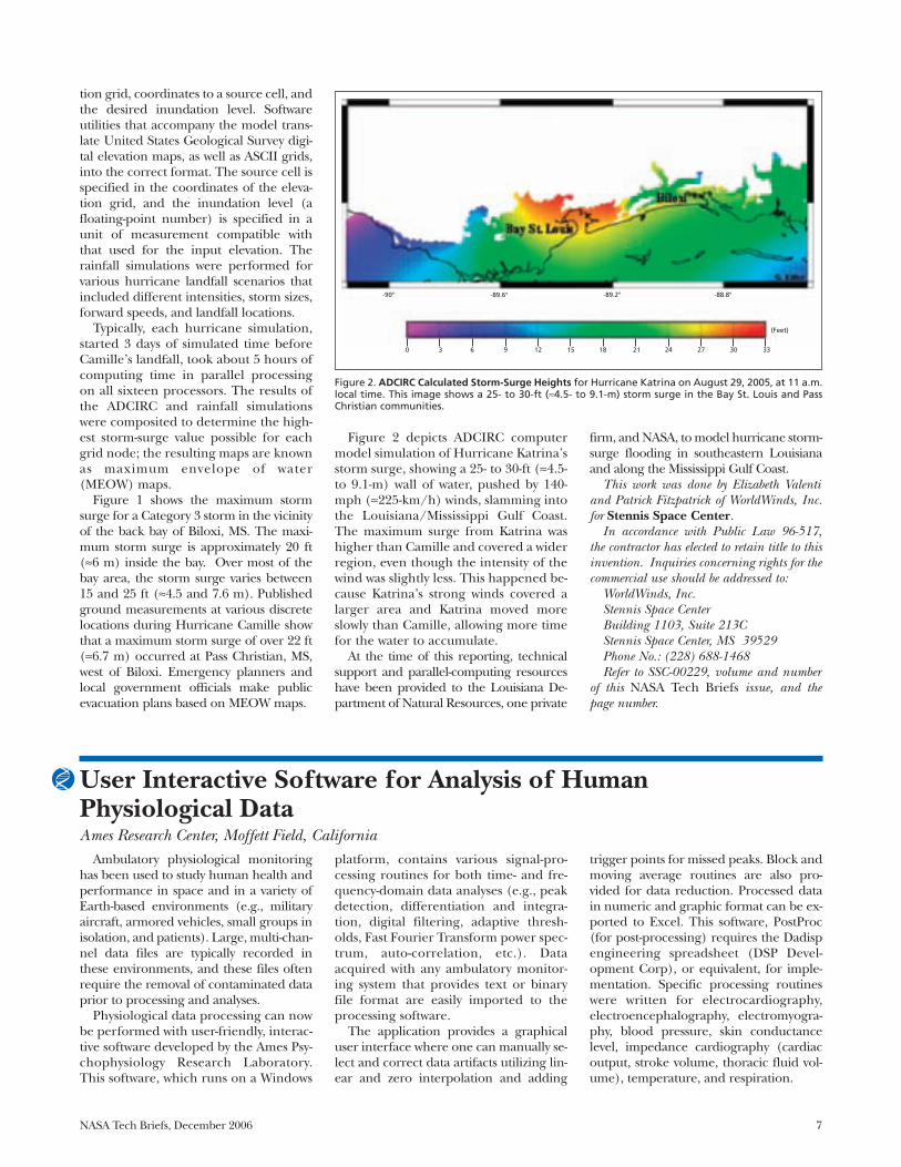
Figure 2 depicts ADCIRC computermodel simulation of Hurricane Katrina’sstorm surge, showing a 25- to 30-ft (≈4.5-to 9.1-m) wall of water, pushed by 140-mph (≈225-km/h) winds, slamming intothe Louisiana/Mississippi Gulf Coast.The maximum surge from Katrina washigher than Camille and covered a widerregion, even though the intensity of thewind was slightly less. This happened be-cause Katrina’s strong winds covered alarger area and Katrina moved moreslowly than Camille, allowing more timefor the water to accumulate.
At the time of this reporting, technicalsupport and parallel-computing resourceshave been provided to the Louisiana De-partment of Natural Resources, one private
firm, and NASA, to model hurricane storm-surge flooding in southeastern Louisianaand along the Mississippi Gulf Coast.
This work was done by Elizabeth Valentiand Patrick Fitzpatrick of WorldWinds, Inc.for Stennis Space Center.
In accordance with Public Law 96-517,the contractor has elected to retain title to thisinvention. Inquiries concerning rights for thecommercial use should be addressed to:
WorldWinds, Inc.Stennis Space CenterBuilding 1103, Suite 213CStennis Space Center, MS 39529Phone No.: (228) 688-1468Refer to SSC-00229, volume and number
of this NASA Tech Briefs issue, and thepage number.
Figure 2. ADCIRC Calculated Storm-Surge Heights for Hurricane Katrina on August 29, 2005, at 11 a.m.local time. This image shows a 25- to 30-ft (≈4.5- to 9.1-m) storm surge in the Bay St. Louis and PassChristian communities.
-90° -89.6° -89.2° -88.8°
0 3 9 6 12 15 18 21 24 27 30 33
(Feet)
Ambulatory physiological monitoringhas been used to study human health andperformance in space and in a variety ofEarth-based environments (e.g., militaryaircraft, armored vehicles, small groups inisolation, and patients). Large, multi-chan-nel data files are typically recorded inthese environments, and these files oftenrequire the removal of contaminated dataprior to processing and analyses.
Physiological data processing can nowbe performed with user-friendly, interac-tive software developed by the Ames Psy-chophysiology Research Laboratory.This software, which runs on a Windows
platform, contains various signal-pro-cessing routines for both time- and fre-quency-domain data analyses (e.g., peakdetection, differentiation and integra-tion, digital filtering, adaptive thresh-olds, Fast Fourier Transform power spec-trum, auto-correlation, etc.). Dataacquired with any ambulatory monitor-ing system that provides text or binaryfile format are easily imported to theprocessing software.
The application provides a graphicaluser interface where one can manually se-lect and correct data artifacts utilizing lin-ear and zero interpolation and adding
trigger points for missed peaks. Block andmoving average routines are also pro-vided for data reduction. Processed datain numeric and graphic format can be ex-ported to Excel. This software, PostProc(for post-processing) requires the Dadispengineering spreadsheet (DSP Devel-opment Corp), or equivalent, for imple-mentation. Specific processing routineswere written for electrocardiography,electroencephalography, electromyogra-phy, blood pressure, skin conductancelevel, impedance cardiography (cardiacoutput, stroke volume, thoracic fluid vol-ume), temperature, and respiration.
User Interactive Software for Analysis of Human Physiological DataAmes Research Center, Moffett Field, California
8 NASA Tech Briefs, December 2006
PostProc users do not need program-ming experience or extensive knowl-edge of human electrophysiological sig-nal processing. Routines written inSeries Processing Language (SPL) canbe modified to accommodate different
biomedical instruments, calibration lev-els, or sampling rates.
This program was written by Patricia S.Cowings and William Toscano of Ames Re-search Center and Bruce C. Taylor andSoumydipta Acharya of the University of
Akron. Further information is contained in aTSP (see page 1).
Inquiries concerning rights for the commer-cial use of this invention should be addressedto the Ames Technology Partnerships Divisionat (650) 604-2954. Refer to ARC-15287-1.
A computer program defines and im-plements an innovative kind of datastructure than can be used for represent-ing information derived from serendipi-tous discoveries made via collection ofscientific data on long exploratory space-craft missions. Data structures capable ofcollecting any kind of data can easily beimplemented in advance, but the task ofdesigning a fixed and efficient data struc-ture suitable for processing raw data intouseful information and taking advantageof serendipitous scientific discovery is be-
coming increasingly difficult as missionsgo deeper into space. The present soft-ware eases the task by enabling definitionof arbitrarily complex data structuresthat can adapt at run time as raw data aretransformed into other types of informa-tion. This software runs on a variety ofcomputers, and can be distributed in ei-ther source code or binary code form. Itmust be run in conjunction with any oneof a number of Lisp compilers that areavailable commercially or as shareware.It has no specific memory requirements
and depends upon the other softwarewith which it is used. This program is im-plemented as a library that is called by,and becomes folded into, the other soft-ware with which it is used.
This program was written by Mark Jamesof Caltech for NASA’s Jet Propulsion Lab-oratory. Further information is contained ina TSP (see page 1).
This software is available for commerciallicensing. Please contact Karina Edmonds ofthe California Institute of Technology at(626) 395-2322. Refer to NPO-42086.
Representation of Serendipitous Scientific DataNASA’s Jet Propulsion Laboratory, Pasadena, California
NASA Tech Briefs, December 2006 9
Automatic Locking of Laser Frequency to an Absorption PeakInitial manual tuning is ordinarily not necessary.Langley Research Center, Hampton, Virginia
An electronic system adjusts the fre-quency of a tunable laser, eventually lock-ing the frequency to a peak in the opticalabsorption spectrum of a gas (or of aFabry-Perot cavity that has an absorptionpeak like that of a gas). This system wasdeveloped to enable precise locking ofthe frequency of a laser used in differen-tial absorption LIDAR measurements oftrace atmospheric gases. This system alsohas great commercial potential as a pro-totype of means for precise control offrequencies of lasers in future densewavelength-division-multiplexing opticalcommunications systems.
The operation of this system is com-pletely automatic: Unlike in the opera-tion of some prior laser-frequency-lock-ing systems, there is ordinarily no needfor a human operator to adjust the fre-quency manually to an initial valueclose enough to the peak to enable au-
tomatic locking to take over. Instead,this system also automatically performsthe initial adjustment.
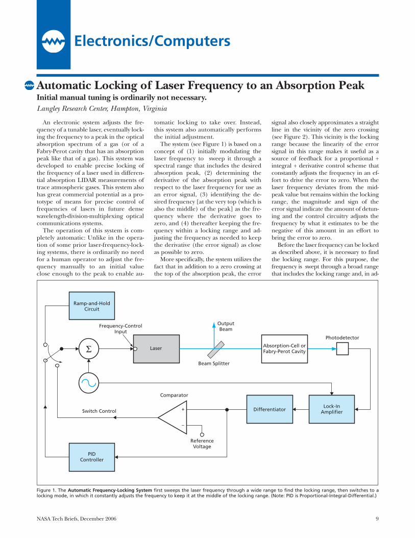
The system (see Figure 1) is based on aconcept of (1) initially modulating thelaser frequency to sweep it through aspectral range that includes the desiredabsorption peak, (2) determining thederivative of the absorption peak withrespect to the laser frequency for use asan error signal, (3) identifying the de-sired frequency [at the very top (which isalso the middle) of the peak] as the fre-quency where the derivative goes tozero, and (4) thereafter keeping the fre-quency within a locking range and ad-justing the frequency as needed to keepthe derivative (the error signal) as closeas possible to zero.
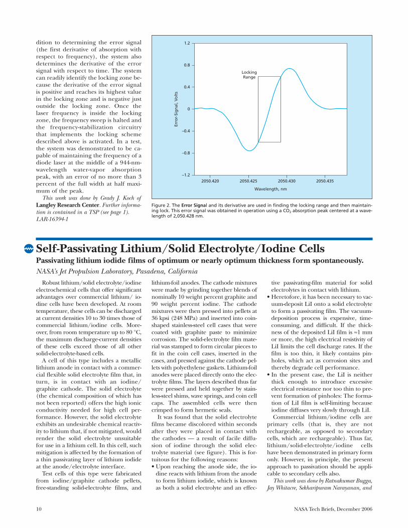
More specifically, the system utilizes thefact that in addition to a zero crossing atthe top of the absorption peak, the error
signal also closely approximates a straightline in the vicinity of the zero crossing(see Figure 2). This vicinity is the lockingrange because the linearity of the errorsignal in this range makes it useful as asource of feedback for a proportional +integral + derivative control scheme thatconstantly adjusts the frequency in an ef-fort to drive the error to zero. When thelaser frequency deviates from the mid-peak value but remains within the lockingrange, the magnitude and sign of theerror signal indicate the amount of detun-ing and the control circuitry adjusts thefrequency by what it estimates to be thenegative of this amount in an effort tobring the error to zero.
Before the laser frequency can be lockedas described above, it is necessary to findthe locking range. For this purpose, thefrequency is swept through a broad rangethat includes the locking range and, in ad-
Σ
Ramp-and-HoldCircuit
Frequency-ControlInput
Laser
Beam Splitter
OutputBeam
Photodetector
Lock-InAmplifierDifferentiator+
–
ReferenceVoltage
Comparator
Switch Control
PIDController
Absorption-Cell orFabry-Perot Cavity
Figure 1. The Automatic Frequency-Locking System first sweeps the laser frequency through a wide range to find the locking range, then switches to alocking mode, in which it constantly adjusts the frequency to keep it at the middle of the locking range. (Note: PID is Proportional-Integral-Differential.)
Electronics/Computers
10 NASA Tech Briefs, December 2006
dition to determining the error signal(the first derivative of absorption withrespect to frequency), the system alsodetermines the derivative of the errorsignal with respect to time. The systemcan readily identify the locking zone be-cause the derivative of the error signalis positive and reaches its highest valuein the locking zone and is negative justoutside the locking zone. Once thelaser frequency is inside the lockingzone, the frequency sweep is halted andthe frequency-stabilization circuitrythat implements the locking schemedescribed above is activated. In a test,the system was demonstrated to be ca-pable of maintaining the frequency of adiode laser at the middle of a 944-nm-wavelength water-vapor absorptionpeak, with an error of no more than 3percent of the full width at half maxi-mum of the peak.
This work was done by Grady J. Koch ofLangley Research Center. Further informa-tion is contained in a TSP (see page 1).LAR-16394-1
1.2
0.8
0.4
0
–0.4
–0.8
–1.22050.420 2050.425 2050.430 2050.435
Wavelength, nm
Erro
r-Si
gn
al, V
olt
s
LockingRange
Figure 2. The Error Signal and its derivative are used in finding the locking range and then maintain-ing lock. This error signal was obtained in operation using a CO2 absorption peak centered at a wave-length of 2,050.428 nm.
Self-Passivating Lithium/Solid Electrolyte/Iodine CellsPassivating lithium iodide films of optimum or nearly optimum thickness form spontaneously.NASA’s Jet Propulsion Laboratory, Pasadena, California
Robust lithium/solid electrolyte/iodineelectrochemical cells that offer significantadvantages over commercial lithium/ io-dine cells have been developed. At roomtemperature, these cells can be dischargedat current densities 10 to 30 times those ofcommercial lithium/iodine cells. More-over, from room temperature up to 80 °C,the maximum discharge-current densitiesof these cells exceed those of all othersolid-electrolyte-based cells.
A cell of this type includes a metalliclithium anode in contact with a commer-cial flexible solid electrolyte film that, inturn, is in contact with an iodine/graphite cathode. The solid electrolyte(the chemical composition of which hasnot been reported) offers the high ionicconductivity needed for high cell per-formance. However, the solid electrolyteexhibits an undesirable chemical reactiv-ity to lithium that, if not mitigated, wouldrender the solid electrolyte unsuitablefor use in a lithium cell. In this cell, suchmitigation is affected by the formation ofa thin passivating layer of lithium iodideat the anode/electrolyte interface.
Test cells of this type were fabricatedfrom iodine/graphite cathode pellets,free-standing solid-electrolyte films, and
lithium-foil anodes. The cathode mixtureswere made by grinding together blends ofnominally 10 weight percent graphite and90 weight percent iodine. The cathodemixtures were then pressed into pellets at36 kpsi (248 MPa) and inserted into coin-shaped stainless-steel cell cases that werecoated with graphite paste to minimizecorrosion. The solid-electrolyte film mate-rial was stamped to form circular pieces tofit in the coin cell cases, inserted in thecases, and pressed against the cathode pel-lets with polyethylene gaskets. Lithium-foilanodes were placed directly onto the elec-trolyte films. The layers described thus farwere pressed and held together by stain-less-steel shims, wave springs, and coin cellcaps. The assembled cells were thencrimped to form hermetic seals.
It was found that the solid electrolytefilms became discolored within secondsafter they were placed in contact withthe cathodes — a result of facile diffu-sion of iodine through the solid elec-trolyte material (see figure). This is for-tuitous for the following reasons:• Upon reaching the anode side, the io-
dine reacts with lithium from the anodeto form lithium iodide, which is knownas both a solid electrolyte and an effec-
tive passivating-film material for solidelectrolytes in contact with lithium.
• Heretofore, it has been necessary to vac-uum-deposit LiI onto a solid electrolyteto form a passivating film. The vacuum-deposition process is expensive, time-consuming, and difficult. If the thick-ness of the deposited LiI film is ≈1 mmor more, the high electrical resistivity ofLiI limits the cell discharge rates. If thefilm is too thin, it likely contains pin-holes, which act as corrosion sites andthereby degrade cell performance.
• In the present case, the LiI is neitherthick enough to introduce excessiveelectrical resistance nor too thin to pre-vent formation of pinholes: The forma-tion of LiI film is self-limiting becauseiodine diffuses very slowly through LiI.Commercial lithium/iodine cells are
primary cells (that is, they are notrechargeable, as opposed to secondarycells, which are rechargeable). Thus far,lithium/solid-electrolyte/iodine cellshave been demonstrated in primary formonly. However, in principle, the presentapproach to passivation should be appli-cable to secondary cells also.
This work was done by Ratnakumar Bugga,Jay Whitacre, Sekharipuram Narayanan, and
William West of Caltech for NASA’s JetPropulsion Laboratory. Further informa-tion is contained in a TSP (see page 1).
In accordance with Public Law 96-517,the contractor has elected to retain title to thisinvention. Inquiries concerning rights for itscommercial use should be addressed to:
Innovative Technology Assets ManagementJPLMail Stop 202-2334800 Oak Grove DrivePasadena, CA 91109-8099(818) 354-2240E-mail: [email protected] to NPO-40789, volume and number
of this NASA Tech Briefs issue, and thepage number.
NASA Tech Briefs, December 2006 11
The Half Cell on the left contains a graphite cathode pellet behind a solid-electrolyte film. The halfcell on the right contains a graphite/iodine pellet behind a solid-electrolyte film; the darkening of thiscell was caused by diffusion of iodine through the solid electrolyte.
Four-Quadrant Analog Multipliers Using G4-FETsDevices with independently biased multiple inputs are exploited to simplify multiplier circuits. NASA’s Jet Propulsion Laboratory, Pasadena, California
Theoretical analysis and some experi-ments have shown that the silicon-on-in-sulator (SOI) 4-gate transistors known asG4-FETs can be used as building blocksof four-quadrant analog voltage multi-plier circuits. Whereas a typical prioranalog voltage multiplier contains be-tween six and 10 transistors, it is possibleto construct a superior voltage multi-plier using only four G4-FETs.
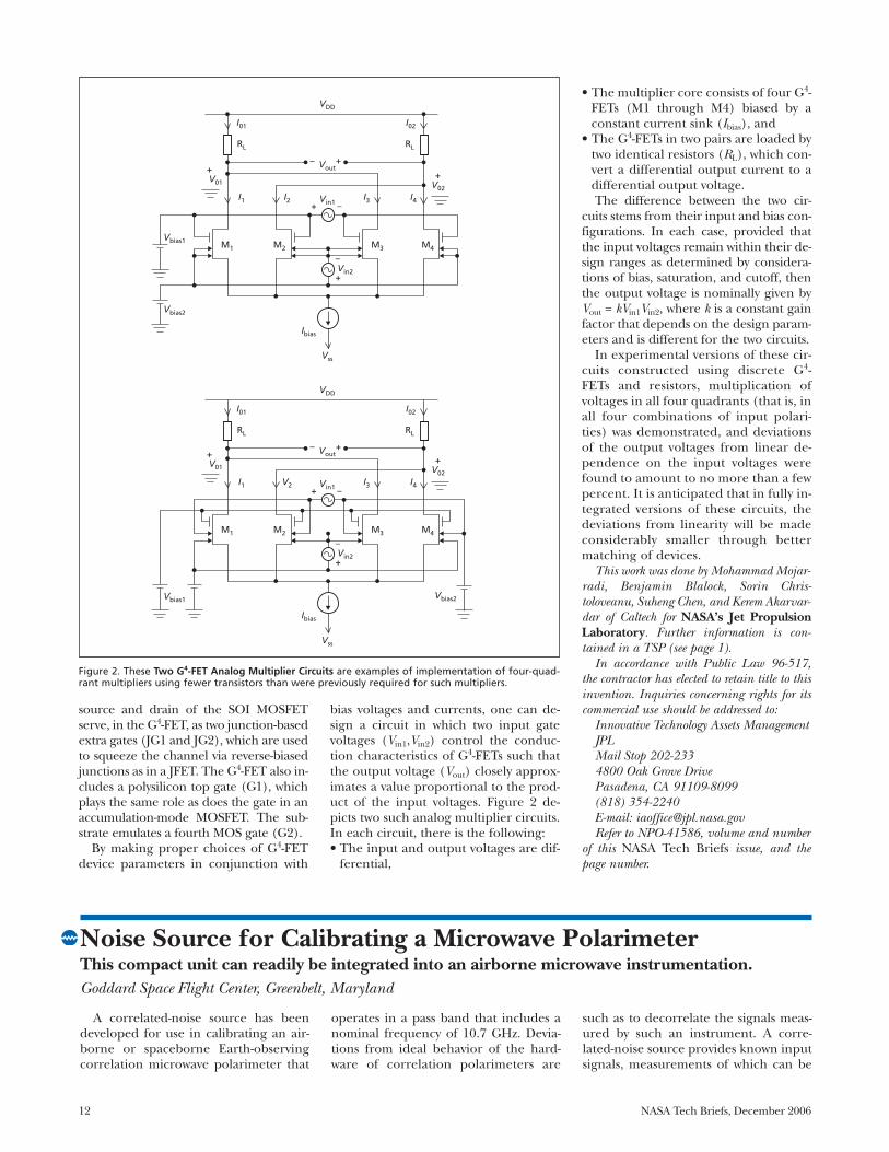
A G4-FET is a combination of a junctionfield-effect transistor (JFET) and a metaloxide/semiconductor field-effect transis-tor (MOSFET). It can be regarded as asingle transistor having four gates, whichare parts of a structure that affords highfunctionality by enabling the utilization ofindependently biased multiple inputs.The structure of a G4-FET of the type ofinterest here (see Figure 1) is that of a
partially-depleted SOI MOSFET with twoindependent body contacts, one on eachside of the channel. The drain currentcomprises of majority charge carriersflowing from one body contact to theother — that is, what would otherwise bethe side body contacts of the SOI MOS-FET are used here as the end contacts[the drain (D) and the source (S)] of theG4-FET. What would otherwise be the
Silicon Substrate (G2)
Buried Oxide
n+-DopedSource (S)
n+-DopedDrain
(D)
p+-DopedJunction-Based
Gate (JG1)
p+-DopedJunction-Based
Gate (JG2)
n-DopedChannel
PolysiliconTop Gate (G1)
G1
JG1
JG2
G2
D
S
GEOMETRIC LAYOUT SCHEMATIC SYMBOLS
Figure 1. In this G4-FET, the top gate plays the same role as does the sole gate in a conventional accumulation-mode MOSFET. The side gates (JG1 and JG2)provide additional degrees of freedom for design and operation, beyond those of a conventional MOSFET.
12 NASA Tech Briefs, December 2006
source and drain of the SOI MOSFETserve, in the G4-FET, as two junction-basedextra gates (JG1 and JG2), which are usedto squeeze the channel via reverse-biasedjunctions as in a JFET. The G4-FET also in-cludes a polysilicon top gate (G1), whichplays the same role as does the gate in anaccumulation-mode MOSFET. The sub-strate emulates a fourth MOS gate (G2).
By making proper choices of G4-FETdevice parameters in conjunction with
bias voltages and currents, one can de-sign a circuit in which two input gatevoltages (Vin1,Vin2) control the conduc-tion characteristics of G4-FETs such thatthe output voltage (Vout) closely approx-imates a value proportional to the prod-uct of the input voltages. Figure 2 de-picts two such analog multiplier circuits.In each circuit, there is the following:• The input and output voltages are dif-
ferential,
• The multiplier core consists of four G4-FETs (M1 through M4) biased by aconstant current sink (Ibias), and
• The G4-FETs in two pairs are loaded bytwo identical resistors (RL), which con-vert a differential output current to adifferential output voltage.The difference between the two cir-
cuits stems from their input and bias con-figurations. In each case, provided thatthe input voltages remain within their de-sign ranges as determined by considera-tions of bias, saturation, and cutoff, thenthe output voltage is nominally given byVout = kVin1Vin2, where k is a constant gainfactor that depends on the design param-eters and is different for the two circuits.
In experimental versions of these cir-cuits constructed using discrete G4-FETs and resistors, multiplication ofvoltages in all four quadrants (that is, inall four combinations of input polari-ties) was demonstrated, and deviationsof the output voltages from linear de-pendence on the input voltages werefound to amount to no more than a fewpercent. It is anticipated that in fully in-tegrated versions of these circuits, thedeviations from linearity will be madeconsiderably smaller through bettermatching of devices.
This work was done by Mohammad Mojar-radi, Benjamin Blalock, Sorin Chris-toloveanu, Suheng Chen, and Kerem Akarvar-dar of Caltech for NASA’s Jet PropulsionLaboratory. Further information is con-tained in a TSP (see page 1).
In accordance with Public Law 96-517,the contractor has elected to retain title to thisinvention. Inquiries concerning rights for itscommercial use should be addressed to:
Innovative Technology Assets ManagementJPLMail Stop 202-2334800 Oak Grove DrivePasadena, CA 91109-8099(818) 354-2240E-mail: [email protected] to NPO-41586, volume and number
of this NASA Tech Briefs issue, and thepage number.
VDD
Vout
Vin1
Vss
Vin2
Vbias1
Vbias2
Ibias
V01
I01
I1
M1 M2 M3 M4
I2 I3 I4
RL RL
I02
+
V02
+
– +
+
+
–
–
Vbias2
VDD
Vout
Vin1
Vss
Vin2
Vbias1
Ibias
V01
I01
I1
M1 M2 M3 M4
V2 I3 I4
RL RL
I02
+
V02
+ – +
+
+
–
–
Figure 2. These Two G4-FET Analog Multiplier Circuits are examples of implementation of four-quad-rant multipliers using fewer transistors than were previously required for such multipliers.
Noise Source for Calibrating a Microwave PolarimeterThis compact unit can readily be integrated into an airborne microwave instrumentation.Goddard Space Flight Center, Greenbelt, Maryland
A correlated-noise source has beendeveloped for use in calibrating an air-borne or spaceborne Earth-observingcorrelation microwave polarimeter that
operates in a pass band that includes anominal frequency of 10.7 GHz. Devia-tions from ideal behavior of the hard-ware of correlation polarimeters are
such as to decorrelate the signals meas-ured by such an instrument. A corre-lated-noise source provides known inputsignals, measurements of which can be
NASA Tech Briefs, December 2006 13
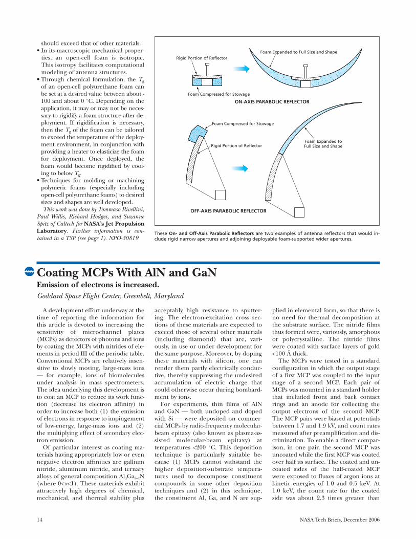
Hybrid deployable radio antennas andreflectors of a proposed type would featurerigid narrower apertures plus wider adjoin-ing apertures comprising reflective sur-faces supported by open-cell polymericfoam structures (see figure). The open-cellfoam structure of such an antenna wouldbe compressed for compact stowage dur-ing transport. To initiate deployment ofthe antenna, the foam structure would sim-ply be released from its stowage mechani-cal restraint. The elasticity of the foamwould drive the expansion of the foamstructure to its full size and shape.
There are several alternatives for fabri-cating a reflective surface supported by apolymeric foam structure. One approachwould be to coat the foam with a metal.Another approach would be to attach ametal film or a metal-coated polymeric
membrane to the foam. Yet another ap-proach would be to attach a metal meshto the foam.
The hybrid antenna design and de-ployment concept as proposed offers sig-nificant advantages over other conceptsfor deployable antennas:• In the unlikely event of failure to de-
ploy, the rigid narrow portion of theantenna would still function, provid-ing a minimum level of assured per-formance. In contrast, most otherconcepts for deploying a large an-tenna from compact stowage are of an“all or nothing” nature: the antenna isnot useful at all until and unless it isfully deployed.
• Stowage and deployment would not de-pend on complex mechanisms or actu-ators, nor would it involve the use of in-
flatable structures. Therefore, relativeto antennas deployed by use of mecha-nisms, actuators, or inflation systems,this antenna could be lighter, cheaper,amenable to stowage in a smaller vol-ume, and more reliable.An open-cell polymeric (e.g.,
polyurethane) foam offers several advan-tages for use as a compressible/expand-able structural material to support a largeantenna or reflector aperture. A few ofthese advantages are the following:• The open cellular structure is
amenable to compression to a verysmall volume — typically to 1/20 of itsfull size in one dimension.
• At a temperature above its glass-transi-tion temperature (Tg), the foamstrongly damps vibrations. Even at atemperature below Tg, the damping
processed to estimate and correct forthe decorrelation effect.
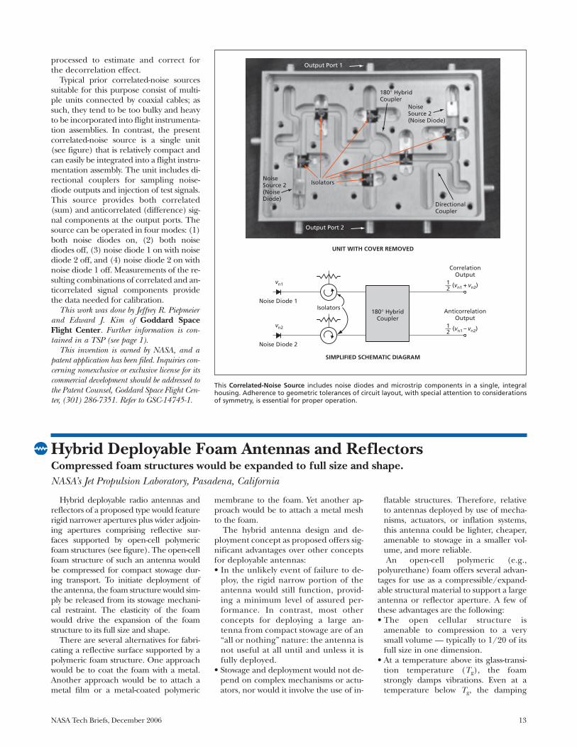
Typical prior correlated-noise sourcessuitable for this purpose consist of multi-ple units connected by coaxial cables; assuch, they tend to be too bulky and heavyto be incorporated into flight instrumenta-tion assemblies. In contrast, the presentcorrelated-noise source is a single unit(see figure) that is relatively compact andcan easily be integrated into a flight instru-mentation assembly. The unit includes di-rectional couplers for sampling noise-diode outputs and injection of test signals.This source provides both correlated(sum) and anticorrelated (difference) sig-nal components at the output ports. Thesource can be operated in four modes: (1)both noise diodes on, (2) both noisediodes off, (3) noise diode 1 on with noisediode 2 off, and (4) noise diode 2 on withnoise diode 1 off. Measurements of the re-sulting combinations of correlated and an-ticorrelated signal components providethe data needed for calibration.
This work was done by Jeffrey R. Piepmeierand Edward J. Kim of Goddard SpaceFlight Center. Further information is con-tained in a TSP (see page 1).
This invention is owned by NASA, and apatent application has been filed. Inquiries con-cerning nonexclusive or exclusive license for itscommercial development should be addressed tothe Patent Counsel, Goddard Space Flight Cen-ter, (301) 286-7351. Refer to GSC-14745-1.
vn1 (vn1 + vn2)
Noise Diode 1
CorrelationOutput
12
vn2 (vn1 – vn2)
Noise Diode 2
AnticorrelationOutput
12
180° HybridCoupler
SIMPLIFIED SCHEMATIC DIAGRAM
UNIT WITH COVER REMOVED
Isolators
Noise Source 2(Noise Diode)
Output Port 2
Output Port 1
Directional Coupler
Noise Source 2(Noise Diode)
180° Hybrid Coupler
Isolators
This Correlated-Noise Source includes noise diodes and microstrip components in a single, integralhousing. Adherence to geometric tolerances of circuit layout, with special attention to considerationsof symmetry, is essential for proper operation.
Hybrid Deployable Foam Antennas and ReflectorsCompressed foam structures would be expanded to full size and shape.NASA’s Jet Propulsion Laboratory, Pasadena, California
14 NASA Tech Briefs, December 2006
should exceed that of other materials.• In its macroscopic mechanical proper-
ties, an open-cell foam is isotropic.This isotropy facilitates computationalmodeling of antenna structures.
• Through chemical formulation, the Tg
of an open-cell polyurethane foam canbe set at a desired value between about -100 and about 0 °C. Depending on theapplication, it may or may not be neces-sary to rigidify a foam structure after de-ployment. If rigidification is necessary,then the Tg of the foam can be tailoredto exceed the temperature of the deploy-ment environment, in conjunction withproviding a heater to elasticize the foamfor deployment. Once deployed, thefoam would become rigidified by cool-ing to below Tg.
• Techniques for molding or machiningpolymeric foams (especially includingopen-cell polyurethane foams) to desiredsizes and shapes are well developed.This work was done by Tommaso Rivellini,
Paul Willis, Richard Hodges, and SuzanneSpitz of Caltech for NASA’s Jet PropulsionLaboratory. Further information is con-tained in a TSP (see page 1). NPO-30819
Foam Expanded to Full Size and Shape
Foam Expanded toFull Size and Shape
Rigid Portion of Reflector
Rigid Portion of Reflector
Foam Compressed for Stowage
ON-AXIS PARABOLIC REFLECTOR
OFF-AXIS PARABOLIC REFLECTOR
Foam Compressed for Stowage
These On- and Off-Axis Parabolic Reflectors are two examples of antenna reflectors that would in-clude rigid narrow apertures and adjoining deployable foam-supported wider apertures.
Coating MCPs With AlN and GaNEmission of electrons is increased.Goddard Space Flight Center, Greenbelt, Maryland
A development effort underway at thetime of reporting the information forthis article is devoted to increasing thesensitivity of microchannel plates(MCPs) as detectors of photons and ionsby coating the MCPs with nitrides of ele-ments in period III of the periodic table.Conventional MCPs are relatively insen-sitive to slowly moving, large-mass ions— for example, ions of biomoleculesunder analysis in mass spectrometers.The idea underlying this development isto coat an MCP to reduce its work func-tion (decrease its electron affinity) inorder to increase both (1) the emissionof electrons in response to impingementof low-energy, large-mass ions and (2)the multiplying effect of secondary elec-tron emission.
Of particular interest as coating ma-terials having appropriately low or evennegative electron affinities are galliumnitride, aluminum nitride, and ternaryalloys of general composition AlxGal–xN(where 0<x<1). These materials exhibitattractively high degrees of chemical,mechanical, and thermal stability plus
acceptably high resistance to sputter-ing. The electron-excitation cross sec-tions of these materials are expected toexceed those of several other materials(including diamond) that are, vari-ously, in use or under development forthe same purpose. Moreover, by dopingthese materials with silicon, one canrender them partly electrically conduc-tive, thereby suppressing the undesiredaccumulation of electric charge thatcould otherwise occur during bombard-ment by ions.
For experiments, thin films of AlNand GaN — both undoped and dopedwith Si — were deposited on commer-cial MCPs by radio-frequency molecular-beam epitaxy (also known as plasma-as-sisted molecular-beam epitaxy) attemperatures <200 °C. This depositiontechnique is particularly suitable be-cause (1) MCPs cannot withstand thehigher deposition-substrate tempera-tures used to decompose constituentcompounds in some other depositiontechniques and (2) in this technique,the constituent Al, Ga, and N are sup-
plied in elemental form, so that there isno need for thermal decomposition atthe substrate surface. The nitride filmsthus formed were, variously, amorphousor polycrystalline. The nitride filmswere coated with surface layers of gold<100 Å thick.
The MCPs were tested in a standardconfiguration in which the output stageof a first MCP was coupled to the inputstage of a second MCP. Each pair ofMCPs was mounted in a standard holderthat included front and back contactrings and an anode for collecting theoutput electrons of the second MCP.The MCP pairs were biased at potentialsbetween 1.7 and 1.9 kV, and count ratesmeasured after preamplification and dis-crimination. To enable a direct compar-ison, in one pair, the second MCP wasuncoated while the first MCP was coatedover half its surface. The coated and un-coated sides of the half-coated MCPwere exposed to fluxes of argon ions atkinetic energies of 1.0 and 0.5 keV. At1.0 keV, the count rate for the coatedside was about 2.3 times greater than
NASA Tech Briefs, December 2006 15
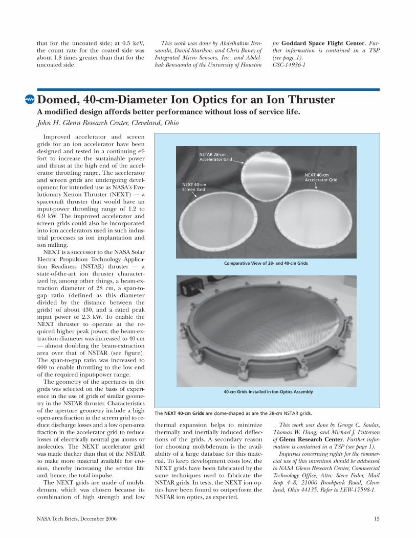
Domed, 40-cm-Diameter Ion Optics for an Ion Thruster A modified design affords better performance without loss of service life.John H. Glenn Research Center, Cleveland, Ohio
Improved accelerator and screengrids for an ion accelerator have beendesigned and tested in a continuing ef-fort to increase the sustainable powerand thrust at the high end of the accel-erator throttling range. The acceleratorand screen grids are undergoing devel-opment for intended use as NASA’s Evo-lutionary Xenon Thruster (NEXT) — aspacecraft thruster that would have aninput-power throttling range of 1.2 to6.9 kW. The improved accelerator andscreen grids could also be incorporatedinto ion accelerators used in such indus-trial processes as ion implantation andion milling.
NEXT is a successor to the NASA SolarElectric Propulsion Technology Applica-tion Readiness (NSTAR) thruster — astate-of-the-art ion thruster character-ized by, among other things, a beam-ex-traction diameter of 28 cm, a span-to-gap ratio (defined as this diameterdivided by the distance between thegrids) of about 430, and a rated peakinput power of 2.3 kW. To enable theNEXT thruster to operate at the re-quired higher peak power, the beam-ex-traction diameter was increased to 40 cm— almost doubling the beam-extractionarea over that of NSTAR (see figure).The span-to-gap ratio was increased to600 to enable throttling to the low endof the required input-power range.
The geometry of the apertures in thegrids was selected on the basis of experi-ence in the use of grids of similar geome-try in the NSTAR thruster. Characteristicsof the aperture geometry include a highopen-area fraction in the screen grid to re-duce discharge losses and a low open-areafraction in the accelerator grid to reducelosses of electrically neutral gas atoms ormolecules. The NEXT accelerator gridwas made thicker than that of the NSTARto make more material available for ero-sion, thereby increasing the service lifeand, hence, the total impulse.
The NEXT grids are made of molyb-denum, which was chosen because itscombination of high strength and low
thermal expansion helps to minimizethermally and inertially induced deflec-tions of the grids. A secondary reasonfor choosing molybdenum is the avail-ability of a large database for this mate-rial. To keep development costs low, theNEXT grids have been fabricated by thesame techniques used to fabricate theNSTAR grids. In tests, the NEXT ion op-tics have been found to outperform theNSTAR ion optics, as expected.
This work was done by George C. Soulas,Thomas W. Haag, and Michael J. Pattersonof Glenn Research Center. Further infor-mation is contained in a TSP (see page 1).
Inquiries concerning rights for the commer-cial use of this invention should be addressedto NASA Glenn Research Center, CommercialTechnology Office, Attn: Steve Fedor, MailStop 4–8, 21000 Brookpark Road, Cleve-land, Ohio 44135. Refer to LEW-17598-1.
NSTAR 28-cm Accelerator Grid
NEXT 40-cm Screen Grid
NEXT 40-cmAccelerator Grid
Comparative View of 28- and 40-cm Grids
40-cm Grids Installed in Ion-Optics Assembly
The NEXT 40-cm Grids are dome-shaped as are the 28-cm NSTAR grids.
that for the uncoated side; at 0.5 keV,the count rate for the coated side wasabout 1.8 times greater than that for theuncoated side.
This work was done by Abdelhakim Ben-saoula, David Starikov, and Chris Boney ofIntegrated Micro Sensors, Inc. and Abdel-hak Bensaoula of the University of Houston
for Goddard Space Flight Center. Fur-ther information is contained in a TSP (see page 1).GSC-14936-1

16 NASA Tech Briefs, December 2006
Gesture-Controlled Interfaces for Self-Service MachinesPotential advantages include immunity to wear and increased safety.Lyndon B. Johnson Space Center, Houston, Texas
Gesture-controlled interfaces are soft-ware-driven systems that facilitate devicecontrol by translating visual hand andbody signals into commands. Such inter-faces could be especially attractive forcontrolling self-service machines (SSMs)— for example, public informationkiosks, ticket dispensers, gasolinepumps, and automated teller machines(see figure).
A gesture-controlled interface wouldinclude a vision subsystem comprisingone or more charge-coupled-devicevideo cameras (at least two would beneeded to acquire three-dimensionalimages of gestures). The output of thevision system would be processed by apure software gesture-recognition sub-system. Then a translator subsystemwould convert a sequence of recognizedgestures into commands for the SSM tobe controlled; these could include, forexample, a command to display re-quested information, change controlsettings, or actuate a ticket- or cash-dis-pensing mechanism.
Depending on the design and opera-tional requirements of the SSM to becontrolled, the gesture-controlled inter-face could be designed to respond tospecific static gestures, dynamic ges-tures, or both. Static and dynamic ges-tures can include stationary or movinghand signals, arm poses or motions,and/or whole-body postures or motions.Static gestures would be recognized onthe basis of their shapes; dynamic ges-tures would be recognized on the basisof both their shapes and their motions.Because dynamic gestures include tem-poral as well as spatial content, this ges-ture-controlled interface can extractmore information from dynamic than itcan from static gestures.
Gesture-controlled interfaces offerseveral advantages over other input de-vices commonly used in SSMs:• There would be no mechanical wear
because unlike a keyboard, push-but-ton switch, and/or computer mouse, agesture-controlled interface containsno moving parts.
• Inasmuch as there would be no directcontact with users, there would be no
problem of hygiene as there is with atouch screen.
• Unlike a speech-recognition system, agesture-controlled interface could op-erate in a noisy location because itdoes not respond to sound.
• The safety of users of automated tellermachines could be increased becausethe translator subsystems of gesture-controlled interfaces could be made torecognize poses and motions associ-ated with the crimes committed atsuch machines.
• Systems will be designed to recognizegestures that are natural to users,thereby decreasing the time requiredto learn how to operate SSMs. Thearea of an SSM surrounding a displayscreen could contain pictures of handsignals or other gestures recognized bythe system.
• The use of gestures as a communica-tion medium may help to overcomelanguage barriers to the use of SSMs incommunities with diverse populations.This work was done by Charles J. Cohen
and Glenn Beach of Cybernet Systems Corp.for Johnson Space Center.
In accordance with Public Law 96-517,the contractor has elected to retain title to thisinvention. Inquiries concerning rights for itscommercial use should be addressed to:
Cybernet Systems Corporation727 Airport BoulevardAnn Arbor, MI 48108Phone: (734) 668-2567Fax: (734) 668-8780Web: www.cybernet.comRefer to MSC-23002, volume and number
of this NASA Tech Briefs issue, and thepage number.
A User Would Control an Automated Teller Machine through gestures. Panels on the sides of the ma-chine would depict static and dynamic hand and arm signals recognized by the system.
Cameras
Illustrations ofGesture Commands

NASA Tech Briefs, December 2006 17
Software
Dynamically Alterable Arraysof Polymorphic Data Types
An application library package was de-veloped that represents data packets forDeep Space Network (DSN) messagepackets as dynamically alterable arrayscomposed of arbitrary polymorphic datatypes. The software was to address a limi-tation of the present state of the practicefor having an array directly composed of asingle monomorphic data type. This is asevere limitation when one is dealing withscience data in that the types of objectsone is dealing with are typically notknown in advance and, therefore, are dy-namic in nature. The unique feature ofthis approach is that it enables one to de-fine at run-time the dynamic shape of thematrix with the ability to store polymor-phic data types in each of its indices. Exist-ing languages such as C and C++ have therestriction that the shape of the arraymust be known in advance and each of itselements be a monomorphic data typethat is strictly defined at compile-time.This program can be executed on a vari-ety of platforms. It can be distributed ineither source code or binary code form. Itmust be run in conjunction with any oneof a number of Lisp compilers that areavailable commercially or as shareware.
This program was written by Mark Jamesof Caltech for NASA’s Jet Propulsion Lab-oratory. FFurther information is containedin a TSP (see page 1).
This software is available for commerciallicensing. Please contact Karina Edmonds ofthe California Institute of Technology at(626) 395-2322. Refer to NPO-42071.
Identifying Trends in DeepSpace Network Monitor Data
A computer program has been devel-oped that analyzes Deep Space Networkmonitor data, looking for changes oftrends in critical parameters. This pro-gram represents a significant improve-ment over the previous practice of man-ually plotting data and visually inspectingthe resulting graphs to identify trends.This program uses proven numericaltechniques to identify trends. When a sta-tistically significant trend is detected,then it is characterized by means of asymbol that can be used by pre-existing
model-based reasoning software. Theprogram can perform any of the follow-ing functions:• Given an expectation that data in a
given list should exhibit an upward,downward, constant, or unknown trend,it can determine whether the data do ordo not follow such a trend.
• Given a list of data, it can identify whichof the aforementioned trends the datafollow.
• Given two lists of data, it can deter-mine whether or not both follow thesame trend.This program can be executed on a va-
riety of computers. It can be distributed ineither source code or binary code form. Itmust be run in conjunction with any oneof a number of Lisp compilers that areavailable commercially or as shareware.
This program was written by Mark Jamesof Caltech for NASA’s Jet Propulsion Lab-oratory. Further information is contained ina TSP (see page 1).
This software is available for commerciallicensing. Please contact Karina Edmonds ofthe California Institute of Technology at(626) 395-2322. Refer to NPO-42107.
Predicting Lifetime of a ThermomechanicallyLoaded Component
NASALIFE is a computer program forpredicting the lifetime, as affected bylow cycle fatigue (LCF) and creep rup-ture, of a structural component subjectto temporally varying, multiaxial ther-momechanical loads. The componentcould be, for example, part of an aircraftturbine engine. Empirical data fromLCF tests, creep rupture tests, and statictensile tests are used as references forpredicting the number of missions thecomponent can withstand under a giventhermomechanical loading condition.
The user prepares an input file con-taining the creep-rupture and cyclic-fa-tigue information, temperature-depend-ent material properties, and missionloading and control flags. The creep rup-ture information can be entered in tabu-lar form as stress versus life or by meansof parameters of the Larson-Miller equa-tion. The program uses the Walkermean-stress model to adjust predictedlife for ranges of the ratio between the
maximum and minimum stresses. Datarepresenting complex load cycles are re-duced by the rainflow counting method.Miner’s rule is utilized to combine thedamage at different load levels. Finally,the program determines the total dam-age due to creep and combines it withthe fatigue damage due to the cyclicloading and predicts the approximatenumber of missions a component canendure before failing.
This work was done by Pappu L. N.Murthy of Glenn Research Center, JohnZ. Gyekenyesi of N&R Engineering andManagement Services Corp., Subodh Mitalof the University of Toledo, and David N.Brewer of the U. S. Army Aviation SystemsCommand. Further information is containedin a TSP (see page 1).
Inquiries concerning rights for the commer-cial use of this invention should be addressedto NASA Glenn Research Center, InnovativePartnerships Office, Attn: Steve Fedor, MailStop 4–8, 21000 Brookpark Road, Cleveland,Ohio 44135. Refer to LEW-18081.
Partial Automation of Re-quirements Tracing
Requirements Tracing on Target(RETRO) is software for after-the-facttracing of textual requirements to supportindependent verification and validationof software. RETRO applies one of threeuser-selectable information-retrieval tech-niques: (1) term frequency/inverse docu-ment frequency (TF/IDF) vector re-trieval, (2) TF/IDF vector retrieval withsimple thesaurus, or (3) keyword extrac-tion. One component of RETRO is thegraphical user interface (GUI) for use ininitiating a requirements-tracing project(a pair of artifacts to be traced to eachother, such as a requirements spec and adesign spec). Once the artifacts have beenspecified and the IR technique chosen,another component constructs a repre-sentation of the artifact elements andstores it on disk.
Next, the IR technique is used to pro-duce a first list of candidate links (poten-tial matches between the two artifact lev-els). This list, encoded in ExtensibleMarkup Language (XML), is optionallyprocessed by a “filtering” component de-signed to make the list somewhat smallerwithout sacrificing accuracy. Through the

18 NASA Tech Briefs, December 2006
GUI, the user examines a number oflinks and returns decisions (yes, these arelinks; no, these are not links). Coded inXML, these decisions are provided to a“feedback processor” component thatprepares the data for the next applica-tion of the IR technique. The feedbackreduces the incidence of erroneous can-didate links. Unlike related prior soft-ware, RETRO does not require the userto assign keywords, and automaticallybuilds a document index.
This program was developed by JaneHayes, Alex Dekhtyar, Senthil Sundaram,and Sravanthi Vadlamudi of the Universityof Kentucky for Goddard Space FlightCenter. Further information is contained ina TSP (see page 1).GSC-14976-1.
Automated Synthesis of Archi-tectures of Avionic Systems
The Architecture Synthesis Tool (AST)is software that automatically synthesizessoftware and hardware architectures ofavionic systems. The AST is expected tobe most helpful during initial formula-tion of an avionic-system design, whensystem requirements change frequentlyand manual modification of architectureis time-consuming and susceptible toerror. The AST comprises two parts: (1)an architecture generator, which utilizes agenetic algorithm to create a multitude ofarchitectures; and (2) a functionality eval-uator, which analyzes the architectures forviability, rejecting most of the non-viableones. The functionality evaluator gener-
ates and uses a viability tree — a hierarchyrepresenting functions and componentsthat perform the functions such that thesystem as a whole performs system-levelfunctions representing the requirementsfor the system as specified by a user. Archi-tectures that survive the functionality eval-uator are further evaluated by the selec-tion process of the genetic algorithm.Architectures found to be most promisingto satisfy the user’s requirements and toperform optimally are selected as parentsto the next generation of architectures.The foregoing process is iterated as manytimes as the user desires. The final outputis one or a few viable architectures thatsatisfy the user’s requirements.
This program was written by Savio Chau,Joseph Xu, Van Dang, and James F. Lu ofCaltech for NASA’s Jet Propulsion Labo-ratory. Further information is contained ina TSP (see page 1).
This software is available for commerciallicensing. Please contact Karina Edmonds ofthe California Institute of Technology at(626) 395-2322. Refer to NPO-42607.
SSRL Emergency ResponseShore Tool
The SSRL Emergency ResponseShore Tool (wherein “SSRL” signifies“Smart Systems Research Laboratory”) isa computer program within a system ofcommunication and mobile-computingsoftware and hardware being developedto increase the situational awareness offirst responders at building collapses.This program is intended for use mainly
in planning and constructing shores tostabilize partially collapsed structures.The program consists of client andserver components, runs in the Win-dows operating system on commercialoff-the-shelf portable computers, andcan utilize such additional hardware asdigital cameras and Global PositioningSystem devices.
A first responder can enter directly,into a portable computer running thisprogram, the dimensions of a requiredshore. The shore dimensions, plus anoptional digital photograph of theshore site, can then be uploaded via awireless network to a server. Once onthe server, the shore report is time-stamped and made available on simi-larly equipped portable computers car-ried by other first responders, includingshore wood cutters and an incidentcommander. The staff in a commandcenter can use the shore reports andphotographs to monitor progress andto consult with structural engineers toassess whether a building is in imminentdanger of further collapse.
This program was written by Robert W. Mah,Richard Papasin, Dawn M. McIntosh, DouglasDenham, and Charles Jorgensen of Ames Re-search Center; Bradley J. Betts of ComputerSciences Corporation; and Rommel Del Mundoof QSS Group, Inc. Further information is con-tained in a TSP (see page 1).
This invention is owned by NASA and apatent application has been filed. Inquiriesconcerning rights for the commercial use ofthis invention should be addressed to theAmes Technology Partnerships Division at(650) 604-2954. Refer to ARC-15461-1.
NASA Tech Briefs, December 2006 19
Materials
Wholly Aromatic Ether-Imides as n-Type SemiconductorsSome of the compounds exhibit promising electron-transport properties.Langley Research Center, Hampton, Virginia
Some wholly aromatic ether-imidesconsisting of rod-shaped, relatively-low-mass molecules that can form liquidcrystals have been investigated for po-tential utility as electron-donor-type (n-type) organic semiconductors. It is envi-sioned that after further research toimprove understanding of their physicaland chemical properties, compounds ofthis type would be used to make thin-film semiconductor devices (e.g., photo-voltaic cells and field-effect transistors)on flexible electronic-circuit substrates.
This investigation was inspired by sev-eral prior developments:• Poly(ether-imides) [PEIs] are a class of
engineering plastics that have beenused extensively in the form of films ina variety of electronic applications, in-cluding insulating layers, circuitboards, and low-permittivity coatings.
• Wholly aromatic PEIs containingnaphthalene and perylene moietieshave been shown to be useful as elec-trochromic polymers.
• More recently, low-molecular-weightimides comprising naphthalene-basedmolecules with terminal fluorinatedtails were shown to be useful as n-type
organic semiconductors in such de-vices as field-effect transistors andSchottky diodes.Poly(etherimide)s as structural resins
have been extensively investigated atNASA Langley Research Center for over30 years. More recently, the need formulti-functional materials has becomeincreasingly important. This n-type semi-conductor illustrates the scope of cur-rent work towards new families of PEIsthat not only can be used as structuralresins for carbon-fiber reinforced com-posites, but also can function as sensors.Such a multi-functional material wouldpermit so-called in-situ health monitor-ing of composite structures during serv-ice. The work presented here demon-strates that parts of the PEI backbonecan be used as an n-type semiconductorwith such materials being sensitive todamage, temperature, stress, and pres-sure. In the near future, multi-func-tional or “smart” composite structuresare envisioned to be able to communi-cate such important parameters to theflight crew and provide vital informationwith respect to the operational status oftheir aircraft.
Prior attempts to make electronic de-vices based on n-type organic semicon-ductors had failed because permeationby oxygen from air limited the lifetimesof the devices. In this development, theclose molecular packing in the fluori-nated imides is believed to have ex-tended the lifetimes and improved theperformances of the devices by prevent-ing permeation by oxygen and moisture.
On the basis of promising results inthe aforementioned prior develop-ments and of other considerations, itwas conjectured that for the purpose ofdeveloping n-type organic semiconduc-tors, wholly aromatic imide-based meso-genic (liquid-crystal-forming) com-pounds would offer several advantagesover non-mesogenic compounds. Liquidcrystals are well known for their out-standing barrier properties, and whendesigned properly, their unique packingmotifs could result in increased charge-carrier mobilities. Conceivably, rigidaromatic dianhydrides terminated withappropriate aryl-ether amines couldhave the requisite liquid crystallineproperties. Prior to this investigation,some research groups had reported on
O
Tail
Core
Rigid Flexible
n
n = 0, 1, and 2
O O N N O Ar
Ar =
PMDA NDA BPDA ODPA
O O
O O
O
Tail
n
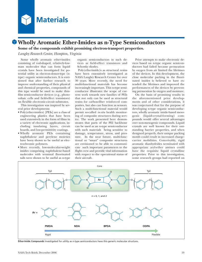
Ether-Imide Compounds investigated for utility as n-type semiconductors have this generic molecular structure.
20 NASA Tech Briefs, December 2006
low-molecular-weight imide-based liq-uid crystals, but these compounds con-tain aliphatic units, which lack the ox-idative stability necessary forsemiconductor applications.
The generic molecular structure ofthe wholly aromatic ether-imide com-pounds of this investigation is a classic“tail-core-tail” structure, which is de-noted by the term “calamitic” in the liq-uid-crystal art. In the generic molecule,the core contains one of four dianhy-drides with a p-phenylamine at each end.The dianhydrides are pyromellitic dian-hydride (PMDA); 1,4,5,8-naphthalenete-tracarboxylic dianhydride (NDA);3,3'4,4'-biphenyltetracarboxylic dianhy-dride (BPDA), and 3,3',4,4'oxydiph-thalic dianhydride (ODPA). The tailsare members of a homologous series ofmeta-substituted aryl-ethers. Each tail isthe para substituent on the p-pheny-lamine (see figure).
This generic molecular structure waschosen for the following reasons: The p-
phenylamine functionality increases thelength of the core beyond that of therigid di-imide portion, while the bulkymeta-substituted aryl-ether tails havesome flexibility. Increasing the numbersof meta-substituted aryl units in the tailsreduces melt transition temperaturesand increases solubilities. Also, the tailsstabilize the molecular orientations nec-essary for mesophase formation. Aryl-ether flexible tails had not been usedpreviously as flexible tail segments in liq-uid crystals, and in comparison withalkyl or alkyloxy flexible tails, aryl-ethertails have more breath, which keeps theoverall diameters of mesogens morenearly uniform.
In the investigation, monofunctionalamines (destined to become tails) weresynthesized by various techniques, thencombined with the dianhydrides (des-tined to become the cores) in one-stepsolution imidization procedures to ob-tain the desired ether imides. Thesecompounds were examined for tempera-
ture-dependent phase behavior bymeans of optical microscopy and x-raydiffraction, and cyclic voltammetry wasused to characterize redox behavior. Ab-sorption spectroscopic measurementswere also performed on dilute solutionsof the compounds. Of these com-pounds, those containing NDA andBPDA in the cores were found to haveelectron-transport properties suitablefor n-type semiconductors. Of all thecompounds tested, onlyone containingNDA in the core clearly exhibited a ten-dency toward formation of liquid crys-tals. This is the first example, known atthe time of the tests, in which amesophase was detected in a wholly aro-matic ether-imide compound.
This work was done by Erik Weiser and TerryL. St. Clair of Langley Research Center;Theo J. Dingemans (ICASE); Edward T. Samul-ski and Gene Irene of the University of NorthCarolina at Chapel Hill. Further informationis contained in a TSP (see page 1).LAR-17041-1
Carbon-Nanotube-Carpet Heat-Transfer PadsThe compliance and high longitudinal thermal conductivity of carbon nanotubes are exploited.Ames Research Center, Moffett Field, California
Microscopic thermal-contact pads thatinclude carpetlike arrays of carbon nan-otubes have been invented for dissipatingheat generated in integrated circuits andsimilarly sized single electronic compo-nents. The need for these or other innova-tive thermal-contact pads arises becausethe requisite high thermal conductancescannot be realized by scaling conventionalmacroscopic thermal-contact pads down tomicroscopic sizes. Overcoming limitationsof conventional thermal-contact materialsand components, the carbon-nanotubethermal-contact pads offer the high ther-mal conductivities needed to accommo-date the high local thermal power densi-ties of modern electronic circuits, withoutneed for large clamping pressures, ex-treme smoothness of surfaces in contact,or gap-filling materials (e.g., thermallyconductive greases) to ensure adequatethermal contact. Moreover, unlike someconventional thermal-contact compo-nents, these pads are reusable.
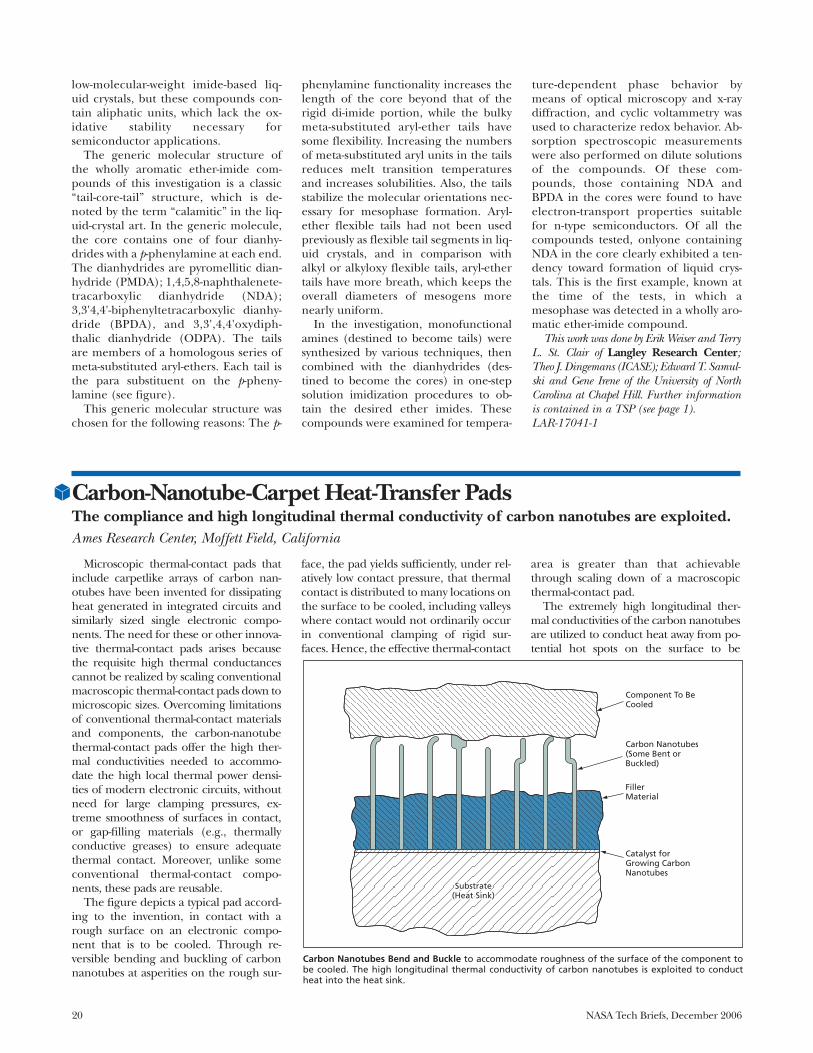
The figure depicts a typical pad accord-ing to the invention, in contact with arough surface on an electronic compo-nent that is to be cooled. Through re-versible bending and buckling of carbonnanotubes at asperities on the rough sur-
face, the pad yields sufficiently, under rel-atively low contact pressure, that thermalcontact is distributed to many locations onthe surface to be cooled, including valleyswhere contact would not ordinarily occurin conventional clamping of rigid sur-faces. Hence, the effective thermal-contact
area is greater than that achievablethrough scaling down of a macroscopicthermal-contact pad.
The extremely high longitudinal ther-mal conductivities of the carbon nanotubesare utilized to conduct heat away from po-tential hot spots on the surface to be
Component To BeCooled
Carbon Nanotubes(Some Bent orBuckled)
FillerMaterial
Catalyst forGrowing CarbonNanotubes
SubstrateSubstrate(Heat Sink)(Heat Sink)Substrate
(Heat Sink)
Carbon Nanotubes Bend and Buckle to accommodate roughness of the surface of the component tobe cooled. The high longitudinal thermal conductivity of carbon nanotubes is exploited to conductheat into the heat sink.
NASA Tech Briefs, December 2006 21
cooled. The fibers protrude from a layer ofa filler material (Cu, Ag, Au, or metal-parti-cle-filled gels), which provides both me-chanical support to maintain the carbonnanotubes in alignment and thermal con-ductivity to enhance the diffusion of con-centrated heat from the nanotubes into thelarger adjacent volume of a heat sink.
The array of carbon nanotubes, thefiller material, and the heat sink areparts of a unitary composite structurethat is fabricated as follows:1. Using techniques that have been re-
ported previously, the array of substan-
tially perpendicularly oriented carbonnanotubes is grown on a metal, silicon,or other suitable thermally conductivesubstrate that is intended to becomethe heat sink.
2. By means of chemical vapor deposi-tion, physical vapor deposition, plasmadeposition, ion sputtering, electro-chemical deposition, or casting from aliquid phase, some or all of the intersti-tial volume between carbon nanotubesis filled with the aforementioned layerof mechanically supporting, thermallyconductive material.
3. To cause the carbon nanotubes to pro-trude the desired length from the fillermaterial, an outer layer of filler is re-moved by mechanical polishing, chem-ical mechanical polishing, wet chemicaletching, electrochemical etching, ordry plasma etching.This work was done by Jun Li of Ames Re-
search Center and Brett A. Cruden andAlan M. Cassel of UARC.
Inquiries concerning rights for the commercialuse of this invention should be addressed to theTechnology Partnerships Division, Ames ResearchCenter, (650) 604-2954. Refer to ARC-15173-1.

NASA Tech Briefs, December 2006 23
Manufacturing & Prototyping
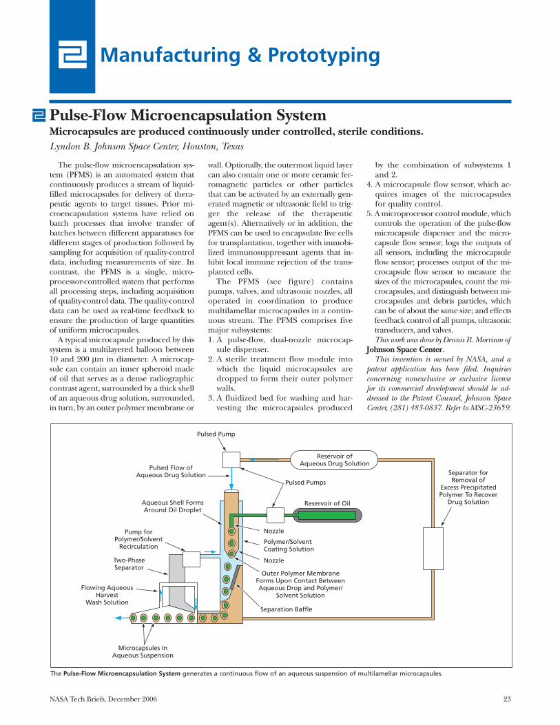
The pulse-flow microencapsulation sys-tem (PFMS) is an automated system thatcontinuously produces a stream of liquid-filled microcapsules for delivery of thera-peutic agents to target tissues. Prior mi-croencapsulation systems have relied onbatch processes that involve transfer ofbatches between different apparatuses fordifferent stages of production followed bysampling for acquisition of quality-controldata, including measurements of size. Incontrast, the PFMS is a single, micro-processor-controlled system that performsall processing steps, including acquisitionof quality-control data. The quality-controldata can be used as real-time feedback toensure the production of large quantitiesof uniform microcapsules.
A typical microcapsule produced by thissystem is a multilayered balloon between10 and 200 μm in diameter. A microcap-sule can contain an inner spheroid madeof oil that serves as a dense radiographiccontrast agent, surrounded by a thick shellof an aqueous drug solution, surrounded,in turn, by an outer polymer membrane or
wall. Optionally, the outermost liquid layercan also contain one or more ceramic fer-romagnetic particles or other particlesthat can be activated by an externally gen-erated magnetic or ultrasonic field to trig-ger the release of the therapeuticagent(s). Alternatively or in addition, thePFMS can be used to encapsulate live cellsfor transplantation, together with immobi-lized immunosuppressant agents that in-hibit local immune rejection of the trans-planted cells.
The PFMS (see figure) containspumps, valves, and ultrasonic nozzles, alloperated in coordination to producemultilamellar microcapsules in a contin-uous stream. The PFMS comprises fivemajor subsystems:1. A pulse-flow, dual-nozzle microcap-
sule dispenser.2. A sterile treatment flow module into
which the liquid microcapsules aredropped to form their outer polymerwalls.
3. A fluidized bed for washing and har-vesting the microcapsules produced
by the combination of subsystems 1and 2.
4. A microcapsule flow sensor, which ac-quires images of the microcapsulesfor quality control.
5. A microprocessor control module, whichcontrols the operation of the pulse-flowmicrocapsule dispenser and the micro-capsule flow sensor; logs the outputs ofall sensors, including the microcapsuleflow sensor; processes output of the mi-crocapsule flow sensor to measure thesizes of the microcapsules, count the mi-crocapsules, and distinguish between mi-crocapsules and debris particles, whichcan be of about the same size; and effectsfeedback control of all pumps, ultrasonictransducers, and valves.This work was done by Dennis R. Morrison of
Johnson Space Center. This invention is owned by NASA, and a
patent application has been filed. Inquiriesconcerning nonexclusive or exclusive licensefor its commercial development should be ad-dressed to the Patent Counsel, Johnson SpaceCenter, (281) 483-0837. Refer to MSC-23659.
Pulse-Flow Microencapsulation SystemMicrocapsules are produced continuously under controlled, sterile conditions.Lyndon B. Johnson Space Center, Houston, Texas
The Pulse-Flow Microencapsulation System generates a continuous flow of an aqueous suspension of multilamellar microcapsules.
Separator forRemoval of
Excess PrecipitatedPolymer To Recover
Drug Solution
Flowing AqueousHarvest
Wash Solution
Pulsed Pump
Pulsed Pumps
Reservoir ofAqueous Drug Solution
Reservoir of Oil
Nozzle
Nozzle
Polymer/SolventCoating Solution
Outer Polymer MembraneForms Upon Contact BetweenAqueous Drop and Polymer/
Solvent Solution
Separation Baffle
Microcapsules InAqueous Suspension
Two-PhaseSeparator
Pump forPolymer/Solvent
Recirculation
Aqueous Shell FormsAround Oil Droplet
Pulsed Flow ofAqueous Drug Solution
24 NASA Tech Briefs, December 2006
A report describes a proposed auto-mated facility that would be operated inouter space to produce high-quality opti-cal fibers from fluoride-based glasses, freeof light-scattering crystallites that formduring production in normal Earth gravi-tation. Before launch, glass preformswould be loaded into a mechanism thatwould later dispense them. A dispensedpreform would be melted, cooled to itsglass-transition temperature rapidlyenough to prevent crystallization, cooled
to ambient temperature, then pushed intoa preform tip heater, wherein it would bereheated to the softening temperature. Arobotic manipulator would touch a fused-silica rod to the softened glass to initiatepulling of a fiber. The robot would pullthe fiber to an attachment on a take-upspool, which would thereafter be turnedto pull the fiber. The diameter of the fiberwould depend on the pulling speed andthe viscosity of the glass at the preform tip.Upon depletion of a preform, the robot
would place the filled spool in storage andposition an empty spool to pull a fiberfrom a new preform. Pulling would be re-motely monitored by a video camera andrestarted by remote command if a breakin the fiber were observed.
This work was done by Dennis S. Tucker ofMarshall Space Flight Center and PhillipJ. Williams and Patrick A. Tobbe of DynamicConcepts. Further information is containedin a TSP (see page 1).MFS-31921-1
Automated Low-Gravitation Facility Would Make Optical FibersMarshall Space Flight Center, Alabama

NASA Tech Briefs, December 2006 25
Alignment Cube With One Diffractive FaceOnly one theodolite is needed instead of two.Goddard Space Flight Center, Greenbelt, Maryland
An enhanced alignment cube hasbeen invented for use in a confined set-ting (e.g., a cryogenic chamber) inwhich optical access may be limited to asingle line of sight. Whereas traditionalalignment-cube practice entails the useof two theodolites aimed along two linesof sight, the enhanced alignment cubeyields complete alignment informationthrough use of a single theodolite aimedalong a single line of sight.
Typically, an alignment cube is placedin contact with a datum surface or otherreference feature on a scientific instru-ment during assembly or testing of the in-strument. The alignment cube is thenused in measuring a small angular devia-tion of the feature from a precise re-quired orientation. Commonly, the devia-tion is expressed in terms of rotations(Rx,Ry,Rz) of the cube about the corre-sponding Cartesian axes (x,y,z). In tradi-tional practice, in order to measure allthree rotations, it is necessary to use twotheodolites aimed at two orthogonal facesof the alignment cube, as shown in theupper part of the figure. To be able toperform such a measurement, one needsoptical access to these two faces. In thecase of an alignment cube inside a cryo-genic chamber or other enclosed space,the optical-access requirement translatesto a requirement for two windows locatedalong the corresponding two orthogonallines of sight into the chamber. In a typi-cal application, it is difficult or impossibleto provide two windows. The present en-hanced version of the alignment cubemakes it possible to measure all three ro-tations by use of a single line of sight,thereby obviating a second window.
Commercially available alignment cubesare usually made of glass or metal and havelinear dimensions of about 1 in. (≈2.5 cm).The faces are reflective and highly pol-ished and are orthogonal to within an an-gular tolerance of about 10 arc seconds. Intraditional practice, one utilizes the specu-lar reflections from the observed faces.
An alignment cube according to thepresent innovation is made from a com-mercially available alignment cube byforming a diffraction grating on the face
that is to be observed. This can be doneeither by using a ruling engine to ma-chine grating grooves into the face or byattaching a replica grating to the face.The light from the theodolite striking thissurface is diffracted into many orders.The light diffracted to zeroth order is thespecular reflection; it gives the samealignment information (concerning the
rotations about the axes perpendicular tothe line of sight) as does the light re-flected from a traditional alignment cube.The light diffracted to higher orders cre-ates additional image components in thetheodolite field of view. The horizontaland vertical displacements of these com-ponents are related in a known way to therotation about the line of sight. Hence, as
Two Theodolites are needed to measure rotations about all three Cartesian axes in traditional prac-tice using a purely specular alignment cube. Applying a diffraction grating to one face of an align-ment cube makes it possible to measure all three rotations using a single theodolite.
z
x
y
z
x y
Alignment Cube
Alignment Cube
Theodolite 1: Measures Ry and Rz
Theodolite
Theodolite 2: Measures Rx and Ry
TRADITIONAL PRACTICE: USING TWO THEODOLITES TO MEASURE THREE ROTATIONS
TOP VIEW OF SETUP FOR MEASURING THREE ROTATIONS USING ONE THEODOLITE
Grating Surface
Specularly Reflected Light (Light Diffracted to Zero Order)
Used To Measure Rx and Ry
Light Diffracted to First Order Used To Measure Rz
Physical Sciences

26 NASA Tech Briefs, December 2006
depicted schematically in the lower part ofthe figure, a single theodolite can be usedto measure rotation about all three axes.
The amplitude and spatial period of thegrating should be optimized for the peakwavelength (e.g. ≈540 nm) of the lightsource in the theodolite and for the view-ing geometry as limited by the edge of thewindow (if any) in the intended applica-tion. Prior to use of the alignment cube, itis necessary to perform a calibration in
which the orientations of the remainingpolished sides are measured with re-spect to the orientations of the specularreflection and the pertinent non-zerograting orders. If the cube is to be usedduring cryogenic operation, then thecube is placed in a small chamber at theanticipated operating temperature andthe calibration is repeated. If thesemeasurements show the calibration tobe consistent in the presence of thermal
cycling, then the alignment cube can beused as described above to measure allthree rotations.
This work was done by Raymond G. Ohl,Henry P. Sampler, Carl R. Strojny, and JohnG. Hagopian of Goddard Space FlightCenter and Joseph C. McMann of ManTechInternational Corp. Further information iscontained in a TSP (see page 1).GSC-14954-1
NASA Tech Briefs, December 2006 27
Books & Reports
Graphite Composite BoomsWith Integral Hinges
A document discusses lightweight in-strument booms under development foruse aboard spacecraft. A boom of thistype comprises a thin-walled graphite-fiber/matrix composite tube with an inte-gral hinge that can be bent for stowageand later allowed to spring back tostraighten the boom for deployment inouter space. The boom design takes ad-vantage of both the stiffness of the com-posite in tubular geometry and the flexi-bility of thin sections of the composite.The hinge is formed by machining win-dows in the tube at diametrically oppositelocations so that there remain two oppos-ing cylindrical strips resembling measur-ing tapes. Essential to the design is a pro-prietary composite layup that renders thehinge tough yet flexible enough to bebendable as much as 90° in either of twoopposite directions. When the boom isreleased for deployment, the torque ex-erted by the bent hinge suffices to over-come parasitic resistance from harnessesand other equipment, so that the two sec-tions of the hinge snap to a straight, rigidcondition in the same manner as that ofmeasuring tapes. Issues addressed in de-velopment thus far include selection ofmaterials, out-of-plane bending, edgecracking, and separation of plies.
This work was done by Wes Alexander, ReneCarlos, Peter Rossoni, and James Sturm ofGoddard Space Flight Center. Further in-formation is contained in a TSP (see page 1).GSC-14896-1
Tool for Sampling Permafroston a Remote Planet
A report discusses the robotic armtool for rapidly acquiring permafrost(RATRAP), which is being developed foracquiring samples of permafrost onMars or another remote planet and im-mediately delivering the samples to adja-cent instruments for analysis. The proto-type RATRAP includes a rasp thatprotrudes through a hole in the bottomof a container that is placed in contactwith the permafrost surface. Moving athigh speed, the rasp cuts into the sur-face and loads many of the resultingsmall particles of permafrost throughthe hole into the container. The proto-type RATRAP has been shown to be ca-pable of acquiring many grams of per-mafrost simulants in times of the orderof seconds. In contrast, a current per-mafrost-sampling system that the RA-TRAP is intended to supplant works byscraping with tines followed by pickingup the scrapings in a scoop, sometimestaking hours to acquire a few grams.Also, because the RATRAP inherentlypulverizes the sampled material, it is anattractive alternative to other samplingapparatuses that generate core or chunksamples that must be further processedby a crushing apparatus to make thesample particles small enough for analy-sis by some instruments.
This work was done by Gregory Peters ofCaltech for NASA’s Jet Propulsion Labora-tory. Further information is contained in aTSP (see page 1). NPO-43128
Special Semaphore Schemefor UHF Spacecraft Com-munications
A semaphore scheme has been devisedto satisfy a requirement to enable ultra-high-frequency (UHF) radio communica-tion between a spacecraft descending fromorbit to a landing on Mars and a spacecraft,in orbit about Mars, that relays communi-cations between Earth and the landerspacecraft. There are also two subsidiary re-quirements: (1) to use UHF transceivers,built and qualified for operation aboardthe spacecraft that operate with residual-carrier binary phase-shift-keying (BPSK)modulation at a selectable data rate of 8,32, 128, or 256 kb/s; and (2) to enable low-rate signaling even when received signalsbecome so weak as to prevent communica-tion at the minimum BPSK rate of 8 kHz.The scheme involves exploitation of Man-chester encoding, which is used in con-junction with residual-carrier modulationto aid the carrier-tracking loop. By choos-ing various sequences of 1s, 0s, or 1s alter-nating with 0s to be fed to the residual-car-rier modulator, one would cause themodulator to generate sidebands at a fun-damental frequency of 4 or 8 kHz and har-monics thereof. These sidebands wouldconstitute the desired semaphores. In re-ception, the semaphores would be de-tected by a software demodulator.
This work was done by Stanley Butman,Edgar Satorius, and Peter Ilott of Caltech forNASA’s Jet Propulsion Laboratory. Fur-ther information is contained in a TSP (seepage 1). NPO-42910


National Aeronautics andSpace Administration
Related Documents


![Review Article Iodine: A Longer-Life Positron Emitter Isotope New … · 2019. 7. 31. · 131 Iodine (131 I), 123 Iodine (123 I), and 125 Iodine (125 I), have limitations[ ]. Due](https://static.cupdf.com/doc/110x72/60fd8c07bb6c4a2e9a0c696e/review-article-iodine-a-longer-life-positron-emitter-isotope-new-2019-7-31.jpg)