NIPPON STEEL TECHNICAL REPORT No. 103 MAY 2013 - 91 - 1. Introduction Today, measures to curb global warming are being employed in diverse fields such as energy, ships, aircrafts, rail rolling stocks, au- tomobiles, and household appliances. The automotive industry, too, has been making positive efforts to reduce CO 2 gas emissions through reduction of the weight of car bodies. 1-3) The most striking of these efforts is the application of high- strength steel sheets (590 to 1,470 MPa) to automotive parts. 4-5) Considerable volumes of high-strength steel sheet have already been applied to not only reduce the weight of car bodies but also enhance their crashworthiness. It is expected that efforts to further reduce car body weight by making most effective use of high-strength steel sheet will be continued in the future. However, considering the stiff- ness required of each member, there is a certain limit to the reduc- tion of weight through the use of thinner steel sheets. If a further weight reduction of 30% or more is called for in the future, it will become necessary to develop and deploy a multi-material structure composed partly of lightweight materials. 6) Materials such as aluminum alloy, magnesium alloy, plastics, Technical Report UDC 621 . 791 / . 792 : 621 . 88 : 669 . 14 - 415 : 669 . 715 : 629 . 11 . 011 . 5 * Senior Researcher, Welding & Joining Research Center, Steel Research Laboratories 20-1 Shintomi, Futtsu, Chiba 293-8511 Dissimilar Metal Joining Technologies for Steel Sheet and Aluminum Alloy Sheet in Auto Body Tatsuya SAKIYAMA* Gen MURAYAMA Yasuaki NAITO Kenji SAITA Yasunobu MIYAZAKI Hatsuhiko OIKAWA Tetsuro NOSE Abstract Multi-material structure of auto body partially employing aluminum alloy sheets may be adopted in order to satisfy requests at the same time improving crash safety and lightweight. This paper described the dissimilar metal joining technologies required to achieve multi- material structure. In resistance spot welding, high current & short time welding condition is conducted to avoid formation of brittle Fe-Al intermetallic compound layer at joint inter- face and joint strength is investigated. In mechanical joining, current application situation of SPR, Tog-L-Loc ® , TOX ® and FDS ® methods are outlined and application examples of Blind rivet in automobile body are introduced. In addition to that, joint strengths in shear direction of SPR joints for cold rolled steel sheets and 6000 series aluminum alloy sheets are described. In adhesion bonding, it was shown that joint strength of TSS over 20 MPa is obtained by using of recent adhesive for automobile in sheet combinations of cold rolled mild steel sheets and 6000 series aluminum alloy sheets. In FSSW, effects of holding time, rotating speed and coating layer on joint strength were clarified in sheet combinations of Super Dyma ® steel sheets and 6000 series aluminum alloy sheets. Also, in laser brazing, it was shown that joining of cold rolled or GA mild steel sheets and 6000 series aluminum alloy sheets are possible by using 4000 series aluminum alloy filler (A4043) with fluoride type NOCOLOK ® flux. Finally, direction of development needed in the future in the field of dissimilar metal joining technologies of steel and aluminum alloy was described based on past development history.

Welcome message from author
This document is posted to help you gain knowledge. Please leave a comment to let me know what you think about it! Share it to your friends and learn new things together.
Transcript
NIPPON STEEL TECHNICAL REPORT No. 103 MAY 2013
- 91 -
1. IntroductionToday, measures to curb global warming are being employed in
diverse fields such as energy, ships, aircrafts, rail rolling stocks, au-tomobiles, and household appliances. The automotive industry, too, has been making positive efforts to reduce CO2 gas emissions through reduction of the weight of car bodies.1-3)
The most striking of these efforts is the application of high-strength steel sheets (590 to 1,470 MPa) to automotive parts.4-5) Considerable volumes of high-strength steel sheet have already been
applied to not only reduce the weight of car bodies but also enhance their crashworthiness. It is expected that efforts to further reduce car body weight by making most effective use of high-strength steel sheet will be continued in the future. However, considering the stiff-ness required of each member, there is a certain limit to the reduc-tion of weight through the use of thinner steel sheets. If a further weight reduction of 30% or more is called for in the future, it will become necessary to develop and deploy a multi-material structure composed partly of lightweight materials.6)
Materials such as aluminum alloy, magnesium alloy, plastics,
Technical Report UDC 621 . 791 / . 792 : 621 . 88 : 669 . 14 - 415 : 669 . 715 : 629 . 11 . 011 . 5
* Senior Researcher, Welding & Joining Research Center, Steel Research Laboratories 20-1 Shintomi, Futtsu, Chiba 293-8511
Dissimilar Metal Joining Technologies for Steel Sheet and Aluminum Alloy Sheet in Auto Body
Tatsuya SAKIYAMA* Gen MURAYAMAYasuaki NAITO Kenji SAITAYasunobu MIYAZAKI Hatsuhiko OIKAWATetsuro NOSE
AbstractMulti-material structure of auto body partially employing aluminum alloy sheets may be
adopted in order to satisfy requests at the same time improving crash safety and lightweight. This paper described the dissimilar metal joining technologies required to achieve multi-material structure. In resistance spot welding, high current & short time welding condition is conducted to avoid formation of brittle Fe-Al intermetallic compound layer at joint inter-face and joint strength is investigated. In mechanical joining, current application situation of SPR, Tog-L-Loc®, TOX® and FDS® methods are outlined and application examples of Blind rivet in automobile body are introduced. In addition to that, joint strengths in shear direction of SPR joints for cold rolled steel sheets and 6000 series aluminum alloy sheets are described. In adhesion bonding, it was shown that joint strength of TSS over 20 MPa is obtained by using of recent adhesive for automobile in sheet combinations of cold rolled mild steel sheets and 6000 series aluminum alloy sheets. In FSSW, effects of holding time, rotating speed and coating layer on joint strength were clarified in sheet combinations of Super Dyma® steel sheets and 6000 series aluminum alloy sheets. Also, in laser brazing, it was shown that joining of cold rolled or GA mild steel sheets and 6000 series aluminum alloy sheets are possible by using 4000 series aluminum alloy filler (A4043) with fluoride type NOCOLOK® flux. Finally, direction of development needed in the future in the field of dissimilar metal joining technologies of steel and aluminum alloy was described based on past development history.
NIPPON STEEL TECHNICAL REPORT No. 103 MAY 2013
- 92 -
and carbon-fiber-reinforced plastic allow for reduction of car body weight,3) among which aluminum alloy seems the most promising on the basis of actual use to date and cost. However, in light of the costs and properties of aluminum alloy as a structural material, the most effective way of using aluminum alloy is applying it only where really needed. For this reason, aluminum alloy has so far been applied to only those car body parts that do not require ex-tremely high strength, such as the hood, trunk, doors, and roof.7) Such partial application of aluminum alloy calls for technology to join aluminum alloy sheet and steel sheet, which exhibit different material properties.
Various methods have been proposed to join materials together, including fusion welding (e.g., resistance spot welding, resistance seam welding, arc welding), solid state bonding (e.g., explosive welding, friction welding, electromagnetic welding, roll bonding, diffusion bonding), brazing (e.g., burner brazing, arc brazing, laser brazing), mechanical joining (e.g., self-pierce riveting (SPR), TOX®, flow drill screw (FDS®), blind riveting), and adhesive bonding.8) In addition, joining methods using coating or inserts have been stud-ied.9) For any joining method that requires high temperatures, a brit-tle layer of intermetallic compound (IMC) is formed at the joint in-terface, making it difficult to obtain the desired joint strength. In practice, therefore, attention was first paid to mechanical methods that do not form this unwanted layer of IMC.
When two dissimilar metals come into contact, the difference in their ionization tendency causes corrosion to occur at the interface. To prevent this, attempts have been made to use mechanical joining and adhesive bonding in combination.10) Such methods have been put into practical use ahead of other joining methods and are still used widely.6) It is also possible to restrain the formation of a brittle layer of IMC by applying solid state bonding. Therefore, friction welding and friction stir spot welding (FSSW) have been put into use for propeller shafts 11) and hatchback doors,12) respectively. Thus, various methods have been developed for joining steel sheet and aluminum alloy sheet, a process that was previously considered dif-ficult. With the recent strong demand for lighter car bodies, the need for such joining methods is again increasing. Spot welding, mechan-ical joining, adhesive bonding, FSSW, and laser brazing are consid-ered to be especially promising technologies for joining steel and aluminum alloy sheets; therefore, we describe here the research into these materials and their application to actual cars in recent years.
2. Spot WeldingWhen steel sheet and aluminum alloy sheet are spot welded, the
very brittle IMC produced at the interface during welding becomes a problem.13) The presence of this material can decrease joint strength, especially the cross-tension strength (CTS). Therefore, for today’s car bodies, a joining method that combines mechanical join-ing (e.g., SPR, TOX®, etc.) and adhesive bonding is most widely used.7) In this section, the weldability and joint strength of spot welding are examined by the combination of a 0.8-mm-thick gal-vannealed (GA) mild steel sheet and a 1.0-mm-thick 6000-series aluminum alloy sheet.
The welding machine used was a pneumatic, single-phase, recti-fier-type welder (power frequency: 50 Hz) with a rated capacity of 150 kVA, and the electrode used was a chromium-copper electrode of Dome Radius (DR) type with a tip diameter of 8 mm. The weld-ing conditions were as follows: squeeze time, 70 cycles; upslope time, 2 cycles; weld time, 3 cycles; hold time, 20 cycles; and elec-trode force, 5.89 kN.
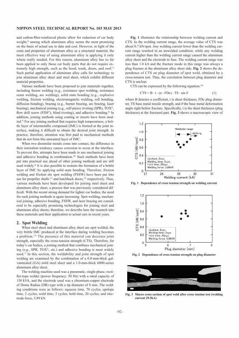
Fig. 1 illustrates the relationship between welding current and CTS. In the welding current range, the average value of CTS was about 0.7 kN/spot. Any welding current lower than the welding cur-rent range resulted in an unwelded condition, while any welding current higher than the welding current range caused the aluminum alloy sheet and the electrode to fuse. The welding current range was less than 1.0 kA and the fracture mode in this range was always a plug fracture at the aluminum alloy sheet side. Fig. 2 shows the de-pendence of CTS on plug diameter of spot weld, obtained by a cross-tension test. Thus, the correlation between plug diameter and CTS is unclear.
CTS can be expressed by the following equation.14)
CTS = B . t . (π . FDc) . TS . sin θ (1)
where B denotes a coefficient, t is sheet thickness, FDc plug diame-ter, TS base metal tensile strength, and θ the base metal deformation angle right before fracture. Specifically, t is the sheet thickness (plug thickness) at the fractured part. Fig. 3 shows a macroscopic view of
Fig. 1 Dependence of cross tension strength on welding current
Fig. 2 Dependence of cross tension strength on plug diameter
Fig. 3 Macro cross section of spot weld after cross tension test (welding current 29.5kA)
NIPPON STEEL TECHNICAL REPORT No. 103 MAY 2013
- 93 -
the cross section of a weld subjected to a cross tension test. It can be seen that the plug thickness is about 25% of the thickness of the base metal of the aluminum alloy sheet. Thus, in spot welding of steel sheet and aluminum alloy sheet, the decrease in aluminum al-loy sheet thickness is so large that the joint strength cannot be ex-pressed by the plug diameter alone. Thus, it is necessary to consider the plug thickness too.
3. Mechanical Joining3.1 Trends of mechanical joining methods
Various methods exist for mechanical joining.15) In the field of automobiles (in addition to conventional joining methods such as using nuts, bolts, and screws), new methods such as SPR, Blind Rivet, TOX®, Tog-L-Loc®, and FDS® have come to be applied in re-cent years.6, 16-19). Mechanical joining provides joints of high quality and allows for automatic operation. Because of these advantages, study of the application of SPR and TOX® began early,20-23) and these methods came to be applied to high-grade cars ahead of other new joining methods.
SPR offers strong joints but can cause significant damage to the material surface. Therefore, it is applied mainly to parts that demand strong joints. Blind riveting permits access to the material from one side, causes little damage to the material, and offers strong joints. Thus, both SPR and blind riveting result in joints with high strength. However, the rivets used are relatively expensive. Furthermore, the latter method requires previous drilling of the materials to be joined.
TOX® and Tog-L-Loc® clinch two materials together by pressing them with a punch and die.17) These techniques result in very little damage to the material surface, although the joints obtained are not very strong. Therefore, they are applied to parts that demand good
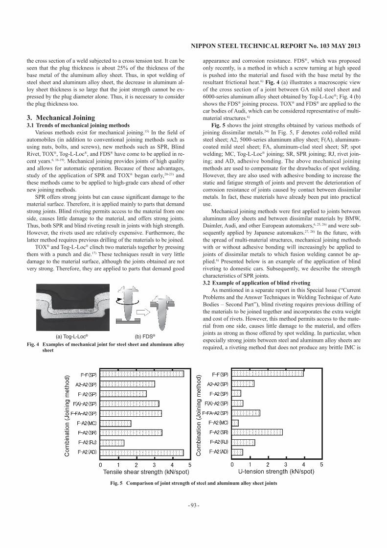
appearance and corrosion resistance. FDS®, which was proposed only recently, is a method in which a screw turning at high speed is pushed into the material and fused with the base metal by the resultant frictional heat.6) Fig. 4 (a) illustrates a macroscopic view of the cross section of a joint between GA mild steel sheet and 6000-series aluminum alloy sheet obtained by Tog-L-Loc®; Fig. 4 (b) shows the FDS® joining process. TOX® and FDS® are applied to the car bodies of Audi, which can be considered representative of multi-material structures.6)
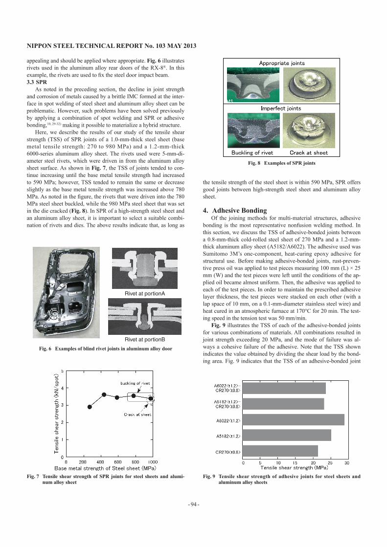
Fig. 5 shows the joint strengths obtained by various methods of joining dissimilar metals.24) In Fig. 5, F denotes cold-rolled mild steel sheet; A2, 5000-series aluminum alloy sheet; F(A), aluminum-coated mild steel sheet; FA, aluminum-clad steel sheet; SP, spot welding; MC, Tog-L-Loc® joining; SR, SPR joining; RJ, rivet join-ing; and AD, adhesive bonding. The above mechanical joining methods are used to compensate for the drawbacks of spot welding. However, they are also used with adhesive bonding to increase the static and fatigue strength of joints and prevent the deterioration of corrosion resistance of joints caused by contact between dissimilar metals. In fact, these materials have already been put into practical use.
Mechanical joining methods were first applied to joints between aluminum alloy sheets and between dissimilar materials by BMW, Daimler, Audi, and other European automakers,6, 25, 26) and were sub-sequently applied by Japanese automakers.27, 28) In the future, with the spread of multi-material structures, mechanical joining methods with or without adhesive bonding will increasingly be applied to joints of dissimilar metals to which fusion welding cannot be ap-plied.6) Presented below is an example of the application of blind riveting to domestic cars. Subsequently, we describe the strength characteristics of SPR joints.3.2 Example of application of blind riveting
As mentioned in a separate report in this Special Issue (“Current Problems and the Answer Techniques in Welding Technique of Auto Bodies – Second Part”), blind riveting requires previous drilling of the materials to be joined together and incorporates the extra weight and cost of rivets. However, this method permits access to the mate-rial from one side, causes little damage to the material, and offers joints as strong as those offered by spot welding. In particular, when especially strong joints between steel and aluminum alloy sheets are required, a riveting method that does not produce any brittle IMC is
(a) Tog-L-Loc® (b) FDS®
Fig. 4 Examples of mechanical joint for steel sheet and aluminum alloy sheet
Fig. 5 Comparison of joint strength of steel and aluminum alloy sheet joints
NIPPON STEEL TECHNICAL REPORT No. 103 MAY 2013
- 94 -
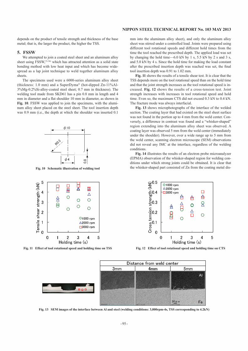
appealing and should be applied where appropriate. Fig. 6 illustrates rivets used in the aluminum alloy rear doors of the RX-8®. In this example, the rivets are used to fix the steel door impact beam.3.3 SPR
As noted in the preceding section, the decline in joint strength and corrosion of metals caused by a brittle IMC formed at the inter-face in spot welding of steel sheet and aluminum alloy sheet can be problematic. However, such problems have been solved previously by applying a combination of spot welding and SPR or adhesive bonding,10, 29-32) making it possible to materialize a hybrid structure.
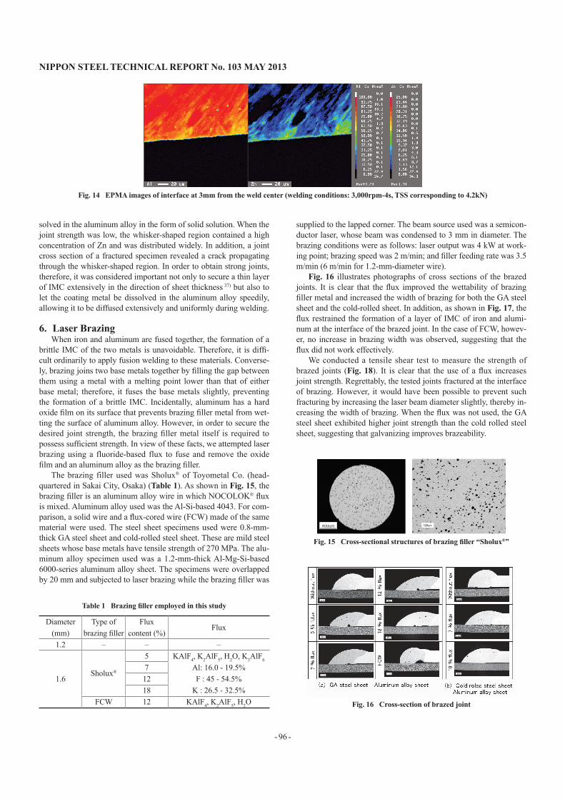
Here, we describe the results of our study of the tensile shear strength (TSS) of SPR joints of a 1.0-mm-thick steel sheet (base metal tensile strength: 270 to 980 MPa) and a 1.2-mm-thick 6000-series aluminum alloy sheet. The rivets used were 5-mm-di-ameter steel rivets, which were driven in from the aluminum alloy sheet surface. As shown in Fig. 7, the TSS of joints tended to con-tinue increasing until the base metal tensile strength had increased to 590 MPa; however, TSS tended to remain the same or decrease slightly as the base metal tensile strength was increased above 780 MPa. As noted in the figure, the rivets that were driven into the 780 MPa steel sheet buckled, while the 980 MPa steel sheet that was set in the die cracked (Fig. 8). In SPR of a high-strength steel sheet and an aluminum alloy sheet, it is important to select a suitable combi-nation of rivets and dies. The above results indicate that, as long as
the tensile strength of the steel sheet is within 590 MPa, SPR offers good joints between high-strength steel sheet and aluminum alloy sheet.
4. Adhesive BondingOf the joining methods for multi-material structures, adhesive
bonding is the most representative nonfusion welding method. In this section, we discuss the TSS of adhesive-bonded joints between a 0.8-mm-thick cold-rolled steel sheet of 270 MPa and a 1.2-mm-thick aluminum alloy sheet (A5182/A6022). The adhesive used was Sumitomo 3M’s one-component, heat-curing epoxy adhesive for structural use. Before making adhesive-bonded joints, rust-preven-tive press oil was applied to test pieces measuring 100 mm (L) × 25 mm (W) and the test pieces were left until the conditions of the ap-plied oil became almost uniform. Then, the adhesive was applied to each of the test pieces. In order to maintain the prescribed adhesive layer thickness, the test pieces were stacked on each other (with a lap space of 10 mm, on a 0.1-mm-diameter stainless steel wire) and heat cured in an atmospheric furnace at 170°C for 20 min. The test-ing speed in the tension test was 50 mm/min.
Fig. 9 illustrates the TSS of each of the adhesive-bonded joints for various combinations of materials. All combinations resulted in joint strength exceeding 20 MPa, and the mode of failure was al-ways a cohesive failure of the adhesive. Note that the TSS shown indicates the value obtained by dividing the shear load by the bond-ing area. Fig. 9 indicates that the TSS of an adhesive-bonded joint
Rivet at portionA
Rivet at portionB
Fig. 6 Examples of blind rivet joints in aluminum alloy door
Fig. 7 Tensile shear strength of SPR joints for steel sheets and alumi-num alloy sheet
Fig. 8 Examples of SPR joints
Fig. 9 Tensile shear strength of adhesive joints for steel sheets and aluminum alloy sheets
NIPPON STEEL TECHNICAL REPORT No. 103 MAY 2013
- 95 -
depends on the product of tensile strength and thickness of the base metal; that is, the larger the product, the higher the TSS.
5. FSSWWe attempted to join a coated steel sheet and an aluminum alloy
sheet using FSSW,33-36) which has attracted attention as a solid state bonding method with low heat input and which has become wide-spread as a lap joint technique to weld together aluminum alloy sheets.
The specimens used were a 6000-series aluminum alloy sheet (thickness: 1.0 mm) and a SuperDyma® (hot-dipped Zn-11%Al-3%Mg-0.2%Si-alloy-coated steel sheet; 0.7 mm in thickness). The welding tool made from SKD61 has a pin 0.8 mm in length and 4 mm in diameter and a flat shoulder 10 mm in diameter, as shown in Fig. 10. FSSW was applied to join the specimens, with the alumi-num alloy sheet placed on the steel sheet. The tool insertion depth was 0.9 mm (i.e., the depth at which the shoulder was inserted 0.1
mm into the aluminum alloy sheet), and only the aluminum alloy sheet was stirred under a controlled load. Joints were prepared using different tool rotational speeds and different hold times from the time the tool reached the prescribed depth. The applied load was set by changing the hold time—6.0 kN by 1 s, 5.5 kN by 2 s and 3 s, and 5.0 kN by 4 s. Since the hold time for making the load constant after the prescribed insertion depth was reached was set, the final tool insertion depth was 0.91 to 1.02 mm.
Fig. 11 shows the results of a tensile shear test. It is clear that the TSS depends more on the tool rotational speed than on the hold time and that the joint strength increases as the tool rotational speed is in-creased. Fig. 12 shows the results of a cross-tension test. Joint strength increases with increases in tool rotational speed and hold time. Even so, the maximum CTS did not exceed 0.3 kN to 0.4 kN. The fracture mode was always interfacial.
Fig. 13 shows microphotographs of the interface of the welded section. The coating layer that had existed on the steel sheet surface was not found in the portion up to 4 mm from the weld center. Con-versely, a difference in contrast was found and a “whisker-shaped” region extending into the aluminum alloy sheet was observed. A coating layer was observed 5 mm from the weld center (immediately under the shoulder). However, over a wide range up to 5 mm from the weld center, scanning electron microscope (SEM) observations did not reveal any IMC at the interface, regardless of the welding conditions.
Fig. 14 illustrates the results of an electron probe microanalyzer (EPMA) observation of the whisker-shaped region for welding con-ditions under which strong joints could be obtained. It is clear that the whisker-shaped part consisted of Zn from the coating metal dis-Fig. 10 Schematic illustration of welding tool
Fig. 11 Effect of tool rotational speed and holding time on TSS Fig. 12 Effect of tool rotational speed and holding time on CTS
Fig. 13 SEM images of the interface between Al and steel (welding conditions: 3,000rpm-4s, TSS corresponding to 4.2kN)
NIPPON STEEL TECHNICAL REPORT No. 103 MAY 2013
- 96 -
solved in the aluminum alloy in the form of solid solution. When the joint strength was low, the whisker-shaped region contained a high concentration of Zn and was distributed widely. In addition, a joint cross section of a fractured specimen revealed a crack propagating through the whisker-shaped region. In order to obtain strong joints, therefore, it was considered important not only to secure a thin layer of IMC extensively in the direction of sheet thickness 37) but also to let the coating metal be dissolved in the aluminum alloy speedily, allowing it to be diffused extensively and uniformly during welding.
6. Laser BrazingWhen iron and aluminum are fused together, the formation of a
brittle IMC of the two metals is unavoidable. Therefore, it is diffi-cult ordinarily to apply fusion welding to these materials. Converse-ly, brazing joins two base metals together by filling the gap between them using a metal with a melting point lower than that of either base metal; therefore, it fuses the base metals slightly, preventing the formation of a brittle IMC. Incidentally, aluminum has a hard oxide film on its surface that prevents brazing filler metal from wet-ting the surface of aluminum alloy. However, in order to secure the desired joint strength, the brazing filler metal itself is required to possess sufficient strength. In view of these facts, we attempted laser brazing using a fluoride-based flux to fuse and remove the oxide film and an aluminum alloy as the brazing filler.
The brazing filler used was Sholux® of Toyometal Co. (head-quartered in Sakai City, Osaka) (Table 1). As shown in Fig. 15, the brazing filler is an aluminum alloy wire in which NOCOLOK® flux is mixed. Aluminum alloy used was the Al-Si-based 4043. For com-parison, a solid wire and a flux-cored wire (FCW) made of the same material were used. The steel sheet specimens used were 0.8-mm-thick GA steel sheet and cold-rolled steel sheet. These are mild steel sheets whose base metals have tensile strength of 270 MPa. The alu-minum alloy specimen used was a 1.2-mm-thick Al-Mg-Si-based 6000-series aluminum alloy sheet. The specimens were overlapped by 20 mm and subjected to laser brazing while the brazing filler was
supplied to the lapped corner. The beam source used was a semicon-ductor laser, whose beam was condensed to 3 mm in diameter. The brazing conditions were as follows: laser output was 4 kW at work-ing point; brazing speed was 2 m/min; and filler feeding rate was 3.5 m/min (6 m/min for 1.2-mm-diameter wire).
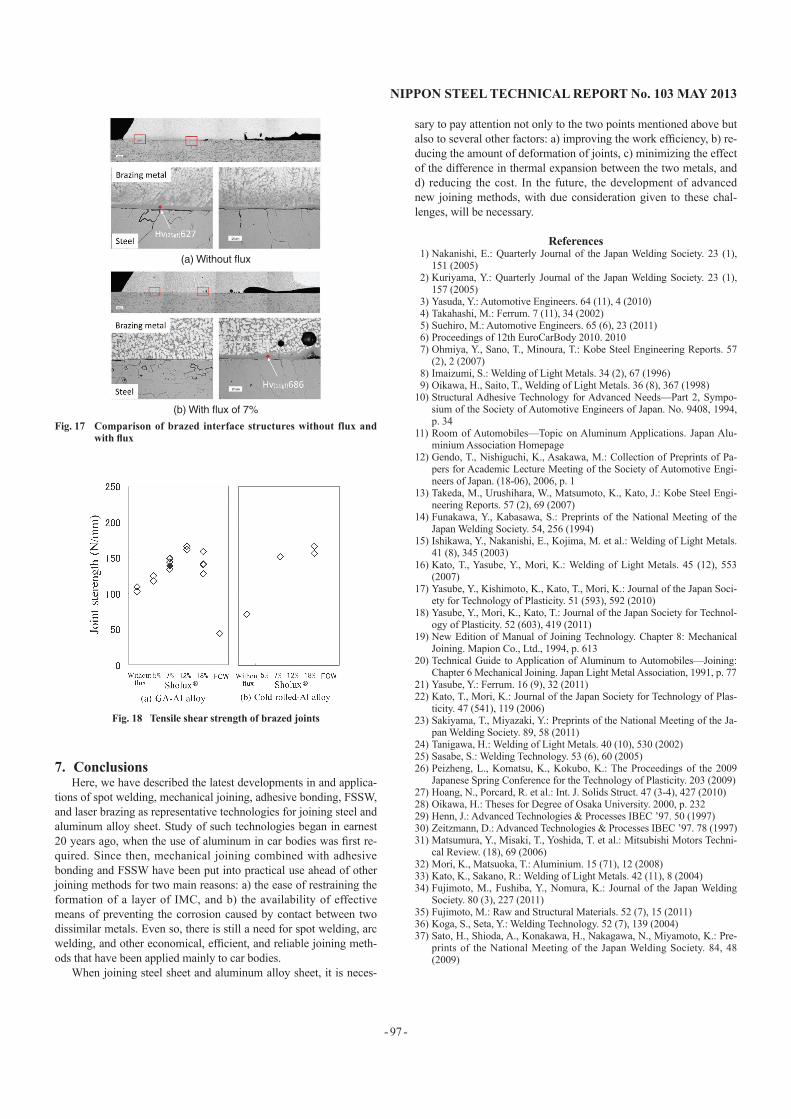
Fig. 16 illustrates photographs of cross sections of the brazed joints. It is clear that the flux improved the wettability of brazing filler metal and increased the width of brazing for both the GA steel sheet and the cold-rolled sheet. In addition, as shown in Fig. 17, the flux restrained the formation of a layer of IMC of iron and alumi-num at the interface of the brazed joint. In the case of FCW, howev-er, no increase in brazing width was observed, suggesting that the flux did not work effectively.
We conducted a tensile shear test to measure the strength of brazed joints (Fig. 18). It is clear that the use of a flux increases joint strength. Regrettably, the tested joints fractured at the interface of brazing. However, it would have been possible to prevent such fracturing by increasing the laser beam diameter slightly, thereby in-creasing the width of brazing. When the flux was not used, the GA steel sheet exhibited higher joint strength than the cold rolled steel sheet, suggesting that galvanizing improves brazeability.
Fig. 15 Cross-sectional structures of brazing filler “Sholux®”
Table 1 Brazing filler employed in this study
Diameter(mm)
Type of brazing filler
Flux content (%)
Flux
1.2 – – –
1.6Sholux®
5 KAlF4, K2AlF5, H2O, K3AlF6
Al: 16.0 - 19.5%F : 45 - 54.5%
K : 26.5 - 32.5%
71218
FCW 12 KAlF4, K2AlF5, H2O Fig. 16 Cross-section of brazed joint
Fig. 14 EPMA images of interface at 3mm from the weld center (welding conditions: 3,000rpm-4s, TSS corresponding to 4.2kN)
NIPPON STEEL TECHNICAL REPORT No. 103 MAY 2013
- 97 -
7. ConclusionsHere, we have described the latest developments in and applica-
tions of spot welding, mechanical joining, adhesive bonding, FSSW, and laser brazing as representative technologies for joining steel and aluminum alloy sheet. Study of such technologies began in earnest 20 years ago, when the use of aluminum in car bodies was first re-quired. Since then, mechanical joining combined with adhesive bonding and FSSW have been put into practical use ahead of other joining methods for two main reasons: a) the ease of restraining the formation of a layer of IMC, and b) the availability of effective means of preventing the corrosion caused by contact between two dissimilar metals. Even so, there is still a need for spot welding, arc welding, and other economical, efficient, and reliable joining meth-ods that have been applied mainly to car bodies.
When joining steel sheet and aluminum alloy sheet, it is neces-
sary to pay attention not only to the two points mentioned above but also to several other factors: a) improving the work efficiency, b) re-ducing the amount of deformation of joints, c) minimizing the effect of the difference in thermal expansion between the two metals, and d) reducing the cost. In the future, the development of advanced new joining methods, with due consideration given to these chal-lenges, will be necessary.
References1) Nakanishi, E.: Quarterly Journal of the Japan Welding Society. 23 (1),
151 (2005)2) Kuriyama, Y.: Quarterly Journal of the Japan Welding Society. 23 (1),
157 (2005)3) Yasuda, Y.: Automotive Engineers. 64 (11), 4 (2010)4) Takahashi, M.: Ferrum. 7 (11), 34 (2002)5) Suehiro, M.: Automotive Engineers. 65 (6), 23 (2011)6) Proceedings of 12th EuroCarBody 2010. 20107) Ohmiya, Y., Sano, T., Minoura, T.: Kobe Steel Engineering Reports. 57
(2), 2 (2007)8) Imaizumi, S.: Welding of Light Metals. 34 (2), 67 (1996)9) Oikawa, H., Saito, T., Welding of Light Metals. 36 (8), 367 (1998)
10) Structural Adhesive Technology for Advanced Needs—Part 2, Sympo-sium of the Society of Automotive Engineers of Japan. No. 9408, 1994, p. 34
11) Room of Automobiles—Topic on Aluminum Applications. Japan Alu-minium Association Homepage
12) Gendo, T., Nishiguchi, K., Asakawa, M.: Collection of Preprints of Pa-pers for Academic Lecture Meeting of the Society of Automotive Engi-neers of Japan. (18-06), 2006, p. 1
13) Takeda, M., Urushihara, W., Matsumoto, K., Kato, J.: Kobe Steel Engi-neering Reports. 57 (2), 69 (2007)
14) Funakawa, Y., Kabasawa, S.: Preprints of the National Meeting of the Japan Welding Society. 54, 256 (1994)
15) Ishikawa, Y., Nakanishi, E., Kojima, M. et al.: Welding of Light Metals. 41 (8), 345 (2003)
16) Kato, T., Yasube, Y., Mori, K.: Welding of Light Metals. 45 (12), 553 (2007)
17) Yasube, Y., Kishimoto, K., Kato, T., Mori, K.: Journal of the Japan Soci-ety for Technology of Plasticity. 51 (593), 592 (2010)
18) Yasube, Y., Mori, K., Kato, T.: Journal of the Japan Society for Technol-ogy of Plasticity. 52 (603), 419 (2011)
19) New Edition of Manual of Joining Technology. Chapter 8: Mechanical Joining. Mapion Co., Ltd., 1994, p. 613
20) Technical Guide to Application of Aluminum to Automobiles—Joining: Chapter 6 Mechanical Joining. Japan Light Metal Association, 1991, p. 77
21) Yasube, Y.: Ferrum. 16 (9), 32 (2011)22) Kato, T., Mori, K.: Journal of the Japan Society for Technology of Plas-
ticity. 47 (541), 119 (2006)23) Sakiyama, T., Miyazaki, Y.: Preprints of the National Meeting of the Ja-
pan Welding Society. 89, 58 (2011)24) Tanigawa, H.: Welding of Light Metals. 40 (10), 530 (2002)25) Sasabe, S.: Welding Technology. 53 (6), 60 (2005)26) Peizheng, L., Komatsu, K., Kokubo, K.: The Proceedings of the 2009
Japanese Spring Conference for the Technology of Plasticity. 203 (2009)27) Hoang, N., Porcard, R. et al.: Int. J. Solids Struct. 47 (3-4), 427 (2010)28) Oikawa, H.: Theses for Degree of Osaka University. 2000, p. 23229) Henn, J.: Advanced Technologies & Processes IBEC ’97. 50 (1997)30) Zeitzmann, D.: Advanced Technologies & Processes IBEC ’97. 78 (1997)31) Matsumura, Y., Misaki, T., Yoshida, T. et al.: Mitsubishi Motors Techni-
cal Review. (18), 69 (2006)32) Mori, K., Matsuoka, T.: Aluminium. 15 (71), 12 (2008)33) Kato, K., Sakano, R.: Welding of Light Metals. 42 (11), 8 (2004)34) Fujimoto, M., Fushiba, Y., Nomura, K.: Journal of the Japan Welding
Society. 80 (3), 227 (2011)35) Fujimoto, M.: Raw and Structural Materials. 52 (7), 15 (2011)36) Koga, S., Seta, Y.: Welding Technology. 52 (7), 139 (2004)37) Sato, H., Shioda, A., Konakawa, H., Nakagawa, N., Miyamoto, K.: Pre-
prints of the National Meeting of the Japan Welding Society. 84, 48 (2009)
(a) Without flux
(b) With flux of 7%
Fig. 17 Comparison of brazed interface structures without flux and with flux
Fig. 18 Tensile shear strength of brazed joints

NIPPON STEEL TECHNICAL REPORT No. 103 MAY 2013
- 98 -
Tatsuya SAKIYAMASenior ResearcherWelding & Joining Research CenterSteel Research Laboratories20-1 Shintomi, Futtsu, Chiba 293-8511
Gen MURAYAMASenior ResearcherWelding & Joining Research CenterSteel Research Laboratories
Yasuaki NAITOSenior Researcher, Dr.Eng.Welding & Joining Research CenterSteel Research Laboratories
Kenji SAITASenior ResearcherYawata R&D Lab.
Yasunobu MIYAZAKIChief ResearcherWelding & Joining Research CenterSteel Research Laboratories
Hatsuhiko OIKAWAChief Researcher, Dr.Eng.Welding & Joining Research CenterSteel Research Laboratories
Tetsuro NOSEGeneral Manager, Dr.Eng.Welding & Joining Research CenterSteel Research Laboratories
Related Documents