Target Injection/Positioning Update Presented by Ron Petzoldt Neil Alexander 1 , Lane Carlson 2 , Dan Frey 1 , Jonathan Hares 3 , Dan Goodin 1 , Jeremy Stromsoe 2 , and Emanuil Valmianski 1 HAPL Project Review Sante Fe, NM April 8-9, 2008 . General Atomics . UCSD . Kentech Instruments, UK

Target Injection/Positioning Update Presented by Ron Petzoldt Neil Alexander 1, Lane Carlson 2, Dan Frey 1, Jonathan Hares 3, Dan Goodin 1, Jeremy Stromsoe.
Dec 31, 2015
Welcome message from author
This document is posted to help you gain knowledge. Please leave a comment to let me know what you think about it! Share it to your friends and learn new things together.
Transcript
Target Injection/Positioning Update
Presented by Ron Petzoldt
Neil Alexander1, Lane Carlson2, Dan Frey1, Jonathan Hares3, Dan Goodin1,
Jeremy Stromsoe2, and Emanuil Valmianski1
HAPL Project ReviewSante Fe, NM
April 8-9, 20081. General Atomics2. UCSD3. Kentech Instruments, UK
IFT\P2008-015
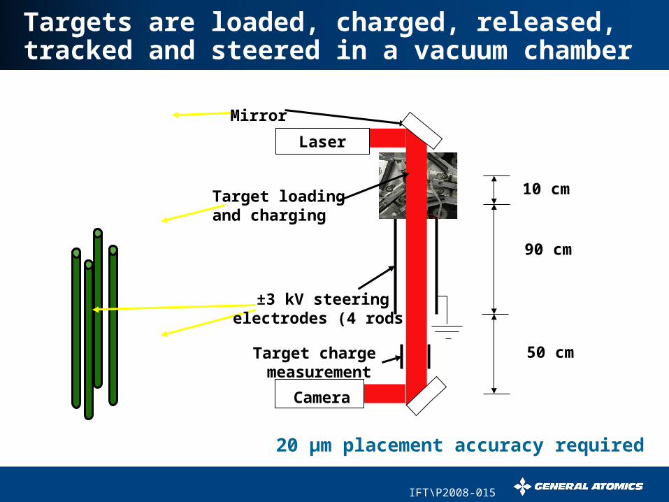
Targets are loaded, charged, released, tracked and steered in a vacuum chamber
Qu
ickTim
e™
an
d a
TIF
F (U
nco
mpre
ssed) d
ecom
pre
sso
rare
need
ed
to se
e th
is pictu
re.
±3 kV steeringelectrodes (4 rods)
Mirror
Target loading and charging
Camera
Laser
10 cm
50 cm
90 cm
Target charge measurement
20 µm placement accuracy required
IFT\P2008-015
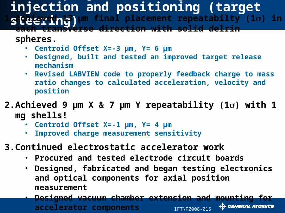
Recent progress in target injection and positioning (target steering)1.Achieved 13 µm final placement repeatabilty (1) in each transverse direction with solid delrin spheres.
• Centroid Offset X=-3 µm, Y= 6 µm• Designed, built and tested an improved target release
mechanism• Revised LABVIEW code to properly feedback charge to mass
ratio changes to calculated acceleration, velocity and position
2.Achieved 9 µm X & 7 µm Y repeatability (1) with 1 mg shells!
• Centroid Offset X=-1 µm, Y= 4 µm• Improved charge measurement sensitivity
3.Continued electrostatic accelerator work • Procured and tested electrode circuit boards• Designed, fabricated and began testing electronics
and optical components for axial position measurement
• Designed vacuum chamber extension and mounting for accelerator components
IFT\P2008-015
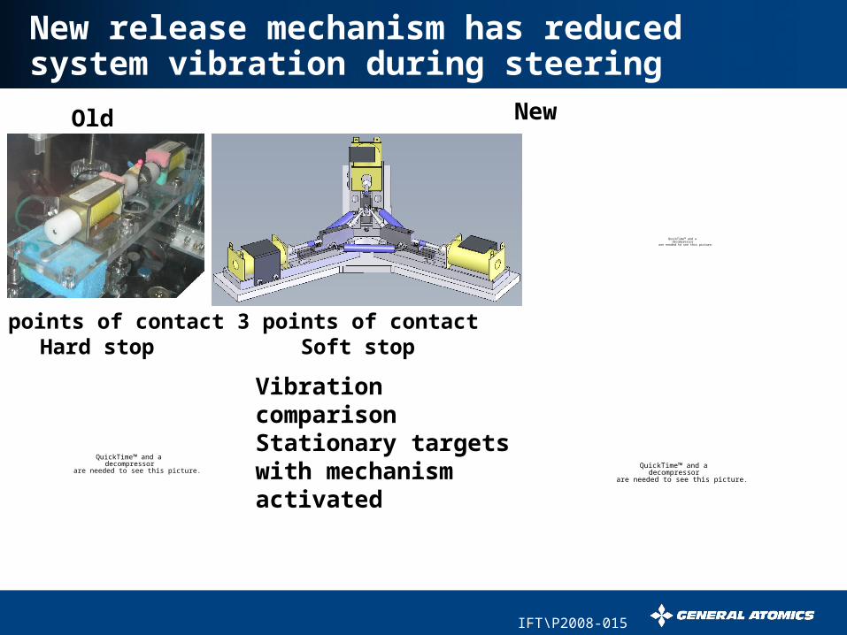
New release mechanism has reduced system vibration during steering
3 points of contactSoft stop
Vibration comparisonStationary targets with mechanism activated
Old New
4 points of contactHard stop
QuickTime™ and a decompressor
are needed to see this picture.QuickTime™ and a
decompressorare needed to see this picture.
QuickTime™ and a decompressor
are needed to see this picture.
Old New
IFT\P2008-015
Example Labview screen shot shows accurate target steering
QuickTime™ and a decompressor
are needed to see this picture.
IFT\P2008-015
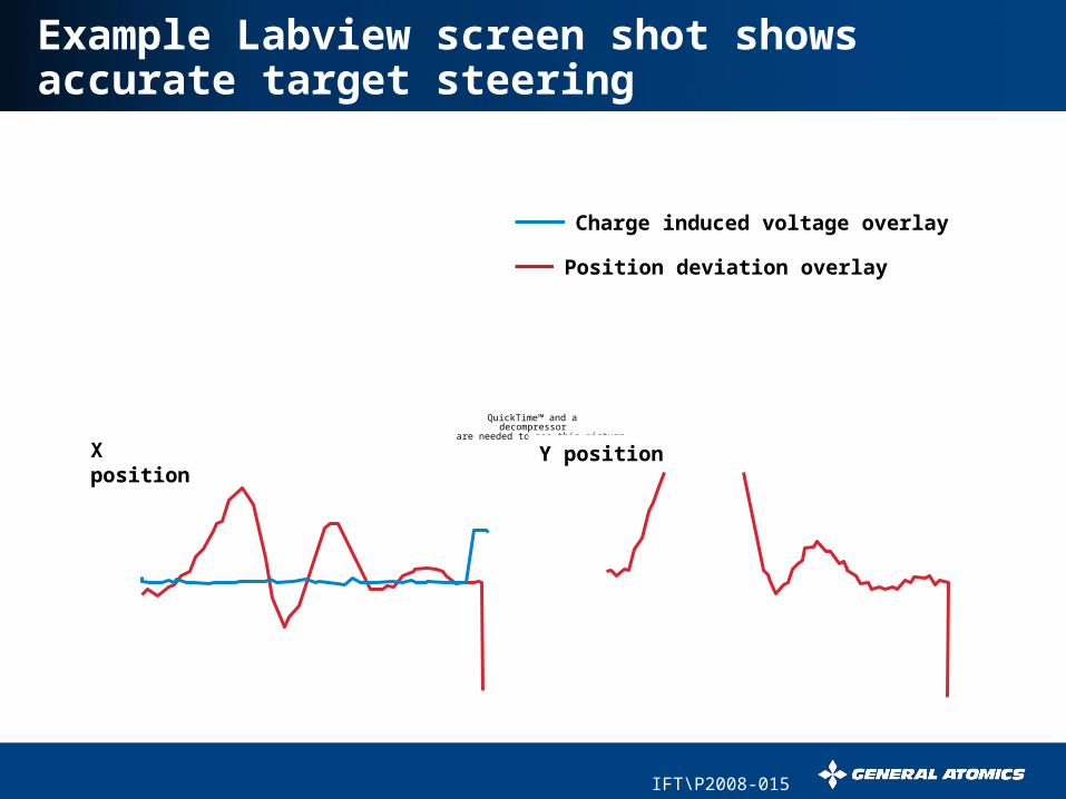
Example Labview screen shot shows accurate target steering
QuickTime™ and a decompressor
are needed to see this picture.
Charge induced voltage overlay
Position deviation overlay
X position
Y position
IFT\P2008-015
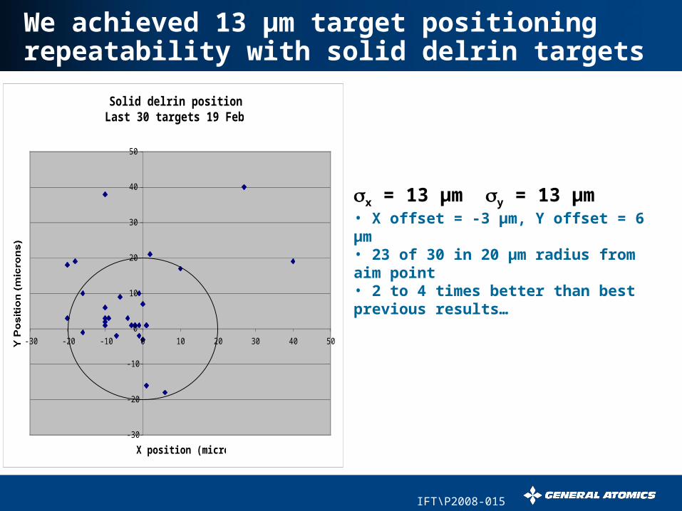
We achieved 13 µm target positioning repeatability with solid delrin targets
x = 13 µm y = 13 µm• X offset = -3 µm, Y offset = 6 µm• 23 of 30 in 20 µm radius from aim point• 2 to 4 times better than best previous results…
Solid delrin position errorLast 30 targets 19 Feb 2008
-30
-20
-10
0
10
20
30
40
50
-30 -20 -10 0 10 20 30 40 50
X position (microns)
Y Position (microns)
IFT\P2008-015
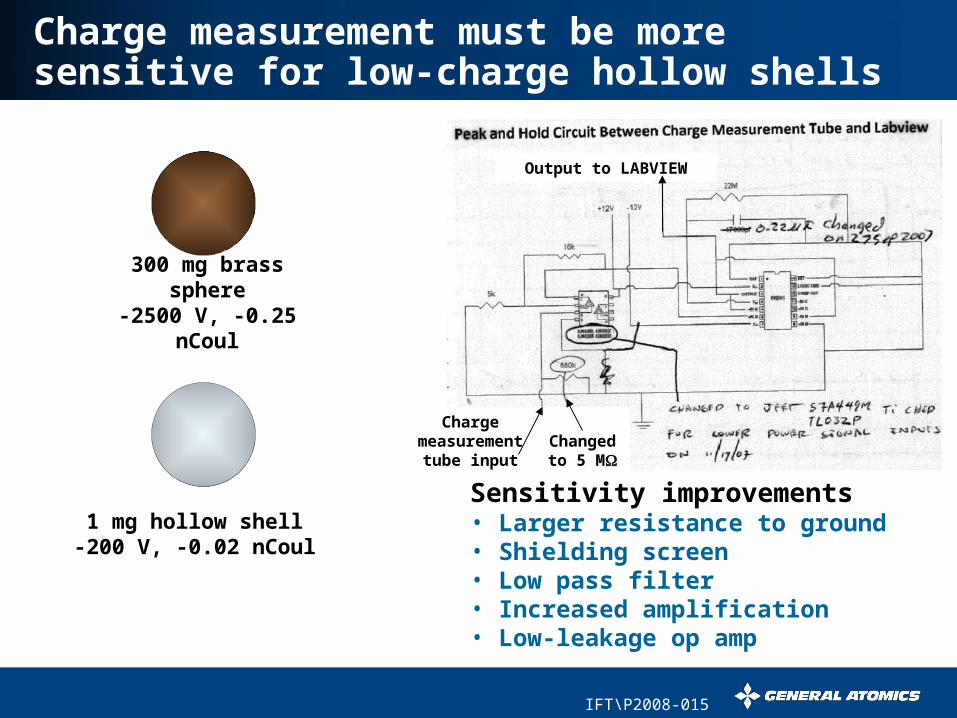
Charge measurement must be more sensitive for low-charge hollow shells
Sensitivity improvements• Larger resistance to ground• Shielding screen• Low pass filter• Increased amplification• Low-leakage op amp
300 mg brass sphere
-2500 V, -0.25 nCoul
1 mg hollow shell-200 V, -0.02 nCoul
Charge measurement
tube input
Output to LABVIEW
Changed to 5
M
IFT\P2008-015
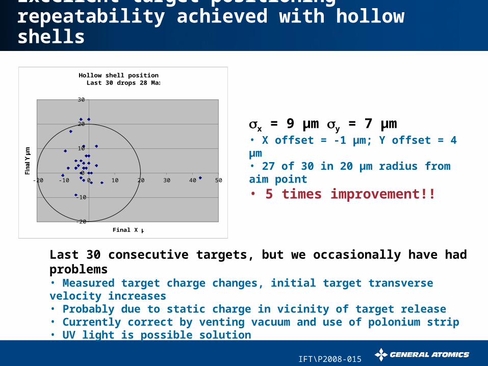
Excellent target positioning repeatability achieved with hollow shells
x = 9 µm y = 7 µm• X offset = -1 µm; Y offset = 4 µm• 27 of 30 in 20 µm radius from aim point• 5 times improvement!!
Last 30 consecutive targets, but we occasionally have had problems• Measured target charge changes, initial target transverse velocity increases• Probably due to static charge in vicinity of target release• Currently correct by venting vacuum and use of polonium strip• UV light is possible solution
Hollow shell position error Last 30 drops 28 March
-20
-10
0
10
20
30
-20 -10 0 10 20 30 40 50
Final X µm
Final Y µm
IFT\P2008-015
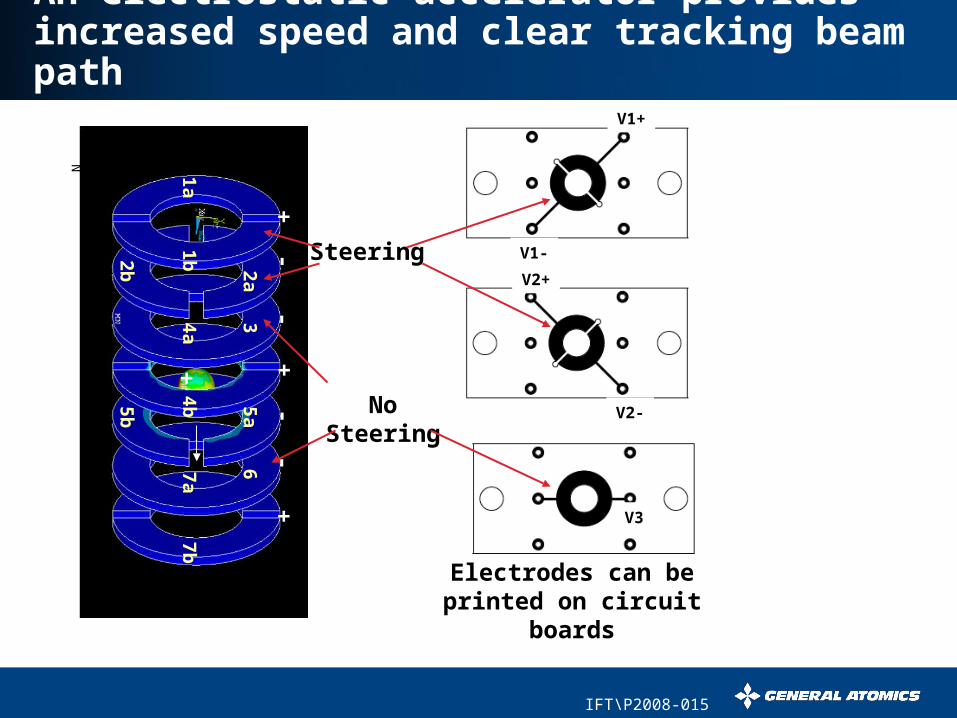
An electrostatic accelerator provides increased speed and clear tracking beam path
1a1b
32a
2b
5a5b
4b4a
6
7b7a
N
++
+-
--
-
+
V1-
V1+
V2+
V3
V2-
Electrodes can be printed on circuit
boards
No Steering
Steering
IFT\P2008-015
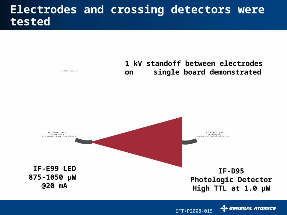
Electrodes and crossing detectors were tested
QuickTime™ and a decompressor
are needed to see this picture.
1 kV standoff between electrodes on single board demonstrated
QuickTime™ and a decompressor
are needed to see this picture.
IF-E99 LED875-1050 µW
@20 mA
IF-D95Photologic DetectorHigh TTL at 1.0 µW
IFT\P2008-015
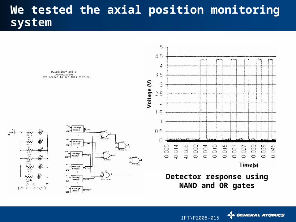
We tested the axial position monitoring system
Detector response using NAND and OR gates
QuickTime™ and a decompressor
are needed to see this picture.
IFT\P2008-015
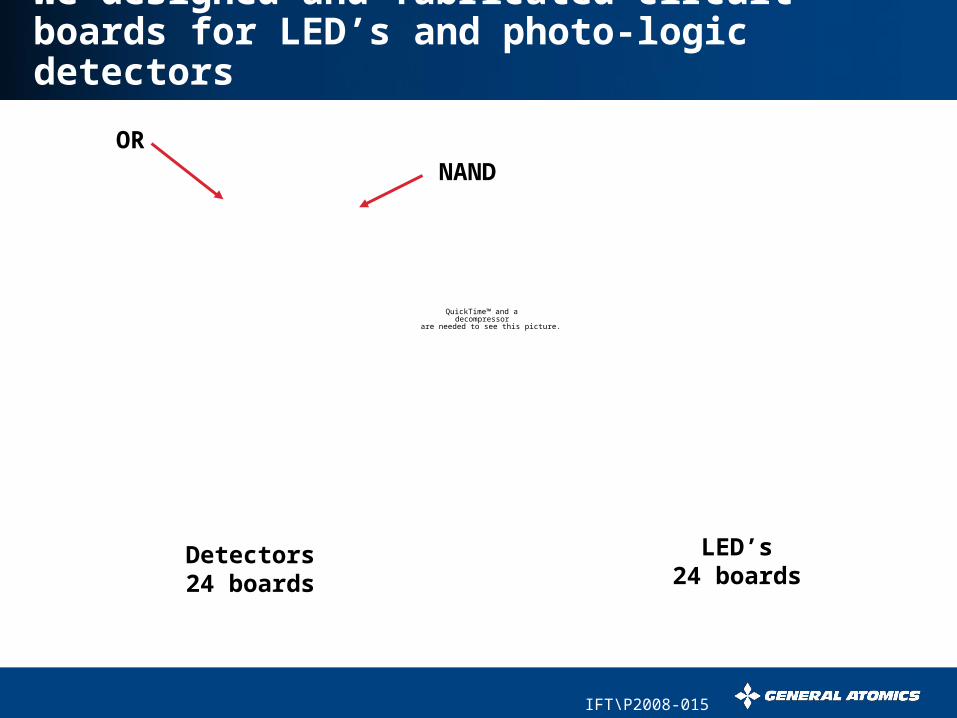
We designed and fabricated circuit boards for LED’s and photo-logic detectors
QuickTime™ and a decompressor
are needed to see this picture.
Detectors24 boards
LED’s24 boards
NANDOR
IFT\P2008-015
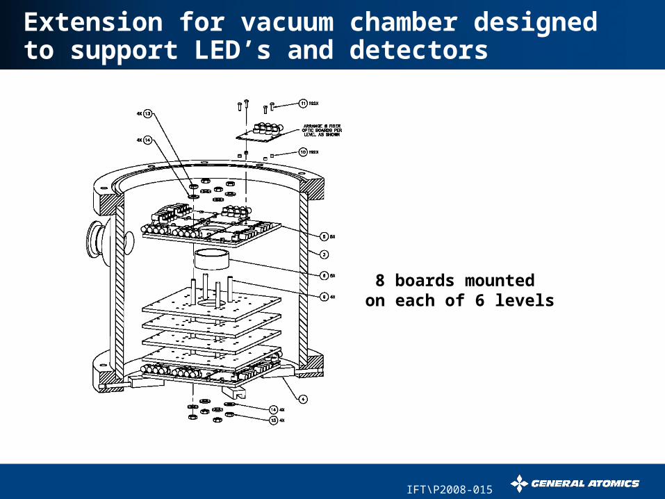
Extension for vacuum chamber designed to support LED’s and detectors
8 boards mounted on each of 6 levels
IFT\P2008-015
Summary of injection/positioning progress
In-flight target steering substantially improved• Achieved 9 µm X & 7 µm Y repeatability (1) with 1 mg
shells!• Centroid Offset X = -1 µm, Y = 4 µm• Low-vibration target release mechanism developed• Improved charge measurement sensitivity• Static charge issues may require more work
Electrostatic accelerator is under construction• Procured and tested electrode circuit boards• Designed, fabricated and began testing electronics and
optical components for axial position measurement• Designed vacuum chamber extension and mounting for
accelerator components
Related Documents