Series 10120 - 40180 ANALOG COMPUT, R S

Welcome message from author
This document is posted to help you gain knowledge. Please leave a comment to let me know what you think about it! Share it to your friends and learn new things together.
Transcript
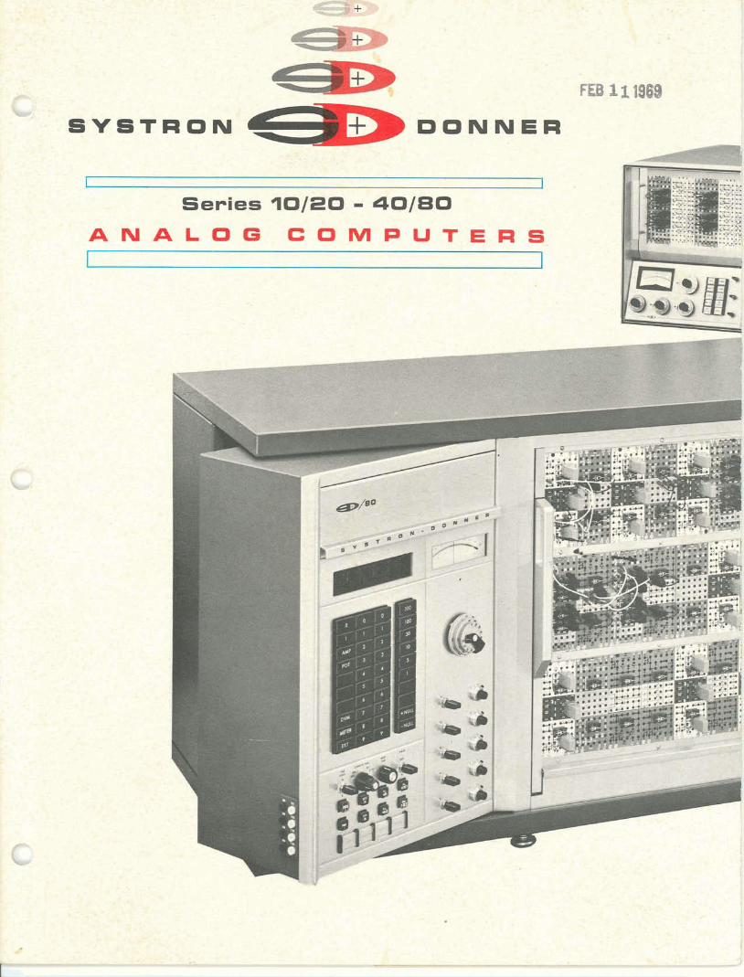
Series 1 0 1 2 0 - 4 0 1 8 0 A N A L O G C O M P U T , R S
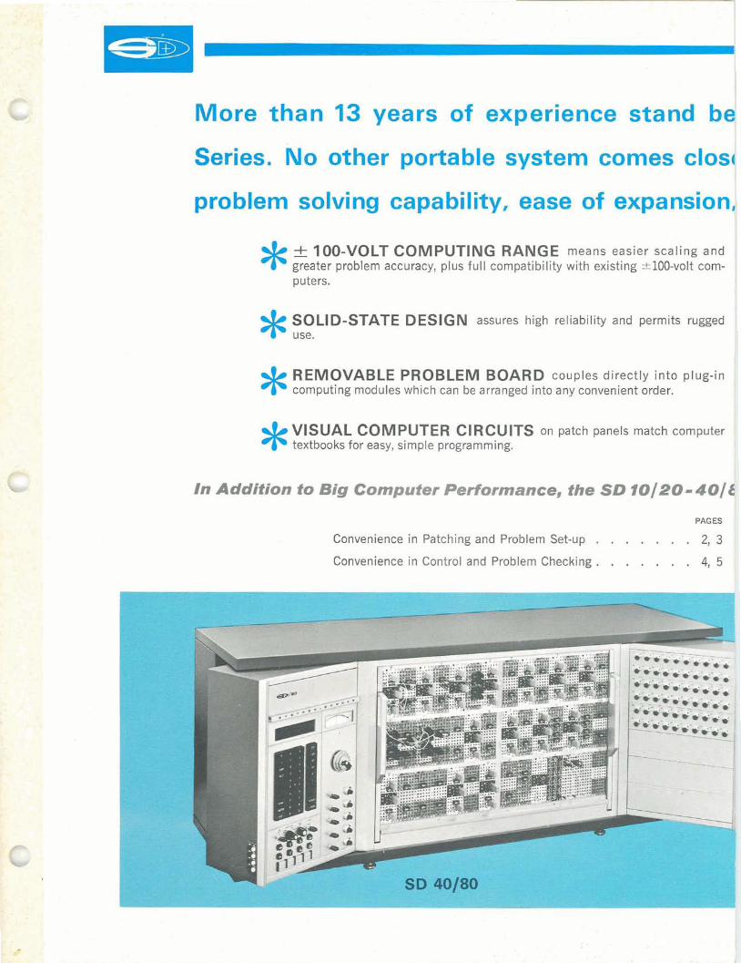
More than 13 years of experience stand b':4 Series. No other portable system comes cl6s
problem solving capability, ease of expansion1 -t 100-VOLT COMPUTING RANGE means easier scaling and greater problem accuracy, plus full compatibility with existing *loo-volt com-puters. I
I
SOLID-STATE DESIGN assures high reliability and permits rugged *use.
I REMOVABLE PROBLEM BOARD couples directly into plug-in I computing modules which can be arranged into any convenient order.
I *
1* VISUAL COMPUTER CIRCUITS on patch panels match computer )
I
textbooks for easy, simple programming. \
PAGES
Convenience in Patching and Problem Set-up . . . 2 , 3
Convenience in Control and Problem Checking. . . . . . . 4, 5
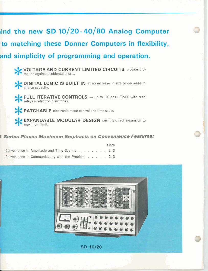
b[ind the new SD 10/20 - 40/80 Analog Computer
ro matching these Donner Computers in flexibility,
:and simplicity of programming and operation.
* VOLTAGE AND CURRENT LIMITED CIRCUITS provide pro-
*tection against accidental shorts.
DIGITAL LOGIC IS BUILT IN at no increase in size or decrease in
*analog capacity.
FULL ITERATIVE CONTROLS -up to 100 cps REP-OP with reed *PATCHABLE
relays or electronic switches.
electronic mode control and time scale. * EXPANDABLE MODULAR DESIGN permits direct expansion to maximum limit.
PAGES
Convenience in Amplitude and Time Scaling . . 2, 3
Convenience in Communicating with the Problem . . . . . 2, 3
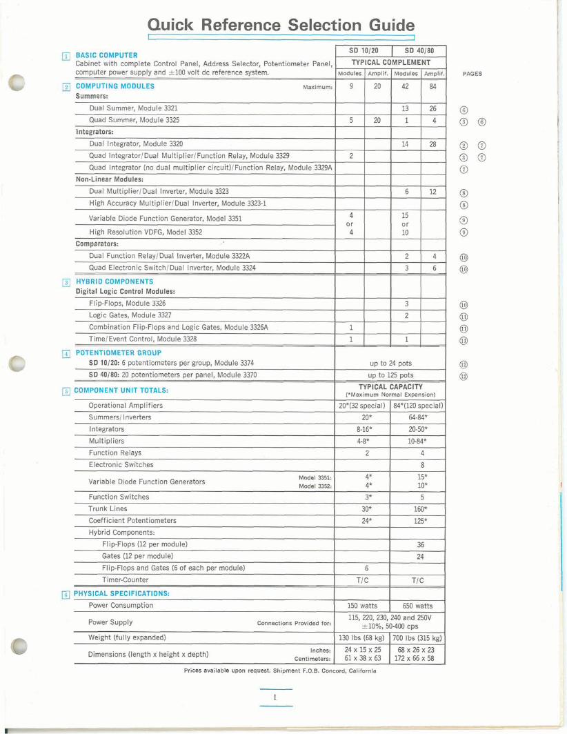
Quick Reference Selection Guide SD 10120 1 SD 40180
BASIC COMPUTER Cabinet with complete Control Panel, Address Selector, Potentiometer Panel, IXIMPLEMENT computer power supply and k100 volt dc reference system. Modules Arnplif. Modules Amplif. PAGES
COMPl G MODULES Maximum: 9 20 42 84 Summe .
Dual Summer, Module 3321 13 26
Quad Summer, Module 3325 5 20 1 4
Integrators:
Dual Integrator, Module 3320 14 28
Quad IntegratorIDual MultiplierIFunction Relay, Module 3329 2
Quad Integrator (no dual multiplier circuit)/Function Relay, Module 3329A
Non-Linear Modules:
Dual Multiplier1Dual Inverter, Module 3323 6 12
High Accuracy MultiplierIDual Inverter, Module 3323-1 I I I I I Variable Diode Function Generator, Model 3351 4
High Resolution VDFG, Model 3352 0 4 ~ 1 1 5 1 1 Comparators:
Dual Function Relay/Dual Inverter, Module 3322A 2 4 Quad Electronic SwitchIDual Inverter, Module 3324 3 6
UVBRID CQMPONENTS :ital Logic Control Modules:
Flip-Flops, Module 3326 3
Logic Gates, Module 3327 2
Combination Flip-Flops and Logic Gates, Module 3326A 1
TimelEvent Control, Module 3328 1 I 1 1 1
POTENTIOMETERGROUP SD 10120: 6 potentiometers per group, Module 3374 up to 24 pots
--SO 40180: 20 potentiometers per panel, Module 3370 up to 125 pots
TYPICAL CAPACITYCOI (*Maximum Normal Expansion)
Operational Amplifiers 20*(32special) 1 84*(120special)
Summers/ Inverters 20* I 64-84*
Integrators
Function Relays I 2 I 4 Electronic Switches 8
Model 3351:Variable Diode Function Generators
Model 3352:
Function Switches I 3* I 5 Trunk Lines 30* 160*
I I
Coefficient Potentiometers I 24* 125* I Hybrid Components:
Flip-Flops (12per module) 36
Gates (12per module) 24
Flip-Flops and Gates (6of each per module) 6
Timer-Counter TIC TIC
-150 watts 650 watts
115,220,230,240 and 250~-Power Supply Connections Provided for: &lo%, 50-400CPS
Weight (fully expanded) 130 Ibs (68kg)- 1 700 Ibs (315ke)- -. Inches: 24 X 15 X 25 68X 26 X 23
Dimensions (length x height x depth) centimeters; 61 x 38 x 63 172 x 66 x 58
Prices available upon request. Shipment F.O.B. Concord, California
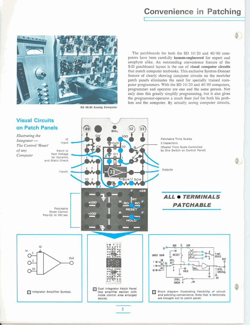
The patchboards for both the SD 10/20 and 40/80 com- puters have been carefully human-engineered for expert and neophyte alike. An outstanding convenience feature of the S-D patchboard layout is the use of visual computer circuits that match computer textbooks. This exclusive Systron-Donner feature of clearly showing computer circuits on the modular patch panels eliminates the need for specially trained com- puter programmers. With the SD 10/20 and 40/80 computers, programmer and operator are one and the same person. Not only does this greatly simplify programming, but it also gives the programmer-operator a much finer feel for both his prob- lem and the computer. By actually seeing computer circuits,
SD 40180 Analog Computer
Visual Circuits on Patch Panels Illustrating the Integrator - The Control 'Heart' of any Computer
I C Input
Patchable Time Scales 3 Capacitors (Master Time Scale Controlled by One Switch on Control Panel) Patch in
Test Voltage for Dynamic
and Static Check
Inputs outputs
Patchable Mode Control
Rep-Op to 100Isec
ALL TERMINALS
PATCHABLE
TIME SCALE
OUT
Dual lntegrator Patch Panel (top amplifier section with mode control area enlarged above).
lntegrator Amplifier Symbol. Block diagram illustrating flexibility of circuit and patching convenience. Note that 0 terminals are brought out to patch panel.
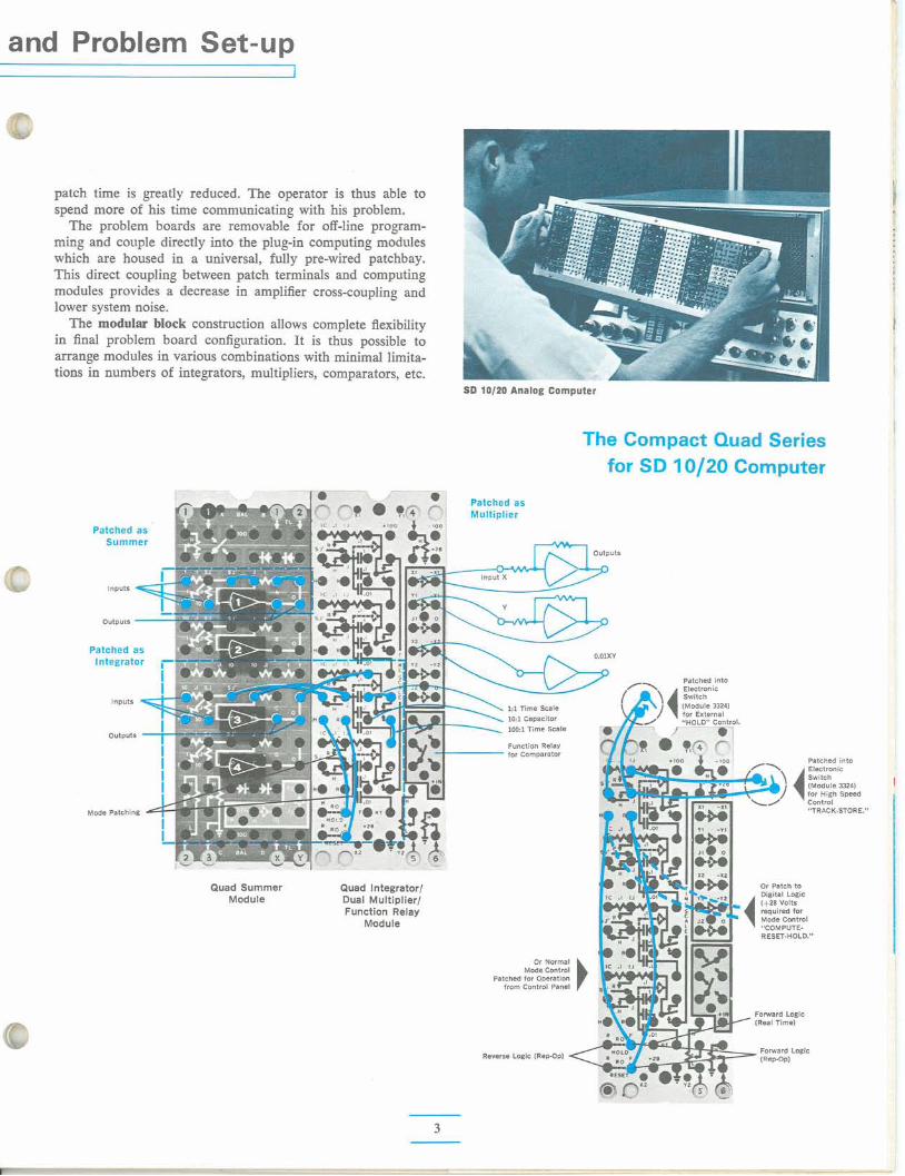
and Problem Set-up
patch time is greatly reduced. The operator is thus able to spend more of his time communicating with his problem.
The problem boards are removable for off-line program- ming and couple directly into the plug-in computing modules which are housed in a universal, fully pre-wired patchbay. This direct coupling between patch terminals and computing modules provides a decrease in amplifier cross-coupling and lower system noise.
The modular block construction allows complete flexibility in final problem board configuration. It is thus possible to arrange modules in various combinations with minimal lirnita- tions in numbers of integrators, multipliers, comparators, etc.
SD 10/20 Analog Computer
The Compact Quad Series for SD 10120 Computer
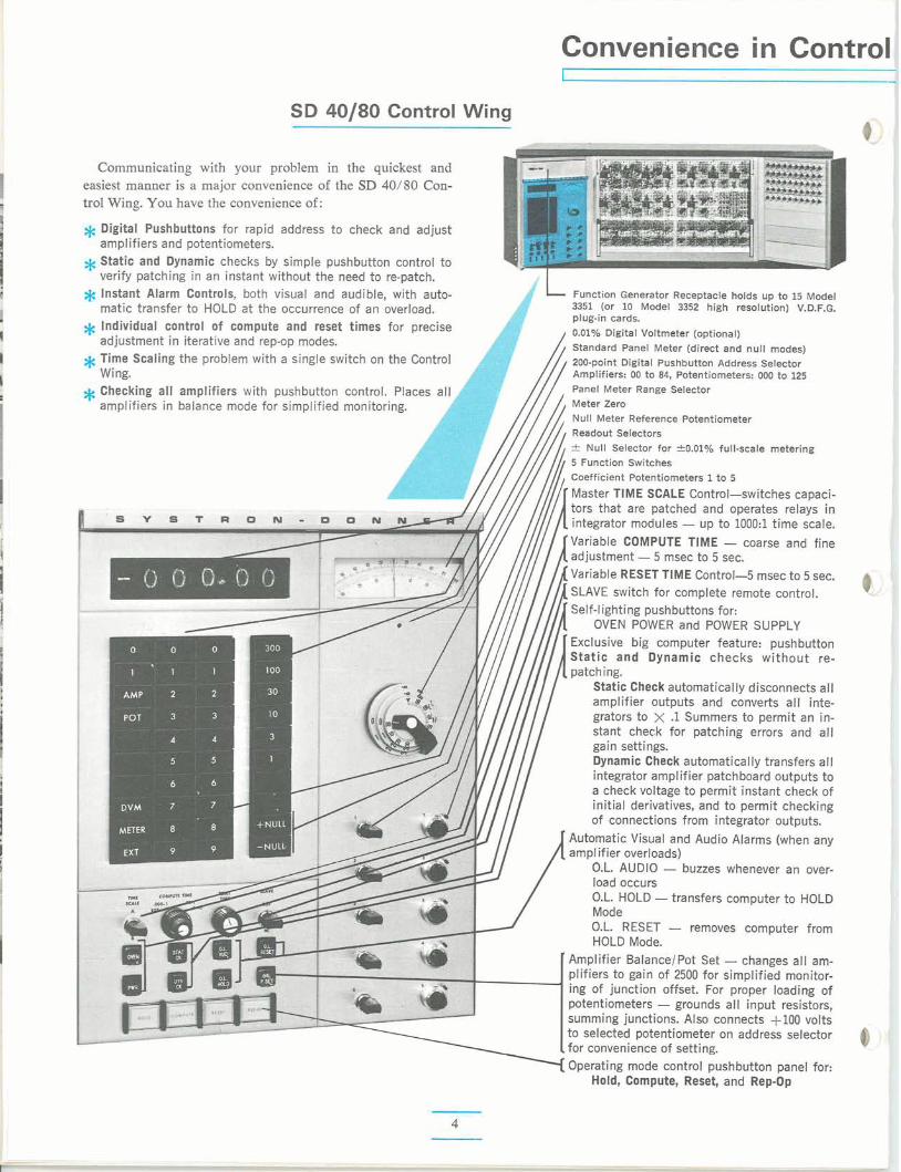
SD 40180 Control Wing
Communicating w i th your problem in the quickest and easiest manner is a major convenience o f the SD 40/80 Con-t ro l Wing. Y o u have the convenience of :
$ Digital Pushbuttons for rapid address to check and adjust amplifiers and potentiometers.
*Static and Dynamic checks by simple pushbutton control to verify patching in an instant without the need to re-patch.
Ije Instant Alarm Controls, both visual and audible, with auto- matic transfer to HOLD at the occurrence of an overload. Individual control of compute and reset times for precise
* adjustment in iterative and rep-op modes. Time Scaling the problem with a single switch on the Control
*Wing. Checking al l amplifiers with pushbutton control. Places al l Aamplifiers in balance mode for simplified monitoring.
LFunction Generator Receptacle holds up to 15 Model 3351 (or 10 Model 3352 high resolution) V.D.F.G. plug-in cards.
0.01% Digital Voltmeter (optional)
Standard Panel Meter (direct and null modes)
200-point Digital Pushbutton Address Selector Amplifiers: 00 to 84, Potentiometers: 000 to 125
Panel Meter Range Selector Meter Zero
Null Meter Reference Potentiometer Readout Selectors
f Null Selector for *0.01% full-scale metering
5 Function Switches Coefficient Potentiometers 1to 5
Master TlME SCALE Control-switches capaci-tors that are patched and operates relays in integrator modules - up to 1000:l time scale. Variable COMPUTE TlME - coarse and fine adjustment -5 msec to 5 sec. Variable RESET TlME Control-5 msec to 5 see. SLAVE switch for complete remote control. Self-lighting pushbuttons for:
OVEN POWER and POWER SUPPLY Exclusive big computer feature: pushbutton Static and Dynamic checks wi thout re-patching.
Static Check automatically disconnects all amplifier outputs and converts a l l inte-grators to X .1 Summers to permit an in- stant check for patching errors and all gain settings. Dynamic Check automatically transfers all integrator amplifier patchboard outputs to a check voltage to permit instant check of initial derivatives, and to permit checking of connections from integrator outputs.
Automatic Visual and Audio Alarms (when any amp1ifier overloads)
O.L. AUDIO - buzzes whenever an over- load occurs O.L. HOLD -transfers computer to HOLD Mode O.L. RESET - removes computer from HOLD Mode.
Amplifier BalanceIPot Set -changes all am- plifiers to gain of 2500 for simplified monitor- ing of junction offset. For proper loading of potentiometers - grounds all input resistors, summing junctions. Also connects +I00 volts to selected potentiometer on address selector for convenience of setting. Operating mode control pushbutton panel for:
Hold, Compute, Reset, and Rep-Op
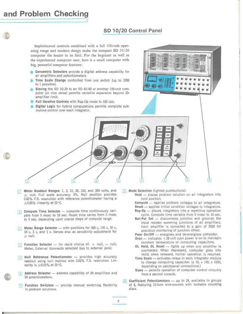
and Problem Checking
SD 10/20 Control Panel
Sophisticated controls combined wi th a full 100-volt oper- ating range and modern design make the compact SD 10/20 computer the leader in its field. F o r the beginner as well as the experienced computer user, here is a small computer w i th big, powerful computer features:
Concentric Selectors provide a digital address capability for 311 amplifiers and potentiometers. rime Scale Change controlled from one switch (up to 1000 :o 1possible). Slaving the SD 10120 to an SD 40180 or another 100-volt com- wter (or vice versa) permits versatile expansion beyond 20- amp1 if ier limit. Full Iterative Controls with Rep-Op mode to 100 cps. Digital Logic for hybrid computations permits complete sub- routine control over each integrator.
Meter Readout Ranges: 1, 3, 10, 30, 100, and 300 volts, and Mode Selection (lighted pushbuttons): f null. Full scale accuracy: 3%. Null position provides Hold - places problem solution on all integrators into 0.02% F.S. resolution with reference potentiometer having a hold position. &0.05% linearity at 25°C. Compute - applies problem voltages to all integrators.
Reset -applies initial condition voltages to integrators. Compute Time Selector - compute time continuously vari- Rep-Op - places integrators into a repetitive operation able from 5 msec to 10 sec. Reset time varies from 5 msec cycle. Compute time variable from 5 msec to 10 sec. to 5 sec, depending upon coarse steps of compute range. Ballpot Set - disconnects junction and grounds the
input resistor summing junctions of all amplifiers.
Meter Range Selector -with positions for 300 v, 100 v, 30 v, Each amplifier is converted to a gain of 2500 for
10 v, 3 v, and 1v. Serves also as sensitivity adjustment for precision monitoring of junction offset.
-t null. Pwer On/Off - energizes and de-energizes computer. Oven - indicates f28-volt oven power is on to maintain
Function Selector - for rapid choice of: + null, - null, constant temperature of computing capacitors.
Meter, External (connects selected bus to external jack). OL Hold, OL Reset - lights up when any amplifier is overloaded. When depressed, computer goes into Hold; when released, normal operation is resumed.
Null Reference Potentiometer - provides high accuracy Time Scale -activates relays in each integrator module readout using null method with 0.02% F.S. resolution. Lin- to change computing capacitor. (x 10, x 100, x 1000, earity is t_0.05% at 25°C. depending on patchpanel connections.)
Slave -permits operation of computer control circuitry Address Selector - address capability of 20 amplifiers and from a second console. 24 potentiometers.
Coefficient Potentiometers - up to 24, available in groups Function Switches - provide manual switching flexibility of 6, featuring 10-turn wire-wounds with lockable counting i n problem solutions. dials.
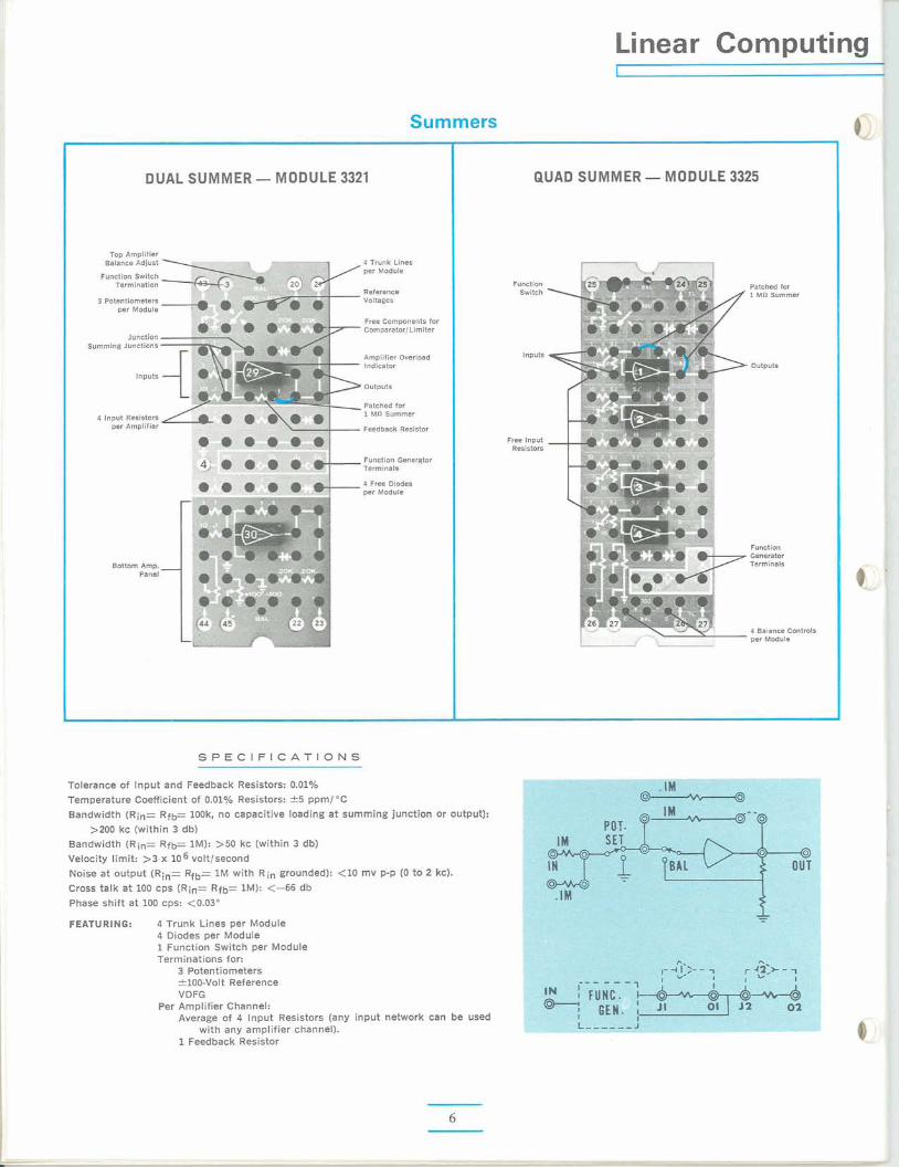
Linear Computing I
Summers
DUAL SUMMER -MODULE 3321 QUAD SUMMER -MODULE 3325
TOP Amplifier 4 Trunk Lines per Module
Reference Fu(Icti0~
Switch \ Patched for 1 M n Summer
Voltages
Free components for Cornparator/Limiter
Amplifier Overload Indicator
outputs
Patched for 1 M n Summer
Feedback Resistor Free lnput
Resistors
Function Generqtor Terminals
4 Free Diodes Der Module
Function Generator Termmals
4 Balance Controls per Module
S P E C I F I C A T I O N S
Tolerance of lnput and Feedback Resistors: 0.01% Temperature Coefficient of 0.01% Resistors: C5 ppml0C
Bandwidth (Rin= RW- look, no capacitive loading at summing junction or output): >200 kc (within 3 db)
Bandwidth (Rin= Rfb= 1M): >50 kc (within 3 db) Velocity limit: >3 x 10⁶ volt/second Noise at output (R;,= Rfb= 1M with Rin grounded): <10 Cross talk at 100 cps (Rin= Rfb= 1M): <-66 db Phase shift at 100 cps: <0.03"
FEATURING: 4 Trunk Lines per Module 4 Diodes per Module 1Function Switch per Module Terminations for:
3 Potentiometers C 100-Volt Reference VDFG
Per Amplifier Channel:
mv p-p (0 to 2 kc).
Average of 4 lnput Resistors (any input network can be used with any amplifier channel).
1Feedback Resistor
Modules- SD 10/20 - 40180
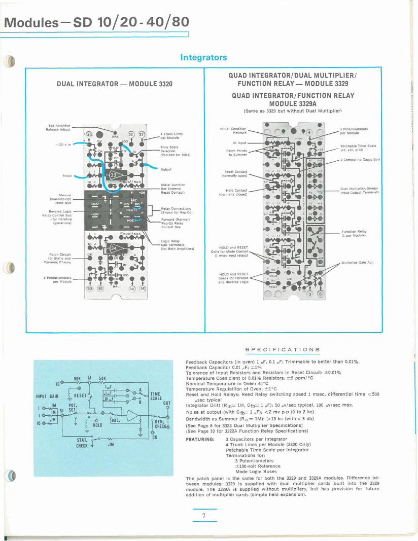
DUAL INTEGRATOR -
Manual ("on-Rep-Op] -
Reset BUS
Reverse Logic -Relay Control Bus
lfor Iterative operatmns)
Patch ClrCUlt for Static and
Wnamio Checkr
3 Potentiometers per Module
lntegrators
QUAD INTEGRATORIDUAL MULTIPLIER1 MODULE 3320 FUNCTION RELAY -MODULE 3329
QUAD INTEGRATORIFUNCTION RELAY MODULE 3329A
(Same as 3329 but without Dual Multiplier\
Initial Condition 3 Potentiometers
4 Trunk Lines Network per Module per Module
Time Scale IC Input
~atchabie Time Scale
'Selection Patch Points 1x1, xl0, ~100) (Patched for 100.11 to Summer
3 Computing CaPac8tore
output Reset Contact
(normally open)
lfor External Dual Multiplier/Divider Hold Contact Re& Contact) (normally closed) Input-Output Terminals
Relay Connections (Shown for Repop)
Forward (Normal) Rop-Op Relay Control Bus
Function Relay (1per Module)
Logx Relay .Coil Termmats
(for Both Ampl~fuers) HOLD and RESET Coils for Mode Control
(1 msec reed relays)
Multiplier Gain Adj.
HOLD and RESET Buses for Forward and Reverse Logic
S P E C I F I C A T I O N S
Feedback Capacitors (in oven) 1MF, 0.1 ,LF: Trimmable to better than 0.01%. Feedback Capacitor 0.01 &F: 41% Tolerance of Input Resistors and Resistors in Reset Circuit: 40.01% Temperature Coefficient of 0.01% Resistors? zk5 ppml OX2
Nominal Temperature in Oven: 45"G Temperature Regulatilon of Oven: S 0 C Reset and Hold Relays: Reed Relay switching speed 1msec, differential time <500
ssec typical lntegrator Drift (Rin= l M , Cfbr 1pF): 50 .df/sec typical, 100 &5ec max. Noise at output (with Cf+ 1@F):4 2 mv p-p (0 to 2 kc)
(See Page 8 for 3323 Dual Multiplier Sper;ificationsl {See Page 10 for 3322A Function Relay Specifications)
FEATURIYG: 3 Capacitors per Integrator 4 Trunk Lines per Module (3320Only) Patchable Time Scale per Interntor Terminations for:
3 Potentiometers &loo-volt Reference Mode Logic Buses
The patch panel is the same for both the 3329 and 3329A modules. Difference be- tween modules: 3329 is supplied With dual multiplier cards built into the 3329 module. The 3329A is supplied without multipliers, but has provision for future addition of multiplier cards [simple field expansion).
Non- Linear Computing
Multipliers
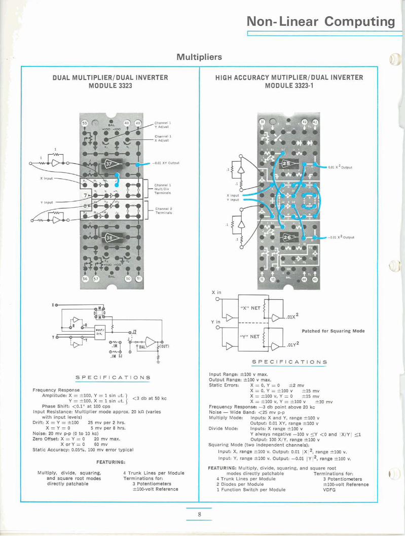
DUAL MULTIPLIERIDUAL 1NVERTE.R MODULE 3323
Channel 1 Y Adjust
Channel 1 ' X Adlust
e -0.01 XY output
X lnput -Channel 1 Mult/Div Terminals
. Channel 2 Terminals
S P E C I F I C A T I O N S
. - . Amplitude: X = 2100, Y = 1 sin at. 1
Y = *loo, x = 1 sin ot. 1 <3 db at 50 kc Phase Shift: <0.l0 at 100 dps
lnput Resistance: Multiplier mode approx. 20 kn (varies with input levels)
Drift: X = Y = f100 25 mv per 2 hrs. X = Y = O 5 mv per 8 hrs.
Noise: 20 mv p-p (0 to 10 kc) Zero Offset: X = Y = 0 20 mv max.
X orY = 0 60 mv Static Accuracy: 0.05%, 100 mv error typical
FEATURING:
Multiply, divide, squaring, 4 Trunk Lines per Module and square root modes Terminations for: directly patchable 3 Potentiometers
f100-volt Reference
HIGH ACCURACY MUTIPLIERIDUAL INVERTER M0D U LE 3323-1
Y lnput
Patched for Squaring Mode "Y" NET
.01~2
S P E C I F I C A T I O N S
lnput Range: f100 v max. Output Range: f100 v max. Static Errors: X = 0, Y = 0 3?mv
X = 0, Y = 9 0 0 v f15 mv X = *I00 V, Y = 0 f15 mv X=f100v,Y=~lOOv f 3 0 m v
Frequency Response: -3 db point above 20 kc Noise -Wide Band: <25 mv p-p Multiply Mode: Inputs: X and Y, range 2100 v
Output: 0.01 XY, range f100 v Divide Mode: Inputs: X range el00 v
Y always negative -100 v 5 Y <O and IX/YI 5 1 Output: 100 X/Y, range '100 v
Squaring Mode (two independent channels):
Input: X, range f100 v. Output: 0.01 1x12, range 2100 v.
Input: Y, range f100 v. Output: -0.01 1 Y 12, range flOO v.
FEATURING: Multiply, divide, squaring, and square root modes directly patchable Terminations for:
4 Trunk Lines per Module 3 Potentiometers 2 Diodes per Module f100-volt Reference 1 Function Switch per Module VDFG
rurn Page
Comparators
Variable Diode Function Generators
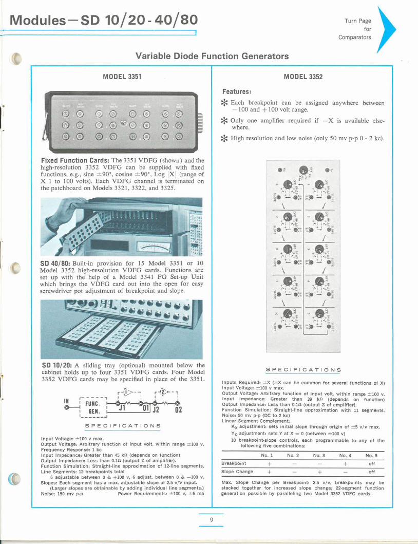
MODEL 3351
Fixed Function Cards: The 3351 VDFG (shown) and the high-resolution 3352 VDFG can be supplied with fixed functions, e.g., sine +90°, cosine +90°, Log IX I (range of X 1 to 100 volts). Each VDFG channel is terminated on :he patchboard on Models 3321, 3322, and 3325.
SD 40180: Built-in provision for 15 Model 3351 or 10 Model 3352 high-resolution VDFG cards. Functions are set up with the help of a Model 3341 FG Set-up Unit vhich brings the VDFG card out into the open for easy xrewdriver pot adjustment of breakpoint and slope.
SD 10120: A sliding tray (optional) mounted below the cabinet holds up to four 3351 VDFG cards. Four Model 3352 VDFG cards may be specified in place of the 3351.
-S P E C I F I C A T I O N S
Jnput Voltage: 2100 v Output Voltage: Arbitrary function of input volt. within range f l 0 0 v. Frequency Response: 1 kc lnput Impedance: Greater than 45 kD (depends on function) Output Impedance: Less than O.lD (output Z of amplifier). Function Simulation: Straight-line approximation of 12-line segments. Line Segments: 12 breakpoints total
6 adjustable between 0 & +I00 v, 6 adjust. between 0 & -100 v. Slopes: Each segment has a max. adjustable slope of 2.5 v/'v input.
(Larger slopes are obtainable by adding individual line segments.) Voise: 150 mv p-p Power Requirements: 2100 v, &6 ma
MODEL 3352
Features:* Each breakpoint can be assigned anywhere between -100 and +100 volt range. * Only one amplifier required if -X is available else-
* High resolution and low noise (only 50
where.
mv p-p 0 - 2 kc).
S P E C I F I C A T I O N S
Inputs Required: 2 X (2X can be common for several functions of X) lnput Voltage: f100 v max. Output Voltage: Arbitrary function of input volt. within range 2100 v. lnput Impedance: Greater than 39 kn (depends on function) Output Impedance: Less than O.1D (output Z of amplifier). Function Simulation: Straight-line approximation with 11 segments. Noise: 50 mv p-p (DC to 2 kc) Linear Segment Complement:
Kx adjustment: sets initial slope through origin of ?5 v/v max.
Yo adjustment: sets Y at X = 0 (between 2100 v)
10 breakpoint-slope controls, each programmable to any of the following five combinations:
No. 1 No. 2 No. 3 No. 4 No. 5
Breakpoint + - - f off
Slope Change + - + - off
Max. Slope Change per Breakpoint: 2.5 vlv, breakpoints may be stacked together for increased slope change; 22-segment function generation possible by paralleling two Model 3352 VDFG cards.
Function Relays
Solid-state Switches (All Summers, 3321 and 3325,patchable to ComparatorslL~rniters)
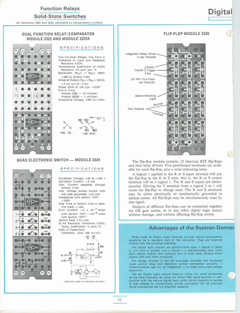
DUAL FUNCTION RELAYICOMPARATOR MODULE 3322 AND MODULE 3322A
S P E C I F I C A T I O N S
Two Function Relays: Two Form C Tolerance of Input and Feedback
Resistors: 0.01% Temperature Coefficient of 0.01%
Resistors: 2 5 ppm per "C Bandwidth (Rinn = Rfb= 1M)kk
>ZOO kc (within 3 db) Noise at Output (Rin =Rfb=100 k): <5 mv p-p (0- 2 kc)
Phase Shift at 100 cps: <0.03" Pull-in Time:
Module 3322 - 10 millisec Module 3322A -1millisec
Energizing Voltage: f28v to f100v.
fU IC . S W .
I??"", Q
QUAD ELECTRONIC SWITCH -MODULE 3324
S P E C I F I C A T I O N S
Excitation Voltage: +20 to +lo0 v Excitation Current: <2 ma Max. Current passable through
Switch: 3 ma Max. Voltage across Switch with
one side grounded: f10 volt Impedance with switch "ON":
<200a Rise Time of Switch (into a resis-
tive load): 1 .sec Error Current: <5 x 10-' amps
with Switch "ON"; <lo-' amps with Switch "OFF."
Switch Rate: 1 kc max. 10 kn Resistors: Tolerance, 0.01%;
Temp. Coefficient, 5 ppm/"C 0.001 .F Capacitors:
Tolerance, f1%, 500 w.v.d.c. +100 -100
0 Q..
Digital
FLIP-FLOP MODULE 3326
Integrator1 Relay Driver ,(4 per Module)
~ e s e tA Inputs Trigger.-{set
(12RST Flip-Flops per Module)
State-Indicating / Light
The flip-flop module contains 12 identical RST flip-flops and four relay drivers. Five patchboard terminals are avail- able for each flip-flop, plus a state indicating lamp.
A logical 1 applied to the R or S input terminal will put the flip-flop in the R or S state, that is, the R or S output terminal will be a logical 1. The R and S inputs are direct- coupled. Driving the T terminal from a logical 0 to 1 will cause the flip-flop to change state. The R and S terminals may be either electrically or mechanically grounded to initiate action. All flip-flops may be simultaneously reset by one signal.
Outputs of different flip-flops can be connected together for OR gate action, or to any other digital logic output without damage, and without affecting flip-flop action.
I Logic Control Modules
LOGIC GATES -MODULE 3327
lndicat
Two outputs
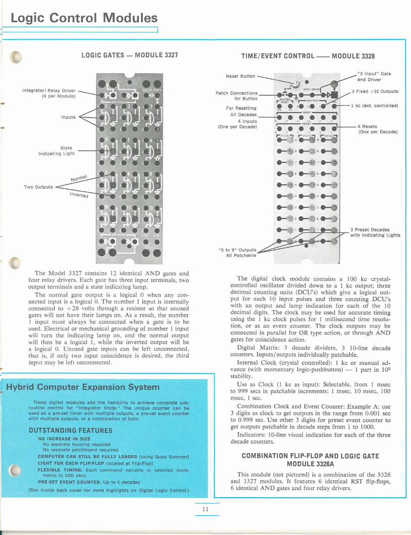
The Model 3327 contains 12 identical AND gates and four relay drivers. Each gate has three input terminals, two output terminals and a state indicating lamp.
The normal gate output is a logical 0 when any con- nected input is a logical 0. The number 1 input is internally connected to +28 volts through a resistor so that unused gates will not have their lamps on. As a result, the number 1 input must always be connected when a gate is to be used. Electrical or mechanical grounding of number 1 input will turn the indicating lamp on, and the normal output will then be a logical 1, while the inverted output will be a logical 0. Unused gate inputs can be left unconnected, that is, if only two input coincidence is desired, the third input may be left unconnected.
TIMEIEVENT CONTROL -MODULE 3328
Reset Button "3 Input" Gate and Driver
Patch Connections 3 Fixed e l 0 Outputs
for Button
For Resetting 1kc text. controlled)
All Decades 6 Inputs
(One per Decade) 6 Resets (One per Decade)
3 Preset Decades with Indicating Lights
"0 to 9" outputs All Patchable
The digital clock module contains a 100 kc crystal- controlled oscillator divided down to a 1 kc output; three decimal counting units (DCUs) which give a logical out- put for each 10 input pulses and three counting DCU's with an output and lamp indication for each of the 10 decimal digits. The clock may be used for accurate timing using the 1 kc clock pulses for 1 millisecond time resolu- tion, or as an event counter. The clock outputs may be connected in parallel for OR type action, or through AND gates for coincidence action.
Digital Matrix: 3 decade dividers, 3 10-line decade counters. Inputs/outputs individually patchable.
Internal Clock (crystal controlled): 1 kc or manual ad- vance (with momentary logic-pushbutton) - 1 part in 105 stability.
Use as Clock (1 kc as input): Selectable, from 1 msec to 999 secs in patchable increments: 1 msec, 10 msec, 100 msec, 1 sec.
Combination Clock and Event Counter: Example A: use 3 digits as clock to get outputs in the range from 0.001 sec to 0.999 sec. Use other 3 digits for preset event counter to get outputs patchable in decade steps from 1 to 1000.
Indicators: 10-line visual indication for each of the three decade counters.
COMBINATION FLIP-FLOP AND LOGIC GATE MODULE 3326A
This module (not pictured) is a combination of the 3326 and 3327 modules. It features 6 identical RST flip-flops, 6 identical AND gates and four relay drivers.
Coefficient Potentiometer Group
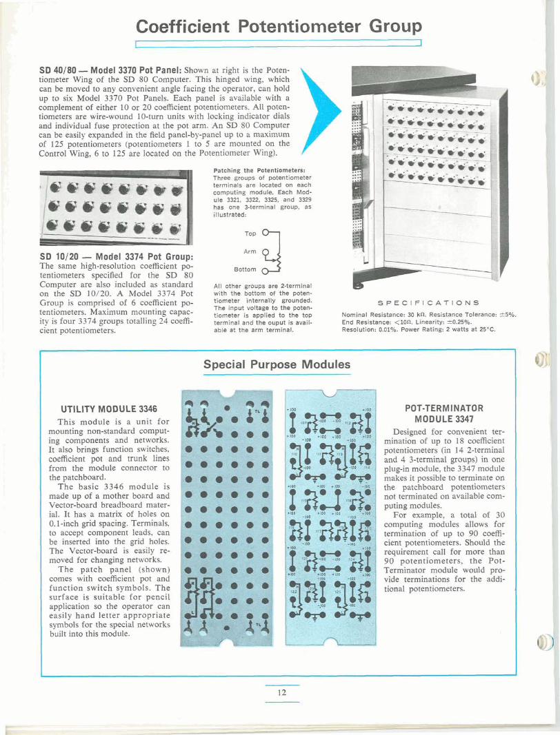
SD 40180 -Model 3370 Pot Panel: Shown at right is the Poten- tiometer Wing of the SD 80 Computer. This hinged wing, which can be moved to any convenient angle facing the operator, can hold up to six Model 3370 Pot Panels. Each panel is available with a complement of either 10 or 20 coefficient potentiometers. All poten- tiometers are wire-wound 10-turn units with locking indicator dials and individual fuse protection at the pot arm. An SD 80 Computer can be easily expanded in the field panel-by-panel up to a maximum of 125 potentiometers (potentiometers 1 to 5 are mounted on the Control Wing, 6 to 125 are located on the Potentiometer Wing).
Patching the Potentiometers: Three groups of potentiometer terminals are located on each computing module. Each Mod- ule 3321, 3322, 3325, and 3329 has one 3-terminal group, as illustrated:
SD 10/20 - Model 3374 Pot Group: 5The same high-resolution coefficient po- BottomArm tentiometers specified for the SD 80 Computer are also included as standard All other groups are 2-terminal on the SD 10/20. A Model 3374 Pot with the bottom of the poten-
Group is comprised of 6 coefficient po- tiometer internally grounded. S P E C I F I C A T I O N S The input voltage to the poten- tentiometers. Maximum mounting capac- tiometer is applied to the top Nominal Resistance: 30 kn. Resistance Tolerance: 15%.
ity is four 3374 groups totalling 24 coeffi- terminal and the ouput is avail- End Resistance: <Ion. Linearity: &0.25%. cient potentiome?ers. able at the arm terminal. Resolution: 0.01%. Power Rating: 2 watts at 2S°C.
Special Purpc-- -K-luln--
UTILITY MODULE 3346 POT-TERMINATOR This module is a unit for MODULE 3347
mounting non-standard comput- Designed for convenient ter- ing components and networks. mination of up to 18 coefficient It also brings function switches, potentiometers (in 14 2-terminal coefficient pot and trunk lines and 4 3-terminal groups) in one from the module connector to plug-in module, the 3347 module the patchboard. makes it possible to terminate on
The basic 3346 module is the patchboard potentiometers made up of a mother board and not terminated on available com- Vector-board breadboard mater- puting modules. ial. It has a matrix of holes on For example, a total of 30 0.1-inch grid spacing. Terminals, computing modules allows for to accept component leads, can termination of up to 90 coeffi- be inserted into the grid holes. cient potentiometers. Should the The Vector-board is easily re- requirement call for more than moved for changing networks. 90 potentiometers, the Pot-
The patch panel (shown) Terminator module would pro- comes with coefficient pot and vide terminations for the addi- function switch symbols. The tional potentiometers. surface is suitable for pencil application so the operator can easily hand letter appropriate symbols for the special networks built into this module.
State- of-the- Art Computer Features
Of the many sophisticated convenience and performance features designed into this new SD computer series, two fea- t~uesare of paramount importance: built-in digital logic con- trol and Static/Dynamic Check. Until now, both of these features have been included only in large computation center machines at a premium cost. Systron-Donner offers these exclusive big computer features as standard equipment and thus places a most powerful programming tool at the disposal of all anblog computer users.
DIGITAL LOGIC CONTROL Digital control, the new way of multiplying the efficiency
of an analog computer, can be included in the SD 40/80 as well as the small 10/20 computers. The SD hybrid computer expansion system (described on pages 10 - 11) is comprised of three types of compact plug-in modules.
The advantages gained by digital control in an analog com- puter are of far-reaching significance. Here are some important new advantages made possible by SD's Digital Logic Control:
1. Track and hold operation by individual integrators. 2. Sub-routines can be flexibly programmed at different speeds de-
pending on decisions made by logical equations. 3. Program statements can be arranged into a flow chart quite sim-
ilar to those used in digital computation.
The flexibility gained through this interplay of analog/ digital equipment results in:
1. Better and greater problem-solving capacity. 2. Ability to solve a wide range of problems that before could ~ U L
easily be handled by an analog computer. 3. Speed. Problem solving time is greatly reduced.
Through digital logic control, sub-routines start and termi- nate when the corresponding binary control variables change state as logical functions of:
1. External control (switches, relays controlled by external devices). 2. The states of timers or sub-routine counters. 3. Analog-comparator decisions.
The interplay of binary control variables and analog com- putation results in a special hybrid analog-digital structure. Relays or electronic switches implement analog sub-routine changes under control of digital (binary) control variables and constitute the digital-to-analog interface of the computer. Analog solutions, in turn, can modify digital control.
The combination of the three SD digital logic modules (Flip-Flops, Gates, Time/Event Control) results in a most flexible hybrid analog-digital structure. The operator can easily set all Reset-Compute-Hold intervals of integrators with the Tirne/Event Control Module.
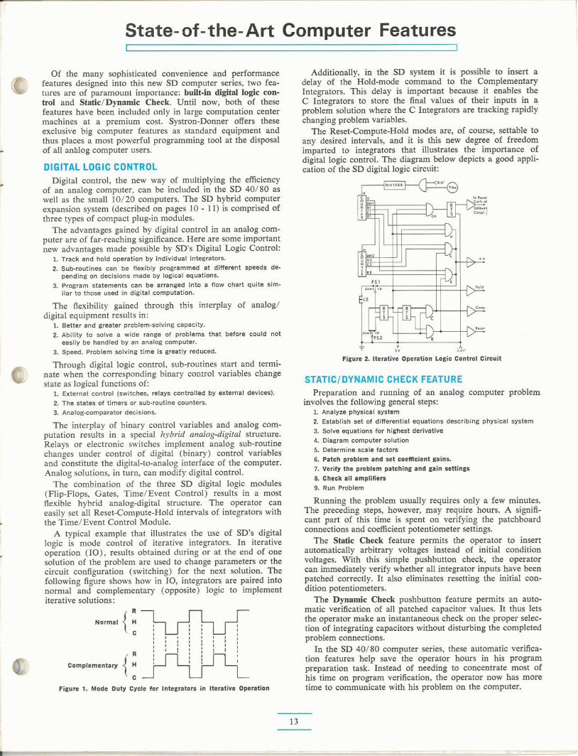
A typical example that illustrates the use of SD's digital logic is mode control of iterative integrators. In iterative operation (IO), results obtained during or at the end of one solution of the problem are used to change parameters or the circuit configuration (switching) for the next solution. The following figure shows how in 10, integrators are paired into normal and complementary (opposite) logic to implement iterative solutions :
Figure 1. Mode Duty Cycle for Integrators in Iterative Operation
Additionally, in the SD system it is possible to insert a delay of the Hold-mode command to the Complementary Integrators. This delay is important because it enables the C Integrators to store the final values of their inputs in a problem solution where the C Integrators are tracking rapidly changing problem variables.
he Reset-compute- old modes are, of course, settable to any desired intervals, and it is this new degree of freedom imparted to integrators that illustrates the importance of digital logic control. The diagram below depicts a good appli- cation of the SD digital logic circuit:
* ov A,'
Figure 2. Iterative Operation Logic Control Circuit
STATIC/DYNAMIC CHECK "1TU" Preparation and running oi an analog computer problem
involves the following general steps: 1. Analyze physical system 2. Establish set of differential equations describing physical system 3. Solve equations for highest derivative 4. Diagram computer solution 5. Determine scale factors 6. Patch problem and set coefficient gains. 7. Verify the problem patching and gain settings 8. Check all amplifiers
9. Run Problem
Running the problem usually requires only a few minutes. The preceding steps, however, may require hours. A signifi- cant part of this time is spent on verifying the patchboard connections and coefficient potentiometer settings.
The Static Check feature permits the operator to insert automatically arbitrary voltages instead of initial condition voltages. With this simple pushbutton check, the operator can immediately verify whether all integrator inputs have been patched correctly. It also eliminates resetting the initial con- dition potentiometers.
The Dynamic Check pushbutton feature permits an auto- matic verification of all patched capacitor values. It thus lets the operator make an instantaneous check on the proper selec- tion of integrating capacitors without disturbing the completed problem connections.
In the SD 40/80 computer series, these automatic verifica- tion features help save the operator hours in his program preparation task. Instead of needing to concentrate most of his time on program verification, the operator now has more time to communicate with his problem on the computer.
Built- in Quality and Reliability
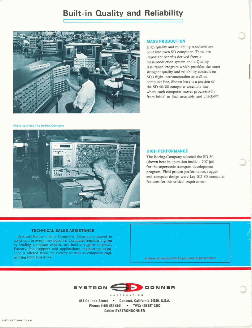
MASS PRODUCTION High quality and reliability standards are built into each SD computer. These are important benefits derived from a mass-production system and a Quality Assurance Program which provides the same stringent quality and reliability controls on SD's flight instrumentation as well as computer line. Shown here is a portion of the SD 401 80 computer assembly line where each computer moves progressively from initial to final assembly and checkout.
HIGH "eSFORMANf'L The B L , ~ Company ,,.- zted the SD 80 (shown here in operation inside a 707 jet) for the supersonic transport development program. Field proven performance, rugged and compact design were key SD 80 computer features for this critical requirement.
TECHNICAL SALES ASSISTANCE Systron-Donner's Total Computer Program is geared to
assist you in every way possible. Computer Seminars, given by leading computer experts, are held at regular intervals. Factory field support and applications engineering assist- ance is offered *from the factory as well as computer engi-
-neering representatives.
C O R P O R A T I O N
888 Galindo Street Concord, California 94520, U.S.A. Phone: (415) 682-6161 M I X : 415-687-3200
Cable: SYSTRONDONNER
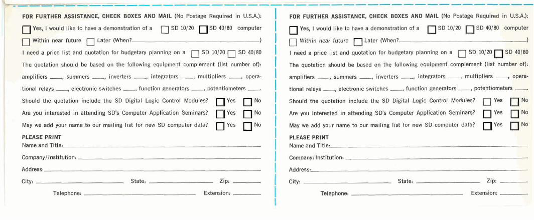
FOR FURTHER ASSISTANCE, CHECK BOXES AND MAIL (No Postage Required in U.S.A.):
Yes, I would like to have a demonstration of a SD 10120 SD 40180 computer
Within near future Later (When? [7 1 I need a price list and quotation for budgetary planning on a fl SD 10120 5 SD 40180
The quotation should be based on the following equipment complement (list number of):
amplifiers , summers , inverters , integrators , multipliers , opera- b' I tional r e l a y s , electronic switches , function generators , potentiometers . Should the quotation include the SD Digital Logic Control Modules? Yes No
Are you interested i n attending SD's Computer Application Seminars? Yes No
May we add your name to our mailing list for new SD computer data? Yes No
PLEASE PRINT Name and Title:
Company/ Institution:
Address:
City: State: Zip:
Telephone: Extension:
FOR FURTHER ASSISTANCE, CHECK BOXES AND MAIL (No Postage Required in U.S.A.):
Yes, I would like to have a demonstration of a SD 10120 SD 40180 computer
/J Within near future Later (When? 1
I need a price list and quotation for budgetary planning on a SD 10120 SD 40180
The quotation should be based on the following equipment complement (list number of):
amplifiers , summers , inverters , integrators , multipliers , opera-
tional r e l a y s , electronic switches , function g e n e r a t o r s , potentiometers -. Should the quotation include the SD Digital Logic Control Modules? 17 Yes No
Are you interested in attending SD's Computer Application Seminars? Yes No
May we add your name to our mailing list for new SD computer data? Yes NO
PLEASE PRINT Name and Title:
Company1 Institution:
Address:
City: State: Zip:
Telephone: Extension:
BUSINESS REPLY MAIL NO postage required if mailed in the United States
POSTAGE WlLL BE PAlD BY
S Y S T R O N ---D O N N E R
I
I :-1 Ii
BUSINESS REPLY MAIL NO postage required if mailed in the United States
POSTAGE WlLL BE PAlD BY 1
C O R P O R A T I O N
ANALOG COMPUTER OPERATIONS
888 GALINDO STREET
CONCORD, CALIFORNIA 94520
C O R P O R A T I O N
ANALOG COMPUTER OPERATIONS
888 GALINDO STREET
CONCORD, CALIFORNIA 94520
Related Documents