System Sump and Pump NEWTON PUMP CONTROLLER (CP9) Twin Pump Controller with Alarm Rev 1.9 - 26 November2018 © Newton Waterproofing Systems Operational Manual ®

Welcome message from author
This document is posted to help you gain knowledge. Please leave a comment to let me know what you think about it! Share it to your friends and learn new things together.
Transcript
System Sump and Pump
NEWTON PUMP CONTROLLER (CP9)Twin Pump Controller with Alarm
Rev 1.9 - 26 November2018© Newton Waterproofing Systems
Operational Manual
®
2 For more information visit us online www.newtonwaterproofing.co.uk Call us for more information on +44 (0)1732 360095 3
PAGE
INTRODUCTION 4
DESCRIPTION OF FEATURES 5
CONNECTING POWER 6 - 7
CONNECTING POWER, PUMPS & OPTIONAL EQUIPMENT 6 - 7
OPERATION 8 - 9
SIZING OF NEWTON POWER INVERTERS 10 - 11
DIMENSIONS300 mm wide x 132 mm high x 78 mm deep. Weight - 2.18 kg
WARRANTY STATEMENTLimited Product Warranties. Three-year limited product warranty from date on delivery note or invoice to the customer. Delivery note must include the product code number and serial number of the product.
What is covered by this limited hardware warranty?
This limited warranty covers warranty back to base (Newton Waterproofing Systems) only for defects in materials and workmanship. The manufacturer will exchange the product with a product that is new or which has been manufactured from new or serviceable used parts and is at least functionally equivalent to the original product.
What is not covered by this limited hardware warranty?
• Products the supplier has not received payment for
• Normal wear and tear
• Problems caused by defective electrical power supply
• Failure to follow product installation instructions and user instructions
• Failure to perform preventive maintenance of the supplied product or the system the product is used within
• Usage that is not in accordance with the product instructions
• Servicing not authorised by the manufacturer
• Problems caused by connecting devices not supplied or authorised by the manufacturer
Warranty Information
This warranty gives you specific legal rights, and you may also have other rights which may vary from area to area (or jurisdiction to jurisdiction). The manufacturers responsibility for malfunctions and defects in the product is limited to repair and replacement as set forth in this warranty statement. All expressed and implied warranties for the product, including but not limited to any implied warranties and conditions of merchantability and fitness for a particular purpose, are limited in time to the term of the limited warranty which is the three-year period reflected on your delivery note or invoice. No warranties, whether expressed or implied, will apply after the limited warranty period has expired.
We do not accept liability beyond the remedies provided for in this limited product warranty or for consequential or incidental damages, including without limitation, any liability for third party claims against you, for damages for products not being available for use. Our liability will be no more than the amount you paid for the product that is the subject of a claim. This is the maximum amount for which we are responsible. Newton Waterproofing Systems reserve the right to change the product specification at any time.
This is a dual purpose document that is designed to be the reference manual for the installation of the Pump Controller and then should be handed over to the occupier as the user manual and service record.
Panel Serial Number
Date Installed
Installation Company
Installation Engineer
Service Contact Number
WARNINGSSHOCK HAZARD – DO NOT OPEN
THIS CONTROL PANEL MUST ONLY BE INSTALLED BY TRAINED ENGINEERS.
NO USER SERVICE PARTS INSIDE PANEL - DO NOT OPEN. THIS PANEL HAS TWO MAINS POWER INPUTS. BOTH MUST BE ISOLATED BEFORE SERVICE OF PANEL OR PUMPS.
Please keep this Operational Manual with the Pump Controller at all times. The service engineer should confirm findings using the service sheet below.
Date Engineer Readings Pump 1Running Amps / Pump Count
Readings Pump 2Running Amps
INFORMATION CONTENTS & WARRANTY STATEMENT
4 For more information visit us online www.newtonwaterproofing.co.uk Call us for more information on +44 (0)1732 360095 5
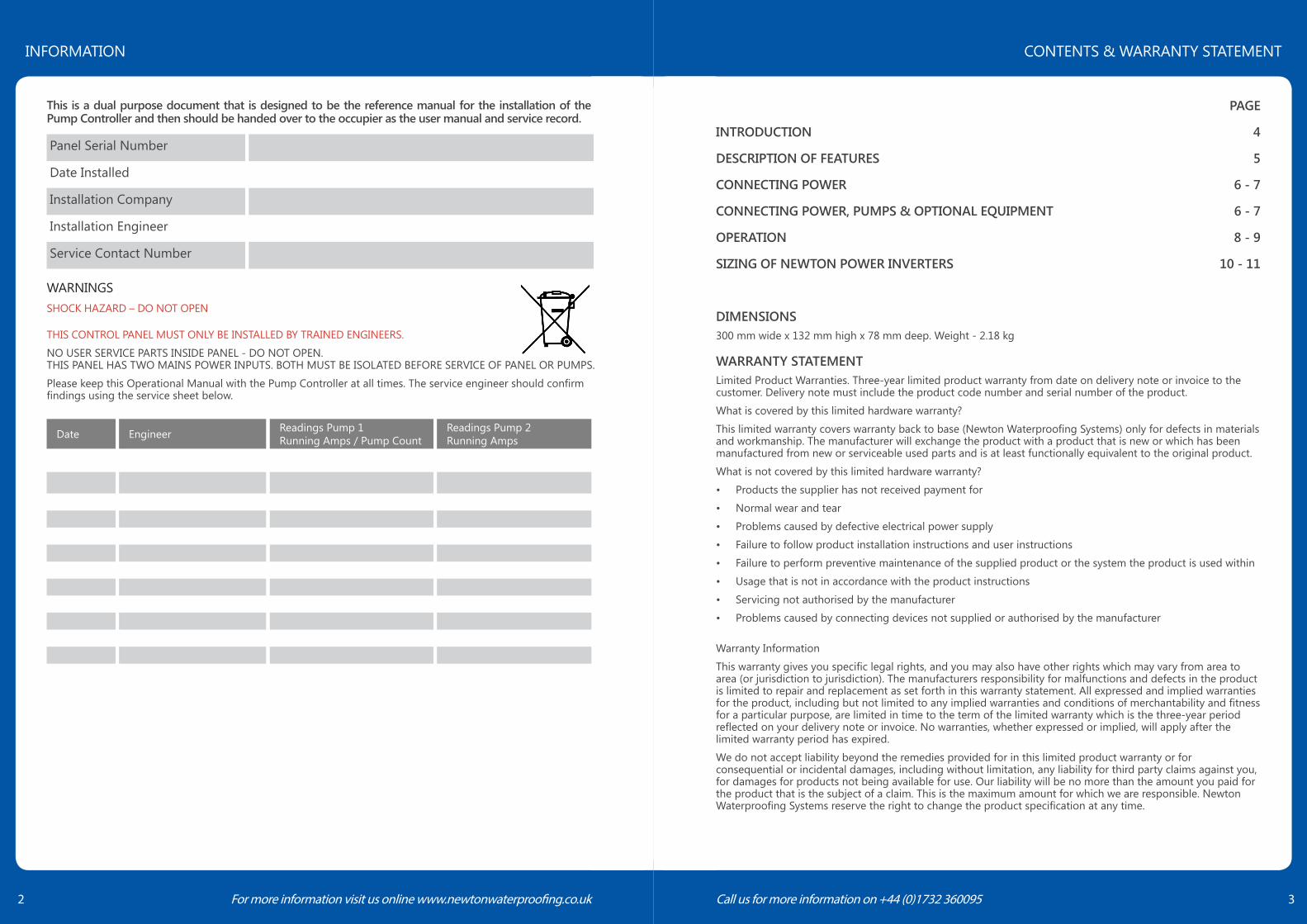
The Newton Pump Controller is designed to be used with matched pairs of manual versions of Newton Pumps, and provides a sophisticated, yet simple to install, twin pump control system which offers some of the features of the Newton Control Panel-Pro, but at a much lower cost.
The controller has a mains powered alarm with battery backup alarm and features interfaces for use with Newton battery backup and telemetry systems, as well as connections to whole house alarm and monitoring systems. The major feature of the control system is the self diagnostic program that operates both pumps on a weekly basis to ensure that they are not stood idle for extended periods, in order to prevent seizure and premature pump failure. Each pump will operate for 5 seconds, (one after the other) once per week.
Each pump is operated by its own vertical type float switch with a single reed type switch supplied for the alarm system which incorporates the same PCB as the Newton PA50 Alarm unit. The panel is designed to be used with an optional Newton Victron Power Inverter, sized to suit the pumps and installed with sufficient battery power to ensure continued pumping during power outages.
A typical system is shown below:
PANEL HIGHLIGHTS1. Two independent power supply inputs - Each pump is separately and independently powered from the
other. The operation of the pumps is not at all dependent on the operation of the Pump Controller. If the Pump Controller should fail, the float switches will still have the ability to switch on the pumps as if they were automatic pumps.
2. Automatic pump duty assist - If one pump cannot cope with the volume of water entering the sump, the water level will rise to the switch of the second pump, which will automatically start to increase the pumping capability. Please be aware that separate discharge lines maximises the volume of water removed when this feature is utilised.
3. Automatic alarm float checking - An alarm checking signal is continually monitored to confirm the alarm float cables have been fitted correctly, not been tampered with, or been disconnected.
4. Automatic testing of each pump every 7 days - The test ensures the pumps are used each week. Each control circuit has its own independent timer to ensure that each pump is tested at different times.
5. Test Button - Both pumps can be started from the panel for testing.
6. Alarm Power - The Alarm is powered under normal circumstances by 230V mains and by internal 9V battery during power outage.
7. If the sounder is beeping to warn of high water level, you can mute the sounder by pressing the mute button once. The LED will still flash until reset (in Alarm Mode 1).
8. Pump Counter - An internal, 6 digit counter is included that counts the number of times Pump 1 operates (Not Pump 2). This count includes the weekly pump test and pump operations activated by the float switch.
9. Choice of pumps - A choice of a number of Newton manual pumps of 250, 400 and 750 watts.
10. Battery Backup - Optional Newton Victron Power Inverter can be connected to the unit to provide continuation of pumping (Pump 2) during power outage.
11. Fail-Safe - Telemetry - Pump Controller can be connected to the Newton Dialer (PA5) or to home alarm system (BMS - Building Management System)
ENCLOSUREThe Pump Controller is housed in a 300 mm wide x 132 mm high x 78 mm deep, painted steel enclosure with a minimum of 8 knockouts for fitting suitable plastic cable glands or conduit connectors ready for the following cables:
Mains Power 1; Mains Power 2; Pump Float 1; Pump Float 2; Pump 1; Pump 2; Alarm Float; Connection to Dialer.
The Pump Controller can be surface mounted or flush mounted. Please ensure the correct variant is ordered:
SURFACE MOUNTED - PURCHASE CODE CP9Parts:
1 x Pump Controller
2 x Pump Float Switches
1 x Alarm Float Switch
2 x 32 mm Conduit Connectors
10 m 32 mm Conduit
1 x 25 mm Conduit Connectors
5 m 25 mm Conduit
FLUSH MOUNTED - PURCHASE CODE CP9FParts:
1 x Pump Controller
2 x Pump Float Switches
1 x Alarm Float Switch
8 x Cable Glands
1 x Flush Mount Trim
8 x Cable Glands
Fix the enclosure to the wall or within the wall using fixings that are suitable for the weight of the unit and your wall type. The face plate is attached to the back-box and supplied with M3 flange combi screws and plastic washers.
Newton Pump Controller
Grid mains power supply 230V AC 13A
PumpFloat
PumpFloat
ManualNewtonPump400 to750W
ManualNewtonPump400 to750W
Power Inverter(option) Battery
BatteryOPTIONAL BATTERY(S)
DialerPA5 - (Option)
House Alarm(option)
AlarmFloat
INTRODUCTION DESCRIPTION OF FEATURES
6 For more information visit us online www.newtonwaterproofing.co.uk Call us for more information on +44 (0)1732 360095 7
ELECTRICAL CONNECTIONINSTALLATION WARNINGS:THIS CONTROL PANEL MUST ONLY BE INSTALLED BY TRAINED ENGINEERS.BEFORE COMMENCING INSTALLATION, ISOLATE YOUR MAINS ELECTRIC SUPPLY.This product should be installed in accordance with the relevant sections of the building regulations code and the current edition of the IEE Wiring Regulations (BS 7671: Requirements for electrical installations) and appropriate statutory regulations.
As of April 2004, new installations in the UK should be wired using the EU harmonised colours for the supply conductors. NEW COLOURS: BROWN = Live, BLUE = Neutral, YELLOW / GREEN = Earth. This installation MUST be earthed.
This control panel is not waterproof, is of metal construction and must be installed in a dry, well ventilated area.
Warning: it is important to read and understand the Pump Controller instructions
This Newton Pump Controller has been designed to be wall mounted or recessed within the wall. When the unit is recessed into the wall, the routing of all cables is also within the wall, making a neater installation than if the unit is wall mounted. Cable entry is via the knock-outs to the bottom and side of the panel, and glands are supplied for recessed mounting.
For ease of maintenance in changing pumps, it is recommended to always use 1 x 32 mm conduit for the two pumps, 1 x 32 mm conduit for the two float cables and 1 x 25 mm conduit for the Alarm Float Cable.
For surface mounting, the panel looks neater if the 32 mm and 25 mm conduits are fitted directly to the unit.
NOTES:The two supplied vertical floats, when connected to the unit, are high-voltage. Please note that low-voltage rated cables cannot be run in the same conduit as high-voltage (230V AC) cables. The Panel must be earthed.
If the sump chamber is full of water on first powering up the panel, the alarm may sound and both pumps may start together. When the water level is below the alarm float, the alarm sounder will cease and the remainder of the water will be removed by Pump 1.
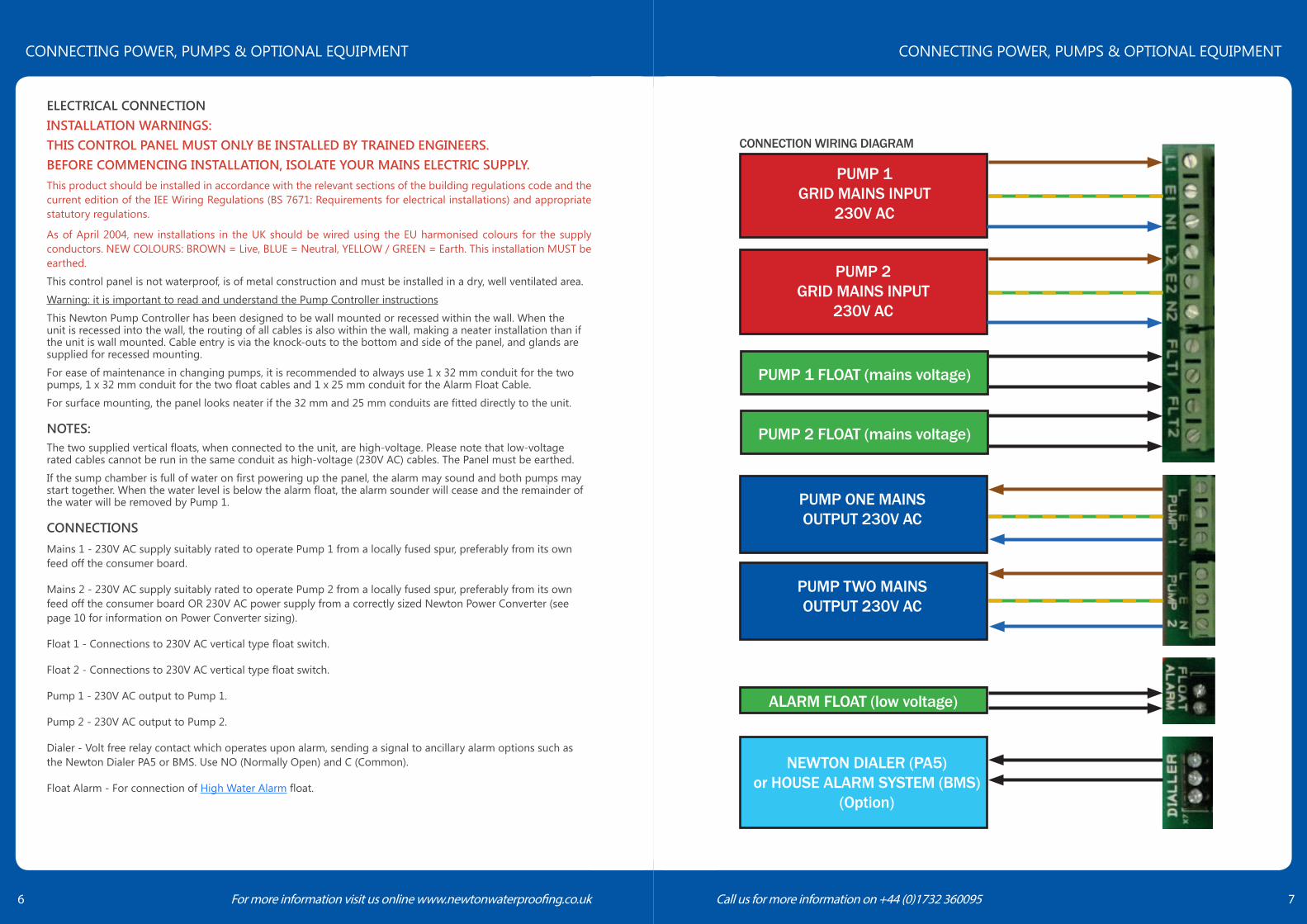
CONNECTIONSMains 1 - 230V AC supply suitably rated to operate Pump 1 from a locally fused spur, preferably from its own feed off the consumer board.
Mains 2 - 230V AC supply suitably rated to operate Pump 2 from a locally fused spur, preferably from its own feed off the consumer board OR 230V AC power supply from a correctly sized Newton Power Converter (see page 10 for information on Power Converter sizing).
Float 1 - Connections to 230V AC vertical type float switch.
Float 2 - Connections to 230V AC vertical type float switch.
Pump 1 - 230V AC output to Pump 1.
Pump 2 - 230V AC output to Pump 2.
Dialer - Volt free relay contact which operates upon alarm, sending a signal to ancillary alarm options such as the Newton Dialer PA5 or BMS. Use NO (Normally Open) and C (Common).
Float Alarm - For connection of High Water Alarm float.
CONNECTION WIRING DIAGRAM
PUMP 1GRID MAINS INPUT
230V AC
ALARM FLOAT (low voltage)
PUMP 1 FLOAT (mains voltage)
PUMP ONE MAINSOUTPUT 230V AC
NEWTON DIALER (PA5)or HOUSE ALARM SYSTEM (BMS)
(Option)
PUMP 2GRID MAINS INPUT
230V AC
PUMP 2 FLOAT (mains voltage)
PUMP TWO MAINSOUTPUT 230V AC
CONNECTING POWER, PUMPS & OPTIONAL EQUIPMENT CONNECTING POWER, PUMPS & OPTIONAL EQUIPMENT
8 For more information visit us online www.newtonwaterproofing.co.uk Call us for more information on +44 (0)1732 360095 9
CONNECTION NOTES• Ensure that the grid mains connection is not connected until all connections are complete and the Pump
Controller casing is fitted and locked closed.
• The Alarm Float is the smaller Reed Pivot Switch and the Pump Switches are the larger Vertical Action Float Switches. The Alarm Float should be installed so that the switch is always closed and only opens when lifted upwards by rising water.
• The three floats each have two wires. The connection of these wires is not dependent on polarity and can be fitted to either of the terminals for each connection.
• The three switches should be fitted to the two pump vertical discharge pipes in order to give a switching order of: PUMP 1; ALARM; PUMP 2
• Ensure that the switches are set at the correct levels so the pumps operate correctly. If the switch is too high, the switch may not operate until the water level in the sump is at its peak. If the switch is too low, it is possible that the pump removes all the water before the switch has turned off. It is vitally important to test the pump switching to ensure the pumps operate correctly.
ALARM SET - Attach the battery with the alarm float in the closed position.
The alarm will continue to sound and the Alarm Warning LED will flash until the client manually resets the alarm. Pressing the mute button once mutes the buzzer and a second press will reset the alarm and cancel the flashing LED light. This means that the client will be aware of an alarm condition, even when the second pump has lowered the water in the sump.
CONNECTION TO NEWTON DIALER - PA5The Newton Dialer can receive a signal from the alarm of the Pump Controller, allowing notice of the alarm condition to be received as a voice message to landline phones and as a text message to mobile phones. Up to 8 separate numbers can receive the voice or text message.
The terminals for the connection to the Dialer are at the top of the inside circuit board of the Pump Controller. Use normal two-core bell wire and make a connection with one of the two coloured wires between the NO (Normally Open) terminal of the Alarm and Trigger Input 1 of the Dialer, with the other wire connecting the C (Common) terminal of the Alarm with the OV Trigger Input of the Dialer.
The NC and C terminals in the Alarm (Labelled Dialer) can also be used to send a zero-voltage signal to home alarm and BMS (Building Management System).
DISPLAY INFORMATIONThe Pump Controller fascia is fitted with LED lights which indicate the following:
• OPERATING - Blue LED lit steadily with option to reduce brightness via “Set” button (see Controls section on page 9)
• PUMP 1 - Green LED lit steadily while Pump 1 is running on test
• PUMP 2 - Green LED lit steadily while Pump 2 is running on test (Pump 1 will also be running indicating high water ingress). If Pump 1 is not running, this indicates that Pump 1 did not start. Contact service engineer. NOTE: Alarm should have sounded also
• WARNING - Blue LED shows fault on High Water Alarm unit
• WATER HIGH - Blue LED shows High Water Alarm
INTERNAL INFORMATION COUNTER - A 6-digit counter will count the number of times the output to Pump 1 operates. This count includes the weekly pump test and pump operations activated by the float switch. The counter is not enabled by default. To enable the counter, move the J2 jumper on the PCB from both contact pins to just one contact pin. The counter can be reset by shorting jumper J2.
CONTROLSPump Controller
When the Pump Test button is pressed for three seconds, initially Pump 1 will run for 5 seconds and then stop. After a 5 second delay, Pump 2 will run for 5 seconds and then stop.
When the Set button is pressed briefly, (for 1 second or less) the brightness of the “Operating” LED will be reduced to half normal brightness. Pressing briefly when at reduced brightness will return to default full brightness setting.
When the Set button is pressed for more than 3 seconds, it will reset the weekly test operation timer so that the next test will be at the same time the following week from when the button was pressed. The “Operating” LED indicator will flash 3 times to confirm that the timer has been reset.
High Water Alarm
When the Alarm Test button is pressed, both the alarm indicators will light and the internal buzzer will sound.
When the Alarm Mute button is pressed, the internal buzzer will be silenced.
OPERATIONAfter installation and power up, the weekly timer will start and the blue Operating LED shall light at full brightness.
After one week from initial power up (or after a 3 second press of the Set Button as described above), a test will take place of the two pumps. During the test, both pumps will be separately tested with a 5 second period between the two pump starts. Pump LED lights will show the test occurring.
The test process will repeat each week.
OPERATION OPERATION
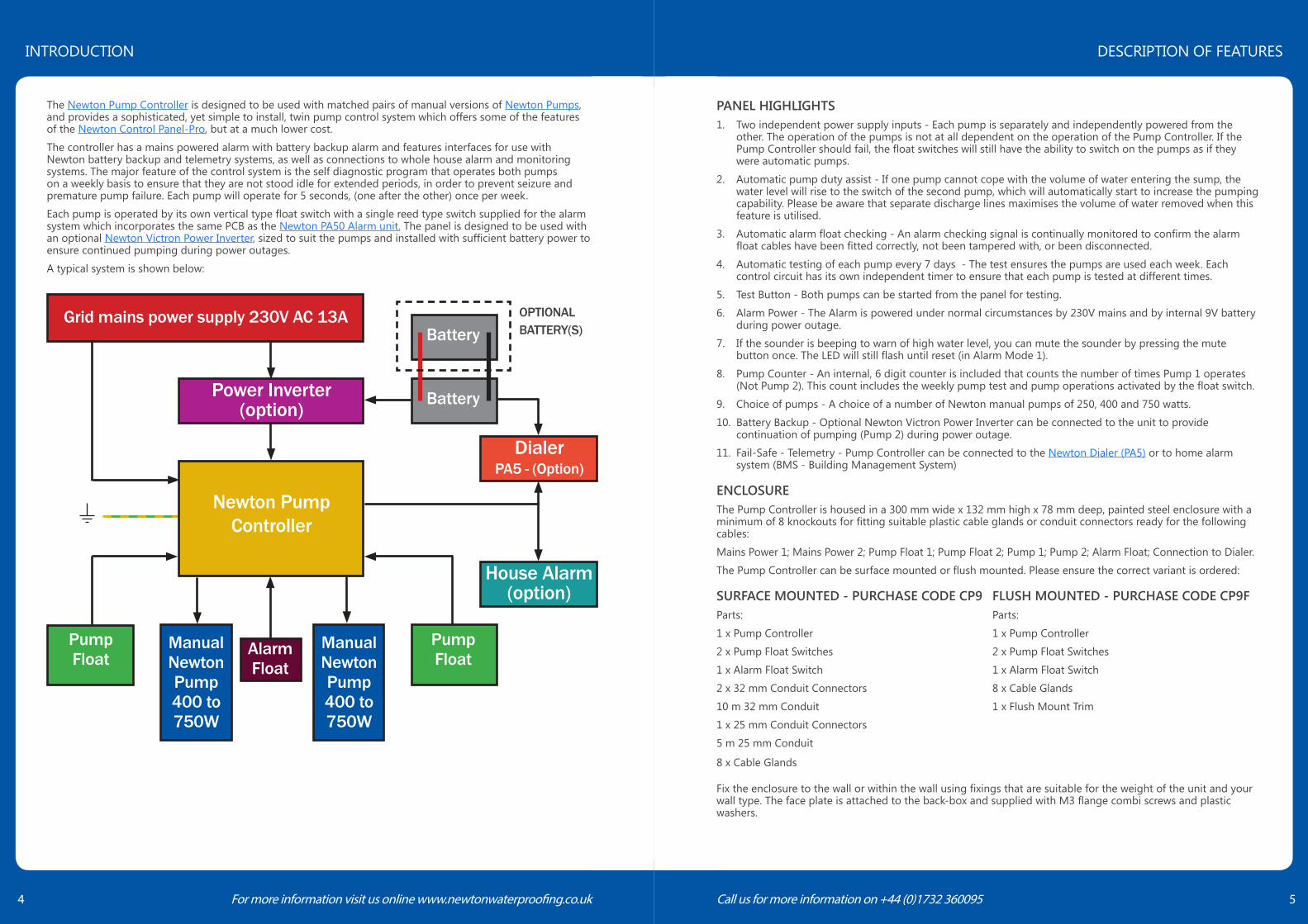
SETUP SELECT+
victron energyB L U E P O W E R
BMV-600SBATTERY MONITOR
BB5 Battery Monitor18
victron energyB L U E P O W E R
AC1output
AC1input
--
Pumps compatible withMultiPlus 12/1200/50CP400/NP400/NP400W
For Battery dimensionsplease see drawingsprefixed Batt
Pump controller CP-9
JOHN NEWTON& COMPANY LIMITED (EST. 1848)
High Water Alarm
WARNINGSHOCK HAZARD ISOLATE BOTH POWER SUPPLIES,GRID MAINS AND BATTERY BACK-UP POWER SUPPLYBEFORE OPENING
Mute Test Test Set
Newton Pump Controller and High Water Alarm - PC9
Warning (See Manual)
High Water Alarm
Operating
Pump 1 On
Pump 2 On
Pump Control
Pum
ps
Hig
h W
ater
Ala
rm
Mai
ns fl
oat
BMV shunt500A/50mV
Pumps compatible withMultiPlus 12/800/35CP250
Multiplus Invertor12/3000/12012/1200/5012/800/35
Pressure rated pipe. 50mminternal including one wayvalve and releasecouplings - 50mm external.
Newton Titan-Pro pumping system with
2 x NP400
fuse fuse
Main Earth
Section
NOTE: This is a waterproofing detail. For the design of the structure, please use a professional designer. We strongly recommend that Newton waterproofing systems are installed by our NSBC registered contractors who will guarantee,insure and accept liability for both the design and the installation of our systems. Please refer to product data sheets before installation of our products. Newton Waterproofing Systems reserves the right to update drawings.
DO NOT SCALE
Checked byDesigned byDate
Scale Drawing Reference
Drawn by
Original Reference Drawing Revision17 - 20 Sovereign Way, Tonbridge, TN9 1RHTel: 01732 360095 Fax: 01732 359033
www.newtonwaterproofing.co.uk - [email protected]
Notes
To access the details mentioned above,relevant NBSClauses, product data and MSDS sheets, please visitTechnical resources viawww.newtonwaterproofing.co.uk
®
NEWTONWATERPROOFING AJG AJGAJG
P-07
28/06/17
Not to scale b
This drawings shows a Victron batteryback up system used in conjunction withNewton System 500 Waterproofingsystem incorporating titan pro white andPC9 Control panel.
The Victron Inverter/Charger ensuresthat water is still removed during poweroutage until the battery is discharged.Protection can be increased withadditional batteries.
For unlimited protection use the Quattro12/3000/120 Generator system, thisrecharges the battery(s) to giveunlimited protection if the fuel isreplenished.
For pump system specification pleasecontact out technical team or a Newtonspecialist contractor.
Newton Dialler also available providingwarnings via a standard BT Telephoneline.
Newton System 500
Titan-Pro White pumping System withbattery back up.
10 For more information visit us online www.newtonwaterproofing.co.uk Call us for more information on +44 (0)1732 360095 11
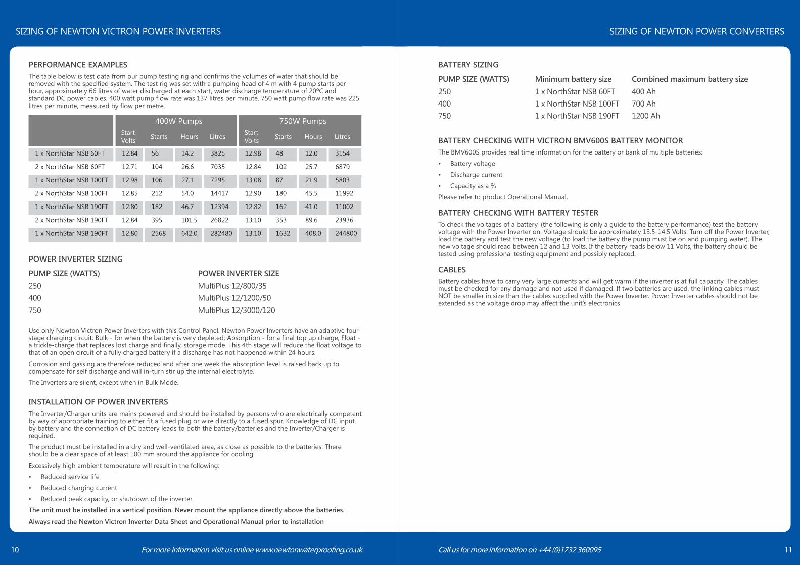
BATTERY SIZING
PUMP SIZE (WATTS) Minimum battery size Combined maximum battery size250 1 x NorthStar NSB 60FT 400 Ah400 1 x NorthStar NSB 100FT 700 Ah750 1 x NorthStar NSB 190FT 1200 Ah
BATTERY CHECKING WITH VICTRON BMV600S BATTERY MONITORThe BMV600S provides real time information for the battery or bank of multiple batteries:
• Battery voltage
• Discharge current
• Capacity as a %
Please refer to product Operational Manual.
BATTERY CHECKING WITH BATTERY TESTERTo check the voltages of a battery, (the following is only a guide to the battery performance) test the battery voltage with the Power Inverter on. Voltage should be approximately 13.5-14.5 Volts. Turn off the Power Inverter, load the battery and test the new voltage (to load the battery the pump must be on and pumping water). The new voltage should read between 12 and 13 Volts. If the battery reads below 11 Volts, the battery should be tested using professional testing equipment and possibly replaced.
CABLESBattery cables have to carry very large currents and will get warm if the inverter is at full capacity. The cables must be checked for any damage and not used if damaged. If two batteries are used, the linking cables must NOT be smaller in size than the cables supplied with the Power Inverter. Power Inverter cables should not be extended as the voltage drop may affect the unit’s electronics.
PERFORMANCE EXAMPLESThe table below is test data from our pump testing rig and confirms the volumes of water that should be removed with the specified system. The test rig was set with a pumping head of 4 m with 4 pump starts per hour, approximately 66 litres of water discharged at each start, water discharge temperature of 20ºC and standard DC power cables. 400 watt pump flow rate was 137 litres per minute. 750 watt pump flow rate was 225 litres per minute, measured by flow per metre.
400W Pumps 750W PumpsStart Volts Starts Hours Litres Start
Volts Starts Hours Litres
1 x NorthStar NSB 60FT 12.84 56 14.2 3825 12.98 48 12.0 3154
2 x NorthStar NSB 60FT 12.71 104 26.6 7035 12.84 102 25.7 6879
1 x NorthStar NSB 100FT 12.98 106 27.1 7295 13.08 87 21.9 5803
2 x NorthStar NSB 100FT 12.85 212 54.0 14417 12.90 180 45.5 11992
1 x NorthStar NSB 190FT 12.80 182 46.7 12394 12.82 162 41.0 11002
2 x NorthStar NSB 190FT 12.84 395 101.5 26822 13.10 353 89.6 23936
1 x NorthStar NSB 190FT 12.80 2568 642.0 282480 13.10 1632 408.0 244800
POWER INVERTER SIZING
PUMP SIZE (WATTS) POWER INVERTER SIZE250 MultiPlus 12/800/35400 MultiPlus 12/1200/50750 MultiPlus 12/3000/120
Use only Newton Victron Power Inverters with this Control Panel. Newton Power Inverters have an adaptive four-stage charging circuit: Bulk - for when the battery is very depleted; Absorption - for a final top up charge, Float - a trickle-charge that replaces lost charge and finally, storage mode. This 4th stage will reduce the float voltage to that of an open circuit of a fully charged battery if a discharge has not happened within 24 hours.
Corrosion and gassing are therefore reduced and after one week the absorption level is raised back up to compensate for self discharge and will in-turn stir up the internal electrolyte.
The Inverters are silent, except when in Bulk Mode.
INSTALLATION OF POWER INVERTERSThe Inverter/Charger units are mains powered and should be installed by persons who are electrically competent by way of appropriate training to either fit a fused plug or wire directly to a fused spur. Knowledge of DC input by battery and the connection of DC battery leads to both the battery/batteries and the Inverter/Charger is required.
The product must be installed in a dry and well-ventilated area, as close as possible to the batteries. There should be a clear space of at least 100 mm around the appliance for cooling.
Excessively high ambient temperature will result in the following:
• Reduced service life
• Reduced charging current
• Reduced peak capacity, or shutdown of the inverter
The unit must be installed in a vertical position. Never mount the appliance directly above the batteries.
Always read the Newton Victron Inverter Data Sheet and Operational Manual prior to installation
SIZING OF NEWTON VICTRON POWER INVERTERS SIZING OF NEWTON POWER CONVERTERS

Newton Waterproofing Systems Is A Trading Name Of
John Newton & Company Ltd.Newton House, 17-20 Sovereign Way
Tonbridge, Kent TN9 1RH
T: +44 (0)1732 360095E: [email protected]: www.newtonwaterproofing.co.uk
“As part of our policy of continuous product improvement we reserve the right to change our specifications at any time”“As part of our policy of continuous product improvement we reserve the right to change our specifications at any time”
®
®
Related Documents