Swing Check Valves ORION S.p.A. via Caboto, 8 • 34148 Trieste • Italy • tel. +39 040813204 • fax +39 040811203 e mail [email protected] • http://www.orionvalves.com

Welcome message from author
This document is posted to help you gain knowledge. Please leave a comment to let me know what you think about it! Share it to your friends and learn new things together.
Transcript
Swing Check Valves
ORION S.p.A. via Caboto, 8 • 34148 Trieste • Italy • tel. +39 040813204 • fax +39 040811203e mail [email protected] • http://www.orionvalves.com
Swing Check Va l ves
2
3
1
7
2
6
5
4
3
1
2
3
4
5
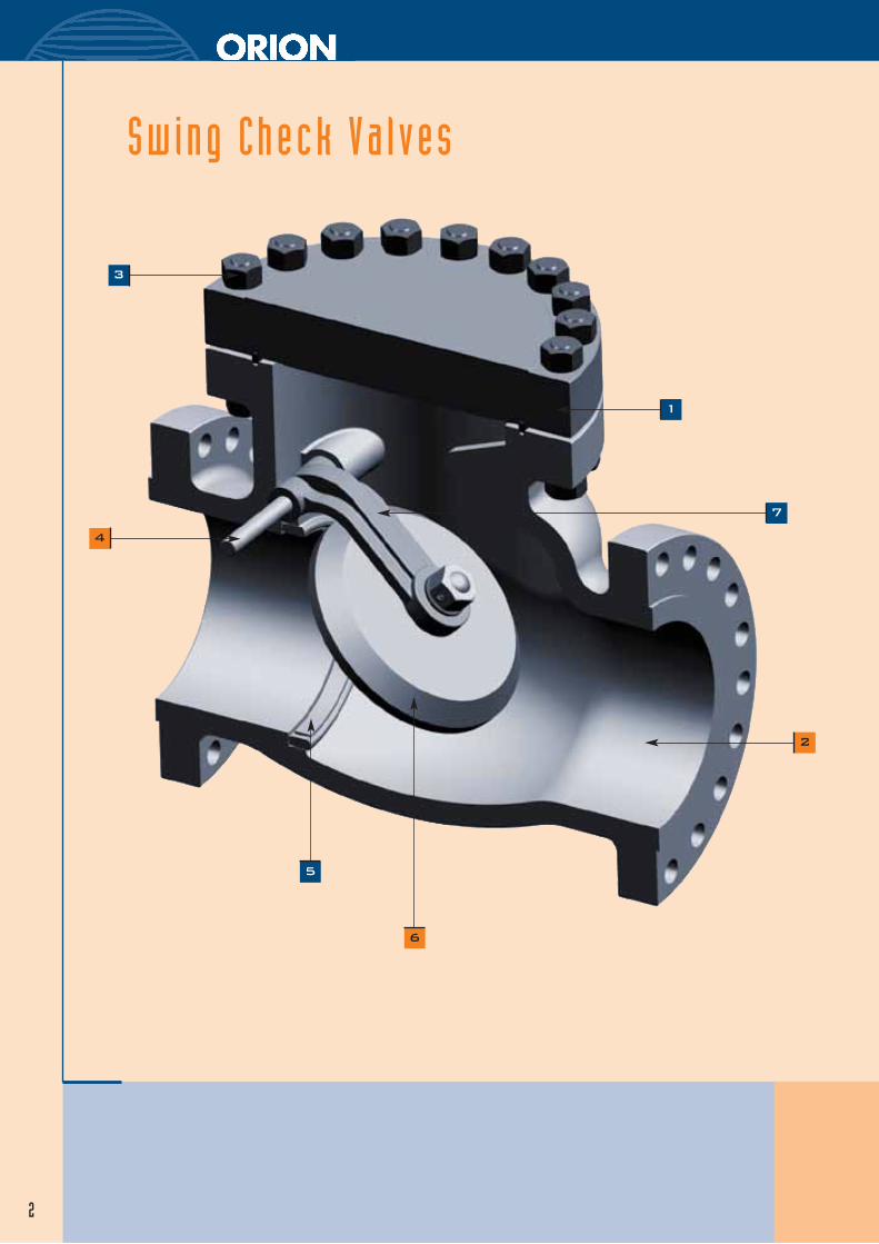
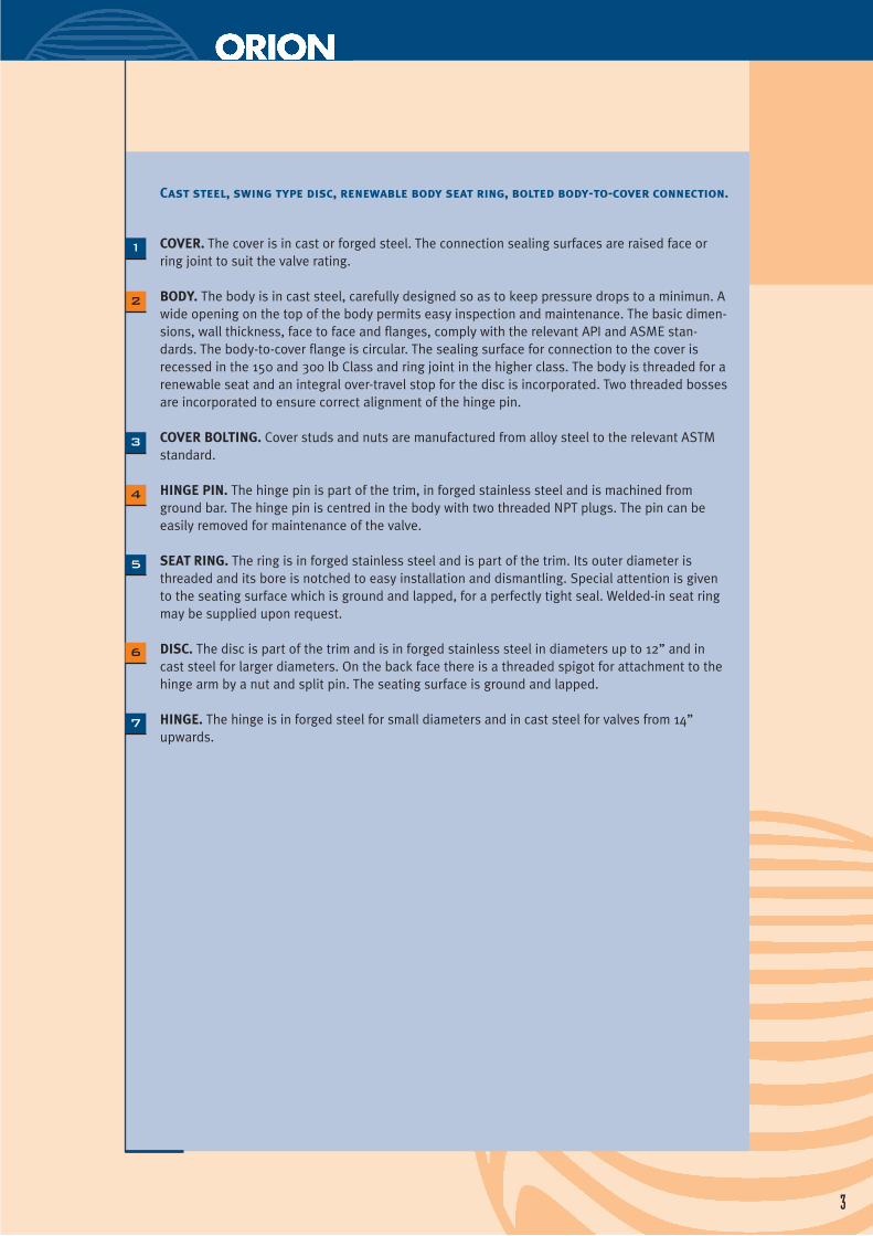
Cast steel, swing type disc, renewable body seat ring, bolted body-to-cover connection.
COVER. The cover is in cast or forged steel. The connection sealing surfaces are raised face orring joint to suit the valve rating.
BODY. The body is in cast steel, carefully designed so as to keep pressure drops to a minimun. Awide opening on the top of the body permits easy inspection and maintenance. The basic dimen-sions, wall thickness, face to face and flanges, comply with the relevant API and ASME stan-dards. The body-to-cover flange is circular. The sealing surface for connection to the cover isrecessed in the 150 and 300 lb Class and ring joint in the higher class. The body is threaded for arenewable seat and an integral over-travel stop for the disc is incorporated. Two threaded bossesare incorporated to ensure correct alignment of the hinge pin.
COVER BOLTING. Cover studs and nuts are manufactured from alloy steel to the relevant ASTMstandard.
HINGE PIN. The hinge pin is part of the trim, in forged stainless steel and is machined fromground bar. The hinge pin is centred in the body with two threaded NPT plugs. The pin can beeasily removed for maintenance of the valve.
SEAT RING. The ring is in forged stainless steel and is part of the trim. Its outer diameter isthreaded and its bore is notched to easy installation and dismantling. Special attention is givento the seating surface which is ground and lapped, for a perfectly tight seal. Welded-in seat ringmay be supplied upon request.
DISC. The disc is part of the trim and is in forged stainless steel in diameters up to 12” and incast steel for larger diameters. On the back face there is a threaded spigot for attachment to thehinge arm by a nut and split pin. The seating surface is ground and lapped.
HINGE. The hinge is in forged steel for small diameters and in cast steel for valves from 14” upwards.
6
7
44
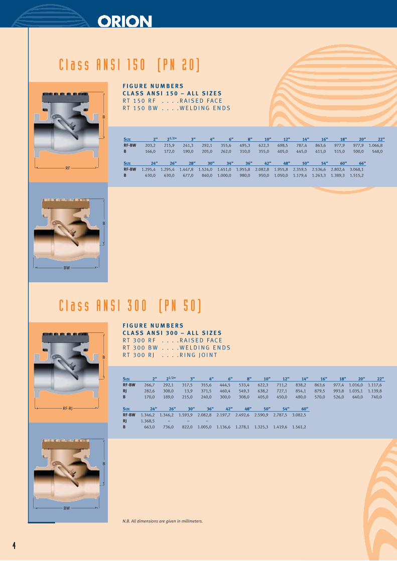
C l a s s A N S I 1 5 0 ( P N 2 0 )F I G U R E N U M B E R SC L A S S A N S I 1 5 0 – A L L S I Z E SR T 1 5 0 R F . . . . R A I S E D F A C ER T 1 5 0 B W . . . . W E L D I N G E N D S
SIZE 2” 21/2” 3” 4” 6” 8” 10” 12” 14” 16” 18” 20” 22”RF-BW 203,2 215,9 241,3 292,1 355,6 495,3 622,3 698,5 787,4 863,6 977,9 977,9 1.066,8B 166,0 172,0 190,0 205,0 262,0 310,0 355,0 405,0 445,0 411,0 515,0 500,0 548,0
SIZE 24” 26” 28” 30” 34” 36” 42” 48” 50” 54” 60” 66”RF-BW 1.295,4 1.295,4 1.447,8 1.524,0 1.651,0 1.955,8 2.082,8 1.955,8 2.359,5 2.536,6 2.802,4 3.068,1B 630,0 630,0 677,0 840,0 1.000,0 980,0 950,0 1.050,0 1.179,4 1.263,3 1.389,3 1.515,2
F I G U R E N U M B E R SC L A S S A N S I 3 0 0 – A L L S I Z E SR T 3 0 0 R F . . . . R A I S E D F A C ER T 3 0 0 B W . . . . W E L D I N G E N D SR T 3 0 0 R J . . . . R I N G J O I N T
SIZE 2” 21/2” 3” 4” 6” 8” 10” 12” 14” 16” 18” 20” 22”RF-BW 266,7 292,1 317,5 355,6 444,5 533,4 622,3 711,2 838,2 863,6 977,4 1.016,0 1.117,6RJ 282,6 308,0 13,9 371,5 460,4 549,3 638,2 727,1 854,1 879,5 993,8 1.035,1 1.139,8B 170,0 189,0 215,0 240,0 300,0 308,0 405,0 450,0 480,0 570,0 526,0 640,0 740,0
SIZE 24” 26” 30” 36” 42” 48” 50” 54” 60”RF-BW 1.346,2 1.346,2 1.593,9 2.082,8 2.197,7 2.492,6 2.590,9 2.787,5 3.082,5RJ 1.368,5 – – –B 663,0 736,0 822,0 1.005,0 1.136,6 1.278,1 1.325,3 1.419,6 1.561,2
C l a s s A N S I 3 0 0 ( P N 5 0 )
4
N.B. All dimensions are given in millimeters.
B
RF
B
BW
B
RF-RJ
B
BW
5
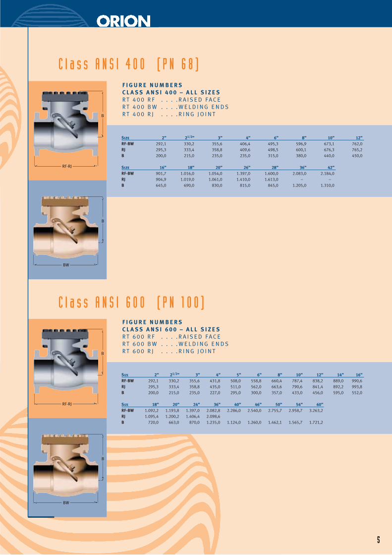
C l a s s A N S I 4 0 0 ( P N 6 8 )F I G U R E N U M B E R SC L A S S A N S I 4 0 0 – A L L S I Z E SR T 4 0 0 R F . . . . R A I S E D F A C ER T 4 0 0 B W . . . . W E L D I N G E N D SR T 4 0 0 R J . . . . R I N G J O I N T
Size 2” 21/2” 3” 4” 6” 8” 10” 12”RF-BW 292,1 330,2 355,6 406,4 495,3 596,9 673,1 762,0RJ 295,3 333,4 358,8 409,6 498,5 600,1 676,3 765,2B 200,0 215,0 235,0 235,0 315,0 380,0 440,0 450,0
Size 16” 18” 20” 26” 28” 36” 42”RF-BW 901,7 1.016,0 1.054,0 1.397,0 1.600,0 2.083,0 2.184,0RJ 904,9 1.019,0 1.061,0 1.410,0 1.613,0 – –B 645,0 690,0 830,0 815,0 845,0 1.205,0 1.310,0
F I G U R E N U M B E R SC L A S S A N S I 6 0 0 – A L L S I Z E SR T 6 0 0 R F . . . . R A I S E D F A C ER T 6 0 0 B W . . . . W E L D I N G E N D SR T 6 0 0 R J . . . . R I N G J O I N T
SIZE 2” 21/2” 3” 4” 5” 6” 8” 10” 12” 14” 16”RF-BW 292,1 330,2 355,6 431,8 508,0 558,8 660,4 787,4 838,2 889,0 990,6RJ 295,3 333,4 358,8 435,0 511,0 562,0 663,6 790,6 841,4 892,2 993,8B 200,0 215,0 235,0 227,0 295,0 300,0 357,0 433,0 456,0 595,0 552,0
SIZE 18” 20” 24” 36” 40” 46” 50” 54” 60”RF-BW 1.092,2 1.193,8 1.397,0 2.082,8 2.286,0 2.540,0 2.755,7 2.958,7 3.263,2RJ 1.095,4 1.200,2 1.406,4 2.098,6B 720,0 663,0 870,0 1.235,0 1.124,0 1.260,0 1.462,1 1.565,7 1.721,2
5
C l a s s A N S I 6 0 0 ( P N 1 0 0 )
B
BW
B
BW
B
RF-RJ
B
RF-RJ
6
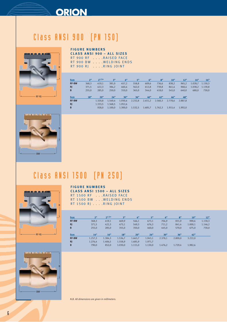
C l a s s A N S I 9 0 0 ( P N 1 5 0 )F I G U R E N U M B E R SC L A S S A N S I 9 0 0 – A L L S I Z E SR T 9 0 0 R F . . . . R A I S E D F A C ER T 9 0 0 B W . . . . W E L D I N G E N D SR T 9 0 0 R J . . . . R I N G J O I N T
Size 2” 21/2” 3” 4” 5” 6” 8” 10” 12” 14” 16”RF-BW 368,3 419,1 381,0 457,2 558,8 609,6 736,6 838,2 965,2 1.028,7 1.130,3RJ 371,5 422,3 384,2 460,4 562,0 612,8 739,8 841,4 968,4 1.038,2 1.139,8B 255,0 285,0 250,0 310,0 365,0 344,0 418,0 545,0 640,0 680,0 730,0
Size 18” 20” 24” 30” 36” 40” 42” 46” 48”RF-BW 1.320,8 1.549,4 1.930,4 2.232,8 2.451,2 2.560,3 2.778,6 2.887,8RJ 1.333,5 1.568,5 1.952,6B 928,0 1.100,0 1.300,0 1.532,5 1.685,7 1.762,3 1.915,4 1.992,0
F I G U R E N U M B E R SC L A S S A N S I 1 5 0 0 – A L L S I Z E SR T 1 5 0 0 R F . . . R A I S E D F A C ER T 1 5 0 0 B W . . . W E L D I N G E N D SR T 1 5 0 0 R J . . . . R I N G J O I N T
Size 2” 21/2” 3” 4” 5” 6” 8” 10” 12”RF-BW 368,3 419,1 469,9 546,1 673,1 704,9 831,9 990,6 1.130,3RJ 371,5 422,3 473,1 549,3 676,3 711,2 841,4 1.000,1 1.146,2B 255,0 285,0 355,0 350,0 460,0 445,0 570,0 675,0 730,0
Size 14” 16” 18” 20” 24” 30” 36” 42”RF-BW 1.257,3 1.384,3 1.536,7 1.663,7 1.943,1 2.378,1 2.800,0 3.222,0RJ 1.276,4 1.406,5 1.558,9 1.685,9 1.971,7B 790,0 852,0 1.030,0 1.115,0 1.130,0 1.476,2 1.729,4 1.982,6
C l a s s A N S I 1 5 0 0 ( P N 2 5 0 )
B
BW
B
BW
B
RF-RJ
B
RF-RJ
N.B. All dimensions are given in millimeters.
7
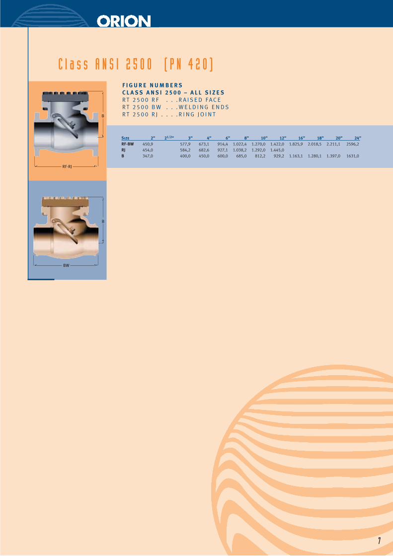
Size 2” 21/2” 3” 4” 6” 8” 10” 12” 16” 18” 20” 24”RF-BW 450,9 577,9 673,1 914,4 1.022,4 1.270,0 1.422,0 1.825,9 2.018,5 2.211,1 2596,2RJ 454,0 584,2 682,6 927,1 1.038,2 1.292,0 1.445,0B 347,0 400,0 450,0 600,0 685,0 812,2 929,2 1.163,1 1.280,1 1.397,0 1631,0
C l a s s A N S I 2 5 0 0 ( P N 4 2 0 )F I G U R E N U M B E R SC L A S S A N S I 2 5 0 0 – A L L S I Z E SR T 2 5 0 0 R F . . . R A I S E D F A C ER T 2 5 0 0 B W . . . W E L D I N G E N D SR T 2 5 0 0 R J . . . . R I N G J O I N T
B
BW
B
RF-RJ
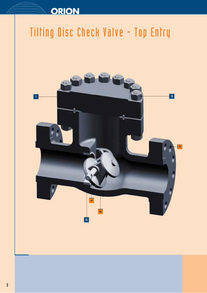
T i l t i ng D i sc Check Va l ve - Top En t ry
8
1
4
2
3
5
6
9
1
2
3
4
5
6
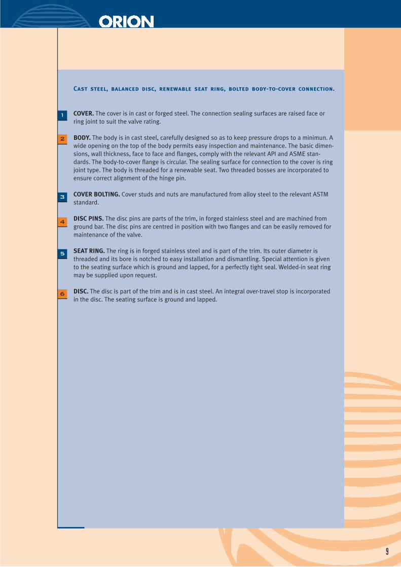
Cast steel, balanced disc, renewable seat ring, bolted body-to-cover connection.
COVER. The cover is in cast or forged steel. The connection sealing surfaces are raised face orring joint to suit the valve rating.
BODY. The body is in cast steel, carefully designed so as to keep pressure drops to a minimun. Awide opening on the top of the body permits easy inspection and maintenance. The basic dimen-sions, wall thickness, face to face and flanges, comply with the relevant API and ASME stan-dards. The body-to-cover flange is circular. The sealing surface for connection to the cover is ringjoint type. The body is threaded for a renewable seat. Two threaded bosses are incorporated toensure correct alignment of the hinge pin.
COVER BOLTING. Cover studs and nuts are manufactured from alloy steel to the relevant ASTMstandard.
DISC PINS. The disc pins are parts of the trim, in forged stainless steel and are machined fromground bar. The disc pins are centred in position with two flanges and can be easily removed formaintenance of the valve.
SEAT RING. The ring is in forged stainless steel and is part of the trim. Its outer diameter isthreaded and its bore is notched to easy installation and dismantling. Special attention is givento the seating surface which is ground and lapped, for a perfectly tight seal. Welded-in seat ringmay be supplied upon request.
DISC. The disc is part of the trim and is in cast steel. An integral over-travel stop is incorporatedin the disc. The seating surface is ground and lapped.
10
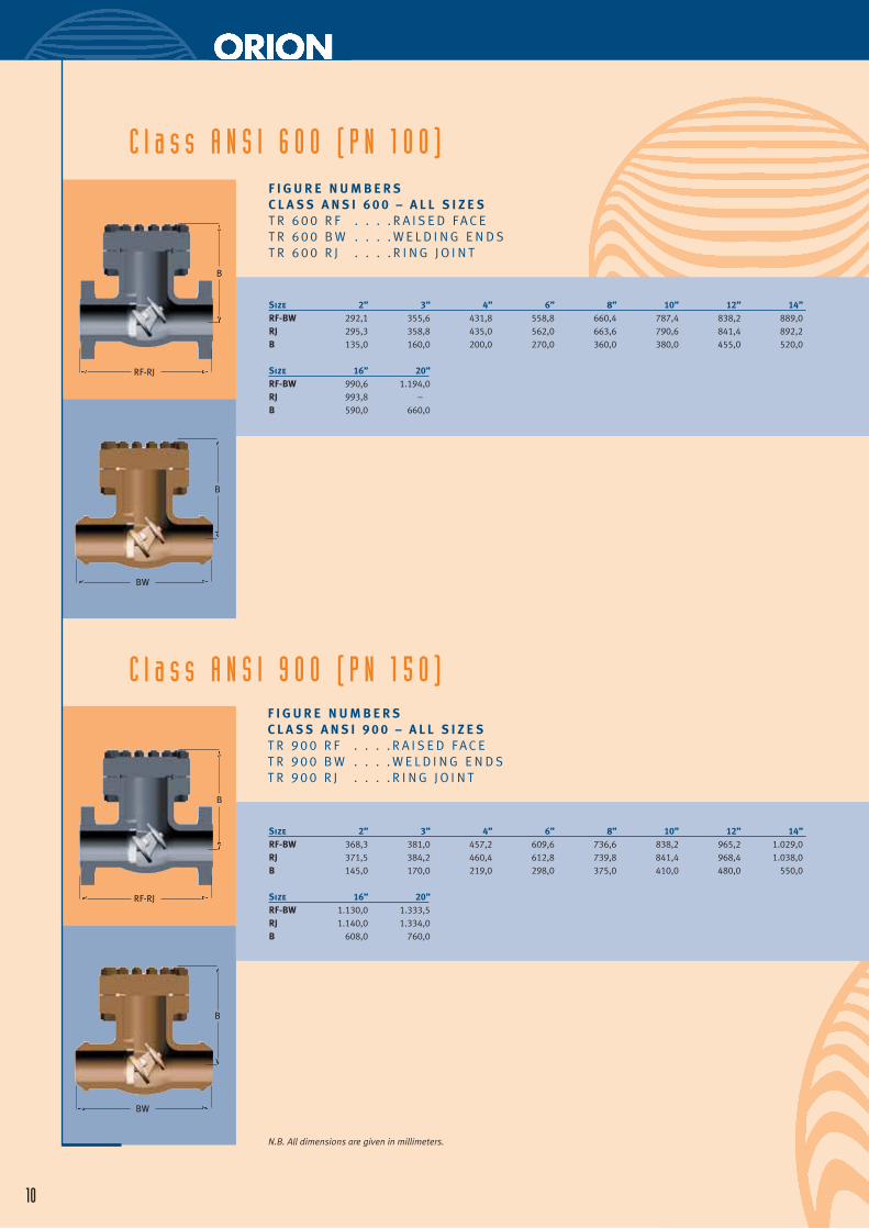
C l a s s A N S I 6 0 0 ( P N 1 0 0 )F I G U R E N U M B E R SC L A S S A N S I 6 0 0 – A L L S I Z E ST R 6 0 0 R F . . . . R A I S E D F A C ET R 6 0 0 B W . . . . W E L D I N G E N D ST R 6 0 0 R J . . . . R I N G J O I N T
Size 2” 3” 4” 6” 8” 10” 12” 14”RF-BW 292,1 355,6 431,8 558,8 660,4 787,4 838,2 889,0RJ 295,3 358,8 435,0 562,0 663,6 790,6 841,4 892,2B 135,0 160,0 200,0 270,0 360,0 380,0 455,0 520,0
Size 16” 20”RF-BW 990,6 1.194,0RJ 993,8 –B 590,0 660,0
C l a s s A N S I 9 0 0 ( P N 1 5 0 )F I G U R E N U M B E R SC L A S S A N S I 9 0 0 – A L L S I Z E ST R 9 0 0 R F . . . . R A I S E D F A C ET R 9 0 0 B W . . . . W E L D I N G E N D ST R 9 0 0 R J . . . . R I N G J O I N T
Size 2” 3” 4” 6” 8” 10” 12” 14”RF-BW 368,3 381,0 457,2 609,6 736,6 838,2 965,2 1.029,0RJ 371,5 384,2 460,4 612,8 739,8 841,4 968,4 1.038,0B 145,0 170,0 219,0 298,0 375,0 410,0 480,0 550,0
Size 16” 20”RF-BW 1.130,0 1.333,5RJ 1.140,0 1.334,0B 608,0 760,0
N.B. All dimensions are given in millimeters.
B
RF-RJ
B
BW
B
RF-RJ
B
BW
11
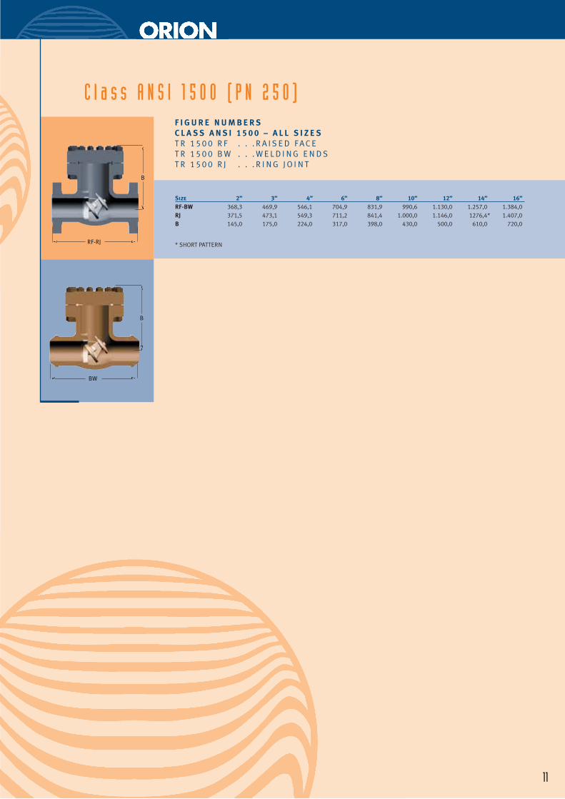
C l a s s A N S I 1 5 0 0 ( P N 2 5 0 )F I G U R E N U M B E R SC L A S S A N S I 1 5 0 0 – A L L S I Z E ST R 1 5 0 0 R F . . . R A I S E D F A C ET R 1 5 0 0 B W . . . W E L D I N G E N D ST R 1 5 0 0 R J . . . R I N G J O I N T
Size 2” 3” 4” 6” 8” 10” 12” 14” 16”RF-BW 368,3 469,9 546,1 704,9 831,9 990,6 1.130,0 1.257,0 1.384,0RJ 371,5 473,1 549,3 711,2 841,4 1.000,0 1.146,0 1276,4* 1.407,0B 145,0 175,0 224,0 317,0 398,0 430,0 500,0 610,0 720,0
* SHORT PATTERN
B
RF-RJ
B
BW
T i l t i ng D i sc Check Va l ve - Sp l i t Body
12
3
4
5
1
2
13
1
2
3
4
5
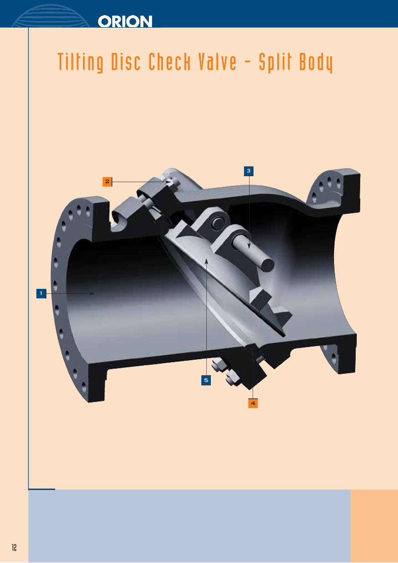
Cast steel, two pieces body, renewable seat ring, balanced disc. This type is re-
commended when it is desirable to operate check valves at low differential
pressure or when it is necessary to reduce pressure drop and eliminate prob-
lem of slamming and wear of moving parts.
BODY. The body is in cast steel, carefully designed so as to keep pressure drops to a minimun.Itis made in two sections bolted together. The basic dimensions, wall thickness, face to face andflanges, comply with the relevant API and ASME standards. Two threaded bosses are incorporat-ed in the bonnet to ensure correct alignment of the disc.
BODY BOLTING. Body studs and nuts are manufactured from alloy steel to the relevant ASTMstandard.
DISC PINS. The disc pins are parts of the trim, in forged stainless steel and are machined fromground bar. The two disc pins are centred in the body with two flanges and can be easilyremoved for maintenance of the valve.
SEAT RING. The ring is in forged stainless steel and is part of the trim. Special attention is givento the seating surface which is ground and lapped, for a perfectly tight seal.
DISC. The disc is part of the trim and is in cast steel. The seating surface is ground and lapped.
14
N.B. All dimensions are given in millimeters.
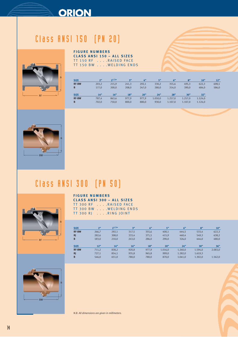
C l a s s A N S I 1 5 0 ( P N 2 0 )F I G U R E N U M B E R S C L A S S A N S I 1 5 0 – A L L S I Z E ST T 1 5 0 R F . . . . R A I S E D F A C ET T 1 5 0 B W . . . . W E L D I N G E N D S
SIZE 2” 21/2” 3” 4” 5” 6” 8” 10” 12”RF-BW 203,2 215,9 241,3 292,1 330,2 355,6 495,3 622,3 698,5B 177,0 200,0 208,0 247,0 280,0 314,0 390,0 484,0 586,0
SIZE 14” 16” 18” 20” 24” 28” 30” 32”RF-BW 787,4 863,6 977,9 977,9 1.050,0 1.257,0 1.257,0 1.524,0B 702,0 750,0 800,0 880,0 930,0 1.107,0 1.107,0 1.124,0
C l a s s A N S I 3 0 0 ( P N 5 0 )F I G U R E N U M B E R S C L A S S A N S I 3 0 0 – A L L S I Z E ST T 3 0 0 R F . . . . R A I S E D F A C ET T 3 0 0 B W . . . . W E L D I N G E N D ST T 3 0 0 R J . . . . R I N G J O I N T
SIZE 2” 21/2” 3” 4” 5” 6” 8” 10”RF-BW 266,7 292,1 317,5 355,6 400,1 444,5 533,4 622,3RJ 282,6 308,0 333,4 371,5 415,9 460,4 549,3 638,2B 183,0 210,0 243,0 286,0 290,0 326,0 444,0 480,0
SIZE 12” 14” 16” 18” 20” 24” 30” 36”RF-BW 711,2 838,2 920,8 977,9 1.016,0 1.260,0 1.594,0 2.083,0RJ 727,1 854,1 935,8 965,8 999,0 1.282,0 1.619,3 B 546,0 651,0 780,0 780,0 870,0 1.041,0 1.302,0 1.562,0
B
RF
B
BW
B
RF
B
BW
15
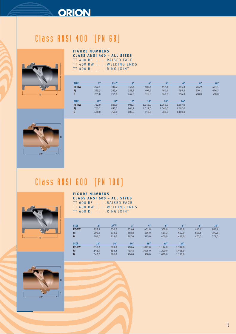
C l a s s A N S I 4 0 0 ( P N 6 8 )F I G U R E N U M B E R S C L A S S A N S I 4 0 0 – A L L S I Z E ST T 4 0 0 R F . . . . R A I S E D F A C ET T 4 0 0 B W . . . . W E L D I N G E N D ST T 4 0 0 R J . . . . R I N G J O I N T
SIZE 2” 21/2” 3” 4” 5” 6” 8” 10”RF-BW 292,1 330,2 355,6 406,4 457,2 495,3 596,9 673,1RJ 295,3 333,4 358,8 409,6 460,4 498,5 600,1 676,3B 205,0 215,0 267,0 315,0 360,0 394,0 460,0 560,0
SIZE 12” 14” 16” 18” 20” 24”RF-BW 762,0 889,0 901,7 1.016,0 1.054,0 1.397,0RJ 765,2 892,2 904,9 1.019,0 1.060,0 1.407,0B 620,0 750,0 800,0 910,0 980,0 1.100,0
F I G U R E N U M B E R S C L A S S A N S I 6 0 0 – A L L S I Z E ST T 6 0 0 R F . . . . R A I S E D F A C ET T 6 0 0 B W . . . . W E L D I N G E N D ST T 6 0 0 R J . . . . R I N G J O I N T
SIZE 2” 21/2” 3” 4” 5” 6” 8” 10”RF-BW 292,1 330,2 355,6 431,8 508,0 558,8 660,4 787,4RJ 295,3 333,4 358,8 435,0 511,2 562,0 663,6 790,6B 205,0 215,0 267,0 315,0 400,0 418,0 470,0 571,0
SIZE 12” 14” 16” 18” 20” 24”RF-BW 838,2 889,0 990,6 1.092,0 1.194,0 1.397,0RJ 841,4 892,2 993,8 1.095,0 1.200,0 1.406,0B 647,0 800,0 900,0 980,0 1.080,0 1.150,0
C l a s s A N S I 6 0 0 ( P N 1 0 0 )
B
RF
B
BW
B
RF
B
BW

Last Update: December 2004
Related Documents