[1] SUPPLY OF EXCHANGER 141A-E-105 (N)

Welcome message from author
This document is posted to help you gain knowledge. Please leave a comment to let me know what you think about it! Share it to your friends and learn new things together.
Transcript
[1]
SUPPLY OF EXCHANGER 141A-E-105 (N)
[2]
1. Introduction:
BPCL intends to install a standby Exchanger similar to existing exchanger 141A- E-105
in CCR Unit, Mahul Refinery, Mumbai. Vendor has to follow this purchase specification
for supply of the said Exchanger.
2. Scope of Work:
Scope of work includes Adequacy check and compliance of with latest codes/design of
provided mechanical design with respect to Thermal design and providing the
confirmation and report, Preparation of fabrication drawings for new exchanger based
of Mechanical design and procurement of materials and bought out components,
fabrication, inspection, testing, painting, packing and transportation of the complete
exchanger with test rings, spares as per design data available in the reference drawings,
documents attached, specifications, existing exchangers’ drawings, latest codes and
standards.
Vendor shall design test ring (Carbon steel) and supply along with exchanger.
Applicable codes and standards:
Following codes and standards in their latest editions shall form basis for design,
materials selection, fabrication, inspection, testing and acceptance of documents -
ASME boiler and pressure vessel code section VIII DIV 1
ASME Section II part A, B, C and D
ASME Section V
ASME section IX
TEMA class R
National and local laws or regulations as applicable
All material required for fabrication, testing, inspection shall be in vendor scope.
3. EQUIPMENT QUALIFICATION CRITERIA:
a. Bidder shall be capable of Designing, Manufacturing, Testing, Supply and commissioning of Shell & Tube Heat exchangers as per ASME SEC VIII DIV I and TEMA Class R.
b. During the last Seven (7) years, Bidder on his own must have fabricated and supplied
at least a single unit of Carbon Steel shell and carbon steel tube exchanger with shell thickness ranging from 25 mm & above and minimum shell diameter of 1000 mm & above.
[3]
c. Bidder shall submit the documents meeting the Equipment Qualification Criteria (i.e., Purchase Order Copy, Inspection release note / completion certificate and Drawings clearing indicating the above parameters.
4. SCOPE OF SUPPLY:
Supply of following items is in vendor scope:
a. Exchanger as per design data sheet, drawings, Specification and Codes.
b. Test rings and testing accessories– Carbon Steel (A105)
c. Fasteners for all Nozzles and their companion flanges (5 sets, each set individually
packed)
Fastener specification:
Material spec-stud-bolts : ASTM A193 GRADE B7 Material spec-nuts : ASTM A194 GRADE 2H Service : HIGH TEMP SERVICE UPTO 450 C Design-spec-stud-bolt : ANSI B18.2.1 Design-spec-nut : ANSI B18.2.2 Thread-class-symbol-stud-bolt : 2A
Thread-class-symbol-nut : 2B
Type-of-thread : UNC Type-nut : HEAVY HEXAGONAL NUT
Number-nuts-per-stud-bolt : 2
d. Gaskets for all Nozzles (8 Sets, each set individually packed)
Gaskets Specification:
Gasket Type : Spiral wound Design-spec : ASME B16.20 Design-spec-flange-s : ANSI B16.5 Mat-windings : STAINLESS STEEL 316L Mat-filler : GRAFOIL Mat-centring-ring : CARBON STEEL Mat-spec-windings : AISI 316 L
Note: (Spacer Ring on Inlet & Outlet Nozzles shall be considered for fastener length)
[4]
5. PRE BID MEETING AND SITE VIST:
Pre Bid meeting will be held at BPCL Mumbai refinery on dates mentioned elsewhere in the tender followed by site visit.
Site Visit is mandatory for better understanding of job.
Pre Bid Queries shall be submitted within one week or as mentioned in tender. Queries raised after this date may not be entertained/ considered.
6. DOCUMENTATION:
The successful vendor shall make fabrication drawings of the Exchanger and submit to
BPCL for review/approval before starting the fabrication. If any discrepancy is found
during design and fabrication stages the fabricator shall inform BPCL immediately, and
obtain necessary approval before proceeding with that portion of the job any further.
BPCL review of fabrication drawings and documents must not be considered as a check
and shall not relieve the Vendor of his responsibilities to supply equipment as per tender
document.
Vendor shall remain responsible for conflicts between his drawings /documents and
BPCL drawings / documents.
All fabrication drawings submitted to BPCL shall be based on tender document and shall
bear reference number and revision of the corresponding drawings. In addition it shall
indicate item number, client’s name, fabricator’s name, purchase order number, drawing
number etc. All revisions shall be clearly marked by encircling with revision marks.
Submission of required drawing / documents shall be the responsibility of the vendor.
Drawing index shall be prepared for each item giving serial number, description of
drawing, drawing number and revision number. Updated index shall be forwarded along
with each submission. Submission of all required drawing / documents in time shall be
responsibility of the fabricator.
7. AS BUILT DRAWING:
Six sets of “As built” drawings and “Data folder” (containing test certificates, inspection
reports etc.), including one set of reproducible and electronic formats (CD), shall be
supplied by the successful bidder along with the equipment. Soft copies of all drawings
in AutoCAD (.DWG format) shall be submitted to BPCL in CD as part of final
documentation. Gasket drawings shall be given separately in A4 size drawings. Vendor
[5]
shall ensure that all data folder documents including the “AS BUILT DRAWING” are
updated & complete in all respects and shall incorporate all suggestions/correction
informed by BPCL or the authorized inspector while obtaining certificate of
completeness from the Inspection Agency. In the event of the fabricator’s failure to meet
the above requirements, the supply of equipment shall be considered as incomplete.
8. VENDORS RESPONSIBILITIES:
It shall be entirely the vendor’s responsibility to ensure compliance to codes and
standards specified for design, fabrication, testing etc. and to all requirements of the
requisition including specifications and drawings after the order is placed. In view of this,
the fabrication drawings prepared by vendor will be reviewed by BPCL to the following
extent only:
a) Nozzle data, orientation and location, support location, dimensions for
interfacing.
b) Design data and materials of construction
c) Pass partition arrangement, tube layout and bundle detail.
d) Critical details like tube to tube-sheet joint detail.
Vendor has to ensure that all aspects covered in the Specifications and design data
mentioned in attached drawings with the enquiry are complied with.
All drawings shall be thoroughly checked and duly signed by the Vendor. Unchecked
drawings and drawings without revisions clearly marked shall be returned without
review. Successive review of the same fabrication drawing shall apply only to BPCL s
latest data sheet/ comments on the previous revision. Drawings and documents
returned to the Vendor for revision shall be resubmitted at the earliest. Vendor must
ensure that all the vendor documents are thoroughly checked and approved at vendor’s
end by vendor’s competent engineer and responsible engineering office in charge,
before the same are submitted to BPCL for review.
Vendor shall furnish list of drawings/ documents with schedule of submission of
drawings for approval by BPCL. The same shall be submitted to BPCL immediately after
[6]
placement of order. Drawing index duly updated to be submitted with each submission
of documents. While preparing fabrication drawing it shall be endeavored to cover all
fabrication details in minimum number of drawings, not exceeding 5 in any case.
Fabrication drawings shall be submitted in the following sequence (whichever is
applicable)
1) General arrangement drawing indicating design data, fabricated equipment’s
weight, general notes, nozzle schedule, detail of shell, head, skirt / supporting
arrangement, main weld seams, nozzle orientation plan etc.
2) Detail of all nozzles, accessories etc.
3) Detail of internals, gaskets etc.
4) Detail of external clips for ladder, platform, pipe support, insulation, fire
proofing, pipe davit, lifting lugs etc.
5) Shell development drawings incorporating all attachments and weld seams.
6) Bill of material for each item showing part size, quantity, material
specification, scope of supply and weight etc.
All the drawings shall be prepared on Auto CAD 2000 or later versions. English
language and metric units shall be used in all documents. Drawings shall be prepared
in prescribed sizes as standardized by Bureau of Indian Standards (BIS).
9. MATERIAL PROCUREMENT:
1. Material/bought out items required for the fabrication of Exchangers shall be
procured from BPCL approved Vendors.
10. PAINTING:
Vendor shall follow the BPCL painting specification AES 5340 Rev 1 (enclosed in tender) for painting of Exchanger.
11. THIRD PARTY INSPECTION:
Vendor shall submit Quality Assurance Plan for review and approval by BPCL. Quality
assurance plan shall be as per standard inspection and test plan for exchangers. The
exchanger shall be inspected by BPCL approved third party inspection agency.
[7]
Inspection shall be carried out stage wise as per QAP. Vendor shall coordinate with
inspection agency for each stage wise inspection. It is vendor responsibility to give prior
information to TPI agency for timely inspection. Delivery period mentioned in the tender
is inclusive of all stage wise inspection. Delay in inspection cannot be considered for
extension of delivery period. Fabrication shall not commence before the approval of the
QAP and necessary stage wise inspection by the inspection agency. Vendor shall make
all arrangements for carrying out all tests, including hydro test of the tube bundle. All
materials and accessories, like test rings / test flanges etc. required for carrying out the
tests shall be in vendor’s scope.
12. SCHEDULE OF EXECUTION OF JOB/ PROGRESS REPORTS:
After receipt of order, the Vendor shall submit the detailed schedule of execution of job
in the form of progress reports. The schedule shall be prepared right from purchasing
of equipment components to the end of fabrication and delivery of equipment. A time
period of 2 to 3 weeks shall be considered for approval of drawings by BPCL.
13. SPARES
Vendor shall supply the spare gaskets and bolts as per quantity mentioned below, as a
minimum, along with the equipment. Any higher quantity mentioned elsewhere in the
standard specifications shall also be furnished. The spares shall be listed separately
along with description, item no., detailed specifications, name of supplier etc.
Gaskets = 400% (Except Nozzles)
Bolting = 20% each size (min 4 studs with 8 nuts) (Except for Nozzles)
2 YEARS MAINTENANCE SPARES:
Vendor to quote item wise separate prices for 2 years maintenance spares and special
tools and tackles, if any. A list of the same to be included in the vendor’s offer. (Separate
Quote and shall not be considered for evaluation purpose)
14. DELIVERY PERIOD:
6 months from date of issue of LOI/PO.
Vendor shall submit QAP and drawings within 7 to 15 days from the date of issue of LOI/PO.
BPCL will approve the QAP/drawings within 7 to 15 days from the date of submission of QAP/drawings. Delivery period is inclusive of submission & approval of QAP/ drawings.
[8]
15. DELIVERY ADDRESS:
Vendor shall deliver the material at below location:
Main Warehouse,
BPCL Mahul Refinery,
Chembur,
Mumbai – 400074
16. TERMS OF PAYMENT:
i) 10% on approval of all drawings by BPCL against submission of bank guarantee for an equivalent amount valid till complete execution of order plus six months claim period as per BPCL format.
ii) 10% after placement of order for major material subject to submission of Unpriced copy of PO against certification by BPCL Engineer-in-Charge and submission of bank guarantee for equivalent amount valid till complete execution of order plus six months claim period as per BPCL format.
iii) 10% after receipt of raw materials at vendor’s works and against certification by BPCL Engineer-in-Charge and submission of bank guarantee for equivalent amount valid till complete execution of order plus six months claim period as per BPCL format.
iv) 70% within 30 days from the date of supply and acceptance of Material at BPCL Warehouse and on receipt of final documentation against submission of Performance Bank Guarantee for 10% of the PO value with six months claim period, as per BPCL format.
17. REFERENCE DOCUMENTS/DRAWINGS:
Thermal Design Data Sheet _ TDS-141-A-E105
Mechanical Design Data Sheet _ MDS-141-A-E105_R0
Standard Specifications
Fabrication Standard drawing

Rev Date
Engineering Services
CCR PROJECT AT MAHUL, MUMBAI
DOCUMENT TITLE:
TEMA DATASHEET FOR
HP ABSORBER FEED COOLER (141-A-E105)
DOCUMENT NUMBER:
TDS-141-A-E105
Client BHARAT PETROLEUM CORP. LTD.
Unit CCR Octanizing Unit / Reaction Section
Location Mahul, Mumbai
Document StatusPrepared
By
Checked
By
Approved
By
0 21-05-2018 Issued for Review PK CNR PB
CCR Octanizing Unit / Reaction Section TEMA Datasheet for HP Absorber FEED Cooler
TDS-141-A-E105
Rev Date Revision Details
Engineering Services
RECORD OF REVISIONS
Page 2 of 5
CCR Octanizing Unit / Reaction Section TEMA Datasheet for HP Absorber FEED Cooler
TDS-141-A-E105
Rev.
1.
2.
3. x
4. / /
5.
6.
7.
8.
9.
10.
11.
12.
13.
14.
15.
16.
17.
18.
19.
20.
21.
22.
23.
24.
25.
26.
27.
28.
29.
30.
31.
32.
33.
34.
35.
36.
37.
38.
39.
40.
41.
42.
43.
44.
45.
46.
47.
48.
49.
50.
51.
52.
53.
54.
55.
56.
57.
58.
59.
60.
61.
62.
63.
64.
65.
66.
67.
68.
69.
70.
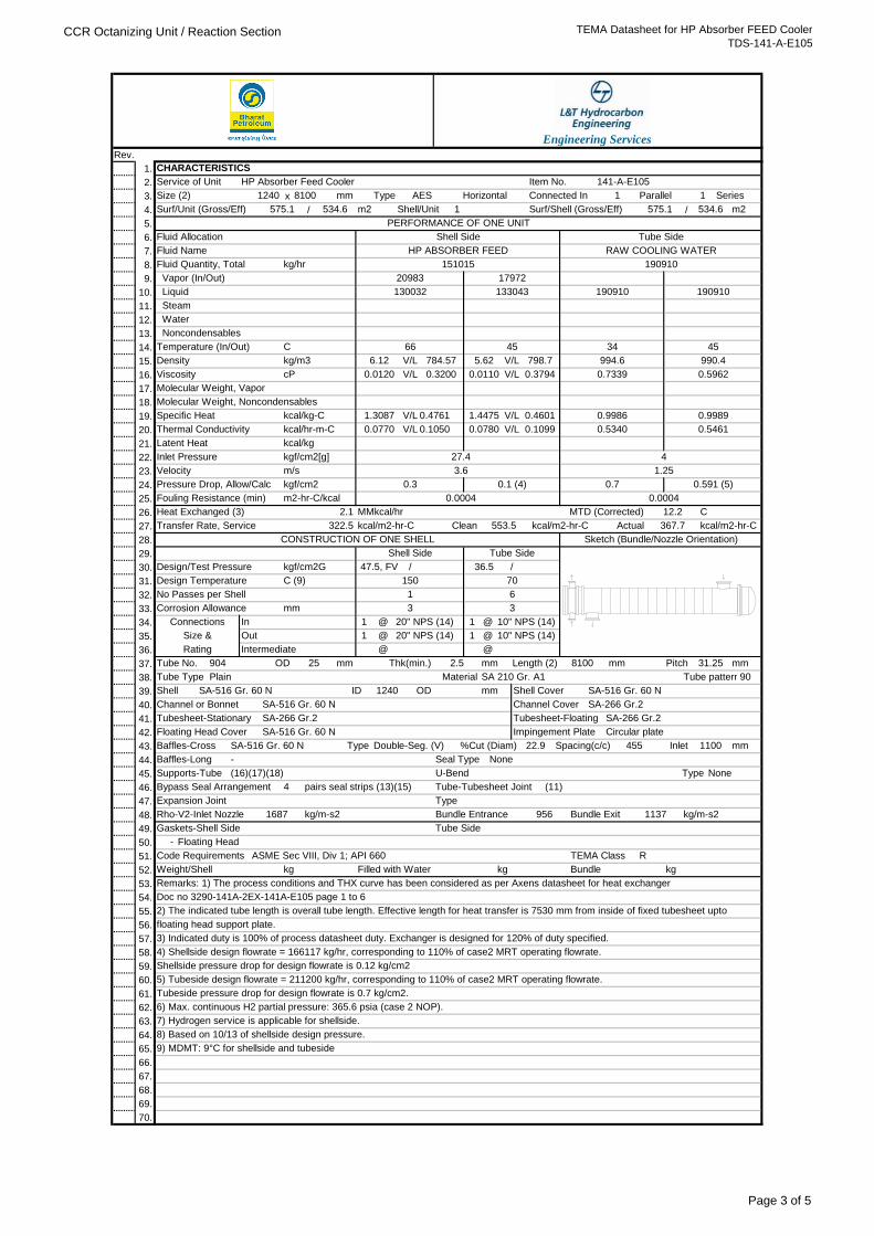
5) Tubeside design flowrate = 211200 kg/hr, corresponding to 110% of case2 MRT operating flowrate.
4) Shellside design flowrate = 166117 kg/hr, corresponding to 110% of case2 MRT operating flowrate.
Shellside pressure drop for design flowrate is 0.12 kg/cm2
Tubeside pressure drop for design flowrate is 0.7 kg/cm2.
7) Hydrogen service is applicable for shellside.
3) Indicated duty is 100% of process datasheet duty. Exchanger is designed for 120% of duty specified.
V/L 0.1050 0.0780 V/L 0.1099
1.3087 V/L 0.4761
5.62 V/L 798.7
0.0120 V/L 0.3200 0.0110 V/L 0.3794
Tubesheet-Stationary
kg/m-s2
6.12 V/L 784.57
m2-hr-C/kcal
C (9)
9) MDMT: 9°C for shellside and tubeside
floating head support plate.
31.25
90
Floating Head
6) Max. continuous H2 partial pressure: 365.6 psia (case 2 NOP).
956 Bundle Exit
Type
Type
8) Based on 10/13 of shellside design pressure.
@
2) The indicated tube length is overall tube length. Effective length for heat transfer is 7530 mm from inside of fixed tubesheet upto
SA-516 Gr. 60 N
kg
C
SA-516 Gr. 60 N
4
(16)(17)(18)
CONSTRUCTION OF ONE SHELL
3
20" NPS (14)
20" NPS (14)
1
kcal/m2-hr-C
1
47.5, FV
@
10" NPS (14)
6
150
1
/
4
1.25
0.7 0.591 (5)
0.9989
0.7339 0.5962
34
Shell Side
994.6 990.4
45
Transfer Rate, Service
70
Fouling Resistance (min)
kcal/m2-hr-CActual
Heat Exchanged (3) 2.1
0.9986
0.5340 0.5461
1.4475 V/L 0.4601
12.2
553.5
0.0004
MTD (Corrected)
kcal/kg-C
Molecular Weight, Noncondensables
Doc no 3290-141A-2EX-141A-E105 page 1 to 6
45
Velocity
Latent Heat
Specific Heat
kgf/cm2[g]
kcal/m2-hr-C
cPViscosity
66
Water
Density
130032 Liquid 133043
Temperature (In/Out)
534.6
Connected In
190910
17972
HP ABSORBER FEED
1
PERFORMANCE OF ONE UNIT
Parallel Series1
575.1 Shell/Unit
Steam
CHARACTERISTICS
20983
m2575.1
Type
m2
kg/hr
534.6
190910 190910
mm
141-A-E105Item No.
1 Surf/Shell (Gross/Eff)
Tube Side
151015
HP Absorber Feed Cooler
HorizontalAES
RAW COOLING WATER
Size (2)
Fluid Allocation
Service of Unit
81001240
Surf/Unit (Gross/Eff)
Fluid Quantity, Total
Fluid Name
Molecular Weight, Vapor
No Passes per Shell
Vapor (In/Out)
kg/m3
Noncondensables
C
kgf/cm2G
Clean322.5 367.7
mm 3
Tube SideShell Side
36.5
Sketch (Bundle/Nozzle Orientation)
Design/Test Pressure
1
Intermediate
Out
InConnections
1
OD
1687
ASME Sec VIII, Div 1; API 660
Gaskets-Shell Side
U-Bend
Tube No.
Tube Side
Bundle Entrance
Remarks: 1) The process conditions and THX curve has been considered as per Axens datasheet for heat exchanger
BundleWeight/Shell
R
kgFilled with Water
mm
Design Temperature
Rating
Plain
Supports-Tube
Channel or Bonnet
kg
-
1100
Seal Type None
22.9Baffles-Cross
Material
Corrosion Allowance
Code Requirements
Rho-V2-Inlet Nozzle
Floating Head Cover
Bypass Seal Arrangement
Shell
Size &
mm
Tube Type
OD
25
ID
2.5mm904 Thk(min.) 8100
Tube pattern
mmPitch
Shell Cover
Length (2)
%Cut (Diam)
SA-516 Gr. 60 N
SA-516 Gr. 60 N Type 455Spacing(c/c)
None
kg/m-s2
TEMA Class
Engineering Services
InletDouble-Seg. (V)
27.4
mm
Tube-Tubesheet Joint
1137
0.0004
Pressure Drop, Allow/Calc
m/s
Thermal Conductivity
kgf/cm2 0.3
Inlet Pressure
kcal/kg
kcal/hr-m-C
3.6
0.1 (4)
0.0770
Channel Cover SA-266 Gr.2
10" NPS (14)
@
@
/
@
MMkcal/hr
SA 210 Gr. A1
mm
@
Circular plateImpingement Plate
SA-266 Gr.2
SA-516 Gr. 60 N
SA-266 Gr.2 Tubesheet-Floating
(11)
Baffles-Long
1240
Expansion Joint
-
pairs seal strips (13)(15)
Page 3 of 5
CCR Octanizing Unit / Reaction Section TEMA Datasheet for HP Absorber FEED Cooler
TDS-141-A-E105
Rev.
1.
2.
3. x
4. / /
5.
6.
7.
8.
9.
10.
11.
12.
13.
14.
15.
16.
17.
18.
19.
20.
21.
22.
23.
24.
25.
26.
27.
28.
29.
30.
31.
32.
33.
34.
35.
36.
37.
38.
39.
40.
41.
42.
43.
44.
45.
46.
47.
48.
49.
50.
51.
52.
53.
54.
55.
56.
57.
58.
59.
60.
61.
62.
63.
64.
65.
66.
67.
68.
69.
70.
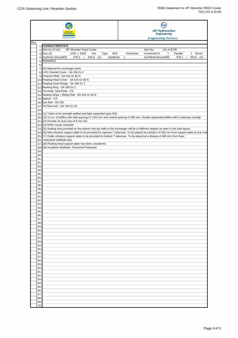
Eye Bolt - SA 105
Tie Rod nuts - SA 194 Gr.2H
11) Tubes to be strength welded and light expanded (upto 5%)
14) Refer nozzle schedule
12) 13 no. of baffles with inlet spacing of 1100 mm and central spacing of 455 mm. Double segmental baffles with 6 tuberows overlap
13) Provide 20 seal rods of 9 mm OD.
15) Sealing strip provided on the bottom and top halfs of the exchanger will be of different heights as seen in the tube layout.
19) Insulation Shellside: Personnel Protection
10) Material for exchanger parts.
LHS Channel Cover - SA 266 Gr.2
Channel Shell - SA 516 Gr 60 N
Floating Head Cover - SA 516 Gr 60 N
Floating head Flange - SA 266 Gr 2
Backing Ring - SA 266 Gr 2
16) Inlet vibration support plate to be provided for topmost 7 tuberows. To be placed at a distace of 550 mm from support plate at rear end.
17) Outlet vibration support plate to be provided for bottom 7 tuberows. To be placed at a distace of 485 mm from fixed
Spacer - CS
Sealing Strips / Sliding Rail - SA 516 Gr 60 N
Tie Rods, Seal Rods - CS
tubesheet shellside face.
18) Floating head support plate has been considered.
m2
REMARKS
Surf/Unit (Gross/Eff) 575.1 534.6 m2 Shell/Unit 1
1 Parallel
Surf/Shell (Gross/Eff) 575.1 534.6
1 SeriesSize (2) 1240 8100 mm Type AES Horizontal Connected In
Engineering Services
CHARACTERISTICS
Service of Unit HP Absorber Feed Cooler Item No. 141-A-E105
Page 4 of 5
CCR Octanizing Unit / Reaction Section TEMA Datasheet for HP Absorber FEED Cooler
TDS-141-A-E105
Rev.
1.
2.
3. x
4. / /
5.
6.
7.
8.
9.
10.
11.
12.
13.
14.
15.
16.
17.
18.
19.
20.
21.
22.
23.
24.
25.
26.
27.
28.
29.
30.
31.
32.
33.
34.
35.
36.
37.
38.
39.
40.
41.
42.
43.
44.
45.
46.
47.
48.
49.
50.
51.
52.
53. SKETCH
54.
55.
56.
57.
58.
59.
60.
61.
62.
63.
64.
65.
66.
67.
68.
69.
70.
300#
T3 2" TUBESIDE STUB CONNECTION -1 1 300#
10" TUBE SIDE INLET 1 300#
T2 10" TUBE SIDE OUTLET 1
T1
CHARACTERISTICS
Service of Unit HP Absorber Feed Cooler Item No. 141-A-E105
Engineering Services
Size (2) 1240 8100 mm Type AES 1 Parallel
Surf/Shell (Gross/Eff) 575.1 534.6
1 SeriesHorizontal Connected In
m2
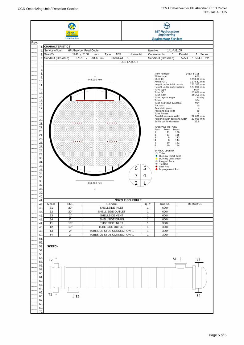
TUBE LAYOUT
Surf/Unit (Gross/Eff) 575.1 534.6 m2 Shell/Unit 1
SERVICE
NOZZLE SCHEDULE
S3 2" SHELLSIDE VENT 1
QTY RATING REMARKS
S1 20" SHELLSIDE INLET 1 600#
MARK SIZE
600#
S2 20" SHELL SIDE OUTLET 1 600#
S4 2" SHELLSIDE DRAIN 1 600#
T4 2" TUBESIDE STUB CONNECTION -1 1 300#
448.000 mm
448.000 mm
Item number
TEMA typeShell ID
Actual OTL
Height under inlet nozzleHeight under outlet nozzle
Tube typeTube OD
Tube pitch
Tube layout angle
Tubes
Tube positions availableTie rods
Seal strip pairsPasslane seal rods
Tube PassesParallel passlane width
Perpendicular passlane width
Baffle cut % diameter
141A-E-105
AES1240.00
1174.82
170.325123.000
Plain25.000
31.250
90
904
90410
420
622.000
22.000
22.9
mm
mm
mm mm
mm
mm
deg
mm
mm
TUBEPASS DETAILSPass
12
3
45
6
Rows
1111
8
810
10
Tubes
156155
143
144152
154
Tube
Dummy Short Tube
Dummy Long TubePlugged Tube
Tie RodSeal Rod
Impingement Rod
SYMBOL LEGEND
6 5
3 4
2 1
T1
S3S1
S4S2
T2
Page 5 of 5
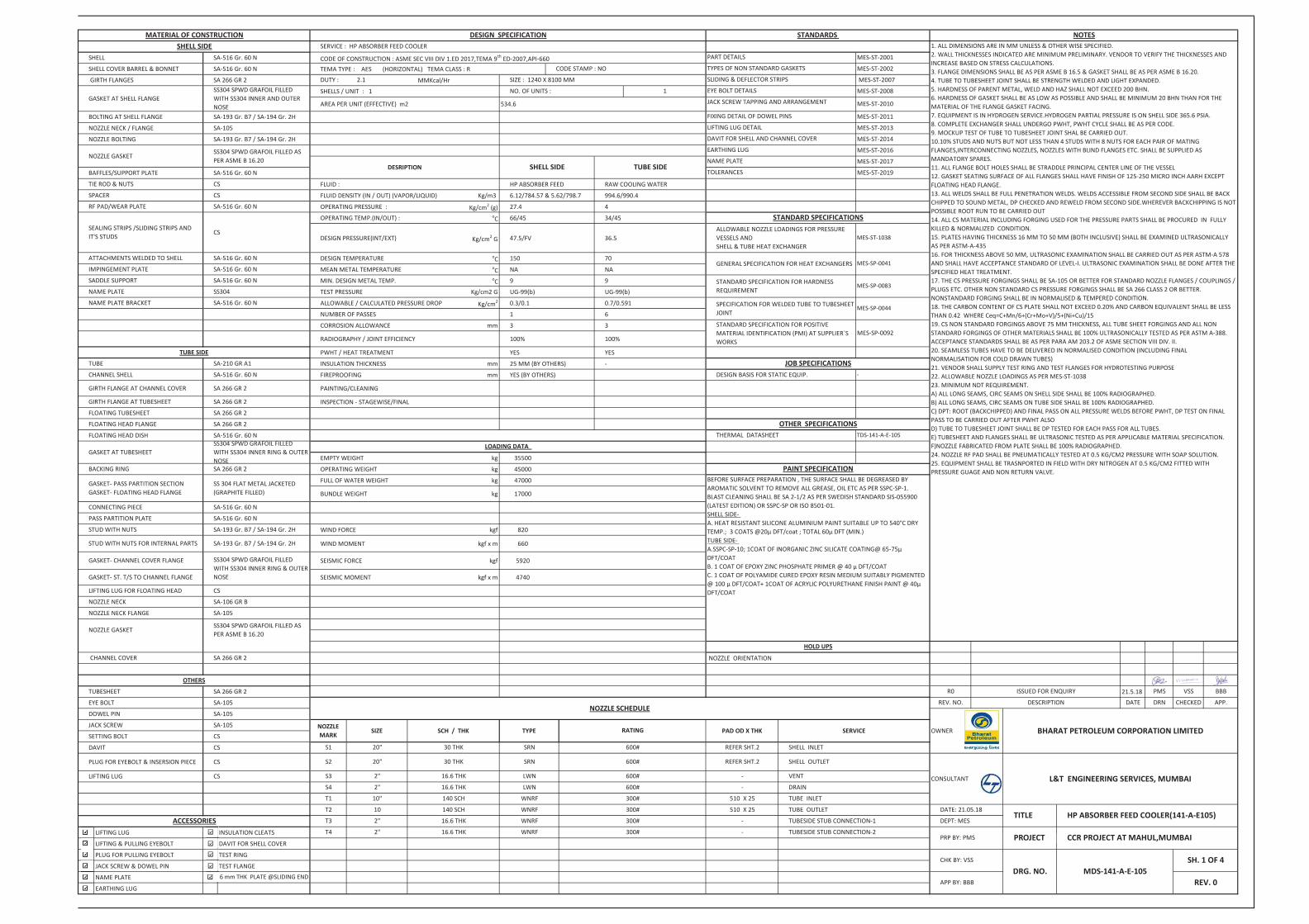
CODE OF CONSTRUCTION : ASME SEC VIII DIV 1.ED 2017,TEMA 9th ED-2007,API-660TEMA TYPE : AES (HORIZONTAL) TEMA CLASS : R
MMKcal/Hr
FLUID : HP ABSORBER FEED RAW COOLING WATER
FLUID DENSITY (IN / OUT) (VAPOR/LIQUID) Kg/m3 6.12/784.57 & 5.62/798.7 994.6/990.4
OPERATING PRESSURE : Kg/cm2 (g) 27.4 4
OPERATING TEMP.(IN/OUT) : oC 66/45 34/45
DESIGN PRESSURE(INT/EXT) Kg/cm2 G 47.5/FV 36.5
DESIGN TEMPERATURE oC 150 70
MEAN METAL TEMPERATURE oC NA NA
MIN. DESIGN METAL TEMP. oC 9 9
TEST PRESSURE Kg/cm2 G UG-99(b) UG-99(b)
ALLOWABLE / CALCULATED PRESSURE DROP Kg/cm2 0.3/0.1 0.7/0.591
NUMBER OF PASSES 1 6
CORROSION ALLOWANCE mm 3 3
RADIOGRAPHY / JOINT EFFICIENCY 100% 100%
PWHT / HEAT TREATMENT YES YES
INSULATION THICKNESS mm 25 MM (BY OTHERS) -
FIREPROOFING mm YES (BY OTHERS)
PAINTING/CLEANING
INSPECTION - STAGEWISE/FINAL
EMPTY WEIGHT kg 35500
OPERATING WEIGHT kg 45000
FULL OF WATER WEIGHT kg 47000
BUNDLE WEIGHT kg 17000
WIND FORCE kgf 820
WIND MOMENT kgf x m 660
SEISMIC FORCE kgf 5920
SEISMIC MOMENT kgf x m 4740
NOZZLE ORIENTATION
21.5.18
LIFTING LUG INSULATION CLEATS
LIFTING & PULLING EYEBOLT DAVIT FOR SHELL COVER
PLUG FOR PULLING EYEBOLT TEST RING
JACK SCREW & DOWEL PIN TEST FLANGE
NAME PLATE
EARTHING LUG
OTHER SPECIFICATIONSTHERMAL DATASHEET TDS-141-A-E-105
JOB SPECIFICATIONS
STANDARD SPECIFICATIONSALLOWABLE NOZZLE LOADINGS FOR PRESSURE VESSELS ANDSHELL & TUBE HEAT EXCHANGER
GENERAL SPECIFICATION FOR HEAT EXCHANGERS MES-SP-0041
MES-SP-0083
SPECIFICATION FOR WELDED TUBE TO TUBESHEET JOINT
NOZZLE GASKETSS304 SPWD GRAFOIL FILLED AS PER ASME B 16.20
MES-ST-1038
DOWEL PIN SA-105
OTHERS
TUBESHEET SA 266 GR 2
EYE BOLT SA-105
TUBE SIDE
CHANNEL COVER SA 266 GR 2
SA 266 GR 2
FLOATING HEAD DISH SA-516 Gr. 60 N
PASS PARTITION PLATE
STUD WITH NUTS SA-193 Gr. B7 / SA-194 Gr. 2H
GASKET- PASS PARTITION SECTIONGASKET- FLOATING HEAD FLANGE
SS 304 FLAT METAL JACKETED (GRAPHITE FILLED)
FLOATING HEAD FLANGE
SA-210 GR A1
GIRTH FLANGE AT CHANNEL COVER SA 266 GR 2
SA-516 Gr. 60 N
SHELL SA-516 Gr. 60 N
SS304 SPWD GRAFOIL FILLED AS PER ASME B 16.20
NOZZLE GASKET
BAFFLES/SUPPORT PLATE SA-516 Gr. 60 N
SA-105
SA-193 Gr. B7 / SA-194 Gr. 2HBOLTING AT SHELL FLANGE
SA-516 Gr. 60 N
CS
GASKET AT SHELL FLANGESS304 SPWD GRAFOIL FILLED WITH SS304 INNER AND OUTER NOSE
RF PAD/WEAR PLATE SA-516 Gr. 60 N
ATTACHMENTS WELDED TO SHELL
TIE ROD & NUTS
SPACER
SEALING STRIPS /SLIDING STRIPS AND IT'S STUDS
CS
JACK SCREW
SETTING BOLT
DAVIT
PLUG FOR EYEBOLT & INSERSION PIECE
LIFTING LUG
SA-105
CS
CS
NAME PLATE SS304
TUBE
IMPINGEMENT PLATE
SA-516 Gr. 60 NNAME PLATE BRACKET
SA 266 GR 2
CONNECTING PIECE SA-516 Gr. 60 N
BACKING RING
GASKET- CHANNEL COVER FLANGE
SS304 SPWD GRAFOIL FILLED WITH SS304 INNER RING & OUTER NOSE
GASKET AT TUBESHEET
SA-516 Gr. 60 N
GIRTH FLANGE AT TUBESHEET SA 266 GR 2
NOZZLE BOLTING SA-193 Gr. B7 / SA-194 Gr. 2H
CHANNEL SHELL
FLOATING TUBESHEET SA 266 GR 2
SA-516 Gr. 60 N
SADDLE SUPPORT SA-516 Gr. 60 N
NOZZLE NECK FLANGE SA-105
STUD WITH NUTS FOR INTERNAL PARTS
SS304 SPWD GRAFOIL FILLED WITH SS304 INNER RING & OUTER NOSE
NOZZLE NECK SA-106 GR B
GASKET- ST. T/S TO CHANNEL FLANGE
SA-193 Gr. B7 / SA-194 Gr. 2H
LIFTING LUG FOR FLOATING HEAD CS
EARTHING LUG MES-ST-2016
NAME PLATE
1. ALL DIMENSIONS ARE IN MM UNLESS & OTHER WISE SPECIFIED.2. WALL THICKNESSES INDICATED ARE MINIMUM PRELIMINARY. VENDOR TO VERIFY THE THICKNESSES AND INCREASE BASED ON STRESS CALCULATIONS.3. FLANGE DIMENSIONS SHALL BE AS PER ASME B 16.5 & GASKET SHALL BE AS PER ASME B 16.20.4. TUBE TO TUBESHEET JOINT SHALL BE STRENGTH WELDED AND LIGHT EXPANDED.5. HARDNESS OF PARENT METAL, WELD AND HAZ SHALL NOT EXCEED 200 BHN.6. HARDNESS OF GASKET SHALL BE AS LOW AS POSSIBLE AND SHALL BE MINIMUM 20 BHN THAN FOR THE MATERIAL OF THE FLANGE GASKET FACING.7. EQUIPMENT IS IN HYDROGEN SERVICE.HYDROGEN PARTIAL PRESSURE IS ON SHELL SIDE 365.6 PSIA.8. COMPLETE EXCHANGER SHALL UNDERGO PWHT, PWHT CYCLE SHALL BE AS PER CODE.9. MOCKUP TEST OF TUBE TO TUBESHEET JOINT SHAL BE CARRIED OUT.10.10% STUDS AND NUTS BUT NOT LESS THAN 4 STUDS WITH 8 NUTS FOR EACH PAIR OF MATING FLANGES,INTERCONNECTING NOZZLES, NOZZLES WITH BLIND FLANGES ETC. SHALL BE SUPPLIED AS MANDATORY SPARES.11. ALL FLANGE BOLT HOLES SHALL BE STRADDLE PRINCIPAL CENTER LINE OF THE VESSEL12. GASKET SEATING SURFACE OF ALL FLANGES SHALL HAVE FINISH OF 125-250 MICRO INCH AARH EXCEPT FLOATING HEAD FLANGE.13. ALL WELDS SHALL BE FULL PENETRATION WELDS. WELDS ACCESSIBLE FROM SECOND SIDE SHALL BE BACK CHIPPED TO SOUND METAL, DP CHECKED AND REWELD FROM SECOND SIDE.WHEREVER BACKCHIPPING IS NOT POSSIBLE ROOT RUN TO BE CARRIED OUT14. ALL CS MATERIAL INCLUDING FORGING USED FOR THE PRESSURE PARTS SHALL BE PROCURED IN FULLY KILLED & NORMALIZED CONDITION.15. PLATES HAVING THICKNESS 16 MM TO 50 MM (BOTH INCLUSIVE) SHALL BE EXAMINED ULTRASONICALLY AS PER ASTM-A-43516. FOR THICKNESS ABOVE 50 MM, ULTRASONIC EXAMINATION SHALL BE CARRIED OUT AS PER ASTM-A 578 AND SHALL HAVE ACCEPTANCE STANDARD OF LEVEL-I. ULTRASONIC EXAMINATION SHALL BE DONE AFTER THE SPECIFIED HEAT TREATMENT.17. THE CS PRESSURE FORGINGS SHALL BE SA-105 OR BETTER FOR STANDARD NOZZLE FLANGES / COUPLINGS / PLUGS ETC. OTHER NON STANDARD CS PRESSURE FORGINGS SHALL BE SA 266 CLASS 2 OR BETTER. NONSTANDARD FORGING SHALL BE IN NORMALISED & TEMPERED CONDITION.18. THE CARBON CONTENT OF CS PLATE SHALL NOT EXCEED 0.20% AND CARBON EQUIVALENT SHALL BE LESS THAN 0.42 WHERE Ceq=C+Mn/6+(Cr+Mo+V)/5+(Ni+Cu)/1519. CS NON STANDARD FORGINGS ABOVE 75 MM THICKNESS, ALL TUBE SHEET FORGINGS AND ALL NON STANDARD FORGINGS OF OTHER MATERIALS SHALL BE 100% ULTRASONICALLY TESTED AS PER ASTM A-388. ACCEPTANCE STANDARDS SHALL BE AS PER PARA AM 203.2 OF ASME SECTION VIII DIV. II.20. SEAMLESS TUBES HAVE TO BE DELIVERED IN NORMALISED CONDITION (INCLUDING FINAL NORMALISATION FOR COLD DRAWN TUBES)21. VENDOR SHALL SUPPLY TEST RING AND TEST FLANGES FOR HYDROTESTING PURPOSE22. ALLOWABLE NOZZLE LOADINGS AS PER MES-ST-103823. MINIMUM NDT REQUIREMENT. A) ALL LONG SEAMS, CIRC SEAMS ON SHELL SIDE SHALL BE 100% RADIOGRAPHED.B) ALL LONG SEAMS, CIRC SEAMS ON TUBE SIDE SHALL BE 100% RADIOGRAPHED.C) DPT: ROOT (BACKCHIPPED) AND FINAL PASS ON ALL PRESSURE WELDS BEFORE PWHT, DP TEST ON FINAL PASS TO BE CARRIED OUT AFTER PWHT ALSOD) TUBE TO TUBESHEET JOINT SHALL BE DP TESTED FOR EACH PASS FOR ALL TUBES.E) TUBESHEET AND FLANGES SHALL BE ULTRASONIC TESTED AS PER APPLICABLE MATERIAL SPECIFICATION.F)NOZZLE FABRICATED FROM PLATE SHALL BE 100% RADIOGRAPHED.24. NOZZLE RF PAD SHALL BE PNEUMATICALLY TESTED AT 0.5 KG/CM2 PRESSURE WITH SOAP SOLUTION.25. EQUIPMENT SHALL BE TRASNPORTED IN FIELD WITH DRY NITROGEN AT 0.5 KG/CM2 FITTED WITH PRESSURE GUAGE AND NON RETURN VALVE.
DESIGN BASIS FOR STATIC EQUIP.
TOLERANCES
MES-ST-2013
PART DETAILS
MES-ST-2014
-
MES-ST-2017
MES-ST-2019
MES-SP-0044
6 mm THK PLATE @SLIDING END
ACCESSORIEST4 WNRF 300#
WNRF
NOTES
NOZZLE SCHEDULE
TITLE
CS
TYPE
CS
CS
SA-516 Gr. 60 N
OWNER BHARAT PETROLEUM CORPORATION LIMITED
HOLD UPS
-
NOZZLEMARK
140 SCH
TUBESIDE STUB CONNECTION-1
16.6 THK
DESRIPTION
SHELL COVER BARREL & BONNET
MATERIAL OF CONSTRUCTIONSHELL SIDE
NOZZLE NECK / FLANGE
2.1
DESIGN SPECIFICATION
AREA PER UNIT (EFFECTIVE) m2
NO. OF UNITS :SHELLS / UNIT : 1
DUTY : GIRTH FLANGES SA 266 GR 2
MES-ST-2008
JACK SCREW TAPPING AND ARRANGEMENT
FIXING DETAIL OF DOWEL PINS
LIFTING LUG DETAIL
MES-ST-2010
MES-ST-2011
MES-ST-2002
MES-ST-2007
SHELL SIDE
DAVIT FOR SHELL AND CHANNEL COVER
STANDARD SPECIFICATION FOR HARDNESS REQUIREMENT
LOADING DATA
2''
SIZE SCH / THK
16.6 THK
30 THK
16.6 THK
TUBE SIDE
30 THK
140 SCH
T3 2''
SRN
TYPES OF NON STANDARD GASKETS
SLIDING & DEFLECTOR STRIPS
EYE BOLT DETAILS
MES-ST-2001
1
534.6
CODE STAMP : NO
SERVICE : HP ABSORBER FEED COOLER
SIZE : 1240 X 8100 MM
STANDARDS
LWN
SHELL OUTLET
TUBE INLETWNRF
WNRF
VENT
DRAIN
600#
300#
RATING
REFER SHT.2
-
510 X 25
300#
300#
600#
600# -
510 X 25
PROJECT �TUBESIDE STUB CONNECTION-2
CHK BY: VSS
L&T ENGINEERING SERVICES, MUMBAI
R0
CCR PROJECT AT MAHUL,MUMBAI
DATE DRN
PRP BY: PMS
CHECKED
HP ABSORBER FEED COOLER(141-A-E105)
DESCRIPTION
DEPT: MES
2''
SERVICE
SHELL INLET
APP.
TUBE OUTLET
REFER SHT.2
REV. NO.
CONSULTANT-
20"
20"
10''
10
S1
S2
S3
T1
T2
PAINT SPECIFICATIONBEFORE SURFACE PREPARATION , THE SURFACE SHALL BE DEGREASED BY AROMATIC SOLVENT TO REMOVE ALL GREASE, OIL ETC AS PER SSPC-SP-1.BLAST CLEANING SHALL BE SA 2-1/2 AS PER SWEDISH STANDARD SIS-055900 (LATEST EDITION) OR SSPC-SP OR ISO 8501-01.SHELL SIDE- A. HEAT RESISTANT SILICONE ALUMINIUM PAINT SUITABLE UP TO 540°C DRY TEMP.; 3 COATS @20μ DFT/coat ; TOTAL 60μ DFT (MIN.)TUBE SIDE- A.SSPC-SP-10; 1COAT OF INORGANIC ZINC SILICATE COATING@ 65-75μ DFT/COAT B. 1 COAT OF EPOXY ZINC PHOSPHATE PRIMER @ 40 μ DFT/COATC. 1 COAT OF POLYAMIDE CURED EPOXY RESIN MEDIUM SUITABLY PIGMENTED @ 100 μ DFT/COAT+ 1COAT OF ACRYLIC POLYURETHANE FINISH PAINT @ 40μ DFT/COAT
SRN
PAD OD X THK
S4 2'' 16.6 THK LWN 600#
APP BY: BBB
DATE: 21.05.18
STANDARD SPECIFICATION FOR POSITIVE MATERIAL IDENTIFICATION (PMI) AT SUPPLIER`S WORKS
MES-SP-0092
PMS VSS BBB
DRG. NO. MDS-141-A-E-105SH. 1 OF 4
REV. 0
ISSUED FOR ENQUIRY


REV.
01
APPD.CHKD.BY
ALLOWABLE NOZZLE LOADS
DESCRIPTION
ALLOWABLE NOZZLE LOADINGS
MES-ST-1038
00
1 OF 9
ISSUED FOR IMPLEMENTATION
FOR
PRESSURE VESSELS
AND
(PRESSURE VESSELS ANDSHELL & TUBE HEAT EXCHANGER)
DATE22/04/2010
10-JUN-201601 REVISED & REISSUED AS STANDARD DRAWING
AKGANDAKV
RGOHASSMP
STANDARD NO.
SHEET
REV.
L&T Hydrocarbon Engineering
SHELL & TUBE HEAT EXCHANGERS
NOZZLE SIZE
NPS(Inch)
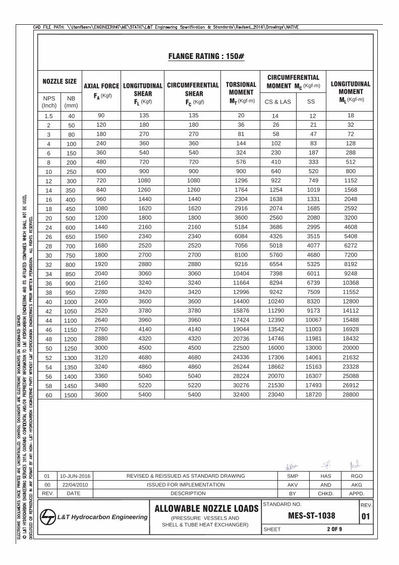
FLANGE RATING : 150#
(Kgf)(Kgf) (Kgf) (Kgf-m) (Kgf-m)
(Kgf-m)
901.5 135 20 12 181202 180 36 21 321803 270 81 47 722404 360 144 83 1283606 540 324 187 2884808 720 576 333 51260010 900 900 520 80072012 1080 1296 749 115284014 1260 1764 1019 156896016 1440 2304 1331 2048
108018 1620 2916 1685 2592120020 1800 3600 2080 3200144024 2160 5184 2995 4608156026 2340 6084 3515 5408168028 2520 7056 4077 6272180030 2700 8100 4680 7200192032 2880 9216 5325 8192204034 3060 10404 6011 9248216036 3240 11664 6739 10368228038 3420 12996 7509 11552240040 3600 14400 8320 12800252042 3780 15876 9173 14112264044 3960 17424 10067 15488276046 4140 19044 11003 16928288048 4320
2250011981 18432
3000 450024336
13000 2000050
NB(mm)
AXIAL FORCE LONGITUDINAL CIRCUMFERENTIAL TORSIONAL SHEAR SHEAR MOMENT
CIRCUMFERENTIAL MOMENT LONGITUDINAL
MOMENTSSCS & LAS
142658102230410640922125416382074256036864326501857606554739882949242102401129012390135421474616000
405080
100150200250300350400450500600650700750800850900950100010501100115012001250
312052 468026244
14061 21632324054 4860
2822415163 23328
336056 504030276
16307 25088348058 5220
3240017493 26912
3600 5400 18720 2880060
1730618662200702153023040
13001350140014501500
135180270360540720900108012601440162018002160234025202700288030603240342036003780396041404320450046804860504052205400
20736
FAFL FC
MTML
MC
REV.
01
APPD.CHKD.BY
ALLOWABLE NOZZLE LOADS
DESCRIPTION
MES-ST-1038
00
2 OF 9
ISSUED FOR IMPLEMENTATION
(PRESSURE VESSELS ANDSHELL & TUBE HEAT EXCHANGER)
DATE
22/04/2010
10-JUN-201601 REVISED & REISSUED AS STANDARD DRAWING
AKGANDAKV
RGOHASSMP
STANDARD NO.
SHEET
REV.
L&T Hydrocarbon Engineering
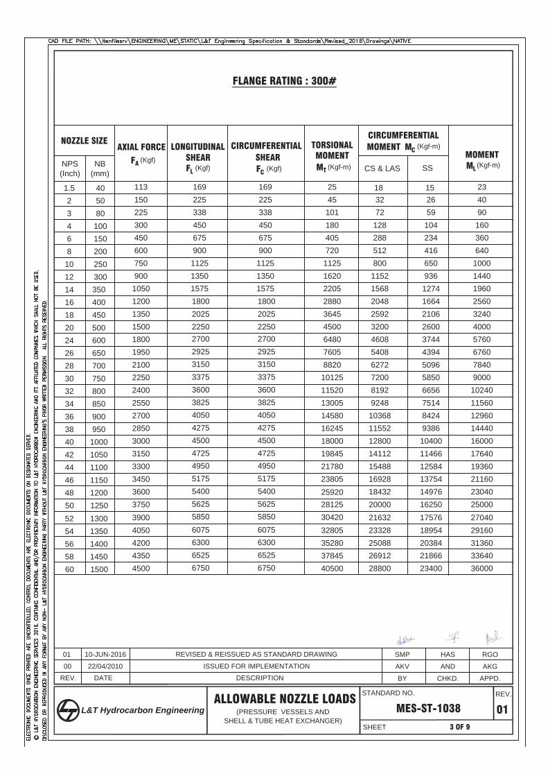
FLANGE RATING : 300#
1131.5 169 25 15 231502 225 45 26 402253 338 101 59 903004 450 180 104 1604506 675 405 234 3606008 900 720 416 64075010 1125 1125 650 100090012 1350 1620 936 1440105014 1575 2205 1274 1960120016 1800 2880 1664 2560135018 2025 3645 2106 3240150020
27004500 2600 4000
1800242925
6480 3744 5760195026
31507605 4394 6760
2100283375
8820 5096 7840225030
360010125 5850 9000
2400323825
11520 6656 10240255034
405013005 7514 11560
2700364275
14580 8424 12960285038
450016245 9386 14440
3000404725
18000 10400 16000315042
495019845 11466 17640
3300445175
21780 12584 19360345046
540023805 13754 21160
3600485625 28125
14976 230403750
5850 3042016250 2500050
183272128288512800115215682048259232004608540862727200819292481036811552128001411215488169281843220000
405080100150200250300350400450500600650700750800850900950100010501100115012001250
3900526075 32805
17576 27040405054
6300 3528018954 29160
4200566525 37845
20384 31360435058
6750 4050021866 33640
4500 23400 3600060
2163223328250882691228800
13001350140014501500
25920
2250
16922533845067590011251350157518002025
2700292531503375360038254050427545004725495051755400562558506075630065256750
2250
NOZZLE SIZE
NPS(Inch)
(Kgf)(Kgf) (Kgf) (Kgf-m) (Kgf-m)
(Kgf-m)
NB(mm)
AXIAL FORCE LONGITUDINAL CIRCUMFERENTIAL TORSIONAL SHEAR SHEAR MOMENT
CIRCUMFERENTIAL MOMENT
MOMENTSSCS & LAS
FAFL FC
MT ML
MC
REV.
01
APPD.CHKD.BY
ALLOWABLE NOZZLE LOADS
DESCRIPTION
MES-ST-1038
00
3 OF 9
ISSUED FOR IMPLEMENTATION
(PRESSURE VESSELS ANDSHELL & TUBE HEAT EXCHANGER)
DATE
22/04/2010
10-JUN-201601 REVISED & REISSUED AS STANDARD DRAWING
AKGANDAKV
RGOHASSMP
STANDARD NO.
SHEET
REV.
L&T Hydrocarbon Engineering
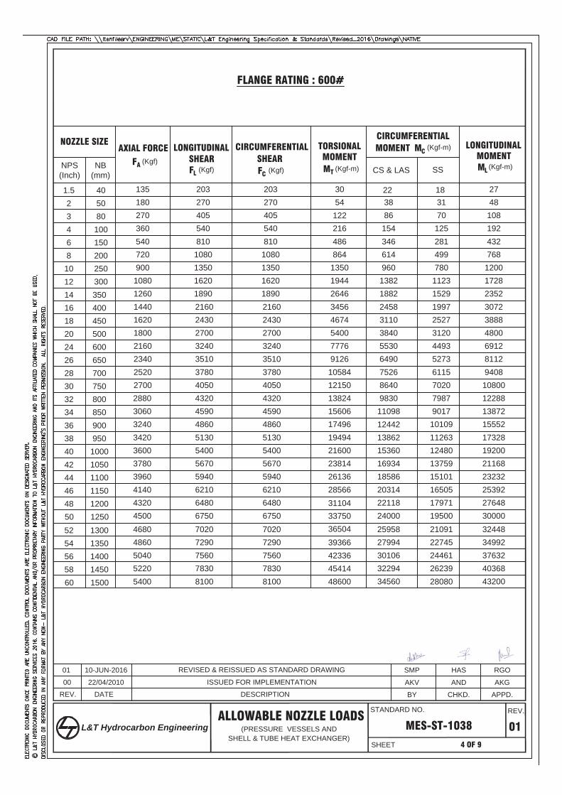
FLANGE RATING : 600#
1351.5 203 30 18 271802 270 54 31 482703 405 122 70 1083604 540 216 125 1925406 810 486 281 4327208 1080 864 499 76890010 1350 1350 780 1200108012 1620 1944 1123 1728126014 1890 2646 1529 2352144016 2160 3456 1997 3072162018 2430 4674 2527 3888180020 2700 5400 3120 4800216024 3240 7776 4493 6912234026 3510 9126 5273 8112252028 3780 10584 6115 9408270030 4050 12150 7020 10800
32 4320 13824 7987 12288
34 4590 15606 9017 13872
36 4860 17496 10109 15552
38 5130 19494 11263 17328
40 5400 21600 12480 19200
42 5670 23814 13759 21168
44 5940 26136 15101 23232
46 6210 28566 16505 25392
48 648033750
17971 276486750
3650419500 3000050
2238861543466149601382188224583110384055306490752686409830110981244213862153601693418586203142211824000
405080100150200250300350400450500600650700750800850900950100010501100115012001250
52 702039366
21091 32448
54 729042336
22745 34992
56 756045414
24461 37632
58 783048600
26239 403688100 28080 4320060
2595827994301063229434560
13001350140014501500
31104
288030603240342036003780396041404320450046804860504052205400
20327040554081010801350162018902160243027003240351037804050432045904860513054005670594062106480675070207290756078308100
NOZZLE SIZE
NPS(Inch)
(Kgf)(Kgf) (Kgf) (Kgf-m) (Kgf-m)
(Kgf-m)
NB(mm)
AXIAL FORCE LONGITUDINAL CIRCUMFERENTIAL TORSIONAL SHEAR SHEAR MOMENT
CIRCUMFERENTIAL MOMENT LONGITUDINAL
MOMENTSSCS & LAS
FAFL FC
MTML
MC
REV.
01
APPD.CHKD.BY
ALLOWABLE NOZZLE LOADS
DESCRIPTION
MES-ST-1038
00
4 OF 9
ISSUED FOR IMPLEMENTATION
(PRESSURE VESSELS ANDSHELL & TUBE HEAT EXCHANGER)
DATE
22/04/2010
10-JUN-201601 REVISED & REISSUED AS STANDARD DRAWING
AKGANDAKV
RGOHASSMP
STANDARD NO.
SHEET
REV.
L&T Hydrocarbon Engineering
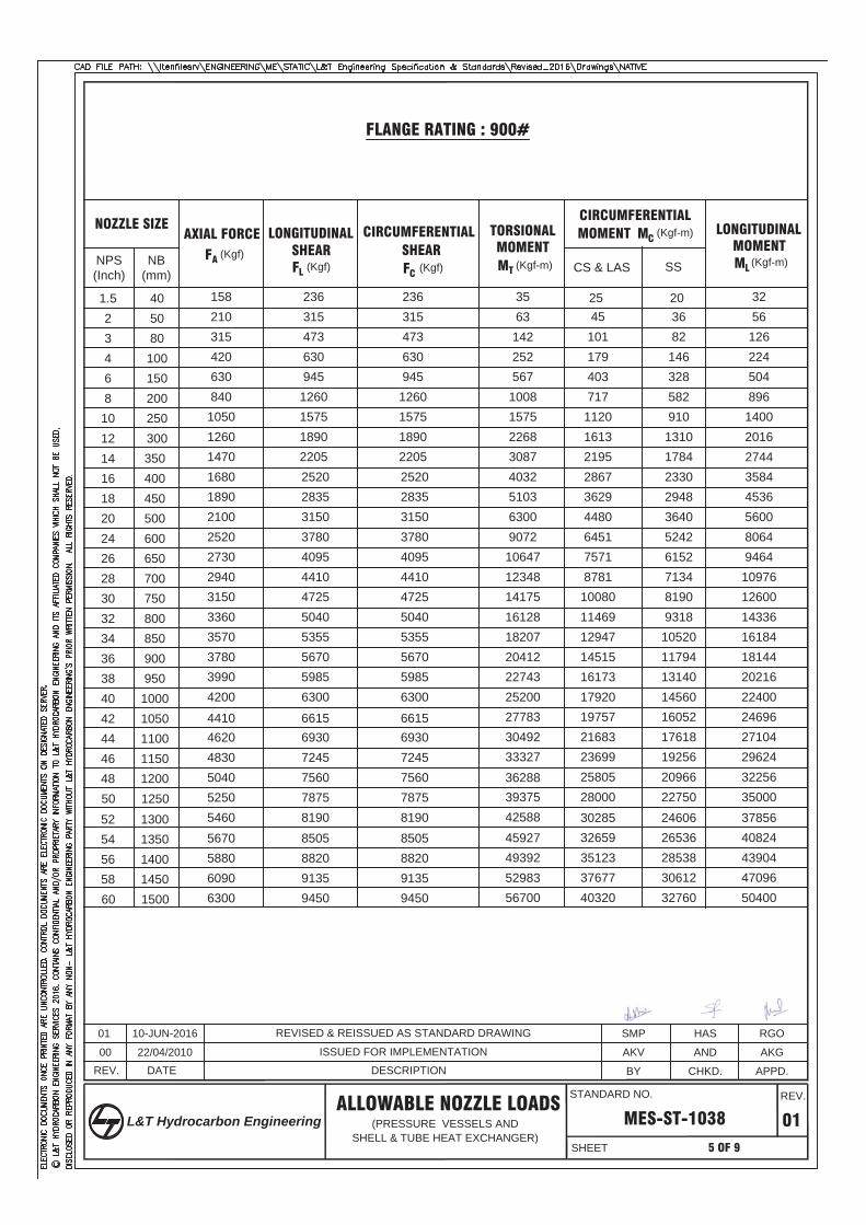
FLANGE RATING : 900#
1581.5 236 35 20 322102 315 63 36 563153 473 142 82 1264204 630 252 146 2246306 945 567 328 5048408 1260 1008 582 896105010 1575 1575 910 1400126012 1890 2268 1310 2016147014 2205 3087 1784 2744168016 2520 4032 2330 3584189018 2835 5103 2948 4536210020 3150 6300 3640 5600252024 3780 9072 5242 8064273026 4095 10647 6152 9464294028 4410 12348 7134 10976315030 4725 14175 8190 12600336032 5040 16128 9318 14336357034 5355 18207 10520 16184378036 5670 20412 11794 18144399038 5985 22743 13140 20216420040 6300 25200 14560 22400
462042
693027783 16052 24696
483044
724530492 17618 27104
504046
756033327 19256 29624
525048
7875 3937520966 32256
5460 8190 4258822750 3500050
25451011794037171120161321952867362944806451757187811008011469129471451516173179201975721683236992580528000
405080100150200250300350400450500600650700750800850900950100010501100115012001250
567052
8505 4592724606 37856
588054
8820 4939226536 40824
609056
9135 5298328538 43904
630058
9450 5670030612 4709632760 5040060
3028532659351233767740320
13001350140014501500
36288
4410 6615
2363154736309451260157518902205252028353150378040954410472550405355567059856300
693072457560787581908505882091359450
6615
NOZZLE SIZE
NPS(Inch)
(Kgf)(Kgf) (Kgf) (Kgf-m) (Kgf-m)
(Kgf-m)
NB(mm)
AXIAL FORCE LONGITUDINAL CIRCUMFERENTIAL TORSIONAL SHEAR SHEAR MOMENT
CIRCUMFERENTIAL MOMENT LONGITUDINAL
MOMENTSSCS & LAS
FAFL FC
MT ML
MC
REV.
01
APPD.CHKD.BY
ALLOWABLE NOZZLE LOADS
DESCRIPTION
MES-ST-1038
00
5 OF 9
ISSUED FOR IMPLEMENTATION
(PRESSURE VESSELS ANDSHELL & TUBE HEAT EXCHANGER)
DATE22/04/2010
10-JUN-201601 REVISED & REISSUED AS STANDARD DRAWING
AKGANDAKV
RGOHASSMP
STANDARD NO.
SHEET
REV.
L&T Hydrocarbon Engineering

FLANGE RATING : 1500#
1801.5 270 41 23 362402 360 72 42 643603 540 162 94 1444804 720 288 166 2567206 1080 648 374 5769608 1440 1152 666 1024120010 1800 1800 1040 1600144012 2160 2592 1498 2304168014 2520 3528 2038 3136192016 2880 4608 2662 4096216018 3240 5382 3370 5184240020 3600 7200 4160 6400288024 4320 10368 5990 9216312026 4680 12168 7030 10816336028 5040 14112 8154 12544360030 5400 16200 9360 14400384032 5760 18432 10650 16384408034 6120 20808 12022 18496432036 6480 23328 13478 20736456038 6840 25992 15018 23104480040 7200 28880 16640 25600504042 7560 31752 18346 28224528044 7920 34848 20134 30976552046 8280 38088 22006 33856576048 8640
4500023962 36864
6000 900048672
26000 4000050
295111520546181912801843250932774147512073738653100351152013107147971658918483204802257924781270852949132000
405080
100150200250300350400450500600650700750800850900950100010501100115012001250
624052 936052488
28122 43264648054 9720
5644830326 46656
672056 1008060552
32614 50176696058 10440
6480034986 53824
7200 10800 37440 5760060
3461137325401414305946080
13001350140014501500
41472
270360540720108014401800216025202880324036004320468050405400576061206480684072007560792082808640900093609720100801044010800
NOZZLE SIZE
NPS(Inch)
(Kgf)(Kgf) (Kgf) (Kgf-m) (Kgf-m)
(Kgf-m)
NB(mm)
AXIAL FORCE LONGITUDINAL CIRCUMFERENTIAL TORSIONAL SHEAR SHEAR MOMENT
CIRCUMFERENTIAL MOMENT LONGITUDINAL
MOMENTSSCS & LAS
FAFL FC
MT ML
MC
REV.
01
APPD.CHKD.BY
ALLOWABLE NOZZLE LOADS
DESCRIPTION
MES-ST-1038
00
6 OF 9
ISSUED FOR IMPLEMENTATION
(PRESSURE VESSELS ANDSHELL & TUBE HEAT EXCHANGER)
DATE
22/04/2010
10-JUN-201601 REVISED & REISSUED AS STANDARD DRAWING
AKGANDAKV
RGOHASSMP
STANDARD NO.
SHEET
REV.
L&T Hydrocarbon Engineering
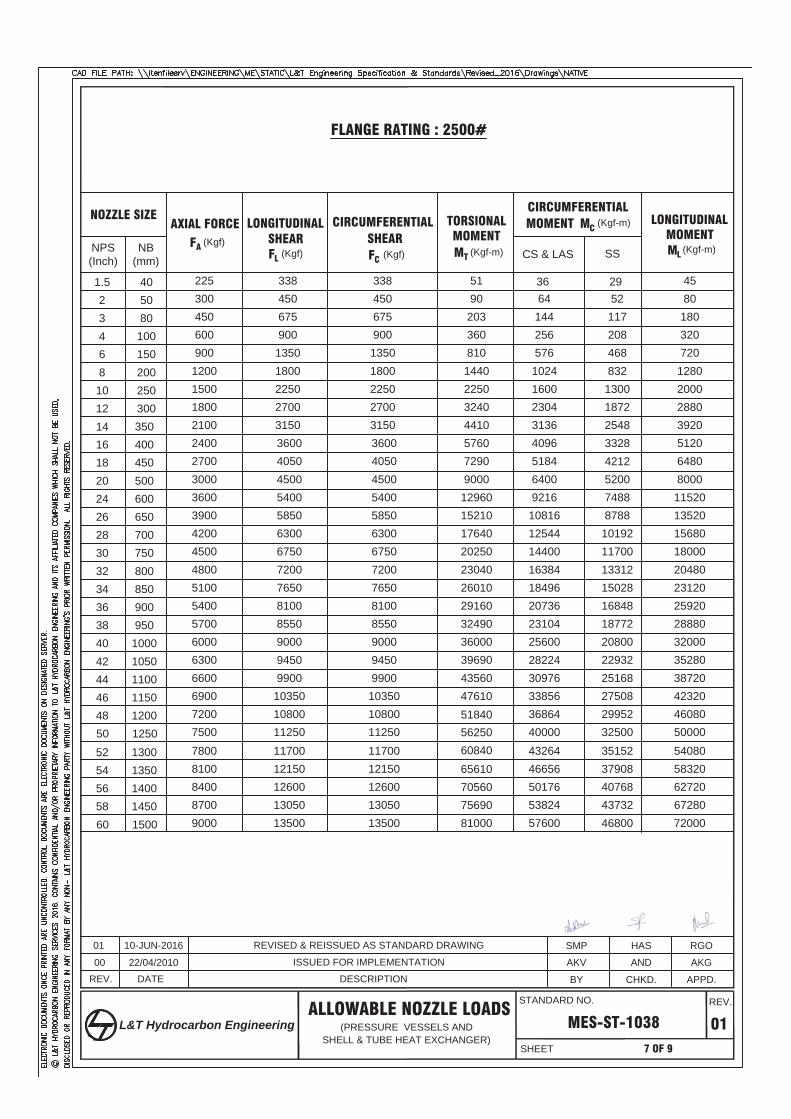
FLANGE RATING : 2500#
2251.5 338 51 29 453002 450 90 52 804503 675 203 117 1806004 900 360 208 3209006 1350 810 468 720
12008 1800 1440 832 1280150010 2250 2250 1300 2000180012 2700 3240 1872 2880210014 3150 4410 2548 3920240016 3600 5760 3328 5120270018 4050 7290 4212 6480300020 4500 9000 5200 8000360024 5400 12960 7488 11520390026 5850 15210 8788 13520420028 6300 17640 10192 15680450030 6750 20250 11700 18000480032 7200 23040 13312 20480510034 7650 26010 15028 23120540036 8100 29160 16848 25920570038 8550 32490 18772 28880600040 9000 36000 20800 32000630042 9450 39690 22932 35280660044 9900 43560 25168 38720690046 10350 47610 27508 42320720048 10800
5625029952 46080
7500 1125060840
32500 5000050
3664
14425657610241600230431364096518464009216
10816125441440016384184962073623104256002822430976338563686440000
405080
100150200250300350400450500600650700750800850900950
100010501100115012001250
780052 1170065610
35152 54080810054 12150
7056037908 58320
840056 1260075690
40768 62720870058 13050
8100043732 67280
9000 13500 46800 7200060
4326446656501765382457600
13001350140014501500
51840
3384506759001350180022502700315036004050450054005850630067507200765081008550900094509900
1035010800112501170012150126001305013500
NOZZLE SIZE
NPS(Inch)
(Kgf)(Kgf) (Kgf) (Kgf-m) (Kgf-m)
(Kgf-m)
NB(mm)
AXIAL FORCE LONGITUDINAL CIRCUMFERENTIAL TORSIONAL SHEAR SHEAR MOMENT
CIRCUMFERENTIAL MOMENT LONGITUDINAL
MOMENTSSCS & LAS
FAFL FC
MT ML
MC
REV.
01
APPD.CHKD.BY
ALLOWABLE NOZZLE LOADS
DESCRIPTION
MES-ST-1038
00
7 OF 9
ISSUED FOR IMPLEMENTATION
(PRESSURE VESSELS ANDSHELL & TUBE HEAT EXCHANGER)
DATE22/04/2010
10-JUN-201601 REVISED & REISSUED AS STANDARD DRAWING
AKGANDAKV
RGOHASSMP
STANDARD NO.
SHEET
REV.
L&T Hydrocarbon Engineering
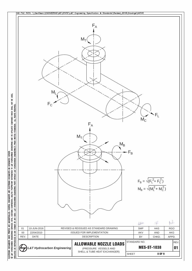
FLMC
FA
MT
ML
FC
FB
MB
FA
MT
FB = (FL + FC )2 2
MB = (ML + MC )2 2
REV.
01
APPD.CHKD.BY
ALLOWABLE NOZZLE LOADS
DESCRIPTION
MES-ST-1038
00
8 OF 9
ISSUED FOR IMPLEMENTATION
(PRESSURE VESSELS ANDSHELL & TUBE HEAT EXCHANGER)
DATE22/04/2010
10-JUN-201601 REVISED & REISSUED AS STANDARD DRAWING
AKGANDAKV
RGOHASSMP
STANDARD NO.
SHEET
REV.
L&T Hydrocarbon Engineering
NOTES :-
2 2
REV.
01
APPD.CHKD.BY
ALLOWABLE NOZZLE LOADS
DESCRIPTION
MES-ST-1038
00
9 OF 9
ISSUED FOR IMPLEMENTATION
(PRESSURE VESSELS ANDSHELL & TUBE HEAT EXCHANGER)
DATE22/04/2010
10-JUN-201601 REVISED & REISSUED AS STANDARD DRAWING
AKGANDAKV
RGOHASSMP
STANDARD NO.
SHEET
REV.
L&T Hydrocarbon Engineering
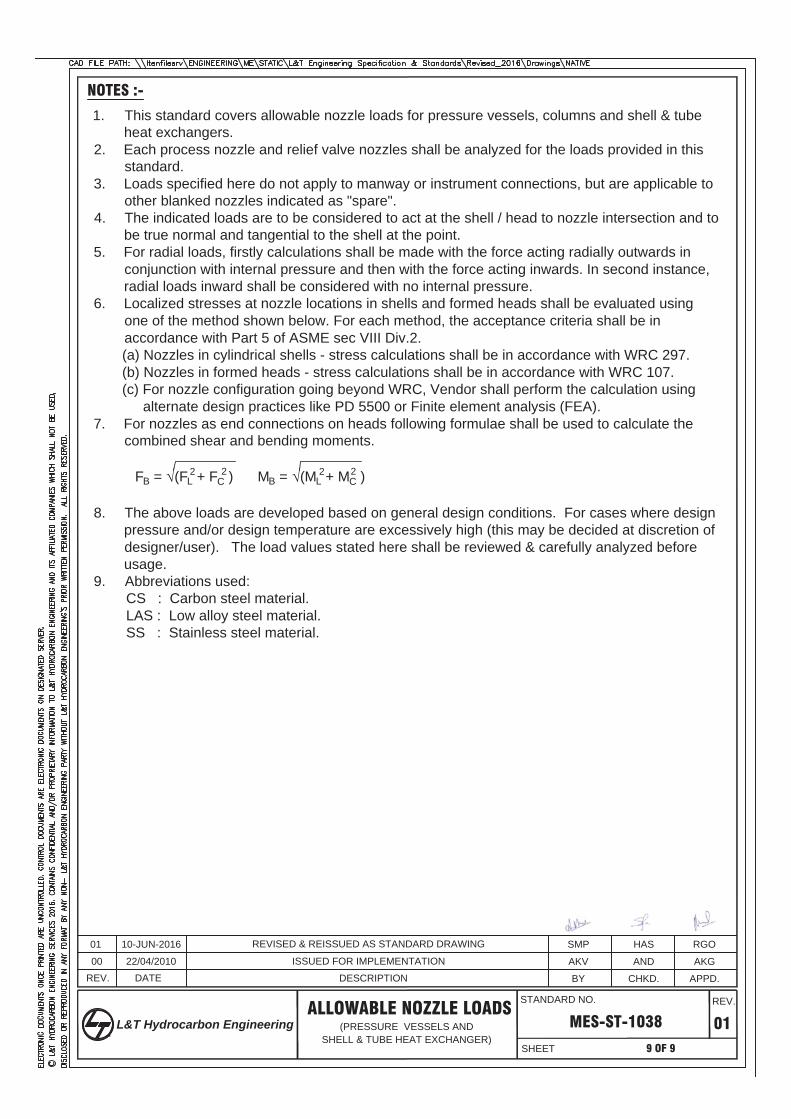
1. This standard covers allowable nozzle loads for pressure vessels, columns and shell & tubeheat exchangers.
2. Each process nozzle and relief valve nozzles shall be analyzed for the loads provided in thisstandard.
3. Loads specified here do not apply to manway or instrument connections, but are applicable toother blanked nozzles indicated as "spare".
4. The indicated loads are to be considered to act at the shell / head to nozzle intersection and tobe true normal and tangential to the shell at the point.
5. For radial loads, firstly calculations shall be made with the force acting radially outwards inconjunction with internal pressure and then with the force acting inwards. In second instance,radial loads inward shall be considered with no internal pressure.
6. Localized stresses at nozzle locations in shells and formed heads shall be evaluated using one of the method shown below. For each method, the acceptance criteria shall be in accordance with Part 5 of ASME sec VIII Div.2.
(a) Nozzles in cylindrical shells - stress calculations shall be in accordance with WRC 297. (b) Nozzles in formed heads - stress calculations shall be in accordance with WRC 107. (c) For nozzle configuration going beyond WRC, Vendor shall perform the calculation using alternate design practices like PD 5500 or Finite element analysis (FEA).7. For nozzles as end connections on heads following formulae shall be used to calculate the
combined shear and bending moments.
FB = (FL + FC ) MB = (ML + MC )
8. The above loads are developed based on general design conditions. For cases where designpressure and/or design temperature are excessively high (this may be decided at discretion ofdesigner/user). The load values stated here shall be reviewed & carefully analyzed beforeusage.
9. Abbreviations used: CS : Carbon steel material. LAS : Low alloy steel material. SS : Stainless steel material.
2 2
Mechanical Static DOC. NO.: MES SP 0041
General Specification forHeat Exchangers Sheet 1 of 23 REV 01
© 2016 LTHE Engineering Services. All rights reserved. Electronic documents once printed are uncontrolled. Control documents areelectronic documents on designated server or originally signed print copy. Contains confidential and / or proprietary information of LTHE Engineering Services and its affiliated companies, which shall not be used, disclosed or reproduced in any format without prior written permission of LTHE- Engineering Services.
GENERAL SPECIFICATION FOR
HEAT EXCHANGERS
01 Revised and Reissued as Standard Specification SAC SBG RGO 17-May-2016 00 Issued for Use AG HS RG 12/05/2012
REV DESCRIPTION Preparedby
Reviewed by
Approved by
Approved Date
Mechanical Static DOC. NO.: MES SP 0041
General Specification forHeat Exchangers Sheet 2 of 23 REV 01
© 2016 LTHE Engineering Services. All rights reserved. Electronic documents once printed are uncontrolled. Control documents areelectronic documents on designated server or originally signed print copy. Contains confidential and / or proprietary information of LTHE Engineering Services and its affiliated companies, which shall not be used, disclosed or reproduced in any format without prior written permission of LTHE- Engineering Services.
CONTENTS
1. SCOPE ......................................................................................................................................... 4
2. CODE & REGULATIONS ............................................................................................................. 4
3. DEFINITIONS ............................................................................................................................... 6
4. MATERIAL SPECIFICATION ....................................................................................................... 6
5. FABRICATION ............................................................................................................................ 10
6. NON DESTRUCTIVE TESTS ..................................................................................................... 16
7. HEAT TREATMENT ................................................................................................................... 17
8. INSPECTION AND TESTING ..................................................................................................... 18
9. SUPPLY ...................................................................................................................................... 19
10. GUARANTEE ..............................................................................................................................21
11. TRANSPORTATION,SITE FABRICATION AND ERECTION..................................................... 21
12. FINAL DOCUMENTATION ......................................................................................................... 22
Mechanical Static DOC. NO.: MES SP 0041
General Specification forHeat Exchangers Sheet 3 of 23 REV 01
© 2016 LTHE Engineering Services. All rights reserved. Electronic documents once printed are uncontrolled. Control documents areelectronic documents on designated server or originally signed print copy. Contains confidential and / or proprietary information of LTHE Engineering Services and its affiliated companies, which shall not be used, disclosed or reproduced in any format without prior written permission of LTHE- Engineering Services.
Abbreviations:ASME American Society of Mechanical Engineers ASTM American Society of Testing and Materials AWS American Welding Specification BHN Brinell Hardness Number BTD Bolt Tensioning Device BV Bureau Veritas CIB Chief Inspector of Boilers CS Carbon Steel DIA Designated Inspection Agency DNV Det Norske Veritas DP Dye Penetrant FPW Full Penetration Weld GPC General Purchase Condition HAZ Heat Affected Zone HIC Hydrogen Induced Cracking IBR Indian Boiler Regulation ID Inside Diameter IGC Inter Granular Cracking IS Indian Standards LAS Low Alloy Steel LTCS Low Temperature Carbon Steel MDMT Minimum Design Metal Temperature MP Magnetic Particle NB Nominal Bore NDT Non Destructive Testing PO Purchase Order PPM Parts Per Million PTC Production Test Coupons PWHT Post Weld Heat Treatment QAP Quality Assurance Plan SS Stainless Steel TEMA Tubular Exchangers Manufacturers' Association UT Ultrasonically Tested UTS Ultimate Tensile Strength
Mechanical Static DOC. NO.: MES SP 0041
General Specification forHeat Exchangers Sheet 4 of 23 REV 01
© 2016 LTHE Engineering Services. All rights reserved. Electronic documents once printed are uncontrolled. Control documents areelectronic documents on designated server or originally signed print copy. Contains confidential and / or proprietary information of LTHE Engineering Services and its affiliated companies, which shall not be used, disclosed or reproduced in any format without prior written permission of LTHE- Engineering Services.
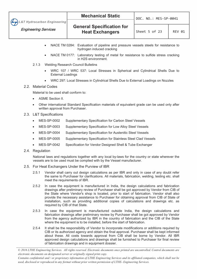
1. SCOPE 1.1. This specification specifies the general requirements for residual design, engineering, materials,
fabrication, workmanship, inspection, testing and supply of heat exchangers and is intended to supplement the requirements of the applicable Codes, L&T specifications & standards wherever indicated in the requisition shall be followed unless stated otherwise.
1.2. Supplementary specification indicating special or additional requirements shall form addenda to this specification and shall be referred to in the Material / Purchase Requisition and/or Purchase Order.
1.3. This specification shall not be applied to the design of non-TEMA exchangers, such as sometimes used for lube and seal oil cooling duties for packaged equipment like compressors, pumps and turbines.
1.4. In case of conflict, the order of precedence shall be as follows:
Local Laws and Statutory Requirements
Data Sheets
Specifications
International Codes and Standards
As a general rule, the most stringent requirements shall govern. Where a requirement of a licensor’s or a relevant industry standard/specification is more stringent than that of this specification, the most stringent requirement will govern.
2. CODE & REGULATIONS 2.1. Design Codes
The following codes / Standards in their latest edition including their addenda referenced in drawings, datasheets or design basis along with other specifications enclosed with the requisition at the time of enquiry shall form the basis of design, fabrication, inspection, testing and acceptance of equipment:
2.1.1 Boiler & Pressure Vessel Codes
ASME Section VIII
ASME Section IX
ASME Section V
ASME B 16.5 / 16.47 for flanges
ASME B 16.20 / 16.21 for gaskets
IBR (Indian Boiler Regulations) as applicable
The Static and Mobile Pressure Vessel (Unfired) Rules 1981 (whenever applicable)
TEMA (Class as specified on the drawings or data sheets or design basis)
2.1.2 National Association of Corrosion Engineers Standards
NACE MR 0103: Material resistant to sulfide stress cracking in corrosive petroleum refining environment
NACE MR 0175: Petroleum and natural gas industries material for use in H2S containing environment in oil and gas production
Mechanical Static DOC. NO.: MES SP 0041
General Specification forHeat Exchangers Sheet 5 of 23 REV 01
© 2016 LTHE Engineering Services. All rights reserved. Electronic documents once printed are uncontrolled. Control documents areelectronic documents on designated server or originally signed print copy. Contains confidential and / or proprietary information of LTHE Engineering Services and its affiliated companies, which shall not be used, disclosed or reproduced in any format without prior written permission of LTHE- Engineering Services.
NACE TM 0284: Evaluation of pipeline and pressure vessels steels for resistance to hydrogen induced cracking
NACE TM 0177: Laboratory testing of metal for resistance to sulfide stress cracking in H2S environment.
2.1.3 Welding Research Council Bulletins
WRC 107 / WRC 537: Local Stresses in Spherical and Cylindrical Shells Due to External Loadings
WRC 297: Local Stresses in Cylindrical Shells Due to External Loadings on Nozzles
2.2. Material Codes Material to be used shall conform to:
ASME Section II.
Other international Standard Specification materials of equivalent grade can be used only after written approval from Purchaser.
2.3. L&T Specifications
MES-SP-0002 Supplementary Specification for Carbon Steel Vessels
MES-SP-0003 Supplementary Specification for Low Alloy Steel Vessels
MES-SP-0004 Supplementary Specification for Austenitic Steel Vessels
MES-SP-0005 Supplementary Specification for Stainless Steel Clad Vessels
MES-SP-0042 Specification for Vendor Designed Shell & Tube Exchanger
2.4. Regulation National laws and regulations together with any local by-laws for the country or state wherever the vessels are to be used must be complied with by the Vessel manufacturer.
2.5. For Heat Exchangers Under the Purview of IBR 2.5.1 Vendor shall carry out design calculations as per IBR and only in case of any doubt refer
the same to Purchaser for clarifications. All materials, fabrication, welding, testing etc. shall meet the requirements of IBR.
2.5.2 In case the equipment is manufactured in India, the design calculations and fabrication drawings after preliminary review of Purchaser shall be got approved by Vendor from CIB of the State where Vendor's shop is located, prior to start of fabrication. Vendor shall also provide the necessary assistance to Purchaser for obtaining approval from CIB of State of installation, such as providing additional copies of calculations and drawings etc. as required by CIB of that State.
2.5.3 In case the equipment is manufactured outside India, the design calculations and fabrication drawings after preliminary review by Purchaser shall be got approved by Vendor from the agency authorized by IBR in the country of fabrication and the CIB of the State where the equipment is to be installed, before the start of fabrication.
2.5.4 It shall be the responsibility of Vendor to incorporate modifications or additions required by CIB or its authorized agency and obtain the final approval. Purchaser shall be kept informed about these. All costs towards approval from CIB shall be borne by Vendor. All IBR approved design calculations and drawings shall be furnished to Purchaser for final review of fabrication drawings and in equipment dossier.
Mechanical Static DOC. NO.: MES SP 0041
General Specification forHeat Exchangers Sheet 6 of 23 REV 01
© 2016 LTHE Engineering Services. All rights reserved. Electronic documents once printed are uncontrolled. Control documents areelectronic documents on designated server or originally signed print copy. Contains confidential and / or proprietary information of LTHE Engineering Services and its affiliated companies, which shall not be used, disclosed or reproduced in any format without prior written permission of LTHE- Engineering Services.
3. DEFINITIONSCompany: Public or Private Entity referred as owner of the Project
Contractor: Public or Private Entity responsible for detailed engineering, design, engineering, procurement, construction Pre-Commissioning and Start-up of the Project.
Vendor: Single point responsible firm or other Corporate Entity contracted by purchaser to supply goods to purchaser i.e. Company or Contractor.
4. MATERIAL SPECIFICATION 4.1 General
4.1.1 All material used for fabrication shall be new and of first quality. All materials and accessories required for the fabrication, inspection, testing etc. of the heat exchanger shall be supplied by the Vendor unless otherwise stated. Whenever some material is to be supplied by the Purchaser, this shall be so indicated as Free Issue Material and the supplementary specifications in this regard shall be complied with.
4.1.2 In addition to the requirement of materials as per material specifications, materials shall also meet the requirements mentioned in this specification and other specifications enclosed with the requisition. All materials shall be certified for compliance with applicable specifications for the item(s) so specified. While procuring materials, Vendor shall stipulate additional requirements such as limits on hardness, UTS, yield strength, chemical composition, heat treatment and any other specific requirements to ensure that final requirement as per specification and Code are met with.
4.1.3 All materials for pressure parts and parts welded to pressure parts including materials in the scope of sub-Vendors shall be accompanied with mill test certificates duly certified by a reputed third party inspection agency. In the absence of mill test certificate the material shall be got tested from a reputed third party inspection and test results shall be submitted in lieu of mill test certificate. All cost towards such testing and inspection shall be borne by the Vendor. All materials shall be inspected at Vendor and sub-Vendor's shop for verification prior to use on the job. The decision of DIA to accept or reject materials on the basis of such testing shall be final.
4.1.4 Wherever simulated heat treatment of test specimens is required as per Code or specification, the simulation cycle shall include one extra cycle of stress relieving for any eventuality of repair at site by Purchaser during the life of the equipment.
4.1.5 MDMT shall be taken as 0°C or the design temperature specified in drawing or datasheet whichever is lower, unless specified otherwise in design basis or datasheets or drawings. For low temperature service, all CS and LTCS materials for pressure parts and attachments to pressure parts shall be charpy V-notch impact tested. All LAS materials for pressure parts and attachments to pressure parts shall be charpy V-notch impact tested irrespective of the design temperature. Impact test temperature shall be lowest of minimum ambient temperature, design temperature and MDMT. Low temperature service shall be specified in datasheets or drawings.
4.1.6 Plates
a) Pressure parts having thickness 16 to 50 mm (both inclusive) shall be UT as per SA-435.
b) Pressure parts having thickness >50mm shall be UT as per ASME SA-578 Level B.
4.1.7 Tubes
Mechanical Static DOC. NO.: MES SP 0041
General Specification forHeat Exchangers Sheet 7 of 23 REV 01
© 2016 LTHE Engineering Services. All rights reserved. Electronic documents once printed are uncontrolled. Control documents areelectronic documents on designated server or originally signed print copy. Contains confidential and / or proprietary information of LTHE Engineering Services and its affiliated companies, which shall not be used, disclosed or reproduced in any format without prior written permission of LTHE- Engineering Services.
a) All the tubes shall be seamless and cold drawn.
b) Product analysis of tubes shall be carried out and reported in the material test certification.
c) Tubes shall be in fully heat-treated condition as received from the mill. CS tubes shall be in annealed condition and copper alloy tubes shall be in annealed temper condition. LAS tubes shall be supplied in normalized and tempered condition.
d) All un-stabilized SS tubes shall be supplied in the solution annealed condition and all stabilized grades of SS such as SS 321 and SS 347 shall be supplied in stabilization heat treated condition, in addition to solution annealing.
e) It is preferable while ordering tubes the maximum yield strength and hardness of tubes are specified such as to be lower than those of tube sheet, in order to achieve a sound expanded tube to tube sheet joint, complying with Code requirements.
f) “Air under water” testing shall be carried out for all tubes except non-ferrous tubes. As an alternative, tubes can be hydro tested. In case the tubes are hydro tested, hydro test pressure of tubes shall be higher of tube side test pressure or as required by Code. Water quality shall be as per Para 8.2.1 of this specification.
g) For requirement of U tubes refer L&T specification MES-SP-0043.
4.1.8 Forgings
Forgings manufactured to SA-105 and SA-266 above 75 mm thickness, all tube sheet forgings and all forgings of other materials, except for the standard nozzle flanges up to 8" NB and small forgings (of couplings, plugs and eye bolts) shall be 100% UT as per SA-388. Acceptance criteria shall be as per ASME Section VIII Division 2.
4.1.9 Pipes
Pipe shall be seamless and size above 1.5’’ NB shall be hot finished. Dimension and tolerances shall be in accordance with ASME 36.10 or ASME 36.19, as applicable, as per material specification.
4.2 Specific Material Requirement (Pressure Part And Part Welded To Pressure Parts) 4.2.1 CS and LTCS Materials
a) Carbon content shall not exceed 0.23%.
b) All plates shall be in normalized condition and forgings in normalized & tempered condition.
c) Use of SA 515 of any grade is not permitted.
d) Plates > 50mm thickness shall meet following additional requirements of SA-20 :
i. Vacuum treatment as per the supplementary requirement S1. If vacuum degassing is not reported in the certificates, then through thickness test as per SA 770 shall be conducted in area of 35% shall be ensured.
ii. Charpy V-notch test as per supplementary requirement S5 of the Specification SA-20. Material to be used for design temperature warmer than 0°C, Impact test shall be carried out at 0°C or MDMT whichever is lower and acceptance criteria for energy absorption shall be as per applicable design code. Orientation of test bar shall be transverse to rolling direction.
e) Unless specified otherwise in requisition or bid document, all CS materials specified as HIC test shall meet the following requirement
Mechanical Static DOC. NO.: MES SP 0041
General Specification forHeat Exchangers Sheet 8 of 23 REV 01
© 2016 LTHE Engineering Services. All rights reserved. Electronic documents once printed are uncontrolled. Control documents areelectronic documents on designated server or originally signed print copy. Contains confidential and / or proprietary information of LTHE Engineering Services and its affiliated companies, which shall not be used, disclosed or reproduced in any format without prior written permission of LTHE- Engineering Services.
i. Carbon equivalent shall be <0.40% nickel content shall be<0.2%.
ii. Sulpher content shall be < 0.002% for plates and < 0.01 % for tubes, pipes and forgings.
iii. Hardness of plates and pipes shall not exceed 200 BHN, and that of forgings shall not exceed 187 BHN.
iv. Plate shall conform to SA 516 Gr 60 only (higher grades like SA 516 Gr.65 and 70 are not acceptable). The plates shall be treated with calcium or other rare earth elements to create spherical inclusions instead of stringers. The plates shall be tested in accordance with NACE TM-0284 using the test solution 'A' of NACE TM-01-77. The acceptance criteria shall be crack length ratio 10 % maximum.
f) All LTCS and CS charpy plate material shall be made to fine grain practice and the Primary austenitic grain size, shall be measured and reported in mill test certificates.
g) CS pipes shall be SA-106 Gr. B LTCS pipes shall be SA 333 Gr.1 or 6.
4.2.2 LAS Materials
a) All LAS plates, pipes, forgings and fittings shall be in normalized and tempered condition. Use of C-1/2 Mo material is prohibited. All LAS materials shall be charpy V-notch impact tested. Test temperatures shall be lowest of minimum ambient temperature, design temperature, MDMT and minus 18°C (0 °C instead of -18 °C for 5Cr- l/2Mo materials). Impact energy values as per UG-84 or applicable specification, whichever is higher.
b) In the case of 1.25 Cr – 0.5 Mo materials and weldments, the maximum room temperature tensile strength for all pressure containing components, materials and welds shall be 100000 psi.
c) For LAS tubes (SA-199, 209 and 213) hardness test shall be performed on outside of the tubes as per SA-450.
d) For LAS plates > 50 mm thickness, following supplementary requirements of SA-20 shall also apply:
i. Vacuum treatment as per supplementary requirement S1. If vacuum degassing is not reported in the test certificates, then through thickness test as per SA 770 shall be conducted and minimum reduction in area of 35% shall be ensured.
ii. Bend test as per supplementary requirement S14.
4.2.3 SS and Other High Alloy Material
a) All SS material (300 series) shall be in the solution heat-treated (fully annealed) and pickled condition. All stabilized grades of SS (SS 321, SS 347 etc.) shall be given stabilization heat treatment, in addition to solution annealing.
b) SS (300 series) plates shall be hot rolled and shall have No.1 finish on both sides.
c) SS (300 series) materials for all components including non-pressure parts like baffles, tie rods, etc. shall be procured with the IGC test as per ASTM A-262 (test shall be carried out, after the specified heat treatment and sensitization per specification) with acceptable corrosion rate and practices as under:
i. For all services except nitric acid services, practice E shall be followed. Specimen after exposure shall be bent as per requirement mentioned in A 262 practice E and shall be inspected under magnification of 200X. The bent specimen shall be
Mechanical Static DOC. NO.: MES SP 0041
General Specification forHeat Exchangers Sheet 9 of 23 REV 01
© 2016 LTHE Engineering Services. All rights reserved. Electronic documents once printed are uncontrolled. Control documents areelectronic documents on designated server or originally signed print copy. Contains confidential and / or proprietary information of LTHE Engineering Services and its affiliated companies, which shall not be used, disclosed or reproduced in any format without prior written permission of LTHE- Engineering Services.
free of any cracks or grain dropping. The microstructure shall be submitted to DIA for approval.
ii. Nitric acid service: Practice C with corrosion rate not > 25 mils per year.
d) For straight chrome (13% Cr.) material, Maximum carbon content shall be < 0.06%. Hardness of UNS no. S41000 & S40500 shall be < 85 RB.
4.2.4 Non-Ferrous Material
a) All copper based non-ferrous plates shall be procured in annealed condition.
b) Plates for pressure parts shall be 100% UT. Vendor shall submit the procedure for UT to DIA for approval.
c) In addition to hydro test, all tubes shall be eddy current tested in their final annealed condition.
d) All pipe bends shall be stress relief annealed after bending.
e) The paragraph NF7 and NF14 in part UNF of Code are mandatory. This applies to non-ferrous cladding and weld overlay also.
4.2.5 Clad Materials
a) Cladding shall be integrally and continuously bonded to the base metal. All clad plates shall be rolled-on or explosion bonded type.
b) Clad plates shall be UT from the cladding surface as per SA-578. Scanning shall be 100% of the plate surface. Acceptance standard shall be level B. Clad plates shall meet the supplementary requirements of S7 of SA-578. All UT shall be undertaken after specified heat treatment of clad plates.
c) Both base material and clad material shall meet the specification of the respective materials as stipulated in this specification.
d) Alloy Clad steel plates shall be as per SA 263 or SA 264 or SA 265. Bond between cladding and the base metal shall be checked for a minimum strength of 14 kg/mm2 in shear for alloy clad steel plates, by conducting shear test as per applicable material specification.
e) For copper alloy clad plates, the bond between cladding and base metal shall be checked for a minimum strength of 10 kg/mm2 in shear by conducting shear test.
f) During tension test of clad plates the cladding shall be removed and the tensile properties of the base material shall meet the Code material requirements.
g) For austenitic SS clad plates the SS surface shall be acid pickled as per ASTM A- 380. For chromium steel clad surfaces the pickling shall be as per Vendor's established procedure. The same shall be submitted to Purchaser for approval.
h) For clad components, Vendor to ensure that plate thickness after bonding and machining shall not be less than the thickness specified in drawings. Vendor to consider sufficient margin on clad and base materials so that thickness after machining and complete fabrication shall be as per the drawings. For nozzle necks with weld deposit, sufficient margin on ID shall be taken to allow for shrinkage.
4.3 Non Pressure part 4.3.1 The basic allowable stressed for non-pressure parts shall be 33-1/3% of the ultimate tensile
strength or 66-2/3% of the yield strength, whichever is less, and for welds attaching non pressure parts to pressure parts shall be the same as for pressure parts.
Mechanical Static DOC. NO.: MES SP 0041
General Specification forHeat Exchangers Sheet 10 of 23 REV 01
© 2016 LTHE Engineering Services. All rights reserved. Electronic documents once printed are uncontrolled. Control documents areelectronic documents on designated server or originally signed print copy. Contains confidential and / or proprietary information of LTHE Engineering Services and its affiliated companies, which shall not be used, disclosed or reproduced in any format without prior written permission of LTHE- Engineering Services.
4.3.2 CS plate shall be minimum IS-2062 or SA 283 Gr. C or equivalent. Pipe shall be to IS 1239 or SA 53 or equivalent.
4.3.3 Saddle material shall be of same as of shell for shell design temperature > 350 ºC.
4.4 Equivalent materials The materials for various components in a heat exchanger shall be as per Purchaser’s requirement. This does not preclude use of equivalent or better materials. However, these deviations should be clearly indicated in the prescribed format. If an equivalent material sought by the Vendor is to a specification, other than IS or ASTM or ASME, it is necessary for the Vendor to submit the specifications of the equivalent material with complete details in English for approval.
5. FABRICATION 5.1 Edge Preparation
5.1.1 For CS, the edges for welding shall be made by machining, chipping, cold shearing, oxy- acetylene flame cutting or a combination of these. Chipping or cold shearing shall be followed by grinding to a smooth and regular surface. Oxy-acetylene flame cutting shall be followed by machining or grinding to eliminate any discoloration of material affected.
5.1.2 For LAS, the edges for welding shall be made by oxy-acetylene flame cutting or by machining. Cold shearing may be used for cutting thickness up to 10 mm. Oxy-acetylene flame cutting shall be used with preheat and shall be followed by machining or grinding to eliminate any discoloration of material affected.
5.1.3 For austenitic SS, the edges for welding shall be made by plasma arc; however, cold shearing may be adopted for thickness up to 15 mm. In all cases the cut edges shall be ground back or machined back by 2 to 3 mm.
5.1.4 All welding edges after cutting shall be DP or MP examined for laminations, cracks or segregation. Additionally UT shall be carried out within five times the material thickness of edge for LAS materials or when the service is low temperature or hydrogen or HIC.
5.1.5 The paragraphs NF7 and NF14 in part UNF of Code are mandatory. This applies to non- ferrous cladding and weld overlay also.
5.2 Rolling and Dishing of Plates 5.2.1 Rolling
Rolling for bending and forming of plates shall be in the longitudinal direction of the plates. This direction shall be clearly marked on the plates.
Rerolling after welding is not normally recommended. However, if for large diameter shells, rerolling of welded shell course is inevitable, procedure for rerolling along with extent of NDT shall be submitted for approval of the DIA. All welds on the section to be rerolled must be ground flush. After rerolling all the welds on the re-rolled section must be DP checked. Such Welds shall then be subjected to radiography as required by drawings and Code.
5.2.2 Dishing
All dished heads shall preferably be of single piece construction. However dished ends with one chordal seam are acceptable for shells with diameter greater than 1 m. In such cases, the chordal seam shall preferably be in the one-third of the blank. Dished ends shall be tori-spherical (knuckle radius 15% of outside diameter and crown radius 80% of outside diameter) or 2:1 ellipsoidal. Dished heads shall be subjected to DP test on knuckle portions (both inside and outside) and weld edges after heat treatment. Vendor to ensure adequacy of indicated thinning allowance for dished head. If nominal thickness indicated is not
Mechanical Static DOC. NO.: MES SP 0041
General Specification forHeat Exchangers Sheet 11 of 23 REV 01
© 2016 LTHE Engineering Services. All rights reserved. Electronic documents once printed are uncontrolled. Control documents areelectronic documents on designated server or originally signed print copy. Contains confidential and / or proprietary information of LTHE Engineering Services and its affiliated companies, which shall not be used, disclosed or reproduced in any format without prior written permission of LTHE- Engineering Services.
adequate then the nominal thickness should be increased accordingly, keeping minimum thickness as per item drawing. A straight face of 38 mm or 3 times the nominal thickness of dished head, whichever is more, shall be provided, but maximum straight face shall be limited to 50 mm.
5.3 Welding 5.3.1 All welding and weld overlays shall be done with electrodes, fillers and fluxes of reputed
make with proven reproducibility of results. DIA shall specifically approve brand names. For CS pressure parts, the electrodes shall be of low hydrogen type. IGC test as per ASTM A262 Practice E shall be done for austenitic SS consumables, which are to be used in application involving solution annealing. Austenitic SS consumables of low carbon and stabilized grade shall also be IGC tested as per ASTM A262 Practice E. Straight chrome materials shall be welded with electrode that produces an austenitic chromium nickel weld deposit or a non-air hardening nickel-chromium-iron weld deposit.
5.3.2 All welding procedures shall be submitted for approval by DIA giving all relevant details. Welding qualification records shall indicate hardness values of weld metal, HAZ and parent metal and also results of impact tests when design temperature are below 0°C or when specifically indicated for materials being welded. No welding shall be undertaken until DIA has approved the welding procedure and welder's qualification. All welding procedures and welders shall be qualified for the particular type of welding and material in accordance with the ASME Section IX. Vendor shall be responsible for the quality of the welds performed.
5.3.3 Pressure holding joints shall be FPW. Root pass of single side welded joints shall be done with GTAW process. Backing strip for single side welded joints is not permitted. For LTCS materials, both inside and outside of welds shall be ground flush and dressed smooth. All internal welds in the shell shall be ground flush in order to insert and remove tube bundle. Also all internal welds shall be ground flush to the extent of facilitating draining of complete equipment. All other weld may be left in the descaled condition only.
5.3.4 Longitudinal seams shall be staggered with the circumferential distance between the centers of welds being at least 5 times the thickness of the thicker-plate. Weld seams shall be located so as to avoid interference with weld seam of nozzles and external attachments.
5.3.5 Attachment to pressure part shall be of same quality as the pressure part. All LAS weld attachments to pressure retaining component shall be FPW and ground to a smooth concave contour. External attachments like lugs, supports etc. of CS shall not be welded directly to high alloy or austenitic SS heat exchanger components. These attachments should be of the same material as the heat exchanger component. If this is not so, intermediate pad plate of the same material type as the heat exchanger component may be used. These pads shall be at least 100mm wider and longer than the attachment and shall be at least 5 mm thick. Welding of CS or LAS to austenitic SS shall be done with austenitic SS electrodes or filler wire (AWS-ASTM-E 309L or E-309 Mo L only).
Wrapper plates, reinforcing pads, saddle plates or stiffeners of higher thickness than specified can be used provided there is no change in basic dimensions and with the approval from DIA. No separate deviation permit is required for the same.
5.3.6 Partition plates of CS and 300 series SS except for low temperature service, shall be welded to channels etc. by continuous fillet welds with minimum size of 6 mm on both sides. For all other materials and for hydrogen and low temperature services, all welds involving partition plates shall be FPW. However all pass partition plates shall be FPW up to a distance of 2"(50mm) from the gasket contact surface. Partition plates thicker than 10 mm shall be tapered to 10 mm at partition groove end except when mentioned otherwise on drawings. One weep hole of 6 mm diameter shall be provided at the center of each
Mechanical Static DOC. NO.: MES SP 0041
General Specification forHeat Exchangers Sheet 12 of 23 REV 01
© 2016 LTHE Engineering Services. All rights reserved. Electronic documents once printed are uncontrolled. Control documents areelectronic documents on designated server or originally signed print copy. Contains confidential and / or proprietary information of LTHE Engineering Services and its affiliated companies, which shall not be used, disclosed or reproduced in any format without prior written permission of LTHE- Engineering Services.
horizontal pass partition plate and a 5 mm radius notch on top and bottom point of each vertical pass partition plate for all multi-pass exchangers for effective venting and draining.
5.3.7 Welding of shell to unhubbed tube sheet shall meet the requirements of Code considering that the tube sheet is unsupported.
5.3.8 When impact tests are required on material as per Code or specification the welds shall also be qualified for impact test. In such case following special requirement shall apply to the welding procedure qualification:
a) Qualification test shall be made on plates of the ASME specification as specified for the exchanger using welding electrodes of AWS or SFA specification and wire & flux of the specification and brand as are to be used on the job.
b) Welding current and travel speed shall be considered essential variables in order to ensure that production welding is substantially equivalent to the procedure qualification.
c) Welding test plates shall be subjected to a total thermal cycle sequence similar to the finished equipment. Specifically, test plates shall be held at intermediate and final stress relief temperatures for approximately the same length of time as the finished exchanger. Final cooling rate shall be approximate to that expected for the finished exchanger.
d) Charpy V-notch impact tests shall be made on the weld and HAZ of the test plate for each welding procedure to be qualified. Test procedure shall be as per UG 84 of Code. Test temperature shall not be higher than MDMT. Impact energy requirements shall be as per Table 2.15 of SA 20 of ASME Section II Part A or UG 84 of Code whichever is higher.
5.3.9 Weld Overlay
a) Wherever cladding is specified in datasheets or drawings, weld overlays are not acceptable.
b) Weld deposit overlay shall be done by a qualified welding procedure and surface shall be properly machined or ground flush after overlay. Minimum thickness of finished weld deposit shall be as indicated in the datasheet or specifications. In case a higher deposition thickness and multiple weld layers are required to achieve the minimum specified undiluted deposit metal, the same shall be done only after taking prior approval from Purchaser. Minimum thickness of undiluted finished weld overlay from top shall be 3 mm or as specified in the datasheet. For non-ferrous weld deposit, the iron dilution should be restricted to 2.5% (maximum) in the finished undiluted layer (thickness defined above).
c) The weld overlay procedure shall be qualified on base metal of the same composition as the exchanger component and meeting the requirements of ASME Section IX.
d) The weld overlay relatively smooth with no notches and undercuts that would act as stress raisers. All cracks, fissures and circular defects greater than 1/16 inch diameter shall be removed. Repaired areas shall be DP checked. Weld overlay shall be applied to base metal, which has been grit blasted and is smooth and clean so as to ensure full bonding. Welding overlay cladding shall be applied after any normalizing but before PWHT. The weld overlay shall consist of at least 2 layers.
e) The alloy cladding shall be cut back at all seams to permit back welding of the base metal. Weld metal shall be ground flush and fully covered with the applicable weld deposit. The weld joint in base plate shall be 100% DP tested for detection of cracks and flaws before welding from clad side. The weld deposit shall be at least as thick as the cladding.
Mechanical Static DOC. NO.: MES SP 0041
General Specification forHeat Exchangers Sheet 13 of 23 REV 01
© 2016 LTHE Engineering Services. All rights reserved. Electronic documents once printed are uncontrolled. Control documents areelectronic documents on designated server or originally signed print copy. Contains confidential and / or proprietary information of LTHE Engineering Services and its affiliated companies, which shall not be used, disclosed or reproduced in any format without prior written permission of LTHE- Engineering Services.
f) Shells, cones, dished heads and nozzles formed from clad plates shall be subject to UT after forming, for a minimum of 10% of the clad surface, but no less than one square feet in each 10 square feet or fraction thereof. Un-bonded areas that cannot be encompassed by a 3 inch diameter circle shall be repaired by weld overlay. When repairs in excess of 5 % of the total examined area are required, the complete component shall be subject to 100% UT. Repaired areas and weld deposit overlay at weld seams shall be DP examined. UT shall be repeated for dished heads after heat treatment. UT procedures shall be in accordance with SA 578 S6 for spot examination and SA 578 S7 for 100% examination.
g) All weld overlays shall be 100% DP examined in accordance with the method described in ASTM-E-165. The barrier layer shall be 100% examined. When the overlay involves multiple passes (layers) and the procedure uses an intermediate heat treatment with cooling to room temperature prior to applying the subsequent layer, each layer shall be examined by DP. Where overlay is to be machined such as for flange facing, machined surface shall be 100 % examined after final PWHT. If 100% of overlay is examined prior to the final PWHT, overlay shall be spot examined (not less than 10% of the surface) after heat treatment.
h) Sample of the weld overlay shall be taken to perform chemical analysis to the specified depth. The number and location of samples and method of taking samples shall be approved by DIA. However, they shall be representative of each exchanger component for each type of welding process. Report of chemical analysis shall be submitted to DIA for approval.
i) For all weld overlays used in hydrogen or H2S service with design temperature greater than 350°C, Hydrogen dis-bonding test shall be carried out. The test condition shall be representative of the actual design conditions and the procedure shall be submitted to DIA for approval. Rate of cooling shall be 100°C/hr (min.) unless specified otherwise in datasheets. Holding time shall be 48 hours unless specified otherwise in datasheets.
j) PTCs are required for CS welds above 50 mm thickness and for LAS welds above 25 mm or when required by the Code or when specified in the requisition. The following shall apply: -
i. Two PTCs representative of one longitudinal and another circumferential seam shall be provided for each procedure, position and thickness.
ii. PTC shall be from material of the same heat and thickness as that of parent metal. During and after production welding PTC shall be subjected to same heat treatment as and together with the course they represent. Extra PTC shall be preserved to take care of eventuality of retests.
iii. The test mentioned below shall be carried out as per method of testing in code :
a. One transverse tension test.
b. Two sides bend test with weld located in the center of bend.
c. One hardness test on PTC weld and HAZ. The acceptable limits are 200 BHN for CS, 225 BHN for P3 & P4 materials and 235 BHN for P5.
d. Micro and macro structural examination of welds.
e. For CS charpy V notch test on weld and HAZ shall be carried out. For MDMT < 0°C, impact test temperature shall be MDMT and for MDMT > or equal to 0°C, the test temperature shall be 0°C. The acceptance criteria for impact energy shall be as per table a 2.15 of SA 20 of ASME Section II part A or UG-84 of Code whichever is higher.
Mechanical Static DOC. NO.: MES SP 0041
General Specification forHeat Exchangers Sheet 14 of 23 REV 01
© 2016 LTHE Engineering Services. All rights reserved. Electronic documents once printed are uncontrolled. Control documents areelectronic documents on designated server or originally signed print copy. Contains confidential and / or proprietary information of LTHE Engineering Services and its affiliated companies, which shall not be used, disclosed or reproduced in any format without prior written permission of LTHE- Engineering Services.
f. LAS, charpy V notch test on weld and HAZ shall be carried out. Test temperature and acceptance criteria shall be as per clause 4.2.2 (d) (ii).
5.4 Tube to tube sheet joints Requirement of L&T specification no. MES-SP-0044 shall be complied with for welded tube-to-tube sheet joints and that of L&T specification no. MES-SP-0045 shall be complied with for expanded tube-to-tube sheet joints.
5.5 Hardness limitation Hardness limitation for CS and LAS materials, welds and HAZ wherever specified on drawings or datasheets shall be ensured as per Specification MES-SP-0083. Hardness limitation compliance for tube-to-tube sheet welded joints shall be established / verified on a mock-up with simulation heat treatment
5.6 Nozzle flanges, nozzle and reinforcing pad 5.6.1 Flanges
Unless otherwise indicated, dimensions, drilling, facing and tolerances for nozzle flanges (and blind covers if required) shall be as per ASME B 16.5 (for size up to 24" NB) and ASME B 16.47 series B (for sizes above 24" NB) for the respective class. Weld overlays, wherever specified or required, shall be in addition to the thickness as per these standards. Bolt holes on these nozzle flanges shall straddle principal vertical and horizontal centerlines of equipment. If the component to which nozzles are attached is subsequently stress relieved, it shall be Vendor's responsibility to maintain true gasket faces by machining or otherwise. If distortion is expected, final machining operation should be done after stress relieving; sufficient machining allowance for this purpose should be available. Gaskets, for flanges to ASME B 16.5 and B16.47, shall be as per ASME B16.20.
5.6.2 Nozzles
a) Nozzle pipes shall be attached to the heat exchanger components by FPW. Attachment welds using only inner and outer fillet welds are not permitted. Unless otherwise indicated on the datasheets or drawings, necks of all nozzles shall be flush with the inside of the heat exchanger component. Inside corners of nozzle pipes at shell and channel inside diameter shall be radiused. All nozzles 2" NB and below, except long weld neck, shall have two stiffeners (30 mm x 6 mm) at right angles.
b) Whenever nozzle inside surface is required to be overlaid, these shall be done by weld overlay or cladding. Minimum nozzle ID before weld depositing to be 50 mm. Liners are not acceptable.
5.6.3 Reinforcing Pads and Testing
Reinforcing pads whenever required as per drawings or Code shall be of the same material or equivalent as the heat exchanger component to which it is welded. All reinforcing pads shall be provided with two 1/8" (3 mm) NPT tapped holes located 180 apart for air soap solution test with a pressure of 1.25 kg/cm2 (g). This test shall also be required to be carried out for slip on flanges. Higher test pressures are not recommended because of accompanying risks and also because the soap bubbles have a chance to blow off. Tell-tale holes in the reinforcing pads shall be plugged with hard grease unless otherwise indicated after the hydro test of the exchanger.
5.7 Bolts, Studs and Tapped Holes
Mechanical Static DOC. NO.: MES SP 0041
General Specification forHeat Exchangers Sheet 15 of 23 REV 01
© 2016 LTHE Engineering Services. All rights reserved. Electronic documents once printed are uncontrolled. Control documents areelectronic documents on designated server or originally signed print copy. Contains confidential and / or proprietary information of LTHE Engineering Services and its affiliated companies, which shall not be used, disclosed or reproduced in any format without prior written permission of LTHE- Engineering Services.
5.7.1 All inch bolting and threading shall conform to ASME B 1.1 except for size 1" and above where it shall be 8 threads per inch. Metric bolting and threading shall conform to ISO-R261 except for size M24 and above, where it shall have 3 mm pitch.
5.7.2 Studs shall extend beyond the nut by about 10 mm and shall be threaded full length except when square ends are required for use with BTD, in which case the extension shall be as per BTD manufacturer's recommendation. The studs for extended tube sheets and the studs for use with connecting piece shall also have square ends.
5.7.3 All nuts shall be of heavy series only and nut seating faces shall be machined or spot faced.
5.7.4 Threads on external bolting, plugs etc. shall be lubricated with graphite grease for working temperature up to 200°C and with Molybdenum Disulphide for higher temperatures.
5.7.5 Tapped holes on the channel side face of clad tube sheet for removable bundles shall be fitted with plugs of a material similar to channel side material in contact with tube side fluid.
5.7.6 All floating head bolting to have 2 mm wide and 0.5 mm deep groove at both ends to prevent mix up with other bolts.
5.7.7 In addition to stamping, the specifications and manufacturers symbol as specified in ASME material specifications, on one of the ends the size of the studs shall be clearly punch marked. Similarly the nuts shall have the size punch marked on one of the faces. In case of tapped hole the size shall be punch marked near the hole without disturbing the gasket seating area. Further for all alloy/SS metallurgy bolts & nuts shall also be identified by distinct color marking at the stud end/bolt side face.
5.8 Assembly and Handling 5.8.1 Vendor shall be responsible for taking adequate preventive measures to ensure the quality
and finish of materials and to avoid any rusting.
5.8.2 Suitable method of alignment like dowels etc. shall be provided for proper assembly of channel, channel covers, stationary tube sheet etc.
5.8.3 Stacked exchangers shall be assembled in the shop for a trial fit. Special care shall be exercised in truing up connecting nozzle flanges.
5.8.4 “T” wherever indicated on drawings, denotes match mark for assembly and shall be punched on all mating parts.
5.8.5 Lifting lugs shall be provided as per standard for lifting of channels, channel covers, floating heads, shell covers, test rings, test flanges etc.
5.8.6 In case of removable bundles the following are required: -
a) Stationary tube sheets shall be drilled and tapped at vertical (0º) position for attaching eyebolts or a lifting lug of adequate thickness shall be welded with 25 mm (minimum) diameter hole.
b) Drilling and tapping as above shall be carried out on floating tube sheet.
c) Last support plate shall be drilled (25 mm diameter hole) for lifting the assembled bundle. Local stiffening may be necessary to withstand the bundle and load, which shall be designed by the Vendor.
5.8.7 Pulling eyebolts made from forged CS shall be provided for all removable bundles. These shall be sent loose along with the spares. Insert piece shall be provided for all clad tube sheets. Material of insert piece shall be same as that of cladding material.
5.8.8 Stationary tube sheet shall be drilled and tapped for tie rods. Care should be taken to ensure that holes are not drilled through.
Mechanical Static DOC. NO.: MES SP 0041
General Specification forHeat Exchangers Sheet 16 of 23 REV 01
© 2016 LTHE Engineering Services. All rights reserved. Electronic documents once printed are uncontrolled. Control documents areelectronic documents on designated server or originally signed print copy. Contains confidential and / or proprietary information of LTHE Engineering Services and its affiliated companies, which shall not be used, disclosed or reproduced in any format without prior written permission of LTHE- Engineering Services.
5.8.9 Interchangeable and 180° rotatable bundles shall have common pass-partition groove arrangement in the respective tube sheet. For exchangers where bundles are specified to be interchangeable, the same shall be ensured at the Vendor's shop by actually inserting the bundles or using a template consisting of 4 full diameter baffles, each spaced at a distance equal to the baffle pitch.
5.8.10 Jackscrews shall be provided on all girth flanges.
5.9 Fabrication tolerances and finish 5.9.1 The dimensional tolerances shall be within the limits indicated on L&T standard no. MS-ST-
2019. Where tolerances are not specified, these shall be in accordance with the requirements of TEMA and Code.
5.9.2 All edges and corners including baffle holes shall be de-burred (or rounded, if shown).
5.9.3 Finish of all machined components shall be minimum 12 microns (500 RMS) unless otherwise indicated. Parts subjected to UT shall have minimum finish of 6 microns.
5.9.4 Tube sheet face shall be flat within +/- 1.5 mm (camber).
5.10 Descaling Pickling and passivation shall be done for all SS parts in accordance with ASTM A-380. The Vendor shall furnish details of the procedure for approval to DIA.
5.11 No distortion whatsoever shall be permitted on the gasket seating surfaces due to tube to tube sheet welding, shell to tube sheet welding, PWHT etc. If distorted, the same shall be machined subsequently.
5.12 Stamping, Name Plates And Warning Plates 5.12.1 Each exchanger shall be fitted with an SS nameplate.
5.12.2 Warning plates, if required, shall be provided.
5.12.3 The following exchanger parts shall have the item number stamped except for heat exchangers in low temperature service in which case the item number shall be marked with non-removable ink:
Shell girth flanges, shell cover flange, channel girth flanges, flat channel cover, stationary and floating tube sheets, floating head cover flange, floating head backing ring, connecting pieces, test rings, test flanges and other main removable parts.
6. NON DESTRUCTIVE TESTS 6.1 All the NDT procedures shall be submitted to DIA for approval. For all NDT activities, only qualified
NDT technicians shall be deployed with the approval of DIA.
6.2 The extent of radiography shall be as specified in datasheets or drawings or job specification. Radiography shall be performed after PWHT. In case radiography is carried out before PWHT, then UT shall be carried out on the welds after PWHT.
6.3 Minimum extent of radiography shall be spot, unless full radiography is specified in the drawings or required as per specification or Code. Spot radiography shall mean that at least 10% of the total welded length must be radio graphed. Further, all "T joints must be radio graphed and at least one shot must be taken on each longitudinal and circumferential seam. This requirement shall supplement the ones specified in Code. DIA shall be consulted in marking the areas to be radio graphed.
Mechanical Static DOC. NO.: MES SP 0041
General Specification forHeat Exchangers Sheet 17 of 23 REV 01
© 2016 LTHE Engineering Services. All rights reserved. Electronic documents once printed are uncontrolled. Control documents areelectronic documents on designated server or originally signed print copy. Contains confidential and / or proprietary information of LTHE Engineering Services and its affiliated companies, which shall not be used, disclosed or reproduced in any format without prior written permission of LTHE- Engineering Services.
6.4 Full radiography when specified shall imply 100% radiography of all butt welds including nozzle flange to nozzle neck, pipe to pipe and pipe to fitting (Irrespective of size of the nozzle or fitting).
6.5 All welds of nozzle necks fabricated, from plate, irrespective of diameter, thickness of plate and radiography specified, shall be 100% radio graphed.
6.6 Weld seams of formed heads shall be 100% radio graphed after forming and heat treatment.
6.7 All nozzle to shell welds and unhubbed tube sheet to shell welds shall be DP or MP checked at the root run and final weld.
6.8 All welds, which cannot be fully radio graphed such as nozzle to shell, shell to unhubbed tube sheet, unhubbed floating head to cover etc., shall be 100% UT after final PWHT. Fillet welds and welds which cannot be radio graphed or UT (i.e. pass partition plate to channel and floating head etc.), the root run shall be DP checked and the welds shall be finally MP checked after PWHT.
6.9 All attachment welds shall be either DP or MP tested.
6.10 If radiography is being substituted by UT for the final closing seam as permitted by Code, MP shall be carried out in addition to UT.
7. HEAT TREATMENT 7.1 PWHT shall be done if required by datasheets, drawings, specifications, Code etc. PWHT when
mentioned on the datasheet shall be over and above the requirements of specifications or Code. No welding or heating is permitted after PWHT. All machining operations shall preferably be carried out after PWHT (also refer clause 5.4.6.1). It shall be the responsibility of the Vendor to leave sufficient allowance for this purpose. Vendor shall submit all the procedures for PWHT to DIA for review.
7.2 During PWHT of assemblies of fixed tube sheet exchangers, care shall be taken to ensure that differential stresses are not caused between tubes, shell and tube sheet. The temperature differential between shell and tubes during PWHT to be minimized (not to exceed 25°C) and the rate of heating and cooling shall not exceed 25-30°C per hour. For this purpose, thermocouples shall be installed on various components and compliance assured.
7.3 Heat treatment of SS clad assemblies shall be at reduced temperature to avoid sensitization of SS materials. The soaking time shall be increased accordingly as per Code.
7.4 Heat treatment of non-ferrous clad assemblies, if required, shall be performed with extra care, at reduced temperatures to avoid differential thermal expansion. The soaking time in such a case shall be increased accordingly as per Code.
7.5 Heat treatment of CS and LAS dished heads shall be as follows:
7.5.1 Stress Relieving for:
a) Cold formed dish heads up to 16 mm thick.
b) Cold formed floating head cover up to 16 mm thick if fiber stretch exceeds 5 %.
7.5.2 Normalizing for CS and normalizing and tempering for LAS:
a) Hot formed dish head and floating head dish if not formed in normalizing range.
b) Cold formed dish heads for thickness greater than 16 mm.
c) Cold formed floating head dish above 16 mm thick.
This heat treatment need not be given if same heat treatment is given subsequently on sub-assembly. Thicknesses specified above are nominal.
Mechanical Static DOC. NO.: MES SP 0041
General Specification forHeat Exchangers Sheet 18 of 23 REV 01
© 2016 LTHE Engineering Services. All rights reserved. Electronic documents once printed are uncontrolled. Control documents areelectronic documents on designated server or originally signed print copy. Contains confidential and / or proprietary information of LTHE Engineering Services and its affiliated companies, which shall not be used, disclosed or reproduced in any format without prior written permission of LTHE- Engineering Services.
7.6 SS components shall be solution annealed in the following cases.
Cold formed dished heads with nominal thickness of 16 mm or above.
Hardness value of dished heads after cold forming exceeds 235 BHN.
Hot formed shells, cones, dished heads.
After any heat treatment on austenitic SS, IGC test shall be carried out as per clause 4.2.3 (c)
7.7 All LAS welds shall be PWHT.
7.8 If stress relieving is indicated on shell side or tube side and the service on either side is lethal or low temperature or if specifically indicated in the datasheet or drawings, the welded tube-to-tube sheet joints of CS or LTCS material shall be stress relieved.
7.9 For LAS materials, preheating procedure shall be established in the welding procedure and got approved by DIA. Preheating by resistance or induction-heating method is preferred. Preheating shall extend uniformly to at least three times the thickness of joint but not less than 50 mm on both sides of the weld. Temperature indicating crayons shall be used for assessment of correct pre-heat temperature.
8. INSPECTION AND TESTING 8.1 Inspection
8.1.1 The inspection shall be carried out by DIA. The materials, fabrication and testing of exchangers shall be open to inspection by DIA in addition to any inspection required by the specified Code or local authorities having jurisdiction over the installation.
8.1.2 Inspection shall be carried out both during fabrication and before delivery and also for sub ordered materials. In addition to final inspection and certification by DIA during the course of manufacture, DIA's written approval shall be obtained by the Vendor at various stages of fabrication. For this purpose, Vendor shall prepare his QAP, defining the stages of fabrication, hold points for his own inspection and that by the DIA or Code or Statutory Authorities etc. The QAP shall be discussed with DIA before start of job and mutually agreed. The various stages of fabrication to be inspected (either by Vendor or DIA or both) shall include but not limited to the following.
Raw material identification and verification of mill test certificate. Edge preparation for welding, including visual cheek for lamination. Alignment of longitudinal and circumferential seams. Rolling tolerances on individual section. Alignment and fit up of sections and components. Root pass clearance before further welding and cleaning. Profile and thinning of dished ends and tori conical pieces after forming. Checking of tube sheet after drilling including checking of tube layout patterns, tube
holes, pass partitions, visual check for lamination. Tube sheet to shell set up for fixed sheet exchangers, prior to welding. Tube to tube sheet joint expansion or welding. Visual check of shell inside and tube bundle insertion. Welding of expansion bellows or joints, if required. Review of NDT reports and heat treatment charts. Final visual and dimensional inspection.
Mechanical Static DOC. NO.: MES SP 0041
General Specification forHeat Exchangers Sheet 19 of 23 REV 01
© 2016 LTHE Engineering Services. All rights reserved. Electronic documents once printed are uncontrolled. Control documents areelectronic documents on designated server or originally signed print copy. Contains confidential and / or proprietary information of LTHE Engineering Services and its affiliated companies, which shall not be used, disclosed or reproduced in any format without prior written permission of LTHE- Engineering Services.
Witnessing of hydro test.
8.1.3 The presence of DIA shall not modify or reduce the obligation of the Vendor to carry out his own tests and control. If any material and/or equipment are not found in compliance with the specified requirements, DIA or his delegate shall be entitled to irrevocably reject them, even if such non-compliance has not been evidenced in the course of inspection and/or tests.
8.1.4 DIA will, at the time of his initial visit, set up with the Vendor actual details of inspection stages to be witnessed or carried out, the schedule of future visits and subsequent inspection notices can be arranged between DIA and the Vendor
8.1.5 The Vendor shall notify DIA sufficiently in advance of any fabrication operations to permit arrival at the Vendor's shop in time to witness these.
8.1.6 The Vendor shall provide to DIA, free access to his shops at all times. He shall also supply all tools and tackles to DIA for carrying out the inspection. The Vendor shall also arrange for similar facilities at his sub-contractor's shops.
8.1.7 The Vendor must satisfy DIA that the welding procedures, welders, electrodes, fluxes, welding wires etc. are in accordance with the requirements of the Code and specifications. Further the welder's qualification test must be carried out in the presence of DIA.
8.1.8 Prior to final inspection, all slag, weld spatter, loose scale, dirt, grit, paint, grease, oil and other foreign matter shall be removed in order to facilitate inspection. All reinforcing pads and slip-on type flange welds shall be pressure tested with air and soap solution before and after heat treatment (if any) and before final hydrostatic test.
8.1.9 A dimensional check of equipment shall be carried out taking into account the tolerances shown on drawings, standards, specifications or Code, the more stringent values shall govern. Dimensional checks are to be taken of the internal measurements of equipment together with external ones and these are to be recorded on the drawings as being the "As-Built" dimensions.
8.2 Hydrostatic test 8.2.1 Hydrostatic tests shall be witnessed by DIA. When hydrostatic tests are performed the
indicating gauge shall be connected to the upper most part of the equipment. Testing water shall be clean potable water. Seawater shall not be used. For SS equipment, water used for these tests shall not contain more than 25 ppm chlorides. Minimum metal temperature during hydrostatic tests shall be 200C. Test pressures shall be maintained for at least one hour. Shell and tube sides shall be tested separately, unless otherwise mentioned on the drawing. For tube sheets designed for differential pressure, special care shall be taken during testing. Equipment drawings shall clearly indicate if tube sheets have been designed for differential pressure. Drying out as per this specification shall be carried out immediately after hydro test.
8.2.2 All vertical exchangers shall be tested in vertical position. Alternatively, exchanger may be tested in horizontal position with test pressure modified with prior approval of Designer.
8.2.3 Stacked exchangers with nozzles interconnected shall be hydro tested in stacked condition except when the hydro test pressure of the individual exchanger is different.
9. SUPPLY Supply shall be in accordance with requisition or bid document to which this specification is attached. It shall, however, include the following also.
9.1 Test ring assembly, dummy shell and flange
Mechanical Static DOC. NO.: MES SP 0041
General Specification forHeat Exchangers Sheet 20 of 23 REV 01
© 2016 LTHE Engineering Services. All rights reserved. Electronic documents once printed are uncontrolled. Control documents areelectronic documents on designated server or originally signed print copy. Contains confidential and / or proprietary information of LTHE Engineering Services and its affiliated companies, which shall not be used, disclosed or reproduced in any format without prior written permission of LTHE- Engineering Services.
9.1.1 Test ring assemblies, dummy shells and test flanges wherever required shall be designed and supplied by the Vendor. The stresses shall not exceed 90% of the minimum yield stress of the material as stipulated in material specification. Material used for fabricating these shall be of tested quality. For removable bundle with tube side test pressure higher than shell side, the bundle shall be tested outside the shell, with tube side pressurized for tube side test pressure to check tube to tube sheet joint leakage from the back of tube sheet. Test flange shall be designed accordingly.
9.1.2 Test ring assembly construction shall be stuffing box type as per fig. E-4.13.2 of TEMA. It is preferred that the test ring flange thickness not exceed the shell cover flange thickness, Otherwise, Vendor to provide separate bolting for assembling test ring flange to shell. Similarly, Vendor to check that the studs for stationary tube sheet bolting can be used with test flange. Else separate bolting shall be provided for assembling test flange.
9.1.3 For "T" type of floating head exchanger necessary washers, bolts and nuts for sealing of bolt holes in tube sheet to be provided during hydro test.
9.2 Accessories for testing All necessary accessories such as supports, blind flanges, test gaskets, bolts, nuts etc. shall be provided and supplied by the Vendor for testing of heat exchangers in Vendor's shop and for subsequent testing by Purchaser at site, whenever required.
9.3 Other accessories 9.3.1 Vendor shall also supply tie bolts, leveling shims or intermediate supports for stacked units.
Gaskets, nuts and bolts for interconnecting nozzles (both tube and shell side) along with spares shall be supplied by Vendor. All these components shall be dispatched separately with due care having been taken regarding identification of these for ease of installation.
9.3.2 Earthing lugs shall be provided on each heat exchanger and shall be located in such a way as to avoid any fouling with the exchanger foundation bolts at site.
9.3.3 Hydraulic Bolt Tensioner
Hydraulic bolt tensioner shall be used for tightening of bolts are as per details given below. Length of the stud/bolts shall be longer by one diameter to suit the bolt tensioner. Hydraulic bolt tensioning shall be used for following:
Nominal Bolt Diameter Condition
50 mm and above All joints
38 mm and above
Class 600 and over
Hydrogen Service
Lethal / Toxic Service
25 mm and above
Joints subject to high temperature and cyclic duties
Joints with leakage history
Joints where high accuracy is required
Other duties specified by the Purchaser
9.3.4 Davits, if required as per design basis or drawings, shall be provided.
Mechanical Static DOC. NO.: MES SP 0041
General Specification forHeat Exchangers Sheet 21 of 23 REV 01
© 2016 LTHE Engineering Services. All rights reserved. Electronic documents once printed are uncontrolled. Control documents areelectronic documents on designated server or originally signed print copy. Contains confidential and / or proprietary information of LTHE Engineering Services and its affiliated companies, which shall not be used, disclosed or reproduced in any format without prior written permission of LTHE- Engineering Services.
9.3.5 Addition like cleats for piping, ladder, platform, insulation etc. that may be required at a later stage shall be provided.
9.4 Cathodic protection Whenever cathodic protection is specified both sacrificial anodes and internal painting shall be provided. Separate specifications shall be provided in the requisition.
For exchangers having dissimilar metallurgy and having cathodic protection on tube side, weld deposit of minimum 5 mm compatible with tube sheet metallurgy on channel flange adjacent to tube sheet, floating head flange & pass partition plate and weld deposit of 3 mm on inside of channel flange ( up to a distance of 25 mm) and floating head flange, shall be provided.
9.5 Spares Quantities 9.5.1 Mandatory Spares:
S. No. Description Spares Quantity
1 Fasteners 20% (Minimum 4 studs & 8 nuts per joint) for each girth flange, nozzle with blind flange, interconnected nozzle and companion flange.
2 Gaskets 400% For each Girth flange, nozzle with blind flange, interconnected nozzles & Companion flanges.
9.5.2 Two years Operation and Maintenance Spares:
Vendor shall furnish a list of recommended spares for two years of normal operation along with the firm unit prices.
9.5.3 Erection and Commissioning Spares
S. No. Description Spares Quantity
1 Fasteners 10% (Minimum two in each size) of installed fasteners.
2 Gaskets 100% For each girth flanges.
Over and above, vendor shall recommend and supply all the spares considered necessary for successful erection and commissioning of the Equipment’s. The list of such recommended spares shall be submitted along with the offer. Any commissioning spare consumed over and above the recommended commissioning spare during commissioning of the equipment shall be supplied by the Vendor, at no cost to the Purchaser.
10. GUARANTEE The Vendor shall be completely responsible for the compliance to Code requirements, residual design, detailing, fabrication, materials and workmanship of the exchangers as per the stipulations of the requisition and its attachments. In this regard, it may be noted that review by Purchaser shall not relieve the Vendor of his responsibility of meeting all requirements and ensuring satisfactory performance of the equipment. Guarantee period shall be as per GPC of Purchaser.
11. TRANSPORTATION,SITE FABRICATION AND ERECTION 11.1 After completion of all testing and inspection, the inside of complete equipment shall be thoroughly
drained and dried out. Equipment shall be completely dried by passing hot air for sufficient time until no further increase in relative humidity of outgoing air is observed. Dry out shall be done
Mechanical Static DOC. NO.: MES SP 0041
General Specification forHeat Exchangers Sheet 22 of 23 REV 01
© 2016 LTHE Engineering Services. All rights reserved. Electronic documents once printed are uncontrolled. Control documents areelectronic documents on designated server or originally signed print copy. Contains confidential and / or proprietary information of LTHE Engineering Services and its affiliated companies, which shall not be used, disclosed or reproduced in any format without prior written permission of LTHE- Engineering Services.
simultaneously on both shell and tube sides. After drying, the equipment shall be purged and filled with dry N2 at 0.25 kg/cm2. The equipment shall be provided with pressure gauge to monitor N2 pressure, and ½” non-return valve. All threaded holes, other than telltale holes for testing, shall be suitably protected with steel bar plugs. All nozzles not provided with blind flange shall be provided with steel covers, temporary gaskets and bolts.
11.2 Shop Painting For shop painting of equipment, vendor shall comply the requirements given in L&T specification no. MES-SP-0082,”Specification for Painting”.
11.3 The equipment item number, PO number and Purchaser name and address shall be painted in bold white paint letters written with stencil, on the heat exchanger.
Sliding end of exchangers shall be painted as "CAUTION-SLIDING END" in black on the primer coating in the shop.
11.4 Dispatch of Equipment 11.4.1 Transportation saddles shall be checked for the following forces as minimum acting
simultaneously during transit, plus ambient wind condition.
Longitudinal = 0.6*g Transverse = 0.7*g Vertical Upwards = 0.2*g Vertical downwards = 1.5*g
11.4.2 No heat exchanger shall be released for shipment until it has been approved by DIA. Heat exchangers shall be dispatched after the operations as required by clauses 11.1, 11.2 and 11.3 have been carried out and shall be dispatched in as-tested condition. In case stacked exchanger shells are dispatched separately the Vendor shall provide additional set of gaskets for interconnected nozzles other than the gaskets included in spares. Heat exchangers shall be securely anchored for dispatch in order to prevent any shifting and damage during transportation. Expansion joints and bellows shall be suitably protected against any possible damage by providing tie bars before boxing up. Packaging shall be suitable for rail or road transport and also sea worthy if transported by sea. Spares shall be dispatched separately in a box and marked with PO number, item number and Purchaser’s name and address.
Vendor shall provide sling mark identification on all heat exchangers with respect to center of gravity of the equipment.
12. FINAL DOCUMENTATION Vendor shall complete requisite no. of copies of final document folder as required in purchase order. This folder shall contain the following information duly certified by Inspector:
Vendor’s Code Certificate.
Sketches of Exchanger showing `As Built’ dimensions and the plates used with their cast and test numbers.
Material test and analysis certificates.
Welding procedure qualification reports.
Welder qualification reports.
Radiographic results.
Mechanical Static DOC. NO.: MES SP 0041
General Specification forHeat Exchangers Sheet 23 of 23 REV 01
© 2016 LTHE Engineering Services. All rights reserved. Electronic documents once printed are uncontrolled. Control documents areelectronic documents on designated server or originally signed print copy. Contains confidential and / or proprietary information of LTHE Engineering Services and its affiliated companies, which shall not be used, disclosed or reproduced in any format without prior written permission of LTHE- Engineering Services.
Ultrasonic, Magnetic particle, Dye-penetrant test results (if applicable).
Hardness, corrosion and leak test records (if applicable).
Record charts showing complete heat treatment cycle (if applicable).
Production test coupon results (if applicable).
Charpy V-notch test results (if applicable).
Record chart of pressure test (Hydrostatic and/or pneumatic).
Rubbing of name plate.
Any other documentation as required in the purchase requisition/purchase order.
Any special handling instruction, in case equipment is to be delivered in pieces.
������������������������������������������������������������������������
Mechanical Static
Specification for Welded Tube to Tubesheet Joint
© 2016 LTHE Engineering Services. All rights reserved. Electronic documents once printed are uncontrolled. Control documents are
electronic documents on designated server or originally signed print copy.
Contains confidential and / or proprietary information of LTHE Engineering Services and its affiliated companies, which shall not be
used, disclosed or reproduced in any format without prior written permission of LTHE- Engineering Services.
SPECIFICATION
FOR
WELDED TUBE TO TUBESHEET JOINT
01 Revised and Reissued as Standard Specification SMP SGB RGO 17-May-2016
00 Issued for Use AG HS RG 21/05/2012
REV DESCRIPTION Prepared
by Reviewed
by Approved
by Approved
Date

������������������������������������������������������������������������
Mechanical Static
Specification for Welded Tube to Tubesheet Joint
© 2016 LTHE Engineering Services. All rights reserved. Electronic documents once printed are uncontrolled. Control documents are
electronic documents on designated server or originally signed print copy.
Contains confidential and / or proprietary information of LTHE Engineering Services and its affiliated companies, which shall not be
used, disclosed or reproduced in any format without prior written permission of LTHE- Engineering Services.
CONTENTS
�� ��������������������������������������������������������������������������������������������������������������������������������
� ���� ���������������������������������������������� �������������������������������������������������
� ���� ����������������� ������� �������������������� ������������������������������������������������
�� ���� ����������������� � ��� ���������������������� ����������������������������������������������
�� ������������ � ��� ��������������������������������������������������������������������������������������������
�� �������� ������������������������������������������ ��������������������������������������������
�� ���� ��������������������������������������������������������������������������������������������������������������������������
�� ��� ��� �������� �����������������������������������������������������������������������������������������������
!� ����������� �����������������������������������������������������������������������������������������������������������
�"� ���� ���������������������������������������������������������������������������������������������������������������������������
��� ������������� ������������������������������������� ����������������������������������������������������������
�� ������ ����#��� ������� ���������������������������������������������������������������������������������������
�� ������ ���#����� ��������������� ���$ ��%����� ��&'���������������������������
�
�
�
�
� �
�
�
�
�
Abbreviations:
API American Petroleum Institute
ASME American Society of Mechanical Engineers
AWS American Welding Society
OD Outside Diameter
TEMA Tubular Exchangers Manufacturer’s Association
TIG Tungsten Inert Gas shielded Arc
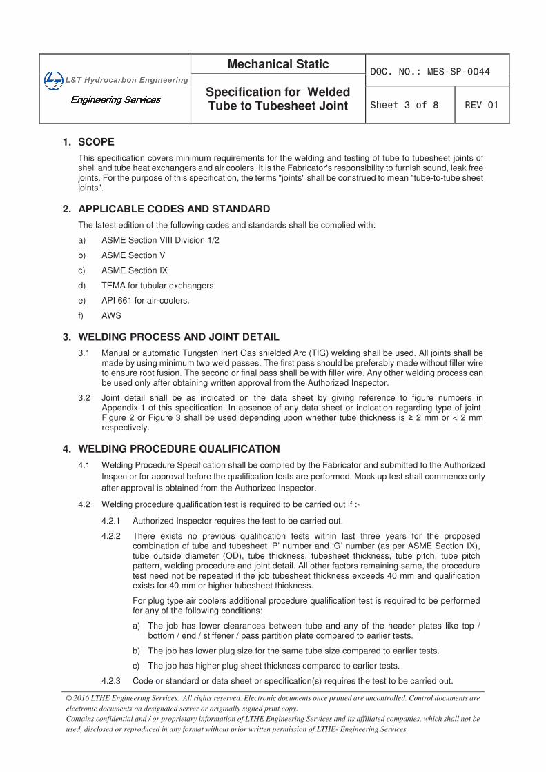
������������������������������������������������������������������������
Mechanical Static
Specification for Welded Tube to Tubesheet Joint
© 2016 LTHE Engineering Services. All rights reserved. Electronic documents once printed are uncontrolled. Control documents are
electronic documents on designated server or originally signed print copy.
Contains confidential and / or proprietary information of LTHE Engineering Services and its affiliated companies, which shall not be
used, disclosed or reproduced in any format without prior written permission of LTHE- Engineering Services.
1. SCOPE
This specification covers minimum requirements for the welding and testing of tube to tubesheet joints of shell and tube heat exchangers and air coolers. It is the Fabricator's responsibility to furnish sound, leak free joints. For the purpose of this specification, the terms "joints" shall be construed to mean "tube-to-tube sheet joints".
2. APPLICABLE CODES AND STANDARD
The latest edition of the following codes and standards shall be complied with:
a) ASME Section VIII Division 1/2
b) ASME Section V
c) ASME Section IX
d) TEMA for tubular exchangers
e) API 661 for air-coolers.
f) AWS
3. WELDING PROCESS AND JOINT DETAIL
3.1 Manual or automatic Tungsten Inert Gas shielded Arc (TIG) welding shall be used. All joints shall be made by using minimum two weld passes. The first pass should be preferably made without filler wire to ensure root fusion. The second or final pass shall be with filler wire. Any other welding process can be used only after obtaining written approval from the Authorized Inspector.
3.2 Joint detail shall be as indicated on the data sheet by giving reference to figure numbers in Appendix-1 of this specification. In absence of any data sheet or indication regarding type of joint, Figure 2 or Figure 3 shall be used depending upon whether tube thickness is 2 mm or < 2 mm respectively.
4. WELDING PROCEDURE QUALIFICATION
4.1 Welding Procedure Specification shall be compiled by the Fabricator and submitted to the Authorized
Inspector for approval before the qualification tests are performed. Mock up test shall commence only
after approval is obtained from the Authorized Inspector.
4.2 Welding procedure qualification test is required to be carried out if :-
4.2.1 Authorized Inspector requires the test to be carried out.
4.2.2 There exists no previous qualification tests within last three years for the proposed combination of tube and tubesheet ‘P’ number and ‘G’ number (as per ASME Section IX), tube outside diameter (OD), tube thickness, tubesheet thickness, tube pitch, tube pitch pattern, welding procedure and joint detail. All other factors remaining same, the procedure test need not be repeated if the job tubesheet thickness exceeds 40 mm and qualification exists for 40 mm or higher tubesheet thickness.
For plug type air coolers additional procedure qualification test is required to be performed for any of the following conditions:
a) The job has lower clearances between tube and any of the header plates like top / bottom / end / stiffener / pass partition plate compared to earlier tests.
b) The job has lower plug size for the same tube size compared to earlier tests.
c) The job has higher plug sheet thickness compared to earlier tests.
4.2.3 Code or standard or data sheet or specification(s) requires the test to be carried out.
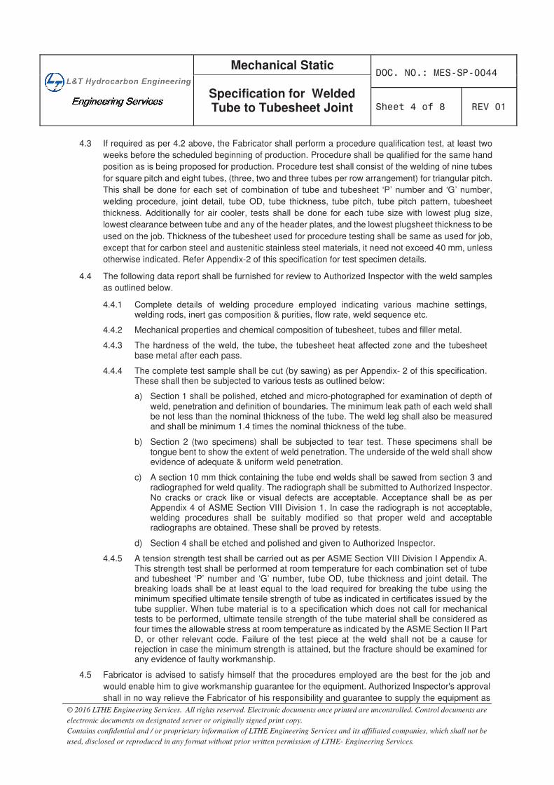
������������������������������������������������������������������������
Mechanical Static
Specification for Welded Tube to Tubesheet Joint
© 2016 LTHE Engineering Services. All rights reserved. Electronic documents once printed are uncontrolled. Control documents are
electronic documents on designated server or originally signed print copy.
Contains confidential and / or proprietary information of LTHE Engineering Services and its affiliated companies, which shall not be
used, disclosed or reproduced in any format without prior written permission of LTHE- Engineering Services.
4.3 If required as per 4.2 above, the Fabricator shall perform a procedure qualification test, at least two
weeks before the scheduled beginning of production. Procedure shall be qualified for the same hand
position as is being proposed for production. Procedure test shall consist of the welding of nine tubes
for square pitch and eight tubes, (three, two and three tubes per row arrangement) for triangular pitch.
This shall be done for each set of combination of tube and tubesheet ‘P’ number and ‘G’ number,
welding procedure, joint detail, tube OD, tube thickness, tube pitch, tube pitch pattern, tubesheet
thickness. Additionally for air cooler, tests shall be done for each tube size with lowest plug size,
lowest clearance between tube and any of the header plates, and the lowest plugsheet thickness to be
used on the job. Thickness of the tubesheet used for procedure testing shall be same as used for job,
except that for carbon steel and austenitic stainless steel materials, it need not exceed 40 mm, unless
otherwise indicated. Refer Appendix-2 of this specification for test specimen details.
4.4 The following data report shall be furnished for review to Authorized Inspector with the weld samples
as outlined below.
4.4.1 Complete details of welding procedure employed indicating various machine settings, welding rods, inert gas composition & purities, flow rate, weld sequence etc.
4.4.2 Mechanical properties and chemical composition of tubesheet, tubes and filler metal.
4.4.3 The hardness of the weld, the tube, the tubesheet heat affected zone and the tubesheet base metal after each pass.
4.4.4 The complete test sample shall be cut (by sawing) as per Appendix- 2 of this specification. These shall then be subjected to various tests as outlined below:
a) Section 1 shall be polished, etched and micro-photographed for examination of depth of weld, penetration and definition of boundaries. The minimum leak path of each weld shall be not less than the nominal thickness of the tube. The weld leg shall also be measured and shall be minimum 1.4 times the nominal thickness of the tube.
b) Section 2 (two specimens) shall be subjected to tear test. These specimens shall be tongue bent to show the extent of weld penetration. The underside of the weld shall show evidence of adequate & uniform weld penetration.
c) A section 10 mm thick containing the tube end welds shall be sawed from section 3 and radiographed for weld quality. The radiograph shall be submitted to Authorized Inspector. No cracks or crack like or visual defects are acceptable. Acceptance shall be as per Appendix 4 of ASME Section VIII Division 1. In case the radiograph is not acceptable, welding procedures shall be suitably modified so that proper weld and acceptable radiographs are obtained. These shall be proved by retests.
d) Section 4 shall be etched and polished and given to Authorized Inspector.
4.4.5 A tension strength test shall be carried out as per ASME Section VIII Division I Appendix A. This strength test shall be performed at room temperature for each combination set of tube and tubesheet ‘P’ number and ‘G’ number, tube OD, tube thickness and joint detail. The breaking loads shall be at least equal to the load required for breaking the tube using the minimum specified ultimate tensile strength of tube as indicated in certificates issued by the tube supplier. When tube material is to a specification which does not call for mechanical tests to be performed, ultimate tensile strength of the tube material shall be considered as four times the allowable stress at room temperature as indicated by the ASME Section II Part D, or other relevant code. Failure of the test piece at the weld shall not be a cause for rejection in case the minimum strength is attained, but the fracture should be examined for any evidence of faulty workmanship.
4.5 Fabricator is advised to satisfy himself that the procedures employed are the best for the job and
would enable him to give workmanship guarantee for the equipment. Authorized Inspector's approval
shall in no way relieve the Fabricator of his responsibility and guarantee to supply the equipment as
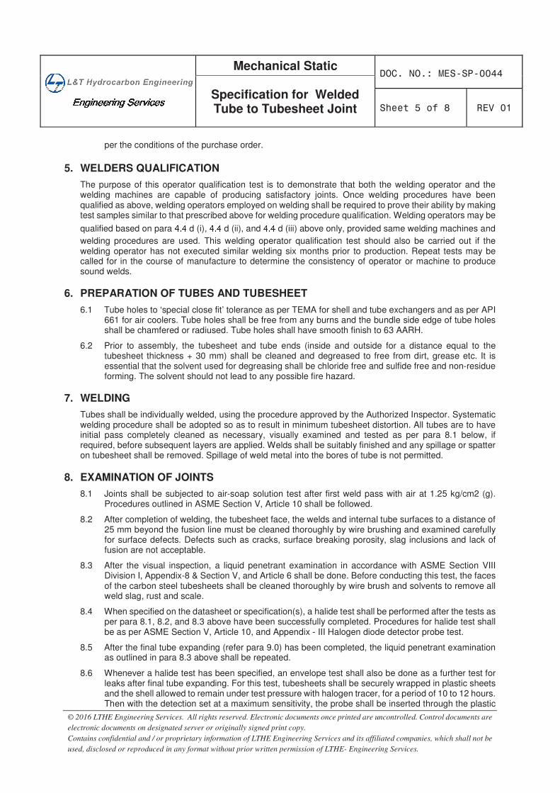
������������������������������������������������������������������������
Mechanical Static
Specification for Welded Tube to Tubesheet Joint
© 2016 LTHE Engineering Services. All rights reserved. Electronic documents once printed are uncontrolled. Control documents are
electronic documents on designated server or originally signed print copy.
Contains confidential and / or proprietary information of LTHE Engineering Services and its affiliated companies, which shall not be
used, disclosed or reproduced in any format without prior written permission of LTHE- Engineering Services.
per the conditions of the purchase order.
5. WELDERS QUALIFICATION
The purpose of this operator qualification test is to demonstrate that both the welding operator and the welding machines are capable of producing satisfactory joints. Once welding procedures have been qualified as above, welding operators employed on welding shall be required to prove their ability by making test samples similar to that prescribed above for welding procedure qualification. Welding operators may be
qualified based on para���� d (i), ��� d (ii), and���� d (iii) above only, provided same welding machines and
welding procedures are used. This welding operator qualification test should also be carried out if the welding operator has not executed similar welding six months prior to production. Repeat tests may be called for in the course of manufacture to determine the consistency of operator or machine to produce sound welds.
6. PREPARATION OF TUBES AND TUBESHEET
6.1 Tube holes to ‘special close fit’ tolerance as per TEMA for shell and tube exchangers and as per API 661 for air coolers. Tube holes shall be free from any burns and the bundle side edge of tube holes shall be chamfered or radiused. Tube holes shall have smooth finish to 63 AARH.
6.2 Prior to assembly, the tubesheet and tube ends (inside and outside for a distance equal to the tubesheet thickness + 30 mm) shall be cleaned and degreased to free from dirt, grease etc. It is essential that the solvent used for degreasing shall be chloride free and sulfide free and non-residue forming. The solvent should not lead to any possible fire hazard.
7. WELDING
Tubes shall be individually welded, using the procedure approved by the Authorized Inspector. Systematic welding procedure shall be adopted so as to result in minimum tubesheet distortion. All tubes are to have initial pass completely cleaned as necessary, visually examined and tested as per para 8.1 below, if required, before subsequent layers are applied. Welds shall be suitably finished and any spillage or spatter on tubesheet shall be removed. Spillage of weld metal into the bores of tube is not permitted.
8. EXAMINATION OF JOINTS
8.1 Joints shall be subjected to air-soap solution test after first weld pass with air at 1.25 kg/cm2 (g). Procedures outlined in ASME Section V, Article 10 shall be followed.
8.2 After completion of welding, the tubesheet face, the welds and internal tube surfaces to a distance of 25 mm beyond the fusion line must be cleaned thoroughly by wire brushing and examined carefully for surface defects. Defects such as cracks, surface breaking porosity, slag inclusions and lack of fusion are not acceptable.
8.3 After the visual inspection, a liquid penetrant examination in accordance with ASME Section VIII Division I, Appendix-8 & Section V, and Article 6 shall be done. Before conducting this test, the faces of the carbon steel tubesheets shall be cleaned thoroughly by wire brush and solvents to remove all weld slag, rust and scale.
8.4 When specified on the datasheet or specification(s), a halide test shall be performed after the tests as per para 8.1, 8.2, and 8.3 above have been successfully completed. Procedures for halide test shall be as per ASME Section V, Article 10, and Appendix - III Halogen diode detector probe test.
8.5 After the final tube expanding (refer para 9.0) has been completed, the liquid penetrant examination as outlined in para 8.3 above shall be repeated.
8.6 Whenever a halide test has been specified, an envelope test shall also be done as a further test for leaks after final tube expanding. For this test, tubesheets shall be securely wrapped in plastic sheets and the shell allowed to remain under test pressure with halogen tracer, for a period of 10 to 12 hours. Then with the detection set at a maximum sensitivity, the probe shall be inserted through the plastic

������������������������������������������������������������������������
Mechanical Static
Specification for Welded Tube to Tubesheet Joint
© 2016 LTHE Engineering Services. All rights reserved. Electronic documents once printed are uncontrolled. Control documents are
electronic documents on designated server or originally signed print copy.
Contains confidential and / or proprietary information of LTHE Engineering Services and its affiliated companies, which shall not be
used, disclosed or reproduced in any format without prior written permission of LTHE- Engineering Services.
cover at the bottom of the tubesheets and readings taken to observe if any leakage has occurred.
8.7 Final acceptance hydraulic pressure test shall be conducted after tube expansion at hydrotest pressure for at least one hour.
9. TUBE EXPANDING
After the tests outlined in 8.1, 8.2, 8.3, and 8.4 have been successfully completed and all leaking welds repaired, the tubes shall be "contact expanded" with a PARALLEL type expander. Contact expanding is intended to bring the tube OD into contact with the tubesheet hole. Contact expanding shall begin 12 mm from the tubesheet face and extend to 3 mm from the back face. The contact expansion shall have thinning of 3-5% which shall be ensured by measuring the inside diameter of tubes.
10. REPAIRS
If leaks are found during any of the above testing procedures these shall be reported to the Authorized Inspector and after obtaining his approval, repairs shall be made by removing the defects down to sound parent metal and repeating the qualified weld procedures. All weld repairs shall be retested in accordance with procedures outlined in para 8.0 above.
11. TEST AND REPAIR REPORTS
Test and repair reports shall be included in the Data Folder. These reports shall also indicate the number of leaks discovered on each test and the extent of the repair done.
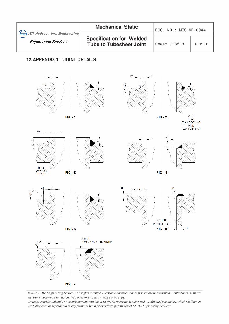
������������������������������������������������������������������������
Mechanical Static
Specification for Welded Tube to Tubesheet Joint
© 2016 LTHE Engineering Services. All rights reserved. Electronic documents once printed are uncontrolled. Control documents are
electronic documents on designated server or originally signed print copy.
Contains confidential and / or proprietary information of LTHE Engineering Services and its affiliated companies, which shall not be
used, disclosed or reproduced in any format without prior written permission of LTHE- Engineering Services.
12. APPENDIX 1 – JOINT DETAILS
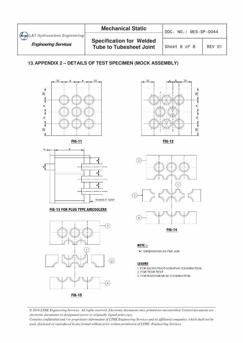
������������������������������������������������������������������������
Mechanical Static
Specification for Welded Tube to Tubesheet Joint
© 2016 LTHE Engineering Services. All rights reserved. Electronic documents once printed are uncontrolled. Control documents are
electronic documents on designated server or originally signed print copy.
Contains confidential and / or proprietary information of LTHE Engineering Services and its affiliated companies, which shall not be
used, disclosed or reproduced in any format without prior written permission of LTHE- Engineering Services.
13. APPENDIX 2 – DETAILS OF TEST SPECIMEN (MOCK ASSEMBLY)
�
������������������������������������������������������������������������
Mechanical Static
Standard Specification for Hardness Requirement
of Static Equipment
© 2016 LTHE Engineering Services. All rights reserved. Electronic documents once printed are uncontrolled. Control documents are
electronic documents on designated server or originally signed print copy.
Contains confidential and / or proprietary information of LTHE Engineering Services and its affiliated companies, which shall not be
used, disclosed or reproduced in any format without prior written permission of LTHE- Engineering Services.
STANDARD SPECIFICATION
FOR
HARDNESS REQUIREMENT
OF
STATIC EQUIPMENTS
00 Issued as Standard Specification SMP SGB RGO 17-May-2016
REV DESCRIPTION Prepared
by Reviewed
by Approved
by Approved
Date
������������������������������������������������������������������������
Mechanical Static
Standard Specification for Hardness Requirement
of Static Equipment
© 2016 LTHE Engineering Services. All rights reserved. Electronic documents once printed are uncontrolled. Control documents are
electronic documents on designated server or originally signed print copy.
Contains confidential and / or proprietary information of LTHE Engineering Services and its affiliated companies, which shall not be
used, disclosed or reproduced in any format without prior written permission of LTHE- Engineering Services.
CONTENTS
�� ������������������������������������������������������������������������������������������������������������������������������
� �� ������ ���� ������������������������������������ �������������������������������������������������������
� ��������������������������������������������������������������������������������������������������������
�� � ����������������������������������������������������������������������������������������������������������������
�� ��� ����������������������������������������������������������������������������������������������������������������������
ABBREVIATIONS:
ASTM American Society of Testing Materials
HAZ Heat Affected Zone
PWHT Post Weld Heat Treatment
������������������������������������������������������������������������
Mechanical Static
Standard Specification for Hardness Requirement
of Static Equipment
© 2016 LTHE Engineering Services. All rights reserved. Electronic documents once printed are uncontrolled. Control documents are
electronic documents on designated server or originally signed print copy.
Contains confidential and / or proprietary information of LTHE Engineering Services and its affiliated companies, which shall not be
used, disclosed or reproduced in any format without prior written permission of LTHE- Engineering Services.
1. SCOPE
1.1 This specification covers general requirement of hardness of base metal, weld and heat affected zone (HAZ) and is applicable to all C-1/2 Mo, Cr-Mo and other materials whenever specified in data sheet / specifications / standards.
1.2 On heat-treated vessels, hardness testing shall be carried out after PWHT.
2. HARDNESS REQUIREMENT
Hardness in base metals, weld and heat affected zone as per ASTM E10 shall not exceed the following:
Material P No. Brinell Hardness Number (BHN)
P1 200
P3 & P4 225
P5 & P6 235
3. WELDING QUALIFICATION TEST
3.1 For each welding procedure qualification six tests shall be made, three in weld metal and three in HAZ. Hardness requirements shall be as per clause 2.0 above.
3.2 In addition to the requirement of clause 3.1 above, Vickers Micro hardness test shall be made on a full cross-section at 25 mm intervals beginning at 3 mm from the top surface with 5 kg load or with a load approved by the authorized inspector. Tests shall be made at each level for each of the following locations as per ASTM E 92:
Three tests shall be made in the weld metals, two tests in HAZ and one test in the base metal in accordance with Fig.1 and the hardness shall not exceed the following in base metal, weld metal and HAZ.
Material P No. Vickers Hardness Number (VHN)
P1 210
P3 & P4 237
P5 & P6 247
4. PRODUCTION TEST
4.1 All pressure containing weld metals are to be checked for hardness of weld and HAZ after PWHT but before hydro-test. The hardness shall not exceed the value stipulated above.
4.2 Each longitudinal seam shall be checked both internally and externally near the center and at one end.
4.3 Each circumferential weld shall be checked at four locations approximately 90°apart, both internally and externally.
4.4 Each nozzle weldments shall be checked at two locations, 180° apart, both internally and externally.
5. APPROVAL
In case the hardness as obtained on production test is more than the limit specified in clause 2.0 above, the vendor shall submit the corrective procedure to lower the hardness in writing to purchaser and/or authorized inspection agency for review/approval.
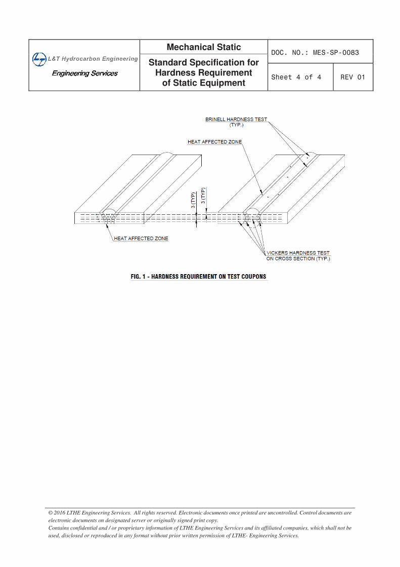
������������������������������������������������������������������������
Mechanical Static
Standard Specification for Hardness Requirement
of Static Equipment
© 2016 LTHE Engineering Services. All rights reserved. Electronic documents once printed are uncontrolled. Control documents are
electronic documents on designated server or originally signed print copy.
Contains confidential and / or proprietary information of LTHE Engineering Services and its affiliated companies, which shall not be
used, disclosed or reproduced in any format without prior written permission of LTHE- Engineering Services.
Mechanical Static DOC.NO.: MES SP 0092
Standard Specification for Positive Material Identification
(PMI) At Supplier`s Works Sheet 1 of 6 REV 01
© 2016 LTHE Engineering Services. All rights reserved. Electronic documents once printed are uncontrolled. Control documents are electronic documents on designated server or originally signed print copy. Contains confidential and / or proprietary information of LTHE Engineering Services and its affiliated companies, which shall not be used, disclosed or reproduced in any format without prior written permission of LTHE- Engineering Services.
STANDARD SPECIFICATIONFOR
POSITIVE MATERIAL IDENTIFICATION (PMI)
AT SUPPLIER`S WORKS
01 Issued for implementation RIG BBB MVA 25-Oct-2016 00 Draft SMP SGB RGO 04-Jul-2016
REV DESCRIPTION Preparedby
Reviewed by
Approved by
Approved Date
Mechanical Static DOC.NO.: MES SP 0092
Standard Specification for Positive Material Identification
(PMI) At Supplier`s Works Sheet 2 of 6 REV 01
© 2016 LTHE Engineering Services. All rights reserved. Electronic documents once printed are uncontrolled. Control documents are electronic documents on designated server or originally signed print copy. Contains confidential and / or proprietary information of LTHE Engineering Services and its affiliated companies, which shall not be used, disclosed or reproduced in any format without prior written permission of LTHE- Engineering Services.
CONTENTS
Abbreviation:API American Petroleum Institute
PMI Positive Material Identification
Sch Schedule
TPIA Third Party Inspection Agency
Mechanical Static DOC.NO.: MES SP 0092
Standard Specification for Positive Material Identification
(PMI) At Supplier`s Works Sheet 3 of 6 REV 01
© 2016 LTHE Engineering Services. All rights reserved. Electronic documents once printed are uncontrolled. Control documents are electronic documents on designated server or originally signed print copy. Contains confidential and / or proprietary information of LTHE Engineering Services and its affiliated companies, which shall not be used, disclosed or reproduced in any format without prior written permission of LTHE- Engineering Services.
1. SCOPE 1.1 This specification applies to the requirements for Positive Material Identification (PMI) to be
performed at the Supplier's works on Metallic Materials procured either directly by the Company / Purchaser / Contractor or indirectly through the sub-Suppliers.
1.2 Any deviation from this specification must be approved by Company / Purchaser in the Deviation / Waiver Permit format enclosed with Requisition.
1.3 This specification covers the procedures and methodology to be adopted to assure that the chemical composition of the material is consistent with the material specifications as specified in purchase documents using 'Alloy Analyzer' at the time of final inspection before dispatch.
1.4 The Scope of this specification shall include but shall not be limited to Positive Material Identification (PMI) to be performed on Materials listed below:
1.4.1 For alloy Steel materials as below: Alloy Steel Pipes including Clad Pipes Alloy Steel Flanges & Forgings Alloy Steel Fittings including Clad Fittings Alloy Steel Fasteners Alloy Cast & Forged steel valves Alloy Steel Instrumentation Items (Control Valves, Safety Valves etc.) Longitudinal Pipe & Fittings Welds. Gaskets (for Ring Type Joints)
1.4.2 For Carbon Steel materials as below: All Carbon Steel Piping items under NACE or HIC or H2 Carbon Steel flanges and valves (Rating 900# and above) Carbon Steel Pipes & fittings for following thicknesses: Size 1"- 2" NB : Sch 160 & above Size 3" NB : Sch XS & above Size 4" - 12" NB : Sch 120 & above
1.4.3 Following items shall be excluded from scope of PMI examination. Gaskets other than for Ring Type Internal Components of valves
1.5 All grades of material supplies including Stainless Steels shall be liable for PMI test at site. In case of any defective materials being found at site, the Supplier shall be responsible to effect replacement of such defective materials at project site without any delays to the satisfaction of Company / Purchaser.
2. REFERENCE DOCUMENTS API Recommended Practice 578 (Second edition, March 2010) - Material Verification Program for New and Existing Alloy Piping Systems.
3. DEFINITIONS3.1 Supplier: Any Supplier or Manufacturer on whom an order is placed for the supply of referred items.
This definition shall also include any sub-Supplier or manufacturer on whom a sub-order is placed by the Supplier.
3.2 Inspection Lot: A group of items offered for inspection covered under same size, Heat and Heat treatment lot.
3.3 Alloy Material: Any metallic material (including welding filler materials) that contains alloying elements such as chromium, nickel, molybdenum or vanadium, which are intentionally added to
Mechanical Static DOC.NO.: MES SP 0092
Standard Specification for Positive Material Identification
(PMI) At Supplier`s Works Sheet 4 of 6 REV 01
© 2016 LTHE Engineering Services. All rights reserved. Electronic documents once printed are uncontrolled. Control documents are electronic documents on designated server or originally signed print copy. Contains confidential and / or proprietary information of LTHE Engineering Services and its affiliated companies, which shall not be used, disclosed or reproduced in any format without prior written permission of LTHE- Engineering Services.
enhance mechanical or physical properties and/or corrosion resistance.
4. PMI EXAMINATION 4.1 The Supplier shall submit a procedure of PMI to comply with the requirements of this specification
approval of PMI Procedure shall be obtained from Company / Purchaser /TPIA prior to commencing manufacture / inspection of product.
4.2 PMI examination of materials is independent of any certification, markings or colour coding that may exist and is aimed at verifying that the alloy used are as per specified grades.
4.3 The Supplier shall identify all incoming alloy materials and maintain full traceability of all alloy materials, including all off-cuts. Transfer of identification marks shall be undertaken prior to cutting to ensure maintenance of identification on off-cuts.
4.4 The Supplier shall ensure that all alloy materials are segregated and stored in separately identified locations to prevent the mix up of materials of different alloy specifications or alloy material with carbon steel. Non ferro-magnetic materials shall be segregated at all times from ferro-magnetic materials.
4.5 PMI examination is subject to surveillance inspection by Company / Purchaser / TPIA.
5. ACCEPTABLE METHODS FOR PMI 5.1 The method used for PMI examination shall provide a quantitative determination of the alloying
elements like chromium, nickel, molybdenum or vanadium in Alloy Steel items.
5.2 Instruments or methods used for PMI examination shall be able to provide quantitative, recordable, elemental composition results for positive identification of alloying elements present.
5.3 The acceptable instruments for alloy analyzer shall be either "Portable X-Ray fluorescence" or "Optical Emission" type each capable of verifying the percentage of alloy elements within specified range.
5.4 Chemical spot testing, magnets, alloy sorters and other methods using eddy current or triboelectric testing methods are not acceptable for PMI examination.
5.5 The PMI instrument used shall have the sensitivity to detect the alloying elements in the specified range.
5.6 All PMI instruments shall have been serviced within a 6 month period of the time of use to verify the suitability of batteries, sources etc., and the data of the last service shall be stated on the PMI Report Form (Sample enclosed).
5.7 Each analyzer must be calibrated according to the manufacturer's specification at the beginning and end of each shift. Instrument must be checked against known standard for each alloy type to be inspected during the shift.
5.8 Certified samples, with full traceability, of a known alloy materials shall be available for use as a random spot check on the instrument calibration.
5.9 The surfaces to be examined shall be prepared by light grinding or abrasive paper and solvent cleaner. Evidence of Arc burn resulting from examination shall be removed by light grinding or abrasive paper. No permanent marks, which are injurious to the usage of product in service, are acceptable.
5.10 Alloy Steel ring type joint Gaskets shall be inspected by using portable X-Ray fluorescence instrument.
5.11 Testing shall be done as per the procedures outlined by the manufactures of alloy analyzer being used. Modification of these procedures if any must be approved by Company / Purchaser.
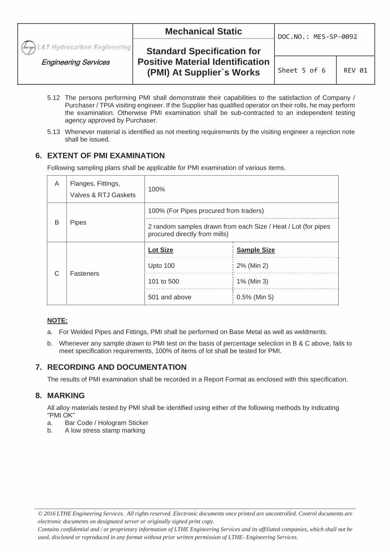
Mechanical Static DOC.NO.: MES SP 0092
Standard Specification for Positive Material Identification
(PMI) At Supplier`s Works Sheet 5 of 6 REV 01
© 2016 LTHE Engineering Services. All rights reserved. Electronic documents once printed are uncontrolled. Control documents are electronic documents on designated server or originally signed print copy. Contains confidential and / or proprietary information of LTHE Engineering Services and its affiliated companies, which shall not be used, disclosed or reproduced in any format without prior written permission of LTHE- Engineering Services.
5.12 The persons performing PMI shall demonstrate their capabilities to the satisfaction of Company / Purchaser / TPIA visiting engineer. If the Supplier has qualified operator on their rolls, he may perform the examination. Otherwise PMI examination shall be sub-contracted to an independent testing agency approved by Purchaser.
5.13 Whenever material is identified as not meeting requirements by the visiting engineer a rejection note shall be issued.
6. EXTENT OF PMI EXAMINATION Following sampling plans shall be applicable for PMI examination of various items.
A Flanges, Fittings,
Valves & RTJ Gaskets 100%
B Pipes
100% (For Pipes procured from traders)
2 random samples drawn from each Size / Heat / Lot (for pipes procured directly from mills)
C Fasteners
Lot Size Sample Size
Upto 100 2% (Min 2)
101 to 500 1% (Min 3)
501 and above 0.5% (Min 5)
NOTE:
a. For Welded Pipes and Fittings, PMI shall be performed on Base Metal as well as weldments.
b. Whenever any sample drawn to PMI test on the basis of percentage selection in B & C above, fails to meet specification requirements, 100% of items of lot shall be tested for PMI.
7. RECORDING AND DOCUMENTATION The results of PMI examination shall be recorded in a Report Format as enclosed with this specification.
8. MARKING All alloy materials tested by PMI shall be identified using either of the following methods by indicating "PMI OK" a. Bar Code / Hologram Sticker b. A low stress stamp marking
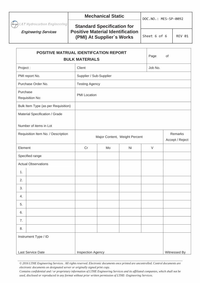
Mechanical Static DOC.NO.: MES SP 0092
Standard Specification for Positive Material Identification
(PMI) At Supplier`s Works Sheet 6 of 6 REV 01
© 2016 LTHE Engineering Services. All rights reserved. Electronic documents once printed are uncontrolled. Control documents are electronic documents on designated server or originally signed print copy. Contains confidential and / or proprietary information of LTHE Engineering Services and its affiliated companies, which shall not be used, disclosed or reproduced in any format without prior written permission of LTHE- Engineering Services.
POSITIVE MATRUAL IDENTIFCATION REPORT BULK MATERIALS
Page of
Project : Client Job No.
PMI report No. Supplier / Sub-Supplier
Purchase Order No. Testing Agency
Purchase
Requisition No: PMI Location
Bulk Item Type (as per Requisition)
Material Specification / Grade
Number of items in Lot
Requisition Item No. / Description Major Content, Weight Percent
Remarks
Accept / Reject
Element Cr Mo Ni V
Specified range
Actual Observations
1.
2.
3.
4.
5.
6.
7.
8.
Instrument Type / ID
Last Service Date Inspection Agency Witnessed By
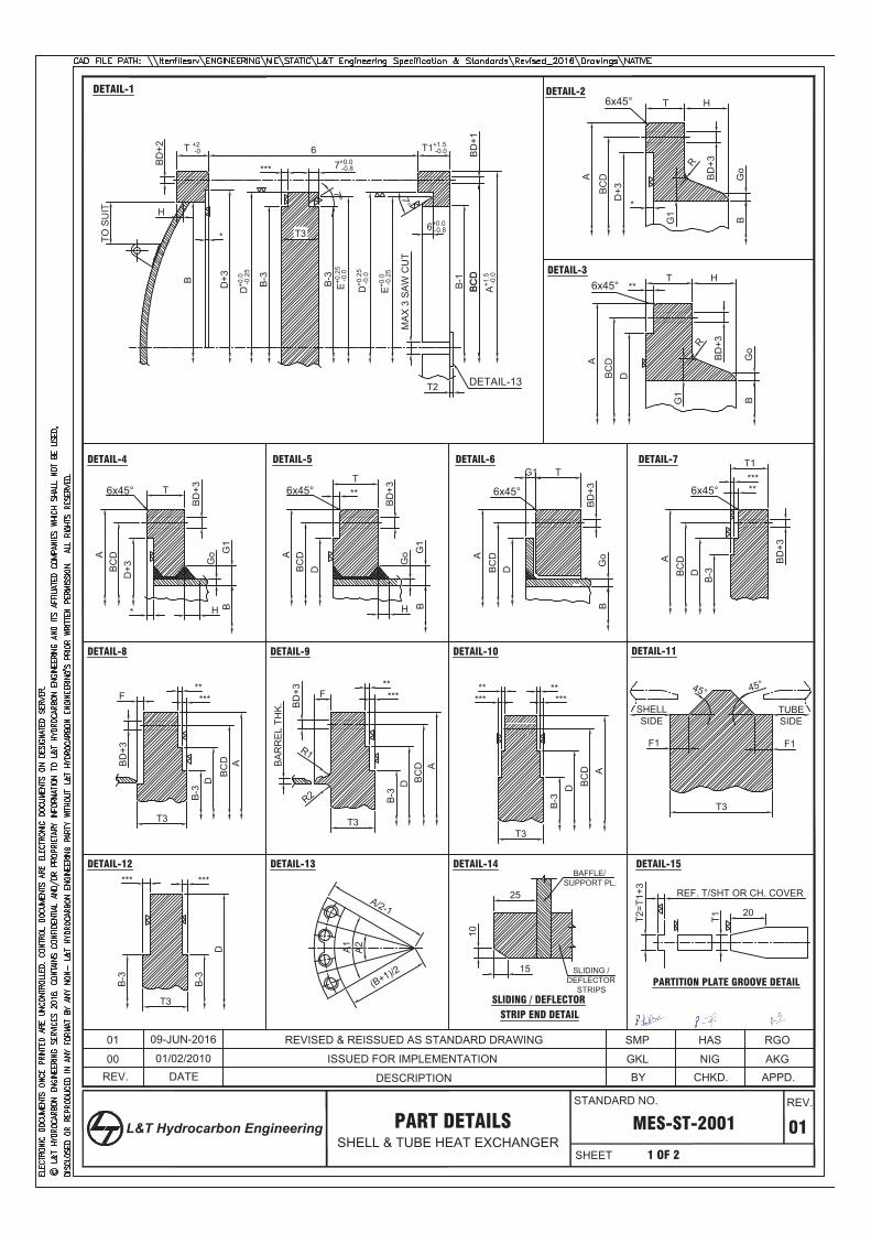
BD
+1
T +2 -0
***
6 T1+1.5 -0.0
T3
T2
BD
+2
TO S
UIT
6x45°
BD
+3R
*
G1
BD
+3
T1***
6x45°
BD
+3
T
Go
6x45°
G1
Go G
1
BD
+3T
H*
**F
T3
BD
+3
*****
F
T3
BD
+3 ***
R1
BA
RR
EL
THK
.
** **
T3
******
F1 F1
T3
A/2-1
A2A1
(B+1)/2
25
10
15
BAFFLE/SUPPORT PL.
SLIDING /DEFLECTOR
STRIPS
20
T1T2=T
1+3
REF. T/SHT OR CH. COVER
PARTITION PLATE GROOVE DETAIL
D+3B
CDA A
BC
D
B-3DB
CD
A
BC
DD
+3
B-3
D
A
B-3
D BC
D A
BC
D
B-3
D
A
*
B D+3
D+0
.0 -0
.25
B-3 B-3
E+0.2
5 -0
.0
D+0
.25
-0.0
E+0.0
-0.2
5
B-1
BC
DA+1
.5 -0
.0
MA
X 3
SA
W C
UT
TUBESIDE
SHELLSIDE
6x45°
A
7° 7°
HT
6x45°
BD
+3R
**
G1
A
BC
DD
HT
Go
BG
oB
DETAIL-13
Go G
1
BD
+3
T
H
**
DBC
DA
6x45°D
B
**
BC
D
45°45°
*** ***
T3
B-3
D
B-3
DETAIL-1 DETAIL-2
DETAIL-4 DETAIL-5 DETAIL-6
DETAIL-8 DETAIL-9 DETAIL-10 DETAIL-11
DETAIL-12 DETAIL-13 DETAIL-14 DETAIL-15
DETAIL-3
7+0.0 -0.8
R2
SLIDING / DEFLECTORSTRIP END DETAIL
H
BC
D
6+0.0 -0.8
DETAIL-7
B B
MES-ST-2001 01
APPD.AKG
1 OF 2
CHKD.NIG
BYGKL
STANDARD NO.
SHEET
REV.
L&T Hydrocarbon Engineering
REV.ISSUED FOR IMPLEMENTATION
DATE01/02/201000
RGOHASSMPREVISED & REISSUED AS STANDARD DRAWING09-JUN-201601
PART DETAILSSHELL & TUBE HEAT EXCHANGER
DESCRIPTION
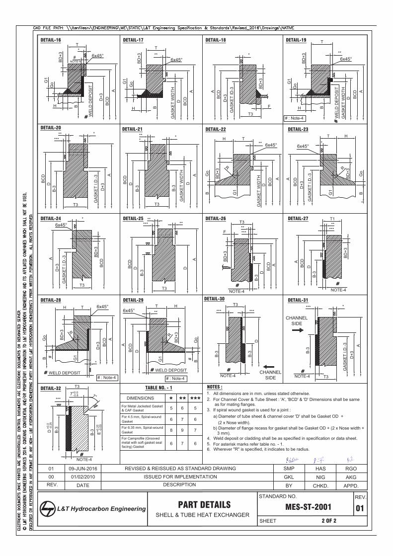
GoG
1
BD
+3
T
H
*
D+3
BC
DA
6x45°
GoG
1
BD
+3
T
H
BC
DA
6x45°
D
**#
BD
+3
F
GA
SK
ET
ID-3
BC
DA
D+3
*
T3
GoG
1
BD
+3
T
H
GA
SK
ET
WID
TH
BC
D A
6x45°
D
**
B B B
T3
******
GA
SK
ET
I.D.-3
D+3
A
B-3
DBC
D
***
T3
B-3
GA
SK
ET
WID
THD
A
BC
D
B-3
D*
6x45°
BD
+3
R
**
G1
A
BC
DD
H T
Go
B
GA
SK
ET
WID
TH
6x45°
BD
+3
R
*
G1
A
BC
DD
+3
HT
Go
B
GA
SK
ET
I.D.-3
T3
*
GA
SK
ET
I.D.-3
D+3
A
BC
DB
D+3
6x45° *****
T3
A
BC
D
B-3
D
****
F
T3B
D+3
***
B-3
D
AB
CD
NOTE-4
**T1
BD
+3
***
B-3
D
AB
CD
NOTE-4
6x45°
BD
+3 R
*
G1
AB
CD
D+3
H T6x45°
BD
+3R
**
G1
A
BC
DD
HT
Go
B
Go
B
WELD DEPOSIT
#
WELD DEPOSIT
#
*** ***T3
B-3
D
B-3
NOTE-4 T3
****
GA
SK
ET
I.D.-3
D+3
A
B-3
***
T3
NOTE-4
7+0.0 -0.8
B-3D +
0.0
-0.2
5
B-3 E+0
.25
-0.0
0
MES-ST-2001 01
APPD.
2 OF 2
CHKD.BY
PART DETAILSSHELL & TUBE HEAT EXCHANGER
7°
DETAIL-16 DETAIL-17 DETAIL-18 DETAIL-19
DETAIL-20 DETAIL-21 DETAIL-22 DETAIL-23
DETAIL-24 DETAIL-25 DETAIL-26 DETAIL-27
DETAIL-31DETAIL-30DETAIL-29DETAIL-28
DETAIL-32
DIMENSIONS
For Metal Jacketed Gasket
For 4.5 mm, Spiral-wound
TABLE NO. - 1
* ** ***565
Gasket 676
For 6.35 mm, Spiral-woundGasket 798
2.
NOTES :
For Channel Cover & Tube Sheet : 'A', 'BCD' & 'D' Dimensions shall be same as for mating flanges.
3. If spiral wound gasket is used for a joint :a) Diameter of tube sheet & channel cover 'D' shall be Gasket OD +
(2 x Nose width).
4. Weld deposit or cladding shall be as specified in specification or data sheet.5. For asterisk marks refer table no. - 1.6. Wherever "R" is specified, it indicates to be radius.
GA
SK
ET
WID
TH
WE
LD D
EP
OS
IT
WE
LD D
EP
OS
IT
NOTE-4CHANNEL
SIDE
CHANNELSIDE
#
#
#
# #
# #
GKL AKGNIG
1. All dimensions are in mm. unless stated otherwise.
#
#
NOTE-4
For Camprofile (Groovedmetal with soft gasket seal 676
& CAF Gasket
b) Diameter of flange recess for gasket shall be Gasket OD + (2 x Nose width +3 mm).
# : Note-4
facing) Gasket
D
# : Note-4 # : Note-4
SMP RGOHAS
REV. DESCRIPTION00 ISSUED FOR IMPLEMENTATION01/02/2010
01 REVISED & REISSUED AS STANDARD DRAWING09-JUN-2016
DATE
STANDARD NO.
SHEET
REV.
L&T Hydrocarbon Engineering
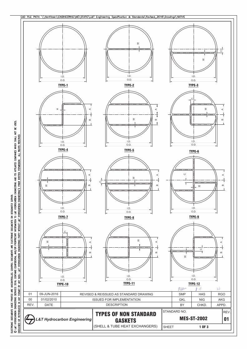
REV.
01
APPD.
1 OF 3
CHKD.BYDESCRIPTION
I.D.O.D.
I.D.O.D.
I.D.
O.D.
I.D.O.D.
I.D.O.D.
I.D.O.D.
I.D.O.D.
I.D.O.D.
I.D.O.D.
I.D.O.D.
I.D.O.D.
I.D.O.D.
W
WWA
WB
W
AB
W
C
AB W
W
W
B AA
B
W
A
B
C
C AB
AB
AB
C
C
TYPES OF NON STANDARD
(SHELL & TUBE HEAT EXCHANGERS)GASKETS MES-ST-2002
w
00 ISSUED FOR IMPLEMENTATION
TYPE-1 TYPE-2
TYPE-4
TYPE-7 TYPE-8 TYPE-9
TYPE-3
TYPE-6TYPE-5
TYPE-10 TYPE-11 TYPE-12
C
AKGNIGGKL
01 REVISED & REISSUED AS STANDARD DRAWING RGOHASSMP01/02/2010
09-JUN-2016
DATE
STANDARD NO.
SHEET
REV.
L&T Hydrocarbon Engineering
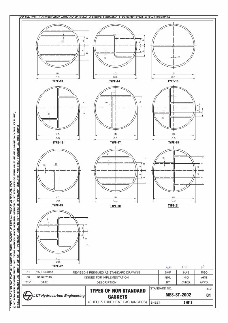
AA
BB
O.D.
I.D.
W
AA
BB
I.D.
O.D.
W
I.D.
O.D.
ABW
O.D.
W
I.D.
O.D.
AA
B
W
AA
BB
AA
BB
W
I.D.O.D.
I.D.O.D.
W
I.D.O.D.
I.D.
O.D.
W
I.D.
A
C
C
W
TYPE-13 TYPE-14 TYPE-15
TYPE-19 TYPE-20 TYPE-21
TYPE-16 TYPE-17 TYPE-18
C
REV.
01
APPD.
2 OF 3
CHKD.BY
TYPES OF NON STANDARD
(SHELL & TUBE HEAT EXCHANGERS)GASKETS MES-ST-2002
00 ISSUED FOR IMPLEMENTATION AKGNIGGKL
W
AA
BB
I.D.O.D.
TYPE-22
01/02/2010
DATE
RGOHASSMPREVISED & REISSUED AS STANDARD DRAWING
DESCRIPTION
01 09-JUN-2016
STANDARD NO.
SHEET
REV.
L&T Hydrocarbon Engineering
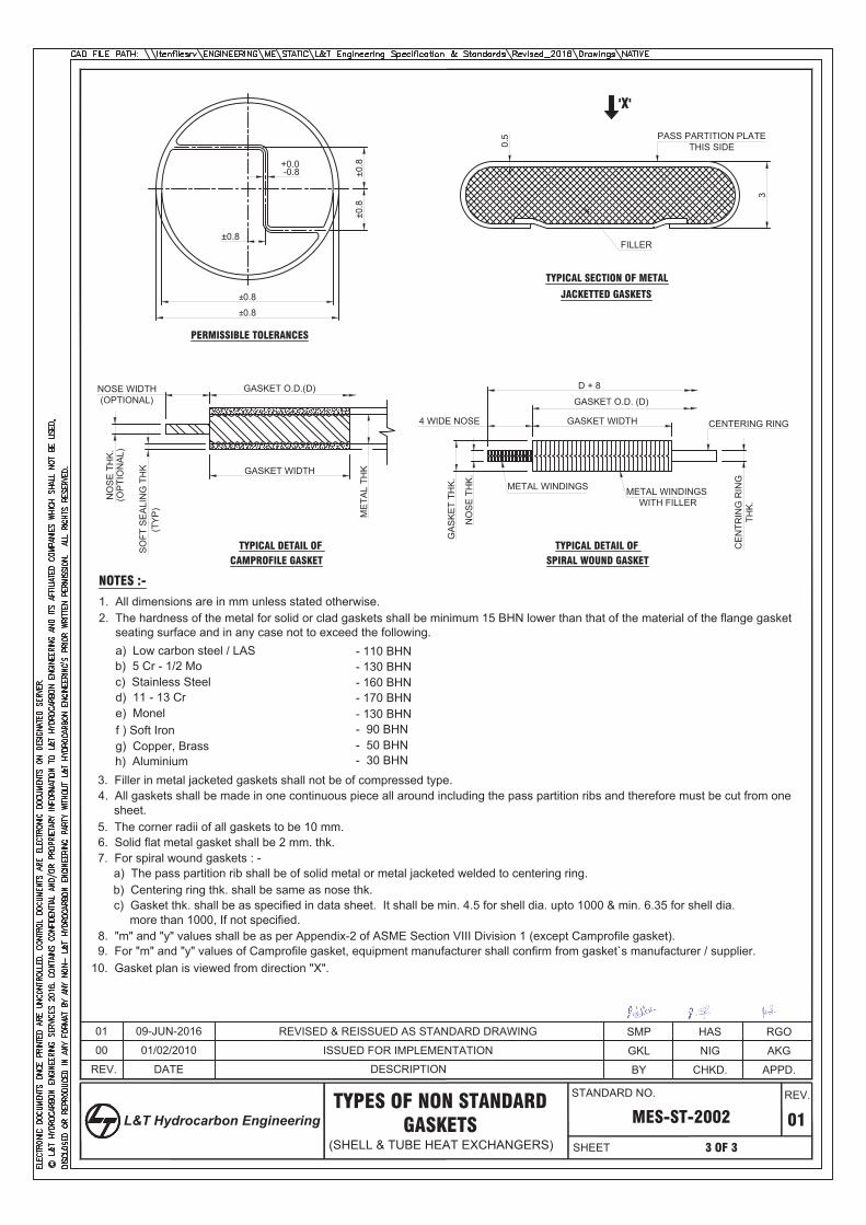
REV.
01
APPD.
3 OF 3
CHKD.BYDESCRIPTION
-0.8
±0.8
±0.8
±0.8±0.8
0.5
3
PASS PARTITION PLATETHIS SIDE
TYPICAL SECTION OF METAL
JACKETTED GASKETS
CE
NTR
ING
RIN
GTH
K.
GASKET O.D. (D)
D + 8
NO
SE
TH
K.
GA
SK
ET
THK
.
4 WIDE NOSE GASKET WIDTH
METAL WINDINGS METAL WINDINGS WITH FILLER
TYPICAL DETAIL OF SPIRAL WOUND GASKET
±0.8FILLER
NOTES :-
1. All dimensions are in mm unless stated otherwise.2. The hardness of the metal for solid or clad gaskets shall be minimum 15 BHN lower than that of the material of the flange gasket
seating surface and in any case not to exceed the following.
3. Filler in metal jacketed gaskets shall not be of compressed type.4. All gaskets shall be made in one continuous piece all around including the pass partition ribs and therefore must be cut from one
sheet.5. The corner radii of all gaskets to be 10 mm.
a) Low carbon steel / LAS - 110 BHNb) 5 Cr - 1/2 Mo - 130 BHNc) Stainless Steel - 160 BHNd) 11 - 13 Cr - 170 BHNe) Monel - 130 BHNf ) Soft Iron - 90 BHNg) Copper, Brass - 50 BHNh) Aluminium - 30 BHN
6. Solid flat metal gasket shall be 2 mm. thk.7. For spiral wound gaskets : -
a) The pass partition rib shall be of solid metal or metal jacketed welded to centering ring.b) Centering ring thk. shall be same as nose thk.c) Gasket thk. shall be as specified in data sheet. It shall be min. 4.5 for shell dia. upto 1000 & min. 6.35 for shell dia.
more than 1000, If not specified.8. "m" and "y" values shall be as per Appendix-2 of ASME Section VIII Division 1 (except Camprofile gasket).
10. Gasket plan is viewed from direction "X".
PERMISSIBLE TOLERANCES
TYPES OF NON STANDARD
(SHELL & TUBE HEAT EXCHANGERS)GASKETS MES-ST-2002
CENTERING RING
00 ISSUED FOR IMPLEMENTATION
+0.0
'X'
AKGNIGGKL
9. For "m" and "y" values of Camprofile gasket, equipment manufacturer shall confirm from gasket`s manufacturer / supplier.
GASKET O.D.(D)
NO
SE
TH
K.
(OP
TIO
NA
L)
NOSE WIDTH(OPTIONAL)
GASKET WIDTH
TYPICAL DETAIL OF CAMPROFILE GASKET
ME
TAL
THK
SO
FT S
EA
LIN
G T
HK
(TY
P)
DATE
01/02/2010
RGOHASSMP01 09-JUN-2016 REVISED & REISSUED AS STANDARD DRAWING
STANDARD NO.
SHEET
REV.
L&T Hydrocarbon Engineering
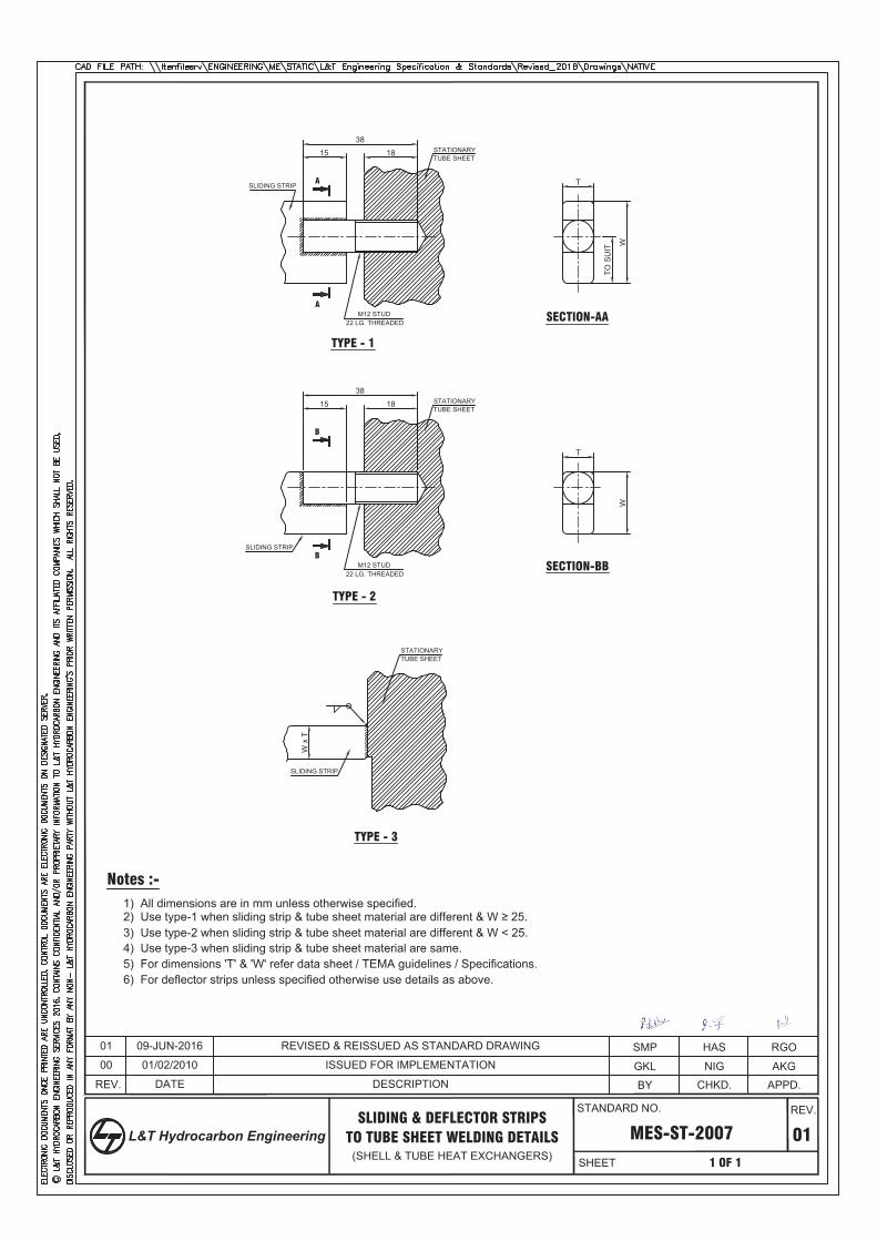
15 18
38
T
W
TO S
UIT
M12 STUD22 LG. THREADED
STATIONARYTUBE SHEET
A
A
TYPE - 1
SECTION-AA
15 18
38
T
W
M12 STUD22 LG. THREADED
STATIONARYTUBE SHEET
B
B
TYPE - 2
SECTION-BB
SLIDING STRIP
SLIDING STRIP
REV.
MES-ST-2007 01
APPD.
1 OF 1
CHKD.BY
SLIDING & DEFLECTOR STRIPSTO TUBE SHEET WELDING DETAILS
(SHELL & TUBE HEAT EXCHANGERS)
Notes :-1) All dimensions are in mm unless otherwise specified.2) Use type-1 when sliding strip & tube sheet material are different & W ≥ 25.3) Use type-2 when sliding strip & tube sheet material are different & W < 25.4) Use type-3 when sliding strip & tube sheet material are same.5) For dimensions 'T' & 'W' refer data sheet / TEMA guidelines / Specifications.6) For deflector strips unless specified otherwise use details as above.
STATIONARYTUBE SHEET
TYPE - 3
SLIDING STRIP
W x
T
00 ISSUED FOR IMPLEMENTATION AKGNIGGKL
RGOHASSMP01/02/2010
01 09-JUN-2016
DATE
REVISED & REISSUED AS STANDARD DRAWING
DESCRIPTION
STANDARD NO.
SHEET
REV.
L&T Hydrocarbon Engineering
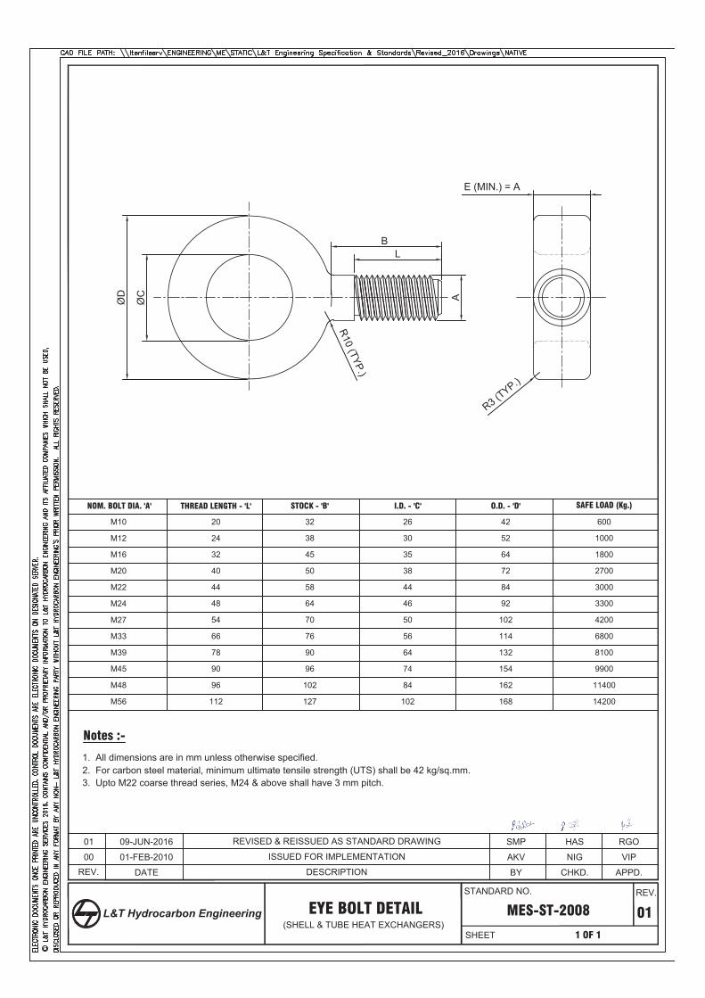
ØC
ØD
LB
A
R10 (TYP.)
REV.
MES-ST-2008 01
APPD.
1 OF 1
CHKD.BY
EYE BOLT DETAIL
NOM. BOLT DIA. 'A' THREAD LENGTH - 'L'
M10 20
M12
M16
M20
M22
M24
Notes :-
1. All dimensions are in mm unless otherwise specified.2. For carbon steel material, minimum ultimate tensile strength (UTS) shall be 42 kg/sq.mm.
M27
M33
M39
M45
M48
M56
STOCK - 'B' I.D. - 'C' O.D. - 'D' SAFE LOAD (Kg.)
(SHELL & TUBE HEAT EXCHANGERS)
24
32
40
44
48
54
66
78
90
96
112
32
38
45
50
58
64
70
76
90
96
102
127
26
30
35
38
44
46
50
56
64
74
84
102
42
52
64
72
84
92
102
114
132
154
162
168
600
1000
1800
2700
3000
3300
4200
6800
8100
9900
11400
14200
3. Upto M22 coarse thread series, M24 & above shall have 3 mm pitch.
E (MIN.) = A
R3 (TYP.)
00 ISSUED FOR IMPLEMENTATION VIPNIGAKV
01 09-JUN-2016
01-FEB-2010
DATE
RGOHASSMPREVISED & REISSUED AS STANDARD DRAWING
DESCRIPTION
STANDARD NO.
SHEET
REV.
L&T Hydrocarbon Engineering
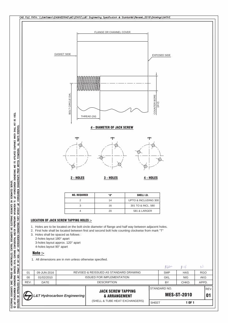
THREAD (2d)
FLANGE OR CHANNEL COVER
CO
UN
TER
BO
RE
(d+2
)
EXPOSED SIDE
BO
LT C
IRC
LE D
IA.
d - DIAMETER OF JACK SCREW
3 - HOLES2 - HOLES 4 - HOLES
"T" "T" "T"
REV.
MES-ST-2010 01
APPD.
1 OF 1
CHKD.BY
JACK SCREW TAPPING
(SHELL & TUBE HEAT EXCHANGERS)
LOCATION OF JACK SCREW TAPPING HOLES :-
1. Holes are to be located on the bolt circle diameter of flange and half way between adjacent holes.2. First hole shall be located between first and second bolt hole counting clockwise from mark "T"3. Holes shall be spaced as follows :
2-holes layout 180° apart3-holes layout approx. 120° apart
& ARRANGEMENT
NO. REQUIRED "d"
2 14
3
4
SHELL I.D.
16
20
UPTO & INCLUDING 300
301 TO & INCL. 580
581 & LARGER
Note :-1. All dimensions are in mm unless otherwise specified.
4-holes layout 90° apart
GASKET SIDE
00 ISSUED FOR IMPLEMENTATION AKGNIGGKL
RGOHASSMP
01/02/2010
09-JUN-2016
DATE
01 REVISED & REISSUED AS STANDARD DRAWING
DESCRIPTION
STANDARD NO.
SHEET
REV.
L&T Hydrocarbon Engineering
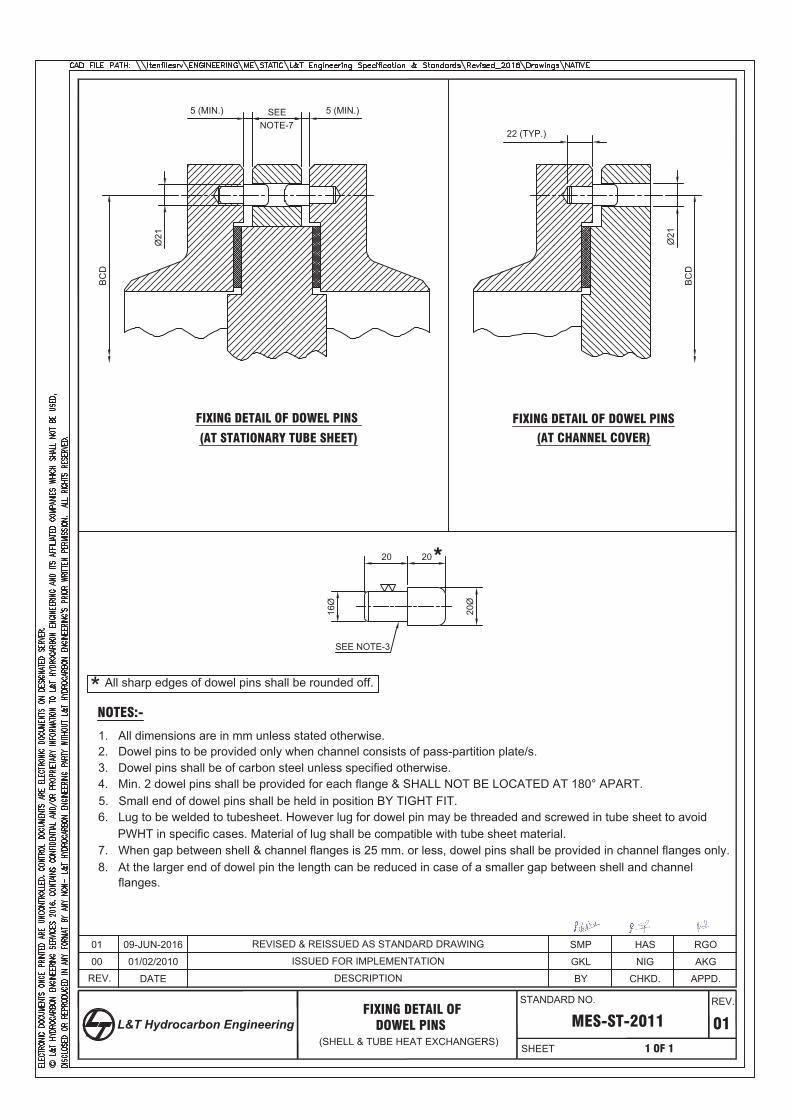
REV.
MES-ST-2011 01
APPD.
1 OF 1
CHKD.BY
FIXING DETAIL OF
(SHELL & TUBE HEAT EXCHANGERS)DOWEL PINS
NOTES:-
1. All dimensions are in mm unless stated otherwise.2. Dowel pins to be provided only when channel consists of pass-partition plate/s.3. Dowel pins shall be of carbon steel unless specified otherwise.4. Min. 2 dowel pins shall be provided for each flange & SHALL NOT BE LOCATED AT 180° APART.5. Small end of dowel pins shall be held in position BY TIGHT FIT.6. Lug to be welded to tubesheet. However lug for dowel pin may be threaded and screwed in tube sheet to avoid
PWHT in specific cases. Material of lug shall be compatible with tube sheet material.7. When gap between shell & channel flanges is 25 mm. or less, dowel pins shall be provided in channel flanges only.8. At the larger end of dowel pin the length can be reduced in case of a smaller gap between shell and channel
flanges.
20 20
20Ø
16Ø
SEE NOTE-3
Ø21
5 (MIN.) SEE 5 (MIN.)
22 (TYP.)
BC
D
BC
D
Ø21
FIXING DETAIL OF DOWEL PINS FIXING DETAIL OF DOWEL PINS
00 ISSUED FOR IMPLEMENTATION
(AT STATIONARY TUBE SHEET) (AT CHANNEL COVER)
NOTE-7
*
AKGNIGGKL
All sharp edges of dowel pins shall be rounded off.*
01 RGOHASSMP
01/02/2010
09-JUN-2016
DATE
REVISED & REISSUED AS STANDARD DRAWING
DESCRIPTION
STANDARD NO.
SHEET
REV.
L&T Hydrocarbon Engineering
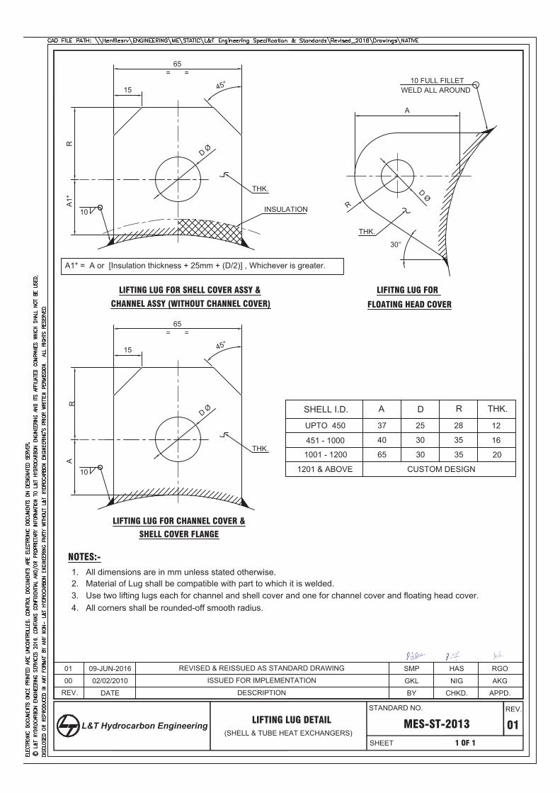
REV.
MES-ST-2013 01
APPD.
1 OF 1
CHKD.BY
LIFTING LUG DETAIL(SHELL & TUBE HEAT EXCHANGERS)
A
D Ø
THK.
65= =
15
RA
1*
D Ø
10
THK.
LIFITNG LUG FOR
FLOATING HEAD COVER
SHELL I.D. A D R THK.
UPTO 450
451 - 1000
1001 - 1200
1201 & ABOVE
37
40
25
30
30
28
35
35
12
16
20
CUSTOM DESIGN
NOTES:-
1. All dimensions are in mm unless stated otherwise.2. Material of Lug shall be compatible with part to which it is welded.3. Use two lifting lugs each for channel and shell cover and one for channel cover and floating head cover.
10 FULL FILLETWELD ALL AROUND
30°
R
45°
00 ISSUED FOR IMPLEMENTATION AKGNIGGKL
65= =
15
A
D Ø
10
THK.
LIFTING LUG FOR CHANNEL COVER &
R
45°
A1* = A or [Insulation thickness + 25mm + (D/2)] , Whichever is greater.
INSULATION
LIFTING LUG FOR SHELL COVER ASSY &
CHANNEL ASSY (WITHOUT CHANNEL COVER)
01 RGOHASSMP
02/02/2010
09-JUN-2016
DATE
REVISED & REISSUED AS STANDARD DRAWING
DESCRIPTION
SHELL COVER FLANGE
65
STANDARD NO.
SHEET
REV.
L&T Hydrocarbon Engineering
4. All corners shall be rounded-off smooth radius.
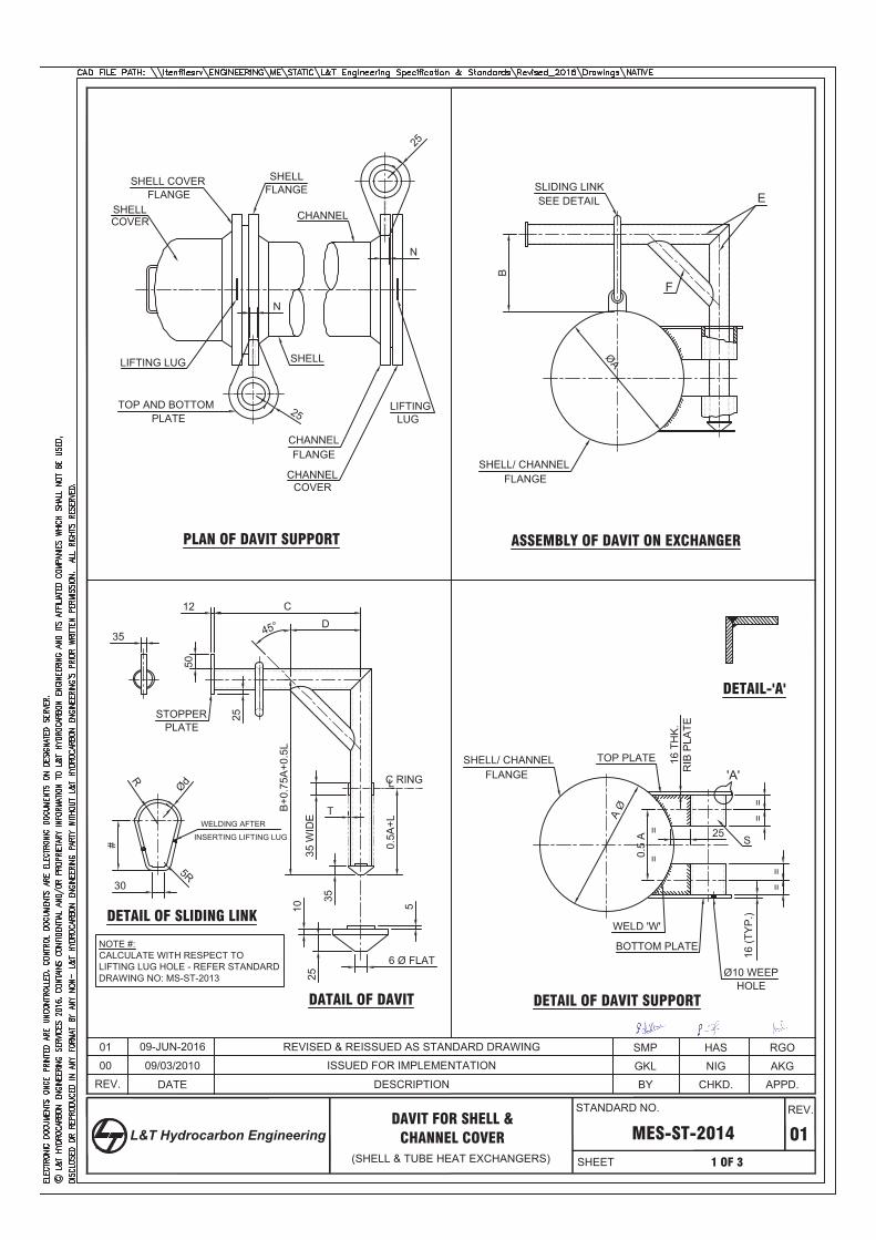
REV.
MES-ST-2014 01
APPD.
00
1 OF 3
CHKD.BY
DAVIT FOR SHELL &
ISSUED FOR IMPLEMENTATION
(SHELL & TUBE HEAT EXCHANGERS)
SHELL
SHELL COVER SHELL
CHANNEL
SHELL
CHANNEL
CHANNEL
TOP AND BOTTOMPLATE
LIFTING
FLANGE
LUG
FLANGE
COVER
N
2525
SLIDING LINKSEE DETAIL E
F
SHELL/ CHANNELFLANGE
ØA
B
12 CD
50
25
45°35
35 W
IDE
0.5A
+L
35
B+0
.75A
+0.5
L
#
30
ØdR
5R
1025
6 Ø FLAT
5
STOPPER
PLAN OF DAVIT SUPPORT ASSEMBLY OF DAVIT ON EXCHANGER
DETAIL OF DAVIT SUPPORTDATAIL OF DAVIT
DETAIL OF SLIDING LINK
A Ø
25
0.5
A
==
==
16 T
HK
.R
IB P
LATE
SHELL/ CHANNEL TOP PLATE
WELD 'W'
BOTTOM PLATE
Ø10 WEEPHOLE
FLANGE
S
DETAIL-'A'
LC RING
CHANNEL COVER
LIFTING LUG
'A'
COVER
FLANGE
N
PLATE
==
T
16 (T
YP
.)
AKGNIGGKL09/03/2010
09-JUN-201601 REVISED & REISSUED AS STANDARD DRAWING
DATE DESCRIPTION
RGOHASSMP
NOTE #:CALCULATE WITH RESPECT TOLIFTING LUG HOLE - REFER STANDARDDRAWING NO: MS-ST-2013
WELDING AFTER
INSERTING LIFTING LUG
STANDARD NO.
SHEET
REV.
L&T Hydrocarbon Engineering
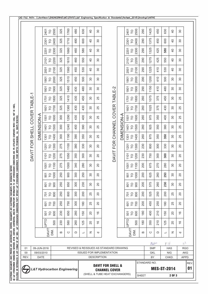
REV.
MES-ST-2014 01
APPD.
2 OF 3
CHKD.BY
DIM
EN
SIO
N-A
DA
VIT
DIM
.
UP
TO
500
501
600
TO60
1
700
TO70
1
800
TO80
1
900
TO90
1
1000TO
1001
1100TO
1200TO
1300TO
1400TO
1500TO
1600TO
1700TO
1800TO
1101
1201
1301
1401
1501
1601
1701
1900TO1801
2000TO1901
2100TO2001
2200TO2101
2300TO2201
2400TO2301
2500TO2401
B C D L N d
230
230
230
230
230
230
250
250
250
250
250
250
250
250
275
275
275
300
300
300
300
300
300
300
300
300
300
300
325
325
325
325
325
325
325
325
325
580
580
580
650
750
750
800
800
850
875
925
975
1025
1075
1150
1200
1225
1275
1325
1375
1425
900
1000
1050
1100
1190
1290
1360
1410
1460
1510
1610
1660
1710
1760
1560
1240
260
260
260
260
260
260
260
340
350
350
350
350
350
350
350
380
390
390
400
430
430
430
430
400
430
450
450
450
460
460
480
480
480
500
530
550
600
630
125
150
180
200
280
330
2020
2525
2525
2525
2530
3030
3030
3030
3030
3030
3030
3030
3030
3030
2020
2020
2020
2016
16
4040
4040
40
230
250
300
580
350
380
400
430
450
480
500
530
550
600
630
125
150
180
200
280
330
2020
2525
2525
2525
2530
3030
3030
3030
3030
3030
3030
3030
3030
3030
2020
2020
2020
2016
16
4040
4040
40
180
180
200
200
200
200
200
290
290
290
290
290
290
290
400
450
525
575
625
675
210
210
260
260
270
375
375
410
410
410
425
425
450
450
DA
VIT
DIM
.
B C D L N d
UP
TO
500
501
600
TO60
1
700
TO70
1
800
TO80
1
900
TO90
1
1000TO
1001
1100TO
1200TO
1300TO
1400TO
1500TO
1600TO
1700TO
1800TO
1101
1201
1301
1401
1501
1601
1701
1900TO1801
2000TO1901
2100TO2001
2200TO2101
2300TO2201
2400TO2301
2500TO2401
DIM
EN
SIO
N-A
DA
VIT
FO
R S
HE
LL C
OV
ER
TA
BLE
-1
DA
VIT
FO
R C
HA
NN
EL
CO
VE
R T
AB
LE-2
DAVIT FOR SHELL &
(SHELL & TUBE HEAT EXCHANGERS)CHANNEL COVER
00 ISSUED FOR IMPLEMENTATION AKGNIGGKL
RGOHASSMP
09/03/2010
09-JUN-2016
DATE
01 REVISED & REISSUED AS STANDARD DRAWING
DESCRIPTION
STANDARD NO.
SHEET
REV.
L&T Hydrocarbon Engineering
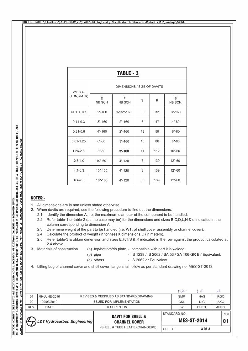
REV.
MES-ST-2014 01
APPD.
3 OF 3
CHKD.BY
DAVIT FOR SHELL &
(SHELL & TUBE HEAT EXCHANGERS)CHANNEL COVER
UPTO 0.1
0.11-0.3
0.31-0.6
0.61-1.25
1.26-2.5
2.6-4.0
4.1-6.3
6.4-7.8
2"-160
3"-160
4"-160
6"-80
10"-60
10"-120
10"-160
8"-80
2"-160
2"-160
3"-160
3"-1603"-160
4"-120
1-1/2"-160
4"-120
4"-120
3
3
13
10
11
8
8
8
32
47
59
86
112
139
139
139
3"-160
4"-80
6"-80
8"-80
10"-60
12"-60
12"-60
12"-60
ENB SCH
FNB SCH T R
SNB SCH.
WT. x C.(TON) (MTR)
DIMENSIONS / SIZE OF DAVITS
TABLE - 3
NOTES:-
1. All dimensions are in mm unless stated otherwise.2. When davits are required, use the following procedure to find out the dimensions. 2.1 Identify the dimension A, i.e; the maximum diameter of the component to be handled. 2.2 Refer table-1 or table-2 (as the case may be) for the dimensions and sizes B,C,D,L,N & d indicated in the
column corresponding to dimension A. 2.3 Determine weight of the part to be handled (i.e; WT. of shell cover assembly or channel cover). 2.4 Calculate the product of weight (in tonnes) X dimensions C (in meters). 2.5 Refer table-3 & obtain dimension and sizes E,F,T,S & R indicated in the row against the product calculated at
2.4 above.3. Materials of construction (a) top/bottom/rib plate - compatible with part it is welded.
(c) others - IS 2062 or Equivalent.
00 ISSUED FOR IMPLEMENTATION AKGNIGGKL
RGOHASSMP
09/03/2010
09-JUNE-201601
DATE
REVISED & REISSUED AS STANDARD DRAWING
DESCRIPTION
4. Lifting Lug of channel cover and shell cover flange shall follow as per standard drawing no: MES-ST-2013.
(b) pipe - IS 1239 / IS 2062 / SA 53 / SA 106 GR B / Equivalent.
STANDARD NO.
SHEET
REV.
L&T Hydrocarbon Engineering
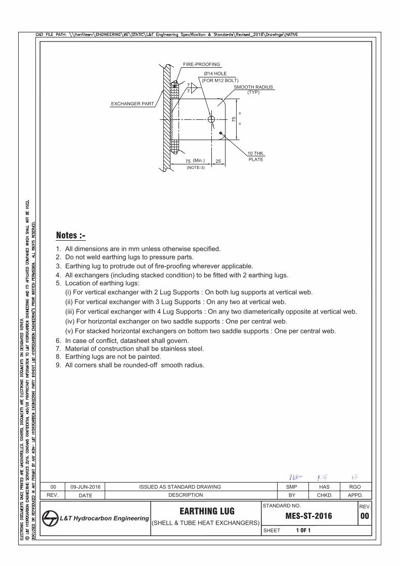
REV.
MES-ST-2016
APPD.RGO00
1 OF 1
CHKD.HAS
BYSMP
EARTHING LUG
DESCRIPTIONISSUED AS STANDARD DRAWING
Notes :-1. All dimensions are in mm unless otherwise specified.2. Do not weld earthing lugs to pressure parts.3. Earthing lug to protrude out of fire-proofing wherever applicable.4. All exchangers (including stacked condition) to be fitted with 2 earthing lugs.5. Location of earthing lugs:
(i) For vertical exchanger with 2 Lug Supports : On both lug supports at vertical web.(ii) For vertical exchanger with 3 Lug Supports : On any two at vertical web.(iii) For vertical exchanger with 4 Lug Supports : On any two diameterically opposite at vertical web.(iv) For horizontal exchanger on two saddle supports : One per central web.
In case of conflict, datasheet shall govern.6.(v) For stacked horizontal exchangers on bottom two saddle supports : One per central web.
Material of construction shall be stainless steel. 7.
75
2575
10 THK.
=
=
EXCHANGER PART
Ø14 HOLE(FOR M12 BOLT)
PLATE
77
SMOOTH RADIUS
(Min.)
FIRE-PROOFING
(SHELL & TUBE HEAT EXCHANGERS)
(NOTE-3)
(TYP)
00
09-JUN-2016
DATE
STANDARD NO.
SHEET
REV.
L&T Hydrocarbon Engineering
Earthing lugs are not be painted.8.All corners shall be rounded-off smooth radius.9.
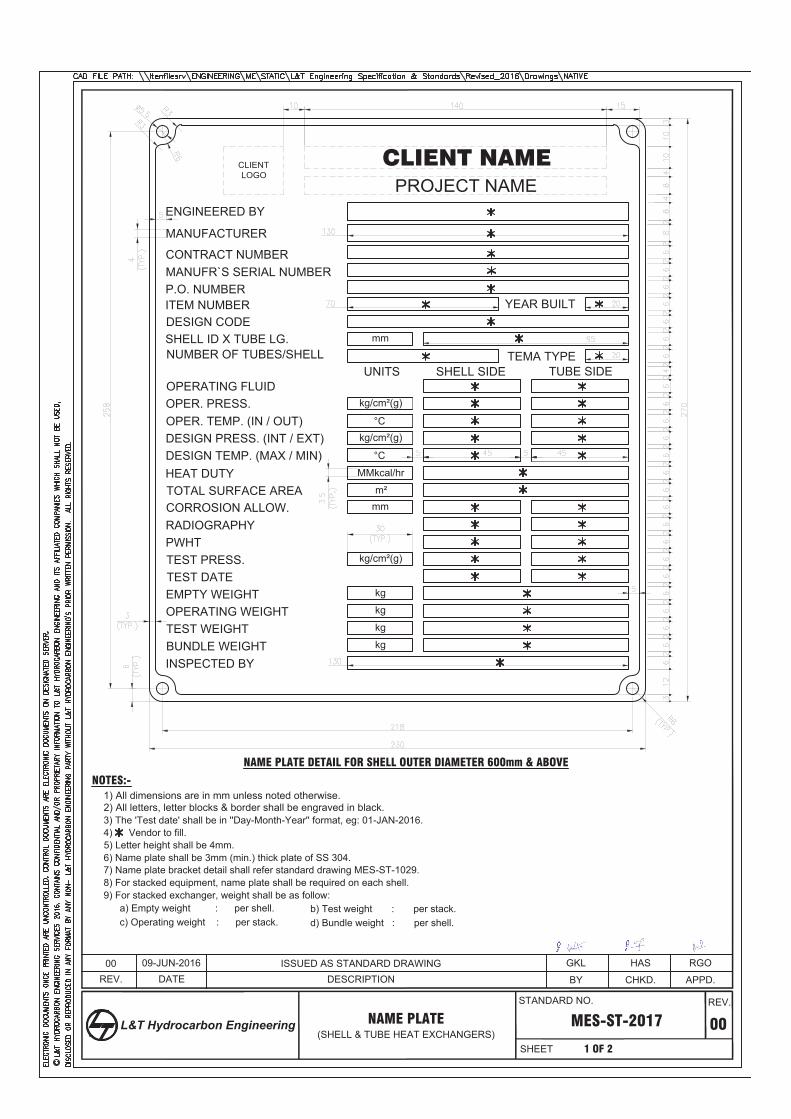
P.O. NUMBERITEM NUMBER YEAR BUILT
INSPECTED BY
4) Vendor to fill.
2) All letters, letter blocks & border shall be engraved in black.1) All dimensions are in mm unless noted otherwise.
NOTES:-
OPER. TEMP. (IN / OUT)DESIGN PRESS. (INT / EXT)DESIGN TEMP. (MAX / MIN)
kg/cm²(g)
°COPER. PRESS.
TEST PRESS.
EMPTY WEIGHT
TEST WEIGHT
kg
OPERATING FLUID
PWHT
TEST DATE
HEAT DUTY MMkcal/hr
CORROSION ALLOW. mm
BUNDLE WEIGHT
DESIGN CODE
5) Letter height shall be 4mm.6) Name plate shall be 3mm (min.) thick plate of SS 304. 7) Name plate bracket detail shall refer standard drawing MES-ST-1029.
CLIENT NAME
ENGINEERED BY
MANUFACTURER
PROJECT NAME
NUMBER OF TUBES/SHELL
CLIENTLOGO
CONTRACT NUMBER
SHELL ID X TUBE LG.TEMA TYPE
OPERATING WEIGHT kg
°C
kg
kg
REV.
MES-ST-2017 00
APPD.
1 OF 2
CHKD.BYDESCRIPTION
STANDARD NO.
SHEET
REV.
L&T Hydrocarbon Engineering NAME PLATE(SHELL & TUBE HEAT EXCHANGERS)
ISSUED AS STANDARD DRAWING
kg/cm²(g)
kg/cm²(g)
mm
TUBE SIDEUNITS SHELL SIDE
TOTAL SURFACE AREA m²
RADIOGRAPHY
8) For stacked equipment, name plate shall be required on each shell.9) For stacked exchanger, weight shall be as follow:
a) Empty weight : per shell. b) Test weight : per stack.c) Operating weight : per stack. d) Bundle weight : per shell.
3) The 'Test date' shall be in ''Day-Month-Year'' format, eg: 01-JAN-2016.
DATE09-JUN-201600 RGOHASGKL
MANUFR`S SERIAL NUMBER
NAME PLATE DETAIL FOR SHELL OUTER DIAMETER 600mm & ABOVE
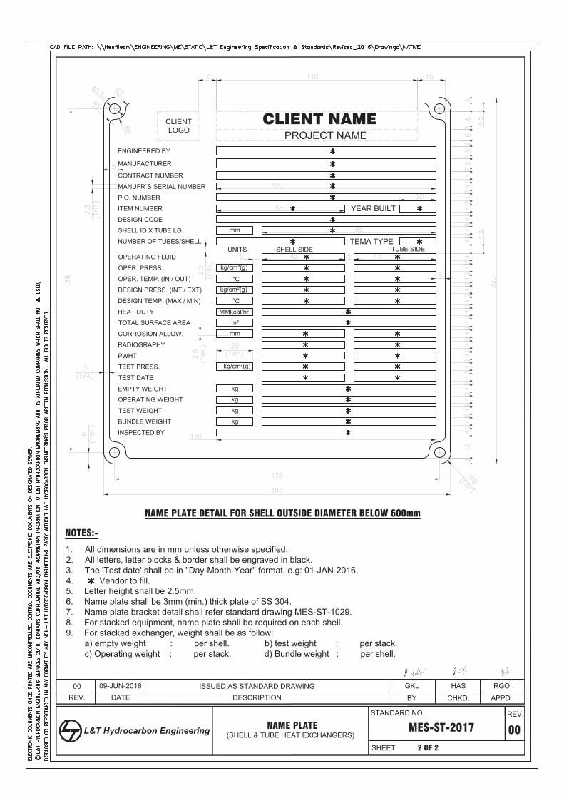
P.O. NUMBER
NOTES:-
OPER. TEMP. (IN / OUT)
OPER. PRESS.
OPERATING FLUID
CLIENT NAME
ENGINEERED BY
MANUFACTURER
PROJECT NAME
NUMBER OF TUBES/SHELL
CLIENTLOGO
CONTRACT NUMBER
SHELL ID X TUBE LG.
TEMA TYPE
REV.
MES-ST-2017 00
APPD.
2 OF 2
CHKD.BYDESCRIPTION
STANDARD NO.
SHEET
REV.
L&T Hydrocarbon Engineering NAME PLATE(SHELL & TUBE HEAT EXCHANGERS)
ISSUED AS STANDARD DRAWING
TUBE SIDEUNITS SHELL SIDE
DATE09-JUN-201600 RGOHASGKL
MANUFR`S SERIAL NUMBER
NAME PLATE DETAIL FOR SHELL OUTSIDE DIAMETER BELOW 600mm
ITEM NUMBER YEAR BUILTDESIGN CODE
mm
kg/cm²(g)
°Ckg/cm²(g)
°CDESIGN TEMP. (MAX / MIN)
DESIGN PRESS. (INT / EXT)
MMkcal/hrHEAT DUTY
m²TOTAL SURFACE AREAmmCORROSION ALLOW.
RADIOGRAPHY
PWHTkg/cm²(g)TEST PRESS.
TEST DATE
kgEMPTY WEIGHTkgOPERATING WEIGHT
kgTEST WEIGHTkgBUNDLE WEIGHT
INSPECTED BY
1. All dimensions are in mm unless otherwise specified.2. All letters, letter blocks & border shall be engraved in black.3. The 'Test date' shall be in ''Day-Month-Year'' format, e.g: 01-JAN-2016.4. Vendor to fill.5. Letter height shall be 2.5mm.6. Name plate shall be 3mm (min.) thick plate of SS 304.7. Name plate bracket detail shall refer standard drawing MES-ST-1029.8. For stacked equipment, name plate shall be required on each shell.9. For stacked exchanger, weight shall be as follow:
a) empty weight : per shell. b) test weight : per stack.c) Operating weight : per stack. d) Bundle weight : per shell.
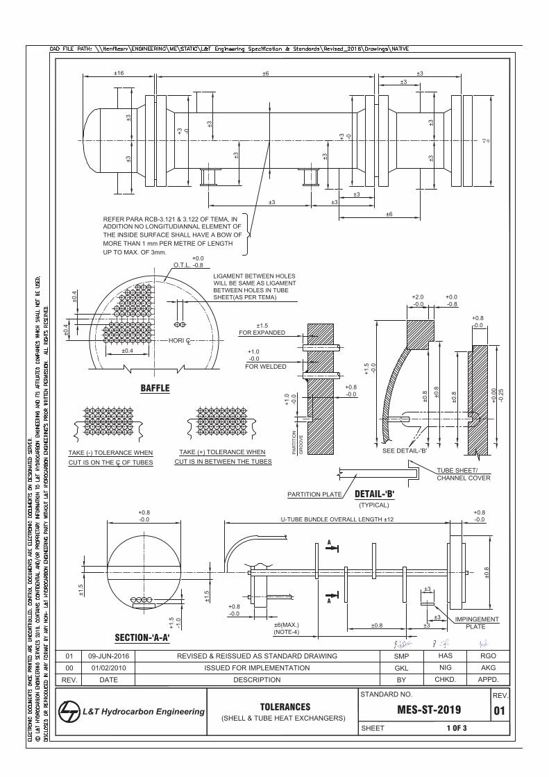
REV.
MES-ST-2019 01
APPD.
00
1 OF 3
CHKD.BY
ISSUED FOR IMPLEMENTATION
TOLERANCES(SHELL & TUBE HEAT EXCHANGERS)
±16 ±6 ±3±3
±3±3
±6
±3±3±3
±3±3
±3
±3
+3 -0
±3
REFER PARA RCB-3.121 & 3.122 OF TEMA, INADDITION NO LONGITUDIANNAL ELEMENT OFTHE INSIDE SURFACE SHALL HAVE A BOW OF MORE THAN 1 mm PER METRE OF LENGTH UP TO MAX. OF 3mm.
±0.4
±0.4
±0.4
LIGAMENT BETWEEN HOLESWILL BE SAME AS LIGAMENTBETWEEN HOLES IN TUBESHEET(AS PER TEMA)
+1.0
-0.0
+0.8-0.0
+1.0-0.0
FOR WELDED
±1.5FOR EXPANDED
+2.0-0.0
+0.0-0.8
+1.5
-0.0
±0.8 ±0
.8
±0.8
+0.8-0.0
+0.0
0-0
.25
±1.5
+0.8-0.0
±1.5
+1.5
-1.0
U-TUBE BUNDLE OVERALL LENGTH ±12+0.8-0.0
±0.8
±3
±3±3±0.8±6(MAX.)
(NOTE-4)
+0.8-0.0
PARTITION PLATE
TUBE SHEET/CHANNEL COVER
DETAIL-'B'(TYPICAL)
TAKE (-) TOLERANCE WHENCUT IS ON THE C OF TUBESL
TAKE (+) TOLERANCE WHENCUT IS IN BETWEEN THE TUBES
SECTION-'A-A'
A
A
BAFFLE
HORI CL
SEE DETAIL-'B'
+3 -0
IMPINGEMENTPLATE
O.T.L.
+3 -0
-0.8+0.0
AKGNIGGKL
PA
RTI
TIO
NG
RO
OV
E
01/02/2010
DATE
RGOHASSMPREVISED & REISSUED AS STANDARD DRAWING
DESCRIPTION
01 09-JUN-2016
STANDARD NO.
SHEET
REV.
L&T Hydrocarbon Engineering
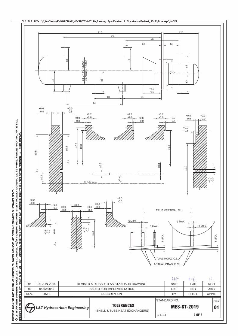
REV.
MES-ST-2019 01
APPD.
00
2 OF 3
CHKD.BY
ISSUED FOR IMPLEMENTATION
TOLERANCES(SHELL & TUBE HEAT EXCHANGERS)
±3±16
±3
±6
±3
±3
±3
±3
±3
±3 ±3 U
P T
O 1
200Ø
±6 A
BO
VE
120
0Ø
±3
+3 -0
±3
±3
+3.0-0.0
±3
±16
+0.0-0.8
+0.0-0.8
±0.8 ±0
.8
±0.4
±0.4
±0.8
±0.8
±0.8
+0.2-0.0+0.0
-0.8
+0.2-0.0 +0.8
-0.0
+0.2-0.0 +0.0
-0.8
+0.8-0.0
+0.3-0.0
+0.0-0.8
+1.0
-0.0
±0.8
±0.8
+0.2-0.0
+0.8-0.0
+0.8
-0.0
±0.8
+0.8+0.0-0.8
+0.0-0.8
+1.5
-0.0
±0.8
+0.8-0.0
+2.0-0.0
3 MAX.
3 MAX.
3 M
AX
.
3 M
AX
.
TRUE VERTICAL C.L.
TURE HORZ. C.L.
ACTUAL CRADLE C.L.
3 MAX.
3 MAX.
±0.8
TRUE C.L.
AKGNIGGKL
RGOHASSMP01/02/2010
09-JUN-2016
DATE
01 REVISED & REISSUED AS STANDARD DRAWING
DESCRIPTION
STANDARD NO.
SHEET
REV.
L&T Hydrocarbon Engineering
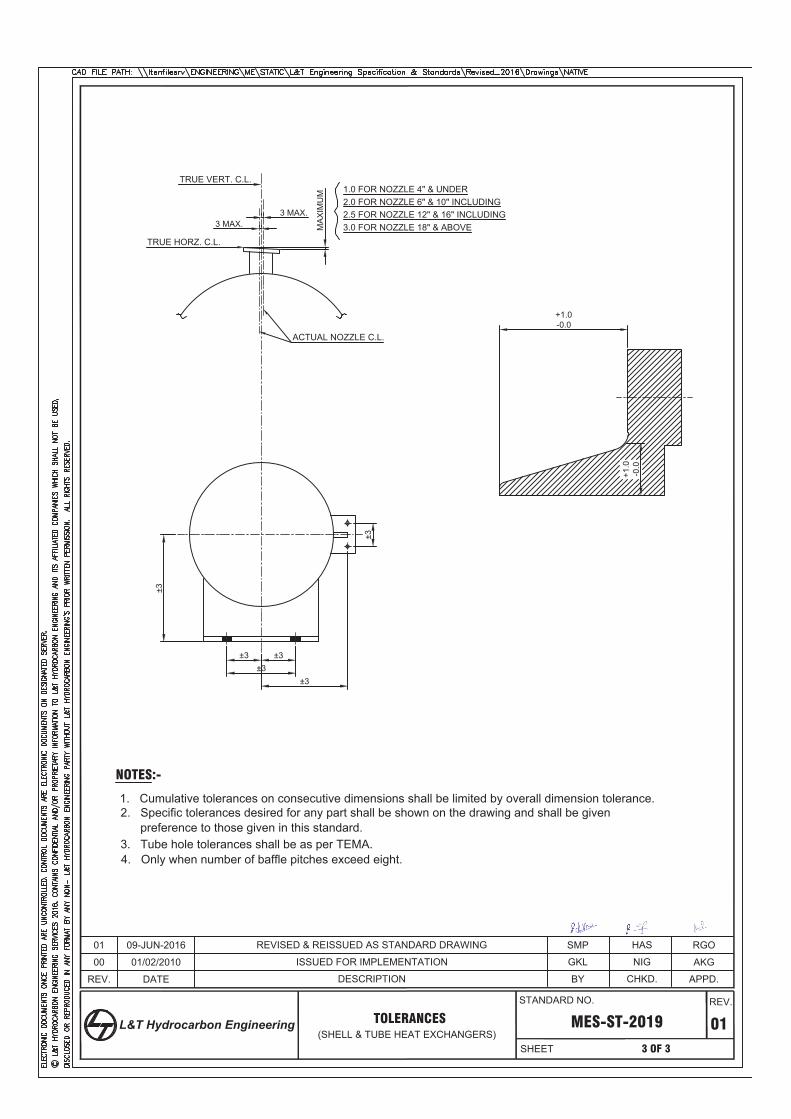
REV.
MES-ST-2019 01
APPD.
3 OF 3
CHKD.BY
TOLERANCES(SHELL & TUBE HEAT EXCHANGERS)
MA
XIM
UM
3 MAX.3 MAX.
±3
±3±3 ±3
±3
±3
+1.0
-0.0
+1.0-0.0
1.0 FOR NOZZLE 4" & UNDER2.0 FOR NOZZLE 6" & 10" INCLUDING2.5 FOR NOZZLE 12" & 16" INCLUDING3.0 FOR NOZZLE 18" & ABOVE
TRUE HORZ. C.L.
ACTUAL NOZZLE C.L.
NOTES:-
1. Cumulative tolerances on consecutive dimensions shall be limited by overall dimension tolerance.2. Specific tolerances desired for any part shall be shown on the drawing and shall be given
preference to those given in this standard.3. Tube hole tolerances shall be as per TEMA.4. Only when number of baffle pitches exceed eight.
00 ISSUED FOR IMPLEMENTATION
TRUE VERT. C.L.
AKGNIGGKL
RGOHASSMP
01/02/2010
09-JUN-201601
DATE
REVISED & REISSUED AS STANDARD DRAWING
DESCRIPTION
STANDARD NO.
SHEET
REV.
L&T Hydrocarbon Engineering

Rev Date
Engineering Services
CCR PROJECT AT MAHUL, MUMBAI
DOCUMENT TITLE:
TEMA DATASHEET FOR
HP ABSORBER FEED COOLER (141-A-E105)
DOCUMENT NUMBER:
TDS-141-A-E105
Client BHARAT PETROLEUM CORP. LTD.
Unit CCR Octanizing Unit / Reaction Section
Location Mahul, Mumbai
Document StatusPrepared
By
Checked
By
Approved
By
0 21-05-2018 Issued for Review PK CNR PB

CCR Octanizing Unit / Reaction Section TEMA Datasheet for HP Absorber FEED Cooler
TDS-141-A-E105
Rev Date Revision Details
Engineering Services
RECORD OF REVISIONS
Page 2 of 5

CCR Octanizing Unit / Reaction Section TEMA Datasheet for HP Absorber FEED Cooler
TDS-141-A-E105
Rev.
1.
2.
3. x
4. / /
5.
6.
7.
8.
9.
10.
11.
12.
13.
14.
15.
16.
17.
18.
19.
20.
21.
22.
23.
24.
25.
26.
27.
28.
29.
30.
31.
32.
33.
34.
35.
36.
37.
38.
39.
40.
41.
42.
43.
44.
45.
46.
47.
48.
49.
50.
51.
52.
53.
54.
55.
56.
57.
58.
59.
60.
61.
62.
63.
64.
65.
66.
67.
68.
69.
70.
5) Tubeside design flowrate = 211200 kg/hr, corresponding to 110% of case2 MRT operating flowrate.
4) Shellside design flowrate = 166117 kg/hr, corresponding to 110% of case2 MRT operating flowrate.
Shellside pressure drop for design flowrate is 0.12 kg/cm2
Tubeside pressure drop for design flowrate is 0.7 kg/cm2.
7) Hydrogen service is applicable for shellside.
3) Indicated duty is 100% of process datasheet duty. Exchanger is designed for 120% of duty specified.
V/L 0.1050 0.0780 V/L 0.1099
1.3087 V/L 0.4761
5.62 V/L 798.7
0.0120 V/L 0.3200 0.0110 V/L 0.3794
Tubesheet-Stationary
kg/m-s2
6.12 V/L 784.57
m2-hr-C/kcal
C (9)
9) MDMT: 9°C for shellside and tubeside
floating head support plate.
31.25
90
Floating Head
6) Max. continuous H2 partial pressure: 365.6 psia (case 2 NOP).
956 Bundle Exit
Type
Type
8) Based on 10/13 of shellside design pressure.
@
2) The indicated tube length is overall tube length. Effective length for heat transfer is 7530 mm from inside of fixed tubesheet upto
SA-516 Gr. 60 N
kg
C
SA-516 Gr. 60 N
4
(16)(17)(18)
CONSTRUCTION OF ONE SHELL
3
20" NPS (14)
20" NPS (14)
1
kcal/m2-hr-C
1
47.5, FV
@
10" NPS (14)
6
150
1
/
4
1.25
0.7 0.591 (5)
0.9989
0.7339 0.5962
34
Shell Side
994.6 990.4
45
Transfer Rate, Service
70
Fouling Resistance (min)
kcal/m2-hr-CActual
Heat Exchanged (3) 2.1
0.9986
0.5340 0.5461
1.4475 V/L 0.4601
12.2
553.5
0.0004
MTD (Corrected)
kcal/kg-C
Molecular Weight, Noncondensables
Doc no 3290-141A-2EX-141A-E105 page 1 to 6
45
Velocity
Latent Heat
Specific Heat
kgf/cm2[g]
kcal/m2-hr-C
cPViscosity
66
Water
Density
130032 Liquid 133043
Temperature (In/Out)
534.6
Connected In
190910
17972
HP ABSORBER FEED
1
PERFORMANCE OF ONE UNIT
Parallel Series1
575.1 Shell/Unit
Steam
CHARACTERISTICS
20983
m2575.1
Type
m2
kg/hr
534.6
190910 190910
mm
141-A-E105Item No.
1 Surf/Shell (Gross/Eff)
Tube Side
151015
HP Absorber Feed Cooler
HorizontalAES
RAW COOLING WATER
Size (2)
Fluid Allocation
Service of Unit
81001240
Surf/Unit (Gross/Eff)
Fluid Quantity, Total
Fluid Name
Molecular Weight, Vapor
No Passes per Shell
Vapor (In/Out)
kg/m3
Noncondensables
C
kgf/cm2G
Clean322.5 367.7
mm 3
Tube SideShell Side
36.5
Sketch (Bundle/Nozzle Orientation)
Design/Test Pressure
1
Intermediate
Out
InConnections
1
OD
1687
ASME Sec VIII, Div 1; API 660
Gaskets-Shell Side
U-Bend
Tube No.
Tube Side
Bundle Entrance
Remarks: 1) The process conditions and THX curve has been considered as per Axens datasheet for heat exchanger
BundleWeight/Shell
R
kgFilled with Water
mm
Design Temperature
Rating
Plain
Supports-Tube
Channel or Bonnet
kg
-
1100
Seal Type None
22.9Baffles-Cross
Material
Corrosion Allowance
Code Requirements
Rho-V2-Inlet Nozzle
Floating Head Cover
Bypass Seal Arrangement
Shell
Size &
mm
Tube Type
OD
25
ID
2.5mm904 Thk(min.) 8100
Tube pattern
mmPitch
Shell Cover
Length (2)
%Cut (Diam)
SA-516 Gr. 60 N
SA-516 Gr. 60 N Type 455Spacing(c/c)
None
kg/m-s2
TEMA Class
Engineering Services
InletDouble-Seg. (V)
27.4
mm
Tube-Tubesheet Joint
1137
0.0004
Pressure Drop, Allow/Calc
m/s
Thermal Conductivity
kgf/cm2 0.3
Inlet Pressure
kcal/kg
kcal/hr-m-C
3.6
0.1 (4)
0.0770
Channel Cover SA-266 Gr.2
10" NPS (14)
@
@
/
@
MMkcal/hr
SA 210 Gr. A1
mm
@
Circular plateImpingement Plate
SA-266 Gr.2
SA-516 Gr. 60 N
SA-266 Gr.2 Tubesheet-Floating
(11)
Baffles-Long
1240
Expansion Joint
-
pairs seal strips (13)(15)
Page 3 of 5

CCR Octanizing Unit / Reaction Section TEMA Datasheet for HP Absorber FEED Cooler
TDS-141-A-E105
Rev.
1.
2.
3. x
4. / /
5.
6.
7.
8.
9.
10.
11.
12.
13.
14.
15.
16.
17.
18.
19.
20.
21.
22.
23.
24.
25.
26.
27.
28.
29.
30.
31.
32.
33.
34.
35.
36.
37.
38.
39.
40.
41.
42.
43.
44.
45.
46.
47.
48.
49.
50.
51.
52.
53.
54.
55.
56.
57.
58.
59.
60.
61.
62.
63.
64.
65.
66.
67.
68.
69.
70.
Eye Bolt - SA 105
Tie Rod nuts - SA 194 Gr.2H
11) Tubes to be strength welded and light expanded (upto 5%)
14) Refer nozzle schedule
12) 13 no. of baffles with inlet spacing of 1100 mm and central spacing of 455 mm. Double segmental baffles with 6 tuberows overlap
13) Provide 20 seal rods of 9 mm OD.
15) Sealing strip provided on the bottom and top halfs of the exchanger will be of different heights as seen in the tube layout.
19) Insulation Shellside: Personnel Protection
10) Material for exchanger parts.
LHS Channel Cover - SA 266 Gr.2
Channel Shell - SA 516 Gr 60 N
Floating Head Cover - SA 516 Gr 60 N
Floating head Flange - SA 266 Gr 2
Backing Ring - SA 266 Gr 2
16) Inlet vibration support plate to be provided for topmost 7 tuberows. To be placed at a distace of 550 mm from support plate at rear end.
17) Outlet vibration support plate to be provided for bottom 7 tuberows. To be placed at a distace of 485 mm from fixed
Spacer - CS
Sealing Strips / Sliding Rail - SA 516 Gr 60 N
Tie Rods, Seal Rods - CS
tubesheet shellside face.
18) Floating head support plate has been considered.
m2
REMARKS
Surf/Unit (Gross/Eff) 575.1 534.6 m2 Shell/Unit 1
1 Parallel
Surf/Shell (Gross/Eff) 575.1 534.6
1 SeriesSize (2) 1240 8100 mm Type AES Horizontal Connected In
Engineering Services
CHARACTERISTICS
Service of Unit HP Absorber Feed Cooler Item No. 141-A-E105
Page 4 of 5

CCR Octanizing Unit / Reaction Section TEMA Datasheet for HP Absorber FEED Cooler
TDS-141-A-E105
Rev.
1.
2.
3. x
4. / /
5.
6.
7.
8.
9.
10.
11.
12.
13.
14.
15.
16.
17.
18.
19.
20.
21.
22.
23.
24.
25.
26.
27.
28.
29.
30.
31.
32.
33.
34.
35.
36.
37.
38.
39.
40.
41.
42.
43.
44.
45.
46.
47.
48.
49.
50.
51.
52.
53. SKETCH
54.
55.
56.
57.
58.
59.
60.
61.
62.
63.
64.
65.
66.
67.
68.
69.
70.
300#
T3 2" TUBESIDE STUB CONNECTION -1 1 300#
10" TUBE SIDE INLET 1 300#
T2 10" TUBE SIDE OUTLET 1
T1
CHARACTERISTICS
Service of Unit HP Absorber Feed Cooler Item No. 141-A-E105
Engineering Services
Size (2) 1240 8100 mm Type AES 1 Parallel
Surf/Shell (Gross/Eff) 575.1 534.6
1 SeriesHorizontal Connected In
m2
TUBE LAYOUT
Surf/Unit (Gross/Eff) 575.1 534.6 m2 Shell/Unit 1
SERVICE
NOZZLE SCHEDULE
S3 2" SHELLSIDE VENT 1
QTY RATING REMARKS
S1 20" SHELLSIDE INLET 1 600#
MARK SIZE
600#
S2 20" SHELL SIDE OUTLET 1 600#
S4 2" SHELLSIDE DRAIN 1 600#
T4 2" TUBESIDE STUB CONNECTION -1 1 300#
448.000 mm
448.000 mm
Item number
TEMA typeShell ID
Actual OTL
Height under inlet nozzleHeight under outlet nozzle
Tube typeTube OD
Tube pitch
Tube layout angle
Tubes
Tube positions availableTie rods
Seal strip pairsPasslane seal rods
Tube PassesParallel passlane width
Perpendicular passlane width
Baffle cut % diameter
141A-E-105
AES1240.00
1174.82
170.325123.000
Plain25.000
31.250
90
904
90410
420
622.000
22.000
22.9
mm
mm
mm mm
mm
mm
deg
mm
mm
TUBEPASS DETAILSPass
12
3
45
6
Rows
1111
8
810
10
Tubes
156155
143
144152
154
Tube
Dummy Short Tube
Dummy Long TubePlugged Tube
Tie RodSeal Rod
Impingement Rod
SYMBOL LEGEND
6 5
3 4
2 1
T1
S3S1
S4S2
T2
Page 5 of 5

CODE OF CONSTRUCTION : ASME SEC VIII DIV 1.ED 2017,TEMA 9th ED-2007,API-660TEMA TYPE : AES (HORIZONTAL) TEMA CLASS : R
MMKcal/Hr
FLUID : HP ABSORBER FEED RAW COOLING WATER
FLUID DENSITY (IN / OUT) (VAPOR/LIQUID) Kg/m3 6.12/784.57 & 5.62/798.7 994.6/990.4
OPERATING PRESSURE : Kg/cm2 (g) 27.4 4
OPERATING TEMP.(IN/OUT) : oC 66/45 34/45
DESIGN PRESSURE(INT/EXT) Kg/cm2 G 47.5/FV 36.5
DESIGN TEMPERATURE oC 150 70
MEAN METAL TEMPERATURE oC NA NA
MIN. DESIGN METAL TEMP. oC 9 9
TEST PRESSURE Kg/cm2 G UG-99(b) UG-99(b)
ALLOWABLE / CALCULATED PRESSURE DROP Kg/cm2 0.3/0.1 0.7/0.591
NUMBER OF PASSES 1 6
CORROSION ALLOWANCE mm 3 3
RADIOGRAPHY / JOINT EFFICIENCY 100% 100%
PWHT / HEAT TREATMENT YES YES
INSULATION THICKNESS mm 25 MM (BY OTHERS) -
FIREPROOFING mm YES (BY OTHERS)
PAINTING/CLEANING
INSPECTION - STAGEWISE/FINAL
EMPTY WEIGHT kg 35500
OPERATING WEIGHT kg 45000
FULL OF WATER WEIGHT kg 47000
BUNDLE WEIGHT kg 17000
WIND FORCE kgf 820
WIND MOMENT kgf x m 660
SEISMIC FORCE kgf 5920
SEISMIC MOMENT kgf x m 4740
NOZZLE ORIENTATION
21.5.18
LIFTING LUG INSULATION CLEATS
LIFTING & PULLING EYEBOLT DAVIT FOR SHELL COVER
PLUG FOR PULLING EYEBOLT TEST RING
JACK SCREW & DOWEL PIN TEST FLANGE
NAME PLATE
EARTHING LUG
OTHER SPECIFICATIONSTHERMAL DATASHEET TDS-141-A-E-105
JOB SPECIFICATIONS
STANDARD SPECIFICATIONSALLOWABLE NOZZLE LOADINGS FOR PRESSURE VESSELS ANDSHELL & TUBE HEAT EXCHANGER
GENERAL SPECIFICATION FOR HEAT EXCHANGERS MES-SP-0041
MES-SP-0083
SPECIFICATION FOR WELDED TUBE TO TUBESHEET JOINT
NOZZLE GASKETSS304 SPWD GRAFOIL FILLED AS PER ASME B 16.20
MES-ST-1038
DOWEL PIN SA-105
OTHERS
TUBESHEET SA 266 GR 2
EYE BOLT SA-105
TUBE SIDE
CHANNEL COVER SA 266 GR 2
SA 266 GR 2
FLOATING HEAD DISH SA-516 Gr. 60 N
PASS PARTITION PLATE
STUD WITH NUTS SA-193 Gr. B7 / SA-194 Gr. 2H
GASKET- PASS PARTITION SECTIONGASKET- FLOATING HEAD FLANGE
SS 304 FLAT METAL JACKETED (GRAPHITE FILLED)
FLOATING HEAD FLANGE
SA-210 GR A1
GIRTH FLANGE AT CHANNEL COVER SA 266 GR 2
SA-516 Gr. 60 N
SHELL SA-516 Gr. 60 N
SS304 SPWD GRAFOIL FILLED AS PER ASME B 16.20
NOZZLE GASKET
BAFFLES/SUPPORT PLATE SA-516 Gr. 60 N
SA-105
SA-193 Gr. B7 / SA-194 Gr. 2HBOLTING AT SHELL FLANGE
SA-516 Gr. 60 N
CS
GASKET AT SHELL FLANGESS304 SPWD GRAFOIL FILLED WITH SS304 INNER AND OUTER NOSE
RF PAD/WEAR PLATE SA-516 Gr. 60 N
ATTACHMENTS WELDED TO SHELL
TIE ROD & NUTS
SPACER
SEALING STRIPS /SLIDING STRIPS AND IT'S STUDS
CS
JACK SCREW
SETTING BOLT
DAVIT
PLUG FOR EYEBOLT & INSERSION PIECE
LIFTING LUG
SA-105
CS
CS
NAME PLATE SS304
TUBE
IMPINGEMENT PLATE
SA-516 Gr. 60 NNAME PLATE BRACKET
SA 266 GR 2
CONNECTING PIECE SA-516 Gr. 60 N
BACKING RING
GASKET- CHANNEL COVER FLANGE
SS304 SPWD GRAFOIL FILLED WITH SS304 INNER RING & OUTER NOSE
GASKET AT TUBESHEET
SA-516 Gr. 60 N
GIRTH FLANGE AT TUBESHEET SA 266 GR 2
NOZZLE BOLTING SA-193 Gr. B7 / SA-194 Gr. 2H
CHANNEL SHELL
FLOATING TUBESHEET SA 266 GR 2
SA-516 Gr. 60 N
SADDLE SUPPORT SA-516 Gr. 60 N
NOZZLE NECK FLANGE SA-105
STUD WITH NUTS FOR INTERNAL PARTS
SS304 SPWD GRAFOIL FILLED WITH SS304 INNER RING & OUTER NOSE
NOZZLE NECK SA-106 GR B
GASKET- ST. T/S TO CHANNEL FLANGE
SA-193 Gr. B7 / SA-194 Gr. 2H
LIFTING LUG FOR FLOATING HEAD CS
EARTHING LUG MES-ST-2016
NAME PLATE
1. ALL DIMENSIONS ARE IN MM UNLESS & OTHER WISE SPECIFIED.2. WALL THICKNESSES INDICATED ARE MINIMUM PRELIMINARY. VENDOR TO VERIFY THE THICKNESSES AND INCREASE BASED ON STRESS CALCULATIONS.3. FLANGE DIMENSIONS SHALL BE AS PER ASME B 16.5 & GASKET SHALL BE AS PER ASME B 16.20.4. TUBE TO TUBESHEET JOINT SHALL BE STRENGTH WELDED AND LIGHT EXPANDED.5. HARDNESS OF PARENT METAL, WELD AND HAZ SHALL NOT EXCEED 200 BHN.6. HARDNESS OF GASKET SHALL BE AS LOW AS POSSIBLE AND SHALL BE MINIMUM 20 BHN THAN FOR THE MATERIAL OF THE FLANGE GASKET FACING.7. EQUIPMENT IS IN HYDROGEN SERVICE.HYDROGEN PARTIAL PRESSURE IS ON SHELL SIDE 365.6 PSIA.8. COMPLETE EXCHANGER SHALL UNDERGO PWHT, PWHT CYCLE SHALL BE AS PER CODE.9. MOCKUP TEST OF TUBE TO TUBESHEET JOINT SHAL BE CARRIED OUT.10.10% STUDS AND NUTS BUT NOT LESS THAN 4 STUDS WITH 8 NUTS FOR EACH PAIR OF MATING FLANGES,INTERCONNECTING NOZZLES, NOZZLES WITH BLIND FLANGES ETC. SHALL BE SUPPLIED AS MANDATORY SPARES.11. ALL FLANGE BOLT HOLES SHALL BE STRADDLE PRINCIPAL CENTER LINE OF THE VESSEL12. GASKET SEATING SURFACE OF ALL FLANGES SHALL HAVE FINISH OF 125-250 MICRO INCH AARH EXCEPT FLOATING HEAD FLANGE.13. ALL WELDS SHALL BE FULL PENETRATION WELDS. WELDS ACCESSIBLE FROM SECOND SIDE SHALL BE BACK CHIPPED TO SOUND METAL, DP CHECKED AND REWELD FROM SECOND SIDE.WHEREVER BACKCHIPPING IS NOT POSSIBLE ROOT RUN TO BE CARRIED OUT14. ALL CS MATERIAL INCLUDING FORGING USED FOR THE PRESSURE PARTS SHALL BE PROCURED IN FULLY KILLED & NORMALIZED CONDITION.15. PLATES HAVING THICKNESS 16 MM TO 50 MM (BOTH INCLUSIVE) SHALL BE EXAMINED ULTRASONICALLY AS PER ASTM-A-43516. FOR THICKNESS ABOVE 50 MM, ULTRASONIC EXAMINATION SHALL BE CARRIED OUT AS PER ASTM-A 578 AND SHALL HAVE ACCEPTANCE STANDARD OF LEVEL-I. ULTRASONIC EXAMINATION SHALL BE DONE AFTER THE SPECIFIED HEAT TREATMENT.17. THE CS PRESSURE FORGINGS SHALL BE SA-105 OR BETTER FOR STANDARD NOZZLE FLANGES / COUPLINGS / PLUGS ETC. OTHER NON STANDARD CS PRESSURE FORGINGS SHALL BE SA 266 CLASS 2 OR BETTER. NONSTANDARD FORGING SHALL BE IN NORMALISED & TEMPERED CONDITION.18. THE CARBON CONTENT OF CS PLATE SHALL NOT EXCEED 0.20% AND CARBON EQUIVALENT SHALL BE LESS THAN 0.42 WHERE Ceq=C+Mn/6+(Cr+Mo+V)/5+(Ni+Cu)/1519. CS NON STANDARD FORGINGS ABOVE 75 MM THICKNESS, ALL TUBE SHEET FORGINGS AND ALL NON STANDARD FORGINGS OF OTHER MATERIALS SHALL BE 100% ULTRASONICALLY TESTED AS PER ASTM A-388. ACCEPTANCE STANDARDS SHALL BE AS PER PARA AM 203.2 OF ASME SECTION VIII DIV. II.20. SEAMLESS TUBES HAVE TO BE DELIVERED IN NORMALISED CONDITION (INCLUDING FINAL NORMALISATION FOR COLD DRAWN TUBES)21. VENDOR SHALL SUPPLY TEST RING AND TEST FLANGES FOR HYDROTESTING PURPOSE22. ALLOWABLE NOZZLE LOADINGS AS PER MES-ST-103823. MINIMUM NDT REQUIREMENT. A) ALL LONG SEAMS, CIRC SEAMS ON SHELL SIDE SHALL BE 100% RADIOGRAPHED.B) ALL LONG SEAMS, CIRC SEAMS ON TUBE SIDE SHALL BE 100% RADIOGRAPHED.C) DPT: ROOT (BACKCHIPPED) AND FINAL PASS ON ALL PRESSURE WELDS BEFORE PWHT, DP TEST ON FINAL PASS TO BE CARRIED OUT AFTER PWHT ALSOD) TUBE TO TUBESHEET JOINT SHALL BE DP TESTED FOR EACH PASS FOR ALL TUBES.E) TUBESHEET AND FLANGES SHALL BE ULTRASONIC TESTED AS PER APPLICABLE MATERIAL SPECIFICATION.F)NOZZLE FABRICATED FROM PLATE SHALL BE 100% RADIOGRAPHED.24. NOZZLE RF PAD SHALL BE PNEUMATICALLY TESTED AT 0.5 KG/CM2 PRESSURE WITH SOAP SOLUTION.25. EQUIPMENT SHALL BE TRASNPORTED IN FIELD WITH DRY NITROGEN AT 0.5 KG/CM2 FITTED WITH PRESSURE GUAGE AND NON RETURN VALVE.
DESIGN BASIS FOR STATIC EQUIP.
TOLERANCES
MES-ST-2013
PART DETAILS
MES-ST-2014
-
MES-ST-2017
MES-ST-2019
MES-SP-0044
6 mm THK PLATE @SLIDING END
ACCESSORIEST4 WNRF 300#
WNRF
NOTES
NOZZLE SCHEDULE
TITLE
CS
TYPE
CS
CS
SA-516 Gr. 60 N
OWNER BHARAT PETROLEUM CORPORATION LIMITED
HOLD UPS
-
NOZZLEMARK
140 SCH
TUBESIDE STUB CONNECTION-1
16.6 THK
DESRIPTION
SHELL COVER BARREL & BONNET
MATERIAL OF CONSTRUCTIONSHELL SIDE
NOZZLE NECK / FLANGE
2.1
DESIGN SPECIFICATION
AREA PER UNIT (EFFECTIVE) m2
NO. OF UNITS :SHELLS / UNIT : 1
DUTY : GIRTH FLANGES SA 266 GR 2
MES-ST-2008
JACK SCREW TAPPING AND ARRANGEMENT
FIXING DETAIL OF DOWEL PINS
LIFTING LUG DETAIL
MES-ST-2010
MES-ST-2011
MES-ST-2002
MES-ST-2007
SHELL SIDE
DAVIT FOR SHELL AND CHANNEL COVER
STANDARD SPECIFICATION FOR HARDNESS REQUIREMENT
LOADING DATA
2''
SIZE SCH / THK
16.6 THK
30 THK
16.6 THK
TUBE SIDE
30 THK
140 SCH
T3 2''
SRN
TYPES OF NON STANDARD GASKETS
SLIDING & DEFLECTOR STRIPS
EYE BOLT DETAILS
MES-ST-2001
1
534.6
CODE STAMP : NO
SERVICE : HP ABSORBER FEED COOLER
SIZE : 1240 X 8100 MM
STANDARDS
LWN
SHELL OUTLET
TUBE INLETWNRF
WNRF
VENT
DRAIN
600#
300#
RATING
REFER SHT.2
-
510 X 25
300#
300#
600#
600# -
510 X 25
PROJECT �TUBESIDE STUB CONNECTION-2
CHK BY: VSS
L&T ENGINEERING SERVICES, MUMBAI
R0
CCR PROJECT AT MAHUL,MUMBAI
DATE DRN
PRP BY: PMS
CHECKED
HP ABSORBER FEED COOLER(141-A-E105)
DESCRIPTION
DEPT: MES
2''
SERVICE
SHELL INLET
APP.
TUBE OUTLET
REFER SHT.2
REV. NO.
CONSULTANT-
20"
20"
10''
10
S1
S2
S3
T1
T2
PAINT SPECIFICATIONBEFORE SURFACE PREPARATION , THE SURFACE SHALL BE DEGREASED BY AROMATIC SOLVENT TO REMOVE ALL GREASE, OIL ETC AS PER SSPC-SP-1.BLAST CLEANING SHALL BE SA 2-1/2 AS PER SWEDISH STANDARD SIS-055900 (LATEST EDITION) OR SSPC-SP OR ISO 8501-01.SHELL SIDE- A. HEAT RESISTANT SILICONE ALUMINIUM PAINT SUITABLE UP TO 540°C DRY TEMP.; 3 COATS @20μ DFT/coat ; TOTAL 60μ DFT (MIN.)TUBE SIDE- A.SSPC-SP-10; 1COAT OF INORGANIC ZINC SILICATE COATING@ 65-75μ DFT/COAT B. 1 COAT OF EPOXY ZINC PHOSPHATE PRIMER @ 40 μ DFT/COATC. 1 COAT OF POLYAMIDE CURED EPOXY RESIN MEDIUM SUITABLY PIGMENTED @ 100 μ DFT/COAT+ 1COAT OF ACRYLIC POLYURETHANE FINISH PAINT @ 40μ DFT/COAT
SRN
PAD OD X THK
S4 2'' 16.6 THK LWN 600#
APP BY: BBB
DATE: 21.05.18
STANDARD SPECIFICATION FOR POSITIVE MATERIAL IDENTIFICATION (PMI) AT SUPPLIER`S WORKS
MES-SP-0092
PMS VSS BBB
DRG. NO. MDS-141-A-E-105SH. 1 OF 4
REV. 0
ISSUED FOR ENQUIRY
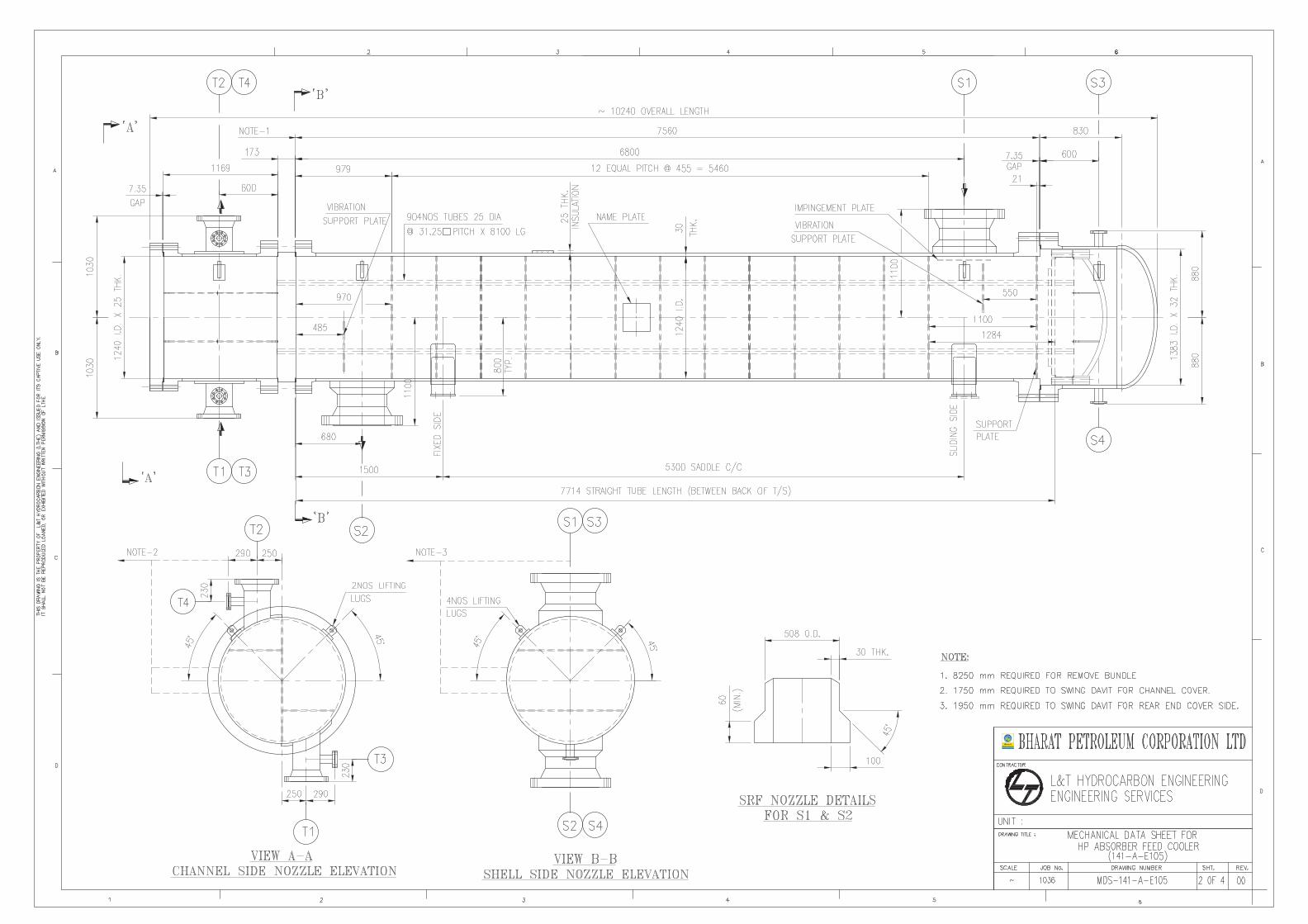

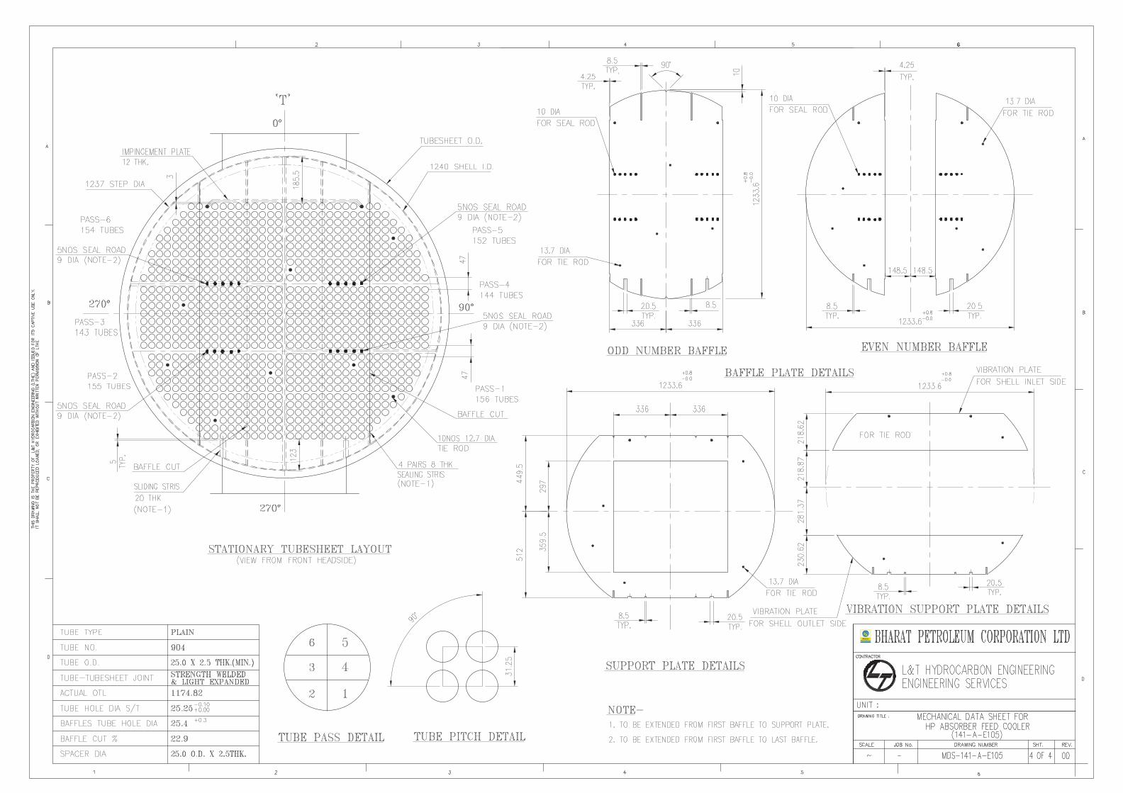
Related Documents