190-02128-04 2018 Revision 4 Supplemental Maintenance Manual Textron Aviation Inc. NAV III Aircraft Includes Instructions for Continued Airworthiness for STC SA01830WI

Welcome message from author
This document is posted to help you gain knowledge. Please leave a comment to let me know what you think about it! Share it to your friends and learn new things together.
Transcript

190-02128-04 2018 Revision 4
Supplemental Maintenance Manual
Textron Aviation Inc. NAV III Aircraft
Includes Instructions for Continued Airworthiness
for STC SA01830WI

G1000 System Maintenance Manual Page i Textron Nav III Series Revision 4 190-02128-04
© Copyright 2017-2018 Garmin Ltd. or its subsidiaries
All Rights Reserved Except as expressly provided herein, no part of this manual may be reproduced, copied, transmitted, disseminated, downloaded or stored in any storage medium, for any purpose without the express prior written consent of Garmin. Garmin hereby grants permission to download a single copy of this manual and of any revision to this manual onto a hard drive or other electronic storage medium to be viewed and to print one copy of this manual or of any revision hereto, provided that such electronic or printed copy of this manual or revision must contain the complete text of this copyright notice and provided further that any unauthorized commercial distribution of this manual or any revision hereto is strictly prohibited.
Garmin International, Inc. 1200 E. 151st Street
Olathe, KS 66062 USA Telephone: 913.397.8200
www.garmin.com
Garmin (Europe) Ltd. Liberty House, Bulls Copse Road
Hounsdown Business Park Southampton, SO40 9RB, UK Phone: +44 (0) 23 8052 4000
Fax: +44 (0) 23 8052 4004
Garmin AT, Inc. 2345 Turner Rd., SE
Salem, OR 97302 USA Telephone: 503.581.8101
RECORD OF REVISIONS
Revision Date Description
2 02/02/2017 Updated Loader Card Creation Instructions (Section 3.2.2) and Traffic System Test Procedures (Section 7.13 and 8.8)
3 07/28/2017 Added pitot static drain check (Section 7.7.3) 4 08/31/2018 Updated for Phase 2 hardware/software
DOCUMENT PAGINATION
Section Pagination
Table of Contents i – vi Section 1 1-1 – 1-6 Section 2 2-1 – 2-8 Section 3 3-1 – 3-44 Section 4 4-1– 4-11 Section 5 5-1 – 5-33 Section 6 6-1 – 6-10 Section 7 7-1– 7-50 Section 8 8-1 – 8-6 Section 9 9-1 - 9-10
Appendix A A-1

G1000 System Maintenance Manual Page ii Textron Nav III Series Revision 4 190-02128-04
INFORMATION SUBJECT TO EXPORT CONTROL LAWS
This document may contain information which is subject to the Export Administration Regulations (“EAR”) issued by the United States Department of Commerce (15 CFR, Chapter VII Subchapter C) and which may not be exported, released or disclosed to foreign nationals inside or outside the United States without first obtaining an export license. The preceding statement is required to be included on any and all reproductions in whole or in part of this manual.
This product, its packaging, and its components contain chemicals known to the State of California to cause cancer, birth defects, or reproductive harm. This Notice is being provided in accordance with California's Proposition 65. If you have any questions or would like additional information, please refer to our web site at www.garmin.com/prop65.
The GDU lens is coated with a special anti-reflective coating that is very sensitive to skin oils, waxes and abrasive cleaners. CLEANERS CONTAINING AMMONIA WILL HARM THE ANTI-REFLECTIVE COATING. It is very important to clean the lens using a clean, lint-free cloth and an eyeglass lens cleaner that is specified as safe for anti-reflective coatings.
All G1000 screen shots used in this document are current at the time of publication. Screen shots are intended to provide visual reference only. All information depicted in screen shots, including software file names, versions and part numbers, is subject to change and may not be up to date.
CAUTION
WARNING
IMPORTANT

G1000 Supplemental Maintenance Manual Page iii Textron Nav III Series Revision 4 190-02128-04
TABLE OF CONTENTS
PARAGRAPH PAGE
1. INTRODUCTION ................................................................................................................. 1-1 1.1 Content, Scope, Purpose .............................................................................................. 1-1 1.2 Organization .................................................................................................................. 1-2 1.3 Definitions/Abbreviations .............................................................................................. 1-3 1.4 Units of Measure ........................................................................................................... 1-4 1.5 Publications................................................................................................................... 1-4 1.6 Revision and Distribution .............................................................................................. 1-6
2. SYSTEM DESCRIPTION .................................................................................................... 2-1 2.1 Equipment Descriptions ................................................................................................ 2-1 2.2 G1000 Optional Interfaces ............................................................................................ 2-6 2.3 Electrical Power Distribution ......................................................................................... 2-6 2.4 Pitot/Static System ........................................................................................................ 2-6 2.5 GDU 1054B and GDU 1050 Displays ........................................................................... 2-6 2.6 Softkeys ........................................................................................................................ 2-6 2.7 FMS Knob ..................................................................................................................... 2-6 2.8 G1000 Normal Mode ..................................................................................................... 2-7 2.9 Reversionary Mode ....................................................................................................... 2-8
3. SOFTWARE AND CONFIGURATION ................................................................................ 3-1 3.1 Configuration Mode Overview ....................................................................................... 3-1 G1000 System Software Information ...................................................................................... 3-6 3.2 Configuration Mode ..................................................................................................... 3-14 3.3 G1000 Hardware/Software Compatibility Check ......................................................... 3-14 3.4 Equipment Verification (Third Party/Optional Equipment Documentation) ................. 3-14 3.5 G1000 Software/Configuration Procedure .................................................................. 3-16 3.6 System Software and Configuration Load .................................................................. 3-17 3.7 Feature Enablement ................................................................................................... 3-33 3.8 Aircraft Registration Number Entry and Flight ID Configuration ................................. 3-37 3.9 Configuration Manager ............................................................................................... 3-39 3.10 Splash Screen Loading ............................................................................................... 3-39 3.11 Database Loading ....................................................................................................... 3-40 3.12 Configuration of Navigation Map for Traffic System ................................................... 3-42 3.13 Clearing Default User Settings .................................................................................... 3-42 3.14 Interface Confirmation ................................................................................................. 3-43
4. INSTRUCTIONS FOR CONTINUED AIRWORTHINESS ................................................... 4-1 4.1 Airworthiness Limitations .............................................................................................. 4-1 4.2 Servicing Information .................................................................................................... 4-2 4.3 Maintenance Intervals ................................................................................................... 4-4 4.4 Electrical Bonding Test ................................................................................................. 4-5 4.5 GSU 75 Earth Magnetic Field Updates ......................................................................... 4-7 4.6 G1000 Redundant Connection Check .......................................................................... 4-7 4.7 GSM 86 Spring Cartridge Torque Check ...................................................................... 4-9
5. TROUBLESHOOTING ........................................................................................................ 5-1 5.1 System Annunciations .................................................................................................. 5-2 5.2 G1000 Alerting System ............................................................................................... 5-12 5.3 Synthetic Vision and Pathways Troubleshooting ........................................................ 5-13 5.4 Backup Communications Path Checks ....................................................................... 5-14 5.5 GDU 105X Troubleshooting ........................................................................................ 5-15 5.6 GDU 105X Alerts ........................................................................................................ 5-17 5.7 GTX Troubleshooting .................................................................................................. 5-21 5.8 GDL69A SXM Troubleshooting (if installed) ............................................................... 5-22

G1000 Supplemental Maintenance Manual Page iv Textron Nav III Series Revision 4 190-02128-04
5.9 GEA 71B Troubleshooting (if installed) ....................................................................... 5-22 5.10 GIA 64W Troubleshooting (if installed) ....................................................................... 5-22 5.11 GMA 1360 Troubleshooting (if installed) ..................................................................... 5-22 5.12 GSR 56 Troubleshooting ............................................................................................ 5-22 5.13 GSU 75 and GMU 44 Troubleshooting ....................................................................... 5-23 5.14 GSU 75 Troubleshooting ............................................................................................ 5-27 5.15 Software/Configuration Troubleshooting ..................................................................... 5-28 5.16 Backshell/Backplate Connectors ................................................................................ 5-30
6. EQUIPMENT REMOVAL & INSTALLATION ..................................................................... 6-1 6.1 GDU 1054B/1050 .......................................................................................................... 6-2 6.2 GTX 335R/GTRX 345R Transponder (if installed) ........................................................ 6-2 6.3 GSU 75 ADAHRS (if installed) ...................................................................................... 6-2 6.4 GDL 69A SXM (if installed) ........................................................................................... 6-3 6.5 Configuration Modules .................................................................................................. 6-3 6.6 GMA 1360 Audio Panel (if installed) ............................................................................. 6-7 6.7 GIA 64W Integrated Avionics Unit (if installed) ............................................................. 6-7 6.8 GSR 56 Satellite Transceiver (if installed) ................................................................... 6-7 6.9 Iridium Antenna (if installed) ......................................................................................... 6-8 6.10 GEA 71B Engine/Airframe Unit (if installed) ................................................................. 6-8 6.11 FS 510 Wifi/Bluetooth Data Link (if installed) ................................................................ 6-9 6.12 GSA 81 Servo Actuator (if installed) ............................................................................. 6-9 6.13 GSM 86 Servo Gearbox (if installed) .......................................................................... 6-10
7. GARMIN G1000 LRU REPLACEMENT/CONFIGURATION & TESTING .......................... 7-1 7.1 GDU 1054B/1050 PFD & MFD ..................................................................................... 7-1 7.2 GMA 1347 or GMA 1360 Audio Panel .......................................................................... 7-4 7.3 GIA 63W or GIA 64W Integrated Avionics Unit ............................................................. 7-8 7.4 GEA 71 or GEA 71B Engine/Airframe Unit ................................................................. 7-17 7.5 GTX 335R, GTX 345R, or GTX 33 Transponder ........................................................ 7-21 7.6 GSU 75 ADAHRS (if installed) .................................................................................... 7-24 7.7 GDC 74A Air Data ....................................................................................................... 7-26 7.8 GRS 77 and GMU 44 Magnetometer (if installed) ...................................................... 7-30 7.9 GMU 44 Magnetometer .............................................................................................. 7-32 7.10 GSU/GRS/GMU Calibration Procedures .................................................................... 7-33 7.11 GDL 69A or GDL 69A SXM Data Link (if installed) ..................................................... 7-42 7.12 GSA 81 Servos (if installed) ........................................................................................ 7-44 7.13 Garmin Traffic Systems (GTS 800) (if installed) ......................................................... 7-46 7.14 GSR 56 ....................................................................................................................... 7-49
8. SUBSYSTEM FUNCTIONAL CHECKS .............................................................................. 8-1 8.1 Stormscope Functional Check (if installed) ................................................................... 8-1 8.2 TAWS Functional Check ............................................................................................... 8-1 8.3 FliteCharts Functional Check ........................................................................................ 8-1 8.4 ChartView Functional Check ......................................................................................... 8-2 8.5 SafeTaxi Functional Check ........................................................................................... 8-3 8.6 DME Functional Check ................................................................................................. 8-4 8.7 ADF Functional Check .................................................................................................. 8-4 8.8 GTS Traffic System Functional Check .......................................................................... 8-4 8.9 Search and Rescue Functional Check (if installed) ...................................................... 8-6
9. G1000 SYSTEM RETURN TO SERVICE PROCEDURE ................................................... 9-1 9.1 Display Test .................................................................................................................. 9-1 9.2 Display Failure Test ...................................................................................................... 9-4 9.3 Reversion Mode Check ................................................................................................. 9-5 9.4 GPS Signal Acquisition ................................................................................................. 9-6 9.5 GPS Failure Test .......................................................................................................... 9-7

G1000 Supplemental Maintenance Manual Page v Textron Nav III Series Revision 4 190-02128-04
9.6 GIA Failure Test ............................................................................................................ 9-8 9.7 GEA Functional Check .................................................................................................. 9-9 9.8 G1000 Backup Path Test ............................................................................................ 9-10 9.9 GFC 700 Autopilot Clutch Overpower Check ............................................................. 9-10 9.10 Maintenance Records ................................................................................................. 9-10
LIST OF ILLUSTRATIONS
FIGURE PAGE
Figure 2-1, Flight Stream 510 ................................................................................................... 2-1 Figure 2-2, GTX 345R/GTX 335R Transponder ........................................................................ 2-2 Figure 2-3, GSU-75 ADAHRS with Connector and Mounting Tray ........................................... 2-3 Figure 2-4, GDL 69A SXM Datalink ........................................................................................... 2-4 Figure 2-20, GSA 81 Servo Actuator, GSM 86 Servo Gearbox ................................................. 2-4 Figure 2-3, GMA 1360 Audio Panel ........................................................................................... 2-5 Figure 2-7, GIA 64W unit ........................................................................................................... 2-5 Figure 2-8, GEA 71B unit ........................................................................................................... 2-5 Figure 2-5, G1000 Softkeys ....................................................................................................... 2-6 Figure 2-6, Normal Mode ........................................................................................................... 2-7 Figure 2-7, Automatic Reversion with MFD failure ................................................................... 2-8 Figure 3-1, SET>ACTV Diagram ............................................................................................... 3-2 Figure 3-2, Loss of Communication ........................................................................................... 3-3 Figure 3-3, Configuration Status ................................................................................................ 3-3 Figure 3-4, Data Transmission Indicators .................................................................................. 3-3 Figure 3-5, GSU Configuration Settings Storage ..................................................................... 3-13 Figure 3-6, Garmin Unit S/N Location ...................................................................................... 3-15 Figure 3-7, Software/Configuration Overview .......................................................................... 3-16 Figure 3-8, Airframe Group Selection ...................................................................................... 3-18 Figure 3-9, Airframe Change Confirmation .............................................................................. 3-19 Figure 3-10, MFD Aux - Database Page DB Transfer ............................................................. 3-41 Figure 3-11, Stormscope Configuration Page .......................................................................... 3-43 Figure 3-12, Stormscope Configuration ................................................................................... 3-43 Figure 4-3, GFC Status Page .................................................................................................... 4-9 Figure 5-1, Aux – System Status Page ...................................................................................... 5-1 Figure 5-2, System Annunciations ............................................................................................. 5-2 Figure 5-3, Alerts & Annunciations .......................................................................................... 5-12 Figure 5-4, Alerts Softkey Annunciation ................................................................................... 5-12 Figure 5-5, Magnetometer Interference Test ........................................................................... 5-25 Figure 5-6, GTX 335R/345R Looking at Front of Connector (P3251) ...................................... 5-30 Figure 5-7, GTX 345R (Only) Looking at Front of Connector (P3252)..................................... 5-30 Figure 5-8, GDU 1054B/1050 Backshell Connector (P10401) ................................................ 5-31 Figure 5-9, GSU 75 Connector View from Front (P751) .......................................................... 5-31 Figure 5-10, GDL 69A SXM Backplate Connector (P69A1) .................................................... 5-31 Figure 5-11, GIA 64W Backplate Connectors .......................................................................... 5-32 Figure 5-12, GEA 71B Backplate Connectors ......................................................................... 5-32 Figure 5-13, GMA 1360 Backplate Connectors ....................................................................... 5-33 Figure 5-14, GSR 56 Mating Connector .................................................................................. 5-33 Figure 6-1, Configuration Module Installation ............................................................................ 6-4 Figure 6-2, GSU 75 Configuration Module Installation .............................................................. 6-5 Figure 6-1, Servo Gear .............................................................................................................. 6-9 Figure 7-1, G1000 Normal Mode Check ................................................................................... 7-3 Figure 7-2, Aux – GPS Status Page (MFD) ............................................................................. 7-14 Figure 7-3, Normal Engine Instrument Markings (MFD) ......................................................... 7-20

G1000 Supplemental Maintenance Manual Page vi Textron Nav III Series Revision 4 190-02128-04
Figure 7-4, Aircraft Registration ............................................................................................... 7-23 Figure 7-5, GRS/GMU Calibration, Pitch/Roll Offset ............................................................... 7-35 Figure 7-6, GRS/GMU Calibration, Engine Run-Up ................................................................. 7-39 Figure 7-7, Normal Mode AHRS Check .................................................................................. 7-41 Figure 8-1, Traffic Map ............................................................................................................... 8-4 Figure 9-1, MFD Power Up Page ............................................................................................... 9-1 Figure 9-2, PFD Power-up System Annunciations .................................................................... 9-2 Figure 9-3, PFD Normal Operation ............................................................................................ 9-3 Figure 9-4, GDU Reversionary Mode ........................................................................................ 9-5 Figure 9-5, AUX-GPS Status Page ............................................................................................ 9-6
LIST OF TABLES TABLE .................................................................................................................................. PAGE Table 1-1, Required Documents ................................................................................................ 1-4 Table 1-2, Reference Publications ............................................................................................ 1-6 Table 4-1, Maintenance Intervals ............................................................................................... 4-4 Table 4-2, GSM 86 Allowable Torque Values (Automated Test) ............................................. 4-10 Table 4-3, GSM 86 Allowable Torque Values (Fixture Test) ................................................... 4-11 Table 5-1, SVS Troubleshooting .............................................................................................. 5-13 Table 5-2, SVS-Related Alert Messages ................................................................................ 5-14 Table 5-3, Magnetometer Interference Test Sequence ........................................................... 5-26 Table 6-1, Configuration Module Kit – 011-00979-00 ............................................................... 6-4 Table 6-2, GSU 75 Configuration Module Kit – 011-00979-20 .................................................. 6-5 Table 7-1, Altitude Test Points ................................................................................................. 7-28 Table 7-2, Airspeed Test Points ............................................................................................... 7-29 Table 7-3, Vertical Speed Table .............................................................................................. 7-29 Table 7-4, Required GRS/GMU Calibrations ........................................................................... 7-34

G1000 Supplemental Maintenance Manual Page 1-1 Textron Nav III Series Revision 4 190-02128-04
1. INTRODUCTION
1.1 Content, Scope, Purpose
This document provides Instructions for Continued Airworthiness (ICA) for the NXi configuration of the Garmin G1000 Integrated Flight Deck including the GFC700 Automatic Flight Control System (AFCS) as installed in the Textron Aviation Inc., NAV III series of aircraft, under STC SA01830WI. This document satisfies the requirements for continued airworthiness as defined by 14 CFR Part 23.1529 and 14 CFR Part 23 Appendix G. Information in this document is required to maintain the continued airworthiness of the G1000 and GFC700.
Throughout this document, the GFC 700 autopilot system is included in the G1000NXi system description and is identified separately only when needed.
References to “NAV III” throughout this document include 172R, 172S, 182T, T182T, 206H, and T206H models. Items in this document that are aircraft model(s) specific will identify the model(s) instead of “NAV III”.
This document is a supplement to the existing G1000 Nav III Line Maintenance Manual, Garmin part number 190-00352-00. Except where noted, refer to the G1000 Nav III Line Maintenance Manual for servicing instructions.
Applicability
This document applies to all Textron Aviation Inc. NAV III aircraft equipped with the G1000NXi system. All G1000NXi NAV III airplanes are configured per General Arrangement drawing 005-00620-22 Rev 1 or subsequent.
Modification of an aircraft by this Supplemental Type Certificate (STC) obligates the aircraft operator to include the maintenance information provided by this document in the operator’s Aircraft Maintenance Manual.
Identifying an STC Configuration
The General Arrangement drawing lists the G1000 System Software Version numbers approved for this STC.
IMPORTANT!
If the technician is unsure of an aircraft’s STC configuration, perform the following:
After acknowledgement of the splash screen, use the FMS knob to go to the Aux – System Status page on the MFD. In the AIRFRAME section (upper right corner,) the display shows the current G1000NXi airframe configuration and system software version number. The airframe configuration is shown in the Airframe field and the system software version number is shown in the following format: ‘SYS SOFTWARE VERSION XXXX.XX’. It correlates to the software image used to load the software to the system:
EXAMPLE:
System Software Version ’2501.00’ = Software Image P/N 006-B2501-00

G1000 Supplemental Maintenance Manual Page 1-2 Textron Nav III Series Revision 4 190-02128-04
1.2 Organization
The following outline briefly describes the organization of this manual:
Section 2: System Description Provides a description of the type design change associated with installing the G1000 update in the Cessna Nav III Series.
Section 3: Software and Configuration Provides software and configuration loading instructions for a complete system software load.
Section 4: Instructions for Continued Airworthiness Provides maintenance instructions for continued airworthiness of the G1000 system.
Section 5: Troubleshooting Provides troubleshooting information to aid in diagnosing and resolving potential problems with the G1000 system.
Section 6: Equipment Removal & Replacement Gives instructions for the removal and replacement of G1000 equipment.
Section 7: Garmin G1000 LRU Replacement/Configuration & Testing Gives instructions for loading software, configuring, and testing of G1000 equipment.
Section 8: Subsystem Functional Checks Gives instructions for testing G1000 subsystems.
Section 9: G1000 System Return to Service Procedure Specifies return-to-service procedures to be performed upon completion of maintenance of the G1000 system.
G1000 Supplemental Maintenance Manual Page 1-3 Textron Nav III Series Revision 4 190-02128-04
1.3 Definitions/Abbreviations
ADAHRS: Air Data and Attitude Heading Reference System ADC: Air Data Computer ADF: Automatic Direction Finder ADS-B: Automatic Dependent Surveillance – Broadcast ADTS: Air Data Test Set AFCS: Automatic Flight Control System AFM: Airplane Flight Manual AFMS: Airplane Flight Manual Supplement AHRS: Attitude Heading Reference System AML: Approved Model List CDU: Control Display Unit CFR: Code of Federal Regulations DME: Distance Measuring Equipment EIS: Engine Indication System FIS-B: Flight Information Services – Broadcast FS: Flight StreamTM GPS: Global Positioning System HSDB: High-Speed Data Bus (Ethernet) ICS: Inter-Com System LRU: Line Replaceable Unit MFD: Multi-Function Display MMC: Multi-Media Card OAT: Outside Air Temperature PFD: Primary Flight Display STC: Supplemental Type Certificate TAWS: Terrain Awareness & Warning System TIS-B: Traffic Information Services – Broadcast VHF: Very High Frequency

G1000 Supplemental Maintenance Manual Page 1-4 Textron Nav III Series Revision 4 190-02128-04
1.4 Units of Measure
Unless otherwise stated, all units of measure are English units.
1.5 Publications
The following documents are required by this maintenance manual to perform maintenance. It is the responsibility of the owner / operator to ensure latest versions of these documents are used during operation, servicing or maintenance of the airplane.
Table 1-1, Required Documents
Part Number Garmin Document
005-00620-21 Master Drawing List, G1000 Avionics Updates, Part 23 AML STC
005-00620-22 General Arrangement, G1000 Textron NAV III
005-00620-24 Forward Avionics Install, G1000 Update 172R/172S
005-00620-25 Forward Avionics Install, G1000 Update, 182T/T182T
005-00620-26 Forward Avionics Install G1000 Update, 206H/T206H
005-00620-27 Remote Avionics Install, G1000 Update, 172R/172S
005-00620-28 Remote Avionics Install, G1000 Update, 182T/T182T
005-00620-29 Remote Avionics Install, G1000 Update, 206H/T206H
005-00620-31 Wiring Diagram, GDU 105X PFD/MFD, Textron Models 172, 182, 206
005-00620-32 Wiring Diagram, GSU 75 ADAHRS, Textron Models 172, 182, 206
005-00620-33 Wiring Diagram, GTX3X5 Transponder, Textron Models 172, 182, 206
005-00620-34 Wire Harness Install/Routing, Textron Model 172R/172S
005-00620-35 Wire Harness Install/Routing, Textron Model 182T/T182T
005-00620-36 Wire Harness Install/Routing, Textron Model 206H/T206H
005-00620-38 Pitot/Static Plumbing Mod, Textron Model 182T/T182T
005-00620-39 Pitot/Static Plumbing Mod, Textron Model 206H/T206H
005-00620-AQ Pitch and Trim Servo Installs, Textron 172, GFC 700 Update
005-00620-AR Roll Servo Install, Textron 172, GFC 700 Update
005-00620-AY Wiring Diagram, Cessna 172 E-AFCS
005-00620-B5 Servo Install, GFC700 Update, Textron 182
005-00620-B6 Servo Install, GFC700 Update, Textron 206
005-00620-B7 GSR 56 Install, G1000 Update, Textron 172
005-00620-B8 GSR 56 Install, G1000 Update, Textron 182
005-00620-B9 GSR 56 Install, G1000 Update, Textron 206
005-00620-BA Wiring Diagram, E-AFCS, Textron 182/206
005-00620-BB Wiring Diagram, GMA1360 Audio Panel, Textron NAV III
005-00620-BR Wiring Diagram, GSR 56 Iridium, Textron NAV III

G1000 Supplemental Maintenance Manual Page 1-5 Textron Nav III Series Revision 4 190-02128-04
Part Number Textron Aviation Documents
C172RMM Model 172R/172S Maintenance Manual
C182SMM Model 182S/182T/T182T Maintenance Manual
C206HMM Model 206H/T206H Maintenance Manual
SESR Single Engine Structural Repair Manual – 172, 182, 206 Series

G1000 Supplemental Maintenance Manual Page 1-6 Textron Nav III Series Revision 4 190-02128-04
The following publications are recommended to be on hand during the performance of maintenance activities.
Table 1-2, Reference Publications
Part Number Garmin Document
190-02128-02 Airplane Flight Manual Supplement, G1000 NXi Integrated Avionics System and GFC 700 AFCS In Textron NAV III Series of aircraft
190-02178-00 G1000 Cockpit Reference Guide for Cessna NAV III
190-00355-04 GDL 69 Series SiriusXM Satellite Radio Activation Instructions
190-00352-00 G1000 NAV III Line Maintenance Manual
Generic installation manuals for individual Garmin LRUs are also available through the ‘Dealer Resource Center’ section of the Garmin web site; refer to Section 1.6 for details.
1.6 Revision and Distribution
This document is required for maintaining the continued airworthiness of the aircraft. When this document is revised, every page will be revised to indicate current revision level.
Garmin Dealers may obtain the latest revision of this document on the Garmin Dealer Resource Center website.
Owner/operators may obtain the latest revision of this document from the https://fly.garmin.com/ Support page, or by contacting a Garmin dealer, contacting Garmin Product Support at 913-397-8200, toll free 866-739-5687, or using around the world contact information on https://fly.garmin.com/.
A Garmin Service Bulletin describing the revision to this document will be sent to Garmin dealers if the revision is determined to be significant.

G1000 Supplemental Maintenance Manual Page 2-1 Textron Nav III Series Revision 4 190-02128-04
2. SYSTEM DESCRIPTION
2.1 Equipment Descriptions
For description of equipment and functions not listed here, refer to the G1000 Nav III Line Maintenance Manual, Garmin part number 190-00352-00.
GDU 1054B OR GDU 1050 PFD & MFD
Two Garmin GDU 1054B or GDU 1050 displays are installed in the Nav III instrument panel. The GDU 1054B displays are standard equipment on all Nav III models, while the GDU 1050 displays are installed on Model 172 aircraft that are not equipped with the Garmin GFC700 autopilot.
The GDU 1054B or GDU 1050 displays are 10.4 inch LCD displays with 1024 x 768 resolution.
The GDU 1054B or GDU 1050 units communicate with each other and the GIA 63W units through a high-speed data bus (HSDB) Ethernet connection.
The PFD receives primary electrical power from the Essential Bus and secondary electrical power from Avionics Bus No. 1. The MFD receives electrical power from Avionics Bus No. 2. The displays will power-up immediately with external or aircraft power or battery operation.
All displays are installed in the panel using ¼-turn fasteners.
Flight Stream 510
The Flight Stream™ 510 (FS 510) is a Wi-Fi/Bluetooth capable multi-media card (MMC) installed the bottom SD slot of the MFD. It sends position, velocity, time, attitude, heading, FIS-B, TIS-B traffic, Sirius XM audio control, Sirius XM weather data, and flight plan transfer to mobile devices via Bluetooth. The FS 510 can also interface with a mobile device via Wi-Fi pairing for the purposes of updating databases used by the GDU(s). Bluetooth and Wi-Fi are mutually exclusive with only one interface functional at a time. Connecting via Wi-Fi requires a pilot-configurable Wi-Fi Protected Access WPA2 security password. By updating databases wirelessly, new databases may be transferred to the G1000 system without taking the data card out of the aircraft.
Figure 2-1, Flight Stream 510
G1000 Supplemental Maintenance Manual Page 2-2 Textron Nav III Series Revision 4 190-02128-04
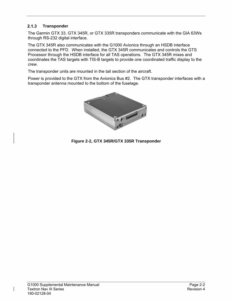
Transponder
The Garmin GTX 33, GTX 345R, or GTX 335R transponders communicate with the GIA 63Ws through RS-232 digital interface.
The GTX 345R also communicates with the G1000 Avionics through an HSDB interface connected to the PFD. When installed, the GTX 345R communicates and controls the GTS Processor through the HSDB interface for all TAS operations. The GTX 345R mixes and coordinates the TAS targets with TIS-B targets to provide one coordinated traffic display to the crew.
The transponder units are mounted in the tail section of the aircraft.
Power is provided to the GTX from the Avionics Bus #2. The GTX transponder interfaces with a transponder antenna mounted to the bottom of the fuselage.
Figure 2-2, GTX 345R/GTX 335R Transponder

G1000 Supplemental Maintenance Manual Page 2-3 Textron Nav III Series Revision 4 190-02128-04
GSU 75 ADAHRS
The GSU 75 ADAHRS is a combined Air Data and AHRS system. The unit is mounted in the tail avionics area. It contains advanced tilt sensors, accelerometers, rate sensors, static pressure sensors, and pitot pressure sensors. The GSU 75 receive GPS data from the GIA 63Ws, and magnetic heading from the GMU 44 Magnetometer.
The GSU receives primary electrical power from the Essential Bus and a secondary power supply from Avionics Bus 1. The GSU provides electrical power to the onside GMU 44 Magnetometer and the GTP 59 OAT probe.
The GSU connects to the existing pitot/static ports.
Each GSU 75 provides the following information via ARINC 429 busses to both GIAs, the PFD and the MFD.
Aircraft altitude and airspeed
Aircraft vertical speed, Mach and outside air temperature
Aircraft heading, pitch and roll
Aircraft yaw, pitch and roll rates
Aircraft body-axis accelerations
Rates of change of heading, pitch and roll
Aircraft accelerations expressed in a local level frame of reference
Figure 2-3, GSU-75 ADAHRS with Connector and Mounting Tray

G1000 Supplemental Maintenance Manual Page 2-4 Textron Nav III Series Revision 4 190-02128-04
GDL 69A SXM Datalink
The GDL 69A SXM provides SiriusXM Radio weather and music entertainment through means of a dedicated satellite data link. The GDL 69A SXM is mounted behind the instrument panel in the 182 and 206 models and in the aft avionics area for 172 models. Power to the GDL 69A SXM is received from the Avionics No. 1 bus. The GDL 69A SXM sends weather data through the HSDB bus to the MFD, where the data link interface is controlled. Audio is sent directly to the GMA Audio Panel.
Figure 2-4, GDL 69A SXM Datalink
GSA 81 Servo Actuator and GSM 86 Servo Gearbox
The Garmin GSA 81 Servo Actuators are electromechanical units that provides the autopilot control for pitch, roll and pitch trim. The GSM 86 Servo Gearboxes are attached to a mount bracket and are responsible for transferring the output torque of the GSA 81 servo actuators to the mechanical flight control surface linkage.
Figure 2-5, GSA 81 Servo Actuator, GSM 86 Servo Gearbox
The installation of these units supports Electronic Stability Protection (ESP) and Under Speed Protection (USP) features. ESP works to assist the pilot in maintaining the aircraft in a stable flight condition. When autopilot is not engaged, ESP helps avoid inadvertent flight attitudes and provide airspeed protection while the pilot is hand-flying the aircraft. The USP feature will correct for slow airspeeds while the autopilot is engaged. USP will lower the nose of the aircraft to maintain an airspeed that prevents the aircraft from stalling.

G1000 Supplemental Maintenance Manual Page 2-5 Textron Nav III Series Revision 4 190-02128-04
GMA 1360 Audio Panel
The GMA 1360 audio panel integrates NAV/COM digital audio, intercom system and marker beacon controls. Manual display reversion mode (red DISPLAY BACKUP button) for the PFD and MFD is controlled by the GMA.
Figure 2-6, GMA 1360 Audio Panel
GIA 64W Integrated Avionics Unit
The GIA 64W functions as the main communication hub to the G1000 system linking LRUs with the PFD and MFD displays. The GIA 64W contains the GPS/WAAS receiver, VHF COM/NAV receivers, and system integration microprocessors.
Figure 2-7, GIA 64W unit
GEA 71B Engine Airframe Unit
The GEA 71B Engine/Airframe unit receives and processes signals from engine sensors. Communication interface is to the GIA via RS-485.
Figure 2-8, GEA 71B unit

G1000 Supplemental Maintenance Manual Page 2-6 Textron Nav III Series Revision 4 190-02128-04
2.2 G1000 Optional Interfaces
There are no new optional interfaces approved as part of this STC. Refer to the G1000 Nav III Line Maintenance Manual for optional interfaces.
2.3 Electrical Power Distribution
The electrical power distribution has not changed as a result of this STC. Refer to the G1000 Nav III Line Maintenance Manual for power distribution.
2.4 Pitot/Static System
The layout of the pitot/static system has not changed as a result of this STC, except that the plumbing has been rerouted from the instrument panel area to the tail avionics area for 182 and 206 models.
2.5 GDU 1054B and GDU 1050 Displays
The location and function of the controls on the GDU 1054B or GDU 1050 displays are unchanged from those described for the GDU 1040 or GDU 1044B in the G1000 Nav III Line Maintenance Manual.
2.6 Softkeys
Some pages have commands or selections that are activated by the GDU 1054B or GDU 1050 softkeys. If a softkey is associated with a command, that command will be displayed directly above the key. A grayed-out softkey shows a command that is unavailable. A softkey that is highlighted (green bar) shows the current active selection.
Figure 2-9, G1000 Softkeys
2.7 FMS Knob
The FMS knob is the primary control for the G1000 system.
To cycle through different configuration screens:
To change page groups: Rotate the large FMS knob.
To change pages in a group: Rotate the small FMS knob.
To activate the cursor for a page, press the small FMS knob directly in, as one would push a regular button.
To cycle the cursor through different data fields, rotate the large FMS knob.
To change the contents of a highlighted data field, rotate the small FMS knob. This action either brings up an options menu for the particular field, or in some cases allows the operator to enter data for the field.
To confirm a selection, press the ENT key.

G1000 Supplemental Maintenance Manual Page 2-7 Textron Nav III Series Revision 4 190-02128-04
To cancel a selection, press the small FMS knob in again, deactivating the cursor. The CLR key may also be used to cancel a selection or deactivate the cursor.
2.8 G1000 Normal Mode
To start the G1000 system in Normal Mode:
1. With a ground power unit connected to the external power receptacle, turn ON the BAT (battery) switch. The following G1000 equipment is powered on:
PFD display
GSU 75 ADAHRS
GIA #1 (NAV and COM)
GEA Engine/Airframe Unit
2. Turn ON the AVIONICS BUS 1 and AVIONICS BUS 2 switches. The following G1000 equipment is powered on:
PFD (secondary power)
MFD
GSU 75 ADAHRS (secondary power)
GIA #1 (NAV) (secondary power)
GEA Engine/Airframe Unit (secondary power)
GTS 800 Traffic System (if installed)
GTX Mode S/ADS-B Transponder
GIA #2 (NAV and COM)
GMA Audio Panel
GSA Servos
GSR 56 Satellite Transceiver
The G1000 system is now powered in the normal mode. In the normal operating mode, data fields that are invalid have large red X’s through them. A valid field does not display a red X. Allow the displays to initialize for approximately one minute for the red X’s to be removed.
The PFD and MFD will function as specified in the G1000 Cockpit Reference Guide when the system has been correctly installed and configured.
Figure 2-10, Normal Mode

G1000 Supplemental Maintenance Manual Page 2-8 Textron Nav III Series Revision 4 190-02128-04
2.9 Reversionary Mode
Reversionary mode allows for display of information related to safe flight in the event of a display communication or hardware failure. The PFD automatically goes into reversionary mode when communication to the MFD is lost. Manual reversionary mode allows the operator to force the PFD and MFD into reversionary mode by pressing the large red button labeled ‘DISPLAY BACKUP’ on the GMA audio panel.
NOTE
When the ‘DISPLAY BACKUP’ button is pushed to exit reversionary mode, there is a 5-second delay until the display returns to normal mode. If the ‘DISPLAY BACKUP’ button is pushed again during this 5-second delay, the display will reset the five second delay timer.
Figure 2-11, Automatic Reversion with MFD failure

G1000 Supplemental Maintenance Manual Page 3-1 Textron Nav III Series Revision 4 190-02128-04
3. Software and Configuration
3.1 Configuration Mode Overview
Throughout this document, references are made to the PFD and/or MFD being in configuration mode. The configuration mode exists to provide the avionics technician with a means of configuring, checking, and calibrating various G1000 sub-systems. Troubleshooting and diagnostics information can also be viewed in this mode.
To start the G1000 system in configuration mode, follow these steps:
1. Apply power to the G1000 system by applying aircraft EXT power, selecting the BAT MASTER and AVIONICS BUS 1 and AVIONICS BUS 2 switches to ON.
2. Pull the MFD, PFD (ESS BUS), and PFD (AVN BUS 1) circuit breakers.
3. Press and hold the ENT key on the MFD while applying power using the MFD circuit breaker.
4. Release the ENT key after ‘INITIALIZING SYSTEM’ appears in the upper left corner of the MFD.
5. Press and hold the ENT key on the PFD while applying power using the PFD (ESS BUS) circuit breaker.
6. Release the ENT key after ‘INITIALIZING SYSTEM’ appears in the upper left corner of the PFD.
CAUTION:
Configuration Mode contains certain pages and settings that are critical to aircraft operation and safety. These pages are protected and cannot be modified, unless the technician is properly authorized and equipped. However, most protected pages are viewable to allow system awareness for troubleshooting.
NOTES
If the specific procedure requires an SD card to be in the top slot of the PFD/MFD, this card must be inserted prior to applying power to the PFD/MFD. Any time a card is inserted, the power to the PFD/MFD must be cycled.
For a complete description and breakdown of each Configuration Mode page, refer to the G1000 System Maintenance Manual listed in Table 1-2.
SET>ACTV Configuration
Throughout the configuration mode pages, there are SET and ACTIVE columns for input/output settings and other parameters.
SET: Refers to a setting or group of settings that reside in PFD Internal Memory and/or the Master Configuration Module.
ACTIVE: Refers to an ‘active’ setting or parameter currently being used by the LRU. LRUs store the ‘active’ settings within internal memory.
Data can be manually copied from one column to the other (and consequently from PFD memory to the LRU memory and vice-versa) by using the following two softkeys, when available:
SET>ACTV (read ‘Set to Active’) softkey: Allows the installer to send the information in the SET column (data stored in the master config module) to the ACTV column (data used by LRU).

G1000 Supplemental Maintenance Manual Page 3-2 Textron Nav III Series Revision 4 190-02128-04
ACTV>SET (read ‘Active to Set’) softkey: Causes the LRUs current settings to be copied to the master configuration module as SET items.
CAUTION:
The ACTV>SET softkey must be used with caution! If an improperly configured unit is installed, this softkey causes the wrong configuration to replace the correct aircraft configuration.
In the first example shown in Figure 3-1 the SET columns do not match the ACTIVE columns. The inequality between SET and ACTIVE indicates a configuration mismatch. By pressing the SET>ACTV softkey, this copies the SET column to the LRU unit’s configuration memory. The settings then become the ACTIVE settings for the LRU being configured.
Figure 3-1, SET>ACTV Diagram
When troubleshooting the system, technicians can look for inequalities between SET and ACTIVE columns. Certain problems can be resolved simply by pressing the SET>ACTV softkey, which reloads settings to the specific LRU from the PFD. (Note that this can also be accomplished by reloading the configuration files for the LRU. Section 7 describes this process for each LRU).
G1000 Supplemental Maintenance Manual Page 3-3 Textron Nav III Series Revision 4 190-02128-04
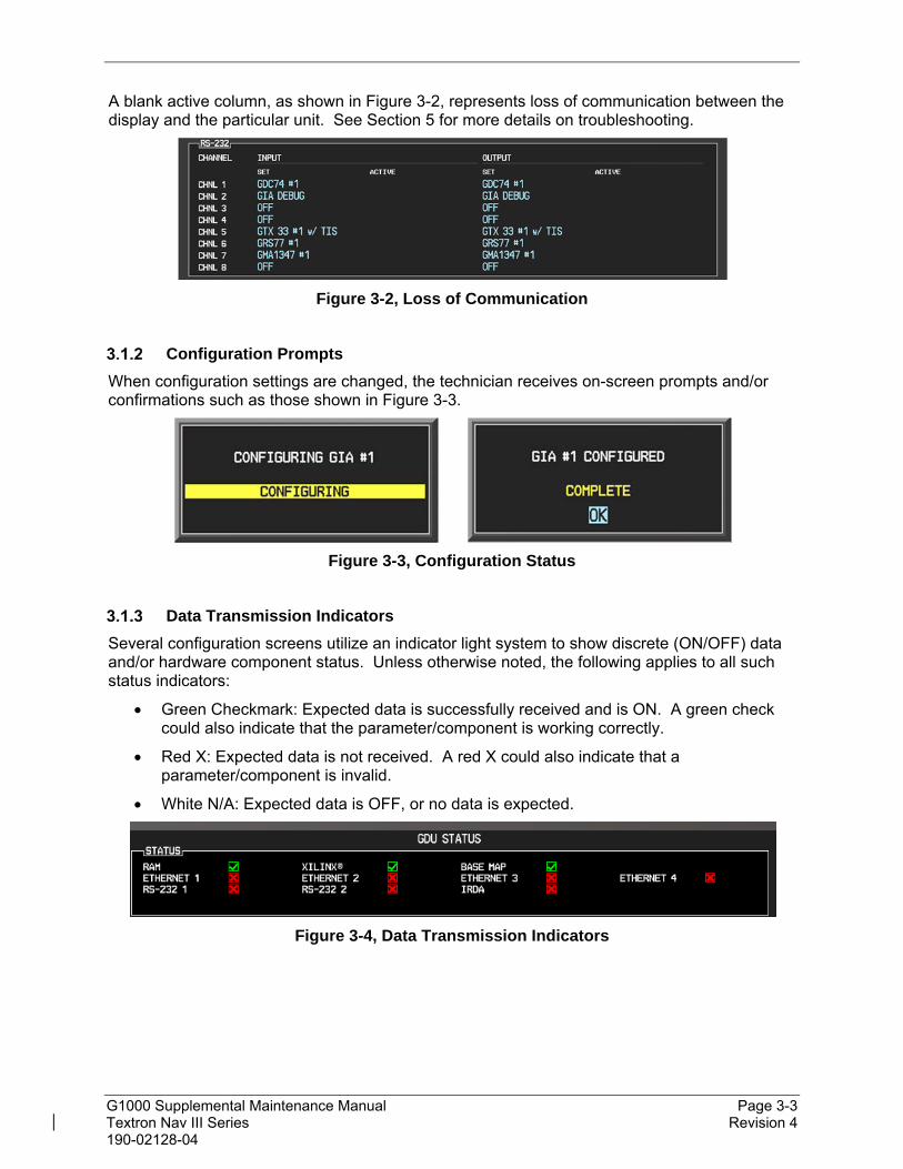
A blank active column, as shown in Figure 3-2, represents loss of communication between the display and the particular unit. See Section 5 for more details on troubleshooting.
Figure 3-2, Loss of Communication
Configuration Prompts
When configuration settings are changed, the technician receives on-screen prompts and/or confirmations such as those shown in Figure 3-3.
Figure 3-3, Configuration Status
Data Transmission Indicators
Several configuration screens utilize an indicator light system to show discrete (ON/OFF) data and/or hardware component status. Unless otherwise noted, the following applies to all such status indicators:
Green Checkmark: Expected data is successfully received and is ON. A green check could also indicate that the parameter/component is working correctly.
Red X: Expected data is not received. A red X could also indicate that a parameter/component is invalid.
White N/A: Expected data is OFF, or no data is expected.
Figure 3-4, Data Transmission Indicators

G1000 Supplemental Maintenance Manual Page 3-4 Textron Nav III Series Revision 4 190-02128-04
Configuration Mode Navigation
Using the FMS knob as described in Section 2.7, a user can navigate through different pages and page groups in the Configuration Mode. For complete description and breakdown of each page, refer to the G1000 System Maintenance Manual listed in Table 1-2. Pages below will be shown only for the units/options installed on the aircraft.
System Page Group
1. System Status 7. Transaction Log 13. System Setup
2. Time Configuration 8. Aircraft Configuration 14. Manifest Configuration
3. Lighting Configuration 9. Diagnostics Terminal 15. Log Utilities
4. System Audio 10. OEM Diagnostics 16. Configuration Manager
5. System Upload 11. System Configuration
6. LRU Replacement 12. System Data Path Configuration
GDU Page Group
1. Serial Configuration 6. Diagnostics 11. Airframe Configuration
2. CDU Status Page 7. Ethernet Test 12. TAWS Configuration
3. Key Test 8. Video Test 13. SurfaceWatch Configuration
4. FS 510 Test 9. Alert Configuration 14. Connext Connections
5. CDU Calibration 10. DAT Configuration
GIA Page Group (for GIA 63W only)
1. Serial Configuration 3. GIA I/O Configuration 5. GIA Status Page
2. GIA RS-485 Configuration 4. GIA COM Setup Page 6. GIA CAN Configuration
GIA 64x Page Group (for GIA 64W only)
1. ARINC Configuration 5. GFC Status 9. IO Configuration
2. CAN Configuration 6. COM Status 10. NAV Status
3. COM Calibration 7. GFC Configuration 11. Serial Configuration
4. COM Configuration 8. GIA Status
GEA Page Group (for GEA 71 only)
1. Engine Configuration 2. GEA Status Page 3. GEA Configuration
GEA 71x Page Group (for GEA 71B only)
1. Engine Configuration 4. Digital In 7. GEA Status
2. Analog In 5. Discrete In 8. XVDT In
3. Annunciate Out 6. Excitation 9. XVDT Out
GTX Page Group (for GTX 33 only)
1. Serial Configuration 2. Transponder Configuration
GTX 3X5 Page Group
1. Transponder Airframe Config 2. Transponder Wiring Config 3. Transponder Diagnostics
GTX 3X5 Page Group (for GTX 335R, GTX 345R only)
1. Transponder Airframe Config 2. Transponder Diagnostics 3. Transponder Wiring Config
GRS Page Group
1. Inputs Configuration 3. GRS Flight Data Log 4. GRS 79 Flight Log Download
2. GRS / GMU Calibration

G1000 Supplemental Maintenance Manual Page 3-5 Textron Nav III Series Revision 4 190-02128-04
ADC Page Group
1. ADC Configuration
GFC Page Group
1. GFC Configuration 2. GFC Status
GMA Page Group (for GMA 1347 only)
1. GMA Configuration
GMA x36x Page Group (for GMA 1360 only)
1. GMA Discrete In 5. GMA Misc 9. GMA Status
2. GMA Discrete Out 6. GMA Noise 10. GMA Volume
3. GMA Fast Volume Configuration
7. GMA Options
4. GMA Marker 8. GMA Squelch
GDL Page Group
1. GDL 69 Configuration 2. GSR 56 Configuration
GTS Page Group
1. GTS Configuration
OTHER Page Group
1. Stormscope
CAL Page Group
1. Fuel Tank Calibration 3. HSCM Calibration
2. Flaps & Trim Calibration 4. DAT Calibration

G1000 Supplemental Maintenance Manual Page 3-6 Textron Nav III Series Revision 4 190-02128-04
G1000 System Software Information
NOTE
The following sections provide a detailed description of loading all G1000 software and configuration files, which may be excessive for individual LRU removal and replacement. If removing and replacing individual LRUs, refer to Section 6 of this manual for the necessary steps.
G1000 Software Image
All software and configuration files were certified by Garmin and are considered part of FAA-approved Type Design data. Approved software and hardware definitions for each STC Configuration are defined on the appropriate General Arrangement drawing listed in Table 1-1.
G1000 software and configuration files are controlled via the approved software image part number listed on the General Arrangement drawing listed in Table 1-1. This software image is loaded into the G1000 using a software loader card. The installer shall create this software loader card by downloading the approved software image in accordance with Section 3.1.6.
NOTE
Only SanDisk brand SD cards are recommended for use with the G1000 system. Other brand cards have not been tested by Garmin.
IMPORTANT!
To satisfy the G1000/GFC700 STC requirements for the Nav III aircraft, it is critical that the technician install correct software image part number when servicing the G1000 system.
Approved software image part numbers are defined on the appropriate General Arrangement drawing (see Table 1-1).
CAUTION:
Be cautious when using software loader cards during maintenance. The G1000 system immediately initializes the card upon power-up. On-screen prompts must be given careful attention in order to avoid potential loss of data. Always read through procedures given in this manual before attempting to use the software loader cards.

G1000 Supplemental Maintenance Manual Page 3-7 Textron Nav III Series Revision 4 190-02128-04
Loader Card Creation
The software image is an executable self-extracting file which builds the correct file structure onto an SD card for use loading software to the G1000 System. To obtain the current file follow the procedures outlined below.
NOTE
In order to create a Textron Nav III system loader card, the installer completing these procedures must be an authorized Garmin Service Center to gain access to the necessary data via the Garmin website.
1. Go to www.garmin.com and click on the Dealer Resource Center link in the lower portion of the home page. Enter your Garmin Dealer username and password.
2. Select Support button then select Software Downloads.

G1000 Supplemental Maintenance Manual Page 3-8 Textron Nav III Series Revision 4 190-02128-04
3. In the Product Search tab, type Cessna in the Product Name or Part Number box, then select the appropriate system and then press the Search button.
4. A screen similar to the one shown below will appear. The numbers shown are for example only.
5. Click on the Select Action button for the appropriate software image part number as shown on the Garmin General Arrangement drawing 005-00620-22 and choose Download to save the software file to the local hard drive.
6. After the file is downloaded, close the web browser.
7. Insert a blank (empty) SD card in the card reader. The loader card program will delete all files on the SD card before loading G1000 system software files on it if the card is not blank.
8. Double-click the .exe file that was downloaded onto the local hard drive. The following window will pop-up on the screen. Click Yes to continue.

G1000 Supplemental Maintenance Manual Page 3-9 Textron Nav III Series Revision 4 190-02128-04
9. Follow the on screen prompts to continue.
10. Check the “I accept the terms of the License Agreement” checkbox.

G1000 Supplemental Maintenance Manual Page 3-10 Textron Nav III Series Revision 4 190-02128-04
11. Select the SD card reader drive and click Next>.
12. Follow the on screen prompts to continue.

G1000 Supplemental Maintenance Manual Page 3-11 Textron Nav III Series Revision 4 190-02128-04
13. The program will make the SD loader card and prompt you when it’s done.
14. Once successfully completed, the following window will display. Click Finish to close the program. The SD card can then be removed from the computer and is ready for use in the aircraft.

G1000 Supplemental Maintenance Manual Page 3-12 Textron Nav III Series Revision 4 190-02128-04
Software Files
Software files are defined by part number and version number on the General Arrangement drawing. Each G1000 system LRU reports the software version it currently contains to the user in two places.
Normal System Mode: The Aux – System Status page lists each LRU and the reported software version.
Configuration Mode: The System Status page (System page group) reports more detailed LRU information, including software version, part number, and LRU status.
Software files are loaded to LRUs from the PFD System Upload page in configuration mode.
Configuration File Descriptions
There are configuration files for baseline settings and various options. Configuration files contain preset selections for input/output channels, aircraft-specific settings, and LRU-specific settings.
IMPORTANT!
Certain software and configuration files are REQUIRED to be re-loaded during maintenance that involves removal and replacement of G1000 equipment.
Refer to Section 7 for re-configuration requirements for each individual G1000 LRU. Pay special attention to the selection of option files for the units to assure a complete load.

G1000 Supplemental Maintenance Manual Page 3-13 Textron Nav III Series Revision 4 190-02128-04
Configuration File Storage
The storage of G1000 system configuration files is unchanged from that depicted in the G1000 Nav III Line Maintenance Manual, except as noted in Figure 3-5 for the GSU 75.
The GSU 75 ADAHRS air data configuration file is loaded directly to GSU 75 internal memory. A copy of the file is stored in the GSU 75 configuration module. The GSU also stores AHRS calibration data acquired during the post installation checkout, which is characteristic to the specific installation. A copy of this calibration data is stored in the GSU configuration module. While performing maintenance on this unit, re-calibration may be required. See Section 7.10 for more information on re-calibration criteria.
Figure 3-5, GSU Configuration Settings Storage

G1000 Supplemental Maintenance Manual Page 3-14 Textron Nav III Series Revision 4 190-02128-04
3.2 Configuration Mode
Throughout this document, references are made to the PFD and/or MFD being in configuration mode. To start the G1000 system in configuration mode, follow these steps:
1. With the G1000 system off, open the MFD, PFD (ESS BUS), and PFD (AVN BUS 1) circuit breakers.
2. Connect external power to the aircraft and energize the aircraft and avionics electrical busses.
3. Press and hold the ENT key on the MFD and close the MFD circuit breaker.
4. Release the ENT key after ‘INITIALIZING SYSTEM’ appears in the upper left corner of the MFD.
5. Press and hold the ENT key on the PFD and close the PFD (ESS BUS) and PFD (AVN BUS 1) circuit breaker.
6. Release the ENT key after ‘INITIALIZING SYSTEM’ appears in the upper left corner of the PFD.
3.3 G1000 Hardware/Software Compatibility Check
Before installing software, the technician must first ensure that hardware part numbers are compatible with the G1000 system software image that is to be used. The General Arrangement drawing shows all available combinations of hardware and software part numbers.
A G1000 system loader card is required to install software and configuration settings to a newly installed G1000 system. The part number of the software image used to create the loader card is directly associated with the combination of software file part numbers and version levels that are defined on the General Arrangement drawing. Should software part numbers or versions change, a new software image part number is issued.
IMPORTANT
After verifying hardware/loader card compatibility, record the software image part number and all LRU hardware part numbers in the appropriate aircraft records before proceeding.
NOTE
Throughout the next section of this document, screen shots and examples are used to illustrate the software and configuration loading process. These screen shots are provided as reference only. Always refer to the General Arrangement drawing for the correct software file names, versions and part numbers.
3.4 Equipment Verification (Third Party/Optional Equipment Documentation)
It is extremely important to know exactly what equipment the aircraft is equipped with before loading any files. Loading the incorrect files could lead to longer down time and unplanned removal of equipment.
Garmin optional equipment (i.e. GDC 74 ADC, GRS 77 AHRS or GSU 75 ADAHRS, GTX 33 or GTX 3X5 transponder, etc.). Section 3.4.1 helps find which units are installed without a physical inspection.

G1000 Supplemental Maintenance Manual Page 3-15 Textron Nav III Series Revision 4 190-02128-04
Third party avionics equipment interfaced to G1000 (ADF, DME, non-Garmin traffic systems, WX-500, etc.). To determine if the third party equipment is installed, check the circuit breaker panel for circuit breakers for the units, and check for G1000 controls for the third party devices.
Determining Installed Garmin Units
Use the table in Appendix A to determine what the unit part number is based on the unit’s serial number reported on the MFD Aux - System Status page in Normal mode or PFD System Status page in Config mode. The table lists the units that have different loader card option files so the installer can choose the correct file without requiring the unit to be physically inspected.
Figure 3-6, Garmin Unit S/N Location

G1000 Supplemental Maintenance Manual Page 3-16 Textron Nav III Series Revision 4 190-02128-04
3.5 G1000 Software/Configuration Procedure
This section summarizes the procedures required to load software and configuration files to the G1000. It is intended to work as a central guide for technicians to use while performing maintenance on the aircraft. In sections of this manual where software is required to be reloaded, these sections will make reference back to this section for instructions. The technician should use proper judgment regarding the context of maintenance required while following this section.
The following diagram depicts an overview of the software/configuration sequence for the G1000 system. This applies mostly to a new G1000 system software installation by Service Bulletin and is for informative purposes only.
Figure 3-7, Software/Configuration Overview

G1000 Supplemental Maintenance Manual Page 3-17 Textron Nav III Series Revision 4 190-02128-04
3.6 System Software and Configuration Load
System Power Up
Apply power to the G1000 system by connecting external power to the aircraft to energize the aircraft and avionics electrical busses.
DO NOT RELY ON THE AIRCRAFT BATTERY TO LOAD SOFTWARE. DO NOT USE A BATTERY CHARGER AS AN EXTERNAL POWER SOURCE DUE TO ELECTRICAL NOISE IT MAY INJECT IN THE G1000 SYSTEM.
Power loss during a software upgrade may cause a LRU to become corrupted and unresponsive requiring replacement. Remove power only when told to do so in the procedure.
MFD & PFD Software Load
1. Open the MFD, PFD (ESS BUS) and PFD (AVN BUS 1) circuit breakers.
2. Remove Garmin SD/MMC/FS510 cards from bottom slots of PFD and MFD if present.
3. Insert the software loader card into the MFD top card slot.
4. Turn on Avionics/electrical busses.
5. Press and hold the ENT key on the MFD.
6. Close the MFD circuit breaker.
7. When the “DO YOU WANT TO UPDATE SYSTEM FILES?” prompt appears, release the ENT key, then press the YES softkey.
8. After the new GDU software is loaded to the MFD, a “DO YOU WANT TO UPDATE THE SPLASH SCREEN?” prompt may appear. If it does, press the NO softkey. The splash screen will be loaded later in this procedure.
9. When complete, the MFD starts in configuration mode displaying the “System Status” page.
10. Open MFD circuit breaker, remove the loader card from the MFD and insert it into the PFD top card slot.
11. Repeat Steps 5 through 9 for the PFD. When complete, leave the PFD on with the loader card remaining in the top card slot.
12. Start the MFD in configuration mode by pressing and holding the ENT key when closing the circuit breaker. Release the key when the words “INITIALIZING SYSTEM” appear on the screen.

G1000 Supplemental Maintenance Manual Page 3-18 Textron Nav III Series Revision 4 190-02128-04
Baseline Software and Configuration Load
IMPORTANT
If the aircraft being modified has incorporated any modifications beyond factory configuration that effect engine or airspeed limitations, your configuration may not be supported at this time. It is the responsibility of the installer to ensure compatibility with existing modifications.
Do not allow power to be removed from the system when loading software. Remove power only when instructed by the following procedures.
Unless instructed otherwise, all displays should be in the same mode (configuration or normal).
Follow the order of software and configuration loading, do not skip or rearrange steps.
Do not operate or turn off MFD while loading software and configuration files unless specifically instructed to do so. A failed or cancelled load may result.
If an incorrect configuration file is loaded at any time during this procedure, STOP and start the configuration load over.
1. Ensure all avionics circuit breakers are closed and the G1000 system is fully powered.
2. On the PFD, go to the SYSTEM UPLOAD page using the small FMS knob.
3. Push in the PFD FMS knob to activate the cursor in the Group field. Rotate the small FMS knob to activate the drop-down menu. Rotate the small FMS knob to highlight the applicable airframe from the selections shown in Figure 3-8 in the drop-down menu and press the ENT key to select it.
Figure 3-8, Airframe Group Selection
4. If an airframe type was selected that does not match the previously configured airframe type, a popup similar to the one shown in Figure 3-9 will appear. Select “NO” by pressing the “NO” softkey at the bottom of the screen. Return to the previous step and select the correct airframe type in the Airframe Group selection.
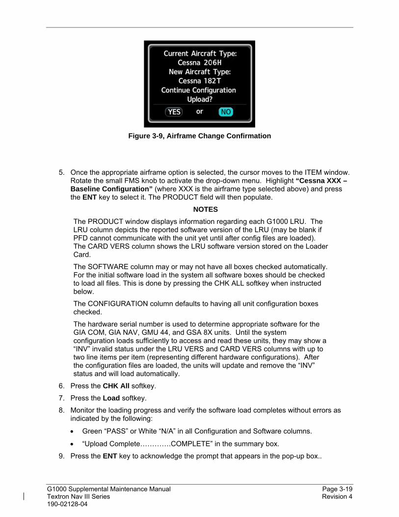
G1000 Supplemental Maintenance Manual Page 3-19 Textron Nav III Series Revision 4 190-02128-04
Figure 3-9, Airframe Change Confirmation
5. Once the appropriate airframe option is selected, the cursor moves to the ITEM window. Rotate the small FMS knob to activate the drop-down menu. Highlight “Cessna XXX – Baseline Configuration” (where XXX is the airframe type selected above) and press the ENT key to select it. The PRODUCT field will then populate.
NOTES
The PRODUCT window displays information regarding each G1000 LRU. The LRU column depicts the reported software version of the LRU (may be blank if PFD cannot communicate with the unit yet until after config files are loaded). The CARD VERS column shows the LRU software version stored on the Loader Card.
The SOFTWARE column may or may not have all boxes checked automatically. For the initial software load in the system all software boxes should be checked to load all files. This is done by pressing the CHK ALL softkey when instructed below.
The CONFIGURATION column defaults to having all unit configuration boxes checked.
The hardware serial number is used to determine appropriate software for the GIA COM, GIA NAV, GMU 44, and GSA 8X units. Until the system configuration loads sufficiently to access and read these units, they may show a “INV” invalid status under the LRU VERS and CARD VERS columns with up to two line items per item (representing different hardware configurations). After the configuration files are loaded, the units will update and remove the “INV” status and will load automatically.
6. Press the CHK All softkey.
7. Press the Load softkey.
8. Monitor the loading progress and verify the software load completes without errors as indicated by the following:
Green “PASS” or White “N/A” in all Configuration and Software columns.
“Upload Complete………….COMPLETE” in the summary box.
9. Press the ENT key to acknowledge the prompt that appears in the pop-up box..

G1000 Supplemental Maintenance Manual Page 3-20 Textron Nav III Series Revision 4 190-02128-04
GSU 75 Software/Configuration Loading (if installed)
Follow this procedure to configure the GSU 75 ADAHRS.
Move the cursor to the Item window and rotate FMS inner knob to display drop down menu. Highlight “Baseline Option – GSU75 Installation” and press the ENT key to select it.
Press the CHK All softkey.
Press the Load softkey.
Monitor the loading progress and verify the software load completes without errors as indicated by the following:
Green “PASS” or White “N/A” in all Configuration and Software columns.
“Upload Complete………….COMPLETE” in the summary box.
Press the ENT key to acknowledge the prompt that appears in the pop-up box.
GTX 335 Transponder Software/Configuration Loading (if installed)
Follow this procedure to configure the GTX 335 transponder in the aircraft. Do not follow the procedures in this section if a GTX 335 is not installed in the aircraft.
Move the cursor to the Item window and rotate FMS inner knob to display drop down menu. Highlight “Baseline Option – GTX 335 Installation” and press the ENT key to select it.
Press the CHK All softkey.
Press the Load softkey.
Monitor the loading progress and verify the software load completes without errors as indicated by the following:
Green “PASS” in the Configuration and Software columns for each item loaded.
“Upload Complete………….COMPLETE” in the summary box.
Press the ENT key to acknowledge the prompt that appears in the pop-up box.

G1000 Supplemental Maintenance Manual Page 3-21 Textron Nav III Series Revision 4 190-02128-04
GTX 345 without GTS 800 Transponder Software/Configuration Loading (if installed)
Follow this procedure to configure the GTX 345 transponder in the aircraft in aircraft without a GTS 800. Do not follow the procedures in this section if a GTX 345 is not installed in the aircraft or if the GTX 345 is installed with a GTS 800.
Move the cursor to the Item window and rotate FMS inner knob to display drop down menu. Highlight “Baseline Option – GTX 345 Installation, without GTS 800” and press the ENT key to select it.
Press the CHK All softkey.
Press the Load softkey.
Monitor the loading progress and verify the software load completes without errors as indicated by the following:
Green “PASS” in the Configuration and Software columns for each item loaded.
“Upload Complete………….COMPLETE” in the summary box.
Press the ENT key to acknowledge the prompt that appears in the pop-up box.
GTX 345 with GTS 800 Transponder Software/Configuration Loading (if installed) Follow this procedure to configure the GTX 345 transponder in the aircraft in those aircraft that have a GTX 345 and a GTS 800 installed Do not follow the procedures in this section if a GTX 345 is not installed in the aircraft or if there is a GTX 345 installed without a GTS 800 installed.
Move the cursor to the Item window and rotate FMS inner knob to display drop down menu. Highlight “Baseline Option – GTX 345 Installation, with GTS 800” and press the ENT key to select it.
Press the CHK All softkey.
Press the Load softkey.
Monitor the loading progress and verify the software load completes without errors as indicated by the following:
Green “PASS” in the Configuration and Software columns for each item loaded.
“Upload Complete………….COMPLETE” in the summary box.
Press the ENT key to acknowledge the prompt that appears in the pop-up box.

G1000 Supplemental Maintenance Manual Page 3-22 Textron Nav III Series Revision 4 190-02128-04
GDL 69A SXM Software/Configuration Loading (if installed)
Follow this procedure to configure the GDL 69A SXM Receiver. Do not follow the procedures in this section if a GDL69A SXM unit is not installed.
Rotate the large FMS knob until the Item field is highlighted, rotate the small FMS knob to activate the drop down menu. Rotate the small FMS knob and select “Baseline Option – GDL 69A SXM Installation” and press the ENT key to select it.
Press the CHK All softkey.
Press the Load softkey.
Monitor the loading progress and verify the software load completes without errors as indicated by the following:
Green “PASS” in the Configuration and Software columns for each item loaded.
“Upload Complete………….COMPLETE” in the summary box.
Press the ENT key to acknowledge the prompt that appears in the pop-up box.
GMA 1360 Software/Configuration Loading
Follow this procedure to configure the GMA 1360 Audio panel.
1. Rotate the large FMS knob until the Item field is highlighted, rotate the small FMS knob to activate the drop down menu. Rotate the small FMS knob and select “Baseline Option – GMA 1360 Installation” and press the ENT key to select it.
2. Press the CHK All softkey.
3. Press the Load softkey.
4. Monitor the loading progress and verify the software load completes without errors as indicated by the following:
Green “PASS” in the Configuration and Software columns for each item loaded.
“Upload Complete………….COMPLETE” in the summary box.
5. Press the ENT key to acknowledge the prompt that appears in the pop-up box.

G1000 Supplemental Maintenance Manual Page 3-23 Textron Nav III Series Revision 4 190-02128-04
Enhanced GFC 700 Software/Configuration Loading (if installed)
Follow this procedure to configure the GFC 700 Enhanced Autopilot. Do not follow the procedures in this section if the aircraft is not equipped with GFC 700.
1. Rotate the large FMS knob until the Item field is highlighted, rotate the small FMS knob to activate the drop down menu. Rotate the small FMS knob and select “Option – GFC 700 E-AFCS Installation” and press the ENT key to select it.
2. Press the CHK All softkey.
3. Press the Load softkey.
4. Monitor the loading progress and verify the software load completes without errors as indicated by the following:
Green “PASS” in the Configuration and Software columns for each item loaded.
“Upload Complete………….COMPLETE” in the summary box.
Press the ENT key to acknowledge the prompt that appears in the pop-up box.
GFC 700 Software/Configuration Loading (if installed)
Follow this procedure to configure the GFC 700 Autopilot. Do not follow the procedures in this section if the aircraft is not equipped with GFC 700.
Rotate the large FMS knob until the Item field is highlighted, rotate the small FMS knob to activate the drop down menu. Rotate the small FMS knob and select “Option – GFC 700 Installation” and press the ENT key to select it.
Press the CHK All softkey.
Press the Load softkey.
Monitor the loading progress and verify the software load completes without errors as indicated by the following:
Green “PASS” in the Configuration and Software columns for each item loaded.
“Upload Complete………….COMPLETE” in the summary box.
Press the ENT key to acknowledge the prompt that appears in the pop-up box.

G1000 Supplemental Maintenance Manual Page 3-24 Textron Nav III Series Revision 4 190-02128-04
Flight Stream 510 Configuration Loading (if installed)
Follow this procedure to configure the system to use the FS 510 WiFI/Bluetooth datalink. Do not follow the procedures in this section if the aircraft is not equipped with a FS 510.
Rotate the large FMS knob until the Item field is highlighted, rotate the small FMS knob to activate the drop down menu. Rotate the small FMS knob and select “Option – Enable FS510” and press the ENT key to select it.
Press the CHK All softkey.
Press the Load softkey.
Monitor the loading progress and verify the software load completes without errors as indicated by the following:
Green “PASS” in the Configuration column for each item loaded.
“Upload Complete………….COMPLETE” in the summary box.
Press the ENT key to acknowledge the prompt that appears in the pop-up box.
CAN Bus Fuel Level Sensors (if installed)
Follow this procedure to configure the system to use CAN Bus Fuel Level Sensors. Do not follow the procedures in this section if the aircraft is not equipped with CAN Bus Fuel Level Sensors.
Rotate the large FMS knob until the Item field is highlighted, rotate the small FMS knob to activate the drop down menu. Rotate the small FMS knob and select “Option – CAN BUS FUEL LEVEL SENSORS” and press the ENT key to select it.
Press the CHK All softkey.
Press the Load softkey.
Monitor the loading progress and verify the software load completes without errors as indicated by the following:
Green “PASS” in the Configuration and Software columns for each item loaded.
“Upload Complete………….COMPLETE” in the summary box.
Press the ENT key to acknowledge the prompt that appears in the pop-up box.

G1000 Supplemental Maintenance Manual Page 3-25 Textron Nav III Series Revision 4 190-02128-04
GSR 56 loading (if installed)
Follow this procedure to load the GSR 56 satellite phone/text/weather datalink transceiver. Do not follow the procedures in this section if the aircraft is not equipped with a GSR 56.
Rotate the large FMS knob until the Item field is highlighted, rotate the small FMS knob to activate the drop down menu. Rotate the small FMS knob and select “Option – GSR 56 Installation” and press the ENT key to select it.
Press the CHK All softkey.
Press the Load softkey.
Monitor the loading progress and verify the software load completes without errors as indicated by the following:
Green “PASS” in the Configuration and Software columns for each item loaded.
“Upload Complete………….COMPLETE” in the summary box.
6. Press the ENT key to acknowledge the prompt that appears in the pop-up box.
GTS 800 without GTX 345 Software/Configuration Loading (if installed)
Follow this procedure to configure the GTS 800 Traffic System. Do not follow the procedures in this section if the aircraft is not equipped with GTS 800 or if it is equipped with a GTS 800 and a GTX 345.
NOTE
Configuration of the GTS Processor will require entering the aircraft registration number into the unit using Section 3.8, “Aircraft Registration Number Entry”.
Rotate the large FMS knob until the Item field is highlighted, rotate the small FMS knob to activate the drop down menu. Rotate the small FMS knob and select “Option – GTS 800 Installation, without GTX 345” and press the ENT key to select it.
Press the CHK All softkey.
Press the Load softkey.
Monitor the loading progress and verify the software load completes without errors as indicated by the following:
Green “PASS” in the Configuration and Software columns for each item loaded.
“Upload Complete………….COMPLETE” in the summary box.
Press the ENT key to acknowledge the prompt that appears in the pop-up box.

G1000 Supplemental Maintenance Manual Page 3-26 Textron Nav III Series Revision 4 190-02128-04
GTS 800 with GTX 345 Software/Configuration Loading (if installed)
Follow this procedure to configure the GTS 800 Traffic System. Do not follow the procedures in this section if the aircraft is not equipped with GTS 800 or if it is equipped with a GTS 800 and without a GTX 345.
NOTE
Configuration of the GTS Processor will require entering the aircraft registration number into the unit using Section 3.8, “Aircraft Registration Number Entry”.
Rotate the large FMS knob until the Item field is highlighted, rotate the small FMS knob to activate the drop down menu. Rotate the small FMS knob and select “Option – GTS 800 Installation, with GTX 345” and press the ENT key to select it.
Press the CHK All softkey.
Press the Load softkey.
Monitor the loading progress and verify the software load completes without errors as indicated by the following:
Green “PASS” in the Configuration and Software columns for each item loaded.
“Upload Complete………….COMPLETE” in the summary box.
Press the ENT key to acknowledge the prompt that appears in the pop-up box.
WX500 Configuration Loading (if installed)
Follow this procedure to configure the system to utilize the WX 500. Do not follow the procedures in this section if the aircraft is not equipped with WX500.
Rotate the large FMS knob until the Item field is highlighted, rotate the small FMS knob to activate the drop down menu. Rotate the small FMS knob and select “Option – WX500 Installation” and press the ENT key to select it.
Press the CHK All softkey.
Press the Load softkey.
Monitor the loading progress and verify the software load completes without errors as indicated by the following:
Green “PASS” in the Configuration and Software columns for each item loaded.
“Upload Complete………….COMPLETE” in the summary box.
Press the ENT key to acknowledge the prompt that appears in the pop-up box.
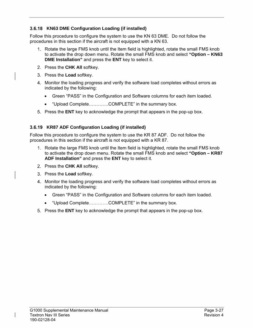
G1000 Supplemental Maintenance Manual Page 3-27 Textron Nav III Series Revision 4 190-02128-04
KN63 DME Configuration Loading (if installed)
Follow this procedure to configure the system to use the KN 63 DME. Do not follow the procedures in this section if the aircraft is not equipped with a KN 63.
Rotate the large FMS knob until the Item field is highlighted, rotate the small FMS knob to activate the drop down menu. Rotate the small FMS knob and select “Option – KN63 DME Installation” and press the ENT key to select it.
Press the CHK All softkey.
Press the Load softkey.
Monitor the loading progress and verify the software load completes without errors as indicated by the following:
Green “PASS” in the Configuration and Software columns for each item loaded.
“Upload Complete………….COMPLETE” in the summary box.
Press the ENT key to acknowledge the prompt that appears in the pop-up box.
KR87 ADF Configuration Loading (if installed)
Follow this procedure to configure the system to use the KR 87 ADF. Do not follow the procedures in this section if the aircraft is not equipped with a KR 87.
Rotate the large FMS knob until the Item field is highlighted, rotate the small FMS knob to activate the drop down menu. Rotate the small FMS knob and select “Option – KR87 ADF Installation” and press the ENT key to select it.
Press the CHK All softkey.
Press the Load softkey.
Monitor the loading progress and verify the software load completes without errors as indicated by the following:
Green “PASS” in the Configuration and Software columns for each item loaded.
“Upload Complete………….COMPLETE” in the summary box.
Press the ENT key to acknowledge the prompt that appears in the pop-up box.

G1000 Supplemental Maintenance Manual Page 3-28 Textron Nav III Series Revision 4 190-02128-04
GRS 77 and GDC 74 Software/Configuration Loading (if installed)
Follow this procedure to configure the system for GRS 77 and GDC 74. Do not follow the procedures in this section if the aircraft is not equipped with the GRS 77 and GDC 74.
Rotate the large FMS knob until the Item field is highlighted, rotate the small FMS knob to activate the drop down menu. Rotate the small FMS knob and select “Baseline Option – Legacy – GRS77 and GDC74 Installation” and press the ENT key to select it.
Press the CHK All softkey.
Press the Load softkey.
Monitor the loading progress and verify the software load completes without errors as indicated by the following:
Green “PASS” in the Configuration and Software columns for each item loaded.
“Upload Complete………….COMPLETE” in the summary box.
Press the ENT key to acknowledge the prompt that appears in the pop-up box.
GTX 33 ES Software/Configuration Loading (if installed)
Follow this procedure to configure the system to use a GTX 33 ES Transponder. Do not follow the procedures in this section if the aircraft is not equipped with a GTX 33 ES.
Rotate the large FMS knob until the Item field is highlighted, rotate the small FMS knob to activate the drop down menu. Rotate the small FMS knob and select “Baseline Option – Legacy – GTX 33 ES Installation” and press the ENT key to select it.
Press the CHK All softkey.
Press the Load softkey.
Monitor the loading progress and verify the software load completes without errors as indicated by the following:
Green “PASS” in the Configuration and Software columns for each item loaded.
“Upload Complete………….COMPLETE” in the summary box.
Press the ENT key to acknowledge the prompt that appears in the pop-up box.

G1000 Supplemental Maintenance Manual Page 3-29 Textron Nav III Series Revision 4 190-02128-04
GDL 69 Software/Configuration Loading (if installed)
Follow this procedure to configure the GDL 69 Receiver. Do not follow the procedures in this section if a GDL69 unit is not installed or if a GDL 69A SXM unit is installed.
Rotate the large FMS knob until the Item field is highlighted, rotate the small FMS knob to activate the drop down menu. Rotate the small FMS knob and select “Baseline Option – Legacy – GDL 69 Installation” and press the ENT key to select it.
Press the CHK All softkey.
Press the Load softkey.
Monitor the loading progress and verify the software load completes without errors as indicated by the following:
Green “PASS” in the Configuration and Software columns for each item loaded.
“Upload Complete………….COMPLETE” in the summary box.
Press the ENT key to acknowledge the prompt that appears in the pop-up box.
Disable CO Guardian Configuration Loading (if CO Guardian not installed)
Follow this procedure to disable the CO Guardian (if a CO Guardian is not installed). Do not follow the procedures in this section if the aircraft is equipped with a CO Guardian.
Rotate the large FMS knob until the Item field is highlighted, rotate the small FMS knob to activate the drop down menu. Rotate the small FMS knob and select “Option – Disable CO Guardian Installation” and press the ENT key to select it.
Press the CHK All softkey.
Press the Load softkey.
Monitor the loading progress and verify the software load completes without errors as indicated by the following:
Green “PASS” in the Configuration and Software columns for each item loaded.
“Upload Complete………….COMPLETE” in the summary box.
Press the ENT key to acknowledge the prompt that appears in the pop-up box.
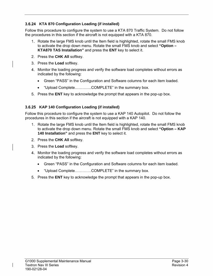
G1000 Supplemental Maintenance Manual Page 3-30 Textron Nav III Series Revision 4 190-02128-04
KTA 870 Configuration Loading (if installed)
Follow this procedure to configure the system to use a KTA 870 Traffic System. Do not follow the procedures in this section if the aircraft is not equipped with a KTA 870.
Rotate the large FMS knob until the Item field is highlighted, rotate the small FMS knob to activate the drop down menu. Rotate the small FMS knob and select “Option – KTA870 TAS Installation” and press the ENT key to select it.
Press the CHK All softkey.
Press the Load softkey.
Monitor the loading progress and verify the software load completes without errors as indicated by the following:
Green “PASS” in the Configuration and Software columns for each item loaded.
“Upload Complete………….COMPLETE” in the summary box.
Press the ENT key to acknowledge the prompt that appears in the pop-up box.
KAP 140 Configuration Loading (if installed)
Follow this procedure to configure the system to use a KAP 140 Autopilot. Do not follow the procedures in this section if the aircraft is not equipped with a KAP 140.
Rotate the large FMS knob until the Item field is highlighted, rotate the small FMS knob to activate the drop down menu. Rotate the small FMS knob and select “Option – KAP 140 Installation” and press the ENT key to select it.
Press the CHK All softkey.
Press the Load softkey.
Monitor the loading progress and verify the software load completes without errors as indicated by the following:
Green “PASS” in the Configuration and Software columns for each item loaded.
“Upload Complete………….COMPLETE” in the summary box.
Press the ENT key to acknowledge the prompt that appears in the pop-up box.

G1000 Supplemental Maintenance Manual Page 3-31 Textron Nav III Series Revision 4 190-02128-04
Pre BP 2007 CI 2480-400 Antenna Configuration Loading (if installed)
Follow this procedure to configure the system to use a CI 2480-400 Antenna (Pre BP 2007 aircraft). Do not follow the procedures in this section if the aircraft is not a Pre-BP 2007 Aircraft with CI 2480-400 Antenna installed.
Rotate the large FMS knob until the Item field is highlighted, rotate the small FMS knob to activate the drop down menu. Rotate the small FMS knob and select “Option – Pre BP 2007 Comant CI 2480-400 Antenna Configuration” and press the ENT key to select it.
Press the CHK All softkey.
Press the Load softkey.
Monitor the loading progress and verify the software load completes without errors as indicated by the following:
Green “PASS” in the Configuration and Software columns for each item loaded.
“Upload Complete………….COMPLETE” in the summary box.
Press the ENT key to acknowledge the prompt that appears in the pop-up box.
BP 2007 CI 2580-410 Antenna Configuration Loading (if installed)
Follow this procedure to configure the system to use a CI 2580-410 Antenna (BP 2007 aircraft). Do not follow the procedures in this section if the aircraft is not a BP 2007 Aircraft with CI 2580-410 Antenna installed.
Rotate the large FMS knob until the Item field is highlighted, rotate the small FMS knob to activate the drop down menu. Rotate the small FMS knob and select “Option – BP 2007 Comant CI 2580-410 Antenna Configuration” and press the ENT key to select it.
Press the CHK All softkey.
Press the Load softkey.
Monitor the loading progress and verify the software load completes without errors as indicated by the following:
Green “PASS” in the Configuration and Software columns for each item loaded.
“Upload Complete………….COMPLETE” in the summary box.
Press the ENT key to acknowledge the prompt that appears in the pop-up box.

G1000 Supplemental Maintenance Manual Page 3-32 Textron Nav III Series Revision 4 190-02128-04
Initialize Fuel Cal Data (Only for CAN Bus Fuel sensors before fuel cal)
Follow this procedure to initialize fuel cal data. This section is only for aircraft with CAN Bus Fuel Sensor and only before the fuel calibration is completed.
Rotate the large FMS knob until the Item field is highlighted, rotate the small FMS knob to activate the drop down menu. Rotate the small FMS knob and select “Option – INITIALIZE FUEL CAL DATA (only for CAN Bus sensors before fuel cal)” and press the ENT key to select it.
Press the CHK All softkey.
Press the Load softkey.
Monitor the loading progress and verify the software load completes without errors as indicated by the following:
Green “PASS” in the Configuration and Software columns for each item loaded.
“Upload Complete………….COMPLETE” in the summary box.
Press the ENT key to acknowledge the prompt that appears in the pop-up box.
Delete CAN Fuel Sensor Fuel Calibration (if installed)
Follow this procedure to delete the CAN Bus Fuel Sensor Fuel Calibration.
Rotate the large FMS knob until the Item field is highlighted, rotate the small FMS knob to activate the drop down menu. Rotate the small FMS knob and select “Option – Delete CAN Fuel Sensor Fuel Calibration” and press the ENT key to select it.
Press the CHK All softkey.
Press the Load softkey.
Monitor the loading progress and verify the software load completes without errors as indicated by the following:
Green “PASS” in the Configuration and Software columns for each item loaded.
“Upload Complete………….COMPLETE” in the summary box.
Press the ENT key to acknowledge the prompt that appears in the pop-up box.
Save Configuration
1. Press the UPDT CFG softkey at the bottom of the SYSTEM UPLOAD page.
2. Press the ENT key to select YES in the pop-up window to start the update.
3. When the config module update is done, press the ENT key to select OK in the pop-up window to close it.
4. Open PFD circuit breakers, remove the software loader card.

G1000 Supplemental Maintenance Manual Page 3-33 Textron Nav III Series Revision 4 190-02128-04
3.7 Feature Enablement
This section describes how to unlock or enable optional features. The installer will only load the sections for the features they require. For installing all feature enablement cards, the PFD and the MFD must be in configuration mode.
The G1000 has various features that require the use of unlock/enable cards to activate the feature. Throughout this document these cards are generically referred to as ‘enablement cards’. In some cases, the actual label on the physical card may say ‘unlock’.
If uncertain what SD Card to use, the technician must verify the card part number on the General Arrangement drawing prior to use to assure the correct feature is unlocked.
ChartView Feature Enablement
Follow this procedure to activate Jeppesen ChartView. Enabling this feature, allows the pilot to switch between Garmin FliteCharts and Jeppesen ChartView products.
NOTES
The required ChartView databases are subscription-based and need to be procured by the installing agency from the Garmin or Jeppesen website. The ChartView database is not present in a new display.
Insert the ChartView Enablement card in the top slot of the PFD and power on the PFD in configuration mode.
If a message appears on the PFD stating an “arfrm_imgs.zip” file is not present, follow the on screen instructions to continue. This file will be loaded in Section 3.10
On the PFD, select the “System Upload” page using the small FMS knob.
Push in the FMS knob to activate the cursor in the Group field. Rotate the small FMS knob to highlight “Configuration Files” and press the ENT key to select it.
In the ITEM window, rotate the small FMS knob to highlight “Enable ChartView” and press the ENT key to select it.
Press the Load softkey.
Monitor load progress. Verify software load completes without errors as indicated by the following:
Green “PASS” in the Configuration column for each item loaded.
“Upload Complete………….COMPLETE” in the summary box.
Press the ENT key to acknowledge the prompt that appears in the pop-up box.
Open the PFD circuit breakers and remove the ChartView enablement card.

G1000 Supplemental Maintenance Manual Page 3-34 Textron Nav III Series Revision 4 190-02128-04
Synthetic Vision System Enablement
Follow this procedure to enable the Synthetic Vision feature.
Insert the SVS Enablement card in the top slot of the PFD and power on the PFD in configuration mode.
If a message appears on the PFD stating an “arfrm_imgs.zip” file is not present, follow the on screen instructions to continue. This file will be loaded in Section 3.10.
On the PFD, select the “System Upload” page using the small FMS knob.
Push in the FMS knob to activate the cursor in the Group field. Rotate the small FMS knob to highlight “Configuration Files” and press the ENT key to select it.
In the ITEM window, rotate the small FMS knob to highlight “Enable SVS Single PFD” and press the ENT key to select it.
Press the Load softkey.
Monitor load progress. Verify software load completes without errors as indicated by the following:
Green “PASS” in the Configuration column for each item loaded.
“Upload Complete………….COMPLETE” in the summary box.
Press the ENT key to acknowledge the prompt that appears in the pop-up box.
Open the PFD circuit breakers and remove SVS enablement card.
SurfaceWatch Enablement
Follow this procedure to enable the SurfaceWatch feature.
Insert the SurfaceWatch Enablement card in the top slot of the PFD and power on the PFD in configuration mode.
If a message appears on the PFD stating an “arfrm_imgs.zip” file is not present, follow the on screen instructions to continue. This file will be loaded in Section 3.10.
On PFD, select the “System Upload” page using the small FMS knob.
Push in the FMS knob to activate the cursor in the Group field. Rotate the small FMS knob to highlight “Enable_SurfaceWatch” and press the ENT key to select it.
In the ITEM window, rotate the small FMS knob to highlight “SurfaceWatch Feature Enable” and press the ENT key to select it.
Press the Load softkey.
Monitor load progress. Verify software load completes without errors as indicated by the following:
Green “PASS” in the Configuration column for each item loaded.
“Upload Complete………….COMPLETE” in the summary box.
Press the ENT key to acknowledge the prompt that appears in the pop-up box.
Open PFD circuit breaker and remove the SurfaceWatch enablement card.

G1000 Supplemental Maintenance Manual Page 3-35 Textron Nav III Series Revision 4 190-02128-04
TAWS-B Enablement
Follow this procedure to enable the TAWS-B feature.
Insert the TAWS-B Enablement card in the top slot of the PFD, power on the PFD in configuration mode.
If a message appears on the PFD stating an “arfrm_imgs.zip” file is not present, follow the on screen instructions to continue. This file will be loaded in Section 3.10.
On the PFD, select the “System Upload” page using the small FMS knob.
Push in the FMS knob to activate the cursor in the Group field. Rotate the small FMS knob to highlight “Configuration Files” and press the ENT key to select it.
In the ITEM window, rotate the small FMS knob to highlight “Enable TAWS” and press the ENT key to select it.
Press the Load softkey.
Monitor load progress. Verify software load completes without errors as indicated by the following:
Green “PASS” in the Configuration column for each item loaded.
“Upload Complete………….COMPLETE” in the summary box.
Press the ENT key to acknowledge the prompt that appears in the pop-up box.
Open the PFD circuit breaker and remove TAWS-B enablement card.
Enhanced Search and Rescue Enablement
Follow this procedure to enable the Enhanced Search and Rescue (SAR) feature.
Insert the Enhanced SAR Enablement card in the top slot of the PFD, power on PFD in configuration mode.
If a message appears on the PFD stating an “arfrm_imgs.zip” file is not present, follow the on screen instructions to continue. This file will be loaded in Section 3.10.
On the PFD, select the “System Upload” page using the small FMS knob.
Push in the FMS knob to activate the cursor in the Group field. Rotate the small FMS knob to highlight “Enhanced SAR” and press the ENT key to select it.
In the ITEM window, rotate the small FMS knob to highlight “Enhanced Search and Rescue” and press the ENT key to select it.
Press the Load softkey.
Monitor load progress. Verify software load completes without errors as indicated by the following:
Green “PASS” in the Configuration column for each item loaded.
“Upload Complete………….COMPLETE” in the summary box.
Press the ENT key to acknowledge the prompt that appears in the pop-up box.
Open the PFD circuit breaker and remove Enhanced SAR enablement card.

G1000 Supplemental Maintenance Manual Page 3-36 Textron Nav III Series Revision 4 190-02128-04
Search and Rescue Enablement (not required if enhanced SAR is enabled)
Follow this procedure to enable the Search and Rescue (SAR) feature.
Insert the SAR Enablement card in the top slot of the PFD, power on PFD in configuration mode.
If a message appears on the PFD stating an “arfrm_imgs.zip” file is not present, follow the on screen instructions to continue. This file will be loaded in Section 3.10.
On the PFD, select the “System Upload” page using the small FMS knob.
Push in the FMS knob to activate the cursor in the Group field. Rotate the small FMS knob to highlight “Configuration Files” and press the ENT key to select it.
In the ITEM window, rotate the small FMS knob to highlight “Enable SAR” and press the ENT key to select it.
Press the Load softkey.
Monitor load progress. Verify software load completes without errors as indicated by the following:
Green “PASS” in the Configuration column for each item loaded.
“Upload Complete………….COMPLETE” in the summary box.
Press the ENT key to acknowledge the prompt that appears in the pop-up box.
Open the PFD circuit breaker and remove the SAR enablement card.
Enhanced AFCS Enablement
Follow this procedure to enable the Enhanced AFCS feature.
Insert the Enhanced AFCS Enablement card in the top slot of the PFD, power on PFD in configuration mode.
If a message appears on the PFD stating an “arfrm_imgs.zip” file is not present, follow the on screen instructions to continue. This file will be loaded in Section 3.7.
On the PFD, select the “System Upload” page using the small FMS knob.
Push in the FMS knob to activate the curser in the Group field. Rotate the small FMS knob to highlight “Enhanced AFCS” and press the ENT key to select it.
In the ITEM window, rotate the small FMS knob to highlight “Enable Enhanced AFCS” and press the ENT key to select it.
Press the Load softkey.
Monitor load progress. Verify software load completes without errors as indicated by the following:
Green “PASS” in the Configuration column for each item loaded.
“Upload Complete………….COMPLETE” in the summary box.
Press the ENT key to acknowledge the prompt that appears in the pop-up box.
Open the PFD circuit breaker and remove the Enhanced AFCS enablement card.

G1000 Supplemental Maintenance Manual Page 3-37 Textron Nav III Series Revision 4 190-02128-04
3.8 Aircraft Registration Number Entry and Flight ID Configuration
NOTE
Steps to complete the aircraft registration entry and Flight ID configuration are dependent on transponder equipment installed. Choose the appropriate procedure from Section 3.8.1 or 3.8.2 to complete the aircraft registration entry.
Aircraft Equipped with GTX 33
Aircraft Registration Number Entry
Place the PFD in configuration mode, if not already there. Select the AIRCRAFT CONFIGURATION page on the PFD.
Activate the cursor to select the” AIRCRAFT REGISTRATION” field and enter the aircraft’s tail number.
If the ICAO Address field does not auto-fill, rotate the large FMS knob to select the “ICAO ADDRESS” and enter the aircraft’s 24 bit ICAO address.
If applicable, rotate the large FMS knob to select the “ICAO REGION” field and select the appropriate ICAO region.
If applicable, rotate the large FMS knob to select the “DOMAIN IDENTIFIER” field and enter the number. Press the ENT key to save. Otherwise, leave blank.
Rotate the large FMS knob to select the “VFR CODE” field and enter the desired code that will become active when the VFR key on the GDU is pressed.
Press the SET GTX1 softkey and acknowledge the PFD prompt by pressing the ENT key.
Press the SET GTS softkey (if present) and acknowledge the PFD prompt by pressing the ENT key.
After completing transponder configuration, deactivate the cursor.
Flight ID Configuration
1. Select the GTX Group and the TRANSPONDER CONFIGURATION page on the PFD.
2. Activate the cursor and select the “FLIGHT ID TYPE” field.
3. Rotate the small FMS knob to activate the drop-down menu.
4. Select “PFD ENTRY” and press the ENT key.
5. After completing transponder configuration, deactivate the cursor.

G1000 Supplemental Maintenance Manual Page 3-38 Textron Nav III Series Revision 4 190-02128-04
Aircraft Equipped with GTX 335 or GTX 345
Aircraft Registration Number Entry
Insert the software loader card into the top slot of the PFD.
Place the PFD in configuration mode.
Press the NO softkey (number 11 softkey) to acknowledge the following prompt.
Rotate the small FMS knob, select the AIRCRAFT CONFIGURATION page on PFD.
Activate the cursor to select the “AIRCRAFT REGISTRATION” field and enter the aircraft’s tail number.
If the ICAO Address field does not auto-fill, rotate the large FMS knob to select the “ICAO ADDRESS” and enter the aircraft’s 24 bit ICAO address.
If applicable, rotate the large FMS knob to select the “ICAO REGION” field and select the appropriate ICAO region.
If applicable, rotate the large FMS knob to select the “DOMAIN IDENTIFIER” field and enter the number. Press the ENT key to save. Otherwise, leave blank
Rotate the large FMS knob to select the “VFR CODE” field and enter the desired code that will become active when the VFR key on the GDU is pressed.
Press the SET GTS softkey (if present) and acknowledge the prompt by pressing the ENT key.
Deactivate the cursor.
Rotate large FMS knob to select “GTX 3X5.”
Rotate the small FMS knob to select “Transponder Airframe Configuration” page.
Verify the GTX1 box at the top of the page is green and the tail number, ICAO address, IATA Airline Designator, and VFR code that were entered previously are correct.
Flight ID Configuration
1. Select the GTX 3X5 Group and the Transponder Airframe Config page on the PFD.
2. Activate the cursor and select the “Allow Flight ID Entry” field.
3. Rotate the small FMS knob to activate the drop-down menu.
4. Select “PFD ENTRY” and press the ENT key.
5. Scroll Down to highlight “SET > ACTIVE” and press the ENT key.
6. After completing transponder configuration, deactivate the cursor.

G1000 Supplemental Maintenance Manual Page 3-39 Textron Nav III Series Revision 4 190-02128-04
3.9 Configuration Manager
NOTE
All items listed in the Configuration Manager will display “Valid” in the Status column, with the exception of the GSR 56 (if installed). The GSR 56 will display “Status not supported” in the Status column.
Rotate the large FMS knob to select “SYSTEM”.
Rotate the small FMS knob to select Configuration Manager page on PFD.
Press the softkey labelled CNFM CFG on PFD.
Press the ENT key on PFD to select OK when prompted to confirm configuration as expected configuration.
Verify the fleet, aircraft expected and actual configuration IDs match.
If they do not match, repeat steps 2-4. If they match, continue to next step.
Open MFD, PFD (ESS BUS), and PFD (AVN BUS 1) circuit breakers.
3.10 Splash Screen Loading
When all software and configuration has been loaded, the splash screens must be loaded to the display units (PFD and MFD).
Insert the software loader card in the upper slot of the MFD.
Cloe MFD circuit breaker.
When prompted to update system files, press the NO softkey.
When prompted to update splash screen files, press the YES softkey.
When the SYSTEM STATUS configuration page appears, Open the MFD circuit breaker.
Remove the loader card from the MFD and insert it into the upper slot of the PFD.
Close PFD (ESS BUS) circuit breaker.
When prompted to update system files, press the NO softkey.
When prompted to update splash screen files, press the YES softkey.
When the SYSTEM STAUTS configuration page appears, Open PFD (ESS BUS) circuit breaker.

G1000 Supplemental Maintenance Manual Page 3-40 Textron Nav III Series Revision 4 190-02128-04
3.11 Database Loading
Follow this procedure to load the databases.
Obtain the following databases from fly.garmin.com and install on a blank 16GB or larger card or by obtaining Garmin SD Card p/n 010-00474-50. Databases with an asterisk are not included on the p/n 010-00474-50 SD card. When obtaining the databases from fly.garmin.com and using SD cards smaller than 16GB, you may need to use multiple cards (or reuse one) to load all the databases into the G1000 system.
a. Terrain (Worldwide, 4.9 Arc Second, TBD2 format)
b. Obstacle (US/Canada/Europe, OBD2 format)
c. AOPA Airport Directory (US)
d. AC-U-KWIK Airport Directory*
e. SafeTaxi (US, North America*, Canada*, Europe*, Full Coverage*)
f. Basemap (Worldwide)
g. Garmin FliteCharts (US, Canada*, Europe*)
h. Jeppesen ChartView*
i. IFR/VFR Charts (US)
j. Navigation*
With the displays off, insert the SD card into the MFD bottom slot.
Apply power to the PFD and the MFD.
On the MFD, database verification messages may appear. If so, follow the on-screen instructions to continue.
Go to the MFD Aux - Databases page to monitor the automatic database update progress. The new databases will show “Syncing” to the Standby column. After the databases are synchronized, the system will verify them for use by showing “Verifying” in the Standby column. After the databases are verified, a cyan double arrow symbol will appear between the Standby and Active columns to show which databases will be transferred to Active use on the next power cycle or restart.

G1000 Supplemental Maintenance Manual Page 3-41 Textron Nav III Series Revision 4 190-02128-04
Figure 3-10, MFD Aux - Database Page DB Transfer
When all database updates are complete, the Database Update field at the top of the screen will say, “Restart avionics to activate selected standby databases.” If the engine is not running, a Restart softkey appears at the bottom of the MFD. Press Restart to cycle power on the displays. If the Restart softkey is not present, turn OFF PFD and MFD.
Remove the database update card from the top slot of the MFD.
Turn ON the displays.
The displays may state they are verifying databases at power-up. If so, follow the on-screen instructions to continue.
Go to the MFD Aux - Databases page and verify the uploaded databases transferred from the Standby column to the Active column. If any did not transfer, follow these steps to initiate a manual transfer -
a. Push the FMS knob on the MFD controller to turn on the cursor.
b. Turn the FMS knob to highlight the database to transfer to the Active column.
c. Press the ENT key on the MFD and a cyan double arrow will appear between the Standby and Active columns.
d. Restart the displays.
e. Go to the MFD Aux - Databases page and confirm the databases transferred.

G1000 Supplemental Maintenance Manual Page 3-42 Textron Nav III Series Revision 4 190-02128-04
3.12 Configuration of Navigation Map for Traffic System
With the MFD in normal mode, use the FMS knob to select the Navigation Map page then press the Map Opt softkey, the press the Traffic Softkey and ensure that the bar under the Traffic softkey turns green.
Press the MENU button on the MFD, then select “Map Settings” with the FMS knob, then press ENT.
Verify the flashing cursor highlights the GROUP field.
Turn the small FMS knob to select Traffic and press ENT on the MFD.
If not already selected, use the MFD FMS knob to make the following selections:
Traffic – On
Traffic Mode – All Traffic
Traffic Symbols – 250NM
Traffic Labels – On 250NM
Return to the Map Page by pressing the FMS knob.
3.13 Clearing Default User Settings
Open MFD, PFD (ESS BUS), and PFD (AVN BUS 1) circuit breakers.
While holding the CLR button on the PFD, close the PFD (ESS BUS) circuit breaker.
When prompted to clear user settings, select the YES softkey.
When user settings have been cleared appears on the screen, Open the PFD (ESS BUS) circuit breaker.
Wait ten seconds, then while holding the CLR button on the MFD, close the MFD circuit breaker.
When prompted to clear user settings, select the YES softkey.
When user settings have been cleared appears on the screen, open MFD circuit breaker.

G1000 Supplemental Maintenance Manual Page 3-43 Textron Nav III Series Revision 4 190-02128-04
3.14 Interface Confirmation
Lightning Detection System Configuration Load Confirmation
Coordinate the StormScope configuration with Section 8.1 “Stormscope Functional Check”.
1. With PFD in configuration mode, use the PFD large FMS knob to select OTHER and the Stormscope configuration page.
Figure 3-11, Stormscope Configuration Page
2. Activate the cursor to highlight the DATA field. Use the small FMS knob to open the drop down menu then select ‘Config’ and press ENT key on the PFD.
Figure 3-12, Stormscope Configuration
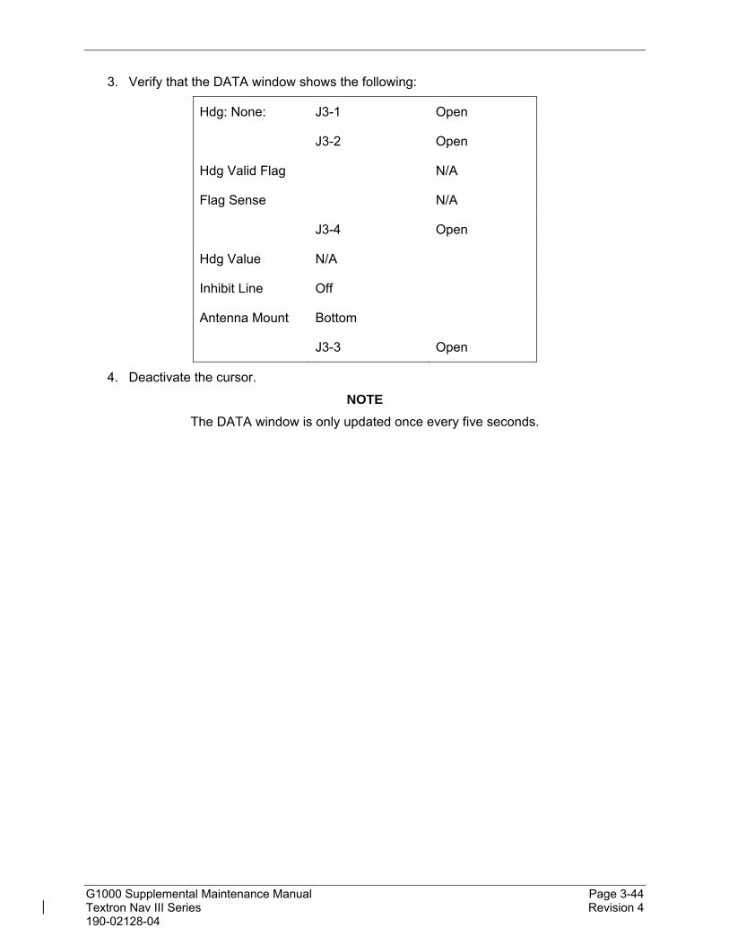
G1000 Supplemental Maintenance Manual Page 3-44 Textron Nav III Series Revision 4 190-02128-04
3. Verify that the DATA window shows the following:
Hdg: None: J3-1 Open
J3-2 Open
Hdg Valid Flag N/A
Flag Sense N/A
J3-4 Open
Hdg Value N/A
Inhibit Line Off
Antenna Mount Bottom
J3-3 Open
4. Deactivate the cursor.
NOTE
The DATA window is only updated once every five seconds.


G1000 Supplemental Maintenance Manual Page 4-2 Textron Nav III Series Revision 4 190-02128-04
4.2 Servicing Information
G1000 LRU maintenance is ‘on condition’ only. No component-level overhaul is required for this type design change.
On Condition Servicing
‘On Condition’ replacement and/or servicing should occur when an item exhibits conditions, symptoms, and/or abnormalities defined in Section 5 of this manual. Replacement and/or servicing should be made only after the technician troubleshoots the system to the extent determined necessary by using the guidance in this manual along with common avionics maintenance practices.
IMPORTANT!
It is impossible to provide guidance for every conceivable failure scenario within the scope of this manual. Every effort has been made to provide comprehensive guidance for possible failures. The information in this document should always be combined with sound aviation maintenance practices and a thorough knowledge of the system. Use sound avionics maintenance practices when working around or on G1000 equipment.
The remainder of this document is organized in the following fashion:
Section 4.3 lists maintenance requirements related to the G1000 system.
Section 6 gives instructions regarding the removal and replacement of physical G1000 equipment and parts.
Section 7 gives configuration and testing instructions to be accomplished if G1000 equipment or parts are removed or replaced.
Section 9 specifies system return-to-service procedures.
The beginning of Section 6 provides instructions to check the software part number and version of each LRU before removing a unit. Procedures in Section 7 require the same check after LRU replacement and software loading.
IMPORTANT!
All structural repairs associated with this installation are to be addressed in accordance with the Cessna Structural Repair Manual listed in Table 1-1.
NOTE
After replacing or servicing electrical components near the GMU 44 magnetometers, the Magnetometer Interference Test (reference Section 5) and Magnetometer Calibration Procedure (reference Section 7) must be performed.

G1000 Supplemental Maintenance Manual Page 4-3 Textron Nav III Series Revision 4 190-02128-04
Required Tools
The following tools are needed to perform maintenance tasks on G1000 equipment:
Calibrated Milliohm meter, OR
o Agilent 34410A Ammeter or equivalent
o Fluke 187 Voltmeter or equivalent
o Variable DC Power Supply capable of providing 1 amp current
#2 Non-Magnetic Phillips Screwdriver
3/32” Hex tool
Calibrated digital level (Required for AHRS ‘Procedure A’ Calibration)
Calibrated VHF NAV/COM/ILS ramp tester or equivalent
Calibrated transponder ramp tester or equivalent
Calibrated pitot/static ramp tester
Outdoor line-of-site to GPS satellite signals or GPS indoor repeater
Headset/microphone
Ground Power Unit (Capable of supplying 28 VDC)

G1000 Supplemental Maintenance Manual Page 4-4 Textron Nav III Series Revision 4 190-02128-04
4.3 Maintenance Intervals
Table 4-1 shows systems and items, installed by this STC, which must undergo tests or checks at specific intervals. If the interval is shown in flight time as well as calendar months, the first interval reached should be used as the limit.
IMPORTANT!
The tolerance for inspection times is the same as that stated in 5-10-00 of the Cessna Maintenance Manual applicable to the airframe.
The intention of Garmin is to align this maintenance program as best as possible with the existing Cessna Nav III inspection program. For a complete description of the Cessna inspection program, refer to the Cessna Maintenance Manuals listed in Table 1-1.
For equipment not listed here, refer to the G1000 Nav III Line Maintenance Manual.
Table 4-1, Maintenance Intervals
Item Description/Procedure Manual
Section No. Interval
G1000/GFC 700 Equipment
GDU 1054B PFD and MFD (Qty 2) or
GDU 1050 PFD and MFD (Qty 2
Removal & Replacement 6.1 On Condition
GTX 335R or GTX 345R Transponder
Removal & Replacement 6.2 On Condition
Special Inspection - Perform GTX 335R, GTX 345R test.
7.5.4 24 Calendar Months
GSU 75 ADAHRS
Removal & Replacement 6.3 On Condition
Magnetic variation database update. 0 On Condition
Special Inspection – Perform Air Data Test. 7.7.3 24 Calendar Months
GDL 69A SXM Removal & Replacement 6.4 On Condition
GMA 1360 Audio Panel
Removal & Replacement 6.6 On Condition
GEA 71B Engine/Airframe Unit
Removal & Replacement 6.10 On Condition
GSR 56 Satellite Transceiver
Removal & Replacement 6.8 On Condition
Iridium Antenna Removal & Replacement 6.9 On Condition
GSA 81 Servo Actuators
Removal & Replacement 6.12 On Condition
GSM 86 Servo Gearboxes
Removal & Replacement 6.13 On Condition
GSM 86 Servo Gearbox Spring Cartridge Torque Check
Verify that the pitch, roll, and pitch trim GSM 86 spring cartridge torque values are within acceptable limits
4.7 1000 flt-hrs or 1 year (annual inspection)
whichever occurs first

G1000 Supplemental Maintenance Manual Page 4-5 Textron Nav III Series Revision 4 190-02128-04
Item Description/Procedure Manual
Section No. Interval
G1000 Redundant Connection Check
Verify PRI and SEC power sources for PFD, GIA 1, and GSU.
Verify secondary paths for ADAHRS, engine parameters and GPS data.
Verify the operation of PFD and MFD Ethernet connections.
Verify ARINC connection between GSU 1 and MFD.
Verify DISPLAY BACKUP button function.
4.6 24 Calendar Months
G1000 Accessories Configuration Module Replacement
Removal & Replacement. 6.5 On Condition
G1000 Lightning Protection
Electrical Bonding Test
Perform the electrical bonding resistance check of G1000 equipment.
4.4.3 24 Calendar Months
4.4 Electrical Bonding Test
The following bonding tests are provided for G1000-equipped Nav III Series aircraft as a requirement beyond what is given in the 172, 182, or 206 Series Maintenance Manual.
Requirements
All G1000 equipment must be installed. Gain access for the procedure listed below in Section 4.4.3 as required and in accordance with the Cessna Nav III Series Maintenance Manuals.
Test Equipment
A milliohm meter and Kelvin probes are recommended for this test. However, an alternate method may be used to provide equivalent results by using the following procedure and a standard voltmeter, power supply with adjustable current limit, and ammeter. The test set up for this alternate method is described below.
All test equipment used for the bond checks must be calibrated.
1. Connect the positive lead of the power supply to airframe ground. Connect/touch the positive lead of the voltmeter to the same point.
NOTE
Ensure that the voltmeter and power supply probes do not touch, so as not to induce contact resistance.
2. Touch negative lead of power supply to each of the test points listed while performing Step 3. At each required point, configure the power supply to produce 1 amp before measuring voltage. (Use an ammeter to ensure current is within minimum of 1 amp ±100 milliamp at each point). Do not allow the reference current to exceed 1.5 amps for safety.

G1000 Supplemental Maintenance Manual Page 4-6 Textron Nav III Series Revision 4 190-02128-04
3. With the current set to 1A, the voltage reading will be the value of the bonding resistance. Set the voltmeter to measure millivolts and null the reading. Measure the voltage from airframe ground (step 1) to each required test points and record the voltage. (Perform Step 2 at each required point and ensure that minimum of 1 amp ±100 milliamp is present when measuring the voltage.)
TIP: When a 1A current is used all the millivolt readings are the same as milliohms, and required no further calculation of bond resistance. If 1 amp reference current cannot be maintained and is higher divide the measured voltage by current to get the resistance value. Alternatively, calculate the percentage increase in current and then reduce the measured voltage reading by the same percentage. Example: If the measured current is 1.2 amps, (20% high from the desired 1 amp current) and the measured voltage is 3.0 millivolts, then the value recorded will be 3 millivolts reduced by 20% which is 2.4 millivolts which is the same as 2.4 milliohms.
Electrical Bonding Procedure
Using one of the two measurement methods in Section 4.4.2 record the bonding measurement for the following equipment. Some equipment in the list is optional and may not be installed.
Ensure that the PFD unit, and MFD unit test points, no more than 40 mΩ is present. Ensure that at other unit test points, no more than 5 mΩ is present.
Pilot Compartment
Metal case of PFD: __________ mΩ
Metal case of MFD: __________ mΩ
GDL 69A body (182 and 206 only): __________ mΩ
GEA 71B body: __________ mΩ
GMA 1360 body: __________ mΩ
Rear Fuselage and Empennage
GDL 69A body (172 only): __________ mΩ
GSU 75 body: __________ mΩ
GTX 335R or GTX 345R body: __________ mΩ
GIA 64W body: __________ mΩ
GSR 56 body: __________ mΩ
Rear Fuselage and Wing
GSA 81 body (pitch): __________ mΩ
GSA 81 body (trim): __________ mΩ
GSA 81 body (roll): __________ mΩ

G1000 Supplemental Maintenance Manual Page 4-7 Textron Nav III Series Revision 4 190-02128-04
4.5 GSU 75 Earth Magnetic Field Updates
The GSU 75, utilizes an Earth magnetic field model which is updated once every five years. The update is expected to be available from Garmin every five years, as long as the GSU 75, remain Garmin-supported products.
The G1000 system alerts the operator that the magnetic field database is out of date by issuing the message “AHRS SERVICE – AHRS Magnetic-field model needs update”. Garmin will distribute updates as part of the navigation database cycle. If the IGRF model in the update is newer than the model installed, a prompt will appear for each GRS/GSU (Select “OK” to update the IGRF Magnetic Field Model). Use the FM Knob and ENT key to select “OK”.
4.6 G1000 Redundant Connection Check
Perform the following steps to verify the following:
(A) The primary (PRI) and secondary (SEC) power sources for the PFD, GSU (if installed) or GDC and GRS (if installed).
(B) The GSU (if installed) data path to PFD and MFD.
Note: Section B is not required if a GSU 75 is not installed. Refer to the Cessna Nav III Line Maintenance Manual for procedures if a GDC 74A and GRS 77 are installed..
(A) PRI and SEC power sources for PFD and GSU (if installed) check
1. Connect a ground power unit to the external power receptacle and turn on the ground power unit.
2. Set the BAT and AVIONICS MASTER PWR switches to ON.
3. With the G1000 system in normal mode, pull the following circuit breakers on the circuit breaker panel:
PFD (ESS BUS)
ADC/AHRS (ESS BUS)
NAV 1/ENG (ESS BUS)
4. Wait at least 5 seconds, then verify the data on the PFD remains valid and the following alert messages are not present:
GIA 1 FAIL (or any related message such as COM1, NAV1, XPDR1, GPS1)
AHRS 1 FAIL
ADC 1 FAIL
5. Close the circuit breakers listed in step 3.
6. Repeat step 4.
7. Pull the following circuit breakers on the circuit breaker panel:
PFD (AVN BUS 1)
ADC/AHRS (AVN BUS 1)
NAV 1/ENG (AVN BUS 1)
8. Wait at least 5 seconds, then repeat step 4.
9. Close the circuit breakers listed in step 7.

G1000 Supplemental Maintenance Manual Page 4-8 Textron Nav III Series Revision 4 190-02128-04
(B) AHRS and ADC data path check (when GSU 75 installed)
1. Verify there are no AHRS loss of data messages, such as:
AHRS not receiving any GPS information
AHRS not receiving backup GPS information
AHRS using backup GPS source
2. Place the G1000 system in configuration mode.
3. In the GIA page group, go to the GIA RS-232/ARINC 429 CONFIG page.
4. With GIA1 selected in the SELECT UNIT window, verify the following indicators are green checks:
RS232 Channel 1 (GDC72 #1)
RS232 Channel 6 (GRS79 #1)
ARINC 429 IN 6 (GSU75 #1)
(Ref. Section 5.1.1.2.)
5. With GIA2 selected in the SELECT UNIT window, verify the following indicators are green checks:
RS232 Channel 2 (GRS79 #1)
ARINC 429 IN 5 (GSU75 #1)
(Ref. Section 5.1.1.2.)
6. In the GDU page group, go to the GIA RS-232/ARINC 429 CONFIG page.
7. With PFD1 selected in the SELECT UNIT window, verify the following indicators are green checks:
ARINC 429 IN1 (GSU75 #1)
ARINC 429 IN2 (GDC72 #1)
(Ref. Section 5.1.1.1.)
8. With MFD selected in the SELECT UNIT window, verify the following indicators are green checks:
ARINC 429 IN1 (GSU75 #1)
ARINC 429 IN2 (GDC72 #1)
(Ref. Section 5.1.1.1.)
9. Restart the G1000 in normal mode.

G1000 Supplemental Maintenance Manual Page 4-9 Textron Nav III Series Revision 4 190-02128-04
4.7 GSM 86 Spring Cartridge Torque Check
Perform the test per Sections 4.71 or 4.7.2.
Automated Torque Check Procedure
1. Start the G1000 system in Configuration Mode and go to the GFC Page Group and select the GFC STATUS page using the FMS knob.
Figure 4-1, GFC Status Page
IMPORTANT!
It is highly recommended that the following test be performed at temperatures between 50° F and 120° F.
2. Use GIA 1 in the SELECT GIA UNIT field for these tests. Use the FMS knob to select the desired servo (Pitch, Roll, or Pitch Trim) in the SELECT SERVO AXIS field.
3. Verify that the Monitor Board and Control Board PFT status fields show PASSED.
4. Verify that the aircraft control surface to be checked is free to travel throughout its range of motion.
5. Press the Test SVO softkey on the PFD. Follow prompts to begin the test.
IMPORTANT!
Once the test starts the servo will begin to move the aircraft controls. If the test must be stopped, firmly grasp the aircraft control being moved and press the red AP DISC switch on the aircraft control wheel. If an abnormal disconnect of a servo occurs, reset the AFCS SERVO circuit breaker and repeat the test.
6. The test begins and the selected servo drives the control surface to the control stop.

G1000 Supplemental Maintenance Manual Page 4-10 Textron Nav III Series Revision 4 190-02128-04
7. Upon reaching the control stop, the test initializes and begins a 50 second data collection period, where the servo is commanded to drive at ~2.5 rpm while the servo load cell measures clutch torque.
8. Monitor the CURRENT field and verify the current displayed is greater than zero.
9. After the data is collected and processed, the test displays the results of the first direction on the PFD.
10. The servo immediately begins to drive in the opposite direction toward the opposite control stop.
11. Upon reaching the stop, the test repeats the data collection process and displays the results on the PFD.
12. Firmly grasp the aircraft control under test and push the red AP DISC button to relieve any control tension. Push the ENT key to acknowledge the COMPLETE prompt on the PFD.
13. Record the torque values in Table 4-2 or in the appropriate aircraft maintenance records.
14. Repeat this procedure for each servo axis.
15. Verify the minimum and maximum torque values measured are within the Minimum and Maximum torque values allowed for the given axis, listed in Table 4-2.
16. If the values are outside of the torque values allowed, repeat the test twice in the failed axis. If the tests do not pass, the servo gearbox must be removed from the aircraft and tested per Section 4.7.2.
Table 4-2, GSM 86 Allowable Torque Values (Automated Test)
Axis Direction
Min Measured
Torque (in-lb)
Max Measured
Torque (in-lb)
Min Allowed Torque (in-lb)
Max Allowed Torque (in-lb) Model
Roll Left 45
53
62
62
72
86
172
182
206 Right
Pitch Up 39
53
34
53
72
46
172
182
206 Down
Pitch Trim
Up 39
39
53
53
53
72
172
182
206 Down

G1000 Supplemental Maintenance Manual Page 4-11 Textron Nav III Series Revision 4 190-02128-04
Fixture Torque Check Procedure
This test is an alternative to the automated torque check procedure.
The GSM 86 servo gearbox does not have an adjustable slip clutch; however, the torque value can be measured using this procedure.
IMPORTANT!
This adjustment requires the use of the Garmin fixture, P/N T10-00110-01. For detailed operating instructions for the fixture, refer to GSA8X / GSM85(A) Installation Manual.
It is highly recommended that the following test be performed at temperatures between 50° F and 120° F.
1. Remove the GSM 86 servo gearbox as per Section 6.13.
2. Place the GSM 86 servo gearbox on the adjustment fixture and secure with the toggle clamps. Install the fixture cable between the capstan under test and the fixture capstan. Remove the slack in the cable using the tension adjustment knob. Tighten the two wingnuts on bottom of fixture while holding the top thumbscrews.
3. Attach a socket to a calibrated torque wrench of appropriate range and place on top of the fixture capstan. Adjust the wrench support fixture so that it contacts the handle in the appropriate location.
4. Connect a 2 Amp, 24 V, DC power supply to the fixture.
5. Place the solenoid switch to "on" and move the direction switch to the clockwise or counter-clockwise position. Allow the spring clutch to rotate at least one revolution in each direction (note: the capstan itself is fixed.)
6. Observe the torque reading for at least two full revolutions in each direction. Ensure the minimum and maximum torque readings are within the tolerance specified.
7. If the minimum and maximum torque values are within the specified range in Table 4-3, the GSM 86 spring cartridge is acceptable. Reinstall the GSM 86 servo gearbox per Section 6.13.
8. If the minimum and maximum torque values are not within the specified range in Table 4-3, the GSM 86 slip clutch cartridge must be replaced.
Table 4-3, GSM 86 Allowable Torque Values (Fixture Test)
Model Pitch Trim Pitch Roll
172 32 to 59 in-lb 32 to 59 in-lb 36 to 68 in-lb
182 32 to 59 in-lb 43 to 79 in-lb 43 to 79 in-lb
206 43 to 79 in-lb 27 to 51 in-lb 62 to 86 in-lb

G1000 Supplemental Maintenance Manual Page 5-1 Textron Nav III Series Revision 4 190-02128-04
5. TROUBLESHOOTING
This section provides instructions and guidance for G1000 system troubleshooting as installed in the Cessna Nav III Series.
IMPORTANT!
Sections 6, 7 and 9 provide detailed instructions on equipment removal, replacement, configuration, and return-to-service testing. Anytime a G1000 component or LRU is removed, swapped, or replaced, the technician must follow the procedures given in Sections 6, 7 and 9 to ensure proper operation of the system.
Troubleshoot the G1000 system by first identifying, then isolating the specific failure to the responsible LRU. There are several indications that the G1000 presents to the pilot or technician, showing overall system condition. A course of action should be determined based on the information presented on the display. This section shows possible scenarios likely to be encountered during normal operation and gives troubleshooting guidance to the technician to resolve problems.
Figure 5-1, Aux – System Status Page

G1000 Supplemental Maintenance Manual Page 5-2 Textron Nav III Series Revision 4 190-02128-04
The Aux – System Status page displays the following information for each LRU and sub-function:
Status: A green check is displayed for properly operating LRUs. A red ‘x’ appears when an internal LRU fault is detected and it has taken itself offline, or if the MFD cannot communicate with the LRU.
Serial Number: Each LRU serial number is displayed (functions such as COM and GS are contained within an LRU; therefore, serial numbers are not shown for these).
Current SW Version Loaded.
When troubleshooting, first check to ensure that each LRU status is ‘green’ and that the correct software is loaded in each unit. Additional airframe and database information is also displayed on this page.
5.1 System Annunciations
If data fields become invalid due to an LRU failure, the PFD/MFD typically annunciates the failure with a large red X, as shown in Figure 5-2.
Figure 5-2, System Annunciations

G1000 Supplemental Maintenance Manual Page 5-3 Textron Nav III Series Revision 4 190-02128-04
Failed Path Messages
The following message indicates there is a data path connected to the GDU (PFD or MFD) or the GIA (1 or 2) that has failed.
FAILED PATH – A data path has failed.
The FAILED PATH message is triggered by a timeout of any one digital channel.
IMPORTANT!
Once the FAILED PATH message has been triggered, it will remain on the list of messages until the next power cycle. This latching was implemented so that for intermittent failures, the message would remain at the end of the flight (to alert maintenance crew). Also, this keeps the crew from having to acknowledge message repeatedly in the case of intermittent failures.
To determine which path is causing the FAILED PATH message, start the PFD and MFD in configuration mode. Using the FMS knobs, scroll to the pages listed below.
The channels that are checked are listed on these pages in config mode:
1) GDU RS-232 / ARINC 429 CONFIG (PFD and MFD)
2) GIA RS-232 / ARINC 429 CONFIG (GIA1 and GIA2)
3) GIA CAN / RS-485 CONFIGURATION (GIA1 and GIA2)
The box next to each channel indicates the current status of the channel per the below:
Red X = data path is known to be failed
Amber question mark (?) = data path status is unknown
Green checkmark ()= data path is known to be good
The applicable data paths can be verified by viewing the following configuration mode pages.
NOTE
For paths not listed here, refer to the Cessna G1000 Nav III Line Maintenance Manual.

G1000 Supplemental Maintenance Manual Page 5-4 Textron Nav III Series Revision 4 190-02128-04
GDU ARINC 429 CONFIG Page
PFD and MFD ARINC 429
Channel LRU Indicator Status
IN 1 GSU 75 #1 (if installed)
Green PFD/GSU 75 data path is functioning correctly.
Red
PFD/GSU 75 data path is not functioning correctly.
Verify GSU 75 status is “OK” using the Aux – System Status page on the MFD. If it is not, correct condition before proceeding, reference GRS troubleshooting sections.
Load PFD configuration file.
Swap PFD and MFD to confirm if the problem is in the original PFD.
o Replace original PFD if box turns green after swapping displays.
Check the PFD/GSU 75 interconnect wiring for faults.
o Replace the GSU75 if the problem persists.
Amber PFD/GSU 75 #1 data path functionally is unknown. Reload PFD configuration file.
IN 2 GDC 72 #1
(if GSU 75 installed)
Green PFD/GSU 75 (ADC) data path is functioning correctly
Red
PFD/GSU 75 (ADC) data path is not functioning correctly.
Verify GDC status is “OK” using the Aux – System Status page on the MFD. If it is not, correct condition before proceeding, reference GSU troubleshooting sections.
Load PFD and GSU configuration files.
Swap PFD and MFD to confirm if the problem is in the original PFD.
o Replace original PFD if box turns green after swapping displays.
Check the PFD/GSU 75 interconnect wiring for faults.
Replace GSU if problem remains.
Amber PFD/GSU 75 (ADC) data path functionality is unknown. Reload PFD configuration file.

G1000 Supplemental Maintenance Manual Page 5-5 Textron Nav III Series Revision 4 190-02128-04
GIA RS-232 / ARINC 429 CONFIG Page
GIA1 RS-232
Channel LRU Indicator Status
CHNL 1 GDC 72 #1
(if GSU 75 is installed)
Green GIA1/GSU 75 (ADC) data path is functioning correctly.
Red
GIA1/GSU 75 (ADC) data path is not functioning correctly.
Load GIA1 and GSU configuration files.
Swap GIA1 and GIA2, reconfigure both GIA’s to their new locations to confirm if the problem is in the original GIA1.
o Replace original GIA1 if box turns green after swapping units.
Check the GIA1/GSU 75 interconnect wiring for faults.
Replace GSU 75 if problem remains.
Amber GIA1/GSU 75 (ADC) data path functionality is unknown. Reload GIA1 configuration files.
CHNL 5
GTX 3x5 #1 (if GTX 335 or GTX 345
installed)
Green GIA1/GTX 3X5 data path is functioning correctly.
Red
GIA1/GTX 3X5 data path is not functioning correctly.
Load GIA1 and GTX 335 or GTX 345 (as applicable) configuration files.
Swap GIA1 and GIA2, reconfigure both GIA’s to their new locations to confirm if the problem is in the original GIA1.
o Replace original GIA1 if box turns green after swapping units.
Check the GIA1/GTX 3X5 interconnect wiring for faults.
Replace GTX 335 or GTX 345 (as applicable) if problem remains.
Amber GIA1/GTX 3X5 data path functionality is unknown. Reload GIA1 configuration files.

G1000 Supplemental Maintenance Manual Page 5-6 Textron Nav III Series Revision 4 190-02128-04
GIA1 RS-232 (continued)
Channel LRU Indicator Status
CHNL 6 GRS 79 #1 (if GSU 75 installed)
Green GIA1/GSU 75 (AHRS) data path is functioning correctly.
Red
GIA1/GSU 75 (AHRS) data path is not functioning correctly.
Load GIA1 configuration files.
Swap GIA1 and GIA2, reconfigure both GIA’s to their new locations to confirm if the problem is in the original GIA1.
o Replace original GIA1 if box turns green after swapping units.
Check the GIA1/GSU 75 interconnect wiring for faults.
o Replace the GSU 75 if the problem persists.
Amber GIA1/GSU 75 (AHRS) data path functionality is unknown. Reload GIA1 configuration files.
GIA1 ARINC 429
Channel LRU Indicator Status
IN 6 GSU 75 #1 (if GSU 75 is installed)
Green GIA1/GSU 75 (ADAHRS) data path is functioning correctly.
Red
GIA1/GSU 75 (ADAHRS) data path is not functioning correctly.
Load GIA1 configuration files.
Swap GIA1 and GIA2, reconfigure both GIA’s to their new locations to confirm if the problem is in the original GIA1.
o Replace original GIA1 if box turns green after swapping units.
Check the GIA1/GSU 75 interconnect wiring for faults.
o Replace the GSU 72 if the problem persists.
Amber GIA1/GSU 75 (ADAHRS) data path functionality is unknown. Reload GIA1 configuration files.
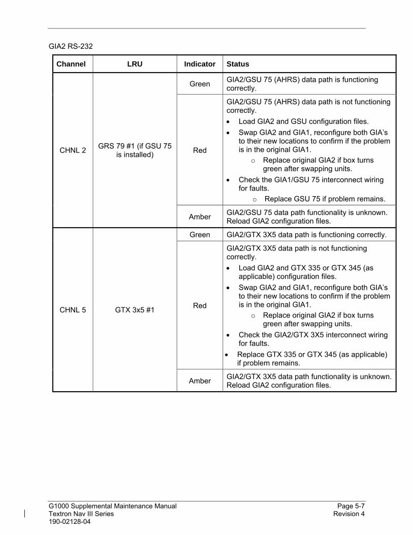
G1000 Supplemental Maintenance Manual Page 5-7 Textron Nav III Series Revision 4 190-02128-04
GIA2 RS-232
Channel LRU Indicator Status
CHNL 2 GRS 79 #1 (if GSU 75
is installed)
Green GIA2/GSU 75 (AHRS) data path is functioning correctly.
Red
GIA2/GSU 75 (AHRS) data path is not functioning correctly.
Load GIA2 and GSU configuration files.
Swap GIA2 and GIA1, reconfigure both GIA’s to their new locations to confirm if the problem is in the original GIA1.
o Replace original GIA2 if box turns green after swapping units.
Check the GIA1/GSU 75 interconnect wiring for faults.
o Replace GSU 75 if problem remains.
Amber GIA2/GSU 75 data path functionality is unknown. Reload GIA2 configuration files.
CHNL 5 GTX 3x5 #1
Green GIA2/GTX 3X5 data path is functioning correctly.
Red
GIA2/GTX 3X5 data path is not functioning correctly.
Load GIA2 and GTX 335 or GTX 345 (as applicable) configuration files.
Swap GIA2 and GIA1, reconfigure both GIA’s to their new locations to confirm if the problem is in the original GIA1.
o Replace original GIA2 if box turns green after swapping units.
Check the GIA2/GTX 3X5 interconnect wiring for faults.
Replace GTX 335 or GTX 345 (as applicable) if problem remains.
Amber GIA2/GTX 3X5 data path functionality is unknown. Reload GIA2 configuration files.

G1000 Supplemental Maintenance Manual Page 5-8 Textron Nav III Series Revision 4 190-02128-04
GIA2 ARINC 429
Channel LRU Indicator Status
IN 5 GSU 75 #1 (if GSU 75 is installed)
Green GIA2/GSU 75 data path is functioning correctly.
Red
GIA2/GSU 75 data path is not functioning correctly.
Load GIA2 and GSU 75 configuration files.
Swap GIA2 and GIA1, reconfigure both GIA’s to their new locations to confirm if the problem is in the original GIA2.
o Replace original GIA2 if box turns green after swapping units.
Check the GIA2/GSU 75 interconnect wiring for faults.
Replace GSU 75 if problem remains.
Amber GIA2/GSU 75 data path functionality is unknown. Reload GIA2 configuration files.

G1000 Supplemental Maintenance Manual Page 5-9 Textron Nav III Series Revision 4 190-02128-04
System Failure Troubleshooting
The following table provides basic troubleshooting guidance for LRU failures. Refer to G1000 Wiring Diagram, listed in Table 1-1, as needed to verify interconnects.
NOTE:
For troubleshooting of data fields and units not listed here, refer to the Cessna Nav III Line Maintenance Manual.
Invalid Data Field Associated
LRU(s) Solution
XPDR FAIL
GTX 335R, GTX 345R (if installed)
Check GTX 335R/345R configuration settings for GIA1 and GIA2.
Check GTX 335R/345R and GIA1 interconnect.
Check GTX 335R/345R and GIA2 interconnect.
Perform a SET>ACTV configuration reset on the GTX Config page, and verify the aircraft registration is present.
Replace GTX 335R/345R. If problem persists, replace GIA.
TAS FAIL AIRSPEED FAIL ALTITUDE FAIL
VERT SPEED FAIL
GSU 75 (if installed)
Inspect GSU 75 pitot/static plumbing integrity.
Inspect pitot/static ports and associated equipment for faults.
For TAS failure, also check GTP 59 probe.
Check GSU 75 configuration settings for the PFD, MFD, GIA1, and GIA2. If problem persists, replace the GSU 75.

G1000 Supplemental Maintenance Manual Page 5-10 Textron Nav III Series Revision 4 190-02128-04
Invalid Data Field Associated LRU(s)
Solution
ATTITUDE FAIL
GSU 75
(if installed)
Ensure that a cell phone or a device using cell phone technology is not turned on (even in a monitoring state) in the cabin.
Cycle GSU 75 power to restart initialization.
Ensure GSU 75 connecter is secure and proper wire harness strain relief is provided.
Ensure the GSU 75is fastened down tightly in its mounting rack and that the mounting rack is not loose (CAUTION - do not loosen the mounting rack hardware to the airframe shelf or the aircraft will need to be re-leveled and the PITCH/ROLL OFFSET procedure performed).
Ensure GPS has acquired at least four satellites, has a 3D navigation solution, and a DOP of less than 5.0. This is particularly important for an ATTITUDE FAIL that appears during ground operation only.
Perform an Engine Run-Up Test to check if engine vibration is causing the GSU 75 to go offline.
Load configuration files to the PFD, MFD, GIA1, and GIA2.
Calibrate the GSU 75 (Pitch/Roll Offset and Magnetometer Calibration).
Replace GSU 75. If problem persists replace GSU 75 configuration
module.
Contact Garmin Aviation Product Support if condition continues after replacing the GSU 75 and config module for additional assistance.

G1000 Supplemental Maintenance Manual Page 5-11 Textron Nav III Series Revision 4 190-02128-04
Invalid Data Field Associated LRU(s)
Solution
HDG FAIL
GSU 75
(if installed)
&
GMU 44
Ensure metal objects (tool boxes, power carts, etc.) are not interfering with the magnetometer and aircraft is not in hangar, near other buildings, parked over metal drainage culverts or on hard surfaces that may contain steel reinforcements
Ensure that a cell phone or a device using cell phone technology is not turned on (even in a monitoring state) in the cabin.
Cycle power after moving aircraft away from metal objects to determine if metal objects were the source of the interference. Allow up to five minutes for the heading to reinitialize.
Perform a Magnetometer Interference Test to check for interference from onboard electrical system components (e.g. NAV lights). Pay particular attention to any new electrical devices that have been installed since the aircraft was new. Correct any discrepancies that do not allow this test to pass before continuing.
Ensure GSU 75 and GMU 44 connectors are secure.
Check the wiring and any inline connectors between the GSU and GMU for faults.
Recalibrate the GMU 44
Load configuration files to the PFD, GIA1, and GIA2 If problem persists replace the GMU 44.
If problem persists, replace the GSU 75.
GSU 75
(if installed)
&
GMU 44
If this message persists longer than five minutes, perform AHRS calibration procedures as described in Section 7.10.

G1000 Supplemental Maintenance Manual Page 5-12 Textron Nav III Series Revision 4 190-02128-04
5.2 G1000 Alerting System
Figure 5-3, Alerts & Annunciations
The G1000 Alert System conveys alerts to the pilot using combinations of the following features:
Alert Window:
The Alert window displays alert text messages. Pressing the Alerts softkey displays the Alerts window. Pressing the ALERTS softkey again removes the Alerts window from the display.
Softkey Annunciation:
When the G1000 Alerting System issues an alert, the Alerts softkey is used as a flashing annunciation to accompany the alert. During the alert, the Alerts softkey label flashes between white letters on black to black letters on a white. The flashing continues until the alert is acknowledged by a press of the Alerts softkey. The alerts softkey remains black letters on white until the condition causing the alert is corrected, or a new alert triggers the flashing.
Figure 5-4, Alerts Softkey Annunciation
System Failure Annunciations:
Typically, a large red X appears in windows when a failure is detected in the LRU providing the information to the window.

G1000 Supplemental Maintenance Manual Page 5-13 Textron Nav III Series Revision 4 190-02128-04
5.3 Synthetic Vision and Pathways Troubleshooting
The SVS/Pathways software feature requires the following G1000 sensors/data to be valid:
AHRS
Heading
GPS Position
9 Arc-Second (or less) Terrain Data
In the event that one the above items fails or is unavailable, the SVS/Pathways feature is automatically removed from the PFD. The following table describes possible symptoms associated with the SVS/Pathways feature, and provides corresponding actions for troubleshooting:
Table 5-1, SVS Troubleshooting
Symptom Recommended Action
“SVT” softkey does not appear on PFD softkey tier.
Follow the steps in Section 3.7.2 to reactivate the SVS/Pathways feature.
3D terrain presentation does not appear on PFD.
Verify that terrain database is current on the Aux – Databases page on the MFD.
Verify that the alert messages shown in Table 5-2 are not displayed on the PFD Alerts Window. If so, follow the solutions described in Table 5-2.
Verify that the G1000 AHRS and heading data are valid on the PFD. Verify that a valid GPS 3D position solution is being received. Troubleshoot these systems in accordance with Section 5.13 and the Cessna G1000 Nav III Line Maintenance Manual.
If a terrain database update has just been performed, allow the system time to initialize and verify the data. When the databases have been verified, the current database cycle and version are reported on the MFD Aux – System Status and Aux – Databases page.
The following table provides SVS/Pathways specific alert messages which may appear in the Alerts Window on the PFD (press the ALERTS softkey on the PFD to view the Alerts Window):

G1000 Supplemental Maintenance Manual Page 5-14 Textron Nav III Series Revision 4 190-02128-04
Table 5-2, SVS-Related Alert Messages Failure Message Cause Solution
SVS – SVS DISABLED: Out of available terrain region.
SVS is disabled because the aircraft exceeded the boundaries of the loaded terrain database.
Geographical operation limitations are defined in the AFMS listed in Table 1-1. Ensure that operations are within this geographic area.
5.4 Backup Communications Path Checks
Overview
The G1000 system architecture is designed with redundant communication ports for several LRUs so that critical information can continue to be displayed in the event of an equipment or wiring failure. Of most importance is flight attitude, heading, and air data information. The GSU 75 (if installed) has two separate ARINC 429 data lines which are all capable of sending data to the displays. The GTX 335R or GTX 345R (if installed) have two redundant serial communication paths for the same purpose. See the Cessna Nav III Line Maintenance Manual for a basic G1000 block diagram depicting this architecture. Several other diagrams are shown later in this section for illustrative purposes. When troubleshooting, refer to the G1000 Wiring Diagram listed in Table 1-1.
NOTE
Refer to Section 9.8 for procedures on checking the status of each configured G1000 / GFC 700 backup data path.

G1000 Supplemental Maintenance Manual Page 5-15 Textron Nav III Series Revision 4 190-02128-04
Data Path Failures
Failure Message Cause Solutions
FAILED PATH – A data path has failed.
A communications data path status is not being received by the G1000.
Determine which data path has failed: See Section 0. Check wiring continuity for the failed path. Swap or replace the affected LRU.
5.5 GDU 105X Troubleshooting
GDU 105X Symptoms
Symptom Recommended Action
Display is blank
Ensure that a cell phone or a device using cell phone technology is not turned on (even in a monitoring state) in the cabin.
Cycle power. If GDU recovers, observe display for yellow text containing error
information at the top of the screen. If message indicates software need to be re-loaded, then re-load software. Otherwise, replace the GDU.
Use a bright light to verify LCD is active. Adjust avionics dimmer control full clockwise. Manually turn up backlight on the PFD and load configuration files to the
GDU.
Ensure slide lock is fully engaged with the locking tabs on the back of the unit. If slide lock is not fully engaged, remove connector and verify the locking
tabs on the GDU are perpendicular to the connector. If necessary, straighten them before reseating connector.
Ensure GDU is receiving power. If a circuit breaker is tripped, determine source of short before resetting breaker.
Ensure circuit breakers have not failed and power wire connections are secure.
Swap PFD and MFD If problem follows unit, replace the display. Please note the position it
failed in (PFD or MFD). If problem does not follow unit, troubleshoot aircraft wiring for fault.
Display resets
Display flickers
SD card is stuck in GDU
DO NOT insert a screwdriver of any length into the card slot.
DO NOT pry against the overlay.
DO NOT force the SD Card out.
Use a small screwdriver in the groove on the side of the exposed end of the card to help pull out the card.
Push the card in further to release the card locking mechanism.
Check SD Card for having more than one label. Two or more labels on the card will cause sticking. Remove all but one label.
Ensure the SD card is from SanDisk. Use of other SD Cards is not recommended.
If card was inserted with the label facing to the right, do not attempt to remove. Return the unit to an authorized repair facility.

G1000 Supplemental Maintenance Manual Page 5-16 Textron Nav III Series Revision 4 190-02128-04
Symptom Recommended Action
A button/knob/joystick does not appear to function
Go to the GDU TEST page in configuration mode and verify button, knob, or joystick operates correctly by observing a change in color from red to green in the button/knob/joystick icon when the button/knob/joystick is pressed. If a button is stuck, the button icon will be green without pressing the button as soon as you turn to the GDU TEST page. If problem is verified, replace GDU.
Terrain/Obstacle/SafeTaxi does not display
Allow the system to verify the data in internal memory for approximately five minutes after power-up.
If a database does not activate, reload the problem database.
Display will not track dimmer bus
Reload GDU configuration files.
Swap PFD and MFD to see if problem remains with display. Replace display if condition remains with the same unit. If condition remains in original position after swapping displays, check GDU
dimmer input to verify voltage is present.

G1000 Supplemental Maintenance Manual Page 5-17 Textron Nav III Series Revision 4 190-02128-04
5.6 GDU 105X Alerts
Software/Configuration Alerts
Failure Message Cause Solution
SW MISMATCH – GDU software version mismatch. Xtalk is off.
The system has found the PFD and MFD software versions do not match.
Load correct software version. See Section 3.6.2 for GDU 1050A Software Loading procedure.
MANIFEST – PFD 1 software mismatch. Communication Halted. The system has detected an
incorrect software version loaded in the specified display. MANIFEST – MFD1 software
mismatch. Communication Halted.
CNFG MODULE – PFD 1 configuration module is inoperative.
The PFD master configuration module has failed.
Check master configuration module connector and wiring for damage inside the GDU connector backshell. Replace master configuration
module wiring and pins. If problem persists, replace
master configuration module. NOTE
New Terrain/Obstacle databases, Jeppesen Aviation Database and other optional features (i.e. TAWS unlock card) will need to be replaced if the master configuration module is changed. The G1000 System ID number will change to a new number when installing a new master config module. The old Terrain and other databases will no longer work as they will remain locked to the old System ID number.

G1000 Supplemental Maintenance Manual Page 5-18 Textron Nav III Series Revision 4 190-02128-04
Failure Message Cause Solution
MFD1 CONFIG – MFD1 configuration error. Config service req’d.
A configuration mismatch has occurred between the display and the Master Configuration Module.
Reload the display configuration files from SD Loader Card.
Reload system configuration files by pressing the UPDT CFG softkey on the Configuration Upload Page in the PFD System Page Group to load configuration files into the configuration module. If message persists, check
PFD config module wiring for faults and replace if necessary.
If issue continues, replace PFD master configuration module.
If problem persists, replace the display.
NOTE
New Terrain/Obstacle databases, Jeppesen Aviation Database and other optional features (i.e. TAWS unlock card) will need to be replaced if the master configuration module is changed. The G1000 System ID number will change to a new number when installing a new master config module. The old Terrain and other databases will no longer work as they will remain locked to the old System ID number.
PFD 1 CONFIG – PFD 1 configuration error. Config service req’d.

G1000 Supplemental Maintenance Manual Page 5-19 Textron Nav III Series Revision 4 190-02128-04
Key Alerts
Failure Message Cause Solution
MFD “key” KEYSTK – key is stuck.
The SYSTEM has determined a key is stuck on MFD.
Go to the GDU TEST page in configuration mode and verify key is stuck (if key is stuck the corresponding indicator will be green).
Exercise suspected stuck key and reset GDU TEST page to see if indicator remains green without pressing the key. If problem persists replace the
display.
PFD “key” KEYSTK – key is stuck. The system has determined a key is stuck on the PFD.
Miscellaneous Alerts
Failure Message Cause Solution
XTALK ERROR – A flight display cross talk error has occurred.
A communication error has occurred between the MFD and PFD.
Ensure a database error has not occurred (identified in the ALERTS window on the PFD). If a database error has
occurred, correct error before proceeding.
Check display Ethernet interconnect wiring.
Replace PFD with a known good unit, to verify location of problem: If problem persists, reinstall
original PFD and replace MFD.
DATA LOST – Pilot stored data lost. Recheck settings.
Pilot stored data has been lost.
If the CLR key was held during a power cycle, disregard message.
Cycle power to PFD: Ensure CLR key is not stuck
on the GDU TEST page. If problem persists, replace
PFD.

G1000 Supplemental Maintenance Manual Page 5-20 Textron Nav III Series Revision 4 190-02128-04
Failure Message Cause Solution
MFD SERVICE – needs service. Return unit for repair.
The G1000 has determined MFD needs service.
Ensure the MFD connector is fully seated and locked.
Replace the MFD.
Return faulty unit to an Authorized Repair Facility.
PFD SERVICE – needs service. Return unit for repair.
The G1000 has determined the PFD needs service.
Ensure the PFD connector is fully seated and locked.
Replace the PFD.
Return faulty unit to an Authorized Repair Facility.
PFD VOLTAGE – PFD has low voltage. Reducing power usage.
The specified PFD supply voltage is low.
Check input voltage to PFD.
If input voltage is ok, replace PFD.
MFD VOLTAGE – MFD has low voltage. Reducing power usage.
The MFD supply voltage is low. Check input voltage to MFD.
If input voltage is ok, replace MFD.

G1000 Supplemental Maintenance Manual Page 5-21 Textron Nav III Series Revision 4 190-02128-04
5.7 GTX Troubleshooting
GTX Alerts
Failure Message Cause Solutions MANIFEST – GTX software mismatch. Communication halted.
The system has detected an incorrect software version loaded in the GTX unit.
Reload software.
XPDR CONFIG – XPDR configuration error. Config service req’d.
The system has detected a configuration mismatch for the GTX unit.
Perform a SET>ACTV configuration reset on the GTX Config page and verify the aircraft registration is present.
If error is still present, reload config files from a loader card. If problem persists, replace
master configuration module, check config module harness for faults and replace if necessary.
NOTE New Terrain/Obstacle databases, Jeppesen Aviation Database and other optional features (i.e. TAWS unlock card) will need to be replaced if the master configuration module is changed. The G1000 System ID number will change to a new number when installing a new master config module. The old Terrain and other databases will no longer work as they will remain locked to the old System ID number.
XPDR SRVC – XPDR needs service. Return unit for repair.
The G1000 has detected a failure in the GTX
Replace GTX unit.
Return faulty unit to an Authorized Repair Facility.
XPDR FAIL – XPDR is inoperative.
The GTX is not responding.
Check wiring between GIA’s and GTX.
Replace GTX unit.
Return faulty unit to an Authorized Repair Facility.
XPDR ADS-B FAIL – XPDR unable to transmit ADS-B message.
The GTX transponder is not able to transmit ADS-B data.
Check wiring between GIA’s and GPS antenna.
Check wiring between GIA’s and GTX.

G1000 Supplemental Maintenance Manual Page 5-22 Textron Nav III Series Revision 4 190-02128-04
5.8 GDL69A SXM Troubleshooting (if installed)
For GDL69A SXM Troubleshooting, refer to the GDL 69A Troubleshooting section in the G1000 Nav III Line Maintenance Manual.
5.9 GEA 71B Troubleshooting (if installed)
For GEA 71B Troubleshooting, refer to the GEA 71 section in the G1000 Nav III Line Maintenance Manual.
5.10 GIA 64W Troubleshooting (if installed)
For GIA 64W Troubleshooting, refer to the GIA 63W section in the G1000 Nav III Line Maintenance Manual.
5.11 GMA 1360 Troubleshooting (if installed)
For GMA 1360 Troubleshooting, refer to the GMA 1347 section in the G1000 Nav III Line Maintenance Manual.
5.12 GSR 56 Troubleshooting
Symptom Recommended Action
No communication with GSR 56 Check power wiring and pin out of GSR 56 unit.
Ensure GSR 56 configuration option has been loaded.
No or low-quality Iridium signal
Ensure the Iridium antenna has an unobstructed view of satellite constellation.
Check the Iridium antenna cable and connectors.
Verify antenna ground plane is adequate.
No audio output Check wiring from GSR 56 to GIA #1.
Verify subscription with Garmin Connext (reference Section 7.14.1.
Unable to make a phone call
Verify signal quality is adequate
Verify communication between GSR 56 and the display/control device
Verify subscription with Garmin Connext (reference Section 7.14.1).

G1000 Supplemental Maintenance Manual Page 5-23 Textron Nav III Series Revision 4 190-02128-04
5.13 GSU 75 and GMU 44 Troubleshooting
For troubleshooting of the GRS 77, refer to the G1000 Nav III Line Maintenance Manual
AHRS Symptoms
Symptom Recommended Action
ADAHRS does not complete initialization
Ensure that a cell phone or a device using cell phone technology is not turned on (even in a monitoring state) in the cabin.
Ensure GPS has acquired at least four satellites, has a 3D navigation solution, and a DOP of less than 5.0. This is particularly important if this issue appears during ground operation only.
Calibrate the GSU 75.
Check GSU 75 configuration module wiring for damage.
Check GSU 75 connector for bent pins. If no damage can be found, replace GSU 75 configuration module. If problem persists, replace the GSU 75.
Attitude appears unstable
Ensure that a cell phone or a device using cell phone technology is not turned on (even in a monitoring state) in the cabin. (Wi-Fi and Bluetooth may be operational)
Ensure the two mounting jack screws are tight. Finger tight is not sufficient, a screwdriver must be used to verify.
Ensure mounting rack and airframe shelf are secure and all hardware and brackets are present (CAUTION - do not loosen the mounting rack hardware to the airframe shelf or the aircraft will need to be re-leveled and the PITCH/ROLL OFFSET procedure performed).
Ensure the GSU 75 connector is securely fastened and proper strain relief is provided.
Remove the GSU 75 connector and verify there are no bent pins.
Replace the GSU 75.
Contact Garmin for further troubleshooting if required.
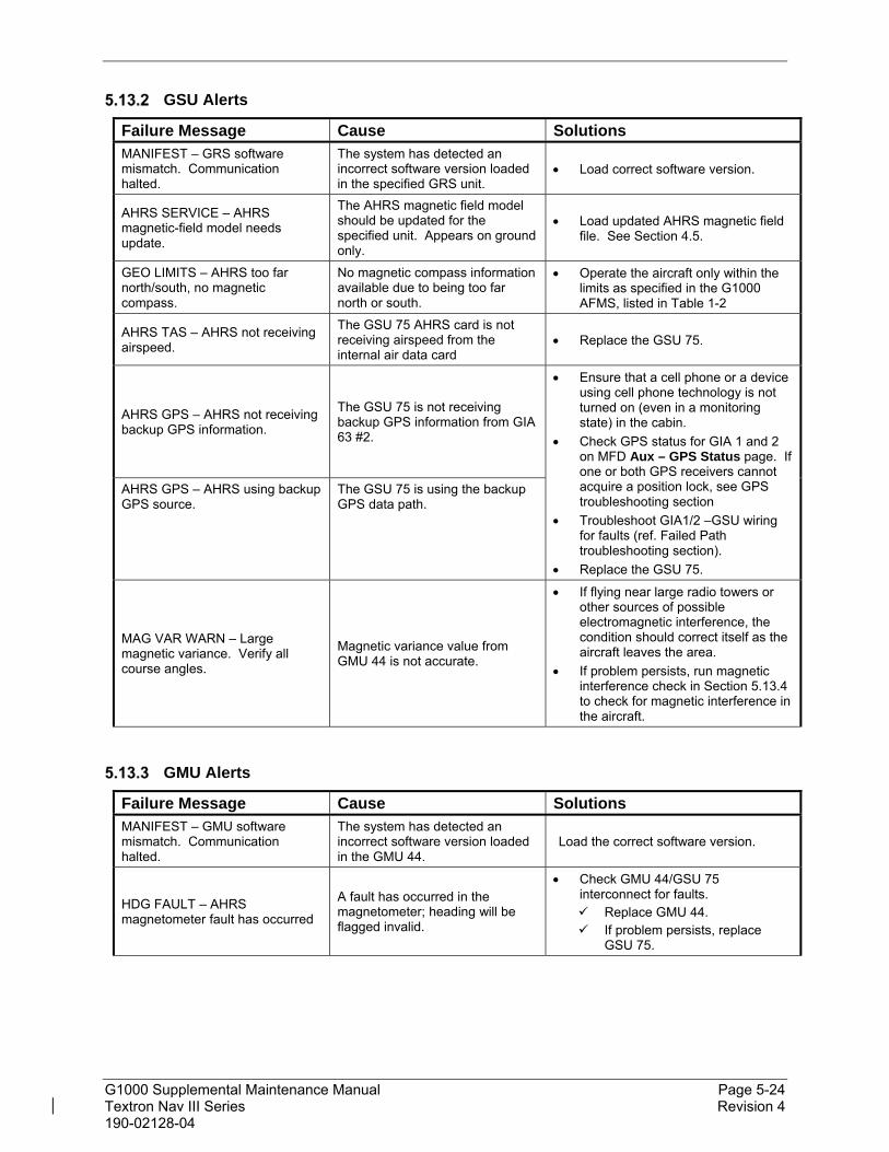
G1000 Supplemental Maintenance Manual Page 5-24 Textron Nav III Series Revision 4 190-02128-04
GSU Alerts
Failure Message Cause Solutions MANIFEST – GRS software mismatch. Communication halted.
The system has detected an incorrect software version loaded in the specified GRS unit.
Load correct software version.
AHRS SERVICE – AHRS magnetic-field model needs update.
The AHRS magnetic field model should be updated for the specified unit. Appears on ground only.
Load updated AHRS magnetic field file. See Section 4.5.
GEO LIMITS – AHRS too far north/south, no magnetic compass.
No magnetic compass information available due to being too far north or south.
Operate the aircraft only within the limits as specified in the G1000 AFMS, listed in Table 1-2
AHRS TAS – AHRS not receiving airspeed.
The GSU 75 AHRS card is not receiving airspeed from the internal air data card
Replace the GSU 75.
AHRS GPS – AHRS not receiving backup GPS information.
The GSU 75 is not receiving backup GPS information from GIA 63 #2.
Ensure that a cell phone or a device using cell phone technology is not turned on (even in a monitoring state) in the cabin.
Check GPS status for GIA 1 and 2 on MFD Aux – GPS Status page. If one or both GPS receivers cannot acquire a position lock, see GPS troubleshooting section
Troubleshoot GIA1/2 –GSU wiring for faults (ref. Failed Path troubleshooting section).
Replace the GSU 75.
AHRS GPS – AHRS using backup GPS source.
The GSU 75 is using the backup GPS data path.
MAG VAR WARN – Large magnetic variance. Verify all course angles.
Magnetic variance value from GMU 44 is not accurate.
If flying near large radio towers or other sources of possible electromagnetic interference, the condition should correct itself as the aircraft leaves the area.
If problem persists, run magnetic interference check in Section 5.13.4 to check for magnetic interference in the aircraft.
GMU Alerts
Failure Message Cause Solutions MANIFEST – GMU software mismatch. Communication halted.
The system has detected an incorrect software version loaded in the GMU 44.
Load the correct software version.
HDG FAULT – AHRS magnetometer fault has occurred
A fault has occurred in the magnetometer; heading will be flagged invalid.
Check GMU 44/GSU 75 interconnect for faults. Replace GMU 44. If problem persists, replace
GSU 75.

G1000 Supplemental Maintenance Manual Page 5-25 Textron Nav III Series Revision 4 190-02128-04
Calibration Procedure E: Magnetometer Interference Test
A magnetometer interference test is available for troubleshooting and/or verifying a magnetically ‘clean’ installation of the GMU 44. This test exercises various devices on the aircraft that could potentially affect the magnetic field as measured by the GMU 44.
NOTE
This test is used to validate that no electronic device or magnetized components produce a magnetic field sufficient to interfere with the operation of the GMU 44 magnetometer. It is highly recommended that this test be performed after installation or maintenance of electrical components on the aircraft and/or for troubleshooting the GMU 44.
Figure 5-5, Magnetometer Interference Test
1. Initiate the AHRS magnetometer interference test procedure by performing the following steps:
2. On the PFD, enter Configuration Mode and go to GRS/GMU Calibration page as shown in Figure 5-5.
3. This page is protected and requires a keystroke password to perform this test. Press the following softkeys in sequence: (as counted from left to right on lower bezel of MFD)
softkey 9
softkey 10
softkey 11
softkey 12
4. Select MAG INTERFERENCE TEST and press the PFD ENT key.
5. Follow the checklist items displayed on the PFD, and press the ENT key as each one is completed or confirmed.

G1000 Supplemental Maintenance Manual Page 5-26 Textron Nav III Series Revision 4 190-02128-04
NOTE
The 3rd item on the checklist instructs the operator to “prepare a detailed test sequence with precise start and stop times for exercising all electronic devices”. The list of relevant electronic devices is given in Table 5-3. Begin test with flaps retracted, flight controls in a neutral position, all lights selected OFF.
Elapsed Time since Start of Test (min:secs)
Action
0:00 Test begins
0:10 Navigation lights on
0:20 Navigation lights off
0:30 Landing lights on
0:40 Landing lights off
0:50 Recog/Taxi lights on
1:00 Recog/Taxi lights off
1:10 Strobes on
1:20 Strobes off
1:30 Beacon on
1:40 Beacon off
1:50 Pitot Heat on
2:00 Pitot Heat off
2:10 Aileron full right
2:20 Aileron full left
2:30 Flaps full down
3:00 Flaps full up
3:30 Rudder full left
3:40 Rudder full right
3:50 Elevator full nose UP
4:00 Elevator full nose DN
4:10 Elevator trim full nose UP
(manual)
4:40 Elevator trim full nose DN
(manual)
5:10 End of test
Table 5-3, Magnetometer Interference Test Sequence
6. When the CALIBRATE field is blinking, press the ENT key to begin the procedure, and have a stopwatch ready to begin recording the elapsed time.
NOTE
It is important that the “time equals zero” moment corresponds with the moment the PFD first displays the blinking TEST COMPLETE? Message.

G1000 Supplemental Maintenance Manual Page 5-27 Textron Nav III Series Revision 4 190-02128-04
7. The operator should carry out the actions called for in the prepared test sequence.
NOTE
It is important that all actions are carried out in the order and at the precise elapsed time as specified in the prepared test sequence.
8. When the operator has completed the actions specified in the test sequence, press the ENTER button to indicate that the process is complete. When this is done, the TEST COMPLETE field stops blinking.
9. The PFD informs the operator if the installation has passed or failed the magnetometer interference test. If the test passes, no further action is required for this test.
If the test fails, the installation should be considered unreliable until the source of magnetic interference is identified and remedied. When the magnetometer interference test fails, record the three magnetometer maximum deviation values and their corresponding timestamps. Reference the installation manual for the GSU 75 (190-01639-00 for acceptable magnetic interference limits. Compare the corresponding timestamps with the prepared test sequence to identify which action produced the problem. Contact Garmin for assistance in resolving the problem.
NOTE
Two common reasons for a failed magnetometer interference test are: 1) new equipment is installed in close proximity to the GMU 44 magnetometer, and 2) an existing or new electronic device has become grounded through the aircraft structure instead of via the proper ground wire in a twisted shielded pair.
10. Press the ENT key on the PFD to conclude this procedure.
5.14 GSU 75 Troubleshooting
Air Data Symptoms
For GSU 75 Air Data Troubleshooting, refer to the GDC 74A section in the G1000 Nav III Line Maintenance Manual.

G1000 Supplemental Maintenance Manual Page 5-28 Textron Nav III Series Revision 4 190-02128-04
5.15 Software/Configuration Troubleshooting
Problem Solutions
MFD or PFD displays do not power up: Ensure that the criteria listed in Section 5.15.1 are fulfilled for the applicable situation.
Ensure power is present at display backshell connector.
Troubleshoot per the “Blank Display” GDU section.
Software file load fails:
Ensure that criteria listed in Section 5.15.1 are fulfilled for the applicable situation.
Ensure that LRU is reporting data on Aux – System Status page (LRU is ‘ONLINE’). Check data path wiring as needed.
Retry software file load or try using a different card. Ensure that the MFD is not touched during the loading process.
Ensure that LRU part number is compatible with software version and Card Loader. Refer to Section 3.1.7.
Replace LRU.
Configuration file load fails:
Ensure that the criteria listed in Section 5.15.1 are fulfilled for the applicable situation.
Ensure that LRU is reporting data on the Aux – System Status page (LRU is ‘ONLINE’). Check data path wiring as needed.
Retry configuration file load or try using a different card. Ensure that the MFD is not touched during the loading process.
Ensure that LRU part number is compatible with Card Loader. Refer to Section 3.1.7.
Replace LRU.
GIA1 and/or GIA2 to ‘LRU’ data path not working Ensure that the criteria listed in Section 5.15.1 are fulfilled for the applicable situation.
Ensure GIA1 and GIA2 are configured correctly.
Check wiring, connectors & pins as needed.
Software File Mismatch Alert appears in lower right corner of PFD when started in normal mode:
Ensure that proper software file part number and version were loaded to LRU. Refer to Section 5.15.1.
Check and ensure that correct Card Loader was used during load process. Refer to the General Arrangement Drawing.
Reload software to LRU.
After being in configuration mode, the PFD displays a red AFCS annunciation and cycling of the transponder field between valid and invalid states.
With the G1000 system powered on, open the MFD, PFD (ESS BUS), and PFD (AVN BUS 1) circuit breakers for approximately 30 seconds, then close the circuit breakers.

G1000 Supplemental Maintenance Manual Page 5-29 Textron Nav III Series Revision 4 190-02128-04
System Communication Hierarchy
The following criteria must be satisfied to be able to perform the desired operation:
Desired Operation Criteria for Success
Load Software to MFD or PFD Displays SW Loader Card must be inserted in top slot for each display to be loaded.
ENT keys must be held during power up of display.
Power on only one display at a time during software loading.
Load AIRFRAME, SYSTEM, MFD, PFD and MANIFEST configuration files to MFD and PFD
SW Loader Card must be inserted in top slot of PFD.
PFD and MFD must be powered on.
PFD and MFD must have correct software.
Load Software/Configuration files to GIAs SW Loader Card must be inserted in top slot of PFD.
G1000 system must be powered on.
PFD and MFD must have correct software.
PFD and MFD must be successfully configured with AIRFRAME, SYSTEM, MANIFEST, MFD and PFD configuration files.
Load Software/Configuration files to:
- GMA 1347 / GMA 1360
- GSU 75 (if installed)
- GDC 74 (if installed)
- GEA 71 / GEA 71B
- GRS 77 (software only) (if installed)
- GMU 44 (software only)
- GTX 33 (if installed)
- GTX 335R or GTX 345R (if installed)
SW Loader Card must be inserted into PFD top slot.
G1000 must be powered on.
PFD and MFD must have correct software and configuration settings.
GIAs must have correct software.
GIAs must be successfully configured with GIA1 and GIA2 configuration files.
Data path from GIA1 to each LRU must be operational.

G1000 Supplemental Maintenance Manual Page 5-30 Textron Nav III Series Revision 4 190-02128-04
5.16 Backshell/Backplate Connectors
The following figures depict the backplate connectors as viewed with the LRU removed. For units not shown here, refer to the G1000 Nav III Line Maintenance Manual.
Figure 5-6, GTX 335R/345R Looking at Front of Connector (P3251)
Figure 5-7, GTX 345R (Only) Looking at Front of Connector (P3252)

G1000 Supplemental Maintenance Manual Page 5-31 Textron Nav III Series Revision 4 190-02128-04
Figure 5-8, GDU 1054B/1050 Backshell Connector (P10401)
Figure 5-9, GSU 75 Connector View from Front (P751)
Figure 5-10, GDL 69A SXM Backplate Connector (P69A1)

G1000 Supplemental Maintenance Manual Page 5-32 Textron Nav III Series Revision 4 190-02128-04
Figure 5-11, GIA 64W Backplate Connectors
Figure 5-12, GEA 71B Backplate Connectors
1 2 3
16 17
4 5 6 7 8 9 10 1112131415
1819 20 21222324 2526 2728 2930
31323334 353637 38394041 424344
1 2 3 4 5 6 7 8 9 10 11 12 13 14 15 16 17 18 19 20
21 22 23 24 25 26 27 28 29 30 31 32 33 34 35 36 37 38 39
40 41 42 43 44 45 46 47 48 49 50 51 52 53 54 55 56 57 58 59
60 61 62 63 64 65 66 67 68 69 70 71 72 73 74 75 76 77 78
1 2 3 4 5 6 7 8 9 10 11 12 13 14 15 16 17 18 19 20
21 22 23 24 25 26 27 28 29 30 31 32 33 34 35 36 37 38 39
40 41 42 43 44 45 46 47 48 49 50 51 52 53 54 55 56 57 58 59
60 61 62 63 64 65 66 67 68 69 70 71 72 73 74 75 76 77 78
COM BOARD CONNECTOR (P601)
COM ANTENNA CONNECTORCOOLING PORT
MAIN DISCRETE CONNECTOR (P604)
MAIN SERIAL CONNECTOR (P603)
GPS ANTENNA CONNECTO
I/O CONNECTOR #2 (P606) I/O CONNECTOR #1 (P605)
G/S ANTENNA CONNECTOR
NAV ANTENNA CONNECTORVOR/ILS CONNECTOR (P602
1 2 3 4 5 6 7 8 9 10 11 12 13 14 15 16 17 18 19 20
21 22 23 24 25 26 27 28 29 30 31 32 33 34 35 36 37 38
40 41 42 43 44 45 46 47 48 49 50 51 52 53 54 55 56 57 58 59
60 61 62 63 64 65 66 67 68 69 70 71 72 73 74 75 76 77 78

G1000 Supplemental Maintenance Manual Page 5-33 Textron Nav III Series Revision 4 190-02128-04
Figure 5-13, GMA 1360 Backplate Connectors
Figure 5-14, GSR 56 Mating Connector
123456789101112131415
161718192021222324252627282930
3132333435363738394041424344

G1000 Supplemental Maintenance Manual Page 6-1 Textron Nav III Series Revision 4 190-02128-04
6. Equipment Removal & Installation
This section describes how to remove and replace equipment in the Cessna Nav III Series associated with this STC. After removal and replacement, LRUs must be configured and tested as described in Section 7.
CAUTION:
When removing and/or replacing any G1000 component, always ensure that aircraft power is off. Unplug any auxiliary power supplies. Before performing maintenance, it is required that the technician verify the LRU software part number and version number matches the software configuration listed in the General Arrangement drawing, listed in Table 1-1.
NOTE
After installation or maintenance of electrical components near the GMU 44 magnetometers, perform the Calibration Procedure E: Magnetometer Interference Test (reference Section 5) and Procedure B: GSU 75 and GMU 44 magnetic calibration (reference Section 7).
To check an LRU software part number and/or version, follow the procedure defined in Section 3.1.7.
If a faulty LRU is not reporting its software version and part number, check aircraft maintenance logs for last software version loaded and verify against the General Arrangement drawing. The Software Manifest page may also be used to check part numbers and versions.
The General Arrangement drawing allows alternate part number units to be installed with certain hardware/software combination restrictions. Refer to the applicable “Garmin Equipment/Software List” contained in the General Arrangement drawing for details.

G1000 Supplemental Maintenance Manual Page 6-2 Textron Nav III Series Revision 4 190-02128-04
6.1 GDU 1054B/1050
Removal:
1. Using a 3/32” hex tool, rotate all four ¼-turn fasteners counter-clockwise until they reach their stops.
2. Carefully remove the display from the panel.
3. While supporting the display, disconnect the connector.
Reinstallation:
1. Visually inspect the connector and pins for signs of damage. Repair any damage.
2. While supporting the display, connect the connector to the rear of the unit. Verify the connector is fully locked by rocking the connector up and down to verify the connector stays attached to the unit.
3. Carefully insert the display into the panel cutout, ensuring that all 4 ¼-turn fasteners align with the corresponding holes.
4. Seat the display in the panel cutout. Do not use excessive force while inserting the display.
5. Once seated, rotate all four ¼-turn fasteners clockwise to lock the display to the panel.
6. Configure and test the MFD and/or PFD according to Section 7.1.
6.2 GTX 335R/GTRX 345R Transponder (if installed)
GTX 335R/GTX 345R Removal:
1. Gain access to the aft avionics compartment in the tail of the aircraft.
2. Insert a 3/32” hex drive tool into the access hole in the front of the unit.
3. Turn hex drive tool counterclockwise until the hex drive tool stops.
4. Pull the unit from the rack using the spring-loaded tab on the front of the unit.
GTX 335R/GTX 345R Reinstallation:
1. Visually inspect the connectors in the back of the rack to ensure there are no bent or damaged pins. Repair any damage if found.
2. Insert a 3/32” hex drive tool into the access hole in the front of the unit.
3. Turn hex drive tool counterclockwise until the hex drive tool stops.
4. Slide the unit in the rack until it stops. The unit will appear to stick out of the rack approximately 3/8”.
5. Insert a 3/32” hex drive tool into the access hole in the front of the unit.
6. Push on the left side of the unit and turn hex drive tool clockwise until it stops. Do not apply more than 8 in-lbs of torque on the hex tool to seat the unit.
7. Configure and test the GTX 335R or GTX 345R according to Section 7.5.
6.3 GSU 75 ADAHRS (if installed)
GSU 75 Removal:
1. Gain access to the aft avionics compartment in the tail of the aircraft.

G1000 Supplemental Maintenance Manual Page 6-3 Textron Nav III Series Revision 4 190-02128-04
2. Disconnect the ADAHRS connector.
3. Disconnect the pitot and static lines.
4. Turn each retention screw counterclockwise until they disconnect from the remote rack.
5. Gently slide the unit from the remote rack. Do NOT loosen the remote rack hardware fastening it to the avionics shelf or the GSU 75 must be re-calibrated per Section 7.10)
GSU 75 Installation:
1. Visually inspect the connector to ensure there are no bent or damaged pins. Also inspect the pitot and static fittings for damage. Repair any damage.
2. Place the GSU 75 unit on the remote rack and slide the unit back until the feet are fully engaged with the remote rack.
3. Push down and turn each retention screw clockwise. Torque each retention screw to 15-20 in-lbs.
4. Connect the pitot and static lines.
5. Connect the ADAHRS connector to the unit.
6. Calibrate and test the GSU 75 per Section 7.10.
6.4 GDL 69A SXM (if installed)
Removal:
1. For 182 and 206 aircraft, gain access by removing the right side GDU 1054B display unit (see Section 6.1.)
2. For 172 aircraft, gain access to the aft avionics compartment in the tail of the aircraft.
3. Unlock the GDL 69A SXM handle by loosening the Phillips screw on the handle.
4. Pull the handle upward to unlock the GDL 69A. Gently remove the unit from the rack.
Reinstallation:
1. Visually inspect the connectors to ensure there are no bent or damaged pins. Repair any damage.
2. Lift the handle and gently insert the GDL 69A SXM into its rack. The handle should engage the dogleg track.
3. Press down on the GDL 69A SXM handle to lock the unit into the rack.
4. Lock the handle to the GDL 69A SXM body using the Philips screw. Torque the handle screw to 10-14 in-lbs.
5. Configure and test the GDL 69A SXM according to Section 7.11.
6.5 Configuration Modules
Configuration Module Removal & Replacement
Configuration modules (Reference Figure 6-1 and Table 6-1, Item 1 shown below) are located in the following LRU harness connector backshells: GDU 1054B or GDU 1050 PFD. Additionally, the GSU 75 has different style configuration modules that are located in the connector backshells. Refer to Section 6.5.2 for the GSU 75 configuration module removal and

G1000 Supplemental Maintenance Manual Page 6-4 Textron Nav III Series Revision 4 190-02128-04
replacement instructions. Refer to the Master Drawing List, listed in Table 1-1, for specific installation drawings.
Figure 6-1, Configuration Module Installation
Table 6-1, Configuration Module Kit – 011-00979-00
Item Description Qty Needed Garmin Part
Number
1 Configuration Module PCB Board Assembly w/EEPROM & Temp Sensor
1 012-00605-00 or -02
2 Spacer, Config Module 1 213-00043-00
3 Cable, 4-Conductor Harness 1 325-00122-00
4 Pins, #22 AWG (HD) 5 336-00021-00
Removal:
1. Disconnect connector from LRU.
2. Remove 2 screws (8) from cover (7) and remove cover.
3. Unplug connector from configuration module (1).
4. Remove configuration module.
Installation:
1. Inspect connector for damaged pins (4).
2. Place configuration module (1) in position.
3. Insert connector into configuration module (1).
4. Assembly of the connector is the reverse of disassembly.
5. Checkout per Section 6.5.3.

G1000 Supplemental Maintenance Manual Page 6-5 Textron Nav III Series Revision 4 190-02128-04
GSU 75 Configuration Module Removal & Replacement
CO NFIG URATIO N M O DULE
Figure 6-2, GSU 75 Configuration Module Installation
Table 6-2, GSU 75 Configuration Module Kit – 011-00979-20
Item Description Qty Needed Garmin Part
Number
1 Sub-Assy,Potted,Config Mdl,w/EEPROM,Jackscrew 1 011-02179-00
2 Cable, 4-Conductor Harness 1 325-00122-00
3 Pins, #22 AWG (HD) 4 336-00021-00
4 Pan Head Screw 1 211-60232-07
Removal:
1. Disconnect connector from LRU.
2. Remove 2 screws from cover and remove cover.
3. Unplug the connector from the configuration module.
4. Remove 1 screw from configuration module.
5. Remove the configuration module.
Installation:
1. Inspect connector for damaged pins.
2. Insert the connector into the configuration module.
3. Place configuration module in position.
4. Install 1 screw attaching the configuration module to the backshell.
5. Assembly of the connector is the reverse of the disassembly.
6. Checkout per Section 6.5.3.

G1000 Supplemental Maintenance Manual Page 6-6 Textron Nav III Series Revision 4 190-02128-04
Configuration Module Checkout
If a GSU 75 Configuration Module is replaced:
Configuration settings must be reloaded to the GSU 75 per Section 7.6, then proceed to Section 7.7.3.
Additionally, GSU 75 and GMU 44 calibration procedures must be performed. Proceed to Section 7.10.
If only the Master (PFD) Configuration Module is replaced:
NOTE
New Terrain/Obstacle databases, Jeppesen Aviation Database and other optional features (i.e. unlock/enablement cards) will need to be replaced if the master configuration module is changed. The G1000 System ID number will change to a new number when installing a new master config module. The old databases and feature enable cards will no longer work as they will remain locked to the old System ID number.
1. Start the G1000 system in configuration mode.
2. Go to the Configuration Upload Page on the PFD.
3. Press the UPDT CFG softkey and press ENT.
If both the PFD and Master Configuration Module are replaced:
NOTE
New Terrain/Obstacle databases, Jeppesen Aviation Database and other optional features (i.e. unlock/enablement cards) will need to be replaced if the master configuration module is changed. The G1000 System ID number will change to a new number when installing a new master config module. The old databases and feature enable cards will no longer work as they will remain locked to the old System ID number.
1. The entire G1000 system must be re-configured. Insert the correct G1000 software loader card into the PFD.
2. Start the G1000 in configuration mode. Go to the System Upload Page on the PFD.
3. See Section 3.6 for instructions on how to use the System Upload page. Check all configuration files and reload them.
4. After reloading configuration files, examine the G1000 installation for any installed configuration options. Options are listed in Section 3.6. Load optional files as necessary.
5. Continue to Section 9 and conduct the return to service checkout.

G1000 Supplemental Maintenance Manual Page 6-7 Textron Nav III Series Revision 4 190-02128-04
6.6 GMA 1360 Audio Panel (if installed)
Removal:
1. Using a 3/32” hex tool, turn the hex nut counter-clockwise until the GMA is unlocked from the rack in the instrument panel.
2. Carefully remove the GMA from its rack.
Reinstallation:
1. Visually inspect the connectors to ensure there are no bent or damaged pins. Repair any damage.
2. Using a 3/32” hex tool, turn the hex nut counter-clockwise until the lock tab stops.
3. Gently insert the GMA into the rack until the locking tab engages the rack.
4. Tighten the hex nut until resistance is felt and the unit stops sliding into the rack. Do not over-tighten the nut.
5. Configure and test the GMA according to Section 7.2.
6.7 GIA 64W Integrated Avionics Unit (if installed)
Removal:
1. Gain access to the tail of the aircraft.
2. Unlock the GIA handle by loosening the Phillips screw on the handle.
3. Pull the handle upward to unlock the GIA. Gently remove the unit from the rack.
Reinstallation:
1. Visually inspect the connectors to ensure there are no bent or damaged pins. Repair any damage.
2. Lift the handle and gently insert the GIA into its rack. The handle should engage the dogleg track.
3. Press down on the GIA handle to lock the unit into the rack.
4. Lock the handle to the GIA body using the Philips screw. Torque the handle screw to 10-14 in-lbs.
6. Configure and test the GIA(s) according to Section 7.3
6.8 GSR 56 Satellite Transceiver (if installed)
Removal:
1. Gain access to the tail of the aircraft.
2. Unlock the unit from the rack by pulling out on the ratcheting latch mechanism and turning counter-clockwise until the latch mechanism clears the tab on the unit.
3. Slide the unit out of the rack.
Reinstallation:
1. Visually inspect the connectors to ensure there are no bent or damaged pins. Repair any damage.
2. Insert the unit into the installation rack.

G1000 Supplemental Maintenance Manual Page 6-8 Textron Nav III Series Revision 4 190-02128-04
CAUTION:
Do not use excessive force when inserting the GSR 56 into the rack. This may cause damage to occur to the connectors, unit, and/or unit rack. If heavy resistance is felt during installation, stop! Remove the GSR 56 and identify the source of resistance.
3. Lock the unit into the rack by using the ratcheting latch mechanism.
4. Register with Garmin Connext per Section 7.14.1.
5. No software or configuration loading is required for the GSR 56. Test the GSR 56 according to Section 7.14.2.
6.9 Iridium Antenna (if installed)
Removal:
1. Gain access to the antenna coaxial cable connector in the tail.
2. Disconnect the antenna coaxial cable.
3. Remove the antenna mounting screws.
4. Remove antenna.
Reinstallation:
1. Install antenna using retained mounting screws.
2. Connect the antenna coaxial cable.
3. Fillet seal around antenna.
4. Proceed to Section 7.14.2 for testing of the GSR 56.
6.10 GEA 71B Engine/Airframe Unit (if installed)
Removal:
1. Gain access by removing the MFD (see Section 6.1).
2. Unlock the GEA handle by unscrewing the Phillips screw.
3. Firmly grasp the GEA handle and pull it. This unlocks the unit from the rack.
4. Gently remove the GEA from its rack.
Reinstallation:
1. Visually inspect the connectors to ensure there are no bent or damaged pins. Repair any damage.
2. Lift the handle and gently insert the GEA into the rack. The handle should engage the dogleg track.
3. Press on the handle to lock the unit into place.
4. Lock the handle to the GEA body using the Philips screw. Torque the handle screw to 10-14 in-lbs.
5. Reinstall the MFD.
6. Configure and test the GEA according to Section 7.4.

G1000 Supplemental Maintenance Manual Page 6-9 Textron Nav III Series Revision 4 190-02128-04
6.11 FS 510 Wifi/Bluetooth Data Link (if installed)
Removal:
1. FS 510 card is installed in the bottom slot of the MFD.
2. Press the edge of the card and release to remove card.
Reinstallation:
1. Insert FS510 card in the bottom slot of the MFD.
6.12 GSA 81 Servo Actuator (if installed)
Removal:
1. Gain access to the desired servo(s).
2. Disconnect the servo harness connector.
3. Use a socket or open-wrench to loosen and remove the servo attachment bolts.
4. Carefully remove the servo and place a protective cover on the output gear.
5. Place a protective cover over the GSM 86 servo gearbox.
Reinstallation:
1. Inspect the servo output gear for abnormal wear.
2. Using a lint-free cloth, remove excess grease build-up from the servo output gear (see Figure 6-1.)
IMPORTANT!
It is not necessary to remove all of the grease from the output gear, only the excess grease. DO NOT USE SOLVENTS TO CLEAN THE OUTPUT GEAR!
3. Using a brush or other applicator, apply a thin coat of Aeroshell 33MS (Lithium-complex based) grease to the servo output gear.
Figure 6-3, Servo Gear
4. Carefully place the servo into the servo gearbox, ensuring proper orientation and alignment.

G1000 Supplemental Maintenance Manual Page 6-10 Textron Nav III Series Revision 4 190-02128-04
5. Fasten the servo to the servo gearbox using the existing hardware. Follow the installation instructions provided in the respective servo installation drawing(s) listed in Table 1-1.
6. Inspect the harness connectors and check that no pins are bent or otherwise damaged. Connect the harness and secure it appropriately.
7. Configure and test the GSA according to Section 7.12.
6.13 GSM 86 Servo Gearbox (if installed)
Removal:
1. Remove the desired servo(s) per Section 6.12.
2. Disconnect the servo cables from the flight control system.
3. Use a socket or open-wrench to loosen and remove the servo gearbox attachment bolts.
4. Carefully remove the servo gearbox(es).
5. Remove the cable retention pins and top ring and then remove the servo cable from the capstan.
Reinstallation:
1. Follow the installation instructions provided in the respective servo installation drawing(s) listed in Table 1-1 to reinstall the servo cable and servo gearbox.
2. If no other maintenance is to be performed, reinstall the servo(s) per Section 6.12.
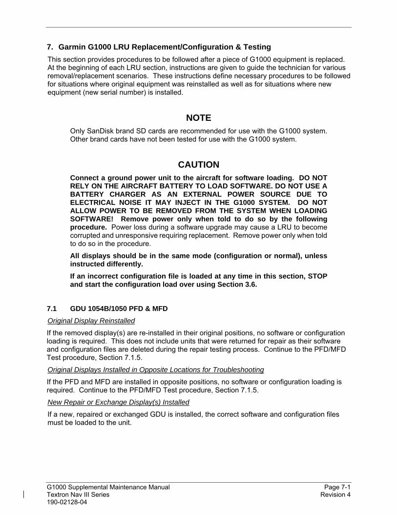
G1000 Supplemental Maintenance Manual Page 7-1 Textron Nav III Series Revision 4 190-02128-04
7. Garmin G1000 LRU Replacement/Configuration & Testing
This section provides procedures to be followed after a piece of G1000 equipment is replaced. At the beginning of each LRU section, instructions are given to guide the technician for various removal/replacement scenarios. These instructions define necessary procedures to be followed for situations where original equipment was reinstalled as well as for situations where new equipment (new serial number) is installed.
NOTE Only SanDisk brand SD cards are recommended for use with the G1000 system. Other brand cards have not been tested for use with the G1000 system.
CAUTION Connect a ground power unit to the aircraft for software loading. DO NOT RELY ON THE AIRCRAFT BATTERY TO LOAD SOFTWARE. DO NOT USE A BATTERY CHARGER AS AN EXTERNAL POWER SOURCE DUE TO ELECTRICAL NOISE IT MAY INJECT IN THE G1000 SYSTEM. DO NOT ALLOW POWER TO BE REMOVED FROM THE SYSTEM WHEN LOADING SOFTWARE! Remove power only when told to do so by the following procedure. Power loss during a software upgrade may cause a LRU to become corrupted and unresponsive requiring replacement. Remove power only when told to do so in the procedure.
All displays should be in the same mode (configuration or normal), unless instructed differently.
If an incorrect configuration file is loaded at any time in this section, STOP and start the configuration load over using Section 3.6.
7.1 GDU 1054B/1050 PFD & MFD
Original Display Reinstalled
If the removed display(s) are re-installed in their original positions, no software or configuration loading is required. This does not include units that were returned for repair as their software and configuration files are deleted during the repair testing process. Continue to the PFD/MFD Test procedure, Section 7.1.5.
Original Displays Installed in Opposite Locations for Troubleshooting
If the PFD and MFD are installed in opposite positions, no software or configuration loading is required. Continue to the PFD/MFD Test procedure, Section 7.1.5.
New Repair or Exchange Display(s) Installed
If a new, repaired or exchanged GDU is installed, the correct software and configuration files must be loaded to the unit.

G1000 Supplemental Maintenance Manual Page 7-2 Textron Nav III Series Revision 4 190-02128-04
LRU Replacement Procedure PFD
1. Open the MFD, PFD (ESS BUS), and PFD (AVN BUS 1) circuit breakers.
2. Remove SD cards from top and bottom slots of the MFD and PFD if present.
3. Apply power to the G1000 system by connecting external power to the aircraft to energize the aircraft and avionics electrical busses.
4. Turn on Avionics/electrical busses.
5. Power on the MFD and PFD in configuration mode.
6. Using the MFD, scroll to the LRU replacement page.
7. Activate the cursor and select PFD in the LRU dropdown box.
8. Press the CHK All softkey.
9. Press the Load softkey.
10. Press ENT to acknowledge the process was complete.
11. Deactivate the cursor.
12. Scroll to the Configuration Manager page.
13. Press the CNFM CFG softkey.
14. Select ok when prompted to “Confirm configuration as expected configuration”
15. Power cycle the system verify there are no red-Xs or system alerts.
16. If red-Xs or system alerts are present, troubleshoot as necessary using Section 5 or re-load the system using the legacy method in Section 3.6.
17. If there are no red-Xs or system alerts, continue to Section 7.1.5.
Legacy Replacement Procedure PFD (Alternate Method)
A full system configuration re-load is required when a new, repaired, or exchanged display is installed using this method. This includes all options and feature enablements.
To complete this procedure, continue to Section 3.6.
LRU Replacement Procedure MFD
NOTE
Anytime the MFD is replaced, all databases must be reloaded.
1. Open the MFD, PFD (ESS BUS), and PFD (AVN BUS) circuit breakers.
2. Remove SD cards from top and bottom slots of the MFD and PFD if present.
3. Apply power to the G1000 system by connecting external power to the aircraft to energize the aircraft and avionics electrical busses.
4. Turn on Avionics electrical busses.
5. Power on the MFD and PFD in configuration mode.
6. Using the PFD, scroll to the LRU replacement page.
7. Activate the cursor and select MFD in the LRU dropdown box.

G1000 Supplemental Maintenance Manual Page 7-3 Textron Nav III Series Revision 4 190-02128-04
8. Press the CHK All softkey.
9. Press the Load softkey.
10. Press ENT to acknowledge the process was complete.
11. Deactivate the cursor.
12. Scroll to the Configuration Manager page.
13. Press the CNFM CFG softkey.
14. Select ok when prompted to “Confirm configuration as expected configuration”
15. Power cycle the system verify there are no red-Xs or system alerts.
16. If red-Xs or system alerts are present, troubleshoot as necessary using Section 5 or re-load the system using the legacy method in Section 3.8.
17. Install databases as directed in Section 3.14.
18. After databases are re-loaded, continue to Section 7.1.5.
Legacy Replacement Procedure MFD (Alternate Method)
A full system configuration re-load is required when a new, repaired, or exchanged display is installed using this method. This includes all options and feature enablements. To complete this procedure, perform Section 3.6.
PFD/MFD Test
1. Allow displays to initialize for ~1 minute.
2. Check that all COM/NAV display fields are valid in the top corners of the PFD.
3. Check that attitude, heading, altitude, airspeed, vertical speed and OAT fields are valid within 2 minutes of power up on the PFD.
4. Check that the engine instrument fields are valid on the MFD.
Figure 7-1, G1000 Normal Mode Check
5. Push the red DISPLAY BACKUP button on the GMA. Verify that the PFD and MFD displays enter reversion mode. MFD should have valid altitude, airspeed, vertical speed, COMM1, COMM2, NAV1, NAV2 and engine instruments.
6. De-activate pilot-side reversion mode by pushing the DISPLAY BACKUP button. Verify the PFD and MFD return to normal display modes.
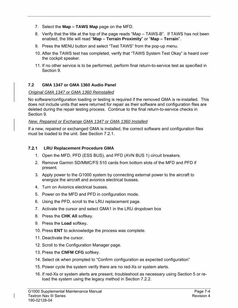
G1000 Supplemental Maintenance Manual Page 7-4 Textron Nav III Series Revision 4 190-02128-04
7. Select the Map – TAWS Map page on the MFD.
8. Verify that the title at the top of the page reads “Map – TAWS-B”. If TAWS has not been enabled, the title will read “Map – Terrain Proximity” or “Map – Terrain”.
9. Press the MENU button and select “Test TAWS” from the pop-up menu.
10. After the TAWS test has completed, verify that “TAWS System Test Okay” is heard over the cockpit speaker.
11. If no other service is to be performed, perform final return-to-service test as specified in Section 9.
7.2 GMA 1347 or GMA 1360 Audio Panel
Original GMA 1347 or GMA 1360 Reinstalled
No software/configuration loading or testing is required if the removed GMA is re-installed. This does not include units that were returned for repair as their software and configuration files are deleted during the repair testing process. Continue to the final return-to-service checks in Section 9.
New, Repaired or Exchange GMA 1347 or GMA 1360 Installed
If a new, repaired or exchanged GMA is installed, the correct software and configuration files must be loaded to the unit. See Section 7.2.1.
LRU Replacement Procedure GMA
1. Open the MFD, PFD (ESS BUS), and PFD (AVN BUS 1) circuit breakers.
2. Remove Garmin SD/MMC/FS 510 cards from bottom slots of the MFD and PFD if present.
3. Apply power to the G1000 system by connecting external power to the aircraft to energize the aircraft and avionics electrical busses.
4. Turn on Avionics electrical busses.
5. Power on the MFD and PFD in configuration mode.
6. Using the PFD, scroll to the LRU replacement page.
7. Activate the cursor and select GMA1 in the LRU dropdown box
8. Press the CHK All softkey.
9. Press the Load softkey.
10. Press ENT to acknowledge the process was complete.
11. Deactivate the cursor.
12. Scroll to the Configuration Manager page.
13. Press the CNFM CFG softkey.
14. Select ok when prompted to “Confirm configuration as expected configuration”
15. Power cycle the system verify there are no red-Xs or system alerts.
16. If red-Xs or system alerts are present, troubleshoot as necessary using Section 5 or re-load the system using the legacy method in Section 7.2.2.

G1000 Supplemental Maintenance Manual Page 7-5 Textron Nav III Series Revision 4 190-02128-04
17. If there are no red-Xs or system alerts, continue to Section 7.2.3.
Legacy Replacement Procedure GMA (Alternate Method)
To load the GMA complete the following subsections in order as they apply to the aircraft.
Cessna XXX – Baseline Configuration (where XXX is the airframe type)
1. Insert the software loader card in the top slot of the PFD.
2. Power on the MFD and PFD in configuration mode.
3. Select no when “Do you want to update system files” is displayed on the screen of the PFD.
4. Select the “SYSTEM UPLOAD” page using the small FMS knob on PFD.
5. Activate cursor and rotate the small FMS knob to display the drop down menu. Rotate the small FMS knob to highlight “0X-XXX” (where 0X is the menu position, and XXX is the airframe type) and press ENT key on the PFD.
6. Rotate the small FMS knob to display the drop down menu. Rotate the large FMS knob to highlight “Cessna XXX – Baseline Configuration” (where XXX is the airframe type). Press ENT key on the PFD.
7. Press the CLR ALL softkey.
8. Use the large FMS knob to scroll to GMA.
9. Highlight the software box and press the ENT key.
10. Highlight the Configuration box and press the ENT key.
11. Press “Load” softkey.
12. Monitor load progress. Verify software load completes without errors as indicated by the following:
13. Green “PASS” in the Configuration and Software columns for each item loaded.
14. “Upload Complete………….”COMPLETE” in the summary box.
15. Acknowledge the prompt by pushing the ENT key.
Option – KR87 ADF Installation (For GMA replacement and aircraft equipped with an ADF only)
1. In the ITEM window highlight “Option – KR87 ADF Installation” and press the ENT key on the PFD.
2. Press the CLR ALL softkey.
3. Scroll the cursor to GMA and press the ENT key to check the box.
4. Press “Load” softkey.
5. Monitor load progress. Verify software load completes without errors as indicated by the following:
Green “PASS” in the Configuration and Software columns for each item loaded.
“Upload Complete………….”COMPLETE” in the summary box.
6. Acknowledge the prompt by pushing the ENT key.

G1000 Supplemental Maintenance Manual Page 7-6 Textron Nav III Series Revision 4 190-02128-04
Option – KN63 DME Installation (For GMA replacement and aircraft equipped with a DME only)
1. Scroll the cursor to the ITEM window highlight “Option – KN63 DME Installation” and press the ENT key on the PFD.
2. Press the CLR ALL softkey.
3. Scroll the cursor to GMA and press the ENT key to check the box.
4. Press “Load” softkey.
5. Monitor load progress. Verify software load completes without errors as indicated by the following:
Green “PASS” in the Configuration and Software columns for each item loaded.
“Upload Complete………….”COMPLETE” in the summary box.
6. Acknowledge the prompt by pushing the ENT key.
Configuration Manager Update
1. With the system still in configuration mode, scroll to the Configuration Manager page on the PFD.
2. Press the CNFM CFG softkey.
3. Select ok when prompted to “Confirm configuration as expected configuration”
4. Power cycle the system verify there are no red-Xs or system alerts.
5. If red-Xs or system alerts are present, troubleshoot as necessary using Section 5.
6. If there are no red-Xs or system alerts, continue to Section 7.2.3.
GMA 1347 or GMA 1360 Test
Except for marker beacon operation, an in-aircraft checkout may be performed in the aircraft with a known good microphone, headset, and speaker.
Intercom System (ICS) Check
1. Ensure that the MAN SQ key is off (no light).
2. Ensure that PILOT and COPLT ICS ISOLATION are off (no light).
3. Adjust GMA ICS volume to a comfortable level.
4. Plug in a headset at each COCKPIT position. One at a time, plug a headset into each left and right CABIN ICS jack location (if installed) (one headset on right, one headset on left).
5. Verify that there is two-way communications between all jack positions.
6. On GMA select COM1 MIC and AUDIO.
7. Verify an active (green) COM1 frequency is displayed on the PFD.
8. On the GMA, select PA and verify the PA select annunciator is illuminated on GMA. Verify COM1 active frequency is displayed white.

G1000 Supplemental Maintenance Manual Page 7-7 Textron Nav III Series Revision 4 190-02128-04
9. Initiate passenger address using pilot’s headset boom mic by keying the pilot’s PTT. Verify the following:
Clear PA audio can be heard over cabin speaker and headsets
PA selected annunciator on GMA flashes ~ once per second during PA address.
10. Repeat Step 8 using hand mic.
11. Initiate passenger address using copilot’s headset boom mic by keying the copilot’s PTT. Verify the following:
Clear PA audio can be heard over cabin speaker and headsets
PA selected annunciator on GMA flashes ~ once per second during PA address.
Transceiver Operational Check
Perform a ramp test radio check by exercising the installed transceivers, microphone, microphone key and audio over the headphones and speaker. Verify that communications are clear and PTT operation is correct for each pilot position.
1. On the pilot’s audio panel, select the audio source corresponding to each installed avionics unit (i.e. NAV1, NAV2, COM1, COM2, ADF and DME) and check for audio over the pilot’s headset.
2. Press the SPKR key on pilot’s audio panel and verify that the selected audio is heard over the pilot’s speaker.
Failsafe Operation Check – GMA
1. Turn the GMA off by pulling the AUDIO circuit breaker. This directs all COM 1 phone audio, MIC audio and MIC key to the pilot’s position.
2. Check the failsafe operation by exercising the COM 1 boom mic, hand mic, microphone key and audio over the headphones. All volume control for the COM audio should be through the PFD volume control. Verify proper operation of COM 1 using the failsafe operation.
3. Close the AUDIO circuit breaker to continue testing.
Marker Beacon Test
1. Using a ramp tester, simulate the outer marker, middle marker, and inner marker signals by following the test equipment manufacturer’s instructions. Verify that each marker audio signal is present over the pilot and co-pilot headphones and speaker.
2. Verify that the outer, middle, and inner annunciations appear on PFD when the corresponding signal is applied. Marker beacon annunciations ( , , and ) appear at the upper left corner of the altitude indicator on the PFD. Operate the MKR MUTE key on the GMA and ensure that the audio signal is muted.
3. If no other service is to be performed, continue to the return-to-service checks in Section 9.
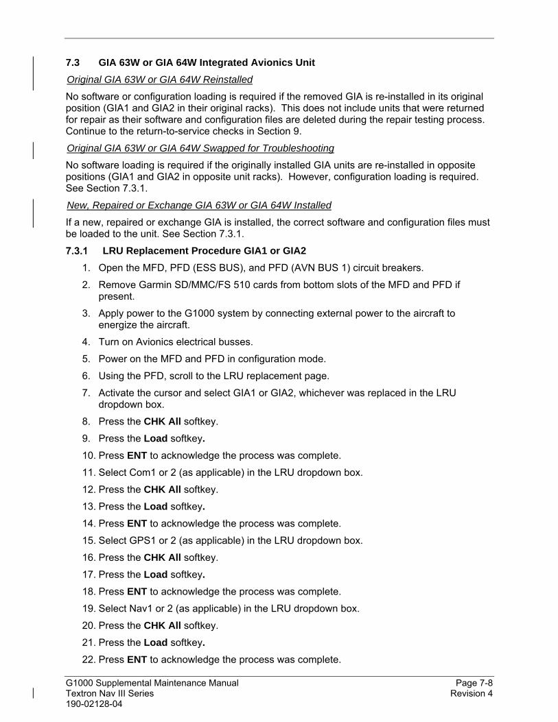
G1000 Supplemental Maintenance Manual Page 7-8 Textron Nav III Series Revision 4 190-02128-04
7.3 GIA 63W or GIA 64W Integrated Avionics Unit
Original GIA 63W or GIA 64W Reinstalled
No software or configuration loading is required if the removed GIA is re-installed in its original position (GIA1 and GIA2 in their original racks). This does not include units that were returned for repair as their software and configuration files are deleted during the repair testing process. Continue to the return-to-service checks in Section 9.
Original GIA 63W or GIA 64W Swapped for Troubleshooting
No software loading is required if the originally installed GIA units are re-installed in opposite positions (GIA1 and GIA2 in opposite unit racks). However, configuration loading is required. See Section 7.3.1.
New, Repaired or Exchange GIA 63W or GIA 64W Installed
If a new, repaired or exchange GIA is installed, the correct software and configuration files must be loaded to the unit. See Section 7.3.1.
LRU Replacement Procedure GIA1 or GIA2
1. Open the MFD, PFD (ESS BUS), and PFD (AVN BUS 1) circuit breakers.
2. Remove Garmin SD/MMC/FS 510 cards from bottom slots of the MFD and PFD if present.
3. Apply power to the G1000 system by connecting external power to the aircraft to energize the aircraft.
4. Turn on Avionics electrical busses.
5. Power on the MFD and PFD in configuration mode.
6. Using the PFD, scroll to the LRU replacement page.
7. Activate the cursor and select GIA1 or GIA2, whichever was replaced in the LRU dropdown box.
8. Press the CHK All softkey.
9. Press the Load softkey.
10. Press ENT to acknowledge the process was complete.
11. Select Com1 or 2 (as applicable) in the LRU dropdown box.
12. Press the CHK All softkey.
13. Press the Load softkey.
14. Press ENT to acknowledge the process was complete.
15. Select GPS1 or 2 (as applicable) in the LRU dropdown box.
16. Press the CHK All softkey.
17. Press the Load softkey.
18. Press ENT to acknowledge the process was complete.
19. Select Nav1 or 2 (as applicable) in the LRU dropdown box.
20. Press the CHK All softkey.
21. Press the Load softkey.
22. Press ENT to acknowledge the process was complete.

G1000 Supplemental Maintenance Manual Page 7-9 Textron Nav III Series Revision 4 190-02128-04
23. Deactivate the cursor.
24. Scroll to the Configuration Manager page.
25. Press the CNFM CFG softkey.
26. Select ok when prompted to “Confirm configuration as expected configuration”
27. Power cycle the system verify there are no red-Xs or system alerts.
28. If red-Xs or system alerts are present, troubleshoot as necessary using Section 5 or re-load the system using the legacy method in Section 7.3.2.
29. If there are no red-Xs or system alerts, continue to Section 7.3.3.
Legacy Replacement Procedure GIA1 or GIA2 (Alternate Method)
To load the GIA complete the following subsections in order as they apply to the aircraft.
Cessna XXX – Baseline Configuration (For GIA 1 or GIA 2 replacement) (where XXX is the airframe type)
1. Insert the software loader card in the top slot of the PFD.
2. Power on the MFD and PFD in configuration mode.
3. Select no when “Do you want to update system files” is displayed on the screen of PFD.
4. Select the “SYSTEM UPLOAD” page using the small FMS knob on the PFD.
5. Activate the cursor and rotate the small FMS knob to display the drop down menu. Rotate the large FMS knob to highlight “0X-XXX” (where 0X is the menu position, and XXX is the airframe type) and press ENT key on the PFD.
6. Rotate the small FMS knob to display the drop down menu. Rotate the large FMS knob to highlight Cessna XXX – Baseline Configuration (where XXX is the airframe type) Press ENT key on the PFD.
7. Press the CLR ALL softkey.
8. Use the large FMS knob to scroll to GIA 1 - SYS or GIA 2 - SYS, whichever was replaced.
9. Highlight the software box and press the ENT key to check the box.
10. Highlight the Configuration box and press the ENT key to check the box.
11. Use the large FMS knob to scroll to GIA 1 – GEA PIN MAPPING or GIA 2 – GEA PIN MAPPING, whichever was replaced.
12. Highlight the Configuration box and press the ENT key to check the box.
13. Use the large FMS knob to scroll to NAV 1 or NAV 2, whichever was replaced.
14. Highlight the software box and press the ENT key to check the box.
15. Use the large FMS knob to scroll to COM 1 or COM 2, whichever was replaced.
16. Highlight the software box and press the ENT key to check the box.
17. Highlight the configuration box and press the ENT key to check the box.
18. Use the large FMS knob to scroll to GIA 1 – AUDIO or GIA 2 – AUDIO, whichever was replaced.
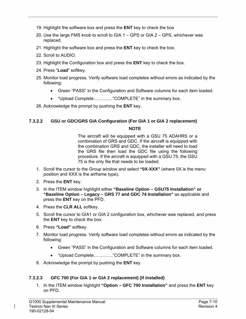
G1000 Supplemental Maintenance Manual Page 7-10 Textron Nav III Series Revision 4 190-02128-04
19. Highlight the software box and press the ENT key to check the box
20. Use the large FMS knob to scroll to GIA 1 – GPS or GIA 2 – GPS, whichever was replaced.
21. Highlight the software box and press the ENT key to check the box.
22. Scroll to AUDIO.
23. Highlight the Configuration box and press the ENT key to check the box.
24. Press “Load” softkey.
25. Monitor load progress. Verify software load completes without errors as indicated by the following:
Green “PASS” in the Configuration and Software columns for each item loaded.
“Upload Complete………….”COMPLETE” in the summary box.
26. Acknowledge the prompt by pushing the ENT key.
GSU or GDC/GRS GIA Configuration (For GIA 1 or GIA 2 replacement)
NOTE
The aircraft will be equipped with a GSU 75 ADAHRS or a combination of GRS and GDC. If the aircraft is equipped with the combination GRS and GDC, the installer will need to load the GRS file then load the GDC file using the following procedure. If the aircraft is equipped with a GSU 75, the GSU 75 is the only file that needs to be loaded.
1. Scroll the cursor to the Group window and select “0X-XXX” (where 0X is the menu position and XXX is the airframe type).
2. Press the ENT key.
3. In the ITEM window highlight either “Baseline Option – GSU75 Installation” or “Baseline Option – Legacy – GRS 77 and GDC 74 Installation” as applicable and press the ENT key on the PFD.
4. Press the CLR ALL softkey.
5. Scroll the cursor to GIA1 or GIA 2 configuration box, whichever was replaced, and press the ENT key to check the box.
6. Press “Load” softkey.
7. Monitor load progress. Verify software load completes without errors as indicated by the following:
Green “PASS” in the Configuration and Software columns for each item loaded.
“Upload Complete………….”COMPLETE” in the summary box.
8. Acknowledge the prompt by pushing the ENT key
GFC 700 (For GIA 1 or GIA 2 replacement) (if installed)
1. In the ITEM window highlight “Option – GFC 700 Installation” and press the ENT key on PFD.

G1000 Supplemental Maintenance Manual Page 7-11 Textron Nav III Series Revision 4 190-02128-04
2. Press the CLR ALL softkey.
3. Scroll the cursor to GIA CERT software box, and press the ENT key to check the box.
4. Press “Load” softkey.
5. Monitor load progress. Verify software load completes without errors as indicated by the following:
Green “PASS” in the Configuration and Software columns for each item loaded.
“Upload Complete………….”COMPLETE” in the summary box.
6. Acknowledge the prompt by pushing the ENT key.
KAP 140 Autopilot (For GIA 2 replacement) (if installed)
1. In the ITEM window highlight “Option – KAP 140 Installation” and press the ENT key on PFD.
2. Press the CLR ALL softkey.
3. Scroll the cursor to GIA2 configuration box, and press the ENT key to check the box.
4. Press “Load” softkey.
5. Monitor load progress. Verify software load completes without errors as indicated by the following:
Green “PASS” in the Configuration and Software columns for each item loaded.
“Upload Complete………….”COMPLETE” in the summary box.
6. Acknowledge the prompt by pushing the ENT key.
Transponder GIA Configuration (For GIA 1 or GIA 2 replacement)
1. In the ITEM window highlight either “Baseline Option – GTX 335 Installation” or “Baseline Option – GTX 345 Installation, without GTS 800” or “Baseline Option – GTX 345 Installation, with GTS 800” or “Baseline Option – Legacy – GTX 33 ES Installation” (as applicable) and press the ENT key on the PFD.
2. Press the CLR ALL softkey.
3. Scroll the cursor to GIA1 or GIA 2 configuration box, whichever was replaced, and press the ENT key to check the box.
4. Press “Load” softkey.
5. Monitor load progress. Verify software load completes without errors as indicated by the following:
Green “PASS” in the Configuration and Software columns for each item loaded.
“Upload Complete………….”COMPLETE” in the summary box.
6. Acknowledge the prompt by pushing the ENT key.
ADF GIA Configuration (For GIA 2 replacement and aircraft equipped with a ADF only)
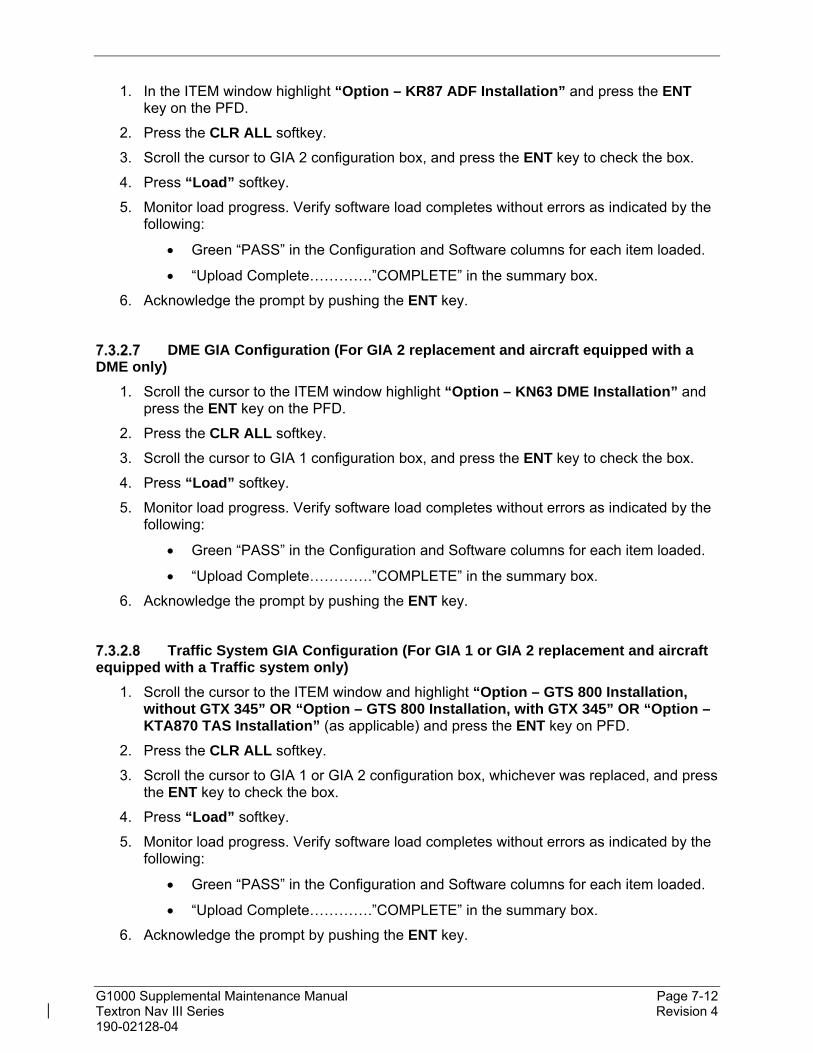
G1000 Supplemental Maintenance Manual Page 7-12 Textron Nav III Series Revision 4 190-02128-04
1. In the ITEM window highlight “Option – KR87 ADF Installation” and press the ENT key on the PFD.
2. Press the CLR ALL softkey.
3. Scroll the cursor to GIA 2 configuration box, and press the ENT key to check the box.
4. Press “Load” softkey.
5. Monitor load progress. Verify software load completes without errors as indicated by the following:
Green “PASS” in the Configuration and Software columns for each item loaded.
“Upload Complete………….”COMPLETE” in the summary box.
6. Acknowledge the prompt by pushing the ENT key.
DME GIA Configuration (For GIA 2 replacement and aircraft equipped with a DME only)
1. Scroll the cursor to the ITEM window highlight “Option – KN63 DME Installation” and press the ENT key on the PFD.
2. Press the CLR ALL softkey.
3. Scroll the cursor to GIA 1 configuration box, and press the ENT key to check the box.
4. Press “Load” softkey.
5. Monitor load progress. Verify software load completes without errors as indicated by the following:
Green “PASS” in the Configuration and Software columns for each item loaded.
“Upload Complete………….”COMPLETE” in the summary box.
6. Acknowledge the prompt by pushing the ENT key.
Traffic System GIA Configuration (For GIA 1 or GIA 2 replacement and aircraft equipped with a Traffic system only)
1. Scroll the cursor to the ITEM window and highlight “Option – GTS 800 Installation, without GTX 345” OR “Option – GTS 800 Installation, with GTX 345” OR “Option – KTA870 TAS Installation” (as applicable) and press the ENT key on PFD.
2. Press the CLR ALL softkey.
3. Scroll the cursor to GIA 1 or GIA 2 configuration box, whichever was replaced, and press the ENT key to check the box.
4. Press “Load” softkey.
5. Monitor load progress. Verify software load completes without errors as indicated by the following:
Green “PASS” in the Configuration and Software columns for each item loaded.
“Upload Complete………….”COMPLETE” in the summary box.
6. Acknowledge the prompt by pushing the ENT key.

G1000 Supplemental Maintenance Manual Page 7-13 Textron Nav III Series Revision 4 190-02128-04
Stormscope GIA Configuration (For GIA 2 replacement and aircraft equipped with a WX500 system only)
1. Scroll the cursor to the ITEM window highlight “Option – WX500 Installation” and press the ENT key on the PFD.
2. Press the CHK ALL softkey.
3. Press “Load” softkey.
4. Monitor load progress. Verify software load completes without errors as indicated by the following:
Green “PASS” in the Configuration and Software columns for each item loaded.
“Upload Complete………….”COMPLETE” in the summary box.
5. Acknowledge the prompt by pushing the ENT key.
Configuration Manager Update
1. With the system still in configuration mode, scroll to the Configuration Manager page on the PFD.
2. Press the CNFM CFG softkey.
3. Select ok when prompted to “Confirm configuration as expected configuration”.
4. Power cycle the system verify there are no red-Xs or system alerts.
5. If red-Xs or system alerts are present, troubleshoot as necessary using Section 5.
6. If there are no red-Xs or system alerts, continue to Section 7.3.3.
This area intentionally blank

G1000 Supplemental Maintenance Manual Page 7-14 Textron Nav III Series Revision 4 190-02128-04
GIA Test
GPS Signal Acquisition
Figure 7-2, Aux – GPS Status Page (MFD)
The GIA units should normally acquire a GPS navigation solution within 5 to 10 minutes of startup, provided the aircraft is outside (or indoors with a GPS repeater). Select the Aux – GPS Status page on the MFD. Two softkeys on the bottom of the display allow the user to toggle between GPS 1 and GPS 2. Verify that both receivers show 3D DIFF NAV on the MFD.
NOTE
It may be necessary to temporarily disable or move away from GPS repeaters while testing, as repeaters may adversely affect GPS receiver performance.
VHF COM Interference Test
This test must be conducted outside. Use of a GPS repeater inside a hangar may result in a failed test. This procedure assumes that the system is currently set to 25 kHz COM channel spacing. Once the signal acquisition test has been completed successfully, perform the following steps:
1. On the MFD, monitor GPS signal strength bars on the Aux – GPS Status page.
2. On the PFD, ensure that the CDI is set to GPS. If it is not, press the ‘CDI’ softkey until GPS ENR is displayed.
3. Verify that the GPS “INTEG” flag is out of view.
4. Select 121.150 MHz on the No. 1 COM transceiver.
5. Transmit for a period of 35 seconds while monitoring GPS 1 signal strength levels.
6. During the transmit period, verify that the GPS “INTEG” flag does not come into view on the PFD and verify that GPS 1 does not lose a 3-D navigation solution on the MFD.

G1000 Supplemental Maintenance Manual Page 7-15 Textron Nav III Series Revision 4 190-02128-04
7. Repeat steps 5 and 6 and re-transmit while monitoring GPS 2 signal levels on the MFD.
8. Repeat steps 4 through 7 for each of the following frequencies:
121.175 MHz
121.200 MHz
131.250 MHz
131.275 MHz
131.300 MHz
9. Repeat steps 4 through 8 for the No. 2 COM transceiver (GIA2).
10. On the MFD, select the Aux – System Setup page.
11. Under the COM CONFIG field, change the COM channel spacing from 25 kHz to 8.33 kHz.
12. Go back to the Aux – GPS Status page.
13. Select 121.185 MHz on the No. 1 COM transceiver.
14. Transmit for a period of 35 seconds while monitoring GPS 1 signal strength levels.
15. During the transmit period, verify that the GPS “INTEG” flag does not come into view on the PFD and verify that GPS 1 does not lose a 3-D navigation solution on the MFD.
16. Repeat steps 14 and 15 and re-transmit while monitoring GPS 2 signal levels on the MFD.
17. Repeat steps 14 through 16 for each of the following frequencies:
121.190 MHz
130.285 MHz
131.290 MHz
18. Repeat steps 14 through 17 for the No. 2 COM transceiver (GIA2).
19. On the MFD, select the Aux – System Setup page and change the COM channel spacing back to 25 kHz.
VOR/LOC/GS Test
Check the VOR, ILS, and Glideslope functions with ramp test equipment. Operate the equipment according to the test equipment manufacturer’s instructions. Adjust the RF signal to a level adequate to perform the test. Select the appropriate HSI source by using the CDI softkey.
NOTE
The PFD HSI does not show a course deviation bar unless a valid VHF NAV frequency is tuned.

G1000 Supplemental Maintenance Manual Page 7-16 Textron Nav III Series Revision 4 190-02128-04
GFC 700 VOR/LOC/GS Test (if GFC 700 is installed)
1. Simulate a VOR signal on a radial equivalent to the aircraft heading. Tune the NAV 1 and NAV 2 receivers to the simulation frequency.
2. Set the HSI on the PFD to VOR1 by pressing the CDI softkey until VOR1 is selected. Rotate CRS knob to set VOR1 course pointer to aircraft heading.
3. Verify full scale deflection of VOR1 CDI by varying CRS1 selected course at least 10° left and right. Reset course pointer to aircraft heading.
4. Engage the autopilot and press the NAV key on the AFCS mode controller. Using the CRS knob alter course by 10° to the right. Verify the flight director and aircraft controls respond by flying to the VOR course. Repeat to the left.
5. Set CRS course pointer to aircraft heading.
6. Simulate a Localizer/Glideslope signal. Tune this signal on NAV 1 and NAV 2 receiver. Set the PFD HSI to LOC1 by pressing CDI softkey until LOC1 is selected. Use the test equipment to center the deviation bars (localizer and glideslope) on the PFD.
7. Press the APR key on the AFCS mode controller. Verify that the LOC and PIT annunciations are green and ALTS and GS are white on the PFD. Apply right/left and up/down localizer/glideslope signals using the test equipment. Verify that the Flight Director and flight controls respond appropriately.
8. If no other service is to be performed, continue to the return-to-service checks in Section 9.

G1000 Supplemental Maintenance Manual Page 7-17 Textron Nav III Series Revision 4 190-02128-04
7.4 GEA 71 or GEA 71B Engine/Airframe Unit
Original GEA 71 or GEA 71B Reinstalled
No software or configuration loading is required if the removed GEA is re-installed. This does not include units that were returned for repair as their software and configuration files are deleted during the repair testing process. Continue to the return-to-service checks in Section 9.
New, Repaired or Exchange GEA 71 or GEA 71B Installed
If a new, repaired or exchange GEA is installed, the correct software and configuration files must be loaded to the unit. See Section 7.4.1.
LRU Replacement Procedure GEA
1. Open the MFD, PFD (ESS BUS), and PFD (AVN BUS 1) circuit breakers.
2. Remove Garmin SD/MMC/FS 510 cards from bottom slots of the MFD and PFD if present.
3. Apply power to the G1000 system by connecting external power to the aircraft to energize the aircraft and avionics electrical busses.
4. Turn on Avionics electrical busses.
5. Power on the MFD and PFD in configuration mode.
6. Using the PFD, scroll to the LRU replacement page.
7. Activate the cursor and select GEA1 in the LRU dropdown box.
8. Press the CHK All softkey.
9. Press the Load softkey.
10. Press ENT to acknowledge the process was complete.
11. Deactivate the cursor.
12. Scroll to the Configuration Manager page.
13. Press the CNFM CFG softkey.
14. Select ok when prompted to “Confirm configuration as expected configuration”
15. Power cycle the system verify there are no red-Xs or system alerts.
16. If red-Xs or system alerts are present, troubleshoot as necessary using Section 5 or re-load the system using the legacy method in Section 7.4.2
17. If there are no red-Xs or system alerts, continue to Section 7.4.3.

G1000 Supplemental Maintenance Manual Page 7-18 Textron Nav III Series Revision 4 190-02128-04
Legacy Replacement Procedure GEA (Alternate Method)
To load the GEA complete the following subsections in order as they apply to the aircraft.
GEA Configuration (For GEA replacement)
1. Insert the software loader card in the top slot of the PFD.
2. Power on the MFD and PFD in configuration mode.
3. Select no when “Do you want to update system files” is displayed on the screen of PFD.
4. Select the “SYSTEM UPLOAD” page using the small FMS knob on the PFD.
5. Activate the cursor and rotate the small FMS knob to display the drop down menu. Rotate the large FMS knob to highlight “0X - XXX” (where 0X is the menu position and XXX is the airframe type) and press ENT key on the PFD.
6. Rotate the small FMS knob to display the drop down menu. Rotate the large FMS knob to highlight “Cessna XXX – Baseline Configuration” (where XXX is the airframe type) and Press ENT key on the PFD.
7. Press the CLR ALL softkey.
8. Use the large FMS knob to scroll to GEA.
9. Highlight the software box and press the ENT key to check the box.
10. Highlight the Configuration box and press the ENT key to check the box.
11. Press “Load” softkey.
12. Monitor load progress. Verify software load completes without errors as indicated by the following:
Green “PASS” in the Configuration and Software columns for each item loaded.
“Upload Complete………….”COMPLETE” in the summary box.
13. Acknowledge the prompt by pushing the ENT key.
CAN Bus Fuel Probe Configuration (For GEA replacement) (if installed)
1. In the ITEM window highlight “Option – CAN BUS FUEL LEVEL SENSORS” and press the ENT key on the PFD.
2. Press the CLR ALL softkey.
3. Scroll the cursor to GEA configuration box and press the ENT key to check the box.
4. Press “Load” softkey.
5. Monitor load progress. Verify software load completes without errors as indicated by the following:
Green “PASS” in the Configuration and Software columns for each item loaded.
“Upload Complete………….”COMPLETE” in the summary box.
6. Acknowledge the prompt by pushing the ENT key.

G1000 Supplemental Maintenance Manual Page 7-19 Textron Nav III Series Revision 4 190-02128-04
Configuration Manager Update
1. With the system still in configuration mode, scroll to the Configuration Manager page on the PFD.
2. Press the CNFM CFG softkey.
3. Select ok when prompted to “Confirm configuration as expected configuration”
4. Power cycle the system verify there are no red-Xs or system alerts.
5. If red-Xs or system alerts are present, troubleshoot as necessary using Section 5.
6. If there are no red-Xs or system alerts, test the GEA per Section 7.4.3.

G1000 Supplemental Maintenance Manual Page 7-20 Textron Nav III Series Revision 4 190-02128-04
GEA Test
On the MFD (normal mode), check the indication for each of the sensor or monitor inputs with the aircraft engines off.
In general, verify all engine and system instruments show valid static normal values and markings, with no red Xs or erratic indications. Reference Figure 7-3 for normal engine instrument markings (figure may not reflect actual aircraft installation). If individual engine readings do not appear normal or have a red-X over them, refer to the G1000 Nav III Line Maintenance Manual.
Figure 7-3, Normal Engine Instrument Markings (MFD)
If no other service is to be performed and individual GEA input testing is not required, continue to the return-to-service checks in Section 9.

G1000 Supplemental Maintenance Manual Page 7-21 Textron Nav III Series Revision 4 190-02128-04
7.5 GTX 335R, GTX 345R, or GTX 33 Transponder
Original GTX is Reinstalled
No software or configuration loading is required if the removed GTX 335R, GTX 345R, or GTX 33 is re-installed. This does not include units that were returned for repair as their software and configuration files are deleted during the repair testing process. Continue to GTX 335R, GTX 345R, or GTX 33 Test Section 7.5.4.
New, Repaired or Exchange GTX is Installed
If a new, repaired or exchange GTX 335R, GTX 345R, or GTX 33 is installed, the correct software and configuration files must be loaded to the unit. See Section 7.5.1.
LRU Replacement Procedure GTX1
1. Open the MFD, PFD (ESS BUS), and PFD (AVN BUS) circuit breakers.
2. Remove Garmin SD/MMC/FS 510 cards from bottom slots of the MFD and PFD if present.
3. Apply power to the G1000 system by connecting external power to the aircraft to energize the aircraft and avionics electrical busses.
4. Turn on Avionics electrical busses.
5. Power on the MFD and PFD in configuration mode.
6. Using the PFD, scroll to the LRU replacement page.
7. Activate the cursor and select GTX1 in the LRU dropdown box.
8. Press the CHK All softkey.
9. Press the Load softkey.
10. Press ENT to acknowledge the process was complete.
11. Deactivate the cursor.
12. Scroll to the Configuration Manager page.
13. Press the CNFM CFG softkey.
14. Select ok when prompted to “Confirm configuration as expected configuration”
15. Power cycle the system verify there are no red-Xs or system alerts.
16. If red-Xs or system alerts are present, troubleshoot as necessary using Section 5 or re-load the system using the legacy method in Section 7.5.2.
17. If there are no red-Xs or system alerts, continue to Section 7.5.3.
Legacy Replacement Procedure GTX (Alternate Method)
1. Insert the software loader card in the top slot of the PFD.
2. Power on the MFD and PFD in configuration mode.
3. Select no when “Do you want to update system files” is displayed on the screen of the PFD.
4. Select the “SYSTEM UPLOAD” page using the small FMS knob on the PFD.

G1000 Supplemental Maintenance Manual Page 7-22 Textron Nav III Series Revision 4 190-02128-04
5. Activate cursor and rotate the small FMS knob to display the drop down menu. Rotate the large FMS knob to highlight “0X - XXX” (where 0X is the menu position and XXX is the airframe type) and press ENT key on the PFD.
6. Rotate the small FMS knob to display the drop down menu. Rotate the large FMS knob to highlight “Baseline Option – GTX 335 Installation” OR “Baseline Option – GTX 345 Installation, without GTS 800” or “Baseline Option – GTX 345 Installation, with GTS 800” or “Baseline Option – Legacy – GTX 33 ES Installation” (as applicable). Press ENT key on the PFD.
7. Press the CLR ALL softkey.
8. Use the large FMS knob to scroll to GTX.
9. Highlight the software box(es) and press the ENT key to check the box.
10. Highlight the Configuration box and press the ENT key to check the box.
11. Press “Load” softkey.
12. Monitor load progress. Verify software load completes without errors as indicated by the following:
Green “PASS” in the Configuration and Software columns for each item loaded.
“Upload Complete………….”COMPLETE” in the summary box.
13. Acknowledge the prompt by pushing the ENT key.
14. Deactivate the cursor.
15. Scroll to the Configuration Manager page.
16. Press the CNFM CFG softkey.
17. Select ok when prompted to “Confirm configuration as expected configuration”
18. Power cycle the system verify there are no red-Xs or system alerts.
19. If red-Xs or system alerts are present, troubleshoot as necessary using Section 5.
20. If there are no red-Xs or system alerts, continue to Section 7.5.3.
Transponder Configuration
1. If not applied, apply power to the G1000 system and put all displays into config mode.
2. On the PFD, select the AIRCRAFT CONFIGURATION page.
3. For GTX 33 unit replacement only, press the Set GTX #1 softkey and acknowledge the PFD prompt by pressing the ENT key. GTX 335R and 345R units automatically save the registration number, no action is needed for these units.
4. After completing transponder configuration, deactivate the cursor.

G1000 Supplemental Maintenance Manual Page 7-23 Textron Nav III Series Revision 4 190-02128-04
Figure 7-4, Aircraft Registration
GTX 335R, GTX 345R, or GTX 33 Test
Operation of the GTX 335R, GTX 345R, or GTX 33 Mode-S transponder is accomplished using the PFD or the MFD. Refer to G1000 Cessna Nav III Cockpit Reference Guide, listed in Table 1-1, for basic operation.
The integrated transponder/altitude reporting system must be verified in accordance with Title 14 of the Code of Federal Regulations (14 CFR) §§ 91.411 and 91.413, every 24 calendar months, or any time the transponder is removed. This test requires the use of a Mode S ramp generator. Specific instructions for operating the ramp tester are contained in the applicable operator's manual. Refer to 14 CFR Part 43 Appendices E and F for testing criteria.
If no other service is to be performed, continue to the return-to-service checks in Section 9.

G1000 Supplemental Maintenance Manual Page 7-24 Textron Nav III Series Revision 4 190-02128-04
7.6 GSU 75 ADAHRS (if installed)
Original GSU unit is Reinstalled
No software or configuration loading is required if the removed GSU 75 is re-installed. This does not include units that were returned for repair as their software and configuration files are deleted during the repair testing process. Perform a pitot - static system leak check and continue to Section 9.
New, Repaired or Exchange GSU unit is Installed
If a new, repaired or exchange GSU unit is installed, the correct software and configuration files must be loaded to the unit.
New GSU 75 Configuration Module is Installed
The correct configuration files must be loaded if the GSU75 configuration module has been replaced.
LRU Replacement Procedure GSU
1. Open the MFD PFD (ESS BUS), and PFD (AVN BUS 1) circuit breakers.
2. Remove Garmin SD/MMC/FS 510 cards from bottom slots of the MFD and PFD if present.
3. Apply power to the G1000 system by connecting external power to the aircraft to energize the aircraft and avionics electrical busses.
4. Turn on Avionics electrical busses.
5. Power on the MFD and PFD in configuration mode.
6. Using the PFD, scroll to the LRU replacement page.
7. Activate the cursor and select GRS1 in the LRU dropdown box.
8. Press the CHK All softkey.
9. Press the Load softkey.
10. Press ENT to acknowledge the process was complete.
11. Select GDC 1 in the LRU dropdown box.
12. Press the CHK All softkey.
13. Press the Load softkey.
14. Press ENT to acknowledge the process was complete.
15. Deactivate the cursor.
16. Scroll to the Configuration Manager page.
17. Press the CNFM CFG softkey.
18. Select ok when prompted to “Confirm configuration as expected configuration”
19. Power cycle the system verify there are no red-Xs or system alerts.
20. If red-Xs or system alerts are present, troubleshoot as necessary using Section 5 or re-load the system using the legacy method in Section 7.6.2.
21. If there are no red-Xs or system alerts, continue to Section 7.7.3 for the air data portion of the GSU and Section 7.10.5 for the AHRS portion of the GSU.

G1000 Supplemental Maintenance Manual Page 7-25 Textron Nav III Series Revision 4 190-02128-04
Legacy Replacement Procedure GSU (Alternate Method) (if installed)
1. Insert the software loader card in the top slot of the PFD.
2. Power on the MFD and PFD in configuration mode.
3. Select no when “Do you want to update system files” is displayed on the screen of PFD.
4. Select the “SYSTEM UPLOAD” page using the small FMS knob on the PFD.
5. Activate cursor and rotate the small FMS knob to display the drop down menu. Rotate the large FMS knob to highlight “0X - XXX” (where 0X is the menu position and XXX is the airframe type) and press ENT key on PFD.
6. Rotate the small FMS knob to display the drop down menu. Rotate the large FMS knob to highlight “Baseline Option – GSU75 Installation”. Press ENT key on PFD.
7. Press the CLR ALL softkey.
8. Use the large FMS knob to scroll to GSU - AHRS.
9. Highlight the software box and press the ENT key to check the box.
10. Highlight the Configuration box and press the ENT key to check the box.
11. Use the large FMS knob to scroll to GSU – ADC.
12. Highlight the software box and press the ENT key to check the box.
13. Highlight the Configuration box and press the ENT key to check the box.
14. Press “Load” softkey.
15. Monitor load progress. Verify software load completes without errors as indicated by the following:
Green “PASS” in the Configuration and Software columns for each item loaded.
“Upload Complete………….”COMPLETE” in the summary box.
16. Acknowledge the prompt by pushing the ENT key.
17. Deactivate the cursor.
18. Scroll to the Configuration Manager page.
19. Press the CNFM CFG softkey.
20. Select ok when prompted to “Confirm configuration as expected configuration”
21. Power cycle the system verify there are no red-Xs or system alerts.
22. If red-Xs or system alerts are present, troubleshoot as necessary using Section 5.
22. If there are no red-Xs or system alerts, continue to Section 7.7.3 for the air data portion of the GSU and Section 7.10.5 for the AHRS portion of the GSU.

G1000 Supplemental Maintenance Manual Page 7-26 Textron Nav III Series Revision 4 190-02128-04
7.7 GDC 74A Air Data
Original GDC unit is Reinstalled
No software or configuration loading is required if the removed GDC 74 is re-installed. This does not include units that were returned for repair as their software and configuration files are deleted during the repair testing process. Perform a pitot - static system leak check and continue to Section 9 if no other service is performed.
New, Repaired or Exchange GDC unit is Installed
If a new, repaired or exchange GDC unit is installed, the correct software and configuration files must be loaded to the unit.
New GDC 74A Configuration Module is Installed
The correct configuration files must be loaded if the GDC 74A configuration module has been replaced.
LRU Replacement Procedure GDC 74A (if installed)
1. Open the MFD, PFD (ESS BUS), and PFD (AVN BUS 1) circuit breakers.
2. Remove Garmin SD/MMC/FS 510 cards from bottom slots of the MFD and PFD if present.
3. Apply power to the G1000 system by connecting external power to the aircraft to energize the aircraft and avionics electrical busses.
4. Turn on Avionics electrical busses.
5. Power on the MFD and PFD in configuration mode.
6. Using the PFD, scroll to the LRU replacement page.
7. Activate the cursor and select GDC1 in the LRU dropdown box.
8. Press the CHK All softkey.
9. Press the Load softkey.
10. Press ENT to acknowledge the process was complete.
11. Deactivate the cursor.
12. Scroll to the Configuration Manager page.
13. Press the CNFM CFG softkey.
14. Select ok when prompted to “Confirm configuration as expected configuration”
15. Power cycle the system verify there are no red-Xs or system alerts.
16. If red-Xs or system alerts are present, troubleshoot as necessary using Section 5 or re-load the system using the legacy method in Section 7.7.2.
17. If there are no red-Xs or system alerts, continue to Section 7.7.3.

G1000 Supplemental Maintenance Manual Page 7-27 Textron Nav III Series Revision 4 190-02128-04
Legacy Replacement Procedure GDC 74A (Alternate Method) (if installed)
1. Insert the software loader card in the top slot of the PFD.
2. Power on the MFD and PFD in configuration mode.
3. Select no when “Do you want to update system files” is displayed on the screen of the PFD.
4. Select the “SYSTEM UPLOAD” page using the small FMS knob on the PFD.
5. Activate cursor and rotate the small FMS knob to display the drop down menu. Rotate the large FMS knob to highlight “0X - XXX” (where 0X is the menu position and XXX is the airframe type) and press ENT key on the PFD.
6. Rotate the small FMS knob to display the drop down menu. Rotate the large FMS knob to highlight “Baseline Option – Legacy – GRS77 and GDC 74 Installation”. Press ENT key on the PFD.
7. Press the CLR ALL softkey.
8. Use the large FMS knob to scroll to GDC.
9. Highlight the software box and press the ENT key to check the box.
10. Highlight the Configuration box and press the ENT key to check the box.
11. Press “Load” softkey.
12. Monitor load progress. Verify software load completes without errors as indicated by the following:
Green “PASS” in the Configuration and Software columns for each item loaded.
“Upload Complete………….”COMPLETE” in the summary box.
13. Acknowledge the prompt by pushing the ENT key.
14. Deactivate the cursor.
15. Scroll to the Configuration Manager page.
16. Press the CNFM CFG softkey.
17. Select ok when prompted to “Confirm configuration as expected configuration”
18. Power cycle the system verify there are no red-Xs or system alerts.
19. If red-Xs or system alerts are present, troubleshoot as necessary using Section 5.
20. If there are no red-Xs or system alerts, continue to Section 7.7.3.
Air Data Test (GSU 75 or GDC 74A)
The G1000 system must be maintained in accordance with the G1000 System Maintenance Manual listed in Table 1-2 and appropriate regulations. When the GDC unit is tested in accordance with 14 CFR Part 43, Appendix E, note the following exceptions:
Do not perform paragraph (b)(1)(iv) Friction
Do not perform paragraph (b)(1)(vi) Barometric Scale Error
The following Air Data Test is to be performed in addition to or in conjunction with any other regulated tests. This test must be performed with a calibrated Air Data Test Set (ADTS) with a combined accuracy/repeatability specification of less than ±20 feet for the test altitude range.

G1000 Supplemental Maintenance Manual Page 7-28 Textron Nav III Series Revision 4 190-02128-04
1. For GSU 75 installations, gain access to the aft avionics compartment in the tail of the aircraft. Locate the tee fittings in the pitot and static lines just forward of the GSU 75 and remove the capped nuts. Drain any condensation from the lines and tees. Reinstall the capped nuts onto the tees and tighten, ensuring caps are facing downward. NOTE: If tee fittings are not installed in the pitot and static lines, disconnect the lines directly from the GSU 75 and drain any condensation from the lines. Reconnect the pitot and static lines to the GSU 75 and tighten the nuts.
2. Perform pitot static system leak check as described in Chapter 34 of the appropriate Cessna Maintenance Manual (refer to Table 1-1 for Manual details.)
3. Connect the pitot/static tester to the aircraft pitot and static ports.
4. Verify that the PFD altimeter baro setting is set to 29.92 in Hg (1013.25 mb).
5. Start the PFD in configuration mode and navigate to the GRS page. The values for altitude and airspeed are shown on the AHRS/AIR DATA INPUT table as B ALT and IAS for AIR DATA 1.
6. Simulate the altitudes shown in Table 7-1. Wait for ADTS to report that target values have been achieved.
7. On Table 7-1, record the altitude (B ALT) displayed on the PFD for AIR DATA 1 for each altitude.
8. Simulate the airspeeds shown in Table 7-1.
9. On Table 7-2, record the airspeed (IAS) displayed on the PFD for AIR DATA 1 for each airspeed.
10. Verify that the indicated altitudes and airspeeds are within allowable tolerances.
11. File the results with the aircraft maintenance records.
If either the pilot or copilot air data system does not meet the tolerances specified, have maintenance checks performed on the air data system or the pitot/static system.
Table 7-1, Altitude Test Points
Test Set Altitude PFD Altitude Reading
(from B ALT field) Allowed Tolerance
0 +/- 20 500 +/- 20
1000 +/- 20 1500 +/- 20 2000 +/- 20 4000 +/- 25 8000 +/- 30
11000 +/- 35 14000 +/- 40 17000 +/- 45 20000 +/- 50

G1000 Supplemental Maintenance Manual Page 7-29 Textron Nav III Series Revision 4 190-02128-04
Table 7-2, Airspeed Test Points
Test Set Airspeed PFD Airspeed Reading
(from IAS field) Allowed Tolerance
50 +/- 5.0 80 +/- 3.0
100 +/- 2.0 120 +/- 2.0 150 +/- 2.0 180 +/- 2.0
Static Port Vertical Speed (Rate of Climb) Test
1. Command ADTS to change the altitude at the rates shown in the table below.
2. Wait for ADTS to report that target rates have been achieved.
3. Verify that the Rate of Climb reported by the Vertical Speed field on the PFD are within the tolerances specified in Table 7-3.
Table 7-3, Vertical Speed Table Vertical Speed, feet/minute Allowed tolerance, ±feet/minute
2000 100 1000 50 500 45 200 45
0 N/A (No VS Display) -200 45 -500 45
-1000 50 -2000 100
OAT Probe Check
1. Ensure the outside air temperature (OAT) probes and a calibrated thermometer stabilize at ambient temperature.
2. Verify that the OAT measurement shown on the PFD, in degrees Celsius, indicate within 2 °C of the ambient temperature as measured by the calibrated thermometer.
If no other service is to be performed, continue to the return-to-service checks in Section 9.

G1000 Supplemental Maintenance Manual Page 7-30 Textron Nav III Series Revision 4 190-02128-04
7.8 GRS 77 and GMU 44 Magnetometer (if installed)
Original GRS is Reinstalled
If the original GRS is reinstalled, then no software loading is required. This does not include units that were returned for repair as their software and configuration files are deleted during the repair testing process.
If the GRS rack was not removed or loosened, continue to the GRS/GMU Test Section 7.10.5.
If the GRS rack was removed or loosened, continue to the GRS/GMU Calibration Procedures Section 7.10.
New, Repaired or Exchange GRS is Installed
If a new, repaired or exchange GRS is installed, then software must be loaded.
New GRS Configuration Module is Installed
If the GRS configuration module is replaced, no software loading is required. Continue to the GRS/GMU Calibration Procedures Section 7.10.
LRU Replacement Procedure GRS 77 (if installed)
1. Open the MFD, PFD (ESS BUS), and PFD (AVN BUS 1) circuit breakers.
2. Remove Garmin SD/MMC/FS 510 cards from bottom slots of the MFD and PFD if present.
3. Apply power to the G1000 system by connecting external power to the aircraft to energize the aircraft and avionics electrical busses.
4. Turn on Avionics electrical busses.
5. Power on the MFD and PFD in configuration mode.
6. Using the PFD, scroll to the LRU replacement page.
7. Activate the cursor and select GRS1 in the LRU dropdown box.
8. Verify all boxes are checked. If they are not checked, press the CHK All softkey.
9. Press the Load softkey.
10. Press ENT to acknowledge the process was complete.
11. Deactivate the cursor.
12. Scroll to the Configuration Manager page.
13. Press the CNFM CFG softkey.
14. Select ok when prompted to “Confirm configuration as expected configuration”
15. Power cycle the system verify there are no red-Xs or system alerts.
16. If red-Xs or system alerts are present, troubleshoot as necessary using Section 5 or re-load the system using the legacy method in Section 7.8.2.
17. If there are no red-Xs or system alerts and the GRS rack(s) were not removed or loosened, continue to the GRS/GMU Test Section 7.10.5.
18. If there are no red-Xs or system alerts and the GRS rack(s) was removed or loosened, continue to the GRS/GMU Calibration Procedures Section 7.10.

G1000 Supplemental Maintenance Manual Page 7-31 Textron Nav III Series Revision 4 190-02128-04
Legacy Replacement Procedure GRS 77 (Alternate Method) (if installed)
1. Insert the software loader card in the top slot of the PFD.
2. Power on the MFD and PFD in configuration mode.
3. Select no when “Do you want to update system files” is displayed on the screen of the PFD.
4. Select the “SYSTEM UPLOAD” page using the small FMS knob on the PFD.
5. Activate cursor and rotate the small FMS knob to display the drop down menu. Rotate the large FMS knob to highlight “0X - XXX” (where 0X is the menu position and XXX is the airframe type) and press ENT key on the PFD.
6. Rotate the small FMS knob to display the drop down menu. Rotate the large FMS knob to highlight “Baseline Option – Legacy – GRS77 and GDC74 Installation”. Press ENT key on the PFD.
7. Press the CLR ALL softkey.
8. Use the large FMS knob to scroll to GRS
9. Highlight the software box and press ENT.
10. Press “Load” softkey.
11. Monitor load progress. Verify software load completes without errors as indicated by the following:
Green “PASS” in the Configuration and Software columns for each item loaded.
“Upload Complete………….”COMPLETE” in the summary box.
12. Acknowledge the prompt by pushing the ENT key.
13. Deactivate the cursor.
14. Scroll to the Configuration Manager page.
15. Press the CNFM CFG softkey.
16. Select ok when prompted to “Confirm configuration as expected configuration”
17. Power cycle the system verify there are no red-Xs or system alerts.
18. If red-Xs or system alerts are present, troubleshoot as necessary using Section 5.
17. If there are no red-Xs or system alerts and the GRS rack(s) were not removed or loosened, continue to the GRS/GMU Test Section 7.10.5.
18. If there are no red-Xs or system alerts and the GRS rack(s) was removed or loosened, continue to the GRS/GMU Calibration Procedures Section 7.10.

G1000 Supplemental Maintenance Manual Page 7-32 Textron Nav III Series Revision 4 190-02128-04
7.9 GMU 44 Magnetometer
Original GMU 44 is Reinstalled
If the original GMU 44 is reinstalled, then no software loading is required. This does not include units that were returned for repair as their software and configuration files are deleted during the repair testing process. Continue to the GRS/GMU Test Section 7.10.5.
New, Repaired or Exchange GMU 44 is Installed
If a new, repaired or exchange GMU 44 is installed, then software must be loaded.
LRU Replacement Procedure GMU
1. Open the MFD, PFD (ESS BUS), and PFD (AVN BUS 1) circuit breakers.
2. Remove Garmin SD/MMC/FS 510 cards from bottom slots of the MFD and PFD if present.
3. Apply power to the G1000 system by connecting external power to the aircraft to energize the aircraft and avionics electrical busses.
4. Turn on Avionics electrical busses.
5. Power on the MFD and PFD in configuration mode.
6. Using the PFD, scroll to the LRU replacement page.
7. Activate the cursor and select GMU1 in the LRU dropdown box.
8. Verify all boxes are checked. If they are not checked, press the CHK All softkey.
9. Press the Load softkey.
10. Press ENT to acknowledge the process was complete.
11. Deactivate the cursor.
12. Scroll to the Configuration Manager page.
13. Press the CNFM CFG softkey.
14. Select ok when prompted to “Confirm configuration as expected configuration”
15. Power cycle the system verify there are no red-Xs or system alerts.
16. If red-Xs or system alerts are present, troubleshoot as necessary using Section 5 or re-load the system using the legacy method in Section 7.9.2.
17. If there are no red-Xs or system alerts, continue to Section 7.10.
Legacy Replacement Procedure GMU1 (Alternate Method)
1. Insert the software loader card in the top slot of the PFD.
19. Power on the MFD and PF1 in configuration mode.
20. Select no when “Do you want to update system files” is displayed on the screen of the PFD.
21. Select the “SYSTEM UPLOAD” page using the small FMS knob on the PFD.
22. Activate cursor and rotate the small FMS knob to display the drop down menu. Rotate the large FMS knob to highlight “0X – XXX” (where 0X is the menu position and XXX is the airframe type) and press ENT key on the PFD.
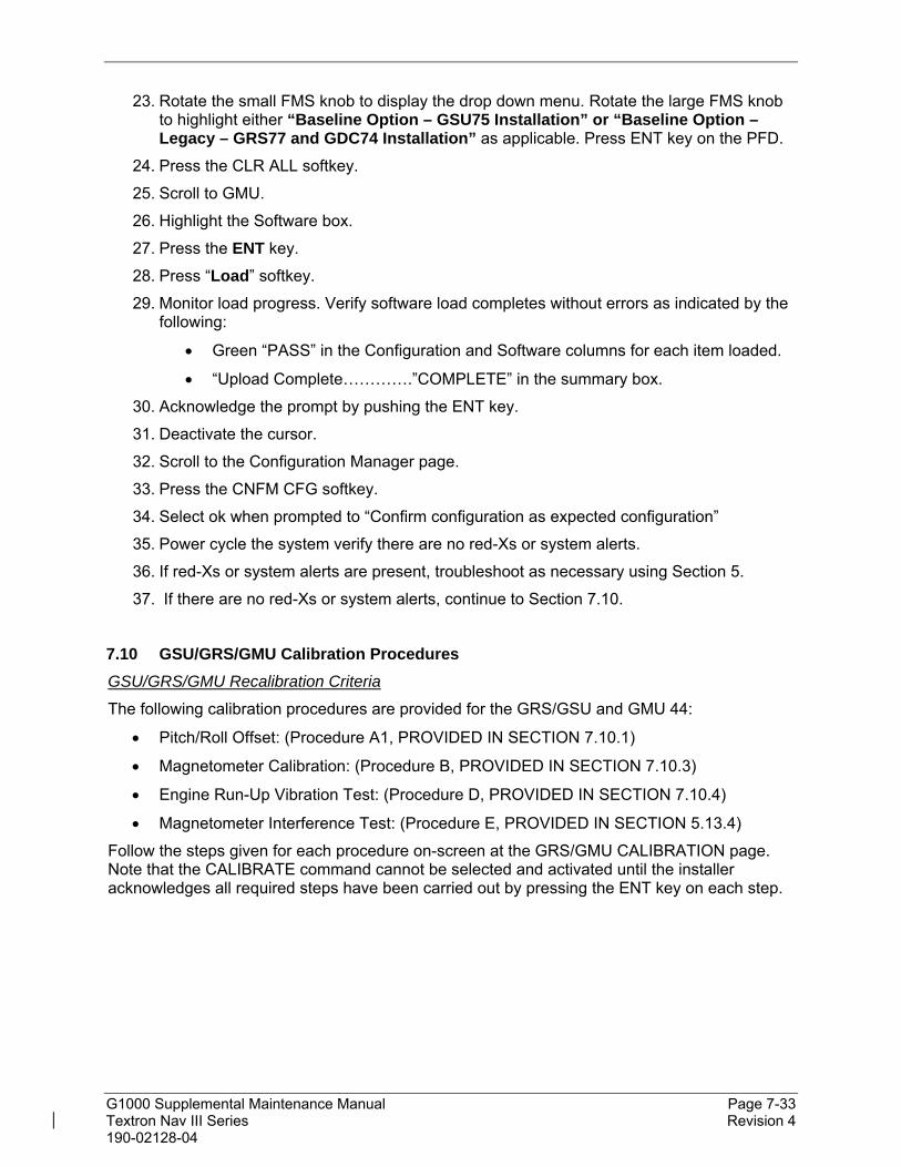
G1000 Supplemental Maintenance Manual Page 7-33 Textron Nav III Series Revision 4 190-02128-04
23. Rotate the small FMS knob to display the drop down menu. Rotate the large FMS knob to highlight either “Baseline Option – GSU75 Installation” or “Baseline Option – Legacy – GRS77 and GDC74 Installation” as applicable. Press ENT key on the PFD.
24. Press the CLR ALL softkey.
25. Scroll to GMU.
26. Highlight the Software box.
27. Press the ENT key.
28. Press “Load” softkey.
29. Monitor load progress. Verify software load completes without errors as indicated by the following:
Green “PASS” in the Configuration and Software columns for each item loaded.
“Upload Complete………….”COMPLETE” in the summary box.
30. Acknowledge the prompt by pushing the ENT key.
31. Deactivate the cursor.
32. Scroll to the Configuration Manager page.
33. Press the CNFM CFG softkey.
34. Select ok when prompted to “Confirm configuration as expected configuration”
35. Power cycle the system verify there are no red-Xs or system alerts.
36. If red-Xs or system alerts are present, troubleshoot as necessary using Section 5.
37. If there are no red-Xs or system alerts, continue to Section 7.10.
7.10 GSU/GRS/GMU Calibration Procedures
GSU/GRS/GMU Recalibration Criteria
The following calibration procedures are provided for the GRS/GSU and GMU 44:
Pitch/Roll Offset: (Procedure A1, PROVIDED IN SECTION 7.10.1)
Magnetometer Calibration: (Procedure B, PROVIDED IN SECTION 7.10.3)
Engine Run-Up Vibration Test: (Procedure D, PROVIDED IN SECTION 7.10.4)
Magnetometer Interference Test: (Procedure E, PROVIDED IN SECTION 5.13.4)
Follow the steps given for each procedure on-screen at the GRS/GMU CALIBRATION page. Note that the CALIBRATE command cannot be selected and activated until the installer acknowledges all required steps have been carried out by pressing the ENT key on each step.

G1000 Supplemental Maintenance Manual Page 7-34 Textron Nav III Series Revision 4 190-02128-04
Table 7-4, Required GRS/GMU Calibrations
Condition
Calibrations Required Procedure A1:
GSU 75 or GRS 77 Pitch/Roll
Offset
Procedure B: GSU/GRS/GMU
Magnetic Calibration
Procedure D: Engine Run-up
Vibration Test
GMU 44 was removed and reinstalled. (no change in serial number)
None Required. Continue to GSU/GRS/GMU Test Section.
GMU 44 was replaced with new unit. (New serial number)
X
GRS AHRS or GSU ADAHRS was removed and/or replaced. The mounting tray was NOT removed and the mounting tray bolts were NOT loosened.
None Required. Continue to GSU/GRS/GMU Test Section.
GRS AHRS or GSU ADAHRS was removed and/or replaced. The mounting tray WAS removed and/or mounting tray bolts WERE loosened.
X
X
X
GRS AHRS or GSU ADAHRS Configuration Module was replaced.
X X X
Procedure A1: GSU 75 or GRS 77 Pitch/Roll Offset Calibration
This first procedure must be carried out with the engine off.
1. Level the aircraft to within 0.25° of zero pitch and zero roll. (Follow instructions in the appropriate Cessna Nav III Series Maintenance Manual, listed in Table 1-1, for leveling)
2. Start the PFD in Configuration mode.
3. Go to the GRS Page Group and select the GRS/GMU Calibration page at the PFD. This page is protected and the following softkey password must be entered at the PFD to continue:
9
10
11
12 (Far Right softkey)

G1000 Supplemental Maintenance Manual Page 7-35 Textron Nav III Series Revision 4 190-02128-04
Figure 7-5, GRS/GMU Calibration, Pitch/Roll Offset
NOTE
On the calibration pages, “GRS” includes GRS and GSU units.
4. Ensure that the GRS 1 is selected in the SELECT GRS UNIT window on the PFD.
5. Activate the cursor and highlight the SELECT PROCEDURE window and select PITCH / ROLL OFFSET.
6. Press the ENT key.
7. Use the cursor to highlight Step 1 in the BEFORE CALIBRATION window.
8. Follow the checklist items displayed on the PFD and press the ENT key as each step is completed or confirmed.
9. When the CALIBRATE field is blinking, press the ENT button to begin the procedure.
10. After several seconds, a new checklist appears in the lower half of the PFD. Press the ENT key as each step is confirmed. When the CONFIRM AIRCRAFT IS LEVEL field is blinking, press the ENT key to continue.
11. The result of the pitch/roll offset compensation is displayed on the PFD. If successful, the AHRS records the required pitch and roll offsets, informs the operator of a successful conclusion and returns to normal operation.
12. Press the ENT key on the PFD to conclude this procedure for GRS 1.

G1000 Supplemental Maintenance Manual Page 7-36 Textron Nav III Series Revision 4 190-02128-04
Compass Rose Evaluation of Magnetic Disturbances for Magnetometer Calibration Procedure (Optional)
NOTE
The Magnetometer Calibration Procedure that follows in Section 7.10.3 (Calibration Procedure B) must be carried out at a site that is determined to be free of magnetic disturbances. If it is unsure whether the site is ‘clean’, the technician should verify that the site is ‘clean’ by following the guidance provided in Section 7.10.2. The technician may skip Section 7.10.2 if the site condition is acceptable.
Typically, a compass rose is an acceptable location to perform the magnetometer calibration procedure. However, because not all compass roses are well maintained, even an existing compass rose should be regularly evaluated using the method described here to determine if it is free of magnetic disturbances. If evaluation of an existing compass rose indicates that magnetic disturbances are present, then an alternative location must be found to perform the Magnetometer Calibration Procedure.
A G1000-equipped airplane that has completed the pitch/roll offset compensation procedure (Procedure A-1, Section 7.10.1) can be used to evaluate a candidate site for magnetic disturbances and determine whether it is a suitable location to perform the magnetometer calibration procedure. The magnetometer calibration procedure itself contains the logic to simultaneously survey the location for magnetic cleanliness while it is computing the magnetometer calibration parameters.
In order to evaluate a candidate site, the Magnetometer Calibration Procedure must be performed twice: once turning clockwise around the site, and once turning counter-clockwise. Both times, the procedure should be conducted as described in Section 7.10.3 of this document, with the exception of the direction of turns around the site.
NOTE
Although Section 7.10.3 indicates that the Magnetometer Calibration Procedure should be performed by making a series of clockwise turns around the site, the procedure can also be performed by making counter-clockwise turns for the purpose of evaluating the site for magnetic disturbances.
If the PFD displays the “CALIBRATION SUCCESSFUL / SITE IS CLEAN” message upon completion of the Magnetometer Calibration Procedure in each clockwise and counter-clockwise direction, then the candidate site is sufficiently free of magnetic disturbances and is acceptable for performing the Magnetometer Calibration Procedure. It is important to obtain successful result in both the clockwise and counter-clockwise directions to ensure that the magnetometer sweeps over a large enough area at the candidate site.
If the PFD displays either the “MAG FIELD AT SITE NOT UNIFORM” or “MAG FIELD AT SITE DIFFERS FROM IGRF MODEL” message upon completion of the Magnetometer Calibration Procedure in either of the two directions, then the site contains magnetic disturbances that are too large.

G1000 Supplemental Maintenance Manual Page 7-37 Textron Nav III Series Revision 4 190-02128-04
Procedure B: GSU 75 or GRS 77 and GMU 44 Magnetic Calibration
NOTES
Procedure A-1 (Section 7.10.1) must first be successfully accomplished before performing Procedure B, only for situations where the GSU/GRS was replaced with a new unit.
On the calibration pages, “GRS” refers to whichever GRS or GSU unit is installed.
1. Start the aircraft engine following the procedures referenced in the appropriate Cessna Nav III AFM as listed in Table 1-1.
2. After aircraft engine startup, taxi the aircraft to a properly calibrated compass rose.
3. At the compass rose, align the aircraft to a heading of magnetic north (5°).
CAUTION
Calibration Procedure B must be carried out on a compass rose in order to guarantee measurements free of environmental magnetic disturbances. Attempting to carry out this maneuver on a typical ramp area may not yield a successful calibration. The accuracy of the AHRS/ADAHRS cannot be guaranteed if this calibration is not performed on a magnetically clean compass rose or equivalent. If the compass rose condition is not known, it is recommended that the technician follow the guidance in Section 7.10.2.
4. Restart the PFD in configuration mode.
5. Go to the GRS Page Group on the PFD.
6. Select the GRS/GMU Calibration page and enter the following softkey password:
9
10
11
12 (far right softkey)
7. Use the FMS small knob to highlight GRS/GSU for calibration and press the ENT key.
8. Using the FMS small knob, select MAGNETOMETER. Press the ENT button.
9. Use the cursor to highlight the first step in the BEFORE CALIBRATION window.
10. Follow the checklist items displayed on the PFD and press the ENT key as each one is completed or confirmed. When the CALIBRATE field is blinking, press the ENT key to begin the procedure.
11. The PFD display advises the operator when to turn the aircraft, when to stop, and when to turn again.
12. Upon instruction to turn, taxi the aircraft in a right turn. After approximately 25° to 30° of turn from the last heading, the PFD display advises the operator to stop the aircraft.
NOTE
Due to the difficulties in executing smooth, accurate turns the PFD may incorrectly interpret a station and instruct to “HOLD POSITION” prior to full

G1000 Supplemental Maintenance Manual Page 7-38 Textron Nav III Series Revision 4 190-02128-04
completion of a 30 turn. If this scenario is encountered, it is best for the operator to ignore the “HOLD POSITION” command and instead use outside references to complete the approximate 30 turn. Instead of using the PFD instruction to turn as a real-time indication of when to turn, simply judge the 30° (±5°) turn increments of the aircraft by using the compass rose radials. Dwelling at these 30 increments for the time recommended by the PFD should result in successful calibration.
13. The PFD guides the operator to dwell at multiple headings around a complete circle.
NOTE
Due to high winds or excessive airframe vibration, the operator may encounter a condition where the PFD restarts the 18-second countdown without full completion of the previous countdown. If this is encountered more than once for a given station, the operator should begin turning to the next station (approximately 30). A minimum of 2 successful stations per quadrant is required, where a successful station is a full 18-second countdown followed by instruction to move. Ensure that at least 2 stations per quadrant are completed. Thus, it may sometimes be required to dwell at a station after a countdown restart. A maximum of 30 stations is allowed for the entire calibration procedure. If too many countdown restarts are encountered, the calibration will fail with the message, “TOO MANY STATIONS.”
14. Repeat the turn-and-stop process until the PFD advises that a successful calibration is complete. The GRS AHRS/GSU ADAHRS then enters its normal operational mode. Press the ENT button on the PFD to conclude this procedure.

G1000 Supplemental Maintenance Manual Page 7-39 Textron Nav III Series Revision 4 190-02128-04
Procedure D: Engine Run-Up Vibration Procedure
NOTES
On the calibration pages, “GRS” refers to whatever GRS or GSU unit is installed.
Calibration Procedure D is performed in order to guarantee that the ADAHRS/AHRS mounting is sufficiently rigid and insensitive to vibration. This procedure must be performed for both GSU/GRS units installed in the aircraft. Calibration Procedures A1 and B (Sections 7.10.1 and 7.10.3 respectively) are not required prior to this procedure.
Figure 7-6, GRS/GMU Calibration, Engine Run-Up
1. Restart the PFD in configuration mode.
2. Use the FMS small knob to highlight GRS 1 for calibration and press the ENT key. The SELECT PROCEDURE field is not blinking.
3. Initiate the AHRS engine run-up vibration test procedure by performing the following steps:
a) Select the ENGINE RUN-UP TEST procedure and press the ENT key.
b) Follow the checklist items displayed on the PFD, and press the ENT key as each one is completed or confirmed. When the CALIBRATE field is blinking, press the ENT key to begin the procedure.
4. The PFD display instructs the operator to gradually increase power from idle to full throttle and back to idle over a period of 1-2 minutes.
5. When the operator has completed the engine run-up and the engine is back to an idle setting, press the ENT key to indicate that the process is complete. When this is done, the TEST COMPLETE field stops blinking.

G1000 Supplemental Maintenance Manual Page 7-40 Textron Nav III Series Revision 4 190-02128-04
6. The PFD informs the operator if the installation has passed or failed the vibration test. If the test fails, the specific measurements causing the failure are identified and associated numeric values are displayed on the PFD.
NOTE
Should a failure occur, the technician may perform the Engine Run-up test up to 3 times successively before corrective action must be taken. If the test does not pass after three attempts, then the installation should not be considered reliable until the source of the vibration problem is identified and remedied. In the event of repeated failure of the engine run-up test, record the values that are reported to be out of range for future reference.
The following are potential causes for failure of the engine run-up test:
a) Vibration motion of GSU/GRS and/or GMU44 caused by neighboring equipment and/or supports.
b) Mounting screws and other hardware for GSU/GRS and/or GMU44 not firmly attached.
c) GSU/GRS connector not firmly attached to unit.
d) Cabling leading to GSU/GRS or GMU44 not firmly secured to supporting structure.
e) An engine / propeller that is significantly out of balance.
7. Press the ENT key on the PFD to conclude this procedure, then the aircraft can be taxied back and the engine can be shut down for final testing. Continue to Section 7.10.5.
GSU/GRS/GMU Test
Start the displays in normal mode. The ADAHRS/AHRS attitude and heading information displayed should become valid within 1 minute of power-up as shown in Figure 7-7 if at least one GPS receiver has a valid position. If GPS is unavailable, the ADAHRS/AHRS initialization may take up to 2 minutes.

G1000 Supplemental Maintenance Manual Page 7-41 Textron Nav III Series Revision 4 190-02128-04
Figure 7-7, Normal Mode AHRS Check
If no other service is to be performed, continue to the return-to-service checks in Section 9.
This area intentionally blank.

G1000 Supplemental Maintenance Manual Page 7-42 Textron Nav III Series Revision 4 190-02128-04
7.11 GDL 69A or GDL 69A SXM Data Link (if installed)
Original GDL 69A/69A SXM is Reinstalled
No software or configuration loading is required if the removed GDL 69A is re-installed. This does not include units that were returned for repair as their software and configuration files are deleted during the repair testing process. Continue to the GDL 69A/69A SXM Test Section 7.11.3.
New, Repaired or Exchange GDL 69A/69A SXM is Installed
If a new, repaired or exchange GDL 69A/69A SXM is installed, the correct software and configuration files must be loaded to the unit, then the SiriusXM Satellite Radio subscription must be reactivated. See the SiriusXM Activation Instructions listed in Table 1-2.
LRU Replacement Procedure
1. Open the MFD, PFD (ESS BUS), and PFD (AVN BUS 1) circuit breakers.
2. Remove Garmin SD/MMC/FS 510 cards from bottom slots of the MFD and PFD if present.
3. Apply power to the G1000 system by connecting external power to the aircraft to energize the aircraft and avionics electrical busses.
4. Turn on Avionics electrical busses.
5. Power on the MFD and PFD in configuration mode.
6. Using the PFD, scroll to the LRU replacement page.
7. Activate the cursor and select GDL69 in the LRU dropdown box.
8. Press the CHK All softkey.
9. Press the Load softkey.
10. Press ENT to acknowledge the process was complete.
11. Deactivate the cursor.
12. Scroll to the Configuration Manager page.
13. Press the CNFM CFG softkey.
14. Select ok when prompted to “Confirm configuration as expected configuration”
15. Power cycle the system verify there are no red-Xs or system alerts.
16. If red-Xs or system alerts are present, troubleshoot as necessary using Section 5 or re-load the system using the legacy method in Section 7.11.2.
17. If there are no red-Xs or system alerts, continue to Section 7.11.3.
Legacy Replacement Procedure GDL69 (Alternate Method)
1. Insert the software loader card in the top slot of the PFD.
38. Power on the MFD and PFD in configuration mode.
39. Select no when “Do you want to update system files” is displayed on the screen of the PFD.
40. Select the “SYSTEM UPLOAD” page using the small FMS knob on the PFD.

G1000 Supplemental Maintenance Manual Page 7-43 Textron Nav III Series Revision 4 190-02128-04
41. Activate cursor and rotate the small FMS knob to display the drop down menu. Rotate the large FMS knob to highlight “0X – XXX” (where 0X is the menu position and XXX is the airframe type) and press ENT key on the PFD.
42. Rotate the small FMS knob to display the drop down menu. Rotate the large FMS knob to highlight “Baseline Option – GDL 69A SXM Installation” or “Baseline Option – Legacy – GDL 69 Installation” as applicable. Press ENT key on the PFD.
43. Press the CLR ALL softkey.
44. Using the large FMS knob scroll down to the GDL software box and press ENT.
45. Scroll down to the GDL configuration box and press ENT.
46. Press the Load softkey.
47. Monitor load progress. Verify software load completes without errors as indicated by the following:
Green “PASS” in the Configuration and Software columns for each item loaded.
“Upload Complete………….COMPLETE” in the summary box.
NOTE
If the software load fails, cycle power to the GDL 69A only and confirm that the software part number and version are updated in the DATA window on the MFD. Then, press ENT button on the PFD to check the GDL 69A SXM SOFTWARE and CONFIGURATION check boxes and press LOAD softkey again to resume the software update.
48. Press ENT key on the PFD to acknowledge upload complete.
49. Deactivate cursor.
50. Scroll to the Configuration Manager page.
51. Press the CNFM CFG softkey.
52. Select ok when prompted to “Confirm configuration as expected configuration”
53. Power cycle the system verify there are no red-Xs or system alerts.
54. If red-Xs or system alerts are present, troubleshoot as necessary using Section 5.
55. If there are no red-Xs or system alerts, continue to Section 7.11.3.
GDL 69A Test
If a SiriusXM Satellite Radio subscription has already been activated for the GDL 69A/69A SXM, then power up the G1000 and go to the Aux – Information page and verify that the GDL 69A/69A SXM is working properly. Refer to the Cockpit Reference Guide, listed in Table 1-2, for details on Sirius XM Radio weather and music operation.
If the GDL 69A/69A SXM is replaced (new unit), the owner must re-activate the subscription, using the new GDL 69A/69A SXM’s Radio ID number(s). Refer to the GDL 69A/69A SXM Satellite Radio Activation Instructions, listed in Table 1-2, for details on the activation process.
As a final operations check, make sure there are no MANIFEST errors shown on the PFD for the GDL 69A/69A SXM.
If no other service is to be performed, continue to the return-to-service checks in Section 9.

G1000 Supplemental Maintenance Manual Page 7-44 Textron Nav III Series Revision 4 190-02128-04
7.12 GSA 81 Servos (if installed)
Original Servo(s) Reinstalled
No software loading is required if the removed servo(s) is re-installed. This does not include units that were returned for repair as their software and configuration files are deleted during the repair testing process. Continue to the return-to-service checks in Section 9.
New, Repaired or Exchange Servo(s) Installed
If a new, repaired or exchange servo is installed, the correct software files and certification gains must be loaded to the unit.
LRU Replacement Procedure GSA81 Servos
1. Open the MFD, PFD (ESS BUS), and PFD (AVN BUS 1) circuit breakers.
2. Remove Garmin SD/MMC/FS 510 cards from bottom slots of the MFD and PFD if present.
3. Apply power to the G1000 system by connecting external power to the aircraft to energize the aircraft and avionics electrical busses.
4. Turn on Avionics electrical busses.
5. Power on the MFD and PFD in configuration mode.
6. Using the PFD, scroll to the LRU replacement page.
7. Activate the cursor and select the installed GSA CTRL in the LRU dropdown box.
8. Press the CHK All softkey.
9. Press the Load softkey.
10. Press ENT to acknowledge the process was complete.
11. Select the installed GSA MON in the LRU dropdown box.
12. Press the CHK All softkey.
13. Press the Load softkey.
14. Press ENT to acknowledge the process was complete.
15. Deactivate the cursor.
16. Scroll to the Configuration Manager page.
17. Press the CNFM CFG softkey.
18. Select ok when prompted to “Confirm configuration as expected configuration”
19. Power cycle the system verify there are no red-Xs or system alerts.
20. If red-Xs or system alerts are present, troubleshoot as necessary using Section 5 or re-load the system using the legacy method in Section 7.12.2.
21. If there are no red-Xs or system alerts, continue to return to service checks in Section 9.

G1000 Supplemental Maintenance Manual Page 7-45 Textron Nav III Series Revision 4 190-02128-04
Legacy Replacement Procedure GSA81 Servos (Alternate Method)
1. Insert the software loader card in the top slot of the PFD.
56. Power on the MFD and PFD in configuration mode.
57. Select no when “Do you want to update system files” is displayed on the screen of the PFD.
58. Select the “SYSTEM UPLOAD” page using the small FMS knob on the PFD.
59. Activate cursor and rotate the small FMS knob to display the drop down menu. Rotate the large FMS knob to highlight “0X – XXX” (where 0X is the menu position and XXX is the airframe type) and press ENT key on the PFD.
60. Rotate the small FMS knob to display the drop down menu. Rotate the large FMS knob highlight “Option – GFC 700 Installation”. Press ENT key on the PFD.
61. Press the CLR ALL key.
62. Scroll to highlight the installed servo.
63. Highlight the software box and press the ENT key to check the box.
64. Scroll to highlight the installed servo cert line.
65. Highlight the software box and press the ENT key to check the box.
66. Press the Load softkey.
67. Monitor load progress. Verify software load completes without errors as indicated by the following:
Green “PASS” in the Configuration and Software columns for each item loaded.
“Upload Complete………….COMPLETE” in the summary box.
68. Press ENT key on the PFD to acknowledge upload complete.
69. Deactivate cursor.
70. Scroll to the Configuration Manager page.
71. Press the CNFM CFG softkey.
72. Select ok when prompted to “Confirm configuration as expected configuration”
73. Power cycle the system verify there are no red-Xs or system alerts.
74. If red-Xs or system alerts are present, troubleshoot as necessary using Section 5.
75. If there are no red-Xs or system alerts, continue to return to service checks in Section 9.

G1000 Supplemental Maintenance Manual Page 7-46 Textron Nav III Series Revision 4 190-02128-04
7.13 Garmin Traffic Systems (GTS 800) (if installed)
Original GTS Reinstalled
No software or configuration loading is required if the removed GTS is re-installed. This does not include units that were returned for repair as their software and configuration files are deleted during the repair testing process. Continue to the GTS Test Section 7.13.3.
New, Repaired or Exchange GTS Installed
If a new, repaired or exchange GTS is installed, the correct software and configuration files must be loaded to the unit. See Section 7.13.1 and then continue to the GTS Test Section 7.13.3.
LRU Replacement Procedure GTS
1. Open the MFD, PFD (ESS BUS), and PFD (AVN BUS 1) circuit breakers.
2. Remove Garmin SD/MMC/FS 510 cards from bottom slots of the MFD and PFD if present.
3. Apply power to the G1000 system by connecting external power to the aircraft to energize the aircraft and avionics electrical busses.
4. Turn on Avionics electrical busses.
5. Power on the MFD and PFD in configuration mode.
6. Using the PFD, scroll to the LRU replacement page.
7. Activate the cursor and select GTS in the LRU dropdown box.
8. Press the CHK All softkey.
9. Press the Load softkey.
10. Press ENT to acknowledge the process was complete.
11. Deactivate the cursor.
12. Scroll to the Configuration Manager page.
13. Press the CNFM CFG softkey.
14. Select ok when prompted to “Confirm configuration as expected configuration”
15. Power cycle the system verify there are no red-Xs or system alerts.
16. If red-Xs or system alerts are present, troubleshoot as necessary using Section 5 or re-load the system using the legacy method in Section 7.13.2.
17. If there are no red-Xs or system alerts, continue to Section 7.13.3.
Legacy Replacement Procedure GTS (Alternate Method)
1. Insert the software loader card in the top slot of the PFD.
76. Power on the MFD and PFD in configuration mode.
77. Select no when “Do you want to update system files” is displayed on the screen of the PFD.
78. Select the “SYSTEM UPLOAD” page using the small FMS knob on the PFD.

G1000 Supplemental Maintenance Manual Page 7-47 Textron Nav III Series Revision 4 190-02128-04
79. Activate cursor and rotate the small FMS knob to display the drop down menu. Rotate the large FMS knob to highlight “0X – XXX” (where 0X is the menu position and XXX is the airframe type) and press ENT key on the PFD.
80. Rotate the small FMS knob to display the drop down menu. Rotate the large FMS knob to highlight “Option – GTS 800 Installation, without GTX 345” or “Option – GTS 800 Installation, with GTX 345” as applicable. Press ENT key on the PFD.
81. Press the CHK All softkey.
82. Press the Load softkey.
83. Monitor load progress. Verify software load completes without errors as indicated by the following:
Green “PASS” in the Configuration and Software columns for each item loaded.
“Upload Complete………….COMPLETE” in the summary box.
84. Press ENT key on PFD to acknowledge upload complete.
85. Deactivate cursor.
86. Scroll to the Configuration Manager page.
87. Press the CNFM CFG softkey.
88. Select ok when prompted to “Confirm configuration as expected configuration”
89. Power cycle the system verify there are no red-Xs or system alerts.
90. If red-Xs or system alerts are present, troubleshoot as necessary using Section 5.
91. If there are no red-Xs or system alerts, continue to Section 7.13.3.
GTS Antenna Functional Check
The following test assures the GA 58 traffic antennas and coaxial cables are properly connected.
1. On the MAP-TRAFFIC MAP page of the MFD, press the OPERATE softkey. A self-test of the antenna circuit is initialized. If the MFD displays FAILURE at the upper left corner of the traffic display area, it will be necessary to recheck the coaxial connections. If MFD displays OPERATING without indicating a fault, proceed to the next step of antenna verification.
2. Ensure that the transmitter or receiver (RX/TX) that you are testing is significantly closer to the ramp tester than another operating RX/TX, or erroneous and inaccurate results may occur. All four quadrants (0, 90, 180 and 270 degrees) will be similarly tested to verify bearing of simulated intruder supplied via the ramp tester are correctly displayed on the MAP-TRAFFIC MAP page of the MFD.

G1000 Supplemental Maintenance Manual Page 7-48 Textron Nav III Series Revision 4 190-02128-04
3. Set up a stationary intruder by selecting the following on the ramp tester:
Intruder type: ATCRBS.
Intruder Start Distance: 2 nm
Intruder Start Altitude: 600 feet above field elevation
Vertical Speed: 0 fpm
Velocity: 0 kts (on some ramp testers, a velocity greater than 0 kts is required and a stationary intruder is created by not starting the scenario.)
4. Position ramp tester at 0 degrees.
5. Initiate the intruder scenario and verify a target is annunciated on the MAP-TRAFFIC MAP page of the MFD at the correct bearing of approximately 0 degree azimuth at 2 NM and co-altitude (read as +06 above a filled diamond indicating proximate traffic).
6. On the ramp tester, toggle intruder traffic to standby or off.
7. Reposition ramp tester and reengage the same intruder scenario for 90, 180 and 270 degrees.
8. Verify a target is annunciated on the MAP-TRAFFIC MAP page of the MFD at the same bearing as the ramp tester.
9. If the bearing is not as anticipated or multiple targets are displayed during tests, verify the following:
Coax cable connectors are properly secured at the bulkhead adapter fittings, GA 58 antennas, and GTS unit
Connections are made to the proper channels and color-coded heat shrink is the same color on both ends of coax cables
Connectors are correctly installed on coax cables.
Note: These tests are conducted at field elevation. Additional local traffic targets may appear and are not an indication of improper system operation.
Note: When an IFR6000 ramp tester is used with a GTS 800, the IFR6000 must be configured for a distance that is 4 times the actual distance. For example, if the ramp tester is located 10 ft away from an aircraft, the IFR6000 should be configured as if it were 40 ft away from the aircraft. This will adjust the MTL setting of the IFR6000 such that it will see the GTS 800 low power interrogations and reply to the interrogations.
GTS Ramp Functional Check
The following test provides a scenario that will converge and intercept the GTS to assure proper operational and surveillance functions.
1. On the MAP-TRAFFIC MAP page of the MFD, press the OPERATE softkey.
2. Position ramp tester at 90 degrees.
3. Select the following on the ramp tester:
Intruder type: ATCRBS.

G1000 Supplemental Maintenance Manual Page 7-49 Textron Nav III Series Revision 4 190-02128-04
Intruder Start Distance: 10 nm
Intruder Start Altitude : 600 ft above field altitude
Vertical Speed: 0 fpm
Velocity:600 kts
4. Initiate the intruder scenario and observe the following:
Traffic should be acquired at approximately 10 NM at 90 degree bearing and co-altitude. Observe intruder closes on own aircraft at a rate of 0.1 NM/sec. Verify that only a single target is displayed in the expected quadrant.
The intruder should transition from Other Traffic (displayed as an open diamond with +06 displayed above), to proximate traffic (displayed as a filled white diamond with +06 displayed above), to a Traffic Advisory (TA) alarm (yellow filled circle with +06 displayed above.)
NOTE
The aural TA annunciations are muted if the height above terrain is below 400 feet.
Note: When an IFR6000 ramp tester is used with a GTS 800, the IFR6000 must be configured for a distance that is 4 times the actual distance. For example, if the ramp tester is located 10 ft away from an aircraft, the IFR6000 should be configured as if it were 40 ft away from the aircraft. This will adjust the MTL setting of the IFR6000 such that it will see the GTS 800 low power interrogations and reply to the interrogations
7.14 GSR 56
Original GSR 56 Reinstalled
No software or configuration loading is required if the removed GSR 56 is re-installed. This does not include units that were returned for repair as their software and configuration files are deleted during the repair testing process. Continue to the GSR 56 Functional Check Section 7.14.2.
New, Repaired or Exchange GSR 56 Installed
If a new, repaired or exchange GSR 56 is installed, the correct software and configuration files must be loaded to the unit. See Section 3.6 and then continue to the GSR 56 Functional Check Section 7.14.2.

G1000 Supplemental Maintenance Manual Page 7-50 Textron Nav III Series Revision 4 190-02128-04
Activation of Garmin Connext
In order to activate the optional GSR 56 for Garmin Connext, contact Garmin Product Support at one of the following numbers (M-F, 7:00 a.m. to 7:00 p.m. Central Standard Time, - Central USA):
1.866.739.5687 (toll free in USA)
+1.913.440.1135 (worldwide)
Have the following information ready prior to calling:
o Aircraft tail number, serial number, manufacturer, and model
o GSR 56 serial number
o G1000 system ID number
o Name of aircraft owner and contact information
o Credit card information
Garmin Product Support will provide additional information for activation of data services.
To obtain the G1000 system ID number and unit serial numbers, accomplish the following:
1. Turn the large FMS knob on the MFD to select the AUX page group.
2. Turn the small FMS knob to select the SYSTEM STATUS page. Record the SYSTEM ID number shown in the AIRFRAME field. This number is unique for each G1000 system.
3. Press the LRU softkey to activate the cursor in the LRU INFO field. Use the large FMS knob to scroll the cursor to GSR1 (if GSR 56 is installed). Record the GSR 56 serial number shown in the LRU INFO field.
GSR 56 Functional Check
1. Power up the aircraft.
2. Using the large FMS knob, select the AUX page group on the MFD. Using the small FMS knob, select the AUX-TELEPHONE page.
3. Ensure the system is showing Iridium signal strength (best if aircraft is outside).
4. Press TEL button on the pilot’s GMA.
5. Press the DIAL softkey on the MFD.
6. Enter the test phone number in the ENTER PHONE NUMBER field using the GCU keypad.
7. Press the ENT key on the GCU keypad to accept the phone number.
8. Press the ENT key on the GCU keypad to initiate the dialing sequence.
9. When call is complete, press the HANGUP softkey on the AUX – TELEPHONE page on the MFD to end the call.

G1000 Supplemental Maintenance Manual Page 8-1 Textron Nav III Series Revision 4 190-02128-04
8. Subsystem Functional Checks
8.1 Stormscope Functional Check (if installed)
Refer to the G1000 Nav III Line Maintenance Manual for Stormscope Functional Checks.
If no other service is to be performed, continue to the return-to-service checks in Section 9.
8.2 TAWS Functional Check
For Functional Check of the TAWS-B system, refer to the G1000 Nav III Line Maintenance Manual.
8.3 FliteCharts Functional Check
FliteCharts is enabled by default.
1. If Dual Charts are installed, ensure FlightCharts are set as the preferred charts.
2. With the G1000 in Normal Mode, use the MFD FMS knob to select Aux – System Status page, then select MFD1 DB softkey.
3. Use the small FMS knob to scroll to CHART.
4. Verify “FliteCharts” is displayed in blue text adjacent to “CHART”.
5. Verify the FliteCharts database cycle number is displayed in blue text and the FliteCharts database is current.
6. Deactivate the cursor and use the MFD large FMS knob to select the Map - Navigation Map page then press the Charts softkey.
7. Verify the airport chart is displayed and the following softkeys are displayed (some softkeys may be grayed out):
CHRT OPT APR
Show Map WX
INFO-1 NOTAM
DP Go Back
STAR
8. Press the CHRT OPT softkey and verify the following softkeys are displayed (some softkeys may be grayed out):
All
Header
Plan
Profile
Minimums
Fit WDTH
Full SCN
Back

G1000 Supplemental Maintenance Manual Page 8-2 Textron Nav III Series Revision 4 190-02128-04
9. If no other service is to be performed, continue to the return-to-service checks in Section 9.
8.4 ChartView Functional Check
ChartView must be enabled using a ChartView Enable Card. Reference Section 3.7.1 for enabling procedures.
NOTE
The required ChartView databases are subscription-based and are to be procured by the aircraft owner directly from Jeppesen.
1. Ensure ChartView are set as the preferred charts.
2. With the G1000 in Normal Mode, use the MFD FMS knob to select ‘Aux – System Status’ page, then select MFD1 DB softkey.
3. Use the small FMS knob to scroll to CHART.
4. Verify “ChartView” is displayed in blue text adjacent to CHART.
5. Verify the ChartView database cycle number is displayed in blue text and the ChartView database is current.
6. Deactivate the cursor and use the large MFD FMS knob to select the Navigation Map Page then press the Charts softkey.
7. Verify the airport chart is displayed and the following softkeys are displayed(some softkeys may be grayed out):
CHRT OPT APR
Show Map WX
INFO-1 NOTAM
DP Go Back
STAR
8. Press CHRT OPT softkey and verify the following softkeys are displayed (some softkeys may be grayed out):
All
Header
Plan
Profile
Minimums
Fit WDTH
Full SCN
Back
9. If no other service is to be performed, continue to the return-to-service checks in Section 9.

G1000 Supplemental Maintenance Manual Page 8-3 Textron Nav III Series Revision 4 190-02128-04
8.5 SafeTaxi Functional Check
The maximum map ranges for enhanced detail are configurable by the flight crew. When zoomed in close enough to show the airport detail, the map reveals runways with numbers, taxiways with identifying letters/numbers, and airport landmarks including ramps, buildings, control towers, and other prominent features. Resolution is greater at lower map ranges. When the aircraft location is within the screen boundary, including within SafeTaxi ranges, an airplane symbol is shown on any of the navigation map views for enhanced position awareness.
Any map page that displays the navigation view can also show the SafeTaxi airport layout, within the maximum configured range. The following is a list of pages where the SafeTaxi feature can be seen:
Navigation Map Page
Inset map
HSI map
Weather Datalink Page
Airport Information Page
Intersection Information Page
NDB Information Page
VOR Information Page
User Waypoint Information Page
Trip Planning Page
Nearest Pages
1. Use the FMS knob on the MFD to select Map - Navigation Map page.
2. On the MFD, press MENU. With Map Settings highlighted, press ENT on the MFD. Rotate the small MFD FMS knob to select the Aviation group and press the ENT key on MFD.
3. Turn the MFD large FMS Knob to scroll through the Aviation Group options to ‘SafeTaxi’.
4. Turn the MFD small FMS Knob to display the range of distances.
5. Turn the MFD FMS Knob to select 1.5nm as the distance for maximum SafeTaxi display range, and then press the MFD ENT key to complete the selection.
6. Using the MFD range knob, select a range of 1.5nm or less. Verify SafeTaxi display represents the current aircraft location and the airport layout.
7. If no other service is to be performed, continue to the return-to-service checks in Section 9.

G1000 Supplemental Maintenance Manual Page 8-4 Textron Nav III Series Revision 4 190-02128-04
8.6 DME Functional Check
For DME Functional Check, refer to the G1000 Nav III Line Maintenance Manual.
8.7 ADF Functional Check
For ADF Functional Check, refer to the G1000 Nav III Line Maintenance Manual.
8.8 GTS Traffic System Functional Check
This section is applicable to the GTS 800 (TAS) traffic systems. Perform the following tests to verify GTS 800 operational and surveillance functions. Use a ramp tester such as a TIC TR220 or equivalent to perform the tests.
These tests are conducted at field elevation. Note that additional local traffic targets may appear and are not an indication of improper system operation.
Note: Due to running the test at field altitude, additional traffic targets may be present, and are not an indication of improper system operation.
Note: When an IFR6000 ramp tester is used with a GTS 800, the IFR6000 must be configured for a distance that is 4 times the actual distance. For example, if the ramp tester is located 10 ft away from an aircraft, the IFR6000 should be configured as if it were 40 ft away from the aircraft. This will adjust the MTL setting of the IFR6000 such that it will see the GTS 800 low power interrogations and reply to the interrogations.
NOTE
The aural TA annunciations are muted if the height above terrain is below 400 feet.
Figure 8-1, Traffic Map

G1000 Supplemental Maintenance Manual Page 8-5 Textron Nav III Series Revision 4 190-02128-04
Antenna Verification
The following test assures the antennas and coaxial cables are properly connected. The GTS 800 must be in Ground Test mode.
1. On the Map – Traffic Map page of the MFD, press the TAS OPER softkey. A self-test of the antenna circuit is initialized. If the MFD displays FAILURE at the upper left corner of the traffic display area, it will be necessary to recheck the coaxial connections. If MFD displays OPERATE without indicating a fault, proceed to the next step of antenna verification.
2. Ensure that the transmitter or receiver (TX/RX) that you are testing is significantly closer to the ramp tester than another operating RX/TX, or erroneous and inaccurate results may occur. All four quadrants (0, 90, 180 and 270 degrees) will be similarly tested to verify bearing of simulated intruder supplied via the ramp tester are correctly displayed on the Map – Traffic Map page of the MFD.
3. Set up a stationary intruder by selecting the following on the ramp tester:
Intruder type: ATCRBS.
Intruder Start Distance: 2 nm
Intruder Start Altitude: 600 feet above field elevation
Vertical Speed: 0 fpm
Velocity: 0 kts (on some ramp testers, a velocity greater than 0 kts is required and a stationary intruder is created by not starting the scenario.)
4. Position ramp tester at 0 degrees.
5. Initiate the intruder scenario and verify a target is annunciated on the Map – Traffic Map page of the MFD at the correct bearing of approximately 0 degree azimuth at 2 NM and co-altitude (read as +06 above a filled diamond indicating proximate traffic).
6. On the ramp tester, toggle intruder traffic to standby or off.
7. Reposition ramp tester and reengage the same intruder scenario for 90, 180 and 270 degrees.
8. Verify a target is annunciated on the Map – Traffic Map page of the MFD at the same bearing as the ramp tester.
9. If the bearing is not as anticipated or multiple targets are displayed during tests, verify the following:
Coax cable connectors are properly secured at the GA58 antennas and GTS unit.
Connections are made to the proper channels and color-coded heat shrink is the same color on both ends of coax cables
Connectors are correctly installed on coax cables
10. If no other service is to be performed, continue to the return-to-service checks in Section 9.

G1000 Supplemental Maintenance Manual Page 8-6 Textron Nav III Series Revision 4 190-02128-04
Ramp Test
The following test provides a scenario that will converge and intercept the GTS 800 to assure proper operational and surveillance functions.
1. On the Map – Traffic Map page of the MFD, press the TAS OPER softkey.
2. Position ramp tester at 90 degrees.
3. Select the following on the ramp tester:
Intruder type: ATCRBS.
Intruder Start Distance: 10 nm
Intruder Start Altitude: 600 ft above field elevation
Vertical Speed: 0 fpm
Velocity: 600 kts
4. Initiate the intruder scenario and observe the following:
Traffic should be acquired at approximately 10 NM at 90 degree bearing and co-altitude. Observe intruder closes on own aircraft at a rate of 0.1 NM/sec. Verify that only a single target is displayed in the expected quadrant.
The intruder should transition from Other Traffic (displayed as an open diamond with +06 displayed above), to proximate traffic (displayed as a filled white diamond with +06 displayed above), to a Traffic Advisory (TA) alarm (yellow filled circle with +06 displayed above.)
NOTE
The aural TA annunciations are muted if the height above terrain is below 400 feet.
If no other service is to be performed, continue to the return-to-service checks in Section 9.
8.9 Search and Rescue Functional Check (if installed)
Refer to the G1000 Nav III Line Maintenance Manual for Search and Rescue Functional Check.

G1000 Supplemental Maintenance Manual Page 9-1 Textron Nav III Series Revision 4 190-02128-04
9. G1000 System Return to Service Procedure
If a G1000 LRU was replaced, verify the correct LRU software part numbers and versions against the numbers listed on the General Arrangement drawing listed in Table 1-1.
Perform the following subsection tests to confirm the G1000 system is operating correctly.
9.1 Display Test
Apply aircraft power. On the MFD power-up screen in the upper right corner, find the ‘Cessna XXX System XXXX.XX’ number, where XXX is the airframe type and XXXX-XX is the number of the G1000 System Software Loader Image version number that was used to install the software to the system. (182T image shown for reference, others are similar)
Figure 9-1, MFD Power Up Page
Verify that the System Software Version is the same as listed in Table 1 of the 005-00620-22 General Arrangement Drawing.
Press the MFD ENT key to acknowledge the ‘DEFAULT PROFILE’ Crew Profile option on the MFD (NOTE: The rightmost softkey may also be used).

G1000 Supplemental Maintenance Manual Page 9-2 Textron Nav III Series Revision 4 190-02128-04
Figure 9-2, PFD Power-up System Annunciations
Allow the displays to initialize for approximately one minute. During normal operation, this causes the airspeed, altitude, vertical speed, and OAT fields to be invalid during the first ~40-60 seconds of PFD power-up. After two minutes, verify no Red-X’s are present on the PFD and the MFD. Examples of potential Red-Xs are shown in Figure 9-2. If any Red-X’s are present, stop and troubleshoot per Section 5. Examples of a PFD with no Red-X failure indications are shown in Figure 9-3.

G1000 Supplemental Maintenance Manual Page 9-3 Textron Nav III Series Revision 4 190-02128-04
(Without SVS enabled)
(With SVS enabled)
Figure 9-3, PFD Normal Operation

G1000 Supplemental Maintenance Manual Page 9-4 Textron Nav III Series Revision 4 190-02128-04
NOTE
Outputs from the GRS 77 or GSU 75 (AHRS portion) and GMU 44 are not valid until the units have been calibrated.
Check that all COM/NAV fields are valid in the top corners of the PFD.
Check that altitude, airspeed, vertical speed, GS, TAS, and OAT fields are valid on PFD.
Press the PFD Opt softkey on each PFD.
Check that engine instrument fields are valid on the MFD.
Verify that no MANIFEST alert messages appear in the lower right corner (press the flashing ALERTS softkey to view alert messages). If any MANIFEST errors appear, the correct software to the related LRU must be loaded before proceeding.
9.2 Display Failure Test
Step Desired Result
MFD Failure Condition:
1. Open MFD CB.
2. Verify desired results.
3. Close MFD CB.
For an MFD failure condition, the following shall occur:
MFD goes blank.
All PFD primary flight information is retained.
The COM 1 and NAV 1 tuning fields remain valid and can be tuned by rotating the tuning knobs on PFD.
XPDR fields remain valid and XPDR can adjusted via PFD softkeys.
PFD Display Failure Condition:
1. Open PFD ESS BUS and PFD AVN BUS 1 circuit breakers.
2. Verify desired results.
3. Close PFD ESS BUS and PFD AVN BUS 1 circuit breakers.
For a PFD failure condition, the following shall occur:
PFD goes blank.
MFD switches automatically to reversionary mode

G1000 Supplemental Maintenance Manual Page 9-5 Textron Nav III Series Revision 4 190-02128-04
9.3 Reversion Mode Check
Push the red DISPLAY BACKUP button on the GMA. Verify that the PFD and MFD displays enter reversion mode (See Figure 9-4). MFD should have valid altitude, airspeed, vertical speed, COM1, COM2, NAV1, NAV2 and engine instruments.
Figure 9-4, GDU Reversionary Mode
De-activate reversion mode by pushing the DISPLAY BACKUP button. Verify PFD and MFD return to normal display modes.

G1000 Supplemental Maintenance Manual Page 9-6 Textron Nav III Series Revision 4 190-02128-04
9.4 GPS Signal Acquisition
This test requires the aircraft to be outside to see the GPS satellites or indoors with a GPS repeater.
Figure 9-5, AUX-GPS Status Page
Select the AUX - GPS Status page on the MFD. After the G1000 system has been on for a minimum of two minutes, toggle between GPS 1 and GPS 2 using the two softkeys on the bottom of the display. Verify that both receivers show a 3D GPS Solution in the GPS Status field.

G1000 Supplemental Maintenance Manual Page 9-7 Textron Nav III Series Revision 4 190-02128-04
9.5 GPS Failure Test
Before starting this test, create a simple Direct-To flight plan to an airport or other waypoint that is greater than 31 NM from the present aircraft position. Verify that the phase of flight displayed on the GPS CDI is ENR.
Step Desired Result
Single GPS Failure Condition:
1. Ensure GPS satellites are acquired.
2. Place a shroud over the GPS antenna for GIA 1 to prevent signal reception. Verify loss of signal on MFD Aux – GPS Status page.
3. Check for desired results.
4. Remove shroud from the GIA 1 GPS antenna and allow system to re-acquire satellites.
5. Place a shroud over the GPS antenna for GIA 2 to prevent signal reception. Verify loss of signal on MFD Aux – GPS Status page.
6. Check for desired results.
7. Remove shroud from the GIA 2 GPS antenna.
For each of the single GPS failure conditions, the following shall remain valid on the PFD throughout the procedure:
Attitude and Heading from AHRS.
Airspeed, Altitude, Vertical Speed, and OAT from Air Data Computer.
GPS Course Deviation Indicator
Dual GPS Failure Condition:
1. Ensure GPS satellites are acquired.
2. Cover both GPS antennas. Verify loss of signal on Aux – GPS Status page.
3. Check for desired results.
4. Remove shrouds from GPS antennas.
5. Allow both receivers to re-acquire satellite signals before continuing.
For a dual GPS failure condition, the following shall occur:
GPS CDI flags LOI on the PFD.
Attitude and Heading remain valid from both AHRS on the PFD.
Airspeed, Altitude, Vertical Speed and OAT remain valid from both Air Data Computers on the PFD.
LOI appears on MFD Map.
TAWS N/A aural alert & annunciation given.
When GPS satellites are re-acquired, verify that the INTEG OK annunciation is given on the HSI in white for a brief period of time then disappears.
After ~10 seconds of stable GPS position reacquisition, verify the TAWS AVAILABLE aural alert is given.
Verify that the system returns to normal navigation mode (GPS CDI restored, LOI annunciation removed, & GPS data magenta).

G1000 Supplemental Maintenance Manual Page 9-8 Textron Nav III Series Revision 4 190-02128-04
9.6 GIA Failure Test
Step Desired Result
GIA 1 Failure Condition:
1. Ensure GPS satellites are acquired.
2. Open NAV1/ENG (ESS BUS) and NAV1/ENG (AVN BUS 1) CBs.
3. Verify desired results.
4. Close both NAV1/ENG CBs. Allow system to re-acquire satellites and return to normal display modes.
For a GIA 1 failure condition, the following shall occur:
NAV 1 and COMM1 tuning fields on PFD are invalid (red X).
Engine data remains valid
AHRS is using backup GPS source.
AHRS and ADC data remain valid on PFD.
GIA 2 Failure Condition:
1. Open NAV2 CB.
2. Verify desired results.
3. Close NAV2 CB. Allow system to re-acquire satellites and return to normal display modes.
For a GIA 2 failure condition, the following shall occur:
NAV2 and COMM2 tuning fields on PFD are invalid (red X).
Engine data remains valid.
AHRS not receiving backup GPS Information.
AHRS and ADC data remain valid on PFD.
Dual GIA Failure Condition:
1. Open NAV1/ENG (ESS BUS), NAV1/ENG (AVN BUS 1), and NAV 2 CBs.
2. Check for desired results.
3. Restore power to both GIA units.
For a dual GIA failure, the following shall occur:
COM1/NAV1 & COM2/NAV2 fields flag invalid.
GPS CDI flags LOI on PFD
NAV1 & NAV2 CDI loses deviation bar.
XPDR field flags invalid on PFD.
Engine Instrument field flags invalid on MFD.
All AHRS & ADC fields remain valid.
Red AFCS status annunciation given.
TAWS FAIL annunciation given.
ADF/DME windows flag invalid.*
*If equipped.

G1000 Supplemental Maintenance Manual Page 9-9 Textron Nav III Series Revision 4 190-02128-04
9.7 GEA Functional Check
Verify the MFD engine instruments are displayed and indicate valid readings. Reference figure below for normal EIS Display. Note: 182T model EIS strip is shown. Other models are similar.
On GMA, select DISPLAY BACKUP button. Observe MFD in reversion mode and verify all engine instruments are displayed and indicate valid readings.
Normal EIS Display

G1000 Supplemental Maintenance Manual Page 9-10 Textron Nav III Series Revision 4 190-02128-04
9.8 G1000 Backup Path Test
With both displays in normal mode and the entire avionics system turned on, verify on PFD there is not a system alert message stating “Failed Data Path". If this message is present, troubleshoot per Section 0 and resolve the issue before continuing.
9.9 GFC 700 Autopilot Clutch Overpower Check
The basic operation and checkout of the GFC 700 AFCS is not changed by this STC. Refer to the G1000 NAV III Line Maintenance Manual for specific procedures for the GFC 700 AFCS. Refer to Section 4.7 for the GSM 86 servo gearbox spring cartridge torque check.
NOTE
The GFC 700 uses electronic torque limiting as well as mechanical clutches to limit the maximum servo effort. When the system is on the ground, the electronic torque limiting is removed, allowing manual checks of the clutch settings.
1. Move the flight controls through their full range motions. Check for any signs of binding or resistance.
2. Engage the Autopilot by pressing the AP key.
3. Manually overpower the autopilot clutches in pitch and roll.
4. Actuate and hold PITCH TRIM switch in either the NOSE UP or NOSE DOWN direction to disconnect the autopilot. While the trim is running, restrain the aircraft pitch trim wheel and verify that the trim clutch can be overpowered.
5. Verify that the trim wheel moves smoothly in both directions throughout the entire trim range during manual electric trim operation. If the trim wheel hesitates, this may indicate that the pitch trim servo gearbox clutch is slipping. Verify GSM 86 servo gearbox torque and cable tension.
6. If the autopilot servo cannot be overpowered during any of the preceding steps, check the GSM 86 servo gearbox torque per Section 4.7.
9.10 Maintenance Records
Record the following information:
Part number of the G1000 software loader card used to perform software loading or software updates.
Record part and serial numbers of any LRU which was replaced.
Record any database updates which were performed during maintenance.
Any other applicable information related to the maintenance work performed on the aircraft.
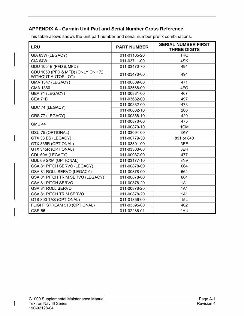
G1000 Supplemental Maintenance Manual Page A-1 Textron Nav III Series Revision 4 190-02128-04
APPENDIX A - Garmin Unit Part and Serial Number Cross Reference
This table allows shows the unit part number and serial number prefix combinations.
LRU PART NUMBER SERIAL NUMBER FIRST
THREE DIGITS GIA 63W (LEGACY) 011-01105-20 1HQ
GIA 64W 011-03711-00 4SK
GDU 1054B (PFD & MFD) 011-03470-70 494
GDU 1050 (PFD & MFD) (ONLY ON 172 WITHOUT AUTOPILOT)
011-03470-00 494
GMA 1347 (LEGACY) 011-00809-00 471
GMA 1360 011-03568-00 4FQ
GEA 71 (LEGACY) 011-00831-00 467
GEA 71B 011-03682-00 497
GDC 74 (LEGACY) 011-00882-00 478
011-00882-10 206
GRS 77 (LEGACY) 011-00868-10 420
GMU 44 011-00870-00 475
011-00870-10 1CM
GSU 75 (OPTIONAL) 011-03094-00 3KY
GTX 33 ES (LEGACY) 011-00779-30 891 or 848
GTX 335R (OPTIONAL) 011-03301-00 3EF
GTX 345R (OPTIONAL) 011-03303-00 3EH
GDL 69A (LEGACY) 011-00987-00 477
GDL 69 SXM (OPTIONAL) 011-03177-10 3NV
GSA 81 PITCH SERVO (LEGACY) 011-00878-00 664
GSA 81 ROLL SERVO (LEGACY) 011-00878-00 664
GSA 81 PITCH TRIM SERVO (LEGACY) 011-00878-00 664
GSA 81 PITCH SERVO 011-00878-20 1A1
GSA 81 ROLL SERVO 011-00878-20 1A1
GSA 81 PITCH TRIM SERVO 011-00878-20 1A1
GTS 800 TAS (OPTIONAL) 011-01356-00 15L
FLIGHT STREAM 510 (OPTIONAL) 011-03595-00 402
GSR 56 011-02286-01 2HU
Related Documents