® http://www.3com.com/ SuperStack ® II PS Hub User Guide 3C16405 — PS Hub 40 12-port 3C16406 — PS Hub 40 24-port 3C16450 — PS Hub 50 24-port Part No. DUA1640-5AAA02 Published July 1997

Welcome message from author
This document is posted to help you gain knowledge. Please leave a comment to let me know what you think about it! Share it to your friends and learn new things together.
Transcript
®
SuperStack® II PS Hub User Guide
http://www.3com.com/
3C16405 — PS Hub 40 12-port3C16406 — PS Hub 40 24-port3C16450 — PS Hub 50 24-port
Part No. DUA1640-5AAA02Published July 1997
3Com Corporation5400 Bayfront PlazaSanta Clara, California95052-8145
© 3Com Technologies, 1997. All rights reserved. No part of this documentation may be reproduced in anyform or by any means or used to make any derivative work (such as translation, transformation, oradaptation) without permission from 3Com Technologies.
3Com Technologies reserves the right to revise this documentation and to make changes in content fromtime to time without obligation on the part of 3Com Technologies to provide notification of such revisionor change.
3Com Technologies provides this documentation without warranty of any kind, either implied or expressed,including, but not limited to, the implied warranties of merchantability and fitness for a particular purpose.3Com may make improvements or changes in the product(s) and/or the program(s) described in thisdocumentation at any time.
UNITED STATES GOVERNMENT LEGENDS:If you are a United States government agency, then this documentation and the software described hereinare provided to you subject to the following restricted rights:
For units of the Department of Defense:Restricted Rights Legend: Use, duplication or disclosure by the Government is subject to restrictions as setforth in subparagraph (c) (1) (ii) for restricted Rights in Technical Data and Computer Software clause at 48C.F.R. 52.227-7013. 3Com Centre, Boundary Way, Maylands Park South, Hemel Hempstead, Herts,HP2 7YU, UK.
For civilian agencies:Restricted Rights Legend: Use, reproduction or disclosure is subject to restrictions set forth in subparagraph(a) through (d) of the Commercial Computer Software - Restricted Rights Clause at 48 C.F.R. 52.227-19 andthe limitations set forth in 3Com Corporation’s standard commercial agreement for the software.Unpublished rights reserved under the copyright laws of the United States.
If there is any software on removable media described in this documentation, it is furnished under a licenseagreement included with the product as a separate document, in the hard copy documentation, or on theremovable media in a directory file named LICENSE.TXT. If you are unable to locate a copy, please contact3Com and a copy will be provided to you.
Unless otherwise indicated, 3Com registered trademarks are registered in the United States and may or maynot be registered in other countries.
3Com, LANplex, LinkBuilder, NETBuilder II, SmartAgent, SuperStack and Transcend are registered trademarksof 3Com Corporation. CoreBuilder and FMS are trademarks of 3Com Corporation. 3ComFacts is a servicemark of 3Com Corporation.
CompuServe is a registered trademark of CompuServe, Inc. Windows and Windows NT are registeredtrademarks of Microsoft. IPX is a registered trademark of Ideographix, Inc. Netscape Navigator is atrademark of Netscape Communications Corporation.
Other brand and product names may be registered trademarks or trademarks of their respective holders.
Environmental Statement
It is 3Com’s policy to be environmentally friendly in all its operations. This manual is printed on paper thatcomes from sustainable, managed European forests. The production process for making the pulp has areduced AOX level (adsorbable organic halogen) resulting in elemental chlorine free paper.
The paper is fully bio-degradable and recyclable.
ii
CONTENTS
IMPORTANT SAFETY INFORMATIONL’INFORMATION DE SÉCURITÉ IMPORTANTEWICHTIGE SICHERHEITSHINWEISE
ABOUT THIS GUIDE
Introduction 1How to Use This Guide 2Conventions 2
1 ABOUT THE PS HUB
Introduction 1-1Features 1-2
How You Can Use the PS Hub 1-4Building Up a Network 1-4Expanding an Existing Network 1-5Migrating to Higher Performance 1-6
Workgroups 1-7What Are Workgroups? 1-7Segments and Port Switching 1-8Workgroup Example 1-11
2 HOW THE PS HUBS DIFFER
Overview 2-1PS Hub 40 2-2PS Hub 50 2-2
Segment Switch 2-2PS Hub 50 Transceiver Module Slot 2-6
3 USING THE PS HUB
LEDs and Ports 3-1Before You Start 3-4
What Other Equipment Is Needed? 3-4Positioning the PS Hub 3-6Using the Rubber Feet 3-6Using the Labels 3-7Rack and Wall Mounting 3-8
Rack Mounting 3-8Wall Mounting 3-9
Connecting Workstations to Your Hub 3-11Using Transceiver Modules 3-12
Connecting PS Hubs Together (Stacking) 3-12About Cascade Cables 3-13Using Cascade Cables 3-14Using Hot Swap Cascade Units 3-15
Connecting Different Hubs and Stacks to Your Hub 3-16Powering On the Units 3-17Spot Checks 3-17
4 LOAD BALANCING
Overview 4-1How Does Load Balancing Work? 4-2Using an External Switch 4-3
Performing Load Balancing 4-3
5 MANAGING THE PS HUB
Introduction 5-1Why Manage Your Stack? 5-2How You Can Manage Your Stack 5-3
Command Line Interface 5-3Web Interface 5-3SNMP Network Management 5-4
Methods of Management 5-5Requirements for Managing Over the Network 5-6IP Addresses 5-7
iv
Command Line Interface (CLI) 5-8Through the Console Port 5-8Over the Network 5-11
Web Interface 5-12Through the Console Port 5-12Over the Network 5-12Which Web Browsers are Supported? 5-12
Quick Config Manager 5-13Through the Console Port 5-13Over the Network 5-14
6 USING THE COMMAND LINE INTERFACE
Accessing the CLI 6-2Initial Access 6-2Logging On 6-2Logging Off 6-3
Using the CLI Menus 6-4CLI Menu Structure 6-4Navigating the Menus and Entering Commands 6-5
Quick Guide to the Commands 6-6Commands 6-7
Changing the Password 6-7Setting the IP Configuration 6-8Viewing the Configuration 6-9Resetting the Stack 6-10Initializing the Stack 6-11Configuring Another Unit in the Stack 6-11Enabling and Disabling RMON Filter Capture 6-12
7 MANAGEMENT USING THE WEB INTERFACE
Accessing the Web Interface 7-1About the Web Interface 7-4
General Components 7-4Page Components 7-6Web Interface Map 7-6
v
vi
Using the Web Interface 7-7Unit View and Unit Pages 7-8User Access Levels 7-9Exiting the Web Interface 7-9
Online Help System and Documentation 7-9Unit Pages 7-10
Unit View 7-10Unit Status 7-11Management Address 7-12Port Setup 7-13Console Port Configuration 7-14Segment Configuration 7-15Switch Configuration 7-16Permanent Address Management 7-16
Management Settings Pages 7-17Documentation 7-17Getting Started 7-18Password Setting 7-19System Name 7-19
Configuration Pages 7-20Initialize 7-20Load Balancing 7-20Reset 7-20Resilient Links 7-21Add Resilient Link 7-23Software Upgrade 7-24
Health Pages 7-25Segment Graph 7-25
8 PROBLEM SOLVING
Isolating a Problem 8-1Solving Problems With the Hub 8-2Solving Problems With the Command Line Interface 8-3Solving Problems With the Web Interface 8-4Solving Problems With an SNMP Network Management Application 8-5
A DIMENSIONS, STANDARDS AND CABLING
Dimensions and Operating Environment A-1BABT Approval (for U.K. Users Only) A-1Standards A-2Cabling A-3
10BASE-T Cable A-3Console Cable A-4Modem Cable A-5Cascade Connections A-6
Management Settings A-6
B MANAGEMENT USING QUICK CONFIG MANAGER
Installing Quick Config Manager and the Load Balancing Tool B-2Installation Requirements B-2Installation Procedure B-3
Running Quick Config Manager B-4Configuring Multiple Stacks B-4Selecting Your Management Access Method (Windows ‘95 and Windows NT only) B-5Quick Config Manager Window Map B-5Accessing the Stack B-8Giving the Stack an IP Address B-9Viewing the Stack B-12Configuring Segments B-14Configuring the Segment Switch B-17Load Balancing B-18
Menus B-19Changing the Community Name B-19Viewing Current Utilization B-20Viewing Utilization History B-21Fixing and Unfixing Segments and Ports B-23Performing Load Balancing B-25
Changing the Console Port Settings B-27Upgrading a Stack B-28Solving Problems With Quick Config Manager B-29
vii
C SERIAL WEB UTILITY
Introduction C-1Installing the Serial Web Utility C-1Using the Serial Web Utility C-3Solving Problems With the Serial Web Utility C-4
D AGENT UPGRADE UTILITY
Using the Upgrade Utility D-1Solving Problems With the Agent Upgrade Utility D-3
E TECHNICAL SUPPORT
Online Technical Services E-1World Wide Web Site E-13Com Bulletin Board Service E-13ComFacts Automated Fax Service E-23ComForum on CompuServe Online Service E-3
Support from Your Network Supplier E-3Support from 3Com E-4Returning Products for Repair E-5
GLOSSARY
INDEX
3COM CORPORATION LIMITED WARRANTY
EMC STATEMENTS
viii
IMPORTANT SAFETY INFORMATION
WARNING: Warnings contain directions that you must follow for your personal safety. Follow all instructions carefully.
Please read the following safety information thoroughly before installing the PS Hub.
■ Installation and removal of the unit must be carried out by qualified personnel only.
■ Connect the unit to an earthed power supply to ensure compliance with European safety standards.
■ The power cord set must be approved for the country where it will be used.
■ The appliance coupler, that is, the connector to the device itself and not the wall plug, must have a configuration for mating with an EN60320/IEC320 appliance inlet.
■ For U.S.A. and Canada:
■ The cord set must be UL-approved and CSA certified.
■ The minimum specification for the flexible cord is:
No. 18 AWGType SV or SJ3-conductor
■ The cord set must have a rated current capacity of at least 10A.
■ The attachment plug must be an earth-grounding type with a NEMA 5-15P (15A, 125V) or NEMA 6-15P (15A, 250V) configuration.
■ For Denmark:
■ The supply plug must comply with section 107-2-D1, standard sheet DK2-1a or DK2-5a.
■ For Switzerland:
■ The supply plug must comply with SEV/ASE 1011.
■ It is essential that the mains socket outlet is installed near to the unit and is accessible. You can only disconnect the unit by removing the appliance coupler from the unit.
■ This unit operates under SELV conditions (Safety Extra Low Voltage) according to IEC 950, the conditions of which are maintained only if the equipment to which it is connected is also operational under SELV.
■ France and Peru only:
■ This unit cannot be powered from IT (impedance à la terre) supplies. If your supplies are of the IT type, this unit should be powered by 230V (2P+T) via an isolation transformer ratio 1:1, with the secondary connection point labelled Neutral, connected directly to Earth (Ground).
■ U.K. only:
■ The PS Hub is covered by Oftel General Approval, NS/G/12345/J/100003, for indirect connection to a public telecommunications system. This can only be achieved using the console port on the unit and an approved modem.
■ Twisted Pair RJ45 ports: These are shielded RJ45 data sockets. They cannot be used as telephone sockets. Only connect RJ45 data connectors to these sockets. Either shielded or unshielded data cables with shielded or unshielded jacks can be connected to these data sockets.
■ Sockets for Redundant Power System (RPS): Only connect a 3Com Redundant Power System to this socket. For details, follow the installation instructions in the manuals accompanying the Redundant Power System.
L’INFORMATION DE SÉCURITÉ IMPORTANTE
AVERTISSEMENT: Les avertissements contiennent les directions que vous devez suivre pour votre sécurité personnelle. Suivez toutes les directives avec soin.
Veuillez lire à fond l'information de la sécurité suivante avant d'installer le PS Hub.
■ L'installation et l'enlèvement de l'unité doivent être faits seulement par le personnel qualifié.
■ Brancher l'unité à une source de courant mise à la terre pour assurer la conformité aux normes de sécurité européennes.
■ La cordon d'alimentation surmoulé doit être approuvé pour le pays auquel il sera utilisé.
■ Le socle de connecteur, c'est-à-dire, le connecteur à l'appareil lui-même et non pas la prise murale, doit avoir une configuration pour le branchement avec une admission d'appareil EN60320/IEC320.
■ Pour U.S.A. et le Canada:
■ Le cordon surmoulé doit être UL Certifié et CSA Certifié.
■ Les spécifications minimales pour le cordon souple sont:
■ No. 18 AWGType SV ou SJ3-conducteur
■ Le cordon surmoulé doit avoir une capacité de courant calculée au moins de 10A.
■ La fiche de fixation doit être un type mis à la terre avec une configuration NEMA 5-15P (15A, 125V) ou NEMA 6-15P (15A, 250V).
■ C'est essentiel que le socle soit installé près de l'unité et soit accessible. Vous pouvez seulement débrancher l'unité en enlevant la fiche d'alimentation de la prise de courant.
■ Cette unité marche sous les conditions SELV (Safety Extra Low Voltage) conformément à IEC950, ces conditions sont maintenues seulement si le matériel auquel elle est branchée, est aussi en exploitation sous SELV.
■ Seulement Pour La France et Le Pérou:
■ Cette unité ne peut pas être mise en marche des sources de courant IT (Impédance à la terre). Si vos sources de courant sont de type IT, cette unité doit être alimentée par 230V (2P+T) via un rapport de transformation d'isolation de 1:1, avec un point de connexion secondaire étiqueté Neutre, branché directement à la Terre (à la Masse).
■ Les ports RJ45 de paire tordue: Ceux-ci sont les prises de courant de données RJ45 protégées. Ils ne peuvent pas être utilisés comme prises de courant téléphoniques. Brancher seulement les connecteurs RJ45 de données à ces prises de courant. Les câbles de données blindés ou non blindés, avec les jacks blindés ou non blindés, l'un ou l'autre, peuvent être branchés à ces prises de courant de données.
■ Socle Pour Alimentation Multiple: Brancher seulement une alimentation multiple de 3Com à cet socle. Suivre pour les détails les directives de l’installation dans le manual qui accompagne l’alimentation multiple.

WICHTIGE SICHERHEITSHINWEISE
WARNUNG: Warnungen enthalten Anweisungen, die zur eigenen Sicherheit unbedingt zu beachten sind. Bitte befolgen Sie alle Anweisungen sorgfältig und genau.
Bitte unbedingt vor dem Einbauen des PS Hub Einheit die folgenden Sicherheitsanweisungen durchlesen.
■ Ein- und Ausbau des Gerätes ist nur von Fachpersonal vorzunehmen.
■ Das Gerät an geerdete Stromversorgung anschließen, um eine Übereinstimmung mit den europäischen Sicherheitsbestimmungen zu gewährleisten.
■ Der Anschlußkabelsatz muß mit den Bestimmungen des Landes übereinstimmen, in dem er verwendet werden soll.
■ Die Anordnung der Gerätsteckvorrichtung, d.h. die Steckverbindung am Gerät selbst im Gegensatz zum Wandstecker, muß in den EN60320/IEC320 Zuführungsstecker am Gerät passen.
■ Es ist wichtig, daß der Netzstecker sich in unmittelbarer Nähe zum Gerät befindet und leicht erreichbar ist. Das Gerät kann nur durch Herausziehen des Verbindungssteckers aus der Steckdose vom Stromnetz getrennt werden.
■ Das Gerät wird mit Sicherheits-Kleinspannung nach IEC 950 (SELV = Safety Extra Low Voltage) betrieben. Angeschloßen werden können nur Geräte, die ebenfalls nach SELV betrieben werden.
■ Gedrehte paarfache RJ45 Anschlüsse: Hierbei handelt es sich um abgeschirmte RJ45 Datenbuchsen, die nicht als Telefonbuchsen verwendbar sind. Nur RJ45 Datensteckverbinder an diese Buchsen anschließen. Diese Datenstecker können entweder mit abgeschirmten oder unabgeschirmten Datenkabeln mit abgeschirmten oder unabgeschirmten Klinkensteckern verbunden werden.

■ Steckdose Für Redundant Power System: Nur ein 3Com Redundant Power System an diese Steckdose anschließen. Für weitere Angaben die genauen Einbauanweisungen im Handbuch zum Redundant Power System befolgen.
Die Einheit ist unter keinen Umständen an einen Wechselstrom Netzstecker (A.C.) anzuschließen, wenn dieser keine Erdung hat.
ABOUT THIS GUIDE
Introduction This guide describes how to set up and manage these SuperStack® II PS Hubs:
■ 3C16405 — PS Hub 40 12-port
■ 3C16406 — PS Hub 40 24-port
■ 3C16450 — PS Hub 50 24-port
AudienceDescription
This guide is intended for users who have networking experience. If you have used 3Com’s SuperStack II range of products, you may already be familiar with using this kind of hub. We recommend that you read through this guide as the PS Hub has a number of important features which are described in this guide.
If you are familiar with the PS Hub and know how the PS Hub’s port switching and segments work, you may only want to know how the PS Hub 40 and PS Hub 50 are different; refer to Chapter 2.
When referring to both the PS Hub 40 and PS Hub 50 generally, this guide uses the term ‘PS Hub’.
For information on the Limited Warranty, refer to the “3Com Corporation Limited Warranty” at the back of this guide.
A Quick Reference Guide accompanies this user guide, and provides a summary of some of the information in this user guide.
If there are Release Notes shipped with your product and the information in them differs from the information in this guide, follow the Release Notes.
2 ABOUT THIS GUIDE
How to Use This Guide
This table shows where to find specific information in this guide.
Conventions Table 1 and Table 2 list conventions that are used throughout this guide.
If you are looking for... Turn to...
An introduction to the hub, workgrouping and segments Chapter 1
Information on how the PS Hub 40 and PS Hub 50 are different from each other
Chapter 2
Information on installing and using the hub Chapter 3
An introduction to load balancing and how it works Chapter 4
Ways you can manage the hub and how to start your management session
Chapter 5
Information on using the Command Line Interface to set up the hub for management
Chapter 6
Information on using the web interface to manage the hub or stack of hubs
Chapter 7
Information on solving any problems Chapter 8
The hub’s dimensions, the standards it conforms to, and the cabling you can use with it
Appendix A
Information on using Quick Config Manager to manage the hub or stack of hubs
Appendix B
Information on installing and using the serial web utility Appendix C
Information on using the agent upgrade utility Appendix D
Technical support Appendix E
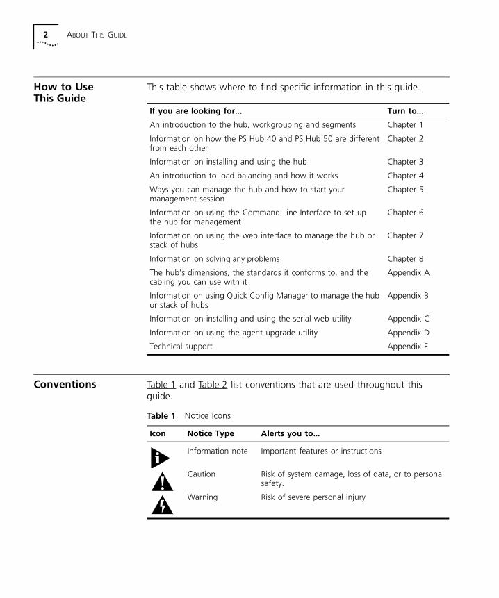
Table 1 Notice Icons
Icon Notice Type Alerts you to...
Information note Important features or instructions
Caution Risk of system damage, loss of data, or to personal safety.
Warning Risk of severe personal injury
Conventions 3
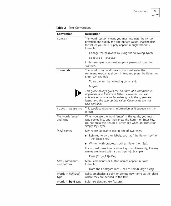
Table 2 Text Conventions
Convention Description
Syntax The word ‘syntax’ means you must evaluate the syntax provided and supply the appropriate values. Placeholders for values you must supply appear in angle brackets. Example:
Change the password by using the following syntax:
password <string>
In this example, you must supply a password string for <string>.
Commands The word ‘command’ means you must enter the command exactly as shown in text and press the Return or Enter key. Example:
To exit, enter the following command:
Logout
This guide always gives the full form of a command in uppercase and lowercase letters. However, you can abbreviate commands by entering only the uppercase letters and the appropriate value. Commands are not case-sensitive.
Screen displays This typeface represents information as it appears on the screen.
The words ‘enter’ and ‘type’
When you see the word ‘enter’ in this guide, you must type something, and then press the Return or Enter key. Do not press the Return or Enter key when an instruction simply says ‘type’.
[Key] names Key names appear in text in one of two ways:
■ Referred to by their labels, such as “the Return key” or “the Escape key”
■ Written with brackets, such as [Return] or [Esc].
If you must press two or more keys simultaneously, the key names are linked with a plus sign (+). Example:
Press [Ctrl]+[Alt]+[Del].
Menu commands and buttons
Menu commands or button names appear in italics. Example:
From the Configure menu, select Community/Polling...
Words in italicized type
Italics emphasize a point or denote new terms at the place where they are defined in the text.
Words in bold type Bold text denotes key features.

4 ABOUT THIS GUIDE
1
ABOUT THE PS HUBThis chapter contains the following topics:
■ Features and benefits of the PS Hub
■ How the PS Hub can be used
■ Using workgroups
■ Description and example of the PS Hub segmentation
■ How the PS Hub works
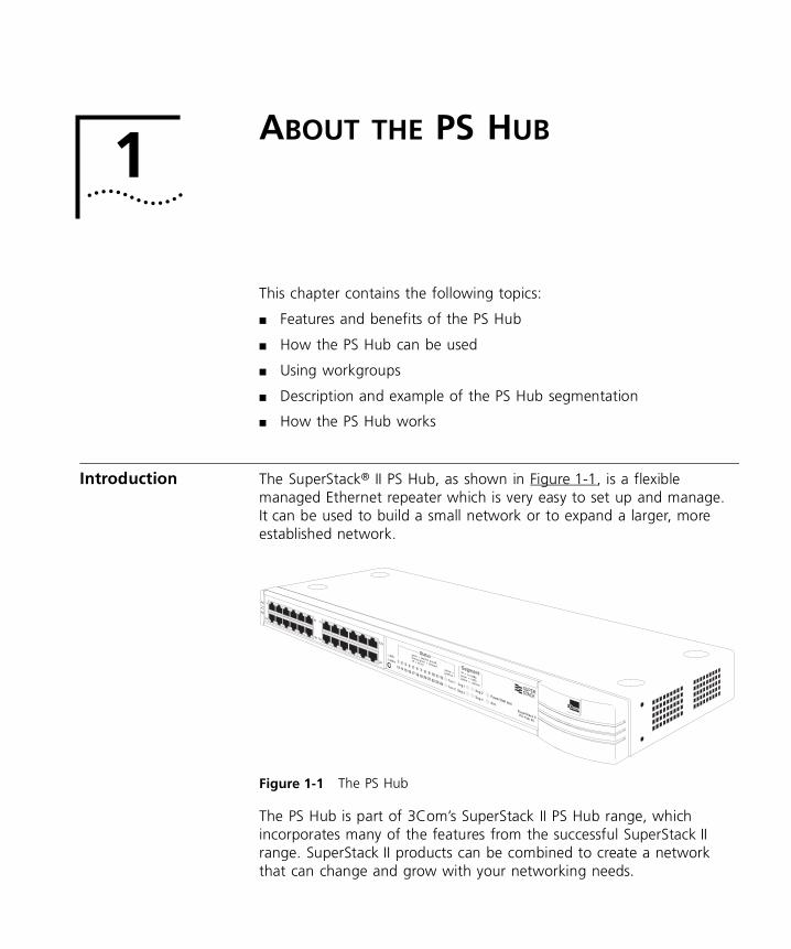
Introduction The SuperStack® II PS Hub, as shown in Figure 1-1, is a flexible managed Ethernet repeater which is very easy to set up and manage. It can be used to build a small network or to expand a larger, more established network.
Figure 1-1 The PS Hub
The PS Hub is part of 3Com’s SuperStack II PS Hub range, which incorporates many of the features from the successful SuperStack II range. SuperStack II products can be combined to create a network that can change and grow with your networking needs.
1-2 CHAPTER 1: ABOUT THE PS HUB
Features The PS Hub 40 and PS Hub 50 share many features:
NOTE: These terms and features are described in this chapter and the following chapters.
■ 12 or 24 shielded twisted pair ports for easy connection to 10BASE-T networks. An MDI/MDIX switch allows you to cross-over one of these ports, for connection to other types of hubs and network equipment.
■ One or two transceiver module slots, providing a choice of media options:
■ The PS Hub 40 has two 10Mbps transceiver module slots that can be fitted with 3Com 10Mbps transceiver modules.
■ The PS Hub 50 has one transceiver module slot that can be fitted with a 3Com 10Mbps or 100Mbps transceiver module.
■ SuperStack II architecture — You can stack up to 10 hubs (six if free standing), giving you a possible 260 ports per stack.
■ LEDs for quick viewing of hub and port status.
■ Hot-swappable technology which allows hubs to be added and removed from a stack without affecting stack performance.
■ Mounting brackets for easy installation into a standard 19 inch rack, or onto a table or wall.
■ +5 Lifetime Limited Warranty — Please refer to the “3Com Corporation Limited Warranty” at the back of this guide for more information.
DUA1640-5AAA02
Introduction 1-3
ManagementFeatures
■ Complete SmartAgent™ management which is built into each hub; no additional management cards are needed. When PS Hubs are stacked, the management is distributed between all hubs in the stack.
■ Easy to use built-in management interfaces for configuration of your hub or stack locally or over the network:
■ A Command Line Interface for quick configuration of IP information for the hub.
■ A web interface for comprehensive management of the hub using any suitable web browser.
■ Additional management software (supplied on the CD-ROM), including 3Com’s Transcend® Quick Configuration Manager for Windows®.
■ An implementation of SNMP for management over the network, using the IP protocol.
■ Support for traps (messages) which can alert an SNMP network management station of any problems.
■ Built-in security and resilience, which protects your network.
■ Port switching — Allows you to build up workgroups by switching ports easily between the four internal segments. When stacked, all four segments are carried between the hubs by cascade cables.
■ Automated load balancing — Configures the segments so that the traffic is distributed evenly across them, making the segments more efficient. It also analyses inter-segment traffic and moves frequently communicating ports to the same segment.
DUA1640-5AAA02
1-4 CHAPTER 1: ABOUT THE PS HUB
How You Can Use the PS Hub
The flexibility of the PS Hub allows it to be used in a number of ways. You can build up a network or expand a large, established network. For information on connecting and using your equipment, refer to Chapter 3.
The PS Hub can be used on its own or in a stack with other PS Hubs. All PS Hubs have a useful feature called port switching which allows you to create workgroups within your stack. For information on this feature, refer to “Segments and Port Switching” on page 1-8.
Building Up aNetwork
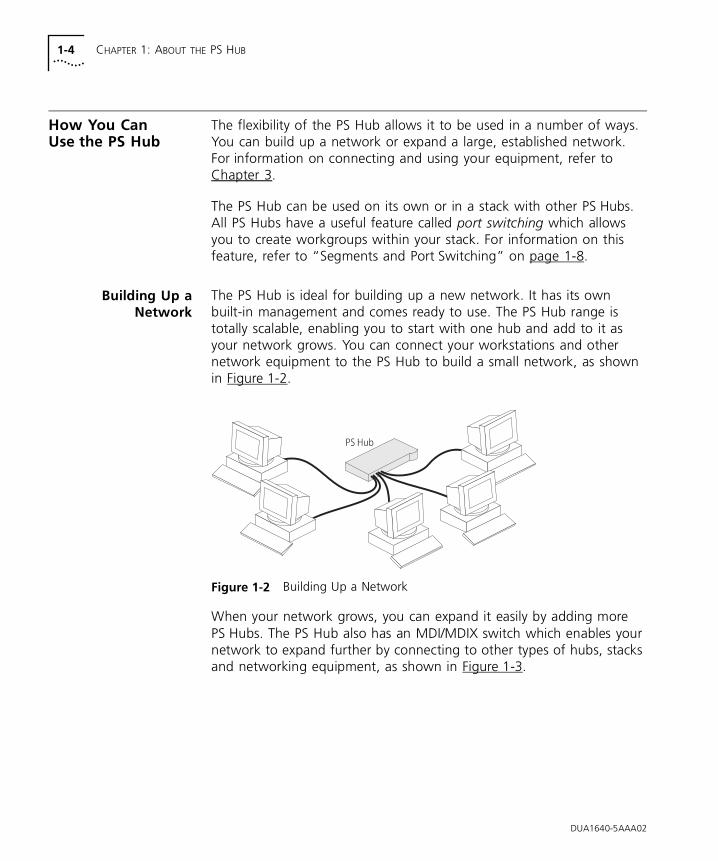
The PS Hub is ideal for building up a new network. It has its own built-in management and comes ready to use. The PS Hub range is totally scalable, enabling you to start with one hub and add to it as your network grows. You can connect your workstations and other network equipment to the PS Hub to build a small network, as shown in Figure 1-2.
Figure 1-2 Building Up a Network
When your network grows, you can expand it easily by adding more PS Hubs. The PS Hub also has an MDI/MDIX switch which enables your network to expand further by connecting to other types of hubs, stacks and networking equipment, as shown in Figure 1-3.
DUA1640-5AAA02
How You Can Use the PS Hub 1-5
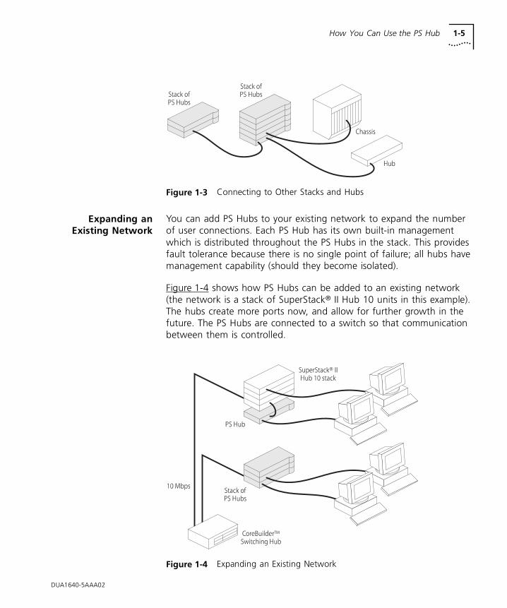
Figure 1-3 Connecting to Other Stacks and Hubs
Expanding anExisting Network
You can add PS Hubs to your existing network to expand the number of user connections. Each PS Hub has its own built-in management which is distributed throughout the PS Hubs in the stack. This provides fault tolerance because there is no single point of failure; all hubs have management capability (should they become isolated).
Figure 1-4 shows how PS Hubs can be added to an existing network (the network is a stack of SuperStack® II Hub 10 units in this example). The hubs create more ports now, and allow for further growth in the future. The PS Hubs are connected to a switch so that communication between them is controlled.
Figure 1-4 Expanding an Existing Network
DUA1640-5AAA02
1-6 CHAPTER 1: ABOUT THE PS HUB
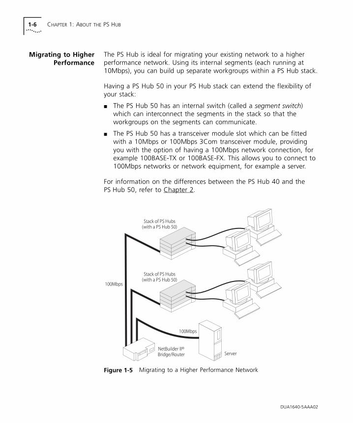
Migrating to HigherPerformance
The PS Hub is ideal for migrating your existing network to a higher performance network. Using its internal segments (each running at 10Mbps), you can build up separate workgroups within a PS Hub stack.
Having a PS Hub 50 in your PS Hub stack can extend the flexibility of your stack:
■ The PS Hub 50 has an internal switch (called a segment switch) which can interconnect the segments in the stack so that the workgroups on the segments can communicate.
■ The PS Hub 50 has a transceiver module slot which can be fitted with a 10Mbps or 100Mbps 3Com transceiver module, providing you with the option of having a 100Mbps network connection, for example 100BASE-TX or 100BASE-FX. This allows you to connect to 100Mbps networks or network equipment, for example a server.
For information on the differences between the PS Hub 40 and the PS Hub 50, refer to Chapter 2.
Figure 1-5 Migrating to a Higher Performance Network
DUA1640-5AAA02
Workgroups 1-7
Workgroups An important feature of the PS Hub is that you can create workgroups.
What AreWorkgroups?
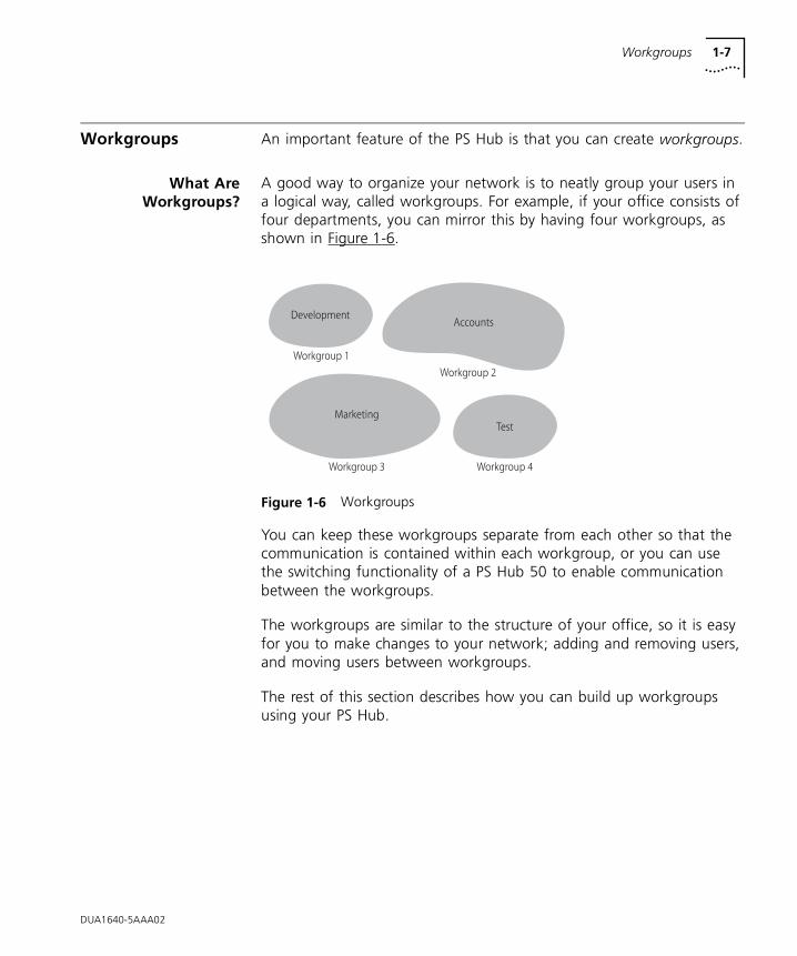
A good way to organize your network is to neatly group your users in a logical way, called workgroups. For example, if your office consists of four departments, you can mirror this by having four workgroups, as shown in Figure 1-6.
Figure 1-6 Workgroups
You can keep these workgroups separate from each other so that the communication is contained within each workgroup, or you can use the switching functionality of a PS Hub 50 to enable communication between the workgroups.
The workgroups are similar to the structure of your office, so it is easy for you to make changes to your network; adding and removing users, and moving users between workgroups.
The rest of this section describes how you can build up workgroups using your PS Hub.
DUA1640-5AAA02
1-8 CHAPTER 1: ABOUT THE PS HUB
Segments andPort Switching
The PS Hub has four separate internal repeaters (called segments) which you can use to create your workgroups. You can switch the hub’s ports to any of these segments (called port switching). With the segments and port switching, you can easily create your workgroups.
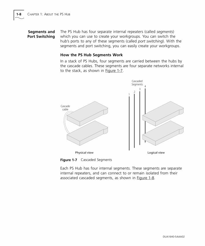
How the PS Hub Segments Work
In a stack of PS Hubs, four segments are carried between the hubs by the cascade cables. These segments are four separate networks internal to the stack, as shown in Figure 1-7.
Figure 1-7 Cascaded Segments
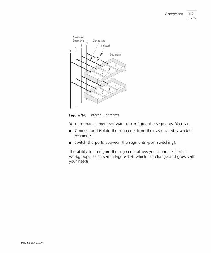
Each PS Hub has four internal segments. These segments are separate internal repeaters, and can connect to or remain isolated from their associated cascaded segments, as shown in Figure 1-8.
DUA1640-5AAA02
Workgroups 1-9
Figure 1-8 Internal Segments
You use management software to configure the segments. You can:
■ Connect and isolate the segments from their associated cascaded segments.
■ Switch the ports between the segments (port switching).
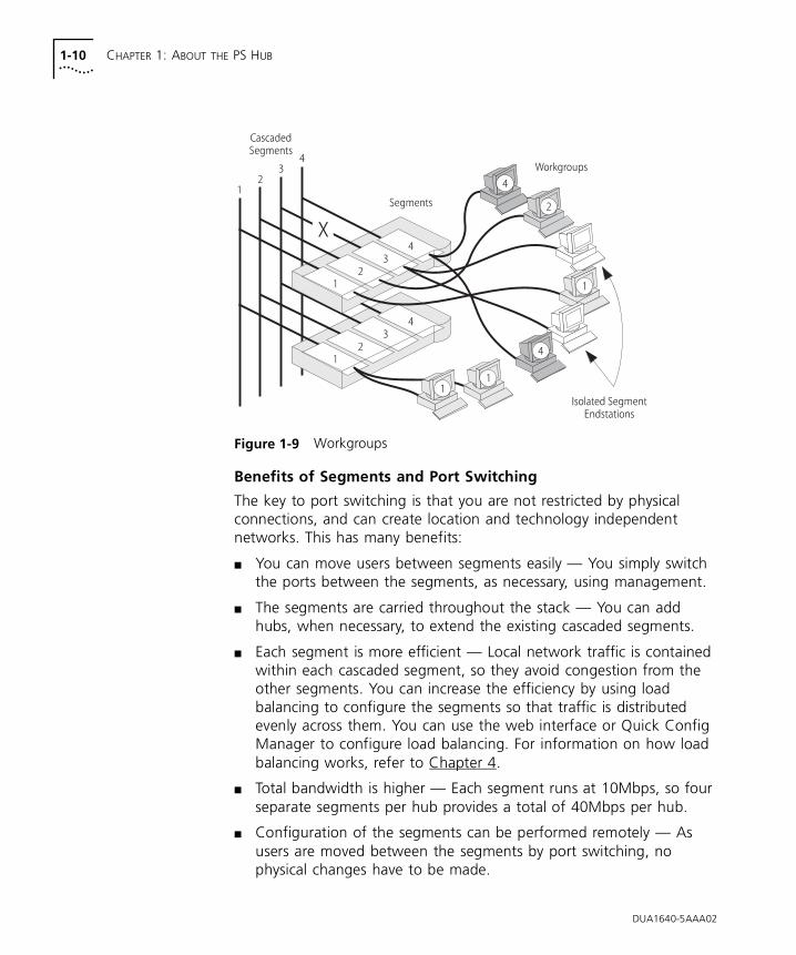
The ability to configure the segments allows you to create flexible workgroups, as shown in Figure 1-9, which can change and grow with your needs.
DUA1640-5AAA02
1-10 CHAPTER 1: ABOUT THE PS HUB
Figure 1-9 Workgroups
Benefits of Segments and Port Switching
The key to port switching is that you are not restricted by physical connections, and can create location and technology independent networks. This has many benefits:
■ You can move users between segments easily — You simply switch the ports between the segments, as necessary, using management.
■ The segments are carried throughout the stack — You can add hubs, when necessary, to extend the existing cascaded segments.
■ Each segment is more efficient — Local network traffic is contained within each cascaded segment, so they avoid congestion from the other segments. You can increase the efficiency by using load balancing to configure the segments so that traffic is distributed evenly across them. You can use the web interface or Quick Config Manager to configure load balancing. For information on how load balancing works, refer to Chapter 4.
■ Total bandwidth is higher — Each segment runs at 10Mbps, so four separate segments per hub provides a total of 40Mbps per hub.
■ Configuration of the segments can be performed remotely — As users are moved between the segments by port switching, no physical changes have to be made.
DUA1640-5AAA02
Workgroups 1-11
■ There is extra security — Hub segments can be isolated from the cascaded segments, so that only workstations on the same hub segment can communicate with each other.
■ Port switching enables you to extend any existing workgroups you may have, across the whole network infrastructure, including shared Ethernet workgroups.
DUA1640-5AAA02
1-12 CHAPTER 1: ABOUT THE PS HUB
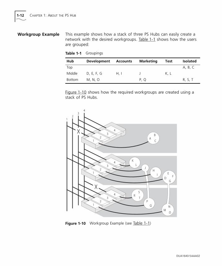
Workgroup Example This example shows how a stack of three PS Hubs can easily create a network with the desired workgroups. Table 1-1 shows how the users are grouped:
Figure 1-10 shows how the required workgroups are created using a stack of PS Hubs.
Figure 1-10 Workgroup Example (see Table 1-1)
Table 1-1 Groupings
Hub Development Accounts Marketing Test Isolated
Top A, B, C
Middle D, E, F, G H, I J K, L
Bottom M, N, O P, Q R, S, T
DUA1640-5AAA02
Workgroups 1-13
DUA1640-5AAA02
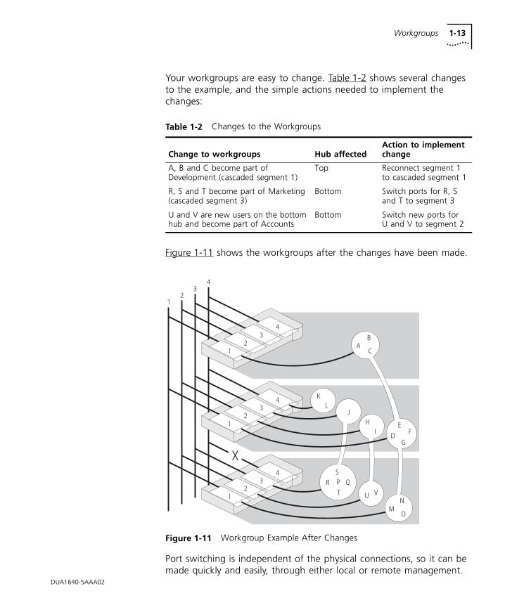
Your workgroups are easy to change. Table 1-2 shows several changes to the example, and the simple actions needed to implement the changes:
Figure 1-11 shows the workgroups after the changes have been made.
Figure 1-11 Workgroup Example After Changes
Port switching is independent of the physical connections, so it can be made quickly and easily, through either local or remote management.
Table 1-2 Changes to the Workgroups
Change to workgroups Hub affectedAction to implement change
A, B and C become part of Development (cascaded segment 1)
Top Reconnect segment 1 to cascaded segment 1
R, S and T become part of Marketing (cascaded segment 3)
Bottom Switch ports for R, S and T to segment 3
U and V are new users on the bottom hub and become part of Accounts
Bottom Switch new ports for U and V to segment 2
1-14 CHAPTER 1: ABOUT THE PS HUB
If one of the PS Hubs in the example is a PS Hub 50, you can enable communication between the four cascaded segments in the stack, so that your workstations can communicate across the segments. For information on the PS Hub 50, refer to “PS Hub 50” on page 2-2.
For information on the segment switch in the PS Hub 50, refer to “Segment Switch” on page 2-2.
For information on load balancing, refer to Chapter 4.
DUA1640-5AAA02
2
HOW THE PS HUBS DIFFERThis chapter contains the following topics:
■ An overview of the differences between the PS Hub 40 and PS Hub 50
■ How the PS Hub 50 segment switch and transceiver module slot work
Overview This chapter describes how the PS Hub 40 and PS Hub 50 are different. However, they are both part of the PS Hub family and have many similar features. For information on these common features, refer to “Features” on page 1-2.
Table 2-1 shows a summary of the differences between the PS Hubs:
Apart from the differences shown in Table 2-1, the PS Hubs have the same features.
Table 2-1 Differences Between the PS Hubs
Features PS Hub 40 PS Hub 50
Has the hub got an internal segment switch? No Yes
Number and type of transceiver module slots 2 x 10Mbps 1 x 10Mbps or 100Mbps
2-2 CHAPTER 2: HOW THE PS HUBS DIFFER
PS Hub 40 The PS Hub 40 has two 10Mbps transceiver module slots. When fitted with transceiver modules, these ports can be port switched to any of the hub’s four internal segments.
For information on what transceiver modules you can use, refer to “Using Transceiver Modules” on page 3-12.
PS Hub 50 The main feature of the PS Hub 50 over the PS Hub 40 is that it has an internal segment switch.
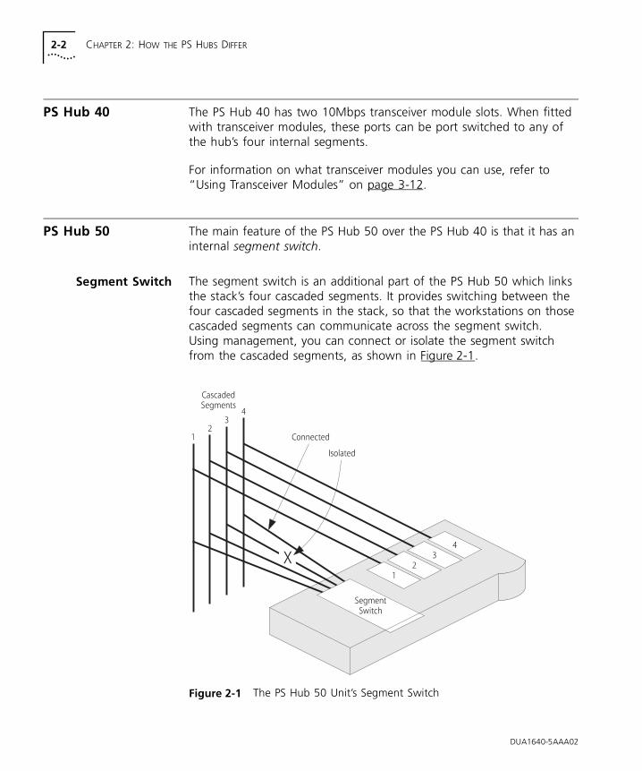
Segment Switch The segment switch is an additional part of the PS Hub 50 which links the stack’s four cascaded segments. It provides switching between the four cascaded segments in the stack, so that the workstations on those cascaded segments can communicate across the segment switch. Using management, you can connect or isolate the segment switch from the cascaded segments, as shown in Figure 2-1.
Figure 2-1 The PS Hub 50 Unit’s Segment Switch
DUA1640-5AAA02
PS Hub 50 2-3
How Does the Segment Switch Work?
Information is passed around the network in small units, called packets. These packets contain various Ethernet addresses called MAC addresses, which are unique addresses that are permanently stored within each piece of network equipment:
■ Source address — the MAC address of the equipment that sent the packet.
■ Destination address — the MAC address of the equipment that the packet is intended for.
The network adapters in your workstations have a MAC address which is used to identify the workstations on the network. An example of a MAC address is ‘08004e0849d1’.
Using the source addresses, the PS Hub 50 unit’s segment switch can learn which workstations are connected to each of the cascaded segments. This information is stored in a switching database, which is a list containing each source address together with the associated cascaded segment. Using this database, the segment switch can then selectively pass future packets to the relevant cascaded segment.
When the switch database is full, no new addresses are learnt. The segment switch regularly removes unused learnt addresses from the switch database (known as ageing), if they have not been used after 30 minutes (the ageing period). Using the web interface, you can make address entries permanent so that they are not removed by the ageing process.
The segment switch has the following features:
■ Support for multiple PS Hub 50 units in the same stack.
■ Switch database with a capacity of 500 workstation addresses.
■ Self-selecting switch mode:
■ If a 100Mbps transceiver module is fitted, the segment switch is in LOI (Local Office Interconnect) mode — The 100Mbps transceiver module port behaves like a downlink port. A downlink port is a port that is typically connected to the rest of the network. All packets with an unknown destination address are forwarded to the downlink port only, and addresses are not learnt on this port.
DUA1640-5AAA02
2-4 CHAPTER 2: HOW THE PS HUBS DIFFER
■ If a 10Mbps transceiver module is fitted or no transceiver module is fitted, the segment switch is in 802.1d Bridge mode — All packets with an unknown destination address are forwarded to all ports.
Default Settings
The PS Hub 50 comes ready to use with all of the cascaded segments connected to its segment switch (the default configuration). To isolate and connect segments, and to control the way the hub’s segment switch works, you must manage the hub. For information on management, refer to Chapter 5.
Multiple PS Hub 50 Units in a Stack
The PS Hub 50 has been designed so that you can have multiple PS Hub 50 units in the same stack. You may want to do this so that the cascaded segments are always switched, when:
■ The stack is split.
■ One of the PS Hub 50 units is removed or fails.
You could have two PS Hub 50 units in a stack of PS Hubs, one at the top and one at the bottom.
PS Hub 50 units automatically detect each other in the stack and configure themselves so that one of the hubs becomes the active switch, and the segment switches in all the other hubs are disabled. This is to reduce the possibility of loops in the stack. If a PS Hub 50 is removed from the stack or fails, the other hubs reconfigure themselves.
The process for detecting and reconfiguring is as follows:
1 If one hub has a 100Mbps transceiver module fitted, that hub becomes the active switch.
2 If more than one hub has a 100Mbps transceiver module fitted but only one has a link (is receiving information through its transceiver module port), that hub becomes the active switch.
3 If all PS Hub 50 units appear to be equal, the hub with the lowest unit number (the one nearest the bottom of the stack if connected correctly) becomes the active switch.
Only the active switch learns addresses and adds them to its switch database.
DUA1640-5AAA02
PS Hub 50 2-5
Fast Ethernet Resilience
The process that chooses the active switch (when there are multiple PS Hub 50 units in a stack) enables you to have a Fast Ethernet resilient link in your stack.
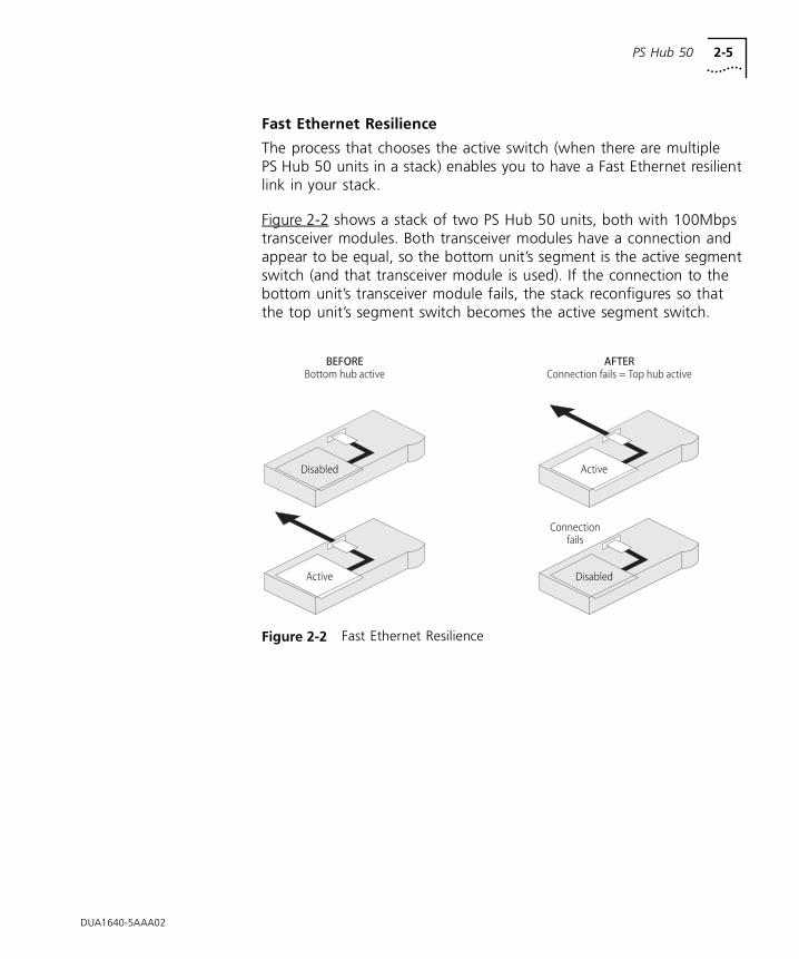
Figure 2-2 shows a stack of two PS Hub 50 units, both with 100Mbps transceiver modules. Both transceiver modules have a connection and appear to be equal, so the bottom unit’s segment is the active segment switch (and that transceiver module is used). If the connection to the bottom unit’s transceiver module fails, the stack reconfigures so that the top unit’s segment switch becomes the active segment switch.
Figure 2-2 Fast Ethernet Resilience
DUA1640-5AAA02
2-6 CHAPTER 2: HOW THE PS HUBS DIFFER
PS Hub 50Transceiver Module
Slot
The PS Hub 50 unit’s transceiver module can be fitted with a 3Com 10Mbps or 100Mbps transceiver module. The operation of the transceiver module slot differs when using either a 10Mbps or 100Mbps transceiver module:
■ Packets with an unknown destination address are dealt with differently by the segment switch, refer to “How Does the Segment Switch Work?” on page 2-3.
■ The configuration of the transceiver module port is different.
For information on what transceiver modules you can use, refer to “Using Transceiver Modules” on page 3-12.
Using a 10Mbps Transceiver Module
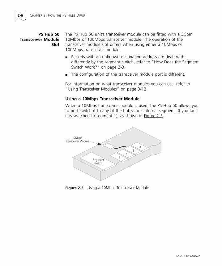
When a 10Mbps transceiver module is used, the PS Hub 50 allows you to port switch it to any of the hub’s four internal segments (by default it is switched to segment 1), as shown in Figure 2-3.
Figure 2-3 Using a 10Mbps Transceiver Module
DUA1640-5AAA02
PS Hub 50 2-7
Using a 100Mbps Transceiver Module
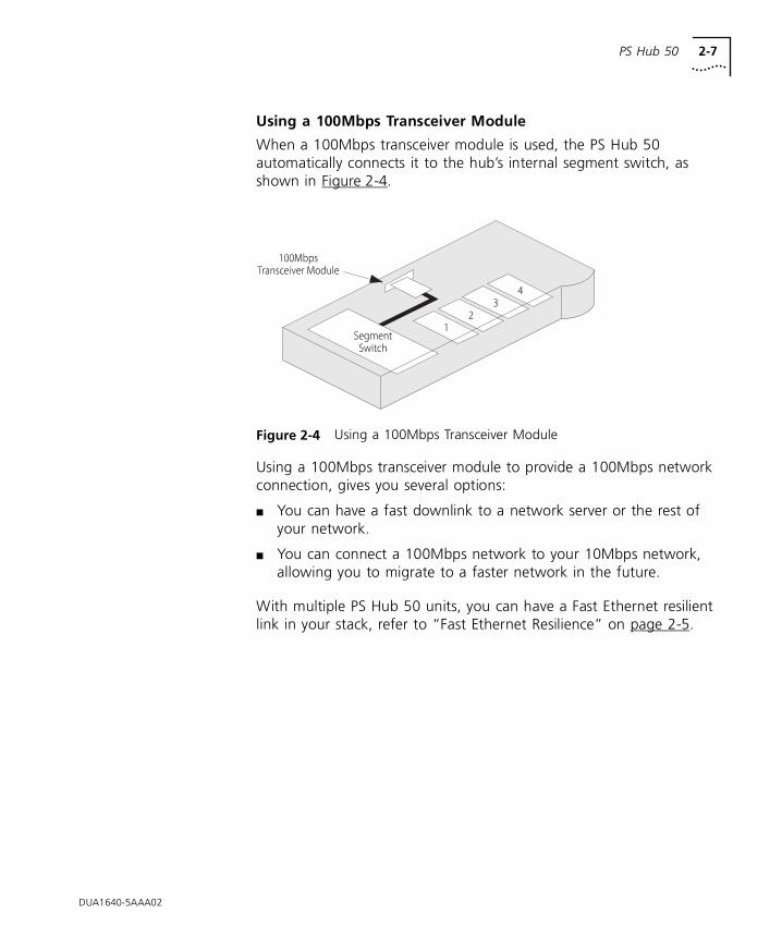
When a 100Mbps transceiver module is used, the PS Hub 50 automatically connects it to the hub’s internal segment switch, as shown in Figure 2-4.
Figure 2-4 Using a 100Mbps Transceiver Module
Using a 100Mbps transceiver module to provide a 100Mbps network connection, gives you several options:
■ You can have a fast downlink to a network server or the rest of your network.
■ You can connect a 100Mbps network to your 10Mbps network, allowing you to migrate to a faster network in the future.
With multiple PS Hub 50 units, you can have a Fast Ethernet resilient link in your stack, refer to “Fast Ethernet Resilience” on page 2-5.
DUA1640-5AAA02

2-8 CHAPTER 2: HOW THE PS HUBS DIFFER
DUA1640-5AAA02
3
USING THE PS HUBThis chapter contains the following topics:
■ Description of the hub’s LEDs and ports
■ Positioning the hub
■ Rack and wall mounting the hub
■ Connecting PS Hubs together
■ Connecting workstations and other equipment to the hub
■ Spot Checks
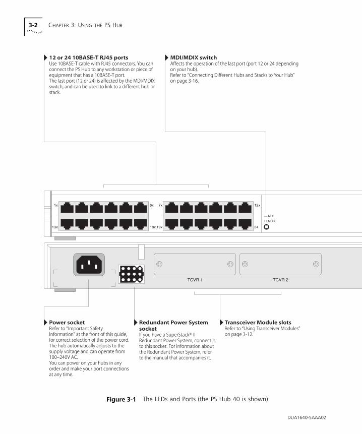
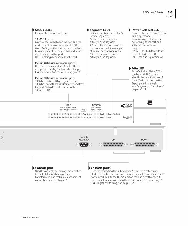
LEDs and Ports Figure 3-1 (over the page) shows the hub’s diagnostic LEDs and easy to use ports. This diagram also appears on the Quick Reference Guide.
The LEDs:
■ Show you how the hub and its ports are operating
■ Show you how the hub’s segments are operating
■ Alert you to a potential problem with your network
The different types of ports are used for:
■ Connecting workstations and other equipment to your hub
■ Connecting your hub to other PS Hubs, to form a stack
■ Connecting a management station to your hub for local management
CAUTION: Only connect a SuperStack® II Redundant Power System to the Redundant Power System socket.Do not remove the transceiver module blanking plate with the power still connected.
3-2 CHAPTER 3: USING THE PS HUB
Figure 3-1 The LEDs and Ports (the PS Hub 40 is shown)
DUA1640-5AAA02
DUA1640-5AAA02
LEDs and Ports 3-3
3-4 CHAPTER 3: USING THE PS HUB
Before You Start Your PS Hub comes with:
■ One power cord for use with the PS Hub
■ Four standard height and two reduced height self-adhesive rubber feet
■ Two mounting brackets and four screws
■ Four self-adhesive labels
■ One CD-ROM featuring:
■ The 3Com serial web utility (SLIP driver for Windows ‘95)
■ An agent upgrade utility
■ Transcend® Quick Configuration Manager for Windows
■ Transcend® Load Balancing Tool
■ Online help
■ Online versions of this user guide
■ A Warranty Registration card for you to fill out and return
■ A Quick Reference Guide
What OtherEquipment Is
Needed?
You may need to get some cables and other equipment for connecting your workstations and other hubs to the PS Hub. Your supplier should stock these cables and equipment. For information on how the cables’ pins are connected, refer to “Cabling” on page A-3.
Connecting Workstations
To connect workstations to your hub, you need:
■ One ‘Straight-through’ 10BASE-T cable for every workstation. We recommend you use shielded 10BASE-T cables. The maximum length you can use is 100m (328ft).
In order to comply with the 10BASE-T standard, ports designed for workstation connections have been marked with the graphical symbol ‘x’. This denotes a crossover in the port’s internal wiring, for example 1x, 2x, 3x...
For information on connecting workstations to your hub, refer to “Connecting Workstations to Your Hub” on page 3-11.
DUA1640-5AAA02
Before You Start 3-5
Connecting PS Hubs (Stacking)
To connect another PS Hub 40 or PS Hub 50 to your hub using the cascade ports, you need:
■ One cascade cable for each additional hub.
Cascade cables have resilience built into them which protects the internal segments and management communication that is carried between the hubs in the stack. You can increase this resilience by using SuperStack II PS Hub Hot Swap Cascade Units with the cascade cables, refer to “Using Hot Swap Cascade Units” on page 3-15.
Cascade cables are available from your supplier in a variety of lengths, refer to “Cascade Connections” on page A-6. For information on connecting another PS Hub to your hub, refer to “Connecting PS Hubs Together (Stacking)” on page 3-12.
Connecting Different Hubs and Stacks
To connect different hubs or stacks to your hub, you need:
■ One ‘Straight-through’ 10BASE-T cable for each unit or stack — if using the last port (port 12 or 24) and the MDI/MDIX switch.
■ One ‘Crossover’ 10BASE-T cable for each unit or stack — if using any 10BASE-T port other than port 24.
For information on connecting a hub or stack to your hub, refer to “Connecting Different Hubs and Stacks to Your Hub” on page 3-16.
Connecting Management Equipment
For information on what equipment you need to manage the hub, refer to Chapter 5.
DUA1640-5AAA02
3-6 CHAPTER 3: USING THE PS HUB
Positioning the PS Hub
When installing your PS Hub, ensure that:
■ It is accessible and cables can be connected easily.
■ It is out of direct sunlight and away from sources of heat.
■ Cabling is away from power lines, fluorescent lighting fixtures, and sources of electrical noise such as radios, transmitters and broadband amplifiers.
■ Water or moisture cannot enter the case of the unit.
■ Air flow around the unit and through the vents in the side of the case is not restricted. We recommend you provide a minimum of 25.4mm (1in.) clearance.
■ Free standing hubs are not stacked more than six high, and that cables are supported so that they cannot pull the stack over.
■ No objects are placed on top of any hub or stack.
Using the Rubber Feet
Four standard height and two reduced height self-adhesive rubber feet are supplied with the hub.
Do not apply the feet if you intend to rack or wall mount the hub.
Usage of the feet depends on where the PS Hub is placed:
■ If the hub is going to be placed on top of a flat surface or another PS Hub, use the four standard height feet.
■ If the hub is going to be placed on top of a LinkBuilder® FMS™ II hub or other SuperStack II unit, use two standard height feet towards the front, and the two reduced height feet towards the rear.
CAUTION: If the hub is to be part of a free standing stack, apply the feet to each marked corner area on the underside of the hub. If the free standing stack contains different size hubs, ensure that the larger hubs are at the bottom of the stack.
DUA1640-5AAA02
Using the Labels 3-7
Using the Labels A sheet of four labels is supplied with the hub. Some labels have already been attached to the hub.
The labels on the bottom of the hub show:
■ The product number, serial number and MAC (Ethernet) address of the hub.
■ The safety approvals to which the hub conforms.
The labels on the rear of the hub show:
■ The product number of the hub.
■ The power safety information.
The four labels left on the sheet are for you to use as necessary. Depending on how you are going to position the hub, you may want to stick the labels in a more accessible place; on the top or on the front of the hub, for example. All four labels have the name, product number, serial number and MAC (Ethernet) address of the hub printed on them.
CAUTION: Do not stick the labels over any of the vents on the sides of the hub.
DUA1640-5AAA02
3-8 CHAPTER 3: USING THE PS HUB
Rack and Wall Mounting
Two mounting brackets and four screws are supplied with the hub. These are used for rack mounting and wall mounting the hub.
CAUTION: Disconnect all cables from the hub(s) before continuing. Remove the self-adhesive rubber feet from the underside of the hub, if already fitted.
Rack Mounting The hub is 1U high and fits a standard 19in. rack.
To rack mount the hub:
1 Place the hub the right way up on a hard, flat surface with the front facing towards you.
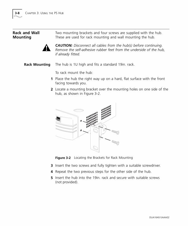
2 Locate a mounting bracket over the mounting holes on one side of the hub, as shown in Figure 3-2.
Figure 3-2 Locating the Brackets for Rack Mounting
3 Insert the two screws and fully tighten with a suitable screwdriver.
4 Repeat the two previous steps for the other side of the hub.
5 Insert the hub into the 19in. rack and secure with suitable screws (not provided).
DUA1640-5AAA02
Rack and Wall Mounting 3-9
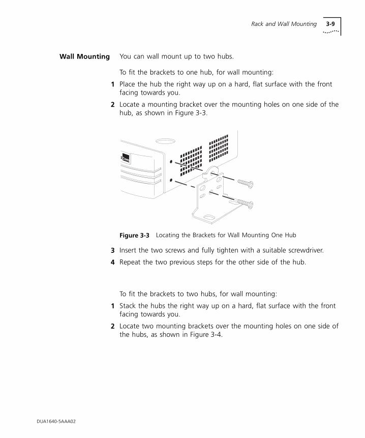
Wall Mounting You can wall mount up to two hubs.
To fit the brackets to one hub, for wall mounting:
1 Place the hub the right way up on a hard, flat surface with the front facing towards you.
2 Locate a mounting bracket over the mounting holes on one side of the hub, as shown in Figure 3-3.
Figure 3-3 Locating the Brackets for Wall Mounting One Hub
3 Insert the two screws and fully tighten with a suitable screwdriver.
4 Repeat the two previous steps for the other side of the hub.
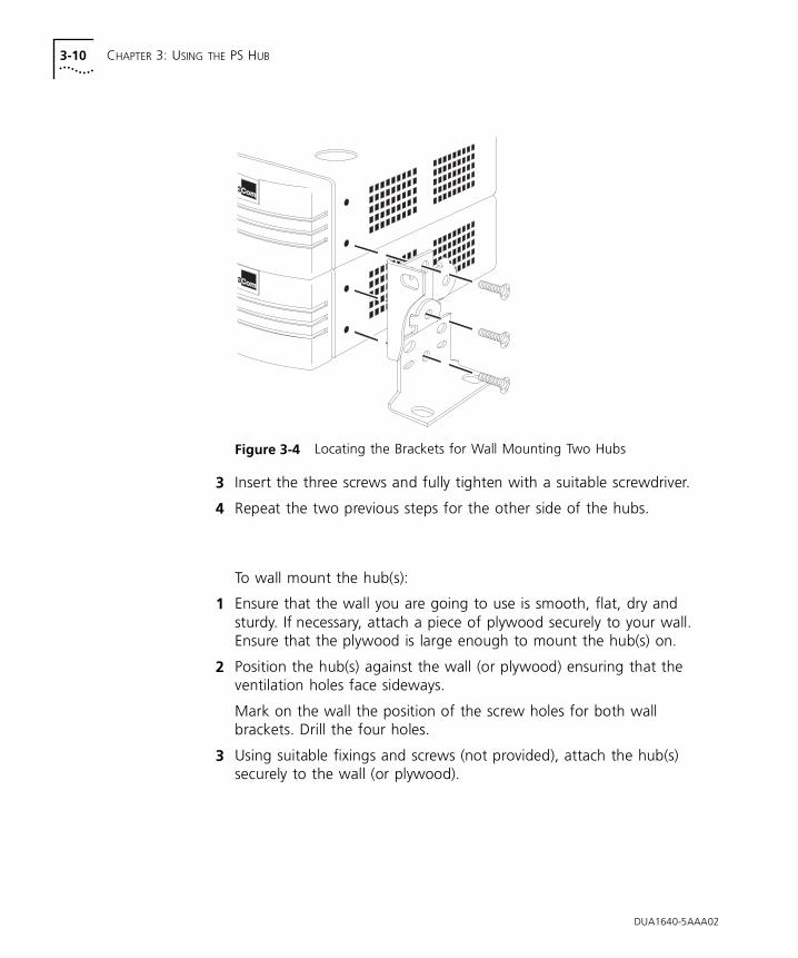
To fit the brackets to two hubs, for wall mounting:
1 Stack the hubs the right way up on a hard, flat surface with the front facing towards you.
2 Locate two mounting brackets over the mounting holes on one side of the hubs, as shown in Figure 3-4.
DUA1640-5AAA02
3-10 CHAPTER 3: USING THE PS HUB
Figure 3-4 Locating the Brackets for Wall Mounting Two Hubs
3 Insert the three screws and fully tighten with a suitable screwdriver.
4 Repeat the two previous steps for the other side of the hubs.
To wall mount the hub(s):
1 Ensure that the wall you are going to use is smooth, flat, dry and sturdy. If necessary, attach a piece of plywood securely to your wall. Ensure that the plywood is large enough to mount the hub(s) on.
2 Position the hub(s) against the wall (or plywood) ensuring that the ventilation holes face sideways.
Mark on the wall the position of the screw holes for both wall brackets. Drill the four holes.
3 Using suitable fixings and screws (not provided), attach the hub(s) securely to the wall (or plywood).
DUA1640-5AAA02
Connecting Workstations to Your Hub 3-11
Connecting Workstations to Your Hub
This section describes how to connect workstations to the hub using the 10BASE-T RJ45 ports.
WARNING: Ensure you have read the Important Safety Information section carefully before you start.
ACHTUNG: Versichern Sie sich, daß Sie den Abschnitt mit den wichtigen Sicherheitshinweisen gelesen haben, bevor Sie das Gerät benutzen.
AVERTISSEMENT: Assurer que vous avez lu soigneusement la section de L’information de Sécurité Importante avant que vous commenciez.
CAUTION: Always wait about 5 seconds between powering off and powering on the hub, to ensure that the hub performs a full reset.
Connecting workstations to your hub is easy. Connect them using 10BASE-T cables to any of the hub’s 10BASE-T RJ45 ports. To connect a 10BASE-T cable, simply slot the connector into the relevant RJ45 port. When the connector is fully in, its latch locks it in place. To disconnect the cable, push the connector’s latch in and remove it.
The hub detects all port connections, so you can start using your network immediately. When you need more ports, simply add more PS Hubs.
In order to comply with the 10BASE-T standard, ports designed for workstation connections have been marked with the graphical symbol ‘x’. This denotes a crossover in the port’s internal wiring, for example 1x, 2x, 3x...
If you are using the last port (port 12 or 24) to connect a workstation, ensure the MDI/MDIX switch is set to MDIX.
DUA1640-5AAA02
3-12 CHAPTER 3: USING THE PS HUB
Using TransceiverModules
Depending on your hub, the PS Hub has one or two transceiver module slots, providing a choice of media options.
PS Hub 40
The PS Hub 40 has two 10Mbps transceiver module slots that can be fitted with 3Com 10Mbps transceiver modules.
CAUTION: The only transceiver modules that can be used in the PS Hub 40 unit’s transceiver module slots are 3Com 10Mbps transceiver modules.
You cannot use two AUI Transceiver Modules or Bridge MicroModules at the same time.
PS Hub 50
The PS Hub 50 has one transceiver module slot that can be fitted with a 3Com 10Mbps or 100Mbps transceiver module.
You cannot use an AUI Transceiver Module or Bridge MicroModule. The operation of the transceiver module in the PS Hub 50 is determined by the type of transceiver module you use; refer to “PS Hub 50 Transceiver Module Slot” on page 2-6.
Connecting PS Hubs Together (Stacking)
You can increase the number of ports in your network by connecting additional PS Hub 40 and PS Hub 50 units to your hub, to form a stack (this process is called stacking). The four cascaded segments are carried through the stack, enabling you to switch the ports on all of the hubs between the four segments.
You can stack up to 10 units (if they are rack mounted) or six units (if they are free standing).
CAUTION: Do not have a free standing stack of more than six hubs. When you connect workstations and other equipment to the stack, ensure that all cables are supported and cannot pull the stack over. If installing the PS Hub in a stack of mixed SuperStack II units, the PS Hub must be installed above the deeper units.
For conformance with Ethernet rules, you can only have four repeaters in series. For a stack of more than one PS Hub, any path through the stack counts as going through two logical repeaters.
DUA1640-5AAA02
Connecting PS Hubs Together (Stacking) 3-13
About CascadeCables
Cascade cables are used to connect the PS Hubs to form a stack. These cables carry the stack’s cascaded segments and distributed management information; the stack will not work with any other cables. Cascade cables are available from your supplier, and come in a variety of lengths, refer to “Cascade Connections” on page A-6.
You can use a maximum of 6m (19.6ft) of cascade cabling between the top and bottom hubs in the stack.
Stack Resilience and Hot Swap Functionality
Cascade cables have built-in resilience and hot swap functionality:
■ Up to three units within the stack can be powered off without affecting the operation of the other units in the stack.
■ The units within a stack automatically reconfigure when a unit is added or removed from the stack.
However, if a cascade cable is disconnected, the stack splits into two isolated stacks. The units within the stack(s) automatically reconfigure when a cascade cable is connected or disconnected.
Hot Swap Cascade Units
You can increase the resilience of the stack by using 3Com Hot Swap Cascade Units (3C16430) with the cascade cables. These units can be fitted to any PS Hub and provide total hot swap functionality.
The stack is held together even if units fail or are removed, added, or powered off. For more information on how the Hot Swap Cascade Units work, refer to the documentation that accompanies them.
Hot Swap Cascade Units are available from your supplier, refer to “Cascade Connections” on page A-6.
DUA1640-5AAA02
3-14 CHAPTER 3: USING THE PS HUB
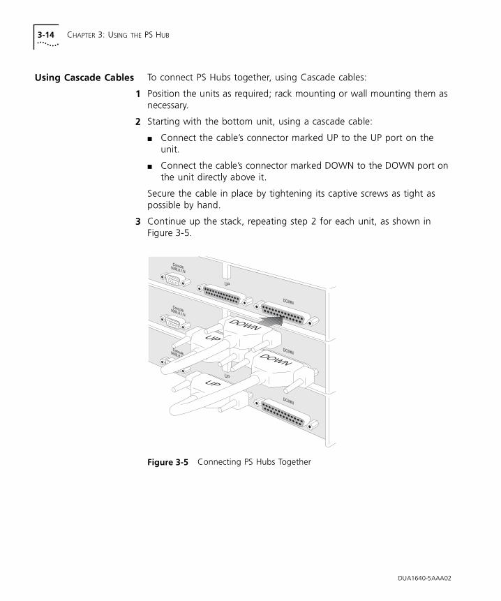
Using Cascade Cables To connect PS Hubs together, using Cascade cables:
1 Position the units as required; rack mounting or wall mounting them as necessary.
2 Starting with the bottom unit, using a cascade cable:
■ Connect the cable’s connector marked UP to the UP port on the unit.
■ Connect the cable’s connector marked DOWN to the DOWN port on the unit directly above it.
Secure the cable in place by tightening its captive screws as tight as possible by hand.
3 Continue up the stack, repeating step 2 for each unit, as shown in Figure 3-5.
Figure 3-5 Connecting PS Hubs Together
DOWN
DOWN
UP
UP
DUA1640-5AAA02
Connecting PS Hubs Together (Stacking) 3-15
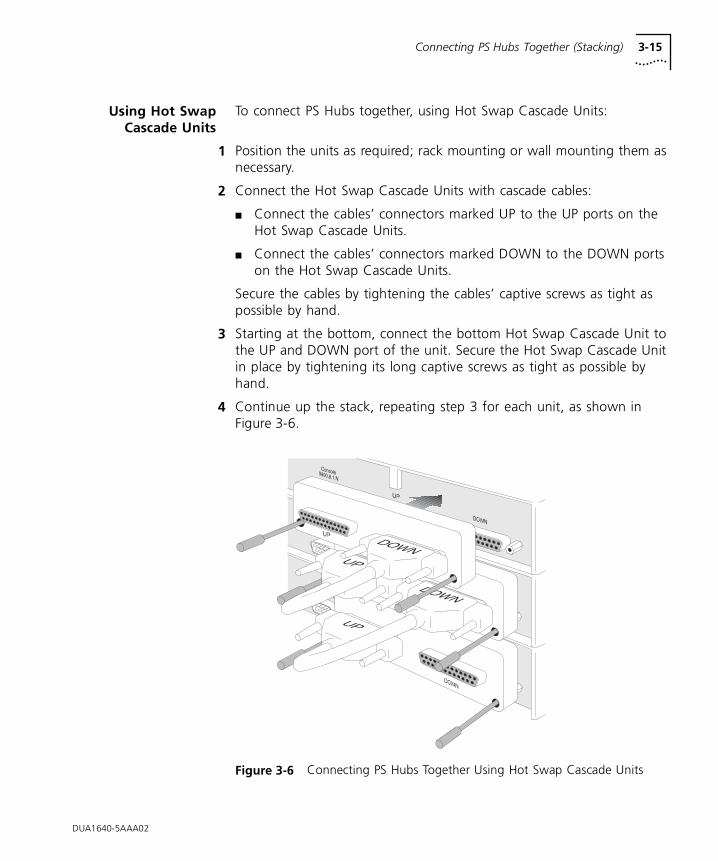
Using Hot SwapCascade Units
To connect PS Hubs together, using Hot Swap Cascade Units:
1 Position the units as required; rack mounting or wall mounting them as necessary.
2 Connect the Hot Swap Cascade Units with cascade cables:
■ Connect the cables’ connectors marked UP to the UP ports on the Hot Swap Cascade Units.
■ Connect the cables’ connectors marked DOWN to the DOWN ports on the Hot Swap Cascade Units.
Secure the cables by tightening the cables’ captive screws as tight as possible by hand.
3 Starting at the bottom, connect the bottom Hot Swap Cascade Unit to the UP and DOWN port of the unit. Secure the Hot Swap Cascade Unit in place by tightening its long captive screws as tight as possible by hand.
4 Continue up the stack, repeating step 3 for each unit, as shown in Figure 3-6.
Figure 3-6 Connecting PS Hubs Together Using Hot Swap Cascade Units
DOWN
DOWN
UP
UP
DUA1640-5AAA02
3-16 CHAPTER 3: USING THE PS HUB
DUA1640-5AAA02
Connecting Different Hubs and Stacks to Your Hub
You can connect the PS Hub to different hubs and stacks (for example a stack of SuperStack II Hub 10 units), giving you flexibility when creating a new network, or expanding an existing network.
In order to conform with Ethernet rules, you can only have four repeaters in series. For a stack of more than one PS Hub, any path through the stack counts as going through two logical repeaters.
Each of the PS Hub’s 10BASE-T ports are internally crossed (MDIX). The type of cable and ports used must be correct for the connection to work:
■ You can use ‘Straight-through’ 10BASE-T cable to connect a crossover (MDIX) port to an uncrossed (MDI) port.
■ You can use ‘Crossover’ 10BASE-T cable to connect two crossover (MDIX) ports.
The last port (port 12 or 24) on the PS Hub can be either crossed or uncrossed. The MDI/MDIX switch affects the port’s state:
■ If the switch is IN, the port is uncrossed (MDI).
■ If the switch is OUT, the port is crossed (MDIX).
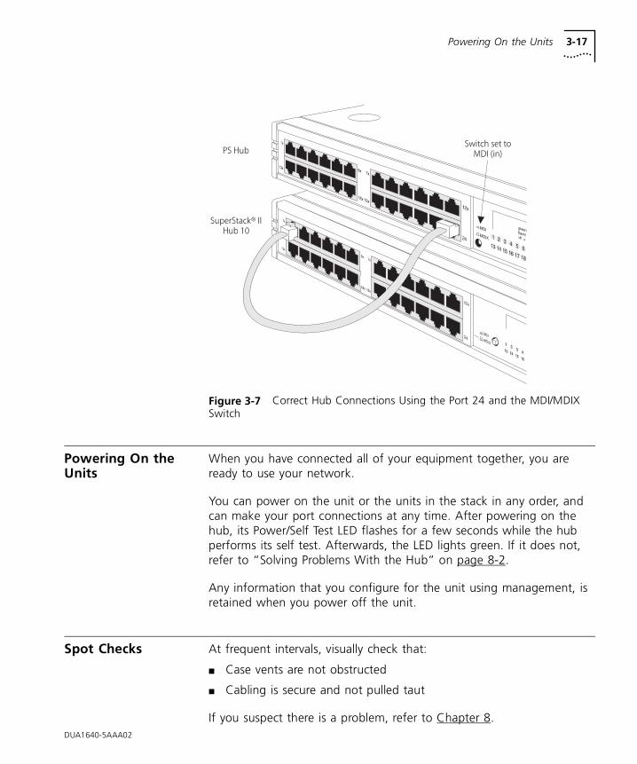
Figure 3-7 shows a SuperStack II Hub 10 connected to the PS Hub. A ‘Straight-through’ cable is used, and one of the SuperStack II Hub 10 unit’s crossed (MDIX) ports is connected to port 24 on the PS Hub (note that the MDI/MDIX switch is IN, so the port is uncrossed).
Powering On the Units 3-17
DUA1640-5AAA02
Figure 3-7 Correct Hub Connections Using the Port 24 and the MDI/MDIX Switch
Powering On the Units
When you have connected all of your equipment together, you are ready to use your network.
You can power on the unit or the units in the stack in any order, and can make your port connections at any time. After powering on the hub, its Power/Self Test LED flashes for a few seconds while the hub performs its self test. Afterwards, the LED lights green. If it does not, refer to “Solving Problems With the Hub” on page 8-2.
Any information that you configure for the unit using management, is retained when you power off the unit.
Spot Checks At frequent intervals, visually check that:
■ Case vents are not obstructed
■ Cabling is secure and not pulled taut
If you suspect there is a problem, refer to Chapter 8.

3-18 CHAPTER 3: USING THE PS HUB
DUA1640-5AAA02
4
LOAD BALANCINGThis chapter contains the following topics:
■ An overview of load balancing
■ How load balancing works
Overview The PS Hub has a very useful feature called load balancing which can be used to configure segments in a stack of PS Hubs. The aim of load balancing is to increase total throughput across the segments in a stack, providing more efficient segments.
As load balancing configures segments in a stack, you cannot perform workgrouping at the same time. In effect, the segments participating in load balancing are a single, high-capacity workgroup.
For load balancing to work properly, there must be either:
■ A PS Hub 50 in the stack
■ A switch connected to the hubs in the stack
4-2 CHAPTER 4: LOAD BALANCING
How Does LoadBalancing Work?
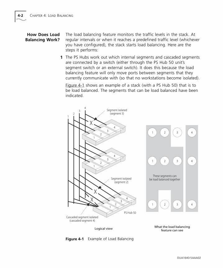
The load balancing feature monitors the traffic levels in the stack. At regular intervals or when it reaches a predefined traffic level (whichever you have configured), the stack starts load balancing. Here are the steps it performs:
1 The PS Hubs work out which internal segments and cascaded segments are connected by a switch (either through the PS Hub 50 unit’s segment switch or an external switch). It does this because the load balancing feature will only move ports between segments that they currently communicate with (so that no workstations become isolated).
Figure 4-1 shows an example of a stack (with a PS Hub 50) that is to be load balanced. The segments that can be load balanced have been indicated.
Figure 4-1 Example of Load Balancing
DUA1640-5AAA02
Performing Load Balancing 4-3
2 The load balancing feature notes:
■ Any ports or segments that have been fixed — Through management you can fix ports and segments that you do not want load balancing to move.
■ Any ports that are connected to external switches.
These segments and ports will not be moved by load balancing. However, traffic generated by these ports and segments will still be considered by the load balancing feature, when it works out what other ports it will move.
3 The load balancing feature works out how it can configure the segments. It attempts to:
■ Have frequently communicating ports on the same segment.
■ Reduce the total traffic utilization across the segments.
4 If some benefit will be gained from the new configuration, the load balancing feature completes the operation by moving the ports between the segments as required.
Using an ExternalSwitch
The best way to interconnect the cascaded segments in a stack of PS Hubs is to use a PS Hub 50. However, if you want to connect two or more segments using an external switch, you must connect the switch to the PS Hub’s 10BASE-T or transceiver module ports and then port switch those ports to the relevant segments.
For information on using your switch, refer to the documentation that accompanies it.
Performing Load Balancing
You can configure the load balancing feature through management (it is disabled by default). For information on initiating the load balancing feature using the web interface, refer to “Load Balancing” on page 7-20. For information on setting it up using the Load Balancing Tool (which is launched from within Quick Config Manager), refer to “Load Balancing” on page B-18.
DUA1640-5AAA02

4-4 CHAPTER 4: LOAD BALANCING
DUA1640-5AAA02
5
MANAGING THE PS HUBThis chapter contains the following topics:
■ The management tasks you can perform
■ What you can use to manage your stack
■ How you can make a management connection to your stack
Introduction Network management is not required to make the PS Hub work, but allows you to change the way it works and to monitor what is happening to the segments and the rest of the network. There are many features that can improve the operation of the hub or stack.
A stack of PS Hubs is treated as a single manageable entity, and the management is distributed. This guide uses the word ‘stack’ to refer to a stack of one or more PS Hubs, and ‘management station’ to refer to the piece of equipment you are using to manage the stack (for example a computer).
If the stack is connected and configured as recommended, the bottom hub in the stack is unit number 1, the next hub up is unit number 2, and so on.
All PS Hubs must be running agent software version 2.00 or later for them to have the functionality mentioned in this user guide (for example the web interface, CLI and load balancing). However, PS Hubs that are running earlier agent software are compatible with newer PS Hubs but do not have the newer functionality.You can use Quick Configuration Manager to see what versions of management software are on the units in the stack, and to upgrade the stack; refer to “Upgrading a Stack” on page B-28.
5-2 CHAPTER 5: MANAGING THE PS HUB
Why Manage Your Stack?
With management, you can change and view the way the stack or network operates in the following way:
■ Display a graphical representation for the stack to quickly view the status of each hub and its ports.
■ Display general information for the stack or hubs.
■ Graphically display network information for the stack’s cascaded segments.
■ Enable and disable ports, and switch them between segments.
■ Perform load balancing so that the traffic is distributed evenly across the segments in the stack, resulting in more efficient segments.
■ Configure security for the ports, including specifying what equipment is allowed to communicate through the ports on the hub.
■ Set up resilience; specify a backup connection that takes over should a main connection fail.
■ View statistics.
■ Configure the console port for connection to a modem.
■ Configure user management access levels.
■ Upgrade the management software in the stack with any future agent software upgrade.
■ Configure the stack to send messages (called traps) to an SNMP network management application (for example, Transcend® Enterprise Manager) if certain conditions arise — you cannot configure this using the web interface.
■ Perform remote monitoring using RMON — not manageable using the web interface or Quick Config Manager.
■ Restart the hub to refresh its statistics and use any new configurations.
■ Initialize the hub to return it to its factory settings (IP information is retained).
DUA1640-5AAA02
How You Can Manage Your Stack 5-3
How You Can Manage Your Stack
A stack of PS Hubs is treated as a single manageable entity, and the management is distributed. Any network address information (IP information) that you configure for a hub, can be used to access the stack.
The PS Hub has two built-in management interfaces which you can access locally (through the hub’s console port) or remotely (over the network):
■ A Command Line Interface (CLI) — can be used to set up the stack with network address information.
■ A web interface — provides easy management of the stack from any suitable web browser.
There is also a management application called Transcend Quick Configuration Manager, referred to as ‘Quick Config Manager’ in this guide, that is supplied on the CD-ROM. It runs under Microsoft Windows® and provides an easy-to-use graphical management system.
Command LineInterface
The PS Hub’s Command Line Interface (CLI) is a simple text-based user interface which allows you to configure some network information for your hub. The CLI provides just a subset of the web interface’s functionality but is intended as a quick setup tool, to get your hub ready for management over the network. You can use a Terminal or Terminal emulator to access the CLI.
Web Interface The PS Hub’s web interface provides easy management of the stack. It behaves in a similar way to a web site on the World Wide Web in that you access it using a web browser. You use its different pages to change the network information in your stack and perform different management tasks.
DUA1640-5AAA02
5-4 CHAPTER 5: MANAGING THE PS HUB
SNMP NetworkManagement
The web interface and CLI built into your PS Hub allow you to manage the stack. However, as your network grows, you may need a more powerful SNMP network management application that will control all of your managed units and stacks. Whether your network is large or small, its ongoing performance, growth and security are only as good as its management system.
3Com produces a range of powerful graphical SNMP network management applications (for example Transcend Enterprise Manager for Windows) that give you total control over your entire 3Com network from a single management station.
Using intelligent 3Com software distributed throughout the network, 3Com’s Transcend management applications support all of today’s platforms and manage a wide variety of 3Com products.
For further information about which Transcend management application can benefit your growing network, call your local sales office; refer to Appendix E.
DUA1640-5AAA02
Methods of Management 5-5
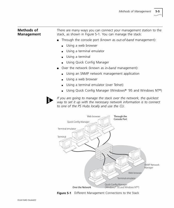
Methods of Management
There are many ways you can connect your management station to the stack, as shown in Figure 5-1. You can manage the stack:
■ Through the console port (known as out-of-band management):
■ Using a web browser
■ Using a terminal emulator
■ Using a terminal
■ Using Quick Config Manager
■ Over the network (known as in-band management):
■ Using an SNMP network management application
■ Using a web browser
■ Using a terminal emulator (over Telnet)
■ Using Quick Config Manager (Windows® ‘95 and Windows NT®)
If you are going to manage the stack over the network, the quickest way to set it up with the necessary network information is to connect to one of the PS Hubs locally and use the CLI.
Figure 5-1 Different Management Connections to the Stack
DUA1640-5AAA02
5-6 CHAPTER 5: MANAGING THE PS HUB
Requirements forManaging Over the
Network
When managing your stack over the network, you must remember that (regardless of your method of management):
■ The hub or stack must be correctly configured with IP information. You must make a direct management connection through the console port to do this (or use a BOOTP server).
IP addresses are unique, no two hubs must have the same IP address. If you have no previous knowledge of IP, refer to “IP Addresses” on page 5-7.
If you have a BOOTP server, it can automatically assign your network equipment, including the PS Hubs, with IP information so that it can be communicated with and managed over the network. Refer to the documentation that accompanies your BOOTP server for more information.
■ Any IP information configured for a hub in a stack can be used to access the whole stack. If the stack is physically split in two, the IP information remains with the hub and is used by its half; the other half has no IP information so it becomes unmanageable over the network. You can configure more than one hub in a stack with IP information. We recommend you do this for the top and bottom hubs to obtain redundant management capabilities (should the stack split).
■ IP must be correctly set up for your management station.
■ You can manage the hub or stack over the network, through any of the ports. However, for the communication to work over the network, the port through which your communication reaches the stack must be connected to segment 1 (either directly or indirectly) of the hub with the IP address configured. If you are going to use load balancing to configure your segments, it is a good idea to fix this port to segment 1.
■ You can manage a mixed stack of PS Hub 40 and PS Hub 50 units. If you have multiple PS Hub 50 units, only one of the hubs’ segment switch will be active, refer to “Multiple PS Hub 50 Units in a Stack” on page 2-4.
DUA1640-5AAA02
Methods of Management 5-7
IP Addresses If you are uncertain about what IP addresses to assign your equipment, contact your network administrator.
To operate correctly, each device on your network (for example a hub or management station) must have a unique IP address (if one is configured). IP addresses have the format n.n.n.n where n is a decimal number between 0 and 255. An example IP address is ‘191.1.1.8’.
The IP address can be split into two parts:
■ The first part (‘191.1’ in the example) identifies the network on which the device resides.
■ The second part (‘1.8’ in the example) identifies the device within the network.
If your network is internal to your organization only, you may use any arbitrary IP address. We suggest you use addresses in the series 191.1.1.X where X is a number between 1 and 254. Use the default SLIP address of 192.168.101.1.
If your network has a connection to the external IP network, you must apply for a registered IP address. This system ensures that every IP address used is unique; if you do not have a registered IP address, you may be using an identical address to someone else and your network will not operate correctly.
Obtaining a Registered IP Address
InterNIC Registration Services is the organization responsible for supplying registered IP addresses. The following contact information is correct at time of publication:
Network SolutionsAttn.: InterNIC Registration Service505 Huntmar Park DriveHerndonVA 22070USA
Telephone: (1) (703) 742 4777
World Wide Web site: http://www.internic.com/
DUA1640-5AAA02
5-8 CHAPTER 5: MANAGING THE PS HUB
Command Line Interface (CLI)
The CLI allows you to configure a limited set of parameters for the hub. You can access the CLI:
■ Through the console port
■ Over the network
This section has information on accessing the CLI. For more information on using the CLI, refer to Chapter 6.
Through the ConsolePort
Table E-1 shows the settings for the hub’s console port.
You can access the console port through a direct local connection, or you can set up a remote connection using a modem.
The terminal or management station (with the terminal emulator) connected to the console port must use the same settings. By default, the hub has auto-configuration enabled which will change the hub’s console port settings to match those of the connected equipment and automatically detect the baud rate (line speed). The hub can auto-detect a maximum baud rate of 19200.
You need to use a null modem cable for connecting your terminal or management station directly to the console port. This should be available from your supplier. There are a variety of null modem cables that you can use. For an example of one of these, refer to “Console Cable” on page A-4.
If you are using a modem in your setup, you need to use a modem cable. For an example of one of these, refer to “Modem Cable” on page A-5. For information on setting up a connecting to the modem, refer to the documentation that accompanies the modem.
Table E-1 Console Port Settings
Data bits (character size) 8
Stop bit 1
Parity None
DUA1640-5AAA02
Command Line Interface (CLI) 5-9
To connect your equipment:
1 Connect the serial port on your terminal or management station to the console port on the PS Hub, using a null modem cable.
2 Ensure that the terminal or management station’s serial port settings match those of the console port on the PS Hub.
Using a Terminal Emulator
You can use the terminal emulator that comes with Microsoft Windows to access the hub’s CLI:
■ Windows ‘95 and Windows NT (version 4 or later) have a program called ‘HyperTerminal’.
■ Other versions of Windows have a program called ‘Terminal’.
For other types of management stations and operating systems, refer to the documentation that accompanies your terminal emulator for information on how to use it.
HyperTerminal HyperTerminal can usually be found from the Windows Start menu, in Programs, Accessories. To start a HyperTerminal session (after connecting to the hub’s console port):
1 Double-click on the ‘Hypertrm.exe’ icon to start the application.
The Connection Description dialog box appears.
2 Enter a dummy name in the Name field and click OK.
The Phone Number dialog box appears.
3 Select the serial port that you are using to connect to the hub, in the Connect using field.
The COM Properties dialog box appears.
4 Configure the data bits to ‘8’, stop bit to ‘1’, parity to ‘none’, and click OK.
5 Click in the main HyperTerminal window and press [Return] several times to start the communication.
DUA1640-5AAA02
5-10 CHAPTER 5: MANAGING THE PS HUB
Terminal Terminal can usually be found from the Main window, in the Accessories program group. To start a Terminal session (after connecting to the hub’s console port):
1 Double-click on the ‘Terminal’ icon to start the application.
2 If the Default Serial Port dialog box appears, select the serial port that you are using to connect to the hub and click OK.
3 From the Settings menu in the main Terminal window, select Terminal Emulation.
The Terminal Emulation dialog box appears.
4 Select ‘DEC VT-100 (ANSI)’ and click OK.
5 From the Settings menu, select Communications.
The Communications dialog box appears.
6 Configure the data bits to ‘8’, stop bit to ‘1’, parity to ‘none’, and click OK.
7 Click in the main Terminal window and press [Return] several times to start the communication.
DUA1640-5AAA02
Command Line Interface (CLI) 5-11
Over the Network You can access the CLI over a TCP/IP network using Telnet. To run Telnet, you need a suitable terminal or management station running a terminal emulator.
You can have multiple CLI management sessions at the same time. If a connection is lost inadvertently, the connection is closed by the hub after about 30 minutes of inactivity.
You can manage the hub or stack over the network, through any of the ports. However, for the communication to work over the network, the port through which your communication reaches the stack must be connected to segment 1 (either directly or indirectly) of the hub with the IP address configured.
Using a Telnet Terminal Emulator
You can use the Telnet terminal emulator that comes with Microsoft Windows ‘95 (called ‘Telnet’) to access the hub’s CLI.
To open the Telnet session, you must specify the IP address of the hub you want to manage. For other types of management stations and operating systems, refer to the documentation that accompanies your Telnet terminal emulator for information on how to do this.
Telnet The Telnet application (‘Telnet.exe’) can usually be found in the Windows directory on your PC. To start a Telnet session:
1 Run the ‘Telnet.exe’ application.
The Telnet application’s window appears.
2 From the Connect menu, select Remote System.
The Connect dialog box appears.
3 Type the IP address of the stack in the Host name field, select ‘telnet’ for the Port field, and select ‘vt-100’ for the TermType field.
4 Click Connect.
DUA1640-5AAA02
5-12 CHAPTER 5: MANAGING THE PS HUB
Web Interface You can manage the PS Hub using its web interface. You can access the web interface:
■ Through the console port
■ Over the network
This section has information on accessing the web interface. For more information on using the web interface, refer to Chapter 7.
Through the ConsolePort
You can access the web interface through the hub’s console port, using a management station running SLIP (Serial Line Interface Protocol).
If your management station is running Windows ‘95, you must use the 3Com serial web utility that is supplied on the CD-ROM. This is a SLIP driver that sets up SLIP access for web interface management. To install and use the serial web utility, refer to Appendix C.
You need to use a null modem cable for connecting your management station directly to the console port. This should be available from your supplier. There are a variety of null modem cables that you can use. For an example of one of these, refer to “Console Cable” on page A-4.
Over the Network You must have an IP stack on your management station, so that you can manage over a TCP/IP network. An easy way to check this is that if you have access to the Internet and can download web pages from it, your management station has already got an IP stack.
Which WebBrowsers are
Supported?
For fully operational management, your web browser must support:
■ Java
■ Frames
■ HTML 3.2
Suitable web browsers are Netscape Navigator™ Version 3.0 or Microsoft Internet Explorer Version 3.0.
Configuring Your Browser
Before you use your web browser to access the web interface, you must make one small configuration change to it, so that it always downloads the latest version of a page.
DUA1640-5AAA02
Quick Config Manager 5-13
To do this for Netscape Navigator:
1 Start Netscape Navigator.
2 From the Options menu, select Network Preferences.
The preferences dialog box appears.
3 Check the ‘Every Time’ checkbox.
4 Click OK.
To do this for Microsoft Internet Explorer:
1 Start Microsoft Internet Explorer.
2 From the View menu, select Options.
The Options dialog box appears.
3 Select the Advanced tab, and in the Advanced property sheet click Settings.
4 Check the ‘Every visit to the page’ checkbox.
5 Click OK.
Quick Config Manager
You can manage the PS Hub using Quick Config Manager. You can manage the hub:
■ Through the console port
■ Over the network — Windows ‘95 and Windows NT (version 4 or later) only
You can perform similar management functions using Quick Config Manager as you can using the web interface.
Through the ConsolePort
You need to use a null modem cable for connecting your management station directly to the console port. This should be available from your supplier. There are a variety of null modem cables that you can use. For an example of one of these, refer to “Console Cable” on page A-4.
Connect one end of the null modem cable to the console port on the hub, and the other to the serial (RS232) port on your management station with Quick Config Manager installed.
DUA1640-5AAA02
5-14 CHAPTER 5: MANAGING THE PS HUB
When using Quick Config Manager with Windows ‘95 and managing through the console port, you must first disable FIFO buffers in the Advanced Port Settings window in Windows ‘95. To do this:
1 In the Windows ‘95 environment, select My Computer.
2 Select (in turn): Control Panel, System, Device Manager, Ports, COM1 (or whatever COM port you are using instead), Port Settings, and Advanced.
The Advanced Port Settings window appears.
3 Uncheck the Use FIFO Buffers checkbox.
4 Click OK for the Advanced Port Settings window, and all of the windows that were opened in order to access the window.
When you have made your connection and installed Quick Config Manager, you are ready to manage the stack. Quick Config Manager uses COM 1 as the default serial port on your management station. If you want to change this, refer to “Running Quick Config Manager” on page B-4.
Over the Network You must have an IP stack on your management station, so that you can manage over a TCP/IP network.
You can manage the hub or stack over the network, through any of the ports. However, for the communication to work over the network, the port through which your communication reaches the stack must be connected to segment 1 (either directly or indirectly) of the hub with the IP address configured.
For information on installing and using Quick Config Manager, refer to Appendix B.
DUA1640-5AAA02
6
USING THE COMMAND LINE INTERFACEThis chapter describes how to use the Command Line Interface (CLI). The CLI is a quick and simple interface that is built-in to the hub, which allows you to enter various IP address settings, reset it and initialize it. The web interface and Quick Config Manager can perform most of the tasks that the CLI can do.
You would normally use the CLI if you have many hubs that you want to set up quickly with IP address information, for eventual management using an SNMP network management application.
Simple help is provided with each command in the Command Line Interface.
Ensure that your terminal or management station (which has the terminal emulator) has been appropriately set up for your particular management method and that any necessary connections have been made, refer to “Command Line Interface (CLI)” on page 5-8.
If you have any problems using the CLI, refer to “Solving Problems With the Command Line Interface” on page 8-3.
6-2 CHAPTER 6: USING THE COMMAND LINE INTERFACE
Accessing the CLI By default, the hub automatically configures the baud rate of its console port to operate with the connected management station or terminal, provided the parity, stop bits and character size are identical to the connected management station or terminal. You may need to perform the wake-up procedure to initiate the communication. To do this, press [Return] several times at the management station or terminal.
The login sequence for the CLI begins as soon as the hub detects a connection to its console port, or as soon as a Telnet session is started.
Initial Access The login prompt Login: is displayed.
As the initial user, enter the default user name admin and press [Return] at the Password: prompt. The first time you access the CLI, the password is null.
We recommend that when you have accessed the stack, you change the default passwords for the user levels (if you have not already done so) by logging in as the different user levels.
Logging On At subsequent logins, enter your user name. If the user name is valid, the Password: prompt appears. You must enter your password correctly before you can continue with your management session.
If you have logged on correctly, the initial menu appears. If you have not logged on correctly, the message Incorrect password appears and the login sequence starts again.
DUA1640-5AAA02
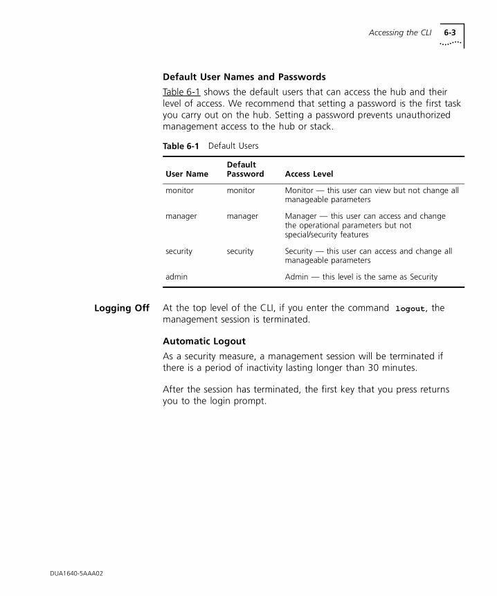
Accessing the CLI 6-3
Default User Names and Passwords
Table 6-1 shows the default users that can access the hub and their level of access. We recommend that setting a password is the first task you carry out on the hub. Setting a password prevents unauthorized management access to the hub or stack.
Logging Off At the top level of the CLI, if you enter the command logout , the management session is terminated.
Automatic Logout
As a security measure, a management session will be terminated if there is a period of inactivity lasting longer than 30 minutes.
After the session has terminated, the first key that you press returns you to the login prompt.
Table 6-1 Default Users
User NameDefault Password Access Level
monitor monitor Monitor — this user can view but not change all manageable parameters
manager manager Manager — this user can access and change the operational parameters but not special/security features
security security Security — this user can access and change all manageable parameters
admin Admin — this level is the same as Security
DUA1640-5AAA02
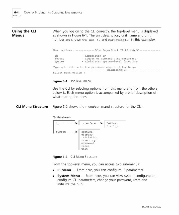
6-4 CHAPTER 6: USING THE COMMAND LINE INTERFACE
Using the CLI Menus
When you log on to the CLI correctly, the top-level menu is displayed, as shown in Figure 6-1. The unit description, unit name and unit number are shown (PS Hub 50 and Marketing(1) in this example).
Figure 6-1 Top-level menu
Use the CLI by selecting options from this menu and from the others below it. Each menu option is accompanied by a brief description of what that option does.
CLI Menu Structure Figure 6-2 shows the menu/command structure for the CLI.
Figure 6-2 CLI Menu Structure
From the top-level menu, you can access two sub-menus:
■ IP Menu — From here, you can configure IP parameters.
■ System Menu — From here, you can view system configuration, configure CLI parameters, change your password, reset and initialize the hub.
DUA1640-5AAA02
Using the CLI Menus 6-5
Navigating theMenus and Entering
Commands
You can navigate the menus using any of the following methods:
■ Following the menu hierarchy — at the Select menu option:
prompt, type your selected menu name and press [Return]. The screen changes to show the next level of menus available or the list of commands available within your selected menu.
■ Entering multiple menu names on the same line — if you are familiar with the menu structure you can enter successive menus on the same line at the Select menu option: prompt. For example, to display the system configuration, the CLI would read:
Select menu option: system display
■ Abbreviated commands — for speedy navigation of the menus, you need only enter enough characters to uniquely identify the menu you want at the prompt. For example, to display system configuration, the CLI would read:
Select menu option: sy di
As you navigate through the menus, the prompt changes to display your current position in the hierarchy. For example, if you are in the interface sub-menu of the system menu, ready to enter your next option, the prompt reads:
Select menu option (system) :
Entering Commands
When you reach the menu level containing the specific command you want to enter, you are prompted for a command name. Commands can also be entered at the end of the menu string. Where applicable, default values for commands are shown in parentheses after the prompt. If you press the [Return] key for a command with such a value, the hub continues to use that value.
Returning to the Previous Menu
You can return to the previous menu, by entering q at the prompt.
Returning to the Top-level Menu
You can return to the top-level menu by pressing the [Esc] key.
Obtaining Help
You can get help at any time by entering ? at the prompt.
DUA1640-5AAA02
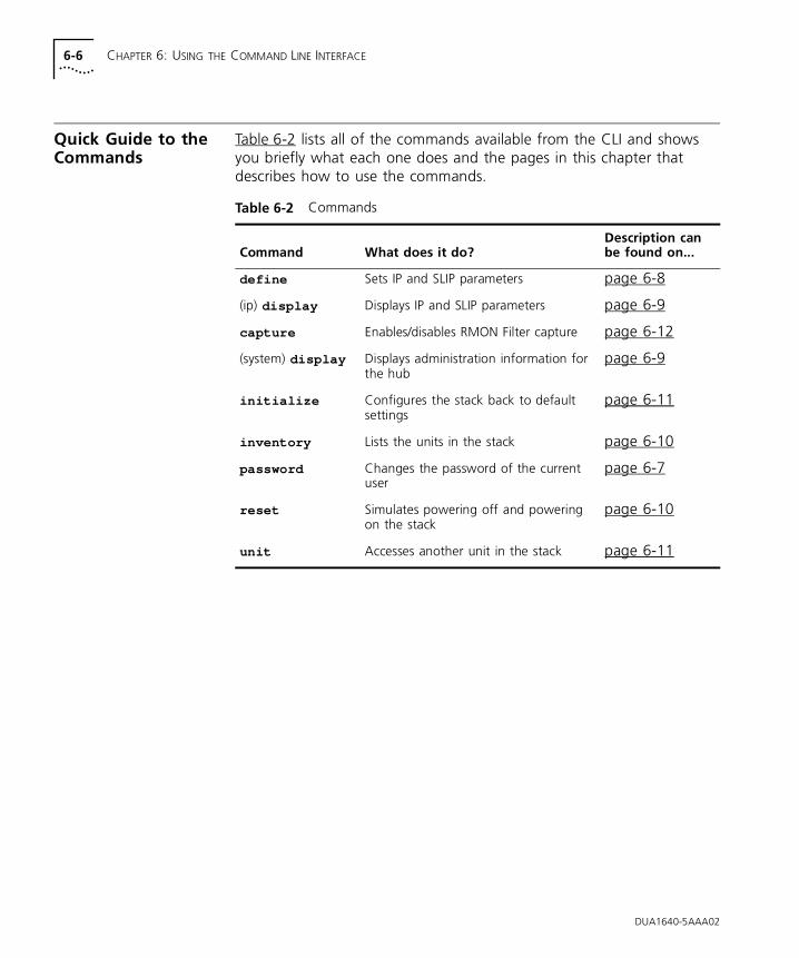
6-6 CHAPTER 6: USING THE COMMAND LINE INTERFACE
Quick Guide to the Commands
Table 6-2 lists all of the commands available from the CLI and shows you briefly what each one does and the pages in this chapter that describes how to use the commands.
Table 6-2 Commands
Command What does it do?Description can be found on...
define Sets IP and SLIP parameters page 6-8
(ip) display Displays IP and SLIP parameters page 6-9
capture Enables/disables RMON Filter capture page 6-12
(system) display Displays administration information for the hub
page 6-9
initialize Configures the stack back to default settings
page 6-11
inventory Lists the units in the stack page 6-10
password Changes the password of the current user
page 6-7
reset Simulates powering off and powering on the stack
page 6-10
unit Accesses another unit in the stack page 6-11
DUA1640-5AAA02
Commands 6-7
Commands The remaining sections in this chapter detail the management functions that can be carried out from the CLI.
Changing thePassword
We recommend that setting a password is the first task you carry out on the hub. Setting a password prevents unauthorized management access to the hub or stack.
If you forget your password while logged out of the hub, refer to “Solving Problems With the Command Line Interface” on page 8-3.
To set a new password or change an existing password:
1 At the top-level menu, enter:
system password
2 You are prompted for your old password:
Old password:
If this is the first time you are setting a password, press [Return] without entering any text. If you already have a password set up, then enter the password.
3 The prompt changes to show:
Enter new password:
Enter your new password. The prompt asks you to confirm your new password by entering it again.
The CLI displays a message to tell you that your password has successfully changed.
DUA1640-5AAA02
6-8 CHAPTER 6: USING THE COMMAND LINE INTERFACE
Setting the IPConfiguration
Before you can manage the hub over the network, you must assign it an IP address and subnet mask. You may also need to enter a default router (sometimes known as the default gateway) address. The default router is the router (if you have one) which is used by the stack to communicate with other networks. For serial management, you may need to configure the SLIP address and SLIP subnet mask.
If you have no previous knowledge of IP, refer to “IP Addresses” on page 5-7. If you change any of these values, you may need to re-access the hub using the new values.
To enter new IP settings:
1 At the top-level menu, enter:
ip interface define
2 You are prompted for the hub’s IP address:
Enter IP address [0.0.0.0]:
Enter a valid IP address for the Hub.
3 You are prompted for the hub’s subnet mask:
Enter subnet mask [255.255.255.0]:
Enter a subnet mask.
4 You are prompted for a default router address:
Enter default gateway [0.0.0.0]:
Enter a default gateway address or press [Return] if it’s not needed.
5 You are prompted for a SLIP address:
Enter SLIP address [192.168.101.1]:
Enter a SLIP address or press [Return] if it’s not needed.
6 Finally, you are prompted for a SLIP subnet mask:
Enter SLIP subnet mask [255.255.255.0]:
Enter a SLIP subnet mask or press [Return] if it’s not needed.
DUA1640-5AAA02
Commands 6-9
Viewing theConfiguration
You can use the display command to show current configuration information for your hub or stack.
Displaying the Hub Configuration
At the top-level menu, enter:
system display
The CLI displays information similar to this example:
3Com PS Hub 50 (3C16450)Unit Name: MarketingLocation: Top floorContact: James
Time since reset: 2 days, 3 hours, 10 minutesOperational Version: 1.00 Boot Version: 1.00Hardware Version: 1.00Serial Number: 2103332
This information is in the hub’s MIB (Management Information Base) and is read-only. You can change the Unit name, Location and Contact using the web interface.
If a problem occurs and you need advice from your support representative, you may be asked for some of the information shown on this screen.
Displaying the IP Configuration
At the top-level menu, enter:
ip interface display
The CLI displays the IP address, subnet mask, default router address, SLIP address and SLIP subnet mask for the hub.
DUA1640-5AAA02
6-10 CHAPTER 6: USING THE COMMAND LINE INTERFACE
Displaying the Stack Configuration
The inventory commands allows you to list the units in the stack.
At the top-level menu, enter:
system inventory
The CLI displays information similar to this example:
Position Description Name State1 PS Hub 50 Marketing Unit Operational2 PS Hub 40 Accounts Unit Operational3 PS Hub 40 Development Unit Operational
Where:
■ Position — The position of the unit in the stack; if the stack is correctly connected and configured as recommended, the bottom unit in the stack is unit number 1, the next unit is unit number 2, and so on.
■ Description — The type of unit.
■ Name — The name that you have assigned to the unit.
■ State — The current operating status of the unit:
■ Unit Operational — Indicates that the unit is operating normally.
■ Unit Loading — Indicates that there is a process taking place, for example a software upgrade.
Resetting the Stack Resetting the stack simulates powering off and powering on the stack. You may want to do this if you want to reset the stack’s statistics counters.
CAUTION: Performing a reset may cause some of the data being transmitted over the network to be lost. It also clears the non-permanent addresses in the PS Hub 50 unit’s switch database.
To reset the stack:
1 At the top-level menu, enter:
system reset
2 The CLI asks you to confirm the reset. Enter y if you wish to proceed, or n if you want to stop the reset.
DUA1640-5AAA02
Commands 6-11
Initializing the Stack Initializing the stack causes it to return to its factory default settings. You may want to do this if the stack has been previously used in a different part of your network, and its settings are incorrect for its new environment.
CAUTION: Initializing the stack removes all configuration information including security, resilient links and passwords. However, IP, SLIP and default router information is retained to ensure you can continue management communication with the stack over the network.
To initialize the stack:
1 At the top-level menu, enter:
system initialize
2 The CLI asks you to confirm the initialize. Enter y if you wish to proceed, or n if you want to stop the initialize.
The stack’s passwords return to the default passwords.
Configuring AnotherUnit in the Stack
The unit command allows you log on to another unit in the stack without disconnecting from the current unit.
To configure another unit:
1 At the top-level menu, enter:
system unit
You are prompted for the unit’s number (note that the command displays the number of the unit that you are currently configuring):
Select unit (1):
2 Enter the unit’s number.
When you have finished configuring the unit, simply log out to return to the previous unit.
DUA1640-5AAA02
6-12 CHAPTER 6: USING THE COMMAND LINE INTERFACE
Enabling andDisabling RMON
Filter Capture
You can enable or disable RMON Filter capture. By default this is enabled. You may wish to disable this if you have no requirement to perform RMON packet monitoring and wish to increase the security of your network.
To configure RMON Filter capture:
1 At the top-level menu, enter:
system capture
2 Enable or disable RMON Filter capture as required.
DUA1640-5AAA02
7
MANAGEMENT USING THE WEB INTERFACEThis chapter describes how to use the web interface. If you have any problems using the web interface, refer to “Solving Problems With the Web Interface” on page 8-4.
Accessing the Web Interface
You can access the web interface for the stack either through the console port or over the network. Ensure that your management station has been appropriately set up for your particular management method and that any necessary connections have been made, refer to “Web Interface” on page 5-12.
If you want to access the web interface through a serial link from a Windows® ‘95 management station (connected to the console port of a hub in the stack), you must use the 3Com serial web utility (SLIP Driver); refer to Appendix C.
Any number of people can access the web interface over the network, at the same time. There is a password panel to prevent unauthorized management of the stack.
To access the web interface:
1 Start your web browser.
2 In the browser, select the option for opening a location.
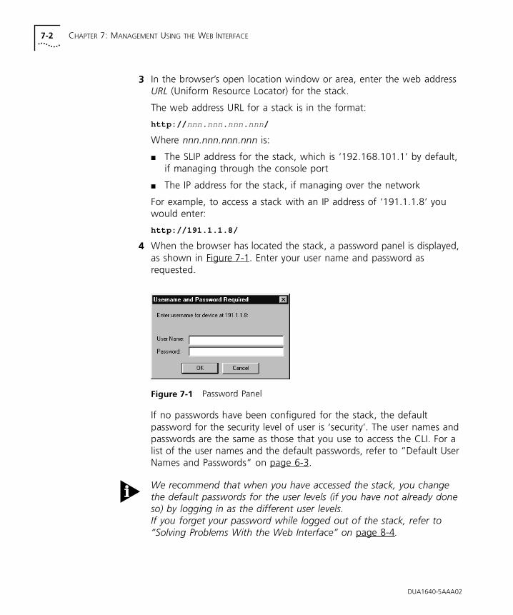
7-2 CHAPTER 7: MANAGEMENT USING THE WEB INTERFACE
3 In the browser’s open location window or area, enter the web address URL (Uniform Resource Locator) for the stack.
The web address URL for a stack is in the format:
http:// nnn.nnn.nnn.nnn /
Where nnn.nnn.nnn.nnn is:
■ The SLIP address for the stack, which is ‘192.168.101.1’ by default, if managing through the console port
■ The IP address for the stack, if managing over the network
For example, to access a stack with an IP address of ‘191.1.1.8’ you would enter:
http://191.1.1.8/
4 When the browser has located the stack, a password panel is displayed, as shown in Figure 7-1. Enter your user name and password as requested.
Figure 7-1 Password Panel
If no passwords have been configured for the stack, the default password for the security level of user is ‘security’. The user names and passwords are the same as those that you use to access the CLI. For a list of the user names and the default passwords, refer to “Default User Names and Passwords” on page 6-3.
We recommend that when you have accessed the stack, you change the default passwords for the user levels (if you have not already done so) by logging in as the different user levels.If you forget your password while logged out of the stack, refer to “Solving Problems With the Web Interface” on page 8-4.
DUA1640-5AAA02
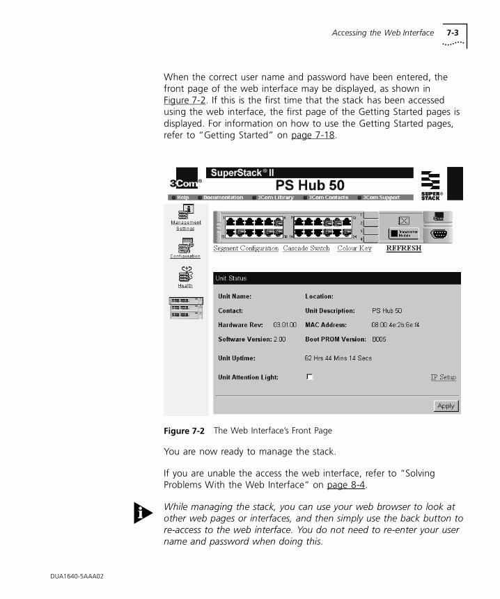
Accessing the Web Interface 7-3
When the correct user name and password have been entered, the front page of the web interface may be displayed, as shown in Figure 7-2. If this is the first time that the stack has been accessed using the web interface, the first page of the Getting Started pages is displayed. For information on how to use the Getting Started pages, refer to “Getting Started” on page 7-18.
Figure 7-2 The Web Interface’s Front Page
You are now ready to manage the stack.
If you are unable the access the web interface, refer to “Solving Problems With the Web Interface” on page 8-4.
While managing the stack, you can use your web browser to look at other web pages or interfaces, and then simply use the back button to re-access to the web interface. You do not need to re-enter your user name and password when doing this.
DUA1640-5AAA02
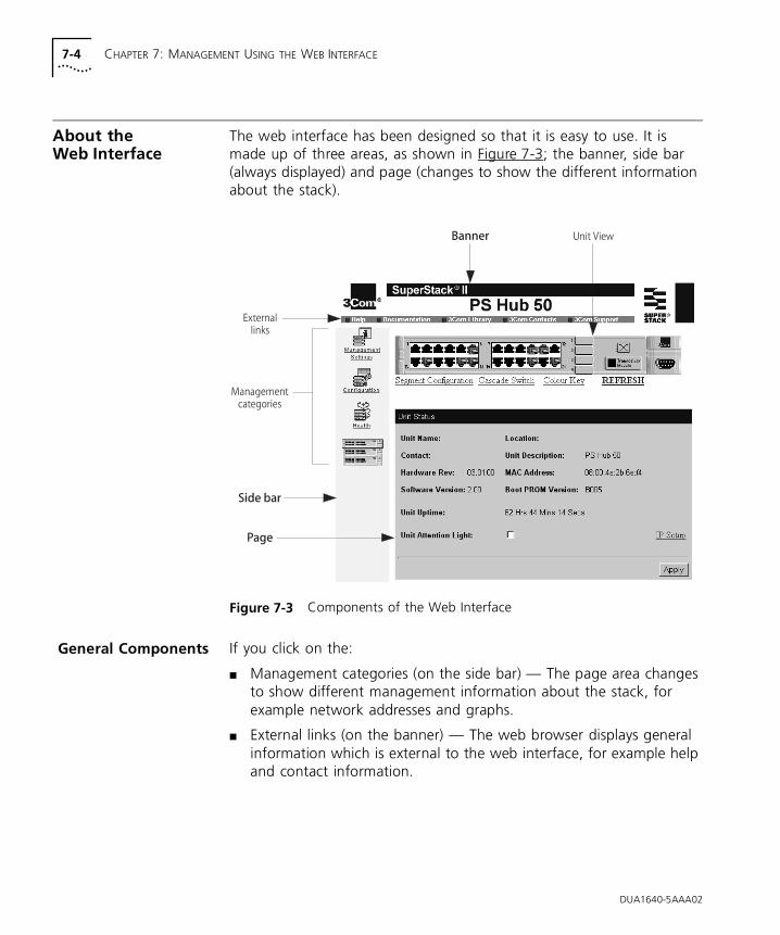
7-4 CHAPTER 7: MANAGEMENT USING THE WEB INTERFACE
About the Web Interface
The web interface has been designed so that it is easy to use. It is made up of three areas, as shown in Figure 7-3; the banner, side bar (always displayed) and page (changes to show the different information about the stack).
Figure 7-3 Components of the Web Interface
General Components If you click on the:
■ Management categories (on the side bar) — The page area changes to show different management information about the stack, for example network addresses and graphs.
■ External links (on the banner) — The web browser displays general information which is external to the web interface, for example help and contact information.
DUA1640-5AAA02
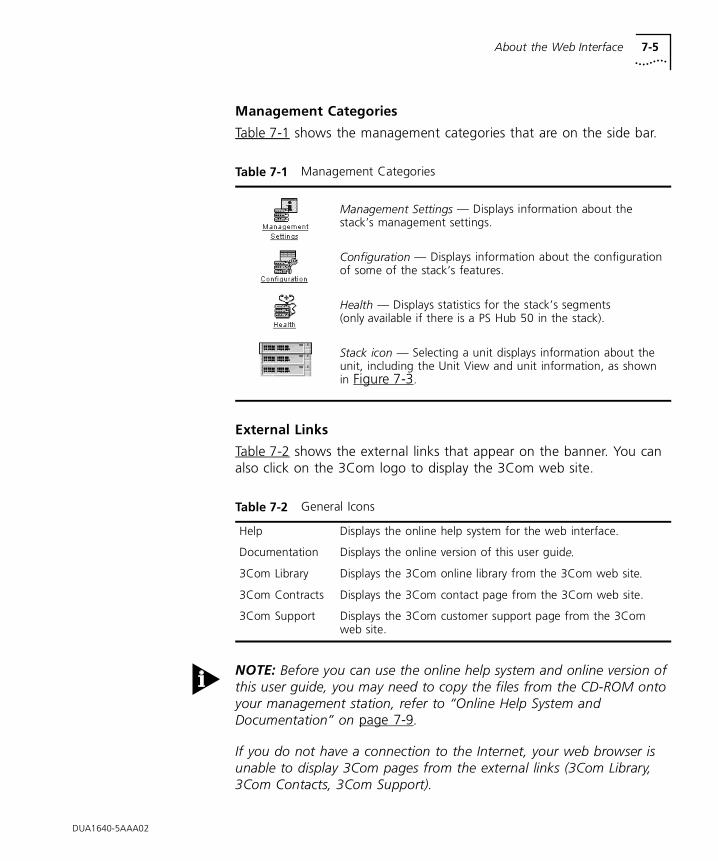
About the Web Interface 7-5
DUA1640-5AAA02
Management Categories
Table 7-1 shows the management categories that are on the side bar.
External Links
Table 7-2 shows the external links that appear on the banner. You can also click on the 3Com logo to display the 3Com web site.
NOTE: Before you can use the online help system and online version of this user guide, you may need to copy the files from the CD-ROM onto your management station, refer to “Online Help System and Documentation” on page 7-9.
If you do not have a connection to the Internet, your web browser is unable to display 3Com pages from the external links (3Com Library, 3Com Contacts, 3Com Support).
Table 7-1 Management Categories
Management Settings — Displays information about the stack’s management settings.
Configuration — Displays information about the configuration of some of the stack’s features.
Health — Displays statistics for the stack’s segments (only available if there is a PS Hub 50 in the stack).
Stack icon — Selecting a unit displays information about the unit, including the Unit View and unit information, as shown in Figure 7-3.
Table 7-2 General Icons
Help Displays the online help system for the web interface.
Documentation Displays the online version of this user guide.
3Com Library Displays the 3Com online library from the 3Com web site.
3Com Contracts Displays the 3Com contact page from the 3Com web site.
3Com Support Displays the 3Com customer support page from the 3Com web site.
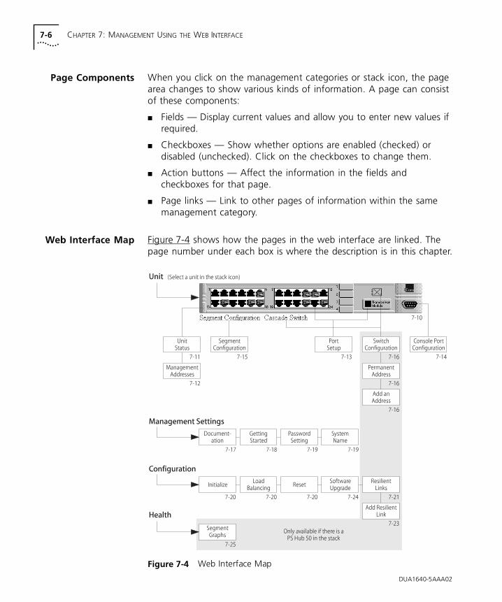
7-6 CHAPTER 7: MANAGEMENT USING THE WEB INTERFACE
DUA1640-5AAA02
Page Components When you click on the management categories or stack icon, the page area changes to show various kinds of information. A page can consist of these components:
■ Fields — Display current values and allow you to enter new values if required.
■ Checkboxes — Show whether options are enabled (checked) or disabled (unchecked). Click on the checkboxes to change them.
■ Action buttons — Affect the information in the fields and checkboxes for that page.
■ Page links — Link to other pages of information within the same management category.
Web Interface Map Figure 7-4 shows how the pages in the web interface are linked. The page number under each box is where the description is in this chapter.
Figure 7-4 Web Interface Map
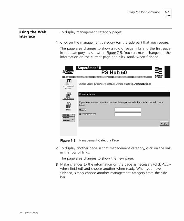
Using the Web Interface 7-7
Using the Web Interface
To display management category pages:
1 Click on the management category (on the side bar) that you require.
The page area changes to show a row of page links and the first page in that category, as shown in Figure 7-5. You can make changes to the information on the current page and click Apply when finished.
Figure 7-5 Management Category Page
2 To display another page in that management category, click on the link in the row of links.
The page area changes to show the new page.
3 Make changes to the information on the page as necessary (click Apply when finished) and choose another when ready. When you have finished, simply choose another management category from the side bar.
DUA1640-5AAA02
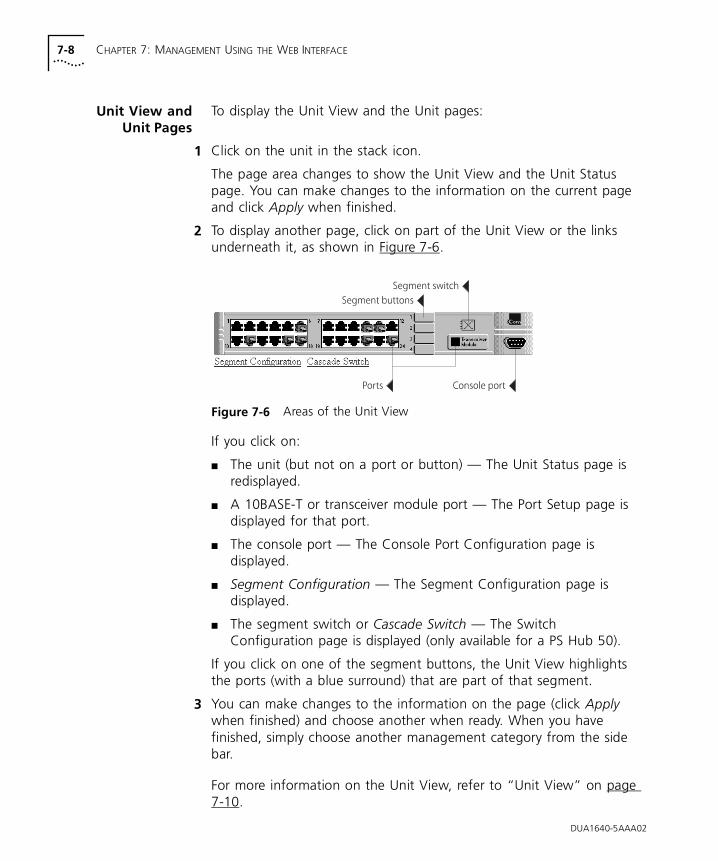
7-8 CHAPTER 7: MANAGEMENT USING THE WEB INTERFACE
Unit View andUnit Pages
To display the Unit View and the Unit pages:
1 Click on the unit in the stack icon.
The page area changes to show the Unit View and the Unit Status page. You can make changes to the information on the current page and click Apply when finished.
2 To display another page, click on part of the Unit View or the links underneath it, as shown in Figure 7-6.
Figure 7-6 Areas of the Unit View
If you click on:
■ The unit (but not on a port or button) — The Unit Status page is redisplayed.
■ A 10BASE-T or transceiver module port — The Port Setup page is displayed for that port.
■ The console port — The Console Port Configuration page is displayed.
■ Segment Configuration — The Segment Configuration page is displayed.
■ The segment switch or Cascade Switch — The Switch Configuration page is displayed (only available for a PS Hub 50).
If you click on one of the segment buttons, the Unit View highlights the ports (with a blue surround) that are part of that segment.
3 You can make changes to the information on the page (click Apply when finished) and choose another when ready. When you have finished, simply choose another management category from the side bar.
For more information on the Unit View, refer to “Unit View” on page 7-10.
DUA1640-5AAA02
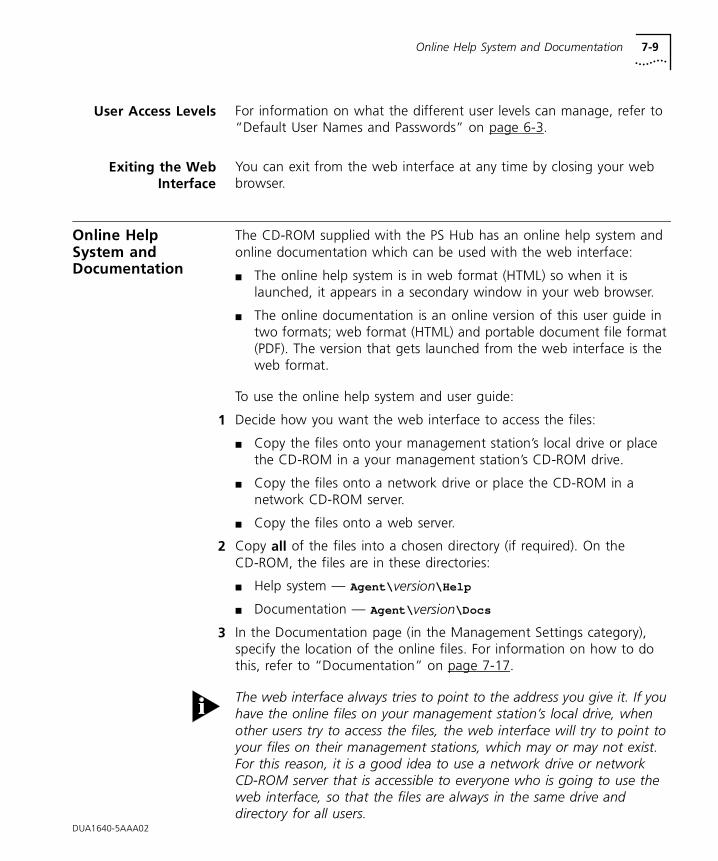
Online Help System and Documentation 7-9
DUA1640-5AAA02
User Access Levels For information on what the different user levels can manage, refer to “Default User Names and Passwords” on page 6-3.
Exiting the WebInterface
You can exit from the web interface at any time by closing your web browser.
Online Help System and Documentation
The CD-ROM supplied with the PS Hub has an online help system and online documentation which can be used with the web interface:
■ The online help system is in web format (HTML) so when it is launched, it appears in a secondary window in your web browser.
■ The online documentation is an online version of this user guide in two formats; web format (HTML) and portable document file format (PDF). The version that gets launched from the web interface is the web format.
To use the online help system and user guide:
1 Decide how you want the web interface to access the files:
■ Copy the files onto your management station’s local drive or place the CD-ROM in a your management station’s CD-ROM drive.
■ Copy the files onto a network drive or place the CD-ROM in a network CD-ROM server.
■ Copy the files onto a web server.
2 Copy all of the files into a chosen directory (if required). On the CD-ROM, the files are in these directories:
■ Help system — Agent\ version\Help
■ Documentation — Agent\ version\Docs
3 In the Documentation page (in the Management Settings category), specify the location of the online files. For information on how to do this, refer to “Documentation” on page 7-17.
The web interface always tries to point to the address you give it. If you have the online files on your management station’s local drive, when other users try to access the files, the web interface will try to point to your files on their management stations, which may or may not exist. For this reason, it is a good idea to use a network drive or network CD-ROM server that is accessible to everyone who is going to use the web interface, so that the files are always in the same drive and directory for all users.
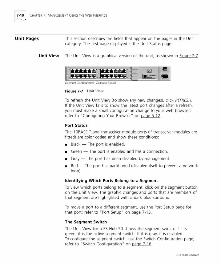
7-10 CHAPTER 7: MANAGEMENT USING THE WEB INTERFACE
Unit Pages This section describes the fields that appear on the pages in the Unit category. The first page displayed is the Unit Status page.
Unit View The Unit View is a graphical version of the unit, as shown in Figure 7-7.
Figure 7-7 Unit View
To refresh the Unit View (to show any new changes), click REFRESH. If the Unit View fails to show the latest port changes after a refresh, you must make a small configuration change to your web browser; refer to “Configuring Your Browser” on page 5-12.
Port Status
The 10BASE-T and transceiver module ports (if transceiver modules are fitted) are color coded and show these conditions:
■ Black — The port is enabled.
■ Green — The port is enabled and has a connection.
■ Gray — The port has been disabled by management.
■ Red — The port has partitioned (disabled itself to prevent a network loop).
Identifying Which Ports Belong to a Segment
To view which ports belong to a segment, click on the segment button on the Unit View. The graphic changes and ports that are members of that segment are highlighted with a dark blue surround.
To move a port to a different segment, use the Port Setup page for that port; refer to “Port Setup” on page 7-13.
The Segment Switch
The Unit View for a PS Hub 50 shows the segment switch. If it is green, it is the active segment switch. If it is gray, it is disabled. To configure the segment switch, use the Switch Configuration page; refer to “Switch Configuration” on page 7-16.
DUA1640-5AAA02
Unit Pages 7-11
Unit Status This page provides detailed information about the unit:
Unit Name The name configured for the stack.
Location Where the stack is located.
Contact The person to contact if there is a problem with the stack.
The Unit Name can be configured using the System Name page (in the Management Settings category), refer to “System Name” on page 7-19.The Location and Contact can be configured using Quick Config Manager or an SNMP network management application.
Unit Description The unit’s product name.
Hardware Rev The version of hardware inside the unit.
MAC Address The unit’s MAC (Ethernet) address.
Software Version The version of management software that the unit is running.
Boot PROM Version The version of software on the Boot PROM inside the unit.
Unit Uptime The time that has elapsed since the unit was last reset, initialized or powered on.
Unit Attention Light A checkbox for you to light the Attn LED, to help identify the unit in the stack.
To display the Management Addresses page, click IP Setup at the bottom of the Unit Status page.
DUA1640-5AAA02
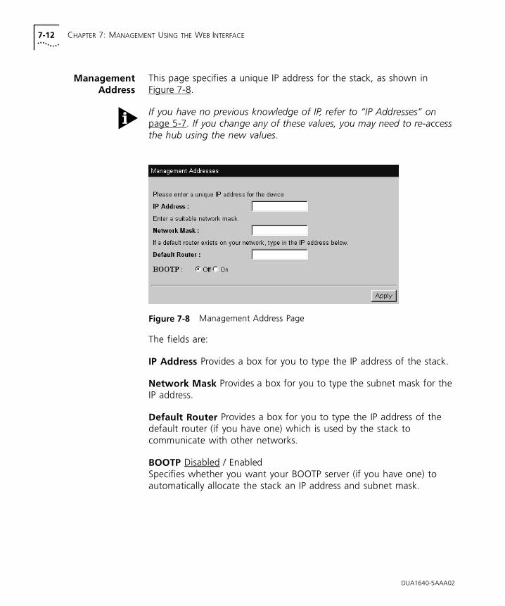
7-12 CHAPTER 7: MANAGEMENT USING THE WEB INTERFACE
ManagementAddress
This page specifies a unique IP address for the stack, as shown in Figure 7-8.
If you have no previous knowledge of IP, refer to “IP Addresses” on page 5-7. If you change any of these values, you may need to re-access the hub using the new values.
Figure 7-8 Management Address Page
The fields are:
IP Address Provides a box for you to type the IP address of the stack.
Network Mask Provides a box for you to type the subnet mask for the IP address.
Default Router Provides a box for you to type the IP address of the default router (if you have one) which is used by the stack to communicate with other networks.
BOOTP Disabled / EnabledSpecifies whether you want your BOOTP server (if you have one) to automatically allocate the stack an IP address and subnet mask.
DUA1640-5AAA02
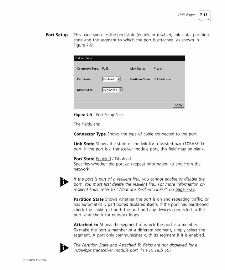
Unit Pages 7-13
Port Setup This page specifies the port state (enable or disable), link state, partition state and the segment to which the port is attached, as shown in Figure 7-9.
Figure 7-9 Port Setup Page
The fields are:
Connector Type Shows the type of cable connected to the port.
Link State Shows the state of the link for a twisted pair (10BASE-T) port. If the port is a transceiver module port, this field may be blank.
Port State Enabled / DisabledSpecifies whether the port can repeat information to and from the network.
If the port is part of a resilient link, you cannot enable or disable the port. You must first delete the resilient link. For more information on resilient links, refer to “What are Resilient Links?” on page 7-22.
Partition State Shows whether the port is on and repeating traffic, or has automatically partitioned (isolated itself). If the port has partitioned check the cabling at both the port and any devices connected to the port, and check for network loops.
Attached to Shows the segment of which the port is a member. To make the port a member of a different segment, simply select the segment. A port only communicates with its segment if it is enabled.
The Partition State and Attached To fields are not displayed for a 100Mbps transceiver module port (in a PS Hub 50).
DUA1640-5AAA02
7-14 CHAPTER 7: MANAGEMENT USING THE WEB INTERFACE
Console PortConfiguration
This page configures the console port.
The PS Hub’s console port is already correctly configured by default, for direct connection to a management station. Only alter these default settings if you are connecting a modem to the console port.
CAUTION: Do not change any of these settings unless you fully understand what you are doing. Incorrect settings may lock you out from the hub’s console port when you select Apply, and you may have to contact your supplier for information on recovering management communication if you cannot access the unit over the network.
If you want to change the settings but are unsure of the correct settings to use, refer to the user documentation that accompanies your terminal or modem.
The fields are:
Console connection Terminal / ModemSpecifies what you are connecting directly to the console port. If you are connecting to a modem, select Modem, otherwise leave as Terminal (management station).
Port Speed 1200 / 2400 / 4800 / 9600 / 19200 / 38400 / AutoConfigSpecifies the baud rate of your management station or modem. The stack hub can automatically configure its baud rate to work with your management station or modem. Leave this field as Autoconfig if you require auto-configuration.
Flow Control None / Xon/Xoff / Hardware RTS/CTSSpecifies the flow control option that corresponds to your management station or modem.
DUA1640-5AAA02
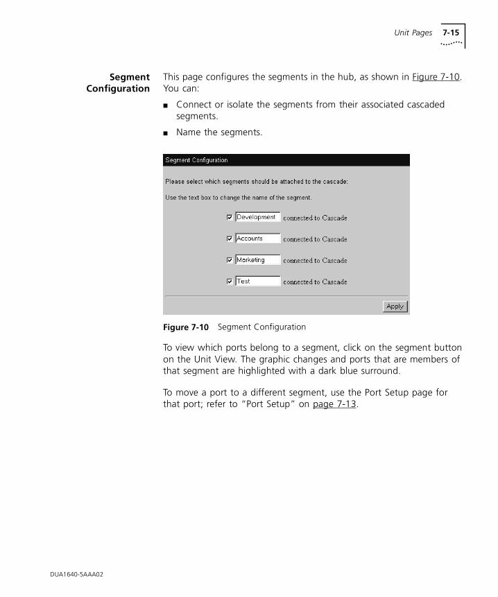
Unit Pages 7-15
SegmentConfiguration
This page configures the segments in the hub, as shown in Figure 7-10. You can:
■ Connect or isolate the segments from their associated cascaded segments.
■ Name the segments.
Figure 7-10 Segment Configuration
To view which ports belong to a segment, click on the segment button on the Unit View. The graphic changes and ports that are members of that segment are highlighted with a dark blue surround.
To move a port to a different segment, use the Port Setup page for that port; refer to “Port Setup” on page 7-13.
DUA1640-5AAA02
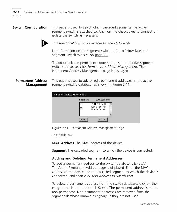
7-16 CHAPTER 7: MANAGEMENT USING THE WEB INTERFACE
Switch Configuration This page is used to select which cascaded segments the active segment switch is attached to. Click on the checkboxes to connect or isolate the switch as necessary.
This functionality is only available for the PS Hub 50.
For information on the segment switch, refer to “How Does the Segment Switch Work?” on page 2-3.
To add or edit the permanent address entries in the active segment switch’s database, click Permanent Address Management. The Permanent Address Management page is displayed.
Permanent AddressManagement
This page is used to add or edit permanent addresses in the active segment switch’s database, as shown in Figure 7-11.
Figure 7-11 Permanent Address Management Page
The fields are:
MAC Address The MAC address of the device.
Segment The cascaded segment to which the device is connected.
Adding and Deleting Permanent Addresses
To add a permanent address to the switch database, click Add. The Add a Permanent Address page is displayed. Enter the MAC address of the device and the cascaded segment to which the device is connected, and then click Add Address to Switch Port.
To delete a permanent address from the switch database, click on the entry in the list and then click Delete. The permanent address is made non-permanent. Non-permanent addresses are removed from the segment database (known as ageing) if they are not used.
DUA1640-5AAA02
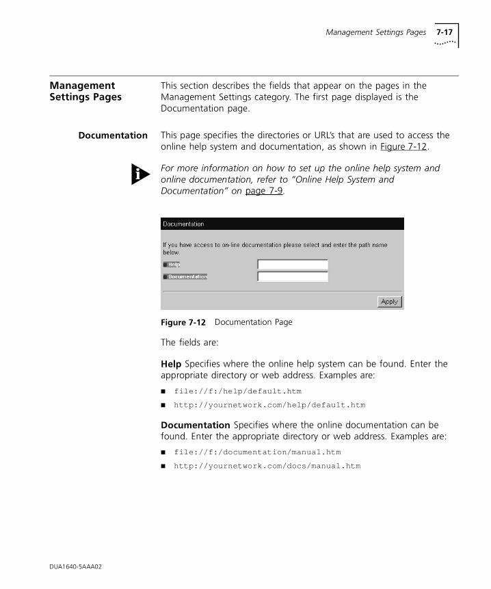
Management Settings Pages 7-17
Management Settings Pages
This section describes the fields that appear on the pages in the Management Settings category. The first page displayed is the Documentation page.
Documentation This page specifies the directories or URL’s that are used to access the online help system and documentation, as shown in Figure 7-12.
For more information on how to set up the online help system and online documentation, refer to “Online Help System and Documentation” on page 7-9.
Figure 7-12 Documentation Page
The fields are:
Help Specifies where the online help system can be found. Enter the appropriate directory or web address. Examples are:
■ file://f:/help/default.htm
■ http://yournetwork.com/help/default.htm
Documentation Specifies where the online documentation can be found. Enter the appropriate directory or web address. Examples are:
■ file://f:/documentation/manual.htm
■ http://yournetwork.com/docs/manual.htm
DUA1640-5AAA02
7-18 CHAPTER 7: MANAGEMENT USING THE WEB INTERFACE
Getting Started The Getting Started pages are a series of pages which set up basic information for the stack. You are asked:
■ For a descriptive name for the stack.
■ If you want to allocate the stack IP information or leave the allocation to a BOOTP server on your network (if you have one). A BOOTP server automatically allocates IP addresses to all equipment on your network.
If you chose to allocate the IP information, you are asked:
■ For an IP address and subnet mask for the selected unit.
■ For an IP address for a default router — You may have a default router which you want the hub to use to communicate with other networks.
■ The file path or web address (URL) for the online help system and documentation files.
■ To enter a new password (you can leave it blank if you don’t want to change it).
If you have no previous knowledge of IP, refer to “IP Addresses” on page 5-7.
You do not have to use the Getting Started pages to configure this information, as it can all be configured using other pages in the web interface.
If you have already configured some of this information for the stack, it appears in the appropriate fields on the pages.
When you have entered the information in a page, click Apply to display the next page. You can use the back button of your web browser to return to a previous page. When you display the last page, click Finish to accept the changes you have made and to exit from the Getting Started pages.
If you have changed any of the IP information, you may need to re-access the web interface using the new IP address.
DUA1640-5AAA02
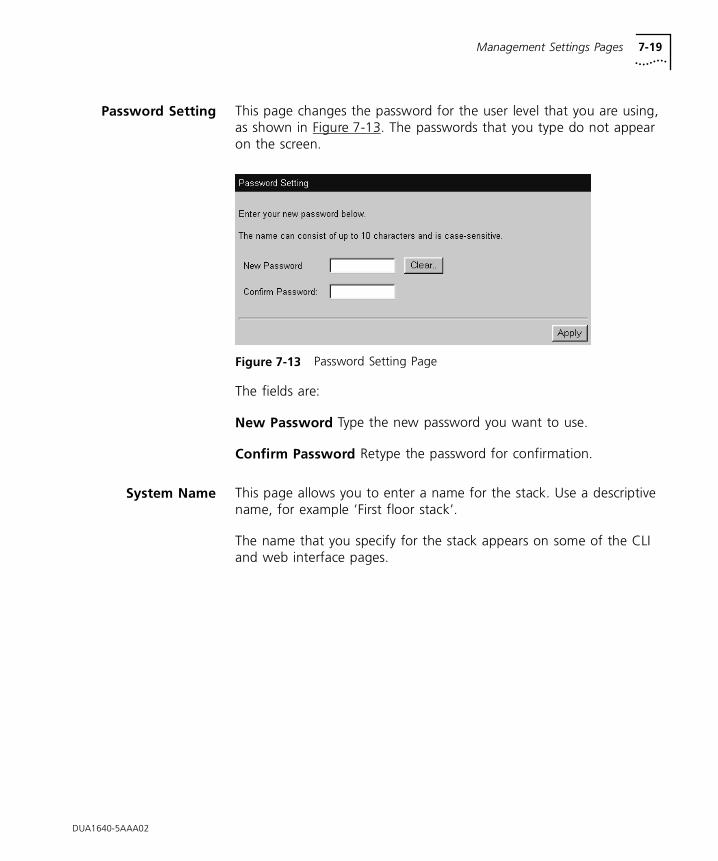
Management Settings Pages 7-19
Password Setting This page changes the password for the user level that you are using, as shown in Figure 7-13. The passwords that you type do not appear on the screen.
Figure 7-13 Password Setting Page
The fields are:
New Password Type the new password you want to use.
Confirm Password Retype the password for confirmation.
System Name This page allows you to enter a name for the stack. Use a descriptive name, for example ‘First floor stack’.
The name that you specify for the stack appears on some of the CLI and web interface pages.
DUA1640-5AAA02
7-20 CHAPTER 7: MANAGEMENT USING THE WEB INTERFACE
Configuration Pages
This section describes the fields that appear on the pages in the Configuration category. The first page displayed is the Initialization page.
Initialize This page is used to initialize the stack. Initializing the stack causes it to return to its factory default settings. You may want to do this if the stack has been previously used in a different part of your network, and its settings are incorrect for its new environment.
CAUTION: Initializing the stack removes all configuration information including security, resilient links and passwords. However, IP, SLIP and default router information is retained to ensure you can continue management communication with the stack over the network.
The stack’s passwords return to the default passwords.
Load Balancing This page is used to initiate the load balancing feature in the stack.
For information on load balancing, refer to Chapter 4. You can configure the stack’s load balancing feature by using the Load Balancing Tool; refer to “Load Balancing” on page B-18.
The stack may take some time to complete the load balancing operation.
The load balancing feature will not work if Load Balancing has been disabled by using the Load Balancing Tool.
Load Balancing works by monitoring traffic levels, so the stack only starts to benefit from it when it has been powered on for a few hours, and Load Balancing has been enabled for a few hours.
Reset This page is used to reset the stack. Resetting the stack simulates powering on and powering off the stack. You may want to do this if you want to reset the stack’s statistics counters.
CAUTION: Performing a reset may cause some of the data being transmitted over the network to be lost. It also clears the non-permanent addresses in the PS Hub 50 unit’s switch database.
DUA1640-5AAA02
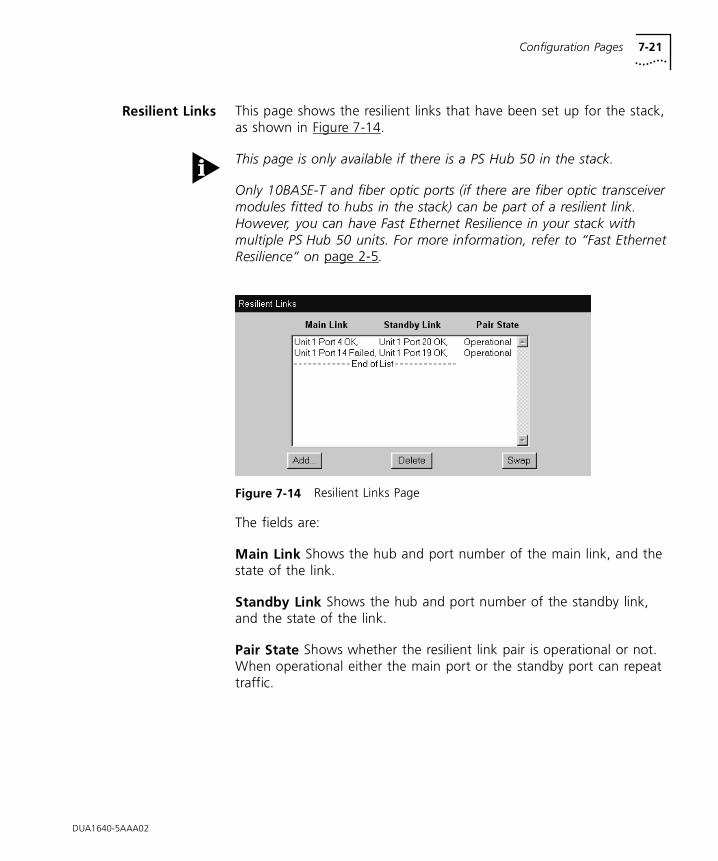
Configuration Pages 7-21
Resilient Links This page shows the resilient links that have been set up for the stack, as shown in Figure 7-14.
This page is only available if there is a PS Hub 50 in the stack.
Only 10BASE-T and fiber optic ports (if there are fiber optic transceiver modules fitted to hubs in the stack) can be part of a resilient link. However, you can have Fast Ethernet Resilience in your stack with multiple PS Hub 50 units. For more information, refer to “Fast Ethernet Resilience” on page 2-5.
Figure 7-14 Resilient Links Page
The fields are:
Main Link Shows the hub and port number of the main link, and the state of the link.
Standby Link Shows the hub and port number of the standby link, and the state of the link.
Pair State Shows whether the resilient link pair is operational or not. When operational either the main port or the standby port can repeat traffic.
DUA1640-5AAA02
7-22 CHAPTER 7: MANAGEMENT USING THE WEB INTERFACE
What are Resilient Links?
You can make the network more robust by adding resilience to it. When a link fails all communication between equipment on each side of the link is lost. To ensure important communication is not lost, the network needs to be reinstated immediately which could be very inconvenient for the network manager. If a spare link was configured to automatically pick up when the broken link failed, the network would appear to function normally to the user. At worst, a few packets would be corrupted or lost.
This is the concept of resilience. One link is on standby (called the standby link) waiting to take over if another link (called the main link) fails. This pair is called a resilient link pair. The resilient link ports can be on different hubs in the stack, and any network devices can be at the other ends of the links.
When the network is in use, the stack that has been used to set up the resilient link pair, monitors the state of both the main link and the standby link. If the main link fails, the standby link becomes active.
You can use the Resilient Links page to view the status of the links. If you have an SNMP network management application, you can configure the hub to send traps (messages) to the SNMP network management application, if the states of the links change.
Resilient Link Pairs
To set up a resilient link pair, you need to manage the stack that both links in the pair are connected to. The number of resilient link pairs you can set up is only restricted by the number of ports you have in the stack.
When you set up the resilient link pair, you need to specify the ports that the main link and standby link are connected to.
Load Balancing does not move ports that are part of a resilient link pair.
DUA1640-5AAA02
Configuration Pages 7-23
Resilient Link Rules
Always follow these rules when setting up a resilient link pair:
■ Only 10BASE-T and fiber optic ports (if the hub has a fiber optic transceiver module fitted) can be part of a resilient link.
■ Configure the resilient link pair at only one end of the link. In other words, only one stack controls each resilient link pair you set up.
■ Each resilient link pair can only have one main link and one standby link (the ports used can be on different hubs in the stack).
■ Each link must not belong to more than one resilient link pair.
■ For a port that is part of a resilient link pair:
■ Do not disable the link pulse generation (you cannot disable this using the web interface or Quick Config manager).
■ Do not enable security for the port.
If you have more than two stacks there are a number of ways you can use resilience when linking them. Remember to connect the stacks correctly for both links, refer to “Connecting Different Hubs and Stacks to Your Hub” on page 3-16.
If the main link fails, the standby link becomes active.
Adding, Deleting and Swapping Links
To add a resilient link pair to the list, click Add. The Add Resilient Link page is displayed.
To delete a resilient link pair from the list, click on the entry in the list and then click Delete. The resilient link pair is deleted, and the current active link remains enabled and the standby link is cancelled.
To swap the main and standby ports for a resilient link pair in the list, click on the entry in the list and then click Swap.
Add Resilient Link This page is used for adding resilient links to the stack. Choose on the main link and click Next, and then choose the standby link and click Next. The resilient link pair appear in the list on the Resilient Links page.
DUA1640-5AAA02
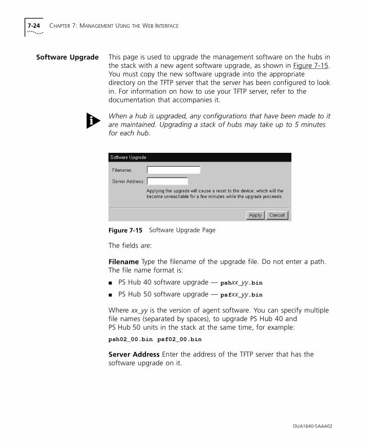
7-24 CHAPTER 7: MANAGEMENT USING THE WEB INTERFACE
Software Upgrade This page is used to upgrade the management software on the hubs in the stack with a new agent software upgrade, as shown in Figure 7-15. You must copy the new software upgrade into the appropriate directory on the TFTP server that the server has been configured to look in. For information on how to use your TFTP server, refer to the documentation that accompanies it.
When a hub is upgraded, any configurations that have been made to it are maintained. Upgrading a stack of hubs may take up to 5 minutes for each hub.
Figure 7-15 Software Upgrade Page
The fields are:
Filename Type the filename of the upgrade file. Do not enter a path. The file name format is:
■ PS Hub 40 software upgrade — psh xx_yy.bin
■ PS Hub 50 software upgrade — psf xx_yy.bin
Where xx_yy is the version of agent software. You can specify multiple file names (separated by spaces), to upgrade PS Hub 40 and PS Hub 50 units in the stack at the same time, for example:
psh02_00.bin psf02_00.bin
Server Address Enter the address of the TFTP server that has the software upgrade on it.
DUA1640-5AAA02
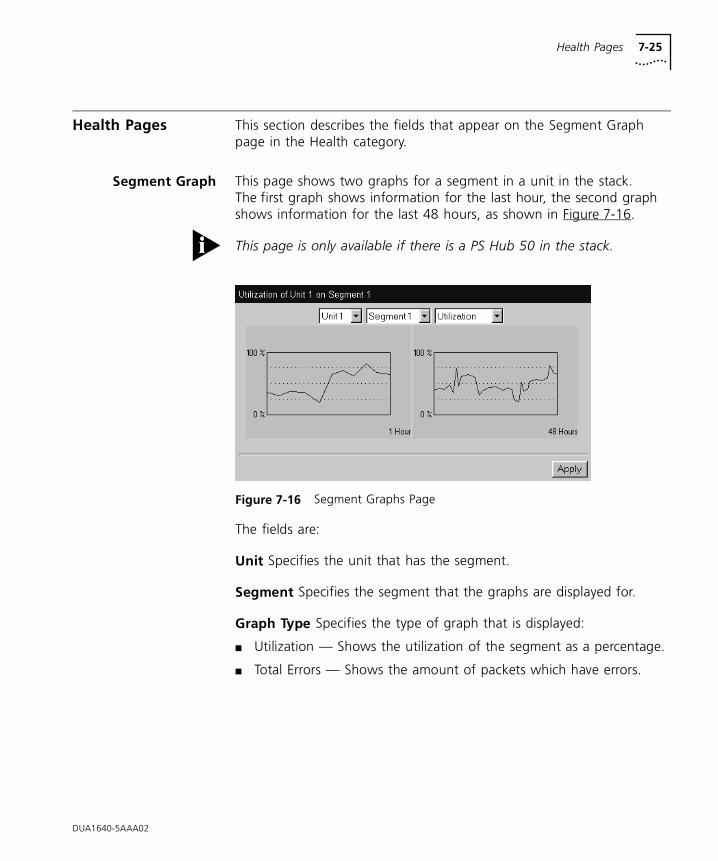
Health Pages 7-25
Health Pages This section describes the fields that appear on the Segment Graph page in the Health category.
Segment Graph This page shows two graphs for a segment in a unit in the stack. The first graph shows information for the last hour, the second graph shows information for the last 48 hours, as shown in Figure 7-16.
This page is only available if there is a PS Hub 50 in the stack.
Figure 7-16 Segment Graphs Page
The fields are:
Unit Specifies the unit that has the segment.
Segment Specifies the segment that the graphs are displayed for.
Graph Type Specifies the type of graph that is displayed:
■ Utilization — Shows the utilization of the segment as a percentage.
■ Total Errors — Shows the amount of packets which have errors.
DUA1640-5AAA02

7-26 CHAPTER 7: MANAGEMENT USING THE WEB INTERFACE
DUA1640-5AAA02
8
PROBLEM SOLVINGThe PS Hub has been designed to aid you when detecting and solving possible problems with your network. These problems are rarely serious, the cause is usually a disconnected or damaged cable, or incorrect configuration. If this chapter does not solve your problem, contact your supplier for information on what to do next.
Perform these actions first:
■ Ensure all equipment is powered on.
■ Power each hub off, wait about 5 seconds and then power them on so they perform a self test. The self test only takes a few seconds, during which the Power/Self Test LED flashes.
If you have a problem using Quick Config Manager, refer to “Solving Problems With Quick Config Manager” on page B-29.If you have a problem with the serial web utility, refer to “Solving Problems With the Serial Web Utility” on page C-4.If you have a problem using the agent upgrade utility, refer to “Solving Problems With the Agent Upgrade Utility” on page D-3.
Isolating a Problem A good way of isolating a problem is to see whether it occurs on a particular port only. This can be done by:
■ Using a different port to see if the problem still exists.
■ Using management to view how a port has been set up. In particular, see if the port is:
■ Partitioned because of a network loop
■ Disabled by management
■ Part of a resilient link pair
■ Performing security
8-2 CHAPTER 8: PROBLEM SOLVING
Solving Problems With the Hub
Power LED not lit. Check your power cord connection. If the connection is secure and there is still no power, you may have a faulty power cord which needs replacing with another PS Hub power cord. If you have another PS Hub, try that hub’s power cord with this hub to isolate whether the fault is with the power cord or the hub.
Power LED yellow. The hub has failed its self-test due to an internal problem, you need to contact your supplier.
Port Status LED yellow (PS Hub 40) or flashing green (PS Hub 50) for a 10Mbps transceiver module port. It is likely that there is a loop in your network which has caused this port to partition. Examine your connections and remove the loop. Each piece of equipment needs only one connection to your stack.
Port Status LED flashing green for a 10BASE-T port. It is likely that there is a loop in your network which has caused this port to partition. Examine your connections and remove the loop. Each piece of equipment needs only one connection to your stack.
Port Status LED not lit for a port that has a connection. There is a problem with this connection. Check you are using a ‘Straight-through’ 10BASE-T cable which is properly connected at both ends, is not damaged, and that the equipment it is connected to is powered on and operating correctly.
Link between two PS Hubs not working. Check your stack connections; follow the information given in “Connecting PS Hubs Together (Stacking)” on page 3-12.
Link between two stacks not working. Check your hub connections; follow the information given in “Connecting Different Hubs and Stacks to Your Hub” on page 3-16. It is likely an MDI/MDIX switch is incorrectly set.
Segment LEDs constantly lit. There may be a network loop caused by connecting the segments with:
■ An external switch in addition to the segment switch in a PS Hub 50.
■ Multiple external switches.
DUA1640-5AAA02
Solving Problems With the Command Line Interface 8-3
To remove this loop, either disable some of the ports that connect the external switch to the segments, or isolate the active segment switch in the PS Hub 50 from the cascaded segments.
Transceiver module not working. Check the Status LED for the transceiver module slot. There is a problem if the LED is yellow (PS Hub 40) or flashing green (PS Hub 50 10Mbps transceiver module). It may be for these reasons:
■ It could be that the transceiver module is incorrectly fitted (highly possible if it is a coaxial transceiver module), refer to the manual that accompanies your transceiver module.
■ It could be that a port has partitioned due to a loop in your network. Examine your connections and remove the loop. Each piece of equipment needs only one connection to your stack.
■ It could be that SQE test is enabled for the transceiver module. Ensure that it is disabled on the transceiver module.
Solving Problems With the Command Line Interface
The initial Login prompt does not display. Check that your terminal or terminal emulator is correctly configured to operate as a standard terminal. If this doesn’t work, try configuring it to operate as a VT100 terminal.
For console port access, check you have performed the wake-up procedure correctly, by pressing [Return] several times.
Check the settings on your terminal or emulator. The parity must be set to ‘none’, the stop bit ‘1’ and the data bits (character size) ‘8’. The management facility’s auto-configuration works only with speeds from 1200 to 19200 baud.
If you still cannot access the hub, reset the hub using Quick Config Manager and retry the wake-up procedure. If this does not work, initialize the hub.
You forget your password. Contact your supplier.
DUA1640-5AAA02
8-4 CHAPTER 8: PROBLEM SOLVING
DUA1640-5AAA02
Solving Problems With the Web Interface
The web browser cannot access the stack. Check that:
■ The stack’s IP address, subnet mask and default router are correctly configured, refer to “Giving the Stack an IP Address” on page B-9.
■ The stack has been reset.
■ Web Access has not been disabled for the access level you are using to manage the stack. Use the Access Information panel of the General Info dialog box in Quick Config Manager, refer to Appendix B.
■ For management communication to work over the network, the port through which your communication reaches the stack must be connected to segment 1 (either directly or indirectly) of the hub with the IP address configured. For information, refer to “Requirements for Managing Over the Network” on page 5-6.
The web browser cannot access the stack over a serial link from a Windows ‘95 management station. You must use the 3Com serial web utility (SLIP Driver), refer to Appendix C.
The web browser can no longer access the stack. Check that the port through which you are trying to access the stack has not been disabled. If it is enabled, check the connections and network cabling at the port. Try accessing the stack through a different port. If you can now access the stack, a problem with the original port is indicated, or it has been switched from segment 1 to another segment. Re-examine the connections and cabling.
Possibly there is a network problem preventing you from accessing the stack over the network. Try accessing the stack through the console port of one of the hubs, and reset the stack.
Some of the web interface is not displayed in the web browser after downloading. This is probably due to large amounts of traffic over the network. Either reload (download) the web interface, or click in the part of the web interface that has not displayed and select the reload frame option in your web browser.
The Unit View does not display the latest port states. Every time you want to change the port states or want to update the Unit View, simply click REFRESH (underneath the Unit View). If the Unit View fails to show the latest port changes after a refresh, you must make a small configuration change to your web browser; refer to “Configuring Your Browser” on page 5-12.
Solving Problems With an SNMP Network Management Application 8-5
Solving Problems With an SNMP Network Management Application
The SNMP network management application cannot access the stack. Check that:
■ The stack’s IP address, subnet mask and default router are correctly configured, refer to “Giving the Stack an IP Address” on page B-9.
■ The stack has been reset.
■ The stack’s IP address is correctly recorded by the management application. For information on how to do this, refer to the documentation accompanying the application.
■ SNMP Access has not been disabled for the access level you are using to manage the stack. Use the Access Information panel of the General Info dialog box in Quick Config Manager, refer to Appendix B.
■ For management communication to work over the network, the port through which your communication reaches the stack must be connected to segment 1 (either directly or indirectly) of the hub with the IP address configured. For information, refer to “Requirements for Managing Over the Network” on page 5-6.
Traps are not received by the SNMP network management application. Check that the address of the management station is entered in the stack. You can do this using Quick Config Manager; refer to “Giving the Stack an IP Address” on page B-9.
The SNMP network management application can no longer access the stack. Check that the port through which you are trying to access the stack has not been disabled. If it is enabled, check the connections and network cabling at the port. Try accessing the stack through a different port. If you can now access the stack, a problem with the original port is indicated, or it has been switched from segment 1 to another segment. Re-examine the connections and cabling.
Possibly there is a network problem preventing you from accessing the stack over the network. Try accessing the stack through the console port of one of the hubs, and reset the stack.
If you still cannot access the hub, use the Access Information panel of the General Info dialog box in Quick Config Manager to check if SNMP access is enabled, refer to Appendix B.
DUA1640-5AAA02

8-6 CHAPTER 8: PROBLEM SOLVING
DUA1640-5AAA02

A
DIMENSIONS, STANDARDS AND CABLINGDimensions and Operating Environment
Table A-1 and Table A-2 show the specifications for the PS Hub.
BABT Approval (for U.K. Users Only)
The PS Hub is covered by Oftel General Approval, NS/G/12345/J/100003, for indirect connection to a public telecommunications system. This can be achieved using the console port and an approved modem.
Table A-1 Dimensions, Power and Operating Environment For All PS Hubs
Height 43.6mm 1.7in.
Width 440mm 17.4in.
Depth 168.5mm 6.7in.
Operating temperature 0 – 50° C 32 – 122° F
Humidity 0 – 90% (non-condensing)
AC line frequency 50/60 Hz
Input voltage 100 – 240V AC
Current rating 1A (maximum)
Table A-2 Weight and Power Consumption
3C16405 3C16406 3C16450
Weight 2Kg / 4.4lb 2.1Kg / 4.6lb 2.2Kg / 4.8lb
Power consumption 26W 29W 35W
Heat dissipation 90 BTU/hr 103 BTU/hr 124 BTU/hr
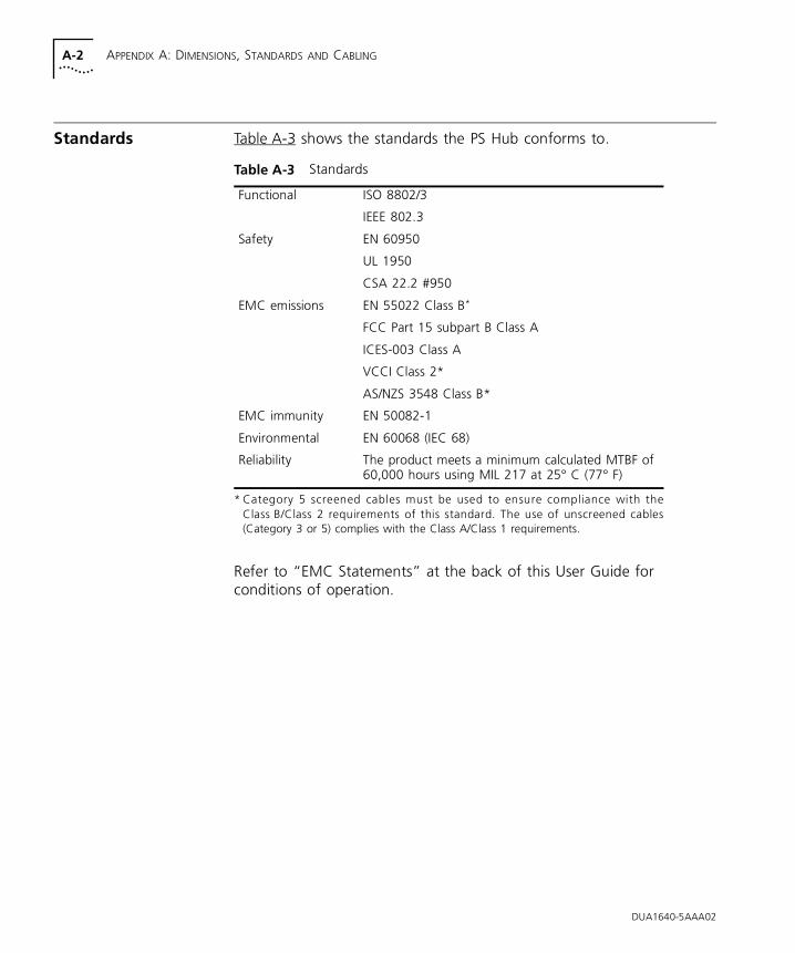
A-2 APPENDIX A: DIMENSIONS, STANDARDS AND CABLING
Standards Table A-3 shows the standards the PS Hub conforms to.
Refer to “EMC Statements” at the back of this User Guide for conditions of operation.
* Category 5 screened cables must be used to ensure compliance with theClass B/Class 2 requirements of this standard. The use of unscreened cables(Category 3 or 5) complies with the Class A/Class 1 requirements.
Table A-3 Standards
Functional ISO 8802/3
IEEE 802.3
Safety EN 60950
UL 1950
CSA 22.2 #950
EMC emissions EN 55022 Class B*
FCC Part 15 subpart B Class A
ICES-003 Class A
VCCI Class 2*
AS/NZS 3548 Class B*
EMC immunity EN 50082-1
Environmental EN 60068 (IEC 68)
Reliability The product meets a minimum calculated MTBF of 60,000 hours using MIL 217 at 25° C (77° F)
DUA1640-5AAA02
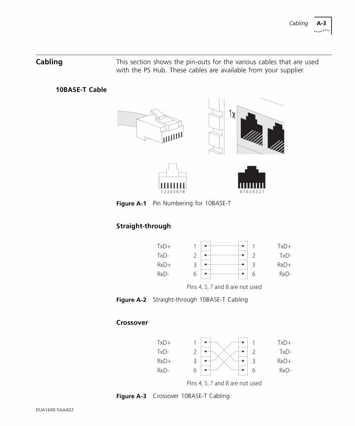
Cabling A-3
Cabling This section shows the pin-outs for the various cables that are used with the PS Hub. These cables are available from your supplier.
10BASE-T Cable
Figure A-1 Pin Numbering for 10BASE-T
Straight-through
Figure A-2 Straight-through 10BASE-T Cabling
Crossover
Figure A-3 Crossover 10BASE-T Cabling
DUA1640-5AAA02
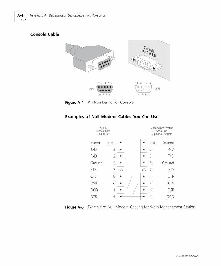
A-4 APPENDIX A: DIMENSIONS, STANDARDS AND CABLING
Console Cable
Figure A-4 Pin Numbering for Console
Examples of Null Modem Cables You Can Use
Figure A-5 Example of Null Modem Cabling for 9-pin Management Station
DUA1640-5AAA02
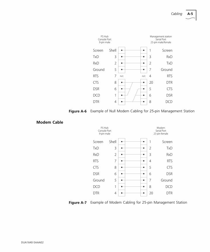
Cabling A-5
Figure A-6 Example of Null Modem Cabling for 25-pin Management Station
Modem Cable
Figure A-7 Example of Modem Cabling for 25-pin Management Station
DUA1640-5AAA02
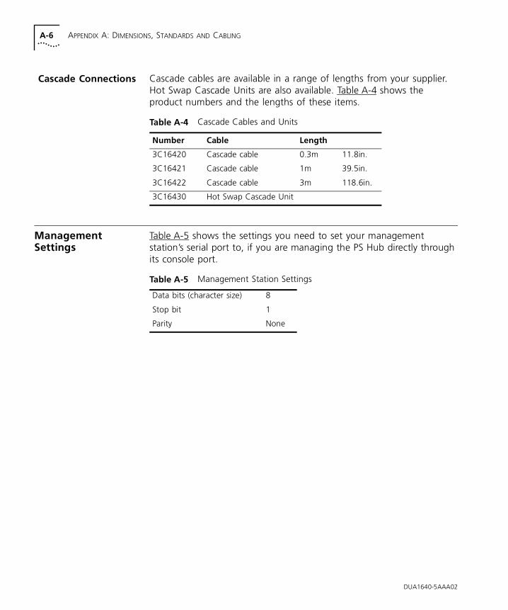
A-6 APPENDIX A: DIMENSIONS, STANDARDS AND CABLING
Cascade Connections Cascade cables are available in a range of lengths from your supplier. Hot Swap Cascade Units are also available. Table A-4 shows the product numbers and the lengths of these items.
Management Settings
Table A-5 shows the settings you need to set your management station’s serial port to, if you are managing the PS Hub directly through its console port.
Table A-4 Cascade Cables and Units
Number Cable Length
3C16420 Cascade cable 0.3m 11.8in.
3C16421 Cascade cable 1m 39.5in.
3C16422 Cascade cable 3m 118.6in.
3C16430 Hot Swap Cascade Unit
Table A-5 Management Station Settings
Data bits (character size) 8
Stop bit 1
Parity None
DUA1640-5AAA02
B
MANAGEMENT USING QUICK CONFIG MANAGERThis appendix describes how to install and use Quick Config Manager. For an overview of what you can do when managing the stack, refer to “Why Manage Your Stack?” on page 5-2.
Quick Config Manager has a comprehensive help system that has the same useful information as this appendix. Many of the features in Quick Config Manager are also available using the web interface, and they work in a similar way.If you want to know how to use a feature that is not documented in this appendix, refer to the Quick Config Manager help files. To invoke the help files, simply select Help from the Quick Config Manager menu bar.
Quick Config Manager uses a familiar Windows interface with point and click operation. To use Quick Config Manager effectively, you need to be familiar with Microsoft Windows. Refer to the documentation that accompanies Microsoft Windows, for more information on how to use the interface.
Quick Config Manager can only manage one stack at a time.
Quick Config Manager cannot perform remote monitoring using RMON, and remote polling.
If you have any problems using Quick Config Manager, refer to “Solving Problems With Quick Config Manager” on page B-29.
B-2 APPENDIX B: MANAGEMENT USING QUICK CONFIG MANAGER
What’s new There are some new and updated windows and dialog boxes in Quick Config Manager since the previous version (3.00). This is mainly to include the new PS Hub 50 functionality:
■ Zoom View (updated)
■ Access Information (updated)
■ Switch Configuration (new)
■ Software Upgrade (updated)
■ Launch Load Balancing Tool (new)
Installing Quick Config Manager and the Load Balancing Tool
This section has information on what you need to install Quick Config Manager and how to install it. The Load Balancing Tool is installed by the Quick Config Manager installation program.
InstallationRequirements
Quick Config Manager and the Load Balancing Tool require an IBM compatible PC with at least a 486/33 processor. Your system must also include:
■ Microsoft Windows 3.1 or lateror Windows ‘95or Windows NT.
The Load Balancing Tool only installs and runs on a Windows ‘95 or Windows NT system.
■ MS-DOS 5.0 or later (not needed for Windows ‘95).
■ Minimum of 13MB available hard disk space.
■ Minimum of:
■ 8MB RAM for Windows 3.1 or later.
■ 16MB RAM for Windows ‘95 or Windows NT.
All RAM above the first megabyte must be configured as extended memory.
■ CD-ROM drive.
■ VGA color monitor or higher.
■ Mouse.
■ Console port capable of 9600 baud, no parity, 8 data bits (character size), 1 stop bit.
DUA1640-5AAA02
Installing Quick Config Manager and the Load Balancing Tool B-3
InstallationProcedure
Quick Config Manager can be installed on its own or onto a workstation that already has other Transcend management applications installed.
CAUTION: Do not install Quick Config Manager in the same directory as any previously installed Transcend management applications. Quick Config Manager and the Load Balancing Tool are installed in subdirectories (QCM and LOADBAL) under the default directory of C:\TRANSCND. You can change the default directory during installation if required.
If you have an earlier version of Quick Config Manager on your system, you can simply install this version over it.
The installation program is a standard Windows based installation. To install Quick Config Manager:
1 Start Microsoft Windows.
If you already have an existing Transcend management application running, ensure that it is closed down.
2 Insert the CD-ROM into your CD-ROM drive.
3 Depending on your version of Windows:
■ Select Run from the Start menu — Windows ‘95 and Windows NT (version 4 or later).
■ Select Run from the File menu — other versions of Windows.
4 In the Run dialog box, type drive :\TRANSCND\QCM\SETUP (where drive is the letter of your CD-ROM drive) and click OK.
The installation program starts and checks your system configuration. Choose which installation you want and enter any information that’s requested. The installation program reports when installation is complete.
When the Quick Config Manager installation is complete, it has its own program group called Transcend. If other Transcend management applications are present, the existing Transcend program group now includes Quick Config Manager.
DUA1640-5AAA02
B-4 APPENDIX B: MANAGEMENT USING QUICK CONFIG MANAGER
Running Quick Config Manager
Whenever you want to start the Quick Config Manager application, double-click on the Quick Configuration Manager icon.
CAUTION: Do not run Quick Config Manager in parallel with any other Transcend management application.
Before you can manage the stack, you must make a management connection to the stack. If you are going to manage over a serial link from your management station, Quick Config Manager uses COM1 as the default serial port. You can change this by editing the following line under the [slip] subsection of the QUICKMGR.INI file:
SerialAttrib=COM1:9600,n,8,1
Editing it to SerialAttrib=COM2:9600,n,8,1 changes the default serial port to COM2.
Before Managing with Quick Config Manager, you must ensure that your management equipment and the hub have been set up, refer to “Quick Config Manager” on page 5-13.
Configuring Multiple Stacks
There is a special feature which enables you to refresh your management communication when connecting your management station to different stacks. This means that you do not need to close and re-open Quick Config Manager, which is particularly useful if you have many separate stacks that need configuring or monitoring.
To do this:
1 Make your serial connection to the new stack.
2 From the File menu, select Reset View.
Quick Config Manager closes any windows that are open in preparation for the new management session.
DUA1640-5AAA02
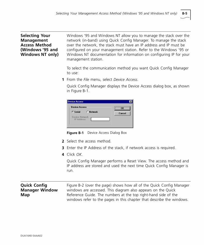
Selecting Your Management Access Method (Windows ‘95 and Windows NT only) B-5
Selecting Your Management Access Method (Windows ‘95 and Windows NT only)
Windows ‘95 and Windows NT allow you to manage the stack over the network (in-band) using Quick Config Manager. To manage the stack over the network, the stack must have an IP address and IP must be configured on your management station. Refer to the Windows ‘95 or Windows NT documentation for information on configuring IP for your management station.
To select the communication method you want Quick Config Manager to use:
1 From the File menu, select Device Access.
Quick Config Manager displays the Device Access dialog box, as shown in Figure B-1.
Figure B-1 Device Access Dialog Box
2 Select the access method.
3 Enter the IP Address of the stack, if network access is required.
4 Click OK.
Quick Config Manager performs a Reset View. The access method and IP address are stored and used the next time Quick Config Manager is run.
Quick Config Manager Window Map
Figure B-2 (over the page) shows how all of the Quick Config Manager windows are accessed. This diagram also appears on the Quick Reference Guide. The numbers at the top right-hand side of the windows refer to the pages in this chapter that describe the windows.
DUA1640-5AAA02
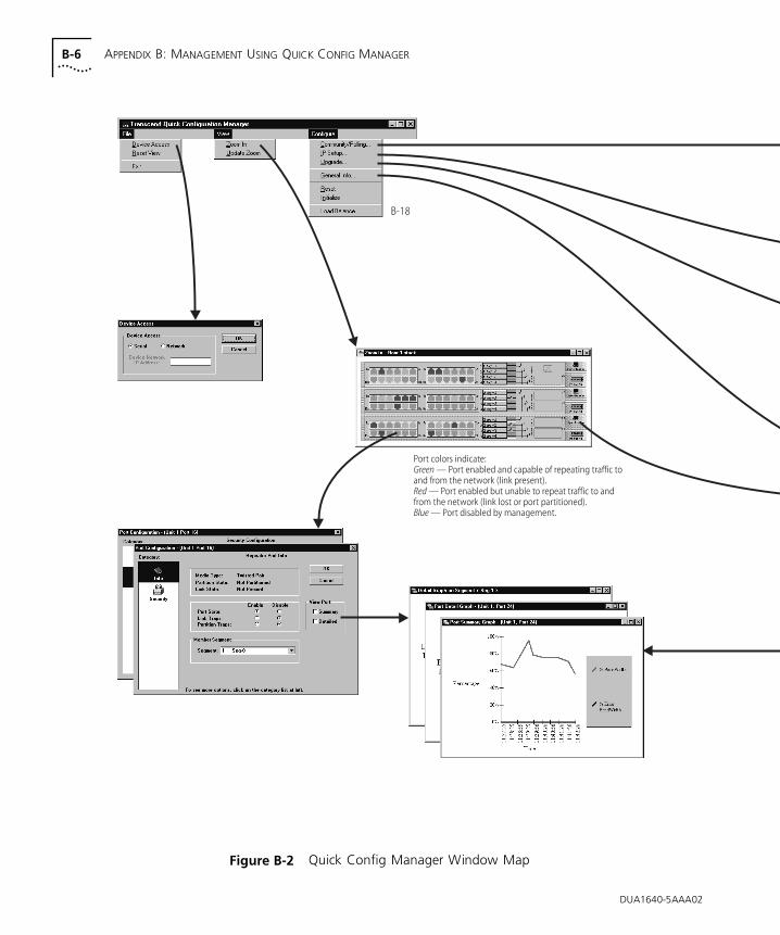
B-6 APPENDIX B: MANAGEMENT USING QUICK CONFIG MANAGER
Figure B-2 Quick Config Manager Window Map
DUA1640-5AAA02

DUA1640-5AAA02
Quick Config Manager Window Map B-7
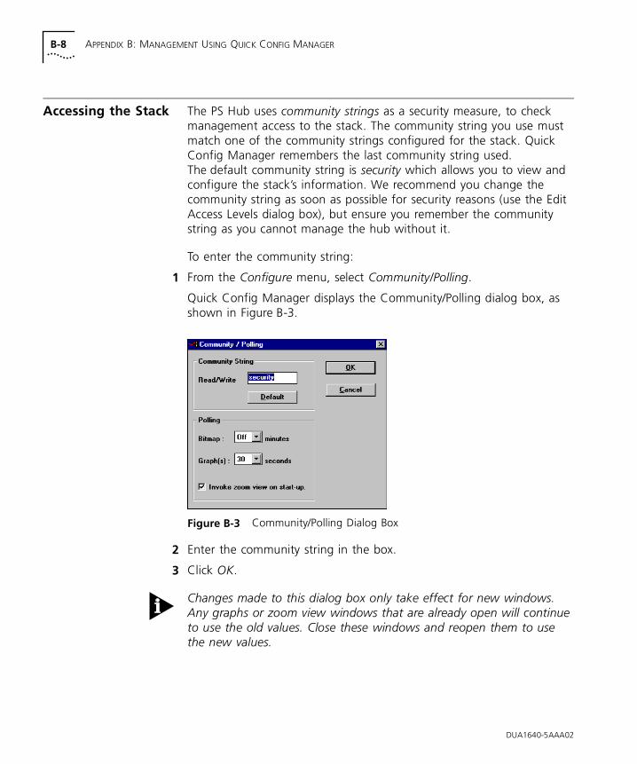
B-8 APPENDIX B: MANAGEMENT USING QUICK CONFIG MANAGER
Accessing the Stack The PS Hub uses community strings as a security measure, to check management access to the stack. The community string you use must match one of the community strings configured for the stack. Quick Config Manager remembers the last community string used. The default community string is security which allows you to view and configure the stack’s information. We recommend you change the community string as soon as possible for security reasons (use the Edit Access Levels dialog box), but ensure you remember the community string as you cannot manage the hub without it.
To enter the community string:
1 From the Configure menu, select Community/Polling.
Quick Config Manager displays the Community/Polling dialog box, as shown in Figure B-3.
Figure B-3 Community/Polling Dialog Box
2 Enter the community string in the box.
3 Click OK.
Changes made to this dialog box only take effect for new windows. Any graphs or zoom view windows that are already open will continue to use the old values. Close these windows and reopen them to use the new values.
DUA1640-5AAA02
Giving the Stack an IP Address B-9
Giving the Stack an IP Address
You can configure the stack with an IP address and other address information, enabling it to communicate over (become part of) an IP network.
The stack does not need an IP address to make Quick Config Manager work with it over a serial connection.
You need to give the stack an IP address if you want to manage it over the network using:
■ An SNMP network manager, for example Transcend Enterprise Manager.
■ Quick Config Manager (Windows ‘95 and Windows NT only).
■ The web interface.
■ The Command Line Interface (over Telnet).
Any IP information given to a hub in the stack is used by the whole stack. If the stack is physically split, the IP information remains with the hub and is used by its half, the other half has no IP information. You can configure more than one hub in a stack with IP information. Doing this, provides the stack with backup management, should the stack split or a hub fail.
If you have no previous knowledge of IP, refer to “IP Addresses” on page 5-7.
The IP Setup dialog box has a useful Easy Setup option which takes you through the IP configuration process. The information that you enter during the Easy Setup process is the same as, and is entered into, the IP Setup dialog box.
If you are managing a stack of hubs, this dialog box shows and affects the settings of the hub which is unit number 1 in the stack (the bottom hub, if the stack is correctly configured). To make a different hub unit number 1, disconnect the stack in such a way that the required hub becomes the bottom hub. However, be very careful not to break the management connection.
DUA1640-5AAA02
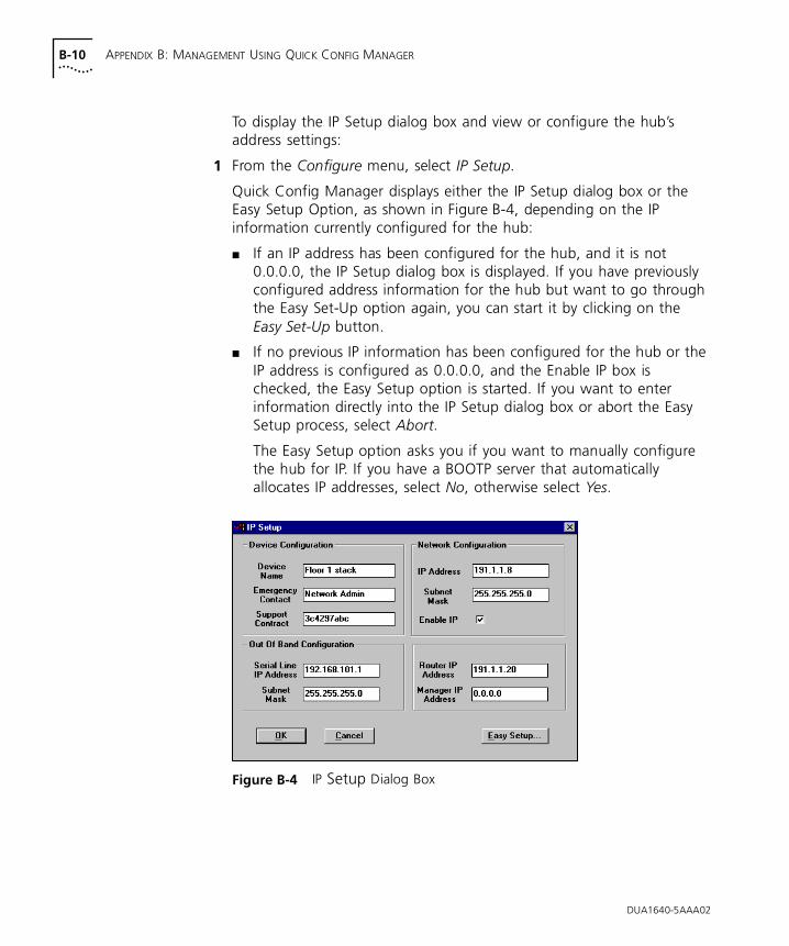
B-10 APPENDIX B: MANAGEMENT USING QUICK CONFIG MANAGER
To display the IP Setup dialog box and view or configure the hub’s address settings:
1 From the Configure menu, select IP Setup.
Quick Config Manager displays either the IP Setup dialog box or the Easy Setup Option, as shown in Figure B-4, depending on the IP information currently configured for the hub:
■ If an IP address has been configured for the hub, and it is not 0.0.0.0, the IP Setup dialog box is displayed. If you have previously configured address information for the hub but want to go through the Easy Set-Up option again, you can start it by clicking on the Easy Set-Up button.
■ If no previous IP information has been configured for the hub or the IP address is configured as 0.0.0.0, and the Enable IP box is checked, the Easy Setup option is started. If you want to enter information directly into the IP Setup dialog box or abort the Easy Setup process, select Abort.
The Easy Setup option asks you if you want to manually configure the hub for IP. If you have a BOOTP server that automatically allocates IP addresses, select No, otherwise select Yes.
Figure B-4 IP Setup Dialog Box
DUA1640-5AAA02
Giving the Stack an IP Address B-11
2 Enter the relevant information into the IP Setup dialog box or Easy Setup dialog boxes and click OK to exit the dialog boxes.
3 Reset the hub for any changes to take effect.
After resetting the hub, you may need to select Reset View from the File menu to restart communication using the new information.
CAUTION: Always make a note of any changes that you make to the settings on this dialog box.
If you are communicating with the stack over the network (Windows ‘95 and Windows NT only) and you change the IP address of the hub, you need to change the Device Network IP Address entry in the Device Access dialog box (refer to “Accessing the Stack” on page B-8) to continue managing the stack over the network.
If you are using SLIP (Quick Config Manager over the console port), ensure that Flow Control is not set to XON/XOFF (by default, it is set to None). Unless you need to connect to the stack through a modem, do not change the console port or SLIP default settings. For information on the console port, refer to “Changing the Console Port Settings” on page B-27. If you require more information on SLIP, read the Internet Activities Board document RFC 155.
Quick Config Manager does not have a facility to receive traps.
DUA1640-5AAA02
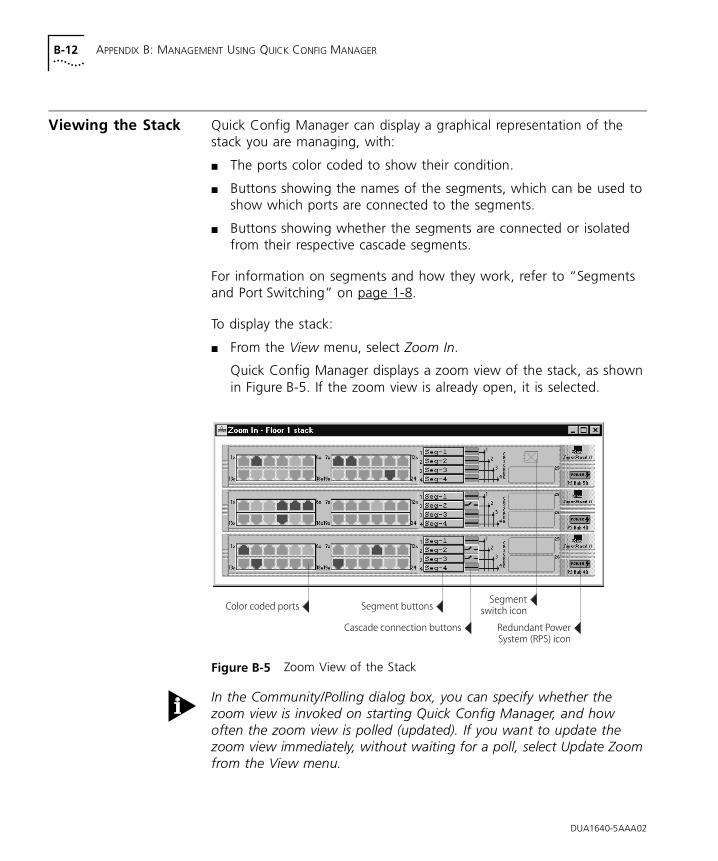
B-12 APPENDIX B: MANAGEMENT USING QUICK CONFIG MANAGER
Viewing the Stack Quick Config Manager can display a graphical representation of the stack you are managing, with:
■ The ports color coded to show their condition.
■ Buttons showing the names of the segments, which can be used to show which ports are connected to the segments.
■ Buttons showing whether the segments are connected or isolated from their respective cascade segments.
For information on segments and how they work, refer to “Segments and Port Switching” on page 1-8.
To display the stack:
■ From the View menu, select Zoom In.
Quick Config Manager displays a zoom view of the stack, as shown in Figure B-5. If the zoom view is already open, it is selected.
Figure B-5 Zoom View of the Stack
In the Community/Polling dialog box, you can specify whether the zoom view is invoked on starting Quick Config Manager, and how often the zoom view is polled (updated). If you want to update the zoom view immediately, without waiting for a poll, select Update Zoom from the View menu.
DUA1640-5AAA02
Viewing the Stack B-13
Port Colors and Icons
Port colors The port color coding shows these conditions:
■ Green — Port enabled and capable of repeating traffic to and from the network (link present).
■ Red — Port enabled but unable to repeat traffic to and from the network (link lost or port partitioned).
■ Blue — Port disabled by management.
Segment Switchicon
If you have a PS Hub 50 in the stack, its Segment Switch icon is:
■ Blue and white — Active.
■ Gray — Inactive.
RPS icon If a hub is connected to a Redundant Power System (RPS), an icon is shown on the right of the hub’s graphical representation. It shows these conditions:
■ Green — RPS active and no faults.
■ Red — RPS active but has one or more faults.
Identifying the Ports that are Connected to a Segment
You can find out what ports in the stack are connected to a segment by clicking on that segment’s name button on any of the hubs:
■ If the hub’s segment is isolated from the cascade segment, only ports that are connected to the hub’s segment are highlighted.
■ If the hub’s segment is connected to the cascade segment, all other ports in the stack which are part of segments that are connected to the same cascade segment, are highlighted.
The ports (and any transceiver module ports) that are part of the segment, are highlighted with a dark blue surround. Click the name button again to turn off the highlighting.
DUA1640-5AAA02
B-14 APPENDIX B: MANAGEMENT USING QUICK CONFIG MANAGER
Connecting or Isolating Segments from Their Cascade Segments
Next to each segment name button, is another button that shows if the segment is connected or isolated from its associated cascade segment:
■ Green with a solid line through it — the segment is connected.
■ Blue with a broken line — the segment is isolated.
Double-click the button to connect or disconnect the segment from the cascade segment.
Displaying Information for the Stack
You can display information for the stack by double-clicking on the zoom view:
■ If you double-click on a port, the Port Configuration dialog box is displayed. This is used to display and configure information about a port.
■ If you double-click on anything other than a port or button, the General Info dialog box is displayed. This is used to display and configure information about the stack.
Configuring Segments
You can use Quick Config Manager to set up the segments within the stack to create workgroups. For information on the segments and how they work, refer to “Segments and Port Switching” on page 1-8.
If you want to use load balancing to configure your segments, refer to “Load Balancing” on page B-18.
Quick Config Manager handles segments at two levels: the segments within each hub, and the cascade segments that run through the stack.
Refer to “Connecting or Isolating Segments from Their Cascade Segments” on page B-14 for information on connecting and isolating segments from their associated cascade segments.
By default, all ports are assigned to segment 1.
Using the Segment Configuration panel, you can:
■ Move the ports between the segments
■ Name the segments
DUA1640-5AAA02
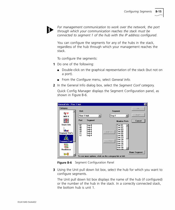
Configuring Segments B-15
For management communication to work over the network, the port through which your communication reaches the stack must be connected to segment 1 of the hub with the IP address configured.
You can configure the segments for any of the hubs in the stack, regardless of the hub through which your management reaches the stack.
To configure the segments:
1 Do one of the following:
■ Double-click on the graphical representation of the stack (but not on a port).
■ From the Configure menu, select General Info.
2 In the General Info dialog box, select the Segment Conf category.
Quick Config Manager displays the Segment Configuration panel, as shown in Figure B-6.
Figure B-6 Segment Configuration Panel
3 Using the Unit pull down list box, select the hub for which you want to configure segments.
The Unit pull down list box displays the name of the hub (if configured) or the number of the hub in the stack. In a correctly connected stack, the bottom hub is unit 1.
DUA1640-5AAA02
B-16 APPENDIX B: MANAGEMENT USING QUICK CONFIG MANAGER
4 Using the Segment pull down list box, select the segment to which you want to move ports.
5 Highlight the ports in the Port Segment list and click Add >> to add them to the Segment Member Ports list.
6 Click Apply to confirm your changes before choosing any other hubs or segments for which you want to move ports.
7 Click OK.
In the unlikely event that you should lose your management connection while moving ports, simply close this dialog box, perform a Reset View and then re-enter this dialog box to continue moving ports.
If you have a Zoom View of the stack open, it is not automatically updated with the information you configured using this panel. To update the Zoom View, select Update Zoom from the View menu.
Unit Select the hub in the stack you want to configure segments for.
Segment Specify the segment in the hub that you want to configure.
Port Segment Select the ports you want to add to the segment. The list shows what segments the ports are currently members of.
Segment Member Ports Shows the ports that are members of the segment.
Add >> Adds the highlighted ports in the Port LAN list to the Segment Member Ports list.
<< Undo Moves the highlighted ports in the Segment Member Ports list from the segment, back to the Port Segment list, if these changes have not been written to the stack.
Name Segment Opens a dialog box which is used to configure the name for the segment, specified in the Segment field. The name of the segment appears on the hub’s segment name button, on the graphical representation (zoom view) of the stack, and is limited to 8 characters.
Apply Writes changes to the stack without closing the panel. Use Apply if you want to configure another segment.
OK Writes changes to the stack and closes the panel.
DUA1640-5AAA02
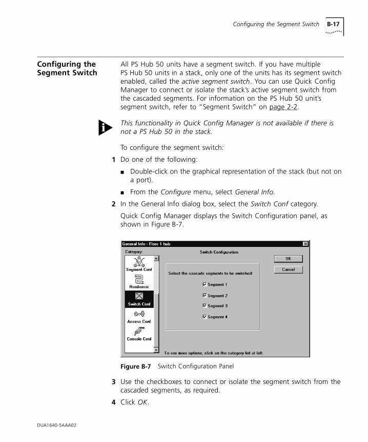
Configuring the Segment Switch B-17
Configuring the Segment Switch
All PS Hub 50 units have a segment switch. If you have multiple PS Hub 50 units in a stack, only one of the units has its segment switch enabled, called the active segment switch. You can use Quick Config Manager to connect or isolate the stack’s active segment switch from the cascaded segments. For information on the PS Hub 50 unit’s segment switch, refer to “Segment Switch” on page 2-2.
This functionality in Quick Config Manager is not available if there is not a PS Hub 50 in the stack.
To configure the segment switch:
1 Do one of the following:
■ Double-click on the graphical representation of the stack (but not on a port).
■ From the Configure menu, select General Info.
2 In the General Info dialog box, select the Switch Conf category.
Quick Config Manager displays the Switch Configuration panel, as shown in Figure B-7.
Figure B-7 Switch Configuration Panel
3 Use the checkboxes to connect or isolate the segment switch from the cascaded segments, as required.
4 Click OK.
DUA1640-5AAA02
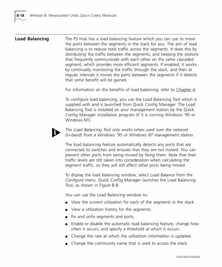
B-18 APPENDIX B: MANAGEMENT USING QUICK CONFIG MANAGER
Load Balancing The PS Hub has a load balancing feature which you can use to move the ports between the segments in the stack for you. The aim of load balancing is to reduce total traffic across the segments. It does this by distributing the traffic between the segments, and keeping the stations that frequently communicate with each other on the same cascaded segment, which provides more efficient segments. If enabled, it works by continually monitoring the traffic through the stack, and then at regular intervals it moves the ports between the segments if it detects that some benefit will be gained.
For information on the benefits of load balancing, refer to Chapter 4.
To configure load balancing, you use the Load Balancing Tool which is supplied with and is launched from Quick Config Manager. The Load Balancing Tool is installed on your management station by the Quick Config Manager installation program (if it is running Windows ‘95 or Windows NT).
The Load Balancing Tool only works when used over the network (in-band) from a Windows ‘95 or Windows NT management station.
The load balancing feature automatically detects any ports that are connected to switches and ensures that they are not moved. You can prevent other ports from being moved by fixing them. Note that their traffic levels are still taken into consideration when calculating the segment traffic, so they will still affect other ports being moved.
To display the load balancing window, select Load Balance from the Configure menu. Quick Config Manager launches the Load Balancing Tool, as shown in Figure B-8.
You can use the Load Balancing window to:
■ View the current utilization for each of the segments in the stack.
■ View a utilization history for the segments.
■ Fix and unfix segments and ports.
■ Enable or disable the automatic load balancing feature, change how often it occurs, and specify a threshold at which it occurs.
■ Change the rate at which the utilization information is updated.
■ Change the community name that is used to access the stack.
DUA1640-5AAA02
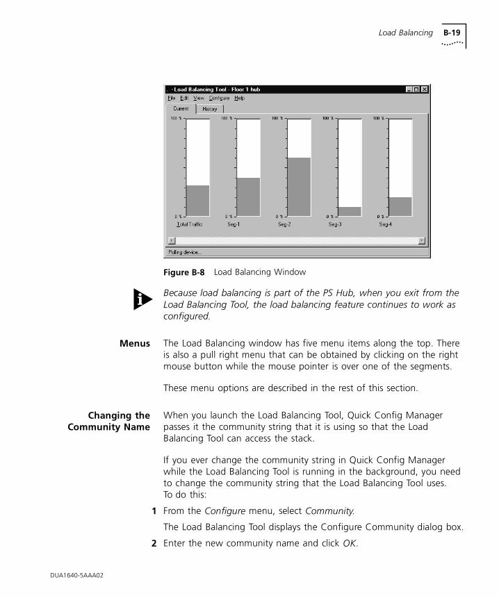
Load Balancing B-19
Figure B-8 Load Balancing Window
Because load balancing is part of the PS Hub, when you exit from the Load Balancing Tool, the load balancing feature continues to work as configured.
Menus The Load Balancing window has five menu items along the top. There is also a pull right menu that can be obtained by clicking on the right mouse button while the mouse pointer is over one of the segments.
These menu options are described in the rest of this section.
Changing theCommunity Name
When you launch the Load Balancing Tool, Quick Config Manager passes it the community string that it is using so that the Load Balancing Tool can access the stack.
If you ever change the community string in Quick Config Manager while the Load Balancing Tool is running in the background, you need to change the community string that the Load Balancing Tool uses. To do this:
1 From the Configure menu, select Community.
The Load Balancing Tool displays the Configure Community dialog box.
2 Enter the new community name and click OK.
DUA1640-5AAA02
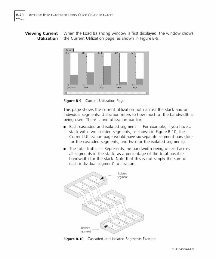
B-20 APPENDIX B: MANAGEMENT USING QUICK CONFIG MANAGER
Viewing CurrentUtilization
When the Load Balancing window is first displayed, the window shows the Current Utilization page, as shown in Figure B-9.
Figure B-9 Current Utilization Page
This page shows the current utilization both across the stack and on individual segments. Utilization refers to how much of the bandwidth is being used. There is one utilization bar for:
■ Each cascaded and isolated segment — For example, if you have a stack with two isolated segments, as shown in Figure B-10, the Current Utilization page would have six separate segment bars (four for the cascaded segments, and two for the isolated segments).
■ The total traffic — Represents the bandwidth being utilized across all segments in the stack, as a percentage of the total possible bandwidth for the stack. Note that this is not simply the sum of each individual segment’s utilization.
Figure B-10 Cascaded and Isolated Segments Example
DUA1640-5AAA02
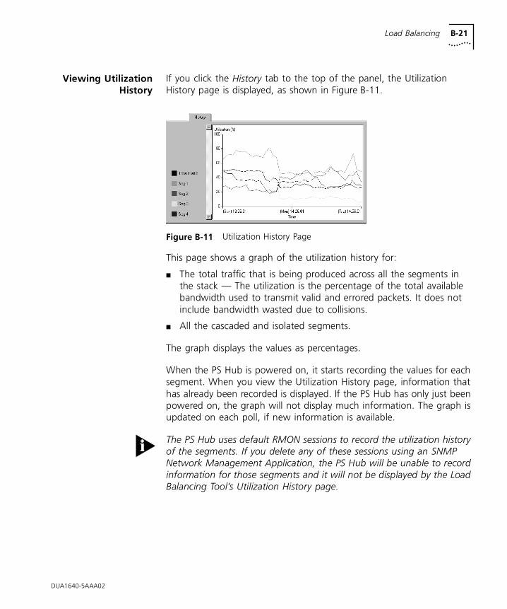
Load Balancing B-21
Viewing UtilizationHistory
If you click the History tab to the top of the panel, the Utilization History page is displayed, as shown in Figure B-11.
Figure B-11 Utilization History Page
This page shows a graph of the utilization history for:
■ The total traffic that is being produced across all the segments in the stack — The utilization is the percentage of the total available bandwidth used to transmit valid and errored packets. It does not include bandwidth wasted due to collisions.
■ All the cascaded and isolated segments.
The graph displays the values as percentages.
When the PS Hub is powered on, it starts recording the values for each segment. When you view the Utilization History page, information that has already been recorded is displayed. If the PS Hub has only just been powered on, the graph will not display much information. The graph is updated on each poll, if new information is available.
The PS Hub uses default RMON sessions to record the utilization history of the segments. If you delete any of these sessions using an SNMP Network Management Application, the PS Hub will be unable to record information for those segments and it will not be displayed by the Load Balancing Tool’s Utilization History page.
DUA1640-5AAA02
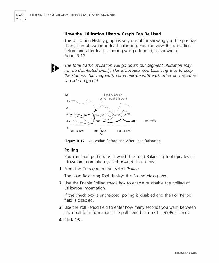
B-22 APPENDIX B: MANAGEMENT USING QUICK CONFIG MANAGER
How the Utilization History Graph Can Be Used
The Utilization History graph is very useful for showing you the positive changes in utilization of load balancing. You can view the utilization before and after load balancing was performed, as shown in Figure B-12.
The total traffic utilization will go down but segment utilization may not be distributed evenly. This is because load balancing tries to keep the stations that frequently communicate with each other on the same cascaded segment.
Figure B-12 Utilization Before and After Load Balancing
Polling
You can change the rate at which the Load Balancing Tool updates its utilization information (called polling). To do this:
1 From the Configure menu, select Polling.
The Load Balancing Tool displays the Polling dialog box.
2 Use the Enable Polling check box to enable or disable the polling of utilization information.
If the check box is unchecked, polling is disabled and the Poll Period field is disabled.
3 Use the Poll Period field to enter how many seconds you want between each poll for information. The poll period can be 1 – 9999 seconds.
4 Click OK.
DUA1640-5AAA02
Load Balancing B-23
Fixing and UnfixingSegments and Ports
You can fix segments and ports so that they are not moved by load balancing:
■ Fixing a segment prevents any ports being moved to or from that segment.
■ Fixing a port prevents that port from being moved to another segment.
Fixing ports or segments does not prevent you from moving the ports between segments yourself, using the web interface or Quick Config Manager. It just prevents the load balancing feature from doing it automatically.
You may want to fix segments that contain users that communicate frequently. You may also want to fix ports that have network equipment (other than workstations) connected directly to them. It is a good idea to fix ports that are:
■ Used to connect your management station to the stack (this port must remain on segment 1).
■ Connected to switches, servers and receivers of network traffic, for example printers.
Segments
To fix or unifx a segment:
1 Right-click on the segment’s name or utilization bar.
A pull right menu appears next to the mouse pointer, which has Fixed and Fixed Ports options. If Fixed has a tick next to it, the segment is currently fixed. If it has not got a tick next to it, the segment is currently unfixed.
2 Select Fix to make the segment fixed or unfixed.
DUA1640-5AAA02
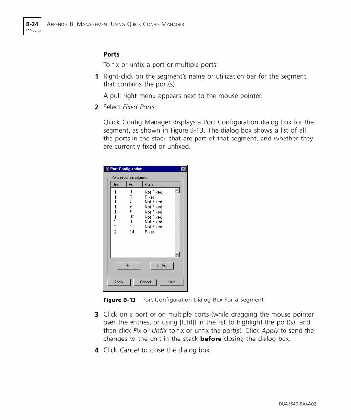
B-24 APPENDIX B: MANAGEMENT USING QUICK CONFIG MANAGER
Ports
To fix or unfix a port or multiple ports:
1 Right-click on the segment’s name or utilization bar for the segment that contains the port(s).
A pull right menu appears next to the mouse pointer.
2 Select Fixed Ports.
Quick Config Manager displays a Port Configuration dialog box for the segment, as shown in Figure B-13. The dialog box shows a list of all the ports in the stack that are part of that segment, and whether they are currently fixed or unfixed.
Figure B-13 Port Configuration Dialog Box For a Segment
3 Click on a port or on multiple ports (while dragging the mouse pointer over the entries, or using [Ctrl]) in the list to highlight the port(s), and then click Fix or Unfix to fix or unfix the port(s). Click Apply to send the changes to the unit in the stack before closing the dialog box.
4 Click Cancel to close the dialog box.
DUA1640-5AAA02
Load Balancing B-25
Performing LoadBalancing
You can control many areas of the load balancing feature, including:
■ Invoking the load balancing feature manually.
■ Enabling or disable the automatic load balancing feature.
■ Changing how often the automatic load balancing feature occurs (if enabled).
■ Changing the reactive threshold for the load balancing process — if this level is exceeded on any segment, the load balancing feature is automatically invoked (if enabled).
Load Balancing works by monitoring traffic levels, so the stack only starts to benefit fully from it when it has been powered on for an hour, and Load Balancing has been enabled for an hour.
We recommend that you perform load balancing during quiet periods of network activity (possibly at night). To really benefit from load balancing it is a good idea not to perform load balancing too often. A suggested rate is every 24 hours.
CAUTION: The equipment connected to the ports that are moved by load balancing must have their MAC addresses relearnt by the PS Hub 50 (or external switch), so a small amount of packet loss may occur while these addresses are relearnt.
Invoking Load Balancing Manually
To invoke the load balancing feature manually:
1 Select Balance Now from the Configure menu.
The feature immediately starts to load balance the units in the stack.
This feature is not available if load balancing has been disabled.
2 Select Refresh from the View menu to update the information that is displayed in the Load Balancing Tool.
The stack may take some time to complete the load balancing operation, so you may not see changes straight away.
DUA1640-5AAA02
B-26 APPENDIX B: MANAGEMENT USING QUICK CONFIG MANAGER
Enabling or Disabling the Automatic Load Balancing Feature
To enable or disable the automatic load balancing feature:
1 From the Configure menu, select Load Balancing.
Quick Config Manager displays the Load Balancing dialog box.
2 Use the Enable Load Balancing check box to enable or disable the automatic load balancing feature.
If the check box is unchecked, the feature is disabled and the Frequency and Balance At fields are disabled.
3 Use the Frequency field to enter how many hours you want between each automatic load balance.
4 Use the Balance At field to enter a the utilization level at which you want the load balancing feature to automatically start, should any segment exceed this level.
5 Click Apply to send the changes to the units in the stack before closing the dialog box.
6 Click Cancel to close the dialog box.
Setting both the Frequency and Balance At fields to ‘0’ disables automatic load balancing, but the load balancing feature still collects data so that you can do a manual load balance at any time.
DUA1640-5AAA02
Changing the Console Port Settings B-27
DUA1640-5AAA02
Changing the Console Port Settings
The PS Hub’s console port is already correctly configured by default, for direct connection to a management station (terminal). Only alter these default settings if you are connecting a modem to the console port.
CAUTION: Do not change any of these settings unless you fully understand what you are doing. Incorrect settings may lock you out from the hub’s console port when you select OK, and you will have to contact your supplier for information on recovering management communication.
Please note that:
■ If you want to change the settings but are unsure of the correct settings to use, refer to the user documentation that accompanies your terminal or modem. If you change the settings by accident, click Cancel to exit from the panel without changing anything.
■ If you are managing a stack of hubs, this panel shows and affects the settings of the hub which is unit number 1 in the stack (the bottom hub, if the stack is correctly configured). To make a different hub unit number 1, disconnect the stack in such a way that the required hub becomes the bottom hub. However, be very careful not to break the management connection.
■ If you are using Quick Config Manager over the console port, it is best to have the Speed set to Auto Config.
■ While changing the speed, Quick Config Manager’s line speed may become out-of-sync with that of the hub. To resolve this problem, change the ‘SerialAttrib’ entry to SerialAttrib=COM1: line speed,n,8,1 under the [slip] section of the QUICKMGR.INI file. Restart Quick Config Manager.
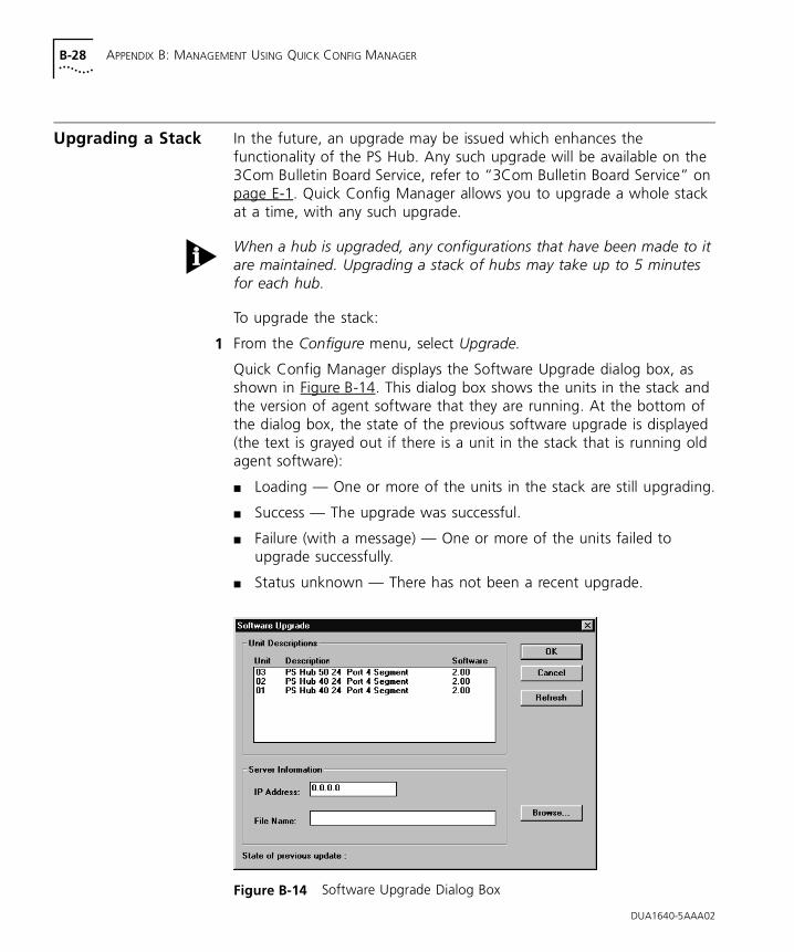
B-28 APPENDIX B: MANAGEMENT USING QUICK CONFIG MANAGER
DUA1640-5AAA02
Upgrading a Stack In the future, an upgrade may be issued which enhances the functionality of the PS Hub. Any such upgrade will be available on the 3Com Bulletin Board Service, refer to “3Com Bulletin Board Service” on page E-1. Quick Config Manager allows you to upgrade a whole stack at a time, with any such upgrade.
When a hub is upgraded, any configurations that have been made to it are maintained. Upgrading a stack of hubs may take up to 5 minutes for each hub.
To upgrade the stack:
1 From the Configure menu, select Upgrade.
Quick Config Manager displays the Software Upgrade dialog box, as shown in Figure B-14. This dialog box shows the units in the stack and the version of agent software that they are running. At the bottom of the dialog box, the state of the previous software upgrade is displayed (the text is grayed out if there is a unit in the stack that is running old agent software):
■ Loading — One or more of the units in the stack are still upgrading.
■ Success — The upgrade was successful.
■ Failure (with a message) — One or more of the units failed to upgrade successfully.
■ Status unknown — There has not been a recent upgrade.
Figure B-14 Software Upgrade Dialog Box
Solving Problems With Quick Config Manager B-29
2 Specify the IP address of the TFTP server that has the upgrade file on it.
3 Specify the file name.
Do not enter a path. The upgrade file must be in the appropriate directory on the TFTP server that the server has been configured to look in.
The file name format is:
■ PS Hub 40 software upgrade — psh xx_yy.bin
■ PS Hub 50 software upgrade — psf xx_yy.bin
Where xx_yy is the version of agent software. You can specify multiple file names (separated by spaces), to upgrade PS Hub 40 and PS Hub 50 units in the stack at the same time, for example:
psh02_00.bin psf02_00.bin
4 Click OK.
Solving Problems With Quick Config Manager
You cannot access the hub over a serial connection for the first time. There may be a number of reasons for this:
■ For a successful local management connection, you need to use a standard null modem cable, and have the hub’s console port set to 9600 baud or auto-configuration enabled. These are the default settings. For information on the console port settings, refer to “Changing the Console Port Settings” on page B-27.
■ It may be that you have made your management connection to a serial port, on your management station, which is not the port Quick Config Manager is using. Quick Config Manager uses COM1 as the default serial port. For information on changing this, refer to “Running Quick Config Manager” on page B-4.
■ When using Quick Config Manager with Windows ‘95 and managing through the console port, you must first disable FIFO buffers in the Advanced Port Settings window in Windows ‘95. For information on doing this, refer to “Through the Console Port” on page 5-13.
■ There may be another application running on your management station, that is using the management station’s serial (COM) port, for example HyperTerminal.
DUA1640-5AAA02
B-30 APPENDIX B: MANAGEMENT USING QUICK CONFIG MANAGER
You cannot access the hub over the network for the first time. Check that:
■ Your management station is correctly configured for IP.
■ The port through which your communication reaches the stack must be connected to segment 1 (either directly or indirectly) of the hub with the IP address configured. For more information, refer to “Requirements for Managing Over the Network” on page 5-6.
You lose your management connection while managing the stack. If you have changed the community string of the access level that you are using, you must enter the new community string in the Community/Polling dialog box.
Reset the connection by selecting Reset View from the File menu.
If this does not work, it may be that Quick Config Manager’s line speed has become unsynchronized with that of the hub. To resolve this problem, make Quick Config Manager use a different speed by changing the ‘SerialAttrib’ entry to SerialAttrib=COM1: line speed,n,8,1 under the [slip] section of the QUICKMGR.INI file, and restart Quick Config Manager.
You forget your community string. Contact your supplier.
You cannot access the stack using the web interface or CLI after changing the community string. When you changed the community string using the Edit Access Levels dialog box, the Device Password and Password Confirmation fields were probably left blank, which has blanked the password. Log on to the web interface or CLI using the same user level but without a password, and change the password.
You cannot access the Load Balancing Tool. The Load Balancing Tool only installs and runs on a Windows ‘95 or Windows NT system, and only works when used over the network (in-band).
DUA1640-5AAA02
C
SERIAL WEB UTILITYIntroduction If you are using a management station running Microsoft Windows® ‘95 and want to access the web interface through the PS Hub’s console port, you must use the 3Com serial web utility (SLIP Driver) supplied on the CD-ROM that accompanies the hub.
Every time you want to access the web interface, use the serial web utility to set up the connection to the web interface; it launches your web browser and accesses the web interface using SLIP for you.
If you have any problems accessing the hub’s web interface using the serial web utility, refer to “Solving Problems With the Serial Web Utility” on page C-4.
Installing the Serial Web Utility
The serial web utility can be installed on to a management station that already has other Transcend management applications installed on it.
The default directory into which the serial web utility is installed is C:\Program Files\3Com\3Com Serial Web.This can be changed during the installation if required.
The installation program is a standard Windows based installation. To install the serial web utility:
1 Start Windows ‘95.
If you already have an existing Transcend® management application running, ensure that it is closed down.
2 Insert the CD-ROM into your CD-ROM drive.
3 Select Run from the Start menu.
C-2 APPENDIX C: SERIAL WEB UTILITY
4 In the Run dialog box, type drive :\Win95\Drivers\Slip\SETUP (where drive is the letter of your CD-ROM drive) and click OK.
The installation program starts and checks your system configuration; enter any information that’s requested.
If the setup program cannot find specific files on your management station, it asks you to insert you Windows ‘95 CD-ROM. If it still cannot find the files, you must obtain them directly from Microsoft. Contact Microsoft for more information.
5 When the installation program has ensured all the relevant files are installed, it asks you to select the COM port. This is the serial port on your management station that you are going to use when connecting to the hub’s console port.
If you click Advanced, the Advanced Configuration Parameters dialog box is displayed, showing all of the settings the serial web utility will use when it is run. These default settings are already correct for connection to the hub so you should not need to change them.
The fields are:
Connection name Allows you to enter a name for the connection.
Modem name Allows you to enter a name for the modem connection.
PC SLIP Address The SLIP address that is to be allocated to the management station. The default address is ‘192.168.101.2’.
Device URL The URL that the serial web utility uses to access the hub, which includes the hub’s SLIP address. For example, the default SLIP address for the hub is ‘192.168.101.1’ so the URL is: http://192.168.101.1/
Flow Control None / XON/XOFF / Hardware RTS/CTSAllows you to specify the flow control that the management station is to use.
Data bits, Stop bits and Parity are all fixed.
Speed 1200 / 2400 / 4800 / 9600 / 19200Allows you to specify the baud rate that the management station is to use.
You also have the option of changing the PC SLIP Address, Device URL, Flow Control and Speed after the installation is complete.
DUA1640-5AAA02
Using the Serial Web Utility C-3
6 When you have finished, the final installation dialog box is displayed informing you that the serial web utility has been installed on your management station. Click Finish to close the dialog box.
7 You are asked if you want to restart Windows ‘95 so that it can use the new settings you have configured. You must restart Windows ‘95 before running the serial web utility.
When you return to the Windows ‘95 desktop, the serial web utility shortcut (‘Serial Web Management’) created by the installation program is visible. The utility also has its own program group called ‘Serial Web’ under the default program group specified during the install, which contains:
■ Serial Web Management — Launches the serial web utility.
■ Serial Web Setup — Displays the Advanced Configuration Parameters dialog box, which allows you to view and change some of the settings the serial web utility uses when it is run.
■ License agreement.
Using the Serial Web Utility
Every time you want to access the web interface through a serial link, make your management connection (refer to “Web Interface” on page 5-12) and use the serial web utility to set up your connection:
1 Either:
■ Double-click on the Serial Web Management shortcut.
■ Select the Serial Web Management program item in the Serial Web program group.
2 The serial web utility opens and asks you if you want to use the URL that has been set up. The URL includes the hub’s SLIP address. For example, if the SLIP address for the hub is ‘192.168.101.1’, the URL is: http://192.168.101.1/
If you want to change the URL, click URL. If the URL is correct, click OK.
3 The serial web utility attempts to establish a connection.
If successful, the standard Windows ‘95 Dial-Up Networking dialog box is displayed, showing the various connection details. Your default web browser is then launched with the specified URL.
DUA1640-5AAA02
C-4 APPENDIX C: SERIAL WEB UTILITY
4 The connection is successful if the web interface’s password panel is displayed. You are now ready to manage the hub or stack; refer to Chapter 7.
Solving Problems With the Serial Web Utility
If you are unable to connect to the hub’s web interface, it may be that:
■ The hub is not turned on.
■ You are not using a proper null modem cable, refer to “Examples of Null Modem Cables You Can Use” on page A-4.
■ The following settings are different on your hub and management station:
■ Flow control.
■ Speed (baud rate).
■ The hub has automatically configured its communication speed, but you have subsequently changed the speed configured on your management station (the device only automatically configures the speed the first time it connects).
■ You have selected the wrong COM port on your management station.
To change some of the settings for the management station, use the Advanced Configuration Parameters dialog box. To display this, select the Serial Web Setup program item in the Serial Web program group.
DUA1640-5AAA02
D
AGENT UPGRADE UTILITYThe CD-ROM supplied with the hub has an agent upgrade utility on it that can be used for upgrading the new version of agent software to the PS Hub.
NOTE: You would only use this utility if a previous software upgrade has failed and you are unable to communicate with your hubs using the web interface or Quick Config Manager. At all other times you should use the web interface or Quick Config Manager to upgrade your hubs.
If you have any problems using the agent upgrade utility, refer to “Solving Problems With the Agent Upgrade Utility” on page D-3.
Using the Upgrade Utility
The upgrade utility works from an MS-DOS prompt. It upgrades one hub at a time.
Upgrading a hub may take up to 5 minutes.
To upgrade agent software to a hub:
1 Connect your PC’s serial (COM) port to the hub’s console port, using a null modem cable.
2 If you are using Microsoft Windows, exit out of it so that you are at the MS-DOS prompt.
This utility must be run from MS-DOS. It cannot be used from an MS-DOS Window within Microsoft Windows.
3 At the MS-DOS prompt, change your directory to the drive that is your CD-ROM drive.
D-2 APPENDIX D: AGENT UPGRADE UTILITY
4 Enter the upgrade command:
■ PS Hub 40 software upgrade — update psh xx_yy.bin
■ PS Hub 50 software upgrade — update psf xx_yy.bin
Where xx_yy is the version of agent software. The version of agent software on the CD-ROM is the current version that was in the hub originally. View the contents of the CD-ROM to see the filename for this version of agent software.
You can also use the following parameter with the upgrade command to specify the serial (COM) port to use for the PC. The default for this is COM 1:
-c 1 or -c 2
An example of the upgrade command with this parameter is:
update -c 1 psh xx_yy.bin
5 Power off the hub.
6 Press [Return].
7 Power on the hub immediately (within 5 seconds).
The utility transfers the agent software to the hub.
8 Repeat all of the steps for any other hubs that need upgrading.
DUA1640-5AAA02
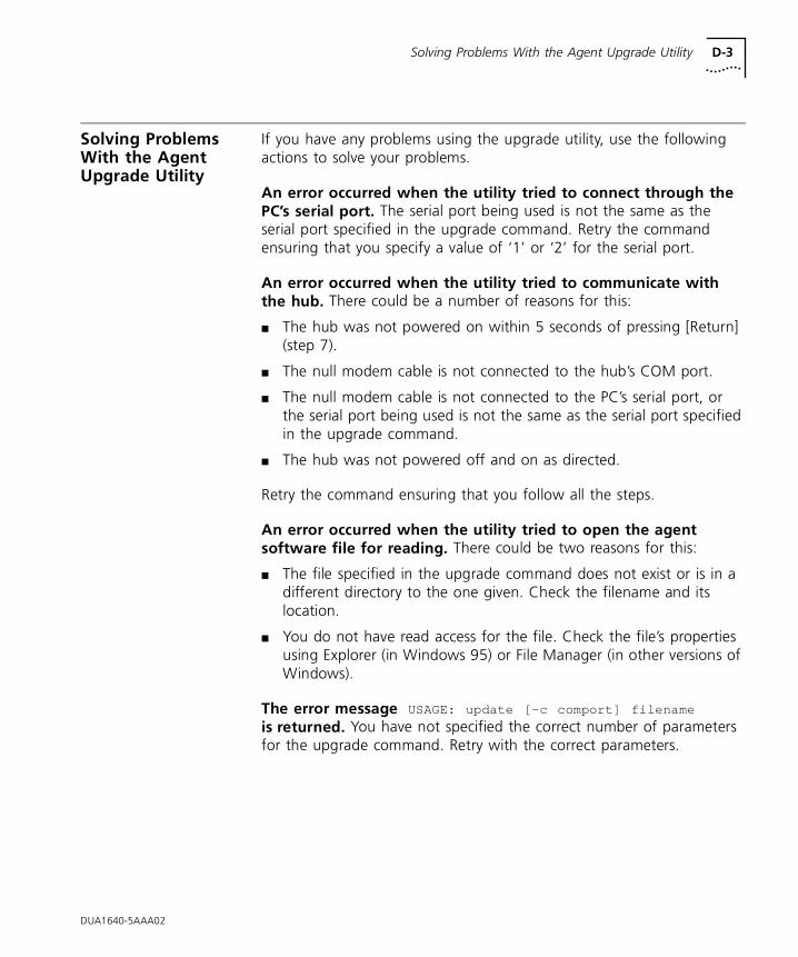
Solving Problems With the Agent Upgrade Utility D-3
Solving Problems With the Agent Upgrade Utility
If you have any problems using the upgrade utility, use the following actions to solve your problems.
An error occurred when the utility tried to connect through the PC’s serial port. The serial port being used is not the same as the serial port specified in the upgrade command. Retry the command ensuring that you specify a value of ‘1’ or ‘2’ for the serial port.
An error occurred when the utility tried to communicate with the hub. There could be a number of reasons for this:
■ The hub was not powered on within 5 seconds of pressing [Return] (step 7).
■ The null modem cable is not connected to the hub’s COM port.
■ The null modem cable is not connected to the PC’s serial port, or the serial port being used is not the same as the serial port specified in the upgrade command.
■ The hub was not powered off and on as directed.
Retry the command ensuring that you follow all the steps.
An error occurred when the utility tried to open the agent software file for reading. There could be two reasons for this:
■ The file specified in the upgrade command does not exist or is in a different directory to the one given. Check the filename and its location.
■ You do not have read access for the file. Check the file’s properties using Explorer (in Windows 95) or File Manager (in other versions of Windows).
The error message USAGE: update [-c comport] filename
is returned. You have not specified the correct number of parameters for the upgrade command. Retry with the correct parameters.
DUA1640-5AAA02
D-4 APPENDIX D: AGENT UPGRADE UTILITY
DUA1640-5AAA02
An error occurred when the utility tried to transfer the file. There could be a number of reason for this:
■ The null modem cable has become disconnected from the hub or the PC during the file transfer. Reconnect the cable and start again.
■ Power to the hub has been disrupted during the file transfer. Check the power connection to the hub and start again.
■ An incorrect file has been specified and transferred to the hub. Check the filenames and start again.
■ The utility must be run from MS-DOS. It cannot be used from an MS-DOS Window within Microsoft Window.

E
TECHNICAL SUPPORT3Com provides easy access to technical support information through a variety of services. This appendix describes these services.
Information contained in this appendix is correct at time of publication. For the very latest, we recommend that you access 3Com Corporation’s World Wide Web site.
Online Technical Services
3Com offers worldwide product support 24 hours a day, 7 days a week, through the following online systems:
■ World Wide Web site
■ 3Com Bulletin Board Service (3ComBBS)
■ 3ComFactsSM automated fax service
■ 3ComForum on CompuServe® online service
World Wide Web Site Access the latest networking information on 3Com Corporation’s World Wide Web site by entering our URL into your Internet browser:
http://www.3Com.com/
This service features the latest information about 3Com solutions and technologies, customer service and support, news about the company, technical publications, NetAge® Magazine, and more.
3Com Bulletin BoardService
3ComBBS contains patches, software, and drivers for all 3Com products, as well as technical articles. This service is available through analog modem or digital modem (ISDN) 24 hours a day, 7 days a week.
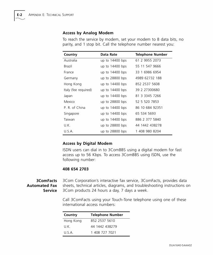
E-2 APPENDIX E: TECHNICAL SUPPORT
Access by Analog Modem
To reach the service by modem, set your modem to 8 data bits, no parity, and 1 stop bit. Call the telephone number nearest you:
Access by Digital Modem
ISDN users can dial in to 3ComBBS using a digital modem for fast access up to 56 Kbps. To access 3ComBBS using ISDN, use the following number:
408 654 2703
3ComFactsAutomated Fax
Service
3Com Corporation’s interactive fax service, 3ComFacts, provides data sheets, technical articles, diagrams, and troubleshooting instructions on 3Com products 24 hours a day, 7 days a week.
Call 3ComFacts using your Touch-Tone telephone using one of these international access numbers:
Country Data Rate Telephone Number
Australia up to 14400 bps 61 2 9955 2073
Brazil up to 14400 bps 55 11 547 9666
France up to 14400 bps 33 1 6986 6954
Germany up to 28800 bps 4989 62732 188
Hong Kong up to 14400 bps 852 2537 5608
Italy (fee required) up to 14400 bps 39 2 27300680
Japan up to 14400 bps 81 3 3345 7266
Mexico up to 28800 bps 52 5 520 7853
P. R. of China up to 14400 bps 86 10 684 92351
Singapore up to 14400 bps 65 534 5693
Taiwan up to 14400 bps 886 2 377 5840
U.K. up to 28800 bps 44 1442 438278
U.S.A. up to 28800 bps 1 408 980 8204
Country Telephone Number
Hong Kong 852 2537 5610
U.K. 44 1442 438279
U.S.A. 1 408 727 7021
DUA1640-5AAA02
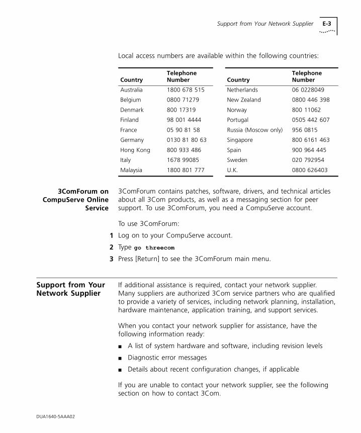
Support from Your Network Supplier E-3
Local access numbers are available within the following countries:
3ComForum onCompuServe Online
Service
3ComForum contains patches, software, drivers, and technical articles about all 3Com products, as well as a messaging section for peer support. To use 3ComForum, you need a CompuServe account.
To use 3ComForum:
1 Log on to your CompuServe account.
2 Type go threecom
3 Press [Return] to see the 3ComForum main menu.
Support from Your Network Supplier
If additional assistance is required, contact your network supplier. Many suppliers are authorized 3Com service partners who are qualified to provide a variety of services, including network planning, installation, hardware maintenance, application training, and support services.
When you contact your network supplier for assistance, have the following information ready:
■ A list of system hardware and software, including revision levels
■ Diagnostic error messages
■ Details about recent configuration changes, if applicable
If you are unable to contact your network supplier, see the following section on how to contact 3Com.
CountryTelephone Number Country
Telephone Number
Australia 1800 678 515 Netherlands 06 0228049
Belgium 0800 71279 New Zealand 0800 446 398
Denmark 800 17319 Norway 800 11062
Finland 98 001 4444 Portugal 0505 442 607
France 05 90 81 58 Russia (Moscow only) 956 0815
Germany 0130 81 80 63 Singapore 800 6161 463
Hong Kong 800 933 486 Spain 900 964 445
Italy 1678 99085 Sweden 020 792954
Malaysia 1800 801 777 U.K. 0800 626403
DUA1640-5AAA02
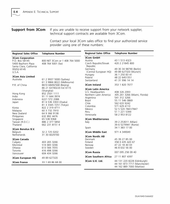
E-4 APPENDIX E: TECHNICAL SUPPORT
Support from 3Com If you are unable to receive support from your network supplier, technical support contracts are available from 3Com.
Contact your local 3Com sales office to find your authorized service provider using one of these numbers:
Regional Sales Office Telephone Number
3Com CorporationP.O. Box 581455400 Bayfront PlazaSanta Clara, California95052-8145U.S.A.
800 NET 3Com or 1 408 764 5000408 764 5001 (fax)
3Com Asia LimitedAustralia
P.R. of China
Hong KongIndiaIndonesiaJapan
KoreaMalaysiaNew ZealandPhilippinesSingaporeTaiwan (R.O.C.)Thailand
61 2 9937 5000 (Sydney)61 3 9866 8022 (Melbourne)8610 68492568 (Beijing)86 21 63740220 Ext 6115 (Shanghai)852 2501 111191 11 644 39746221 572 208881 6 536 3303 (Osaka)81 3 3345 7251 (Tokyo)822 2 319 471160 3 732 791064 9 366 9138632 892 447665 538 9368886 2 377 5850662 231 8151 4
3Com Benelux B.V.BelgiumNetherlands
32 2 725 020231 30 6029700
3Com CanadaCalgaryMontrealOttawaTorontoVancouver
403 265 3266514 683 3266613 566 7055416 498 3266604 434 3266
3Com European HQ 49 89 627320
3Com France 33 1 69 86 68 00
3Com GmbHAustriaCzech Republic/SlovakRepublic
Germany(Central European HQ)
HungaryPolandSwitzerland
43 1 513 4323420 2 21845 800
49 30 34 98790 (Berlin)49 89 627320 (Munich)36 1 250 83 4148 22 645135141 31 996 14 14
3Com Ireland 353 1 820 7077
3Com Latin AmericaU.S. HeadquartersNorthern Latin AmericaArgentinaBrazilChileColombiaMexicoPeruVenezuela
408 326 2093305 261 3266 (Miami, Florida)541 312 326655 11 546 0869562 633 9242571 629 411052 5 520 7841/784751 1 221 539958 2 953 8122
3Com MediterraneoItaly
Spain
39 2 253011 (Milan)39 6 5279941 (Rome)34 1 383 17 00
3Com Middle East 971 4 349049
3Com Nordic ABDenmarkFinlandNorwaySweden
45 39 27 85 00358 0 435 420 6747 22 18 40 0346 8 632 56 00
3Com Russia 007 095 258 09 40
3Com Southern Africa 27 11 807 4397
3Com U.K. Ltd. 44 131 220 8228 (Edinburgh)44 161 873 7717 (Manchester)44 162 889 7000 (Marlow)
Regional Sales Office Telephone Number
DUA1640-5AAA02
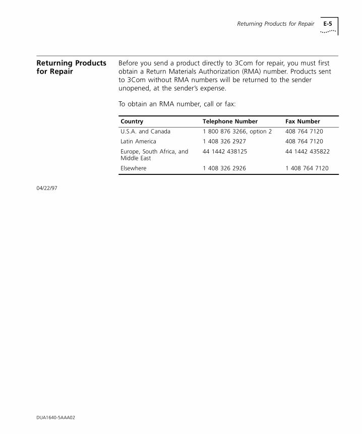
Returning Products for Repair E-5
Returning Products for Repair
Before you send a product directly to 3Com for repair, you must first obtain a Return Materials Authorization (RMA) number. Products sent to 3Com without RMA numbers will be returned to the sender unopened, at the sender’s expense.
To obtain an RMA number, call or fax:
04/22/97
Country Telephone Number Fax Number
U.S.A. and Canada 1 800 876 3266, option 2 408 764 7120
Latin America 1 408 326 2927 408 764 7120
Europe, South Africa, and Middle East
44 1442 438125 44 1442 435822
Elsewhere 1 408 326 2926 1 408 764 7120
DUA1640-5AAA02

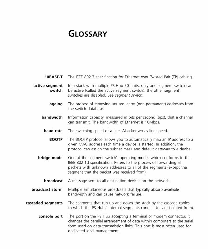
GLOSSARY
10BASE-T The IEEE 802.3 specification for Ethernet over Twisted Pair (TP) cabling.
active segmentswitch
In a stack with multiple PS Hub 50 units, only one segment switch can be active (called the active segment switch), the other segment switches are disabled. See segment switch.
ageing The process of removing unused learnt (non-permanent) addresses from the switch database.
bandwidth Information capacity, measured in bits per second (bps), that a channel can transmit. The bandwidth of Ethernet is 10Mbps.
baud rate The switching speed of a line. Also known as line speed.
BOOTP The BOOTP protocol allows you to automatically map an IP address to a given MAC address each time a device is started. In addition, the protocol can assign the subnet mask and default gateway to a device.
bridge mode One of the segment switch’s operating modes which conforms to the IEEE 802.1d specification. Refers to the process of forwarding all packets with unknown addresses to all of the segments (except the segment that the packet was received from).
broadcast A message sent to all destination devices on the network.
broadcast storm Multiple simultaneous broadcasts that typically absorb available bandwidth and can cause network failure.
cascaded segments The segments that run up and down the stack by the cascade cables, to which the PS Hubs’ internal segments connect (or are isolated from).
console port The port on the PS Hub accepting a terminal or modem connector. It changes the parallel arrangement of data within computers to the serial form used on data transmission links. This port is most often used for dedicated local management.
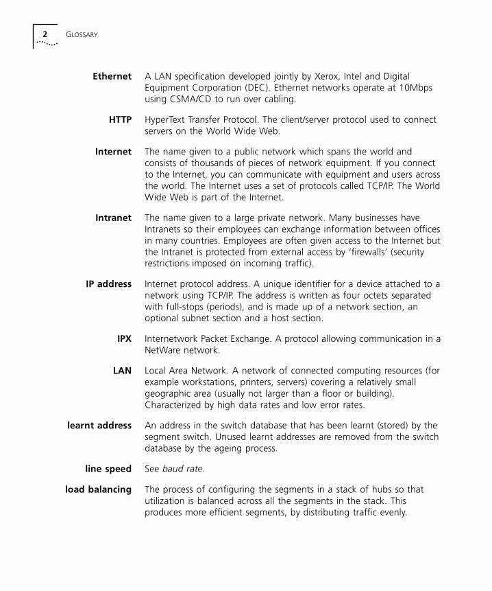
2 GLOSSARY
Ethernet A LAN specification developed jointly by Xerox, Intel and Digital Equipment Corporation (DEC). Ethernet networks operate at 10Mbps using CSMA/CD to run over cabling.
HTTP HyperText Transfer Protocol. The client/server protocol used to connect servers on the World Wide Web.
Internet The name given to a public network which spans the world and consists of thousands of pieces of network equipment. If you connect to the Internet, you can communicate with equipment and users across the world. The Internet uses a set of protocols called TCP/IP. The World Wide Web is part of the Internet.
Intranet The name given to a large private network. Many businesses have Intranets so their employees can exchange information between offices in many countries. Employees are often given access to the Internet but the Intranet is protected from external access by ‘firewalls’ (security restrictions imposed on incoming traffic).
IP address Internet protocol address. A unique identifier for a device attached to a network using TCP/IP. The address is written as four octets separated with full-stops (periods), and is made up of a network section, an optional subnet section and a host section.
IPX Internetwork Packet Exchange. A protocol allowing communication in a NetWare network.
LAN Local Area Network. A network of connected computing resources (for example workstations, printers, servers) covering a relatively small geographic area (usually not larger than a floor or building). Characterized by high data rates and low error rates.
learnt address An address in the switch database that has been learnt (stored) by the segment switch. Unused learnt addresses are removed from the switch database by the ageing process.
line speed See baud rate.
load balancing The process of configuring the segments in a stack of hubs so that utilization is balanced across all the segments in the stack. This produces more efficient segments, by distributing traffic evenly.
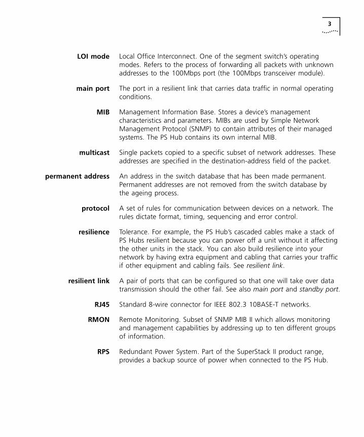
3
LOI mode Local Office Interconnect. One of the segment switch’s operating modes. Refers to the process of forwarding all packets with unknown addresses to the 100Mbps port (the 100Mbps transceiver module).
main port The port in a resilient link that carries data traffic in normal operating conditions.
MIB Management Information Base. Stores a device’s management characteristics and parameters. MIBs are used by Simple Network Management Protocol (SNMP) to contain attributes of their managed systems. The PS Hub contains its own internal MIB.
multicast Single packets copied to a specific subset of network addresses. These addresses are specified in the destination-address field of the packet.
permanent address An address in the switch database that has been made permanent. Permanent addresses are not removed from the switch database by the ageing process.
protocol A set of rules for communication between devices on a network. The rules dictate format, timing, sequencing and error control.
resilience Tolerance. For example, the PS Hub’s cascaded cables make a stack of PS Hubs resilient because you can power off a unit without it affecting the other units in the stack. You can also build resilience into your network by having extra equipment and cabling that carries your traffic if other equipment and cabling fails. See resilient link.
resilient link A pair of ports that can be configured so that one will take over data transmission should the other fail. See also main port and standby port.
RJ45 Standard 8-wire connector for IEEE 802.3 10BASE-T networks.
RMON Remote Monitoring. Subset of SNMP MIB II which allows monitoring and management capabilities by addressing up to ten different groups of information.
RPS Redundant Power System. Part of the SuperStack II product range, provides a backup source of power when connected to the PS Hub.
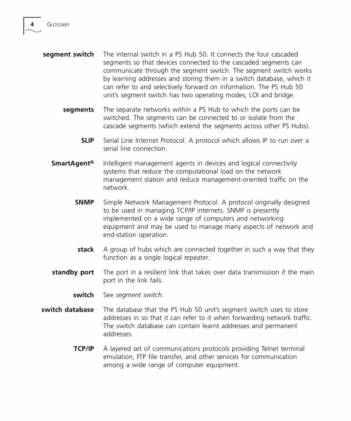
4 GLOSSARY
segment switch The internal switch in a PS Hub 50. It connects the four cascaded segments so that devices connected to the cascaded segments can communicate through the segment switch. The segment switch works by learning addresses and storing them in a switch database, which it can refer to and selectively forward on information. The PS Hub 50 unit’s segment switch has two operating modes; LOI and bridge.
segments The separate networks within a PS Hub to which the ports can be switched. The segments can be connected to or isolate from the cascade segments (which extend the segments across other PS Hubs).
SLIP Serial Line Internet Protocol. A protocol which allows IP to run over a serial line connection.
SmartAgent® Intelligent management agents in devices and logical connectivity systems that reduce the computational load on the network management station and reduce management-oriented traffic on the network.
SNMP Simple Network Management Protocol. A protocol originally designed to be used in managing TCP/IP internets. SNMP is presently implemented on a wide range of computers and networking equipment and may be used to manage many aspects of network and end-station operation.
stack A group of hubs which are connected together in such a way that they function as a single logical repeater.
standby port The port in a resilient link that takes over data transmission if the main port in the link fails.
switch See segment switch.
switch database The database that the PS Hub 50 unit’s segment switch uses to store addresses in so that it can refer to it when forwarding network traffic. The switch database can contain learnt addresses and permanent addresses.
TCP/IP A layered set of communications protocols providing Telnet terminal emulation, FTP file transfer, and other services for communication among a wide range of computer equipment.
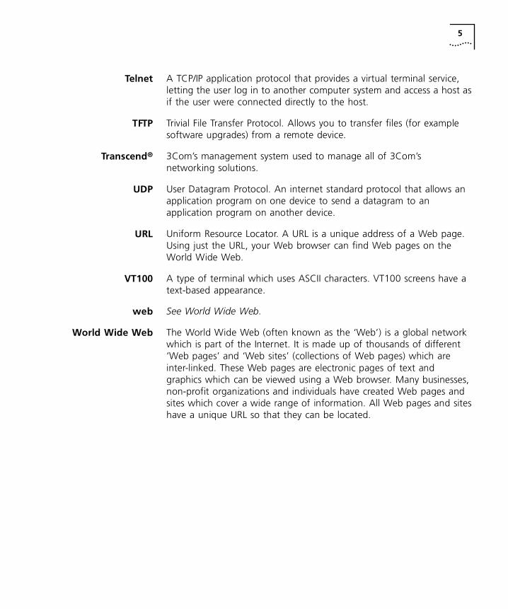
5
Telnet A TCP/IP application protocol that provides a virtual terminal service, letting the user log in to another computer system and access a host as if the user were connected directly to the host.
TFTP Trivial File Transfer Protocol. Allows you to transfer files (for example software upgrades) from a remote device.
Transcend® 3Com’s management system used to manage all of 3Com’s networking solutions.
UDP User Datagram Protocol. An internet standard protocol that allows an application program on one device to send a datagram to an application program on another device.
URL Uniform Resource Locator. A URL is a unique address of a Web page. Using just the URL, your Web browser can find Web pages on the World Wide Web.
VT100 A type of terminal which uses ASCII characters. VT100 screens have a text-based appearance.
web See World Wide Web.
World Wide Web The World Wide Web (often known as the ‘Web’) is a global network which is part of the Internet. It is made up of thousands of different ‘Web pages’ and ‘Web sites’ (collections of Web pages) which are inter-linked. These Web pages are electronic pages of text and graphics which can be viewed using a Web browser. Many businesses, non-profit organizations and individuals have created Web pages and sites which cover a wide range of information. All Web pages and sites have a unique URL so that they can be located.

6 GLOSSARY

INDEX
Numerics100Mbps transceiver module 2-610BASE-T
cable 3-4, 3-5, A-3ports 3-2using cables 3-11
3Com Bulletin Board Service (3ComBBS) E-13Com sales offices E-43Com URL E-13ComFacts E-23ComForum E-3802.1 bridge mode 2-4
Aabout the hub 1-1access
levels, default 6-3method B-5
accessingCLI 6-2hub or stack B-8web interface 7-1
active segment switch 2-4Add Resilient Link page 7-23adding hubs to the stack 1-10, 3-13address, IP 5-7adhesive labels 3-7ageing 2-3agent software
upgrading 7-24version 7-11
agent upgrade utility D-1approvals A-2associated cascade segments 1-8Attn LED 7-11auto-configuration 5-8automatic load balancing B-26avoiding congestion 1-10
BBABT approvals A-1balancing the segments 4-1baud rate 5-8, 7-14before you start 3-4benefits of switching 1-10bitmap B-12blanking plate 3-1BOOTP 7-12
server B-10box contents 3-4brackets 3-9bridge mode 2-4browser 5-12building up
network 1-4workgroups 1-8
built-inmanagement 1-4resilience 3-13
Bulletin Board Service E-1
Ccables 3-4, 3-17
10BASE-T A-3resilience 3-5specifications A-3
capacity of the switch database 2-3cascade
cables 1-8, 3-5, 3-13, A-6ports 3-2segments 1-8, B-14units 3-13
cascaded segment switch 2-2case vents 3-17CD-ROM B-3changing
COM port of the management station B-4console port B-27password 6-7, 7-19speed B-27
character size 5-8checking 3-17

2 INDEX
CLI 5-3, 5-8, 6-1commands 6-7
colors, ports 7-10, B-13COM port of the management station B-4Command Line Interface 5-3, 5-8, 6-1
problems 8-3commands, entering 6-5community string B-8Community/Polling dialog box B-8components of the web interface 7-4CompuServe E-3Configuration pages 7-20configuration, displaying 6-9Configure menu
Community/Polling B-8General Info B-15, B-17IP Setup B-10Load Balance B-18Upgrade B-28
configuringconsole port 7-14, B-27IP 6-8, 7-12, B-9load balancing B-18multiple stacks B-4resilient links 7-21, 7-22segment switch 7-16, B-17segments 1-8, 7-15, B-14
conformance standards A-2congestion, avoiding 1-10connecting
10BASE-T cable 3-11different hubs 3-16different hubs, switches and stacks 3-5hubs together 3-12management station 5-5segment switch 7-16segments 7-15, B-14stacks 3-16workstations 3-11
connection lost 5-11connections 3-4console port 3-2, 5-8, 5-13, A-6
cables A-4configuring B-27
Console Port Configuration page 7-14contents of the box 3-4controlling the CLI 6-5conventions
notice icons, About This Guide 2text, About This Guide 3
correcting faults 8-1creating flexible workgroups 1-9crossover 10BASE-T cable 3-5, A-3current utilization B-20
Ddata bits 5-8default
setting for segment switch 2-4SLIP address 5-7user names and passwords 6-3
default router 6-8, 7-12defaults, returning to 6-11, 7-20Device Access dialog box B-5diagnostic LEDs 3-1dialog box
Community/Polling B-8device access B-5IP Setup B-10map B-5Software Upgrade B-28
differences between the PS Hubs 2-1different
hub, connecting 3-5, 3-16stacks, configuring B-4switch, connecting 3-5
dimensions A-1disconnecting 10BASE-T cable 3-11displaying information 6-9distributed management 1-5Documentation page 7-17double-clicking B-14downlink 2-7
port 2-3download utility D-1downloading new software to the stack B-28
Eeasy setup option B-10EMC A-2emulator 5-9entering commands 6-5environment for operation A-1equipment
connecting 3-11that comes with the hub 3-4
Ethernetaddress of the hub 3-7repeater 1-1rules 3-16shared workgroups 1-10
example of workgrouping 1-11expanding a network 1-6external
links 7-5switch,using 4-3
extra bits 3-4
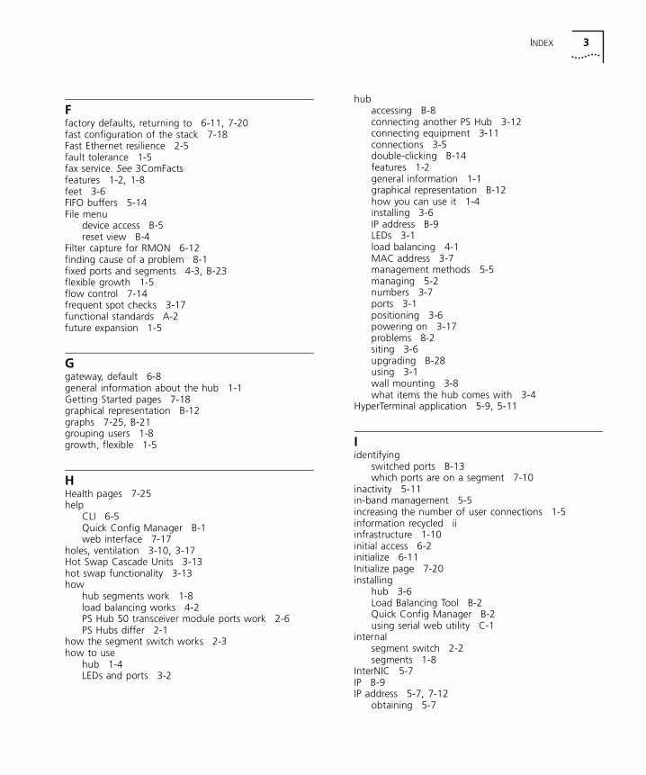
INDEX 3
Ffactory defaults, returning to 6-11, 7-20fast configuration of the stack 7-18Fast Ethernet resilience 2-5fault tolerance 1-5fax service. See 3ComFactsfeatures 1-2, 1-8feet 3-6FIFO buffers 5-14File menu
device access B-5reset view B-4
Filter capture for RMON 6-12finding cause of a problem 8-1fixed ports and segments 4-3, B-23flexible growth 1-5flow control 7-14frequent spot checks 3-17functional standards A-2future expansion 1-5
Ggateway, default 6-8general information about the hub 1-1Getting Started pages 7-18graphical representation B-12graphs 7-25, B-21grouping users 1-8growth, flexible 1-5
HHealth pages 7-25help
CLI 6-5Quick Config Manager B-1web interface 7-17
holes, ventilation 3-10, 3-17Hot Swap Cascade Units 3-13hot swap functionality 3-13how
hub segments work 1-8load balancing works 4-2PS Hub 50 transceiver module ports work 2-6PS Hubs differ 2-1
how the segment switch works 2-3how to use
hub 1-4LEDs and ports 3-2
hubaccessing B-8connecting another PS Hub 3-12connecting equipment 3-11connections 3-5double-clicking B-14features 1-2general information 1-1graphical representation B-12how you can use it 1-4installing 3-6IP address B-9LEDs 3-1load balancing 4-1MAC address 3-7management methods 5-5managing 5-2numbers 3-7ports 3-1positioning 3-6powering on 3-17problems 8-2siting 3-6upgrading B-28using 3-1wall mounting 3-8what items the hub comes with 3-4
HyperTerminal application 5-9, 5-11
Iidentifying
switched ports B-13which ports are on a segment 7-10
inactivity 5-11in-band management 5-5increasing the number of user connections 1-5information recycled iiinfrastructure 1-10initial access 6-2initialize 6-11Initialize page 7-20installing
hub 3-6Load Balancing Tool B-2Quick Config Manager B-2using serial web utility C-1
internalsegment switch 2-2segments 1-8
InterNIC 5-7IP B-9IP address 5-7, 7-12
obtaining 5-7

4 INDEX
IP information 7-12configuring 6-8displaying 6-9
IP Setup dialog box B-10IP/IPX-based network management 5-5
application problems 8-5isolating
problems 8-1segment switch 7-16segments 7-15, B-14
items that come with the hub 3-4
Llabels 3-7learnt addresses 2-3LEDs 3-1lights 3-1line speed 5-8, 7-14link
external 7-5main and standby 7-22state 7-13
load balancing 1-10, 4-1, 7-20how it works 4-2
Load Balancing Tool B-18installing B-2
Local Office Interconnect mode 2-3logging off from the CLI 6-3logging on to the CLI 6-2logical repeaters 3-16login prompt 6-2LOI mode 2-3lost connection 5-11
MMAC addresses 2-3, 3-7, 7-11, 7-16main link 7-21, 7-22management 5-1
access method B-5built-in 1-4categories 7-5connections 5-5distributed 1-5features 1-3methods 5-5settings A-6software 1-8software, upgrading 7-24tasks 5-2
Management Address page 7-12Management Settings pages 7-17management station 5-1
COM port B-4managing
requirements 5-6the hub 5-2web interface 7-1with Quick Config Manager B-1
mapQuick Config Manager B-5web interface 7-6
MDI/MDIX switch 1-4, 1-6, 3-2, 3-5, 3-11, 3-16, 7-23menu structure for CLI 6-4messages 7-22methods of management 5-5migrating to higher performance 1-6, 2-7modem 7-14
cables A-5mounting 3-8
brackets 3-9moving users 1-10multiple
PS Hub 50 units 2-4segment switches 2-4stacks, configuring B-4
Nnaming
segments 7-15, B-14stack 7-19
network 1-8address 5-7building 1-4expanding 1-6growth 1-4infrastructure 1-10management 5-1mask 7-12supplier support E-3
network management stationconnecting 5-5settings A-6
new features 1-2null modem cable A-4number 3-7
unit 5-1user connections, increasing 1-5
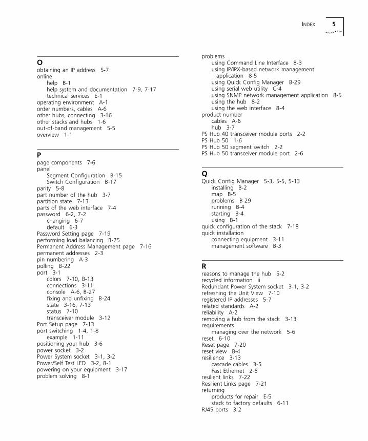
INDEX 5
Oobtaining an IP address 5-7online
help B-1help system and documentation 7-9, 7-17technical services E-1
operating environment A-1order numbers, cables A-6other hubs, connecting 3-16other stacks and hubs 1-6out-of-band management 5-5overview 1-1
Ppage components 7-6panel
Segment Configuration B-15Switch Configuration B-17
parity 5-8part number of the hub 3-7partition state 7-13parts of the web interface 7-4password 6-2, 7-2
changing 6-7default 6-3
Password Setting page 7-19performing load balancing B-25Permanent Address Management page 7-16permanent addresses 2-3pin numbering A-3polling B-22port 3-1
colors 7-10, B-13connections 3-11console A-6, B-27fixing and unfixing B-24state 3-16, 7-13status 7-10transceiver module 3-12
Port Setup page 7-13port switching 1-4, 1-8
example 1-11positioning your hub 3-6power socket 3-2Power System socket 3-1, 3-2Power/Self Test LED 3-2, 8-1powering on your equipment 3-17problem solving 8-1
problemsusing Command Line Interface 8-3using IP/IPX-based network management
application 8-5using Quick Config Manager B-29using serial web utility C-4using SNMP network management application 8-5using the hub 8-2using the web interface 8-4
product numbercables A-6hub 3-7
PS Hub 40 transceiver module ports 2-2PS Hub 50 1-6PS Hub 50 segment switch 2-2PS Hub 50 transceiver module port 2-6
QQuick Config Manager 5-3, 5-5, 5-13
installing B-2map B-5problems B-29running B-4starting B-4using B-1
quick configuration of the stack 7-18quick installation
connecting equipment 3-11management software B-3
Rreasons to manage the hub 5-2recycled information iiRedundant Power System socket 3-1, 3-2refreshing the Unit View 7-10registered IP addresses 5-7related standards A-2reliability A-2removing a hub from the stack 3-13requirements
managing over the network 5-6reset 6-10Reset page 7-20reset view B-4resilience 3-13
cascade cables 3-5Fast Ethernet 2-5
resilient links 7-22Resilient Links page 7-21returning
products for repair E-5stack to factory defaults 6-11
RJ45 ports 3-2

6 INDEX
RMON B-21Filter capture 6-12
router, default 6-8, 7-12RPS
icon B-13socket 3-1, 3-2
rubber feet 3-6rules
Ethernet 3-16resilient links 7-23
rules for managing over the network 5-6running
Quick Config Manager B-4
Sscalable 1-4screen map B-5seeing how the hub is operating 3-1Segment Configuration page 7-15Segment Configuration panel B-15Segment Graph page 7-25segment switch 2-2
active 2-4colors 7-10configuration 7-16configuring B-17icon B-13
segmentationbenefits 1-10how it works 1-8
segments 1-8configuring B-14connecting B-14fixing and unfixing B-23graphs 7-25identifying ports B-13identifying which ports are part of it 7-10isolating B-14LEDs 3-2load balancing 4-1naming B-14
selecting management access method B-5self test 3-17, 8-1self-adhesive rubber feet 3-6self-selecting switch mode 2-3separate networks 1-8serial access C-1serial number of the hub 3-7serial web utility C-1server B-29setting up
IP information 6-8online help system and documentation 7-9
settingsconsole port 5-8displaying 6-9management station A-6
shared Ethernet workgroups 1-10sheet of labels 3-7siting your hub 3-6SLIP
address 5-7, 6-8driver C-1subnet mask 6-8
small networkbuilding 1-4
SNMP 5-5network management application
problems 8-5socket
power 3-2Redundant Power System 3-1, 3-2
software 1-8upgrade for stack B-28upgrading 7-24
Software Upgrade dialog box B-28Software Upgrade page 7-24software version 7-11solving problems 8-1specifications A-1speed, console port 7-14spot checks 3-17stack 5-1
accessing B-8connecting 3-5, 3-16information, displaying 6-10management 5-1name 7-19resilience 3-13upgrading B-28
Stack/Attn LED 3-2standards A-2standby link 7-21, 7-22starting Quick Config Manager B-4status LEDs 3-2sticky labels 3-7stop bit 5-8straight-through 10BASE-T cable 3-4, 3-5, A-3subnet mask 5-7, 6-8summary of differences between the PS Hubs 2-1SuperStack hubs 3-16switch
configuring B-17connections 3-5database 2-3icon B-13
Switch Configuration page 7-16Switch Configuration panel B-17
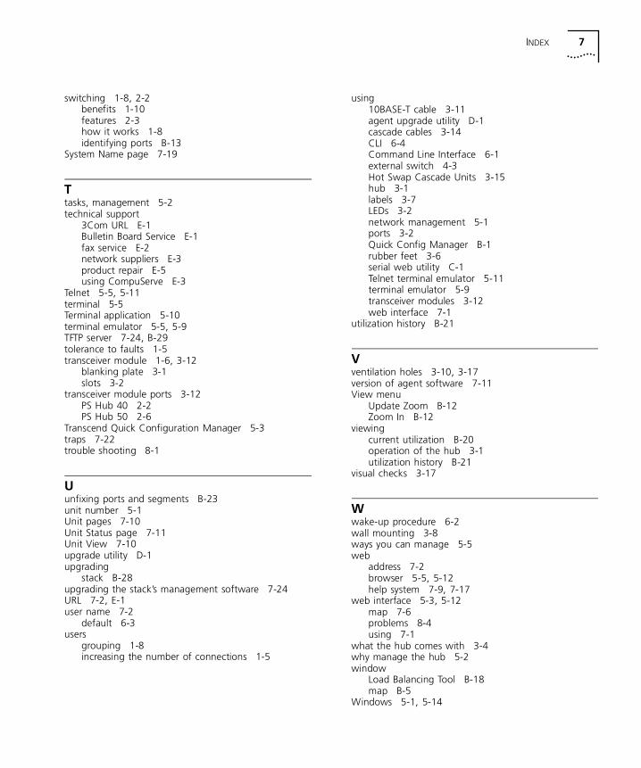
INDEX 7
switching 1-8, 2-2benefits 1-10features 2-3how it works 1-8identifying ports B-13
System Name page 7-19
Ttasks, management 5-2technical support
3Com URL E-1Bulletin Board Service E-1fax service E-2network suppliers E-3product repair E-5using CompuServe E-3
Telnet 5-5, 5-11terminal 5-5Terminal application 5-10terminal emulator 5-5, 5-9TFTP server 7-24, B-29tolerance to faults 1-5transceiver module 1-6, 3-12
blanking plate 3-1slots 3-2
transceiver module ports 3-12PS Hub 40 2-2PS Hub 50 2-6
Transcend Quick Configuration Manager 5-3traps 7-22trouble shooting 8-1
Uunfixing ports and segments B-23unit number 5-1Unit pages 7-10Unit Status page 7-11Unit View 7-10upgrade utility D-1upgrading
stack B-28upgrading the stack’s management software 7-24URL 7-2, E-1user name 7-2
default 6-3users
grouping 1-8increasing the number of connections 1-5
using10BASE-T cable 3-11agent upgrade utility D-1cascade cables 3-14CLI 6-4Command Line Interface 6-1external switch 4-3Hot Swap Cascade Units 3-15hub 3-1labels 3-7LEDs 3-2network management 5-1ports 3-2Quick Config Manager B-1rubber feet 3-6serial web utility C-1Telnet terminal emulator 5-11terminal emulator 5-9transceiver modules 3-12web interface 7-1
utilization history B-21
Vventilation holes 3-10, 3-17version of agent software 7-11View menu
Update Zoom B-12Zoom In B-12
viewingcurrent utilization B-20operation of the hub 3-1utilization history B-21
visual checks 3-17
Wwake-up procedure 6-2wall mounting 3-8ways you can manage 5-5web
address 7-2browser 5-5, 5-12help system 7-9, 7-17
web interface 5-3, 5-12map 7-6problems 8-4using 7-1
what the hub comes with 3-4why manage the hub 5-2window
Load Balancing Tool B-18map B-5
Windows 5-1, 5-14
8 INDEX
workgroups 1-4, 1-7building up 1-8example 1-11
workstation connections 3-4World Wide Web (WWW) E-1
ZZoom View B-8, B-12, B-16
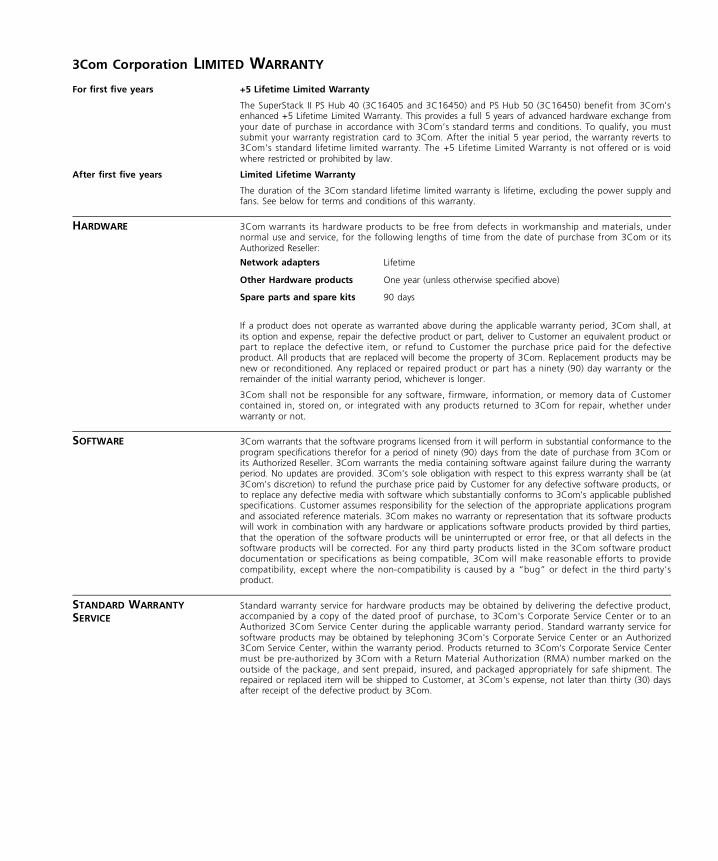
3Com Corporation LIMITED WARRANTY
For first five years +5 Lifetime Limited Warranty
The SuperStack II PS Hub 40 (3C16405 and 3C16450) and PS Hub 50 (3C16450) benefit from 3Com’senhanced +5 Lifetime Limited Warranty. This provides a full 5 years of advanced hardware exchange fromyour date of purchase in accordance with 3Com’s standard terms and conditions. To qualify, you mustsubmit your warranty registration card to 3Com. After the initial 5 year period, the warranty reverts to3Com’s standard lifetime limited warranty. The +5 Lifetime Limited Warranty is not offered or is voidwhere restricted or prohibited by law.
After first five years Limited Lifetime Warranty
The duration of the 3Com standard lifetime limited warranty is lifetime, excluding the power supply andfans. See below for terms and conditions of this warranty.
HARDWARE 3Com warrants its hardware products to be free from defects in workmanship and materials, undernormal use and service, for the following lengths of time from the date of purchase from 3Com or itsAuthorized Reseller:
If a product does not operate as warranted above during the applicable warranty period, 3Com shall, atits option and expense, repair the defective product or part, deliver to Customer an equivalent product orpart to replace the defective item, or refund to Customer the purchase price paid for the defectiveproduct. All products that are replaced will become the property of 3Com. Replacement products may benew or reconditioned. Any replaced or repaired product or part has a ninety (90) day warranty or theremainder of the initial warranty period, whichever is longer.
3Com shall not be responsible for any software, firmware, information, or memory data of Customercontained in, stored on, or integrated with any products returned to 3Com for repair, whether underwarranty or not.
SOFTWARE 3Com warrants that the software programs licensed from it will perform in substantial conformance to theprogram specifications therefor for a period of ninety (90) days from the date of purchase from 3Com orits Authorized Reseller. 3Com warrants the media containing software against failure during the warrantyperiod. No updates are provided. 3Com's sole obligation with respect to this express warranty shall be (at3Com's discretion) to refund the purchase price paid by Customer for any defective software products, orto replace any defective media with software which substantially conforms to 3Com's applicable publishedspecifications. Customer assumes responsibility for the selection of the appropriate applications programand associated reference materials. 3Com makes no warranty or representation that its software productswill work in combination with any hardware or applications software products provided by third parties,that the operation of the software products will be uninterrupted or error free, or that all defects in thesoftware products will be corrected. For any third party products listed in the 3Com software productdocumentation or specifications as being compatible, 3Com will make reasonable efforts to providecompatibility, except where the non-compatibility is caused by a “bug” or defect in the third party'sproduct.
STANDARD WARRANTY SERVICE
Standard warranty service for hardware products may be obtained by delivering the defective product,accompanied by a copy of the dated proof of purchase, to 3Com's Corporate Service Center or to anAuthorized 3Com Service Center during the applicable warranty period. Standard warranty service forsoftware products may be obtained by telephoning 3Com's Corporate Service Center or an Authorized3Com Service Center, within the warranty period. Products returned to 3Com's Corporate Service Centermust be pre-authorized by 3Com with a Return Material Authorization (RMA) number marked on theoutside of the package, and sent prepaid, insured, and packaged appropriately for safe shipment. Therepaired or replaced item will be shipped to Customer, at 3Com's expense, not later than thirty (30) daysafter receipt of the defective product by 3Com.
Network adapters Lifetime
Other Hardware products One year (unless otherwise specified above)
Spare parts and spare kits 90 days
WARRANTIES EXCLUSIVE IF A 3COM PRODUCT DOES NOT OPERATE AS WARRANTED ABOVE, CUSTOMER'S SOLE REMEDY FORBREACH OF THAT WARRANTY SHALL BE REPAIR, REPLACEMENT, OR REFUND OF THE PURCHASE PRICEPAID, AT 3COM'S OPTION. TO THE FULL EXTENT ALLOWED BY LAW, THE FOREGOING WARRANTIES ANDREMEDIES ARE EXCLUSIVE AND ARE IN LIEU OF ALL OTHER WARRANTIES, TERMS, OR CONDITIONS,EXPRESS OR IMPLIED, EITHER IN FACT OR BY OPERATION OF LAW, STATUTORY OR OTHERWISE,INCLUDING WARRANTIES, TERMS, OR CONDITIONS OF MERCHANTABILITY, FITNESS FOR A PARTICULARPURPOSE, AND SATISFACTORY QUALITY. 3COM NEITHER ASSUMES NOR AUTHORIZES ANY OTHERPERSON TO ASSUME FOR IT ANY OTHER LIABILITY IN CONNECTION WITH THE SALE, INSTALLATION,MAINTENANCE OR USE OF ITS PRODUCTS.
3COM SHALL NOT BE LIABLE UNDER THIS WARRANTY IF ITS TESTING AND EXAMINATION DISCLOSETHAT THE ALLEGED DEFECT IN THE PRODUCT DOES NOT EXIST OR WAS CAUSED BY CUSTOMER'S ORANY THIRD PERSON'S MISUSE, NEGLECT, IMPROPER INSTALLATION OR TESTING, UNAUTHORIZEDATTEMPTS TO REPAIR OR MODIFY, OR ANY OTHER CAUSE BEYOND THE RANGE OF THE INTENDED USE,OR BY ACCIDENT, FIRE, LIGHTNING, OR OTHER HAZARD.
LIMITATION OF LIABILITY TO THE FULL EXTENT ALLOWED BY LAW 3COM ALSO EXCLUDES FOR ITSELF AND ITS SUPPLIERS ANYLIABILITY, WHETHER BASED IN CONTRACT OR TORT (INCLUDING NEGLIGENCE), FOR INCIDENTAL,CONSEQUENTIAL, INDIRECT, SPECIAL, OR PUNITIVE DAMAGES OF ANY KIND, OR FOR LOSS OF REVENUEOR PROFITS, LOSS OF BUSINESS, LOSS OF INFORMATION OR DATA, OR OTHER FINANCIAL LOSS ARISINGOUT OF OR IN CONNECTION WITH THE SALE, INSTALLATION, MAINTENANCE, USE, PERFORMANCE,FAILURE, OR INTERRUPTION OF ITS PRODUCTS, EVEN IF 3COM OR ITS AUTHORIZED RESELLER HAS BEENADVISED OF THE POSSIBILITY OF SUCH DAMAGES, AND LIMITS ITS LIABILITY TO REPAIR, REPLACEMENT,OR REFUND OF THE PURCHASE PRICE PAID, AT 3COM'S OPTION. THIS DISCLAIMER OF LIABILITY FORDAMAGES WILL NOT BE AFFECTED IF ANY REMEDY PROVIDED HEREIN SHALL FAIL OF ITS ESSENTIALPURPOSE.
Some countries, states, or provinces do not allow the exclusion or limitation of implied warranties or thelimitation of incidental or consequential damages for certain products supplied to consumers or thelimitation of liability for personal injury, so the above limitations and exclusions may be limited in theirapplication to you. This warranty gives you specific legal rights which may vary depending on local law.
GOVERNING LAW This Limited Warranty shall be governed by the laws of the state of California.
3Com Corporation, 5400 Bayfront Plaza, Santa Clara, CA, 95052-8145, U.S.A. Tel: (408) 764-5000
9/1/96
EMC STATEMENTS
FCC STATEMENT This equipment has been tested and found to comply with the limits for a Class A digital device, pursuantto part 15 of the FCC rules. These limits are designed to provide reasonable protection against harmfulinterference when the equipment is operated in a commercial environment. This equipment generates,uses and can radiate radio frequency energy and, if not installed and used in accordance with theinstructions, may cause harmful interference to radio communications. Operation of this equipment in aresidential area is likely to cause harmful interference to radio communications, in which case the user willbe required to correct the interference at their own expense.
CSA STATEMENT This Class A digital apparatus meets all requirements of the Canadian Interference-Causing EquipmentRegulations.
Cet appareil numérique de la classe A respecte toutes les exigences du Règlement sur le matériel brouilleurdu Canada.
VCCI STATEMENT
INFORMATION TO THE USER If this equipment does cause interference to radio or television reception, which can be determined byturning the equipment off and on, the user is encouraged to try to correct the interference by one ormore of the following measures:
— Reorient the receiving antenna.
— Relocate the equipment with respect to the receiver.
— Move the equipment away from the receiver.
— Plug the equipment into a different outlet so that equipment and receiver are on different branchcircuits.
If necessary, the user should consult the dealer or an experienced radio/television technician for additionalsuggestions. The user may find the following booklet prepared by the Federal CommunicationsCommission helpful:
How to Identify and Resolve Radio-TV Interference Problems
This booklet is available from the U.S. Government Printing Office, Washington, DC 20402, Stock No.004-000-00345-4.
In order to meet FCC emissions limits, this equipment must be used only with cables which comply withIEEE 802.3.

Related Documents