Superhydrophobic Carbon Nanotube Forests Kenneth K. S. Lau *1 , José Bico 2 , Kenneth B. K. Teo 3 , Manish Chhowalla 4 , Gehan A. J. Amaratunga 3 , William I. Milne 3 , Gareth H. McKinley 2 and Karen K. Gleason 1 1 Department of Chemical Engineering, Massachusetts Institute of Technology, Cambridge, Massachusetts 02139, USA 2 Department of Mechanical Engineering, Massachusetts Institute of Technology, Cambridge, Massachusetts 02139, USA 3 Engineering Department, University of Cambridge, Cambridge CB2 1PZ, United Kingdom 4 Department of Ceramics and Materials Engineering, Rutgers University, Piscataway, New Jersey 08854, USA * e-mail: [email protected]

Welcome message from author
This document is posted to help you gain knowledge. Please leave a comment to let me know what you think about it! Share it to your friends and learn new things together.
Transcript
Superhydrophobic Carbon Nanotube Forests
Kenneth K. S. Lau*1, José Bico2, Kenneth B. K. Teo3, Manish Chhowalla4, Gehan A. J.
Amaratunga3, William I. Milne3, Gareth H. McKinley2 and Karen K. Gleason1
1Department of Chemical Engineering, Massachusetts Institute of Technology, Cambridge,
Massachusetts 02139, USA
2Department of Mechanical Engineering, Massachusetts Institute of Technology,
Cambridge, Massachusetts 02139, USA
3Engineering Department, University of Cambridge, Cambridge CB2 1PZ, United
Kingdom
4Department of Ceramics and Materials Engineering, Rutgers University, Piscataway, New
Jersey 08854, USA
*e-mail: [email protected]
2Kenneth K. S. Lau, Nano Letters
ABSTRACT
The present study demonstrates the creation of a stable, superhydrophobic surface
using the nano-scale roughness inherent in a vertically aligned carbon nanotube forest
together with a thin, conformal hydrophobic polytetrafluoroethylene (PTFE) coating on the
surface of the nanotubes. Superhydrophobicity is achieved down to the microscopic level
where essentially spherical, micrometer-sized water droplets can be suspended on top of
the nanotube forest.
3Kenneth K. S. Lau, Nano Letters
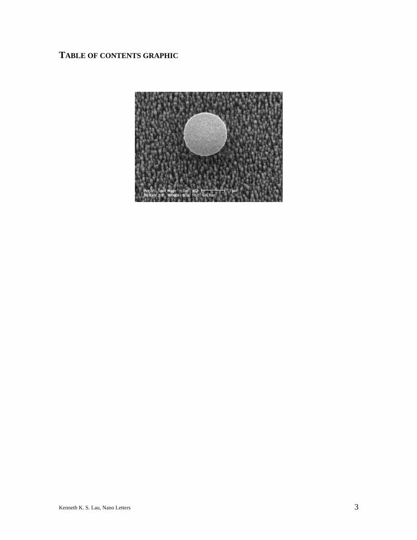
TABLE OF CONTENTS GRAPHIC
4Kenneth K. S. Lau, Nano Letters
Since their discovery in 19911, carbon nanotubes continue to be a subject of
unabated scientific research and development. Their extraordinary properties2-4 make
them highly attractive as technology enablers in a host of different applications, ranging
from fillers in polymer nanocomposites to conductors in molecular electronics5. Carbon
nanotubes can be single-walled (SWNTs) or multi-walled (MWNTs), metallic or
semiconducting, and isolated or attached to a substrate. The ability to grow nanotubes
directly on a substrate using various chemical vapor deposition techniques allows the
production of high purity nanotubes in a controlled manner. Added to this, the ability to
functionalize the surface of individual nanotubes can create synergistic effects in nanotube
properties. Here we report the creation of a superhydrophobic surface via
functionalization of vertically aligned carbon nanotubes with a non-wetting
polytetrafluoroethylene (PTFE) coating. Vapor condensation experiments inside an
environmental scanning electron microscope (ESEM) confirmed that the superhydrophobic
effect is observable even for microscopic water droplets. We further demonstrate that this
superhydrophobicity on a functionalized forest can be achieved with relatively short
nanotube heights.
Such superhydrophobicity can be understood by observing nature. In certain plant
leaves, such as the lotus leaf (Nelumbo nucifera), rain droplets are known to roll or bounce
off these leaves, removing dust particles and surface contaminants. This self-cleaning or
Lotus effect6 is caused by both the hierarchical roughness of the leaf surface from
micrometer-sized papillae having nanometer-sized branch like protrusions and the intrinsic
material hydrophobicity of a surface layer of epicuticular wax covering these papillae7. A
very rough, heterogeneous surface allows air to be trapped more easily underneath the
5Kenneth K. S. Lau, Nano Letters
water droplet so the droplet essentially rests on a layer of air. A significantly higher
surface area compared to the projected area in the case of a rough surface requires a greater
energy barrier to create a liquid-solid interface. Coupled to this, when the surface energy
of the surface material is intrinsically low, the combined effect is the surface will repel any
water that comes into contact with it.
Likewise, our PTFE-coated carbon nanotube forests aim to mimic nature’s design.
By growing a forest of nanotube pillars, an organized, heterogeneous surface is
synthesized on a nano-scale. This makes it easy even for extremely small water droplets to
be suspended on a surface approaching that of a perfect air-water interface (contact angle
of 180°8). By coating this forest template with a PTFE layer, the water comes into contact
with a material having one of the lowest surface energy (18 mN/m) and thus a high contact
angle (108° on a smooth PTFE surface9). By combining these two elements, the PTFE-
coated nanotube forest can prevent water penetration down to the microscopic level,
creating an enhanced superhydrophobic effect. Such modified carbon nanotubes may
potentially be used in microfluidic devices, anti-soiling or anti-fouling surfaces, efficient
heat transfer areas, or non-binding biopassive surfaces.
We deposited the vertically aligned carbon nanotube forest with a plasma enhanced
chemical vapor deposition (PECVD) technique10-12. Although a variety of different
methods are also currently available, the PECVD process is the only technique that
produces perfectly aligned, untangled (i.e. individually standing) carbon nanotubes whose
height and diameter can be conveniently controlled. The PECVD process can be
summarized in two main steps. First, the formation of nickel (Ni) catalyst islands on an
oxidized (20 nm) silicon substrate through the sintering of a thin (5 nm) Ni film at 650 °C.
6Kenneth K. S. Lau, Nano Letters
Second, nanotube growth from these discrete catalyst islands in a DC plasma discharge
(bias –600V) of acetylene and ammonia, using flow rates of 75 and 200 sccm, respectively,
at a partial pressure of 4 Torr. The PECVD process enables the growth of nanotubes
aligned in the vertical direction. The nanotube diameter and areal density are controlled by
the initial thickness of the Ni catalyst layer, with a thinner film leading to narrower
nanotubes of higher density. The nanotube height is controlled by the plasma deposition
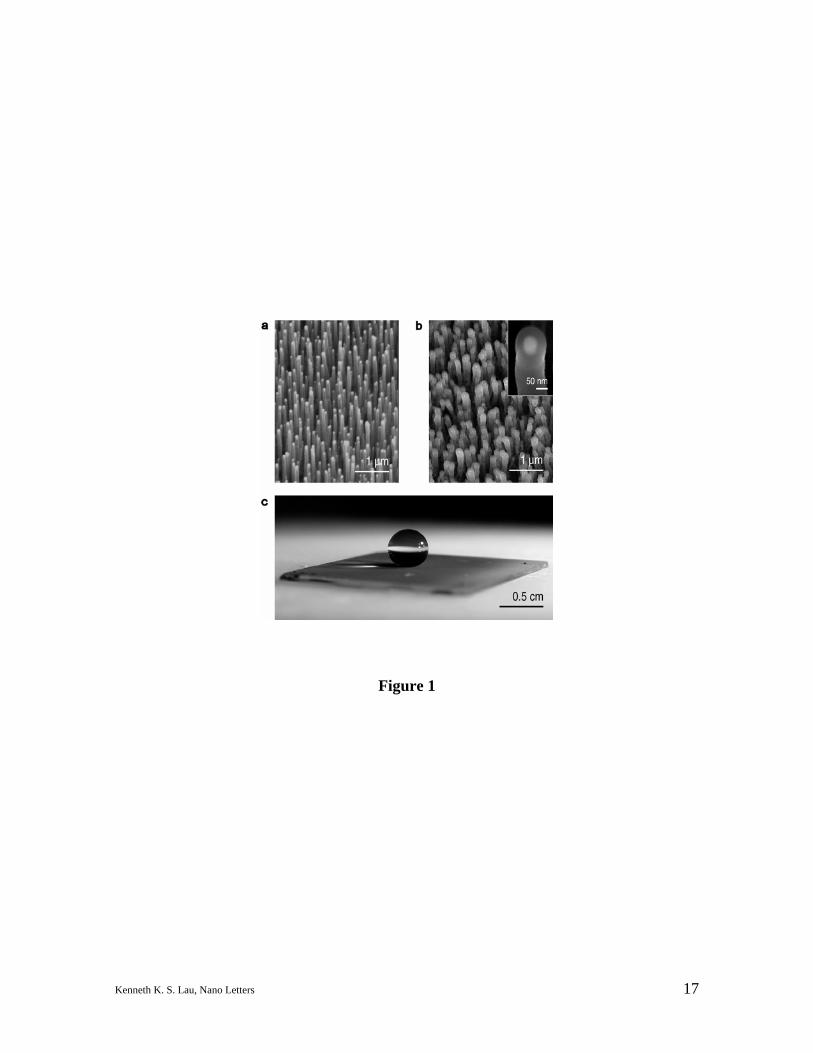
time (typical nanotube growth rate is 330 nm/min). Figure 1a illustrates a typical nanotube
forest grown through this process as viewed under scanning electron microscopy (SEM)
using a Hitachi S800-FE SEM operating at 20 kV The sample has an areal density of 10
MWNTs per µm2, with the vertical MWNTs having a mean diameter of 50 nm (as-grown)
and a height of 2 µm.
An array of such relatively short nanotubes is not sufficiently hydrophobic on its
own, on the contrary, water droplets deposited on the surface immediately penetrate into
the forest. This is presumably due to the high surface energy of the nanotubes, essentially
a graphite material (contact angle of 84–86°13,14), that caused the water to seep into the
voids of the forest. Further, microscopic examination of such samples after drying
revealed that the nanotubes were forced into bundles under the surface tension effects of
the evaporating water between the nanotubes, confirming our hypothesis. Our observation
may appear contradictory with experiments on tall carbon nanotubes grown off a substrate
where superhydrophobicity has been observed15,16. Thus, we investigated taller (10–15
µm) nanotube forests and these surfaces in the as-grown state did give an initial water
contact angle of 161°. However, the droplets were not stable and eventually seeped into
the forest voids after a few minutes. The apparent superhydrophobicity of the taller
7Kenneth K. S. Lau, Nano Letters
nanotubes most likely resulted from secondary roughness as there is a larger variation in
height of the taller nanotubes which was observed through electron microscopy. The
eventual penetration of the water droplets is due to the high surface energy of the
nanotube’s graphitic surface. This suggests that PTFE functionalization is a necessary step
for making a stable superhydrophobic surface.
The PTFE coating is applied onto the forest of carbon nanotubes through a hot
filament chemical vapor deposition (HFCVD) process17,18. The process coats along the
height of carbon nanotubes with a sufficiently thin PTFE coating, unlike conventional
methods in which greater minimum coating thicknesses (> 10 µm) can smooth out the
surface texture. Using an array of stainless steel filaments resistively heated to 500 °C,
hexafluoropropylene oxide (HFPO) gas is thermally decomposed to form difluorocarbene
(CF2) radicals. These radicals polymerize into PTFE on the nanotube forest substrate that
is kept at room temperature. An initiator, perfluorobutane-1-sulfonyl fluoride is used to
promote the polymerization process. Flow rates of HFPO and the initiator are maintained
at 23 and 6 sccm, respectively, and pressure is kept at 0.5 Torr. Figure 1b shows an SEM
micrograph of the 2 µm tall nanotube forest after being coated with PTFE. Each individual
pillar is seen to be coated uniformly and the forest structure is preserved. Unlike the as-
grown forests, the treated forests show stable superhydrophobicity, yielding nearly
spherical water droplets on a macroscopic level when water is deposited on the surface, as
shown in Figure 1c. The advancing and receding contact angles of the treated forest
shown here are 170° and 160°, respectively. Contact angle measurements are performed
using the sessile drop method, the water droplets are introduced using a microsyringe and
images are captured to measure the angle of the liquid-solid interface.
8Kenneth K. S. Lau, Nano Letters
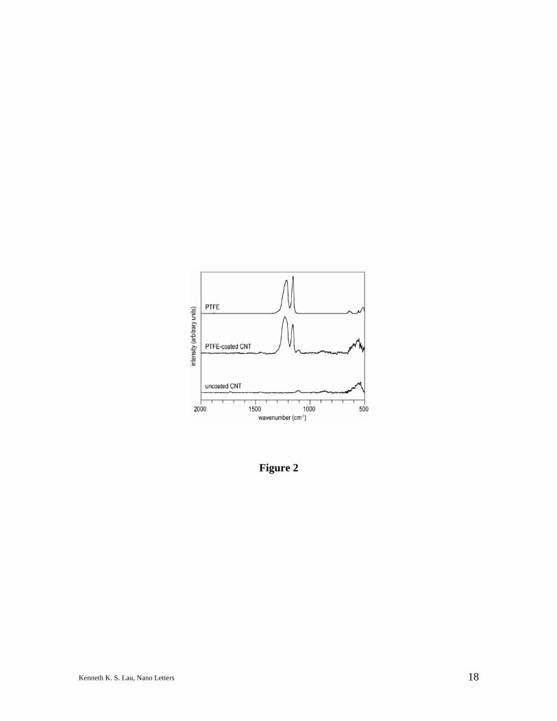
Fourier transform infrared spectroscopy (FTIR) confirms that our PTFE coating is
essentially identical to bulk PTFE, see Figure 2. FTIR spectra are acquired using a
Thermo Nicolet NEXUS 870 equipped with a DTGS detector at 4 cm–1 resolution. The
spectrum of the as-grown carbon nanotube forest shows no distinctive FTIR peaks. The
spectrum of the PTFE-coated forest in contrast shows strong absorptions of the symmetric
and asymmetric CF2 stretches in the 1250–1150 cm–1 region characteristic of bulk
PTFE19,20. Other methods, such as PECVD or laser ablation, may yield thin fluorocarbon
coatings that can also cover the entire length of the nanotubes but these coatings, unlike
HFCVD, suffer from poor compositional resemblance to bulk PTFE.
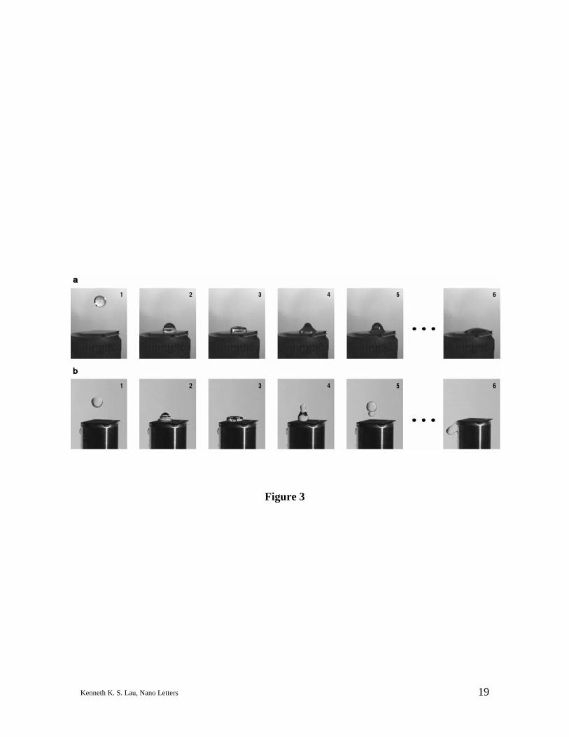
Aside from static experiments, we were interested in the dynamic behavior of water
on the PTFE-treated carbon nanotube forest. On a macroscopic level, we compared the
behavior of a water droplet free falling on the untreated and the PTFE-treated forest. This
is captured using a Photo-Sonics Phantom V5.0 high speed camera at a 1000 Hz frame rate
and selected time sequence of images are presented in Figure 3 (video clips can be viewed
from Ref. 21). Figure 3a shows the behavior of a droplet falling on the as-grown nanotube
forest during its first impact. The droplet advances with a contact angle greater than 90°
(panels 2 and 3) but recedes with an angle less than 90° (panels 4 and 5), and eventually
comes to rest by wetting the surface (panel 6). Figure 3b reveals a significantly different
behavior on a PTFE-coated nanotube forest, showing the droplet advances (panels 2 and 3)
and recedes (panel 4) with an angle greater than 90°. The surface is so superhydrophobic
that the droplet on receding actually has sufficient momentum to leave the surface (panel
5). After several more bounces (not shown), the droplet eventually bounces off without
ever coming to rest on the surface (panel 6).
9Kenneth K. S. Lau, Nano Letters
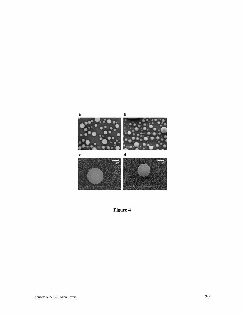
On a microscopic level, we used ESEM to observe the behavior of water
condensing on our nanotube forest surface. By precisely controlling the water vapor
pressure (5.5 Torr) and the temperature of the sample stage (3.4 °C) in the Philips/FEI
XL30 FEG ESEM chamber, we were able to image the formation of micrometer-sized
water droplets at 30 kV, as seen in Figures 4a and 4b from a top-down and 15° tilt views,
respectively. Figures 4c and 4d capture remarkably close-up views, both from top-down
and at a 15° tilt, of water droplets (3–4 µm in diameter) that are essentially spherical and
clearly suspended on top of the template of carbon nanotubes which are also visible,
demonstrating that we have created a carbon nanotube forest that is superhydrophobic
down to the micrometer dimension (video clip can be viewed from Ref. 21).
Quantitatively, model surfaces with a controlled topography suggest a very simple
relation (Cassie-Baxter equation22) between the apparent contact angle θ* observed on a
rough surface and the equilibrium contact angle θ obtained on a smooth surface of the
same chemical composition:
cos θ* = –1 + φs (cos θ + 1) (1)
where the surface fraction φs corresponds to the ratio of the surface of the top of the
roughness in contact with the liquid with the apparent surface of the substrate. The value
of θ relies on the Young’s relation, cos θ = (γSV – γSL)/γLV, where γij’s correspond to the
solid-vapor, solid-liquid and liquid-vapor interfacial tensions, respectively. By analogy
with porous wicking, Equation (1) is expected to be valid for θ > 90°, independent of the
height of the rough structure. In order to probe the validity of the equation in our case, the
value of the surface fraction φs can be estimated from the pillar geometry of the forest:
φs = n πr2 (2)
10Kenneth K. S. Lau, Nano Letters
where r is the radius of the tubes and n the number of tubes per sample area. In the
example illustrated in Figure 4, the tubes have an average radius of 60 nm (coated) and a
density of 10 nanotubes per µm2, which yields a value for φs of 11% from Equation (2).
The advancing and receding contact angles of water on a smooth silicon wafer coated with
PTFE are 150° and 110°, respectively, these higher values compared to conventional,
smooth PTFE indicate some inherent rough texture in the PTFE made using the HFCVD
process18. Using these values, the advancing and receding contact angles on the coated
forest as predicted from Equation (1) are therefore 170° and 158°, respectively. This is in
good agreement with the experimentally measured values of 170° and 160°, respectively.
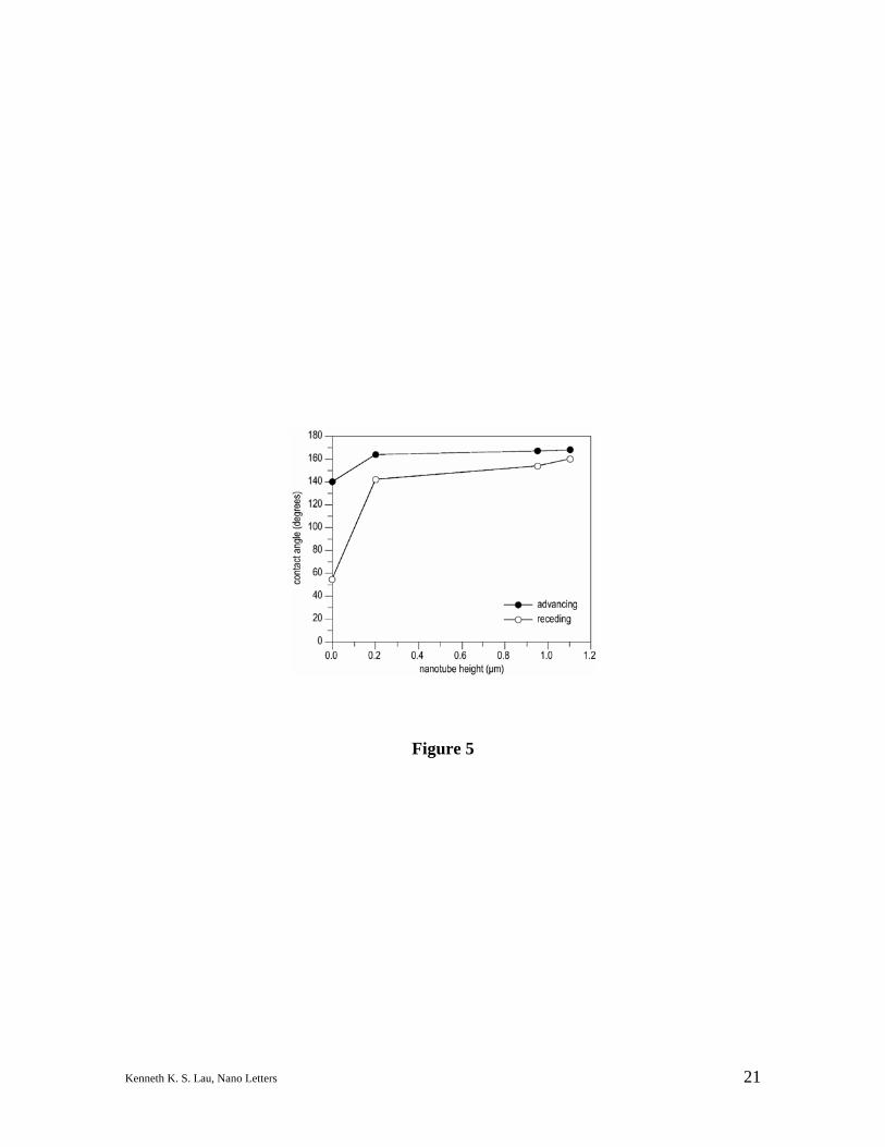
Finally, we evaluated the superhydrophobicity of a series of even shorter and
narrower nanotube forests in dynamic mode, measuring the advancing and receding angles
and hysteresis as a more sensitive way to assess wettability. Figure 5 shows the results for
forests of nanotubes 50 nm in diameter (coated) with heights ranging from 0.2–1.1 µm, as
well as for a plain substrate with the nickel catalyst but without any nanotube growth. We
observe that the advancing angles are significantly higher for the forests than for the plain
substrate even at the shortest height and reaches a value of 168° at the tallest. However,
the receding angles are more sensitive to differences in nanotube height, with hysteresis
(difference between the advancing and receding angles) becoming smaller as the height of
the forest increases, the tallest forest showing a hysteresis of 8°. This decrease in
hysteresis may be a result of a decrease in interaction of the water droplet with the base
surface. There seems to be a strong attraction of the water to the base surface since a
strong hysteresis is observed just for the plain substrate without nanotubes. The water
seepage into the uncoated nanotube forest also supports this view. By coating the
11Kenneth K. S. Lau, Nano Letters
nanotube forests with PTFE, we are able to introduce superhydrophobicity to forests with
much shorter heights (down to 0.2 µm) than is possible without the PTFE treatment. This
superhydrophobicity is also more stable, showing no signs of water seepage even after
prolonged periods of time.
We have successfully created superhydrophobic carbon nanotube forests by
modifying the surface of vertically aligned nanotubes with a PTFE coating. From our
results, it is apparent that both the surface roughness templated by the nanotube forest and
the low surface energy imparted by the PTFE coating are necessary components to achieve
a stable superhydrophobic surface. The ability to use our HFCVD process to modify the
surfaces of nanotubes directly is certainly attractive. It is unclear at this point how the
PTFE polymer chains are attached to the nanotube surface. There is evidence that carbene
radicals are sufficiently reactive to add directly to the sp2-hybridized carbons23,24, so it is
conceivable that the difluorocarbene radicals may attach covalently to the nanotube surface
and subsequently polymerize from these sites. Regardless, HFCVD on a broader scope
may be an important way to functionalize the surfaces of carbon nanotubes. Besides
PTFE, HFCVD is able to make other common polymers including organosilicones25,26 and
fluorosilicones27,28. These and other functionalities may be useful for dispersing and
separating carbon nanotubes since carbon nanotubes are notorious for their insolubility and
tendency to aggregate into bundles. HFCVD would be helpful in many applications,
including fillers for nanocomposites and single strand conductors in molecular electronics,
where a need for separability is highly desirable.

12Kenneth K. S. Lau, Nano Letters
ACKNOWLEDGEMENT
This work was supported by the Cambridge-MIT Institute (CMI) Project of Carbon
Nanotube Enabled Materials.
13Kenneth K. S. Lau, Nano Letters
REFERENCES
(1) Iijima, S. Nature 1991, 354, 56–58.
(2) Wong, E. W.; Sheehan, P. E.; Lieber, C. M. Science 1997, 277, 1971–1975.
(3) Tans, S. J.; Devoret, M. H.; Dal, H.; Thess, A.; Smalley, R. E.; Geerligs, L. J.;
Dekker, C. Nature 1997, 386, 474–477.
(4) Hone, J.; Batlogg, B.; Benes, Z.; Johnson, A. T.; Fischer, J. E. Science 2000, 289,
1730–1734.
(5) Baughman, R. H.; Zakhidov, A. A.; de Heer, W. A. Science 2002, 297, 787–792.
(6) Barthlott, W.; Neinhuis, C. Planta 1997, 202, 1–8.
(7) Feng, L.; Li, S.; Li, Y.; Li, H.; Zhang, L.; Zhai, J.; Song, Y.; Liu, B.; Jiang, L.;
Zhu, D. Adv. Mater. 2002, 14, 1857–1860.
(8) Quéré, D. Nature Mater. 2002, 1, 14–15.
(9) Fox, H. W.; Zisman, W. A. J. Colloid Sci. 1950, 5, 514–531.
(10) Ren, Z. F.; Huang, Z. P.; Xu, J. W.; Wang, J. H.; Bush, P.; Siegel, M. P.;
Provencio, P. N. Science 1998, 282, 1105–1107.
(11) Teo, K. B. K.; Chhowalla, M.; Amaratunga, G. A. J.; Milne, W. I.; Hasko, D. G.;
Pirio, G.; Legagneux, P.; Wyczisk, F.; Pribat, D. Appl. Phys. Lett. 2001, 79, 1534–
1536.
(12) Chhowalla, M.; Teo, K. B. K.; Ducati, C.; Rupesinghe, N. L.; Amaratunga, G. A.
J.; Ferrari, A. C.; Roy, D.; Robertson, J.; Milne, W. I. J. Appl. Phys. 2001, 90,
5308–5317.
(13) Fowkes, F. M.; Harkins, W. D. J. Am. Chem. Soc. 1940, 62, 3377–3386.
14Kenneth K. S. Lau, Nano Letters
(14) Morcos, I. J. Chem. Phys. 1972, 57, 1801–1802.
(15) Li, H.; Wang, X.; Song, Y.; Liu, Y.; Li, Q.; Jiang, L.; Zhu, D. Angew. Chem.
Int. Edn 2001, 40, 1743–1746.
(16) Li, S.; Li, H.; Wang, X.; Song, Y.; Liu, Y.; Jiang, L.; Zhu, D. J. Phys. Chem. B
2002, 106, 9274–9276.
(17) Limb, S. J.; Labelle, C. B.; Gleason, K. K.; Edell, D. J.; Gleason, E. F. Appl.
Phys. Lett. 1996, 68, 2810–2812.
(18) Lau, K. K. S.; Caulfield, J. A.; Gleason, K. K. Chem. Mater. 2000, 12, 3032–3037.
(19) Liang, C. Y.; Krimm, S. J. Chem. Phys. 1956, 25, 563–571.
(20) Moynihan, R. E. J. Am. Chem. Soc. 1959, 81, 1045–1050.
(21) Videos of dynamic water experiments on uncoated and PTFE-coated carbon
nanotube forests can be viewed from the web page link at
http://web.mit.edu/gleasongroup/cnt/cntwater.html.
(22) Cassie, A. B. D.; Baxter, S. Trans. Faraday Soc. 1944, 40, 546–551.
(23) Chen, J.; Hamon, M. A.; Hu, H.; Chen, Y.; Rao, A. M.; Eklund, P. C.; Haddon,
R. C. Science 1998, 282, 95–98.
(24) Chen, Y.; Haddon, R. C.; Fang, S.; Rao, A. M.; Eklund, P. C.; Lee, W. H.;
Dickey, E. C.; Grulke, E. A.; Pendergrass, J. C.; Chavan, A.; Haley, B. E.;
Smalley, R. E. J. Mater. Res. 1998, 13, 2423–2431.
(25) Lau, K. K. S.; Pryce Lewis, H. G.; Limb, S. J.; Kwan, M. C.; Gleason, K. K. Thin
Solid Films 2001, 395, 288–291.
(26) Lewis, H. G. P.; Casserly, T. B.; Gleason, K. K. J. Electrochem. Soc. 2001, 148,
F212–F220.

15Kenneth K. S. Lau, Nano Letters
(27) Murthy, S. K.; Gleason, K. K. Macromolecules 2002, 35, 1967–1972.
(28) Murthy, S. K.; Olsen, B. D.; Gleason, K. K. Langmuir 2002, 18, 6424–6428.
16Kenneth K. S. Lau, Nano Letters
FIGURE CAPTIONS
Figure 1 SEM images of carbon nanotube forests. (a) As-grown forest prepared by
PECVD with nanotube diameter of 50 nm and a height of 2 µm, (b) PTFE-
coated forest after HFCVD treatment, and (c) an essentially spherical water
droplet suspended on the PTFE-coated forest.
Figure 2 FTIR spectra of carbon nanotube forests. The spectrum of the PTFE-coated
forest shows CF2 related peaks similar to the spectrum of bulk PTFE. The
spectrum of the as-grown forest shows no distinctive peaks.
Figure 3 Time sequence images of a water droplet free falling on carbon nanotube
forests. (a) As-grown forest in which the droplet eventually seeps through
the forest, and (b) PTFE-coated forest in which the droplet eventually
bounces off the forest. The droplets are millimeter-sized.
Figure 4 ESEM images of water droplets on carbon nanotube forests. (a) Top-down
view of micron-sized water droplets suspended on the PTFE-coated forest,
(b) 15° tilt view at the same magnification, (c) top-down view of a single
suspended water droplet in which the PTFE-coated nanotubes are also
visible, and (d) 15° tilt view at the same magnification.
Figure 5 Dynamic water contact angle measurements on carbon nanotube forests.
Hysteresis, the difference between the advancing and receding angles,
decreases with increasing forest height, for the same nanotube diameter and
spacing.
17Kenneth K. S. Lau, Nano Letters
Figure 1
18Kenneth K. S. Lau, Nano Letters
Figure 2
19Kenneth K. S. Lau, Nano Letters
Figure 3
20Kenneth K. S. Lau, Nano Letters
Figure 4
21Kenneth K. S. Lau, Nano Letters
Figure 5
Related Documents