The 21 st AIAA Applied Aerodynamics Conference AIAA-2003-3800 June 23-26, 2003, Orlando, Florida American Institute of Aeronautics and Astronautics 1 SUMMARY OF FLUIDIC THRUST VECTORING RESEARCH CONDUCTED AT NASA LANGLEY RESEARCH CENTER Karen A. Deere * NASA Langley Research Center Hampton, VA 23681 * Aerospace Engineer, Configuration Aerodynamics Branch, AIAA Senior Member This material is declared a work of the U.S. Government and is not subject to copyright protection in the United States. ABSTRACT Interest in low-observable aircraft and in lowering an aircraft's exhaust system weight sparked decades of research for fixed geometry exhaust nozzles. The desire for such integrated exhaust nozzles was the catalyst for new fluidic control techniques; including throat area control, expansion control, and thrust-vector angle control. This paper summarizes a variety of fluidic thrust vectoring concepts that have been tested both experimentally and computationally at NASA Langley Research Center. The nozzle concepts are divided into three categories according to the method used for fluidic thrust vectoring: the shock vector control method, the throat shifting method, and the counterflow method. This paper explains the thrust vectoring mechanism for each fluidic method, provides examples of configurations tested for each method, and discusses the advantages and disadvantages of each method. INTRODUCTION Maintaining United States air supremacy requires an elite Air Force with stealthy, super- maneuverable aircraft. Decades of research on mechanical thrust vectoring techniques was initiated in the 1970's to meet the demand for fighter aircraft with increased agility. Additional requirements for low-observable aircraft and for lower exhaust system weights were the catalysts for research on fluidic control of nozzles in the 1990's. The research completed by NASA Langley Research Center (LaRC) in collaboration with the United States Air Force (USAF), industry, and academia partners now comprises an extraordinary database of fluidic control techniques that empowers researchers with the freedom to explore conceptual designs for lightweight, low-observable exhaust nozzles. Many of the collaborative programs conducted at NASA LaRC were focused on fixed-aperture nozzle concepts. Researchers embarked on fluidic control techniques, with visions of integrated exhaust nozzles, containing no moving parts. The potential benefits of fluidic thrust vectoring nozzles, over fully-mechanical schemes, were estimated in the NASA and USAF Fluidic Injection Nozzle Technology (FLINT) program (ref. 1) as a 28-40% weight reduction by implementing fluidic throat area control, a 43-80% weight reduction by implementing fluidic throat area and exit area control, a 7-12% improvement in engine thrust-to- weight ratio, and a 37-53% reduction in nozzle procurement and life cycle costs. In addition, fixed aperture nozzles would enhance low-observable integration aspects by eliminating moving flaps, discontinuities, and gaps. This paper is intended to provide a summary of the fluidic thrust vectoring concepts investigated both experimentally and computationally at NASA LaRC. Since the exhaust flows associated with fluidic thrust vectoring concepts are highly complex, only a brief summary of the investigations are provided herein. The reader is encouraged to examine the details of the complexity of the fluidic thrust vectoring concepts in the designated references. The nozzle concepts are divided into the three categories according to the method used for fluidic thrust vectoring: the shock vector control method, the throat shifting method, and the counterflow method. The discussion section will explain the thrust vectoring mechanism for each fluidic method, provide examples of configurations tested for each method, and discuss the advantages and disadvantages of each method.

Welcome message from author
This document is posted to help you gain knowledge. Please leave a comment to let me know what you think about it! Share it to your friends and learn new things together.
Transcript
The 21st AIAA Applied Aerodynamics Conference AIAA-2003-3800June 23-26, 2003, Orlando, Florida!!!
American Institute of Aeronautics and Astronautics1
SUMMARY OF FLUIDIC THRUST VECTORING RESEARCHCONDUCTED AT NASA LANGLEY RESEARCH CENTER
Karen A. Deere*
NASA Langley Research CenterHampton, VA 23681
* Aerospace Engineer, Configuration Aerodynamics Branch, AIAA Senior Member
This material is declared a work of the U.S. Government and is not subject to copyright protection in the United States.
ABSTRACT
Interest in low-observable aircraft and inlowering an aircraft's exhaust system weight sparkeddecades of research for fixed geometry exhaustnozzles. The desire for such integrated exhaustnozzles was the catalyst for new fluidic controltechniques; including throat area control, expansioncontrol, and thrust-vector angle control. This papersummarizes a variety of fluidic thrust vectoringconcepts that have been tested both experimentallyand computationally at NASA Langley ResearchCenter. The nozzle concepts are divided into threecategories according to the method used for fluidicthrust vectoring: the shock vector control method, thethroat shifting method, and the counterflow method.This paper explains the thrust vectoring mechanismfor each fluidic method, provides examples ofconfigurations tested for each method, and discussesthe advantages and disadvantages of each method.
INTRODUCTION
Maintaining United States air supremacyrequires an elite Air Force with stealthy, super-maneuverable aircraft. Decades of research onmechanical thrust vectoring techniques was initiatedin the 1970's to meet the demand for fighter aircraftwith increased agility. Additional requirements forlow-observable aircraft and for lower exhaust systemweights were the catalysts for research on fluidiccontrol of nozzles in the 1990's. The researchcompleted by NASA Langley Research Center(LaRC) in collaboration with the United States AirForce (USAF), industry, and academia partners nowcomprises an extraordinary database of fluidiccontrol techniques that empowers researchers with
the freedom to explore conceptual designs forlightweight, low-observable exhaust nozzles.
Many of the collaborative programs conducted atNASA LaRC were focused on fixed-aperture nozzleconcepts. Researchers embarked on fluidic controltechniques, with visions of integrated exhaustnozzles, containing no moving parts. The potentialbenefits of fluidic thrust vectoring nozzles, overfully-mechanical schemes, were estimated in theNASA and USAF Fluidic Injection NozzleTechnology (FLINT) program (ref. 1) as a 28-40%weight reduction by implementing fluidic throat areacontrol, a 43-80% weight reduction byimplementing fluidic throat area and exit areacontrol, a 7-12% improvement in engine thrust-to-weight ratio, and a 37-53% reduction in nozzleprocurement and life cycle costs. In addition, fixedaperture nozzles would enhance low-observableintegration aspects by eliminating moving flaps,discontinuities, and gaps.
This paper is intended to provide a summary ofthe fluidic thrust vectoring concepts investigated bothexperimentally and computationally at NASA LaRC.Since the exhaust flows associated with fluidic thrustvectoring concepts are highly complex, only a briefsummary of the investigations are provided herein.The reader is encouraged to examine the details ofthe complexity of the fluidic thrust vectoringconcepts in the designated references. The nozzleconcepts are divided into the three categoriesaccording to the method used for fluidic thrustvectoring: the shock vector control method, the throatshifting method, and the counterflow method. Thediscussion section will explain the thrust vectoringmechanism for each fluidic method, provideexamples of configurations tested for each method,and discuss the advantages and disadvantages of eachmethod.
AIAA-2003-3800
American Institute of Aeronautics and Astronautics2
NOMENCLATURE
Symbols:Ae exit area, in2
At minimum ("throat") area, in2
Cfg,sys system thrust ratio, Fr / (Fi,p + Fi,s )Fr resultant thrustFi,p ideal isentropic thrust of primary flowFi,s ideal isentropic thrust of injection flowH Counterflow Nozzle primary jet height, inL Counterflow Nozzle suction collar length, inpamb ambient pressure, psipslot static pressure at suction slot exit, psipt,e ejector total pressure, psipt,j primary jet total pressure, psipt,s secondary total pressure, psip2 upper secondary slot static pressure, psip3 lower secondary slot static pressure, psiDpslot average differential (suction) static pressure at
primary nozzle exit (slot), pamb-pslot, psiU1 primary nozzle exit velocity, ft/sx distance downstream of upstream minimum, in.z distance above nozzle centerline, in.dp pitch thrust-vector angle, degdy yaw thrust-vector angle, dege expansion ratio, Ae/Atr1 primary nozzle exit density, slug/ft3
f fluidic injection angle, degh thrust-vectoring efficiency, deg/percent injectionl suction parameter, (p3-p2)L / (r1 U1
2)*H
Abbreviations:AXI axisymmetric2D two-dimensionalCD convergent-divergentEPR ejector pressure ratio, pt,e/ pt,jFYVN Fluidic Yaw Vector NozzleJETF Jet Exit Test FacilityLOLA Low Observable, Lightweight, AffordableMATV multi-axis thrust vectoringNPR nozzle pressure ratio, pt,j / pambNPRD design nozzle pressure ratioPTV pitch thrust vectoringSALIENT Survivable Affordable Lightweight
Integrated Exhaust Nozzle TechnologiesSPR secondary pressure ratio, pt,s / pt,jSVC shock vector controlTS throat shifting
FLUIDIC THRUST VECTORING CONCEPTS
Fluidic control in exhaust nozzles includes throatarea, expansion ratio, and thrust-vector angle. Whilethe former two are equally important, the resources at
NASA LaRC were focused on investigating fluidicthrust vectoring techniques. Promising conceptswere investigated with computational andexperimental tools, as well as system studies whenappropriate. The cooperative teams collaborated onthe design and testing of the hardware, with Langleyresearchers typically leading experimental testing inthe NASA LaRC Jet Exit Test Facility (JETF) andthe industry partners generally leading the design ofthe nozzle. It is important to note that fluidicresearch has been conducted independent of NASAand this paper will only discuss work conducted atNASA LaRC.
Fluidic thrust vectoring methods tend to fall intothree basic categories: shock vector control (SVC),throat shifting (TS), and counterflow methods. Theeight nozzle concepts listed in Table 1 were used toinvestigate the shock vector control method of fluidicthrust vectoring (refs. 2-10). The nozzle conceptsutilized to investigate the throat shifting method offluidic thrust vectoring are listed in Table 2 (refs. 11-12). The nozzle concept listed in Table 3 was used toinvestigate a combination of the shock vector controland the throat shifting methods for multi-axis thrustvectoring (MATV) in a fixed aperture nozzle.Research completed on the counterflow thrustvectoring method is listed in Table 4 (refs. 13-14).
EXPERIMENTAL FACILITY DESCRIPTION
Jet Exit Test FacilityAll of the experimental fluidic thrust vectoring
work conducted at NASA LaRC that is summarizedherein, was completed in the Jet Exit Test Facility(JETF). Internal nozzle performance is obtained inJETF by simulating propulsion flows at static (wind-off) conditions. The test apparatus consists of apropulsion simulation system, two independentlycontrollable air supply systems, and a dataacquisition room. The primary and secondary air-supply systems are each capable of delivering air atapproximately 23 lb/sec to the test stand. The high-pressure air supply system provides clean, dry air at aconstant total temperature near 530°R. Test articlesare mounted on the propulsion simulation system in asoundproof room with an air exhaust collector ductdownstream of the exhaust jet. A completedescription of JETF can be found in reference 15.
Propulsion Simulation SystemThe single-engine propulsion simulation system,
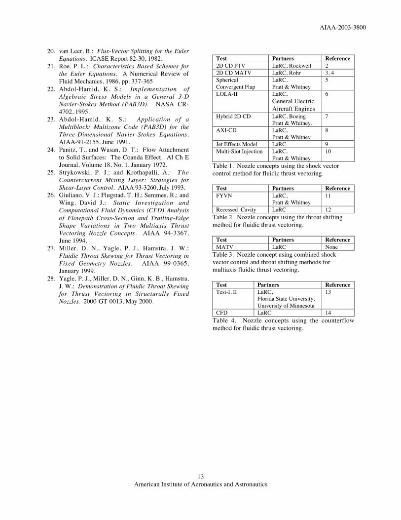
shown in figure 1, was used for one test discussed inthis paper. The rest of the experimental tests wereconducted on the dual-flow propulsion simulationsystem (ref. 15). The dual-flow system mounted on
AIAA-2003-3800
American Institute of Aeronautics and Astronautics3
the static thrust stand is shown in figure 2(a) and adetailed sketch of the hardware is shown in figure2(b). This system contains two isolated co-annularflow paths for primary and secondary flows, witheach of the flow paths containing a plenum and aninstrumentation section. The co-annular arrangementwas designed for testing dual-flow, axisymmetricturbofan exhaust nozzles. However, for fluidic thrustvectoring tests, the secondary annular flow can becapped off, allowing attachment of secondary airlines and control valves for fluidic injection.
Independently controlled primary and secondaryflow systems provide pressurized air to isolatedplenum chambers on the propulsion system throughtwo pairs of semirigid, thin-walled (0.021-in. wallthickness), 1-in. diameter, S-shaped, stainless steeltubes (S-tubes). The S-tubes, shown in figure 2(a),were designed to minimize balance tares caused byflexure during increased pressurization or by thetransfer of axial momentum as air is transferred fromthe nonmetric to the metric part (supported by theforce balance) of the system. This design providesrepeatable force and moment tares. Systemcalibrations are completed so that the final datareflects only forces and moments produced by thetest article. The primary and secondary air systemscan be used separately or in combination for dual-flow operation. The two independent flow streamseach pass through a multiple critical venturi system(ref. 16) where the flow rate of each air stream ismeasured to within a 0.1 percent measurementuncertainty.
The air supplied to the propulsion system isdischarged in a radial fashion through eight equallyspaced sonic nozzles, from the primary plenum intoan annular low-pressure duct (on the modelcenterline). The airflow then passes over anaerodynamic balance fairing and through anaxisymmetric choke plate that provides a pressuredrop to encourage a uniform flow field. Downstreamof the choke plate, the air passes through theaxisymmetric primary instrumentation section andthen through the test article. The airflow exhausts toatmospheric conditions in a test bay with louveredceiling vents to channel the flow outside the facility.
COMPUTATIONAL DESCRIPTION
The computational fluid dynamics (CFD) codePAB3D was developed for and has been used toaccurately predict propulsive flows with mixing,separated flow regions, and jet shear layers (refs. 17-19). PAB3D solves the three-dimensional, Reynolds-averaged Navier-Stokes (RANS) equations and usesone of several turbulence models for closure of the
RANS equations. The governing equations arewritten in generalized coordinates and inconservative form. In an effort to decreasecomputational resources, the simplified, thin-layerNavier-Stokes equations are implemented intoPAB3D. This approximation neglects derivatives inthe viscous terms streamwise and parallel to thesurface, since they are typically negligible incomparison to the derivatives normal to the surface.
The PAB3D flow solver was written with threenumerical schemes: the flux vector-splitting scheme ofvan Leer (ref. 20), the flux difference-splitting schemeof Roe (ref. 21), and a modified Roe scheme primarilyused for space marching solutions. These schemesimplement the finite volume principle to balance thefluxes across grid cells and the upwind biased schemeof van Leer or Roe to determine fluxes at the cellinterfaces. Only the inviscid terms of the flux vectorsare split and upwind differenced, while the diffusionterms of the Navier-Stokes equations are centraldifferenced.
Turbulence simulations are computed withinPAB3D by implementing an algebraic, a linear 2-equation, or a nonlinear 2-equation turbulence model.The 2-equation turbulence model, with second orderclosure, is used to model more complex viscous flowfeatures. The pair of coupled transport equations;turbulent kinetic energy and turbulent energydissipation rate, are written in conservative form andcan be uncoupled from the Navier-Stokes equationsand from each other to decrease computationalrequirements. Extensive details of PAB3D are foundin references 17-23.
In an effort to simulate a configuration tested atstatic (wind-off) freestream conditions, a smallfreestream Mach number (M=0.05) is generallyimplemented to reduce error and aid the stability ofthe computational solution.
DISCUSSION
Mechanical thrust vectoring nozzles use actuatedhardware to manipulate the primary exhaust flow.Although mechanical thrust vectoring schemes arehighly effective, the actuator hardware can create aheavy, complex propulsion system that, with gapsand discontinuities, is an obvious target for radardetection. In an effort to develop less detectable,light-weight, fixed geometry nozzles with low partscount, research was shifted from mechanical thrustvectoring schemes to fluidic thrust vectoring methodsin the 1990's. Fluidic thrust vectoring nozzles use asecondary air source to create an off-axis deflectionof the primary jet thrust vector. Three primarymethods of fluidic thrust vectoring have been
AIAA-2003-3800
American Institute of Aeronautics and Astronautics4
investigated over the past decade; the shock vectorcontrol (SVC) method, the throat shifting (TS)method, and the counterflow method. Each methoduses the secondary air source in a different way, asdiscussed in separate sections below. However, thethrust vectoring mechanism in all three methods issimply the creation of an asymmetric pressuredistribution on the nozzle surfaces.
In addition to the three primary fluidic thrustvectoring methods listed above, the Coanda effect(ref. 24) was used in one concept with the shockvector control method for multiaxis thrust vectoring.The Coanda effect is the tendency of a fluid to adhereto a curved surface because of the reduced pressurecaused by flow acceleration around the surface. Thiseffect can be enhanced by injecting a thin sheet ofhigh velocity, turbulent air tangential to the curvedsurface. The higher-velocity injected flow causes alow pressure region along the curved surface thatattracts the larger, higher pressure main flow andcauses it to follow the curved surface farther than itwould without the secondary injection (delaysseparation). This was the technique used in reference4 to attempt to vector the high energy jet exhaustflow in the yaw plane.
The eight nozzle concepts listed in Table 1 wereused to investigate the shock vector control, fluidicthrust vectoring method. The first shock vectorcontrol concept tested at NASA LaRC in 1987 was atwo-dimensional, convergent-divergent (2D CD)nozzle with fluidic pitch thrust vectoring (ref. 2). In1992, the highly successful shock vector controlmethod in the pitch axis was combined with a less-successful Coanda blowing method in the yaw axisfor multi-axis thrust vectoring in a 2D CD nozzleconcept (ref. 3-4). In 1995, a Spherical ConvergentFlap Nozzle, designed with a hexagonal flow path,fluidic pitch thrust vectoring, and ejectors, wasinvestigated with the SALIENT-I Nozzle concept.Multi-axis fluidic thrust vectoring capability wasadded to this concept during the testing of theSALIENT-II Nozzle in 1996 (ref. 5). The LOLA-IINozzle and the Hybrid 2D CD Nozzle were alsotested in 1996. In the LOLA-II program, fluidic pitchthrust vectoring was added to the successful fluidicthroat-area control concept demonstrated withLOLA-I (ref. 6). The Hybrid 2D CD Nozzle wasdesigned with a fixed aperture, ejectors, and a hybridthrust vectoring scheme that included combinationsof fluidic and mechanical pitch thrust vectoring (ref.7). The axisymmetric, convergent-divergent (AXICD) nozzle was tested in 1997 to determine the thrustvectoring and internal nozzle performancecompetitiveness with rectangular nonaxisymmetricnozzles (ref. 8). Since all concepts thus far had beentested at static freestream conditions, a computational
assessment of the freestream effects on fluidic thrustvectoring was initiated in 1998, using the Fluidic JetEffects Model (ref. 9). The Multi-Slot InjectionNozzle tested at NASA LaRC in 1999, was a 2D CDnozzle designed with multiple injection slots toinvestigate the potential benefits of dual-slot injectionover single-slot injection (ref. 10). As noted above,two of the test articles were designed with ejectors,which are used to improve off-design efficiency.Ejectors are used at over-expanded conditions to"fill" the divergent section of the nozzle withsecondary air in an effort to raise static pressure andreduce overexpansion losses.
The nozzle concepts utilized to investigate thethroat-shifting, fluidic thrust vectoring method arelisted in Table 2. A promising twin-engineconfiguration and a less successful single-engineconfiguration, designed with a fixed aperture andlemon-shaped cross section, were investigated withthe Fluidic Yaw Vectoring Nozzle (FYVN) conceptin 1995. Limited computational and experimentalresults for FYVN are found in reference 11. TheNASA LaRC developed Recessed Cavity Nozzleconcept enhances the throat shifting method withseparation control to achieve substantial thrust-vectorangles, without detrimental impacts on thrustefficiency. PAB3D was used to guide the design ofthe Recessed Cavity Nozzle in a parametriccomputational investigation that was completed in2002 (ref. 12). Experimental testing of thispromising concept was completed in March 2003.
The test article listed in Table 3 was used toinvestigate the combination of the shock vectorcontrol and the throat shifting methods for MATV ina fixed aperture nozzle in 2001. Unfortunately,adding the shock vector control method for pitchthrust vectoring to the efficient yaw thrust-vectoringnozzle, optimized for the throat shifting method, wasrelatively unsuccessful.
The first laboratory tests of the counterflowmethod were conducted on a nozzle with anextremely small throat area, At=0.62 in2 (ref. 25).The research completed at NASA LaRC on thecounterflow thrust vectoring method is listed in Table4. The first Langley experimental test entry in 1995investigated thrust vectoring and nozzle performanceof a larger-scale (At=3 in2) counterflow nozzle, whilethe second test entry in 1998 focused on relievinghysteretic jet attachment with a porous collar (ref.13). The first and only successful computationalinvestigation of the counterflow method that could befound in the literature was completed with thePAB3D computational fluid dynamics code in 1999(ref. 14).
AIAA-2003-3800
American Institute of Aeronautics and Astronautics5
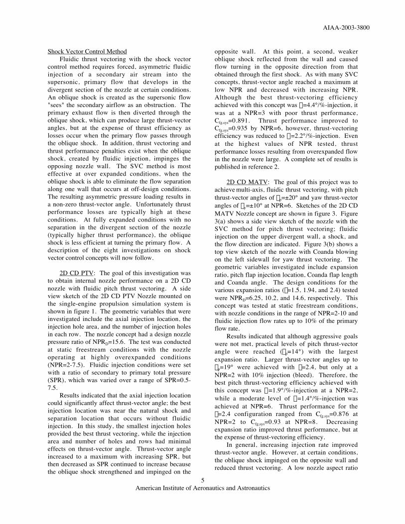
Shock Vector Control MethodFluidic thrust vectoring with the shock vector
control method requires forced, asymmetric fluidicinjection of a secondary air stream into thesupersonic, primary flow that develops in thedivergent section of the nozzle at certain conditions.An oblique shock is created as the supersonic flow"sees" the secondary airflow as an obstruction. Theprimary exhaust flow is then diverted through theoblique shock, which can produce large thrust-vectorangles, but at the expense of thrust efficiency aslosses occur when the primary flow passes throughthe oblique shock. In addition, thrust vectoring andthrust performance penalties exist when the obliqueshock, created by fluidic injection, impinges theopposing nozzle wall. The SVC method is mosteffective at over expanded conditions, when theoblique shock is able to eliminate the flow separationalong one wall that occurs at off-design conditions.The resulting asymmetric pressure loading results ina non-zero thrust-vector angle. Unfortunately thrustperformance losses are typically high at theseconditions. At fully expanded conditions with noseparation in the divergent section of the nozzle(typically higher thrust performance), the obliqueshock is less efficient at turning the primary flow. Adescription of the eight investigations on shockvector control concepts will now follow.
2D CD PTV: The goal of this investigation wasto obtain internal nozzle performance on a 2D CDnozzle with fluidic pitch thrust vectoring. A sideview sketch of the 2D CD PTV Nozzle mounted onthe single-engine propulsion simulation system isshown in figure 1. The geometric variables that wereinvestigated include the axial injection location, theinjection hole area, and the number of injection holesin each row. The nozzle concept had a design nozzlepressure ratio of NPRD=15.6. The test was conductedat static freestream conditions with the nozzleoperating at highly overexpanded conditions(NPR=2-7.5). Fluidic injection conditions were setwith a ratio of secondary to primary total pressure(SPR), which was varied over a range of SPR=0.5-7.5.
Results indicated that the axial injection locationcould significantly affect thrust-vector angle; the bestinjection location was near the natural shock andseparation location that occurs without fluidicinjection. In this study, the smallest injection holesprovided the best thrust vectoring, while the injectionarea and number of holes and rows had minimaleffects on thrust-vector angle. Thrust-vector angleincreased to a maximum with increasing SPR, butthen decreased as SPR continued to increase becausethe oblique shock strengthened and impinged on the
opposite wall. At this point, a second, weakeroblique shock reflected from the wall and causedflow turning in the opposite direction from thatobtained through the first shock. As with many SVCconcepts, thrust-vector angle reached a maximum atlow NPR and decreased with increasing NPR.Although the best thrust-vectoring efficiencyachieved with this concept was h=4.4°/%-injection, itwas at a NPR=3 with poor thrust performance,Cfg,sys=0.891. Thrust performance improved toCfg,sys=0.935 by NPR=6, however, thrust-vectoringefficiency was reduced to h=2.2°/%-injection. Evenat the highest values of NPR tested, thrustperformance losses resulting from overexpanded flowin the nozzle were large. A complete set of results ispublished in reference 2.
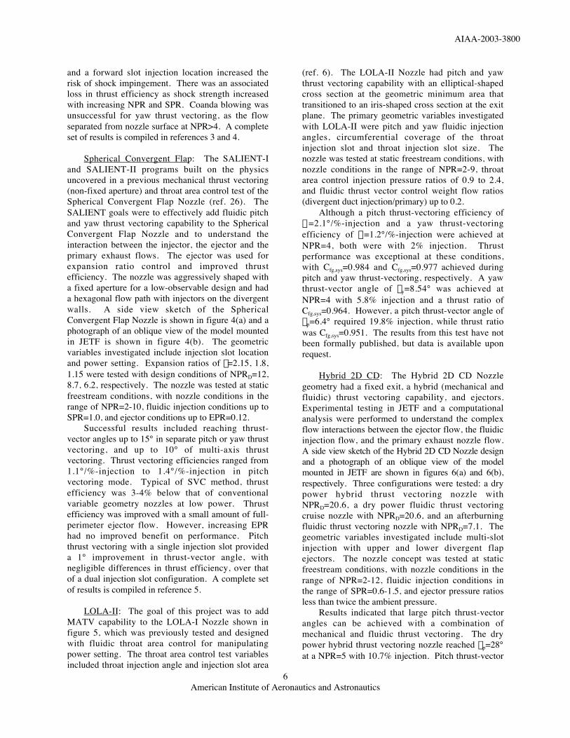
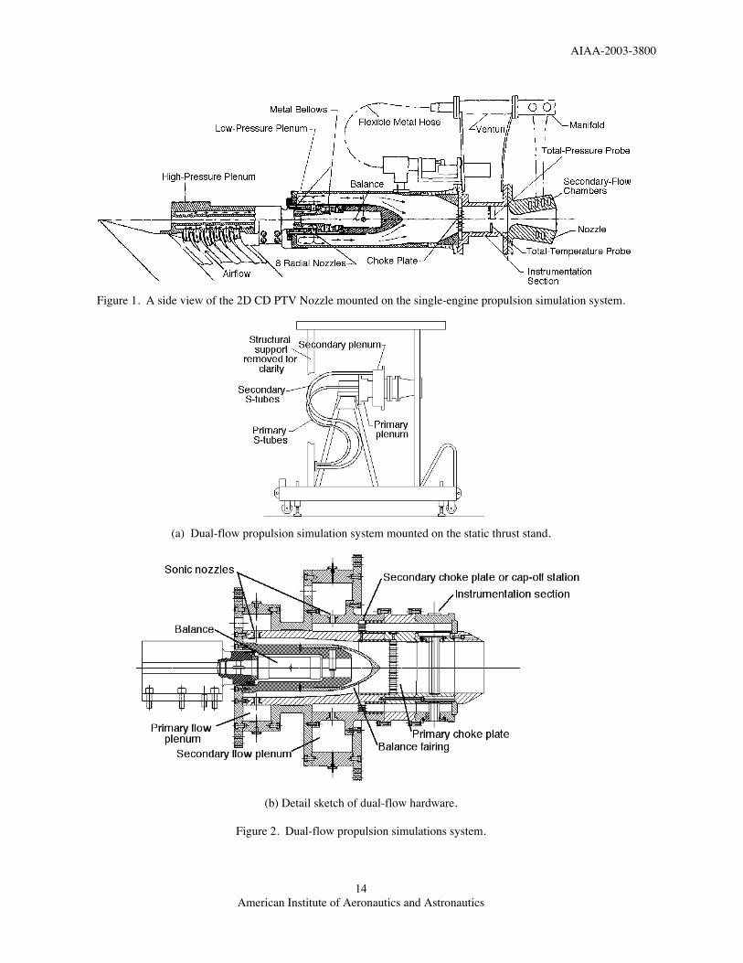
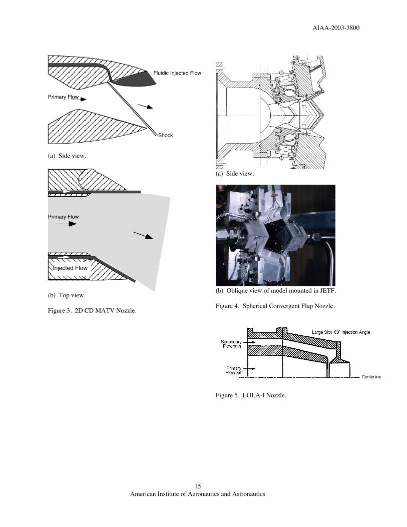
2D CD MATV: The goal of this project was toachieve multi-axis, fluidic thrust vectoring, with pitchthrust-vector angles of dp=±20° and yaw thrust-vectorangles of dy=±10° at NPR=6. Sketches of the 2D CDMATV Nozzle concept are shown in figure 3. Figure3(a) shows a side view sketch of the nozzle with theSVC method for pitch thrust vectoring; fluidicinjection on the upper divergent wall, a shock, andthe flow direction are indicated. Figure 3(b) shows atop view sketch of the nozzle with Coanda blowingon the left sidewall for yaw thrust vectoring. Thegeometric variables investigated include expansionratio, pitch flap injection location, Coanda flap lengthand Coanda angle. The design conditions for thevarious expansion ratios (e=1.5, 1.94, and 2.4) testedwere NPRD=6.25, 10.2, and 14.6, respectively. Thisconcept was tested at static freestream conditions,with nozzle conditions in the range of NPR=2-10 andfluidic injection flow rates up to 10% of the primaryflow rate.
Results indicated that although aggressive goalswere not met, practical levels of pitch thrust-vectorangle were reached (dp=14°) with the largestexpansion ratio. Larger thrust-vector angles up todp=19° were achieved with e=2.4, but only at aNPR=2 with 10% injection (bleed). Therefore, thebest pitch thrust-vectoring efficiency achieved withthis concept was h=1.9°/%-injection at a NPR=2,while a moderate level of h=1.4°/%-injection wasachieved at NPR=6. Thrust performance for thee=2.4 configuration ranged from Cfg,sys=0.876 atNPR=2 to Cfg,sys=0.93 at NPR=8. Decreasingexpansion ratio improved thrust performance, but atthe expense of thrust-vectoring efficiency.
In general, increasing injection rate improvedthrust-vector angle. However, at certain conditions,the oblique shock impinged on the opposite wall andreduced thrust vectoring. A low nozzle aspect ratio
AIAA-2003-3800
American Institute of Aeronautics and Astronautics6
and a forward slot injection location increased therisk of shock impingement. There was an associatedloss in thrust efficiency as shock strength increasedwith increasing NPR and SPR. Coanda blowing wasunsuccessful for yaw thrust vectoring, as the flowseparated from nozzle surface at NPR>4. A completeset of results is compiled in references 3 and 4.
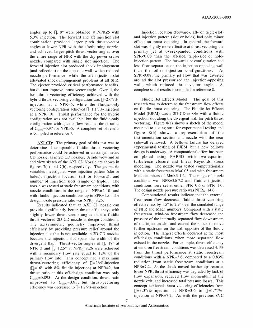
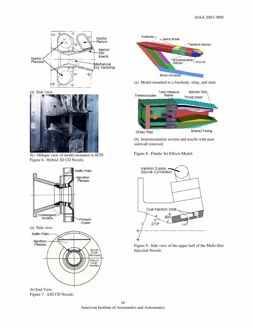
Spherical Convergent Flap: The SALIENT-Iand SALIENT-II programs built on the physicsuncovered in a previous mechanical thrust vectoring(non-fixed aperture) and throat area control test of theSpherical Convergent Flap Nozzle (ref. 26). TheSALIENT goals were to effectively add fluidic pitchand yaw thrust vectoring capability to the SphericalConvergent Flap Nozzle and to understand theinteraction between the injector, the ejector and theprimary exhaust flows. The ejector was used forexpansion ratio control and improved thrustefficiency. The nozzle was aggressively shaped witha fixed aperture for a low-observable design and hada hexagonal flow path with injectors on the divergentwalls. A side view sketch of the SphericalConvergent Flap Nozzle is shown in figure 4(a) and aphotograph of an oblique view of the model mountedin JETF is shown in figure 4(b). The geometricvariables investigated include injection slot locationand power setting. Expansion ratios of e=2.15, 1.8,1.15 were tested with design conditions of NPRD=12,8.7, 6.2, respectively. The nozzle was tested at staticfreestream conditions, with nozzle conditions in therange of NPR=2-10, fluidic injection conditions up toSPR=1.0, and ejector conditions up to EPR=0.12.
Successful results included reaching thrust-vector angles up to 15° in separate pitch or yaw thrustvectoring, and up to 10° of multi-axis thrustvectoring. Thrust vectoring efficiencies ranged from1.1°/%-injection to 1.4°/%-injection in pitchvectoring mode. Typical of SVC method, thrustefficiency was 3-4% below that of conventionalvariable geometry nozzles at low power. Thrustefficiency was improved with a small amount of full-perimeter ejector flow. However, increasing EPRhad no improved benefit on performance. Pitchthrust vectoring with a single injection slot provideda 1° improvement in thrust-vector angle, withnegligible differences in thrust efficiency, over thatof a dual injection slot configuration. A complete setof results is compiled in reference 5.
LOLA-II: The goal of this project was to addMATV capability to the LOLA-I Nozzle shown infigure 5, which was previously tested and designedwith fluidic throat area control for manipulatingpower setting. The throat area control test variablesincluded throat injection angle and injection slot area
(ref. 6). The LOLA-II Nozzle had pitch and yawthrust vectoring capability with an elliptical-shapedcross section at the geometric minimum area thattransitioned to an iris-shaped cross section at the exitplane. The primary geometric variables investigatedwith LOLA-II were pitch and yaw fluidic injectionangles, circumferential coverage of the throatinjection slot and throat injection slot size. Thenozzle was tested at static freestream conditions, withnozzle conditions in the range of NPR=2-9, throatarea control injection pressure ratios of 0.9 to 2.4,and fluidic thrust vector control weight flow ratios(divergent duct injection/primary) up to 0.2.
Although a pitch thrust-vectoring efficiency ofh=2.1°/%-injection and a yaw thrust-vectoringefficiency of h=1.2°/%-injection were achieved atNPR=4, both were with 2% injection. Thrustperformance was exceptional at these conditions,with Cfg,sys=0.984 and Cfg,sys=0.977 achieved duringpitch and yaw thrust-vectoring, respectively. A yawthrust-vector angle of dy=8.54° was achieved atNPR=4 with 5.8% injection and a thrust ratio ofCfg,sys=0.964. However, a pitch thrust-vector angle ofdp=6.4° required 19.8% injection, while thrust ratiowas Cfg,sys=0.951. The results from this test have notbeen formally published, but data is available uponrequest.
Hybrid 2D CD: The Hybrid 2D CD Nozzlegeometry had a fixed exit, a hybrid (mechanical andfluidic) thrust vectoring capability, and ejectors.Experimental testing in JETF and a computationalanalysis were performed to understand the complexflow interactions between the ejector flow, the fluidicinjection flow, and the primary exhaust nozzle flow.A side view sketch of the Hybrid 2D CD Nozzle designand a photograph of an oblique view of the modelmounted in JETF are shown in figures 6(a) and 6(b),respectively. Three configurations were tested: a drypower hybrid thrust vectoring nozzle withNPRD=20.6, a dry power fluidic thrust vectoringcruise nozzle with NPRD=20.6, and an afterburningfluidic thrust vectoring nozzle with NPRD=7.1. Thegeometric variables investigated include multi-slotinjection with upper and lower divergent flapejectors. The nozzle concept was tested at staticfreestream conditions, with nozzle conditions in therange of NPR=2-12, fluidic injection conditions inthe range of SPR=0.6-1.5, and ejector pressure ratiosless than twice the ambient pressure.
Results indicated that large pitch thrust-vectorangles can be achieved with a combination ofmechanical and fluidic thrust vectoring. The drypower hybrid thrust vectoring nozzle reached dp=28°at a NPR=5 with 10.7% injection. Pitch thrust-vector
AIAA-2003-3800
American Institute of Aeronautics and Astronautics7
angles up to dp=9° were obtained at NPR≤5 with5.3% injection. The forward and aft injection slotcombination provided larger pitch thrust-vectorangles at lower NPR with the afterburning nozzle,and achieved larger pitch thrust-vector angles overthe entire range of NPR with the dry power cruisenozzle, compared with single slot injection. Theforward injection slot produced shock impingement(and reflection) on the opposite wall, which reducednozzle performance, while the aft injection slotalleviated shock impingement problems at all SPR.The ejector provided critical performance benefits,but did not improve thrust-vector angle. Overall, thebest thrust-vectoring efficiency achieved with thehybrid thrust vectoring configuration was h=2.6°/%-injection at a NPR=6, while the fluidic-onlyvectoring configuration achieved h=1.1°/%-injectionat a NPR=10. Thrust performance for the hybridconfiguration was not available, but the fluidic-onlyconfiguration with ejector flow reached thrust ratiosof Cfg,sys=0.97 for NPR>5. A complete set of resultsis compiled in reference 7.
AXI CD: The primary goal of this test was todetermine if comparable fluidic thrust vectoringperformance could be achieved in an axisymmetricCD nozzle, as in 2D CD nozzles. A side view and anend view sketch of the AXI CD Nozzle are shown infigures 7(a) and 7(b), respectively. The geometricvariables investigated were injection pattern (slot orholes), injection location (aft or forward), andnumber of injection slots (single or triple). Thenozzle was tested at static freestream conditions, withnozzle conditions in the range of NPR=2-10, andwith fluidic injection conditions up to SPR=1.5. Thedesign nozzle pressure ratio was NPRD=8.26.
Results indicated that an AXI CD nozzle canprovide significantly better thrust efficiency, withslightly lower thrust-vector angles than a fluidicthrust vectored 2D CD nozzle at design conditions.The axisymmetric geometry improved thrustefficiency by providing pressure relief around theinjection slot that is not available in 2D CD nozzlesbecause the injection slot spans the width of thedivergent flap. Thrust-vector angles of dp=18° atNPR=3 and dp=12.5° at NPRD=8.26 were achievedwith a secondary flow rate equal to 12% of theprimary flow rate. This concept had a maximumthrust-vectoring efficiency of h =2°/%-injection(dp=16° with 8% fluidic injection) at NPR=2, butthrust ratio at this off-design condition was onlyCfg,sys=0.895. At the design condition, thrust ratioimproved to Cfg,sys=0.95, but thrust-vectoringefficiency was decreased to h=1.2°/%-injection.
Injection location (forward-, aft- or triple-slot)and injection pattern (slot or holes) had only minoreffects on thrust vectoring. In general, the forwardslot was slightly more effective at thrust vectoring theprimary jet at overexpanded conditions withSPR<0.08 than the aft-slot, triple-slot or hole-injection pattern. The forward slot configuration hadless flow separation on the injection-opposing wallthan the other injection configurations. AtSPR>0.08, the primary jet flow that was divertedaround the slot pressurized the injection-opposingwall, which reduced thrust-vector angle. Acomplete set of results is compiled in reference 8.
Fluidic Jet Effects Model: The goal of thisresearch was to determine the freestream flow effectson fluidic thrust vectoring. The Fluidic Jet EffectsModel (FJEM) was a 2D CD nozzle with a fluidicinjection slot along the divergent wall for pitch thrustvectoring. Figure 8(a) shows a sketch of the modelmounted to a sting-strut for experimental testing andfigure 8(b) shows a representation of theinstrumentation section and nozzle with the nearsidewall removed. A bellows failure has delayedexperimental testing of FJEM, but a new bellowsdesign is underway. A computational effort has beencompleted using PAB3D with two-equationturbulence closure and linear Reynolds stressmodeling. The nozzle was tested computationallywith a static freestream M=0.05 and with freestreamMach numbers of M=0.3-1.2. The range of nozzleconditions was NPR=3.6-7.2 and fluidic injectionconditions were set at either SPR=0.6 or SPR=1.0.The design nozzle pressure ratio was NPRD=14.6.
Computational results indicate that the externalfreestream flow decreases fluidic thrust vectoringeffectiveness by 1.5° to 2.9° over the simulated rangeof NPR and Mach numbers. Compared with a staticfreestream, wind-on freestream flow decreased thepressure of the internally separated flow downstreamof the injection slot and caused the shock to movefurther upstream on the wall opposite of the fluidicinjection. The largest effects occurred at the mostoff-design conditions, when more separated flowexisted in the nozzle. For example, thrust efficiencyat wind-on freestream conditions was decreased 4.1%from the thrust performance at static freestreamconditions with a NPR=3.6, compared to a 0.83%reduction from static freestream conditions at aNPR=7.2. As the shock moved further upstream atlower NPR, thrust efficiency was degraded by lack offlow expansion, reduced flow momentum at thenozzle exit, and increased total pressure losses. Thisconcept achieved thrust-vectoring efficiencies fromh =3.3°/%-injection at NPR=3.6 to h =1.7°/%-injection at NPR=7.2. As with the previous SVC
AIAA-2003-3800
American Institute of Aeronautics and Astronautics8
concepts, the largest thrust ratio penalty occurredwith the highest thrust-vectoring efficiency. Acomplete set of results is compiled in reference 9.
Multi-Slot Injection: The goal of this projectwas to enhance the thrust vectoring capability of asingle slot injection scheme, without increasing thesecondary flow requirements or incurring anyperformance penalties. The test nozzle was a 2D CDnozzle with a slot located on the divergent flap forfluidic pitch thrust vectoring. A side view sketch ofthe upper half of the Multi-Slot Injection Nozzle isshown in figure 9. The configurations testedincluded a baseline nozzle (NPRD=8.78) with a singleinjection slot and four dual injection slotconfigurations. The geometric variable underinvestigation was distance between the dual injectionslots. All configurations had the same injection areato keep mass flow constant for a given pressure. Theconcept was tested at static freestream conditions,with nozzle conditions in the range of NPR=2-10,and injection conditions of SPR≤1.0. Computationalmodeling of two configurations using linear two-equation turbulence closure was completed withPAB3D at NPR≤10 and SPR=0.7.
Results indicated that dual injection slots arebeneficial at off-design conditions compared to thebaseline, single slot injection configuration. Dualinjection slots improved thrust vectoring and thrustefficiency ratio with high SPR at NPR<4 comparedto the baseline. However, there was no benefit todual injection slots at NPR>4. Thrust vectoringefficiencies of h=2.4°/%-injection and h=1.2°/%-injection were achieved at NPR=3 and NPR=7,respectively. System thrust ratios were not calculatedfor this concept because adequate secondary flowinstrumentation was not available. Simulation of theslot and fluidic injection plenum geometry withcomputational grid was required to accurately predictnozzle performance. As found in othercomputational efforts like reference 9, a simplesurface boundary condition for the injected flow wasnot sufficient for capturing all the physics and forpredicting performance. A complete set of results iscompiled in reference 10.
Throat Shifting MethodThe hypothesis of the throat shifting method is
that thrust vectoring occurs by shifting the throat ofthe nozzle with forced, asymmetric secondary fluidicinjection. In a non-vectoring mode, the sonic planeor "throat" of the nozzle occurs at the nozzle'sgeometric minimum area. In a thrust-vectoringmode, the secondary air stream creates a new skewedaerodynamic minimum area, which shifts the location
of the throat from the geometric minimum area to thenewly created aerodynamic minimum area. Flowturning then occurs in the subsonic flow region aheadof the new throat. Subsonic flow turning minimizesthrust losses. The resulting asymmetric pressureloading on the nozzle surfaces causes a thrust-vectorangle of the primary exhaust flow.
In practice, an asymmetric pressure loading andprimary flow thrust-vector angle can be createdwithout completely shifting the throat location. Forexample, at some conditions, the throat did nottechnically shift in the Fluidic Yaw Vector Nozzle orin the Recessed Cavity Nozzle described below, butthe sonic line was modified enough to create anasymmetric pressure loading and generate thrustvectoring from the asymmetric fluidic injection.Secondary injection mass-flow rate and pressureamplify asymmetric pressure loading.
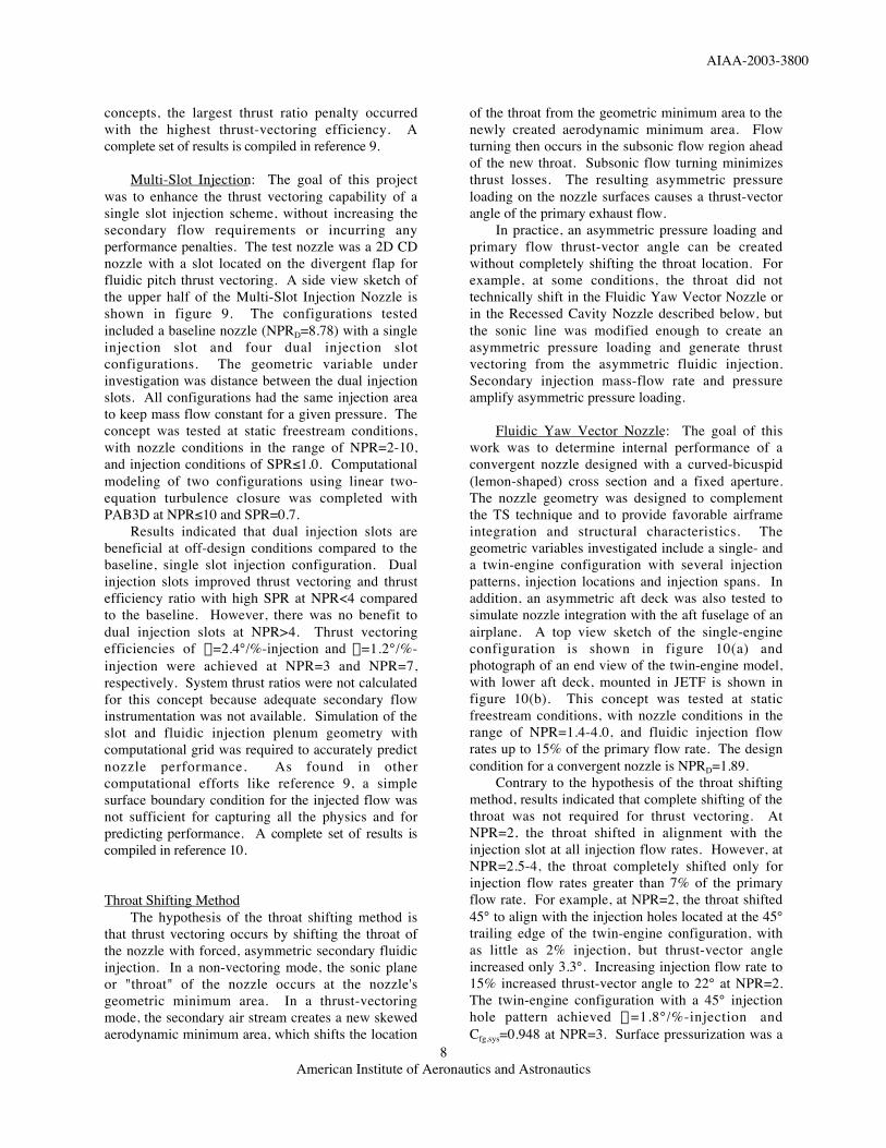
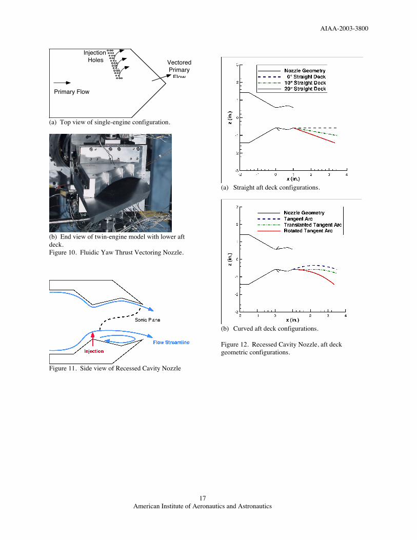
Fluidic Yaw Vector Nozzle: The goal of thiswork was to determine internal performance of aconvergent nozzle designed with a curved-bicuspid(lemon-shaped) cross section and a fixed aperture.The nozzle geometry was designed to complementthe TS technique and to provide favorable airframeintegration and structural characteristics. Thegeometric variables investigated include a single- anda twin-engine configuration with several injectionpatterns, injection locations and injection spans. Inaddition, an asymmetric aft deck was also tested tosimulate nozzle integration with the aft fuselage of anairplane. A top view sketch of the single-engineconfiguration is shown in figure 10(a) andphotograph of an end view of the twin-engine model,with lower aft deck, mounted in JETF is shown infigure 10(b). This concept was tested at staticfreestream conditions, with nozzle conditions in therange of NPR=1.4-4.0, and fluidic injection flowrates up to 15% of the primary flow rate. The designcondition for a convergent nozzle is NPRD=1.89.
Contrary to the hypothesis of the throat shiftingmethod, results indicated that complete shifting of thethroat was not required for thrust vectoring. AtNPR=2, the throat shifted in alignment with theinjection slot at all injection flow rates. However, atNPR=2.5-4, the throat completely shifted only forinjection flow rates greater than 7% of the primaryflow rate. For example, at NPR=2, the throat shifted45° to align with the injection holes located at the 45°trailing edge of the twin-engine configuration, withas little as 2% injection, but thrust-vector angleincreased only 3.3°. Increasing injection flow rate to15% increased thrust-vector angle to 22° at NPR=2.The twin-engine configuration with a 45° injectionhole pattern achieved h=1.8°/%-injection andCfg,sys=0.948 at NPR=3. Surface pressurization was a
AIAA-2003-3800
American Institute of Aeronautics and Astronautics9
function of injection flow rate, such that increasedflow rate increased pressurization and improvedthrust vectoring. Unfortunately, the single-engineconfiguration was unsuccessful at vectoring theprimary jet thrust; the fluidic injection createdcounter-acting forces that resulted in a zero degreethrust-vector angle. The CFD code PAB3D was usedto predict the nozzle performance of the twin-engineconfiguration and the results are documented inreference 11.
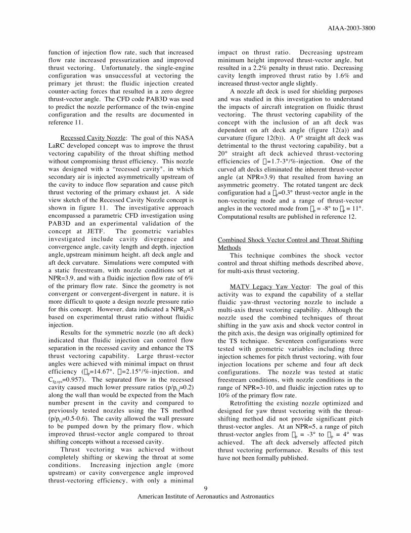
Recessed Cavity Nozzle: The goal of this NASALaRC developed concept was to improve the thrustvectoring capability of the throat shifting methodwithout compromising thrust efficiency. This nozzlewas designed with a “recessed cavity", in whichsecondary air is injected asymmetrically upstream ofthe cavity to induce flow separation and cause pitchthrust vectoring of the primary exhaust jet. A sideview sketch of the Recessed Cavity Nozzle concept isshown in figure 11. The investigative approachencompassed a parametric CFD investigation usingPAB3D and an experimental validation of theconcept at JETF. The geometric variablesinvestigated include cavity divergence andconvergence angle, cavity length and depth, injectionangle, upstream minimum height, aft deck angle andaft deck curvature. Simulations were computed witha static freestream, with nozzle conditions set atNPR=3.9, and with a fluidic injection flow rate of 6%of the primary flow rate. Since the geometry is notconvergent or convergent-divergent in nature, it ismore difficult to quote a design nozzle pressure ratiofor this concept. However, data indicated a NPRD≈3based on experimental thrust ratio without fluidicinjection.
Results for the symmetric nozzle (no aft deck)indicated that fluidic injection can control flowseparation in the recessed cavity and enhance the TSthrust vectoring capability. Large thrust-vectorangles were achieved with minimal impact on thrustefficiency (dp=14.67°, h=2.15°/%-injection, andCfg,sys=0.957). The separated flow in the recessedcavity caused much lower pressure ratios (p/pt,j≈0.2)along the wall than would be expected from the Machnumber present in the cavity and compared topreviously tested nozzles using the TS method(p/pt,j=0.5-0.6). The cavity allowed the wall pressureto be pumped down by the primary flow, whichimproved thrust-vector angle compared to throatshifting concepts without a recessed cavity.
Thrust vectoring was achieved withoutcompletely shifting or skewing the throat at someconditions. Increasing injection angle (moreupstream) or cavity convergence angle improvedthrust-vectoring efficiency, with only a minimal
impact on thrust ratio. Decreasing upstreamminimum height improved thrust-vector angle, butresulted in a 2.2% penalty in thrust ratio. Decreasingcavity length improved thrust ratio by 1.6% andincreased thrust-vector angle slightly.
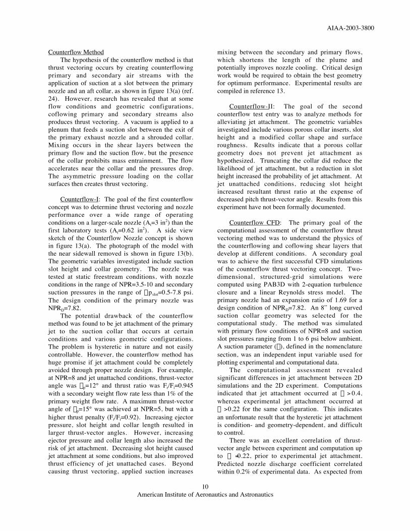
A nozzle aft deck is used for shielding purposesand was studied in this investigation to understandthe impacts of aircraft integration on fluidic thrustvectoring. The thrust vectoring capability of theconcept with the inclusion of an aft deck wasdependent on aft deck angle (figure 12(a)) andcurvature (figure 12(b)). A 0° straight aft deck wasdetrimental to the thrust vectoring capability, but a20° straight aft deck achieved thrust-vectoringefficiencies of h=1.7-3°/%-injection. One of thecurved aft decks eliminated the inherent thrust-vectorangle (at NPR=3.9) that resulted from having anasymmetric geometry. The rotated tangent arc deckconfiguration had a dp=0.3° thrust-vector angle in thenon-vectoring mode and a range of thrust-vectorangles in the vectored mode from dp = -8° to dp = 11°.Computational results are published in reference 12.
Combined Shock Vector Control and Throat ShiftingMethods
This technique combines the shock vectorcontrol and throat shifting methods described above,for multi-axis thrust vectoring.
MATV Legacy Yaw Vector: The goal of thisactivity was to expand the capability of a stellarfluidic yaw-thrust vectoring nozzle to include amulti-axis thrust vectoring capability. Although thenozzle used the combined techniques of throatshifting in the yaw axis and shock vector control inthe pitch axis, the design was originally optimized forthe TS technique. Seventeen configurations weretested with geometric variables including threeinjection schemes for pitch thrust vectoring, with fourinjection locations per scheme and four aft deckconfigurations. The nozzle was tested at staticfreestream conditions, with nozzle conditions in therange of NPR=3-10, and fluidic injection rates up to10% of the primary flow rate.
Retrofitting the existing nozzle optimized anddesigned for yaw thrust vectoring with the throat-shifting method did not provide significant pitchthrust-vector angles. At an NPR=5, a range of pitchthrust-vector angles from dp = -3° to d p = 4° wasachieved. The aft deck adversely affected pitchthrust vectoring performance. Results of this testhave not been formally published.
AIAA-2003-3800
American Institute of Aeronautics and Astronautics10
Counterflow MethodThe hypothesis of the counterflow method is that
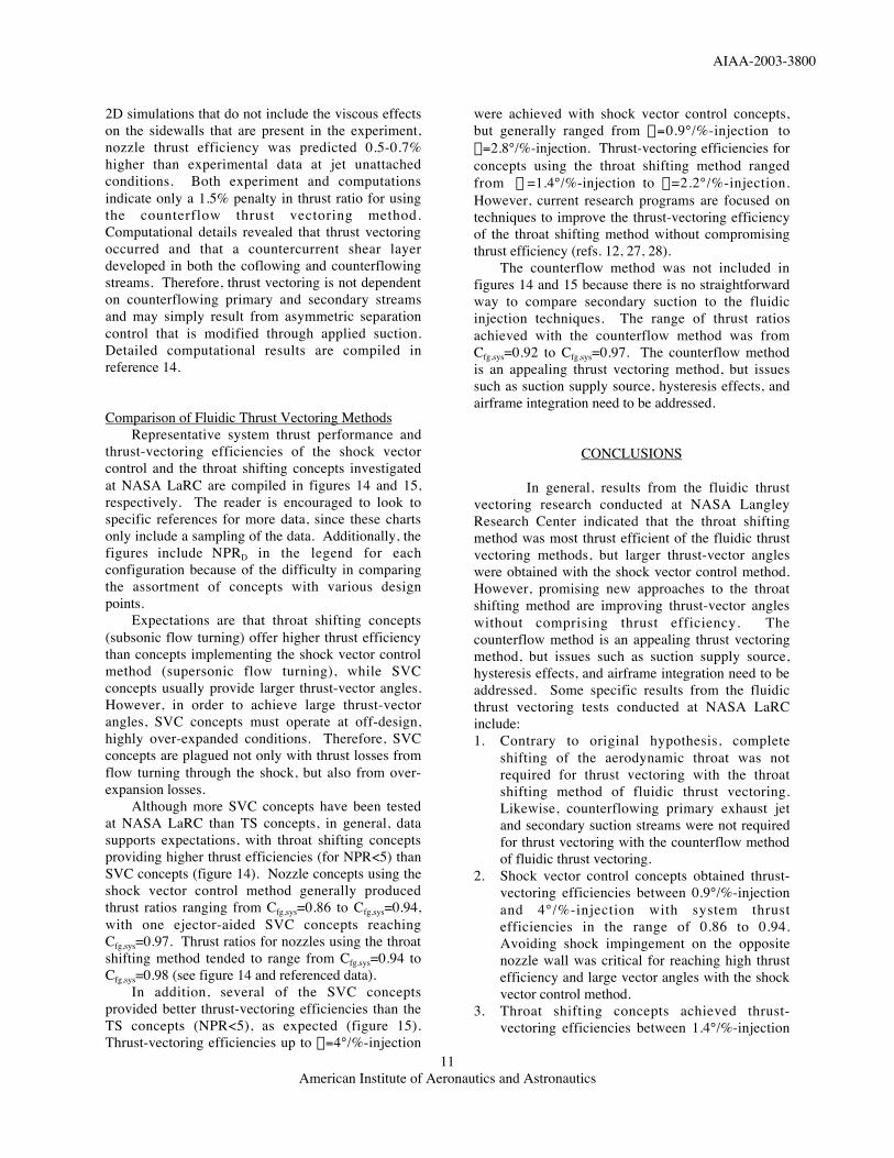
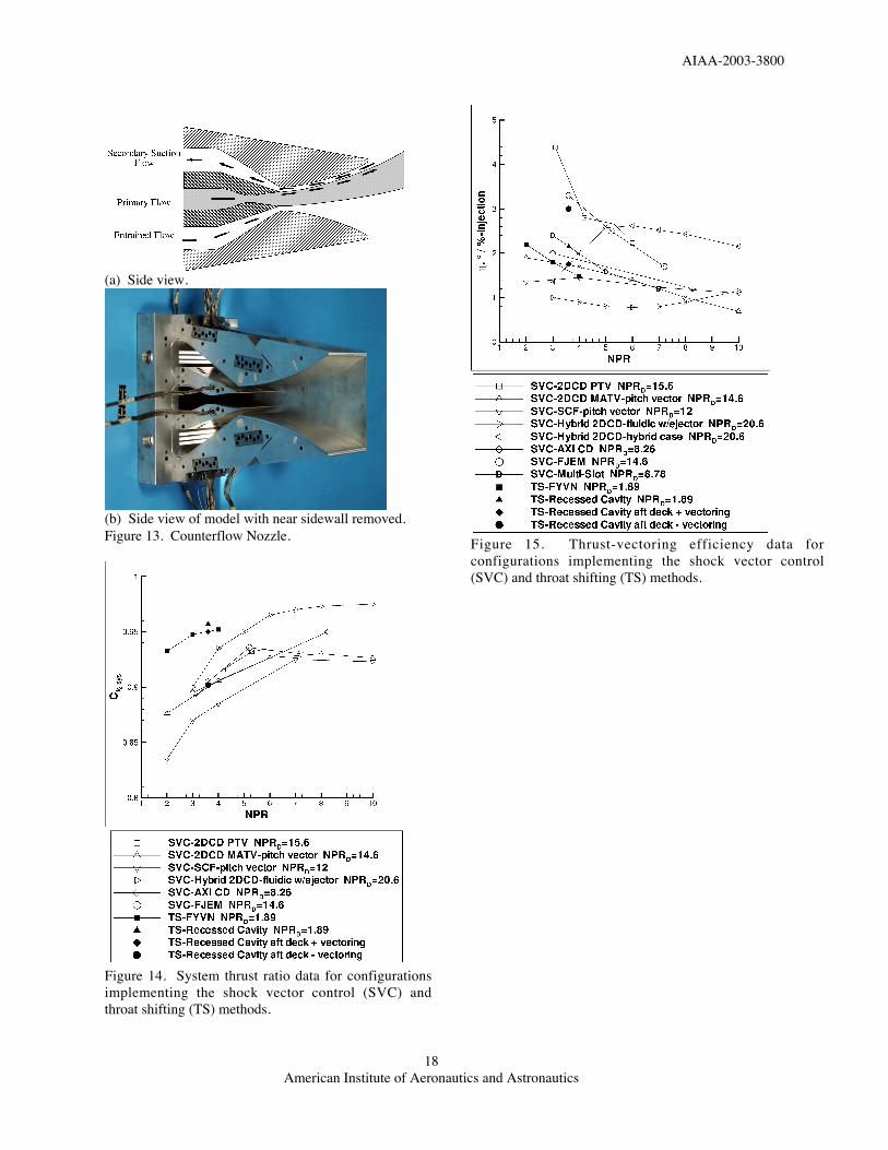
thrust vectoring occurs by creating counterflowingprimary and secondary air streams with theapplication of suction at a slot between the primarynozzle and an aft collar, as shown in figure 13(a) (ref.24). However, research has revealed that at someflow conditions and geometric configurations,coflowing primary and secondary streams alsoproduces thrust vectoring. A vacuum is applied to aplenum that feeds a suction slot between the exit ofthe primary exhaust nozzle and a shrouded collar.Mixing occurs in the shear layers between theprimary flow and the suction flow, but the presenceof the collar prohibits mass entrainment. The flowaccelerates near the collar and the pressures drop.The asymmetric pressure loading on the collarsurfaces then creates thrust vectoring.
Counterflow-I: The goal of the first counterflowconcept was to determine thrust vectoring and nozzleperformance over a wide range of operatingconditions on a larger-scale nozzle (At=3 in2) than thefirst laboratory tests (At=0.62 in2). A side viewsketch of the Counterflow Nozzle concept is shownin figure 13(a). The photograph of the model withthe near sidewall removed is shown in figure 13(b).The geometric variables investigated include suctionslot height and collar geometry. The nozzle wastested at static freestream conditions, with nozzleconditions in the range of NPR=3.5-10 and secondarysuction pressures in the range of Dpslot=0.5-7.8 psi.The design condition of the primary nozzle wasNPRD=7.82.
The potential drawback of the counterflowmethod was found to be jet attachment of the primaryjet to the suction collar that occurs at certainconditions and various geometric configurations.The problem is hysteretic in nature and not easilycontrollable. However, the counterflow method hashuge promise if jet attachment could be completelyavoided through proper nozzle design. For example,at NPR=8 and jet unattached conditions, thrust-vectorangle was dp=12° and thrust ratio was Fr/Fi=0.945with a secondary weight flow rate less than 1% of theprimary weight flow rate. A maximum thrust-vectorangle of dp=15° was achieved at NPR=5, but with ahigher thrust penalty (Fr/Fi=0.92). Increasing ejectorpressure, slot height and collar length resulted inlarger thrust-vector angles. However, increasingejector pressure and collar length also increased therisk of jet attachment. Decreasing slot height causedjet attachment at some conditions, but also improvedthrust efficiency of jet unattached cases. Beyondcausing thrust vectoring, applied suction increases
mixing between the secondary and primary flows,which shortens the length of the plume andpotentially improves nozzle cooling. Critical designwork would be required to obtain the best geometryfor optimum performance. Experimental results arecompiled in reference 13.
Counterflow-II: The goal of the secondcounterflow test entry was to analyze methods foralleviating jet attachment. The geometric variablesinvestigated include various porous collar inserts, slotheight and a modified collar shape and surfaceroughness. Results indicate that a porous collargeometry does not prevent jet attachment ashypothesized. Truncating the collar did reduce thelikelihood of jet attachment, but a reduction in slotheight increased the probability of jet attachment. Atjet unattached conditions, reducing slot heightincreased resultant thrust ratio at the expense ofdecreased pitch thrust-vector angle. Results from thisexperiment have not been formally documented.
Counterflow CFD: The primary goal of thecomputational assessment of the counterflow thrustvectoring method was to understand the physics ofthe counterflowing and coflowing shear layers thatdevelop at different conditions. A secondary goalwas to achieve the first successful CFD simulationsof the counterflow thrust vectoring concept. Two-dimensional, structured-grid simulations werecomputed using PAB3D with 2-equation turbulenceclosure and a linear Reynolds stress model. Theprimary nozzle had an expansion ratio of 1.69 for adesign condition of NPRD=7.82. An 8” long curvedsuction collar geometry was selected for thecomputational study. The method was simulatedwith primary flow conditions of NPR=8 and suctionslot pressures ranging from 1 to 6 psi below ambient.A suction parameter (l), defined in the nomenclaturesection, was an independent input variable used forplotting experimental and computational data.
The computational assessment revealedsignificant differences in jet attachment between 2Dsimulations and the 2D experiment. Computationsindicated that jet attachment occurred at l > 0.4,whereas experimental jet attachment occurred atl > 0.22 for the same configuration. This indicatesan unfortunate result that the hysteretic jet attachmentis condition- and geometry-dependent, and difficultto control.
There was an excellent correlation of thrust-vector angle between experiment and computation upto l = 0.22, prior to experimental jet attachment.Predicted nozzle discharge coefficient correlatedwithin 0.2% of experimental data. As expected from
AIAA-2003-3800
American Institute of Aeronautics and Astronautics11
2D simulations that do not include the viscous effectson the sidewalls that are present in the experiment,nozzle thrust efficiency was predicted 0.5-0.7%higher than experimental data at jet unattachedconditions. Both experiment and computationsindicate only a 1.5% penalty in thrust ratio for usingthe counterflow thrust vectoring method.Computational details revealed that thrust vectoringoccurred and that a countercurrent shear layerdeveloped in both the coflowing and counterflowingstreams. Therefore, thrust vectoring is not dependenton counterflowing primary and secondary streamsand may simply result from asymmetric separationcontrol that is modified through applied suction.Detailed computational results are compiled inreference 14.
Comparison of Fluidic Thrust Vectoring MethodsRepresentative system thrust performance and
thrust-vectoring efficiencies of the shock vectorcontrol and the throat shifting concepts investigatedat NASA LaRC are compiled in figures 14 and 15,respectively. The reader is encouraged to look tospecific references for more data, since these chartsonly include a sampling of the data. Additionally, thefigures include NPRD in the legend for eachconfiguration because of the difficulty in comparingthe assortment of concepts with various designpoints.
Expectations are that throat shifting concepts(subsonic flow turning) offer higher thrust efficiencythan concepts implementing the shock vector controlmethod (supersonic flow turning), while SVCconcepts usually provide larger thrust-vector angles.However, in order to achieve large thrust-vectorangles, SVC concepts must operate at off-design,highly over-expanded conditions. Therefore, SVCconcepts are plagued not only with thrust losses fromflow turning through the shock, but also from over-expansion losses.
Although more SVC concepts have been testedat NASA LaRC than TS concepts, in general, datasupports expectations, with throat shifting conceptsproviding higher thrust efficiencies (for NPR<5) thanSVC concepts (figure 14). Nozzle concepts using theshock vector control method generally producedthrust ratios ranging from Cfg,sys=0.86 to Cfg,sys=0.94,with one ejector-aided SVC concepts reachingCfg,sys=0.97. Thrust ratios for nozzles using the throatshifting method tended to range from Cfg,sys=0.94 toCfg,sys=0.98 (see figure 14 and referenced data).
In addition, several of the SVC conceptsprovided better thrust-vectoring efficiencies than theTS concepts (NPR<5), as expected (figure 15).Thrust-vectoring efficiencies up to h=4°/%-injection
were achieved with shock vector control concepts,but generally ranged from h=0.9°/%-injection toh=2.8°/%-injection. Thrust-vectoring efficiencies forconcepts using the throat shifting method rangedfrom h =1.4°/%-injection to h=2.2°/%-injection.However, current research programs are focused ontechniques to improve the thrust-vectoring efficiencyof the throat shifting method without compromisingthrust efficiency (refs. 12, 27, 28).
The counterflow method was not included infigures 14 and 15 because there is no straightforwardway to compare secondary suction to the fluidicinjection techniques. The range of thrust ratiosachieved with the counterflow method was fromCfg,sys=0.92 to Cfg,sys=0.97. The counterflow methodis an appealing thrust vectoring method, but issuessuch as suction supply source, hysteresis effects, andairframe integration need to be addressed.
CONCLUSIONS
In general, results from the fluidic thrustvectoring research conducted at NASA LangleyResearch Center indicated that the throat shiftingmethod was most thrust efficient of the fluidic thrustvectoring methods, but larger thrust-vector angleswere obtained with the shock vector control method.However, promising new approaches to the throatshifting method are improving thrust-vector angleswithout comprising thrust efficiency. Thecounterflow method is an appealing thrust vectoringmethod, but issues such as suction supply source,hysteresis effects, and airframe integration need to beaddressed. Some specific results from the fluidicthrust vectoring tests conducted at NASA LaRCinclude:1. Contrary to original hypothesis, complete
shifting of the aerodynamic throat was notrequired for thrust vectoring with the throatshifting method of fluidic thrust vectoring.Likewise, counterflowing primary exhaust jetand secondary suction streams were not requiredfor thrust vectoring with the counterflow methodof fluidic thrust vectoring.
2. Shock vector control concepts obtained thrust-vectoring efficiencies between 0.9°/%-injectionand 4°/%-injection with system thrustefficiencies in the range of 0.86 to 0.94.Avoiding shock impingement on the oppositenozzle wall was critical for reaching high thrustefficiency and large vector angles with the shockvector control method.
3. Throat shifting concepts achieved thrust-vectoring efficiencies between 1.4°/%-injection
AIAA-2003-3800
American Institute of Aeronautics and Astronautics12
and 2.2°/%-injection, with system thrustefficiencies in the range of 0.94 to 0.98.
4. The Recessed Cavity Nozzle, a recentlyenhanced throat shifting concept, vectored theprimary jet 3°/%-injection in the negativedirection and 1.76°/%-injection in the positivedirection with an aft deck.
5. The Hybrid 2DCD and the Multi-Slot InjectionNozzle indicated a benefit of dual-injection slotsover single-injection slots, but only for limitednozzle pressure ratios and secondary to primarytotal pressure ratios.
6. Results from several tests; the Fluidic YawVector Nozzle, the legacy Multi-Axis ThrustVectoring Nozzle, and the Recessed CavityNozzle, indicated the difficulty of thrustvectoring with the inclusion of an aft deck.However, significant ranges of thrust-vectorangle were achieved with several RecessedCavity Nozzle, aft deck configurations. Inaddition, the inherent thrust-vector angle causedby the asymmetric deck geometry waseliminated with some aft deck curvature.
7. Injection angle was a geometric variable thatproved to be critical for achieving large thrust-vector angles. The Recessed Cavity Nozzleshowed an improvement of 4° in thrust-vectorangle by simply directing the fluidic injectionflow upstream toward the oncoming, primaryexhaust flow at an injection angle of 150°,compared to injecting normal to the flow.
REFERENCES
1. Walker, S. H.: Lessons Learned in theDevelopment of a National CooperativeProgram. AIAA 97-3348. 1997.
2. Abeyounis, W. K.; and Bennett, B. D. Jr.: StaticInternal Performance of an Overexpanded,Fixed-Geometry, Nonaxisymmetric Nozzle WithFluidic Pitch-Thrust-Vectoring Capability.NASA TP-3645, October 1997.
3. Wing, David J.: Static Investigation of TwoFluidic Thrust-Vectoring Concepts on a Two-Dimensional Convergent-Divergent Nozzle.NASA TM-4574, December 1994.
4. Chiarelli, C.; Johnsen, R. K.; Shieh, C. F.; Wing,D. J.: Fluidic Scale Model Multi-Plane ThrustVector Control Test Results. AIAA 93-2433,June 1993.
5. Giuliano, V. J.; and Wing, David J.: StaticInvestigation of a Fixed-Aperture Exhaust NozzleEmploying Fluidic Injection for Multiaxis ThrustVector Control. AIAA 97-3149, July 1997.
6. Federspiel, J. F.; Bangert, L. S.; Wing, D. J.; andHawkes, T.: Fluidic Control of Nozzle Flow -Some Performance Measurements. AIAA 95-2605, July 1995.
7. Anderson, C. J.; Giuliano, V. J.; and Wing, David J.:Investigation of Hybrid Fluidic / MechanicalThrust Vectoring for Fixed-Exit Exhaust Nozzles.AIAA 97-3148, July 1997.
8. Wing, David J.; and Giuliano, V. J.: FluidicThrust Vectoring of an Axisymmetric ExhaustNozzle at Static Conditions. ASME FEDSM97-3228, June 1997.
9. Deere, K. A.: Computational Investigation ofthe Aerodynamic Effects on Fluidic ThrustVectoring. AIAA 2000-3598, July 2000.
10. Waithe, K. A: An Experimental andComputational Investigation of MultipleInjection Ports in a Convergent-DivergentNozzle for Fluidic Thrust Vectoring. GWUMaster's Thesis, May 2001.
11. Deere, K. A.: PAB3D Simulations of a Nozzlewith Fluidic Injection for Yaw Thrust-VectorControl. AIAA 98-3254, July 1998.
12. Deere, K. A.; Berrier, B. L.; Flamm, J. D.; andJohnson, S. K.: Computational Study of FluidicThrust Vectoring using Separation Control in aNozzle. AIAA 2003-3803, June 2003.
13. Flamm, J. D.: Experimental Study of a NozzleUsing Fluidic Counterflow for Thrust Vectoring.AIAA 98-3255, July 1998.
14. Hunter, C. A. and Deere, K. A.: ComputationalInvestigation of Fluidic Counterflow ThrustVectoring. AIAA 99-2669, June 1999.
15. A User’s Guide to the Langley 16-FootTransonic Tunnel Complex, Revision 1. NASATM-102750, September 1990. (SupersedesNASA TM-83186.)
16. Berrier, B. L.; Leavitt, L. D.; and Bangert, L. S.:Operating Characteristics of the Multiple CriticalVenturi System and Secondary CalibrationNozzles Used for Weight-Flow Measurements inthe Langley 16-Foot Transonic Tunnel. NASATM 86405, September 1985.
17. Abdol-Hamid, K. S.; Lakshmanan, B.; andCarlson, J. R.: Application of Navier-Stokes CodePAB3D With k-e Turbulence Model to Attachedand Separated Flows. NASA TP-3480, January1995.
18. Balakrishnan, L.; and Abdol-Hamid, K. S.: AComparative Study of Two Codes with an ImprovedTwo-Equation Turbulence Model For Predicting JetPlumes. AIAA 92-2604, June 1992.
19. Pao, S. P.; and Abdol-Hamid, K. S.: NumericalSimulation of Jet Aerodynamics Using the Three-Dimensional Navier-Stokes Code PAB3D. NASATP 3596, September 1996.
AIAA-2003-3800
American Institute of Aeronautics and Astronautics13
20. van Leer, B.: Flux-Vector Splitting for the EulerEquations. ICASE Report 82-30, 1982.
21. Roe, P. L.: Characteristics Based Schemes forthe Euler Equations. A Numerical Review ofFluid Mechanics, 1986, pp. 337-365
22. Abdol-Hamid, K. S.: Implementation ofAlgebraic Stress Models in a General 3-DNavier-Stokes Method (PAB3D). NASA CR-4702, 1995.
23. Abdol-Hamid, K. S.: Application of aMultiblock/ Multizone Code (PAB3D) for theThree-Dimensional Navier-Stokes Equations.AIAA-91-2155, June 1991.
24. Panitz, T., and Wasan, D. T.: Flow Attachmentto Solid Surfaces: The Coanda Effect. Al Ch EJournal, Volume 18, No. 1, January 1972.
25. Strykowski, P. J.; and Krothapalli, A.: TheCountercurrent Mixing Layer: Strategies forShear-Layer Control. AIAA 93-3260, July 1993.
26. Giuliano, V. J.; Flugstad, T. H.; Semmes, R.; andWing, David J.: Static Investigation andComputational Fluid Dynamics (CFD) Analysisof Flowpath Cross-Section and Trailing-EdgeShape Variations in Two Multiaxis ThrustVectoring Nozzle Concepts. AIAA 94-3367,June 1994.
27. Miller, D. N., Yagle, P. J., Hamstra, J. W.:Fluidic Throat Skewing for Thrust Vectoring inFixed Geometry Nozzles. AIAA 99-0365,January 1999.
28. Yagle, P. J., Miller, D. N., Ginn, K. B., Hamstra,J. W.: Demonstration of Fluidic Throat Skewingfor Thrust Vectoring in Structurally FixedNozzles. 2000-GT-0013, May 2000.
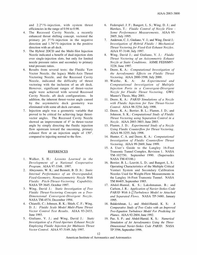
Test Partners Reference2D CD PTV LaRC, Rockwell 22D CD MATV LaRC, Rohr 3, 4SphericalConvergent Flap
LaRC,Pratt & Whitney
5
LOLA-II LaRC,General ElectricAircraft Engines
6
Hybrid 2D CD LaRC, BoeingPratt & Whitney,
7
AXI-CD LaRC,Pratt & Whitney
8
Jet Effects Model LaRC 9Multi-Slot Injection LaRC,
Pratt & Whitney10
Table 1. Nozzle concepts using the shock vectorcontrol method for fluidic thrust vectoring.
Test Partners ReferenceFYVN LaRC,
Pratt & Whitney11
Recessed Cavity LaRC 12Table 2. Nozzle concepts using the throat shiftingmethod for fluidic thrust vectoring.
Test Partners ReferenceMATV LaRC None
Table 3. Nozzle concept using combined shockvector control and throat shifting methods formultiaxis fluidic thrust vectoring.
Test Partners ReferenceTest-I, II LaRC,
Florida State University,University of Minnesota
13
CFD LaRC 14Table 4. Nozzle concepts using the counterflowmethod for fluidic thrust vectoring.
AIAA-2003-3800
American Institute of Aeronautics and Astronautics14
Figure 1. A side view of the 2D CD PTV Nozzle mounted on the single-engine propulsion simulation system.
(a) Dual-flow propulsion simulation system mounted on the static thrust stand.
(b) Detail sketch of dual-flow hardware.
Figure 2. Dual-flow propulsion simulations system.
AIAA-2003-3800
American Institute of Aeronautics and Astronautics15
(a) Side view.
(b) Top view.
Figure 3. 2D CD MATV Nozzle.
(a) Side view.
(b) Oblique view of model mounted in JETF.
Figure 4. Spherical Convergent Flap Nozzle.
Figure 5. LOLA-I Nozzle.
Shock
Fluidic Injected Flow
Primary Flow
Injected Flow
Primary Flow
AIAA-2003-3800
American Institute of Aeronautics and Astronautics16
(a) Side view.
(b) Oblique view of model mounted in JETF.Figure 6. Hybrid 2D CD Nozzle.
(a) Side view.
(b) End View.Figure 7. AXI CD Nozzle.
(a) Model mounted to a forebody, sting, and strut.
(b) Instrumentation section and nozzle with nearsidewall removed.
Figure 8. Fluidic Jet Effects Model.
Figure 9. Side view of the upper half of the Multi-SlotInjection Nozzle.
AIAA-2003-3800
American Institute of Aeronautics and Astronautics17
(a) Top view of single-engine configuration.
(b) End view of twin-engine model with lower aftdeck.Figure 10. Fluidic Yaw Thrust Vectoring Nozzle.
Figure 11. Side view of Recessed Cavity Nozzle
(a) Straight aft deck configurations.
(b) Curved aft deck configurations.
Figure 12. Recessed Cavity Nozzle, aft deckgeometric configurations.
InjectionHoles
Primary Flow
VectoredPrimary
Flow
AIAA-2003-3800
American Institute of Aeronautics and Astronautics18
(a) Side view.
(b) Side view of model with near sidewall removed.Figure 13. Counterflow Nozzle.
Figure 14. System thrust ratio data for configurationsimplementing the shock vector control (SVC) andthroat shifting (TS) methods.
Figure 15. Thrust-vectoring efficiency data forconfigurations implementing the shock vector control(SVC) and throat shifting (TS) methods.
Related Documents