SPN – EL2007461/10 Branch - Electronics BSNL TRAINING REPORT BSNL, SDOP I, NAYAPURA,

Sumit's BSNL Training Report
Nov 15, 2014
Welcome message from author
This document is posted to help you gain knowledge. Please leave a comment to let me know what you think about it! Share it to your friends and learn new things together.
Transcript
SPN – EL2007461/10Branch - Electronics
BSNL TRAINING REPORT
BSNL, SDOP I, NAYAPURA, KOTA
2009
Sumit KumarSPN - EL2007461/10
Govt. Polytechnic College, Kota (Raj.)
PREFACE
Practical training in an industry is an essential part of an engineering curriculum towards making a successful engineer, as in an industry only a student can realize the theory thought in classroom and it also gives an exposure to modern technology.
In the field of Electronics Computer engineering there has been rapid development to
support the ever increasing volume information, so Electronics students has an opportunity
during Training period to knowledge about the latest technologies.
The training period of 28 days is not much sufficient to take complete knowledge of
technology used but one is expected to identify components, the process flow in an industry for
high efficiency and about the knowledge of product technology.
Practical knowledge means the visualization of the knowledge, which we read in books. For this we perform experiments and get observations. Practical knowledge is very important in every field. One must be familiar with the problems related to that field so that we may solve them and became successful person.
After achieving the proper goal of life an Engineer has to enter in professional life. According to this life he has to serve an industry, may be public or private sector or self-own. For the efficient work in the field he must be well aware of practical knowledge as well as theoretical knowledge.
To be a good Engineer, one must be aware of the industrial environment & must know about management, working in industry, labor problems etc., so we can tackle them successfully.
Due to all the above reasons & to bridge the gap between theory and practical, our engineering
curriculum provides a practical training course of 28 days. During this period a student in
industry and gets all type of experience and knowledge about the working and maintenance of
various types of machinery.
Since time immemorial, a man has tried hard to bring the world as close to himself as
possible. His thirst for information is hard to quench so he has continuously tried to develop
new technologies, which have helped to reach the objective.
2
2009
Sumit KumarSPN - EL2007461/10
Govt. Polytechnic College, Kota (Raj.)
The world we see today is a result of the continuous research in the field of
communication, which started with the invention of telephone by Graham Bell to the current
avatar as we see in the form INTERNET and mobile phones. All these technologies have come to
existence because man continued its endeavor towards the objective.
This project report of mine, STUDY OF TRENDS TECHNOLOGIES IN COMMUNICATION
AND NETWORKING has been a small effort in reviewing the trends technologies prevailing. For
this purpose, no organization other than BAHRAT SANCHAR NIGAM LIMITED could have been a
better choice.
I have undergone by 28 days of training (after II yr.) at BAHRAT SANCHAR NIGAM
LIMITED, NAYAPURA, KOTA (Raj.). This report has been prepared on the basis of the
knowledge which I acquired during my 28 days (15-06-2005 to 13-07-2005) training at
Company.
3
2009
Sumit KumarSPN - EL2007461/10
Govt. Polytechnic College, Kota (Raj.)
Acknowledgement:-
Practical training has an important role in a shaping up an engineering student for practical knowledge how a keeping him update with latest technology. First of all, I would like to express my attitude towards Mr. S.C.Gupta (Training cum placement officer, GPC, Kota) and towards Ms. Rajul Goyal (H.O.D., Electronics department, GPC, Kota) for providing me a great opportunity to undertake training at BSNL, Kota.
I would also like to thanks to Mr. Rajkishore Sharma (TTA EWSD, Nayapura, Kota) and the co-operative management helpful staff for giving me a knowledge of their services and helping me time to time.
Last but not least I would like to thanks to training incharge Mr. R.P.Manthwal (SDE SDOP1, KOTA), BSNL, Kota for arranging the training programmer for my practical training.
With extreme regards and obligations.
4
2009
Sumit KumarSPN - EL2007461/10
Govt. Polytechnic College, Kota (Raj.)
CONTENTS: -
1) INTRODUCTION2) COMPANY PROFILE3) PROFILE OF THE COMPANY’S BUSINESS
A. GLIMPES OF MAIN SERVICE OFFEREDi. BASIC AND LIMITED MOBILE TELEPHONE SERVICES
ii. CELLULAR MOBILE TELEPHONE SERVICESiii. INTERNET SERVICESiv. INTELLIGENT NETWORK
v. IP TV SERVICESvi. THIRD GENERATION 3G WIRELESS TECHNOLOGY
B. DEVELOPMENT OF RURAL TELECOM NETWORKi. Rural DELs
ii. Village Telephonesa) Village Public Telephones (VPTs) & RCPsb) Public Telephones:-
C. NETWORK MANAGEMENTD. Setting up KU Band VSAT networkE. Policy on transmission network maintenanceF. Annual Maintenance contracts for switching system & WLL
G. COMPUTERISATIONH. OBLIGATIONS
i. Towards customers and dealersii. Towards employees
iii. Towards the Society –Corporate Social Responsibilities
1) STRUCTURE AND ABOUT THE EXCHANGES
i. COMPUTER UNITii. POWER PLANT
iii. AC Plant (CENTRAL AIR CONDITIONER)iv. MDF (MAIN DISTRIBUTION FRAME)
5
2009
Sumit KumarSPN - EL2007461/10
Govt. Polytechnic College, Kota (Raj.)
2) CONNECTING SYSTEM
3) EWSD EXCHANGE1. GENERAL OVERVIEW2. INTRODUCTION OF EWSD3. FUNCTIONAL BLOCK DIAGRAM OF EWSD4. GENERAL FEATURES5. POSITION AND FUNCTIONAL STRUCTURE6. CAPACITY STAGES7. FUNCTIONAL UNIT OF SN8. SWITCHING NETWORK (B)9. RACK ASSIGNMENT10. MODULE FRAME LAYOT11. INTERCONECTIONS OF SWITHING MODULE12. FUNCTIONS13. O&M ASPECTS14. EXCERCISES 15. SWITCHING TECHNIQUES
4) INTERNET 5) CELLULAR MOBILE SERVICES
1. WLL (WIRE LESS IN LOCAL LOOP) MOBILE2. CODE DIVISION MULTIPLE ACCESS (CDMA) MOBILE3. GLOBAL SYSTEM FOR MOBILE COMMUNICATION (GSM) 4. THIRD GENERATION (3G) TECHNOLOGY
6) BSNL’S IP TV7) CONCLUSION8) GLOSSARY OF TERMS AND ABBREVIATIONS
6
2009
Sumit KumarSPN - EL2007461/10
Govt. Polytechnic College, Kota (Raj.)
Introduction:-
Today, BSNL is the No. 1 telecommunication company and the largest public sector undertaking of India and its responsibilities includes improvement of the already impeccable quality of telecom services, expansion of telecom services in all villages and instilling confidence among its customers.
Apart from vast network expansions, especial emphasis has given for introducing latest technologies and new services like I-NET, INTERNET, ISDN (INTEGRATED SERVICES DIGITAL NETWORK), IN (INTELLIGENT NETWORK), CDMA, GSM and WLL (WIRELESS IN LOCAL LOOP), BROADBAND, 3G services etc. Now BSNL has also entered in mobile communication. BSNL has all the new services send technological advantages, which are available with any well, developed Telecom network anywhere else in the country. Full credit for all above achievement goes to the officers and staff of the BSNL. The administration is fully aware of the challenges lying ahead and quite committed to provide the latest and best telecom services by their continued support and active co-operation.
7
2009
Sumit KumarSPN - EL2007461/10
Govt. Polytechnic College, Kota (Raj.)
COMPANY PROFILE
BHARAT SANCHAR NIGAM LIMITED
Bharat Sanchar Nigam Limited (BSNL) is India's leading telecommunications provider and the country's largest public-sector firm. BSNL provides local-exchange access and domestic long-distance services through a network of more than 45 million access lines covering most of India. It also offers wireless communications, data and Internet services, as well as business voice and data services. The company is still controlled by the government, as is one of India's other large phone companies, Mahanagar Telephone Nigam Limited (MTNL). Plans to merge the two companies have been discussed but seem to be on hold.
HIGHLIGHTS
Bharat Sanchar Nigam Limited has a vast reservoir of highly skilled and
Experienced work force of about 3,57,000 personnel.
We believe that our staff, which is one of the best trained manpower in the
telecom sector, is our biggest asset.
To meet the technological challenges, employees are trained for technology
up-gradation, modernization, computerization etc in BSNL's training Centers
spread across Country.
To apex training centers of BSNL i.e. Advance level Telecom Training Center
(ALTTC) at Ghaziabad and Bharat Ratna Bhimrao Telecom Training Center
At Jabalpur are comparable to any world class Telecom Training Center.
Moreover, 43 zonal training centers and a National Academy of Telecom
Finance and Management have been running for several years now.
8
2009
Sumit KumarSPN - EL2007461/10
Govt. Polytechnic College, Kota (Raj.)
Different curriculum run in these centers to impart technology based training,
Training for Attitudinal change, basic educational and skill development
Program etc.
DOT: - Till 31st December, 1984, the postal, telegraph and telephone services were
managed by the Posts and Telegraphs Department. In January 1985, two separate Departments
for the Posts and the Telecommunications were created. The accounts of the department,
initially, were maintained by the Accountant General of the P&T. However, by April 1972, the
telecommunications accounts were separated. Simultaneously the department also started
preparing the balance sheet annually. With the takeover of the accounts from the audit and
delegation of larger financial powers to the field units, internal Financial Advisers were posted to
all the circles and units.
DEPARTMENT OF TELECOMMUNICATIONS (DOT) The Telecommunication Board consisted of the Secretary Telecommunications, who was the Chairman with Member (Finance), Member (Operations), Member (Development), Member (Personnel) and Member (Technology). The Telecom Commission was constituted in 1989. The Commission has the DoT Secretary as its Chairman with Member (Services), Member (Technology) and Member (Finance) as its full time members. The Secretary (Finance), Secretary (DoE), Secretary (Industries) and Secretary (Planning Commission) are part time members of the Commission. The Department in 1986 reorganised the Telecommunication Circles with the Secondary Switching Areas as basic units. This was implemented in a phased manner. Bombay and Delhi Telephones were separated to create the new entity called Mahanagar Telephone Nigam Ltd. (MTNL). On 1st October 2000, Department created BSNL, a new entity to operate services in different parts of the country as a public sector unit.
9
2009
Sumit KumarSPN - EL2007461/10
Govt. Polytechnic College, Kota (Raj.)
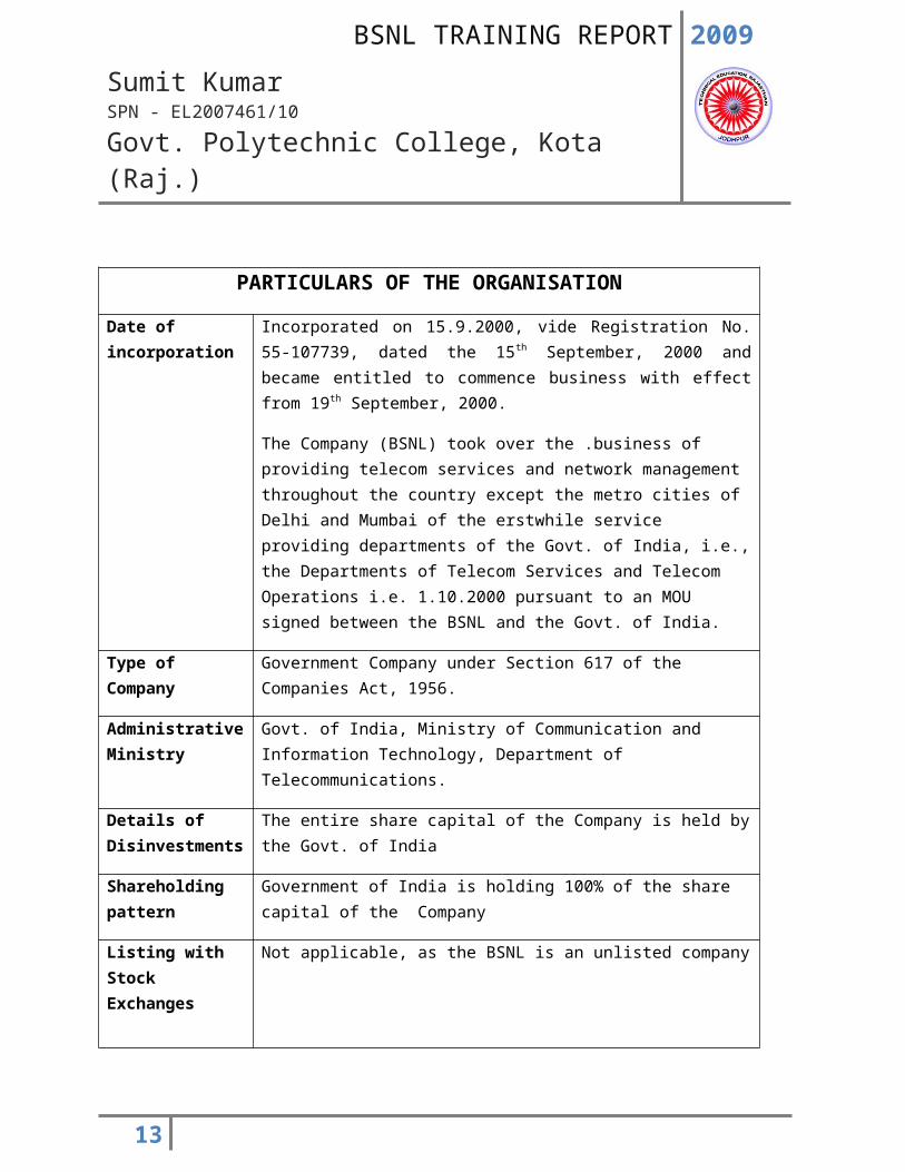
PARTICULARS OF THE ORGANISATION
Date of incorporation
Incorporated on 15.9.2000, vide Registration No. 55-107739, dated the 15th September, 2000 and became entitled to commence business with effect from 19th September, 2000.
The Company (BSNL) took over the .business of providing telecom services and network management throughout the country except the metro cities of Delhi and Mumbai of the erstwhile service providing departments of the Govt. of India, i.e., the Departments of Telecom Services and Telecom Operations i.e. 1.10.2000 pursuant to an MOU signed between the BSNL and the Govt. of India.
Type of Company Government Company under Section 617 of the Companies Act, 1956.
Administrative Ministry
Govt. of India, Ministry of Communication and Information Technology, Department of Telecommunications.
Details of Disinvestments
The entire share capital of the Company is held by the Govt. of India
Shareholding pattern
Government of India is holding 100% of the share capital of the Company
Listing with Stock Exchanges
Not applicable, as the BSNL is an unlisted company
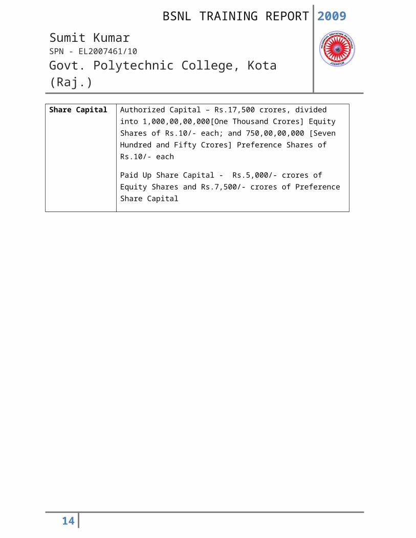
Share Capital Authorized Capital – Rs.17,500 crores, divided into 1,000,00,00,000[One Thousand Crores] Equity Shares of Rs.10/- each; and 750,00,00,000 [Seven Hundred and Fifty Crores] Preference Shares of Rs.10/- each
Paid Up Share Capital - Rs.5,000/- crores of Equity Shares and Rs.7,500/- crores of Preference Share Capital
10
2009
Sumit KumarSPN - EL2007461/10
Govt. Polytechnic College, Kota (Raj.)
11
2009
Sumit KumarSPN - EL2007461/10
Govt. Polytechnic College, Kota (Raj.)
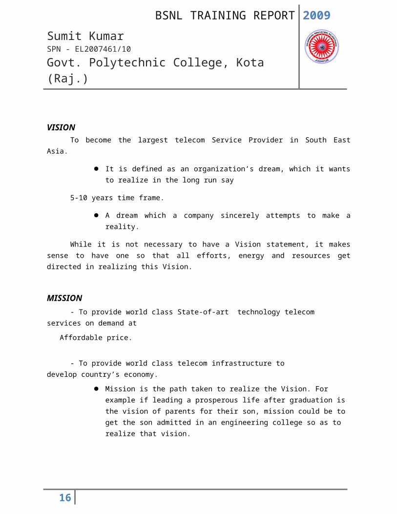
VISION To become the largest telecom Service Provider in South East Asia.
It is defined as an organization’s dream, which it wants to realize in the long run say
5-10 years time frame.
A dream which a company sincerely attempts to make a reality.
While it is not necessary to have a Vision statement, it makes sense to have one so that all efforts, energy and resources get directed in realizing this Vision.
MISSION
- To provide world class State-of-art technology telecom services on demand at
Affordable price.
- To provide world class telecom infrastructure to develop country’s economy.
Mission is the path taken to realize the Vision. For example if leading a prosperous life after graduation is the vision of parents for their son, mission could be to get the son admitted in an engineering college so as to realize that vision.
12
2009
Sumit KumarSPN - EL2007461/10
Govt. Polytechnic College, Kota (Raj.)
PROFILE OF THE COMPANY’S BUSINESS
A. GLIMPSES OF MAIN SERVICES OFFERED
1. BASIC AND LIMITED MOBILE TELEPHONE SERVICES
BSNL is the leading service provider in the country in the Basic Telephone Services. As of now more than 35 million Direct Exchange Lines & more than 2.2.Million telephones in the Limited Mobile telephone Services are existing. BSNL has provides a number of attractive tariff packages & Plans which shall further strengthen its subscriber base.
2. CELLULAR MOBILE TELEPHONE SERVICES
BSNL’s GSM Technology based Cellular Mobile Network has reached a long way, covering more than 6400 towns, with a subscriber base of over 1.54 crore as on 31 st Jan. 2006 out of which 1.16 Crore
cellular telephones are in the prepaid segment.
3. INTERNET SERVICESBSNL offers Dialup and Broad Band Internet services to the customers by Post-paid service with
the brand name ‘Net one’, and pre-paid service with the brand name ‘Sancharnet’. The post-paid service is a CLI based access service, currently operational in 100 cities. Sancharnet is available on local call basis throughout India to ISDN and PSTN subscribers. The Internet Dhaba scheme of the Company aims to further promote Internet usage in rural and semi urban areas.
To keep pace with the latest and varied value added services to its customers, BSNL uses IP/MPLS based core to offer world class IP VPN services. MPLS based VPNs is a very useful service for
Corporate, as it reduces the cost involved as well as the complexity in setting up VPNs for customers networking. As on 31.03.2005, your Company’s total Internet customer base was 17,98,089 and total
Internet Dhabas were 4143. A total of 708594 dial up Internet connections have been given during
2004-2005, against a target of 7 Lakhs. BSNL plans to give 1215980 more dial up connections during the year 2005-06. As on 31.1.2006, there were 2367404 internet subscribers working in BSNL net work.
13
2009
Sumit KumarSPN - EL2007461/10
Govt. Polytechnic College, Kota (Raj.)
BSNL has launched its Broadband Services under the brand name ‘DataOne’ on 14/1/2005. This offers services like High Speed Internet Access with speed ranging from 256 Kbps to 8 Mbps. Other services like streaming video, Video on Demand, Bandwidth on demand etc., have also been planned. As on 31.12.2005, there were more than 356000 broad band connection provided by the BSNL. There are plans to give 2 million and 3 million connections in 2006 and 2007 respectively.
4. INTELLIGENT NETWORK
Intelligent Network Services is a service that incorporates several value added facilities, thoroughly designed to save time and money, and enhance productivity. At present, your company offers Free Phone (FPH), Premium Rate Service (PRM), India Telephone Card (ITC), Account Card Calling (ACC), Virtual Private Network (VPN), Universal Access Number (UAN) and Tele voting IN services. With the commissioning of five numbers of new technology IN Platforms (Four General purpose and One Mass Calling) at Kolkata, Bangalore, Ahmadabad and Hyderabad, the India Telephone Card facility and new value added services are being provided throughout the country. Activation of these new IN platforms had increased the sale of ITC Cards taking the figure to Rs.265 crores in 2004-05 alone.
5. IP TV Service
First started in Japan in 2002. Popular in France, South Korea, Germany, Hongkong etc., France is leading in IPTV having more than 1.7 million IPTV viewers, Global IPTV subscribers base will reach 14.5 million in 2007 and will be approximately 63 million by 2010.
6. Third Generation (3G) Wireless Technology
Capability to support circuit and packet data at high bit rates:
144 kilobits/second or higher in high mobility (vehicular) traffic
384 kilobits/second for pedestrian traffic
2 Megabits/second or higher for indoor traffic
Support of multimedia services/capabilities:
Fixed and variable rate bit traffic
Bandwidth on demand
14
2009
Sumit KumarSPN - EL2007461/10
Govt. Polytechnic College, Kota (Raj.)
Asymmetric data rates in the forward and reverse links
Multimedia mail store and forward
Broadband access up to 2 Megabits/second
B. DEVELOPMENT OF RURAL TELECOM NETWORK
1. Rural DELs
As on 31.03.2005, in BSNL’s network, a total of 1.356 Crore rural telephone connections were working. As on 31.1.2006, there are 1.425 Crore rural telephones working in BSNL network.
2. (a)Village Public Telephones (VPTs) & RCPs:-
BSNL, in its unstinted efforts to make the slogan ‘Connecting India’, a reality, had provided VPTs in 5,18,992 villages up to 31.03.2005. The Company entered into an agreement with USO Fund for expansion of rural telecom network by November 2007, by providing VPTs in 66,822 undisputed, undisturbed, accessible and inhabited villages having population more than 100 as per Census, 1991 in the country. BSNL provided VPTs in 5,28,886 villages up to 31.01.2006. There are plans to replace all MARR VPTs in the country . As of now total 123194 MARR VPTs already replaced in the country by BSNL. BSNL also committed to provide the Rural Community Phones as per the USO Fund agreement. As of now around 13713 RCPs already provided by BSNL.
2 (b)Public Telephones:-
There are more than 2 million PCOs working in the BSNL Network out of which around 1 million PCOs are having STD/ISD.
15
2009
Sumit KumarSPN - EL2007461/10
Govt. Polytechnic College, Kota (Raj.)
C. NETWORK MANAGEMENT
BSNL is committed to provide a robust state of the art infrastructure that will provide stable and superior services to its customers. Accordingly, the MLLN network covering more than 200 cities was made operational in May 2004. Since then, about 22000 circuits have been provided on this network. This has provided high level of stability to the leased circuits and capability to offer N X 64 Kbps circuits. Keeping in view the growing demand of leased circuits, the network is being expanded to cover about 50 more locations and additional capacity at many existing locations is also being provided.
To improve the operational efficiency of CCS 7 signaling, stand-alone signaling transfer point (SSTP) equipment is being procured. This will also enable the Company to measure signaling traffic of other operators, who are using its signaling network for exchanging messages, especially with regard to cellular services. BSNL has more than 4.7 Lakhs Route Kilometers of optical fiber network in the country & has installed capacity more than 6.4 million lines for the TAX meant for the STD/ISD network.
D. Setting up KU Band VSAT network
As regards the KU Band VSAT network equipment, the hub of this network is being set up at Bangalore, The equipment has been installed and expected to be commissioned shortly. This will help your Company, to become a service provider with all types of media equipment i.e. OFC, Microwave and satellite for provision of bandwidth, this will also enable the Company to offer composite solutions to its customers.
What is V-SAT?
It can be defined as a class of very small aperture Intelligent Satellite Earth Station suitable for easy on-premise installation, usually operating in conjugation with a large size HUB earth station. Capable of supporting a wide range of two ways integrated Telecom Services.It has the following components:Micro Earth StationMini Earth StationPersonal Earth StationRoof Top TerminalCustomer Premises Terminal
16
2009
Sumit KumarSPN - EL2007461/10
Govt. Polytechnic College, Kota (Raj.)
ADVANTAGES OF V-SAT
Can be located in the user premises on roof top or backyard and hence eliminate last mile problem.Superior quality satellite based data services.Quick implementation time.Reliable communication.Broadcast feature on satellite communication.Communication to different areas.Flexibility for network and changes.Service in distance insensitive.Low cost.
E. Policy on transmission network maintenance
Telecom Circles have large transmission networks. To improve the maintenance of transmission network, guidelines for route parties and vehicles have been formalized. Telecom Territorial Circles are also being connected with computerized network for booking of transmission system faults, with a view to improve follow up and faster restoration of faults.
F. Annual Maintenance contracts for switching system & WLL
Comprehensive AMC, which includes hardware and software maintenance and upgrade, has been arranged with the respective equipment suppliers. Initial feedback suggests that, as a result of preventive and corrective maintenance support, the performance of switches is improving. Difficulties in entering into AMC with rural WLL equipments suppliers have been resolved and procedures streamlined so that adequate maintenance support becomes available. As a result, the performance of WLL network is improving. AMC arrangements have also been made with suppliers of FWTs and hand held terminals.
17
2009
Sumit KumarSPN - EL2007461/10
Govt. Polytechnic College, Kota (Raj.)
G. COMPUTERISATION
Implementation of Inter Operator Billing and Accounting system (IOBAS) has been completed. Your Company plans to provide CDR based Customer Care and Convergent Billing system. This will help Company in providing effective and efficient billing & customer care solutions for its fixed line subscribers. It envisages building of country wide intranet to reduce the cost of operation, increase realization, stop leakage of revenue and minimize frauds, besides providing round the clock best customer care services to the Company’s subscribers.
Call center facility has been introduced for 71 SSAs, which is a single point approach for addressing all customer needs cum grievances. Web based Public grievance Management System has been implemented for speedy disposal and monitoring of public grievances. Web based Inventory Management package has also been introduced, through which, material management functions are being computerized gradually in different circles. Online Mobile Bill viewing facility has been made available to all Cell One Mobile Customers (all States) through Company’s Portal (http://bsnl.in). Duplicate Telephone bill viewing facility for landline telephone has also been made available at many places through Websites of respective telecom circles.
H. OBLIGATIONS
1. Towards customers and dealers
To provide prompt, courteous and efficient service and quality of products/services at fair and
reasonable services.
2. Towards employees
Develop their capability and advancement through appropriate training and career planning
Expeditious redressed of grievances
Fair dealings with recognized representatives of employees in pursuance of healthy trade union practices and sound personnel policies
3. Towards the Society –Corporate Social Responsibilities
18
2009
Sumit KumarSPN - EL2007461/10
Govt. Polytechnic College, Kota (Raj.)
CORPORATE SOCIAL RESPONSIBILITIES
BSNL is committed to provide quality Telecom Services at affordable price to the citizens of the remotest part of the Country. BSNL is making all effort to ensure that the main objectives of the new Telecom Policy 1999 (salient points indicated below) are achieved:
Access to telecommunications is of utmost importance for achievement of the country's social and economic goals. Availability of affordable and effective communications for the citizens is at the core of the vision and goal of the new Telecom policy 1999.
Strive to provide a balance between the provision of universal service to all uncovered areas, including the rural areas, and the provision of high-level services capable of meeting the needs of the country's economy encourage development of telecommunication facilities in remote, hilly and tribal areas of the country;
Transform in a time bound manner, the telecommunications sector to a greater competitive environment in both urban and rural areas providing equal opportunities and level playing field for all players.
19
2009
Sumit KumarSPN - EL2007461/10
Govt. Polytechnic College, Kota (Raj.)
STRUCTURE AND ABOUT THE EXCHANGES
All telephone subscribers are served by automatic exchanges, which perform the functions the human operator. The number being dialed is stored and then passed to the exchange’s central computer, which in turns operates the switching to complete the call or routes it a higher level switch for further processing. Today’s automatic exchanges uses a pair of computers, one running the program that provides services and the second monitoring the operation of the first, ready to take over in a few seconds in the event of equipment failure.
Various exchanges present in BSNL are: C-DOT E-10B OCB283 (Exchange & TAX) EWSD (Exchange & TAX)
All exchange has some purposes and some basic structural units, which are:
1. subscriber’s connection unit 2. Switching network (CX) 3. Control unit 4. OMC (Operational & maintenance Control)
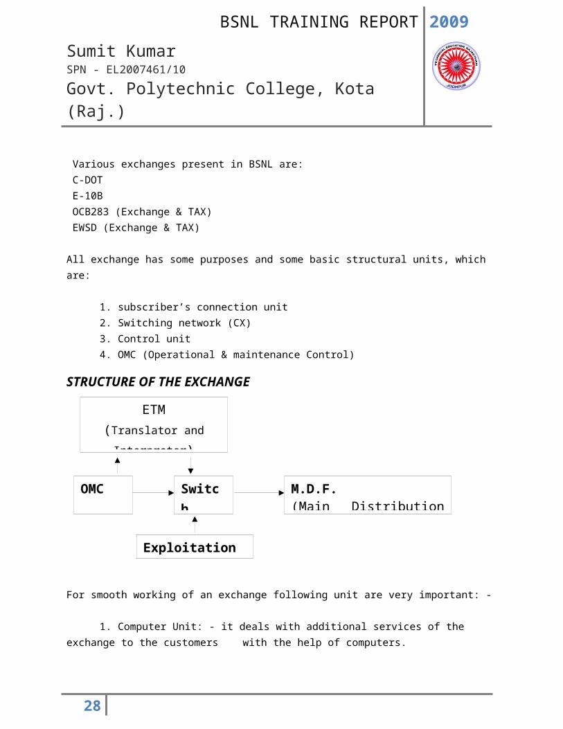
STRUCTURE OF THE EXCHANGE
20
OMC
Room
Switch
Room
M.D.F.(Main Distribution Frame)
ETM(Translator and Interpreter)
Exploitation Room
2009
Sumit KumarSPN - EL2007461/10
Govt. Polytechnic College, Kota (Raj.)
For smooth working of an exchange following unit are very important: -
1. Computer Unit: - it deals with additional services of the exchange to the customers with the help of computers.
2. Power Plant:- to feed proper power supply to exchange
3. AC Plant: - to maintain the continuous temperature + or – 2 degree Celsius to the digital switch (exchange).
4. MDF: - to connect switch (exchange) with the external environment (subscriber) i.e. it is the interface between subscribers and exchange.
1. Computer unit: - as the name specified it is the main part of the exchange that deals with the all services provided by the exchange to the customers with the help of computer. It also provides the updated data to all other part of the exchange.
The customers are using the services of the exchange by using the internet also gets connected to the main server present this room via an internet room.
It mainly consists of the servers that are providing the different services. The main servers of this room are:-
IVRS is used for the change number services provided by the exchange. CERS are provided by the exchange to avoid the problems that the users are facing the repairing of telephone. In this system when the user enters its complained it gets directly entered to the server and user is allotted with an id number.
LOCAL DIRECTORY ENQUIRY is another services provided by the exchange, by using this; subscribers calls the particular number and gets the directory enquiry. The server present in the main computer room provides this service.
INTERNET DIRECTORY ENQUIRY is the latest service by the exchange. In this type of service makes it enquiry using the internet, which gets connected to the main server at the internet room in the exchange and further to the main server in the computer room.
21
2009
Sumit KumarSPN - EL2007461/10
Govt. Polytechnic College, Kota (Raj.)
2. POWERPLANT: -As we know that, the power is the main source or any organization. It is the case of E-10B
exchange. That is the first requirement of any organization is the input.The main source of this exchange is AC supply. However, as soon as the power supply is gone off, then what is source? No one think on this that the telephone is always plays its role in the human life. Even if the power supply gone off. Thus there must be adjustment source of power.
The main parts of the power room are: -i. Batteries: - these are the instant sources of the power as soon as power is gone off.
ii. Charging- Discharging Unit: - the batteries we are using in the power room need timely charging. As soon as the AC power supply is on, we make use of the charging unit present in the power room. The slowly charging of the batteries is known as the trickle charging. But sometimes we need the BOOSTER charging. In this type of charging awe take of the batteries from the load and charge separately, until it gets fully charged.The main work of the discharging unit is to control the discharging of the batteries.
iii. Inverter and Converter Unit: - the main use of this system is to change AC mains to DC and vice versa as required by the parts of exchange.
iv. Engine Room:-we know that the batteries are the instant source of supply but we cannot use it for much larger time, thus for this, we have an engine to generate the power supply. They are of 885 KVA. Thus, this room controls the supply of the engine.
UPS OPERATING MODES :
UPS system has three operating mode which can be designated as
1. Normal mode
2. Emergency mode
3. Recovery mode
22
2009
Sumit KumarSPN - EL2007461/10
Govt. Polytechnic College, Kota (Raj.)
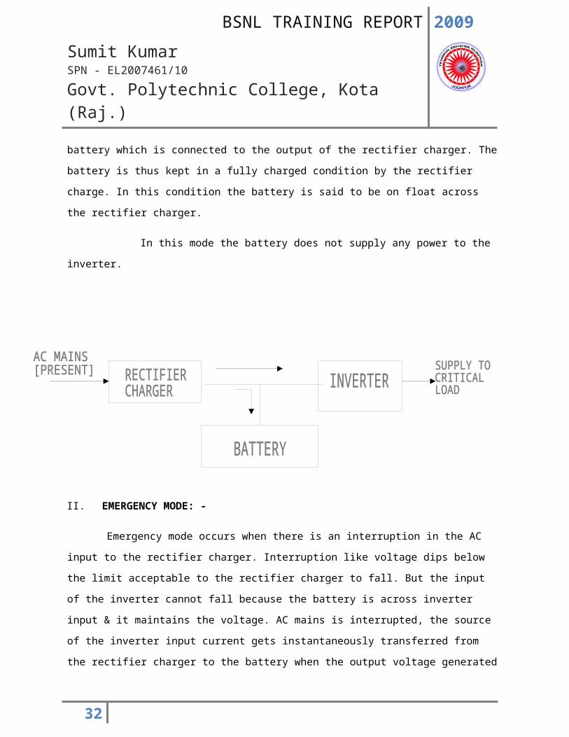
I. NORMAL MODE:
The rectifier charger draws power from the ac mains & convert it into DC. This DC power is
supplied to the inverter which converts it back into AC power to feed the critical load connected to the
output of the inverter. A small amount of DC owner is also supplied to the battery which is connected to
the output of the rectifier charger. The battery is thus kept in a fully charged condition by the rectifier
charge. In this condition the battery is said to be on float across the rectifier charger.
In this mode the battery does not supply any power to the inverter.
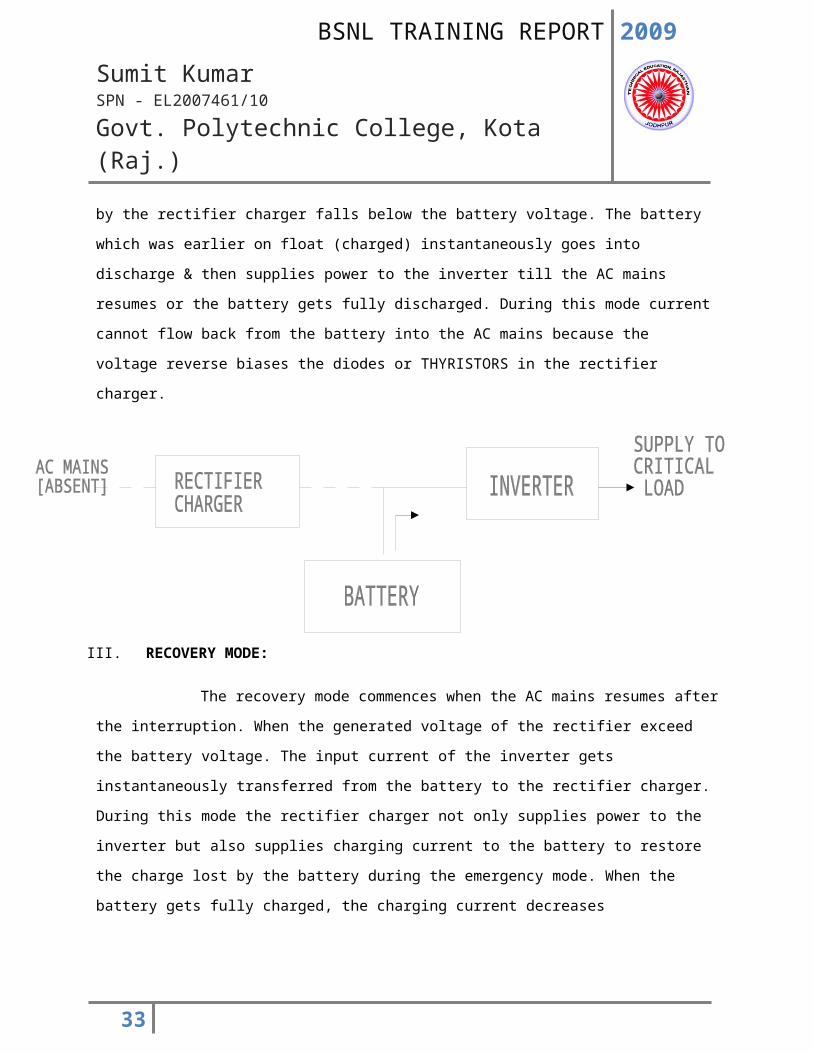
II. EMERGENCY MODE: -
Emergency mode occurs when there is an interruption in the AC input to the rectifier charger.
Interruption like voltage dips below the limit acceptable to the rectifier charger to fall. But the input of
the inverter cannot fall because the battery is across inverter input & it maintains the voltage. AC mains
is interrupted, the source of the inverter input current gets instantaneously transferred from the
rectifier charger to the battery when the output voltage generated by the rectifier charger falls below
the battery voltage. The battery which was earlier on float (charged) instantaneously goes into discharge
& then supplies power to the inverter till the AC mains resumes or the battery gets fully discharged.
During this mode current cannot flow back from the battery into the AC mains because the voltage
reverse biases the diodes or THYRISTORS in the rectifier charger.
23
2009
Sumit KumarSPN - EL2007461/10
Govt. Polytechnic College, Kota (Raj.)
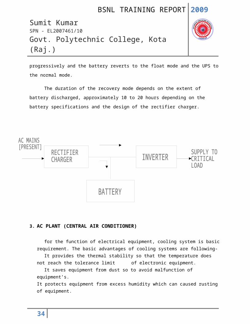
III. RECOVERY MODE:
The recovery mode commences when the AC mains resumes after the interruption. When the
generated voltage of the rectifier exceed the battery voltage. The input current of the inverter gets
instantaneously transferred from the battery to the rectifier charger. During this mode the rectifier
charger not only supplies power to the inverter but also supplies charging current to the battery to
restore the charge lost by the battery during the emergency mode. When the battery gets fully charged,
the charging current decreases progressively and the battery reverts to the float mode and the UPS to
the normal mode.
The duration of the recovery mode depends on the extent of battery discharged, approximately
10 to 20 hours depending on the battery specifications and the design of the rectifier charger.
24
2009
Sumit KumarSPN - EL2007461/10
Govt. Polytechnic College, Kota (Raj.)
3. AC PLANT (CENTRAL AIR CONDITIONER)
for the function of electrical equipment, cooling system is basic requirement. The basic advantages of cooling systems are following- It provides the thermal stability so that the temperature does not reach the tolerance limit of electronic equipment. It saves equipment from dust so to avoid malfunction of equipment’s.It protects equipment from excess humidity which can caused rusting of equipment.
The basic unit of measurement used in the industry is known as “ton of refrigeration” (TR) which is equivalent to the heat extracted in 24 hours for converting thousands kg of liquid to ice at zero degree. The compressor is the heart of the AC system and the costliest. It increases the pressure and temperature of the refrigerant gas coming from the evaporator coils by compressing it.Compressor comes in various types. The most widely used is simple reciprocal type a cylinder and piston arrangement. For capacity more than 120 TR, centrifugal compressors are used. The condenser liquefies the refrigerant gas by a heat exchange process. The capillary tube or the expansion valve pressurizes liquid refrigerant and meters it flows to the evaporator.The refrigerant then passes through the evaporator coils, which extract heat out of the ambience.
4. MAIN DISTRIBUTION FRAME
The primary function of MDF is: - The fault of telephone number is removed in the MDF; it is called as Fault Remove Section. For removing the fault of telephone number, we use the testing these testing are T.T.Y. testing, Group testing, etc. For any type of testing firstly we need the vertical no. or the live tester, printer and computer test N.E. number of that particular telephone number.The telephone numbers are also disconnected in the MDF because of some specific reason.
25
2009
Sumit KumarSPN - EL2007461/10
Govt. Polytechnic College, Kota (Raj.)
ORGANISATION OF THE MDFPARTS OF THE MDF
Horizontal sideVertical side
a. HORIZONTAL SIDE:It is again subdivided in to two partsExchange sideLine side
Description of the horizontal side:-
RACK: - On the rack, the tags are situated. One rack is having eight tags. The courting is done from up (0) to down (7).
TAG: - Each rack consists of eight tags.1 tag = 4 core1 core = 4 bunch1 bunch = 2 line
N.E.:- The word NE stands for the ‘NUMBER OF EQUIPMENT’.It is a 128 pair cable. The EWSD and MDF connected by NE.
WEDGE:-If we want to disconnect any two numbers then we insert a wedge between subscriber side and exchange side. Here wedge works as insulator made of plastic.
a. VERTICAL SIDE:
The vertical aside connected to the underground cable. This cable is having 100 pairs.These pair is distributed when we allot the telephone number to the subscriber.Vertical side is again subdivided in two parts:
One part is connected with the horizontal side and another with the subscriber line by using 100 pair underground cable.
This is how the present day telephone system works. Different exchanges have different architectures of switching call routing and other features.
26
2009
Sumit KumarSPN - EL2007461/10
Govt. Polytechnic College, Kota (Raj.)
FUNCTION OF MDF: -• A fixed means of terminating the external cables.• A means for mounting the protective devices for incoming circuits.• A convenient point of interception for locating of faults.• A means for cross connecting the external circuits to the appropriate
Internal circuits.The MDF is properly earthed for the protection of the equipment. The external
pairs are area wise terminated on the line side of the frame, while connection fromthe equipment is done on the exchange side in a numerical order. Byinterconnections at this frame with the help of jumper wires, any subscriber in anyarea can be given any exchange number. This MDF mounts Delay Fuses only.
PROTECTIVE DEVICES : -Comprehensive protection against effects of lightning
and power line contacts, is achieved in practice by fuses, arresters and heat coils.They are not affected by normal speech and signaling voltage and current butoperates when the foreign voltage or current on the line is excessive. The line isthen disconnected automatically from the equipment or a connection to earth isFor safety precautions fuses are used. Every subscriber line has individual fuse.These fuses are made of GD (gas discharge) tube, which are connected in parallel.These fuses have two sides, one is exchange side and other is subscriber side.Connections between the different tag blocks are made using the jumper wires ofred and white colors.
GD tubes are connected in parallel while electrical fuses are connected in series.In electrical fuse, when high voltage appears across it, then it will break up theConnection and thus safeguard the system. If GD tube is connected in series, thendue to high voltage across any line, the whole exchange will be disconnected.Thus when GD tubes are connected in parallel, it will provide the requiredfacility.
GASE DISCHARGE PROCTECTORS: -
In case of heavy lightning discharges,gas discharge protectors are used and more consistent voltage is obtained. The gasdischarge protector essentially consists of two tungsten electrodes sealed in aspecial glass envelope containing a mixture of inert gases, mainly neon. One ofthe electrodes are for connections to the lines and the other is the earth electrode.
If the potential difference across the electrodes rises to a certain critical value (theStriking value) the gas is ionized and becomes conducting. This condition willContinue till the potential difference across the electrodes falls to the extinctionvoltage value. For voltages less than striking value it will not conduct. For normaloperating voltages on the lines, it offers extremely high impedance and thus does
27
2009
Sumit KumarSPN - EL2007461/10
Govt. Polytechnic College, Kota (Raj.)
not introduce any transmission loss.For equipment side:
MDF has many tag blocks of 100 and that numbered from 1 to 100.In a tag block, there are 128 pair wire theoretically. Therefore, total number ofConnecting wires are 1024 theoretically. But in practical, there are only 1000 pairs.For equipment side:
From ground, a single pair of 400 wires originates, which is dividedIn 4 pairs of 100 wires. Practically, each pair is provided with 102 wires. TheseExact 2 wires are used in case of any manufacturing defect.For broadband connections, different colored tag blocks are provided.Broadband is used to provide different facilities on land-line phones with highSpeed to access them. A grey colored tag block is used for line side while yellow
Colored tag block is used on equipment side. These tag blocks has 0 to 47 pairs.In order to know the centre load point.:Cabinet and pillar are provided with capacity as per requirement. The D.P. box isProvided with 10 or 20 or 5 pairs. Now a days, a D.P. box of 5 pairs is used whichis wall mount instead of being mounted on pole.
To identify any telephone, we require the following two addresses:-
1. Exchange/line address2. Equipment address
Exchange address is written in given manner:Vertical number-tag block number-pair numberFor example 7-5-15Here, vertical no.=7Tag block no.=5Pair no.=15This gives the address of a telephone in the exchange.Equipment address is given as:-Rack number-tag block number-pair numberFor example7-6-87Here,rack no.=7Tag block no.=6Pair no.=87This gives the information about the actual location of telephone equipment. Thisaddress is provided to lineman for repairing, in case of any fault.There is a section of fault repairing located in MDF section. Whensubscriber’s phone is not working, then subscriber call to exchange. For this hedial,198.
28
2009
Sumit KumarSPN - EL2007461/10
Govt. Polytechnic College, Kota (Raj.)
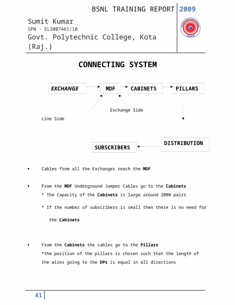
CONNECTING SYSTEM
Exchange Side Line Side
Cables from all the Exchanges reach the MDF
From the MDF Underground Jumper Cables go to the Cabinets
* The Capacity of the Cabinets is large around 2000 pairs
* If the number of subscribers is small then there is no need for
the Cabinets
From the Cabinets the cables go to the Pillars
*the position of the pillars is chosen such that the length of the wires going to the DPs is equal
in all directions
From the Pillars the wires go to the DPs
* the capacity of each of the Pillars is about 10 or 15
29
EXCHANGE MDF CABINETS PILLARS
DISTRIBUTION SUBSCRIBERS
2009
Sumit KumarSPN - EL2007461/10
Govt. Polytechnic College, Kota (Raj.)
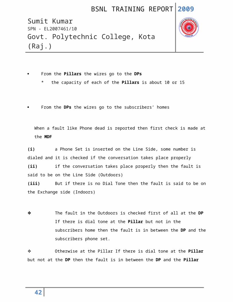
From the DPs the wires go to the subscribers’ homes
When a fault like Phone dead is reported then first check is made at the MDF
(i) a Phone Set is inserted on the Line Side, some number is dialed and it is checked if the
conversation takes place properly
(ii) if the conversation takes place properly then the fault is said to be on the Line Side
(Outdoors)
(iii) But if there is no Dial Tone then the fault is said to be on the Exchange side (Indoors)
The fault in the Outdoors is checked first of all at the DP
If there is dial tone at the Pillar but not in the subscribers home then the fault is in
between the DP and the subscribers phone set.
Otherwise at the Pillar If there is dial tone at the Pillar but not at the DP then the fault is
in between the DP and the Pillar
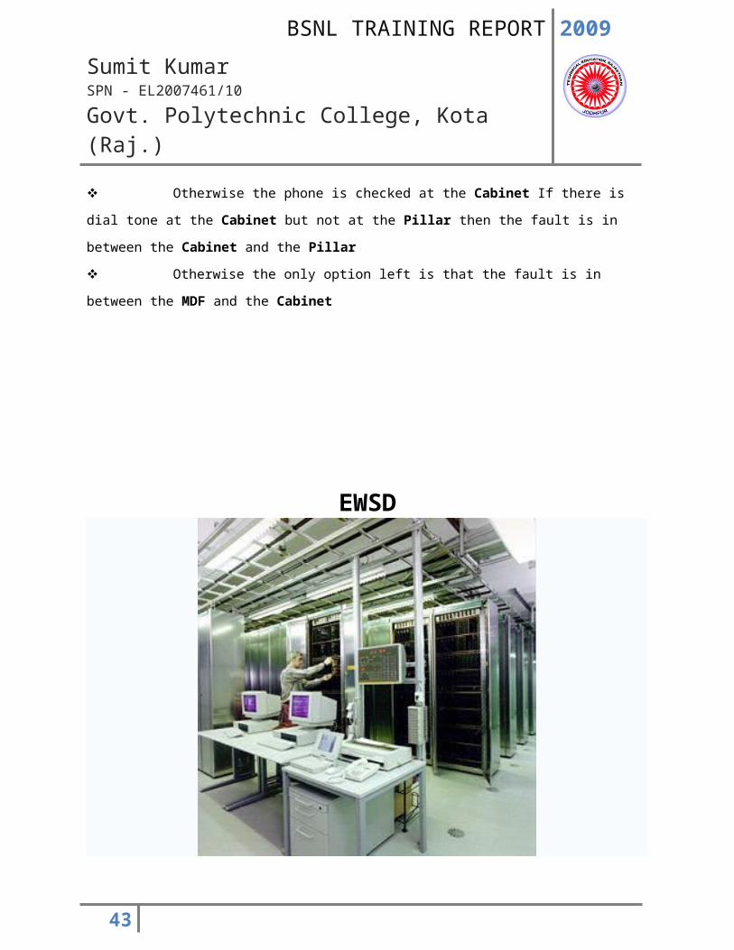
Otherwise the phone is checked at the Cabinet If there is dial tone at the Cabinet but
not at the Pillar then the fault is in between the Cabinet and the Pillar
Otherwise the only option left is that the fault is in between the MDF and the Cabinet
30
2009
Sumit KumarSPN - EL2007461/10
Govt. Polytechnic College, Kota (Raj.)
EWSD
EWSD and Office Switch
1. General Overview
EWSD (Elektronisches Wählsystem Digital in German, Electronic Digital Switching System/Electronic World Switch Digital in English) is one of the most widely installed telephone exchange systems in the world. EWSD can work as a local or tandem switch or combined local/tandem, and for landline or mobile phones. It is manufactured by Siemens AG, who claims that EWSD switches perform switching for over 160 million subscriber lines in more than 100 countries.
DeTeWe bought its first EWSD under license in 1985 for remote switching. Bosch built its first EWSD as a local exchange in 1986. Deutsche Telekom, formerly Deutsche Bundespost, the largest German telephone company, uses EWSD and System 12 (Alcatel), the former more than the latter.
In 2007, Nokia Corporation and Siemens AG formed the new company Nokia Siemens Networks, and responsibility of further development and shipments of the EWSD system is dependent on this new company.
Contents
31
2009
Sumit KumarSPN - EL2007461/10
Govt. Polytechnic College, Kota (Raj.)
1 Hardware 2 Software 3 Technical data
Hardware
Main subsystems are:
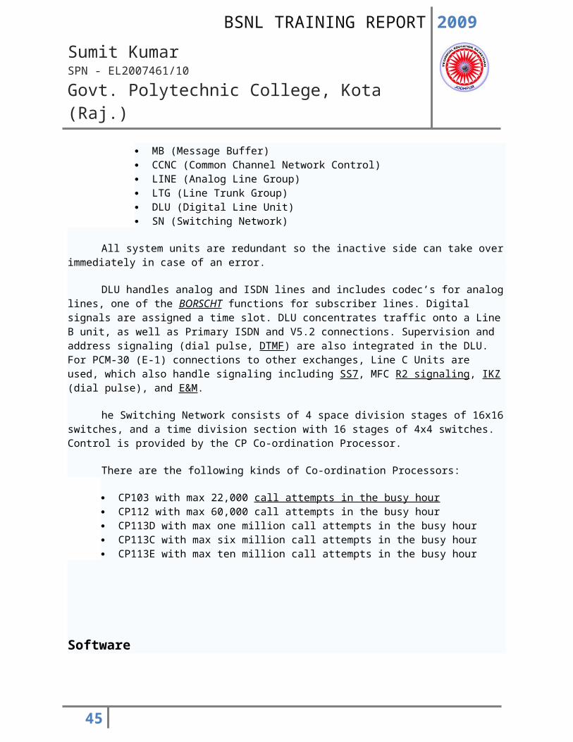
CP (Central Processor) MB (Message Buffer) CCNC (Common Channel Network Control) LINE (Analog Line Group) LTG (Line Trunk Group) DLU (Digital Line Unit) SN (Switching Network)
All system units are redundant so the inactive side can take over immediately in case of an error.
DLU handles analog and ISDN lines and includes codec’s for analog lines, one of the BORSCHT functions for subscriber lines. Digital signals are assigned a time slot. DLU concentrates traffic onto a Line B unit, as well as Primary ISDN and V5.2 connections. Supervision and address signaling (dial pulse, DTMF) are also integrated in the DLU. For PCM-30 (E-1) connections to other exchanges, Line C Units are used, which also handle signaling including SS7, MFC R2 signaling, IKZ (dial pulse), and E&M.
he Switching Network consists of 4 space division stages of 16x16 switches, and a time division section with 16 stages of 4x4 switches. Control is provided by the CP Co-ordination Processor.
There are the following kinds of Co-ordination Processors:
CP103 with max 22,000 call attempts in the busy hour CP112 with max 60,000 call attempts in the busy hour CP113D with max one million call attempts in the busy hour CP113C with max six million call attempts in the busy hour CP113E with max ten million call attempts in the busy hour
Software
32
2009
Sumit KumarSPN - EL2007461/10
Govt. Polytechnic College, Kota (Raj.)
The software of EWSD is called APS (Automatic Program System). The APS is on a hard drive and includes the operating system, developed by Siemens in cooperation with Bosch. It is predominantly written in the CHILL language. Application software is switch specific and serves among other things traffic management, path search, and call charging. Support software serves translating programs, binding modules as well as administration of libraries for generating data. Operating and data communication software serve for co-operation of maintenance centers and switching centers.
Technical data
Number of access lines: to 250,000 Number of feeder lines: 240,000 Traffic connection: 25,200 Call attempts in busy hour: 10 million Operating voltages: -48V -60V -90V Rate zones: 127, for each zone of 6 tariffs Tariff change-over at 15 minute intervals Space requirement with 10,000 access lines: 35 square meters 15-25 *C Temperature
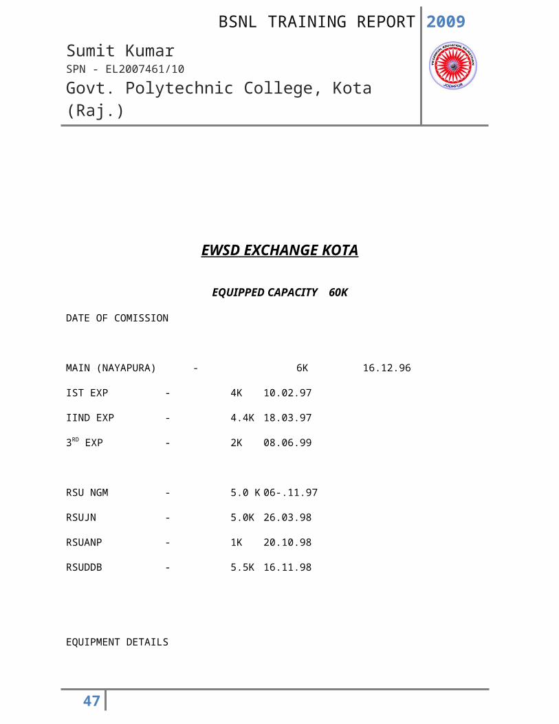
EWSD EXCHANGE KOTA
33
2009
Sumit KumarSPN - EL2007461/10
Govt. Polytechnic College, Kota (Raj.)
EQUIPPED CAPACITY 60K
DATE OF COMISSION
MAIN (NAYAPURA) - 6K 16.12.96
IST EXP - 4K 10.02.97
IIND EXP - 4.4K 18.03.97
3RD EXP - 2K 08.06.99
RSU NGM - 5.0 K 06-.11.97
RSUJN - 5.0K 26.03.98
RSUANP - 1K 20.10.98
RSUDDB - 5.5K 16.11.98
EQUIPMENT DETAILS
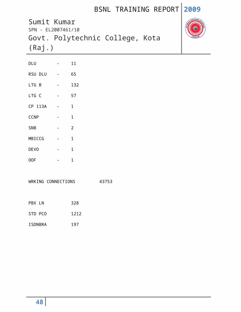
DLU - 11
RSU DLU - 65
LTG B - 132
LTG C - 57
CP 113A - 1
CCNP - 1
SNB - 2
MBICCG - 1
DEVO - 1
34
2009
Sumit KumarSPN - EL2007461/10
Govt. Polytechnic College, Kota (Raj.)
OOF - 1
WRKING CONNECTIONS 43753
PBX LN 328
STD PCO 1212
ISDNBRA 197
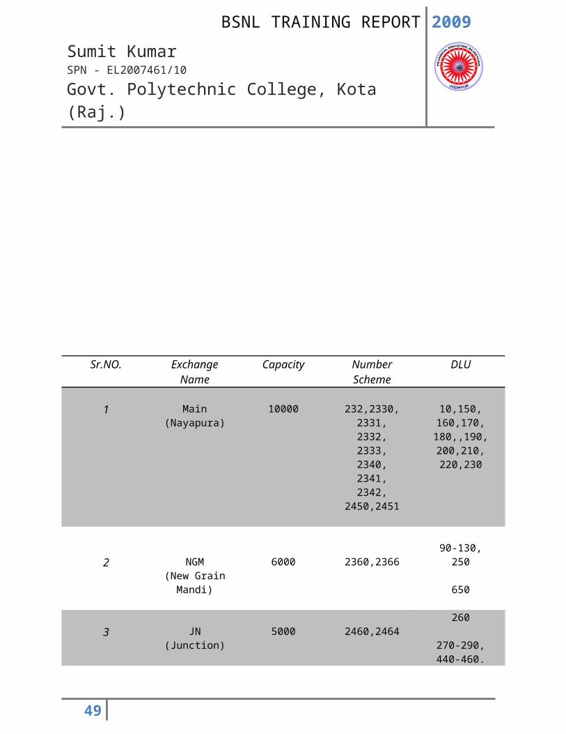
Sr.NO. Exchange Name Capacity Number Scheme DLU
1 Main(Nayapura)
10000 232,2330,2331,2332,
10,150,160,170,180,,190,
35
2009
Sumit KumarSPN - EL2007461/10
Govt. Polytechnic College, Kota (Raj.)
2333,2340,2341,2342,
2450,2451
200,210,220,230
2 NGM(New Grain
Mandi)
6000 2360,236690-130,
250
650
3 JN(Junction)
5000 2460,2464260
270-290,440-460.
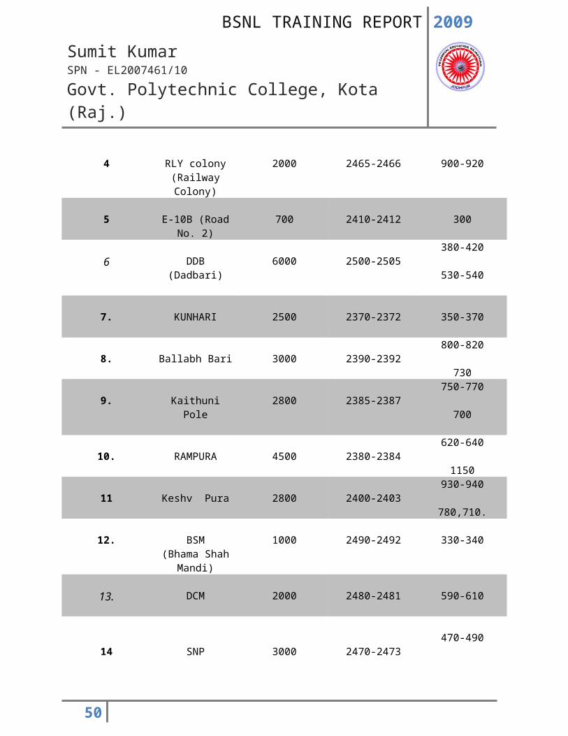
4 RLY colony(Railway Colony)
2000 2465-2466 900-920
5 E-10B (Road No. 2) 700 2410-2412 300
6 DDB (Dadbari) 6000 2500-2505380-420
530-540
7. KUNHARI 2500 2370-2372 350-370
8. Ballabh Bari 3000 2390-2392800-820
730
9. Kaithuni Pole 2800 2385-2387750-770
700
10. RAMPURA 4500 2380-2384620-640
1150
11 Keshv Pura 2800 2400-2403930-940
780,710.
12. BSM(Bhama Shah
1000 2490-2492 330-340
36
2009
Sumit KumarSPN - EL2007461/10
Govt. Polytechnic College, Kota (Raj.)
Mandi)
13. DCM 2000 2480-2481 590-610
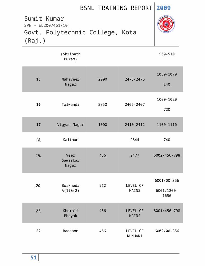
14 SNP(Shrinath Puram)
3000 2470-2473470-490
500-510
15 Mahaveer Nagar 2000 2475-24761050-1070
140
16 Talwandi 2850 2405-24071000-1020
720
17 Vigyan Nagar 1000 2410-2412 1100-1110
18. Kaithun 2844 740
19. Veer Sawarkar Nagar
456 2477 6002/456-798
20. Borkheda A(1)&(2) 912 LEVEL OF MAINS6001/00-356
6001/1200-1656
21. Kherali Phayak 456 LEVEL OF MAINS 6001/456-798
22 Badgaon 456 LEVEL OF KUNHARI
6002/00-356
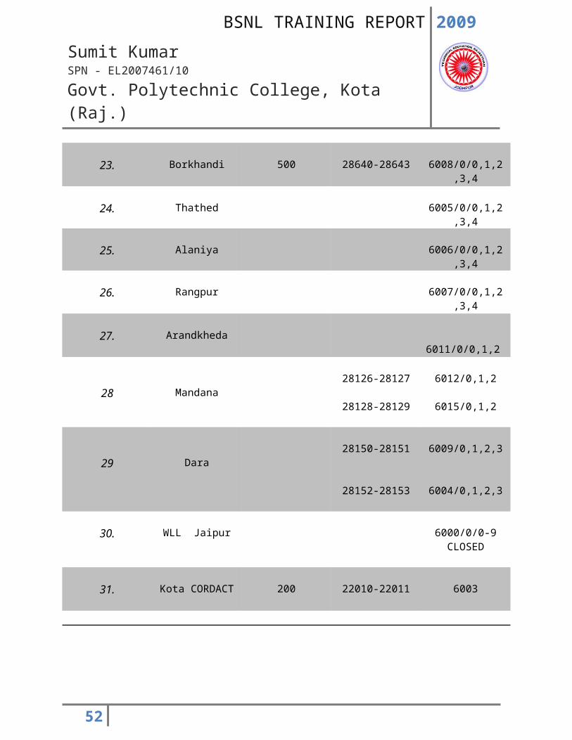
23. Borkhandi 500 28640-28643 6008/0/0,1,2,3,4
37
2009
Sumit KumarSPN - EL2007461/10
Govt. Polytechnic College, Kota (Raj.)
24. Thathed 6005/0/0,1,2,3,4
25. Alaniya 6006/0/0,1,2,3,4
26. Rangpur 6007/0/0,1,2,3,4
27. Arandkheda 6011/0/0,1,2
28 Mandana28126-28127
28128-28129
6012/0,1,2
6015/0,1,2
29 Dara28150-28151
28152-28153
6009/0,1,2,3
6004/0,1,2,3
30. WLL Jaipur 6000/0/0-9CLOSED
31. Kota CORDACT 200 22010-22011 6003
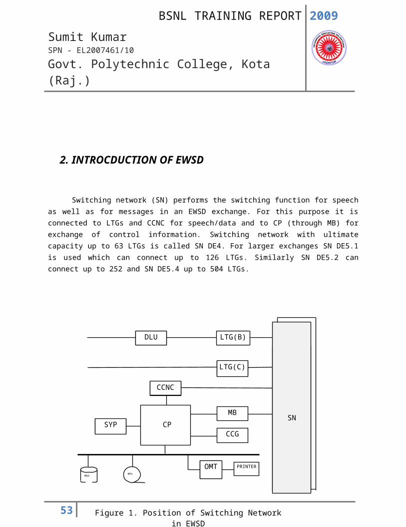
2. INTROCDUCTION OF EWSD
38
DLU LTG(B)
LTG(C)
CCNC
MB
CCGSYP
OMT PRINTER
CP
MTUMDD
SN
Figure 1. Position of Switching Network in EWSD
2009
Sumit KumarSPN - EL2007461/10
Govt. Polytechnic College, Kota (Raj.)
Switching network (SN) performs the switching function for speech as well as for messages in an EWSD exchange. For this purpose it is connected to LTGs and CCNC for speech/data and to CP (through MB) for exchange of control information. Switching network with ultimate capacity up to 63 LTGs is called SN DE4. For larger exchanges SN DE5.1 is used which can connect up to 126 LTGs. Similarly SN DE5.2 can connect up to 252 and SN DE5.4 up to 504 LTGs.
39
2009
Sumit KumarSPN - EL2007461/10
Govt. Polytechnic College, Kota (Raj.)
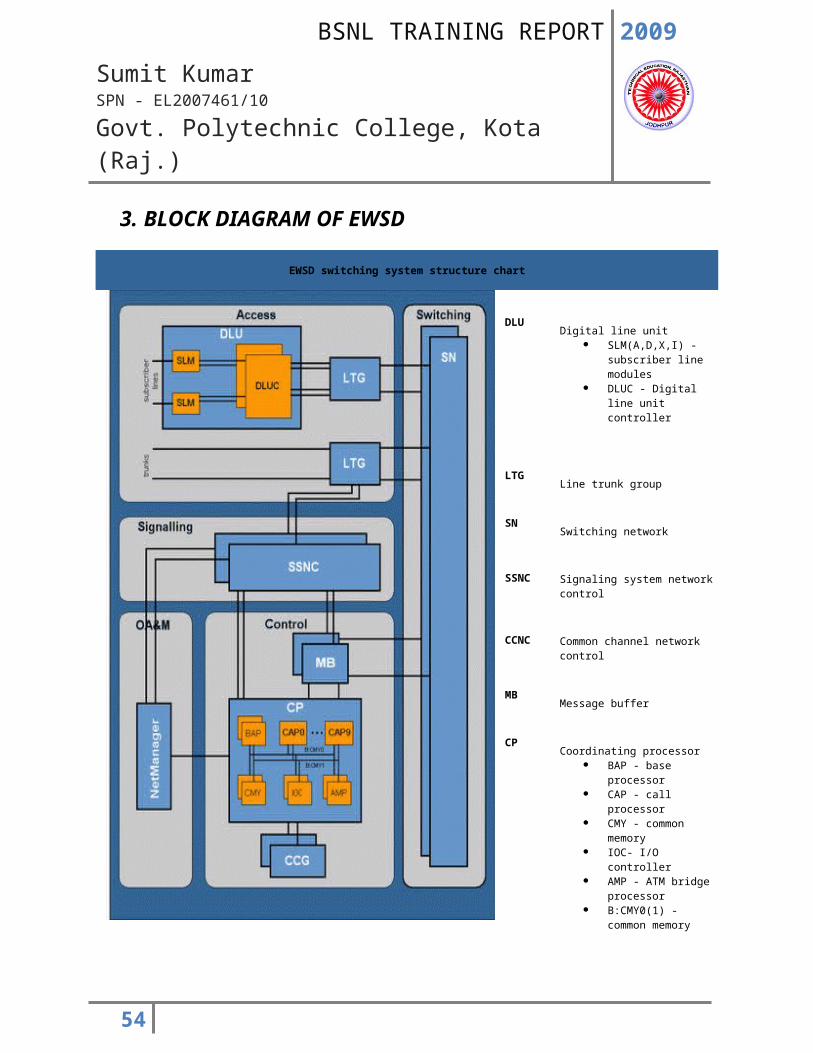
3. BLOCK DIAGRAM OF EWSD
EWSD switching system structure chart
DLUDigital line unit
SLM(A,D,X,I) - subscriber line modules
DLUC - Digital line unit controller
LTGLine trunk group
SNSwitching network
SSNC Signaling system network control
CCNCCommon channel network control
MBMessage buffer
CPCoordinating processor
BAP - base processor CAP - call processor CMY - common memory IOC- I/O controller AMP - ATM bridge
processor B:CMY0(1) - common
memory access bus
CCGCentral clock generator
Net
Manager
Network management system
40
2009
Sumit KumarSPN - EL2007461/10
Govt. Polytechnic College, Kota (Raj.)
4. GENERAL FEATURES
Switching network is provided in capacity stages SN: 63LTG to SN: 504LTG, i.e. up to 63 LTGs can be connected or, via other intermediate capacity stages, up to 504 LTGs can be connected. The modularly expandable SN has negligibly small internal blocking and can be used in EWSD exchanges of all types and sizes.
The self monitoring switching network uses a uniform through connection format. Octets (8 bit speech samples) from the incoming time slots are switched to the outgoing time slots leading to the desired destination fully transparently. This means that each bit of all octets is transmitted to the output of the switching network in the way that it appears at the input (bit integrity). For each connection made via the switching network, the octets have the same sequence at the output as at the input (digit sequence integrity). The switching network’s full availability makes it possible for each incoming octet to be switched at any time to any outgoing highway at the output of the switching network. The time slots used in switching network for making through-connections make up a 64 Kbit/s connection path.
All of the switching network’s internal highways have a bit rate of 8192 bits/s (Secondary Digital Carriers, SDCs). 128 time slots with a transmission capacity of 64 Kbits/s each (128x64 = 8192 Kbits/s) are available on each 8192 Kbits/s highway. Separate cables each containing several (eight or sixteen) such internal highways, are used for each transmission direction. All externally connected highways also have the same uniform bit rate.
The switching network combines the numerous switching network functions in a few module types. These modules work at very high through-connection bit rates; 8192 Kbits/s and some even at 32768 Kbit/s. For example 1024 connections can be switched simultaneously through a space stage with 16 inputs and 16 outputs. Although these highly integrated switching network modules switch a large number of connections with a high degree of reliability, the EWSD switching networks are always duplicated. The amount of space needed for the switching network in the EWSD exchange is still very low despite this duplication.
Two different switching network versions have been supplied in India:
* Switching network [SN] supplied with first 110K order.
* Switching network B [SN (B)] supplied with subsequent orders.
41
2009
Sumit KumarSPN - EL2007461/10
Govt. Polytechnic College, Kota (Raj.)
5. Position and Functional Structure
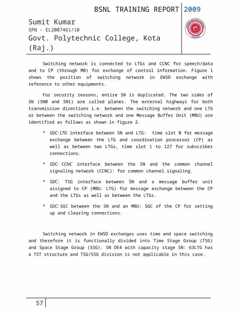
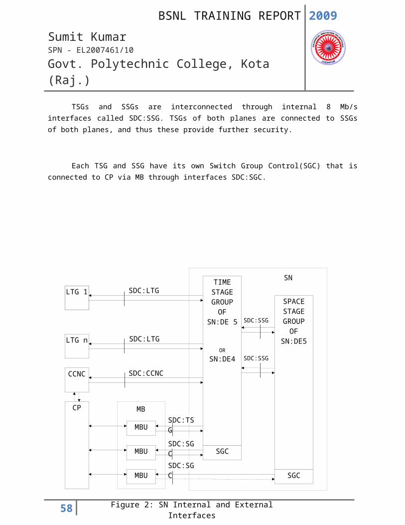
Switching network is connected to LTGs and CCNC for speech/data and to CP (through MB) for exchange of control information. Figure 1 shows the position of switching network in EWSD exchange with reference to other equipments.
For security reasons, entire SN is duplicated. The two sides of SN (SN0 and SN1) are called planes. The external highways for both transmission directions i.e. between the switching network and one LTG or between the switching network and one Message Buffer Unit (MBU) are identified as follows as shown in figure 2.
* SDC: LTG interface between SN and LTG: time slot 0 for message exchange between the LTG and coordination processor (CP) as well as between two LTGs, time slot 1 to 127 for subscriber connections.
* SDC: CCNC interface between the SN and the common channel signaling network (CCNC): for common channel signaling.
* SDC: TSG interface between SN and a message buffer unit assigned to CP (MBU: LTG) for message exchange between the CP and the LTGs as well as between the LTGs.
* SDC: SGC between the SN and an MBU: SGC of the CP for setting up and clearing connections.
Switching network in EWSD exchanges uses time and space switching and therefore it is functionally divided into Time Stage Group (TSG) and Space Stage Group (SSG). SN DE4 with capacity stage SN: 63LTG has a TST structure and TSG/SSG division is not applicable in this case.
TSGs and SSGs are interconnected through internal 8 Mb/s interfaces called SDC:SSG. TSGs of both planes are connected to SSGs of both planes, and thus these provide further security.
Each TSG and SSG have its own Switch Group Control(SGC) that is connected to CP via MB through interfaces SDC:SGC.
42
LTG 1
LTG n
CCNC
CP
MBU
MBU
MBU
SPACE STAGE GROUP
OFSN:DE5
TIME STAGE GROUP
OFSN:DE 5
OR
SN:DE4
SGC
SGC
Figure 2: SN Internal and External Interfaces
SDC:LTG
SDC:LTG
SDC:CCNC
SDC:TSG
SDC:SGC
SDC:SGC
SN
MB
SDC:SSG
SDC:SSG
2009
Sumit KumarSPN - EL2007461/10
Govt. Polytechnic College, Kota (Raj.)
43
2009
Sumit KumarSPN - EL2007461/10
Govt. Polytechnic College, Kota (Raj.)
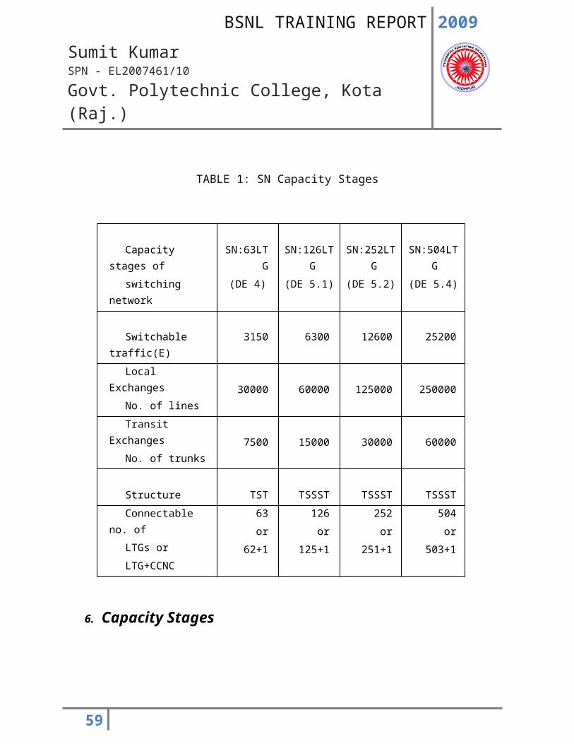
TABLE 1: SN Capacity Stages
Capacity stages of
switching network
SN:63LTG
(DE 4)
SN:126LTG
(DE 5.1)
SN:252LTG
(DE 5.2)
SN:504LTG
(DE 5.4)
Switchable traffic(E) 3150 6300 12600 25200
Local Exchanges
No. of lines 30000 60000 125000 250000
Transit Exchanges
No. of trunks 7500 15000 30000 60000
Structure TST TSSST TSSST TSSST
Connectable no. of
LTGs or
LTG+CCNC
63
or
62+1
126
or
125+1
252
or
251+1
504
or
503+1
6. Capacity Stages
The present version of SN is available in capacity stages SN:63LTG, SN:126LTG, SN:252LTG and SN:504LTG. Modular structure permits partially equipped SN. Up gradation from DE5.1 to DE5.2 and from DE5.2 to DE5.4 is possible with the help of supplier. SN DE4 is not upgradable to DE5.1 as TSG and SSG are not separately identified in SN DE4. The traffic handling capacity, connect ability for various capacity stages of SN are shown in Table 1.
44
2009
Sumit KumarSPN - EL2007461/10
Govt. Polytechnic College, Kota (Raj.)
7. Functional Units of SN
7.1 Switching path
The switching network is subdivided into time stage groups (TSG) and space stage groups (SSG). Due to its modular structure, the EWSD switching network can be partially equipped as needed and expanded step by step. The switching network uses the following switching stages:
one time stage incoming (TSI) three space stages (SS) and One time stage outgoing (TSO).
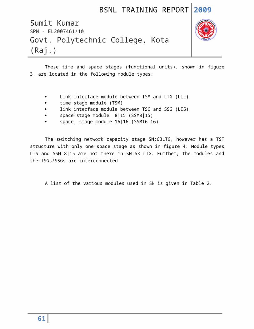
These time and space stages (functional units), shown in figure 3, are located in the following module types:
Link interface module between TSM and LTG (LIL) time stage module (TSM) link interface module between TSG and SSG (LIS) space stage module 8|15 (SSM8|15) space stage module 16|16 (SSM16|16)
The switching network capacity stage SN:63LTG, however has a TST structure with only one space stage as shown in figure 4. Module types LIS and SSM 8|15 are not there in SN:63 LTG. Further, the modules and the TSGs/SSGs are interconnected
A list of the various modules used in SN is given in Table 2.
45
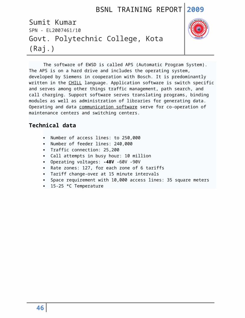
Figure 4: The five module types in SN:DE4
LTG
MBU:SGC
SN1
SN0
LIL TSM SSM 16|16
SGC LIM
TSO
TSI
SSG1.0
LTG
MBU: SGC
TSG1.0
TSG0.0
LIL TSM LIS
SGC LIM
TS0
TSI
MBU: SGC
SSG0.0
LIS SSM 8|15 SSM16|16
SGC LIM
SSM15|8
SSM8|15
Figure 3: The seven module types in SN: DE5
2009
Sumit KumarSPN - EL2007461/10
Govt. Polytechnic College, Kota (Raj.)
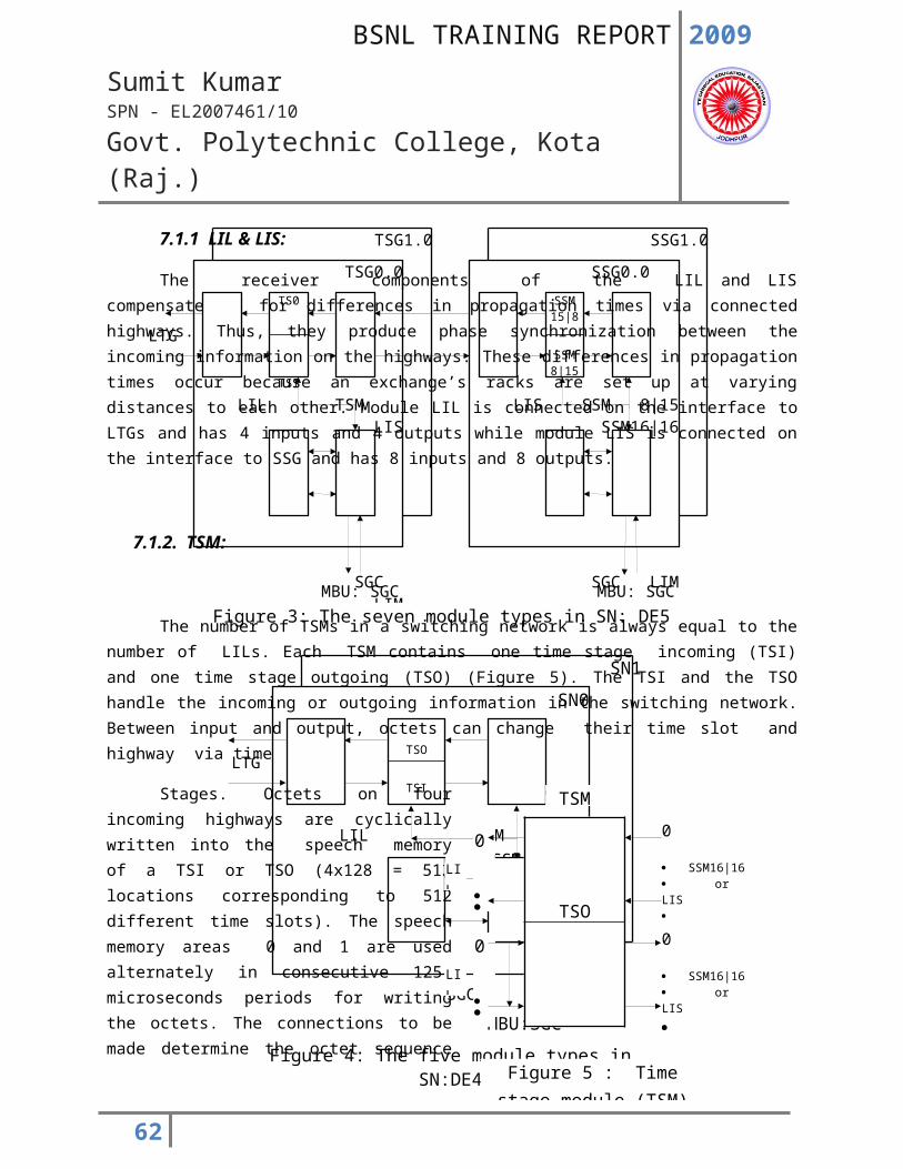
7.1.1 LIL & LIS:
The receiver components of the LIL and LIS compensate for differences in propagation times via connected highways. Thus, they produce phase synchronization between the incoming information on the highways. These differences in propagation times occur because an exchange’s racks are set up at varying distances to each other. Module LIL is connected on the interface to LTGs and has 4 inputs and 4 outputs while module LIS is connected on the interface to SSG and has 8 inputs and 8 outputs.
7.1.2. TSM:
The number of TSMs in a switching network is always equal to the number of LILs. Each TSM contains one time stage incoming (TSI) and one time stage outgoing (TSO) (Figure 5). The TSI and the TSO handle the incoming or outgoing information in the switching network. Between input and output, octets can change their time slot and highway via time
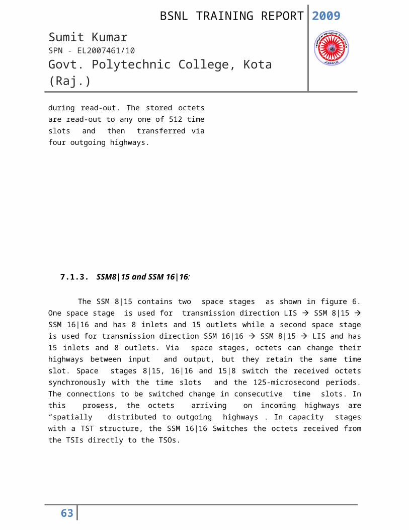
Stages. Octets on four incoming highways are cyclically written into the speech memory of a TSI or TSO (4x128 = 512 locations corresponding to 512 different time slots). The speech memory areas 0 and 1 are used alternately in consecutive 125- microseconds periods for writing the octets. The connections to be made determine the octet sequence during read-out. The stored octets are read-out to any one of 512 time slots and then transferred via four outgoing highways.
46
LIL
0
SSM16|16 or LIS
0
3
TSM
Figure 5 : Time stage module (TSM)
LIL
0
3
TSO
0
SSM16|16 or LIS
3
0
SSM16|16
14
0SSM16|16
14
SSM16|16
TSM or SSM8|15
0
15
0
TSM or SSM8|15
15
0
7
0
7
SSM8|15
SS 8|15
SS 15|8LIS
LIS
Figure 6 : Space stage modules (SSM16|16 and SSM8|15)
2009
Sumit KumarSPN - EL2007461/10
Govt. Polytechnic College, Kota (Raj.)
7.1.3. SSM8|15 and SSM 16|16:
The SSM 8|15 contains two space stages as shown in figure 6. One space stage is used for transmission direction LIS SSM 8|15 SSM 16|16 and has 8 inlets and 15 outlets while a second space stage is used for transmission direction SSM 16|16 SSM 8|15 LIS and has 15 inlets and 8 outlets. Via space stages, octets can change their highways between input and output, but they retain the same time slot. Space stages 8|15, 16|16 and 15|8 switch the received octets synchronously with the time slots and the 125-microsecond periods. The connections to be switched change in consecutive time slots. In this process, the octets arriving on incoming highways are “spatially” distributed to outgoing highways . In capacity stages with a TST structure, the SSM 16|16 Switches the octets received from the TSIs directly to the TSOs.
47
2009
Sumit KumarSPN - EL2007461/10
Govt. Polytechnic College, Kota (Raj.)
TABLE 2: List of Modules used in SN
PCB
No. of cards in SN:63
LTG
No. of cards in TSG of SN:DE5
No. of cards in SSG of SN:DE5
Remarks
LIL 16 16 - One LIL can connect up to 4 LTGs. The cards LIL and TSM
TSM 16 16 - are always used in pairs
LIS - 8 16 This PCB has 8 inlets and 8 outlets. LIS and SSM8|15
SSM8|15 - - 16 are always used in pairs
SSM16|16 4 - 15 Used to cross connect outlets of 16 SSM8/15 to inlets of SSM15/8
LIM 1 1 1
These two PCBs are used
SGC 1 1 1 in the SGC
DCC(B) 2 2 2 Separate shelf is provided for
the DCC(B)s in the rack
48
2009
Sumit KumarSPN - EL2007461/10
Govt. Polytechnic College, Kota (Raj.)
7.2 Control section:
Each TSG, each SSG, and with SN: 63LTG, each switching network side has its own control. These controls each consist of two modules viz. switch group control (SGC) and link interface module between SGC and MBU: SGC (LIM)
An SGC consists of a microprocessor with accompanying memory and peripheral components. The main tasks of an SGC are to handle CP commands (such as connection setup and clear down), message generation and routine test execution. Apart from the interface to the message buffer unit (MBU: SGC), an LIM has a hardware controller (HWC) and a clock generator for clock distribution.
7.3Firmware
The firmware for the switching network is permanently stored in the program memory of each SGC. For this reason, it does not have to be loaded or initialized by the coordination processor (CP). SN firmware is organized in the following manner:
executive control programs call processing programs maintenance programs startup and safeguarding programs
49
2009
Sumit KumarSPN - EL2007461/10
Govt. Polytechnic College, Kota (Raj.)
8. Switching network (B)
Switching network (B) is a special compact version of switching network wherein a number of functional units are integrated over a single module. This arrangement has the following advantages:
* Reduction in shelf space
* Reduction in number of PCB types
* Utilization of available space in SN rack for accommodating LTGs
Functionally SN(B) is entirely similar to SN. However, only the following five types of modules are used in SN(B) as shown in table 3.
TSMB: Two LILs and two time stage modules TSMs are combined to form one TSMB.
LISB: This is formed by combining two LIS functional units in a TSG.
SSM8B: Two LIS and two SSM8|15 functional units in a SSG are combined
to form one SSM8B.
SSM16B: This is formed by combining eight SSM16|16 functional units.
SGCB: Functional units LIM and SGC are combined to form one SGCB.
50
2009
Sumit KumarSPN - EL2007461/10
Govt. Polytechnic College, Kota (Raj.)
TABLE 3: SN(B) Modules
PCB
No. of cards in SN(B)
:63LTG
No. of cards in TSG of SN(B):DE5
No. of cards in SSG of SN(B):DE5 Equivalent modules in SN
TSMB 8 8 - 2 X TSM +
2 X LIL
LIS - 4 - 2 X LIS of TSG
SSM8B - - 8 2 X LIS of SSG +
2 X SSM8|15
SSM16B 1 - 2 8 X SSM16|16
SGCB 1 1 1 LIM +
SGC
DCCMS 1 1 1 Provided in same shelf
containing SN/TSG/SSG
51
TSG0.x or SSG0.x or
SN0
*) duplicated time stage group (TSG), duplicated space stage group (SSG), or both SN:63LTG sides (SN0 and SN1)
Figure 7: Rack for Switching Network (R:SN)
*)
DCC(B)
Fuse Panel
TSG1x or SSG1x or
SN1
770 mm
2009
Sumit KumarSPN - EL2007461/10
Govt. Polytechnic College, Kota (Raj.)
9. Rack Assignment
Both planes of SN: 63LTG are accommodated in two frames of a single SN rack. In case of SN: 126 LTG, both planes of TSG or SSG occupy one rack each. Thus there are two racks for 2 TSGs and one rack for one SSG. SN: 252LTG and SN: 504LTG have rack assignment similar to SN: 126 LTG and occupy 6 and 12 racks respectively. Rack assignment for SN is shown in figure 7.
In case of SN (B) both planes of SN (B) of SN DE4 and both planes of TSG or SSG of SN DE5 are accommodated in two frames of a single SN rack. However since each such frame consists of one shelf only, the balance space in the rack is utilized for accommodating LTGs. The SSG shelf can accommodate two SSGs. The composite rack is called rack for SN (B)/LTG. Rack assignment for SN (B)/LTG is shown in figure 8.
52
2450 mm
TSG0.x or SSG0.x or
SN0
*) duplicated time state group (TSG), duplicated space stage group(s) (SSG) or both SN:63LTG sides (SN0 and SN1)
Fuse Panel
F:LTG3
F:LTG2
F:LTG1
F:LTG0
TSG1x or SSG1x or
SN1
*)
Fuse Panel
F:LTG3
F:LTG2
F:LTG1
F:LTG0
*)
TSG1x or SSG1x or
SN1
TSG0.x or SSG0.x or
SN0
Figure 8. Rack for switching network B and line/trunk group (R:SN(B)/LTG) with cable lead-in from
top (left) and from bottom (right)
2009
Sumit KumarSPN - EL2007461/10
Govt. Polytechnic College, Kota (Raj.)
53
LIL
SSM16|16
TSM
SSM16|
16
LI
M
LIL
TSM
LIL
TSM
LIL
TSM
LIL
TSM
LIL
TSM
LIL
TSM
LIL
TSM
LIL
TSM
LIL
TSM
LIL
TSM
LIL
SSM16|16
TSM
SSM16|
16
SGC
LIL
TSM
LIL
TSM
LIL
TSM
LIL
TSM
Figure 9: Module Locations (SN:63LTG)
SN0orSN1
2009
Sumit KumarSPN - EL2007461/10
Govt. Polytechnic College, Kota (Raj.)
10. Module Frame Layout
10.1 SN:63LTG
One plane of SN:63LTG is accommodated in one frame consisting of two shelves. The arrangement of modules in module frame for SN:63LTG is shown in figure 9.
54
Supporting Plate
Figure 10 (a): Module Locations (TSG)
B
A
TSM
00
LIL
01
TSM
01
LIL
00
LIL
03
TSM
03
LIL
02
TSM
02
LIS
04
LIS
00
TSM
08
LIL
09
TSM
09
LIL
08
LIL
11
TSM
11
LIL
10
TSM
10
LIS
06
LIS
02
D
C
001006
011016
021026
031036
044 050 061
LIS
01
LIM
LIS
05
TSM
05
LIL
04
TSM
04
LIS
03
SGC
LIS
07
TSM
13
LIL
12
TSM
12
LIL
05
TSM
06
LIL
06
TSM
07
LIL
13
TSM
14
LIL
14
TSM
15
LIL
07
LIL
15
070 076 087092
097102
107112
117122
MOLOC
Row
2009
Sumit KumarSPN - EL2007461/10
Govt. Polytechnic College, Kota (Raj.)
10.2 SN:126LTG and higher capacity stages
One TSG or one SSG of SN: 126LTG or above occupies one frame consisting of two shelves. The arrangement of modules in module frame for SN: 126LTG or above is shown in figure 10 (a) and (b).
55
Figure 10 (b): Module Locations (SSG)
B
A
D
C
001006
011016
021
LIS
11
SSM8/15
1
LIS
00
SSM8/15
00 L
IS
9
9
SSM8/15
99
LIS
88
SSM8/15
88
LIS
33
SSM8/15
33
LIS
22
SSM8/15
22
SSM16/16
14
SSM16/16
00
SSM16/16
32
SSM16/16
28
SSM16/16
55
SSM16/16
41
LIM
SSM8/15
44
SSM16/16
73
SSM16/16
69
SSM8/15
66
LIS
55
SSM8/15
55
LIS
44
LIS
66
SSM8/15
77
LIS
77L
IS
111
SSM8/15
111
LIS
100
SSM8/15
100
SSM16/16
96
SSM16/16
8
2
SSM16/16
114
SSM16/16
100
SSM16/16
137
SSM16/16
123
SGC
026031
036041 047
001053
057061
067073 079
083087
092097
102107
112117
122
SSM8/15
122
SSM16/16
141
SSM8/15
1446
LIS
1335
SSM8/15
1335
LIS
122
LIS
144
146
SSM8/15
1457
LIS
1557
MOLOC
2009
Sumit KumarSPN - EL2007461/10
Govt. Polytechnic College, Kota (Raj.)
56
TSMB
TSMB
TSMB
TSMB
SGCB
LISB
LISB
TSMB
LISB
LISB
TSMB
TSMB
TSMB
DCCMS
Figure 11 (a): Module Frame for TSG(B) (F:TSG(B))
SSM8B
SSM8B
SSM16B
SSM8B
SSM8B
SSM16B
SSM8B
SSM8B
SSM8B
SGCB
SSM8B
SSM8B
SSM8B
SSM16B
SSM8B
DCCMS
Figure 11 (b): Module frame for two SSG(B) (F:SSG(B))
SSM8B
SGCB
SSM8B
SSM8B
SSM16B
SSM8B
SSM8B
DCCMS
TSMB
TSMB
TSMB
TSMB
SSM16B
TSMB
SGCB
Figure 12: Module Frame for SN(B):63LTG
TSMB
TSMB
TSMB
DCCMS
2009
Sumit KumarSPN - EL2007461/10
Govt. Polytechnic College, Kota (Raj.)
10.3 SN (B):126LTG and higher capacity stages
One TSG or two SSGs of SN(B):DE5 (126LTG or higher capacity) occupy one frame consisting of one shelf only. The arrangement of modules in module frame for SN:126LTG or above is shown in figure11 (a) and (b).
10.4 SN (B):63LTG: - One plane of SN(B):63LTG requires one frame consisting of only one shelf. The arrangement of modules in the module frame for SN(B):63LTG is shown in figure 12.
57
TSC0 LIL0
LIL1 TSC1
LIL14 TSC14
LIL15 TSC15
LISB0
LISB1
LISB2
LISB3
SDC: LTG
0
1
2
3
4
5
6
7
56
57
58
59
60
61
62
63
0
1
2
3
0
1
2
3
0
1
2
3
0
1
2
3
0
1
2
3
TSMB-00
1
2
3
0
1
2
3
TSMB-70
1
2
3
0
1
2
3
0
1
2
3
0
1
14
15
0
1
14
15
0
1
0
2
3
14
15
0
1
2
3
0
1
14
15
TSGx-x
2009
Sumit KumarSPN - EL2007461/10
Govt. Polytechnic College, Kota (Raj.)
58
Fig. Time Stage group internal connections
2009
Sumit KumarSPN - EL2007461/10
Govt. Polytechnic College, Kota (Raj.)
11.Interconnection of Switching Modules
Switching modules in EWSD switching network are connected in a manner so as to ensure nearly full availability. One module LIL, which can handle highways coming from 4 LTGs is connected to 4 inlets of a module TSM on one-to-one basis. Thus these 4 highways coming from 4 LTGs undergo a T-switching function and are then connected to inlets of 4 different LIS modules. The 8 inlets of a LIS module are connected to outlets of 8 different TSMs. Two such groups form a Time Stage Group wherein 63 LTGs can be connected. The TSG has 64 outlets coming out of 8 LIS modules. The interconnection arrangement is shown in figure 13.
Eight outlets of LIS modules in TSG are connected to 8 inlets of LIS modules in SSG on one-to-one basis. One SSG consists of 16 LIS modules and therefore two TSGs can be connected to one SSG. There is again one-to-one connection between 8 outlets of LIS modules and 8 inlets of SSM8|15 modules. Fifteen outlets of SSM8|15 and 16 inlets of SSM16|16 are cross connected. Similarly 16 outlets of SSM16|16 and 15 inlets of SSM15|8 are cross connected. The interconnection arrangement within SSG is shown in figure 14.
All the TSGs of SN are connected to all the SSGs in such a manner as to ensure nearly full availability. The interconnection of TSGs with SSGs in case of SN:504 LTG is shown in figure 15, and that for SN:252 LTG and SN:126 LTG are shown in figure 16.
Interconnection of the modules in SN DE4 is simpler as there are no TSG or SSG. The TSMs are directly connected to SSM16|16 as shown in figure 17.
59
LIS
0
0
7
8 15
SSM
0
To inputs 0 of SSM1-13
1
13
0
7
16 16
SSM
0
0
15
LIS0
7
8 15
15 15
To inputs 15 of SSM1-13
1
13
0
7
16 16
140
14
0
15
SN1
SN0
MBU:SGC
LIM SGC
Figure 14: Space Stage Group Internal connections
2009
Sumit KumarSPN - EL2007461/10
Govt. Polytechnic College, Kota (Raj.)
60
2009
Sumit KumarSPN - EL2007461/10
Govt. Polytechnic College, Kota (Raj.)
61
SSGx.0
LIS01234567
TSGx.0
01230123
TSGx.1
0LIS123456789101112131415
TSG1TSG2
TSG3
TSG4
TSG5TSG6
SSGx.0
TSGx.2
01230123
01230123
TSGx.3
0LIS123456789101112131415
TSG1TSG2
TSG3
TSG4
TSG5TSG6
SSGx.0
TSGx.2
01230123
01230123
TSGx.3
0LIS123456789101112131415
TSG1TSG2
TSG3
TSG4
TSG5TSG6
SSGx.0
TSGx.2
01230123
LIS01234567
> SSG
TSGx.3
0LIS123456789101112131415
TSG1TSG2
TSG3
TSG4
TSG5TSG6
Figure 15: TSG-SSG interconnection for SN: 504LTG
Figure 16: TSG-SSG interconnection for SN:252 and 126 LTG
0LIS123456789101112131415
SSGx.0
LIS01234567
TSGx.0
LIS01234567
TSGx.0
TSGx.1
LIS01234567
TSGx.0
0LIS123456789101112131415
SSGx.001230123
TSGx.2
01230123
LIS01234567
TSGx.3
TSG2
TSG1
TSG2
TSG1
0LIS123456789101112131415
SSGx.1
TSG2
TSG1
TSG2
TSG1
2009
Sumit KumarSPN - EL2007461/10
Govt. Polytechnic College, Kota (Raj.)
62
2009
Sumit KumarSPN - EL2007461/10
Govt. Polytechnic College, Kota (Raj.)
63
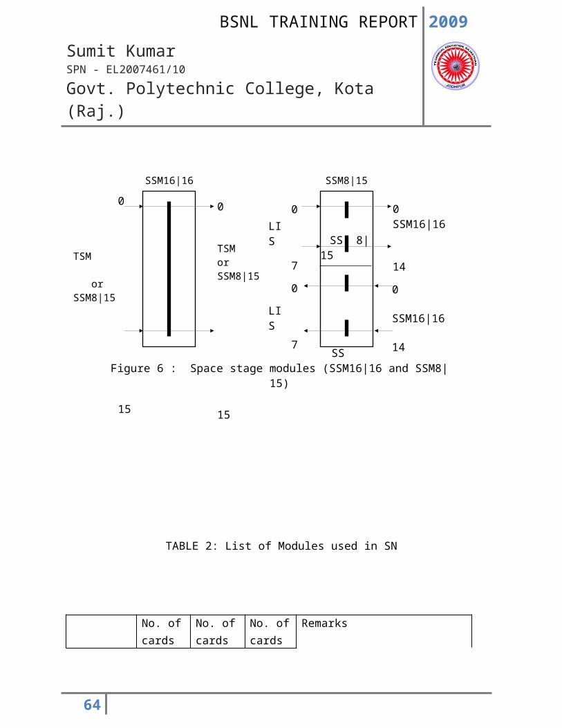
Figure 18: Speech path of a through connection
SN
Space Stage Part 0
Space Stage Part 1
Space Stage Part 2
Space Stage Part 3CP MBU:
SGC
SGC/LIM
LTG of the calling party TSI
TSO
Setting command
TSM
TSM
LTG of the called party
TSI
TSO
2009
Sumit KumarSPN - EL2007461/10
Govt. Polytechnic College, Kota (Raj.)
12. Functions
Three essential functions of switching network namely speech path switching, message path switching and changeover to standby are described below: -
12.1 Speech path switching
The switching network switches single channel and broadcast connections with a bit rate of 64 Kbit/s and multichannel connection with nx64 Kbits/s. Two connection paths are necessary per single channel connection (e.g. from calling to called party and from called to calling party). For a multichannel connection, nx2 connection paths are necessary. In broadcast connections, the information is passed from one signal source to a number of signal sinks (no opposing direction).
The coordination processor (CP) searches for free paths through the switching network according to the busy status of connection paths stored at that moment in the switching network’s memory. The path selection procedure is always the same and is independent of the capacity stage of the switching network. During path selection, the two connection paths of a call are always chosen so that they will be switched via the same space stage section. A space stage section is a quarter of the space stage arrangement; with an SN: 252 LTG, for example, this corresponds to half a space stage group SSG.
After path selection, the CP causes the same connection paths to be switched through in both switching network sides of an SN. The SGCs are responsible for switching the connection paths. In a capacity stage with 63 LTGs, one switch group control participates in switching a connection path; however in a capacity stage with 504, 252, or 126 LTGs, two or three switch group controls are involved. This depends on whether or not the subscribers are connected to the same TSG. The CP gives every involved switch group control setting instructions necessary for the through-connection. These setting instructions always have the same data format.
An SGC receives the setting instruction from the CP via the message buffer unit MBU: SGC, the secondary digital carrier SDC: SGC, n an SGC and the CP are exchanged via an LIM. The SGC calculates the setting data using the call processing programs and service routines. The SGC loads the data into registers in the hardware controller (HWC) of the LIM and, via the HWC, controls the setting of desired connection paths in
64
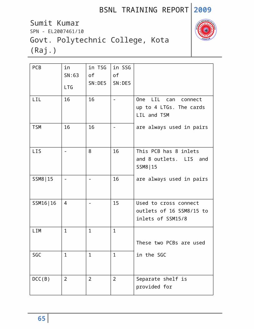
SN0
SN 1
TSG 1.0
LIL TSMLIS
E
S
TSO
TSI
SSG 1.0
LIS SSM8|15 SSM16|16
S
E
SSM15|8
SSM8|15
LTG
TSG0.0
LIL TSMLIS
E
S
TSO
TSI
SSG0.0
LIS SSM8|15 SSM16|16
S
E
SSM15|8
SSM8|15
Figure 19 :Example of possibilities for changeover to standby in the switching network capacity stage SN:504LTG, SN:252LTG and SN:126LTG
2009
Sumit KumarSPN - EL2007461/10
Govt. Polytechnic College, Kota (Raj.)
65
2009
Sumit KumarSPN - EL2007461/10
Govt. Polytechnic College, Kota (Raj.)
12.2 Message path switching.
Apart from the connections determined by subscribers by inputting dialing information, the switching network also makes connections between the LTG and the CP. These connections are used to exchange control information; they are setup only once, and then they are always available. For this reason, they are called semi permanent connections. Via these same connections, the LTGs also interchange message without having to burden the CP’s processing unit. In this manner, a separate line network for the exchange of messages within an exchange is not necessary. Nailed-up connections and connections for common channel signaling are made on a semi permanent basis as well.
12.3 Changeover to standby
All connection paths are duplicated, i.e. switched through in SN0 and SN1. This provides an alternative route for each connection in case of failure.
Figure 19 provides a simplified illustration of the various alternative routes possible in capacity stages with 504, 252, and 126 LTGs. The connection paths are switched in the same manner over both switching network sides (SN0 and SN1). The LTGs accept the incoming octets of the effective connections (subscriber/ subscriber connections) from only one switching network side. In figure 19, the effective connections lead over SN0. Of note is the duplicated routing between the time stage groups (TSG) and space stage group (SSG). This makes it possible for the TSGs and SSGs to be individually switched over to standby. Switching over to standby is implemented only if errors occur simultaneously in both switching network sides. The effective connections are then lead over routed TSGs and SSGs of both switching network sides 0 and 1. In the switching network capacity stage with 63 LTGs, it is only possible to route the connections over SN0 or SN1.
If an error occurs in the switching network, the CP initiates corresponding measures for switching over to standby and issues the corresponding messages. Changeover to standby do not interrupt existing connections. Thanks to this duplication principle, all operational measures are easily carried out without impairing traffic (e.g. adding new modules or replacing defective modules).
66
2009
Sumit KumarSPN - EL2007461/10
Govt. Polytechnic College, Kota (Raj.)
13. O&M Aspects
The following MML commands are used during operation and maintenance of switching network.
Display and Modification in number of TSMs.
DISP TSG MOD TSG
Status display and Configuration commands
STAT SN CONF SN CONF TSG CONF SSG
Diagnosis and Test commands - SN DE4 and DE5
DIAG SN TEST SN
Diagnosis and Test commands - SN DE5 only
DIAG TSG DIAG SSG
TEST TSG TEST SSG
13.1 Safeguarding Concept
The switching network (SN) is duplicated. Normally one SN side is active (the SSG and both TSGs in ACT), and the other SN side is standby (the SSG and the TSGs in STB).
In the event of a malfunction in a switch group (SSG or TSG) in the active SN, the affected switch group is configured to UNA and the other switch groups in the previously standby SN are configured to ACT.
N the event of a malfunction in a switch group in the standby SN, only the affected switch group is configured to UNA.
None of these reconfigurations affect switching traffic.
67
2009
Sumit KumarSPN - EL2007461/10
Govt. Polytechnic College, Kota (Raj.)
13.2 Fault Printouts
An SN fault printout is the result report of the fault analysis program for the SN or for a switch group (SSG or TSG). It complements the more general alarm signaling with SYP etc. i.e. whenever the safeguarding system detects a malfunction in the SN, an appropriate fault printout is formulated, typically as follows:
SN FAILURE WITH CONFIGURATION MMN:SN0xx-000
SGC DEFECT
FAULT LOCATION : TSG-side-tsg SGC
CONFIGURATION : TSG-side-tsg FROM : zzz TO : UNA
SUPPLEMENTARY INFORMATION :
H ‘zzzzzzzz zzzzzzzz zzzzzzzz zzzzzzzz
H ‘zzzzzzzz zzzzzzzz zzzzzzzz zzzzzzzz
Faults affecting the SN can be divided into two groups which are clearly distinguishable in terms of the system response: -
* Unconditional fault
These are serious faults. The switch group in which such a fault occurs is always reconfigured to UNA. With unconditional faults, the following codeword’s may be output :
- SGC/SGC FAILURE
- SGC/HWC FAILURE
- PATH SET/HWC-FAILURE
- CYCLE DEFEKT
- NO CYCLE
- SGC CHANNEL ERROR
* Conditional faults
68
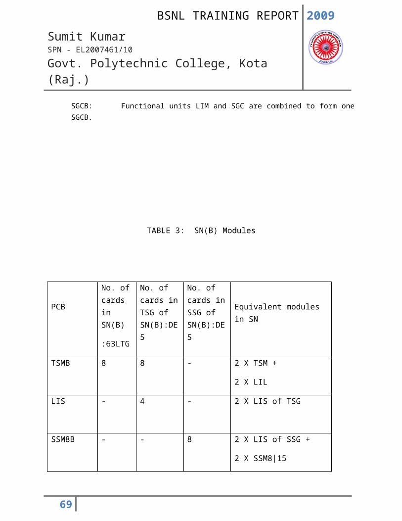
2009
Sumit KumarSPN - EL2007461/10
Govt. Polytechnic College, Kota (Raj.)
These are not serious. If such a fault occurs in a switch group with no redundancy (i.e. where the partner switch group is in NAC, UNA or MBL), then the affected switch group is not configured to UNA. If the switch group is duplicated, then it is configured to UNA, even for a conditional fault. Codeword’s for conditional faults are :
- SGC/PLLU-FAILURE
- SN-PLL FAILURE
- PATH SET/TSM-FAILURE
- PATH SET/SSM8-FAILURE
- PATH SET/SSM16-FAILURE
- SGC-DEFECT
- All COC-FAILURE
- All MCH-FAILURE
- All MUX-FAILURE
13.3 Diagnostics
Explanation: -
* DIAG TSG
This command starts a test program, to be specified under parameter TA, for a time stage group (TSG).
* DIAG SSG
69
DIAG TSG: SN=side, TSG=tsg,TA=area, SUBUNT= TSM/ SSM/ CSM - x;
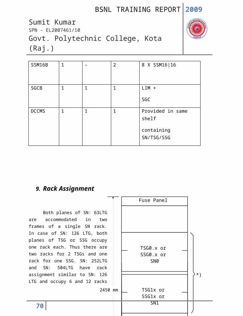
2009
Sumit KumarSPN - EL2007461/10
Govt. Polytechnic College, Kota (Raj.)
This command starts a test program, to be specified under parameter TA, for a space stage group (SSG).
* side SN plane, either 0 or 1
* tsg Number of TSG, 0 to 7
* TA (test area = test program)
* Area
The identifier entered for the parameter TA specifies the test program to be called up. The following test programs are possible: CHALL, ALL, HWC, TSM, SSM, CSM, PLL
In test program TSM, SSM and CSM, in the diagnostic command, a subunit must also be specified.
- CHALL (check all)
- For TSG, tests central sections,
CPU with program and data memory
PLL supervision circuit
hardware controller
tests decentralize sections :
control memory of TSM modules
- For SSG, tests central sections :
70
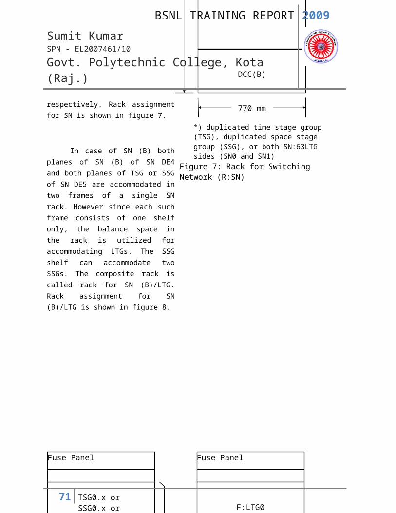
2009
Sumit KumarSPN - EL2007461/10
Govt. Polytechnic College, Kota (Raj.)
CPU with program and data memory
PLL supervision circuit
hardware controller
tests decentralize sections :
control memory of SSM16|16 and SSM8|15
- ALL (check all control memories)
- For TSG, The control memories of modules TSM are tested.
Each bit in a control memory is checked for 1 and 0.
The addressing of each Ram chip in a control memory
is also checked.
- For SSG The control memories of modules SSM16|16 and
SSM8|15 are tested. Each bit in a control memory is
checked for 1 and 0.
The addressing of each RAM chip in a control memory is also checked. Whereas modules SSM8|15 are only tested according to the SN capacity stage specified in the CP command, all 15 SSM16|16 modules are tested.
- HWC (HWC test) - for TSG and SSG
The HWC registers are checked. A good or bad message gives the states of the HWC registers and the interface between SGC and HWC. The HWC interface to the switching modules is not tested.
71
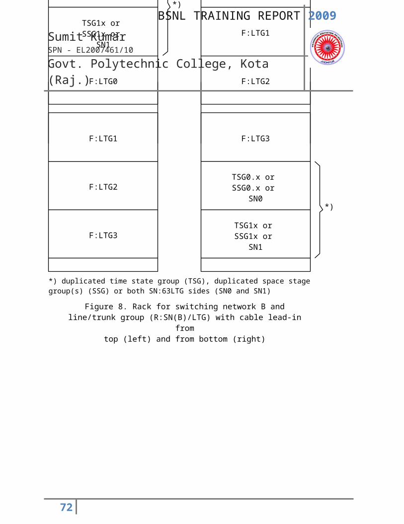
2009
Sumit KumarSPN - EL2007461/10
Govt. Polytechnic College, Kota (Raj.)
- TSM (TSM test)
The addressing and functioning of each bit in the control memory of a TSM module are tested.
- CSM (SSM16|16 test)
The addressing and functioning of each bit in the control memory of an SSM16|16 module are tested.
- SSM (SSM8|15 test)
The addressing and functioning of each bit in the control memory of an SSM8|15 are tested.
- PLL (PLL supervision circuit test)
* SUBUNT
For diagnostic identifiers TSM, CSM & SSM, the subunit must be specified.
Possible subunits are: TSM = functional unit TSM/LIL
SSM = functional unit LIS/SSM8|15
CSM = SSM16|16
72
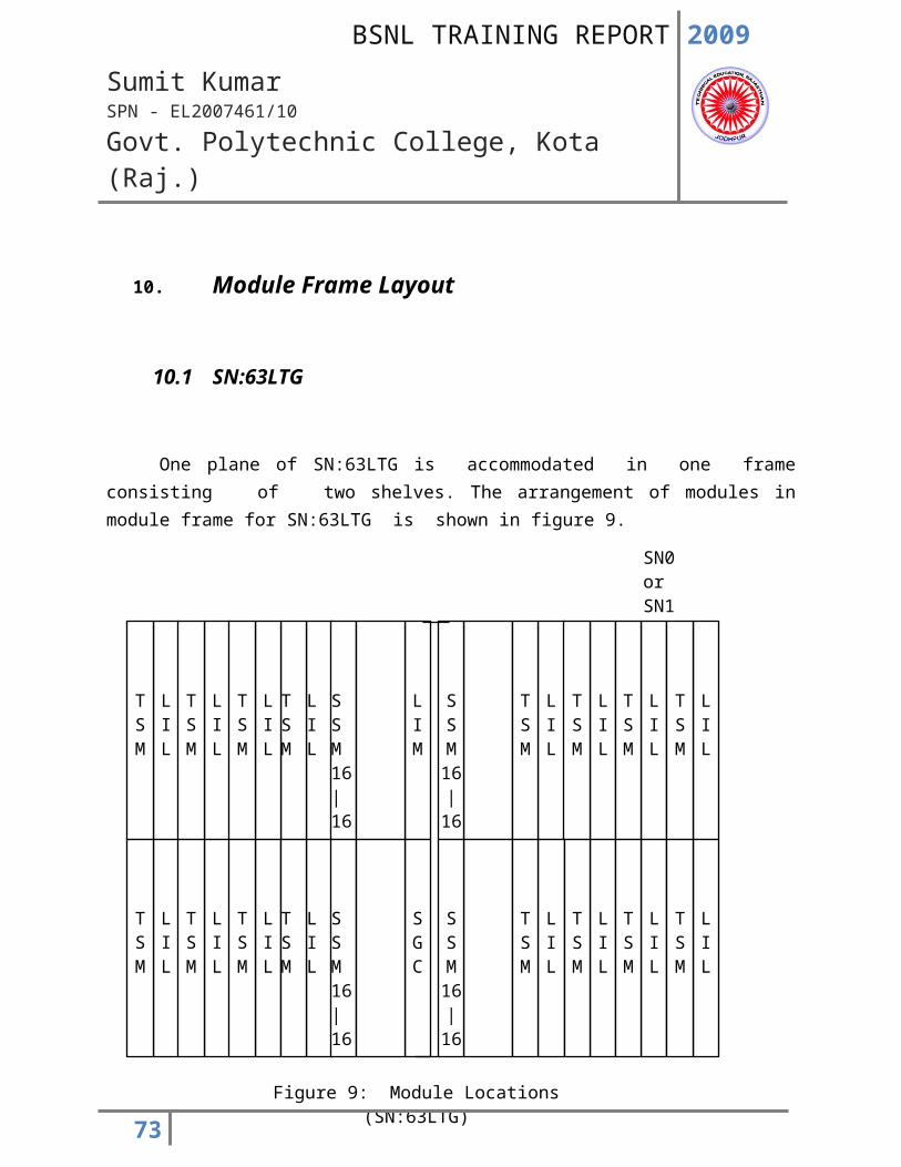
2009
Sumit KumarSPN - EL2007461/10
Govt. Polytechnic College, Kota (Raj.)
* X TSM number (0 to 15)
SSM8|15 number (0 to 15)
SSM16|16 number (0 to 14)
13.4 Test
The SN speech path test makes a cross-office check per SN side, switch group or subunit, depending on the command.
This involves setting up connections via SN, which are then tested with a test pattern. If the SN speech path detects a COC error in such a connection path, the test is repeated with a new path setup attempt (with the same parameters). If the test again detects a COC error, it is terminated with FAILURE DETECTED. The MML command used is as follows, where symbols/parameters are same as in DIAG SN.
73
TEST TSG: SN=side, TSG=tsg, TA=area, SUBUNT= TSM/ SSM/ CSM - x;
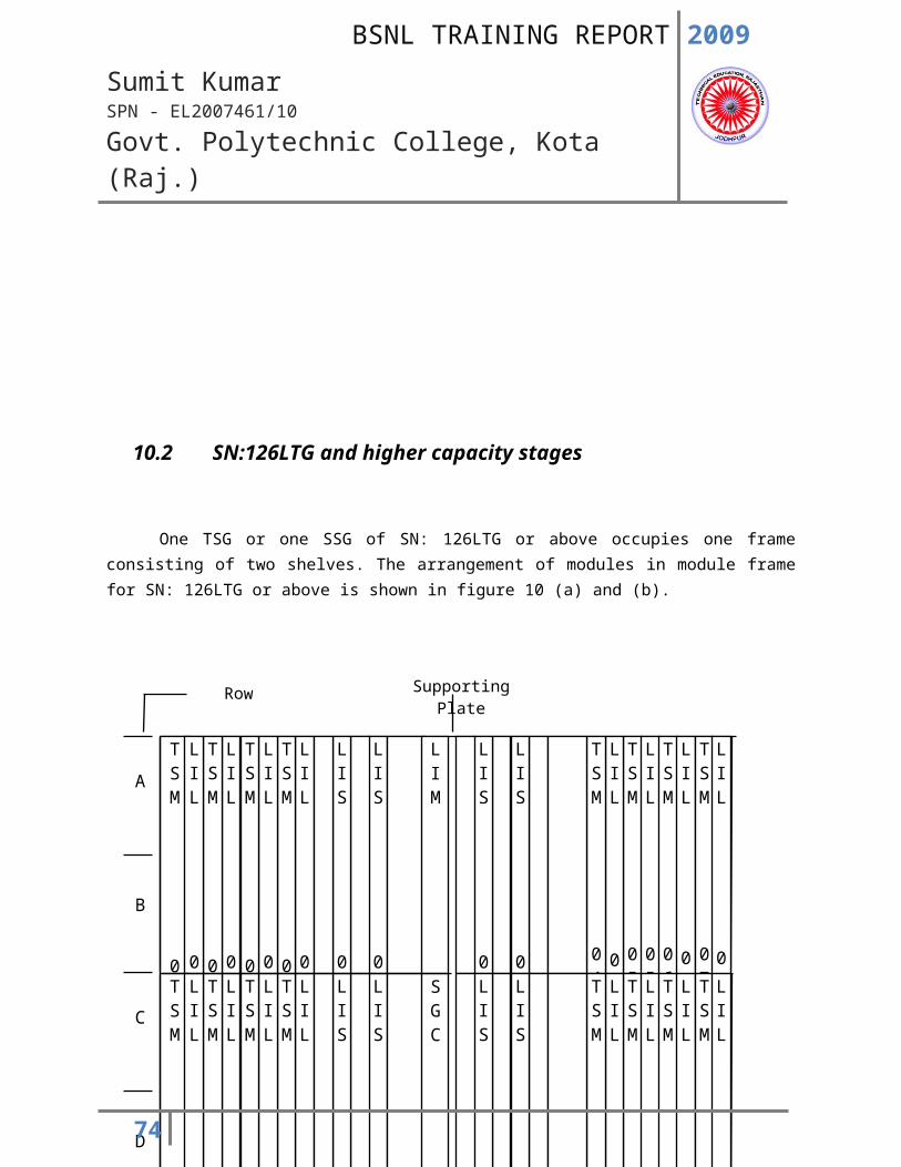
2009
Sumit KumarSPN - EL2007461/10
Govt. Polytechnic College, Kota (Raj.)
14. Exercises
1. Interrogate and find out the capacity stage of SN in your exchange. Identify its racks, frames and modules.
2. Find out the number of LTGs and TSMs in your exchange and correlate. How many additional LTGs can be provided with the existing SN configuration?
3. Change status of both planes of SNs, one by one, using all possible combinations of OST and tabulate the results.
4. A fault in SN plane 0 has affected the third LTG connected to TSG1. What functional unit in SN could be faulty? Write MML commands to configure and diagnose the faulty unit.
74
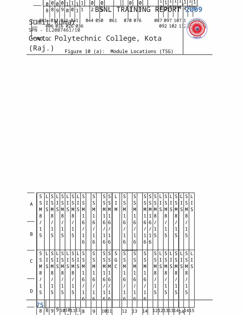
2009
Sumit KumarSPN - EL2007461/10
Govt. Polytechnic College, Kota (Raj.)
SWITCHING TECHNIQUES
SPACE DIVISION SWITCHING
MULTIPLE STAGE SWITCHING
TIME DIVISION SWITCHING
TWO-DIMENSIONAL SWITCHING
MULTI STAGE TIME AND SPACE SWITCHING
75
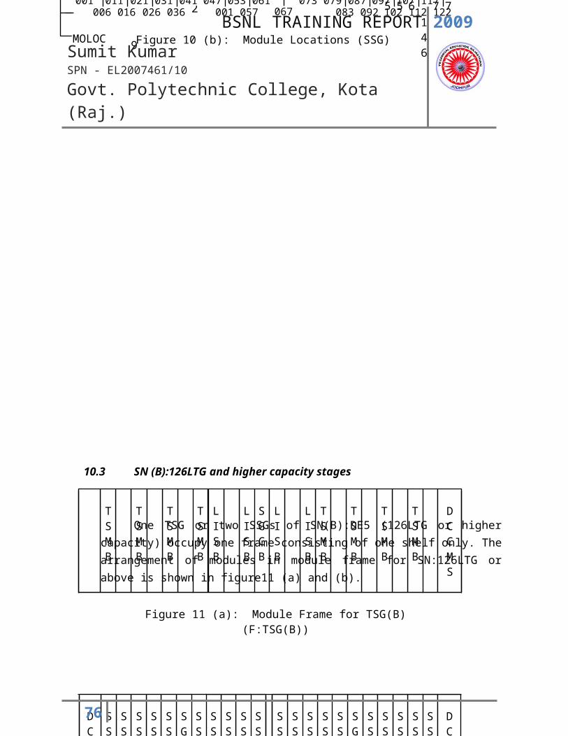
2009
Sumit KumarSPN - EL2007461/10
Govt. Polytechnic College, Kota (Raj.)
INTERNET
Introduction:
The Internet is not a program, not software, not hardware or a big system. It is a group of various co-
operating computers worldwide interconnected by computer based on TCP\IP communication
protocols. People use it to get information over a standard communication link. The hundreds or
thousands or millions of computer network are connected to each other for exchanging the information
which is based on the unique identity and set of procedures. Internet is a series of interconnected
networks providing global link to information.
GIAS: BSNL launched the Gateway Internet Access Service (GAIS) through dial up/leased/ISDN network.
Users can access GAIS from 99 cities in India by this means.
INTERNET CONNECTIVITY
INTERNET TECHNOLOGY
The basic function of Internet can be summarized as under-
Interconnecting of computers to form a network.
Interconnecting of computers to form a network of networks.
To establish a communication link between two computers within as network.
To provide alternate communication link among the networks, even if one network is not working.
These are based on TCP/IP communications protocol.
76
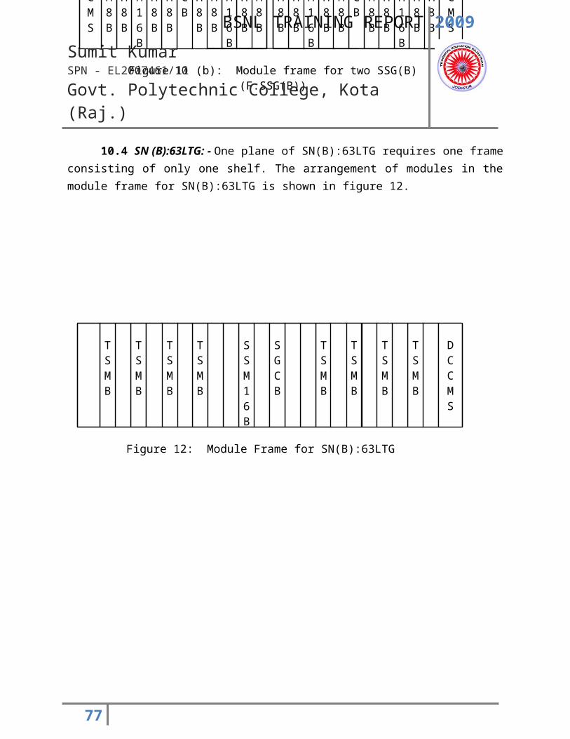
2009
Sumit KumarSPN - EL2007461/10
Govt. Polytechnic College, Kota (Raj.)
Transfer of a file through Internet:-
Suppose a file is to be transmitted on Internet from one computer to other ones
Break the file in to small packets
Attached destination and source address in o packets
Multiplexed and transmit these packets
At destination de-multiplex the packets
Remove address bits from the packets and assemble the data in to the original file
Make source bits as destination address and send the acknowledgement in to the source
Therefore, it is clear that network hardware sends the packets to specified destination and network
software reassembles of communications, the computer network performs the following functions-
Addressing and routing
Fragmentation and error correction
Data error checking
Connectivity control
Multiplexing and de-multiplexing
Data flow control
End users interface etc.
The data handling
A single module cannot handle the entire process. One that adopted as a standard is an open system
interconnection (OSI) model.
77
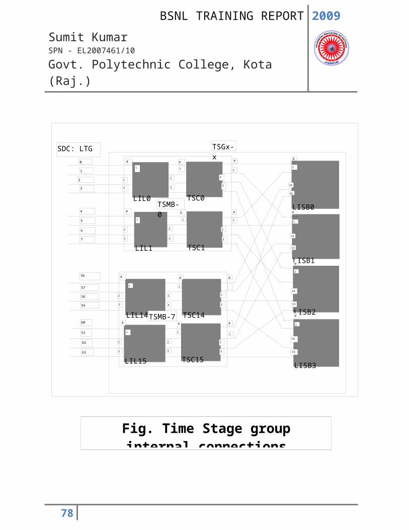
2009
Sumit KumarSPN - EL2007461/10
Govt. Polytechnic College, Kota (Raj.)
COMMON TERMINOLOGY USED IN INTERNET:
WWW:
World Wide Web (WWW) is a wide area hypermedia information retrieval aiming to give
universal access to a large universe of documents.
HTTP:
Hyper text transmission Protocol (HTTP) is the communication protocol used to transfer
documents from the server to client over the WWW (http:// www).
HTML:
Hyper Text Markup Language (HTML) is a system of marking or tagging the various parts of web
documents to tell the browser software how to display the document text, link graphics and
link media.
ISDN:
Integrated Service Digital Network (ISDN) is a digital phone connection technology that provides
both voice and data services over the same connection.
ISP:
Internet Service Provider (ISP) is an agency that provides Internet access and other net related
services.
78
2009
Sumit KumarSPN - EL2007461/10
Govt. Polytechnic College, Kota (Raj.)
NATIONAL INTERNET BACKBONE (NIB)
Networking is a key component of any Internet Services Provider (ISP) operations. The networking
equipments like access servers, routers and modems are critical to the successful functioning of ISP.
An ISP node where subscribers enter internet, consists of a set of equipments as given below.
Access server
Router
Modem bank
LAN (Local Area Network) components
Security server
Rack, console & power supply
Network management agent.
Help desk
79
2009
Sumit KumarSPN - EL2007461/10
Govt. Polytechnic College, Kota (Raj.)
CELLULAR MOBILE SERVICES: -
Cellular is one of the fastest growing and most demanding telecommunication applications. Today, it
represents a continuously increasing percentage of all new telephone subscriptions around the world.
Currently there are more than 45 million subscribers in worldwide and nearly 50% of those subscribers
are located in USA. It is forecasted that cellular system using a digital technology will become the
universal method of telecommunications. By the year 2005, forecasters predict that there will be more
than 100 million cellular subscribers worldwide.
1. WIRELESS IN LOCAL LOOP (WLL) MOBILE
WLL is a communication system that connects customers to the Public Switch Telephone
Network (PSTN) using radio frequency signals as substitutes of conventional wires for all part of
connection between the subscribers and the telephone exchange. It works on CDMA technique.
The local loop is access part of telecommunication network i.e. the part between PSTN switch
and subscribers. WLL network application involves uses of radio to replace of the wire link
between PSTN switch and subscriber. The radio technology is able to provide same quality of
services as that provided by the wires line. Application of wireless loop technology has just been
started in the worldwide. There is no standard for this so far. However, a number of national
and international air interface standards for digital cellular mobile telephone system are
available.
TECHNICAL ASPECTS:
WLL is based on CDMA technique and is entirely different from GSM. The system for
WLL services can be divided in two following parts:-
BSC (Base Switching Centre):- It provides links between BTS & BSM; it consists of
different processors, in BSNL it is of SUN Polaris of LG Company. In LG 1 BSC can have 48 BTS? In
80
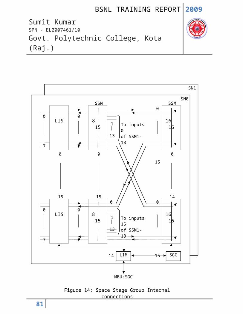
2009
Sumit KumarSPN - EL2007461/10
Govt. Polytechnic College, Kota (Raj.)
BSNL we have two types of BSC:-
I. V-5.2:- This type of BSC cannot switch by itself so it is dependent on local exchange /
PSTN for switching and keeping records of billing etc. BSNL uses this type of BSC for rural areas.
ii. CCS-7 / R2:- These types of BSC are totally automatic it doesn’t depend on local
exchange for its functions, it is complete in itself. BSNL uses this type of BSC for urban areas.
BTS (Base Transreceiver System):- As it is clear from its name it transmits as well as receive
signal, it works as an amplifier (router) to overcome the loss in signal in transmission.
BSM (Base Station Management):- It controls and manages the WLL services. It can
troubleshoot the problem; add new users as well as capable to block service given to user. It is
basically a computer system, which manages the whole process of WLL service. In BSNL BSM are
two UNIX based computer system.
ADVANTAGES OF WLL:
Country wide induction of WLL underway of areas than are non-feasible for the normal
network
Helping relieves congestion of connections in the normal cable / wire based network in urban
areas
Limited the mobility without any airtime charges
It has improved signal and reducing the interference
Greater capacity than mobile
Provides ease of operation, administration & maintenance at lower cost.
The telecommunication is the biggest factor in influencing the speed of life in the modern age.
Today we can get connection with any corner of world through the push button of computer;
with the small mobile phone we can send not only the messages but also the secret document.
As we know that there is positive view behind any mention that it should be helpful in the
81
2009
Sumit KumarSPN - EL2007461/10
Govt. Polytechnic College, Kota (Raj.)
development of society. But humans have diverted mentality some of them of positive view and
some of them of negative view. Where use any invention for the welfare of society but some
uses for the satisfaction their disturbed mentality and to earn more and more money whether it
may be harmful for the society. They infringe the norms of society and their behavior is
condemned as antisocial, immoral and sinful.
2. CODE DIVISION MULTIPLE ACCESS (CDMA):
CONCEPT OF MULTIPLE ACCESSES: -
Multiple access system allows a large number of users to share a common pool of radio
telephone circuits, like sharing of trunked radio facility. Multiple access radio has similarity to
the LAN in which the common channel is available to all users. The circuits are demands
assigned i.e. assigned on demand first-cum-first-served basis. The provision of access to the
radio circuits methods of multiple accesses are:
CDMA: - Where large number of transmission are combined on the same channel at the same
time and separated by the codes.
WHAT IS CDMA?
CDMA, a cellular technology originally known as IS-95, competes with GSM technology for
dominance in the cellular world.
There are now different variations, but the original CDMA is known as CdmaOne.
Latest CDMA global subscriber & operator’s numbers
As of December 2002, there were 120 million users worldwide, with 55 million of these in the
USA.
See other cellular technology in the world.
We now have CDMA2000 and its variant like 1X EV, 1XEV-DO and MC 3X. The refer of variant of
82
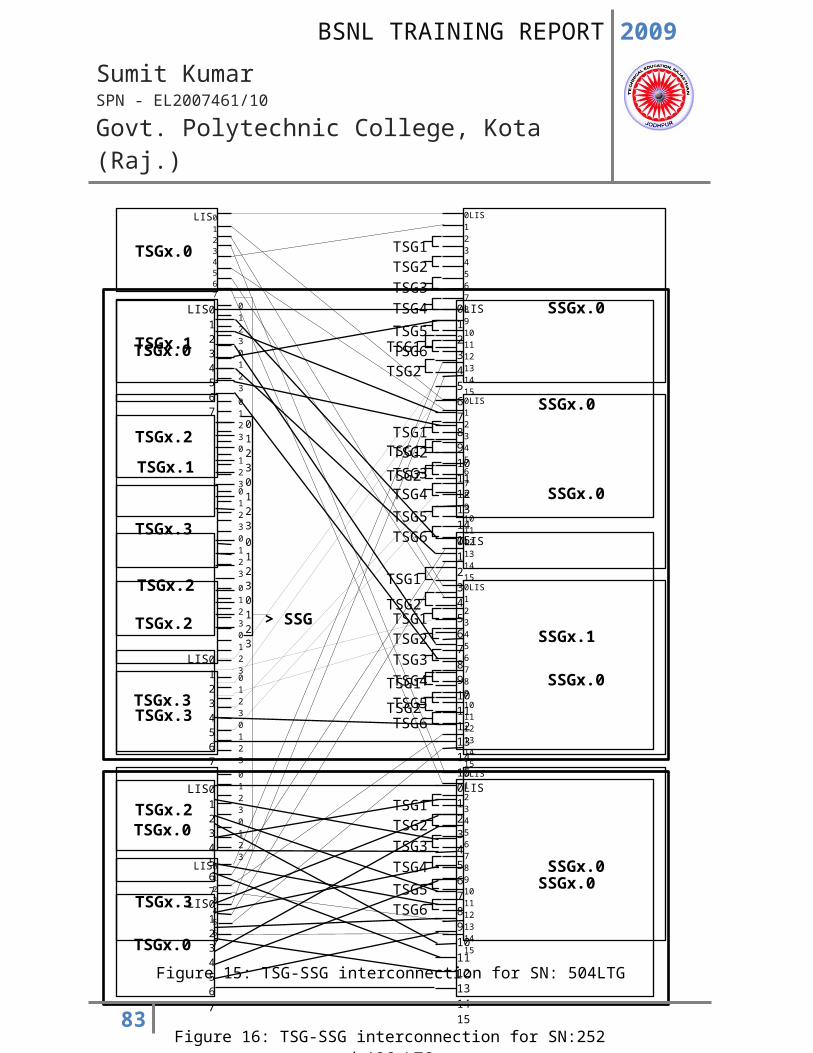
2009
Sumit KumarSPN - EL2007461/10
Govt. Polytechnic College, Kota (Raj.)
usage of a 1.25 MHz channel. 3X uses a 5 MHz channel. Wide band CDMA forms that the basis of
UMTS 3G networks, developed originally by Qualcomm, high capacity and small cell radius,
employing spread-spectrum technology and special coding scheme characterized by CDMA.
The Telecommunication Industry Association (TIA) in 1993 adopted CDMA. May 2001 there
were 35 million subscribers on cdmaOne system worldwide. Over 35 countries have either
commercial or trial activity ongoing. There were already 43 WLL systems in 22 countries using
cdmaOne technology.
Enhancing today’s data capabilities is the 1XRTT CDMA standard this next evolutionary step for
cdmaOne operators will provide data rates up to 300 kbps, significant capacity increases as well
as extended batteries life for handsets.
Worldwide resources are being devoted to roll out third generation CDMA technology, including
multi-carrier (cdmaOne2000 1xMC and HDR in 1.25 MHz bandwidth and 3xMC in 5 MHz
bandwidth) and direct spread (WCDMA in 5 MHz bandwidth).
This first phase of cdmaOne2000 variously called 1XRTT, 3G1X or just plain 1X is designed to
double current voce capacity and support always on data transmission speed 10 times faster
than typically available today, some 153.6 kbps on both the forward and reverse links.
3. GLOBAL SYSTEM FOR MOBILE COMMUNICATION (GSM): -
The GSM Association is a unique organization, with a truly global reach, offering a full
range of business and technical services to its members. Now as the wireless family unfolds the
association is deriving forward its vision of seamless, limitless, world of wireless communication.
Throughout the evolution of cellular telecommunications, various systems have been developed
without the benefit of standardized specifications. This presented many problems directly
related to compatibility, especially with the development of digital radio technology. The GSM
standard is intended to address these problems.
Global system for mobile communication (GSM) is a globally accepted standard for digital
cellular communication. GSM is the name of a standardization group established in 1982 to
create a common European mobile telephone standard that would formulae the specifications
83

2009
Sumit KumarSPN - EL2007461/10
Govt. Polytechnic College, Kota (Raj.)
for a pan-European mobile cellular radio system operating at 900 MHz it is estimated that many
countries outside of Europe will join the GSM partnership.
OBJECTIVES OF GSM SYSTEM:
One of the important objectives of GSM group is to evolve a unified standard to provide seamless roaming across Europe. Another landmark decision taken by the group is to standardize a digital radio interface for the communication between the mobile handset and the radio transmitter / receiver. The design objectives of the GSM system can be briefly states as below:
Excellent speech quality High security and privacy Low module terminal cost Low service and facilities cost Design of sleek and handled mobile terminals International roaming Wide range of services and facilities Ability to adopt to new and innovative features Narrowband ISDN compatibility Digital Radio High Spectral efficiency
GSM NETWORK ELEMENTS AND ARCHITECTURE:
1. Mobile Station (MS) i. Mobile Terminal or Equipment (MT)
ii. Subscriber Identity Module (SIM) Card
2. Base Station Subsystem (BSS) i. Base transceiver Station (BTS)
ii. Base Station Controller (BSC) iii. Main Station Controller (MSC)iv. Transcoding and Rate Adoption Unit (XCDR/TRAU)
3. Network Switching Subsystem (NSS) i. Registration
ii. Authentication and security iii. Location updating iv. Handovers and
84
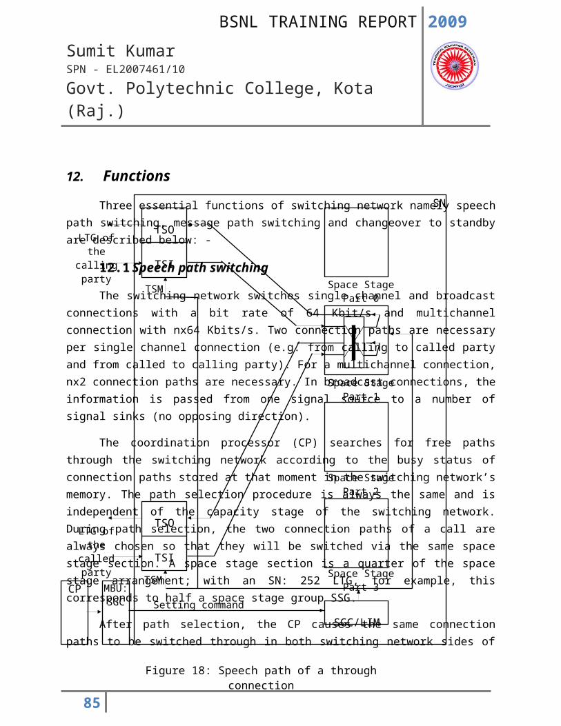
2009
Sumit KumarSPN - EL2007461/10
Govt. Polytechnic College, Kota (Raj.)
v. Routing to roaming subscribers
4. Operation and Maintenance Subsystem (OMS) i. Operation and Maintenance Centre – Switch
ii. Operation and Maintenance Centre – Radio
5. Enhanced Services Subsystem (ESS)
6. Billing and Customer Care System (B&CCS)
85
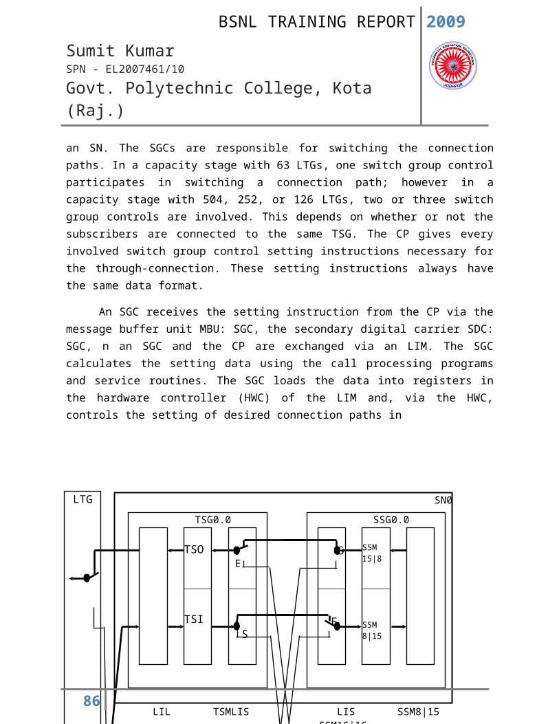
2009
Sumit KumarSPN - EL2007461/10
Govt. Polytechnic College, Kota (Raj.)
4. THIRD GENERATION 3G TECHNOLOGY : -
Introduction: -
Third generation (3G) networks were conceived from the Universal Mobile Telecommunications Service (UMTS) concept for high speed networks for enabling a variety of data intensive applications. 3G systems consist of the two main standards, CDMA2000 and W-CDMA, as well as other 3G variants such as NTT DoCoMo's Freedom of Mobile Multimedia Access (FOMA) and Time Division Synchronous Code Division Multiple Access (TD-SCDMA) used primarily in China.
Data Speed
The data speed of 3G is determined based on a combination of factors including the chip rate, channel structure, power control, and synchronization.
An example of calculating the theoretical 3G data speed is as follows:
W-CDMA assigned code 400-500 Kbps/code. 6 codes X 400 > 2Mbps (UMTS target for 3G data speed in fixed location)
Actual data speeds will vary in accordance with several factors including:
Number of users in cell/sector Distance of user from cell User is moving or stationary Network operator capacity and network optimization requirements
1xEV-DO is a data-only solution, supporting a theoretical data speed of up to 2.457 Mbps
1xEV-DV is a data and voice solution, supporting a theoretical data speed of up to 3.072 Mbps
FOMA has two operational modes, supporting a dedicated 64 Kbps connection or a 384 Kbps downlink/64 Kbps uplink best-effort connection.
TD-SCDMA can operate in 1.6 MHz or 5 MHz mode for 2 Mbps or 6 Mbps respectively
86
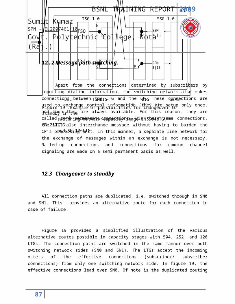
2009
Sumit KumarSPN - EL2007461/10
Govt. Polytechnic College, Kota (Raj.)
87
2009
Sumit KumarSPN - EL2007461/10
Govt. Polytechnic College, Kota (Raj.)
3G is the short form for third-generation technology. It is one of the popular mobile phone standards. The services utilizing 3G provide the ability to transmit both voice data such as calls and non-voice data such as instant messaging, email and video telephony at the same time. Japan was the first country to introduce 3G on a wide scale commercially. In 2005, almost 40 per cent of the subscribers in Japan used 3G services. On the technical front, 3G services are wide area cellular telephone networks unlike IEEE 802.11 networks, which are short range networks meant for Internet access. Now, 3G is being used to provide various services.
You have to plug in 3G Data Card into your laptop and can get the fastest available connection, with mobile broadband speeds of up to 1.8 Mbps. It’s neat, compact design makes it easy to use; you can easily swap it between laptops for use at work, home or on the move. Laptops have a PC Card slot (also known as a PCMCIA slot), or an Express Card slot. There is PCMCIA to Express Card Converter for using 3G broadband; you need 3G Data card, network SIM card, software, user guide.
88
History of Wireless
2009
Sumit KumarSPN - EL2007461/10
Govt. Polytechnic College, Kota (Raj.)
BSNL’s IPTV
• First started in Japan in 2002.
• Popular in France, South Korea, Germany, Hongkong etc.
• France is leading in IPTV having more than 1.7 million IPTV viewers
Global IPTV subscriber’s base will reach 14.5 million in 2007 and will be approximately 63 million by 2010.
89
2009
Sumit KumarSPN - EL2007461/10
Govt. Polytechnic College, Kota (Raj.)
90
2009
Sumit KumarSPN - EL2007461/10
Govt. Polytechnic College, Kota (Raj.)
CONCLUSION: -
Hence in the last I can say that taking training in such an organization proved to be very beneficial for me. I learnt quite a lot about electronic exchange, Internet, Land line, WLL, Mobile GSM & 3G, and the basis of processing Exchange. I also got firsthand knowledge of how a Telephone Exchange works.
The first phase of training has proved to be quite fruitful. It provides an opportunity to encounter with such huge machines.
The architecture of company has various units. They are linked and working of whole plant is controlled make the student realized that engineering is not just learning the structure description and working of various machines. But the greater part is planning proper management.
-------×-------
91
2009
Sumit KumarSPN - EL2007461/10
Govt. Polytechnic College, Kota (Raj.)
GLOSSARY OF TERMS AND ABBREVIATIONS
ADM Add/Drop Multiplexers
ANALOGUE An electrical signal which is analogous to changing physical quantity measured
BSC Base Station Controller
BTS Base Tran receiver Station
C-DOT Centre for Development of Telemetric
CD Cabinet Cable Distribution Cabinet
CDMA Code Division Multiple Access
CKM Cable conductor kilometer – cable sheath kilometers multiplied by the number of conductor pairs in each cable
CLIP Calling Line Identification Processing
COAXIAL CABLE A cable with a single wire in the centre of cylindrical conductor forming a pair of carrying electrical signals
CT BOXES Cable Termination Boxes
DECT Digital Enhanced Cordless Telecommunications
DEL Direct exchange lines, one each for every telephone connection
DIGITAL EXCHANGE The exchange having signals coded into binary pulses and having little or no moving parts
DIU DECT interface unit
DLC Digital Loop Carrier
DWDM Dense Wavelength Multiplexing Terminal
EDX Electronic Data Exchange
EPABX Electronic Private Automatic Branch Exchange
ETRP Electronic Trunk Relay Plates
EWSD TAX Electronic Wheeler System of Digital Trunk Automatic Exchange
92
2009
Sumit KumarSPN - EL2007461/10
Govt. Polytechnic College, Kota (Raj.)
GHz Giga Hertz
GSM Global System for Mobile Communications
HDPE High density polyethylene
HDSL High bit rate Digital Subscriber Line
Hertz or Hz Frequency (cycles per second), named after Heinrich Hertz - usually in ranges of kilo 1000 - KHz, mega 1,000,000 - MHz or giga 1,000,000,000 - GHz
IDR Intermediate Data Rate
ISDN Integrated Services Digital Network
LDST Long Distance Satellite Telephone
LOI Letter of Intent
MARR Multi Access Rural Radio
MBM Multi Base Module
Mbps Mega bits per second denoting digital frequency
MCPC Multi Channel Per Carrier
MDF Main Distribution Frame
MUX Multiplex
NIT Notice Inviting Tender
NE Lines Non Exchange Lines
OFC Optical Fiber Cable
Optical Fiber (OF) Glass fibers using light waves for transmission of signals
OLA Optical Line Amplifiers
OYT Own your telephone
PABX Private Automatic Branch exchange
PBX Private branch exchange
PCM Pulse Code Modulation
PCO Public Call Offices
PDH Plesiochronous Digital Hierarchy
PERT Chart Programmed Evaluation Review Technique Chart
93
2009
Sumit KumarSPN - EL2007461/10
Govt. Polytechnic College, Kota (Raj.)
PIJF Cable Polyethylene Insulated Jelly Filled Cable
PSPDN Packet Switch Public Data Network
PST Progressive Stock Taking
PSTN Public Switched Telephone Network
PVC Polyvinyl chloride
PW Private Wires
RLU Remote Line Unit
RSU Remote Switching Unit
SACFA Standing Advisory Committee on Radio Frequency Allocation
SDH Synchronous Digital Hierarchy
SMPS Switch Mode Power Supply
SRCs Subscriber Record Cards
SSAs Secondary Switching Areas
STD Subscriber trunk dialing
STM Synchronous Transport Module
TAX Trunk automatic exchange
TDMA Time Division Multiple Access – A transmission technique used in digital radio transmission in which the use of a frequency is divided into time slots that are shared amongst several users.
TELEX TelePrompTer exchange
TTH Triangular Tubular Hybrid
UHF Ultra high frequency (300 to 3000 MHz)
VHF Very high frequency
VPT Village Public Telephones
VSAT Very small aperture terminal
WLL Wireless-in-Local Loop
-----×-----
94
Related Documents