NJ-2014-003 Steel Erection Out-of-Plumb FINAL REPORT OCTOBER 2014 Submitted by Hugh Louch Cambridge Systematics, Inc. New York, New York 10016 Scott Johnsen Vincent Liang Greenman Pedersen, Inc. Lebanon, NJ 08833 NJDOT Research Project Manager Giri Venkiteela In cooperation with New Jersey Department of Transportation Bureau of Research

Welcome message from author
This document is posted to help you gain knowledge. Please leave a comment to let me know what you think about it! Share it to your friends and learn new things together.
Transcript

NJ-2014-003
Steel Erection Out-of-Plumb
FINAL REPORT OCTOBER 2014
Submitted by
Hugh Louch Cambridge Systematics, Inc. New York, New York 10016
Scott Johnsen Vincent Liang
Greenman Pedersen, Inc. Lebanon, NJ 08833
NJDOT Research Project Manager Giri Venkiteela
In cooperation with
New Jersey Department of Transportation
Bureau of Research

DISCLAIMER STATEMENT
“The contents of this report reflect the views of the authors who are responsible for the facts and the accuracy of the data presented herein. The contents do not necessarily reflect the official views or policies of the New Jersey Department of Transportation. This report does not constitute a standard, specification, or regulation.”

TECHNICAL REPORT STANDARD TITLE PAGE
1. Report No. 2. Government Accession No. 3. Recipient’s Catalog No. NJ-2014-003 4. Title and Subtitle 5. Report Date Steel Erection Out-of-Plumb October 2014
6. Performing Organization Code
7. Author(s) 8. Performing Organization Report No.
Hugh Louch, Scott Johnsen, and Vincent Liang 9. Performing Organization Name and Address 10. Work Unit No. Cambridge Systematics, Inc. 38 East 32nd Street, 7th Floor New York, NY 10016
11. Contract or Grant No.
12. Sponsoring Agency Name and Address 13. Type of Report and Period Covered
New Jersey Department of Transportation P.O. 600 Trenton, NJ 08625
14. Sponsoring Agency Code
15. Supplementary Notes 16. Abstract This study reviews available research papers, reports, presentations, Design and Construction guidelines from various agencies and universities related to the construction engineering of curved and/or skewed steel I-girder highway bridges, with a main focus on the recently published NCHRP Report 725 - Guidelines for Analysis Methods and Construction Engineering of Curved and Skewed Steel Girder Bridges. This study also compiles design and construction engineering guidelines/checklists to address out-of-plumb issues based on literature review and the authors’ past project experience from both design and construction inspection projects of curved and/or skewed steel I-girder bridges. 17. Key Words 18. Distribution Statement Steel I-girder, Curved, Skewed, Out-of-Plumb, Web Layover, NLF, SDLF, TDLF, Cross Frame
19. Security Classif. (of this report) 20. Security Classif. (of this page) 21. 48 pages 22. Price Unclassified Unclassified Form DOT F 1700.7 (8-69)

ii
ACKNOWLEDGEMENTS
The authors of this report wish to thank in particular the staff of the New Jersey Department of Transportation (NJDOT) whom completion of this report would not have been possible.

iii
TABLE OF CONTENTS
Page EXECUTIVE SUMMARY ................................................................................................ 1 OBJECTIVES ................................................................................................................. 2 INTRODUCTION ............................................................................................................. 2 SUMMARY OF thE LITERATURE REVIEW .................................................................. 3
NCHRP Report 725 – Guidelines for Analysis Methods and Construction Engineering of Curved and Skewed Steel Girder Bridges ..................................... 3 AASHTO LRFD Bridge Design Specifications, Section 6 ....................................... 5 NSBA G13.1 – Guidelines for Steel Bridge Girder Analysis ................................... 5 NSBA G12.1-2003 – Guidelines for Design for Constructability ............................ 5 NSBA S10.1-2007 – Steel Bridge Erection Guide Specification ............................. 5 FHWA-PA-2010-013-PSU 009 – Guidelines for Analyzing Curved and Skewed Bridges and Designing Them for Construction....................................................... 6 NCHRP Report 725 Appendix G ................................................................................ 6 Ohio DOT Summary of Skewed Bridge Issues ........................................................ 7 NYSDOT Steel Construction Manual (SCM) Sections 204 and 1403 ...................... 8
SUMMARY OF WORK PERFORMED ............................................................................ 9 Literature Review ....................................................................................................... 9 Identification of Key Terms ..................................................................................... 19 Project Review ......................................................................................................... 23
CONCLUSIONS AND RECOMMENDATIONS ............................................................. 33 Guidelines for Design and Contract Documents for Skewed and/or Curved Steel I-girder Bridges .............................................................................................. 34 Guidelines for Construction Engineering Provisions and Checklists ................. 38
BIBLIOGRAPHY ........................................................................................................... 48

iv
LIST OF TABLES Page Table 1 - Ohio DOT Summary of Skewed Bridge Issues ....................................................... 8 Table 2 – Simplified Matrix for Recommended Level of Analysis: I-girder Bridges .............. 13 Table 3 - Matrix for Recommended Level of Analysis: Steel I-girder Bridges
as per Report 725 .......................................................................................................... 14 Table 4 – Geometry, Connectivity Index and Skew Index by Structure .............................. 31 Table 5 – NCHRP Report 725 Recommended Detailing and analysis Method by
Structure ........................................................................................................................ 31

v
LIST OF FIGURES Figure 1 – Illustration of offset distance and adjacent unbraced length. .............................. 15 Figure 2 - Configuration 1: No Load Geometry (before connecting the cross-frames) ....... 20 Figure 3 - Configuration 2: Girder "locked" in the initial no-load, plumb and cambered
geometry ........................................................................................................................ 21 Figure 4 - Configuration 3: Theoretical Geometry under no-load, after initial fit .................. 22 Figure 5 – Configuration 4: Geometry under dead load (final condition).............................. 22 Figure 6 – Structure No. 1 Framing Plan .............................................................................. 23 Figure 7 - Structure No. 1 Overall Deformed Shape under Non-composite Dead Load ...... 24 Figure 8 – Structure No. 1 Close-up of the deformed shape at the acute corner depicting
both deflection and twisting ........................................................................................... 24 Figure 9 – Structure No. 1 Showing Acute Corner of the Steel Framing ............................. 26 Figure 10 – Structure No. 1 Showing Partially Erected Steel Framing................................. 26 Figure 11 – Structure No. 2 Framing Plan ............................................................................ 27 Figure 12 – Structure No. 3 Plan, Elevation and Framing Plan ............................................ 28

1
EXECUTIVE SUMMARY
Skewed and/or horizontally curved steel I-girder bridges make up a significant portion of the steel bridge population in the United States. Due to the skewed and/or curvature effects, the structural behavior of such bridges is more complicated than straight bridges and as such supplemental guidance is recommended for both the design and construction phases.
Currently, NJDOT does not have specific guidance on how designers and contractors are to address out-of-plumb girders associated with skewed and/or horizontally curved steel I-girder bridges as part of design and during construction. Other state DOTs offer guidance on design, detailing, and fabrication policies but guidance varies from state to state and may even be contradictory on certain issues. AASHTO/NSBA has guidelines related to the erection of skewed and/or horizontally curved steel I-girder bridges, covered under three different AASHTO/NSBA documents - Steel Bridge Girder Analysis, Guidelines for Design for Constructability, and Steel Bridge Erection Guide Specification mingled with guidelines for other issues, instead of under a single document. However, these AASHTO/NSBA guidelines have not been formally adopted by NJDOT. Therefore, NJDOT construction personnel in the field often have no guidelines to follow when out-of-plumb issues arise.
The objective of this work is to generate and compile guidelines and checklists for design and construction; based on literature review including NCHRP Report 725 – “Guidelines for Analysis Methods and Construction Engineering of Curved and Skewed Steel Girder Bridges”, the three AASHTO/NSBA documents mentioned above and other publications, as well as past project design and construction inspection experience on these types of bridges with input from other subject matter experts (SMEs); in order to properly address the out-of-plumb issues typical to curved and highly skewed bridges during both the design and construction phases.
This report covers out-of-plumb tolerance; the appropriate evaluation methods (1D line girder analysis, 2D grid analysis, or 3D FEA) for the bridge design and analysis; the appropriate Cross Frame Detailing Method (NLF – No Load Fit, SDLF – Steel Dead Load Fit, TDLF – Total Dead Load Fit, and in-between SDLF and TDLF) based on connectivity index and skew index; and problematic characteristics and details to avoid. This report also provides Guidelines for Design and Contract Documents, and Guidelines for Construction Engineering Provisions and Checklists for skewed and/or curved steel I-girder bridges. These guidelines are recommended to be incorporated within the NJDOT Design Manual for implementation on future projects involving the design and construction of curved and/or skewed steel I-girder bridges.standards.
BACKGROUND
Currently, NJDOT does not have specific guidance on how designers and contractors are to address out-of-plumb girders associated with curved and/or skewed steel I-girder bridges as part of design and during construction. Other state DOTs offer guidance on design, detailing, and fabrication policies but guidance varies from state to state and
2
may even be contradictory on certain issues. AASHTO/NSBA has guidelines related to the erection of curved and/or skewed steel I-girder bridges, covered under three different AASHTO/NSBA documents - Steel Bridge Girder Analysis, Guidelines for Design for Constructability, and Steel Bridge Erection Guide Specification mingled with guidelines for other issues, instead of under a single document. However, these AASHTO/NSBA guidelines have not been formally adopted by NJDOT, as the recently published NCHRP Report 725 has not been adopted by AASHTO or NJDOT. Therefore, NJDOT construction personnel in the field often have no guidelines to follow when out-of-plumb issues arise.
OBJECTIVES
The primary objective of this research is to examine out-of-plumb girders associated with curved and skewed steel girder bridges as part of design and during construction. Outcomes of this effort include recommendations for construction engineering guidance based on a focused review of relevant DOT/University research papers, reports, presentations, available DOT Design and Construction guidelines, AASHTO LRFD Specifications, National Guidelines for Steel Girder Bridge Analysis and Design for Constructability, and NCHRP/TRB reports.
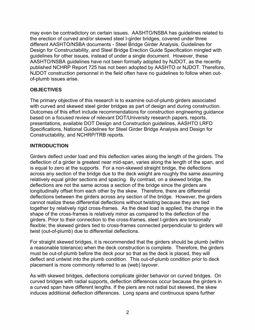
INTRODUCTION
Girders deflect under load and this deflection varies along the length of the girders. The deflection of a girder is greatest near mid-span, varies along the length of the span, and is equal to zero at the supports. For a non-skewed straight bridge, the deflections across any section of the bridge due to the deck weight are roughly the same assuming relatively equal girder sections and spacing. By contrast, on a skewed bridge, the deflections are not the same across a section of the bridge since the girders are longitudinally offset from each other by the skew. Therefore, there are differential deflections between the girders across any section of the bridge. However, the girders cannot realize these differential deflections without twisting because they are tied together by relatively rigid cross-frames. As the dead load is applied, the change in the shape of the cross-frames is relatively minor as compared to the deflection of the girders. Prior to their connection to the cross-frames, steel I-girders are torsionally flexible; the skewed girders tied to cross-frames connected perpendicular to girders will twist (out-of-plumb) due to differential deflections.
For straight skewed bridges, it is recommended that the girders should be plumb (within a reasonable tolerance) when the deck construction is complete. Therefore, the girders must be out-of-plumb before the deck pour so that as the deck is placed, they will deflect and untwist into the plumb condition. This out-of-plumb condition prior to deck placement is more commonly referred to as (web) layover.
As with skewed bridges, deflections complicate girder behavior on curved bridges. On curved bridges with radial supports, deflection differences occur because the girders in a curved span have different lengths. If the piers are not radial but skewed, the skew induces additional deflection differences. Long spans and continuous spans further

3
complicate the issue. As long spans tend to deflect more, the differential deflection between adjacent girders also increases. On continuous bridges, girder deflections are influenced by adjacent spans. In combination with skewed supports and/or curved geometry, the differential deflection between adjacent girders is further amplified, especially for bridges with an unbalanced span arrangement.
This study develops guidelines and checklists to address out-of-plumb issues stemming from differential girder deflection associated with curved and/or skewed steel I-girder bridges, based on the results of literature review, the authors’ project experience in both design and construction inspection projects, and input from other subject matter experts.
SUMMARY OF THE LITERATURE REVIEW
The study team conducted a literature review of current research papers, reports and presentations issued by governmental agencies, DOTs, universities, consulting firms and steel fabricators which are specific to the design and construction of curved and skewed steel girder bridges . The documents reviewed for this effort included the following:
NCHRP Report 725 – Guidelines for Analysis Methods and Construction Engineering of Curved and Skewed Steel Girder Bridges
AASHTO LRFD Bridge Design Specifications, Section 6
NSBA G13.1 – Guidelines for Steel Bridge Girder Analysis
NSBA G12.1-2003 – Guidelines for Design for Constructability
NSBA S10.1-2007 – Steel Bridge Erection Guide Specification
FHWA-PA-2010-013-PSU 009 – Guidelines for Analyzing Curved and Skewed Bridges and Designing Them for Construction
DOT Guidelines/Policies/Manuals/Specifications for Steel Bridge Design and Construction related to curved and skewed steel girder bridges.
The following summarizes the findings from the resource documents reviewed within this analysis.
NCHRP Report 725 – Guidelines for Analysis Methods and Construction Engineering of Curved and Skewed Steel Girder Bridges1
As stated in the title, this document covers the analysis methods and construction engineering specific to curved and skewed steel girder bridges. It presents the findings 1 http://onlinepubs.trb.org/onlinepubs/nchrp/nchrp_rpt_725.pdf
4
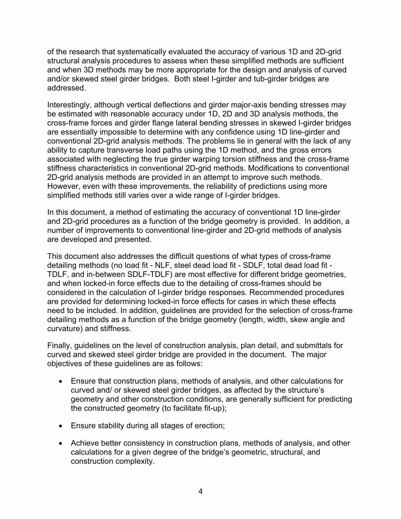
of the research that systematically evaluated the accuracy of various 1D and 2D-grid structural analysis procedures to assess when these simplified methods are sufficient and when 3D methods may be more appropriate for the design and analysis of curved and/or skewed steel girder bridges. Both steel I-girder and tub-girder bridges are addressed.
Interestingly, although vertical deflections and girder major-axis bending stresses may be estimated with reasonable accuracy under 1D, 2D and 3D analysis methods, the cross-frame forces and girder flange lateral bending stresses in skewed I-girder bridges are essentially impossible to determine with any confidence using 1D line-girder and conventional 2D-grid analysis methods. The problems lie in general with the lack of any ability to capture transverse load paths using the 1D method, and the gross errors associated with neglecting the true girder warping torsion stiffness and the cross-frame stiffness characteristics in conventional 2D-grid methods. Modifications to conventional 2D-grid analysis methods are provided in an attempt to improve such methods. However, even with these improvements, the reliability of predictions using more simplified methods still varies over a wide range of I-girder bridges.
In this document, a method of estimating the accuracy of conventional 1D line-girder and 2D-grid procedures as a function of the bridge geometry is provided. In addition, a number of improvements to conventional line-girder and 2D-grid methods of analysis are developed and presented.
This document also addresses the difficult questions of what types of cross-frame detailing methods (no load fit - NLF, steel dead load fit - SDLF, total dead load fit - TDLF, and in-between SDLF-TDLF) are most effective for different bridge geometries, and when locked-in force effects due to the detailing of cross-frames should be considered in the calculation of I-girder bridge responses. Recommended procedures are provided for determining locked-in force effects for cases in which these effects need to be included. In addition, guidelines are provided for the selection of cross-frame detailing methods as a function of the bridge geometry (length, width, skew angle and curvature) and stiffness.
Finally, guidelines on the level of construction analysis, plan detail, and submittals for curved and skewed steel girder bridge are provided in the document. The major objectives of these guidelines are as follows:
Ensure that construction plans, methods of analysis, and other calculations for curved and/ or skewed steel girder bridges, as affected by the structure’s geometry and other construction conditions, are generally sufficient for predicting the constructed geometry (to facilitate fit-up);
Ensure stability during all stages of erection;
Achieve better consistency in construction plans, methods of analysis, and other calculations for a given degree of the bridge’s geometric, structural, and construction complexity.
5
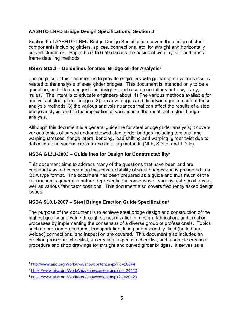
AASHTO LRFD Bridge Design Specifications, Section 6
Section 6 of AASHTO LRFD Bridge Design Specification covers the design of steel components including girders, splices, connections, etc. for straight and horizontally curved structures. Pages 6-57 to 6-59 discuss the basics of web layover and cross-frame detailing methods.
NSBA G13.1 – Guidelines for Steel Bridge Girder Analysis2
The purpose of this document is to provide engineers with guidance on various issues related to the analysis of steel girder bridges. This document is intended only to be a guideline, and offers suggestions, insights, and recommendations but few, if any, “rules.” The intent is to educate engineers about: 1) The various methods available for analysis of steel girder bridges, 2) the advantages and disadvantages of each of those analysis methods, 3) the various analysis nuances that can affect the results of a steel bridge analysis, and 4) the implication of variations in the results of a steel bridge analysis.
Although this document is a general guideline for steel bridge girder analysis; it covers various topics of curved and/or skewed steel girder bridges including torsional and warping stresses, flange lateral bending, load shifting and warping, girder twist due to deflection, and various cross-frame detailing methods (NLF, SDLF, and TDLF).
NSBA G12.1-2003 – Guidelines for Design for Constructability3
This document aims to address many of the questions that have been and are continually asked concerning the constructability of steel bridges and is presented in a Q&A type format. The document has been prepared as a guide and thus much of the information is general in nature, representing a consensus of various state positions as well as various fabricator positions. This document also covers frequently asked design issues.
NSBA S10.1-2007 – Steel Bridge Erection Guide Specification4
The purpose of the document is to achieve steel bridge design and construction of the highest quality and value through standardization of design, fabrication, and erection processes by implementing the consensus of a diverse group of professionals. Topics such as erection procedures, transportation, lifting and assembly, field (bolted and welded) connections, and inspection are covered. This document also includes an erection procedure checklist, an erection inspection checklist, and a sample erection procedure and shop drawings for straight and curved girder bridges. It serves as a
2 http://www.aisc.org/WorkArea/showcontent.aspx?id=28844 3 https://www.aisc.org/WorkArea/showcontent.aspx?id=20112 4 https://www.aisc.org/WorkArea/showcontent.aspx?id=20120

6
general steel bridge erection guide, without specifically covering any skewed and/or curved bridge issues.
Sample erection procedures and shop drawings can be downloaded from:
https://www.aisc.org/WorkArea/showcontent.aspx?id=20122
FHWA-PA-2010-013-PSU 009 – Guidelines for Analyzing Curved and Skewed Bridges and Designing Them for Construction5
This document contains findings from instruments on two structures in the Interstate 99 corridor: a horizontally curved steel I-girder bridge, and a skewed pre-stressed concrete bridge. Data obtained from these structures was examined and the numerical model accuracy for curved and skewed steel I-girder bridges and selected appropriate model types and software was investigated. Parametric studies were undertaken on a group of representative curved and skewed steel bridge structures to numerically examine the influence of specific variables on behavior during construction. Results enabled the identification of preferred erection sequencing approaches.
DOT Guidelines/Policies/Manuals/Specifications Review
Regarding the review of DOT Guidelines/Policies/Manuals/Specifications, there are no specific publications stated in the Scope of Work to be undertaken during this research project. However, review summaries of three publications are provided below covering both design and construction issues:
NCHRP Report 725 Appendix G6
NCHRP Report 725 “Guidelines for Analysis Methods and Construction Engineering of Curved and Skewed Steel Girder Bridges, Appendix G - Owner/Agency Policies and Procedures” summarizes the survey of the current practices of steel girder design throughout the US. Appendix G provides brief guidelines from DOTs of a few different states including CalTrans, TxDOT, FDOT (Florida DOT), PennDOT, ITD (Idaho DOT), IDOT (Illinois DOT), NCDOT and ODOT (Ohio DOT). The main theme of the design guidelines of these DOTs is to determine when a 1D analysis is acceptable with or without an adjustment factor, when skewed and/or curved effects can be ignored, when a 2D or 3D analysis is required, and guidance for simplified analysis. In general, these guidelines allow a simple 1D analysis for bridges with a minor skew (<10 to 20 degrees of skew) and 2D or grid analysis for bridges with moderate to severe skew, without addressing the accuracy of predicting cross-frame forces, flange
5 ftp://ftp.dot.state.pa.us/public/pdf/BPR_PDF_FILES/Documents/Research/Complete%20Projects/Improving%20Pennsylvania%20Bridges/Guidelines%20for%20Analyzing%20Curved%20and%20Skewed%20Bridges.pdf 6 http://www.trb.org/main/blurbs/167646.aspx

7
lateral bending stresses and girder layover. For severely skewed and curved bridges, agencies may require a more refined analysis or 3D finite element method to be implemented. Some of these guidelines may have been developed one or two decades ago and have not been updated. They are also not as comprehensive as NCHRP Report 725 (Chapters 3 – 3.1 and Table 3-1), which provides a detailed and systematic evaluation on different analysis methods, to determine the reliability associated with major-axis bending, vertical deflection, cross-frame forces, flange lateral bending and girder layover. Furthermore, as technology advances, some sophisticated software packages now come with built-in model generation modules, making them more user-friendly and significantly cutting down the time required for 2D-grid analysis or even 3D FEA, making such analysis more affordable. These advances may eventually make using a 1D analysis with an adjustment factor or in combination with V-load analysis (as suggested by some DOTs) no longer an efficient approach.
A few of the State DOTs listed above offer limited guidance on fabrication, erection, detailing and shop drawing submission requirements. For some specific issues, they may be slightly different from other states, or in some cases, even contradictory to other states. The most noticeable conflict between guidance is that Ohio DOT requires detailing for the webs to be plumb under the steel dead load and prohibits web layover.
Ohio DOT Summary of Skewed Bridge Issues7
As mentioned in Table 1, Ohio DOT has a design policy that does not allow web layover but allows the designer to stiffen the superstructure up to 125% of the weight of the primary members (from an optimized line girder analysis), in order to reduce deflection and differential deflection, so as to reduce girder twisting to be within tolerance. However, the authors believe overdesigning the superstructure to avoid web layover is not consistent with NCHRP recommendations and would increase cost unnecessarily. Based on the authors’ design experience, increasing just the fascia girder section by 20% to 40% can reasonably reduce the differential deflections at the fascia bay (between fascia and 1st interior girder on each side) where deflections are usually more severe. However, this approach still may not get the web layover to be within tolerance. The authors recommend an iterative approach when designing the girders to achieve the desired stiffness and performance to accommodate the construction and erection of the structure.
See the table on the next page showing a portion of the ODOT Summary of Skewed Bridge Issues.
7 http://www.dot.state.oh.us/Divisions/Engineering/Structures/standard/State%20of%20practice%20for%20highly%20skewed%20bridges/skew/crossframes/Printable/Summary%20of%20Skew%20Issues.pdf

8
Table 1 - Ohio DOT Summary of Skewed Bridge Issues
Source: Ohio Department of Transportation
NYSDOT Steel Construction Manual (SCM) Sections 204 and 14038
As indicated in the title of the document, this manual covers only construction and is not curved/skewed specific. The SCM prescribes the minimum requirements for the
8 https://www.dot.ny.gov/divisions/engineering/structures/manuals/scm/repository/SCM_3rd_Addm_1_2010.pdf
9
preparation of fabrication drawings, ordering and receipt of materials, fabrication by welding and bolting, transportation, erection, repair, rehabilitation, and testing and inspection of structural metals.
Section 204 lists the requirements for erection drawings and Section 1403 lists the requirements for structural steel erection and erector qualifications. Lists from both sections are very detailed and cover a majority of the construction conditions including skewed and/or curved bridges.
SUMMARY OF WORK PERFORMED
The objective of this research is to generate and compile guidelines and checklists for design and construction in order to address the out-of-plumb issues typical to curved and highly skewed bridges. Therefore, the focus is to identify studies and guidelines related to the out-of-plumb issues from publications listed under the “Literature Review” section; and then systematically compare, summarize, and compile guidelines together with backup information. The NCHRP Report 725 “Guidelines for Analysis Methods and Construction Engineering of Curved and Skewed Steel Girder Bridges” is about seven hundred pages including all appendices and is the most comprehensive and up-to-date literature related to this research topic. Reading through the entire document is a major under-taking and therefore, we aim to summarize all pertinent issues in this research paper. Relevant information from other publications were also reviewed and used together with various guidelines under Report 725 to ensure the guidelines developed under this research paper can cover the majority of the possible scenarios.
Unfortunately, Report 725 and other listed documents mainly cover the analysis and construction engineering aspects, with minimal coverage on the design aspect. Therefore, the design portion of the guidelines presented in this research paper were developed based on the authors’ past project design experience, past project review, and limited design related guidance covered under Report 725. Design requirements specified under AASHTO LRFD Bridge Design Specifications and NJDOT Bridge Design Manual will not be reiterated in this research paper.
Literature Review
Tolerance:
Tolerance for layover of the webs should be within D/96, where D is the girder web depth. Formulation of this tolerance allowance is based on the following four sources:
• As per AASHTO/NSBA S10.1_2007 Steel Bridge Erection Guide Specification 9.2.2, 1/8” per ft deviation from theoretical erected web position is allowed for fabrication under steel dead load. For steel I-girder, it implies 1/8” per ft out-of-plumb tolerance.
• As per pages 83 and 94 of the NCHRP Report 725, the D/96 tolerance (which is equivalent to 1/8” per ft) is mentioned.

10
• As per Ohio DOT’s “Summary of Skewed Bridge Issues”, the out-of-plumb rotation due to the total deck placement loading shall not exceed 0.6 degrees or 1/8” per ft, as ODOT does not allow web layover and all girders shall be erected with the webs plumb under steel dead load only. Although we do not agree with ODOT ultra conservative approach of prohibiting of web layover in the final condition, their out-of-plumb tolerance of 1/8” per ft is consistent with AASHTO/NSBA and Report 725.
• As per FHWA-PA-2010-013-PSU 009 “Guidelines for Analyzing Curved and Skewed Bridges and Designing Them for Construction”, web out-of-plumbness did not cause appreciable bridge deflection and stress increases when the out-of-plumbness is within the limit (1%) specified in the Structural Welding Code, as exceeding the 1% limit can result in slightly higher deformations and stresses, based on analyses performed under the FHWA-PA Report. This 1% limit is approximately equal to D/96 or 1/8” per ft.
(Note: NYSDOT SCM requires a stricter requirement for tolerance under Section 1215. However, it is the authors’ opinion that stricter requirements than those mentioned above are unnecessary and may result in higher construction costs, and is therefore not recommended.)
Based on the above, an out-of-plumb tolerance of D/96 under total deck placement is proposed. If the computed out-of-plumbness is D/96 or less under total deck placement, the designer has the option to determine the need for web layover. Based on the authors’ past projects experience, web layover of D/96 or less can be easily achieved. If the designer decides not to induce web layover, the girder shall be truly plumb under steel dead load without any tolerance, so that the girder web will be out-of-plumb by D/96 or less under total dead load. Also, the D/96 tolerance cannot be used to reduce the magnitude of layover.
In summary:
• If the designer decides not to induce web layover, since the end twist is within the D/96 tolerance, the girder shall be truly plumb under steel dead load without any tolerance, so that the girder web will be out-of-plumb by D/96 or less under total dead load.
• If web layover is determined to be required, the D/96 tolerance cannot be used to reduce the magnitude of layover, so that the girder web will be out-of-plumb by D/96 or less under total dead load.
Analysis Methods:
A quantitative assessment of the accuracy of conventional 1D line-girder and 2D-grid analysis methods was obtained in the NCHRP Project 12-79 research by identifying several error measures that compared the conventional approximate
11
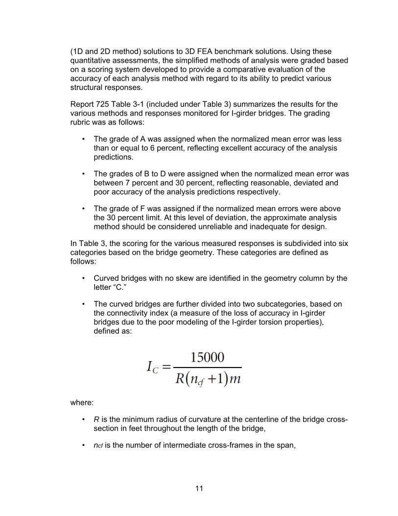
(1D and 2D method) solutions to 3D FEA benchmark solutions. Using these quantitative assessments, the simplified methods of analysis were graded based on a scoring system developed to provide a comparative evaluation of the accuracy of each analysis method with regard to its ability to predict various structural responses.
Report 725 Table 3-1 (included under Table 3) summarizes the results for the various methods and responses monitored for I-girder bridges. The grading rubric was as follows:
• The grade of A was assigned when the normalized mean error was less than or equal to 6 percent, reflecting excellent accuracy of the analysis predictions.
• The grades of B to D were assigned when the normalized mean error was between 7 percent and 30 percent, reflecting reasonable, deviated and poor accuracy of the analysis predictions respectively.
• The grade of F was assigned if the normalized mean errors were above the 30 percent limit. At this level of deviation, the approximate analysis method should be considered unreliable and inadequate for design.
In Table 3, the scoring for the various measured responses is subdivided into six categories based on the bridge geometry. These categories are defined as follows:
• Curved bridges with no skew are identified in the geometry column by the letter “C.”
• The curved bridges are further divided into two subcategories, based on the connectivity index (a measure of the loss of accuracy in I-girder bridges due to the poor modeling of the I-girder torsion properties), defined as:
where:
• R is the minimum radius of curvature at the centerline of the bridge cross-section in feet throughout the length of the bridge,
• ncf is the number of intermediate cross-frames in the span,

12
• m is a constant taken equal to 1 for simple-span bridges and 2 for continuous-span bridges.
In bridges with multiple spans, Ic is taken as the largest value obtained from any of the spans.
Straight skewed bridges are identified in the geometry column by the letter “S.”
The straight skewed bridges are further divided into three subcategories, based on the skew index (that relates the skew angle with the width and the span length of the bridge), defined as:
where:
• Wg is the width of the bridge measured between fascia girders,
• Ɵ is the skew angle measured from a line perpendicular to the tangent of the bridge centerline, (Note: In bridges with unequal skew at the bearing lines, Ɵ is taken as the angle of the bearing line with the largest skew.)
• Ls is the span length at the bridge centerline.
Bridges that are both curved and skewed are identified in the geometry column by the letters “C&S.”
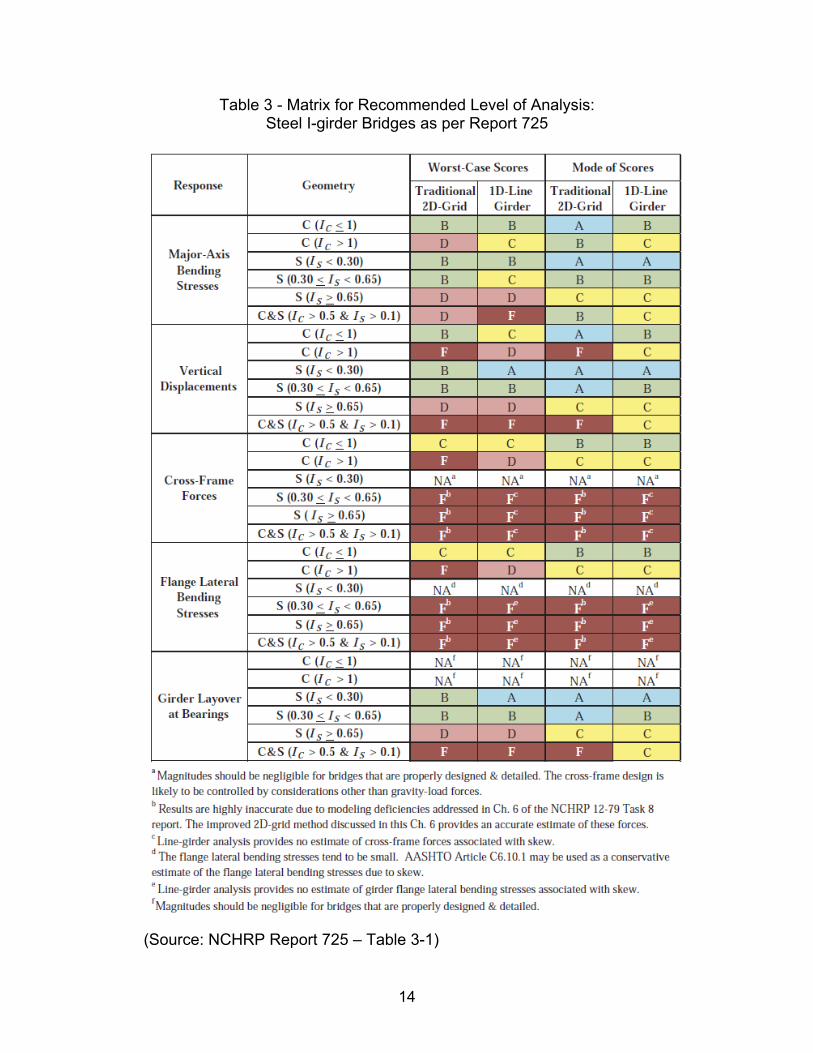
Two letter grades are indicated for each of the cells in Table 3. The first grade corresponds to the worst-case results encountered for the bridges studied by NCHRP Project 12-79 within the specified category. The second grade indicates the mode of the letter grades for that category (i.e. the letter grade encountered most often for that category).
It is useful to understand the qualifier indicated on the “C&S” bridges, i.e., “(IC > 0.5 & IS > 0.1)” in Table 3. If a bridge has an IC < 0.5 and an IS > 0.1, it can be considered as a straight-skewed bridge for the purposes of assessing the expected analysis accuracy. Furthermore, if a bridge has an IC > 0.5 and an IS ≤

13
0.1, it can be considered as a curved radially supported bridge for these purposes.
Table 3 can be used to assess when a certain analysis method can be expected to give acceptable results. Should a 1D-Line Girder or Traditional 2D Grid Analysis be expected to yield unreliable (Grade F) or less reliable (Grade D) results based on their Ic and Is values, a 3D FE Analysis is recommended.
Other DOTs, such as PennDOT and FDOT, do provide some explicit guidelines on analysis methods which are described under Report 725 Appendix G. However, these guidelines may be over-simplified since they do not consider the width to length ratio of the spans or the number of cross-frames. Additionally, the guidelines between the DOTs are not consistent with each other nor are they consistent with Report 725 Table 3-1. These guidelines can be slightly simplified by following the grading system under “Mode of Scores” but ignoring the “Worst-Case Scores” if NJDOT decides to implement the recommendations outlined in this research paper. The connectivity index “Ic” and skew index “Is” based on framing geometry and the evaluation matrix can be easily set up and computed by spreadsheet.
The table below is the authors’ recommended simplified evaluation matrix by ignoring the “Worst-Case Scores”.
Table 2 – Simplified Matrix for Recommended Level of Analysis: I-girder Bridges
Note: The scores for Traditional 2D Analysis presented in the matrix above and the matrix on the next page are based on software evaluation performed in 2011 under Report 725. As 2D Analysis software is continuously being updated, the the actual scores will be slightly different from the scores as shown above.
14
Table 3 - Matrix for Recommended Level of Analysis: Steel I-girder Bridges as per Report 725
(Source: NCHRP Report 725 – Table 3-1)

15
• Cross-Frame Detailing:
In general there are three key considerations that dictate what type of detailing method is to be used: 1) limiting dead load rotation at bearings for the final, permanent condition, 2) difficulty of fit-up during erection, 3) additive locked-in forces associated with detailing methods that require fit-up during erection. In order to select good detailing, the design engineer must achieve a good balance between all three considerations.
For skewed girders, the first intermediate cross-frame generally should be positioned at an offset distance “a” which is greater than the maximum of 1.5D and 0.4b, where D is the girder depth and b is the second unbraced length within the span adjacent to the offset from the bearing line (see the figure below). This is intended to alleviate local spikes in the cross-frame forces and thereby reduces the potential for fit-up difficulty at these locations.
Figure 1 – Illustration of offset distance and adjacent unbraced length.
In curved girders, for other than NLF detailing, the locked-in force effects in the cross-frames and in the girder flange lateral bending moments at the cross-frame positions tend to be additive with the dead load effects. Accurate calculation of these values requires an accurate 2D-grid or 3D FE analysis including the calculation of locked-in forces due to the initial lack-of-fit effects. Since locked-in forces tend to be additive with the internal forces due to the dead load effects, the internal forces from an accurate 2D-grid or 3D FE analysis neglecting the initial lack-of-fit effects tend to underestimate the true forces.
If TDLF or SDLF detailing is to be used, expected layovers at erection can be indicated in the engineering drawings. At skewed bearing lines, the layover can be estimated as the sum of the initial camber and the SDL girder major-axis bending rotations, multiplied by the tangent of the skew angle. The girder twist rotation at cross-frames normal to the girders within the spans may be estimated as the differential vertical displacement between the cross-frame ends due to the sum of the initial TDL camber and the SDL displacement divided by the girder spacing.

16
Selection of Cross-Frame Detailing Method by Scenarios:
For straight skewed bridges:
• For straight-skewed bridges with relatively short span length and small skew and width (Is < 0.30) Total Dead Load Fit (TDLF) is typically a good option. In this type of structure with TDLF, the girder webs will be approximately plumb at total dead load while fit-up concerns during the steel erection should be minimal.
• For straight-skewed bridges with small-to-moderate span length and relatively high skew and large width (Is > 0.30), TDLF detailing is typically a good option. In this type of structure with TDLF, the girder webs will be approximately plumb at total dead load while fit-up during the steel erection should be feasible.
• For straight-skewed bridges with large span lengths and relatively high skew and large width (Is > 0.30), Steel Dead Load Fit (SDLF) detailing, or detailing between SDLF and TDLF, typically are good options. There might be fit-up difficulty for TDLF detailing and SDLF detailing can be introduced to alleviate the problem. The tendency for excessive layover at highly skewed bearing lines can be addressed by a combination of the cross-frame detailing, the use of beveled sole plates, and/or by using bearings with a larger rotational capacity.
For curved bridges with or without skew:
• For curved bridges with radial supports, NLF detailing, or detailing between NLF and SDLF typically are good options. NLF detailing tends to minimize the fit-up forces but the experience of some fabricators and erectors indicates that curved radially supported bridges are easier to fit-up under unshored SDL erection conditions if SDLF detailing is used. Layover of girder webs occur within spans, but this layover is more difficult to detect visually and is not of any significance with respect to the bridge structural resistance.
• For curved bridges with sharply skewed supports, minor horizontal curvature and small span length, TDLF detailing is typically a good option.
• For curved bridges with moderately skewed supports, and small to moderate span lengths, detailing of the cross-frames anywhere between NLF and TDLF can be a good option. The Engineer should select the detailing method to balance between 1) limiting dead load twist rotations at the skewed bearing lines, 2) alleviating the larger additive locked-in forces associated with TDLF detailing on a curved bridge, and 3) facilitating fit-up during the steel erection.

17
• For curved bridges with skewed supports and large span length, SDLF detailing, or detailing between SDLF and NLF, are typically good options. Alleviation of fit-up difficulty during the steel erection is the overriding consideration.
Note: Report 725 does not define small, moderate and large span lengths. However, based on Appendix E – Executive Summary of Study Bridges, span lengths of all steel I-girder bridges studied in the report were between 90 feet and 350 feet per span. Based on correspondence with the lead author of Report 725, “short” span lengths can be considered as anything less than 150 feet, “moderate” spans as 150 to 200 feet, and “long” spans as longer than 200 feet.
• Problematic Characteristics and Details to Avoid
• Oversized or Slotted Holes
As per NSBA G12.1-2003 “Guidelines for Design for Constructability”, Section 1.6, “Oversized holes are not a solution to the issues of differential deflections. Although oversized holes will help with fit up; serious alignment problems, rotations, and additional lateral stresses will still result.”
As per NCHRP Synthesis 345 Chapter 2, “Sixteen owners allow oversized or slotted holes under some circumstances to facilitate fit-up of diaphragms or cross-frames. Another allows only vertical slots to permit differential movement between girders during deck pour (staged construction or bridge widening, not staged deck placement). Ten owners prohibit the use of oversized holes.” As per Synthesis 345 Appendix B, on one PennDOT project using oversized holes in cross-frames connection, the first erector erected the curved spans without falsework and ended up with horizontal alignment errors of 2.6 inches and vertical alignment errors of 3 inches. A second erector replaced the first erector and used falsework on the curved section, loosing up and retightening connections to properly realign the members and completed the job properly.
As per Report 725 Appendix B3.7, “The use of oversized or slotted holes in gusset and connection plates can decrease significantly the stability bracing efficiency of cross-frames. In addition, the control of the deformed bridge geometry can also be affected since cross-frames are necessary to integrate the girders and make them deform as a unit rather than as independent components. Therefore, it is not recommended to use this scheme as a solution to erecting cross-frames at stiff locations such as the regions near skewed supports.”
As per NSBA S10.1-2007 “Steel Bridge Erection Guide Specification”, Section 7.5, “Fully tighten all bolts in the bridge by completion of steel erection (unless otherwise specified) in accordance with the Bolt

18
Specification. Fully tighten bolts before exposure to the elements affects their rotational capacity test characteristics.”
However, the authors have seen projects successfully constructed using oversized holes at all diaphragm and cross-frame connection plates (see Reference 11), locally used near end supports, and finger-tightened bolts during deck placement (see Reference 11), as well as cross-frames installed after deck placement at locations near acute corners of the framing. As per the guidelines and research mentioned above, the use of oversized or slotted holes, or finger-tight bolts during deck pour are generally not recommended. In the authors’ opinion, the use of oversized or slotted holes at all diaphragm and cross-frame connection plates should be avoided, especially for long and/or wide bridges with severe skews or curvature. Should the local use of oversized or slotted holes, or finger-tight bolts during deck pour be deemed necessary; the design engineer should carefully evaluate each individual structure based on detailed analysis.
• Narrow Bridges or Bridge Units
In some cases, I-girder bridges can be susceptible to large response amplifications due to global second-order effects. Pedestrian bridges with twin girders, phased construction, and erection stages where only a few girders of the bridge are in place, are some examples of structures that can be susceptible to considerable global second order amplifications. When potential amplifications of the system stress and displacement responses are a concern, it is recommended to study the structure with refined 3D FEA or an approximate method based on amplified responses of a linear analysis solution.
• V-Type Cross-Frames without Top Chords
Cross-frames are needed to stabilize I-girders prior to hardening of the concrete deck. In some cases, V-type cross-frames without top chords may not be able to perform this function. The flexural stiffness of this type of cross-frame is substantially smaller than other configurations (i.e. X-type or V-type with top chord). Therefore, its ability to provide stability bracing needs to be considered carefully during design. (Note: The presence of bottom chord is assumed for all types of cross-frames.)
• Bent-Plate Connections in I-Girder Bridges
• Bent-plate details can introduce excessive flexibility in the system, affecting the stability bracing capacity of skewed cross-frames, particularly end diaphragms. Due to this limitation, designers may consider the use of other connection details that do not represent a detriment to the system performance, or stiffen the bent plate. Details such as the half-pipe
19
stiffener and the reinforced bent-plate are options that may be considered to connect skewed end cross-frames at angles larger than 20 degrees. For additional information about half-pipe stiffener or split pipe stiffener, refer to “Cross-Frame Connection Details for Skewed Steel Bridges”, FHWA/TX-11/0-5701-1, by Craig Quadrato, Weihua Wang, Anthony Battistini, Andrew Wahr, Todd.
Identification of Key Terms
In order to understand the review summary, the reader must first understand the meaning of several terms used in the referenced report pertaining to cross-frame detailing. Described below are a few key terms listed in alphabetical order extracted from Appendix A of NCHRP Report 725:
Fit-Up Forces. The forces required to physically bring the components together and complete a connection during the erection of the steel. These forces can be influenced by initial lack-of-fit effects from Steel Dead Load Fit (SDLF) or Total Dead Load Fit (TDLF) detailing of the cross-frames, but generally, they are distinctly different from the forces associated with the initial lack of fit between the girders and the cross-frames in their initially fabricated no-load geometry.
Initial Lack of Fit. For analysis of SDLF or TDLF effects, the displacement incompatibility between the connection work points on the cross-frames and the corresponding points on the girders, with the cross-frames and girders in their initially fabricated no-load geometry, and in the context of this paper, with plumb cambered initial girder geometry. For SDLF or TDLF detailing of cross-frames in I-girder bridges, the cross-frame may be considered to be connected to the initially plumb and cambered girder on one side, and the initial lack of fit is the displacement incompatibility with the work points on the girder on the other side. It should be noted that for cross-frames that are not normal (perpendicular) to the girders, there are generally two contributions to the initial lack of fit: (1) the difference in the vertical camber between the work points on the connected girders and (2) the major-axis bending rotations of the girders at the girder work points. The initial no-load geometry defines the reference state of the corresponding conservative elastic system at which the strain energy is equal to zero. Hence, the no-load configuration is the only appropriate configuration to use as a basis for determining the corresponding lack-of-fit forces in the structure. (See Figure 1.)
20
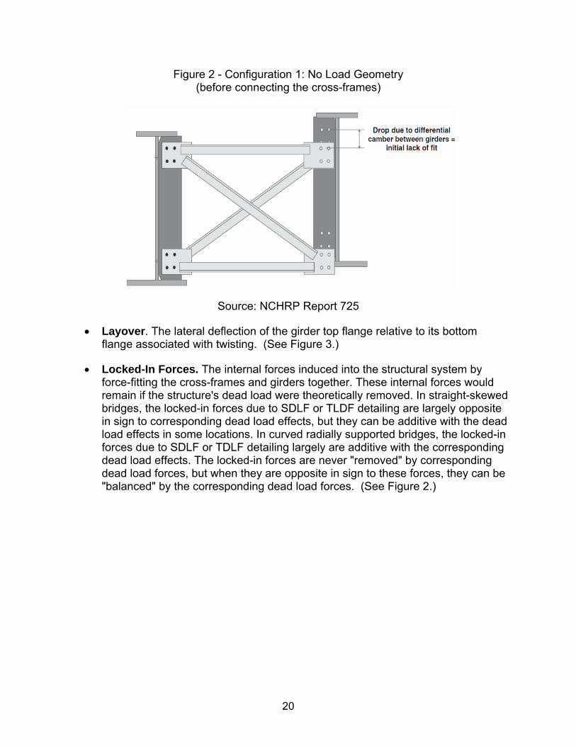
Figure 2 - Configuration 1: No Load Geometry (before connecting the cross-frames)
Source: NCHRP Report 725
Layover. The lateral deflection of the girder top flange relative to its bottom flange associated with twisting. (See Figure 3.)
Locked-In Forces. The internal forces induced into the structural system by force-fitting the cross-frames and girders together. These internal forces would remain if the structure's dead load were theoretically removed. In straight-skewed bridges, the locked-in forces due to SDLF or TLDF detailing are largely opposite in sign to corresponding dead load effects, but they can be additive with the dead load effects in some locations. In curved radially supported bridges, the locked-in forces due to SDLF or TDLF detailing largely are additive with the corresponding dead load effects. The locked-in forces are never "removed" by corresponding dead load forces, but when they are opposite in sign to these forces, they can be "balanced" by the corresponding dead load forces. (See Figure 2.)
21
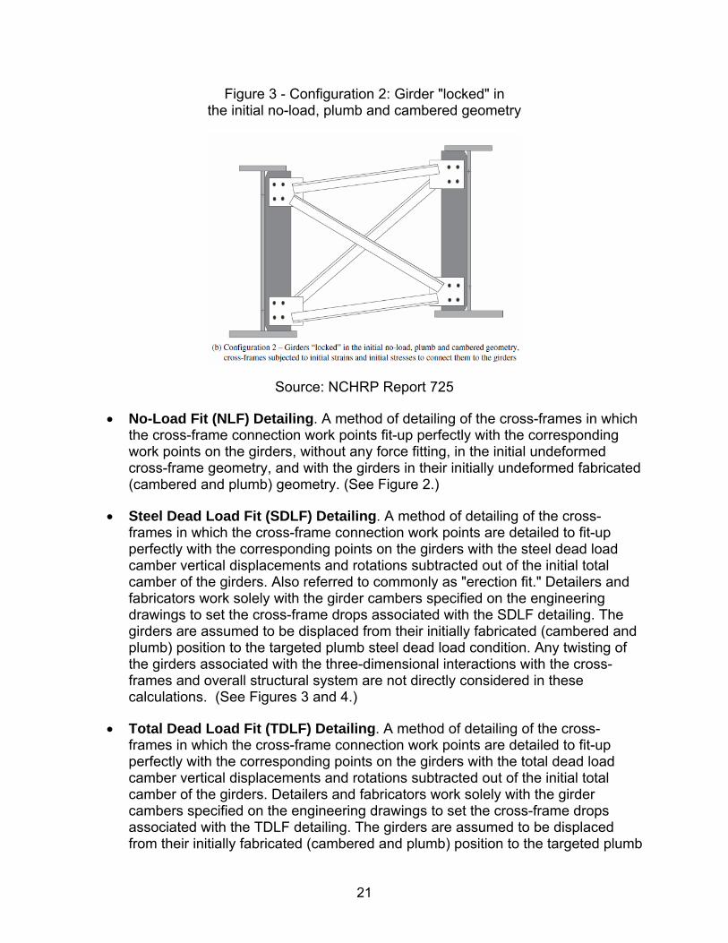
Figure 3 - Configuration 2: Girder "locked" in the initial no-load, plumb and cambered geometry
Source: NCHRP Report 725
No-Load Fit (NLF) Detailing. A method of detailing of the cross-frames in which the cross-frame connection work points fit-up perfectly with the corresponding work points on the girders, without any force fitting, in the initial undeformed cross-frame geometry, and with the girders in their initially undeformed fabricated (cambered and plumb) geometry. (See Figure 2.)
Steel Dead Load Fit (SDLF) Detailing. A method of detailing of the cross-frames in which the cross-frame connection work points are detailed to fit-up perfectly with the corresponding points on the girders with the steel dead load camber vertical displacements and rotations subtracted out of the initial total camber of the girders. Also referred to commonly as "erection fit." Detailers and fabricators work solely with the girder cambers specified on the engineering drawings to set the cross-frame drops associated with the SDLF detailing. The girders are assumed to be displaced from their initially fabricated (cambered and plumb) position to the targeted plumb steel dead load condition. Any twisting of the girders associated with the three-dimensional interactions with the cross-frames and overall structural system are not directly considered in these calculations. (See Figures 3 and 4.)
Total Dead Load Fit (TDLF) Detailing. A method of detailing of the cross-frames in which the cross-frame connection work points are detailed to fit-up perfectly with the corresponding points on the girders with the total dead load camber vertical displacements and rotations subtracted out of the initial total camber of the girders. Detailers and fabricators work solely with the girder cambers specified on the engineering drawings to set the cross-frame drops associated with the TDLF detailing. The girders are assumed to be displaced from their initially fabricated (cambered and plumb) position to the targeted plumb

22
total dead load condition. Any twisting of the girders associated with the three-dimensional interactions with the cross-frames, slab, and overall structural system are not directly considered in these calculations. Also referred to commonly as "final fit." (See Figures 3 and 4.)
Figure 4 - Configuration 3: Theoretical Geometry under no-load, after initial fit
Source: NCHRP Report 725
Figure 5 – Configuration 4: Geometry under dead load (final condition)
Source: NCHRP Report 725
Note: Cross-frame detailing methods (NLF, SDLF and TDLF) are also covered in great detail under NSBA G13.1 "Guidelines for Steel Bridge Girder Analysis", Section 3.10 and also has extensive illustrations. For readers not familiar with NLF, SDLF and TDLF, Section 3.10 of NSBA G13.1 should be reviewed.

23
Project Review
i. Project List and Description (including out-of-plumb related issues)
Five bridges with different severity of skew and/or curvature were selected for review under this research project. Three of the bridges were designed by GPI and the other two were designed by others but inspected by GPI during construction. Below is a list and description of the five bridges:
1. Structure No. 1 - A straight two-span (135’-135’) continuous severely skewed steel I-girder bridge (with roughly 70 degree skew between centerline of bearing and the normal to centerline of bridge) with an out-to-out width of 63.75 ft, designed by GPI. Refer to Figure 6 for the Framing Plan.
Figure 6 – Structure No. 1 Framing Plan
During preliminary design, 1D MDX line girder analysis was first used to size the girder and determine girder spacing. Afterwards, MDX (2012) 2D Analysis - “Plate and Eccentric Beam Finite Element Model” (PEB) was developed to refine the girder design and size the cross-frames. Multiple framing plan layouts were developed and simulated in MDX (PEB) to come up with an optimal layout. Later, the fascia girders were stiffened by making the flanges roughly 30% larger and making the web roughly 10% thicker than those of interior girders so as to increase the fascia girder section and reduce the differential deflection between the fascia girder and first interior girder leading to slightly smaller girder end twist (out-of-plumb rotation).
During final design, the superstructure and substructure were modeled three-dimensionally in CsiBridge for dead, live, thermal and seismic loads; as well as for various construction load cases and conditions. Girder forces, reactions, vertical deflections, and girder end rotations computed by MDX (PEB) were within reason of what was computed by the 3D model. However, cross-frame forces based on 3D modeling were found to

24
be larger than the MDX values. Also, the 3D model provided additional data such as displacement and rotation about all three axes along the entire length of girders, thermal behavior, deflection and rotation under different phases of deck pour. The ability to see deformed shapes and stress/load contour under different load cases proved very beneficial and helped the engineer to better understand the behavior of a severely skewed bridge and design accordingly. Below are two screenshots of the 3D model showing the deformed shape (with a scale factor of 15) of the steel framing under non-composite dead load. Figure 7 shows the overall view, as Figure 8 shows a close-up of the deformed shape at the acute corner depicting both deflection and twisting. During steel erection, the framing will be deflected upward and twisted in the opposite direction due to camber and web layover.
Figure 7 - Structure No. 1 Overall Deformed Shape under Non-composite Dead Load
Figure 8 – Structure No. 1 Close-up of the deformed shape at the acute corner depicting both deflection and twisting
25
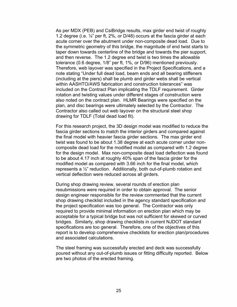
As per MDX (PEB) and CsiBridge results, max girder end twist of roughly 1.2 degree (i.e. ¼” per ft, 2%, or D/48) occurs at the fascia girder at each acute corner over the abutment under non-composite dead load. Due to the symmetric geometry of this bridge, the magnitude of end twist starts to taper down towards centerline of the bridge and towards the pier support, and then reverse. The 1.2 degree end twist is two times the allowable tolerance (0.6 degree, 1/8” per ft, 1%, or D/96) mentioned previously. Therefore, web layover was specified in the Project Specifications, and a note stating “Under full dead load, beam ends and all bearing stiffeners (including at the piers) shall be plumb and girder webs shall be vertical within AASHTO/AWS fabrication and construction tolerances” was included on the Contract Plan implicating the TDLF requirement. Girder rotation and twisting values under different stages of construction were also noted on the contract plan. HLMR Bearings were specified on the plan, and disc bearings were ultimately selected by the Contractor. The Contractor also called out web layover on the structural steel shop drawing for TDLF (Total dead load fit).
For this research project, the 3D design model was modified to reduce the fascia girder sections to match the interior girders and compared against the final model with heavier fascia girder sections. The max girder end twist was found to be about 1.38 degree at each acute corner under non-composite dead load for the modified model as compared with 1.2 degree for the design model. Max non-composite dead load deflection was found to be about 4.17 inch at roughly 40% span of the fascia girder for the modified model as compared with 3.66 inch for the final model, which represents a ½” reduction. Additionally, both out-of-plumb rotation and vertical deflection were reduced across all girders.
During shop drawing review, several rounds of erection plan resubmissions were required in order to obtain approval. The senior design engineer responsible for the review commented that the current shop drawing checklist included in the agency standard specification and the project specification was too general. The Contractor was only required to provide minimal information on erection plan which may be acceptable for a typical bridge but was not sufficient for skewed or curved bridges. Similarly, shop drawing checklists in current NJDOT standard specifications are too general. Therefore, one of the objectives of this report is to develop comprehensive checklists for erection plan/procedures and associated calculations.
The steel framing was successfully erected and deck was successfully poured without any out-of-plumb issues or fitting difficulty reported. Below are two photos of the erected framing.
26
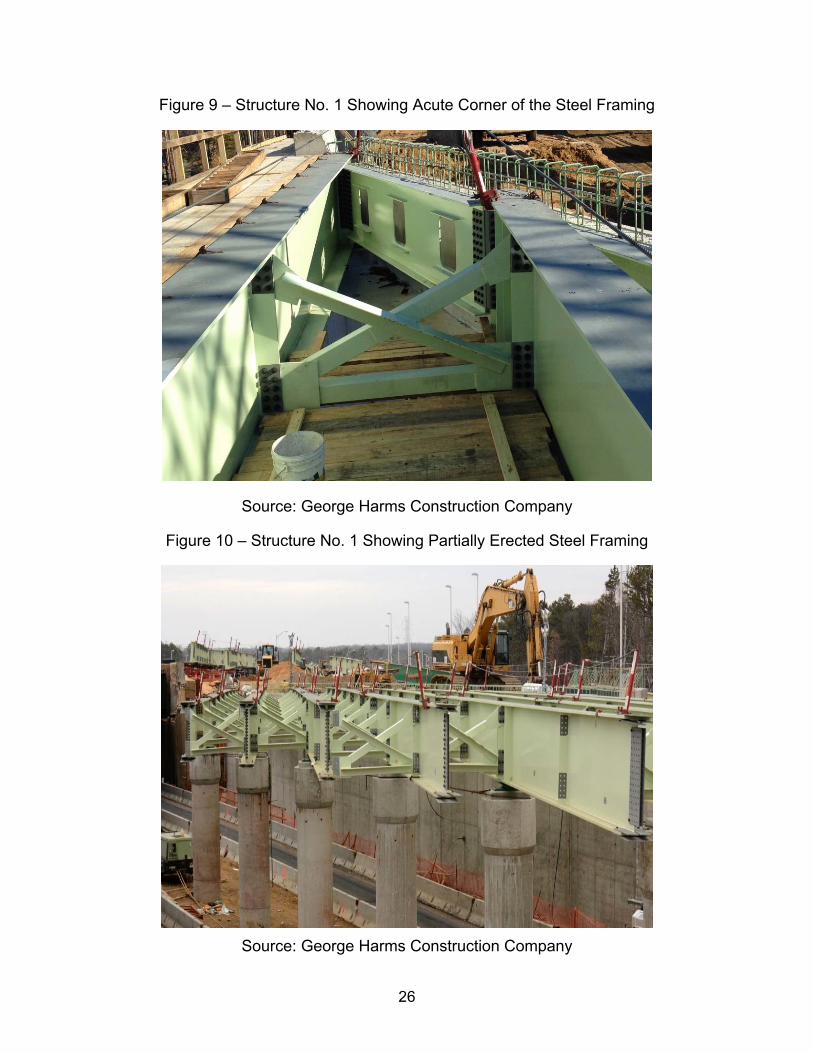
Figure 9 – Structure No. 1 Showing Acute Corner of the Steel Framing
Source: George Harms Construction Company
Figure 10 – Structure No. 1 Showing Partially Erected Steel Framing
Source: George Harms Construction Company
27
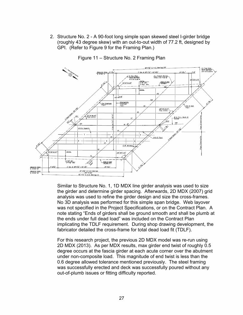
2. Structure No. 2 - A 90-foot long simple span skewed steel I-girder bridge
(roughly 43 degree skew) with an out-to-out width of 77.2 ft, designed by GPI. (Refer to Figure 9 for the Framing Plan.)
Figure 11 – Structure No. 2 Framing Plan
Similar to Structure No. 1, 1D MDX line girder analysis was used to size the girder and determine girder spacing. Afterwards, 2D MDX (2007) grid analysis was used to refine the girder design and size the cross-frames. No 3D analysis was performed for this simple span bridge. Web layover was not specified in the Project Specifications, or on the Contract Plan. A note stating “Ends of girders shall be ground smooth and shall be plumb at the ends under full dead load” was included on the Contract Plan implicating the TDLF requirement. During shop drawing development, the fabricator detailed the cross-frame for total dead load fit (TDLF).
For this research project, the previous 2D MDX model was re-run using 2D MDX (2013). As per MDX results, max girder end twist of roughly 0.5 degree occurs at the fascia girder at each acute corner over the abutment under non-composite load. This magnitude of end twist is less than the 0.6 degree allowed tolerance mentioned previously. The steel framing was successfully erected and deck was successfully poured without any out-of-plumb issues or fitting difficulty reported.
28
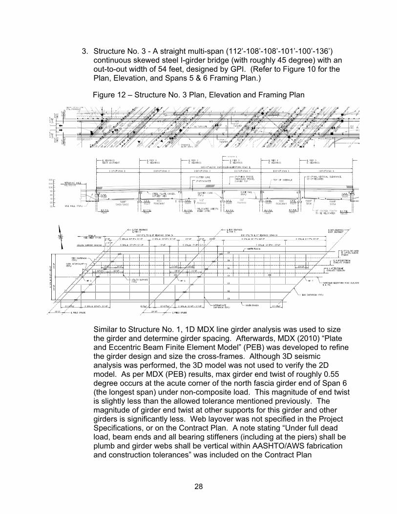
3. Structure No. 3 - A straight multi-span (112’-108’-108’-101’-100’-136’) continuous skewed steel I-girder bridge (with roughly 45 degree) with an out-to-out width of 54 feet, designed by GPI. (Refer to Figure 10 for the Plan, Elevation, and Spans 5 & 6 Framing Plan.)
Figure 12 – Structure No. 3 Plan, Elevation and Framing Plan
Similar to Structure No. 1, 1D MDX line girder analysis was used to size the girder and determine girder spacing. Afterwards, MDX (2010) “Plate and Eccentric Beam Finite Element Model” (PEB) was developed to refine the girder design and size the cross-frames. Although 3D seismic analysis was performed, the 3D model was not used to verify the 2D model. As per MDX (PEB) results, max girder end twist of roughly 0.55 degree occurs at the acute corner of the north fascia girder end of Span 6 (the longest span) under non-composite load. This magnitude of end twist is slightly less than the allowed tolerance mentioned previously. The magnitude of girder end twist at other supports for this girder and other girders is significantly less. Web layover was not specified in the Project Specifications, or on the Contract Plan. A note stating “Under full dead load, beam ends and all bearing stiffeners (including at the piers) shall be plumb and girder webs shall be vertical within AASHTO/AWS fabrication and construction tolerances” was included on the Contract Plan

29
implicating the TDLF requirement. During shop drawing development, the fabricator called out for web layover. The steel framing was successfully erected and deck was successfully poured without any out-of-plumb issues or fitting difficulty reported.
4. Structure No. 4 - A straight two-span (125.6’-123.8’) continuous severely skewed steel I-girder bridge (with roughly 74 degree skew) with an out-to-out width of 59 feet, designed by others, with construction inspection by GPI.
Based on our review of the contract documents, web layover was specified in the Project Specifications, and the following notes were included in the plans explicitly stating the TDLF requirement: (1) “Shop Drawings shall be developed (cross frames detailed) such that all girder webs are vertical when girders are in their final position after casting of the deck.” (2) “All stringer ends, end diaphragms, and bearing stiffeners shall be plumb under full dead load. Stringer ends shall be ground smooth.” Girder rotation and twisting values were not noted on the contract plan. Max non-composite dead load vertical deflection was found to be about 4.2 inches at 40% of Span 1 at the west fascia girder. Max girder end twist was estimated to be about 1.7 to 1.8 degrees at Span 1 of west fascia girder based on the camber table, which is about three times of the 0.6 degree tolerance.
After discussions with the senior inspector of this project and review of all steel girder related RFIs, three out-of plumb related issues were identified as follows:
The first issue was regarding the different orientation of the bearing stiffeners and cross-frame connection plates. The common practice is to make bearing stiffeners plumb under full dead load, and cross-frame connection plate normal to the top and bottom flanges. For certain intermediate cross-frames near the abutment, cross-frames connect to the bearing stiffener at one end and to the connection plate at the other end. This orientation difference will cause the cross-frame to warp. To resolve this issue, all connection plates with cross-frames connected to bearing stiffeners were made plumb under full dead load.
The second issue was that the differences in drop values between girders fully cambered and in final position are very large at some places due to the severe skew, making it very difficult to connect the cross-frame during erection. To resolve this issue, it was recommended that a few lines of cross-frames near the acute corners to be erected after the deck has been poured, instead of erected together with steel girders.

30
The last issue was that bolt hole reaming was required in the field in order to fit certain cross-frames.
In general, the steel framing erection was considered successfully.
5. Structure No. 5 - A multi-span (122’-157’-157’-157’-144’) continuous curved steel I-girder bridge (with 800 to 900 ft radius without skew), designed by others, with construction inspection by GPI.
Based on review of the contract document, a note stating “Under full dead load, beam ends and all bearing stiffeners including at the piers shall be plumb and girder web shall be vertical within AASHTO/AWS fabrication and construction tolerances” was included on the Contract Plan implicating the TDLF requirement. Girder rotation and twisting values were not noted on the contract plan. Max differential deflection between adjacent girders under non-composite dead load was found to be about 0.3 inches at mid-span Span 5 with a 144 foot span length, whereas typical differential deflection is about 0.1 to 0.2 inch at other spans. Max girder twist is estimated to be about 0.5 degrees at Pier 4, based on camber table.
Based on discussion with the resident engineer, no web out-of plumb related issues were reported.
31
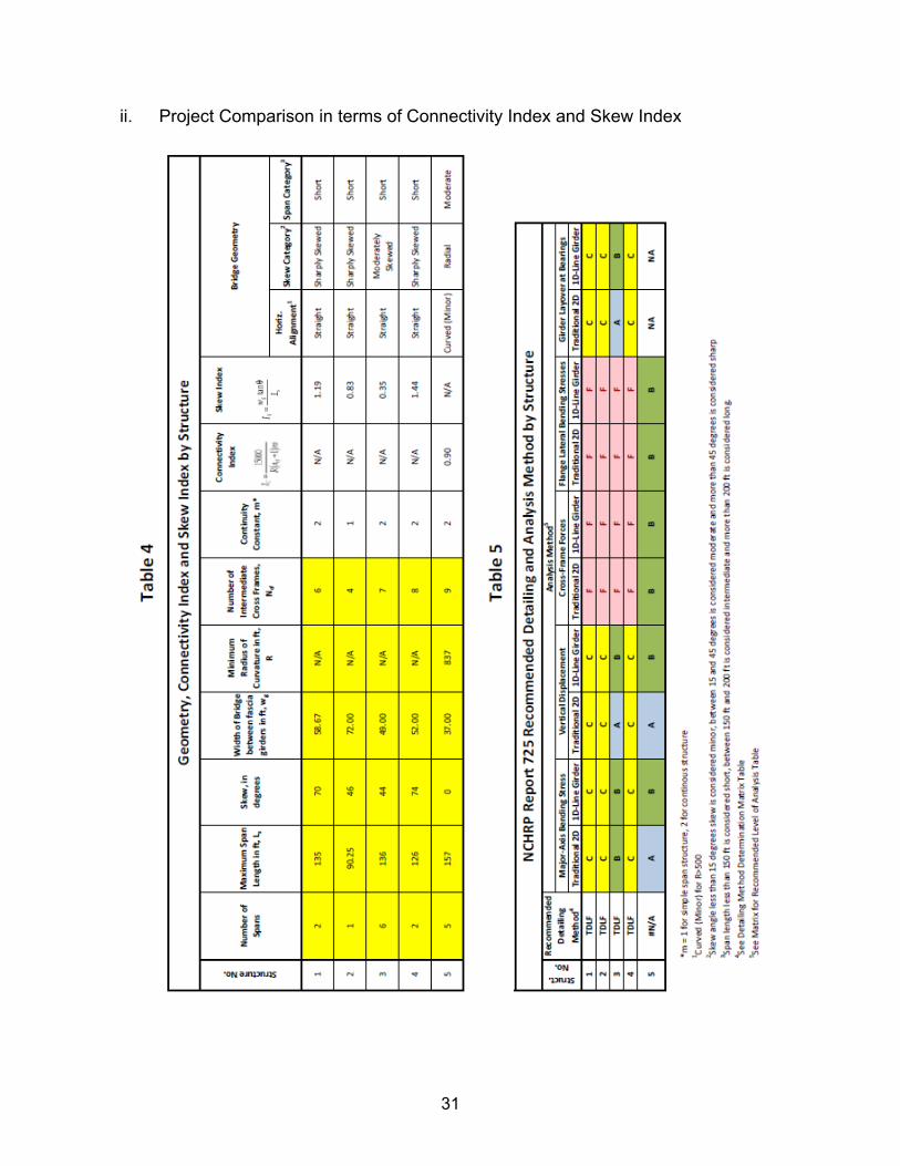
ii. Project Comparison in terms of Connectivity Index and Skew Index
Table 4 – Geometry, Connectivity Index and Skew Index by Structure
Table 5 – NCHRP Report 725 Recommended Detailing and analysis Method by Structure
32
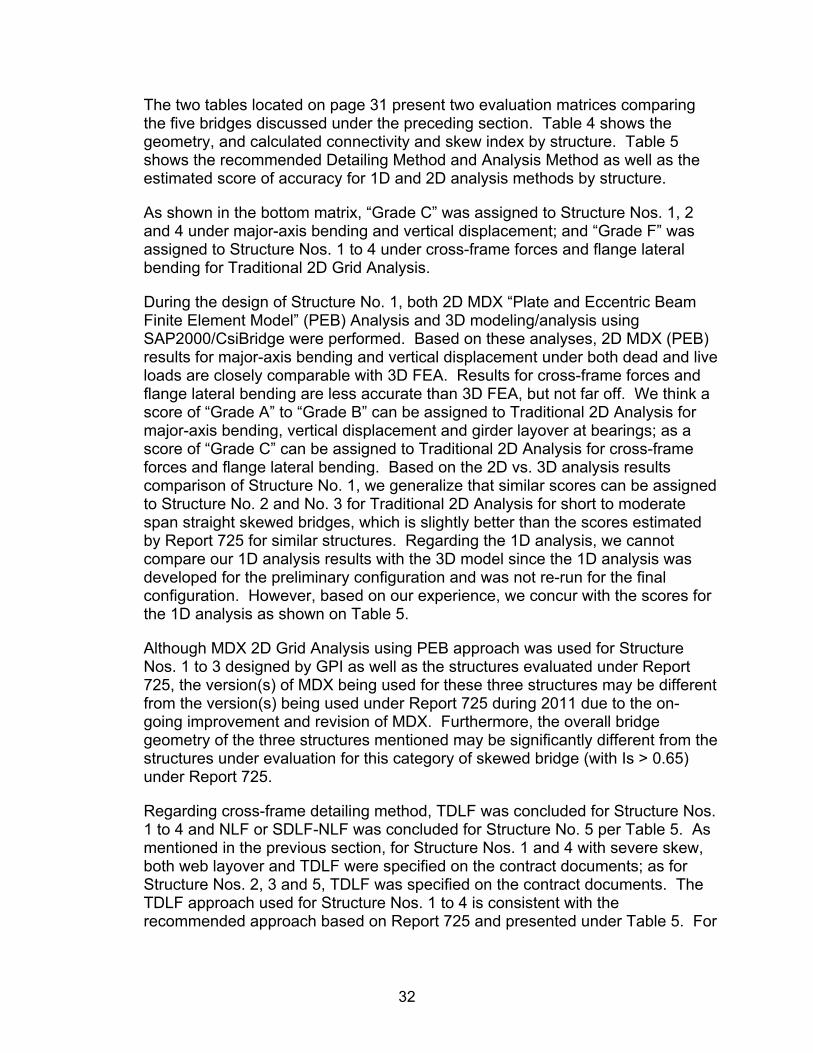
The two tables located on page 31 present two evaluation matrices comparing the five bridges discussed under the preceding section. Table 4 shows the geometry, and calculated connectivity and skew index by structure. Table 5 shows the recommended Detailing Method and Analysis Method as well as the estimated score of accuracy for 1D and 2D analysis methods by structure.
As shown in the bottom matrix, “Grade C” was assigned to Structure Nos. 1, 2 and 4 under major-axis bending and vertical displacement; and “Grade F” was assigned to Structure Nos. 1 to 4 under cross-frame forces and flange lateral bending for Traditional 2D Grid Analysis.
During the design of Structure No. 1, both 2D MDX “Plate and Eccentric Beam Finite Element Model” (PEB) Analysis and 3D modeling/analysis using SAP2000/CsiBridge were performed. Based on these analyses, 2D MDX (PEB) results for major-axis bending and vertical displacement under both dead and live loads are closely comparable with 3D FEA. Results for cross-frame forces and flange lateral bending are less accurate than 3D FEA, but not far off. We think a score of “Grade A” to “Grade B” can be assigned to Traditional 2D Analysis for major-axis bending, vertical displacement and girder layover at bearings; as a score of “Grade C” can be assigned to Traditional 2D Analysis for cross-frame forces and flange lateral bending. Based on the 2D vs. 3D analysis results comparison of Structure No. 1, we generalize that similar scores can be assigned to Structure No. 2 and No. 3 for Traditional 2D Analysis for short to moderate span straight skewed bridges, which is slightly better than the scores estimated by Report 725 for similar structures. Regarding the 1D analysis, we cannot compare our 1D analysis results with the 3D model since the 1D analysis was developed for the preliminary configuration and was not re-run for the final configuration. However, based on our experience, we concur with the scores for the 1D analysis as shown on Table 5.
Although MDX 2D Grid Analysis using PEB approach was used for Structure Nos. 1 to 3 designed by GPI as well as the structures evaluated under Report 725, the version(s) of MDX being used for these three structures may be different from the version(s) being used under Report 725 during 2011 due to the on-going improvement and revision of MDX. Furthermore, the overall bridge geometry of the three structures mentioned may be significantly different from the structures under evaluation for this category of skewed bridge (with Is > 0.65) under Report 725.
Regarding cross-frame detailing method, TDLF was concluded for Structure Nos. 1 to 4 and NLF or SDLF-NLF was concluded for Structure No. 5 per Table 5. As mentioned in the previous section, for Structure Nos. 1 and 4 with severe skew, both web layover and TDLF were specified on the contract documents; as for Structure Nos. 2, 3 and 5, TDLF was specified on the contract documents. The TDLF approach used for Structure Nos. 1 to 4 is consistent with the recommended approach based on Report 725 and presented under Table 5. For
33
Structure No. 5, since the estimated max out-of-plumb rotation is less than the 0.6 degree tolerance, NLF, SDLF and TDLF are all acceptable.
Note: “Plate and Eccentric Beam Finite Element Model” (PEB), is a variant on the 2D Grid/Grillage analysis model, where the deck is modeled using plate or shell elements, while the girders and cross frames are still modeled using line elements offset from the deck elements. PEB is typically more accurate than a traditional (pure) 2D-grid analysis. For non-composite condition, the deck has no stiffness. Only the steel framing has stiffness. Even when PEB is specified, “pure 2D grid” or “Traditional 2D Analysis” is used for the non-comp condition (non-composite dead load), as PEB is used for the composite condition (superimposed dead load and live load). As the 2D analysis comparison results presented under Tables 2, 3 and 5 are mainly for non-composite dead load, results based on PEB and Traditional 2D Analysis are basically the same. This is the reason Traditional 2D Analysis was specified under Tables 2, 3 and 5 in this research paper and under Table 3-1 in Report 725, even though PEB Analysis was performed. For definition of Traditional 2D Grid Analysis and “Plate and Eccentric Beam Analysis” (PEB), see Section 1.2 of NSBA G13.1.
CONCLUSIONS AND RECOMMENDATIONS
It is recommended based on the research performed that NJDOT consider the implementation of the proposed "Guidelines for Design and Contract Documents for Skewed and/or Curved Steel I-Girder Bridges" and “Guidelines for Construction Engineering Provisions and Checklists” via Design Manual updates (through BDC) or project scopes of work. As noted the guidelines were developed for use in the design phase by the design consultant to develop a bridge design and contract documents that consider all of the information presented in the guidelines when the project has skewed and/or curved steel I-Girder bridges. It is most important that these guidelines first be made available formally to the design consultant. The design consultant would then review and follow the guidelines for development of the bridge design, plans and special provisions as applicable to address on a project specific basis. NJDOT Structural and Construction SME's will have an opportunity to review and provide input as part of the design process. With this process the design and construction engineering provisions will have been vetted with NJDOT and Fabricators/Erectors during Final Design so as to ensure the bid documents clearly address all requirements and checklists for the Contractor. The checklists for both erection plan and backup calculations are categorized based on types of construction equipment/device and are self-explanatory regarding their applicability. If this process is followed there is no need to make any reference to the general guidelines in the construction contract as all the pertinent provisions would be made part of the contract thru the design process. The review of the construction engineering provisions and checklists can still be highlighted and reviewed with the contractor at the pre-construction meeting and is considered a good practice for handoff between design and construction.
34
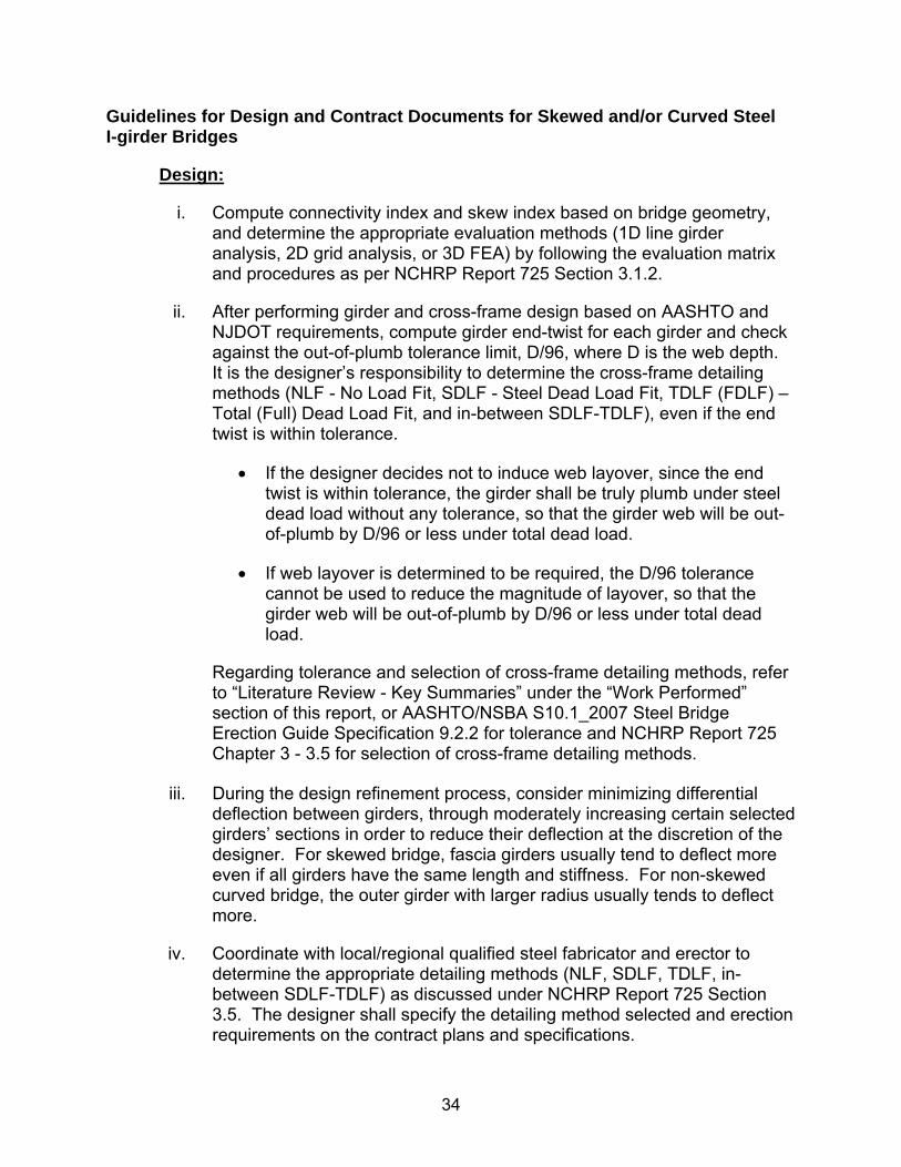
Guidelines for Design and Contract Documents for Skewed and/or Curved Steel I-girder Bridges
Design:
i. Compute connectivity index and skew index based on bridge geometry, and determine the appropriate evaluation methods (1D line girder analysis, 2D grid analysis, or 3D FEA) by following the evaluation matrix and procedures as per NCHRP Report 725 Section 3.1.2.
ii. After performing girder and cross-frame design based on AASHTO and NJDOT requirements, compute girder end-twist for each girder and check against the out-of-plumb tolerance limit, D/96, where D is the web depth. It is the designer’s responsibility to determine the cross-frame detailing methods (NLF - No Load Fit, SDLF - Steel Dead Load Fit, TDLF (FDLF) – Total (Full) Dead Load Fit, and in-between SDLF-TDLF), even if the end twist is within tolerance.
If the designer decides not to induce web layover, since the end twist is within tolerance, the girder shall be truly plumb under steel dead load without any tolerance, so that the girder web will be out-of-plumb by D/96 or less under total dead load.
If web layover is determined to be required, the D/96 tolerance cannot be used to reduce the magnitude of layover, so that the girder web will be out-of-plumb by D/96 or less under total dead load.
Regarding tolerance and selection of cross-frame detailing methods, refer to “Literature Review - Key Summaries” under the “Work Performed” section of this report, or AASHTO/NSBA S10.1_2007 Steel Bridge Erection Guide Specification 9.2.2 for tolerance and NCHRP Report 725 Chapter 3 - 3.5 for selection of cross-frame detailing methods.
iii. During the design refinement process, consider minimizing differential
deflection between girders, through moderately increasing certain selected girders’ sections in order to reduce their deflection at the discretion of the designer. For skewed bridge, fascia girders usually tend to deflect more even if all girders have the same length and stiffness. For non-skewed curved bridge, the outer girder with larger radius usually tends to deflect more.
iv. Coordinate with local/regional qualified steel fabricator and erector to determine the appropriate detailing methods (NLF, SDLF, TDLF, in-between SDLF-TDLF) as discussed under NCHRP Report 725 Section 3.5. The designer shall specify the detailing method selected and erection requirements on the contract plans and specifications.

35
v. For complex bridges and narrow long span bridges, perform 3-D buckling or p-delta analysis to ensure the steel framing system is stable per the designer’s anticipated erection scheme and various phases of the deck pour. The designer shall provide a conceptual erection scheme consistent with the design on the contract plans. Furthermore, staged construction using only 2 or 3 girders may require additional bracing and shoring since long and narrow units tend to over-rotate and experience large amplifications in the girder displacements. It is undesirable and shall be avoided, unless it can be properly braced against adjacent structure.
vi. Perform stability and stress checks of the final completed as well as the staged steel framing without deck and during various phases of the deck pour as shown on the contract plans. Individual stage conditions often produce the controlling design loads and displacements. For deck pour sequence check, see discussion under Deck Pour Sequence Consideration.
vii. Provide estimated girder rotations (both directions – twisting and rotation) on the contract plans in addition to the vertical displacements during all construction stages and final condition. Under-estimated or over-estimated displacements can be equally bad.
viii. Should there be any uplift during any construction stages for any applicable limit state, provide the uplift locations and specify minimum tie-down forces.
ix. Determine the level of analysis (1D, 2D, 3D) required for construction engineering – backup calculations for the erection plan and procedures submittal that are to be developed by the contractor’s engineer, and specify such requirement on the contract plans. (Note: As most contractors’ engineers may not have sophisticated design software capable of performing 2D and/or 3D analysis for loading conditions during erection, 1D line girder analysis will usually be performed. Avoid requiring the contractors’ engineers to re-develop a 2D or 3D model. The design engineer shall determine the proper level of analysis required during construction engineering phase based on complexity of the bridge erection. Except for complex bridges and narrow long span bridges, 1-D analysis with additional safety factor is generally sufficient. The design engineer can determine the required additional safety factor based on the 1-D analysis scores and associated degree of inaccuracy listed under Report 725 Appendix B Table 3.1. The requirements shall be specified by the design engineer in the contract plans.)
x. The behavior of skewed and/or curved bridges due to thermal loads is quite different from straight bridges with little to no skew. Therefore, the designer shall perform 2D or 3D thermal analysis and develop the bearing
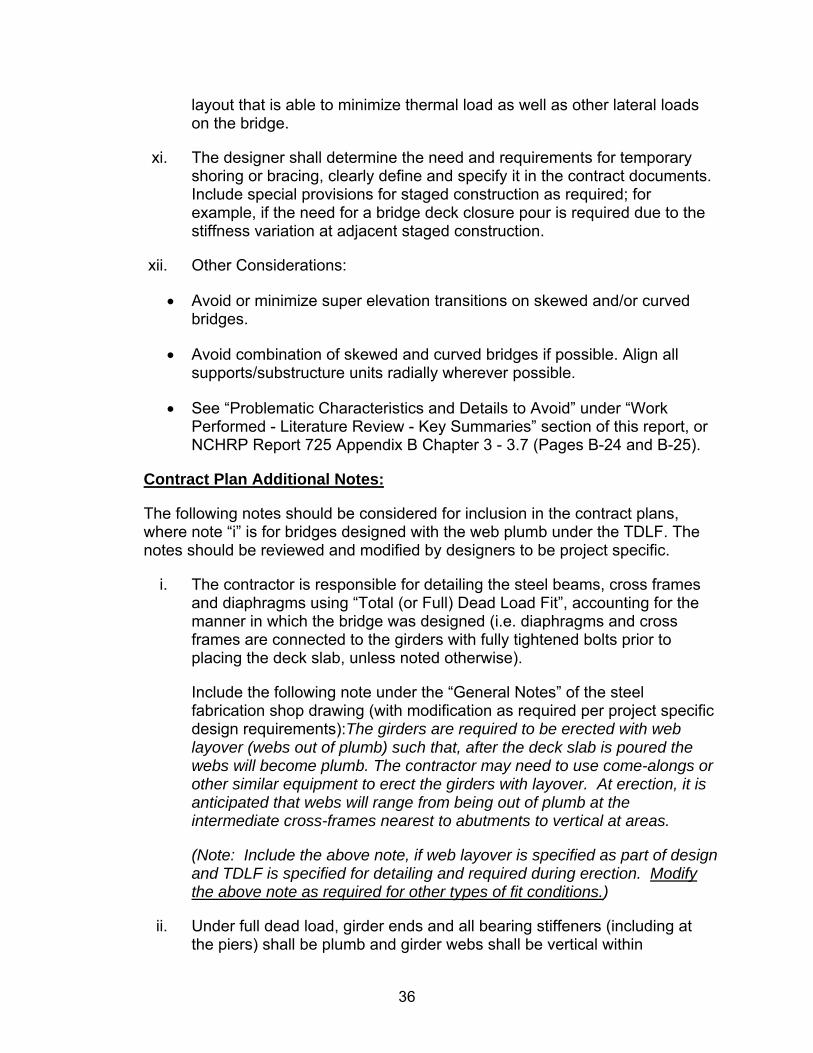
36
layout that is able to minimize thermal load as well as other lateral loads on the bridge.
xi. The designer shall determine the need and requirements for temporary shoring or bracing, clearly define and specify it in the contract documents. Include special provisions for staged construction as required; for example, if the need for a bridge deck closure pour is required due to the stiffness variation at adjacent staged construction.
xii. Other Considerations:
Avoid or minimize super elevation transitions on skewed and/or curved bridges.
Avoid combination of skewed and curved bridges if possible. Align all supports/substructure units radially wherever possible.
See “Problematic Characteristics and Details to Avoid” under “Work Performed - Literature Review - Key Summaries” section of this report, or NCHRP Report 725 Appendix B Chapter 3 - 3.7 (Pages B-24 and B-25).
Contract Plan Additional Notes:
The following notes should be considered for inclusion in the contract plans, where note “i” is for bridges designed with the web plumb under the TDLF. The notes should be reviewed and modified by designers to be project specific.
i. The contractor is responsible for detailing the steel beams, cross frames and diaphragms using “Total (or Full) Dead Load Fit”, accounting for the manner in which the bridge was designed (i.e. diaphragms and cross frames are connected to the girders with fully tightened bolts prior to placing the deck slab, unless noted otherwise).
Include the following note under the “General Notes” of the steel fabrication shop drawing (with modification as required per project specific design requirements):The girders are required to be erected with web layover (webs out of plumb) such that, after the deck slab is poured the webs will become plumb. The contractor may need to use come-alongs or other similar equipment to erect the girders with layover. At erection, it is anticipated that webs will range from being out of plumb at the intermediate cross-frames nearest to abutments to vertical at areas.
(Note: Include the above note, if web layover is specified as part of design and TDLF is specified for detailing and required during erection. Modify the above note as required for other types of fit conditions.)
ii. Under full dead load, girder ends and all bearing stiffeners (including at the piers) shall be plumb and girder webs shall be vertical within

37
fabrication and construction tolerances of 1/8” per foot as per AASHTO/NSBA S10.1_2007 Steel Bridge Erection Guide Specification 9.2.2. The Contractor shall account for deflections and rotations of the girders such that, under full dead load, connection plates and bearing stiffeners are plumb and the girder webs are vertical.
iii. The Contractor is responsible for stability of the girders during erection.
Deck Pour Sequence Consideration:
i. For bridges having continuous spans, the deck is usually poured over the positive moment zone first, and then the negative moment zone. Positive zone(s) on all spans can be poured simultaneously or one after another, but some agencies only allow one pour per span at a time. Constructability of pouring over positive zones in all spans simultaneously shall be investigated as it requires the Contractor to dispense large volume of fresh concrete and finish extensive deck area in a short period of time, as well as to address issues such as ongoing displacing and rotating girders during deck pour due to the skewed and curved nature of the bridge.
ii. The deck pour sequence shall be checked during the design to account for composite/non-composite action and its effect on the girder displacements at various phases, check for girder uplift, as well as assess deck stresses under various deck pour phases and the need for additional deck reinforcement or crack control provisions.
iii. Requirements for the starting point and direction of deck pours shall be provided in the contract documents.
iv. Due to end diaphragm and girder end movement/twisting during deck pours, particularly for moderately to severely skewed and/or curved girder bridges, the designer should consider using a separate deck pour stage for placing concrete at the deck joints.
Additional Designer Responsibility:
The Guidelines for Construction Engineering Provisions and Checklists were developed to cover majority of the bridges, and hence not project specific. The designer shall review and determine which checklist items are relevant and applicable. The designer may modify and incorporate the modified Checklists in the Project Specification, and provide such information to the Department during PS&E Submission so that the Department can inform the Contractor during the bidding process or preconstruction meeting.

38
Additional Steel Bridge Analysis and Construction Engineering Guidelines for Designer Reference:
NCHRP Report 725 – Guidelines for Analysis Methods and Construction Engineering of Curved and Skewed Steel Girder Bridges
AASHTO/NSBA Steel Bridge Collaboration's S10.1-2007, Steel Bridge Erection Guide Specification.
AASHTO/NSBA Steel Bridge Collaboration's G12.1-2003_Guidelines for Design for Constructability, 2nd Edition
AASHTO/NSBA Steel Bridge Collaboration's_G13.1 Steel Girder Bridges Analysis
Guidelines for Construction Engineering Provisions and Checklists
Erection Plan and Procedures Checklist:
The Contractor shall be required to submit a detailed erection plan and procedures to the Department for each structural unit, prepared by or under the supervision of a licensed Professional Engineer registered in the State of New Jersey. All submittals including drawings and calculations shall be signed and sealed by a Professional Engineer registered in the State of New Jersey. The detailed erection plan and procedures shall contain drawings and calculations that support the proposed erection plan and procedures. The plan and procedures shall address all requirements for erection of the structural steel into the final designed configuration and satisfy all written comments by the Department prior to the start of erection. As a minimum, the erection plan and procedures shall include the items cited in the sections that follow.
Erection Plan and Procedures Checklist:
i. Plan of Work Area
Show all existing and new features located within the work area, including but not limited to the following: existing and proposed bridge components (piers, abutments, etc.), all temporary support structures, roads, railroad tracks, waterways (including dimensions for navigational channel, and navigational clearances required during construction), overhead and underground utilities, drainage structures, and sign structures.
Show structures and conditions that may limit access, right-of-way and property lines, material (steel) storage, and assembly areas.

39
Show any other information that may be pertinent to the steel erection (i.e. proximity to adjacent traffic lanes, wetlands, protected areas, etc.).
ii. Erection Sequence, Plans and Details
Provide written narrative of a complete step by step erection sequence for each construction stage compliant with the erection plans and details, as well as a preassembly sequence and details if on-site preassembly is required.
Include an illustrative plan view of the bridge framing plan for each erection stage.
Show complete details of erection accessories and devices, quantity and location of all bracing diaphragms, temporary supports, towers, posts, guys, false-work, tie-downs, etc., for each erection stage along with supporting design calculations and stability analysis for all components.
Show location of each crane and each lifting point with corresponding lifting radii and crane capacities at the load pick and the load release; noting the use of temporary support conditions, such as holding crane positions, temporary supports, guys, false-work, tie-down stability provisions, blocking of the bearings, etc.
Include primary member delivery location and orientation, demonstrating that the distance between crane and pick point(s) is within the maximum crane lift radius.
(Note: Member reference marks shall be shown on the shop drawings.)
iii. Crane Information
Show location of each crane to be used for each member pick, the crane type, the crane pick radius, the crane support methods (mats, barges, etc.), and the means of attachment to the girders being lifted or supported.
Provide crane capacity charts for each crane configuration. Provide boom length, configuration, counterweights, and outrigger spread for each crane.
Provide “Hold Crane Loads” if any; specify when the load shall be released; show crane tail swing proximity to limits of the workzone.
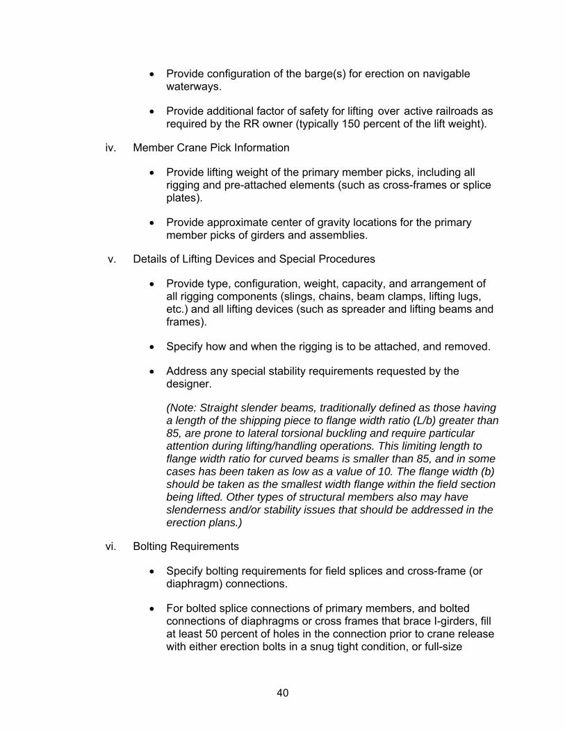
40
Provide configuration of the barge(s) for erection on navigable waterways.
Provide additional factor of safety for lifting over active railroads as required by the RR owner (typically 150 percent of the lift weight).
iv. Member Crane Pick Information
Provide lifting weight of the primary member picks, including all rigging and pre-attached elements (such as cross-frames or splice plates).
Provide approximate center of gravity locations for the primary member picks of girders and assemblies.
v. Details of Lifting Devices and Special Procedures
Provide type, configuration, weight, capacity, and arrangement of all rigging components (slings, chains, beam clamps, lifting lugs, etc.) and all lifting devices (such as spreader and lifting beams and frames).
Specify how and when the rigging is to be attached, and removed.
Address any special stability requirements requested by the designer.
(Note: Straight slender beams, traditionally defined as those having a length of the shipping piece to flange width ratio (L/b) greater than 85, are prone to lateral torsional buckling and require particular attention during lifting/handling operations. This limiting length to flange width ratio for curved beams is smaller than 85, and in some cases has been taken as low as a value of 10. The flange width (b) should be taken as the smallest width flange within the field section being lifted. Other types of structural members also may have slenderness and/or stability issues that should be addressed in the erection plans.)
vi. Bolting Requirements
Specify bolting requirements for field splices and cross-frame (or diaphragm) connections.
For bolted splice connections of primary members, and bolted connections of diaphragms or cross frames that brace I-girders, fill at least 50 percent of holes in the connection prior to crane release with either erection bolts in a snug tight condition, or full-size

41
erection pins (a.k.a., “drift pins”). Sufficient erection pins shall be used near the outside corners of splice plate and at member ends near splice plate edges to ensure alignment. The filled holes shall be uniformly distributed across the connection.
(Note: Steel I-girders depend on their connections to adjacent girders through bracing members for their stability and stiffness during steel erection. This is especially true for curved steel girders, as the cross frames serve as primary load carrying members. Therefore, loosely connected cross frames should not be used during steel girder bridge erection, as this may compromise the girder alignment (geometry control) and stability.)
Specify 100 percent of bolts be installed and properly tightened for all on-site pre-assembled girders and frames prior to the beginning of lifting operations.
vii. Bearing Blocking and Tie-Down Details
Indicate the blocking and/or tie-down details for the bridge bearings, as necessary.
(Note: When temporary tie-downs are used to provide torsional/uplift or lateral restraint, specify calculated minimum bracing force, capacity of tie-down components including anchorage reactions (2D/3D resultants) & resistances (accounting for spacing, edge & group anchorage reduction factors as applicable).)
viii. Load Restrictions
Specify any construction load (dead load, live load, or wind) restrictions.
Include any necessary provisions for temporary supports or tie-downs of partially completed structures during high wind conditions, if applicable.
ix. Temporary Supports
Temporary supports must be designed and detailed as required for the proposed erection scheme. Indicate the purpose of the use of temporary support; and installation and removal schedule relative to various phases of the construction such as deck placement.
The design, erection, and stability of these supports shall be the sole responsibility of the Contractor.

42
Provide all foundation requirements and necessary attachments for temporary support structures.
x. Jacking Devices and Procedures
Show jacking devices required to complete the steel erection, as necessary.
Specify minimum jack capacity.
Provide jacking schematics showing location, type, size, and capacity of jacks, as well as a jacking table with jacking loads, pressures and not to exceed pressures.
xi. Web Layover
Include web layover requirements and any applicable additional details in the project specific erection procedure, if applicable.
Calculation Checklist:
Calculations by the Contractor’s Engineer investigating the steel erection sequence are required to substantiate the erection plan and procedures submitted for a given project. This section presents guidelines regarding these calculations, when investigating the adequacy of the erection sequence of a curved or skewed steel girder bridge.
Calculation Checklist for Erection:
i. Method of Analysis
The contractor’s engineer shall perform a 1D line girder analysis (as a minimum) with or without an additional safety factor (in addition to load factors required per AASHTO LRFD), or a 2D grid analysis, or a 3D FEA as per requirements specified in the Contract Documents. For definition and applicability of different types of analysis, refer to AASHTO/NSBA Steel Bridge Collaboration's G13.1-2011 “Guidelines for Steel Girder Bridge Analysis”.
ii. Girder Transportation Layout and Backup Computation
Include girder transportation layout and backup computation, in accordance with NJDOT 2007 Standard Specifications for Road and Bridge Construction Section 906.04.04.
43
iii. Support Conditions
The boundary (support) conditions assumed in the erection analysis should accurately reflect the actual support conditions in the structure at all stages of erection (including accurate consideration of any and all temporary supports).
iv. Design Criteria
The calculations supporting the erection plan and procedures shall be completed in accordance with the AASHTO LRFD Bridge Design Specifications, the AASHTO LRFD Bridge Construction Specifications, and the AASHTO Guide Design Specifications for Bridge Temporary Works, unless otherwise directed by the Department or the contract documents.
v. Loads and Load Combinations
The calculations supporting the erection plan and procedures shall consider all applicable loads. Typical load considerations include permanent dead load, construction dead load, construction live load, and wind loads. Permanent dead loads typically include the self-weight of the structural members and detail attachments. Construction dead and live loads may consist of deck placement machinery, Contractor’s equipment, deck overhang brackets, concrete formwork, or other similar attachments applied in the appropriate sequence. Wind loads shall be considered in each step of the steel erection analysis and are to be computed in accordance with the established design criteria. It is permissible to set limits on maximum wind velocities during steel erection, but these limits must be clearly stated in the erection plan. In some cases, it may be advisable and/or necessary to include provisions in the erection plan for temporary supports and/or tie-downs to address high wind conditions. Load combinations should be in accordance with AASHTO LRFD Load Combinations and Load Factors defined under Sections 3.4.1 and 3.4.2, and Table 3.4.1-1, unless noted otherwise in the contract documents.
vi. Stability Check of Girder and Bridge System
The calculations supporting the erection plan and procedures shall verify the stability both of individual girders, partial and entire erected steel framing for each step of the bridge erection; as well as during the deck pour if the contractor elects to use a sequence or layout different than that shown on the contract plan. These calculations are highly dependent on the particular features of the bridge being erected and also of the particular sequence of erection of each part of the bridge. The assumptions used in the analysis should directly and fully conform to all steps and all details in the erection plan. The constructability provisions of

44
Article 6.10.3 of the AASHTO LRFD Bridge Design Specifications should be referenced by the Contractor’s Engineer when investigating structural adequacy and stability during steel erection.
(Note: Particular attention should be given to the lateral torsional buckling capacity of a singly erected I-girder, if used. Global overturning stability is also a concern for single curved girders. The offset of the center of gravity of the girder from a chord line drawn between the support points results in an overturning moment. Single girders are typically afforded little or no torsional restraint at their supports unless tie downs, bracing, temporary shoring, or hold cranes are provided. Erection of a “pair” of girders is the preferred method. During the various stages of erection of most steel girder bridges there are often cases where field sections of girders are supported in a cantilevered position. Capacity and stability of these cantilever conditions shall be evaluated by the Contractor’s Engineer. For long cantilevers, lateral torsional buckling will typically govern over yielding of the section. For curved girders, additional consideration needs to be given to the torsional forces that develop due to the offset centroid of the cantilever. For additional information on this subject, refer to NCHRP Report 725 Appendix B, Section 3.3.3.)
vii. Girder Reactions Check for Uplift
Uplift at temporary and permanent supports during steel erection shall be accounted for in the development of the erection plan and procedures. Curved or skewed I-girder bridge systems are particularly susceptible to uplift during various stages of steel erection due to the torsional twisting of the system caused by curvature and/or skew.
viii. Temporary Hold Crane Loads
The computations for hold crane loads (if hold cranes are used) should be included in the erection plan calculations. Hold cranes are used to apply an upward load at some location with the span of a girder, thereby reducing the load carried by the girder. Oftentimes, the hold crane load is used to reduce the girder flexural moment due to self-weight (and any other applied loads) to a level at which the moment is less than the lateral-torsional bucking capacity. A hold crane shall not be considered as a brace point in the evaluation of the lateral torsional buckling capacity of a girder. (Note: See Erection Plan and Procedures Checklist “iii” for submission requirements.)
ix. Temporary Support Loads
The erection plan calculations should include computations for the loads on temporary supports provided at critical stages of the erection sequence. These loads may include vertical and lateral reactions from the

45
superstructure, self-weight of the temporary support, wind loads on the temporary support, etc.
x. Bearing Rotational Capacity Check
Computed bearing rotations during construction should not exceed the rotational capacity of the bearing. The erection plan calculations should include these bearing rotations. Skewed bridges are particularly vulnerable to twisting about the longitudinal axis of the girder. During steel erection, the girder could be rotated beyond the rotational capacity of the bearing, regardless of the vertical load on the bearing.
xi. Cross-frame and Bracing Capacity Check (if required)
During steel erection, if the erector choose to install the minimum required number of cross frames when initially erecting the girders, so as to reduce erection time, allowing a follow-up crew to install the remaining cross frames later, correct determination of the minimum number of required cross frames to prevent lateral torsional buckling of the girders is critical to ensuring the stability of the girders. Additional calculations should be performed to check that individual cross frame members and connections have adequate capacity.
xii. Checks of Structural Adequacy of Temporary Supports and Devices
Calculations to substantiate the structural adequacy and stability of any and all temporary support components, bearings and foundations for each step of the steel erection shall be submitted with the erection plan. Additionally, calculations supporting the use of lifting beams, lifting devices (rigging), tie-downs, and jacking devices shall be included in the calculation submittal.
(Note: Lifting and spreader beams are Below-The-Hook (BTH) lifting devices. Pre-manufactured spreader and lifting beams are designed and tested as a BTH lifting device and do not need to be designed or load tested. If a spreader beam is designed and manufactured by the contractor, it shall meet Below-The-Hook lifting devices requirements (design and load testing) as specified in the ASME publication BTH-1.)
xiii. Crane Pick Location Calculations
Provide calculations (or reasons) for the approximate pick locations for girder erection. These approximate crane pick locations should be determined with consideration of the centroid of the entire assembly being lifted into place, including the girder as well as any attached cross frames, splice plates, stiffening trusses, or other attached items.

46
xiv. Field Splice Connection Alignment Check
Oftentimes, the field splice location will be at the end of the girder that is cantilevered over an interior support. For long span and/or bridges with complex geometrics (e.g., significant skew/curvature/flare/differential deflections), displacements and rotations may be significant enough to hinder the Contractor’s attempts to align bolt holes in bolted field splice connections. Vertical displacements and end rotations at the end of the previously placed, cantilevered section may result in the end of the girder being out of position and out of alignment relative to the next field section being erected, which is often in a level, neutral position when being lifted. Lateral displacements are caused by the natural behavior of a curved steel girder to rotate outward from the radius of curvature. Since the next girder piece being lifted into place will typically be in a vertically plumb position, laterally displaced cantilever tips of the previously erected girder could cause alignment issues. For such case, the Contractor’s Engineer shall evaluate the lateral and vertical displacements and rotations at field splice locations of previously erected girders in relation to the next girder segment being erected, using the erection analysis results.
xv. Cross-frame Connection Alignment Check
Using the erection analysis results, the Contractor’s Engineer shall verify that the lateral displacements and girder rotations do not cause problems in erecting cross frames, whether cross frames are installed before or after girders are released from the lifting crane. Long unbraced girder lengths may result in significant out-of-plane rotations and displacements of the top and bottom flanges. Curvature and skew also produce potentially significant girder displacements and rotations. If the rotations and displacements are too large, the Contractor may have difficulty aligning connections. Contractors typically use various methods to correct these types of misalignments, including the use of temporary hold cranes, jacks, come-alongs, or other means. In certain situations, these means may prove insufficient. In extreme cases, the inherent stiffness of the girders is such that enough force cannot be practically applied to pull the connections into alignment, or alternately the amount of force required to pull the connections into alignment would damage the structure.
Additional Erector Qualification Requirement for Skewed and/or Curved Steel Bridge:
For bridges with sharp skew angle (measured from a line perpendicular to the tangent of the bridge centerline to centerline of abutment or pier) and/or with a tight radius of curvature, the Contractor and/or Erector shall meet the following additional qualification requirements:

47
i. For bridges with skew angle ranging from 30 to 60 degrees, and/or with a radius of curvature between 600 and 1200 feet, the Contractor shall provide evidence to demonstrate that the Contractor and/or Erector have successfully erected similar bridges within this geometric range, or a more severe geometric range within the past five years.
ii. For bridges with skew angle greater than 60 degrees, and/or with a radius of curvature less than 600 feet, the Contractor shall provide evidence to demonstrate that the Contractor or Erector have successfully erected similar bridges within this geometric range in the past five years.
Please note that skewed bridge erection experience cannot substitute for curved bridge experience and vice versa.
Additional Steel Bridge Erection Guidelines for Contractor Reference:
AASHTO/NSBA Steel Bridge Collaboration's S10.1-2007, Steel Bridge Erection Guide Specification.
AASHTO/NSBA Steel Bridge Collaboration's G12.1-2003_Guidelines for Design for Constructability, 2nd Edition
AASHTO/NSBA Steel Bridge Collaboration's_G13.1 Steel Girder Bridges Analysis
Additional Steel Bridge Erection and Web Layover related Articles for Contractor Reference:
Bob Cisneros, Ronnie Medlock, Sue Steele, and Bobby Urban (2013) “Skewed Steel Girder Bridge Erection: Tricks of the Trade”, High Steel News, Fall 2013, http://www.highsteel.com/upload/HSN_Fall_2013_final.pdf
Ahmad K. Ahmadi, Raymond Henney, and Doug Thompson (2005) “Lessons Learned from the Construction of a Sharply Skewed, Two-span, Steel Multi-girder Bridge,” in the Proceedings of the 22nd Annual International Bridge Conference 2005, (A copy of the proceedings can be purchased through Proceedings.com) http://www.proceedings.com/03465.html

48
BIBLIOGRAPHY
AASHTO/NSBA Steel Bridge Collaboration, “G 13.1Guidelines for Steel Girder Bridge Analysis,” 1st Edition, 2011
AASHTO/NSBA Steel Bridge Collaboration, “G 12.1 Guidelines for Design for Constructability,” 2003
AASHTO/NSBA Steel Bridge Collaboration, “S 10.1 Steel Bridge Erection Guide Specification,” 2007
Ahmad K. Ahmadi, Raymond Henney, and Doug Thompson, “Lessons Learned from the Construction of a Sharply Skewed, Two-span, Steel Multi-girder Bridge,” 22nd Annual International Bridge Conference Proceedings, 2005.
American Association of State Highway and Transportation Officials, “AASHTO LRFD Bridge Design Specifications”, 6th Edition, 2012
Bob Cisneros, Ronnie Medlock, Sue Steele, and Bobby Urban, “Skewed Steel Girder Bridge Erection: Tricks of the Trade”, High Steel News, 2013.
Craig Quadrato, Weihua Wang, Anthony Battistini, Andrew Wahr, Todd Helwig, Karl Frank, and Michael Engelhardt, “Cross-Frame Connection Details for Skewed Steel Bridges”, 2010.
CsiBridge,“Computer & Structures, Inc., Software for Structural and Earthquake Engineering,” 2012-2013.
MDX, “MDX Software, The Proven Steel Bridge Design Solution,” 2012-2013.
New York State, “NYSDOT Steel Construction Manual,” 3rd Edition, Sections 204 and 1403, 2008
Transportation Research Board, “Guidelines for Analysis Methods and Construction Engineering of Curved and Skewed Steel Girder Bridges - NCHRP Report 725,” 2012.
PennDOT, “Guidelines for Analyzing Curved and Skewed Bridges and Designing Them for Construction,” 2010.
Transportation Research Board, “Steel Bridge Erection Practices - NCHRP Synthesis 345,” 2005.
Related Documents