ST4000+ Wheel & Tiller Autopilots Owner’s Handbook Document number: 81131-6 Date: August 2001

Welcome message from author
This document is posted to help you gain knowledge. Please leave a comment to let me know what you think about it! Share it to your friends and learn new things together.
Transcript
ST4000+ Wheel & Tiller AutopilotsOwner’s Handbook
Document number: 81131-6
Date: August 2001
ii ST4000+ Wheel & Tiller Autopilots: Owner’s Handbook
Autohelm, HSB (High Speed Bus), SailPilot, SeaTalk and SportPilot are registered trademarks of Raymarine Ltd.
Raymarine, AST (Advanced Steering Technology), AutoAdapt, AutoLearn, AutoRelease, AutoSeastate, AutoTack, AutoTrim, FastTrim, GyroPlus, RayGyro, RayPilot and WindTrim are trademarks of Raymarine Ltd.
Handbook contents © Raymarine Ltd 2001.
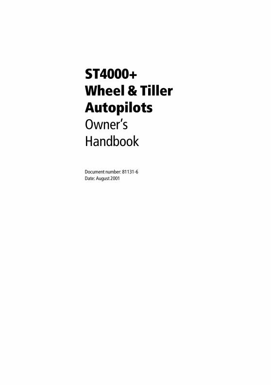
Preface iii
OR
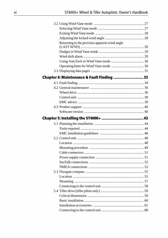
Boat's electricaldistribution panel
Rudder position sensor(optional fit for wheel pilot only)
ST4000+control unitFluxgate compass
SeaTalk instrumentNMEAinstrumentor navigator
Tiller drive
Wheel drive
ST4000+ autopilot system layout
D5332-1

iv ST4000+ Wheel & Tiller Autopilots: Owner’s Handbook
Preface v
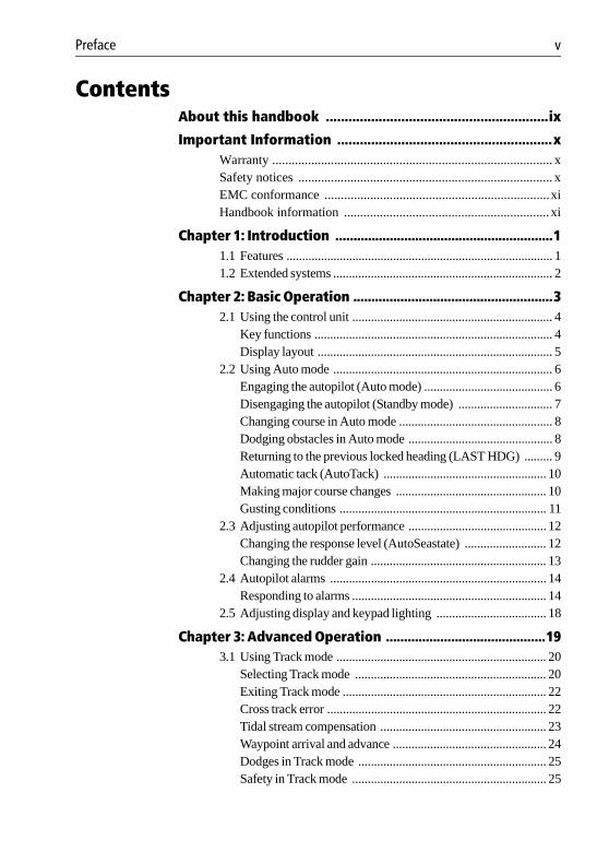
ContentsAbout this handbook ...........................................................ix
Important Information .........................................................xWarranty ...................................................................................... xSafety notices .............................................................................. xEMC conformance .....................................................................xiHandbook information ...............................................................xi
Chapter 1: Introduction ............................................................11.1 Features ..................................................................................... 11.2 Extended systems ...................................................................... 2
Chapter 2: Basic Operation .......................................................32.1 Using the control unit ................................................................ 4
Key functions ............................................................................ 4Display layout ........................................................................... 5
2.2 Using Auto mode ...................................................................... 6Engaging the autopilot (Auto mode) ......................................... 6Disengaging the autopilot (Standby mode) .............................. 7Changing course in Auto mode ................................................. 8Dodging obstacles in Auto mode .............................................. 8Returning to the previous locked heading (LAST HDG) ......... 9Automatic tack (AutoTack) .................................................... 10Making major course changes ................................................ 10Gusting conditions .................................................................. 11
2.3 Adjusting autopilot performance ............................................ 12Changing the response level (AutoSeastate) .......................... 12Changing the rudder gain ........................................................ 13
2.4 Autopilot alarms ..................................................................... 14Responding to alarms .............................................................. 14
2.5 Adjusting display and keypad lighting ................................... 18
Chapter 3: Advanced Operation ............................................193.1 Using Track mode ................................................................... 20
Selecting Track mode ............................................................. 20Exiting Track mode ................................................................. 22Cross track error ...................................................................... 22Tidal stream compensation ..................................................... 23Waypoint arrival and advance ................................................. 24Dodges in Track mode ............................................................ 25Safety in Track mode .............................................................. 25
vi ST4000+ Wheel & Tiller Autopilots: Owner’s Handbook
3.2 Using Wind Vane mode .......................................................... 27Selecting Wind Vane mode ..................................................... 27Exiting Wind Vane mode ........................................................ 28Adjusting the locked wind angle ............................................. 28Returning to the previous apparent wind angle (LAST WND) ......................................................................... 28Dodges in Wind Vane mode .................................................... 29Wind shift alarm ...................................................................... 29Using AutoTack in Wind Vane mode ...................................... 30Operating hints for Wind Vane mode ...................................... 30
3.3 Displaying data pages ............................................................. 31
Chapter 4: Maintenance & Fault Finding ..............................334.1 Fault finding ............................................................................ 344.2 General maintenance .............................................................. 36
Wheel drive ............................................................................. 36Control unit ............................................................................. 38EMC advice ............................................................................ 39
4.3 Product support ....................................................................... 40Software version ..................................................................... 40
Chapter 5: Installing the ST4000+ ..........................................435.1 Planning the installation ......................................................... 44
Tools required ......................................................................... 44EMC installation guidelines ................................................... 46
5.2 Control unit ............................................................................. 48Location .................................................................................. 48Mounting procedure ............................................................... 49Cable connectors ..................................................................... 51Power supply connection ........................................................ 51SeaTalk connections ............................................................... 52NMEA connections ................................................................ 53
5.3 Fluxgate compass ................................................................... 55Location .................................................................................. 55Mounting ................................................................................ 57Connecting to the control unit ................................................. 58
5.4 Tiller drive (tiller pilots only) .................................................. 59Critical dimensions ................................................................. 59Basic installation ..................................................................... 60Installation accessories ........................................................... 61Connecting to the control unit ................................................. 68
Preface vii
5.5 Wheel drive (wheel pilots only) .............................................. 70Installation stages .................................................................... 70Drilling the spoke clamp holes ................................................ 71Securing the wheel drive to the wheel ..................................... 74Attaching the pedestal bracket ................................................ 75Connecting to the control unit ................................................. 79
5.6 Rudder position sensor (wheel pilot option) ........................... 81Ensuring correct alignment ..................................................... 81Securing the sensor to the boat ................................................ 83Attaching the sensor to the tiller arm ....................................... 83Checking alignment ................................................................ 84Connecting to the control unit ................................................. 84
Chapter 6: Setting-up the ST4000+ ........................................856.1 Functional test ......................................................................... 86
Switch on ................................................................................ 86Autopilot steering direction .................................................... 86Checking connections ............................................................. 88
6.2 Check rudder sensor operation (if fitted) ................................ 906.3 Initial sea trial .......................................................................... 91
Overview ................................................................................ 91Correcting the compass deviation .......................................... 92Adjusting the heading alignment ............................................ 95Checking autopilot operation .................................................. 95Checking the rudder gain ........................................................ 96
6.4 Autopilot calibration techniques ............................................. 98Step 1 - Switch on ancillary equipment ................................... 98Step 2 - Apply initial settings .................................................. 98Step 3 - Adjust the rudder damping ......................................... 99Step 4 - Adjust the rudder gain ................................................ 99Step 5 - Adjust the AutoTrim setting ....................................... 99Step 6 - Further adjustments .................................................... 99
Chapter 7: Customizing the ST4000+ ..................................1017.1 User setup .............................................................................. 102
Compass deviation correction (SWING COMPASS) .......... 102Deviation display (DEVIATION) ........................................ 102Heading alignment (ALIGN HDG) ...................................... 102Heading mode (HDG MAG/TRU) ....................................... 102Bar selection (RUDD BAR/STEER BAR/NO BAR) .......... 104Data pages 1-7 (DATA PAGE) .............................................. 104
viii ST4000+ Wheel & Tiller Autopilots: Owner’s Handbook
7.2 Dealer setup .......................................................................... 106Calibration lock (CAL LOCK) ............................................. 108Pilot type (4000 WHL/TILL) ............................................... 108Rudder gain (RUDD GAIN) ................................................. 108Response level (RESPONSE) .............................................. 108Turn limit (TURN RATE) ..................................................... 108Rudder alignment (ALIGN RUD) ........................................ 108Rudder limit (RUD LIMIT) .................................................. 109Off course alarm (OFF COURSE) ........................................ 109AutoTack angle (AUTOTACK) ........................................... 109AutoTrim (AUTOTRIM) ..................................................... 110Drive type (DRIVE TYP) ..................................................... 110Magnetic variation (VARIATION) ....................................... 110AutoAdapt (AUTOADAPT) .................................................111Latitude (LATITUDE) ...........................................................111Rudder damping (RUDD DAMP) ........................................ 112Cruise speed (CRUISE SP) .................................................. 112
Specifications .................................................................... 113
Glossary .............................................................................. 115
Index ................................................................................... 117
Preface ix
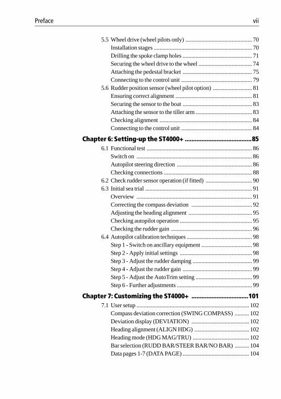
About this handbookWelcome to the handbook for the ST4000+ wheel and tiller autopilot systems. This handbook contains two main parts:
Part 1: Using the ST4000+ Autopilot
Part 2: Installing the ST4000+ Autopilot
At the end of this handbook we have included product specifications, a glossary and index, and templates for installing different parts of the system.
Note: This handbook contains important information about installing, using and maintaining your new Raymarine product. To get the best from the product, please read this handbook thoroughly.
1 Chapter 1: IntroductionIntroduces the autopilot, its features and its use. page 1
2Chapter 2: Basic OperationCovers basic autopilot operation: using Auto mode, interpreting alarms, adjusting autopilot performance and changing the control unit lighting.
page 3
3Chapter 3: Advanced OperationExplains how to use Track and Wind Vane modes, and display data pages.
page 19
4Chapter 4: Maintenance & Fault FindingProvides general maintenance procedures and information to help you resolve problems you may encounter with the autopilot
page 33
5 Chapter 5: Installing the ST4000+Explains how to install your autopilot and its components. page 43
6Chapter 6: Setting-up the ST4000+Covers functional testing and dockside procedures after installation, and initial sea trials.
page 85
7Chapter 7: Customizing the ST4000+Provides details on adjusting the autopilot settings to suit your boat.
page 101
x ST4000+ Wheel & Tiller Autopilots: Owner’s Handbook
Important Information
WarrantyTo register your new Raymarine product, please take a few minutes to fill out the warranty card. It is important that you complete the owner information and return the card to us to receive full warranty benefits.
Safety noticesWARNING: Product installation
This equipment must be installed and operated in accordance with the instructions contained in this handbook. Failure to do so could result in poor product performance, personal injury and/or damage to your boat.
WARNING: Electrical safety
Make sure the power supply is switched off before you make any electrical connections.
WARNING: Calibration
We supply this product calibrated to default settings that should provide stable performance for most boats. To ensure optimum performance on your boat, you must complete Chapter 6: Setting-up the ST4000+ before use.
WARNING: Navigation aid
Although we have designed this product to be accurate and reliable, many factors can affect its performance. As a result, it should only be used as an aid to navigation and should never replace common sense and navigational judgement. Always maintain a permanent watch so you can respond to situations as they develop.
Your Raymarine autopilot will add a new dimension to your boating enjoyment. However, it is the skipper’s responsibility to ensure the safety of the boat at all times by following these basic rules:
• Ensure that someone is present at the helm AT ALL TIMES, to take manual control in an emergency.
Preface xi
• Make sure that all members of crew know how to disengage the autopilot.
• Regularly check for other boats and any obstacles to navigation – no matter how clear the sea may appear, a dangerous situation can develop rapidly.
• Maintain an accurate record of the boat’s position by using either a navigation aid or visual bearings.
• Maintain a continuous plot of your boat’s position on a current chart. Ensure that the locked autopilot heading will steer the boat clear of all obstacles. Make proper allowance for tidal set – the autopilot cannot.
• Even when your autopilot is locked onto the desired track using a navigation aid, always maintain a log and make regular positional plots. Navigation signals can produce significant errors under some circumstances and the autopilot will not be able to detect these errors.
EMC conformanceAll Raymarine equipment and accessories are designed to the best industry standards for use in the recreational marine environment. The design and manufacture of Raymarine equipment and accessories conform to the appropriate Electromagnetic Compatibility (EMC) standards, but correct installation is required to ensure that performance is not compromised.
Handbook informationTo the best of our knowledge, the information in this handbook was correct when it went to press. However, Raymarine cannot accept liability for any inaccuracies or omissions it may contain. In addition, our policy of continuous product improvement may change specifications without notice. As a result, Raymarine cannot accept liability for any differences between the product and the handbook.

xii ST4000+ Wheel & Tiller Autopilots: Owner’s Handbook

Part 1: Using the ST4000+
Part 1:Using the ST4000+

Part
1: U
sing
the
ST40
00+
Chapter 1: Introduction 1
1 Introduction
Chapter 1: Introduction
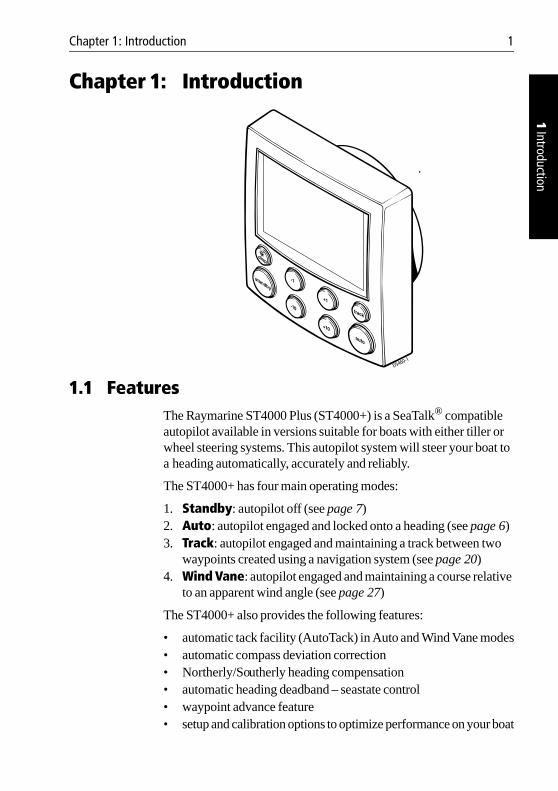
1.1 FeaturesThe Raymarine ST4000 Plus (ST4000+) is a SeaTalk® compatible autopilot available in versions suitable for boats with either tiller or wheel steering systems. This autopilot system will steer your boat to a heading automatically, accurately and reliably.
The ST4000+ has four main operating modes:
1. Standby: autopilot off (see page 7)2. Auto: autopilot engaged and locked onto a heading (see page 6)3. Track: autopilot engaged and maintaining a track between two
waypoints created using a navigation system (see page 20)4. Wind Vane: autopilot engaged and maintaining a course relative
to an apparent wind angle (see page 27)
The ST4000+ also provides the following features:
• automatic tack facility (AutoTack) in Auto and Wind Vane modes• automatic compass deviation correction• Northerly/Southerly heading compensation• automatic heading deadband – seastate control• waypoint advance feature• setup and calibration options to optimize performance on your boat
D5460-1
2 ST4000+ Wheel & Tiller Autopilots: Owner’s Handbook
1 In
trodu
ctio
n
1.2 Extended systemsThe ST4000+ is compatible with all other SeaTalk instruments. You can connect it to additional fixed or handheld SeaTalk autopilot control units located at secondary steering and control positions (see page 52).
You can also use the ST4000+ autopilot with any navigator (GPS, Decca, Loran) or wind instrument that transmits data in the internationally-accepted National Marine Electronics Association (NMEA) 0183 format.
The ST4000+ can display SeaTalk and NMEA instrument data in a user-defined selection of data pages. When you are using the ST4000+ to repeat instrument data, it shows a ‘pop-up’ pilot page for 5 seconds whenever you make a change in autopilot control.
The ST4000+ can share all data transmitted from SeaTalk instruments:
• it can use wind information from a SeaTalk wind instrument for wind trim steering in Wind Vane mode without the need for a separate vane
• it can use track information from a SeaTalk navigation instrument to provide waypoint control in Track mode
• it can use boat speed from a SeaTalk speed instrument to optimize track-keeping performance
Rudder position sensor (wheel drives only)On wheel drive systems you can fit a rudder position sensor to improve the wheel pilot’s performance (see page 81). This is particularly advisable if your boat’s steering system has significant backlash, or you require optimum performance from a mechanical or cable steering system. By using the information from the rudder angle sensor, the ST4000+ will also be able to show the true rudder angle in Standby and Auto modes.
Note: You MUST add a rudder position sensor if fitting the ST4000+ to a hydraulic steering system.
Chapter 2: Basic Operation 3
2 Basic Operation
Chapter 2: Basic Operation
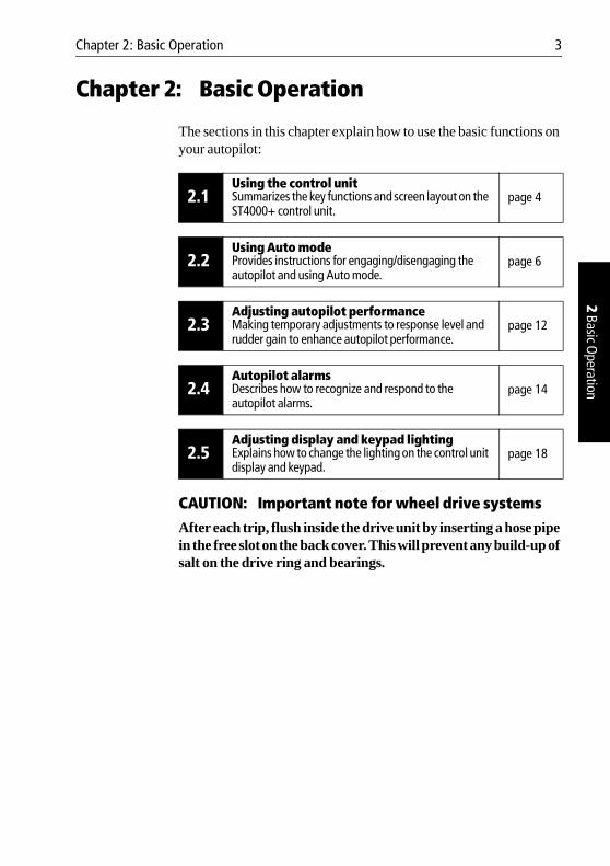
The sections in this chapter explain how to use the basic functions on your autopilot:
CAUTION: Important note for wheel drive systemsAfter each trip, flush inside the drive unit by inserting a hose pipe in the free slot on the back cover. This will prevent any build-up of salt on the drive ring and bearings.
2.1Using the control unitSummarizes the key functions and screen layout on the ST4000+ control unit.
page 4
2.2Using Auto modeProvides instructions for engaging/disengaging the autopilot and using Auto mode.
page 6
2.3Adjusting autopilot performanceMaking temporary adjustments to response level and rudder gain to enhance autopilot performance.
page 12
2.4Autopilot alarmsDescribes how to recognize and respond to the autopilot alarms.
page 14
2.5Adjusting display and keypad lightingExplains how to change the lighting on the control unit display and keypad.
page 18
4 ST4000+ Wheel & Tiller Autopilots: Owner’s Handbook
2 Ba
sic O
pera
tion
2.1 Using the control unit
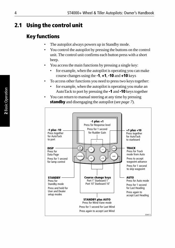
Key functions• The autopilot always powers up in Standby mode.• You control the autopilot by pressing the buttons on the control
unit. The control unit confirms each button press with a short beep.
• You access the main functions by pressing a single key:• for example, when the autopilot is operating you can make
course changes using the -1, +1, -10 and +10 keys• To access other functions you need to press two keys together:
• for example, when the autopilot is operating you make an AutoTack to port by pressing the -1 and -10 keys together
• You can return to manual steering at any time by pressing standby and disengaging the autopilot (see page 7).
TRACKPress for Track mode from AutoPress to accept waypoint advancePress for 1 secondto skip waypoint
AUTOPress for Auto modePress for 1 second for Last HeadingPress again to accept Last Heading
DISPPress for Data PagePress for 1 second for lamp control
STANDBYPress forStandby modePress and hold for User and Dealer setup modes
Course change keysPort 1˚ Starboard 1˚
Port 10˚ Starboard 10˚
STANDBY plus AUTOPress for Wind Vane mode
Press for 1 second for Last WindPress again to accept Last Wind
-1 plus +1Press for Response level
Press for 1 secondfor Rudder Gain
+1 plus +10Press togetherfor AutoTackto starboard
-1 plus -10Press togetherfor AutoTackto port
D3447-2
Chapter 2: Basic Operation 5
2 Basic Operation
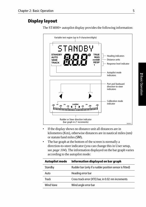
Display layoutThe ST4000+ autopilot display provides the following information:
• If the display shows no distance unit all distances are in kilometres (Km), otherwise distances are in nautical miles (nm) or statute/land miles (SM).
• The bar graph at the bottom of the screen is normally a direction-to-steer indicator (you can change this in User setup, see page 104). The information displayed on the bar graph varies according to the autopilot mode:
Autopilot mode Information displayed on bar graph
Standby Rudder bar (only if a rudder position sensor is fitted)
Auto Heading error bar
Track Cross track error (XTE) bar, in 0.02 nm increments
Wind Vane Wind angle error bar
Rudder or Steer direction indicator(bar graph in 2˚ increments)
Port and Starboarddirection-to-steerindicators
Autopilot modeindicators
Response level indicator
Distance units
Heading indicators
Variable text region (up to 9 characters/digits)
D3316-2
Calibration modeindicator
6 ST4000+ Wheel & Tiller Autopilots: Owner’s Handbook
2 Ba
sic O
pera
tion
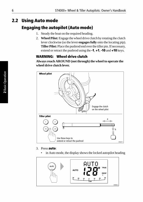
2.2 Using Auto modeEngaging the autopilot (Auto mode)
1. Steady the boat on the required heading.2. Wheel Pilot: Engage the wheel drive clutch by rotating the clutch
lever clockwise (so the lever engages fully onto the locating pip).Tiller Pilot: Place the pushrod end over the tiller pin. If necessary, extend or retract the pushrod using the -1, +1, -10 and +10 keys.
WARNING: Wheel drive clutchAlways reach AROUND (not through) the wheel to operate the wheel drive clutch lever. .
3. Press auto: • in Auto mode, the display shows the locked autopilot heading
D5341-1
Engage the clutchon the wheel pilot
Wheel pilot
Tiller pilot
Use these keys toextend or retract the pushrod
a
b
D3560-2
Chapter 2: Basic Operation 7
2 Basic Operation
CAUTION:Autopilot course control makes it easier to sail a boat, but it is NOT a substitute for good seamanship. ALWAYS maintain a permanent watch, no matter how clear the sea appears to be.
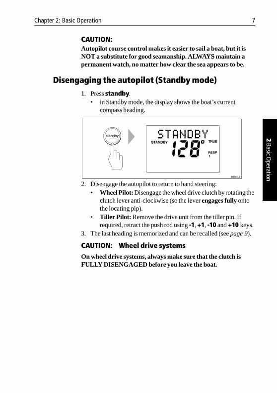
Disengaging the autopilot (Standby mode) 1. Press standby.
• in Standby mode, the display shows the boat’s current compass heading.
2. Disengage the autopilot to return to hand steering:• Wheel Pilot: Disengage the wheel drive clutch by rotating the
clutch lever anti-clockwise (so the lever engages fully onto the locating pip).
• Tiller Pilot: Remove the drive unit from the tiller pin. If required, retract the push rod using -1, +1, -10 and +10 keys.
3. The last heading is memorized and can be recalled (see page 9).
CAUTION: Wheel drive systemsOn wheel drive systems, always make sure that the clutch is FULLY DISENGAGED before you leave the boat.
D3561-2
8 ST4000+ Wheel & Tiller Autopilots: Owner’s Handbook
2 Ba
sic O
pera
tion
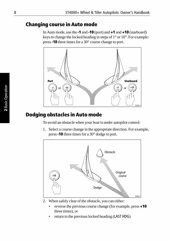
Changing course in Auto modeIn Auto mode, use the -1 and -10 (port) and +1 and +10 (starboard) keys to change the locked heading in steps of 1° or 10°. For example: press -10 three times for a 30° course change to port.
Dodging obstacles in Auto modeTo avoid an obstacle when your boat is under autopilot control:
1. Select a course change in the appropriate direction. For example, press -10 three times for a 30° dodge to port.
2. When safely clear of the obstacle, you can either: • reverse the previous course change (for example, press +10
three times), or • return to the previous locked heading (LAST HDG)
Port Starboard
oror
D3320-2
D3303-2
Original course
Dodge
Obstacle

Chapter 2: Basic Operation 9
2 Basic Operation
Returning to the previous locked heading (LAST HDG)If you have steered the boat away from the selected locked heading for any reason (for example, executing a dodge maneuver or selecting Standby), you can return to the previous locked heading as follows:
1. Press auto for 1 second. The display shows the previous locked heading (LAST HDG?) for 7 seconds.
Note: The direction-to-steer indicator shows the direction the boat will turn.
2. To accept the previous heading, and resume this course, press auto within this 7 second period.
Note: If you do not press auto while the display is flashing, the autopilot will maintain the current heading.
D3562-2
SECOND
Originalcourse
Resumed course
Dodge
Obstacle
D5431-1
10 ST4000+ Wheel & Tiller Autopilots: Owner’s Handbook
2 Ba
sic O
pera
tion
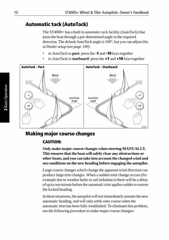
Automatic tack (AutoTack)The ST4000+ has a built in automatic tack facility (AutoTack) that turns the boat through a pre-determined angle in the required direction. The default AutoTack angle is 100°, but you can adjust this in Dealer setup (see page 109).
• to AutoTack to port: press the -1 and -10 keys together• to AutoTack to starboard: press the +1 and +10 keys together
Making major course changes
CAUTION:Only make major course changes when steering MANUALLY. This ensures that the boat will safely clear any obstructions or other boats, and you can take into account the changed wind and sea conditions on the new heading before engaging the autopilot.
Large course changes which change the apparent wind direction can produce large trim changes. When a sudden trim change occurs (for example due to weather helm or sail imbalance) there will be a delay of up to one minute before the automatic trim applies rudder to restore the locked heading.
In these situations, the autopilot will not immediately assume the new automatic heading, and will only settle onto course when the automatic trim has been fully established. To eliminate this problem, use the following procedure to make major course changes:
Wind
AutoTack - Starboard
D5399-1
Wind
AutoTack - Port
AutoTackangle
AutoTackangle
Chapter 2: Basic Operation 11
2 Basic Operation
1. Note the required new heading.2. Select standby for manual steering, so you can bring the boat to
the new heading MANUALLY.3. Select auto: allow the boat to settle onto course, then bring the
boat to the final course in 1° steps using the -1 or +1 keys
Gusting conditionsIn gusting conditions, the course may tend to wander slightly, particularly if the sails are badly balanced. If you take the following precautions, the autopilot will be able to maintain competent control even in gale force conditions:
• You can significantly improve course keeping by improving the sail balance:• do not allow the boat to heel over excessively• ease the mainsheet traveller to leeward to reduce heeling and
weather helm• if necessary, reef the mainsail a little early
• In very strong winds and large seas, you should avoid sailing with the wind dead astern:• ideally, bring the wind at least 30° away from a dead run• in severe conditions, you may also need to remove the
mainsail and sail under headsail only
12 ST4000+ Wheel & Tiller Autopilots: Owner’s Handbook
2 Ba
sic O
pera
tion
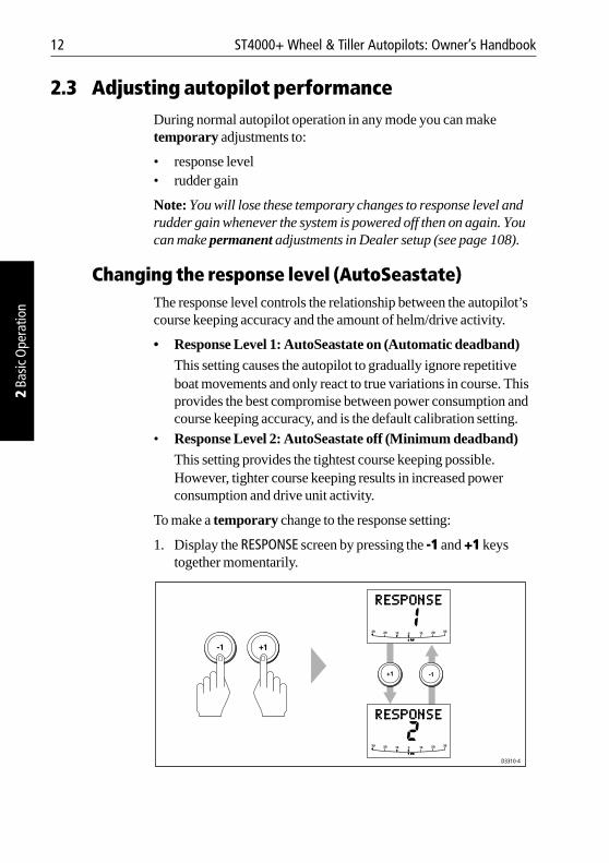
2.3 Adjusting autopilot performanceDuring normal autopilot operation in any mode you can make temporary adjustments to:
• response level • rudder gain
Note: You will lose these temporary changes to response level and rudder gain whenever the system is powered off then on again. You can make permanent adjustments in Dealer setup (see page 108).
Changing the response level (AutoSeastate)The response level controls the relationship between the autopilot’s course keeping accuracy and the amount of helm/drive activity.
• Response Level 1: AutoSeastate on (Automatic deadband)
This setting causes the autopilot to gradually ignore repetitive boat movements and only react to true variations in course. This provides the best compromise between power consumption and course keeping accuracy, and is the default calibration setting.
• Response Level 2: AutoSeastate off (Minimum deadband)
This setting provides the tightest course keeping possible. However, tighter course keeping results in increased power consumption and drive unit activity.
To make a temporary change to the response setting:
1. Display the RESPONSE screen by pressing the -1 and +1 keys together momentarily.
D3310-4
Chapter 2: Basic Operation 13
2 Basic Operation
Note: If you have set up the RESPONSE screen as a default data page (see page 104) you can also access it by pressing disp and then scrolling through the data pages.
2. Press -1 or +1 to change the response level.3. Press disp or wait for 5 seconds to return to the previous display.
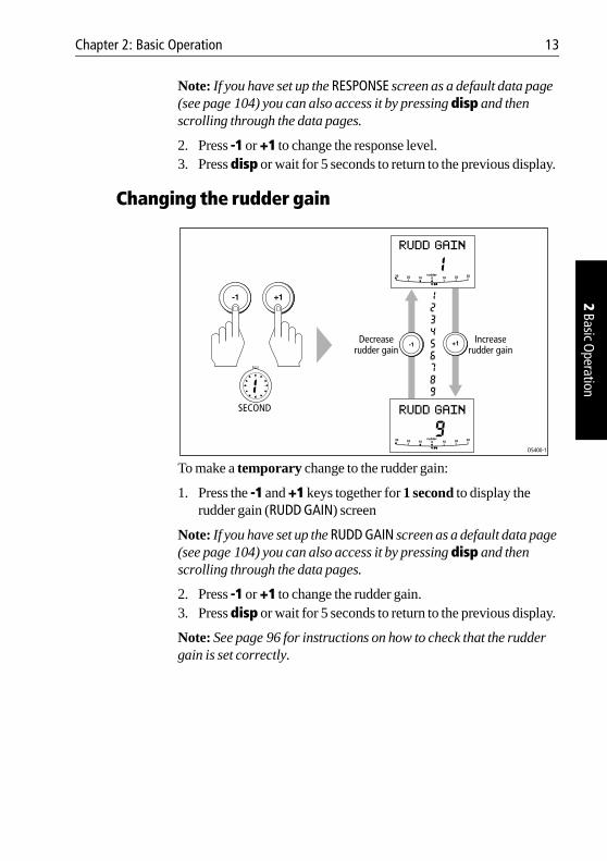
Changing the rudder gain
To make a temporary change to the rudder gain:
1. Press the -1 and +1 keys together for 1 second to display the rudder gain (RUDD GAIN) screen
Note: If you have set up the RUDD GAIN screen as a default data page (see page 104) you can also access it by pressing disp and then scrolling through the data pages.
2. Press -1 or +1 to change the rudder gain.3. Press disp or wait for 5 seconds to return to the previous display.
Note: See page 96 for instructions on how to check that the rudder gain is set correctly.
D5400-1
Increaserudder gain
Decreaserudder gain
SECOND
14 ST4000+ Wheel & Tiller Autopilots: Owner’s Handbook
2 Ba
sic O
pera
tion
2.4 Autopilot alarms
Responding to alarmsThe ST4000+ activates the alarms listed on the following pages:
• Unless otherwise stated, you should deal with alarms by pressing standby to clear the alarm and return to hand steering.
• In some situations, the autopilot will raise more than one alarm. When you have dealt with the first alarm, the autopilot will display the next alarm.
SeaTalk Failure alarm (STLK FAIL)The ST4000+ displays the SeaTalk failure message if there is a wiring fault in the SeaTalk connection.
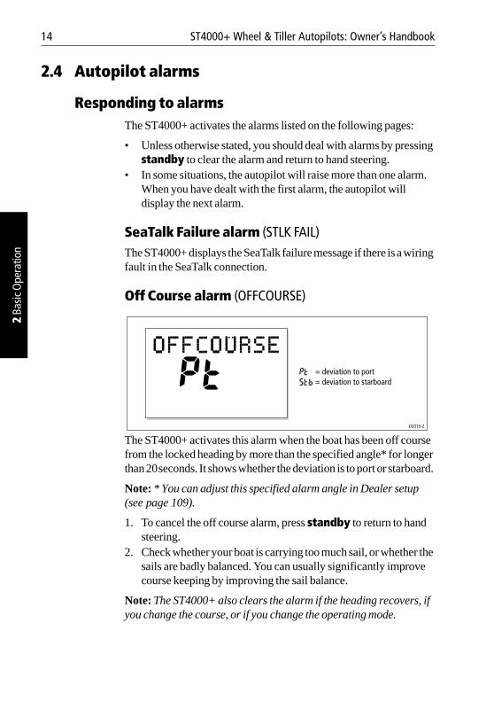
Off Course alarm (OFFCOURSE)
The ST4000+ activates this alarm when the boat has been off course from the locked heading by more than the specified angle* for longer than 20seconds. It shows whether the deviation is to port or starboard.
Note: * You can adjust this specified alarm angle in Dealer setup (see page 109).
1. To cancel the off course alarm, press standby to return to hand steering.
2. Check whether your boat is carrying too much sail, or whether the sails are badly balanced. You can usually significantly improve course keeping by improving the sail balance.
Note: The ST4000+ also clears the alarm if the heading recovers, if you change the course, or if you change the operating mode.
D3315-2
= deviation to port= deviation to starboard
Chapter 2: Basic Operation 15
2 Basic Operation
Wind Shift alarm (WINDSHIFT)The ST4000+ activates the Windshift alarm when it detects a change in the apparent wind angle of more than 15° (see page 29).
Large Cross Track Error alarm (LARGE XTE)The ST4000+ activates this alarm when the cross track error exceeds 0.3 nm (see page 22).The alarm clears if the heading recovers, if you change the course, or if you change the operating mode.
Drive Stopped alarm (DRIVESTOP)The ST4000+ activates this alarm if:
• the rudder position sensor fails, or• the autopilot is unable to turn the rudder (this occurs if the weather
load on helm is too high, or if the rudder position sensor has passed beyond the preset rudder limits or rudder end-stops)
Data Not Received alarm (NO DATA)The ST4000+ activates this alarm in any of the following situations:
• the compass is not connected• the autopilot is in Wind Vane mode and it has not received wind
angle data for 30 seconds• the autopilot is in Track mode and:
• the boat has arrived at the last waypoint in the track, or• the autopilot is not receiving SeaTalk navigation data, or • the position sensor (GPS, Loran, Decca) is receiving a low
strength signal – this will clear as soon as the signal strength improves
The autopilot stops adjusting the heading as soon as it loses data.
Waypoint Advance alarm (NEXT WPT?)The ST4000+ activates the Waypoint Advance alarm whenever the target waypoint number changes. This occurs when:
• you select automatic acquisition by pressing track from Auto• you request waypoint advance by pressing track for 1 second in
Track mode (with SeaTalk navigators only)
16 ST4000+ Wheel & Tiller Autopilots: Owner’s Handbook
2 Ba
sic O
pera
tion
• the boat arrives at the target waypoint and the navigator accepts the next waypoint
• you activate the Man Overboard (MOB) function in Track mode
When the alarm sounds, the pilot continues on its current heading but displays:
• the bearing to the next waypoint • the direction the boat will turn to take up that bearing
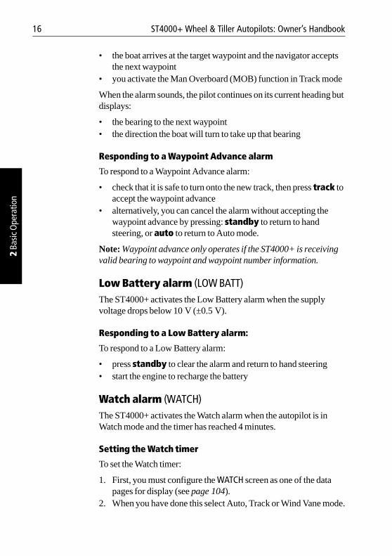
Responding to a Waypoint Advance alarm
To respond to a Waypoint Advance alarm:
• check that it is safe to turn onto the new track, then press track to accept the waypoint advance
• alternatively, you can cancel the alarm without accepting the waypoint advance by pressing: standby to return to hand steering, or auto to return to Auto mode.
Note: Waypoint advance only operates if the ST4000+ is receiving valid bearing to waypoint and waypoint number information.
Low Battery alarm (LOW BATT)The ST4000+ activates the Low Battery alarm when the supply voltage drops below 10 V (±0.5 V).
Responding to a Low Battery alarm:
To respond to a Low Battery alarm:
• press standby to clear the alarm and return to hand steering• start the engine to recharge the battery
Watch alarm (WATCH)The ST4000+ activates the Watch alarm when the autopilot is in Watch mode and the timer has reached 4 minutes.
Setting the Watch timer
To set the Watch timer:
1. First, you must configure the WATCH screen as one of the data pages for display (see page 104).
2. When you have done this select Auto, Track or Wind Vane mode.
Chapter 2: Basic Operation 17
2 Basic Operation
3. Press the disp key until you see the WATCH data page:• the watch timer will start counting• when the timer reaches 3 minutes, the WATCH text starts
flashing to indicate that the timer is in the last minute• when the timer reaches 4 minutes, the ST4000+ activates the
audible Watch alarm
Responding to a Watch alarm
To respond to a Watch alarm:
• press auto to silence the alarm and reset the timer to 4 minutesor
• press any other key to silence the alarm, reset the timer and perform that key’s normal function
Note: You cannot engage Auto mode directly from Watch mode – pressing auto will only reset the Watch timer. If you want to enter Auto mode, you must first exit Watch mode (see below).
Exiting Watch mode
To exit Watch mode:
• press disp to display a different data pageor
• press standby
Shallow alarm (SHALLOW)The ST4000+ activates the Shallow alarm if it receives a shallow depth alarm via SeaTalk:
• press standby or disp to cancel the alarm
Man Overboard alarm (MOB)The ST4000+ activates the Man Overboard alarm if it receives a man overboard (MOB) message from another instrument on the SeaTalk system. It displays the text MOB instead of the waypoint number for the XTE, DTW and BTW data pages.
If the autopilot is in Track mode, it will sound the Waypoint Advance alarm to notify you of the change in waypoint.
18 ST4000+ Wheel & Tiller Autopilots: Owner’s Handbook
2 Ba
sic O
pera
tion
2.5 Adjusting display and keypad lightingNote: When the display lighting is off, the control unit still illuminates the keys at a courtesy level.
To adjust the display and keypad lighting:
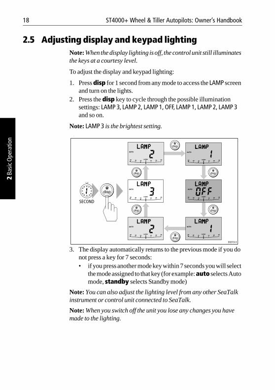
1. Press disp for 1 second from any mode to access the LAMP screen and turn on the lights.
2. Press the disp key to cycle through the possible illumination settings: LAMP 3, LAMP 2, LAMP 1, OFF, LAMP 1, LAMP 2, LAMP 3 and so on.
Note: LAMP 3 is the brightest setting. .
3. The display automatically returns to the previous mode if you do not press a key for 7 seconds:• if you press another mode key within 7 seconds you will select
the mode assigned to that key (for example: auto selects Auto mode, standby selects Standby mode)
Note: You can also adjust the lighting level from any other SeaTalk instrument or control unit connected to SeaTalk.
Note: When you switch off the unit you lose any changes you have made to the lighting.
D3313-3
SECOND
Chapter 3: Advanced Operation 19
3 Advanced Operation
Chapter 3: Advanced Operation
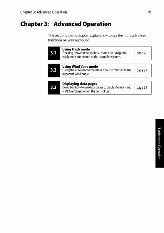
The sections in this chapter explain how to use the more advanced functions on your autopilot:
3.1Using Track modeTracking between waypoints created on navigation equipment connected to the autopilot system.
page 20
3.2Using Wind Vane modeUsing the autopilot to maintain a course relative to the apparent wind angle.
page 27
3.3Displaying data pagesDescribes how to use data pages to display SeaTalk and NMEA information on the control unit.
page 31
20 ST4000+ Wheel & Tiller Autopilots: Owner’s Handbook
3 Ad
vanc
ed O
pera
tion
3.1 Using Track modeNote: You can only use Track mode if you have connected the ST4000+ to a suitable navigation system providing SeaTalk or NMEA navigation information.
The ST4000+ can receive track and cross track error information from either:
• a SeaTalk navigation instrument or chartplotter (see page 52 for information on connecting to SeaTalk)or
• a non-SeaTalk navigation system transmitting data in the NMEA 0183 format – you can connect this directly to the ST4000+ NMEA input (see page 53 for information on connecting to NMEA equipment)
In Track mode, the ST4000+ maintains a track between two waypoints created on the navigation system. The autopilot computes any course changes to keep your boat on track, automatically compensating for tidal streams and leeway.
Selecting Track modeTo select Track mode, press the track key with the autopilot in Auto mode.
When you select Track mode, the autopilot can acquire a track through either:
• automatic acquisition (see below), when both cross track error (XTE) and bearing to waypoint (BTW) data are availableor
• manual acquisition (see page 21), when only cross track error information is available
Automatic track acquisition
If cross track error and bearing to waypoint information are both available (via SeaTalk or NMEA), the autopilot can acquire a track automatically:
1. Bring the boat within 0.1 nm of track.2. Press auto. The autopilot will display the current locked heading. 3. Press track to enter Track mode.
Chapter 3: Advanced Operation 21
3 Advanced Operation
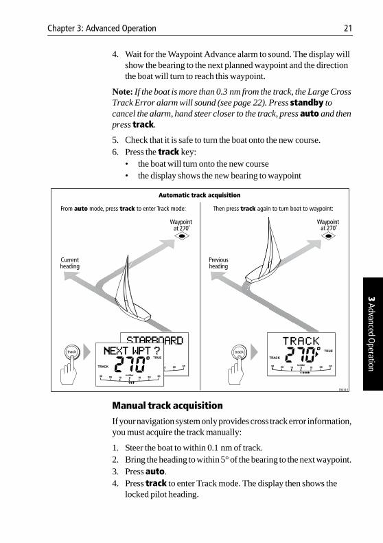
4. Wait for the Waypoint Advance alarm to sound. The display will show the bearing to the next planned waypoint and the direction the boat will turn to reach this waypoint.
Note: If the boat is more than 0.3 nm from the track, the Large Cross Track Error alarm will sound (see page 22). Press standby to cancel the alarm, hand steer closer to the track, press auto and then press track.
5. Check that it is safe to turn the boat onto the new course.6. Press the track key:
• the boat will turn onto the new course• the display shows the new bearing to waypoint
Manual track acquisition
If your navigation system only provides cross track error information, you must acquire the track manually:
1. Steer the boat to within 0.1 nm of track.2. Bring the heading to within 5° of the bearing to the next waypoint. 3. Press auto.4. Press track to enter Track mode. The display then shows the
locked pilot heading.
Automatic track acquisition
Currentheading
Previousheading
Waypoint at 270˚
D5414-1
Waypoint at 270˚
From auto mode, press track to enter Track mode: Then press track again to turn boat to waypoint:
22 ST4000+ Wheel & Tiller Autopilots: Owner’s Handbook
3 Ad
vanc
ed O
pera
tion
Note: Tidal streams have a far more significant effect at lower speeds than at higher speeds. If the tidal flow is less than 35% of the boat’s speed, you will not notice any difference in the autopilot’s performance in Track mode. However, you should take extra care during manual acquisition, as follows:
• Before you select Track mode, make sure the boat is as close as possible to track, and the direction made good over the ground is as close as possible to the direction of the next waypoint.
• Make positive checks of the boat’s position at regular intervals, especially if you are close to potential navigational hazards.
Exiting Track modeYou can return to either Auto or Standby mode from Track mode by:
• pressing auto to return to Auto mode• pressing standby to return to manual steering
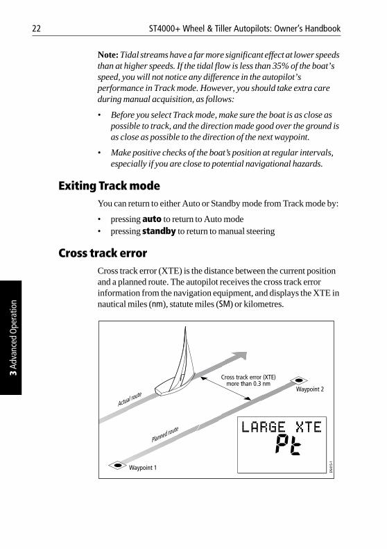
Cross track errorCross track error (XTE) is the distance between the current position and a planned route. The autopilot receives the cross track error information from the navigation equipment, and displays the XTE in nautical miles (nm), statute miles (SM) or kilometres.
Waypoint 1
Waypoint 2
Cross track error (XTE)more than 0.3 nm
D541
5-1
Planned route
Actual route
Chapter 3: Advanced Operation 23
3 Advanced Operation
If the cross track error is greater than 0.3 nm, the ST4000+ will sound the Large Cross Track Error alarm and shows whether you are to the port (Pt) or starboard (Stb) of the planned track.
To cancel the Large Cross Track Error alarm:
• press standby to return to hand steering, or• press auto to return to Auto mode and retain the current heading
Note: When the Large Cross Track Error alarm sounds, it usually means that the cross tide is too great for your boat’s current speed.
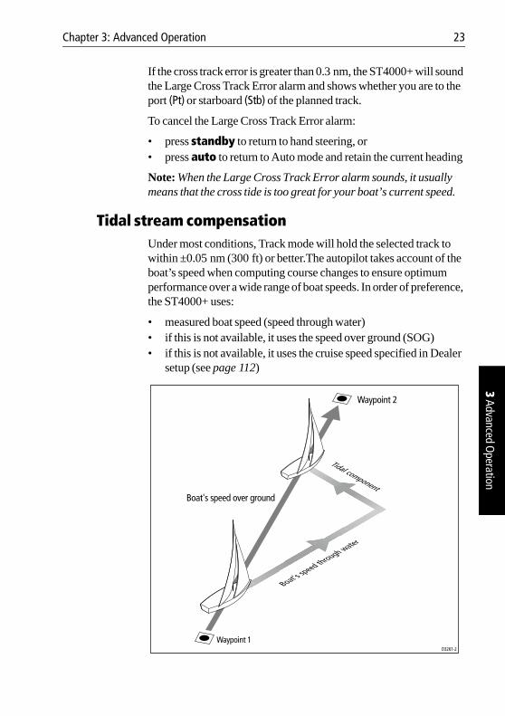
Tidal stream compensationUnder most conditions, Track mode will hold the selected track to within ±0.05 nm (300 ft) or better.The autopilot takes account of the boat’s speed when computing course changes to ensure optimum performance over a wide range of boat speeds. In order of preference, the ST4000+ uses:
• measured boat speed (speed through water)• if this is not available, it uses the speed over ground (SOG)• if this is not available, it uses the cruise speed specified in Dealer
setup (see page 112)
D3261-2
Waypoint 2
Waypoint 1
Tidal component
Boat's speed through water
Boat's speed over ground
24 ST4000+ Wheel & Tiller Autopilots: Owner’s Handbook
3 Ad
vanc
ed O
pera
tion
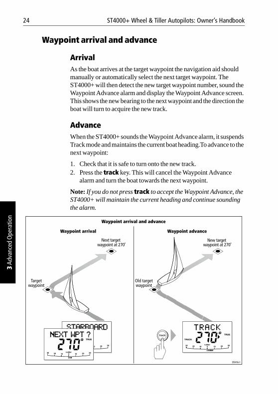
Waypoint arrival and advance
ArrivalAs the boat arrives at the target waypoint the navigation aid should manually or automatically select the next target waypoint. The ST4000+ will then detect the new target waypoint number, sound the Waypoint Advance alarm and display the Waypoint Advance screen. This shows the new bearing to the next waypoint and the direction the boat will turn to acquire the new track.
AdvanceWhen the ST4000+ sounds the Waypoint Advance alarm, it suspends Track mode and maintains the current boat heading.To advance to the next waypoint:
1. Check that it is safe to turn onto the new track.2. Press the track key. This will cancel the Waypoint Advance
alarm and turn the boat towards the next waypoint.
Note: If you do not press track to accept the Waypoint Advance, the ST4000+ will maintain the current heading and continue sounding the alarm.
Waypoint arrival and advance
Targetwaypoint
Old targetwaypoint
New target waypoint at 270˚
D5416-1
Next target waypoint at 270˚
Waypoint arrival Waypoint advance
Chapter 3: Advanced Operation 25
3 Advanced Operation
Note: When you reach the last waypoint in the track, the NO DATA alarm will sound to indicate that there is no further waypoint information. Press auto to continue on the same heading, or standby to return to hand steering.
Skipping a waypoint – SeaTalk navigators onlyIf you want to advance to the next waypoint before you have arrived at the target waypoint, you can skip a waypoint by pressing track for 1 second. The display will then show the Waypoint Advance screen for the next waypoint.
Dodges in Track modeWhen the autopilot is in Track mode you still have full control from the keypad.
Initiating a dodge maneuverIn Track mode, you can make a dodge maneuver by using the course change keys (-1, +1, -10 or +10) to select the desired course change.
Cancelling a dodge maneuverAfter you have avoided the hazard, you can cancel the dodge course change by making an equal course change in the opposite direction.
Note: Provided the boat remains within 0.1 nm of track, you do not need to steer back towards the track.
Safety in Track modeWARNING:Track mode provides accurate track keeping even in complex navigational situations. However, it is still the skipper’s responsibility to ensure the safety of their boat at all times through careful navigation and frequent position checks.
Sailing in Track mode assists precise navigation and removes the tasks of compensating for wind and tidal drift. However, you MUST still maintain an accurate log with regular plots.
26 ST4000+ Wheel & Tiller Autopilots: Owner’s Handbook
3 Ad
vanc
ed O
pera
tion
Confirming position at the start of a journeyAt the start of a journey you must always use an easily identifiable fixed object to confirm the fix given by the navigation system. Check for fixed positional errors and compensate for them.
Verifying computed positionsAlways verify the computed position with a dead reckoned position, calculated from the average course steered and the distance logged.
Plot frequency• In open water, you should make plots at least every hour. • In confined waters or when near to potential hazards, you should
make plots more frequently.
Setting waypoints• Local variations in radio signal quality and changes in the tidal
stream can produce deviations from the desired track. When setting waypoints, remember that deviations can occur.
• Thoroughly check along each track. Check up to 0.5 nm each side of the track to ensure that there are no hazards within this zone.
Note: For the waypoint advance function to work, the last four characters of adjacent waypoint names must be different.
Chapter 3: Advanced Operation 27
3 Advanced Operation
3.2 Using Wind Vane modeNote: You can only use Wind Vane mode if you have connected the ST4000+ to a suitable wind instrument/vane providing SeaTalk or NMEA wind direction information.
To use Wind Vane mode (also known as Vane mode), the ST4000+ must receive wind information from one of the following sources:
• SeaTalk wind instrument, connected to the ST4000+ via SeaTalk• NMEA wind instrument• Raymarine wind vane connected through a SeaTalk interface box
In Wind Vane mode the ST4000+ maintains a course relative to an apparent wind angle. It uses wind trim to eliminate the effects of turbulence and short term wind variations. This provides smooth and precise performance with minimal power consumption.
When the ST4000+ is in Wind Vane mode it uses the fluxgate compass as the primary heading reference. As changes in the apparent wind angle occur, the ST4000+ adjusts the locked compass heading to maintain the original apparent wind angle.
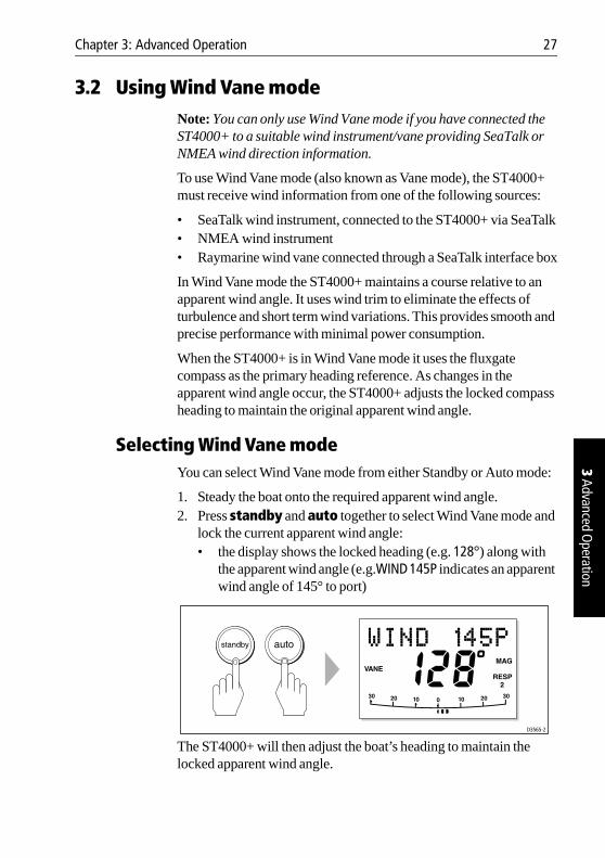
Selecting Wind Vane modeYou can select Wind Vane mode from either Standby or Auto mode:
1. Steady the boat onto the required apparent wind angle.2. Press standby and auto together to select Wind Vane mode and
lock the current apparent wind angle:• the display shows the locked heading (e.g. 128°) along with
the apparent wind angle (e.g.WIND 145P indicates an apparent wind angle of 145° to port)
The ST4000+ will then adjust the boat’s heading to maintain the locked apparent wind angle.
D3565-2
28 ST4000+ Wheel & Tiller Autopilots: Owner’s Handbook
3 Ad
vanc
ed O
pera
tion
Exiting Wind Vane modeYou can return to Auto or Standby mode from Wind Vane mode by:
• pressing auto to return to Auto mode• pressing standby to steer manually in Standby mode
Adjusting the locked wind angleYou can adjust the locked wind angle by using the -1, +1, -10 and +10 keys to change course. For example, to bear away by 10° when the boat is on a starboard tack:
• press -10 to turn the boat 10° to port – the locked apparent wind angle and locked heading will both change by 10°
• the autopilot will then adjust the locked heading as required to maintain the new apparent wind angle
Note: Because turning the boat affects the relationship between the true and apparent wind angles, you should only use this method to make minor adjustments to the apparent wind angle. For major changes, return to Standby mode, steer onto the new heading, then reselect Wind Vane mode.
Returning to the previous apparent wind angle (LAST WND)
If you have steered the boat away from the selected apparent wind angle for any reason (such as a dodge maneuver or selecting Standby mode), you can return to the previous locked wind angle:
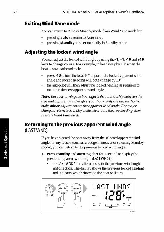
1. Press standby and auto together for 1 second to display the previous apparent wind angle (LAST WND?):• the LAST WND? text alternates with the previous wind angle
and direction. The display shows the previous locked heading and indicates which direction the boat will turn
D3566-2
SECOND
Chapter 3: Advanced Operation 29
3 Advanced Operation
2. Check that it is safe to turn onto this course.3. To accept this apparent wind angle, press standby and auto
together within 7 seconds.
Note: If you do not accept the previous wind within 7 seconds, the autopilot will lock onto the current apparent wind angle.
Dodges in Wind Vane modeWhen the autopilot is in Wind Vane mode you still have full control from the keypad.
Initiating a dodge maneuverIn Wind Vane mode, you can make a dodge maneuver by using the course change keys (-1, +1, -10 or +10) to select the desired course change. The autopilot will adjust both the locked heading and locked apparent wind angle.
Cancelling a dodge maneuverAfter you have avoided the hazard, you can reverse the previous course change, or return to the previous wind angle (LAST WND?).
Wind shift alarmIf the autopilot detects a wind shift of more than 15° it will sound the wind shift alarm and display the WINDSHIFT alarm message (see page 15).
• To cancel the alarm and retain the existing wind angle and new heading:• press standby and auto together.
• Alternatively, to cancel the alarm and return to the previous heading, either: • adjust the locked wind angle using the -1, +1, -10 and
+10 keysor
• press standby to return to hand steering, steer onto the required heading, and press standby and auto together to return to Wind Vane mode with the new apparent wind angle
30 ST4000+ Wheel & Tiller Autopilots: Owner’s Handbook
3 Ad
vanc
ed O
pera
tion
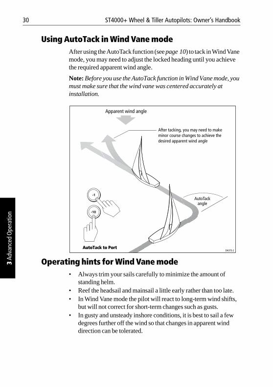
Using AutoTack in Wind Vane modeAfter using the AutoTack function (see page 10) to tack in Wind Vane mode, you may need to adjust the locked heading until you achieve the required apparent wind angle.
Note: Before you use the AutoTack function in Wind Vane mode, you must make sure that the wind vane was centered accurately at installation.
Operating hints for Wind Vane mode• Always trim your sails carefully to minimize the amount of
standing helm.• Reef the headsail and mainsail a little early rather than too late.• In Wind Vane mode the pilot will react to long-term wind shifts,
but will not correct for short-term changes such as gusts.• In gusty and unsteady inshore conditions, it is best to sail a few
degrees further off the wind so that changes in apparent wind direction can be tolerated.
D4373-2
Apparent wind angle
AutoTackangle
After tacking, you may need to make minor course changes to achieve the desired apparent wind angle
AutoTack to Port
Chapter 3: Advanced Operation 31
3 Advanced Operation
3.3 Displaying data pagesUse the disp key to show ‘data pages’ of SeaTalk or NMEA data:
1. Press disp to access the first data page, and press it again to cycle through each data page in turn:• to return to a previous data page, press disp for 1 second
within 2 seconds of displaying a page• when you cycle past the last data page, the display returns to
the current autopilot mode screen (for example, Auto)2. Select the data page you want to use as the principle display on the
control unit: • the current autopilot mode is shown at the left of the display
and the autopilot bar graph remains in use• if you then select a new mode or make a course change, the
autopilot mode screen appears as a ‘pop-up’ for 5 seconds
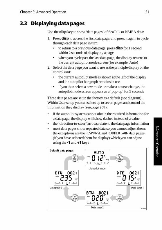
Three data pages are set in the factory as a default (see diagram). Within User setup you can select up to seven pages and control the information they display (see page 104):
• if the autopilot system cannot obtain the required information for a data page, the display will show dashes instead of a value
• the ‘direction-to-steer’ arrows relate to the data page information• most data pages show repeated data so you cannot adjust them:
the exceptions are the RESPONSE and RUDDER GAIN data pages (if you have selected them for display) which you can adjust using the -1 and +1 keys
D3314-2
Autopilot mode
Data page 1Data page 3
Data page 2
Default data pages

32 ST4000+ Wheel & Tiller Autopilots: Owner’s Handbook
3 Ad
vanc
ed O
pera
tion
Chapter 4: Maintenance & Fault Finding 33
4 Maintenance &
Fault Finding
Chapter 4: Maintenance & Fault Finding
This chapter provides information about identifying common problems, maintaining your autopilot system and obtaining product support:
4.1Fault findingThis section provides a checklist to help you identify and resolve common autopilot problems.
page 34
4.2General maintenanceThis section explains how to maintain your autopilot system.
page 36
4.3Product supportThis section outlines the product support available from Raymarine worldwide.
page 40
34 ST4000+ Wheel & Tiller Autopilots: Owner’s Handbook
4 M
aint
enan
ce &
Faul
t Fin
ding
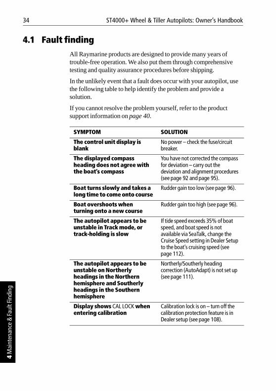
4.1 Fault findingAll Raymarine products are designed to provide many years of trouble-free operation. We also put them through comprehensive testing and quality assurance procedures before shipping.
In the unlikely event that a fault does occur with your autopilot, use the following table to help identify the problem and provide a solution.
If you cannot resolve the problem yourself, refer to the product support information on page 40.
SYMPTOM SOLUTION
The control unit display is blank
No power – check the fuse/circuit breaker.
The displayed compass heading does not agree with the boat’s compass
You have not corrected the compass for deviation – carry out the deviation and alignment procedures (see page 92 and page 95).
Boat turns slowly and takes a long time to come onto course
Rudder gain too low (see page 96).
Boat overshoots when turning onto a new course
Rudder gain too high (see page 96).
The autopilot appears to be unstable in Track mode, or track-holding is slow
If tide speed exceeds 35% of boat speed, and boat speed is not available via SeaTalk, change the Cruise Speed setting in Dealer Setup to the boat’s cruising speed (see page 112).
The autopilot appears to be unstable on Northerly headings in the Northern hemisphere and Southerly headings in the Southern hemisphere
Northerly/Southerly heading correction (AutoAdapt) is not set up (see page 111).
Display shows CAL LOCK when entering calibration
Calibration lock is on – turn off the calibration protection feature is in Dealer setup (see page 108).
Chapter 4: Maintenance & Fault Finding 35
4 Maintenance &
Fault Finding
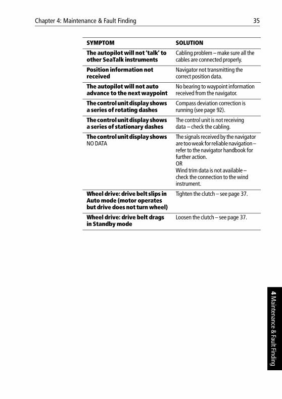
The autopilot will not ‘talk’ to other SeaTalk instruments
Cabling problem – make sure all the cables are connected properly.
Position information not received
Navigator not transmitting the correct position data.
The autopilot will not auto advance to the next waypoint
No bearing to waypoint information received from the navigator.
The control unit display shows a series of rotating dashes
Compass deviation correction is running (see page 92).
The control unit display shows a series of stationary dashes
The control unit is not receiving data – check the cabling.
The control unit display shows NO DATA
The signals received by the navigator are too weak for reliable navigation – refer to the navigator handbook for further action.ORWind trim data is not available – check the connection to the wind instrument.
Wheel drive: drive belt slips in Auto mode (motor operates but drive does not turn wheel)
Tighten the clutch – see page 37.
Wheel drive: drive belt drags in Standby mode
Loosen the clutch – see page 37.
SYMPTOM SOLUTION
36 ST4000+ Wheel & Tiller Autopilots: Owner’s Handbook
4 M
aint
enan
ce &
Faul
t Fin
ding
4.2 General maintenance
CAUTION:The control unit, fluxgate compass, tiller drive and rudder position sensor do not contain any user serviceable parts. These products should be serviced only by authorized Raymarine service technicians.
Wheel drive
Routine maintenanceAfter each trip, flush inside the drive unit by inserting a hose pipe in the free slot on the back cover.
Cleaning the wheel drive
CAUTION:Do not use mineral-based solvents (such as WD40) to lubricate or clean the wheel drive as they will damage the material.
We recommend that you complete the following steps each season to prevent the build-up of salt on the wheel drive bearings and drive belt:
1. Remove the wheel drive from the wheel: • remove the wheel from the pedestal• remove the spoke clamp screws• remove the wheel drive front cover
2. Check inside the drive unit for any signs of damage. 3. Thoroughly flush the wheel drive interior with fresh water to
remove any salt build-up on the bearings and drive belt. Do not lubricate any part of the wheel drive. It is designed to run without lubrication.
4. Replace the front cover then fit wheel drive back onto the wheel.5. Fit the wheel and wheel drive back onto the pedestal.6. Clean the wheel drive case (using mild detergent if necessary),
then flush thoroughly with fresh water.
Chapter 4: Maintenance & Fault Finding 37
4 Maintenance &
Fault Finding
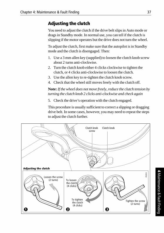
Adjusting the clutchYou need to adjust the clutch if the drive belt slips in Auto mode or drags in Standby mode. In normal use, you can tell if the clutch is slipping if the motor operates but the drive does not turn the wheel.
To adjust the clutch, first make sure that the autopilot is in Standby mode and the clutch is disengaged. Then:
1. Use a 3 mm allen key (supplied) to loosen the clutch knob screw about 2 turns anti-clockwise.
2. Turn the clutch knob either 4 clicks clockwise to tighten the clutch, or 4 clicks anti-clockwise to loosen the clutch.
3. Use the allen key to re-tighten the clutch knob screw.4. Check that the wheel still moves freely with the clutch off.
Note: If the wheel does not move freely, reduce the clutch tension by turning the clutch knob 2 clicks anti-clockwise and check again
5. Check the drive’s operation with the clutch engaged.
This procedure is usually sufficient to correct a slipping or dragging drive belt. In some cases, however, you may need to repeat the steps to adjust the clutch further.
2 31
Loosen the screw(2 turns)
Tighten the screw(2 turns)
To tighten the clutch(4 clicks)
To loosen the clutch(4 clicks)
Adjusting the clutch
Clutch knob screw
Clutch knob
D534
9-2
38 ST4000+ Wheel & Tiller Autopilots: Owner’s Handbook
4 M
aint
enan
ce &
Faul
t Fin
ding
Replacing the belt The drive belt is designed to be user serviceable. If there is insufficient adjustment to cure a slipping clutch, or if the drive belt is damaged in any way (if it is broken, frayed or stretched), you should replace the drive belt. You can obtain a replacement belt from any Raymarine dealer (part number A18083). Fitting instructions are supplied with the belt.
User serviceable partsYou can obtain the following 4000 mk2 wheel drive spare parts from your Raymarine dealer:
Control unit
Routine checksThe control unit is a sealed unit. As a result, user maintenance is limited to the following routine checks:
• make sure all cable connectors are firmly attached• examine the cables for signs of wear or damage – replace any
damaged cables
Part description Part number
Front cover A18074
Clutch lever A18077
Clutch knob A18078
Pedestal bracket (torque restraint) A18080
Drive belt A18083
Clutch kit (clutch eccentric and clutch roller) A18084
Single spoke clamp, screws and inserts A18089
Chapter 4: Maintenance & Fault Finding 39
4 Maintenance &
Fault Finding
Cleaning the display
CAUTION:Take care when cleaning the display. Do not wipe the display screen with a dry cloth as this could scratch the screen coating. Do not use acid, ammonia based or abrasive products.
• Never use chemical or abrasive materials to clean the control unit. If the control unit is dirty, wipe it with a clean, damp cloth.
• In certain conditions, condensation may appear inside the display screen. This will not harm the unit, and you can clear it by switching on the illumination for a short time.
EMC advice• When powered up, all electrical equipment produces
electromagnetic fields. These can cause adjacent pieces of electrical equipment to interact with one another, with a consequent adverse effect on operation.
• To minimize these effects and enable you to get the best possible performance from your Raymarine equipment, guidelines are given in the installation instructions, to enable you to ensure minimum interaction between different items of equipment, i.e. ensure optimum Electromagnetic Compatibility (EMC).
• Always report any EMC-related problems to your nearest Raymarine dealer. We use such information to improve our quality standards.
• In some installations, it may not be possible to prevent the equipment from being affected by external influences. In general this will not damage the equipment but it can lead to spurious resetting action, or momentarily may result in faulty operation.
40 ST4000+ Wheel & Tiller Autopilots: Owner’s Handbook
4 M
aint
enan
ce &
Faul
t Fin
ding
4.3 Product support
Raymarine products are supported by a worldwide network of distributors and Authorized Service Representatives. If you encounter any difficulties with this product, please contact either your national distributor, service representative, or the Raymarine Technical Services Call Center. Refer to the back cover or the Worldwide Distributor List for contact details.
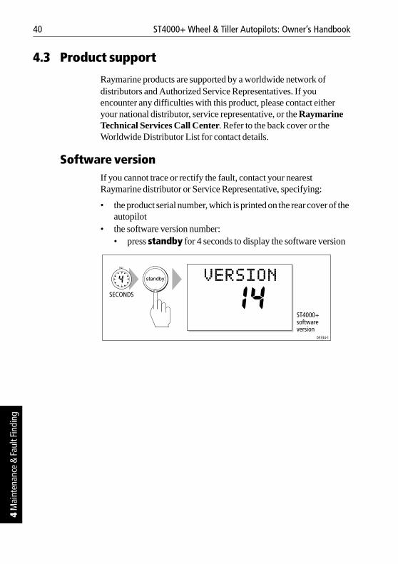
Software versionIf you cannot trace or rectify the fault, contact your nearest Raymarine distributor or Service Representative, specifying:
• the product serial number, which is printed on the rear cover of the autopilot
• the software version number:• press standby for 4 seconds to display the software version
D5334-1
SECONDS
ST4000+software version

Part 2:Installing the ST4000+
Part 2: Installing the ST4000+

Part
2: I
nsta
lling
the
ST40
00+
Chapter 5: Installing the ST4000+ 43
5 Installing the ST4000+
Chapter 5: Installing the ST4000+
The sections in this chapter explain how to install and connect the components of your autopilot system:
5.1Planning the installationPreparation steps, tools required and EMC installation guidelines.
page 44
5.2Control unitHow to install the surface mount and flush mount control units, and connect power, SeaTalk and NMEA.
page 48
5.3 Fluxgate compassHow to install the fluxgate compass. page 55
5.4 Tiller drive (tiller pilots only)How to install the 4000 tiller drive. page 59
5.5 Wheel drive (wheel pilots only)How to install the wheel drive. page 70
5.6Rudder position sensor (wheel pilot option)How to install the optional rudder position sensor for wheel pilots.
page 81
44 ST4000+ Wheel & Tiller Autopilots: Owner’s Handbook
5 In
stal
ling
the
ST40
00+
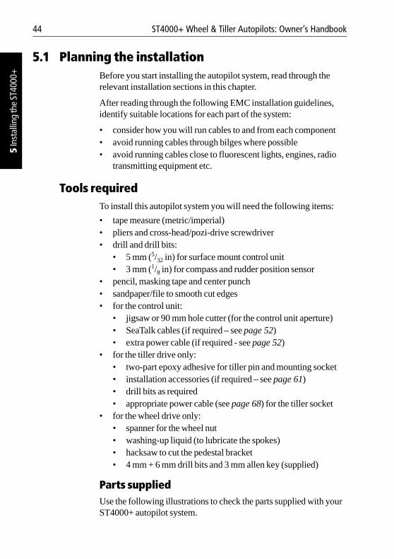
5.1 Planning the installationBefore you start installing the autopilot system, read through the relevant installation sections in this chapter.
After reading through the following EMC installation guidelines, identify suitable locations for each part of the system:
• consider how you will run cables to and from each component• avoid running cables through bilges where possible• avoid running cables close to fluorescent lights, engines, radio
transmitting equipment etc.
Tools requiredTo install this autopilot system you will need the following items:
• tape measure (metric/imperial)• pliers and cross-head/pozi-drive screwdriver • drill and drill bits:
• 5 mm (5/32 in) for surface mount control unit• 3 mm (1/8 in) for compass and rudder position sensor
• pencil, masking tape and center punch• sandpaper/file to smooth cut edges• for the control unit:
• jigsaw or 90 mm hole cutter (for the control unit aperture) • SeaTalk cables (if required – see page 52)• extra power cable (if required - see page 52)
• for the tiller drive only:• two-part epoxy adhesive for tiller pin and mounting socket• installation accessories (if required – see page 61)• drill bits as required• appropriate power cable (see page 68) for the tiller socket
• for the wheel drive only: • spanner for the wheel nut• washing-up liquid (to lubricate the spokes)• hacksaw to cut the pedestal bracket• 4 mm + 6 mm drill bits and 3 mm allen key (supplied)
Parts suppliedUse the following illustrations to check the parts supplied with your ST4000+ autopilot system.
Chapter 5: Installing the ST4000+ 45
5 Installing the ST4000+
D5438-1
!COMPASSAREA
Stud (x2)
Thumb screw (x2)
Sun cover
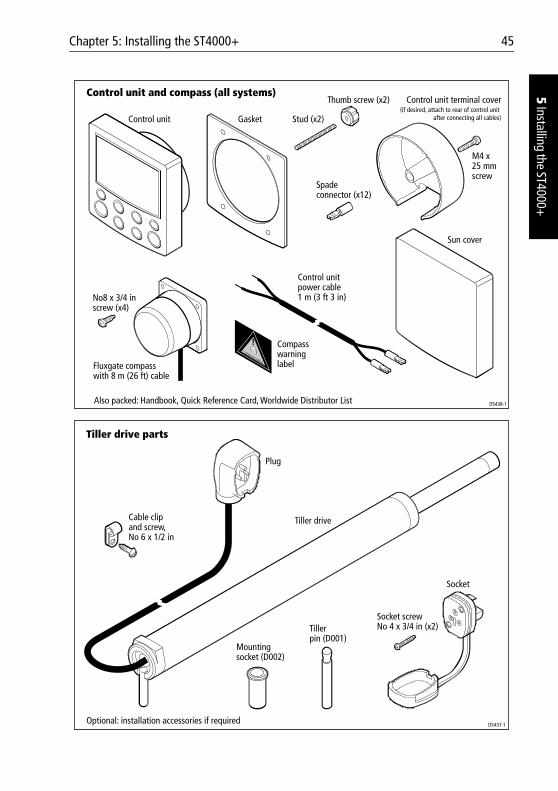
Control unit and compass (all systems)
Control unit
M4 x 25 mmscrew
No8 x 3/4 inscrew (x4)
Spadeconnector (x12)
Fluxgate compasswith 8 m (26 ft) cable
Also packed: Handbook, Quick Reference Card, Worldwide Distributor List
Compasswarninglabel
Control unit terminal cover(if desired, attach to rear of control unit
after connecting all cables)Gasket
Control unitpower cable1 m (3 ft 3 in)
D5437-1
Mountingsocket (D002)
Tillerpin (D001)
Socket
Plug
Socket screwNo 4 x 3/4 in (x2)
Tiller drive
Tiller drive parts
Cable clipand screw,No 6 x 1/2 in
Optional: installation accessories if required
46 ST4000+ Wheel & Tiller Autopilots: Owner’s Handbook
5 In
stal
ling
the
ST40
00+
EMC installation guidelinesAll Raymarine equipment and accessories are designed to the best industry standards for use in the recreational marine environment.
Their design and manufacture conforms to the appropriate Electromagnetic Compatibility (EMC) standards, but correct installation is required to ensure that performance is not compromised.
Although every effort has been taken to ensure that they will perform under all conditions, it is important to understand what factors could affect the operation of the product.
The guidelines given here describe the conditions for optimum EMC performance, but it is recognized that it may not be possible to meet all of these conditions in all situations. To ensure the best possible conditions for EMC performance within the constraints imposed by any location, always ensure the maximum separation possible between different items of electrical equipment.
For optimum EMC performance, it is recommended that wherever possible:
D5439-1
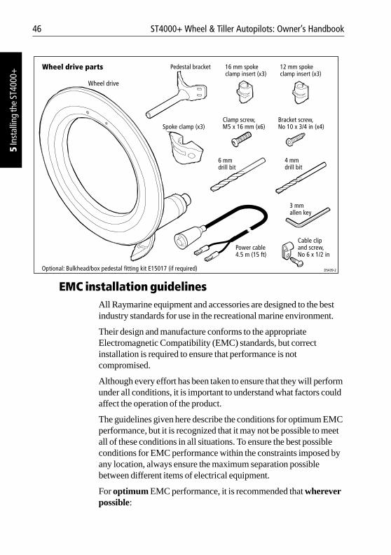
Wheel drive parts
Clamp screw, M5 x 16 mm (x6)
Wheel drive
Pedestal bracket
Spoke clamp (x3)
16 mm spokeclamp insert (x3)
12 mm spokeclamp insert (x3)
6 mmdrill bit
3 mmallen key
4 mmdrill bit
Power cable4.5 m (15 ft)
Bracket screw, No 10 x 3/4 in (x4)
Cable clipand screw,No 6 x 1/2 in
Optional: Bulkhead/box pedestal fitting kit E15017 (if required) D5439-2
Wheel drive parts
Clamp screw,M5 x 16 mm (x6)
Wheel drive
Pedestal bracket
Spoke clamp (x3)
16 mm spokeclamp insert (x3)
12 mm spokeclamp insert (x3)
6 mmdrill bit
3 mmallen key
4 mmdrill bit
Power cable4.5 m (15 ft)
Bracket screw,No 10 x 3/4 in (x4)
Cable clipand screw,No 6 x 1/2 in
Optional: Bulkhead/box pedestal fitting kit E15017 (if required)
Chapter 5: Installing the ST4000+ 47
5 Installing the ST4000+
• Raymarine equipment and cables connected to it are:• At least 3 ft (1 m) from any equipment transmitting or cables
carrying radio signals e.g. VHF radios, cables and antennas. In the case of SSB radios, the distance should be increased to 7 ft (2 m).
• More than 7 ft (2 m) from the path of a radar beam. A radar beam can normally be assumed to spread 20 degrees above and below the radiating element.
• The equipment is supplied from a separate battery from that used for engine start. Voltage drops below 10 V, and starter motor transients, can cause the equipment to reset. This will not damage the equipment, but may cause the loss of some information and may change the operating mode.
• Raymarine specified cables are used. Cutting and rejoining these cables can compromise EMC performance and must be avoided unless doing so is detailed in the installation manual.
• If a suppression ferrite is attached to a cable, this ferrite should not be removed. If the ferrite needs to be removed during installation it must be reassembled in the same position.
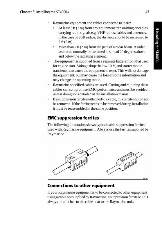
EMC suppression ferritesThe following illustration shows typical cable suppression ferrites used with Raymarine equipment. Always use the ferrites supplied by Raymarine.
Connections to other equipmentIf your Raymarine equipment is to be connected to other equipment using a cable not supplied by Raymarine, a suppression ferrite MUST always be attached to the cable near to the Raymarine unit.
D3548-2
48 ST4000+ Wheel & Tiller Autopilots: Owner’s Handbook
5 In
stal
ling
the
ST40
00+
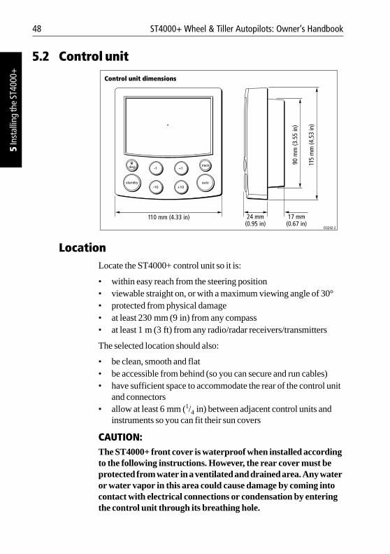
5.2 Control unit
LocationLocate the ST4000+ control unit so it is:
• within easy reach from the steering position• viewable straight on, or with a maximum viewing angle of 30°• protected from physical damage• at least 230 mm (9 in) from any compass• at least 1 m (3 ft) from any radio/radar receivers/transmitters
The selected location should also:
• be clean, smooth and flat• be accessible from behind (so you can secure and run cables)• have sufficient space to accommodate the rear of the control unit
and connectors• allow at least 6 mm (1/4 in) between adjacent control units and
instruments so you can fit their sun covers
CAUTION:The ST4000+ front cover is waterproof when installed according to the following instructions. However, the rear cover must be protected from water in a ventilated and drained area. Any water or water vapor in this area could cause damage by coming into contact with electrical connections or condensation by entering the control unit through its breathing hole.
110 mm (4.33 in)
115
mm
(4.5
3 in
)
90 m
m (3
.55
in)
24 mm(0.95 in)
17 mm(0.67 in)
D3242-2
Control unit dimensions
Chapter 5: Installing the ST4000+ 49
5 Installing the ST4000+
Mounting procedureControl units are available in surface mount and flush mount styles.
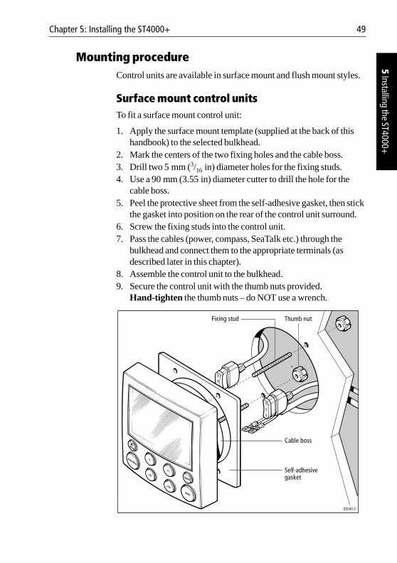
Surface mount control unitsTo fit a surface mount control unit:
1. Apply the surface mount template (supplied at the back of this handbook) to the selected bulkhead.
2. Mark the centers of the two fixing holes and the cable boss.3. Drill two 5 mm (3/16 in) diameter holes for the fixing studs. 4. Use a 90 mm (3.55 in) diameter cutter to drill the hole for the
cable boss.5. Peel the protective sheet from the self-adhesive gasket, then stick
the gasket into position on the rear of the control unit surround.6. Screw the fixing studs into the control unit.7. Pass the cables (power, compass, SeaTalk etc.) through the
bulkhead and connect them to the appropriate terminals (as described later in this chapter).
8. Assemble the control unit to the bulkhead.9. Secure the control unit with the thumb nuts provided.
Hand-tighten the thumb nuts – do NOT use a wrench.
D3243-3
Cable boss
Self-adhesivegasket
Fixing stud Thumb nut
50 ST4000+ Wheel & Tiller Autopilots: Owner’s Handbook
5 In
stal
ling
the
ST40
00+
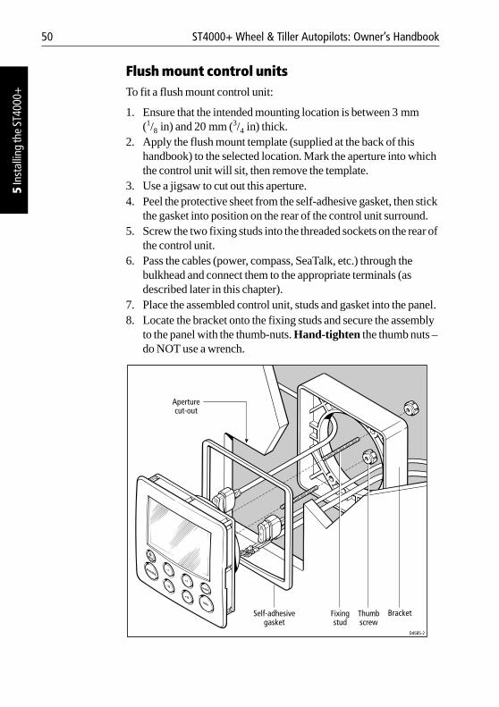
Flush mount control unitsTo fit a flush mount control unit:
1. Ensure that the intended mounting location is between 3 mm (1/8 in) and 20 mm (3/4 in) thick.
2. Apply the flush mount template (supplied at the back of this handbook) to the selected location. Mark the aperture into which the control unit will sit, then remove the template.
3. Use a jigsaw to cut out this aperture.4. Peel the protective sheet from the self-adhesive gasket, then stick
the gasket into position on the rear of the control unit surround.5. Screw the two fixing studs into the threaded sockets on the rear of
the control unit.6. Pass the cables (power, compass, SeaTalk, etc.) through the
bulkhead and connect them to the appropriate terminals (as described later in this chapter).
7. Place the assembled control unit, studs and gasket into the panel. 8. Locate the bracket onto the fixing studs and secure the assembly
to the panel with the thumb-nuts. Hand-tighten the thumb nuts – do NOT use a wrench.
D4585-2
Fixingstud
Thumbscrew
Bracket
Aperturecut-out
Self-adhesivegasket
Chapter 5: Installing the ST4000+ 51
5 Installing the ST4000+
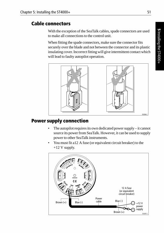
Cable connectorsWith the exception of the SeaTalk cables, spade connectors are used to make all connections to the control unit.
When fitting the spade connectors, make sure the connector fits securely over the blade and not between the connector and its plastic insulating cover. Incorrect fitting will give intermittent contact which will lead to faulty autopilot operation.
Power supply connection• The autopilot requires its own dedicated power supply – it cannot
source its power from SeaTalk. However, it can be used to supply power to other SeaTalk instruments.
• You must fit a12 A fuse (or equivalent circuit breaker) to the +12 V supply.
D3286-2
+12 V power supply
Powercable
Brown (+)
12 A fuse(or equivalentcircuit breaker)
Blue (-)
D3287-2
Brown (+) Blue (-)
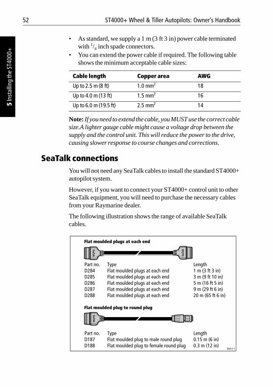
52 ST4000+ Wheel & Tiller Autopilots: Owner’s Handbook
5 In
stal
ling
the
ST40
00+
• As standard, we supply a 1 m (3 ft 3 in) power cable terminated with 1/4 inch spade connectors.
• You can extend the power cable if required. The following table shows the minimum acceptable cable sizes:
Note: If you need to extend the cable, you MUST use the correct cable size.A lighter gauge cable might cause a voltage drop between the supply and the control unit. This will reduce the power to the drive, causing slower response to course changes and corrections.
SeaTalk connectionsYou will not need any SeaTalk cables to install the standard ST4000+ autopilot system.
However, if you want to connect your ST4000+ control unit to other SeaTalk equipment, you will need to purchase the necessary cables from your Raymarine dealer.
The following illustration shows the range of available SeaTalk cables.
Cable length Copper area AWG
Up to 2.5 m (8 ft) 1.0 mm2 18
Up to 4.0 m (13 ft) 1.5 mm2 16
Up to 6.0 m (19.5 ft) 2.5 mm2 14
Flat moulded plug to round plug
Flat moulded plugs at each end
D5417-1
Part no. Type LengthD187 Flat moulded plug to male round plug 0.15 m (6 in)D188 Flat moulded plug to female round plug 0.3 m (12 in)
Part no. Type LengthD284 Flat moulded plugs at each end 1 m (3 ft 3 in)D285 Flat moulded plugs at each end 3 m (9 ft 10 in)D286 Flat moulded plugs at each end 5 m (16 ft 5 in)D287 Flat moulded plugs at each end 9 m (29 ft 6 in)D288 Flat moulded plugs at each end 20 m (65 ft 6 in)
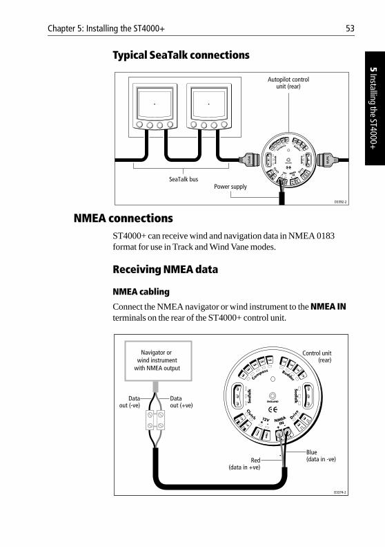
Chapter 5: Installing the ST4000+ 53
5 Installing the ST4000+
Typical SeaTalk connections
NMEA connectionsST4000+ can receive wind and navigation data in NMEA 0183 format for use in Track and Wind Vane modes.
Receiving NMEA data
NMEA cabling
Connect the NMEA navigator or wind instrument to the NMEA IN terminals on the rear of the ST4000+ control unit.
D3392-2
SeaTalk busPower supply
Autopilot controlunit (rear)
D3374-2
Red(data in +ve)
Blue(data in -ve)
Navigator or wind instrument
with NMEA output
Dataout (+ve)
Dataout (-ve)
Control unit(rear)
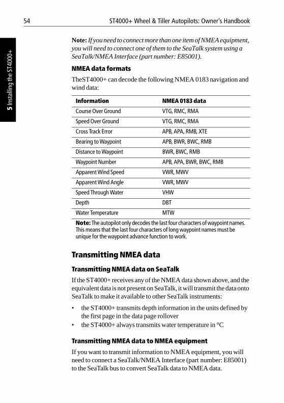
54 ST4000+ Wheel & Tiller Autopilots: Owner’s Handbook
5 In
stal
ling
the
ST40
00+
Note: If you need to connect more than one item of NMEA equipment, you will need to connect one of them to the SeaTalk system using a SeaTalk/NMEA Interface (part number: E85001).
NMEA data formats
TheST4000+ can decode the following NMEA 0183 navigation and wind data:
Transmitting NMEA data
Transmitting NMEA data on SeaTalk
If the ST4000+ receives any of the NMEA data shown above, and the equivalent data is not present on SeaTalk, it will transmit the data onto SeaTalk to make it available to other SeaTalk instruments:
• the ST4000+ transmits depth information in the units defined by the first page in the data page rollover
• the ST4000+ always transmits water temperature in °C
Transmitting NMEA data to NMEA equipment
If you want to transmit information to NMEA equipment, you will need to connect a SeaTalk/NMEA Interface (part number: E85001) to the SeaTalk bus to convert SeaTalk data to NMEA data.
Information NMEA 0183 data
Course Over Ground VTG, RMC, RMA
Speed Over Ground VTG, RMC, RMA
Cross Track Error APB, APA, RMB, XTE
Bearing to Waypoint APB, BWR, BWC, RMB
Distance to Waypoint BWR, BWC, RMB
Waypoint Number APB, APA, BWR, BWC, RMB
Apparent Wind Speed VWR, MWV
Apparent Wind Angle VWR, MWV
Speed Through Water VHW
Depth DBT
Water Temperature MTW
Note: The autopilot only decodes the last four characters of waypoint names. This means that the last four characters of long waypoint names must be unique for the waypoint advance function to work.
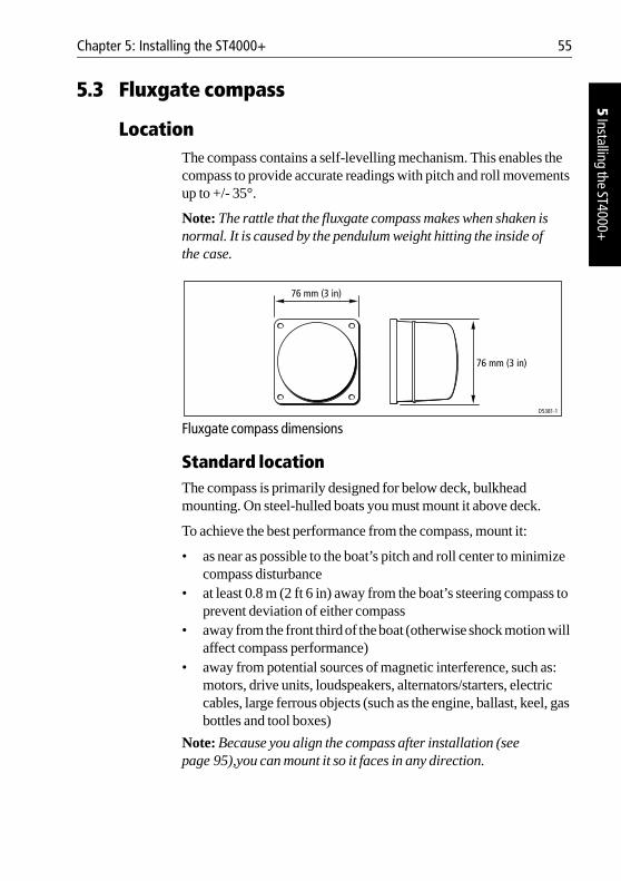
Chapter 5: Installing the ST4000+ 55
5 Installing the ST4000+
5.3 Fluxgate compass
LocationThe compass contains a self-levelling mechanism. This enables the compass to provide accurate readings with pitch and roll movements up to +/- 35°.
Note: The rattle that the fluxgate compass makes when shaken is normal. It is caused by the pendulum weight hitting the inside of the case.
Fluxgate compass dimensions
Standard locationThe compass is primarily designed for below deck, bulkhead mounting. On steel-hulled boats you must mount it above deck.
To achieve the best performance from the compass, mount it:
• as near as possible to the boat’s pitch and roll center to minimize compass disturbance
• at least 0.8 m (2 ft 6 in) away from the boat’s steering compass to prevent deviation of either compass
• away from the front third of the boat (otherwise shock motion will affect compass performance)
• away from potential sources of magnetic interference, such as: motors, drive units, loudspeakers, alternators/starters, electric cables, large ferrous objects (such as the engine, ballast, keel, gas bottles and tool boxes)
Note: Because you align the compass after installation (see page 95),you can mount it so it faces in any direction.
76 mm (3 in)
76 mm (3 in)
D5381-1
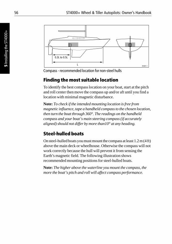
56 ST4000+ Wheel & Tiller Autopilots: Owner’s Handbook
5 In
stal
ling
the
ST40
00+
Compass - recommended location for non-steel hulls
Finding the most suitable locationTo identify the best compass location on your boat, start at the pitch and roll center then move the compass up and/or aft until you find a location with minimal magnetic disturbance.
Note: To check if the intended mounting location is free from magnetic influence, tape a handheld compass to the chosen location, then turn the boat through 360°. The readings on the handheld compass and your boat’s main steering compass (if accurately aligned) should not differ by more than10° at any heading.
Steel-hulled boatsOn steel-hulled boats you must mount the compass at least 1.2 m (4 ft) above the main deck or wheelhouse. Otherwise the compass will not work correctly because the hull will prevent it from sensing the Earth’s magnetic field. The following illustration shows recommended mounting positions for steel-hulled boats.
Note: The higher above the waterline you mount the compass, the more the boat’s pitch and roll will affect compass performance.
0.3L to 0.5L
LD5401-1
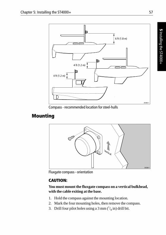
Chapter 5: Installing the ST4000+ 57
5 Installing the ST4000+
Compass - recommended location for steel-hulls
Mounting
Fluxgate compass - orientation
CAUTION:You must mount the fluxgate compass on a vertical bulkhead, with the cable exiting at the base.
1. Hold the compass against the mounting location.2. Mark the four mounting holes, then remove the compass. 3. Drill four pilot holes using a 3 mm (1/8 in) drill bit.
6 ft (1.8 m)
D5383-1
4 ft (1.2 m)
4 ft (1.2 m)
D5384-1
Vertical
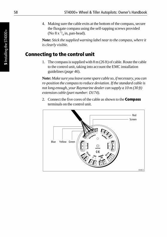
58 ST4000+ Wheel & Tiller Autopilots: Owner’s Handbook
5 In
stal
ling
the
ST40
00+
4. Making sure the cable exits at the bottom of the compass, secure the fluxgate compass using the self-tapping screws provided (No 8 x 3/4 in, pan-head).
Note: Stick the supplied warning label near to the compass, where it is clearly visible.
Connecting to the control unit1. The compass is supplied with 8 m (26 ft) of cable. Route the cable
to the control unit, taking into account the EMC installation guidelines (page 46).
Note: Make sure you leave some spare cable so, if necessary, you can re-position the compass to reduce deviation. If the standard cable is not long enough, your Raymarine dealer can supply a 10 m (30 ft) extension cable (part number: D174).
2. Connect the five cores of the cable as shown to the Compass terminals on the control unit.
D3282-2
Blue Yellow Green
Screen
Red
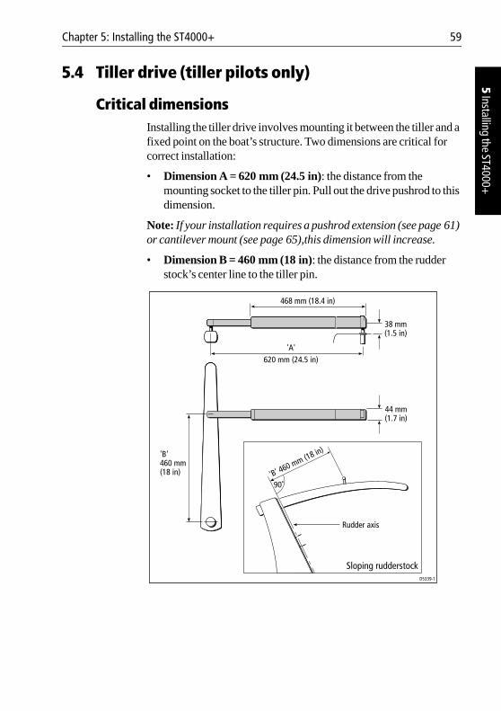
Chapter 5: Installing the ST4000+ 59
5 Installing the ST4000+
5.4 Tiller drive (tiller pilots only)
Critical dimensionsInstalling the tiller drive involves mounting it between the tiller and a fixed point on the boat’s structure. Two dimensions are critical for correct installation:
• Dimension A = 620 mm (24.5 in): the distance from the mounting socket to the tiller pin. Pull out the drive pushrod to this dimension.
Note: If your installation requires a pushrod extension (see page 61) or cantilever mount (see page 65),this dimension will increase.
• Dimension B = 460 mm (18 in): the distance from the rudder stock’s center line to the tiller pin.
'A'620 mm (24.5 in)
468 mm (18.4 in)
38 mm(1.5 in)
44 mm(1.7 in)
'B'460 mm(18 in) 'B' 460 mm (18 in)
D5339-1
90˚
Sloping rudderstock
Rudder axis
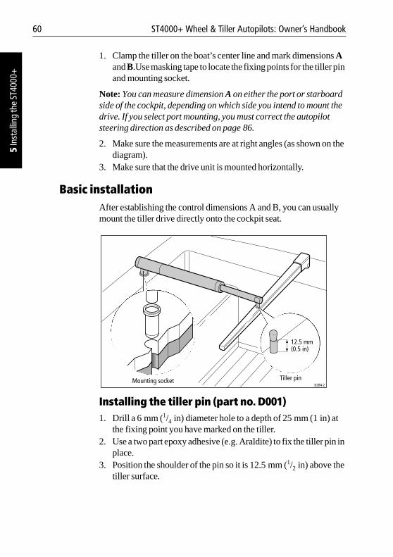
60 ST4000+ Wheel & Tiller Autopilots: Owner’s Handbook
5 In
stal
ling
the
ST40
00+
1. Clamp the tiller on the boat’s center line and mark dimensions A and B.Use masking tape to locate the fixing points for the tiller pin and mounting socket.
Note: You can measure dimension A on either the port or starboard side of the cockpit, depending on which side you intend to mount the drive. If you select port mounting, you must correct the autopilot steering direction as described on page 86.
2. Make sure the measurements are at right angles (as shown on the diagram).
3. Make sure that the drive unit is mounted horizontally.
Basic installationAfter establishing the control dimensions A and B, you can usually mount the tiller drive directly onto the cockpit seat.
Installing the tiller pin (part no. D001)1. Drill a 6 mm (1/4 in) diameter hole to a depth of 25 mm (1 in) at
the fixing point you have marked on the tiller.2. Use a two part epoxy adhesive (e.g. Araldite) to fix the tiller pin in
place.3. Position the shoulder of the pin so it is 12.5 mm (1/2 in) above the
tiller surface.
Mounting socket
12.5 mm(0.5 in)
Tiller pinD284-2
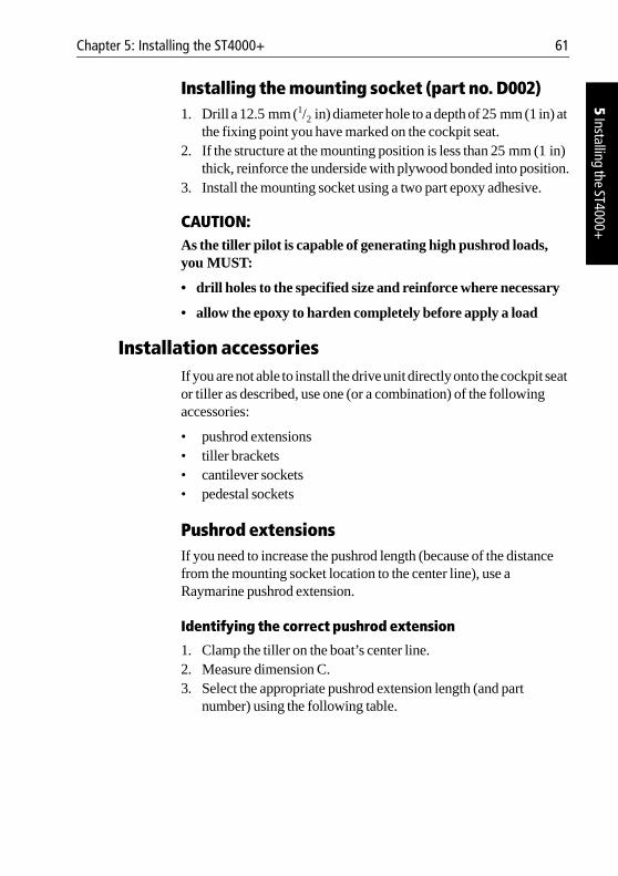
Chapter 5: Installing the ST4000+ 61
5 Installing the ST4000+
Installing the mounting socket (part no. D002)1. Drill a 12.5 mm (1/2 in) diameter hole to a depth of 25 mm (1 in) at
the fixing point you have marked on the cockpit seat.2. If the structure at the mounting position is less than 25 mm (1 in)
thick, reinforce the underside with plywood bonded into position.3. Install the mounting socket using a two part epoxy adhesive.
CAUTION:As the tiller pilot is capable of generating high pushrod loads, you MUST:
• drill holes to the specified size and reinforce where necessary
• allow the epoxy to harden completely before apply a load
Installation accessoriesIf you are not able to install the drive unit directly onto the cockpit seat or tiller as described, use one (or a combination) of the following accessories:
• pushrod extensions• tiller brackets• cantilever sockets• pedestal sockets
Pushrod extensionsIf you need to increase the pushrod length (because of the distance from the mounting socket location to the center line), use a Raymarine pushrod extension.
Identifying the correct pushrod extension
1. Clamp the tiller on the boat’s center line.2. Measure dimension C.3. Select the appropriate pushrod extension length (and part
number) using the following table.
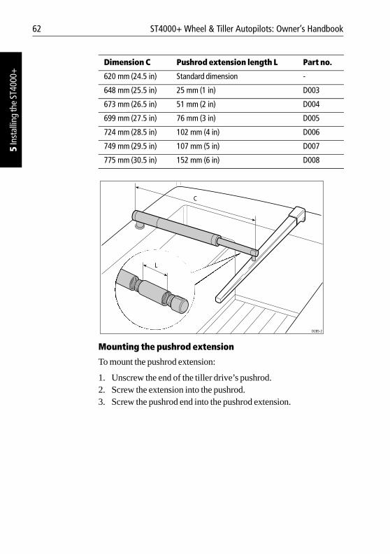
62 ST4000+ Wheel & Tiller Autopilots: Owner’s Handbook
5 In
stal
ling
the
ST40
00+
Mounting the pushrod extension
To mount the pushrod extension:
1. Unscrew the end of the tiller drive’s pushrod.2. Screw the extension into the pushrod.3. Screw the pushrod end into the pushrod extension.
Dimension C Pushrod extension length L Part no.
620 mm (24.5 in) Standard dimension -
648 mm (25.5 in) 25 mm (1 in) D003
673 mm (26.5 in) 51 mm (2 in) D004
699 mm (27.5 in) 76 mm (3 in) D005
724 mm (28.5 in) 102 mm (4 in) D006
749 mm (29.5 in) 107 mm (5 in) D007
775 mm (30.5 in) 152 mm (6 in) D008
L
C
D285-2
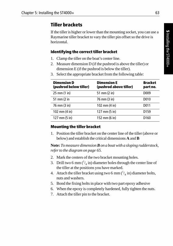
Chapter 5: Installing the ST4000+ 63
5 Installing the ST4000+
Tiller bracketsIf the tiller is higher or lower than the mounting socket, you can use a Raymarine tiller bracket to vary the tiller pin offset so the drive is horizontal.
Identifying the correct tiller bracket
1. Clamp the tiller on the boat’s center line.2. Measure dimension D (if the pushrod is above the tiller) or
dimension E (if the pushrod is below the tiller).3. Select the appropriate bracket from the following table:
Mounting the tiller bracket
1. Position the tiller bracket on the center line of the tiller (above or below) and establish the critical dimensions A and B
Note: To measure dimension B on a boat with a sloping rudderstock, refer to the diagram on page 65.
2. Mark the centers of the two bracket mounting holes.3. Drill two 6 mm (1/4 in) diameter holes through the center line of
the tiller at the positions you have marked.4. Attach the tiller bracket using two 6 mm (1/4 in) diameter bolts,
nuts and washers.5. Bond the fixing bolts in place with two part epoxy adhesive6. When the epoxy is completely hardened, fully tighten the nuts.7. Attach the tiller pin to the bracket.
Dimension D (pushrod below tiller)
Dimension E (pushrod above tiller)
Bracket part no.
25 mm (1 in) 51 mm (2 in) D009
51 mm (2 in 76 mm (3 in) D010
76 mm (3 in) 102 mm (4 in) D011
102 mm (4 in) 127 mm (5 in) D159
127 mm (5 in) 152 mm (6 in) D160
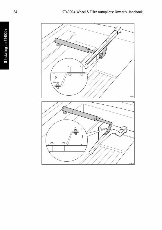
64 ST4000+ Wheel & Tiller Autopilots: Owner’s Handbook
5 In
stal
ling
the
ST40
00+
D286-2
D
E
D287-2
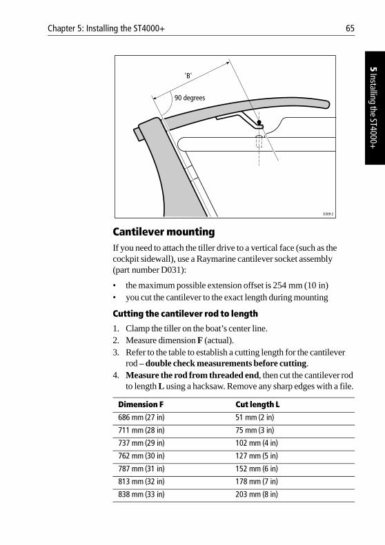
Chapter 5: Installing the ST4000+ 65
5 Installing the ST4000+
Cantilever mountingIf you need to attach the tiller drive to a vertical face (such as the cockpit sidewall), use a Raymarine cantilever socket assembly (part number D031):
• the maximum possible extension offset is 254 mm (10 in)• you cut the cantilever to the exact length during mounting
Cutting the cantilever rod to length
1. Clamp the tiller on the boat’s center line.2. Measure dimension F (actual).3. Refer to the table to establish a cutting length for the cantilever
rod – double check measurements before cutting.4. Measure the rod from threaded end, then cut the cantilever rod
to length L using a hacksaw. Remove any sharp edges with a file.
Dimension F Cut length L
686 mm (27 in) 51 mm (2 in)
711 mm (28 in) 75 mm (3 in)
737 mm (29 in) 102 mm (4 in)
762 mm (30 in) 127 mm (5 in)
787 mm (31 in) 152 mm (6 in)
813 mm (32 in) 178 mm (7 in)
838 mm (33 in) 203 mm (8 in)
'B'
D309-2
90 degrees
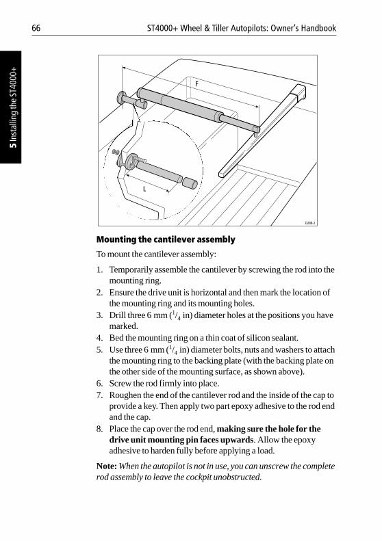
66 ST4000+ Wheel & Tiller Autopilots: Owner’s Handbook
5 In
stal
ling
the
ST40
00+
Mounting the cantilever assembly
To mount the cantilever assembly:
1. Temporarily assemble the cantilever by screwing the rod into the mounting ring.
2. Ensure the drive unit is horizontal and then mark the location of the mounting ring and its mounting holes.
3. Drill three 6 mm (1/4 in) diameter holes at the positions you have marked.
4. Bed the mounting ring on a thin coat of silicon sealant. 5. Use three 6 mm (1/4 in) diameter bolts, nuts and washers to attach
the mounting ring to the backing plate (with the backing plate on the other side of the mounting surface, as shown above).
6. Screw the rod firmly into place. 7. Roughen the end of the cantilever rod and the inside of the cap to
provide a key. Then apply two part epoxy adhesive to the rod end and the cap.
8. Place the cap over the rod end, making sure the hole for the drive unit mounting pin faces upwards. Allow the epoxy adhesive to harden fully before applying a load.
Note: When the autopilot is not in use, you can unscrew the complete rod assembly to leave the cockpit unobstructed.
L
F
D288-2
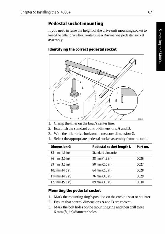
Chapter 5: Installing the ST4000+ 67
5 Installing the ST4000+
Pedestal socket mountingIf you need to raise the height of the drive unit mounting socket to keep the tiller drive horizontal, use a Raymarine pedestal socket assembly.
Identifying the correct pedestal socket
1. Clamp the tiller on the boat’s center line.2. Establish the standard control dimensions A and B.3. With the tiller drive horizontal, measure dimension G. 4. Select the appropriate pedestal socket assembly from the table.
Mounting the pedestal socket
1. Mark the mounting ring’s position on the cockpit seat or counter.2. Ensure that control dimensions A and B are correct.3. Mark the bolt holes on the mounting ring and then drill three
6 mm (1/4 in) diameter holes.
Dimension G Pedestal socket length L Part no.
38 mm (1.5 in) Standard dimension -
76 mm (3.0 in) 38 mm (1.5 in) D026
89 mm (3.5 in) 50 mm (2.0 in) D027
102 mm (4.0 in) 64 mm (2.5 in) D028
114 mm (4.5 in) 76 mm (3.0 in) D029
127 mm (5.0 in) 89 mm (3.5 in) D030
G
D289-2
L
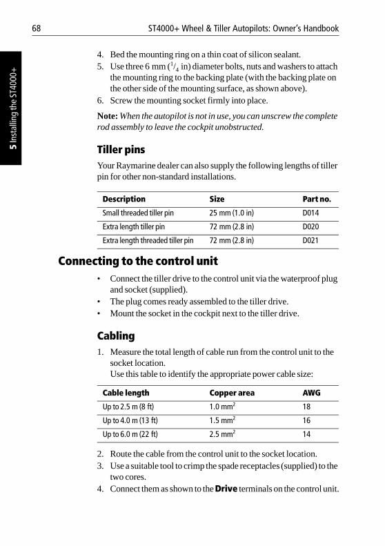
68 ST4000+ Wheel & Tiller Autopilots: Owner’s Handbook
5 In
stal
ling
the
ST40
00+
4. Bed the mounting ring on a thin coat of silicon sealant. 5. Use three 6 mm (1/4 in) diameter bolts, nuts and washers to attach
the mounting ring to the backing plate (with the backing plate on the other side of the mounting surface, as shown above).
6. Screw the mounting socket firmly into place.
Note: When the autopilot is not in use, you can unscrew the complete rod assembly to leave the cockpit unobstructed.
Tiller pinsYour Raymarine dealer can also supply the following lengths of tiller pin for other non-standard installations.
Connecting to the control unit • Connect the tiller drive to the control unit via the waterproof plug
and socket (supplied). • The plug comes ready assembled to the tiller drive. • Mount the socket in the cockpit next to the tiller drive.
Cabling1. Measure the total length of cable run from the control unit to the
socket location. Use this table to identify the appropriate power cable size:
2. Route the cable from the control unit to the socket location.3. Use a suitable tool to crimp the spade receptacles (supplied) to the
two cores.4. Connect them as shown to the Drive terminals on the control unit.
Description Size Part no.
Small threaded tiller pin 25 mm (1.0 in) D014
Extra length tiller pin 72 mm (2.8 in) D020
Extra length threaded tiller pin 72 mm (2.8 in) D021
Cable length Copper area AWG
Up to 2.5 m (8 ft) 1.0 mm2 18
Up to 4.0 m (13 ft) 1.5 mm2 16
Up to 6.0 m (22 ft) 2.5 mm2 14
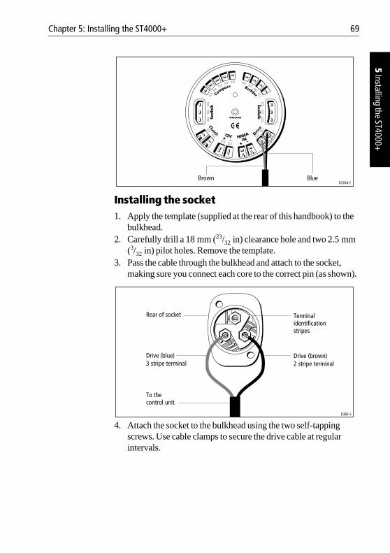
Chapter 5: Installing the ST4000+ 69
5 Installing the ST4000+
Installing the socket1. Apply the template (supplied at the rear of this handbook) to the
bulkhead.2. Carefully drill a 18 mm (23/32 in) clearance hole and two 2.5 mm
(3/32 in) pilot holes. Remove the template.3. Pass the cable through the bulkhead and attach to the socket,
making sure you connect each core to the correct pin (as shown).
4. Attach the socket to the bulkhead using the two self-tapping screws. Use cable clamps to secure the drive cable at regular intervals.
Brown BlueD3284-2
D383-5
Drive (brown)2 stripe terminal
Drive (blue)3 stripe terminal
To the control unit
Terminalidentificationstripes
Rear of socket
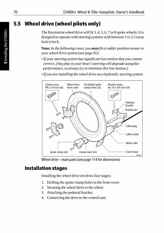
70 ST4000+ Wheel & Tiller Autopilots: Owner’s Handbook
5 In
stal
ling
the
ST40
00+
5.5 Wheel drive (wheel pilots only)The Raymarine wheel drive will fit 3, 4, 5, 6, 7 or 8 spoke wheels. It is designed to operate with steering systems with between 1 to 3.5 turns lock to lock.
Note: In the following cases, you must fit a rudder position sensor to your wheel drive system (see page 81):
• If your steering system has significant lost motion that you cannot correct. (Any play in your boat’s steering will degrade autopilot performance, so always try to minimize this lost motion.)
• If you are installing the wheel drive on a hydraulic steering system.
Wheel drive – main parts (see page 114 for dimensions)
Installation stagesInstalling the wheel drive involves four stages:
1. Drilling the spoke clamp holes in the front cover.2. Securing the wheel drive to the wheel.3. Attaching the pedestal bracket.4. Connecting the drive to the control unit.
Clamp screw, M5 x 16 mm (x6)
Wheel drivefront cover
Pre-drilled spokeclamp holes (x2)
Bracket screw, No 10 x 3/4 inch (x4)
Clutch lever
Motor tube
Cable socket
Cable plug
Bracket pin
Pedestalbracket
D5402-2
Spoke clamp (x3) Clamp insert (x3)
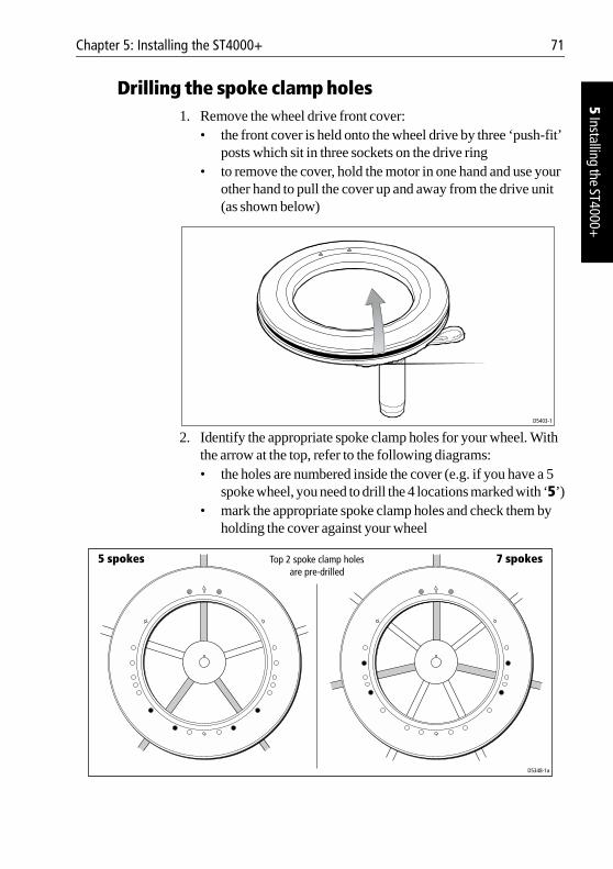
Chapter 5: Installing the ST4000+ 71
5 Installing the ST4000+
Drilling the spoke clamp holes1. Remove the wheel drive front cover:
• the front cover is held onto the wheel drive by three ‘push-fit’ posts which sit in three sockets on the drive ring
• to remove the cover, hold the motor in one hand and use your other hand to pull the cover up and away from the drive unit (as shown below)
2. Identify the appropriate spoke clamp holes for your wheel. With the arrow at the top, refer to the following diagrams:• the holes are numbered inside the cover (e.g. if you have a 5
spoke wheel, you need to drill the 4 locations marked with ‘5’)• mark the appropriate spoke clamp holes and check them by
holding the cover against your wheel
D5403-1
D5348-1a
5 spokes 7 spokesTop 2 spoke clamp holesare pre-drilled
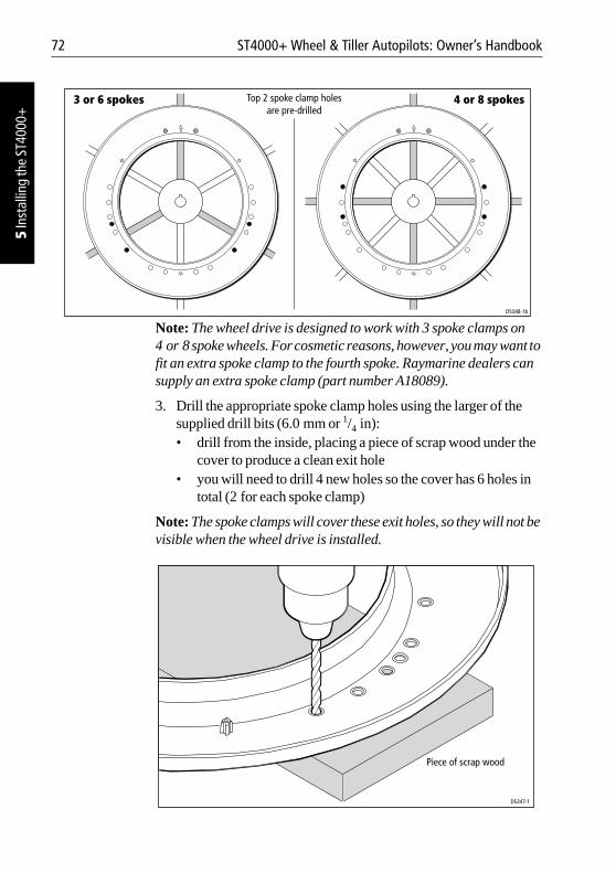
72 ST4000+ Wheel & Tiller Autopilots: Owner’s Handbook
5 In
stal
ling
the
ST40
00+
Note: The wheel drive is designed to work with 3 spoke clamps on 4 or 8 spoke wheels. For cosmetic reasons, however, you may want to fit an extra spoke clamp to the fourth spoke. Raymarine dealers can supply an extra spoke clamp (part number A18089).
3. Drill the appropriate spoke clamp holes using the larger of the supplied drill bits (6.0 mm or 1/4 in):• drill from the inside, placing a piece of scrap wood under the
cover to produce a clean exit hole • you will need to drill 4 new holes so the cover has 6 holes in
total (2 for each spoke clamp)
Note: The spoke clamps will cover these exit holes, so they will not be visible when the wheel drive is installed.
D5348-1b
3 or 6 spokes 4 or 8 spokesTop 2 spoke clamp holesare pre-drilled
Piece of scrap wood
D5347-1
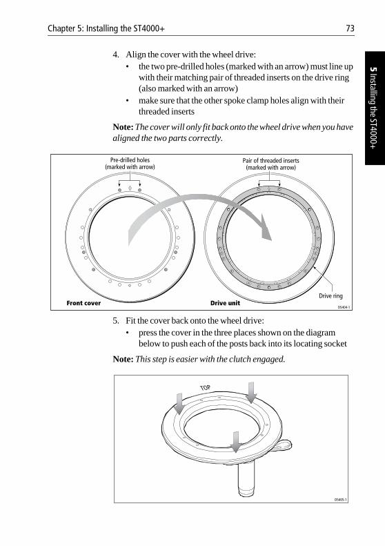
Chapter 5: Installing the ST4000+ 73
5 Installing the ST4000+
4. Align the cover with the wheel drive:• the two pre-drilled holes (marked with an arrow) must line up
with their matching pair of threaded inserts on the drive ring (also marked with an arrow)
• make sure that the other spoke clamp holes align with their threaded inserts
Note: The cover will only fit back onto the wheel drive when you have aligned the two parts correctly.
5. Fit the cover back onto the wheel drive:• press the cover in the three places shown on the diagram
below to push each of the posts back into its locating socket
Note: This step is easier with the clutch engaged.
Pre-drilled holes(marked with arrow)
Pair of threaded inserts(marked with arrow)
Drive ringFront cover Drive unit
D5404-1
D5405-1
TOP
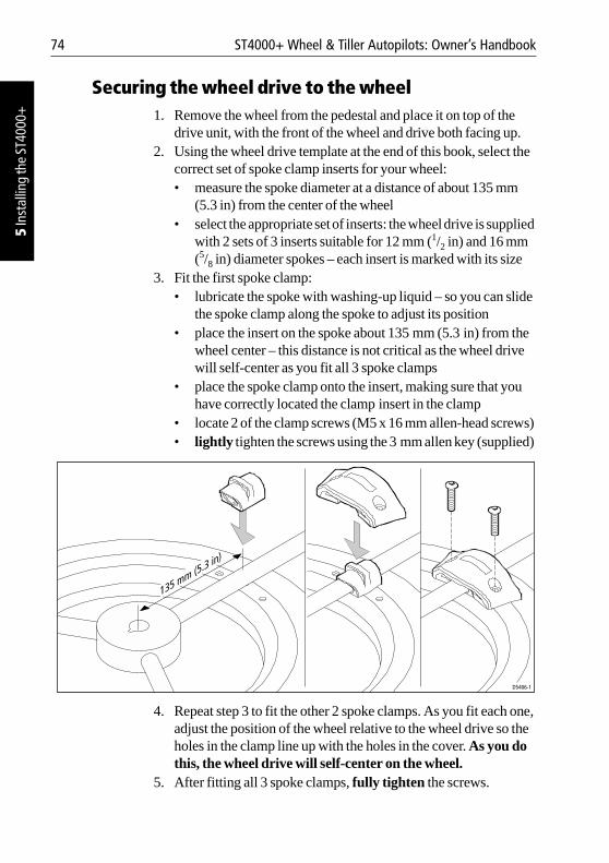
74 ST4000+ Wheel & Tiller Autopilots: Owner’s Handbook
5 In
stal
ling
the
ST40
00+
Securing the wheel drive to the wheel1. Remove the wheel from the pedestal and place it on top of the
drive unit, with the front of the wheel and drive both facing up.2. Using the wheel drive template at the end of this book, select the
correct set of spoke clamp inserts for your wheel:• measure the spoke diameter at a distance of about 135 mm
(5.3 in) from the center of the wheel• select the appropriate set of inserts: the wheel drive is supplied
with 2 sets of 3 inserts suitable for 12 mm (1/2 in) and 16 mm (5/8 in) diameter spokes – each insert is marked with its size
3. Fit the first spoke clamp:• lubricate the spoke with washing-up liquid – so you can slide
the spoke clamp along the spoke to adjust its position• place the insert on the spoke about 135 mm (5.3 in) from the
wheel center – this distance is not critical as the wheel drive will self-center as you fit all 3 spoke clamps
• place the spoke clamp onto the insert, making sure that you have correctly located the clamp insert in the clamp
• locate 2 of the clamp screws (M5 x 16 mm allen-head screws) • lightly tighten the screws using the 3 mm allen key (supplied)
4. Repeat step 3 to fit the other 2 spoke clamps. As you fit each one, adjust the position of the wheel relative to the wheel drive so the holes in the clamp line up with the holes in the cover. As you do this, the wheel drive will self-center on the wheel.
5. After fitting all 3 spoke clamps, fully tighten the screws.
D5406-1
135 mm (5.3 in)
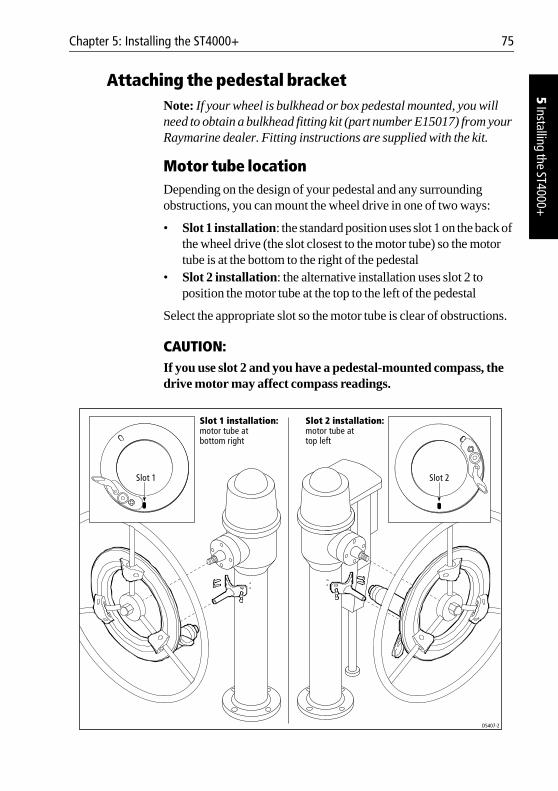
Chapter 5: Installing the ST4000+ 75
5 Installing the ST4000+
Attaching the pedestal bracketNote: If your wheel is bulkhead or box pedestal mounted, you will need to obtain a bulkhead fitting kit (part number E15017) from your Raymarine dealer. Fitting instructions are supplied with the kit.
Motor tube locationDepending on the design of your pedestal and any surrounding obstructions, you can mount the wheel drive in one of two ways:
• Slot 1 installation: the standard position uses slot 1 on the back of the wheel drive (the slot closest to the motor tube) so the motor tube is at the bottom to the right of the pedestal
• Slot 2 installation: the alternative installation uses slot 2 to position the motor tube at the top to the left of the pedestal
Select the appropriate slot so the motor tube is clear of obstructions.
CAUTION:If you use slot 2 and you have a pedestal-mounted compass, the drive motor may affect compass readings.
D5407-2
Slot 2 installation:
motor tube attop left
Slot 1 installation:
motor tube atbottom right
Slot 1 Slot 2
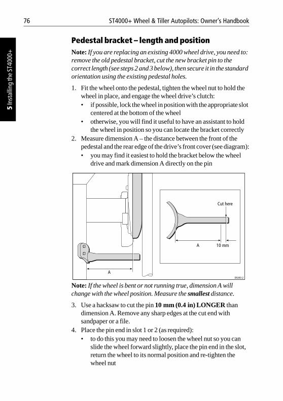
76 ST4000+ Wheel & Tiller Autopilots: Owner’s Handbook
5 In
stal
ling
the
ST40
00+
Pedestal bracket – length and positionNote: If you are replacing an existing 4000 wheel drive, you need to: remove the old pedestal bracket, cut the new bracket pin to the correct length (see steps 2 and 3 below), then secure it in the standard orientation using the existing pedestal holes.
1. Fit the wheel onto the pedestal, tighten the wheel nut to hold the wheel in place, and engage the wheel drive’s clutch:• if possible, lock the wheel in position with the appropriate slot
centered at the bottom of the wheel• otherwise, you will find it useful to have an assistant to hold
the wheel in position so you can locate the bracket correctly2. Measure dimension A – the distance between the front of the
pedestal and the rear edge of the drive’s front cover (see diagram):• you may find it easiest to hold the bracket below the wheel
drive and mark dimension A directly on the pin
Note: If the wheel is bent or not running true, dimension A will change with the wheel position. Measure the smallest distance.
3. Use a hacksaw to cut the pin 10 mm (0.4 in) LONGER than dimension A. Remove any sharp edges at the cut end with sandpaper or a file.
4. Place the pin end in slot 1 or 2 (as required):• to do this you may need to loosen the wheel nut so you can
slide the wheel forward slightly, place the pin end in the slot, return the wheel to its normal position and re-tighten the wheel nut
D5343-2
A 10 mm
Cut here
A
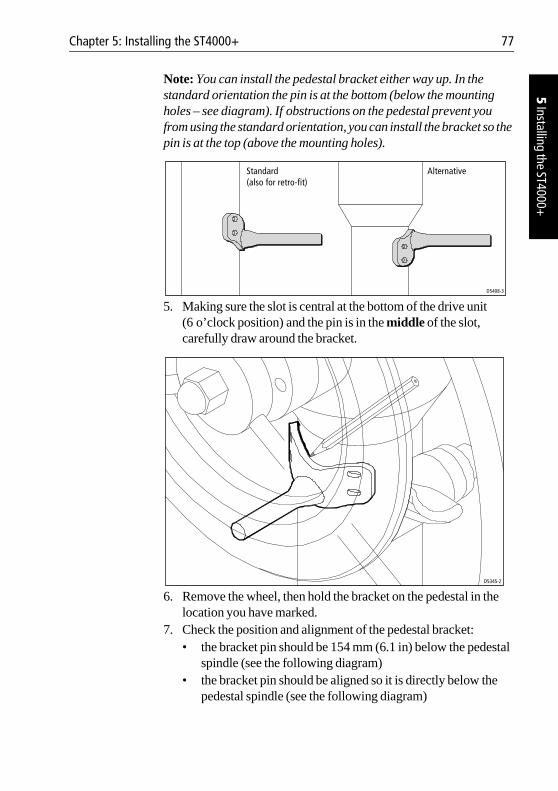
Chapter 5: Installing the ST4000+ 77
5 Installing the ST4000+
Note: You can install the pedestal bracket either way up. In the standard orientation the pin is at the bottom (below the mounting holes – see diagram). If obstructions on the pedestal prevent you from using the standard orientation, you can install the bracket so the pin is at the top (above the mounting holes).
5. Making sure the slot is central at the bottom of the drive unit (6 o’clock position) and the pin is in the middle of the slot, carefully draw around the bracket.
6. Remove the wheel, then hold the bracket on the pedestal in the location you have marked.
7. Check the position and alignment of the pedestal bracket:• the bracket pin should be 154 mm (6.1 in) below the pedestal
spindle (see the following diagram)• the bracket pin should be aligned so it is directly below the
pedestal spindle (see the following diagram)
Standard
(also for retro-fit)
Alternative
D5408-3
D5345-2
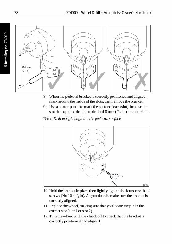
78 ST4000+ Wheel & Tiller Autopilots: Owner’s Handbook
5 In
stal
ling
the
ST40
00+
8. When the pedestal bracket is correctly positioned and aligned, mark around the inside of the slots, then remove the bracket.
9. Use a center-punch to mark the center of each slot, then use the smaller supplied drill bit to drill a 4.0 mm (5/32 in) diameter hole.
Note: Drill at right angles to the pedestal surface.
10. Hold the bracket in place then lightly tighten the four cross-head screws (No 10 x 3/4 in). As you do this, make sure the bracket is correctly aligned.
11. Replace the wheel, making sure that you locate the pin in the correct slot (slot 1 or slot 2).
12. Turn the wheel with the clutch off to check that the bracket is correctly positioned and aligned.
D5346-2
154 mm(6.1 in)
D5344-2
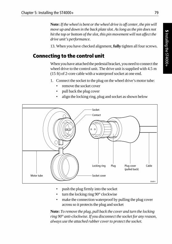
Chapter 5: Installing the ST4000+ 79
5 Installing the ST4000+
Note: If the wheel is bent or the wheel drive is off center, the pin will move up and down in the back plate slot. As long as the pin does not hit the top or bottom of the slot, this pin movement will not affect the drive unit’s performance.
13. When you have checked alignment, fully tighten all four screws.
Connecting to the control unitWhen you have attached the pedestal bracket, you need to connect the wheel drive to the control unit. The drive unit is supplied with 4.5 m (15 ft) of 2-core cable with a waterproof socket at one end.
1. Connect the socket to the plug on the wheel drive’s motor tube:• remove the socket cover • pull back the plug cover • align the locking ring, plug and socket as shown below
• push the plug firmly into the socket• turn the locking ring 90° clockwise• make the connection waterproof by pulling the plug cover
across so it protects the plug and socket
Note: To remove the plug, pull back the cover and turn the locking ring 90° anti-clockwise. If you disconnect the socket for any reason, always use the attached rubber cover to protect the socket.
D5409-1
CablePlug cover(pulled back)
Locking ring
Contact
Socket
Socket coverMotor tube
Plug
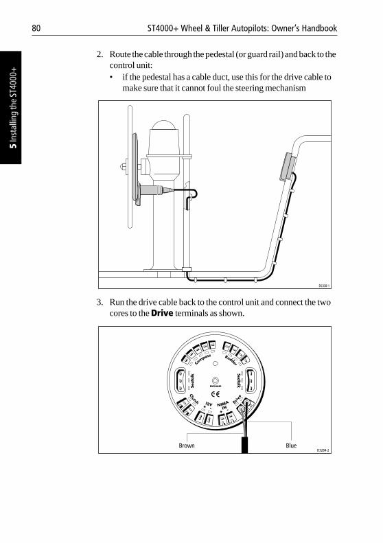
80 ST4000+ Wheel & Tiller Autopilots: Owner’s Handbook
5 In
stal
ling
the
ST40
00+
2. Route the cable through the pedestal (or guard rail) and back to the control unit:• if the pedestal has a cable duct, use this for the drive cable to
make sure that it cannot foul the steering mechanism
3. Run the drive cable back to the control unit and connect the two cores to the Drive terminals as shown.
D5338-1
Brown BlueD3284-2
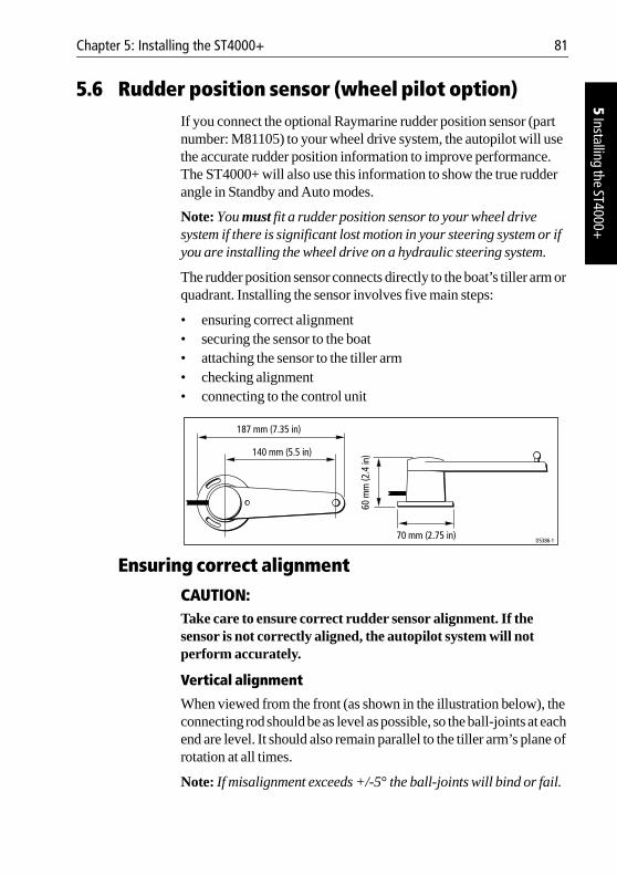
Chapter 5: Installing the ST4000+ 81
5 Installing the ST4000+
5.6 Rudder position sensor (wheel pilot option)If you connect the optional Raymarine rudder position sensor (part number: M81105) to your wheel drive system, the autopilot will use the accurate rudder position information to improve performance. The ST4000+ will also use this information to show the true rudder angle in Standby and Auto modes.
Note: You must fit a rudder position sensor to your wheel drive system if there is significant lost motion in your steering system or if you are installing the wheel drive on a hydraulic steering system.
The rudder position sensor connects directly to the boat’s tiller arm or quadrant. Installing the sensor involves five main steps:
• ensuring correct alignment• securing the sensor to the boat• attaching the sensor to the tiller arm• checking alignment• connecting to the control unit
Ensuring correct alignment
CAUTION:Take care to ensure correct rudder sensor alignment. If the sensor is not correctly aligned, the autopilot system will not perform accurately.
Vertical alignment
When viewed from the front (as shown in the illustration below), the connecting rod should be as level as possible, so the ball-joints at each end are level. It should also remain parallel to the tiller arm’s plane of rotation at all times.
Note: If misalignment exceeds +/-5° the ball-joints will bind or fail.
140 mm (5.5 in)
187 mm (7.35 in)
70 mm (2.75 in)
60mm
(2.4
in)
D5386-1
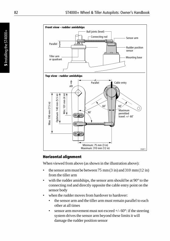
82 ST4000+ Wheel & Tiller Autopilots: Owner’s Handbook
5 In
stal
ling
the
ST40
00+
Horizontal alignment
When viewed from above (as shown in the illustration above):
• the sensor arm must be between 75 mm (3 in) and 310 mm (12 in) from the tiller arm
• with the rudder amidships, the sensor arm should be at 90° to the connecting rod and directly opposite the cable entry point on the sensor body
• when the rudder moves from hardover to hardover:• the sensor arm and the tiller arm must remain parallel to each
other at all times• sensor arm movement must not exceed +/- 60°: if the steering
system drives the sensor arm beyond these limits it will damage the rudder position sensor
Maximum permittedtravel: +/- 60˚
Cable entryParallel
Minimum: 75 mm (3 in)Maximum: 310 mm (12 in)
90˚
60˚ 60˚
Min
: 101
mm
(4 in
)
Opt
imum
: 140
mm
(5.5
in)
Max
: 190
mm
(7.5
in)
D5387-1
Mounting baseTiller armor quadrant
Rudder position sensor
Connecting rod
Ball joints (level)
Sensor arm
Parallel
Front view - rudder amidships
Top view - rudder amidships
Aft
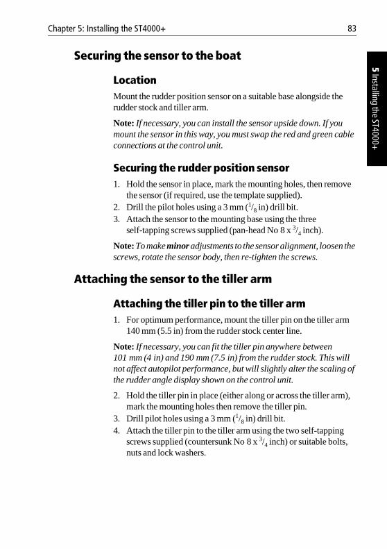
Chapter 5: Installing the ST4000+ 83
5 Installing the ST4000+
Securing the sensor to the boat
LocationMount the rudder position sensor on a suitable base alongside the rudder stock and tiller arm.
Note: If necessary, you can install the sensor upside down. If you mount the sensor in this way, you must swap the red and green cable connections at the control unit.
Securing the rudder position sensor1. Hold the sensor in place, mark the mounting holes, then remove
the sensor (if required, use the template supplied).2. Drill the pilot holes using a 3 mm (1/8 in) drill bit. 3. Attach the sensor to the mounting base using the three
self-tapping screws supplied (pan-head No 8 x 3/4 inch).
Note: To make minor adjustments to the sensor alignment, loosen the screws, rotate the sensor body, then re-tighten the screws.
Attaching the sensor to the tiller arm
Attaching the tiller pin to the tiller arm1. For optimum performance, mount the tiller pin on the tiller arm
140 mm (5.5 in) from the rudder stock center line.
Note: If necessary, you can fit the tiller pin anywhere between 101 mm (4 in) and 190 mm (7.5 in) from the rudder stock. This will not affect autopilot performance, but will slightly alter the scaling of the rudder angle display shown on the control unit.
2. Hold the tiller pin in place (either along or across the tiller arm), mark the mounting holes then remove the tiller pin.
3. Drill pilot holes using a 3 mm (1/8 in) drill bit.4. Attach the tiller pin to the tiller arm using the two self-tapping
screws supplied (countersunk No 8 x 3/4 inch) or suitable bolts, nuts and lock washers.
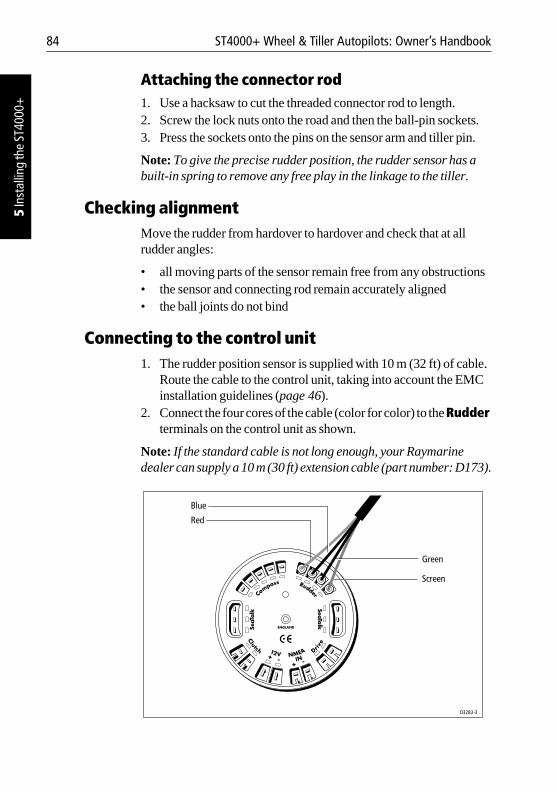
84 ST4000+ Wheel & Tiller Autopilots: Owner’s Handbook
5 In
stal
ling
the
ST40
00+
Attaching the connector rod1. Use a hacksaw to cut the threaded connector rod to length.2. Screw the lock nuts onto the road and then the ball-pin sockets.3. Press the sockets onto the pins on the sensor arm and tiller pin.
Note: To give the precise rudder position, the rudder sensor has a built-in spring to remove any free play in the linkage to the tiller.
Checking alignmentMove the rudder from hardover to hardover and check that at all rudder angles:
• all moving parts of the sensor remain free from any obstructions • the sensor and connecting rod remain accurately aligned• the ball joints do not bind
Connecting to the control unit1. The rudder position sensor is supplied with 10 m (32 ft) of cable.
Route the cable to the control unit, taking into account the EMC installation guidelines (page 46).
2. Connect the four cores of the cable (color for color) to the Rudder terminals on the control unit as shown.
Note: If the standard cable is not long enough, your Raymarine dealer can supply a 10 m (30 ft) extension cable (part number: D173).
D3283-3
Screen
Blue
Red
Green
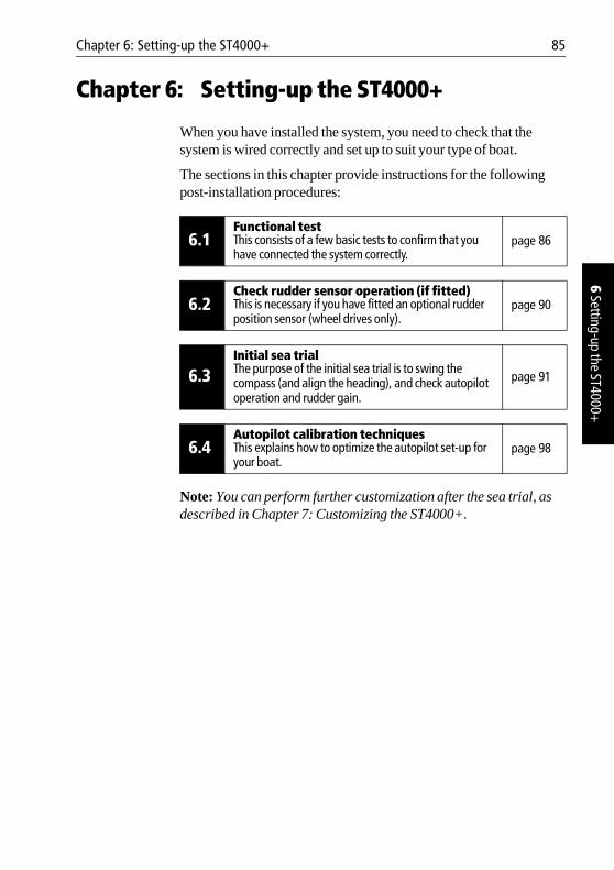
Chapter 6: Setting-up the ST4000+ 85
6 Setting-up the ST4000+
Chapter 6: Setting-up the ST4000+
When you have installed the system, you need to check that the system is wired correctly and set up to suit your type of boat.
The sections in this chapter provide instructions for the following post-installation procedures:
Note: You can perform further customization after the sea trial, as described in Chapter 7: Customizing the ST4000+.
6.1Functional testThis consists of a few basic tests to confirm that you have connected the system correctly.
page 86
6.2Check rudder sensor operation (if fitted)This is necessary if you have fitted an optional rudder position sensor (wheel drives only).
page 90
6.3Initial sea trialThe purpose of the initial sea trial is to swing the compass (and align the heading), and check autopilot operation and rudder gain.
page 91
6.4Autopilot calibration techniquesThis explains how to optimize the autopilot set-up for your boat.
page 98
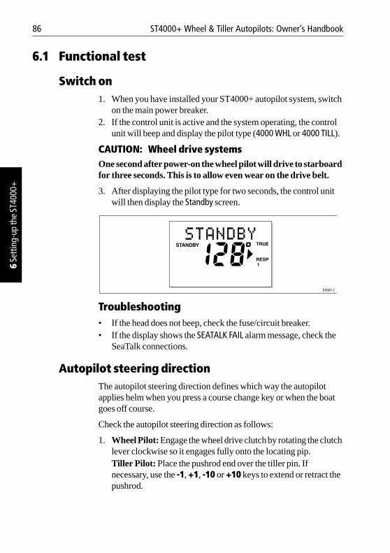
86 ST4000+ Wheel & Tiller Autopilots: Owner’s Handbook
6 Se
tting
-up
the
ST40
00+
6.1 Functional test
Switch on1. When you have installed your ST4000+ autopilot system, switch
on the main power breaker. 2. If the control unit is active and the system operating, the control
unit will beep and display the pilot type (4000 WHL or 4000 TILL).
CAUTION: Wheel drive systemsOne second after power-on the wheel pilot will drive to starboard for three seconds. This is to allow even wear on the drive belt.
3. After displaying the pilot type for two seconds, the control unit will then display the Standby screen.
Troubleshooting• If the head does not beep, check the fuse/circuit breaker. • If the display shows the SEATALK FAIL alarm message, check the
SeaTalk connections.
Autopilot steering directionThe autopilot steering direction defines which way the autopilot applies helm when you press a course change key or when the boat goes off course.
Check the autopilot steering direction as follows:
1. Wheel Pilot: Engage the wheel drive clutch by rotating the clutch lever clockwise so it engages fully onto the locating pip.Tiller Pilot: Place the pushrod end over the tiller pin. If necessary, use the -1, +1, -10 or +10 keys to extend or retract the pushrod.
D3567-2
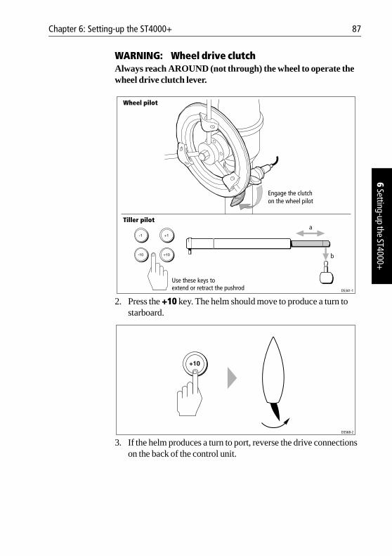
Chapter 6: Setting-up the ST4000+ 87
6 Setting-up the ST4000+
WARNING: Wheel drive clutchAlways reach AROUND (not through) the wheel to operate the wheel drive clutch lever.
2. Press the +10 key. The helm should move to produce a turn to starboard.
3. If the helm produces a turn to port, reverse the drive connections on the back of the control unit.
D5341-1
Engage the clutchon the wheel pilot
Wheel pilot
Tiller pilot
Use these keys toextend or retract the pushrod
a
b
D3568-2
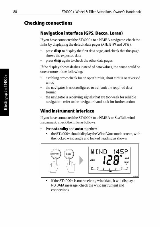
88 ST4000+ Wheel & Tiller Autopilots: Owner’s Handbook
6 Se
tting
-up
the
ST40
00+
Checking connections
Navigation interface (GPS, Decca, Loran)If you have connected the ST4000+ to a NMEA navigator, check the links by displaying the default data pages (XTE, BTW and DTW):
• press disp to display the first data page, and check that this page shows the expected data
• press disp again to check the other data pages
If the display shows dashes instead of data values, the cause could be one or more of the following:
• a cabling error: check for an open circuit, short circuit or reversed wires
• the navigator is not configured to transmit the required data format
• the navigator is receiving signals that are too weak for reliable navigation: refer to the navigator handbook for further action
Wind instrument interfaceIf you have connected the ST4000+ to a NMEA or SeaTalk wind instrument, check the links as follows:
• Press standby and auto together:• the ST4000+ should display the Wind Vane mode screen, with
the locked wind angle and locked heading as shown
• if the ST4000+ is not receiving wind data, it will display a NO DATA message: check the wind instrument and connections
D3565-2
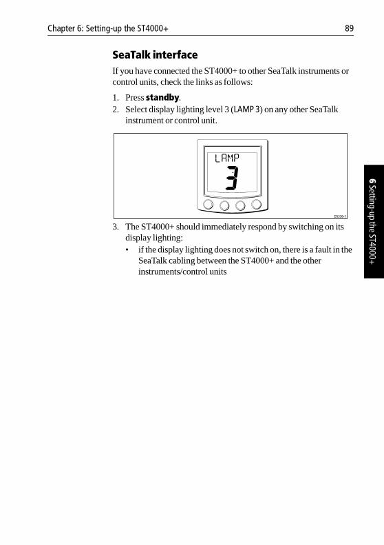
Chapter 6: Setting-up the ST4000+ 89
6 Setting-up the ST4000+
SeaTalk interfaceIf you have connected the ST4000+ to other SeaTalk instruments or control units, check the links as follows:
1. Press standby.2. Select display lighting level 3 (LAMP 3) on any other SeaTalk
instrument or control unit.
3. The ST4000+ should immediately respond by switching on its display lighting:• if the display lighting does not switch on, there is a fault in the
SeaTalk cabling between the ST4000+ and the other instruments/control units
LAMP
D5336-1
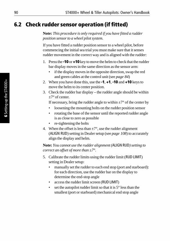
90 ST4000+ Wheel & Tiller Autopilots: Owner’s Handbook
6 Se
tting
-up
the
ST40
00+
6.2 Check rudder sensor operation (if fitted)Note: This procedure is only required if you have fitted a rudder position sensor to a wheel pilot system.
If you have fitted a rudder position sensor to a wheel pilot, before commencing the initial sea trial you must make sure that it senses rudder movement in the correct way and is aligned with the rudder:
1. Press the -10 or +10 key to move the helm to check that the rudder bar display moves in the same direction as the sensor arm:• if the display moves in the opposite direction, swap the red
and green cables at the control unit (see page 84)2. When you have done this, use the -1, +1, -10 and +10 keys to
move the helm to its center position.3. Check the rudder bar display – the rudder angle should be within
±7° of center.If necessary, bring the rudder angle to within ±7° of the center by
• loosening the mounting bolts on the rudder position sensor • rotating the base of the sensor until the reported rudder angle
is as close to zero as possible• re-tightening the bolts
4. When the offset is less than ±7°, use the rudder alignment (ALIGN RUD) setting in Dealer setup (see page 108) to accurately align the display and helm.
Note: You cannot use the rudder alignment (ALIGN RUD) setting to correct an offset of more than ±7°.
5. Calibrate the rudder limits using the rudder limit (RUD LIMIT) setting in Dealer setup: • manually set the rudder to each end stop (port and starboard):
for each direction, use the rudder bar on the display to determine the end-stop angle
• access the rudder limit screen (RUD LIMIT)• set the autopilot rudder limit so that it is 5° less than the
smallest (port or starboard) mechanical end stop angle
Chapter 6: Setting-up the ST4000+ 91
6 Setting-up the ST4000+
6.3 Initial sea trial
OverviewWhen you have checked that the system is functioning correctly, you must complete the setup by taking the boat on a short sea trial to:
• correct the compass deviation • adjust the heading alignment • check autopilot operation • adjust the rudder gain
Note: The ST4000+ has built-in calibration so you can fine tune it to suit your boat, its steering system and its dynamic steering characteristics. So you can perform the initial sea trial, we calibrate the unit at the factory to provide safe and stable autopilot control for the majority of boats.
You should perform the initial sea trial:
• when you have successfully completed all of the installation, functional tests and rudder sensor checks
• before making any other changes to default calibration settings: check and, if necessary, reset the values to the recommended levels described in Chapter 7: Customizing the ST4000+
• in conditions of light wind and calm water, so you can assess autopilot performance without the influence of strong winds or large waves
• in waters that are clear of any obstructions
Note: You can return to hand steering at any time during the sea trial by disengaging the wheel drive clutch, or removing the tiller drive pushrod from the tiller pin.
EMC conformanceAlways check the installation before going to sea to make sure that it is not affected by radio transmissions, engine starting etc.
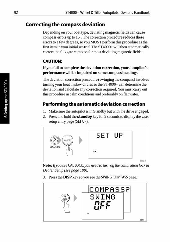
92 ST4000+ Wheel & Tiller Autopilots: Owner’s Handbook
6 Se
tting
-up
the
ST40
00+
Correcting the compass deviation Depending on your boat type, deviating magnetic fields can cause compass errors up to 15°. The correction procedure reduces these errors to a few degrees, so you MUST perform this procedure as the first item in your initial sea trial.The ST4000+ will then automatically correct the fluxgate compass for most deviating magnetic fields.
CAUTION:If you fail to complete the deviation correction, your autopilot’s performance will be impaired on some compass headings.
The deviation correction procedure (swinging the compass) involves turning your boat in slow circles so the ST4000+ can determine the deviation and calculate any correction required. You must carry out this procedure in calm conditions and preferably on flat water.
Performing the automatic deviation correction1. Make sure the autopilot is in Standby but with the drive engaged.2. Press and hold the standby key for 2 seconds to display the User
setup entry page (SET UP).
Note: If you see CAL LOCK, you need to turn off the calibration lock in Dealer Setup (see page 108).
3. Press the DISP key so you see the SWING COMPASS page.
D3448-2
SECONDS
D3460-2
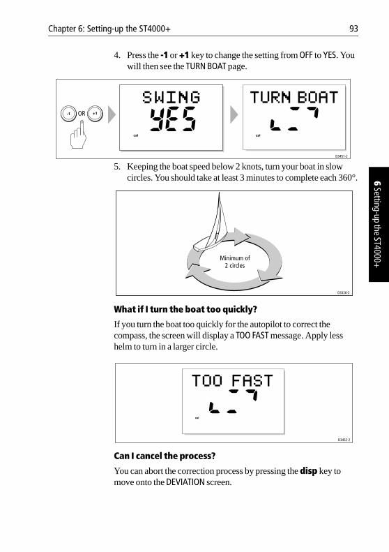
Chapter 6: Setting-up the ST4000+ 93
6 Setting-up the ST4000+
4. Press the -1 or +1 key to change the setting from OFF to YES. You will then see the TURN BOAT page.
5. Keeping the boat speed below 2 knots, turn your boat in slow circles. You should take at least 3 minutes to complete each 360°.
What if I turn the boat too quickly?
If you turn the boat too quickly for the autopilot to correct the compass, the screen will display a TOO FAST message. Apply less helm to turn in a larger circle.
Can I cancel the process?
You can abort the correction process by pressing the disp key to move onto the DEVIATION screen.
D3451-2
OR
D3326-2
Minimum of
2 circles
D3452-2
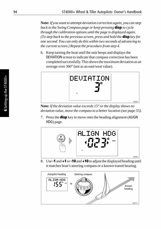
94 ST4000+ Wheel & Tiller Autopilots: Owner’s Handbook
6 Se
tting
-up
the
ST40
00+
Note: If you want to attempt deviation correction again, you can step back to the Swing Compass page or keep pressing disp to cycle through the calibration options until the page is displayed again. (To step back to the previous screen, press and hold the disp key for one second. You can only do this within two seconds of advancing to the current screen.) Repeat the procedure from step 4.
6. Keep turning the boat until the unit beeps and displays the DEVIATION screen to indicate that compass correction has been completed successfully. This shows the maximum deviation as an average over 360° (not as an east/west value).
Note: If the deviation value exceeds 15° or the display shows no deviation value, move the compass to a better location (see page 55).
7. Press the disp key to move onto the heading alignment (ALIGN HDG) page.
8. Use -1 and +1 or -10 and +10 to adjust the displayed heading until it matches boat’s steering compass or a known transit bearing.
D3458-2
D3459-2
Autopilot heading Steering compass
Knownheading
D3327-2
Chapter 6: Setting-up the ST4000+ 95
6 Setting-up the ST4000+
9. Press and hold standby for 2 seconds to exit calibration and save the new settings.
Note: Setup options are always saved on exit.
Adjusting the heading alignmentYou should always check the compass alignment after completing the deviation correction procedure (swinging the compass). After you have completed the initial deviation correction procedure, you can make adjustments to the alignment as often as you wish without swinging the compass again.
Although the compass deviation correction procedure removes most of the alignment error, small errors (of the order of a few degrees) will probably remain, that vary depending on the heading.
Ideally, you should check the heading reading against a number of known headings, plot a deviation curve, and determine the heading alignment value that will give the lowest average alignment error. You can then enter this value on the Heading Alignment screen, as described above.
If the average heading error is more than 5°, you should perform the compass deviation correction procedure again, circling slower and in move favorable conditions.
Checking autopilot operationAfter calibrating the compass, familiarize yourself with autopilot operation:
1. Steer onto a compass heading and hold the course steady.2. Wheel Pilot: Engage the wheel drive clutch.
Tiller Pilot: Place the push rod end over the tiller pin.3. Press auto to lock onto the current heading. The autopilot should
achieve a constant heading in calm sea conditions.4. Use the -1, +1, -10 and +10 keys to check that the autopilot alters
the course to port and starboard in multiples of 1° and 10°.5. Press standby and disengage the autopilot to return to hand
steering:• Wheel Pilot: disengage the wheel drive clutch by rotating the
clutch lever anti-clockwise• Tiller Pilot: remove the drive unit from the tiller pin (if
required, retract the push rod using -1, +1, -10 and +10 keys)
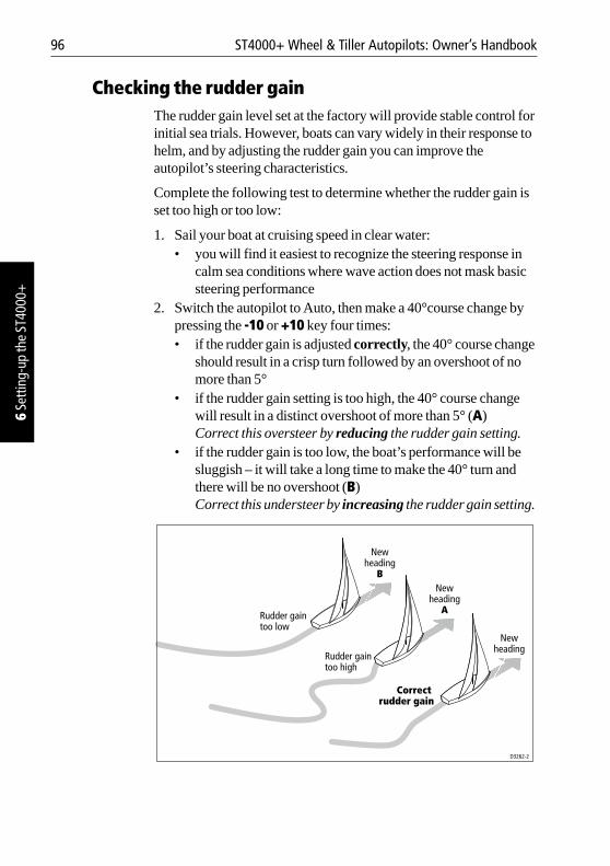
96 ST4000+ Wheel & Tiller Autopilots: Owner’s Handbook
6 Se
tting
-up
the
ST40
00+
Checking the rudder gainThe rudder gain level set at the factory will provide stable control for initial sea trials. However, boats can vary widely in their response to helm, and by adjusting the rudder gain you can improve the autopilot’s steering characteristics.
Complete the following test to determine whether the rudder gain is set too high or too low:
1. Sail your boat at cruising speed in clear water:• you will find it easiest to recognize the steering response in
calm sea conditions where wave action does not mask basic steering performance
2. Switch the autopilot to Auto, then make a 40°course change by pressing the -10 or +10 key four times:• if the rudder gain is adjusted correctly, the 40° course change
should result in a crisp turn followed by an overshoot of no more than 5°
• if the rudder gain setting is too high, the 40° course change will result in a distinct overshoot of more than 5° (A) Correct this oversteer by reducing the rudder gain setting.
• if the rudder gain is too low, the boat’s performance will be sluggish – it will take a long time to make the 40° turn and there will be no overshoot (B)Correct this understeer by increasing the rudder gain setting.
Newheading
Newheading
A
Newheading
B
Correct rudder gain
Rudder gain too high
Rudder gain too low
D3262-2
Chapter 6: Setting-up the ST4000+ 97
6 Setting-up the ST4000+
3. To make a temporary adjustment to the rudder gain:• press the -1 and +1 keys together for 1 second to display the
rudder gain (RUDD GAIN) screen• then press -1 or +1 to change the level• press disp or wait for 5 seconds to return to the previous
display and save the temporary changes4. Repeat the test until you achieve a crisp course change with no
more 5° of overshoot.
Note: Set the rudder gain to the lowest value that gives accurate course keeping. By minimizing helm movements this will reduce power consumption and wear.
5. When you have determined the correct setting, change the permanent rudder gain setting in Dealer setup (see page 108).
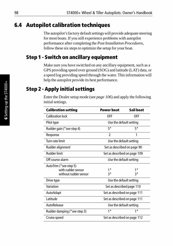
98 ST4000+ Wheel & Tiller Autopilots: Owner’s Handbook
6 Se
tting
-up
the
ST40
00+
6.4 Autopilot calibration techniquesThe autopilot’s factory default settings will provide adequate steering for most boats. If you still experience problems with autopilot performance after completing the Post Installation Procedures, follow these six steps to optimize the setup for your boat.
Step 1 - Switch on ancillary equipmentMake sure you have switched on any ancillary equipment, such as a GPS providing speed over ground (SOG) and latitude (LAT) data, or a speed log providing speed through the water. This information will help the autopilot provide its best performance.
Step 2 - Apply initial settingsEnter the Dealer setup mode (see page 106) and apply the following initial settings.
Calibration setting Power boat Sail boat
Calibration lock OFF OFF
Pilot type Use the default setting
Rudder gain (*see step 4) 5* 5*
Response 2 1
Turn rate limit Use the default setting
Rudder alignment Set as described on page 90
Rudder limit Set as described on page 109
Off course alarm Use the default setting
AutoTrim (*see step 5)with rudder sensorwithout rudder sensor
1*3*
1*3*
Drive type Use the default setting
Variation Set as described page 110
AutoAdapt Set as described on page 111
Latitude Set as described on page 111
AutoRelease Use the default setting
Rudder damping (*see step 3) 1* 1*
Cruise speed Set as described on page 112
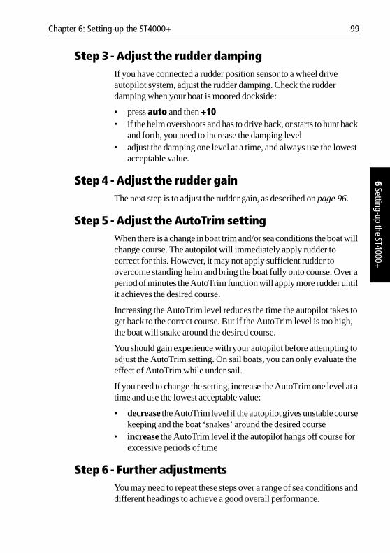
Chapter 6: Setting-up the ST4000+ 99
6 Setting-up the ST4000+
Step 3 - Adjust the rudder dampingIf you have connected a rudder position sensor to a wheel drive autopilot system, adjust the rudder damping. Check the rudder damping when your boat is moored dockside:
• press auto and then +10• if the helm overshoots and has to drive back, or starts to hunt back
and forth, you need to increase the damping level • adjust the damping one level at a time, and always use the lowest
acceptable value.
Step 4 - Adjust the rudder gainThe next step is to adjust the rudder gain, as described on page 96.
Step 5 - Adjust the AutoTrim settingWhen there is a change in boat trim and/or sea conditions the boat will change course. The autopilot will immediately apply rudder to correct for this. However, it may not apply sufficient rudder to overcome standing helm and bring the boat fully onto course. Over a period of minutes the AutoTrim function will apply more rudder until it achieves the desired course.
Increasing the AutoTrim level reduces the time the autopilot takes to get back to the correct course. But if the AutoTrim level is too high, the boat will snake around the desired course.
You should gain experience with your autopilot before attempting to adjust the AutoTrim setting. On sail boats, you can only evaluate the effect of AutoTrim while under sail.
If you need to change the setting, increase the AutoTrim one level at a time and use the lowest acceptable value:
• decrease the AutoTrim level if the autopilot gives unstable course keeping and the boat ‘snakes’ around the desired course
• increase the AutoTrim level if the autopilot hangs off course for excessive periods of time
Step 6 - Further adjustmentsYou may need to repeat these steps over a range of sea conditions and different headings to achieve a good overall performance.

100 ST4000+ Wheel & Tiller Autopilots: Owner’s Handbook
6 Se
tting
-up
the
ST40
00+
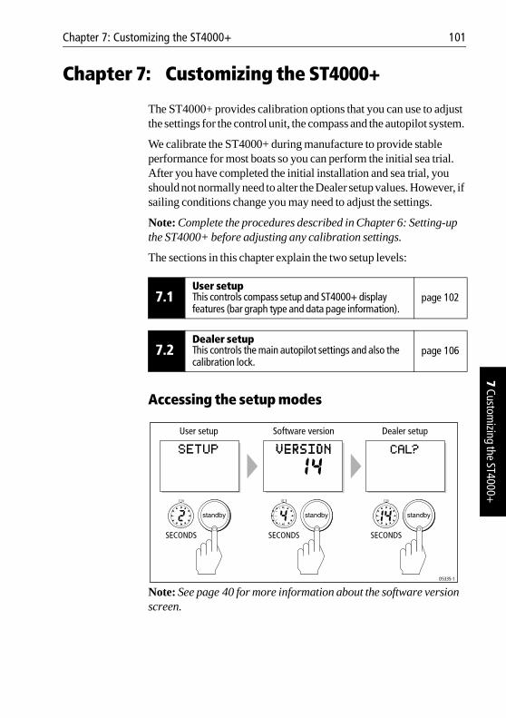
Chapter 7: Customizing the ST4000+ 101
7 Customizing the ST4000+
Chapter 7: Customizing the ST4000+
The ST4000+ provides calibration options that you can use to adjust the settings for the control unit, the compass and the autopilot system.
We calibrate the ST4000+ during manufacture to provide stable performance for most boats so you can perform the initial sea trial. After you have completed the initial installation and sea trial, you should not normally need to alter the Dealer setup values. However, if sailing conditions change you may need to adjust the settings.
Note: Complete the procedures described in Chapter 6: Setting-up the ST4000+ before adjusting any calibration settings.
The sections in this chapter explain the two setup levels:
Accessing the setup modes
Note: See page 40 for more information about the software version screen.
7.1User setupThis controls compass setup and ST4000+ display features (bar graph type and data page information).
page 102
7.2Dealer setupThis controls the main autopilot settings and also the calibration lock.
page 106
D5335-1
SECONDS
User setup Software version Dealer setup
SECONDS SECONDS
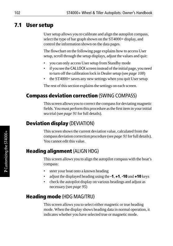
102 ST4000+ Wheel & Tiller Autopilots: Owner’s Handbook
7 Cu
stom
izin
g th
e ST
4000
+
7.1 User setupUser setup allows you to calibrate and align the autopilot compass, select the type of bar graph shown on the ST4000+ display, and control the information shown on the data pages.
The flowchart on the following page explains how to access User setup, scroll through the setup displays, adjust the values and quit:
• you can only access User setup from Standby mode • if you see the CAL LOCK screen instead of the initial page, you need
to turn off the calibration lock in Dealer setup (see page 108)• the ST4000+ saves any new settings when you quit User setup
The rest of this section explains the settings on each screen.
Compass deviation correction (SWING COMPASS)This screen allows you to correct the compass for deviating magnetic fields. You must perform this procedure as the first item in your initial sea trial (see page 91 for full details).
Deviation display (DEVIATION)This screen shows the current deviation value, calculated from the compass deviation correction procedure (see page 91 for full details). You cannot edit this value.
Heading alignment (ALIGN HDG)This screen allows you to align the autopilot compass with the boat’s compass:
• steer your boat onto a known heading• adjust the displayed heading using the -1, +1, -10 and +10 keys• check the autopilot display on various headings and adjust as
necessary (see page 95)
Heading mode (HDG MAG/TRU)This screen allows you to select either magnetic or true heading mode. When the display shows heading data in normal operation, it indicates whether you have selected true or magnetic mode.
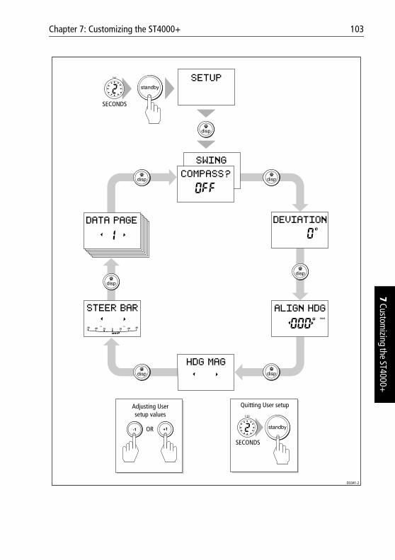
Chapter 7: Customizing the ST4000+ 103
7 Customizing the ST4000+
2
SECONDS
D3341-2
Adjusting Usersetup values
Quitting User setup
OR
SECONDS
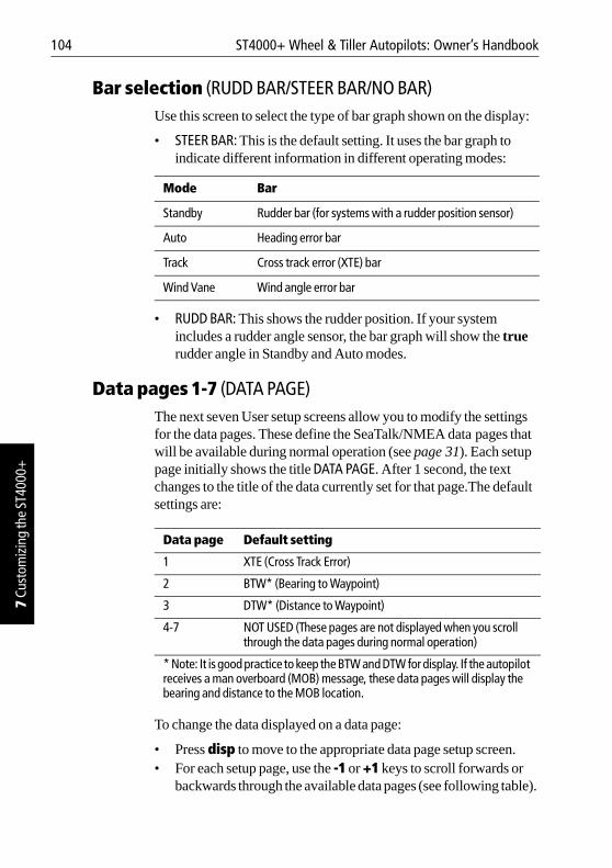
104 ST4000+ Wheel & Tiller Autopilots: Owner’s Handbook
7 Cu
stom
izin
g th
e ST
4000
+
Bar selection (RUDD BAR/STEER BAR/NO BAR)Use this screen to select the type of bar graph shown on the display:
• STEER BAR: This is the default setting. It uses the bar graph to indicate different information in different operating modes:
• RUDD BAR: This shows the rudder position. If your system includes a rudder angle sensor, the bar graph will show the true rudder angle in Standby and Auto modes.
Data pages 1-7 (DATA PAGE)The next seven User setup screens allow you to modify the settings for the data pages. These define the SeaTalk/NMEA data pages that will be available during normal operation (see page 31). Each setup page initially shows the title DATA PAGE. After 1 second, the text changes to the title of the data currently set for that page.The default settings are:
To change the data displayed on a data page:
• Press disp to move to the appropriate data page setup screen.• For each setup page, use the -1 or +1 keys to scroll forwards or
backwards through the available data pages (see following table).
Mode Bar
Standby Rudder bar (for systems with a rudder position sensor)
Auto Heading error bar
Track Cross track error (XTE) bar
Wind Vane Wind angle error bar
Data page Default setting
1 XTE (Cross Track Error)
2 BTW* (Bearing to Waypoint)
3 DTW* (Distance to Waypoint)
4-7 NOT USED (These pages are not displayed when you scroll through the data pages during normal operation)
* Note: It is good practice to keep the BTW and DTW for display. If the autopilot receives a man overboard (MOB) message, these data pages will display the bearing and distance to the MOB location.
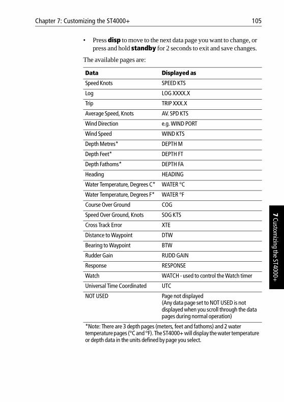
Chapter 7: Customizing the ST4000+ 105
7 Customizing the ST4000+
• Press disp to move to the next data page you want to change, or press and hold standby for 2 seconds to exit and save changes.
The available pages are:
Data Displayed as
Speed Knots SPEED KTS
Log LOG XXXX.X
Trip TRIP XXX.X
Average Speed, Knots AV. SPD KTS
Wind Direction e.g. WIND PORT
Wind Speed WIND KTS
Depth Metres* DEPTH M
Depth Feet* DEPTH FT
Depth Fathoms* DEPTH FA
Heading HEADING
Water Temperature, Degrees C* WATER °C
Water Temperature, Degrees F* WATER °F
Course Over Ground COG
Speed Over Ground, Knots SOG KTS
Cross Track Error XTE
Distance to Waypoint DTW
Bearing to Waypoint BTW
Rudder Gain RUDD GAIN
Response RESPONSE
Watch WATCH - used to control the Watch timer
Universal Time Coordinated UTC
NOT USED Page not displayed(Any data page set to NOT USED is not displayed when you scroll through the data pages during normal operation)
*Note: There are 3 depth pages (meters, feet and fathoms) and 2 water temperature pages (°C and °F). The ST4000+ will display the water temperature or depth data in the units defined by page you select.
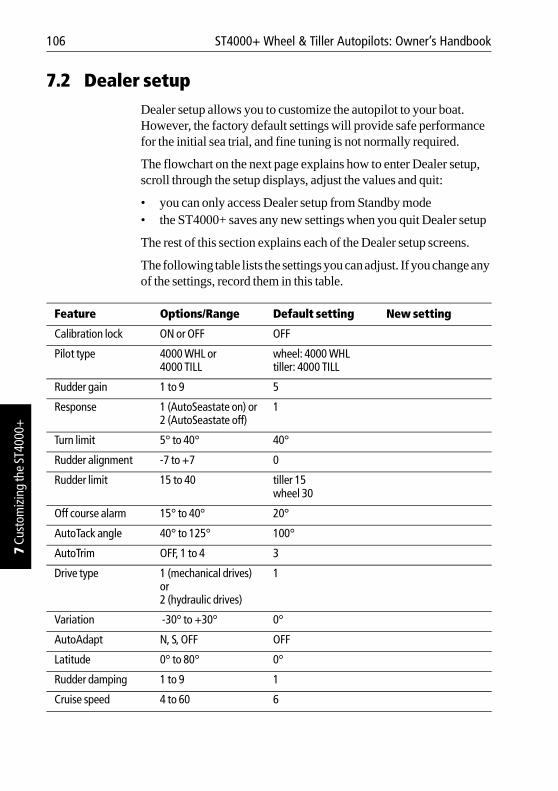
106 ST4000+ Wheel & Tiller Autopilots: Owner’s Handbook
7 Cu
stom
izin
g th
e ST
4000
+
7.2 Dealer setupDealer setup allows you to customize the autopilot to your boat. However, the factory default settings will provide safe performance for the initial sea trial, and fine tuning is not normally required.
The flowchart on the next page explains how to enter Dealer setup, scroll through the setup displays, adjust the values and quit:
• you can only access Dealer setup from Standby mode• the ST4000+ saves any new settings when you quit Dealer setup
The rest of this section explains each of the Dealer setup screens.
The following table lists the settings you can adjust. If you change any of the settings, record them in this table.
Feature Options/Range Default setting New setting
Calibration lock ON or OFF OFF
Pilot type 4000 WHL or 4000 TILL
wheel: 4000 WHLtiller: 4000 TILL
Rudder gain 1 to 9 5
Response 1 (AutoSeastate on) or2 (AutoSeastate off)
1
Turn limit 5° to 40° 40°
Rudder alignment -7 to +7 0
Rudder limit 15 to 40 tiller 15wheel 30
Off course alarm 15° to 40° 20°
AutoTack angle 40° to 125° 100°
AutoTrim OFF, 1 to 4 3
Drive type 1 (mechanical drives) or2 (hydraulic drives)
1
Variation -30° to +30° 0°
AutoAdapt N, S, OFF OFF
Latitude 0° to 80° 0°
Rudder damping 1 to 9 1
Cruise speed 4 to 60 6
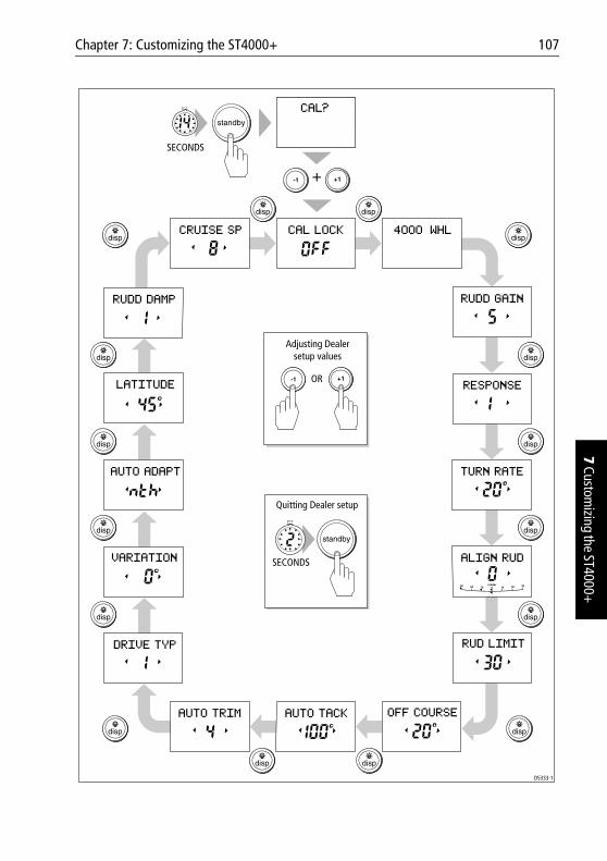
Chapter 7: Customizing the ST4000+ 107
7 Customizing the ST4000+
SECONDS
Adjusting Dealersetup values
Quitting Dealer setup
+
SECONDS
OR
D5333-1
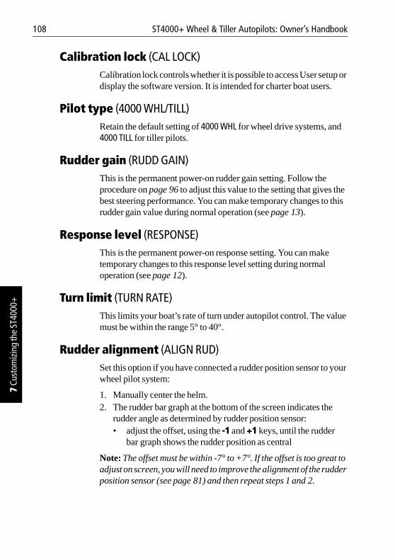
108 ST4000+ Wheel & Tiller Autopilots: Owner’s Handbook
7 Cu
stom
izin
g th
e ST
4000
+
Calibration lock (CAL LOCK)Calibration lock controls whether it is possible to access User setup or display the software version. It is intended for charter boat users.
Pilot type (4000 WHL/TILL)Retain the default setting of 4000 WHL for wheel drive systems, and 4000 TILL for tiller pilots.
Rudder gain (RUDD GAIN)This is the permanent power-on rudder gain setting. Follow the procedure on page 96 to adjust this value to the setting that gives the best steering performance. You can make temporary changes to this rudder gain value during normal operation (see page 13).
Response level (RESPONSE)This is the permanent power-on response setting. You can make temporary changes to this response level setting during normal operation (see page 12).
Turn limit (TURN RATE)This limits your boat’s rate of turn under autopilot control. The value must be within the range 5° to 40°.
Rudder alignment (ALIGN RUD)Set this option if you have connected a rudder position sensor to your wheel pilot system:
1. Manually center the helm.2. The rudder bar graph at the bottom of the screen indicates the
rudder angle as determined by rudder position sensor:• adjust the offset, using the -1 and +1 keys, until the rudder
bar graph shows the rudder position as central
Note: The offset must be within -7° to +7°. If the offset is too great to adjust on screen, you will need to improve the alignment of the rudder position sensor (see page 81) and then repeat steps 1 and 2.
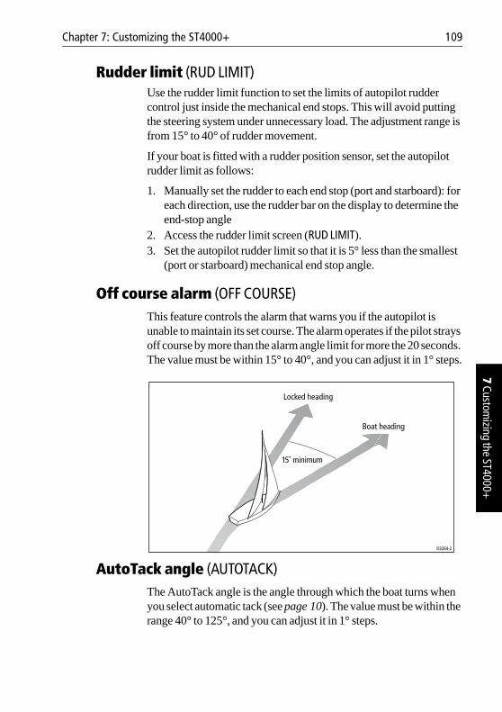
Chapter 7: Customizing the ST4000+ 109
7 Customizing the ST4000+
Rudder limit (RUD LIMIT)Use the rudder limit function to set the limits of autopilot rudder control just inside the mechanical end stops. This will avoid putting the steering system under unnecessary load. The adjustment range is from 15° to 40° of rudder movement.
If your boat is fitted with a rudder position sensor, set the autopilot rudder limit as follows:
1. Manually set the rudder to each end stop (port and starboard): for each direction, use the rudder bar on the display to determine the end-stop angle
2. Access the rudder limit screen (RUD LIMIT).3. Set the autopilot rudder limit so that it is 5° less than the smallest
(port or starboard) mechanical end stop angle.
Off course alarm (OFF COURSE)This feature controls the alarm that warns you if the autopilot is unable to maintain its set course. The alarm operates if the pilot strays off course by more than the alarm angle limit for more the 20 seconds. The value must be within 15° to 40°, and you can adjust it in 1° steps.
AutoTack angle (AUTOTACK)The AutoTack angle is the angle through which the boat turns when you select automatic tack (see page 10). The value must be within the range 40° to 125°, and you can adjust it in 1° steps.
D3264-2
Locked heading
Boat heading
15˚ minimum
110 ST4000+ Wheel & Tiller Autopilots: Owner’s Handbook
7 Cu
stom
izin
g th
e ST
4000
+
AutoTrim (AUTOTRIM)The AutoTrim setting determines the rate at which the autopilot applies ‘standing helm’ to correct for trim changes caused by varying wind loads on the sails or superstructure. The possible settings are:
The default setting (Level 3) should provide optimum performance with the ST4000+ autopilot. However, depending on the boat’s dynamic stability, an incorrect rate of trim application may result in poor course keeping due to autopilot instability. After gaining experience with the ST4000+, you may wish to change the setting.
You must evaluate the effect of the setting while under sail:
• decrease the AutoTrim level if the autopilot gives unstable course keeping and the boat ‘snakes’ around the desired course
• increase the AutoTrim level if the autopilot hangs off course for excessive periods of time
Drive type (DRIVE TYP)The drive type setting controls how the autopilot drives the steering system. Retain the default setting (DRIVE TYP 1) for mechanically driven boats.
Magnetic variation (VARIATION)If required, set this to the level of magnetic variation present at your boat’s current position – indicated as east (E) or west (W). The ST4000+ sends this variation setting to other instruments on the SeaTalk system, and it can be updated by other SeaTalk instruments.
Setting Effect
Off No trim correction
1 Slow trim correction
2 Medium trim correction
3 Rapid trim correction
4 Very rapid correction
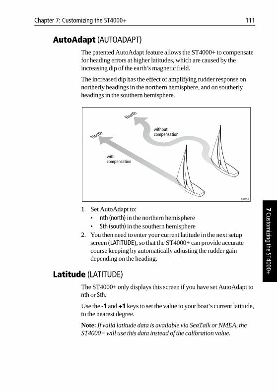
Chapter 7: Customizing the ST4000+ 111
7 Customizing the ST4000+
AutoAdapt (AUTOADAPT)The patented AutoAdapt feature allows the ST4000+ to compensate for heading errors at higher latitudes, which are caused by the increasing dip of the earth’s magnetic field.
The increased dip has the effect of amplifying rudder response on northerly headings in the northern hemisphere, and on southerly headings in the southern hemisphere.
1. Set AutoAdapt to:• nth (north) in the northern hemisphere• Sth (south) in the southern hemisphere
2. You then need to enter your current latitude in the next setup screen (LATITUDE), so that the ST4000+ can provide accurate course keeping by automatically adjusting the rudder gain depending on the heading.
Latitude (LATITUDE)The ST4000+ only displays this screen if you have set AutoAdapt to nth or Sth.
Use the -1 and +1 keys to set the value to your boat’s current latitude, to the nearest degree.
Note: If valid latitude data is available via SeaTalk or NMEA, the ST4000+ will use this data instead of the calibration value.
D3263-2
Northwithout compensation
North
withcompensation
112 ST4000+ Wheel & Tiller Autopilots: Owner’s Handbook
7 Cu
stom
izin
g th
e ST
4000
+
Rudder damping (RUDD DAMP)Set this option if your system includes a rudder position sensor and the drive ‘hunts’ when trying to position the rudder. Increasing the rudder damping value will reduce hunting.
Check the rudder damping when your boat is moored dockside:
• press auto and then +10• if the helm overshoots and has to drive back or starts to hunt back
and forth, you need to increase the damping level• adjust the damping one level at a time, and always use the lowest
acceptable value.
Cruise speed (CRUISE SP)Set the cruise speed to the boat’s typical cruising speed. If both the boat’s speed through the water and speed over ground are unavailable via SeaTalk or NMEA, the autopilot will use the cruise speed when computing course changes.
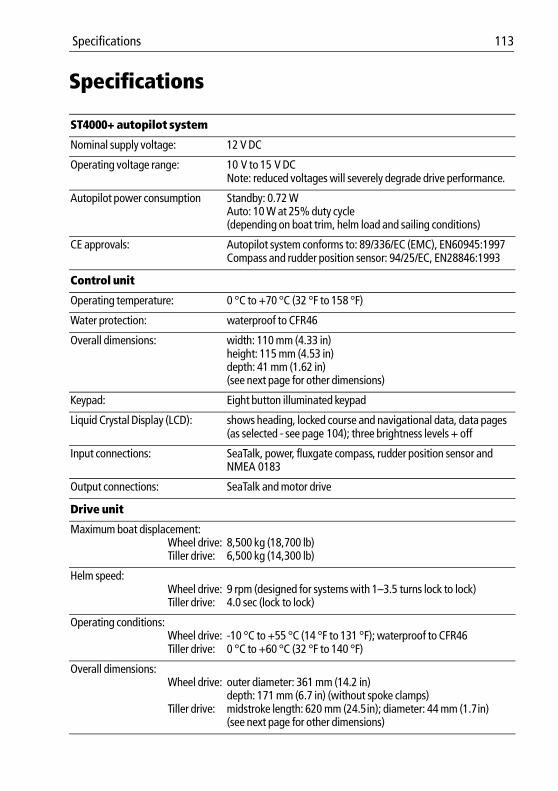
Specifications 113
Specifications
ST4000+ autopilot system
Nominal supply voltage: 12 V DC
Operating voltage range: 10 V to 15 V DCNote: reduced voltages will severely degrade drive performance.
Autopilot power consumption Standby: 0.72 WAuto: 10 W at 25% duty cycle (depending on boat trim, helm load and sailing conditions)
CE approvals: Autopilot system conforms to: 89/336/EC (EMC), EN60945:1997Compass and rudder position sensor: 94/25/EC, EN28846:1993
Control unit
Operating temperature: 0 °C to +70 °C (32 °F to 158 °F)
Water protection: waterproof to CFR46
Overall dimensions: width: 110 mm (4.33 in)height: 115 mm (4.53 in)depth: 41 mm (1.62 in)(see next page for other dimensions)
Keypad: Eight button illuminated keypad
Liquid Crystal Display (LCD): shows heading, locked course and navigational data, data pages (as selected - see page 104); three brightness levels + off
Input connections: SeaTalk, power, fluxgate compass, rudder position sensor and NMEA 0183
Output connections: SeaTalk and motor drive
Drive unit
Maximum boat displacement:Wheel drive:Tiller drive:
8,500 kg (18,700 lb)6,500 kg (14,300 lb)
Helm speed:Wheel drive:Tiller drive:
9 rpm (designed for systems with 1–3.5 turns lock to lock)4.0 sec (lock to lock)
Operating conditions: Wheel drive:Tiller drive:
-10 °C to +55 °C (14 °F to 131 °F); waterproof to CFR460 °C to +60 °C (32 °F to 140 °F)
Overall dimensions:Wheel drive:
Tiller drive:
outer diameter: 361 mm (14.2 in) depth: 171 mm (6.7 in) (without spoke clamps)midstroke length: 620 mm (24.5in); diameter: 44 mm (1.7in)(see next page for other dimensions)
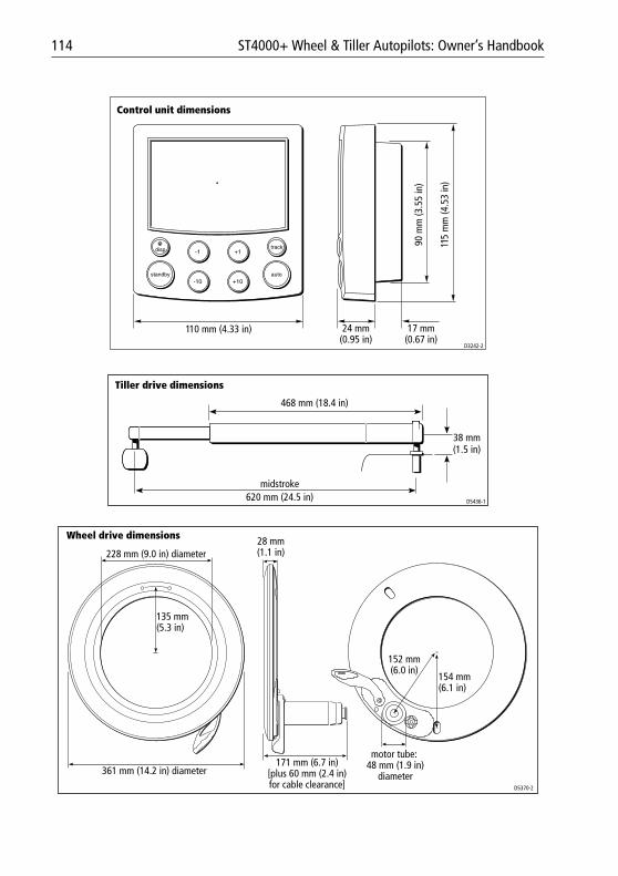
114 ST4000+ Wheel & Tiller Autopilots: Owner’s Handbook
110 mm (4.33 in)
115
mm
(4.5
3 in
)
90 m
m (3
.55
in)
24 mm(0.95 in)
17 mm(0.67 in)
D3242-2
Control unit dimensions
Tiller drive dimensions
midstroke620 mm (24.5 in)
468 mm (18.4 in)
38 mm(1.5 in)
D5436-1
D5370-2
361 mm (14.2 in) diameter
228 mm (9.0 in) diameter
135 mm(5.3 in)
171 mm (6.7 in)[plus 60 mm (2.4 in)for cable clearance]
motor tube: 48 mm (1.9 in)
diameter
Wheel drive dimensions 28 mm(1.1 in)
152 mm(6.0 in)
154 mm(6.1 in)
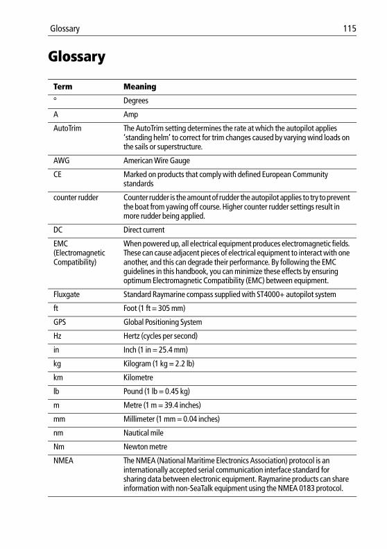
Glossary 115
Glossary
Term Meaning
° Degrees
A Amp
AutoTrim The AutoTrim setting determines the rate at which the autopilot applies ‘standing helm’ to correct for trim changes caused by varying wind loads on the sails or superstructure.
AWG American Wire Gauge
CE Marked on products that comply with defined European Community standards
counter rudder Counter rudder is the amount of rudder the autopilot applies to try to prevent the boat from yawing off course. Higher counter rudder settings result in more rudder being applied.
DC Direct current
EMC(Electromagnetic Compatibility)
When powered up, all electrical equipment produces electromagnetic fields. These can cause adjacent pieces of electrical equipment to interact with one another, and this can degrade their performance. By following the EMC guidelines in this handbook, you can minimize these effects by ensuring optimum Electromagnetic Compatibility (EMC) between equipment.
Fluxgate Standard Raymarine compass supplied with ST4000+ autopilot system
ft Foot (1 ft = 305 mm)
GPS Global Positioning System
Hz Hertz (cycles per second)
in Inch (1 in = 25.4 mm)
kg Kilogram (1 kg = 2.2 lb)
km Kilometre
lb Pound (1 lb = 0.45 kg)
m Metre (1 m = 39.4 inches)
mm Millimeter (1 mm = 0.04 inches)
nm Nautical mile
Nm Newton metre
NMEA The NMEA (National Maritime Electronics Association) protocol is an internationally accepted serial communication interface standard for sharing data between electronic equipment. Raymarine products can share information with non-SeaTalk equipment using the NMEA 0183 protocol.
116 ST4000+ Wheel & Tiller Autopilots: Owner’s Handbook
oz Ounce (1 oz = 0.028 kg)
response The autopilot response level controls the relationship between course keeping accuracy and the amount of helm/drive activity.
rudder gain Rudder gain is a measure of how much helm the autopilot will apply to correct course errors. The higher the setting the more rudder will be applied.
rpm Revolutions per minute
SeaTalk SeaTalk is Raymarine’s proprietary communication system. It links the products to provide a single, integrated system sharing power and data.
SeaTalk bus This refers to the continuous SeaTalk system connecting together a series of Raymarine units.
SM Statute (land) mile
SSB Single Side Band (radio)
V Volt
VHF Very High Frequency (radio)
W Watt
Yaw The boat’s rate of turn
Term Meaning
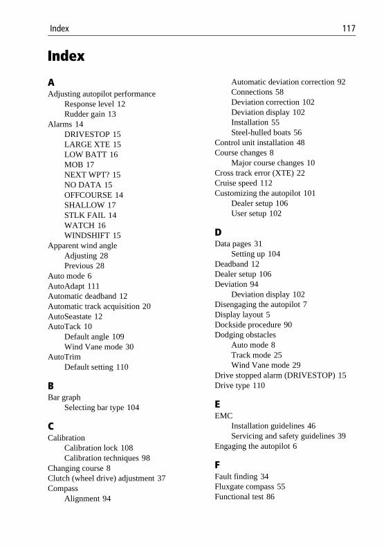
Index 117
Index
AAdjusting autopilot performance
Response level 12Rudder gain 13
Alarms 14DRIVESTOP 15LARGE XTE 15LOW BATT 16MOB 17NEXT WPT? 15NO DATA 15OFFCOURSE 14SHALLOW 17STLK FAIL 14WATCH 16WINDSHIFT 15
Apparent wind angleAdjusting 28Previous 28
Auto mode 6AutoAdapt 111Automatic deadband 12Automatic track acquisition 20AutoSeastate 12AutoTack 10
Default angle 109Wind Vane mode 30
AutoTrimDefault setting 110
BBar graph
Selecting bar type 104
CCalibration
Calibration lock 108Calibration techniques 98
Changing course 8Clutch (wheel drive) adjustment 37Compass
Alignment 94
Automatic deviation correction 92Connections 58Deviation correction 102Deviation display 102Installation 55Steel-hulled boats 56
Control unit installation 48Course changes 8
Major course changes 10Cross track error (XTE) 22Cruise speed 112Customizing the autopilot 101
Dealer setup 106User setup 102
DData pages 31
Setting up 104Deadband 12Dealer setup 106Deviation 94
Deviation display 102Disengaging the autopilot 7Display layout 5Dockside procedure 90Dodging obstacles
Auto mode 8Track mode 25Wind Vane mode 29
Drive stopped alarm (DRIVESTOP) 15Drive type 110
EEMC
Installation guidelines 46Servicing and safety guidelines 39
Engaging the autopilot 6
FFault finding 34Fluxgate compass 55Functional test 86
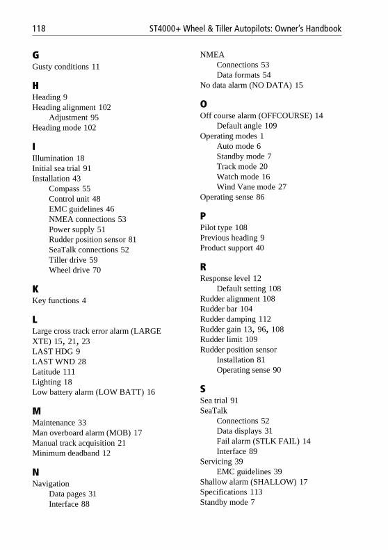
118 ST4000+ Wheel & Tiller Autopilots: Owner’s Handbook
GGusty conditions 11
HHeading 9Heading alignment 102
Adjustment 95Heading mode 102
IIllumination 18Initial sea trial 91Installation 43
Compass 55Control unit 48EMC guidelines 46NMEA connections 53Power supply 51Rudder position sensor 81SeaTalk connections 52Tiller drive 59Wheel drive 70
KKey functions 4
LLarge cross track error alarm (LARGE XTE) 15, 21, 23LAST HDG 9LAST WND 28Latitude 111Lighting 18Low battery alarm (LOW BATT) 16
MMaintenance 33Man overboard alarm (MOB) 17Manual track acquisition 21Minimum deadband 12
NNavigation
Data pages 31Interface 88
NMEAConnections 53Data formats 54
No data alarm (NO DATA) 15
OOff course alarm (OFFCOURSE) 14
Default angle 109Operating modes 1
Auto mode 6Standby mode 7Track mode 20Watch mode 16Wind Vane mode 27
Operating sense 86
PPilot type 108Previous heading 9Product support 40
RResponse level 12
Default setting 108Rudder alignment 108Rudder bar 104Rudder damping 112Rudder gain 13, 96, 108Rudder limit 109Rudder position sensor
Installation 81Operating sense 90
SSea trial 91SeaTalk
Connections 52Data displays 31Fail alarm (STLK FAIL) 14Interface 89
Servicing 39EMC guidelines 39
Shallow alarm (SHALLOW) 17Specifications 113Standby mode 7
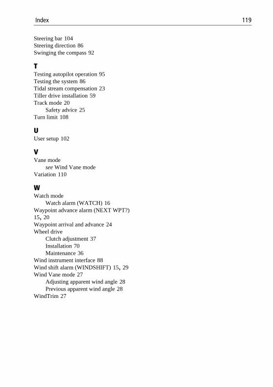
Index 119
Steering bar 104Steering direction 86Swinging the compass 92
TTesting autopilot operation 95Testing the system 86Tidal stream compensation 23Tiller drive installation 59Track mode 20
Safety advice 25Turn limit 108
UUser setup 102
VVane mode
see Wind Vane modeVariation 110
WWatch mode
Watch alarm (WATCH) 16Waypoint advance alarm (NEXT WPT?) 15, 20Waypoint arrival and advance 24Wheel drive
Clutch adjustment 37Installation 70Maintenance 36
Wind instrument interface 88Wind shift alarm (WINDSHIFT) 15, 29Wind Vane mode 27
Adjusting apparent wind angle 28Previous apparent wind angle 28
WindTrim 27

120 ST4000+ Wheel & Tiller Autopilots: Owner’s Handbook
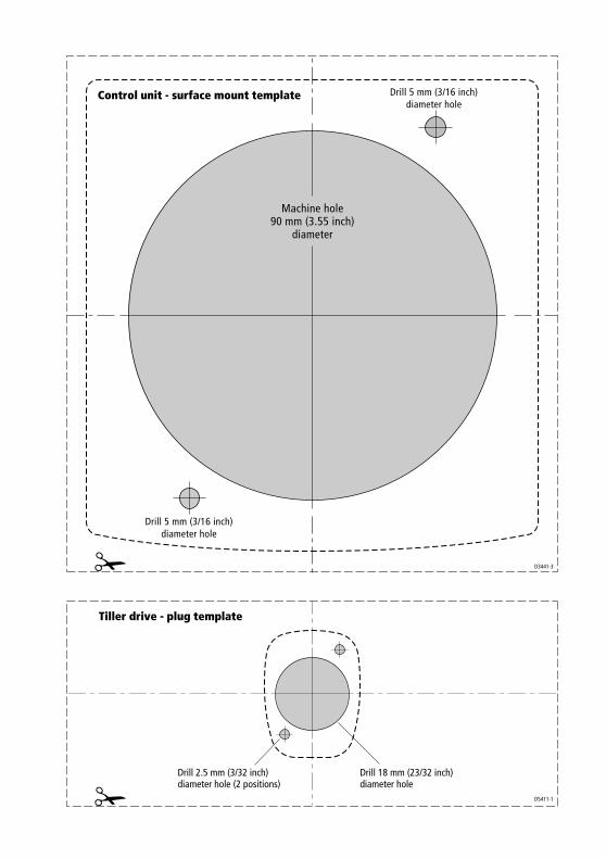
D3441-3
Machine hole90 mm (3.55 inch)
diameter
Drill 5 mm (3/16 inch)diameter hole
Drill 5 mm (3/16 inch)diameter hole
Control unit - surface mount template
Drill 2.5 mm (3/32 inch)diameter hole (2 positions)
Drill 18 mm (23/32 inch)diameter hole
Tiller drive - plug template
D5411-1

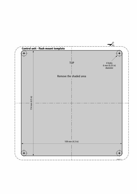
Remove the shaded area
TOP
109 mm (4.3 in)
Control unit - flush mount template
114
mm
(4.5
in)
4 holes6 mm (0.25 in)
diameter
D4437-3

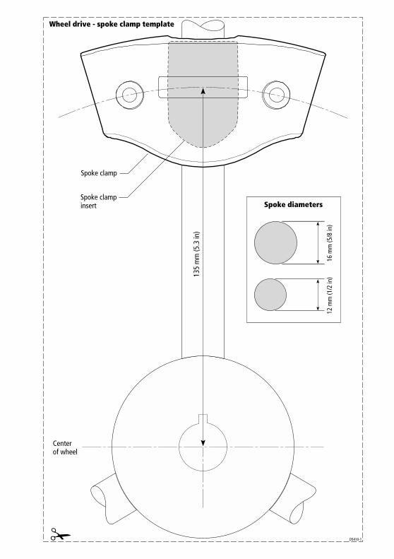
Spoke clamp
Spoke diameters
Wheel drive - spoke clamp template
Center of wheel
Spoke clampinsert
D5410-1
135
mm
(5.3
in)
16 m
m (5
/8 in
)12
mm
(1/2
in)


Aft
Cable position
Drill 3 mm (1/8 in)diameter hole(3 positions)
D3440-2
Rudderpositionedamidships
Rudder position sensor template
Maximum permitted travel: +/- 60˚

Document number: 84064-8
Limited Warranty CertificateRaymarine warrants each new Light Marine/Dealer Distributor Product to be of good materials and workmanship, and will repair or exchange any parts proven to be defective in material and workmanship under normal use for a period of 2 years/24 months from date of sale to end user, except as provided below.Defects will be corrected by Raymarine or an authorized Raymarine dealer. Raymarine will, except as provided below, accept labor cost for a period of 2 years/24 months from the date of sale to end user. During this period, except for certain products, travel costs (auto mileage and tolls) up to 100 round trip highway miles (160 kilometres) and travel time of 2 hours, will be assumed by Raymarine only on products where proof of installation or commission by authorized service agents, can be shown.
Warranty LimitationsRaymarine Warranty policy does not apply to equipment which has been subjected to accident, abuse or misuse, shipping damage, alterations, corrosion, incorrect and/or non-authorized service, or equipment on which the serial number has been altered, mutilated or removed.Except where Raymarine or its authorized dealer has performed the installation, it assumes no responsibility for damage incurred during installation.This Warranty does not cover routine system checkouts or alignment/calibration, unless required by replacement of part(s) in the area being aligned.A suitable proof of purchase, showing date, place, and serial number must be made available to Raymarine or authorized service agent at the time of request for Warranty service.Consumable items, (such as: Chart paper, lamps, fuses, batteries, styli, stylus/drive belts, radar mixer crystals/diodes, snap-in impeller carriers, impellers, impeller bearings, and impeller shaft) are specifically excluded from this Warranty.Magnetrons, Cathode Ray Tubes (CRT), TFT Liquid Crystal Displays (LCD) and cold cathode fluorescent lamps (CCFL), hailer horns and transducers are warranted for 1 year/12 months from date of sale. These items must be returned to a Raymarine facility.All costs associated with transducer replacement, other than the cost of the transducer itself, are specifically excluded from this Warranty.Overtime premium labor portion of services outside of normal working hours is not covered by this Warranty.Travel cost allowance on certain products with a suggested retail price below $2500.00 is not authorized. When/or if repairs are necessary, these products must be forwarded to a Raymarine facility or an authorized dealer at owner’s expense will be returned via surface carrier at no cost to the owner.Travel costs other than auto mileage, tolls and two (2) hours travel time, are specifically excluded on all products. Travel costs which are excluded from the coverage of this Warranty include but are not limited to: taxi, launch fees, aircraft rental, subsistence, customs, shipping and communication charges etc. Travel costs, mileage and time, in excess to that allowed must have prior approval in writing. TO THE EXTENT CONSISTENT WITH STATE AND FEDERAL LAW:(1) THIS WARRANTY IS STRICTLY LIMITED TO THE TERMS INDICATED HEREIN, AND NO OTHER WARRANTIES OR REMEDIES SHALL BE BINDING ON RAYMARINE INCLUDING WITHOUT LIMITATION ANY WARRANTIES OF MERCHANTABLE OR FITNESS FOR A PARTICULAR PURPOSE.(2) Raymarine shall not be liable for any incidental, consequential or special (including punitive or multiple) damages.All Raymarine products sold or provided hereunder are merely aids to navigation. It is the responsibility of the user to exercise discretion and proper navigational skill independent of any Raymarine equipment.
April 2001
Factory Service Centers
United States of America UK, Europe, Middle East, Far EastRaymarine Inc22 Cotton Road, Unit DNashua, NH 03063-4219, USA
Raymarine LtdAnchorage Park, PortsmouthPO3 5TD, England
Telephone: +1 603 881 5200Fax: +1 603 864 4756www.raymarine.com
Telephone: +44 (0)23 9269 3611Fax: +44 (0)23 9269 4642www.raymarine.com
Sales & Order ServicesTelephone: +1 800 539 5539 Ext. 2333 or
+1 603 881 5200 Ext. 2333
Customer SupportTelephone: +44 (0)23 9271 4713Fax: +44 (0)23 9266 1228
Technical SupportTelephone: +1 800 539 5539 Ext. 2444 or
+1 603 881 5200 Ext. 2444Email: [email protected]
Email: [email protected]
Product Repair CenterTelephone: +1 800 539 5539 Ext. 2118
Purchased from Purchase date
Dealer address
Installed by Installation date
Commissioned by
Commissioning date
Owner’s name
Mailing address
This portion should be completed and retained by the owner.
Stick barcode label here
Related Documents