SRX320 Services Gateway Hardware Guide Modified: 2016-05-27 Copyright © 2016, Juniper Networks, Inc.

Welcome message from author
This document is posted to help you gain knowledge. Please leave a comment to let me know what you think about it! Share it to your friends and learn new things together.
Transcript
SRX320 Services Gateway Hardware Guide
Modified: 2016-05-27
Copyright © 2016, Juniper Networks, Inc.
Juniper Networks, Inc.1133 Innovation WaySunnyvale, California 94089USA408-745-2000www.juniper.net
Copyright © 2016, Juniper Networks, Inc. All rights reserved.
Juniper Networks, Junos, Steel-Belted Radius, NetScreen, and ScreenOS are registered trademarks of Juniper Networks, Inc. in the UnitedStates and other countries. The Juniper Networks Logo, the Junos logo, and JunosE are trademarks of Juniper Networks, Inc. All othertrademarks, service marks, registered trademarks, or registered service marks are the property of their respective owners.
Juniper Networks assumes no responsibility for any inaccuracies in this document. Juniper Networks reserves the right to change, modify,transfer, or otherwise revise this publication without notice.
SRX320 Services Gateway Hardware GuideCopyright © 2016, Juniper Networks, Inc.All rights reserved.
The information in this document is current as of the date on the title page.
YEAR 2000 NOTICE
Juniper Networks hardware and software products are Year 2000 compliant. Junos OS has no known time-related limitations through theyear 2038. However, the NTP application is known to have some difficulty in the year 2036.
ENDUSER LICENSE AGREEMENT
The Juniper Networks product that is the subject of this technical documentation consists of (or is intended for use with) Juniper Networkssoftware. Use of such software is subject to the terms and conditions of the End User License Agreement (“EULA”) posted athttp://www.juniper.net/support/eula.html. By downloading, installing or using such software, you agree to the terms and conditions ofthat EULA.
Copyright © 2016, Juniper Networks, Inc.ii
Table of Contents
About the Documentation . . . . . . . . . . . . . . . . . . . . . . . . . . . . . . . . . . . . . . . . . . . . xi
Documentation and Release Notes . . . . . . . . . . . . . . . . . . . . . . . . . . . . . . . . . . xi
Supported Platforms . . . . . . . . . . . . . . . . . . . . . . . . . . . . . . . . . . . . . . . . . . . . . xi
Documentation Conventions . . . . . . . . . . . . . . . . . . . . . . . . . . . . . . . . . . . . . . . xi
Documentation Feedback . . . . . . . . . . . . . . . . . . . . . . . . . . . . . . . . . . . . . . . . xiii
Requesting Technical Support . . . . . . . . . . . . . . . . . . . . . . . . . . . . . . . . . . . . . xiv
Self-Help Online Tools and Resources . . . . . . . . . . . . . . . . . . . . . . . . . . . xiv
Opening a Case with JTAC . . . . . . . . . . . . . . . . . . . . . . . . . . . . . . . . . . . . . xiv
Part 1 Overview
Chapter 1 System Overview . . . . . . . . . . . . . . . . . . . . . . . . . . . . . . . . . . . . . . . . . . . . . . . . . . . 3
SRX320 Services Gateway Description . . . . . . . . . . . . . . . . . . . . . . . . . . . . . . . . . . . 3
SRX320 Services Gateway CLI and J-Web Access . . . . . . . . . . . . . . . . . . . . . . . . . . 4
Chapter 2 Chassis Description . . . . . . . . . . . . . . . . . . . . . . . . . . . . . . . . . . . . . . . . . . . . . . . . 5
SRX320 Services Gateway Chassis Overview . . . . . . . . . . . . . . . . . . . . . . . . . . . . . . 5
Understanding the SRX320 Services Gateway Front Panel . . . . . . . . . . . . . . . . . . . 5
Understanding the SRX320 Services Gateway Back Panel . . . . . . . . . . . . . . . . . . . 8
Chapter 3 Interface Module Descriptions . . . . . . . . . . . . . . . . . . . . . . . . . . . . . . . . . . . . . . . 11
SRX320 Services Gateway Interface Modules Overview . . . . . . . . . . . . . . . . . . . . . 11
Chapter 4 Cooling System Description . . . . . . . . . . . . . . . . . . . . . . . . . . . . . . . . . . . . . . . . . 13
Understanding the SRX320 Services Gateway Cooling System . . . . . . . . . . . . . . . 13
Chapter 5 Power System Description . . . . . . . . . . . . . . . . . . . . . . . . . . . . . . . . . . . . . . . . . . 15
Understanding the SRX320 Services Gateway Power Supply . . . . . . . . . . . . . . . . 15
Part 2 Site Planning and Specifications
Chapter 6 Planning and Preparing the Site . . . . . . . . . . . . . . . . . . . . . . . . . . . . . . . . . . . . . 19
SRX320 Services Gateway Physical Specifications . . . . . . . . . . . . . . . . . . . . . . . . 19
SRX320 Services Gateway Environmental Specifications . . . . . . . . . . . . . . . . . . . 19
Site Preparation Checklist for the SRX320 Services Gateway . . . . . . . . . . . . . . . . 20
General Site Installation Guidelines for the SRX320 Services Gateway . . . . . . . . 22
Chapter 7 Rack Requirements . . . . . . . . . . . . . . . . . . . . . . . . . . . . . . . . . . . . . . . . . . . . . . . . 25
SRX320 Services Gateway Rack-Mounting Requirements and Warnings . . . . . . 25
SRX320 Services Gateway Rack Size and Strength Requirements . . . . . . . . . . . . 29
SRX320 Services Gateway Spacing of Mounting Brackets and Flange Holes . . . . 29
SRX320 Services Gateway Clearance Requirements for Airflow and Hardware
Maintenance . . . . . . . . . . . . . . . . . . . . . . . . . . . . . . . . . . . . . . . . . . . . . . . . . . . 30
iiiCopyright © 2016, Juniper Networks, Inc.
Chapter 8 Cabinet Requirements . . . . . . . . . . . . . . . . . . . . . . . . . . . . . . . . . . . . . . . . . . . . . 31
SRX320 Services Gateway Cabinet Size and Clearance Requirements . . . . . . . . . 31
SRX320 Services Gateway Cabinet Airflow Requirements . . . . . . . . . . . . . . . . . . . 31
Chapter 9 Power Requirements and Specifications . . . . . . . . . . . . . . . . . . . . . . . . . . . . . 33
SRX320 Services Gateway Electrical Wiring Guidelines . . . . . . . . . . . . . . . . . . . . . 33
SRX320 Services Gateway Power Specifications and Requirements . . . . . . . . . . 34
Chapter 10 Cable Specifications and Pinouts . . . . . . . . . . . . . . . . . . . . . . . . . . . . . . . . . . . 37
RJ-45 Connector Pinouts for the SRX320 Services Gateway Ethernet Port . . . . . 37
RJ-45 Connector Pinouts for the SRX320 Services Gateway Console Port . . . . . . 37
Mini-USB Connector Pinouts for the SRX320 Services Gateway Console Port . . 38
Part 3 Initial Installation and Configuration
Chapter 11 Installation Overview . . . . . . . . . . . . . . . . . . . . . . . . . . . . . . . . . . . . . . . . . . . . . . 43
SRX320 Services Gateway Installation Overview . . . . . . . . . . . . . . . . . . . . . . . . . . 43
Required Tools and Parts for Installing the SRX320 Services Gateway . . . . . . . . 44
SRX320 Services Gateway Autoinstallation Overview . . . . . . . . . . . . . . . . . . . . . . 44
Chapter 12 Unpacking the SRX320 Services Gateway . . . . . . . . . . . . . . . . . . . . . . . . . . . 45
Required Tools and Parts for Unpacking the SRX320 Services Gateway . . . . . . . 45
Unpacking the SRX320 Services Gateway . . . . . . . . . . . . . . . . . . . . . . . . . . . . . . . 45
Verifying Parts Received with the SRX320 Services Gateway . . . . . . . . . . . . . . . . 46
Chapter 13 Installing the Rack Mounting Hardware . . . . . . . . . . . . . . . . . . . . . . . . . . . . . . 49
Preparing the SRX320 Services Gateway for Rack-Mount Installation . . . . . . . . . 49
Preparing the SRX320 Services Gateway for Wall-Mount Installation . . . . . . . . . 50
Preparing the SRX320 Services Gateway for Desk-Mount Installation . . . . . . . . . 50
Connecting the SRX320 Services Gateway to the Building Structure . . . . . . . . . . 51
Chapter 14 Installing the SRX320 Services Gateway . . . . . . . . . . . . . . . . . . . . . . . . . . . . . 53
Installing the SRX320 Services Gateway in a Rack . . . . . . . . . . . . . . . . . . . . . . . . 53
Installing the SRX320 Services Gateway on a Desk . . . . . . . . . . . . . . . . . . . . . . . . 56
Installing the SRX320 Services Gateway on a Wall . . . . . . . . . . . . . . . . . . . . . . . . 57
Chapter 15 Connecting the SRX320 Services Gateway to Ground . . . . . . . . . . . . . . . . . . 61
Required Tools and Parts for Grounding the SRX320 Services Gateway . . . . . . . . 61
SRX320 Services Gateway Grounding Specifications . . . . . . . . . . . . . . . . . . . . . . . 61
Connecting the SRX320 Services Gateway Grounding Cable . . . . . . . . . . . . . . . . 62
Chapter 16 Connecting the SRX320 Services Gateway to External Devices . . . . . . . . . 65
Connecting the SRX320 Services Gateway to a Management Console . . . . . . . . 65
Chapter 17 Providing Power to the SRX320 Services Gateway . . . . . . . . . . . . . . . . . . . . 67
Connecting the SRX320 Services Gateway to the Power Supply . . . . . . . . . . . . . 67
Powering On the SRX320 Services Gateway . . . . . . . . . . . . . . . . . . . . . . . . . . . . . 68
Powering Off the SRX320 Services Gateway . . . . . . . . . . . . . . . . . . . . . . . . . . . . . 68
Copyright © 2016, Juniper Networks, Inc.iv
SRX320 Services Gateway Hardware Guide
Chapter 18 Performing the Initial Configuration . . . . . . . . . . . . . . . . . . . . . . . . . . . . . . . . . . 71
SRX320 Services Gateway Software Configuration Overview . . . . . . . . . . . . . . . . 71
Understanding SRX320 Services Gateway Factory-Default Settings . . . . . . . . . . . 71
Viewing SRX320 Services Gateway Factory-Default Settings . . . . . . . . . . . . . . . . 72
Accessing J-Web on the SRX320 Services Gateway . . . . . . . . . . . . . . . . . . . . . . . 74
Configuring the SRX320 Services Gateway Using the J-Web Setup Wizard . . . . . 75
About the Setup Wizard . . . . . . . . . . . . . . . . . . . . . . . . . . . . . . . . . . . . . . . . . . 75
About the Default Setup Mode . . . . . . . . . . . . . . . . . . . . . . . . . . . . . . . . . . . . . 76
About the Guided Setup Mode . . . . . . . . . . . . . . . . . . . . . . . . . . . . . . . . . . . . . 76
Accessing the CLI on the SRX320 Services Gateway . . . . . . . . . . . . . . . . . . . . . . . 77
Connecting to the SRX320 Services Gateway from the CLI Remotely . . . . . . . . . 78
Configuring the SRX320 Services Gateway Using the CLI . . . . . . . . . . . . . . . . . . . 79
Verifying Settings for the SRX320 Services Gateway . . . . . . . . . . . . . . . . . . . . . . . 81
Part 4 Maintaining and Troubleshooting Components
Chapter 19 Maintaining Components . . . . . . . . . . . . . . . . . . . . . . . . . . . . . . . . . . . . . . . . . . 85
Required Tools and Parts for Maintaining the SRX320 Services Gateway
Hardware Components . . . . . . . . . . . . . . . . . . . . . . . . . . . . . . . . . . . . . . . . . . 85
Routine Maintenance Procedures for the SRX320 Services Gateway . . . . . . . . . . 85
Maintaining the SRX320 Services Gateway Cooling System Components . . . . . 86
Maintaining the SRX320 Services Gateway Power Supply . . . . . . . . . . . . . . . . . . 86
Chapter 20 Troubleshooting Components . . . . . . . . . . . . . . . . . . . . . . . . . . . . . . . . . . . . . . 87
Troubleshooting Resources for the SRX320 Services Gateway Overview . . . . . . . 87
Troubleshooting Chassis and Interface Alarm Messages on the SRX320 Services
Gateway . . . . . . . . . . . . . . . . . . . . . . . . . . . . . . . . . . . . . . . . . . . . . . . . . . . . . . 88
Troubleshooting the Power System on the SRX320 Services Gateway . . . . . . . . 89
Using the RESET CONFIG Button on the SRX320 Services Gateway . . . . . . . . . . 90
Changing the RESET CONFIG Button Behavior on the SRX320 Services
Gateway . . . . . . . . . . . . . . . . . . . . . . . . . . . . . . . . . . . . . . . . . . . . . . . . . . . . . . 90
Part 5 Replacing Components
Chapter 21 Overview of Replacing Components . . . . . . . . . . . . . . . . . . . . . . . . . . . . . . . . . 95
Required Tools and Parts for Replacing the SRX320 Services Gateway
Components . . . . . . . . . . . . . . . . . . . . . . . . . . . . . . . . . . . . . . . . . . . . . . . . . . . 95
SRX320 Services Gateway Field Replaceable Units Overview . . . . . . . . . . . . . . . 95
Chapter 22 Replacing Interface Modules . . . . . . . . . . . . . . . . . . . . . . . . . . . . . . . . . . . . . . . 97
Replacing Mini-Physical Interface Modules in the SRX320 Services Gateway . . . 97
Chapter 23 Contacting Customer Support and Returning Components . . . . . . . . . . . . 99
Contacting Customer Support . . . . . . . . . . . . . . . . . . . . . . . . . . . . . . . . . . . . . . . . 99
Returning a SRX320 Services Gateway Component to Juniper Networks . . . . . 100
Locating the SRX320 Services Gateway Chassis Serial Number and Agency
Labels . . . . . . . . . . . . . . . . . . . . . . . . . . . . . . . . . . . . . . . . . . . . . . . . . . . . . . . . 101
Locating the SRX320 Services Gateway Mini-Physical Interface Module Serial
Number Label . . . . . . . . . . . . . . . . . . . . . . . . . . . . . . . . . . . . . . . . . . . . . . . . . . 101
vCopyright © 2016, Juniper Networks, Inc.
Table of Contents
Listing the SRX320 Services Gateway Component Details with the CLI . . . . . . . 101
Information You Might Need to Supply to JTAC . . . . . . . . . . . . . . . . . . . . . . . . . . . 102
Required Tools and Parts for Packing the SRX320 Services Gateway . . . . . . . . . 103
Packing the SRX320 Services Gateway for Shipment . . . . . . . . . . . . . . . . . . . . . 103
Packing SRX320 Services Gateway Components for Shipment . . . . . . . . . . . . . 104
Part 6 Safety and Regulatory Compliance Information
Chapter 24 General Safety Guidelines and Warnings . . . . . . . . . . . . . . . . . . . . . . . . . . . . 109
SRX320 Services Gateway Definition of Safety Warning Levels . . . . . . . . . . . . . 109
SRX320 Services Gateway General Safety Guidelines and Warnings . . . . . . . . . . 111
SRX320 Services Gateway Safety Requirements, Warnings, and Guidelines . . . . 112
Restricted Access Area Warning . . . . . . . . . . . . . . . . . . . . . . . . . . . . . . . . . . . . . . . 112
Qualified Personnel Warning . . . . . . . . . . . . . . . . . . . . . . . . . . . . . . . . . . . . . . . . . . 114
Preventing Electrostatic Discharge Damage to the SRX320 Services
Gateway . . . . . . . . . . . . . . . . . . . . . . . . . . . . . . . . . . . . . . . . . . . . . . . . . . . . . . 115
Chapter 25 Fire Safety Requirements . . . . . . . . . . . . . . . . . . . . . . . . . . . . . . . . . . . . . . . . . . 117
SRX320 Services Gateway Fire Safety Requirements and Fire Suppression
Equipment . . . . . . . . . . . . . . . . . . . . . . . . . . . . . . . . . . . . . . . . . . . . . . . . . . . . . 117
Chapter 26 Laser and LED Safety Guidelines andWarnings . . . . . . . . . . . . . . . . . . . . . . . 119
General Laser Safety Guidelines . . . . . . . . . . . . . . . . . . . . . . . . . . . . . . . . . . . . . . . 119
Class 1 Laser Warning . . . . . . . . . . . . . . . . . . . . . . . . . . . . . . . . . . . . . . . . . . . . . . . 120
Class 1 LED Product Warning . . . . . . . . . . . . . . . . . . . . . . . . . . . . . . . . . . . . . . . . . 120
Laser Beam Warning . . . . . . . . . . . . . . . . . . . . . . . . . . . . . . . . . . . . . . . . . . . . . . . . 121
Radiation from Open Port Apertures Warning . . . . . . . . . . . . . . . . . . . . . . . . . . . . 122
Chapter 27 Maintenance and Operational Safety Guidelines and Warnings . . . . . . . . 123
Battery-Handling Warning . . . . . . . . . . . . . . . . . . . . . . . . . . . . . . . . . . . . . . . . . . . 123
Lightning Activity Warning . . . . . . . . . . . . . . . . . . . . . . . . . . . . . . . . . . . . . . . . . . . 124
Jewelry Removal Warning . . . . . . . . . . . . . . . . . . . . . . . . . . . . . . . . . . . . . . . . . . . . 125
Operating Temperature Warning . . . . . . . . . . . . . . . . . . . . . . . . . . . . . . . . . . . . . . 126
Product Disposal Warning . . . . . . . . . . . . . . . . . . . . . . . . . . . . . . . . . . . . . . . . . . . 128
Chapter 28 Electrical Safety Guidelines andWarnings . . . . . . . . . . . . . . . . . . . . . . . . . . . 129
In Case of Electrical Accident . . . . . . . . . . . . . . . . . . . . . . . . . . . . . . . . . . . . . . . . . 129
General Electrical Safety Guidelines and Warnings . . . . . . . . . . . . . . . . . . . . . . . 129
Chapter 29 Agency Approvals and Regulatory Compliance Information . . . . . . . . . . . . 131
SRX320 Services Gateway Agency Approvals . . . . . . . . . . . . . . . . . . . . . . . . . . . . 131
SRX320 Services Gateway Acoustic Noise Compliance Statements . . . . . . . . . . 132
SRX320 Services Gateway EMC Requirements . . . . . . . . . . . . . . . . . . . . . . . . . . . 133
Canada . . . . . . . . . . . . . . . . . . . . . . . . . . . . . . . . . . . . . . . . . . . . . . . . . . . . . . . 133
European Community . . . . . . . . . . . . . . . . . . . . . . . . . . . . . . . . . . . . . . . . . . . 133
Israel . . . . . . . . . . . . . . . . . . . . . . . . . . . . . . . . . . . . . . . . . . . . . . . . . . . . . . . . . 133
Japan . . . . . . . . . . . . . . . . . . . . . . . . . . . . . . . . . . . . . . . . . . . . . . . . . . . . . . . . 133
United States . . . . . . . . . . . . . . . . . . . . . . . . . . . . . . . . . . . . . . . . . . . . . . . . . . 133
Part 7 Index
Index . . . . . . . . . . . . . . . . . . . . . . . . . . . . . . . . . . . . . . . . . . . . . . . . . . . . . . . . . 137
Copyright © 2016, Juniper Networks, Inc.vi
SRX320 Services Gateway Hardware Guide
List of Figures
Part 1 Overview
Chapter 2 Chassis Description . . . . . . . . . . . . . . . . . . . . . . . . . . . . . . . . . . . . . . . . . . . . . . . . 5
Figure 1: SRX320 Services Gateway Front Panel . . . . . . . . . . . . . . . . . . . . . . . . . . . 6
Figure 2: SRX320 Services Gateway Front Panel LEDs . . . . . . . . . . . . . . . . . . . . . . . 7
Figure 3: SRX320 Services Gateway Back Panel . . . . . . . . . . . . . . . . . . . . . . . . . . . 8
Chapter 4 Cooling System Description . . . . . . . . . . . . . . . . . . . . . . . . . . . . . . . . . . . . . . . . . 13
Figure 4: Airflow Through the SRX320 Services Gateway Chassis . . . . . . . . . . . . . 13
Part 3 Initial Installation and Configuration
Chapter 14 Installing the SRX320 Services Gateway . . . . . . . . . . . . . . . . . . . . . . . . . . . . . 53
Figure 5: Positioning the Mounting Brackets (75 W Power Supply Adapter) . . . . 54
Figure 6: Positioning the Mounting Brackets (280 W Power Supply Adapter) . . . 54
Figure 7: Securing the Mounting Brackets . . . . . . . . . . . . . . . . . . . . . . . . . . . . . . . . 54
Figure 8: Positioning the Power Supply Adapter . . . . . . . . . . . . . . . . . . . . . . . . . . . 55
Figure 9: Positioning the SRX320 Services Gateway (PoE Model with 280 W
Power Supply Adapter) in a Rack . . . . . . . . . . . . . . . . . . . . . . . . . . . . . . . . . . . 55
Figure 10: Positioning the SRX320 Services Gateway (with 75 W Power Supply
Adapter) in a Rack . . . . . . . . . . . . . . . . . . . . . . . . . . . . . . . . . . . . . . . . . . . . . . 56
Figure 11: Attaching Wall-Mount Brackets . . . . . . . . . . . . . . . . . . . . . . . . . . . . . . . . 57
Figure 12: Orienting the SRX320 Services Gateway on a Wall . . . . . . . . . . . . . . . . 58
Figure 13: Mounting the SRX320 Services Gateway on a Wall . . . . . . . . . . . . . . . . 58
Chapter 15 Connecting the SRX320 Services Gateway to Ground . . . . . . . . . . . . . . . . . . 61
Figure 14: Connecting the SRX320 Services Gateway Grounding Cable . . . . . . . . 63
Chapter 16 Connecting the SRX320 Services Gateway to External Devices . . . . . . . . . 65
Figure 15: Connecting the SRX320 Services Gateway to a Management
Console . . . . . . . . . . . . . . . . . . . . . . . . . . . . . . . . . . . . . . . . . . . . . . . . . . . . . . . 65
Chapter 17 Providing Power to the SRX320 Services Gateway . . . . . . . . . . . . . . . . . . . . 67
Figure 16: Connecting the SRX320 Services Gateway to the Power Supply . . . . . 67
Chapter 18 Performing the Initial Configuration . . . . . . . . . . . . . . . . . . . . . . . . . . . . . . . . . . 71
Figure 17: Connecting to the Ethernet Port on the SRX320 Services Gateway . . . 74
Figure 18: Connecting to the Console Port on the SRX320 Services Gateway . . . 78
Part 6 Safety and Regulatory Compliance Information
Chapter 24 General Safety Guidelines and Warnings . . . . . . . . . . . . . . . . . . . . . . . . . . . . 109
Figure 19: Placing a Component into an Electrostatic Bag . . . . . . . . . . . . . . . . . . . 115
viiCopyright © 2016, Juniper Networks, Inc.

Copyright © 2016, Juniper Networks, Inc.viii
SRX320 Services Gateway Hardware Guide
List of Tables
About the Documentation . . . . . . . . . . . . . . . . . . . . . . . . . . . . . . . . . . . . . . . . . . xi
Table 1: Notice Icons . . . . . . . . . . . . . . . . . . . . . . . . . . . . . . . . . . . . . . . . . . . . . . . . . xii
Table 2: Text and Syntax Conventions . . . . . . . . . . . . . . . . . . . . . . . . . . . . . . . . . . . xii
Part 1 Overview
Chapter 2 Chassis Description . . . . . . . . . . . . . . . . . . . . . . . . . . . . . . . . . . . . . . . . . . . . . . . . 5
Table 3: SRX320 Services Gateway Front Panel Components . . . . . . . . . . . . . . . . 6
Table 4: SRX320 Services Gateway Front Panel LEDs . . . . . . . . . . . . . . . . . . . . . . . 7
Table 5: SRX320 Services Gateway Back Panel Components . . . . . . . . . . . . . . . . . 8
Part 2 Site Planning and Specifications
Chapter 6 Planning and Preparing the Site . . . . . . . . . . . . . . . . . . . . . . . . . . . . . . . . . . . . . 19
Table 6: Physical Specifications for the SRX320 Services Gateway . . . . . . . . . . . 19
Table 7: Environmental Specifications for the SRX320 Services Gateway . . . . . . . 19
Table 8: Site Preparation Checklist for SRX320 Services Gateway
Installation . . . . . . . . . . . . . . . . . . . . . . . . . . . . . . . . . . . . . . . . . . . . . . . . . . . . 20
Chapter 9 Power Requirements and Specifications . . . . . . . . . . . . . . . . . . . . . . . . . . . . . 33
Table 9: Site Electrical Wiring Guidelines for the SRX320 Services Gateway . . . . 33
Table 10: Power Specifications for the SRX320 Services Gateway Power Supply
Adapter . . . . . . . . . . . . . . . . . . . . . . . . . . . . . . . . . . . . . . . . . . . . . . . . . . . . . . . 34
Chapter 10 Cable Specifications and Pinouts . . . . . . . . . . . . . . . . . . . . . . . . . . . . . . . . . . . 37
Table 11: RJ-45 Connector Pinouts for the SRX320 Services Gateway Ethernet
Port . . . . . . . . . . . . . . . . . . . . . . . . . . . . . . . . . . . . . . . . . . . . . . . . . . . . . . . . . . 37
Table 12: RJ-45 Connector Pinouts for the SRX320 Services Gateway Console
Port . . . . . . . . . . . . . . . . . . . . . . . . . . . . . . . . . . . . . . . . . . . . . . . . . . . . . . . . . . 38
Table 13: Mini-USB Type-B Connector Pinouts for the Services Gateway Console
Port . . . . . . . . . . . . . . . . . . . . . . . . . . . . . . . . . . . . . . . . . . . . . . . . . . . . . . . . . . 38
Part 3 Initial Installation and Configuration
Chapter 12 Unpacking the SRX320 Services Gateway . . . . . . . . . . . . . . . . . . . . . . . . . . . 45
Table 14: Parts List for a Fully Configured SRX320 Services Gateway . . . . . . . . . . 46
Table 15: Accessory/Upgrade Parts List for the SRX320 Services Gateway . . . . . 46
Chapter 15 Connecting the SRX320 Services Gateway to Ground . . . . . . . . . . . . . . . . . . 61
Table 16: Grounding Cable Specifications for the Services Gateway . . . . . . . . . . . 62
Chapter 18 Performing the Initial Configuration . . . . . . . . . . . . . . . . . . . . . . . . . . . . . . . . . . 71
Table 17: Default Interface Configuration for the SRX320 Services Gateway . . . . . 72
ixCopyright © 2016, Juniper Networks, Inc.
Part 4 Maintaining and Troubleshooting Components
Chapter 20 Troubleshooting Components . . . . . . . . . . . . . . . . . . . . . . . . . . . . . . . . . . . . . . 87
Table 18: SRX320 Services Gateway Chassis Alarm Conditions and Corrective
Actions . . . . . . . . . . . . . . . . . . . . . . . . . . . . . . . . . . . . . . . . . . . . . . . . . . . . . . . 88
Table 19: SRX320 Services Gateway Power LED Status . . . . . . . . . . . . . . . . . . . . 89
Copyright © 2016, Juniper Networks, Inc.x
SRX320 Services Gateway Hardware Guide
About the Documentation
• Documentation and Release Notes on page xi
• Supported Platforms on page xi
• Documentation Conventions on page xi
• Documentation Feedback on page xiii
• Requesting Technical Support on page xiv
Documentation and Release Notes
To obtain the most current version of all Juniper Networks®
technical documentation,
see the product documentation page on the Juniper Networks website at
http://www.juniper.net/techpubs/.
If the information in the latest release notes differs from the information in the
documentation, follow the product Release Notes.
Juniper Networks Books publishes books by Juniper Networks engineers and subject
matter experts. These books go beyond the technical documentation to explore the
nuances of network architecture, deployment, and administration. The current list can
be viewed at http://www.juniper.net/books.
Supported Platforms
For the features described in this document, the following platforms are supported:
• SRX320
Documentation Conventions
Table 1 on page xii defines notice icons used in this guide.
xiCopyright © 2016, Juniper Networks, Inc.
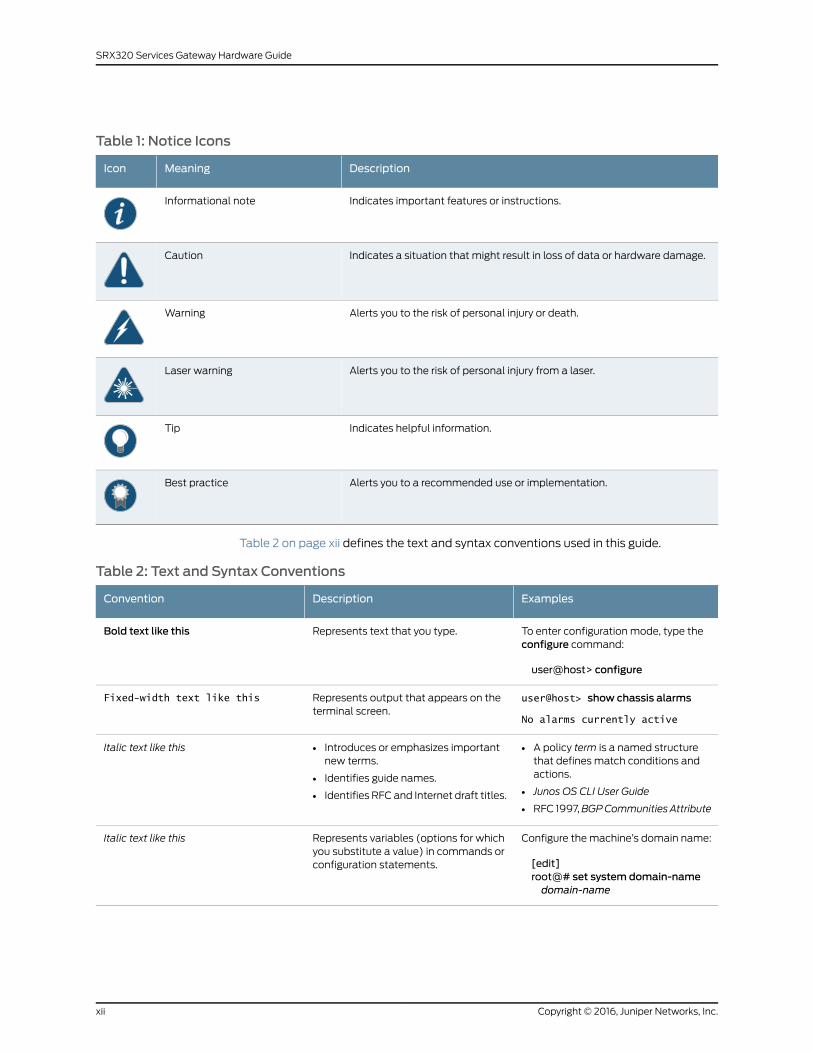
Table 1: Notice Icons
DescriptionMeaningIcon
Indicates important features or instructions.Informational note
Indicates a situation that might result in loss of data or hardware damage.Caution
Alerts you to the risk of personal injury or death.Warning
Alerts you to the risk of personal injury from a laser.Laser warning
Indicates helpful information.Tip
Alerts you to a recommended use or implementation.Best practice
Table 2 on page xii defines the text and syntax conventions used in this guide.
Table 2: Text and Syntax Conventions
ExamplesDescriptionConvention
To enter configuration mode, type theconfigure command:
user@host> configure
Represents text that you type.Bold text like this
user@host> show chassis alarms
No alarms currently active
Represents output that appears on theterminal screen.
Fixed-width text like this
• A policy term is a named structurethat defines match conditions andactions.
• Junos OS CLI User Guide
• RFC 1997,BGPCommunities Attribute
• Introduces or emphasizes importantnew terms.
• Identifies guide names.
• Identifies RFC and Internet draft titles.
Italic text like this
Configure the machine’s domain name:
[edit]root@# set system domain-namedomain-name
Represents variables (options for whichyou substitute a value) in commands orconfiguration statements.
Italic text like this
Copyright © 2016, Juniper Networks, Inc.xii
SRX320 Services Gateway Hardware Guide
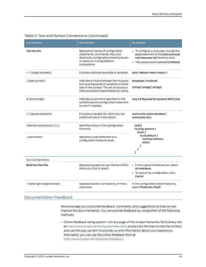
Table 2: Text and Syntax Conventions (continued)
ExamplesDescriptionConvention
• To configure a stub area, include thestub statement at the [edit protocolsospf area area-id] hierarchy level.
• The console port is labeledCONSOLE.
Represents names of configurationstatements, commands, files, anddirectories; configuration hierarchy levels;or labels on routing platformcomponents.
Text like this
stub <default-metricmetric>;Encloses optional keywords or variables.< > (angle brackets)
broadcast | multicast
(string1 | string2 | string3)
Indicates a choice between the mutuallyexclusive keywords or variables on eitherside of the symbol. The set of choices isoften enclosed in parentheses for clarity.
| (pipe symbol)
rsvp { # Required for dynamicMPLS onlyIndicates a comment specified on thesame line as the configuration statementto which it applies.
# (pound sign)
community namemembers [community-ids ]
Encloses a variable for which you cansubstitute one or more values.
[ ] (square brackets)
[edit]routing-options {static {route default {nexthop address;retain;
}}
}
Identifies a level in the configurationhierarchy.
Indention and braces ( { } )
Identifies a leaf statement at aconfiguration hierarchy level.
; (semicolon)
GUI Conventions
• In the Logical Interfaces box, selectAll Interfaces.
• To cancel the configuration, clickCancel.
Represents graphical user interface (GUI)items you click or select.
Bold text like this
In the configuration editor hierarchy,select Protocols>Ospf.
Separates levels in a hierarchy of menuselections.
> (bold right angle bracket)
Documentation Feedback
We encourage you to provide feedback, comments, and suggestions so that we can
improve the documentation. You can provide feedback by using either of the following
methods:
• Online feedback rating system—On any page of the Juniper Networks TechLibrary site
athttp://www.juniper.net/techpubs/index.html, simply click the stars to rate the content,
and use the pop-up form to provide us with information about your experience.
Alternately, you can use the online feedback form at
http://www.juniper.net/techpubs/feedback/.
xiiiCopyright © 2016, Juniper Networks, Inc.
About the Documentation
• E-mail—Send your comments to [email protected]. Include the document
or topic name, URL or page number, and software version (if applicable).
Requesting Technical Support
Technical product support is available through the Juniper Networks Technical Assistance
Center (JTAC). If you are a customer with an active J-Care or Partner Support Service
support contract, or are covered under warranty, and need post-sales technical support,
you can access our tools and resources online or open a case with JTAC.
• JTAC policies—For a complete understanding of our JTAC procedures and policies,
review the JTAC User Guide located at
http://www.juniper.net/us/en/local/pdf/resource-guides/7100059-en.pdf.
• Product warranties—For product warranty information, visit
http://www.juniper.net/support/warranty/.
• JTAC hours of operation—The JTAC centers have resources available 24 hours a day,
7 days a week, 365 days a year.
Self-Help Online Tools and Resources
For quick and easy problem resolution, Juniper Networks has designed an online
self-service portal called the Customer Support Center (CSC) that provides you with the
following features:
• Find CSC offerings: http://www.juniper.net/customers/support/
• Search for known bugs: http://www2.juniper.net/kb/
• Find product documentation: http://www.juniper.net/techpubs/
• Find solutions and answer questions using our Knowledge Base: http://kb.juniper.net/
• Download the latest versions of software and review release notes:
http://www.juniper.net/customers/csc/software/
• Search technical bulletins for relevant hardware and software notifications:
http://kb.juniper.net/InfoCenter/
• Join and participate in the Juniper Networks Community Forum:
http://www.juniper.net/company/communities/
• Open a case online in the CSC Case Management tool: http://www.juniper.net/cm/
To verify service entitlement by product serial number, use our Serial Number Entitlement
(SNE) Tool: https://tools.juniper.net/SerialNumberEntitlementSearch/
Opening a Casewith JTAC
You can open a case with JTAC on the Web or by telephone.
• Use the Case Management tool in the CSC at http://www.juniper.net/cm/.
• Call 1-888-314-JTAC (1-888-314-5822 toll-free in the USA, Canada, and Mexico).
Copyright © 2016, Juniper Networks, Inc.xiv
SRX320 Services Gateway Hardware Guide
For international or direct-dial options in countries without toll-free numbers, see
http://www.juniper.net/support/requesting-support.html.
xvCopyright © 2016, Juniper Networks, Inc.
About the Documentation

Copyright © 2016, Juniper Networks, Inc.xvi
SRX320 Services Gateway Hardware Guide
PART 1
Overview
• System Overview on page 3
• Chassis Description on page 5
• Interface Module Descriptions on page 11
• Cooling System Description on page 13
• Power System Description on page 15
1Copyright © 2016, Juniper Networks, Inc.
Copyright © 2016, Juniper Networks, Inc.2
SRX320 Services Gateway Hardware Guide
CHAPTER 1
System Overview
• SRX320 Services Gateway Description on page 3
• SRX320 Services Gateway CLI and J-Web Access on page 4
SRX320 Services Gateway Description
The SRX320 Services Gateway consolidates security, routing, switching, and WAN
interfaces for small distributed enterprises. With advanced threat mitigation capabilities,
the services gateway provides cost-effective and secure connectivity across distributed
enterprises.
With a desktop form-factor chassis, the SRX320 Services Gateway has six 1 G Ethernet
ports, two 1 G SFP ports, 4 GB of DRAM memory, 8 GB of flash memory, and two
Mini-Physical Interface Module (Mini-PIM) slots.
The SRX320 Services Gateway is available with or without Power over Ethernet (PoE)
capability. In the PoE model. the six Ethernet ports are PoE capable.
The SRX320 Services Gateway runs the Junos operating system (Junos OS) and supports
the following features:
• Firewall support with key features such as IPsec and VPN
• Intrusion Detection and Prevention (IDP)
• High availability
• QoS
• MPLS
RelatedDocumentation
SRX320 Services Gateway Chassis Overview on page 5•
• Understanding the SRX320 Services Gateway Front Panel on page 5
• Understanding the SRX320 Services Gateway Back Panel on page 8
3Copyright © 2016, Juniper Networks, Inc.
SRX320 Services Gateway CLI and J-Web Access
The SRX320 Services Gateway runs the Junos operating system (Junos OS). You can
use two user interfaces to monitor, configure, troubleshoot, and manage the services
gateway:
• J-Web interface—A Web-based graphical interface that allows you to operate the
services gateway without commands.
• Junos OS command-line interface (CLI)—Juniper Networks command shell that runs
on top of a UNIX-based operating system kernel. The CLI is a straightforward command
interface. On a single line, you type commands that are executed when you press the
Enter key. The CLI provides command help and command completion.
In addition, you can also use Junos Space Security Director to define and manage security
policies on the services gateway.
RelatedDocumentation
• SRX320 Services Gateway Description on page 3
• SRX320 Services Gateway Chassis Overview on page 5
Copyright © 2016, Juniper Networks, Inc.4
SRX320 Services Gateway Hardware Guide
CHAPTER 2
Chassis Description
• SRX320 Services Gateway Chassis Overview on page 5
• Understanding the SRX320 Services Gateway Front Panel on page 5
• Understanding the SRX320 Services Gateway Back Panel on page 8
SRX320 Services Gateway Chassis Overview
The SRX320 Services Gateway chassis measures 1.73 in. high, 11.81 in. wide, and 7.52 in.
deep. The PoE model weighs 3.4 lb. and the non-PoE model weighs 3.28 lb.
CAUTION: Before removingor installingcomponentsofa functioningservicesgateway, attach an electrostatic discharge (ESD) strap to an ESD point andplace the other end of the strap around your barewrist. Failure to use an ESDstrap could result in damage to the device.
The services gateway must be connected to earth ground during normal operation. The
protective earthing terminal on the rear of the chassis is provided to connect the services
gateway to ground.
RelatedDocumentation
Understanding the SRX320 Services Gateway Front Panel on page 5•
• Understanding the SRX320 Services Gateway Back Panel on page 8
Understanding the SRX320 Services Gateway Front Panel
Figure 1 on page 6 shows the front panel of the SRX320 Services Gateway.
5Copyright © 2016, Juniper Networks, Inc.
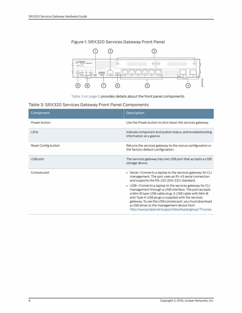
Figure 1: SRX320 Services Gateway Front Panel
Table 3 on page 6 provides details about the front panel components.
Table 3: SRX320 Services Gateway Front Panel Components
DescriptionComponent
Use the Power button to shut down the services gateway.Power button
Indicate component and system status, and troubleshootinginformation at a glance.
LEDs
Returns the services gateway to the rescue configuration orthe factory-default configuration.
Reset Config button
The services gateway has one USB port that accepts a USBstorage device.
USB port
• Serial—Connects a laptop to the services gateway for CLImanagement. The port uses an RJ-45 serial connectionand supports the RS-232 (EIA-232) standard.
• USB—Connects a laptop to the services gateway for CLImanagement through a USB interface. The port acceptsa Mini-B type USB cable plug. A USB cable with Mini-Band Type A USB plugs is supplied with the servicesgateway. To use the USB console port, you must downloada USB driver to the management device fromhttp://www.juniper.net/support/downloads/group/?f=junos.
Console port
Copyright © 2016, Juniper Networks, Inc.6
SRX320 Services Gateway Hardware Guide
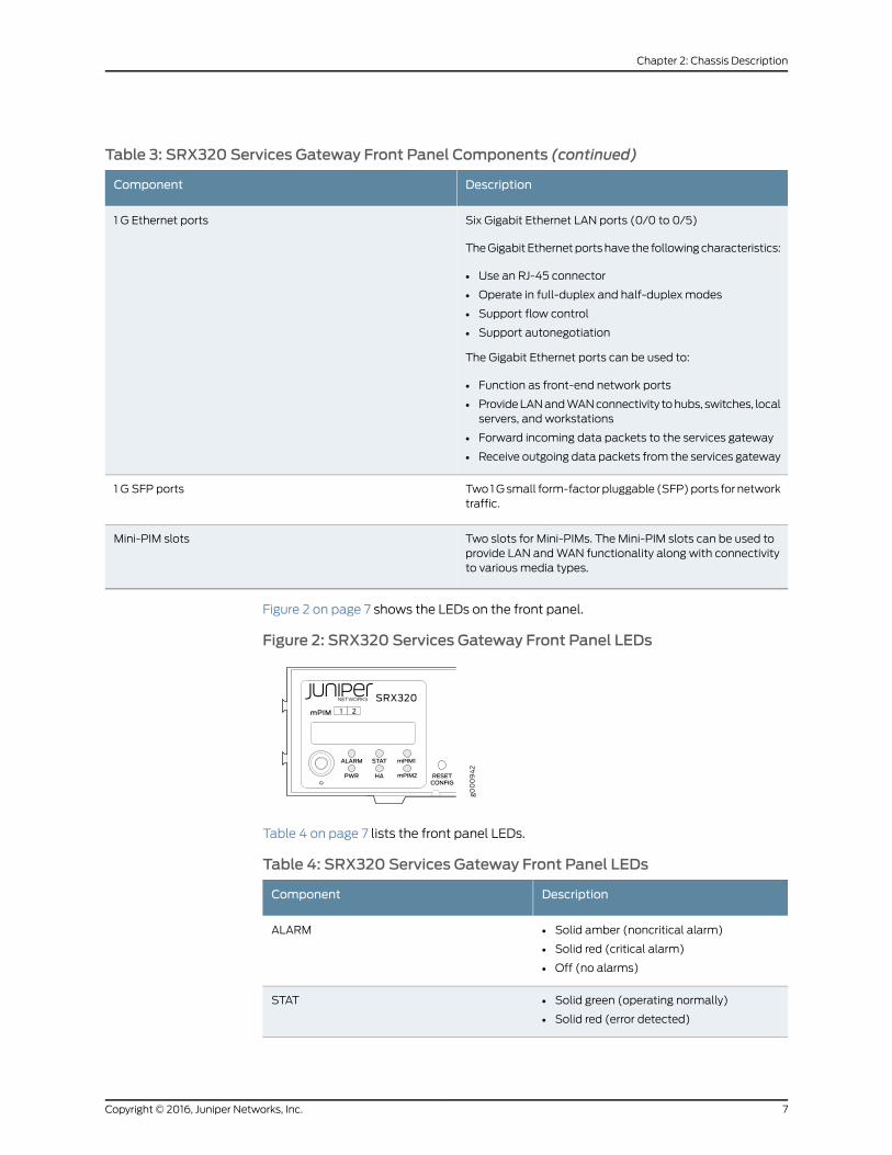
Table 3: SRX320 Services Gateway Front Panel Components (continued)
DescriptionComponent
Six Gigabit Ethernet LAN ports (0/0 to 0/5)
The Gigabit Ethernet ports have the following characteristics:
• Use an RJ-45 connector
• Operate in full-duplex and half-duplex modes
• Support flow control
• Support autonegotiation
The Gigabit Ethernet ports can be used to:
• Function as front-end network ports
• Provide LAN and WAN connectivity to hubs, switches, localservers, and workstations
• Forward incoming data packets to the services gateway
• Receive outgoing data packets from the services gateway
1 G Ethernet ports
Two 1 G small form-factor pluggable (SFP) ports for networktraffic.
1 G SFP ports
Two slots for Mini-PIMs. The Mini-PIM slots can be used toprovide LAN and WAN functionality along with connectivityto various media types.
Mini-PIM slots
Figure 2 on page 7 shows the LEDs on the front panel.
Figure 2: SRX320 Services Gateway Front Panel LEDs
Table 4 on page 7 lists the front panel LEDs.
Table 4: SRX320 Services Gateway Front Panel LEDs
DescriptionComponent
• Solid amber (noncritical alarm)
• Solid red (critical alarm)
• Off (no alarms)
ALARM
• Solid green (operating normally)
• Solid red (error detected)
STAT
7Copyright © 2016, Juniper Networks, Inc.
Chapter 2: Chassis Description
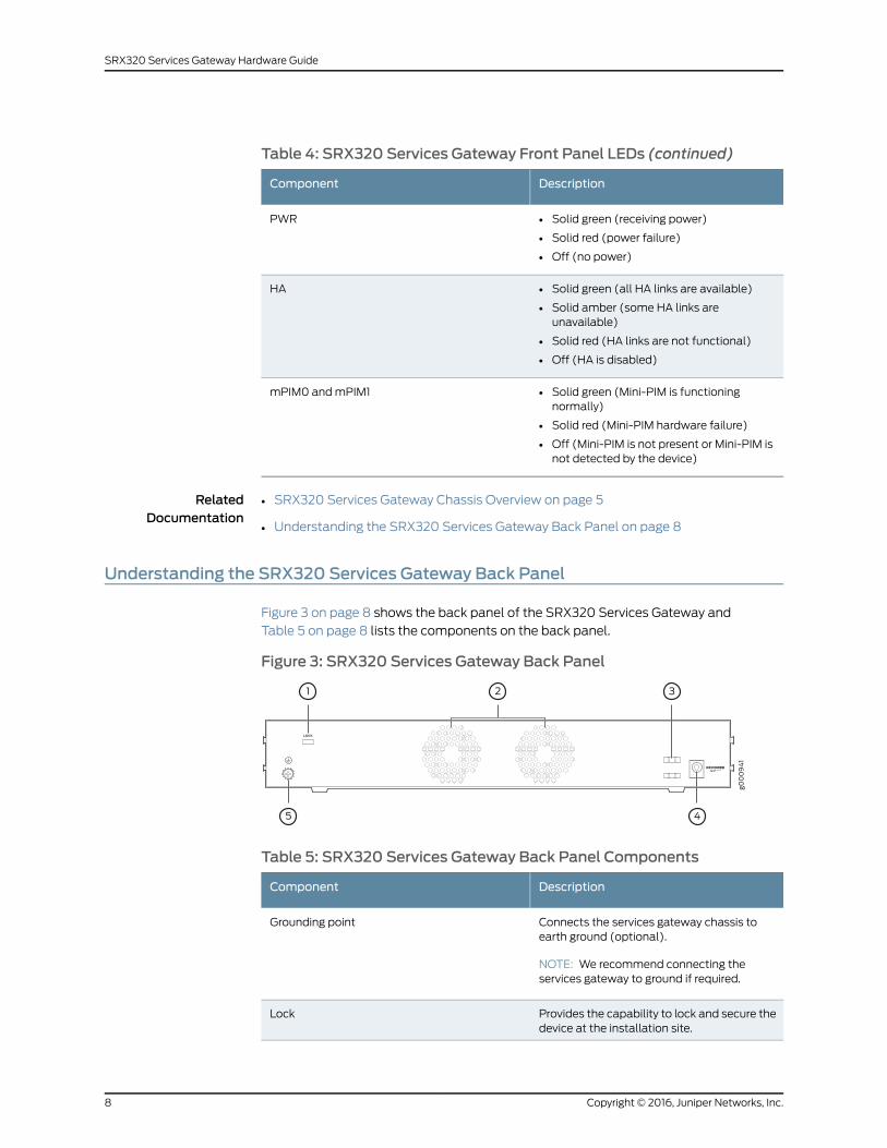
Table 4: SRX320 Services Gateway Front Panel LEDs (continued)
DescriptionComponent
• Solid green (receiving power)
• Solid red (power failure)
• Off (no power)
PWR
• Solid green (all HA links are available)
• Solid amber (some HA links areunavailable)
• Solid red (HA links are not functional)
• Off (HA is disabled)
HA
• Solid green (Mini-PIM is functioningnormally)
• Solid red (Mini-PIM hardware failure)
• Off (Mini-PIM is not present or Mini-PIM isnot detected by the device)
mPIM0 and mPIM1
RelatedDocumentation
SRX320 Services Gateway Chassis Overview on page 5•
• Understanding the SRX320 Services Gateway Back Panel on page 8
Understanding the SRX320 Services Gateway Back Panel
Figure 3 on page 8 shows the back panel of the SRX320 Services Gateway and
Table 5 on page 8 lists the components on the back panel.
Figure 3: SRX320 Services Gateway Back Panel
Table 5: SRX320 Services Gateway Back Panel Components
DescriptionComponent
Connects the services gateway chassis toearth ground (optional).
NOTE: We recommend connecting theservices gateway to ground if required.
Grounding point
Provides the capability to lock and secure thedevice at the installation site.
Lock
Copyright © 2016, Juniper Networks, Inc.8
SRX320 Services Gateway Hardware Guide
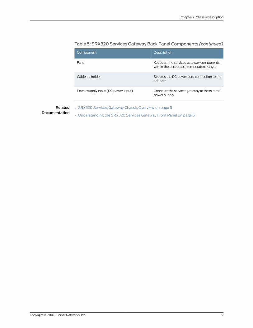
Table 5: SRX320ServicesGatewayBackPanel Components (continued)
DescriptionComponent
Keeps all the services gateway componentswithin the acceptable temperature range.
Fans
Secures the DC power cord connection to theadapter.
Cable tie holder
Connects the services gateway to the externalpower supply.
Power supply input (DC power input)
RelatedDocumentation
• SRX320 Services Gateway Chassis Overview on page 5
• Understanding the SRX320 Services Gateway Front Panel on page 5
9Copyright © 2016, Juniper Networks, Inc.
Chapter 2: Chassis Description

Copyright © 2016, Juniper Networks, Inc.10
SRX320 Services Gateway Hardware Guide
CHAPTER 3
Interface Module Descriptions
• SRX320 Services Gateway Interface Modules Overview on page 11
SRX320 Services Gateway InterfaceModules Overview
Mini-Physical Interface Modules (Mini-PIMs) are field-replaceable network interface
cards (NICs) supported on the SRX300 line of services gateways. You can easily insert
or remove Mini-PIMs from the front slots of the services gateway chassis. The Mini-PIMs
provide physical connections to a LAN or a WAN. The Mini-PIMs receive incoming packets
from the network and transmit outgoing packets to the network. During this process,
they perform framing and line-speed signaling for the medium type.
CAUTION: TheMini-PIMs are not hot-swappable. Youmust power off theservices gateway before removing or installing Mini-PIMs.
The following Mini-PIMs are supported on the SRX320 Services Gateway:
• 1-Port Serial Mini-Physical Interface Module (SRX-MP-1SERIAL-R)
• 1-Port T1/E1 Mini-Physical Interface Module (SRX-MP-1T1E1-R)
• 1-Port VDSL2 (Annex A) Mini-Physical Interface Module (SRX-MP-1VDSL2-R)
For more information on the Mini-PIMs, see theSRX300Series andSRX550HighMemory
Gateway Interface Modules Reference.
RelatedDocumentation
• SRX320 Services Gateway Chassis Overview on page 5
• Understanding the SRX320 Services Gateway Front Panel on page 5
• Understanding the SRX320 Services Gateway Back Panel on page 8
11Copyright © 2016, Juniper Networks, Inc.
Copyright © 2016, Juniper Networks, Inc.12
SRX320 Services Gateway Hardware Guide
CHAPTER 4
Cooling System Description
• Understanding the SRX320 Services Gateway Cooling System on page 13
Understanding the SRX320 Services Gateway Cooling System
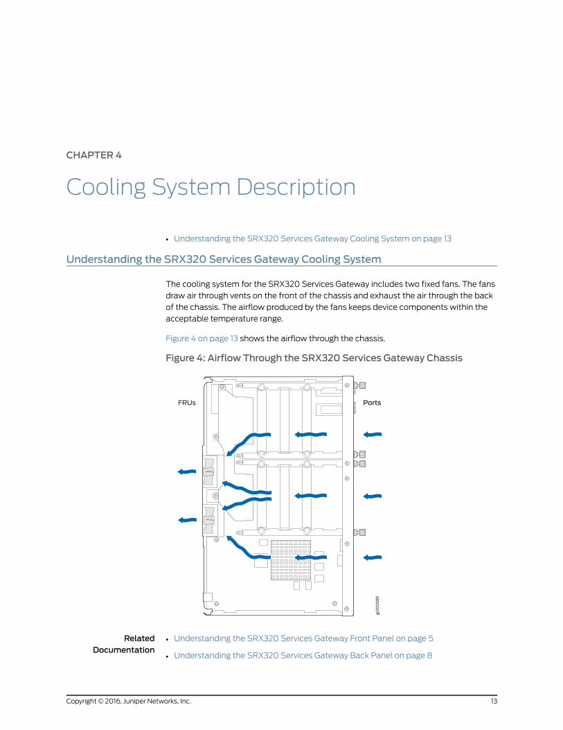
The cooling system for the SRX320 Services Gateway includes two fixed fans. The fans
draw air through vents on the front of the chassis and exhaust the air through the back
of the chassis. The airflow produced by the fans keeps device components within the
acceptable temperature range.
Figure 4 on page 13 shows the airflow through the chassis.
Figure 4: Airflow Through the SRX320 Services Gateway Chassis
RelatedDocumentation
• Understanding the SRX320 Services Gateway Front Panel on page 5
• Understanding the SRX320 Services Gateway Back Panel on page 8
13Copyright © 2016, Juniper Networks, Inc.

Copyright © 2016, Juniper Networks, Inc.14
SRX320 Services Gateway Hardware Guide
CHAPTER 5
Power System Description
• Understanding the SRX320 Services Gateway Power Supply on page 15
Understanding the SRX320 Services Gateway Power Supply
The power supply for the SRX320 Services Gateway is external. You must use the
following power supply adapters provided by Juniper Networks to provide power to the
services gateway.
• 75 W, 12 V power supply adapter for non-PoE models
• 280 W, 54 V power supply adapter for PoE models
Each PoE port delivers a maximum power of 30 W. Because of line loss, the powered
device connected to a PoE port can use only 25.5 W of power. Line loss is influenced
by cable length, quality, and other factors and is typically less than 16 percent of the
maximum power.
RelatedDocumentation
• Understanding the SRX320 Services Gateway Front Panel on page 5
• Understanding the SRX320 Services Gateway Back Panel on page 8
15Copyright © 2016, Juniper Networks, Inc.

Copyright © 2016, Juniper Networks, Inc.16
SRX320 Services Gateway Hardware Guide
PART 2
Site Planning and Specifications
• Planning and Preparing the Site on page 19
• Rack Requirements on page 25
• Cabinet Requirements on page 31
• Power Requirements and Specifications on page 33
• Cable Specifications and Pinouts on page 37
17Copyright © 2016, Juniper Networks, Inc.

Copyright © 2016, Juniper Networks, Inc.18
SRX320 Services Gateway Hardware Guide
CHAPTER 6
Planning and Preparing the Site
• SRX320 Services Gateway Physical Specifications on page 19
• SRX320 Services Gateway Environmental Specifications on page 19
• Site Preparation Checklist for the SRX320 Services Gateway on page 20
• General Site Installation Guidelines for the SRX320 Services Gateway on page 22
SRX320 Services Gateway Physical Specifications
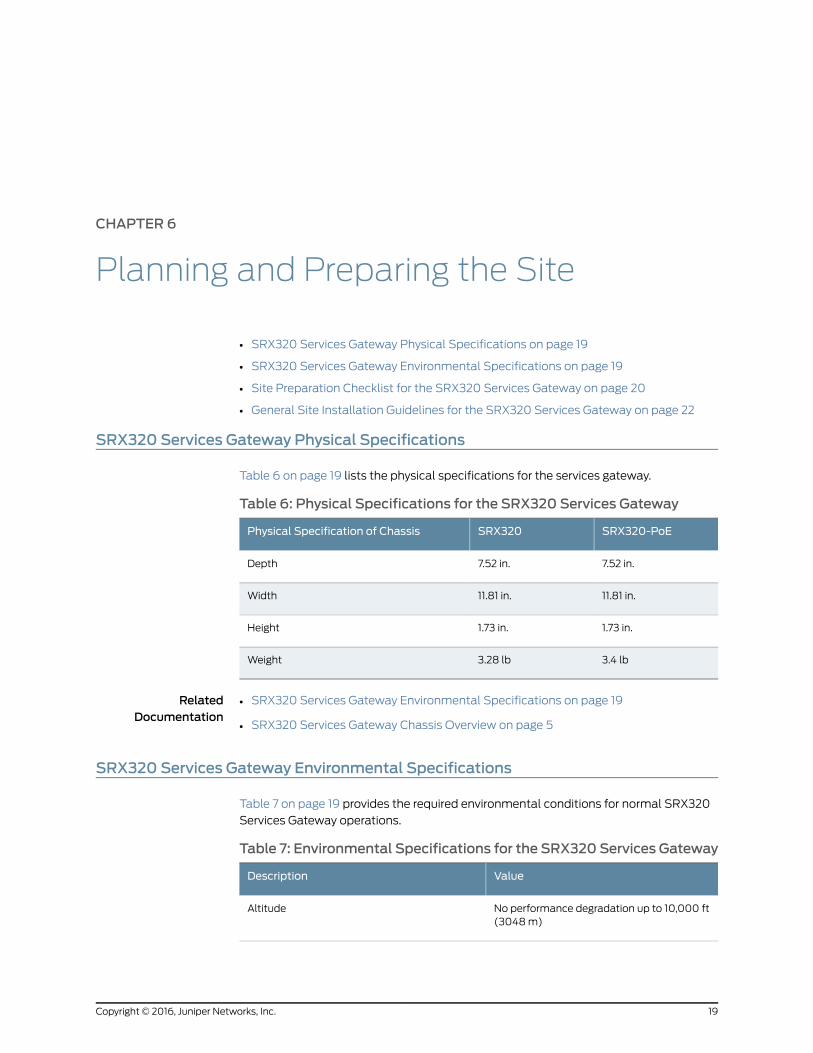
Table 6 on page 19 lists the physical specifications for the services gateway.
Table 6: Physical Specifications for the SRX320 Services Gateway
SRX320-PoESRX320Physical Specification of Chassis
7.52 in.7.52 in.Depth
11.81 in.11.81 in.Width
1.73 in.1.73 in.Height
3.4 lb3.28 lbWeight
RelatedDocumentation
SRX320 Services Gateway Environmental Specifications on page 19•
• SRX320 Services Gateway Chassis Overview on page 5
SRX320 Services Gateway Environmental Specifications
Table 7 on page 19 provides the required environmental conditions for normal SRX320
Services Gateway operations.
Table 7: Environmental Specifications for the SRX320 Services Gateway
ValueDescription
No performance degradation up to 10,000 ft(3048 m)
Altitude
19Copyright © 2016, Juniper Networks, Inc.
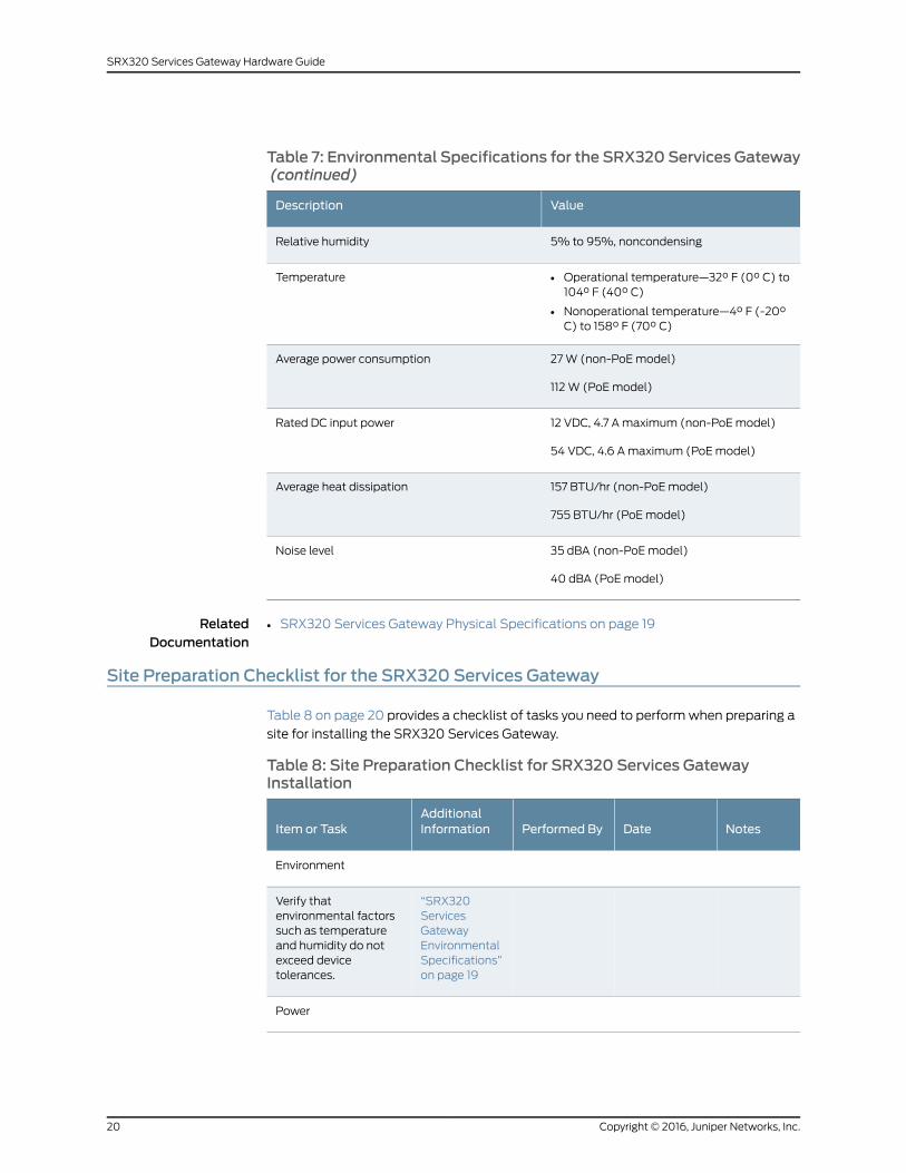
Table 7: Environmental Specifications for the SRX320 Services Gateway(continued)
ValueDescription
5% to 95%, noncondensingRelative humidity
• Operational temperature—32° F (0° C) to104° F (40° C)
• Nonoperational temperature—4° F (-20°C) to 158° F (70° C)
Temperature
27 W (non-PoE model)
112 W (PoE model)
Average power consumption
12 VDC, 4.7 A maximum (non-PoE model)
54 VDC, 4.6 A maximum (PoE model)
Rated DC input power
157 BTU/hr (non-PoE model)
755 BTU/hr (PoE model)
Average heat dissipation
35 dBA (non-PoE model)
40 dBA (PoE model)
Noise level
RelatedDocumentation
SRX320 Services Gateway Physical Specifications on page 19•
Site Preparation Checklist for the SRX320 Services Gateway
Table 8 on page 20 provides a checklist of tasks you need to perform when preparing a
site for installing the SRX320 Services Gateway.
Table 8: Site Preparation Checklist for SRX320 Services GatewayInstallation
NotesDatePerformed ByAdditionalInformationItem or Task
Environment
“SRX320ServicesGatewayEnvironmentalSpecifications”on page 19
Verify thatenvironmental factorssuch as temperatureand humidity do notexceed devicetolerances.
Power
Copyright © 2016, Juniper Networks, Inc.20
SRX320 Services Gateway Hardware Guide
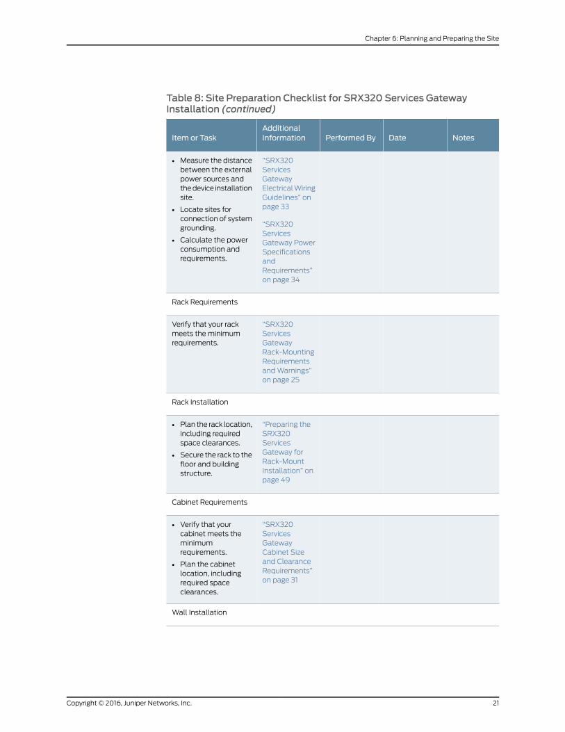
Table 8: Site Preparation Checklist for SRX320 Services GatewayInstallation (continued)
NotesDatePerformed ByAdditionalInformationItem or Task
“SRX320ServicesGatewayElectrical WiringGuidelines” onpage 33
“SRX320ServicesGateway PowerSpecificationsandRequirements”on page 34
• Measure the distancebetween the externalpower sources andthe device installationsite.
• Locate sites forconnection of systemgrounding.
• Calculate the powerconsumption andrequirements.
Rack Requirements
“SRX320ServicesGatewayRack-MountingRequirementsand Warnings”on page 25
Verify that your rackmeets the minimumrequirements.
Rack Installation
“Preparing theSRX320ServicesGateway forRack-MountInstallation” onpage 49
• Plan the rack location,including requiredspace clearances.
• Secure the rack to thefloor and buildingstructure.
Cabinet Requirements
“SRX320ServicesGatewayCabinet Sizeand ClearanceRequirements”on page 31
• Verify that yourcabinet meets theminimumrequirements.
• Plan the cabinetlocation, includingrequired spaceclearances.
Wall Installation
21Copyright © 2016, Juniper Networks, Inc.
Chapter 6: Planning and Preparing the Site
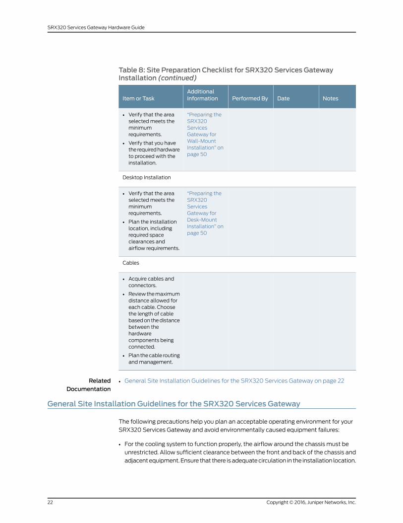
Table 8: Site Preparation Checklist for SRX320 Services GatewayInstallation (continued)
NotesDatePerformed ByAdditionalInformationItem or Task
“Preparing theSRX320ServicesGateway forWall-MountInstallation” onpage 50
• Verify that the areaselected meets theminimumrequirements.
• Verify that you havethe required hardwareto proceed with theinstallation.
Desktop Installation
“Preparing theSRX320ServicesGateway forDesk-MountInstallation” onpage 50
• Verify that the areaselected meets theminimumrequirements.
• Plan the installationlocation, includingrequired spaceclearances andairflow requirements.
Cables
• Acquire cables andconnectors.
• Review the maximumdistance allowed foreach cable. Choosethe length of cablebased on the distancebetween thehardwarecomponents beingconnected.
• Plan the cable routingand management.
RelatedDocumentation
General Site Installation Guidelines for the SRX320 Services Gateway on page 22•
General Site Installation Guidelines for the SRX320 Services Gateway
The following precautions help you plan an acceptable operating environment for your
SRX320 Services Gateway and avoid environmentally caused equipment failures:
• For the cooling system to function properly, the airflow around the chassis must be
unrestricted. Allow sufficient clearance between the front and back of the chassis and
adjacent equipment. Ensure that there is adequate circulation in the installation location.
Copyright © 2016, Juniper Networks, Inc.22
SRX320 Services Gateway Hardware Guide

• Follow the ESD procedures to avoid damaging equipment. Static discharge can cause
components to fail completely or intermittently over time. For more information, see
“Preventing Electrostatic Discharge Damage to the SRX320 Services Gateway” on
page 115.
• Ensure that a blank Mini-PIM panel is installed in the empty slot to prevent any
interruption or reduction in the flow of air across internal components.
RelatedDocumentation
• Site Preparation Checklist for the SRX320 Services Gateway on page 20
23Copyright © 2016, Juniper Networks, Inc.
Chapter 6: Planning and Preparing the Site

Copyright © 2016, Juniper Networks, Inc.24
SRX320 Services Gateway Hardware Guide
CHAPTER 7
Rack Requirements
• SRX320 Services Gateway Rack-Mounting Requirements and Warnings on page 25
• SRX320 Services Gateway Rack Size and Strength Requirements on page 29
• SRX320 Services Gateway Spacing of Mounting Brackets and Flange Holes on page 29
• SRX320 Services Gateway Clearance Requirements for Airflow and Hardware
Maintenance on page 30
SRX320 Services Gateway Rack-Mounting Requirements andWarnings
Ensure that the equipment rack into which the services gateway is installed is evenly and
securely supported to avoid hazardous conditions that could result from uneven
mechanical loading.
WARNING: To prevent bodily injury whenmounting or servicing the servicesgateway in a rack, take the following precautions to ensure that the systemremains stable. The following directives helpmaintain your safety:
• The services gatewaymust be installed into a rack that is secured to thebuilding structure.
• The services gateway should bemounted at the bottom of the rack if it isthe only unit in the rack.
• Whenmounting the services gateway in a partially filled rack, load the rackfrom the bottom to the topwith the heaviest component at the bottom ofthe rack.
• If the rack is providedwith stabilizing devices, install the stabilizers beforemounting or servicing the services gateway in the rack.
WaarschuwingOm lichamelijk letsel te voorkomenwanneer u dit toestel ineen rekmonteert of het daar een servicebeurt geeft, moet u specialevoorzorgsmaatregelen nemen om ervoor te zorgen dat het toestel stabielblijft. De onderstaande richtlijnen worden verstrekt om uw veiligheid teverzekeren:
25Copyright © 2016, Juniper Networks, Inc.
• De Juniper Networks services gatewaymoet in een stellage wordengeïnstalleerd die aan een bouwsel is verankerd.
• Dit toestel dient onderaan in het rek gemonteerd teworden als het toestelhet enige in het rek is.
• Wanneer u dit toestel in een gedeeltelijk gevuld rekmonteert, dient u hetrekvanonderennaarboven te ladenmethet zwaarsteonderdeelonderaanin het rek.
• Als het rek voorzien is van stabiliseringshulpmiddelen, dient u destabilisatoren temonteren voordat u het toestel in het rekmonteert of hetdaar een servicebeurt geeft.
VaroitusKun laiteasetetaan telineeseen taihuolletaansenollessa telineessä,onnoudatettavaerityisiävarotoimia järjestelmänvakavuudensäilyttämiseksi,jotta vältytään loukkaantumiselta. Noudata seuraavia turvallisuusohjeita:
• Juniper Networks services gateway on asennettava telineeseen, joka onkiinnitetty rakennukseen.
• Jos telineessä ei ole muita laitteita, aseta laite telineen alaosaan.
• Jos laite asetetaan osaksi täytettyyn telineeseen, aloita kuormittaminensen alaosasta kaikkein raskaimmalla esineellä ja siirry sitten sen yläosaan.
• Jos telinettä varten on vakaimet, asenna ne ennen laitteen asettamistatelineeseen tai sen huoltamista siinä.
Attention Pour éviter toute blessure corporelle pendant les opérations demontage ou de réparation de cette unité en casier, il convient de prendre desprécautions spécialesafindemaintenir la stabilité du système. Lesdirectivesci-dessous sont destinées à assurer la protection du personnel:
• Le rack sur lequel estmonté le JuniperNetworks services gatewaydoit êtrefixé à la structure du bâtiment.
• Si cette unité constitue la seule unitémontéeencasier, elle doit êtreplacéedans le bas.
• Si cette unité est montée dans un casier partiellement rempli, charger lecasier de bas en haut en plaçant l'élément le plus lourd dans le bas.
• Si lecasier estéquipédedispositifs stabilisateurs, installer les stabilisateursavant demonter ou de réparer l'unité en casier.
WarnungZurVermeidungvonKörperverletzungbeimAnbringenoderWartendieser Einheit in einemGestell müssen Sie besondere Vorkehrungen treffen,um sicherzustellen, daß das System stabil bleibt. Die folgenden Richtliniensollen zur Gewährleistung Ihrer Sicherheit dienen:
Copyright © 2016, Juniper Networks, Inc.26
SRX320 Services Gateway Hardware Guide
• Der Juniper Networks services gatewaymuß in einemGestell installiertwerden, das in der Gebäudestruktur verankert ist.
• Wenn diese Einheit die einzige im Gestell ist, sollte sie unten im Gestellangebracht werden.
• Bei Anbringung dieser Einheit in einem zum Teil gefüllten Gestell ist dasGestell von unten nach oben zu laden, wobei das schwerste Bauteil untenim Gestell anzubringen ist.
• Wird das Gestell mit Stabilisierungszubehör geliefert, sind zuerst dieStabilisatoren zu installieren, bevor Sie die Einheit im Gestell anbringenoder sie warten.
AvvertenzaPerevitare infortuni fisici durante ilmontaggioo lamanutenzionedi questa unità in un supporto, occorre osservare speciali precauzioni pergarantire che il sistema rimanga stabile. Le seguenti direttive vengono forniteper garantire la sicurezza personale:
• Il Juniper Networks services gateway deve essere installato in un telaio, ilquale deve essere fissato alla struttura dell'edificio.
• Questa unità deve venire montata sul fondo del supporto, se si trattadell'unica unità damontare nel supporto.
• Quando questa unità vienemontata in un supporto parzialmente pieno,caricare il supporto dal basso all'alto, con il componente più pesantesistemato sul fondo del supporto.
• Se il supporto è dotato di dispositivi stabilizzanti, installare tali dispositiviprimadimontareodiprocedereallamanutenzionedell'unitànel supporto.
AdvarselUnngå fysiske skader under montering eller reparasjonsarbeid pådenne enheten når den befinner seg i et kabinett. Vær nøyemed at systemeter stabilt. Følgende retningslinjer er gitt for å verne om sikkerheten:
• JuniperNetworksservicesgatewaymå installeres i et stativ somer forankrettil bygningsstrukturen.
• Denne enheten børmonteres nederst i kabinettet hvis dette er den enesteenheten i kabinettet.
• Vedmontering av denne enheten i et kabinett som er delvis fylt, skalkabinettet lastes frabunnenogoppmeddentyngstekomponentennedersti kabinettet.
• Hvis kabinettet er utstyrt med stabiliseringsutstyr, skal stabilisatoreneinstalleres før montering eller utføring av reparasjonsarbeid på enheten ikabinettet.
Aviso Para se prevenir contra danos corporais aomontar ou reparar estaunidade numaestante, deverá tomar precauções especiais para se certificar
27Copyright © 2016, Juniper Networks, Inc.
Chapter 7: Rack Requirements
de que o sistema possui um suporte estável. As seguintes directrizesajudá-lo-ão a efectuar o seu trabalho com segurança:
• O Juniper Networks services gateway deverá ser instalado numaprateleirafixa à estrutura do edificio.
• Esta unidade deverá ser montada na parte inferior da estante, caso sejaesta a única unidade a ser montada.
• Aomontar esta unidade numa estante parcialmente ocupada, coloque ositensmais pesados na parte inferior da estante, arrumando-os de baixopara cima.
• Se a estante possuir um dispositivo de estabilização, instale-o antes demontar ou reparar a unidade.
¡Atención! Para evitar lesiones durante el montaje de este equipo sobre unbastidor, o posteriormente durante sumantenimiento, se debeponermuchocuidado en que el sistema quede bien estable. Para garantizar su seguridad,proceda según las siguientes instrucciones:
• El Juniper Networks services gateway debe instalarse en un bastidor fijadoa la estructura del edificio.
• Colocar el equipo en la parte inferior del bastidor, cuando sea la únicaunidad en el mismo.
• Cuandoesteequiposevayaa instalarenunbastidorparcialmenteocupado,comenzar la instalación desde la parte inferior hacia la superior colocandoel equipomás pesado en la parte inferior.
• Si el bastidor dispone de dispositivos estabilizadores, instalar éstos antesdemontaroprocederalmantenimientodel equipo instaladoenelbastidor.
Varning! För att undvika kroppsskada när du installerar eller utförunderhållsarbete på denna enhet på en ställningmåste du vidta särskildaförsiktighetsåtgärder föratt försäkradigomattsystemetstår stadigt. Följanderiktlinjer ges för att trygga din säkerhet:
• Juniper Networks services gatewaymåste installeras i en ställning som ärförankrad i byggnadens struktur.
• Omdenna enhet är den enda enheten på ställningen skall den installeraslängst ned på ställningen.
• Omdenna enhet installeras på en delvis fylld ställning skall ställningenfyllasnedifrånochupp,meddetyngstaenheterna längstnedpåställningen.
• Omställningenär förseddmedstabiliseringsdonskalldessamonteras fastinnan enheten installeras eller underhålls på ställningen.
RelatedDocumentation
SRX320 Services Gateway Rack Size and Strength Requirements on page 29•
Copyright © 2016, Juniper Networks, Inc.28
SRX320 Services Gateway Hardware Guide
• SRX320 Services Gateway Spacing of Mounting Brackets and Flange Holes on page 29
• SRX320 Services Gateway Clearance Requirements for Airflow and Hardware
Maintenance on page 30
SRX320 Services Gateway Rack Size and Strength Requirements
When installing the services gateway in a rack, you must ensure that the rack complies
with a 1U (19 in. or 48.7 cm) rack as defined in Cabinets, Racks, Panels, and Associated
Equipment (document number EIA-310-D), published by the Electronic Industries Alliance
(http://www.ecaus.org/eia/site/index.html).
When selecting a rack, ensure that the physical characteristics of the rack comply with
the following specifications:
• The outer edges of the mounting brackets extend the width of either chassis to 19 in.
(48.3 cm).
• The front of the chassis extends approximately 0.5 in. (1.27 cm) beyond the mounting
ears.
• Maximum permissible ambient temperature when two devices are placed side by side
in a 19 in. rack is 40° C.
RelatedDocumentation
SRX320 Services Gateway Rack-Mounting Requirements and Warnings on page 25•
• SRX320 Services Gateway Spacing of Mounting Brackets and Flange Holes on page 29
• SRX320 Services Gateway Clearance Requirements for Airflow and Hardware
Maintenance on page 30
SRX320 Services Gateway Spacing of Mounting Brackets and Flange Holes
The spacing of the mounting brackets and flange holes on the rack and device mounting
brackets are as follows:
• The holes within each rack set are spaced at 1 U (1.75 in. or 4.5 cm).
• The mounting brackets and front-mount flanges used to attach the chassis to a rack
are designed to fasten to holes spaced at rack distances of 1 U (1.75 in.).
• The mounting holes in the mounting brackets provided with the device are spaced
1.25 in. (3.2 cm) apart (top and bottom mounting hole).
RelatedDocumentation
SRX320 Services Gateway Rack-Mounting Requirements and Warnings on page 25•
• SRX320 Services Gateway Rack Size and Strength Requirements on page 29
• SRX320 Services Gateway Clearance Requirements for Airflow and Hardware
Maintenance on page 30
29Copyright © 2016, Juniper Networks, Inc.
Chapter 7: Rack Requirements
SRX320 Services Gateway Clearance Requirements for Airflow and HardwareMaintenance
When planning the installation site for the SRX320 Services Gateway, you need to allow
sufficient clearance around the device. Consider the following:
• For the operating temperature of the services gateway to be optimal, the airflow around
the chassis must be unrestricted.
• For service personnel to remove and install hardware components, there must be
adequate space at the front and back of the device. Allow at least 24 in. (61 cm) both
in front of and behind the device.
• If you are mounting the device in a rack with other equipment, or if you are placing it
on the desktop near other equipment, ensure that the exhaust from other equipment
does not blow into the intake vents of the chassis.
For information on the airflow through the chassis, see “Understanding the SRX320
Services Gateway Cooling System” on page 13.
RelatedDocumentation
• SRX320 Services Gateway Rack-Mounting Requirements and Warnings on page 25
• SRX320 Services Gateway Rack Size and Strength Requirements on page 29
• SRX320 Services Gateway Spacing of Mounting Brackets and Flange Holes on page 29
Copyright © 2016, Juniper Networks, Inc.30
SRX320 Services Gateway Hardware Guide
CHAPTER 8
Cabinet Requirements
• SRX320 Services Gateway Cabinet Size and Clearance Requirements on page 31
• SRX320 Services Gateway Cabinet Airflow Requirements on page 31
SRX320 Services Gateway Cabinet Size and Clearance Requirements
You can install the SRX320 Services Gateway in a 19 in. (48.7 cm) cabinet as defined in
Cabinets, Racks, Panels, and Associated Equipment (document number EIA-310-D)
published by the Electronic Industries Alliance (http://www.ecaus.org/eia/site/index.html).
You must mount the services gateway horizontally in the cabinet using appropriate rack
adapters.
When selecting a cabinet, ensure that it meets the following specifications:
• The cabinet is at least 1U (3.50 in. or 8.89 cm) and can accommodate the services
gateway.
• The outer edges of the mounting brackets extend the width of either chassis to 19 in.
(48.7 cm), and the front of the chassis extends approximately 0.5 in. (1.27 cm) beyond
the mounting brackets.
• The minimum total clearance inside the cabinet is 30.7 in. (78 cm) between the inside
of the front door and the inside of the rear door.
NOTE: A cabinet larger than theminimum required provides better airflowand reduces the chance of overheating.
RelatedDocumentation
SRX320 Services Gateway Cabinet Airflow Requirements on page 31•
SRX320 Services Gateway Cabinet Airflow Requirements
When you mount the SRX320 Services Gateway in a cabinet, you must ensure that
ventilation through the cabinet is sufficient to prevent overheating. Consider the following
when planning for chassis cooling:
31Copyright © 2016, Juniper Networks, Inc.
• Ensure that the cool air supply you provide through the cabinet can adequately dissipate
the thermal output of the services gateway.
• Install the services gateway as close as possible to the front of the cabinet so that the
cable management system clears the inside of the front door. Installing the chassis
close to the front of the cabinet maximizes the clearance in the rear of the cabinet for
critical airflow.
• Route and dress all cables to minimize the blockage of airflow to and from the chassis.
RelatedDocumentation
• SRX320 Services Gateway Cabinet Size and Clearance Requirements on page 31
Copyright © 2016, Juniper Networks, Inc.32
SRX320 Services Gateway Hardware Guide
CHAPTER 9
Power Requirements and Specifications
• SRX320 Services Gateway Electrical Wiring Guidelines on page 33
• SRX320 Services Gateway Power Specifications and Requirements on page 34
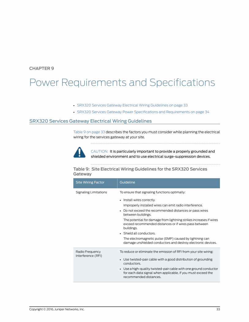
SRX320 Services Gateway ElectricalWiring Guidelines
Table 9 on page 33 describes the factors you must consider while planning the electrical
wiring for the services gateway at your site.
CAUTION: It is particularly important to provide a properly grounded andshielded environment and to use electrical surge-suppression devices.
Table 9: Site ElectricalWiring Guidelines for the SRX320 ServicesGateway
GuidelineSiteWiring Factor
To ensure that signaling functions optimally:
• Install wires correctly.
Improperly installed wires can emit radio interference.
• Do not exceed the recommended distances or pass wiresbetween buildings.
The potential for damage from lightning strikes increases if wiresexceed recommended distances or if wires pass betweenbuildings.
• Shield all conductors.
The electromagnetic pulse (EMP) caused by lightning candamage unshielded conductors and destroy electronic devices.
Signaling Limitations
To reduce or eliminate the emission of RFI from your site wiring:
• Use twisted-pair cable with a good distribution of groundingconductors.
• Use a high-quality twisted-pair cable with one ground conductorfor each data signal when applicable, if you must exceed therecommended distances.
Radio FrequencyInterference (RFI)
33Copyright © 2016, Juniper Networks, Inc.
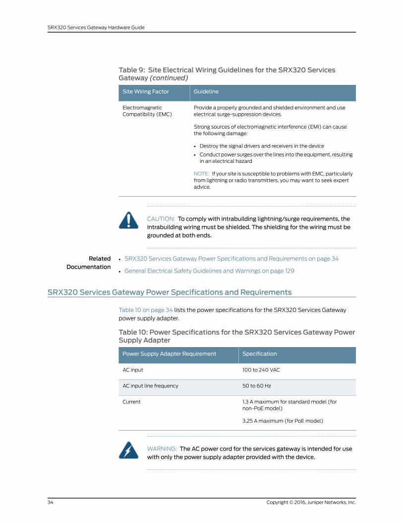
Table 9: Site ElectricalWiring Guidelines for the SRX320 ServicesGateway (continued)
GuidelineSiteWiring Factor
Provide a properly grounded and shielded environment and useelectrical surge-suppression devices.
Strong sources of electromagnetic interference (EMI) can causethe following damage:
• Destroy the signal drivers and receivers in the device
• Conduct power surges over the lines into the equipment, resultingin an electrical hazard
NOTE: If your site is susceptible to problems with EMC, particularlyfrom lightning or radio transmitters, you may want to seek expertadvice.
ElectromagneticCompatibility (EMC)
CAUTION: To comply with intrabuilding lightning/surge requirements, theintrabuilding wiringmust be shielded. The shielding for the wiringmust begrounded at both ends.
RelatedDocumentation
SRX320 Services Gateway Power Specifications and Requirements on page 34•
• General Electrical Safety Guidelines and Warnings on page 129
SRX320 Services Gateway Power Specifications and Requirements
Table 10 on page 34 lists the power specifications for the SRX320 Services Gateway
power supply adapter.
Table 10: Power Specifications for the SRX320 Services Gateway PowerSupply Adapter
SpecificationPower Supply Adapter Requirement
100 to 240 VACAC input
50 to 60 HzAC input line frequency
1.3 A maximum for standard model (fornon-PoE model)
3.25 A maximum (for PoE model)
Current
WARNING: The AC power cord for the services gateway is intended for usewith only the power supply adapter provided with the device.
Copyright © 2016, Juniper Networks, Inc.34
SRX320 Services Gateway Hardware Guide
RelatedDocumentation
• SRX320 Services Gateway Electrical Wiring Guidelines on page 33
• Understanding the SRX320 Services Gateway Power Supply on page 15
35Copyright © 2016, Juniper Networks, Inc.
Chapter 9: Power Requirements and Specifications

Copyright © 2016, Juniper Networks, Inc.36
SRX320 Services Gateway Hardware Guide
CHAPTER 10
Cable Specifications and Pinouts
• RJ-45 Connector Pinouts for the SRX320 Services Gateway Ethernet Port on page 37
• RJ-45 Connector Pinouts for the SRX320 Services Gateway Console Port on page 37
• Mini-USB Connector Pinouts for the SRX320 Services Gateway Console Port on page 38
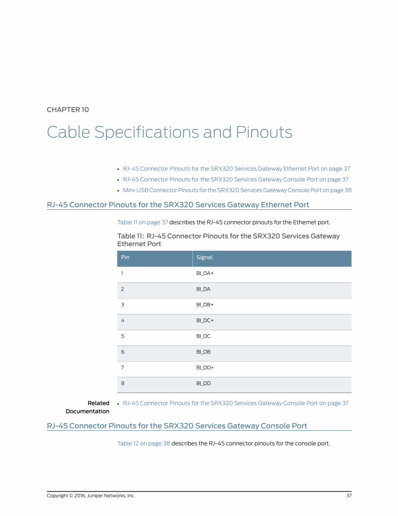
RJ-45 Connector Pinouts for the SRX320 Services Gateway Ethernet Port
Table 11 on page 37 describes the RJ-45 connector pinouts for the Ethernet port.
Table 11: RJ-45 Connector Pinouts for the SRX320 Services GatewayEthernet Port
SignalPin
BI_DA+1
BI_DA2
BI_DB+3
BI_DC+4
BI_DC5
BI_DB6
BI_DD+7
BI_DD8
RelatedDocumentation
RJ-45 Connector Pinouts for the SRX320 Services Gateway Console Port on page 37•
RJ-45 Connector Pinouts for the SRX320 Services Gateway Console Port
Table 12 on page 38 describes the RJ-45 connector pinouts for the console port.
37Copyright © 2016, Juniper Networks, Inc.
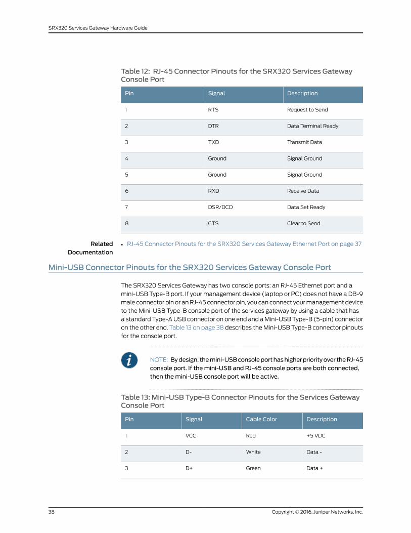
Table 12: RJ-45 Connector Pinouts for the SRX320 Services GatewayConsole Port
DescriptionSignalPin
Request to SendRTS1
Data Terminal ReadyDTR2
Transmit DataTXD3
Signal GroundGround4
Signal GroundGround5
Receive DataRXD6
Data Set ReadyDSR/DCD7
Clear to SendCTS8
RelatedDocumentation
RJ-45 Connector Pinouts for the SRX320 Services Gateway Ethernet Port on page 37•
Mini-USB Connector Pinouts for the SRX320 Services Gateway Console Port
The SRX320 Services Gateway has two console ports: an RJ-45 Ethernet port and a
mini-USB Type-B port. If your management device (laptop or PC) does not have a DB-9
male connector pin or an RJ-45 connector pin, you can connect your management device
to the Mini-USB Type-B console port of the services gateway by using a cable that has
a standard Type-A USB connector on one end and a Mini-USB Type-B (5-pin) connector
on the other end. Table 13 on page 38 describes the Mini-USB Type-B connector pinouts
for the console port.
NOTE: Bydesign, themini-USBconsoleporthashigherpriorityover theRJ-45console port. If themini-USB and RJ-45 console ports are both connected,then themini-USB console port will be active.
Table 13: Mini-USB Type-B Connector Pinouts for the Services GatewayConsole Port
DescriptionCable ColorSignalPin
+5 VDCRedVCC1
Data -WhiteD-2
Data +GreenD+3
Copyright © 2016, Juniper Networks, Inc.38
SRX320 Services Gateway Hardware Guide
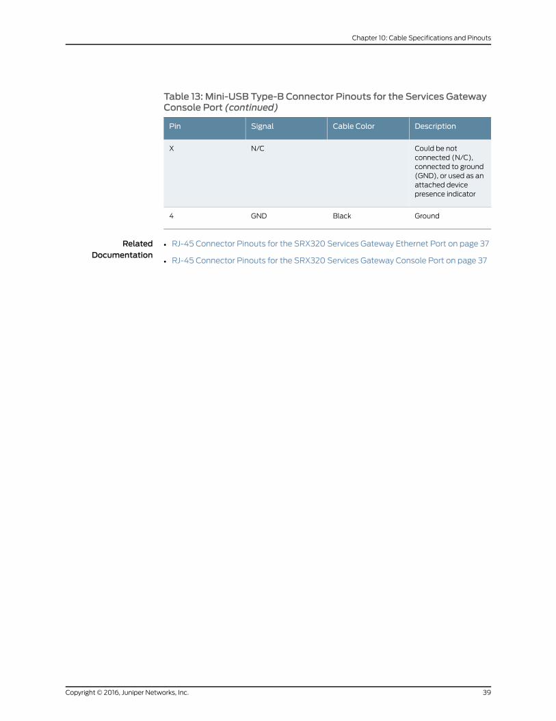
Table 13: Mini-USB Type-B Connector Pinouts for the Services GatewayConsole Port (continued)
DescriptionCable ColorSignalPin
Could be notconnected (N/C),connected to ground(GND), or used as anattached devicepresence indicator
N/CX
GroundBlackGND4
RelatedDocumentation
• RJ-45 Connector Pinouts for the SRX320 Services Gateway Ethernet Port on page 37
• RJ-45 Connector Pinouts for the SRX320 Services Gateway Console Port on page 37
39Copyright © 2016, Juniper Networks, Inc.
Chapter 10: Cable Specifications and Pinouts

Copyright © 2016, Juniper Networks, Inc.40
SRX320 Services Gateway Hardware Guide
PART 3
Initial Installation and Configuration
• Installation Overview on page 43
• Unpacking the SRX320 Services Gateway on page 45
• Installing the Rack Mounting Hardware on page 49
• Installing the SRX320 Services Gateway on page 53
• Connecting the SRX320 Services Gateway to Ground on page 61
• Connecting the SRX320 Services Gateway to External Devices on page 65
• Providing Power to the SRX320 Services Gateway on page 67
• Performing the Initial Configuration on page 71
41Copyright © 2016, Juniper Networks, Inc.

Copyright © 2016, Juniper Networks, Inc.42
SRX320 Services Gateway Hardware Guide
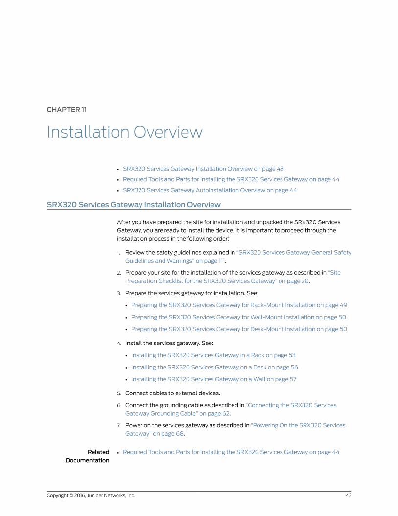
CHAPTER 11
Installation Overview
• SRX320 Services Gateway Installation Overview on page 43
• Required Tools and Parts for Installing the SRX320 Services Gateway on page 44
• SRX320 Services Gateway Autoinstallation Overview on page 44
SRX320 Services Gateway Installation Overview
After you have prepared the site for installation and unpacked the SRX320 Services
Gateway, you are ready to install the device. It is important to proceed through the
installation process in the following order:
1. Review the safety guidelines explained in “SRX320 Services Gateway General Safety
Guidelines and Warnings” on page 111.
2. Prepare your site for the installation of the services gateway as described in “Site
Preparation Checklist for the SRX320 Services Gateway” on page 20.
3. Prepare the services gateway for installation. See:
• Preparing the SRX320 Services Gateway for Rack-Mount Installation on page 49
• Preparing the SRX320 Services Gateway for Wall-Mount Installation on page 50
• Preparing the SRX320 Services Gateway for Desk-Mount Installation on page 50
4. Install the services gateway. See:
• Installing the SRX320 Services Gateway in a Rack on page 53
• Installing the SRX320 Services Gateway on a Desk on page 56
• Installing the SRX320 Services Gateway on a Wall on page 57
5. Connect cables to external devices.
6. Connect the grounding cable as described in “Connecting the SRX320 Services
Gateway Grounding Cable” on page 62.
7. Power on the services gateway as described in “Powering On the SRX320 Services
Gateway” on page 68.
RelatedDocumentation
Required Tools and Parts for Installing the SRX320 Services Gateway on page 44•
43Copyright © 2016, Juniper Networks, Inc.
• SRX320 Services Gateway Autoinstallation Overview on page 44
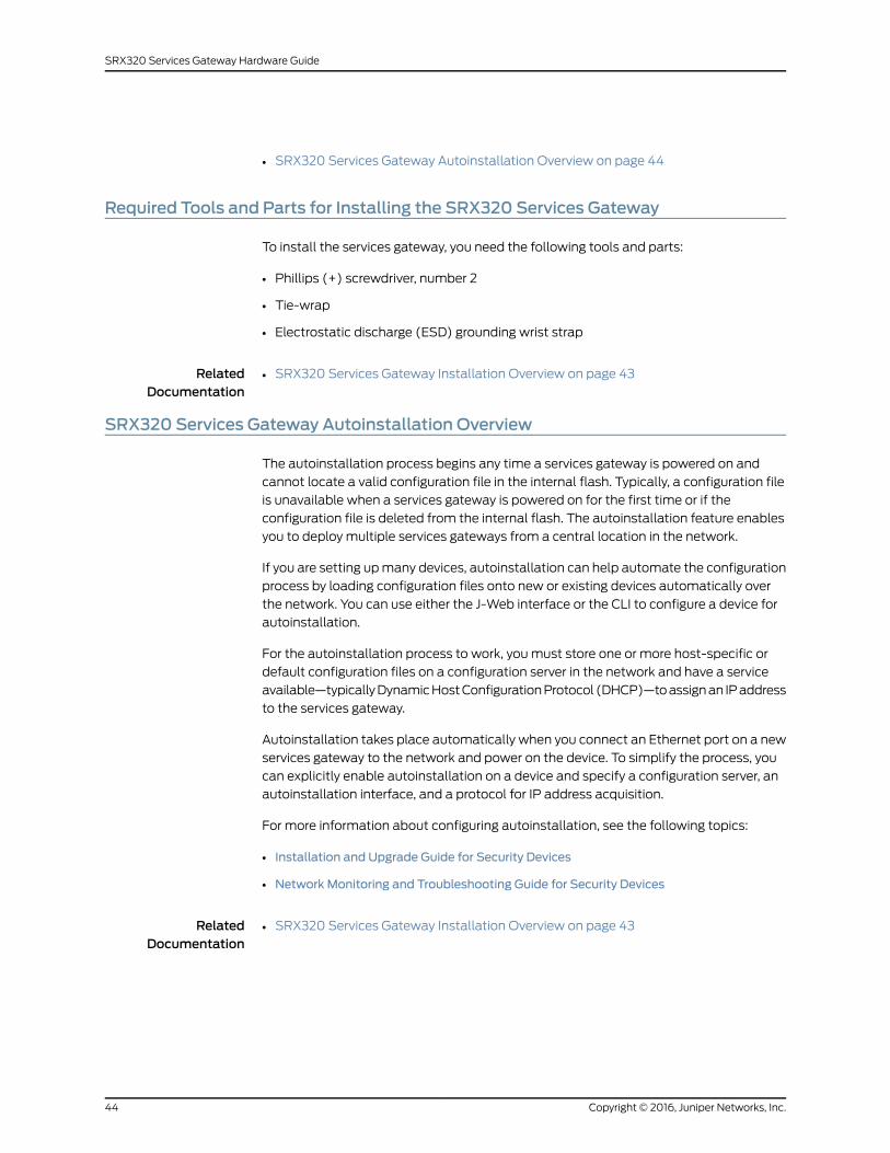
Required Tools and Parts for Installing the SRX320 Services Gateway
To install the services gateway, you need the following tools and parts:
• Phillips (+) screwdriver, number 2
• Tie-wrap
• Electrostatic discharge (ESD) grounding wrist strap
RelatedDocumentation
SRX320 Services Gateway Installation Overview on page 43•
SRX320 Services Gateway Autoinstallation Overview
The autoinstallation process begins any time a services gateway is powered on and
cannot locate a valid configuration file in the internal flash. Typically, a configuration file
is unavailable when a services gateway is powered on for the first time or if the
configuration file is deleted from the internal flash. The autoinstallation feature enables
you to deploy multiple services gateways from a central location in the network.
If you are setting up many devices, autoinstallation can help automate the configuration
process by loading configuration files onto new or existing devices automatically over
the network. You can use either the J-Web interface or the CLI to configure a device for
autoinstallation.
For the autoinstallation process to work, you must store one or more host-specific or
default configuration files on a configuration server in the network and have a service
available—typically Dynamic Host Configuration Protocol (DHCP)—to assign an IP address
to the services gateway.
Autoinstallation takes place automatically when you connect an Ethernet port on a new
services gateway to the network and power on the device. To simplify the process, you
can explicitly enable autoinstallation on a device and specify a configuration server, an
autoinstallation interface, and a protocol for IP address acquisition.
For more information about configuring autoinstallation, see the following topics:
• Installation and Upgrade Guide for Security Devices
• Network Monitoring and Troubleshooting Guide for Security Devices
RelatedDocumentation
• SRX320 Services Gateway Installation Overview on page 43
Copyright © 2016, Juniper Networks, Inc.44
SRX320 Services Gateway Hardware Guide
CHAPTER 12
Unpacking theSRX320ServicesGateway
• Required Tools and Parts for Unpacking the SRX320 Services Gateway on page 45
• Unpacking the SRX320 Services Gateway on page 45
• Verifying Parts Received with the SRX320 Services Gateway on page 46
Required Tools and Parts for Unpacking the SRX320 Services Gateway
To unpack the SRX320 Services Gateway, you need the following tools:
• Phillips (+) screwdriver, number 2
• Blank panels to cover any slots not occupied by a component
RelatedDocumentation
Unpacking the SRX320 Services Gateway on page 45•
• Verifying Parts Received with the SRX320 Services Gateway on page 46
Unpacking the SRX320 Services Gateway
The SRX320 Services Gateway is shipped in a cardboard carton and secured with foam
packing material. The carton also contains an accessory box and quick-start instructions.
To unpack the SRX320 Services Gateway:
1. Move the cardboard carton to a staging area as close to the installation site as possible,
where you have enough room to remove the components from the chassis.
2. Position the cardboard carton with the arrows pointing up.
3. Carefully open the top of the cardboard carton.
4. Remove the foam covering the top of the services gateway.
5. Remove the accessory box.
6. Verify the parts received against the lists in “Verifying Parts Received with the SRX320
Services Gateway” on page 46.
7. Store the brackets and bolts inside the accessory box.
8. Save the shipping carton and packing materials in case you need to move or ship the
services gateway at a later time.
45Copyright © 2016, Juniper Networks, Inc.
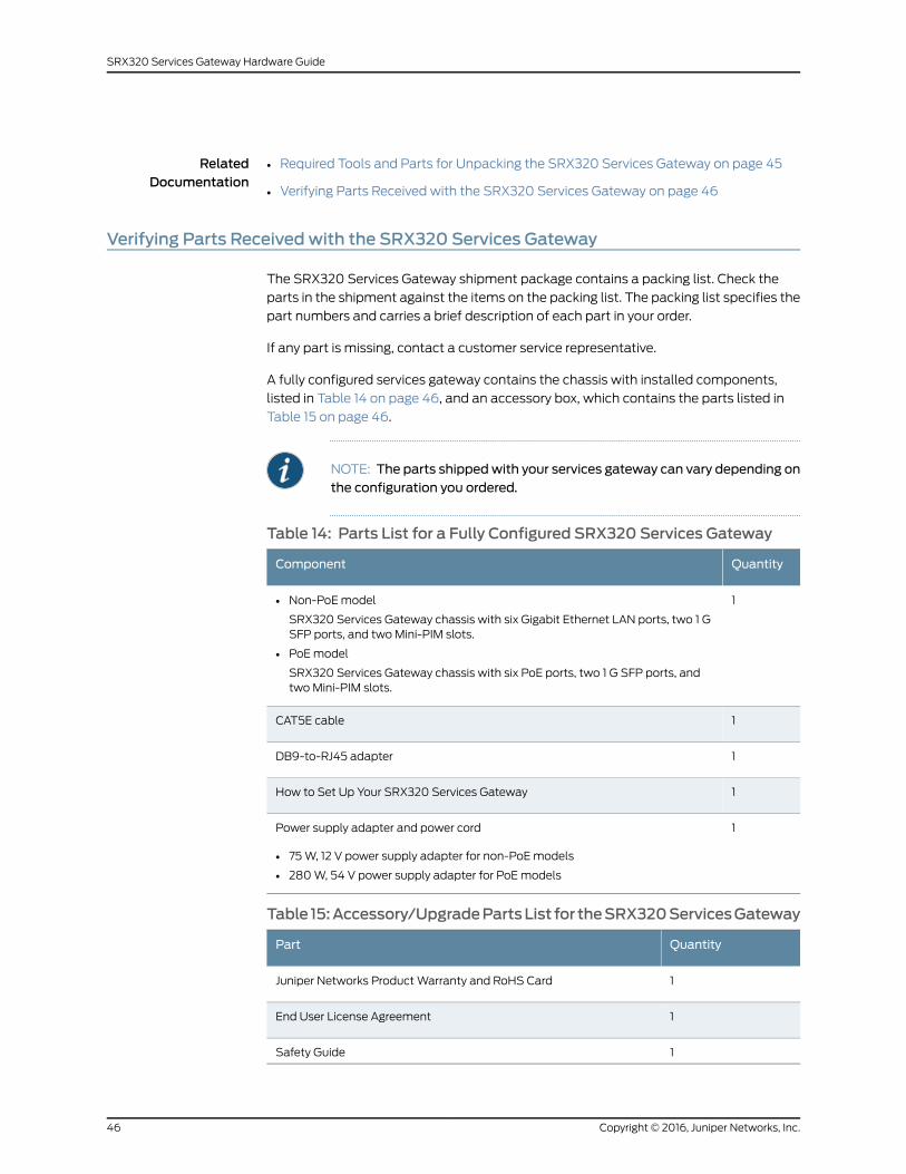
RelatedDocumentation
Required Tools and Parts for Unpacking the SRX320 Services Gateway on page 45•
• Verifying Parts Received with the SRX320 Services Gateway on page 46
Verifying Parts Receivedwith the SRX320 Services Gateway
The SRX320 Services Gateway shipment package contains a packing list. Check the
parts in the shipment against the items on the packing list. The packing list specifies the
part numbers and carries a brief description of each part in your order.
If any part is missing, contact a customer service representative.
A fully configured services gateway contains the chassis with installed components,
listed in Table 14 on page 46, and an accessory box, which contains the parts listed in
Table 15 on page 46.
NOTE: The parts shippedwith your services gateway can vary depending onthe configuration you ordered.
Table 14: Parts List for a Fully Configured SRX320 Services Gateway
QuantityComponent
1• Non-PoE model
SRX320 Services Gateway chassis with six Gigabit Ethernet LAN ports, two 1 GSFP ports, and two Mini-PIM slots.
• PoE model
SRX320 Services Gateway chassis with six PoE ports, two 1 G SFP ports, andtwo Mini-PIM slots.
1CAT5E cable
1DB9-to-RJ45 adapter
1How to Set Up Your SRX320 Services Gateway
1Power supply adapter and power cord
• 75 W, 12 V power supply adapter for non-PoE models
• 280 W, 54 V power supply adapter for PoE models
Table 15:Accessory/UpgradePartsList for theSRX320ServicesGateway
QuantityPart
1Juniper Networks Product Warranty and RoHS Card
1End User License Agreement
1Safety Guide
Copyright © 2016, Juniper Networks, Inc.46
SRX320 Services Gateway Hardware Guide
RelatedDocumentation
• Required Tools and Parts for Unpacking the SRX320 Services Gateway on page 45
• Unpacking the SRX320 Services Gateway on page 45
47Copyright © 2016, Juniper Networks, Inc.
Chapter 12: Unpacking the SRX320 Services Gateway

Copyright © 2016, Juniper Networks, Inc.48
SRX320 Services Gateway Hardware Guide
CHAPTER 13
Installing the Rack Mounting Hardware
• Preparing the SRX320 Services Gateway for Rack-Mount Installation on page 49
• Preparing the SRX320 Services Gateway for Wall-Mount Installation on page 50
• Preparing the SRX320 Services Gateway for Desk-Mount Installation on page 50
• Connecting the SRX320 Services Gateway to the Building Structure on page 51
Preparing the SRX320 Services Gateway for Rack-Mount Installation
You can mount an SRX320 Services Gateway in four-post (telco) racks, enclosed cabinets,
and open-frame racks.
NOTE: The SRX320 Services Gateway cannot be center-mounted in racks.
Before mounting the SRX320 Services Gateway in a rack:
• Verify that the installation site meets the requirements described in “Site Preparation
Checklist for the SRX320 Services Gateway” on page 20.
• Verify that the racks or cabinets meet the specific requirements described in “SRX320
Services Gateway Rack-Mounting Requirements and Warnings” on page 25.
• Place the rack or cabinet in its permanent location, allowing adequate clearance for
airflow and maintenance, and secure it to the building structure. For more information,
see “SRX320 Services Gateway Clearance Requirements for Airflow and Hardware
Maintenance” on page 30.
• Remove the services gateway chassis from the shipping carton. For unpacking
instructions, see “Unpacking the SRX320 Services Gateway” on page 45.
• Verify that you have the following parts available in your rack-mounting kit:
• Rack-mount tray
• Screws
NOTE: The rack-mounting kit is not shipped with the device andmust beordered separately.
49Copyright © 2016, Juniper Networks, Inc.
RelatedDocumentation
Preparing the SRX320 Services Gateway for Wall-Mount Installation on page 50•
• Preparing the SRX320 Services Gateway for Desk-Mount Installation on page 50
• Installing the SRX320 Services Gateway in a Rack on page 53
Preparing the SRX320 Services Gateway forWall-Mount Installation
You can mount an SRX320 Services Gateway on a wall. The four rubber feet attached
to the chassis provide stability. Before mounting the SRX320 Services Gateway on a wall:
• Verify that the installation site meets the requirements described in “Site Preparation
Checklist for the SRX320 Services Gateway” on page 20.
• Remove the services gateway chassis from the shipping carton. For unpacking
instructions, see “Unpacking the SRX320 Services Gateway” on page 45.
• Verify that you have the following parts available in your wall-mounting kit:
• Wall-mounting brackets
• Screws
NOTE: The wall-mounting kit is not shipped with the device andmust beordered separately.
RelatedDocumentation
Preparing the SRX320 Services Gateway for Rack-Mount Installation on page 49•
• Installing the SRX320 Services Gateway on a Wall on page 57
Preparing the SRX320 Services Gateway for Desk-Mount Installation
You can mount an SRX320 Services Gateway on a desk or any other level surface
horizontally or vertically. The four rubber feet attached to the chassis provide stability.
Before mounting an SRX320 Services Gateway on a desk or other level surface:
• Verify that the installation site meets the requirements described in “Site Preparation
Checklist for the SRX320 Services Gateway” on page 20.
• Place the desk in its permanent location, allowing adequate clearance for airflow and
maintenance, and secure it to the building structure.
• Remove the services gateway chassis from the shipping carton. For unpacking
instructions, see “Unpacking the SRX320 Services Gateway” on page 45.
RelatedDocumentation
Installing the SRX320 Services Gateway on a Desk on page 56•
• Preparing the SRX320 Services Gateway for Rack-Mount Installation on page 49
• Preparing the SRX320 Services Gateway for Wall-Mount Installation on page 50
Copyright © 2016, Juniper Networks, Inc.50
SRX320 Services Gateway Hardware Guide
Connecting the SRX320 Services Gateway to the Building Structure
Always secure the rack in which you are installing the services gateway to the structure
of the building. If your geographical area is subject to earthquakes, bolt the rack to the
floor. For maximum stability, also secure the rack to ceiling brackets.
RelatedDocumentation
• Preparing the SRX320 Services Gateway for Rack-Mount Installation on page 49
51Copyright © 2016, Juniper Networks, Inc.
Chapter 13: Installing the Rack Mounting Hardware

Copyright © 2016, Juniper Networks, Inc.52
SRX320 Services Gateway Hardware Guide
CHAPTER 14
Installing the SRX320 Services Gateway
• Installing the SRX320 Services Gateway in a Rack on page 53
• Installing the SRX320 Services Gateway on a Desk on page 56
• Installing the SRX320 Services Gateway on a Wall on page 57
Installing the SRX320 Services Gateway in a Rack
You can front-mount the SRX320 Services Gateway in a rack. Many types of racks are
acceptable, including four-post (telco) racks, enclosed cabinets, and open-frame racks.
For more information about the type of rack or cabinet the SRX320 Services Gateway
can be installed in, see “SRX320 Services Gateway Rack Size and Strength Requirements”
on page 29.
NOTE: The rack-mounting kit is not shipped with the device andmust beordered separately.
NOTE: If you are installingmultiple devices in one rack, install the lowest onefirst and proceed upward in the rack. Ensure that the rubber feet from thebase of the chassis are removed for rack installation.
To install the device in a rack:
53Copyright © 2016, Juniper Networks, Inc.
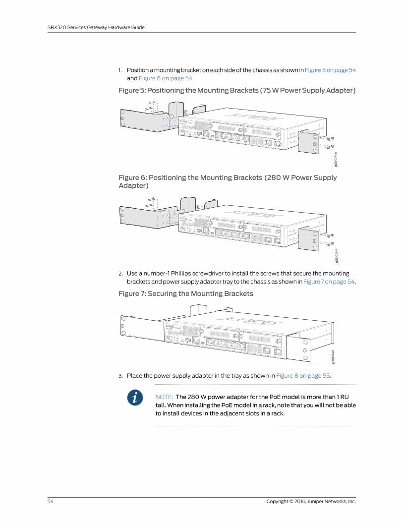
1. Position a mounting bracket on each side of the chassis as shown in Figure 5 on page 54
and Figure 6 on page 54.
Figure5:PositioningtheMountingBrackets(75WPowerSupplyAdapter)
Figure 6: Positioning theMounting Brackets (280WPower SupplyAdapter)
2. Use a number-1 Phillips screwdriver to install the screws that secure the mounting
brackets and power supply adapter tray to the chassis as shown in Figure 7 on page 54.
Figure 7: Securing theMounting Brackets
3. Place the power supply adapter in the tray as shown in Figure 8 on page 55.
NOTE: The 280Wpower adapter for the PoEmodel is more than 1 RUtall.When installing thePoEmodel in a rack, note that youwill not beableto install devices in the adjacent slots in a rack.
Copyright © 2016, Juniper Networks, Inc.54
SRX320 Services Gateway Hardware Guide
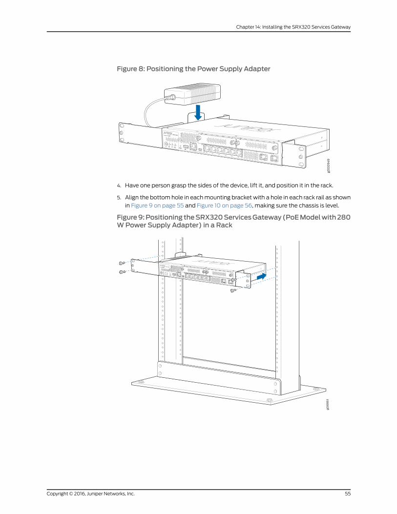
Figure 8: Positioning the Power Supply Adapter
4. Have one person grasp the sides of the device, lift it, and position it in the rack.
5. Align the bottom hole in each mounting bracket with a hole in each rack rail as shown
in Figure 9 on page 55 and Figure 10 on page 56, making sure the chassis is level.
Figure9:Positioning theSRX320ServicesGateway(PoEModelwith280WPower Supply Adapter) in a Rack
g000
951
55Copyright © 2016, Juniper Networks, Inc.
Chapter 14: Installing the SRX320 Services Gateway
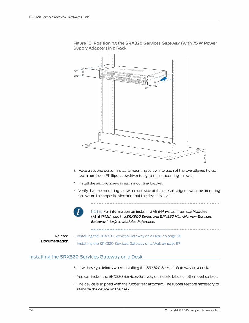
Figure 10: Positioning the SRX320 Services Gateway (with 75WPowerSupply Adapter) in a Rack
6. Have a second person install a mounting screw into each of the two aligned holes.
Use a number-1 Phillips screwdriver to tighten the mounting screws.
7. Install the second screw in each mounting bracket.
8. Verify that the mounting screws on one side of the rack are aligned with the mounting
screws on the opposite side and that the device is level.
NOTE: For information on installing Mini-Physical Interface Modules(Mini-PIMs), see the SRX300 Series and SRX550 High Memory ServicesGateway Interface Modules Reference.
RelatedDocumentation
Installing the SRX320 Services Gateway on a Desk on page 56•
• Installing the SRX320 Services Gateway on a Wall on page 57
Installing the SRX320 Services Gateway on a Desk
Follow these guidelines when installing the SRX320 Services Gateway on a desk:
• You can install the SRX320 Services Gateway on a desk, table, or other level surface.
• The device is shipped with the rubber feet attached. The rubber feet are necessary to
stabilize the device on the desk.
Copyright © 2016, Juniper Networks, Inc.56
SRX320 Services Gateway Hardware Guide
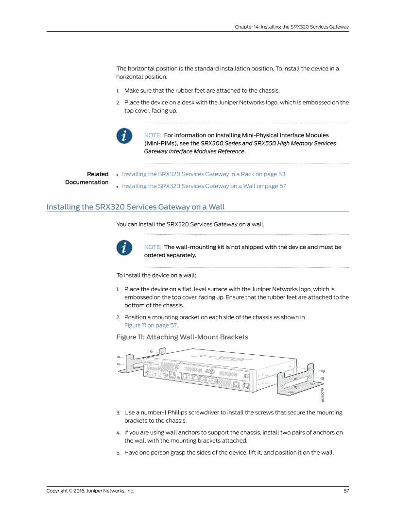
The horizontal position is the standard installation position. To install the device in a
horizontal position:
1. Make sure that the rubber feet are attached to the chassis.
2. Place the device on a desk with the Juniper Networks logo, which is embossed on the
top cover, facing up.
NOTE: For information on installing Mini-Physical Interface Modules(Mini-PIMs), see the SRX300 Series and SRX550 High Memory ServicesGateway Interface Modules Reference.
RelatedDocumentation
Installing the SRX320 Services Gateway in a Rack on page 53•
• Installing the SRX320 Services Gateway on a Wall on page 57
Installing the SRX320 Services Gateway on aWall
You can install the SRX320 Services Gateway on a wall.
NOTE: The wall-mounting kit is not shipped with the device andmust beordered separately.
To install the device on a wall:
1. Place the device on a flat, level surface with the Juniper Networks logo, which is
embossed on the top cover, facing up. Ensure that the rubber feet are attached to the
bottom of the chassis.
2. Position a mounting bracket on each side of the chassis as shown in
Figure 11 on page 57.
Figure 11: AttachingWall-Mount Brackets
3. Use a number-1 Phillips screwdriver to install the screws that secure the mounting
brackets to the chassis.
4. If you are using wall anchors to support the chassis, install two pairs of anchors on
the wall with the mounting brackets attached.
5. Have one person grasp the sides of the device, lift it, and position it on the wall.
57Copyright © 2016, Juniper Networks, Inc.
Chapter 14: Installing the SRX320 Services Gateway
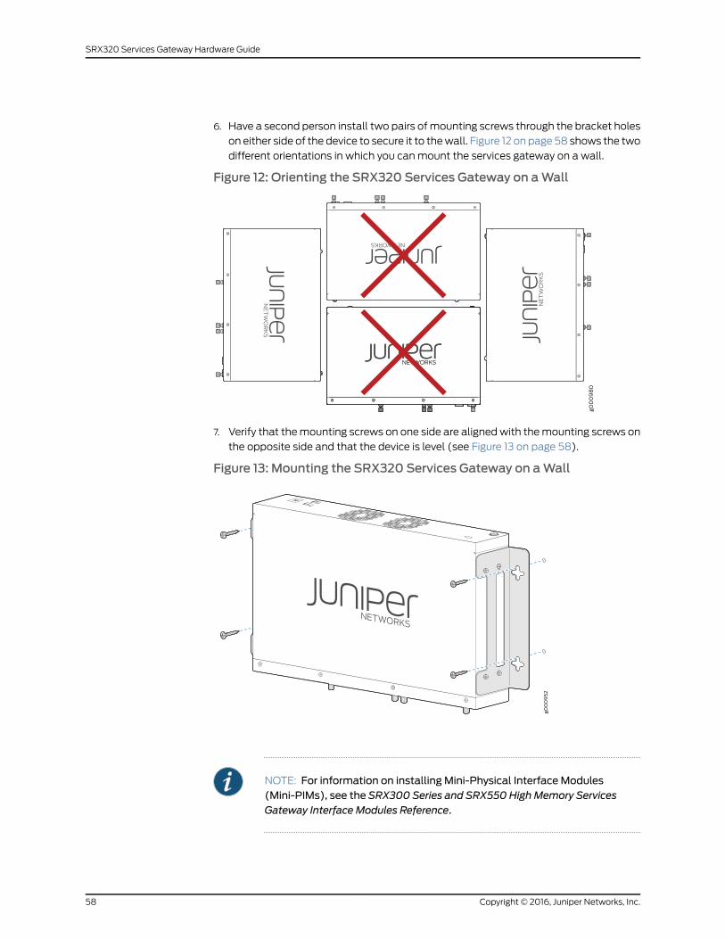
6. Have a second person install two pairs of mounting screws through the bracket holes
on either side of the device to secure it to the wall. Figure 12 on page 58 shows the two
different orientations in which you can mount the services gateway on a wall.
Figure 12: Orienting the SRX320 Services Gateway on aWall
7. Verify that the mounting screws on one side are aligned with the mounting screws on
the opposite side and that the device is level (see Figure 13 on page 58).
Figure 13: Mounting the SRX320 Services Gateway on aWall
NOTE: For information on installing Mini-Physical Interface Modules(Mini-PIMs), see the SRX300 Series and SRX550 High Memory ServicesGateway Interface Modules Reference.
Copyright © 2016, Juniper Networks, Inc.58
SRX320 Services Gateway Hardware Guide
RelatedDocumentation
• Installing the SRX320 Services Gateway in a Rack on page 53
• Installing the SRX320 Services Gateway on a Wall on page 57
59Copyright © 2016, Juniper Networks, Inc.
Chapter 14: Installing the SRX320 Services Gateway

Copyright © 2016, Juniper Networks, Inc.60
SRX320 Services Gateway Hardware Guide
CHAPTER 15
Connecting theSRX320ServicesGatewayto Ground
• Required Tools and Parts for Grounding the SRX320 Services Gateway on page 61
• SRX320 Services Gateway Grounding Specifications on page 61
• Connecting the SRX320 Services Gateway Grounding Cable on page 62
Required Tools and Parts for Grounding the SRX320 Services Gateway
To ground and to provide power to the services gateway, you need the following tools:
• Phillips (+) screwdrivers, numbers 1 and 2
• Electrostatic discharge (ESD) grounding wrist strap
• Wire cutters
RelatedDocumentation
SRX320 Services Gateway Grounding Specifications on page 61•
• Connecting the SRX320 Services Gateway Grounding Cable on page 62
SRX320 Services Gateway Grounding Specifications
To meet safety and electromagnetic interference (EMI) requirements and to ensure
proper operation, the SRX320 Services Gateway must be adequately grounded before
power is connected. You must provide a grounding lug to connect the services gateway
to earth ground.
WARNING: Before you connect power to the services gateway, a licensedelectricianmust attach a cable lug to the grounding and power cables thatyou supply. A cablewith an incorrectly attached lug can damage the servicesgateway (for example, by causing a short circuit).
The services gateway chassis has one grounding point on the back panel. The grounding
point hole fits M5 screws.
Table 16 on page 62 lists the specifications of the grounding cable used with the device.
61Copyright © 2016, Juniper Networks, Inc.
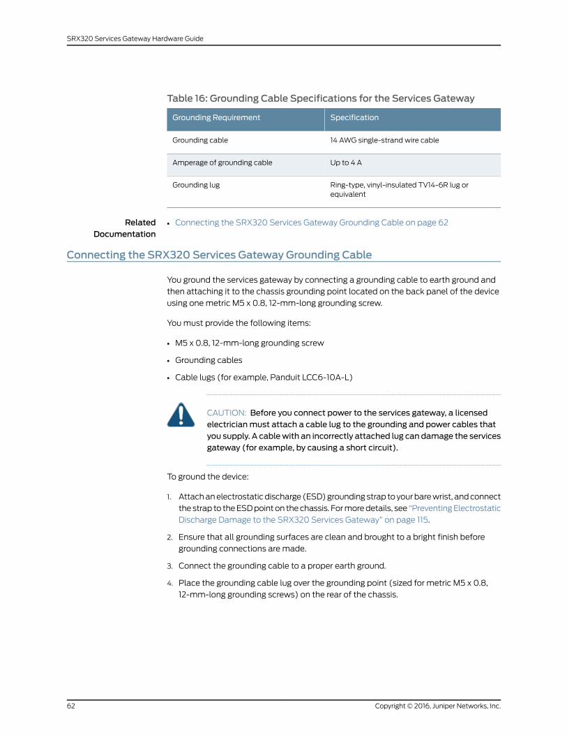
Table 16: Grounding Cable Specifications for the Services Gateway
SpecificationGrounding Requirement
14 AWG single-strand wire cableGrounding cable
Up to 4 AAmperage of grounding cable
Ring-type, vinyl-insulated TV14-6R lug orequivalent
Grounding lug
RelatedDocumentation
Connecting the SRX320 Services Gateway Grounding Cable on page 62•
Connecting the SRX320 Services Gateway Grounding Cable
You ground the services gateway by connecting a grounding cable to earth ground and
then attaching it to the chassis grounding point located on the back panel of the device
using one metric M5 x 0.8, 12-mm-long grounding screw.
You must provide the following items:
• M5 x 0.8, 12-mm-long grounding screw
• Grounding cables
• Cable lugs (for example, Panduit LCC6-10A-L)
CAUTION: Before you connect power to the services gateway, a licensedelectricianmust attach a cable lug to the grounding and power cables thatyou supply. A cablewith an incorrectly attached lug can damage the servicesgateway (for example, by causing a short circuit).
To ground the device:
1. Attach an electrostatic discharge (ESD) grounding strap to your bare wrist, and connect
the strap to the ESD point on the chassis. For more details, see “Preventing Electrostatic
Discharge Damage to the SRX320 Services Gateway” on page 115.
2. Ensure that all grounding surfaces are clean and brought to a bright finish before
grounding connections are made.
3. Connect the grounding cable to a proper earth ground.
4. Place the grounding cable lug over the grounding point (sized for metric M5 x 0.8,
12-mm-long grounding screws) on the rear of the chassis.
Copyright © 2016, Juniper Networks, Inc.62
SRX320 Services Gateway Hardware Guide
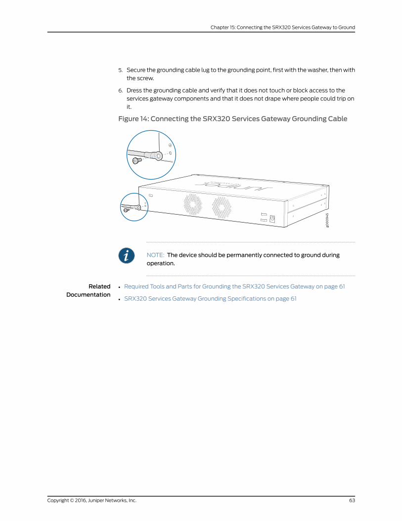
5. Secure the grounding cable lug to the grounding point, first with the washer, then with
the screw.
6. Dress the grounding cable and verify that it does not touch or block access to the
services gateway components and that it does not drape where people could trip on
it.
Figure 14: Connecting the SRX320 Services Gateway Grounding Cable
NOTE: The device should be permanently connected to ground duringoperation.
RelatedDocumentation
• Required Tools and Parts for Grounding the SRX320 Services Gateway on page 61
• SRX320 Services Gateway Grounding Specifications on page 61
63Copyright © 2016, Juniper Networks, Inc.
Chapter 15: Connecting the SRX320 Services Gateway to Ground

Copyright © 2016, Juniper Networks, Inc.64
SRX320 Services Gateway Hardware Guide
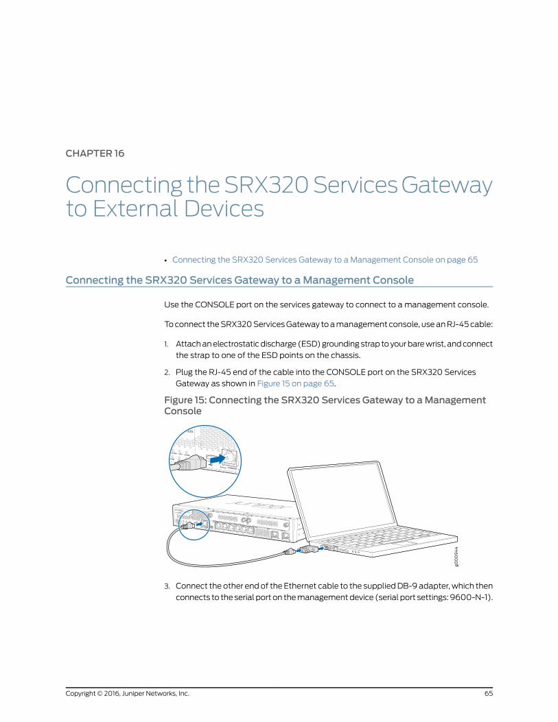
CHAPTER 16
Connecting theSRX320ServicesGatewayto External Devices
• Connecting the SRX320 Services Gateway to a Management Console on page 65
Connecting the SRX320 Services Gateway to aManagement Console
Use the CONSOLE port on the services gateway to connect to a management console.
To connect the SRX320 Services Gateway to a management console, use an RJ-45 cable:
1. Attach an electrostatic discharge (ESD) grounding strap to your bare wrist, and connect
the strap to one of the ESD points on the chassis.
2. Plug the RJ-45 end of the cable into the CONSOLE port on the SRX320 Services
Gateway as shown in Figure 15 on page 65.
Figure 15: Connecting the SRX320 Services Gateway to aManagementConsole
3. Connect the other end of the Ethernet cable to the supplied DB-9 adapter, which then
connects to the serial port on the management device (serial port settings: 9600-N-1).
65Copyright © 2016, Juniper Networks, Inc.
NOTE: Alternately, you can use theUSBcable to connect to themini-USBconsole port on the services gateway. To use the USB console port, youmust download a USB driver to themanagement device fromhttp://www.juniper.net/support/downloads/group/?f=junos.
RelatedDocumentation
• Accessing J-Web on the SRX320 Services Gateway on page 74
• Configuring the SRX320 Services Gateway Using the J-Web Setup Wizard on page 75
Copyright © 2016, Juniper Networks, Inc.66
SRX320 Services Gateway Hardware Guide
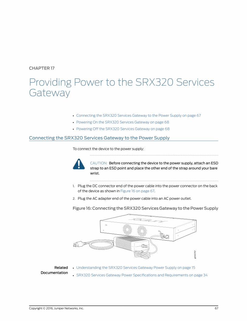
CHAPTER 17
Providing Power to the SRX320 ServicesGateway
• Connecting the SRX320 Services Gateway to the Power Supply on page 67
• Powering On the SRX320 Services Gateway on page 68
• Powering Off the SRX320 Services Gateway on page 68
Connecting the SRX320 Services Gateway to the Power Supply
To connect the device to the power supply:
CAUTION: Before connecting the device to the power supply, attach an ESDstrap to an ESD point and place the other end of the strap around your barewrist.
1. Plug the DC connector end of the power cable into the power connector on the back
of the device as shown in Figure 16 on page 67.
2. Plug the AC adapter end of the power cable into an AC power outlet.
Figure 16:Connecting theSRX320ServicesGateway to thePowerSupply
RelatedDocumentation
Understanding the SRX320 Services Gateway Power Supply on page 15•
• SRX320 Services Gateway Power Specifications and Requirements on page 34
67Copyright © 2016, Juniper Networks, Inc.
Powering On the SRX320 Services Gateway
To power on the services gateway:
1. Ensure that you have connected the power supply to the device.
2. Insert the plug of the power supply adapter into an AC power source receptacle.
3. Turn on the power to the AC power receptacle.
The device starts automatically as the power supply completes its startup sequence.
The PWR LED lights during startup and remains on when the device is operating normally.
NOTE: After the power supply is turned on, it can take up to 60 seconds forstatus indicators—such as theSTATandPWRLEDs—to show that the powersupply is functioning normally. Ignore error indicators that appear during thefirst 60 seconds.
NOTE: Whenthesystem iscompletelypoweredoffandyouturnonthepowersupply, thedevicestartsas thepowersupplycompletes its startupsequence.If the device finishes starting and you need to power off the system again,first issue the CLI request system power-off command.
RelatedDocumentation
Understanding the SRX320 Services Gateway Power Supply on page 15•
• Powering Off the SRX320 Services Gateway on page 68
Powering Off the SRX320 Services Gateway
You can power off the services gateway in one of the following ways:
• Graceful shutdown—Press and immediately release the Power button. The device
begins gracefully shutting down the operating system and then powers itself off.
CAUTION: Use the graceful shutdownmethod to power off or reboot theservices gateway.
• Forced shutdown—Press the Power button and hold it for ten seconds. The device
immediately powers itself off without shutting down the operating system.
CAUTION: Use the forced shutdownmethod as a last resort to recover theservicesgateway if theservicesgatewayoperatingsystemisnot respondingto the graceful shutdownmethod.
Copyright © 2016, Juniper Networks, Inc.68
SRX320 Services Gateway Hardware Guide
WARNING: Donotpress thePowerbuttonwhile thedevice is shuttingdown.
CAUTION: Forced shutdown can result in data loss and corruption of the filesystem.
NOTE: To remove power completely from the device, unplug the power cordor switch off the AC power source.
After powering off a power supply, wait at least 10 seconds before turning itback on. After powering on a power supply, wait at least 10 seconds beforeturning it off.
The power button on the services gateway is a standby power switch, whichwill not turn off the input power to the services gateway.
TIP: When you are powering off the device, the CLI displays the followingmessage:Turning the systempoweroff. You cannowsafely remove thepower
cable to completely power off the device.
NOTE: You can use the request system reboot CLI command to schedule areboot.
RelatedDocumentation
• Understanding the SRX320 Services Gateway Power Supply on page 15
• Powering On the SRX320 Services Gateway on page 68
69Copyright © 2016, Juniper Networks, Inc.
Chapter 17: Providing Power to the SRX320 Services Gateway

Copyright © 2016, Juniper Networks, Inc.70
SRX320 Services Gateway Hardware Guide
CHAPTER 18
Performing the Initial Configuration
• SRX320 Services Gateway Software Configuration Overview on page 71
• Understanding SRX320 Services Gateway Factory-Default Settings on page 71
• Viewing SRX320 Services Gateway Factory-Default Settings on page 72
• Accessing J-Web on the SRX320 Services Gateway on page 74
• Configuring the SRX320 Services Gateway Using the J-Web Setup Wizard on page 75
• Accessing the CLI on the SRX320 Services Gateway on page 77
• Connecting to the SRX320 Services Gateway from the CLI Remotely on page 78
• Configuring the SRX320 Services Gateway Using the CLI on page 79
• Verifying Settings for the SRX320 Services Gateway on page 81
SRX320 Services Gateway Software Configuration Overview
The services gateway is shipped with the Juniper Networks Junos operating system (Junos
OS) preinstalled and ready to be configured when the device is powered on. You can
perform the initial software configuration of the services gateway by using the
browser-based setup wizard or by using the command-line interface (CLI).
Before configuring the device, gather the configuration information required to deploy
the device in your network. At a minimum, the setup wizard requires the following
information:
• Device name
• Password for the root user
• Time information for the services gateway location
RelatedDocumentation
Configuring the SRX320 Services Gateway Using the J-Web Setup Wizard on page 75•
• Configuring the SRX320 Services Gateway Using the CLI on page 79
Understanding SRX320 Services Gateway Factory-Default Settings
Your services gateway comes configured with a factory-default configuration. The default
configuration includes the following security configuration:
71Copyright © 2016, Juniper Networks, Inc.
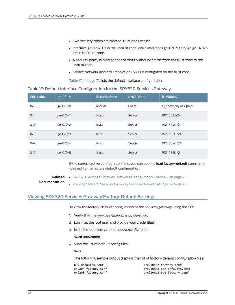
• Two security zones are created: trust and untrust.
• Interface ge-0/0/0 is in the untrust zone, while interfaces ge-0/0/1 through ge-0/0/5
are in the trust zone.
• A security policy is created that permits outbound traffic from the trust zone to the
untrust zone.
• Source Network Address Translation (NAT) is configured on the trust zone.
Table 17 on page 72 lists the default interface configuration.
Table 17: Default Interface Configuration for the SRX320 Services Gateway
IP AddressDHCP StateSecurity ZoneInterfacePort Label
Dynamically assignedClientuntrustge-0/0/00/0
192.168.1.1/24Servertrustge-0/0/10/1
192.168.2.1/24Servertrustge-0/0/20/2
192.168.3.1/24Servertrustge-0/0/30/3
192.168.4.1/24Servertrustge-0/0/40/4
192.168.5.1/24Servertrustge-0/0/50/5
If the current active configuration fails, you can use the load factory-default command
to revert to the factory-default configuration.
RelatedDocumentation
SRX320 Services Gateway Software Configuration Overview on page 71•
• Viewing SRX320 Services Gateway Factory-Default Settings on page 72
Viewing SRX320 Services Gateway Factory-Default Settings
To view the factory-default configuration of the services gateway using the CLI:
1. Verify that the services gateway is powered on.
2. Log in as the root user and provide your credentials.
3. In shell mode, navigate to the /etc/config folder.
%cd /etc/config
4. View the list of default config files.
% ls
The following sample output displays the list of factory-default configuration files:
blv-defaults.conf srx210he2-factory.confex9204-factory.conf srx210he2-poe-defaults.confex9208-factory.conf srx210he2-poe-factory.conf
Copyright © 2016, Juniper Networks, Inc.72
SRX320 Services Gateway Hardware Guide

ex9214-factory.conf srx220-8xge-factory.confj-series-defaults.conf srx220-poe-8xge-factory.confjnu-factory.conf srx220h-defaults.confjsrxsme-series-defaults.conf srx220h-factory.confjsrxsme-series-factory.conf srx220h-poe-defaults.confjunos-defaults.conf srx220h-poe-factory.confjunos-factory.conf srx220h2-defaults.confjunos-fips-defaults.conf srx220h2-factory.confptx-series-defaults.conf srx220h2-poe-defaults.confshmlog srx220h2-poe-factory.confsrx100-8xfe-factory.conf srx240-16xge-factory.confsrx100b-defaults.conf srx240-poe-16xge-factory.confsrx100b-factory.conf srx240b-factory.confsrx100h-defaults.conf srx240b2-factory.confsrx100h-factory.conf srx240h-dc-defaults.confsrx100h2-defaults.conf srx240h-dc-factory.confsrx100h2-factory.conf srx240h-defaults.confsrx110-8xfe-vdsl-factory.conf srx240h-factory.confsrx110-8xfe-vdsl-wl-factory.conf srx240h-poe-defaults.confsrx110-8xfe-wl-factory.conf srx240h-poe-factory.confsrx110b-defaults.conf srx240h2-dc-defaults.confsrx110b-va-defaults.conf srx240h2-dc-factory.confsrx110b-va-factory.conf srx240h2-defaults.confsrx110b-vb-defaults.conf srx240h2-factory.confsrx110b-vb-factory.conf srx240h2-poe-defaults.confsrx110b-wl-defaults.conf srx240h2-poe-factory.confsrx110b-wl-factory.conf srx300-8xge-factory.confsrx110h-defaults.conf srx300-defaults.confsrx110h-va-defaults.conf srx300-factory.confsrx110h-va-factory.conf srx300-lem-factory.confsrx110h-va-wl-defaults.conf srx320-8xge-factory.confsrx110h-va-wl-factory.conf srx320-defaults.confsrx110h-vb-defaults.conf srx320-factory.confsrx110h-vb-factory.conf srx320-lem-factory.confsrx110h-vb-wl-defaults.conf srx320-poe-8xge-factory.confsrx110h-vb-wl-factory.conf srx320-poe-defaults.confsrx110h-wl-defaults.conf srx320-poe-factory.confsrx110h-wl-factory.conf srx320-poe-lem-factory.confsrx110h2-va-defaults.conf srx340-16xge-factory.confsrx110h2-va-factory.conf srx340-defaults.confsrx110h2-vb-defaults.conf srx340-factory.confsrx110h2-vb-factory.conf srx340-lem-factory.confsrx210-2xge-6xfe-factory.conf srx345-defaults.confsrx210-poe-2xge-6xfe-factory.conf srx345-factory.confsrx210b-defaults.conf srx345-lem-factory.confsrx210b-factory.conf srx550-6xge-factory.confsrx210be-defaults.conf srx550-defaults.confsrx210be-factory.conf srx550-factory.confsrx210h-defaults.conf srx550m-6xge-factory.confsrx210h-factory.conf srx550m-defaults.confsrx210h-poe-defaults.conf srx550m-factory.confsrx210h-poe-factory.conf srx650-4xge-factory.confsrx210he-defaults.conf srx650-defaults.confsrx210he-factory.conf srx650-factory.confsrx210he-poe-defaults.conf subs-mgmt-proc-setsrx210he-poe-factory.conf vrr-series-defaults.confsrx210he2-defaults.conf
5. View the required default config file.
%vi config filename
73Copyright © 2016, Juniper Networks, Inc.
Chapter 18: Performing the Initial Configuration
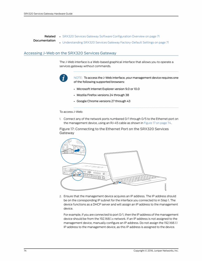
RelatedDocumentation
SRX320 Services Gateway Software Configuration Overview on page 71•
• Understanding SRX320 Services Gateway Factory-Default Settings on page 71
Accessing J-Web on the SRX320 Services Gateway
The J-Web interface is a Web-based graphical interface that allows you to operate a
services gateway without commands.
NOTE: Toaccess the J-Web interface, yourmanagement device requires oneof the following supported browsers:
• Microsoft Internet Explorer version 9.0 or 10.0
• Mozilla Firefox versions 24 through 38
• Google Chrome versions 27 through 43
To access J-Web:
1. Connect any of the network ports numbered 0/1 through 0/5 to the Ethernet port on
the management device, using an RJ-45 cable as shown in Figure 17 on page 74.
Figure 17: Connecting to the Ethernet Port on the SRX320 ServicesGateway
2. Ensure that the management device acquires an IP address. The IP address should
be on the corresponding IP subnet for the interface you connected to in Step 1. The
device functions as a DHCP server and will assign an IP address to the management
device.
For example, if you are connected to port 0/1, then the IP address of the management
device should be from the 192.168.1.x network. If an IP address is not assigned to the
management device, manually configure an IP address. Do not assign the 192.168.1.1
IP address to the management device, as this IP address is assigned to the device.
Copyright © 2016, Juniper Networks, Inc.74
SRX320 Services Gateway Hardware Guide
You can use the ipconfig (or ifconfig for Macintosh or Linux users) command to verify
the IP address.
For information on the subnet for each interface, see “Understanding SRX320 Services
Gateway Factory-Default Settings” on page 71.
3. Open a Web browser on the management device and enter the IP address
http://192.168.x.1 in the address field, where x is the port number to which you are
connected on the services gateway.
RelatedDocumentation
Configuring the SRX320 Services Gateway Using the J-Web Setup Wizard on page 75•
• Connecting the SRX320 Services Gateway to a Management Console on page 65
Configuring the SRX320 Services Gateway Using the J-Web SetupWizard
This topic describes how to perform the initial software configuration of your services
gateway using the setup wizard.
This topic includes the following sections:
• About the Setup Wizard on page 75
• About the Default Setup Mode on page 76
• About the Guided Setup Mode on page 76
About the SetupWizard
The setup wizard guides you through the step-by-step configuration of a services gateway
that can securely pass traffic. To help guide you through the process, the wizard:
• Provides recommended settings based on your previous selections. For example, the
wizard recommends security policies based on the security topology you have defined.
• Determines which configuration tasks to present to you based on your selections.
• Flags any missing required configuration when you attempt to leave a page.
• Indicates which configuration elements or tasks are unavailable to you based on your
previous selections by graying them out.
You can choose one of the following setup modes to configure the services gateway:
• Default Setup mode—This mode allows you to quickly set up a services gateway in a
default security configuration. In this mode, you can configure basic system settings,
such as the administrator password, and download purchased licenses. Any additional
configuration can be carried out after completing the wizard setup.
• Guided Setup mode—This mode allows you to set up a services gateway in a custom
security configuration.
75Copyright © 2016, Juniper Networks, Inc.
Chapter 18: Performing the Initial Configuration
NOTE: It ismandatory to configure only the device nameand root password.You can skip all the other steps by clicking Next to go directly to the Confirm
& Apply page to apply the configuration.
About the Default SetupMode
If you choose the Default Setup mode, the wizard takes you through the minimal
configuration needed to set up the services gateway that can securely pass traffic in the
default configuration.
In the Default Setup mode, you configure:
• Device name
• Password for the root account
• Time information for the services gateway location:
• Local time zone
• Name or IP address of a Network Time Protocol (NTP) server, if NTP is used to set
the time on the services gateway
• Local date and time if an NTP server is not used to set the time
You cannot do additional configuration in the Default Setup mode. You must commit
your changes and exit the wizard to perform any additional configuration. You can perform
additional configuration by rerunning the wizard in the Guided Setup mode, by using the
J-Web interface, or by using the CLI.
See the How to Set Up Your SRX320 Services Gateway for step-by-step instructions on
how to configure your services gateway in the Default Setup mode.
About the Guided SetupMode
If you choose the Guided Setup mode, the wizard guides you through configuring your
services gateway in a custom security configuration. You can choose between the Basic
and Expert levels based on your experience level. The following table compares the Basic
and Expert levels.
ExpertBasic
Can configure more than three internal zonesCan configure only three internal zones
Can configure static IP, static pool, and dynamicIP for the Internet zone
Can configure static and dynamic IP for theInternet zone
Can configure internal zone serviceCan configure internal zone service
Can configure internal destination NATCannot configure internal destination NAT
Copyright © 2016, Juniper Networks, Inc.76
SRX320 Services Gateway Hardware Guide
Configurations you can perform with the setup wizard include:
• Configuring basic options such as device name, root password, and system time
• Configuring the security topology
• Internet zone
• Internal zones
• DMZ
• Defining security policies and Network Address Translation (NAT) rules
• Configuring remote access
NOTE: Before applying the configuration changes to the services gateway,check the connectivity to the services gateway. Youmight lose connectivityif youhave changed themanagement zone IP. Click theURL for reconnectioninstructions for information on how to reconnect to the device.
After you finish configuring the services gateway with the setup wizard and commit your
configuration, you are redirected to the J-Web interface. Thereafter, whenever you connect
to the services gateway, you are placed in the J-Web interface. You can access the setup
wizard from the J-Web interface and use it to reconfigure your services gateway. To do
so, select ConfigurationWizards>Set Up. You can either edit an existing configuration or
create a new configuration.
NOTE: If you elect to create a new configuration, then all the currentconfiguration in the services gateway will be deleted.
RelatedDocumentation
Configuring the SRX320 Services Gateway Using the CLI on page 79•
Accessing the CLI on the SRX320 Services Gateway
To access the CLI on the SRX320 Services Gateway:
1. Plug one end of the Ethernet cable into the RJ-45 to DB-9 serial port adapter supplied
with your services gateway.
2. Plug the RJ-45 to DB-9 serial port adapter into the serial port on the management
device.
3. Connect the other end of the Ethernet cable to the serial console port on the services
gateway. See Figure 18 on page 78.
77Copyright © 2016, Juniper Networks, Inc.
Chapter 18: Performing the Initial Configuration
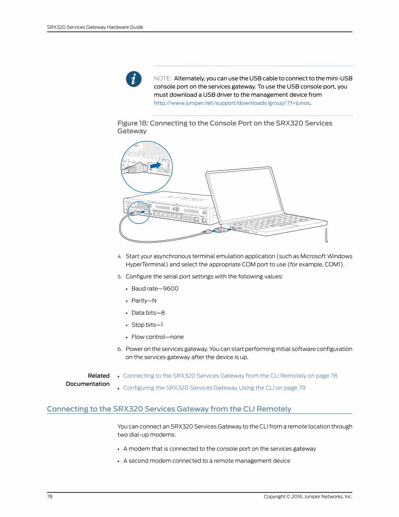
NOTE: Alternately, you can use theUSBcable to connect to themini-USBconsole port on the services gateway. To use the USB console port, youmust download a USB driver to themanagement device fromhttp://www.juniper.net/support/downloads/group/?f=junos.
Figure 18: Connecting to the Console Port on the SRX320 ServicesGateway
4. Start your asynchronous terminal emulation application (such as Microsoft Windows
HyperTerminal) and select the appropriate COM port to use (for example, COM1).
5. Configure the serial port settings with the following values:
• Baud rate—9600
• Parity—N
• Data bits—8
• Stop bits—1
• Flow control—none
6. Power on the services gateway. You can start performing initial software configuration
on the services gateway after the device is up.
RelatedDocumentation
Connecting to the SRX320 Services Gateway from the CLI Remotely on page 78•
• Configuring the SRX320 Services Gateway Using the CLI on page 79
Connecting to the SRX320 Services Gateway from the CLI Remotely
You can connect an SRX320 Services Gateway to the CLI from a remote location through
two dial-up modems:
• A modem that is connected to the console port on the services gateway
• A second modem connected to a remote management device
Copyright © 2016, Juniper Networks, Inc.78
SRX320 Services Gateway Hardware Guide
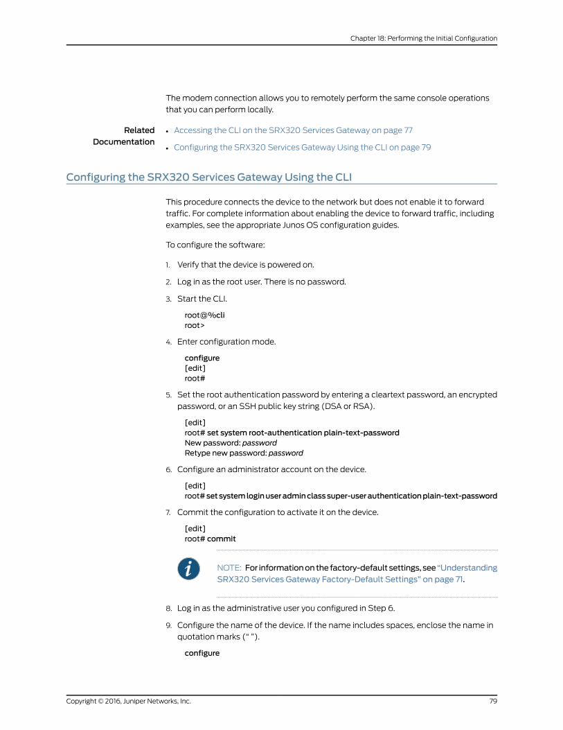
The modem connection allows you to remotely perform the same console operations
that you can perform locally.
RelatedDocumentation
Accessing the CLI on the SRX320 Services Gateway on page 77•
• Configuring the SRX320 Services Gateway Using the CLI on page 79
Configuring the SRX320 Services Gateway Using the CLI
This procedure connects the device to the network but does not enable it to forward
traffic. For complete information about enabling the device to forward traffic, including
examples, see the appropriate Junos OS configuration guides.
To configure the software:
1. Verify that the device is powered on.
2. Log in as the root user. There is no password.
3. Start the CLI.
root@%cliroot>
4. Enter configuration mode.
configure[edit]root#
5. Set the root authentication password by entering a cleartext password, an encrypted
password, or an SSH public key string (DSA or RSA).
[edit]root# set system root-authentication plain-text-passwordNew password: passwordRetype new password: password
6. Configure an administrator account on the device.
[edit]root#setsystemloginuseradminclasssuper-userauthenticationplain-text-password
7. Commit the configuration to activate it on the device.
[edit]root# commit
NOTE: For informationonthe factory-default settings, see“UnderstandingSRX320 Services Gateway Factory-Default Settings” on page 71.
8. Log in as the administrative user you configured in Step 6.
9. Configure the name of the device. If the name includes spaces, enclose the name in
quotation marks (“ ”).
configure
79Copyright © 2016, Juniper Networks, Inc.
Chapter 18: Performing the Initial Configuration
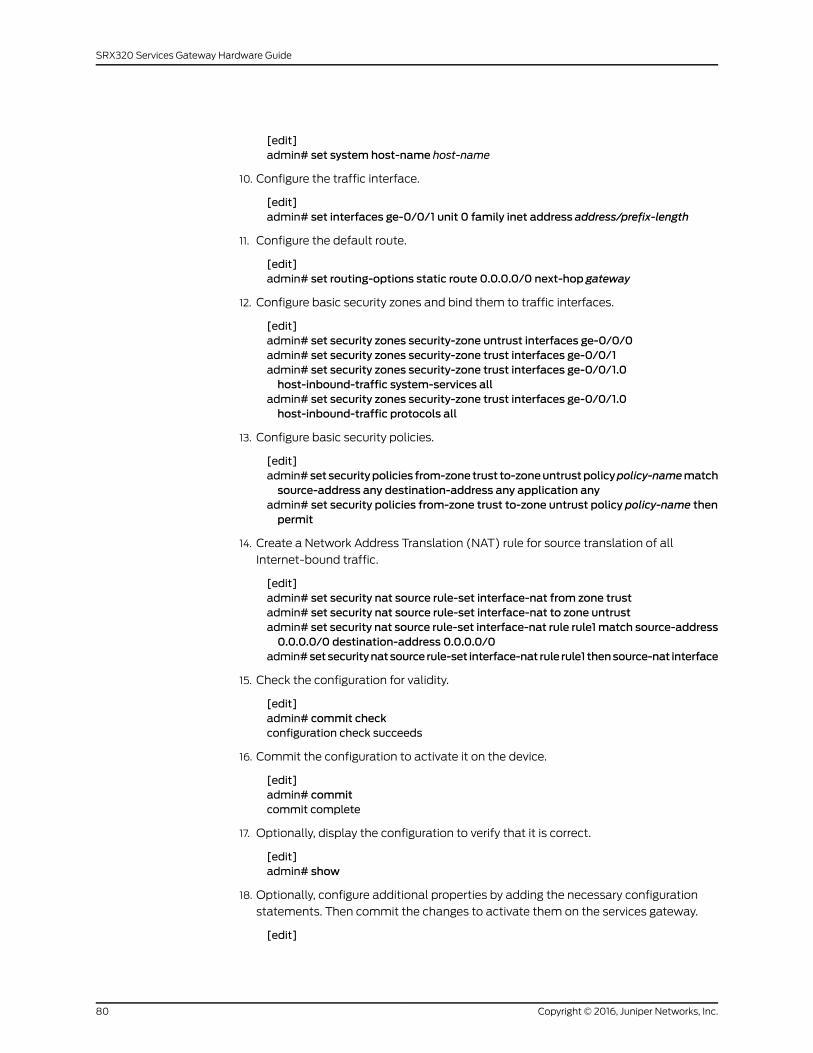
[edit]admin# set system host-name host-name
10. Configure the traffic interface.
[edit]admin# set interfaces ge-0/0/1 unit 0 family inet address address/prefix-length
11. Configure the default route.
[edit]admin# set routing-options static route 0.0.0.0/0 next-hop gateway
12. Configure basic security zones and bind them to traffic interfaces.
[edit]admin# set security zones security-zone untrust interfaces ge-0/0/0admin# set security zones security-zone trust interfaces ge-0/0/1admin# set security zones security-zone trust interfaces ge-0/0/1.0host-inbound-traffic system-services all
admin# set security zones security-zone trust interfaces ge-0/0/1.0host-inbound-traffic protocols all
13. Configure basic security policies.
[edit]admin#setsecuritypolicies from-zonetrust to-zoneuntrustpolicypolicy-namematchsource-address any destination-address any application any
admin# set security policies from-zone trust to-zone untrust policy policy-name thenpermit
14. Create a Network Address Translation (NAT) rule for source translation of all
Internet-bound traffic.
[edit]admin# set security nat source rule-set interface-nat from zone trustadmin# set security nat source rule-set interface-nat to zone untrustadmin# set security nat source rule-set interface-nat rule rule1match source-address0.0.0.0/0 destination-address 0.0.0.0/0
admin#setsecuritynatsource rule-set interface-nat rule rule1 thensource-nat interface
15. Check the configuration for validity.
[edit]admin# commit checkconfiguration check succeeds
16. Commit the configuration to activate it on the device.
[edit]admin# commitcommit complete
17. Optionally, display the configuration to verify that it is correct.
[edit]admin# show
18. Optionally, configure additional properties by adding the necessary configuration
statements. Then commit the changes to activate them on the services gateway.
[edit]
Copyright © 2016, Juniper Networks, Inc.80
SRX320 Services Gateway Hardware Guide
admin@device# commit
19. When you have finished configuring the services gateway, exit configuration mode.
[edit]admin@device# exitadmin@device>
RelatedDocumentation
Configuring the SRX320 Services Gateway Using the J-Web Setup Wizard on page 75•
Verifying Settings for the SRX320 Services Gateway
Access http://www.juniper.net to verify connectivity. If the page does not load, perform
the following checks to see if you can identify the problem:
• Check if the cable connecting the ISP-supplied device to the SRX Series device is firmly
seated.
• Use the CLI ping command to verify that the services gateway can be accessed from
the management device.
• Check if the management device has an IP address in the 192.168.1.0/24 subnetwork.
• Clear the browser cache on the management device.
After you complete these steps, the device can pass traffic from any trust port to the
untrust port. You can connect other devices to the SRX Series device.
RelatedDocumentation
• Configuring the SRX320 Services Gateway Using the CLI on page 79
• Configuring the SRX320 Services Gateway Using the J-Web Setup Wizard on page 75
81Copyright © 2016, Juniper Networks, Inc.
Chapter 18: Performing the Initial Configuration

Copyright © 2016, Juniper Networks, Inc.82
SRX320 Services Gateway Hardware Guide
PART 4
Maintaining and TroubleshootingComponents
• Maintaining Components on page 85
• Troubleshooting Components on page 87
83Copyright © 2016, Juniper Networks, Inc.

Copyright © 2016, Juniper Networks, Inc.84
SRX320 Services Gateway Hardware Guide
CHAPTER 19
Maintaining Components
• Required Tools and Parts for Maintaining the SRX320 Services Gateway Hardware
Components on page 85
• Routine Maintenance Procedures for the SRX320 Services Gateway on page 85
• Maintaining the SRX320 Services Gateway Cooling System Components on page 86
• Maintaining the SRX320 Services Gateway Power Supply on page 86
Required Tools and Parts for Maintaining the SRX320 Services Gateway HardwareComponents
The following tools and parts are required to maintain the hardware components of the
services gateway:
• Electrostatic bag or antistatic mat
• Electrostatic discharge (ESD) grounding wrist strap
• Flat-blade screw-blade screwdriver, approximately 1/8 in. (3 mm)
• Phillips (+) screwdrivers, numbers 1 and 2
RelatedDocumentation
Routine Maintenance Procedures for the SRX320 Services Gateway on page 85•
• Maintaining the SRX320 Services Gateway Cooling System Components on page 86
• Maintaining the SRX320 Services Gateway Power Supply on page 86
RoutineMaintenance Procedures for the SRX320 Services Gateway
For optimum performance of the services gateway, perform the following preventive
maintenance procedures regularly:
• Inspect the installation site for moisture, loose wires or cables, and excessive dust.
• Make sure that airflow is unobstructed around the device and into the air intake vents.
• Check the status LEDs on the front panel of the services gateway and on the
Mini-Physical Interface Module (Mini-PIM) that you are using.
85Copyright © 2016, Juniper Networks, Inc.
RelatedDocumentation
Required Tools and Parts for Maintaining the SRX320 Services Gateway Hardware
Components on page 85
•
• Maintaining the SRX320 Services Gateway Cooling System Components on page 86
• Maintaining the SRX320 Services Gateway Power Supply on page 86
Maintaining the SRX320 Services Gateway Cooling SystemComponents
The services gateway cooling system works to maintain an optimal temperature for the
device. If the fan controller fails, the device temperature will exceed the maximum working
temperature, and the device will fail. Ensure that you maintain the recommended
clearances behind the device to enable the cooling system to function optimally.
RelatedDocumentation
Required Tools and Parts for Maintaining the SRX320 Services Gateway Hardware
Components on page 85
•
• Routine Maintenance Procedures for the SRX320 Services Gateway on page 85
• Maintaining the SRX320 Services Gateway Power Supply on page 86
Maintaining the SRX320 Services Gateway Power Supply
To maintain the power supply on the services gateway:
• Make sure that the power and grounding cables are arranged so that they do not
obstruct access to other device components.
• Routinely check the PWR LED on the front panel. If this LED is solid green, the power
supplies are functioning normally.
• Periodically inspect the site to ensure that the grounding and power cables connected
to the services gateway are securely in place and that there is no moisture accumulating
near the services gateway.
CAUTION: Werecommendusinga surgeprotector for thepower connection.
RelatedDocumentation
• Required Tools and Parts for Maintaining the SRX320 Services Gateway Hardware
Components on page 85
• Routine Maintenance Procedures for the SRX320 Services Gateway on page 85
• Maintaining the SRX320 Services Gateway Cooling System Components on page 86
Copyright © 2016, Juniper Networks, Inc.86
SRX320 Services Gateway Hardware Guide
CHAPTER 20
Troubleshooting Components
• Troubleshooting Resources for the SRX320 Services Gateway Overview on page 87
• Troubleshooting Chassis and Interface Alarm Messages on the SRX320 Services
Gateway on page 88
• Troubleshooting the Power System on the SRX320 Services Gateway on page 89
• Using the RESET CONFIG Button on the SRX320 Services Gateway on page 90
• Changing the RESET CONFIG Button Behavior on the SRX320 Services
Gateway on page 90
Troubleshooting Resources for the SRX320 Services Gateway Overview
To troubleshoot a services gateway, you use the Junos OS command-line interface (CLI)
and LEDs on the components:
• LEDs—When the services gateway detects an alarm condition, the alarm LED on the
interfaces glows red or yellow.
• CLI—The CLI is the primary tool for controlling and troubleshooting hardware, Junos
OS, and network connectivity. Use the CLI to display more information about alarms.
CLI commands display information about network connectivity derived from the ping
and traceroute utilities. For information about using the CLI to troubleshoot Junos OS,
see the appropriate Junos OS configuration guide.
• JTAC—If you need assistance during troubleshooting, you can contact the Juniper
Networks Technical Assistance Center (JTAC) by using the Web or by telephone. If
you encounter software problems, or problems with hardware components not
discussed here, contact JTAC.
RelatedDocumentation
Troubleshooting Chassis and Interface Alarm Messages on the SRX320 Services
Gateway on page 88
•
• Troubleshooting the Power System on the SRX320 Services Gateway on page 89
• Using the RESET CONFIG Button on the SRX320 Services Gateway on page 90
87Copyright © 2016, Juniper Networks, Inc.
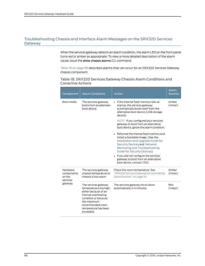
Troubleshooting Chassis and Interface AlarmMessages on the SRX320 ServicesGateway
When the services gateway detects an alarm condition, the alarm LED on the front panel
turns red or amber as appropriate. To view a more detailed description of the alarm
cause, issue the show chassis alarms CLI command.
Table 18 on page 88 describes alarms that can occur for an SRX320 Services Gateway
chassis component.
Table 18: SRX320 Services Gateway Chassis Alarm Conditions andCorrective Actions
AlarmSeverityActionAlarm ConditionsComponent
Amber(minor)
• If the internal flash memory fails atstartup, the services gatewayautomatically boots itself from thealternative boot device (USB storagedevice).
NOTE: If you configured your servicesgateway to boot from an alternativeboot device, ignore this alarm condition.
• Reformat the internal flash memory andinstall a bootable image. (See theInstallation and Upgrade Guide forSecurity Devices and NetworkMonitoring and TroubleshootingGuide for Security Devices)
• If you did not configure the servicesgateway to boot from an alternativeboot device, contact JTAC.
The services gatewayboots from an alternateboot device.
Boot media
Amber(minor)
Check the room temperature. See“SRX320 Services Gateway EnvironmentalSpecifications” on page 19.
The services gatewaychassis temperature orchassis is too warm
Hardwarecomponentson theservicesgateway Red
(major)The services gateway shuts downautomatically in 4 minutes.
The services gatewaytemperature is too high,either because of aninternal overheatingcondition or becausethe maximumrecommended roomtemperature has beenexceeded.
Copyright © 2016, Juniper Networks, Inc.88
SRX320 Services Gateway Hardware Guide
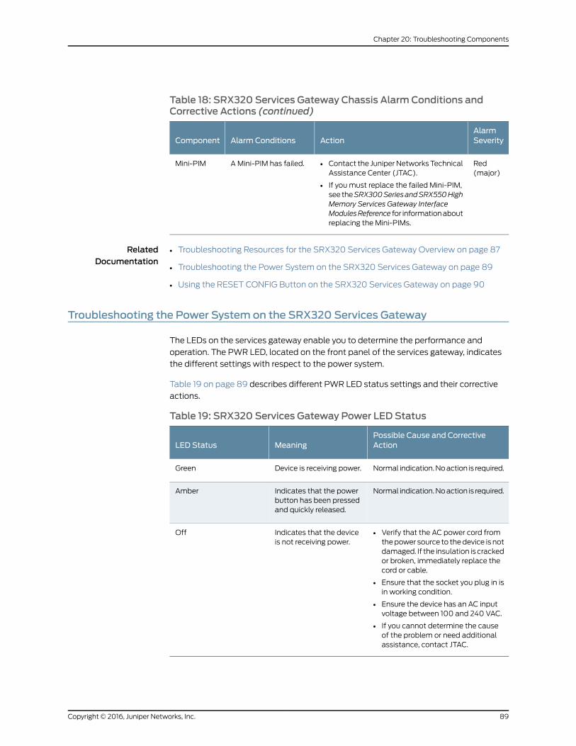
Table 18: SRX320 Services Gateway Chassis Alarm Conditions andCorrective Actions (continued)
AlarmSeverityActionAlarm ConditionsComponent
Red(major)
• Contact the Juniper Networks TechnicalAssistance Center (JTAC).
• If you must replace the failed Mini-PIM,see theSRX300SeriesandSRX550HighMemory Services Gateway InterfaceModulesReference for information aboutreplacing the Mini-PIMs.
A Mini-PIM has failed.Mini-PIM
RelatedDocumentation
Troubleshooting Resources for the SRX320 Services Gateway Overview on page 87•
• Troubleshooting the Power System on the SRX320 Services Gateway on page 89
• Using the RESET CONFIG Button on the SRX320 Services Gateway on page 90
Troubleshooting the Power System on the SRX320 Services Gateway
The LEDs on the services gateway enable you to determine the performance and
operation. The PWR LED, located on the front panel of the services gateway, indicates
the different settings with respect to the power system.
Table 19 on page 89 describes different PWR LED status settings and their corrective
actions.
Table 19: SRX320 Services Gateway Power LED Status
Possible Cause and CorrectiveActionMeaningLED Status
Normal indication. No action is required.Device is receiving power.Green
Normal indication. No action is required.Indicates that the powerbutton has been pressedand quickly released.
Amber
• Verify that the AC power cord fromthe power source to the device is notdamaged. If the insulation is crackedor broken, immediately replace thecord or cable.
• Ensure that the socket you plug in isin working condition.
• Ensure the device has an AC inputvoltage between 100 and 240 VAC.
• If you cannot determine the causeof the problem or need additionalassistance, contact JTAC.
Indicates that the deviceis not receiving power.
Off
89Copyright © 2016, Juniper Networks, Inc.
Chapter 20: Troubleshooting Components
RelatedDocumentation
Troubleshooting Resources for the SRX320 Services Gateway Overview on page 87•
• Troubleshooting Chassis and Interface Alarm Messages on the SRX320 Services
Gateway on page 88
Using the RESET CONFIG Button on the SRX320 Services Gateway
If a configuration fails or denies management access to the services gateway, you can
use the RESET CONFIG button to restore the device to the factory-default configuration
or a rescue configuration. For example, if someone inadvertently commits a configuration
that denies management access to a services gateway, you can delete the invalid
configuration and replace it with a rescue configuration by pressing the RESET CONFIG
button.
NOTE: TheRESETCONFIGbutton is recessedtoprevent it frombeingpressedaccidentally.
The rescue configuration is a previously committed, valid configuration. You must have
previously set the rescue configuration through the J-Web interface or the CLI. To press
the RESET CONFIG button, insert a small probe (such as a straightened paper clip) into
the pinhole on the front panel.
• By default, pressing and quickly releasing the RESET CONFIG button loads and commits
the rescue configuration through the J-Web interface or the CLI. The Status LED is solid
amber during this time.
• By default, pressing and holding the RESET CONFIG button for 15 seconds or more—until
the Status LED is solid amber — deletes all configurations on the device, including the
backup configurations and rescue configuration, and loads and commits the factory
configuration.
RelatedDocumentation
Changing the RESET CONFIG Button Behavior on the SRX320 Services Gateway on
page 90
•
Changing the RESET CONFIG Button Behavior on the SRX320 Services Gateway
You can change the default operation of the RESET CONFIG button by limiting how the
button resets the services gateway:
• To prevent the RESET CONFIG button from setting the device to the factory-default
configuration and deleting all other configurations:
admin@host# set chassis config-button no-clear
You can still press and quickly release the button to reset it to the rescue configuration.
• To prevent the RESET CONFIG button from setting the device to the rescue
configuration:
Copyright © 2016, Juniper Networks, Inc.90
SRX320 Services Gateway Hardware Guide
admin@host# set chassis config-button no-rescue
You can still press and hold the button for 15 seconds or more to reset the gateway to
the factory-default configuration.
• To disable the button and prevent the device from resetting to either configuration:
admin@host# set chassis config-button no-clear no-rescue
The no-clear option prevents the RESET CONFIG button from deleting all configurations
on the services gateway. The no-rescue option prevents the RESET CONFIG button from
loading the rescue configuration.
To return the function of the RESET CONFIG button to its default behavior, remove the
config-button statement from the device configuration.
RelatedDocumentation
• Using the RESET CONFIG Button on the SRX320 Services Gateway on page 90
91Copyright © 2016, Juniper Networks, Inc.
Chapter 20: Troubleshooting Components

Copyright © 2016, Juniper Networks, Inc.92
SRX320 Services Gateway Hardware Guide
PART 5
Replacing Components
• Overview of Replacing Components on page 95
• Replacing Interface Modules on page 97
• Contacting Customer Support and Returning Components on page 99
93Copyright © 2016, Juniper Networks, Inc.

Copyright © 2016, Juniper Networks, Inc.94
SRX320 Services Gateway Hardware Guide
CHAPTER 21
Overview of Replacing Components
• Required Tools and Parts for Replacing the SRX320 Services Gateway
Components on page 95
• SRX320 Services Gateway Field Replaceable Units Overview on page 95
Required Tools and Parts for Replacing the SRX320 Services Gateway Components
The following tools and parts are required for replacing a Mini-Physical Interface Module
(MPIM) on the services gateway:
• Electrostatic bag or antistatic mat, for each component
• Electrostatic discharge (ESD) grounding wrist strap
• Flat-blade (–) screwdriver, approximately 1/8 in. (3 mm)
• Phillips (+) screwdriver, number 1
• Blank panels (if no component will be installed)
RelatedDocumentation
Replacing Mini-Physical Interface Modules in the SRX320 Services Gateway on page 97•
SRX320 Services Gateway Field Replaceable Units Overview
Field-replaceable units (FRUs) are components that you can replace at your site. The
Mini-Physical Interface Module (MPIM) is the only FRU on the SRX320 Services Gateway.
The Mini-PIMs are not hot-swappable. You must power off the services gateway before
removing or installing Mini-PIMs.
RelatedDocumentation
• Replacing Mini-Physical Interface Modules in the SRX320 Services Gateway on page 97
95Copyright © 2016, Juniper Networks, Inc.

Copyright © 2016, Juniper Networks, Inc.96
SRX320 Services Gateway Hardware Guide
CHAPTER 22
Replacing Interface Modules
• Replacing Mini-Physical Interface Modules in the SRX320 Services Gateway on page 97
ReplacingMini-Physical InterfaceModules in the SRX320 Services Gateway
The Mini-PIMs available on the SRX320 Services Gateway are not hot-swappable. You
need to power off the device before removing or installing Mini-PIMs. For information on
replacing Mini-PIMs, see the SRX300 Series and SRX550 High Memory Services Gateway
Interface Modules Reference.
RelatedDocumentation
• SRX320 Services Gateway Interface Modules Overview on page 11
97Copyright © 2016, Juniper Networks, Inc.

Copyright © 2016, Juniper Networks, Inc.98
SRX320 Services Gateway Hardware Guide
CHAPTER 23
Contacting Customer Support andReturning Components
• Contacting Customer Support on page 99
• Returning a SRX320 Services Gateway Component to Juniper Networks on page 100
• Locating the SRX320 Services Gateway Chassis Serial Number and Agency
Labels on page 101
• Locating the SRX320 Services Gateway Mini-Physical Interface Module Serial Number
Label on page 101
• Listing the SRX320 Services Gateway Component Details with the CLI on page 101
• Information You Might Need to Supply to JTAC on page 102
• Required Tools and Parts for Packing the SRX320 Services Gateway on page 103
• Packing the SRX320 Services Gateway for Shipment on page 103
• Packing SRX320 Services Gateway Components for Shipment on page 104
Contacting Customer Support
Once you have located the serial numbers of the device or component, you can return
the device or component for repair or replacement. For this, you need to contact Juniper
Networks Technical Assistance Center (JTAC).
You can contact JTAC 24 hours a day, 7 days a week, using any of the following methods:
• On the Web: Using the Case Manager link at http://www.juniper.net/support/
• By telephone:
• From the US and Canada: 1-888-314-JTAC
• From all other locations: 1-408-745-9500
NOTE: If contacting JTAC by telephone, enter your 11-digit case numberfollowed by the pound (#) key if this is an existing case, or press the star(*) key to be routed to the next available support engineer.
99Copyright © 2016, Juniper Networks, Inc.
RelatedDocumentation
Returning a SRX320 Services Gateway Component to Juniper Networks on page 100•
• Locating the SRX320 Services Gateway Chassis Serial Number and Agency Labels on
page 101
• Locating the SRX320 Services Gateway Mini-Physical Interface Module Serial Number
Label on page 101
• Listing the SRX320 Services Gateway Component Details with the CLI on page 101
• Information You Might Need to Supply to JTAC on page 102
• Required Tools and Parts for Packing the SRX320 Services Gateway on page 103
• Packing the SRX320 Services Gateway for Shipment on page 103
• Packing SRX320 Services Gateway Components for Shipment on page 104
Returning a SRX320 Services Gateway Component to Juniper Networks
To return an SRX320 Services Gateway or component to Juniper Networks for repair or
replacement:
1. Determine the part number and serial number of the services gateway or component.
2. Obtain a Return Materials Authorization (RMA) number from JTAC.
NOTE: Do not return the services gateway or any component to JuniperNetworksunlessyouhave firstobtainedanRMAnumber. JuniperNetworksreserves the right to refuse shipments that do not have an RMA. Refusedshipments are returned to the customer via collect freight.
3. Pack the SRX320 Services Gateway or component for shipping.
For more information about return and repair policies, see the customer support webpage
at http://www.juniper.net/support/guidelines.html.
For product problems or technical support issues, open a support case using the Case
Manager link athttp://www.juniper.net/support/or call 1-888-314-JTAC (within the United
States) or 1-408-745-9500 (outside the United States).
RelatedDocumentation
Contacting Customer Support on page 99•
• Locating the SRX320 Services Gateway Chassis Serial Number and Agency Labels on
page 101
• Locating the SRX320 Services Gateway Mini-Physical Interface Module Serial Number
Label on page 101
• Listing the SRX320 Services Gateway Component Details with the CLI on page 101
• Information You Might Need to Supply to JTAC on page 102
• Required Tools and Parts for Packing the SRX320 Services Gateway on page 103
Copyright © 2016, Juniper Networks, Inc.100
SRX320 Services Gateway Hardware Guide
• Packing the SRX320 Services Gateway for Shipment on page 103
• Packing SRX320 Services Gateway Components for Shipment on page 104
Locating the SRX320 Services Gateway Chassis Serial Number and Agency Labels
The chassis serial number is located on the side of the chassis.
RelatedDocumentation
Contacting Customer Support on page 99•
• Returning a SRX320 Services Gateway Component to Juniper Networks on page 100
• Locating the SRX320 Services Gateway Mini-Physical Interface Module Serial Number
Label on page 101
• Listing the SRX320 Services Gateway Component Details with the CLI on page 101
• Information You Might Need to Supply to JTAC on page 102
• Required Tools and Parts for Packing the SRX320 Services Gateway on page 103
• Packing the SRX320 Services Gateway for Shipment on page 103
• Packing SRX320 Services Gateway Components for Shipment on page 104
Locating theSRX320ServicesGatewayMini-Physical InterfaceModuleSerialNumberLabel
Mini-PIMs are field-replaceable on the SRX320 Services Gateway. Each Mini-PIM has a
unique serial number. The serial number label is located on the right side of the Mini-PIM,
when the Mini-PIM is horizontally oriented (as it would be when installed on the device).
The exact location might be slightly different on different Mini-PIMs, depending on the
placement of components on the Mini-PIM.
RelatedDocumentation
Contacting Customer Support on page 99•
• Returning a SRX320 Services Gateway Component to Juniper Networks on page 100
• Locating the SRX320 Services Gateway Chassis Serial Number and Agency Labels on
page 101
• Listing the SRX320 Services Gateway Component Details with the CLI on page 101
• Information You Might Need to Supply to JTAC on page 102
• Required Tools and Parts for Packing the SRX320 Services Gateway on page 103
• Packing the SRX320 Services Gateway for Shipment on page 103
• Packing SRX320 Services Gateway Components for Shipment on page 104
Listing the SRX320 Services Gateway Component Details with the CLI
Before contacting Juniper Networks to request an RMA, you must find the serial number
on the SRX320 Services Gateway or component.
101Copyright © 2016, Juniper Networks, Inc.
Chapter 23: Contacting Customer Support and Returning Components
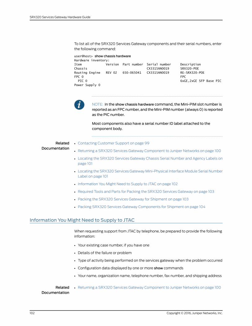
To list all of the SRX320 Services Gateway components and their serial numbers, enter
the following command:
user@host> show chassis hardwareHardware inventory:Item Version Part number Serial number DescriptionChassis CX3315AN0019 SRX320-POERouting Engine REV 02 650-065041 CX3315AN0019 RE-SRX320-POEFPC 0 FPC PIC 0 6xGE,2xGE SFP Base PICPower Supply 0
NOTE: In the show chassis hardware command, the Mini-PIM slot number is
reported as an FPCnumber, and theMini-PIM number (always 0) is reportedas the PIC number.
Most components also have a serial number ID label attached to thecomponent body.
RelatedDocumentation
Contacting Customer Support on page 99•
• Returning a SRX320 Services Gateway Component to Juniper Networks on page 100
• Locating the SRX320 Services Gateway Chassis Serial Number and Agency Labels on
page 101
• Locating the SRX320 Services Gateway Mini-Physical Interface Module Serial Number
Label on page 101
• Information You Might Need to Supply to JTAC on page 102
• Required Tools and Parts for Packing the SRX320 Services Gateway on page 103
• Packing the SRX320 Services Gateway for Shipment on page 103
• Packing SRX320 Services Gateway Components for Shipment on page 104
Information YouMight Need to Supply to JTAC
When requesting support from JTAC by telephone, be prepared to provide the following
information:
• Your existing case number, if you have one
• Details of the failure or problem
• Type of activity being performed on the services gateway when the problem occurred
• Configuration data displayed by one or more show commands
• Your name, organization name, telephone number, fax number, and shipping address
RelatedDocumentation
Returning a SRX320 Services Gateway Component to Juniper Networks on page 100•
Copyright © 2016, Juniper Networks, Inc.102
SRX320 Services Gateway Hardware Guide
• Locating the SRX320 Services Gateway Chassis Serial Number and Agency Labels on
page 101
• Locating the SRX320 Services Gateway Mini-Physical Interface Module Serial Number
Label on page 101
• Listing the SRX320 Services Gateway Component Details with the CLI on page 101
Required Tools and Parts for Packing the SRX320 Services Gateway
To remove the components from the SRX320 Services Gateway or to remove the services
gateway from a rack, you need the following tools and parts:
• Electrostatic bag or antistatic mat for each component
• Electrostatic discharge (ESD) grounding wrist strap
• Flat-blade screwdriver, approximately 1/4 in. (6 mm)
• Phillips (+) screwdrivers, numbers 1 and 2
RelatedDocumentation
Contacting Customer Support on page 99•
• Information You Might Need to Supply to JTAC on page 102
• Packing the SRX320 Services Gateway for Shipment on page 103
• Packing SRX320 Services Gateway Components for Shipment on page 104
Packing the SRX320 Services Gateway for Shipment
To pack the SRX320 Services Gateway for shipment:
1. Retrieve the shipping carton and packing materials in which the services gateway was
originally shipped. If you do not have these materials, contact your Juniper Networks
representative about approved packaging materials.
2. Attach an electrostatic discharge (ESD) grounding strap to your bare wrist and connect
the strap to the ESD point on the chassis or to an outside ESD point if the device is
disconnected from earth ground. For more information about ESD, see “Preventing
Electrostatic Discharge Damage to the SRX320 Services Gateway” on page 115.
3. On the console or other management device connected to the services gateway, enter
CLI operational mode and issue the following command to shut down the services
gateway software:
user@host> request system halt
Wait until a message appears on the console confirming that the operating system
has halted.
4. Shut down power to the services gateway by pressing the Power button on the front
of the services gateway.
5. Disconnect power from the services gateway.
103Copyright © 2016, Juniper Networks, Inc.
Chapter 23: Contacting Customer Support and Returning Components
6. Remove the cables that connect to all external devices.
7. If the device is installed on a wall or rack, have one person support the weight of the
device while another person unscrews and removes the mounting screws.
8. Place the services gateway in the shipping carton.
9. Cover the services gateway with an ESD bag, and place the packing foam on top of
and around the device.
10. Replace the accessory box on top of the packing foam.
11. Securely tape the box closed.
12. Write the Return Materials Authorization (RMA) number on the exterior of the box to
ensure proper tracking.
RelatedDocumentation
Contacting Customer Support on page 99•
• Returning a SRX320 Services Gateway Component to Juniper Networks on page 100
• Locating the SRX320 Services Gateway Chassis Serial Number and Agency Labels on
page 101
• Locating the SRX320 Services Gateway Mini-Physical Interface Module Serial Number
Label on page 101
• Listing the SRX320 Services Gateway Component Details with the CLI on page 101
• Information You Might Need to Supply to JTAC on page 102
• Required Tools and Parts for Packing the SRX320 Services Gateway on page 103
• Packing SRX320 Services Gateway Components for Shipment on page 104
Packing SRX320 Services Gateway Components for Shipment
Follow these guidelines for packing and shipping individual components of the services
gateway:
• When you return a component, make sure that it is adequately protected with packing
materials and packed so that the pieces are prevented from moving around inside the
carton.
• Use the original shipping materials if they are available.
• Place the individual component in an electrostatic bag.
• Write the Return Materials Authorization (RMA) number on the exterior of the box to
ensure proper tracking.
CAUTION: Do not stack any of the services gateway components duringpacking.
Copyright © 2016, Juniper Networks, Inc.104
SRX320 Services Gateway Hardware Guide
RelatedDocumentation
• Contacting Customer Support on page 99
• Returning a SRX320 Services Gateway Component to Juniper Networks on page 100
• Locating the SRX320 Services Gateway Chassis Serial Number and Agency Labels on
page 101
• Locating the SRX320 Services Gateway Mini-Physical Interface Module Serial Number
Label on page 101
• Listing the SRX320 Services Gateway Component Details with the CLI on page 101
• Information You Might Need to Supply to JTAC on page 102
• Required Tools and Parts for Packing the SRX320 Services Gateway on page 103
• Packing the SRX320 Services Gateway for Shipment on page 103
105Copyright © 2016, Juniper Networks, Inc.
Chapter 23: Contacting Customer Support and Returning Components
Copyright © 2016, Juniper Networks, Inc.106
SRX320 Services Gateway Hardware Guide

PART 6
Safety and Regulatory ComplianceInformation
• General Safety Guidelines and Warnings on page 109
• Fire Safety Requirements on page 117
• Laser and LED Safety Guidelines and Warnings on page 119
• Maintenance and Operational Safety Guidelines and Warnings on page 123
• Electrical Safety Guidelines and Warnings on page 129
• Agency Approvals and Regulatory Compliance Information on page 131
107Copyright © 2016, Juniper Networks, Inc.

Copyright © 2016, Juniper Networks, Inc.108
SRX320 Services Gateway Hardware Guide
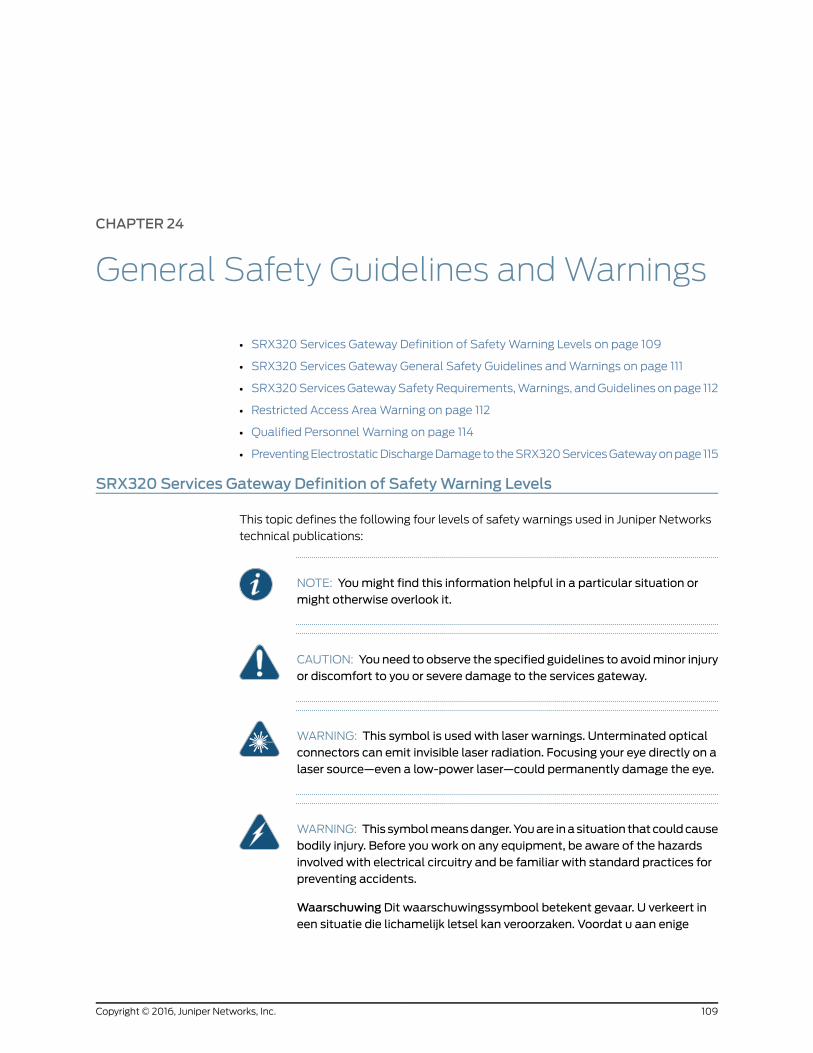
CHAPTER 24
General Safety Guidelines andWarnings
• SRX320 Services Gateway Definition of Safety Warning Levels on page 109
• SRX320 Services Gateway General Safety Guidelines and Warnings on page 111
• SRX320 Services Gateway Safety Requirements, Warnings, and Guidelines on page 112
• Restricted Access Area Warning on page 112
• Qualified Personnel Warning on page 114
• Preventing Electrostatic Discharge Damage to the SRX320 Services Gateway on page 115
SRX320 Services Gateway Definition of SafetyWarning Levels
This topic defines the following four levels of safety warnings used in Juniper Networks
technical publications:
NOTE: Youmight find this information helpful in a particular situation ormight otherwise overlook it.
CAUTION: You need to observe the specified guidelines to avoidminor injuryor discomfort to you or severe damage to the services gateway.
WARNING: This symbol is used with laser warnings. Unterminated opticalconnectors can emit invisible laser radiation. Focusing your eye directly on alaser source—even a low-power laser—could permanently damage the eye.
WARNING: This symbolmeansdanger.Youare inasituation thatcouldcausebodily injury. Before you work on any equipment, be aware of the hazardsinvolved with electrical circuitry and be familiar with standard practices forpreventing accidents.
Waarschuwing Dit waarschuwingssymbool betekent gevaar. U verkeert ineen situatie die lichamelijk letsel kan veroorzaken. Voordat u aan enige
109Copyright © 2016, Juniper Networks, Inc.
apparatuur gaat werken, dient u zich bewust te zijn van de bij elektrischeschakelingen betrokken risico's en dient u opde hoogte te zijn van standaardmaatregelen om ongelukken te voorkomen.
Varoitus Tämä varoitusmerkki merkitsee vaaraa. Olet tilanteessa, joka voijohtaa ruumiinvammaan.Ennenkuin työskenteletminkään laitteistonparissa,ota selvää sähkökytkentöihin liittyvistä vaaroista ja tavanomaisistaonnettomuuksien ehkäisykeinoista.
AttentionCe symbole d'avertissement indique un danger. Vous vous trouvezdansunesituationpouvantcauserdesblessuresoudesdommagescorporels.Avant de travailler sur un équipement, soyez conscient des dangers poséspar les circuits électriques et familiarisez-vous avec les procédurescouramment utilisées pour éviter les accidents.
Warnung DiesesWarnsymbol bedeutet Gefahr. Sie befinden sich in einerSituation, die zu einer Körperverletzung führen könnte. Bevor Sie mit derArbeit an irgendeinemGerät beginnen, seien Sie sich der mit elektrischenStromkreisen verbundenen Gefahren und der Standardpraktiken zurVermeidung von Unfällen bewußt.
AvvertenzaQuesto simbolo di avvertenza indica un pericolo. La situazionepotrebbe causare infortuni alle persone. Prima di lavorare su qualsiasiapparecchiatura, occorre conoscere i pericoli relativi ai circuiti elettrici edessere al corrente delle pratiche standard per la prevenzione di incidenti.
AdvarselDette varselsymbolet betyr fare. Du befinner deg i en situasjon somkan føre til personskade. Før du utfører arbeid på utstyr, må du vareoppmerksom på de faremomentene som elektriske kretser innebærer, samtgjøre deg kjent med vanlig praksis når det gjelder å unngå ulykker.
Aviso Este símbolo de aviso indica perigo. Encontra-se numa situação quelhepoderá causar danos físicos. Antes de começar a trabalhar comqualquerequipamento, familiarize-se com os perigos relacionados com circuitoseléctricos, e com quaisquer práticas comuns que possam prevenir possíveisacidentes.
¡Atención! Este símbolo de aviso significa peligro. Existe riesgo para suintegridad física. Antes demanipular cualquier equipo, considerar los riesgosque entraña la corriente eléctrica y familiarizarse con los procedimientosestándar de prevención de accidentes.
Varning!Denna varningssymbol signalerar fara. Du befinner dig i en situationsom kan leda till personskada. Innan du utför arbete på någon utrustningmåste du varamedveten om farornamed elkretsar och känna till vanligtförfarande för att förebygga skador.
RelatedDocumentation
SRX320 Services Gateway General Safety Guidelines and Warnings on page 111•
• SRX320 Services Gateway Safety Requirements, Warnings, and Guidelines on page 112
Copyright © 2016, Juniper Networks, Inc.110
SRX320 Services Gateway Hardware Guide
• Restricted Access Area Warning on page 112
• Qualified Personnel Warning on page 114
• Preventing Electrostatic Discharge Damage to the SRX320 Services Gateway on
page 115
SRX320 Services Gateway General Safety Guidelines andWarnings
The following guidelines help ensure your safety and protect the services gateway from
damage. The list of guidelines might not address all potentially hazardous situations in
your working environment, so be alert and exercise good judgment at all times.
• Perform only the procedures explicitly described in these topics. Ensure that only
authorized service personnel perform other system services.
• Keep the area around the chassis clear and free from dust before, during, and after
installation.
• Keep tools away from areas where people could trip on them.
• Wear safety glasses if you are working under any conditions that could be hazardous
to your eyes.
• Do not perform any actions that create a potential hazard to people or make the
equipment unsafe.
• Never install or manipulate wiring during electrical storms.
• Never install electrical jacks in wet locations unless the jacks are specifically designed
for wet environments.
• Do not open or remove chassis covers or sheet metal parts unless instructions are
provided in this guide. Such an action could cause severe electrical shock.
• Do not push or force any objects through any opening in the chassis frame. Such an
action could result in electrical shock or fire.
• Avoid spilling liquid onto the services gateway chassis or onto any services gateway
component. Such an action could cause electrical shock or damage the services
gateway.
• Avoid touching uninsulated electrical wires or terminals that have not been
disconnected from their power source. Such an action could cause electrical shock.
RelatedDocumentation
SRX320 Services Gateway Definition of Safety Warning Levels on page 109•
• SRX320 Services Gateway Safety Requirements, Warnings, and Guidelines on page 112
• Restricted Access Area Warning on page 112
• Qualified Personnel Warning on page 114
• Preventing Electrostatic Discharge Damage to the SRX320 Services Gateway on
page 115
111Copyright © 2016, Juniper Networks, Inc.
Chapter 24: General Safety Guidelines and Warnings
SRX320 Services Gateway Safety Requirements, Warnings, and Guidelines
To avoid harm to yourself or the device as you install and maintain it, follow the guidelines
for working with and near electrical equipment, as well as the safety procedures for
working with devices. For a discussion of how to make the installation site a safe
environment and a list of safety warnings, see “General Site Installation Guidelines for
the SRX320 Services Gateway” on page 22 and “SRX320 Services Gateway General
Safety Guidelines and Warnings” on page 111.
NOTE: Providing an exhaustive set of guidelines for working with electricalequipment is beyond the scope of this guide.
RelatedDocumentation
SRX320 Services Gateway Definition of Safety Warning Levels on page 109•
• SRX320 Services Gateway General Safety Guidelines and Warnings on page 111
• Restricted Access Area Warning on page 112
• Qualified Personnel Warning on page 114
• Preventing Electrostatic Discharge Damage to the SRX320 Services Gateway on
page 115
Restricted Access AreaWarning
WARNING: The services gateway is intended for installation in restrictedaccess areas. A restricted access area is an area to which access can begained only by service personnel through the use of a special tool, lock andkey, or other means of security, and which is controlled by the authorityresponsible for the location.
WaarschuwingDit toestel isbedoeldvoor installatieopplaatsenmetbeperktetoegang.Eenplaatsmetbeperkte toegang iseenplaatswaar toegangslechtsdoor servicepersoneel verkregen kan worden door middel van een speciaalinstrument, een slot en sleutel, of een ander veiligheidsmiddel, en welkebeheerd wordt door de overheidsinstantie die verantwoordelijk is voor delocatie.
Varoitus Tämä laite on tarkoitettu asennettavaksi paikkaan, johon pääsy onrajoitettua. Paikka, johon pääsy on rajoitettua, tarkoittaa paikkaa, johon vainhuoltohenkilöstö pääsee jonkin erikoistyökalun, lukkoon sopivan avaimentai jonkin muun turvalaitteen avulla ja joka on paikasta vastuussa olevientoimivaltaisten henkilöiden valvoma.
Attention Cet appareil est à installer dans des zones d'accès réservé. Cesdernières sontdeszonesauxquelles seul lepersonneldeservicepeutaccéderen utilisant un outil spécial, unmécanisme de verrouillage et une clé, ou tout
Copyright © 2016, Juniper Networks, Inc.112
SRX320 Services Gateway Hardware Guide
autre moyen de sécurité. L'accès aux zones de sécurité est sous le contrôlede l'autorité responsable de l'emplacement.
Warnung Diese Einheit ist zur Installation in Bereichenmit beschränktemZutritt vorgesehen. Ein Bereichmit beschränktem Zutritt ist ein Bereich, zudem nurWartungspersonal mit einem Spezialwerkzeugs, Schloß undSchlüssel oder anderer Sicherheitsvorkehrungen Zugang hat, und der vondem für die Anlage zuständigen Gremium kontrolliert wird.
AvvertenzaQuestaunitàdeveessere installata inun'areaadaccesso limitato.Un'area ad accesso limitato è un'area accessibile solo a personale diassistenza tramite un'attrezzo speciale, lucchetto, o altri dispositivi disicurezza, ed è controllata dall'autorità responsabile della zona.
Advarsel Denne enheten er laget for installasjon i områder med begrensetadgang.Etområdemedbegrensetadganggir kunadgangtil servicepersonalesom bruker et spesielt verktøy, lås og nøkkel, eller en annensikkerhetsanordning, og det kontrolleres av den autoriteten som er ansvarligfor området.
AvisoEstaunidade foi concebidapara instalaçãoemáreasdeacesso restrito.Uma área de acesso restrito é uma área à qual apenas temacesso o pessoalde serviço autorizado, que possua uma ferramenta, chave e fechaduraespecial, ou qualquer outra forma de segurança. Esta área é controlada pelaautoridade responsável pelo local.
¡Atención! Esta unidad ha sido diseñada para instalarse en áreas de accesorestringido. Área de acceso restringido significa un área a la que solamentetieneaccesoelpersonaldeserviciomediante lautilizacióndeunaherramientaespecial, cerradura con llave, o algún otromedio de seguridad, y que estábajo el control de la autoridad responsable del local.
Varning! Denna enhet är avsedd för installation i områdenmed begränsattillträde. Ett områdemed begränsat tillträde får endast tillträdas avservicepersonal med ett speciellt verktyg, lås och nyckel, eller annansäkerhetsanordning, och kontrolleras av den auktoritet som ansvarar förområdet.
RelatedDocumentation
SRX320 Services Gateway Definition of Safety Warning Levels on page 109•
• SRX320 Services Gateway General Safety Guidelines and Warnings on page 111
• SRX320 Services Gateway Safety Requirements, Warnings, and Guidelines on page 112
• Qualified Personnel Warning on page 114
• Preventing Electrostatic Discharge Damage to the SRX320 Services Gateway on
page 115
113Copyright © 2016, Juniper Networks, Inc.
Chapter 24: General Safety Guidelines and Warnings
Qualified PersonnelWarning
WARNING: Only trainedandqualified personnel should install or replace theservices gateway.
Waarschuwing Installatie en reparaties mogen uitsluitend door getraind enbevoegd personeel uitgevoerd worden.
VaroitusAinoastaankoulutettu japätevähenkilökuntasaaasentaatai vaihtaatämän laitteen.
Attention Tout installation ou remplacement de l'appareil doit être réalisépar du personnel qualifié et compétent.
WarnungGerät nur vongeschultem, qualifiziertemPersonal installierenoderauswechseln lassen.
Avvertenza Solo personale addestrato e qualificato deve essere autorizzatoad installare o sostituire questo apparecchio.
Advarsel Kun kvalifisert personell med riktig opplæring bør montere ellerbytte ut dette utstyret.
Aviso Este equipamento deverá ser instalado ou substituído apenas porpessoal devidamente treinado e qualificado.
¡Atención! Estos equipos deben ser instalados y reemplazadosexclusivamenteporpersonal técnicoadecuadamentepreparadoycapacitado.
Varning! Denna utrustning ska endast installeras och bytas ut av utbildadoch kvalificerad personal.
RelatedDocumentation
SRX320 Services Gateway Definition of Safety Warning Levels on page 109•
• SRX320 Services Gateway General Safety Guidelines and Warnings on page 111
• SRX320 Services Gateway Safety Requirements, Warnings, and Guidelines on page 112
• Restricted Access Area Warning on page 112
• Preventing Electrostatic Discharge Damage to the SRX320 Services Gateway on
page 115
Copyright © 2016, Juniper Networks, Inc.114
SRX320 Services Gateway Hardware Guide
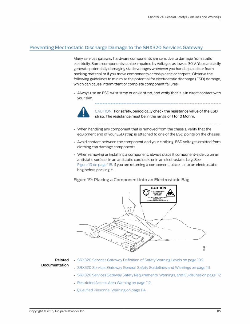
Preventing Electrostatic Discharge Damage to the SRX320 Services Gateway
Many services gateway hardware components are sensitive to damage from static
electricity. Some components can be impaired by voltages as low as 30 V. You can easily
generate potentially damaging static voltages whenever you handle plastic or foam
packing material or if you move components across plastic or carpets. Observe the
following guidelines to minimize the potential for electrostatic discharge (ESD) damage,
which can cause intermittent or complete component failures:
• Always use an ESD wrist strap or ankle strap, and verify that it is in direct contact with
your skin.
CAUTION: For safety, periodically check the resistance value of the ESDstrap. The resistancemust be in the range of 1 to 10 Mohm.
• When handling any component that is removed from the chassis, verify that the
equipment end of your ESD strap is attached to one of the ESD points on the chassis.
• Avoid contact between the component and your clothing. ESD voltages emitted from
clothing can damage components.
• When removing or installing a component, always place it component-side up on an
antistatic surface, in an antistatic card rack, or in an electrostatic bag. See
Figure 19 on page 115. If you are returning a component, place it into an electrostatic
bag before packing it.
Figure 19: Placing a Component into an Electrostatic Bag
RelatedDocumentation
• SRX320 Services Gateway Definition of Safety Warning Levels on page 109
• SRX320 Services Gateway General Safety Guidelines and Warnings on page 111
• SRX320 Services Gateway Safety Requirements, Warnings, and Guidelines on page 112
• Restricted Access Area Warning on page 112
• Qualified Personnel Warning on page 114
115Copyright © 2016, Juniper Networks, Inc.
Chapter 24: General Safety Guidelines and Warnings

Copyright © 2016, Juniper Networks, Inc.116
SRX320 Services Gateway Hardware Guide
CHAPTER 25
Fire Safety Requirements
• SRX320 Services Gateway Fire Safety Requirements and Fire Suppression
Equipment on page 117
SRX320ServicesGateway Fire Safety Requirements and Fire Suppression Equipment
In the event of a fire emergency involving devices and other network equipment, the
safety of people is the primary concern. Establish procedures for protecting people in
the event of a fire emergency, provide safety training, and properly provision fire control
equipment and fire extinguishers.
In addition, establish procedures to protect your equipment in the event of a fire
emergency. Juniper Networks products should be installed in an environment suitable
for electronic equipment. We recommend that fire suppression equipment be available
in the event of a fire in the vicinity of the equipment and that all local fire, safety, and
electrical codes and ordinances be observed when installing and operating your
equipment.
In the event of an electrical hazard or an electrical fire, first turn power off to the equipment
at the source. Then use a Type C fire extinguisher to extinguish the fire. Type C fire
extinguishers, which use noncorrosive fire retardants such as carbon dioxide (CO2) and
Halotron, are most effective for suppressing electrical fires. Type C fire extinguishers
displace the oxygen from the point of combustion to eliminate the fire. For extinguishing
fire on or around equipment that draws air from the environment for cooling, use this
type of inert oxygen displacement extinguisher instead of an extinguisher that leave
residues on equipment.
Do not use multipurpose Type ABC chemical fire extinguishers (dry chemical fire
extinguishers) near Juniper Networks equipment. The primary ingredient in these fire
extinguishers is monoammonium phosphate, which is very sticky and difficult to clean.
In addition, in minute amounts of moisture, monoammonium phosphate can become
highly corrosive and corrodes most metals.
Any equipment in a room in which a chemical fire extinguisher has been discharged is
subject to premature failure and unreliable operation. The equipment is considered to
be irreparably damaged.
117Copyright © 2016, Juniper Networks, Inc.
NOTE: Tokeepwarrantieseffective,donotuseadrychemical fireextinguisherto control a fire at or near a Juniper Networks services gateway. If a drychemical fire extinguisher is used, the unit is no longer eligible for coverageunder a service agreement.
We recommend that you dispose of any irreparably damaged equipment in an
environmentally responsible manner.
RelatedDocumentation
• SRX320 Services Gateway Definition of Safety Warning Levels on page 109
• SRX320 Services Gateway General Safety Guidelines and Warnings on page 111
• SRX320 Services Gateway Safety Requirements, Warnings, and Guidelines on page 112
Copyright © 2016, Juniper Networks, Inc.118
SRX320 Services Gateway Hardware Guide

CHAPTER 26
Laser and LED Safety Guidelines andWarnings
• General Laser Safety Guidelines on page 119
• Class 1 Laser Warning on page 120
• Class 1 LED Product Warning on page 120
• Laser Beam Warning on page 121
• Radiation from Open Port Apertures Warning on page 122
General Laser Safety Guidelines
When working around the services gateway, observe the following safety guidelines to
prevent eye injury:
• Do not look into unterminated ports or at fibers that connect to unknown sources.
• Do not examine unterminated optical ports with optical instruments.
• Avoid direct exposure to the beam.
WARNING: Unterminated optical connectors can emit invisible laserradiation. The lens in the human eye focuses all the laser power on theretina, so focusing the eye directly on a laser source—even a low-powerlaser—could permanently damage the eye.
RelatedDocumentation
Class 1 Laser Warning on page 120•
• Class 1 LED Product Warning on page 120
• Laser Beam Warning on page 121
• Radiation from Open Port Apertures Warning on page 122
119Copyright © 2016, Juniper Networks, Inc.
Class 1 LaserWarning
WARNING: Class 1 laser product.
Waarschuwing Klasse-1 laser produkt.
Varoitus Luokan 1 lasertuote.
Attention Produit laser de classe I.
Warnung Laserprodukt der Klasse 1.
Avvertenza Prodotto laser di Classe 1.
Advarsel Laserprodukt av klasse 1.
Aviso Produto laser de classe 1.
¡Atención! Producto láser Clase I.
Varning! Laserprodukt av klass 1.
RelatedDocumentation
General Laser Safety Guidelines on page 119•
• Class 1 LED Product Warning on page 120
• Laser Beam Warning on page 121
• Radiation from Open Port Apertures Warning on page 122
Class 1 LED ProductWarning
WARNING: Class 1 LED product.
Waarschuwing Klasse 1 LED-product.
Varoitus Luokan 1 valodiodituote.
Attention Alarme de produit LED Class I.
Warnung Class 1 LED-Produktwarnung.
Avvertenza Avvertenza prodotto LED di Classe 1.
Advarsel LED-produkt i klasse 1.
Aviso Produto de classe 1 com LED.
¡Atención! Aviso sobre producto LED de Clase 1.
Copyright © 2016, Juniper Networks, Inc.120
SRX320 Services Gateway Hardware Guide
Varning! Lysdiodprodukt av klass 1.
RelatedDocumentation
General Laser Safety Guidelines on page 119•
• Class 1 Laser Warning on page 120
• Laser Beam Warning on page 121
• Radiation from Open Port Apertures Warning on page 122
Laser BeamWarning
WARNING: Do not stare into the laser beam or view it directly with opticalinstruments.
WaarschuwingNiet in de straal staren of hem rechtstreeks bekijkenmetoptische instrumenten.
Varoitus Älä katso säteeseen äläkä tarkastele sitä suoraan optisen laitteenavulla.
AttentionNe pas fixer le faisceau des yeux, ni l'observer directement à l'aided'instruments optiques.
WarnungNicht direkt in den Strahl blicken und ihn nicht direktmit optischenGeräten prüfen.
AvvertenzaNon fissare il raggio con gli occhi né usare strumenti ottici perosservarlo direttamente.
Advarsel Stirr eller se ikke direkte p strlenmed optiske instrumenter.
AvisoNão olhe fixamente para o raio, nem olhe para ele directamente cominstrumentos ópticos.
¡Atención!Nomirar fijamente el haz ni observarlo directamente coninstrumentos ópticos.
Varning! Rikta inte blicken in mot strålen och titta inte direkt på den genomoptiska instrument.
RelatedDocumentation
General Laser Safety Guidelines on page 119•
• Class 1 Laser Warning on page 120
• Class 1 LED Product Warning on page 120
• Radiation from Open Port Apertures Warning on page 122
121Copyright © 2016, Juniper Networks, Inc.
Chapter 26: Laser and LED Safety Guidelines and Warnings
Radiation fromOpen Port AperturesWarning
WARNING: Because invisible radiation can be emitted from the aperture ofthe port when no fiber cable is connected, avoid exposure to radiation anddo not stare into open apertures.
Waarschuwing Aangezien onzichtbare straling vanuit de opening van depoort kan komen als er geen fiberkabel aangesloten is, dient blootstellingaan straling en het kijken in open openingen vermeden te worden.
Varoitus Koska portin aukosta voi emittoitua näkymätöntä säteilyä, kunkuitukaapelia ei ole kytkettynä, vältä säteilylle altistumista äläkä katsoavoimiin aukkoihin.
Attention Des radiations invisibles à l'il nu pouvant traverser l'ouverture duport lorsqu'aucun câble en fibre optique n'y est connecté, il est recommandéde ne pas regarder fixement l'intérieur de ces ouvertures.
Warnung Aus der Port-Öffnung können unsichtbare Strahlen emittieren,wenn kein Glasfaserkabel angeschlossen ist. Vermeiden Sie es, sich denStrahlungen auszusetzen, und starren Sie nicht in die Öffnungen!
AvvertenzaQuando i cavi in fibranonsono inseriti, radiazioni invisibili possonoessere emesse attraverso l'apertura della porta. Evitate di esporvi alleradiazioni e non guardate direttamente nelle aperture.
AdvarselUnngåutsettelse for stråling, ogstirr ikke inn i åpninger someråpne,fordi usynlig stråling kan emiteres fra portens åpning når det ikke er tilkobleten fiberkabel.
AvisoDadaapossibilidadedeemissãode radiação invisível atravésdoorifícioda via de acesso, quando esta não tiver nenhum cabo de fibra conectado,deverá evitar a exposição à radiação e não deverá olhar fixamente paraorifícios que se encontrarem a descoberto.
¡Atención!Debidoaque laaperturadelpuertopuedeemitir radiación invisiblecuando no existe un cable de fibra conectado, evitemirar directamente a lasaperturas para no exponerse a la radiación.
Varning!Osynlig strålning kan avges från en portöppning utan anslutenfiberkabel ochdubör därför undvika att bli utsatt för strålning genomatt intestirra in i oskyddade öppningar.
RelatedDocumentation
• General Laser Safety Guidelines on page 119
• Class 1 Laser Warning on page 120
• Class 1 LED Product Warning on page 120
• Laser Beam Warning on page 121
Copyright © 2016, Juniper Networks, Inc.122
SRX320 Services Gateway Hardware Guide
CHAPTER 27
Maintenance and Operational SafetyGuidelines andWarnings
• Battery-Handling Warning on page 123
• Lightning Activity Warning on page 124
• Jewelry Removal Warning on page 125
• Operating Temperature Warning on page 126
• Product Disposal Warning on page 128
Battery-HandlingWarning
WARNING: Replacing the battery incorrectly might result in an explosion.Replace the battery only with the same or equivalent type recommended bythemanufacturer. Disposeof usedbatteries according to themanufacturer'sinstructions.
Waarschuwing Er is ontploffingsgevaar als de batterij verkeerd vervangenwordt. Vervang de batterij slechts met hetzelfde of een equivalent type datdoor de fabrikant aanbevolen is. Gebruikte batterijendienenovereenkomstigfabrieksvoorschriften weggeworpen te worden.
Varoitus Räjähdyksen vaara, jos akku on vaihdettu väärään akkuun. Käytävaihtamiseen ainoastaan saman- tai vastaavantyyppistä akkua, joka onvalmistajansuosittelema.Hävitäkäytetytakutvalmistajanohjeidenmukaan.
Attention Danger d'explosion si la pile n'est pas remplacée correctement.Ne la remplacer que par une pile de type semblable ou équivalent,recommandée par le fabricant. Jeter les piles usagées conformément auxinstructions du fabricant.
Warnung Bei Einsetzen einer falschen Batterie besteht Explosionsgefahr.Ersetzen Sie die Batterie nur durch den gleichen oder vomHerstellerempfohlenen Batterietyp. Entsorgen Sie die benutzten Batterien nach denAnweisungen des Herstellers.
123Copyright © 2016, Juniper Networks, Inc.
Avvertenza Pericolo di esplosione se la batteria non è installatacorrettamente.Sostituiresoloconunadi tipougualeoequivalente, consigliatadalproduttore. Eliminare lebatterieusatesecondo le istruzionidelproduttore.
Advarsel Det kan være fare for eksplosjon hvis batteriet skiftes på feil måte.Skift kunmed sammeeller tilsvarende type somer anbefalt av produsenten.Kasser brukte batterier i henhold til produsentens instruksjoner.
AvisoExiste perigo de explosão se a bateria for substituída incorrectamente.Substitua a bateria por uma bateria igual ou de um tipo equivalenterecomendado pelo fabricante. Destrua as baterias usadas conforme asinstruções do fabricante.
¡Atención! Existe peligro de explosión si la batería se reemplaza demaneraincorrecta. Reemplazar la batería exclusivamente con el mismo tipo o elequivalente recomendado por el fabricante. Desechar las baterías gastadassegún las instrucciones del fabricante.
Varning!Explosionsfara vid felaktigt batteribyte. Ersätt endast batterietmedsamma batterityp som rekommenderas av tillverkaren eller motsvarande.Följ tillverkarens anvisningar vid kassering av använda batterier.
RelatedDocumentation
Lightning Activity Warning on page 124•
• Jewelry Removal Warning on page 125
• Operating Temperature Warning on page 126
• Product Disposal Warning on page 128
Lightning ActivityWarning
WARNING: Donotworkon thesystemorconnectordisconnectcablesduringperiods of lightning activity.
Waarschuwing Tijdens onweer dat gepaard gaat met bliksem, dient u nietaan het systeem te werken of kabels aan te sluiten of te ontkoppelen.
Varoitus Älä työskentele järjestelmän parissa äläkä yhdistä tai irrotakaapeleita ukkosilmalla.
AttentionNe pas travailler sur le système ni brancher ou débrancher lescâbles pendant un orage.
Warnung Arbeiten Sie nicht am System und schließen Sie keine Kabel anbzw. trennen Sie keine ab, wenn es gewittert.
AvvertenzaNon lavorare sul sistema o collegare oppure scollegare i cavidurante un temporale con fulmini.
Copyright © 2016, Juniper Networks, Inc.124
SRX320 Services Gateway Hardware Guide
AdvarselUtfør aldri arbeidpåsystemet, eller koble kabler til eller fra systemetnår det tordner eller lyner.
AvisoNão trabalhe no sistema ou ligue e desligue cabos durante períodosdemau tempo (trovoada).
¡Atención!No operar el sistema ni conectar o desconectar cables durante eltranscurso de descargas eléctricas en la atmósfera.
Varning!Vid åska skall du aldrig utföra arbete på systemet eller ansluta ellerkoppla loss kablar.
RelatedDocumentation
Battery-Handling Warning on page 123•
• Jewelry Removal Warning on page 125
• Operating Temperature Warning on page 126
• Product Disposal Warning on page 128
Jewelry RemovalWarning
WARNING: Before working on equipment that is connected to power lines,remove jewelry, including rings, necklaces, and watches. Metal objects heatup when connected to power and ground and can cause serious burns orweld themetal object to the terminals.
Waarschuwing Alvorens aan apparatuur te werken die met elektrischeleidingen is verbonden, sieraden (inclusief ringen, kettingen en horloges)verwijderen. Metalen voorwerpen worden warmwanneer zemet stroom enaarde zijn verbonden, en kunnen ernstige brandwonden veroorzaken of hetmetalen voorwerp aan de aansluitklemmen lassen.
Varoitus Ennen kuin työskentelet voimavirtajohtoihin kytkettyjen laitteidenparissa, otapois kaikki korut (sormukset, kaulakorut ja kellotmukaan lukien).Metalliesineet kuumenevat, kun ne ovat yhteydessä sähkövirran ja maankanssa, janevoivataiheuttaavakaviapalovammoja tai hitsatametalliesineetkiinni liitäntänapoihin.
AttentionAvantd'accéderàcetéquipementconnectéaux lignesélectriques,ôter toutbijou(anneaux,colliersetmontrescompris). Lorsqu'ilssontbranchésà l'alimentation et reliés à la terre, les objets métalliques chauffent, ce quipeutprovoquerdesblessuresgravesousouder l'objetmétalliqueauxbornes.
Warnung Vor der Arbeit an Geräten, die an das Netz angeschlossen sind,jeglichen Schmuck (einschließlich Ringe, Ketten und Uhren) abnehmen.Metallgegenstände erhitzen sich, wenn sie an das Netz und die Erde
125Copyright © 2016, Juniper Networks, Inc.
Chapter 27: Maintenance and Operational Safety Guidelines and Warnings
angeschlossen werden, und können schwere Verbrennungen verursachenoder an die Anschlußklemmen angeschweißt werden.
Avvertenza Prima di intervenire su apparecchiature collegate alle linee dialimentazione, togliersi qualsiasi monile (inclusi anelli, collane, braccialettied orologi). Gli oggetti metallici si riscaldano quando sono collegati tra puntidi alimentazione emassa: possono causare ustioni gravi oppure il metallopuò saldarsi ai terminali.
Advarsel Fjern alle smykker (inkludert ringer, halskjeder og klokker) før duskal arbeidepåutstyr somer koblet til kraftledninger.Metallgjenstander somer koblet til kraftledninger og jord blir svært varme og kan forårsake alvorligebrannskader eller smelte fast til polene.
Aviso Antes de trabalhar em equipamento que esteja ligado a linhas decorrente, retire todas as jóias que estiver a usar (incluindo anéis, fios erelógios). Os objectosmetálicos aquecerão em contacto com a corrente eem contacto com a ligação à terra, podendo causar queimaduras graves ouficarem soldados aos terminais.
¡Atención! Antes de operar sobre equipos conectados a líneas dealimentación, quitarse las joyas (incluidos anillos, collares y relojes). Losobjetosdemetal secalientancuandoseconectana laalimentaciónyatierra,lo que puede ocasionar quemaduras graves o que los objetosmetálicosqueden soldados a los bornes.
Varning! Tag av alla smycken (inklusive ringar, halsband och armbandsur)innanduarbetarpåutrustningsomärkopplad till kraftledningar.Metallobjekthettas upp när de kopplas ihopmed ström och jord och kan förorsakaallvarliga brännskador; metallobjekt kan också sammansvetsasmedkontakterna.
RelatedDocumentation
Battery-Handling Warning on page 123•
• Lightning Activity Warning on page 124
• Operating Temperature Warning on page 126
• Product Disposal Warning on page 128
Operating TemperatureWarning
WARNING: Toprevent theservicesgateway fromoverheating,donotoperateit in anarea that exceeds themaximumrecommendedambient temperatureof 104οF (40οC). To prevent airflow restriction, allow at least 6 in. (15.2 cm)
of clearance around the ventilation openings.
Copyright © 2016, Juniper Networks, Inc.126
SRX320 Services Gateway Hardware Guide
WaarschuwingOmte voorkomendatwelke services gateway van de JuniperNetworks services gateway dan ook oververhit raakt, dient u deze niet tebedienen op een plaats waar demaximale aanbevolenomgevingstemperatuur van 40οCwordt overschreden. Om te voorkomen
dat de luchtstroomwordt beperkt, dient erminstens 15,2 cm speling rond deventilatie-openingen te zijn.
VaroitusEttei JuniperNetworksservicesgateway-sarjan reititinylikuumentuisi,sitä ei saa käyttää tilassa, jonka lämpötila ylittää korkeimman suositellunympäristölämpötilan 40οC. Ettei ilmanvaihto estyisi, tuuletusaukkojen
ympärille on jätettävä ainakin 15,2 cm tilaa.
Attention Pour éviter toute surchauffe des routeurs de la gamme JuniperNetworks services gateway, ne l'utilisez pasdansune zoneoù la températureambianteestsupérieureà40οC.Pourpermettreunflotd'air constant,dégagez
un espace d'aumoins 15,2 cm autour des ouvertures de ventilations.
WarnungUm einen services gateway der services gateway vor Überhitzungzu schützen, darf dieser nicht in einer Gegend betrieben werden, in der dieUmgebungstemperatur das empfohlene Maximum von 40οC überschreitet.
UmLüftungsverschlußzuverhindern, achtenSiedarauf, daßmindestens 15,2cm lichter Raum um die Lüftungsöffnungen herum frei bleibt.
Avvertenza Per evitare il surriscaldamento dei services gateway, nonadoperateli in un locale che ecceda la temperatura ambientale massima di40οC.Perevitareche lacircolazionedell'aria sia impedita, lasciateunospazio
di almeno 15.2 cm di fronte alle aperture delle ventole.
AdvarselUnngå overoppheting av eventuelle rutere i Juniper Networksservices gateway Disse skal ikke brukes på steder der den anbefaltemaksimale omgivelsestemperaturen overstiger 40οC. Sørg for at klaringen
rundt lufteåpningene erminst 15,2 cm for å forhindre nedsatt luftsirkulasjon.
Aviso Para evitar o sobreaquecimento do encaminhador Juniper Networksservices gateway, não utilize este equipamento numa área que exceda atemperaturamáxima recomendada de 40οC. Para evitar a restrição à
circulaçãodear, deixepelomenosumespaçode 15,2cmàvoltadasaberturasde ventilação.
¡Atención! Para impedir que un encaminador de la serie Juniper Networksservices gateway se recaliente, no lo haga funcionar en un área en la que sesupere la temperaturaambientemáximarecomendadade40οC.Para impedir
la restricción de la entrada de aire, deje un espacio mínimo de 15,2 cmalrededor de las aperturas para ventilación.
Varning! Förhindra att en Juniper Networks services gateway överhettasgenomatt inteanvändaden iettområdedärdenmaximalt rekommenderadeomgivningstemperaturen på 40οC överskrids. Förhindra att luftcirkulationen
127Copyright © 2016, Juniper Networks, Inc.
Chapter 27: Maintenance and Operational Safety Guidelines and Warnings
inskränksgenomattse till attdet finns fritt utrymmepåminst 15,2cmomkringventilationsöppningarna.
RelatedDocumentation
Battery-Handling Warning on page 123•
• Lightning Activity Warning on page 124
• Jewelry Removal Warning on page 125
• Product Disposal Warning on page 128
Product DisposalWarning
WARNING: Disposalof thisproductmustbehandledaccording toall nationallaws and regulations.
Waarschuwing Dit produkt dient volgens alle landelijke wetten envoorschriften te worden afgedankt.
VaroitusTämän tuotteen lopullisesta hävittämisestä tulee huolehtia kaikkiavaltakunnallisia lakeja ja säännöksiä noudattaen.
Attention Lamise au rebut définitive de ce produit doit être effectuéeconformément à toutes les lois et réglementations en vigueur.
Warnung Dieses Produkt muß den geltenden Gesetzen und Vorschriftenentsprechend entsorgt werden.
Avvertenza L'eliminazione finale di questo prodotto deve essere eseguitaosservando le normative italiane vigenti in materia
AdvarselEndeligdisponeringavdetteproduktetmåskje ihenholdtil nasjonalelover og forskrifter.
Aviso A descartagem final deste produto deverá ser efectuada de acordocom os regulamentos e a legislação nacional.
¡Atención! El desecho final de este producto debe realizarse según todas lasleyes y regulaciones nacionales
Varning!Slutlig kasseringavdennaproduktbör skötas i enlighetmed landetsalla lagar och föreskrifter.
RelatedDocumentation
• Battery-Handling Warning on page 123
• Lightning Activity Warning on page 124
• Jewelry Removal Warning on page 125
• Operating Temperature Warning on page 126
Copyright © 2016, Juniper Networks, Inc.128
SRX320 Services Gateway Hardware Guide

CHAPTER 28
Electrical SafetyGuidelines andWarnings
• In Case of Electrical Accident on page 129
• General Electrical Safety Guidelines and Warnings on page 129
In Case of Electrical Accident
If an electrical accident results in an injury, take the following actions in this order:
1. Use caution. Be aware of potentially hazardous conditions that could cause further
injury.
2. Disconnect power from the services gateway.
3. If possible, send another person to get medical aid. Otherwise, assess the condition
of the victim, then call for help.
RelatedDocumentation
General Electrical Safety Guidelines and Warnings on page 129•
General Electrical Safety Guidelines andWarnings
• Install the services gateway in compliance with the following local, national, or
international electrical codes:
• United States—National Fire Protection Association (NFPA 70), United States
National Electrical Code
• Canada—Canadian Electrical Code, Part 1, CSA C22.1
• Other countries—International Electromechanical Commission (IEC) 60364, Part 1
through Part 7
• Evaluated to the TN power system
• Locate the emergency power-off switch for the room in which you are working so that
if an electrical accident occurs, you can quickly turn off the power.
• Do not work alone if potentially hazardous conditions exist anywhere in your workspace.
• Never assume that power is disconnected from a circuit. Always check the circuit before
starting to work.
129Copyright © 2016, Juniper Networks, Inc.
• Carefully look for possible hazards in your work area, such as moist floors, ungrounded
power extension cords, and missing safety grounds.
• Operate the services gateway within marked electrical ratings and product usage
instructions.
• For the services gateway and peripheral equipment to function safely and correctly,
use the cables and connectors specified for the attached peripheral equipment, and
make certain they are in good condition.
RelatedDocumentation
• In Case of Electrical Accident on page 129
Copyright © 2016, Juniper Networks, Inc.130
SRX320 Services Gateway Hardware Guide

CHAPTER 29
Agency Approvals and RegulatoryCompliance Information
• SRX320 Services Gateway Agency Approvals on page 131
• SRX320 Services Gateway Acoustic Noise Compliance Statements on page 132
• SRX320 Services Gateway EMC Requirements on page 133
SRX320 Services Gateway Agency Approvals
The services gateway complies with the following standards:
• Safety
• CAN/CSA-C22.2 No.60950-1 (2007) Information Technology Equipment
• UL 60950-1 (2nd Ed.) Information Technology Equipment
• EN 60950-1 (2006+ A11:2010) Information Technology Equipment - Safety
• IEC 60950-1 (2005 +A1:2009) Information Technology Equipment - Safety (All
country deviations): CB Scheme report
• EN 60825-1 (2007) Safety of Laser Products - Part 1: Equipment classification and
requirements
• EMC
• EN 300 386 V1.6.1 Telecom Network Equipment - EMC requirements
• EN 55032:2012 + EN55032:2012/AC:2013 Electromagnetic compatibility of
multimedia equipment - Emission requirements
• CISPR 32:2012
• EN 55022:2010/AC:2011 European Radiated Emissions
• CISPR 22 edition 6.0 : 2008-09
• EN 55024: 2010 Information Technology Equipment Immunity Characteristics
• CISPR 24 edition 2b :2010 COREC 2011 IT Equipment Immunity Characteristics
• EMI
131Copyright © 2016, Juniper Networks, Inc.
• FCC 47CFR , Part 15 Class A (2012) USA Radiated Emissions
• ICES-003 Issue 5, August 2012 Canada Radiated Emissions
• VCCI-V-3/2013.04 and V-4/2012.04 Japanese Radiated Emissions
• BSMI CNS 13438 and NCC C6357 Taiwan Radiated Emissions
• Immunity
• EN-61000-3-2 Power Line Harmonics
• EN-61000-3-3 Voltage Fluctuations and Flicker
• EN-61000-4-2 Electrostatic Discharge
• EN-61000-4-3 Radiated Immunity
• EN-61000-4-4 (2004) Electrical Fast Transients
• EN-61000-4-5 (2006) Surge
• EN-61000-4-6 (2007) Low Frequency Common Immunity
• EN-61000-4-11 (2004) Voltage Dips and Sags
• EN 55024 +A1+A2 (1998) Information Technology Equipment Immunity
Characteristics
• Environmental
• Reduction of Hazardous Substances (ROHS) 6
• Telco
• Common Language Equipment Identifier (CLEI) code
RelatedDocumentation
SRX320 Services Gateway Acoustic Noise Compliance Statements on page 132•
• SRX320 Services Gateway EMC Requirements on page 133
SRX320 Services Gateway Acoustic Noise Compliance Statements
The maximum emitted sound pressure level is 70 dB(A) or less per EN ISO 7779.
German Translation:
Maschinenlärminformations-Verordnung - 3. GPSGV, der höchste Schalldruckpegel
beträgt 70 dB(A) oder weniger gemäss EN ISO 7779.
RelatedDocumentation
SRX320 Services Gateway Agency Approvals on page 131•
• SRX320 Services Gateway EMC Requirements on page 133
Copyright © 2016, Juniper Networks, Inc.132
SRX320 Services Gateway Hardware Guide
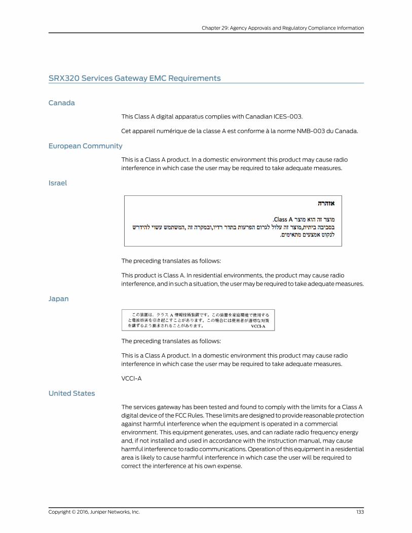
SRX320 Services Gateway EMCRequirements
Canada
This Class A digital apparatus complies with Canadian ICES-003.
Cet appareil numérique de la classe A est conforme à la norme NMB-003 du Canada.
European Community
This is a Class A product. In a domestic environment this product may cause radio
interference in which case the user may be required to take adequate measures.
Israel
The preceding translates as follows:
This product is Class A. In residential environments, the product may cause radio
interference, and in such a situation, the user may be required to take adequate measures.
Japan
The preceding translates as follows:
This is a Class A product. In a domestic environment this product may cause radio
interference in which case the user may be required to take adequate measures.
VCCI-A
United States
The services gateway has been tested and found to comply with the limits for a Class A
digital device of the FCC Rules. These limits are designed to provide reasonable protection
against harmful interference when the equipment is operated in a commercial
environment. This equipment generates, uses, and can radiate radio frequency energy
and, if not installed and used in accordance with the instruction manual, may cause
harmful interference to radio communications. Operation of this equipment in a residential
area is likely to cause harmful interference in which case the user will be required to
correct the interference at his own expense.
133Copyright © 2016, Juniper Networks, Inc.
Chapter 29: Agency Approvals and Regulatory Compliance Information
RelatedDocumentation
• SRX320 Services Gateway Agency Approvals on page 131
• SRX320 Services Gateway Acoustic Noise Compliance Statements on page 132
Copyright © 2016, Juniper Networks, Inc.134
SRX320 Services Gateway Hardware Guide

PART 7
Index
• Index on page 137
135Copyright © 2016, Juniper Networks, Inc.

Copyright © 2016, Juniper Networks, Inc.136
SRX320 Services Gateway Hardware Guide
Index
Symbols#, comments in configuration statements...................xiii
( ), in syntax descriptions.....................................................xiii
< >, in syntax descriptions...................................................xiii
[ ], in configuration statements.........................................xiii
{ }, in configuration statements........................................xiii
| (pipe), in syntax descriptions..........................................xiii
Aaccident procedures, electrical........................................129
acoustic noise compliance statement..........................132
agency approvals...................................................................131
Bbattery-handling warning...................................................123
braces, in configuration statements................................xiii
brackets
angle, in syntax descriptions......................................xiii
square, in configuration statements.......................xiii
Cclass 1 laser warning.............................................................120
class 1 LED warning..............................................................120
comments, in configuration statements.......................xiii
compliance statement, acoustic noise.........................132
compliance statements for EMC requirements
Canada.............................................................................133
European Community.................................................133
Hebrew.............................................................................133
Japan.................................................................................133
United States.................................................................133
components, packing for shipment...............................104
console port, RJ-45................................................................38
conventions
text and syntax.................................................................xii
curly braces, in configuration statements.....................xiii
customer support...................................................................xiv
contacting JTAC..............................................................xiv
customer support, contacting.........................................100
Ddamage, preventing ESD.....................................................115
documentation
comments on..................................................................xiii
Eelectrical
accident procedures....................................................129
safety guidelines and warnings...............................129
electromagnetic compatibility...........................................33
EMC requirements
Canada.............................................................................133
European Community.................................................133
Hebrew.............................................................................133
Japan.................................................................................133
United States.................................................................133
Ethernet port
RJ-45...................................................................................37
Ffont conventions......................................................................xii
Gguidelines, electrical safety...............................................129
Iimmunity standards..............................................................131
Jjewelry removal warning.....................................................125
JTAC.............................................................................................99
Juniper Technical Assistance Center See JTAC
Llaser beam warning...............................................................121
laser safety guidelines..........................................................119
LEDs
class 1 warning...............................................................120
safety warnings..............................................................119
lightning activity warning...................................................124
Mmanuals
comments on..................................................................xiii
NNEBS standards......................................................................131
Ooperating temperature warning.......................................126
137Copyright © 2016, Juniper Networks, Inc.
Ppacking services gateway
components for shipment........................................104
required tools and parts............................................103
parentheses, in syntax descriptions................................xiii
parts
required for packing....................................................103
verifying received...........................................................46
preventing ESD damage......................................................115
product disposal warning..................................................128
Qqualified personnel warning..............................................114
Rradiation from open port apertures warning...............122
radio frequency interference...............................................33
repair policies.........................................................................100
restricted access area warning..........................................112
return materials authorization See RMA
return procedure...................................................................100
RMA
return materials authorization................................100
Ssafety guidelines, laser.........................................................119
services gateway
packing for shipment..................................................103
returning..........................................................................100
setup wizard
default setup mode.......................................................76
description........................................................................75
guided setup mode........................................................76
shipment
packing components..................................................104
packing services gateway.........................................103
signaling limitations...............................................................33
standards compliance..........................................................131
support, requesting from JTAC.................................99, 102
support, technical See technical support
syntax conventions.................................................................xii
Ttechnical support
contacting JTAC..............................................................xiv
tools required for
packing.............................................................................103
Uunpacking
services gateway............................................................45
Vverifying parts received with services gateway...........46
Wwarning
electrical safety guidelines.......................................129
warnings
battery-handling...........................................................123
class 1 laser.....................................................................120
class 1 LED.......................................................................120
jewelry removal.............................................................125
laser beam........................................................................121
lightning activity............................................................124
operating temperature...............................................126
product disposal...........................................................128
radiation from open apertures.................................122
Copyright © 2016, Juniper Networks, Inc.138
SRX320 Services Gateway Hardware Guide
Related Documents